Craftsman 13953939D El manual del propietario
- Categoría
- Abridor de puerta de garage
- Tipo
- El manual del propietario

Owner'sManual/Manualdelpropietario
CRRFTSMRN°
GARAGEDOOROPENER
ABRIDORDEPUERTADE COCHERA
ForResidentialUse0nly/S61oparausoresidencial
Model/Modelo139.53939D
I"11
z
I"11
"o
;z=,
z_
Readandfollowall safetyrulesandoperating
instructionsbeforefirstuseofthis product.
Fastenthe manualnearthegaragedoorafter
installation.
Periodic checksof theopener arerequiredto
ensuresafeoperation.
Leery seguirtodaslas reglasdeseguridady
lasinstruccionesdeoperaci6n antesde usar
esteproductoporprimeravez.
Guardarestemanualcercade la puerta de la
cochera.
Sedebenrealizarrevisionesperi6dicas
del abridorde puertas para asegurarsu
operaci6n segura.
c_us
Sears, Roebuck and Co., Hoffman Estates, IL 60179 U.S.A
www.sears.com/craftsman

TABLE OF CONTENTS
Introduction 2-7
Safetysymbol reviewandsignal word review................ 2
Preparingyour garagedoor ............................. 3
Tools needed......................................... 3
Planning .......................................... 4-5
Carton inventory ...................................... 6
Hardware inventory.................................... 7
Assembly 8-11
Assemblethe rail and install thetrolley ..................... 8
Fastenthe rail to the motor unit .......................... 9
Install the idler pulley .................................. 9
Install the belt ....................................... 10
Tighten the belt...................................... 10
Install the sprocket cover .............................. 11
Installation 11-26
Installation safety instructions .......................... 11
Determinethe headerbracket location .................... 12
Install the header bracket .............................. 13
Attachthe rail to the headerbracket ...................... 14
Position theopener................................... 15
Hangthe opener ..................................... 16
Install the door control ................................ 17
Install the battery .................................... 18
Install the lights ..................................... 18
Attachthe emergency releaseropeand handle.............. 19
Electrical requirements................................ 19
Install The Protector System®........................ 20-22
Fastenthe door bracket............................. 23-24
Connectthedoor arm to the trolley ................... 25-26
Adjustment 27-29
Program thetravel limits............................... 27
Setting the force ..................................... 28
Testthe safety reversalsystem.......................... 29
TestThe ProtectorSystem® ............................ 29
Operation 30-36
Operationsafety instructions ........................... 30
Using your garagedoor opener ......................... 30
Using the wall-mounted door control ..................... 31
Careof your opener .................................. 32
Toopen the door manually ............................. 32
Batterybackup ...................................... 33
Having a problem (Troubleshooting) ..................... 34
Diagnostic chart ..................................... 35
Smart Control Paner messages ......................... 36
Programming 37
Toadd or reprograma hand-held remote control ............ 37
Toeraseall codesfrom motor unit memory................ 37
3-Function remotes................................... 37
Repair Parts 38-39
Rail assemblyparts................................... 38
Installation parts ..................................... 38
Motor unit assembly parts ............................. 39
Accessories 40
Warranty 40
Notes 41
Repair Parts & Service Back Cover
INTRODUCTION
SafetySymbolReview andSignal WordReview
This garage door opener has beendesignedand tested to offer safe serviceprovided it is installed, operated,maintained and tested in
strict accordancewith the instructions and warnings contained in this manual.
Mechanical
Electrical
Whenyou seethese SafetySymbols and Signal Words on the
following pages,they will alert you to the possibility of serious
injuryor deathif you do not comply with the warnings that
accompany them, The hazardmay come from something
mechanicalor from electric shock. Readthe warnings carefully.
Whenyou seethis Signal Word on the following pages,it will alert
you to the possibility of damageto your garage door and/or the
garage door opener if you do not comply with the cautionary
statements that accompany it. Readthem carefully.

Preparingyourgaragedoor
Beforeyou begin:
• Disable locks.
• Removeany ropes connectedto garagedoor.
• Completethefollowingtestto makesureyour garage door is
balancedand is not sticking or binding:
1. Liftthe door about halfway asshown. Releasethe door.
If balanced,it should stay in place,supported entirely by its
springs.
2. Raiseand lower the door to seeif there is any binding or
sticking.
If your door binds, sticks, or is out of balance,call a trained door
systems technician.
To prevent possible SERIOUSINJURYor DEATH:
• ALWAYScall a trained door systems technician if garage
door binds, sticks, or is out of balance.An unbalanced
garage door may NOTreversewhen required.
• NEVERtry to loosen, move or adjust garage door, door
springs, cables, pulleys, bracketsortheir hardware, ALL of
which are under EXTREMEtension.
• DisableALL locks and remove ALL ropesconnectedto
garage door BEFOREinstalling and operating garage door
opener to avoid entanglement.
To prevent damageto garage door and opener:
• ALWAYSdisable locks BEFOREinstalling and operatingthe
opener.
• ONLYoperategaragedoor opener at 120V, 60 Hzto avoid
malfunction and damage.
SectionalDoor
One-Piece Door
Tools needed
During assembly,installation and adjustment of the opener,
instructions will callfor handtools as illustrated below.
Drill
Tape Measure
Pencil
Drill Wire Cutters
3/16", 5/16"
and 5/32"
Hack Saw
Screwdriver
Stepladder
and 1/4"
Pliers
Adjustable End Wrench

Planning
Identify the type and height of your garagedoor. Surveyyour
garage areato see if any of the conditions below apply to your
installation. Additional materials may be required.You may find it
helpful to refer backto this page andthe accompanying
illustrations asyou proceedwith the installation of your opener.
Dependingon your requirements,there are several installation
steps which may call for materialsor hardwarenot included in the
carton.
• Installation Step 1 - Lookat the wall or ceiling abovethe
garagedoor. Theheader bracketmust be securelyfastenedto
structural supports.
• Installation Step 5 - Doyou havea finished ceiling inyour
garage? If so, a support bracketand additional fastening
hardware may be required.
• Installation Step 11 - Dependingupon garageconstruction,
extension brackets or wood blocks may be neededto install
sensors.
• Installation Step 11 - Alternate floor mounting of the safety
reversingsensor will require hardwarenot provided.
Doyou havean access door in addition to the garagedoor?
If not, Model 139.53702 EmergencyKeyReleaseis required.
SeeAccessoriespage.
Lookat the garage door where it meetsthe floor. Any gap
betweenthe floor andthe bottom of the door must not exceed
1/4" (6 mm). Otherwise,the safety reversalsystem may not
work properly. SeeAdjustment Step 3. Floor or door should be
repaired.
SECTIONALDOORINSTALLATIONS
• Doyou havea steel, aluminum, fiberglass or glass panel door?
If so, horizontal and vertical reinforcement is required
(Installation Step12).
• Theopener should be installed abovethe center of the door.
If there is a torsion spring or center bearing platein the way of
the header bracket, it may be installed within 4 feet (1.22 m)
to the leftor right of the door center. See Installation
Steps 1 and 12.
• If your door is morethan 7 feet (2.13 m) high, seerail
extension kits listed on Accessories page.
SECTIONALDOORINSTALLATION
Horizontal and vertical reinforcement
is neededfor lightweight garage doors
(fiberglass, steel, aluminum, door with
glass panels, etc.). Seepage23 for details.
FINISHEDCEILING
Support bracket & _\ -"_,_r]:_
fastening hardware _:k /_
is required, "_'_ _/
See p_
_r Torsion Spring _ I t
w& gu#gd
I
AccessDoor
t?
u
Header Wall
y Reversing Sensor
Gapbetween floor
and bottom of door
must not exceed 1/4" (6 mm).
Safety
Reversing
Sensor
0 CLOSEDPOSITION
Header
Bracket Rail Tab
/ / Trolley
araoe
Door t?J "--I Belt
Spring /c_°C_Straight I
t{/ Door I_ Emergency Release
_j Arm I_ Rope & Handle
X/_ _ Curved
q I \ Door
_11 Door Arnl
II Bracket

Planning(Continued)
ONE-PIECEDOORINSTALLATIONS
• Generally,a one-piecedoor does not require reinforcement.
If your door is lightweight, refer to the information relating to
sectional doors in Installation Step 12.
• Dependingon your door's construction, you may need
additional mounting hardwarefor the door bracket (Step 12).
Without aproperly working safety reversalsystem, persons
(particularly small children) could beSERIOUSLYINJUREDor
KILLEDby a closing garagedoor.
• Thegap betweenthe bottom of the garage door and the floor
MUSTNOTexceed1/4" (6 mm). Otherwise,the safety
reversalsystem may NOTwork properly.
• Thefloor or the garage door MUSTbe repairedto eliminate
the gap.
ONE-PIECEDOORWITHOUTTRACK
FINISHEDCEILING
Header Wall
Rail
Suppod bracket
& fastening
ha_wareis required.
See page 16.
Wall-Mounted
Door Control
Access
Door
oi
Safety Reversing
Sensor
Safety Reversing
Sensor
Gapbetween floor
and bottom of door must
not exceed 1/4" (6 mm).
Motor Unit
CLOSEDPOSITION
RailTab Belt Trolley
Door
Cul
Door
Arm
Emergency
Release
Rope & Handle
ONE-PIECEDOORWITH TRACK
Gapbetween floor
and bottom of door
Safety must not exceed
Reversing Sensor 1/4" (6 mm).
Access
Door
0
Safety
Reversing Sensor
Header
Wall
CLOSEDPOSITION
Rail Tab Belt Trolley
Door
Bracket
Garage
Door
Straight
Door
Arm
Rail
Emergency
Release
Rope &
Handle

CartonInventory
Your garagedoor opener is packagedin one carton which
contains the motor unit and all parts illustrated below. Accessories
will dependon the model purchased. If anything is missing,
carefully checkthe packing material.
Hardwarefor assembly and installation is shownon the next page.
Savethe carton and packing material until installation and
adjustment is complete.
Smart Control Panel®
3-Function Mini
SECURITY.I.® Remote Control Battery
3-Function Remote Control (2)
Sprocket Cover
LaserGarage Parking Assist
Motor Unit with 2 Light Lenses
Garage Door Monitor
Rail
Front (header)
Section
Trolley
Idler Pulley
Rail
Center/Back
I Sections
@
Belt
Door Bracket
Curved Door
Arm Section
Plug-In Light Control
Safety Reversing
Sensor Bracket (2)
Header Bracket
The Protector System®
(2) Safety Reversing Sensors
(1 Sending Eye and 1 Receiving Eye)
with 2-Conductor White & White/Black
BellWire attached
2-Conductor BellWire
White & White/Red
Surge Protector
Safety Labels
and
Literature
Security+®
KeylessEntry
i_ Iqt
% %
% %
I° %
% %
9. %
Hanging Brackets
Straight Door
Arm Section

HardwareInventory
Separateall hardwareand group asshown below for the assembly and installation procedures.
ASSEMBLYHARDWARE
i
i
e O G
Lock Nut Lock Washer 8/8" Nut 3/8"
1/4"-20 Master Link
Bolt1/4"-20x1-3/4" !!!!!!!!!})
Idler Bolt
©
Threaded Shaftwith
Spring Trolley Nut
INSTALLATIONHARDWARE
CarriageBolt Wing Nut
1/4"-20xl/2" (2) 1/4"-20 (2)
Lag Screw
5/16"-9xl-5/8" (4)
_ng Screw
1/4"-14x5/8" (2)
hltllll
Drywall Anchors (2)
o]
Clevis Pin
5/16"x1-1/2"
0
Ring
Fastener (3)
_,1111111111D
Hex Bolt
5/16"-18x7/8" (4)
@
Nut 5/16"-18 (6)
@
Lock Washer 5/16" (5)
Handle
Insulated Staples
(Not shown)
_lllllllllMIMl'lll_
Screw
6ABxl" (2)
Screw 6-32x1" (2)
{
o_
Clevis Pin
5/16"xl"
Clevis Pin
5/16"xl -1/4"
oH
Rope

ASSEMBLY STEP 1
Assemb/etheRai/ and Insta//the Tro//ey
To avoidinstallationdifficulties,do notrunthe garagedoor
openeruntil instructedto do so.
Thefront rail hasa cut out "window" at the door end. Thefront
and back rail both haverail tabs. Theserail tabs MUST be on top
of the railwhen assembled.
1. Removethe straight door arm and hanging bracket
packagedinside the front rail and set asidefor Installation
Steps 5 and 12.
NOTE:Toprevent INJURY whileunpacking therail carefully
remove thestraight door arm stored within the rail section.
2. Align the rail sections on a flat surface asshown and slide the
taperedends into the larger ones. Tabs along the side will lock
into place.
3. Placethe motor unit on packing material to protect the cover,
and rest the back end of the rail on top. Forconvenience,put a
support under the front end of the rail.
To prevent INJURYfrom pinching, keephandsand fingers
away from the joints while assembling the rail.
4. As a temporary stop, insert a screwdriver into the hole
10"(25 cm) from the front end of the rail, as shown.
5. Checkto besure there are 4 plastic wear pads insidethe inner
trolley. If they becameloose during shipping, checkall packing
material. Snapthem back into position asshown.
6. Slide the trolley assembly along the rail from the back end to
the screwdriver.
7. Slide the railonto the "U" bracket, until it reachesall the stops
on thetop and sides of the "U" bracket.
Back Rail Section
(TO MOTOR UNIT)
Outer Trolley
Inner Trolley
SLIDETO STOPSON
TOPAND SIDESOF
"U" BRACKET
FrontRail Section
(TO DOOR)
Rail Tab
Idler Pulley
Trolley
Window
Cut-Out

ASSEMBLY STEP 2
FastentheRai/ to theMotorUnit
1. Inserta 1/4"-20xl-3/4 bolt into the cover protection bolt hole
on the back end of the rail as shown. Tighten securelywith a
1/4"-20 lock nut. DONOTovertighten.
2. Removethe two bolts from the top of the motor unit.
3. Usethe carton to support the front end of the rail.
4. Placethe "U" bracket,flat side down onto the motor unit and
align the bracketholes with the bolt holes. Fastenthe "U"
bracketwith the previously removed bolts; DONOTuse any
power tools. Theuse of powertools may permanently damage
the garagedoor opener.
To avoid SERIOUSdamageto garagedoor opener, use ONLY
those bolts/fasteners mounted in the top of the opener.
Cover
Protection
Bolt Hole
Bolts
"U" Bracket
Bolt \
HARDWARESHOWNACTUALSIZE
d @
Bolt 1/4"-20xl-3/4"
Lock Nut
1/4"-20
Lock Nut i
ASSEMBLY STEP 3
Insta// theId/er Pu//ey
1. Laythe belt besidethe rail, asshown. Graspthe end with the
hookedtrolley connector and pass approximately 12"(30 cm)
of beltthrough the window. Keepthe ribbed side toward the
rail,and allow it to hang until Assembly Step 4.
2. Removethe tapefrom the idler pulley. The inside center should
be pre-greased. If dry, regreaseto ensure proper operation.
3. Placethe idler pulley into the window as shown.
4. Insertthe idler bolt from the top through the rail and pulley.
Tighten with a 3/8" lockwasher and nut underneaththe rail until
the lock washer is compressed.
5. Rotatethe pulleyto besure it spins freely.
6. Locatethe rail tab. The rail tab is betweenthe idler bolt and the
trolley in the front rail section. Usea flat head screwdriver and
lift the rail tab until the tab is vertical (90°).
Screwdriver
... - - - _Grease
Lock
Washer _ Idler Pulley
3/8" %ut 3/8"
Trolley
Connector
CORRECT
@
INCORRECT
@
Inside Pulley
HARDWARESHOWNACTUALSIZE
Idler Bolt Nut 3/8"
Lock Washer 3/8"

ASSEMBLY STEP 4
Installthe Belt
1. Pull the belt around the idler pulley and toward the trolley.
Theribbed sidemust contact the pufley.
2. Hook the trolley connector into the retaining slot on the trolley
asshown (Figure 1).
3. With thetrolley against the screwdriver, dispense the
remainderof the belt along the rail lengthtoward the motor
unit and around the sprocket (Figure2). The sprocket teeth
must engagethe belt.
4. Checkto make surethe belt is not twisted. Connectthe trolley
threaded shaft with the master link (Figure 3).
• Push pins of masterlink bar through holes in end of belt
and trolley threadedshaft.
• Push master link cap over pins and past pin notches.
• Slide clip-on spring overcap and onto pin notches until both
pins are securely locked in place.
5. Removethe spring trolley nut from the threaded shaft.
6. Insert the trolley threadedshaft through the hole in the trolley.
[©
ure I
HARDWARESHOWNACTUALSIZE
Master Link
Threaded Shaft with
Spring Trolley Nut
Figure2
Sprocket
Figure3
ASSEMBLY STEP 5
Tightenthe Belt
1. By hand,threadthe spring trolley nut on the threadedshaft
until it is finger tight against the trolley. Do not use anytools.
Removethe screwdriver.
2. Insert a flathead screwdriver tip into one of the nut ring slots
and braceit firmly againstthe trolley.
3. Tighten the spring trolley nut with an adjustablewrench or a
7/16" openend wrench about a quarter turn until the spring
releasesand snaps the nut ring againstthe trolley. This sets
the spring to optimum belt tension.
Nut Ring
I- BEFORE-I
1"
(2.5 cm)
1-1/4"
(3.18 cm)
Spring Trolley Nut
10

ASSEMBLY STEP 6
Install theSprocketCover
1. Position the sprocket cover overthe sprocket as shown and
fastento the mounting platewith 8x3/8"hex screws provided.
To avoid possible SERIOUSINJURYto fingers from moving
garagedoor opener:
• ALWAYSkeephand clearof sprocket while operating opener.
• Securely attachsprocket cover BEFOREoperating.
Youhave nowfinishedassemb/ingyourgaragedooropener.
P/ease read thelot/owingwarningsbeforeproceedingtothe
insta//ationsection.
Sprocket
Mounting
Plate
INSTALLATION
IMPORTANTINSTALLATIONINSTRUCTIONS
To reducethe riskofSEVEREINJURYor DEATH:
1. READAND FOLLOWALL INSTALLATIONWARNINGSAND
INSTRUCTIONS.
2. Install garagedoor opener ONLYon properly balancedand
lubricated garagedoor. An improperly balanceddoor may
NOTreversewhen required and could result in SEVERE
INJURYor DEATH.
3. ALL repairsto cables,spring assembliesand other hardware
MUST be madeby a trained door systems technician
BEFOREinstalling opener.
4. DisableALL locks and removeALL ropes connectedto
garagedoor BEFOREinstalling opener to avoid
entanglement.
5. Install garagedoor opener 7 feet (2.1 m) or more above
floor.
6. Mount the emergency releasewithin reach, but at least
6 feet (1.8 m) abovethe floor and avoiding contact with
vehiclesto avoid accidental release.
7. NEVERconnect garagedoor opener to power source until
instructed to do so.
8. NEVERwearwatches, rings or loose clothing while
installing or servicing opener.They could be caught in
garage door or opener mechanisms.
9. Install wall-mounted garagedoor control:
• within sight of the garagedoor.
• out of reachof children at minimum heightof
5 feet (1.5 m).
• away from ALL moving parts of the door.
10. Placeentrapment warning labelon wall nextto garage door
control.
11. Placemanual release/safetyreversetest labelin plain view
on inside of garagedoor.
12. Uponcompletion of installation, test safety reversalsystem.
Door MUSTreverseon contact with a 1-1/2" (3.8 cm) high
object (or a 2x4 laid flat) on the floor.
13. To avoid SERIOUSPERSONALINJURYor DEATHfrom
electrocution, disconnectALL electric and battery power
BEFOREperforming ANYserviceor maintenance.
11

INSTALLATION STEP 1
Determinethe HeaderBracketLocation
To prevent possible SERIOUSINJURYor DEATH:
• HeaderbracketMUSTbe RIGIDLYfastenedto structural
support on headerwall or ceiling, otherwise garagedoor
might NOTreversewhen required. DONOTinstall header
bracket over drywall.
• Concreteanchors MUST be usedif mounting headerbracket
or 2x4 into masonry.
• NEVERtry to loosen, move or adjust garagedoor, springs,
cables,pulleys, brackets,or their hardware,ALL of which are
under EXTREMEtension.
• ALWAYScall a trained door systems technician if garage
door binds, sticks, or is out of balance.An unbalancedgarage
door might NOTreversewhen required.
Follow the instructions which applyto your door.
1. Closethe door and mark the insidevertical centerline of the
garagedoor.
2. Extendthe line onto the headerwall abovethe door.
Youcanfastenthe headerbracketwithin 4 feet (1.22 m) of
the left or rightof thedoorcenter onlyif a torsionspringor
center bearingplate is in theway; or youcan attachitto the
ceiling (see page 13) whenclearanceis minimal. (It may be
mountedon thewall upsidedownif necessary,to gain
approximately1/2" (1 cm).)
If you needto install the headerbracket on a 2x4 (on wall or
ceiling), use lag screws (not provided) to securelyfasten the
2x4 to structural supports as shown hereand on page13.
3. Openyour door to the highestpoint of travel asshown. Draw
an intersecting horizontal line on the headerwall abovethe high
point:
• 2"(5 cm) abovethe high point for sectional door and
one-piecedoor with track.
• 8"(20 cm) abovethe high point for one-piecedoor without
track.
This heightwill provide travel clearancefor the top edgeof the
door.
NOTE:If thetotal number of inches exceedsthe height available
in your garage,use themaximum height possible, or refer to
page 13 for ceiling installation.
HeaderWall
II I
Unfinished
Ceiling __, OPTIONAL
-- _ CEILING
J%.NT
-J HEADER
/,RACKET
VerticalCenterline
ofGarageDoor
Level
(optional)
2x4 Structural
Supports
J
HeaderWall Track
t
!
One-piece doorwith horizontal track
Header Wall
_,__2" 15cm) Tlack
HighestPoint
ofTravel
--Door
Sectional doorwith curved track
E Heal_.._Wall
Door IJ_,,,,.,j_" Highest
_ _iTn/avel
rd°reII/
One-piecedoorwithouttrack:
jambhardware
deader Wall
Pivot
One-piecedoor without track:
pivothardware
12

INSTALLATION STEP 2
Install theHeaderBracket
You can attachthe headerbracket eitherto the wall abovethe
garage door, or to the ceiling. Follow the instructions which will
work best for your particular requirements. Donot install the
headerbracketoverdrywall. If installingintomasonry,use
concreteanchors(not provided).
WALLHEADERBRACKETINSTALLATION
1. Centerthe bracketon the vertical centerlinewith the
bottom edgeof the bracketon the horizontal line asshown
(with the arrow pointing toward the ceiling).
2. Mark the vertical setof bracket holes. Drill 3/16" pilot holesand
fastenthe bracketsecurely to a structural support with the
hardware provided.
HARDWARESHOWNACTUALSIZE
Icrel
5/16"-9x1-5/8"
CEILINGHEADERBRACKETINSTALLATION
1. Extendthe vertical centerlineonto the ceiling as shown.
2. Centerthe bracketon the vertical mark, no more than
6"(15 cm) from the wall. Make sure the arrow is pointing away
from the wall. The bracketcan be mounted flush against the
ceiling when clearanceis minimal.
3. Mark the side holes.Drill 3/16" pilot holes and fasten bracket
securelyto a structural support with the hardwareprovided.
Wall Mount
Optional
MountingHoles
- HeaderWall -
Vertical
Centerline
of GarageDoor
2x4
Structural
Support
1
Horizontal
Line
i
HighestPointof
GarageDoorTravel
_ LagScrews
5/16"-9xl -5/8"
Door Spring
- GarageDoor -
Vertical
Centerline
of GarageDoor
- FinishedCeiling-
VerticalCenterline
ofGarageDoor
CeilingMountingHoles
Door
Spring
-- LagScrews
5/16"-9xl -5/8"
HeaderWall -
13

INSTALLATION STEP 3
AttachtheRail to the HeaderBracket
1. Positionthe opener on the garagefloor below the header
bracket. Usepacking material asa protective base.
NOTE:If thedoor spring is in the way,you will need help. Have
someone hold the opener securely on a temporary support to
allow the rail to clear the spring.
2. Positionthe rail bracket againstthe headerbracket.
3. Align the bracket holesand join with a clevis pin as shown.
4. Insert aring fastenerto secure.
Header Wall
Header Bracket
Idler Pulley
Ring
\
\
Mounting
Hole
__ Garage
Door
Temporary
Support
HARDWARESHOWNACTUALSIZE
oD
ClevisPin5/]B"x]-]/2"
0
Ring Fastener
14

INSTALLATION STEP 4
Positionthe Opener
Follow instructions which applyto your door type as illustrated.
SECTIONALDOORORONE-PIECEDOORWITH TRACK
A 2x4 laidflat is convenient for setting an ideal door-to-rail
distance.
1. Raisethe openeronto a stepladder.You will need help at this
point if the ladder is not tall enough.
2. Openthe door all the way and placea 2x4 laid flat on the top
section beneaththe rail.
3. Ifthe top section or panel hits the trolley when you raise
the door, pull down on the trolley releasearm to disconnect
inner and outer sections. Slide the outer trolley toward the
motor unit. Thetrolley can remain disconnected until
Installation Step 12 is completed.
Trolley
lease
ENGAGED RELEASED _
To prevent damageto garage door, restgaragedoor opener rail
on 2x4 placedon top section of door.
Rail
Door 2x4 is used to
from ceiling.
ONE-PIECEDOORWITHOUTTRACK
A 2x4 on its side is convenientfor setting anideal door-to-rail
distance.
1. Raisethe openeronto a stepladder.You will need help at this
point if the ladder is not tall enough.
2. Openthe door all the way and placea 2x4 on its side on the top
section of the door beneaththe rail.
3. Thetop of the door should belevelwith the top of the motor
unit. Donot position the opener more than 4" (10 cm) above
this point.
Header
I
i
Top of Door
2x4 is usedto
determine the correct
mounting height
from ceiling.
15

INSTALLATION STEP 5
Hangthe Opener
Threerepresentative installations are shown. Yours maybe
different. Hanging brackets should be angled (Figure 1) to provide
rigid support. On finished ceilings (Figures 2 and 3), attach a
sturdy metalbracket to structural supports before installing the
opener.This bracket and fastening hardwareare not provided.
1. Measurethe distancefrom eachside of the motor unit to the
structural support.
2. Cut both piecesof the hanging bracket to requiredlengths.
3. Drill 3/16" pilot holes in the structural supports.
4. Attach one end of eachbracketto a support with
5/16"-9xl-5/8" lag screws.
5. Fastenthe opener to the hanging brackets with
5/16"-18x7/8" hex bolts, lock washers and nuts.
6. Checkto makesure the rail is centered over the door (or in
line with the header bracketif the bracket is not centeredabove
the door).
7. Removethe 2x4. Operatethe door manually. If the door hits the
rail, raisethe header bracket.
NOTE:DONOTconnectpower to openerat this time.
HARDWARESHOWNACTUALSIZE
Lag Screw 5/16"-9xl-5/8"
HexBolt
5/1B"-18x7/8" Nut 5/16"-18 LockWasher 5/1B"
To avoid possible SERIOUSINJURYfrom a falling garage door
opener,fasten it SECURELYto structural supports of the
garage.Concreteanchors MUST be usedif installing ANY
brackets into masonry.
FigureI
Supports
Measure ',
Distance
Bolt 5/16"-18x7/8"
Lock Washer 5/16"
Nut 5/16"-18
Lag Screw
5/16"-9xl -5/8"
Figure2
Hidden .. _ -
Support _---
(Not Provided) .... _1 _j_-
_ -- FINISHEDCEILING
Lag Screw
5/16"-9xl-5/8" - _--
(Not Provided)
Bolt 5/16"-18x7/8"
_ Lock Washer 5/16"
Nut 5/16"-18
Bolt 5/16"-18x7/8"
Lock Washer 5/16"
Nut 5/16"-18
Figure3
Lag Screw
5/16"-9xl -5/8"
Bolt 5/16"-18x7/8"
Lock Washer 5/16"
Nut 5/16"-18
(Not Provided)
Bolt 5/16"-18x7/8"
Lock Washer 5/16"
Nut 5/16"-18
16

INSTALLATION STEP 6
Install theDoorControl
Locate the door control within sight of door, at a minimum height
of 5feet (1.5 m) where smallchildren cannot reach,away from
moving parts of door and door hardware. If installing into drywall,
drill 5/32" holes andusethe anchors provided. Forpre-wired
installations (as in new home construction), it may be mounted to
a single gang box (Figure1).
1. Strip 7/16" (11 mm) of insulation from one end of bell wire and
connect to the two screwterminals on the back of the door
control by color: white wire to 2 and white/red wire to the 1
(Figure 2).
2. Removecover by gently prying at slot in top of the cover with a
small flat head screwdriver (Figure3). Fastenwith 6ABxl"
self-tapping screws(drywall installation) or 6-32x1" machine
screws (into gang box) as follows:
• Install bottom screw, allowing 1/8" (3 mm) to protrude above
wall surface.
• Position the bottom of the door control on the screw head
and slide down to secure. Adjust screwfor snugfit.
• Drill and install top screw with care to avoid cracking plastic
housing. Do not overtighten.
• Insert top tabs and snap on cover.
3. (For standard installation only)Run bell wire up wall and
across ceiling to motor unit. Use insulated staplesto secure
wire inseveral places. Donot piercewire with a staple, creating
a short or open circuit.
4. Strip 7/16" (11 mm) of insulation from end of bell wire. Connect
bell wire to the quick-connect terminals as follows: white to
white and white/red to red (Figure4).
5. Positionthe antennawire as shown.
6. Usetacks or staplesto permanently attachentrapment warning
label to wall nearthe door control, and manual release/safety
reversetest labelin a prominent location on inside of garage
door.
NOTE:DONOTconnectpower and operate openerat this time.
Thetrolley will travel to the furl open position but will not return
to the closeposition until thesensor beamis connectedand
properly aligned.
Figure4
Door Control
Connections
To releaseor insert wire, pushin tab
with screwdriver tip
Strip wire 7/16" (11 ram)
(7/16"(11 mnU)
Red WhiteGrey
Smart Control Panel_'
/
o
To prevent possible SERIOUSINJURYor DEATHfrom
electrocution:
• DisconnectALL electric and batterypower BEFORE
performing ANY serviceor maintenance.
• ConnectONLYto 24 VOLTlow voltage wires.
To prevent possible SERIOUSINJURYor DEATHfrom a
closing garagedoor:
• Installthe door control within sight of garagedoor, out of
reachof children at a minimum height of 5 feet (1.5 m), and
away from ALL moving parts of door.
• NEVERpermit children to operateor play with door control
push buttons or remotecontrols.
• Activate door ONLYwhen it can be seenclearly, is properly
adjusted, andthere are no obstructions to door travel.
• ALWAYSkeepgarage door in sight until completely closed.
NEVERpermit anyoneto cross path of closing garagedoor.
HARDWARESHOWNACTUALSIZE
'''>
(std installation)
(Gang boxinstallation)
Insulated Staples
(Not shown)
Drywall Anchors
Figure1
PRE-WIREDINSTALLATION
Figure2
__i Top
Mounting
Bell ( + -- + I) Hole
W_ _,.,...__ __j:lk_ "_Terminal
screws
_--i--J __-lu-F-_---h_ Bottom
_ Pl Mounting
(BACKVIEW) Hole
Figure3
To Replace,
Insert Top
Push Bar Cover

INSTALLATION STEP 7
Install theBattery
1. Make sure motor unit is unplugged.
2. Usinga Phillips headscrewdriver, removethe batterycover on
the motor unit.
3. Partiallyinsert battery into motor unit with terminals facing out.
4. Connectthe red (+) and black (-) wires from motor unit to
corresponding terminals on battery.
5. Verify the batterywires are seated in the channel.
6. Replacebattery cover.
ALWAYSwear protective gloves and eyeprotection when
changing the battery or working around the battery
compartment.
INSTALLATION STEP 8
Install theLights
1. Pressthe releasetabs on both sides of lens. Gentlyrotate lens
back and downward until the lens hinge is in the fully open
position. Donot removethe lens.
2. Install upto a 100 watt maximum light bulb in eachsocket.
Light bulb size should be A19, standard neck only. Thelights
will turn ONand remainlit for approximately 4-1/2 minutes
when power is connected.Thenthe lights will turn OFF.
3. Reversethe procedureto close the lens.
4. UseA19,standard neck garagedoor opener bulbs for
replacement.
NOTE:Useonly standardlight bulbs. Theuseof short neck or
speciafity light bulbs may overheatthe endpanelor light socket.
To prevent possible OVERHEATINGof the endpanelor light
socket:
• DONOTuseshort neck or specialty light bulbs.
• DONOTuse halogen bulbs. UseONLYincandescent.
To prevent damageto the opener:
• DONOTuse bulbs larger than 100W.
• ONLYuseA19 sizebulbs.
ReleaseTab
100 Watt (Max)_
Standard Light Bulb f_,...____ _
/
/
/
100 Watt,
Standard Light Bulb
Lens
Hinge
18

INSTALLATION STEP 9
Attachthe EmergencyReleaseRopeandHandle
1. Insert one end of the emergencyreleaserope through the
handle.Make sure that "NOTICE"is right side up. Tie a knot at
least 1 inch (2.5 cm) from the end of the emergency release
rope.
2. Insert the other end of the emergency releaserope through the
hole in the trolley releasearm. Mount the emergencyrelease
within reach,but at least 6 feet (1.83 m) abovethe floor,
avoiding contact with vehiclesto preventaccidental releaseand
securewith a knot.
NOTE:If it is necessaryto cut the emergencyreleaserope, seal
the cut end with a match or lighter to prevent unraveling. Ensure
the emergencyreleaserope and handleare abovethe top of aft
vehiclesto avoid entanglement.
To prevent possible SERIOUSINJURYor DEATHfrom a falling
garagedoor:
• If possible, useemergency releasehandleto disengage
trolley ONLYwhen garagedoor is CLOSED.Weak or broken
springs or unbalanceddoor could result in an open door
falling rapidly and/or unexpectedly.
• NEVERuseemergency releasehandle unless garagedoorway
is clear of personsand obstructions.
• NEVERusehandle to pull door open or closed. If rope knot
becomes untied, you could fall.
Trolley
• !
_ _ Overhand
Emergency
_ Knot
ReleaseHandle
INSTALLATION STEP 10
Electrical Requirements
To avoidinstallationdifficulties,do notrunthe openerat this
time.
To reducethe risk of electric shock, your garagedoor openerhas
a grounding type plug with a third grounding pin. This plug will
only fit into agrounding type outlet. If the plug doesn't fit into the
outlet you have,contact a qualified electricianto install the proper
outlet.
To prevent possible SERIOUSINJURYor DEATHfrom
electrocution or fire:
• DisconnectALL electric and battery power BEFORE
performing ANY serviceor maintenance.
• Garagedoor installation and wiring MUSTbe in compliance
with ALL local electrical and building codes.
• NEVERusean extension cord, 2-wire adapter,or change
plug in ANYway to makeit fit outlet. Besure the opener is
grounded.
PERMANENTWIRING
CONNECTION
If permanent wiring isrequired byyourlocal code,refer to the
followingprocedure.
To makea permanent connection through the 7/8" hole in the top
of the motor unit:
1. Removethe motor unit cover screws and set the cover aside.
2. Removethe attached3-prong cord.
3. Connectthe black (line) wire to the screw on the brass terminal;
the white (neutral) wire to the screw on the silver terminal;
and the ground wire to the green ground screw.
The openermustbe grounded.
4. Reinstallthe cover.
To avoidinstallationdifficulties,do notrunthe openerat this
time.
19
Ground Tab
Green
Ground Screw
Ground Wire . Wire
White Wire BlackWire

INSTALLATION STEP 1 1
Install TheProtectorSystem®
The safetyreversingsensormustbeconnectedandaligned
correctlybeforethe garagedooropenerwill movein the down
direction.
IMPORTANTINFORMATIONABOUTTHESAFETYREVERSING
SENSOR
When properly connectedand aligned, the sensor will detectan
obstacle in the pathof its electronic beam. Thesending eye
(with an amber indicator light) transmits aninvisible light beam
to the receivingeye(with a green indicator light). If an obstruction
breaks the light beamwhile the door is closing, the door will stop
and reverseto full open position, and the opener lights will flash
10 times.
The units must be installed inside the garageso that the sending
and receivingeyes face eachother across the door, no morethan
6" (15 cm) abovethefloor. Either can be installed on the left or
right of the door aslong as the sun never shines directly into the
receiving eyelens.
The mounting brackets are designedto clip onto the track of
sectional garagedoors without additional hardware.
Besure power is NOTconnectedto the garagedoor opener
BEFOREinstalling the safety reversing sensor.
To prevent SERIOUSINJURYor DEATHfrom a closing garage
door:
• Correctly connect and align the safety reversingsensor.
This required safety device MUSTNOTbe disabled.
• Install the safety reversing sensor so beamis NOHIGHER
than 6" (15cm) abovegaragefloor.
If it is necessaryto mount the units on the wall, the brackets must
be securely fastenedto a solid surface such as the wall framing.
Extensionbrackets (seeaccessories) are availableif needed.
If installing in masonry construction, add a pieceof wood at each
location to avoid drilling extra holesin masonry if repositioning
is necessary.
The invisible light beam path must be unobstructed. No part of the
garage door (or door tracks, springs, hinges, rollers or other
hardware) may interrupt the beamwhile the door is closing.
[ ! !oJ!Jl
_'af(_t5YcRm)max. I;v2_2_le_igAhr;aB_ _af(_t5YcRe_ermS2;? Sensor
above floor above floor
Facingthe doorfrom insidethe garage.
2O

INSTALLINGTHE BRACKETS
Besure power to the openeris disconnected.Install and align
the brackets so the sensors will faceeachother across the garage
door, with the beam no higher than 6"(15 cm) abovethe floor.
They may be installed in one of three ways, as follows.
Garage doortrackinstallation(preferred):
1. Slip the curved arms overthe roundededge of eachdoor track,
with the curved arms facing the door. Snapinto placeagainst
the side of the track. It should lie flush, with the lip hugging the
back edge of the track (Figure1).
If your door track will not support the bracket securely,wall
installation is recommended.
Waftinstallation(Figures2 and 3):
1. Placethe bracketagainst the wall with curved arms facing the
door. Besure there is enough clearancefor the sensor beamto
be unobstructed.
2. Ifadditional depth is needed,an extension bracket
(seeAccessories) or wood blocks can be used.
3. Usebracket mounting holes asa template to locateand drill
(2) 3/16" diameter pilot holeson the wall at eachside of the
door, no higher than 6" (15cm) abovethe floor.
4. Attach brackets to wall with lag screws (not provided).
5. Ifusing extension bracketsor wood blocks, adjust right and left
assembliesto the same distance out from the mounting
surface. Make sure all door hardwareobstructions are cleared.
Floorinstallation(Figure4):
1. Usewood blocks or extension brackets (seeAccessories)to
elevatesensor bracketsso the lenseswill be no higher than
6"(15 cm) abovethe floor.
2. Carefully measureandplace right and left assembliesat the
same distanceout from the wall. Besure all door hardware
obstructions arecleared.
3. Fastento the floor with concrete anchors as shown.
CarriageBolt
1/4"-20xl/2"
HARDWARESHOWNACTUALSIZE
Wing Nut
1/4"-20
InsulatedStaples
(NotShown)
FigureI
Figure2
DOORTRACKMOUNT(RIGHT SIDE)
--Door
' . Track
"; Lip
Safety
Reversing
Sensor
Bracket
zz_
Indicator
Light
WALL MOUNT(RIGHT SIDE)
FastenWood Block to Wall with
(Notprovided)
Indicator
Light Safety
Reversing
Sensor
Bracket
rovided)
Lens "" -'_e(_
Figure3
Provided with .
xtension Bracket)
WALL MOUNT(RIGHT SIDE)
Extension Bracket
(See Accessories)
I (Providedwith
:_;,_"_ _ _ Reversing
Sensor
I " Bracket
Lens Indicator
Light
Figure4 FLOORMOUNT(RIGHTSIDE)
-- ttach with
Concrete Anchors
; (Not provided)
Indicator
Light
Reversing
Sensor
Bracket
21

MOUNTINGANDWIRINGTHESAFETYREVERSINGSENSORS
1. Slide a 1/4"-20xl/2" carriage bolt headinto the slot on each
sensor. Use wing nutsto fastensensors to brackets,with
lenses pointing toward eachother across the door. Besure the
lens is not obstructed by a bracket extension (Figure5).
2. Fingertighten the wing nuts.
3.Run the wires from both sensorsto the opener. Useinsulated
staplesto secure wire to wall and ceiling.
4. Strip 7/16" (11 mm) of insulation from eachset of wires.
Separatewhite and white/black wires sufficiently to connect to
the opener quick-connect terminals. Twist like colored wires
together. Insert wires into quick-connect holes:white to white
and white/black to grey (Figure6).
ALIGNINGTHESAFETYREVERSINGSENSORS
1. Plugin the opener. Theindicator lights in both the sending and
receiving eyeswill glow steadilyif wiring connections and
alignment arecorrect.
The sendingeyeamber indicator light will glow regardlessof
alignment or obstruction. If the green indicator light in the
receiving eyeis off, dim, or flickering (and the invisible light beam
path is not obstructed), alignment is required.
2. Loosenthe sending eyewing nut andreadjust, aiming directly
at the receivingeye.Lock in place.
3. Loosenthe receiving eyewing nut andadjust sensor until it
receivesthe sender's beam.Whenthe green indicator light
glows steadily, tighten the wing nut.
Figure5
CarriageBolt-m_
1/4"-20xl/2"
WingNut
TROUBLESHOOTINGTHESAFETYREVERSINGSENSORS
1. Ifthe sending eyeindicator light does not glow steadily after
installation, checkfor:
• Electric powerto the opener.
• A short in the white or white/black wires. These canoccur at
staples, or at opener connections.
• Incorrect wiring between sensors and opener.
• A broken wire.
2. If the sending eyeindicator light glows steadilybut the
receiving eyeindicator light doesn't:
• Checkalignment.
• Checkfor an open wire to the receiving eye.
3. Ifthe receiving eyeindicator light is dim, realign either sensor.
NOTE:Whenthe invisible beampath is obstructed or misaligned
while thedoor is closing, thedoor will reverse.If the door is
alreadyopen,it will not close. Theopenerlights will blink 10times.
Seepage20.
Figure6
BellWire
Connect Wire to
Quick-Connect Terminals
BellWire
\
1. Strip wire 7/16"
(11 mm)
17/16"(11 ram) I
2. Twist like colored
wires together
3. To insert or release
wire, push in tab with
screwdriver tip
Safety
Reversing
Sensor
Invisible Light Beam
Protection Area
Safety
Reversing
Sensor
White Grey
Quick-Connect Terminals
22

INSTALLATION STEP 12
Fastenthe DoorBracket
Follow instructions which applyto your door type as illustrated
below or on the following page.
A horizontal reinforcementbrace shouldbe longenoughto be
securedtotwo orthree vertical supports.A vertical
reinforcementbraceshouldcoverthe heightof thetop panel.
Figure1 shows one pieceof angle iron as the horizontal brace.
Forthe vertical brace, 2 pieces of angle iron are usedto createa
U-shaped support. The best solution isto checkwith your garage
door manufacturer for an opener installation door reinforcement
kit.
NOTE:Many door reinforcement kits provide for direct attachment
of the clevispin and door arm. In this caseyou will not needthe
door bracket, proceed to Step 13.
SECTIONALDOORS
1. Centerthe door bracketon the previously marked vertical
centerline usedfor the headerbracket installation. Note correct
UPplacement,as stamped insidethe bracket.
2. Positionthe top edge of the bracket2"-4"(5-10 cm) below the
top edge of the door, ORdirectly below any structural support
across the top of the door.
3. Mark, drill holes and install as follows, depending on your
door's construction:
Metal orlight weight doorsusinga vertical angleiron brace
betweenthe doorpanelsupportand thedoorbracket:
• Drill 3/16" fastening holes.Securethe door bracket using the
two 1/4"-14x5/8" self-threading screws (Figure 2A).
• Alternately, usetwo 5/16" bolts, lock washers and nuts (not
provided) (Figure2B).
Metal, insulatedor light weightfactoryreinforceddoors:
• Drill 3/16" fastening holes.Securethe door bracket using the
self-threading screws (Figure3).
WoodDoors:
• Usetop and bottom or sideto side door bracket holes. Drill
5/16" holes through the door and secure bracketwith 5/16"x2"
carriage bolts, lock washersand nuts (not provided) (Figure 4).
NOTE:The1/4"-14x5/8"self-threading screws are not intended for
use on wood doors.
HARDWARESHOWN
L/I I_}j ACTUALSIZE
_ Self-Threading
Screw
1/4"-14x5/8"
Fiberglass,aluminum or lightweight steel garagedoors WILL
REQUIREreinforcement BEFOREinstallation of door bracket.
Contactyour door manufacturer for reinforcement kit.
Door
Bracket
Location
Vertical
Centerline
of Garage
Door
Figure1
Vertical
Reinforcement
Vertical
Centerline
o;arage Door
,,
Self-Threading
Screw1/4"-14x5/8"
Figure2A
ertical
Centerline
of Garage Door
Self-Threading
Screw
1/4"-14x5/8"
HORIZONTALANDVERTICAL
REINFORCEMENTIS NEEDEDFOR
LIGHTWEIGHTGARAGEDOORS
(FIBERGLASS,ALUMINUM, STEEL,
DOORSWITH GLASSPANEL, ETC.).
(NOT PROVIDED)
Bolt
5/16"-18x2"
(Not Provided)
Vertical
Reinforcement
Vertical
Centerline
of GarageDoor
\
Door
Lock
5/16"
Nut
5/16"-18
Figure2B
Inside Edge
of Door or
Reinforcement Board
Bolt5/16"x2"_..
(Not Provided)<_
Vertical
Centerline -_@--_
of Garage _ v_._.
Door
Figure4
Figure3
23

ONE-PIECEDOORS
Pleasereadand comply with the warnings and reinforcement
instructions on the previous page.They applyto one-piecedoors
also.
• Centerthe door bracketon thetop of the door, in linewith the
header bracketas shown. Mark either the left and right, or the
top and bottom holes.
• Metal Doors: Drill 3/16" pilot holesand fasten the bracketwith
the 1/4"-14x5/8" self-threading screws provided.
• WoodDoors:Drill 5/16" holesand use5/16"x2"carriage bolts,
lock washersand nuts (not provided) or 5/16"x1-1/2" lag
screws (not provided) depending on your installation needs.
NOTE:Thedoor bracket may be instafledon the top edgeof the
door if required for your installation. (Refer to the dotted line
optional placement drawing.)
HARDWARESHOWN
ACTUALSIZE
Self-Threading Screw
1/4"-14x5/8"
HeaderWall
Door
Bracket
Optional
Placement
of Door
Bracket
Vertical
2x4 SuppoR
Centerline of
GarageDoor
-- Finished Ceiling --
HORIZONTALAND VERTICAL
REINFORCEMENTIS NEEDED
FOR LIGHTWEIGHTGARAGE
DOORS(FIBERGLASS,ALUMINUM,
STEEL, DOORSWITH GLASS
PANEL, ETC.). (NOT PROVIDED)
For a door with no exposed framing,
or for the optional installation, use
lag screws 5/16"x1-1/2" (Not Provided)
to fasten door bracket.
Door
__ elf-Threading
Screw
• 1/4"-14x5/8"
t
Top of Door
(Inside Garage)
Optional
Placement
METAL DOOR
Lock
,_Washer
5/16"
Topof Door
Garage)
Top Edge
of Door
Optional
Placement
Carriage Bolt
_ ___ 5/16"x2"
(Not Provided)
WOOD DOOR
24

INSTALLATION STEP 13
ConnectDoorArmto Trolley
Follow instructions which applyto your door type as illustrated
below and on the following page.
SECTIONALDOORSONLY
Make sure garagedoor isfully closed. Pull the emergencyrelease
handle to disconnect the outer trolley from the inner trolley. Slide
the outer trolley back (awayfrom the pulley) about 8" (20 cm)
(Figures 1, 2 and 3).
Figure 1:
• Fastenstraight door arm section to outer trolley with the
5/16"x1"clevis pin. Securethe connection with a ring fastener.
• Fastencurved section to the door bracketin the same way,
using the 5/16"x1-1/4" clevis pin.
IMPORTANT:Thegroove on the straight door arm MUSTface
away from the curved door arm (Figure4).
Figure2:
• Bring arm sections together. Findtwo pairs of holes that line
up and join sections. Select holes asfar apartas possible to
increase door arm rigidity.
Figure3, Hole alignmentalternative:
• If holes in curved arm are aboveholes in straight arm,
disconnect straight arm. Cut about 6" (15 cm) from the solid
end. Reconnectto trolley with cut end down asshown.
• Bring arm sections together.
• Findtwo pairs of holesthat line up and join with bolts, lock
washers and nuts.
Pull the emergencyreleasehandle toward the opener at a 45°
angle so that thetrolley releasearm is horizontal. Proceedto
Adjustment Step 1, page27. Trolley will re-engageautomatically
when opener is operated.
HARDWARESHOWNACTUALSIZE
&
Nut 5/16"-18 Ring Fastener Lock Washer 5/16"
Clevis Pin Clevis Pin
5/16"x1" (Trolley) 5/16"x1-1/4" (Door Bracket)
Hex Bolt
5/16"-18x7/8"
Figure1
Figure2
Figure3
Figure4
(
Pulley
/i_.._ 8" (20 cm) rain. -!
/ /nrno_ TOrutlel_y
Ring Iol _ Clevis Pin
Fastener I°1 II 5/16"x1"
/ lil_JLEmergency
e' n Iol_Z---_ Release
Door IOl_ Handle
Bracket I_1--
Straight
Door Arm
Cuwed DoorArm
\ Clevis Pin 5/16"x1-1/4"
Pulley
i
8"(20 cm) rain._)',,
I-]
Lock /
Washers /oj
5/16" /o/
Nuts I /o/
5/16"-18 _ _ /oO°/
Door Bracket
i
J
_ Bolts
5/16"-18x7/8"
Pulley
_i 8" (20 cm) min. ,,
Lock / / !
Washers _/
5/16" /-,7
Nuts / /o7
N
__ _lItS'-__8x: '
"J Cut this end
INCORRECT
)
25

ALL0NE-PIECEDOORS
1. Assemblethe DoorArm:
IMPORTANT:Thegroove on the straight door arm MUSTface
away from the curved door arm (Figure5).
• Fastenthe straight and curved door arm sections together to
the longest possible length (with a 2 or 3 hole overlap).
• Make sure the garagedoor isfully closed. Connectthe straight
door arm section to the door bracketwith the 5/16"x1-1/4"
clevis pin.
• Securewith a ring fastener.
• Pull the emergencyreleasehandle,disconnecting the outer
trolley from the inner trolley by pulling straight down on the
emergency releasehandleand sliding the outer trolley back
toward the motor unit.
• Connectthe curved door arm section to the trolley using the
5/16"x1-1/4" clevis pin and ring fastener.
NOTE:Adjusting the limits on the foflowing page:
• Thetrolley will automatically connect. If not, review the trolley
lockout featureon page 32.
• Whensetting theup limit on the foflowing page, the door
should not havea "backward" slant whenfully open as
illustrated below.A slight backward slant will cause
unnecessarybucking and/or jerking operation as the door is
being openedor closed from the fully open position.
Figure5
Groove
Facing
Out
Door
Bracket
Clevis Pin
5/16"x1-1/4"
Straight
Arm
CORRECT INCORRECT
__ Ring
Fastener
Lock
Washers
5/16"
Nuts
5/16"-18
Bolts
5/16"-18x7/8"
;urved
Door Arm
Figure6
Inner Trolley
Inner Trolley
Open Door
(Incorrect)
26

ADJUSTMENT STEP 1
Programthe TravelLimits
Travellimits regulatethepoints at whichthedoor will stop
whenmovingup or down.
Adjust the position of the door by using the black and purple
buttons. Blackmoves the door UP(open) and purple moves the
door DOWN(close).
-LED
Black Button
-- Purple Button
Without aproperly installed safety reversalsystem, persons
(particularly small children) could beSERIOUSLYINJUREDor
KILLEDby a closing garagedoor.
• Incorrect adjustment of garage door travel limits will interfere
with proper operation of safetyreversal system.
• NEVERuseforce adjustments to compensate for a binding or
sticking garage door.
• After ANY adjustments are made,the safety reversalsystem
MUSTbe tested. Door MUSTreverse on contact with
1-1/2" (3.8 cm) high object (or 2x4 laid flat) on floor.
To prevent damageto vehicles, be surefully open door
provides adequateclearance.
Settingthe UPposition:
1. Pressand hold the blackbutton until the LEDstarts flashing
slowly, then release(Figure 2).
2. Pushand hold the black button until the door reachesthe
desired UP(open) position.
NOTE:Make sure the door openshigh enough for your vehicle.
3. Pushthe door control or programmed remote control. This sets
the UP(open) limit and begins closing the door (Figure 3).
4. Immediatelywhen the door begins to close, pressand release
eitherthe black or purple button. This will stop the door.
Settingthe DOWNposition:
5. Pushand hold the purple button until the door reachesthe
desired DOWN(closed) position (Figure 4).
6. Oncethe door is closed, if there appearsto be too much
pressure on the door, you maytoggle the door back and forth
using the black and purple buttons to reachthe desired closed
position.
7. Pushthe door control or programmed remote control
(Figure3). This sets the DOWN(close) limit and the door
should open.
Proceedto Setting theForce.
Figure2 LED
Figure3
Figure4
._ Push and hold
until the door
is at desired UP
position
t
LED
Push either
button to stop
door at desired
DOWNposition
27

ADJUSTMENT STEP 2
Setting the Force
The forcesettingmeasuresthe amountof forcerequiredto
openand closethedoor.
1. Pushthe purple button twice to enter into the ForceAdjustment
Mode.The LEDwill flash quickly.
2. Pushthe door control or programmed remote control. Thedoor
will close (DOWN).
3. Pushthe door control or programmed remote control again.
Thedoor will open (UP).
4. Pushthe door control or programmed remote control a third
time to close the door (DOWN).
The LEDwill stop flashing when theforce hasbeen programmed.
Thedoor must travel through a complete cycle, up and down, in
order for the force to beset properly. If the garagedoor opener
cannot open and close the door fully, inspect the door to ensure
that it is balancedproperly and is not sticking or binding.
If the door is not stopping exactlywhere you would like it,
repeat Program the TravelLimits.
Without aproperly installed safety reversalsystem, persons
(particularly small children) could beSERIOUSLYINJUREDor
KILLEDby a closing garagedoor.
• Too much force on garage door will interferewith proper
operation of safetyreversal system.
• NEVERuseforce adjustments to compensatefor abinding or
sticking garage door.
• After ANY adjustments are made,the safety reversalsystem
MUSTbe tested. Door MUSTreverse on contact with
1-1/2" (3.8 cm) high object (or 2x4 laid flat) on floor.
Figure1
--LED
-- Black Button
- Purple Button
Figure2
Push Purple button
twice to enter
unit into Force
Adjustment Mode
Button
)le Button
Figure3
28

ADJUSTMENT STEP 3
Testthe SafetyReversa/System
TEST
1. With the door fully open, placea 1-1/2" (3.8 cm) board
(or 2x4 laid flat) on the floor, centered under the garagedoor.
2. Operatethe door in the down direction. The door must reverse
on striking the obstruction.
ADJUST
• If the door stops on the obstruction, it is not traveling far
enough in the down direction. CompleteAdjustment
Steps 1 and 2.
NOTE:On a sectional door, make sure limit adjustments do not
force the door arm beyond a straight up and down position.
SeeFigure 3, page25.
• Repeatthe test.
• Whenthe door reverseson the 1-1/2" (3.8 cm) board
(or 2x4 laid flat), removethe obstruction and run the opener
through 3 or 4 completetravel cycles to test adjustment.
• If the unit continues to fail the Safety ReverseTest, callfor a
trained door systems technician.
IMPORTANTSAFETYCHECK:
Testthe Safety ReverseSystem after:
• Eachadjustment of door arm length, limits, or force controls.
• Any repair to or adjustment of the garagedoor
(including springs and hardware).
• Any repair to or buckling of the garagefloor.
• Any repair to or adjustment of the opener.
Without aproperly installed safety reversalsystem, persons
(particularly small children) could beSERIOUSLYINJUREDor
KILLEDby a closing garagedoor.
• Safety reversalsystem MUST betested every month.
• After ANY adjustments are made,the safety reversalsystem
MUSTbe tested. Door MUSTreverse on contact with
1-1/2" high (3.8 cm) object (or 2x4 laid flat) on the floor.
[
J
1/2 (38 cm)board
(or a 2x4 laid flat)
ADJUSTMENT STEP 4
TestTheProtectorSysterr
1. Pressthe remote control push button to open the door.
2. Placethe opener carton in the pathof the door.
3. Pressthe remote control push button to close the door.
Thedoor will not move morethan an inch (2.5 cm), andthe
opener lights will flash.
Thegarage door openerwill not close from a remote if the
indicator light in either sensor is off (alerting you to the fact that
the sensor is misaligned or obstructed).
If the openerclosesthedoorwhenthe safety reversingsensor
is obstructed(and the sensorsare nomore than 6" (15 cm)
abovethefloor), call for a trained doorsystemstechnician.
Without aproperly installed safety reversing sensor, persons
(particularly small children) could beSERIOUSLYINJUREDor
KILLEDby a closing garagedoor.
I I
I I
I I
I I
Safety Reversing Sensor Safety Reversing Sensor
29

OPERATION
IMPORTANTSAFETYINSTRUCTIONS
To reducetheriskofSEVEREINJURYorDEATH:
1. READAND FOLLOWALL WARNINGSAND INSTRUCTIONS.
2. ALWAYSkeepremote controls out of reachof children.
NEVERpermit children to operate or playwith garagedoor
control push buttons or remote controls.
3. ONLYactivate garagedoor when it can be seenclearly, it is
properly adjusted, and there are no obstructions to door
travel.
4. ALWAYSkeepgaragedoor insight until completely closed.
NOONESHOULDCROSSTHEPATHOFTHEMOVING
DOOR.
5. NOONESHOULDGOUNDERA STOPPED,PARTIALLY
OPENDOOR.
6. If possible, use emergencyreleasehandle to disengage
trolley ONLYwhen garage door is closed. Weakor broken
springs or unbalanceddoor could result in an open door
falling rapidly and/or unexpectedly,causing SEVERE
INJURYor DEATH.
7. NEVERuse emergencyreleasehandle unless garage
doorway is clearof persons and obstructions.
8. NEVERuse handleto pull garage door open or closed. If
rope knot becomes untied, you could fall.
9. If one control (force or travel limits) is adjusted, the other
control may also needadjustment.
10. After ANYadjustments are made, the safety reversal
system MUSTbe tested.
11. Safetyreversal system MUSTbe tested every month.
Garagedoor MUSTreverseon contact with 1-1/2"
(3.8 cm) high object (or a 2x4 laid flat) on the floor.
Failureto adjust the garagedoor opener properly may
causeSEVEREINJURYor DEATH.
12. ALWAYSKEEPGARAGEDOORPROPERLYBALANCED
(seepage 3). An improperly balanceddoor may NOT
reversewhen required and could result in SEVEREINJURY
or DEATH.
13. ALL repairs to cables,spring assembliesand other
hardware,ALL of which are under EXTREMEtension,
MUSTbe made by a trained door systems technician.
14. To avoid SERIOUSPERSONALINJURYor DEATHfrom
electrocution, disconnect ALL electric and battery power
BEFOREperforming ANYservice or maintenance.
15SAVETHESEINSTRUCTIONS.
Using Your Garage Door Opener
Your Security.I-®openerand hand-held remote control have
beenfactory-set to a matching codewhich changes with each
use, randomly accessingover 100billion new codes.Your opener
will operatewith up to ten Security.I-® remotecontrols, one
Security.I-® KeylessEntry System, and one accessorywall
control. If you purchase a new remote,or if you wish to
deactivateany remote,follow the instructions in the
Programming section.
Activateyouropener withany ofthefollowing:
• TheHand-HeldRemoteControh Hold the large push button
down until the door starts to move.
• TheWaft-MountedDoor Control: Holdthe push button or bar
down until the door starts to move.
• TheKeylessEntry (seeAccessories): If providedwith your
garagedoor opener, it must be programmed beforeuse. See
Programming.
Whenthe openeris activated(with thesafety reversingsensor
correctlyinstalled andaligned)
1. If open, the door will close. If closed, it will open.
2. If closing, the door will reverse.
3. If opening, the door will stop.
4. If the door has been stopped in a partially open position,
it will close.
5. If obstructed while closing, the door will reverse.If the
obstruction interrupts the sensor beam,the opener lights will
blink for five seconds.
6. If obstructed while opening,the door will stop.
7. Iffully open,the door will not close when the beamis broken.
Thesensor has no effect in the opening cycle.
If the sensoris not installed, or is misaligned,the door won't
close from a hand-held remote. However,you can close the door
with the door control or KeylessEntry, if you activatethem until
down travel is complete.If you releasethem too soon, the door
will reverse.
The openerlightswill turn on under the following conditions:
when the opener is initially plugged in; when power is restored
after interruption; when the opener is activated.
They will turn off automatically after 4-1/2 minutes or provide
constant light whenthe Light featureon the Smart Control Panel®
is activated.Bulb size is A19. Bulbpower is 100 watts maximum.
Security.i_ light feature: Lights will alsoturn on when someone
walks through the opengarage door. With a Smart Control
Panel¢, this feature may beturned off as follows: With the opener
lights off, press and hold the light button for 10 seconds, until the
light goes on, then off again.To restore this feature, start with the
opener lights on, then press and hold the light button for
10 seconds until the light goes off, then on again.
3O

Usingthe Wall-MountedDoorControl
THESMARTCONTROLPANEL®
Press the push button to
open or close the door.
Press againto reversethe
door during the closing
cycle or to stop the door
while it's opening.
This door control contains
a motion detectorthat will
automatically turn onthe
light when it detects a
person entering the garage.
This feature can be easily turned
off for extendedwork light use.
Motion Detecting
Light On/Off
Prog <Learn> _
Hour
Minute --
i
Language J
Degrees(F/C) J
_ _/,Push Bar
\ LockButton
LightFeature
I U IPressthe Light button to turn the opener light on or off.
LIGHT
I lit will not control the opener lights when the door is in
motion. If you turn it on and then activate the opener,the light will
remain on for 4-1/2 minutes. Pressagain to turn it off sooner. The
4-1/2 minute interval can be changedto 1-1/2, 2-1/2, or 3-1/2
minutes as follows: Press and hold the Lock button until the light
blinks (about 10 seconds). A single blink indicatesthat the timer
is resetto 1-1/2 minutes. Repeatthe procedure and the light will
blink twice, resettingthe timer to 2-1/2 minutes. Repeatagainfor
a 3-1/2 minute interval, etc., up to a maximum of four blinks and
4-1/2 minutes.
When using the opener lights as working lights, we recommend
that you first disable the motion sensor.
MotionDetectingLightFeature:The opener light will turn on
automatically when a person walks in front of the wall-mounted
door control. This feature works by detecting motion and body
heatand may not work intemperatures around 100° F,(37.7° C).
Theopener lightwill come on for 5 minutes, then shut off
automatically if no additional motion or heat differential is
calculated.
To disablethis feature, press the Automatic Light 0n/Off button
on the left sideof the door control.
We recommendthat you disablethe motion sensor
when using the openerlights as working lights.
Otherwise,they will turn off automatically if you are
work ng beyondthe sensor s range.
LockFeature
I I I IDesignedto preventoperation of the door from
I LOCK Ihand-held remotecontrols. However,the door will open
and close from the door control, the Outside Keylockand the
KeylessEntry Accessories.
To activate,press and hold the Lock button for 2 seconds. The
push bar light will flash aslong asthe Lock feature is on.
Toturn off, press and hold the Lock button again for 2 seconds.
The push bar light will stop flashing. The Lock feature will also
turn off wheneverthe "learn" button is activated.
PROG<Learn>Feature
Thedoor control is equipped with a PROG<LEARN>button to
assist in learning remote controls to the unit. Pressthe PROG
<LEARN>button onceto initiate LEARNmodeand the display will
show 'Learn RemoteControl - Press Learn Button Again to
Confirm.' Pressthe PROG<LEARN>button a second time and the
display will show 'Learn Mode - Press RemoteControl Button to
Learn Remote.' Press the button of the remotecontrol to be
learned andthe worklight will blink to confirm the remote control
has beenlearned.
Hourand Minute Feature
H--_--M Press or hold either of these side buttons
to
increment the hour or minute displayed on the
LCDdisplay.
<LANG>LanguageFeature
Press this side button to toggle betweenthe three languages-
English, Spanish, and French.
DegreesF/CFeature
Pressthis side button to toggle the temperature units
betweenFahrenhet and Ces us.
Display ContrastAdjustment
Press and hold the light button then pushthe hour button to
increasethe contrast or the minute button to decreasethe
contrast.
Additionalfeature when used with the3-Function
hand-heldremote
Tocontrol the opener lights:
1. With the door closed, press and hold a small
remote button that you want to control the
light.
2. Pressand hold the Light button on the door control.
3. While holding the Light button, pressand hold the Lock button
on the door control.
4. After the openerlights flash, releaseall buttons.
31

Careof YourOpener
MAINTENANCESCHEDULE
EveryMonth
• Manually operate door. If it is unbalancedor binding, call a
trained door systems technician.
• Checkto be sure door opens and closes fully. Adjust limits
and/or force if necessary(see pages27 and 28).
• Repeatthe safety reversetest. Make any necessaryadjustments
(seeAdjustment Step 3).
EveryYear
• Oil door rollers, bearingsand hinges. Theopener does not
require additional lubrication. Do not greasethe doortracks.
THEREMOTECONTROLBATTERY
To prevent possible SERIOUSINJURYor DEATH:
• NEVERallow small children near batteries.
• If battery is swallowed, immediately notify doctor.
To reduce risk of fire, explosion or chemical burn:
• ReplaceONLYwith 3V2032 coin batteries.
• DONOTrecharge, disassemble,heatabove100° C(212° F)
or incinerate.
Thelithium battery should produce
power for upto 5 years.To replace
battery, usethe visor clip or
screwdriver bladeto pry open the case
as shown. Insert battery positive side
up (+).
Dispose of old battery properly.
Replacethe batterywith only 3V2032
coin cell batteries.
Open this end ,,,,_
first to avoidJ,____(--...__ j-'_
cracking _ (_::_._/
hously
NOTICE:To complywith FCCand or Industry Canadarules (IC),adjustment or modificationsof this
receiverand/or transmitter are prohibited,except for changing the code setting or replacingthe
battery.THEREARENOOTHERUSERSERVICEABLEPARTS.
Tested to Comply with FCCStandards FORHOMEOR OFFICEUSE.Operation is subject to the
following two conditions: (1) this device may not cause harmful interference,and (2) this device
mustacceptanyinterferencereceived,including interferencethat maycauseundesiredoperation.
ToOpenthe DoorManua/ly
DISCONNECTTHETROLLEY:
Thedoor should be fully closed if
possible. Pulldown on the
emergency releasehandle (so that
the trolley releasearm snaps into a Trolley
vertical position) and lift the door
manually. Thelockout feature
preventsthe trolley from
reconnecting automatically, and the
door can be raised and lowered
manually as often asnecessary.
Trolley
Release Arm
(In Manual
Disconnect
Position)
Lockoutposition
(Manual disconnect)
TORE-CONNECTTHETROLLEY:
Pull the emergencyreleasehandle
toward the opener at an angle so
that the trolley releasearm is
horizontal. Thetrolley will
reconnect on the nextUPor
DOWNoperation, either manually
or by using the
Smart Control Panel® or remote.
Trolley
e
Emergency ". __Arm
Release Handle _ '_ ._
(Down and Back) _"_._./.-_,'
TOreconnect
To prevent possible SERIOUSINJURYor DEATHfrom a falling
garagedoor:
• If possible, useemergencyreleasehandleto disengagetrolley
ONLYwhen garage door is CLOSED.Weakor brokensprings
or unbalanceddoor could result in an open door falling
rapidly and/or unexpectedly.
• NEVERuseemergency releasehandle unless garagedoorway
is clear of personsand obstructions.
• NEVERusehandle to pull door open or closed. If rope knot
becomes untied,you could fall.
32

Battery Backup
OPERATINGINSTRUCTIONS
1. Testthe installedbattery withthe motorunit.
Totest the battery, disconnect the motor unit power cord from the
electrical outlet.
• A solid orangeLEDindicatesthe battery is operating on battery
power.
• A flashing orange LEDwith beepindicates the unit is operating
on battery power and that the battery chargeis low.
• To test the battery is functioning properly, open and close the
garagedoor.
• Re-connectthe motor unit power cord back into the electrical
outlet.
• Verify that the green LEDis flashing on the BBU
(indicates that the battery is now charging).
• Test completed.
2. Chargethe battery.
• Batterywill take 24 to 48 hours to fully charge.
A fully chargedbattery supplies 12 Vdc to the motor unit for one
to two days of normal operation during an electrical power
outage. If the battery voltage drops too low, the batterieswill
disconnect andthe motor unit will no longer operateunder battery
power.
After the electrical power hasbeenrestored, the batterywill
rechargewithin 48 hours. Under normal usagebatterieswill last
3 to 5years.
To obtainmaximumbattery life andprevent damage,
disconnectthe batterywhenthe motorunitis unpluggedforan
extendedperiodoftime.
NOTE:Door operation may be limited until battery is fully charged.
Themotor unit's lights will not turn on during battery mode.
Battery
Door
To reducethe risk of FIREor INJURYto persons:
• DisconnectALL electric and battery power BEFORE
performing ANYservice or maintenance.
• UseONLYCraftsmanpart #41B822 for replacementbattery.
• DONOTdispose of battery in fire. Batterymay explode.
Checkwith local codes for disposal instructions.
Battery
Status LED
NOTE:LEDis most visible with worklight off.
GREENLED:
Aft systems are normal
• A solid LEDlight indicatesthe battery is fully charged.
• A flashing LEDindicatesthe battery is being charged.
NOTE:Battery doesnot haveto be fully chargedto operatethe
motor unit.
ORANGELED:
Themotor unit haslost power and is operating off of thebattery.
• A solid LEDwith beep,sounding approximately every
2 seconds, indicatesthe motor unit is activating the door
and is operating off of the battery.
• A flashing LEDwith beep,sounding every 30 seconds, indicates
battery is low.
• Oncethe power is restored the battery will recharge.This is
indicated by a flashing green LED.
REDLED:
• If a red LEDremains on when the power is restored, and is
accompaniedby a beep sounding every 30 seconds, replacethe
battery.
• To obtain maximum battery life and prevent damage,also
disconnect the battery if you unplug the motor unit while on
vacation or anyother extended period of time.
33

Having a Problem (Troubleshooting)
NOTE:Always unplug battery prior to troubleshooting.
1. My doorwill not close andthe light bulbsblink on my motor
unit:Thesafety reversing sensor must be connectedand
aligned correctly before the garagedoor opener will move in the
down direction.
• Verify the safety reversing sensors are properly installed,
aligned and free of anyobstructions. Referto Installation
Step 11:Instal/The Protector System®.
• Checkdiagnostic LEDfor flashes on the motor unit then refer
to the DiagnosticChart on the following page.
2. My remoteswill notactivatethe door:
• Verify your door control does not display "Lock Mode." If it
does, deactivatethe Lock Mode following the instructions for
Using the Waft-MountedDoor Control
• Reprogram remotesfollowing the programming instructions.
Refer to Programming.
• If remote will still not activateyour door, checkdiagnostic
LEDfor flashes on motor unit then referto Diagnostic Chart
on the following page.
3. My doorreversesfor noapparent reason:Repeatsafety
reversetest afteradjustments to force or travel limits. The need
for occasionaladjustment for the force and limit settings is
normal. Weatherconditions in particular can affect door travel.
• Manually check door for balanceor anybinding problems.
• Refer to Adjustment Step2, Setting the Force.
4. My doorreversesfor noapparentreasonafterfully closing
and touchingthe floor: Repeatsafety reversetest after
adjustments to force or travel limits. The needfor occasional
adjustment for the force and limit settings is normal. Weather
conditions in particular canaffect door travel.
• Refer to Adjustment Step 1,Program the TravelLimits.
5. My lightswill not turnoffwhendoor isopen:
• Thegarage door opener isequipped with a security light
feature.This feature activatesthe light on whenthe safety
reversing sensor beamhas been obstructed. Referto
Operationsection; Using the Waft-MountedDoor Control
Light Feature.
BellWire
Safety Reversing Sensor
Sending Eye Safety
Reversing Sensor
(Amber Indicator Light)
Receiving Eye Safety
Reversing Sensor
(Green Indicator Light)
8. IVlymotor unithumsbriefly:
• First verify that the trolley is againstthe stop bolt.
• Releasethe door from the opener by pulling the Emergency
ReleaseRope.
• Manually bring the doorto a closed position.
• Loosenthe belt by adjusting the outernut4 to 5 turns. This
relievesthe tension.
• Run the motor unit from the remotecontrol or door control.
Thetrolley should travel towards the door and stop. If the
trolley re-engageswith the door, pull the EmergencyRelease
Ropeto disengage.
• Decreasethe UPtravel.
• Re-Tightenthe outer nut until the trolley spring is
approximately 1-1/4" (3.18 cm) in length.
Trolley --
6. BatterystatusLEDis not lit properly:
• Checkbattery connections.
7. My garage dooropenerbeeps:
• A solid LEDwith beep,sounding approximatelyevery 2
seconds, indicates the motor unit is activating the door and is
operating off of the battery.
• A flashing LEDwith beep,sounding every 30 seconds,
indicates battery is low.
• If a red LEDremains on when the power is restored,and is
accompaniedby a beepsounding every 30 seconds, replace
the battery.
• If the trolley does not move away from the bolt, repeatthe
steps above.
34

BellWire
i
Safety Reversing Sensor
Diagnostic Chart
Safetyreversingsensorswire
open(brokenor disconnected).
I L
Your garage door openeris programmed with self-diagnostic
capabilities. The "Learn"button/diagnostic LED will flash a
number of times thenpausesignifying it has found a potential
issue. Consult Diagnostic Chart below.
OR
Safetyreversingsensorswire
shortedor black/whitewire
reversed.
Doorcontrolor wire shorted.
Safetyreversingsensors
slightlymisaligned
(dim or flashingLED).
Motor RPMis notrecognized.
•"0 Symptom:Oneor bothofthe Indicatorfights onthesafetyreversingsensorsdonotglow
steady.
• Inspect sensor wires for a short (staple in wire), correct wiring polarity (black/white wires
reversed),broken or disconnected wires, replace/attachas needed.
• Disconnectall wires from back of motor unit.
• Removesensorsfrom brackets and shorten sensor wires to 1-2 ft (30-60 cm) from back each
of sensor.
• Reattachsending eyeto motor unit using shortenedwires. If sending eyeindicator light glows
steadily, attachthe receiving eye.
• Align sensors, if the indicator lights glow replacethe wires for the sensors. If the sensor
indicator lights do not light, replacethe safety reversing sensors.
•.0 Symptom:Thedoordoesn'tactivatefromthe doorcontrol
• Inspect door control/wires for a short (staple in wire), replaceas needed.
• Disconnectwires at door control, touch wires together. If motor unit activates, replacedoor
control.
• If motor unit does not activate, disconnect door control wires from motor unit. Momentarily
short across red and white terminals with jumper wire. If motor unit activates, replacedoor
control wires.
•• Symptom:Sendingindicatorfight glowssteadily, receivingindicatorfight is dim or flashing.
• Realignreceiving eyesensor, cleanlens and secure brackets.
•• Symptom:Doortravels 2-3 inches and stops.
• Reprogram limits andforces. SeeAdjustment section.
• If the motor unit continues to travel 2-3 inches,checkthe travel module connection or replace
the travel module.
Symptom:No movement,motorruns2-3 seconds.
• Reconnectthe emergencyrelease.
• Motor may needto be replaced.
35

SmartControlPanel®Messages
Thefollowing messagesare contained within the Smart Control Panel_ and may appearduring the operations of the unit:
SafetySensorscheckalignment,
blockageor miswiringsee
owner'smanual
SafetySensorsmalfunctioncheck
miswiringsee owner'smanual
Learnremote controlpress LEARN
buttonto confirm
Learnmodepress remotecontrol
buttonto program remote
Lockmoderemotecontrollocked
out press LOCKbuttontoenable
remote
English,FrangaisandEspafiol
MotionSensingON
MotionSensingOFF
........................ •
Batterybackupenabled
........................ •
Batterybackupenabled
........................ •
Batterylow
Batterybackupenabled
Meaning: Thismessagewill appearif the SafetyReversingSensorsare out of
alignment, if theyare blockedor if the wiringis disconnected.Toclear messagefrom
doorcontroldothe following:
• Checkto seethat area is clear betweenthe Safety ReversingSensors.
• Checkto seethat the Safety ReversingSensors are not misaligned.
• Realignreceiving eyesensor, cleanlens and secure brackets.
• Verify door track is firmly secured to wall anddoes not move.
• Checkto seethat the Safety ReversingSensors' wires are connectedto the motor unit.
• If messagehasnot cleared after the abovechecks, referto message#2.
Meaning: Thismessagewill appearif the SafetyReversingSensorsaremiswired.
Toclear themessage, dothefollowing:
• Inspect the safety reversing sensor wires for a short (staple in wire), correct wiring
polarity (blacWwhitewires reversed), replace/attachas needed.
• Disconnectall wires from back of motor unit.
• Removesafety reversing sensorsfrom brackets and shorten sensor wires to 1-2 ft.
(30-60 cm) from back of eachsensor.
• Reattachsending eyeto motor unit using shortened wires. If sendingeye indicator light
glows steadily, attachthe receivingeye.
• Align sensors, if the indicator lights glow replacethe wires for the sensors. If the sensor
indicator lights do not light, replacethe safety reversing sensors.
Meaning: Thismessagewill appearwhenthe 'LEARN'buttonhasbeenpressedon the
doorcontrol. Pressingthe 'LEARN'buttonagain will allow the usertoprograman
additionalremote controltothe opener.
Meaning: Thismessagewill appearwhenthe 'LEARN'buttonhasbeenpresseda
secondtime on thedoorcontroloranytime on the opener. Theopenerisready to
programanotherremote controlbysimplypressingtheremote controlbutton.Once
the openerhas 'LEARNED'the remotecontrol, the work/ightwill blink onetime.
Meaning: Thismessagewill appearwhenthe 'LOCK'buttonhasbeen pressedand held
for more than onesecond. Thisfeature will disablethe openerfrom receivingremote
controlsignals. Toexit 'LOCK'mode,press andhold thebuttonfor morethan one
second.
Meaning: Thismessagewill appearwhenthe 'LANGUAGE'buttonhasbeenpressed.
Pressingthebuttonwill toggleto the nextlanguage.
Meaning: Thismessagewill appearwhenthe MotionSensingbuttonis pressed.
Themotiondetectorwill toggle onor off with eachpress ofthe button.
Meaning: Openeris runningonbatterypower.
Meaning: Openeris runningonbatterypowerwith furlcharge.
Meaning: Openeris runningonbatterypowerwith low charge.
........................ • Meaning: Batteryis beyonda recoverablecondition.
Batterybad replacebatterynow
see owner's manual
.0 Meaning:Batterychargingfrom recentbatterybackupstate.
Power restoredbatterycharging
36

PROGRAMMING
NOTICE:If this Security÷° garage door opener is operated with a non-rolling code remote control, the technical measurein the receiver
of thegarage door opener,which provides security against code-theft devices, will be circumvented. Theowner of the copyright in the
garage door opener doesnot authorize thepurchaser or suppfier of the non-rolling code remote control to circumvent that technical
measure.
Your garagedoor opener has alreadybeen programmed at the factory to operatewith your hand-held remote control. The door will
open and close when you press the large push button.
Below are instructions for programming your openerto operatewith additional Security÷® 315IVIHzremote controls.
ToAddorReprograma Hand-heldRemoteControl
USINGTHE "LEARN" BUTTON USINGTHEDOORCONTROL
1. Pressand releasethe "learn" button on
the motor unit. Thelearn indicator light
will glow steadilyfor 30 seconds.
2. Within 30 seconds, press and hold the
button on the hand-held remote* that
you wish to operateyour garagedoor.
3. Releasethe button when the motor unit
lights blink. It has learnedthe code.
If light bulbs are not installed, two
clicks will be heard.
I /
1. Pressthe Learn button on the door control.
2. Pressthe Learn button again to confirm
LearnMode.
3. Pressthe button on the hand-held remote*
that you wish to operateyour garagedoor.
4. Whenthe motor unit lights blink, it has
learned the code. If light bulbs are not
installed, two clicks will be heard.
\1 /
ToErase All Codes From Motor Unit Memory
To deactivateany unwantedremote, first eraseall codes:
Pressand hold the purple "learn" button on _/ I
motor unit until the learn indicator light goes
out (approximately6 seconds). All previous
codes are now erased.Reprogram each
remote or keylessentry you wish to use.
*3-Function Remotes (315 MHz)
If provided with your garagedoor opener, the large button is
factory programmed to operateit. Additional buttons on any
Security÷®3-Function remote
or compact remote can be
programmed to operateother
Security÷®garage door
openers.
37

REPAIR PARTS
Rail Assembly Parts
1 2 3
A_¢_ _ 2 41C5141-2 Completetrolley assembly
_ / 3 41A5665 Completerail
_/ .,_ _ _ 4 41B4103 Spring trolley nut
J._'f _ 5 144C54 Idler pulley
_7"_ 6 67 _12A552958!1F,Uu',',bber'tcakSe_emb'Y
NOTSHOWN
183A163 Wearpads
Installation Parts
I
KEY
NO.
1
2
3
4
5
6
7
10
11
12
13
14
15
16
7
PART
NO. DESCRIPTION
41A6317
41A6140-1
10A20
29B137
41D543-1
41D541
41A2828
41B4494-1
41A5047-3
41A5047-1
178B35
178B34
12B776
41A5034
041A5266-3
41B822
101D165
041A7920-2
114A4332
Smart Control Panel®
3-Function remotecontrol case
(no circuit board)
3V2032 Lithium battery
Visor clip
Keylessentry keypadcover
Keylessentry battery cover
Emergency releaserope and handle
assembly
2-Conductor bellwire: white and
white/red
Headerbracketwith clevis pin and
fastener
Door bracketwith clevis pin andfastener
Curved door arm section
Straight door arm section
Hangingbracket
Safety reversing sensor kit (receiving
and sendingeyes) with 2-conductor bell
wire attached
Safety reversing sensor bracket (2)
Battery
NOTSHOWN
Pushbar for wall control
Installation hardwarebag
(includes hardware listed on page 7)
Owner's manual
38

Motor UnitAssemblyParts
2
6
10
10
9
KEY
NO.
1
2
3
4
5
6
7
PART
NO.
41A537
41B4245
41B4375-3
41A6281
41D843
41DB102-2
41A6268
KEY PART
DESCRIPTION NO. NO.
Sprocket cover and pulley 8 41C190
Line cord 9 41D503-2
Terminal block with screws 10 108D77
Wire harness kit 11 175B88
Motor with travel module
Receiverlogic assembly
Endpanelwith batterydoor 41B822
and screw
DESCRIPTION
Transformer and harness
Cover
Light lens
Light socket
NOTSHOWN
Batterykit
39

ACCESSORIES
139.53702
f
139.53728
139.53729
EmergencyKeyRelease:
Requiredfor a garagewith NOaccessdoor.
Enableshomeowner to open garage door
manually from outside by disengaging
trolley.
8 Foot(2.4 m) Rail Extension:
To allow a8 foot (2.4 m) door to open
fully.
10 Foot(3 m) Rail Extension:
To allow a10 foot (3 m) door to open fully.
139.53589
139.30498
139.30499
SupportBrackets:
Forfinished ceilings or where additional
support is required, basedon garage
construction. Includes brackets and fastening
hardware.
RemoteControl:
Works with all Craftsmanopeners
1993-Present.Includes visor clip.
KeychainRemoteControl:
Works with all Craftsman openers
1993-Present.With key ring.
041A5281-1
139.53709
ExtensionBrackets:
(Available onlythroughSearsParts &
Service)
(Optional) For safety reversing sensor
installation onto the wall or floor.
DoorClearanceBrackets:
(For SectionalDoorsOnly)
Replacestop brackets and rollers ondoor
to reduceheight of door travel. Foruse
when installing opener in garagewith low
headroomclearance.
139.3050
41A6344
Wireless Keypad:
Foruse outsideof the hometo enableaccess
to the garageusinga 4-digit PIN.Works with
ALL Craftsman openers1993-Present.
Wireless ControlConsole:
(Available onlythroughSearsParts&
Service)
Onebutton control console for additional
control panel.
WARRANTY
139.53749
Plug-In LightControl:
Enableshomeowner to turn on a lamp,
television or other appliancefrom car,
bedside, or anywherein the home with a
remote.
CRAFTSMAN GARAGE DOOR OPENER LIMITED WARRANTY
90-DAY IN-HOME FULLWARRANTYONPRODUCT
For 90 daysfrom the date of purchase, this product will be repaired, free of charge, if defective in material or workmanship.
ADDITIONALLIMITED WARRANTY ONPARTS
Fromthe 91st day up to 3 year from the date of purchase, replacement parts for any defective parts onthis product will be furnished, free of charge. You pay for labor.
IO-YEAR LIMITEDWARRANTY ONMOTOR
From the 91st day and through 10 years, ifthe motor on this product is defective,a replacement motor will be furnished free of charge. You pay for labor.
WARRANTYRESTRICTION
This Craftsman GarageDoor Opener Limited Warranty does not cover light bulbs or repair parts necessary because of operator abuse or negligence, including the failure to install, adjust
and operate this garage door opener according to instructions contained in the owner's manual. This limited warranty also does not cover any problems caused by interference.
LIMITATION ONLIABILITY
Seller will not be liable forloss or damage to property orany incidental or consequential loss or expensefrom propertydamage due directly or indirectly to the useof this product.
Some statesdo not allow the exclusion or limitation of incidental or consequential damages, sothe above limitation or exclusion may not apply to you.
DISCLAIMER OFIMPLIED WARRANTIES
Exceptforthe motor, all implied warranties for this product, including but not limited to any implied warranties of merchantability and fitness fora particular purpose, are limited
in durationto the91st day through3-year limited warranty period set forth above.All implied warranties with respectto the motor are limited in durationto the 91st day through
lO-year limited warranty period set forth above. No implied warranties will exist or apply after suchperiods. Some States do not allow limitations on how long an implied warranty
lasts, so the above limitations may not apply to you.
FROM THE91ST DAY, WARRANTY SERVICEIS AVAILABLEBYSIMPLY CONTACTINGTHENEARESTSEARSSTOREORSEARS SERVICECENTERIN
THEUNITED STATES.
WARRANTYSERVICEIS AVAILABLEBYCALLING1-800-4-MY-HOME ®
This warranty applies only while this product is in use in the United States,
This warranty gives you specific legal rights, andyou may also have other rights which vary from state to state.
Sears, Roebuckand Co., Dept. 817WA, Hollman Estates, IL 60179
40

NOTES
41

CONTENIDO
Introducci6n 2-7
Revisi6n de los simbolos y t_rminos de seguridad.................. 2
Preparaci6n de la puerta desu cochera .......................... 3
Herramientas necesarias...................................... 3
Planificaci6n ............................................. 4-5
Inventario de lacajade cart6n ................................. 6
Inventario de piezas ......................................... 7
Montaje 8-11
Monte elriel e instale eltrole .................................. 8
Fijeel riel ala unidad del motor ................................ 9
Instale la poleaIoca.......................................... 9
Instale la banda............................................ 10
Ajuste de la correa ......................................... 10
Instalaci6n de lacubiertade la rueda dentada..................... 11
Instalaci6n 11-26
Instrucci6nes importantes para lainstalaci6n..................... 11
Determine d6ndeva a instalar la m_nsula del cabezal .............. 12
Instale la m_nsuladel cabezal................................. 13
Coloqueel riel en la m_nsula del cabezal........................ 14
Coloqueel abridor en posici6n ................................ 15
Cuelgueel abridor .......................................... 16
Instale la control de la puerta ................................. 17
nstale la bateria............................................ 18
Instale las luces ........................................... 18
Instale la manija y lacuerda deemergencia ...................... 19
Requisitos para la instalaci6n el_ctrica .......................... 19
Instale la Protector System_*............................... 20-22
Fijela m_nsula de lapuerta................................ 23-24
Conecteel brazo de lapuertaal trole ........................ 25-26
Ajustes 27-29
Programar los limites de recorrido ............................. 27
Adjuste lafuerza ........................................... 28
Pruebeel sistemade reversade seguridad....................... 29
Pruebe la Protector System® ................................. 29
Operaci6n 30-36
Instrucci6nes importantes de seguridad......................... 30
C6mo usarsu abridor de puerta de cochera...................... 30
C6mo usarla control de la puertade pared ...................... 31
Mantenimiento de su abridor de puerta de cochera ................ 32
Cdmoabrir la puerta manualmente............................. 32
Reservade bateria ......................................... 33
Tienealg_n problema (diagndstico defallas) ..................... 34
Tablade diagn6stico........................................ 35
Mensajes de la SmartControl Panel®........................... 36
C6moprogramarel abridor 37
C6moagregar o reprogramar un
control remoto manual ...................................... 37
Paraborrar todos los c6digos de la memoria
de launidad la motor ....................................... 37
Controles remotos de3 funciones ............................. 37
Accesorios 38
Garantia 38
Notas 39
N#merosde servicio Contratapa
INTRODUCCION
Revisi6n de los dimbolos y t_rminos de seguridad
Esteabridor de puertade cochera ha sido dise_ado y probado para un funcionamiento seguro, siempre y cuando se instale, se pruebe,seopere y se le
d_ mantenimiento como se indica en este manual,cumpliendo al pie de la letracon todas las advertenciase instrucciones generalesaqui contenidas.
Mecanica
El_ctrica
Estasadvertenciasy/o simbolos de seguridad que aparecen en este
manual lealertar_.nde que existe el riesgo de una lesi6n seria o de
muerte si no se siguen las instrucciones correspondientes. El peligro
puede ser el_ctrico (electrocuci6n) o mec_.nico.Lea las instrucciones con
mucho cuidado.
Cuandovea estapalabray/o simbolo de seguridad en este manual, le
alertar_,de queexiste el riesgo de daffar la puerta de la cocheray/o el
abridor si no se siguen las instrucciones correspondientes. Lea las
instrucciones con mucho cuidado.

Preparaci6nde la puerta de su cochera
Antes decomenzar:
• Quite los seguros.
• Retire cualquier cuerdao cable queest6 conectado a la puerta.
• Haga la siguiente pruebacon su puerta paraverificar que est6
balanceaday que no seatore ni se pandea:
1. Levantela puerta hasta la mitad de su recorrido como semuestra.
Sueltela puerta. Si est,.balanceada,deber_,mantenerseen esa
posici6n con s61oel soporte de los resortes.
2. Subay baje lapuerta; observesi se atora con algo o si se pandea.
Si su puertase atora o se pandea,o no est,. balanceadaIlamea un
t6cnico especializadoen sistemas de puertas.
Para evitar una LESIONGRAVEo INCLUSOLA MUERTE:
• SIEMPREIlamea unt@nico profesional para que le d_ servicio a su
puerta de cocherasi _sta seatora, se pandeao est,.desbalanceada.
Una puertade cochera que no est6 bien balanceadapuedeque NO
retroceda como se requiere.
• NUNCAintente aflojar, mover ni ajustar lapuerta de su cochera, los
resortes de la puerta, los cables,las poleas, las m_nsulas ni la
tornilleria, puesTODOSestos elementos est_.nbajo tensi6n
EXTREMA.
• Quite TODOSlos segurosy retire TODASlas cuerdas conectadasa
la puertade cocheraANTESde instalar y operar el abridor de la
puerta de cochera paraevitar que seenreden.
Para evitarque sedaffen el puerta y el abridor:
• SIEMPREquite los seguros ANTESde instalar y/o de operar el
abridor.
• SOLAMENTEopereel abridor de puertade cochera con corriente de
120V, 60 Hzcon objeto de evitar su mal funcionamiento y que el
abridor se @fie.
Puertaseccional
Puertadeunasolapieza
Herramientasnecesarias
Duranteel montaje, instalaci6n y ajuste delabridor, las instrucciones le
indicar_.nc6mo usar las herramientas queaparecen en la siguiente
ilustraci6n.
Escalera
Cinta de medir
Taladro Brocas de3/16, 5/16
y 5/32 de pulgada
NO 7/16, 9/16 y 1/4 dep'ulgada
L_piz
Cortadora dealambre
Sierra de mano
Martillo
Destornillador
...... O_
Llave inglesa

Planificaci6n
Identifique la altura y el tipo de su puerta de cochera. Reviseel _.reade
su cocheray observesi alguna de lassiguientes instalaciones
corresponden a la suya. A veces serequieren materiales adicionales, asi
quetal vez seaconvenientetener esta hoja y las ilustraciones
correspondientes a mano cuando inicie lainstalaci6n de su abridor.
Dependiendode sus necesidadesindividuales, es posible queen algunos
casos vayaa necesitar materialeso herramientasque no se incluyen con
este producto.
• Instalaci6n Paso 1- Observe la paredo el cielo rasojusto por encima
de la puertade la cochera. La m_nsula del cabezaldebe estar
firmemente sujeta a los soportes de la estructura.
• Instalaci6n Paso 5- Si el plaf6n o cielo rasode su cocheratiene
acabado,es posible quenecesite una m_nsula de soporte y/o m_.s
pernos y tornilleria para lainstalaci6n.
• Instalaci6n Paso 11 - Dependiendodel tipo de construcci6n de su
cochera, esposible que necesitem_nsulas deextensi6n o bloques de
madera para instalar los sensores.
• Instalaci6n Paso 11 - El montaje en el piso del sensor que activa el
sistema de retroceso de seguridad podria requerir piezasque no se
incluyen.
_,Hayotra puerta que d_ acceso a la cochera? Si no esasi,
ser_.necesariocontar con el sistema de Ilavede emergencia
Modelo 139.53702. Vea la p_.ginadeAccesorios.
Observe el punto donde la puerta hace contacto con el piso.
El espacioentre la basede la puertay el piso no debeexceder
6 mm (1/4 de pulgada). Si no esasi, se corre el riesgo de que el
sistema de retroceso de emergencia nofuncione correctamente.
VeaAjustes, Paso 3. Ser_.necesario repararya seael piso o la puerta.
INSTALACIONCONUNA PUERTASECCIONAL
• Si tiene una puertade acero,aluminio, fibra de vidrio o con paneles
de vidrio, necesitar_,refuerzos verticales y horizontales en la puerta
(Instalaci6n, Paso 12).
• El abridor sedebe instalar por encima del centro de lapuerta, pero si
existe alg_n resorte de tensi6n o placa de apoyo en el paso de la
m_nsula del cabezal,se puede instalar hastaa 1.22 m (4 pies)a la
derecha oa la izquierdadel centro de la puerta.VeaInstalaci6n, Pasos
del 1 al 12.
• Si su puertaes de m_.sde 2.13 m (7 pies) de altura,vea Extensiones
de riel en la secci6nde Accesorios.
INSTALACIONCONUNA PUERTASECCIONAL
Los refuerzosverticales y horizontales son
necesarios para las puertas de cochera de
materiales m_s Iivianos (fibra de vidrio, acero,
aluminio o puertas con paneles de vidrio).
Vea la p_gina 23, donde encontrar_ m_s detalles.
Pareddelantera
Resorte de extension
0
Resorte de torsion
CIELORASOCONACABADO
Se requiere mdnsula de
soporte y tornillos o
sujetadores. Yea lap_gina 16.
Unidad del motor
:Linea
central--ql I
vertical de_1
la puerta de I
g
Unidad de
control de
la puerta,
instalada en
la pared
Puerta de
acceso
O
Sensor de seguridad de reversa
Sensor de seguridad de
El espacio entre la basede
la puertay el piso no debe
exceder 6 mm (1/4 de pulg.).
ENPOSICIONCERRADA
Pesta_a
Mensula delriel
delcabezal /
J - Zrie
...... o_-__ ,,,,,....
puertade Z°t --I Banda
garaje /_/\ II
_/Br_%de P CuerdaYmanija
.r..--.. l#d recto II delsistemade
F;I .... _ liberaciOn
x_l_---Jj _-'T'_ de emergencia
_._ _._ _ Brazo
\_1 I \ curvo de
_x-'_llMensula la puerta
- 11dela
p puerta

Planificaci6n(contin#a)
INSTALACIONCONPUERTASDE UNASOLAPIEZA
• Generalmenteuna puerta de una sola pieza no requiererefuerzos
adicionales. Si ustedtiene una puerta de material liviano y quiere
reforzarla, consulte la informacidn respecto a puertas seccionales,
contenida en Instalaci6n, Paso 12.
• Dependiendodel dise_o de su puerta, tal vez necesite piezasde
montaje adicionales para la m_nsula de la puerta(Paso 12).
Sin un sistema de retrocesode seguridad que funcione debidamente,
al cerrar la puertade la cocherase corre el riesgo de quelas personas
(y en particular los ni_os peque_os) sufran LESIONESGRAVESo
INCLUSOLA MUERTE.
• El espacio entre la basede la puerta de la cocheray el piso NO
DEBEexceder 6 mm (1/4 de pulgada). De no ser asi, elsistema de
retroceso de seguridad NOvaa funcionar debidamente.
• El piso o lapuerta de la cochera se DEBEreparar para eliminar este
espacio.
PUERTADE UNASOLAPIEZASIN CARRIL
Pared delantera
CIELORASOCONACABADO
Se requiere m6nsula de soporte
y tornillos o sujetadores.
Vea la p_gina 16.
Riel
J
Puerta de
acceso
0
Sensor de seguridad
de reversa
Sensor de seguridad
Ele_ _acioentre la base de reversa
la puerta y el piso no debe de
exceder 6 mm (1/4 depulg.).
Unidad delmotor
Unidad de control de lapuerta,
instalada en la pared
ENPOSICIONCERRADA
T'r'e'r
V/A delcabezal Rie, I I e
_._/S////I Mensula J ,I
V////'J!J_ _ _ . Brazode la
______ _eal_°peuC_ta puerta ourvo
Pared _ r"
delantera _-_ Puerta de
_.] la cochera
-- Cuerda y manija
del sistema de
liberaci6n de
emergencia
PUERTADEUNAPIEZACONCARRIL
Elespacio entre la base de
_I- la puerta y el piso no debede
Sensor de seguridad exceder 6 mm (1/4 de pulg.).
de reversa
Puertade
acceso
(
Sensordeseguridad
dereversa
EN POSICIONCERRADA
Pesta_a del riel Trole
Riel
y manija
de Brazo recto del sistema de
de lapuerta liberaciOn
de emergencia
la cochera

Inventariode/a caja de cart6n
Su abridor viene empacadoen unacaja de cart6n quecontiene el motor
y las piezasque se muestranen la siguiente ilustraci6n. Tome notade
que los accesorios depender_.ndel modelo que hayacomprado. Si falta
alguna pieza,revisecon cuidado el material de empaqueya queen
ocasiones las piezasseatoran en el mismo.
Toda la tornilleria y las piezasnecesariaspara elmontaje e instalaci6n de
su puerta se ilustran en la siguiente p_.gina.Conserve la caja y los
materiales de empaquehastaque la instalaci6n y el ajuste se hayan
terminado.
SECURITY÷® Controlremoto
Controlesremotode 3 funciones(2) compactode3 funciones Bateria
SmartControlPanel®
Guia de estadonamiento
Cubiertade laruedadentada
Trole
Seccionescentral
yposteriordelriel
Monitorde puerta
degaraje
SecciSndelantera
del riel(cabezal)
Mensulasparalos sensoresdel
sistemade retrocesode seguridad(2)
Unidaddel motorcondos lente
M_nsuladelcabezal
Banda
Mensulade la puerta
,=%
The ProtectorSystem®
Sensoresdelsistemade
retrocesode seguridad(unojoemisor
y unojo receptor)conectadosa uncable
de campanadedos conductores
Blancoyblanco/negro(2)
Controlde luz enchufable
PoleaLoca
Secci6ncurvadel
brazode lapuerta
O'--
Cablede campanade 2 conductores
Blancoy blanco/rojo
Etiquetasde
seguridady
literatura
SECURITY÷®
La EntradasinIlave
%
Io
Io
9o
M_nsulasparacolgar
Protectordesobrecarga
Secci6n recta
del brazo de
la puerta

Inventario de piezas
Antes de lainstalaci6n, organicetodas las piezas engrupos como se muestra en la siguiente ilustraci6n.
TORNILLERIAY PIEZASPARAELMONTAJE
i '
Tuerca de Arandela de Tuerca de
1/4 de pulg.-20 3/8 de pulg. 3/8 de pulg. Eslab6n
maestro
1/4-20xl-3/4 de pulg. Perno Ioco
Ejeroscado delcarro con
resorte/tuerca de carro
TORNILLERIAY PIEZASPARALAINSTALACION
Perno de coche
de 1/4-20xl/2 de pulg. (2)
Tuercademariposa
1/4depulg.-20(2)
IIIIIIIII1_
d Tornillo de cabeza cuadrada
de 5/16 de pulg.-9xl-5/8 de pulg. (4)
O
Anillo sujetador (3) Tuerca de
5/16 depulg.-18 (6)
_,1111111111D
Perno hexagonal
de 5/16-18x7/8 de pulg. (4)
_lllllMIMl'l'lllll_
Tornillo 6ABxl pulg. (2)
_orroscante
de1/4-14x5/8depulg.(2)
Pasador de chaveta
de 5/16x1-1/2 de pulg.
o]
Arandelade 5/16 de pulg. (5)
Manija
Taquete para muro falso (2)
oB oB
Pasador de chaveta Pasador de chaveta
de 5/16xl de pulg de 5/16x1-1/4 de pulg.
Grapas conaislamiento
(No mostrado)
Tornillo de 6-32xl pulg. (2)
Cuerda

MONTAJE, PASO 1
Monte el fie/e instale el trole
Noenciendani useel abridorhastaqueIleguealpasodela
instalaci6ncorrespondiente,deotramaneracorreel riesgode
complicarelprocesodeinstalaci6n.
El riel delantero tiene una "ventana" en elextremo de puerta. Elfrente y el
posterior del reiltienen pestafias. Estas pestafiasdel riel DEBENestar
encima del carril cuando est_.nensamblado.
1. Quite el brazo recto de la puerta, las m_nsulas paracolgar y el pasador
de chavetaque viene empacado dentro del riel delanteroy p6ngalosa
un lado para usarlos en el Paso5 y 12 de la Instalaci6n.
NOTA:Parano sufrir una LESIONal desempacarel riel, mueva con
cuidado el brazo recto dela puerta que est_ almacenadodentro de la
secciSn de rieL
2. Alinee las seccionesdel riel sobre una superficie planaexactamente
como se indica y luego deslice los extremos m_.spequefios dentro de
los m_.sgrandes. Las pestafias quese encuentrana Io largo de los
lados del riel sevan a ajustar en su lugar.
Para evitarQUESE PELLIZQUE,conserve los manos y dedos lejosde
las juntas cuando monte el reil.
3. Coloque el motor sobre el material de empaquepara proteger la
cubierta del mismo y apoye elextremo posterior del riel encima.
Para quele resulte m_.sc6modo, pongaalg_n tipo de apoyo bajo el
extremo delantero del riel.
4. Ponga en el riel un destornillador como tope temporal del trole a
25 cm (10 pulg.) del centro del orificio de la polea Ioca, como se
indica en la ilustraci6n.
5. Revisey cerci6rese de que haya4 cojinetes de desgastedentro del
trole interno, estos cojinetes son de pl_.stico.Si los cojinetes se han
soltado durante el transporte, revise todo el material de empaque.
Ponga los cojinetes de desgasteen su lugar como seindica.
6. Deslice el trole a Io largo del riel desde el extremo posterior hacia el
destornillador.
7. Deslice del riel en la m_nsula en 'U', hastalos topes quesobresalen en
la partesuperior y a los lados de la m_nsula.
Rieles posteriores
(AL MOTOR)
M6nsula en'U'
Trole externo
Trole interno
Cojinetes de
desgaste
INSERTAREL RIEL
HASTALOSTOPES
SUPERIORY
LATERALESDE
LA MENSULA
Riel delantero
(A LA PUERTA)
PestaRa
del riel
Orificio de
Trole
\
Ventana

MONTAJE, PASO 2
Fije el fie/a la unidadde/motor
1. Coloque un pernode 1/4-20xl-3/4 de pulg. dentro del orificio de la
cubierta de protecci6n que seencuentra en el extremo posterior del
riel, como se indica en la ilustraci6n. Apriete bien el perno con tuerca
de 1/4 de pulg.-20. NOajuste demasiado la tuerca.
2. Quite dos pernos de la parte superior del motor.
3. Uso el cart6n para soporte el frente del riel.
4. Ponga la m_nsula en 'U' sobre el motor con el lado piano hacia abajo
y alinee los orificios de la m_nsula con los orificios de los pernos.
Ajustar la abrazaderaen "U" con los pernosquitados anteriormente;
SIN usar herramientas el_ctricas. El uso de herramientasel_ctricas
podria da_ar permanentementeel abre-puerta de garaje.
Use SOLOel pernoy la tuerca quevienen montados en la parte
superior del abridor para evitar queel abridor de la puerta de cochera
sedaSeSERIAMENTE.
Orificiopara
el pernoen
la cubierta
de proteccbn
Perno
Mensulaen 'U'_
Perno
ESTASPIEZASSE [VIUESTRANEN SUTA[VIA_IOREAL
Tuerca do
Pemo de 1/4-20x1-3/4 de pulg. 1/4 de pulg.-20
Tuerca
MONTAJE, PASO 3
tnstale /a po/ea Ioca
1. Ponga la bandaa un lado del riel como semuestra en la ilustraci6n.
Tomeel extremo del cable y pasepor la ventanaaproximadamente
30 cm (12 pulg.) D_jeloquecuelgue hastaque Ileque al Paso 4 de
Montaje.
2. Retire lacinta de la poleaIoca. El interior del centro debe estar
engrasado. Sise ha secado,vuelva a engrasarlo paraasegurar que
la operaci6n seaadecuada.
3. Coloque la polea Iocadentro de la ventanacomo se muestra en la
ilustraci6n.
4. Inserteel perno Ioco desde la partesuperior y a trav_s del riel y la
polea.Apriete con una arandelay unatuerca de 3/8 de pulg. por
debajo del riel hastaque laarandela quede comprimida.
5. Hagagirar la polea paracerciorarse de que davuelta libremente.
6. Ubicar la pestaSadel riel. La pestaSadel riel seencuentra entre el
perno de la poleaIoca y eltrolley, en la partedelantera del riel.
Utilizar un destornillador de punta planapara levantarla pestaSa
hastaque quede en posici6n vertical (a 90°).
Destornillador
CORRECTO
Q
INCORRECTO
_ _. _ Engrase el interior
. _ de la polea
Arandela de _1 _Polea Ioca
3/8 de pulg. I_ Tuerca de
3/8 de pulg.
Conector
del trole
PernoIoco
ESTASPIEZASSE[VIUESTRANEN SUTAMANO REAL
Tuerca de3/8de pulg. Arandelade3/8 de pulg.

MONTAJE, PASO 4
/nsta/e/a banda
1. Jab la bandaalrededor de la poleaIoca haciael trole.
Ellado acanaladodebeestar en contacto con la polea.
2. Engancheel conectador deltrole en la ranura de retenci6n que se
encuentra en el trole como se indica en la ilustraci6n (Figura 1).
3. Pongael trole contra las pinzasy alimente el resto de la banda atodo
Iolargo del riel hacia la unidad del motor y alrededor de la rueda
dentada (Figura2). Los dientes de la rueda dentadadeben retener la
polea.
4. Compruebe que la correa no este torcida. Conecteel eje roscado del
carro al enlacemaestro (Figura 3).
• Empuje las clavijas del enlacemaestro por los orificios en el extremo
de lacorrea y el eje roscado del carro.
• Empuje la tapa del enlacemaestro sobre los pernosy las muescas
de los pernos.
• Deslice el resorte desujeci6n sobre latapa y sobre las muescasde
los pernos hastaque los dos pernos est_n bien colocados y seguros
en su lugar.
5. Quite latuerca con resorte del carro del eje roscado.
6. Introduzca el eje roscadodel carro por el orificio del carro.
Figura1
Conector deltrole
ESTASPIEZASSE MUESTRANENSU TAMA_IOREAL
Eslab6n maestro
Eje roscado del carro con
resorte/tuerca de carro
Figura2
Rueda dentada
ura 3 Resorte de clip del
enlace maestro
Tapa del enlace
maestro
del trole
MONTAJE, PASO 5
Ajustedela correa
1. Con la mano, enrosque latuerca del carro con resorte en eleje
roscado hastaque este ajustadafirmemente contra elcarro. No utilice
ninguna herramienta.Quite el destornillador.
2. Introduzcala punta de un destornillador piano en una de las ranuras
del aro de la tuerca yfijelo firmemente contra el carro.
3. Ajuste la tuerca del carro con resorte con unaIlave regulable o con
unaIlavede bocaancha de 7/16 de pulg,aproximadamente un cuarto
de giro, hastaque sesuelte el resorte yelaro de latuerca quede
presionadocontra el carro. Enesta posici6n, se obtiene la tensi6n
6ptima de la correa.
I-ANTES--I
2.5 cm
(1 pulg.)
Anillo de latuerca _ rl
liiiii l
(1-1/4 de pulg.)
Resorte/tuerca
del trole
10

MONTAJE, PASO 6
/nsta/aci6n de/a cubierta de/a rueda dentada
1. Coloque la cubierta de la ruedadentadasobre la ruedadentadadel
abre-puertas del garajey sujetecon los tornillos hexagonales.
Para evitar posibles LESIONESGRAVESen los dedoscausadaspor las
partes m6viles delabre-puertas de garaje:
• SIEMPREtenga las manos lejos de la rueda dentadamientras el
abre-puertas este enfuncionamiento.
• Ponga bien lacubierta de la ruedadentadaANTESde hacerfuncionar
el abre-puertas.
Yatermin#dearmarsuabridordepuertadecochera.Leales
siguientesadvertenciasantesdecontinuara lasecci#nde
instalaci#n.
Tornillo hexagonals
8x3/8 de pulg.
I '
Rueda dentada
Placade
montaje
INSTALACION
INSTRUCCIONESIMPORTANTESPARALA INSTALACION
Parareducirel riesgode unaLESIONGRAVEo LAMUERTE:
1. LEAY SIGAAL PIEDE LA LETRATODASLAS INSTRUCCIONES
PARALA INSTALACION.
2. Instale el abridor de puertade cochera SOLOsi la puerta de la
cocheraest,. debidamente balanceaday lubricada. Si la puerta no
est,. debidamente balanceadaes posibleque NOretroceda cuando
se requiera,Io que podria ocasionar unaLESIONGRAVEo INCLUSO
LA MUERTE.
3. TODASlas reparacionesde los cables, resortes y otras piezas las
DEBEIlevara cabo unt_cnico especializadoen sistemas de puertas,
ANTESde instalar el abridor.
4. Quite TODOSlos segurosy retire TODASlas cuerdas conectadasa
la puerta de lacochera ANTESde instalar el abridor para de evitar
que se enreden.
5. Instale el abridor de la puerta de cocheraa unadistancia de
2.1 m (7 pies)del piso.
6. Monte la manijade liberaci6n de emergencia dentro alcance, pero
unaaltura minima de 1.8 m (6 pies) sobre el y evitar contacto con
los vehiculos para evitar liberaci6n accidente.
7. NUNCAconecte elabridor de la puerta de cocheraa una fuente de
energiael_ctrica hastaque asi se indique.
8. NUNCAIlevepuestos relojes, anillos niropa muy floja mientras
est_ instalando o dando servicio al abridor, pues podrian atorarse
en la puertade la cocherao en los mecanismos del abridor.
9. Instale la consola de control de garaje de pared:
• de manera quequede a la vista desde lapuerta de la cochera.
•fuera del alcancede los ni_os y a una altura minima de
5 pies (1.5 m).
• lejos de TODASlas partes m6viles de lapuerta.
10. Coloque la calcomaniaque adviertesobre el riesgo de atraparse
cercadel control de la puerta de la cochera,en la pared.
11. Coloque la calcomaniaque contienela pruebade retroceso de
seguridad y liberaci6n de emergenciaa plenavista en la parte
interior de lapuerta de la cochera.
12. AI concluir la instalaci6n, pruebeel sistema de retroceso de
seguridad. La puerta DEBEretrocederal entrar en contacto con un
objeto de 3.8 cm (1-1/2 de pulg.) o bien con un pedazode madera
de 5x10 cm (2x4 pulg.) puesto pianosobre el piso.
13. Paraevitar LESIONESPERSONALESGRAVESo MORTALES
debidas aelectrocuci6n, desconecte TODAla corriente el_ctrica y
de la bateriaANTESde realizarcualquier servicio o mantenimiento.
11

INSTALACION, PASO 1
Determine d6ndevaa insta/ar/a m_nsu/ade/cabeza/
Paraevitar unaposible LESIONGRAVEo INOLUSOLA MUERTE:
• La m_nsula del cabezalDEBEquedar RJGIDAMENTEsujetaal
soporte estructural en la pareddelanterao en el cielo raso, de no
ser asi es posible que lapuerta de la cocheraNO retroceda cuando
se requiera. NOinstale la m_nsula del cabezalen muros falsos.
• Se DEBENusar sujetadores paraconcreto si el montaje de la
m_nsula delcabezalo del pedazode maderade 5x10 cm
(2x4 pulg.) sehace en mamposteria.
• NUNCAtrate de aflojar, mover ni ajustar la puerta de la cochera, los
resortes, los cables,las poleas,las m_nsulas ni la tornilleria, pues
TODASestas piezasest_.nbajo unatensi6n EXTREMA.
• SIEMPREIlamea unt_cnico especializadoen sistemas de puertas
si la puerta de cocherase pandea,se atora o si est&desbalanceada.
Una puertade cochera que no est_ balanceadapuede NO
retroceder cuando se requiera.
El proceso de instalaci6n varia dependiendo de los diferentes tipos de
puerta de cochera. Siga lasinstrucciones quecorrespondan asu puerta.
1. Cierre la puerta y marque la lineacentral vertical del interior de la
puerta.
2. ContinUemarcando esta linea haciaarriba hasta Ilegara la pared
delantera, por encima de la puerta.
Esposible instalarla m_nsuladel cabezal hastauna distancia
m_xima de 1.22 m (4 pies) a cada ladodel centro de la puerta, pero
t_nicamentesi unresortede torsi6n o unplaca central de apoyose
encuentraen el recorrido. Tambi_ncuandoel espacioes reducido,
se puede instalar la m_nsulaen el cielo raso o plaf6n de la cochera
(yea la p_gina 13). (Asimismo, se puede instalar invertidasobre
la pared si es necesario,esto le dar_ aproximadamente
1 cm(1/2 pulg.) de espacio.)
Si necesitainstalar la m_nsula del cabezalen un pedazode madera de
5x10 cm (2x4 pulg.) (ya seaen la pared o en el techo), usetornillos de
cabezacuadrada o pijas (no se incluyen) para sujetar el pedazo de
madera a lossoportes estructurales, como se indica aqui yen la
p_.gina13.
3. Abra la puerta hastael punto m_.salto de su recorrido como se
muestra. Marque una linea horizontal que intersecte en la pared
delanteray a del punto m_.salto del recorrido:
• 5 cm (2 pulg.) por encima del punto m_.salto en el caso de puertas
seccionalesy puertas de unasola piezacon riel.
• 20 cm (8 pulg.) por encima del punto m_.salto enel caso de
puertas de unasola piezasin riel.
A estaaltura, el extremo superior de la puertatendr_,suficiente espacio
para su recorrido.
NOTA:Si el nEimerototal de centfinetros excedela altura disponible en
su cochera, use la altura m#xima posible o consulte la p#gina 13para
la InstalaciSn en el cielo raso o plafSn.
Pared
delantera
Cielo raso
sin acabado
Linea
vertical de la
puerta de garaje
Paredde cabecera
--5 cm(2 pulg.)
Puntomas
altode recorrido
Puertaseccionalconguia curva
Pue_a
Accesorios
de montaje
de lapuerta
Pared de cabecera
: 20cm (8 pulg.)
Punto
m_s
alto de
recorrido
Puerta deuna piezasin rielguia:
accesorios demontaje
INSTALACION
OPCIONALDE
LAMI_NSULADEL
CABEZALEN EL
CIELORASO
5x10 cm (2x4 pulg.)
Soportes de
la estructura
J
Pareddecabecera
cm(2 pulg.)
Puntomas
alto derecorrido
T
Puerta deuna piezacon rielguiahorizontal
Pareddecabecera
20cm(8pulg.)
Punto
m_s
altode
reoorrido
Puertade unapiezasin riel guia:
accesorios de articulaci6n
12

INSTALACION, PASO 2
Insta/e /a m_nsu/ade/cabeza/
La m_nsuladel cabezalse puedefijar a lapared justo por encima de la
puerta de la cochera o en el cielo raso. Siga las instrucciones que sean
m_.sadecuadas parasu cochera. No instale la m_nsula del cabezal
en unmuro falso. Si va a fijar la m_nsuladel cabezala ladrillo o
mamposteria, aseghrese de utilizar sujetadores de cemento
(no se incluyen).
INSTALACIONDE LAMENSULADELCABEZALEN LAPARED
DELANTERA
1. Coloque la m_nsula sobre la lineacentral vertical con el borde
inferior sobre la linea horizontal, como se muestra en la ilustraci6n
(con laflecha de la m_nsula apuntando haciael techo).
2. Marque los orificios de lam_nsula que van en lineavertical. Taladre
los orificios con una broca de 3/16 de pulgaday sujete la m_nsula al
soporte de la estructura con la tornilleria que se incluye.
ESTASPIEZASSEMUESTRANEN SU
TAMANO REAL
de 5/16 de pulg. 9xl-5/8 de pulg.
Punto mds alto del
recorrido de la puerta
de lagaraje
Montaje en la pared
D
Orifioiosopcionales
paralainstalaci6n
Linea central
vertical de la
puerta de garaje
•Tornillos decabeza
cuadrada de
5/16 de pulg.-9xl-5/8 de pulg.
puerta
- Puerta de la cochera-
Linea central
de la
puerta de garaje
INSTALACIONDE LAMENSULADELCABEZALEN ELCIELORASO
1. Extienda lalinea central vertical sobre el cielo raso como semuestra
en la ilustraci6n.
2. Coloque la m_nsula en el centro de lalinea a no m_.sde
15 cm (6 pulg.) de la pared.Cerci6resede que laflecha de lam_nsula
apunte haciael ladoopuesto de la pared. La m_nsula puede ser
instalada pegadaal cielo rasocuando elespacio es muy reducido.
3. Marque d6nde vaa taladrar los orificios laterales.Taladre los orificios
con una broca de 3/16 de pulgaday fije la m_nsula firmemente al
soporte de la estructura con la tornilleria que se incluye.
Orificios para la instalaciOn
en elcielo raso
/_ _._- Cielorasoconacabado-
t _ t __ __ _ _ Lineacentral
__ verticaldelapuerta de garaje
Mdnsula del _._
cabezal
M_ximo de 15 cm (6
Resorte Torniilos de cabeza
la puerta cuadrada de
5/16-9xl-5/8 de pulg.
-Pared delantera-
13

INSTALACION, PASO 3
Co/oquee/fie/en/a m_nsu/ade/cabeza/
1. Coloque el abridor sobre el piso de la cocheradebajo de la m_nsula
del cabezal.Useel material de empaquecomo base para protegerlo.
NOTA:Si el resorte de lapuerta est# obstruyendo, vaa necesitar
ayuda. Otrapersona tendr# que sostener el abridor firmemente sobre
un soporte temporal para permitir que el riel pueda librar el resorte.
2. Coloque la m_nsula del riel contra la m_nsuladel cabezal.
3. Procedaa alinear los agujeros de las m_nsulas y _nalas con una
chavetatal se muestra.
4. Introduzcaun anillo de seguro paraterminar la uni6n.
Pareddelantera
del cabezal
Anillo
etador
cabezal --... "0
\
\
Orificiode
montaje
la cochera
ESTASPIEZASSE [VlUESTRANEN SUTAIVIANOREAL
o]
Pasador de chaveta de
5/16 por 1-1/2 de pulg.
O
Anillo sujetador
14

INSTALACION, PASO 4
Coloqueel abridoren posici6n
Siga las instrucciones correspondientes al tipo de puerta de su cochera,
como semuestra en la ilustraci6n.
PUERTASECCIONAL0 PUERTADE UNASOLAPIEZACONCARRIL
Un pedazode madera de 5x10 cm (2x4 pulg.) leser_.de ayudaal
determinar ladistancia idealentre la puerta y el riel.
1. Ponga elabridor sobre la escalera; si la escalera no es Io
suficientemente alta,va a necesitar ayuda.
2. Abra completamente la puertay coloque el pedazode madera de
5x10 cm (2x4 pulg.) en la secci6n superior, de manera que quede
debajo del riel.
3. Si el panelsuperior golpea eltrole al levantarla puerta, tire hacia abajo
el brazo de liberaci6n del trole para desconectar las seccionesinterna
y externadel mismo. Deslice el trole externo hacia el motor. Eltrole
puede permanecerdesconectado hastaelfinal del Paso12 de la
secci6n de Instalaci6n.
Brazede --
eraci6
CONECTADO deltrole SUELTO '_/
Para evitarque la puertade cochera sufra da_os, apoye el riel del
abridor de la misma sobre un pedazode madera de 5x10 cm
(2x4 pulg.) colocado en la secci6n superior de la puerta.
Riel
(2x4 pulg.)se utilizapara
PUERTADEUNA SOLAPIEZASIN CARRIL
Coloque un pedazode maderade 5x10 cm (2x4 pulg.) sobre su lado de
ayudaal determinar la distancia idealentre la puertay el riel.
1. Ponga elabridor sobre la escalera;si la escalerano es Io
suficientemente alta,va a necesitar ayuda.
2. Abra completamente la puertay coloque un pedazode maderade
5x10 cm (2x4 pulg.) sobre su lado en la secci6n superior, de manera
que quededebajo del riel.
3. La parte superior de la puerta debeestar alineadacon la parte superior
de la unidad del motor. No instale elabridor a m_.sde 10 cm (4 pulg.)
por encima de este punto.
Mensula
de cabezal
Partesuperior
i
Elpedazo de maderade 5x10cm
(2x4pulg.)se utilizapara
determinarla distanciacorrecta
de instalacbndesde eltecho.
15

INSTALACION, PASO 5
Cue/gueel abridor
Aqui se muestran tres ejemplos distintos parala instalaci6n; sin embargo,
es posible que su cochera no concuerde con ninguno de ellos. Las
m_nsulas de soporte deben estar en _.ngulo(Figura 1), para que
proporcionen un soporte rigido. En caso detener un cielo rasoacabado
(Figura2 y Figura3), instale una m_nsulade metal resistente en algQn
soporte de la estrucura antesde instalar el abridor. No se incluye esta
m_nsula ni latornilleria.
1. Mida ladistancia desde cada lado de la unidad del motor hasta el Figura 1
soporte de la estructura.
2. Corte las dos partes de las m_nsulas colgantes a la medida adecuada.
3. Taladre losorificios de 3/16 de pulgadaen los soportes de la
estructura.
4. Fije un extremo de cada m_nsula al soporte con tornillos de cabeza
cuadradade 5/16-9xl-5/6 de pulg.
5. Fijeel abridor alas m_nsulas colgantes con pernos hexagonales de
5/16-18x7/8 de pulg., y sustuercas y arandelas correspondientes.
6. Verifique que elabridor est_ centrado sobre la puerta (o alineado con
la m_nsuladel cabezal,si la m_nsula no est,.centrada sobre la puerta).
7. Quite el pedazode madera de 5x10 cm (2x4 pulg.). Hagafuncionar la
puerta manualmente. Si la puerta golpeael riel, suba la m_nsula del
cabezal.
NOTA:NOconecte e/abridor a/a fuente de energfae/#ctricaen este Figura 2
momento.
ESTASPIEZASSEMUESTRAN ENSU TAIVIANOREAL
lelrnloIhlxlglonla,I 1_
de 5/16-18x7/8 Tuerca de
de pulg. 5/16 de pulg.-18
Arandela de
5/16 de pulg.
Paraevitar laposibilidad de una LESIONGRAVEsi se cae el abridor
de la puertade cochera suj_telo FIRMEMENTEa los soportes
estructurales de la cochera SeDEBENusar sujetadores para concreto
si alguna de las m_nsulas se va a instalar en mamposteria.
)ortes de
la estructura
Mida la ',
Pernos de ,
5/16-18x7/8 de pulg. ',
Arandelas de
5/16 de pulg.
Tuercas de
5/16-18 de pulg.
de cabeza cuadrada de
5/16 de pulg.-9xl-5/8 de pulg.
Soportedela _---
estructuranovisible_.- *
M6nsula _.--" __
(noseincluye)- .... / ..... ._// ....
Pernos de _cc
5/16-18x7/8 de pulg.
Arandelas de
5/16 de pulg.
Tuercas de
5/16-18 de pulg.
CIELORASOCONACABADO
._--__Tornillos de cabeza cuadrada
5/16 depulg.-9xl-5/8 de pulg.
(No se incluyen)
Pernos de
5/16-18x7/8 de pulg.
Arandelas de 5/16 de pulg.
Tuercas de 5/16-18 de pulg.
Figura3
Tornillos de cabeza cuadrada _ _
de 5/16 de pulg.-9xl-5/8 de pulg. _ _ _ _
Pernos de
5/16-18x7/8 de pulg.
Arandelas de
5/16 depulg.
Tuercas de
5/16-18 de pulg.
- - CC cc - --CIELORASOCONACABADO
(No se incluyen)
Pernos de
5/16-18x7/8 de pulg.
Arandelas de 5/16 de pulg.
Tuercas de5/16-18 de pulg.
16

INSTALACION, PASO 6
Instale la control de la puerta
Ubique lacontrol de lapuerta demanera quequede a lavista desde la
puertay auna altura minima de 1.5 m (5 pies) dondelosni_os peque_os
no Iopuedanalcanzary lejosde las partes m6vilesde la puertay de la
tornilleria. Si sevaa instalar en un muro falso, taladredos orificios de
5/32 de pulg. y use los sujetadoresque se incluyen. Parauna instalaci6n
precableada,(por ejemplo, en una casaen construcci6n) los modelosde
consola se puedeninstalar en unacaja m_ltiple est_.ndar(Figura 1).
1. Pele11 mm (7/16 depulg.) delextremodel cabledecampanay
con@teloalas terminalesdetornillo correspondientesal color delcable
en laparteposterior de launidad de control de la puerta: blancoa 2 y
blanco y rojo a 1 (Figura 2).
2. Conun destornilladorabra latapa por elcostado (Figura3). Sujetecon
un tornillo autorroscantede 6ABxl pulg. (instalaci6nen muro falso) o
con un tornillo para metalesde 6-32xl pulg. (dentro de lacajam_ltiple)
como se indicaa continuaci6n:
• Instaleel tornillo dela parteinferior demaneraquesobresalgapor Io
menos3 mm (1/8 de pulg.) de lapared.
• Coloque la parte inferior de la control de lapuerta sobre la cabeza
del tornillo y deslicelo para sujetarlo, vuelva aapretar el tornillo para
un ajustefirme.
• Taladre y coloque el tornillo de la parte superior con precauci6n de
no romper la cubierta pl_.sticade la unidad. No apriete enexceso.
• Inserte lasleng_etassuperiores y cierre la cubierta.
3. (0nicamente para las instalaciones est_ndar) Corrael cable de
campanaal motor a Io largode laparedy el techo. Use grapascon
aislamientoenvarios puntos a Iolargo del cableparasujetarlo.Tenga
cuidadode no perforar el cableal engraparlo,creandoasi un corto
circuito oun circuito abierto.
4. Pele11 mm (7/16 pulg.) delaislamientoen unextremo delcablede
campana.Conecteel cablea lasterminales deconexi6n r_.pidade
acuerdoasu color,como sigue: el blancoal blancoy el blanco/rojo
al rojo (Figura4).
5. Coloque el cable de la antenacomo se indica.
6. Usetachuelas o grapas parasujetar permanentementela calcomania
de advertenciasobre el riesgo de quedar atrapado; esta calcomania
debe estaren la paredy cercade la control de la puerta. La calcomania
de advertenciade la pruebade retroceso de seguridad y liberaci6n
manual debe colocarse en un punto prominente del interior de la
puerta de la cochera.
NOTA:NOconecte e/abridor a/a energfa e/#ctricani /o haga funcionar en
este momento. E/tro/e har# e/recorrido hasta//egar a/a posiciSn
comp/etamente abierta,pero no regresar#a/a posiciSn cerrada hasta que
e/rayo de/sensor est# conectadoy a/ineado debidamente.
Figura4
Para evitar la posibilidad de una LESIONGRAVEo INCLUSOLA
MUERTEpor electrocuci6n:
• DesconecteTODA la corriente el@trica y de la bateriaANTESde
realizar cualquier servicio o mantenimiento.
• Conecteel control SOLOacablesde bajovoltaje de24 VOLTIOS.
Para evitar la posibilidad de una LESIONGRAVEo INCLUSOLA
MUERTEcuando la puerta de la cochera seest,. cerrando:
• Instaleel control de la puertade manera que quedea la vista desde
la puertade la cochera,fuera del alcancede los niSos a una altura
minima de 1.5 m (5 pies), y alejadode las partes m6viles de la
puerta.
• NUNOApermita que los niSos haganfuncionar o jueguen con los
botones de control de la puerta ni con los transmisores de control
remoto.
• Hagafuncionar la puerta SOLOsi la puedever claramente, si la
puerta est,. debidamenteajustada,y si no no hay ninguna
obstrucci6n en su recorrido.
• SIEMPREtenga a lavista la puerta de la cochera hastaque est_
completamente cerrada. NUNCApermita quealguien seatraviese en
el recorrido de la puerta de la cochera cuando se est,. cerrando.
ESTASPIEZAS SE[VIUESTRANEN SU TA[VIA_IOREAL
_a de control de
6ABxl pulg. (instalaci6n est_ndar)
_a de control de
6-32xl pulg. (instalaci0n precableada)
Grapas con aislamiento
(No mostrado)
Taquetes para muro falso
Figura1 Figura2
INSTALACII)NPRECABLEADA ( , _ ...'_ Orifici.o
/_ superior
Cablede (_1+ _ +119 demontaje
campanaH 1!4
"" _ _-_:1"tornillos
_Ir terminales
_ I_1-1_--_ Orificio
,_'l-r_-_ _ F.,, inferior de
ana ( montaje
_--_-_!_ de24 voltios de dos VISTA POSTERIOR)
conductores
Figura3
Para volver a
ponerla, _._
primero
inserte las lengeetas .. -"
superiores - -"
Tapa debarra
pulsadora
Conexionesdel
Para soltaro insertirel cable,empuje lalengQeta
haciadentroconla puntade undestornillador
Peleelcable11 mm(7/16 pulg.) I
4111 mm (7,16 pu g).
Rojo Blanco Gris
Barra Pulsadora
de carnpana
la decontrol
teccbn
vienmiento
O
17

INSTALACION, PASO 7
Insta/e /a bateria
1. Aseg_resede que la unidad de motor est_ desenchufada.
2. Quite latapa de la bateriade launidad de motor usandoun
destornillador de cabezaPhillips.
3. Introduzcaparcialmente la bateriaen la unidad de motor con los
terminales apuntando haciaafuera.
4. Conectelos cablesrojos (+) y negros (-) de la unidad de motor con los
terminales correspondientes de labateria.
5. Verificar que los cables de bateriaest_.nasentado en elcanal.
6. Vuelvaacolocar la tapa de la bateria.
SIEMPREuso los guantes protectores y protecci6n ocular cuando
cambiar la bateriaotrabajando cercael compartimiento de la bateria.
Tapa de la bateria
INSTALACION, PASO 8
Insta/e/as /uces
1. Oprima las leng[Jetasde liberaci6n a ambos lados de la lente.Rote la
lente suavementehaciaatr_.sy hacia abajo hastaquela bisagra quede
en la posici6n totalmente abierta. No quite la lente.
2. Instalebombillos de hasta100 vatios como m_imo en cada
portal_.mpara.Los bombillos deben serdeA19 cuello estandar s61o.
En cuanto se conecte laelectricidad, las lucesse ENCENDERANy
permanecer_.nencendidas por aproximadamente cuatro minutos y
medio; luego las lucesseAPAGAN.
3. Invierta el procedimiento para cerrar la lente.
4. Para reemplazouso los bombillos paraabridorde puerta de cocherade
A19, estandar.
NOTA:$51outilice bombillos est#ndar.El uso de bombillos de cuello
corto o especialespuede sobrecalentar elpanel o laportal#mpara.
Para evitar un posible SOBRECALENTAMIENTOdel portabombillas:
• NO utilice bombillas de cuello corto ni de tipo especial.
• NO utilice bombillas hal6genas. Utilice SOLObombillas
incandescentes.
Para evitar daSoal abridor:
• NO utilice bombillas m_.sgrandeque 100W.
• SOLOutilice bombillas de tamaSoA19.
Bombillo estandar
de 100vatios ---_ )
(maximo)
LengOeta
de liberaciOn /
1 I /
dme_O!v_t,o_ a_ de lalente X_,,_
18

INSTALACION, PASO 9
Instale la manijay la cuerdade emergencia
1. Inserte un extremo de la cuerdade desenganchede emergenciaa
trav_sde la manija. Verifique que la palabra "NOTICE"(aviso)este;
mirando haciaarriba. Asegurela con un nudo por Io menosa
2.5 cm (1 pulg.) del extremo de la cuerda dedesenganchede
emergencia.
2. Inserte el otro extremo de la cuerdade desenganchede emergencia a
trav_s del orificio delbrazode desenganchedel carro. Instaleel abridor
de emergenciadonde puedaser alcanzado,almenosa 1.83 m (6 pies)
sobre el nivel piso, donde no est_ en riesgo de entrar en contacto con
vehiculos. Fijelo con un nudo.
NOTA:Si esnecesariocortar la cuerdadedesenganchede emergencia,
quemeel extremo cortado con un f6sforo o con unencendedor para evitar
queelcord6n se desate.AsegEiresede quela cuerdade desenganchede
emergenciay la manijaesten encimade laparte superior de los vehfculos
para queno seenreden.
Para evitar la posibilidad de una LESIONGRAVEo INCLUSOLA
MUERTEsi lapuerta de la cochera secae:
• De ser posible, use la manija de emergencia parasoltar el trole
SOLOcuando la puerta de la cochera est_ CERRADA.Si los resortes
est,. d_biles o rotos, o bien si la puerta est,. desbalanceada,la
puerta abierta podria caerse r_.piday/o inesperadamente.
• NUNCAuse la manijade emergencia a menos que la entrada ala
cocheraest_ libre de obstrucciones y no haya ninguna persona
presente.
• NUNCAuse la manija paratirar de la puerta para abrirla o cerrarla.
Si el nudo de la cuerdase suelta, usted podria caerse.
Trole
I
emergencia
INSTALACION, PASO 10
Requisitosparala instalaci6nel ctrica
Para evitar dificultadescon la instalaci6n, no enciendani use el
abridoren estemomento.
Para reducir el riesgo de choque el6ctrico, su abridor para puerta de
cocheraviene con unaclavija de conexi6n a tierra detres patas. Esta
clavija s61ose puedeconectar a una toma de corriente puestaatierra y
con tres entradas. Si la clavija no entra en la toma de corriente queusted
tiene, dirijase a un electricista profesional para que le instale latoma de
corriente correcta.
CORRECT_
INCORRECTO
Si la reglamentaci6n local exige que su abridortenga cableado
permanente, siga los siguientespasos.
Paraconectar el abridor a la corriente el_ctrica deforma permanentea
trav_s del orificio de 7/8 pulg. Iocalizado en la partesuperior del motor:
1. Quite lostornillos de la cubierta de launidad del motor y deje la
cubierta a un lado.
2. Quite elcable de tres entradas.
3. Conecteelcable negro (linea) al tornillo de laterminal de cobre,
el cable blanco (neutral) al tornillo de la terminal color plata,y el
cable verde (tierra) al tornillo verde de la puesta atierra.
Elabridordebe estar puesto atierra.
4. Vuelvaa poner la cubierta en su lugar y atornillela.
Para evitar dificultadescon la instalaci6n, no enciendani use el
abridoren estemomento.
Para evitar la posibilidad de una LESIONGRAVEo INCLUSOLA
MUERTEpor electrocuci6n o incendio:
• Cerci6resede que el abridor no est6 conectado a la energia
el6ctrica, y desconectelaalimentaci6n el6ctrica al circuito ANTES
de quitar la cubierta paraestablecer laconexi6n del cableado
permanente.
• Tanto la instalaci6n como el cableadode la puerta de cochera
DEBENcumplir con TODOSlos c6digos localesde construcci6n y
el6ctricos.
• NUNCAuse una extensi6n ni un adaptador de dos hilos, tampoco
modifique la clavija para poder enchufarla.AsegQresede queel
abridor est6 puesto atierra.
CONEXIONCON
CABLEADOPERMANENTE
LengiJeta
de latierra
Tornillo verde
de puesta
Cable atierra
negro
Cable blanco Cable
negro
19

INSTALACION, PASO 11
Insta/e /a ProtectorSystem®
Elsensordelsistemaderetrocesodeseguridaddebeestarinstalado
y alineadocorrectamente,antesdequeel abridordela puertade
cocheramuevalapuertahaciaabajo.
INFORMACIONIMPORTANTECONRESPECTOALSENSORDEL
SISTEMADERETROCESODESEGURIDAD
Si seinstala y sealineacorrectamente, el sensor del sistema de retroceso
de seguridad detectar_,cualquier obst_.culoque secruce en el recorrido
del rayo electr6nico. El ojo emisor (el quetiene la luz indicadora de color
_.mbar)envia un rayoelectr6nico invisible al ojo receptor (el que tiene la
luz indicadora de color verde). Si alg_n objeto obstruyera este rayo
invisible mientras la puertase est,. cerrando, la puertase detendr_.
autom_.ticamente,retroceder_,hastaabrirse por completo, y la luz del
abridor parpadear_,diezveces.
Estos sensoresse deben instalar en el interior de lacochera de manera
que el ojo emisor y el ojo receptor est_nuno frente al otro a ambos lados
de la puertay a unadistancia m_.ximade 15 cm (6 pulg.) del piso.
Ambos sensoresse puedeninstalar en cualquiera de los dos lados de la
puerta, ya seael derecho o el izquierdo, siempre y cuando nunca le d_el
sol directamentea la lente del ojo receptor.
Las m_nsulas para la instalaci6n han sido dise_adas paraque sesujeten
directamente al carril de la puerta, sin la necesidadde tornilleria ni piezas
adicionales.
Cerci6resede que la energiael_ctrica NO est_conectadaalabridor de
la puertade la cocheraANTESde instalar el sensor del sistema de
retroceso de segur dad.
Para evitar una LESIONGRAVEo INCLUSOLA MUERTEcuando la
puerta de la cochera seest,. cerrando:
• Conectey alineecorrectamente el sensor del sistema de retroceso
de seguridad. Estedispositivo de seguridad esnecesarioy NO se
DEBEdesactivar.
• Instaleel sensor del sistema de retroceso de seguridad de manera
queel rayo NO ESTI_A MA,S de 15 cm (6 pulg.) del piso.
Si esnecesario instalar las unidadessobre la pared,aseg_resede que
todas las m_nsulas est_nsujetas auna superficie s61ida,por ejemplo,
uno de los soportes de la pared. Las m_nsulasde extensi6n est_.n
disponibles, si se necesitan (vea la secci6n deaccesorios). Siva a
instalar los sensoressobre ladrillo o mamposteria, use un pedazode
madera para evitar hacer orificios innecesarios sobre la mamposteria en
caso que necesitecambiarlos de lugar.
Eltrayecto del rayo elecr6nico invisible debe estar libre de cualquier
obstrucci6n. Ninguna de las partesde la puerta (los carriles, resortes,
bisagras, rodillos, u otras piezasotornilleria) debeinterrumpir elrayo
cuando lapuerta seest_ cerrando.
]0I
]0l
]0l
]I
Sensor de seguridad de reversa a
una distancia maxima
de 15cm (6 pulg.) del piso
_,rea deprotecciOn del
rayo electrOnico invisible
Sensor de seguridad de reversaa
una distancia maxima
de 15 cm (6 pulg.) del piso
Vistadela puertadesdeel interiordela cochera.
2O

INSTALACIONDE LAS MENSULAS
Aseg_resede queel abridor noest_ conectadoa la corrienteel_ctrica.
Instaley alinee lasm_nsulas de manera que los sensoresest_n uno
frente al otro en los lados opuestos de la puerta,a una distancia m_.xima
de 15 cm (6 pulg.) del piso. Instale las m_nsulas de unade las tres
maneras siguientes.
Instalaci6n en el carril de la puertade la cocflera(recomendada):
1. Deslice los brazos curvos sobre la orilla redondeadade cadauno de
los carriles de la puerta, con los brazoscurvos apuntando hacia la
puerta. Col6quelos en su posici6n contra el costado delcarril. Debe
quedar ras, con el reborde pegadoa la orilla posterior del carril, como
se ilustra en la (Figura 1).
Si el carril de su puerta no soporta la m_nsulafirmemente, se recomienda
que la instalesobre la pared.
Instalaci6n en la pared (Figuras2 y 3):
1. Coloque la m_nsula contra la paredcon los brazos curvos apuntando
hacia la puerta. Cerci6resede que hayasuficiente espacio para queel
rayo del sensor no est_ obstruido.
2. Si es necesariotener m_.sprofundidad, puedeusar m_nsulas de
extensi6n (veaAccesorios) o bloques de madera.
3. Use los orificios de montaje de la m_nsula para marcar y taladrar los
(2) orificios de 3/16 de pulgada de di_metro a cada lado de la puerta a
unadistancia m_.ximade 15 cm (6 pulg.) del piso.
4. Fije la m_nsula a la paredcon tornillos de cabezacuadrada
(no se incluyen).
5. Si est,. usando m_nsulasde extensi6n o bloques de madera por lafalta
de espacio, aseg_resede que lasdos unidadesquedena la misma
distancia de la superficie de montaje.Asimismo, aseg_resede que no
hayaninguna obstrucci6n.
Instalaci6n en el piso (Figura 4):
1. Use bloques de maderao m_nsulas de extensi6n(veaAccesorios)
para elevar lasm_nsulas de los sensores de manera quelas lentes
quedena una distancia m_.ximade 15 cm (6 pulg.) del piso.
2. Cuidadosamentemida e instale lasunidades derechay izquierda a la
misma distancia con respecto a lapared.Aseg_rese de que no haya
ninguna obstrucci6n.
3. Fijeal piso las m_nsulas para lossensores con los sujetadores para
cemento, como semuestra en la ilustraci6n.
ESTASPIEZASSE MUESTRANEN SUTAMA_IOREAL
Perno de coche de Tuercade mariposa
1/4 de pulg.-2Oxl/2 de pulg. 1/4 de pulg.-20
Grapas conaislamiento
(No mostrado)
Figura1 INSTALACIONENEL CARRILDELAPUERTA(LADODERECHO)
--- Carril de
II t'. lapuerta
"ll I_ Reborde
_ 222 _
sensor
Figura2 INSTALACIONEN LA PARED(LADODERECHO)
el bloque de maderaa la paredcon
de cabezacuadrada (No se incluyen)
Luz
indicadora IVl6nsula
Tornillos decabeza
...... cuadrada (No se incluyen)
Lente -'"_
Figura3
(Seincluye en_ _-
el paquetede _
las m6nsulas "_
de extensi6n)
INSTALACIONEN LAPARED(LADODERECHO)
Oeoxt nsi n
/VeaAccesorios/
I <Seineluyeenel
I_ paquetedelas
_ .,,"_.._l mdnsulas de extensi6n)
g_.-J I Luz
Lente indicadora
Figura4
/
INSTALACI(SNENELPISO (LADO DERECHO)
-_ se sujetadores
o pernos para
• concreto
(No se incluyen)
Luz
indicadora
Mdnsula
del sensor
21

MONTAJEU CABLEADODELOSSENSORESDELSISTEMADE
SEGURIDADDEREVERSA
1. Deslice la cabezade un perno de cochede 1/4-20xl/2 de pulgada
dentro de la ranura de los sensores. Usetuercas de mariposa para
sujetar los sensoresalas m_nsulas,con las lentes de cadasensor
frente afrente a ambos lados de la puerta. Cerci6resede que la
extensi6n de la m_nsulano obstruya las lentes (Figura5).
2. Apriete lastuercas de mariposa a mano.
3. Lleve los cables de los dos sensoresal abridor. Utilice grapas con
aislamiento para sujetar el cable a la paredy al cielo raso.
4. Pele11 mm (7/16 pulg.) delaislamiento en cadajuego decables.
Separelos alambres blancoy blanco/negro los suficiente para que
pueda conectarlos alas terminales de conexi6n r_.pidadel abridor, de
laforma siguiente. Tuerzajuntos los cables del mismo color. Inserte
los cablesen los orificios de conexi6n r_.pida:el blanco al blancoy el
blanco/negro al gris (Figura 6).
COMOALINEARLOSSENSORESDESEGURIDADDE REVERSA
1. Conecteelabridor; las luces del sensor emisory del sensor receptor
sedeben de encenderypermanecer encendidassi todas las
conexionesdel cableado y laalineaci6n sehan hecho correctamente.
La luz_.mbardel sensor que emite el rayo se encender#aunque est_
obstruido ofuera de alineaci6n, pero si la luz verde del sensor receptor
del rayoest,. apagada,parpadeao seve baja, (y no hay ninguna
obstrucci6n en el recorrido del rayode luz invisible), ser_.necesario
alinearlos.
2. Afloje la tuerca de mariposa del sensor emisor y reajusteel sensor.
Apunte directamente al otro sensory apriete latuerca de mariposa.
3. Afloje la tuerca de mariposa del sensor receptor del rayo,y reajuste
hastaque reciba el rayo del sensor emisor. Unavezque laluz verde
brille continuamente, apriete la tuerca de mariposa.
Figura5
Tuerca demariposa
Pernodecochede
1/4 de pulg.-2Oxl/2 de pulg.
DIAGNOSTICODEFALLASCONRESPECTOA LOSSENSORESDEL
SISTEIVIADESEGURIDADDEREVERSA
1. Si la luz verde del sensorque emite el rayo no permanece encendida
despu_s de la instalaci6n, verifique Io siguiente:
• Elsuministro de corriente el_ctrica alabridor.
• Que hayaun corto circuito en alguno de los cables,yasea el blanco,
o el blanco/negro. Esto ocurre frecuentemente donde hayalguna
grapa.
• AIgQnerror en la conexi6n de los cables de los sensoresal abridor.
• AIg_n cable roto.
2. Si la luz indicadora del sensor que emite el rayo enciende y permanece
encendida, pero la luzdel otro sensor no enciende:
• Verifique que est_ncorrectamente alineados.
• Verifique que no hayaun alambre roto en el cable del sensor
receptor.
3. Si la luz indicadora del sensor receptoresta d_bil o baja, verifique la
alineaci6n de los sensores.
NOTA:Si la trayectoria delrayo invisible se ve obstruida o est_ fuera de
alineaciSn,al tratar de cerrar la puerta #sta seabrir# autom#ticamente.
Si la puerta est# abierta, simplemente no sepodr# cerrar, y las luces de
abridor parpadear#n diez veces. Veala p#gina 20.
Figura6
Cablede campana
Conecteel cable alas
terminales de conexi6n r_pida
-- Cielo raso conacabado -- ...---"
Cable decampana
"Sensor
de seguridad
de reversa
Area de protecciOn del
rayo electrOnico invisible
Sensor
de seguridad
de reversa
\
1. Peleel cable
11mm(7/16pulg.)
I 7_16pulg (11 ram) I
2. Tuerza juntos los cables
delmismo color
3. Para soltar o insertir el
cable, empuje laleng_Jeta
hacia dentro con la punta
de undestornillador
Rojo Blanco Gris
Terminales de conexi6n r_pida
22

INSTALACION, PASO 12
Fije la M6nsulade/a Puerta
Siga las instrucciones quecorrespondan al tipo de puerta que usted
tenga, segOnlas ilustraciones siguientes o de la pr6xima pD.gina.
Si usa un refuerzohorizontal, debeser Io suficientementelargo para
poder fijarlo a dos otres soportesverticales. Si usaun refuerzo
vertical, debe cubrirla altura del panel superiorde la puerta.
Enla Figura1 semuestra un tramo de hierro en D.ngulocomo refuerzo
horizontal. Como refuerzo vertical, se usan dos hierros en D.ngulopara
formar un perfil en U. La mejor alternativa seriaconsultar con el
fabricante de la puerta paracomprar directamente un juego de refuerzo
estructural para instalaci6n del mecanismo deapertura.
NOTA:Hayjuegos prefabricados de refuerzo quepermiten la conexiSn
directa de la chavetay del brazode la puerta. Eneste caso, no necesitar#
instalar la m#nsulade la puerta; continE/econ el Paso 13.
PUERTASSECCIONALES
1. Centre la m_nsula de la puerta en la lineavertical decentro marcada
anteriormente para lainstalaci6n de la m_nsulade cabecera.
AsegOresede queel lado marcado con la inscripci6n "UP" en el
interior de la m_nsula quede hacia arriba.
2. El borde superior de la m_nsula debe quedara una distanciade 5 a 10
cm (2 a 4 pulgadas) por debajo del borde superior de la puerta, o
directamente bajo un soporte transversal en la parte superior de la
puerta.
3. Hagalos agujeros y procedacon las siguientes instrucciones de
instalaci6n, segOnel tipo de puerta:
Puertasmet_licas o livianas con refuerzovertical de flierroen _ngulo
entre/a nervadurade soporte de/panel de/a puerta y/a m_nsu/ade
/a puerta:
• Hagalos agujeros de 3/16 de pulg. parafijar la m_nsula. Fijela
m_nsula de la puertacon dos tornillos autorroscantes de 1/4-14x5/8
de pulg. (Figura2A).
• Como alternativa puede usar dos pernosde 5/16 de pulg. con
arandelas de presi6n y tuercas (no incluidos) (Figura2B).
Puertasmet_licas, con aislaci6n o livianas, reforzadasde f_brica:
• Hagalos agujeros de 3/16 de pulg. parafijar la m_nsula. Fijela
m_nsula de la puertacon tornillos autorroscantes (Figura3).
Puertasde madera:
• Puedeusar los agujeros laterales o superior einferior de la m_nsula.
Hagalos agujeros correspondientes de 5/16 de pulg. en la puerta y fije
la m_nsula con tornillos de 5/16x2 de pulg., arandelas de presi6n y
tuercas (no incluidos) (Figura 4).
NOTA:Los tomillos autorroscantes de 1/4-14x5/8 de pulg. no son aptos
para puertas de madera.
ESTASPIEZAS SE
MUESTRANEN SU
TAMANO REAL
Tornillo autorroscantede
1/4de pulg.-14x5/8de pulg.
En puertas degaraje de fibra de vidrio, aluminio o acero liviano ES
NECESARIOcolocar los refuerzos ANTESde instalar la m_nsula de la
puerta. Consulte con el fabricante de la puerta sobre juegos
prefabricados de refuerzo.
Ubicaci0n de
la 116nsu
de puerta
Linea vertical
de lapuerta
Figura1
Refuerzo
vertical
_ inea vertical
del centro
de la puerta
!/ up
.i_ ARR'BA)
M@sula _.,_ "_,
de la puerta "_r_'--.
Tornilloautorroecante
de 1/4 de pulg.-14x5/8 de pulg.
Figura2A
Linea
vertical
centro
de lapuerta
UP
(ARRIBA)
PARAPUERTASLIVIANASDE
GARAJE(DE FIBRADEVIDRIO,
ACEROFINO,ALUMINIO, PUERTAS
CONPANELESDEVIDRIO, ETC.), ES
NECESARIOINSTALARUN
REFUERZOHORIZONTALY UNO
VERTICAL(NO INCLUIDOS)+
Refuerzovertical
(No/incluid_ Linea vertical
L &lo]l_l,,l del centro
de i puerta
Pernode Ioll_lfJ ', up
5/16-18x2 IotlSI I"-Ab',(ARR'BA>
de pulgqo_._. ,.,_q_
M@sula _.1 _'@_ } _JJ"_
de lapuerta _.
Arandela de_
presi6n de Tuerca'de _"
5/16 de pulg. 5/16 de pulg.-18
l
Figura2B
Bordeinterno
_ de lapuertao
Pe+rno,de, (_,_ panelde refuezo
b/] b aepulg.xz _
de pulg. \ _ ._)
Lineavertica_ _ _"
del centro --_/_,,_
de lapuerta _ "_"_.
autorroscante de
1/4 de pulg.-14x5/8
de pulg.
Figura3
1
Figura4
23

PUERTASDEUNASOLAPIEZA
Leay respetetodas lasadvertencias e instrucciones respectoa los
refuerzos contenidasen la p_.ginaanterior, yaque son v_.lidastambi_n
para puertas de una sola pieza.
• Centre la m_nsulaen la parte superior de la puerta, alineadacon la
m_nsula del cabezal,tal se muestra en la ilustraci6n. Marque ya sea
los orificios derecho e izquierdo o superior e inferior.
• Puertas met_licas: Hagaagujeros guia de 3/16 de pulg. y fije la
m_nsula con los tornillos autorroscantes de 1/4-14x5/8 de pulg.
(incluidos).
• Puertas de madera: Haga losagujeros de 5/16 de pulgaday fije la
m_nsula con tornillos de5/16x2 de pulg., tuercas y arandelasde
presi6n (no incluidos), o con tirafondos de 5/16x1-1/2 de pulg.
(no incluidos), segOnlas condiciones particulares de instalaci6n.
NOTA:La m_nsulapara la puerta puede ser instalada sobre el borde
superior de la puerta si es necesariopara su instalaci6n en particular.
(Yeala ilustraci6n de colocaci6n opcional, sefialadacon la Ifnea
punteada.)
ESTASPIEZASSE
MUESTRANEN SU
TAMA_IOREAL
TorniNoautorroscantede
1/4de pulg.-14x5/8 de pulg
Pared de cabecera
M6nsula
dela puerta
Soporte de 38 mm
Ubicaci6n
opcional del
a m6nsula
de la puerta
Linea vertical
del centro
de la puerta
--Techo terminado--
PARAPUERTASLIVIANASDE
GARAJE(DE FIBRADEVIDRIO,
ACEROFINO,ALUMINIO, PUERTAS
CONPANELESDEVIDRIO, ETC.),
ESNECESARIOINSTALARUN
REFUERZOHORIZONTALY UNO
VERTICAL. (NOINCLUIDOS
t:1
M6nsula
Tuerca de
5/16 de pulg.-]8+
M6nsula
de lapuerta_
l_._To rnillos autorroscantes
de 1/4 de pulg.-14x5/8
de pulg.
+
, Parte superior
la puerta
(lado interno)
Borde
superior
de lapuerta
Ubicaci6n
opcional
PUERTAMETALICA
En puertas sin marco expuesto o en instalacion
opcional, utilice tirafondos de 5/16x1-1/2 de pulg.
(No incluidos) parafijar la m6nsula de lapuerta.
e Arandela de
presiOnde
5/16 depulg.
Parte superior
de la puerta
do interno)
Borde superior
de la puerta
_._1 _ a"_ I:'_ bicaci6 n
._'¢_J opcional
_-Perno de 5/16 de pulg.x2
de pulg. (No incluidos)
PUERTADE MADERA
24

INSTALACION, PASO 13
Conectee/brazo de/a puerta a/tro/e
Figura1
Siga las instrucciones que correspondan al tipo de puerta de cocheraque
usted tenga, como se muestra acontinuaci6n y en la p_.ginasiguiente.
SOLOPARAPUERTASSECCIONALES
Cerci6resede que la puerta de la cochera est_ completamente cerrada.
Tire de la manija deemergencia para desconectarel trole exterior del
trole interior. Deslice el trole exterior hacia atr_.s(en direcci6n opuestaa
la polea)por Io menos 20 cm (8 pulg.) como seindica en las
(Figuras 1, 2 y 3).
Figura 1:
• Fije lasecci6n rectadel brazo de la puerta altrole exterior usando un
pasador de chaveta de 5/16xl pulg.Asegure la conexi6n con el anillo
sujetador.
• Fije lasecci6n curvadel brazoa la m_nsula de la puertade la misma
manera,con un pasadorde chaveta de 5/16 por 1-1/4 de pulg.
IMPORTANTE:El ranura en el brazo recto de lapuerta DEBEvolt#ese Figura2
del brazo curvado de la puerta (Figura4).
Figura2:
• Junte las dos secciones del brazo, Iocalizandodos pares de orificios
que se puedanalinear. Seleccionedos orificios que est_ntan
separadoscomo seaposible para aumentar la rigidezdel brazode la
puerta.
Figura3, Opcionespara alinear los orificios:
• En casode que los orificios del brazo curvo no sepuedan alinear con
los orificios del brazo recto, desconecteel brazo recto y corte
aproximadamente 15 cm (6 pulg.) del extremo queno tiene orificios.
Vuelvaa conectarlo al trole, con el extremo cortado hacia abajo, como
se muestra.
• Junte las dos secciones de los brazos.
• Localice dos pares de orificios de ambas seccionesque sepuedan
alinear y _nalos contornillos, arandelasy tuercas.
Tire de la manija deemergencia hacia el abridor en un _.ngulode 45 Figura3
grados, de manera que el brazode liberaci6n del trole est_ en posici6n
horizontal. Procedaa la secci6n deAjustes, Paso 1, en la p_.gina27.
El trole volver_,a estar listo autom_.ticamente,cuando seopereel abridor.
ESTASPIEZASSE MUESTRANEN SU TAMA_IOREAL
[
Perno hexagonal de
5/16-18x7/8 de pulg.
Tuerca de Anillo sujetador Arandela de
5/16 de pulg.-18 5/16 de pulg.
Pasador de chaveta de Pasador de chaveta de
5/16xl de pulg. (para el 5/16x1-1/4 de pulg.
trole) (parala mdnsula de la puerta)
Polea
Lo menos 20 cm ,,
i
i
Troh
inter
Anillo
sujetador
Mdnsula de
puerta
Brazo curvo
" Pasador de chaveta
de 5/16x1-1/4 de pulg.
\ Trole
exterior
Pasador de chaveta
de 5/16xl depulg.
Manija de
emergencia
Brazo
recto
Polea
Lo menos20 cm ,
_(8 p.I,.)_.._!
Arandelas / i
de 5/16 /o/
de pulg. /o/
Tuercas de / /o/
5/16 de pulg.-18 / /o/
Mdnsuladelapuerta
_ ernos de
5/16-18x7/8
de pulg.
Polea
Lo menos 20 cm
- -
Aran elas// I
de5/16/_/
Tuercas de de pulg. L°/
5/16 de_Xo _.
r _ % j_ Pernos de
I /./ v 5/16-18x7/8
I [__. de pulg.
v Corte este extremo
Figura4 CORRECTO INCORRECTO
i anura
voltdesea
fuera
25

TODASLASPUERTASDEUNASOLAPIEZA
1. Arme el brazode/a puerta:
IMPORTANTE:El ranura el7el brazo recto de la puerta DEBEvolt#ese
del brazo curvado de la puerta (Figura5).
• Sujete las dos secciones de los brazos de la puerta (recto y curvo) a la
mayor distancia posible, de manera que dos o tres de los orificios se
sobrepongan uno alotro.
• Cierre la puerta y fije la secci6n rectadel brazo a la m_nsula de la
puerta con el pasador de chavetade 5/16x1-1/4 de pulgada.
• Aseg_relos con un anillo sujetador.
• Tire hacia abajode la manija de separaci6n de emergencia,
desconectando el trole externo deltrole internoy deslice el trole
externo hacia la unidad del motor.
• Conectela secci6n curvadadel brazode la puertaa la puerta usando la
clavija horquilla de 5/16x1-1/4 de pulg. y sujetador anular.
NOTA:Ajuste los Ifi_ites en la p_gina siguiente:
• El trole seconecta autom_ticamente. Si no, consultar la caracteffstica
de traba del trole en la p_gina 32.
• AI establecerel Ifmite haciaarriba como se indica en la p_gina
siguiente, lapuerta no debe tener una inclinacibn "haciaatr_s" cuando
est# totalmente abierta, como se ilustra abajo. Unaligera inclinacibn
hacia atr_s ocasionar_ quela puerta sepandeainnecesariamentey/o
quela operaci6n no sea uniforme al abrir o cerrar la puerta desde la
posici6n totalmente abierta.
Figura5
CORRECTO INCORRECTO
Mdnsula dela puerta
_6 deAnill° sujetador
Tuerca de
Arandela de 5/16 de pulg.-188
pu,g.t [+il
Pasad°rde Brazo recto / "_'__ '_,A_Y \ I /I
VI
x]-]/4 tiepul_ 5/16depulg,_ -'_""_ /
-18x7/8depulg. Brazocurvo
Figura6
Trole interno
I ,,.L-- Manija de emergencia
.__ Puerta
I cerrada
Trole interno
Puerta abierta
Angulodelapuerta
(incorrecto)
26

AJUSTES PASO 1
Programar/os #mites de recorrido
Los #mites de/recorrido regu/anlospuntosen los que/a puertase
detendr_a/abrirse y cerrarse.
Ajuste laposici6n de lapuerta utilizando el bot6n negro y el p_rpura.
El botdn negro mueve la puertahacia ARRIBA (abierta)y el pQrpura
mueve la puerta haciaABAJO (cerrada).
Figura1
o o
negro
Bot6n morado
Si el sistema de retroceso de seguridad no seha instalado
debidamente,las personas (y los ni_os peque_os en particular)
podrian sufrir LESIONESGRAVESo INCLUSOLA MUERTEcuando se
cierra la puerta de la cochera.
• El ajuste incorrecto de los limites del recorrido de la puertade la
cochera interferir_,con la operaci6n adecuadadel sistema de
retroceso de seguridad.
• NUNCAuse los ajustesde lafuerza para compensar si la puerta del
garaje seatascao se atora.
• Despu_sde Ilevara cabocualquier ajuste, se DEBEprobar el
sistema de retroceso de seguridad. La puerta DEBEretroceder al
entrar en contacto con un objeto de3.8 cm (1-1/2 de pulg.) de
altura (o bien un pedazode madera de 5x10 cm (2x4 pulg.)
acostado) enel piso.
Ajustede la posici6n ARRIBA:
1. Oprima y mantengaoprimido el bot6n negro hastaque laDEL
(luz indicadora)amarilla comience a parpadearlentamente,luego
su_ltelo (Figura 2).
2. Oprima y mantengaoprimido el bot6n negro hastaque lapuerta
alcancela posici6nARRIBA (abierta) deseada.
NOTA: Verifiqueque la puerta se abra Io suficiente para que pase su
vehfculo.
3. Oprima el estaci6n de un solo bot6n. Esto fija el limite ARRIBA
(abierta) y comienza a cerrar la puerta (Figura3).
4. Inmediatamentedespu_s deque la puertacomience amoverse hacia
abajo, oprima y suelte el bot6n negroo el p_rpura. Esto detendr_,la
puerta.
Ajustede la p0sici6nABAJ0:
5. Oprima y mantengaoprimido el bot6n p_rpura hastaque la puerta
alcancela posicidnABAJO (cerrada) deseada(Figura4).
6. Si la puerta tiene presidnexceso, puede mover la puerta hacia adelente
y haciaatras utilizando el boton negroy purpura paraalcanzar la
posicidn deseada.
7. Optima el estacidn de un solo botdn (Figura3). Estofija el limite
ABAJO(cerrada) y debe mover la puertahacia la posicidn abierta.
Procedaal C6mo ajustar la fuerza.
Paraevitar quelos vehiculos sufran da_os, cercidrese de que cuando
la puerta est_completamente abierta haya espaciosuficiente.
Figura2
DEL
!
!
_ primay mantenga
oprimidohastaque
la puertaesteen la
posicionhacia
ARRIBA deseada
Figura3
Figura4
DEL
!
Optima cualquierabot6n
paradetenerla pue_a en
la posici6ndeABAJO que
usteddesea.
27

AJUSTES PASO 2
Ajustar/a fuerza
Elajuste de la fuerzamide la cantidadde fuerza necesaria para
abriry cerrar la puerta.
1. Oprima el bot6n p_rpura dos vecespara que la consola ingrese al
Mode deAjuste de Fuerza.La DEL(luz Indicadora) parpadear_.
r_.pidamente.
2. Oprima la control de la puerta o control remote programado. La puerta
se mover_,hastala posici6n ABAJO (cerrada).
3. Oprima la control de la puerta o control remote programado
nuevamentey la puertase mover_,asta la posici6nARRIBA (abierta).
4. Oprima la control de la puerta o control remote programado un solo
bot6n per tercera vez paraenviar la puertaa la posici6n ABAJO
(cerrada).
La DEL(luz Indicadora) dejar_,de parpadearcuando la fuerza se haya
programado.
La puerta debe recorrer un ciclo complete, arriba y abajo, para que la
fuerza seajuste adecuadamente.Si la consola no puedeabrir ni cerrar
su puerta completamente, inspeccione su puerta paraasegurarse de que
est_ bien equilibrada y no est_atascadani atorada.
Si la puerta no se detiene exactamentedonde usted quiere,
repita Programaci6n de los limites del recorrido.
Si el sistema de retroceso de seguridad no seha instalado
debidamente,las personas (y los ni_os peque_os en particular)
podrian sufrir LESIONESGRAVESo INCLUSOLA MUERTEcuando se
cierra la puerta de la cochera.
• El ajuste incorrecto de los limites del recorrido de la puertade la
cochera interferir_,con la operaci6n adecuadadel sistema de
retroceso de seguridad.
• NUNCAuse los ajustesde lafuerza para compensar si la puerta del
garaje seatascao se atora.
• Despu_sde Ilevara cabocualquier ajuste, se DEBEprobar el
sistema de retroceso de seguridad. La puerta DEBEretroceder al
entrar en contacto con un objeto de3.8 cm (1-1/2 de pulg.) de
altura (o bien un pedazode madera de 5x10 cm (2x4 pulg.)
acostado) enel piso.
Figura1
negro
Bot6n morado
Figura2
Oprima elbot6nmorado
dos vecesparaquela
unidadentreen elmode
A]uste de lafuerza
negro
Figura3
28

AJUSTES, PASO 3
Pruebee/sistema de reversade seguridad
PRUEBA
1. Abra completamente la puerta, coloque un pedazode madera de
3.8 cm (o untabl6n de madera de 2x4 pulg.) acostadosobre el piso al
centro de la puertadel garaje.
2. Opere la puerta en la direcci6n hacia abajo. La puerta deber_ entrar en
reversaautom_.ticamenteal hacercontacto con la obstrucci6n.
AJUSTE
• Si la puerta sedetiene al toparse con la obstrucci6n, esto significa que
el recorrido HACIAABAJO (cerrar) no essuficiente. Termine los pasos
de progresi6n 1 y 2 del ajuste que programan los limites y las fuerzas.
NOTA:Si su puerta es seccional,asegEiresede que los ajustesal Ifmite
no hagan queel brazo dela puerta se mueva m#s all#de unaposiciSn
recta hacia arriba y haciaabajo. VeaFigura3, de la p#gina 25.
• Repita la prueba.
• Si la puerta retrocede autom_.ticamenteal hacer contacto con el
pedazode madera de3.8 cm (o un tabl6n de maderade 2x4 pulg.),
quite la obstrucci6n y abra y cierre la puerta completamente por Io
menos tres o cuatroveces para verificar queel ajuste seaadecuado.
• Si la unidad a_n no pasa la prueba del sistema de reversa, Ilamea un
t_cnico especializadoen sistemas de apertura de puertas.
VERIFICACIONIMPORTANTEDESEGURIDAD:
Pruebedel sistemade reversade seguridad despu_s de que:
• Se haganajustes al largo del brazo de lapuerta, los limites del
recorrido, o los controles de lafuerza.
• Se haganreparacioneso ajustes a la puerta del garaje
(incluyendo los resortes y la perneria).
• Se haganreparacionesal piso del garaje porque est,. desnivelado.
• Se haganreparacioneso ajustes al abre-puertas.
AJUSTES, PASO 4
Prueba/a ProtectorSystem®
1. Abra la puertacon el control remoto.
2. Coloque en el piso la cajaen la que vino embalado el abre-puertas,
adonde interfiera con el recorrido de la puerta.
3. Comandeel cierre de la puerta con el control remoto. La puerta no se
mover_,m_.sde 2.5 cm (1 pulgada) y la luz del abre-puertas comenzar_.
a destellar.
El abre-puertas no ejecutar_,el cierre con comando remoto si la luz
indicadora de cualquiera de los sensores de seguridad de reversa
estuvieraapagada (adviertiendoal usuario quelos sensores est_.n
desalineadoso hay unaobstrucci6n).
Si el abre-puertas comandael cierre de la puertacon una obstrucci6n
presente (y lossensoresde seguridadde reversa noest_n instaladosa
m_s de 15 cm(6 pulgadas) de alturasobre el piso), Ilame a unt_cnico
especializadopara reparar esteproblema.
Si el sistema de reversade seguridad no se ha instalado debidamente,
las personas (y los ni_os peque_os en particular) podrian sufrir
LESIONESGRAVESo INCLUSOLA MUERTEcuando secierre la puerta
del garaje.
• El sistema de reversade seguridad se DEBEprobar cada mes.
• Despu_sde Ilevara cabocualquier ajuste, se DEBEprobar el
sistema de reversade seguridad. La puerta DEBEretroceder al
entrar en contacto con un objeto de3.8 cm (1-1/2 de pulg.) de
altura (o un tabl6n de maderade 2x4 pulg.) acostado en el piso.
E
i
8cm(1 1/2 depulg)
(o un tabldnde maderade 3.8cm (2x4 pulg.)
acostadosobreelpiso)
Si el sistema de auto-reversa de seguridad no seha instalado
debidamente,las personas (y los ni_os peque_os en particular)
podrian sufrir ACCIDENTESGRAVESo FATALEScuando secierre la
puerta del garaje.
Sensordeseguridadde reversa Sensorde seguridadde reversa
29

OPERACION
INSTRUCCIONESIMPORTANTESDESEGURIDAD
Para reducirel riesgode LESIONESGRAVESo LA IViUERTE:
1. LEAY RESPETETOCASLASADVERTENCIASEINSTRUCCIONES.
2. SIEMPREconservelos controles remotos lejosdel alcancede los
niSos. NUNCApermita que los niSos operen o jueguencon los
botones del control del abre-puertas de garajeni con los controles
remotos.
3. SOLOactive el abre-puertas de garajeSIEMPREy cuando est_ a
plenavista, correctamente calibrado y no haya ninguna obstrucci6n
en el recorrido de la puerta.
4. TengaSIEMPREla puerta del garaje a lavista hastaque est_
completamente cerrada. NADIEDEBEATRAVESAREL RECORRIDO
DE LA PUERTACUANDOESTAEN MOVIMIENTO.
5. NO DEJAR PASARA NADIEPORDEBAJODEUNA PUERTADE
GARAJEDETENIDA,NI PARCIALMENTEABIERTA.
6. De ser posible, use el desenganchede emergencia parasoltar el
carro, SOLOcuando la puerta del garaje est_ CERRADA.Un resorte
d_bil o roto, o una puerta desbalanceadapuedecaerse r_.piday
repentinamente,y es un RIESGOGRAVEDEACCIDENTES,que
puedenser INCLUSOMORTALES.
7. NUNCAuse la manijadel desenganchede emergenciaa menos que
la entrada al garaje est_ libre de obstrucciones y no hayaninguna
persona en elcamino.
8. NUNCAuse la manija paraabrir o cerrar la puerta. Si el nudo de la
cuerdase desatara, usted podria caerse.
9. Cuandose ajusta unode los controles (limites defuerza o de
recorrido), es posible quesea necesarioajustar tambi_n el otro
control.
10. Despu_sde Ilevaracabo cualquier ajuste,SE DEBEprobar el
sistemade reversade seguridad.
11. Elsistema de reversade seguridad se DEBEprobar cada mes.La
puerta DEBEinvertir su direcci6n al entrar en contacto con un
objeto de 3.8 cm (1-1/2 de pulg.) de altura (o un tabl6n de
maderade 2x4 pulg.) apoyado sobre el piso. Elajustey la
regulaci6n incorrectas de la abre-puertas de garaje puede causar
GRAVESLESIONESe INCLUSOLA MUERTE.
12. MANTENGASIEMPRELA PUERTADELGARAJEDEBIDAMENTE
BALANCEADA(v_ase lap_.gina3). Si la puerta no est,.
debidamente balanceadaes posible que no retroceda cuando asi
serequiera y podria ocasionar una LESIONACCIDENTALGRAVE
o INCLUSOLA MUERTE.
13. TODASlasreparaciones necesariasde cables,resortes y otras
piezaslas DEBEIlevara cabo un t_cnico especializadoen
sistemasde puertas, pues TODASestas piezasest_.nbajo una
tensi6n EXTREMA.
14. Paraevitar LESIONESPERSONALESGRAVESo MORTALES
debidasa electrocuci6n, desconecteTODA lacorriente el_ctrica
y de la bateriaANTESde realizarcualquier servicio o
mantenimiento.
CONSERVEESTAS
INSTRUCCIONES.
C6mousar suabridordepuerta de cochera
Su abridor Security÷®y el control remoto manual hansido programados
en laf_.bricacon un c6digo coincidente que cambia cadavez que se usa,
accesandoalazar m_.sde 100,000 millones de c6digos nuevos. Su
abridor funcionar_,hastacon 10 controles remotos Security÷® y un
sistema de entrada sin IlaveSecurity÷ ®.Si compra un control remoto
nuevo, o si deseadesactivaralg_n control remoto, siga las instrucciones
queaparecen en la secci6n sobre CSmoprogramar elabridor.
Activesu abridorde algunade/as siguientes maneras:
• El control remoto manual:Mantenga oprimido el bot6n grande hasta
que la puerta seempiece a mover.
• La control de la puerta de pared. Mantengaoprimido el bot6n hasta
que la puerta seempiece a mover.
• La entradasin flare (yeaaccesorios): Si su abridor de puerta de
cocheraviene con este accesorio, deber_,estar programado antesde
usarlo. Vea CSmoprogramar el abridor.
Una vezactivadoel aflridor(conel sensor de seguridad de reversa
correctamenteinsta/adoy a/ineado)
1. Si la puerta est,. abierta se va a cerrar. Si la puertaest,. cerrada se va
aabrir.
2. Si la puerta seest,. cerrando va a retroceder.
3. Si la puerta seest,. abriendo seva adetener.
4. Si la puerta se hadetenido en un punto parcialmenteabierta, se va a
cerrar.
5. Sial cerrarse la puerta setop6 con alguna obstrucci6n, vaa
retroceder. Si la obstrucci6n interrumpe el rayo del sensor, las luces
del abridor van a parpadeardurante cinco segundos.
6. Si al abrirse la puerta setop6 con alguna obstrucci6n, seva adetener.
7. Si la puertaest,. completamente abierta, no va a cerrar si el rayo est,.
interrumpido. El sensor no tiene ning_n efectoen el ciclo de apertura.
Si el sensor no se ha instalado o est,. desalineado,la puerta no secerrar_.
con elcontrol remoto manual.Sin embargo, la puerta se puede cerrar
con elcontrol de la puertao la Entradasin Ilave, sbmpre y cuando los
active hastaque el recorrido hacb abajohaya terminado. Si lossuelta
demasiado pronto, la puerta va a retroceder&
Lasluces de/abridorse encender_.nen los siguientes casos:Siempre
queconecte el abridor inicialmente; cuando se restaura el suministro de
energiadespu_sde una interrupci6n; cuando el abridor se activa.
Las lucesse apaganautom_.ticamentedespu_s de 4 minutos y 1/2 o se
quedanencendidascuando se activa Luz en la Smart Control PaneP.
Los bombillos deben ser A19. El poderde la bombillos es 100 m_imo de
vatios.
La funci#n de la luz de/Security÷®: Las lucesse encender_.ntambi_n si
alguien camina por la puerta de la cocheracuando est,.abierta. Si tiene la
Smart Control Panel®,esta funci6n puede desactivarse como sigue: Con
las luces del abridor apagadas,oprima y mantengaoprimido el bot6n de
la luz durante 10 segundos hasta que la luzse encienday se apague de
nuevo. Paravolver aactivar estafunci6n, empiece el procedimiento con
las luces encendidas, luego oprima y mantengaoprimido el bot6n de la
luz durante 10 segundos hastaque la luz seapaguey luego se encienda
de nuevo.
30

C6mousar la contre/de lapuerta depared
LASMARTCONTROLPANEL®
Luz deDeteccbn
Optima el bot6n iluminado demovirniento
para abrir o cerrar la puerta. (encendidooapagado)
\
Oprima de nuevo paraque
la puerta retrocedaen el Prog<Programaci6n>_
Hora
ciclo de cierre o para
Minuto-
detener la puertacuando se
est,. abriendo. IdiomaJ
Esta lacontrol de la puerta Grados (F/C)/"
de paredcontiene un
detector de movimiento que
encender_,autom_.ticamente
la luzcuando detecte la entrada de
una personaen el garaje.Estacaracteristica
puede apagarsef_.cilmentecuando se usen
extensivamente lasluces detrabajo.
Boton
delSeguro
Barra
de Luz
Luz
Oprima el bot6n de Luz paraencender o apagar la luzdel
LGHT abridor. Este bot6n no controla las luces delabridor cuando la
puerta est,. en movimiento. Si usted enciende la luzy luegoactiva el
abridor, la luzpermanecer_,encendidadurante cuatro minutos y medic.
Optima el bot6n nuevamente paraque la luzse apagueantes. El intervalo
de 4 minutos y 1/2 puede cambiarsea 1 minuto y 1/2, 2 minutos y 1/2 o
3 minutos y 1/2, como sigue: Optima y mantengaoprimido el bot6n del
seguro (Lock) hastaque la luz empiece a parpadear(alrededor de 10
segundos). Si parpadeaunavez,esto indica que el medidor de tiempo se
ha fijado a un minuto y medic. Repita el procedimiento y la luz
parpadear_,dos veces, Io que significa que el intervalo se hafijado en
2 minutos y 1/2. Repitaunavez m_.ssi deseaun intervalo de 3 minutos
y 1/2, etc., hasta un m_.ximode 4 minutos y 1/2, en cuyo caso laluz
parpadear_,cuatro veces.
AI usar las luces del abre-puertascomo luces detrabajo, recomendamos
que primero inhabilite el detector de movimiento.
Caracteristica de la luz de detecci6ndemovimiento:La luz del abridor
se encender_,autom_.ticamentecuando unapersona camine por delante
de laControl de la puertade pared. Estacaracteristica funciona al
detectar el movimiento y el calor del cuerpoy tal vez no funcione a
temperaturas de unos 100° F, (37.7° C). La luz delabridor se encender_.
durante 5 minutos, y despu_sde apagar_,autom_.ticamentesi no se
calcula unadiferencia de movimiento o calor adicionales.
Paradesactivar esta caracteristica, optima el bot6n deencendido/
apagadoautom_.ticode la luz del lado izquierdo de la control de la puerta.
Recomendamos que desactive el sensor de movimiento
cuando use lasluces del abridor como lucesde trabajo. De Io
contrario seapagar_.nautom_.ticamentesi est,.trabajando
m_.sall_.de la gama del sensor.
Seguro
Estafunci6n est,. dise_adapara evitar la operaci6n de la
LOCK puerta con los controles remotos manuales.No obstante, la
puerta se puedeabrir y cerrar con los siguientes accesorios: el Control de
la puerta, el Interruptor de Ilaveexterno, y la Entradasin Ilave.
Paraactivar esta funci6n, optima y mantengaoprimido el bot6n del
seguro (Lock) por dos segundos. La luz del bot6n vaa parpadear_.n
mientras est_ activado el seguro.
Paradesactivar la funci6n, optima y mantengaoprimido el bot6n del
seguro por dos segundos. La luz del bot6n dejar_,de parpadear.La
funci6n del segurotambi_n se apaga siempre que el bot6n "aprender" del
paneldel motor est_activado.
Caracter/sticade programaci6n
La control de la puerta est,. equipadacon un bot6n de PROG
<PROGRAMACION>para asistir en la programaci6n de los controles
remotos de la unidad. Optima el bot6n de PROG<PROGRAMACION>una
vezpara iniciar la modalidad de PROGRAMACIONy la pantalla mostrar_.
Learn Remote Control- Press LearnButton Again to Confirm (Control de
programaci6n remoto - Optima nuevamenteel bot6n de Programaci6n
para confirmar). Optima el bot6n de PROG<PROGRAMACION>por
segundavezy la pantalla mostrar_.'Learn Mode - PressRemote Control
Button to LearnRemote' (Modalidad de Programaci6n- Optima el bot6n
de control remoto para programar el control remoto) Optima elbot6n del
control remoto que sevaya a programar y la luz detrabajo destellar_,para
confirmar que seha programado elcontrol remoto.
Caracteristicade horasy minutos
fm
H--_.,)--M Oprima o mantenga oprimido uno de estos botones
ateraes para aumentar as horas o m nutos mostrados
en la pantalla LCD.
<LANG>Caracteristicade idioma
Optima este bot6n lateral paramoverse por los tres idiomas - Ingles,
Espa_oly Franc_s.
Caracterfsticadegrados(F/C)
Oprima este bot6n lateral para pasarde grados Fahrenheita
Centigradosy v ceversa.
Ajustede contrastde la pantalla
Oprima sin soltar el bot6n de luzy despu_s oprima el bot6n de hora para
aumentar el contrast o el bot6n de minuto para disminuir el contrast.
Funci#nadicionalcuandoseusaconel controlremotomanualdetres
funciones
Para controiar /as luces delabridor:
Adem_.sde la operaci6n de la puerta,tambi_n puede _C__
programar el control remoto para elfuncionamiento
de las luces.
1. Con la puerta cerrada,optima y mantenga
oprimido un bot6n peque_o del control remoto que deseeusar para el
control de la luz.
2. Oprima y mantengaoprimido el bot6n de Luzdel control de la puerta.
3. Mientras mantieneoprimido el bot6n de Luz, optima y mantenga
oprimido el bot6n del seguro (Lock) del control de la puerta.
4. Despu_sde que las luces del abridor se enciendan brevemente,suelte
todos los botones.
31

Mantenimiento de su abridor de puerta de cochera
CALENDARIODE iVlANTENliVlIENTO
Una vezal mes
• Hagafuncionar la puerta manualmente. Si est,. desbalanceadao se
pandea,Ilamea un t_cnico especializadoen sistemas de puertas.
• Revise paracerciorarse de que lapuerta seabra y secierre
completamente. Ajuste los limites de ser necesario
(vealas p_.ginas27 y 28).
• Repita laprueba de la retroceso de seguridad. Hagalos ajustes
necesarios(veaAjustes, Paso 3).
Una vezal afio
• Pongaaceiteen los rodillos, los cojinetes y las bisagras de la puerta.
Elabridor no necesitalubricaci6n adicional. No lubrique los carriles de
la puerta.
LABATERIADELCONTROLREMOTO
Para evitar la posibilidad de LESIONESGRAVESo INCLUSOLA
MUERTE:
• NUNCApermita que los nifros pequefrosest_ncerca de las baterias.
• Si alguien setraga una bateria, Ilameal m_dico de inmediato.
Para reducir el riesgo de incendio, explosi6n o combusti6n quimica:
• Reemplace UNICAMENTEcon baterias planas3V2032.
• NO recargue,desarme, caliente por encima de 212° F (100° C)
o incinere.
La bateriade litio puede durar hasta
5 afros. Paracambiar la bateria,use el broche Abraesteextremo
del visera o un destornillador paraabrir la
tapa,tal como se indica en la ilustraci6n.
Coloque la bateriacon el lado positivo hacia
arriba (+).
Elimine lasbaterias usadasenforma
adecuada.Reemplacelas pilas solamente
por pilasde bot6n 3V2032.
primero para .,_
evitar que / ('- _"_C}
la ctajase ,/-,_/-"--/-._._.//
AVISO: Para cumplir con las reglas de la FCCy/o de Canad_ (IC), ajustes o modificaciones de este receptor
y/o transmisor estS.nprohibidos, excepto por el cambio de la graduaci6n del c6digo o el reemplazo de la pila.
NO HAY OTRAS PIEZAS REPARABLESDEL USUARIO.
Se ha probado para cumplir con las normas de laFCCpara USO DEL HOGARO DELA OFICINA. La
operaci6n est_ sujeta alas dos condiciones siguientes:(1) este dispositivo no puede causar interferencia
perjudicial, y (2) este dispositivo debe aceptar cualquier interferencia recibida, incluyendo la interferencia
que puede causar una operaci6n no deseable.
C6moabrir lapuerta manualmente
COMODESCONECTARELTROLE:
La puerta debeestar completamente
cerrada si es posible. Tire de la manijade
liberaci6n de emergencia (de maneraque el
brazo de liberaci6n deltrole quede en una
posici6n vertical) y levante la puerta
manualmente. Lafunci6n de seguro evita
queel trole se vuelva aconectar
autom_.ticamente,y la puerta pueda subirse
y bajarse manualmente con lafrecuencia
quesea necesaria.
COMORECONECTARELTROLE:
Tire de la manijade liberaci6n de
emergencia haciael abridor en un _.ngulo
queel brazo de liberaci6n deltrole quede
horizontal. Eltrole se reconectaen la
siguiente operaci6n HACIAARRIBAo
HACIAABAJO,ya sea manual o mediante
el uso de la Smart Control Panel®o del
control remoto.
Trole
Brazode -- ..-
liberacbn
(en la posicidn
dedesconexbn
manual)
Posici6nconelseguro
(desconexi6nmanual)
Trole
". _ liberaci6n
"'% del trole
Manijade _ _ .-
liberacidnde"_,_ '
emergencla k "_,"
(por debajoY'_lb.
por detras)
Parareconectar
Para evitar la posibilidad de una LESIONGRAVEo INCLUSOLA
MUERTEsi lapuerta de la cochera secae:
• De ser posible, use la manija de liberaci6n de emergencia parasoltar
el trole SOLOcuando lapuerta de la cochera est_ CERRADA.Si los
resortes est_.nd_biles o rotos, o bien si la puerta est,.
desbalanceada,la puerta abierta podria caerser_.piday/o
inesperadamente.
• NUNCAuse la manijade liberaci6n de emergenciaa menos quela
entrada a lacochera est_ libre de obstrucciones y no haya ninguna
persona presente.
• NUNCAuse la manija paratirar de la puerta paraabrirla o cerrarla.
Si el nudo de la cuerdase suelta, usted podria caerse.
32

Reservade bateria
INSTRUCCIONESDE OPERACION
1. Pruebe /a bateria con/a unidadde motor.
Para probar labateria, desconecteel cord6n de la unidad de motor de la
salida el_ctrica.
• Un indicador DELnaranjas61idoindica que la bateria est,. operando
con energia de baterias.
• Un indicador DELnaranjaque parpadeacon bip indica que la unidad
est,. operando con energia de bateriay que la carga de la bateria est,.
baja.
• Para probarque la bateriaest,.funcionando adecuadamente,abra y
cierre la puerta de garaje.
• Vuelvaaconectar el cord6n de energia de launidad de motor a la
salida el_ctrica.
• Verifique que elindicador DELverde est,. parpadeandoen la BBU
(indica que ahorase est,. cargando la bateria).
• Pruebacompletada.
2. Cargue/a bateria.
• Permita que lasbateriasse carguen completamente de 24 a48 horas
antesde usarel sistema de la bateria.
Una bateriacompletamente cargadasuministra 24 Vdc ala unidad de
motor durante unoo dos dias de operaci6n normal durante unafalla de
energia el_ctrica. Si el voltaje de la bateriacaea un niveldemasiado bajo,
las bateriassedesconectar_.ny la unidad de motor ya no operar_,bajo el
poder de la bateria.
Despu_sde que seha restaurado la energiael_ctrica, las bateriasse
recargar_.nen las siguientes 48 horas. Enuso normal, las baterias
durar_.nde 3 a 5 a_os.
Para obtenerla vida m_ximade la bateria y evitar dafio, tambi_n
desconecteel respaldode bateria si desconectael motormientras
est_ devacacioneso durantecualquierotroperiodo extensode
tiempo.
NOTA:La operaciSnde puertas puede ser limitada hasta que las baterfas
estbn completamente cargadas.Las luces de la unidad de motor no se
encender_n durante el modo baterfa.
Puerta
de bateria
Para reducir el riesgo de INCENDIOo LESIONESalas personas:
• DesconecteTODA la corriente el_ctrica y de la bateria ANTESde
realizar cualquier servicio o mantenimiento.
• Use SOLAMENTElapiezaCraftsman N° 41B822 como bateriade
repuesto.
• NOarroje la bateria al fuego. La bateriapuedeestallar. Compruebe
las instrucciones dedesechado en los c6digos locales.
@
Estadode bateria(DEL)
NOTA:El indicador DELes mas visiblecon el luz apagado.
INDICADORDELVERDE:
Todos los sistemas est_nnormales.
• La luzs61idade un indicador DELindica que las baterias est_.n
totalmente cargadas.
• Un indicador DELque parpadeaindica que las baterias se est_.n
cargando.
NOTA:Las baterfasno deben estar totalmente cargadaspara operar la
unidad de motor.
INDICADORDELNARANJA:
La unidad de motor haperdido energfay est_ operando fuera dela
baterfa.
• Un indicador DELs61idocon bip, que suenaaproximadamente cada
2 segundos, indica que la unidad de motor est,. activando la puerta
y est,.operando fuera de la bateria.
• Un indicador DELque parpadeacon bip, que suena cada30 segundos,
indica que las bateriasest_.nbajas.
• Unavez quese restaura la energia, se recargar_,la bateria. Esto se
indica con un indicador DELverde queparpadea.
INDICADORDELROJO:
• Si un indicador DELrojo permaneceencendido cuando serestaura la
energia, y viene acompa_adocon un bip que suenacada30 segundos,
reemplazela bateria.
• Para obtenerla m_.ximaduraci6n de la bateriae impedir da_os,
desconectetambi_n la bateriasi desenchufa la unidad de motor
mientras est_ de vacaciones o durante cualquier otro periodo largo.
33

Tiene alg_n prob/ema (diagn6stico de fa//as)
NOTA:Desenchufesiempre labaterfaantes de resolverproblemas.
1. La puerta nocierray las lucesde la unidaddel motorparpadean:
El sensor del sistema de retrocesode seguridad debeestar instalado y
alineado correctamente paraque el sistema de apertura de la puerta de
la cochera se muevaen sentido descendente.
• Aseg_rese de que lossensores de seguridadde reversaest_n
instaladosy alineados correctamente, y que est_n libres de
obstrucciones. Consulte la secci6n Instalaci6n, Paso 11: InstaleLa
Protector System®.
• Compruebe los DELde diagn6stico de la unidad del motor para ver
si parpadean.Luego consulte la Tablade diagnSsticoen la siguiente
p_.gina.
2. Elcontrol remotonoactiva la puerta:
• Compruebe la control de lapuerta de pared paraver si parpadea.En
caso afirmativo, desactiveel modo de bloqueosiguiendo las
instrucciones de Uso la control de la puerta de pared.
• Vuelva a programar el control remoto seg_n las instrucciones.
Consulte la secci6n sobre su ProgramaciSn.
• Si el control remoto sigue sin activar la puerta, compruebe el DELde
diagn6stico de launidad del motor paraver si parpadea;luego
consulte la Tablade diagnSstico en la siguiente p_.gina.
3. La puerta invierte el movimientosin ningunaraz6naparente:
Ajuste lafuerza o los limites del recorrido y repita laprueba de
retroceso de seguridad. Esnormal tener que ajustar lafuerza y los
limites del recorrido peri6dicamente. Las condiciones atmosf@icas
puedenafectar al recorrido de la puerta.
• Compruebe manualmente si la puerta tiene problemas de equilibrado
o si quedaatascada.
• Consulte el apartadoAjustes, Paso 2.Ajuste la fuerza.
4. La puerta se cierra completamente,toca el sueloy se vuelve a
abrir, sin ninghnmotivo aparente:Ajuste lafuerza o los limites del
recorrido y repita la pruebade retroceso de seguridad. Esnormal tener
queajustar lafuerza y loslimitesdel recorrido peri6dicamente. Las
condiciones atmosf@icaspuedenafectar al recorrido de la puerta.
• Consulte el apartadoAjustes, Paso 1:Programar los ffmites de
recorrido
5. Las luces nose apagancuando la puertase abre:
• Elsistema de apertura de la puerta de la cochera cuenta con una
funci6n de seguridad de luz. Estafunci6n activa la luz cuandoel haz
del sensor est,. obstruido; Uso la control de la puerta depared, Luz.
Sensordeseguridad
de reversa
Cable decampana
\
Bot6n )
"Aprender"
DELo
Sensor de seguridad de reversa sensor Sensor de seguridad de reversa sensor
emisor (Luz indicadora 4mbar) recepto (Luz indicadora verde)
8. La unidad del motoremite un brevezumbido:
• Enprimer lugar, compruebe si el trole est,. atascado en el perno
de tope.
• Libere lapuerta del abridor tirando de lacuerda deemergencia.
• Cierre la puerta manualmente.
• Afloje la cadena haciendogirar la tuercaexterior4 6 5 vueltas.
Se aliviar_,la tensi6n.
• Hagafuncionar la unidad del motor con el control remoto o con
la control de la puerta. Eltrole debe desplazarsehacia la puerta,
y detenerse.Si se engrana con la puerta, tire de lacuerda de
liberaci6n de emergencia para desengranarlo.
• Disminuya el desplazamientoHACIAARRIBA.
• Vuelva aapretar la tuerca exterior hasta que el resorte del trole est_
aproximadamente a 3.18 cm (1-1/4 de pulg.) de Iongitud.
Trole
6. IndicadorDELde estadode bateria no illuminado:
• Compruebe los conexi6nes de la bateria.
7. La abre-puerta del garaje hace unbip:
• Un indicador DELs61idocon hip, que suenaaproximadamente cada
2 segundos, indicaque launidad de motor est,. activando lapuerta
y est,. operandofuera de la bateria.
• Un indicadorDELque parpadeacon bip, que suena cada
30 segundos, indica que las bateriasest_.nbajas.
• Si un indicador DELrojo permaneceencendido cuando se
restaurala energia, y viene acompa_ado con un bip que
suena cada30 segundos, reemplazela bateria.
3.18 cm --
(1-1/4 de pulg.)
• Repitaestos pasossi el trole no se libera del perno detope.
34

Cable decampana
\
Sensor de seguridad
de reversa
El sistema de apertura de lapuerta cuenta con una funciSnde
autodiagnSstico. El botSn "Aprender"/DELde diagnSstico parpadear_
variasvecesantes dedetenerse, indicando queha encontrado un posible
problema. Consultela Tablade diagnSsticoa continuaciSn.
Tabla de diagn6stico
........... • Sintoma: Una oambas /uces indicadorasde lossensoresde reversa deseguridadnose i/uminan
continuamente.
Cabledelossensoresdereversa
• Verifiquequenohayaning_ncortoenloscablesdelossensores(unagrapaenelcable),quela
deseguridadabierto(rotoo
desconectado), polaridaddelcableadoseacorrecta(loscablesnegrosy blancosest_.ninvertidos)y quenohayacables
rotoso desconectados.Reemplaceo ajusteloscables,seg_nseanecesario.
0 B/EN • Desconectetodosloscablesdela parteposteriordel motor.
• Quitelossensoresde lossoportesyacorteloscablesdelossensoresde1 a2 pies(30a60 cm)dela
parte posterior de cadasensor.
Cablede sensoresde reversa de • Conectenuevamente el emisor al motor utilizando los cables acortados. Si la luz indicadora del emisor
seguridaden cortoo cables
se ilumina continuamente, conecte el receptor.
blancoy negroinvertidos.
• Alinee los sensores. Si las luces indicadoras se iluminan, reemplacelos cables de los sensores.Si las
luces indicadoras de lossensores no se iluminan, reemplace los sensoresde reversade seguridad.
........... • Sintoma: Elabridornofuncioniaconel controlde lapuerta.
Controlde la puertao cable en • Verifique que no hayaun corto (una grapaen el cable) en el control de la puerta ni en los cables.
corto. Reempl_.celosseg_n sea necesario.
• Desconecte loscables en el control de la puerta y toque un cable con el otro. Si el motor se activa,
reemplaceel control de la puerta.
• Si el motor no seactiva, desconecte del motor los cables del control de la puerta. Una
moment_.neamenteelterminal rojo y el terminal blancocon un cable conector. Si el motor seactiva,
reemplacelos cables del control de la puerta.
"'• Sintoma: La luz indicadoradel emisorse ilumina continuamente,pero la luz indicadoradel receptor
Sensoresde reversade es d_bi/o parpadea.
seguridadun pocodesalineados • Realineeel sensor receptor, limpie el cristal y sujete los soportes.
(LEDd_bil o parpadeante).
........... • Sintoma: Lapuerta recorrido 2 a 3pulg. yparar.
• Reprogramar los limites de recorrido. Vea el secci6n deAjuste.
reconocer. • Si el motor continua a recorrido de 2 a 3 pulg., verifique que el conexion del m6dulo de recorrido o
reemplaceel m6dulo de recorrido.
Sfntoma:Nomovemimineto,el motorcorrie 2 a3 segundos.
• Volver aconectar el desenganchede emergencia.
• Reemplace el motor.
ElRPMdemotornoes
35

Mensajesde la SmartControlPanel®
Los mensajessiguientes est_.ncontenidos dentro de la Smart Control Panel®y puedenaparecerdurante lasoperacionesde la unidad:
Sensoresdeseguridadcompruebeel
alineamientoobstrucciono cableadoyea
elmanualdelpropietario
Funcionamientodefectuosodelos
sensoresdeseguridadcompruebe
conexionesdelcableadoyeaelmanual
delpropietario
Aprendaelcontrolremoto,oprimabot6n
"APRENDER"otravezparaconfirmar
•.• Significado:Estemensaje aparecer_ si lossensores deseguridad de reversa est_n
desa/ineados,b/oqueadoso si los cablesest_n desconectados.Haga/o siguientepara
borrarel mensaje de/a controlde/a puerta de pared:
• Compruebe paraver que el _.reaest_ despejadaentre los sensores de seguridad de reversa.
• Compruebe paraver que los sensores de seguridad de reversa no est_ndesalineados.
• Vuelva aalinear el sensor de la c_lulafotoel_ctrica de recepci6n, limpie la lentey fije los
soportes.
• Verifique que el carril de la puerta est_firmemente sujeto a la paredy no se mueva.
• Compruebe paraver que los cables de los sensoresde seguridad de reversaest_n
conectadosa la unidad de motor.
• Si no seha borrado el mensaje despu_s de las comprobaciones anteriores,
consulte el mensaje2.
•• Significado:Estemensaje aparecer_ si lossensores de seguridad de reversa est_nmal
conectados.Haga/o siguientepara borrarel mensaje:
• Inspeccione los cables de los sensoresde seguridad de reversapara ver si hay un
cortocircuito (grapa en elcable), polaridad correcta de las conexiones (cables negro/blanco
invertidos), reemplace/conecteseg_n seanecesario.
• Desconectetodos los cables de la parte trasera de la unidad del motor.
• Desconecte lossensores de seguridad de reversa de los soportes y acorte los cables de los
sensores 1-2 pies (30-60 cm) de laparte trasera decada sensor.
• Vuelva aconectar la c_lulafotoel_ctrica de emisi6n a la unidad de motor usando cables
acortados. Si el indicador de la c_lulafotoel_ctrica de emisi6n brilla deforma constante,
conecte lac_lula fotoel_ctrica de recepci6n.
• Alinee los sensores,si las luces indicadoras brillan, reemplace los cables de los sensores. Si
no se enciendenlas luces indicadoras de los sensores, reemplacelos sensoresde seguridad
de reversa.
•0 Significado:Estemensaje aparecer_ cuandose flaya oprimidoel bot6nde PROGRAMACION
de/a controlde/a puerta depared. A/ oprimirnuevamenteel bot6nde PROGRAMACION,se
permitir_ que el usuario programe un controlremote adiciona/de/ abridor.
.0
Listopara aprendercodigodel conrol
remoto oprima bot6ndel controlremoto
para aprendercodigo
Listo para desactivarcontrolremoto
(LOCK)controlremoto desactivadooprima
bot6n(LOCK)para reactivar controlremoto
Ingles, Franc_sy Espafiol
Sensorde movimientoENCENDIDO
Sensor de movimientoAPAGADO
Bateriaderespaldoactivada
Bateriaderespaldoactivada
Bateriabajabateriaderespaldoactivada
Bateriamalareemplacela bateriaahora
consulteel manualdelpropietario
Suministroel_ctrico
restablecidobateriacargando
Significado:Estemensaje aparecer_ cuandose haya opfimidoel bot6nde PROGRAMAC/ON
por segundavezen /a Controlde/a puerta depared o en cua/quier momentoen el abridor.
Elabridorest_ /istopara programar ottocontrol remoteoprimiendosimp/emente el bot6n
de controlremoto. Una vezque se haya PROGRAMADOel controlremote,/a/uz de trabajo
deste//ar_ una vezm_s.
Significado:Estemensaje aparecer_ cuandose haya oprimidoel bot6nde SEGUROsin
so/tar/odurante m_s deun segundo.Estacaracteristicadesactivar_el abridorde/as
sena/es de controlremote de recepci6n. Para sa/ir de/a moda/idadde SEGURO,optima el
bot6nsin so/tar/o durantem_s deun segundo.
Significado:Estemensajeaparecer_cuandose hayaoprimidoelbot6ndeID/OMA.A/
oprimirel bot6nsepasar_a/ idiomasiguiente.
Significado:Estemensaje aparecer_ cuandose haya oprimidoel bot6nde detecci6nde
movimiento. El detector de movimientose encender_yse apagar_ cada vezque se optima
el bot6n.
"• Significado:Elabridorest_funcionandocon/abateria.
"• Significado:Elabridorest_funcionandocon/abateriatota/mentecargada.
..• Significado:El abridor est_ funcionandocon/a bateria concarga baja.
• • Significado:Labaterianosepuederecuperar.
•• Significado:La bateria se est_ cargandodespu_sde un estadoreciente de funcionamiento
con/a bateria.
36

COMO PROGRAMAR EL ABRIDOR
AVISO:Si utiliza este abre puertas de garajeSecurity÷_ con un transmisor no dotado de un sistema de c6digos de salto (c6digo aleatorio), se ver_n
circunvenidas las medidas t_cnicas incorporadas enel receptor del abridor para proteger contra los aparatos de captura de c6digos. Elpropietario de
los derechospropiedad intelectual del abridor no autoriza ni al comprador ni alproveedor de un transmisor no dotado de un sistema de c6digos de
salto (c6digo aleatorio) a circunvenir dichas medidas t_cnicas.
Su abridor de puertade cochera ya viene programado de f_.bricapara operar con sucontrol remoto manual. La puerta se abrir_,y se cerrar_,cuando
oprima el bot6n grande.
A continuaci6n se proveen las instrucciones para programar suabridor para que opere con controles remotos Security+ <_315 MHzadicionales.
C6moagregaro reprogramaruncontro/remotomanua/
COMOUSAREL BOTONLEARN(APRENDER) USO DECONTROLDELAPUERTA
1. Oprima y suelteel bot6n "Aprender" de la
unidad del motor. La luzindicadora de este
bot6n estar_,encendida por 30 segundos.
2. En los 30 segundos, oprima y mantenga
oprimido el bot6n del control remoto manual*
quedesee usar parasu puertade cochera.
3. Suelte el bot6n cuando las luces de la unidad
del motor empiecena parpadear.Yaaprendi6
el c6digo. Si no se han puesto bombillos, se
escuchar_.ndos chasquidos.
\1 /
1. Pulse elbot6n "Aprender" dela control de la
puerta de pared.
2. Oprima nuevamente el bot6n "Aprender" para
confirmar la modalidad de "Aprender".
3. Oprima el bot6n del control remoto* port_.tilque
deseeusar parala puertade su garaje.
4. Cuandodestellen lasluces de la unidad de
motor, tiene el c6digo programado. Si no se han
instalado las bombillas, se oir_.ndos clics.
\1 /
Paraborrartodos/osc6digosde/a memoria de la
unidadde/motor
Para desactivarcualquier control remoto que no
deseeusar, antes que nada borre todos los c6digos:
Oprima y mantenga oprimido elbot6n "Aprender" de
la unidad del motor, hasta que la luz del indicador de
Aprender seapague (aproximadamente6 segundos).
Ya estar_.nborrados todos los c6digos anteriores.
Vuelvaa programar cada uno de los controles
remotos o laentrada sin Ilaveque deseeusar.
*Contro/es remotos de 3 funciones (315 MHz)
Si es provisto con su abridor de puerta de la cochera,el bot6n grande
ha sido programado en laf_.bricapara operaci6n de su abridor. Los
botonesadicionales decualquier
control remoto de funciones
mQItiplesSecurity÷ <_o de un
minicontrol remoto pueden
programarse paraoperar otros
abridores de puertade cochera
Security÷<_.
37

ACCESORIOS
139.53702
/
139.53728
Liberadorde la Ilave de emergencia:
Se requiereen las cocherasque NOtienen puerta de
acceso. Permiteal dueSo de la casaabrir lapuerta
de la cochera manualmentedesdeel exterior,
desconectando el trole.
Extensi6ndel riel de 2.4 m (8 pies):
Permiteque una puertade 2.4 m (8 pies)se abra
completamente.
139.53589
139.30498
M_nsulas de soporte:
Paracielos rases sin acabados o en los casesen
que se necesitesoporte adicional, basadoen la
construcci6n de la cochera. Incluye lasm_nsulas y
los sujetadores.
Control remote:
Compatiblecon todos los modelos Craftsman desde
1993 hastael presente.Conbroche para visera.
139.53729
041A5281-1
139.53709
GARANTiA
Extensi6ndel riel de 3 m (10 pies):
Permiteque una puertade 3 m (10 pies) se abra
completamente.
M_nsulasdeextension:
($61oest_ndisponiblesatrav6sderefaccionesy
servicioSears)
(Opcionales)Parala instalaci6ndelsensorde
seguridaddereversaenla paredo enel piso.
M_nsulas para la altura de la puerta:
(S61opara puertasseccionales)
Sustituyenalas m_nsulas superiores y los rodillos
de lapuerta para reducir la altura del recorrido de la
puerta. Parausarse cuando se instala elabridor en
unacochera con pocatolerancia (altura).
13g.30499
139.3050
41A6344
139.53749
Control remotede Ilavero:
Compatible contodos los modelos Craftsman desde
1993 hastael presente.ConIlavero.
Teclado inal_mbrico:
Utilizadodel ladodeafuera para facilitar elingreso
al garajecon un c6digo de 4 digitos. Compatible
con TODOSlosmodelos Craftsman desde 1993
hastael presente.
Consoladecontrolsincable:
(S#loest#ndisponiblesa trav6sdeRefaccionesy
ServicioSears)
Consoladecontrolde unbot6nparaunpanelde
controladicional.
Controlde luz enchufable:
Permite al dueSode la casa encenderuna
I_mpara,latelevisi6n, u otro aparato dom_stico
con el control remoto desde el coche, lacam& o
dondequieraque seencuentre en lacasa.
GARANTIA LIMITADA DE ABRIDOR DE PUERTA DE COCHERA CRAFTSMAN
GARANTIACOMPLETAENCASADE90 DiAS POR PRODUCTO
Para 90 dias a partir de la fechade compra, este producto se reparar, sin cargo, si se determina que est4 defectuoso ensu material o manufactura.
GARANTIALIMITADA ADICIONAL PORLAS PIEZAS
Desdeel dia 91 hasta 3 a_os despuds dela fecha de compra, las piezasdel reemplazo paraalguna parte defectuosa en este producto se proporcionar4n, libre de la carga.
Usted paga por el trabajo.
GARANTiALIMITADA ADICIONALPOR10 ANOS DELMOTOR
Desdeel dia 91 hasta 10 a_os,si elmotor eneste producto es defectuoso, un motor del reenlplazo se proporcionar4 libre la carga. Usted paga por el trabajo.
RESTRICCIONDE LAGARANTiA
Estegarantia limitada del abridor depuerta de cochera de Craftsman no cubre las bombillas ni la reparaci6n despiden necesario a causadel abuso deoperario ni negligencia, inclusive
el fracaso parainstalar, ajustar y operar este abridor de puerta de cochera segQninstrucciones contenidas en el manual. Este garantia limitada tambi6n no cubre ningQn problema
causado por interferencia.
LiMITE DERESPONSABILIDAD LEGAL
El vendedorno sera responsible de la pdrdida ni el dafio a la propiedad ni ninguna pdrdida ni el gastocasualsni consecuentesdel dafio de la propiedaddebido directamenta
ni indirectamenta al uso deeste producto. Algunosestados nopermiten la exclusionni la limitaci6n de dafioscasuals, asi qeel encima de la limitacibn ni la exclusibn
nopuede aplicar a usted.
DENEGACIONDEGARANTIASIMPLICITAS
Menos el motor, todas garantias implicitas para este producto, inclusive pero no limitado a ninguna garantia implicita de merchantability y salad para unprop6sito particular, se
limitan en la duraci6n al dia 91 porde 3 afios limit6 la garantiia el conjuntodel periodo adelante arrriba. Todas garantias implicitas conrespecto al motorse limitan en la duracibn
al dia 91 aunque de 10 afiosde la garantia adelante arriba. Algunosestados no permiten las limitaciones en cuean laraga una garantia implicita duran, asi que el encima de
limitaciones no puede aplicar a usted.
SERVICIO DELA OARANTIAESTADISPONIBLELLAMANDO1-800-4-MY-I-IOME®
Estagaranti_ aplica solo mientras este producto est_ en eluso en los EstadosUnidos.
Estagarantia le da derechos legales especificos, y useted puede tener tambi6n otoros derechos que varian del estado para indicar.
Sears, Roebuck and Co., Dept. 817WA, Bellman Estates, IL 60179
38

NOTAS
39

Your Home
For troubleshooting, product manuals and expert advice:
www.rnanagemylife.com
For repair - in your home - of all major brand appliances,
lawn and garden equipment, or heating and cooling systems,
no matter who made it, no matter who sold it!
For the replacement parts, accessories and
owner's manuals that you need to do-it-yourself.
For Sears professional installation of home appliances
and items like garage door openers and water heaters.
1-800-4-MY-HOME ® (1-800-469-4663)
Call anytime, day or night (U.S.A. and Canada)
www.sears.com www.sears.ca
Our Home
For repair of carry-in items like vacuums, lawn equipment,
and electronics, call anytime for the location of your nearest
Sears Parts & Repair Service Center
1-800-488-1222 (u.s.A.) 1-800-469-4663 (Canada)
www.sears.com www.sears.ca
To purchase a protection agreement on a product serviced by Sears:
TM
® Registered Trademark / Trademark of KCD IP, LLC in the United States, or Sears Brands, LLC in other countries
® Marca Registrada / TMMarca de Fabrica de KCD IP, LLC en Estados Unidos, o Sears Brands, LLC in otros paises
MCMarque de commerce / MDMarque d6pos6e de Sears Brands, LLC
114A4332G © 2013 KCPIP, LLC
-
 1
1
-
 2
2
-
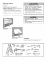 3
3
-
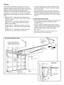 4
4
-
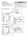 5
5
-
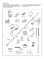 6
6
-
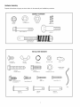 7
7
-
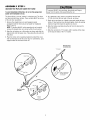 8
8
-
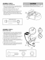 9
9
-
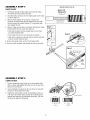 10
10
-
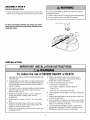 11
11
-
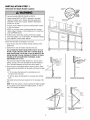 12
12
-
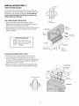 13
13
-
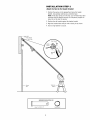 14
14
-
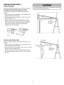 15
15
-
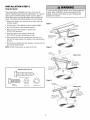 16
16
-
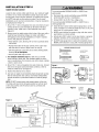 17
17
-
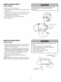 18
18
-
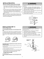 19
19
-
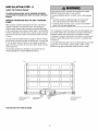 20
20
-
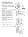 21
21
-
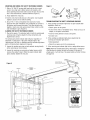 22
22
-
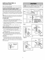 23
23
-
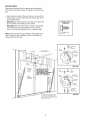 24
24
-
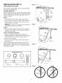 25
25
-
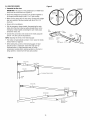 26
26
-
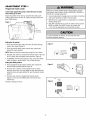 27
27
-
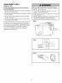 28
28
-
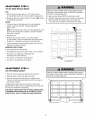 29
29
-
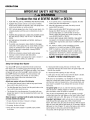 30
30
-
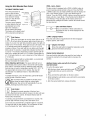 31
31
-
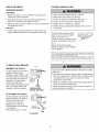 32
32
-
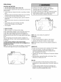 33
33
-
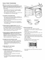 34
34
-
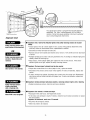 35
35
-
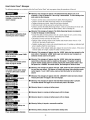 36
36
-
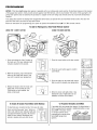 37
37
-
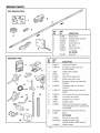 38
38
-
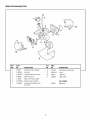 39
39
-
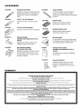 40
40
-
 41
41
-
 42
42
-
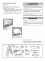 43
43
-
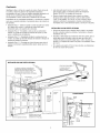 44
44
-
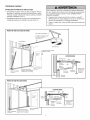 45
45
-
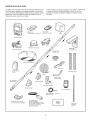 46
46
-
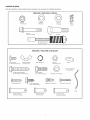 47
47
-
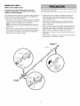 48
48
-
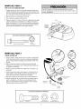 49
49
-
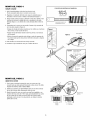 50
50
-
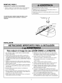 51
51
-
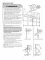 52
52
-
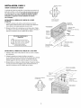 53
53
-
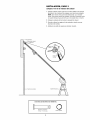 54
54
-
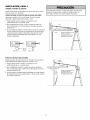 55
55
-
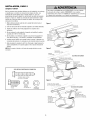 56
56
-
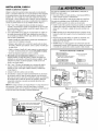 57
57
-
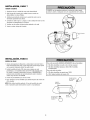 58
58
-
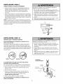 59
59
-
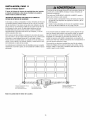 60
60
-
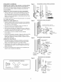 61
61
-
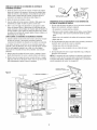 62
62
-
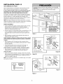 63
63
-
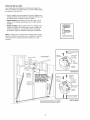 64
64
-
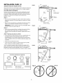 65
65
-
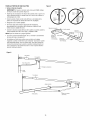 66
66
-
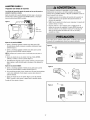 67
67
-
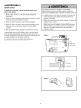 68
68
-
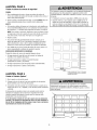 69
69
-
 70
70
-
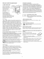 71
71
-
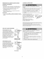 72
72
-
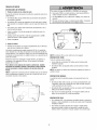 73
73
-
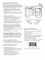 74
74
-
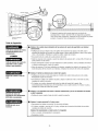 75
75
-
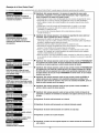 76
76
-
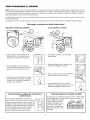 77
77
-
 78
78
-
 79
79
-
 80
80


Craftsman 13953939D El manual del propietario
- Categoría
- Abridor de puerta de garage
- Tipo
- El manual del propietario
en otros idiomas
- English: Craftsman 13953939D Owner's manual
Artículos relacionados
-
Craftsman 13953904D El manual del propietario
-
-
-
-
-
Craftsman 139.3043 Manual de usuario
-
-
-
-