MOTO GUZZI V7 II Racer Manual de usuario
- Categoría
- Motocicletas
- Tipo
- Manual de usuario
Este manual también es adecuado para

MOTO GUZZI DESEA AGRADECERLE
por haber elegido uno de sus productos. Hemos preparado este manual para permitirle apreciar todas sus cualidades. Le aconsejamos que lea todo
su contenido antes de conducir por primera vez. Contiene información, consejos y advertencias para el uso de su vehículo; asimismo, descubrirá
características, piezas y soluciones que le convencerán de lo acertado de su elección. Estamos seguros de que teniendo todo esto en cuenta, le
resultará fácil conocer su nuevo vehículo, el cual podrá disfrutar por mucho tiempo con total satisfacción. La presente publicación es parte integrante
del vehículo y en caso de venderlo debe entregarse al nuevo propietario.
MOTO GUZZI WOULD LIKE TO THANK YOU
for choosing one of its products. We have compiled this booklet to provide a comprehensive overview of your vehicle's quality features. Please read it
carefully before riding the vehicle for the first time. It contains information, tips and precautions for using your vehicle. It also describes features, details
and devices to assure you that you have made the right choice. We believe that if you follow our suggestions, you will soon get to know your new vehicle
well and that it will continue to give you satisfactory service for many years to come. This booklet forms an integral part of the vehicle; should the vehicle
be sold, it must be transferred to the new owner.
V7 II Racer - V7 II Special - V7 II Stone
Ed. 01_11/2014

Las instrucciones de este manual han sido preparadas principalmente para suministrar una guía simple y clara de uso; se indican también las
operaciones de mantenimiento básico y los controles periódicos que se deberán realizar en los CONCESIONARIOS o Talleres autorizados Moto
Guzzi. Además, el manual contiene las instrucciones para que pueda realizar algunas reparaciones simples. Las operaciones que no se describen
explícitamente en esta publicación requieren la disponibilidad de herramientas especiales y/o de conocimientos técnicos específicos. para su ejecución
recomendamos dirigirse a los CONCESIONARIOS o Talleres autorizados Moto Guzzi.
The instructions in this manual have been prepared to offer mainly a simple and clear guide to its use; it also describes routine maintenance procedures
and regular checks that should be carried out on the vehicle at an authorised Moto Guzzi Dealer or Workshop, The booklet also contains instructions
for simple repairs. Any operations not specifically described in this booklet require the use of special tools and/or particular technical knowledge; for
these operations, please take your vehicle to an authorised Moto Guzzi Dealer or Workshop.
2

Seguridad de las personas
El no-cumplimiento total o parcial de estas prescrip-
ciones puede comportar peligro grave para la incolu-
midad de las personas.
Personal safety
Failure to completely observe these instructions will
result in serious risk of personal injury.
Salvaguardia del ambiente
Indica el comportamiento correcto para que el uso del
vehículo no cause ningún daño a la naturaleza.
Safeguarding the environment
Sections marked with this symbol indicate the correct
use of the vehicle to prevent damaging the environ-
ment.
Integridad del vehículo
El no-cumplimiento total o parcial de estas prescrip-
ciones comporta el peligro de serios daños al vehículo
e incluso la caducidad de la garantía
Vehicle intactness
The incomplete or non-observance of these regula-
tions leads to the risk of serious damage to the vehicle
and sometimes even the invalidity of the guarantee
Las señales indicadas previamente son de gran im-
portancia. Sirven para evidenciar las partes del ma-
nual que requieren de más atención. Como se puede
observar, cada señal está compuesta por un símbolo
gráfico diferente, para facilitar y agilizar la búsqueda
de los temas en las diversas áreas. Antes de poner
en marcha el motor, leer atentamente este manual,
especialmente el apartado "CONDUCCIÓN SEGU-
RA". Su seguridad y la de los demás no depende
solamente de la rapidez de sus reflejos y agilidad, si-
no también del conocimiento del vehículo, de su efi-
ciencia y del conocimiento de las reglas fundamenta-
les para la CONDUCCIÓN SEGURA. Por lo tanto, le
recomendamos familiarizarse con el vehículo lo sufi-
ciente como para circular por la carretera con total
control y seguridad. IMPORTANTE Este manual se
debe considerar como parte integrante del vehículo y
debe acompañarlo en caso de venta.
The symbols illustrated above are very important.
They are used to highlight parts of the booklet that
should be read with particular care. The different sym-
bols are used to make each topic in the manual simple
and quick to locate. Before starting the engine, read
this booklet thoroughly and the "SAFE RIDING" sec-
tion in particular. Your safety as well as other's does
not only depend on the quickness of your reflexes and
agility, but also on how well you know your vehicle,
the state of maintenance of the vehicle itself and your
knowledge of the rules for SAFE RIDING. For your
safety, get to know your vehicle well so as to safely
ride and master it in road traffic IMPORTANT This
booklet is an integral part of the vehicle, and must be
handed to the new owner in the event of sale.
3
La página se está cargando...

INDICE
INDEX
NORMAS GENERALES................................................................. 9
Introducción.............................................................................. 10
Cuidado de la motocicleta........................................................ 10
Monóxido de carbono............................................................... 14
Combustible............................................................................. 16
Componentes calientes............................................................ 17
Puesta en marcha y Conducción............................................. 17
Testigos.................................................................................... 18
Aceite motor y aceite cambio usados...................................... 19
Líquido de frenos..................................................................... 20
Electrolito y gas hidrógeno de la batería.................................. 21
Soporte..................................................................................... 22
Comunicación de los defectos que influyen en la seguridad
................................................................................................. 23
VEHÌCULO...................................................................................... 25
Ubicación componentes principales............................................ 26
Tablero de instrumentos.............................................................. 33
Conjunto de instrumentos............................................................ 34
Grupo testigos............................................................................. 35
Reloj............................................................................................. 35
Representacion visual digital por cristales liquidos..................... 37
Simbolos de manutencion........................................................ 38
Regulacion cuentakilometros y parciales................................. 38
Regulacion muestra de la temperatura exterior....................... 40
Teclas de mando...................................................................... 41
Funciones avanzadas.............................................................. 41
Conmutador de encendido....................................................... 44
Bloqueo del volante.................................................................. 45
Pulsante claxon........................................................................... 46
Conmutador intermitentes........................................................... 47
Commutador luces....................................................................... 47
GENERAL RULES............................................................................ 9
Foreword.................................................................................... 10
Motorcycle care.......................................................................... 10
Carbon monoxide....................................................................... 14
Fuel............................................................................................ 16
Hot components......................................................................... 17
Start off and Riding..................................................................... 17
Warning lights............................................................................. 18
Used engine oil and gearbox oil................................................. 19
Liquido freni................................................................................ 20
Battery hydrogen gas and electrolyte......................................... 21
Stand.......................................................................................... 22
Reporting of defects that affect safety........................................ 23
VEHICLE........................................................................................... 25
Arrangement of the main components........................................... 26
Dashboard..................................................................................... 33
Instrument panel............................................................................ 34
Light unit........................................................................................ 35
Clock.............................................................................................. 35
Digital lcd display........................................................................... 37
Maintenance icons..................................................................... 38
Setting the total and trip odometers........................................... 38
Setting the outside temperature display..................................... 40
Control buttons........................................................................... 41
Advanced functions.................................................................... 41
Ignition switch............................................................................. 44
Locking the steering wheel......................................................... 45
Horn button.................................................................................... 46
Switch direction indicators............................................................. 47
High/low beam selector.................................................................. 47
Passing button............................................................................... 48
5

Pulsador ráfaga luz de carretera................................................. 48
Pulsante arranque....................................................................... 49
Interruptor parada motor.............................................................. 50
Sistema ABS................................................................................ 51
Sistema MGCT (Moto Guzzi Controllo Trazione)........................ 53
Abertura sillín........................................................................... 61
Protección asiento.................................................................... 62
Compartimiento porta-doc./kit herramientas............................ 63
La identificación........................................................................... 64
EL USO........................................................................................... 67
Controles..................................................................................... 68
Abastecimiento............................................................................ 72
Regulación amortiguadores traseros........................................... 74
Regulación horquilla delantera.................................................... 79
Regulación pedal freno trasero.................................................... 79
Regulación leva embrague.......................................................... 82
Regulación pedal del cambio....................................................... 83
Rodaje......................................................................................... 84
Arranque dificultoso..................................................................... 86
Aparcamiento............................................................................... 86
Escape catalítico.......................................................................... 88
Soporte........................................................................................ 90
Sugerencias contra los robos...................................................... 91
Normas basicás de seguridad..................................................... 92
EL MANTENIMIENTO.................................................................... 99
Premisa........................................................................................ 100
Control del nivel de aceite motor.............................................. 101
Llenado de aceite motor........................................................... 103
Sustitución aceite motor........................................................... 104
Nivel aceite cardán...................................................................... 108
Nivel aceite cambio...................................................................... 109
Neumáticos.................................................................................. 109
Desmontaje bujía......................................................................... 113
Desmontaje de los laterales........................................................ 114
Desmontaje filtro aire................................................................... 116
Control nivel aceite frenos........................................................... 116
Llenado liquido circuito de frenos............................................. 118
Puesta en servicio de una batería nueva................................. 118
Comprobacion del nivel del electrolito..................................... 121
Start-up button............................................................................... 49
Engine stop switch......................................................................... 50
System ABS................................................................................... 51
MGTC system(Moto Guzzi Controllo Trazione)............................. 53
Opening the saddle.................................................................... 61
Saddle guard.............................................................................. 62
Glove/tool kit compartment......................................................... 63
Identification................................................................................... 64
USE................................................................................................... 67
Checks........................................................................................... 68
Refuelling....................................................................................... 72
Rear shock absorbers adjustment................................................. 74
Front fork adjustment..................................................................... 79
Rear brake pedal adjustment......................................................... 79
Clutch lever adjustment................................................................. 82
Gear pedal adjustment................................................................... 83
Running in...................................................................................... 84
Difficult start up.............................................................................. 86
Parking........................................................................................... 86
Catalytic silencer............................................................................ 88
Stand.............................................................................................. 90
Suggestion to prevent theft............................................................ 91
Basic safety rules........................................................................... 92
MAINTENANCE................................................................................ 99
Foreword........................................................................................ 100
Engine oil level check................................................................. 101
Engine oil top-up........................................................................ 103
Engine oil change....................................................................... 104
Universal joint oil level................................................................... 108
Gearbox oil level............................................................................ 109
Tyres.............................................................................................. 109
Spark plug dismantlement............................................................. 113
Removing the sides....................................................................... 114
Removing the air filter.................................................................... 116
Checking the brake oil level........................................................... 116
Braking system fluid top up........................................................ 118
Use of a new battery.................................................................. 118
Checking the electrolyte level..................................................... 121
Charging the battery................................................................... 121
6

Recarga batería....................................................................... 121
Larga inactividad.......................................................................... 122
Fusibles....................................................................................... 123
Bombillas..................................................................................... 125
Regulación proyector............................................................... 128
Indicadores de dirección delanteros............................................ 130
Grupo óptico trasero.................................................................... 132
Indicadores de dirección traseros................................................ 132
Espejos retrovisores.................................................................... 134
Freno de disco delantero y trasero.............................................. 136
Inactividad del vehiculo................................................................ 138
Limpieza del vehiculo.................................................................. 140
Transporte................................................................................... 145
DATOS TÉCNICOS........................................................................ 147
EL MANTENIMIENTO PROGRAMADO......................................... 157
Tabla manutención programada.................................................. 158
PREPARACIONES ESPECIALES................................................. 165
Índice accesorios......................................................................... 166
Long periods of inactivity............................................................... 122
Fuses............................................................................................. 123
Lamps............................................................................................ 125
Headlight adjustment.................................................................. 128
Front direction indicators................................................................ 130
Rear optical unit............................................................................. 132
Rear turn indicators........................................................................ 132
Rear-view mirrors........................................................................... 134
Front and rear disc brake............................................................... 136
Periods of inactivity........................................................................ 138
Cleaning the vehicle....................................................................... 140
Transport........................................................................................ 145
TECHNICAL DATA........................................................................... 147
PROGRAMMED MAINTENANCE.................................................... 157
Scheduled maintenance table........................................................ 158
SPECIAL FITTINGS.......................................................................... 165
Accessories index.......................................................................... 166
7
La página se está cargando...
La página se está cargando...
La página se está cargando...

dos puede dañar los componentes del
vehículo. Para la limpieza no usar sol-
ventes como "diluyente nitro", "detergen-
tes en frío", combustibles o similares, o
productos para la limpieza que conten-
gan alcohol.
vehicle components. For cleaning do not
use solvents such as "nitro thinner", "cold
cleaning agents", or similar fuels, or
cleaning products that contain alcohol.
LAVADO DE LA MOTOCICLETA
Moto Guzzi recomienda ablandar con
abundante agua y luego quitar con cui-
dado los insectos y la suciedad más re-
sistente antes de lavar el vehículo.
Para prevenir manchas, no lavar la mo-
tocicleta inmediatamente después de
una exposición a la luz solar, y no lavarla
al sol.
Si se utiliza el vehículo durante los meses
invernales, asegurarse de lavar la moto-
cicleta con frecuencia. Para quitar la sal
de deshielo esparcida en las carreteras
en los períodos invernales, lavar la mo-
tocicleta con agua fría, inmediatamente
después de usar.
ATENCIÓN
DESPUÉS DE LAVAR LA MOTOCI-
CLETA, LA EFICIENCIA DEL SISTEMA
DE FRENOS PODRÍA VERSE MOMEN-
TÁNEAMENTE COMPROMETIDA A
CAUSA DE LA PRESENCIA DE AGUA
EN LAS SUPERFICIES DE FRICCIÓN.
PREVER UN AUMENTO DEL ESPACIO
DE FRENADA, ACCIONAR VARIAS
VECES LOS FRENOS PARA RESTA-
BLECER LAS CONDICIONES NORMA-
WASHING THE MOTORCYCLE
Moto Guzzi recommends softening with
water and then carefully removing the in-
sects and stubborn stains before wash-
ing the vehicle.
To prevent stains, do not wash the mo-
torcycle immediately after exposure to
sunlight, and do not wash it in the sun.
If the vehicle is used during the winter
months, be sure to frequently wash the
motorcycle. To remove anti-icing salt
sprayed on roads in the winter, wash the
motorcycle with cold water immediately
after use.
CAUTION
AFTER CLEANING YOUR MOTORCY-
CLE, THE EFFICIENCY OF THE BRAK-
ING SYSTEM MAY BE TEMPORARILY
AFFECTED DUE TO THE PRESENCE
OF WATER ON THE FRICTION SUR-
FACES. CONSIDER AN INCREASE IN
BRAKING SPACE, OPERATE THE
BRAKES REPEATEDLY TO RESTORE
NORMAL CONDITIONS. CARRY OUT
THE PRE-RIDE CHECKS BEFORE
USE.
11
1 Normas generales / 1 General rules

LES. EFECTUAR LOS CONTROLES
PRELIMINARES ANTES DE USAR.
EL USO DE AGUA CALIENTE INTEN-
SIFICA EL EFECTO DE LA SAL. USAR
SÓLO ABUNDANTE AGUA FRÍA PA-
RA LAVAR Y QUITAR LA SAL DE DES-
HIELO
EL USO DE SISTEMAS DE LAVADO
DE ALTA PRESIÓN (O LIMPIADORES
A VAPOR) PUEDEN DAÑAR LAS JUN-
TAS DE ESTANQUEIDAD, EL RETÉN
DE ACEITE, EL SISTEMA DE FRENOS,
EL SISTEMA ELÉCTRICO Y EL ASIEN-
TO. NO USAR SISTEMAS DE LAVADO
A VAPOR O DE ALTA PRESIÓN.
USE OF HOT WATER INTENSIFIES
THE EFFECT OF THE SALT. USE ON-
LY PLENTY OF COLD WATER TO
WASH AND REMOVE ANTI-ICING
SALT
USE OF HIGH PRESSURE WASHING
SYSTEMS (OR STEAM CLEANERS)
CAN DAMAGE THE SEALS, OIL
SEALS, BRAKING SYSTEM, ELECTRI-
CAL SYSTEM AND THE SADDLE. DO
NOT USE STEAM OR HIGH PRES-
SURE CLEANING SYSTEMS. DO NOT
USE STEAM OR HIGH PRESSURE
CLEANING SYSTEMS.
LIMPIEZA DE LAS PARTES SENSI-
BLES
CARROCERÍA
Para mantener brillante la motocicleta,
lavarla con regularidad, especialmente si
se usa en áreas con elevados niveles de
contaminación o lodo. Manchas agresi-
vas de resina de los árboles, gasolina,
aceite, líquido de frenos o excremento de
aves en general.
CLEANING OF SENSITIVE PARTS
BODYWORK
To keep the motorcycle bright, wash it
regularly, especially if used in areas with
high levels of pollution or mud. Aggres-
sive stains from tree resins, gasoline, oil,
brake fluid or bird excrement in general.
must be removed immediately, otherwise
permanent stains on the paint can ap-
pear. After washing it is easy to identify
marks and residual stains, remove them
12
1 Normas generales / 1 General rules

Deben quitarse de inmediato, de lo con-
trario se corre el riesgo de que provoquen
manchas permanentes en la pintura.
Tras el lavado es fácil identificar las au-
reolas y manchas remanentes, eliminar-
las de la carrocería usando paños sua-
ves, abrillantadores de marca reconoci-
da, no abrasivos y proteger con una cera
protectora para automóvil. Un cuidado
periódico, un meticuloso lavado y una
protección regular de la carrocería con
cera protectora, preserva la calidad es-
tética de la motocicleta durante mucho
tiempo.
COMPONENTES DE PLÁSTICO
SI LOS COMPONENTES DE PLÁSTI-
CO SE LIMPIAN UTILIZANDO AGEN-
TES AGRESIVOS, SE PUEDEN DA-
ÑAR LAS SUPERFICIES. NO USAR
PRODUCTOS QUE CONTENGAN AL-
COHOL, SOLVENTES O ABRASIVOS
PARA LA LIMPIEZA DE LAS PARTES
DE PLÁSTICO. CEPILLOS GIRATO-
RIOS O ESPONJAS CON SUPERFI-
CIES DURAS PUEDEN PROVOCAR
RAYAS.
from the body using a soft cloth and
brand-name, non-abrasive polish, and
protect with a protective wax for cars. Pe-
riodic care, a thorough cleaning and reg-
ular protective wax for the bodywork
preserves the aesthetic quality of the mo-
torcycle over the long term.
PLASTIC COMPONENTS
IF THE PLASTIC COMPONENTS ARE
CLEANED USING AGGRESSIVE
AGENTS, THE SURFACE MAY BE
DAMAGED. DO NOT USE CLEANING
PRODUCTS CONTAINING ALCOHOL,
SOLVENTS OR THAT ARE ABRASIVE
FOR THE CLEANING OF PLASTIC
PARTS. ROTARY BRUSHES OR
SPONGES WITH HARD SURFACES
CAN MAKE SCRATCHES
PARTES CROMADAS Y METALES PU-
LIDOS
CHROME PARTS AND POLISHED
METAL
13
1 Normas generales / 1 General rules

CUIDAR MUY ESPECIALMENTE LAS
PARTES CROMADAS Y LAS DE ALU-
MINIO O ACERO PULIDO. LAVARLAS
CON ABUNDANTE AGUA Y CHAMPÚ
PARA AUTOMÓVILES, PULIRLAS Y
REAVIVARLAS PERIÓDICAMENTE
CON PASTA ABRILLANTADORA,
PROTEGERLAS CON CERA O PRO-
DUCTOS ADECUADOS SIN ÁCIDOS
(POR EJ. VASELINA)
TREAT THE PARTS MADE OF
CHROME, ALUMINIUM OR POLISHED
STEEL IN A SPECIAL MANNER. WASH
THEM WITH PLENTY OF WATER AND
CAR SHAMPOO, POLISH AND REGU-
LARLY BRIGHTEN THEM WITH POL-
ISH PASTE, PROTECT THEM WITH
WAXES OR SUITABLE ACID-FREE
PRODUCTS (E.G. VASELINE)
PARTES DE GOMA
Limpiar las partes de goma usando agua
y champú neutro (de marca, adecuado
para carrocerías de automóviles)
EL USO DE SILICONAS EN SPRAY
PARA LA LIMPIEZA DE LAS JUNTAS
DE GOMA PUEDE PROVOCAR DA-
ÑOS. NO USAR OTROS PRODUCTOS
QUE CONTENGAN SILICONAS PARA
LIMPIAR LA MOTOCICLETA.
RUBBER PARTS
Clean the rubber parts using water and
mild shampoo (brand-name, suitable for
car bodies)
THE USE OF SILICONE SPRAY TO
CLEAN THE RUBBER SEALS MAY
CAUSE DAMAGE. DO NOT USE OTH-
ER PRODUCTS CONTAINING SILI-
CON FOR CLEANING THE MOTORCY-
CLE
Monóxido de carbono
Si es necesario hacer funcionar el motor
para poder realizar alguna operación,
asegurarse de que la puesta en marcha
Carbon monoxide
If you need to keep the engine running in
order to perform a procedure, please en-
sure that you do so in an open or very well
14
1 Normas generales / 1 General rules

se realice en un espacio abierto o en un
local bien ventilado. Nunca hacer funcio-
nar el motor en espacios cerrados. Si se
trabaja en un espacio cerrado, utilizar el
sistema de evacuación de los gases de
escape.
ATENCIÓN
LOS HUMOS DE ESCAPE CONTIENEN
MONÓXIDO DE CARBONO, UN GAS
VENENOSO QUE PUEDE PROVOCAR
LA PÉRDIDA DE CONOCIMIENTO E
INCLUSO LA MUERTE.
ATENCIÓN
EL MONÓXIDO DE CARBONO ES INO-
DORO E INCOLORO, POR LO TANTO
NO PUEDE SER DETECTADO ME-
DIANTE EL OLFATO, LA VISTA U
OTROS SENTIDOS. NO RESPIRAR
LOS HUMOS DE ESCAPE BAJO NIN-
GUNA CIRCUNSTANCIA.
ventilated area. Never let the engine run
in an enclosed area. If you do work in an
enclosed area, make sure to use a
smoke-extraction system.
CAUTION
EXHAUST EMISSIONS CONTAIN
CARBON MONOXIDE, A POISONOUS
GAS WHICH CAN CAUSE LOSS OF
CONSCIOUSNESS AND EVEN
DEATH.
CAUTION
CARBON MONOXIDE IS ODOURLESS
AND COLOURLESS, THEREFORE IT
CANNOT BE DETECTED BY SMELL,
SIGHT OR OTHER SENSES. DO NOT
BREATHE IN EXHAUST FUMES UN-
DER ANY CIRCUMSTANCES.
15
1 Normas generales / 1 General rules
La página se está cargando...

DUCIR DERRAMES DE COMBUSTI-
BLE.
Componentes calientes
El motor y los componentes del sistema
de escape se calientan demasiado y per-
manecen calientes durante un cierto
tiempo incluso después de apagar el mo-
tor. Antes de manipular estos componen-
tes, colocarse guantes aislantes o aguar-
dar a que el motor y el sistema de escape
se enfríen.
Hot components
The engine and the exhaust system com-
ponents get very hot and remain in this
condition for a certain time interval after
the engine has been switched off. Before
handling these components, make sure
that you are wearing insulating gloves or
wait until the engine and the exhaust sys-
tem have cooled down.
Puesta en marcha y
Conducción
ATENCIÓN
SI MIENTRAS ESTÁ CONDUCIENDO,
EN EL TABLERO SE ENCIENDE EL
TESTIGO DE RESERVA DE COMBUS-
TIBLE, SIGNIFICA QUE SE HA REDU-
CIDO LA CANTIDAD DE COMBUSTI-
BLE, Y QUE LA AUTONOMÍA ES
LIMITADA.
REPONER COMBUSTIBLE LO ANTES
POSIBLE.
Start off and Riding
CAUTION
IF THE FUEL RESERVE WARNING
LAMP ILLUMINATES WHILE RIDING,
THIS INDICATES THAT THE FUEL
LEVEL IS LOW AND ONLY LIMITED
RANGE IS REMAINING.
REFUEL AS SOON AS POSSIBLE.
ADVERTENCIA
EN CASO DE QUE EL MOTOCICLO SE
APAGUE ACCIDENTALMENTE, LA
WARNING
IF THE MOTORCYCLE TURNS OFF
ACCIDENTALLY THE ECU WILL AL-
17
1 Normas generales / 1 General rules
La página se está cargando...
La página se está cargando...
La página se está cargando...
La página se está cargando...
La página se está cargando...

Comunicación de los defectos
que influyen en la seguridad
Salvo que se especifique en este Manual
de Uso y Mantenimiento, no desmontar
ningún componente mecánico o eléctri-
co.
ATENCIÓN
ALGUNOS CONECTORES DEL VEHÍ-
CULO PUEDEN INTERCAMBIARSE Y
SI SE MONTAN DE MANERA EQUIVO-
CADA PUEDEN PERJUDICAR EL
FUNCIONAMIENTO NORMAL DEL VE-
HÍCULO.
Reporting of defects that
affect safety
Unless otherwise specified in this Use
and Maintenance Booklet, do not remove
any mechanical or electrical component.
CAUTION
SOME CONNECTORS IN THE VEHI-
CLE MAY BE ACCIDENTALLY SWAP-
PED AND MAY COMPROMISE NOR-
MAL VEHICLE OPERATION IF INCOR-
RECTLY INSTALLED.
23
1 Normas generales / 1 General rules

24
1 Normas generales / 1 General rules
La página se está cargando...

Ubicación componentes
principales (02_01, 02_02,
02_03, 02_04)
Arrangement of the main
components (02_01, 02_02,
02_03, 02_04)
26
2 Vehìculo / 2 Vehicle
La página se está cargando...

02_02
Leyenda V7 Special / V7 Stone:
1. Faro delantero
2. Intermitente delantero izquierdo
3. Instrumental
4. Palanca del embrague
5. Conmutador de luces izquierdo
6. Espejo retrovisor izquierdo
7. Tapón del depósito de combus-
tible
8. Depósito de combustible
9. Lateral izquierdo
10. Filtro de aire
11. Asiento
Legend: V7 Special / V7 Stone:
1. Headlamp
2. Front left turn indicator
3. Instrument panel
4. Clutch lever
5. Left light switch
6. Left rear-view mirror
7. Fuel tank cap
8. Fuel tank
9. Left side fairing
10. Air filter
11. Saddle
12. Passenger handgrip (if applica-
ble)
28
2 Vehìculo / 2 Vehicle

12. Correa pasajero (donde esté
previsto)
13. Compartimiento portadocumen-
tos
14. Asa de agarre pasajero izquier-
da (donde esté previsto)
15. Piloto trasero
16. Intermitente trasero izquierdo
17. Amortiguador trasero izquierdo
18. Terminal de escape izquierdo
19. Disco trasero
20. Pinza del freno trasero
21. Estribo izquierdo pasajero
22. Caballete lateral
23. Cerradura del asiento
24. Estribo izquierdo del conductor
25. Pedal de mando del cambio
26. Varilla nivel de aceite del motor
27. Claxon izquierdo
28. Pinza del freno delantero
29. Disco delantero
30. Intermitente trasero derecho
31. Asa de agarre pasajero derecha
(donde esté previsto)
32. Depósito de líquido del freno
trasero
33. Caja fusibles
34. Conmutador de luces derecho
35. Espejo retrovisor derecho
36. Depósito líquido freno delantero
37. Maneta del freno delantero
38. Intermitente delantero derecho
39. Horquilla delantera
40. Claxon derecho
41. Maneta del freno trasero
42. Estribo derecho conductor
43. Batería
44. Estribo derecho pasajero
13. Glove-box
14. Left hand passenger grab han-
dle (if applicable)
15. Taillight
16. Rear left turn indicator
17. Rear left shock absorber
18. Left hand exhaust muffler
19. Rear disc
20. Rear brake calliper
21. Passenger left footrest
22. Side stand
23. Seat lock
24. Left rider footrest
25. Gear shift lever
26. Engine oil level dipstick
27. Left horn
28. Front brake calliper
29. Front disc
30. Rear right turn indicator
31. Right hand passenger grab han-
dle (if applicable)
32. Rear brake fluid reservoir
33. Fuse box
34. Right hand light switch
35. Right rear-view mirror
36. Front brake fluid reservoir
37. Front brake lever
38. Front right turn indicator
39. Front fork
40. Right horn
41. Rear brake lever
42. Right rider footrest
43. Battery
44. Right hand passenger footpeg
45. Right hand exhaust muffler
46. Rear right shock absorber
47. Front speed sensor
48. Front tone wheel
29
2 Vehìculo / 2 Vehicle

45. Terminal de escape derecho
46. Amortiguador trasero derecho
47. Sensor de velocidad delantero
48. Rueda fónica delantera
49. Rueda fónica trasera
50. Sensor de velocidad trasero
49. Rear tone wheel
50. Rear speed sensor
02_03
30
2 Vehìculo / 2 Vehicle

02_04
Leyenda V7 Racer:
1. Faro delantero
2. Intermitente delantero izquierdo
3. Instrumental
4. Palanca del embrague
5. Conmutador de luces izquierdo
6. Espejo retrovisor izquierdo
7. Tapón del depósito de combus-
tible
8. Depósito de combustible (*)
9. Lateral izquierdo
10. Filtro de aire
11. Asiento
Legend: V7 Racer:
1. Headlamp
2. Front left turn indicator
3. Instrument panel
4. Clutch lever
5. Left light switch
6. Left rear-view mirror
7. Fuel tank cap
8. Fuel tank (*)
9. Left side fairing
10. Air filter
11. Saddle
12. Glove-box
13. Taillight
31
2 Vehìculo / 2 Vehicle

12. Compartimiento portadocumen-
tos
13. Piloto trasero
14. Intermitente trasero izquierdo
15. Amortiguador trasero izquierdo
16. Terminal de escape izquierdo
17. Disco trasero
18. Pinza del freno trasero
19. Caballete lateral
20. Cerradura del asiento
21. Estribo izquierdo del conductor
22. Pedal de mando del cambio
23. Varilla nivel de aceite del motor
24. Claxon izquierdo
25. Pinza del freno delantero
26. Disco delantero
27. Intermitente trasero derecho
28. Colín
29. Depósito de líquido del freno
trasero
30. Caja fusibles
31. Espejo retrovisor derecho
32. Conmutador de luces derecho
33. Depósito líquido freno delantero
34. Maneta del freno delantero
35. Intermitente delantero derecho
36. Horquilla delantera
37. Claxon derecho
38. Maneta del freno trasero
39. Estribo derecho conductor
40. Batería
41. Terminal de escape derecho
42. Amortiguador trasero derecho
43. Sensor de velocidad delantero
44. Rueda fónica delantera
45. Sensor de velocidad trasero
46. Rueda fónica trasera
14. Rear left turn indicator
15. Rear left shock absorber
16. Left hand exhaust muffler
17. Rear disc
18. Rear brake calliper
19. Side stand
20. Seat lock
21. Left rider footrest
22. Gear shift lever
23. Engine oil level dipstick
24. Left horn
25. Front brake calliper
26. Front disc
27. Rear right turn indicator
28. Tail fairing
29. Rear brake fluid reservoir
30. Fuse box
31. Right rear-view mirror
32. Right hand light switch
33. Front brake fluid reservoir
34. Front brake lever
35. Front right turn indicator
36. Front fork
37. Right horn
38. Rear brake lever
39. Right rider footrest
40. Battery
41. Right hand exhaust muffler
42. Rear right shock absorber
43. Front speed sensor
44. Front tone wheel
45. Rear speed sensor
46. Rear tone wheel
CAUTION
(*) THIS MOTORCYCLE HAS BEEN
PRODUCED AS A LIMITED EDITION
32
2 Vehìculo / 2 Vehicle
La página se está cargando...

02_06
10. Pulsador claxon
11. Interruptor de parada del motor
11. Engine stop switch
02_07
Conjunto de instrumentos
(02_07)
Leyenda:
1. Velocímetro
2. Cuentarrevoluciones
3. Pantalla digital multifunción
Instrument panel (02_07)
Key:
1. Speedometer
2. Rpm indicator
3. Multifunctional digital display
34
2 Vehìculo / 2 Vehicle

02_08
Grupo testigos (02_08)
Leyenda:
1. Testigo intermitentes (color ver-
de)
2. Testigo luz de carretera (color
azul)
3. Testigo de presión de aceite
motor (color rojo)
4. Testigo reserva del combustible
(color amarillo ámbar)
5. Testigo MI (color amarillo ám-
bar)
6. Testigo cambio en punto muerto
(color verde)
7. Testigo ABS (color amarillo ám-
bar)
8. Testigo MGCT (color amarillo
ámbar)
Light unit (02_08)
key:
1. Turn indicator warning light
(green)
2. High beam warning light (blue)
3. Engine oil pressure warning
light (red)
4. Low fuel warning light (amber
yellow)
5. MI warning light (amber yellow)
6. Gear in neutral warning light
(green)
7. ABS warning light (amber yel-
low)
8. MGCT warning light (amber yel-
low)
02_09
Reloj (02_09)
Regulación del reloj
•
Presionar durante dos segun-
dos consecutivos el botón (B).
•
Al activarse esta función el sím-
bolo AM parpadea.
•
Presionando el botón (A) se pa-
sa de AM a PM, con los símbo-
los parpadeantes.
•
Si se presiona el botón (B), se
pasa a la configuración de las
HORAS con el parpadeo de las
cifras correspondientes. Cada
vez que se presiona el botón (A)
Clock (02_09)
Clock adjustment
•
Press key (B) for a couple of
seconds.
•
When this function is used, the
AM symbol starts flashing.
•
Press key (A) to change from
AM to PM, with the flashing sym-
bols.
•
Press key (B) to change to the
HOUR setting, and the specific
digits flash. Each time key (A) is
pressed, the value increases by
1 (from 0 to 11 and back to 0).
35
2 Vehìculo / 2 Vehicle

el valor avanza 1 (de 0 a 11 y
vuelve a 0).
•
Si se presiona el botón (B), se
pasa a la configuración de los
MINUTOS con el parpadeo de
las cifras correspondientes.
•
Cada vez que se presiona el bo-
tón (A) el conteo avanza 1 (de 0
a 59 y vuelve a cero).
•
Si el botón (A) se mantiene pre-
sionado durante más de cinco
segundos: el valor aumenta 1
cada 100 ms.
•
Presionando una vez más el bo-
tón (B) se sale de la modalidad
de configuración para volver a la
función normal.
•
El reloj sólo se puede regular
con el vehículo detenido (velo-
cidad nula).
•
Press key (B) to change to the
MINUTE setting, and the specif-
ic digits flash.
•
Each time key (A) is pressed,
the counting advances by 1
(from 0 to 59 and back to zero).
•
Press and hold key (A) for more
than five seconds: the value in-
creases by 1 every 100 ms.
•
Press key (B) again to exit the
setting mode and to go back to
standard operation.
•
The clock can be adjusted only
when the vehicle is at standstill
(zero speed).
Visualización del reloj
•
La visualización se distingue de
la regulación porque parpadean
los dos puntos centrales.
Secuencia visualizada:
- AM de 0.00 a 11.59
- PM de 12.00 a 11.59
Clock display
•
The display function is different
from the adjustment function in
that the central colon flashes.
Sequence displayed:
- AM from 0:00 to 11:59
- PM from 12:00 to 11:59
36
2 Vehìculo / 2 Vehicle

02_10
Representacion visual digital
por cristales liquidos (02_10)
•
Girando la llave de encendido a
la posición "ON", el sistema se
comporta del siguiente modo:
- activa simultáneamente todos los testi-
gos (lamp check);
- pone a cero la posición de las agujas,
que después realizan una carrera hasta
el fondo de escala y regresan nuevamen-
te a cero;
- activa durante un segundo todos los
segmentos de ambas pantallas;
- apaga todos los testigos (menos los que
están activados) y las pantallas vuelven
a la visualización normal.
Las programaciones estándar que se vi-
sualizan en la pantalla son:
- odómetro total (Pantalla LCD izquierda)
(1);
- temperatura aire (Pantalla LCD dere-
cha) (2).
Cualquiera sea el estado de las pantallas
antes del Key-Off.
Digital lcd display (02_10)
•
By turning the ignition key to
"ON", the system works as fol-
lows:
- it turns on all the warning lights at the
same time (lamp check);
- it resets the position of all the needles,
which afterwards go to the bottom of the
scale and return to zero;
- it activates all the segments of both dis-
plays for one second;
- it turns off all the warning lights (except
the active ones) and the displays go back
to standard view.
The standard indications displayed are:
- total odometer (left LCD Display) (1);
- air temperature (right LCD Display) (2).
no matter the status of the displays be-
fore Key-Off.
37
2 Vehìculo / 2 Vehicle

02_11
Simbolos de manutencion
(02_11)
•
El sistema visualiza la función
de la siguiente manera:
después de haber superado el kilometra-
je correspondiente al primer control pe-
riódico o a uno de los controles siguien-
tes, aparece la palabra "MAInt" en la
Pantalla LCD izquierda (1).
•
Esta visualización aparecerá
sólo después de cada arranque
y durante 5 segundos, luego se
pasará a la visualización nor-
mal.
•
Para la puesta a cero del Servi-
ce, dirigirse a un Concesionario
Oficial Moto Guzzi.
Maintenance icons (02_11)
•
The system displays the func-
tion as follows:
the word "MAInt" is shown on the left LCD
Display (1) after the mileage correspond-
ing to the first servicing or any subse-
quent servicing is exceeded.
•
This view is shown only after
each start-up for 5 seconds; af-
terwards, it will shift to the stand-
ard view.
•
Consult an Official Moto Guzzi
Dealer to reset Service.
02_12
Regulacion cuentakilometros
y parciales (02_12, 02_13)
Odómetro total
Unidad de medida para el conteo: Km o
Millas.
Visualización: en la pantalla LCD izquier-
da (1).
•
El dato se memoriza en forma
permanente.
•
No es posible volverlo a cero.
•
El odómetro total visualiza el da-
to del siguiente modo:
Setting the total and trip
odometers (02_12, 02_13)
Total odometer
Unit of measurement for the counter: Km
or Miles.
- View: on the left LCD display (1).
•
This value is stored permanent-
ly.
•
It cannot be reset.
•
Total odometer displays this val-
ue as follows:
- the TOTAL symbol is activated;
38
2 Vehìculo / 2 Vehicle

- se activa el símbolo TOTAL;
- si el valor supera 199999 se visualizan
en modo permanente "----".
- if the value exceeds 199999, the symbol
"----" is displayed permanently.
02_13
Odómetro parcial
Unidad de medida para el conteo: Km o
Millas.
Visualización: en la pantalla LCD izquier-
da (1).
•
El dato se memoriza.
•
Se puede volver a cero el con-
tador presionando durante dos
segundos consecutivos el botón
(A).
•
El odómetro parcial visualiza el
dato del siguiente modo:
- se activa el símbolo TRIP y el punto de-
cimal;
- si el valor supera 999.9 el contador se
pone a cero e inicia el conteo desde "0.0".
Trip odometer
Unit of measurement for the counter: Km
or Miles.
- View: on the left LCD display (1).
•
This value is stored.
•
Press and hold down key (A) for
two seconds to reset the coun-
ter.
•
Trip odometer displays the val-
ue as follows:
- the TRIP symbol and the decimal point
are activated;
- if the value exceeds 999.9, the counter
is reset and starts from "0.0" again.
39
2 Vehìculo / 2 Vehicle

02_14
Regulacion muestra de la
temperatura exterior (02_14)
Unidad de medida: °C o °F.
Visualización: en la pantalla LCD dere-
cha (1).
Los extremos de visualización son -10 /
+60 °C (14 / 140 °F).
•
Si la temperatura es inferior a
-10 °C (14 °F) en la pantalla LCD
derecha se visualizará la leyen-
da "LO" parpadeante.
•
Si el valor se encuentra entre
-10°C (14 °F) y +60°C (140 °F)
la pantalla visualizará el dato fi-
jo.
•
Si el valor es igual o superior a
+60°C (140 °F) la pantalla vi-
sualizará la leyenda "HI" parpa-
deante. Al mismo tiempo se
encenderá el símbolo de la uni-
dad de medida que se está
usando.
•
En el caso de que el sensor no
emitiera ninguna señal (corto
circuito o sensor desconectado)
se visualizarán tres líneas "---"
fijas.
Setting the outside
temperature display (02_14)
Unit of measurement: °C or °F.
- View: on the right LCD display (1).
The view limits are -10 / +60 °C (14 / 140
°F).
•
If temperature is below -10 °C
(14 °F), the word "LO" flashes
on the right LCD display.
•
If the value is between -10°C (14
°F) and +60°C (140 °F), it is
shown steadily on the display.
•
If the value is equivalent to or
higher than +60°C (140 °F), the
word "HI" flashes on the display.
The symbol signalling what unit
of measurement is being used
comes on at the same time.
•
If the sensor has no signal (short
circuit or disconnected), three
dashes "---" are shown steadily.
40
2 Vehìculo / 2 Vehicle

02_15
Teclas de mando (02_15)
•
Presionando el pulsador (A) con
la llave de encendido en la po-
sición "ON", en la pantalla LCD
izquierda (1) se alternan las si-
guientes visualizaciones:
- odómetro total (indica la distancia total
recorrida);
- odómetro parcial (indica la distancia re-
corrida desde la última puesta a cero o
bien desde que entra en reserva);
•
Presionando el pulsador (B) con
la llave de encendido en la po-
sición "ON", en la Pantalla LCD
derecha (2) se alternan las si-
guientes visualizaciones:
- reloj;
- temperatura de aire.
Control buttons (02_15)
•
Push button (A) with the ignition
key set to "ON" and the following
views are shown alternately on
the left LCD Display (1):
- total odometer (shows the total distance
travelled);
- trip odometer (shows the distance trav-
elled since the last reset or use of re-
serve);
•
Push button (B) with the ignition
key set to "ON" and the following
views are shown alternately on
the right LCD Display (2):
- clock;
- air temperature.
02_16
Funciones avanzadas (02_16)
Función Trip Fuel (si ha sido prevista)
Esta función consiste en el recuento y vi-
sualización del espacio recorrido con el
vehículo con combustible en reserva.
Al encenderse el testigo de reserva:
•
en la pantalla LCD izquierda (1)
se visualiza automáticamente el
totalizador del Trip Fuel;
•
presionando sucesivamente la
tecla (A) se puede volver a la vi-
sualización del Odómetro o Trip
Advanced functions (02_16)
Trip Fuel Function (if supplied)
This function counts and displays the dis-
tance travelled with the vehicle in fuel
reserve.
When the low fuel warning light turns on:
•
the Trip Fuel counter is automat-
ically shown on the left LCD dis-
play (1);
•
if key (A) is pressed again, the
Odometer or Trip can be viewed
again and scroll through the full
41
2 Vehìculo / 2 Vehicle

y efectuar un recorrido circular
de las tres magnitudes: Odóme-
tro - Trip - Trip Fuel.
Si se posiciona la llave de contacto en
"ON":
•
durante los primeros sesenta
segundos (fase de estabiliza-
ción del sensor de reserva) el
Trip Fuel no se visualiza. Des-
pués de este tiempo se visualiza
automáticamente el Trip Fuel.
La modalidad de visualización
del Trip Fuel es la siguiente:
- se activa el símbolo TRIP, el punto y en
el carácter más a la izquierda se visualiza
la letra "F";
- el valor inicial es "0.0".
sequence of the three measure-
ments: Odometer - Trip - Trip
Fuel.
If the ignition key is set to "ON":
•
the Trip Fuel is not shown the
first sixty seconds (Reserve
sensor stabilisation phase).
Once this time is over, the Trip
Fuel is displayed automatically.
The Trip Fuel display mode is
the following:
- the TRIP symbol and point are activated
and the letter "F" is shown in the digit fur-
thermost on the left;
- the initial value is "0.0".
Función Alarma Fuel (si ha sido pre-
vista)
Cuando el vehículo se encuentra en RE-
SERVA de combustible:
•
en la pantalla LCD derecha (2)
se visualiza automáticamente la
leyenda "FUEL" alternándose
con la magnitud que se visualiza
normalmente (reloj o tempera-
tura aire)
•
La leyenda "FUEL" no se en-
ciende durante el arranque.
Fuel Alarm Function (if supplied)
When the vehicle is in fuel RESERVE:
•
the word "FUEL" is automatical-
ly shown on the right LCD dis-
play (2); it alternates with the
measurement generally dis-
played (Clock or air tempera-
ture)
•
The word "FUEL" does not
come on at start-up.
42
2 Vehìculo / 2 Vehicle

Función selección unidad
Esta función permite cambiar la unidad
de medida de la temperatura del aire (°C
o °F).
•
Si se posiciona la llave de en-
cendido en "ON" mantener pre-
sionados ambos botones (A y
B): en la pantalla LCD derecha
(1) se visualiza la configuración
actual "EU" (°C) o "USA" (°F)
parpadeante.
•
Presionando el botón (A): se pa-
sa de "EU" (°C) a "USA" (°F) y
viceversa.
•
Manteniendo presionado el bo-
tón (B) durante 5 segundos, se
memoriza en forma permanente
la última configuración y en la
pantalla LCD derecha (1) apa-
rece la leyenda "OFF".
•
Para volver a la modalidad nor-
mal se debe girar la llave de
encendido en "OFF".
Esta configuración no afecta a la unidad
de medida para Odómetro/Trip (Km o Mi-
llas).
Unit selection function
This function allows changing the unit of
measurement (°C or °F) for air tempera-
ture.
•
If the ignition key is set to "ON",
press and hold down both keys
(A and B): the current setting,
either "EU" (°C) or "USA" (°F),
flashes on the right LCD display
(1).
•
Press key (A): to shift from
"EU" (°C) to "USA" (°F) and vice
versa.
•
Press and hold down key (B) for
5 seconds and the last setting is
stored permanently and the
word "OFF" is shown on the
right LCD display (1).
•
To go back to the standard
mode, turn the ignition key to
"OFF".
This setting does not affect the unit of
measurement for the Odometer/Trip (Km
or Mile).
Regulación de la retroiluminación de
los instrumentos
La retroiluminación de los instrumentos
se puede regular (índices de las escalas
y pantalla) en tres niveles.
Instrument backlighting adjustment
Backlighting of instruments and gauges
(needles of scales and displays) can be
adjusted at three levels.
This parameter can be adjusted within
five seconds after start-up. Every time
43
2 Vehìculo / 2 Vehicle

Dicho parámetro se puede regular dentro
de los 5 segundos siguientes al arran-
que. Con cada presión del botón (B) se
pasa al nivel inferior, para volver de for-
ma circular, al nivel máximo.
Al soltar el botón (B) durante dos segun-
dos se memoriza la selección y en el
arranque siguiente el sistema mantiene
el nivel de iluminación seleccionado.
key (B) is pressed, it goes to the lower
level to return afterwards, in circular se-
quential mode, to the maximum level.
Once key (B) is released for two seconds,
the selection is stored and the next time
the vehicle is started, the system main-
tains the lighting level selected.
Conmutador de encendido
(02_17)
El interruptor de arranque se encuentra
en la placa superior del tubo de la direc-
ción.
Con el vehículo se entregan dos llaves
(una de reserva).
Las luces se apagan cuando el interrup-
tor de arranque está en «OFF»
NOTA
LA LLAVE ACCIONA EL CONMUTA-
DOR DE ARRANQUE/BLOQUEO DEL
MANILLAR, LA CERRADURA DEL TA-
PÓN DEL DEPÓSITO DEL COMBUSTI-
BLE Y LA CERRADURA DEL ASIEN-
TO.
Ignition switch (02_17)
The ignition switch is located on the
headstock upper plate.
The vehicle is supplied with two keys
(one is the spare key).
The light switch turns off when the ignition
switch is set to «KEY OFF»
NOTE
THE KEY ACTIVATES THE IGNITION
SWITCH/ STEERING LOCK, THE FUEL
TANK CAP LOCK AND THE SADDLE
LOCK.
NOTE
THE LIGHTS TURN ON AUTOMATI-
CALLY UPON ENGINE START-UP.
44
2 Vehìculo / 2 Vehicle

NOTA
LAS LUCES SE ENCIENDEN AUTO-
MÁTICAMENTE AL ARRANCAR EL
MOTOR.
NOTA
CONSERVAR LA LLAVE DE RESER-
VA EN UN LUGAR SEPARADO DEL
VEHÍCULO.
NOTE
KEEP THE SPARE KEY IN DIFFERENT
PLACE, NOT WITH THE VEHICLE.
02_17
LOCK (1): La dirección está bloqueada.
No es posible poner en marcha el motor
y accionar las luces. Se puede sacar la
llave
OFF (2): El motor y las luces no se pue-
den poner en funcionamiento. Se puede
sacar la llave.
ON (3): El motor puede ponerse en fun-
cionamiento. La llave no se puede sacar.
LOCK (1): The steering is locked. It is not
possible to start the engine or switch on
the lights. The key can be extracted
OFF (2): The engine and lights cannot be
set to work. The key can be extracted.
ON (3): the engine may be started. The
key cannot be extracted.
Bloqueo del volante (02_18)
ATENCIÓN
NUNCA GIRAR LA LLAVE A LA POSI-
CIÓN «LOCK» DURANTE LA MAR-
CHA, PARA EVITAR LA PÉRDIDA DEL
CONTROL DEL VEHÍCULO.
Locking the steering wheel
(02_18)
CAUTION
AVOIDING LOSING CONTROL OF THE
VEHICLE - NEVER TURN THE KEY TO
«LOCK» WHILE RIDING.
45
2 Vehìculo / 2 Vehicle

02_18
Para bloquear la dirección:
•
Girar el manillar completamente
hacia la izquierda.
•
Girar la llave a la posición
«OFF».
•
Presionar y girar la llave en sen-
tido antihorario (hacia la izquier-
da), virar lentamente el manillar
hasta colocar la llave en
«LOCK».
•
Sacar la llave.
To lock the steering:
•
Turn the handlebar fully to the
left.
•
Turn the key to «OFF».
•
Press and turn the key anti-
clockwise (to the left), move the
handlebar slowly until the key is
set to «LOCK».
•
Take out the key.
Pulsante claxon (02_19)
NOTA
LOS COMPONENTES ELÉCTRICOS
FUNCIONAN SÓLO CON EL INTE-
RRUPTOR DE ARRANQUE EN POSI-
CIÓN «ON»
Horn button (02_19)
NOTE
ELECTRICAL COMPONENTS FUNC-
TION ONLY WHEN THE IGNITION KEY
IS SET TO "ON"
02_19
Presionado, pone en funcionamiento el
avisador acústico.
Press it to activate the horn.
46
2 Vehìculo / 2 Vehicle

Conmutador intermitentes
(02_20)
NOTA
LOS COMPONENTES ELÉCTRICOS
FUNCIONAN SÓLO CON EL INTE-
RRUPTOR DE ARRANQUE EN POSI-
CIÓN «ON»
Switch direction indicators
(02_20)
NOTE
ELECTRICAL COMPONENTS FUNC-
TION ONLY WHEN THE IGNITION KEY
IS SET TO "ON"
02_20
Para girar hacia la izquierda, desplazar el
interruptor hacia la izquierda; para girar
hacia la derecha, desplazar el interruptor
hacia la derecha. Presionar el interruptor
para desactivar el intermitente.
ATENCIÓN
SI EL TESTIGO FLECHAS PARPADEA
RÁPIDAMENTE, SIGNIFICA QUE UNA
O AMBAS BOMBILLAS DE LOS IN-
TERMITENTES ESTÁN QUEMADAS.
Move the switch to the left, to indicate a
left turn; move the switch to the right to
indicate a right turn. Pressing the switch
deactivates the turn indicator.
CAUTION
IF THE WARNING LIGHT WITH AR-
ROWS FLASHES QUICKLY, IT MEANS
THAT ONE OR BOTH TURN SIGNALS
LIGHT BULBS ARE BURNT OUT.
Commutador luces (02_21)
NOTA
LOS COMPONENTES ELÉCTRICOS
FUNCIONAN SÓLO CON EL INTE-
RRUPTOR DE ARRANQUE EN POSI-
CIÓN «ON»
High/low beam selector
(02_21)
NOTE
ELECTRICAL COMPONENTS FUNC-
TION ONLY WHEN THE IGNITION KEY
IS SET TO "ON"
47
2 Vehìculo / 2 Vehicle

02_21
Conmutador de luces
•
Con el conmutador presionado
hacia abajo, están siempre ac-
cionadas la luz de posición, la
luz del tablero y la luz de cruce.
•
Con el conmutador presionado
hacia arriba, se acciona la luz de
carretera.
Light switch
•
With the switch down, the day-
light running lights, instrument
panel backlight and low beam
lights are lit at all times.
•
Push the switch up to turn on the
high beam lights.
Pulsador ráfaga luz de
carretera (02_22)
NOTA
LOS COMPONENTES ELÉCTRICOS
FUNCIONAN SÓLO CON EL INTE-
RRUPTOR DE ARRANQUE EN POSI-
CIÓN «ON»
Passing button (02_22)
NOTE
ELECTRICAL COMPONENTS FUNC-
TION ONLY WHEN THE IGNITION KEY
IS SET TO "ON"
02_22
Permite utilizar el destello de la luz de
carretera en casos de peligro o emergen-
cia.
Al soltar el pulsador se desactiva el des-
tello de la luz de carretera.
Uses the high beam flash in case of dan-
ger or emergency.
Releasing the switch deactivates the high
beam flash.
48
2 Vehìculo / 2 Vehicle

02_23
Pulsante arranque (02_23)
NOTA
LOS COMPONENTES ELÉCTRICOS
FUNCIONAN SÓLO CON EL INTE-
RRUPTOR DE ARRANQUE EN POSI-
CIÓN «ON»
Start-up button (02_23)
NOTE
ELECTRICAL COMPONENTS FUNC-
TION ONLY WHEN THE IGNITION KEY
IS SET TO "ON"
•
Presionando el pulsador, el mo-
tor de arranque pone en funcio-
namiento el motor.
•
Con el motor en funcionamien-
to, si se mantiene presionado el
pulsador de arranque durante 3
segundos, se activa/desactiva
el sistema de control MGCT.
NOTA
PARA REPETIR LA OPERACIÓN DE
ACTIVACIÓN/DESACTIVACIÓN DEL
SISTEMA DE CONTROL MGCT, ESPE-
RAR 2 SEGUNDOS ANTES DE VOL-
VER A PRESIONAR EL PULSADOR DE
ARRANQUE
•
Press the button and the starter
motor spins the engine.
•
After starting the engine, by
keeping the starter button press-
ed for 3 seconds, the MGCT
control system activates/deacti-
vates.
NOTE
TO REPEAT THE ACTIVATION/DEAC-
TIVATION OF THE MGCT CONTROL
SYSTEM, WAIT 2 SECONDS BEFORE
PRESSING THE STARTER BUTTON
AGAIN
49
2 Vehìculo / 2 Vehicle

Interruptor parada motor
(02_24)
ATENCIÓN
NO UTILIZAR EL INTERRUPTOR DE
PARADA DEL MOTOR DURANTE LA
MARCHA.
Engine stop switch (02_24)
CAUTION
DO NOT OPERATE THE ENGINE STOP
SWITCH WHILE RIDING THE VEHI-
CLE.
02_24
Cumple la función de interruptor de se-
guridad o de emergencia.
Presionando el interruptor en la posición
«KEY ON» se puede arrancar el motor;
presionándolo en la posición «KEY
OFF», el motor se detiene.
ATENCIÓN
CON EL MOTOR DETENIDO Y EL IN-
TERRUPTOR DE ARRANQUE EN PO-
SICIÓN «ON» LA BATERÍA PODRÍA
DESCARGARSE.
CON EL VEHÍCULO DETENIDO Y DES-
PUÉS DE HABER PARADO EL MO-
TOR, COLOCAR EL INTERRUPTOR
DE ARRANQUE EN LA POSICIÓN
«OFF».
It acts as an engine cut-off or emergency
stop switch.
When the switch is pressed in "KEY ON",
the engine can be started; when pressed
in " KEY OFF", the engine stops.
CAUTION
WITH ENGINE OFF AND THE IGNITION
SWITCH SET TO «ON» THE BATTERY
MAY GET DISCHARGED.
WITH THE VEHICLE AT A STAND-
STILL AND AFTER SHUTTING OFF
THE ENGINE, TURN THE IGNITION
SWITCH TO «OFF».
50
2 Vehìculo / 2 Vehicle

02_25
02_26
02_27
Sistema ABS (02_25, 02_26,
02_27)
El vehículo está equipado con un sistema
antibloqueo «ABS» en las ruedas delan-
tera y trasera.
A: Rueda fónica
B: Sensor de velocidad
•
ABS: Se trata de un dispositivo
hidráulico-electrónico que limita
la presión del circuito de freno
en el momento en que un sen-
sor, ubicado en la rueda, detec-
ta su tendencia al bloqueo. Di-
cho sistema impide el bloqueo
de las ruedas y evitar el riesgo
de caída.
En caso de avería del sistema ABS, que
se indica de inmediato al conductor me-
diante el testigo ABS encendido en el
tablero, el vehículo conserva las carac-
terísticas de un sistema de frenos tradi-
cional. Si se enciende el testigo ABS,
reducir la velocidad y dirigirse a la breve-
dad a un Centro de Asistencia Autori-
zado para realizar los controles que
correspondan. El aporte del ABS a la se-
guridad nunca justifica maniobras ries-
gosas. En las siguientes condiciones, el
espacio de frenada podría ser mayor que
el de un vehículo equipado con sistema
de freno tradicional:
•
Conducción en carreteras irre-
gulares, con grava o nieve
System ABS (02_25, 02_26,
02_27)
The vehicle is equipped with a locking
ABS system on the front and rear wheel.
A: Tone wheel
B: Speed sensor
•
ABS: It is a hydraulic - electronic
device that limits the pressure
within the braking circuit when a
sensor, located on the wheels,
detects its tendency to lock. This
system prevents the wheels
from locking to avoid the risk of
falling.
In case of failure of the ABS system, im-
mediately reported to the rider with ABS
warning light on the instrument panel, the
vehicle retains the characteristics of a
conventional braking system. In case of
ABS warning light, reduce speed and go
to an Authorised Service Centre for the
appropriate checks.. The safety provided
by the ABS does not, in any case, justify
risky manoeuvres. The stopping distance
may be greater, compared to a conven-
tional vehicle equipped with traditional
braking in the following conditions:
•
Riding on rough roads, with
gravel or snow
•
Riding on roads with holes or
bumps
It is therefore recommended to reduce
speed in these conditions.
51
2 Vehìculo / 2 Vehicle

•
Conducción en carreteras con
baches o cunetas
Por lo tanto se recomienda reducir la ve-
locidad en las condiciones mencionadas.
ATENCIÓN
A MUY BAJA VELOCIDAD (INFERIOR
A 5 KM/H) EL SISTEMA ABS SE DE-
SACTIVA.
POR LO TANTO SE RECOMIENDA
PRUDENCIA EN CASOS DE FRENADA
EN CONDICIONES DE BAJA ADHE-
RENCIA Y BAJA VELOCIDAD (POR
EJEMPLO AL FRENAR EN PAVIMEN-
TOS DE GARAJE EMBALDOSADOS
DESPUÉS DE HABER CONDUCIDO
EN CARRETERAS MOJADAS O SI-
TUACIONES ANÁLOGAS).
NOTA
AL ARRANCAR, EL TESTIGO ABS SE
ENCIENDE Y PARPADEA HASTA AL-
CANZAR LOS 5 km/h Y LUEGO SE
APAGA.
ATENCIÓN
SI EL TESTIGO ABS SE ENCIENDE FI-
JO O PARPADEA CONTINUAMENTE,
INDICA UNA ANOMALÍA Y LA DESAC-
TIVACIÓN DE LA FUNCIÓN ABS.
CAUTION
AT VERY LOW SPEEDS (LESS THAN
5 KM/H) THE ABS SYSTEM IS DISA-
BLED.
IT IS THEREFORE RECOMMENDED
TO PAY ATTENTION IN CASES OF
BRAKING IN LOW GRIP CONDITIONS
AT LOW SPEED (FOR EXAMPLE
BRAKING ON GARAGE FLOOR TILES
AFTER HAVING RIDDEN ON WET
ROADS OR SIMILAR SITUATIONS).
NOTE
WHEN TURNING THE KEY ON, THE
ABS WARNING LIGHT TURNS ON
AND FLASHES UNTIL REACHING 5
km/h; AT THIS POINT IT TURNS OFF.
CAUTION
THE STEADY LIGHTING OR THE CON-
TINUOUS FLASHING OF THE ABS
WARNING LIGHT INDICATES THE
PRESENCE OF AN ANOMALY AND
THE DEACTIVATION OF THE ABS
FUNCTIONALITY.
52
2 Vehìculo / 2 Vehicle

ATENCIÓN
EN CASO DE MAL FUNCIONAMIENTO
DE LA BATERÍA, EL SISTEMA ABS -
MGCT SE DESACTIVA.
CAUTION
IN THE EVENT OF MALFUNCTION OF
THE BATTERY, THE ABS - MGCT SYS-
TEM TURNS OFF.
Sistema MGCT (Moto Guzzi
Controllo Trazione) (02_28,
02_29)
SISTEMA MGCT
El sistema MGCT es un dispositivo de
ayuda para la conducción que asiste el
conductor en las maniobras de acelera-
ción para aumentar la estabilidad del ve-
hículo, especialmente en firmes de baja
adherencia o en condiciones que puedan
provocar deslizamientos imprevistos de
la rueda trasera. EL MGCT en estas si-
tuaciones interviene automáticamente
reduciendo la potencia suministrada por
el motor dentro del límite impuesto por
las condiciones de adherencia, contribu-
yendo significativamente a mantener la
estabilidad del vehículo. Es responsabi-
lidad del conductor conducir a una velo-
cidad oportuna teniendo en cuenta las
condiciones atmosféricas, el firme de ca-
rretera, las condiciones de carga de la
motocicleta y el estado de los neumáti-
cos, dejando el margen necesario de se-
guridad y recordando siempre de no
MGTC system(Moto Guzzi
Controllo Trazione) (02_28,
02_29)
MGCT SYSTEM
The MGCT system is a device that helps
the rider during acceleration in manoeu-
vres with the aim to increase the stability
of the vehicle, especially on slippery sur-
faces or in conditions that can cause sud-
den slippage of the rear wheel. In these
situations, the MGCT automatically inter-
venes by reducing engine output within
the limit imposed by the grip conditions,
contributing significantly to the mainte-
nance of stability of the vehicle. The rider
is entirely responsible for riding at an ap-
propriate speed in relation to the weather,
road conditions, vehicle load and state of
the tyres, and allowing for an adequate
margin of safety, taking into considera-
tion that the physical limits of vehicle grip
on the road never have to be exceeded.
Under no circumstances can MGCT com-
pensate for any rider error or improper
use of the throttle.
53
2 Vehìculo / 2 Vehicle
La página se está cargando...

PARA CALIBRAR LA CENTRALITA
REALIZAR EL SIGUIENTE PROCEDI-
MIENTO.
02_28
02_29
•
PULSADOR (1) (con el motor
en movimiento): activación /
desactivación.
•
ICONO (2): icono indicación
funcionamiento.
Modalidad de destello:
- Apagado con vehículo en marcha: el
sistema funciona pero no está inactivo
(estado normal).
-
Destello rápido con vehículo en mar-
cha: el sistema funciona y está activo
(estado de baja adherencia e interven-
ción de la reducción de la potencia del
motor); se recomienda la máxima pru-
dencia porque se ha superado el límite
de adherencia; llevar el vehículo en con-
diciones de seguridad reduciendo sua-
vemente la aceleración.
-
Encendido con luz fija con vehículo en
marcha: el sistema está desactivado y no
intervendrá en caso de pérdida de adhe-
rencia.
•
Si ha sido desactivado volunta-
riamente (presionando el pulsa-
dor correspondiente (1) durante
2 segundos con el motor en mo-
vimiento) se recomienda reacti-
var el sistema a la brevedad.
•
Si NO se ha desactivado volun-
tariamente, el sistema MGCT
•
BUTTON (1) (with the engine
running): on / off.
•
ICON (2): operating indication
icon.
Flashing mode:
-
Off with the vehicle in gear: the system
is working, but is not active (normal con-
dition).
-
Flashing quickly with moving vehicle:
the system is up and running (conditions
of low grip and intervention to reduce en-
gine power); we recommend the utmost
caution because the grip limit has been
exceeded; restore the vehicle safety con-
ditions by gently reducing the throttle
opening.
-
Lit with moving vehicle: the system is
disabled and will not intervene in case of
loss of grip.
•
If the deactivation was voluntary
(by pressing the appropriate
button (1) for 2 seconds with the
engine running) it is recommen-
ded to reactivate the system as
soon as possible.
•
If the deactivation was NOT vol-
untary, there is an MGCT fail-
ure: in this case you must con-
tact an Authorised Service
55
2 Vehìculo / 2 Vehicle

está averiado: en este caso di-
rigirse a un Centro de Asisten-
cia Autorizado para el corres-
pondiente diagnóstico y reacti-
vación del sistema.
Para garantizar la máxima seguridad del
vehículo se sugiere mantener siempre el
sistema activo. Sólo podría ser necesario
desactivarlo en caso de salida sobre fir-
mes de muy baja adherencia (lodo, nie-
ve) en los cuales la intervención del
MGCT podría impedir el movimiento del
vehículo.
NOTA
AL ARRANCAR EL VEHÍCULO EL
TESTIGO MGCT DESTELLA CON LA
MISMA FRECUENCIA DEL TESTIGO
ABS, INDICANDO UNA FASE DE
DIAGNÓSTICO DEL SISTEMA. SI NO
SE DETECTAN ERRORES AMBOS
TESTIGOS SE APAGAN SIMULTÁ-
NEAMENTE AL SUPERAR LOS 5 km/
h.
EN CASO DE QUE NO DESTELLE AL
ARRANCAR EL SISTEMA PODRÍA NO
ESTAR FUNCIONANDO; DIRIGIRSE A
UN CENTRO DE ASISTENCIA AUTO-
RIZADO.
Centre
for the diagnosis and the
reactivation of the system.
To ensure maximum safety of the vehicle
it is advisable to keep the system active.
Deactivation may be necessary only in
case of starting with very low grip surfa-
ces (mud, snow) on which the operation
of the MGCT could actually prevent the
movement of the vehicle.
NOTE
AT VEHICLE START-UP THE MGCT
WARNING LIGHT FLASHES AT THE
SAME FREQUENCY AS THE ABS
WARNING LIGHT, INDICATING A DI-
AGNOSTIC PHASE OF THE SYSTEM.
IN THE ABSENCE OF ERRORS, BOTH
WARNING LIGHTS TURN OFF AT THE
SAME TIME WHEN EXCEEDING 5 KM/
H.
IN CASE OF ABSENCE OF FLASHING
AT START-UP, THE SYSTEM MAY
NOT WORKING, PLEASE CONTACT
AN AUTHORISED SERVICE CENTRE.
WARNING
THE MGCT SYSTEM IS ACTIVATED
AT EVERY «ON» POSITIONING OF
THE IGNITION SWITCH.
IF DISABLED BY THE USER, THE
MGCT SYSTEM KEEPS THE STATE
OF INACTIVITY ONLY IF THE VEHICLE
IS OFF, BY USING THE ENGINE STOP
56
2 Vehìculo / 2 Vehicle
La página se está cargando...
La página se está cargando...

tante o después de haber sustituido uno
o ambos neumáticos, lo cual provoca un
comportamiento no conforme del MGCT,
es necesario efectuar el procedimiento
de regulación del sistema con las moda-
lidades que se indican, en un tramo rec-
tilíneo de carretera plana.
• Es necesario que se complete la fase
de diagnóstico de los sistemas MGCT y
ABS: para ello, tras colocar la llave en
(ON), recorrer un breve tramo a una ve-
locidad superior a los 5 km/h y esperar a
que se apague el destello de los dos tes-
tigos.
• Dejar funcionar en ralentí el motor du-
rante al menos 5 segundos.
• Desactivar el sistema de control MGCT
presionando el pulsador de activación/
desactivación hasta que el testigo se en-
cienda con luz fija.
• Accionar la palanca del embrague y si-
multáneamente presionar el pulsador de
arranque (1) durante al menos 5 segun-
dos. El procedimiento se activa cuando
se enciende el testigo MGCT (2) con des-
tello lento.
• Conducir a una velocidad constante de
30 km/h y mantenerla durante 8 segun-
dos como mínimo. La permanencia de la
velocidad del vehículo en el rango co-
rrecto para completar el procedimiento
será confirmada por un destello más rá-
pido del testigo MGCT (2).
ment of one or both tyres or in the case
of serious wear, causing a non-compliant
behaviour of the MGCT, a calibration pro-
cedure of the system must be performed
as follows on a straight flat stretch of
road.
• It is necessary that the diagnostic phase
of the MGCT and ABS systems is com-
plete: for this purpose, after switching to
(ON), ride a short distance above 5 km/h
and wait for the flashing of the two warn-
ing lights to stop.
• Allow the engine to idle for at least 5
seconds.
• Disable the MGCT control system by
pressing the on / off button until the warn-
ing light is steady lighting.
• Pull the clutch lever while pressing the
starter button (1) for at least 5 seconds.
The activation of the process will be con-
firmed by the MGCT warning light (2)
turning on with slow flashing.
• Accelerate to a constant speed of 30
km/h and maintain it for at least to 8 sec-
onds. The permanence of the vehicle
speed in the correct field to complete the
procedure will be confirmed by a very
quick flashing of the MGCT warning light
(2).
• The end of the procedure will be indica-
ted by the MGCT warning light (2) turning
off. The MGCT system is active.
59
2 Vehìculo / 2 Vehicle

• El procedimiento finaliza cuando se
apaga el testigo MGCT (2). El sistema
MGCT está activo.
• Una vez finalizado el procedimiento, se
debe conmutar a la posición (OFF) y
aguardar al menos 60 segundos para po-
der conmutar nuevamente a (ON).
• Si el procedimiento no se completa den-
tro de los 5 minutos, el testigo MGCT (2)
permanecerá encendido con luz fija y el
MGCT permanecerá desactivado hasta
que se conmute a (OFF).
• Para reactivar el MGCT, será necesario
conmutar nuevamente a (ON). El proce-
dimiento se debe repetir hasta que fina-
lice correctamente.
ATENCIÓN
SI ES NECESARIO DIRIGIRSE A UN
CENTRO DE ASISTENCIA AUTORIZA-
DO.
• Once the procedure is completed, it is
necessary to switch to (OFF) and wait for
at least 60 seconds before being able to
switch again to (ON).
• In case of failure to complete the proce-
dure within 5 minutes, the MGCT warning
light (2) will stay on steady and the MGCT
system will remain off until switching to
(OFF).
• To reactivate the MGCT system, it must
be switched again to (ON). It is however
necessary to repeat the process until it
succeeds.
CAUTION
IF NECESSARY, CONTACT AN AU-
THORISED SERVICE CENTRE.
60
2 Vehìculo / 2 Vehicle

02_30
02_31
Abertura sillín (02_30, 02_31)
•
Colocar el vehículo sobre el ca-
ballete.
•
Introducir la llave en la cerradu-
ra del asiento.
•
Girar la llave en sentido horario
presionando levemente el cen-
tro de la parte posterior del
asiento para poder desengan-
char el perno, levantar y luego
extraer el asiento.
ATENCIÓN
ANTES DE BAJAR Y BLOQUEAR EL
ASIENTO, CONTROLAR DE NO HA-
BER OLVIDADO LA LLAVE EN LOS
COMPARTIMIENTOS PORTADOCU-
MENTOS/KIT HERRAMIENTAS.
Opening the saddle (02_30,
02_31)
•
Rest the vehicle on its stand.
•
Insert the key in the saddle lock.
•
Turn the key clockwise by
pressing slightly the centre of
the saddle rear part so that the
hook is easily released; lift and
slide off the saddle backwards.
CAUTION
BEFORE LOWERING AND LOCKING
THE SADDLE, CHECK THAT THE KEY
HAS NOT BEEN LEFT IN THE GLOVE-
BOX / TOOL KIT COMPARTMENT.
Para bloquear el asiento:
•
Posicionar la parte delantera del
asiento en su alojamiento y ba-
jar la parte trasera.
•
Presionar en la parte trasera,
hasta que enganche la cerradu-
ra.
To lock the saddle:
•
Place the saddle front part in its
seat and lower the rear part.
•
Press the rear part to trip the
lock.
BEFORE RIDING, MAKE SURE THAT
THE SADDLE IS CORRECTLY
LOCKED.
61
2 Vehìculo / 2 Vehicle
La página se está cargando...

02_32
•
Extraer el asiento.
•
Sacar de la bolsa de contención
la protección del asiento (1).
•
Colocar la bolsa de contención
en el vano correspondiente al
lado de la batería.
•
Envolver el asiento con la pro-
tección (1) que se queda unida
al chasis.
•
Volver a colocar el asiento cu-
bierto con la protección (1).
•
Remove the saddle.
•
Remove the saddle cover (1)
from the bag.
•
Store the saddle cover bag in
the specific compartment next to
the battery.
•
Wrap the cover (1) around the
saddle. The cover will be held in
place by the frame.
•
Refit the saddle, with the saddle
cover (1) fitted
Después del uso:
•
Extraer el asiento.
•
Sacar el asiento de la protec-
ción del asiento (1) y apoyarlo
en una zona seca.
•
Agitar enérgicamente la protec-
ción del asiento (1) para retirar
eventuales gotas de agua.
•
Introducir la protección del
asiento (1), en la bolsa de con-
tención.
•
Volver a colocar el asiento.
After use:
•
Remove the saddle.
•
Remove the saddle cover (1)
from the saddle and set the sad-
dle down in a dry place.
•
Shake the saddle cover (1) vig-
ourously to remove any water.
•
Place the saddle cover (1) in the
bag.
•
Refit the saddle.
Compartimiento porta-doc./kit
herramientas
Para acceder al compartimiento portado-
cumentos / kit de herramientas, sacar el
asiento.
Glove/tool kit compartment
Remove the saddle to have access to the
glove-box / toolkit compartment.
63
2 Vehìculo / 2 Vehicle

La identificación (02_33,
02_34)
Es conveniente tomar nota de los núme-
ros del chasis y del motor, en el espacio
reservado para los mismos en el presen-
te manual. El número de chasis puede
ser útil para adquirir piezas de repuesto.
ATENCIÓN
LA MODIFICACIÓN DE LOS CÓDIGOS
DE IDENTIFICACIÓN CONSTITUYE
UN DELITO QUE PUEDE SER SANCIO-
NADO CON GRAVES CARGOS CRIMI-
NALES. ADEMÁS, LA GARANTÍA LI-
MITADA PARA NUEVOS VEHÍCULOS
SERÁ ANULADA SI EL NÚMERO DE
IDENTIFICACIÓN DEL VEHÍCULO
(NIV) HA SIDO MODIFICADO O NO
PUEDE SER DETERMINADO RÁPIDA-
MENTE.
Identification (02_33, 02_34)
Write down the chassis and engine num-
ber in the specific space in this booklet.
The chassis number is handy when pur-
chasing spare parts.
CAUTION
THE MODIFICATION OF THE IDENTI-
FICATION CODES IS A SERIOUS PUN-
ISHABLE CRIME. HOWEVER, THE
LIMITED WARRANTY FOR NEW VEHI-
CLES WILL BE VOID IF THE VEHICLE
IDENTIFICATION NUMBER (VIN) HAS
BEEN MODIFIED OR NOT PROMPTLY
DETERMINED.
02_33
NÚMERO DE CHASIS
El número de chasis está estampillado
en el tubo de la dirección, lado derecho.
Chasis Nº....................
CHASSIS NUMBER
The chassis number is stamped on the
right side of the headstock.
Chassis No. ....................
64
2 Vehìculo / 2 Vehicle

02_34
NÚMERO DE MOTOR
El número del motor está estampillado en
la parte izquierda del vehículo cerca del
tapón de control del nivel de aceite motor.
Motor Nº....................
ENGINE NUMBER
The engine number is stamped on the left
side, close to the engine oil level check
cap.
Engine No. ....................
65
2 Vehìculo / 2 Vehicle
La página se está cargando...

V7 II Racer - V7 II Special - V7 II Stone
Cap. 03
El uso
Chap. 03
Use
67
La página se está cargando...

03_01
Cada vez que se posiciona el interruptor
de arranque en 'KEY ON' se enciende el
testigo 'EOBD' durante aproximadamen-
te dos segundos.
Every time the ignition switch is set to
'KEY ON', the 'EOBD' warning light turns
on for about two seconds.
CONTROLES PRELIMINARES
Freno de disco delantero y trasero Controlar el funcionamiento, la
carrera en vacío de las manetas de
mando, el nivel del líquido y
eventuales pérdidas. Controlar el
desgaste de las pastillas. Si es
necesario efectuar el rellenado del
líquido de frenos.
acelerador Controlar que funcione con
suavidad y que se pueda abrir y
cerrar completamente, en todas
las posiciones de la dirección.
Regular y/o lubricar si es
necesario.
Aceite motor Controlar y/o restaurar el nivel si es
necesario.
ruedas/neumáticos controlar el estado superficial de
los neumáticos, la presión de
PRE-RIDE CHECKS
Front and rear disc brake Check for proper operation. Check
brake lever empty travel and brake
fluid level. Check for leaks. Check
brake pads for wear. If necessary
top-up with brake fluid.
Throttle grip Check that the throttle functions
smoothly and can be fully opened
and closed in all steering positions.
Adjust and/or lubricate if
necessary.
Engine oil Check and/or top-up as required.
Wheels/ tyres Check that tyres are in good
conditions. Check inflation
pressure, tyre wear and potential
damage.
69
3 El uso / 3 Use

inflado, el desgaste y eventuales
daños.
Quitar eventuales cuerpos
extraños encastrados en las
esculturas de la banda de
rodadura.
levas del freno Controlar que funcionen con
suavidad.
Lubricar las articulaciones y
regular la carrera si es necesario.
Palanca del embrague Controlar que funcione
correctamente y la carrera en
vacío. Controlar el estado del cable
en el manillar y en el motor.
Sustituir el cable si resultara
deshilado. Lubricar las
articulaciones si es necesario.
Dirección controlar que la rotación sea
homogénea, fácilmente deslizable
y sin juego ni aflojamientos.
Caballete lateral Controlar su desplazamiento y que
la tensión de los muelles lo regrese
a la posición normal. Lubricar los
acoplamientos y las articulaciones
si es necesario.
elementos de fijación controlar que los elementos de
fijación no se estén flojos.
eventualmente, regular o apretar.
Remove any possible strange
body that might be stuck in the
tread design.
Brake levers Check they function smoothly.
Lubricate the joints and adjust the
travel if necessary.
Clutch lever Check correct operation and empty
travel. Check the condition of the
cable on the handlebar and on the
engine. The cable must be
replaced if it shows any signs of
fraying. Lubricate the joints if
necessary.
Steering Check that the rotation is uniform,
smooth and there are no signs of
clearance or slackness.
Side stand Check that it slides smoothly and
that it snaps back to its rest position
upon spring tension. Lubricate
couplings and joints if necessary.
Clamping elements Check that the clamping elements
are not loose.
Adjust or tighten them as required.
Fuel tank Check the coolant level and refill if
necessary.
Check the circuit for leaks or
obstructions.
70
3 El uso / 3 Use

Depósito de combustible controlar el nivel y reabastecer si
es necesario.
controlar las eventuales pérdidas u
oclusiones del circuito.
controlar que el tapón de
combustible esté correctamente
cerrado.
Interruptor de parada del motor
(ON - OFF)
Controlar el funcionamiento
correcto.
Luces, testigos, avisador acústico,
interruptores luz de freno trasera y
dispositivos eléctricos
Controlar el funcionamiento
correcto de los dispositivos
sonoros y visuales. Sustituir las
bombillas o intervenir en caso de
avería.
Aceite de transmisión - Guzzi Controlar. Si fuera necesario
realizar el llenado, dirigirse a un
taller autorizado Moto Guzzi.
Ruedas fónicas Controlar que las ruedas fónicas
estén perfectamente limpias y
sanas.
Check that the tank cap closes
correctly.
Engine stop switch (ON - OFF) Check function.
Lights, warning lights, horn, rear
stop light switch and electrical
devices
Check function of horn and lights.
Replace bulbs or repair any faults
noted.
Transmission oil - Guzzi Check. Should top-up be
necessary, please refer to an
authorised Moto Guzzi repair
shop.
Tone wheels Check that the tone wheels are
perfectly clean and in good
conditions.
71
3 El uso / 3 Use
La página se está cargando...

CAR DAÑOS A LAS COSAS Y/O PER-
SONAS.
Características Técnicas
Depósito de combustible (incluida la
reserva)
21 l (4,62 UK gal; 5,55 US gal)
Reserva depósito combustible
4 l (0,88 UK gal; 1,06 US gal)
Fuel tank reserve
4 l (0.88 UKgal; 1.06 US gal)
•
Reabastecer.
efectuado el reabastecimiento:
ATENCIÓN
EL TAPÓN PUEDE CERRARSE SOLA-
MENTE CON LA LLAVE (1) INTRODU-
CIDA.
•
Refuel.
After refuelling:
CAUTION
THE CAP CAN ONLY BE CLOSED IF
THE KEY (1) IS INSERTED.
•
Con la llave (1) introducida, vol-
ver a cerrar el tapón, presionán-
dolo.
ASEGURARSE DE QUE EL TAPÓN
ESTÉ CORRECTAMENTE CERRADO.
•
Once the key (1) is inserted,
press the cap to close it again.
MAKE SURE THE CAP IS TIGHTLY
CLOSED.
•
Retirar la llave (1).
•
Remove the key (1).
73
3 El uso / 3 Use

Regulación amortiguadores
traseros (03_04, 03_05, 03_06,
03_07)
(V7 Special / V7 Stone)
Rear shock absorbers
adjustment (03_04, 03_05,
03_06, 03_07)
(V7 Special / V7 Stone)
03_04
Para regular el ajuste, el amortiguador
está dotado de un regulador con tuerca
anular (1) para regular la precarga del
muelle (2).
NOTA
SE PUEDE REGULAR LA ALTURA DE
LA PARTE TRASERA DEL VEHÍCULO
PARA PERSONALIZAR EL AJUSTE
DEL MISMO.
To adjust the setting, the shock absorber
has a ring adjustment (1) in order to reg-
ulate the spring preload (2).
NOTE
THE MOTORCYCLE REAR HEIGHT
CAN BE ADJUSTED TO PERSONAL-
ISE THE SUSPENSION SETTING.
NOTA
EL TIEMPO PREVISTO PARA REALI-
ZAR LAS OPERACIONES DE MANTE-
NIMIENTO, DEBE SER REDUCIDO A
LA MITAD SI EL VEHÍCULO SE UTILI-
ZA EN ZONAS LLUVIOSAS, POLVO-
RIENTAS, EN RECORRIDOS ACCI-
DENTADOS O EN CONDUCCIÓN
DEPORTIVA.
ATENCIÓN
NO FORZAR LA ROTACIÓN DEL RE-
GULADOR (1), MÁS ALLÁ DEL FINAL
DE CARRERA EN LOS DOS SENTI-
NOTE
CARRY OUT MAINTENANCE OPERA-
TIONS AT HALF THE INTERVALS
SPECIFIED IF THE VEHICLE IS USED
IN PARTICULAR RAINY OR DUSTY
CONDITIONS, OFF ROAD OR FOR
TRACK USE.
CAUTION
TO AVOID DAMAGE, DO NOT FORCE
THE SET SCREW (1) BEYOND THE
RESPECTIVE END OF TRAVEL ON EI-
THER SIDE.
74
3 El uso / 3 Use

DOS, PARA EVITAR POSIBLES DA-
ÑOS.
03_05
•
Utilizar la tuerca de regulación
(1) para regular la precarga del
muelle (2).
•
Enroscar para aumentar la pre-
carga; viceversa, desenroscar
para disminuirla.
ATENCIÓN
PARA LOGRAR UNA BUENA ESTABI-
LIDAD DEL VEHÍCULO ES SIEMPRE
CONVENIENTE ASEGURARSE DE
QUE AMBOS AMORTIGUADORES
HAYAN SIDO REGULADOS EN LA
MISMA POSICIÓN. SI FUERA NECE-
SARIO DIRIGIRSE A UN Concesiona-
rio Oficial Moto Guzzi.
•
Operate on the set ring nut (1) to
adjust the spring (2) preloading.
•
Screw to increase preloading;
and vice versa, screw to reduce
it.
CAUTION
TO OBTAIN A GOOD STABILITY IN
YOUR VEHICLE, MAKE SURE THAT
BOTH SHOCK ABSORBERS ARE AD-
JUSTED AT THE SAME POSITION. IF
NECESSARY, CONTACT AN Official
Moto Guzzi Dealer.
(V7 Racer) (V7 Racer)
03_06
Para regular la configuración, los amorti-
guadores están provistos de un regula-
dor con tuerca (1) para la regulación de
la precarga del muelle, de una tuerca (2)
para la regulación del frenado en exten-
sión y de un pomo para la regulación del
freno hidráulico en compresión (3).
To permit adjustment, the shock absorb-
ers feature an adjuster ring (1) for setting
spring preload, a ring (2) for setting re-
bound damping and a knob for setting
compression damping (3).
75
3 El uso / 3 Use
La página se está cargando...
La página se está cargando...

CARRETERA HASTA OBTENER LA
REGULACIÓN OPTIMA.
03_07
Colocar la tuerca (2) en "HARD" cuando
se está a plena carga. En los otros casos,
colocarla en "SOFT".
Turn the ring (2) to "HARD" if the vehicle
is fully loaded. In all other cases, turn the
ring to "SOFT".
REGULACIÓN DEL AMORTIGUADOR TRASERO
Regulación en compresión - soft 1 - 4 clic, partiendo del pomo (3)
completamente cerrado
Regulación en compresión -
medium
5 - 8 clic, partiendo del pomo (3)
completamente cerrado
Regulación en compresión - hard 9 - 12 clic, partiendo del pomo (3)
completamente cerrado
REAR SHOCK ABSORBER ADJUSTMENT
Compression damping setting -
soft
1 - 4 clicks, starting with the knob
(3) in the fully closed position
Compression damping setting -
medium
5 - 8 clicks, starting with the knob
(3) in the fully closed position
Compression damping setting -
hard
9 - 12 clicks, starting with the knob
(3) in the fully closed position
78
3 El uso / 3 Use

03_08
Regulación horquilla
delantera (03_08)
Periódicamente, efectuar los siguientes
controles:
Con la maneta del freno delantero accio-
nada, presionar repetidamente en el ma-
nillar, empujando a fondo la horquilla. La
carrera debe ser suave y los vástagos no
deben evidenciar marcas de aceite.
Controlar el ajuste de todos los órganos
y el funcionamiento de las articulaciones
de la suspensión delantera y trasera.
ATENCIÓN
PARA CAMBIAR EL ACEITE DE LA
HORQUILLA DELANTERA Y LOS RE-
TENES DE ACEITE, DIRIGIRSE A UN
Concesionario Oficial Moto Guzzi.
Front fork adjustment (03_08)
Carry out the following checks regularly:
Operating the front brake lever, press the
handlebar repeatedly to send the fork
fully down. The stroke should be soft and
there should be no oil marks on the
stems.
Check the tightening of all the elements
and the correct operation of the front and
rear suspension joints.
CAUTION
TO HAVE THE FRONT FORK OIL AND
OIL SEALS REPLACED, CONTACT AN
Official Moto Guzzi Dealer.
Regulación pedal freno
trasero (03_09)
(V7 Racer)
Rear brake pedal adjustment
(03_09)
(V7 Racer)
79
3 El uso / 3 Use

03_09
La palanca de mando del freno se posi-
ciona ergonómicamente en la fase de
ensamblaje del vehículo.
Si es necesario se puede regular el juego
de la palanca de mando del freno:
•
Aflojar la contratuerca (1).
•
Desenroscar la varilla de mando
de la bomba (2) para garantizar
un juego mínimo de 0,5 - 1 mm
(0,019 - 0,039 in) entre la misma
y el pistón de la bomba.
ATENCIÓN
COMPROBAR LA PRESENCIA DE CA-
RRERA EN VACÍO DE LA PALANCA
(3) PARA EVITAR QUE EL FRENO
QUEDE ACCIONADO CON EL CONSI-
GUIENTE DESGASTE PREMATURO
DE LOS ELEMENTOS FRENANTES.
CARRERA EN VACÍO DE LA PALAN-
CA (3): 4 mm (0.16 in) (MEDIDA EN EL
EXTREMO DE LA PALANCA).
The brake pedal is set to the correct er-
gonomic position during assembly of the
vehicle.
If necessary, the brake lever clearance
can be adjusted:
•
Loosen the lock nut (1).
•
Unscrew the pump actuator rod
(2) to allow a minimum clear-
ance of 0.5 - 1 mm (0.019 -
0.039 in) between the rod and
the pump piston.
CAUTION
MAKE SURE THE LEVER (3) HAS
SOME FREE PLAY SO THAT THE
BRAKE DOES NOT REMAIN OPERAT-
ED AND CAUSES EARLY WEAR OF
THE BRAKING ELEMENTS.
LEVER (3) EMPTY TRAVEL: 4 mm
(0.16 in) (MEASURED AT THE END OF
THE LEVER).
•
Bloquear la varilla de mando de
la bomba (2) con la contratuerca
(1).
ATENCIÓN
DESPUÉS DE LA REGULACIÓN, CON-
TROLAR QUE LA RUEDA GIRE LIBRE-
MENTE CUANDO SE SUELTA EL FRE-
NO.
•
Fasten the pump actuator rod
(2) with the lock nut (1).
CAUTION
AFTER ADJUSTMENT, MAKE SURE
THE WHEEL TURNS FREELY WHEN
THE BRAKE IS RELEASED.
CHECK BRAKING EFFICIENCY.
80
3 El uso / 3 Use

CONTROLAR LA EFICIENCIA DEL
FRENADO.
EN CASO DE NECESIDAD, DIRIGIRSE
A UN Concesionario Oficial Moto Guz-
zi.
IF NECESSARY, CONTACT AN official
Moto Guzzi dealer.
También se puede regular la posición del
estribo reposapiés (4).
•
Colocar el vehículo sobre el ca-
ballete.
•
Desenroscar parcialmente el
tornillo (5).
•
Girar el excéntrico (4) hasta en-
contrar la posición óptima.
•
Apretar el tornillo (5) y controlar
la estabilidad del excéntrico en
su posición.
The pedal position (4) is also adjustable.
•
Rest the vehicle on its stand.
•
Partially undo the screw (5).
•
Turn the cam (4) into the desired
position.
•
Tighten the screw (5) and check
the cam is stable in position.
PARA REGULAR LA ALTURA DE LOS
ESTRIBOS DEL CONDUCTOR DIRI-
GIRSE A UN Concesionario Oficial
Moto Guzzi.
TO ADJUST THE RIDER FOOTPEG
HEIGHT, CONTACT AN official Moto
Guzzi dealer.
81
3 El uso / 3 Use

03_10
Regulación leva embrague
(03_10)
Regular el embrague cuando el motor se
detenga o cuando el vehículo tienda a
avanzar con la palanca del embrague ac-
cionada y la marcha acoplada, o bien
cuando el embrague "patine", causando
un retardo de la aceleración respecto del
número de revoluciones del motor.
Las regulaciones más simples se pueden
efectuar con el regulador de la palanca
del embrague del siguiente modo:
•
Extraer la cubierta de protección
(1)
•
Aflojar la tuerca (2)
•
Girar el regulador (3) hasta que
la carrera en vacío hasta el ex-
tremo de la palanca del embra-
gue sea de aproximadamente 2
mm (0.08 in)
•
Apretar la tuerca (2), bloquean-
do el regulador (3).
•
Controlar la carrera en vacío
hasta el extremo de la palanca
del embrague.
•
Volver a colocar la cubierta de
protección (1).
•
Si el regulador (3) está comple-
tamente enroscado o desenros-
cado o no se logra obtener la
carrera en vacío correcta:
•
Extraer la cubierta de protección
(1). Enroscar completamente la
tuerca (2) del regulador (3).
Clutch lever adjustment
(03_10)
Adjustment clutch when the engine stops
or the vehicle tends to move forward even
when clutch lever is operated and the
gear engaged, or if the clutch "slides", re-
sulting in acceleration delay considering
the engine revs.
Minor adjustments can be realized by
acting on the clutch lever adjuster oper-
ating as follows:
•
Remove the protection casing
(1)
•
Loosen the nut (2)
•
Turn the set screw (3) until the
empty travel at the clutch lever
end is of 2 mm (0.08 in)
•
Tighten the nut (2), locking the
adjuster (3).
•
Check the empty travel at the
clutch lever end.
•
Refit he protection casing (1).
•
If the adjuster (3) is completely
bolted, completely unscrewed
or is not possible to obtain the
correct empty travel:
•
Remove the protection casing
(1). Completely screw the nut
(2) to the adjuster (3).
•
Completely loosen the adjuster
(3).
82
3 El uso / 3 Use

•
Enroscar completamente el re-
gulador (3).
Regulación pedal del cambio
(03_11)
(V7 Racer)
Gear pedal adjustment (03_11)
(V7 Racer)
03_11
Es posible regular la posición de la pa-
lanca de cambios accionando la varilla
de reenvío (1) de la siguiente manera:
•
Aflojar las tuercas (2, 3).
•
Girar la varilla de reenvío y re-
gular la altura de la palanca del
cambio.
•
Apretar las tuercas (2, 3).
El perno de la palanca de cambios se
mantiene engrasado gracias a la ranu-
ra específica y a los dos anillos de
estanqueidad.
En caso de desmontaje, lubricar y prestar
atención a no dañar los anillos de estan-
queidad.
The gear shift lever can be adjusted by
operating the transmission rod (1) as fol-
lows:
•
Loosen the nuts (2, 3).
•
Turn the link rod and adjust the
gear shift lever height.
•
Tighten the nuts (2, 3).
The gear shift lever pin is kept greased
thanks to the specific slot and the two
sealing rings.
Should the gear shift be removed, lubri-
cate it and be careful not to damage the
sealing rings.
También se puede regular la posición del
estribo reposapiés (4).
•
Colocar el vehículo sobre el ca-
ballete.
•
Desenroscar parcialmente el
tornillo (5).
The pedal position (4) is also adjustable.
•
Rest the vehicle on its stand.
•
Partially undo the screw (5).
•
Turn the cam (4) into the desired
position.
83
3 El uso / 3 Use

•
Girar el excéntrico (4) hasta en-
contrar la posición óptima.
•
Apretar el tornillo (5) y controlar
la estabilidad del excéntrico en
su posición.
•
Tighten the screw (5) and check
the cam is stable in position.
PARA REGULAR LA ALTURA DE LOS
ESTRIBOS DEL CONDUCTOR DIRI-
GIRSE A UN Concesionario Oficial
Moto Guzzi.
TO ADJUST THE RIDER FOOTPEG
HEIGHT, CONTACT AN official Moto
Guzzi dealer.
Rodaje
El rodaje es fundamental para garantizar
una duración satisfactoria del vehículo.
En los primeros 1000 km (621,37 mi),
atenerse a las siguientes indicaciones
para asegurar la fiabilidad y las presta-
ciones futuras:
•
Evitar salidas a todo gas y ace-
leraciones rápidas;
•
Evitar frenadas violentas y pro-
longadas;
•
Evitar tramos a velocidad eleva-
da y constante; son preferibles
los recorridos variados con ace-
leraciones y deceleraciones fre-
cuentes y moderadas;
•
Conducir con prudencia para
coger confianza gradualmente
con la moto, aumentando pro-
Running in
Running in is essential to ensure the du-
rability of the vehicle. During the first
1000 Km (621.37 mi), observe the follow-
ing rules to ensure the reliability and per-
formance of the vehicle throughout its
lifetime:
•
Avoid full throttle starts and hard
acceleration;
•
Avoid hard or prolonged brak-
ing;
•
Do not ride for prolonged peri-
ods at sustained high speed;
preferably ride the motorcycle
on varied routes with frequent,
gentle acceleration and deceler-
ation;
•
Ride prudently to gradually gain
familiarity with the motorcycle,
84
3 El uso / 3 Use
La página se está cargando...

Arranque dificultoso
El vehículo está provisto de estárter au-
tomático y no requiere ninguna adverten-
cia para el arranque en frío.
En caso de temperatura ambiente baja
(cercana o inferior a 0°C / 32°F) el estár-
ter automático entra en funcionamiento
aumentando el número de revoluciones
hasta alcanzar la temperatura óptima del
motor y se desconecta luego automáti-
camente.
NOTA
EL ESTÁRTER AUTOMÁTICO NO
PUEDE ACCIONARSE MANUALMEN-
TE.
Difficult start up
The vehicle has an automatic starter and
does not require any special instruction
for cold start.
If the ambient temperature is low (near or
below 0°C / 32°F) the automatic starter
activates, increasing the number of revs
until the ideal engine temperature is
reached and disconnects itself automati-
cally.
NOTE
THE AUTOMATIC STARTER CANNOT
BE ACTIVATED MANUALLY.
Aparcamiento
La elección de la zona de aparcamiento
es muy importante y se deben respetar la
señalización vial y las indicaciones que
se presentan a continuación.
ATENCIÓN
APARCAR EL VEHÍCULO SOBRE UN
TERRENO SÓLIDO Y PLANO PARA
EVITAR QUE SE CAIGA.
NO APOYAR EL VEHÍCULO EN LAS
PAREDES Y NO ACOSTARLO EN EL
PAVIMENTO.
ASEGURARSE DE QUE EL VEHÍCULO
Y, EN PARTICULAR, LAS PIEZAS QUE
Parking
It is very important to select an adequate
parking spot, in compliance with road sig-
nals and the guidelines described below.
CAUTION
PARK ON SAFE AND LEVEL GROUND
TO PREVENT THE VEHICLE FROM
FALLING.
DO NOT LEAN THE VEHICLE
AGAINST A WALL OR LAY IT ON THE
GROUND.
ENSURE THAT THE VEHICLE AND, IN
PARTICULAR, PARTS OF THE VEHI-
CLE WHICH MAY BECOME HOT (EN-
86
3 El uso / 3 Use
La página se está cargando...

Escape catalítico
El vehículo cuenta con un silenciador con
catalizador metálico del tipo "trivalente al
platino - paladio - rodio".
Este dispositivo tiene la tarea de oxidar
el CO (monóxido de carbono) convirtién-
dolo en anhídrido carbónico, los HC (hi-
drocarburos sin quemar) convirtiéndolos
en vapor de agua y de reducir los NOX
(óxidos de nitrógeno) convirtiéndolos en
oxígeno y nitrógeno presentes en los ga-
ses de escape.
EVITAR ESTACIONAR EL VEHÍCULO
CERCA DE ARBUSTOS SECOS O EN
LUGARES ACCESIBLES PARA LOS
NIÑOS DADO QUE EL SILENCIADOR
DEL ESCAPE, DURANTE EL USO, AL-
CANZA TEMPERATURAS MUY ELE-
VADAS; POR LO TANTO PRESTAR LA
MÁXIMA ATENCIÓN Y EVITAR TODO
TIPO DE CONTACTO ANTES DE QUE
SE HAYA ENFRIADO COMPLETA-
MENTE.
NO UTILIZAR NAFTA CON PLOMO
DADO QUE PROVOCA LA DESTRUC-
CIÓN DEL CATALIZADOR.
Catalytic silencer
The vehicle has a silencer with a "plati-
num - palladium - rhodium three-way"
metal catalytic converter.
This device oxidises the CO (carbon
monoxide) producing carbon dioxide,
and the UHC (unburned hydrocarbons)
producing water vapour and reduces
NOx (nitrogen oxide) producing oxygen
and nitrogen present in the exhaust
fumes.
DO NOT PARK THE VEHICLE NEAR
DRY BRUSHWOOD OR IN PLACES
EASILY ACCESSIBLE BY CHILDREN
BECAUSE THE CATALYTIC CON-
VERTER REACHES HIGH TEMPERA-
TURES DURING VEHICLE OPERA-
TION; FOR THIS REASON, PAY
UTMOST ATTENTION AND DO NOT
TOUCH IT UNTIL IT HAS COMPLETE-
LY COOLED DOWN.
DO NOT USE LEADED PETROL AS IT
CAUSES IRREPARABLE DAMAGE TO
THE CATALYTIC CONVERTER.
88
3 El uso / 3 Use

Se advierte al propietario del vehículo
que la ley puede prohibir lo siguiente:
•
la eliminación de cualquier dis-
positivo o elemento incorporado
a un vehículo nuevo, con el fin
de controlar la emisión de rui-
dos, antes de la venta o entrega
del vehículo al comprador final o
mientras se lo está utilizando, o
cualquier otro acto tendiente a
inutilizarlo, por parte de cual-
quiera, salvo por intervenciones
de mantenimiento, reparación o
sustitución;
•
el uso del vehículo después de
que dicho dispositivo o elemen-
to constitutivo haya sido extraí-
do o inutilizado.
Controlar el escape/silenciador de esca-
pe y los tubos del silenciador, compro-
bando que no existan indicios de herrum-
bre y que el sistema de escape funcione
correctamente.
Si el ruido producido por el sistema de
escape aumenta, contactar inmediata-
mente con un CONCESIONARIO o un
Taller autorizado Moto Guzzi.
NOTA
ESTÁ PROHIBIDO ALTERAR EL SIS-
TEMA DE ESCAPE.
Vehicle owners are warned that the law
may prohibit the following:
•
the removal of any device or el-
ement belonging to a new vehi-
cle or any other action by any-
one leading to render it non-
operating, if not for mainte-
nance, repair or replacement
reasons, in order to control
noise emission before the sale
or delivery of the vehicle to the
ultimate buyer or while it is used;
•
using the vehicle after that de-
vice or element has been re-
moved or rendered non-operat-
ing.
Check the exhaust silencer and the si-
lencer pipes, ensuring there are no signs
of penetrative corrosion and that the ex-
haust system works properly.
If the noise produced by the exhaust sys-
tem increases, get immediately in touch
with the Dealer or with a Moto Guzzi au-
thorised repair shop.
NOTE
DO NOT TAMPER WITH THE EX-
HAUST SYSTEM.
89
3 El uso / 3 Use

03_12
Soporte (03_12, 03_13)
EL CABALLETE LATERAL Y EL CEN-
TRAL (SI LO HAY) DEBEN GIRAR LI-
BREMENTE: ENGRASAR LA ARTICU-
LACIÓN SI ES NECESARIO.
Stand (03_12, 03_13)
THE SIDE STAND AND THE CENTRE
STAND (IF INSTALLED) MUST MOVE
SMOOTHLY; GREASE THE JOINT, IF
NECESSARY.
03_13
CABALLETE LATERAL
En el caso de que alguna maniobra (por
ejemplo: el desplazamiento del vehículo)
haya provocado el retroceso del caballe-
te,se debe proceder como se indica a
continuación para volver a poner el vehí-
culo sobre el mismo:
•
Sujetar el puño izquierdo y apo-
yar la mano derecha en la parte
trasera superior del vehículo.
•
Empujar el caballete lateral con
el pie derecho extendiéndolo
por completo.
•
Inclinar el vehículo hasta apoyar
el caballete en el piso.
•
Girar el manillar completamente
hacia la izquierda.
ATENCIÓN
ASEGURARSE DE LA ESTABILIDAD
DEL VEHÍCULO.
SIDE STAND
If the stand has been folded up for any
manoeuvre (for example, when the vehi-
cle is in motion), place the vehicle on the
stand again as follows:
•
Grasp the left grip and put the
right hand on the upper rear part
of the vehicle.
•
Push the side stand with your
right foot to fully extend the
stand.
•
Lean the vehicle until the stand
touches the ground.
•
Turn the handlebar fully left-
wards.
CAUTION
MAKE SURE THE VEHICLE IS STA-
BLE.
90
3 El uso / 3 Use

En el caballete lateral (1) se encuentra un
interruptor de seguridad (2) que tiene la
función de impedir o interrumpir el fun-
cionamiento del motor con la marcha
acoplada y el caballete lateral (1) bajo.
A safety switch (2) is installed on the side
stand (1) to inhibit ignition or to stop the
engine when a gear is engaged and the
side stand (1) is lowered.
Sugerencias contra los robos
ATENCIÓN
SI SE UTILIZA UN DISPOSITIVO DE
BLOQUEO DE DISCO, RECORDAR
MUY ESPECIALMENTE RETIRARLO
ANTES DE CONDUCIR EL VEHÍCULO.
LA INOBSERVANCIA DE ESTA AD-
VERTENCIA PODRÍA CAUSAR SE-
RIOS DAÑOS A LA INSTALACIÓN DE
FRENOS Y PROVOCAR ACCIDENTES
CON LOS CONSIGUIENTES DAÑOS
FÍSICOS O LA MUERTE
Suggestion to prevent theft
CAUTION
WHEN USING A DISC LOCKING DE-
VICE, PAY UTMOST ATTENTION TO
REMOVE IT BEFORE RIDING. FAIL-
URE TO OBSERVE THIS WARNING
MAY CAUSE SERIOUS DAMAGE TO
THE BRAKING SYSTEM AND ACCI-
DENTS WITH CONSEQUENT PHYSI-
CAL INJURIES OR EVEN DEATH.
NUNCA dejar la llave de contacto colo-
cada y siempre bloquear la dirección. Es-
tacionar el vehículo en un lugar seguro,
en lo posible en un garaje o en un lugar
con vigilancia. Siempre que sea posible,
utilizar un segundo dispositivo antirrobo.
Controlar que los documentos y el im-
puesto de circulación estén en orden. Es-
cribir los datos personales y el número de
teléfono en esta página para facilitar la
identificación del propietario, en caso de
NEVER leave the ignition key in the lock
and always use the steering lock. Park
the vehicle in a safe place such as a ga-
rage or a place with guards. Whenever
possible, use an additional anti-theft de-
vice. Make sure all vehicle documents
are in order and the road tax paid. Write
down your personal details and tele-
phone number on this page to help iden-
tifying the owner in case of vehicle
retrieval after a theft.
LAST NAME: ..................................
91
3 El uso / 3 Use

que se encuentre el vehículo, después
de un robo.
APELLIDO: ....................................
NOMBRE: .........................................
DIRECCIÓN: ....................................
Nº TELEFÓNICO: ..........................
ADVERTENCIA
EN MUCHOS CASOS LOS VEHÍCU-
LOS ROBADOS SE IDENTIFICAN
GRACIAS A LOS DATOS INDICADOS
EN EL MANUAL DE USO Y MANTENI-
MIENTO.
NAME: .........................................
ADDRESS: .................................
TELEPHONE NO.: ..........................
WARNING
IN MANY CASES, STOLEN VEHICLES
CAN BE IDENTIFIED BY DATA IN THE
USE / MAINTENANCE BOOKLET
Normas basicás de seguridad
(03_14, 03_15)
ATENCIÓN
EL VEHÍCULO EN ESTA CONFIGURA-
CIÓN ES SÓLO PARA UNA PERSONA.
NO SENTARSE EN EL COLÍN. SI SE
DESEA TRANSFORMAR EL VEHÍCU-
LO EN VERSIÓN BIPLAZA, EFEC-
TUAR LAS OPERACIONES INDICA-
DAS EN LOS DATOS TÉCNICOS.
Basic safety rules (03_14,
03_15)
CAUTION
IN THIS CONFIGURATION, THE VEHI-
CLE IS STRICTLY A SINGLE-SEATER.
DO NOT SIT ON THE TAIL FAIRING.
TO TRANSFORM THE VEHICLE INTO
TWO-SEAT CONFIGURATION, PER-
FORM THE PROCEDURES INDICA-
TED IN THE TECHNICAL SPECIFICA-
TIONS.
Prestar la máxima atención a las indica-
ciones siguientes porque fueron redacta-
das para evitar daños a las personas, a
Follow the instructions given below atten-
tively to avoid injuring persons, damaging
property or the vehicle in the event of the
92
3 El uso / 3 Use

las cosas o al vehículo, derivados de una
posible caída del conductor o del pasa-
jero, o de la caída o vuelco del vehículo.
El ascenso y descenso del vehículo se
debe efectuar con total libertad de movi-
miento y con las manos libres (de obje-
tos, casco, guantes o gafas aún no
utilizados).
Ascender y descender sólo por el lado
izquierdo del vehículo y sólo con el ca-
ballete lateral bajo.
rider or the passenger falling off the ve-
hicle and/or the vehicle falling or over-
turning.
When getting on and off the vehicle,
make sure nothing is restricting your
movements; do not hold any objects in
your hands (helmet, gloves or goggles
not put on).
Always get on and off the vehicle on the
left side and with the side stand lowered.
03_14
El caballete fue proyectado para soste-
ner el peso del vehículo y un mínimo de
carga, sin conductor ni pasajero.
El ascenso en posición de conducción,
con el vehículo posicionado sobre el ca-
ballete lateral, sólo está permitido para
prevenir una posible caída o vuelco y no
prevé la carga del peso del conductor y/
o del pasajero.
Durante el ascenso y el descenso, el pe-
so del vehículo puede ocasionar un des-
balanceo con la consiguiente pérdida de
equilibrio y la posibilidad de una caída o
vuelco.
ATENCIÓN
EL CONDUCTOR ES SIEMPRE EL PRI-
MERO QUE ASCIENDE AL VEHÍCULO
Y EL ULTIMO EN DESCENDER Y ES
EL QUE GOBIERNA EL EQUILIBRIO Y
LA ESTABILIDAD DURANTE EL AS-
The stand has been designed to support
the weight of the vehicle and a minimum
load, without the added weight of rider
and passenger.
The purpose of the side stand is to pre-
vent the vehicle from falling or overturn-
ing while rider and passenger get on the
vehicle and get ready to ride; the stand
should not be used to support the weight
of rider and passenger.
While getting on and off, the vehicle may
become unstable due to its weight and it
may fall or overturn.
CAUTION
THE RIDER MUST GET ON THE VEHI-
CLE FIRST AND GET OFF LAST TO BE
ABLE TO CONTROL AND BALANCE
THE VEHICLE WHILE THE PASSEN-
GER IS GETTING ON OR OFF THE VE-
HICLE.
93
3 El uso / 3 Use
La página se está cargando...

EN EL ASCENSO O DESCENSO DEL
MISMO.
EN TODOS LOS CASOS PREVER Y
EFECTUAR MOVIMIENTOS BIEN
CONTROLADOS CON LA PIERNA DE-
RECHA, LA QUE DEBE EVITAR Y SU-
PERAR LA PARTE TRASERA DEL
VEHÍCULO (COLÍN O EQUIPAJE) SIN
DESBALANCEARLO.
LUGGAGE) AND COMPROMISE STA-
BILITY.
03_16
Normas basicás de seguridad
(03_15, 03_16, 03_17)
ASCENSO
•
Sujetar correctamente el mani-
llar y ascender al vehículo sin
cargar el propio peso en el ca-
ballete lateral.
ATENCIÓN
SI NO LOGRARA APOYAR AMBOS
PIES EN EL PISO, APOYAR EL DERE-
CHO (EN CASO DE DESBALANCEO
EL LADO IZQUIERDO ESTÁ "PROTE-
GIDO" POR EL CABALLETE LATE-
RAL) Y MANTENER EL IZQUIERDO
LISTO PARA APOYARSE.
Basic safety rules (03_15,
03_16, 03_17)
GETTING ON THE VEHICLE
•
Grip the handlebar correctly and
get on the vehicle without rest-
ing your weight on the side
stand
CAUTION
IF YOU CAN NOT REACH THE
GROUND WITH BOTH FEET WHEN
SEATED, PLACE YOUR RIGHT FOOT
ON THE GROUND (IF YOU LOSE BAL-
ANCE, THE SIDE STAND WILL PRE-
VENT A FALL ON THE LEFT SIDE)
AND BE READY TO PUT YOUR LEFT
FOOT ON THE GROUND.
•
Apoyar ambos pies a tierra y en-
derezar el vehículo en posición
•
Place both feet on the ground,
straighten and balance the ve-
hicle keeping it upright in riding
position.
95
3 El uso / 3 Use

de marcha, manteniéndolo en
equilibrio.
ATENCIÓN
EL CONDUCTOR NO DEBE EXTRAER
O INTENTAR EXTRAER LOS ESTRI-
BOS REPOSAPIÉS DEL PASAJERO
DESDE LA POSICIÓN DE CONDUC-
CIÓN, PODRÍA COMPROMETER EL
EQUILIBRIO Y LA ESTABILIDAD DEL
VEHÍCULO.
CAUTION
THE RIDER MUST NOT EXTRACT OR
ATTEMPT TO EXTRACT THE PAS-
SENGER FOOTRESTS WHILE SEAT-
ED, BECAUSE THIS MIGHT COMPRO-
MISE VEHICLE STABILITY AND
BALANCE.
03_17
•
Hacer que el pasajero extraiga
los dos estribos reposapiés pa-
sajero.
•
Instruirlo acerca del ascenso al
vehículo.
•
Intervenir con el pie izquierdo en
el caballete lateral y hacer que
retorne completamente.
DESCENSO
•
Elegir la zona de estaciona-
miento.
•
Detener el vehículo.
ASEGURARSE DE QUE EL TERRENO
EN EL QUE SE HA ESTACIONADO LA
MOTOCICLETA SEA ESTABLE, RE-
GULAR Y CARENTE DE OBSTÁCU-
LOS.
•
Have the passenger fold out the
two passenger footrests.
•
Give instructions as necessary
to help the passenger mount the
vehicle.
•
Lift and retract the side stand
completely with the left foot.
GETTING OFF THE VEHICLE
•
Select an appropriate parking
spot.
•
Stop the vehicle.
MAKE SURE THAT THE GROUND ON
WHICH THE MOTORCYCLE IS
PARKED IS STABLE, EVEN AND FREE
OF OBSTACLES.
96
3 El uso / 3 Use

•
Con el taco del pie izquierdo,
accionar en el caballete lateral y
extenderlo completamente.
ATENCIÓN
SI NO LOGRARA APOYAR AMBOS
PIES EN EL PISO, APOYAR EL DERE-
CHO (EN CASO DE DESBALANCEO
EL LADO IZQUIERDO ESTÁ "PROTE-
GIDO" POR EL CABALLETE LATE-
RAL) Y MANTENER EL IZQUIERDO
LISTO PARA APOYARSE.
•
With the left shoe heel, lower
and extend the side stand com-
pletely.
CAUTION
IF YOU CAN NOT REACH THE
GROUND WITH BOTH FEET WHEN
SEATED, PLACE YOUR RIGHT FOOT
ON THE GROUND (IF YOU LOSE BAL-
ANCE, THE SIDE STAND WILL PRE-
VENT A FALL ON THE LEFT SIDE)
AND BE READY TO PUT YOUR LEFT
FOOT ON THE GROUND.
•
Apoyar ambos pies en el piso y
mantener en equilibrio el vehí-
culo en posición de marcha.
•
Instruir al pasajero acerca de la
forma correcta de descender del
vehículo.
PELIGRO DE CAÍDA O VUELCO.
ASEGURARSE DE QUE EL PASAJE-
RO HAYA DESCENDIDO DEL VEHÍCU-
LO. NO CARGAR EL PROPIO PESO
EN EL CABALLETE LATERAL
.
•
Place both feet on the ground
and keep the vehicle balanced
in the upright position.
•
Give instructions as necessary
to help the passenger dismount
the vehicle.
RISK OF FALLING AND OVERTURN-
ING.
MAKE SURE THE PASSENGER HAS
GOT OFF THE VEHICLE.
DO NOT REST YOUR WEIGHT ON THE
SIDE STAND.
•
Inclinar la motocicleta hasta que
el caballete toque el suelo.
•
Tilt the motorcycle until the
stand touch the ground.
•
Grasp the handlebar firmly and
get off the vehicle.
97
3 El uso / 3 Use

•
Empuñar correctamente el ma-
nillar y descender del vehículo.
•
Girar el manillar completamente
hacia la izquierda.
•
Colocar el reposapiés del pasa-
jero en posición.
ATENCIÓN
ASEGURARSE DE LA ESTABILIDAD
DEL VEHÍCULO.
•
Turn the handlebar fully left-
wards.
•
Return the passenger footrests
to position.
CAUTION
MAKE SURE THE VEHICLE IS STA-
BLE.
98
3 El uso / 3 Use

V7 II Racer - V7 II Special - V7 II Stone
Cap. 04
El
mantenimiento
Chap. 04
Maintenance
99

Premisa
Normalmente las operaciones de mante-
nimiento ordinario pueden ser realizadas
por el usuario y a veces pueden necesitar
de la utilización de utillaje específico y de
una cierta preparación técnica. En caso
de mantenimiento periódico, interven-
ción de asistencia o de consulta técnica,
dirigirse a un CONCESIONARIO OFI-
CIAL Moto Guzzi, en donde se le garan-
tiza un servicio esmerado y rápido.
ADVERTENCIA
ESTE VEHÍCULO ESTA PREPARADO
PARA IDENTIFICAR EN TIEMPO
REAL, EVENTUALES ANOMALÍAS DE
FUNCIONAMIENTO, MEMORIZADAS
POR LA CENTRALITA ELECTRÓNI-
CA.
CADA VEZ QUE EL CONMUTADOR DE
ARRANQUE SE POSICIONA EN "ON",
EN EL TABLERO SE ENCIENDE, DU-
RANTE APROXIMADAMENTE TRES
SEGUNDOS, EL TESTIGO LED
"ALARMA".
Foreword
In general terms, scheduled mainte-
nance can be carried out by the owner;
however, some operations may require
specific tools and technical training. For
periodic maintenance, servicing or tech-
nical advice, contact an Official Moto
Guzzi Dealer for prompt and accurate
service.
WARNING
THIS VEHICLE HAS BEEN PROGRAM-
MED TO INDICATE IN REAL TIME ANY
ACTIVATION FAILURE STORED IN
THE ELECTRONIC CONTROL UNIT
MEMORY.
ANY TIME THE IGNITION SWITCH IS
SET TO "ON", THE "ALARMS" WARN-
ING LIGHT ON THE INSTRUMENT
PANEL TURNS ON FOR THREE SEC-
ONDS.
100
4 El mantenimiento / 4 Maintenance
La página se está cargando...

ALARMA Y EL ICONO DE PRESIÓN
ACEITE DEL MOTOR.
ATENCIÓN
PARA CALENTAR EL MOTOR Y LLE-
VAR EL ACEITE A TEMPERATURA DE
FUNCIONAMIENTO, NO HACER FUN-
CIONAR EL MOTOR EN RALENTÍ CON
EL VEHÍCULO DETENIDO.
EL PROCEDIMIENTO CORRECTO
PREVÉ EFECTUAR EL CONTROL
DESPUÉS DE UN VIAJE O DESPUÉS
DE HABER RECORRIDO APROXIMA-
DAMENTE 15 Km (10 mi) FUERA DE
LA CIUDAD (SUFICIENTES PARA
ELEVAR LA TEMPERATURA DEL
ACEITE DEL MOTOR).
CAUTION
DO NOT LET THE ENGINE IDLE WITH
THE VEHICLE AT STANDSTILL TO
WARM UP THE ENGINE AND OBTAIN
THE OPERATING TEMPERATURE OF
ENGINE OIL.
PREFERABLY CHECK THE OIL AF-
TER A JOURNEY OF AFTER TRAVEL-
LING APPROXIMATELY 15 Km (10
miles) IN EXTRAURBAN CONDITIONS
(ENOUGH TO WARM UP THE ENGINE
OIL TO OPERATING TEMPERATURE).
•
Parar el motor.
•
Mantener el vehículo en posi-
ción vertical con las dos ruedas
apoyadas en el piso.
•
Desenroscar el tapón de llena-
do / la varilla de nivel del aceite.
•
Comprobar a través de la varilla
el nivel de aceite.
'MÁX ' = nivel máximo.
'MÍN' = nivel mínimo.
La diferencia entre "MÁX" y "MÍN" es de
aproximadamente 400 cc (24.40 cu in).
•
Shut off the engine.
•
Keep the vehicle upright with
both wheels on the ground.
•
Unscrew the filler plug / oil dip-
stick.
•
Check oil level by means of the
oil dipstick.
'MAX' = maximum level.
'MIN' = minimum level.
The difference between 'MAX' and 'MIN'
marks is approx. 400 cm³ (24.40 cu.in).
•
The oil level is correct when it is
close to the 'MAX' mark.
102
4 El mantenimiento / 4 Maintenance

•
El nivel es correcto, si alcanza
aproximadamente el nivel
"MÁX".
ATENCIÓN
NO SOBREPASAR LA MARCA "MAX"
NI DESCENDER POR DEBAJO DE LA
MARCA "MIN", PARA EVITAR GRA-
VES DAÑOS AL MOTOR.
CAUTION
DO NOT GO BEYOND THE "MAX" AND
BELOW THE "MIN" LEVEL MARK TO
AVOID SEVERE ENGINE DAMAGE.
04_03
Llenado de aceite motor
(04_03)
Si es necesario, restablecer el nivel de
aceite del motor:
•
Desenroscar y quitar el tapón de
llenado.
NO AGREGAR ADITIVOS U OTRAS
SUSTANCIAS AL ACEITE.
Engine oil top-up (04_03)
Fill with engine oil as required:
•
Unscrew and remove the filler
plug.
DO NOT ADD ADDITIVES OR OTHER
SUBSTANCES TO THE OIL.
Si se usa un embudo u otro objeto,
asegurarse de que esté perfectamente
limpio.
When using a funnel or any other ele-
ment, make sure it is perfectly clean.
CAUTION
USE HIGH-QUALITY 10W - 60 OIL.
103
4 El mantenimiento / 4 Maintenance
La página se está cargando...
La página se está cargando...

04_04
04_05
•
Colocar un recipiente, con ca-
pacidad superior a 2000 cm³
(122 cu in) en correspondencia
de los tapones de drenaje (1).
•
Desenroscar y quitar los tapo-
nes de drenaje (1).
•
Desenroscar y quitar el tapón de
llenado (2).
•
Drenar y dejar escurrir el aceite
durante algunos minutos dentro
del recipiente.
•
Controlar y eventualmente sus-
tituir las arandelas de estan-
queidad de los tapones de dre-
naje (1).
•
Retirar los residuos metálicos
adheridos al imán de los tapo-
nes de drenaje (1).
•
Enroscar y apretar los tapones
de drenaje (1).
Par de apriete de los tapones de dre-
naje (1): 12 Nm (1,2 kg).
NO ARROJAR EL ACEITE AL MEDIO
AMBIENTE.
SE RECOMIENDA LLEVARLO AL TA-
LLER DE SERVICIO DONDE HABI-
TUALMENTE SE LO COMPRA O A UN
CENTRO DE RECOLECCIÓN DE ACEI-
TES, EN UN RECIPIENTE CERRADO
HERMÉTICAMENTE.
•
Place a container with + 2000
cm³ (122 cu.in) capacity under
the drainage plugs (1).
•
Unscrew and remove the drain-
age plugs (1).
•
Unscrew and remove the filler
cap (2).
•
Drain the oil into the container;
allow several minutes for oil to
drain out completely.
•
Check and if necessary, replace
the sealing washers of drainage
plugs (1).
•
Remove any metal scrap attach-
ed to the magnet of drainage
plugs (1).
•
Screw and tighten the drainage
plugs (1).
Drainage plugs tightening torque (1):
12 Nm (1.2 kgm)
DO NOT DISPOSE OF OIL INTO THE
ENVIRONMENT.
DISPOSE OF ENGINE OIL IN A
SEALED CONTAINER AND TAKE IT
TO YOUR SUPPLIER OR TO THE
NEAREST USED OIL COLLECTION
CENTRE.
106
4 El mantenimiento / 4 Maintenance

Sustitución del filtro de aceite motor
NOTA
EL TIEMPO PREVISTO PARA REALI-
ZAR LAS OPERACIONES DE MANTE-
NIMIENTO, DEBE SER REDUCIDO A
LA MITAD SI EL VEHÍCULO SE UTILI-
ZA EN ZONAS LLUVIOSAS, POLVO-
RIENTAS, EN RECORRIDOS ACCI-
DENTADOS O EN CONDUCCIÓN
DEPORTIVA.
ATENCIÓN
SUSTITUIR EL FILTRO DE ACEITE
MOTOR CADA 10000 km (6213 mi) (O
CADA CAMBIO DE ACEITE MOTOR).
Engine oil filter replacement
NOTE
CARRY OUT MAINTENANCE OPERA-
TIONS AT HALF THE INTERVALS
SPECIFIED IF THE VEHICLE IS USED
IN PARTICULAR RAINY OR DUSTY
CONDITIONS, OFF ROAD OR FOR
TRACK USE.
CAUTION
REPLACE THE ENGINE OIL FILTER
EVERY 10000 KM (6213 MILES) (OR
EACH TIME YOU CHANGE THE EN-
GINE OIL).
04_06
•
Desenroscar el tornillo (3) y re-
tirar la tapa (4).
•
Retirar el filtro de aceite motor
(5).
NOTA
NO VOLVER A UTILIZAR EL FILTRO
USADO.
•
Loosen the screw (3) and re-
move the cover (4).
•
Remove the engine oil filter (5).
NOTE
NEVER REUSE AN OLD FILTER.
•
Extender una capa de aceite en
el anillo de estanqueidad (6) del
nuevo filtro de aceite motor.
•
Colocar el nuevo filtro de aceite
del motor con el muelle orienta-
do hacia abajo.
•
Spread a thin layer of oil on the
sealing ring (6) of the new en-
gine oil filter.
•
Fit the new engine oil filter with
the spring facing downwards.
107
4 El mantenimiento / 4 Maintenance

•
Montar la tapa (4), enroscar y
apretar el tornillo (3).
•
Refit the cover (4), screw and
tighten the screw (3)
Nivel aceite cardán (04_07)
NOTA
EL TIEMPO PREVISTO PARA REALI-
ZAR LAS OPERACIONES DE MANTE-
NIMIENTO, DEBE SER REDUCIDO A
LA MITAD SI EL VEHÍCULO SE UTILI-
ZA EN ZONAS LLUVIOSAS, POLVO-
RIENTAS, EN RECORRIDOS ACCI-
DENTADOS O EN CONDUCCIÓN
DEPORTIVA.
Universal joint oil level (04_07)
NOTE
CARRY OUT MAINTENANCE OPERA-
TIONS AT HALF THE INTERVALS
SPECIFIED IF THE VEHICLE IS USED
IN PARTICULAR RAINY OR DUSTY
CONDITIONS, OFF ROAD OR FOR
TRACK USE.
04_07
Controlar periódicamente el nivel de
aceite del cardan, sustituirlo en los inter-
valos previstos en la tabla de manteni-
miento programado.
Para el control:
•
Mantener el vehículo en posi-
ción vertical con las dos ruedas
apoyadas en el piso.
•
Desenroscar y quitar el tapón de
nivel.
•
Controlar a través del tapón de
nivel que el aceite toque el orifi-
cio. Si el aceite está por debajo
del nivel indicado se debe pro-
ceder al llenado.
Check the cardan shaft oil level regularly;
change the oil at the specified intervals
according to the scheduled maintenance
table
To check:
•
Keep the vehicle upright with
both wheels on the ground.
•
Unscrew and remove the level
plug.
•
Check that the oil touches lightly
the hole of the level plug. Top-
up if oil is below the specified
level.
CAUTION
TO TOP-UP OR CHANGE THE OIL IN
THE CARDAN SHAFT TRANSMISSION
108
4 El mantenimiento / 4 Maintenance
La página se está cargando...
La página se está cargando...
La página se está cargando...
La página se está cargando...

04_11
Límite mínimo de profundidad de la
banda de rodadura:
delantero y trasero de 2 mm (0.079 in)
(USA 3 mm) (USA 0.118 in) y no inferior
a lo establecido por la legislación vigente
en el país de uso del vehículo.
Minimum tread depth:
front and rear 2 mm (0.079 in) (USA 3
mm) (USA 0.118 in) and anyway not low-
er to what it is specified in the current
legislation in the country in which the ve-
hicle is used.
Desmontaje bujía
ATENCIÓN
PARA EL DESMONTAJE, EL CON-
TROL Y LA SUSTITUCIÓN DE LAS BU-
JÍAS, DIRIGIRSE A UN Concesionario
Oficial Moto Guzzi.
ATENCIÓN
DURANTE EL MONTAJE CONTRO-
LAR QUE LA PIPETA DE LA BUJÍA
ESTÉ COLOCADA CORRECTAMEN-
TE, YA QUE LA NUEVA REQUIERE
MAYOR PRECISIÓN DE COLOCA-
CIÓN QUE LA ANTERIOR.
Spark plug dismantlement
CAUTION
THE SPARK PLUGS MUST BE RE-
MOVED, CHECKED AND CHANGED
BY AN Official Moto Guzzi Dealership.
CAUTION
DURING ASSEMBLY CHECK FOR A
CORRECT INSERTION OF THE
SPARK PLUG TUBE, SINCE THE NEW
ONE REQUIRES A GREATER INSER-
TION PERCEPTION AND PRECISION
THAN THE OLD ONE.
113
4 El mantenimiento / 4 Maintenance

Desmontaje de los laterales
(04_12, 04_13)
(V7 Special / V7 Stone)
Removing the sides (04_12,
04_13)
(V7 Special / V7 Stone)
04_12
•
Extraer el asiento del conductor.
•
Desenroscar y quitar el tornillo
(1).
•
Remove the rider saddle.
•
Loosen and remove screw (1).
•
Desenganchar delicadamente
los pernos (2) de sus gomas de
sujeción.
El carenado (3) derecho se puede ex-
traer completamente.
El carenado (3) izquierdo se puede ex-
traer manteniéndolo unido al chasis me-
diante el cable de desenganche del
asiento.
ATENCIÓN
PROCEDER CON ATENCIÓN.
NO DAÑAR LAS LENGÜETAS Y/O
SUS ALOJAMIENTOS.
MANIPULAR CON CUIDADO LAS
PARTES DE PLÁSTICO Y LAS PAR-
•
Carefully release the pins (2)
from the relevant retaining rub-
ber rings.
The right fairing (3) can be fully removed.
The left fairing (3) can be removed,
though keeping it connected to the chas-
sis, via the saddle unlocking cable.
CAUTION
PROCEED WITH CAUTION.
DO NOT DAMAGE THE TABS AND/OR
THEIR SLOTS.
HANDLE THE PLASTIC AND PAINTED
PARTS CAREFULLY SO AS NOT TO
SCRATCH OR DAMAGE THEM
114
4 El mantenimiento / 4 Maintenance

TES PINTADAS PARA NO RAYARLAS
O DAÑARLAS
ATENCIÓN
DURANTE EL MONTAJE ASEGURAR-
SE DE HABER COLOCADO CORREC-
TAMENTE LOS PERNOS DE REFE-
RENCIA (2).
CAUTION
UPON REFITTING, PAY ATTENTION
TO POSITIONING THE REFERENCE
PINS (2) CORRECTLY.
(V7 Racer) (V7 Racer)
04_13
•
Extraer el asiento del conductor.
•
Desenroscar y extraer los tres
tornillos (1).
NOTA
MANIPULAR CON CUIDADO LOS
COMPONENTES PINTADOS Y DE
PLÁSTICO; TENER CUIDADO PARA
NO RAYARLOS O DAÑARLOS.
•
Remove the rider saddle.
•
Undo and remove the three
screws (1).
NOTE
HANDLE PAINTED AND PLASTIC
COMPONENTS WITH CARE; BE
CAREFUL NOT TO SCRATCH OR
DAMAGE THEM.
El lateral (2) derecho se puede extraer
completamente.
El lateral (2) izquierdo se puede extraer
manteniéndolo unido al chasis mediante
el cable de desenganche del asiento.
The right fairing (2) can be fully removed.
The left fairing (2) can be removed,
though keeping it connected to the chas-
sis, via the saddle unlocking cable.
115
4 El mantenimiento / 4 Maintenance

•
Repetir las operaciones para
extraer el otro carenado.
•
Repeat the operations to re-
move the other fairing.
Desmontaje filtro aire
ATENCIÓN
PARA DESMONTAR, COMPROBAR Y
SUSTITUIR EL FILTRO DE AIRE, DIRI-
GIRSE A UN Concesionario Oficial
Moto Guzzi.
Removing the air filter
CAUTION
TO DISASSEMBLE, INSPECT AND RE-
PLACE THE AIR FILTER REFER TO
AN Official Moto Guzzi Dealership.
04_14
Control nivel aceite frenos
(04_14, 04_15)
FRENO DELANTERO
CONTROL
•
Colocar el vehículo sobre el ca-
ballete
•
Girar completamente el manillar
hacia la derecha.
•
Controlar que el líquido del de-
pósito (1) supere la referencia
"MIN".
MÍN= nivel mínimo.
Si el líquido no llega por lo menos a la
referencia "MIN":
Checking the brake oil level
(04_14, 04_15)
FRONT BRAKE
CHECK
•
Rest the vehicle on its stand
•
Turn the handlebar fully to the
right.
•
Make sure the fluid level in the
reservoir (1) is above the 'MIN'
level reference mark
MIN = minimum level
If the fluid does not reach at least the
'MIN' reference mark:
CAUTION
BRAKE LEVEL DECREASES GRADU-
ALLY AS BRAKE PADS WEAR DOWN.
116
4 El mantenimiento / 4 Maintenance

ATENCIÓN
EL NIVEL DEL LÍQUIDO DISMINUYE
PROGRESIVAMENTE CON EL DES-
GASTE DE LAS PASTILLAS.
•
Controlar el desgaste de las
pastillas de freno y del disco.
Si las pastillas y/o el disco no se deben
sustituir, realizar el llenado.
•
Check brake pads and discs for
wear.
If the pads and/or the disc do not need
replacing, top up the fluid.
04_15
FRENO TRASERO
CONTROL
•
Extraer el carenado lateral de-
recho.
•
Mantener el vehículo en posi-
ción vertical de manera de que
el líquido del depósito (1) se en-
cuentre paralelo al tapón (2).
•
Controlar que el líquido del de-
pósito supere la referencia
"MÍN".
MIN= nivel mínimo.
MAX= nivel máximo
Si el líquido no llega por lo menos a la
referencia "MIN":
ATENCIÓN
EL NIVEL DEL LÍQUIDO DISMINUYE
PROGRESIVAMENTE CON EL DES-
GASTE DE LAS PASTILLAS.
REAR BRAKE
CHECK
•
Remove the right side fairing.
•
Place the vehicle upright so that
the fluid in the reservoir (1) is
parallel to the cap (2).
•
Make sure that the fluid level in
the reservoir is above the 'MIN'
mark.
MIN = minimum level
MAX = maximum level
If the fluid does not reach at least the
'MIN' reference mark:
CAUTION
BRAKE LEVEL DECREASES GRADU-
ALLY AS BRAKE PADS WEAR DOWN.
117
4 El mantenimiento / 4 Maintenance

•
Controlar el desgaste de las
pastillas de freno y del disco.
Si las pastillas y/o el disco no se deben
sustituir, realizar el llenado.
•
Check brake pads and discs for
wear.
If the pads and/or the disc do not need
replacing, top up the fluid.
Llenado liquido circuito de
frenos
ATENCIÓN
PARA LLENAR CON LÍQUIDO LOS
SISTEMAS DE FRENO DIRIGIRSE A
UN Concesionario Oficial Moto Guzzi
Braking system fluid top up
CAUTION
IN ORDER TO TOP UP BRAKE FLUID,
CONSULT AN Official Moto Guzzi
Dealership
Puesta en servicio de una
batería nueva (04_16, 04_17)
LA EXTRACCIÓN DE LA BATERÍA
PROVOCA LA PUESTA A CERO DE LA
FUNCIÓN RELOJ DIGITAL.
Use of a new battery (04_16,
04_17)
REMOVING THE BATTERY RESETS
THE DIGITAL CLOCK FUNCTION.
118
4 El mantenimiento / 4 Maintenance

04_16
•
Asegurarse de que el interruptor
de arranque esté en posición
'KEY OFF'.
•
Extraer el asiento del conductor.
•
Quitar el lateral derecho.
•
Desenroscar los dos tornillos de
fijación (1) de modo que se pue-
da extraer la batería (2) lo sufi-
ciente para desenroscar los tor-
nillos de los bornes en los polos.
•
Make sure the ignition switch is
set to 'KEY OFF'.
•
Remove the rider saddle.
•
Remove the right hand side fair-
ing.
•
Undo the two fastener screws
(1) in order to be able to pull out
the battery (2) sufficiently to un-
do the screws on the terminal
clamps.
04_17
•
Desenroscar y extraer el tornillo
(3) del borne negativo (-).
•
Desplazar lateralmente el cable
negativo (4).
•
Desenroscar y extraer el tornillo
(5) del borne positivo (+).
•
Desplazar lateralmente el cable
positivo (6).
•
Retirar luego el estribo de suje-
ción de la batería (7)
•
Sujetar firmemente la batería (2)
y extraerla de su alojamiento.
ATENCIÓN
LA BATERÍA EXTRAÍDA SE DEBE
GUARDAR EN UN LUGAR SEGURO Y
FUERA DEL ALCANCE DE LOS NI-
ÑOS.
•
Unscrew and remove the screw
(3) of the negative terminal (-).
•
Move the negative lead (4)
aside.
•
Unscrew and remove the screw
(5) of the positive terminal (+).
•
Move the positive lead (6) aside.
•
Remove the battery retainer
bracket (7)
•
Grip the battery (2) firmly and
remove from its seat.
CAUTION
ONCE REMOVED THE BATTERY
MUST BE PUT AWAY IN A SAFE
PLACE AND OUT OF THE REACH OF
CHILDREN.
119
4 El mantenimiento / 4 Maintenance
La página se está cargando...

Comprobacion del nivel del
electrolito
ADVERTENCIA
ESTE VEHÍCULO ESTA EQUIPADO
CON UNA BATERÍA QUE NO REQUIE-
RE MANTENIMIENTO Y NO REQUIE-
RE NINGÚN TIPO DE INTERVENCIÓN,
SINO UN ESPORÁDICO CONTROL Y
UNA EVENTUAL RECARGA.
Checking the electrolyte level
WARNING
THIS VEHICLE IS FITTED WITH A
MAINTENANCE-FREE BATTERY AND
DOES NOT NEED ANY INTERVEN-
TION, EXCEPT FOR SPORADIC
CHECKS AND RECHARGE.
Recarga batería
•
Extraer la batería.
•
Proveerse de un cargador de
baterías adecuado.
•
Predisponer el cargador de ba-
terías para el tipo de recarga
deseada.
•
Conectar la batería al cargador
de baterías.
ATENCIÓN
DURANTE LA RECARGA O USO, VEN-
TILAR ADECUADAMENTE EL LOCAL,
EVITAR LA INHALACIÓN DE LOS GA-
SES EMITIDOS DURANTE LA RECAR-
GA DE LA BATERÍA.
Charging the battery
•
Remove the battery.
•
Get an adequate battery charg-
er.
•
Set the battery charger for the
recharge type indicated.
•
Connect the battery to the bat-
tery charger.
CAUTION
WHEN RECHARGING OR USING THE
BATTERY, BE CAREFUL TO HAVE
THE ROOM ADEQUATELY AIRED. DO
NOT BREATH GASES RELEASED
WHEN THE BATTERY IS RECHARG-
ING.
Encender el cargador de baterías. Switch on the battery charger.
121
4 El mantenimiento / 4 Maintenance

Características Técnicas
MODALIDAD DE RECARGA
Recarga - Normal
Corriente Eléctrica - 1,8 A
Tiempo - 8-10 horas
Characteristic
RECHARGE MODES:
Recharge - Ordinary
Electric Current - 1.8A
Time - 8-10 hours
Larga inactividad
En caso de que el vehículo permanezca
inactivo durante más de quince días es
necesario recargar la batería para evitar
la sulfatación.
•
Extraer la batería y colocarla en
un lugar fresco y seco.
En los períodos invernales o cuando el
vehículo permanece detenido, controlar
periódicamente la carga (una vez al
mes), para evitar su degradación.
•
Recargarla completamente con
una carga normal.
Si la batería permanece en el vehículo,
desconectar los cables de los bornes.
Long periods of inactivity
If the vehicle is inactive longer than fifteen
days, it is necessary to recharge the bat-
tery to avoid sulphation.
•
Remove the battery and put it
away in a cool and dry place.
In winter or when the vehicle remains
stopped, check the charge frequently
(about once a month) to avoid deteriora-
tion.
•
Recharge it fully with an ordina-
ry charge.
If the battery is still installed in the vehicle,
disconnect the cables from the terminals.
CONTROL Y LIMPIEZA DE TERMINA-
LES Y BORNES
•
Extraer parcialmente la batería
de su alojamiento.
CHECKING AND CLEANING TERMI-
NALS AND LEADS
•
Partially remove the battery
from its housing.
•
Check that the cable terminals
and battery leads are:
122
4 El mantenimiento / 4 Maintenance

•
Controlar que los terminales de
los cables y los bornes de la ba-
tería se encuentren:
- en buenas condiciones (y no corroídos
o cubiertos de depósitos);
- cubiertos con grasa neutra o vaselina.
- in good conditions (not corroded or cov-
ered by deposits);
- covered by neutral grease or petroleum
jelly.
Fusibles (04_18, 04_19, 04_20,
04_21)
ATENCIÓN
NO REPARAR FUSIBLES DEFECTUO-
SOS.
NO UTILIZAR NUNCA UN FUSIBLE DE
POTENCIA DISTINTA A LA ESPECIFI-
CADA PARA EVITAR DAÑOS EN LA
INSTALACIÓN ELÉCTRICA O CORTO-
CIRCUITOS, CON EL CONSIGUIENTE
RIESGO DE INCENDIOS.
NOTA
CUANDO UN FUSIBLE SE DAÑA FRE-
CUENTEMENTE, ES PROBABLE QUE
EXISTA UN CORTOCIRCUITO O UNA
SOBRECARGA. EN ESTE CASO CON-
SULTAR UN CONCESIONARIO OFI-
CIAL Moto Guzzi.
Fuses (04_18, 04_19, 04_20,
04_21)
CAUTION
DO NOT REPAIR FAULTY FUSES.
NEVER USE A FUSE THAT IS DIFFER-
ENT THAN WHAT IS SPECIFIED TO
PREVENT DAMAGES TO THE ELEC-
TRICAL SYSTEM OR SHORT CIR-
CUITS, AND THE RISK OF FIRE.
NOTE
A FUSE THAT BLOWS FREQUENTLY
MAY INDICATE A SHORT CIRCUIT OR
OVERLOAD. IF THIS OCCURS, CON-
TACT AN Official Guzzi Dealer.
123
4 El mantenimiento / 4 Maintenance

04_18
04_19
Para el control:
•
Colocar en "OFF" el interruptor
de arranque, para evitar un cor-
tocircuito accidental.
•
Extraer el asiento.
•
Sacar la tapa de la caja de los
fusibles.
•
Extraer un fusible a la vez y con-
trolar si el filamento está inte-
rrumpido.
•
Antes de sustituir el fusible bus-
car, en lo posible, la causa que
produjo el inconveniente.
•
Sustituir el fusible si está daña-
do por uno del mismo amperaje.
NOTA
SI SE UTILIZA UN FUSIBLE DE RE-
SERVA, REPONER UNO IGUAL EN EL
ALOJAMIENTO CORRESPONDIENTE.
To check:
•
Set the ignition switch to 'OFF' to
avoid an accidental short circuit.
•
Remove the saddle.
•
Remove the cover of the fuse
box.
•
Take out one fuse at a time and
check if the filament is broken.
•
Before replacing the fuse, find
and solve, whenever possible,
the problem that caused it to
blow.
•
If the fuse is damaged, replace
it with one of the same current
rating.
NOTE
IF THE SPARE FUSE IS USED, RE-
PLACE WITH ONE OF THE SAME
TYPE IN THE CORRESPONDING FIT-
TING.
04_20
DISPOSICIÓN DE LOS FUSIBLES
A) Stop, luces de posición, claxon (15 A).
B) Preinstalación para GPS, luces de
cruce / de carretera, passing, USB, blue-
dash (15 A).
C) Centralita, engine kill, relé de arran-
que, tablero, relé cargas inyección (15
A).
FUSE LOCATION
A) Stop lights, tail lights, horn (15 A).
B) GPS predisposition, low beam / high
beam, passing, USB, bluedash (15 A).
C) ECU, engine kill, start relay, instru-
ment panel, injection loads relay (15 A).
D) (Battery positive) Instrument panel,
turn indicators, bluedash (5 A).
E) (Battery positive) MIU G3 ECU (5 A).
124
4 El mantenimiento / 4 Maintenance

D) (Positivo batería) Tablero, intermiten-
tes, bluedash (5 A).
E) (Positivo batería) Centralita MIU G3 (5
A).
F) Fusible principal, bobina 1 y 2, inyec-
tores 1 y 2, lambda 1 y 2 (30 A).
F) Main fuse, coil 1 and 2, injectors 1 and
2, lambda 1 and 2 (30 A).
04_21
DISPOSICIÓN FUSIBLES ABS
A) Centralita ABS (20 A).
B) Fusible de reserva (20 A).
ABS FUSE DISTRIBUTION
A) ABS Control unit (20 A).
B) Reserve fuse (20 A).
Bombillas (04_22, 04_23,
04_24)
ATENCIÓN
ANTES DE SUSTITUIR UNA BOMBI-
LLA, COLOCAR EL INTERRUPTOR DE
ARRANQUE EN LA POSICIÓN «OFF»
Y ESPERAR ALGUNOS MINUTOS PA-
RA PERMITIR EL ENFRIAMIENTO DE
LA MISMA.
Lamps (04_22, 04_23, 04_24)
CAUTION
BEFORE REPLACING A BULB, TURN
THE IGNITION SWITCH TO «KEY OFF»
AND WAIT A FEW MINUTES FOR THE
BULB TO COOL OFF.
WEAR CLEAN GLOVES OR USE A
CLEAN DRY CLOTH TO REPLACE
THE BULB.
125
4 El mantenimiento / 4 Maintenance

SUSTITUIR LA BOMBILLA USANDO
GUANTES LIMPIOS O USANDO UN
PAÑO LIMPIO Y SECO.
NO DEJAR HUELLAS EN LA BOMBI-
LLA PORQUE PODRÍA CAUSAR SU
SOBRECALENTAMIENTO Y LUEGO
SU ROTURA. SI SE TOCA LA BOMBI-
LLA CON LAS MANOS DESNUDAS,
LIMPIAR CON ALCOHOL LAS EVEN-
TUALES HUELLAS PARA EVITAR
QUE SE DAÑE.
NO FORZAR LOS CABLES ELÉCTRI-
COS.
DO NOT LEAVE PRINTS ON THE
BULB AS THIS MAY CAUSE IT TO
OVERHEAT OR EVEN BLOW OUT. IF
YOU TOUCH THE BULB WITHOUT
WEARING GLOVES, CLEAN OFF
PRINTS WITH ALCOHOL TO AVOID
DAMAGING THE BULB.
DO NOT FORCE ELECTRICAL CA-
BLES.
04_22
DISTRIBUCIÓN DE LAS BOMBILLAS
En el faro delantero están alojadas:
- una bombilla (1) luz de cruce / luz de
carretera (superior);
- una bombilla (2) luz de posición (infe-
rior);
SUSTITUCIÓN BOMBILLAS FARO DE-
LANTERO
•
Colocar el vehículo sobre el ca-
ballete.
•
Desenroscar el tornillo (3) y re-
tirar la parábola completa del
cuerpo del proyector.
BULB LAYOUT
In the front headlight there are:
- one high-beam / low-beam bulb (1) (up-
per);
- one tail light bulb (2) (lower);
Front headlamp bulb replacement
•
Rest the vehicle on its stand.
•
Remove the complete parabole
from the headlight body by un-
doing the screw (3).
126
4 El mantenimiento / 4 Maintenance

BOMBILLA LUZ DE CRUCE / LUZ DE
CARRETERA
•
Sujetar el conector eléctrico de
la bombilla (4), tirar del mismo y
desconectarlo de la bombilla.
•
Con las manos, desplazar la cu-
bierta (5).
•
Desenganchar los dos extre-
mos del muelle de retención (6)
del portalámpara.
•
Extraer la bombilla (1) de su alo-
jamiento.
NOTA
INTRODUCIR LA BOMBILLA EN EL
PORTALÁMPARAS HACIENDO COIN-
CIDIR LOS ALOJAMIENTOS DE POSI-
CIONAMIENTO.
LOW-BEAM / HIGH-BEAM LIGHT
BULB
•
Pull out the electrical connection
to the bulb (4), and disconnect it
from the bulb.
•
Move hood (5) manually.
•
Release the two ends of the re-
taining spring (6) located on the
bulb holder.
•
Pull the bulb (1) out of its seat.
NOTE
INSERT THE BULB INTO THE BULB
HOLDER, MAKING SURE THE REFER-
ENCE FITTINGS MATCH.
04_23
•
Instalar correctamente una
bombilla del mismo modelo.
•
Install a bulb of the same type
adequately.
127
4 El mantenimiento / 4 Maintenance

04_24
BOMBILLA LUZ DE POSICIÓN
•
Sujetar el portalámparas de luz
de posición (7), tirar de él y ex-
traerlo de su alojamiento.
•
Sacar la bombilla (2) y sustituirla
por una del mismo modelo.
•
Controlar que la bombilla esté
correctamente introducida en el
portalámpara.
TAIL LIGHT BULB
•
Pull out the tail light bulb holder
(7) from its seat.
•
Remove the bulb (2) and re-
place it with another of the same
type.
•
Check the proper insertion of
the bulb in the bulb holder.
Regulación proyector (04_25,
04_26)
NOTA
EN FUNCIÓN DE LO DE LA ORIENTA-
CIÓN DEL HAZ LUMINOSO SE DEBEN
ADOPTAR PROCEDIMIENTOS ESPE-
CÍFICOS.
Headlight adjustment (04_25,
04_26)
NOTE
IN COMPLIANCE WITH LOCAL LEGAL
REQUIREMENTS, SPECIFIC PROCE-
DURES MUST BE FOLLOWED WHEN
CHECKING LIGHT BEAM ADJUST-
MENT.
04_25
Para realizar un control rápido de la
orientación correcta del haz luminoso de-
lantero:
•
Colocar el vehículo a 10 m ( 32.8
ft) de distancia de una pared
vertical, asegurándose de que
el piso sea plano.
•
Encender la luz de cruce, sen-
tarse en el vehículo y controlar
que el haz luminoso proyectado
For a quick check of the correct direction
of the front light beam:
•
Place the vehicle 10 m (32.8 ft)
from a vertical wall and make
sure the ground is level.
•
Turn on the low beam light, sit
on the vehicle and check that
the light beam projected to the
wall is a little below the headlight
128
4 El mantenimiento / 4 Maintenance

en la pared quede inmediata-
mente debajo de la recta hori-
zontal del faro (aproximada-
mente 9/10 de la altura total).
horizontal straight line (about
9/10 of the total height).
Para la regulación vertical del haz lu-
minoso:
•
Colocar el vehículo en posición
vertical.
•
Aflojar ligeramente los tornillos
(1) de fijación del proyector, y
orientar manualmente el haz lu-
minoso a la posición deseada.
•
Al finalizar la regulación apretar
los tornillos (1).
In order to carry out vertical adjust-
ment of the light beam:
•
Stand the scooter in a vertical
position.
•
Slightly loosen the headlight fix-
ing screws (1), and move the
light beam manually to the de-
sired position.
•
Once the adjustment is finished
tighten the screws (1).
04_26
Al finalizar la regulación:
NOTA
CONTROLAR LA CORRECTA ORIEN-
TACIÓN VERTICAL DEL HAZ LUMINO-
SO.
After adjusting:
NOTE
CHECK THAT THE LIGHT BEAM VER-
TICAL DIRECTION IS CORRECT.
Para la regulación horizontal del haz
luminoso:
•
Colocar el vehículo en posición
vertical.
In order to carry out horizontal adjust-
ment of the light beam:
•
Stand the scooter in a vertical
position.
129
4 El mantenimiento / 4 Maintenance

•
Regular la orientación del haz
luminoso interviniendo en el tor-
nillo (2).
Al finalizar la regulación:
NOTA
CONTROLAR LA CORRECTA ORIEN-
TACIÓN HORIZONTAL DEL HAZ LU-
MINOSO.
•
Actuating on the screw (2) ad-
just the direction of the light
beam.
After adjusting:
NOTE
CHECK THAT THE LIGHT BEAM HOR-
IZONTAL DIRECTION IS CORRECT.
04_27
Indicadores de dirección
delanteros (04_27)
•
Colocar el vehículo sobre el ca-
ballete.
•
Desenroscar y quitar el tornillo
(1).
NOTA
AL EXTRAER LA PANTALLA DE PRO-
TECCIÓN, PROCEDER CON CAUTE-
LA PARA NO ROMPER EL DIENTE DE
ACOPLAMIENTO.
Front direction indicators
(04_27)
•
Rest the vehicle on its stand.
•
Loosen and remove screw (1).
NOTE
REMOVE THE PROTECTION GLASS
WITH CAUTION SO AS NOT TO
BREAK THE FITTING TOOTH.
•
Extraer la pantalla de protección
(2).
ATENCIÓN
DURANTE EL ENSAMBLAJE, POSI-
CIONAR CORRECTAMENTE LA PAN-
TALLA DE PROTECCIÓN EN SU ALO-
JAMIENTO.
•
Remove the protective glass (2).
CAUTION
UPON REFITTING, POSITION THE
PROTECTIVE GLASS CORRECTLY IN
ITS POSITION.
TIGHTEN THE SCREW (1) CAREFUL-
LY AND MODERATELY TO AVOID
130
4 El mantenimiento / 4 Maintenance
La página se está cargando...

04_28
04_29
Grupo óptico trasero (04_28,
04_29)
•
Colocar el vehículo sobre el ca-
ballete.
•
Desenroscar y extraer los dos
tornillos (1).
•
Sacar la pantalla de protección
(2) procediendo con cuidado.
•
Presionar con moderación la
bombilla (3) y girarla en sentido
antihorario.
•
Extraer la bombilla (3) de su alo-
jamiento.
•
Introducir una bombilla del mis-
mo tipo en el portalámparas, ha-
ciendo coincidir las dos espigas
de guía con las guías corres-
pondientes en el portalámparas.
•
Apretar con cuidado y modera-
damente los dos tornillos (1) pa-
ra evitar que se dañe la pantalla
de protección (2).
Rear optical unit (04_28,
04_29)
•
Rest the vehicle on its stand.
•
Undo and remove the two
screws (1).
•
Remove the protective glass (2)
with caution.
•
Press the bulb (3) slightly and
turn it anticlockwise.
•
Pull the bulb (3) out of its fitting.
•
Insert a bulb of equal rating in
the bulb holder making the two
guiding pins coincide with their
guides on the bulb holder.
•
Tighten the two screws (1) care-
fully and moderately so as to
avoid damaging the protective
glass (2).
04_30
Indicadores de dirección
traseros (04_30)
•
Colocar el vehículo sobre el ca-
ballete.
•
Desenroscar y quitar el tornillo
(1).
NOTA
AL EXTRAER LA PANTALLA DE PRO-
TECCIÓN, PROCEDER CON CAUTE-
Rear turn indicators (04_30)
•
Rest the vehicle on its stand.
•
Loosen and remove screw (1).
NOTE
REMOVE THE PROTECTION GLASS
WITH CAUTION SO AS NOT TO
BREAK THE FITTING TOOTH.
132
4 El mantenimiento / 4 Maintenance

LA PARA NO ROMPER EL DIENTE DE
ACOPLAMIENTO.
•
Extraer la pantalla de protección
(2).
ATENCIÓN
DURANTE EL ENSAMBLAJE, POSI-
CIONAR CORRECTAMENTE LA PAN-
TALLA DE PROTECCIÓN EN SU ALO-
JAMIENTO.
AJUSTAR CON CAUTELA Y MODERA-
CIÓN EL TORNILLO (1) PARA EVITAR
QUE SE DAÑE LA PANTALLA DE
PROTECCIÓN.
•
Remove the protective glass (2).
CAUTION
UPON REFITTING, POSITION THE
PROTECTIVE GLASS CORRECTLY IN
ITS POSITION.
TIGHTEN THE SCREW (1) CAREFUL-
LY AND MODERATELY TO AVOID
DAMAGING THE PROTECTIVE
GLASS.
•
Presionar con moderación la
bombilla (3) y girarla en sentido
antihorario.
•
Extraer la bombilla (3) de su alo-
jamiento.
NOTA
INTRODUCIR LA BOMBILLA EN EL
PORTALÁMPARAS DE MODO QUE
COINCIDAN LAS DOS ESPIGAS DE
GUÍA CON LAS GUÍAS CORRESPON-
DIENTES EN EL PORTALÁMPARAS.
•
Press bulb (3) slightly and turn it
anticlockwise.
•
Pull the bulb (3) out of its fitting.
NOTE
INSERT THE BULB IN THE BULB
HOLDER SO THAT THE TWO GUIDING
PINS COINCIDE WITH THEIR GUIDES
ON THE BULB HOLDER.
•
Instalar correctamente una
bombilla del mismo modelo.
•
Install a bulb of the same type
adequately.
133
4 El mantenimiento / 4 Maintenance
La página se está cargando...

AL VOLVER A MONTAR, ASEGURAR-
SE, ANTES DE APRETAR LA TUERCA
DE BLOQUEO, QUE LA BARRA QUE
SOSTIENE EL ESPEJO RETROVISOR
ESTE ORIENTADA DE TAL MODO
QUE RESULTE ALINEADA CON EL
MANILLAR.
MAKE SURE THAT THE REAR VIEW
MIRROR SUPPORT STEM IS ALIGNED
WITH THE HANDLEBAR.
04_32
•
Sacar hacia arriba y extraer el
grupo espejo retrovisor comple-
to.
Eventualmente repetir la operación para
extraer el otro espejo retrovisor.
Regulación espejos retrovisores:
•
Subir al vehículo en posición de
conducción.
•
Girar el espejo regulando co-
rrectamente la inclinación.
Repetir el mismo procedimiento para re-
gular el otro espejo retrovisor.
•
Controlar que no presenten de-
pósitos de suciedad y barro.
•
Slide up and remove the com-
plete rear-view mirror unit.
Repeat the procedure to remove the oth-
er rear-view mirror, if necessary.
Rear-view mirrors adjustment:
•
Get onto the bike in the riding
position.
•
Turn the mirror, correctly adjust-
ing the inclination.
Repeat the procedure to adjust the other
mirror.
•
Make sure there is no dirt or
mud.
135
4 El mantenimiento / 4 Maintenance
La página se está cargando...

04_33
Para realizar el control rápido del des-
gaste de las pastillas:
•
Colocar el vehículo sobre el ca-
ballete.
•
Efectuar un control visual entre
el disco y las pastillas trabajan-
do:
- desde arriba y atrás, para la pinza del
freno delantero (1);
- desde abajo y atrás, para la pinza del
freno trasero (2).
ATENCIÓN
EL DESGASTE MÁS ALLÁ DEL LÍMITE
DEL MATERIAL DE FRICCIÓN CAU-
SARÍA EL CONTACTO DEL SOPORTE
METÁLICO DE LA PASTILLA CON EL
DISCO, CON EL CONSIGUIENTE RUI-
DO METÁLICO Y ESCAPE DE CHIS-
PAS DE LA PINZA; LA EFICACIA DE
FRENADO, LA SEGURIDAD Y EL
BUEN ESTADO DEL DISCO QUEDA-
RÍAN DE ESTE MODO COMPROMETI-
DOS.
To perform a quick pad wear check:
•
Rest the vehicle on its stand.
•
Carry out a visual inspection of
brake disc and pads as follows:
- look from above at the rear to check the
front brake calliper (1);
- from the bottom rear side to check the
rear brake calliper (2);
CAUTION
EXCESSIVE WEAR OF THE FRICTION
MATERIAL MAKES THE PAD METAL
SUPPORT GET INTO CONTACT WITH
THE DISC, WHICH RESULTS IN A
METALLIC NOISE AND SPARKS IN
THE CALLIPER; THEREFORE, BRAK-
ING EFFICIENCY AND DISC SAFETY
AND INTEGRITY ARE AT RISK.
137
4 El mantenimiento / 4 Maintenance

04_34
Si el espesor del material de fricción (in-
cluso de una sola pastilla delantera (3) o
trasera (4)) se encuentra reducido hasta
aproximadamente 1,5 mm. (0.059 in) (o
si uno solo de los indicadores de desgas-
te no es visible) hacer sustituir todas las
pastillas de las pinzas del freno, dirigién-
dose a un CONCESIONARIO OFICIAL
Moto Guzzi.
If the friction material thickness (even of
one front (3) or rear (4) pad) is reduced
to a value of about 1.5 mm (0.059 in) (or
even if one of the wear indicators is not
very visible), contact an Official Moto
Guzzi Dealer to replace all the calliper
pads.
04_35
Inactividad del vehiculo
(04_35)
Es necesario adoptar algunas precaucio-
nes para evitar los efectos originados por
la falta de uso del vehículo. Además es
necesario realizar las reparaciones y un
control general antes del aparcamiento,
pues de lo contrario posteriormente po-
dría olvidarse.
Proceder de la siguiente manera:
•
Extraer la batería.
•
Lavar y secar el vehículo.
•
Pasar cera sobre las superficies
pintadas y cromadas.
•
Inflar los neumáticos.
•
Situar el vehículo en un local no
calefaccionado, libre de hume-
dad, protegido de los rayos so-
lares en donde las variaciones
de temperaturas sean mínimas.
•
Colocar y atar una bolsa de
plástico en el extremo del esca-
Periods of inactivity (04_35)
Take some measures to avoid the side
effects of not using the scooter. Besides,
it is necessary to carry out general repairs
and checks before garaging the motorcy-
cle as one can forget to do so afterwards.
Proceed as follows:
•
Remove the battery.
•
Wash and dry the motorcycle.
•
Apply wax polish to painted and
chromed surfaces.
•
Inflate the tyres.
•
Set the vehicle in a room with no
heating or humidity, with mini-
mum temperature variations
and not exposed to sun rays.
•
Wrap and tie a plastic bag
around the exhaust pipe open-
ing to keep moisture out.
138
4 El mantenimiento / 4 Maintenance

pe para evitar que ingrese hu-
medad.
ATENCIÓN
SE ACONSEJA COLOCAR EL VEHÍ-
CULO SOBRE SOPORTES ESTABLES
QUE MANTENGAN AMBOS NEUMÁTI-
COS LEVANTADOS DEL SUELO.
CAUTION
PLACE THE VEHICLE ON SUITABLE
SUPPORTS TO KEEP THE TYRES OFF
THE GROUND.
Cubrir el vehículo evitando usar materia-
les plásticos impermeables.
ATENCIÓN
PARA EVITAR QUE SE DETERIORE
LA BATERÍA, PROCEDER COMO SE
HA INDICADO PARA LOS PERIODOS
DE INACTIVIDAD PROLONGADA.
Cover the vehicle but do not use plastic
or waterproof materials.
CAUTION
TO AVOID BATTERY DETERIORA-
TION, FOLLOW THE PROCEDURE DE-
SCRIBED FOR PROLONGED INAC-
TIVITY.
DESPUÉS DEL PERÍODO DE ESTA-
CIONAMIENTO
NOTA
SACAR LAS BOLSAS PLÁSTICAS DE
LOS EXTREMOS DEL SILENCIADOR.
AFTER STORAGE
NOTE
TAKE THE PLASTIC BAGS OFF THE
EXHAUST PIPE OPENING.
•
Descubrir y limpiar el vehículo.
•
Controlar el estado de carga de
la batería e instalarla.
•
Reabastecer el depósito de
combustible.
•
Efectuar los controles prelimina-
res.
•
Uncover and clean the vehicle.
•
Check the battery for correct
charge and install it.
•
Refill the fuel tank.
•
Carry out the pre-ride checks.
139
4 El mantenimiento / 4 Maintenance

ATENCIÓN
RECORRER ALGUNOS KILÓMETROS
DE PRUEBA A VELOCIDAD MODERA-
DA Y EN UNA ZONA ALEJADA DE
TRÁFICO.
CAUTION
AS A TEST, RIDE THE MOTORCYCLE
FOR A FEW KILOMETRES AT A MOD-
ERATE SPEED AND AWAY FROM
TRAFFIC AREAS.
04_36
Limpieza del vehiculo (04_36,
04_37, 04_38)
Limpiar frecuentemente el vehículo si
se utiliza en zonas o en condiciones
de:
•
Contaminación atmosférica
(ciudad y zonas industriales).
•
Salinidad y humedad de la at-
mósfera (zonas marinas, clima
cálido y húmedo).
•
Particulares condiciones am-
bientales/estacionales (uso de
sal, productos químicos anti-
congelantes en carreteras du-
rante el período invernal).
•
Se debe dedicar especial aten-
ción para evitar que en la carro-
cería queden depósitos, resi-
duos de polvos industriales y
contaminantes, manchas de al-
quitrán, insectos muertos, ex-
crementos de pájaros, etc.
•
Evitar aparcar el vehículo deba-
jo de los árboles. En algunas
estaciones, de los árboles caen
Cleaning the vehicle (04_36,
04_37, 04_38)
Clean the motorcycle frequently if ex-
posed to adverse conditions, such as:
•
Air pollution (cities and industrial
areas).
•
Salinity and humidity in the at-
mosphere (seashore areas, hot
and wet weather).
•
Special environmental/season-
al conditions (use of salt, anti-
icing chemical products on the
roads in winter).
•
Always clean off any smog and
pollution residue, tar stains, in-
sects, bird droppings, etc. from
the bodywork.
•
Avoid parking the vehicle under
trees. In some seasons, as from
the trees may fall residues, res-
ins, fruits or leaves that contain
chemicals which are harmful to
the paintwork.
140
4 El mantenimiento / 4 Maintenance
La página se está cargando...

ATENCIÓN
DESPUÉS DE LAVAR EL VEHÍCULO,
LA EFICIENCIA DEL FRENADO PO-
DRÍA VERSE MOMENTÁNEAMENTE
COMPROMETIDA A CAUSA DE LA
PRESENCIA DE AGUA EN LAS SU-
PERFICIES DE FRICCIÓN DE LA INS-
TALACIÓN DE FRENOS. ES NECESA-
RIO PREVER DISTANCIAS MAYORES
DE FRENADO PARA EVITAR ACCI-
DENTES. ACCIONAR REPETIDAMEN-
TE LOS FRENOS PARA RESTABLE-
CER LAS CONDICIONES NORMALES.
EFECTUAR LOS CONTROLES PRELI-
MINARES.
CAUTION
AFTER CLEANING YOUR MOTORCY-
CLE, BRAKING EFFICIENCY MAY BE
TEMPORARILY AFFECTED DUE TO
THE PRESENCE OF WATER ON THE
FRICTION SURFACES OF THE BRAK-
ING CIRCUIT. ALLOW LONGER
BRAKING DISTANCES TO PREVENT
ACCIDENTS. BRAKE REPEATEDLY
TO RESTORE NORMAL OPERATION.
CARRY OUT THE PRE-RIDE CHECKS.
04_37
Para eliminar la suciedad y el fango de-
positados en las superficies pintadas, es
necesario utilizar un chorro de agua a
baja presión, mojar cuidadosamente las
partes sucias, eliminar el fango y la su-
ciedad con una esponja suave para ca-
rrocería, embebida en abundante agua y
champú (2 ÷ 4 partes de champú en
agua). Luego enjuagar con abundante
agua y secar con un paño suave. Para
limpiar las partes exteriores del motor,
utilizar detergentes desengrasantes, pin-
celes y trapos. Las partes de aluminio
anodizado o pintado como horquillas,
llantas, chasis, estribos, etc. se deben la-
var con jabón neutro y agua. El uso de
detergentes demasiado agresivos puede
To clean off dirt and mud deposited from
painted surfaces, soften caked dirt with a
low-pressure water jet. Sponge off using
a car body sponge soaked in a car body
shampoo and water solution (2 - 4% parts
of shampoo). Then rinse with plenty of
water, and dry with a soft cloth. To clean
the engine outer parts, use degreasing
detergent, brushes and old cloths. Ano-
dised or painted aluminium parts such as
forks, wheel rims, frame, footrests etc.
should be washed using water and mild
soap. Using aggressive detergents may
damage the surface treatment of these
components.
142
4 El mantenimiento / 4 Maintenance
La página se está cargando...
La página se está cargando...
La página se está cargando...

146
4 El mantenimiento / 4 Maintenance
La página se está cargando...

DIMENSIONES Y MASA
Longitud máx. 2185 mm (86.02 in)
Anchura máx. - V7 Special / V7
Stone
800 mm (31.50 in)
Anchura máx. - V7 Racer 740 mm (29.13 in)
Altura máx. 1115 mm (43.90 in)
Altura del asiento 790 mm (31.10 in)
Distancia entre ejes 1449 mm (57.04 in)
Altura libre mínima desde el piso 179 mm (7.05 in)
Peso en orden de marcha 198 Kg (436 lb)
WEIGHT AND DIMENSIONS
Max. length. 2185 mm (86.02 in)
Max. width - V7 Special / V7 Stone 800 mm (31.50 in)
Max. width - V7 Racer 740 mm (29.13 in)
Max. height. 1115 mm (43.90 in)
Saddle height 790 mm (31.10 in)
Wheelbase 1449 mm (57.04 in)
Minimum ground clearance 179 mm (7.05 in)
Kerb weight 198 kg (436 lb)
MOTOR
Tipo bicilíndrico transversal en V de 90°,
de cuatro tiempos
Número de cilindros 2
Cilindrada 744 cm³ (45.40 cu in)
Diámetro interior/carrera 80x74 mm (3.15x2.91 in)
ENGINE
Type traverse-mounted twin-cylinder
four-stroke V 90°
No. of cylinders 2
Engine capacity 744 cm³ (45.40 cu.in)
Bore / stroke 80x74 mm (3.15x2.91 in)
148
5 Datos técnicos / 5 Technical data

Relación de compresión 10,4: 1
Arranque Eléctrico
N° revoluciones del motor en
ralentí
1250 +/- 100 rev/min (rpm)
Embrague monodisco en seco con
acoplamiento flexible
Sistema de lubricación Sistema a presión regulado por
válvulas y bomba trocoidal
Filtro de aire con cartucho, en seco
Refrigeración aire
Compression ratio 10.4 : 1
Electric Electric starter
Engine idle speed 1,250 +/- 100 rpm
Clutch dry single-disc clutch with flexible
coupling
Lubrication Pressure-fed, controlled by valves
and trochoidal pump
Air filter cartridge-type dry filter
Cooling air
CAMBIO DE VELOCIDADES
Tipo mecánico de 6 relaciones con
mando por pedal en el lado
izquierdo del motor
GEARBOX
Type mechanical, 6 speeds with foot
lever on the left hand side of the
engine
CAPACIDAD
Depósito de combustible (incluida
la reserva)
21 l (4,62 UK gal; 5,55 US gal)
Reserva depósito combustible 4 l (0,88 UK gal; 1,06 US gal)
CAPACITY
Fuel tank (reserve included) 21 l (4.62 UKgal; 5.55 US gal)
Fuel tank reserve 4 l (0.88 UKgal; 1.06 US gal)
149
5 Datos técnicos / 5 Technical data

Aceite motor Cambio de aceite y filtro de aceite
2000 cc (122.05 cu in)
Aceite del cambio 500 cc (30.51 pulg cu)
Aceite de la transmisión 170 cm³ (10.37 cu in)
Ubicaciones - V7 Special / V7
Stone
2
Ubicaciones - V7 Racer 1 + 1*
Máxima carga vehículo 203 kg (447 lb) (conductor +
pasajero + equipaje)
* 2 puestos, si el vehículo está
equipado con asiento largo
(biplaza), estribos de
acompañante, asas de agarre de
acompañante (para el montaje de
los cuales resulta necesario dar la
vuelta a los amortiguadores
traseros de abajo a arriba) y los
soportes del escape.
En tal caso, el usuario debe
informarse, en las autoridades
locales competentes, sobre las
modalidades necesarias para la
actualización de los documentos
de matriculación.
Engine oil Oil change and oil filter
replacement: 2000 cm³ (122.05
cu.in)
Gearbox oil 500 cm³ (30.51 cu.in)
Transmission oil 170 cm³ (10.37 cu.in)
Seats - V7 Special / V7 Stone 2
Seats - V7 Racer 1 + 1*
Maximum carrying load 203 kg (447 lb) (rider + passenger
+ luggage)
* 2 seats, if vehicle is fitted with long
two-seater saddle, passenger
footpegs, passenger grab handles
(necessitating rear shock
absorbers to be installed upside-
down) and exhaust mounts.
In this case, the user is responsible
for finding out the correct
procedures for revising the
vehicle's road registration
documentation from the relevant
local authorities.
150
5 Datos técnicos / 5 Technical data

TRANSMISIÓN
Transmisión primaria de engranajes, relación 18 / 23 =
1 : 1,277
Relaciones cambio 1° marcha 14 / 37 = 1: 2,642
Relaciones cambio 2° marcha 18 / 32 = 1: 1,777
Relaciones cambio 3° marcha 21 / 28 = 1: 1,333
Relaciones cambio 4° marcha 24 / 26 = 1: 1,083
Relaciones cambio 5° marcha 25 / 24 = 1: 0,96
Relaciones cambio 6° marcha 27 / 24 = 1: 0,888
Transmisión final de cardan, relación 8 / 33 = 1 :
4,125
TRANSMISSION
Primary drive with gears, ratio: 18 / 23 = 1 : 1.277
Gear ratios, 1st gear 14 / 37 = 1 : 2.642
Gear ratios, 2nd gear 18 / 32 = 1 : 1.777
Gear ratios, 3rd gear 21 / 28 = 1 : 1.333
Gear ratios, 4th gear 24 / 26 = 1 : 1.083
Gear ratios, 5th gear 25 / 24 = 1 : 0.96
Gear ratios, 6th gear 27 / 24 = 1 : 0.888
Final drive with cardan shaft, ratio: 8 / 33 = 1 :
4.125
ALIMENTACIÓN
Tipo Inyección electrónica (Marelli MIU
G3)
Difusor diám. 38 mm (1.50 in)
Combustible Gasolina súper sin plomo, con
octanaje mínimo 95 (N.O.R.M.) y
85 (N.O.M.M.).
FUEL SYSTEM
Type Electronic injection (Marelli MIU
G3)
Venturi Ø 38 mm (1.50 in)
Fuel Premium unleaded petrol,
minimum octane rating of 95
(NORM) and 85 (NOMM)
151
5 Datos técnicos / 5 Technical data

CHASIS
Tipo Tubular de doble cuna de acero
desmontable con alto límite de
deformación elástica
Ángulo de inclinación de la
dirección
27.5°
Avance 117 mm (4.61 in)
CHASSIS
Type Modular double cradle, high
strength steel tubular chassis
Steering rake 27.5°
Trail 117 mm (4.61 in)
SUSPENSIONES
Delantera horquilla telescópica hidráulica
diám. 40 mm (1.57 in)
Carrera 137 mm (3.93 in)
Trasera - V7 Special / V7 Stone Basculante fundido a presión en
aleación ligera con 2
amortiguadores regulables en la
precarga del muelle
Trasera - V7 Racer Basculante fundido a presión en
aleación ligera con 2
amortiguadores regulables en
extensión, compresión y precarga
del muelle
Carrera - V7 Special / V7 Stone 85 mm (3.35 in)
Carrera - V7 Racer 75 mm (2.95 in)
SUSPENSIONS
Front hydraulic telescopic fork, Ø 40 mm
(1.57 in)
Stroke 137 mm (3.93 in)
Rear - V7 Special / V7 Stone Swingarm in die-cast light alloy, 2
shock absorbers with adjustable
spring preloading
Rear - V7 Racer Swingarm in die-cast light alloy, 2
shock absorbers with adjustable
extension, compression and spring
preloading
Stroke- V7 Special / V7 Stone 85 mm (3.35 in)
Stroke- V7 Racer 75 mm (2.95 in)
152
5 Datos técnicos / 5 Technical data

FRENOS
Delantera disco flotante de acero inoxidable
diámetro 320 mm. (12.59 in) pinza
de 4 pistones diferenciados y
contrapuestos
Trasera disco de acero inoxidable diám.
260 mm (10.24 in) pinza flotante de
2 pistones diám. 22 mm (0.87 in)
BRAKES
Front stainless steel floating disc, Ø 320
mm (12.59 in), callipers with 4
different and counteracting
plungers
Rear 260 mm (10.24 in) stainless steel
disc, floating calliper with two 22
mm (0.87 in) diameter pistons
LLANTAS DE LAS RUEDAS
Tipo - V7 Stone En aleación para neumáticos
tubeless
Tipo - V7 Special / V7 Racer De radios con canal de aleación
para neumáticos con cámara de
aire
Delantera 2,5''x18''
Trasera 3,50 x 17''
WHEEL RIMS
Type - V7 Stone Alloy wheels for tubeless tyres
Type - V7 Special / V7 Racer with spokes with alloy rims, for
tyres with inner tubes
Front 2.5''x18''
Rear 3.50 x 17''
NEUMÁTICOS
Neumático delantero PIRELLI SPORT DEMON
TYRES
Front tyre PIRELLI SPORT DEMON
153
5 Datos técnicos / 5 Technical data

Delantero (medida) 100 / 90 - 18 56H
Delantero (presión de inflado) 2,5 bar (250 kPa) (36.3 PSI)
Delantero (presión de inflado con
pasajero)
2,6 bar (260 kPa) (37,71 PSI)
Neumático trasero PIRELLI SPORT DEMON
Trasero (medida) 130 / 80 - 17 65H
Trasero (presión de inflado) 2,5 bar (250 kPa) (36.3 PSI)
Trasero (presión de inflado con
pasajero)
2,6 bar (260 kPa) (37,71 PSI)
Front (size) 100 / 90 - 18 56H
Front (inflation pressure) 2.5 bar (250 kPa) (36.3 PSI)
Front (inflation pressure with
passenger)
2.6 bar (260 kPa) (37.71 PSI)
Rear tyre PIRELLI SPORT DEMON
Rear (size) 130 / 80 - 17 65H
Rear (inflation pressure) 2.5 bar (250 kPa) (36.3 PSI)
Rear (inflation pressure with
passenger)
2.6 bar (260 kPa) (37.71 PSI)
BUJÍAS
Estándar NGK CPR8EB-9
Distancia electrodos bujías 0,6 ÷ 0,7 mm (0.024 ÷ 0.027 in)
Resistencia 5 kOhm
SPARK PLUGS
Standard NGK CPR8EB-9
Spark plug electrode gap 0.6 - 0.7 mm (0.024 - 0.027 in)
Resistance 5 kOhm
INSTALACIÓN ELÉCTRICA
Batería 12V - 12 Ah
Fusibles 5 (2) - 15 (3) - 20 - 30 A
Alternador con magneto
permanente
12V - 270W
ELECTRICAL SYSTEM
Battery 12V - 12 Ah
Fuses 5 (2) - 15 (3) - 20 - 30 A
Permanent magnet alternator 12V - 270W
154
5 Datos técnicos / 5 Technical data

BOMBILLAS
Luz de cruce/de carretera
(halógena)
12 V - 55 W / 60 W H4
Luz de posición delantera 12V - 5W
Intermitentes 12 V - 10 W (RY 10 W bombilla
anaranjada)
Luces de posición trasera / stop 12 V - 5 / 21 W
Iluminación instrumento LED
BULBS
Low/high beam light (halogen) 12 V - 55 W / 60 W H4
Front daylight running lights 12V - 5W
Turn indicator light 12 V - 10 W (orange RY 10 W bulb)
tail light /stop lights 12 V - 5 / 21 W
Dashboard lighting LED
TESTIGOS
Cambio en punto muerto LED
Intermitentes LED
Reserva de combustible LED
Luz de carretera LED
Presión aceite motor LED
Testigo control inyección LED
Testigo ABS LED
Testigo MGCT LED
WARNING LIGHTS
Gear in neutral LED
Turn indicators LED
Fuel reserve LED
High beam light LED
Engine oil pressure LED
Injection check warning light LED
ABS warning light LED
MGCT warning light LED
155
5 Datos técnicos / 5 Technical data

156
5 Datos técnicos / 5 Technical data

V7 II Racer - V7 II Special - V7 II Stone
Cap. 06
El
mantenimiento
programado
Chap. 06
Programmed
maintenance
157

Tabla manutención
programada
Un mantenimiento adecuado constituye
un factor determinante para una mayor
duración del vehículo en condiciones óp-
timas de funcionamiento y rendimiento.
A tal fin Moto Guzzi dispuso una serie de
controles y de intervenciones de mante-
nimiento a pagar, que se detallan en el
cuadro sinóptico que se muestra en la
página siguiente. Es recomendable que
eventuales pequeñas anomalías de fun-
cionamiento se informen inmediatamen-
te al Concesionario o Revendedor
Autorizado Moto Guzzi, sin esperar a la
siguiente revisión periódica para reme-
diarlo.
Es indispensable realizar las revisiones
periódicas en los intervalos de kilómetros
y tiempos prescritos, en cuanto se alcan-
za el kilometraje previsto. Las revisiones
periódicas de mantenimiento se deben
efectuar puntualmente para la correcta
utilización de la garantía. Por cualquier
otra información relacionada con la mo-
dalidad de aplicación de la Garantía y la
ejecución del "Mantenimiento programa-
do", remitirse al "Manual de Garantía".
Scheduled maintenance table
Correct maintenance is fundamental for
ensuring the longevity of your vehicle and
maintaining optimum function and per-
formance.
For this purpose, Moto Guzzi has formu-
lated a series of checks and scheduled
services (at the owner's expense), are
summarised in the table given in the fol-
lowing page. We recommend having any
minor faults resolved immediately by an
Authorised Moto Guzzi Dealer, without
waiting until the next scheduled service
interval.
All scheduled services must be carried
out at the specified intervals and mileage,
as soon as the predetermined mileage is
reached. Carrying out scheduled serv-
ices on time is essential for the validity of
your warranty. For further information re-
garding Warranty procedures and
''Scheduled Maintenance'', please refer
to the ''Warranty Booklet''.
NOTA
EL TIEMPO PREVISTO PARA REALI-
ZAR LAS OPERACIONES DE MANTE-
NIMIENTO, DEBE SER REDUCIDO A
NOTE
CARRY OUT MAINTENANCE OPERA-
TIONS AT HALF THE INTERVALS
SPECIFIED IF THE VEHICLE IS USED
158
6 El mantenimiento programado / 6 Programmed maintenance

LA MITAD SI EL VEHÍCULO SE UTILI-
ZA EN ZONAS LLUVIOSAS, POLVO-
RIENTAS, EN RECORRIDOS ACCI-
DENTADOS O EN CONDUCCIÓN
DEPORTIVA.
IN PARTICULAR RAINY OR DUSTY
CONDITIONS, OFF ROAD OR FOR
TRACK USE.
I: CONTROLAR Y LIMPIAR, REGULAR,
LUBRICAR O SUSTITUIR SI ES NECE-
SARIO
V: CONTROLAR Y LIMPIAR, REGULAR
Y SUSTITUIR SI NECESARIO
C: LIMPIAR, R: SUSTITUIR, A: REGU-
LAR, L: LUBRICAR
(1) Sustituir en caso de fugas.
(2) Sustituir cada 2 años o 20000 km
(12427 mi).
(3) Sustituir cada 4 años.
(4) Controlar en cada arranque.
(5) Controlar cada mes.
(6) Controlar cada 3000 km (1864 mi)
(7) Controlar y limpiar, regular o sustituir
si fuera necesario cada 1000 km (621 mi)
(8) Sustituir cuando se cumpla una de las
dos situaciones siguientes: 40000 km
(24854 mi) o 48 meses
I: INSPECT AND CLEAN, ADJUST, LU-
BRICATE OR REPLACE IF NECESSA-
RY
V: CHECK AND CLEAN, ADJUST AND
REPLACE IF NECESSARY
C: CLEAN, R: REPLACE, A: ADJUST, L:
LUBRICATE
(1) Replace in case of leaks.
(2) Replace every 2 years or 20000 Km
(12427 mi).
(3) Replace every 4 years.
(4) At each engine start.
(5) Check every month.
(6) Check every 3,000 km (1,864 mi)
(7) Check and clean and adjust or re-
place, if necessary, every 1,000 Km (621
mi)
(8) Replace at whichever of the following
occurs first: 40000 km (24854 mi) or 48
months
159
6 El mantenimiento programado / 6 Programmed maintenance

TABLA DE MANTENIMIENTO PERIÓDICO
Km x 1.000 1 10 20 30 40 50 60
Bujías R R R R R R
Cables de la transmisión y mandos I I I I I I I
Cojinetes de dirección y juego de dirección I I I I I I I
Cojinetes de las ruedas I I I I I I
Discos de freno I I I I I I I
Filtro de aire R R R R R R
Filtro de aceite del cambio C C
Filtro del aceite motor R R R R R R R
Funcionamiento orientación de las luces I I I I I I
Funcionamiento general del vehículo I I I I I I I
Instalaciones de frenos I I I I I I I
Instalación de luces I I I I I I I
Interruptores de seguridad I I I I I I I
Líquido de frenos (2) I I I I I I I
Aceite del cambio R R
Aceite horquilla (8) R
Aceite motor (6) R R R R R R R
Aceite transmisión final R R R R
Retén de aceite horquilla (1) I I I I I I
Neumáticos - presión/desgaste (5) I I I I I I I
160
6 El mantenimiento programado / 6 Programmed maintenance

Km x 1.000 1 10 20 30 40 50 60
Regulación del juego de las válvulas A A A A A A A
Ruedas I I I I I I I
Apriete de los bulones I I I I I I I
Apriete de los bornes de la batería I
Apriete de los tornillos de la culata A
Suspensiones y ajuste I I I I
Testigo presión de aceite motor (4)
Tapón de drenaje de la caja del filtro C C C C C C C
Tubos de combustible (3) I I I I I I
Tubos frenos I I I I I I
Desgaste del embrague I I I I I I
Desgaste de las pastillas de freno (7) V V V V V V V
ROUTINE MAINTENANCE TABLE
km x 1,000 1 10 20 30 40 50 60
Spark plugs R R R R R R
Transmission cables and controls I I I I I I I
Steering bearings and steering clearance I I I I I I I
Wheel bearings I I I I I I
Brake discs I I I I I I I
Air filter R R R R R R
Gearbox oil filter C C
161
6 El mantenimiento programado / 6 Programmed maintenance
La página se está cargando...

km x 1,000 1 10 20 30 40 50 60
Brake pipes I I I I I I
Clutch wear I I I I I I
Brake pads wear (7) V V V V V V V
TABLA DE PRODUCTOS RECOMENDADOS
Producto
Denominación Características
ENI i-RIDE PG 10W-60 Lubricante formulado con tecnología top
synthetic que contiene aditivos de altas
prestaciones para responder a las
necesidades de los motores de 4 tiempos de
moto con elevada potencia específica.
JASO MA, MA2 - API SG
AGIP GEAR MG SAE 85W-140 Aceite de la transmisión API GL-4 y GL-5
ENI ROTRA LSX 75W-90 Aceite del cambio API GL-5
AGIP FORK 7.5W Aceite horquilla SAE 5W / SAE 20W
AGIP GREASE SM 2 Grasa de litio de color gris negro y aspecto
pastoso, con bisulfuro de molibdeno.
-
Grasa neutra o vaselina. Polos batería
AGIP BRAKE 4 Líquido de frenos Fluido sintético SAE J 1703 -FMVSS 116 -
DOT 3/4 - ISO 4925 - CUNA NC 956 DOT 4
RECOMMENDED PRODUCTS TABLE
Product Description Specifications
ENI i-RIDE PG 10W-60 Lubricant formulated with advanced synthetic
technology and high performance additives to
JASO MA, MA2 - API SG
163
6 El mantenimiento programado / 6 Programmed maintenance
La página se está cargando...

V7 II Racer - V7 II Special - V7 II Stone
Cap. 07
Preparaciones
especiales
Chap. 07
Special fittings
165

Índice accesorios
Para este vehículo, se dispone de acce-
sorios e indumentaria especial. Para ma-
yor información, consultar con su provee-
dor o visitar el sitio:
www.motoguzzi.it
Accessories index
For this vehicle, dedicated accessories
and clothing are available. For additional
info please refer to your dealer or visit our
site:
www.motoguzzi.it
166
7 Preparaciones especiales / 7 Special fittings

TABLA DE MATERIAS
A
ABS: 51
Accesorios: 166
Aceite cardán: 108
Aceite motor: 19, 101, 103,
104
Amortiguadores: 74
Arranque: 49, 86
Asiento: 62
B
Batería: 21, 118, 121
Bombillas: 125
Bujía: 113
C
Cambio: 19, 83, 109
Cardán: 108
Claxon: 46
Combustible: 16
Conmutador intermitentes:
47
D
Datos técnicos: 147
E
Embrague: 82
Escape: 88
Espejos: 134
Espejos retrovisores: 134
F
Freno: 79, 136
Freno de disco: 136
Funciones avanzadas: 41
Fusibles: 123
G
Grupo óptico: 132
H
Horquilla: 79
I
Identificación: 64
Intermitentes: 47
L
Laterales: 114
Líquido de frenos: 20
M
Mantenimiento: 99, 157
Mantenimiento programado:
157
N
Neumáticos: 109
P
Proyector: 128
R
Reloj: 35
T
Tablero: 33
Tablero de instrumentos: 33
Testigos: 18, 35
167
La página se está cargando...
La página se está cargando...

EL VALOR DE LA ASISTENCIA
Gracias a las permanentes actualizaciones y a los programas de formación técnica sobre los productos Moto Guzzi, los mecánicos de la Red Oficial Moto Guzzi conocen en detalle este vehículo y
disponen de las herramientas específicas necesarias para realizar correctamente las intervenciones de mantenimiento y reparación.
La fiabilidad del vehículo también depende de sus condiciones mecánicas. ¡El control previo a la conducción, el mantenimiento regular y el uso exclusivo de piezas de repuesto originales Moto
Guzzi son factores fundamentales!
Para obtener información sobre el Concesionario y/o Centro de Asistencia Oficial más cercano, consultar nuestro sitio web:
www.motoguzzi.com
Sólo si se utilizan piezas de repuesto originales Moto Guzzi, se obtendrá un producto ya estudiado y probado durante la fase de diseño del vehículo. Las piezas de repuesto originales Moto Guzzi se
someten sistemáticamente a procedimientos de control de calidad, para garantizar su absoluta fiabilidad y durabilidad.
Las descripciones e ilustraciones de la presente publicación se proporcionan con fines descriptivos y no pueden considerarse vinculantes.
Piaggio & C. S.p.A. se reserva el derecho, manteniendo las características esenciales del modelo aquí descrito e ilustrado, de aportar en cualquier momento, sin comprometerse a actualizar inmedia-
tamente esta publicación, posibles modificaciones de partes, piezas o suministros de accesorios que considere convenientes, con el fin de aportar mejoras o por cualquier exigencia de carácter
constructivo o comercial.
Algunas versiones presentadas en esta publicación no están disponibles en algunos países. La disponibilidad de cada versión se debe comprobar en la red oficial de venta Moto Guzzi.
La marca Moto Guzzi es propiedad de Piaggio & C. S.p.A.
© Copyright 2014 - Piaggio & C. S.p.A. Todos los derechos reservados. Prohibida la reproducción total o parcial.
Piaggio & C. S.p.A. Viale Rinaldo Piaggio, 25 - 56025 PONTEDERA (PI), Italia
www.piaggio.com
THE VALUE OF SERVICE
As a result of continuous updates and specific technical training programmes for Moto Guzzi products, only Moto Guzzi Official Network mechanics know this vehicle fully and have the specific tools
necessary to carry out maintenance and repair operations correctly.
La página se está cargando...
Transcripción de documentos
MOTO GUZZI DESEA AGRADECERLE por haber elegido uno de sus productos. Hemos preparado este manual para permitirle apreciar todas sus cualidades. Le aconsejamos que lea todo su contenido antes de conducir por primera vez. Contiene información, consejos y advertencias para el uso de su vehículo; asimismo, descubrirá características, piezas y soluciones que le convencerán de lo acertado de su elección. Estamos seguros de que teniendo todo esto en cuenta, le resultará fácil conocer su nuevo vehículo, el cual podrá disfrutar por mucho tiempo con total satisfacción. La presente publicación es parte integrante del vehículo y en caso de venderlo debe entregarse al nuevo propietario. MOTO GUZZI WOULD LIKE TO THANK YOU for choosing one of its products. We have compiled this booklet to provide a comprehensive overview of your vehicle's quality features. Please read it carefully before riding the vehicle for the first time. It contains information, tips and precautions for using your vehicle. It also describes features, details and devices to assure you that you have made the right choice. We believe that if you follow our suggestions, you will soon get to know your new vehicle well and that it will continue to give you satisfactory service for many years to come. This booklet forms an integral part of the vehicle; should the vehicle be sold, it must be transferred to the new owner. V7 II Racer - V7 II Special - V7 II Stone Ed. 01_11/2014 Las instrucciones de este manual han sido preparadas principalmente para suministrar una guía simple y clara de uso; se indican también las operaciones de mantenimiento básico y los controles periódicos que se deberán realizar en los CONCESIONARIOS o Talleres autorizados Moto Guzzi. Además, el manual contiene las instrucciones para que pueda realizar algunas reparaciones simples. Las operaciones que no se describen explícitamente en esta publicación requieren la disponibilidad de herramientas especiales y/o de conocimientos técnicos específicos. para su ejecución recomendamos dirigirse a los CONCESIONARIOS o Talleres autorizados Moto Guzzi. The instructions in this manual have been prepared to offer mainly a simple and clear guide to its use; it also describes routine maintenance procedures and regular checks that should be carried out on the vehicle at an authorised Moto Guzzi Dealer or Workshop, The booklet also contains instructions for simple repairs. Any operations not specifically described in this booklet require the use of special tools and/or particular technical knowledge; for these operations, please take your vehicle to an authorised Moto Guzzi Dealer or Workshop. 2 Seguridad de las personas Personal safety El no-cumplimiento total o parcial de estas prescripciones puede comportar peligro grave para la incolumidad de las personas. Failure to completely observe these instructions will result in serious risk of personal injury. Salvaguardia del ambiente Safeguarding the environment Indica el comportamiento correcto para que el uso del vehículo no cause ningún daño a la naturaleza. Sections marked with this symbol indicate the correct use of the vehicle to prevent damaging the environment. Integridad del vehículo Vehicle intactness El no-cumplimiento total o parcial de estas prescripciones comporta el peligro de serios daños al vehículo e incluso la caducidad de la garantía The incomplete or non-observance of these regulations leads to the risk of serious damage to the vehicle and sometimes even the invalidity of the guarantee Las señales indicadas previamente son de gran importancia. Sirven para evidenciar las partes del manual que requieren de más atención. Como se puede observar, cada señal está compuesta por un símbolo gráfico diferente, para facilitar y agilizar la búsqueda de los temas en las diversas áreas. Antes de poner en marcha el motor, leer atentamente este manual, especialmente el apartado "CONDUCCIÓN SEGURA". Su seguridad y la de los demás no depende solamente de la rapidez de sus reflejos y agilidad, sino también del conocimiento del vehículo, de su eficiencia y del conocimiento de las reglas fundamentales para la CONDUCCIÓN SEGURA. Por lo tanto, le recomendamos familiarizarse con el vehículo lo suficiente como para circular por la carretera con total control y seguridad. IMPORTANTE Este manual se debe considerar como parte integrante del vehículo y debe acompañarlo en caso de venta. The symbols illustrated above are very important. They are used to highlight parts of the booklet that should be read with particular care. The different symbols are used to make each topic in the manual simple and quick to locate. Before starting the engine, read this booklet thoroughly and the "SAFE RIDING" section in particular. Your safety as well as other's does not only depend on the quickness of your reflexes and agility, but also on how well you know your vehicle, the state of maintenance of the vehicle itself and your knowledge of the rules for SAFE RIDING. For your safety, get to know your vehicle well so as to safely ride and master it in road traffic IMPORTANT This booklet is an integral part of the vehicle, and must be handed to the new owner in the event of sale. 3 INDICE INDEX NORMAS GENERALES................................................................. Introducción.............................................................................. Cuidado de la motocicleta........................................................ Monóxido de carbono............................................................... Combustible............................................................................. Componentes calientes............................................................ Puesta en marcha y Conducción............................................. Testigos.................................................................................... Aceite motor y aceite cambio usados...................................... Líquido de frenos..................................................................... Electrolito y gas hidrógeno de la batería.................................. Soporte..................................................................................... Comunicación de los defectos que influyen en la seguridad ................................................................................................. VEHÌCULO...................................................................................... Ubicación componentes principales............................................ Tablero de instrumentos.............................................................. Conjunto de instrumentos............................................................ Grupo testigos............................................................................. Reloj............................................................................................. Representacion visual digital por cristales liquidos..................... Simbolos de manutencion........................................................ Regulacion cuentakilometros y parciales................................. Regulacion muestra de la temperatura exterior....................... Teclas de mando...................................................................... Funciones avanzadas.............................................................. Conmutador de encendido....................................................... Bloqueo del volante.................................................................. Pulsante claxon........................................................................... Conmutador intermitentes........................................................... Commutador luces....................................................................... 9 10 10 14 16 17 17 18 19 20 21 22 23 25 26 33 34 35 35 37 38 38 40 41 41 44 45 46 47 47 GENERAL RULES............................................................................ Foreword.................................................................................... Motorcycle care.......................................................................... Carbon monoxide....................................................................... Fuel............................................................................................ Hot components......................................................................... Start off and Riding..................................................................... Warning lights............................................................................. Used engine oil and gearbox oil................................................. Liquido freni................................................................................ Battery hydrogen gas and electrolyte......................................... Stand.......................................................................................... Reporting of defects that affect safety........................................ VEHICLE........................................................................................... Arrangement of the main components........................................... Dashboard..................................................................................... Instrument panel............................................................................ Light unit........................................................................................ Clock.............................................................................................. Digital lcd display........................................................................... Maintenance icons..................................................................... Setting the total and trip odometers........................................... Setting the outside temperature display..................................... Control buttons........................................................................... Advanced functions.................................................................... Ignition switch............................................................................. Locking the steering wheel......................................................... Horn button.................................................................................... Switch direction indicators............................................................. High/low beam selector.................................................................. Passing button............................................................................... 5 9 10 10 14 16 17 17 18 19 20 21 22 23 25 26 33 34 35 35 37 38 38 40 41 41 44 45 46 47 47 48 Pulsador ráfaga luz de carretera................................................. 48 Pulsante arranque....................................................................... 49 Interruptor parada motor.............................................................. 50 Sistema ABS................................................................................ 51 Sistema MGCT (Moto Guzzi Controllo Trazione)........................ 53 Abertura sillín........................................................................... 61 Protección asiento.................................................................... 62 Compartimiento porta-doc./kit herramientas............................ 63 La identificación........................................................................... 64 EL USO........................................................................................... 67 Controles..................................................................................... 68 Abastecimiento............................................................................ 72 Regulación amortiguadores traseros........................................... 74 Regulación horquilla delantera.................................................... 79 Regulación pedal freno trasero.................................................... 79 Regulación leva embrague.......................................................... 82 Regulación pedal del cambio....................................................... 83 Rodaje......................................................................................... 84 Arranque dificultoso..................................................................... 86 Aparcamiento............................................................................... 86 Escape catalítico.......................................................................... 88 Soporte........................................................................................ 90 Sugerencias contra los robos...................................................... 91 Normas basicás de seguridad..................................................... 92 EL MANTENIMIENTO.................................................................... 99 Premisa........................................................................................ 100 Control del nivel de aceite motor.............................................. 101 Llenado de aceite motor........................................................... 103 Sustitución aceite motor........................................................... 104 Nivel aceite cardán...................................................................... 108 Nivel aceite cambio...................................................................... 109 Neumáticos.................................................................................. 109 Desmontaje bujía......................................................................... 113 Desmontaje de los laterales........................................................ 114 Desmontaje filtro aire................................................................... 116 Control nivel aceite frenos........................................................... 116 Llenado liquido circuito de frenos............................................. 118 Puesta en servicio de una batería nueva................................. 118 Comprobacion del nivel del electrolito..................................... 121 Start-up button............................................................................... 49 Engine stop switch......................................................................... 50 System ABS................................................................................... 51 MGTC system(Moto Guzzi Controllo Trazione)............................. 53 Opening the saddle.................................................................... 61 Saddle guard.............................................................................. 62 Glove/tool kit compartment......................................................... 63 Identification................................................................................... 64 USE................................................................................................... 67 Checks........................................................................................... 68 Refuelling....................................................................................... 72 Rear shock absorbers adjustment................................................. 74 Front fork adjustment..................................................................... 79 Rear brake pedal adjustment......................................................... 79 Clutch lever adjustment................................................................. 82 Gear pedal adjustment................................................................... 83 Running in...................................................................................... 84 Difficult start up.............................................................................. 86 Parking........................................................................................... 86 Catalytic silencer............................................................................ 88 Stand.............................................................................................. 90 Suggestion to prevent theft............................................................ 91 Basic safety rules........................................................................... 92 MAINTENANCE................................................................................ 99 Foreword........................................................................................ 100 Engine oil level check................................................................. 101 Engine oil top-up........................................................................ 103 Engine oil change....................................................................... 104 Universal joint oil level................................................................... 108 Gearbox oil level............................................................................ 109 Tyres.............................................................................................. 109 Spark plug dismantlement............................................................. 113 Removing the sides....................................................................... 114 Removing the air filter.................................................................... 116 Checking the brake oil level........................................................... 116 Braking system fluid top up........................................................ 118 Use of a new battery.................................................................. 118 Checking the electrolyte level..................................................... 121 Charging the battery................................................................... 121 6 Recarga batería....................................................................... 121 Larga inactividad.......................................................................... 122 Fusibles....................................................................................... 123 Bombillas..................................................................................... 125 Regulación proyector............................................................... 128 Indicadores de dirección delanteros............................................ 130 Grupo óptico trasero.................................................................... 132 Indicadores de dirección traseros................................................ 132 Espejos retrovisores.................................................................... 134 Freno de disco delantero y trasero.............................................. 136 Inactividad del vehiculo................................................................ 138 Limpieza del vehiculo.................................................................. 140 Transporte................................................................................... 145 DATOS TÉCNICOS........................................................................ 147 EL MANTENIMIENTO PROGRAMADO......................................... 157 Tabla manutención programada.................................................. 158 PREPARACIONES ESPECIALES................................................. 165 Índice accesorios......................................................................... 166 Long periods of inactivity............................................................... 122 Fuses............................................................................................. 123 Lamps............................................................................................ 125 Headlight adjustment.................................................................. 128 Front direction indicators................................................................ 130 Rear optical unit............................................................................. 132 Rear turn indicators........................................................................ 132 Rear-view mirrors........................................................................... 134 Front and rear disc brake............................................................... 136 Periods of inactivity........................................................................ 138 Cleaning the vehicle....................................................................... 140 Transport........................................................................................ 145 TECHNICAL DATA........................................................................... 147 PROGRAMMED MAINTENANCE.................................................... 157 Scheduled maintenance table........................................................ 158 SPECIAL FITTINGS.......................................................................... 165 Accessories index.......................................................................... 166 7 vehicle components. For cleaning do not use solvents such as "nitro thinner", "cold cleaning agents", or similar fuels, or cleaning products that contain alcohol. LAVADO DE LA MOTOCICLETA WASHING THE MOTORCYCLE Moto Guzzi recomienda ablandar con abundante agua y luego quitar con cuidado los insectos y la suciedad más resistente antes de lavar el vehículo. Moto Guzzi recommends softening with water and then carefully removing the insects and stubborn stains before washing the vehicle. Para prevenir manchas, no lavar la motocicleta inmediatamente después de una exposición a la luz solar, y no lavarla al sol. To prevent stains, do not wash the motorcycle immediately after exposure to sunlight, and do not wash it in the sun. Si se utiliza el vehículo durante los meses invernales, asegurarse de lavar la motocicleta con frecuencia. Para quitar la sal de deshielo esparcida en las carreteras en los períodos invernales, lavar la motocicleta con agua fría, inmediatamente después de usar. ATENCIÓN DESPUÉS DE LAVAR LA MOTOCICLETA, LA EFICIENCIA DEL SISTEMA DE FRENOS PODRÍA VERSE MOMENTÁNEAMENTE COMPROMETIDA A CAUSA DE LA PRESENCIA DE AGUA EN LAS SUPERFICIES DE FRICCIÓN. PREVER UN AUMENTO DEL ESPACIO DE FRENADA, ACCIONAR VARIAS VECES LOS FRENOS PARA RESTABLECER LAS CONDICIONES NORMA11 If the vehicle is used during the winter months, be sure to frequently wash the motorcycle. To remove anti-icing salt sprayed on roads in the winter, wash the motorcycle with cold water immediately after use. CAUTION AFTER CLEANING YOUR MOTORCYCLE, THE EFFICIENCY OF THE BRAKING SYSTEM MAY BE TEMPORARILY AFFECTED DUE TO THE PRESENCE OF WATER ON THE FRICTION SURFACES. CONSIDER AN INCREASE IN BRAKING SPACE, OPERATE THE BRAKES REPEATEDLY TO RESTORE NORMAL CONDITIONS. CARRY OUT THE PRE-RIDE CHECKS BEFORE USE. 1 Normas generales / 1 General rules dos puede dañar los componentes del vehículo. Para la limpieza no usar solventes como "diluyente nitro", "detergentes en frío", combustibles o similares, o productos para la limpieza que contengan alcohol. LES. EFECTUAR LOS CONTROLES PRELIMINARES ANTES DE USAR. 1 Normas generales / 1 General rules EL USO DE AGUA CALIENTE INTENSIFICA EL EFECTO DE LA SAL. USAR SÓLO ABUNDANTE AGUA FRÍA PARA LAVAR Y QUITAR LA SAL DE DESHIELO EL USO DE SISTEMAS DE LAVADO DE ALTA PRESIÓN (O LIMPIADORES A VAPOR) PUEDEN DAÑAR LAS JUNTAS DE ESTANQUEIDAD, EL RETÉN DE ACEITE, EL SISTEMA DE FRENOS, EL SISTEMA ELÉCTRICO Y EL ASIENTO. NO USAR SISTEMAS DE LAVADO A VAPOR O DE ALTA PRESIÓN. LIMPIEZA DE LAS PARTES SENSIBLES CARROCERÍA Para mantener brillante la motocicleta, lavarla con regularidad, especialmente si se usa en áreas con elevados niveles de contaminación o lodo. Manchas agresivas de resina de los árboles, gasolina, aceite, líquido de frenos o excremento de aves en general. 12 USE OF HOT WATER INTENSIFIES THE EFFECT OF THE SALT. USE ONLY PLENTY OF COLD WATER TO WASH AND REMOVE ANTI-ICING SALT USE OF HIGH PRESSURE WASHING SYSTEMS (OR STEAM CLEANERS) CAN DAMAGE THE SEALS, OIL SEALS, BRAKING SYSTEM, ELECTRICAL SYSTEM AND THE SADDLE. DO NOT USE STEAM OR HIGH PRESSURE CLEANING SYSTEMS. DO NOT USE STEAM OR HIGH PRESSURE CLEANING SYSTEMS. CLEANING OF SENSITIVE PARTS BODYWORK To keep the motorcycle bright, wash it regularly, especially if used in areas with high levels of pollution or mud. Aggressive stains from tree resins, gasoline, oil, brake fluid or bird excrement in general. must be removed immediately, otherwise permanent stains on the paint can appear. After washing it is easy to identify marks and residual stains, remove them COMPONENTES DE PLÁSTICO SI LOS COMPONENTES DE PLÁSTICO SE LIMPIAN UTILIZANDO AGENTES AGRESIVOS, SE PUEDEN DAÑAR LAS SUPERFICIES. NO USAR PRODUCTOS QUE CONTENGAN ALCOHOL, SOLVENTES O ABRASIVOS PARA LA LIMPIEZA DE LAS PARTES DE PLÁSTICO. CEPILLOS GIRATORIOS O ESPONJAS CON SUPERFICIES DURAS PUEDEN PROVOCAR RAYAS. PARTES CROMADAS Y METALES PULIDOS 13 from the body using a soft cloth and brand-name, non-abrasive polish, and protect with a protective wax for cars. Periodic care, a thorough cleaning and regular protective wax for the bodywork preserves the aesthetic quality of the motorcycle over the long term. PLASTIC COMPONENTS IF THE PLASTIC COMPONENTS ARE CLEANED USING AGGRESSIVE AGENTS, THE SURFACE MAY BE DAMAGED. DO NOT USE CLEANING PRODUCTS CONTAINING ALCOHOL, SOLVENTS OR THAT ARE ABRASIVE FOR THE CLEANING OF PLASTIC PARTS. ROTARY BRUSHES OR SPONGES WITH HARD SURFACES CAN MAKE SCRATCHES CHROME PARTS AND POLISHED METAL 1 Normas generales / 1 General rules Deben quitarse de inmediato, de lo contrario se corre el riesgo de que provoquen manchas permanentes en la pintura. Tras el lavado es fácil identificar las aureolas y manchas remanentes, eliminarlas de la carrocería usando paños suaves, abrillantadores de marca reconocida, no abrasivos y proteger con una cera protectora para automóvil. Un cuidado periódico, un meticuloso lavado y una protección regular de la carrocería con cera protectora, preserva la calidad estética de la motocicleta durante mucho tiempo. 1 Normas generales / 1 General rules CUIDAR MUY ESPECIALMENTE LAS PARTES CROMADAS Y LAS DE ALUMINIO O ACERO PULIDO. LAVARLAS CON ABUNDANTE AGUA Y CHAMPÚ PARA AUTOMÓVILES, PULIRLAS Y REAVIVARLAS PERIÓDICAMENTE CON PASTA ABRILLANTADORA, PROTEGERLAS CON CERA O PRODUCTOS ADECUADOS SIN ÁCIDOS (POR EJ. VASELINA) TREAT THE PARTS MADE OF CHROME, ALUMINIUM OR POLISHED STEEL IN A SPECIAL MANNER. WASH THEM WITH PLENTY OF WATER AND CAR SHAMPOO, POLISH AND REGULARLY BRIGHTEN THEM WITH POLISH PASTE, PROTECT THEM WITH WAXES OR SUITABLE ACID-FREE PRODUCTS (E.G. VASELINE) PARTES DE GOMA RUBBER PARTS Limpiar las partes de goma usando agua y champú neutro (de marca, adecuado para carrocerías de automóviles) Clean the rubber parts using water and mild shampoo (brand-name, suitable for car bodies) EL USO DE SILICONAS EN SPRAY PARA LA LIMPIEZA DE LAS JUNTAS DE GOMA PUEDE PROVOCAR DAÑOS. NO USAR OTROS PRODUCTOS QUE CONTENGAN SILICONAS PARA LIMPIAR LA MOTOCICLETA. THE USE OF SILICONE SPRAY TO CLEAN THE RUBBER SEALS MAY CAUSE DAMAGE. DO NOT USE OTHER PRODUCTS CONTAINING SILICON FOR CLEANING THE MOTORCYCLE Monóxido de carbono Carbon monoxide Si es necesario hacer funcionar el motor para poder realizar alguna operación, asegurarse de que la puesta en marcha If you need to keep the engine running in order to perform a procedure, please ensure that you do so in an open or very well 14 ventilated area. Never let the engine run in an enclosed area. If you do work in an enclosed area, make sure to use a smoke-extraction system. CAUTION ATENCIÓN LOS HUMOS DE ESCAPE CONTIENEN MONÓXIDO DE CARBONO, UN GAS VENENOSO QUE PUEDE PROVOCAR LA PÉRDIDA DE CONOCIMIENTO E INCLUSO LA MUERTE. EXHAUST EMISSIONS CONTAIN CARBON MONOXIDE, A POISONOUS GAS WHICH CAN CAUSE LOSS OF CONSCIOUSNESS AND EVEN DEATH. CAUTION ATENCIÓN EL MONÓXIDO DE CARBONO ES INODORO E INCOLORO, POR LO TANTO NO PUEDE SER DETECTADO MEDIANTE EL OLFATO, LA VISTA U OTROS SENTIDOS. NO RESPIRAR LOS HUMOS DE ESCAPE BAJO NINGUNA CIRCUNSTANCIA. 15 CARBON MONOXIDE IS ODOURLESS AND COLOURLESS, THEREFORE IT CANNOT BE DETECTED BY SMELL, SIGHT OR OTHER SENSES. DO NOT BREATHE IN EXHAUST FUMES UNDER ANY CIRCUMSTANCES. 1 Normas generales / 1 General rules se realice en un espacio abierto o en un local bien ventilado. Nunca hacer funcionar el motor en espacios cerrados. Si se trabaja en un espacio cerrado, utilizar el sistema de evacuación de los gases de escape. Componentes calientes Hot components El motor y los componentes del sistema de escape se calientan demasiado y permanecen calientes durante un cierto tiempo incluso después de apagar el motor. Antes de manipular estos componentes, colocarse guantes aislantes o aguardar a que el motor y el sistema de escape se enfríen. The engine and the exhaust system components get very hot and remain in this condition for a certain time interval after the engine has been switched off. Before handling these components, make sure that you are wearing insulating gloves or wait until the engine and the exhaust system have cooled down. Puesta en marcha y Conducción Start off and Riding ATENCIÓN IF THE FUEL RESERVE WARNING LAMP ILLUMINATES WHILE RIDING, THIS INDICATES THAT THE FUEL LEVEL IS LOW AND ONLY LIMITED RANGE IS REMAINING. SI MIENTRAS ESTÁ CONDUCIENDO, EN EL TABLERO SE ENCIENDE EL TESTIGO DE RESERVA DE COMBUSTIBLE, SIGNIFICA QUE SE HA REDUCIDO LA CANTIDAD DE COMBUSTIBLE, Y QUE LA AUTONOMÍA ES LIMITADA. CAUTION REFUEL AS SOON AS POSSIBLE. REPONER COMBUSTIBLE LO ANTES POSIBLE. ADVERTENCIA WARNING EN CASO DE QUE EL MOTOCICLO SE APAGUE ACCIDENTALMENTE, LA IF THE MOTORCYCLE TURNS OFF ACCIDENTALLY THE ECU WILL AL- 17 1 Normas generales / 1 General rules DUCIR DERRAMES DE COMBUSTIBLE. Reporting of defects that affect safety Salvo que se especifique en este Manual de Uso y Mantenimiento, no desmontar ningún componente mecánico o eléctrico. Unless otherwise specified in this Use and Maintenance Booklet, do not remove any mechanical or electrical component. ATENCIÓN ALGUNOS CONECTORES DEL VEHÍCULO PUEDEN INTERCAMBIARSE Y SI SE MONTAN DE MANERA EQUIVOCADA PUEDEN PERJUDICAR EL FUNCIONAMIENTO NORMAL DEL VEHÍCULO. 23 CAUTION SOME CONNECTORS IN THE VEHICLE MAY BE ACCIDENTALLY SWAPPED AND MAY COMPROMISE NORMAL VEHICLE OPERATION IF INCORRECTLY INSTALLED. 1 Normas generales / 1 General rules Comunicación de los defectos que influyen en la seguridad 24 1 Normas generales / 1 General rules 2 Vehìculo / 2 Vehicle Ubicación componentes principales (02_01, 02_02, 02_03, 02_04) 26 Arrangement of the main components (02_01, 02_02, 02_03, 02_04) 02_02 2 Vehìculo / 2 Vehicle Leyenda V7 Special / V7 Stone: 1. 2. 3. 4. 5. 6. 7. 8. 9. 10. 11. Faro delantero Intermitente delantero izquierdo Instrumental Palanca del embrague Conmutador de luces izquierdo Espejo retrovisor izquierdo Tapón del depósito de combustible Depósito de combustible Lateral izquierdo Filtro de aire Asiento 28 Legend: V7 Special / V7 Stone: 1. 2. 3. 4. 5. 6. 7. 8. 9. 10. 11. 12. Headlamp Front left turn indicator Instrument panel Clutch lever Left light switch Left rear-view mirror Fuel tank cap Fuel tank Left side fairing Air filter Saddle Passenger handgrip (if applicable) 29 13. Glove-box 14. Left hand passenger grab handle (if applicable) 15. Taillight 16. Rear left turn indicator 17. Rear left shock absorber 18. Left hand exhaust muffler 19. Rear disc 20. Rear brake calliper 21. Passenger left footrest 22. Side stand 23. Seat lock 24. Left rider footrest 25. Gear shift lever 26. Engine oil level dipstick 27. Left horn 28. Front brake calliper 29. Front disc 30. Rear right turn indicator 31. Right hand passenger grab handle (if applicable) 32. Rear brake fluid reservoir 33. Fuse box 34. Right hand light switch 35. Right rear-view mirror 36. Front brake fluid reservoir 37. Front brake lever 38. Front right turn indicator 39. Front fork 40. Right horn 41. Rear brake lever 42. Right rider footrest 43. Battery 44. Right hand passenger footpeg 45. Right hand exhaust muffler 46. Rear right shock absorber 47. Front speed sensor 48. Front tone wheel 2 Vehìculo / 2 Vehicle 12. Correa pasajero (donde esté previsto) 13. Compartimiento portadocumentos 14. Asa de agarre pasajero izquierda (donde esté previsto) 15. Piloto trasero 16. Intermitente trasero izquierdo 17. Amortiguador trasero izquierdo 18. Terminal de escape izquierdo 19. Disco trasero 20. Pinza del freno trasero 21. Estribo izquierdo pasajero 22. Caballete lateral 23. Cerradura del asiento 24. Estribo izquierdo del conductor 25. Pedal de mando del cambio 26. Varilla nivel de aceite del motor 27. Claxon izquierdo 28. Pinza del freno delantero 29. Disco delantero 30. Intermitente trasero derecho 31. Asa de agarre pasajero derecha (donde esté previsto) 32. Depósito de líquido del freno trasero 33. Caja fusibles 34. Conmutador de luces derecho 35. Espejo retrovisor derecho 36. Depósito líquido freno delantero 37. Maneta del freno delantero 38. Intermitente delantero derecho 39. Horquilla delantera 40. Claxon derecho 41. Maneta del freno trasero 42. Estribo derecho conductor 43. Batería 44. Estribo derecho pasajero Terminal de escape derecho Amortiguador trasero derecho Sensor de velocidad delantero Rueda fónica delantera Rueda fónica trasera Sensor de velocidad trasero 2 Vehìculo / 2 Vehicle 45. 46. 47. 48. 49. 50. 49. Rear tone wheel 50. Rear speed sensor 02_03 30 2 Vehìculo / 2 Vehicle 02_04 Legend: V7 Racer: Leyenda V7 Racer: 1. 2. 3. 4. 5. 6. 7. 8. 9. 10. 11. Faro delantero Intermitente delantero izquierdo Instrumental Palanca del embrague Conmutador de luces izquierdo Espejo retrovisor izquierdo Tapón del depósito de combustible Depósito de combustible (*) Lateral izquierdo Filtro de aire Asiento 31 1. 2. 3. 4. 5. 6. 7. 8. 9. 10. 11. 12. 13. Headlamp Front left turn indicator Instrument panel Clutch lever Left light switch Left rear-view mirror Fuel tank cap Fuel tank (*) Left side fairing Air filter Saddle Glove-box Taillight 2 Vehìculo / 2 Vehicle 12. Compartimiento portadocumentos 13. Piloto trasero 14. Intermitente trasero izquierdo 15. Amortiguador trasero izquierdo 16. Terminal de escape izquierdo 17. Disco trasero 18. Pinza del freno trasero 19. Caballete lateral 20. Cerradura del asiento 21. Estribo izquierdo del conductor 22. Pedal de mando del cambio 23. Varilla nivel de aceite del motor 24. Claxon izquierdo 25. Pinza del freno delantero 26. Disco delantero 27. Intermitente trasero derecho 28. Colín 29. Depósito de líquido del freno trasero 30. Caja fusibles 31. Espejo retrovisor derecho 32. Conmutador de luces derecho 33. Depósito líquido freno delantero 34. Maneta del freno delantero 35. Intermitente delantero derecho 36. Horquilla delantera 37. Claxon derecho 38. Maneta del freno trasero 39. Estribo derecho conductor 40. Batería 41. Terminal de escape derecho 42. Amortiguador trasero derecho 43. Sensor de velocidad delantero 44. Rueda fónica delantera 45. Sensor de velocidad trasero 46. Rueda fónica trasera 32 14. 15. 16. 17. 18. 19. 20. 21. 22. 23. 24. 25. 26. 27. 28. 29. 30. 31. 32. 33. 34. 35. 36. 37. 38. 39. 40. 41. 42. 43. 44. 45. 46. Rear left turn indicator Rear left shock absorber Left hand exhaust muffler Rear disc Rear brake calliper Side stand Seat lock Left rider footrest Gear shift lever Engine oil level dipstick Left horn Front brake calliper Front disc Rear right turn indicator Tail fairing Rear brake fluid reservoir Fuse box Right rear-view mirror Right hand light switch Front brake fluid reservoir Front brake lever Front right turn indicator Front fork Right horn Rear brake lever Right rider footrest Battery Right hand exhaust muffler Rear right shock absorber Front speed sensor Front tone wheel Rear speed sensor Rear tone wheel CAUTION (*) THIS MOTORCYCLE HAS BEEN PRODUCED AS A LIMITED EDITION 10. Pulsador claxon 11. Interruptor de parada del motor 11. Engine stop switch 02_06 Conjunto de instrumentos (02_07) Leyenda: 1. Velocímetro 2. Cuentarrevoluciones 3. Pantalla digital multifunción 2 Vehìculo / 2 Vehicle 02_07 34 Instrument panel (02_07) Key: 1. Speedometer 2. Rpm indicator 3. Multifunctional digital display Light unit (02_08) Leyenda: key: 1. Testigo intermitentes (color verde) 2. Testigo luz de carretera (color azul) 3. Testigo de presión de aceite motor (color rojo) 4. Testigo reserva del combustible (color amarillo ámbar) 5. Testigo MI (color amarillo ámbar) 6. Testigo cambio en punto muerto (color verde) 7. Testigo ABS (color amarillo ámbar) 8. Testigo MGCT (color amarillo ámbar) Reloj (02_09) Clock (02_09) Regulación del reloj Clock adjustment • • • 02_09 1. Turn indicator warning light (green) 2. High beam warning light (blue) 3. Engine oil pressure warning light (red) 4. Low fuel warning light (amber yellow) 5. MI warning light (amber yellow) 6. Gear in neutral warning light (green) 7. ABS warning light (amber yellow) 8. MGCT warning light (amber yellow) • Presionar durante dos segundos consecutivos el botón (B). Al activarse esta función el símbolo AM parpadea. Presionando el botón (A) se pasa de AM a PM, con los símbolos parpadeantes. Si se presiona el botón (B), se pasa a la configuración de las HORAS con el parpadeo de las cifras correspondientes. Cada vez que se presiona el botón (A) 35 • • • • Press key (B) for a couple of seconds. When this function is used, the AM symbol starts flashing. Press key (A) to change from AM to PM, with the flashing symbols. Press key (B) to change to the HOUR setting, and the specific digits flash. Each time key (A) is pressed, the value increases by 1 (from 0 to 11 and back to 0). 2 Vehìculo / 2 Vehicle 02_08 Grupo testigos (02_08) • • • • • el valor avanza 1 (de 0 a 11 y vuelve a 0). Si se presiona el botón (B), se pasa a la configuración de los MINUTOS con el parpadeo de las cifras correspondientes. Cada vez que se presiona el botón (A) el conteo avanza 1 (de 0 a 59 y vuelve a cero). Si el botón (A) se mantiene presionado durante más de cinco segundos: el valor aumenta 1 cada 100 ms. Presionando una vez más el botón (B) se sale de la modalidad de configuración para volver a la función normal. El reloj sólo se puede regular con el vehículo detenido (velocidad nula). Visualización del reloj 2 Vehìculo / 2 Vehicle • La visualización se distingue de la regulación porque parpadean los dos puntos centrales. • • • • • Press key (B) to change to the MINUTE setting, and the specific digits flash. Each time key (A) is pressed, the counting advances by 1 (from 0 to 59 and back to zero). Press and hold key (A) for more than five seconds: the value increases by 1 every 100 ms. Press key (B) again to exit the setting mode and to go back to standard operation. The clock can be adjusted only when the vehicle is at standstill (zero speed). Clock display • The display function is different from the adjustment function in that the central colon flashes. Secuencia visualizada: Sequence displayed: - AM de 0.00 a 11.59 - AM from 0:00 to 11:59 - PM de 12.00 a 11.59 - PM from 12:00 to 11:59 36 • Girando la llave de encendido a la posición "ON", el sistema se comporta del siguiente modo: - activa simultáneamente todos los testigos (lamp check); 02_10 - pone a cero la posición de las agujas, que después realizan una carrera hasta el fondo de escala y regresan nuevamente a cero; - activa durante un segundo todos los segmentos de ambas pantallas; - apaga todos los testigos (menos los que están activados) y las pantallas vuelven a la visualización normal. Digital lcd display (02_10) • By turning the ignition key to "ON", the system works as follows: - it turns on all the warning lights at the same time (lamp check); - it resets the position of all the needles, which afterwards go to the bottom of the scale and return to zero; - it activates all the segments of both displays for one second; - it turns off all the warning lights (except the active ones) and the displays go back to standard view. The standard indications displayed are: Las programaciones estándar que se visualizan en la pantalla son: - total odometer (left LCD Display) (1); - odómetro total (Pantalla LCD izquierda) (1); no matter the status of the displays before Key-Off. - temperatura aire (Pantalla LCD derecha) (2). Cualquiera sea el estado de las pantallas antes del Key-Off. 37 - air temperature (right LCD Display) (2). 2 Vehìculo / 2 Vehicle Representacion visual digital por cristales liquidos (02_10) Simbolos de manutencion (02_11) • El sistema visualiza la función de la siguiente manera: después de haber superado el kilometraje correspondiente al primer control periódico o a uno de los controles siguientes, aparece la palabra "MAInt" en la Pantalla LCD izquierda (1). 02_11 • 2 Vehìculo / 2 Vehicle • 02_12 Esta visualización aparecerá sólo después de cada arranque y durante 5 segundos, luego se pasará a la visualización normal. Para la puesta a cero del Service, dirigirse a un Concesionario Oficial Moto Guzzi. Maintenance icons (02_11) • The system displays the function as follows: the word "MAInt" is shown on the left LCD Display (1) after the mileage corresponding to the first servicing or any subsequent servicing is exceeded. • • This view is shown only after each start-up for 5 seconds; afterwards, it will shift to the standard view. Consult an Official Moto Guzzi Dealer to reset Service. Regulacion cuentakilometros y parciales (02_12, 02_13) Setting the total and trip odometers (02_12, 02_13) Odómetro total Total odometer Unidad de medida para el conteo: Km o Millas. Unit of measurement for the counter: Km or Miles. Visualización: en la pantalla LCD izquierda (1). - View: on the left LCD display (1). • • • El dato se memoriza en forma permanente. No es posible volverlo a cero. El odómetro total visualiza el dato del siguiente modo: 38 • • • This value is stored permanently. It cannot be reset. Total odometer displays this value as follows: - the TOTAL symbol is activated; - si el valor supera 199999 se visualizan en modo permanente "----". - if the value exceeds 199999, the symbol "----" is displayed permanently. Odómetro parcial Trip odometer Unidad de medida para el conteo: Km o Millas. Unit of measurement for the counter: Km or Miles. Visualización: en la pantalla LCD izquierda (1). - View: on the left LCD display (1). • • 02_13 • El dato se memoriza. Se puede volver a cero el contador presionando durante dos segundos consecutivos el botón (A). El odómetro parcial visualiza el dato del siguiente modo: - se activa el símbolo TRIP y el punto decimal; - si el valor supera 999.9 el contador se pone a cero e inicia el conteo desde "0.0". 39 • • • This value is stored. Press and hold down key (A) for two seconds to reset the counter. Trip odometer displays the value as follows: - the TRIP symbol and the decimal point are activated; - if the value exceeds 999.9, the counter is reset and starts from "0.0" again. 2 Vehìculo / 2 Vehicle - se activa el símbolo TOTAL; Regulacion muestra de la temperatura exterior (02_14) Setting the outside temperature display (02_14) Unidad de medida: °C o °F. Unit of measurement: °C or °F. Visualización: en la pantalla LCD derecha (1). - View: on the right LCD display (1). Los extremos de visualización son -10 / +60 °C (14 / 140 °F). 02_14 • • • 2 Vehìculo / 2 Vehicle • Si la temperatura es inferior a -10 °C (14 °F) en la pantalla LCD derecha se visualizará la leyenda "LO" parpadeante. Si el valor se encuentra entre -10°C (14 °F) y +60°C (140 °F) la pantalla visualizará el dato fijo. Si el valor es igual o superior a +60°C (140 °F) la pantalla visualizará la leyenda "HI" parpadeante. Al mismo tiempo se encenderá el símbolo de la unidad de medida que se está usando. En el caso de que el sensor no emitiera ninguna señal (corto circuito o sensor desconectado) se visualizarán tres líneas "---" fijas. 40 The view limits are -10 / +60 °C (14 / 140 °F). • • • • If temperature is below -10 °C (14 °F), the word "LO" flashes on the right LCD display. If the value is between -10°C (14 °F) and +60°C (140 °F), it is shown steadily on the display. If the value is equivalent to or higher than +60°C (140 °F), the word "HI" flashes on the display. The symbol signalling what unit of measurement is being used comes on at the same time. If the sensor has no signal (short circuit or disconnected), three dashes "---" are shown steadily. • Presionando el pulsador (A) con la llave de encendido en la posición "ON", en la pantalla LCD izquierda (1) se alternan las siguientes visualizaciones: - odómetro total (indica la distancia total recorrida); 02_15 - odómetro parcial (indica la distancia recorrida desde la última puesta a cero o bien desde que entra en reserva); • Presionando el pulsador (B) con la llave de encendido en la posición "ON", en la Pantalla LCD derecha (2) se alternan las siguientes visualizaciones: Control buttons (02_15) • Push button (A) with the ignition key set to "ON" and the following views are shown alternately on the left LCD Display (1): - total odometer (shows the total distance travelled); - trip odometer (shows the distance travelled since the last reset or use of reserve); • Push button (B) with the ignition key set to "ON" and the following views are shown alternately on the right LCD Display (2): - clock; - air temperature. - reloj; - temperatura de aire. Funciones avanzadas (02_16) Advanced functions (02_16) Función Trip Fuel (si ha sido prevista) Trip Fuel Function (if supplied) Esta función consiste en el recuento y visualización del espacio recorrido con el vehículo con combustible en reserva. This function counts and displays the distance travelled with the vehicle in fuel reserve. Al encenderse el testigo de reserva: When the low fuel warning light turns on: • 02_16 • en la pantalla LCD izquierda (1) se visualiza automáticamente el totalizador del Trip Fuel; presionando sucesivamente la tecla (A) se puede volver a la visualización del Odómetro o Trip 41 • • the Trip Fuel counter is automatically shown on the left LCD display (1); if key (A) is pressed again, the Odometer or Trip can be viewed again and scroll through the full 2 Vehìculo / 2 Vehicle Teclas de mando (02_15) y efectuar un recorrido circular de las tres magnitudes: Odómetro - Trip - Trip Fuel. Si se posiciona la llave de contacto en "ON": • durante los primeros sesenta segundos (fase de estabilización del sensor de reserva) el Trip Fuel no se visualiza. Después de este tiempo se visualiza automáticamente el Trip Fuel. La modalidad de visualización del Trip Fuel es la siguiente: - se activa el símbolo TRIP, el punto y en el carácter más a la izquierda se visualiza la letra "F"; sequence of the three measurements: Odometer - Trip - Trip Fuel. If the ignition key is set to "ON": • the Trip Fuel is not shown the first sixty seconds (Reserve sensor stabilisation phase). Once this time is over, the Trip Fuel is displayed automatically. The Trip Fuel display mode is the following: - the TRIP symbol and point are activated and the letter "F" is shown in the digit furthermost on the left; - the initial value is "0.0". - el valor inicial es "0.0". Función Alarma Fuel (si ha sido prevista) Cuando el vehículo se encuentra en RESERVA de combustible: 2 Vehìculo / 2 Vehicle • • en la pantalla LCD derecha (2) se visualiza automáticamente la leyenda "FUEL" alternándose con la magnitud que se visualiza normalmente (reloj o temperatura aire) La leyenda "FUEL" no se enciende durante el arranque. 42 Fuel Alarm Function (if supplied) When the vehicle is in fuel RESERVE: • • the word "FUEL" is automatically shown on the right LCD display (2); it alternates with the measurement generally displayed (Clock or air temperature) The word "FUEL" does not come on at start-up. Unit selection function Esta función permite cambiar la unidad de medida de la temperatura del aire (°C o °F). This function allows changing the unit of measurement (°C or °F) for air temperature. • • • • Si se posiciona la llave de encendido en "ON" mantener presionados ambos botones (A y B): en la pantalla LCD derecha (1) se visualiza la configuración actual "EU" (°C) o "USA" (°F) parpadeante. Presionando el botón (A): se pasa de "EU" (°C) a "USA" (°F) y viceversa. Manteniendo presionado el botón (B) durante 5 segundos, se memoriza en forma permanente la última configuración y en la pantalla LCD derecha (1) aparece la leyenda "OFF". Para volver a la modalidad normal se debe girar la llave de encendido en "OFF". Esta configuración no afecta a la unidad de medida para Odómetro/Trip (Km o Millas). Regulación de la retroiluminación de los instrumentos La retroiluminación de los instrumentos se puede regular (índices de las escalas y pantalla) en tres niveles. 43 • • • • If the ignition key is set to "ON", press and hold down both keys (A and B): the current setting, either "EU" (°C) or "USA" (°F), flashes on the right LCD display (1). Press key (A): to shift from "EU" (°C) to "USA" (°F) and vice versa. Press and hold down key (B) for 5 seconds and the last setting is stored permanently and the word "OFF" is shown on the right LCD display (1). To go back to the standard mode, turn the ignition key to "OFF". This setting does not affect the unit of measurement for the Odometer/Trip (Km or Mile). Instrument backlighting adjustment Backlighting of instruments and gauges (needles of scales and displays) can be adjusted at three levels. This parameter can be adjusted within five seconds after start-up. Every time 2 Vehìculo / 2 Vehicle Función selección unidad Dicho parámetro se puede regular dentro de los 5 segundos siguientes al arranque. Con cada presión del botón (B) se pasa al nivel inferior, para volver de forma circular, al nivel máximo. Al soltar el botón (B) durante dos segundos se memoriza la selección y en el arranque siguiente el sistema mantiene el nivel de iluminación seleccionado. Conmutador de encendido (02_17) El interruptor de arranque se encuentra en la placa superior del tubo de la dirección. Once key (B) is released for two seconds, the selection is stored and the next time the vehicle is started, the system maintains the lighting level selected. Ignition switch (02_17) The ignition switch is located on the headstock upper plate. The vehicle is supplied with two keys (one is the spare key). Con el vehículo se entregan dos llaves (una de reserva). The light switch turns off when the ignition switch is set to «KEY OFF» Las luces se apagan cuando el interruptor de arranque está en «OFF» NOTE NOTA 2 Vehìculo / 2 Vehicle key (B) is pressed, it goes to the lower level to return afterwards, in circular sequential mode, to the maximum level. LA LLAVE ACCIONA EL CONMUTADOR DE ARRANQUE/BLOQUEO DEL MANILLAR, LA CERRADURA DEL TAPÓN DEL DEPÓSITO DEL COMBUSTIBLE Y LA CERRADURA DEL ASIENTO. 44 THE KEY ACTIVATES THE IGNITION SWITCH/ STEERING LOCK, THE FUEL TANK CAP LOCK AND THE SADDLE LOCK. NOTE THE LIGHTS TURN ON AUTOMATICALLY UPON ENGINE START-UP. LAS LUCES SE ENCIENDEN AUTOMÁTICAMENTE AL ARRANCAR EL MOTOR. NOTA NOTE CONSERVAR LA LLAVE DE RESERVA EN UN LUGAR SEPARADO DEL VEHÍCULO. KEEP THE SPARE KEY IN DIFFERENT PLACE, NOT WITH THE VEHICLE. LOCK (1): La dirección está bloqueada. No es posible poner en marcha el motor y accionar las luces. Se puede sacar la llave LOCK (1): The steering is locked. It is not possible to start the engine or switch on the lights. The key can be extracted OFF (2): El motor y las luces no se pueden poner en funcionamiento. Se puede sacar la llave. OFF (2): The engine and lights cannot be set to work. The key can be extracted. ON (3): the engine may be started. The key cannot be extracted. ON (3): El motor puede ponerse en funcionamiento. La llave no se puede sacar. 02_17 Bloqueo del volante (02_18) ATENCIÓN NUNCA GIRAR LA LLAVE A LA POSICIÓN «LOCK» DURANTE LA MARCHA, PARA EVITAR LA PÉRDIDA DEL CONTROL DEL VEHÍCULO. 45 Locking the steering wheel (02_18) CAUTION AVOIDING LOSING CONTROL OF THE VEHICLE - NEVER TURN THE KEY TO «LOCK» WHILE RIDING. 2 Vehìculo / 2 Vehicle NOTA Para bloquear la dirección: • • • 2 Vehìculo / 2 Vehicle 02_18 • Girar el manillar completamente hacia la izquierda. Girar la llave a la posición «OFF». Presionar y girar la llave en sentido antihorario (hacia la izquierda), virar lentamente el manillar hasta colocar la llave en «LOCK». Sacar la llave. To lock the steering: • • • • Turn the handlebar fully to the left. Turn the key to «OFF». Press and turn the key anticlockwise (to the left), move the handlebar slowly until the key is set to «LOCK». Take out the key. Pulsante claxon (02_19) Horn button (02_19) NOTA NOTE LOS COMPONENTES ELÉCTRICOS FUNCIONAN SÓLO CON EL INTERRUPTOR DE ARRANQUE EN POSICIÓN «ON» ELECTRICAL COMPONENTS FUNCTION ONLY WHEN THE IGNITION KEY IS SET TO "ON" Presionado, pone en funcionamiento el avisador acústico. Press it to activate the horn. 02_19 46 Switch direction indicators (02_20) NOTA NOTE LOS COMPONENTES ELÉCTRICOS FUNCIONAN SÓLO CON EL INTERRUPTOR DE ARRANQUE EN POSICIÓN «ON» ELECTRICAL COMPONENTS FUNCTION ONLY WHEN THE IGNITION KEY IS SET TO "ON" Para girar hacia la izquierda, desplazar el interruptor hacia la izquierda; para girar hacia la derecha, desplazar el interruptor hacia la derecha. Presionar el interruptor para desactivar el intermitente. Move the switch to the left, to indicate a left turn; move the switch to the right to indicate a right turn. Pressing the switch deactivates the turn indicator. ATENCIÓN 02_20 SI EL TESTIGO FLECHAS PARPADEA RÁPIDAMENTE, SIGNIFICA QUE UNA O AMBAS BOMBILLAS DE LOS INTERMITENTES ESTÁN QUEMADAS. Commutador luces (02_21) NOTA LOS COMPONENTES ELÉCTRICOS FUNCIONAN SÓLO CON EL INTERRUPTOR DE ARRANQUE EN POSICIÓN «ON» 47 CAUTION IF THE WARNING LIGHT WITH ARROWS FLASHES QUICKLY, IT MEANS THAT ONE OR BOTH TURN SIGNALS LIGHT BULBS ARE BURNT OUT. High/low beam selector (02_21) NOTE ELECTRICAL COMPONENTS FUNCTION ONLY WHEN THE IGNITION KEY IS SET TO "ON" 2 Vehìculo / 2 Vehicle Conmutador intermitentes (02_20) Conmutador de luces • • Con el conmutador presionado hacia abajo, están siempre accionadas la luz de posición, la luz del tablero y la luz de cruce. Con el conmutador presionado hacia arriba, se acciona la luz de carretera. Light switch • • With the switch down, the daylight running lights, instrument panel backlight and low beam lights are lit at all times. Push the switch up to turn on the high beam lights. 02_21 Pulsador ráfaga luz de carretera (02_22) Passing button (02_22) NOTA ELECTRICAL COMPONENTS FUNCTION ONLY WHEN THE IGNITION KEY IS SET TO "ON" LOS COMPONENTES ELÉCTRICOS FUNCIONAN SÓLO CON EL INTERRUPTOR DE ARRANQUE EN POSICIÓN «ON» 2 Vehìculo / 2 Vehicle Permite utilizar el destello de la luz de carretera en casos de peligro o emergencia. Al soltar el pulsador se desactiva el destello de la luz de carretera. 02_22 48 NOTE Uses the high beam flash in case of danger or emergency. Releasing the switch deactivates the high beam flash. Start-up button (02_23) NOTA NOTE LOS COMPONENTES ELÉCTRICOS FUNCIONAN SÓLO CON EL INTERRUPTOR DE ARRANQUE EN POSICIÓN «ON» ELECTRICAL COMPONENTS FUNCTION ONLY WHEN THE IGNITION KEY IS SET TO "ON" 02_23 • • Presionando el pulsador, el motor de arranque pone en funcionamiento el motor. Con el motor en funcionamiento, si se mantiene presionado el pulsador de arranque durante 3 segundos, se activa/desactiva el sistema de control MGCT. NOTA PARA REPETIR LA OPERACIÓN DE ACTIVACIÓN/DESACTIVACIÓN DEL SISTEMA DE CONTROL MGCT, ESPERAR 2 SEGUNDOS ANTES DE VOLVER A PRESIONAR EL PULSADOR DE ARRANQUE 49 • • Press the button and the starter motor spins the engine. After starting the engine, by keeping the starter button pressed for 3 seconds, the MGCT control system activates/deactivates. NOTE TO REPEAT THE ACTIVATION/DEACTIVATION OF THE MGCT CONTROL SYSTEM, WAIT 2 SECONDS BEFORE PRESSING THE STARTER BUTTON AGAIN 2 Vehìculo / 2 Vehicle Pulsante arranque (02_23) Interruptor parada motor (02_24) Engine stop switch (02_24) CAUTION ATENCIÓN NO UTILIZAR EL INTERRUPTOR DE PARADA DEL MOTOR DURANTE LA MARCHA. Cumple la función de interruptor de seguridad o de emergencia. It acts as an engine cut-off or emergency stop switch. Presionando el interruptor en la posición «KEY ON» se puede arrancar el motor; presionándolo en la posición «KEY OFF», el motor se detiene. When the switch is pressed in "KEY ON", the engine can be started; when pressed in " KEY OFF", the engine stops. ATENCIÓN 2 Vehìculo / 2 Vehicle 02_24 DO NOT OPERATE THE ENGINE STOP SWITCH WHILE RIDING THE VEHICLE. CON EL MOTOR DETENIDO Y EL INTERRUPTOR DE ARRANQUE EN POSICIÓN «ON» LA BATERÍA PODRÍA DESCARGARSE. CON EL VEHÍCULO DETENIDO Y DESPUÉS DE HABER PARADO EL MOTOR, COLOCAR EL INTERRUPTOR DE ARRANQUE EN LA POSICIÓN «OFF». 50 CAUTION WITH ENGINE OFF AND THE IGNITION SWITCH SET TO «ON» THE BATTERY MAY GET DISCHARGED. WITH THE VEHICLE AT A STANDSTILL AND AFTER SHUTTING OFF THE ENGINE, TURN THE IGNITION SWITCH TO «OFF». System ABS (02_25, 02_26, 02_27) El vehículo está equipado con un sistema antibloqueo «ABS» en las ruedas delantera y trasera. The vehicle is equipped with a locking ABS system on the front and rear wheel. A: Rueda fónica B: Speed sensor B: Sensor de velocidad 02_25 02_26 • ABS: Se trata de un dispositivo hidráulico-electrónico que limita la presión del circuito de freno en el momento en que un sensor, ubicado en la rueda, detecta su tendencia al bloqueo. Dicho sistema impide el bloqueo de las ruedas y evitar el riesgo de caída. En caso de avería del sistema ABS, que se indica de inmediato al conductor mediante el testigo ABS encendido en el tablero, el vehículo conserva las características de un sistema de frenos tradicional. Si se enciende el testigo ABS, reducir la velocidad y dirigirse a la brevedad a un Centro de Asistencia Autorizado para realizar los controles que correspondan. El aporte del ABS a la seguridad nunca justifica maniobras riesgosas. En las siguientes condiciones, el espacio de frenada podría ser mayor que el de un vehículo equipado con sistema de freno tradicional: • 02_27 A: Tone wheel Conducción en carreteras irregulares, con grava o nieve 51 • ABS: It is a hydraulic - electronic device that limits the pressure within the braking circuit when a sensor, located on the wheels, detects its tendency to lock. This system prevents the wheels from locking to avoid the risk of falling. In case of failure of the ABS system, immediately reported to the rider with ABS warning light on the instrument panel, the vehicle retains the characteristics of a conventional braking system. In case of ABS warning light, reduce speed and go to an Authorised Service Centre for the appropriate checks.. The safety provided by the ABS does not, in any case, justify risky manoeuvres. The stopping distance may be greater, compared to a conventional vehicle equipped with traditional braking in the following conditions: • • Riding on rough roads, with gravel or snow Riding on roads with holes or bumps It is therefore recommended to reduce speed in these conditions. 2 Vehìculo / 2 Vehicle Sistema ABS (02_25, 02_26, 02_27) • Conducción en carreteras con baches o cunetas CAUTION Por lo tanto se recomienda reducir la velocidad en las condiciones mencionadas. AT VERY LOW SPEEDS (LESS THAN 5 KM/H) THE ABS SYSTEM IS DISABLED. ATENCIÓN A MUY BAJA VELOCIDAD (INFERIOR A 5 KM/H) EL SISTEMA ABS SE DESACTIVA. POR LO TANTO SE RECOMIENDA PRUDENCIA EN CASOS DE FRENADA EN CONDICIONES DE BAJA ADHERENCIA Y BAJA VELOCIDAD (POR EJEMPLO AL FRENAR EN PAVIMENTOS DE GARAJE EMBALDOSADOS DESPUÉS DE HABER CONDUCIDO EN CARRETERAS MOJADAS O SITUACIONES ANÁLOGAS). NOTE WHEN TURNING THE KEY ON, THE ABS WARNING LIGHT TURNS ON AND FLASHES UNTIL REACHING 5 km/h; AT THIS POINT IT TURNS OFF. CAUTION NOTA AL ARRANCAR, EL TESTIGO ABS SE ENCIENDE Y PARPADEA HASTA ALCANZAR LOS 5 km/h Y LUEGO SE APAGA. 2 Vehìculo / 2 Vehicle IT IS THEREFORE RECOMMENDED TO PAY ATTENTION IN CASES OF BRAKING IN LOW GRIP CONDITIONS AT LOW SPEED (FOR EXAMPLE BRAKING ON GARAGE FLOOR TILES AFTER HAVING RIDDEN ON WET ROADS OR SIMILAR SITUATIONS). ATENCIÓN SI EL TESTIGO ABS SE ENCIENDE FIJO O PARPADEA CONTINUAMENTE, INDICA UNA ANOMALÍA Y LA DESACTIVACIÓN DE LA FUNCIÓN ABS. 52 THE STEADY LIGHTING OR THE CONTINUOUS FLASHING OF THE ABS WARNING LIGHT INDICATES THE PRESENCE OF AN ANOMALY AND THE DEACTIVATION OF THE ABS FUNCTIONALITY. CAUTION EN CASO DE MAL FUNCIONAMIENTO DE LA BATERÍA, EL SISTEMA ABS MGCT SE DESACTIVA. IN THE EVENT OF MALFUNCTION OF THE BATTERY, THE ABS - MGCT SYSTEM TURNS OFF. Sistema MGCT (Moto Guzzi Controllo Trazione) (02_28, 02_29) MGTC system(Moto Guzzi Controllo Trazione) (02_28, 02_29) SISTEMA MGCT MGCT SYSTEM El sistema MGCT es un dispositivo de ayuda para la conducción que asiste el conductor en las maniobras de aceleración para aumentar la estabilidad del vehículo, especialmente en firmes de baja adherencia o en condiciones que puedan provocar deslizamientos imprevistos de la rueda trasera. EL MGCT en estas situaciones interviene automáticamente reduciendo la potencia suministrada por el motor dentro del límite impuesto por las condiciones de adherencia, contribuyendo significativamente a mantener la estabilidad del vehículo. Es responsabilidad del conductor conducir a una velocidad oportuna teniendo en cuenta las condiciones atmosféricas, el firme de carretera, las condiciones de carga de la motocicleta y el estado de los neumáticos, dejando el margen necesario de seguridad y recordando siempre de no The MGCT system is a device that helps the rider during acceleration in manoeuvres with the aim to increase the stability of the vehicle, especially on slippery surfaces or in conditions that can cause sudden slippage of the rear wheel. In these situations, the MGCT automatically intervenes by reducing engine output within the limit imposed by the grip conditions, contributing significantly to the maintenance of stability of the vehicle. The rider is entirely responsible for riding at an appropriate speed in relation to the weather, road conditions, vehicle load and state of the tyres, and allowing for an adequate margin of safety, taking into consideration that the physical limits of vehicle grip on the road never have to be exceeded. Under no circumstances can MGCT compensate for any rider error or improper use of the throttle. 53 2 Vehìculo / 2 Vehicle ATENCIÓN • PULSADOR (1) (con el motor en movimiento): activación / desactivación. • ICONO (2): icono indicación funcionamiento. Modalidad de destello: - Apagado con vehículo en marcha: el sistema funciona pero no está inactivo (estado normal). 02_28 02_29 - Destello rápido con vehículo en marcha: el sistema funciona y está activo (estado de baja adherencia e intervención de la reducción de la potencia del motor); se recomienda la máxima prudencia porque se ha superado el límite de adherencia; llevar el vehículo en condiciones de seguridad reduciendo suavemente la aceleración. - Encendido con luz fija con vehículo en marcha: el sistema está desactivado y no intervendrá en caso de pérdida de adherencia. • • Si ha sido desactivado voluntariamente (presionando el pulsador correspondiente (1) durante 2 segundos con el motor en movimiento) se recomienda reactivar el sistema a la brevedad. Si NO se ha desactivado voluntariamente, el sistema MGCT 55 • • BUTTON (1) (with the engine running): on / off. ICON (2): operating indication icon. Flashing mode: - Off with the vehicle in gear: the system is working, but is not active (normal condition). - Flashing quickly with moving vehicle: the system is up and running (conditions of low grip and intervention to reduce engine power); we recommend the utmost caution because the grip limit has been exceeded; restore the vehicle safety conditions by gently reducing the throttle opening. - Lit with moving vehicle: the system is disabled and will not intervene in case of loss of grip. • • If the deactivation was voluntary (by pressing the appropriate button (1) for 2 seconds with the engine running) it is recommended to reactivate the system as soon as possible. If the deactivation was NOT voluntary, there is an MGCT failure: in this case you must contact an Authorised Service 2 Vehìculo / 2 Vehicle PARA CALIBRAR LA CENTRALITA REALIZAR EL SIGUIENTE PROCEDIMIENTO. está averiado: en este caso dirigirse a un Centro de Asistencia Autorizado para el correspondiente diagnóstico y reactivación del sistema. Para garantizar la máxima seguridad del vehículo se sugiere mantener siempre el sistema activo. Sólo podría ser necesario desactivarlo en caso de salida sobre firmes de muy baja adherencia (lodo, nieve) en los cuales la intervención del MGCT podría impedir el movimiento del vehículo. NOTA 2 Vehìculo / 2 Vehicle AL ARRANCAR EL VEHÍCULO EL TESTIGO MGCT DESTELLA CON LA MISMA FRECUENCIA DEL TESTIGO ABS, INDICANDO UNA FASE DE DIAGNÓSTICO DEL SISTEMA. SI NO SE DETECTAN ERRORES AMBOS TESTIGOS SE APAGAN SIMULTÁNEAMENTE AL SUPERAR LOS 5 km/ h. EN CASO DE QUE NO DESTELLE AL ARRANCAR EL SISTEMA PODRÍA NO ESTAR FUNCIONANDO; DIRIGIRSE A UN CENTRO DE ASISTENCIA AUTORIZADO. Centre for the diagnosis and the reactivation of the system. To ensure maximum safety of the vehicle it is advisable to keep the system active. Deactivation may be necessary only in case of starting with very low grip surfaces (mud, snow) on which the operation of the MGCT could actually prevent the movement of the vehicle. NOTE AT VEHICLE START-UP THE MGCT WARNING LIGHT FLASHES AT THE SAME FREQUENCY AS THE ABS WARNING LIGHT, INDICATING A DIAGNOSTIC PHASE OF THE SYSTEM. IN THE ABSENCE OF ERRORS, BOTH WARNING LIGHTS TURN OFF AT THE SAME TIME WHEN EXCEEDING 5 KM/ H. IN CASE OF ABSENCE OF FLASHING AT START-UP, THE SYSTEM MAY NOT WORKING, PLEASE CONTACT AN AUTHORISED SERVICE CENTRE. WARNING THE MGCT SYSTEM IS ACTIVATED AT EVERY «ON» POSITIONING OF THE IGNITION SWITCH. IF DISABLED BY THE USER, THE MGCT SYSTEM KEEPS THE STATE OF INACTIVITY ONLY IF THE VEHICLE IS OFF, BY USING THE ENGINE STOP 56 • Es necesario que se complete la fase de diagnóstico de los sistemas MGCT y ABS: para ello, tras colocar la llave en (ON), recorrer un breve tramo a una velocidad superior a los 5 km/h y esperar a que se apague el destello de los dos testigos. • Dejar funcionar en ralentí el motor durante al menos 5 segundos. • Desactivar el sistema de control MGCT presionando el pulsador de activación/ desactivación hasta que el testigo se encienda con luz fija. • Accionar la palanca del embrague y simultáneamente presionar el pulsador de arranque (1) durante al menos 5 segundos. El procedimiento se activa cuando se enciende el testigo MGCT (2) con destello lento. • Conducir a una velocidad constante de 30 km/h y mantenerla durante 8 segundos como mínimo. La permanencia de la velocidad del vehículo en el rango correcto para completar el procedimiento será confirmada por un destello más rápido del testigo MGCT (2). 59 ment of one or both tyres or in the case of serious wear, causing a non-compliant behaviour of the MGCT, a calibration procedure of the system must be performed as follows on a straight flat stretch of road. • It is necessary that the diagnostic phase of the MGCT and ABS systems is complete: for this purpose, after switching to (ON), ride a short distance above 5 km/h and wait for the flashing of the two warning lights to stop. • Allow the engine to idle for at least 5 seconds. • Disable the MGCT control system by pressing the on / off button until the warning light is steady lighting. • Pull the clutch lever while pressing the starter button (1) for at least 5 seconds. The activation of the process will be confirmed by the MGCT warning light (2) turning on with slow flashing. • Accelerate to a constant speed of 30 km/h and maintain it for at least to 8 seconds. The permanence of the vehicle speed in the correct field to complete the procedure will be confirmed by a very quick flashing of the MGCT warning light (2). • The end of the procedure will be indicated by the MGCT warning light (2) turning off. The MGCT system is active. 2 Vehìculo / 2 Vehicle tante o después de haber sustituido uno o ambos neumáticos, lo cual provoca un comportamiento no conforme del MGCT, es necesario efectuar el procedimiento de regulación del sistema con las modalidades que se indican, en un tramo rectilíneo de carretera plana. • El procedimiento finaliza cuando se apaga el testigo MGCT (2). El sistema MGCT está activo. • Una vez finalizado el procedimiento, se debe conmutar a la posición (OFF) y aguardar al menos 60 segundos para poder conmutar nuevamente a (ON). • Si el procedimiento no se completa dentro de los 5 minutos, el testigo MGCT (2) permanecerá encendido con luz fija y el MGCT permanecerá desactivado hasta que se conmute a (OFF). • Para reactivar el MGCT, será necesario conmutar nuevamente a (ON). El procedimiento se debe repetir hasta que finalice correctamente. ATENCIÓN 2 Vehìculo / 2 Vehicle SI ES NECESARIO DIRIGIRSE A UN CENTRO DE ASISTENCIA AUTORIZADO. 60 • Once the procedure is completed, it is necessary to switch to (OFF) and wait for at least 60 seconds before being able to switch again to (ON). • In case of failure to complete the procedure within 5 minutes, the MGCT warning light (2) will stay on steady and the MGCT system will remain off until switching to (OFF). • To reactivate the MGCT system, it must be switched again to (ON). It is however necessary to repeat the process until it succeeds. CAUTION IF NECESSARY, CONTACT AN AUTHORISED SERVICE CENTRE. • • • 02_30 Colocar el vehículo sobre el caballete. Introducir la llave en la cerradura del asiento. Girar la llave en sentido horario presionando levemente el centro de la parte posterior del asiento para poder desenganchar el perno, levantar y luego extraer el asiento. ATENCIÓN ANTES DE BAJAR Y BLOQUEAR EL ASIENTO, CONTROLAR DE NO HABER OLVIDADO LA LLAVE EN LOS COMPARTIMIENTOS PORTADOCUMENTOS/KIT HERRAMIENTAS. Opening the saddle (02_30, 02_31) • • • Rest the vehicle on its stand. Insert the key in the saddle lock. Turn the key clockwise by pressing slightly the centre of the saddle rear part so that the hook is easily released; lift and slide off the saddle backwards. CAUTION BEFORE LOWERING AND LOCKING THE SADDLE, CHECK THAT THE KEY HAS NOT BEEN LEFT IN THE GLOVEBOX / TOOL KIT COMPARTMENT. 02_31 Para bloquear el asiento: • • Posicionar la parte delantera del asiento en su alojamiento y bajar la parte trasera. Presionar en la parte trasera, hasta que enganche la cerradura. To lock the saddle: • • Place the saddle front part in its seat and lower the rear part. Press the rear part to trip the lock. BEFORE RIDING, MAKE SURE THAT THE SADDLE IS CORRECTLY LOCKED. 61 2 Vehìculo / 2 Vehicle Abertura sillín (02_30, 02_31) • • • 02_32 Extraer el asiento. Sacar de la bolsa de contención la protección del asiento (1). Colocar la bolsa de contención en el vano correspondiente al lado de la batería. Envolver el asiento con la protección (1) que se queda unida al chasis. Volver a colocar el asiento cubierto con la protección (1). Después del uso: • • • • • • • • • • Remove the saddle. Remove the saddle cover (1) from the bag. Store the saddle cover bag in the specific compartment next to the battery. Wrap the cover (1) around the saddle. The cover will be held in place by the frame. Refit the saddle, with the saddle cover (1) fitted After use: Extraer el asiento. Sacar el asiento de la protección del asiento (1) y apoyarlo en una zona seca. Agitar enérgicamente la protección del asiento (1) para retirar eventuales gotas de agua. Introducir la protección del asiento (1), en la bolsa de contención. Volver a colocar el asiento. Compartimiento porta-doc./kit herramientas Para acceder al compartimiento portadocumentos / kit de herramientas, sacar el asiento. 63 • • • • • Remove the saddle. Remove the saddle cover (1) from the saddle and set the saddle down in a dry place. Shake the saddle cover (1) vigourously to remove any water. Place the saddle cover (1) in the bag. Refit the saddle. Glove/tool kit compartment Remove the saddle to have access to the glove-box / toolkit compartment. 2 Vehìculo / 2 Vehicle • • La identificación (02_33, 02_34) Es conveniente tomar nota de los números del chasis y del motor, en el espacio reservado para los mismos en el presente manual. El número de chasis puede ser útil para adquirir piezas de repuesto. Identification (02_33, 02_34) Write down the chassis and engine number in the specific space in this booklet. The chassis number is handy when purchasing spare parts. CAUTION ATENCIÓN 2 Vehìculo / 2 Vehicle LA MODIFICACIÓN DE LOS CÓDIGOS DE IDENTIFICACIÓN CONSTITUYE UN DELITO QUE PUEDE SER SANCIONADO CON GRAVES CARGOS CRIMINALES. ADEMÁS, LA GARANTÍA LIMITADA PARA NUEVOS VEHÍCULOS SERÁ ANULADA SI EL NÚMERO DE IDENTIFICACIÓN DEL VEHÍCULO (NIV) HA SIDO MODIFICADO O NO PUEDE SER DETERMINADO RÁPIDAMENTE. THE MODIFICATION OF THE IDENTIFICATION CODES IS A SERIOUS PUNISHABLE CRIME. HOWEVER, THE LIMITED WARRANTY FOR NEW VEHICLES WILL BE VOID IF THE VEHICLE IDENTIFICATION NUMBER (VIN) HAS BEEN MODIFIED OR NOT PROMPTLY DETERMINED. NÚMERO DE CHASIS El número de chasis está estampillado en el tubo de la dirección, lado derecho. CHASSIS NUMBER The chassis number is stamped on the right side of the headstock. Chasis Nº.................... Chassis No. .................... 02_33 64 ENGINE NUMBER El número del motor está estampillado en la parte izquierda del vehículo cerca del tapón de control del nivel de aceite motor. The engine number is stamped on the left side, close to the engine oil level check cap. Motor Nº.................... Engine No. .................... 02_34 65 2 Vehìculo / 2 Vehicle NÚMERO DE MOTOR V7 II Racer - V7 II Special - V7 II Stone Cap. 03 El uso Chap. 03 Use 67 Every time the ignition switch is set to 'KEY ON', the 'EOBD' warning light turns on for about two seconds. 03_01 CONTROLES PRELIMINARES Freno de disco delantero y trasero Controlar el funcionamiento, la carrera en vacío de las manetas de mando, el nivel del líquido y eventuales pérdidas. Controlar el desgaste de las pastillas. Si es necesario efectuar el rellenado del líquido de frenos. acelerador Controlar que funcione con suavidad y que se pueda abrir y cerrar completamente, en todas las posiciones de la dirección. Regular y/o lubricar si es necesario. Aceite motor Controlar y/o restaurar el nivel si es necesario. ruedas/neumáticos controlar el estado superficial de los neumáticos, la presión de PRE-RIDE CHECKS Front and rear disc brake Check for proper operation. Check brake lever empty travel and brake fluid level. Check for leaks. Check brake pads for wear. If necessary top-up with brake fluid. Throttle grip Check that the throttle functions smoothly and can be fully opened and closed in all steering positions. Adjust and/or lubricate if necessary. Engine oil Check and/or top-up as required. Wheels/ tyres Check that tyres are in good conditions. Check inflation pressure, tyre wear and potential damage. 69 3 El uso / 3 Use Cada vez que se posiciona el interruptor de arranque en 'KEY ON' se enciende el testigo 'EOBD' durante aproximadamente dos segundos. inflado, el desgaste y eventuales daños. Remove any possible strange body that might be stuck in the tread design. Quitar eventuales cuerpos extraños encastrados en las esculturas de la banda de rodadura. levas del freno Controlar que suavidad. funcionen Brake levers Lubricate the joints and adjust the travel if necessary. con Clutch lever Check correct operation and empty travel. Check the condition of the cable on the handlebar and on the engine. The cable must be replaced if it shows any signs of fraying. Lubricate the joints if necessary. Steering Check that the rotation is uniform, smooth and there are no signs of clearance or slackness. Side stand Check that it slides smoothly and that it snaps back to its rest position upon spring tension. Lubricate couplings and joints if necessary. Clamping elements Check that the clamping elements are not loose. Lubricar las articulaciones y regular la carrera si es necesario. 3 El uso / 3 Use Palanca del embrague Controlar que funcione correctamente y la carrera en vacío. Controlar el estado del cable en el manillar y en el motor. Sustituir el cable si resultara deshilado. Lubricar las articulaciones si es necesario. Dirección controlar que la rotación sea homogénea, fácilmente deslizable y sin juego ni aflojamientos. Caballete lateral Controlar su desplazamiento y que la tensión de los muelles lo regrese a la posición normal. Lubricar los acoplamientos y las articulaciones si es necesario. elementos de fijación Check they function smoothly. Adjust or tighten them as required. Fuel tank controlar que los elementos de fijación no se estén flojos. Check the coolant level and refill if necessary. Check the circuit for leaks or obstructions. eventualmente, regular o apretar. 70 Interruptor de parada del motor (ON - OFF) Check that the tank cap closes correctly. controlar el nivel y reabastecer si es necesario. controlar las eventuales pérdidas u oclusiones del circuito. Engine stop switch (ON - OFF) Check function. controlar que el tapón de combustible esté correctamente cerrado. Lights, warning lights, horn, rear stop light switch and electrical devices Check function of horn and lights. Replace bulbs or repair any faults noted. Controlar correcto. Transmission oil - Guzzi Check. Should top-up be necessary, please refer to an authorised Moto Guzzi repair shop. Tone wheels Check that the tone wheels are perfectly clean and in good conditions. el funcionamiento Luces, testigos, avisador acústico, Controlar el funcionamiento interruptores luz de freno trasera y correcto de los dispositivos dispositivos eléctricos sonoros y visuales. Sustituir las bombillas o intervenir en caso de avería. Aceite de transmisión - Guzzi Controlar. Si fuera necesario realizar el llenado, dirigirse a un taller autorizado Moto Guzzi. Ruedas fónicas Controlar que las ruedas fónicas estén perfectamente limpias y sanas. 71 3 El uso / 3 Use Depósito de combustible Fuel tank reserve 4 l (0.88 UKgal; 1.06 US gal) Características Técnicas Depósito de combustible (incluida la reserva) 21 l (4,62 UK gal; 5,55 US gal) Reserva depósito combustible 4 l (0,88 UK gal; 1,06 US gal) • • Reabastecer. Refuel. efectuado el reabastecimiento: After refuelling: ATENCIÓN CAUTION EL TAPÓN PUEDE CERRARSE SOLAMENTE CON LA LLAVE (1) INTRODUCIDA. THE CAP CAN ONLY BE CLOSED IF THE KEY (1) IS INSERTED. • Con la llave (1) introducida, volver a cerrar el tapón, presionándolo. ASEGURARSE DE QUE EL TAPÓN ESTÉ CORRECTAMENTE CERRADO. • Retirar la llave (1). 73 • Once the key (1) is inserted, press the cap to close it again. MAKE SURE THE CAP IS TIGHTLY CLOSED. • Remove the key (1). 3 El uso / 3 Use CAR DAÑOS A LAS COSAS Y/O PERSONAS. Regulación amortiguadores traseros (03_04, 03_05, 03_06, 03_07) Rear shock absorbers adjustment (03_04, 03_05, 03_06, 03_07) (V7 Special / V7 Stone) (V7 Special / V7 Stone) Para regular el ajuste, el amortiguador está dotado de un regulador con tuerca anular (1) para regular la precarga del muelle (2). To adjust the setting, the shock absorber has a ring adjustment (1) in order to regulate the spring preload (2). NOTA SE PUEDE REGULAR LA ALTURA DE LA PARTE TRASERA DEL VEHÍCULO PARA PERSONALIZAR EL AJUSTE DEL MISMO. NOTE THE MOTORCYCLE REAR HEIGHT CAN BE ADJUSTED TO PERSONALISE THE SUSPENSION SETTING. 3 El uso / 3 Use 03_04 NOTA NOTE EL TIEMPO PREVISTO PARA REALIZAR LAS OPERACIONES DE MANTENIMIENTO, DEBE SER REDUCIDO A LA MITAD SI EL VEHÍCULO SE UTILIZA EN ZONAS LLUVIOSAS, POLVORIENTAS, EN RECORRIDOS ACCIDENTADOS O EN CONDUCCIÓN DEPORTIVA. CARRY OUT MAINTENANCE OPERATIONS AT HALF THE INTERVALS SPECIFIED IF THE VEHICLE IS USED IN PARTICULAR RAINY OR DUSTY CONDITIONS, OFF ROAD OR FOR TRACK USE. ATENCIÓN TO AVOID DAMAGE, DO NOT FORCE THE SET SCREW (1) BEYOND THE RESPECTIVE END OF TRAVEL ON EITHER SIDE. NO FORZAR LA ROTACIÓN DEL REGULADOR (1), MÁS ALLÁ DEL FINAL DE CARRERA EN LOS DOS SENTI- 74 CAUTION • • Utilizar la tuerca de regulación (1) para regular la precarga del muelle (2). Enroscar para aumentar la precarga; viceversa, desenroscar para disminuirla. ATENCIÓN 03_05 PARA LOGRAR UNA BUENA ESTABILIDAD DEL VEHÍCULO ES SIEMPRE CONVENIENTE ASEGURARSE DE QUE AMBOS AMORTIGUADORES HAYAN SIDO REGULADOS EN LA MISMA POSICIÓN. SI FUERA NECESARIO DIRIGIRSE A UN Concesionario Oficial Moto Guzzi. • • Operate on the set ring nut (1) to adjust the spring (2) preloading. Screw to increase preloading; and vice versa, screw to reduce it. CAUTION TO OBTAIN A GOOD STABILITY IN YOUR VEHICLE, MAKE SURE THAT BOTH SHOCK ABSORBERS ARE ADJUSTED AT THE SAME POSITION. IF NECESSARY, CONTACT AN Official Moto Guzzi Dealer. (V7 Racer) (V7 Racer) Para regular la configuración, los amortiguadores están provistos de un regulador con tuerca (1) para la regulación de la precarga del muelle, de una tuerca (2) para la regulación del frenado en extensión y de un pomo para la regulación del freno hidráulico en compresión (3). To permit adjustment, the shock absorbers feature an adjuster ring (1) for setting spring preload, a ring (2) for setting rebound damping and a knob for setting compression damping (3). 03_06 75 3 El uso / 3 Use DOS, PARA EVITAR POSIBLES DAÑOS. CARRETERA HASTA OBTENER LA REGULACIÓN OPTIMA. Colocar la tuerca (2) en "HARD" cuando se está a plena carga. En los otros casos, colocarla en "SOFT". Turn the ring (2) to "HARD" if the vehicle is fully loaded. In all other cases, turn the ring to "SOFT". 03_07 REGULACIÓN DEL AMORTIGUADOR TRASERO REAR SHOCK ABSORBER ADJUSTMENT 1 - 4 clic, partiendo del pomo (3) completamente cerrado Compression damping setting soft 1 - 4 clicks, starting with the knob (3) in the fully closed position Regulación en compresión medium 5 - 8 clic, partiendo del pomo (3) completamente cerrado Compression damping setting medium 5 - 8 clicks, starting with the knob (3) in the fully closed position Regulación en compresión - hard 9 - 12 clic, partiendo del pomo (3) completamente cerrado Compression damping setting hard 9 - 12 clicks, starting with the knob (3) in the fully closed position 3 El uso / 3 Use Regulación en compresión - soft 78 Front fork adjustment (03_08) Periódicamente, efectuar los siguientes controles: Operating the front brake lever, press the handlebar repeatedly to send the fork fully down. The stroke should be soft and there should be no oil marks on the stems. Con la maneta del freno delantero accionada, presionar repetidamente en el manillar, empujando a fondo la horquilla. La carrera debe ser suave y los vástagos no deben evidenciar marcas de aceite. 03_08 Controlar el ajuste de todos los órganos y el funcionamiento de las articulaciones de la suspensión delantera y trasera. ATENCIÓN PARA CAMBIAR EL ACEITE DE LA HORQUILLA DELANTERA Y LOS RETENES DE ACEITE, DIRIGIRSE A UN Concesionario Oficial Moto Guzzi. Carry out the following checks regularly: Check the tightening of all the elements and the correct operation of the front and rear suspension joints. CAUTION TO HAVE THE FRONT FORK OIL AND OIL SEALS REPLACED, CONTACT AN Official Moto Guzzi Dealer. Regulación pedal freno trasero (03_09) Rear brake pedal adjustment (03_09) (V7 Racer) (V7 Racer) 79 3 El uso / 3 Use Regulación horquilla delantera (03_08) La palanca de mando del freno se posiciona ergonómicamente en la fase de ensamblaje del vehículo. The brake pedal is set to the correct ergonomic position during assembly of the vehicle. Si es necesario se puede regular el juego de la palanca de mando del freno: If necessary, the brake lever clearance can be adjusted: • • 03_09 Aflojar la contratuerca (1). Desenroscar la varilla de mando de la bomba (2) para garantizar un juego mínimo de 0,5 - 1 mm (0,019 - 0,039 in) entre la misma y el pistón de la bomba. Loosen the lock nut (1). Unscrew the pump actuator rod (2) to allow a minimum clearance of 0.5 - 1 mm (0.019 0.039 in) between the rod and the pump piston. ATENCIÓN CAUTION COMPROBAR LA PRESENCIA DE CARRERA EN VACÍO DE LA PALANCA (3) PARA EVITAR QUE EL FRENO QUEDE ACCIONADO CON EL CONSIGUIENTE DESGASTE PREMATURO DE LOS ELEMENTOS FRENANTES. MAKE SURE THE LEVER (3) HAS SOME FREE PLAY SO THAT THE BRAKE DOES NOT REMAIN OPERATED AND CAUSES EARLY WEAR OF THE BRAKING ELEMENTS. CARRERA EN VACÍO DE LA PALANCA (3): 4 mm (0.16 in) (MEDIDA EN EL EXTREMO DE LA PALANCA). • 3 El uso / 3 Use • • Bloquear la varilla de mando de la bomba (2) con la contratuerca (1). ATENCIÓN DESPUÉS DE LA REGULACIÓN, CONTROLAR QUE LA RUEDA GIRE LIBREMENTE CUANDO SE SUELTA EL FRENO. 80 LEVER (3) EMPTY TRAVEL: 4 mm (0.16 in) (MEASURED AT THE END OF THE LEVER). • Fasten the pump actuator rod (2) with the lock nut (1). CAUTION AFTER ADJUSTMENT, MAKE SURE THE WHEEL TURNS FREELY WHEN THE BRAKE IS RELEASED. CHECK BRAKING EFFICIENCY. IF NECESSARY, CONTACT AN official Moto Guzzi dealer. EN CASO DE NECESIDAD, DIRIGIRSE A UN Concesionario Oficial Moto Guzzi. También se puede regular la posición del estribo reposapiés (4). • • • • Colocar el vehículo sobre el caballete. Desenroscar parcialmente el tornillo (5). Girar el excéntrico (4) hasta encontrar la posición óptima. Apretar el tornillo (5) y controlar la estabilidad del excéntrico en su posición. PARA REGULAR LA ALTURA DE LOS ESTRIBOS DEL CONDUCTOR DIRIGIRSE A UN Concesionario Oficial Moto Guzzi. 81 The pedal position (4) is also adjustable. • • • • Rest the vehicle on its stand. Partially undo the screw (5). Turn the cam (4) into the desired position. Tighten the screw (5) and check the cam is stable in position. TO ADJUST THE RIDER FOOTPEG HEIGHT, CONTACT AN official Moto Guzzi dealer. 3 El uso / 3 Use CONTROLAR LA EFICIENCIA DEL FRENADO. 03_10 Regulación leva embrague (03_10) Clutch lever adjustment (03_10) Regular el embrague cuando el motor se detenga o cuando el vehículo tienda a avanzar con la palanca del embrague accionada y la marcha acoplada, o bien cuando el embrague "patine", causando un retardo de la aceleración respecto del número de revoluciones del motor. Adjustment clutch when the engine stops or the vehicle tends to move forward even when clutch lever is operated and the gear engaged, or if the clutch "slides", resulting in acceleration delay considering the engine revs. Las regulaciones más simples se pueden efectuar con el regulador de la palanca del embrague del siguiente modo: • • • • • • 3 El uso / 3 Use • • Extraer la cubierta de protección (1) Aflojar la tuerca (2) Girar el regulador (3) hasta que la carrera en vacío hasta el extremo de la palanca del embrague sea de aproximadamente 2 mm (0.08 in) Apretar la tuerca (2), bloqueando el regulador (3). Controlar la carrera en vacío hasta el extremo de la palanca del embrague. Volver a colocar la cubierta de protección (1). Si el regulador (3) está completamente enroscado o desenroscado o no se logra obtener la carrera en vacío correcta: Extraer la cubierta de protección (1). Enroscar completamente la tuerca (2) del regulador (3). 82 Minor adjustments can be realized by acting on the clutch lever adjuster operating as follows: • • • • • • • • • Remove the protection casing (1) Loosen the nut (2) Turn the set screw (3) until the empty travel at the clutch lever end is of 2 mm (0.08 in) Tighten the nut (2), locking the adjuster (3). Check the empty travel at the clutch lever end. Refit he protection casing (1). If the adjuster (3) is completely bolted, completely unscrewed or is not possible to obtain the correct empty travel: Remove the protection casing (1). Completely screw the nut (2) to the adjuster (3). Completely loosen the adjuster (3). Enroscar completamente el regulador (3). Regulación pedal del cambio (03_11) Gear pedal adjustment (03_11) (V7 Racer) (V7 Racer) Es posible regular la posición de la palanca de cambios accionando la varilla de reenvío (1) de la siguiente manera: • • • 03_11 Aflojar las tuercas (2, 3). Girar la varilla de reenvío y regular la altura de la palanca del cambio. Apretar las tuercas (2, 3). El perno de la palanca de cambios se mantiene engrasado gracias a la ranura específica y a los dos anillos de estanqueidad. En caso de desmontaje, lubricar y prestar atención a no dañar los anillos de estanqueidad. También se puede regular la posición del estribo reposapiés (4). • • Colocar el vehículo sobre el caballete. Desenroscar parcialmente el tornillo (5). 83 The gear shift lever can be adjusted by operating the transmission rod (1) as follows: • • • Loosen the nuts (2, 3). Turn the link rod and adjust the gear shift lever height. Tighten the nuts (2, 3). The gear shift lever pin is kept greased thanks to the specific slot and the two sealing rings. Should the gear shift be removed, lubricate it and be careful not to damage the sealing rings. The pedal position (4) is also adjustable. • • • Rest the vehicle on its stand. Partially undo the screw (5). Turn the cam (4) into the desired position. 3 El uso / 3 Use • • • • Tighten the screw (5) and check the cam is stable in position. PARA REGULAR LA ALTURA DE LOS ESTRIBOS DEL CONDUCTOR DIRIGIRSE A UN Concesionario Oficial Moto Guzzi. TO ADJUST THE RIDER FOOTPEG HEIGHT, CONTACT AN official Moto Guzzi dealer. Rodaje Running in El rodaje es fundamental para garantizar una duración satisfactoria del vehículo. En los primeros 1000 km (621,37 mi), atenerse a las siguientes indicaciones para asegurar la fiabilidad y las prestaciones futuras: Running in is essential to ensure the durability of the vehicle. During the first 1000 Km (621.37 mi), observe the following rules to ensure the reliability and performance of the vehicle throughout its lifetime: • • • 3 El uso / 3 Use Girar el excéntrico (4) hasta encontrar la posición óptima. Apretar el tornillo (5) y controlar la estabilidad del excéntrico en su posición. • Evitar salidas a todo gas y aceleraciones rápidas; Evitar frenadas violentas y prolongadas; Evitar tramos a velocidad elevada y constante; son preferibles los recorridos variados con aceleraciones y deceleraciones frecuentes y moderadas; Conducir con prudencia para coger confianza gradualmente con la moto, aumentando pro84 • • • • Avoid full throttle starts and hard acceleration; Avoid hard or prolonged braking; Do not ride for prolonged periods at sustained high speed; preferably ride the motorcycle on varied routes with frequent, gentle acceleration and deceleration; Ride prudently to gradually gain familiarity with the motorcycle, Arranque dificultoso Difficult start up El vehículo está provisto de estárter automático y no requiere ninguna advertencia para el arranque en frío. The vehicle has an automatic starter and does not require any special instruction for cold start. En caso de temperatura ambiente baja (cercana o inferior a 0°C / 32°F) el estárter automático entra en funcionamiento aumentando el número de revoluciones hasta alcanzar la temperatura óptima del motor y se desconecta luego automáticamente. If the ambient temperature is low (near or below 0°C / 32°F) the automatic starter activates, increasing the number of revs until the ideal engine temperature is reached and disconnects itself automatically. NOTA EL ESTÁRTER AUTOMÁTICO NO PUEDE ACCIONARSE MANUALMENTE. THE AUTOMATIC STARTER CANNOT BE ACTIVATED MANUALLY. Aparcamiento Parking La elección de la zona de aparcamiento es muy importante y se deben respetar la señalización vial y las indicaciones que se presentan a continuación. It is very important to select an adequate parking spot, in compliance with road signals and the guidelines described below. ATENCIÓN 3 El uso / 3 Use NOTE APARCAR EL VEHÍCULO SOBRE UN TERRENO SÓLIDO Y PLANO PARA EVITAR QUE SE CAIGA. NO APOYAR EL VEHÍCULO EN LAS PAREDES Y NO ACOSTARLO EN EL PAVIMENTO. ASEGURARSE DE QUE EL VEHÍCULO Y, EN PARTICULAR, LAS PIEZAS QUE 86 CAUTION PARK ON SAFE AND LEVEL GROUND TO PREVENT THE VEHICLE FROM FALLING. DO NOT LEAN THE VEHICLE AGAINST A WALL OR LAY IT ON THE GROUND. ENSURE THAT THE VEHICLE AND, IN PARTICULAR, PARTS OF THE VEHICLE WHICH MAY BECOME HOT (EN- Escape catalítico Catalytic silencer El vehículo cuenta con un silenciador con catalizador metálico del tipo "trivalente al platino - paladio - rodio". The vehicle has a silencer with a "platinum - palladium - rhodium three-way" metal catalytic converter. Este dispositivo tiene la tarea de oxidar el CO (monóxido de carbono) convirtiéndolo en anhídrido carbónico, los HC (hidrocarburos sin quemar) convirtiéndolos en vapor de agua y de reducir los NOX (óxidos de nitrógeno) convirtiéndolos en oxígeno y nitrógeno presentes en los gases de escape. This device oxidises the CO (carbon monoxide) producing carbon dioxide, and the UHC (unburned hydrocarbons) producing water vapour and reduces NOx (nitrogen oxide) producing oxygen and nitrogen present in the exhaust fumes. 3 El uso / 3 Use EVITAR ESTACIONAR EL VEHÍCULO CERCA DE ARBUSTOS SECOS O EN LUGARES ACCESIBLES PARA LOS NIÑOS DADO QUE EL SILENCIADOR DEL ESCAPE, DURANTE EL USO, ALCANZA TEMPERATURAS MUY ELEVADAS; POR LO TANTO PRESTAR LA MÁXIMA ATENCIÓN Y EVITAR TODO TIPO DE CONTACTO ANTES DE QUE SE HAYA ENFRIADO COMPLETAMENTE. NO UTILIZAR NAFTA CON PLOMO DADO QUE PROVOCA LA DESTRUCCIÓN DEL CATALIZADOR. 88 DO NOT PARK THE VEHICLE NEAR DRY BRUSHWOOD OR IN PLACES EASILY ACCESSIBLE BY CHILDREN BECAUSE THE CATALYTIC CONVERTER REACHES HIGH TEMPERATURES DURING VEHICLE OPERATION; FOR THIS REASON, PAY UTMOST ATTENTION AND DO NOT TOUCH IT UNTIL IT HAS COMPLETELY COOLED DOWN. DO NOT USE LEADED PETROL AS IT CAUSES IRREPARABLE DAMAGE TO THE CATALYTIC CONVERTER. Controlar el escape/silenciador de escape y los tubos del silenciador, comprobando que no existan indicios de herrumbre y que el sistema de escape funcione correctamente. Si el ruido producido por el sistema de escape aumenta, contactar inmediatamente con un CONCESIONARIO o un Taller autorizado Moto Guzzi. NOTA ESTÁ PROHIBIDO ALTERAR EL SISTEMA DE ESCAPE. 89 Vehicle owners are warned that the law may prohibit the following: • the removal of any device or element belonging to a new vehicle or any other action by anyone leading to render it nonoperating, if not for maintenance, repair or replacement reasons, in order to control noise emission before the sale or delivery of the vehicle to the ultimate buyer or while it is used; • using the vehicle after that device or element has been removed or rendered non-operating. Check the exhaust silencer and the silencer pipes, ensuring there are no signs of penetrative corrosion and that the exhaust system works properly. If the noise produced by the exhaust system increases, get immediately in touch with the Dealer or with a Moto Guzzi authorised repair shop. NOTE DO NOT TAMPER WITH THE EXHAUST SYSTEM. 3 El uso / 3 Use Se advierte al propietario del vehículo que la ley puede prohibir lo siguiente: • la eliminación de cualquier dispositivo o elemento incorporado a un vehículo nuevo, con el fin de controlar la emisión de ruidos, antes de la venta o entrega del vehículo al comprador final o mientras se lo está utilizando, o cualquier otro acto tendiente a inutilizarlo, por parte de cualquiera, salvo por intervenciones de mantenimiento, reparación o sustitución; • el uso del vehículo después de que dicho dispositivo o elemento constitutivo haya sido extraído o inutilizado. Soporte (03_12, 03_13) EL CABALLETE LATERAL Y EL CENTRAL (SI LO HAY) DEBEN GIRAR LIBREMENTE: ENGRASAR LA ARTICULACIÓN SI ES NECESARIO. Stand (03_12, 03_13) THE SIDE STAND AND THE CENTRE STAND (IF INSTALLED) MUST MOVE SMOOTHLY; GREASE THE JOINT, IF NECESSARY. 03_12 CABALLETE LATERAL SIDE STAND En el caso de que alguna maniobra (por ejemplo: el desplazamiento del vehículo) haya provocado el retroceso del caballete,se debe proceder como se indica a continuación para volver a poner el vehículo sobre el mismo: If the stand has been folded up for any manoeuvre (for example, when the vehicle is in motion), place the vehicle on the stand again as follows: • 03_13 • • 3 El uso / 3 Use • Sujetar el puño izquierdo y apoyar la mano derecha en la parte trasera superior del vehículo. Empujar el caballete lateral con el pie derecho extendiéndolo por completo. Inclinar el vehículo hasta apoyar el caballete en el piso. Girar el manillar completamente hacia la izquierda. • • • • Grasp the left grip and put the right hand on the upper rear part of the vehicle. Push the side stand with your right foot to fully extend the stand. Lean the vehicle until the stand touches the ground. Turn the handlebar fully leftwards. CAUTION MAKE SURE THE VEHICLE IS STABLE. ATENCIÓN ASEGURARSE DE LA ESTABILIDAD DEL VEHÍCULO. 90 A safety switch (2) is installed on the side stand (1) to inhibit ignition or to stop the engine when a gear is engaged and the side stand (1) is lowered. Sugerencias contra los robos Suggestion to prevent theft ATENCIÓN CAUTION SI SE UTILIZA UN DISPOSITIVO DE BLOQUEO DE DISCO, RECORDAR MUY ESPECIALMENTE RETIRARLO ANTES DE CONDUCIR EL VEHÍCULO. LA INOBSERVANCIA DE ESTA ADVERTENCIA PODRÍA CAUSAR SERIOS DAÑOS A LA INSTALACIÓN DE FRENOS Y PROVOCAR ACCIDENTES CON LOS CONSIGUIENTES DAÑOS FÍSICOS O LA MUERTE WHEN USING A DISC LOCKING DEVICE, PAY UTMOST ATTENTION TO REMOVE IT BEFORE RIDING. FAILURE TO OBSERVE THIS WARNING MAY CAUSE SERIOUS DAMAGE TO THE BRAKING SYSTEM AND ACCIDENTS WITH CONSEQUENT PHYSICAL INJURIES OR EVEN DEATH. NUNCA dejar la llave de contacto colocada y siempre bloquear la dirección. Estacionar el vehículo en un lugar seguro, en lo posible en un garaje o en un lugar con vigilancia. Siempre que sea posible, utilizar un segundo dispositivo antirrobo. Controlar que los documentos y el impuesto de circulación estén en orden. Escribir los datos personales y el número de teléfono en esta página para facilitar la identificación del propietario, en caso de NEVER leave the ignition key in the lock and always use the steering lock. Park the vehicle in a safe place such as a garage or a place with guards. Whenever possible, use an additional anti-theft device. Make sure all vehicle documents are in order and the road tax paid. Write down your personal details and telephone number on this page to help identifying the owner in case of vehicle retrieval after a theft. LAST NAME: .................................. 91 3 El uso / 3 Use En el caballete lateral (1) se encuentra un interruptor de seguridad (2) que tiene la función de impedir o interrumpir el funcionamiento del motor con la marcha acoplada y el caballete lateral (1) bajo. que se encuentre el vehículo, después de un robo. APELLIDO: .................................... NOMBRE: ......................................... DIRECCIÓN: .................................... Nº TELEFÓNICO: .......................... ADVERTENCIA NAME: ......................................... ADDRESS: ................................. TELEPHONE NO.: .......................... WARNING IN MANY CASES, STOLEN VEHICLES CAN BE IDENTIFIED BY DATA IN THE USE / MAINTENANCE BOOKLET 3 El uso / 3 Use EN MUCHOS CASOS LOS VEHÍCULOS ROBADOS SE IDENTIFICAN GRACIAS A LOS DATOS INDICADOS EN EL MANUAL DE USO Y MANTENIMIENTO. Normas basicás de seguridad (03_14, 03_15) Basic safety rules (03_14, 03_15) ATENCIÓN CAUTION EL VEHÍCULO EN ESTA CONFIGURACIÓN ES SÓLO PARA UNA PERSONA. NO SENTARSE EN EL COLÍN. SI SE DESEA TRANSFORMAR EL VEHÍCULO EN VERSIÓN BIPLAZA, EFECTUAR LAS OPERACIONES INDICADAS EN LOS DATOS TÉCNICOS. IN THIS CONFIGURATION, THE VEHICLE IS STRICTLY A SINGLE-SEATER. DO NOT SIT ON THE TAIL FAIRING. TO TRANSFORM THE VEHICLE INTO TWO-SEAT CONFIGURATION, PERFORM THE PROCEDURES INDICATED IN THE TECHNICAL SPECIFICATIONS. Prestar la máxima atención a las indicaciones siguientes porque fueron redactadas para evitar daños a las personas, a Follow the instructions given below attentively to avoid injuring persons, damaging property or the vehicle in the event of the 92 rider or the passenger falling off the vehicle and/or the vehicle falling or overturning. El ascenso y descenso del vehículo se debe efectuar con total libertad de movimiento y con las manos libres (de objetos, casco, guantes o gafas aún no utilizados). When getting on and off the vehicle, make sure nothing is restricting your movements; do not hold any objects in your hands (helmet, gloves or goggles not put on). Ascender y descender sólo por el lado izquierdo del vehículo y sólo con el caballete lateral bajo. Always get on and off the vehicle on the left side and with the side stand lowered. El caballete fue proyectado para sostener el peso del vehículo y un mínimo de carga, sin conductor ni pasajero. The stand has been designed to support the weight of the vehicle and a minimum load, without the added weight of rider and passenger. El ascenso en posición de conducción, con el vehículo posicionado sobre el caballete lateral, sólo está permitido para prevenir una posible caída o vuelco y no prevé la carga del peso del conductor y/ o del pasajero. 03_14 Durante el ascenso y el descenso, el peso del vehículo puede ocasionar un desbalanceo con la consiguiente pérdida de equilibrio y la posibilidad de una caída o vuelco. ATENCIÓN EL CONDUCTOR ES SIEMPRE EL PRIMERO QUE ASCIENDE AL VEHÍCULO Y EL ULTIMO EN DESCENDER Y ES EL QUE GOBIERNA EL EQUILIBRIO Y LA ESTABILIDAD DURANTE EL AS- 93 The purpose of the side stand is to prevent the vehicle from falling or overturning while rider and passenger get on the vehicle and get ready to ride; the stand should not be used to support the weight of rider and passenger. While getting on and off, the vehicle may become unstable due to its weight and it may fall or overturn. CAUTION THE RIDER MUST GET ON THE VEHICLE FIRST AND GET OFF LAST TO BE ABLE TO CONTROL AND BALANCE THE VEHICLE WHILE THE PASSENGER IS GETTING ON OR OFF THE VEHICLE. 3 El uso / 3 Use las cosas o al vehículo, derivados de una posible caída del conductor o del pasajero, o de la caída o vuelco del vehículo. LUGGAGE) AND COMPROMISE STABILITY. EN TODOS LOS CASOS PREVER Y EFECTUAR MOVIMIENTOS BIEN CONTROLADOS CON LA PIERNA DERECHA, LA QUE DEBE EVITAR Y SUPERAR LA PARTE TRASERA DEL VEHÍCULO (COLÍN O EQUIPAJE) SIN DESBALANCEARLO. Normas basicás de seguridad (03_15, 03_16, 03_17) Basic safety rules (03_15, 03_16, 03_17) ASCENSO GETTING ON THE VEHICLE • 03_16 Sujetar correctamente el manillar y ascender al vehículo sin cargar el propio peso en el caballete lateral. • Grip the handlebar correctly and get on the vehicle without resting your weight on the side stand ATENCIÓN CAUTION SI NO LOGRARA APOYAR AMBOS PIES EN EL PISO, APOYAR EL DERECHO (EN CASO DE DESBALANCEO EL LADO IZQUIERDO ESTÁ "PROTEGIDO" POR EL CABALLETE LATERAL) Y MANTENER EL IZQUIERDO LISTO PARA APOYARSE. IF YOU CAN NOT REACH THE GROUND WITH BOTH FEET WHEN SEATED, PLACE YOUR RIGHT FOOT ON THE GROUND (IF YOU LOSE BALANCE, THE SIDE STAND WILL PREVENT A FALL ON THE LEFT SIDE) AND BE READY TO PUT YOUR LEFT FOOT ON THE GROUND. • Apoyar ambos pies a tierra y enderezar el vehículo en posición 95 • Place both feet on the ground, straighten and balance the vehicle keeping it upright in riding position. 3 El uso / 3 Use EN EL ASCENSO O DESCENSO DEL MISMO. de marcha, manteniéndolo en equilibrio. ATENCIÓN EL CONDUCTOR NO DEBE EXTRAER O INTENTAR EXTRAER LOS ESTRIBOS REPOSAPIÉS DEL PASAJERO DESDE LA POSICIÓN DE CONDUCCIÓN, PODRÍA COMPROMETER EL EQUILIBRIO Y LA ESTABILIDAD DEL VEHÍCULO. • • • Hacer que el pasajero extraiga los dos estribos reposapiés pasajero. Instruirlo acerca del ascenso al vehículo. Intervenir con el pie izquierdo en el caballete lateral y hacer que retorne completamente. DESCENSO 03_17 • 3 El uso / 3 Use • CAUTION THE RIDER MUST NOT EXTRACT OR ATTEMPT TO EXTRACT THE PASSENGER FOOTRESTS WHILE SEATED, BECAUSE THIS MIGHT COMPROMISE VEHICLE STABILITY AND BALANCE. • • • GETTING OFF THE VEHICLE • Elegir la zona de estacionamiento. Detener el vehículo. ASEGURARSE DE QUE EL TERRENO EN EL QUE SE HA ESTACIONADO LA MOTOCICLETA SEA ESTABLE, REGULAR Y CARENTE DE OBSTÁCULOS. 96 Have the passenger fold out the two passenger footrests. Give instructions as necessary to help the passenger mount the vehicle. Lift and retract the side stand completely with the left foot. • Select an appropriate parking spot. Stop the vehicle. MAKE SURE THAT THE GROUND ON WHICH THE MOTORCYCLE IS PARKED IS STABLE, EVEN AND FREE OF OBSTACLES. Con el taco del pie izquierdo, accionar en el caballete lateral y extenderlo completamente. • With the left shoe heel, lower and extend the side stand completely. ATENCIÓN CAUTION SI NO LOGRARA APOYAR AMBOS PIES EN EL PISO, APOYAR EL DERECHO (EN CASO DE DESBALANCEO EL LADO IZQUIERDO ESTÁ "PROTEGIDO" POR EL CABALLETE LATERAL) Y MANTENER EL IZQUIERDO LISTO PARA APOYARSE. IF YOU CAN NOT REACH THE GROUND WITH BOTH FEET WHEN SEATED, PLACE YOUR RIGHT FOOT ON THE GROUND (IF YOU LOSE BALANCE, THE SIDE STAND WILL PREVENT A FALL ON THE LEFT SIDE) AND BE READY TO PUT YOUR LEFT FOOT ON THE GROUND. • • Apoyar ambos pies en el piso y mantener en equilibrio el vehículo en posición de marcha. Instruir al pasajero acerca de la forma correcta de descender del vehículo. PELIGRO DE CAÍDA O VUELCO. ASEGURARSE DE QUE EL PASAJERO HAYA DESCENDIDO DEL VEHÍCULO. NO CARGAR EL PROPIO PESO EN EL CABALLETE LATERAL . • Inclinar la motocicleta hasta que el caballete toque el suelo. 97 • • Place both feet on the ground and keep the vehicle balanced in the upright position. Give instructions as necessary to help the passenger dismount the vehicle. RISK OF FALLING AND OVERTURNING. MAKE SURE THE PASSENGER HAS GOT OFF THE VEHICLE. DO NOT REST YOUR WEIGHT ON THE SIDE STAND. • • Tilt the motorcycle until the stand touch the ground. Grasp the handlebar firmly and get off the vehicle. 3 El uso / 3 Use • • • • Empuñar correctamente el manillar y descender del vehículo. Girar el manillar completamente hacia la izquierda. Colocar el reposapiés del pasajero en posición. • • Turn the handlebar fully leftwards. Return the passenger footrests to position. CAUTION ATENCIÓN MAKE SURE THE VEHICLE IS STABLE. 3 El uso / 3 Use ASEGURARSE DE LA ESTABILIDAD DEL VEHÍCULO. 98 V7 II Racer - V7 II Special - V7 II Stone Cap. 04 El mantenimiento Chap. 04 Maintenance 99 Premisa Foreword Normalmente las operaciones de mantenimiento ordinario pueden ser realizadas por el usuario y a veces pueden necesitar de la utilización de utillaje específico y de una cierta preparación técnica. En caso de mantenimiento periódico, intervención de asistencia o de consulta técnica, dirigirse a un CONCESIONARIO OFICIAL Moto Guzzi, en donde se le garantiza un servicio esmerado y rápido. In general terms, scheduled maintenance can be carried out by the owner; however, some operations may require specific tools and technical training. For periodic maintenance, servicing or technical advice, contact an Official Moto Guzzi Dealer for prompt and accurate service. ADVERTENCIA THIS VEHICLE HAS BEEN PROGRAMMED TO INDICATE IN REAL TIME ANY ACTIVATION FAILURE STORED IN THE ELECTRONIC CONTROL UNIT MEMORY. 4 El mantenimiento / 4 Maintenance ESTE VEHÍCULO ESTA PREPARADO PARA IDENTIFICAR EN TIEMPO REAL, EVENTUALES ANOMALÍAS DE FUNCIONAMIENTO, MEMORIZADAS POR LA CENTRALITA ELECTRÓNICA. CADA VEZ QUE EL CONMUTADOR DE ARRANQUE SE POSICIONA EN "ON", EN EL TABLERO SE ENCIENDE, DURANTE APROXIMADAMENTE TRES SEGUNDOS, EL TESTIGO LED "ALARMA". 100 WARNING ANY TIME THE IGNITION SWITCH IS SET TO "ON", THE "ALARMS" WARNING LIGHT ON THE INSTRUMENT PANEL TURNS ON FOR THREE SECONDS. ALARMA Y EL ICONO DE PRESIÓN ACEITE DEL MOTOR. ATENCIÓN PARA CALENTAR EL MOTOR Y LLEVAR EL ACEITE A TEMPERATURA DE FUNCIONAMIENTO, NO HACER FUNCIONAR EL MOTOR EN RALENTÍ CON EL VEHÍCULO DETENIDO. 4 El mantenimiento / 4 Maintenance EL PROCEDIMIENTO CORRECTO PREVÉ EFECTUAR EL CONTROL DESPUÉS DE UN VIAJE O DESPUÉS DE HABER RECORRIDO APROXIMADAMENTE 15 Km (10 mi) FUERA DE LA CIUDAD (SUFICIENTES PARA ELEVAR LA TEMPERATURA DEL ACEITE DEL MOTOR). • • • • Parar el motor. Mantener el vehículo en posición vertical con las dos ruedas apoyadas en el piso. Desenroscar el tapón de llenado / la varilla de nivel del aceite. Comprobar a través de la varilla el nivel de aceite. 'MÁX ' = nivel máximo. 'MÍN' = nivel mínimo. La diferencia entre "MÁX" y "MÍN" es de aproximadamente 400 cc (24.40 cu in). 102 CAUTION DO NOT LET THE ENGINE IDLE WITH THE VEHICLE AT STANDSTILL TO WARM UP THE ENGINE AND OBTAIN THE OPERATING TEMPERATURE OF ENGINE OIL. PREFERABLY CHECK THE OIL AFTER A JOURNEY OF AFTER TRAVELLING APPROXIMATELY 15 Km (10 miles) IN EXTRAURBAN CONDITIONS (ENOUGH TO WARM UP THE ENGINE OIL TO OPERATING TEMPERATURE). • • • • Shut off the engine. Keep the vehicle upright with both wheels on the ground. Unscrew the filler plug / oil dipstick. Check oil level by means of the oil dipstick. 'MAX' = maximum level. 'MIN' = minimum level. The difference between 'MAX' and 'MIN' marks is approx. 400 cm³ (24.40 cu.in). • The oil level is correct when it is close to the 'MAX' mark. El nivel es correcto, si alcanza aproximadamente el nivel "MÁX". ATENCIÓN CAUTION NO SOBREPASAR LA MARCA "MAX" NI DESCENDER POR DEBAJO DE LA MARCA "MIN", PARA EVITAR GRAVES DAÑOS AL MOTOR. DO NOT GO BEYOND THE "MAX" AND BELOW THE "MIN" LEVEL MARK TO AVOID SEVERE ENGINE DAMAGE. Llenado de aceite motor (04_03) Engine oil top-up (04_03) Si es necesario, restablecer el nivel de aceite del motor: • 04_03 Fill with engine oil as required: • Unscrew and remove the filler plug. Desenroscar y quitar el tapón de llenado. DO NOT ADD ADDITIVES OR OTHER SUBSTANCES TO THE OIL. NO AGREGAR ADITIVOS U OTRAS SUSTANCIAS AL ACEITE. Si se usa un embudo u otro objeto, asegurarse de que esté perfectamente limpio. When using a funnel or any other element, make sure it is perfectly clean. CAUTION USE HIGH-QUALITY 10W - 60 OIL. 103 4 El mantenimiento / 4 Maintenance • • • • • 04_04 • • 4 El mantenimiento / 4 Maintenance • Colocar un recipiente, con capacidad superior a 2000 cm³ (122 cu in) en correspondencia de los tapones de drenaje (1). Desenroscar y quitar los tapones de drenaje (1). Desenroscar y quitar el tapón de llenado (2). Drenar y dejar escurrir el aceite durante algunos minutos dentro del recipiente. Controlar y eventualmente sustituir las arandelas de estanqueidad de los tapones de drenaje (1). Retirar los residuos metálicos adheridos al imán de los tapones de drenaje (1). Enroscar y apretar los tapones de drenaje (1). • • • • • • • Place a container with + 2000 cm³ (122 cu.in) capacity under the drainage plugs (1). Unscrew and remove the drainage plugs (1). Unscrew and remove the filler cap (2). Drain the oil into the container; allow several minutes for oil to drain out completely. Check and if necessary, replace the sealing washers of drainage plugs (1). Remove any metal scrap attached to the magnet of drainage plugs (1). Screw and tighten the drainage plugs (1). Drainage plugs tightening torque (1): 12 Nm (1.2 kgm) Par de apriete de los tapones de drenaje (1): 12 Nm (1,2 kg). 04_05 DO NOT DISPOSE OF OIL INTO THE ENVIRONMENT. NO ARROJAR EL ACEITE AL MEDIO AMBIENTE. SE RECOMIENDA LLEVARLO AL TALLER DE SERVICIO DONDE HABITUALMENTE SE LO COMPRA O A UN CENTRO DE RECOLECCIÓN DE ACEITES, EN UN RECIPIENTE CERRADO HERMÉTICAMENTE. 106 DISPOSE OF ENGINE OIL IN A SEALED CONTAINER AND TAKE IT TO YOUR SUPPLIER OR TO THE NEAREST USED OIL COLLECTION CENTRE. Engine oil filter replacement NOTA NOTE EL TIEMPO PREVISTO PARA REALIZAR LAS OPERACIONES DE MANTENIMIENTO, DEBE SER REDUCIDO A LA MITAD SI EL VEHÍCULO SE UTILIZA EN ZONAS LLUVIOSAS, POLVORIENTAS, EN RECORRIDOS ACCIDENTADOS O EN CONDUCCIÓN DEPORTIVA. CARRY OUT MAINTENANCE OPERATIONS AT HALF THE INTERVALS SPECIFIED IF THE VEHICLE IS USED IN PARTICULAR RAINY OR DUSTY CONDITIONS, OFF ROAD OR FOR TRACK USE. ATENCIÓN REPLACE THE ENGINE OIL FILTER EVERY 10000 KM (6213 MILES) (OR EACH TIME YOU CHANGE THE ENGINE OIL). SUSTITUIR EL FILTRO DE ACEITE MOTOR CADA 10000 km (6213 mi) (O CADA CAMBIO DE ACEITE MOTOR). • • Desenroscar el tornillo (3) y retirar la tapa (4). Retirar el filtro de aceite motor (5). NOTA CAUTION • • Loosen the screw (3) and remove the cover (4). Remove the engine oil filter (5). NOTE NEVER REUSE AN OLD FILTER. NO VOLVER A UTILIZAR EL FILTRO USADO. 04_06 • • Extender una capa de aceite en el anillo de estanqueidad (6) del nuevo filtro de aceite motor. Colocar el nuevo filtro de aceite del motor con el muelle orientado hacia abajo. 107 • • Spread a thin layer of oil on the sealing ring (6) of the new engine oil filter. Fit the new engine oil filter with the spring facing downwards. 4 El mantenimiento / 4 Maintenance Sustitución del filtro de aceite motor 4 El mantenimiento / 4 Maintenance • Montar la tapa (4), enroscar y apretar el tornillo (3). • Refit the cover (4), screw and tighten the screw (3) Nivel aceite cardán (04_07) Universal joint oil level (04_07) NOTA NOTE EL TIEMPO PREVISTO PARA REALIZAR LAS OPERACIONES DE MANTENIMIENTO, DEBE SER REDUCIDO A LA MITAD SI EL VEHÍCULO SE UTILIZA EN ZONAS LLUVIOSAS, POLVORIENTAS, EN RECORRIDOS ACCIDENTADOS O EN CONDUCCIÓN DEPORTIVA. CARRY OUT MAINTENANCE OPERATIONS AT HALF THE INTERVALS SPECIFIED IF THE VEHICLE IS USED IN PARTICULAR RAINY OR DUSTY CONDITIONS, OFF ROAD OR FOR TRACK USE. Controlar periódicamente el nivel de aceite del cardan, sustituirlo en los intervalos previstos en la tabla de mantenimiento programado. Check the cardan shaft oil level regularly; change the oil at the specified intervals according to the scheduled maintenance table Para el control: To check: • • 04_07 • Mantener el vehículo en posición vertical con las dos ruedas apoyadas en el piso. Desenroscar y quitar el tapón de nivel. Controlar a través del tapón de nivel que el aceite toque el orificio. Si el aceite está por debajo del nivel indicado se debe proceder al llenado. • • • Keep the vehicle upright with both wheels on the ground. Unscrew and remove the level plug. Check that the oil touches lightly the hole of the level plug. Topup if oil is below the specified level. CAUTION TO TOP-UP OR CHANGE THE OIL IN THE CARDAN SHAFT TRANSMISSION 108 Minimum tread depth: delantero y trasero de 2 mm (0.079 in) (USA 3 mm) (USA 0.118 in) y no inferior a lo establecido por la legislación vigente en el país de uso del vehículo. front and rear 2 mm (0.079 in) (USA 3 mm) (USA 0.118 in) and anyway not lower to what it is specified in the current legislation in the country in which the vehicle is used. Desmontaje bujía Spark plug dismantlement ATENCIÓN CAUTION PARA EL DESMONTAJE, EL CONTROL Y LA SUSTITUCIÓN DE LAS BUJÍAS, DIRIGIRSE A UN Concesionario Oficial Moto Guzzi. THE SPARK PLUGS MUST BE REMOVED, CHECKED AND CHANGED BY AN Official Moto Guzzi Dealership. 04_11 ATENCIÓN DURANTE EL MONTAJE CONTROLAR QUE LA PIPETA DE LA BUJÍA ESTÉ COLOCADA CORRECTAMENTE, YA QUE LA NUEVA REQUIERE MAYOR PRECISIÓN DE COLOCACIÓN QUE LA ANTERIOR. 113 CAUTION DURING ASSEMBLY CHECK FOR A CORRECT INSERTION OF THE SPARK PLUG TUBE, SINCE THE NEW ONE REQUIRES A GREATER INSERTION PERCEPTION AND PRECISION THAN THE OLD ONE. 4 El mantenimiento / 4 Maintenance Límite mínimo de profundidad de la banda de rodadura: Desmontaje de los laterales (04_12, 04_13) Removing the sides (04_12, 04_13) (V7 Special / V7 Stone) (V7 Special / V7 Stone) • • Extraer el asiento del conductor. Desenroscar y quitar el tornillo (1). • • Remove the rider saddle. Loosen and remove screw (1). • Desenganchar delicadamente los pernos (2) de sus gomas de sujeción. • Carefully release the pins (2) from the relevant retaining rubber rings. 4 El mantenimiento / 4 Maintenance 04_12 El carenado (3) derecho se puede extraer completamente. The right fairing (3) can be fully removed. The left fairing (3) can be removed, though keeping it connected to the chassis, via the saddle unlocking cable. El carenado (3) izquierdo se puede extraer manteniéndolo unido al chasis mediante el cable de desenganche del asiento. CAUTION ATENCIÓN PROCEED WITH CAUTION. PROCEDER CON ATENCIÓN. DO NOT DAMAGE THE TABS AND/OR THEIR SLOTS. NO DAÑAR LAS LENGÜETAS Y/O SUS ALOJAMIENTOS. MANIPULAR CON CUIDADO LAS PARTES DE PLÁSTICO Y LAS PAR- 114 HANDLE THE PLASTIC AND PAINTED PARTS CAREFULLY SO AS NOT TO SCRATCH OR DAMAGE THEM ATENCIÓN CAUTION UPON REFITTING, PAY ATTENTION TO POSITIONING THE REFERENCE PINS (2) CORRECTLY. DURANTE EL MONTAJE ASEGURARSE DE HABER COLOCADO CORRECTAMENTE LOS PERNOS DE REFERENCIA (2). (V7 Racer) • • (V7 Racer) Extraer el asiento del conductor. Desenroscar y extraer los tres tornillos (1). • • Remove the rider saddle. Undo and remove the three screws (1). NOTA NOTE MANIPULAR CON CUIDADO LOS COMPONENTES PINTADOS Y DE PLÁSTICO; TENER CUIDADO PARA NO RAYARLOS O DAÑARLOS. HANDLE PAINTED AND PLASTIC COMPONENTS WITH CARE; BE CAREFUL NOT TO SCRATCH OR DAMAGE THEM. El lateral (2) derecho se puede extraer completamente. The right fairing (2) can be fully removed. 04_13 El lateral (2) izquierdo se puede extraer manteniéndolo unido al chasis mediante el cable de desenganche del asiento. 115 The left fairing (2) can be removed, though keeping it connected to the chassis, via the saddle unlocking cable. 4 El mantenimiento / 4 Maintenance TES PINTADAS PARA NO RAYARLAS O DAÑARLAS 4 El mantenimiento / 4 Maintenance • • Repeat the operations to remove the other fairing. Desmontaje filtro aire Removing the air filter ATENCIÓN CAUTION PARA DESMONTAR, COMPROBAR Y SUSTITUIR EL FILTRO DE AIRE, DIRIGIRSE A UN Concesionario Oficial Moto Guzzi. TO DISASSEMBLE, INSPECT AND REPLACE THE AIR FILTER REFER TO AN Official Moto Guzzi Dealership. Control nivel aceite frenos (04_14, 04_15) Checking the brake oil level (04_14, 04_15) FRENO DELANTERO FRONT BRAKE CONTROL CHECK • • 04_14 Repetir las operaciones para extraer el otro carenado. • Colocar el vehículo sobre el caballete Girar completamente el manillar hacia la derecha. Controlar que el líquido del depósito (1) supere la referencia "MIN". MÍN= nivel mínimo. Si el líquido no llega por lo menos a la referencia "MIN": • • • Rest the vehicle on its stand Turn the handlebar fully to the right. Make sure the fluid level in the reservoir (1) is above the 'MIN' level reference mark MIN = minimum level If the fluid does not reach at least the 'MIN' reference mark: CAUTION BRAKE LEVEL DECREASES GRADUALLY AS BRAKE PADS WEAR DOWN. 116 EL NIVEL DEL LÍQUIDO DISMINUYE PROGRESIVAMENTE CON EL DESGASTE DE LAS PASTILLAS. • • Check brake pads and discs for wear. Si las pastillas y/o el disco no se deben sustituir, realizar el llenado. If the pads and/or the disc do not need replacing, top up the fluid. FRENO TRASERO REAR BRAKE CONTROL CHECK • • • 04_15 Controlar el desgaste de las pastillas de freno y del disco. Extraer el carenado lateral derecho. Mantener el vehículo en posición vertical de manera de que el líquido del depósito (1) se encuentre paralelo al tapón (2). Controlar que el líquido del depósito supere la referencia "MÍN". • • • Remove the right side fairing. Place the vehicle upright so that the fluid in the reservoir (1) is parallel to the cap (2). Make sure that the fluid level in the reservoir is above the 'MIN' mark. MIN = minimum level MIN= nivel mínimo. MAX = maximum level MAX= nivel máximo If the fluid does not reach at least the 'MIN' reference mark: Si el líquido no llega por lo menos a la referencia "MIN": CAUTION ATENCIÓN BRAKE LEVEL DECREASES GRADUALLY AS BRAKE PADS WEAR DOWN. EL NIVEL DEL LÍQUIDO DISMINUYE PROGRESIVAMENTE CON EL DESGASTE DE LAS PASTILLAS. 117 4 El mantenimiento / 4 Maintenance ATENCIÓN • Controlar el desgaste de las pastillas de freno y del disco. Check brake pads and discs for wear. Si las pastillas y/o el disco no se deben sustituir, realizar el llenado. If the pads and/or the disc do not need replacing, top up the fluid. Llenado liquido circuito de frenos Braking system fluid top up ATENCIÓN IN ORDER TO TOP UP BRAKE FLUID, CONSULT AN Official Moto Guzzi Dealership PARA LLENAR CON LÍQUIDO LOS SISTEMAS DE FRENO DIRIGIRSE A UN Concesionario Oficial Moto Guzzi 4 El mantenimiento / 4 Maintenance • CAUTION Puesta en servicio de una batería nueva (04_16, 04_17) Use of a new battery (04_16, 04_17) LA EXTRACCIÓN DE LA BATERÍA PROVOCA LA PUESTA A CERO DE LA FUNCIÓN RELOJ DIGITAL. REMOVING THE BATTERY RESETS THE DIGITAL CLOCK FUNCTION. 118 • • • Asegurarse de que el interruptor de arranque esté en posición 'KEY OFF'. Extraer el asiento del conductor. Quitar el lateral derecho. Desenroscar los dos tornillos de fijación (1) de modo que se pueda extraer la batería (2) lo suficiente para desenroscar los tornillos de los bornes en los polos. • Desenroscar y extraer el tornillo (3) del borne negativo (-). Desplazar lateralmente el cable negativo (4). Desenroscar y extraer el tornillo (5) del borne positivo (+). Desplazar lateralmente el cable positivo (6). Retirar luego el estribo de sujeción de la batería (7) Sujetar firmemente la batería (2) y extraerla de su alojamiento. • • • • Make sure the ignition switch is set to 'KEY OFF'. Remove the rider saddle. Remove the right hand side fairing. Undo the two fastener screws (1) in order to be able to pull out the battery (2) sufficiently to undo the screws on the terminal clamps. 04_16 • • • • • 04_17 • • • • • • Unscrew and remove the screw (3) of the negative terminal (-). Move the negative lead (4) aside. Unscrew and remove the screw (5) of the positive terminal (+). Move the positive lead (6) aside. Remove the battery retainer bracket (7) Grip the battery (2) firmly and remove from its seat. CAUTION ATENCIÓN LA BATERÍA EXTRAÍDA SE DEBE GUARDAR EN UN LUGAR SEGURO Y FUERA DEL ALCANCE DE LOS NIÑOS. 119 ONCE REMOVED THE BATTERY MUST BE PUT AWAY IN A SAFE PLACE AND OUT OF THE REACH OF CHILDREN. 4 El mantenimiento / 4 Maintenance • Checking the electrolyte level ADVERTENCIA THIS VEHICLE IS FITTED WITH A MAINTENANCE-FREE BATTERY AND DOES NOT NEED ANY INTERVENTION, EXCEPT FOR SPORADIC CHECKS AND RECHARGE. ESTE VEHÍCULO ESTA EQUIPADO CON UNA BATERÍA QUE NO REQUIERE MANTENIMIENTO Y NO REQUIERE NINGÚN TIPO DE INTERVENCIÓN, SINO UN ESPORÁDICO CONTROL Y UNA EVENTUAL RECARGA. Recarga batería • • • • Extraer la batería. Proveerse de un cargador de baterías adecuado. Predisponer el cargador de baterías para el tipo de recarga deseada. Conectar la batería al cargador de baterías. WARNING Charging the battery • • • • Remove the battery. Get an adequate battery charger. Set the battery charger for the recharge type indicated. Connect the battery to the battery charger. CAUTION ATENCIÓN DURANTE LA RECARGA O USO, VENTILAR ADECUADAMENTE EL LOCAL, EVITAR LA INHALACIÓN DE LOS GASES EMITIDOS DURANTE LA RECARGA DE LA BATERÍA. WHEN RECHARGING OR USING THE BATTERY, BE CAREFUL TO HAVE THE ROOM ADEQUATELY AIRED. DO NOT BREATH GASES RELEASED WHEN THE BATTERY IS RECHARGING. Encender el cargador de baterías. Switch on the battery charger. 121 4 El mantenimiento / 4 Maintenance Comprobacion del nivel del electrolito Características Técnicas Characteristic MODALIDAD DE RECARGA RECHARGE MODES: Recarga - Normal Recharge - Ordinary Corriente Eléctrica - 1,8 A Electric Current - 1.8A Tiempo - 8-10 horas Time - 8-10 hours Larga inactividad Long periods of inactivity En caso de que el vehículo permanezca inactivo durante más de quince días es necesario recargar la batería para evitar la sulfatación. If the vehicle is inactive longer than fifteen days, it is necessary to recharge the battery to avoid sulphation. 4 El mantenimiento / 4 Maintenance • Extraer la batería y colocarla en un lugar fresco y seco. En los períodos invernales o cuando el vehículo permanece detenido, controlar periódicamente la carga (una vez al mes), para evitar su degradación. • Recargarla completamente con una carga normal. Si la batería permanece en el vehículo, desconectar los cables de los bornes. CONTROL Y LIMPIEZA DE TERMINALES Y BORNES • Extraer parcialmente la batería de su alojamiento. 122 • Remove the battery and put it away in a cool and dry place. In winter or when the vehicle remains stopped, check the charge frequently (about once a month) to avoid deterioration. • Recharge it fully with an ordinary charge. If the battery is still installed in the vehicle, disconnect the cables from the terminals. CHECKING AND CLEANING TERMINALS AND LEADS • • Partially remove the battery from its housing. Check that the cable terminals and battery leads are: Controlar que los terminales de los cables y los bornes de la batería se encuentren: - en buenas condiciones (y no corroídos o cubiertos de depósitos); - in good conditions (not corroded or covered by deposits); - covered by neutral grease or petroleum jelly. - cubiertos con grasa neutra o vaselina. Fusibles (04_18, 04_19, 04_20, 04_21) Fuses (04_18, 04_19, 04_20, 04_21) ATENCIÓN CAUTION NO REPARAR FUSIBLES DEFECTUOSOS. DO NOT REPAIR FAULTY FUSES. NO UTILIZAR NUNCA UN FUSIBLE DE POTENCIA DISTINTA A LA ESPECIFICADA PARA EVITAR DAÑOS EN LA INSTALACIÓN ELÉCTRICA O CORTOCIRCUITOS, CON EL CONSIGUIENTE RIESGO DE INCENDIOS. NOTA CUANDO UN FUSIBLE SE DAÑA FRECUENTEMENTE, ES PROBABLE QUE EXISTA UN CORTOCIRCUITO O UNA SOBRECARGA. EN ESTE CASO CONSULTAR UN CONCESIONARIO OFICIAL Moto Guzzi. 123 NEVER USE A FUSE THAT IS DIFFERENT THAN WHAT IS SPECIFIED TO PREVENT DAMAGES TO THE ELECTRICAL SYSTEM OR SHORT CIRCUITS, AND THE RISK OF FIRE. NOTE A FUSE THAT BLOWS FREQUENTLY MAY INDICATE A SHORT CIRCUIT OR OVERLOAD. IF THIS OCCURS, CONTACT AN Official Guzzi Dealer. 4 El mantenimiento / 4 Maintenance • Para el control: • • • • 04_18 • 4 El mantenimiento / 4 Maintenance • To check: Colocar en "OFF" el interruptor de arranque, para evitar un cortocircuito accidental. Extraer el asiento. Sacar la tapa de la caja de los fusibles. Extraer un fusible a la vez y controlar si el filamento está interrumpido. Antes de sustituir el fusible buscar, en lo posible, la causa que produjo el inconveniente. Sustituir el fusible si está dañado por uno del mismo amperaje. • • • • • • Set the ignition switch to 'OFF' to avoid an accidental short circuit. Remove the saddle. Remove the cover of the fuse box. Take out one fuse at a time and check if the filament is broken. Before replacing the fuse, find and solve, whenever possible, the problem that caused it to blow. If the fuse is damaged, replace it with one of the same current rating. NOTA NOTE SI SE UTILIZA UN FUSIBLE DE RESERVA, REPONER UNO IGUAL EN EL ALOJAMIENTO CORRESPONDIENTE. IF THE SPARE FUSE IS USED, REPLACE WITH ONE OF THE SAME TYPE IN THE CORRESPONDING FITTING. DISPOSICIÓN DE LOS FUSIBLES FUSE LOCATION A) Stop, luces de posición, claxon (15 A). A) Stop lights, tail lights, horn (15 A). B) Preinstalación para GPS, luces de cruce / de carretera, passing, USB, bluedash (15 A). B) GPS predisposition, low beam / high beam, passing, USB, bluedash (15 A). 04_19 C) Centralita, engine kill, relé de arranque, tablero, relé cargas inyección (15 A). 04_20 C) ECU, engine kill, start relay, instrument panel, injection loads relay (15 A). D) (Battery positive) Instrument panel, turn indicators, bluedash (5 A). E) (Battery positive) MIU G3 ECU (5 A). 124 F) Main fuse, coil 1 and 2, injectors 1 and 2, lambda 1 and 2 (30 A). E) (Positivo batería) Centralita MIU G3 (5 A). F) Fusible principal, bobina 1 y 2, inyectores 1 y 2, lambda 1 y 2 (30 A). DISPOSICIÓN FUSIBLES ABS ABS FUSE DISTRIBUTION A) Centralita ABS (20 A). A) ABS Control unit (20 A). B) Fusible de reserva (20 A). B) Reserve fuse (20 A). Bombillas (04_22, 04_23, 04_24) Lamps (04_22, 04_23, 04_24) 04_21 CAUTION ATENCIÓN ANTES DE SUSTITUIR UNA BOMBILLA, COLOCAR EL INTERRUPTOR DE ARRANQUE EN LA POSICIÓN «OFF» Y ESPERAR ALGUNOS MINUTOS PARA PERMITIR EL ENFRIAMIENTO DE LA MISMA. 125 BEFORE REPLACING A BULB, TURN THE IGNITION SWITCH TO «KEY OFF» AND WAIT A FEW MINUTES FOR THE BULB TO COOL OFF. WEAR CLEAN GLOVES OR USE A CLEAN DRY CLOTH TO REPLACE THE BULB. 4 El mantenimiento / 4 Maintenance D) (Positivo batería) Tablero, intermitentes, bluedash (5 A). SUSTITUIR LA BOMBILLA USANDO GUANTES LIMPIOS O USANDO UN PAÑO LIMPIO Y SECO. NO DEJAR HUELLAS EN LA BOMBILLA PORQUE PODRÍA CAUSAR SU SOBRECALENTAMIENTO Y LUEGO SU ROTURA. SI SE TOCA LA BOMBILLA CON LAS MANOS DESNUDAS, LIMPIAR CON ALCOHOL LAS EVENTUALES HUELLAS PARA EVITAR QUE SE DAÑE. DO NOT LEAVE PRINTS ON THE BULB AS THIS MAY CAUSE IT TO OVERHEAT OR EVEN BLOW OUT. IF YOU TOUCH THE BULB WITHOUT WEARING GLOVES, CLEAN OFF PRINTS WITH ALCOHOL TO AVOID DAMAGING THE BULB. DO NOT FORCE ELECTRICAL CABLES. 4 El mantenimiento / 4 Maintenance NO FORZAR LOS CABLES ELÉCTRICOS. 04_22 DISTRIBUCIÓN DE LAS BOMBILLAS BULB LAYOUT En el faro delantero están alojadas: In the front headlight there are: - una bombilla (1) luz de cruce / luz de carretera (superior); - one high-beam / low-beam bulb (1) (upper); - una bombilla (2) luz de posición (inferior); - one tail light bulb (2) (lower); SUSTITUCIÓN BOMBILLAS FARO DELANTERO • • Colocar el vehículo sobre el caballete. Desenroscar el tornillo (3) y retirar la parábola completa del cuerpo del proyector. 126 Front headlamp bulb replacement • • Rest the vehicle on its stand. Remove the complete parabole from the headlight body by undoing the screw (3). • • • • Sujetar el conector eléctrico de la bombilla (4), tirar del mismo y desconectarlo de la bombilla. Con las manos, desplazar la cubierta (5). Desenganchar los dos extremos del muelle de retención (6) del portalámpara. Extraer la bombilla (1) de su alojamiento. NOTA INTRODUCIR LA BOMBILLA EN EL PORTALÁMPARAS HACIENDO COINCIDIR LOS ALOJAMIENTOS DE POSICIONAMIENTO. • Instalar correctamente una bombilla del mismo modelo. 04_23 127 LOW-BEAM BULB • • • • / HIGH-BEAM LIGHT Pull out the electrical connection to the bulb (4), and disconnect it from the bulb. Move hood (5) manually. Release the two ends of the retaining spring (6) located on the bulb holder. Pull the bulb (1) out of its seat. NOTE INSERT THE BULB INTO THE BULB HOLDER, MAKING SURE THE REFERENCE FITTINGS MATCH. • Install a bulb of the same type adequately. 4 El mantenimiento / 4 Maintenance BOMBILLA LUZ DE CRUCE / LUZ DE CARRETERA BOMBILLA LUZ DE POSICIÓN • • • Sujetar el portalámparas de luz de posición (7), tirar de él y extraerlo de su alojamiento. Sacar la bombilla (2) y sustituirla por una del mismo modelo. Controlar que la bombilla esté correctamente introducida en el portalámpara. TAIL LIGHT BULB • • • Pull out the tail light bulb holder (7) from its seat. Remove the bulb (2) and replace it with another of the same type. Check the proper insertion of the bulb in the bulb holder. 4 El mantenimiento / 4 Maintenance 04_24 Regulación proyector (04_25, 04_26) Headlight adjustment (04_25, 04_26) NOTA NOTE EN FUNCIÓN DE LO DE LA ORIENTACIÓN DEL HAZ LUMINOSO SE DEBEN ADOPTAR PROCEDIMIENTOS ESPECÍFICOS. IN COMPLIANCE WITH LOCAL LEGAL REQUIREMENTS, SPECIFIC PROCEDURES MUST BE FOLLOWED WHEN CHECKING LIGHT BEAM ADJUSTMENT. Para realizar un control rápido de la orientación correcta del haz luminoso delantero: For a quick check of the correct direction of the front light beam: • • 04_25 Colocar el vehículo a 10 m ( 32.8 ft) de distancia de una pared vertical, asegurándose de que el piso sea plano. Encender la luz de cruce, sentarse en el vehículo y controlar que el haz luminoso proyectado 128 • • Place the vehicle 10 m (32.8 ft) from a vertical wall and make sure the ground is level. Turn on the low beam light, sit on the vehicle and check that the light beam projected to the wall is a little below the headlight Para la regulación vertical del haz luminoso: • • • Colocar el vehículo en posición vertical. Aflojar ligeramente los tornillos (1) de fijación del proyector, y orientar manualmente el haz luminoso a la posición deseada. Al finalizar la regulación apretar los tornillos (1). horizontal straight line (about 9/10 of the total height). In order to carry out vertical adjustment of the light beam: • • • Stand the scooter in a vertical position. Slightly loosen the headlight fixing screws (1), and move the light beam manually to the desired position. Once the adjustment is finished tighten the screws (1). Al finalizar la regulación: After adjusting: NOTA NOTE CONTROLAR LA CORRECTA ORIENTACIÓN VERTICAL DEL HAZ LUMINOSO. CHECK THAT THE LIGHT BEAM VERTICAL DIRECTION IS CORRECT. Para la regulación horizontal del haz luminoso: In order to carry out horizontal adjustment of the light beam: 04_26 • Colocar el vehículo en posición vertical. 129 • Stand the scooter in a vertical position. 4 El mantenimiento / 4 Maintenance en la pared quede inmediatamente debajo de la recta horizontal del faro (aproximadamente 9/10 de la altura total). • Regular la orientación del haz luminoso interviniendo en el tornillo (2). After adjusting: NOTA NOTE CONTROLAR LA CORRECTA ORIENTACIÓN HORIZONTAL DEL HAZ LUMINOSO. CHECK THAT THE LIGHT BEAM HORIZONTAL DIRECTION IS CORRECT. Indicadores de dirección delanteros (04_27) Front direction indicators (04_27) • Colocar el vehículo sobre el caballete. Desenroscar y quitar el tornillo (1). NOTA 4 El mantenimiento / 4 Maintenance Actuating on the screw (2) adjust the direction of the light beam. Al finalizar la regulación: • 04_27 • AL EXTRAER LA PANTALLA DE PROTECCIÓN, PROCEDER CON CAUTELA PARA NO ROMPER EL DIENTE DE ACOPLAMIENTO. • Extraer la pantalla de protección (2). ATENCIÓN DURANTE EL ENSAMBLAJE, POSICIONAR CORRECTAMENTE LA PANTALLA DE PROTECCIÓN EN SU ALOJAMIENTO. 130 • • Rest the vehicle on its stand. Loosen and remove screw (1). NOTE REMOVE THE PROTECTION GLASS WITH CAUTION SO AS NOT TO BREAK THE FITTING TOOTH. • Remove the protective glass (2). CAUTION UPON REFITTING, POSITION THE PROTECTIVE GLASS CORRECTLY IN ITS POSITION. TIGHTEN THE SCREW (1) CAREFULLY AND MODERATELY TO AVOID Grupo óptico trasero (04_28, 04_29) • • • • 04_28 • • 4 El mantenimiento / 4 Maintenance • Colocar el vehículo sobre el caballete. Desenroscar y extraer los dos tornillos (1). Sacar la pantalla de protección (2) procediendo con cuidado. Presionar con moderación la bombilla (3) y girarla en sentido antihorario. Extraer la bombilla (3) de su alojamiento. Introducir una bombilla del mismo tipo en el portalámparas, haciendo coincidir las dos espigas de guía con las guías correspondientes en el portalámparas. Apretar con cuidado y moderadamente los dos tornillos (1) para evitar que se dañe la pantalla de protección (2). Rear optical unit (04_28, 04_29) • • • • • • • Rest the vehicle on its stand. Undo and remove the two screws (1). Remove the protective glass (2) with caution. Press the bulb (3) slightly and turn it anticlockwise. Pull the bulb (3) out of its fitting. Insert a bulb of equal rating in the bulb holder making the two guiding pins coincide with their guides on the bulb holder. Tighten the two screws (1) carefully and moderately so as to avoid damaging the protective glass (2). 04_29 Indicadores de dirección traseros (04_30) • • Colocar el vehículo sobre el caballete. Desenroscar y quitar el tornillo (1). NOTA 04_30 AL EXTRAER LA PANTALLA DE PROTECCIÓN, PROCEDER CON CAUTE132 Rear turn indicators (04_30) • • Rest the vehicle on its stand. Loosen and remove screw (1). NOTE REMOVE THE PROTECTION GLASS WITH CAUTION SO AS NOT TO BREAK THE FITTING TOOTH. • Extraer la pantalla de protección (2). ATENCIÓN DURANTE EL ENSAMBLAJE, POSICIONAR CORRECTAMENTE LA PANTALLA DE PROTECCIÓN EN SU ALOJAMIENTO. AJUSTAR CON CAUTELA Y MODERACIÓN EL TORNILLO (1) PARA EVITAR QUE SE DAÑE LA PANTALLA DE PROTECCIÓN. • • Presionar con moderación la bombilla (3) y girarla en sentido antihorario. Extraer la bombilla (3) de su alojamiento. NOTA INTRODUCIR LA BOMBILLA EN EL PORTALÁMPARAS DE MODO QUE COINCIDAN LAS DOS ESPIGAS DE GUÍA CON LAS GUÍAS CORRESPONDIENTES EN EL PORTALÁMPARAS. • Instalar correctamente una bombilla del mismo modelo. 133 • Remove the protective glass (2). CAUTION UPON REFITTING, POSITION THE PROTECTIVE GLASS CORRECTLY IN ITS POSITION. TIGHTEN THE SCREW (1) CAREFULLY AND MODERATELY TO AVOID DAMAGING THE PROTECTIVE GLASS. • • Press bulb (3) slightly and turn it anticlockwise. Pull the bulb (3) out of its fitting. NOTE INSERT THE BULB IN THE BULB HOLDER SO THAT THE TWO GUIDING PINS COINCIDE WITH THEIR GUIDES ON THE BULB HOLDER. • Install a bulb of the same type adequately. 4 El mantenimiento / 4 Maintenance LA PARA NO ROMPER EL DIENTE DE ACOPLAMIENTO. AL VOLVER A MONTAR, ASEGURARSE, ANTES DE APRETAR LA TUERCA DE BLOQUEO, QUE LA BARRA QUE SOSTIENE EL ESPEJO RETROVISOR ESTE ORIENTADA DE TAL MODO QUE RESULTE ALINEADA CON EL MANILLAR. • Sacar hacia arriba y extraer el grupo espejo retrovisor completo. Eventualmente repetir la operación para extraer el otro espejo retrovisor. Regulación espejos retrovisores: • 04_32 • Subir al vehículo en posición de conducción. Girar el espejo regulando correctamente la inclinación. Repetir el mismo procedimiento para regular el otro espejo retrovisor. • Controlar que no presenten depósitos de suciedad y barro. 135 • Slide up and remove the complete rear-view mirror unit. Repeat the procedure to remove the other rear-view mirror, if necessary. Rear-view mirrors adjustment: • • Get onto the bike in the riding position. Turn the mirror, correctly adjusting the inclination. Repeat the procedure to adjust the other mirror. • Make sure there is no dirt or mud. 4 El mantenimiento / 4 Maintenance MAKE SURE THAT THE REAR VIEW MIRROR SUPPORT STEM IS ALIGNED WITH THE HANDLEBAR. • • 04_33 Colocar el vehículo sobre el caballete. Efectuar un control visual entre el disco y las pastillas trabajando: To perform a quick pad wear check: • • Rest the vehicle on its stand. Carry out a visual inspection of brake disc and pads as follows: - look from above at the rear to check the front brake calliper (1); - desde arriba y atrás, para la pinza del freno delantero (1); - from the bottom rear side to check the rear brake calliper (2); - desde abajo y atrás, para la pinza del freno trasero (2). CAUTION ATENCIÓN EL DESGASTE MÁS ALLÁ DEL LÍMITE DEL MATERIAL DE FRICCIÓN CAUSARÍA EL CONTACTO DEL SOPORTE METÁLICO DE LA PASTILLA CON EL DISCO, CON EL CONSIGUIENTE RUIDO METÁLICO Y ESCAPE DE CHISPAS DE LA PINZA; LA EFICACIA DE FRENADO, LA SEGURIDAD Y EL BUEN ESTADO DEL DISCO QUEDARÍAN DE ESTE MODO COMPROMETIDOS. 137 EXCESSIVE WEAR OF THE FRICTION MATERIAL MAKES THE PAD METAL SUPPORT GET INTO CONTACT WITH THE DISC, WHICH RESULTS IN A METALLIC NOISE AND SPARKS IN THE CALLIPER; THEREFORE, BRAKING EFFICIENCY AND DISC SAFETY AND INTEGRITY ARE AT RISK. 4 El mantenimiento / 4 Maintenance Para realizar el control rápido del desgaste de las pastillas: Si el espesor del material de fricción (incluso de una sola pastilla delantera (3) o trasera (4)) se encuentra reducido hasta aproximadamente 1,5 mm. (0.059 in) (o si uno solo de los indicadores de desgaste no es visible) hacer sustituir todas las pastillas de las pinzas del freno, dirigiéndose a un CONCESIONARIO OFICIAL Moto Guzzi. If the friction material thickness (even of one front (3) or rear (4) pad) is reduced to a value of about 1.5 mm (0.059 in) (or even if one of the wear indicators is not very visible), contact an Official Moto Guzzi Dealer to replace all the calliper pads. Inactividad del vehiculo (04_35) Periods of inactivity (04_35) 4 El mantenimiento / 4 Maintenance 04_34 Es necesario adoptar algunas precauciones para evitar los efectos originados por la falta de uso del vehículo. Además es necesario realizar las reparaciones y un control general antes del aparcamiento, pues de lo contrario posteriormente podría olvidarse. 04_35 Proceder de la siguiente manera: • • • • • • Extraer la batería. Lavar y secar el vehículo. Pasar cera sobre las superficies pintadas y cromadas. Inflar los neumáticos. Situar el vehículo en un local no calefaccionado, libre de humedad, protegido de los rayos solares en donde las variaciones de temperaturas sean mínimas. Colocar y atar una bolsa de plástico en el extremo del esca138 Take some measures to avoid the side effects of not using the scooter. Besides, it is necessary to carry out general repairs and checks before garaging the motorcycle as one can forget to do so afterwards. Proceed as follows: • • • • • • Remove the battery. Wash and dry the motorcycle. Apply wax polish to painted and chromed surfaces. Inflate the tyres. Set the vehicle in a room with no heating or humidity, with minimum temperature variations and not exposed to sun rays. Wrap and tie a plastic bag around the exhaust pipe opening to keep moisture out. ATENCIÓN SE ACONSEJA COLOCAR EL VEHÍCULO SOBRE SOPORTES ESTABLES QUE MANTENGAN AMBOS NEUMÁTICOS LEVANTADOS DEL SUELO. CAUTION PLACE THE VEHICLE ON SUITABLE SUPPORTS TO KEEP THE TYRES OFF THE GROUND. Cubrir el vehículo evitando usar materiales plásticos impermeables. Cover the vehicle but do not use plastic or waterproof materials. ATENCIÓN CAUTION PARA EVITAR QUE SE DETERIORE LA BATERÍA, PROCEDER COMO SE HA INDICADO PARA LOS PERIODOS DE INACTIVIDAD PROLONGADA. TO AVOID BATTERY DETERIORATION, FOLLOW THE PROCEDURE DESCRIBED FOR PROLONGED INACTIVITY. DESPUÉS DEL PERÍODO DE ESTACIONAMIENTO AFTER STORAGE NOTA SACAR LAS BOLSAS PLÁSTICAS DE LOS EXTREMOS DEL SILENCIADOR. • • • • Descubrir y limpiar el vehículo. Controlar el estado de carga de la batería e instalarla. Reabastecer el depósito de combustible. Efectuar los controles preliminares. 139 NOTE TAKE THE PLASTIC BAGS OFF THE EXHAUST PIPE OPENING. • • • • Uncover and clean the vehicle. Check the battery for correct charge and install it. Refill the fuel tank. Carry out the pre-ride checks. 4 El mantenimiento / 4 Maintenance pe para evitar que ingrese humedad. 4 El mantenimiento / 4 Maintenance 04_36 ATENCIÓN CAUTION RECORRER ALGUNOS KILÓMETROS DE PRUEBA A VELOCIDAD MODERADA Y EN UNA ZONA ALEJADA DE TRÁFICO. AS A TEST, RIDE THE MOTORCYCLE FOR A FEW KILOMETRES AT A MODERATE SPEED AND AWAY FROM TRAFFIC AREAS. Limpieza del vehiculo (04_36, 04_37, 04_38) Cleaning the vehicle (04_36, 04_37, 04_38) Limpiar frecuentemente el vehículo si se utiliza en zonas o en condiciones de: • Contaminación atmosférica (ciudad y zonas industriales). • Salinidad y humedad de la atmósfera (zonas marinas, clima cálido y húmedo). • Particulares condiciones ambientales/estacionales (uso de sal, productos químicos anticongelantes en carreteras durante el período invernal). • Se debe dedicar especial atención para evitar que en la carrocería queden depósitos, residuos de polvos industriales y contaminantes, manchas de alquitrán, insectos muertos, excrementos de pájaros, etc. • Evitar aparcar el vehículo debajo de los árboles. En algunas estaciones, de los árboles caen Clean the motorcycle frequently if exposed to adverse conditions, such as: • Air pollution (cities and industrial areas). • Salinity and humidity in the atmosphere (seashore areas, hot and wet weather). • Special environmental/seasonal conditions (use of salt, antiicing chemical products on the roads in winter). • Always clean off any smog and pollution residue, tar stains, insects, bird droppings, etc. from the bodywork. • Avoid parking the vehicle under trees. In some seasons, as from the trees may fall residues, resins, fruits or leaves that contain chemicals which are harmful to the paintwork. 140 4 El mantenimiento / 4 Maintenance 04_37 ATENCIÓN CAUTION DESPUÉS DE LAVAR EL VEHÍCULO, LA EFICIENCIA DEL FRENADO PODRÍA VERSE MOMENTÁNEAMENTE COMPROMETIDA A CAUSA DE LA PRESENCIA DE AGUA EN LAS SUPERFICIES DE FRICCIÓN DE LA INSTALACIÓN DE FRENOS. ES NECESARIO PREVER DISTANCIAS MAYORES DE FRENADO PARA EVITAR ACCIDENTES. ACCIONAR REPETIDAMENTE LOS FRENOS PARA RESTABLECER LAS CONDICIONES NORMALES. EFECTUAR LOS CONTROLES PRELIMINARES. AFTER CLEANING YOUR MOTORCYCLE, BRAKING EFFICIENCY MAY BE TEMPORARILY AFFECTED DUE TO THE PRESENCE OF WATER ON THE FRICTION SURFACES OF THE BRAKING CIRCUIT. ALLOW LONGER BRAKING DISTANCES TO PREVENT ACCIDENTS. BRAKE REPEATEDLY TO RESTORE NORMAL OPERATION. CARRY OUT THE PRE-RIDE CHECKS. Para eliminar la suciedad y el fango depositados en las superficies pintadas, es necesario utilizar un chorro de agua a baja presión, mojar cuidadosamente las partes sucias, eliminar el fango y la suciedad con una esponja suave para carrocería, embebida en abundante agua y champú (2 ÷ 4 partes de champú en agua). Luego enjuagar con abundante agua y secar con un paño suave. Para limpiar las partes exteriores del motor, utilizar detergentes desengrasantes, pinceles y trapos. Las partes de aluminio anodizado o pintado como horquillas, llantas, chasis, estribos, etc. se deben lavar con jabón neutro y agua. El uso de detergentes demasiado agresivos puede To clean off dirt and mud deposited from painted surfaces, soften caked dirt with a low-pressure water jet. Sponge off using a car body sponge soaked in a car body shampoo and water solution (2 - 4% parts of shampoo). Then rinse with plenty of water, and dry with a soft cloth. To clean the engine outer parts, use degreasing detergent, brushes and old cloths. Anodised or painted aluminium parts such as forks, wheel rims, frame, footrests etc. should be washed using water and mild soap. Using aggressive detergents may damage the surface treatment of these components. 142 146 4 El mantenimiento / 4 Maintenance 5 Datos técnicos / 5 Technical data DIMENSIONES Y MASA WEIGHT AND DIMENSIONS Longitud máx. 2185 mm (86.02 in) Max. length. Anchura máx. - V7 Special / V7 Stone 800 mm (31.50 in) Max. width - V7 Special / V7 Stone 800 mm (31.50 in) Anchura máx. - V7 Racer 740 mm (29.13 in) Max. width - V7 Racer 740 mm (29.13 in) Altura máx. 1115 mm (43.90 in) Max. height. 1115 mm (43.90 in) Altura del asiento 790 mm (31.10 in) Saddle height 790 mm (31.10 in) Distancia entre ejes 1449 mm (57.04 in) Wheelbase 1449 mm (57.04 in) Altura libre mínima desde el piso 179 mm (7.05 in) Minimum ground clearance 179 mm (7.05 in) Peso en orden de marcha 198 Kg (436 lb) Kerb weight 198 kg (436 lb) MOTOR 2185 mm (86.02 in) ENGINE Tipo bicilíndrico transversal en V de 90°, de cuatro tiempos Type traverse-mounted four-stroke V 90° Número de cilindros 2 No. of cylinders 2 Cilindrada 744 cm³ (45.40 cu in) Engine capacity 744 cm³ (45.40 cu.in) Diámetro interior/carrera 80x74 mm (3.15x2.91 in) Bore / stroke 80x74 mm (3.15x2.91 in) 148 twin-cylinder 10,4: 1 Compression ratio 10.4 : 1 Arranque Eléctrico Electric Electric starter N° revoluciones del motor en ralentí 1250 +/- 100 rev/min (rpm) Engine idle speed 1,250 +/- 100 rpm Embrague monodisco en seco acoplamiento flexible Clutch dry single-disc clutch with flexible coupling Sistema de lubricación Sistema a presión regulado por válvulas y bomba trocoidal Lubrication Pressure-fed, controlled by valves and trochoidal pump Filtro de aire con cartucho, en seco Air filter cartridge-type dry filter Refrigeración aire Cooling air con CAMBIO DE VELOCIDADES Tipo mecánico de 6 relaciones con mando por pedal en el lado izquierdo del motor GEARBOX Type CAPACIDAD Depósito de combustible (incluida 21 l (4,62 UK gal; 5,55 US gal) la reserva) Reserva depósito combustible mechanical, 6 speeds with foot lever on the left hand side of the engine CAPACITY Fuel tank (reserve included) 21 l (4.62 UKgal; 5.55 US gal) Fuel tank reserve 4 l (0.88 UKgal; 1.06 US gal) 4 l (0,88 UK gal; 1,06 US gal) 149 5 Datos técnicos / 5 Technical data Relación de compresión 5 Datos técnicos / 5 Technical data Aceite motor Cambio de aceite y filtro de aceite 2000 cc (122.05 cu in) Aceite del cambio 500 cc (30.51 pulg cu) Aceite de la transmisión 170 cm³ (10.37 cu in) Ubicaciones - V7 Special / V7 Stone 2 Ubicaciones - V7 Racer 1 + 1* Máxima carga vehículo 203 kg (447 lb) (conductor + pasajero + equipaje) * 2 puestos, si el vehículo está equipado con asiento largo (biplaza), estribos de acompañante, asas de agarre de acompañante (para el montaje de los cuales resulta necesario dar la vuelta a los amortiguadores traseros de abajo a arriba) y los soportes del escape. Engine oil Oil change and oil filter replacement: 2000 cm³ (122.05 cu.in) Gearbox oil 500 cm³ (30.51 cu.in) Transmission oil 170 cm³ (10.37 cu.in) Seats - V7 Special / V7 Stone 2 Seats - V7 Racer 1 + 1* Maximum carrying load 203 kg (447 lb) (rider + passenger + luggage) * 2 seats, if vehicle is fitted with long two-seater saddle, passenger footpegs, passenger grab handles (necessitating rear shock absorbers to be installed upsidedown) and exhaust mounts. En tal caso, el usuario debe informarse, en las autoridades locales competentes, sobre las modalidades necesarias para la actualización de los documentos de matriculación. 150 In this case, the user is responsible for finding out the correct procedures for revising the vehicle's road registration documentation from the relevant local authorities. Transmisión primaria de engranajes, relación 18 / 23 = 1 : 1,277 Relaciones cambio 1° marcha 14 / 37 = 1: 2,642 Relaciones cambio 2° marcha 18 / 32 = 1: 1,777 Relaciones cambio 3° marcha 21 / 28 = 1: 1,333 Relaciones cambio 4° marcha 24 / 26 = 1: 1,083 Relaciones cambio 5° marcha 25 / 24 = 1: 0,96 Relaciones cambio 6° marcha 27 / 24 = 1: 0,888 Transmisión final de cardan, relación 8 / 33 = 1 : 4,125 TRANSMISSION Primary drive with gears, ratio: 18 / 23 = 1 : 1.277 Gear ratios, 1st gear 14 / 37 = 1 : 2.642 Gear ratios, 2nd gear 18 / 32 = 1 : 1.777 Gear ratios, 3rd gear 21 / 28 = 1 : 1.333 Gear ratios, 4th gear 24 / 26 = 1 : 1.083 Gear ratios, 5th gear 25 / 24 = 1 : 0.96 Gear ratios, 6th gear 27 / 24 = 1 : 0.888 Final drive with cardan shaft, ratio: 8 / 33 = 1 : 4.125 ALIMENTACIÓN FUEL SYSTEM Tipo Inyección electrónica (Marelli MIU G3) Type Electronic injection (Marelli MIU G3) Difusor diám. 38 mm (1.50 in) Venturi Ø 38 mm (1.50 in) Combustible Gasolina súper sin plomo, con octanaje mínimo 95 (N.O.R.M.) y 85 (N.O.M.M.). Fuel Premium unleaded petrol, minimum octane rating of 95 (NORM) and 85 (NOMM) 151 5 Datos técnicos / 5 Technical data TRANSMISIÓN CHASIS Tipo Tubular de doble cuna de acero desmontable con alto límite de deformación elástica Ángulo de inclinación de la dirección 27.5° Avance 117 mm (4.61 in) CHASSIS Type Modular double cradle, high strength steel tubular chassis Steering rake 27.5° Trail 117 mm (4.61 in) 5 Datos técnicos / 5 Technical data SUSPENSIONES SUSPENSIONS Delantera horquilla telescópica hidráulica diám. 40 mm (1.57 in) Front hydraulic telescopic fork, Ø 40 mm (1.57 in) Carrera 137 mm (3.93 in) Stroke 137 mm (3.93 in) Trasera - V7 Special / V7 Stone Basculante fundido a presión en aleación ligera con 2 amortiguadores regulables en la precarga del muelle Rear - V7 Special / V7 Stone Swingarm in die-cast light alloy, 2 shock absorbers with adjustable spring preloading Rear - V7 Racer Trasera - V7 Racer Basculante fundido a presión en aleación ligera con 2 amortiguadores regulables en extensión, compresión y precarga del muelle Swingarm in die-cast light alloy, 2 shock absorbers with adjustable extension, compression and spring preloading Stroke- V7 Special / V7 Stone 85 mm (3.35 in) Carrera - V7 Special / V7 Stone 85 mm (3.35 in) Stroke- V7 Racer 75 mm (2.95 in) Carrera - V7 Racer 75 mm (2.95 in) 152 BRAKES Delantera disco flotante de acero inoxidable diámetro 320 mm. (12.59 in) pinza de 4 pistones diferenciados y contrapuestos Front stainless steel floating disc, Ø 320 mm (12.59 in), callipers with 4 different and counteracting plungers Trasera disco de acero inoxidable diám. 260 mm (10.24 in) pinza flotante de 2 pistones diám. 22 mm (0.87 in) Rear 260 mm (10.24 in) stainless steel disc, floating calliper with two 22 mm (0.87 in) diameter pistons WHEEL RIMS LLANTAS DE LAS RUEDAS Tipo - V7 Stone En aleación tubeless para neumáticos Tipo - V7 Special / V7 Racer De radios con canal de aleación para neumáticos con cámara de aire Delantera 2,5''x18'' Trasera 3,50 x 17'' Type - V7 Stone Alloy wheels for tubeless tyres Type - V7 Special / V7 Racer with spokes with alloy rims, for tyres with inner tubes Front 2.5''x18'' Rear 3.50 x 17'' NEUMÁTICOS Neumático delantero PIRELLI SPORT DEMON TYRES Front tyre 153 PIRELLI SPORT DEMON 5 Datos técnicos / 5 Technical data FRENOS Delantero (medida) 100 / 90 - 18 56H Front (size) 100 / 90 - 18 56H Delantero (presión de inflado) 2,5 bar (250 kPa) (36.3 PSI) Front (inflation pressure) 2.5 bar (250 kPa) (36.3 PSI) Delantero (presión de inflado con pasajero) 2,6 bar (260 kPa) (37,71 PSI) Front (inflation pressure with passenger) 2.6 bar (260 kPa) (37.71 PSI) Neumático trasero PIRELLI SPORT DEMON Rear tyre PIRELLI SPORT DEMON Trasero (medida) 130 / 80 - 17 65H Rear (size) 130 / 80 - 17 65H Trasero (presión de inflado) 2,5 bar (250 kPa) (36.3 PSI) Rear (inflation pressure) 2.5 bar (250 kPa) (36.3 PSI) Trasero (presión de inflado con pasajero) 2,6 bar (260 kPa) (37,71 PSI) Rear (inflation pressure with passenger) 2.6 bar (260 kPa) (37.71 PSI) 5 Datos técnicos / 5 Technical data BUJÍAS SPARK PLUGS Estándar NGK CPR8EB-9 Standard NGK CPR8EB-9 Distancia electrodos bujías 0,6 ÷ 0,7 mm (0.024 ÷ 0.027 in) Spark plug electrode gap 0.6 - 0.7 mm (0.024 - 0.027 in) Resistencia 5 kOhm Resistance 5 kOhm INSTALACIÓN ELÉCTRICA ELECTRICAL SYSTEM Batería 12V - 12 Ah Battery 12V - 12 Ah Fusibles 5 (2) - 15 (3) - 20 - 30 A Fuses 5 (2) - 15 (3) - 20 - 30 A Alternador con magneto permanente 12V - 270W Permanent magnet alternator 12V - 270W 154 Luz de cruce/de carretera (halógena) 12 V - 55 W / 60 W H4 Luz de posición delantera 12V - 5W Intermitentes 12 V - 10 W (RY 10 W bombilla anaranjada) Luces de posición trasera / stop 12 V - 5 / 21 W Iluminación instrumento LED Low/high beam light (halogen) 12 V - 55 W / 60 W H4 Front daylight running lights 12V - 5W Turn indicator light 12 V - 10 W (orange RY 10 W bulb) tail light /stop lights 12 V - 5 / 21 W Dashboard lighting LED TESTIGOS WARNING LIGHTS Cambio en punto muerto LED Gear in neutral LED Intermitentes LED Turn indicators LED Reserva de combustible LED Fuel reserve LED Luz de carretera LED High beam light LED Presión aceite motor LED Engine oil pressure LED Testigo control inyección LED Injection check warning light LED Testigo ABS LED ABS warning light LED Testigo MGCT LED MGCT warning light LED 155 5 Datos técnicos / 5 Technical data BULBS BOMBILLAS 156 5 Datos técnicos / 5 Technical data V7 II Racer - V7 II Special - V7 II Stone Cap. 06 El mantenimiento programado Chap. 06 Programmed maintenance 157 Tabla manutención programada 6 El mantenimiento programado / 6 Programmed maintenance Un mantenimiento adecuado constituye un factor determinante para una mayor duración del vehículo en condiciones óptimas de funcionamiento y rendimiento. A tal fin Moto Guzzi dispuso una serie de controles y de intervenciones de mantenimiento a pagar, que se detallan en el cuadro sinóptico que se muestra en la página siguiente. Es recomendable que eventuales pequeñas anomalías de funcionamiento se informen inmediatamente al Concesionario o Revendedor Autorizado Moto Guzzi, sin esperar a la siguiente revisión periódica para remediarlo. Es indispensable realizar las revisiones periódicas en los intervalos de kilómetros y tiempos prescritos, en cuanto se alcanza el kilometraje previsto. Las revisiones periódicas de mantenimiento se deben efectuar puntualmente para la correcta utilización de la garantía. Por cualquier otra información relacionada con la modalidad de aplicación de la Garantía y la ejecución del "Mantenimiento programado", remitirse al "Manual de Garantía". Scheduled maintenance table Correct maintenance is fundamental for ensuring the longevity of your vehicle and maintaining optimum function and performance. For this purpose, Moto Guzzi has formulated a series of checks and scheduled services (at the owner's expense), are summarised in the table given in the following page. We recommend having any minor faults resolved immediately by an Authorised Moto Guzzi Dealer, without waiting until the next scheduled service interval. All scheduled services must be carried out at the specified intervals and mileage, as soon as the predetermined mileage is reached. Carrying out scheduled services on time is essential for the validity of your warranty. For further information regarding Warranty procedures and ''Scheduled Maintenance'', please refer to the ''Warranty Booklet''. NOTA NOTE EL TIEMPO PREVISTO PARA REALIZAR LAS OPERACIONES DE MANTENIMIENTO, DEBE SER REDUCIDO A CARRY OUT MAINTENANCE OPERATIONS AT HALF THE INTERVALS SPECIFIED IF THE VEHICLE IS USED 158 IN PARTICULAR RAINY OR DUSTY CONDITIONS, OFF ROAD OR FOR TRACK USE. I: CONTROLAR Y LIMPIAR, REGULAR, LUBRICAR O SUSTITUIR SI ES NECESARIO I: INSPECT AND CLEAN, ADJUST, LUBRICATE OR REPLACE IF NECESSARY V: CONTROLAR Y LIMPIAR, REGULAR Y SUSTITUIR SI NECESARIO V: CHECK AND CLEAN, ADJUST AND REPLACE IF NECESSARY C: LIMPIAR, R: SUSTITUIR, A: REGULAR, L: LUBRICAR C: CLEAN, R: REPLACE, A: ADJUST, L: LUBRICATE (1) Sustituir en caso de fugas. (1) Replace in case of leaks. (2) Sustituir cada 2 años o 20000 km (12427 mi). (2) Replace every 2 years or 20000 Km (12427 mi). (3) Sustituir cada 4 años. (3) Replace every 4 years. (4) Controlar en cada arranque. (4) At each engine start. (5) Controlar cada mes. (5) Check every month. (6) Controlar cada 3000 km (1864 mi) (6) Check every 3,000 km (1,864 mi) (7) Controlar y limpiar, regular o sustituir si fuera necesario cada 1000 km (621 mi) (7) Check and clean and adjust or replace, if necessary, every 1,000 Km (621 mi) (8) Sustituir cuando se cumpla una de las dos situaciones siguientes: 40000 km (24854 mi) o 48 meses 159 (8) Replace at whichever of the following occurs first: 40000 km (24854 mi) or 48 months 6 El mantenimiento programado / 6 Programmed maintenance LA MITAD SI EL VEHÍCULO SE UTILIZA EN ZONAS LLUVIOSAS, POLVORIENTAS, EN RECORRIDOS ACCIDENTADOS O EN CONDUCCIÓN DEPORTIVA. TABLA DE MANTENIMIENTO PERIÓDICO Km x 1.000 1 6 El mantenimiento programado / 6 Programmed maintenance Bujías 10 20 30 40 50 60 R R R R R R Cables de la transmisión y mandos I I I I I I I Cojinetes de dirección y juego de dirección I I I I I I I I I I I I I I I I I I I R R R R R R Cojinetes de las ruedas Discos de freno I Filtro de aire Filtro de aceite del cambio C Filtro del aceite motor R C Funcionamiento orientación de las luces R R R R R R I I I I I I Funcionamiento general del vehículo I I I I I I I Instalaciones de frenos I I I I I I I Instalación de luces I I I I I I I Interruptores de seguridad I I I I I I I Líquido de frenos (2) I I I I I I I Aceite del cambio R R Aceite horquilla (8) R Aceite motor (6) R R R R Aceite transmisión final R Retén de aceite horquilla (1) I I I I Neumáticos - presión/desgaste (5) I I I I R 160 R R R I R R I I I I 1 10 20 30 40 50 60 Regulación del juego de las válvulas A A A A A A A Ruedas I I I I I I I Apriete de los bulones I I I I I I I Apriete de los bornes de la batería I Apriete de los tornillos de la culata A Suspensiones y ajuste I I I I Testigo presión de aceite motor (4) Tapón de drenaje de la caja del filtro C C C C C C Tubos de combustible (3) I I I I I I Tubos frenos I I I I I I Desgaste del embrague I I I I I I V V V V V V 10 20 30 40 50 60 R R R R R R Desgaste de las pastillas de freno (7) C V ROUTINE MAINTENANCE TABLE km x 1,000 1 Spark plugs Transmission cables and controls I I I I I I I Steering bearings and steering clearance I I I I I I I I I I I I I I I I I I I R R R R R R Wheel bearings Brake discs I Air filter Gearbox oil filter C C 161 6 El mantenimiento programado / 6 Programmed maintenance Km x 1.000 1 10 20 30 40 50 60 Brake pipes I I I I I I Clutch wear I I I I I I V V V V V V Brake pads wear (7) V TABLA DE PRODUCTOS RECOMENDADOS Denominación Producto Características ENI i-RIDE PG 10W-60 Lubricante formulado con tecnología top synthetic que contiene aditivos de altas prestaciones para responder a las necesidades de los motores de 4 tiempos de moto con elevada potencia específica. JASO MA, MA2 - API SG AGIP GEAR MG SAE 85W-140 Aceite de la transmisión API GL-4 y GL-5 ENI ROTRA LSX 75W-90 Aceite del cambio API GL-5 AGIP FORK 7.5W Aceite horquilla SAE 5W / SAE 20W AGIP GREASE SM 2 Grasa de litio de color gris negro y aspecto pastoso, con bisulfuro de molibdeno. - Grasa neutra o vaselina. Polos batería AGIP BRAKE 4 Líquido de frenos Fluido sintético SAE J 1703 -FMVSS 116 DOT 3/4 - ISO 4925 - CUNA NC 956 DOT 4 RECOMMENDED PRODUCTS TABLE Product ENI i-RIDE PG 10W-60 Description Specifications Lubricant formulated with advanced synthetic JASO MA, MA2 - API SG technology and high performance additives to 163 6 El mantenimiento programado / 6 Programmed maintenance km x 1,000 V7 II Racer - V7 II Special - V7 II Stone Cap. 07 Preparaciones especiales Chap. 07 Special fittings 165 Accessories index Para este vehículo, se dispone de accesorios e indumentaria especial. Para mayor información, consultar con su proveedor o visitar el sitio: For this vehicle, dedicated accessories and clothing are available. For additional info please refer to your dealer or visit our site: www.motoguzzi.it www.motoguzzi.it 7 Preparaciones especiales / 7 Special fittings Índice accesorios 166 TABLA DE MATERIAS A ABS: 51 Accesorios: 166 Aceite cardán: 108 Aceite motor: 19, 101, 103, 104 Amortiguadores: 74 Arranque: 49, 86 Asiento: 62 B Batería: 21, 118, 121 Bombillas: 125 Bujía: 113 C Cambio: 19, 83, 109 Cardán: 108 Claxon: 46 Combustible: 16 Conmutador intermitentes: 47 G N Grupo óptico: 132 Neumáticos: 109 D H P Datos técnicos: 147 Horquilla: 79 Proyector: 128 E I R Embrague: 82 Escape: 88 Espejos: 134 Espejos retrovisores: 134 Identificación: 64 Intermitentes: 47 Reloj: 35 L Laterales: 114 Líquido de frenos: 20 F Freno: 79, 136 Freno de disco: 136 Funciones avanzadas: 41 Fusibles: 123 167 M Mantenimiento: 99, 157 Mantenimiento programado: 157 T Tablero: 33 Tablero de instrumentos: 33 Testigos: 18, 35 EL VALOR DE LA ASISTENCIA Gracias a las permanentes actualizaciones y a los programas de formación técnica sobre los productos Moto Guzzi, los mecánicos de la Red Oficial Moto Guzzi conocen en detalle este vehículo y disponen de las herramientas específicas necesarias para realizar correctamente las intervenciones de mantenimiento y reparación. La fiabilidad del vehículo también depende de sus condiciones mecánicas. ¡El control previo a la conducción, el mantenimiento regular y el uso exclusivo de piezas de repuesto originales Moto Guzzi son factores fundamentales! Para obtener información sobre el Concesionario y/o Centro de Asistencia Oficial más cercano, consultar nuestro sitio web: www.motoguzzi.com Sólo si se utilizan piezas de repuesto originales Moto Guzzi, se obtendrá un producto ya estudiado y probado durante la fase de diseño del vehículo. Las piezas de repuesto originales Moto Guzzi se someten sistemáticamente a procedimientos de control de calidad, para garantizar su absoluta fiabilidad y durabilidad. Las descripciones e ilustraciones de la presente publicación se proporcionan con fines descriptivos y no pueden considerarse vinculantes. Piaggio & C. S.p.A. se reserva el derecho, manteniendo las características esenciales del modelo aquí descrito e ilustrado, de aportar en cualquier momento, sin comprometerse a actualizar inmediatamente esta publicación, posibles modificaciones de partes, piezas o suministros de accesorios que considere convenientes, con el fin de aportar mejoras o por cualquier exigencia de carácter constructivo o comercial. Algunas versiones presentadas en esta publicación no están disponibles en algunos países. La disponibilidad de cada versión se debe comprobar en la red oficial de venta Moto Guzzi. La marca Moto Guzzi es propiedad de Piaggio & C. S.p.A. © Copyright 2014 - Piaggio & C. S.p.A. Todos los derechos reservados. Prohibida la reproducción total o parcial. Piaggio & C. S.p.A. Viale Rinaldo Piaggio, 25 - 56025 PONTEDERA (PI), Italia www.piaggio.com THE VALUE OF SERVICE As a result of continuous updates and specific technical training programmes for Moto Guzzi products, only Moto Guzzi Official Network mechanics know this vehicle fully and have the specific tools necessary to carry out maintenance and repair operations correctly.-
 1
1
-
 2
2
-
 3
3
-
 4
4
-
 5
5
-
 6
6
-
 7
7
-
 8
8
-
 9
9
-
 10
10
-
 11
11
-
 12
12
-
 13
13
-
 14
14
-
 15
15
-
 16
16
-
 17
17
-
 18
18
-
 19
19
-
 20
20
-
 21
21
-
 22
22
-
 23
23
-
 24
24
-
 25
25
-
 26
26
-
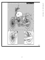 27
27
-
 28
28
-
 29
29
-
 30
30
-
 31
31
-
 32
32
-
 33
33
-
 34
34
-
 35
35
-
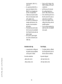 36
36
-
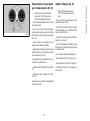 37
37
-
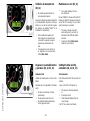 38
38
-
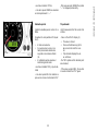 39
39
-
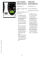 40
40
-
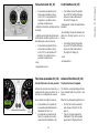 41
41
-
 42
42
-
 43
43
-
 44
44
-
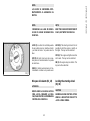 45
45
-
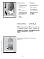 46
46
-
 47
47
-
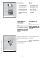 48
48
-
 49
49
-
 50
50
-
 51
51
-
 52
52
-
 53
53
-
 54
54
-
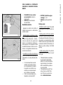 55
55
-
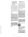 56
56
-
 57
57
-
 58
58
-
 59
59
-
 60
60
-
 61
61
-
 62
62
-
 63
63
-
 64
64
-
 65
65
-
 66
66
-
 67
67
-
 68
68
-
 69
69
-
 70
70
-
 71
71
-
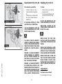 72
72
-
 73
73
-
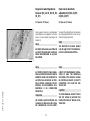 74
74
-
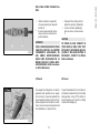 75
75
-
 76
76
-
 77
77
-
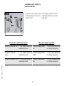 78
78
-
 79
79
-
 80
80
-
 81
81
-
 82
82
-
 83
83
-
 84
84
-
 85
85
-
 86
86
-
 87
87
-
 88
88
-
 89
89
-
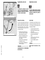 90
90
-
 91
91
-
 92
92
-
 93
93
-
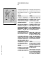 94
94
-
 95
95
-
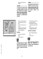 96
96
-
 97
97
-
 98
98
-
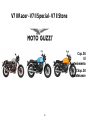 99
99
-
 100
100
-
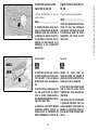 101
101
-
 102
102
-
 103
103
-
 104
104
-
 105
105
-
 106
106
-
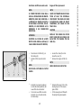 107
107
-
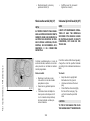 108
108
-
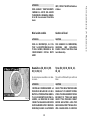 109
109
-
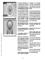 110
110
-
 111
111
-
 112
112
-
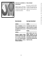 113
113
-
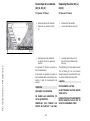 114
114
-
 115
115
-
 116
116
-
 117
117
-
 118
118
-
 119
119
-
 120
120
-
 121
121
-
 122
122
-
 123
123
-
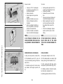 124
124
-
 125
125
-
 126
126
-
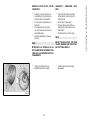 127
127
-
 128
128
-
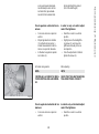 129
129
-
 130
130
-
 131
131
-
 132
132
-
 133
133
-
 134
134
-
 135
135
-
 136
136
-
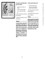 137
137
-
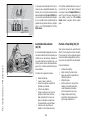 138
138
-
 139
139
-
 140
140
-
 141
141
-
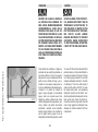 142
142
-
 143
143
-
 144
144
-
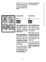 145
145
-
 146
146
-
 147
147
-
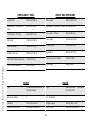 148
148
-
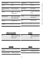 149
149
-
 150
150
-
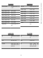 151
151
-
 152
152
-
 153
153
-
 154
154
-
 155
155
-
 156
156
-
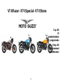 157
157
-
 158
158
-
 159
159
-
 160
160
-
 161
161
-
 162
162
-
 163
163
-
 164
164
-
 165
165
-
 166
166
-
 167
167
-
 168
168
-
 169
169
-
 170
170
-
 171
171


MOTO GUZZI V7 II Racer Manual de usuario
- Categoría
- Motocicletas
- Tipo
- Manual de usuario
- Este manual también es adecuado para
en otros idiomas
- English: MOTO GUZZI V7 II Racer User manual
Artículos relacionados
-
MOTO GUZZI V7 CLASSIC Manual de usuario
-
MOTO GUZZI NORGE GT 8V Manual de usuario
-
-
-
-
-
-
-
-
Otros documentos
-
Honda XR125 El manual del propietario
-
GYS CAR BODY TRESTLE Ficha de datos
-
-
-
-
-
Premier KB-901 Operation Instructions
-
 Vertigo Motors COMBAT TITANIUM R 2019 El manual del propietario
-
VESPA 90 El manual del propietario
-
Daytona DD125E-5C Manual de usuario
