Promax PD-185 Manual de usuario
- Categoría
- Multimetros
- Tipo
- Manual de usuario
Este manual también es adecuado para

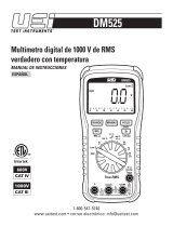
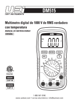
MULTÍMETRO DIGITAL
DIGITAL MULTIMETER
PD-185
- 0 MI1426 -

NOTAS SOBRE SEGURIDAD
Antes de manipular el equipo leer el manual de instrucciones y muy
especialmente el apartado PRESCRIPCIONES DE SEGURIDAD.
El símbolo
sobre el equipo significa "CONSULTAR EL MANUAL
DE INSTRUCCIONES". En este manual puede aparecer también
como símbolo de advertencia o precaución.
Recuadros de ADVERTENCIAS Y PRECAUCIONES pueden aparecer
a lo largo de este manual para evitar riesgos de accidentes a
personas o daños al equipo u otras propiedades.
SAFETY NOTES
Read the instruction manual before using the equipment, mainly
"SAFETY RULES" paragraph.
The symbol
on the equipment means "SEE USER’S MANUAL".
In this manual may also appear as a Caution or Warning symbol.
Warning and Caution statements may appear in this manual to avoid
injury hazard or damage to this product or other property.

MANUAL DE INSTRUCCIONES. PD-185
Í N D I C E
1 INTRODUCCIÓN .......................................................................1
1.1 Especificaciones ...............................................................................1
2 PRESCRIPCIONES DE SEGURIDAD.......................................7
2.1 Generales ..........................................................................................7
2.2 Ejemplos descriptivos de las categorías de Sobretensión............8
3 DESCRIPCIÓN DE MANDOS Y ELEMENTOS.........................9
4 INSTRUCCIONES DE FUNCIONAMIENTO............................13
4.1 Función de auto apagado ..............................................................13
4.2 Indicación acústica de conexión errónea......................................13
4.3 Medidas del verdadero valor eficaz rms .......................................14
4.4 Procedimiento para realizar medidas............................................16
4.5 Medidas de tensión.........................................................................16
4.6 Medidas de corriente ......................................................................17
4.7 Medidas de resistencias.................................................................19
4.8 Prueba de continuidad ...................................................................20
4.9 Prueba de diodos............................................................................20
4.10 Medidas de frecuencia ...................................................................21
4.11 Medidas de capacitancia................................................................21
4.12 Medidas de temperatura ................................................................22
5 CONEXIÓN PC ........................................................................23
5.1 Operación ........................................................................................23
6 MANTENIMIENTO ...................................................................25
6.1 Limpieza del multímetro .................................................................25
6.2 Substitución de la pila.....................................................................25
6.3 Substitución de los fusibles............................................................26

MANUAL DE INSTRUCCIONES. PD-185

MANUAL DE INSTRUCCIONES. PD-185
11/2015 Página 1
MULTÍMETRO DIGITAL
PD-185
1 INTRODUCCIÓN
El PROMAX PD-185 se ha diseñado de acuerdo con los requisitos
más estrictos de calidad, para satisfacer los estándares de
seguridad más rigurosos.
Reúne las características básicas de un instrumento profesional,
tales como alta precisión, fiabilidad y una amplia escala de medidas.
El sistema de visualización con una pantalla LCD de gran tamaño,
así como fácil manejo, permite su uso tanto en laboratorios como en
cadenas de producción.
Su fiabilidad de uso también los hace muy indicados para
actividades educativas.
1.1 Especificaciones
Visualización: 3 ¾ dígitos (4000 cuentas), barra gráfica de
42 segmentos y función/unidad con
indicación de signo.
Polaridad: Automática, indicación de la polaridad
negativa (-).
Indicación de
Desbordamiento: Se visualiza (OL) ó (- OL).

MANUAL DE INSTRUCCIONES. PD-185
Página 2 11/2015
Indicación de pila
baja: Se visualiza el símbolo "
+
" cuando el
voltaje de la batería cae por debajo del nivel
de funcionamiento.
Tasa de medidas: 2/s, nominal; Gráfico de barra: 20/s nominal.
Auto desconexión: 45 min. Aproximadamente.
Temperatura de
funcionamiento: 0°C a 50°C a < 70%.
Temperatura de
almacenamiento: -20°C a 60°C, de 0 al 80% con la batería
retirada.
Coeficiente de
temperatura: 0,1 x (precisión especificada)/ °C (0°C a
18 °C ó de 28 °C a 50 °C).
Auto apagado: 30 minutos después de pulsar el mando
rotatorio o cambiar el modo.
Altitud: 2000 m
Pila: Una pila de 9V 6F22.
Tamaño (Al×An×Pr): 198 x 90 x 44 mm.
Peso: Aproximadamente 400 g incluyendo la
batería.
Accesorios
CD con software para PC.
Cable de comunicación RS232.
Puntas de prueba PP-08.
Termopar tipo S.
Fusible de recambio.
Pila alcalina de 9V 6F22 (instalada)

MANUAL DE INSTRUCCIONES. PD-185
11/2015 Página 3
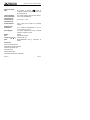
* La precisión se expresa como ± ([% de lectura] + [número del dígito menos
significativos]) de 18 °C a 28 °C, con humedad relativa de hasta el 70 %.
Tensión DC
Escala Resolución Precisión
Impedancia
de entrada
400 mV 100 μV
±(0,1 % lect + 2 díg)
>100 MΩ
4 V 1 mV ±(0,1 % lect + 2 díg)
10 MΩ
40 V 10 mV ±(0,1 % lect + 2 díg)
9,1 MΩ
400 V 100 mV ±(0,1 % lect + 2 díg)
9,1 MΩ
1000 V 1 V ±(0,1 % lect + 2 díg)
9,1 MΩ
Protección contra sobrecarga:
1000V DC / 750V AC RMS en las demás escalas.
Tensión AC (RMS Verdadero)
Escala Resolución
Precisión
(50Hz a 500Hz)
Precisión
(500Hz a 1kHz)
400 mV 100 μV ±(1,2 % lect + 5 díg) Sin especificar*
4 V 1 mV ±(1,0% lect + 3 díg) ±(1,5% lect + 5 díg)
40 V 10 mV ±(1,0% lect + 3 díg) ±(1,2% lect + 5 díg)
400 V 100 mV ±(1,0% lect + 3 díg) ±(1,2% lect + 5 díg)
750 V 1 V ±(1,2% lect + 5 díg) ±(1,5% lect + 5 díg)
* La respuesta en frecuencia para la escala de 400mV es de 50Hz a 100Hz
solamente con impedancia de entrada: Igual que la función DC V con menos
de 100pF.
Factor de cresta: ≤ 3
Protección de sobrecarga:
1000 V DC / 750 V AC RMS en el resto de escalas.

MANUAL DE INSTRUCCIONES. PD-185
Página 4 11/2015
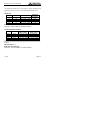
Corriente DC
Escala
Resolución
Precisión Carga de Voltaje
400μA 0,1μA ±(1,0% lect + 1 díg) 500mV máx
4mA 1μA ±(1,0% lect + 1 díg) 2,0V máx
40mA 10μA ±(1,0% lect + 1 díg) 500mV máx
400mA 100μA ±(1,0% lect + 1 díg) 2,0V máx.
20A** 10mA ±(2,0% lect + 3 díg) 500mV máx.
Protección de sobrecarga:
Fusible de 500mA/500V en las entradas de mA fusible de 20A/600V
en las entradas de 20A (fusibles cerámicos de fundido rápido).
** 10 A continuo, 20 A durante 30 segundos como máximo.
Corriente AC (RMS Verdadero)
Escala
Resolución
Precisión (50 Hz a 500 Hz)
Tensión
de la carga
400μA 0.1μA ±(1,5% lect + 4 díg) 500mV máx.
4mA 1μA ±(1,5% lect + 4 díg) 2,0V máx.
40mA 10μA ±(1,5% lect + 4 díg) 500mV máx.
400mA 100μA ±(1,5% lect + 4 díg) 2,0V máx.
20A** 10mA ±(2,5% lect + 4 díg) 500mV máx
Protección contra sobrecarga:
Fusible de 500 mA/500 V en la entrada de mA (fusible cerámico de
fundido rápido) fusible de 20 A/600 V y en la entrada de 20 A
(fusible cerámico de fundido rápido).
** 10A continuo, 20A durante 30 segundos como máximo.
Factor de cresta: ≤ 3.

MANUAL DE INSTRUCCIONES. PD-185
11/2015 Página 5
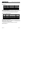
Resistencia
Escala
Resolución
Precisión
Voltios del circuito
abierto
400Ω 0,1Ω
±(0,5% lect + 4 díg) -1,2Vdc
4kΩ 1Ω
±(0,4% lect + 2 díg) -0,45Vdc
40kΩ 10Ω
±(0,4% lect + 2 díg) -0,45Vdc
400kΩ 100Ω
±(0,4% lect + 2 díg) -0,45Vdc
4MΩ 1kΩ
±(0,7% lect + 4 díg) -0,45Vdc
40MΩ 10kΩ
±(1,5% lect + 4 díg) -0,45Vdc
Protección de sobrecarga: 500 V DC ó RMS AC
Prueba de continuidad
Escala
Umbral
audible
Tiempo de
respuesta
Voltios en
circuito abierto
400Ω
Menos que
40Ω
Aprox. 100ms -1,2Vdc
Protección contra sobrecarga: CA de 500V DC ó del RMS AC.
Prueba de diodos
Escala Resolución Precisión
Corriente
de Prueba
Voltios en
circuito
abierto
4V 1mV
±(1,5% lect
+ 3díg)
1,2mA
3,0Vdc típico
Indicación Audible: < 0,2 V.
Protección contra sobrecarga: 500 V DC ó RMS AC.

MANUAL DE INSTRUCCIONES. PD-185
Página 6 11/2015
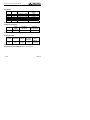
Capacitancia
Escala Resolución Precisión *
4nF 1pF ±(3,0% lect + 20 díg)
40nF 10pF ±(3,0% lect + 5 díg)
400nF 100pF ±(3,0% lect + 5 díg)
4μF 1nF ±(3,0% lect + 5 díg)
40μF 10nF ±(3,0% lect + 5 díg)
400μF 0,1nF ±(5,0% lect + 10 díg)
4mF 1μF ±(5,0% lect + 10 díg)
40mF 10μF ±(5,0% lect + 10 díg)
Protección de sobrecarga: 500V DC ó RMS AC.
* Precisión usando modo relativo con el medidor a cero.
Frecuencia
Escala
Resolución
Precision Sensibilidad
4kHz 1Hz >1,0V rms
40kHz 10Hz >1,0V rms
400kHz 100Hz >1,0V rms
4MHz 1kHz >2,0V rms <5V rms
40MHz 10kHz
±(0,1% lect + 3
díg)
>2,0V rms <5V rms
Anchura mínima del pulso: >25 ns.
Límites del ciclo de trabajo: >30% y <70%.
Protección contra sobrecarga: 500V DC o RMS AC.
Temperatura
Escala Resolución Precisión
-50°C a 400°C 0,1°C ±(0,8% lect + 2°C)
400°C a 1300°C 1°C ±(1,0% lect + 2°C)
-58°F a 400°F 0,1°F ±(0,8% lect + 4°F)
400°F a 2372°F 1°F ±(1,0% lect + 4°F)
Protección contra sobrecarga: 60 V DC ó 24 V AC RMS.

MANUAL DE INSTRUCCIONES. PD-185
11/2015 Página 7
2 PRESCRIPCIONES DE SEGURIDAD
2.1 Generales
• La seguridad puede verse comprometida si no se aplican
las instrucciones dadas en este Manual.
• Este equipo puede ser utilizado en instalaciones con Categoría
de Sobretensión III y ambientes con Grado de Polución 2.
• Al emplear cualquiera de los siguientes accesorios debe
hacerse sólo con los tipos especificados a fin de preservar la
seguridad:
Puntas de Prueba
Revise el estado de las puntas de prueba antes de su
utilización.
• Tener siempre en cuenta los márgenes especificados de
medida.
• Recuerde que las tensiones superiores a 70 V DC o 33 V AC
rms son potencialmente peligrosas.
• Observar en todo momento las condiciones ambientales
máximas especificadas.
• El operador solo está autorizado a intervenir en:
Cambio de pila.
Fusibles.
En el apartado de Mantenimiento se dan instrucciones
específicas para estas intervenciones.
Cualquier otro cambio en el equipo deberá ser efectuado por
personal especializado.
• Seguir las recomendaciones de limpieza que se describen en
el apartado de Mantenimiento.

MANUAL DE INSTRUCCIONES. PD-185
Página 8 11/2015
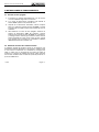
• Simbología de seguridad:
2.2 Ejemplos descriptivos de las categorías de
Sobretensión
Cat I Instalaciones de baja tensión separadas de la red.
Cat II Instalaciones domésticas móviles.
Cat III Instalaciones domésticas fijas.
Cat IV Instalaciones industriales.

MANUAL DE INSTRUCCIONES. PD-185
11/2015 Página 9
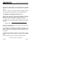
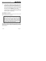
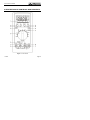
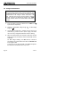
3 DESCRIPCIÓN DE MANDOS Y ELEMENTOS
Figura.-1: Panel frontal

MANUAL DE INSTRUCCIONES. PD-185
Página 10 11/2015
1. Pantalla LCD
3-3/4 dígitos (máximo 3999 cuentas) con barra gráfica analógica
coma decimal automática, e indicadores de función
seleccionada, unidad de medida y de baja carga de pila.
2. Botón de la escala
Botón que permite seleccionar la escala manualmente o
conmutar al modo automático (en este modo aparece en
pantalla el indicador “AUTO”). Con cada pulsación se selecciona
la escala superior y, si se mantiene pulsado, se selecciona el
modo automático.
En el modo de escala manual, cada vez que presiona el botón
(RANGE), la escala (y el indicador de la escala de la entrada) se
incrementa, y un nuevo valor se visualiza. Para abandonar el
modo manual y volver al modo de escala automática, pulsar y
mantener apretado el botón (RANGE) durante 2 segundos. El
indicador “AUTO” volverá a activarse.
3. Botón REL
Cuando el botón REL
se presiona, la actual lectura se
convierte en la lectura cero y todas las lecturas posteriores se
visualizan con relación a este valor. Esta función se desactiva
presionando el botón REL
durante más de 1 s devolviendo
el medidor al modo de operación normal.
4. Botón PEAK ±.
Guarda el valor de peak+ ó peak- de una medida. Se puede
utilizar con tensiones AC/DC y medidas de corriente AC/DC. Si
el tiempo presionado es > 2 s., la función PEAK entra en el
modo de calibración, el LCD mostrará “CAL” y el buffer interno
recordará la tensión de offset OP volviendo de nuevo al modo
de medida. Tiempo de respuesta: Mayor de 1 ms.

MANUAL DE INSTRUCCIONES. PD-185
11/2015 Página 11
5. Conmutador rotativo de función.
Este conmutador rotativo selecciona la función y la escala
requerida.
6. Conector de sonda de temperatura.
El conector para el sensor de temperatura está situado en la
esquina inferior izquierda del panel frontal. Permite medir una
amplia gama de temperaturas de (-50 °C a +1300 °C). Conectar
un termopar tipo-K y tomar la lectura directamente del indicador
digital.
7. Terminal de Entrada CX (+) / mA μA.
Terminal positivo de entrada para la medida de corriente (AC ó
DC) hasta 400mA. Medida de la capacitancia hasta 40mF. La
conexión se realiza utilizando la punta de prueba de color rojo.
8. Terminal de entrada de 20 amperios (20A):
Este es el terminal positivo de la entrada para la medida de
corriente (AC ó DC) hasta 20A. La conexión se realiza utilizando
la punta de prueba de color rojo.
9. Terminal de entrada V / Ω / Hz /
:
Terminal positivo de la entrada para las funciones de medición
de tensión (AC ó DC), resistencia y frecuencia. La conexión se
realiza utilizando la punta de prueba de color rojo.
10. Terminal común COM / Cx (-)
Terminal de entrada negativa (masa) para todos los modos de
medida. La conexión se realiza utilizando la punta de prueba de
color negro.

MANUAL DE INSTRUCCIONES. PD-185
Página 12 11/2015
11. Botón de Shift.
Permite conmutar entre medidas DCA/ACA, Ω /
/ y
entre las diferentes funciones para una misma posición del
conmutador rotativo.
12. Botón RS-232
Presione el botón para activar la comunicación con el
ordenador. El indicador “RS232” se activara en la pantalla del
equipo.
13. Boton MAX/MIN
Al activar el botón MAX/MIN se salvan las lecturas máximas y
mínimas para visualizarlas en el LCD. Presione el MAX/MIN una
vez y la lectura MÁXIMA se visualizará y será actualizada con
cada nueva lectura máxima. Pulsar MAX/MIN de nuevo y la
lectura mínima se visualizará de la misma manera que el
máximo.
Presione el botón una tercera vez y los indicadores de MÁXIMO
y MÍNIMO parpadearan, indicando que el medidor está todavía
guardando las lecturas máximas y mínimas, pero visualiza las
lecturas en tiempo real. Cada pulsación sucesiva del botón
MAX/MIN permite visualizar otro valor o la lectura en tiempo
real. Para desactivar el MAX/MIN, presione y sostenga el botón
MAX/MIN durante 2 segundos. Los indicadores del LCD
desaparecerán y el medidor trabajará en tiempo real
únicamente.
14. Botón HOLD.
Presione el botón (HOLD) para retener en pantalla el ultimo
valor medido. Vuelva a presionar HOLD para volver al estado
normal de medición de valores.

MANUAL DE INSTRUCCIONES. PD-185
11/2015 Página 13
4 INSTRUCCIONES DE FUNCIONAMIENTO
4.1 Función de auto apagado
1. El multímetro se apagará automáticamente si en 30 minutos
no se ha modificado ninguna de sus funciones.
2. Si el modo de desconexión automática está activado el
símbolo “APO” aparece en la pantalla del LCD.
3. Después de la desconexión automática, presione cualquier
botón en el multímetro (excepto el botón de HOLD), o cambie
la posición del conmutador rotativo para encender de nuevo el
multímetro.
4. Para desactivar la función de auto apagado, seleccione la
posición de desconexión (OFF) del multímetro, presione
cualquier botón (excepto el botón de HOLD) en el multímetro,
y sostenga el botón mientras gira el selector rotativo hasta la
posición deseada de función escala. Libere el botón cuando
en la pantalla LCD se visualice con normalidad. El indicador
“APO” desaparecerá de la pantalla LCD.
4.2 Indicación acústica de conexión errónea
La indicación acústica de conexión errónea en la entrada es una
característica adicional diseñada a fin de proteger al medidor contra
un uso erróneo no intencional. Si el multímetro se configura para
medir un voltaje pero los terminales de las puntas de prueba se
conectan en el conector de medida de corriente, podría originarse
una corriente elevada al hacer contacto las puntas de prueba en un
punto de medida activo.

MANUAL DE INSTRUCCIONES. PD-185
Página 14 11/2015
Esta función le advertirá que la punta de prueba debe ser retirada
del actual conector de corriente y ser colocada en el conector de
tensión.
Todas las escalas se encuentran además protegidas mediante
fusibles cerámicos de fundido rápido como protección adicional.
4.3 Medidas del verdadero valor eficaz rms
Este multímetro permite la medida directa del verdadero valor eficaz
RMS de una señal. Ésta es la mejor manera de medir los
parámetros utilizados en las medidas relativas a la potencia.
La relación entre el verdadero valor RMS total (AC+DC) y los
componentes AC y DC de las señales viene dado por la expresión
siguiente:
Verdadero RMS = √ (componente AC)² + (componente DC)²
El RMS es equivalente al valor DC que disipa la misma cantidad de
potencia en una resistencia.
Los medidores de “Respuesta-Promediada” proporcionan a las
lecturas exactas del RMS para las señales sinusoidales, pero
pueden introducir errores significativos al medir formas de onda no
sinusoidales.
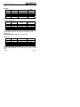
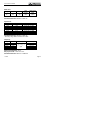
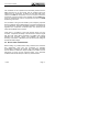
La tabla siguiente muestra los errores que se obtienen al medir
utilizando la “Respuesta-Promediada” en lugar del valor verdadero
RMS.
Cálculo de la potencia (vatios) a partir de medidas de tensión
(Vpk=100V, Carga=1kΩ resistencia)

MANUAL DE INSTRUCCIONES. PD-185
11/2015 Página 15
Respuesta
promedio AC
RMS
AC RMS
verdadero
Error
Onda sinusoidal 5,0 5,0 0%
Onda cuadrada 12,3 10.0 +23%
Onda triangular 3,1 3,1 -6%
Este multímetro está acoplado en AC y medirá exactamente la
componente RMS de alterna de la señal de entrada. La función de
tensión DC medirá el componente de continua. Para obtener el valor
verdadero RMS total, mida la componente AC RMS mediante la
función de tensión AC y la componente DC mediante la función de
tensión DC. Entonces, calcule el valor verdadero RMS, usando las
componentes medidas de AC y DC con la expresión del valor
verdadero RMS indicada más arriba.
Los convertidores AC de cualquier tipo están limitados por su rango
dinámico de respuesta en frecuencia y en la entrada. Las medidas
de las formas de onda complejas no se ven afectadas por las
limitaciones de la anchura de banda del convertidor, de forma que
todos los componentes AC significativos contenidos dentro de las
formas de onda están dentro de la anchura de banda del
convertidor.
El factor de cresta es una medida de la escala dinámica de entrada
de un convertidor AC. Expresa la capacidad del convertidor de
validar una señal que tenga valores máximos grandes comparados
con su valor RMS sin saturar los circuitos internos del convertidor y
alcanzando la precisión especificada. El factor de cresta se define
como la relación de transformación de la tensión máxima respecto a
la tensión total AC RMS.

MANUAL DE INSTRUCCIONES. PD-185
Página 16 11/2015
4.4 Procedimiento para realizar medidas
Antes de hacer cualquier medida examine siempre el instrumento y
los accesorios usados con el instrumento para detectar posibles
daños, contaminación (excesiva suciedad, grasa, etc.) y otros
defectos. Examine los terminales de las puntas de prueba por si el
aislante está agrietado o raído y cerciórese que los terminales estén
correctamente conectados en los conectores del instrumento. Si
existe alguna condición anormal no intente hacer ninguna medida.
4.5 Medidas de tensión
ADVERTENCIA:
Para evitar una posible descarga eléctrica, daños al instrumento y/o
daños de equipo, no intente realizar medidas de tensión si el voltaje
es superior a 1000 V DC / 750 V AC. 1000 V DC y 750 V AC son las
tensiones máximas que este instrumento puede medir. El potencial
del terminal “COM” no debe exceder de 500V medidos respecto a
masa.
1. Inserte los terminales de las puntas de prueba de color
negro y rojo en los terminales de entrada COM y V-Ω
respectivamente.
2. Seleccione la función deseada de la escala de tensión AC
(V~), o de tensión DC (V
).
3. Conecte los terminales de las puntas de prueba en paralelo
al circuito a medir (p.e.: a través de una fuente de la carga o
de alimentación). Tenga cuidado de no tocar ningunos
conductores energizados. Observe la lectura.

MANUAL DE INSTRUCCIONES. PD-185
11/2015 Página 17
4. Cuando todas las medidas estén realizadas, desconecte los
terminales de las puntas de prueba conectados al circuito
bajo prueba. Retire las puntas de prueba del multímetro.
Para las lecturas de tensión DC, el terminal de color ROJO
de la punta de prueba debe conectarse en el lado positivo
del circuito y el de color NEGRO en el lado negativo.
Un signo menos en el lado izquierdo de la pantalla LCD
aparecerá cuando los terminales de las puntas de prueba
estén conectados en sentido inverso.
4.6 Medidas de corriente
Éstas se hacen en serie con el circuito de prueba. Toda la corriente
que se medirá atraviesa el multímetro.
ADVERTENCIA:
No intente medir corrientes en circuitos de alta potencia
capaces de entregar más de 600V. Dado que el fusible
está limitado a 600V podrían producirse daños o
lesiones. El terminal de entrada de 20A está protegido
por un fusible de fundido rápido de 20A/600V de alta
potencia. El terminal de entrada de mA está protegido por
un fusible de fundido rápido de 500mA/500V.
No exceda los límites de cada terminal de entrada de corriente.
Siendo de 20A (con un límite de tiempo máximo de 30 segundos
para corrientes superiores a 10A) en el terminal de 20A y 400mA en
el terminal de mA.

MANUAL DE INSTRUCCIONES. PD-185
Página 18 11/2015
Todas las escalas de corriente están protegidas mediante fusibles.
Si el instrumento conduce una corriente mayor de 20 A para la
escala de 20 A o mayor de 500 mA para el resto de escalas, el
fusible se fundirá provocando un circuito abierto entre los terminales
de medida de corriente.
1. Inserte el terminal NEGRO de la punta de prueba en el
conector de entrada COM.
2. Para corrientes menores de 400 mA, conecte el terminal
ROJO en la entrada de mA. Para medir corrientes entre
400 mA y 20 A conecte el terminal ROJO en el conector de
20A.
3. Seleccione la escala actual deseada para corrientes AC ó
DC.
NOTA: Si se selecciona la escala de 20 A entonces debe utilizarse
el conector de entrada de 20 A en el paso 2 descrito
anteriormente. Si se seleccionan las escalas de μA, ó mA
deberá utilizarse el conector de entrada de mA en el paso 2
descrito anteriormente.
4. Apague o desconecte el circuito para medir todas las fuentes
de potencia, conecte el multímetro en serie con el conductor
en el que se desea medir el flujo de corriente.
5. Encienda (ON) el circuito. Anote la lectura.
6. Apague (OFF) o desconecte el circuito y retire las puntas de
prueba del multímetro.

MANUAL DE INSTRUCCIONES. PD-185
11/2015 Página 19
ADVERTENCIA:
Un error común en el uso de los multímetros es pretender medir una
tensión mientras los terminales de las puntas de prueba todavía se
encuentran conectados a las entradas de corriente. Esto provoca un
cortocircuito en la fuente de tensión puesto que las escalas de
corriente presentan una baja impedancia de entrada, Si la fuente de
tensión es de 240 V AC o de tipo trifásica (415 V), pueden
originarse unas elevadas corrientes de fallo. Este es el motivo por el
que todas las entradas de corriente se queman. En el caso que los
fusibles de las entradas se fundan deberán ser sustituidos
únicamente por otros equivalente de otra forma la seguridad del
instrumento se vería comprometida.
7. Nunca aplique una tensión entre el terminal COM y los
terminales de corriente.
8. Al cambiar entre las escalas de corriente para obtener una
mayor precisión y resolución, desenergice totalmente el
circuito a medir antes de cambiar la escala.
4.7 Medidas de resistencias
ADVERTENCIA:
Desconecte el circuito de prueba y descargue todos los
condensadores antes de intentar realizar medidas de resistencias.
Si un voltaje externo está presente en algún componente, será
imposible efectuar una medida exacta de la resistencia de ese
componente.
1. Inserte el terminal NEGRO y ROJO en los conectores COM
y VΩ de entrada respectivamente.

MANUAL DE INSTRUCCIONES. PD-185
Página 20 11/2015
2. Fije el conmutador rotativo de selección en la posición (Ω).
3. Conecte los extremos NEGRO y ROJO de la punta de
prueba sobre el circuito o dispositivo bajo prueba,
cerciorándose que se desenergizan primero.
4. La resistencia en las puntas de prueba puede disminuir la
precisión de la escala más baja (400 Ω). El error es
generalmente de 0,1 a 0,2 Ω para un par estándar de
puntas de prueba. Para determinar el error, cortocircuitar los
terminales de las puntas de prueba y después utilizar el
modo relativo (REL) para restar automáticamente la
resistencia de las puntas de prueba de las medidas de la
resistencia.
4.8 Prueba de continuidad
1. Seleccione la posición
(Ω) girando el conmutador rotativo de
selección.
2. Pulse SHIFT hasta que aparezca el símbolo
en la
pantalla.
3. Siga los pasos 3 y 4 descritos para el procedimiento de
medidas de resistencias. Un tono audible sonará si el valor
medido es inferior a 40 Ω.
4.9 Prueba de diodos
ADVERTENCIA:
Las medidas se deben hacer solamente con la potencia del circuito
APAGADO.
1. Fije el conmutador rotativo a la posición
(Ω/ / ).

MANUAL DE INSTRUCCIONES. PD-185
11/2015 Página 21
2. Pulse SHIFT hasta que aparezca el símbolo
en la
pantalla.
3. Siga el paso 3 de las medidas de resistencias.
4. La punta de prueba de color ROJO se debe conectar al
ánodo y la punta de prueba de color NEGRO al cátodo.
Para un diodo de silicio, la tensión directa típica debe estar
sobre 0,6V.
4.10 Medidas de frecuencia
1. Fije el conmutador rotativo en la posición Hz para la medida
de Frecuencia.
2. Conecte la punta de prueba roja en el conector de / V /
Ω / Hz y la punta de prueba negra en el conector COM.
3. Conecte las puntas de prueba en el punto de medida y lea
la frecuencia en la pantalla.
4.11 Medidas de capacitancia
ADVERTENCIA:
Desconecte y descargue los condensadores antes de intentar
realizar medidas de capacitancia. Utilice la función de DCV para
confirmar que el condensador está descargado.
1. Fije el conmutador rotativo en la posición
.
2. Conecte entre los terminales COM/Cx(-) y Cx(+)/μA/mA el
condensador a medir. Compruebe la polaridad cuando mida
condensadores electrolíticos.

MANUAL DE INSTRUCCIONES. PD-185
Página 22 11/2015
3. Lea la capacitancia directamente en la pantalla. Un
condensador en cortocircuito indicará un desbordamiento de
escala. Un condensador en abierto indicará
aproximadamente cero en todas las escalas.
4. Para alcanzar una precisión máxima, pasar a la escala
deseada mediante el botón de escala manual RANGE,
después presionar el botón de REL
para suprimir la
capacitancia de las puntas de prueba antes de realizar la
medida.
5. El gráfico de barras está deshabilitado en el modo de
medida de la capacitancia.
6. En las escalas de 4 mF y de 40 mF, el gráfico de barras del
LCD estará activo hacia delante y hacia atrás indicando la
duración del modo de carga, no la lectura medida.
7. Cuando el condensador que se pretende comprobar está
conectado y aparece el símbolo de un “disco” en el LCD
significa que hay voltaje en el condensador y por tanto es
necesario descargarlo antes de proceder a su
comprobación.
4.12 Medidas de temperatura
1. Fije el conmutador rotativo en la posición (°C ó °F) según la
unidad de temperatura requerida.
2. Conecte un termopar tipo-K en el terminal de entrada de
termopares situada en la parte inferior del panel frontal.
3. Ponga el extremo de la unión termopar en el punto donde
debe ser medida la temperatura.
NOTA:
Para temperaturas muy elevadas el multímetro debe guardarse
suficientemente alejado de la fuente de calor para evitar posibles
daños. Con temperaturas altas, la vida de la punta de prueba de
temperatura se verá reducida.

MANUAL DE INSTRUCCIONES. PD-185
11/2015 Página 23
5 CONEXIÓN PC
5.1 Operación
1. Instale el software suministrado (DMM Utility) en el PC si no
lo ha hecho previamente. Para ello, inserte el CD en el
lector, ejecute el fichero “Setup.exe” y siga las instrucciones.
2. Conecte el multimetro con el PC usando el cable serie
proporcionado.
3. Seleccione la función del multimetro requerida.
4. Presione el botón RS232 para activar la salida del puerto
serie.
5. En el PC, ejecute el software del multímetro haciendo doble
clic en el icono DMM Utility del escritorio.
Consulte las operaciones de cada función descrita en el software.
NOTA: El sistema operativo requerido es Windows 98 ó
Superior.

MANUAL DE INSTRUCCIONES. PD-185
Página 24 11/2015

MANUAL DE INSTRUCCIONES. PD-185
11/2015 Página 25
6 MANTENIMIENTO
6.1 Limpieza del multímetro
Limpie la caja de vez en cuando con un paño húmedo. No utilice
disolventes de productos químicos, productos limpiadores,
abrasivos o detergentes.
6.2 Substitución de la pila
ADVERTENCIA:
Desconectar todas las puntas de prueba antes de
iniciar el proceso de sustitución de la pila. Apagar el
equipo.
Este medidor se alimenta mediante una pila del tipo 6F22 o
equivalente de 9 voltios.
Cuando el multímetro visualiza “
+
“ la pila debe ser sustituida para
mantener la capacidad operativa. Utilice el siguiente procedimiento
para sustituir la batería:
1. Desatornillar y retirar el papel posterior con la ayuda de un
destornillador Phillips adecuado.
2. Retire la pila y substitúyala por una nueva de 9V del tipo
6F22.
3. Colocar de nuevo el panel posterior y atornillar

MANUAL DE INSTRUCCIONES. PD-185
Página 26 11/2015
6.3 Substitución de los fusibles
ADVERTENCIA:
Desconectar todas las puntas de prueba antes de
iniciar el proceso de sustitución de los fusibles.
Apagar el equipo.
Los fusibles están ubicados dentro del equipo. Para substituirlos
siga las siguientes instrucciones:
1. Desatornillar y retirar el papel posterior con la ayuda de un
destornillador Phillips adecuado.
2. Retire los fusibles defectuosos y substituyalos por unos
nuevos.
Los fusibles deben de ser del tipo:
Para el terminal mA: 0,5A F500V
Para el terminal 20A: 20A F600V
EL INCUMPLIMIENTO DE ESTAS INSTRUCCIONES
PODRIA DAÑAR EL EQUIPO
.
3. Colocar de nuevo el panel posterior y atornillar.

USER’S MANUAL. PD-185
T A B L E OF C O N T E N T S
1 INTRODUCTION........................................................................1
1.1 Specifications ....................................................................................1
2 GENERAL SAFETY RULES ......................................................7
2.1 General ..............................................................................................7
2.2 Descriptive Examples of Over-Voltage Categories........................8
3 DESCRIPTION OF CONTROLS AND ELEMENTS...................9
4 OPERATING INSTRUCTIONS ................................................13
4.1 Auto power off .................................................................................13
4.2 Input warning beeper......................................................................13
4.3 True rms measurements................................................................14
4.4 How to make measurements.........................................................15
4.5 Voltage measurements ..................................................................16
4.6 Current measurements ..................................................................17
4.7 Resistance measurements ............................................................19
4.8 Continuity testing.............................................................................19
4.9 Diode testing....................................................................................20
4.10 Frequency measurements.............................................................20
4.11 Capacitance measurements..........................................................21
4.12 Temperature measurements .........................................................22
5 PC INTERFACE.......................................................................23
5.1 Operation.........................................................................................23
6 MAINTENANCE .......................................................................24
6.1 Cleaning the multimeter..................................................................24
6.2 Replacing the battery......................................................................24
6.3 Fuse replacement. ..........................................................................24

USER’S MANUAL. PD-185

USER’S MANUAL PD-185
11/2015 Page 1
DIGITAL MULTIMETER
PD-185
1 INTRODUCTION
The PROMAX PD-185 has been designed in agreement with the
strictest requirements of quality, to agree to the more rigorous
security standards.
Joining the basic characteristics of a professional instrument,
such as a high precision, reliability and a wide range of measures.
The display system with a LCD type visualizer of great size as
well as the facility of handling, allows their use in laboratories as in
production chains.
Their use reliability also does them very indicated for the
education.
1.1 Specifications
Display: 3¾ digit (4000 counts), 42 segments with
automatic decimal point analog bar graph,
low battery and full annunciators for function
and unit of measurement.
Polarity: Automatic, (-) negative polarity indication.
Overrange indication: (OL) or (-OL) is displayed.

USER’S MANUAL PD-185
Page 2 11/2015
Low battery indication: The "
+
" is displayed when the battery
voltage drops below accurate operating
level.
Measurement rate: 2/sec, nominal; Bar graph: 20/sec
nominal.
Operating environment: 0°C to 50°C at < 70% R.H.
Storage temperature: -20°C to 60°C, 0 to 80% R.H. with battery
removed from meter.
Temperature coefficient: 0.1 × (specified accuracy) / °C (0°C to
18°C or 28°C to 50°C).
Auto power off: 30 minutes after rotary switch or mode
changes.
Altitude: 2000m.
Battery: Single 9Volt battery 6F22.
Size (H×W×D): (198×90×44mm).
Weight: Approx. 14.1 oz (400 g) including battery.
Accesorios
CD with software for PC.
RS232 Communication Cable.
Test leads PP-08.
S-type thermocouple.
Spare fuse.
9V 6F22 alkaline battery (included).
User’s Manual 0 MI1426.
*Accuracy is given as ±([% of reading] + [number of least significant digits]) at
18°C to 28°C, with relative humidity up to 70%.

USER’S MANUAL PD-185
11/2015 Page 3
DC Volts
Range Resolution Accuracy
Input
Impedance
400mV 100μV ±(0.1% rdg + 2 d)
>100MΩ
4V 1mV ±(0.1% rdg + 2 d)
10MΩ
40V 10mV ±(0.1% rdg + 2 d)
9.1MΩ
400V 100mV ±(0.1% rdg + 2 d)
9.1MΩ
1000V 1V ±(0.1% rdg + 2 d)
9.1MΩ
Overload Protection: 1000 VDC / 750 VAC RMS
AC Volts (TRUE RMS)
Range
Resolution
Accuracy(50Hz to
500Hz)
500Hz to 1kHz
400mV 100μV *±(1.2% rdg + 5 d) Unspecified
4V 1mV ±(1.0% rdg + 3 d) ±(1.5% rdg + 5 d)
40V 10mV ±(1.0% rdg + 3 d) ±(1.2% rdg + 5 d)
400V 100mV ±(1.0% rdg + 3 d) ±(1.2% rdg + 5 d)
750V 1V ±(1.2% rdg + 5 d) ±(1.5% rdg + 5 d)
* The frequency response for 400mV range are 50Hz to 100Hz only
Input Impedance: Same as DCV function with less than 100pF
Crest factor: ≤ 3
Overload Protection: 1000VDC or 750VAC RMS
DC Current
Range
Resolution
Accuracy Burden Voltage
400μA 0.1μA ±(1.0% rdg + 1 d) 500mV max
4mA 1μA ±(1.0% rdg + 1 d) 2.0V max
40mA 10μA ±(1.0% rdg + 1 d) 500mV max
400mA 100μA ±(1.0% rdg + 1 d) 2.0V max.
20A** 10mA ±(2.0% rdg + 3 d) 500mV max.
Overload Protection: 500mA/500V fuse on mA inputs (fast blow
ceramic fuse). 20A/600V fuse on 20A inputs (fast blow ceramic
fuse).

USER’S MANUAL PD-185
Page 4 11/2015
** 10A continuous, 20A for 30 seconds maximum.
AC Current (TRUE RMS)
Range
Resolution
Accuracy (50Hz to
500Hz)
Burden Voltage
400μA 0.1μA ±(1.5% rdg + 4 d) 500mV max.
4mA 1μA ±(1.5% rdg + 4 d) 2.0V max.
40mA 10μA ±(1.5% rdg + 4 d) 500mV max.
400mA 100μA ±(1.5% rdg + 4 d) 2.0V max.
20A** 10mA ±(2.5% rdg + 4 d) 500mV max
Overload Protection: 500mA/500V fuse on mA inputs (fast blow
ceramic fuse). 20A/600V fuse on 20A inputs (fast blow ceramic
fuse).
** 10A continuous, 20A for 30 seconds maximum.
Crest factor: ≤ 3
Resistance
Range
Resolution
Accuracy
Open Circuit
Volts
400Ω 0.1Ω
±(0.5% rdg + 4 d) -1.2Vdc
4kΩ 1Ω
±(0.4% rdg + 2 d) -0.45Vdc
40kΩ 10Ω
±(0.4% rdg + 2 d) -0.45Vdc
400kΩ 100Ω
±(0.4% rdg + 2 d) -0.45Vdc
4MΩ 1kΩ
±(0.7% rdg + 4 d) -0.45Vdc
40MΩ 10kΩ
±(1.5% rdg + 4 d) -0.45Vdc
Overload Protection: 500VDC or RMS AC
Continuity Test
Range
Audible
Threshold
Response Time
Open Circuit
Volts
400Ω
Less than
40Ω
Approx. 100ms -1.2Vdc
Overload Protection: 500VDC or RMS AC

USER’S MANUAL PD-185
11/2015 Page 5
Diode Test
Range Resolution Accuracy
Test
Current
Open Circuit
Volts
4V 1mV
±(1.5% rdg
+ 3d)
1.2mA
3.0Vdc
typical
Audible Indication: < 0.2V
Overload Protection: 500VDC or RMS AC
Capacitance
Range Resolution Accuracy *
4nF 1pF ±(3.0% rdg + 20 dgts)
40nF 10pF ±(3.0% rdg + 5 dgts)
400nF 100pF ±(3.0% rdg + 5 dgts)
4μF 1nF ±(3.0% rdg + 5 dgts)
40μF 10nF ±(3.0% rdg + 5 dgts)
400μF 0.1nF ±(5.0% rdg + 10 dgts)
4mF 1μF ±(5.0% rdg + 10 dgts)
40mF 10μF ±(5.0% rdg + 10 dgts)
Overload Protection: 500VDC or RMS AC
* Accuracy using relative mode to zero meter.
Frequency
Range
Resolution
Accuracy Sensitivity
4kHz 1Hz >1.0V rms
40kHz 10Hz >1.0V rms
400kHz 100Hz >1.0V rms
4MHz 1kHz >2.0V rms <5V rms
40MHz 10kHz
±(0.1% rdg + 3
dgts)
>2.0V rms <5V rms
Minimum Pulse Width: >25 ns.
Duty Cycle Limits: >30% and <70%.
Overload Protection: 500V DC or RMS AC.

USER’S MANUAL PD-185
Page 6 11/2015
Temperature
Range Resolution Accuracy
-50°C to 400°C 0,1°C ±(0.8% rdg + 2°C)
400°C to 1300°C 1°C ±(1.0% rdg + 2°C)
-58°F to 400°F 0,1°F ±(0.8% rdg + 4°F)
400°F to 2372°F 1°F ±(1.0% rdg + 4°F)
Overload Protection: 60V DC or 24V AC RMS

USER’S MANUAL PD-185
11/2015 Page 7
2 GENERAL SAFETY RULES
2.1 General
• The safety could not be assured if the instructions for use are not
closely followed.
• This equipment can be used in Overvoltage Category III installations
and Pollution Degree 2 environments.
• When using some of the following accessories use only the
specified ones to ensure safety:
One pair test leads
Review the state of the test ends before its use.
• Observe all specified ratings of measurement.
• Remember that voltages higher than 70 V DC or 33 V AC rms are
dangereus.
• Use this instrument under the specified environmental conditions.
• The user is only authorised to:
Battery replacement
Fuses
On the Maintenance section proper instructions are given.
Any other change on the equipment should be carried out by qualified
personnel.
• Follow the cleaning conditions described in the Maintenance
paragraph.

USER’S MANUAL PD-185
Page 8 11/2015
• Symbols related with safety.
2.2 Descriptive Examples of Over-Voltage Categories
Cat I Low voltage installations isolated from the mains
Cat II Portable domestic installations
Cat III Fixed domestic installations.
Cat IV Industrial installations.

USER’S MANUAL PD-185
11/2015 Page 9
3 DESCRIPTION OF CONTROLS AND ELEMENTS.
Figure 1.- Front Panel.

USER’S MANUAL PD-185
Page 10 11/2015
1. LCD Display.
3-3/4 digit (3999 maximum) with automatic decimal point analog
bar graph, low battery and full annunciators for function and unit
of measurement.
2. RANGE Button
Button, which allows selecting the range manually, or switching
to the automatic mode (in this mode appears on display the
“AUTO” indicator). After each pressing the higher range is
selected and, if it is hold pressed, the automatic mode is
activated.
3. REL
Button
When the REL
button is pressed the present reading
become the zero reading and all subsequent readings are
displayed relative to this value. This function is cleared by
pressing the REL
button >1 sec which returns the meter to
normal operation.
4. PEAK± Button.
Record the peak+ or peak- value in a measurement. It is usable
with AC/DC voltage, AC/DC current measurements. If the
pressed time > 2 sec, the PEAK function will enter to calibration
mode, the LCD will show "CAL" and the internal buffer will
remember the internal OP off set voltage then back to the
measure mode. Response time: More than 1 ms.
5. Selector Rotary Switch Function.
This rotary switch selects function and range needed. Each time
the rotary switch is moved from OFF to a function setting, all
LCD segments will turn on for one second.

USER’S MANUAL PD-185
11/2015 Page 11
6. Temperature Jack.
The connector for the temperature sensor is located lower left-
hand corner of the front panel. To measure a wide range of
temperature (-50 °C to +1300 °C), plug in a K-type thermocouple
and take the reading direct from the digital display.
7. CX (+) / mA μA Input Terminal.
Positive input terminal for current measurement (AC or DC) up
to 400mA. Capacitance measurement up to 40mF. Connection
is made to it using the Red test lead.
8. 20A: 20 Amperes Input Terminal (20A).
This is the positive input terminal for current measurement (AC
or DC) up to 20A. Connection is made to it using the Red test
lead.
9. V /Ω /Hz /
Input terminal.
This is the positive input terminal for all functions except current
capacitance measurements. Connection is made to it using the
red test lead.
10. COM /Cx(-) Common Terminal
This is the negative (ground) input terminal for all measurement
modes. Connection is made to it using the Black test lead.
11. Shift Boutton.
It allows to switch between DCA/ACA, Ω /
/
measurements and the different functions for a same rotary
selector position.
12. RS232 Button
Press the button to activate the communication with the
computer. “RS232” indicator will be activated on the instrument
display.

USER’S MANUAL PD-185
Page 12 11/2015
13. MAX/MIN Button
The MAX/MIN button activates saving the maximum and
minimum readings for display in the LCD. Press MAX/MIN once
and the MAX reading will display and be updated with each new
maximum reading. Press MAX/MIN again and the minimum
reading will be displayed in the same manner as the maximum.
Press the button a third time and both MAX and MIN indicators
blink, indicating that the meter is still saving both maximum and
minimum readings, but is displaying the real-time reading. Each
successive press of MAX/MIN permits looking at either value or
the real-time reading. To disable MAX/MIN, press and hold the
MAX/MIN button for 2 seconds. The LCD indicators will
disappear and the meter will read real-time only.
14. HOLD Button
Press (HOLD) button to toggle in and out of the Data Hold
mode. In the Data Hold mode, the "HOLD" annunciator is
displayed and the last reading is frozen on the display. Press the
(HOLD) button again to exit and resume readings.

USER’S MANUAL PD-185
11/2015 Page 13
4 OPERATING INSTRUCTIONS
4.1 Auto power off
1. The meter will automatically shut off if the Function/Range
switch position is not changed within 30 minutes.
2. The auto power off mode is activated with an "APO" symbol
indicating on LCD.
3. After auto power off, press any button on DMM (except
HOLD button), or change range position of the rotary knob
to turn the DMM back on again.
4. Disable auto power off, set the DMM to off position, press
any button (except the HOLD button) on DMM, and hold the
button while turning the rotary knob to the desired range
position. Release the button when LCD displays normally.
Note "APO" annunciator is missing form the LCD.
4.2 Input warning beeper
The Input Warning Beeper is a feature to protect the meter and you
from unintentional misuse. If the DMM is set to measure a voltage
while the test leads are plugged into a current jack, very high current
could result when the test lead tips are placed to the voltage test
point.
This feature warns you that the test lead needs to be changed from
a current jack to the voltage jack.
All current ranges are fused with fast acting ceramic fuses as an
added protection.

USER’S MANUAL PD-185
Page 14 11/2015
4.3 True rms measurements
This multimeter permits direct measurement of the true RMS value
of a signal. This is the best way to measure parameters used for
measurements relating to power.
The relationship between the total true RMS (AC+DC) and the
component AC and DC signals is given by the following expression:
True RMS = √ (AC RMS Component)
2
+ (DC Component)
2
RMS is equivalent to that DC value which dissipates the same
amount of power in a resistor.
" Average-responding " meters provide accurate RMS readings for
sinusoidal signals, but can introduce significant errors when
measuring nonsinusoidal waveforms.
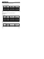
The following table shows the errors that result when the average-
responding measurement is used instead of the True RMS value.
Power Calculations (watts) from Voltage Measurements
(VpK=100V, Load=1kΩ resistor)
AC RMS average
responding
AC True RMS Error
Sine wave 5.0 5.0 0%
Square wave 12.3 10.0 +23%
Triangle wave 3.1 3.1 -6%

USER’S MANUAL PD-185
11/2015 Page 15
This multimeter is AC coupled and will accurately measure the AC
RMS component of an input signal. The DC voltage function will
measure the DC component. To obtain the total true RMS value,
measure the RMS AC component on the AC function and the DC
component on the DC function. Then, calculate the True RMS value,
using the measured AC and DC components and the True RMS
expression given above.
AC converters of all types are limited by their frequency response
and input dynamic range. Measurements of complex waveforms will
not be affected by converter bandwidth limitations, provide that all
significant AC components contained within the waveforms are
within the bandwidth of the converter.
Crest factor is a measure of the input dynamic range of an AC
converter. It expresses the ability of the converter to accept a signal
that has large peak values compared to its RMS value without
saturating the converter circuitry and degading the specified
accuracy. Crest factor is defined as the ratio of the peak voltage to
the total AC RMS voltage.
4.4 How to make measurements
Before making any measurements always examine the instrument
and accessories used with the instrument for damage,
contamination (excessive dirt, grease, ect.) and defects. Examine
the test leads for cracked or frayed insulation and make sure the
lead plugs fit snugly into the instrument jacks. If any abnormal
conditions exist do not attempt to make any measurements.

USER’S MANUAL PD-185
Page 16 11/2015
4.5 Voltage measurements
WARNING:
To avoid possible electric shock, instrument damage and /
or equipment damage, do not attempt to take any voltage
measurements if the voltage is above 1000 VDC / 750
VAC. 1000 VDC and 750 VAC are the maximum voltages
that this instrument is designed to measure. The "COM"
terminal potential should not exceed 500V measured to
ground.
1. Insert the black and red test leads into the COM and V-Ω
input terminals respectively.
2. Select the desired AC voltage range (V∼), or DC voltage
range (V
).
3. Connect the test lead tips in parallel with the circuit to be
measured (e.g. across a load or power supply). Be careful
not to touch any energized conductors. Note the reading.
4. When all measurements are completer, disconnect the test
leads from the circuit under test. Remove test leads from the
multimeter.
For DC voltage readings, the RED lead tip should be
connected to the positive side of the circuit, the BLACK lead
to the negative side.
A minus sign on the left hand side of the LCD will appear if
the leads are connected the other way round.

USER’S MANUAL PD-185
11/2015 Page 17
4.6 Current measurements
These are made in series with the test circuit. All the current to be
measured flows through the multimeter.
WARNING
Do not attempt to measure currents in high energy circuits
capable of delivering greater than 600V. Since the fuse is
rated at 600V damage or injury could occur. The 20A
input terminal is protected by a 20A/600V high energy,
fast blow fuse. The mA input terminal is protected by a
500mA/500V fast blow fuse.
Do not exceed the limits of each current input terminal. This is 20A
(maximum time limit of 30 seconds for currents greater than 10A) for
the 20A terminal and 400mA for the mA terminal.
All current rages are fused. If a current greater than 20A on the 20A
range or greater than 500mA on all other ranges flows, the fuse will
blow causing an open circuit between the current measuring
terminals.
1. Insert the BLACK test lead in the COM input terminal.
2. For measuring currents less than 400mA, connect the RED
test lead to the mA input terminal. For measuring currents
between 400mA and 20A connect the RED test lead to the
20A terminal.
3. Select the desired AC current range or DC current range.
NOTE: If the 20A range is selected then the 20A input terminal must
be selected in step 2. If the μA, mA ranges is selected the
mA input terminal must be selected in step 2.

USER’S MANUAL PD-185
Page 18 11/2015
4. Switch OFF or disconnect the circuit to be measured from all
power sources, connect the multimeter in series with the
conductor in which the current to be measured flows.
5. Switch ON the circuit. Note the reading.
6. Switch OFF or disconnect the circuit and remove the test
leads from multimeter.
CAUTION
A common abuse of multimeters in to attempt to measure
a voltage while the test leads are still plugged into the
current input terminals. This basically puts a short circuit
across the voltage source since current ranges have a
low impedance. If the voltage source is typically 240VAC
or a 3-phase industrial voltage (415V), very high fault
currents can result. This is why all current input terminal
are fused. If the fuses blow they must only be replaced by
the equivalent ones otherwise the safety of the instrument
may be impaired.
7. Never apply a voltage between the COM terminal and
current terminals.
8. When switching between current ranges to obtain greater
accuracy and better resolution, completely de-energize the
circuit to be measured before changing the range.

USER’S MANUAL PD-185
11/2015 Page 19
4.7 Resistance measurements
CAUTION
Turn off power on the test circuit and discharge all
capacitors before attempting in-circuit resistance
measurements. If an external voltage is present across a
component, it will be impossible to take an accurate
measurement of the resistance of that component.
1. Insert the BLACK and RED test leads into the COM and VΩ
input terminals respectively.
2. Set the rotary selector switch to the (Ω) position.
3. Connect the BLACK and RED test probe tips to the circuit or
device under test, making sure it is de-energized first.
4. The resistance in the test leads can diminish accuracy on
the lowest (400 Ω) range. The error is usually 0.1 to 0.2 Ω
for a standard pair of test leads. To determine the error,
short the test leads together and then use the (REL)
Relative mode to automatically subtract the lead resistance
from resistance measurements.
4.8 Continuity testing
1. Select the (Ω /
/ ) position by turning the rotary
selector switch.
2. Press SHIFT until the symbol
appears on the screen.
3. Follow steps 1 and 3 as for resistance measurements. An
audible tone will sound for resistance less than
approximately 40Ω.

USER’S MANUAL PD-185
Page 20 11/2015
4.9 Diode testing
CAUTION
Measurements must only be made with the circuit power
OFF.
1. Set the rotary selector switch to the (Ω/
/ ) position.
2. Press SHIFT until the symbol
appears on the screen.
3. Follow step 3 as for resistance measurements.
4. The RED lead should be connected to the anode and the
BLACK lead to the cathode. For a silicon diode, the typical
forward voltage should be about 0.6V.
4.10 Frequency measurements
1. Set the rotary selector to the Hz position for the Frequency
measurement.
2. Connect the red test lead to the
/V /Ω /Hz jack and the
black test lead to the COM jack.
3. Connect the test leads to the point of measurement and read
the frequency from the display.

USER’S MANUAL PD-185
11/2015 Page 21
4.11 Capacitance measurements
CAUTION
Turn off power and discharge the capacitor before
attempting a capacitance measurement. Use the DCV
function to confirm that the capacitor is discharged.
1. Set the rotary switch position (
).
2. Connect the COM/Cx(-) and the Cx(+) /μA /mA leads to the
capacitor. Observe polarity when measureing polarized
capacitors.
3. Read the capacitance directly from the display. A shorted
capacitor will indicate an overrange. An open capacitor will
indicate near zero on all ranges.
4. To achieve maximum precision, passing the desired scale
using the manual range button RANGE, then press the REL
button to zero out test lead capacitance before the
measurement.
5. The bar graph is disabled in capacitance measurement
mode.
6. In 4mF and 40mF ranges, the bar graph on LCD will be in
action vack and forth. The is a charging mode during, not a
indication of the measured reading.
7. When the capacitor to be tested is connected, if "disc"
symbol indicates on LCD, it means there is voltage existing
the tested capacitor and need to be discharged before
testing.

USER’S MANUAL PD-185
Page 22 11/2015
4.12 Temperature measurements
1. Set the rotary switch in position (°C ó °F) temperature unit as
required.
2. Connect a type K thermocouple to the thermocouple input
terminal (yellow terminal) on the left hand side of the front
panel.
3. Place the thermocouple junction tip at the point where the
temperature is to be measured.
NOTE:
For very high temperatures the multimeter must be kept far enough
away from the source of temperature to avoid heat damage. At high
temperatures, the life of the temperature probe will be reduced.

USER’S MANUAL PD-185
11/2015 Page 23
5 PC INTERFACE
5.1 Operation
1. Install the software provided (DMM Utility) in the PC if it has
not previously done. For it, insert the CD in the drive,
execute the “Setup.exe” file and follow the instructions.
2. Connect the DMM to the PC using the serial cable provided.
3. Select the multimeter required function.
4. Press the RS232 button to activate the serial port output.
Please refer to operations of each function described in the
software.
NOTE: The required operating system is Windows 98 or higher.

USER’S MANUAL PD-185
Page 24 11/2015
6 MAINTENANCE
6.1 Cleaning the multimeter
Wipe the case occasionally with a damp cloth. DO NOT use
chemicals, cleaning solvents, abrasives or detergents.
6.2 Replacing the battery
ADVERTENCIA:
Disconnect all the test leads before initiating the fuse
replacement process. Power off the instrument.
This meter is powered by a 6F22 or equivalent 9-volt battery.
When the multimeter displays the "
+
" the battery must be replaced
to maintain proper operation. Use the following procedure to
replacing the battery:
1. Unscrew and remove the rear panel with the aid of a suitable
Phillips screwdriver.
2. Remove the battery and replace it by a new one of 9V 6F22
type.
3. Back to placing the rear panel and screw it again.
6.3 Fuse replacement.
WARNING:
Disconnect all test leads before beginning the fuse
replacement process. Power off the instrument.

USER’S MANUAL PD-185
11/2015 Page 25
Fuses are located incide the instrument. In order to replace them
you must follow these instructions:
1. Unscrew and remove the rear panel using a Phillips suitable
screwdriver.
2. Remove old fuses and replace them by the new ones.
Fuses must be:
For mA terminal: 0,5A F500V.
For 20A terminal: 20A F600V.
USING DIFFERENT TYPE OF FUSES COULD DAMAGE
THE INSTRUMENT.
3. Back to placing the rear panel and screw it.


PROMAX ELECTRONICA, S. L.
Francesc Moragas, 71-75
08907 L'HOSPITALET (Barcelona)
SPAIN
Tel.: 93 184 77 00; Tel. Intl.: (+34) 93 184 77 02
Fax: 93 338 11 26; Fax. Intl: (+34) 93 338 11 26
http://www.promaxelectronics.com
e-mail: [email protected]
-
 1
1
-
 2
2
-
 3
3
-
 4
4
-
 5
5
-
 6
6
-
 7
7
-
 8
8
-
 9
9
-
 10
10
-
 11
11
-
 12
12
-
 13
13
-
 14
14
-
 15
15
-
 16
16
-
 17
17
-
 18
18
-
 19
19
-
 20
20
-
 21
21
-
 22
22
-
 23
23
-
 24
24
-
 25
25
-
 26
26
-
 27
27
-
 28
28
-
 29
29
-
 30
30
-
 31
31
-
 32
32
-
 33
33
-
 34
34
-
 35
35
-
 36
36
-
 37
37
-
 38
38
-
 39
39
-
 40
40
-
 41
41
-
 42
42
-
 43
43
-
 44
44
-
 45
45
-
 46
46
-
 47
47
-
 48
48
-
 49
49
-
 50
50
-
 51
51
-
 52
52
-
 53
53
-
 54
54
-
 55
55
-
 56
56
-
 57
57
-
 58
58
-
 59
59
-
 60
60


Promax PD-185 Manual de usuario
- Categoría
- Multimetros
- Tipo
- Manual de usuario
- Este manual también es adecuado para
En otros idiomas
- English: Promax PD-185 User manual
Documentos relacionados
Otros documentos
-
KNOVA KN 8058 El manual del propietario
-
Truper MUT-39 El manual del propietario
-
Velleman DVM9912 Manual de usuario
-
-
 UEi DM525 El manual del propietario
-
General Tools & Instruments TS04 Manual de usuario
-
General Tools & Instruments TS04 Instrucciones de operación
-
Amprobe ACDC-400 Manual de usuario
-
Steren MUL-030 El manual del propietario
-
 UEi DM505 El manual del propietario

