ABB Orion3 Extended Excerpts From The Original Instructions
- Categoría
- Iluminación de conveniencia
- Tipo
- Excerpts From The Original Instructions

Excerpts from the original instructions
Orion3 Extended
Safety light grids
Type 4 Active Opto-electronic Protective Device (AOPD)
While every effort has been taken to ensure the accuracy of information contained in this book and any associated promotional and information
material ABB Jokab Safety cannot accept responsibility for errors or omissions and reserves the right to make any improvements without notice. It is
the user’s responsibility to ensure that this equipment is correctly designed, specified, installed, cared for and operated to meet all applicable local,
national and international codes/regulations. Technical data in our book is correct to the level of accuracy of ABB Jokab Safety´s test procedures as
verified by various international approved bodies. Other information (such as application examples, wiring diagrams, operation or use) is intended
solely to illustrate the various uses of our products. ABB Jokab Safety does not guarantee or imply that the product when used in accordance with
such examples in a particular environment will fulfil any particular safety requirement and does not assume any responsibility or liability for actual
use of the product based on the examples given.
[EN] The complete instruction manual is delivered with
the product in a digital format and can also be
downloaded from:
[SE] Den fullständiga bruksanvisningen levereras med
produkten i digitalt format och kan även laddas
ned från:
[DE] Die vollständige Bedienungsanleitung in digitaler
Form wird mit dem Produkt geliefert und steht
auch unter dieser Adresse zum Download bereit:
[IT] Il manuale di istruzioni completo viene fornito in
formato digitale con il prodotto e può anche
essere scaricato da:
[FR] La notice d'instructions complète est fournie avec
le produit au format numérique et peut également
être téléchargée sur le site :
[ES] El manual de instrucciones completo se entrega
junto con el producto en formato digital y también
puede descargarse en este enlace:
www.abb.com/jokabsafety
ABB Jokab Safety Varlabergsvägen 11, SE-434 39 Kungsbacka, Sweden
www.abb.com/jokabsafety

Safety information
Warning! For a correct and safe use of the Orion3 Extended light grids, the following points must be observed:
• The stopping system of the machine must be electrically controlled.
• This control system must be able to stop the hazardous movement of the machine within the total machine
stopping time T as per paragraph “Minimum installation distance” of the instruction manual, and during all
working cycle phases.
• Mounting and connection of the AOPD must be carried out by qualified personnel only, according to the
indications included in the special sections of the instruction manual and in the applicable standards.
• The AOPD must be securely placed in a particular position so that access to the hazard zone is not possible
without the interruption of the beams, see paragraph “Installation” of the instruction manual.
• The personnel operating in the hazard zone must be well trained and must have adequate knowledge of all
the operating procedures of the AOPD.
• The RESET button must be located outside the hazard zone because the operator must check the entire
hazard zone during all the reset and override operations. It must be impossible to reach the button from the
hazard zone.
• The external lamp signaling that muting is active must be visible from all operating sides.
• Please carefully respect the mounting instructions for the muting sensors, see paragraph “Muting” of the
instruction manual.
• If the external device monitoring (EDM) function is to be used, it must be activated with the dip-switches.
Please carefully read the instructions for the correct functioning before powering the AOPD.
2TLC172298M0201 2 www.abb.com/jokabsafety
2015-09-15

Installation
• The outputs (OSSD) of the AOPD must be used as machine stopping devices and not as command devices.
The machine must have its own Start command.
• The dimension of the smallest object to be detected must be larger than the resolution of the AOPD.
• The AOPD must be installed in a room complying with the technical characteristics indicated in paragraph
“Technical data” of the instruction manual.
• Do not place the AOPD near strong and/or flashing light sources or similar devices.
• Strong electromagnetic interferences can jeopardize the function of the AOPD. Please contact your
ABB Jokab Safety representative for advice.
• The operating distance of the device can be reduced in presence of smog, fog or airborne dust.
• A sudden change in environment temperature, with very low minimum peaks, can generate a small
condensation layer on the lenses and so jeopardize the function.
• Reflecting surfaces placed near the light beams of the AOPD (over, under or laterally) can cause passive
reflections. These reflections can compromise the recognition of an object inside the detection zone.
• The Muting/Override function is signaled by a muting/override lamp. Make sure that the lamp has sufficient
lighting and is visibly positioned near the hazard zone.
• Make sure to correctly use the muting sensors as described in paragraph “Muting” of the instruction manual.
• Avoid incongruent connections that cannot be controlled and thus, exclude undesired potentially dangerous
activations.
Warning! The minimum installation distance must be respected. For more information about its calculation,please
refer to the instruction manual or EN ISO 13855:2010.
Warning! Make sure to test the function and to perform the checks described in paragraph “Checks after first
installation” of the instruction manual before machine start-up.
2TLC172298M0201 3 www.abb.com/jokabsafety
2015-09-15

Electrical connections
Active unit
Pin Wire
1
Function Connection to
1 White
RESET
ACKN.
EDM
Auto. Reset with no function +24 VDC
Auto. Reset with EDM
NC contact of force-guided relay to
+24 VDC
Manual Reset with no function NC contact to +24 VDC
Manual Reset with EDM
NC contact in series with NC contact of
force-guided relay to +24 VDC
2 Brown Supply +24 VDC
3 Green MUTING A Muting sensor A
4 Yellow MUTING B Muting sensor B
5 Grey OSSD1 Safety control module for ex.
6 Pink OSSD2 Safety control module for ex.
7 Blue Supply 0 V
8 Red Muting lamp Muting lamp and +24 VDC
1
Colors according to ABB Jokab Safety standard cables.
2TLC172298M0201 4 www.abb.com/jokabsafety
2015-09-15

Connection example to a RT9 safety relay
2TLC172298M0201 5 www.abb.com/jokabsafety
2015-09-15

Connection of the OSSD outputs
YES
NO
NO
NO
YES
2TLC172298M0201 6 www.abb.com/jokabsafety
2015-09-15

Functions
Unscrew the cap on top of the active unit to access the dip-switches.
1 2 3 4 5 6 7 8
1 2 3 4 5 6 7 8
NB: Each function is associated with two different dip-switches: the top and bottom dip-switches must be configured in
the same manner. The “ON” position is the position at delivery.
The dip-switches allows to set the functions as described in the following table:
Dip-switches Function ON* OFF
1 Muting timeout
10 min
∞
2 T / X or L-muting
T / X-muting
L-muting
3 Muting filter
Deactivated
Activated
4 Reset of the Override
Manual
Automatic
5 Not used
-
-
6 EDM
Deactivated
Activated
7 Reset
Automatic
Manual
8 Not used
-
-
*Factory default configuration
Warning! An infinite muting (timeout = ∞) is not compliant with EN 61496-1:2013. Therefore, all possible risks must be
considered and related precautions undertaken before selecting the option “∞”.
Warning! The device does not accept configuration changes during normal operation. A change is taken into account
after the next powering of the device. Therefore, the management and the use of the configuration dip-switches
should be performed with great care.
2TLC172298M0201 7 www.abb.com/jokabsafety
2015-09-15

Alignment procedure
The alignment between the active and the passive unit is necessary to obtain the correct functioning of the AOPD. A
good alignment prevents outputs instability due to dust or vibration.
The alignment is perfect if the optical axes of the beams of the active unit coincide with the optical axes of the
corresponding mirrors on the passive unit.
The alignment is performed after having completed the mechanical installation and the electrical connections.
2TLC172298M0201 8 www.abb.com/jokabsafety
2015-09-15

The Alignment mode is activated by pushing the RESET push-button for at least 0.5 s at power on.
1 ) Keep the active unit in a steady position and adjust the passive unit until the yellow LED ( FIRST) turns off.
This condition shows the alignment of the first transmitter/receiver couple.
2 ) Rotate the passive unit, pivoting around the lower optics axis, until the yellow LED ( LAST) turns off.
NB: Make sure that the green LED ( ) is on and steady.
3 ) Slightly turn both units both ways to find the limits of the area in which the green LED ( ) is steady and “3” is
displayed (Maximum alignment). Place both units in the center of this area.
4 ) Fix the two units firmly using brackets.
Check that the green LED ( ) on the active unit is on when the beams are not interrupted Then check that
the red LED ( ) turns on when one single beam is interrupted. This check shall be made with the special
cylindrical “Test Piece” having a suitable size for the resolution of the device used (see paragraph “Checks after
first installation” of the instruction manual).
5 ) Switch the device off and on to normal operating mode.
Display Alignment status
Alignment
quality
Output status when
out of alignment
mode
First and last couple are not aligned Bad OSSD OFF
Last couple is not aligned Bad OSSD OFF
First couple is not aligned Bad OSSD OFF
Every couple over the lower light reception
threshold and no couple over the upper
light reception threshold
Good
OSSD ON
Every couple over the lower light reception
threshold and one couple over the upper
light reception threshold
OSSD ON
Every couple over the upper light reception
threshold
Excellent OSSD ON
2TLC172298M0201 9 www.abb.com/jokabsafety
2015-09-15

Display and diagnostic functions
Display Alignment status Alignment quality
Every couple over the lower light reception threshold
and no couple over the upper light reception
threshold
Min.
Every couple over the lower light reception threshold
and one couple over the upper light reception
threshold
Every couple over the upper light reception threshold Excellent
Display Status Description Action
Interlock
Detection zone free.
OSSD outputs off.
Push the RESET button to return to
OSSD ON.
Interlock
Beam(s) interrupted.
OSSD outputs off.
Remove the object from the detection
zone and push the RESET button.
OSSD ON OSSD outputs on.
OSSD OFF OSSD outputs off.
Normal operation
mode,
OSSD OFF,
interlock
EDM function activated.
Normal operation
mode,
OSSD OFF,
interlock
EDM function deactivated.
OSSD OFF,
interlock
Override function ready to
be activated
Activate the Override function
according to paragraph “Override” of
the instruction manual.
Error mode
OSSD error, one or both.
OSSD outputs off.
Check the wiring and connections of
the OSSD outputs. Make sure that
there is no short-circuit between them
or with the supply voltage.
Then Acknowledge.
If the error persists, contact your
ABB Jokab Safety representative.
2TLC172298M0201 10 www.abb.com/jokabsafety
2015-09-15

Error mode
(critical)
Microprocessor error.
OSSD outputs off.
Turn AOPD off and on. If the error
persists, contact your
ABB Jokab Safety representative.
Error mode
Optical error.
OSSD outputs off.
Acknowledge the error. If the error
persists, contact your
ABB Jokab Safety representative.
Error mode
EDM error.
OSSD outputs off.
Check the wiring and the
connections of EDM SELECTION
and EDM as well as the time
sequence (see the Time chart in the
instruction manual).
Acknowledge the error.
If the error persists, contact your
ABB Jokab Safety representative.
OSSD OFF
Override sequence error,
OSSD outputs off
Check the time sequence of the
Override function (see the Time
chart in the instruction manual).
If the error persists, contact your
ABB Jokab Safety representative
Error mode
(critical)
Dip switch error,
OSSD outputs off
Check the settings of the dip-
switches and turn the AOPD on and
off.
If the error persists, contact your
ABB Jokab Safety representative.
Error mode
Internal and external lamp
error, OSSD outputs off
Check the connection of the external
lamp and acknowledge. If the error
persists, contact your
ABB Jokab Safety representative
AOPD OFF
Power supply error.
OSSD outputs off.
Check the wiring and connections of
the power supply. Check that its value
is within the allowed range.
If the error persists, contact your
ABB Jokab Safety representative.
It is not possible to acknowledge a critical error. The device must be switched off and on. If the error persists, contact
your ABB Jokab Safety representative.
2TLC172298M0201 11 www.abb.com/jokabsafety
2015-09-15

Technical data
Manufacturer
Address ABB JOKAB SAFETY
Varlabergsvägen 11
SE-434 39 Kungsbacka, Sweden
Electrical data
Power supply:
+24 VDC ± 20 %
Active unit consumption (RX): 2.5 W max (normal operation without load)
Outputs: 2 PNP
Short-circuit protection: 1.4 A max at 55 °C
Output current 0.5 A max / output
Output voltage – status ON: Power supply value less 1 V
Output voltage – status OFF 0.2 V
Capacitive load 2.2 µF at +24 VDC max
Current for external lamp: 20 mA min, 250 mA max
Response times: From 11 to 12 ms. See paragraph 12 of the instruction manual
Protected height: From 500 mm to1200 mm. See paragraph 12 of the
instruction manual.
Electrical protection: Class III - use SELV/PELV
Connections: M12-8 poles male connector
Cables length (for power supply): 70 m. max
Pollution degree 2
Optical data
Emitting light (λ): Infrared, LED (860 nm)
Resolution: See paragraph 12 of the instruction manual.
Operating distance: From 0.5 to 8 m. See paragraph 12 of the instruction manual
Ambient light rejection: According to IEC-61496-2:2013
2TLC172298M0201 12 www.abb.com/jokabsafety
2015-09-15

Mechanical and environmental data
Operating temperature: 0…+ 55 °C
Storage temperature:
- 25…+ 70 °C
Temperature class: T6
Humidity: 15…95 % (no condensation)
Protection class: IP65 (EN 60529:2000)
Vibrations: Width 0.35 mm, Frequency 10 … 55 Hz
20 sweep per axis, 1 octave/min (EN 60068-2-6:2008)
Shock resistance: 16 ms (10 G) 10
3
shocks per axis (EN 60068-2-29: 2008)
Housing material: Painted aluminum (yellow RAL 1003)
Front glass material: PMMA
Caps material: PBT Valox 508 (grey RAL 7035)
Weight, single unit without package:
Orion3-4-K1C-050-E
Orion3-4-K2C-080-E
Orion3-4-K2C-090-E
Orion3-4-K2C-120-E
Orion3-4-M1C-050 (passive)
Orion3-4-M2C-080 (passive)
Orion3-4-M2C-090 (passive)
Orion3-4-M2C-120 (passive)
1.3 Kg
1.8 Kg
2.1 Kg
2.6 Kg
1.2 Kg
1.7 Kg
1.9 Kg
2.5 Kg
Functional safety data
EN ISO 13849-1:2008 PL e, Cat 4
EN IEC 61508-1:2010,
EN IEC 61508-2:2010,
EN IEC 61508-3:2010,
EN IEC 61508-4:2010
SIL 3
EN IEC 62061:2005/A1:2013 SIL CL 3
Prob. of Dangerous Failure/Hour (1/h) PFH
d
8.57x10
-9
Life span (years) T1 20
Mean Time to Dangerous Failure (years) MTTF
d
439
EC Declaration of conformity
A copy of the EC Declaration of conformity can be found in the Instruction Manual and can also be downloaded from
www.abb.com/jokabsafety
2TLC172298M0201 13 www.abb.com/jokabsafety
2015-09-15

Utdrag ur den ursprungliga bruksanvisningen
Orion3 Extended
Säkerhetsljusbom
Aktiv optoelektronisk skyddsanordning (AOPD), typ 4
Även om allt gjorts för att säkerställa riktigheten hos informationen i denna manual och eventuellt tillhörande kampanj- eller informationsmaterial,
frånsäger sig ABB Jokab Safety ansvar för fel eller försummelser och förbehåller sig rätten att göra ändringar och förbättringar utan föregående
meddelande. Det åligger användaren att säkerställa att utrustningen är korrekt konstruerad, specificerad, installerad, skött och hanterad för att
uppfylla alla tillämpliga lokala, nationella och internationella regler och föreskrifter Tekniska data i denna manual är korrekta enligt
ABB Jokab Safetys testprocedurer som är kontrollerade av olika internationella godkända organ. Annan information (t.ex. applikationsexempel,
kopplingsscheman, drift eller användning) är endast avsedd att illustrera de olika användningsområdena för våra produkter. ABB Jokab Safety
utfärdar ingen garanti för att produkten uppfyller specifika säkerhetskrav om den används i de fall som anges ovan och tar inget ansvar för faktisk
användning av produkten utifrån de givna exemplen.
Den fullständiga bruksanvisningen levereras
med produkten i digitalt format och kan även laddas ned
från:
www.abb.com/jokabsafety
ABB Jokab Safety Varlabergsvägen 11, SE-434 39 Kungsbacka, Sverige
www.abb.com/jokabsafety

Säkerhetsinformation
Varning! Punkterna nedan ska följas för korrekt och säker användning av Orion3 Extended ljusbommar:
• Maskinens stoppsystem ska vara elektriskt styrt.
• Detta styrsystem ska kunna stoppa farliga rörelser hos maskinen inom den totala stopptiden för maskinen T enligt
avsnittet ”Min. installationsavstånd” i bruksanvisningen, samt i alla faser av arbetscykeln.
• Montering och anslutning av AOPD:en får endast utföras av kvalificerad personal enligt de anvisningar
som finns i de särskilda avsnitten i bruksanvisningen och i tillämpliga standarder.
• AOPD:en ska placeras på en särskild position så att det inte går att nå riskzonen utan att bryta strålarna
(se avsnittet ”Installation” i bruksanvisningen).
• Personal som arbetar i riskzonen ska vara utbildade och ha adekvat kunskap om AOPD:ens driftförlopp.
• TEST/ÅTERSTÄLLNINGS-knappen ska vara placerad utanför riskzonen eftersom operatören ska kontrollera
hela riskzonen under alla återställningar och förbikopplingar. Det ska vara omöjligt att nå knappen från
riskzonen.
• Den externa lampa som signalerar att muting är aktivt måste vara synlig från alla sidor där arbete utförs.
• Iaktta monteringsanvisningarna för mutingsensorerna noggrant, se avsnittet ”Muting” i bruksanvisningen.
• Om funktionen för övervakning med extern anordning (EDM) ska användas, måste den aktiveras
med DIP-switchar.
Läs instruktionerna för korrekt funktion noga innan AOPD:en startas.
2TLC172298M0201 2 www.abb.com/jokabsafety
2015-09-15

Installation
• Utgångarna (OSSD) på AOPD:en ska användas för att stoppa maskinen och inte för manövrering.
Maskinen ska ha ett eget startkommando.
• Måttet för det minsta föremålet som ska detekteras ska vara större än upplösningen för AOPD:en.
• AOPD:en ska installeras i ett utrymme som uppfyller de tekniska specifikationer som anges i avsnittet
”Tekniska specifikationer” i bruksanvisningen.
• Placera inte AOPD:en nära kraftiga och/eller blinkande ljuskällor eller liknande anordningar.
• Kraftiga elektromagnetiska störningar kan störa AOPD:ens funktion. Kontakta din representant
för ABB Jokab Safety för rådgivning.
• Anordningens arbetsräckvidd kan reduceras av rök, dimma eller luftburet damm.
• En plötslig förändring i omgivningstemperaturen med mycket låga minimitoppar kan orsaka ett kondenslager
på linserna och störa funktionen.
• Reflekterande ytor nära AOPD:ens strålar (över, under eller vid sidan) kan orsaka passiva reflektioner.
Dessa reflektioner kan påverka detektering av föremål i detekteringszonen.
• Funktionen för muting/förbikoppling signaleras med en lampa för muting/förbikoppling. Kontrollera att lampan
har tillräcklig belysning och är synligt placerad nära riskzonen.
• Se till att mutingsensorerna används korrekt i enlighet med avsnittet ”Muting” i bruksanvisningen.
• Undvik felaktiga anslutningar som inte kan kontrolleras för att inte riskera oönskade och potentiellt farliga
aktiveringar.
Varning! Min. installationsavstånd måste följas. För mer information om denna beräkning, se bruksanvisningen
eller EN ISO 13855:2010.
Varning! Se till att testa funktionen och utföra de kontroller som beskrivs i avsnittet ”Kontroller efter första
installationen” i bruksanvisningen innan maskinen startas.
2TLC172298M0201 3 www.abb.com/jokabsafety
2015-09-15

Elektriska anslutningar
Aktiv enhet
Stift Ledare
1
Funktion Anslutning till
1 Vit
ÅTERSTÄLLNING
BEKRÄFTELSE
EDM
Auto. Återställning
utan funktion
+24 VDC
Auto. Återställ med EDM NC-kontakt från tvångsstyrt relä till +24 VDC
Manuell återställning
utan funktion
NC-kontakt till +24 VDC
Manuell återställning
med EDM
NC-kontakt seriekopplad med NC-kontakt
från tvångsstyrt relä till +24 VDC
2 Brun Spänningsförsörjning +24 VDC
3 Grön MUTING A Mutingsensor A
4 Gul MUTING B Mutingsensor B
5
Grå
OSSD1
T ex. säkerhetsmodul
6 Rosa OSSD2 T ex. säkerhetsmodul
7 Blå Spänningsförsörjning 0 V
8 Röd Mutinglampa Mutinglampa och +24 VDC
1
Färger enligt ABB Jokab Safetys standardkablar.
2TLC172298M0201 4 www.abb.com/jokabsafety
2015-09-15

Exempel på anslutning till ett RT9 säkerhetsrelä
2TLC172298M0201 5 www.abb.com/jokabsafety
2015-09-15

Anslutning för OSSD-utgångar
JA
NEJ
NEJ
NEJ
JA
2TLC172298M0201 6 www.abb.com/jokabsafety
2015-09-15

Funktioner
Skruva av locket på den aktiva enheten för att komma åt DIP-switcharna.
1 2 3 4 5 6 7 8
1 2 3 4 5 6 7 8
OBS! Varje funktion är associerad med två olika DIP-switchar: de övre och undre DIP-switcharna måste konfigureras
på samma sätt. De står i positionen PÅ vid leverans.
Med DIP-switcharna kan funktionerna som beskrivs i följande tabell ställas in:
DIP-switchar Funktion ON* OFF
1 Mutingtimeout
10 min
∞
2 T/X- eller L-muting
T/X-muting
L-muting
3 Mutingfilter
Inaktiverad
Aktiverad
4 Återställning av förbikoppling
Manuell
Automatisk
5 Används inte
-
-
6 EDM
Inaktiverad
Aktiverad
7 Återställning
Automatisk
Manuell
8 Används inte
-
-
*Fabriksinställd konfiguration
Varning! Oändlig muting (timeout = ∞) uppfyller inte kraven i SS-EN 61496-1:2013. Därför måste alla möjliga risker
beaktas och lämpliga försiktighetsåtgärder vidtas innan alternativet ”∞” väljs.
Varning! Konfigurationen kan inte ändras under normal drift. Ändringar verkställs inte förrän anordningen startas
om nästa gång. Var därför mycket noga vid konfiguration med DIP-switcharna.
2TLC172298M0201 7 www.abb.com/jokabsafety
2015-09-15

Inriktning
Inriktning av den aktiva och passiva enheten är nödvändig för att AOPD:en ska fungera korrekt. En väl utförd
inriktning förhindrar utgångsinstabilitet på grund av damm eller vibrationer.
Inriktningen är perfekt om de optiska axlarna för strålarna på den aktiva enheten ligger på en linje med de optiska
axlarna för motsvarande speglar på den passiva enheten.
Inriktningen ska göras efter att den mekaniska installationen och de elektriska anslutningarna har slutförts.
2TLC172298M0201 8 www.abb.com/jokabsafety
2015-09-15

Inriktningsläget aktiveras genom att ÅTERSTÄLLNINGS-knappen hålls intryckt under minst 0,5 s vid uppstart.
1 ) Håll den aktiva enheten stabilt och justera den passiva enheten tills den gula lysdioden ( FÖRSTA) slocknar.
Tillståndet visar inriktningen för det första sändar-/mottagarparet.
2 ) Vrid den passiva enheten runt den nedre optikens axel tills den gula lysdioden ( SISTA) slocknar.
OBS! Kontrollera att den gröna lysdioden ( ) lyser konstant.
3 ) Vrid båda enheterna åt båda håll lite grann för att fastställa gränserna för det område där den gröna lysdioden
( ) lyser konstant och ”3” visas (max. inriktning). Ställ båda enheterna i mitten av det här området.
4 ) Fixera de två enheterna med fästen.
Kontrollera att den gröna lysdioden ( ) på den aktiva enheten lyser när strålarna inte är brutna. Kontrollera
därefter att den röda lysdioden ( ) tänds när en enstaka stråle bryts. Kontrollen ska göras med det speciella
cylindriska testföremålet som har en lämplig storlek för den använda anordningens upplösning (se avsnittet
”Kontroller efter första installationen” i bruksanvisningen).
5 ) Stäng av anordningen och slå på den i normalt driftläge.
Display Inriktningsstatus
Inriktnings
kvalitet
Utgångsstatus om
inte i inriktningsläge
Första och sista paret är inte inriktade Dålig OSSD AV
Sista paret är inte inriktat Dålig OSSD AV
Första paret är inte inriktat Dålig OSSD AV
Alla par över den nedre tröskeln
för ljusmottagning och inget par över
den övre tröskeln för ljusmottagning
God
OSSD PÅ
Alla par över den nedre tröskeln
för ljusmottagning och ett par över
den övre tröskeln för ljusmottagning
OSSD PÅ
Alla par över den övre tröskeln
för ljusmottagning
Perfekt OSSD PÅ
2TLC172298M0201 9 www.abb.com/jokabsafety
2015-09-15

Display- och diagnosfunktioner
Display Inriktningsstatus Inriktningskvalitet
Alla par över den nedre tröskeln för ljusmottagning
och inget par över den övre tröskeln för ljusmottagning
Min.
Alla par över den nedre tröskeln för ljusmottagning
och ett par över den övre tröskeln för ljusmottagning
Alla par över den övre tröskeln för ljusmottagning Perfekt
Display Status Beskrivning Åtgärd
Förreglering
Detekteringszon fri.
OSSD-utgångar AV.
Tryck på ÅTERSTÄLLNINGS-knappen
för att återgå till OSSD PÅ.
Förreglering
Stråle eller strålar brutna.
OSSD-utgångar AV.
Ta bort föremålet från
detekteringszonen och tryck
på ÅTERSTÄLLNINGS-knappen.
OSSD PÅ OSSD-utgångar PÅ.
OSSD AV OSSD-utgångar AV.
Normalt driftläge,
OSSD AV,
förregling
Funktion för övervakning
med extern anordning
(EDM) aktiverad.
Normalt driftläge,
OSSD AV,
förregling
Funktion för övervakning
med extern anordning
(EDM) avaktiverad.
OSSD AV,
förregling
Förbikopplingsfunktion klar
att aktiveras
Aktivera förbikopplingsfunktionen
I enlighet med avsnittet ”Förbikoppling”
i bruksanvisningen.
Felläge
OSSD-fel, en eller båda.
OSSD-utgångar AV.
Kontrollera kablarna och
anslutningarna för OSSD-utgångarna.
Kontrollera att de inte är kortslutna
sinsemellan eller med
försörjningsspänning.
Bekräfta därefter.
Kontakta din representant
för ABB Jokab Safety om felet består.
2TLC172298M0201 10 www.abb.com/jokabsafety
2015-09-15

Felläge
(kritiskt)
Mikroprocessorfel.
OSSD-utgångar AV.
Stäng av och slå på AOPD:en.
Kontakta din representant
för ABB Jokab Safety om felet består.
Felläge
Optiskt fel.
OSSD-utgångar AV.
Bekräfta felet. Kontakta din
representant för ABB Jokab Safety
om felet består.
Felläge
EDM-fel.
OSSD-utgångar AV.
Kontrollera kablarna och
anslutningarna för EDM SELECTION
och EDM samt tidssekvensen
(se tiddiagrammet I bruksanvisningen).
Bekräfta felet.
Kontakta din representant
för ABB Jokab Safety om felet består.
OSSD AV
Fel i
förbikopplingssekvens,
OSSD-utgångar AV
Kontrollera tidssekvensen
för förbikopplingsfunktionen
(se tiddiagrammet I bruksanvisningen).
Kontakta din representant
för ABB Jokab Safety om felet består.
Felläge
(kritiskt)
DIP-switchfel,
OSSD-utgångar AV
Kontrollera DIP-switcharnas
inställningar och slå på och
av AOPD:en.
Kontakta din representant
för ABB Jokab Safety om felet består.
Felläge
Fel på intern och extern
lampa, OSSD-utgångar AV
Kontrollera anslutningen
för den externa lampan
och bekräfta. Kontakta din
representant för ABB Jokab Safety
om felet består.
AOPD AV
Spänningsförsörjningsfel.
OSSD-utgångar AV.
Kontrollera kablarna
och anslutningarna för
spänningsförsörjningen. Kontrollera
att värdet är inom tillåtet område.
Kontakta din representant
för ABB Jokab Safety om felet består.
Det går inte att bekräfta ett kritiskt fel. Anordningen måste stängas av och slås på. Kontakta din representant
för ABB Jokab Safety om felet består.
2TLC172298M0201 11 www.abb.com/jokabsafety
2015-09-15

Tekniska specifikationer
Tillverkare
Adress ABB JOKAB SAFETY
Varlabergsvägen 11
SE-434 39 Kungsbacka
Elektriska data
Spänningsförsörjning: +24 VDC ± 20 %
Effektförbrukning för aktiv enhet (RX): Max. 2,5 W (normal drift utan last)
Utgångar: 2 PNP
Kortslutningsskydd: Max. 1,4 A vid 55 °C
Utgångsström Max. 0,5 A/utgång
Utgångsspänning – status PÅ: Spänningsförsörjningsvärde mindre än 1 V
Utgångsspänning – status AV 0,2 V
Kapacitiv last Max. 2,2 µF vid +24 VDC
Ström för extern lampa: 20 mA min, 250 mA max
Svarstider: Från 11 till 12 ms – se avsnitt 12 i bruksanvisningen
Skyddshöjd: Från 500 mm till 1200 mm. Se avsnitt 12 i bruksanvisningen.
Elektrisk skyddsklass: Klass III - använd SELV/PELV
Anslutningar: 8-polig M12-hankontakt
Kabellängd (för spänningsförsörjning): Max. 70 m
Nedsmutsningsgrad 2
Optik
Emission (λ):
Infraröd, lysdiod (860 nm)
Upplösning: Se avsnitt 12 i bruksanvisningen.
Arbetsräckvidd: Från 0,5 till 8 m – se avsnitt 12 i bruksanvisningen
Avskärmning av omgivningsljus: Enligt IEC-61496-2:2013
2TLC172298M0201 12 www.abb.com/jokabsafety
2015-09-15

Mekaniska och miljörelaterade data
Drifttemperatur: 0–55 °C
Förvaringstemperatur: -25–70 °C
Temperaturklass: T6
Luftfuktighet: 15–95 % (icke-kondenserande)
Skyddsklass: IP65 (SS-EN 60529:2000)
Vibrationer: Bredd 0,35 mm, frekvens 10–55 Hz
20 svep per axel, 1 oktav/min (SS-EN 60068-2-6:2008)
Stötmotstånd: 16 ms (10 G) 10
3
stötar per axel (SS-EN 60068-2-29:2008)
Hus: Lackerad aluminium (gul RAL 1003)
Frontglas: PMMA
Kåpornas material: PBT Valox 508 (grå RAL 7035)
Vikt, enstaka enhet utan förpackning:
Orion3-4-K1C-050-E
Orion3-4-K2C-080-E
Orion3-4-K2C-090-E
Orion3-4-K2C-120-E
Orion3-4-M1C-050 (passiv)
Orion3-4-M2C-080 (passiv)
Orion3-4-M2C-090 (passiv)
Orion3-4-M2C-120 (passiv)
1,3 kg
1,8 kg
2,1 kg
2,6 kg
1,2 kg
1,7 kg
1,9 kg
2,5 kg
Funktionssäkerhet
SS-EN ISO 13849-1:2008 PL e, Cat 4
SS-EN IEC 61508-1:2010,
SS-EN IEC 61508-2:2010,
SS-EN IEC 61508-3:2010,
SS-EN IEC 61508-4:2010
SIL 3
SS-EN IEC 62061:2005/A1:2013 SIL CL 3
Sannolikhet för farligt fel per timme (1/h) PFH
d
8,57x10
-9
Livslängd (år) T1 20
Medeltid till farligt fel (år) MTTF
d
439
Försäkran om EG-överensstämmelse
En kopia av försäkran om EG-överensstämmelse finns i bruksanvisningen och kan även laddas ned från
www.abb.com/jokabsafety
2TLC172298M0201 13 www.abb.com/jokabsafety
2015-09-15

Auszüge aus der Originalbetriebsanleitung
Orion3 Extended
Sicherheitslichtgitter
Typ 4 Aktive opto-elektronische Schutzeinrichtung (AOPD)
Auch wenn alle Anstrengungen unternommen wurden, um die Genauigkeit der in diesem Handbuch und eventuellen damit verbundenen
Werbe- und Informationsmaterialien enthaltenen Informationen sicherzustellen, kann ABB Jokab Safety keine Verantwortung für Fehler
oder Auslassungen übernehmen und behält sich das Recht vor, Berichtigungen ohne
Vorankündigung vorzunehmen. Der Benutzer ist dafür
verantwortlich sicherzustellen, dass diese Einrichtung richtig ausgelegt, spezifiziert, installiert, gewartet und betrieben wird und allen geltenden
lokalen, nationalen und internationalen Bestimmungen und Vorschriften entspricht.
Die technischen Daten in unserem Handbuch sind korrekt bis
zu dem Grad der Genauigkeit der von verschiedenen international anerkannten Behörden geprüften Testverfahren von ABB Jokab Safety. Weitere
Informationen (wie etwa Anwendungsbeispiele, Schaltpläne, Betriebs- oder Benutzerinfo) sind ausschließlich dafür gedacht, die unterschiedlichen
Verwendungen unserer Produkte zu veranschaulichen. ABB Jokab Safety übernimmt keinerlei (implizite) Gewährleistung dafür, dass das Produkt
bei der Verwendung auf der Grundlage derartiger Beispiele in einer speziellen Umgebung eventuelle spezielle Sicherheitsanforderungen erfüllt,
und übernimmt keinerlei Verantwortung oder Haftung für die tatsächliche Verwendung des Produkts basierend auf den angeführten Beispielen.
Die vollständige Bedienungsanleitung in digitaler Form
wird mit dem Produkt geliefert und steht auch unter dieser
Adresse zum Download bereit:
www.abb.com/jokabsafety
ABB Jokab Safety Varlabergsvägen 11, SE-434 39 Kungsbacka, Schweden
www.abb.com/jokabsafety

Sicherheits-Informationen
Warnung! Um eine sachgemäße und sichere Verwendung der Orion3 Extended Lichtgitter zu gewährleisten,
müssen die folgenden Punkte beachtet werden:
• Die Nachlaufzeit der Maschine muss elektrisch überwacht sein.
• Dieses Steuerungssystem muss in der Lage sein, die gefährliche Bewegung der Maschine innerhalb
der Gesamtnachlaufzeit der Maschine T gemäß dem Abschnitt „Mindestinstallationsabstand“
in der Bedienungsanleitung anzuhalten und zwar in allen Phasen des Betriebszyklus.
• Montage und Anschluss der AOPD dürfen nur von qualifiziertem Fachpersonal vorgenommen werden.
Die Arbeiten sind entsprechend den Angaben in den Sonderabschnitten der Bedienungsanleitung sowie
in den anzuwendenden Normen auszuführen.
• Die AOPD muss sicher in einer bestimmten Position angebracht werden, sodass kein Zugang
zum Gefährdungsbereich möglich ist, ohne die Strahlen zu unterbrechen, siehe Abschnitt „Installation“
in der Bedienungsanleitung.
• Das im Gefährdungsbereich tätige Personal muss gut geschult sein und über angemessene Kenntnisse
aller Betriebsvorgänge der AOPD verfügen.
• Die RESET-Taste muss sich außerhalb des Gefährdungsbereichs befinden, da der Bediener
den gesamten Gefährdungsbereich bei allen Test- und Override-Durchläufen überprüfen muss.
Die Taste darf vom Gefährdungsbereich aus nicht erreichbar sein.
• Die externe Leuchte, die signalisiert, dass das Muting aktiv ist, muss vom Bediener von allen Seiten
aus sichtbar sein.
• Bitte befolgen Sie genau die Montageanleitung für die Muting-Sensoren, siehe Abschnitt „Muting“
in dieser Bedienungsanleitung.
• Falls die Funktion Überwachung externer Geräte (EDM) verwendet werden soll, muss sie mit Hilfe
der DIP-Schalter aktiviert werden.
Bitte lesen Sie sich die Anweisungen zur sachgemäßen Funktionsweise gut durch, bevor Sie die AOPD in Betrieb
nehmen.
2TLC172298M0201 2 www.abb.com/jokabsafety
2015-09-15

Installation
• Die Ausgänge (OSSD) der AOPD müssen als Stoppeinrichtungen der Maschine fungieren,
nicht als Steuerungseinrichtungen. Die Maschine muss über eine eigene Startfunktion verfügen.
• Die Abmessung des kleinsten zu erfassenden Objekts muss größer sein, als die Auflösung der AOPD.
• Die AOPD muss in einem Raum installiert werden, der den in Abschnitt „Technische Daten“
der Bedienungsanleitung angegebenen technischen Anforderungen entspricht.
• Platzieren Sie die AOPD nicht in der Nähe von hellen und/oder blinkenden Lichtquellen oder ähnlichen
Geräten.
• Starke elektromagnetische Störungen können die Funktionstüchtigkeit der AOPD gefährden. Bitte lassen
Sie sich von Ihrem Ansprechpartner von ABB Jokab Safety beraten.
• Die Reichweite des Geräts kann bei Smog, Nebel oder Staub in der Luft eingeschränkt sein.
• Eine plötzliche Veränderung der Umgebungstemperatur mit sehr niedrigen Minimalpunkten kann eine
dünne Kondensatschicht auf den Linsen hervorrufen und dadurch die Funktionstüchtigkeit gefährden.
• Reflektierende Flächen, die sich in der Nähe der Lichtstrahlen der AOPD befinden (oberhalb, unterhalb
oder seitlich davon) können passive Reflexionen erzeugen. Diese Reflexionen können die Erkennung
eines Objekts innerhalb des Erfassungsbereichs beeinträchtigen.
• Die Muting-/Override-Funktion wird durch eine Muting-/Override-Leuchte angezeigt. Stellen Sie sicher, dass
die Leuchte ausreichend hell leuchtet und sichtbar in der Nähe des Gefährdungsbereichs positioniert wird.
• Stellen Sie sicher, dass die Muting-Sensoren korrekt verwendet werden, wie in Abschnitt „Muting“ in dieser
Bedienungsanleitung beschrieben.
• Vermeiden Sie inkongruente Anschlüsse, die nicht gesteuert werden können. Auf diese Weise werden
unerwünschte, potenziell gefährliche Aktivierungen ausgeschlossen.
Warnung! Der Mindestinstallationsabstand ist einzuhalten. Mehr Informationen zu dieser Berechnung entnehmen
Sie der Bedienungsanleitung oder der Norm EN ISO 13855:2010.
Warnung! Stellen Sie sicher, dass vor dem Starten der Maschine ein Funktionstest und die Überprüfungen durchgeführt
werden, die in Abschnitt „Überprüfungen nach der Erstinstallation“ in der Bedienungsanleitung erläutert werden.
2TLC172298M0201 3 www.abb.com/jokabsafety
2015-09-15

Elektrische Anschlüsse
Aktive Einheit
Pin Ader Ader
1
Funktion Anschluss an
1 Weiß
RESET
QUITT.
EDM
Auto. Reset ohne Funktion +24 V DC
Auto. Reset mit EDM
Öffner-Kontakt eines zwangsgeführten
Relais an +24 V DC
Manueller Reset ohne Funktion Öffner-Kontakt an +24 V DC
Manueller Reset mit EDM
Öffner-Kontakt bei Serien mit Öffner-Kontakt
eines zwangsgeführten Relais an +24 V DC
2 Braun
Stromver-
sorgung
+24 V DC
3 Grün MUTING A Muting-Sensor A
4 Gelb MUTING B Muting-Sensor B
5 Grau OSSD1 z. B. Sicherheitsrelais
6 Rosa OSSD2 z. B. Sicherheitsrelais
7 Blau
Stromver-
sorgung
0 V
8 Rot
Muting-
Leuchte
Muting-Leuchte und +24 V DC
1
Farben gemäß Standardkabel von ABB Jokab Safety.
2TLC172298M0201 4 www.abb.com/jokabsafety
2015-09-15

Beispiel: Anschluss an ein RT9 Sicherheitsrelais
2TLC172298M0201 5 www.abb.com/jokabsafety
2015-09-15

Anschluss der OSSD-Ausgänge
RICHTIG
FALSCH
FALSCH
FALSCH
RICHTIG
2TLC172298M0201 6 www.abb.com/jokabsafety
2015-09-15

Funktionen
Schrauben Sie die Kappe von der Oberseite der aktiven Einheit ab, um an die DIP-Schalter zu gelangen.
1 2 3 4 5 6 7 8
1 2 3 4 5 6 7 8
Anmerkung: Jede Funktion ist zwei unterschiedlichen DIP-Schaltern zugeordnet: Die oberen und unteren
DIP-Schalter müssen auf dieselbe Art konfiguriert werden. Bei Lieferung ist die Position „EIN“.
Die DIP-Schalter ermöglichen das Einstellen der Funktionen gemäß folgender Tabelle:
DIP-Schalter Funktion ON* OFF
1 Muting Zeitüberschreitung
10 min
∞
2 T / X oder L-Muting
T/X-Muting
L-Muting
3 Muting-Filter
Deaktiviert
Aktiviert
4 Override-Reset
Manuell
Automatisch
5 Nicht verwendet
-
-
6 EDM
Deaktiviert
Aktiviert
7 Reset
Automatisch
Manuell
8 Nicht verwendet
-
-
*Werkskonfiguration
Warnung! Muting ohne zeitliche Begrenzung (Timeout = ∞) entspricht nicht der Norm EN 61496-1:2013. Daher
müssen vor der Wahl der „∞“-Option alle potenziellen Gefahren beurteilt und entsprechende Vorsichtsmaßnahmen
ergriffen werden.
Warnung! Das Gerät lässt während des Normalbetriebs keine Änderungen der Konfiguration zu. Die Änderungen
werden erst nach dem nächsten Einschalten des Geräts berücksichtigt. Daher sollte die Verwaltung und Verwendung
der DIP-Schalter für die Konfiguration sehr sorgfältig gehandhabt werden.
2TLC172298M0201 7 www.abb.com/jokabsafety
2015-09-15

Ausrichtung
Die Ausrichtung zwischen aktiver und passiver Einheit ist notwendig, damit die AOPD korrekt funktionieren kann.
Eine ordnungsgemäße Ausrichtung verhindert die Instabilität der Ausgänge aufgrund von Staub oder Vibrationen.
Die Ausrichtung ist optimal, wenn die optischen Achsen der Strahlen an der aktiven Einheit mit den optischen Achsen
der dazugehörigen Spiegel an der passiven Einheit übereinstimmen.
Nachdem die mechanische Montage und die elektrischen Anschlüsse vorgenommen wurden, kann mit der Ausrichtung
begonnen werden.
2TLC172298M0201 8 www.abb.com/jokabsafety
2015-09-15

Der Ausrichtungsmodus wird durch Betätigen der RESET-Taste für mindestens 0,5 s in eingeschaltetem Zustand
aktiviert.
1 ) Die aktive Einheit festhalten und die passive Einheit so lange ausrichten, bis die gelbe LED ( FIRST) erlischt.
Dieser Zustand zeigt die Ausrichtung der ersten Sende- und Empfängereinheit an.
2 ) Die passive Einheit so lange um die Achse der unteren Optik drehen, bis die gelbe LED ( LAST) erlischt.
Anmerkung: Vergewissern Sie sich, dass die grüne LED ( ) eingeschaltet ist und permanent leuchtet.
3 ) Drehen Sie beide Einheiten vorsichtig in beide Richtungen, um die Grenzwerte des Bereichs zu ermitteln,
in dem die grüne LED ( ) permanent leuchtet und „3“ angezeigt wird (Maximale Ausrichtung). Richten Sie
beide Einheiten auf die Mitte dieses Bereichs aus.
4 ) Beide Einheiten sicher mit Halterungen befestigen.
Prüfen Sie, ob die grüne LED ( ) an der aktiven Einheit leuchtet, wenn kein Strahl unterbrochen wurde.
Prüfen Sie anschließend, ob die die rote LED ( ) aktiviert wird, wenn ein einzelner Strahl unterbrochen
wird. Diese Kontrolle sollte mit dem entsprechenden zylinderförmigen „Teststab“ mit einem der Auflösung
der verwendeten AOPD angemessenen Durchmesser durchgeführt werden (siehe Abschnitt „Überprüfungen
nach der Erstinstallation“ der Bedienungsanleitung).
5 ) Die Einrichtung ausschalten und erneut im normalen Betriebszustand einschalten..
Display Ausrichtungsstatus
Ausrichtungs
qualität
Ausgangsstatus,
wenn nicht im
Ausrichtungsmodus
Erstes und letztes Paar nicht aufeinander
ausgerichtet
Schlecht OSSD AUS
Letztes Paar nicht ausgerichtet Schlecht OSSD AUS
Erstes Paar nicht ausgerichtet Schlecht OSSD AUS
Jedes Paar über dem unteren
Lichtempfangsschwellwert
und kein Paar über dem oberen
Lichtempfangsschwellwert
Gut
OSSD AN
Jedes Paar über dem unteren
Lichtempfangsschwellwert
und ein Paar über dem oberen
Lichtempfangsschwellwert
OSSD AN
Jedes Paar über dem oberen
Lichtempfangsschwellwert
Exzellent OSSD AN
2TLC172298M0201 9 www.abb.com/jokabsafety
2015-09-15

Display und Diagnosefunktionen
Display Ausrichtungsstatus Ausrichtungs qualität
Jedes Paar über dem unteren
Lichtempfangsschwellwert und kein Paar über
dem oberen Lichtempfangsschwellwert
Min.
Jedes Paar über dem unteren
Lichtempfangsschwellwert und ein Paar über
dem oberen Lichtempfangsschwellwert
Jedes Paar über dem oberen
Lichtempfangsschwellwert
Exzellent
Display Status Beschreibung Aktion
Interlock
Erfassungsbereich frei.
OSSD-Ausgänge
ausgeschaltet.
Drücken Sie die RESET-Taste,
um zu OSSD ON zurückzukehren.
Interlock
Strahl(en) unterbrochen.
OSSD-Ausgänge
ausgeschaltet.
Entfernen Sie das Objekt aus
dem Erfassungsbereich und drücken
Sie die RESET-Taste.
OSSD AN
OSSD-Ausgänge
eingeschaltet.
OSSD AUS
OSSD-Ausgänge
ausgeschaltet.
Normaler
Betriebszustand,
OSSD AUS, Interlock
EDM-Funktion aktiviert.
Normaler
Betriebszustand,
OSSD AUS, Interlock
EDM-Funktion
deaktiviert.
OSSD AUS, Interlock
Override-Funktion kann
jetzt aktiviert werden
Aktivieren Sie die Override-Funktion
gemäß Abschnitt „Override“
in der Bedienungsanleitung.
Fehlerzustand
Fehler OSSD,
einer oder beide.
OSSD-Ausgänge
ausgeschaltet.
Überprüfen Sie die Kabel und
Anschlüsse der OSSD-Ausgänge.
Stellen Sie sicher, dass es zwischen
ihnen oder an der Betriebsspannung
nicht zu einem Kurzschluss kommt.
Anschließend quittieren.
Falls der Fehler fortbesteht, wenden
Sie sich an Ihren Ansprechpartner
von ABB Jokab Safety.
2TLC172298M0201 10 www.abb.com/jokabsafety
2015-09-15

Fehlerzustand
(kritisch)
Fehler Mikroprozessor.
OSSD-Ausgänge
ausgeschaltet.
Schalten Sie die AOPD aus
und wieder an. Falls der Fehler
fortbesteht, wenden Sie sich
an Ihren Ansprechpartner
von ABB Jokab Safety.
Fehlerzustand
Optischer Fehler.
OSSD-Ausgänge
ausgeschaltet.
Fehler quittieren. Falls der Fehler
fortbesteht, wenden Sie sich
an Ihren Ansprechpartner
von ABB Jokab Safety.
Fehlerzustand
EDM-Fehler.
OSSD-Ausgänge
ausgeschaltet.
Überprüfen Sie die Verkabelung
und Anschlüsse der EDM-ANWAHL
sowie die Zeitsequenz
(siehe das Zeitdiagramm
in der Bedienungsanleitung).
Fehler quittieren.
Falls der Fehler fortbesteht, wenden
Sie sich an Ihren Ansprechpartner
von ABB Jokab Safety.
OSSD AUS
Override-Sequenzfehler,
OSSD-Ausgänge
ausgeschaltet
Überprüfen Sie die Zeitsequenz
der Override-Funktion
(siehe das Zeitdiagramm
in der Bedienungsanleitung).
Falls der Fehler fortbesteht, wenden
Sie sich an Ihren Ansprechpartner
von ABB Jokab Safety
Fehlerzustand
(kritisch)
Fehler DIP-Schalter,
OSSD-Ausgänge
ausgeschaltet
Prüfen Sie die Einstellungen
der DIP-Schalter und schalten
Sie die AOPD ein und aus.
Falls der Fehler fortbesteht, wenden
Sie sich an Ihren Ansprechpartner
von ABB Jokab Safety.
Fehlerzustand
Interner und externer
Leuchten-Fehler, OSSD-
Ausgänge ausgeschaltet
Prüfen Sie den Anschluss
der externen Leuchte und quittieren
Sie den Fehler. Falls der Fehler
fortbesteht, wenden Sie sich
an Ihren Ansprechpartner
von ABB Jokab Safety
AOPD AUS
Fehler
Spannungsversorgung.
OSSD-Ausgänge
ausgeschaltet.
Überprüfen Sie die
Verkabelung und Anschlüsse
der Spannungsversorgung.
Vergewissern Sie sich, dass
der entsprechende Wert
im zulässigen Rahmen liegt.
Falls der Fehler fortbesteht, wenden
Sie sich an Ihren Ansprechpartner
von ABB Jokab Safety.
Es ist nicht möglich, einen schweren Fehler zu quittieren. Das Gerät muss aus- und dann wieder eingeschaltet
werden. Falls der Fehler fortbesteht, wenden Sie sich an Ihren Ansprechpartner von ABB Jokab Safety.
2TLC172298M0201 11 www.abb.com/jokabsafety
2015-09-15

Technische Daten
Hersteller
Adresse ABB JOKAB SAFETY
Varlabergsvägen 11
SE-434 39 Kungsbacka, Schweden
Elektrische Daten
Spannungsversorgung: +24-V DC ± 20 %
Leistungsaufnahme aktive Einheit (RX): 2,5 W max. (Normalbetrieb ohne Last)
Ausgänge: 2 PNP
Kurzschlusssicherung: 1,4 A max. bei 55 °C
Ausgangsstrom max. 0,5 A / Ausgang
Ausgangsspannung – Status AN: Spannungsversorgungswert geringer als 1 V
Ausgangsspannung – Status AUS 0,2 V
Kapazitive Last 2,2 µF bei max. +24 V DC
Strom für externe Lampe: 20 mA min, 250 mA max
Ansprechzeiten: Von 11 auf 12 ms. Siehe Abschnitt 12 der Bedienungsanleitung.
Höhe des Schutzbereichs: Von 500 mm bis 1200 mm. Siehe Abschnitt 12
der Bedienungsanleitung.
Elektrische Schutzklasse: Klasse III - SELV/PELV verwenden
Anschlüsse: 8-poliger M12-Verbinder
Kabellänge (für Spannungsversorgung): max. 70 m
Verschmutzungsgrad 2
Optische Daten
Ausgestrahltes Licht (λ): Infrarot, LED (860 nm)
Auflösung: Siehe Abschnitt 12 der Bedienungsanleitung.
Reichweite: Von 0,5 auf 8 m. Siehe Abschnitt 12 der Bedienungsanleitung.
Umgebungslichtabschirmung: Gemäß IEC-61496-2:2013
2TLC172298M0201 12 www.abb.com/jokabsafety
2015-09-15

Mechanische und Umgebungsdaten
Betriebstemperatur: 0…+ 55 °C
Lagertemperatur: - 25…+ 70 °C
Temperaturklasse: T6
Luftfeuchtigkeit: 15…95 % (nicht kondensierend)
Schutzklasse: IP65 (EN 60529:2000)
Schwingung: Breite 0,35 mm, Frequenz 10…55 Hz
20 Abtastungen pro Achse, 1 Oktave/Min. (EN 60068-2-6:2008)
Stoßfestigkeit: 16 ms (10 G) 103 Stöße pro Achse (EN 60068-2-29:2008)
Gehäusematerial: Lackiertes Aluminium (gelb RAL 1003)
Frontflächenmaterial: PMMA
Material Kappen: PBT Valox 508 (grau RAL 7035)
Gewicht, einzelne Einheit ohne Verpackung:
Orion3-4-K1C-050-E
Orion3-4-K2C-080-E
Orion3-4-K2C-090-E
Orion3-4-K2C-120-E
Orion3-4-M1C-050 (passiv)
Orion3-4-M2C-080 (passiv)
Orion3-4-M2C-090 (passiv)
Orion3-4-M2C-120 (passiv)
1,3 kg
1,8 kg
2,1 kg
2,6 kg
1,2 kg
1,7 kg
1,9 kg
2,5 kg
Daten zur funktionalen Sicherheit
EN ISO 13849-1:2008 PL e, Kat 4
EN IEC 61508-1:2010,
EN IEC 61508-2:2010,
EN IEC 61508-3:2010,
EN IEC 61508-4:2010
SIL 3
EN IEC 62061:2005/A1:2013 SIL CL 3
Wahrsch. eines gefahrbringenden Ausfalls
pro Stunde (1/h)
PFH
d
8,57 x 10
-9
Lebensdauer (Jahre) T1 20
Mittlere Zeit bis zum gefahrbringenden Ausfall
(Jahre)
MTTF
d
439
EG-Konformitätserklärung
Eine Kopie der EG-Konformitätserklärung finden Sie in der Bedienungsanleitung und als Download unter
www.abb.com/jokabsafety
2TLC172298M0201 13 www.abb.com/jokabsafety
2015-09-15

Estratti dalle istruzioni originali
Orion3 Extended
Griglie di sicurezza
Dispositivo di protezione opto-elettronico attivo (AOPD) di tipo 4
Nonostante sia stato impiegato ogni sforzo possibile per assicurare l'accuratezza delle informazioni contenute nel presente libro e in qualsivoglia
materiale promozionale e informativo a esso associato, ABB Jokab Safety non si assume alcuna responsabilità per errori od omissioni e si riserva
il diritto di apportare qualsivoglia modifica senza preavviso. È responsabilità dell'utente verificare che la presente attrezzatura sia correttamente
progettata, specificata, installata, curata e messa in funzione in modo tale da rispettare tutti i codici e i regolamenti locali, nazionali e internazionali.
Il livello di correttezza dei dati tecnici presenti nel nostro libro corrisponde al livello di accuratezza delle procedure di test di ABB Jokab Safety,
verificati da vari enti approvati a livello internazionale. Le altre informazioni (come esempi di applicazione, schemi elettrici, funzionamento o utilizzo)
hanno come unico scopo illustrare i vari utilizzi dei nostri prodotti. ABB Jokab Safety non garantisce o sottintende che il prodotto, quando utilizzato
in conformità a tali esempi in un particolare ambiente, rispetterà qualsivoglia particolare requisito di sicurezza e non si assume alcuna
responsabilità per l'utilizzo effettivo del prodotto sulla base degli esempi forniti.
Il manuale di istruzioni completo viene fornito in formato
digitale con il prodotto e può anche essere scaricato da:
www.abb.com/jokabsafety
ABB Jokab Safety Varlabergsvägen 11, SE-434 39 Kungsbacka, Svezia
www.abb.com/jokabsafety

Informazioni di sicurezza
Avvertenza! Per un utilizzo corretto e sicuro delle griglie di sicurezza Orion3 Extended, osservare i seguenti punti:
• Il sistema di arresto della macchina deve essere controllato elettricamente.
• Il sistema di controllo deve essere in grado di arrestare il movimento pericoloso della macchina entro il tempo
totale di arresto macchina T come da paragrafo "Distanza minima di installazione" del manuale di istruzioni,
e durante tutte le fasi del ciclo di lavoro.
• Il montaggio e il collegamento dell'AOPD devono essere eseguiti esclusivamente da personale qualificato,
in base alle indicazioni incluse nelle sezioni speciali del manuale di istruzioni e negli standard in vigore.
• L'AOPD deve essere collocato in una posizione sicura, dalla quale non sia possibile accedere alla zona
di rischio senza interrompere i raggi, vedere il paragrafo "Installazione" del manuale di istruzioni.
• Il personale operante nella zona di rischio deve essere opportunamente formato e deve possedere
un'adeguata conoscenza di tutte le procedure operative dell'AOPD.
• Il pulsante RESET deve essere collocato al di fuori della zona di rischio, poiché l'operatore deve poter tenere
l'intera zona in questione sotto controllo durante tutte le operazioni di reset ed esclusione. Deve essere
impossibile raggiungere il pulsante dalla zona di rischio.
• La spia esterna che segnala lo stato attivo del muting deve essere visibile da tutti i lati operativi.
• Rispettare scrupolosamente le istruzioni di montaggio dei sensori di muting (vedere il paragrafo "Muting"
del manuale di istruzioni).
• Se si intende utilizzare la funzione di monitoraggio del dispositivo esterno (EDM), questa deve essere attivata
mediante i DIP switch.
Si prega di leggere attentamente le istruzioni per il corretto funzionamento prima di alimentare l'AOPD.
2TLC172298M0201 2 www.abb.com/jokabsafety
2015-09-15

Installazione
• Le uscite (OSSD) dell'AOPD devono essere utilizzate come dispositivi di arresto della macchina,
non come dispositivi di comando. La macchina deve avere un proprio comando di avvio.
• Le dimensioni dell'oggetto più piccolo da rilevare devono essere maggiori della risoluzione dell'AOPD.
• L'AOPD deve essere installato in un locale conforme alle caratteristiche tecniche indicate nel paragrafo
"Dati tecnici" del manuale di istruzioni.
• Non collocare l'AOPD in prossimità di fonti luminose forti e/o lampeggianti o dispositivi analoghi.
• Forti interferenze elettromagnetiche possono compromettere il funzionamento dell'AOPD. Per consigli,
rivolgersi al proprio rappresentante ABB Jokab Safety.
• La distanza operativa del dispositivo può essere ridotta in presenza di smog, nebbia o polveri nell'aria.
• Un'improvvisa variazione della temperatura ambiente, con picchi minimi molto bassi, può generare un piccolo
strato di condensa sulle lenti e comprometterne il funzionamento.
• Eventuali superfici riflettenti collocate in prossimità dei raggi luminosi dell'AOPD (sopra, sotto o di lato)
possono causare riflessioni passive. Tali riflessioni possono compromettere il riconoscimento di un oggetto
all'interno della zona di rilevamento.
• La funzione di muting/esclusione è segnalata da un'apposita spia. Accertarsi che la spia si illumini
a sufficienza e che sia posizionata in maniera visibile nei pressi della zona di rischio.
• Accertarsi inoltre di utilizzare correttamente i sensori di muting, come descritto nel paragrafo "Muting"
del manuale di istruzioni.
• Evitare i collegamenti incoerenti impossibili da controllare, ed escludere pertanto le attivazioni indesiderate
potenzialmente pericolose.
Avvertenza! È necessario rispettare la distanza minima di installazione. Per ulteriori informazioni sul calcolo
da effettuare, fare riferimento al manuale di istruzioni o alla norma EN ISO 13855:2010.
Avvertenza! Prima dell'avvio della macchina assicurarsi di testare il funzionamento e di effettuare le verifiche
descritte nel paragrafo "Verifiche dopo la prima installazione" del manuale di istruzioni.
2TLC172298M0201 3 www.abb.com/jokabsafety
2015-09-15

Collegamenti elettrici
Unità attiva
Piedino Filo
1
Funzione Collegamento a
1 Bianco
RESET
ACKN.
EDM
Automatico. Reset senza funzione +24 V CC
Automatico. Reset con EDM
Contatto NC (normalmente chiuso)
di relè a guida forzata a +24 V CC
Reset manuale senza funzione
Contatto NC (normalmente chiuso)
a +24 V CC
Reset manuale con EDM
Contatto NC (normalmente chiuso)
in serie con contatto NC di relè a guida
forzata a +24 V CC
2 Marrone Alimentazione +24 V CC
3 Verde MUTING A Sensore di muting A
4 Giallo MUTING B Sensore di muting B
5 Grigio OSSD1 Modulo di controllo di sicurezza per es.
6 Rosa OSSD2 Modulo di controllo di sicurezza per es.
7 Blu Alimentazione 0 V
8 Rosso Spia muting Spia muting e +24 V CC
1
Colori come da cavi standard ABB Jokab Safety.
2TLC172298M0201 4 www.abb.com/jokabsafety
2015-09-15

Esempio di collegamento a un relè di sicurezza RT9
2TLC172298M0201 5 www.abb.com/jokabsafety
2015-09-15

Collegamento delle uscite OSSD
SÌ
NO
NO
NO
SÌ
2TLC172298M0201 6 www.abb.com/jokabsafety
2015-09-15

Funzioni
Svitare il tappo superiore dell'unità attiva per accedere ai DIP switch.
1 2 3 4 5 6 7 8
1 2 3 4 5 6 7 8
N.B. Ciascuna funzione è associata a due differenti DIP switch: il DIP switch superiore e quello inferiore devono
essere configurati nello stesso modo. La posizione “ON” è quella presente alla consegna.
I DIP switch consentono di impostare le funzioni come descritto nella seguente tabella;
DIP switch Funzione ON* OFF
1 Timeout di muting
10 min
∞
2 Muting T / X o L
Muting T / X
L-muting
3 Filtro di muting
Disattivato
Attivato
4 Reset dell'esclusione
Manuale
Automatico
5 Non utilizzato
-
-
6 EDM
Disattivato
Attivato
7 Reset
Automatico
Manuale
8 Non utilizzato
-
-
*Configurazione predefinita di fabbrica
Avvertenza! Il muting infinito (timeout = ∞) non è conforme alla norma EN 61496-1:2013. Di conseguenza,
è necessario tenere in considerazione tutti i rischi possibili e le precauzioni ad essi correlate prima di selezionare
l'opzione "∞".
Avvertenza! Il dispositivo non ammette modifiche della configurazione durante il funzionamento standard.
Ogni eventuale modifica verrà attivata solo dopo la successiva accensione del dispositivo. Pertanto, la gestione
e l'utilizzo dei DIP switch di configurazione devono essere effettuati prestando la massima attenzione.
2TLC172298M0201 7 www.abb.com/jokabsafety
2015-09-15

Procedura di allineamento
L'allineamento tra l'unità attiva e passiva è necessario per assicurare il corretto funzionamento dell'AOPD.
Un buon allineamento previene l'instabilità delle uscite dovuta a polvere o vibrazioni.
L'allineamento è perfetto se gli assi ottici dei raggi dell'unità attiva coincidono con gli assi ottici dei corrispondenti
specchi sull'unità passiva.
L'allineamento viene effettuato dopo aver completato l'installazione meccanica e i collegamenti elettrici.
2TLC172298M0201 8 www.abb.com/jokabsafety
2015-09-15

La modalità di allineamento viene attivata premendo il pulsante RESET per almeno 0,5 s ad alimentazione attivata.
1 ) Mantenere l'unità attiva in una posizione stabile e regolare l'unità passiva finché il LED giallo (PRIMO )
non si spegne. Questa condizione mostra l'allineamento della prima coppia trasmettitore/ricevitore.
2 ) Ruotare l'unità passiva intorno all'asse dell'ottica inferiore, finché il LED giallo (ULTIMO ) non si spegne.
N.B. Accertarsi che il LED verde ( ) sia illuminato in modo fisso.
3 ) Ruotare leggermente entrambe le unità in entrambi i sensi, per individuare i limiti dell'area in cui il LED verde
( ) è illuminato in modo fisso e viene visualizzato “3” (allineamento massimo). Collocare entrambe le unità
al centro di tale area.
4 ) Fissare saldamente le due unità per mezzo di staffe.
Verificare che il LED verde ( ) sull'unità attiva sia illuminato quando i raggi non vengono interrotti, quindi
verificare che il LED rosso ( ) si illumini quando viene interrotto un solo raggio. Tale verifica deve essere
effettuata con lo speciale "pezzo di prova" cilindrico avente dimensioni idonee per la risoluzione del dispositivo
utilizzato (vedere il paragrafo "Verifiche dopo la prima installazione" del manuale di istruzioni).
5 ) Spegnere il dispositivo e riaccenderlo in modalità di funzionamento standard.
Display Stato dell'allineamento
Qualità
dell'allineamento
Stato dell'uscita
quando non
è in modalità
di allineamento
La prima e ultima coppia non sono allineate Cattivo
OSSD OFF
(disattivato)
L'ultima coppia non è allineata Cattivo
OSSD OFF
(disattivato)
La prima coppia non è allineata Cattivo
OSSD OFF
(disattivato)
Tutte le coppie al di sopra della soglia
inferiore di ricezione della luce e nessuna
coppia al di sopra della soglia superiore
di ricezione della luce
Buono
OSSD ON (attivato)
Tutte le coppie al di sopra della soglia
inferiore di ricezione della luce e una coppia
al di sopra della soglia superiore
di ricezione della luce
OSSD ON (attivato)
Tutte le coppie al di sopra della soglia
superiore di ricezione della luce
Eccellente OSSD ON (attivato)
2TLC172298M0201 9 www.abb.com/jokabsafety
2015-09-15

Display e funzioni diagnostiche
Display Stato dell'allineamento Qualità dell'allineamento
Tutte le coppie al di sopra della soglia inferiore
di ricezione della luce e nessuna coppia al di sopra
della soglia superiore di ricezione della luce
Min.
Tutte le coppie al di sopra della soglia inferiore
di ricezione della luce e una coppia al di sopra
della soglia superiore di ricezione della luce
Tutte le coppie al di sopra della soglia superiore
di ricezione della luce
Eccellente
Display Stato Descrizione Azione
Interblocco
Zona di rilevamento
libera.
Uscite OSSD OFF
(disattivate).
Premere il pulsante RESET
per ritornare all'OSSD attivato (ON).
Interblocco
Raggio(i) interrotto(i).
Uscite OSSD OFF
(disattivate).
Rimuovere l'oggetto dalla zona
di rilevamento e premere il pulsante
RESET.
OSSD ON (attivato)
Uscite OSSD ON
(attivate).
OSSD OFF (disattivato)
Uscite OSSD OFF
(disattivate).
Modalità
di funzionamento
standard, OSSD OFF
(disattivato), interblocco
Funzione EDM
attivata.
Modalità
di funzionamento
standard, OSSD OFF
(disattivato), interblocco
Funzione EDM
disattivata.
OSSD OFF
(disattivato), interblocco
Funzione
di esclusione pronta
per essere attivata
Attivare la funzione di esclusione
come da paragrafo "Esclusione"
del manuale di istruzioni.
Modalità errore
Errore OSSD,
uno o entrambi.
Uscite OSSD OFF
(disattivate).
Verificare il cablaggio e i collegamenti
delle uscite OSSD. Accertarsi che
non vi siano cortocircuiti tra di esse
né con la tensione di alimentazione.
Quindi riconoscere.
Se l'errore persiste, contattare
il rappresentante ABB Jokab Safety.
2TLC172298M0201 10 www.abb.com/jokabsafety
2015-09-15

Modalità errore
(critico)
Errore
microprocessore.
Uscite OSSD OFF
(disattivate).
Spegnere e riaccendere l'AOPD.
Se l'errore persiste, contattare
il rappresentante ABB Jokab Safety.
Modalità errore
Errore ottico.
Uscite OSSD OFF
(disattivate).
Riconoscere l'errore. Se l'errore
persiste, contattare il rappresentante
ABB Jokab Safety.
Modalità errore
Errore EDM.
Uscite OSSD OFF
(disattivate).
Verificare il cablaggio e I collegamenti
della SELEZIONE EDM e dell'EDM,
nonché la sequenza temporale
(vedere il grafico temporale
nel manuale di istruzioni).
Riconoscere l'errore.
Se l'errore persiste, contattare
il rappresentante ABB Jokab Safety.
OSSD OFF (disattivato)
Errore sequenza
di esclusione,
Uscite OSSD OFF
(disattivate)
Verificare la sequenza temporale
della funzione di esclusione
(vedere il grafico temporale
nel manuale di istruzioni).
Se l'errore persiste, contattare
il rappresentante ABB Jokab Safety
Modalità errore
(critico)
Errore DIP switch,
Uscite OSSD OFF
(disattivate)
Verificare le impostazioni dei DIP
switch, quindi attivare e disattivare
l'AOPD (ON/OFF).
Se l'errore persiste, contattare
il rappresentante ABB Jokab Safety.
Modalità errore
Errore delle spie
interna ed esterna,
uscite OSSD
disattivate
Verificare il collegamento della spia
esterna e riconoscerlo. Se l'errore
persiste, contattare il rappresentante
ABB Jokab Safety
AOPD OFF (disattivato)
Errore alimentazione.
Uscite OSSD OFF
(disattivate).
Verificare il cablaggio e i collegamenti
dell'alimentazione. Verificare che
I valori siano entro il range consentito.
Se l'errore persiste, contattare
il rappresentante ABB Jokab Safety.
Non è possibile riconoscere un errore critico. È necessario spegnere e riaccendere il dispositivo. Se l'errore persiste,
contattare il rappresentante ABB Jokab Safety.
2TLC172298M0201 11 www.abb.com/jokabsafety
2015-09-15

Dati tecnici
Produttore
Indirizzo ABB JOKAB SAFETY
Varlabergsvägen 11
SE-434 39 Kungsbacka, Svezia
Dati elettrici
Alimentazione: +24 V CC ± 20%
Consumo unità attiva (RX): max. 2,5 W (funzionamento standard senza carico)
Uscite: 2 PNP
Protezione da cortocircuiti: max. 1,4 A a 55 °C
Corrente di uscita 0,5 A max./uscita
Tensione di uscita – stato ON (attivata): Valore dell'alimentazione meno 1 V
Tensione di uscita – stato OFF (disattivata) 0,2 V
Carico capacitivo 2,2 µF a +24 V CC max.
Corrente per spia esterna: 20 mA min, 250 mA max
Tempi di risposta: Da 11 a 12 ms. Vedere il paragrafo 12 del manuale di istruzioni.
Altezza protetta: Da 500 mm a 1200 mm. Vedere il paragrafo 12 del manuale
di istruzioni.
Protezione elettrica: Classe III - utilizzare SELV/PELV
Collegamenti: Connettore maschio a 8 poli M12
Lunghezza dei cavi (per l'alimentazione): max. 70 m
Grado di inquinamento 2
Dati ottici
Luce emessa (λ): Infrarossi, LED (860 nm)
Risoluzione: Vedere il paragrafo 12 del manuale di istruzioni.
Distanza operativa: Da 0,5 a 8 m. Vedere il paragrafo 12 del manuale di istruzioni.
Respingimento luce ambiente: In conformità a IEC-61496-2:2013
2TLC172298M0201 12 www.abb.com/jokabsafety
2015-09-15

Dati meccanici e ambientali
Temperatura di esercizio: 0…+55 °C
Temperatura di stoccaggio: -25…+70 °C
Classe di temperatura: T6
Umidità: 15… 95% (nessuna condensa)
Classe di protezione: IP65 (EN 60529:2000)
Vibrazioni: Ampiezza 0,35 mm, frequenza 10… 55 Hz
20 perlustrazioni per asse, 1 ottavo/min (EN 60068-2-6:2008)
Resistenza agli urti: 16 ms (10 G) 10
3
urti per asse (EN 60068-2-29:2008)
Materiale corpo: Alluminio verniciato (giallo RAL 1003)
Materiale vetro anteriore: PMMA
Materiale tappi: PBT Valox 508 (grigio RAL 7035)
Peso, singola unità senza imballaggio:
Orion3-4-K1C-050-E
Orion3-4-K2C-080-E
Orion3-4-K2C-090-E
Orion3-4-K2C-120-E
Orion3-4-M1C-050 (passiva)
Orion3-4-M2C-080 (passiva)
Orion3-4-M2C-090 (passiva)
Orion3-4-M2C-120 (passiva)
1,3 Kg
1,8 Kg
2,1 Kg
2,6 Kg
1,2 Kg
1,7 Kg
1,9 Kg
2,5 Kg
Dati di sicurezza funzionale
EN ISO 13849-1:2008 PL e, Cat 4
EN IEC 61508-1:2010,
EN IEC 61508-2:2010,
EN IEC 61508-3:2010,
EN IEC 61508-4:2010
SIL 3
EN IEC 62061:2005/A1:2013 SIL CL 3
Probabilità di avaria pericolosa/ora (1/h) PFH
d
8,57x10
-9
Durata (anni) T1 20
Tempo medio fino ad avaria pericolosa (anni) MTTF
d
439
Dichiarazione di conformità CE
È possibile trovare una copia della Dichiarazione di conformità CE nel Manuale di istruzioni ed è possibile scaricarla
da www.abb.com/jokabsafety
2TLC172298M0201 13 www.abb.com/jokabsafety
2015-09-15

Extraits des notices originales
Orion3 Extended
Barrières immatérielles de sécurité
Dispositif protecteur optoélectronique actif (AOPD) de type 4
Même si le plus grand soin a été apporté pour garantir l'exactitude des renseignements figurant dans le présent manuel et tous les matériaux
de promotion et d'information qui y sont associés, ABB Jokab Safety décline toute responsabilité en cas d'erreurs ou d'omissions éventuelles
et se réserve le droit d'apporter des améliorations sans avis préalable. Il incombe à l'utilisateur de s'assurer que cet équipement est conçu, documenté,
installé, entretenu et utilisé correctement dans le respect de toutes les lois/réglementations applicables au niveau local, national et international.
Les caractéristiques techniques indiquées dans notre manuel respectent le niveau de précision des procédures de test d'ABB Jokab Safety qui
ont été vérifiées par plusieurs organismes internationaux homologués. Les autres informations (notamment les exemples d'application, les schémas
électriques, le fonctionnement ou l'utilisation) sont uniquement destinées à illustrer les différentes utilisations de nos produits. ABB Jokab Safety
ne garantit ni n'implique que le produit utilisé conformément à ces exemples dans un environnement particulier conviendra à une exigence
de sécurité particulière et se dégage de toute responsabilité ou obligation quant à l'utilisation effective du produit sur la base des exemples fournis.
La notice d'instructions complète est fournie avec le
produit au format numérique et peut également être
téléchargée sur le site :
www.abb.com/jokabsafety
ABB Jokab Safety Varlabergsvägen 11, SE-434 39 Kungsbacka, Suède
www.abb.com/jokabsafety

Informations concernant la sécurité
Avertissement ! L'utilisation correcte et sécurisée des barrières immatérielles Orion3 Extended exige de réunir
les conditions suivantes :
• Le mécanisme d'arrêt de la machine doit être commandé électriquement.
• Ce système de commande doit pouvoir arrêter le mouvement dangereux de la machine en respectant
le temps d'arrêt total de la machine T, selon les consignes de la section « Distance de sécurité » de la notice
d'instructions et pendant toutes les phases du cycle de travail.
• Le montage et le raccordement de l'AOPD doivent impérativement être effectués par du personnel qualifié,
selon les indications figurant dans les sections particulières de la notice d'instructions et les normes applicables.
• L'AOPD doit être monté solidement à un emplacement particulier qui rend l'accès à la zone de danger
impossible sans interrompre les faisceaux (cf. section « Installation » de la notice d'instructions).
• Le personnel travaillant à l'intérieur de la zone de danger doit avoir reçu la formation appropriée et disposer
de connaissances suffisantes sur les procédures de fonctionnement de l'AOPD.
• Le bouton RÉARMEMENT doit être situé en dehors de la zone de danger ; l'opérateur doit en effet vérifier
l'intégralité de la zone de danger pendant toutes les opérations de prise de contrôle et de réarmement.
L'accès au bouton doit être impossible depuis la zone de danger.
• La lampe externe signalant que l'inhibition est active doit être visible depuis tous les côtés de fonctionnement.
• Veuillez respecter scrupuleusement les instructions de montage des capteurs d'inhibition, cf. section
« Inhibition » de cette notice d'instructions.
• Si vous utilisez la fonction de système de surveillance externe (EDM), activez-la avec les dip-switches.
Lisez attentivement les consignes de fonctionnement correct avant d'allumer l'AOPD.
2TLC172298M0201 2 www.abb.com/jokabsafety
2015-09-15

Installation
• Les sorties (OSSD) de l'AOPD doivent être impérativement utilisées comme des mécanismes d'arrêt
de la machine et non comme des dispositifs de commande. La machine doit disposer de sa propre
commande de mise en marche.
• Les dimensions de l'objet le plus petit devant être détecté doivent être supérieures à la résolution de l'AOPD.
• L'AOPD doit être installé dans une pièce conforme aux caractéristiques techniques indiquées à la section
« Caractéristiques techniques » de la notice d'instructions.
• Ne placez pas l'AOPD à proximité de sources lumineuses clignotantes et/ou de forte intensité ou d'appareils
similaires.
• Les fortes perturbations électromagnétiques peuvent compromettre le fonctionnement de l'AOPD.
Demandez conseil à votre représentant d'ABB Jokab Safety.
• La distance de fonctionnement du dispositif peut être réduite en présence de smog, de brouillard
ou de particules de poussière en suspension.
• Un brusque changement de température ambiante, lorsque celle-ci atteint un niveau particulièrement bas,
peut produire une légère couche de buée sur les lentilles et compromettre le bon fonctionnement.
• Les surfaces réfléchissantes se trouvant à proximité des faisceaux lumineux de l'AOPD (au-dessus,
au-dessous ou latéralement) peuvent provoquer des réflexions passives risquant de compromettre
le repérage d'un objet à l'intérieur de la zone de détection.
• La fonction Inhibition/Prise de contrôle est signalée par une lampe d'inhibition/de prise de contrôle.
Assurez-vous que la lampe éclaire suffisamment et que sa position est bien visible près de la zone de danger.
• Assurez-vous d'utiliser correctement les capteurs d'inhibition conformément au paragraphe « Inhibition »
de la notice d'instructions.
• Évitez toute connexion incompatible ne pouvant être contrôlée et, par conséquent, excluez toute activation
non désirée potentiellement dangereuse.
Avertissement ! La distance de sécurité doit être respectée. Pour des précisions sur son calcul, veuillez consulter
la notice d'instructions ou la norme EN ISO 13855:2010.
Avertissement ! Assurez-vous de vérifier le fonctionnement et d'effectuer les contrôles décrits à la section
« Vérifications après la première installation » de la notice d'instructions avant d'allumer la machine.
2TLC172298M0201 3 www.abb.com/jokabsafety
2015-09-15

Raccordements électriques
Unité active
Broche Fil
1
Fonction Raccordement
1 Blanc
RÉARMEMENT
RECON.
EDM
Réarmement automatique
sans fonction
+24 Vcc
Réarmement automatique
avec EDM
Contact NF d'un relais à contacts liés
sur le courant +24 Vcc
Réarmement manuel
sans fonction
Contact NF sur le courant +24 Vcc
Réarmement manuel
avec EDM
Contact NF en série avec contact NF d'un
relais à contacts liés sur le courant +24 Vcc
2 Marron Alimentation +24 Vcc
3 Vert INHIBITION A Capteur d'inhibition A
4 Jaune INHIBITION B Capteur d'inhibition B
5
Gris
OSSD1
Module de commande de la sécurité par ex.
6 Rose OSSD2 Module de commande de la sécurité par ex.
7 Bleu Alimentation 0 V
8 Rouge Lampe d'inhibition Lampe d'inhibition et courant +24 Vcc
1
Code couleur conformément aux câbles standard d'ABB Jokab Safety.
2TLC172298M0201 4 www.abb.com/jokabsafety
2015-09-15

Exemple de raccordement à un relais de sécurité RT9
2TLC172298M0201 5 www.abb.com/jokabsafety
2015-09-15

Raccordement des sorties OSSD
OUI
NON
NON
NON
OUI
2TLC172298M0201 6 www.abb.com/jokabsafety
2015-09-15

Fonctions
Dévissez le bouchon au-dessus de l'unité active pour accéder aux dip-switches.
1 2 3 4 5 6 7 8
1 2 3 4 5 6 7 8
NB : chaque fonction est associée à deux dip-switches différents : les dip-switches du haut et du bas doivent être
configurés de la même manière. La position « Allumé » est la position à la livraison.
Les dip-switches permettent de paramétrer les fonctions décrites dans le tableau suivant :
Dip-switches Fonction ON* OFF
1
Limitation de la durée
de l'inhibition
10 minutes
∞
2 Inhibition T/X ou L
Inhibition T/X
Inhibition L
3 Filtrage de l'inhibition
Fonction désactivée
Fonction activée
4
Réarmement de la prise
de contrôle
Manuel
Automatique
5 Non utilisé
-
-
6 EDM
Fonction désactivée
Fonction activée
7 Réarmement
Automatique
Manuel
8 Non utilisé
-
-
*Configuration d'usine par défaut
Avertissement ! Une inhibition infinie (limitation = ∞) n'est pas conforme à la norme EN 61496-1:2013. Il convient
donc de tenir compte de tous les risques possibles et de prendre toutes les précautions requises avant de sélectionner
l'option « ∞ ».
Avertissement ! Le dispositif n'accepte pas de modifications de la configuration en mode de fonctionnement normal.
Une modification est intégrée après la mise sous tension suivante du dispositif. Soyez donc particulièrement vigilant
lorsque vous gérez et utilisez les dip-switches de configuration.
2TLC172298M0201 7 www.abb.com/jokabsafety
2015-09-15

Procédure d'alignement
L'alignement entre les unités active et passive est indispensable au bon fonctionnement de l'AOPD.
Un bon alignement empêche les sorties de devenir instables en raison de poussières ou de vibrations.
L'alignement est parfait dès lors que les axes optiques des faisceaux de l'unité active coïncident avec les axes
optiques des miroirs correspondants de l'unité passive.
L'alignement s'effectue après l'installation mécanique et les raccordements électriques.
2TLC172298M0201 8 www.abb.com/jokabsafety
2015-09-15

Activez le mode Alignement en appuyant sur le bouton-poussoir RÉARMEMENT pendant au moins 0,5 seconde lors
de la mise en marche.
1 ) Tenez l'unité active immobile et orientez l'unité passive jusqu'à ce que le voyant jaune ( premier
faisceau (FIRST)) s'éteigne. Cette condition indique l'alignement de la première paire émetteur-récepteur.
2 ) Tournez l'unité passive, en la faisant pivoter autour de l'axe du faisceau inférieur jusqu'à ce que le voyant jaune
( dernier faisceau (LAST)) s'éteigne.
NB : vérifiez que le voyant vert ( ) est allumé et ne clignote pas.
3 ) Faites légèrement pivoter les deux unités dans les deux sens afin de délimiter la zone dans laquelle le voyant
vert ( ) reste allumé sans clignoter et d'obtenir l'affichage du chiffre 3 (qui indique l'alignement maximum).
Positionnez les deux unités au centre de cette zone.
4 ) Fixez solidement les deux unités avec les équerres.
Vérifiez que le voyant vert ( ) de l'unité active est allumé lorsque les faisceaux ne sont pas interrompus.
Vérifiez ensuite que le voyant rouge ( ) s'allume en cas d'interruption d'un seul faisceau. Procédez à cette
vérification à l'aide de l'outil d'essai cylindrique spécial d'un diamètre adapté à la résolution du dispositif utilisé
(cf. section « Vérifications après la première installation » de la notice d'instructions).
5 ) Éteignez le dispositif et rallumez-le en mode de fonctionnement normal.
Afficheur État d'alignement
Qualité de
l'alignement
État des sorties
lorsque le dispositif
n'est plus en mode
Alignement
Première et dernière paires non alignées Faible
Sorties OSSD
ouvertes
Dernière paire non alignée Faible
Sorties OSSD
ouvertes
Première paire non alignée Faible
Sorties OSSD
ouvertes
Toutes les paires au-delà du seuil inférieur
de réception des faisceaux lumineux
et aucune paire au-delà du seuil supérieur
de réception des faisceaux lumineux
Bonne
Sorties OSSD fermées
Toutes les paires au-delà du seuil inférieur
de réception des faisceaux lumineux
et une paire au-delà du seuil supérieur
de réception des faisceaux lumineux
Sorties OSSD fermées
Toutes les paires au-delà du seuil supérieur
de réception des faisceaux lumineux
Excellente
Sorties OSSD fermées
2TLC172298M0201 9 www.abb.com/jokabsafety
2015-09-15

Affichage et fonctions Diagnostic
Afficheur État d'alignement Qualité de l'alignement
Toutes les paires au-delà du seuil inférieur
de réception des faisceaux lumineux et aucune
paire au-delà du seuil supérieur de réception
des faisceaux lumineux
Min.
Toutes les paires au-delà du seuil inférieur
de réception des faisceaux lumineux et une
paire au-delà du seuil supérieur de réception
des faisceaux lumineux
Toutes les paires au-delà du seuil supérieur
de réception des faisceaux lumineux
Excellente
Afficheur État Description Action
Interverrouillage
Zone de détection
libre.
Sorties OSSD
ouvertes.
Appuyez sur le bouton RÉARMEMENT
pour retourner au mode OSSD ON.
Interverrouillage
Faisceau(x)
interrompu(s).
Sorties OSSD
ouvertes.
Retirez l'objet de la zone de détection
et appuyez sur le bouton
RÉARMEMENT.
Sorties OSSD fermées
Sorties OSSD
fermées.
Sorties OSSD ouvertes
Sorties OSSD
ouvertes.
Mode de
fonctionnement normal,
sorties OSSD ouvertes,
interverrouillage
Fonction EDM
activée.
Mode de
fonctionnement normal,
sorties OSSD ouvertes,
interverrouillage
Fonction EDM
désactivée.
Sorties OSSD ouvertes,
interverrouillage
La fonction Prise
de contrôle est prête
à être activée.
Activez la fonction Prise de contrôle
conformément à la section « Prise
de contrôle » de la notice d'instructions.
Mode Erreur
Erreur sur une sortie
ou les deux sorties
OSSD.
Sorties OSSD
ouvertes.
Vérifiez le câblage et les raccordements
des sorties OSSD. Vérifiez l'absence
de courts-circuits entre les raccordements
ou avec la tension d'alimentation.
Activez ensuite la fonction
Reconnaissance.
Si l'erreur persiste, contactez votre
représentant d'ABB Jokab Safety.
2TLC172298M0201 10 www.abb.com/jokabsafety
2015-09-15

Mode Erreur
(critique)
Erreur de
microprocesseur.
Sorties OSSD
ouvertes.
Éteignez et rallumez l'AOPD. Si l'erreur
persiste, contactez votre représentant
d'ABB Jokab Safety.
Mode Erreur
Erreur optique.
Sorties OSSD
ouvertes.
Reconnaissez l'erreur. Si l'erreur
persiste, contactez votre représentant
d'ABB Jokab Safety.
Mode Erreur
Erreur EDM.
Sorties OSSD
ouvertes.
Vérifiez le câblage et les raccordements
de la VALIDATION EDM
et de l'EDM ainsi que la séquence
temporelle (cf. chronogramme
dans la notice d'instructions).
Reconnaissez l'erreur.
Si l'erreur persiste, contactez votre
représentant d'ABB Jokab Safety.
Sorties OSSD ouvertes
Erreur de séquence
de la prise
de contrôle, sorties
OSSD ouvertes
Vérifiez la séquence temporelle
de la fonction Prise de contrôle
(cf. chronogramme de la notice
d'instructions).
Si l'erreur persiste, contactez votre
représentant d'ABB Jokab Safety.
Mode Erreur
(critique)
Erreur de dip-switch,
sorties OSSD
ouvertes
Vérifiez les paramètres des dip-switches
et éteignez et rallumez l'AOPD.
Si l'erreur persiste, contactez votre
représentant d'ABB Jokab Safety.
Mode Erreur
Erreur de lampes
interne et externe,
sorties OSSD
ouvertes
Vérifiez la connexion de la lampe
externe et confirmez. Si l'erreur persiste,
contactez votre représentant
d'ABB Jokab Safety.
AOPD éteint
Erreur au niveau
de l'alimentation
électrique.
Sorties OSSD
ouvertes.
Vérifiez le câblage et les raccordements
de l'alimentation. Vérifiez que la valeur
se situe dans la fourchette autorisée.
Si l'erreur persiste, contactez votre
représentant d'ABB Jokab Safety.
Il n'est pas possible de reconnaître une erreur critique. Le dispositif doit être éteint puis rallumé. Si l'erreur persiste,
contactez votre représentant d'ABB Jokab Safety.
2TLC172298M0201 11 www.abb.com/jokabsafety
2015-09-15

Caractéristiques techniques
Fabricant
Adresse ABB JOKAB SAFETY
Varlabergsvägen 11
SE-434 39 Kungsbacka, Suède
Données électriques
Tension d'alimentation : +24 Vcc ± 20 %
Consommation de l'unité active (RX) : 2,5 W max. (fonctionnement normal sans charge)
Sorties : 2 PNP
Protection contre les courts-circuits : 1,4 A max. à 55 °C
Courants des sorties 0,5 A max./sortie
Tension des sorties – état ON : Valeur de la tension d'alimentation moins 1 V
Tension des sorties – état OFF 0,2 V
Charge capacitive : 2,2 µF à +24 Vcc max.
Courant pour la lampe externe : 20 mA min, 250 mA max
Temps de réponse : De 11 à 12 ms - cf. section 12 de la notice d'instructions.
Hauteur protégée : De 500 mm à 1 200 mm. Cf. section 12 de la notice d'instructions.
Protection électrique : Classe III – utilisation d'un système SELV/TBTP
Raccordements : Connecteur M12 mâle à 8 pôles
Longueur des câbles (pour l'alimentation) : 70 m max.
Degré de pollution 2
Données optiques
Système d'éclairage (λ) :
Voyant infrarouge (860 nm)
Résolution : Cf. section 12 de la notice d'instructions.
Distance de fonctionnement : De 0,5 à 8 ms - cf. section 12 de la notice d'instructions.
Réjection à la lumière ambiante : Conformément à la norme CEI 61496-2:2013
2TLC172298M0201 12 www.abb.com/jokabsafety
2015-09-15

Données mécaniques et conditions ambiantes
Température de fonctionnement : 0…+55 °C
Température de stockage : -25…+70 °C
Classe de température : T6
Humidité : 15…95 % (sans condensation)
Classe de protection : IP65 (EN 60529:2000)
Vibrations : Amplitude de 0,35 mm, fréquence de 10…55 Hz,
20 balayages par axe, 1 octave/minute (norme EN 60068-2-6:2008)
Résistance aux chocs : 16 ms (10 G) 1 000 chocs par axe (norme EN 60068-2-29:2008)
Matériau du boîtier : Aluminium peint (jaune RAL 1003)
Matériau de la plaque frontale : PMMA
Matériau des bouchons : PBT Valox 508 (gris RAL 7035)
Poids, par unité et sans emballage :
Orion3-4-K1C-050-E
Orion3-4-K2C-080-E
Orion3-4-K2C-090-E
Orion3-4-K2C-120-E
Orion3-4-M1C-050 (unité passive)
Orion3-4-M2C-080 (unité passive)
Orion3-4-M2C-090 (unité passive)
Orion3-4-M2C-120 (unité passive)
1,3 kg
1,8 kg
2,1 kg
2,6 kg
1,2 kg
1,7 kg
1,9 kg
2,5 kg
Sécurité fonctionnelle
Norme EN ISO 13849-1:2008 PL e, Cat 4
Norme EN CEI 61508-1:2010,
Norme EN CEI 61508-2:2010,
Norme EN CEI 61508-3:2010,
Norme EN CEI 61508-4:2010
SIL 3
Norme EN CEI 62061:2005/A1:2013 SIL CL 3
Probabilité de défaillance dangereuse
par heure (1/h)
PFH
d
8,57 x 10
-9
Durée (en années) T1 20
Temps moyen avant une défaillance
dangereuse (en années)
MTTF
d
439
Déclaration CE de conformité
Un exemplaire de la Déclaration CE de conformité figure dans la notice d'instructions et peut être téléchargé
sur le site www.abb.com/jokabsafety
2TLC172298M0201 13 www.abb.com/jokabsafety
2015-09-15

Fragmentos de las instrucciones originales
Orion3 Extended
Barreras fotoeléctricas de seguridad
Dispositivo activo optoelectrónico de protección (AOPD) de tipo 4
A pesar de que se ha hecho todo lo posible para intentar garantizar la fiabilidad de los datos que aparecen en este documento, así como
en el resto del material promocional e informativo asociado al mismo, ABB Jokab Safety no se hace responsable de los posibles errores
u omisiones que contenga y se reserva el derecho a aplicar actualizaciones en el mismo sin previo aviso. Corresponde al usuario la responsabilidad
de que el equipo se diseñe, especifique, instale, mantenga y maneje correctamente y de conformidad con toda la legislación y regulación local,
nacional e internacional. Los datos de las fichas técnicas que aparecen en nuestros documentos se ajustan a los procedimientos de ensayo
de ABB Jokab Safety, cuyo nivel de fiabilidad ha sido verificado por diversas instituciones internacionales homologadas. El resto de la información
suministrada (como los ejemplos de aplicación y los diagramas de cableado, funcionamiento o uso) solo pretende ilustrar la variedad de usos
posibles de nuestros productos. ABB Jokab Safety no garantiza ni sugiere que el producto utilizado según dichos ejemplos en un entorno
determinado cumpla con los requisitos de seguridad necesarios; del mismo modo, no asume la responsabilidad del uso que se haga del producto
basándose en los ejemplos propuestos.
El manual de instrucciones completo se entrega junto con
el producto en formato digital y también puede
descargarse en este enlace:
www.abb.com/jokabsafety
ABB Jokab Safety Varlabergsvägen, 11 ‒ SE-434 39 Kungsbacka (Suecia)
www.abb.com/jokabsafety

Información de seguridad
Advertencia: Para garantizar un uso correcto y seguro de las barreras fotoeléctricas Orion3 Extended, se deben tener
en cuenta los siguientes puntos:
• El sistema de parada de la máquina debe controlarse eléctricamente.
• Este sistema de control debe tener la capacidad de detener el movimiento peligroso de la máquina dentro
del tiempo total de parada de la máquina (T) indicado en el apartado «Distancia mínima de instalación»,
durante todas las fases del ciclo de trabajo.
• El montaje y la conexión del AOPD debe realizarlos únicamente personal cualificado conforme
a las indicaciones que se adjuntan en las secciones correspondientes y a las normativas aplicables.
• El AOPD debe fijarse en una posición que imposibilite el acceso a la zona peligrosa sin la interrupción
de los haces; consulte el apartado «Instalación» del manual de instrucciones.
• El personal que realice sus funciones en la zona peligrosa debe tener una formación y unos conocimientos
adecuados sobre todos los procedimientos de trabajo del AOPD.
• El botón Rearme (RESET) debe ubicarse fuera de la zona peligrosa, dado que el operario deberá comprobar
toda la zona peligrosa durante cada operación de rearme y anulación. Se debe imposibilitar la activación
del botón desde la zona peligrosa.
• La luz externa que indica que la función de muting está activa debe poder verse desde todas partes.
• Siga cuidadosamente las instrucciones de montaje de los sensores de muting; consulte el apartado «Muting»
del manual de instrucciones.
• Si se utiliza la función de monitorización de dispositivos externos (EDM), esta debe activarse mediante
interruptores DIP.
Lea atentamente las instrucciones antes de conectar el AOPD para asegurarse de su correcto funcionamiento.
2TLC172298M0201 2 www.abb.com/jokabsafety
2015-09-15

Instalación
• Las salidas (OSSD) del AOPD deben utilizarse como dispositivos de parada, no como dispositivos
de comando. La máquina deberá contar con su propio accionamiento de puesta en marcha.
• La resolución del AOPD debe ser inferior a las dimensiones del objeto más pequeño que se desee detectar.
• La instalación del AOPD debe realizarse en una estancia que reúna las características técnicas necesarias
descritas en el apartado «Ficha técnica» del manual de instrucciones.
• Mantenga el AOPD alejado de fuentes de luz intensa o parpadeante y de dispositivos similares.
• Las interferencias electromagnéticas intensas pueden comprometer el correcto funcionamiento del AOPD.
Consulte a su especialista de ABB Jokab Safety para obtener asesoramiento.
• La distancia operativa del dispositivo puede verse reducida en presencia de contaminación, niebla
o partículas en suspensión.
• Los cambios bruscos de temperatura ambiente con picos de descenso muy bajos pueden generar
una ligera capa de condensación sobre las lentes y comprometer el correcto funcionamiento del equipo.
• La existencia de superficies reflectantes cerca de los haces de luz del AOPD (por encima, por debajo
o en sus laterales) puede provocar reflejos pasivos. Estos reflejos pueden afectar al reconocimiento
de los objetos dentro de la zona de detección.
• Una luz de muting/anulación indica la función de muting/anulación. Compruebe que la luz se ilumine
suficientemente y se encuentre en un lugar visible cerca de la zona peligrosa.
• Asegúrese de utilizar los sensores de muting de la forma correcta, tal y como se especifica en apartado
«Muting» del manual de instrucciones.
• Procure no realizar conexiones inapropiadas que no se puedan controlar, así evitará situaciones
potencialmente peligrosas provocadas por activaciones involuntarias.
Advertencia: es necesario respetar la distancia mínima de instalación. Si desea obtener más información acerca
de su método de cálculo, consulte el manual de instrucciones o la norma EN ISO 13855:2010.
Advertencia: asegúrese de probar el funcionamiento y realizar las comprobaciones descritas en el apartado
«Comprobaciones necesarias tras la primera instalación» del manual de instrucciones antes de la puesta en marcha
de la máquina.
2TLC172298M0201 3 www.abb.com/jokabsafety
2015-09-15

Conexiones eléctricas
Unidad activa
Pin Cable
1
Función Conexión a
1 Blanco
RESET
ACKN.
EDM
Rearme auto. sin función +24 V CC
Rearme auto. con EDM
Contacto NC de un relé de guía forzada
a +24 V CC
Rearme manual sin función Contacto NC a +24 V CC
Rearme manual con EDM
Contacto NC en serie con un contacto NC
de un relé de guía forzada a +24 V CC
2 Marrón Alimentación +24 V CC
3 Verde MUTING A Sensor de muting A
4 Amarillo MUTING B Sensor de muting B
5
Gris
OSSD1
Módulo del control de seguridad de ex.
6 Rosa OSSD2 Módulo del control de seguridad de ex.
7 Azul Alimentación 0 V
8 Rojo Luz de muting Luz de muting y +24 V CC
1
Colores de los cables estándar de ABB Jokab Safety.
2TLC172298M0201 4 www.abb.com/jokabsafety
2015-09-15

Ejemplo de conexión a un relé de seguridad RT9
2TLC172298M0201 5 www.abb.com/jokabsafety
2015-09-15

Conexión de las salidas OSSD
SÍ
NO
NO
NO
SÍ
2TLC172298M0201 6 www.abb.com/jokabsafety
2015-09-15

Funciones
Desatornille la tapa que se encuentra en la parte superior de la unidad activa para poder acceder a los interruptores DIP.
1 2 3 4 5 6 7 8
1 2 3 4 5 6 7 8
Nota: cada función está asociada a dos interruptores DIP. Los interruptores DIP superiores e inferiores se deben
configurar del mismo modo. El dispositivo se entrega en la posición «ON».
Los interruptores DIP dan acceso a las funciones que se describen en la siguiente tabla:
Interruptores DIP Función Encendido* Apagado
1 Tiempo límite del muting
10 min
∞
2 Muting en T/X o L
Muting en T/X
Muting en L
3 Filtro de muting
Desactivada
Activada
4 Rearme de la anulación
Manual
Automático
5 No utilizado
-
-
6 EDM
Desactivada
Activada
7 Rearme
Automático
Manual
8 No utilizado
-
-
* Configuración predeterminada de fábrica
Advertencia: el muting infinito (tiempo límite = ∞) no cumple con la normativa EN 61496-1:2013. Este significa
que se deben tener en cuenta todos los posibles riesgos y las medidas de precaución necesarias antes de seleccionar
la opción «∞».
Advertencia: el dispositivo no permite los cambios de configuración durante el funcionamiento normal. Los cambios
se aplicarán la próxima vez que se encienda el dispositivo, por lo que la manipulación y el uso de los interruptores
DIP para la configuración debe llevarse a cabo con sumo cuidado.
2TLC172298M0201 7 www.abb.com/jokabsafety
2015-09-15

Procedimiento de alineación
Para disfrutar de un correcto funcionamiento del AOPD, es necesario llevar a cabo la alineación entre la unidad activa
y la pasiva. Una correcta alineación previene la inestabilidad derivada de la presencia de polvo o vibraciones.
El alineamiento es perfecto cuando los ejes ópticos de los haces de la unidad activa coinciden totalmente
con los correspondientes ejes ópticos de la unidad pasiva.
El proceso de alineación debe realizarse tras haber completado la instalación mecánica y las conexiones eléctricas.
2TLC172298M0201 8 www.abb.com/jokabsafety
2015-09-15

El modo de alineación se activa pulsando el botón Rearme (RESET) durante un mínimo de 0,5 s durante el arranque.
1 ) Mantenga la unidad activa en una posición estable y ajuste la unidad pasiva hasta que el LED amarillo
( FIRST) se apague. Esta condición indica la alineación de la primera pareja transmisor-receptor.
2 ) Gire la unidad pasiva, haciéndola rotar sobre el eje de las ópticas inferiores, hasta que el LED amarillo
( LAST) se apague.
Nota: asegúrese de que el LED verde ( ) esté encendido y no parpadee.
3 ) Gire lentamente las dos unidades en ambas direcciones para localizar los límites de la zona dentro
de los cuales el LED verde ( ) se mantiene encendido sin parpadear y la pantalla muestra un «3»
(alineación máxima). Una vez hecho esto, coloque las dos unidades en el centro de esta zona.
4 ) Fije las dos unidades firmemente con la ayuda de los soportes.
Asegúrese de que el LED verde ( ) de la unidad activa esté encendido cuando los haces no se ven
interrumpidos. A continuación, compruebe que el rojo ( ) se encienda cuando se interrumpa uno de los
haces. Esta comprobación debe realizarse con la «pieza de prueba» cilíndrica especial que tenga el tamaño
adecuado para la resolución del dispositivo utilizado (consulte el apartado «Comprobaciones necesarias tras
la primera instalación» del manual de instrucciones).
5 ) Apague el dispositivo y vuélvalo a encender en modo de funcionamiento normal.
Pantalla Estado de alineación
Calidad de
la alineación
Estado de salida
fuera del modo
de alineación
La primera y la última pareja no están
alineadas
Mala OSSD OFF
La última pareja no está alineada Mala OSSD OFF
La primera pareja no está alineada Mala OSSD OFF
Todas las parejas por encima del umbral
inferior de recepción fotoeléctrica y ninguna
por encima del umbral superior
Buena
OSSD ON
Todas las parejas por encima del umbral
inferior de recepción fotoeléctrica y una por
encima del umbral superior
OSSD ON
Todas las parejas por encima del umbral
superior de recepción fotoeléctrica
Excelente OSSD ON
2TLC172298M0201 9 www.abb.com/jokabsafety
2015-09-15

Pantalla y funciones de diagnóstico
Pantalla Estado de alineación Calidad de la alineación
Todas las parejas por encima del umbral inferior
de recepción fotoeléctrica y ninguna por encima
del umbral superior
Mín.
Todas las parejas por encima del umbral inferior
de recepción fotoeléctrica y una por encima
del umbral superior
Todas las parejas por encima del umbral superior
de recepción fotoeléctrica
Excelente
Pantalla Estado Descripción Acción
Interbloqueo
Zona de detección
despejada.
Salidas OSSD OFF.
Pulse el botón Rearme (RESET)
para volver a OSSD ON.
Interbloqueo
Haces interrumpidos
Salidas OSSD OFF.
Retire el objeto de la zona de detección
y pulse el botón Rearme (Reset).
OSSD ON Salidas OSSD ON.
OSSD OFF Salidas OSSD OFF.
Modo de
funcionamiento
normal, OSSD
OFF, interbloqueo
Función de EDM
activada.
Modo de
funcionamiento
normal, OSSD
OFF, interbloqueo
Función de EDM
desactivada.
OSSD OFF,
interbloqueo
Función de anulación
lista para su activación
Active la función de anulación
según lo descrito en el apartado
«Anulación» del manual
de instrucciones.
Modo de error
Error de OSSD,
en uno o en los dos.
Salidas OSSD OFF.
Compruebe el cableado y las conexiones
de las salidas OSSD. Asegúrese
de que no se haya producido ningún
cortocircuito entre estos dos elementos,
así como en la tensión de alimentación.
A continuación, active la función
de confirmación.
Si el error persiste, póngase en contacto
con un especialista de ABB Jokab Safety.
2TLC172298M0201 10 www.abb.com/jokabsafety
2015-09-15

Modo de error
(grave)
Error del
microprocesador.
Salidas OSSD OFF.
Apague el AOPD y vuélvalo
a encender. Si el error persiste,
póngase en contacto con un
especialista de ABB Jokab Safety.
Modo de error
Error de la óptica.
Salidas OSSD OFF.
Confirme el error. Si el error
persiste, póngase en contacto con
un especialista de ABB Jokab Safety.
Modo de error
Error de EDM.
Salidas OSSD OFF.
Compruebe el cableado y las
conexiones de la selección de EDM
y del EDM, así como la secuencia
temporal (consulte la tabla de tiempos
del manual de instrucciones).
Confirme el error.
Si el error persiste, póngase
en contacto con un especialista
de ABB Jokab Safety.
OSSD OFF
Error de la secuencia
de anulación.
Salidas OSSD OFF
Revise la secuencia temporal
de la función de anulación (consulte
la tabla de tiempos del manual
de instrucciones).
Si el error persiste, póngase
en contacto con un especialista
de ABB Jokab Safety.
Modo de error
(grave)
Error en los interruptores
DIP, Salidas OSSD OFF
Revise la configuración
de los interruptores DIP
y encienda y apague el AOPD.
Si el error persiste, póngase
en contacto con un especialista
de ABB Jokab Safety.
Modo de error
Error de las luces
internas y externas.
Salidas OSSD OFF
Revise la conexión de la luz externa
y confirme la incidencia. Si el error
persiste, póngase en contacto con
un especialista de ABB Jokab Safety.
AOPD apagado
Error de la fuente de
alimentación.
Salidas OSSD OFF.
Compruebe el cableado
y las conexiones de la fuente
de alimentación. Asegúrese de que
su tensión se encuentre dentro
del intervalo permitido.
Si el error persiste, póngase en contacto
con un especialista de
ABB Jokab Safety.
No se puede confirmar un error grave. En estos casos es necesario apagar y volver a encender el dispositivo.
Si el error persiste, póngase en contacto con un especialista de ABB Jokab Safety.
2TLC172298M0201 11 www.abb.com/jokabsafety
2015-09-15

Ficha técnica
Fabricante
Dirección ABB JOKAB SAFETY
Varlabergsvägen, 11
SE-434 39 Kungsbacka (Suecia)
Circuito eléctrico
Fuente de alimentación: +24 V CC ±20 %
Consumo de la unidad activa (RX): 2,5 W máx. (funcionamiento normal sin carga)
Salidas: 2 PNP
Protección frente a cortocircuitos: 1,4 A máx. a 55 °C
Corriente de salida 0,5 A/salida máx.
Tensión de salida (encendido): Fuente de alimentación inferior a 1 V
Tensión de salida: apagado 0,2 V
Carga capacitiva: 2,2 µF a +24 V CC máx.
Corriente para la luz externa: 20 mA mín, 250 mA máx
Tiempo de respuesta: De 11 a 12 ms. Consulte el apartado 12 del manual de instrucciones.
Altura protegida: Entre 500 y 1200 mm. Consulte el apartado 12 del manual
de instrucciones.
Protección eléctrica: Clase III. Utilice SELV/PELV
Conexiones: conector M12 macho de 8 polos
Longitud del cable (fuente de alimentación): 70 m máx.
Grado de polución 2
Óptica
Emitancia luminosa (λ): Infrarrojos, LED (860 nm)
Resolución: Consulte el apartado 12 del manual de instrucciones.
Distancia operativa: De 0,5 a 8 ms. Consulte el apartado 12 del manual de instrucciones.
Atenuación de luz ambiental: Conforme a IEC 61496-2:2013
2TLC172298M0201 12 www.abb.com/jokabsafety
2015-09-15

Mecánica y datos ambientales
Temperatura de funcionamiento: 0 - +55 °C
Temperatura de almacenamiento: -25 - +70 °C
Clase de temperatura: T6
Humedad: 15-95 % (sin condensación)
Clase de protección: IP65 (EN 60529:2000)
Vibraciones: Anchura 0,35 mm; frecuencia 10-55 Hz;
20 barridos por eje; 1/8 min (EN 60068-2-6:2008)
Resistencia a los impactos: 16 ms (10 G) 10
3
impactos por eje (EN 60068-2-29:2008)
Material de la carcasa: Aluminio pintado (amarillo RAL 1003)
Material del cristal delantero: PMMA
Material de las tapas: PBT Valox 508 (gris RAL 7035)
Peso, unidad sencilla sin paquete:
Orion3-4-K1C-050-E
Orion3-4-K2C-080-E
Orion3-4-K2C-090-E
Orion3-4-K2C-120-E
Orion3-4-M1C-050 (pasiva)
Orion3-4-M2C-080 (pasiva)
Orion3-4-M2C-090 (pasiva)
Orion3-4-M2C-120 (pasiva)
1,3 kg
1,8 kg
2,1 kg
2,6 kg
1,2 kg
1,7 kg
1,9 kg
2,5 kg
Seguridad operativa
EN ISO 13849-1:2008 PL e, Cat. 4
EN IEC 61508-1:2010,
EN IEC 61508-2:2010,
EN IEC 61508-3:2010,
EN IEC 61508-4:2010
SIL 3
EN IEC 62061:2005/A1:2013 SIL CL 3
Probabilidad de fallos peligrosos por hora (1/h) PFH
d
8,57 × 10
−9
Vida útil (años) T1 20
Tiempo medio entre fallos peligrosos (años) MTTF
d
439
Declaración CE de conformidad
En el manual de instrucciones se puede consultar la copia de la Declaración CE de conformidad, que también
se puede descargar en la página www.abb.com/jokabsafety
2TLC172298M0201 13 www.abb.com/jokabsafety
2015-09-15
Transcripción de documentos
Excerpts from the original instructions Orion3 Extended Safety light grids Type 4 Active Opto-electronic Protective Device (AOPD) [EN] The complete instruction manual is delivered with the product in a digital format and can also be downloaded from: [SE] Den fullständiga bruksanvisningen levereras med produkten i digitalt format och kan även laddas ned från: [DE] Die vollständige Bedienungsanleitung in digitaler Form wird mit dem Produkt geliefert und steht auch unter dieser Adresse zum Download bereit: [IT] Il manuale di istruzioni completo viene fornito in formato digitale con il prodotto e può anche essere scaricato da: [FR] La notice d'instructions complète est fournie avec le produit au format numérique et peut également être téléchargée sur le site : [ES] El manual de instrucciones completo se entrega junto con el producto en formato digital y también puede descargarse en este enlace: www.abb.com/jokabsafety While every effort has been taken to ensure the accuracy of information contained in this book and any associated promotional and information material ABB Jokab Safety cannot accept responsibility for errors or omissions and reserves the right to make any improvements without notice. It is the user’s responsibility to ensure that this equipment is correctly designed, specified, installed, cared for and operated to meet all applicable local, national and international codes/regulations. Technical data in our book is correct to the level of accuracy of ABB Jokab Safety´s test procedures as verified by various international approved bodies. Other information (such as application examples, wiring diagrams, operation or use) is intended solely to illustrate the various uses of our products. ABB Jokab Safety does not guarantee or imply that the product when used in accordance with such examples in a particular environment will fulfil any particular safety requirement and does not assume any responsibility or liability for actual use of the product based on the examples given. ABB Jokab Safety Varlabergsvägen 11, SE-434 39 Kungsbacka, Sweden www.abb.com/jokabsafety Safety information Warning! For a correct and safe use of the Orion3 Extended light grids, the following points must be observed: • The stopping system of the machine must be electrically controlled. • This control system must be able to stop the hazardous movement of the machine within the total machine stopping time T as per paragraph “Minimum installation distance” of the instruction manual, and during all working cycle phases. • Mounting and connection of the AOPD must be carried out by qualified personnel only, according to the indications included in the special sections of the instruction manual and in the applicable standards. • The AOPD must be securely placed in a particular position so that access to the hazard zone is not possible without the interruption of the beams, see paragraph “Installation” of the instruction manual. • The personnel operating in the hazard zone must be well trained and must have adequate knowledge of all the operating procedures of the AOPD. • The RESET button must be located outside the hazard zone because the operator must check the entire hazard zone during all the reset and override operations. It must be impossible to reach the button from the hazard zone. • The external lamp signaling that muting is active must be visible from all operating sides. • Please carefully respect the mounting instructions for the muting sensors, see paragraph “Muting” of the instruction manual. • If the external device monitoring (EDM) function is to be used, it must be activated with the dip-switches. Please carefully read the instructions for the correct functioning before powering the AOPD. 2TLC172298M0201 2015-09-15 2 www.abb.com/jokabsafety Installation • The outputs (OSSD) of the AOPD must be used as machine stopping devices and not as command devices. The machine must have its own Start command. • The dimension of the smallest object to be detected must be larger than the resolution of the AOPD. • The AOPD must be installed in a room complying with the technical characteristics indicated in paragraph “Technical data” of the instruction manual. • Do not place the AOPD near strong and/or flashing light sources or similar devices. • Strong electromagnetic interferences can jeopardize the function of the AOPD. Please contact your ABB Jokab Safety representative for advice. • The operating distance of the device can be reduced in presence of smog, fog or airborne dust. • A sudden change in environment temperature, with very low minimum peaks, can generate a small condensation layer on the lenses and so jeopardize the function. • Reflecting surfaces placed near the light beams of the AOPD (over, under or laterally) can cause passive reflections. These reflections can compromise the recognition of an object inside the detection zone. • The Muting/Override function is signaled by a muting/override lamp. Make sure that the lamp has sufficient lighting and is visibly positioned near the hazard zone. • Make sure to correctly use the muting sensors as described in paragraph “Muting” of the instruction manual. • Avoid incongruent connections that cannot be controlled and thus, exclude undesired potentially dangerous activations. Warning! The minimum installation distance must be respected. For more information about its calculation,please refer to the instruction manual or EN ISO 13855:2010. Warning! Make sure to test the function and to perform the checks described in paragraph “Checks after first installation” of the instruction manual before machine start-up. 2TLC172298M0201 2015-09-15 3 www.abb.com/jokabsafety Electrical connections Active unit Pin 1 1 Wire1 White Function RESET ACKN. EDM Connection to Auto. Reset with no function +24 VDC Auto. Reset with EDM NC contact of force-guided relay to +24 VDC Manual Reset with no function NC contact to +24 VDC Manual Reset with EDM NC contact in series with NC contact of force-guided relay to +24 VDC 2 Brown Supply +24 VDC 3 Green MUTING A Muting sensor A 4 Yellow MUTING B Muting sensor B 5 Grey OSSD1 Safety control module for ex. 6 Pink OSSD2 Safety control module for ex. 7 Blue Supply 0V 8 Red Muting lamp Muting lamp and +24 VDC Colors according to ABB Jokab Safety standard cables. 2TLC172298M0201 2015-09-15 4 www.abb.com/jokabsafety Connection example to a RT9 safety relay 2TLC172298M0201 2015-09-15 5 www.abb.com/jokabsafety Connection of the OSSD outputs YES YES NO 2TLC172298M0201 2015-09-15 NO NO 6 www.abb.com/jokabsafety Functions Unscrew the cap on top of the active unit to access the dip-switches. 1 2 3 4 5 6 7 8 1 2 3 4 5 6 7 8 NB: Each function is associated with two different dip-switches: the top and bottom dip-switches must be configured in the same manner. The “ON” position is the position at delivery. The dip-switches allows to set the functions as described in the following table: Dip-switches Function ON* OFF 1 Muting timeout 10 min ∞ 2 T / X or L-muting T / X-muting L-muting 3 Muting filter Deactivated Activated 4 Reset of the Override Manual Automatic 5 Not used - - 6 EDM Deactivated Activated 7 Reset Automatic Manual - - 8 Not used *Factory default configuration Warning! An infinite muting (timeout = ∞) is not compliant with EN 61496-1:2013. Therefore, all possible risks must be considered and related precautions undertaken before selecting the option “∞”. Warning! The device does not accept configuration changes during normal operation. A change is taken into account after the next powering of the device. Therefore, the management and the use of the configuration dip-switches should be performed with great care. 2TLC172298M0201 2015-09-15 7 www.abb.com/jokabsafety Alignment procedure The alignment between the active and the passive unit is necessary to obtain the correct functioning of the AOPD. A good alignment prevents outputs instability due to dust or vibration. The alignment is perfect if the optical axes of the beams of the active unit coincide with the optical axes of the corresponding mirrors on the passive unit. The alignment is performed after having completed the mechanical installation and the electrical connections. 2TLC172298M0201 2015-09-15 8 www.abb.com/jokabsafety The Alignment mode is activated by pushing the RESET push-button for at least 0.5 s at power on. 1 ) Keep the active unit in a steady position and adjust the passive unit until the yellow LED ( This condition shows the alignment of the first transmitter/receiver couple. 2 ) Rotate the passive unit, pivoting around the lower optics axis, until the yellow LED ( NB: Make sure that the green LED ( FIRST) turns off. LAST) turns off. ) is on and steady. 3 ) Slightly turn both units both ways to find the limits of the area in which the green LED ( displayed (Maximum alignment). Place both units in the center of this area. ) is steady and “3” is 4 ) Fix the two units firmly using brackets. Check that the green LED ( ) on the active unit is on when the beams are not interrupted Then check that the red LED ( ) turns on when one single beam is interrupted. This check shall be made with the special cylindrical “Test Piece” having a suitable size for the resolution of the device used (see paragraph “Checks after first installation” of the instruction manual). 5 ) Switch the device off and on to normal operating mode. Display Alignment status Alignment quality Output status when out of alignment mode First and last couple are not aligned Bad OSSD OFF Last couple is not aligned Bad OSSD OFF First couple is not aligned Bad OSSD OFF Every couple over the lower light reception threshold and no couple over the upper light reception threshold Good OSSD ON Every couple over the lower light reception threshold and one couple over the upper light reception threshold Every couple over the upper light reception threshold 2TLC172298M0201 2015-09-15 9 OSSD ON Excellent OSSD ON www.abb.com/jokabsafety Display and diagnostic functions Display Alignment status Alignment quality Every couple over the lower light reception threshold and no couple over the upper light reception threshold Min. Every couple over the lower light reception threshold and one couple over the upper light reception threshold Every couple over the upper light reception threshold Display Status Description Action Interlock Detection zone free. OSSD outputs off. Push the RESET button to return to OSSD ON. Interlock Beam(s) interrupted. OSSD outputs off. Remove the object from the detection zone and push the RESET button. OSSD ON OSSD outputs on. OSSD OFF OSSD outputs off. Normal operation mode, OSSD OFF, interlock EDM function activated. Normal operation mode, OSSD OFF, interlock EDM function deactivated. OSSD OFF, interlock Override function ready to be activated Activate the Override function according to paragraph “Override” of the instruction manual. OSSD error, one or both. OSSD outputs off. Check the wiring and connections of the OSSD outputs. Make sure that there is no short-circuit between them or with the supply voltage. Then Acknowledge. If the error persists, contact your ABB Jokab Safety representative. Error mode 2TLC172298M0201 2015-09-15 Excellent 10 www.abb.com/jokabsafety Error mode (critical) Microprocessor error. OSSD outputs off. Turn AOPD off and on. If the error persists, contact your ABB Jokab Safety representative. Error mode Optical error. OSSD outputs off. Acknowledge the error. If the error persists, contact your ABB Jokab Safety representative. EDM error. OSSD outputs off. Check the wiring and the connections of EDM SELECTION and EDM as well as the time sequence (see the Time chart in the instruction manual). Acknowledge the error. If the error persists, contact your ABB Jokab Safety representative. Override sequence error, OSSD outputs off Check the time sequence of the Override function (see the Time chart in the instruction manual). If the error persists, contact your ABB Jokab Safety representative Error mode (critical) Dip switch error, OSSD outputs off Check the settings of the dipswitches and turn the AOPD on and off. If the error persists, contact your ABB Jokab Safety representative. Error mode Internal and external lamp error, OSSD outputs off Check the connection of the external lamp and acknowledge. If the error persists, contact your ABB Jokab Safety representative Power supply error. OSSD outputs off. Check the wiring and connections of the power supply. Check that its value is within the allowed range. If the error persists, contact your ABB Jokab Safety representative. Error mode OSSD OFF AOPD OFF It is not possible to acknowledge a critical error. The device must be switched off and on. If the error persists, contact your ABB Jokab Safety representative. 2TLC172298M0201 2015-09-15 11 www.abb.com/jokabsafety Technical data Manufacturer Address ABB JOKAB SAFETY Varlabergsvägen 11 SE-434 39 Kungsbacka, Sweden Electrical data Power supply: +24 VDC ± 20 % Active unit consumption (RX): 2.5 W max (normal operation without load) Outputs: 2 PNP Short-circuit protection: 1.4 A max at 55 °C Output current 0.5 A max / output Output voltage – status ON: Power supply value less 1 V Output voltage – status OFF 0.2 V Capacitive load 2.2 µF at +24 VDC max Current for external lamp: 20 mA min, 250 mA max Response times: From 11 to 12 ms. See paragraph 12 of the instruction manual Protected height: From 500 mm to1200 mm. See paragraph 12 of the instruction manual. Electrical protection: Class III - use SELV/PELV Connections: M12-8 poles male connector Cables length (for power supply): 70 m. max Pollution degree 2 Optical data Emitting light (λ): Infrared, LED (860 nm) Resolution: See paragraph 12 of the instruction manual. Operating distance: From 0.5 to 8 m. See paragraph 12 of the instruction manual Ambient light rejection: According to IEC-61496-2:2013 2TLC172298M0201 2015-09-15 12 www.abb.com/jokabsafety Mechanical and environmental data Operating temperature: 0…+ 55 °C Storage temperature: - 25…+ 70 °C Temperature class: T6 Humidity: 15…95 % (no condensation) Protection class: IP65 (EN 60529:2000) Vibrations: Width 0.35 mm, Frequency 10 … 55 Hz 20 sweep per axis, 1 octave/min (EN 60068-2-6:2008) Shock resistance: 16 ms (10 G) 103 shocks per axis (EN 60068-2-29: 2008) Housing material: Painted aluminum (yellow RAL 1003) Front glass material: PMMA Caps material: PBT Valox 508 (grey RAL 7035) Weight, single unit without package: Orion3-4-K1C-050-E Orion3-4-K2C-080-E Orion3-4-K2C-090-E Orion3-4-K2C-120-E Orion3-4-M1C-050 (passive) Orion3-4-M2C-080 (passive) Orion3-4-M2C-090 (passive) Orion3-4-M2C-120 (passive) 1.3 Kg 1.8 Kg 2.1 Kg 2.6 Kg 1.2 Kg 1.7 Kg 1.9 Kg 2.5 Kg Functional safety data EN ISO 13849-1:2008 PL e, Cat 4 EN IEC 61508-1:2010, EN IEC 61508-2:2010, EN IEC 61508-3:2010, EN IEC 61508-4:2010 SIL 3 EN IEC 62061:2005/A1:2013 SIL CL 3 Prob. of Dangerous Failure/Hour (1/h) PFHd 8.57x10⁻⁹ Life span (years) T1 20 Mean Time to Dangerous Failure (years) MTTFd 439 EC Declaration of conformity A copy of the EC Declaration of conformity can be found in the Instruction Manual and can also be downloaded from www.abb.com/jokabsafety 2TLC172298M0201 2015-09-15 13 www.abb.com/jokabsafety Utdrag ur den ursprungliga bruksanvisningen Orion3 Extended Säkerhetsljusbom Aktiv optoelektronisk skyddsanordning (AOPD), typ 4 Den fullständiga bruksanvisningen levereras med produkten i digitalt format och kan även laddas ned från: www.abb.com/jokabsafety Även om allt gjorts för att säkerställa riktigheten hos informationen i denna manual och eventuellt tillhörande kampanj- eller informationsmaterial, frånsäger sig ABB Jokab Safety ansvar för fel eller försummelser och förbehåller sig rätten att göra ändringar och förbättringar utan föregående meddelande. Det åligger användaren att säkerställa att utrustningen är korrekt konstruerad, specificerad, installerad, skött och hanterad för att uppfylla alla tillämpliga lokala, nationella och internationella regler och föreskrifter Tekniska data i denna manual är korrekta enligt ABB Jokab Safetys testprocedurer som är kontrollerade av olika internationella godkända organ. Annan information (t.ex. applikationsexempel, kopplingsscheman, drift eller användning) är endast avsedd att illustrera de olika användningsområdena för våra produkter. ABB Jokab Safety utfärdar ingen garanti för att produkten uppfyller specifika säkerhetskrav om den används i de fall som anges ovan och tar inget ansvar för faktisk användning av produkten utifrån de givna exemplen. ABB Jokab Safety Varlabergsvägen 11, SE-434 39 Kungsbacka, Sverige www.abb.com/jokabsafety Säkerhetsinformation Varning! Punkterna nedan ska följas för korrekt och säker användning av Orion3 Extended ljusbommar: • Maskinens stoppsystem ska vara elektriskt styrt. • Detta styrsystem ska kunna stoppa farliga rörelser hos maskinen inom den totala stopptiden för maskinen T enligt avsnittet ”Min. installationsavstånd” i bruksanvisningen, samt i alla faser av arbetscykeln. • Montering och anslutning av AOPD:en får endast utföras av kvalificerad personal enligt de anvisningar som finns i de särskilda avsnitten i bruksanvisningen och i tillämpliga standarder. • AOPD:en ska placeras på en särskild position så att det inte går att nå riskzonen utan att bryta strålarna (se avsnittet ”Installation” i bruksanvisningen). • Personal som arbetar i riskzonen ska vara utbildade och ha adekvat kunskap om AOPD:ens driftförlopp. • TEST/ÅTERSTÄLLNINGS-knappen ska vara placerad utanför riskzonen eftersom operatören ska kontrollera hela riskzonen under alla återställningar och förbikopplingar. Det ska vara omöjligt att nå knappen från riskzonen. • Den externa lampa som signalerar att muting är aktivt måste vara synlig från alla sidor där arbete utförs. • Iaktta monteringsanvisningarna för mutingsensorerna noggrant, se avsnittet ”Muting” i bruksanvisningen. • Om funktionen för övervakning med extern anordning (EDM) ska användas, måste den aktiveras med DIP-switchar. Läs instruktionerna för korrekt funktion noga innan AOPD:en startas. 2TLC172298M0201 2015-09-15 2 www.abb.com/jokabsafety Installation • Utgångarna (OSSD) på AOPD:en ska användas för att stoppa maskinen och inte för manövrering. Maskinen ska ha ett eget startkommando. • Måttet för det minsta föremålet som ska detekteras ska vara större än upplösningen för AOPD:en. • AOPD:en ska installeras i ett utrymme som uppfyller de tekniska specifikationer som anges i avsnittet ”Tekniska specifikationer” i bruksanvisningen. • Placera inte AOPD:en nära kraftiga och/eller blinkande ljuskällor eller liknande anordningar. • Kraftiga elektromagnetiska störningar kan störa AOPD:ens funktion. Kontakta din representant för ABB Jokab Safety för rådgivning. • Anordningens arbetsräckvidd kan reduceras av rök, dimma eller luftburet damm. • En plötslig förändring i omgivningstemperaturen med mycket låga minimitoppar kan orsaka ett kondenslager på linserna och störa funktionen. • Reflekterande ytor nära AOPD:ens strålar (över, under eller vid sidan) kan orsaka passiva reflektioner. Dessa reflektioner kan påverka detektering av föremål i detekteringszonen. • Funktionen för muting/förbikoppling signaleras med en lampa för muting/förbikoppling. Kontrollera att lampan har tillräcklig belysning och är synligt placerad nära riskzonen. • Se till att mutingsensorerna används korrekt i enlighet med avsnittet ”Muting” i bruksanvisningen. • Undvik felaktiga anslutningar som inte kan kontrolleras för att inte riskera oönskade och potentiellt farliga aktiveringar. Varning! Min. installationsavstånd måste följas. För mer information om denna beräkning, se bruksanvisningen eller EN ISO 13855:2010. Varning! Se till att testa funktionen och utföra de kontroller som beskrivs i avsnittet ”Kontroller efter första installationen” i bruksanvisningen innan maskinen startas. 2TLC172298M0201 2015-09-15 3 www.abb.com/jokabsafety Elektriska anslutningar Aktiv enhet Stift 1 Ledare1 Vit Funktion ÅTERSTÄLLNING BEKRÄFTELSE EDM Anslutning till Auto. Återställning utan funktion +24 VDC Auto. Återställ med EDM NC-kontakt från tvångsstyrt relä till +24 VDC Manuell återställning utan funktion NC-kontakt till +24 VDC Manuell återställning med EDM NC-kontakt seriekopplad med NC-kontakt från tvångsstyrt relä till +24 VDC 2 Brun Spänningsförsörjning +24 VDC 3 Grön MUTING A Mutingsensor A 4 Gul MUTING B Mutingsensor B 5 Grå OSSD1 T ex. säkerhetsmodul 6 Rosa OSSD2 T ex. säkerhetsmodul 7 Blå Spänningsförsörjning 0V 8 Röd Mutinglampa Mutinglampa och +24 VDC 1 Färger enligt ABB Jokab Safetys standardkablar. 2TLC172298M0201 2015-09-15 4 www.abb.com/jokabsafety Exempel på anslutning till ett RT9 säkerhetsrelä 2TLC172298M0201 2015-09-15 5 www.abb.com/jokabsafety Anslutning för OSSD-utgångar JA JA NEJ 2TLC172298M0201 2015-09-15 NEJ NEJ 6 www.abb.com/jokabsafety Funktioner Skruva av locket på den aktiva enheten för att komma åt DIP-switcharna. 1 2 3 4 5 6 7 8 1 2 3 4 5 6 7 8 OBS! Varje funktion är associerad med två olika DIP-switchar: de övre och undre DIP-switcharna måste konfigureras på samma sätt. De står i positionen PÅ vid leverans. Med DIP-switcharna kan funktionerna som beskrivs i följande tabell ställas in: DIP-switchar Funktion ON* OFF 1 Mutingtimeout 10 min ∞ 2 T/X- eller L-muting T/X-muting L-muting 3 Mutingfilter Inaktiverad Aktiverad 4 Återställning av förbikoppling Manuell Automatisk 5 Används inte - - 6 EDM Inaktiverad Aktiverad 7 Återställning Automatisk Manuell - - 8 Används inte *Fabriksinställd konfiguration Varning! Oändlig muting (timeout = ∞) uppfyller inte kraven i SS-EN 61496-1:2013. Därför måste alla möjliga risker beaktas och lämpliga försiktighetsåtgärder vidtas innan alternativet ”∞” väljs. Varning! Konfigurationen kan inte ändras under normal drift. Ändringar verkställs inte förrän anordningen startas om nästa gång. Var därför mycket noga vid konfiguration med DIP-switcharna. 2TLC172298M0201 2015-09-15 7 www.abb.com/jokabsafety Inriktning Inriktning av den aktiva och passiva enheten är nödvändig för att AOPD:en ska fungera korrekt. En väl utförd inriktning förhindrar utgångsinstabilitet på grund av damm eller vibrationer. Inriktningen är perfekt om de optiska axlarna för strålarna på den aktiva enheten ligger på en linje med de optiska axlarna för motsvarande speglar på den passiva enheten. Inriktningen ska göras efter att den mekaniska installationen och de elektriska anslutningarna har slutförts. 2TLC172298M0201 2015-09-15 8 www.abb.com/jokabsafety Inriktningsläget aktiveras genom att ÅTERSTÄLLNINGS-knappen hålls intryckt under minst 0,5 s vid uppstart. 1 ) Håll den aktiva enheten stabilt och justera den passiva enheten tills den gula lysdioden ( Tillståndet visar inriktningen för det första sändar-/mottagarparet. 2 ) Vrid den passiva enheten runt den nedre optikens axel tills den gula lysdioden ( OBS! Kontrollera att den gröna lysdioden ( FÖRSTA) slocknar. SISTA) slocknar. ) lyser konstant. 3 ) Vrid båda enheterna åt båda håll lite grann för att fastställa gränserna för det område där den gröna lysdioden ( ) lyser konstant och ”3” visas (max. inriktning). Ställ båda enheterna i mitten av det här området. 4 ) Fixera de två enheterna med fästen. Kontrollera att den gröna lysdioden ( ) på den aktiva enheten lyser när strålarna inte är brutna. Kontrollera därefter att den röda lysdioden ( ) tänds när en enstaka stråle bryts. Kontrollen ska göras med det speciella cylindriska testföremålet som har en lämplig storlek för den använda anordningens upplösning (se avsnittet ”Kontroller efter första installationen” i bruksanvisningen). 5 ) Stäng av anordningen och slå på den i normalt driftläge. Display Inriktningsstatus Inriktnings kvalitet Utgångsstatus om inte i inriktningsläge Första och sista paret är inte inriktade Dålig OSSD AV Sista paret är inte inriktat Dålig OSSD AV Första paret är inte inriktat Dålig OSSD AV Alla par över den nedre tröskeln för ljusmottagning och inget par över den övre tröskeln för ljusmottagning God OSSD PÅ Alla par över den nedre tröskeln för ljusmottagning och ett par över den övre tröskeln för ljusmottagning Alla par över den övre tröskeln för ljusmottagning 2TLC172298M0201 2015-09-15 9 OSSD PÅ Perfekt OSSD PÅ www.abb.com/jokabsafety Display- och diagnosfunktioner Display Inriktningsstatus Inriktningskvalitet Alla par över den nedre tröskeln för ljusmottagning och inget par över den övre tröskeln för ljusmottagning Min. Alla par över den nedre tröskeln för ljusmottagning och ett par över den övre tröskeln för ljusmottagning Alla par över den övre tröskeln för ljusmottagning Display Status Beskrivning Åtgärd Förreglering Detekteringszon fri. OSSD-utgångar AV. Tryck på ÅTERSTÄLLNINGS-knappen för att återgå till OSSD PÅ. Förreglering Stråle eller strålar brutna. OSSD-utgångar AV. Ta bort föremålet från detekteringszonen och tryck på ÅTERSTÄLLNINGS-knappen. OSSD PÅ OSSD-utgångar PÅ. OSSD AV OSSD-utgångar AV. Normalt driftläge, OSSD AV, förregling Funktion för övervakning med extern anordning (EDM) aktiverad. Normalt driftläge, OSSD AV, förregling Funktion för övervakning med extern anordning (EDM) avaktiverad. OSSD AV, förregling Aktivera förbikopplingsfunktionen Förbikopplingsfunktion klar I enlighet med avsnittet ”Förbikoppling” att aktiveras i bruksanvisningen. Felläge 2TLC172298M0201 2015-09-15 Perfekt OSSD-fel, en eller båda. OSSD-utgångar AV. 10 Kontrollera kablarna och anslutningarna för OSSD-utgångarna. Kontrollera att de inte är kortslutna sinsemellan eller med försörjningsspänning. Bekräfta därefter. Kontakta din representant för ABB Jokab Safety om felet består. www.abb.com/jokabsafety Felläge (kritiskt) Mikroprocessorfel. OSSD-utgångar AV. Stäng av och slå på AOPD:en. Kontakta din representant för ABB Jokab Safety om felet består. Felläge Optiskt fel. OSSD-utgångar AV. Bekräfta felet. Kontakta din representant för ABB Jokab Safety om felet består. Felläge EDM-fel. OSSD-utgångar AV. Kontrollera kablarna och anslutningarna för EDM SELECTION och EDM samt tidssekvensen (se tiddiagrammet I bruksanvisningen). Bekräfta felet. Kontakta din representant för ABB Jokab Safety om felet består. OSSD AV Fel i förbikopplingssekvens, OSSD-utgångar AV Kontrollera tidssekvensen för förbikopplingsfunktionen (se tiddiagrammet I bruksanvisningen). Kontakta din representant för ABB Jokab Safety om felet består. Felläge (kritiskt) DIP-switchfel, OSSD-utgångar AV Kontrollera DIP-switcharnas inställningar och slå på och av AOPD:en. Kontakta din representant för ABB Jokab Safety om felet består. Felläge Kontrollera anslutningen för den externa lampan Fel på intern och extern och bekräfta. Kontakta din lampa, OSSD-utgångar AV representant för ABB Jokab Safety om felet består. AOPD AV Spänningsförsörjningsfel. OSSD-utgångar AV. Kontrollera kablarna och anslutningarna för spänningsförsörjningen. Kontrollera att värdet är inom tillåtet område. Kontakta din representant för ABB Jokab Safety om felet består. Det går inte att bekräfta ett kritiskt fel. Anordningen måste stängas av och slås på. Kontakta din representant för ABB Jokab Safety om felet består. 2TLC172298M0201 2015-09-15 11 www.abb.com/jokabsafety Tekniska specifikationer Tillverkare Adress ABB JOKAB SAFETY Varlabergsvägen 11 SE-434 39 Kungsbacka Elektriska data Spänningsförsörjning: +24 VDC ± 20 % Effektförbrukning för aktiv enhet (RX): Max. 2,5 W (normal drift utan last) Utgångar: 2 PNP Kortslutningsskydd: Max. 1,4 A vid 55 °C Utgångsström Max. 0,5 A/utgång Utgångsspänning – status PÅ: Spänningsförsörjningsvärde mindre än 1 V Utgångsspänning – status AV 0,2 V Kapacitiv last Max. 2,2 µF vid +24 VDC Ström för extern lampa: 20 mA min, 250 mA max Svarstider: Från 11 till 12 ms – se avsnitt 12 i bruksanvisningen Skyddshöjd: Från 500 mm till 1200 mm. Se avsnitt 12 i bruksanvisningen. Elektrisk skyddsklass: Klass III - använd SELV/PELV Anslutningar: 8-polig M12-hankontakt Kabellängd (för spänningsförsörjning): Max. 70 m Nedsmutsningsgrad 2 Optik Emission (λ): Infraröd, lysdiod (860 nm) Upplösning: Se avsnitt 12 i bruksanvisningen. Arbetsräckvidd: Från 0,5 till 8 m – se avsnitt 12 i bruksanvisningen Avskärmning av omgivningsljus: Enligt IEC-61496-2:2013 2TLC172298M0201 2015-09-15 12 www.abb.com/jokabsafety Mekaniska och miljörelaterade data Drifttemperatur: 0–55 °C Förvaringstemperatur: -25–70 °C Temperaturklass: T6 Luftfuktighet: 15–95 % (icke-kondenserande) Skyddsklass: IP65 (SS-EN 60529:2000) Vibrationer: Bredd 0,35 mm, frekvens 10–55 Hz 20 svep per axel, 1 oktav/min (SS-EN 60068-2-6:2008) Stötmotstånd: 16 ms (10 G) 103 stötar per axel (SS-EN 60068-2-29:2008) Hus: Lackerad aluminium (gul RAL 1003) Frontglas: PMMA Kåpornas material: PBT Valox 508 (grå RAL 7035) Vikt, enstaka enhet utan förpackning: Orion3-4-K1C-050-E Orion3-4-K2C-080-E Orion3-4-K2C-090-E Orion3-4-K2C-120-E Orion3-4-M1C-050 (passiv) Orion3-4-M2C-080 (passiv) Orion3-4-M2C-090 (passiv) Orion3-4-M2C-120 (passiv) 1,3 kg 1,8 kg 2,1 kg 2,6 kg 1,2 kg 1,7 kg 1,9 kg 2,5 kg Funktionssäkerhet SS-EN ISO 13849-1:2008 PL e, Cat 4 SS-EN IEC 61508-1:2010, SS-EN IEC 61508-2:2010, SS-EN IEC 61508-3:2010, SS-EN IEC 61508-4:2010 SIL 3 SS-EN IEC 62061:2005/A1:2013 SIL CL 3 Sannolikhet för farligt fel per timme (1/h) PFHd 8,57x10⁻⁹ Livslängd (år) T1 20 Medeltid till farligt fel (år) MTTFd 439 Försäkran om EG-överensstämmelse En kopia av försäkran om EG-överensstämmelse finns i bruksanvisningen och kan även laddas ned från www.abb.com/jokabsafety 2TLC172298M0201 2015-09-15 13 www.abb.com/jokabsafety Auszüge aus der Originalbetriebsanleitung Orion3 Extended Sicherheitslichtgitter Typ 4 Aktive opto-elektronische Schutzeinrichtung (AOPD) Die vollständige Bedienungsanleitung in digitaler Form wird mit dem Produkt geliefert und steht auch unter dieser Adresse zum Download bereit: www.abb.com/jokabsafety Auch wenn alle Anstrengungen unternommen wurden, um die Genauigkeit der in diesem Handbuch und eventuellen damit verbundenen Werbe- und Informationsmaterialien enthaltenen Informationen sicherzustellen, kann ABB Jokab Safety keine Verantwortung für Fehler oder Auslassungen übernehmen und behält sich das Recht vor, Berichtigungen ohne Vorankündigung vorzunehmen. Der Benutzer ist dafür verantwortlich sicherzustellen, dass diese Einrichtung richtig ausgelegt, spezifiziert, installiert, gewartet und betrieben wird und allen geltenden lokalen, nationalen und internationalen Bestimmungen und Vorschriften entspricht. Die technischen Daten in unserem Handbuch sind korrekt bis zu dem Grad der Genauigkeit der von verschiedenen international anerkannten Behörden geprüften Testverfahren von ABB Jokab Safety. Weitere Informationen (wie etwa Anwendungsbeispiele, Schaltpläne, Betriebs- oder Benutzerinfo) sind ausschließlich dafür gedacht, die unterschiedlichen Verwendungen unserer Produkte zu veranschaulichen. ABB Jokab Safety übernimmt keinerlei (implizite) Gewährleistung dafür, dass das Produkt bei der Verwendung auf der Grundlage derartiger Beispiele in einer speziellen Umgebung eventuelle spezielle Sicherheitsanforderungen erfüllt, und übernimmt keinerlei Verantwortung oder Haftung für die tatsächliche Verwendung des Produkts basierend auf den angeführten Beispielen. ABB Jokab Safety Varlabergsvägen 11, SE-434 39 Kungsbacka, Schweden www.abb.com/jokabsafety Sicherheits-Informationen Warnung! Um eine sachgemäße und sichere Verwendung der Orion3 Extended Lichtgitter zu gewährleisten, müssen die folgenden Punkte beachtet werden: • Die Nachlaufzeit der Maschine muss elektrisch überwacht sein. • Dieses Steuerungssystem muss in der Lage sein, die gefährliche Bewegung der Maschine innerhalb der Gesamtnachlaufzeit der Maschine T gemäß dem Abschnitt „Mindestinstallationsabstand“ in der Bedienungsanleitung anzuhalten und zwar in allen Phasen des Betriebszyklus. • Montage und Anschluss der AOPD dürfen nur von qualifiziertem Fachpersonal vorgenommen werden. Die Arbeiten sind entsprechend den Angaben in den Sonderabschnitten der Bedienungsanleitung sowie in den anzuwendenden Normen auszuführen. • Die AOPD muss sicher in einer bestimmten Position angebracht werden, sodass kein Zugang zum Gefährdungsbereich möglich ist, ohne die Strahlen zu unterbrechen, siehe Abschnitt „Installation“ in der Bedienungsanleitung. • Das im Gefährdungsbereich tätige Personal muss gut geschult sein und über angemessene Kenntnisse aller Betriebsvorgänge der AOPD verfügen. • Die RESET-Taste muss sich außerhalb des Gefährdungsbereichs befinden, da der Bediener den gesamten Gefährdungsbereich bei allen Test- und Override-Durchläufen überprüfen muss. Die Taste darf vom Gefährdungsbereich aus nicht erreichbar sein. • Die externe Leuchte, die signalisiert, dass das Muting aktiv ist, muss vom Bediener von allen Seiten aus sichtbar sein. • Bitte befolgen Sie genau die Montageanleitung für die Muting-Sensoren, siehe Abschnitt „Muting“ in dieser Bedienungsanleitung. • Falls die Funktion Überwachung externer Geräte (EDM) verwendet werden soll, muss sie mit Hilfe der DIP-Schalter aktiviert werden. Bitte lesen Sie sich die Anweisungen zur sachgemäßen Funktionsweise gut durch, bevor Sie die AOPD in Betrieb nehmen. 2TLC172298M0201 2015-09-15 2 www.abb.com/jokabsafety Installation • Die Ausgänge (OSSD) der AOPD müssen als Stoppeinrichtungen der Maschine fungieren, nicht als Steuerungseinrichtungen. Die Maschine muss über eine eigene Startfunktion verfügen. • Die Abmessung des kleinsten zu erfassenden Objekts muss größer sein, als die Auflösung der AOPD. • Die AOPD muss in einem Raum installiert werden, der den in Abschnitt „Technische Daten“ der Bedienungsanleitung angegebenen technischen Anforderungen entspricht. • Platzieren Sie die AOPD nicht in der Nähe von hellen und/oder blinkenden Lichtquellen oder ähnlichen Geräten. • Starke elektromagnetische Störungen können die Funktionstüchtigkeit der AOPD gefährden. Bitte lassen Sie sich von Ihrem Ansprechpartner von ABB Jokab Safety beraten. • Die Reichweite des Geräts kann bei Smog, Nebel oder Staub in der Luft eingeschränkt sein. • Eine plötzliche Veränderung der Umgebungstemperatur mit sehr niedrigen Minimalpunkten kann eine dünne Kondensatschicht auf den Linsen hervorrufen und dadurch die Funktionstüchtigkeit gefährden. • Reflektierende Flächen, die sich in der Nähe der Lichtstrahlen der AOPD befinden (oberhalb, unterhalb oder seitlich davon) können passive Reflexionen erzeugen. Diese Reflexionen können die Erkennung eines Objekts innerhalb des Erfassungsbereichs beeinträchtigen. • Die Muting-/Override-Funktion wird durch eine Muting-/Override-Leuchte angezeigt. Stellen Sie sicher, dass die Leuchte ausreichend hell leuchtet und sichtbar in der Nähe des Gefährdungsbereichs positioniert wird. • Stellen Sie sicher, dass die Muting-Sensoren korrekt verwendet werden, wie in Abschnitt „Muting“ in dieser Bedienungsanleitung beschrieben. • Vermeiden Sie inkongruente Anschlüsse, die nicht gesteuert werden können. Auf diese Weise werden unerwünschte, potenziell gefährliche Aktivierungen ausgeschlossen. Warnung! Der Mindestinstallationsabstand ist einzuhalten. Mehr Informationen zu dieser Berechnung entnehmen Sie der Bedienungsanleitung oder der Norm EN ISO 13855:2010. Warnung! Stellen Sie sicher, dass vor dem Starten der Maschine ein Funktionstest und die Überprüfungen durchgeführt werden, die in Abschnitt „Überprüfungen nach der Erstinstallation“ in der Bedienungsanleitung erläutert werden. 2TLC172298M0201 2015-09-15 3 www.abb.com/jokabsafety Elektrische Anschlüsse Aktive Einheit Pin Ader 1 Ader1 Weiß Funktion RESET QUITT. EDM Anschluss an Auto. Reset ohne Funktion +24 V DC Auto. Reset mit EDM Öffner-Kontakt eines zwangsgeführten Relais an +24 V DC Manueller Reset ohne Funktion Öffner-Kontakt an +24 V DC Manueller Reset mit EDM Öffner-Kontakt bei Serien mit Öffner-Kontakt eines zwangsgeführten Relais an +24 V DC 2 Braun Stromversorgung +24 V DC 3 Grün MUTING A Muting-Sensor A 4 Gelb MUTING B Muting-Sensor B 5 Grau OSSD1 z. B. Sicherheitsrelais 6 Rosa OSSD2 z. B. Sicherheitsrelais 7 Blau Stromversorgung 0V MutingLeuchte 1 Farben gemäß Standardkabel von ABB Jokab Safety. 8 Rot 2TLC172298M0201 2015-09-15 Muting-Leuchte und +24 V DC 4 www.abb.com/jokabsafety Beispiel: Anschluss an ein RT9 Sicherheitsrelais 2TLC172298M0201 2015-09-15 5 www.abb.com/jokabsafety Anschluss der OSSD-Ausgänge RICHTIG RICHTIG FALSCH 2TLC172298M0201 2015-09-15 FALSCH FALSCH 6 www.abb.com/jokabsafety Funktionen Schrauben Sie die Kappe von der Oberseite der aktiven Einheit ab, um an die DIP-Schalter zu gelangen. 1 2 3 4 5 6 7 8 1 2 3 4 5 6 7 8 Anmerkung: Jede Funktion ist zwei unterschiedlichen DIP-Schaltern zugeordnet: Die oberen und unteren DIP-Schalter müssen auf dieselbe Art konfiguriert werden. Bei Lieferung ist die Position „EIN“. Die DIP-Schalter ermöglichen das Einstellen der Funktionen gemäß folgender Tabelle: DIP-Schalter Funktion ON* OFF 1 Muting Zeitüberschreitung 10 min ∞ 2 T / X oder L-Muting T/X-Muting L-Muting 3 Muting-Filter Deaktiviert Aktiviert 4 Override-Reset Manuell Automatisch 5 Nicht verwendet - - 6 EDM Deaktiviert Aktiviert 7 Reset Automatisch Manuell 8 *Werkskonfiguration Nicht verwendet - - Warnung! Muting ohne zeitliche Begrenzung (Timeout = ∞) entspricht nicht der Norm EN 61496-1:2013. Daher müssen vor der Wahl der „∞“-Option alle potenziellen Gefahren beurteilt und entsprechende Vorsichtsmaßnahmen ergriffen werden. Warnung! Das Gerät lässt während des Normalbetriebs keine Änderungen der Konfiguration zu. Die Änderungen werden erst nach dem nächsten Einschalten des Geräts berücksichtigt. Daher sollte die Verwaltung und Verwendung der DIP-Schalter für die Konfiguration sehr sorgfältig gehandhabt werden. 2TLC172298M0201 2015-09-15 7 www.abb.com/jokabsafety Ausrichtung Die Ausrichtung zwischen aktiver und passiver Einheit ist notwendig, damit die AOPD korrekt funktionieren kann. Eine ordnungsgemäße Ausrichtung verhindert die Instabilität der Ausgänge aufgrund von Staub oder Vibrationen. Die Ausrichtung ist optimal, wenn die optischen Achsen der Strahlen an der aktiven Einheit mit den optischen Achsen der dazugehörigen Spiegel an der passiven Einheit übereinstimmen. Nachdem die mechanische Montage und die elektrischen Anschlüsse vorgenommen wurden, kann mit der Ausrichtung begonnen werden. 2TLC172298M0201 2015-09-15 8 www.abb.com/jokabsafety Der Ausrichtungsmodus wird durch Betätigen der RESET-Taste für mindestens 0,5 s in eingeschaltetem Zustand aktiviert. 1 ) Die aktive Einheit festhalten und die passive Einheit so lange ausrichten, bis die gelbe LED ( Dieser Zustand zeigt die Ausrichtung der ersten Sende- und Empfängereinheit an. 2 ) Die passive Einheit so lange um die Achse der unteren Optik drehen, bis die gelbe LED ( Anmerkung: Vergewissern Sie sich, dass die grüne LED ( FIRST) erlischt. LAST) erlischt. ) eingeschaltet ist und permanent leuchtet. 3 ) Drehen Sie beide Einheiten vorsichtig in beide Richtungen, um die Grenzwerte des Bereichs zu ermitteln, in dem die grüne LED ( ) permanent leuchtet und „3“ angezeigt wird (Maximale Ausrichtung). Richten Sie beide Einheiten auf die Mitte dieses Bereichs aus. 4 ) Beide Einheiten sicher mit Halterungen befestigen. Prüfen Sie, ob die grüne LED ( ) an der aktiven Einheit leuchtet, wenn kein Strahl unterbrochen wurde. Prüfen Sie anschließend, ob die die rote LED ( ) aktiviert wird, wenn ein einzelner Strahl unterbrochen wird. Diese Kontrolle sollte mit dem entsprechenden zylinderförmigen „Teststab“ mit einem der Auflösung der verwendeten AOPD angemessenen Durchmesser durchgeführt werden (siehe Abschnitt „Überprüfungen nach der Erstinstallation“ der Bedienungsanleitung). 5 ) Die Einrichtung ausschalten und erneut im normalen Betriebszustand einschalten.. Display Ausrichtungsstatus Ausrichtungs qualität Ausgangsstatus, wenn nicht im Ausrichtungsmodus Erstes und letztes Paar nicht aufeinander ausgerichtet Schlecht OSSD AUS Letztes Paar nicht ausgerichtet Schlecht OSSD AUS Erstes Paar nicht ausgerichtet Schlecht OSSD AUS Jedes Paar über dem unteren Lichtempfangsschwellwert und kein Paar über dem oberen Lichtempfangsschwellwert Gut OSSD AN Jedes Paar über dem unteren Lichtempfangsschwellwert und ein Paar über dem oberen Lichtempfangsschwellwert Jedes Paar über dem oberen Lichtempfangsschwellwert 2TLC172298M0201 2015-09-15 9 OSSD AN Exzellent OSSD AN www.abb.com/jokabsafety Display und Diagnosefunktionen Display Ausrichtungsstatus Ausrichtungs qualität Jedes Paar über dem unteren Lichtempfangsschwellwert und kein Paar über dem oberen Lichtempfangsschwellwert Min. Jedes Paar über dem unteren Lichtempfangsschwellwert und ein Paar über dem oberen Lichtempfangsschwellwert Jedes Paar über dem oberen Lichtempfangsschwellwert Display Exzellent Status Beschreibung Aktion Interlock Erfassungsbereich frei. OSSD-Ausgänge ausgeschaltet. Drücken Sie die RESET-Taste, um zu OSSD ON zurückzukehren. Interlock Strahl(en) unterbrochen. Entfernen Sie das Objekt aus dem Erfassungsbereich und drücken OSSD-Ausgänge Sie die RESET-Taste. ausgeschaltet. OSSD AN OSSD-Ausgänge eingeschaltet. OSSD AUS OSSD-Ausgänge ausgeschaltet. Normaler Betriebszustand, EDM-Funktion aktiviert. OSSD AUS, Interlock Normaler EDM-Funktion Betriebszustand, deaktiviert. OSSD AUS, Interlock OSSD AUS, Interlock Fehlerzustand 2TLC172298M0201 2015-09-15 Override-Funktion kann jetzt aktiviert werden Aktivieren Sie die Override-Funktion gemäß Abschnitt „Override“ in der Bedienungsanleitung. Fehler OSSD, einer oder beide. OSSD-Ausgänge ausgeschaltet. Überprüfen Sie die Kabel und Anschlüsse der OSSD-Ausgänge. Stellen Sie sicher, dass es zwischen ihnen oder an der Betriebsspannung nicht zu einem Kurzschluss kommt. Anschließend quittieren. Falls der Fehler fortbesteht, wenden Sie sich an Ihren Ansprechpartner von ABB Jokab Safety. 10 www.abb.com/jokabsafety Fehlerzustand (kritisch) Fehler Mikroprozessor. OSSD-Ausgänge ausgeschaltet. Schalten Sie die AOPD aus und wieder an. Falls der Fehler fortbesteht, wenden Sie sich an Ihren Ansprechpartner von ABB Jokab Safety. Fehlerzustand Optischer Fehler. OSSD-Ausgänge ausgeschaltet. Fehler quittieren. Falls der Fehler fortbesteht, wenden Sie sich an Ihren Ansprechpartner von ABB Jokab Safety. EDM-Fehler. OSSD-Ausgänge ausgeschaltet. Überprüfen Sie die Verkabelung und Anschlüsse der EDM-ANWAHL sowie die Zeitsequenz (siehe das Zeitdiagramm in der Bedienungsanleitung). Fehler quittieren. Falls der Fehler fortbesteht, wenden Sie sich an Ihren Ansprechpartner von ABB Jokab Safety. Override-Sequenzfehler, OSSD-Ausgänge ausgeschaltet Überprüfen Sie die Zeitsequenz der Override-Funktion (siehe das Zeitdiagramm in der Bedienungsanleitung). Falls der Fehler fortbesteht, wenden Sie sich an Ihren Ansprechpartner von ABB Jokab Safety Fehler DIP-Schalter, OSSD-Ausgänge ausgeschaltet Prüfen Sie die Einstellungen der DIP-Schalter und schalten Sie die AOPD ein und aus. Falls der Fehler fortbesteht, wenden Sie sich an Ihren Ansprechpartner von ABB Jokab Safety. Interner und externer Leuchten-Fehler, OSSDAusgänge ausgeschaltet Prüfen Sie den Anschluss der externen Leuchte und quittieren Sie den Fehler. Falls der Fehler fortbesteht, wenden Sie sich an Ihren Ansprechpartner von ABB Jokab Safety Fehler Spannungsversorgung. OSSD-Ausgänge ausgeschaltet. Überprüfen Sie die Verkabelung und Anschlüsse der Spannungsversorgung. Vergewissern Sie sich, dass der entsprechende Wert im zulässigen Rahmen liegt. Falls der Fehler fortbesteht, wenden Sie sich an Ihren Ansprechpartner von ABB Jokab Safety. Fehlerzustand OSSD AUS Fehlerzustand (kritisch) Fehlerzustand AOPD AUS Es ist nicht möglich, einen schweren Fehler zu quittieren. Das Gerät muss aus- und dann wieder eingeschaltet werden. Falls der Fehler fortbesteht, wenden Sie sich an Ihren Ansprechpartner von ABB Jokab Safety. 2TLC172298M0201 2015-09-15 11 www.abb.com/jokabsafety Technische Daten Hersteller Adresse ABB JOKAB SAFETY Varlabergsvägen 11 SE-434 39 Kungsbacka, Schweden Elektrische Daten Spannungsversorgung: +24-V DC ± 20 % Leistungsaufnahme aktive Einheit (RX): 2,5 W max. (Normalbetrieb ohne Last) Ausgänge: 2 PNP Kurzschlusssicherung: 1,4 A max. bei 55 °C Ausgangsstrom max. 0,5 A / Ausgang Ausgangsspannung – Status AN: Spannungsversorgungswert geringer als 1 V Ausgangsspannung – Status AUS 0,2 V Kapazitive Last 2,2 µF bei max. +24 V DC Strom für externe Lampe: 20 mA min, 250 mA max Ansprechzeiten: Von 11 auf 12 ms. Siehe Abschnitt 12 der Bedienungsanleitung. Höhe des Schutzbereichs: Von 500 mm bis 1200 mm. Siehe Abschnitt 12 der Bedienungsanleitung. Elektrische Schutzklasse: Klasse III - SELV/PELV verwenden Anschlüsse: 8-poliger M12-Verbinder Kabellänge (für Spannungsversorgung): max. 70 m Verschmutzungsgrad 2 Optische Daten Ausgestrahltes Licht (λ): Infrarot, LED (860 nm) Auflösung: Siehe Abschnitt 12 der Bedienungsanleitung. Reichweite: Von 0,5 auf 8 m. Siehe Abschnitt 12 der Bedienungsanleitung. Umgebungslichtabschirmung: Gemäß IEC-61496-2:2013 2TLC172298M0201 2015-09-15 12 www.abb.com/jokabsafety Mechanische und Umgebungsdaten Betriebstemperatur: 0…+ 55 °C Lagertemperatur: - 25…+ 70 °C Temperaturklasse: T6 Luftfeuchtigkeit: 15…95 % (nicht kondensierend) Schutzklasse: IP65 (EN 60529:2000) Schwingung: Breite 0,35 mm, Frequenz 10…55 Hz 20 Abtastungen pro Achse, 1 Oktave/Min. (EN 60068-2-6:2008) Stoßfestigkeit: 16 ms (10 G) 103 Stöße pro Achse (EN 60068-2-29:2008) Gehäusematerial: Lackiertes Aluminium (gelb RAL 1003) Frontflächenmaterial: PMMA Material Kappen: PBT Valox 508 (grau RAL 7035) Gewicht, einzelne Einheit ohne Verpackung: Orion3-4-K1C-050-E Orion3-4-K2C-080-E Orion3-4-K2C-090-E Orion3-4-K2C-120-E Orion3-4-M1C-050 (passiv) Orion3-4-M2C-080 (passiv) Orion3-4-M2C-090 (passiv) Orion3-4-M2C-120 (passiv) 1,3 kg 1,8 kg 2,1 kg 2,6 kg 1,2 kg 1,7 kg 1,9 kg 2,5 kg Daten zur funktionalen Sicherheit EN ISO 13849-1:2008 PL e, Kat 4 EN IEC 61508-1:2010, EN IEC 61508-2:2010, EN IEC 61508-3:2010, EN IEC 61508-4:2010 SIL 3 EN IEC 62061:2005/A1:2013 SIL CL 3 Wahrsch. eines gefahrbringenden Ausfalls pro Stunde (1/h) PFHd 8,57 x 10⁻⁹ Lebensdauer (Jahre) T1 20 Mittlere Zeit bis zum gefahrbringenden Ausfall (Jahre) MTTFd 439 EG-Konformitätserklärung Eine Kopie der EG-Konformitätserklärung finden Sie in der Bedienungsanleitung und als Download unter www.abb.com/jokabsafety 2TLC172298M0201 2015-09-15 13 www.abb.com/jokabsafety Estratti dalle istruzioni originali Orion3 Extended Griglie di sicurezza Dispositivo di protezione opto-elettronico attivo (AOPD) di tipo 4 Il manuale di istruzioni completo viene fornito in formato digitale con il prodotto e può anche essere scaricato da: www.abb.com/jokabsafety Nonostante sia stato impiegato ogni sforzo possibile per assicurare l'accuratezza delle informazioni contenute nel presente libro e in qualsivoglia materiale promozionale e informativo a esso associato, ABB Jokab Safety non si assume alcuna responsabilità per errori od omissioni e si riserva il diritto di apportare qualsivoglia modifica senza preavviso. È responsabilità dell'utente verificare che la presente attrezzatura sia correttamente progettata, specificata, installata, curata e messa in funzione in modo tale da rispettare tutti i codici e i regolamenti locali, nazionali e internazionali. Il livello di correttezza dei dati tecnici presenti nel nostro libro corrisponde al livello di accuratezza delle procedure di test di ABB Jokab Safety, verificati da vari enti approvati a livello internazionale. Le altre informazioni (come esempi di applicazione, schemi elettrici, funzionamento o utilizzo) hanno come unico scopo illustrare i vari utilizzi dei nostri prodotti. ABB Jokab Safety non garantisce o sottintende che il prodotto, quando utilizzato in conformità a tali esempi in un particolare ambiente, rispetterà qualsivoglia particolare requisito di sicurezza e non si assume alcuna responsabilità per l'utilizzo effettivo del prodotto sulla base degli esempi forniti. ABB Jokab Safety Varlabergsvägen 11, SE-434 39 Kungsbacka, Svezia www.abb.com/jokabsafety Informazioni di sicurezza Avvertenza! Per un utilizzo corretto e sicuro delle griglie di sicurezza Orion3 Extended, osservare i seguenti punti: • Il sistema di arresto della macchina deve essere controllato elettricamente. • Il sistema di controllo deve essere in grado di arrestare il movimento pericoloso della macchina entro il tempo totale di arresto macchina T come da paragrafo "Distanza minima di installazione" del manuale di istruzioni, e durante tutte le fasi del ciclo di lavoro. • Il montaggio e il collegamento dell'AOPD devono essere eseguiti esclusivamente da personale qualificato, in base alle indicazioni incluse nelle sezioni speciali del manuale di istruzioni e negli standard in vigore. • L'AOPD deve essere collocato in una posizione sicura, dalla quale non sia possibile accedere alla zona di rischio senza interrompere i raggi, vedere il paragrafo "Installazione" del manuale di istruzioni. • Il personale operante nella zona di rischio deve essere opportunamente formato e deve possedere un'adeguata conoscenza di tutte le procedure operative dell'AOPD. • Il pulsante RESET deve essere collocato al di fuori della zona di rischio, poiché l'operatore deve poter tenere l'intera zona in questione sotto controllo durante tutte le operazioni di reset ed esclusione. Deve essere impossibile raggiungere il pulsante dalla zona di rischio. • La spia esterna che segnala lo stato attivo del muting deve essere visibile da tutti i lati operativi. • Rispettare scrupolosamente le istruzioni di montaggio dei sensori di muting (vedere il paragrafo "Muting" del manuale di istruzioni). • Se si intende utilizzare la funzione di monitoraggio del dispositivo esterno (EDM), questa deve essere attivata mediante i DIP switch. Si prega di leggere attentamente le istruzioni per il corretto funzionamento prima di alimentare l'AOPD. 2TLC172298M0201 2015-09-15 2 www.abb.com/jokabsafety Installazione • Le uscite (OSSD) dell'AOPD devono essere utilizzate come dispositivi di arresto della macchina, non come dispositivi di comando. La macchina deve avere un proprio comando di avvio. • Le dimensioni dell'oggetto più piccolo da rilevare devono essere maggiori della risoluzione dell'AOPD. • L'AOPD deve essere installato in un locale conforme alle caratteristiche tecniche indicate nel paragrafo "Dati tecnici" del manuale di istruzioni. • Non collocare l'AOPD in prossimità di fonti luminose forti e/o lampeggianti o dispositivi analoghi. • Forti interferenze elettromagnetiche possono compromettere il funzionamento dell'AOPD. Per consigli, rivolgersi al proprio rappresentante ABB Jokab Safety. • La distanza operativa del dispositivo può essere ridotta in presenza di smog, nebbia o polveri nell'aria. • Un'improvvisa variazione della temperatura ambiente, con picchi minimi molto bassi, può generare un piccolo strato di condensa sulle lenti e comprometterne il funzionamento. • Eventuali superfici riflettenti collocate in prossimità dei raggi luminosi dell'AOPD (sopra, sotto o di lato) possono causare riflessioni passive. Tali riflessioni possono compromettere il riconoscimento di un oggetto all'interno della zona di rilevamento. • La funzione di muting/esclusione è segnalata da un'apposita spia. Accertarsi che la spia si illumini a sufficienza e che sia posizionata in maniera visibile nei pressi della zona di rischio. • Accertarsi inoltre di utilizzare correttamente i sensori di muting, come descritto nel paragrafo "Muting" del manuale di istruzioni. • Evitare i collegamenti incoerenti impossibili da controllare, ed escludere pertanto le attivazioni indesiderate potenzialmente pericolose. Avvertenza! È necessario rispettare la distanza minima di installazione. Per ulteriori informazioni sul calcolo da effettuare, fare riferimento al manuale di istruzioni o alla norma EN ISO 13855:2010. Avvertenza! Prima dell'avvio della macchina assicurarsi di testare il funzionamento e di effettuare le verifiche descritte nel paragrafo "Verifiche dopo la prima installazione" del manuale di istruzioni. 2TLC172298M0201 2015-09-15 3 www.abb.com/jokabsafety Collegamenti elettrici Unità attiva Piedino 1 Filo1 Bianco Funzione RESET ACKN. EDM Collegamento a Automatico. Reset senza funzione +24 V CC Automatico. Reset con EDM Contatto NC (normalmente chiuso) di relè a guida forzata a +24 V CC Reset manuale senza funzione Contatto NC (normalmente chiuso) a +24 V CC Reset manuale con EDM Contatto NC (normalmente chiuso) in serie con contatto NC di relè a guida forzata a +24 V CC 2 Marrone Alimentazione +24 V CC 3 Verde MUTING A Sensore di muting A 4 Giallo MUTING B Sensore di muting B 5 Grigio OSSD1 Modulo di controllo di sicurezza per es. 6 Rosa OSSD2 Modulo di controllo di sicurezza per es. 7 Blu Alimentazione 0V 8 Rosso Spia muting Spia muting e +24 V CC 1 Colori come da cavi standard ABB Jokab Safety. 2TLC172298M0201 2015-09-15 4 www.abb.com/jokabsafety Esempio di collegamento a un relè di sicurezza RT9 2TLC172298M0201 2015-09-15 5 www.abb.com/jokabsafety Collegamento delle uscite OSSD SÌ SÌ NO 2TLC172298M0201 2015-09-15 NO NO 6 www.abb.com/jokabsafety Funzioni Svitare il tappo superiore dell'unità attiva per accedere ai DIP switch. 1 2 3 4 5 6 7 8 1 2 3 4 5 6 7 8 N.B. Ciascuna funzione è associata a due differenti DIP switch: il DIP switch superiore e quello inferiore devono essere configurati nello stesso modo. La posizione “ON” è quella presente alla consegna. I DIP switch consentono di impostare le funzioni come descritto nella seguente tabella; DIP switch Funzione ON* OFF 1 Timeout di muting 10 min ∞ 2 Muting T / X o L Muting T / X L-muting 3 Filtro di muting Disattivato Attivato 4 Reset dell'esclusione Manuale Automatico 5 Non utilizzato - - 6 EDM Disattivato Attivato 7 Reset Automatico Manuale - - 8 Non utilizzato *Configurazione predefinita di fabbrica Avvertenza! Il muting infinito (timeout = ∞) non è conforme alla norma EN 61496-1:2013. Di conseguenza, è necessario tenere in considerazione tutti i rischi possibili e le precauzioni ad essi correlate prima di selezionare l'opzione "∞". Avvertenza! Il dispositivo non ammette modifiche della configurazione durante il funzionamento standard. Ogni eventuale modifica verrà attivata solo dopo la successiva accensione del dispositivo. Pertanto, la gestione e l'utilizzo dei DIP switch di configurazione devono essere effettuati prestando la massima attenzione. 2TLC172298M0201 2015-09-15 7 www.abb.com/jokabsafety Procedura di allineamento L'allineamento tra l'unità attiva e passiva è necessario per assicurare il corretto funzionamento dell'AOPD. Un buon allineamento previene l'instabilità delle uscite dovuta a polvere o vibrazioni. L'allineamento è perfetto se gli assi ottici dei raggi dell'unità attiva coincidono con gli assi ottici dei corrispondenti specchi sull'unità passiva. L'allineamento viene effettuato dopo aver completato l'installazione meccanica e i collegamenti elettrici. 2TLC172298M0201 2015-09-15 8 www.abb.com/jokabsafety La modalità di allineamento viene attivata premendo il pulsante RESET per almeno 0,5 s ad alimentazione attivata. 1 ) Mantenere l'unità attiva in una posizione stabile e regolare l'unità passiva finché il LED giallo (PRIMO non si spegne. Questa condizione mostra l'allineamento della prima coppia trasmettitore/ricevitore. 2 ) Ruotare l'unità passiva intorno all'asse dell'ottica inferiore, finché il LED giallo (ULTIMO N.B. Accertarsi che il LED verde ( ) ) non si spegne. ) sia illuminato in modo fisso. 3 ) Ruotare leggermente entrambe le unità in entrambi i sensi, per individuare i limiti dell'area in cui il LED verde ( ) è illuminato in modo fisso e viene visualizzato “3” (allineamento massimo). Collocare entrambe le unità al centro di tale area. 4 ) Fissare saldamente le due unità per mezzo di staffe. Verificare che il LED verde ( ) sull'unità attiva sia illuminato quando i raggi non vengono interrotti, quindi verificare che il LED rosso ( ) si illumini quando viene interrotto un solo raggio. Tale verifica deve essere effettuata con lo speciale "pezzo di prova" cilindrico avente dimensioni idonee per la risoluzione del dispositivo utilizzato (vedere il paragrafo "Verifiche dopo la prima installazione" del manuale di istruzioni). 5 ) Spegnere il dispositivo e riaccenderlo in modalità di funzionamento standard. Display Stato dell'allineamento Qualità dell'allineamento Stato dell'uscita quando non è in modalità di allineamento La prima e ultima coppia non sono allineate Cattivo OSSD OFF (disattivato) L'ultima coppia non è allineata Cattivo OSSD OFF (disattivato) La prima coppia non è allineata Cattivo OSSD OFF (disattivato) Tutte le coppie al di sopra della soglia inferiore di ricezione della luce e nessuna coppia al di sopra della soglia superiore di ricezione della luce Buono OSSD ON (attivato) Tutte le coppie al di sopra della soglia inferiore di ricezione della luce e una coppia al di sopra della soglia superiore di ricezione della luce Tutte le coppie al di sopra della soglia superiore di ricezione della luce 2TLC172298M0201 2015-09-15 9 OSSD ON (attivato) Eccellente OSSD ON (attivato) www.abb.com/jokabsafety Display e funzioni diagnostiche Display Stato dell'allineamento Qualità dell'allineamento Tutte le coppie al di sopra della soglia inferiore di ricezione della luce e nessuna coppia al di sopra della soglia superiore di ricezione della luce Min. Tutte le coppie al di sopra della soglia inferiore di ricezione della luce e una coppia al di sopra della soglia superiore di ricezione della luce Tutte le coppie al di sopra della soglia superiore di ricezione della luce Display Eccellente Stato Descrizione Azione Interblocco Zona di rilevamento libera. Uscite OSSD OFF (disattivate). Premere il pulsante RESET per ritornare all'OSSD attivato (ON). Interblocco Raggio(i) interrotto(i). Uscite OSSD OFF (disattivate). Rimuovere l'oggetto dalla zona di rilevamento e premere il pulsante RESET. OSSD ON (attivato) Uscite OSSD ON (attivate). OSSD OFF (disattivato) Uscite OSSD OFF (disattivate). Modalità di funzionamento Funzione EDM standard, OSSD OFF attivata. (disattivato), interblocco Modalità di funzionamento Funzione EDM standard, OSSD OFF disattivata. (disattivato), interblocco Funzione OSSD OFF di esclusione pronta (disattivato), interblocco per essere attivata Modalità errore 2TLC172298M0201 2015-09-15 Errore OSSD, uno o entrambi. Uscite OSSD OFF (disattivate). 10 Attivare la funzione di esclusione come da paragrafo "Esclusione" del manuale di istruzioni. Verificare il cablaggio e i collegamenti delle uscite OSSD. Accertarsi che non vi siano cortocircuiti tra di esse né con la tensione di alimentazione. Quindi riconoscere. Se l'errore persiste, contattare il rappresentante ABB Jokab Safety. www.abb.com/jokabsafety Modalità errore (critico) Errore microprocessore. Uscite OSSD OFF (disattivate). Spegnere e riaccendere l'AOPD. Se l'errore persiste, contattare il rappresentante ABB Jokab Safety. Modalità errore Errore ottico. Uscite OSSD OFF (disattivate). Riconoscere l'errore. Se l'errore persiste, contattare il rappresentante ABB Jokab Safety. Errore EDM. Uscite OSSD OFF (disattivate). Verificare il cablaggio e I collegamenti della SELEZIONE EDM e dell'EDM, nonché la sequenza temporale (vedere il grafico temporale nel manuale di istruzioni). Riconoscere l'errore. Se l'errore persiste, contattare il rappresentante ABB Jokab Safety. Modalità errore Errore sequenza di esclusione, OSSD OFF (disattivato) Uscite OSSD OFF (disattivate) Verificare la sequenza temporale della funzione di esclusione (vedere il grafico temporale nel manuale di istruzioni). Se l'errore persiste, contattare il rappresentante ABB Jokab Safety Modalità errore (critico) Errore DIP switch, Uscite OSSD OFF (disattivate) Verificare le impostazioni dei DIP switch, quindi attivare e disattivare l'AOPD (ON/OFF). Se l'errore persiste, contattare il rappresentante ABB Jokab Safety. Modalità errore Errore delle spie interna ed esterna, uscite OSSD disattivate Verificare il collegamento della spia esterna e riconoscerlo. Se l'errore persiste, contattare il rappresentante ABB Jokab Safety Errore alimentazione. AOPD OFF (disattivato) Uscite OSSD OFF (disattivate). Verificare il cablaggio e i collegamenti dell'alimentazione. Verificare che I valori siano entro il range consentito. Se l'errore persiste, contattare il rappresentante ABB Jokab Safety. Non è possibile riconoscere un errore critico. È necessario spegnere e riaccendere il dispositivo. Se l'errore persiste, contattare il rappresentante ABB Jokab Safety. 2TLC172298M0201 2015-09-15 11 www.abb.com/jokabsafety Dati tecnici Produttore Indirizzo ABB JOKAB SAFETY Varlabergsvägen 11 SE-434 39 Kungsbacka, Svezia Dati elettrici Alimentazione: +24 V CC ± 20% Consumo unità attiva (RX): max. 2,5 W (funzionamento standard senza carico) Uscite: 2 PNP Protezione da cortocircuiti: max. 1,4 A a 55 °C Corrente di uscita 0,5 A max./uscita Tensione di uscita – stato ON (attivata): Valore dell'alimentazione meno 1 V Tensione di uscita – stato OFF (disattivata) 0,2 V Carico capacitivo 2,2 µF a +24 V CC max. Corrente per spia esterna: 20 mA min, 250 mA max Tempi di risposta: Da 11 a 12 ms. Vedere il paragrafo 12 del manuale di istruzioni. Altezza protetta: Da 500 mm a 1200 mm. Vedere il paragrafo 12 del manuale di istruzioni. Protezione elettrica: Classe III - utilizzare SELV/PELV Collegamenti: Connettore maschio a 8 poli M12 Lunghezza dei cavi (per l'alimentazione): max. 70 m Grado di inquinamento 2 Dati ottici Luce emessa (λ): Infrarossi, LED (860 nm) Risoluzione: Vedere il paragrafo 12 del manuale di istruzioni. Distanza operativa: Da 0,5 a 8 m. Vedere il paragrafo 12 del manuale di istruzioni. Respingimento luce ambiente: In conformità a IEC-61496-2:2013 2TLC172298M0201 2015-09-15 12 www.abb.com/jokabsafety Dati meccanici e ambientali Temperatura di esercizio: 0…+55 °C Temperatura di stoccaggio: -25…+70 °C Classe di temperatura: T6 Umidità: 15… 95% (nessuna condensa) Classe di protezione: IP65 (EN 60529:2000) Vibrazioni: Ampiezza 0,35 mm, frequenza 10… 55 Hz 20 perlustrazioni per asse, 1 ottavo/min (EN 60068-2-6:2008) Resistenza agli urti: 16 ms (10 G) 103 urti per asse (EN 60068-2-29:2008) Materiale corpo: Alluminio verniciato (giallo RAL 1003) Materiale vetro anteriore: PMMA Materiale tappi: PBT Valox 508 (grigio RAL 7035) Peso, singola unità senza imballaggio: Orion3-4-K1C-050-E Orion3-4-K2C-080-E Orion3-4-K2C-090-E Orion3-4-K2C-120-E Orion3-4-M1C-050 (passiva) Orion3-4-M2C-080 (passiva) Orion3-4-M2C-090 (passiva) Orion3-4-M2C-120 (passiva) 1,3 Kg 1,8 Kg 2,1 Kg 2,6 Kg 1,2 Kg 1,7 Kg 1,9 Kg 2,5 Kg Dati di sicurezza funzionale EN ISO 13849-1:2008 PL e, Cat 4 EN IEC 61508-1:2010, EN IEC 61508-2:2010, EN IEC 61508-3:2010, EN IEC 61508-4:2010 SIL 3 EN IEC 62061:2005/A1:2013 SIL CL 3 Probabilità di avaria pericolosa/ora (1/h) PFHd 8,57x10⁻⁹ Durata (anni) T1 20 Tempo medio fino ad avaria pericolosa (anni) MTTFd 439 Dichiarazione di conformità CE È possibile trovare una copia della Dichiarazione di conformità CE nel Manuale di istruzioni ed è possibile scaricarla da www.abb.com/jokabsafety 2TLC172298M0201 2015-09-15 13 www.abb.com/jokabsafety Extraits des notices originales Orion3 Extended Barrières immatérielles de sécurité Dispositif protecteur optoélectronique actif (AOPD) de type 4 La notice d'instructions complète est fournie avec le produit au format numérique et peut également être téléchargée sur le site : www.abb.com/jokabsafety Même si le plus grand soin a été apporté pour garantir l'exactitude des renseignements figurant dans le présent manuel et tous les matériaux de promotion et d'information qui y sont associés, ABB Jokab Safety décline toute responsabilité en cas d'erreurs ou d'omissions éventuelles et se réserve le droit d'apporter des améliorations sans avis préalable. Il incombe à l'utilisateur de s'assurer que cet équipement est conçu, documenté, installé, entretenu et utilisé correctement dans le respect de toutes les lois/réglementations applicables au niveau local, national et international. Les caractéristiques techniques indiquées dans notre manuel respectent le niveau de précision des procédures de test d'ABB Jokab Safety qui ont été vérifiées par plusieurs organismes internationaux homologués. Les autres informations (notamment les exemples d'application, les schémas électriques, le fonctionnement ou l'utilisation) sont uniquement destinées à illustrer les différentes utilisations de nos produits. ABB Jokab Safety ne garantit ni n'implique que le produit utilisé conformément à ces exemples dans un environnement particulier conviendra à une exigence de sécurité particulière et se dégage de toute responsabilité ou obligation quant à l'utilisation effective du produit sur la base des exemples fournis. ABB Jokab Safety Varlabergsvägen 11, SE-434 39 Kungsbacka, Suède www.abb.com/jokabsafety Informations concernant la sécurité Avertissement ! L'utilisation correcte et sécurisée des barrières immatérielles Orion3 Extended exige de réunir les conditions suivantes : • Le mécanisme d'arrêt de la machine doit être commandé électriquement. • Ce système de commande doit pouvoir arrêter le mouvement dangereux de la machine en respectant le temps d'arrêt total de la machine T, selon les consignes de la section « Distance de sécurité » de la notice d'instructions et pendant toutes les phases du cycle de travail. • Le montage et le raccordement de l'AOPD doivent impérativement être effectués par du personnel qualifié, selon les indications figurant dans les sections particulières de la notice d'instructions et les normes applicables. • L'AOPD doit être monté solidement à un emplacement particulier qui rend l'accès à la zone de danger impossible sans interrompre les faisceaux (cf. section « Installation » de la notice d'instructions). • Le personnel travaillant à l'intérieur de la zone de danger doit avoir reçu la formation appropriée et disposer de connaissances suffisantes sur les procédures de fonctionnement de l'AOPD. • Le bouton RÉARMEMENT doit être situé en dehors de la zone de danger ; l'opérateur doit en effet vérifier l'intégralité de la zone de danger pendant toutes les opérations de prise de contrôle et de réarmement. L'accès au bouton doit être impossible depuis la zone de danger. • La lampe externe signalant que l'inhibition est active doit être visible depuis tous les côtés de fonctionnement. • Veuillez respecter scrupuleusement les instructions de montage des capteurs d'inhibition, cf. section « Inhibition » de cette notice d'instructions. • Si vous utilisez la fonction de système de surveillance externe (EDM), activez-la avec les dip-switches. Lisez attentivement les consignes de fonctionnement correct avant d'allumer l'AOPD. 2TLC172298M0201 2015-09-15 2 www.abb.com/jokabsafety Installation • Les sorties (OSSD) de l'AOPD doivent être impérativement utilisées comme des mécanismes d'arrêt de la machine et non comme des dispositifs de commande. La machine doit disposer de sa propre commande de mise en marche. • Les dimensions de l'objet le plus petit devant être détecté doivent être supérieures à la résolution de l'AOPD. • L'AOPD doit être installé dans une pièce conforme aux caractéristiques techniques indiquées à la section « Caractéristiques techniques » de la notice d'instructions. • Ne placez pas l'AOPD à proximité de sources lumineuses clignotantes et/ou de forte intensité ou d'appareils similaires. • Les fortes perturbations électromagnétiques peuvent compromettre le fonctionnement de l'AOPD. Demandez conseil à votre représentant d'ABB Jokab Safety. • La distance de fonctionnement du dispositif peut être réduite en présence de smog, de brouillard ou de particules de poussière en suspension. • Un brusque changement de température ambiante, lorsque celle-ci atteint un niveau particulièrement bas, peut produire une légère couche de buée sur les lentilles et compromettre le bon fonctionnement. • Les surfaces réfléchissantes se trouvant à proximité des faisceaux lumineux de l'AOPD (au-dessus, au-dessous ou latéralement) peuvent provoquer des réflexions passives risquant de compromettre le repérage d'un objet à l'intérieur de la zone de détection. • La fonction Inhibition/Prise de contrôle est signalée par une lampe d'inhibition/de prise de contrôle. Assurez-vous que la lampe éclaire suffisamment et que sa position est bien visible près de la zone de danger. • Assurez-vous d'utiliser correctement les capteurs d'inhibition conformément au paragraphe « Inhibition » de la notice d'instructions. • Évitez toute connexion incompatible ne pouvant être contrôlée et, par conséquent, excluez toute activation non désirée potentiellement dangereuse. Avertissement ! La distance de sécurité doit être respectée. Pour des précisions sur son calcul, veuillez consulter la notice d'instructions ou la norme EN ISO 13855:2010. Avertissement ! Assurez-vous de vérifier le fonctionnement et d'effectuer les contrôles décrits à la section « Vérifications après la première installation » de la notice d'instructions avant d'allumer la machine. 2TLC172298M0201 2015-09-15 3 www.abb.com/jokabsafety Raccordements électriques Unité active Broche 1 Fil1 Blanc Fonction RÉARMEMENT RECON. EDM Raccordement Réarmement automatique sans fonction +24 Vcc Réarmement automatique avec EDM Contact NF d'un relais à contacts liés sur le courant +24 Vcc Réarmement manuel sans fonction Contact NF sur le courant +24 Vcc Réarmement manuel avec EDM Contact NF en série avec contact NF d'un relais à contacts liés sur le courant +24 Vcc 2 Marron Alimentation +24 Vcc 3 Vert INHIBITION A Capteur d'inhibition A 4 Jaune INHIBITION B Capteur d'inhibition B 5 Gris OSSD1 Module de commande de la sécurité par ex. 6 Rose OSSD2 Module de commande de la sécurité par ex. 7 Bleu Alimentation 0V 8 Rouge Lampe d'inhibition Lampe d'inhibition et courant +24 Vcc 1 Code couleur conformément aux câbles standard d'ABB Jokab Safety. 2TLC172298M0201 2015-09-15 4 www.abb.com/jokabsafety Exemple de raccordement à un relais de sécurité RT9 2TLC172298M0201 2015-09-15 5 www.abb.com/jokabsafety Raccordement des sorties OSSD OUI OUI NON 2TLC172298M0201 2015-09-15 NON NON 6 www.abb.com/jokabsafety Fonctions Dévissez le bouchon au-dessus de l'unité active pour accéder aux dip-switches. 1 2 3 4 5 6 7 8 1 2 3 4 5 6 7 8 NB : chaque fonction est associée à deux dip-switches différents : les dip-switches du haut et du bas doivent être configurés de la même manière. La position « Allumé » est la position à la livraison. Les dip-switches permettent de paramétrer les fonctions décrites dans le tableau suivant : Dip-switches Fonction ON* OFF 1 Limitation de la durée de l'inhibition 10 minutes ∞ 2 Inhibition T/X ou L Inhibition T/X Inhibition L 3 Filtrage de l'inhibition Fonction désactivée Fonction activée 4 Réarmement de la prise de contrôle Manuel Automatique 5 Non utilisé - - 6 EDM Fonction désactivée Fonction activée 7 Réarmement Automatique Manuel - - 8 Non utilisé *Configuration d'usine par défaut Avertissement ! Une inhibition infinie (limitation = ∞) n'est pas conforme à la norme EN 61496-1:2013. Il convient donc de tenir compte de tous les risques possibles et de prendre toutes les précautions requises avant de sélectionner l'option « ∞ ». Avertissement ! Le dispositif n'accepte pas de modifications de la configuration en mode de fonctionnement normal. Une modification est intégrée après la mise sous tension suivante du dispositif. Soyez donc particulièrement vigilant lorsque vous gérez et utilisez les dip-switches de configuration. 2TLC172298M0201 2015-09-15 7 www.abb.com/jokabsafety Procédure d'alignement L'alignement entre les unités active et passive est indispensable au bon fonctionnement de l'AOPD. Un bon alignement empêche les sorties de devenir instables en raison de poussières ou de vibrations. L'alignement est parfait dès lors que les axes optiques des faisceaux de l'unité active coïncident avec les axes optiques des miroirs correspondants de l'unité passive. L'alignement s'effectue après l'installation mécanique et les raccordements électriques. 2TLC172298M0201 2015-09-15 8 www.abb.com/jokabsafety Activez le mode Alignement en appuyant sur le bouton-poussoir RÉARMEMENT pendant au moins 0,5 seconde lors de la mise en marche. 1 ) Tenez l'unité active immobile et orientez l'unité passive jusqu'à ce que le voyant jaune ( premier faisceau (FIRST)) s'éteigne. Cette condition indique l'alignement de la première paire émetteur-récepteur. 2 ) Tournez l'unité passive, en la faisant pivoter autour de l'axe du faisceau inférieur jusqu'à ce que le voyant jaune ( dernier faisceau (LAST)) s'éteigne. NB : vérifiez que le voyant vert ( ) est allumé et ne clignote pas. 3 ) Faites légèrement pivoter les deux unités dans les deux sens afin de délimiter la zone dans laquelle le voyant vert ( ) reste allumé sans clignoter et d'obtenir l'affichage du chiffre 3 (qui indique l'alignement maximum). Positionnez les deux unités au centre de cette zone. 4 ) Fixez solidement les deux unités avec les équerres. Vérifiez que le voyant vert ( ) de l'unité active est allumé lorsque les faisceaux ne sont pas interrompus. Vérifiez ensuite que le voyant rouge ( ) s'allume en cas d'interruption d'un seul faisceau. Procédez à cette vérification à l'aide de l'outil d'essai cylindrique spécial d'un diamètre adapté à la résolution du dispositif utilisé (cf. section « Vérifications après la première installation » de la notice d'instructions). 5 ) Éteignez le dispositif et rallumez-le en mode de fonctionnement normal. Afficheur État d'alignement Qualité de l'alignement État des sorties lorsque le dispositif n'est plus en mode Alignement Première et dernière paires non alignées Faible Sorties OSSD ouvertes Dernière paire non alignée Faible Sorties OSSD ouvertes Première paire non alignée Faible Sorties OSSD ouvertes Toutes les paires au-delà du seuil inférieur de réception des faisceaux lumineux et aucune paire au-delà du seuil supérieur de réception des faisceaux lumineux Bonne Sorties OSSD fermées Toutes les paires au-delà du seuil inférieur de réception des faisceaux lumineux et une paire au-delà du seuil supérieur de réception des faisceaux lumineux Toutes les paires au-delà du seuil supérieur de réception des faisceaux lumineux 2TLC172298M0201 2015-09-15 9 Sorties OSSD fermées Excellente Sorties OSSD fermées www.abb.com/jokabsafety Affichage et fonctions Diagnostic Afficheur État d'alignement Qualité de l'alignement Toutes les paires au-delà du seuil inférieur de réception des faisceaux lumineux et aucune paire au-delà du seuil supérieur de réception des faisceaux lumineux Min. Toutes les paires au-delà du seuil inférieur de réception des faisceaux lumineux et une paire au-delà du seuil supérieur de réception des faisceaux lumineux Toutes les paires au-delà du seuil supérieur de réception des faisceaux lumineux Afficheur Excellente État Description Action Interverrouillage Zone de détection libre. Sorties OSSD ouvertes. Appuyez sur le bouton RÉARMEMENT pour retourner au mode OSSD ON. Interverrouillage Faisceau(x) interrompu(s). Sorties OSSD ouvertes. Retirez l'objet de la zone de détection et appuyez sur le bouton RÉARMEMENT. Sorties OSSD fermées Sorties OSSD fermées. Sorties OSSD ouvertes Sorties OSSD ouvertes. Mode de fonctionnement normal, Fonction EDM sorties OSSD ouvertes, activée. interverrouillage Mode de fonctionnement normal, Fonction EDM sorties OSSD ouvertes, désactivée. interverrouillage La fonction Prise Activez la fonction Prise de contrôle Sorties OSSD ouvertes, de contrôle est prête conformément à la section « Prise interverrouillage à être activée. de contrôle » de la notice d'instructions. Mode Erreur 2TLC172298M0201 2015-09-15 Vérifiez le câblage et les raccordements des sorties OSSD. Vérifiez l'absence Erreur sur une sortie de courts-circuits entre les raccordements ou les deux sorties ou avec la tension d'alimentation. OSSD. Activez ensuite la fonction Sorties OSSD Reconnaissance. ouvertes. Si l'erreur persiste, contactez votre représentant d'ABB Jokab Safety. 10 www.abb.com/jokabsafety Mode Erreur (critique) Erreur de microprocesseur. Sorties OSSD ouvertes. Éteignez et rallumez l'AOPD. Si l'erreur persiste, contactez votre représentant d'ABB Jokab Safety. Mode Erreur Erreur optique. Sorties OSSD ouvertes. Reconnaissez l'erreur. Si l'erreur persiste, contactez votre représentant d'ABB Jokab Safety. Mode Erreur Erreur EDM. Sorties OSSD ouvertes. Vérifiez le câblage et les raccordements de la VALIDATION EDM et de l'EDM ainsi que la séquence temporelle (cf. chronogramme dans la notice d'instructions). Reconnaissez l'erreur. Si l'erreur persiste, contactez votre représentant d'ABB Jokab Safety. Sorties OSSD ouvertes Erreur de séquence de la prise de contrôle, sorties OSSD ouvertes Vérifiez la séquence temporelle de la fonction Prise de contrôle (cf. chronogramme de la notice d'instructions). Si l'erreur persiste, contactez votre représentant d'ABB Jokab Safety. Mode Erreur (critique) Vérifiez les paramètres des dip-switches Erreur de dip-switch, et éteignez et rallumez l'AOPD. sorties OSSD Si l'erreur persiste, contactez votre ouvertes représentant d'ABB Jokab Safety. Mode Erreur Erreur de lampes interne et externe, sorties OSSD ouvertes Vérifiez la connexion de la lampe externe et confirmez. Si l'erreur persiste, contactez votre représentant d'ABB Jokab Safety. AOPD éteint Erreur au niveau de l'alimentation électrique. Sorties OSSD ouvertes. Vérifiez le câblage et les raccordements de l'alimentation. Vérifiez que la valeur se situe dans la fourchette autorisée. Si l'erreur persiste, contactez votre représentant d'ABB Jokab Safety. Il n'est pas possible de reconnaître une erreur critique. Le dispositif doit être éteint puis rallumé. Si l'erreur persiste, contactez votre représentant d'ABB Jokab Safety. 2TLC172298M0201 2015-09-15 11 www.abb.com/jokabsafety Caractéristiques techniques Fabricant Adresse ABB JOKAB SAFETY Varlabergsvägen 11 SE-434 39 Kungsbacka, Suède Données électriques Tension d'alimentation : +24 Vcc ± 20 % Consommation de l'unité active (RX) : 2,5 W max. (fonctionnement normal sans charge) Sorties : 2 PNP Protection contre les courts-circuits : 1,4 A max. à 55 °C Courants des sorties 0,5 A max./sortie Tension des sorties – état ON : Valeur de la tension d'alimentation moins 1 V Tension des sorties – état OFF 0,2 V Charge capacitive : 2,2 µF à +24 Vcc max. Courant pour la lampe externe : 20 mA min, 250 mA max Temps de réponse : De 11 à 12 ms - cf. section 12 de la notice d'instructions. Hauteur protégée : De 500 mm à 1 200 mm. Cf. section 12 de la notice d'instructions. Protection électrique : Classe III – utilisation d'un système SELV/TBTP Raccordements : Connecteur M12 mâle à 8 pôles Longueur des câbles (pour l'alimentation) : 70 m max. Degré de pollution 2 Données optiques Système d'éclairage (λ) : Voyant infrarouge (860 nm) Résolution : Cf. section 12 de la notice d'instructions. Distance de fonctionnement : De 0,5 à 8 ms - cf. section 12 de la notice d'instructions. Réjection à la lumière ambiante : Conformément à la norme CEI 61496-2:2013 2TLC172298M0201 2015-09-15 12 www.abb.com/jokabsafety Données mécaniques et conditions ambiantes Température de fonctionnement : 0…+55 °C Température de stockage : -25…+70 °C Classe de température : T6 Humidité : 15…95 % (sans condensation) Classe de protection : IP65 (EN 60529:2000) Vibrations : Amplitude de 0,35 mm, fréquence de 10…55 Hz, 20 balayages par axe, 1 octave/minute (norme EN 60068-2-6:2008) Résistance aux chocs : 16 ms (10 G) 1 000 chocs par axe (norme EN 60068-2-29:2008) Matériau du boîtier : Aluminium peint (jaune RAL 1003) Matériau de la plaque frontale : PMMA Matériau des bouchons : PBT Valox 508 (gris RAL 7035) Poids, par unité et sans emballage : Orion3-4-K1C-050-E Orion3-4-K2C-080-E Orion3-4-K2C-090-E Orion3-4-K2C-120-E Orion3-4-M1C-050 (unité passive) Orion3-4-M2C-080 (unité passive) Orion3-4-M2C-090 (unité passive) Orion3-4-M2C-120 (unité passive) 1,3 kg 1,8 kg 2,1 kg 2,6 kg 1,2 kg 1,7 kg 1,9 kg 2,5 kg Sécurité fonctionnelle Norme EN ISO 13849-1:2008 PL e, Cat 4 Norme EN CEI 61508-1:2010, Norme EN CEI 61508-2:2010, Norme EN CEI 61508-3:2010, Norme EN CEI 61508-4:2010 SIL 3 Norme EN CEI 62061:2005/A1:2013 SIL CL 3 Probabilité de défaillance dangereuse par heure (1/h) PFHd 8,57 x 10⁻⁹ Durée (en années) T1 20 Temps moyen avant une défaillance dangereuse (en années) MTTFd 439 Déclaration CE de conformité Un exemplaire de la Déclaration CE de conformité figure dans la notice d'instructions et peut être téléchargé sur le site www.abb.com/jokabsafety 2TLC172298M0201 2015-09-15 13 www.abb.com/jokabsafety Fragmentos de las instrucciones originales Orion3 Extended Barreras fotoeléctricas de seguridad Dispositivo activo optoelectrónico de protección (AOPD) de tipo 4 El manual de instrucciones completo se entrega junto con el producto en formato digital y también puede descargarse en este enlace: www.abb.com/jokabsafety A pesar de que se ha hecho todo lo posible para intentar garantizar la fiabilidad de los datos que aparecen en este documento, así como en el resto del material promocional e informativo asociado al mismo, ABB Jokab Safety no se hace responsable de los posibles errores u omisiones que contenga y se reserva el derecho a aplicar actualizaciones en el mismo sin previo aviso. Corresponde al usuario la responsabilidad de que el equipo se diseñe, especifique, instale, mantenga y maneje correctamente y de conformidad con toda la legislación y regulación local, nacional e internacional. Los datos de las fichas técnicas que aparecen en nuestros documentos se ajustan a los procedimientos de ensayo de ABB Jokab Safety, cuyo nivel de fiabilidad ha sido verificado por diversas instituciones internacionales homologadas. El resto de la información suministrada (como los ejemplos de aplicación y los diagramas de cableado, funcionamiento o uso) solo pretende ilustrar la variedad de usos posibles de nuestros productos. ABB Jokab Safety no garantiza ni sugiere que el producto utilizado según dichos ejemplos en un entorno determinado cumpla con los requisitos de seguridad necesarios; del mismo modo, no asume la responsabilidad del uso que se haga del producto basándose en los ejemplos propuestos. ABB Jokab Safety Varlabergsvägen, 11 ‒ SE-434 39 Kungsbacka (Suecia) www.abb.com/jokabsafety Información de seguridad Advertencia: Para garantizar un uso correcto y seguro de las barreras fotoeléctricas Orion3 Extended, se deben tener en cuenta los siguientes puntos: • El sistema de parada de la máquina debe controlarse eléctricamente. • Este sistema de control debe tener la capacidad de detener el movimiento peligroso de la máquina dentro del tiempo total de parada de la máquina (T) indicado en el apartado «Distancia mínima de instalación», durante todas las fases del ciclo de trabajo. • El montaje y la conexión del AOPD debe realizarlos únicamente personal cualificado conforme a las indicaciones que se adjuntan en las secciones correspondientes y a las normativas aplicables. • El AOPD debe fijarse en una posición que imposibilite el acceso a la zona peligrosa sin la interrupción de los haces; consulte el apartado «Instalación» del manual de instrucciones. • El personal que realice sus funciones en la zona peligrosa debe tener una formación y unos conocimientos adecuados sobre todos los procedimientos de trabajo del AOPD. • El botón Rearme (RESET) debe ubicarse fuera de la zona peligrosa, dado que el operario deberá comprobar toda la zona peligrosa durante cada operación de rearme y anulación. Se debe imposibilitar la activación del botón desde la zona peligrosa. • La luz externa que indica que la función de muting está activa debe poder verse desde todas partes. • Siga cuidadosamente las instrucciones de montaje de los sensores de muting; consulte el apartado «Muting» del manual de instrucciones. • Si se utiliza la función de monitorización de dispositivos externos (EDM), esta debe activarse mediante interruptores DIP. Lea atentamente las instrucciones antes de conectar el AOPD para asegurarse de su correcto funcionamiento. 2TLC172298M0201 2015-09-15 2 www.abb.com/jokabsafety Instalación • Las salidas (OSSD) del AOPD deben utilizarse como dispositivos de parada, no como dispositivos de comando. La máquina deberá contar con su propio accionamiento de puesta en marcha. • La resolución del AOPD debe ser inferior a las dimensiones del objeto más pequeño que se desee detectar. • La instalación del AOPD debe realizarse en una estancia que reúna las características técnicas necesarias descritas en el apartado «Ficha técnica» del manual de instrucciones. • Mantenga el AOPD alejado de fuentes de luz intensa o parpadeante y de dispositivos similares. • Las interferencias electromagnéticas intensas pueden comprometer el correcto funcionamiento del AOPD. Consulte a su especialista de ABB Jokab Safety para obtener asesoramiento. • La distancia operativa del dispositivo puede verse reducida en presencia de contaminación, niebla o partículas en suspensión. • Los cambios bruscos de temperatura ambiente con picos de descenso muy bajos pueden generar una ligera capa de condensación sobre las lentes y comprometer el correcto funcionamiento del equipo. • La existencia de superficies reflectantes cerca de los haces de luz del AOPD (por encima, por debajo o en sus laterales) puede provocar reflejos pasivos. Estos reflejos pueden afectar al reconocimiento de los objetos dentro de la zona de detección. • Una luz de muting/anulación indica la función de muting/anulación. Compruebe que la luz se ilumine suficientemente y se encuentre en un lugar visible cerca de la zona peligrosa. • Asegúrese de utilizar los sensores de muting de la forma correcta, tal y como se especifica en apartado «Muting» del manual de instrucciones. • Procure no realizar conexiones inapropiadas que no se puedan controlar, así evitará situaciones potencialmente peligrosas provocadas por activaciones involuntarias. Advertencia: es necesario respetar la distancia mínima de instalación. Si desea obtener más información acerca de su método de cálculo, consulte el manual de instrucciones o la norma EN ISO 13855:2010. Advertencia: asegúrese de probar el funcionamiento y realizar las comprobaciones descritas en el apartado «Comprobaciones necesarias tras la primera instalación» del manual de instrucciones antes de la puesta en marcha de la máquina. 2TLC172298M0201 2015-09-15 3 www.abb.com/jokabsafety Conexiones eléctricas Unidad activa Pin 1 Cable1 Blanco Función RESET ACKN. EDM Conexión a Rearme auto. sin función +24 V CC Rearme auto. con EDM Contacto NC de un relé de guía forzada a +24 V CC Rearme manual sin función Contacto NC a +24 V CC Rearme manual con EDM Contacto NC en serie con un contacto NC de un relé de guía forzada a +24 V CC 2 Marrón Alimentación +24 V CC 3 Verde MUTING A Sensor de muting A 4 Amarillo MUTING B Sensor de muting B 5 Gris OSSD1 Módulo del control de seguridad de ex. 6 Rosa OSSD2 Módulo del control de seguridad de ex. 7 Azul Alimentación 0V 8 Rojo Luz de muting Luz de muting y +24 V CC 1 Colores de los cables estándar de ABB Jokab Safety. 2TLC172298M0201 2015-09-15 4 www.abb.com/jokabsafety Ejemplo de conexión a un relé de seguridad RT9 2TLC172298M0201 2015-09-15 5 www.abb.com/jokabsafety Conexión de las salidas OSSD SÍ SÍ NO 2TLC172298M0201 2015-09-15 NO NO 6 www.abb.com/jokabsafety Funciones Desatornille la tapa que se encuentra en la parte superior de la unidad activa para poder acceder a los interruptores DIP. 1 2 3 4 5 6 7 8 1 2 3 4 5 6 7 8 Nota: cada función está asociada a dos interruptores DIP. Los interruptores DIP superiores e inferiores se deben configurar del mismo modo. El dispositivo se entrega en la posición «ON». Los interruptores DIP dan acceso a las funciones que se describen en la siguiente tabla: Interruptores DIP Función Encendido* Apagado 1 Tiempo límite del muting 10 min ∞ 2 Muting en T/X o L Muting en T/X Muting en L 3 Filtro de muting Desactivada Activada 4 Rearme de la anulación Manual Automático 5 No utilizado - - 6 EDM Desactivada Activada 7 Rearme Automático Manual - - 8 No utilizado * Configuración predeterminada de fábrica Advertencia: el muting infinito (tiempo límite = ∞) no cumple con la normativa EN 61496-1:2013. Este significa que se deben tener en cuenta todos los posibles riesgos y las medidas de precaución necesarias antes de seleccionar la opción «∞». Advertencia: el dispositivo no permite los cambios de configuración durante el funcionamiento normal. Los cambios se aplicarán la próxima vez que se encienda el dispositivo, por lo que la manipulación y el uso de los interruptores DIP para la configuración debe llevarse a cabo con sumo cuidado. 2TLC172298M0201 2015-09-15 7 www.abb.com/jokabsafety Procedimiento de alineación Para disfrutar de un correcto funcionamiento del AOPD, es necesario llevar a cabo la alineación entre la unidad activa y la pasiva. Una correcta alineación previene la inestabilidad derivada de la presencia de polvo o vibraciones. El alineamiento es perfecto cuando los ejes ópticos de los haces de la unidad activa coinciden totalmente con los correspondientes ejes ópticos de la unidad pasiva. El proceso de alineación debe realizarse tras haber completado la instalación mecánica y las conexiones eléctricas. 2TLC172298M0201 2015-09-15 8 www.abb.com/jokabsafety El modo de alineación se activa pulsando el botón Rearme (RESET) durante un mínimo de 0,5 s durante el arranque. 1 ) Mantenga la unidad activa en una posición estable y ajuste la unidad pasiva hasta que el LED amarillo ( FIRST) se apague. Esta condición indica la alineación de la primera pareja transmisor-receptor. 2 ) Gire la unidad pasiva, haciéndola rotar sobre el eje de las ópticas inferiores, hasta que el LED amarillo ( LAST) se apague. Nota: asegúrese de que el LED verde ( ) esté encendido y no parpadee. 3 ) Gire lentamente las dos unidades en ambas direcciones para localizar los límites de la zona dentro de los cuales el LED verde ( ) se mantiene encendido sin parpadear y la pantalla muestra un «3» (alineación máxima). Una vez hecho esto, coloque las dos unidades en el centro de esta zona. 4 ) Fije las dos unidades firmemente con la ayuda de los soportes. Asegúrese de que el LED verde ( ) de la unidad activa esté encendido cuando los haces no se ven interrumpidos. A continuación, compruebe que el rojo ( ) se encienda cuando se interrumpa uno de los haces. Esta comprobación debe realizarse con la «pieza de prueba» cilíndrica especial que tenga el tamaño adecuado para la resolución del dispositivo utilizado (consulte el apartado «Comprobaciones necesarias tras la primera instalación» del manual de instrucciones). 5 ) Apague el dispositivo y vuélvalo a encender en modo de funcionamiento normal. Pantalla Estado de alineación Calidad de la alineación Estado de salida fuera del modo de alineación La primera y la última pareja no están alineadas Mala OSSD OFF La última pareja no está alineada Mala OSSD OFF La primera pareja no está alineada Mala OSSD OFF Todas las parejas por encima del umbral inferior de recepción fotoeléctrica y ninguna por encima del umbral superior Buena OSSD ON Todas las parejas por encima del umbral inferior de recepción fotoeléctrica y una por encima del umbral superior Todas las parejas por encima del umbral superior de recepción fotoeléctrica 2TLC172298M0201 2015-09-15 9 OSSD ON Excelente OSSD ON www.abb.com/jokabsafety Pantalla y funciones de diagnóstico Pantalla Estado de alineación Calidad de la alineación Todas las parejas por encima del umbral inferior de recepción fotoeléctrica y ninguna por encima del umbral superior Mín. Todas las parejas por encima del umbral inferior de recepción fotoeléctrica y una por encima del umbral superior Todas las parejas por encima del umbral superior de recepción fotoeléctrica Pantalla Excelente Estado Descripción Acción Interbloqueo Zona de detección despejada. Salidas OSSD OFF. Pulse el botón Rearme (RESET) para volver a OSSD ON. Interbloqueo Haces interrumpidos Salidas OSSD OFF. Retire el objeto de la zona de detección y pulse el botón Rearme (Reset). OSSD ON Salidas OSSD ON. OSSD OFF Salidas OSSD OFF. Modo de funcionamiento Función de EDM normal, OSSD activada. OFF, interbloqueo Modo de funcionamiento Función de EDM normal, OSSD desactivada. OFF, interbloqueo OSSD OFF, interbloqueo Modo de error 2TLC172298M0201 2015-09-15 Función de anulación lista para su activación Active la función de anulación según lo descrito en el apartado «Anulación» del manual de instrucciones. Error de OSSD, en uno o en los dos. Salidas OSSD OFF. Compruebe el cableado y las conexiones de las salidas OSSD. Asegúrese de que no se haya producido ningún cortocircuito entre estos dos elementos, así como en la tensión de alimentación. A continuación, active la función de confirmación. Si el error persiste, póngase en contacto con un especialista de ABB Jokab Safety. 10 www.abb.com/jokabsafety Modo de error (grave) Error del microprocesador. Salidas OSSD OFF. Apague el AOPD y vuélvalo a encender. Si el error persiste, póngase en contacto con un especialista de ABB Jokab Safety. Modo de error Error de la óptica. Salidas OSSD OFF. Confirme el error. Si el error persiste, póngase en contacto con un especialista de ABB Jokab Safety. Error de EDM. Salidas OSSD OFF. Compruebe el cableado y las conexiones de la selección de EDM y del EDM, así como la secuencia temporal (consulte la tabla de tiempos del manual de instrucciones). Confirme el error. Si el error persiste, póngase en contacto con un especialista de ABB Jokab Safety. OSSD OFF Error de la secuencia de anulación. Salidas OSSD OFF Revise la secuencia temporal de la función de anulación (consulte la tabla de tiempos del manual de instrucciones). Si el error persiste, póngase en contacto con un especialista de ABB Jokab Safety. Modo de error (grave) Revise la configuración de los interruptores DIP Error en los interruptores y encienda y apague el AOPD. DIP, Salidas OSSD OFF Si el error persiste, póngase en contacto con un especialista de ABB Jokab Safety. Modo de error Error de las luces internas y externas. Salidas OSSD OFF Revise la conexión de la luz externa y confirme la incidencia. Si el error persiste, póngase en contacto con un especialista de ABB Jokab Safety. Error de la fuente de alimentación. Salidas OSSD OFF. Compruebe el cableado y las conexiones de la fuente de alimentación. Asegúrese de que su tensión se encuentre dentro del intervalo permitido. Si el error persiste, póngase en contacto con un especialista de ABB Jokab Safety. Modo de error AOPD apagado No se puede confirmar un error grave. En estos casos es necesario apagar y volver a encender el dispositivo. Si el error persiste, póngase en contacto con un especialista de ABB Jokab Safety. 2TLC172298M0201 2015-09-15 11 www.abb.com/jokabsafety Ficha técnica Fabricante Dirección ABB JOKAB SAFETY Varlabergsvägen, 11 SE-434 39 Kungsbacka (Suecia) Circuito eléctrico Fuente de alimentación: +24 V CC ±20 % Consumo de la unidad activa (RX): 2,5 W máx. (funcionamiento normal sin carga) Salidas: 2 PNP Protección frente a cortocircuitos: 1,4 A máx. a 55 °C Corriente de salida 0,5 A/salida máx. Tensión de salida (encendido): Fuente de alimentación inferior a 1 V Tensión de salida: apagado 0,2 V Carga capacitiva: 2,2 µF a +24 V CC máx. Corriente para la luz externa: 20 mA mín, 250 mA máx Tiempo de respuesta: De 11 a 12 ms. Consulte el apartado 12 del manual de instrucciones. Altura protegida: Entre 500 y 1200 mm. Consulte el apartado 12 del manual de instrucciones. Protección eléctrica: Clase III. Utilice SELV/PELV Conexiones: conector M12 macho de 8 polos Longitud del cable (fuente de alimentación): 70 m máx. Grado de polución 2 Óptica Emitancia luminosa (λ): Infrarrojos, LED (860 nm) Resolución: Consulte el apartado 12 del manual de instrucciones. Distancia operativa: De 0,5 a 8 ms. Consulte el apartado 12 del manual de instrucciones. Atenuación de luz ambiental: Conforme a IEC 61496-2:2013 2TLC172298M0201 2015-09-15 12 www.abb.com/jokabsafety Mecánica y datos ambientales Temperatura de funcionamiento: 0 - +55 °C Temperatura de almacenamiento: -25 - +70 °C Clase de temperatura: T6 Humedad: 15-95 % (sin condensación) Clase de protección: IP65 (EN 60529:2000) Vibraciones: Anchura 0,35 mm; frecuencia 10-55 Hz; 20 barridos por eje; 1/8 min (EN 60068-2-6:2008) Resistencia a los impactos: 16 ms (10 G) 103 impactos por eje (EN 60068-2-29:2008) Material de la carcasa: Aluminio pintado (amarillo RAL 1003) Material del cristal delantero: PMMA Material de las tapas: PBT Valox 508 (gris RAL 7035) Peso, unidad sencilla sin paquete: Orion3-4-K1C-050-E Orion3-4-K2C-080-E Orion3-4-K2C-090-E Orion3-4-K2C-120-E Orion3-4-M1C-050 (pasiva) Orion3-4-M2C-080 (pasiva) Orion3-4-M2C-090 (pasiva) Orion3-4-M2C-120 (pasiva) 1,3 kg 1,8 kg 2,1 kg 2,6 kg 1,2 kg 1,7 kg 1,9 kg 2,5 kg Seguridad operativa EN ISO 13849-1:2008 PL e, Cat. 4 EN IEC 61508-1:2010, EN IEC 61508-2:2010, EN IEC 61508-3:2010, EN IEC 61508-4:2010 SIL 3 EN IEC 62061:2005/A1:2013 SIL CL 3 Probabilidad de fallos peligrosos por hora (1/h) PFHd 8,57 × 10⁻⁹ Vida útil (años) T1 20 Tiempo medio entre fallos peligrosos (años) MTTFd 439 Declaración CE de conformidad En el manual de instrucciones se puede consultar la copia de la Declaración CE de conformidad, que también se puede descargar en la página www.abb.com/jokabsafety 2TLC172298M0201 2015-09-15 13 www.abb.com/jokabsafety-
 1
1
-
 2
2
-
 3
3
-
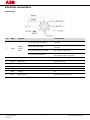 4
4
-
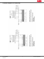 5
5
-
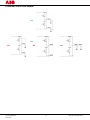 6
6
-
 7
7
-
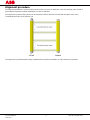 8
8
-
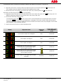 9
9
-
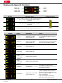 10
10
-
 11
11
-
 12
12
-
 13
13
-
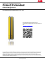 14
14
-
 15
15
-
 16
16
-
 17
17
-
 18
18
-
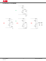 19
19
-
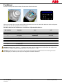 20
20
-
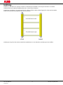 21
21
-
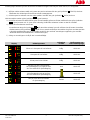 22
22
-
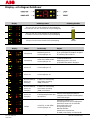 23
23
-
 24
24
-
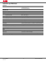 25
25
-
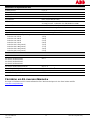 26
26
-
 27
27
-
 28
28
-
 29
29
-
 30
30
-
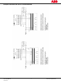 31
31
-
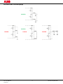 32
32
-
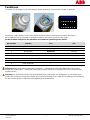 33
33
-
 34
34
-
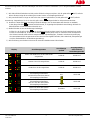 35
35
-
 36
36
-
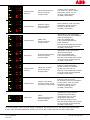 37
37
-
 38
38
-
 39
39
-
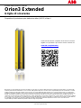 40
40
-
 41
41
-
 42
42
-
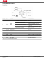 43
43
-
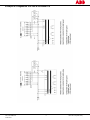 44
44
-
 45
45
-
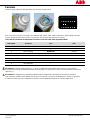 46
46
-
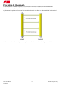 47
47
-
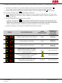 48
48
-
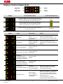 49
49
-
 50
50
-
 51
51
-
 52
52
-
 53
53
-
 54
54
-
 55
55
-
 56
56
-
 57
57
-
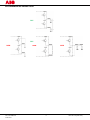 58
58
-
 59
59
-
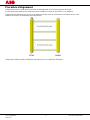 60
60
-
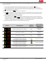 61
61
-
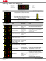 62
62
-
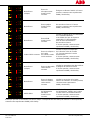 63
63
-
 64
64
-
 65
65
-
 66
66
-
 67
67
-
 68
68
-
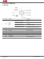 69
69
-
 70
70
-
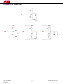 71
71
-
 72
72
-
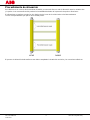 73
73
-
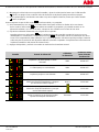 74
74
-
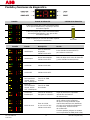 75
75
-
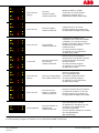 76
76
-
 77
77
-
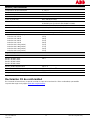 78
78


ABB Orion3 Extended Excerpts From The Original Instructions
- Categoría
- Iluminación de conveniencia
- Tipo
- Excerpts From The Original Instructions
en otros idiomas
- français: ABB Orion3 Extended
- italiano: ABB Orion3 Extended
- English: ABB Orion3 Extended
- Deutsch: ABB Orion3 Extended
- svenska: ABB Orion3 Extended
Artículos relacionados
Otros documentos
-
Schneider Electric TM3SAK6R Instrucciones de operación
-
IFM G2001S Instrucciones de operación
-
IFM OY454S Instrucciones de operación
-
CARLO GAVAZZI SB4315915D25 Guía de instalación
-
SICK Laser Scanner Interface LSI 101 Instrucciones de operación
-
-
-
Leuze MSI-MD-FBX Instrucciones de operación
-
-