ABB Orion1 Base Excerpts From The Instruction Manual
- Tipo
- Excerpts From The Instruction Manual

ABB Jokab Safety Varlabergsvägen 11, SE-434 39 Kungsbacka, Sweden
www.abb.com/jokabsafety
Excerpts from the instruction manual
Orion1 Base
Safety light curtains
Type 4 Active Opto-electronic Protective Device (AOPD)
While every effort has been taken to ensure the accuracy of information contained in this book and any associated promotional and information
material ABB Jokab Safety cannot accept responsibility for errors or omissions and reserves the right to make any improvements without notice. It is
the user’s responsibility to ensure that this equipment is correctly designed, specified, installed, cared for and operated to meet all applicable local,
national and international codes/regulations. Technical data in our book is correct to the level of accuracy of ABB Jokab Safety´s test procedures as
verified by various international approved bodies. Other information (such as application examples, wiring diagrams, operation or use) is intended
solely to illustrate the various uses of our products. ABB Jokab Safety does not guarantee or imply that the product when used in accordance with
such examples in a particular environment will fulfil any particular safety requirement and does not assume any responsibility or liability for actual
use of the product based on the examples given.
[EN] The complete instruction manual is delivered
with the product in a digital format and can also
be downloaded from:
[SE] Den fullständiga bruksanvisningen levereras
med produkten i digitalt format och kan även
laddas ned från:
[DE] Die vollständige Bedienungsanleitung in
digitaler Form wird mit dem Produkt geliefert
und steht auch unter dieser Adresse zum
Download bereit:
[IT] Il manuale di istruzioni completo viene fornito
in formato digitale con il prodotto e può anche
essere scaricato da:
[FR] La notice d'instructions complète est fournie
avec le produit au format numérique et peut
également être téléchargée sur le site :
[ES] El manual de instrucciones completo se
entrega junto con el producto en formato digital
y también puede descargarse en este enlace:
www.abb.com/jokabsafety

2TLC172293M0201 Rev A 2 www.abb.com/jokabsafety
2015-03-20
Safety information
Warning! For a correct and safe use of the Orion1 Base light curtains, the following points must be observed:
The stopping system of the machine must be electrically controlled.
This control system must be able to stop the hazardous movement of the machine within the total machine
stopping time T as per paragraph “Minimum installation distance” of the instruction manual, and during all
working cycle phases.
Mounting and connection of the AOPD must be carried out by qualified personnel only, according to the
indications included in the special sections of the instruction manual and in the applicable standards.
The AOPD must be securely placed in a particular position so that access to the hazard zone is not possible
without the interruption of the beams, see paragraph ”Installation” of the instruction manual.
The personnel operating in the hazard zone must be well trained and must have adequate knowledge of all
the operating procedures of the AOPD.
The TEST button must be located outside the hazard zone because the operator must check the hazard zone
during all the test operations.
The ACKNOWLEDGE/RESET button must be located outside the hazard zone because the operator must
check the hazard zone during all acknowledge/reset operations. It must be impossible to reach the button
from the hazard zone
Please carefully read the instructions for the correct functioning before powering the AOPD.
Installation
Warning! Make sure that the protection level assured by the AOPD is appropriate for the machine to be controlled,
see EN ISO 13849-1:2008.
The outputs (OSSD) of the AOPD must be used as machine stopping devices and not as command devices.
The machine must have its own Start command.
The dimension of the smallest object to be detected must be larger than the resolution of the AOPD.
The AOPD must be installed in a room complying with the technical characteristics indicated in paragraph
“Technical data” of the instruction manual.
Do not place the AOPD near strong and/or flashing light sources or close to a similar device.
Strong electromagnetic interferences can jeopardise the function of the AOPD. Please contact your
ABB Jokab Safety representative for advice.
The operating distance of the device can be reduced in presence of smog, fog or airborne dust.
A sudden change in environment temperature, with very low minimum peaks, can generate a small
condensation layer on the lenses and jeopardise the function.
Reflecting surfaces placed near the light beams of the AOPD (over, under or laterally) can cause passive
reflections. These reflections can compromise the recognition of an object inside the detection zone.
The safety device must be positioned at a distance that prevents a person or part of a person to reach the
hazard zone before the hazardous motion of the machine has been stopped by the AOPD. See the instruction
manual for the calculation of this minimum installation distance.
Warning! The minimum installation distance must be respected. For more information about its calculation,please
refer to the instruction manual or EN ISO 13855:2010.
Warning! Make sure to test the function and to perform the checks described in paragraph “Checks after first
installation” of the instruction manual before machine start-up.

2TLC172293M0201 Rev A 3 www.abb.com/jokabsafety
2015-03-20
Electrical connections
Transmitter
Pin
Wire
1
Function
Connection to
1
Brown
Supply
+24 VDC
2
White
TEST
NO contact to +24 VDC if to be used
Not connected or 0 V if not to be used
3
Blue
Supply
0 V
4
Black
Not used
-
1
Colors according to ABB Jokab Safety standard cables
Receiver
Pin
Wire
1
Function
Connection to
1
White
RESET/
ACKNOWLEDGE
Auto. Reset with no function
Not connected or 0 V
Auto. Reset with Acknowledge function or
Alignment mode
NO contact to +24 VDC
Manual Reset
NO contact to +24 VDC
2
Brown
Supply
+24 VDC
3
Green
EDM SELECTION
Activate EDM
Not connected or 0 V
Deactivate EDM
+24 VDC
4
Yellow
EDM
Function used/activated
NC contact of a force-guided
relay
Function not used/deactivated
Not connected or 0 V
5
Grey
OSSD1
Safety control module for ex.
6
Pink
OSSD2
Safety control module for ex.
7
Blue
Supply
0 V
8
Red
MANUAL/
AUTOMATIC
RESET
Automatic Reset
Pin 5 (OSSD1)
Manual Reset
Pin 6 (OSSD2)
1
Colors according to ABB Jokab Safety standard cables

2TLC172293M0201 Rev A 4 www.abb.com/jokabsafety
2015-03-20
Connection example to a RT9 safety relay

2TLC172293M0201 Rev A 5 www.abb.com/jokabsafety
2015-03-20
Connection of the OSSD outputs
YES
NO
NO
NO

2TLC172293M0201 Rev A 6 www.abb.com/jokabsafety
2015-03-20
Alignment procedure
The alignment between the transmitter and the receiver is necessary to obtain the correct functioning of the AOPD. A
good alignment prevents outputs instability caused by dust or vibrations.
The alignment is perfect if the optical axes of the first and the last beams of the transmitter coincide with the optical
axes of the corresponding elements of the receiver.
The beam used to synchronise the two units is the one closest to the connector. FIRST is the optics connected with
this beam and LAST is the optics connected to the last beam when starting from FIRST.
The alignment is performed after having completed the mechanical installation and the electrical connections.
1. Activate the Alignment mode by pushing the external NO contact (ACKNOWLEDGE/RESET push-button) for
at least 0.5 s at power-on.
2. Keep the receiver in a steady position and adjust the transmitter until the yellow LED ( FIRST) turns off. This
condition shows the alignment of the first synchronisation beam.
3. Rotate the transmitter, pivoting around the lower optics axis, until the yellow LED ( LAST) turns off.
NB: Make sure that the green LED ( ) is on and steady.
4. Slightly turn both units both ways to find the limits of the area in which the green LED ( ) is steady and “4”
is displayed (Maximum alignment). Place both units in the centre of this area.
5. Fix the two units firmly using brackets.
6. Check that the green LED ( ) on the receiver is on when the beams are not interrupted. Then check that
the red LED ( ) turns on when one single beam is interrupted. This check shall be made with the special
cylindrical “Test Piece” having a suitable size for the resolution of the device used (see paragraph “Checks
after first installation” of the instruction manual).
7. Switch the device off and on to normal operating mode.
NB: The OSSD outputs are off in alignment mode.

2TLC172293M0201 Rev A 7 www.abb.com/jokabsafety
2015-03-20
Display
LED
OSSD
ON
LED
OSSD
OFF
LED
FIRST
(yellow)
LED
LAST
(yellow)
Condition
Alignment
status
OFF
ON
ON
ON
First not OK
Last not OK
Not aligned
OFF
ON
First OK
Last not OK
OFF
OFF
First OK
Last OK
Middle optics not OK
ON
OFF
OFF
OFF
Each beam is over the min. operating
light reception threshold and the number
of beams over the light reception
threshold is between 0 and 25%
MINIMUM
alignment
ON
OFF
OFF
OFF
Each beam is over the min. operating
light reception threshold and the number
of beams over the light reception
threshold is between 25 and 50%
ON
OFF
OFF
OFF
Each beam is over the min. operating
light reception threshold and the number
of beams over the light reception
threshold is between 50 and 75%
ON
OFF
OFF
OFF
Each beam is over the min. operating
light reception threshold and the number
of beams over the light reception
threshold is between 75 and 100%
MAXIMUM
alignment

2TLC172293M0201 Rev A 8 www.abb.com/jokabsafety
2015-03-20
Diagnostic functions
The operator can check the status of the AOPD using a one-digit display present on both the receiver and transmitter.
Orion1 Base also has four LEDs on the receiver and two LEDs on the transmitter.
The Figure below shows all LEDs signalling modes: OFF, ON and FLASHING.
The operator can evaluate the main causes of system stops and errors using the display and signalling LEDs.
Transmitter
Function
Status
Meaning
LED
DIGIT
Normal
operation
mode
TEST
(green ON)
AOPD being tested.
OSSD status on the receiver must be OFF.
Emission
(green ON
yellow ON)
AOPD in normal operating mode.
Function
Type
Check and repair
LED
DIGIT
Error mode
Internal error
(green ON)
Switch the power off and on.
If the error persists, contact your ABB Jokab Safety
representative.
Optical error
(green ON)
Switch the power off and on.
If the error persists, contact your ABB Jokab Safety
representative.
No power supply
(LEDs OFF)
Check the wiring, connections and value of the power supply.
If the error persists, contact your ABB Jokab Safety
representative.
LED OFF
LED FLASHING
LED ON

2TLC172293M0201 Rev A 9 www.abb.com/jokabsafety
2015-03-20
Receiver
Function
Status
Meaning
LED
DIGIT
Normal
operation
mode
Alignment
See paragraph “Alignment procedure” of the instruction
manual.
TEST
(red on)
AOPD being tested.
OSSD outputs off.
Reception
(green on)
AOPD working in normal operating mode.
OSSD outputs on.
Beams interrupted
(red on)
Beam(s) interrupted in Automatic Reset.
OSSD outputs off.
Interlock
Beams free
(red on
yellow on)
AOPD in interlock, waiting for reset.
OSSD outputs off.
Interlock
Beams interrupted
(red on
yellow on)
Beam(s) interrupted in Manual Reset.
AOPD in interlock.
OSSD outputs off.
Alignment level
Minimum (1 bar)
Medium (2 bars)
Maximum (3 bars)
EDM enabled
EDM function is selected.
Function
Type
Check and repair
LED
DIGIT
Error mode
OSSD error
(red on)
Check the wiring and connections of the OSSD outputs. Make
sure that there is no short-circuit between them or with the
supply voltage. See also “Connection examples”. Then
Acknowledge.
If the error persists, contact your ABB Jokab Safety
representative.
Internal error
(red on)
Switch the power off and on.
If the error persists, contact your ABB Jokab Safety
representative.
Optical error
(red on)
Acknowledge.
If the error persists, contact your ABB Jokab Safety
representative.
EDM error
(red on)
Check the wiring and connections of the EDM as well as the
time sequence (see Time chart in the instruction manual).
If the error persists, contact your ABB Jokab Safety
representative.
Reset selection error
(red on)
Check the wiring and connections of the MAN / AUTO pin (see
paragraph “Receiver (RX)” off the instruction manual).
If the error persists, contact your ABB Jokab Safety
representative.
No power supply
(LEDs off)
Check the wiring and the connections of the power supply.
Check that its value is within the allowed range.
If the error persists, contact your ABB Jokab Safety
representative.

2TLC172293M0201 Rev A 10 www.abb.com/jokabsafety
2015-03-20
Technical data
Manufacturer
Address
ABB JOKAB SAFETY
Varlabergsvägen 11
SE-434 39 Kungsbacka
Sweden
Electrical data
Power supply (Vdd):
+24 VDC ± 20 %
Consumption (TX):
1.5 W max
Consumption (RX):
4 W max (without load)
Outputs
2 PNP
Short-circuit protection:
Output current:
Output voltage – ON:
Output voltage – OFF:
Capacitive load:
1.4 A max
0.5 A max / output
Vdd -1 V min
0.2 V max
2.2 µF at +24 VDC max
Response time:
See paragraph “Model overview” of the instruction manual
Electrical protection:
Class III – use SELV/PELV
Connections:
M12 4-pole for transmitter
M12 8-pole for receiver
Cable length (for power supply):
50 m max
Optical data
Light emission ( ):
Infrared, LED (950 nm)
Resolution:
14 – 30 mm
Protected height:
150…1800 mm. See paragraph “Model overview” of the instruction
manual
Operating distance:
0.2…19 m for 30 mm
0.2…6 m for 14 mm
Ambient light rejection:
According to IEC 61496-2:2013
Mechanical and environmental data
Operating temperature:
0…+ 55 °C
Storage temperature:
- 25…+ 70 °C
Temperature class:
T6
Humidity:
15…95 % (no condensation)
Mechanical protection:
IP65 (EN 60529:2000)
Vibrations:
Width 0.35 mm, Frequency 10 … 55 Hz,
20 sweeps per axis, 1 octave/min
(EN 60068-2-6:2008)
Shock resistance:
16 ms (10 G) 10
3
shocks per axis
(EN 60068-2-29:2008)
Housing material:
Painted aluminium (yellow RAL 1003)
Front glass material:
PMMA
Cap material:
PC MAKROLON
Weight:
1.3 kg / meter for each single unit

2TLC172293M0201 Rev A 11 www.abb.com/jokabsafety
2015-03-20
Functional safety data
EN ISO 13849-1:2008
PL e, Cat 4
EN IEC 61508-1:2010
EN IEC 61508-2:2010
EN IEC 61508-3:2010
EN IEC 61508-4:2010
SIL 3
EN IEC 62061:2005/A1:2013
SIL CL 3
Prob. of Dangerous Failure/Hour (1/h)
PFH
d
2.64 x10
-9
Life span (years)
T1
20
Mean Time to Dangerous Failure (years)
MTTF
d
444
Average Diagnostic Coverage
DC
98.80 %
Safe Failure Fraction
SFF
99.30 %
Hardware Fault Tolerance
HFT
1
EC Declaration of conformity
A copy of the EC Declaration of conformity can be found in the Instruction Manual and can also be downloaded from
www.abb.com/jokabsafety

ABB Jokab Safety Varlabergsvägen 11, SE-434 39 Kungsbacka, Sverige
www.abb.com/jokabsafety
Utdrag från bruksanvisningen
Orion1 Base
Säkerhetsljusridå
Aktiv optoelektronisk skyddsanordning (AOPD), typ 4
Även om allt gjorts för att säkerställa riktigheten av informationen i denna manual och eventuellt tillhörande kampanj- eller informationsmaterial,
frånsäger sig ABB Jokab Safety ansvar för fel eller försummelser och förbehåller sig rätten att göra ändringar och förbättringar utan föregående
meddelande. Det åligger användaren att säkerställa att utrustningen är korrekt konstruerad, specificerad, installerad, skött och hanterad för att
uppfylla alla tillämpliga lokala, nationella och internationella regler och föreskrifter. Tekniska data i denna manual är korrekta enligt
ABB Jokab Safetys testprocedurer som är kontrollerade av olika internationella godkända organ. Annan information (t.ex. applikationsexempel,
kopplingsscheman, drift eller användning) är endast avsedd att illustrera de olika användningsområdena för våra produkter. ABB Jokab Safety
utfärdar ingen garanti för att produkten uppfyller specifika säkerhetskrav om den används i de fall som anges ovan och tar inget ansvar för faktisk
användning av produkten utifrån de givna exemplen.
Den fullständiga bruksanvisningen levereras
med produkten i digitalt format och kan även
laddas ned från:
www.abb.com/jokabsafety

2TLC172293M3401 Rev A 2 www.abb.com/jokabsafety
2015-03-20
Säkerhetsinformation
Varning! Punkterna nedan ska följas för korrekt och säker användning av ljusridåerna Orion1 Base:
Maskinens stoppsystem ska vara elektriskt styrt.
Detta styrsystem ska kunna stoppa farliga rörelser hos maskinen inom den totala stopptiden för maskinen T
enligt avsnittet ”Min. installationsavstånd” i bruksanvisningen, samt i alla faser av arbetscykeln.
Montering och anslutning av AOPD:en får endast utföras av kvalificerad personal enligt de anvisningar som
finns i de särskilda avsnitten i bruksanvisningen och i tillämpliga standarder.
AOPD:en ska placeras på en särskild position så att det inte går att nå riskzonen utan att bryta strålarna, se
avsnittet ”Installation” i bruksanvisningen.
Personal som arbetar i riskzonen ska vara utbildade och ha adekvat kunskap om AOPD:ens driftförlopp.
Knappen TEST ska vara placerad utanför riskzonen eftersom operatören ska kontrollera riskzonen under alla
testkörningar.
BEKRÄFTA/ÅTERSTÄLLNINGS-knappen måste vara placerad utanför riskzonen eftersom operatören ska
kontrollera riskzonen under alla bekräftelse- och återställningskörningar. Det ska vara omöjligt att nå knappen
från riskzonen.
Läs instruktionerna för korrekt funktion noga innan AOPD:en startas.
Installation
Varning! Se till att AOPD:ens skyddsnivå är lämplig för styrning av maskinen, se EN ISO 13849-1:2008.
Utgångarna (OSSD) på AOPD:en ska användas för att stoppa maskinen och inte för manövrering. Maskinen
ska ha ett eget startkommando.
Måttet för det minsta föremålet som ska detekteras ska vara större än upplösningen för AOPD:en.
AOPD:en ska installeras i ett utrymme som uppfyller de tekniska specifikationer som anges i avsnittet
”Tekniska specifikationer” i bruksanvisningen.
Placera inte AOPD:en nära kraftiga och/eller blinkande ljuskällor eller liknande anordningar.
Kraftiga elektromagnetiska störningar kan störa AOPD:ens funktion. Kontakta din representant för
ABB Jokab Safety för rådgivning.
Anordningens arbetsräckvidd kan reduceras av rök, dimma eller luftburet damm.
En plötslig förändring i omgivningstemperaturen med mycket låga minimitoppar kan orsaka ett kondenslager
på linserna och störa funktionen.
Reflekterande ytor nära AOPD:ens strålar (över, under eller vid sidan) kan orsaka passiva reflektioner. Dessa
reflektioner kan påverka detektering av föremål i detekteringszonen.
Skyddsanordningen ska placeras på ett avstånd som förhindrar att en person eller kroppsdel når riskzonen
innan maskinens farliga rörelse har stoppats av AOPD:en. Se bruksanvisningen för att beräkna min.
installationsavstånd.
Varning! Min. installationsavstånd måste följas. För mer information om denna beräkning, se bruksanvisningen eller
EN ISO 13855:2010.
Varning! Se till att testa funktionen och utföra de kontroller som beskrivs i avsnittet ”Kontroller efter första
installationen” i bruksanvisningen innan maskinen startas.

2TLC172293M3401 Rev A 3 www.abb.com/jokabsafety
2015-03-20
Elektriska anslutningar
Sändare
Stift
Ledare
1
Funktion
Anslutning till
1
Brun
Spänningsförsörjning
+24 VDC
2
Vit
TEST
NO kontakt till +24 VDC om funktionen används
Inte ansluten eller 0 V om funktionen inte används
3
Blå
Spänningsförsörjning
0 V
4
Svart
Används inte
-
1
Färger enligt ABB Jokab Safetys standardkablar
Mottagare
Stift
Ledare
1
Funktion
Anslutning till
1
Vit
ÅTERSTÄLL/
GODKÄNN
Auto. Återställning utan funktion
Ej inkopplad eller 0 V
Auto. Återställning med
bekräftelsefunktion eller inriktningsläge
NO kontakt till +24 VDC
Manuell återställning
NO kontakt till +24 VDC
2
Brun
Spännings-
försörjning
+24 VDC
3
Grön
EDM SELECTION
Aktivera EDM
Ej inkopplad eller 0 V
Inaktivera EDM
+24 VDC
4
Gul
EDM
Funktion använd/aktiverad
NC-kontakt från tvångsstyrt relä
Funktion ej använd/inaktiverad
Ej inkopplad eller 0 V
5
Grå
OSSD1
T.ex. säkerhetsmodul
6
Rosa
OSSD2
T.ex. säkerhetsmodul
7
Blå
Spännings-
försörjning
0 V
8
Röd
MANUELL/
AUTOMATISK
ÅTERSTÄLLNING
Automatisk återställning
Stift 5 (OSSD1)
Manuell återställning
Stift 6 (OSSD2)
1
Färger enligt ABB Jokab Safetys standardkablar

2TLC172293M3401 Rev A 4 www.abb.com/jokabsafety
2015-03-20
Exempel på anslutning till ett RT9 säkerhetsrelä

2TLC172293M3401 Rev A 5 www.abb.com/jokabsafety
2015-03-20
Anslutning för OSSD-utgångar
JA
NEJ
NEJ
NEJ

2TLC172293M3401 Rev A 6 www.abb.com/jokabsafety
2015-03-20
Inriktning
Inriktning av sändaren och mottagaren är nödvändig för att AOPD:en ska fungera korrekt. Korrekt inriktning förhindrar
felaktiga utsignaler orsakade av damm eller vibrationer.
Inriktningen är korrekt när de optiska axlarna för de första och sista strålarna från sändaren ligger på samma plan som
de optiska axlarna för motsvarande element på mottagaren.
Strålen som används för att synkronisera de två enheterna är den som är närmast kontakten. FÖRSTA är den optik
som genererar denna strålen och SISTA är optiken som genererar den sista strålen sett från den FÖRSTA.
Inriktningen ska göras efter att den mekaniska installationen och de elektriska anslutningarna har slutförts.
1. Inriktningsläget aktiveras genom att den externa NO-kontakten (BEKRÄFTA/ÅTERSTÄLLNINGS-knapp) hålls
in under minst 0,5 s vid uppstart.
2. Håll mottagaren stabilt och justera sändaren tills den gula lysdioden ( FÖRSTA) slocknar. Detta tillstånd
visar inriktningen för den första synkroniseringsstrålen.
3. Vrid sändaren runt den nedre optikens axel tills den gula lysdioden ( SISTA) slocknar.
OBS! Kontrollera att den gröna lysdioden ( ) lyser konstant.
4. Vrid båda enheterna lite åt båda håll för att fastställa gränserna för det område där den gröna lysdioden (
) lyser konstant och ”4” visas (max. inriktning). Ställ båda enheterna i mitten av det här området.
5. Fixera de två enheterna med fästen.
6. Kontrollera att den gröna lysdioden ( ) på mottagaren lyser när strålarna inte är brutna. Kontrollera
därefter att den röda lysdioden ( ) tänds när en enstaka stråle bryts. Kontrollen ska göras med det
speciella cylindriska testföremålet som har en lämplig storlek för den använda anordningens upplösning (se
avsnitt ”Kontroller efter första installationen” i bruksanvisningen).
7. Stäng av anordningen och slå på den i normalt driftläge.
OBS! OSSD-utgångarna är frånkopplade i inriktningsläge.

2TLC172293M3401 Rev A 7 www.abb.com/jokabsafety
2015-03-20
Display
Lysdiod
OSSD PÅ
Lysdiod
OSSD AV
Lysdiod
FÖRSTA
(gul)
Lysdiod
SISTA
(gul)
Läge
Inriktning
status
AV
PÅ
PÅ
PÅ
Första Inte OK
Sista Inte OK
Inte
inriktade
AV
PÅ
Första OK
Sista Inte OK
AV
AV
Första OK
Sista OK
Mellersta optiken är inte OK.
PÅ
AV
AV
AV
Varje stråle ligger över min. tröskeln för
ljusmottagning och antalet strålar över
tröskeln för ljusmottagning är mellan 0
och 25 %.
MIN.
inriktning
PÅ
AV
AV
AV
Varje stråle ligger över min. tröskeln för
ljusmottagning och antalet strålar över
tröskeln för ljusmottagning är mellan 25
och 50 %.
PÅ
AV
AV
AV
Varje stråle ligger över min. tröskeln för
ljusmottagning och antalet strålar över
tröskeln för ljusmottagning är mellan 50
och 75 %.
PÅ
AV
AV
AV
Varje stråle ligger över min. tröskeln för
ljusmottagning och antalet strålar över
tröskeln för ljusmottagning är mellan 75
och 100 %.
MAX.
inriktning

2TLC172293M3401 Rev A 8 www.abb.com/jokabsafety
2015-03-20
Diagnosfunktioner
Operatören kan kontrollera status för AOPD via en ensiffrig display som finns på både mottagare och sändare.
Orion1 Base har även fyra lysdioder på mottagaren och två lysdioder på sändaren.
Bilden nedan visar alla signaleringslägen för lysdioder: AV, PÅ och BLINKAR.
Operatören kan utvärdera skälet till systemstopp och fel med hjälp av displayen och lysdiodssignaler.
Sändare
Funktion
Status
Betydelse
Lysdiod
SIFFRA
Normalt
driftläge
TEST
(grön PÅ)
AOPD testas.
OSSD-status på mottagaren måste vara AV.
Aktiverad
(grön PÅ
gul PÅ)
AOPD i normalt driftläge.
Funktion
Typ
Kontrollera och reparera
Lysdiod
SIFFRA
Felläge
Internt fel
(grön PÅ)
Stäng av och slå på spänningen.
Kontakta din representant för ABB Jokab Safety om felet
består.
Optiskt fel
(grön PÅ)
Stäng av och slå på spänningen.
Kontakta din representant för ABB Jokab Safety om felet
består.
Ingen spännings-
försörjning
(lysdioder AV)
Kontrollera kablarna, anslutningarna och värdet för
spänningsförsörjningen.
Kontakta din representant för ABB Jokab Safety om felet
består.
Lysdiod AV
Lysdiod BLINKAR
Lysdiod PÅ

2TLC172293M3401 Rev A 9 www.abb.com/jokabsafety
2015-03-20
Mottagare
Funktion
Status
Betydelse
Lysdiod
SIFFRA
Normalt
driftläge
Inriktning
Se avsnitt ”Inriktning” i bruksanvisningen.
TEST
(röd PÅ)
AOPD testas.
OSSD-utgångar AV.
Mottagning
(grön PÅ)
AOPD är i normalt driftläge.
OSSD-utgångar på.
Strålarna brutna
(röd PÅ)
Strålen eller strålarna brutna i automatisk återställning.
OSSD-utgångar AV.
Förreglering
Strålarna fria
(röd PÅ
gul PÅ)
AOPD i förreglering, väntar på återställning.
OSSD-utgångar AV.
Förreglering
Strålarna brutna
(röd PÅ
gul PÅ)
Strålen eller strålarna brutna i manuell återställning.
AOPD i förreglering.
OSSD-utgångar AV.
Inriktningsnivå
Min. (1 stråle)
Med. (2 strålar)
Max. (3 strålar)
EDM aktiverad
EDM-funktionen är vald.
Funktion
Typ
Kontrollera och reparera
Lysdiod
SIFFRA
Felläge
OSSD-fel
(röd PÅ)
Kontrollera kablarna och anslutningarna för OSSD-
utgångarna. Kontrollera att de inte är kortslutna sinsemellan
eller med försörjningsspänning. Se även
”Anslutningsexempel”. Bekräfta därefter.
Kontakta din representant för ABB Jokab Safety om felet
består.
Internt fel
(röd PÅ)
Stäng av och slå på spänningen.
Kontakta din representant för ABB Jokab Safety om felet
består.
Optiskt fel
(röd PÅ)
Bekräfta.
Kontakta din representant för ABB Jokab Safety om felet
består.
EDM-fel
(röd PÅ)
Kontrollera kablarna och anslutningarna för EDM samt
tidssekvensen (se tiddiagramet i bruksanvisningen).
Kontakta din representant för ABB Jokab Safety om felet
består.
Fel vid val av
återställning
(röd PÅ)
Kontrollera kablarna och anslutningarna för stiftet
MAN/AUTO (se avsnitt 5.2 – ”Mottagare (RX)” i
bruksanvisningen).
Kontakta din representant för ABB Jokab Safety om felet
består.
Ingen
spänningsförsörjning
(lysdioder AV)
Kontrollera kablarna och anslutningarna för
spänningsförsörjningen. Kontrollera att värdet är inom tillåtet
område.
Kontakta din representant för ABB Jokab Safety om felet
består.

2TLC172293M3401 Rev A 10 www.abb.com/jokabsafety
2015-03-20
Tekniska specifikationer
Tillverkare
Adress
ABB JOKAB SAFETY
Varlabergsvägen 11
SE-434 39 Kungsbacka
Sverige
Elektriska data
Spänningsförsörjning (Vdd):
+24 VDC ± 20 %
Effektförbrukning (TX):
Max. 1,5 W
Effektförbrukning (RX):
Max. 4 W (utan last)
Utgångar
2 PNP
Kortslutningsskydd:
Utgångsström:
Utgångsspänning – PÅ:
Utgångsspänning – AV:
Kapacitiv last:
Max. 1,4 A
Max. 0,5 A/utgång
Min. Vdd -1 V
Max. 0,2 V
Max. 2,2 µF vid +24 VDC
Svarstid:
Se avsnitt ”Modellöversikt” i bruksanvisningen.
Elektrisk skyddsklass:
Klass III – använd SELV/PELV
Anslutningar:
4-polig M12 för sändare
8-polig M12 för mottagare
Kabellängd (för spänningsförsörjning):
Max. 50 m
Optik
Ljuskälla ( ):
Infraröd, lysdiod (950 nm)
Upplösning:
14–30 mm
Skyddshöjd:
150–1800 mm. Se avsnitt ”Modellöversikt” i bruksanvisningen.
Arbetsräckvidd:
0,2–19 m för 30 mm
0,2–6 m för 14 mm
Avskärmning av omgivningsljus:
Enligt IEC 61496-2:2013
Mekaniska och miljörelaterade data
Drifttemperatur:
0…+ 55 °C
Förvaringstemperatur:
- 25…+ 70 °C
Temperaturklass:
T6
Luftfuktighet:
15–95 % (icke-kondenserande)
Kapslingsklass:
IP65 (SS-EN 60529:2000)
Vibrationer:
Bredd 0,35 mm, frekvens 10–55 Hz,
20 svep per axel, 1 oktav/min.
(SS-EN 60068-2-6:2008)
Stötmotstånd:
16 ms (10 G) 10
3
stötar per axel
(SS-EN 60068-2-29:2008)
Hus:
Lackerad aluminium (gul RAL 1003)
Frontglas:
PMMA
Kåpans material:
PC MAKROLON
Vikt:
1,3 kg/meter för varje enhet

2TLC172293M3401 Rev A 11 www.abb.com/jokabsafety
2015-03-20
Funktionssäkerhet
SS-EN ISO 13849-1:2008
PL e, Cat 4
EN IEC 61508-1:2010
EN IEC 61508-2:2010
EN IEC 61508-3:2010
EN IEC 61508-4:2010
SIL 3
EN IEC 62061:2005/A1:2013
SIL CL 3
Sannolikhet för farligt fel per timme (1/h)
PFH
d
2,64 x 10
-9
Livslängd (år)
T1
20
Medeltid till farligt fel (år)
MTTF
d
444
Genomsnittlig feldetekteringsförmåga
DC
98,80 %
Andel säkra fel
SFF
99,30 %
Hårdvara feltolerans
HFT
1
Försäkran om EG-överensstämmelse
En kopia av försäkran om EG-överensstämmelse finns i bruksanvisningen och kan även laddas ned från
www.abb.com/jokabsafety

ABB Jokab Safety Varlabergsvägen 11, SE-434 39 Kungsbacka, Schweden
www.abb.com/jokabsafety
Auszüge aus der Bedienungsanleitung
Orion1 Base
Sicherheitslichtvorhänge
Typ 4 Aktive opto-elektronische Schutzeinrichtung (AOPD)
Da alle Anstrengungen unternommen wurden, um die Richtigkeit der in diesem Handbuch enthaltenen Angaben sowie des zugehörigen Werbe-
und Informationsmaterials sicherzustellen, übernimmt ABB JOKAB SAFETY keine Verantwortung für Fehler oder Unvollständigkeiten und Behält
sich das Recht vor, Änderungen und Verbesserungen ohne Vorankündigung zu vorzunehmen. Es liegt in der Verantwortung des Kunden, zu
garantieren, dass diese Ausrüstung korrekt dimensioniert, spezifiziert, installiert, gewartet und betrieben wird und allen geltenden lokalen,
nationalen sowie internationalen Standards entspricht. Die Technischen Daten in unseren Büchern entsprechen exakt dem Genauigkeitsgrad der
Prüfverfahren von ABB JOKAB SAFETY, welcher der Validierung diverser internationaler Prüfinstanzen unterliegt. Weitere Informationen (wie
Anwendungsbeispiele, Verkabelungspläne, Betrieb oder Nutzung) dienen ausschließlich dazu, die verschiedenen Einsatzmöglichkeiten des
Produkts zu illustrieren. Von ABB JOKAB SAFETY wird weder garantiert noch impliziert, dass bei Nutzung des Produkts in bestimmten
Umgebungen einher mit jenen Anwendungsbeispielen die jeweiligen Sicherheitsanforderungen erfüllt werden und übernimmt keine Verantwortung
oder Haftung für den aktuellen Einsatz des Produkts im Sinne der gegebenen Beispiele.
Die vollständige Bedienungsanleitung in
digitaler Form wird mit dem Produkt geliefert
und steht auch unter dieser Adresse zum
Download bereit:
www.abb.com/jokabsafety

2TLC172293M0101 Rev A 2 www.abb.com/jokabsafety
2015-03-20
Sicherheits hinweise
Warnung! Um eine sachgemäße und sichere Verwendung der Orion1 Base Lichtvorhänge zu gewährleisten, müssen
die folgenden Punkte beachtet werden:
Die Nachlaufzeit der Maschine muss elektrisch überwacht sein.
Dieses Steuerungssystem muss in der Lage sein, die gefährliche Bewegung der Maschine innerhalb der
Gesamtnachlaufzeit der Maschine T gemäß dem Abschnitt „Mindestinstallationsabstand“ in der
Bedienungsanleitung anzuhalten und zwar in allen Phasen des Betriebszyklus.
Montage und Anschluss der AOPD dürfen nur von qualifiziertem Fachpersonal vorgenommen werden. Die
Arbeiten sind entsprechend den Angaben in den Sonderabschnitten der Bedienungsanleitung sowie in den
anzuwendenden Normen auszuführen.
Die AOPD muss sicher in einer bestimmten Position angebracht werden, sodass kein Zugang zum
Gefährdungsbereich möglich ist, ohne die Strahlen zu unterbrechen, siehe Abschnitt „Installation“ in der
Bedienungsanleitung.
Das im Gefährdungsbereich tätige Personal muss gut geschult sein und über angemessene Kenntnisse aller
Betriebsvorgänge der AOPD verfügen.
Die TEST-Taste muss sich außerhalb des Gefährdungsbereichs befinden, da der Bediener den
Gefährdungsbereich bei allen Testdurchläufen überprüfen muss.
Die Taste QUITTIEREN/RESET muss sich außerhalb des Gefährdungsbereichs befinden, da der Bediener
den Gefährdungsbereich bei allen Testdurchläufen quittieren/zurückstellen muss. Die Taste darf vom
Gefährdungsbereich aus nicht erreichbar sein
Bitte lesen Sie sich die Anweisungen zur sachgemäßen Funktionsweise gut durch, bevor Sie die AOPD in
Betrieb nehmen.
Installation
Warnung! Stellen Sie sicher, dass der durch die AOPD gewährleistete Schutzgrad der zu überwachenden Maschine
entspricht, siehe EN ISO 13849-1:2008.
Die Ausgänge (OSSD) der AOPD müssen als Stoppeinrichtungen der Maschine fungieren, nicht als
Steuerungseinrichtungen. Die Maschine muss über eine eigene Startfunktion verfügen.
Die Abmessung des kleinsten erfassbaren Objekts muss größer sein, als die Auflösung der AOPD.
Die AOPD muss in einem Raum installiert werden, der den in Abschnitt „Technische Daten“ der
Bedienungsanleitung angegebenen technischen Anforderungen entspricht.
Platzieren Sie die AOPD nicht in der Nähe von hellen und/oder blinkenden Lichtquellen oder ähnlichen
Geräten.
Starke elektromagnetische Störungen können die Funktionstüchtigkeit der AOPD gefährden. Bitte lassen Sie
sich von Ihrem Ansprechpartner von ABB Jokab Safety beraten.
Die Reichweite des Geräts kann bei Smog, Nebel oder Staub in der Luft eingeschränkt sein.
Eine plötzliche Veränderung der Umgebungstemperatur mit sehr niedrigen Minimalpunkten kann eine dünne
Kondensatschicht auf den Linsen hervorrufen und die Funktionstüchtigkeit gefährden.
Reflektierende Flächen, die sich in der Nähe der Lichtstrahlen der AOPD befinden (oberhalb, unterhalb oder
seitlich davon) können passive Reflexionen erzeugen. Diese Reflexionen können die Erkennung eines
Objekts innerhalb des Erfassungsbereichs beeinträchtigen.
Die Sicherheitseinrichtung muss in einem Abstand angebracht werden, durch den eine Person daran
gehindert wird, den Gefährdungsbereich vollständig oder teilweise zu erreichen, bevor die gefährliche
Bewegung der Maschine durch die AOPD angehalten wurde. Siehe die Bedienungsanleitung für die
Berechnung des Mindestinstallationsabstandes.
Warnung! Der Mindestabstand ist einzuhalten. Mehr Informationen zu dieser Berechnung entnehmen Sie der
Bedienungsanleitung oder der Norm EN ISO 13855:2010.
Warnung! Stellen Sie sicher, dass vor dem Starten der Maschine ein Funktionstest und die Überprüfungen
durchgeführt werden, die in Abschnitt „Überprüfungen nach der Erstinstallation“ in der Bedienungsanleitung erläutert
werden.

2TLC172293M0101 Rev A 3 www.abb.com/jokabsafety
2015-03-20
Elektrische Anschlüsse
Sender
Pin
Ader
1
Funktion
Anschluss an
1
Braun
Stromversorgung
+24 V DC
2
Weiß
TEST
Schließer-Kontakt an +24 V DC, falls verwendet
Nicht angeschlossen oder 0 V, falls nicht verwendet
3
Blau
Stromversorgung
0 V
4
Schwarz
Nicht verwendet
-
1
Farben gemäß Standardkabel von ABB Jokab Safety
Empfänger
Pin
Ader
1
Funktion
Anschluss an
1
Weiß
QUITTIEREN/RESE
T
Auto. Reset ohne Funktion
Nicht angeschlossen oder 0 V
Auto. Reset mit Quittierungsfunktion oder
Ausrichtungsmodus
Schließer-Kontakt an +24 VDC
Manueller Reset
Schließer-Kontakt an +24 VDC
2
Braun
Stromversorgung
+24 V DC
3
Grün
EDM-ANWAHL
EDM aktivieren
Nicht angeschlossen oder 0 V
EDM deaktivieren
+24 V DC
4
Gelb
EDM
Funktion verwendet/aktiviert
Öffner-Kontakt eines
zwangsgeführten Relais
Funktion nicht verwendet/deaktiviert
Nicht angeschlossen oder 0 V
5
Grau
OSSD1
z. B. Sicherheitsrelais
6
Rosa
OSSD2
z. B. Sicherheitsrelais
7
Blau
Stromversorgung
0 V
8
Rot
MANUELLER/AUTO
MATISCHER
RESET
Automatische Rückstellung (Reset)
Pin 5 (OSSD1)
Manueller Reset
Pin 6 (OSSD2)
1
Farben gemäß Standardkabel von ABB Jokab Safety

2TLC172293M0101 Rev A 4 www.abb.com/jokabsafety
2015-03-20
Beispiel: Anschluss an ein RT9 Sicherheitsrelais

2TLC172293M0101 Rev A 5 www.abb.com/jokabsafety
2015-03-20
Anschluss der OSSD-Ausgänge
JA
NEIN
NEIN
NEIN

2TLC172293M0101 Rev A 6 www.abb.com/jokabsafety
2015-03-20
Ausrichtung
Die Ausrichtung zwischen Sender und Empfänger ist notwendig, damit die AOPD korrekt funktionieren kann. Durch
eine gute Ausrichtung wird eine Instabilität der Ausgänge aufgrund von Staub oder Schwingungen vermieden.
Eine perfekte Ausrichtung ist dann erreicht, wenn die optischen Achsen des ersten und letzten Strahls des Senders
mit den optischen Achsen der entsprechenden Elemente des Empfängers übereinstimmen.
Zur Synchronisierung der beiden Einheiten wird der Strahl verwendet, der dem Stecker am nächsten liegt. Mit FIRST
wird die Optik bezeichnet, die an diesen Strahl gekoppelt ist, und mit LAST die Optik, die, bei FIRST beginnend, an
den letzten Strahl gekoppelt ist.
Nachdem die mechanische Montage und die elektrischen Anschlüsse vorgenommen wurden, kann mit der
Ausrichtung begonnen werden.
1. Den Ausrichtungsmodus durch Betätigen des externen Schließer-Kontakts (QUITTIEREN/RESET-Taste) für
mindestens 0,5 s in eingeschaltetem Zustand aktivieren.
2. Den Empfänger festhalten und den Sender so lange ausrichten, bis die gelbe LED ( FIRST), erlischt. Dieser
Zustand entspricht der erfolgten Ausrichtung des ersten Synchronisationsstrahls.
3. Den Sender so lange um die Achse der unteren Optik drehen, bis die gelbe LED ( LAST) erlischt.
Anmerkung: Vergewissern Sie sich, dass die grüne LED ( ) eingeschaltet ist und permanent leuchtet.
4. Drehen Sie beide Einheiten vorsichtig in beide Richtungen, um die Grenzwerte des Bereichs zu ermitteln, in
dem die grüne LED ( ) permanent leuchtet und „4“ angezeigt wird (Maximale Ausrichtung). Richten Sie
beide Einheiten auf die Mitte dieses Bereichs aus.
5. Beide Einheiten sicher mit Halterungen befestigen.
6. Vergewissern Sie sich, dass die grüne LED ( ) des Empfängers bei nicht unterbrochenen Strahlen
eingeschaltet ist. Prüfen Sie dann, ob bei Unterbrechung eines einzigen Strahls die rote LED ( )
aufleuchtet. Diese Kontrolle sollte mit dem entsprechenden zylinderförmigen „Teststab“ mit einem der
Auflösung der verwendeten AOPD angemessenen Durchmesser durchgeführt werden (siehe
Bedienungsanleitung, Abschnitt „Überprüfungen nach der Erstinstallation“).
7. Die Einrichtung ausschalten und erneut im normalen Betriebszustand einschalten.
Anmerkung: Die OSSD-Ausgänge sind im Ausrichtungsmodus ausgeschaltet.

2TLC172293M0101 Rev A 7 www.abb.com/jokabsafety
2015-03-20
Display
LED
OSSD AN
LED
OSSD
AUS
LED
FIRST
(gelb)
LED
LAST
(gelb)
Bedingung
Ausrichtung
Status
AUS
AN
AN
AN
First nicht OK
Last nicht OK
Nicht
ausgerichtet
AUS
AN
First OK
Last nicht OK
AUS
AUS
First OK
Last OK
Mittlere Optik nicht OK
AN
AUS
AUS
AUS
Jeder Strahl liegt über dem min.
Betriebsschwellenwert für Lichtempfang
und die Strahlenanzahl über dem
Schwellenwert für Lichtempfang liegt
zwischen 0 und 25 %.
MINIMUM-
Ausrichtung
AN
AUS
AUS
AUS
Jeder Strahl liegt über dem min.
Betriebsschwellenwert für Lichtempfang
und die Strahlenanzahl über dem
Schwellenwert für Lichtempfang liegt
zwischen 25 und 50 %.
AN
AUS
AUS
AUS
Jeder Strahl liegt über dem min.
Betriebsschwellenwert für Lichtempfang
und die Strahlenanzahl über dem
Schwellenwert für Lichtempfang liegt
zwischen 50 und 75 %.
AN
AUS
AUS
AUS
Jeder Strahl liegt über dem min.
Betriebsschwellenwert für Lichtempfang
und die Strahlenanzahl über dem
Schwellenwert für Lichtempfang liegt
zwischen 75 und 100 %.
MAXIMUM-
Ausrichtung

2TLC172293M0101 Rev A 8 www.abb.com/jokabsafety
2015-03-20
Diagnose funktionen
Der Bediener kann den Status der AOPD anhand eines einstelligen Displays überprüfen, das sich an Empfänger und
Sender befindet.
Orion1 Base verfügt zudem über vier LEDs am Empfänger und zwei LEDs am Sender.
Die Abbildung unten zeigt alle Anzeigezustände der LEDs: AUS, AN und BLINKEND. Über das Display und die
Anzeige-LEDs kann der Bediener die wesentlichen Ursachen für einen Stillstand oder einen Defekt des Systems
beurteilen.
Sender
Funktion
Status
Bedeutung
LED
DIGIT
Normaler
Betriebszust
and
TEST
(grün AN)
AOPD wird geprüft.
OSSD-Status am Empfänger muss OFF sein.
Ausstrahlung
(grün AN
gelb AN)
AOPD in normalem Betriebszustand.
Funktion
Typ
Überprüfen und reparieren
LED
DIGIT
Fehler-
zustand
Interner Fehler
(grün AN)
Netzstrom aus- und wieder anschalten.
Falls der Fehler fortbesteht, wenden Sie sich an Ihren
Ansprechpartner von ABB Jokab Safety.
Optischer Fehler
(grün AN)
Netzstrom aus- und wieder anschalten.
Falls der Fehler fortbesteht, wenden Sie sich an Ihren
Ansprechpartner von ABB Jokab Safety.
Keine Spannungs-
versorgung
(LEDs AUS)
Überprüfen Sie die Kabel, Anschlüsse und den Wert der
Spannungsversorgung.
Falls der Fehler fortbesteht, wenden Sie sich an Ihren
Ansprechpartner von ABB Jokab Safety.
LED AUS
LED BLINKEND
LED AN

2TLC172293M0101 Rev A 9 www.abb.com/jokabsafety
2015-03-20
Empfänger
Funktion
Status
Bedeutung
LED
DIGIT
Normaler
Betriebs-
zustand
Ausrichtung
Siehe Bedienungsanleitung, Abschnitt „Ausrichtung“.
TEST
(rot an)
AOPD wird geprüft.
OSSD-Ausgänge ausgeschaltet.
Empfang
(grün an)
AOPD läuft in normalem Betriebszustand.
OSSD-Ausgänge ausgeschaltet
Strahlen
unterbrochen
(rot an)
Strahl(en) bei Automatischem Reset unterbrochen.
OSSD-Ausgänge ausgeschaltet.
Interlock
Strahlen nicht
unterbrochen
(rot an
gelb an)
AOPD im Interlock, Warten auf Reset.
OSSD-Ausgänge ausgeschaltet.
Interlock
Strahlen
unterbrochen
(rot an
gelb an)
Strahl(en) bei Manuellem Reset unterbrochen.
AOPD im Interlock.
OSSD-Ausgänge ausgeschaltet.
Ausrichtungsgrad
Mindestwert (1Strich)
Mittelwert (2 Striche)
Höchstwert (3 Striche)
EDM freigegeben
EDM-Funktion wurde angewählt.
Funktion
Typ
Überprüfen und reparieren
LED
DIGIT
Fehler-
zustand
OSSD-Fehler
(rot an)
Überprüfen Sie die Kabel und Anschlüsse der OSSD-
Ausgänge. Stellen Sie sicher, dass es zwischen ihnen oder an
der Betriebsspannung nicht zu einem Kurzschluss kommt.
Siehe auch Abschnitt „Anschlussbeispiele“ Anschließend
quittieren.
Falls der Fehler fortbesteht, wenden Sie sich an Ihren
Ansprechpartner von ABB Jokab Safety.
Interner Fehler
(rot an)
Netzstrom aus- und wieder anschalten.
Falls der Fehler fortbesteht, wenden Sie sich an Ihren
Ansprechpartner von ABB Jokab Safety.
Optischer Fehler
(rot an)
Quittieren.
Falls der Fehler fortbesteht, wenden Sie sich an Ihren
Ansprechpartner von ABB Jokab Safety.
EDM-Fehler
(rot an)
Überprüfen Sie die Verkabelung und Anschlüsse der EDM
sowie die Zeitsequenz (siehe Zeitdiagramm, Abb. 30).
Falls der Fehler fortbesteht, wenden Sie sich an Ihren
Ansprechpartner von ABB Jokab Safety.
Fehler beim
Rückstellen der
Auswahl
(rot an)
Überprüfen Sie die Verkabelung und die Anschlüsse des MAN
/ AUTO-Pins (siehe Abschnitt „Empfänger (RX)“).
Falls der Fehler fortbesteht, wenden Sie sich an Ihren
Ansprechpartner von ABB Jokab Safety.
Keine Spannungs-
versorgung
(LEDs aus)
Überprüfen Sie die Kabel und Anschlüsse der
Spannungsversorgung. Vergewissern Sie sich, dass der
entsprechende Wert im zulässigen Rahmen liegt.
Falls der Fehler fortbesteht, wenden Sie sich an Ihren
Ansprechpartner von ABB Jokab Safety.

2TLC172293M0101 Rev A 10 www.abb.com/jokabsafety
2015-03-20
Technische Daten
Hersteller
Adresse
ABB JOKAB SAFETY
Varlabergsvägen 11
SE-434 39 Kungsbacka
Schweden
Elektrische Daten
Spannungsversorgung (Vdd):
+24-V DC ± 20 %
Leistungsaufnahme (TX):
max. 1,5 W
Leistungsaufnahme (RX):
max. 4 W (ohne Last)
Ausgänge
2 PNP
Kurzschlusssicherung:
Ausgangsstrom:
Ausgangsspannung – ON:
Ausgangsspannung – OFF:
Kapazitive Last:
max. 1,4 A
max. 0,5 A / Ausgang
Vdd min. -1 V
max. 0,2 V
2,2 µF bei max. +24 V DC
Ansprechzeit:
Siehe Bedienungsanleitung, Abschnitt „Modellübersicht“
Elektrische Schutzklasse:
Klasse III – SELV/PELV verwenden
Anschlüsse:
M12, 4-polig für Sender
M12, 8-polig für Empfänger
Kabellänge (für Spannungsversorgung):
max. 50 m
Optische Daten
Lichtabgabe ( ):
Infrarot, LED (950 nm)
Auflösung:
14 – 30 mm
Höhe des Schutzbereichs:
150...1800 mm. Siehe Bedienungsanleitung, Abschnitt
„Modellübersicht“
Reichweite:
0,2…19 m bei 30 mm Auflösung
0,2…6 m bei 14 mm Auflösung
Umgebungslichtabschirmung:
Gemäß IEC 61496-2:2013
Mechanische und Umgebungsdaten
Betriebstemperatur:
0…+ 55 °C
Lagertemperatur:
- 25…+ 70 °C
Temperaturklasse:
T6
Luftfeuchtigkeit:
15…95 % (nicht kondensierend)
Mechanische Schutzart:
IP65 (EN 60529:2000)
Schwingung:
Breite 0,35 mm, Frequenz 10…55 Hz,
20 Abtastungen pro Achse, 1 Oktave/min
(EN 60068-2-6:2008)
Stoßfestigkeit:
16 ms (10 G) 10
3
Stöße pro Achse
(EN 60068-2-29:2008)
Gehäusematerial:
Lackiertes Aluminium (gelb RAL 1003)
Frontflächenmaterial:
PMMA
Material der Anschlusskappen:
Polycarbonat
Gewicht:
1,3 kg / Meter pro einzelne Einheit

2TLC172293M0101 Rev A 11 www.abb.com/jokabsafety
2015-03-20
Daten zur funktionalen Sicherheit
EN ISO 13849-1:2008
PL e, Kat 4
EN IEC 61508-1:2010
EN IEC 61508-2:2010
EN IEC 61508-3:2010
EN IEC 61508-4:2010
SIL 3
EN IEC 62061:2005/A1:2013
SIL CL 3
Wahrsch. eines gefahrbringenden Ausfalls pro
Stunde (1/h)
PFH
d
2,64 x10
-9
Lebensdauer (Jahre)
T1
20
Mittlere Zeit bis zum gefahrbringenden Ausfall
(Jahre)
MTTF
d
444
Durchschnittlicher Diagnosedeckungsgrad
DC
98,80 %
Gesamtanteil sicherer Ausfälle (Safe Failure
Fraction)
SFF
99,30 %
Hardware-Fehlertoleranz
HFT
1
EG-Konformitätserklärung
Eine Kopie der EG-Konformitätserklärung finden Sie in der Bedienungsanleitung und als Download unter
www.abb.com/jokabsafety

ABB Jokab Safety Varlabergsvägen 11, SE-434 39 Kungsbacka, Suède
www.abb.com/jokabsafety
Extraits de la notice d'instructions
Orion1 Base
Barrages immatériels de sécurité
Dispositif protecteur optoélectronique actif (AOPD) de type 4
Même si le plus grand soin a été apporté pour garantir l'exactitude des renseignements figurant dans le présent manuel, ABB Jokab Safety décline
toute responsabilité en cas d'erreurs ou d'omissions éventuelles et se réserve le droit d'apporter des améliorations sans avis préalable. Il incombe à
l'utilisateur de s'assurer que cet équipement est conçu, documenté, installé, entretenu et utilisé correctement dans le respect de toutes les
lois/réglementations applicables au niveau local, national et international. Les caractéristiques techniques indiquées dans notre brochure respectent
le niveau de précision des procédures de test d'ABB Jokab Safety qui ont été vérifiées par plusieurs organismes internationaux homologués. Les
autres informations (par ex. les exemples d'application, les schémas électriques, le fonctionnement ou l'utilisation) sont uniquement destinées à
illustrer les utilisations de nos produits. ABB Jokab Safety ne garantit ni n'implique que le produit utilisé conformément à ces exemples dans un
environnement particulier conviendra à une exigence de sécurité particulière et se dégage de toute responsabilité civile ou autre pour l'utilisation
effective du produit sur la base des exemples offerts.
La notice d'instructions complète est fournie
avec le produit au format numérique et peut
également être téléchargée sur le site :
www.abb.com/jokabsafety

2TLC172293M0301 Rév. A 2 www.abb.com/jokabsafety
2015-03-20
Informations concernant la sécurité
Avertissement ! L'utilisation correcte et sécurisée des barrages immatériels Orion1 Base exige de réunir les
conditions suivantes :
Le mécanisme d'arrêt de la machine doit être commandé électriquement.
Ce système de commande doit pouvoir arrêter le mouvement dangereux de la machine en respectant le
temps d'arrêt total de la machine T, selon les consignes de la section « Distance de sécurité » de la notice
d'instructions et pendant toutes les phases du cycle de travail.
Le montage et le raccordement de l'AOPD doivent impérativement être effectués par du personnel qualifié,
selon les indications figurant dans les sections particulières de la notice d'instructions et les normes
applicables.
L'AOPD doit être monté solidement à un emplacement particulier qui rend l'accès à la zone de danger
impossible sans interrompre les faisceaux, cf. section « Installation » de la notice d'instructions.
Le personnel travaillant à l'intérieur de la zone de danger doit avoir reçu la formation appropriée et disposer
de connaissances suffisantes sur les procédures de fonctionnement de l'AOPD.
Le bouton TEST doit être situé en dehors de la zone de danger ; l'opérateur doit en effet vérifier la zone de
danger pendant toutes les opérations de test.
Le bouton RECONNAISSANCE/RÉARMEMENT doit être situé en dehors de la zone de danger ; l'opérateur
doit en effet vérifier la zone de danger pendant toutes les opérations de reconnaissance/réarmement. L'accès
au bouton doit être impossible depuis la zone de danger.
Lisez attentivement les consignes de fonctionnement correct avant d'allumer l'AOPD.
Installation
Avertissement ! Veillez à ce que le degré de protection offert par l'AOPD convienne pour la machine à contrôler, cf.
norme EN ISO 13849-1:2008.
Les sorties (OSSD) de l'AOPD doivent être impérativement utilisées comme des mécanismes d'arrêt de la
machine et non comme des dispositifs de commande. La machine doit disposer de sa propre commande de
mise en marche.
Les dimensions de l'objet le plus petit devant être détecté doivent être supérieures à la résolution de l'AOPD.
L'AOPD doit être installé dans une pièce conforme aux caractéristiques techniques indiquées à la section
« Caractéristiques techniques » de la notice d'instructions.
Ne placez pas l'AOPD à proximité de sources lumineuses clignotantes et/ou de forte intensité ou d'un appareil
similaire.
Les fortes perturbations électromagnétiques peuvent compromettre le fonctionnement de l'AOPD. Demandez
conseil à votre représentant d'ABB Jokab Safety.
La distance de fonctionnement du dispositif peut être réduite en présence de smog, de brouillard ou de
particules de poussière en suspension.
Un brusque changement de température ambiante, lorsque celle-ci atteint un niveau particulièrement bas,
peut produire une légère couche de buée sur les lentilles et compromettre de ce fait le bon fonctionnement.
Les surfaces réfléchissantes se trouvant à proximité des faisceaux lumineux de l'AOPD (au-dessus, au-
dessous ou latéralement) peuvent provoquer des réflexions passives risquant de compromettre le repérage
d'un objet à l'intérieur de la zone de détection.
Le dispositif de sécurité doit être positionné à une distance qui empêche une personne ou une partie de son
corps d'atteindre la zone de danger avant que l'AOPD n'ait pu arrêter le déplacement dangereux. Consultez la
notice d'instructions pour calculer la distance de sécurité.
Avertissement ! La distance de sécurité doit être respectée. Pour des précisions sur son calcul, veuillez consulter la
notice d'instructions ou la norme EN ISO 13855:2010.
Avertissement ! Assurez-vous de vérifier le fonctionnement et d'effectuer les contrôles décrits à la section
« Vérifications après la première installation » de la notice d'instructions avant d'allumer la machine.

2TLC172293M0301 Rév. A 3 www.abb.com/jokabsafety
2015-03-20
Raccordements électriques
Émetteur
Broche
Fil
1
Fonction
Raccordement
1
Marron
Alimentation
+24 Vcc
2
Blanc
TEST
Contact NO sur le courant +24 Vcc si la fonction est utilisée
Aucun raccordement ou 0 V si la fonction n'est pas utilisée
3
Bleu
Alimentation
0 V
4
Noir
Non utilisé
-
1
Code couleur conformément aux câbles standard d'ABB Jokab Safety
Récepteur
Broche
Fil
1
Fonction
Raccordement
1
Blanc
RÉARMEMENT/
RECONNAISSANCE
Réarmement automatique sans
fonction
Aucun raccordement ou 0 V
Réarmement automatique avec
fonction Reconnaissance ou mode
Alignement
Contact NO sur le courant
+ 24 Vcc
Réarmement manuel
Contact NO sur le courant
+ 24 Vcc
2
Marron
Alimentation
+24 Vcc
3
Vert
VALIDATION EDM
Activer la fonction EDM
Aucun raccordement ou 0 V
Désactiver la fonction EDM
+24 Vcc
4
Jaune
EDM
Fonction utilisée/activée
Contact NF d'un relais à
contacts liés
Fonction inutilisée/désactivée
Aucun raccordement ou 0 V
5
Gris
OSSD1
Module de commande de la
sécurité par ex.
6
Rose
OSSD2
Module de commande de la
sécurité par ex.
7
Bleu
Alimentation
0 V
8
Rouge
RÉARMEMENT
MANUEL/AUTOMAT
IQUE
Réarmement automatique
Broche 5 (OSSD1)
Réarmement manuel
Broche 6 (OSSD2)
1
Code couleur conformément aux câbles standard d'ABB Jokab Safety

2TLC172293M0301 Rév. A 4 www.abb.com/jokabsafety
2015-03-20
Exemple de raccordement à un relais de sécurité RT9

2TLC172293M0301 Rév. A 5 www.abb.com/jokabsafety
2015-03-20
Raccordement des sorties OSSD
OUI
NON
NON
NON

2TLC172293M0301 Rév. A 6 www.abb.com/jokabsafety
2015-03-20
Procédure d'alignement
L'alignement entre émetteur et récepteur est indispensable au bon fonctionnement de l'AOPD. Un bon alignement
évite que les sorties ne deviennent instables en raison de poussières ou de vibrations.
L'alignement est parfait lorsque les axes optiques des premier et dernier faisceaux de l'émetteur coïncident avec les
axes optiques des éléments correspondants du récepteur.
Le faisceau utilisé pour synchroniser les deux unités est celui qui est le plus proche du connecteur. Le premier
faisceau (FIRST) est l'optique associée à ce faisceau et le dernier faisceau (LAST) est l'optique associée au dernier
faisceau en partant du premier faisceau (FIRST).
L'alignement s'effectue après l'installation mécanique et les raccordements électriques.
1. Activez le mode Alignement en enclenchant le contact externe NO (bouton-poussoir
RECONNAISSANCE/RÉARMEMENT) pendant au moins 0,5 seconde lors de la mise en marche.
2. Tenez le récepteur immobile et orientez l'émetteur jusqu'à ce que le voyant jaune ( premier faisceau
(FIRST)) s'éteigne. Ceci indique l'alignement du premier faisceau de synchronisation.
3. Tournez l'émetteur, en le faisant pivoter autour de l'axe du faisceau inférieur jusqu'à ce que le voyant jaune (
dernier faisceau (LAST)) s'éteigne.
NB : vérifiez que le voyant vert ( ) est allumé et ne clignote pas.
4. Faites légèrement pivoter les deux unités dans les deux sens afin de délimiter la zone dans laquelle le voyant
vert ( ) reste allumé sans clignoter et d'obtenir l'affichage du chiffre 4 (qui indique l'alignement maximum).
Positionnez les deux unités au centre de cette zone.
5. Fixez solidement les deux unités avec les équerres.
6. Vérifiez que le voyant vert ( ) du récepteur est allumé lorsque les faisceaux ne sont pas interrompus.
Vérifiez ensuite que le voyant rouge ( ) s'allume en cas d'interruption d'un seul faisceau. Procédez à cette
vérification à l'aide de l'outil d'essai cylindrique spécial ayant un diamètre adapté à la résolution du dispositif
utilisé (cf. notice d'instructions, section « Vérifications après la première installation »).
7. Éteignez le dispositif et rallumez-le en mode de fonctionnement normal.
NB : les sorties OSSD sont ouvertes en mode Alignement.

2TLC172293M0301 Rév. A 7 www.abb.com/jokabsafety
2015-03-20
Affiche
ur
Voyant
Sorties
OSSD
fermées
Voyant
Sorties
OSSD
ouvertes
Voyant
Premier
faisceau
(FIRST)
(jaune)
Voyant
Dernier
faisceau
(LAST)
(jaune)
Situation
État
d'alignement
Éteint
Allumé
Allumé
Allumé
Premier faisceau (First) non OK
Dernier faisceau (Last) non OK.
Non aligné
Éteint
Allumé
Premier faisceau (First) OK
Dernier faisceau (Last) non OK
Éteint
Éteint
Premier faisceau (First) OK
Dernier faisceau (Last) OK
Faisceaux intermédiaires non OK.
Allumé
Éteint
Éteint
Éteint
Chaque faisceau est au-dessus du
seuil minimum de fonctionnement et le
nombre de faisceaux au-dessus du
seuil optimal est compris entre 0 et
25 %.
Alignement
MINIMUM
Allumé
Éteint
Éteint
Éteint
Chaque faisceau est au-dessus du
seuil minimum de fonctionnement et le
nombre de faisceaux au-dessus du
seuil optimal est compris entre 25 et
50 %.
Allumé
Éteint
Éteint
Éteint
Chaque faisceau est au-dessus du
seuil minimum de fonctionnement et le
nombre de faisceaux au-dessus du
seuil optimal est compris entre 50 et
75 %.
Allumé
Éteint
Éteint
Éteint
Chaque faisceau est au-dessus du
seuil minimum de fonctionnement et le
nombre de faisceaux au-dessus du
seuil optimal est compris entre 75 et
100 %.
Alignement
MAXIMUM

2TLC172293M0301 Rév. A 8 www.abb.com/jokabsafety
2015-03-20
Fonctions Diagnostic
L'opérateur peut vérifier l'état de l'AOPD à l'aide d'un afficheur à un chiffre situé sur le récepteur et l'émetteur.
Les modèles Orion1 Base comptent également quatre voyants sur le récepteur et deux voyants sur l'émetteur.
La figure ci-dessous illustre tous les modes de signalisation des voyants : éteint, allumé et clignotant.
L'afficheur et les voyants de signalisation permettent à l'opérateur d'évaluer les principales causes d'arrêt et d'erreur
du système.
Émetteur
Fonction
État
Signification
Voyant
Chiffre
Mode de
fonctionnem
ent normal
TEST
(voyant vert
allumé)
AOPD en cours de test.
Les sorties OSSD du récepteur doivent être ouvertes (état
OFF).
Émission
(voyant vert allumé
voyant jaune
allumé)
AOPD en mode de fonctionnement normal.
Fonction
Type
Vérification et réparation
Voyant
Chiffre
Mode Erreur
Erreur interne
(voyant vert
allumé)
Éteignez et rallumez le dispositif.
Si l'erreur persiste, contactez votre représentant
d'ABB Jokab Safety.
Erreur optique
(voyant vert
allumé)
Éteignez et rallumez le dispositif.
Si l'erreur persiste, contactez votre représentant
d'ABB Jokab Safety.
Absence
d'alimentation
(voyants éteints)
Vérifiez le câblage, les raccordements et la valeur de la
tension d'alimentation.
Si l'erreur persiste, contactez votre représentant
d'ABB Jokab Safety.
Voyant éteint
Voyant clignotant
Voyant allumé

2TLC172293M0301 Rév. A 9 www.abb.com/jokabsafety
2015-03-20
Récepteur
Fonction
État
Signification
Voyant
Chiffre
Mode de
fonctionne
ment
normal
État
Cf. notice d'instructions, section « Procédure d'alignement ».
TEST
(voyant rouge allumé)
AOPD en cours de test.
Sorties OSSD ouvertes.
Réception
(voyant vert allumé)
AOPD en mode de fonctionnement normal.
Sorties OSSD fermées
Faisceaux
interrompus
(voyant rouge allumé)
Faisceau(x) interrompu(s) en réarmement automatique.
Sorties OSSD ouvertes.
Interverrouillage
Faisceaux libres
(voyant rouge allumé
voyant jaune allumé)
AOPD en interverrouillage, en attente de réarmement.
Sorties OSSD ouvertes.
Interverrouillage
Faisceaux
interrompus
(voyant rouge allumé
voyant jaune allumé)
Faisceau(x) interrompu(s) en réarmement manuel.
AOPD en interverrouillage.
Sorties OSSD ouvertes.
Degré d'alignement
Minimum (1 barre)
Moyen (2 barres)
Maximum (3 barres)
EDM activé
La fonction EDM est sélectionnée.
Fonction
Type
Vérification et réparation
Voyant
Chiffre
Mode
Erreur
Erreur OSSD
(voyant rouge allumé)
Vérifiez le câblage et les raccordements des sorties OSSD.
Vérifiez l'absence de courts-circuits entre les raccordements
ou avec la tension d'alimentation. Reportez-vous également à
la section « Exemples de raccordements ». Activez ensuite la
fonction Reconnaissance.
Si l'erreur persiste, contactez votre représentant
d'ABB Jokab Safety.
Erreur interne
(voyant rouge allumé)
Éteignez et rallumez le dispositif.
Si l'erreur persiste, contactez votre représentant
d'ABB Jokab Safety.
Erreur optique
(voyant rouge allumé)
Activez la fonction Reconnaissance.
Si l'erreur persiste, contactez votre représentant
d'ABB Jokab Safety.
Erreur EDM
(voyant rouge allumé)
Vérifiez le câblage et les raccordements de l'EDM ainsi que la
séquence temporelle (cf. chronogramme, figure 30).
Si l'erreur persiste, contactez votre représentant
d'ABB Jokab Safety.
Erreur de sélection
de réarmement
(voyant rouge allumé)
Vérifiez le câblage et les raccordements de la broche
RÉARMEMENT MANUEL/AUTOMATIQUE (cf. notice
d'instructions, section « Récepteur (RX) »).
Si l'erreur persiste, contactez votre représentant
d'ABB Jokab Safety.
Absence
d'alimentation
(voyants éteints)
Vérifiez le câblage et les raccordements électriques. Vérifiez
que la valeur se situe dans la fourchette autorisée.
Si l'erreur persiste, contactez votre représentant
d'ABB Jokab Safety.

2TLC172293M0301 Rév. A 10 www.abb.com/jokabsafety
2015-03-20
Caractéristiques techniques
Fabricant
Adresse
ABB JOKAB SAFETY
Varlabergsvägen 11
SE-434 39 Kungsbacka
Suède
Données électriques
Alimentation (Vcc) :
+24 Vcc ± 20 %
Consommation (émetteur) :
1,5 W max.
Consommation (récepteur) :
4 W max. (sans charge)
Sorties
2 PNP
Protection contre les courts-circuits :
Courant des sorties :
Tension des sorties – état ON :
Tension des sorties – état OFF :
Charge capacitive :
1,4 A max.
0,5 A max./sortie
Vcc – 1 V min.
0,2 V max.
2,2 µF à +24 Vcc max.
Temps de réponse :
Consultez la notice d'instructions, section « Liste des modèles ».
Protection électrique :
Classe III – utilisation d'un système SELV/TBTP
Raccordements :
Connecteur M12-4 pôles pour l'émetteur
Connecteur M12-8 pôles pour le récepteur
Longueur du câble (pour l'alimentation) :
50 m max.
Données optiques
Émission lumineuse () :
Voyant infrarouge (950 nm)
Résolution :
14 – 30 mm
Hauteur protégée :
150…1 800 mm. Consultez la notice d'instructions, section « Liste des
modèles ».
Distance de fonctionnement :
0,2…19 m pour 30 mm
0,2…6 m pour 14 mm
Réjection à la lumière ambiante :
Conformément à la norme CEI 61496-2:2013
Données mécaniques et conditions
ambiantes
Température de fonctionnement :
0…+ 55 °C
Température de stockage :
- 25…+ 70 °C
Classe de température :
T6
Humidité :
15…95 % (sans condensation)
Protection mécanique :
IP65 (EN 60529:2000)
Vibrations :
Amplitude de 0,35 mm, fréquence de 10 … 55 Hz,
20 balayages par axe, 1 octave/minute
(Norme EN 60068-2-6:2008)
Résistance aux chocs :
16 ms (10 G) 1 000 chocs par axe
(Norme EN 60068-2-29:2008)
Matériau du boîtier :
Aluminium peint (jaune RAL 1003)
Matériau de la plaque frontale :
PMMA
Matériau des bouchons :
PC MAKROLON
Masse :
1,3 kg/mètre par unité individuelle

2TLC172293M0301 Rév. A 11 www.abb.com/jokabsafety
2015-03-20
Sécurité fonctionnelle
Norme EN ISO 13849-1:2008
PL e, Cat 4
Norme EN CEI 61508-1:2010
Norme EN CEI 61508-2:2010
Norme EN CEI 61508-3:2010
Norme EN CEI 61508-4:2010
SIL 3
Norme EN CEI 62061:2005/A1:2013
SIL CL 3
Probabilité de défaillance dangereuse par heure
(1/h)
PFH
d
2,64 x 10
-9
Durée (en années)
T1
20
Temps moyen avant une défaillance dangereuse
(en années)
MTTF
d
444
Couverture moyenne de diagnostic
CD
98,80 %
Pourcentage de défaillance de sécurité
SFF
99,30 %
Tolérance aux pannes matérielles
HFT
1
Déclaration CE de conformité
Un exemplaire de la Déclaration CE de conformité figure dans la notice d'instructions et peut être téléchargé sur le
site www.abb.com/jokabsafety

ABB Jokab Safety Varlabergsvägen 11, SE-434 39 Kungsbacka, Svezia
www.abb.com/jokabsafety
Estratti dal manuale di istruzioni
Orion1 Base
Barriere di sicurezza
Dispositivo di protezione opto-elettronico attivo (AOPD) di tipo 4
Nonostante sia stato impiegato ogni sforzo possibile per assicurare l'accuratezza delle informazioni contenute nel presente libro e in qualsivoglia
materiale promozionale e informativo a esso associato, ABB Jokab Safety non si assume alcuna responsabilità per errori od omissioni e si riserva il
diritto di apportare qualsivoglia modifica senza preavviso. È responsabilità dell'utente verificare che la presente attrezzatura sia correttamente
progettata, specificata, installata, curata e messa in funzione in modo tale da rispettare tutti i codici e i regolamenti locali, nazionali e internazionali.
Il livello di correttezza dei dati tecnici presenti nel nostro libro corrispondono al livello di accuratezza delle procedure di test di ABB Jokab Safety,
verificati da vari enti approvati a livello internazionale. Le altre informazioni (come esempi di applicazione, schemi elettrici, funzionamento o utilizzo)
hanno come unico scopo illustrare i vari utilizzi dei nostri prodotti. ABB Jokab Safety non garantisce o sottintende che il prodotto, quando utilizzato
in conformità a tali esempi in un particolare ambiente, rispetterà qualsivoglia particolare requisito di sicurezza e non si assume alcuna
responsabilità per l'utilizzo effettivo del prodotto sulla base degli esempi forniti.
Il manuale di istruzioni completo viene fornito in
formato digitale con il prodotto e può anche
essere scaricato da:
www.abb.com/jokabsafety

2TLC172293M0901 Rev A 2 www.abb.com/jokabsafety
2015-03-20
Informazioni di sicurezza
Avvertenza! Per un utilizzo corretto e sicuro delle barriere di sicurezza Orion1 Base, osservare i seguenti punti:
Il sistema di arresto della macchina deve essere controllato elettricamente.
Il sistema di controllo deve essere in grado di arrestare il movimento pericoloso della macchina entro il tempo
totale di arresto macchina T come da paragrafo "Distanza minima di installazione" del manuale di istruzioni, e
durante tutte le fasi del ciclo di lavoro.
Il montaggio e il collegamento dell'AOPD devono essere eseguiti esclusivamente da personale qualificato, in
base alle indicazioni incluse nelle sezioni speciali del manuale di istruzioni e negli standard in vigore.
L'AOPD deve essere collocato in una posizione sicura, dalla quale non sia possibile accedere alla zona di
rischio senza interrompere i raggi, vedere il paragrafo "Installazione" del manuale di istruzioni.
Il personale operante nella zona di rischio deve essere opportunamente formato e deve possedere
un'adeguata conoscenza di tutte le procedure operative dell'AOPD.
Il pulsante TEST deve essere collocato al di fuori della zona di rischio, poiché l'operatore deve poter tenere
tale zona sotto controllo durante tutte le operazioni di test.
Il pulsante RICONOSCI/RESET deve essere collocato al di fuori della zona di rischio, poiché l'operatore deve
poter tenere tale zona sotto controllo durante tutte le operazioni di riconoscimento/reset. Deve essere
impossibile raggiungere il pulsante dalla zona di rischio.
Si prega di leggere attentamente le istruzioni per il corretto funzionamento prima di alimentare l'AOPD.
Installazione
Avvertenza! Verificare che il livello di protezione assicurato dall'AOPD sia appropriato per il controllo della macchina,
vedere EN ISO 13849-1:2008.
Le uscite (OSSD) dell'AOPD devono essere utilizzate come dispositivi di arresto della macchina, non come
dispositivi di comando. La macchina deve avere un proprio comando di avvio.
Le dimensioni dell'oggetto più piccolo da rilevare devono essere maggiori della risoluzione dell'AOPD.
L'AOPD deve essere installato in un locale conforme alle caratteristiche tecniche indicate nel paragrafo "Dati
tecnici" del manuale di istruzioni.
Non collocare l'AOPD in prossimità di fonti luminose forti e/o lampeggianti o di un dispositivo analogo.
Forti interferenze elettromagnetiche possono compromettere il funzionamento dell'AOPD. Per consigli,
rivolgersi al proprio rappresentante ABB Jokab Safety.
La distanza operativa del dispositivo può essere ridotta in presenza di smog, nebbia o polveri nell'aria.
Un'improvvisa variazione della temperatura ambiente, con picchi minimi molto bassi, può generare un piccolo
strato di condensa sulle lenti e comprometterne il funzionamento.
Eventuali superfici riflettenti collocate in prossimità dei raggi luminosi dell'AOPD (sopra, sotto o di lato)
possono causare riflessioni passive. Tali riflessioni possono compromettere il riconoscimento di un oggetto
all'interno della zona di rilevamento.
Il dispositivo di sicurezza deve essere posizionato a una distanza tale da impedire a una persona o a una
parte del corpo di raggiungere la zona di rischio prima che il movimento pericoloso della macchina sia stato
arrestato dall'AOPD. Per il calcolo della distanza minima di installazione vedere il manuale di istruzioni.
Avvertenza! La distanza minima di installazione deve essere rispettata. Per ulteriori informazioni sul calcolo da
effettuare, fare riferimento al manuale di istruzioni o alla norma EN ISO 13855:2010.
Avvertenza! Prima dell'avvio della macchina assicurarsi di testare il funzionamento e di effettuare le verifiche
descritte nel paragrafo "Verifiche dopo la prima installazione" del manuale di istruzioni.

2TLC172293M0901 Rev A 3 www.abb.com/jokabsafety
2015-03-20
Collegamenti elettrici
Trasmettitore
Piedino
Filo
1
Funzione
Collegamento a
1
Marrone
Alimentazione
+24 V CC
2
Bianco
TEST
Contatto NO (normalmente aperto) a +24 V CC se deve essere utilizzato
Non collegato oppure 0 V se non deve essere utilizzato
3
Blu
Alimentazione
0 V
4
Nero
Non utilizzato
-
1
Colori come da cavi standard ABB Jokab Safety
Ricevitore
Piedino
Filo
1
Funzione
Collegamento a
1
Bianco
RESET/RICONO
SCI
Automatico. Reset senza funzione
Non collegato o 0 V
Automatico. Reset con funzione
Riconoscimento o modalità di
allineamento
Contatto NO (normalmente aperto)
a +24 V CC
Reset manuale
Contatto NO (normalmente aperto)
a +24 V CC
2
Marrone
Alimentazione
+24 V CC
3
Verde
EDM
SELECTION
EDM attivato
Non collegato o 0 V
EDM disattivato
+24 V CC
4
Giallo
EDM
Funzione utilizzata/attivata
Contatto NC (normalmente chiuso)
di un relè a guida forzata
Funzione non utilizzata/disattivata
Non collegato o 0 V
5
Grigio
OSSD1
Modulo di controllo di sicurezza per
es.
6
Rosa
OSSD2
Modulo di controllo di sicurezza per
es.
7
Blu
Alimentazione
0 V
8
Rosso
RESET
AUTOMATICO/M
ANUALE
Reset automatico
Piedino 5 (OSSD1)
Reset manuale
Piedino 6 (OSSD2)
1
Colori come da cavi standard ABB Jokab Safety

2TLC172293M0901 Rev A 4 www.abb.com/jokabsafety
2015-03-20
Esempio di collegamento a un relè di sicurezza RT9

2TLC172293M0901 Rev A 5 www.abb.com/jokabsafety
2015-03-20
Collegamento delle uscite OSSD
SÌ
NO
NO
NO

2TLC172293M0901 Rev A 6 www.abb.com/jokabsafety
2015-03-20
Procedura di allineamento
L'allineamento tra il trasmettitore e il ricevitore è necessario per assicurare il corretto funzionamento dell'AOPD. Un
buon allineamento previene l'instabilità delle uscite causata dalla polvere o dalle vibrazioni.
L'allineamento è perfetto se gli assi ottici del primo e dell'ultimo raggio del trasmettitore coincidono con gli assi ottici
dei corrispondenti elementi del ricevitore.
Il raggio utilizzato per sincronizzare le due unità è quello più vicino al connettore. La PRIMA è l'ottica collegata con
questo raggio, l'ULTIMA è l'ottica collegata con l'ultimo raggio quando si inizia dalla PRIMA.
L'allineamento viene effettuato dopo aver completato l'installazione meccanica e i collegamenti elettrici.
1. Attivare la modalità di allineamento premendo il contatto NO (normalmente aperto) esterno (pulsante
RICONOSCI/RESET) per almeno 0,5 s ad alimentazione attivata.
2. Mantenere il ricevitore in una posizione stabile e regolare il trasmettitore finché il LED giallo (PRIMO ) non si
spegne. Questa condizione mostra l'allineamento del primo raggio di sincronizzazione.
3. Ruotare il trasmettitore intorno all'asse dell'ottica inferiore, finché il LED giallo (ULTIMO ) non si spegne.
N.B. Accertarsi che il LED verde ( ) sia illuminato in modo fisso.
4. Ruotare leggermente entrambe le unità in entrambi i sensi, per individuare i limiti dell'area in cui il LED verde (
) è illuminato in modo fisso e viene visualizzato “4” (allineamento massimo). Collocare entrambe le unità
al centro di tale area.
5. Fissare saldamente le due unità per mezzo di staffe.
6. Verificare che il LED verde ( ) sul ricevitore sia illuminato quando i raggi non vengono interrotti. Verificare
quindi che il LED rosso ( ) si illumini quando un singolo raggio viene interrotto. Tale verifica deve essere
effettuata con lo speciale "pezzo di prova" cilindrico avente dimensioni idonee per la risoluzione del
dispositivo utilizzato (vedere il manuale di istruzioni, paragrafo "Verifiche dopo la prima installazione").
7. Spegnere il dispositivo e riaccenderlo in modalità di funzionamento standard.
N.B. In modalità di allineamento le uscite OSSD sono disattivate.

2TLC172293M0901 Rev A 7 www.abb.com/jokabsafety
2015-03-20
Display
LED
OSSD
ON
(attivato)
LED
OSSD OFF
(disattivato)
LED
PRIMO
(giallo)
LED
ULTIMA
(giallo)
Condizione
Stato
allineamento
OFF
ON
ON
ON
Prima non OK
Ultima non OK
Non allineato
OFF
ON
Prima OK
Ultima non OK
OFF
OFF
Prima OK
Ultima OK
Ottica mediana non OK
ON
OFF
OFF
OFF
Ciascun raggio è oltre la soglia minima
operativa di ricezione della luce e il
numero di raggi oltre la soglia di
ricezione della luce è compreso tra 0 e
il 25%.
Allineamento
MINIMO
ON
OFF
OFF
OFF
Ciascun raggio è oltre la soglia minima
operativa di ricezione della luce e il
numero di raggi oltre la soglia di
ricezione della luce è compreso tra il
25% e il 50%.
ON
OFF
OFF
OFF
Ciascun raggio è oltre la soglia minima
operativa di ricezione della luce e il
numero di raggi oltre la soglia di
ricezione della luce è compreso tra il
50% e il 75%.
ON
OFF
OFF
OFF
Ciascun raggio è oltre la soglia minima
operativa di ricezione della luce e il
numero di raggi oltre la soglia di
ricezione della luce è compreso tra il
75% e il 100%.
MASSIMO
allineamento

2TLC172293M0901 Rev A 8 www.abb.com/jokabsafety
2015-03-20
Funzioni diagnostiche
L'operatore può verificare lo stato dell'AOPD mediante un display a una cifra presente sia sul ricevitore sia sul
trasmettitore.
L'Orion1 Base è dotato inoltre di quattro LED sul ricevitore e di due LED sul trasmettitore.
La Figura sottostante mostra tutte le modalità di segnalazione dei LED: OFF (non illuminato), ON (illuminato) e
LAMPEGGIANTE.
L'operatore può valutare le principali cause degli arresti e degli errori del sistema mediante il display e i LED di
segnalazione.
Trasmettitore
Funzione
Stato
Significato
LED
CIFRA
Modalità di
funzionamen
to standard
TEST
(verde ON)
Test dell'AOPD in corso.
Lo stato dell'OSSD sul ricevitore deve essere OFF (disattivato).
Emissione
(verde ON
giallo ON)
AOPD in modalità di funzionamento standard.
Funzione
Tipo
Verificare e riparare
LED
CIFRA
Modalità
errore
Errore interno
(verde ON)
Spegnere e riaccendere l'alimentazione.
Se l'errore persiste, contattare il rappresentante
ABB Jokab Safety.
Errore ottico
(verde ON)
Spegnere e riaccendere l'alimentazione.
Se l'errore persiste, contattare il rappresentante
ABB Jokab Safety.
Nessuna tensione
di alimentazione
(LED OFF)
Verificare il cablaggio, i collegamenti e il valore della tensione di
alimentazione.
Se l'errore persiste, contattare il rappresentante
ABB Jokab Safety.
LED OFF
LED LAMPEGGIANTE
LED ON

2TLC172293M0901 Rev A 9 www.abb.com/jokabsafety
2015-03-20
Ricevitore
Funzione
Stato
Significato
LED
CIFRA
Modalità di
funzionam
ento
standard
Allineamento
Vedere il manuale di istruzioni, paragrafo "Procedura di
allineamento".
TEST
(rosso ON)
Test dell'AOPD in corso.
Uscite OSSD OFF (disattivate).
Ricezione
(verde ON)
AOPD funzionante in modalità di funzionamento standard.
Uscite OSSD ON (attivate)
Raggi interrotti
(rosso ON)
Raggio(i) interrotto(i) in reset automatico.
Uscite OSSD OFF (disattivate).
Interblocco
Raggi liberi
(rosso ON
giallo ON)
AOPD in interblocco, in attesa di reset.
Uscite OSSD OFF (disattivate).
Interblocco
Raggi interrotti
(rosso ON
giallo ON)
Raggio(i) interrotto(i) in reset manuale.
AOPD in interblocco.
Uscite OSSD OFF (disattivate).
Livello di
allineamento
Minimo (1 barra)
Medio (2 barre)
Massimo (3 barre)
EDM abilitato
La funzione EDM è selezionata.
Funzione
Tipo
Verificare e riparare
LED
CIFRA
Modalità
errore
Errore OSSD
(rosso ON)
Verificare il cablaggio e i collegamenti delle uscite OSSD.
Accertarsi che non vi siano cortocircuiti tra di esse né con la
tensione di alimentazione. Vedere anche"Esempi di
collegamenti". Quindi riconoscere.
Se l'errore persiste, contattare il rappresentante
ABB Jokab Safety.
Errore interno
(rosso ON)
Spegnere e riaccendere l'alimentazione.
Se l'errore persiste, contattare il rappresentante
ABB Jokab Safety.
Errore ottico
(rosso ON)
Riconoscere.
Se l'errore persiste, contattare il rappresentante
ABB Jokab Safety.
Errore EDM
(rosso ON)
Verificare il cablaggio e i collegamenti dell'EDM nonché la
sequenza temporale (vedere il grafico temporale, Figura 30).
Se l'errore persiste, contattare il rappresentante
ABB Jokab Safety.
Errore di selezione
reset
(rosso ON)
Verificare il cablaggio e i collegamenti del piedino
MANUALE/AUTOMATICO (vedere il manuale di istruzioni,
paragrafo "Ricevitore (RX)").
Se l'errore persiste, contattare il rappresentante
ABB Jokab Safety.
Nessuna tensione di
alimentazione
(LED OFF)
Verificare il cablaggio e i collegamenti dell'alimentazione.
Verificare che i valori siano entro il range consentito.
Se l'errore persiste, contattare il rappresentante
ABB Jokab Safety.

2TLC172293M0901 Rev A 10 www.abb.com/jokabsafety
2015-03-20
Dati tecnici
Produttore
Indirizzo
ABB JOKAB SAFETY
Varlabergsvägen 11
SE-434 39 Kungsbacka
Svezia
Dati elettrici
Alimentazione (V CC):
+24 V CC ± 20%
Consumo (TX):
1,5 W max.
Consumo (RX):
4 W max. (senza carico)
Uscite
2 PNP
Protezione da cortocircuiti:
Corrente di uscita:
Tensione di uscita di uscita – ON
(attivata):
Tensione di uscita di uscita – OFF
(disattivata):
Carico capacitivo:
1,4 A max.
0,5 A max./uscita
V CC - 1 V min.
0,2 V max.
2,2 µF a +24 V CC max.
Tempo di risposta:
Vedere il manuale di istruzioni, paragrafo "Introduzione modelli"
Protezione elettrica:
Classe III - utilizzare SELV/PELV
Collegamenti:
M12 a 4 poli per trasmettitore
M12 a 8 poli per ricevitore
Lunghezza del cavo (per l'alimentazione):
50 m max.
Dati ottici
Emissione di luce ():
Infrarossi, LED (950 nm)
Risoluzione:
14 – 30 mm
Altezza protetta:
150... 1800 mm. Vedere il manuale di istruzioni, paragrafo
"Introduzione modelli"
Distanza operativa:
0,2… 19 m per 30 mm
0,2… 6 m per 14 mm
Respingimento luce ambiente:
In conformità a IEC 61496-2:2013
Dati meccanici e ambientali
Temperatura di esercizio:
0…+ 55 °C
Temperatura di stoccaggio:
- 25…+ 70 °C
Classe di temperatura:
T6
Umidità:
15… 95% (nessuna condensa)
Protezione meccanica:
IP65 (EN 60529:2000)
Vibrazioni:
Ampiezza 0,35 mm, frequenza 10… 55 Hz,
20 perlustrazioni per asse, 1 ottavo/min
(EN 60068-2-6:2008)
Resistenza agli urti:
16 ms (10 G) 10
3
urti per asse
(EN 60068-2-29:2008)
Materiale corpo:
Alluminio verniciato (giallo RAL 1003)
Materiale vetro anteriore:
PMMA
Materiale tappi:
PC MAKROLON
Peso:
1,3 kg/metro per ogni singola unità

2TLC172293M0901 Rev A 11 www.abb.com/jokabsafety
2015-03-20
Dati di sicurezza funzionale
EN ISO 13849-1:2008
PL e, Cat 4
EN IEC 61508-1:2010
EN IEC 61508-2:2010
EN IEC 61508-3:2010
EN IEC 61508-4:2010
SIL 3
EN IEC 62061:2005/A1:2013
SIL CL 3
Probabilità di avaria pericolosa/ora (1/h)
PFH
d
2,64 x10
-9
Durata (anni)
T1
20
Tempo medio fino ad avaria pericolosa (anni)
MTTF
d
444
Copertura diagnostica media
DC
98,80%
Frazione avaria sicura
SFF
99,30%
Tolleranza avaria hardware
HFT
1
Dichiarazione di conformità CE
È possibile trovare una copia della Dichiarazione di conformità CE nel Manuale di istruzioni ed è possibile scaricarla
da www.abb.com/jokabsafety

ABB Jokab Safety Varlabergsvägen, 11 ‒ SE-434 39 Kungsbacka (Suecia)
www.abb.com/jokabsafety
Fragmentos del manual de instrucciones
Orion1 Base
Cortinas fotoeléctricas de seguridad
Dispositivo activo optoelectrónico de protección (AOPD) de tipo 4
A pesar de que se ha hecho todo lo posible para intentar garantizar la fiabilidad de los datos que aparecen en este documento, así como en el
resto del material promocional e informativo asociado al mismo, ABB Jokab Safety no se hace responsable de los posibles errores u omisiones que
contenga y se reserva el derecho a aplicar actualizaciones en el mismo sin previo aviso. Corresponde al usuario la responsabilidad de que el
equipo se diseñe, especifique, instale, mantenga y maneje correctamente y de conformidad con toda la legislación y regulación local, nacional e
internacional. Los datos de las fichas técnicas que aparecen en nuestros documentos se ajustan a los procedimientos de ensayo de
ABB Jokab Safety, cuyo nivel de fiabilidad ha sido verificado por diversas instituciones internacionales homologadas. El resto de la información
suministrada (como los ejemplos de aplicación y los diagramas de cableado, funcionamiento o uso) solo pretende ilustrar la variedad de usos
posibles de nuestros productos. ABB Jokab Safety no garantiza ni sugiere que el producto utilizado según dichos ejemplos en un entorno
determinado cumpla con los requisitos de seguridad necesarios; del mismo modo, no asume la responsabilidad del uso que se haga del producto
basándose en los ejemplos propuestos.
El manual de instrucciones completo se entrega
junto con el producto en formato digital y
también puede descargarse en este enlace:
www.abb.com/jokabsafety

2TLC172293M0701 Rev A 2 www.abb.com/jokabsafety
2015-03-20
Información de seguridad
Advertencia: Para garantizar un uso correcto y seguro de las cortinas fotoeléctricas Orion1 Base se deben tener en
cuenta los siguientes puntos:
El sistema de parada de la máquina debe controlarse eléctricamente.
Este sistema de control debe tener la capacidad de detener el movimiento peligroso de la máquina dentro del
tiempo total de parada de la máquina (T) indicado en el apartado «Distancia mínima de instalación», durante
todas las fases del ciclo de trabajo.
El montaje y la conexión del AOPD debe realizarlos únicamente personal cualificado conforme a las
indicaciones que se adjuntan en las secciones correspondientes y a las normativas aplicables.
El AOPD debe fijarse en una posición que imposibilite el acceso a la zona peligrosa sin la interrupción de los
haces; consulte el apartado «Instalación» del manual de instrucciones.
El personal que realice sus funciones en la zona peligrosa debe tener una formación y unos conocimientos
adecuados sobre todos los procedimientos de trabajo del AOPD.
El botón Prueba (Test) debe ubicarse fuera de la zona peligrosa, dado que el operario deberá comprobar la
zona peligrosa durante todas las operaciones de prueba.
El botón Confirmación/Rearme (Acknowledge/Reset) debe ubicarse fuera de la zona peligrosa, dado que el
operario deberá comprobar la zona peligrosa durante todas las operaciones de confirmación y rearme. Se
debe imposibilitar la activación del botón desde la zona peligrosa.
Lea atentamente las instrucciones antes de conectar el AOPD para asegurarse de su correcto funcionamiento.
Instalación
Advertencia: asegúrese de que el nivel de protección garantizado por el AOPD sea el adecuado para la máquina
que debe controlar; consulte la norma EN ISO 13849-1:2008.
Las salidas (OSSD) del AOPD deben utilizarse como dispositivos de parada, no como dispositivos de
comando. La máquina deberá contar con su propio accionamiento de puesta en marcha.
La resolución del AOPD debe ser inferior a las dimensiones del objeto más pequeño que se desee detectar.
La instalación del AOPD debe realizarse en una estancia que reúna las características técnicas necesarias
descritas en el apartado «Ficha técnica» del manual de instrucciones.
Mantenga el AOPD alejado de fuentes de luz intensa o parpadeante y de dispositivos similares.
Las interferencias electromagnéticas intensas pueden comprometer el correcto funcionamiento del AOPD.
Consulte a su especialista de ABB Jokab Safety para obtener asesoramiento.
La distancia operativa del dispositivo puede verse reducida en presencia de contaminación, niebla o
partículas en suspensión.
Los cambios bruscos de temperatura ambiente con picos de descenso muy bajos pueden generar una ligera
capa de condensación sobre las lentes y comprometer el correcto funcionamiento del equipo.
La existencia de superficies reflectantes cerca de los haces de luz del AOPD (por encima, por debajo o en
sus laterales) puede provocar reflejos pasivos. Estos reflejos pueden afectar al reconocimiento de los objetos
dentro de la zona de detección.
El dispositivo de seguridad deberá colocarse a una distancia suficiente como para evitar que una persona
pueda acceder a la zona peligrosa antes de que el AOPD detenga el movimiento peligroso de la máquina. Si
desea conocer el método de cálculo de esta distancia mínima de instalación, consulte el manual de
instrucciones.
Advertencia: es necesario respetar la distancia mínima de instalación. Si desea obtener más información acerca de
su método de cálculo, consulte el manual de instrucciones o la norma EN ISO 13855:2010.
Advertencia: asegúrese de probar el funcionamiento y realizar las comprobaciones descritas en el apartado
«Comprobaciones necesarias tras la primera instalación» del manual de instrucciones antes de la puesta en marcha
de la máquina.

2TLC172293M0701 Rev A 3 www.abb.com/jokabsafety
2015-03-20
Conexiones eléctricas
transmisor
Pin
Cable
1
Función
Conexión a
1
Marrón
Alimentación
+24 V CC
2
Blanco
TEST (Prueba)
Contacto NA (NO) a +24 V CC si se utiliza
Desconectado o 0 V si no se utiliza
3
Azul
Alimentación
0 V
4
Negro
No utilizado
-
1
Colores de los cables estándar de ABB Jokab Safety
receptor
Pin
Cable
1
Función
Conexión a
1
Blanco
RESET/
ACKNOWLEDGE
(Rearme/
Confirmación)
Rearme auto. sin función
No conectado o 0 V
Rearme auto. con la función de
confirmación o el modo de alineación
Contacto NA (NO) a +24 V CC
Rearme manual
Contacto NA (NO) a +24 V CC
2
Marrón
Alimentación
+24 V CC
3
Verde
EDM SELECTION
(Selección de
EDM)
Activa la función de EDM
No conectado o 0 V
Desactiva la función de EDM
+24 V CC
4
Amarillo
EDM
Función en uso / activada
Contacto NC de un relé de guía
forzada
Función no utilizada / desactivada
No conectado o 0 V
5
Gris
OSSD1
Módulo del control de seguridad
de ex.
6
Rosa
OSSD2
Módulo del control de seguridad
de ex.
7
Azul
Alimentación
0 V
8
Rojo
MAN/AUTO
RESET (Rearme
man./auto.)
Rearme automático
Pin 5 (OSSD1)
Rearme manual
Pin 6 (OSSD2)
1
Colores de los cables estándar de ABB Jokab Safety

2TLC172293M0701 Rev A 4 www.abb.com/jokabsafety
2015-03-20
Ejemplo de conexión a un relé de seguridad RT9

2TLC172293M0701 Rev A 5 www.abb.com/jokabsafety
2015-03-20
Conexión de las salidas OSSD
SÍ
NO
NO
NO

2TLC172293M0701 Rev A 6 www.abb.com/jokabsafety
2015-03-20
Alineación
Para disfrutar de un correcto funcionamiento del AOPD, es necesario llevar a cabo la alineación entre el transmisor y
el receptor. Una alineación adecuada evita la inestabilidad del rendimiento como consecuencia de vibraciones o
polvo.
La alineación se puede considerar perfecta cuando los ejes ópticos del primer y el último haz del transmisor coinciden
con los ejes ópticos de los elementos correspondientes del receptor.
El haz que se utiliza para la sincronización de las dos unidades es el cercano al conector. FIRST es la óptica
conectada a este haz y LAST es la óptica conectada al último haz comenzando desde el primero.
El proceso de alineación debe realizarse tras haber completado la instalación mecánica y las conexiones eléctricas.
1. Para activar el modo de alineación, pulse el contacto NA externo (botón Confirmación/Rearme
[ACKNOWLEDGE/RESET]) durante un mínimo de 0,5 s con el dispositivo encendido.
2. Mantenga el receptor en una posición estable y ajuste el transmisor hasta que el LED amarillo ( FIRST) se
apague. Esto indica la alineación del primer haz de sincronización.
3. Gire el transmisor, haciéndolo rotar sobre el eje de las ópticas inferiores, hasta que el LED amarillo ( LAST)
se apague.
Nota: asegúrese de que el LED verde ( ) esté encendido y no parpadee.
4. Gire lentamente las dos unidades en ambas direcciones para localizar los límites de la zona dentro de los
cuales el LED verde ( ) se mantiene encendido sin parpadear y la pantalla muestra un «4» (alineación
máxima). Una vez hecho esto, coloque las dos unidades en el centro de esta zona.
5. Fije las dos unidades firmemente con la ayuda de los soportes.
6. Compruebe que el LED verde ( ) del receptor esté encendido cuando los haces no se vean
interrumpidos. A continuación, asegúrese de que el LED rojo ( ) se encienda cuando se interrumpe uno
de los haces. Esta comprobación debe realizarse con la «pieza de prueba» cilíndrica especial que tenga el
tamaño adecuado para la resolución del dispositivo utilizado (consulte el manual de instrucciones, apartado
«Comprobaciones necesarias tras la primera instalación»).
7. Apague el dispositivo y vuélvalo a encender en modo de funcionamiento normal.
Nota: las salidas OSSD se desactivan durante el modo de alineación.

2TLC172293M0701 Rev A 7 www.abb.com/jokabsafety
2015-03-20
Pantalla
LED
OSSD ON
LED
OSSD OFF
LED
PRIMERO
(amarillo)
LED
ÚLTIMO
(amarillo)
Situación
Estado de
alineación
Apagado
Encendido
Encendido
Encendido
Primero incorrecto
Último incorrecto
No alineado
Apagado
Encendido
Primero correcto
Último incorrecto
Apagado
Apagado
Primero correcto
Último correcto
Ópticas centrales incorrectas.
Encendido
Apagado
Apagado
Apagado
Todos los haces están por
encima del umbral mín.
operativo de recepción
fotoeléctrica, y el número de
haces por encima del umbral de
recepción fotoeléctrica se
encuentra entre el 0 y el 25 %.
Alineación
MÍNIMA
Encendido
Apagado
Apagado
Apagado
Todos los haces están por
encima del umbral mín.
operativo de recepción
fotoeléctrica, y el número de
haces por encima del umbral de
recepción fotoeléctrica se
encuentra entre el 25 y el 50 %.
Encendido
Apagado
Apagado
Apagado
Todos los haces están por
encima del umbral mín.
operativo de recepción
fotoeléctrica, y el número de
haces por encima del umbral de
recepción fotoeléctrica se
encuentra entre el 50 y el 75 %.
Encendido
Apagado
Apagado
Apagado
Todos los haces están por
encima del umbral mín.
operativo de recepción
fotoeléctrica, y el número de
haces por encima del umbral de
recepción fotoeléctrica se
encuentra entre el 75 y el
100 %.
Alineación
MÁXIMA

2TLC172293M0701 Rev A 8 www.abb.com/jokabsafety
2015-03-20
Funciones de diagnóstico
El operario puede comprobar el estado del AOPD en la pantalla digital (una cifra) con la que cuentan tanto el receptor
como el transmisor.
Orion1 Base también dispone de cuatro LED en el receptor y dos en el transmisor.
La siguiente figura muestra todos los modos de señalización de los LED: apagado, encendido y parpadeando.
La pantalla y los LED de señalización permiten al operario realizar una evaluación de las principales causas de la
parada o el error del sistema.
Transmisor
Función
Estado
Significado
LED
Dígito
Modo de
funcionamie
nto normal
TEST (Prueba)
(verde encendido)
Se está realizando una prueba al AOPD.
El OSSD del receptor debe estar desactivado.
Emisión
(verde encendido,
amarillo
encendido)
AOPD en modo de funcionamiento normal.
Función
Tipo
Comprobación y reparación
LED
Dígito
Modo de
error
Error interno
(verde encendido)
Apague el dispositivo y vuélvalo a encender.
Si el error persiste, póngase en contacto con un especialista de
ABB Jokab Safety.
Error de la óptica
(verde encendido)
Apague el dispositivo y vuélvalo a encender.
Si el error persiste, póngase en contacto con un especialista de
ABB Jokab Safety.
Sin fuente de
alimentación
(todos los LED
apagados)
Compruebe el cableado, las conexiones y la tensión de la
fuente de alimentación.
Si el error persiste, póngase en contacto con un especialista de
ABB Jokab Safety.
LED APAGADO
LED PARPADEANDO
LED ENCENDIDO

2TLC172293M0701 Rev A 9 www.abb.com/jokabsafety
2015-03-20
Receptor
Función
Estado
Significado
LED
Dígito
Modo de
funcionami
ento
normal
Alineación
Consulte el manual de instrucciones, apartado
«Procedimiento de alineación».
TEST (Prueba)
(rojo encendido)
Se está realizando una prueba al AOPD.
Salidas OSSD OFF.
Recepción
(verde encendido)
AOPD en modo de funcionamiento normal.
Salidas OSSD activadas
Haces interrumpidos
(rojo encendido)
Uno o más haces interrumpidos en modo de rearme
automático.
Salidas OSSD OFF.
Interbloqueo
Haces sin
interrupciones
(rojo encendido,
amarillo encendido)
AOPD en modo de interbloqueo, esperando rearme.
Salidas OSSD OFF.
Interbloqueo
Haces interrumpidos
(rojo encendido,
amarillo encendido)
Uno o más haces interrumpidos en modo de rearme manual.
AOPD en modo de interbloqueo.
Salidas OSSD OFF.
Grado de alineación
Mínimo (1 bar)
Medio (2 bar)
Máximo (3 bar)
EDM habilitado
Función de EDM seleccionada.
Función
Tipo
Comprobación y reparación
LED
Dígito
Modo de
error
Error de OSSD
(rojo encendido)
Compruebe el cableado y las conexiones de las salidas
OSSD. Asegúrese de que no se haya producido ningún
cortocircuito entre estos dos elementos, así como en la
tensión de alimentación. Consulte el apartado «Ejemplos de
conexión». A continuación, active la función de confirmación.
Si el error persiste, póngase en contacto con un especialista
de ABB Jokab Safety.
Error interno
(rojo encendido)
Apague el dispositivo y vuélvalo a encender.
Si el error persiste, póngase en contacto con un especialista
de ABB Jokab Safety.
Error de la óptica
(rojo encendido)
Active la función de confirmación.
Si el error persiste, póngase en contacto con un especialista
de ABB Jokab Safety.
Error de EDM
(rojo encendido)
Compruebe el cableado y las conexiones del EDM, así como
la secuencia temporal (consulte la tabla de tiempos de la
figura 30).
Si el error persiste, póngase en contacto con un especialista
de ABB Jokab Safety.
Error en la selección
del rearme
(rojo encendido)
Compruebe el cableado y las conexiones del pin MAN/AUTO
(consulte el manual de instrucciones, apartado «Receptor
[RX]»).
Si el error persiste, póngase en contacto con un especialista
de ABB Jokab Safety.
Sin fuente de
alimentación
(todos los LED
apagados)
Compruebe el cableado y las conexiones a la fuente de
alimentación. Asegúrese de que su tensión se encuentre
dentro del intervalo permitido.
Si el error persiste, póngase en contacto con un especialista
de ABB Jokab Safety.

2TLC172293M0701 Rev A 10 www.abb.com/jokabsafety
2015-03-20
Ficha técnica
Fabricante
Dirección
ABB JOKAB SAFETY
Varlabergsvägen, 11
SE-434 39 Kungsbacka
Suecia
Circuito eléctrico
Fuente de alimentación (Vdd):
+24 V CC ±20 %
Consumo (TX):
1,5 W máx.
Consumo (RX):
4 W máx. (sin carga)
Salidas
2 PNP
Protección frente a cortocircuitos:
Corriente de salida:
Tensión de salida (encendido):
Tensión de salida (apagado):
Carga capacitiva:
1,4 A máx.
0,5 A/salida máx.
Vdd -1 V mín.
0,2 V máx.
2,2 µF a +24 V CC máx.
Tiempo de respuesta:
Consulte el manual de instrucciones, apartado 11, «Descripción de los
modelos»
Protección eléctrica:
Clase III. Utilice SELV/PELV
Conexiones:
M12 de 4 polos para el transmisor
M12 de 8 polos para el receptor
Longitud del cable (fuente de
alimentación):
50 m máx.
Óptica
Emitancia luminosa ():
Infrarrojos, LED (950 nm)
Resolución:
14-30 mm
Altura protegida:
150-1800 mm. Consulte el manual de instrucciones, apartado
«Descripción de los modelos»
Distancia operativa:
0,2-19 m para 30 mm
0,2-6 m para 14 mm
Atenuación de luz ambiental:
Conforme a IEC 61496-2:2013
Mecánica y datos ambientales
Temperatura de funcionamiento:
0 - +55 °C
Temperatura de almacenamiento:
−25 - +70 °C
Clase de temperatura:
T6
Humedad:
15-95 % (sin condensación)
Protección mecánica:
IP65 (EN 60529:2000)
Vibraciones:
Anchura 0,35 mm; frecuencia 10-55 Hz;
20 barridos por eje; 1/8 min
(EN 60068-2-6:2008)
Resistencia a los impactos:
16 ms (10 G) 10
3
impactos por eje
(EN 60068-2-29:2008)
Material de la carcasa:
Aluminio pintado (amarillo RAL 1003)
Material del cristal delantero:
PMMA
Material de la tapa:
Policarbonato Makrolon
Peso:
1,3 kg/m por unidad individual

2TLC172293M0701 Rev A 11 www.abb.com/jokabsafety
2015-03-20
Seguridad operativa
EN ISO 13849-1:2008
PL e, Cat. 4
EN IEC 61508-1:2010
EN IEC 61508-2:2010
EN IEC 61508-3:2010
EN IEC 61508-4:2010
SIL 3
EN IEC 62061:2005/A1:2013
SIL CL 3
Probabilidad de fallos peligrosos por hora (1/h)
PFH
d
2,64 × 10
–9
Vida útil (años)
T1
20
Tiempo medio entre fallos peligrosos (años)
MTTF
d
444
Cobertura media de diagnósticos
DC
98.80 %
Porcentaje de fallos no peligrosos
SFF
99.30 %
Tolerancia del equipo a los fallos
HFT
1
Declaración CE de conformidad
En el manual de instrucciones se puede consultar la copia de la Declaración CE de conformidad, que también se
puede descargar en la página www.abb.com/jokabsafety
Transcripción de documentos
Excerpts from the instruction manual Orion1 Base Safety light curtains Type 4 Active Opto-electronic Protective Device (AOPD) [EN] The complete instruction manual is delivered with the product in a digital format and can also be downloaded from: [SE] Den fullständiga bruksanvisningen levereras med produkten i digitalt format och kan även laddas ned från: [DE] Die vollständige Bedienungsanleitung in digitaler Form wird mit dem Produkt geliefert und steht auch unter dieser Adresse zum Download bereit: [IT] Il manuale di istruzioni completo viene fornito in formato digitale con il prodotto e può anche essere scaricato da: [FR] La notice d'instructions complète est fournie avec le produit au format numérique et peut également être téléchargée sur le site : [ES] El manual de instrucciones completo se entrega junto con el producto en formato digital y también puede descargarse en este enlace: www.abb.com/jokabsafety While every effort has been taken to ensure the accuracy of information contained in this book and any associated promotional and information material ABB Jokab Safety cannot accept responsibility for errors or omissions and reserves the right to make any improvements without notice. It is the user’s responsibility to ensure that this equipment is correctly designed, specified, installed, cared for and operated to meet all applicable local, national and international codes/regulations. Technical data in our book is correct to the level of accuracy of ABB Jokab Safety´s test procedures as verified by various international approved bodies. Other information (such as application examples, wiring diagrams, operation or use) is intended solely to illustrate the various uses of our products. ABB Jokab Safety does not guarantee or imply that the product when used in accordance with such examples in a particular environment will fulfil any particular safety requirement and does not assume any responsibility or liability for actual use of the product based on the examples given. ABB Jokab Safety Varlabergsvägen 11, SE-434 39 Kungsbacka, Sweden www.abb.com/jokabsafety Safety information Warning! For a correct and safe use of the Orion1 Base light curtains, the following points must be observed: The stopping system of the machine must be electrically controlled. This control system must be able to stop the hazardous movement of the machine within the total machine stopping time T as per paragraph “Minimum installation distance” of the instruction manual, and during all working cycle phases. Mounting and connection of the AOPD must be carried out by qualified personnel only, according to the indications included in the special sections of the instruction manual and in the applicable standards. The AOPD must be securely placed in a particular position so that access to the hazard zone is not possible without the interruption of the beams, see paragraph ”Installation” of the instruction manual. The personnel operating in the hazard zone must be well trained and must have adequate knowledge of all the operating procedures of the AOPD. The TEST button must be located outside the hazard zone because the operator must check the hazard zone during all the test operations. The ACKNOWLEDGE/RESET button must be located outside the hazard zone because the operator must check the hazard zone during all acknowledge/reset operations. It must be impossible to reach the button from the hazard zone Please carefully read the instructions for the correct functioning before powering the AOPD. Installation Warning! Make sure that the protection level assured by the AOPD is appropriate for the machine to be controlled, see EN ISO 13849-1:2008. The outputs (OSSD) of the AOPD must be used as machine stopping devices and not as command devices. The machine must have its own Start command. The dimension of the smallest object to be detected must be larger than the resolution of the AOPD. The AOPD must be installed in a room complying with the technical characteristics indicated in paragraph “Technical data” of the instruction manual. Do not place the AOPD near strong and/or flashing light sources or close to a similar device. Strong electromagnetic interferences can jeopardise the function of the AOPD. Please contact your ABB Jokab Safety representative for advice. The operating distance of the device can be reduced in presence of smog, fog or airborne dust. A sudden change in environment temperature, with very low minimum peaks, can generate a small condensation layer on the lenses and jeopardise the function. Reflecting surfaces placed near the light beams of the AOPD (over, under or laterally) can cause passive reflections. These reflections can compromise the recognition of an object inside the detection zone. The safety device must be positioned at a distance that prevents a person or part of a person to reach the hazard zone before the hazardous motion of the machine has been stopped by the AOPD. See the instruction manual for the calculation of this minimum installation distance. Warning! The minimum installation distance must be respected. For more information about its calculation,please refer to the instruction manual or EN ISO 13855:2010. Warning! Make sure to test the function and to perform the checks described in paragraph “Checks after first installation” of the instruction manual before machine start-up. 2TLC172293M0201 Rev A 2015-03-20 2 www.abb.com/jokabsafety Electrical connections Transmitter Pin Wire1 Function 1 Brown Supply Connection to +24 VDC NO contact to +24 VDC if to be used 2 White TEST Not connected or 0 V if not to be used 3 Blue Supply 0V Not used 4 Black 1 Colors according to ABB Jokab Safety standard cables Receiver Pin Wire1 Function 1 White RESET/ ACKNOWLEDGE 2 Brown Supply 3 Green EDM SELECTION 4 Yellow EDM Connection to Auto. Reset with no function Not connected or 0 V Auto. Reset with Acknowledge function or Alignment mode NO contact to +24 VDC Manual Reset NO contact to +24 VDC +24 VDC Activate EDM Not connected or 0 V Deactivate EDM +24 VDC Function used/activated NC contact of a force-guided relay Function not used/deactivated OSSD1 OSSD2 Supply MANUAL/ Automatic Reset AUTOMATIC 8 Red Manual Reset RESET 1 Colors according to ABB Jokab Safety standard cables 5 6 7 Grey Pink Blue 2TLC172293M0201 Rev A 2015-03-20 3 Not connected or 0 V Safety control module for ex. Safety control module for ex. 0V Pin 5 (OSSD1) Pin 6 (OSSD2) www.abb.com/jokabsafety Connection example to a RT9 safety relay 2TLC172293M0201 Rev A 2015-03-20 4 www.abb.com/jokabsafety Connection of the OSSD outputs YES NO 2TLC172293M0201 Rev A 2015-03-20 NO NO 5 www.abb.com/jokabsafety Alignment procedure The alignment between the transmitter and the receiver is necessary to obtain the correct functioning of the AOPD. A good alignment prevents outputs instability caused by dust or vibrations. The alignment is perfect if the optical axes of the first and the last beams of the transmitter coincide with the optical axes of the corresponding elements of the receiver. The beam used to synchronise the two units is the one closest to the connector. FIRST is the optics connected with this beam and LAST is the optics connected to the last beam when starting from FIRST. The alignment is performed after having completed the mechanical installation and the electrical connections. 1. Activate the Alignment mode by pushing the external NO contact (ACKNOWLEDGE/RESET push-button) for at least 0.5 s at power-on. 2. Keep the receiver in a steady position and adjust the transmitter until the yellow LED ( condition shows the alignment of the first synchronisation beam. 3. Rotate the transmitter, pivoting around the lower optics axis, until the yellow LED ( NB: Make sure that the green LED ( FIRST) turns off. This LAST) turns off. ) is on and steady. 4. Slightly turn both units both ways to find the limits of the area in which the green LED ( is displayed (Maximum alignment). Place both units in the centre of this area. ) is steady and “4” 5. Fix the two units firmly using brackets. 6. Check that the green LED ( ) on the receiver is on when the beams are not interrupted. Then check that the red LED ( ) turns on when one single beam is interrupted. This check shall be made with the special cylindrical “Test Piece” having a suitable size for the resolution of the device used (see paragraph “Checks after first installation” of the instruction manual). 7. Switch the device off and on to normal operating mode. NB: The OSSD outputs are off in alignment mode. 2TLC172293M0201 Rev A 2015-03-20 6 www.abb.com/jokabsafety Display LED LED LED LED OSSD ON OSSD OFF FIRST (yellow) LAST (yellow) ON ON OFF ON OFF OFF OFF ON ON OFF OFF OFF ON OFF OFF OFF ON OFF OFF OFF ON OFF 2TLC172293M0201 Rev A 2015-03-20 OFF Alignment status Condition First Last First Last not OK not OK OK not OK Not aligned First OK Last OK Middle optics not OK Each beam is over the min. operating light reception threshold and the number of beams over the light reception threshold is between 0 and 25% Each beam is over the min. operating light reception threshold and the number of beams over the light reception threshold is between 25 and 50% Each beam is over the min. operating light reception threshold and the number of beams over the light reception threshold is between 50 and 75% Each beam is over the min. operating light reception threshold and the number of beams over the light reception threshold is between 75 and 100% OFF 7 MINIMUM alignment MAXIMUM alignment www.abb.com/jokabsafety Diagnostic functions The operator can check the status of the AOPD using a one-digit display present on both the receiver and transmitter. Orion1 Base also has four LEDs on the receiver and two LEDs on the transmitter. The Figure below shows all LEDs signalling modes: OFF, ON and FLASHING. LED OFF LED FLASHING LED ON The operator can evaluate the main causes of system stops and errors using the display and signalling LEDs. Transmitter Function Normal operation mode Function Error mode Status Meaning TEST (green ON) AOPD being tested. OSSD status on the receiver must be OFF. Emission (green ON yellow ON) AOPD in normal operating mode. Type Check and repair Internal error (green ON) Switch the power off and on. If the error persists, contact your ABB Jokab Safety representative. Optical error (green ON) Switch the power off and on. If the error persists, contact your ABB Jokab Safety representative. No power supply (LEDs OFF) Check the wiring, connections and value of the power supply. If the error persists, contact your ABB Jokab Safety representative. 2TLC172293M0201 Rev A 2015-03-20 8 LED DIGIT LED DIGIT www.abb.com/jokabsafety Receiver Function Normal operation mode Function Status Meaning Alignment See paragraph “Alignment procedure” of the instruction manual. TEST (red on) AOPD being tested. OSSD outputs off. Reception (green on) AOPD working in normal operating mode. OSSD outputs on. Beams interrupted (red on) Beam(s) interrupted in Automatic Reset. OSSD outputs off. Interlock Beams free (red on yellow on) Interlock Beams interrupted (red on yellow on) EDM enabled EDM function is selected. Type Check and repair OSSD error (red on) Check the wiring and connections of the OSSD outputs. Make sure that there is no short-circuit between them or with the supply voltage. See also “Connection examples”. Then Acknowledge. If the error persists, contact your ABB Jokab Safety representative. Internal error (red on) Switch the power off and on. If the error persists, contact your ABB Jokab Safety representative. Optical error (red on) Acknowledge. If the error persists, contact your ABB Jokab Safety representative. Reset selection error (red on) No power supply (LEDs off) 2TLC172293M0201 Rev A 2015-03-20 LED DIGIT Beam(s) interrupted in Manual Reset. AOPD in interlock. OSSD outputs off. Minimum Medium Maximum EDM error (red on) DIGIT AOPD in interlock, waiting for reset. OSSD outputs off. Alignment level Error mode LED (1 bar) (2 bars) (3 bars) Check the wiring and connections of the EDM as well as the time sequence (see Time chart in the instruction manual). If the error persists, contact your ABB Jokab Safety representative. Check the wiring and connections of the MAN / AUTO pin (see paragraph “Receiver (RX)” off the instruction manual). If the error persists, contact your ABB Jokab Safety representative. Check the wiring and the connections of the power supply. Check that its value is within the allowed range. If the error persists, contact your ABB Jokab Safety representative. 9 www.abb.com/jokabsafety Technical data Manufacturer Address ABB JOKAB SAFETY Varlabergsvägen 11 SE-434 39 Kungsbacka Sweden Electrical data Power supply (Vdd): +24 VDC ± 20 % Consumption (TX): 1.5 W max 4 W max (without load) Consumption (RX): Outputs Short-circuit protection: Output current: Output voltage – ON: Output voltage – OFF: Capacitive load: Response time: 2 PNP 1.4 A max 0.5 A max / output Vdd -1 V min 0.2 V max 2.2 µF at +24 VDC max See paragraph “Model overview” of the instruction manual Electrical protection: Class III – use SELV/PELV Connections: M12 4-pole for transmitter M12 8-pole for receiver Cable length (for power supply): 50 m max Optical data Light emission ( ): Infrared, LED (950 nm) Resolution: 14 – 30 mm Protected height: Operating distance: Ambient light rejection: 150…1800 mm. See paragraph “Model overview” of the instruction manual 0.2…19 m for 30 mm 0.2…6 m for 14 mm According to IEC 61496-2:2013 Mechanical and environmental data Operating temperature: 0…+ 55 °C Storage temperature: - 25…+ 70 °C Temperature class: T6 Humidity: 15…95 % (no condensation) Mechanical protection: IP65 (EN 60529:2000) Vibrations: Width 0.35 mm, Frequency 10 … 55 Hz, 20 sweeps per axis, 1 octave/min (EN 60068-2-6:2008) Shock resistance: 16 ms (10 G) 103 shocks per axis (EN 60068-2-29:2008) Housing material: Front glass material: Cap material: Weight: Painted aluminium (yellow RAL 1003) PMMA PC MAKROLON 1.3 kg / meter for each single unit 2TLC172293M0201 Rev A 2015-03-20 10 www.abb.com/jokabsafety Functional safety data EN ISO 13849-1:2008 EN IEC 61508-1:2010 EN IEC 61508-2:2010 EN IEC 61508-3:2010 EN IEC 61508-4:2010 EN IEC 62061:2005/A1:2013 Prob. of Dangerous Failure/Hour (1/h) Life span (years) Mean Time to Dangerous Failure (years) Average Diagnostic Coverage Safe Failure Fraction Hardware Fault Tolerance PL e, Cat 4 SIL 3 SIL CL 3 PFHd T1 MTTFd DC SFF HFT 2.64 x10⁻⁹ 20 444 98.80 % 99.30 % 1 EC Declaration of conformity A copy of the EC Declaration of conformity can be found in the Instruction Manual and can also be downloaded from www.abb.com/jokabsafety 2TLC172293M0201 Rev A 2015-03-20 11 www.abb.com/jokabsafety Utdrag från bruksanvisningen Orion1 Base Säkerhetsljusridå Aktiv optoelektronisk skyddsanordning (AOPD), typ 4 Den fullständiga bruksanvisningen levereras med produkten i digitalt format och kan även laddas ned från: www.abb.com/jokabsafety Även om allt gjorts för att säkerställa riktigheten av informationen i denna manual och eventuellt tillhörande kampanj- eller informationsmaterial, frånsäger sig ABB Jokab Safety ansvar för fel eller försummelser och förbehåller sig rätten att göra ändringar och förbättringar utan föregående meddelande. Det åligger användaren att säkerställa att utrustningen är korrekt konstruerad, specificerad, installerad, skött och hanterad för att uppfylla alla tillämpliga lokala, nationella och internationella regler och föreskrifter. Tekniska data i denna manual är korrekta enligt ABB Jokab Safetys testprocedurer som är kontrollerade av olika internationella godkända organ. Annan information (t.ex. applikationsexempel, kopplingsscheman, drift eller användning) är endast avsedd att illustrera de olika användningsområdena för våra produkter. ABB Jokab Safety utfärdar ingen garanti för att produkten uppfyller specifika säkerhetskrav om den används i de fall som anges ovan och tar inget ansvar för faktisk användning av produkten utifrån de givna exemplen. ABB Jokab Safety Varlabergsvägen 11, SE-434 39 Kungsbacka, Sverige www.abb.com/jokabsafety Säkerhetsinformation Varning! Punkterna nedan ska följas för korrekt och säker användning av ljusridåerna Orion1 Base: Maskinens stoppsystem ska vara elektriskt styrt. Detta styrsystem ska kunna stoppa farliga rörelser hos maskinen inom den totala stopptiden för maskinen T enligt avsnittet ”Min. installationsavstånd” i bruksanvisningen, samt i alla faser av arbetscykeln. Montering och anslutning av AOPD:en får endast utföras av kvalificerad personal enligt de anvisningar som finns i de särskilda avsnitten i bruksanvisningen och i tillämpliga standarder. AOPD:en ska placeras på en särskild position så att det inte går att nå riskzonen utan att bryta strålarna, se avsnittet ”Installation” i bruksanvisningen. Personal som arbetar i riskzonen ska vara utbildade och ha adekvat kunskap om AOPD:ens driftförlopp. Knappen TEST ska vara placerad utanför riskzonen eftersom operatören ska kontrollera riskzonen under alla testkörningar. BEKRÄFTA/ÅTERSTÄLLNINGS-knappen måste vara placerad utanför riskzonen eftersom operatören ska kontrollera riskzonen under alla bekräftelse- och återställningskörningar. Det ska vara omöjligt att nå knappen från riskzonen. Läs instruktionerna för korrekt funktion noga innan AOPD:en startas. Installation Varning! Se till att AOPD:ens skyddsnivå är lämplig för styrning av maskinen, se EN ISO 13849-1:2008. Utgångarna (OSSD) på AOPD:en ska användas för att stoppa maskinen och inte för manövrering. Maskinen ska ha ett eget startkommando. Måttet för det minsta föremålet som ska detekteras ska vara större än upplösningen för AOPD:en. AOPD:en ska installeras i ett utrymme som uppfyller de tekniska specifikationer som anges i avsnittet ”Tekniska specifikationer” i bruksanvisningen. Placera inte AOPD:en nära kraftiga och/eller blinkande ljuskällor eller liknande anordningar. Kraftiga elektromagnetiska störningar kan störa AOPD:ens funktion. Kontakta din representant för ABB Jokab Safety för rådgivning. Anordningens arbetsräckvidd kan reduceras av rök, dimma eller luftburet damm. En plötslig förändring i omgivningstemperaturen med mycket låga minimitoppar kan orsaka ett kondenslager på linserna och störa funktionen. Reflekterande ytor nära AOPD:ens strålar (över, under eller vid sidan) kan orsaka passiva reflektioner. Dessa reflektioner kan påverka detektering av föremål i detekteringszonen. Skyddsanordningen ska placeras på ett avstånd som förhindrar att en person eller kroppsdel når riskzonen innan maskinens farliga rörelse har stoppats av AOPD:en. Se bruksanvisningen för att beräkna min. installationsavstånd. Varning! Min. installationsavstånd måste följas. För mer information om denna beräkning, se bruksanvisningen eller EN ISO 13855:2010. Varning! Se till att testa funktionen och utföra de kontroller som beskrivs i avsnittet ”Kontroller efter första installationen” i bruksanvisningen innan maskinen startas. 2TLC172293M3401 Rev A 2015-03-20 2 www.abb.com/jokabsafety Elektriska anslutningar Sändare Stift Ledare1 Funktion Anslutning till 1 Brun Spänningsförsörjning 2 Vit TEST +24 VDC NO kontakt till +24 VDC om funktionen används Inte ansluten eller 0 V om funktionen inte används 0V - 3 Blå Spänningsförsörjning Används inte 4 Svart 1 Färger enligt ABB Jokab Safetys standardkablar Mottagare Stift 1 Ledare1 Vit Funktion ÅTERSTÄLL/ GODKÄNN 2 Brun Spänningsförsörjning 3 Grön EDM SELECTION 4 Gul EDM 5 6 Grå Rosa Anslutning till Auto. Återställning utan funktion Auto. Återställning med bekräftelsefunktion eller inriktningsläge Manuell återställning 2015-03-20 NO kontakt till +24 VDC NO kontakt till +24 VDC +24 VDC Aktivera EDM Ej inkopplad eller 0 V Inaktivera EDM +24 VDC Funktion använd/aktiverad Funktion ej använd/inaktiverad NC-kontakt från tvångsstyrt relä Ej inkopplad eller 0 V T.ex. säkerhetsmodul T.ex. säkerhetsmodul OSSD1 OSSD2 Spännings7 Blå försörjning MANUELL/ Automatisk återställning AUTOMATISK 8 Röd ÅTERSTÄLLNING Manuell återställning 1 Färger enligt ABB Jokab Safetys standardkablar 2TLC172293M3401 Rev A Ej inkopplad eller 0 V 3 0V Stift 5 (OSSD1) Stift 6 (OSSD2) www.abb.com/jokabsafety Exempel på anslutning till ett RT9 säkerhetsrelä 2TLC172293M3401 Rev A 2015-03-20 4 www.abb.com/jokabsafety Anslutning för OSSD-utgångar JA NEJ 2TLC172293M3401 Rev A 2015-03-20 NEJ NEJ 5 www.abb.com/jokabsafety Inriktning Inriktning av sändaren och mottagaren är nödvändig för att AOPD:en ska fungera korrekt. Korrekt inriktning förhindrar felaktiga utsignaler orsakade av damm eller vibrationer. Inriktningen är korrekt när de optiska axlarna för de första och sista strålarna från sändaren ligger på samma plan som de optiska axlarna för motsvarande element på mottagaren. Strålen som används för att synkronisera de två enheterna är den som är närmast kontakten. FÖRSTA är den optik som genererar denna strålen och SISTA är optiken som genererar den sista strålen sett från den FÖRSTA. Inriktningen ska göras efter att den mekaniska installationen och de elektriska anslutningarna har slutförts. 1. Inriktningsläget aktiveras genom att den externa NO-kontakten (BEKRÄFTA/ÅTERSTÄLLNINGS-knapp) hålls in under minst 0,5 s vid uppstart. 2. Håll mottagaren stabilt och justera sändaren tills den gula lysdioden ( visar inriktningen för den första synkroniseringsstrålen. 3. Vrid sändaren runt den nedre optikens axel tills den gula lysdioden ( OBS! Kontrollera att den gröna lysdioden ( FÖRSTA) slocknar. Detta tillstånd SISTA) slocknar. ) lyser konstant. 4. Vrid båda enheterna lite åt båda håll för att fastställa gränserna för det område där den gröna lysdioden ( ) lyser konstant och ”4” visas (max. inriktning). Ställ båda enheterna i mitten av det här området. 5. Fixera de två enheterna med fästen. 6. Kontrollera att den gröna lysdioden ( ) på mottagaren lyser när strålarna inte är brutna. Kontrollera därefter att den röda lysdioden ( ) tänds när en enstaka stråle bryts. Kontrollen ska göras med det speciella cylindriska testföremålet som har en lämplig storlek för den använda anordningens upplösning (se avsnitt ”Kontroller efter första installationen” i bruksanvisningen). 7. Stäng av anordningen och slå på den i normalt driftläge. OBS! OSSD-utgångarna är frånkopplade i inriktningsläge. 2TLC172293M3401 Rev A 2015-03-20 6 www.abb.com/jokabsafety Lysdiod Lysdiod Display OSSD PÅ AV OSSD AV PÅ Lysdiod FÖRSTA (gul) SISTA (gul) PÅ PÅ AV PÅ AV AV PÅ AV AV AV PÅ AV AV AV PÅ AV AV AV PÅ AV AV AV 2TLC172293M3401 Rev A 2015-03-20 Lysdiod Inriktning status Läge Första Inte OK Sista Inte OK Första OK Sista Inte OK Första OK Sista OK Mellersta optiken är inte OK. Varje stråle ligger över min. tröskeln för ljusmottagning och antalet strålar över tröskeln för ljusmottagning är mellan 0 och 25 %. Varje stråle ligger över min. tröskeln för ljusmottagning och antalet strålar över tröskeln för ljusmottagning är mellan 25 och 50 %. Varje stråle ligger över min. tröskeln för ljusmottagning och antalet strålar över tröskeln för ljusmottagning är mellan 50 och 75 %. Varje stråle ligger över min. tröskeln för ljusmottagning och antalet strålar över tröskeln för ljusmottagning är mellan 75 och 100 %. 7 Inte inriktade MIN. inriktning MAX. inriktning www.abb.com/jokabsafety Diagnosfunktioner Operatören kan kontrollera status för AOPD via en ensiffrig display som finns på både mottagare och sändare. Orion1 Base har även fyra lysdioder på mottagaren och två lysdioder på sändaren. Bilden nedan visar alla signaleringslägen för lysdioder: AV, PÅ och BLINKAR. Lysdiod AV Lysdiod BLINKAR Lysdiod PÅ Operatören kan utvärdera skälet till systemstopp och fel med hjälp av displayen och lysdiodssignaler. Sändare Funktion Normalt driftläge Funktion Felläge Status Betydelse TEST (grön PÅ) AOPD testas. OSSD-status på mottagaren måste vara AV. Aktiverad (grön PÅ gul PÅ) AOPD i normalt driftläge. Typ Kontrollera och reparera Internt fel (grön PÅ) Stäng av och slå på spänningen. Kontakta din representant för ABB Jokab Safety om felet består. Optiskt fel (grön PÅ) Stäng av och slå på spänningen. Kontakta din representant för ABB Jokab Safety om felet består. Ingen spänningsförsörjning (lysdioder AV) Kontrollera kablarna, anslutningarna och värdet för spänningsförsörjningen. Kontakta din representant för ABB Jokab Safety om felet består. 2TLC172293M3401 Rev A 2015-03-20 8 Lysdiod SIFFRA Lysdiod SIFFRA www.abb.com/jokabsafety Mottagare Funktion Normalt driftläge Funktion Status Betydelse Inriktning Se avsnitt ”Inriktning” i bruksanvisningen. TEST (röd PÅ) AOPD testas. OSSD-utgångar AV. Mottagning (grön PÅ) AOPD är i normalt driftläge. OSSD-utgångar på. Strålarna brutna (röd PÅ) Strålen eller strålarna brutna i automatisk återställning. OSSD-utgångar AV. Förreglering Strålarna fria (röd PÅ gul PÅ) Förreglering Strålarna brutna (röd PÅ gul PÅ) Strålen eller strålarna brutna i manuell återställning. AOPD i förreglering. OSSD-utgångar AV. Min. Med. Max. EDM aktiverad EDM-funktionen är vald. Typ Kontrollera och reparera Internt fel (röd PÅ) Optiskt fel (röd PÅ) EDM-fel (röd PÅ) Fel vid val av återställning (röd PÅ) Ingen spänningsförsörjning (lysdioder AV) 2TLC172293M3401 Rev A 2015-03-20 AOPD i förreglering, väntar på återställning. OSSD-utgångar AV. Inriktningsnivå OSSD-fel (röd PÅ) Felläge Lysdiod SIFFRA (1 stråle) (2 strålar) (3 strålar) Lysdiod SIFFRA Kontrollera kablarna och anslutningarna för OSSDutgångarna. Kontrollera att de inte är kortslutna sinsemellan eller med försörjningsspänning. Se även ”Anslutningsexempel”. Bekräfta därefter. Kontakta din representant för ABB Jokab Safety om felet består. Stäng av och slå på spänningen. Kontakta din representant för ABB Jokab Safety om felet består. Bekräfta. Kontakta din representant för ABB Jokab Safety om felet består. Kontrollera kablarna och anslutningarna för EDM samt tidssekvensen (se tiddiagramet i bruksanvisningen). Kontakta din representant för ABB Jokab Safety om felet består. Kontrollera kablarna och anslutningarna för stiftet MAN/AUTO (se avsnitt 5.2 – ”Mottagare (RX)” i bruksanvisningen). Kontakta din representant för ABB Jokab Safety om felet består. Kontrollera kablarna och anslutningarna för spänningsförsörjningen. Kontrollera att värdet är inom tillåtet område. Kontakta din representant för ABB Jokab Safety om felet består. 9 www.abb.com/jokabsafety Tekniska specifikationer Tillverkare Adress ABB JOKAB SAFETY Varlabergsvägen 11 SE-434 39 Kungsbacka Sverige Elektriska data Spänningsförsörjning (Vdd): +24 VDC ± 20 % Effektförbrukning (TX): Max. 1,5 W Effektförbrukning (RX): Max. 4 W (utan last) Utgångar 2 PNP Kortslutningsskydd: Utgångsström: Utgångsspänning – PÅ: Utgångsspänning – AV: Kapacitiv last: Svarstid: Max. 1,4 A Max. 0,5 A/utgång Min. Vdd -1 V Max. 0,2 V Max. 2,2 µF vid +24 VDC Se avsnitt ”Modellöversikt” i bruksanvisningen. Elektrisk skyddsklass: Klass III – använd SELV/PELV 4-polig M12 för sändare 8-polig M12 för mottagare Anslutningar: Kabellängd (för spänningsförsörjning): Max. 50 m Optik Ljuskälla ( ): Infraröd, lysdiod (950 nm) Upplösning: 14–30 mm Skyddshöjd: 150–1800 mm. Se avsnitt ”Modellöversikt” i bruksanvisningen. Arbetsräckvidd: 0,2–19 m för 30 mm 0,2–6 m för 14 mm Avskärmning av omgivningsljus: Enligt IEC 61496-2:2013 Mekaniska och miljörelaterade data Drifttemperatur: 0…+ 55 °C Förvaringstemperatur: - 25…+ 70 °C Temperaturklass: T6 Luftfuktighet: 15–95 % (icke-kondenserande) Kapslingsklass: IP65 (SS-EN 60529:2000) Vibrationer: Bredd 0,35 mm, frekvens 10–55 Hz, 20 svep per axel, 1 oktav/min. (SS-EN 60068-2-6:2008) Stötmotstånd: 16 ms (10 G) 103 stötar per axel (SS-EN 60068-2-29:2008) Hus: Lackerad aluminium (gul RAL 1003) Frontglas: Kåpans material: Vikt: PMMA PC MAKROLON 1,3 kg/meter för varje enhet 2TLC172293M3401 Rev A 2015-03-20 10 www.abb.com/jokabsafety Funktionssäkerhet SS-EN ISO 13849-1:2008 EN IEC 61508-1:2010 EN IEC 61508-2:2010 EN IEC 61508-3:2010 EN IEC 61508-4:2010 EN IEC 62061:2005/A1:2013 Sannolikhet för farligt fel per timme (1/h) Livslängd (år) Medeltid till farligt fel (år) Genomsnittlig feldetekteringsförmåga Andel säkra fel Hårdvara feltolerans PL e, Cat 4 SIL 3 SIL CL 3 PFHd T1 MTTFd DC SFF HFT 2,64 x 10⁻⁹ 20 444 98,80 % 99,30 % 1 Försäkran om EG-överensstämmelse En kopia av försäkran om EG-överensstämmelse finns i bruksanvisningen och kan även laddas ned från www.abb.com/jokabsafety 2TLC172293M3401 Rev A 2015-03-20 11 www.abb.com/jokabsafety Auszüge aus der Bedienungsanleitung Orion1 Base Sicherheitslichtvorhänge Typ 4 Aktive opto-elektronische Schutzeinrichtung (AOPD) Die vollständige Bedienungsanleitung in digitaler Form wird mit dem Produkt geliefert und steht auch unter dieser Adresse zum Download bereit: www.abb.com/jokabsafety Da alle Anstrengungen unternommen wurden, um die Richtigkeit der in diesem Handbuch enthaltenen Angaben sowie des zugehörigen Werbeund Informationsmaterials sicherzustellen, übernimmt ABB JOKAB SAFETY keine Verantwortung für Fehler oder Unvollständigkeiten und Behält sich das Recht vor, Änderungen und Verbesserungen ohne Vorankündigung zu vorzunehmen. Es liegt in der Verantwortung des Kunden, zu garantieren, dass diese Ausrüstung korrekt dimensioniert, spezifiziert, installiert, gewartet und betrieben wird und allen geltenden lokalen, nationalen sowie internationalen Standards entspricht. Die Technischen Daten in unseren Büchern entsprechen exakt dem Genauigkeitsgrad der Prüfverfahren von ABB JOKAB SAFETY, welcher der Validierung diverser internationaler Prüfinstanzen unterliegt. Weitere Informationen (wie Anwendungsbeispiele, Verkabelungspläne, Betrieb oder Nutzung) dienen ausschließlich dazu, die verschiedenen Einsatzmöglichkeiten des Produkts zu illustrieren. Von ABB JOKAB SAFETY wird weder garantiert noch impliziert, dass bei Nutzung des Produkts in bestimmten Umgebungen einher mit jenen Anwendungsbeispielen die jeweiligen Sicherheitsanforderungen erfüllt werden und übernimmt keine Verantwortung oder Haftung für den aktuellen Einsatz des Produkts im Sinne der gegebenen Beispiele. ABB Jokab Safety Varlabergsvägen 11, SE-434 39 Kungsbacka, Schweden www.abb.com/jokabsafety Sicherheits hinweise Warnung! Um eine sachgemäße und sichere Verwendung der Orion1 Base Lichtvorhänge zu gewährleisten, müssen die folgenden Punkte beachtet werden: Die Nachlaufzeit der Maschine muss elektrisch überwacht sein. Dieses Steuerungssystem muss in der Lage sein, die gefährliche Bewegung der Maschine innerhalb der Gesamtnachlaufzeit der Maschine T gemäß dem Abschnitt „Mindestinstallationsabstand“ in der Bedienungsanleitung anzuhalten und zwar in allen Phasen des Betriebszyklus. Montage und Anschluss der AOPD dürfen nur von qualifiziertem Fachpersonal vorgenommen werden. Die Arbeiten sind entsprechend den Angaben in den Sonderabschnitten der Bedienungsanleitung sowie in den anzuwendenden Normen auszuführen. Die AOPD muss sicher in einer bestimmten Position angebracht werden, sodass kein Zugang zum Gefährdungsbereich möglich ist, ohne die Strahlen zu unterbrechen, siehe Abschnitt „Installation“ in der Bedienungsanleitung. Das im Gefährdungsbereich tätige Personal muss gut geschult sein und über angemessene Kenntnisse aller Betriebsvorgänge der AOPD verfügen. Die TEST-Taste muss sich außerhalb des Gefährdungsbereichs befinden, da der Bediener den Gefährdungsbereich bei allen Testdurchläufen überprüfen muss. Die Taste QUITTIEREN/RESET muss sich außerhalb des Gefährdungsbereichs befinden, da der Bediener den Gefährdungsbereich bei allen Testdurchläufen quittieren/zurückstellen muss. Die Taste darf vom Gefährdungsbereich aus nicht erreichbar sein Bitte lesen Sie sich die Anweisungen zur sachgemäßen Funktionsweise gut durch, bevor Sie die AOPD in Betrieb nehmen. Installation Warnung! Stellen Sie sicher, dass der durch die AOPD gewährleistete Schutzgrad der zu überwachenden Maschine entspricht, siehe EN ISO 13849-1:2008. Die Ausgänge (OSSD) der AOPD müssen als Stoppeinrichtungen der Maschine fungieren, nicht als Steuerungseinrichtungen. Die Maschine muss über eine eigene Startfunktion verfügen. Die Abmessung des kleinsten erfassbaren Objekts muss größer sein, als die Auflösung der AOPD. Die AOPD muss in einem Raum installiert werden, der den in Abschnitt „Technische Daten“ der Bedienungsanleitung angegebenen technischen Anforderungen entspricht. Platzieren Sie die AOPD nicht in der Nähe von hellen und/oder blinkenden Lichtquellen oder ähnlichen Geräten. Starke elektromagnetische Störungen können die Funktionstüchtigkeit der AOPD gefährden. Bitte lassen Sie sich von Ihrem Ansprechpartner von ABB Jokab Safety beraten. Die Reichweite des Geräts kann bei Smog, Nebel oder Staub in der Luft eingeschränkt sein. Eine plötzliche Veränderung der Umgebungstemperatur mit sehr niedrigen Minimalpunkten kann eine dünne Kondensatschicht auf den Linsen hervorrufen und die Funktionstüchtigkeit gefährden. Reflektierende Flächen, die sich in der Nähe der Lichtstrahlen der AOPD befinden (oberhalb, unterhalb oder seitlich davon) können passive Reflexionen erzeugen. Diese Reflexionen können die Erkennung eines Objekts innerhalb des Erfassungsbereichs beeinträchtigen. Die Sicherheitseinrichtung muss in einem Abstand angebracht werden, durch den eine Person daran gehindert wird, den Gefährdungsbereich vollständig oder teilweise zu erreichen, bevor die gefährliche Bewegung der Maschine durch die AOPD angehalten wurde. Siehe die Bedienungsanleitung für die Berechnung des Mindestinstallationsabstandes. Warnung! Der Mindestabstand ist einzuhalten. Mehr Informationen zu dieser Berechnung entnehmen Sie der Bedienungsanleitung oder der Norm EN ISO 13855:2010. Warnung! Stellen Sie sicher, dass vor dem Starten der Maschine ein Funktionstest und die Überprüfungen durchgeführt werden, die in Abschnitt „Überprüfungen nach der Erstinstallation“ in der Bedienungsanleitung erläutert werden. 2TLC172293M0101 Rev A 2015-03-20 2 www.abb.com/jokabsafety Elektrische Anschlüsse Sender Pin Ader1 Funktion 1 Braun Stromversorgung Anschluss an +24 V DC Schließer-Kontakt an +24 V DC, falls verwendet 2 Weiß TEST Nicht angeschlossen oder 0 V, falls nicht verwendet 3 Blau Stromversorgung 0V 4 Schwarz Nicht verwendet 1 Farben gemäß Standardkabel von ABB Jokab Safety Empfänger Pin 1 Ader1 Weiß Funktion QUITTIEREN/RESE T 2 Braun Stromversorgung 3 Grün EDM-ANWAHL 4 Gelb EDM Anschluss an Auto. Reset ohne Funktion Auto. Reset mit Quittierungsfunktion oder Ausrichtungsmodus Manueller Reset Nicht angeschlossen oder 0 V EDM aktivieren Nicht angeschlossen oder 0 V EDM deaktivieren +24 V DC Funktion verwendet/aktiviert Funktion nicht verwendet/deaktiviert 5 6 7 Grau Rosa Blau OSSD1 OSSD2 Stromversorgung MANUELLER/AUTO Automatische Rückstellung (Reset) MATISCHER 8 Rot Manueller Reset RESET 1 Farben gemäß Standardkabel von ABB Jokab Safety 2TLC172293M0101 Rev A 2015-03-20 3 Schließer-Kontakt an +24 VDC Schließer-Kontakt an +24 VDC +24 V DC Öffner-Kontakt eines zwangsgeführten Relais Nicht angeschlossen oder 0 V z. B. Sicherheitsrelais z. B. Sicherheitsrelais 0V Pin 5 (OSSD1) Pin 6 (OSSD2) www.abb.com/jokabsafety Beispiel: Anschluss an ein RT9 Sicherheitsrelais 2TLC172293M0101 Rev A 2015-03-20 4 www.abb.com/jokabsafety Anschluss der OSSD-Ausgänge JA NEIN 2TLC172293M0101 Rev A 2015-03-20 NEIN NEIN 5 www.abb.com/jokabsafety Ausrichtung Die Ausrichtung zwischen Sender und Empfänger ist notwendig, damit die AOPD korrekt funktionieren kann. Durch eine gute Ausrichtung wird eine Instabilität der Ausgänge aufgrund von Staub oder Schwingungen vermieden. Eine perfekte Ausrichtung ist dann erreicht, wenn die optischen Achsen des ersten und letzten Strahls des Senders mit den optischen Achsen der entsprechenden Elemente des Empfängers übereinstimmen. Zur Synchronisierung der beiden Einheiten wird der Strahl verwendet, der dem Stecker am nächsten liegt. Mit FIRST wird die Optik bezeichnet, die an diesen Strahl gekoppelt ist, und mit LAST die Optik, die, bei FIRST beginnend, an den letzten Strahl gekoppelt ist. Nachdem die mechanische Montage und die elektrischen Anschlüsse vorgenommen wurden, kann mit der Ausrichtung begonnen werden. 1. Den Ausrichtungsmodus durch Betätigen des externen Schließer-Kontakts (QUITTIEREN/RESET-Taste) für mindestens 0,5 s in eingeschaltetem Zustand aktivieren. 2. Den Empfänger festhalten und den Sender so lange ausrichten, bis die gelbe LED ( Zustand entspricht der erfolgten Ausrichtung des ersten Synchronisationsstrahls. 3. Den Sender so lange um die Achse der unteren Optik drehen, bis die gelbe LED ( Anmerkung: Vergewissern Sie sich, dass die grüne LED ( FIRST), erlischt. Dieser LAST) erlischt. ) eingeschaltet ist und permanent leuchtet. 4. Drehen Sie beide Einheiten vorsichtig in beide Richtungen, um die Grenzwerte des Bereichs zu ermitteln, in dem die grüne LED ( ) permanent leuchtet und „4“ angezeigt wird (Maximale Ausrichtung). Richten Sie beide Einheiten auf die Mitte dieses Bereichs aus. 5. Beide Einheiten sicher mit Halterungen befestigen. 6. Vergewissern Sie sich, dass die grüne LED ( ) des Empfängers bei nicht unterbrochenen Strahlen eingeschaltet ist. Prüfen Sie dann, ob bei Unterbrechung eines einzigen Strahls die rote LED ( ) aufleuchtet. Diese Kontrolle sollte mit dem entsprechenden zylinderförmigen „Teststab“ mit einem der Auflösung der verwendeten AOPD angemessenen Durchmesser durchgeführt werden (siehe Bedienungsanleitung, Abschnitt „Überprüfungen nach der Erstinstallation“). 7. Die Einrichtung ausschalten und erneut im normalen Betriebszustand einschalten. Anmerkung: Die OSSD-Ausgänge sind im Ausrichtungsmodus ausgeschaltet. 2TLC172293M0101 Rev A 2015-03-20 6 www.abb.com/jokabsafety LED Display OSSD AN AUS LED LED LED OSSD AUS FIRST (gelb) LAST (gelb) AN AN AUS AN AUS AUS AN AN AUS AUS AUS AN AUS AUS AUS AN AUS AUS AUS AN AUS AUS AUS 2TLC172293M0101 Rev A 2015-03-20 Ausrichtung Status Bedingung First nicht OK Last nicht OK First OK Last nicht OK First OK Last OK Mittlere Optik nicht OK Jeder Strahl liegt über dem min. Betriebsschwellenwert für Lichtempfang und die Strahlenanzahl über dem Schwellenwert für Lichtempfang liegt zwischen 0 und 25 %. Jeder Strahl liegt über dem min. Betriebsschwellenwert für Lichtempfang und die Strahlenanzahl über dem Schwellenwert für Lichtempfang liegt zwischen 25 und 50 %. Jeder Strahl liegt über dem min. Betriebsschwellenwert für Lichtempfang und die Strahlenanzahl über dem Schwellenwert für Lichtempfang liegt zwischen 50 und 75 %. Jeder Strahl liegt über dem min. Betriebsschwellenwert für Lichtempfang und die Strahlenanzahl über dem Schwellenwert für Lichtempfang liegt zwischen 75 und 100 %. 7 Nicht ausgerichtet MINIMUMAusrichtung MAXIMUMAusrichtung www.abb.com/jokabsafety Diagnose funktionen Der Bediener kann den Status der AOPD anhand eines einstelligen Displays überprüfen, das sich an Empfänger und Sender befindet. Orion1 Base verfügt zudem über vier LEDs am Empfänger und zwei LEDs am Sender. LED AUS LED BLINKEND LED AN Die Abbildung unten zeigt alle Anzeigezustände der LEDs: AUS, AN und BLINKEND. Über das Display und die Anzeige-LEDs kann der Bediener die wesentlichen Ursachen für einen Stillstand oder einen Defekt des Systems beurteilen. Sender Funktion Status Bedeutung TEST (grün AN) AOPD wird geprüft. OSSD-Status am Empfänger muss OFF sein. Normaler Betriebszust Ausstrahlung and (grün AN gelb AN) Funktion Fehlerzustand 2015-03-20 DIGIT LED DIGIT AOPD in normalem Betriebszustand. Typ Überprüfen und reparieren Interner Fehler (grün AN) Netzstrom aus- und wieder anschalten. Falls der Fehler fortbesteht, wenden Sie sich an Ihren Ansprechpartner von ABB Jokab Safety. Optischer Fehler (grün AN) Netzstrom aus- und wieder anschalten. Falls der Fehler fortbesteht, wenden Sie sich an Ihren Ansprechpartner von ABB Jokab Safety. Keine Spannungsversorgung (LEDs AUS) Überprüfen Sie die Kabel, Anschlüsse und den Wert der Spannungsversorgung. Falls der Fehler fortbesteht, wenden Sie sich an Ihren Ansprechpartner von ABB Jokab Safety. 2TLC172293M0101 Rev A LED 8 www.abb.com/jokabsafety Empfänger Funktion Normaler Betriebszustand Funktion Status Bedeutung Ausrichtung Siehe Bedienungsanleitung, Abschnitt „Ausrichtung“. TEST (rot an) AOPD wird geprüft. OSSD-Ausgänge ausgeschaltet. Empfang (grün an) AOPD läuft in normalem Betriebszustand. OSSD-Ausgänge ausgeschaltet Strahlen unterbrochen (rot an) Interlock Strahlen nicht unterbrochen (rot an gelb an) Interlock Strahlen unterbrochen (rot an gelb an) Fehlerzustand EDM-Funktion wurde angewählt. Typ Überprüfen und reparieren EDM-Fehler (rot an) Fehler beim Rückstellen der Auswahl (rot an) Keine Spannungsversorgung (LEDs aus) 2TLC172293M0101 Rev A 2015-03-20 DIGIT Strahl(en) bei Manuellem Reset unterbrochen. AOPD im Interlock. OSSD-Ausgänge ausgeschaltet. EDM freigegeben Optischer Fehler (rot an) LED AOPD im Interlock, Warten auf Reset. OSSD-Ausgänge ausgeschaltet. Mindestwert Mittelwert Höchstwert Interner Fehler (rot an) DIGIT Strahl(en) bei Automatischem Reset unterbrochen. OSSD-Ausgänge ausgeschaltet. Ausrichtungsgrad OSSD-Fehler (rot an) LED (1Strich) (2 Striche) (3 Striche) Überprüfen Sie die Kabel und Anschlüsse der OSSDAusgänge. Stellen Sie sicher, dass es zwischen ihnen oder an der Betriebsspannung nicht zu einem Kurzschluss kommt. Siehe auch Abschnitt „Anschlussbeispiele“ Anschließend quittieren. Falls der Fehler fortbesteht, wenden Sie sich an Ihren Ansprechpartner von ABB Jokab Safety. Netzstrom aus- und wieder anschalten. Falls der Fehler fortbesteht, wenden Sie sich an Ihren Ansprechpartner von ABB Jokab Safety. Quittieren. Falls der Fehler fortbesteht, wenden Sie sich an Ihren Ansprechpartner von ABB Jokab Safety. Überprüfen Sie die Verkabelung und Anschlüsse der EDM sowie die Zeitsequenz (siehe Zeitdiagramm, Abb. 30). Falls der Fehler fortbesteht, wenden Sie sich an Ihren Ansprechpartner von ABB Jokab Safety. Überprüfen Sie die Verkabelung und die Anschlüsse des MAN / AUTO-Pins (siehe Abschnitt „Empfänger (RX)“). Falls der Fehler fortbesteht, wenden Sie sich an Ihren Ansprechpartner von ABB Jokab Safety. Überprüfen Sie die Kabel und Anschlüsse der Spannungsversorgung. Vergewissern Sie sich, dass der entsprechende Wert im zulässigen Rahmen liegt. Falls der Fehler fortbesteht, wenden Sie sich an Ihren Ansprechpartner von ABB Jokab Safety. 9 www.abb.com/jokabsafety Technische Daten Hersteller Adresse ABB JOKAB SAFETY Varlabergsvägen 11 SE-434 39 Kungsbacka Schweden Elektrische Daten Spannungsversorgung (Vdd): +24-V DC ± 20 % Leistungsaufnahme (TX): max. 1,5 W Leistungsaufnahme (RX): max. 4 W (ohne Last) Ausgänge Kurzschlusssicherung: Ausgangsstrom: Ausgangsspannung – ON: Ausgangsspannung – OFF: Kapazitive Last: Ansprechzeit: 2 PNP max. 1,4 A max. 0,5 A / Ausgang Vdd min. -1 V max. 0,2 V 2,2 µF bei max. +24 V DC Siehe Bedienungsanleitung, Abschnitt „Modellübersicht“ Elektrische Schutzklasse: Klasse III – SELV/PELV verwenden Anschlüsse: M12, 4-polig für Sender M12, 8-polig für Empfänger Kabellänge (für Spannungsversorgung): max. 50 m Optische Daten Lichtabgabe ( ): Infrarot, LED (950 nm) Auflösung: 14 – 30 mm Höhe des Schutzbereichs: 150...1800 mm. Siehe Bedienungsanleitung, Abschnitt „Modellübersicht“ Reichweite: 0,2…19 m bei 30 mm Auflösung 0,2…6 m bei 14 mm Auflösung Umgebungslichtabschirmung: Gemäß IEC 61496-2:2013 Mechanische und Umgebungsdaten Betriebstemperatur: 0…+ 55 °C Lagertemperatur: - 25…+ 70 °C Temperaturklasse: T6 Luftfeuchtigkeit: 15…95 % (nicht kondensierend) Mechanische Schutzart: IP65 (EN 60529:2000) Schwingung: Breite 0,35 mm, Frequenz 10…55 Hz, 20 Abtastungen pro Achse, 1 Oktave/min (EN 60068-2-6:2008) Stoßfestigkeit: 16 ms (10 G) 103 Stöße pro Achse (EN 60068-2-29:2008) Gehäusematerial: Frontflächenmaterial: Material der Anschlusskappen: Gewicht: Lackiertes Aluminium (gelb RAL 1003) PMMA Polycarbonat 1,3 kg / Meter pro einzelne Einheit 2TLC172293M0101 Rev A 2015-03-20 10 www.abb.com/jokabsafety Daten zur funktionalen Sicherheit EN ISO 13849-1:2008 EN IEC 61508-1:2010 EN IEC 61508-2:2010 EN IEC 61508-3:2010 EN IEC 61508-4:2010 EN IEC 62061:2005/A1:2013 Wahrsch. eines gefahrbringenden Ausfalls pro Stunde (1/h) Lebensdauer (Jahre) Mittlere Zeit bis zum gefahrbringenden Ausfall (Jahre) PL e, Kat 4 SIL 3 SIL CL 3 PFHd 2,64 x10⁻⁹ T1 20 MTTFd 444 Durchschnittlicher Diagnosedeckungsgrad DC 98,80 % Gesamtanteil sicherer Ausfälle (Safe Failure Fraction) SFF 99,30 % Hardware-Fehlertoleranz HFT 1 EG-Konformitätserklärung Eine Kopie der EG-Konformitätserklärung finden Sie in der Bedienungsanleitung und als Download unter www.abb.com/jokabsafety 2TLC172293M0101 Rev A 2015-03-20 11 www.abb.com/jokabsafety Extraits de la notice d'instructions Orion1 Base Barrages immatériels de sécurité Dispositif protecteur optoélectronique actif (AOPD) de type 4 La notice d'instructions complète est fournie avec le produit au format numérique et peut également être téléchargée sur le site : www.abb.com/jokabsafety Même si le plus grand soin a été apporté pour garantir l'exactitude des renseignements figurant dans le présent manuel, ABB Jokab Safety décline toute responsabilité en cas d'erreurs ou d'omissions éventuelles et se réserve le droit d'apporter des améliorations sans avis préalable. Il incombe à l'utilisateur de s'assurer que cet équipement est conçu, documenté, installé, entretenu et utilisé correctement dans le respect de toutes les lois/réglementations applicables au niveau local, national et international. Les caractéristiques techniques indiquées dans notre brochure respectent le niveau de précision des procédures de test d'ABB Jokab Safety qui ont été vérifiées par plusieurs organismes internationaux homologués. Les autres informations (par ex. les exemples d'application, les schémas électriques, le fonctionnement ou l'utilisation) sont uniquement destinées à illustrer les utilisations de nos produits. ABB Jokab Safety ne garantit ni n'implique que le produit utilisé conformément à ces exemples dans un environnement particulier conviendra à une exigence de sécurité particulière et se dégage de toute responsabilité civile ou autre pour l'utilisation effective du produit sur la base des exemples offerts. ABB Jokab Safety Varlabergsvägen 11, SE-434 39 Kungsbacka, Suède www.abb.com/jokabsafety Informations concernant la sécurité Avertissement ! L'utilisation correcte et sécurisée des barrages immatériels Orion1 Base exige de réunir les conditions suivantes : Le mécanisme d'arrêt de la machine doit être commandé électriquement. Ce système de commande doit pouvoir arrêter le mouvement dangereux de la machine en respectant le temps d'arrêt total de la machine T, selon les consignes de la section « Distance de sécurité » de la notice d'instructions et pendant toutes les phases du cycle de travail. Le montage et le raccordement de l'AOPD doivent impérativement être effectués par du personnel qualifié, selon les indications figurant dans les sections particulières de la notice d'instructions et les normes applicables. L'AOPD doit être monté solidement à un emplacement particulier qui rend l'accès à la zone de danger impossible sans interrompre les faisceaux, cf. section « Installation » de la notice d'instructions. Le personnel travaillant à l'intérieur de la zone de danger doit avoir reçu la formation appropriée et disposer de connaissances suffisantes sur les procédures de fonctionnement de l'AOPD. Le bouton TEST doit être situé en dehors de la zone de danger ; l'opérateur doit en effet vérifier la zone de danger pendant toutes les opérations de test. Le bouton RECONNAISSANCE/RÉARMEMENT doit être situé en dehors de la zone de danger ; l'opérateur doit en effet vérifier la zone de danger pendant toutes les opérations de reconnaissance/réarmement. L'accès au bouton doit être impossible depuis la zone de danger. Lisez attentivement les consignes de fonctionnement correct avant d'allumer l'AOPD. Installation Avertissement ! Veillez à ce que le degré de protection offert par l'AOPD convienne pour la machine à contrôler, cf. norme EN ISO 13849-1:2008. Les sorties (OSSD) de l'AOPD doivent être impérativement utilisées comme des mécanismes d'arrêt de la machine et non comme des dispositifs de commande. La machine doit disposer de sa propre commande de mise en marche. Les dimensions de l'objet le plus petit devant être détecté doivent être supérieures à la résolution de l'AOPD. L'AOPD doit être installé dans une pièce conforme aux caractéristiques techniques indiquées à la section « Caractéristiques techniques » de la notice d'instructions. Ne placez pas l'AOPD à proximité de sources lumineuses clignotantes et/ou de forte intensité ou d'un appareil similaire. Les fortes perturbations électromagnétiques peuvent compromettre le fonctionnement de l'AOPD. Demandez conseil à votre représentant d'ABB Jokab Safety. La distance de fonctionnement du dispositif peut être réduite en présence de smog, de brouillard ou de particules de poussière en suspension. Un brusque changement de température ambiante, lorsque celle-ci atteint un niveau particulièrement bas, peut produire une légère couche de buée sur les lentilles et compromettre de ce fait le bon fonctionnement. Les surfaces réfléchissantes se trouvant à proximité des faisceaux lumineux de l'AOPD (au-dessus, audessous ou latéralement) peuvent provoquer des réflexions passives risquant de compromettre le repérage d'un objet à l'intérieur de la zone de détection. Le dispositif de sécurité doit être positionné à une distance qui empêche une personne ou une partie de son corps d'atteindre la zone de danger avant que l'AOPD n'ait pu arrêter le déplacement dangereux. Consultez la notice d'instructions pour calculer la distance de sécurité. Avertissement ! La distance de sécurité doit être respectée. Pour des précisions sur son calcul, veuillez consulter la notice d'instructions ou la norme EN ISO 13855:2010. Avertissement ! Assurez-vous de vérifier le fonctionnement et d'effectuer les contrôles décrits à la section « Vérifications après la première installation » de la notice d'instructions avant d'allumer la machine. 2TLC172293M0301 Rév. A 2015-03-20 2 www.abb.com/jokabsafety Raccordements électriques Émetteur Broche Fil1 Fonction 1 Marron Alimentation Raccordement +24 Vcc Contact NO sur le courant +24 Vcc si la fonction est utilisée 2 Blanc TEST Aucun raccordement ou 0 V si la fonction n'est pas utilisée 3 Bleu Alimentation 0V Non utilisé 4 Noir 1 Code couleur conformément aux câbles standard d'ABB Jokab Safety Récepteur Broche 1 Fil1 Blanc Fonction RÉARMEMENT/ RECONNAISSANCE Raccordement Réarmement automatique sans fonction Réarmement automatique avec fonction Reconnaissance ou mode Alignement Réarmement manuel 2 Marron Alimentation 3 Vert VALIDATION EDM 4 Jaune EDM Gris OSSD1 6 Rose OSSD2 7 Bleu 2015-03-20 Contact NO sur le courant + 24 Vcc +24 Vcc Aucun raccordement ou 0 V Désactiver la fonction EDM +24 Vcc Fonction utilisée/activée Alimentation RÉARMEMENT Réarmement automatique 8 Rouge MANUEL/AUTOMAT Réarmement manuel IQUE 1 Code couleur conformément aux câbles standard d'ABB Jokab Safety 2TLC172293M0301 Rév. A Contact NO sur le courant + 24 Vcc Activer la fonction EDM Fonction inutilisée/désactivée 5 Aucun raccordement ou 0 V 3 Contact NF d'un relais à contacts liés Aucun raccordement ou 0 V Module de commande de la sécurité par ex. Module de commande de la sécurité par ex. 0V Broche 5 (OSSD1) Broche 6 (OSSD2) www.abb.com/jokabsafety Exemple de raccordement à un relais de sécurité RT9 2TLC172293M0301 Rév. A 2015-03-20 4 www.abb.com/jokabsafety Raccordement des sorties OSSD OUI NON 2TLC172293M0301 Rév. A 2015-03-20 NON NON 5 www.abb.com/jokabsafety Procédure d'alignement L'alignement entre émetteur et récepteur est indispensable au bon fonctionnement de l'AOPD. Un bon alignement évite que les sorties ne deviennent instables en raison de poussières ou de vibrations. L'alignement est parfait lorsque les axes optiques des premier et dernier faisceaux de l'émetteur coïncident avec les axes optiques des éléments correspondants du récepteur. Le faisceau utilisé pour synchroniser les deux unités est celui qui est le plus proche du connecteur. Le premier faisceau (FIRST) est l'optique associée à ce faisceau et le dernier faisceau (LAST) est l'optique associée au dernier faisceau en partant du premier faisceau (FIRST). L'alignement s'effectue après l'installation mécanique et les raccordements électriques. 1. Activez le mode Alignement en enclenchant le contact externe NO (bouton-poussoir RECONNAISSANCE/RÉARMEMENT) pendant au moins 0,5 seconde lors de la mise en marche. 2. Tenez le récepteur immobile et orientez l'émetteur jusqu'à ce que le voyant jaune ( premier faisceau (FIRST)) s'éteigne. Ceci indique l'alignement du premier faisceau de synchronisation. 3. Tournez l'émetteur, en le faisant pivoter autour de l'axe du faisceau inférieur jusqu'à ce que le voyant jaune ( dernier faisceau (LAST)) s'éteigne. NB : vérifiez que le voyant vert ( ) est allumé et ne clignote pas. 4. Faites légèrement pivoter les deux unités dans les deux sens afin de délimiter la zone dans laquelle le voyant vert ( ) reste allumé sans clignoter et d'obtenir l'affichage du chiffre 4 (qui indique l'alignement maximum). Positionnez les deux unités au centre de cette zone. 5. Fixez solidement les deux unités avec les équerres. 6. Vérifiez que le voyant vert ( ) du récepteur est allumé lorsque les faisceaux ne sont pas interrompus. Vérifiez ensuite que le voyant rouge ( ) s'allume en cas d'interruption d'un seul faisceau. Procédez à cette vérification à l'aide de l'outil d'essai cylindrique spécial ayant un diamètre adapté à la résolution du dispositif utilisé (cf. notice d'instructions, section « Vérifications après la première installation »). 7. Éteignez le dispositif et rallumez-le en mode de fonctionnement normal. NB : les sorties OSSD sont ouvertes en mode Alignement. 2TLC172293M0301 Rév. A 2015-03-20 6 www.abb.com/jokabsafety Affiche ur Voyant Voyant Sorties OSSD fermées Sorties OSSD ouvertes Éteint Allumé Voyant Premier faisceau (FIRST) (jaune) Dernier faisceau (LAST) (jaune) Allumé Allumé Éteint Allumé Éteint Éteint Allumé Éteint Éteint Éteint Allumé Éteint Éteint Éteint Allumé Éteint Éteint Éteint Allumé Éteint Éteint Éteint 2TLC172293M0301 Rév. A 2015-03-20 Voyant État d'alignement Situation Premier faisceau (First) non OK Dernier faisceau (Last) non OK. Premier faisceau (First) OK Dernier faisceau (Last) non OK Premier faisceau (First) OK Dernier faisceau (Last) OK Faisceaux intermédiaires non OK. Chaque faisceau est au-dessus du seuil minimum de fonctionnement et le nombre de faisceaux au-dessus du seuil optimal est compris entre 0 et 25 %. Chaque faisceau est au-dessus du seuil minimum de fonctionnement et le nombre de faisceaux au-dessus du seuil optimal est compris entre 25 et 50 %. Chaque faisceau est au-dessus du seuil minimum de fonctionnement et le nombre de faisceaux au-dessus du seuil optimal est compris entre 50 et 75 %. Chaque faisceau est au-dessus du seuil minimum de fonctionnement et le nombre de faisceaux au-dessus du seuil optimal est compris entre 75 et 100 %. 7 Non aligné Alignement MINIMUM Alignement MAXIMUM www.abb.com/jokabsafety Fonctions Diagnostic L'opérateur peut vérifier l'état de l'AOPD à l'aide d'un afficheur à un chiffre situé sur le récepteur et l'émetteur. Les modèles Orion1 Base comptent également quatre voyants sur le récepteur et deux voyants sur l'émetteur. La figure ci-dessous illustre tous les modes de signalisation des voyants : éteint, allumé et clignotant. Voyant éteint Voyant clignotant Voyant allumé L'afficheur et les voyants de signalisation permettent à l'opérateur d'évaluer les principales causes d'arrêt et d'erreur du système. Émetteur Fonction Mode de fonctionnem ent normal Fonction État Signification Voyant Chiffre TEST (voyant vert allumé) AOPD en cours de test. Les sorties OSSD du récepteur doivent être ouvertes (état OFF). Émission (voyant vert allumé AOPD en mode de fonctionnement normal. voyant jaune allumé) Type Vérification et réparation Erreur interne (voyant vert allumé) Éteignez et rallumez le dispositif. Si l'erreur persiste, contactez votre représentant d'ABB Jokab Safety. Erreur optique Mode Erreur (voyant vert allumé) Éteignez et rallumez le dispositif. Si l'erreur persiste, contactez votre représentant d'ABB Jokab Safety. Absence d'alimentation (voyants éteints) 2TLC172293M0301 Rév. A 2015-03-20 Voyant Chiffre Vérifiez le câblage, les raccordements et la valeur de la tension d'alimentation. Si l'erreur persiste, contactez votre représentant d'ABB Jokab Safety. 8 www.abb.com/jokabsafety Récepteur Fonction État Signification Voyant Chiffre État Cf. notice d'instructions, section « Procédure d'alignement ». TEST AOPD en cours de test. (voyant rouge allumé) Sorties OSSD ouvertes. Réception (voyant vert allumé) AOPD en mode de fonctionnement normal. Sorties OSSD fermées Faisceaux Faisceau(x) interrompu(s) en réarmement automatique. interrompus Sorties OSSD ouvertes. (voyant rouge allumé) Mode de fonctionne ment normal Fonction Interverrouillage Faisceaux libres (voyant rouge allumé voyant jaune allumé) Interverrouillage Faisceaux interrompus (voyant rouge allumé voyant jaune allumé) AOPD en interverrouillage, en attente de réarmement. Sorties OSSD ouvertes. Faisceau(x) interrompu(s) en réarmement manuel. AOPD en interverrouillage. Sorties OSSD ouvertes. Degré d'alignement Minimum Moyen Maximum (1 barre) (2 barres) (3 barres) EDM activé La fonction EDM est sélectionnée. Type Vérification et réparation Voyant Chiffre Vérifiez le câblage et les raccordements des sorties OSSD. Vérifiez l'absence de courts-circuits entre les raccordements ou avec la tension d'alimentation. Reportez-vous également à Erreur OSSD la section « Exemples de raccordements ». Activez ensuite la (voyant rouge allumé) fonction Reconnaissance. Si l'erreur persiste, contactez votre représentant d'ABB Jokab Safety. Éteignez et rallumez le dispositif. Erreur interne Si l'erreur persiste, contactez votre représentant (voyant rouge allumé) d'ABB Jokab Safety. Mode Erreur Activez la fonction Reconnaissance. Erreur optique Si l'erreur persiste, contactez votre représentant (voyant rouge allumé) d'ABB Jokab Safety. Vérifiez le câblage et les raccordements de l'EDM ainsi que la Erreur EDM séquence temporelle (cf. chronogramme, figure 30). (voyant rouge allumé) Si l'erreur persiste, contactez votre représentant d'ABB Jokab Safety. Vérifiez le câblage et les raccordements de la broche Erreur de sélection RÉARMEMENT MANUEL/AUTOMATIQUE (cf. notice de réarmement d'instructions, section « Récepteur (RX) »). (voyant rouge allumé) Si l'erreur persiste, contactez votre représentant d'ABB Jokab Safety. Absence d'alimentation (voyants éteints) 2TLC172293M0301 Rév. A 2015-03-20 Vérifiez le câblage et les raccordements électriques. Vérifiez que la valeur se situe dans la fourchette autorisée. Si l'erreur persiste, contactez votre représentant d'ABB Jokab Safety. 9 www.abb.com/jokabsafety Caractéristiques techniques Fabricant Adresse ABB JOKAB SAFETY Varlabergsvägen 11 SE-434 39 Kungsbacka Suède Données électriques Alimentation (Vcc) : +24 Vcc ± 20 % Consommation (émetteur) : 1,5 W max. Consommation (récepteur) : 4 W max. (sans charge) Sorties 2 PNP Protection contre les courts-circuits : Courant des sorties : Tension des sorties – état ON : Tension des sorties – état OFF : Charge capacitive : Temps de réponse : 1,4 A max. 0,5 A max./sortie Vcc – 1 V min. 0,2 V max. 2,2 µF à +24 Vcc max. Consultez la notice d'instructions, section « Liste des modèles ». Protection électrique : Classe III – utilisation d'un système SELV/TBTP Connecteur M12-4 pôles pour l'émetteur Connecteur M12-8 pôles pour le récepteur Raccordements : Longueur du câble (pour l'alimentation) : 50 m max. Données optiques Émission lumineuse () : Voyant infrarouge (950 nm) Résolution : 14 – 30 mm Hauteur protégée : 150…1 800 mm. Consultez la notice d'instructions, section « Liste des modèles ». Distance de fonctionnement : 0,2…19 m pour 30 mm 0,2…6 m pour 14 mm Réjection à la lumière ambiante : Données mécaniques et conditions ambiantes Conformément à la norme CEI 61496-2:2013 Température de fonctionnement : 0…+ 55 °C Température de stockage : - 25…+ 70 °C Classe de température : T6 Humidité : 15…95 % (sans condensation) Protection mécanique : IP65 (EN 60529:2000) Vibrations : Amplitude de 0,35 mm, fréquence de 10 … 55 Hz, 20 balayages par axe, 1 octave/minute (Norme EN 60068-2-6:2008) Résistance aux chocs : 16 ms (10 G) 1 000 chocs par axe (Norme EN 60068-2-29:2008) Matériau du boîtier : Aluminium peint (jaune RAL 1003) Matériau de la plaque frontale : Matériau des bouchons : Masse : PMMA PC MAKROLON 1,3 kg/mètre par unité individuelle 2TLC172293M0301 Rév. A 2015-03-20 10 www.abb.com/jokabsafety Sécurité fonctionnelle Norme EN ISO 13849-1:2008 Norme EN CEI 61508-1:2010 Norme EN CEI 61508-2:2010 Norme EN CEI 61508-3:2010 Norme EN CEI 61508-4:2010 Norme EN CEI 62061:2005/A1:2013 Probabilité de défaillance dangereuse par heure (1/h) Durée (en années) Temps moyen avant une défaillance dangereuse (en années) Couverture moyenne de diagnostic Pourcentage de défaillance de sécurité Tolérance aux pannes matérielles PL e, Cat 4 SIL 3 SIL CL 3 PFHd 2,64 x 10⁻⁹ T1 MTTFd 20 444 CD SFF HFT 98,80 % 99,30 % 1 Déclaration CE de conformité Un exemplaire de la Déclaration CE de conformité figure dans la notice d'instructions et peut être téléchargé sur le site www.abb.com/jokabsafety 2TLC172293M0301 Rév. A 2015-03-20 11 www.abb.com/jokabsafety Estratti dal manuale di istruzioni Orion1 Base Barriere di sicurezza Dispositivo di protezione opto-elettronico attivo (AOPD) di tipo 4 Il manuale di istruzioni completo viene fornito in formato digitale con il prodotto e può anche essere scaricato da: www.abb.com/jokabsafety Nonostante sia stato impiegato ogni sforzo possibile per assicurare l'accuratezza delle informazioni contenute nel presente libro e in qualsivoglia materiale promozionale e informativo a esso associato, ABB Jokab Safety non si assume alcuna responsabilità per errori od omissioni e si riserva il diritto di apportare qualsivoglia modifica senza preavviso. È responsabilità dell'utente verificare che la presente attrezzatura sia correttamente progettata, specificata, installata, curata e messa in funzione in modo tale da rispettare tutti i codici e i regolamenti locali, nazionali e internazionali. Il livello di correttezza dei dati tecnici presenti nel nostro libro corrispondono al livello di accuratezza delle procedure di test di ABB Jokab Safety, verificati da vari enti approvati a livello internazionale. Le altre informazioni (come esempi di applicazione, schemi elettrici, funzionamento o utilizzo) hanno come unico scopo illustrare i vari utilizzi dei nostri prodotti. ABB Jokab Safety non garantisce o sottintende che il prodotto, quando utilizzato in conformità a tali esempi in un particolare ambiente, rispetterà qualsivoglia particolare requisito di sicurezza e non si assume alcuna responsabilità per l'utilizzo effettivo del prodotto sulla base degli esempi forniti. ABB Jokab Safety Varlabergsvägen 11, SE-434 39 Kungsbacka, Svezia www.abb.com/jokabsafety Informazioni di sicurezza Avvertenza! Per un utilizzo corretto e sicuro delle barriere di sicurezza Orion1 Base, osservare i seguenti punti: Il sistema di arresto della macchina deve essere controllato elettricamente. Il sistema di controllo deve essere in grado di arrestare il movimento pericoloso della macchina entro il tempo totale di arresto macchina T come da paragrafo "Distanza minima di installazione" del manuale di istruzioni, e durante tutte le fasi del ciclo di lavoro. Il montaggio e il collegamento dell'AOPD devono essere eseguiti esclusivamente da personale qualificato, in base alle indicazioni incluse nelle sezioni speciali del manuale di istruzioni e negli standard in vigore. L'AOPD deve essere collocato in una posizione sicura, dalla quale non sia possibile accedere alla zona di rischio senza interrompere i raggi, vedere il paragrafo "Installazione" del manuale di istruzioni. Il personale operante nella zona di rischio deve essere opportunamente formato e deve possedere un'adeguata conoscenza di tutte le procedure operative dell'AOPD. Il pulsante TEST deve essere collocato al di fuori della zona di rischio, poiché l'operatore deve poter tenere tale zona sotto controllo durante tutte le operazioni di test. Il pulsante RICONOSCI/RESET deve essere collocato al di fuori della zona di rischio, poiché l'operatore deve poter tenere tale zona sotto controllo durante tutte le operazioni di riconoscimento/reset. Deve essere impossibile raggiungere il pulsante dalla zona di rischio. Si prega di leggere attentamente le istruzioni per il corretto funzionamento prima di alimentare l'AOPD. Installazione Avvertenza! Verificare che il livello di protezione assicurato dall'AOPD sia appropriato per il controllo della macchina, vedere EN ISO 13849-1:2008. Le uscite (OSSD) dell'AOPD devono essere utilizzate come dispositivi di arresto della macchina, non come dispositivi di comando. La macchina deve avere un proprio comando di avvio. Le dimensioni dell'oggetto più piccolo da rilevare devono essere maggiori della risoluzione dell'AOPD. L'AOPD deve essere installato in un locale conforme alle caratteristiche tecniche indicate nel paragrafo "Dati tecnici" del manuale di istruzioni. Non collocare l'AOPD in prossimità di fonti luminose forti e/o lampeggianti o di un dispositivo analogo. Forti interferenze elettromagnetiche possono compromettere il funzionamento dell'AOPD. Per consigli, rivolgersi al proprio rappresentante ABB Jokab Safety. La distanza operativa del dispositivo può essere ridotta in presenza di smog, nebbia o polveri nell'aria. Un'improvvisa variazione della temperatura ambiente, con picchi minimi molto bassi, può generare un piccolo strato di condensa sulle lenti e comprometterne il funzionamento. Eventuali superfici riflettenti collocate in prossimità dei raggi luminosi dell'AOPD (sopra, sotto o di lato) possono causare riflessioni passive. Tali riflessioni possono compromettere il riconoscimento di un oggetto all'interno della zona di rilevamento. Il dispositivo di sicurezza deve essere posizionato a una distanza tale da impedire a una persona o a una parte del corpo di raggiungere la zona di rischio prima che il movimento pericoloso della macchina sia stato arrestato dall'AOPD. Per il calcolo della distanza minima di installazione vedere il manuale di istruzioni. Avvertenza! La distanza minima di installazione deve essere rispettata. Per ulteriori informazioni sul calcolo da effettuare, fare riferimento al manuale di istruzioni o alla norma EN ISO 13855:2010. Avvertenza! Prima dell'avvio della macchina assicurarsi di testare il funzionamento e di effettuare le verifiche descritte nel paragrafo "Verifiche dopo la prima installazione" del manuale di istruzioni. 2TLC172293M0901 Rev A 2015-03-20 2 www.abb.com/jokabsafety Collegamenti elettrici Trasmettitore Piedino Filo1 Funzione Collegamento a 1 Marrone Alimentazione 2 Bianco TEST +24 V CC Contatto NO (normalmente aperto) a +24 V CC se deve essere utilizzato Non collegato oppure 0 V se non deve essere utilizzato 0V - 3 Blu Alimentazione Non utilizzato 4 Nero 1 Colori come da cavi standard ABB Jokab Safety Ricevitore Piedino 1 Filo1 Bianco Funzione RESET/RICONO SCI Collegamento a Automatico. Reset senza funzione Automatico. Reset con funzione Riconoscimento o modalità di allineamento Marrone Alimentazione 3 Verde EDM SELECTION 4 Giallo EDM EDM attivato Non collegato o 0 V EDM disattivato +24 V CC Contatto NC (normalmente chiuso) di un relè a guida forzata Non collegato o 0 V Modulo di controllo di sicurezza per es. Modulo di controllo di sicurezza per es. 0V Piedino 5 (OSSD1) Funzione utilizzata/attivata Funzione non utilizzata/disattivata 5 Grigio OSSD1 6 Rosa OSSD2 7 Blu Alimentazione RESET Reset automatico 8 Rosso AUTOMATICO/M Reset manuale ANUALE 1 Colori come da cavi standard ABB Jokab Safety 2TLC172293M0901 Rev A 2015-03-20 Contatto NO (normalmente aperto) a +24 V CC Contatto NO (normalmente aperto) a +24 V CC +24 V CC Reset manuale 2 Non collegato o 0 V 3 Piedino 6 (OSSD2) www.abb.com/jokabsafety Esempio di collegamento a un relè di sicurezza RT9 2TLC172293M0901 Rev A 2015-03-20 4 www.abb.com/jokabsafety Collegamento delle uscite OSSD SÌ NO 2TLC172293M0901 Rev A 2015-03-20 NO NO 5 www.abb.com/jokabsafety Procedura di allineamento L'allineamento tra il trasmettitore e il ricevitore è necessario per assicurare il corretto funzionamento dell'AOPD. Un buon allineamento previene l'instabilità delle uscite causata dalla polvere o dalle vibrazioni. L'allineamento è perfetto se gli assi ottici del primo e dell'ultimo raggio del trasmettitore coincidono con gli assi ottici dei corrispondenti elementi del ricevitore. Il raggio utilizzato per sincronizzare le due unità è quello più vicino al connettore. La PRIMA è l'ottica collegata con questo raggio, l'ULTIMA è l'ottica collegata con l'ultimo raggio quando si inizia dalla PRIMA. L'allineamento viene effettuato dopo aver completato l'installazione meccanica e i collegamenti elettrici. 1. Attivare la modalità di allineamento premendo il contatto NO (normalmente aperto) esterno (pulsante RICONOSCI/RESET) per almeno 0,5 s ad alimentazione attivata. 2. Mantenere il ricevitore in una posizione stabile e regolare il trasmettitore finché il LED giallo (PRIMO spegne. Questa condizione mostra l'allineamento del primo raggio di sincronizzazione. 3. Ruotare il trasmettitore intorno all'asse dell'ottica inferiore, finché il LED giallo (ULTIMO N.B. Accertarsi che il LED verde ( ) non si ) non si spegne. ) sia illuminato in modo fisso. 4. Ruotare leggermente entrambe le unità in entrambi i sensi, per individuare i limiti dell'area in cui il LED verde ( ) è illuminato in modo fisso e viene visualizzato “4” (allineamento massimo). Collocare entrambe le unità al centro di tale area. 5. Fissare saldamente le due unità per mezzo di staffe. 6. Verificare che il LED verde ( ) sul ricevitore sia illuminato quando i raggi non vengono interrotti. Verificare quindi che il LED rosso ( ) si illumini quando un singolo raggio viene interrotto. Tale verifica deve essere effettuata con lo speciale "pezzo di prova" cilindrico avente dimensioni idonee per la risoluzione del dispositivo utilizzato (vedere il manuale di istruzioni, paragrafo "Verifiche dopo la prima installazione"). 7. Spegnere il dispositivo e riaccenderlo in modalità di funzionamento standard. N.B. In modalità di allineamento le uscite OSSD sono disattivate. 2TLC172293M0901 Rev A 2015-03-20 6 www.abb.com/jokabsafety LED Display OSSD ON (attivato) LED LED LED OSSD OFF (disattivato) PRIMO (giallo) ULTIMA (giallo) ON ON OFF ON OFF OFF OFF ON OFF OFF OFF ON OFF OFF OFF ON OFF OFF OFF ON OFF OFF OFF 2TLC172293M0901 Rev A 2015-03-20 ON Stato allineamento Condizione Prima non OK Ultima non OK Prima OK Ultima non OK Prima OK Ultima OK Ottica mediana non OK Ciascun raggio è oltre la soglia minima operativa di ricezione della luce e il numero di raggi oltre la soglia di ricezione della luce è compreso tra 0 e il 25%. Ciascun raggio è oltre la soglia minima operativa di ricezione della luce e il numero di raggi oltre la soglia di ricezione della luce è compreso tra il 25% e il 50%. Ciascun raggio è oltre la soglia minima operativa di ricezione della luce e il numero di raggi oltre la soglia di ricezione della luce è compreso tra il 50% e il 75%. Ciascun raggio è oltre la soglia minima operativa di ricezione della luce e il numero di raggi oltre la soglia di ricezione della luce è compreso tra il 75% e il 100%. 7 Non allineato Allineamento MINIMO MASSIMO allineamento www.abb.com/jokabsafety Funzioni diagnostiche L'operatore può verificare lo stato dell'AOPD mediante un display a una cifra presente sia sul ricevitore sia sul trasmettitore. L'Orion1 Base è dotato inoltre di quattro LED sul ricevitore e di due LED sul trasmettitore. La Figura sottostante mostra tutte le modalità di segnalazione dei LED: OFF (non illuminato), ON (illuminato) e LAMPEGGIANTE. LED OFF LED LAMPEGGIANTE LED ON L'operatore può valutare le principali cause degli arresti e degli errori del sistema mediante il display e i LED di segnalazione. Trasmettitore Funzione Stato Significato TEST (verde ON) Test dell'AOPD in corso. Lo stato dell'OSSD sul ricevitore deve essere OFF (disattivato). Modalità di funzionamen to standard Emissione (verde ON giallo ON) Funzione Modalità errore 2015-03-20 CIFRA LED CIFRA AOPD in modalità di funzionamento standard. Tipo Verificare e riparare Errore interno (verde ON) Spegnere e riaccendere l'alimentazione. Se l'errore persiste, contattare il rappresentante ABB Jokab Safety. Errore ottico (verde ON) Spegnere e riaccendere l'alimentazione. Se l'errore persiste, contattare il rappresentante ABB Jokab Safety. Nessuna tensione di alimentazione (LED OFF) Verificare il cablaggio, i collegamenti e il valore della tensione di alimentazione. Se l'errore persiste, contattare il rappresentante ABB Jokab Safety. 2TLC172293M0901 Rev A LED 8 www.abb.com/jokabsafety Ricevitore Funzione Stato Significato Allineamento Vedere il manuale di istruzioni, paragrafo "Procedura di allineamento". TEST (rosso ON) Test dell'AOPD in corso. Uscite OSSD OFF (disattivate). Ricezione (verde ON) AOPD funzionante in modalità di funzionamento standard. Uscite OSSD ON (attivate) Raggi interrotti (rosso ON) Raggio(i) interrotto(i) in reset automatico. Uscite OSSD OFF (disattivate). Modalità di funzionam Interblocco Raggi liberi ento (rosso ON standard giallo ON) Interblocco Raggi interrotti (rosso ON giallo ON) Funzione EDM abilitato La funzione EDM è selezionata. Tipo Verificare e riparare Errore ottico (rosso ON) Modalità errore Errore EDM (rosso ON) Errore di selezione reset (rosso ON) Nessuna tensione di alimentazione (LED OFF) 2TLC172293M0901 Rev A 2015-03-20 LED CIFRA Raggio(i) interrotto(i) in reset manuale. AOPD in interblocco. Uscite OSSD OFF (disattivate). Minimo Medio Massimo Errore interno (rosso ON) CIFRA AOPD in interblocco, in attesa di reset. Uscite OSSD OFF (disattivate). Livello di allineamento Errore OSSD (rosso ON) LED (1 barra) (2 barre) (3 barre) Verificare il cablaggio e i collegamenti delle uscite OSSD. Accertarsi che non vi siano cortocircuiti tra di esse né con la tensione di alimentazione. Vedere anche"Esempi di collegamenti". Quindi riconoscere. Se l'errore persiste, contattare il rappresentante ABB Jokab Safety. Spegnere e riaccendere l'alimentazione. Se l'errore persiste, contattare il rappresentante ABB Jokab Safety. Riconoscere. Se l'errore persiste, contattare il rappresentante ABB Jokab Safety. Verificare il cablaggio e i collegamenti dell'EDM nonché la sequenza temporale (vedere il grafico temporale, Figura 30). Se l'errore persiste, contattare il rappresentante ABB Jokab Safety. Verificare il cablaggio e i collegamenti del piedino MANUALE/AUTOMATICO (vedere il manuale di istruzioni, paragrafo "Ricevitore (RX)"). Se l'errore persiste, contattare il rappresentante ABB Jokab Safety. Verificare il cablaggio e i collegamenti dell'alimentazione. Verificare che i valori siano entro il range consentito. Se l'errore persiste, contattare il rappresentante ABB Jokab Safety. 9 www.abb.com/jokabsafety Dati tecnici Produttore Indirizzo ABB JOKAB SAFETY Varlabergsvägen 11 SE-434 39 Kungsbacka Svezia Dati elettrici Alimentazione (V CC): +24 V CC ± 20% Consumo (TX): 1,5 W max. Consumo (RX): 4 W max. (senza carico) Uscite 2 PNP Protezione da cortocircuiti: Corrente di uscita: Tensione di uscita di uscita – ON (attivata): Tensione di uscita di uscita – OFF (disattivata): Carico capacitivo: Tempo di risposta: Protezione elettrica: Collegamenti: Lunghezza del cavo (per l'alimentazione): 1,4 A max. 0,5 A max./uscita V CC - 1 V min. 0,2 V max. 2,2 µF a +24 V CC max. Vedere il manuale di istruzioni, paragrafo "Introduzione modelli" Classe III - utilizzare SELV/PELV M12 a 4 poli per trasmettitore M12 a 8 poli per ricevitore 50 m max. Dati ottici Emissione di luce (): Infrarossi, LED (950 nm) Risoluzione: 14 – 30 mm Altezza protetta: 150... 1800 mm. Vedere il manuale di istruzioni, paragrafo "Introduzione modelli" Distanza operativa: 0,2… 19 m per 30 mm 0,2… 6 m per 14 mm Respingimento luce ambiente: In conformità a IEC 61496-2:2013 Dati meccanici e ambientali Temperatura di esercizio: 0…+ 55 °C Temperatura di stoccaggio: - 25…+ 70 °C Classe di temperatura: T6 Umidità: 15… 95% (nessuna condensa) Protezione meccanica: IP65 (EN 60529:2000) Vibrazioni: Ampiezza 0,35 mm, frequenza 10… 55 Hz, 20 perlustrazioni per asse, 1 ottavo/min (EN 60068-2-6:2008) Resistenza agli urti: 16 ms (10 G) 103 urti per asse (EN 60068-2-29:2008) Materiale corpo: Alluminio verniciato (giallo RAL 1003) Materiale vetro anteriore: Materiale tappi: Peso: PMMA PC MAKROLON 1,3 kg/metro per ogni singola unità 2TLC172293M0901 Rev A 2015-03-20 10 www.abb.com/jokabsafety Dati di sicurezza funzionale EN ISO 13849-1:2008 EN IEC 61508-1:2010 EN IEC 61508-2:2010 EN IEC 61508-3:2010 EN IEC 61508-4:2010 EN IEC 62061:2005/A1:2013 Probabilità di avaria pericolosa/ora (1/h) Durata (anni) Tempo medio fino ad avaria pericolosa (anni) Copertura diagnostica media Frazione avaria sicura Tolleranza avaria hardware PL e, Cat 4 SIL 3 SIL CL 3 PFHd T1 MTTFd DC SFF HFT 2,64 x10⁻⁹ 20 444 98,80% 99,30% 1 Dichiarazione di conformità CE È possibile trovare una copia della Dichiarazione di conformità CE nel Manuale di istruzioni ed è possibile scaricarla da www.abb.com/jokabsafety 2TLC172293M0901 Rev A 2015-03-20 11 www.abb.com/jokabsafety Fragmentos del manual de instrucciones Orion1 Base Cortinas fotoeléctricas de seguridad Dispositivo activo optoelectrónico de protección (AOPD) de tipo 4 El manual de instrucciones completo se entrega junto con el producto en formato digital y también puede descargarse en este enlace: www.abb.com/jokabsafety A pesar de que se ha hecho todo lo posible para intentar garantizar la fiabilidad de los datos que aparecen en este documento, así como en el resto del material promocional e informativo asociado al mismo, ABB Jokab Safety no se hace responsable de los posibles errores u omisiones que contenga y se reserva el derecho a aplicar actualizaciones en el mismo sin previo aviso. Corresponde al usuario la responsabilidad de que el equipo se diseñe, especifique, instale, mantenga y maneje correctamente y de conformidad con toda la legislación y regulación local, nacional e internacional. Los datos de las fichas técnicas que aparecen en nuestros documentos se ajustan a los procedimientos de ensayo de ABB Jokab Safety, cuyo nivel de fiabilidad ha sido verificado por diversas instituciones internacionales homologadas. El resto de la información suministrada (como los ejemplos de aplicación y los diagramas de cableado, funcionamiento o uso) solo pretende ilustrar la variedad de usos posibles de nuestros productos. ABB Jokab Safety no garantiza ni sugiere que el producto utilizado según dichos ejemplos en un entorno determinado cumpla con los requisitos de seguridad necesarios; del mismo modo, no asume la responsabilidad del uso que se haga del producto basándose en los ejemplos propuestos. ABB Jokab Safety Varlabergsvägen, 11 ‒ SE-434 39 Kungsbacka (Suecia) www.abb.com/jokabsafety Información de seguridad Advertencia: Para garantizar un uso correcto y seguro de las cortinas fotoeléctricas Orion1 Base se deben tener en cuenta los siguientes puntos: El sistema de parada de la máquina debe controlarse eléctricamente. Este sistema de control debe tener la capacidad de detener el movimiento peligroso de la máquina dentro del tiempo total de parada de la máquina (T) indicado en el apartado «Distancia mínima de instalación», durante todas las fases del ciclo de trabajo. El montaje y la conexión del AOPD debe realizarlos únicamente personal cualificado conforme a las indicaciones que se adjuntan en las secciones correspondientes y a las normativas aplicables. El AOPD debe fijarse en una posición que imposibilite el acceso a la zona peligrosa sin la interrupción de los haces; consulte el apartado «Instalación» del manual de instrucciones. El personal que realice sus funciones en la zona peligrosa debe tener una formación y unos conocimientos adecuados sobre todos los procedimientos de trabajo del AOPD. El botón Prueba (Test) debe ubicarse fuera de la zona peligrosa, dado que el operario deberá comprobar la zona peligrosa durante todas las operaciones de prueba. El botón Confirmación/Rearme (Acknowledge/Reset) debe ubicarse fuera de la zona peligrosa, dado que el operario deberá comprobar la zona peligrosa durante todas las operaciones de confirmación y rearme. Se debe imposibilitar la activación del botón desde la zona peligrosa. Lea atentamente las instrucciones antes de conectar el AOPD para asegurarse de su correcto funcionamiento. Instalación Advertencia: asegúrese de que el nivel de protección garantizado por el AOPD sea el adecuado para la máquina que debe controlar; consulte la norma EN ISO 13849-1:2008. Las salidas (OSSD) del AOPD deben utilizarse como dispositivos de parada, no como dispositivos de comando. La máquina deberá contar con su propio accionamiento de puesta en marcha. La resolución del AOPD debe ser inferior a las dimensiones del objeto más pequeño que se desee detectar. La instalación del AOPD debe realizarse en una estancia que reúna las características técnicas necesarias descritas en el apartado «Ficha técnica» del manual de instrucciones. Mantenga el AOPD alejado de fuentes de luz intensa o parpadeante y de dispositivos similares. Las interferencias electromagnéticas intensas pueden comprometer el correcto funcionamiento del AOPD. Consulte a su especialista de ABB Jokab Safety para obtener asesoramiento. La distancia operativa del dispositivo puede verse reducida en presencia de contaminación, niebla o partículas en suspensión. Los cambios bruscos de temperatura ambiente con picos de descenso muy bajos pueden generar una ligera capa de condensación sobre las lentes y comprometer el correcto funcionamiento del equipo. La existencia de superficies reflectantes cerca de los haces de luz del AOPD (por encima, por debajo o en sus laterales) puede provocar reflejos pasivos. Estos reflejos pueden afectar al reconocimiento de los objetos dentro de la zona de detección. El dispositivo de seguridad deberá colocarse a una distancia suficiente como para evitar que una persona pueda acceder a la zona peligrosa antes de que el AOPD detenga el movimiento peligroso de la máquina. Si desea conocer el método de cálculo de esta distancia mínima de instalación, consulte el manual de instrucciones. Advertencia: es necesario respetar la distancia mínima de instalación. Si desea obtener más información acerca de su método de cálculo, consulte el manual de instrucciones o la norma EN ISO 13855:2010. Advertencia: asegúrese de probar el funcionamiento y realizar las comprobaciones descritas en el apartado «Comprobaciones necesarias tras la primera instalación» del manual de instrucciones antes de la puesta en marcha de la máquina. 2TLC172293M0701 Rev A 2015-03-20 2 www.abb.com/jokabsafety Conexiones eléctricas transmisor Pin Cable1 Función 1 Marrón Alimentación Conexión a +24 V CC Contacto NA (NO) a +24 V CC si se utiliza 2 Blanco TEST (Prueba) Desconectado o 0 V si no se utiliza 3 Azul Alimentación 0V No utilizado 4 Negro 1 Colores de los cables estándar de ABB Jokab Safety receptor Pin 1 Cable1 Función Rearme auto. sin función Rearme auto. con la función de confirmación o el modo de alineación Rearme manual No conectado o 0 V Blanco RESET/ ACKNOWLEDGE (Rearme/ Confirmación) Alimentación EDM SELECTION (Selección de EDM) Activa la función de EDM No conectado o 0 V Desactiva la función de EDM +24 V CC 2 Marrón 3 Verde 4 Amarillo EDM Conexión a Función en uso / activada Función no utilizada / desactivada 5 Gris OSSD1 6 Rosa OSSD2 7 Azul Alimentación MAN/AUTO Rearme automático RESET (Rearme 8 Rojo Rearme manual man./auto.) 1 Colores de los cables estándar de ABB Jokab Safety 2TLC172293M0701 Rev A 2015-03-20 Contacto NA (NO) a +24 V CC Contacto NA (NO) a +24 V CC +24 V CC Contacto NC de un relé de guía forzada No conectado o 0 V Módulo del control de seguridad de ex. Módulo del control de seguridad de ex. 0V Pin 5 (OSSD1) Pin 6 (OSSD2) 3 www.abb.com/jokabsafety Ejemplo de conexión a un relé de seguridad RT9 2TLC172293M0701 Rev A 2015-03-20 4 www.abb.com/jokabsafety Conexión de las salidas OSSD SÍ NO 2TLC172293M0701 Rev A 2015-03-20 NO NO 5 www.abb.com/jokabsafety Alineación Para disfrutar de un correcto funcionamiento del AOPD, es necesario llevar a cabo la alineación entre el transmisor y el receptor. Una alineación adecuada evita la inestabilidad del rendimiento como consecuencia de vibraciones o polvo. La alineación se puede considerar perfecta cuando los ejes ópticos del primer y el último haz del transmisor coinciden con los ejes ópticos de los elementos correspondientes del receptor. El haz que se utiliza para la sincronización de las dos unidades es el cercano al conector. FIRST es la óptica conectada a este haz y LAST es la óptica conectada al último haz comenzando desde el primero. El proceso de alineación debe realizarse tras haber completado la instalación mecánica y las conexiones eléctricas. 1. Para activar el modo de alineación, pulse el contacto NA externo (botón Confirmación/Rearme [ACKNOWLEDGE/RESET]) durante un mínimo de 0,5 s con el dispositivo encendido. 2. Mantenga el receptor en una posición estable y ajuste el transmisor hasta que el LED amarillo ( apague. Esto indica la alineación del primer haz de sincronización. FIRST) se 3. Gire el transmisor, haciéndolo rotar sobre el eje de las ópticas inferiores, hasta que el LED amarillo ( se apague. Nota: asegúrese de que el LED verde ( LAST) ) esté encendido y no parpadee. 4. Gire lentamente las dos unidades en ambas direcciones para localizar los límites de la zona dentro de los cuales el LED verde ( ) se mantiene encendido sin parpadear y la pantalla muestra un «4» (alineación máxima). Una vez hecho esto, coloque las dos unidades en el centro de esta zona. 5. Fije las dos unidades firmemente con la ayuda de los soportes. 6. Compruebe que el LED verde ( ) del receptor esté encendido cuando los haces no se vean interrumpidos. A continuación, asegúrese de que el LED rojo ( ) se encienda cuando se interrumpe uno de los haces. Esta comprobación debe realizarse con la «pieza de prueba» cilíndrica especial que tenga el tamaño adecuado para la resolución del dispositivo utilizado (consulte el manual de instrucciones, apartado «Comprobaciones necesarias tras la primera instalación»). 7. Apague el dispositivo y vuélvalo a encender en modo de funcionamiento normal. Nota: las salidas OSSD se desactivan durante el modo de alineación. 2TLC172293M0701 Rev A 2015-03-20 6 www.abb.com/jokabsafety LED LED Pantalla OSSD ON Apagado OSSD OFF Encendido LED PRIMERO (amarillo) ÚLTIMO (amarillo) Encendido Encendido Apagado Encendido Apagado Apagado Encendido Apagado Apagado Apagado Encendido Apagado Apagado Apagado Encendido Apagado Apagado Apagado Encendido Apagado Apagado Apagado 2TLC172293M0701 Rev A 2015-03-20 LED 7 Estado de alineación Situación Primero incorrecto Último incorrecto Primero correcto Último incorrecto Primero correcto Último correcto Ópticas centrales incorrectas. Todos los haces están por encima del umbral mín. operativo de recepción fotoeléctrica, y el número de haces por encima del umbral de recepción fotoeléctrica se encuentra entre el 0 y el 25 %. Todos los haces están por encima del umbral mín. operativo de recepción fotoeléctrica, y el número de haces por encima del umbral de recepción fotoeléctrica se encuentra entre el 25 y el 50 %. Todos los haces están por encima del umbral mín. operativo de recepción fotoeléctrica, y el número de haces por encima del umbral de recepción fotoeléctrica se encuentra entre el 50 y el 75 %. Todos los haces están por encima del umbral mín. operativo de recepción fotoeléctrica, y el número de haces por encima del umbral de recepción fotoeléctrica se encuentra entre el 75 y el 100 %. No alineado Alineación MÍNIMA Alineación MÁXIMA www.abb.com/jokabsafety Funciones de diagnóstico El operario puede comprobar el estado del AOPD en la pantalla digital (una cifra) con la que cuentan tanto el receptor como el transmisor. Orion1 Base también dispone de cuatro LED en el receptor y dos en el transmisor. La siguiente figura muestra todos los modos de señalización de los LED: apagado, encendido y parpadeando. LED APAGADO LED PARPADEANDO LED ENCENDIDO La pantalla y los LED de señalización permiten al operario realizar una evaluación de las principales causas de la parada o el error del sistema. Transmisor Función Modo de funcionamie nto normal Función Modo de error Estado Significado TEST (Prueba) (verde encendido) Se está realizando una prueba al AOPD. El OSSD del receptor debe estar desactivado. Emisión (verde encendido, amarillo encendido) AOPD en modo de funcionamiento normal. Tipo Comprobación y reparación Error interno (verde encendido) Apague el dispositivo y vuélvalo a encender. Si el error persiste, póngase en contacto con un especialista de ABB Jokab Safety. Error de la óptica (verde encendido) Apague el dispositivo y vuélvalo a encender. Si el error persiste, póngase en contacto con un especialista de ABB Jokab Safety. Sin fuente de alimentación (todos los LED apagados) Compruebe el cableado, las conexiones y la tensión de la fuente de alimentación. Si el error persiste, póngase en contacto con un especialista de ABB Jokab Safety. 2TLC172293M0701 Rev A 2015-03-20 8 LED Dígito LED Dígito www.abb.com/jokabsafety Receptor Función Modo de funcionami ento normal Función Estado Significado Alineación Consulte el manual de instrucciones, apartado «Procedimiento de alineación». TEST (Prueba) (rojo encendido) Se está realizando una prueba al AOPD. Salidas OSSD OFF. Recepción (verde encendido) AOPD en modo de funcionamiento normal. Salidas OSSD activadas Haces interrumpidos (rojo encendido) Uno o más haces interrumpidos en modo de rearme automático. Salidas OSSD OFF. Interbloqueo Haces sin interrupciones (rojo encendido, amarillo encendido) Interbloqueo Haces interrumpidos (rojo encendido, amarillo encendido) EDM habilitado Función de EDM seleccionada. Tipo Comprobación y reparación Error de la óptica (rojo encendido) Modo de error Error de EDM (rojo encendido) Error en la selección del rearme (rojo encendido) Sin fuente de alimentación (todos los LED apagados) 2TLC172293M0701 Rev A 2015-03-20 LED Dígito Uno o más haces interrumpidos en modo de rearme manual. AOPD en modo de interbloqueo. Salidas OSSD OFF. Mínimo Medio Máximo Error interno (rojo encendido) Dígito AOPD en modo de interbloqueo, esperando rearme. Salidas OSSD OFF. Grado de alineación Error de OSSD (rojo encendido) LED (1 bar) (2 bar) (3 bar) Compruebe el cableado y las conexiones de las salidas OSSD. Asegúrese de que no se haya producido ningún cortocircuito entre estos dos elementos, así como en la tensión de alimentación. Consulte el apartado «Ejemplos de conexión». A continuación, active la función de confirmación. Si el error persiste, póngase en contacto con un especialista de ABB Jokab Safety. Apague el dispositivo y vuélvalo a encender. Si el error persiste, póngase en contacto con un especialista de ABB Jokab Safety. Active la función de confirmación. Si el error persiste, póngase en contacto con un especialista de ABB Jokab Safety. Compruebe el cableado y las conexiones del EDM, así como la secuencia temporal (consulte la tabla de tiempos de la figura 30). Si el error persiste, póngase en contacto con un especialista de ABB Jokab Safety. Compruebe el cableado y las conexiones del pin MAN/AUTO (consulte el manual de instrucciones, apartado «Receptor [RX]»). Si el error persiste, póngase en contacto con un especialista de ABB Jokab Safety. Compruebe el cableado y las conexiones a la fuente de alimentación. Asegúrese de que su tensión se encuentre dentro del intervalo permitido. Si el error persiste, póngase en contacto con un especialista de ABB Jokab Safety. 9 www.abb.com/jokabsafety Ficha técnica Fabricante Dirección ABB JOKAB SAFETY Varlabergsvägen, 11 SE-434 39 Kungsbacka Suecia Circuito eléctrico Fuente de alimentación (Vdd): +24 V CC ±20 % Consumo (TX): 1,5 W máx. Consumo (RX): 4 W máx. (sin carga) Salidas 2 PNP Protección frente a cortocircuitos: Corriente de salida: Tensión de salida (encendido): Tensión de salida (apagado): Carga capacitiva: Tiempo de respuesta: Protección eléctrica: Conexiones: Longitud del cable (fuente de alimentación): 1,4 A máx. 0,5 A/salida máx. Vdd -1 V mín. 0,2 V máx. 2,2 µF a +24 V CC máx. Consulte el manual de instrucciones, apartado 11, «Descripción de los modelos» Clase III. Utilice SELV/PELV M12 de 4 polos para el transmisor M12 de 8 polos para el receptor 50 m máx. Óptica Emitancia luminosa (): Infrarrojos, LED (950 nm) Resolución: 14-30 mm Altura protegida: 150-1800 mm. Consulte el manual de instrucciones, apartado «Descripción de los modelos» Distancia operativa: 0,2-19 m para 30 mm 0,2-6 m para 14 mm Atenuación de luz ambiental: Conforme a IEC 61496-2:2013 Mecánica y datos ambientales Temperatura de funcionamiento: 0 - +55 °C Temperatura de almacenamiento: −25 - +70 °C Clase de temperatura: T6 Humedad: 15-95 % (sin condensación) Protección mecánica: IP65 (EN 60529:2000) Vibraciones: Anchura 0,35 mm; frecuencia 10-55 Hz; 20 barridos por eje; 1/8 min (EN 60068-2-6:2008) Resistencia a los impactos: 16 ms (10 G) 103 impactos por eje (EN 60068-2-29:2008) Material de la carcasa: Aluminio pintado (amarillo RAL 1003) Material del cristal delantero: Material de la tapa: Peso: PMMA Policarbonato Makrolon 1,3 kg/m por unidad individual 2TLC172293M0701 Rev A 2015-03-20 10 www.abb.com/jokabsafety Seguridad operativa EN ISO 13849-1:2008 EN IEC 61508-1:2010 EN IEC 61508-2:2010 EN IEC 61508-3:2010 EN IEC 61508-4:2010 EN IEC 62061:2005/A1:2013 Probabilidad de fallos peligrosos por hora (1/h) Vida útil (años) Tiempo medio entre fallos peligrosos (años) Cobertura media de diagnósticos Porcentaje de fallos no peligrosos Tolerancia del equipo a los fallos PL e, Cat. 4 SIL 3 SIL CL 3 PFHd T1 MTTFd DC SFF HFT 2,64 × 10⁻⁹ 20 444 98.80 % 99.30 % 1 Declaración CE de conformidad En el manual de instrucciones se puede consultar la copia de la Declaración CE de conformidad, que también se puede descargar en la página www.abb.com/jokabsafety 2TLC172293M0701 Rev A 2015-03-20 11 www.abb.com/jokabsafety-
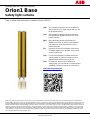 1
1
-
 2
2
-
 3
3
-
 4
4
-
 5
5
-
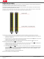 6
6
-
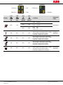 7
7
-
 8
8
-
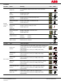 9
9
-
 10
10
-
 11
11
-
 12
12
-
 13
13
-
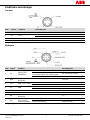 14
14
-
 15
15
-
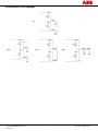 16
16
-
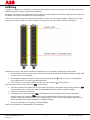 17
17
-
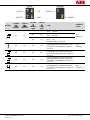 18
18
-
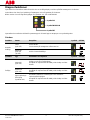 19
19
-
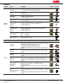 20
20
-
 21
21
-
 22
22
-
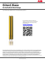 23
23
-
 24
24
-
 25
25
-
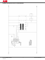 26
26
-
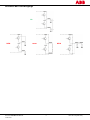 27
27
-
 28
28
-
 29
29
-
 30
30
-
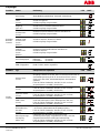 31
31
-
 32
32
-
 33
33
-
 34
34
-
 35
35
-
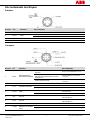 36
36
-
 37
37
-
 38
38
-
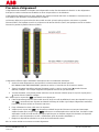 39
39
-
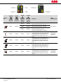 40
40
-
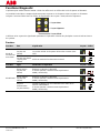 41
41
-
 42
42
-
 43
43
-
 44
44
-
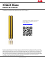 45
45
-
 46
46
-
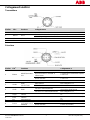 47
47
-
 48
48
-
 49
49
-
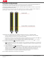 50
50
-
 51
51
-
 52
52
-
 53
53
-
 54
54
-
 55
55
-
 56
56
-
 57
57
-
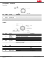 58
58
-
 59
59
-
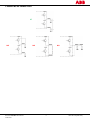 60
60
-
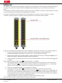 61
61
-
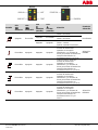 62
62
-
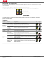 63
63
-
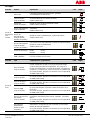 64
64
-
 65
65
-
 66
66


ABB Orion1 Base Excerpts From The Instruction Manual
- Tipo
- Excerpts From The Instruction Manual
en otros idiomas
- français: ABB Orion1 Base
- italiano: ABB Orion1 Base
- English: ABB Orion1 Base
- Deutsch: ABB Orion1 Base
- svenska: ABB Orion1 Base
Artículos relacionados
Otros documentos
-
Schneider Electric TM3SAK6R Instrucciones de operación
-
IFM OY454S Instrucciones de operación
-
schmersal EX-SLC440-ER-0810-30-H Instrucciones de operación
-
SICK Relay Module UE10-2OS Instrucciones de operación
-
CARLO GAVAZZI PD180CBT30MU Manual de usuario
-
-
Pepperl+Fuchs ML29-P/59/103/115 Instrucciones de operación
-
-
Leuze MSI-TRMB-01 Instrucciones de operación
-