Dynatrap DT1250 El manual del propietario
- Tipo
- El manual del propietario

ASSEMBLY
GUIDE
MODEL:
DT1200/DT12S0
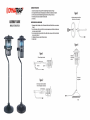
ASSEMBLY
INSTRUCTIONS
I.
Unpack
the
unit,
and
place
ii
on
the
ground
.
Pull
the
cord
light
through
the
pole
stand
as
in
Figure
l.
2.
Insert
upper
and
lower
tubes
and
press
the
spring
bulge
to
ensure
both
tubes
ore
securely
placed,
as
in
Figure
2.
3.
Insert
the
connector
piece
into
the
stand
base
.
Align
pole
and
connect
by
screwing
nu
t
as
in
Figure
3.
4.
Your
Dynatrap
is
now
ready
to
be
connected
to
the
electrical
outlet.
5.
Turn
switch
on.
INSTRUCCIONES
PARA
INSTALACION
I.
Desempaque
la
unidod,
y
col6quela
en
el
piso
.
Joie
firmemente
el
cable
atraves
de
l
tubo
de
lo
base,
como
se
muestra
en
lo
Figura
l.
2.
lnserte
el
tubo
superior
e
inferior
y
opriete
el
bot6n
con
resorte
para
osegurorse
que
ombos
tubos
son
colocodos
seguro-
mente,
como
se
muestra
en
lo
Figura
2.
3.
lnserte
el
conector
de
plastico
en
lo
porte
inferior
de
lo
base
.
Alinee
el
tubo
y
conecte
por
medio
de
lo
tuerco
de
plastico,
como
se
muestro
en
lo
Figura
3.
4.
Su
Dynatrap
esta
lista
para
ser
conectoda
a
la
fuente
de
corriente
.
5.
Enciendo
el
switch
.
Figure
l
Pull
the
cord
through
the
pole
stand
.....................
upper
tube
Figure
2
Insert
both
upper
ond
lower
tubes
together
ond
make
sure
the
spring
bulge
is
securely
ploced
.
press
the
spring
bulge
--- •
Figure
3
Insert
bottom
connector
piece
into
s
tond
base
.
Align
pole
ond
connect
by
screwing
nut
.
/
On
/
Off
switch
locoted
under
the
roin
cover
I
Figure
4
0
0
Place
the
unit
in
upright
position
Ground
•

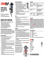
OWNER'S
MANUAL
FLYING
INSECT
TRAP
MODEL:
DTl
2S0
Thank
you
for
purchasing
the
DYNATRAP®
flying
insect
trap!
IMPORTANT
SAFETY
INSTRUCTIONS
WARNING,
When
using
electric
appliances,
basic
precautions
should
always
be
followed,
including
the
following
:
-
To
disconnect,
turn
all
controls
lo
the
off
('O")
position,
then
remove
plug
from
outlet.
-
Unplug
from
outlet
when
not
in
use
and
before
servicing
or
cleaning.
-
To
reduce
the
risk
of
electrical
shock,
do
not
put
appliance
in
wate
r
or
other
liquid.
-
This
appliance
is
provided
with
double
insulation
.
Use
only
identical
replacement
parts
.
-
Connect
only
to
a
cir
c
uit
that
is
protected
by
a
ground-fault
circuit-interrupter
(GFCI).
See
instructions
for
Servicing
of
Double-Insulated
Appliances
.
INSTRUCTIONS
FOR
DOUBLE-INSULATED,
CORD-CONNECTED
APPLIANCES:
In
a
double-insulated
appliance,
two
systems
of
insulation
ore
provided
instead
of
grounding.
No
grounding
means
is
provided
on
a
double-insulated
appliance,
nor
should
a
means
for
grounding
be
added
to
the
appliance.
Servicing
of
a
double-insulated
appliance
requires
extreme
core
and
knowledge
of
the
system,
and
should
be
done
only
by
qualified
service
personnel
.
Replacement
ports
for
a
double-insulated
appliance
must
be
identical
to
those
ports
in
the
appliance
.
IMPORTANT
SAFETY
INSTRUCTIONS
Please
read
these
instructions
before
using
the
DYNATRAP®
Insect
Trap
and
keep
for
future
reference.
l.
Always
turn
unit
off
and
disconnect
plug
before
servicing,
cleaning,
or
changing
bulb.
2.
Do
not
position
the
unit
near
heat,
gos,
oil
or
other
flammable
materials
.
3.
Place
product
out
of
reach
from
children
.
4.
Never
operate
this
product
if
it
hos
a
damaged
cord
or
plug,
ii
it
is
not
working
properly,
ii
it
hos
been
dropped
or
damaged,
or
if
ii
hos
been
dropped
into
water
.
5.
This
product
is
equipped
with
2-conductor
cord
and
2-prong
polarized
plug
as
a
safety
feature.
This
plug
will
fit
in
a
polarized
outlet
only
one
way.
If
the
plug
does
not
fully
lit
in
the
outlet,
then
reverse
the
plug.
If
it
still
does
not
lit,
then
contact
a
qualified
electrician
.
To
reduce
the
risk
of
electrical
shock,
only
plug
into
a
properly
installed
outlet.
Do
not
attempt
to
defeat
this
safety
feature.
6.
Do
not
insert
fingers
or
any
foreign
objects
into
the
unit
while
ii
is
connected
to
an
electrical
outlet.
7.
Collected
insects
within
the
unit
may
contribute
to
fire,
so
clean
insects
from
the
unit
frequent~
.
8.
Do
not
clean
this
product
with
water
spray
.
Do
not
place
where
ii
con
foll
into
water,
or
near
flammable
materials.
9.
Do
not
touch
fan
while
in
motion
.
l
0.
Do
not
abuse
cord--never
carry
or
hong
unit
by
cord
or
yank
it
to
disconnect
from
receptacle.
Keep
cord
away
from
heat,
oil,
or
sharp
edges
.
11.
Extension
cords
used
with
this
product
must
be
marked
with
suffix
letters
"W-A"
and
with
a
tog
stating
"Suitable
for
Use
with
Outdoor
Appliances".
12.
Use
only
extension
cords
that
hove
plug
and
receptacles
that
match
the
product
plug.
Replace
or
repair
damaged
cords.
INSTALLATION
&
OPERATING
INSTRUCTIONS
1.
Unpack
unit.
Save
carton
for
off-season
storage
(if
needed)
.
2.
Assemble
stand
:
Pull
the
cord
tight
through
the
poll
stand.
Turn
base
on
its
side
and
insert
bottom
threaded
plastic
pi
ece
into
hose,
connecting
to
the
threaded
plastic
cop
.
Twist
threaded
plastic
cop
clockwise
to
tighten
.
Complete
installation
by
aligning
upper
ond
lower
support
tube
and
inserting
the
bor
secttons.
(For
more
detailed
instructions,
please
refer
to
the
assembly
guide
.)
3.
Plug
cord
into
on
outlet
or
UL
listed
extension
cord
as
described
in
'IMPORTANT
SAFEIY
INSTRUCTIONS"
.
4.
Hold
the
Power
switch
on
the
side
of
the
revolving
rotation
door
.
Twist
the
unit
to
the
'Power
ON"
position
.
When
you
hear
a
'click
",
the
machine
is
turned
on
.
5.
For
best
catch
results
leave
unit
on
at
all
times
,
except
when
cleaning
or
servicing
.
6.
Catch
rote
activity
will
be
higher
at
night.
For
best
catch
results
ii
is
recommended
to
keep
the
unit
away
from
compettng
light
sources
.
Intended
for
household
use
only
.
7.
It
is
recommended
to
place
the
unit
at
least
10
to
20
feet
away
from
where
people
will
be
sitting.
8.
This
unit
is
all
weather
resistant-
designed
for
outdoor
use
including
rainy
conditions
.
CLEANING
Frequent
cleaning
will
prolong
the
life
of
the
unit,
ensure
lire
prevention
and
provide
for
more
efficient
operation.
1.
Be
sure
to
clean
the
unit
once
per
week
2.
To
clean,
hold
the
switch
on
the
revolving
rotation
door
and
turn
ii
lo
the
'POWER
OFF"
position
.
After
hearing
the
"click",
the
machine
is
turned
off.
Unplug
the
unit.
3.
For
weekly
cleaning,
remove
the
screw
securing
the
retaining
cage
and
then
twist
the
cage
clockwise
.
Remove
any
buildup
from
the
inside
of
the
retaining
cage
and
Ion
with
a
brush
(included)
.
4.
For
major
cleaning,
remove
the
four
screws
securing
the
Ion
housing
to
the
light
housing.
After
removing
the
screws,
gently
pull
the
Ion
housing
away
from
the
light
housing
.
Using
a
soft
brush,
remove
dirt
and
debris
from
the
light
housing
.
Once
the
cleaning
process
hos
been
completed,
align
the
screw
holes
in
the
Ion
housing
with
the
screw
holes
in
the
lighting
unit
and
tighten
the
screws
to
the
base
of
the
lighting
unit
.
5.
When
replacing
the
retaining
cage
-
DO
NOT
press/push
against
the
screen
windows.
REPLACING
BULB
The
light
bulb
life
expectancy
is
approximately
3,000
hours
(or
about
4
months),
and
should
be
replaced
regularly
lo
ensure
opttmol
UV
effectiveness.
Even
though
the
bulb's
light
may
be
visible
to
you,
its
ability
to
attract
insects
diminishes
over
time
.
1.
Turn
power
switch
to
"off"
position
.
UNPLUG
UNIT,
and
allow
bulb
lo
cool
before
replacing.
2.
Remove
the
screw
securing
the
retaining
cage
and
then
remove
the
retaining
cage
by
lwisttng
the
cage
clockwise
.
Turn
the
unit
upside
down
.
3.
Remove
the
lour
screws
securing
the
Ion
housing
to
the
light
housing
.
After
removing
the
screws,
gently
pull
the
Ion
housing
away
from
the
light
housing.
Using
o
soft
brush,
remove
dirt
and
debris
from
the
light
housing
.
Once
the
cleaning
process
hos
been
completed,
untighten
the
screw
securing
the
base
of
the
light
bulb
to
the
light
housing
.
Slide
the
metal
bracket
lo
the
side
.
Cover
the
bulb
with
a
cloth
to
protect
your
linger
and
hand
.
Grasp
the
bulb
(with
your
hand
and
lingers
protected
by
the
cloth)
and
gently
pull
the
bulb
from
the
socket.
4.
Remove
any
debris
from
the
lamp
socket
with
a
brush
before
inserting
the
new
bulb
.
Replace
the
metal
plate
over
the
base
of
the
bulb
and
tighten
the
retaining
screw.
5.
Align
the
screw
holes
in
the
Ion
housing
with
the
screw
holes
in
the
lighttng
unit
and
tighten
the
screws
to
the
hose
of
the
lighting
unit
.
6.
Replace
the
retaining
cage
at
the
bottom
of
the
unit.
Replacement
Fluorescent
Bulbs
con
be
found
at
your
local
retailer
or
con
be
ordered
directly
from
~
IC
.
by
colling
1-877-403-TRAP
(8727)
or
visiting
www
.
dynotrap
.
com.
HOW
THE
DYNATRAP®
INSECT
TRAP
WORKS
F~ing
insects
are
attracted
to
the
unit
by
UV
light
and
CO2
that
is
generated
by
the
photo-catalysis
between
the
UV
lamps
and
spe-
cial
Ti02
coating.
The
Ion
then
pulls
the
insects
into
the
screened
base,
trapping
them
until
they
dehydrate
and
die
.
The
base
con
be
removed,
allowing
the
contents
to
be
periodical~
emptied
into
the
trash.
The
see-through
screen
shows
the
insects
trapped
in
the
comportment,
alerting
you
when
the
net
needs
to
be
emptied
.
TROUBLESHOOTING
Problem:
Possible
cause:
Correction:
Bulb
does
not
illuminate
1.
No
electrical
power.
1.
Check
plug
and
receptacle
and
fuse
or
circuit
breaker.
and
fan
does
not
spin
. 2.
Check
to
make
sure
power
is
switched
to
the
"on"
position.
Bulb
illuminates,
but
fan
1.
Shorted
fan
.
1.
UNPLUG
UNIT:
Examine
fan
to
see
that
it
is
free
from
does
not
spin.
foreign
material,
dirt
or
build-up
of
dead
insects
.
Cleon
unit
as
in
"CLEANING"
section.
Fon
spins,
but
bulb
does
1.
Bulb
not
seated
1.
Check
all
sockets
for
proper
bulb
seating
and
alignment.
not
illuminate.
properly.
2.
Replace
bulb
if
needed
following
instructions
under
2.
Burnt
out
bulb.
"Replacing
Bulb"
.
LIMITED
WARRANTY
DWNlft\
lC
.
warranties
to
the
original
purchaser
that
this
product
is
free
from
defective
materials
and
workmanship.
This
warranty
is
limited
to
remedy
any
defective
par!
for
a
period
of
one
year
from
dale
of
original
date
of
purchase.
Retain
your
original
receipt
as
proof
of
purchase.
This
warranty
does
not
apply
to
the
light
bulb,
nor
to,
in
our
judgment,
misuse
or
abuse.
If
this
unit
has
been
altered,
no
warranty
is
in
force.
This
warranty
does
not
apply
if
this
unit
is
purchased
outside
the
United
States,
excluding
Canada
and
Mexico.
In
no
case
shall
DWtUft\l(
.
be
liable
for
any
accidental,
punitive,
consequential,
or
any
other
damages
of
any
kind
for
breach
of
this
or
any
other
warranty,
expressed
or
implied,
whatsoever.
Some
stales
do
not
allow
limitation
on
how
long
an
implied
warranty
lasts,
so
the
above
limitation
or
exclusion
may
not
apply
to
you.
This
warranty
gives
you
specific
legal
rights,
and
you
may
also
have
other
rights
that
vary
from
state
to
state.
PARTS
&
ACCESSORIES
AVAILABLE
PART
DESCRIPTION
41050
7-Watt
Replacement
Fluorescent
Bulb
(1
piece)
41051
Fon
Blade
Replacement
41052
Fon
Blade
and
DC
Motor
Ultra-Long
Life
Replacement
41053
Retaining
Cage
41061
Lorge
Capacity
Net
(lo
be
used
instead
of
the
Retaining
Cage,
suitable
for
extra
large
catch
performance)
l~
\'IIC
.
Dynamic
Solutions
Worldwide,
LL(
12247
W.
Fairview
Ave
.
Milwaukee,
WI
53226
Phone
:
414-431-2819
Fox:
414-453-9975
Toll
free:
1-877
-
403-TRAP
(8727)
Or
visit
us
online
at
www.dynotrop.com
EPA
Est.
No
.
08Bll9
-
CHN-001
EPA
Est.
No
.
OB7B37-Wl-001
©2012
DSW-LLC
SAVE
THESE
INSTRUCTIONS
lntertek

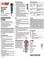
MANUAL
DEL
PROPIETARIO
TRAMPA
DE
INSECTOS
VO
LADO
RES
MODELO:
DTl
2S0
jGracias por comprar
el
DYNATRAP®
trampa
de
insectos voladores!
INSTRUCCIONES
IMPORTANTES
DE
SEGURIDAD
(i
l'
fl1
' .
.......
.ii
• •
Ii
11
1
1,
CUIDADO,
Cuanda
use
aparatas
electricas,
se
deben
de
seguir
precaucianes
bosicas,
incluyenda
la
siguiente:
-
Para
descanectar,
apague
tadas
las
cantrales
en
la
pasicion
("0"),
luega,
remueva
la
clavija
del
enchule
electrico.
-
Desconecte
del
enchule
cuando
no
este
en
usa
y
antes
de
darle
servicio.
-
Para
reducir
el
riesgo
de
chaque
electrico,
na
panga
el
aparato
en
agua
o
cualquier
atra
liquido.
-
Este
aparata
esta
praveido
can
aislado
doble
.
Use
sala
can
partes
de
repuesta
identicas.
Vea
instrucciones
para
Servicio
de
Aparatos
de
Doble
Aislado.
INSTRUCCIONES
PARA
APARATOS
DE
DOBLE
AISLADO,
APARATO
CONECTADO
CON
CABLE:
En
un
aparota
can
oislada
dable,
das
sistemas
de
aislada
san
praveidas
en
lugar
de
tierra.
Na
manera
de
hacer
tierra
es
praveido
en
un
aparata
de
dable
aislada,
ni
tampoco
significa
que
la
tierra
del
aparato
debe
de
ser
anadida
.
El
servicio
de
mantenimiento
electrico
de
un
aparato
con
doble
oislada
requiere
de
extrema
cuidado
y
canocimiento
del
sistema,
y
debe
imicamente
de
ser
dado
por
personal
calilicado.
Las
partes
de
repuesta
de
aparatas
con
doble
aislado
deben
de
ser
identicas
a
los
de
las
partes
originales
del
aparato
.
INSTRUCCIONES
IMPORTANTES
DE
SEGURIDAD
Sirvase
leer
estas
instrucciones
antes
de
usar
el
trampa
electronico
de
insectas
DYNATRAP®
y
guordelas
como
referenda
futura.
l.
Siempre
desenchule
la
unidad
antes
de
darle
servicio,
limpiarla,
cambiar
el
loco,
cuando
no
este
en
uso,
etc
.
2.
No
coloque
este
producto
cerca
de
fuentes
de
color,
gas,
aceite
u
otras
materiales
inflamables
.
3.
Mantengase
alejada
del
alcance
de
los
nifias.
4.
Nunca
apere
este
praducta
si
su
cable
de
corriente
ha
sido
danado,
si
no
esto
trabajando
carrectamente,
si
ha
caido
a
danado,
o
si
ha
sido
tirado
en
agua
.
5.
Esta
producto
esta
equipada
con
un
cable
de
2
conductores
y
un
enchufe
de
clavijas
para
calzar
en
el
tipo
de
tomacor-
rientes
adecuada
.
Para
reducir
el
riesgo
de
choque
electrico,
solo
enchulelo
en
un
receptoculo
instalado
correctamente
.
6.
No
meta
las
dedas
ni
objetas
extrafios
en
la
unidad
mientras
esta
canectada
a
un
receptoculo
electrica
.
7.
Los
insectas
recolectadas
dentra
de
la
unidad
podrian
contribuir
a
un
incendio;
par
lo
!onto,
limpie
los
insectas
muertos
de
la
unidad
con
frecuencia.
8.
No
limpie
este
producto
raciimdolo
con
ogua
.
Na
lo
coloque
dande pueda
caerse
al
agua,
ni
cerca
de
materiales
inllamables.
9.
No
toque
el
ventilador
cuando
este
en
movimiento
.
l
0.
No
mahrate
el
cable-nunca
transporte
la
unidad
par
el
cable
ni
tire
del
mismo
para
desenchularla.
Mantenga
el
cordon
lejos
del
color,
el
aceite,
a
de
hordes
aliladas
.
11.
Los
cables
de
extension
utilizadas
con
este
producto
deben
estar
marcados
con
las
letras
'W-A"
y
con
una
etiqueta
que
dig
a •
Adecuado
para
utilizarse
con
artelactos
en
areas
exteriares".
12.
Solo
use
cables
de
extension
que
tengan
un
enchule
y
receptoculas
compatibles
con
el
enchule
del
praducta
.
Reemplace
o
repare
las
cables
danados
.
INSTALACION
E
INSTRUCCIONES
DE
OPERACION
1.
DeSlimpaque
la
unidad
.
Guarde
la
caja
para
que
re-uSli
luera
de
temparada
.
2.
Como
armor
la
hose:
jole
lirmemente
el
coble
atroves
del
tuba
de
lo
boSli
.
lnSlirle
el
tuba
superior
e
inferior
de
la
hose
y
apriete
el
baton
de
resorte
para
asegurarse
que
ambos
tubas
san
conectados
seguromente
.
lnserte
lo
piezo
de
plostico
del
conector
debojo
de
lo
boSli
.
Alinee
el
tuba
y
conecte
usando
la
tuerca
de
plastico
.
Coloque
el
cable
en
la
hose
.
(Para
instrucciones
mas
detalladas,
par
favor
vea
lo
guio
de
ensambloje).
3.
Enchufe
el
cable
a
un
receptaculo
a
cable
de
aprobodo
par
U~
tal
coma
Ill
describe
en
'INSTRUC-
CIONES
IMPORTANTES
DE
SEGURIDAO"
.
4.
Sujete
la
parte
superior
de
la
unidad
y
girela
en
la
posicion
'ON"
.
Cuando
escuche
un
'dick",
la
unidod
ho
side
prendido
.
Poro
mejores
resultodos,
deje
lo
unidod
todo
el
tiempo
prendido
excepto
cuando
se
vaya
a
limpiar
o
se
de
servicio
.
S.
Para
mejores
resultodos
de
capture,
deje
la
unidod
prendido
en
todo
momenta,
excepto
duronte
su
limpiezo
o
su
montenimiento
.
6.
La
actividad
de
atrapamiento
Slira
mayor
durante
la
noche
.
Para
mejores
resultados,
es
recomendable
que
se
coloque
la
unidad
lejos
de
otras
luentes
de
luz
que
compitan
can
la
trampo.
Este
aparato
esta
diSllfiado
unicamente
pore
usa
solo
en
hogares.
7.
Se
recomienda
colacar
la
unidad
par
la
menos
a
10
a
20
metros
de
d~tancia
de
don
de
la
genie
Sli
encuentra
.
8.
Esta
unidad
peude
Slir
usada
en
de
todos
tipos
de
climes-
d~enodo
pore
el
usa
al
aire
libre
incluyendo
condiciones
lluviosas.
LIMPIEZA
Limpiezo
lrecuente
prolongoro
lo
vido
util
de
lo
unidod,
garonlizoro
la
prevencion
de
incendios,
y
la
unidad
luncionoro
en
lormo
mas
eliciente
.
1.
ASligurese
de
limpiar
la
unidad
al
menos
coda
semana.
2.
Para
darle
limpieza,
sujete
la
parte
superior
de
la
unidad
y
gire
la
compuerta
en
la
posicion
'OFF"
hosta
que
escuche
el
"click"
para
apagar
la
unidad,
y
desenchule
antes
de
limpiorlo.
3.
Para
la
limpieza
Slimanal,
remueva
la
camera
de
recoleccion
simplemente
girando
en
la
direccion
y
aspas
del
ventilador
con
una
brocha
.
4.
Una
vez
que
la
camera
de
recoleccion
este
limpia,
realineelo
con
la
seccion
de
en
media
de
lo
trampo.
Coloque
la
mallo
dentro
de
lo
camera
de
recoleccion
y
presionela
en
su
lugar.
REEMPLAZO
DEL
FOCO
La
vida
de
uso
de
las
locos
es
de
aproximadamente
3,000
horos
(o
cerco
de
4
meses!,
y
deben
de
reemplazarse
despues
de
este
tiempo
para
mantener
la
elicacia
optima
de
la
luz
ultravioleta
.
Aun
cuando
usted
vea
la
luz
de
las
locos,
su
capacidad
para
atraer
inSllclos
disminuye
con
el
tiempo
.
1.
Apague
la
unida
en
la
posicion
"off"
y
Desconecte
El
Coble,
permtta
que
las
locos
se
enlrien
antes
de
cambia~os
.
2.
Remueva
el
tornillo
que
sujeto
lo
canasta
y
despues
remueva
las
conosto
girandolo
en
contra
de
las
monecillos
del
reloj.
Voltee
lo
unidod
de
cabeza
hacia
abojo
.
3.
Remuevo
las
cuatro
tornillos
que
sujeton
la
seccion
del
ventilador
a
la
camaro
de
luz
.
Despues
de
remover
las
tornillos,
remuevo
la
seccion
del
ventilador
de
la
seccion
de
la
camera
de
luz.
Desatornille
el
pequefio
saporte
de
metal
que
sujeta
el
loco
y
con
cuidado
jale
el
loco
de
su
hose
.
4.
Remuevo
cualquier
suciedad
de
la
boSli
del
loco
con
una
brocha
suave
antes
de
inserter
el
loco
nuevo
.
Coloque
el
loco
nuevo
en
la
hose,
y
una
vez
que
el
loco
ho
side
combiodo
y
coloque
el
pequefio
soporte
de
metal
para
sujetar
el
loco.
S.
Aliene
las
agujeros
de
las
tornillos
a
la
seccion
del
ventilador
y a
la
Sliccion
de
la
camera
de
luz
y
ponga
de
nuevo
las
tornillos
.
6.
Coloque
la
camera
de
recoleccion
de
nuevo
en
su
lugar
.
El
loco
de
repuesto,
lo
puede
adquirir
en
la
tiendo
donde
compro
este
praducto,
o
bien
directamente
en
IJl'NPft\
l(
.
llomando
al
1-877-403-TRAP
(8727)
.
COMO
FUNCIONA
EL
TRAMPA
DE
INSECTOS
DYNATRAP®
Los
insectos
voladores
san
atraidos
a
la
unidad
par
media
de
la
luz
y
el
CO,
(dioxide
de
corbona)
que
es
generodo
par
la
loto-cotalisis
que
sucede
entre
la
capo
de
TIO,
(dioxido
de
titanic)
y
las
locos
ultravialetas;
luego
el
venti-
lodor
las
succiono
hocio
uno
camera
de
recoleccion
donde
quedon
atropodos
hasta
que
se
deshidratan
y
mueren
.
La
camera
de
recoleccion
puede
ser
re-
movida,
de
esta
lorma
se
pueden
periodica-mente
vaciar
las
contenidos
en
la
bosuro.
Las
rejillos
en
la
camaro
de
recoleccion
permiten
ver
lo
que
ha
side
atrapodo,
alertando
de
esta
manera
la
siguiente
vez
que
Sli
necestta
vaciar
.
IDENTIFICACION
Y
RESOLUCION
DE
PROBLEMAS
Problema:
Posible
Causa:
Correccion:
Las
locos
no
alumbran
y
1.
No
hay
corriente
1.
Revise
la
conexion,
el
contocto,
a
el
breaker
electrica.
el
ventiladar
na
giro.
electrica
. 2.
Asegurese
de
que
el
swttch
de
prendido
esta
en
la
pasici6n
"on".
Las
locos
prenden,
pero
el
l . 8
ventiladar
esta
en
1.
DESCONECTE
LA
UNIDAD:
Examine
el
ventiladar
para
ver
si
ventilador
no
giro
.
corto.
esta
libre
de
suciedad
o
insectas
muertas
.
Umpie
de
acuerdo
a
la
secci6n
de
"Umpieza".
El
ventilador
giro,
pero
las
1.
Las
locos
no
estan
1.
Revise
que
las
locos
esten
firmemente
colocados
en
la
base
locos
na
prenden.
lirmemente
calacadas.
del
loco.
2.
Las
locos
estan
2.
Cambie
las
locos
si
es
necesario,
de
acuerdo
a
las
instrucciones
fundidas.
bajo
'Reemplazo
del
loco"
.
GARANTIA
LIMITADA
DWNlft\
lC
.
gorantiza
al
comprador
original
que
este
producto
esta
libre
de
defectos
de
materiales
y
mano
de
abra.
Esta
garantia
esta
limitada
a
remediar
cualquier
parte
defectuosa
durante
un
periodo
de
un
aiio
a
partir
de
la
fecha
de
compra
original.
Retenga
su
recibo
original
como
prueba
de
compra.
Esta
garantia
no
es
aplicable
ni
al
foco,
ni
al
maltrato
o
uso
inapropiado,
a
nuestro
juicio.
Si
esta
unidad
es
alterada,
se
anula
la
garantia.
Esta
no
es
aplicable
a
esta
unidad
si
fue
comprada
fuera
de
los
Estados
Unidos,
excluy·
endo
Canada
y
Mexico.
~ .
no
sera
responsable
en
ningun
caso
de
daiios
incidentales,
punitivos,
derivados
o
daiios
de
ningun
otro
tipo
por
incumplimiento
de
esta
o
de
cualquier
otra
garanlia,
ya
sea
expresa
a
implicita.
Algunos
estados
no
permiten
limitacion
can
respedo
a
la
duracion
de
una
garantia
implicita
y,
por
lo
tanto,
la
limitacion
o
exclusion
anterior
podria
no
serle
aplicable.
Esta
garantia
le
otorga
derechos
legales
especificos
y
usted
puede
tener
ademas
otros
derechos
que
variaran
de
un
estado
a
otro.
PARTES
&
ACCESORIOS
DISPONIBLES
PARTE
DESCRIPCCION
41050
Faca
Fluarescente
de
Repuesla
de
7
walls
(l
pieza)
41051
Repueslo
de
Aspas
del
Ventilador
41052
Repuesto
de
Aspas
del
Ventilador
y
Motor
de
Largo
Duraci6n
41053
Camara
de
Recolecci6n
41061
Red
de
Alrapamienla
de
Largo
Capocidad
(para
ser
usoda
en
lugar
de
la
Camara
de
Recolecci6n,
especialmenle
cuanda
se
necesile
capturar
grandes
cantidades)
.
Dynamic
Solutions
Worldwide,
LLC
12247
W.
Fairview
Ave
.
Milwaukee,
WI
53226
Servicios
al
Cansumidar
:
1-877-403-TRAP
(8727)
Para
llamadas
afuero
de
los
Estados
Unidos:
414-431-2819
Fax:
414-453-9975
0
visilenas
en
linea
en
www.dynalrap.cam
EPA
Est.
No.
088119
-
CHN-001
EPA
Est.
Na
.
087837-Wl-001
©2012
DSW-LLC
GUARDE
ESTAS
INSTRUCCIONES
lntertek
-
 1
1
-
 2
2
-
 3
3


Dynatrap DT1250 El manual del propietario
- Tipo
- El manual del propietario
en otros idiomas
- English: Dynatrap DT1250 Owner's manual
Artículos relacionados
-
Dynatrap DT1050 Series El manual del propietario
-
-
Dynamic Dynatrap 3 El manual del propietario
-
-
Dynamic DT1200 El manual del propietario
-
-
-
Dynatrap DT2000XLP El manual del propietario
-
-