
F
D
GB
GA Pkw, GA I, GA II, GA III, GA IV
Betriebsanleitung
Operating Instructions
Manuel d‘instructions
Istruzioni per l’uso
Instrucciones de uso
Инструкция по эксплуатации
Typ
Seriennummer Datum
Rev. C 3134980 03/2013


EG-Konformitätserklärung
im Sinne der EG-Richtlinie 2006/42/EG über Maschinen
Name und Anschrift des Herstellers
BlitzRotary GmbH
Hüfinger Str.55
78199 Bräunlingen, Germany
Diese Erklärung bezieht sich nur auf die Maschine in dem Zustand, in dem sie in Verkehr gebracht wurde; vom Endnutzer
nachträglich angebrachte Teile und/oder nachträglich vorgenommene Eingriffe bleiben unberücksichtigt. Die Erklärung
verliert ihre Gültigkeit, wenn das Produkt ohne Zustimmung umgebaut oder verändert wird.
Hiermit erklären wir, dass die nachstehend beschriebene Maschine
Produktbezeichnung Grubenheber
Serien- / Typenbezeichnung GH, GHS, GHSP, GHU, GHUS, GHUSP, GHUSE, GHL, GHSL,GHSLP,GHUL,GHUSL, GHUSLP,
GHUSLE, GHUST, GHUSTP, GHUSTTP, GWS, GWUS, Twin Ram, X-Lift, GWSK, GWSKT, GWSKTA, GHUSKTP; GHUSFL,
GHUSFFL,GHUSFFT, GHUSFT, GHUSFTT, GHUSFFTT, Pitstar Mobile, Junior Jack, Master Jack, Big Jack, Blitz R, Blitz M,
Blitz X
Maschinen-/Seriennummer: .........................
Baujahr: .........................
allen einschlägigen Bestimmungen der Maschinenrichtlinie 2006/42/EG entspricht. Die Maschine entspricht zusätzlich den
Bestimmungen der Richtlinien 2004/108/EG über elektromagnetische Verträglichkeit (Schutzziele wurden gemäß Anhang I,
Nr. 1.5.1 der Maschinenrichtlinie 2006/42/EG eingehalten).
Angewandte harmonisierte Normen
EN 1494:2000+A1:2008 Fahrbare oder ortsveränderliche Hubgeräte und verwandte Einrichtungen
EN ISO 12100:2010 Sicherheit von Maschinen - Grundbegriffe
EN 60204-1:2006+A1:2009 Elektrische Ausrüstung von Maschinen
EN 349:1993+A1:2008 Sicherheit von Maschinen-Mindestabstände
Angewandte sonstige technische Normen und Spezifikationen
BGR 500 Betreiben von Arbeitsmitteln
BGV A3 Unfallverhütungsvorschrift elektrische Anlagen und Betriebsmittel
Bevollmächtigter für die Zusammenstellung der relevanten technischen Unterlagen:
BlitzRotary GmbH, Hüfinger Str. 55, 78199 Bräunlingen
Ort: Bräunlingen
Datum : 19.03.2013
______________________
Frank Scherer
Geschäftsführer
Hier Typenschild einkleben
Typ
Baujahr
Seriennummer

EC Declaration of Conformity
according to EC directive 2006/42/EC on machinery
Name and address of the manufacturer
BlitzRotary GmbH
Hüfinger Str.55
78199 Bräunlingen, Germany
This declaration relates exclusively to the machinery in the state in which it was placed on the market, and excludes
components which are added and/or operations carried out subsequently by the final user. The declaration is no more valid,
if the product is modified without agreement.
Herewith we declare, that the machinery described below
Product denomination Pit Jack
Model- / Type
GH, GHS, GHSP, GHU, GHUS, GHUSP, GHUSE, GHL, GHSL,GHSLP,GHUL,GHUSL, GHUSLP, GHUSLE, GHUST, GHUSTP,
GHUSTTP, GWS, GWUS, Twin Ram, X-Lift, GWSK, GWSKT, GWSKTA, GHUSKTP; GHUSFL, GHUSFFL, GHUSFFT, GHUSFT,
GHUSFTT, GHUSFFTT, Pitstar Mobile, Junior Jack, Master Jack, Big Jack, Blitz R, Blitz M, Blitz X
Machinery-/Serial number: ..........................
Year of manufacture: ..........................
is complying with all essential requirements of the Machinery Directive2006/42/EC.
In addition the partly completed machinery is in conformity with the EC Directives 2004/108/EC relating to electromagnetic
compatibility (Protection objectives have been met in accordance with Annex I No. 1.5.1 of the Machinery Directive
2006/42/EC).
Harmonised Standards used
EN 1494:2000+A1:2008 Mobile or movable jacks and associated
EN ISO 12100:2010 Safety of Machinery- Basic concepts
EN 60204-1:2006+A1:2009 Electrical equipment of machines
EN 349:1993+A1:2008 Safety of machinery - Minimum gaps
Other technical standards and specifications used
BGR 500 management of working appliances
BGV A3 law accident prevention regulation of electric facilities and equipment
The person authorised to compile the relevant technical documentation
BlitzRotary GmbH, Hüfinger Str. 55, 78199 Bräunlingen
Place: Bräunlingen
Date : 19.03.2013
______________________
Frank Scherer
Managing Director
Hier Typenschild einkleben
Typ
Baujahr
Seriennummer

Declaración CE de Conformidad
de conformidad con la directiva europea
2006/42/CE relativa a las máquinas
Nombre y dirección del fabricante
BlitzRotary GmbH
Hüfinger Str.55
78199 Bräunlingen, Germany
Esta declaración se refiere únicamente a las máquinas en el estado en el que colocaron en el mercado, y excluye los
componentes añadidos y/o las operaciones realizadas porteriormente por el usuario final. La declaración pierde su validez si
el producto es modificado sin autorización.
Declaramos, que la máquina descrita a continuación
Denominación del producto Gatos de fosso
Modelo / tipo
GH, GHS, GHSP, GHU, GHUS, GHUSP, GHUSE, GHL, GHSL, GHSLP, GHUL, GHUSL, GHUSLP, GHUSLE, GHUST, GHUSTP,
GHUSTTP, GWS, GWUS, Twin Ram, X-Lift, GWSK, GWSKT, GWSKTA, GHUSKTP, GHUSFL, GHUSFFL, GHUSFFT, GHUSFT,
GHUSFTT, GHUSFFTT, Pitstar Mobile, Junior Jack, Master Jack, Big Jack, Blitz R, Blitz M, Blitz X
Maquinaria / número de serie: .........................
Año de fabricación: .........................
Cumple con todos los requisitos esenciales de la directiva 2006/42/CE relativa a las máquinas.
Además, la parcialmente completa maquinaria está en conformidad con las directivas europeas 2004/108/CE relativas a la
compatibilidad electromagnética (los objetivos de protección se han cumplido de conformidad con el Anexo I N°. 1.5.1 de la
directiva 2006/42/CE relativa a las máquinas).
Normas armonizadas autorizadas
EN 1494:2000+A1:2008 Gatos móviles o portátiles y equipos de elevación asociados
EN ISO 12100:2010 Seguridad de máquinas- conceptos básicos
EN 60204-1:2006+A1:2009 Equipamiento eléctrico de máquinas
EN 349:1993+A1:2008 Seguridad de máquinas – distancias mínimas
Altri standard e specifiche tecnici utilizzati
BGR 500 gestión de los aparatos de trabajo
BGV A3 regulación de la ley de prevención de accidentes de las instalaciones eléctricas
y equipo eléctrico
La persona autorizada para elaborar la correspondiente documentación técnica
BlitzRotary GmbH, Hüfinger Str. 55, 78199 Bräunlingen
Luogo: Bräunlingen
Data: 19.03.2013
______________________
Frank Scherer
Director general
Hier Typenschild einkleben
Typ
Baujahr
Seriennummer

Déclaration de conformité CE
selon la directive de la CE 2006/42/CE
relative aux machines
Nom et adresse du fabricant
BlitzRotary GmbH
Hüfinger Str.55
78199 Bräunlingen, Germany
Cette déclaration porte exclusivement sur la machine dans l'état auquel elle est mise sur la marché et exclut les
composants qui y sont ajoutés et/ou les opérations effectuées ultérieurement par l'utilisateur final. La déclaration perd sa
validité si le produit est modifié sans accord préalable.
Nous déclarons par la présente, que la machine décrite ci-dessous
Dénomination du produit Cric de fosse
Modèle/Type
GH, GHS, GHSP, GHU, GHUS, GHUSP, GHUSE, GHL, GHSL,GHSLP,GHUL,GHUSL, GHUSLP, GHUSLE, GHUST,
GHUSTP, GHUSTTP, GWS, GWUS, Twin Ram, X-Lift, GWSK, GWSKT, GWSKTA, GHUSKTP; GHUSFL, HUSFFL,GHUSFFT,
GHUSFT, GHUSFTT, GHUSFFTT, Pitstar Mobile, Junior Jack, Master Jack, Big Jack, Blitz R, Blitz M, Blitz X
Machine/Numéro de série: .........................
Année de fabrication: .........................
est conforme aux exigences essentielles de la Directive relative aux Machines 2006/42/CE.
De plus, les machines partiellement complétées sont conformes aux directives de la CE 2004/108/CE relatives aux
compatibilités électromagnétiques (Les objectifs de protection ont été respectés selon l'Annexe I No. 1.5.1 des Directives
relatives aux Machines 2006/42/EC).
Standards normalisés utilisés
EN 1494:2000+A1:2008 Crics mobiles ou déplaçable et équipement de levage associé
EN ISO 12100:2010 Sécurité de Machinerie - Concepts de Base
EN 60204-1:2006+A1:2009 Equipement électrique des machines
EN 349:1993+A1:2008 Sécurité de Machinerie - Jours minimum
Autres normes techniques et spécifications utilisés
BGR 500 fournitures d'exploitation de gestion
BGV A3 une législation empêchant les accidents et les appareils électriques
La personne autorisée à rassembler la documentation technique pertinente
BlitzRotary GmbH, Hüfinger Str. 55, 78199 Bräunlingen
Lieu
: Bräunlingen
Date
: 19.03.2013
______________________
Frank Scherer
Directeur
Hier Typenschild einkleben
Typ
Baujahr
Seriennummer

Dichiarazione di conformità CE
Secondo la Direttiva Macchine 2006/42/CE
Nom et adresse du fabricant
BlitzRotary GmbH
Hüfinger Str.55
78199 Bräunlingen, Germany
La presente dichiarazione si applica esclusivamente al macchinario nelle condizioni di inserimento sul mercato, e
non comprende componenti aggiuntive e/o interventi eseguiti in seguito dall’utente finale. La dichiarazione viene
invalidata in caso di modifiche apportate all’apparecchio in assenza di previo accordo.
Si dichiara di seguito che l’apparecchio sottodescritto
Denominazione apparecchio Sollevatori fosse
Modello/tipo
GH, GHS, GHSP, GHU, GHUS, GHUSP, GHUSE, GHL, GHSL,GHSLP,GHUL,GHUSL, GHUSLP, GHUSLE, GHUST,
GHUSTP, GHUSTTP, GWS, GWUS, Twin Ram, X-Lift, GWSK, GWSKT, GWSKTA, GHUSKTP; GHUSFL, GHUSFFL,
GHUSFFT, GHUSFT, GHUSFTT, GHUSFFTT, Pitstar Mobile, Junior Jack, Master Jack, Big Jack, Blitz R, Blitz M, Blitz
X
Numero di serie: .........................
Anno di produzione: .........................
È conforme ai requisiti essenziali previsti dalla Direttiva Macchine 2006/42/CE.
Inoltre, l’apparecchio parzialmente completato è conforme alle Direttive 2004/108/CE sulla compatibilitá
elettromagnetica (Sono state installate protezioni come indicato nell’allegato I N° 1.5.1 della Direttiva Macchine
2006/42/CE).
Standard armonizzati utilizzati
EN 1494:2000+A1:2008
Martinetti mobili o amovibili e attrezzature di sollevamento relative
EN ISO 12100:2010 Sicurezza macchine - Concetti di base
EN 60204-1:2006+A1:2009 Attrezzature elettriche macchinari
EN 349:1993+A1:2008 Sicurezza macchine – Luci minime
Altri standard e specifiche tecnici utilizzati
BGR 500 gestioni materiali di esercizio
BGV A3 normativa prevenzione incidenti dispositivi e attrezzature elettriche
Persona autorizzata a compilare la documentazione tecnica rilevante
BlitzRotary GmbH, Hüfinger Str. 55, 78199 Bräunlingen
Luogo: Bräunlingen
Data: 19.03.2013
______________________
Frank Scherer
Amministratore Delegato
Hier Typenschild einkleben
Typ
Baujahr
Seriennummer

2 3134980 03/13
Betriebsanleitung
Inhaltsverzeichnis
1 Sicherheit
1.1 Sicherheitshinweise in dieser
Anleitung
Gefahr
Lebens- und Verletzungsgefahr.
Vorsicht
Sachschäden.
Informationen und Tipps.
Inhaltsverzeichnis
1 Sicherheit .............................................. 2
1.1 Sicherheitshinweise in dieser
Anleitung .................................................2
2 Einleitung .............................................. 3
2.1 Einsatzbereiche der
BLITZ-Getriebeplatten ........................... 3
2.2 Gewährleistung und Haftung ............... 3
3 Sicherheit/Unfallverhütung .............. 3
3.1 Heben und Senken der Last ................. 4
3.2 Verfahren der Last ..................................4
4 Technische Daten ................................ 5
5 Bedienung und Betrieb ...................... 5
5.1 GA I ...........................................................5
5.2 GA II .........................................................5
5.3 GA III ........................................................ 6
5.4 GA IV, GA Pkw ........................................6
5.5 Spannen des Gurtes ..............................7
5.6 Entspannen des Gurtes .........................7
6 Wartung.................................................. 8
D

33134980 03/13
Betriebsanleitung
Einleitung
2 Einleitung
2.1 Einsatzbereiche der
BLITZ-Getriebeplatten
BLITZ-Getriebeplatten dürfen nur zum Ein-
und Ausbau von schweren Fahrzeugteilen
(z.B. Getrieben, Motoren, Achsen usw.) und
nur zusammen mit Grubenhebern der Firma
BLITZ verwendet werden.
Eine andere oder über den beschriebenen
Zweck hinausgehende Benutzung gilt als
nicht bestimmungsgemäß.
2.2 Gewährleistung und Haftung
Grundsätzlich gelten unsere „Allgemeinen
Verkaufs- und Lieferbedingungen“. Diese ste-
hen dem Betreiber seit Vertragsabschluß zur
Verfügung.
Gewährleistungs- und Haftungsansprüche
bei Personen- und Sachschäden sind ausge-
schlossen, wenn
• dieGetriebeplattenichtbestimmungsge-
mäß verwendet wurde,
• dieBedienungsanleitungnichtbeachtet
wurde,
• Reparaturenunsachgemäßdurchgeführt
wurden,
• nicht-originalBLITZ-Ersatzteileverwen-
det wurden
• dieGetriebeplatteohneGenehmigungdes
Herstellers technisch verändert wurde.
3 Sicherheit/Unfallverhütung
• DieGetriebeplattedarfnurvonPersonen
bedient werden, die diese Bedienungsan-
leitung gelesen und verstanden haben.
• ErgänzendzurBedienungsanleitungsind
allgemeingültige gesetzliche und sonstige
verbindliche Regelungen zur Unfallverhü-
tung und zum Umweltschutz zu beachten.
• DieBedienungsanleitungistständigam
Einsatzort der Getriebeplatte aufzubewah-
ren.
• DasBesteigenderLastoderdesLastauf-
nahmemittels ist verboten.
• DerAufenthaltvonPersonenimBewe-
gungsbereich der Last ist während des
Bewegungsvorganges verboten.
• BeobachtenSiedieLastbeiallenBewe-
gungsvorgängen.
• PrüfenSievorjederInbetriebnahmeden
Ordnungsgemäßen Zustand des Gerätes,
den festen Sitz der Getriebeplatte auf dem
Heber und den sicheren Einbau des He-
bers.
• AlleBewegungenderLastmüssenruck-
frei und gleichmäßig erfolgen.
• SchützenSiebeischarfkantigenLasten
die Spanngurte an allen Auflagepunkten
mit dem mitgelieferten Schutzschlauch.
• DerSchwerpunktderLastmußimmer
zentrisch über dem Zylinder des Hebers
liegen, nur so kann die max. Tragkraft ga-
rantiert werden.
• DieSpanngurteanderGetriebeplatte
dienen nur zur Sicherung, nicht aber zum
Anheben der Last z.B. mittels Kran.
D

4 3134980 03/13
Betriebsanleitung
Sicherheit/Unfallverhütung
D
Abb. 3:
Abb. 4:
3.2 Verfahren der Last
auf dem Heber ist nur zulässig bei
• ganzabgesenkterLast,
• ausreichenderStandsicherheitund
• hindernisfreiemWeg
Abb. 1:
Abb. 2:
3.1 Heben und Senken der Last
ist nur zulässig, wenn sichergestellt ist, daß
• derLastschwerpunktimmerinnerhalbder
Standfläche des Hebers und innerhalb der
Fläche der Getriebeplatte liegt (Abb.3)
• dieLastsicheraufderGetriebeplatteliegt,
• dieLastmitbeidenSpanngurtengesichert
ist und
• sichkeinePersonenoderHindernisseim
Bewegungsbereich der Last befinden.

53134980 03/13
Betriebsanleitung
Technische Daten
5 Bedienung und Betrieb
5.1 GA I
Einstellen der Auflagepunkte:
Justierschrauben (Abb.5/1) voreinstellen
Einstellen der Neigung:
• ImbeladenenZustandistdieNeigungbei
diesem Modell nicht einstellbar.
Sicherung der Last:
• VorrichtungenfürdieSicherungderLast
sind nicht im Lieferumfang enthalten
1
Abb. 5:
D
4 Technische Daten
Modell GA Pkw GA I GA II GA III GA V
Tragfähigkeit kg 400 1000 1000 1000 1000
Maße Länge mm 300 400 400 400 396
Breite mm 240 380 600 600 546
Höhe mm 152 65 167 275 131
Gewicht kg 10 30 29
5.2 GA II
Einstellen der Auflagepunkte:
Klemmenschrauben der Schieber
(Abb. 6/4) lösen
gewünschte Breite einstellen
Schieber klemmen
Einstellen der Neigung:
• DieNeigungistbeliebigüberJustier-
schrauben in alle Richtungen einstellbar.
• GehenSiebeiNeigungüberdieDiagonale
schrittweise vor, erst Schraube (Abb. 6/2)
Lösen und dann Schraube (Abb. 6/3) nach-
stellen usw.
• VerwendenSiedazueinenGabelschlüssel
SW24.
Sicherung der Last:
• DieSicherungderLasterfolgtmitSpann-
gurten. Der Schutzschlauch dient zum
Schutz der Spanngurte an scharfen Kan-
ten.
5
4
3
2
Abb. 6:

6 3134980 03/13
Betriebsanleitung
Bedienung und Betrieb
5.4 GA IV, GA Pkw
Einstellen der Neigung:
Die Neigung ist beliebig über Getriebe in
alle Richtungen einstellbar.
Verstellen Sie dazu mit einem Gabel-
schlüsseldieWelle(Abb.9/7)fürdieent-
sprechende Neigungsachse bzw. lösen Sie
das entsprechende Handrad (Abb.9/8) und
stellen Sie das gegenüberliegende Hand-
rad nach.
Sicherung der Last:
• DieSicherungderLasterfolgtmitSpann-
gurten. Der Schutzschlauch dient zum
Schutz der Spanngurte an scharfen Kan-
ten.
5
9
Abb. 8:
5
7
8
Abb. 9:
D
5.3 GA III
Einstellen der Auflagepunkte:
Klemmenschrauben der Schieber (Abb.
7/4) lösen
gewünschte Breite einstellen
Schieber klemmen
Einstellen der Neigung:
• DieNeigungistbeliebigüberGetriebein
alle Richtungen einstellbar.
• VerstellenSiedazumiteinemGabel-
schlüsselSW17dieWellefürdieentspre-
chende Neigungsachse.
Sicherung der Last:
• DieSicherungderLasterfolgtmitSpann-
gurten. Der Schutzschlauch dient zum
Schutz der Spanngurte an scharfen Kan-
ten.
5
4
6
Abb. 7:

73134980 03/13
Betriebsanleitung
Bedienung und Betrieb
1
2
3
5.5 Spannen des Gurtes
GurtdurchgeteilteWelleziehen
Abb. 10:
Gurt durch Handkraft leicht vorspannen
Abb. 11:
Gurt durch Vor- und Rüchziehen des Hand-
hebels spannen
Abb. 12:
Handhebel bei gewünschter Gurtstellung
einklappen
Abb. 10:
5.6 Entspannen des Gurtes
obere Sperrklinke zurückziehen und hal-
ten.
Handhebel um 180° umlegen
GurtausgeteilterWelleziehen
Abb. 11:
• RatschenundGurtesindvorjedem
Gebrauch auf Beschädigungen zu
prüfen und bei Mängeln umgehend
zu ersetzen.
• SchützenSiedenGurtdurchdie
mitgelieferten Schutzschläuche vor
scharfen Kanten.
• DieverzurrteLadungmußmehr-
mals kontrolliert und gegebenen-
falls nachgespannt werden.
D

8 3134980 03/13
Betriebsanleitung
Wartung
D
6 Wartung
Monatlich
Spanngurte prüfen Spindel und Lager der
Verstellgetriebe schmieren
Jährlich
Spanngurte + Schutzschlauch ersetzen
Bestell Nr. Spanngurt : 708820
Bestell Nr. Schutzschlauch : 708824

93134980 03/13
Operating Instructions
Table of contents
1 Saftey
1.1 Safety instructions in this
manual
Danger
Risk to life and limb.
Warning
Material damage.
Information and tips.
GB
Table of contents
1 Saftey ..................................................... 9
1.1 Safety instructions in this manual .....9
2 Introduction ........................................ 10
2.1 Application Range of
BLITZ Gear Plates ................................ 10
2.2 WarrantyandLiability ......................... 10
3 Safety/Accident prevention ........... 10
3.1 Lifting and Lowering of Loads ............ 11
3.2 Moving of the Load ..............................11
4 Technical data .................................... 11
5 Handling and Operation .................. 12
5.1 GA I .........................................................12
5.2 GA II .......................................................12
5.3 GA III ...................................................... 12
5.4 GA IV, GA Pkw ......................................13
5.5 Tensioning of the belt .......................... 13
5.6 Release of the belt ...............................14
6 Maintenance ....................................... 14

10 3134980 03/13
Operating Instructions
Introduction
GB
2 Introduction
2.1 Application Range of
BLITZ Gear Plates
BLITZ-gear plates must only to be used for
mounting and demounting of heavy parts
of vehicles (e.g. gear boxes, engines, wheel
shafts etc.) and only in combination with pit
lifts built by BLITZ.
Use of gear plate for other purposes than the
described one is not allowed.
2.2 WarrantyandLiability
Generally our “General Conditions of Sale
and Delivery“ are valid,which are submitted
attimeofcontracting.Wedonotacceptany
responsibility if based on one or more of the
following reasons:
• useofthegearplateforotherpurposes
than the intented one
• disreguardofoperatinginstructions
• repairsbeeingcarriedoutinexpertly
• sparepartsnotoriginatingfromBLITZ
• unauthorisedtechnicalalternationsofthe
gear plate
3 Safety/Accident prevention
• Thegearplatemustonlybeoperatedby
persons who have read and understood
this manual.
• Inadditiontotheinstructionsforuserules
pertaining to other regulations i. e. acci-
dent prevention and environmental rules
have to be observed.
• Theinstructionsforuseareconstantly
to be kept at the place of operation, thus
being at hand at any time.
• Enteringoftheloadandmountingofthe
load carrying device is forbidden.
• Personsarenotallowedtostaywithinthe
movement area of the load during the ope-
ration.
• Whileinmotionobservetheload.
• Priortooperationcheckunituponproper
stage of operation, safe harbouring of the
gear plate on the lift and safe installation
of the lift.
• Liftingandloweringmovementsmustbe
carried out evenly.
• Whenusingsharp-edgedloads,protect
the nylon belts on all supporting points by
means of the delivered protection hose.
• Thecentreofmassoftheloadmustbepo-
sitioned centricallly above the cylinder of
the lift. Only if this is the case the capacity
can be granted.
• Thenylonbeltsonthegearplateareme-
ant to secure the load but not for lifting of
the load (e.g. with a crane)

113134980 03/13
Operating Instructions
Safety/Accident prevention
GB
Fig. 1:
Fig. 2:
3.1 Lifting and Lowering of Loads
is only allowed, if it is guaranted that
• thecentreofmassoftheloadliesinside
the base area of the lift and inside the area
of the gear plate (Fig. 3)
• theloadliessafeonthegearplate
• theloadissecuredwithbothnylonbelts
and
• nopersonsorobstaclesareplacedwithin
the motion area of the gear plate and its
loads
4 Technical data
Model GA Pwk GA I GA II GA III GA V
Capacity kg 400 1000 1000 1000 1000
Measurement L mm 300 400 400 400 396
W mm 240 380 600 600 546
H mm 152 65 167 275 131
Weight kg 10 30 29
Fig. 3:
Fig. 4:
3.2 Moving of the Load
on the lift is only allowed if
• theloadisloweredcompletely,
• thelifthasasafestandand
• therearenoobstaclesinsidethemotion
area.

12 3134980 03/13
Operating Instructions
Handling and Operation
GB
5 Handling and Operation
5.1 GA I
Adjustmentofsupportingpoints
presetadjustingscrews(Fig.5/1)
Adjustmentoftheincline
• Ifplateisloadedinclinecannotbeadjust-
ed with this model.
Securing of load
• Devicesforsecuringoftheloadarenot
part of the range of supply.
1
Fig. 5:
5.2 GA II
Adjustmentofsupportingpoints
loosen clamping screws (Fig.6/4) of the
sliding pieces
adjustdesiredwidth
clamp sliding pieces
Adjustmentoftheincline
• Inclineisfreelyadjustableintoalldirec-
tionsbymeansofadjustmentscrews.
• Changeinclinediagonallystepbystep:
firstloosenscrew(Fig.6/2)andthenadjust
screw (Fig.6/3) etc.
• UseaforkspannerSW24.
Securing of load
• Securingoftheloadiseffectedbynylon
belts. The flexible hose is made to protect
the belts at sharp-edged loads.
5
4
3
2
Fig. 6:
5.3 GA III
Adjustmentofsupportingpoints
loosen clamping screws (Fig.7/4) of the
sliding pieces
adjustdesiredwidth
clamp sliding pieces
Adjustmentoftheincline
• Inclineisfreelyadjustableintoalldirec-
tionsbymeansofadjustablegears.
• UseaforkspannerSW17toadjustthe
spindle to the desired axle.
Securing of load
• Securingoftheloadiseffectedbynylon
belts. The flexible hose is made to protect
the belts at sharp-edged loads.
5
4
6
Fig. 7:

133134980 03/13
Operating Instructions
Handling and Operation
GB
5.4 GA IV, GA Pkw
Adjustmentofsupportingpoints
Inclineisfreelyadjustableovergearboxin
all directions.
Todosoadjusttheshaft(Fig.9/7)witha
fork spanner for the appropriate incline
axle resp.
loosen the corresponding hand wheel
(Fig.9/8)andadjusttheoppositehand
wheel.
Securing of load
• Securingoftheloadiseffectedbynylon
belts. The flexible hose is made to protect
the belts at sharp-edged loads.
5
9
Fig. 8:
5
7
8
Fig. 9:
5.5 Tensioning of the belt
Pull the belt through the divided shaft.
Fig. 10:
Pre-tension the belt slightely by hand.
Fig. 11:
Tension belt by pulling and pressing the
hand lever.
Fig. 12:

14 3134980 03/13
Operating Instructions
Maintenance
GB
6 Maintenance
Monthly
check nylon belts grease spindle and bea-
ringsofadjustablegears
Yearly
replace nylon belts and flexible hose
OrderNo. nylon belt : 708820
OrderNo. flexible hose: 708824
1
2
3
Fix the hand lever at the requested positi-
on of the belt
Fig. 10:
5.6 Release of the belt
Retract the upper safety catch and hold it
Turn hand lever by 180°
Draw the belt out of the divided shaft
Fig. 11:
• Ratchesandbeltshavetobeche-
cked upon damages prior to every
use and in case of defects to be
replaced immediately.
• Protectthebeltbymeansofthe
supplied safety hoses against sharp
edges.
• Thefixedloadmustbechecked
several times and in case of need
retensioned.


16 3134980 03/13
F
Manuel d‘instructions
Table des matières
1 Sécurité
1.1 Consignes de sécurité dans ce
manuel
Danger
Danger de blessures et de mort.
Prudence
Dommages matériels.
Informations et conseils.
Table des matières
1 Sécurité ................................................ 16
1.1 Consignes de sécurité dans ce
manuel ...................................................16
2 Introduction ........................................ 17
2.1 Domaines d’utilisation des plaques
à engrenages BLITZ ............................. 17
2.2 Garantie et responsabilité ..................17
3 Sécurité/Prévention des accidents 17
3.1 La charge ne peut être levée
et abaissée ........................................... 18
3.2 Le déplacement de la cahrge ............ 18
4 Caractéristiques techniques ........... 18
5 Commande et exploitation .............. 19
5.1 GA I .........................................................19
5.2 GA II .......................................................19
5.3 GA III ...................................................... 19
5.4 GA IV, GA Pkw ......................................20
5.5 Serrage du sangle ................................20
5.6 Deserrage du sangle............................21
6 Entretien ............................................. 21

173134980 03/13
F
Manuel d‘instructions
Introduction
2 Introduction
2.1 Domaines d’utilisation des pla-
ques à engrenages BLITZ
Les plaques à engrenages BLITZ ne doivent
être utilisées que pour monter ou démonter
des pièces lourdes de véhicules (par exemples
des boîtes de vitesses, des moteurs, des es-
sieux, etc.) et seulement avec des ponts éléva-
teurs pour fosses, de la Société BLITZ.
Toute autre utilisation, ou toute utilisation
sortant du domaine d’application décrit, est
considérée comme non conforme à l’usage
prévu.
2.2 Garantie et responsabilité
Normalement, les conditions à appliquer sont
nos „Conditions générales de vente et de
livraison“. Elles sont à la disposition de l’utili-
sateur à compter de la date de conclusion du
contrat. Les droits en matière de garantie et
de responsabilité sont exclus, dans le cas de
dommages corporels ou matériels, lorsque :
• laplaqueàengrenagesn‘apasétéutilisée
pour l’usage auquel elle est destinée,
• lesinstructionsd‘utilisationn‘ontpasété
respectées,
• lesréparationsn‘ontpasétéeffectuées
dans les règles,
• lespiècesdétachéesBLITZd’originene
sont pas utilisés, et lorsque,
• laplaqueàengrenagesasubidesmodifi-
cations techniques sans l’autorisation du
fabricant.
3 Sécurité/Prévention des acci-
dents
• Laplaqueàengrenagesnedoitêtreuti-
lisée que par les personnes qui ont lu et
comprislesprésentesinstructionsd‘utili-
sation.
• Onseconformeranonseulementaux
instructionsd‘utilisation,maiségalement
aux réglementations générales en vigueur,
prévuesparlaloioupard‘autrestextes,
relatives à la prévention des accidents et à
la protection de l’environnement.
• Lesinstructionsd‘utilisationsontà
conserverenpermanencesurlelieud‘uti-
lisation de la plaque à engrenages.
• Ilestinterditdemontersurlachargeou
sur le système de réception de la charge.
• Ilestinterditdesetenirdanslepérimètre
de déplacement de la charge pendant que
celle-ci se déplace.
• Observezlachargependanttoutesles
opérations de déplacement.
• Vérifiez,avanttoutemiseenservice,que
l’appareil est en bon état, que la plaque à
engrenages repose solidement sur l’élé-
vateur et que celui-ci est fixé de manière
parfaitement sûre.
• Ilfautquetouslesmouvementsdela
charges‘effectuentsansà-coupsetde
manière parfaitement régulière.
• Danslecasdechargesprésentantdesarê-
tes vives, protégez les sangles de serrage
surtouslespointsoùelless‘appliquent,
en utilisant le tuyau souple de protection
livré avec lesdites plaques.
• Ilconvientdeveilleràcequelecentrede
gravitédelachargeoccupetoujoursune
position centrale, au-dessus du cylindre de
l’élévateur.C‘estleseulmoyendegarantir
une force portante au maximum.
• Lessanglesdeserragedelaplaqueàen-
grenagesn‘ontqu‘unesimplefonctionde
sécurité. Elles ne peuvent, en aucun cas,
être utilisées pour soulever la charge, au
moyend‘unegrue,parexemple.

18 3134980 03/13
F
Manuel d‘instructions
Sécurité/Prévention des accidents
4 Caractéristiques techniques
Modèles GA Pwk GA I GA II GA III GA V
Charge admissible kg 400 1000 1000 1000 1000
Dimensions L mm 300 400 400 400 396
B mm 240 380 600 600 546
H mm 152 65 167 275 131
Poids kg 10 30 29
Fig. 3:
Fig. 4:
3.2 Le déplacement de la cahrge
surl’élévateurn‘estautoriséquesi:
• lachargeesttotalementabaissée,
• ladistancedesécuritéestsuffisante,etsi
• aucunobstaclenesetrouvesurlepar-
cours.
Fig. 1:
Fig. 2:
3.1 La charge ne peut être levée et
abaissée
quelorsqu‘ons‘estassuréque:
• lecentredegravitédelachargesetrouve
toujoursàl’intérieurdelasurfaced‘appui
de l’élévateur, et à l’intérieur de la surface
de la plaque à engrenages (Fig. 3)
• lachargereposeentoutesécuritésurla
plaque à engrenages,
• lachargeestarriméeaveclesdeuxsan-
gles de serrage, et que
• personne,ouaucunobstacle,nesetrouve
dans le périmètre de déplacement de la
charge.

193134980 03/13
F
Manuel d‘instructions
Commande et exploitation
5 Commande et exploitation
5.1 GA I
Réglagedespointsd‘appui
Réglezd‘avancelesvisderéglage
(Fig.5/1).
Réglage de l’inclinaison
• Surcemodèle,iln‘estpaspossiblede
régler l’inclinaison, lorsque l’appareil est
chargé
Arrimage de la charge
• Lesdispositifsservantàarrimerlacharge
ne font pas partie de la livraison.
1
Fig. 5:
5.2 GA II
Réglagedespointsd‘appui
Dévissez les vis de serrage des coulis-
seaux (Fig.6/4).
Réglez la largeur souhaitée.
Serrez les coulisseaux.
Réglage de l’inclinaison
• Pourréglerl’inclinaison,procédezpar
étapes, par la diagonale (croquis): Com-
mencez par dévisser la vis (Fig.6/2), puis
réglez la vis (Fig.6/3), etc.
• Utilisez,pourcela,unecléàmoletteSW
24.
Arrimage de la charge
• Lessanglesdeserragepermettentd‘ar-
rimer la charge de manière parfaitement
sûre. Le tuyau souple de protection sert à
protéger les sangles à l’endroit des arêtes
vives.
5
4
3
2
Fig. 6:
5.3 GA III
Réglagedespointsd‘appui
Dévissez les vis de serrage des coulis-
seaux (Fig.7/4).
Réglez la largeur souhaitée.
Serrez les coulisseaux.
Réglage de l’inclinaison
• L’inclinaisonpeutserégleràvolonté,dans
toutes les directions, au moyen de la boîte
à engrenages.
• Pourcela,réglezavecunecléàmolette
SW17l’arbredel’essieud‘inclinaison
correspondant.
Arrimage de la charge
• Lessanglesdeserragepermettent
d‘arrimerlachargedemanièreparfaite-
ment sûre. Le tuyau flexible sert à protéger
les sangles de serrage, à l’endroit des
arêtes vives.
5
4
6
Fig. 7:

20 3134980 03/13
F
Manuel d‘instructions
Commande et exploitation
5.4 GA IV, GA Pkw
Réglage de l’inclinaison
On peut régler l’inclinaison sur les boîtes
de vitesse en toutes les directions.
Pourréglerl’inclinaisonajustezl’arbre
(Fig.9/7) avec une clé à molette pour l’axe
d’inclinaison approprié resp. dévissez le
volant à main correspondant (Fig.9/8) et
réglez le volant à main se trouvant en
face.
Arrimage de la charge
• Lessanglesdeserragepermettent
d’arrimer la charge.
• Letuyausoupledeprotectionsertàpro-
téger les sangles à l’endroît des arêtes
vives.
5
9
Fig. 8:
5
7
8
Fig. 9:
5.5 Serrage du sangle
Trainez le sangle par l’arbre séparé.
Fig. 10:
Pré-serrez le sangle légèrement à main.
Fig. 11:
Serrez le sangle en tirant et retirant le le-
vier à main.
Fig.12:

213134980 03/13
F
Manuel d‘instructions
Entretien
6 Entretien
Tous les mois
Vérifiez les sangles de serrage. Graissez la
broche et les paliers de l’en grenage ac-
tionnant le déplacement.
Tous les ans
Remplacez les sangles de serrage et le
tuyau souple de protection.
N° de commande de la sangle de serrage:
708820
N° de commande du tuyau souple de protec-
tion: 708824
1
2
3
Fixez le levier à main à la position souhai-
tée.
Fig. 13:
5.6 Deserrage du sangle
Retractez le cliquet d’arret supérieur et
arrêtez-le.
Tournez le levier à main par 180°.
Retirez le sangle de l’arbre séparé.
Fig. 11:
• Leviersàcliquetetsanglesde
serrage doivent être examinés
avant l’operation concernant des
dommages. Au cas de dommages
ceux-ci doivent être immédiatement
remédiés.
• Protégezlesangleparlestuyauxde
protection livrés contre des aretes.
• Lachargeserréepardessangles
doit être controlée plusiers fois et
en cas de besoin être reserrée

22 3134980 03/13
1 Sicurezza
1.1 Indicazioni sulla sicurezza in
questo manuale
Pericolo
Pericolo di morte e di mutilazione.
Avvertenza
Danno materiale.
Informazioni e consigli.
Sommario
1 Sicurezza ............................................. 23
1.1 Indicazioni sulla sicurezza
in questo manuale .............................. 23
2 Introduzione ........................................ 24
2.1 Gamma di applicazioni delle
Piastre per Cambi BLITZ .....................24
2.2 Garanzia e Responsabilità ..................24
3 Sicurezza / Antinfortunistica ........ 24
3.1 Sollevamento e abbassamento
del carico ............................................... 25
3.2 Movimento del carico ..........................25
4 Dati tecnici .......................................... 25
5 Comando e Funzionamento ............ 26
5.1 GA I .........................................................26
5.2 GA II .......................................................26
5.3 GA III ...................................................... 26
5.4 GA IV, GA Pkw ......................................27
5.5 Tensionamento della cinghia ............. 27
5.6 Rilascio della cinghia .......................... 28
6 Manutenzione ..................................... 28
Istruzioni per l’uso
Sommario

233134980 03/13
Istruzioni per l’uso
Sicurezza / Antinfortunistica
2 Introduzione
2.1 Gamma di applicazioni delle
Piastre per Cambi BLITZ
Le piastre per cambi BLITZ devono essere
utilizzate per montaggio e smontaggio di parti
pesanti del veicolo (ad esempio scatole del
cambio, motori, assali, ecc.) e solo in com-
binazione con i sollevatori da fossa costruiti
dalla BLITZ.
È vietato l’utilizzo delle piastre per cambi per
usi diversi da quelli descritti.
2.2 Garanzia e Responsabilità
Sono generalmente valide le nostre “Condizio-
ni generali di vendita e di fornitura”. Queste
vengono messe a disposizione dell’utilizzatore
al momento della stipulazione del contratto.
Le rivendicazioni di garanzia e di responsabi-
lità sono escluse quando sono riconducibili a
una o più delle seguenti cause:
• usodellepiastrepercambidiversoda
quello previsto
• mancatorispettodelleindicazionidiutiliz-
zo
• riparazionieseguiteinmodononappro-
priato
• partidiricambiononoriginaliBLITZ
• modifichetecnichedellepiastrenonauto-
rizzate
3 Sicurezza / Antinfortunistica
• Lapiastrapercambideveessereutilizzata
soltanto da persone che abbiano letto e
compreso questo manuale.
• Oltrealledisposizioniperlasicurezza
riportatenelleistruzionid‘uso,devono
essere osservate le norme relative ad altre
regolamentazioni, come l’antinfortunistica
e le norme ambientali
• Leistruzionid‘usodevonoesseretenutea
portata di mano sul posto di lavoro.
• Èvietatoentrarenelcaricoosaliresul
piano di sollevamento.
• Durantel’utilizzonondevonosostareper-
sone nell’area di movimento del carico
• Osservareilcaricoduranteilmovimento.
• Primadell’utilizzocontrollarechel’ap-
parecchio sia utilizzato nella fase appro-
priata dell’operazione, che la piastra sia
saldamente inserita sul sollevatore e che
il sollevatore stesso sia installato in modo
sicuro
• Imovimentidisollevamentoediabbas-
samento devono essere effettuati in modo
omogeneo.
• Incasodicarichiconbordivivi,proteg-
gere le cinghie di nylon in tutti i punti di
sostegno per mezzo del tubo flessibile di
protezione fornito in dotazione.
• Lapartecentraledelcaricodeveessere
posizionata in modo da concentrarsi sulla
parte centrale sopra il cilindro del solleva-
tore. Solo in questo caso è possibile garan-
tire la portata.
• Lafunzionedellecinghiedinylonsulla
piastra è di fissare il carico ma non quella
di sollevarlo (ad esempio con una gru).

24 3134980 03/13
Istruzioni per l’uso
Sicurezza / Antinfortunistica
Fig. 1:
Fig. 2:
3.1 Il sollevamento e
l’abbassamento del carico
sono consentiti soltanto se sono garantite le
seguenti condizioni:
• ilcentrodelcaricoinsisteall’interno
dell’area della base del sollevatore e all’in-
terno dell’area della piastra (Fig. 3)
• ilcaricoappoggiastabilmentesullapia-
stra
• ilcaricoèassicuratoconentrambelecin-
ghie di nylon e
• noncisonopersoneodostacolipresenti
nell’area di movimento della piastra e del
suo carico.
Fig. 3:
Fig. 4:
3.2 Il movimento del carico
sul sollevatore è consentito soltanto se
• ilcaricoèstatocompletamenteabbassato,
• ilsollevatorehaunsupportostabilee
• noncisonoostacolinell’areadimovimen-
to.

253134980 03/13
Istruzioni per l’uso
Dati tecnici
4 Dati tecnici
Modello GA Pwk GA I GA II GA III GA V
Portata kg 400 1000 1000 1000 1000
Dimensioni L mm 300 400 400 400 396
W mm 240 380 600 600 546
H mm 152 65 167 275 131
Peso kg 10 30 29

26 3134980 03/13
Istruzioni per l’uso
Comando e Funzionamento
5 Comando e Funzionamento
5.1 GA I
Regolazione dei punti di sostegno
regolare le viti di registrazione (Fig.5/1)
Regolazione dell’inclinazione
• Inquestomodellononsipuòregolare
l’inclinazione se la piastra è carica.
Assicurare il carico
• Nonfannopartedelledotazionidispositivi
per assicurare il carico.
1
Fig. 5:
5.2 GA II
Regolazione dei punti di sostegno
allentare le viti di fissaggio (Fig.6/4) degli
elementi a scorrimento
regolare la larghezza desiderata
fissare gli elementi a scorrimento
Regolazione dell’inclinazione
• L’inclinazioneèmodificabileliberamente
in tutte le direzioni per mezzo di viti di
regolazione.
• Modificarel’inclinazioneinsensodiagona-
le per passi successivi: allentare prima la
vite (Fig.6/2), poi regolarla (Fig.6/3), ecc.
• UtilizzareunachiaveaforchettaSW24.
Assicurare il carico
• Ilfermodelcaricoèeffettuatopermezzo
delle cinghie di nylon. Il tubo flessibile è
fatto per proteggere le cinghie in corri-
spondenza dei bordi vivi del carico.
5
4
3
2
Fig. 6:
5.3 GA III
Regolazione dei punti di sostegno
allentare le viti di fissaggio (Fig.7/4) degli
elementi a scorrimento
regolare la larghezza desiderata
fissare gli elementi a scorrimento
Regolazione dell’inclinazione
• L’inclinazioneèmodificabileliberamente
in tutte le direzioni per mezzo di ingranag-
gi regolabili.
• UtilizzareunachiaveaforchettaSW17per
regolare il mandrino sull’asse desiderato.
Assicurare il carico
• Ilfermodelcaricoèeffettuatopermezzo
delle cinghie di nylon. Il tubo flessibile è
fatto per proteggere le cinghie in corri-
spondenza dei bordi vivi del carico.
5
4
6
Fig. 7:

273134980 03/13
Istruzioni per l’uso
Comando e Funzionamento
5.4 GA IV, GA Pkw
Regolazione dei punti di sostegno
L’inclinazione è modificabile liberamente
sulla scatola del cambio in tutte le direzio-
ni.
Per regolarla, agire sul perno (Fig.9/7) con
una chiave a forchetta per ottenere il giu-
stoassed‘inclinazione.
allentare la manopola corrispondente
(Fig.9/8) e regolare quella opposta.
Assicurare il carico
• Ilfermodelcaricoèeffettuatopermezzo
delle cinghie di nylon. Il tubo flessibile è
fatto per proteggere le cinghie in corri-
spondenza dei bordi vivi del carico.
5
9
Fig. 8:
5
7
8
Fig. 9:
5.5 Tensionamento della cinghia
Passare la cinghia attraverso la fessura del
perno.
Fig. 10:
Pretensionare leggermente la cinghia a
mano.
Fig. 11:
Mettere in tensione la cinghia sollevando e
premendo la leva.
Fig. 12:

28 3134980 03/13
Istruzioni per l’uso
Manutenzione
6 Manutenzione
Mensile
controllare la lubrificazione del perno delle
cinghie di nylon e i cuscinetti degli ingra-
naggi regolabili
Annuale
sostituire le cinghie di nylon e i tubi flessi-
bili di protezione
No. ordine cinghia di nylon : 708820
No. ordine tubo flessibile: 708824
1
2
3
Fissare la leva alla posizione voluta della
cinghia.
Fig. 10:
5.6 Rilascio della cinghia
Rovesciare il fermo superiore di sicurezza
e trattenerlo.
Girare la leva di 180°.
Estrarre la cinghia dalla fessura del perno.
Fig. 11:
• Cricchettiecinghiedevonoessere
controllati prima di ogni utilizzo per
verificare eventuali danneggiamen-
ti. In caso di difetti devono essere
immediatamente sostituiti.
• Proteggerelecinghiedaibordivivi
per mezzo dei tubi flessibili di sicu-
rezza in dotazione.
• Unavoltafissato,ilcaricodeve
essere controllato più volte e messo
nuovamente in tensione se neces-
sario.


30 3134980 03/13
Instrucciones de uso
Índice
1 Seguridad
1.1 Instrucciones de seguridad de
este manual
Peligro
Riesgo mortal y de heridas.
Atención
Daños materiales.
Información y recomendaciones.
Índice
1 Seguridad ............................................ 30
1.1 Instrucciones de seguridad
de este manual .................................... 30
2 Introducción ........................................ 31
2.1 Gama de aplicación de las planchas
deengranajeBLITZ.............................. 31
2.2 Garantía y responsabilidad .................31
3 Seguridad/Prevención
de accidentes ...................................... 31
3.1 Elevación y descenso de cargas ........ 32
3.2 Movimiento de la carga ......................32
4 Datos técnicos .................................... 32
5 Manipulación y uso ........................... 33
5.1 GA I .........................................................33
5.2 GA II .......................................................33
5.3 GA III ...................................................... 33
5.4 GA IV, GA Pkw ......................................34
5.5 Tensionado de la correa ...................... 34
5.6 Liberación de la correa ........................35
6 Mantenimiento ................................... 35

313134980 03/13
Instrucciones de uso
Introducción
2 Introducción
2.1 Gama de aplicación de
lasplanchasdeengranaje
BLITZ
LasplanchasdeengranajeBLITZsolamente
deben usarse para montar y desmontar piezas
pesadasdevehículos(comocajasdecambio,
motores,ejesderuedas,etc.)yexclusivamen-
te combinadas con elevadores con pozo fabri-
cados por BLITZ.
Elusodelaplanchadeengranajeparafines
distintos al descrito está prohibido.
2.2 Garantía y responsabilidad
En general se aplican nuestras “Condiciones
generales de venta y entrega” que se ofrecen
en el momento de la contratación.
No aceptaremos responsabilidad alguna si se
basa en una o más de las razones siguientes:
• usodelaplanchadeengranajeparafines
distintos al pretendido
• Ignorerlasinstruccionesdeuso
• reparacionesrealizadasincorrectamente
• recambiosnoprocedentesdeBLITZ
• alteracionestécnicasnoautorizadasdela
planchadeengranaje
3 Seguridad/Prevención
de accidentes
• Laplanchadeengranajedebeserusada
solamente por personas que hayan leído y
comprendan este manual.
• Ademásdelasinstruccionesdeuso,
deben observarse las normas correspon-
dientes a otras normativas, como las de
prevención de accidentes y medioambien-
tales.
• Lasinstruccionesdeusodebenconser-
varse en el lugar de utilización, estando
siempre accesibles.
• Laentradadelacargayelmontajedel
dispositivo de transporte de carga están
prohibidos.
• Nopuedehaberpersonasenlazonade
movimiento de la carga durante el uso.
• Duranteelmovimiento,observelacarga.
• Antesdeluso,compruebeelcorrectoes-
tado de funcionamiento de la unidad, la
colocación segura de la plancha sobre el
elevador y la instalación segura del eleva-
dor.
• Losmovimientosdeelevaciónydescenso
deben ser realizados de forma homogé-
nea.
• Cuandousecargasconbordesafilados,
protejalascorreasdenylonentodoslos
puntosdeanclajemediantelamanguera
de protección incluida.
• Elcentrodemasadelacargadebecolo-
carse céntrica sobre el cilindro del eleva-
dor. Solamente en este caso puede garan-
tizarse la capacidad.
• Lascorreasdenylondelaplanchaestán
diseñadasparafijarlacargaperonopara
elevarla(p.ej.,conunagrúa).

32 3134980 03/13
Instrucciones de uso
Seguridad/Prevención de accidentes
Fig. 3:
Fig. 4:
3.2 Movimiento de la carga
en el elevador se permite solamente si
• lacargaestácompletamentebajada.
• elelevadortieneunaestabilidadseguray
• nohayobstáculosenlazonademovi-
miento.
Fig. 1:
Fig. 2:
3.1 Elevación y descenso de cargas
solamente está permitido si se garantiza que
• elcentrodemasadelacargaseencuentra
en la zona base del elevador y dentro de la
zona de la plancha (Fig. 3)
• lacargareposaconseguridadsobrela
plancha
• lacargaestáaseguradaconcorreasde
nylon y
• nohaypersonasniobstáculosenlazona
de movimiento de la plancha y su carga
4 Datos técnicos
Modelo GA Pkw GA I GA II GA III GA V
Capacidad kg 400 1000 1000 1000 1000
Medidas L mm 300 400 400 400 396
P mm 240 380 600 600 546
R mm 152 65 167 275 131
Peso kg 10 30 29

333134980 03/13
Instrucciones de uso
Manipulación y uso
5 Manipulación y uso
5.1 GA I
Ajustedelospuntosdesoporte
Tornillosdeajusteprecolocados(Fig.5/1)
Ajustedeinclinación:
• Silaplanchaestácargadanosepuede
ajustarlainclinaciónconestemodelo.
Asegurado de la carga:
• Noseincluyenconlaentregadispositivos
para asegurar la carga.
1
Fig. 5:
5.2 GA II
Ajustedelospuntosdesoporte:
aflojelostornillosdefijación(Fig.6/4)de
las piezas deslizantes
ajustelaanchuradeseada
fijelaspiezasdeslizantes
Ajustedeinclinación:
• Lainclinaciónpuedeajustarselibremente
en todas las direcciones mediante los
tornillosdeajuste.
• Cambielainclinaciónendiagonalpasoa
paso:aflojeprimeroeltornillo(Fig.6/2)y
luegoajústelo(Fig.6/3)etc.
• UseunallaveenhorquillaSW24.
Asegurado de la carga:
• Elaseguradodelacargaserealizacon
las correas de nylon. La manguera flexible
sirve para proteger las correas con cargas
de bordes afilados.
5
4
3
2
Fig. 6:
5.3 GA III
Ajustedelospuntosdesoporte:
aflojelostornillosdefijación(Fig.7/4)de
las piezas deslizantes
ajustelaanchuradeseada
fijelaspiezasdeslizantes
Ajustedeinclinación:
• Lainclinaciónpuedeajustarselibremente
en todas las direcciones mediante los
engranajesdeajuste.
• UseunallaveenhorquillaSW17para
ajustarelejealainclinacióndeseada.
Asegurado de la carga:
• Elaseguradodelacargaserealizacon
las correas de nylon. La manguera flexible
sirve para proteger las correas con cargas
de bordes afilados.
5
4
6
Fig. 7:

34 3134980 03/13
Instrucciones de uso
Manipulación y uso
5.4 GA IV, GA Pkw
Ajustedelospuntosdesoporte:
Lainclinaciónpuedeajustarsesobreel
cambio en todas las direcciones.
Parahacerloajusteeleje(Fig.9/7)con
una llave en horquilla para la inclinación
adecuadadeleje.
aflojelaruedamanualcorrespondiente
(Fig.9/8)yajustelaruedaopuesta.
Asegurado de la carga:
• Elaseguradodelacargaserealizacon
las correas de nylon. La manguera flexible
sirve para proteger las correas con cargas
de bordes afilados.
5
9
Fig. 8:
5
7
8
Fig. 9:
5.5 Tensionado de la correa
Paselacorreaporelejedividido.
Fig. 10:
Tense ligeramente la correa a mano.
Fig. 11:
Tense la correa tirando y presionado la
palanca manual.
Fig. 12:

353134980 03/13
Instrucciones de uso
Mantenimiento
1
2
3
Fijelapalancamanualenlaposición
correspondiente de la correa
Fig. 10:
5.6 Liberación de la correa
Retire el cierre de seguridad superior y
aguántelo
Gire la palanca manual 180º
Saquelacorreadelejedividido
Fig. 11:
• Lascorreasdebeninspeccionarse
antes de cada uso y en caso de de-
fectos reemplazarse de inmediato.
• Protejalacorreaconlasmangue-
ras de seguridad en caso de bordes
afilados.
• Lacargafijadadebecomprobarse
varias veces y si es necesario volver
a tensarse.
6 Mantenimiento
Mensual
compruebeelejeengrasadodelascorreas
de nylon y los rodamientos de los engrana-
jesajustables
Anual
sustituya las correas de nylon y la mangu-
era flexible
Nº pedido de correa de nylon: 708820
Nº pedido de manguera flexible: 708824

36 3134980 03/13
1 Безопасность
1.1 Инструкции по безопасности
Опасность
Риск для жизни и здоровья.
Внимание
Материальный ущерб.
Информация и советы.
Содержание
1 Безопасность ................................. 37
1.1 Инструкции по безопасности ........................37
2 Введение ......................................... 38
2.1 Сфера применения подъемной
платформы BLITZ .........................................38
2.2 Гарантия и ответственность .........................38
3 Безопасность/предотвращение
несчастныхслучаев...................... 38
3.1 Подъем и опускание с нагрузкой ..................39
3.2 Перемещение груза .......................................39
4 Техническиехарактеристики ....... 39
5 Обращениеиэксплуатация ......... 40
5.1 GA I .................................................................. 40
5.2 GA II ................................................................. 40
5.3 GA III ................................................................ 40
5.4 GA IV, GA Pkw ................................................. 41
5.5 Натяжение ремня ........................................... 41
5.6 Ослабление ремня ........................................42
6 Обслуживание ................................ 42
Инструкцияпоэксплуатации
Содержание

373134980 03/13
2 Введение
2.1 Сфера применения подъемной
платформы BLITZ
Подъемная платформа BLITZ должна использоваться
только для установки и снятия тяжелых частей
автомобилей (напр., коробок передач, двигателей,
колесных валов и т.д.) и только в комбинации с
канавными подъемниками, выпускаемыми BLITZ.
Использование подъемной платформы с иными
целями, кроме описанных, не допускается.
2.2 Гарантия и ответственность
Как правило, действуют наши „Общие положения
продажи и доставки“, которые заключаются в момент
продажи. Мы не несем ответственность в связи
с одной или несколькими перечисленными ниже
причинами:
• использование подъемной платформы с иными
целями, кроме указанных
• игнорирование инструкции по эксплуатации
• ремонт неквалифицированным персоналом
• использование неоригинальных запасных частей
BLITZ
• несогласованное техническое вмешательство в
подъемную платформу.
3 Безопасность/
Предотвращение
несчастныхслучаев
• Подъемная платформа должна использоваться
только лицами, полностью прочитавшими и
усвоившими донную инструкцию.
• Кроме инструкции должны соблюдаться также
иные правила, напр., по технике безопасности и
защите окружающей среды.
• Инструкция должна всегда храниться в месте
эксплуатации для возможности быстрой
консультации с нею.
• Размещение груза и регулирование подъемной
платформы одновременно запрещается.
• Запрещено находиться в зоне перемещения груза
при работе устройства.
• Следите за грузом при его движении.
• Перед включение проверьте устройство,
надежность креплений платформы на
подъемнике и безопасность установки
подъемника.
• Движения по подъему и опусканию должны
выполняться равномерно.
• При работе с остроугольными грузами защитите
нейлоновые ремни во всех точках поддержки с
помощью защитного шланга в комплекте.
• Центр массы груза должен приходиться
ровно над цилиндром подъемника. Только в
этом случае можно рассчитывать на полную
грузоподъемность.
• Нейлоновые ремни на платформе предназначены
для фиксации груза, но не для подъема груза
(напр., краном).
Инструкцияпоэксплуатации
Введение

38 3134980 03/13
Инструкцияпоэксплуатации
Безопасность/Предотвращение несчастных
случаев
Рис. 1:
Рис. 2:
3.1 Подъем и опускание грузов
разрешены только если соблюдено следующее
• центр массы груза располагается внутри
базы подъемника и внутри зоны подъемной
платформы (Рис. 3)
• груз располагается безопасно на подъемной
платформе
• груз зафиксирован обоими нейлоновыми
ремнями, и
• нет никого и ничего в зоне движения подъемника
с грузом
Рис. 3:
Рис. 4:
3.2 Перемещение груза
разрешено только если соблюдено следующее
• груз полностью опущен,
• подъемник стоит устойчиво, и
• нет препятствий в зоне движения.

393134980 03/13
Инструкцияпоэксплуатации
Технические характеристики
4 Техническиехарактеристики
Модель GA Pwk GA I GA II GA III GA V
Грузоподъемность кг 400 1000 1000 1000 1000
Размеры Д мм 300 400 400 400 396
Ш мм 240 380 600 600 546
В мм 152 65 167 275 131
Вес кг 10 30 29

40 3134980 03/13
Инструкцияпоэксплуатации
Обращение и эксплуатация
5 Обращениеиэксплуатация
5.1 GA I
Регулировка точек поддержки
предустановленные регулировочные болты
(Рис.5/1)
Регулировка наклона
• Если платформа нагружена, регулировка
невозможна у этой модели.
Фиксация груза
• Устройства для фиксации груза не входят в
комплект поставки.
1
Рис. 5:
5.2 GA II
Регулировка точек поддержки
ослабьте винтовые зажимы (Рис.6/4) ползунков
отрегулируйте на желаемую ширину
зажмите ползунки
Регулировка наклона
• Наклон свободно регулируется во всех
направления с помощью регулировочных болтов.
• Диагонально изменяйте наклон последовательно:
сначала отпустите болт (Рис.6/2) и затем
отрегулируйте болт (Рис.6/3) и т.д.
• Используйте вильчатый ключ SW 24.
Фиксация груза
• Фиксация груза выполняется с помощью
нейлоновых ремней. Гибкий шланг предназначен
для защиты ремней от грузов с острыми углами.
5
4
3
2
Рис. 6:
5.3 GA III
Регулировка точек поддержки
ослабьте винтовые зажимы (Рис.7/4) ползунков
отрегулируйте на желаемую ширину
зажмите ползунки
Регулировка наклона
• Наклон свободно регулируется во всех
направления с помощью регулировочных болтов.
• Используйте вильчатый ключ SW 17 для
регулировки шпинделя на желаемый угол.
Фиксация груза
• Фиксация груза выполняется с помощью
нейлоновых ремней. Гибкий шланг предназначен
для защиты ремней от грузов с острыми углами.
5
4
6
Рис. 7:

413134980 03/13
Инструкцияпоэксплуатации
Обращение и эксплуатация
5.4 GA IV, GA Pkw
Регулировка точек поддержки
Наклон свободно регулируется блоком зубчатых
колес во всех направлениях.
для этого отрегулируйте вал (Рис.9/7) вильчатым
ключом на требуемый угол наклона.
ослабьте соответствующий маховичок (Рис.9/8) и
отрегулируйте противоположный маховичок.
Фиксация груза
• Фиксация груза выполняется с помощью
нейлоновых ремней. Гибкий шланг предназначен
для защиты ремней от грузов с острыми углами.
5
9
Рис. 8:
5
7
8
Рис. 9:
5.5 Натяжение ремня
Протяните ремень через разделяющий вал.
Рис.10:
Предварительно слегка натяните ремень рукой.
Рис.11:
Натяните ремень, потянув и зажав ручной рычаг.
Рис.12:

42 3134980 03/13
Инструкцияпоэксплуатации
Обслуживание
6 Обслуживание
Ежемесячно
проверяйте нейлоновые ремни, смазывайте
шпиндель и подшипники регулировочных
шестерен
Ежегодно
заменяйте нейлоновые ремни и гибкий шланг
Номер нейлоновый ремень: 708820
Номер гибкий шланг: 708824
1
2
3
Зафиксируйте ручной рычаг на желаемом
положении ремня
Рис. 10:
5.6 Ослабление ремня
Отпустите верхнюю защелку и удерживайте ее
поверните ручной рычаг на 180°
Вытяните ремень из разделяющего вала
Рис. 11:
• Собачки и ремни должны проверяться
перед каждым использованием и,
при выявлении дефектов, должны
незамедлительно меняться.
• Защищайте ремень с помощью
поставляемого шланга для защиты от
острых углов.
• Зафиксированный груз нужно проверять
несколько раз и при необходимости
проводить повторное затягивание
ремней.


BlitzRotary GmbH
Hüfinger Straße 55
D-78199 Bräunlingen
Telefon +49.771.9233.0
Telefax +49.771.9233.99
info@blitzrotary.com
www.blitzrotary.com
3134980 03/13 Technische Änderungen vorbehalten. Betriebsanleitung Getriebeplatten_de_en_fr_it_es_ru_2013_03
Transcripción de documentos
D GB F GA Pkw, GA I, GA II, GA III, GA IV Betriebsanleitung Operating Instructions Manuel d‘instructions Istruzioni per l’uso Instrucciones de uso Инструкция по эксплуатации Typ Seriennummer Datum Rev. C 3134980 03/2013 EG-Konformitätserklärung Hier Typenschild einkleben im Sinne der EG-Richtlinie 2006/42/EG über Maschinen Typ Name und Anschrift des Herstellers Baujahr BlitzRotary GmbH Hüfinger Str.55 Seriennummer 78199 Bräunlingen, Germany Diese Erklärung bezieht sich nur auf die Maschine in dem Zustand, in dem sie in Verkehr gebracht wurde; vom Endnutzer nachträglich angebrachte Teile und/oder nachträglich vorgenommene Eingriffe bleiben unberücksichtigt. Die Erklärung verliert ihre Gültigkeit, wenn das Produkt ohne Zustimmung umgebaut oder verändert wird. Hiermit erklären wir, dass die nachstehend beschriebene Maschine Produktbezeichnung Grubenheber Serien- / Typenbezeichnung GH, GHS, GHSP, GHU, GHUS, GHUSP, GHUSE, GHL, GHSL,GHSLP,GHUL,GHUSL, GHUSLP, GHUSLE, GHUST, GHUSTP, GHUSTTP, GWS, GWUS, Twin Ram, X-Lift, GWSK, GWSKT, GWSKTA, GHUSKTP; GHUSFL, GHUSFFL,GHUSFFT, GHUSFT, GHUSFTT, GHUSFFTT, Pitstar Mobile, Junior Jack, Master Jack, Big Jack, Blitz R, Blitz M, Blitz X Maschinen-/Seriennummer: ......................... Baujahr: ......................... allen einschlägigen Bestimmungen der Maschinenrichtlinie 2006/42/EG entspricht. Die Maschine entspricht zusätzlich den Bestimmungen der Richtlinien 2004/108/EG über elektromagnetische Verträglichkeit (Schutzziele wurden gemäß Anhang I, Nr. 1.5.1 der Maschinenrichtlinie 2006/42/EG eingehalten). Angewandte harmonisierte Normen EN 1494:2000+A1:2008 EN ISO 12100:2010 EN 60204-1:2006+A1:2009 EN 349:1993+A1:2008 Fahrbare oder ortsveränderliche Hubgeräte und verwandte Einrichtungen Sicherheit von Maschinen - Grundbegriffe Elektrische Ausrüstung von Maschinen Sicherheit von Maschinen-Mindestabstände Angewandte sonstige technische Normen und Spezifikationen BGR 500 Betreiben von Arbeitsmitteln BGV A3 Unfallverhütungsvorschrift elektrische Anlagen und Betriebsmittel Bevollmächtigter für die Zusammenstellung der relevanten technischen Unterlagen: BlitzRotary GmbH, Hüfinger Str. 55, 78199 Bräunlingen Ort: Bräunlingen Datum : 19.03.2013 ______________________ Frank Scherer Geschäftsführer EC Declaration of Conformity Hier Typenschild einkleben according to EC directive 2006/42/EC on machinery Typ Name and address of the manufacturer Baujahr BlitzRotary GmbH Hüfinger Str.55 Seriennummer 78199 Bräunlingen, Germany This declaration relates exclusively to the machinery in the state in which it was placed on the market, and excludes components which are added and/or operations carried out subsequently by the final user. The declaration is no more valid, if the product is modified without agreement. Herewith we declare, that the machinery described below Product denomination Pit Jack Model- / Type GH, GHS, GHSP, GHU, GHUS, GHUSP, GHUSE, GHL, GHSL,GHSLP,GHUL,GHUSL, GHUSLP, GHUSLE, GHUST, GHUSTP, GHUSTTP, GWS, GWUS, Twin Ram, X-Lift, GWSK, GWSKT, GWSKTA, GHUSKTP; GHUSFL, GHUSFFL, GHUSFFT, GHUSFT, GHUSFTT, GHUSFFTT, Pitstar Mobile, Junior Jack, Master Jack, Big Jack, Blitz R, Blitz M, Blitz X Machinery-/Serial number: .......................... Year of manufacture: .......................... is complying with all essential requirements of the Machinery Directive2006/42/EC. In addition the partly completed machinery is in conformity with the EC Directives 2004/108/EC relating to electromagnetic compatibility (Protection objectives have been met in accordance with Annex I No. 1.5.1 of the Machinery Directive 2006/42/EC). Harmonised Standards used EN 1494:2000+A1:2008 Mobile or movable jacks and associated EN ISO 12100:2010 Safety of Machinery- Basic concepts EN 60204-1:2006+A1:2009 Electrical equipment of machines EN 349:1993+A1:2008 Safety of machinery - Minimum gaps Other technical standards and specifications used BGR 500 management of working appliances BGV A3 law accident prevention regulation of electric facilities and equipment The person authorised to compile the relevant technical documentation BlitzRotary GmbH, Hüfinger Str. 55, 78199 Bräunlingen Place: Bräunlingen Date : 19.03.2013 ______________________ Frank Scherer Managing Director Hier Typenschild einkleben Declaración CE de Conformidad de conformidad con la directiva europea 2006/42/CE relativa a las máquinas Typ Nombre y dirección del fabricante Baujahr BlitzRotary GmbH Hüfinger Str.55 Seriennummer 78199 Bräunlingen, Germany Esta declaración se refiere únicamente a las máquinas en el estado en el que colocaron en el mercado, y excluye los componentes añadidos y/o las operaciones realizadas porteriormente por el usuario final. La declaración pierde su validez si el producto es modificado sin autorización. Declaramos, que la máquina descrita a continuación Denominación del producto Gatos de fosso Modelo / tipo GH, GHS, GHSP, GHU, GHUS, GHUSP, GHUSE, GHL, GHSL, GHSLP, GHUL, GHUSL, GHUSLP, GHUSLE, GHUST, GHUSTP, GHUSTTP, GWS, GWUS, Twin Ram, X-Lift, GWSK, GWSKT, GWSKTA, GHUSKTP, GHUSFL, GHUSFFL, GHUSFFT, GHUSFT, GHUSFTT, GHUSFFTT, Pitstar Mobile, Junior Jack, Master Jack, Big Jack, Blitz R, Blitz M, Blitz X Maquinaria / número de serie: ......................... Año de fabricación: ......................... Cumple con todos los requisitos esenciales de la directiva 2006/42/CE relativa a las máquinas. Además, la parcialmente completa maquinaria está en conformidad con las directivas europeas 2004/108/CE relativas a la compatibilidad electromagnética (los objetivos de protección se han cumplido de conformidad con el Anexo I N°. 1.5.1 de la directiva 2006/42/CE relativa a las máquinas). Normas armonizadas autorizadas EN 1494:2000+A1:2008 Gatos móviles o portátiles y equipos de elevación asociados EN ISO 12100:2010 Seguridad de máquinas- conceptos básicos EN 60204-1:2006+A1:2009 Equipamiento eléctrico de máquinas EN 349:1993+A1:2008 Seguridad de máquinas – distancias mínimas Altri standard e specifiche tecnici utilizzati BGR 500 gestión de los aparatos de trabajo BGV A3 regulación de la ley de prevención de accidentes de las instalaciones eléctricas y equipo eléctrico La persona autorizada para elaborar la correspondiente documentación técnica BlitzRotary GmbH, Hüfinger Str. 55, 78199 Bräunlingen Luogo: Bräunlingen Data: 19.03.2013 ______________________ Frank Scherer Director general Hier Typenschild einkleben Déclaration de conformité CE selon la directive de la CE 2006/42/CE relative aux machines Typ Nom et adresse du fabricant Baujahr BlitzRotary GmbH Hüfinger Str.55 Seriennummer 78199 Bräunlingen, Germany Cette déclaration porte exclusivement sur la machine dans l'état auquel elle est mise sur la marché et exclut les composants qui y sont ajoutés et/ou les opérations effectuées ultérieurement par l'utilisateur final. La déclaration perd sa validité si le produit est modifié sans accord préalable. Nous déclarons par la présente, que la machine décrite ci-dessous Dénomination du produit Cric de fosse Modèle/Type GH, GHS, GHSP, GHU, GHUS, GHUSP, GHUSE, GHL, GHSL,GHSLP,GHUL,GHUSL, GHUSLP, GHUSLE, GHUST, GHUSTP, GHUSTTP, GWS, GWUS, Twin Ram, X-Lift, GWSK, GWSKT, GWSKTA, GHUSKTP; GHUSFL, HUSFFL,GHUSFFT, GHUSFT, GHUSFTT, GHUSFFTT, Pitstar Mobile, Junior Jack, Master Jack, Big Jack, Blitz R, Blitz M, Blitz X Machine/Numéro de série: ......................... Année de fabrication: ......................... est conforme aux exigences essentielles de la Directive relative aux Machines 2006/42/CE. De plus, les machines partiellement complétées sont conformes aux directives de la CE 2004/108/CE relatives aux compatibilités électromagnétiques (Les objectifs de protection ont été respectés selon l'Annexe I No. 1.5.1 des Directives relatives aux Machines 2006/42/EC). Standards normalisés utilisés EN 1494:2000+A1:2008 Crics mobiles ou déplaçable et équipement de levage associé EN ISO 12100:2010 Sécurité de Machinerie - Concepts de Base EN 60204-1:2006+A1:2009 Equipement électrique des machines EN 349:1993+A1:2008 Sécurité de Machinerie - Jours minimum Autres normes techniques et spécifications utilisés BGR 500 fournitures d'exploitation de gestion BGV A3 une législation empêchant les accidents et les appareils électriques La personne autorisée à rassembler la documentation technique pertinente BlitzRotary GmbH, Hüfinger Str. 55, 78199 Bräunlingen Lieu: Bräunlingen Date: 19.03.2013 ______________________ Frank Scherer Directeur Dichiarazione di conformità CE Hier Typenschild einkleben Secondo la Direttiva Macchine 2006/42/CE Typ Nom et adresse du fabricant BlitzRotary GmbH Baujahr Hüfinger Str.55 78199 Bräunlingen, Germany Seriennummer La presente dichiarazione si applica esclusivamente al macchinario nelle condizioni di inserimento sul mercato, e non comprende componenti aggiuntive e/o interventi eseguiti in seguito dall’utente finale. La dichiarazione viene invalidata in caso di modifiche apportate all’apparecchio in assenza di previo accordo. Si dichiara di seguito che l’apparecchio sottodescritto Denominazione apparecchio Sollevatori fosse Modello/tipo GH, GHS, GHSP, GHU, GHUS, GHUSP, GHUSE, GHL, GHSL,GHSLP,GHUL,GHUSL, GHUSLP, GHUSLE, GHUST, GHUSTP, GHUSTTP, GWS, GWUS, Twin Ram, X-Lift, GWSK, GWSKT, GWSKTA, GHUSKTP; GHUSFL, GHUSFFL, GHUSFFT, GHUSFT, GHUSFTT, GHUSFFTT, Pitstar Mobile, Junior Jack, Master Jack, Big Jack, Blitz R, Blitz M, Blitz X Numero di serie: ......................... Anno di produzione: ......................... È conforme ai requisiti essenziali previsti dalla Direttiva Macchine 2006/42/CE. Inoltre, l’apparecchio parzialmente completato è conforme alle Direttive 2004/108/CE sulla compatibilitá elettromagnetica (Sono state installate protezioni come indicato nell’allegato I N° 1.5.1 della Direttiva Macchine 2006/42/CE). Standard armonizzati utilizzati EN 1494:2000+A1:2008 Martinetti mobili o amovibili e attrezzature di sollevamento relative EN ISO 12100:2010 Sicurezza macchine - Concetti di base EN 60204-1:2006+A1:2009 Attrezzature elettriche macchinari EN 349:1993+A1:2008 Sicurezza macchine – Luci minime Altri standard e specifiche tecnici utilizzati BGR 500 gestioni materiali di esercizio BGV A3 normativa prevenzione incidenti dispositivi e attrezzature elettriche Persona autorizzata a compilare la documentazione tecnica rilevante BlitzRotary GmbH, Hüfinger Str. 55, 78199 Bräunlingen Luogo: Bräunlingen Data: 19.03.2013 ______________________ Frank Scherer Amministratore Delegato D 2 Betriebsanleitung Inhaltsverzeichnis Inhaltsverzeichnis 1 Sicherheit 1 1.1 Sicherheit............................................... 2 Sicherheitshinweise in dieser Anleitung.................................................. 2 1.1 Sicherheitshinweise in dieser Anleitung 2 2.1 2.2 Einleitung............................................... 3 Einsatzbereiche der BLITZ-Getriebeplatten............................ 3 Gewährleistung und Haftung................ 3 3 3.1 3.2 Sicherheit/Unfallverhütung............... 3 Heben und Senken der Last.................. 4 Verfahren der Last................................... 4 4 Technische Daten................................. 5 5 5.1 5.2 5.3 5.4 5.5 5.6 Bedienung und Betrieb....................... 5 GA I............................................................ 5 GA II.......................................................... 5 GA III......................................................... 6 GA IV, GA Pkw......................................... 6 Spannen des Gurtes............................... 7 Entspannen des Gurtes.......................... 7 6 Wartung.................................................. 8 Gefahr Lebens- und Verletzungsgefahr. Vorsicht Sachschäden. Informationen und Tipps. 3134980 03/13 D Betriebsanleitung Einleitung 2 Einleitung 3 2.1 Einsatzbereiche der BLITZ-Getriebeplatten • Die Getriebeplatte darf nur von Personen bedient werden, die diese Bedienungsanleitung gelesen und verstanden haben. • Ergänzend zur Bedienungsanleitung sind allgemeingültige gesetzliche und sonstige verbindliche Regelungen zur Unfallverhütung und zum Umweltschutz zu beachten. • Die Bedienungsanleitung ist ständig am Einsatzort der Getriebeplatte aufzubewahren. • Das Besteigen der Last oder des Lastaufnahmemittels ist verboten. • Der Aufenthalt von Personen im Bewegungsbereich der Last ist während des Bewegungsvorganges verboten. • Beobachten Sie die Last bei allen Bewegungsvorgängen. • Prüfen Sie vor jeder Inbetriebnahme den Ordnungsgemäßen Zustand des Gerätes, den festen Sitz der Getriebeplatte auf dem Heber und den sicheren Einbau des Hebers. • Alle Bewegungen der Last müssen ruckfrei und gleichmäßig erfolgen. • Schützen Sie bei scharfkantigen Lasten die Spanngurte an allen Auflagepunkten mit dem mitgelieferten Schutzschlauch. • Der Schwerpunkt der Last muß immer zentrisch über dem Zylinder des Hebers liegen, nur so kann die max. Tragkraft garantiert werden. • Die Spanngurte an der Getriebeplatte dienen nur zur Sicherung, nicht aber zum Anheben der Last z.B. mittels Kran. BLITZ-Getriebeplatten dürfen nur zum Einund Ausbau von schweren Fahrzeugteilen (z.B. Getrieben, Motoren, Achsen usw.) und nur zusammen mit Grubenhebern der Firma BLITZ verwendet werden. Eine andere oder über den beschriebenen Zweck hinausgehende Benutzung gilt als nicht bestimmungsgemäß. 2.2 Gewährleistung und Haftung Grundsätzlich gelten unsere „Allgemeinen Verkaufs- und Lieferbedingungen“. Diese stehen dem Betreiber seit Vertragsabschluß zur Verfügung. Gewährleistungs- und Haftungsansprüche bei Personen- und Sachschäden sind ausgeschlossen, wenn • die Getriebeplatte nicht bestimmungsgemäß verwendet wurde, • die Bedienungsanleitung nicht beachtet wurde, • Reparaturen unsachgemäß durchgeführt wurden, • nicht - original BLITZ - Ersatzteile verwendet wurden • die Getriebeplatte ohne Genehmigung des Herstellers technisch verändert wurde. 3134980 03/13 Sicherheit/Unfallverhütung 3 D Betriebsanleitung Sicherheit/Unfallverhütung Abb. 1: Abb. 3: Abb. 2: Abb. 4: 3.1 4 Heben und Senken der Last 3.2 Verfahren der Last ist nur zulässig, wenn sichergestellt ist, daß auf dem Heber ist nur zulässig bei • der Lastschwerpunkt immer innerhalb der Standfläche des Hebers und innerhalb der Fläche der Getriebeplatte liegt (Abb.3) • die Last sicher auf der Getriebeplatte liegt, • die Last mit beiden Spanngurten gesichert ist und • sich keine Personen oder Hindernisse im Bewegungsbereich der Last befinden. • ganz abgesenkter Last, • ausreichender Standsicherheit und • hindernisfreiem Weg 3134980 03/13 D Betriebsanleitung Technische Daten 4 Technische Daten Modell GA Pkw GA I GA II GA III GA V 400 1000 1000 1000 1000 Tragfähigkeit kg Maße Länge mm 300 400 400 400 396 Breite mm 240 380 600 600 546 Höhe mm 152 65 167 275 131 30 29 Gewicht kg 10 5 Bedienung und Betrieb 5.2 5.1 GA I Einstellen der Auflagepunkte: Einstellen der Auflagepunkte: Justierschrauben (Abb.5/1) voreinstellen Einstellen der Neigung: GA II Klemmenschrauben der Schieber (Abb. 6/4) lösen gewünschte Breite einstellen Schieber klemmen Einstellen der Neigung: • Im beladenen Zustand ist die Neigung bei diesem Modell nicht einstellbar. Sicherung der Last: • Vorrichtungen für die Sicherung der Last sind nicht im Lieferumfang enthalten 1 • Die Neigung ist beliebig über Justierschrauben in alle Richtungen einstellbar. • Gehen Sie bei Neigung über die Diagonale schrittweise vor, erst Schraube (Abb. 6/2) Lösen und dann Schraube (Abb. 6/3) nachstellen usw. • Verwenden Sie dazu einen Gabelschlüssel SW 24. Sicherung der Last: • Die Sicherung der Last erfolgt mit Spanngurten. Der Schutzschlauch dient zum Schutz der Spanngurte an scharfen Kanten. 5 4 Abb. 5: 2 3 Abb. 6: 3134980 03/13 5 D Betriebsanleitung Bedienung und Betrieb 5.3 GA III 5.4 Einstellen der Auflagepunkte: GA IV, GA Pkw Einstellen der Neigung: Klemmenschrauben der Schieber (Abb. 7/4) lösen gewünschte Breite einstellen Schieber klemmen Einstellen der Neigung: • Die Neigung ist beliebig über Getriebe in alle Richtungen einstellbar. • Verstellen Sie dazu mit einem Gabelschlüssel SW 17 die Welle für die entsprechende Neigungsachse. Sicherung der Last: Die Neigung ist beliebig über Getriebe in alle Richtungen einstellbar. Verstellen Sie dazu mit einem Gabelschlüssel die Welle (Abb.9/7) für die entsprechende Neigungsachse bzw. lösen Sie das entsprechende Handrad (Abb.9/8) und stellen Sie das gegenüberliegende Handrad nach. Sicherung der Last: • Die Sicherung der Last erfolgt mit Spanngurten. Der Schutzschlauch dient zum Schutz der Spanngurte an scharfen Kanten. • Die Sicherung der Last erfolgt mit Spanngurten. Der Schutzschlauch dient zum Schutz der Spanngurte an scharfen Kanten. 9 5 5 4 Abb. 8: 6 Abb. 7: 5 8 7 Abb. 9: 6 3134980 03/13 D Betriebsanleitung Bedienung und Betrieb 5.5 Spannen des Gurtes Handhebel bei gewünschter Gurtstellung einklappen Gurt durch geteilte Welle ziehen Abb. 10: Abb. 10: Gurt durch Handkraft leicht vorspannen 5.6 Entspannen des Gurtes obere Sperrklinke zurückziehen und halten. Handhebel um 180° umlegen Gurt aus geteilter Welle ziehen 2 1 Abb. 11: 3 Gurt durch Vor- und Rüchziehen des Handhebels spannen Abb. 11: Abb. 12: 3134980 03/13 • Ratschen und Gurte sind vor jedem Gebrauch auf Beschädigungen zu prüfen und bei Mängeln umgehend zu ersetzen. • Schützen Sie den Gurt durch die mitgelieferten Schutzschläuche vor scharfen Kanten. • Die verzurrte Ladung muß mehrmals kontrolliert und gegebenenfalls nachgespannt werden. 7 D Betriebsanleitung Wartung 6 Wartung Monatlich Spanngurte prüfen Spindel und Lager der Verstellgetriebe schmieren Jährlich Spanngurte + Schutzschlauch ersetzen Bestell Nr. Spanngurt : Bestell Nr. Schutzschlauch : 8 708820 708824 3134980 03/13 Operating Instructions Table of contents GB Table of contents 1 Saftey 1.1 Safety instructions in this manual 1 1.1 Saftey...................................................... 9 Safety instructions in this manual ...... 9 2 2.1 2.2 Introduction......................................... 10 Application Range of BLITZ Gear Plates................................. 10 Warranty and Liability.......................... 10 3 3.1 3.2 Safety/Accident prevention ............ 10 Lifting and Lowering of Loads............. 11 Moving of the Load............................... 11 Warning Material damage. 4 Technical data..................................... 11 Information and tips. 5 5.1 5.2 5.3 5.4 5.5 5.6 Handling and Operation................... 12 GA I.......................................................... 12 GA II........................................................ 12 GA III....................................................... 12 GA IV, GA Pkw....................................... 13 Tensioning of the belt........................... 13 Release of the belt................................ 14 6 Maintenance........................................ 14 3134980 03/13 Danger Risk to life and limb. 9 GB Operating Instructions Introduction 2 Introduction 3 2.1 Application Range of BLITZ Gear Plates • The gear plate must only be operated by persons who have read and understood this manual. • In addition to the instructions for use rules pertaining to other regulations i. e. accident prevention and environmental rules have to be observed. • The instructions for use are constantly to be kept at the place of operation, thus being at hand at any time. • Entering of the load and mounting of the load carrying device is forbidden. • Persons are not allowed to stay within the movement area of the load during the operation. • While in motion observe the load. • Prior to operation check unit upon proper stage of operation, safe harbouring of the gear plate on the lift and safe installation of the lift. • Lifting and lowering movements must be carried out evenly. • When using sharp-edged loads, protect the nylon belts on all supporting points by means of the delivered protection hose. • The centre of mass of the load must be positioned centricallly above the cylinder of the lift. Only if this is the case the capacity can be granted. • The nylon belts on the gear plate are meant to secure the load but not for lifting of the load (e.g. with a crane) BLITZ-gear plates must only to be used for mounting and demounting of heavy parts of vehicles (e.g. gear boxes, engines, wheel shafts etc.) and only in combination with pit lifts built by BLITZ. Use of gear plate for other purposes than the described one is not allowed. 2.2 Warranty and Liability Generally our “General Conditions of Sale and Delivery“ are valid,which are submitted at time of contracting. We do not accept any responsibility if based on one or more of the following reasons: • use of the gear plate for other purposes than the intented one • disreguard of operating instructions • repairs beeing carried out inexpertly • spare parts not originating from BLITZ • unauthorised technical alternations of the gear plate 10 Safety/Accident prevention 3134980 03/13 GB Operating Instructions Safety/Accident prevention Fig. 1: Fig. 3: Fig. 2: Fig. 4: 3.2 3.1 Lifting and Lowering of Loads is only allowed, if it is guaranted that • the centre of mass of the load lies inside the base area of the lift and inside the area of the gear plate (Fig. 3) • the load lies safe on the gear plate • the load is secured with both nylon belts and • no persons or obstacles are placed within the motion area of the gear plate and its loads 4 Moving of the Load on the lift is only allowed if • the load is lowered completely, • the lift has a safe stand and • there are no obstacles inside the motion area. Technical data Model Capacity Measurement kg GA Pwk GA I GA II GA III GA V 400 1000 1000 1000 1000 L mm 300 400 400 400 396 W mm 240 380 600 600 546 H mm 152 65 167 275 131 Weight kg 30 29 3134980 03/13 10 11 GB Operating Instructions Handling and Operation 5 Handling and Operation 5.1 GA I 5 4 Adjustment of supporting points preset adjusting screws (Fig.5/1) Adjustment of the incline • If plate is loaded incline cannot be adjusted with this model. 3 2 Fig. 6: Securing of load • Devices for securing of the load are not part of the range of supply. 5.3 GA III Adjustment of supporting points 1 loosen clamping screws (Fig.7/4) of the sliding pieces adjust desired width clamp sliding pieces Adjustment of the incline • Incline is freely adjustable into all directions by means of adjustable gears. • Use a fork spanner SW 17 to adjust the spindle to the desired axle. Fig. 5: 5.2 GA II Adjustment of supporting points Securing of load • Securing of the load is effected by nylon belts. The flexible hose is made to protect the belts at sharp-edged loads. loosen clamping screws (Fig.6/4) of the sliding pieces adjust desired width clamp sliding pieces 5 4 Adjustment of the incline • Incline is freely adjustable into all directions by means of adjustment screws. • Change incline diagonally step by step: first loosen screw (Fig.6/2) and then adjust screw (Fig.6/3) etc. • Use a fork spanner SW 24. 6 Fig. 7: Securing of load • Securing of the load is effected by nylon belts. The flexible hose is made to protect the belts at sharp-edged loads. 12 3134980 03/13 GB Operating Instructions Handling and Operation 5.4 5.5 GA IV, GA Pkw Adjustment of supporting points Tensioning of the belt Pull the belt through the divided shaft. Incline is freely adjustable over gearbox in all directions. To do so adjust the shaft (Fig.9/7) with a fork spanner for the appropriate incline axle resp. loosen the corresponding hand wheel (Fig.9/8) and adjust the opposite hand wheel. Securing of load • Securing of the load is effected by nylon belts. The flexible hose is made to protect the belts at sharp-edged loads. Fig. 10: 9 Pre-tension the belt slightely by hand. 5 Fig. 8: Fig. 11: 5 Tension belt by pulling and pressing the hand lever. 8 7 Fig. 9: Fig. 12: 3134980 03/13 13 GB Operating Instructions Maintenance Fix the hand lever at the requested position of the belt 6 Maintenance Monthly check nylon belts grease spindle and bearings of adjustable gears Yearly replace nylon belts and flexible hose OrderNo. nylon belt : OrderNo. flexible hose: 708820 708824 Fig. 10: 5.6 Release of the belt Retract the upper safety catch and hold it Turn hand lever by 180° Draw the belt out of the divided shaft 2 1 3 Fig. 11: • Ratches and belts have to be checked upon damages prior to every use and in case of defects to be replaced immediately. • Protect the belt by means of the supplied safety hoses against sharp edges. • The fixed load must be checked several times and in case of need retensioned. 14 3134980 03/13 F Manuel d‘instructions Table des matières Table des matières 16 1 1.1 Sécurité................................................. 16 Consignes de sécurité dans ce manuel.................................................... 16 2 2.1 2.2 Introduction......................................... 17 Domaines d’utilisation des plaques à engrenages BLITZ.............................. 17 Garantie et responsabilité ................... 17 3 Sécurité/Prévention des accidents .17 3.1 3.2 La charge ne peut être levée et abaissée ............................................ 18 Le déplacement de la cahrge ............. 18 4 Caractéristiques techniques............ 18 5 5.1 5.2 5.3 5.4 5.5 5.6 Commande et exploitation............... 19 GA I.......................................................... 19 GA II........................................................ 19 GA III....................................................... 19 GA IV, GA Pkw....................................... 20 Serrage du sangle................................. 20 Deserrage du sangle............................ 21 6 Entretien .............................................. 21 1 Sécurité 1.1 Consignes de sécurité dans ce manuel Danger Danger de blessures et de mort. Prudence Dommages matériels. Informations et conseils. 3134980 03/13 F Manuel d‘instructions Introduction 2 Introduction 2.1 Domaines d’utilisation des plaques à engrenages BLITZ Les plaques à engrenages BLITZ ne doivent être utilisées que pour monter ou démonter des pièces lourdes de véhicules (par exemples des boîtes de vitesses, des moteurs, des essieux, etc.) et seulement avec des ponts élévateurs pour fosses, de la Société BLITZ. Toute autre utilisation, ou toute utilisation sortant du domaine d’application décrit, est considérée comme non conforme à l’usage prévu. 2.2 Garantie et responsabilité Normalement, les conditions à appliquer sont nos „Conditions générales de vente et de livraison“. Elles sont à la disposition de l’utilisateur à compter de la date de conclusion du contrat. Les droits en matière de garantie et de responsabilité sont exclus, dans le cas de dommages corporels ou matériels, lorsque : • la plaque à engrenages n‘a pas été utilisée pour l’usage auquel elle est destinée, • les instructions d‘utilisation n‘ont pas été respectées, • les réparations n‘ont pas été effectuées dans les règles, • les pièces détachées BLITZ d’origine ne sont pas utilisés, et lorsque, • la plaque à engrenages a subi des modifications techniques sans l’autorisation du fabricant. 3134980 03/13 3 Sécurité/Prévention des accidents • La plaque à engrenages ne doit être utilisée que par les personnes qui ont lu et compris les présentes instructions d‘utilisation. • On se conformera non seulement aux instructions d‘utilisation, mais également aux réglementations générales en vigueur, prévues par la loi ou par d‘autres textes, relatives à la prévention des accidents et à la protection de l’environnement. • Les instructions d‘utilisation sont à conserver en permanence sur le lieu d‘utilisation de la plaque à engrenages. • Il est interdit de monter sur la charge ou sur le système de réception de la charge. • Il est interdit de se tenir dans le périmètre de déplacement de la charge pendant que celle-ci se déplace. • Observez la charge pendant toutes les opérations de déplacement. • Vérifiez, avant toute mise en service, que l’appareil est en bon état, que la plaque à engrenages repose solidement sur l’élévateur et que celui-ci est fixé de manière parfaitement sûre. • Il faut que tous les mouvements de la charge s‘effectuent sans à-coups et de manière parfaitement régulière. • Dans le cas de charges présentant des arêtes vives, protégez les sangles de serrage sur tous les points où elles s‘appliquent, en utilisant le tuyau souple de protection livré avec lesdites plaques. • Il convient de veiller à ce que le centre de gravité de la charge occupe toujours une position centrale, au-dessus du cylindre de l’élévateur. C‘est le seul moyen de garantir une force portante au maximum. • Les sangles de serrage de la plaque à engrenages n‘ont qu‘une simple fonction de sécurité. Elles ne peuvent, en aucun cas, être utilisées pour soulever la charge, au moyen d‘une grue, par exemple. 17 F Manuel d‘instructions Sécurité/Prévention des accidents Fig. 1: Fig. 3: Fig. 2: Fig. 4: 3.1 La charge ne peut être levée et abaissée que lorsqu‘on s‘est assuré que: • le centre de gravité de la charge se trouve toujours à l’intérieur de la surface d‘appui de l’élévateur, et à l’intérieur de la surface de la plaque à engrenages (Fig. 3) • la charge repose en toute sécurité sur la plaque à engrenages, • la charge est arrimée avec les deux sangles de serrage, et que • personne, ou aucun obstacle, ne se trouve dans le périmètre de déplacement de la charge. 4 Le déplacement de la cahrge sur l’élévateur n‘est autorisé que si: • la charge est totalement abaissée, • la distance de sécurité est suffisante, et si • aucun obstacle ne se trouve sur le parcours. Caractéristiques techniques Modèles 18 3.2 GA Pwk GA I GA II GA III GA V 400 Charge admissible kg 1000 1000 1000 1000 Dimensions L mm 300 400 400 400 396 B mm 240 380 600 600 546 H mm 152 65 167 275 131 Poids kg 30 29 10 3134980 03/13 F Manuel d‘instructions Commande et exploitation 5 Commande et exploitation 5.1 GA I 5 4 Réglage des points d‘appui Réglez d‘avance les vis de réglage (Fig.5/1). Réglage de l’inclinaison 3 2 • Sur ce modèle, il n‘est pas possible de régler l’inclinaison, lorsque l’appareil est chargé Fig. 6: Arrimage de la charge 5.3 • Les dispositifs servant à arrimer la charge ne font pas partie de la livraison. Réglage des points d‘appui 1 GA III Dévissez les vis de serrage des coulisseaux (Fig.7/4). Réglez la largeur souhaitée. Serrez les coulisseaux. Réglage de l’inclinaison • L’inclinaison peut se régler à volonté, dans toutes les directions, au moyen de la boîte à engrenages. • Pour cela, réglez avec une clé à molette SW 17 l’arbre de l’essieu d‘inclinaison correspondant. Fig. 5: 5.2 GA II Réglage des points d‘appui Dévissez les vis de serrage des coulisseaux (Fig.6/4). Réglez la largeur souhaitée. Serrez les coulisseaux. Arrimage de la charge • Les sangles de serrage permettent d‘arrimer la charge de manière parfaitement sûre. Le tuyau flexible sert à protéger les sangles de serrage, à l’endroit des arêtes vives. 5 Réglage de l’inclinaison 4 • Pour régler l’inclinaison, procédez par étapes, par la diagonale (croquis): Commencez par dévisser la vis (Fig.6/2), puis réglez la vis (Fig.6/3), etc. • Utilisez, pour cela, une clé à molette SW 24. Arrimage de la charge 6 Fig. 7: • Les sangles de serrage permettent d‘arrimer la charge de manière parfaitement sûre. Le tuyau souple de protection sert à protéger les sangles à l’endroit des arêtes vives. 3134980 03/13 19 F Manuel d‘instructions Commande et exploitation 5.4 5.5 GA IV, GA Pkw Réglage de l’inclinaison Serrage du sangle Trainez le sangle par l’arbre séparé. On peut régler l’inclinaison sur les boîtes de vitesse en toutes les directions. Pour régler l’inclinaison ajustez l’arbre (Fig.9/7) avec une clé à molette pour l’axe d’inclinaison approprié resp. dévissez le volant à main correspondant (Fig.9/8) et réglez le volant à main se trouvant en face. Arrimage de la charge • Les sangles de serrage permettent d’arrimer la charge. • Le tuyau souple de protection sert à protéger les sangles à l’endroît des arêtes vives. 9 Fig. 10: Pré-serrez le sangle légèrement à main. 5 Fig. 11: Fig. 8: Serrez le sangle en tirant et retirant le levier à main. 5 8 7 Fig. 9: 20 Fig.12: 3134980 03/13 F Manuel d‘instructions Entretien Fixez le levier à main à la position souhaitée. 6 Entretien Tous les mois Vérifiez les sangles de serrage. Graissez la broche et les paliers de l’en grenage actionnant le déplacement. Tous les ans N° de commande de la sangle de serrage: 708820 Fig. 13: 5.6 Remplacez les sangles de serrage et le tuyau souple de protection. N° de commande du tuyau souple de protection: 708824 Deserrage du sangle Retractez le cliquet d’arret supérieur et arrêtez-le. Tournez le levier à main par 180°. Retirez le sangle de l’arbre séparé. 2 1 3 Fig. 11: • Leviers à cliquet et sangles de serrage doivent être examinés avant l’operation concernant des dommages. Au cas de dommages ceux-ci doivent être immédiatement remédiés. • Protégez le sangle par les tuyaux de protection livrés contre des aretes. • La charge serrée par des sangles doit être controlée plusiers fois et en cas de besoin être reserrée 3134980 03/13 21 Istruzioni per l’uso Sommario Sommario 1 Sicurezza 1 1.1 Sicurezza.............................................. 23 Indicazioni sulla sicurezza in questo manuale ............................... 23 1.1 Indicazioni sulla sicurezza in questo manuale 2 2.1 Introduzione......................................... 24 Gamma di applicazioni delle Piastre per Cambi BLITZ...................... 24 Garanzia e Responsabilità................... 24 2.2 3 3.1 22 3.2 Sicurezza / Antinfortunistica ......... 24 Sollevamento e abbassamento del carico................................................ 25 Movimento del carico........................... 25 4 Dati tecnici........................................... 25 5 5.1 5.2 5.3 5.4 5.5 5.6 Comando e Funzionamento............. 26 GA I.......................................................... 26 GA II........................................................ 26 GA III....................................................... 26 GA IV, GA Pkw....................................... 27 Tensionamento della cinghia.............. 27 Rilascio della cinghia........................... 28 6 Manutenzione...................................... 28 Pericolo Pericolo di morte e di mutilazione. Avvertenza Danno materiale. Informazioni e consigli. 3134980 03/13 Istruzioni per l’uso Sicurezza / Antinfortunistica 2 Introduzione 3 2.1 Gamma di applicazioni delle Piastre per Cambi BLITZ • La piastra per cambi deve essere utilizzata soltanto da persone che abbiano letto e compreso questo manuale. • Oltre alle disposizioni per la sicurezza riportate nelle istruzioni d‘uso, devono essere osservate le norme relative ad altre regolamentazioni, come l’antinfortunistica e le norme ambientali • Le istruzioni d‘uso devono essere tenute a portata di mano sul posto di lavoro. • È vietato entrare nel carico o salire sul piano di sollevamento. • Durante l’utilizzo non devono sostare persone nell’area di movimento del carico • Osservare il carico durante il movimento. • Prima dell’utilizzo controllare che l’apparecchio sia utilizzato nella fase appropriata dell’operazione, che la piastra sia saldamente inserita sul sollevatore e che il sollevatore stesso sia installato in modo sicuro • I movimenti di sollevamento e di abbassamento devono essere effettuati in modo omogeneo. • In caso di carichi con bordi vivi, proteggere le cinghie di nylon in tutti i punti di sostegno per mezzo del tubo flessibile di protezione fornito in dotazione. • La parte centrale del carico deve essere posizionata in modo da concentrarsi sulla parte centrale sopra il cilindro del sollevatore. Solo in questo caso è possibile garantire la portata. • La funzione delle cinghie di nylon sulla piastra è di fissare il carico ma non quella di sollevarlo (ad esempio con una gru). Le piastre per cambi BLITZ devono essere utilizzate per montaggio e smontaggio di parti pesanti del veicolo (ad esempio scatole del cambio, motori, assali, ecc.) e solo in combinazione con i sollevatori da fossa costruiti dalla BLITZ. È vietato l’utilizzo delle piastre per cambi per usi diversi da quelli descritti. 2.2 Garanzia e Responsabilità Sono generalmente valide le nostre “Condizioni generali di vendita e di fornitura”. Queste vengono messe a disposizione dell’utilizzatore al momento della stipulazione del contratto. Le rivendicazioni di garanzia e di responsabilità sono escluse quando sono riconducibili a una o più delle seguenti cause: • uso delle piastre per cambi diverso da quello previsto • mancato rispetto delle indicazioni di utilizzo • riparazioni eseguite in modo non appropriato • parti di ricambio non originali BLITZ • modifiche tecniche delle piastre non autorizzate 3134980 03/13 Sicurezza / Antinfortunistica 23 Istruzioni per l’uso Sicurezza / Antinfortunistica Fig. 1: Fig. 3: Fig. 2: Fig. 4: 3.2 3.1 Il sollevamento e l’abbassamento del carico sono consentiti soltanto se sono garantite le seguenti condizioni: • il centro del carico insiste all’interno dell’area della base del sollevatore e all’interno dell’area della piastra (Fig. 3) • il carico appoggia stabilmente sulla piastra • il carico è assicurato con entrambe le cinghie di nylon e • non ci sono persone od ostacoli presenti nell’area di movimento della piastra e del suo carico. 24 Il movimento del carico sul sollevatore è consentito soltanto se • il carico è stato completamente abbassato, • il sollevatore ha un supporto stabile e • non ci sono ostacoli nell’area di movimento. 3134980 03/13 Istruzioni per l’uso Dati tecnici 4 Dati tecnici Modello Portata Dimensioni kg GA Pwk GA I GA II GA III GA V 400 1000 1000 1000 1000 L mm 300 400 400 400 396 W mm 240 380 600 600 546 H mm 152 65 167 275 131 Peso kg 30 29 3134980 03/13 10 25 Istruzioni per l’uso Comando e Funzionamento 5 Comando e Funzionamento 5.1 GA I 5 4 Regolazione dei punti di sostegno regolare le viti di registrazione (Fig.5/1) Regolazione dell’inclinazione • In questo modello non si può regolare l’inclinazione se la piastra è carica. 3 2 Fig. 6: Assicurare il carico • Non fanno parte delle dotazioni dispositivi per assicurare il carico. 5.3 GA III Regolazione dei punti di sostegno 1 allentare le viti di fissaggio (Fig.7/4) degli elementi a scorrimento regolare la larghezza desiderata fissare gli elementi a scorrimento Regolazione dell’inclinazione • L’inclinazione è modificabile liberamente in tutte le direzioni per mezzo di ingranaggi regolabili. • Utilizzare una chiave a forchetta SW 17 per regolare il mandrino sull’asse desiderato. Fig. 5: 5.2 GA II Regolazione dei punti di sostegno allentare le viti di fissaggio (Fig.6/4) degli elementi a scorrimento regolare la larghezza desiderata fissare gli elementi a scorrimento Assicurare il carico • Il fermo del carico è effettuato per mezzo delle cinghie di nylon. Il tubo flessibile è fatto per proteggere le cinghie in corrispondenza dei bordi vivi del carico. 5 Regolazione dell’inclinazione 4 • L’inclinazione è modificabile liberamente in tutte le direzioni per mezzo di viti di regolazione. • Modificare l’inclinazione in senso diagonale per passi successivi: allentare prima la vite (Fig.6/2), poi regolarla (Fig.6/3), ecc. • Utilizzare una chiave a forchetta SW 24. Assicurare il carico 6 Fig. 7: • Il fermo del carico è effettuato per mezzo delle cinghie di nylon. Il tubo flessibile è fatto per proteggere le cinghie in corrispondenza dei bordi vivi del carico. 26 3134980 03/13 Istruzioni per l’uso Comando e Funzionamento 5.4 5.5 GA IV, GA Pkw Regolazione dei punti di sostegno Tensionamento della cinghia Passare la cinghia attraverso la fessura del perno. L’inclinazione è modificabile liberamente sulla scatola del cambio in tutte le direzioni. Per regolarla, agire sul perno (Fig.9/7) con una chiave a forchetta per ottenere il giusto asse d‘inclinazione. allentare la manopola corrispondente (Fig.9/8) e regolare quella opposta. Assicurare il carico • Il fermo del carico è effettuato per mezzo delle cinghie di nylon. Il tubo flessibile è fatto per proteggere le cinghie in corrispondenza dei bordi vivi del carico. Fig. 10: 9 Pretensionare leggermente la cinghia a mano. 5 Fig. 8: Fig. 11: 5 Mettere in tensione la cinghia sollevando e premendo la leva. 8 7 Fig. 9: Fig. 12: 3134980 03/13 27 Istruzioni per l’uso Manutenzione Fissare la leva alla posizione voluta della cinghia. 6 Manutenzione Mensile controllare la lubrificazione del perno delle cinghie di nylon e i cuscinetti degli ingranaggi regolabili Annuale No. ordine cinghia di nylon : No. ordine tubo flessibile: Fig. 10: 5.6 sostituire le cinghie di nylon e i tubi flessibili di protezione 708820 708824 Rilascio della cinghia Rovesciare il fermo superiore di sicurezza e trattenerlo. Girare la leva di 180°. Estrarre la cinghia dalla fessura del perno. 2 1 3 Fig. 11: • Cricchetti e cinghie devono essere controllati prima di ogni utilizzo per verificare eventuali danneggiamenti. In caso di difetti devono essere immediatamente sostituiti. • Proteggere le cinghie dai bordi vivi per mezzo dei tubi flessibili di sicurezza in dotazione. • Una volta fissato, il carico deve essere controllato più volte e messo nuovamente in tensione se necessario. 28 3134980 03/13 Instrucciones de uso Índice Índice 1 Seguridad 1 1.1 Seguridad............................................. 30 Instrucciones de seguridad de este manual ..................................... 30 1.1 Instrucciones de seguridad de este manual 2 2.1 Introducción......................................... 31 Gama de aplicación de las planchas de engranaje BLITZ.............................. 31 Garantía y responsabilidad.................. 31 2.2 3 30 3.1 3.2 Seguridad/Prevención de accidentes....................................... 31 Elevación y descenso de cargas......... 32 Movimiento de la carga ....................... 32 4 Datos técnicos..................................... 32 5 5.1 5.2 5.3 5.4 5.5 5.6 Manipulación y uso............................ 33 GA I.......................................................... 33 GA II........................................................ 33 GA III....................................................... 33 GA IV, GA Pkw....................................... 34 Tensionado de la correa....................... 34 Liberación de la correa......................... 35 6 Mantenimiento.................................... 35 Peligro Riesgo mortal y de heridas. Atención Daños materiales. Información y recomendaciones. 3134980 03/13 Instrucciones de uso Introducción 2 Introducción 2.1 Gama de aplicación de las planchas de engranaje BLITZ Las planchas de engranaje BLITZ solamente deben usarse para montar y desmontar piezas pesadas de vehículos (como cajas de cambio, motores, ejes de ruedas, etc.) y exclusivamente combinadas con elevadores con pozo fabricados por BLITZ. El uso de la plancha de engranaje para fines distintos al descrito está prohibido. 2.2 Garantía y responsabilidad En general se aplican nuestras “Condiciones generales de venta y entrega” que se ofrecen en el momento de la contratación. No aceptaremos responsabilidad alguna si se basa en una o más de las razones siguientes: • uso de la plancha de engranaje para fines distintos al pretendido • Ignorer las instrucciones de uso • reparaciones realizadas incorrectamente • recambios no procedentes de BLITZ • alteraciones técnicas no autorizadas de la plancha de engranaje 3134980 03/13 3 Seguridad/Prevención de accidentes • La plancha de engranaje debe ser usada solamente por personas que hayan leído y comprendan este manual. • Además de las instrucciones de uso, deben observarse las normas correspondientes a otras normativas, como las de prevención de accidentes y medioambientales. • Las instrucciones de uso deben conservarse en el lugar de utilización, estando siempre accesibles. • La entrada de la carga y el montaje del dispositivo de transporte de carga están prohibidos. • No puede haber personas en la zona de movimiento de la carga durante el uso. • Durante el movimiento, observe la carga. • Antes del uso, compruebe el correcto estado de funcionamiento de la unidad, la colocación segura de la plancha sobre el elevador y la instalación segura del elevador. • Los movimientos de elevación y descenso deben ser realizados de forma homogénea. • Cuando use cargas con bordes afilados, proteja las correas de nylon en todos los puntos de anclaje mediante la manguera de protección incluida. • El centro de masa de la carga debe colocarse céntrica sobre el cilindro del elevador. Solamente en este caso puede garantizarse la capacidad. • Las correas de nylon de la plancha están diseñadas para fijar la carga pero no para elevarla (p.ej., con una grúa). 31 Instrucciones de uso Seguridad/Prevención de accidentes Fig. 1: Fig. 3: Fig. 2: Fig. 4: 3.1 Elevación y descenso de cargas Movimiento de la carga solamente está permitido si se garantiza que en el elevador se permite solamente si • el centro de masa de la carga se encuentra en la zona base del elevador y dentro de la zona de la plancha (Fig. 3) • la carga reposa con seguridad sobre la plancha • la carga está asegurada con correas de nylon y • no hay personas ni obstáculos en la zona de movimiento de la plancha y su carga • la carga está completamente bajada. • el elevador tiene una estabilidad segura y • no hay obstáculos en la zona de movimiento. 4 Datos técnicos Modelo Capacidad Medidas Peso 32 3.2 kg GA Pkw GA I GA II GA III GA V 400 1000 1000 1000 1000 L mm 300 400 400 400 396 P mm 240 380 600 600 546 R mm 152 65 167 275 131 30 29 kg 10 3134980 03/13 Instrucciones de uso Manipulación y uso 5 Manipulación y uso 5.1 GA I 5 4 Ajuste de los puntos de soporte Tornillos de ajuste precolocados (Fig. 5/1) Ajuste de inclinación: • Si la plancha está cargada no se puede ajustar la inclinación con este modelo. 3 2 Fig. 6: Asegurado de la carga: • No se incluyen con la entrega dispositivos para asegurar la carga. 1 5.3 GA III Ajuste de los puntos de soporte: afloje los tornillos de fijación (Fig. 7/4) de las piezas deslizantes ajuste la anchura deseada fije las piezas deslizantes Ajuste de inclinación: • La inclinación puede ajustarse libremente en todas las direcciones mediante los engranajes de ajuste. • Use una llave en horquilla SW 17 para ajustar el eje a la inclinación deseada. Fig. 5: 5.2 GA II Ajuste de los puntos de soporte: afloje los tornillos de fijación (Fig. 6/4) de las piezas deslizantes ajuste la anchura deseada fije las piezas deslizantes Asegurado de la carga: • El asegurado de la carga se realiza con las correas de nylon. La manguera flexible sirve para proteger las correas con cargas de bordes afilados. 5 4 Ajuste de inclinación: • La inclinación puede ajustarse libremente en todas las direcciones mediante los tornillos de ajuste. • Cambie la inclinación en diagonal paso a paso: afloje primero el tornillo (Fig.6/2) y luego ajústelo (Fig. 6/3) etc. • Use una llave en horquilla SW 24. 6 Fig. 7: Asegurado de la carga: • El asegurado de la carga se realiza con las correas de nylon. La manguera flexible sirve para proteger las correas con cargas de bordes afilados. 3134980 03/13 33 Instrucciones de uso Manipulación y uso 5.4 GA IV, GA Pkw 5.5 Ajuste de los puntos de soporte: Tensionado de la correa Pase la correa por el eje dividido. La inclinación puede ajustarse sobre el cambio en todas las direcciones. Para hacerlo ajuste el eje (Fig. 9/7) con una llave en horquilla para la inclinación adecuada del eje. afloje la rueda manual correspondiente (Fig. 9/8) y ajuste la rueda opuesta. Asegurado de la carga: • El asegurado de la carga se realiza con las correas de nylon. La manguera flexible sirve para proteger las correas con cargas de bordes afilados. 9 Fig. 10: Tense ligeramente la correa a mano. 5 Fig. 8: Fig. 11: 5 Tense la correa tirando y presionado la palanca manual. 8 7 Fig. 9: Fig. 12: 34 3134980 03/13 Instrucciones de uso Mantenimiento 6 Fije la palanca manual en la posición correspondiente de la correa Mantenimiento Mensual compruebe el eje engrasado de las correas de nylon y los rodamientos de los engranajes ajustables Anual Nº pedido de correa de nylon: Nº pedido de manguera flexible: Fig. 10: 5.6 sustituya las correas de nylon y la manguera flexible 708820 708824 Liberación de la correa Retire el cierre de seguridad superior y aguántelo Gire la palanca manual 180º Saque la correa del eje dividido 2 1 3 Fig. 11: • Las correas deben inspeccionarse antes de cada uso y en caso de defectos reemplazarse de inmediato. • Proteja la correa con las mangueras de seguridad en caso de bordes afilados. • La carga fijada debe comprobarse varias veces y si es necesario volver a tensarse. 3134980 03/13 35 Инструкция по эксплуатации Содержание Содержание 1 Безопасность 1 1.1 Безопасность.................................. 37 Инструкции по безопасности.........................37 1.1 Инструкции по безопасности 2 2.1 Введение.......................................... 38 Сфера применения подъемной платформы BLITZ ..........................................38 Гарантия и ответственность..........................38 2.2 3 36 3.1 3.2 Безопасность/предотвращение несчастных случаев...................... 38 Подъем и опускание с нагрузкой...................39 Перемещение груза........................................39 4 Технические характеристики........ 39 5 5.1 5.2 5.3 5.4 5.5 5.6 Обращение и эксплуатация.......... 40 GA I...................................................................40 GA II..................................................................40 GA III.................................................................40 GA IV, GA Pkw..................................................41 Натяжение ремня............................................41 Ослабление ремня.........................................42 6 Обслуживание................................. 42 Опасность Риск для жизни и здоровья. Внимание Материальный ущерб. Информация и советы. 3134980 03/13 Инструкция по эксплуатации Введение 2 Введение 2.1 Сфера применения подъемной платформы BLITZ Подъемная платформа BLITZ должна использоваться только для установки и снятия тяжелых частей автомобилей (напр., коробок передач, двигателей, колесных валов и т.д.) и только в комбинации с канавными подъемниками, выпускаемыми BLITZ. Использование подъемной платформы с иными целями, кроме описанных, не допускается. 2.2 Гарантия и ответственность Как правило, действуют наши „Общие положения продажи и доставки“, которые заключаются в момент продажи. Мы не несем ответственность в связи с одной или несколькими перечисленными ниже причинами: • • • • • использование подъемной платформы с иными целями, кроме указанных игнорирование инструкции по эксплуатации ремонт неквалифицированным персоналом использование неоригинальных запасных частей BLITZ несогласованное техническое вмешательство в подъемную платформу. 3 • • • • • • • • • • • 3134980 03/13 Безопасность/ Предотвращение несчастных случаев Подъемная платформа должна использоваться только лицами, полностью прочитавшими и усвоившими донную инструкцию. Кроме инструкции должны соблюдаться также иные правила, напр., по технике безопасности и защите окружающей среды. Инструкция должна всегда храниться в месте эксплуатации для возможности быстрой консультации с нею. Размещение груза и регулирование подъемной платформы одновременно запрещается. Запрещено находиться в зоне перемещения груза при работе устройства. Следите за грузом при его движении. Перед включение проверьте устройство, надежность креплений платформы на подъемнике и безопасность установки подъемника. Движения по подъему и опусканию должны выполняться равномерно. При работе с остроугольными грузами защитите нейлоновые ремни во всех точках поддержки с помощью защитного шланга в комплекте. Центр массы груза должен приходиться ровно над цилиндром подъемника. Только в этом случае можно рассчитывать на полную грузоподъемность. Нейлоновые ремни на платформе предназначены для фиксации груза, но не для подъема груза (напр., краном). 37 Инструкция по эксплуатации Безопасность/Предотвращение несчастных случаев Рис. 1: Рис. 3: Рис. 2: Рис. 4: 3.1 Подъем и опускание грузов разрешены только если соблюдено следующее • • • • 38 центр массы груза располагается внутри базы подъемника и внутри зоны подъемной платформы (Рис. 3) груз располагается безопасно на подъемной платформе груз зафиксирован обоими нейлоновыми ремнями, и нет никого и ничего в зоне движения подъемника с грузом 3.2 Перемещение груза разрешено только если соблюдено следующее • • • груз полностью опущен, подъемник стоит устойчиво, и нет препятствий в зоне движения. 3134980 03/13 Инструкция по эксплуатации Технические характеристики 4 Технические характеристики Модель GA Pwk GA I GA II GA III GA V Грузоподъемность кг 400 1000 1000 1000 1000 Размеры Д мм 300 400 400 400 396 Ш мм 240 380 600 600 546 В мм 152 65 167 275 131 кг 10 30 29 Вес 3134980 03/13 39 Инструкция по эксплуатации Обращение и эксплуатация 5 Обращение и эксплуатация 5.1 GA I 5 4 Регулировка точек поддержки предустановленные регулировочные болты (Рис.5/1) Регулировка наклона • Если платформа нагружена, регулировка невозможна у этой модели. Фиксация груза • 3 2 Устройства для фиксации груза не входят в комплект поставки. 1 Рис. 6: 5.3 GA III Регулировка точек поддержки ослабьте винтовые зажимы (Рис.7/4) ползунков отрегулируйте на желаемую ширину зажмите ползунки Регулировка наклона • • Фиксация груза Рис. 5: 5.2 Наклон свободно регулируется во всех направления с помощью регулировочных болтов. Используйте вильчатый ключ SW 17 для регулировки шпинделя на желаемый угол. GA II • Фиксация груза выполняется с помощью нейлоновых ремней. Гибкий шланг предназначен для защиты ремней от грузов с острыми углами. Регулировка точек поддержки 5 ослабьте винтовые зажимы (Рис.6/4) ползунков отрегулируйте на желаемую ширину зажмите ползунки 4 Регулировка наклона • • • Наклон свободно регулируется во всех направления с помощью регулировочных болтов. Диагонально изменяйте наклон последовательно: сначала отпустите болт (Рис.6/2) и затем отрегулируйте болт (Рис.6/3) и т.д. Используйте вильчатый ключ SW 24. 6 Рис. 7: Фиксация груза • 40 Фиксация груза выполняется с помощью нейлоновых ремней. Гибкий шланг предназначен для защиты ремней от грузов с острыми углами. 3134980 03/13 Инструкция по эксплуатации Обращение и эксплуатация 5.4 GA IV, GA Pkw 5.5 Регулировка точек поддержки Натяжение ремня Протяните ремень через разделяющий вал. Наклон свободно регулируется блоком зубчатых колес во всех направлениях. для этого отрегулируйте вал (Рис.9/7) вильчатым ключом на требуемый угол наклона. ослабьте соответствующий маховичок (Рис.9/8) и отрегулируйте противоположный маховичок. Фиксация груза • Фиксация груза выполняется с помощью нейлоновых ремней. Гибкий шланг предназначен для защиты ремней от грузов с острыми углами. Рис.10: 9 5 Предварительно слегка натяните ремень рукой. Рис. 8: 5 Рис.11: Натяните ремень, потянув и зажав ручной рычаг. 8 7 Рис. 9: Рис.12: 3134980 03/13 41 Инструкция по эксплуатации Обслуживание Зафиксируйте ручной рычаг на желаемом положении ремня 6 Обслуживание Ежемесячно проверяйте нейлоновые ремни, смазывайте шпиндель и подшипники регулировочных шестерен Ежегодно заменяйте нейлоновые ремни и гибкий шланг Номер нейлоновый ремень: Номер гибкий шланг: 708820 708824 Рис. 10: 5.6 Ослабление ремня Отпустите верхнюю защелку и удерживайте ее поверните ручной рычаг на 180° Вытяните ремень из разделяющего вала 2 1 3 Рис. 11: • • • 42 Собачки и ремни должны проверяться перед каждым использованием и, при выявлении дефектов, должны незамедлительно меняться. Защищайте ремень с помощью поставляемого шланга для защиты от острых углов. Зафиксированный груз нужно проверять несколько раз и при необходимости проводить повторное затягивание ремней. 3134980 03/13 Hüfinger Straße 55 D-78199 Bräunlingen Telefon +49.771.9233.0 Telefax +49.771.9233.99 [email protected] www.blitzrotary.com 3134980 03/13 Technische Änderungen vorbehalten. Betriebsanleitung Getriebeplatten_de_en_fr_it_es_ru_2013_03 BlitzRotary GmbH-
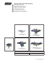 1
1
-
 2
2
-
 3
3
-
 4
4
-
 5
5
-
 6
6
-
 7
7
-
 8
8
-
 9
9
-
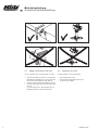 10
10
-
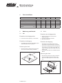 11
11
-
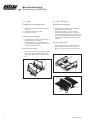 12
12
-
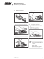 13
13
-
 14
14
-
 15
15
-
 16
16
-
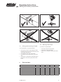 17
17
-
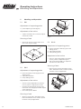 18
18
-
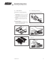 19
19
-
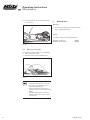 20
20
-
 21
21
-
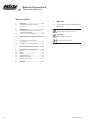 22
22
-
 23
23
-
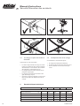 24
24
-
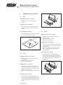 25
25
-
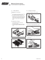 26
26
-
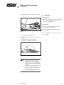 27
27
-
 28
28
-
 29
29
-
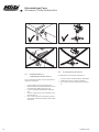 30
30
-
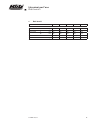 31
31
-
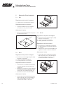 32
32
-
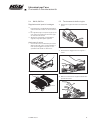 33
33
-
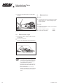 34
34
-
 35
35
-
 36
36
-
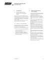 37
37
-
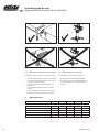 38
38
-
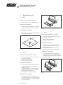 39
39
-
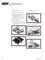 40
40
-
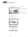 41
41
-
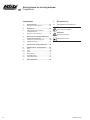 42
42
-
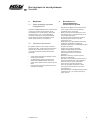 43
43
-
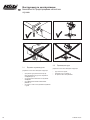 44
44
-
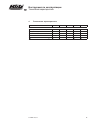 45
45
-
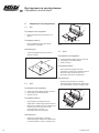 46
46
-
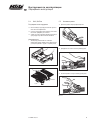 47
47
-
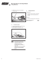 48
48
-
 49
49
-
 50
50


en otros idiomas
- français: Blitz GA I Le manuel du propriétaire
- italiano: Blitz GA I Manuale del proprietario
- English: Blitz GA I Owner's manual
- Deutsch: Blitz GA I Bedienungsanleitung
- русский: Blitz GA I Инструкция по применению
Artículos relacionados
-
Blitz BP 65 Operating Instructions Manual
-
-
Blitz GHUS El manual del propietario
-
Blitz BP 65-215/275 S3 El manual del propietario
-
-
-
Blitz X 15/15 Basic El manual del propietario