
SPMA32
SPMA32/C
2-SÄULEN-HEBEBÜHNE
2 POST LIFT
SOLLEVATORE A 2 COLONNE
ELEVATEUR 2 COLONNES
ELEVADOR DE 2 COLUMNAS
© Gennaio 2007 by ROTARY Lift. Tutti i diritti riservati. CODICE
Rev. 0 (1/01/2017)
0445-M010-0
O
P
E
R
A
T
I
O
N
&
M
A
I
N
T
E
N
A
N
C
E
M
A
N
U
A
L

EG-Konformitätserklärung
EC Declaration of Conformity
im Sinne der EG-Richtlinie 2006/42/EG über Maschinen (Anhang II A)
according to EC directive 2006/42/EC on machinery (Annex II A)
Name und Anschrift des Herstellers Name und Anschrift seines in der EU
Name and address of the manufacturer: niedergelassenen Bevollmächtigten
his authorised representative in EU
Rotary Lift BlitzRotary GmbH
2700 Lanier Drive Hüfinger Str.55
Madison, IN, 47250 USA 78199 Bräunlingen, Germany
Diese Erklärung bezieht sich nur auf die Maschine in dem Zustand, in dem sie in Verkehr gebracht wurde; vom
Endnutzer nachträglich angebrachte Teile und/oder nachträglich vorgenommene Eingriffe bleiben unberücksichtigt. Die
Erklärung verliert ihre Gültigkeit, wenn das Produkt ohne Zustimmung umgebaut oder verändert wird.
This declaration relates exclusively to the machinery in the state in which it was placed on the market, and excludes
components which are added and/or operations carried out subsequently by the final user. The declaration is no more
valid, if the product is modified without agreement.
Hiermit erklären wir, dass die nachstehend beschriebene Maschine
Herewith we declare, that the machinery described below
Produktbezeichnung / product denomination: 2-Säulen-Hebebühne / 2-post vehicle lift
Serien- / Typenbezeichnung / model / type: SPOA3T
Tragfähigkeit 3500 kg / capacity 3500 kg
Maschinen-/Seriennummer / machinery / serial number: .........................
Baujahr / Year of manufacture: 20…
allen einschlägigen Bestimmungen der Maschinenrichtlinie 2006/42/EG entspricht.
Die Maschine entspricht zusätzlich den Bestimmungen der Richtlinien 2004/108/EG über elektromagnetische
Verträglichkeit und 2006/95/EG über elektrische Betriebsmittel
(Schutzziele wurden gemäß Anhang I, Nr. 1.5.1 der
Maschinenrichtlinie 2006/42/EG eingehalten).
is complying with all essential requirements of the Machinery Directive2006/42/EC.
In addition the partly completed machinery is in conformity with the EC Directives 2004/108/EC relating to
electromagnetic compatibility and 2006/95/EC relating to electrical equipment
(Protection objectives have been met in
accordance with Annex I No. 1.5.1 of the Machinery Directive 2006/42/EC).
Angewandte harmonisierte Normen / Harmonised Standards used
EN 1493: 2010 Fahrzeug-Hebebühnen / Vehicle lifts
EN ISO 12100:2010 Sicherheit von Maschinen - Grundbegriffe / Safety of Machinery- Basic concepts
EN 60204-1:2006+A1:2009 Elektrische Ausrüstung von Maschinen / Electrical equipment of machines
EN 349:1993+A1:2008 Sicherheit von Maschinen-Mindestabstände / Safety of machinery - Minimum gaps
EN ISO 13850:2008 Sicherheit von Maschinen-Not-Halt / Safety of machinery – Emergency stop
Angewandte sonstige technische Normen und Spezifikationen
Other technical standards and specifications used:
BGG 945 Prüfung von Hebebühnen / inspection of vehicle lifts
BGR 500 Betreiben von Arbeitsmitteln / management of working appliances
BGV A3 Unfallverhütungsvorschrift elektrische Anlagen und Betriebsmittel / law accident prevention regulation of
electric facilities and equipment
Bevollmächtigter für die Zusammenstellung der relevanten technischen Unterlagen:
The person authorised to compile the relevant technical documentation:
Herr Pohl; Hüfinger Str. 55; 78199 Bräunlingen
Ort / Place : Bräunlingen
Datum / Date : 19.03.2013
______________________
Frank Scherer
Geschäftsführer / Managing Director
SPMA 32
3200kg 3200kg
1/03/2017

EG-Konformitätserklärung
EC Declaration of Conformity
im Sinne der EG-Richtlinie 2006/42/EG über Maschinen (Anhang II A)
according to EC directive 2006/42/EC on machinery (Annex II A)
Name und Anschrift des Herstellers Name und Anschrift seines in der EU
Name and address of the manufacturer: niedergelassenen Bevollmächtigten
his authorised representative in EU
Rotary Lift BlitzRotary GmbH
2700 Lanier Drive Hüfinger Str.55
Madison, IN, 47250 USA 78199 Bräunlingen, Germany
Diese Erklärung bezieht sich nur auf die Maschine in dem Zustand, in dem sie in Verkehr gebracht wurde; vom
Endnutzer nachträglich angebrachte Teile und/oder nachträglich vorgenommene Eingriffe bleiben unberücksichtigt. Die
Erklärung verliert ihre Gültigkeit, wenn das Produkt ohne Zustimmung umgebaut oder verändert wird.
This declaration relates exclusively to the machinery in the state in which it was placed on the market, and excludes
components which are added and/or operations carried out subsequently by the final user. The declaration is no more
valid, if the product is modified without agreement.
Hiermit erklären wir, dass die nachstehend beschriebene Maschine
Herewith we declare, that the machinery described below
Produktbezeichnung / product denomination: 2-Säulen-Hebebühne / 2-post vehicle lift
Serien- / Typenbezeichnung / model / type: SPOA3T
Tragfähigkeit 3500 kg / capacity 3500 kg
Maschinen-/Seriennummer / machinery / serial number: .........................
Baujahr / Year of manufacture: 20…
allen einschlägigen Bestimmungen der Maschinenrichtlinie 2006/42/EG entspricht.
Die Maschine entspricht zusätzlich den Bestimmungen der Richtlinien 2004/108/EG über elektromagnetische
Verträglichkeit und 2006/95/EG über elektrische Betriebsmittel
(Schutzziele wurden gemäß Anhang I, Nr. 1.5.1 der
Maschinenrichtlinie 2006/42/EG eingehalten).
is complying with all essential requirements of the Machinery Directive2006/42/EC.
In addition the partly completed machinery is in conformity with the EC Directives 2004/108/EC relating to
electromagnetic compatibility and 2006/95/EC relating to electrical equipment
(Protection objectives have been met in
accordance with Annex I No. 1.5.1 of the Machinery Directive 2006/42/EC).
Angewandte harmonisierte Normen / Harmonised Standards used
EN 1493: 2010 Fahrzeug-Hebebühnen / Vehicle lifts
EN ISO 12100:2010 Sicherheit von Maschinen - Grundbegriffe / Safety of Machinery- Basic concepts
EN 60204-1:2006+A1:2009 Elektrische Ausrüstung von Maschinen / Electrical equipment of machines
EN 349:1993+A1:2008 Sicherheit von Maschinen-Mindestabstände / Safety of machinery - Minimum gaps
EN ISO 13850:2008 Sicherheit von Maschinen-Not-Halt / Safety of machinery – Emergency stop
Angewandte sonstige technische Normen und Spezifikationen
Other technical standards and specifications used:
BGG 945 Prüfung von Hebebühnen / inspection of vehicle lifts
BGR 500 Betreiben von Arbeitsmitteln / management of working appliances
BGV A3 Unfallverhütungsvorschrift elektrische Anlagen und Betriebsmittel / law accident prevention regulation of
electric facilities and equipment
Bevollmächtigter für die Zusammenstellung der relevanten technischen Unterlagen:
The person authorised to compile the relevant technical documentation:
Herr Pohl; Hüfinger Str. 55; 78199 Bräunlingen
Ort / Place : Bräunlingen
Datum / Date : 19.03.2013
______________________
Frank Scherer
Geschäftsführer / Managing Director
SPMA 32/C
3200kg 3200kg
1/03/2017

CAUTION!
- This manual is an integral part of the product and must be kept together with the lift throughout its lifeti-
me.
- It should therefore be kept in an easily accessible and familiar place and consulted when in doubt. All
product operators must be able to read the manual. Any damage resulting from improper use of the lift and
failure to follow the instructions contained in this manual will release ROTARY from any liability.
ACHTUNG!
- Diese Anleitung ist ergänzender Bestandteil des Produktes und muss zusammen mit der Hebebühne
sorgfältig aufbewahrt werden.
- Die Anleitung in einem bekannten und leicht zugänglichen Ort aufbewahren und bei Bedarf zu Rate
ziehen. Alle Bediener des Produktes müssen zwecks Einsichtnahme Zugang zur Anleitung haben. Alle
Schäden, die auf Nichtbeachtung der Anweisungen dieser Anleitung oder auf einen unsachgemässen
Betrieb der Hebebühne zurückzuführen sind, sind nicht dem Hersteller anzulasten und befreien die Firma
ROTARY von jeglicher Haftungspflicht.
ATTENZIONE!
- Il presente manuale costituisce parte integrante del prodotto, dovrà seguire tutta la vita operativa del
sollevatore.
- Conservarlo, quindi, in luogo noto e facilmente accessibile e consultarlo ogni qualvolta sorgano dubbi.
Tutti gli operatori al prodotto devono poter leggere il manuale. Ogni danno derivante dalla mancata osser-
vanza delle indicazioni contenute nel presente manuale e da un uso improprio del sollevatore esime la
ROTARY da ogni responsabilità.
ATTENTION !
- La présente notice constitue partie intégrante du produit. Elle devra accompagner le pont élévateur pen-
dant tout la durée de son fonctionnement.
- La conserver dans un endroit connu et facilement accessible et la consulter à chaque fois qu’un doute se
présente. Tout dommage provoqué par le non-respect des instructions contenues dans la présente notice
ou par une utilisation incorrecte du pont élévateur décline la Société ROTARY de toute responsabilité.
¡ATENCIÓN!
- El presente manual constituye una parte integrante del producto, por lo que tendrá que seguir toda la
vida operativa del elevador.
- Conservarlo, por lo tanto, en un sitio que conozcan todos, al que se pueda acceder con facilidad y con-
sultarlo cada vez que surjan dudas. Todas las personas que utilizan el elevador tienen que poder leer el
manual. Cualquier daño que derive de la falta de respeto de las indicaciones que contiene el presente
manual, o del uso incorrecto del elevador exime de toda responsabilidad a ROTARY

PAGE INTENTIONELLY LEFT BLANK
ABSICHTLICH LEER GELASSENE SEITE
PAGINA LASCIATA INTENZIONALMENTE BIANCA
PAGE INTENTIONELLEMENT VIDE
PAGINA VACÍA INTENCIONADAMENTE

6
DOVER
A COMPANY
ROTARY LIFT
DRAW ING NUMB ER
SCALE
DRAWN
DATE
APPRO VED
THIRD ANGLE
PROJECTION
NOTES:
SHEET
1 of 1
SPMA32_8504
MG
06-12-16
SPMA32
The design and detail illustrated in this drawing is the property of Rotary
Lift. It is being loaned with the expressed condition that it will not be
duplicated or used except by permission and is subject to return upon request.
REV
CO NUMDATE
BY
DO NOT SCALE DRAWING
UNLESS OTHERWISE SPECIFIED:
0.8mm MIN. CORNER BREAK
REMOVE ALL BURRS
UNLESS OTHERWISE NOTED:
ANGULAR DIMENSIONS:
1
OTHER DIMENSIONS: 0.8mm (<305mm)
1.6mm (>or= 305mm)
Tragfähigkeit: max.3200kg
capacity
HSL-3 M10/20 type
HVU M12x110 type
90
110
My
min.200*
2269
Fundament min 4000
Das Netzkabel wird
von oben in die
Bediensäule geführt.
Insert the power supply
cable from above
to the operating column
Alle Maße in Millimeter
all dimensions in millimeter
Mass- und Konstruktionsänderungen vorbehalten!
subject to alterations!
Betonqualität
quality of concrete
min.C25/30
normal bewehrt
normal armouring
We point out the minimum requirement
of the foundation in our plans.
The condition of the local realities
for example: the ground under the
foundation) does not lie in our
responsibility. The execution of
the installation situation must be
individually specified by the planning
architect or by the engineer engaged in
statically calculations in the special case.
Wir weisen in unseren Plänen
auf die Mindestanforderung
des Fundamentes hin, jedoch
der Zustand der örtlichen
Gegebenheiten (z.B. Untergrund,
Ausführung etc.)
obliegt nicht unserer Verantwortung.
Die Ausbildung der Einbausituation
muss vom planenden Architekten
bzw. Statiker im speziellen Fall
individuell spezifiziert werden.
"H"
Detail "H"
Bauseits an der Bediensäule bereitstellen:
Netzanschluss: SPMA32: 3PH+PE 400V,50Hz
SPMA32/C: 3PH,N+PE 400V,50Hz
Absicherung: 25 Ampere träge
Kabellänge: SPMA32: cable >= 4 x 4mm
2
SPMA32/C: cable >= 5 x 4mm
2
optional: Druckluft, lichte Weite 6mm, 6-10 bar
Prepared by customer at the operating column:
power supply: SPMA32: 3PH+PE 400V,50Hz
SPMA32/C: 3PH,N+PE 400V,50Hz
fuse: 25 Ampere, time lag
cable: SPMA32: cable >= 4 x 4mm
2
SPMA32/C: cable >= 5 x 4mm
2
optional air pressure: inner diameter 6mm, 6-10 bar
OKFFB
Grundplatte/base plate
Bediensäule
Operating column
Mx
Mx
maximale statische Kräfte und Momente
maximum Forces and Moments
empfohlene Dübel / recommended anchors
*) Betonstärke min.200mm
ohne Belag (Fliesen/Estrich)
Concrete thickness
min.200mm without
floor pavement/tiles
Die Mindestverankerungstiefe des Dübels beachten.
Mit Estrich/Fliesen sind längere Dübel einzusetzen.
Observe the min. anchorage of the dowels. With floor
pavements use longer dowels.
Die Montagevorschrift des Dübelherstellers beachten.
Observe the regulation of the dowel manufacturer
PP
P: 19 KN / Mx: 16 K Nm / My: 15 K Nm
Anschlussarmierung zum
vorhandenen Betonboden
herstellen
Produce a connection reinforcement
to the existing concrete floor
optional:
Verlängerungen
extension kit
2510
3901
2042 max
92-152
95
2644
550-1100
2637
2389
2664
Fundament min 1500
3132
926-1440
Einfahrrichtung
Drive in direction
160
100
30
30
220
410
520
350
50
170
30
180
ø18
92-152
38
max.3943

7
IN DER BEDIENUGSANLEITUNG VERWENDETE ZEICHEN
SYMBOLS USED IN THE MANUAL
SIMBOLOGIA UTILIZZATA NEL MANUALE
SYMBOLES UTILISÉS DANS LA NOTICE
SIMBOLOGíA UTILIZADA EN EL MANUAL
SIMBOLISYMBOLSZEICHEN
SYMBOLES SÍMBOLOS
Sollevamento
dall’alto
Lifting from aboveAnheben von oben Levage par le haut
Elevación desde
arriba
Movimentazione
con carrello
elevatore o
transpallets
Moving with fork lift
truck or transpallets
Transport mit
Gabelstapler oder
Handgabelhubwagen
Déplacement avec
chariot élévateur ou
transpalettes
Desplazamiento con
carretilla elevadora
o transpaletas
Indossare guanti da
lavoro
Wear work gloves
Der Arbeit
angemessene
Handschuhe tragen
Porter des gants de
travail
Llevar guantes de
trabajo
Calzare scarpe da
lavoro
Wear work shoes
Der Arbeit
angemessene
Schuhe tragen
Mettre des
chaussures de
travail
Usar zapatos de
trabajo
Non passare nè
sostare sotto carichi
sospesi
Do not walk or stay
beneath suspended
loads
Sich nicht unter
aufgehobener Last
aufhalten oder
durchgehen
Ne pas passer et ne
pas s’arrêter
au-dessous des
charges
suspendues
No pasar ni
permanecer por
debajo de cargas
suspendidas
Personale
specializzato
Specialist staff
Qualifiziertes
Fachpersonal
Personnel qualifié
Personal
especializado
Pericolo di scariche
elettriche
Shock hazard
Gefahr: elektrische
Entladungen
Danger
d'électrocution
Peligro de
descargas
eléctricas
Attenzione!Caution!Achtung! Attention! iAtención
Organi meccanici in
movimento.
Working mechanical
parts
Mechanische
Elemente in
Bewegung
Organes
mécaniques en
mouvement
Órganos mecánicos
en movimiento
SchiacciamentoCrushingQuetschgefahr
Risques
d’écrasement
Aplastamiento
ObbligoObligationPflicht Obligation Obligación

8
INDICE
CONTENTS
INHALTSVERZEICHNIS
0. NORME GENERALI DI SICUREZZA
1. DISPOSITIVI DI SICUREZZA
1.1 INTERRUTTORE GENERALE
LUCCHETTATO
1.2 SISTEMA A UOMO PRESENTE
1.3 BLOCCO MECCANICO D'EMERGENZA
1.4 RIALLINAMENTO CARRELLI
1.5 BLOCCO DI EMERGENZA
1.6 MANOVRE PERMESSE IN CONDIZIONI
DI EMERGENZA
1.7 ARRESTO USURA CHIOCCIOLE
1.8 RISCHI RESIDUI
1.9 PITTOGRAMMI PRESENTI SUL
SOLLEVATORE
2. DESTINAZIONE D’USO
3. DATI TECNICI
3.1 MOVIMENTAZIONE E
PREINSTALLAZIONE
4. DESCRIZIONE DEL SOLLEVATORE
4.1 CARATTERISTICHE TECNICHE
PRINCIPALI
4.2 COMANDI DEL SOLLEVATORE
4.3 ATTITUDINE ALL'IMPIEGO
5. VERIFICA DEI REQUISITI MINIMI
RICHIESTI PER LUOGO DI
INSTALLAZIONE
6 INSTALLAZIONE
6.1 REQUISITI PER L'INSTALLAZIONE
6.2 ISTRUZIONI PER L'INSTALLAZIONE
6.3 CONTROLLO TENSIONE
6.4 ALLACCIAMENTO RETE
6.5 COLLEGAMENTI
6.6 MONTAGGIO DEL CAVO DI RIALLINEO
6.7 COMPLETAMENTO E CONTROLLO
6.8 SMONTAGGIO
7. ISTRUZIONI PER L’USO DEL
SOLLEVATORE
7.1 USO IMPROPRIO DEL SOLLEVATORE
7.2 USO DI ACCESSORI
7.3 ADDESTRAMENTO DEL PERSONALE
PREPOSTO
7.4 PRECAUZIONI D’USO
7.5 IDENTIFICAZIONE DEI COMANDI E
LORO FUNZIONE
8. INCONVENIENTI
9. MANUTENZIONE
9.1 GUIDE DI SCORRIMENTO
9.2 VASCHETTE DI LUBRIFICAZIONE
9.3 CHIOCCIOLE PORTANTI
9.4 CUSCINETTI
10. ACCANTONAMENTO
10.1 ROTTAMAZIONE
11. IMPIANTO ELETTRICO
12. RAPPORTO DI INSTALLAZIONE -
VISITA PERIODICA - MANUTENZIONI
STRAORDINARIE E RIPARAZIONI
13. DATI DI IDENTIFICAZIONE DELLA
MACCHINA
14 CERTIFICATO
0. GENERAL SAFETY PRECAUTIONS
1. SAFETY DEVICES
1.1 PADLOCKABLE MAIN SWITCH
1.2 DEADMAN DEVICE SYSTEM
1.3 MECHANICAL EMERGENCY STOP
1.4 CARRIAGE HEIGHT
SYNCHRONIZATION
1.5 EMERGENCY BLOCK
1.6 MANOEUVRES PERMITTED IN
EMERGENCY CONDITIONS
1.7 NUT WEAR STOP
1.8 INDICATION OF OUTSTANDING RISKS
1.9 PICTOGRAMS ON LIFT
2. INTENDED USE
3. TECHNICAL DETAILS
3.1 PRE-INSTALLATION AND MOVEMENT
4. DESCRIPTION OF LIFT
4.1 MAIN TECHNICAL SPECIFICATIONS
4.2 LIFT CONTROLS
4.3 SUITABILITY FOR USE
5. CHECKING THE MINIMUM
REQUIREMENTS FOR THE PLACE OF
INSTALLATION
6 INSTALLATION
6.1 INSTALLATION REQUIREMENTS
6.2 INSTALLATION INSTRUCTIONS
6.3 VOLTAGE CHECK
6.4 CONNECTING UP TO THE MAINS
6.5 CONNECTIONS
6.6 FITTING THE REALIGNMENT CABLE
6.7 COMPLETION AND CHECK
6.8 DISMANTLING
7. INSTRUCTIONS FOR USING THE LIFT
7.1 IMPROPER USE OF THE LIFT
7.2 USE OF ACCESSORIES
7.3 STAFF TRAINING
7.4 IMPORTANT CHECKS TO BE MADE
7.5 DESCRIPTION AND FUNCTION OF
CONTROLS
8. TROUBLESHOOTING
9. MAINTENANCE
9.1 SLIDEWAYS
9.2 LUBRICATION TANKS
9.3 MAIN NUTS
9.4 BEARINGS
10. STORAGE
10.1 SCRAPPING
11. ELECTRICAL INSTALLATION
12. INSTALLATION REPORT -
PERIODICAL VISIT - UNSCHEDULED
MAINTENANCE AND REPAIRING
13. MACHINE IDENTIFICATION DATA
14 CERTIFICATE
0. ALLGEMEINE
SICHERHEITSVORSCHRIFTEN
1. SICHERHEITSEINRICHTUNGEN
1.1 VERRIEGELBARER HAUPTSCHALTER
1.2 TOTMANN-SYSTEM
1.3 MECHANISCHE NOT-AUS-
VORRICHTUNG
1.4 GLEICHLAUFREGELUNG DER
HUBWAGEN
1.5 NOT-AUS
1.6 BEI NOT-AUS ZUGELASSENE
MANÖVER
1.7 STOPP BEI
TRAGMUTTERABNUTZUNG
1.8 HINWEISE ZU DEN RESTRISIKEN
1.9 AUF DER HEBEBÜHNE VORHANDENE
GEFAHRENZEICHEN
2. BESTIMMUNGSGEMÄSSE
VERWENDUNG
3. TECHNISCHE DATEN
3.1 TRANSPORT UND
VORINSTALLATION
4. BESCHREIBUNG DER HEBEBÜHNE
4.1 TECHNISCHE HAUPTEIGENSCHAFTEN
4.2 STEUERUNGEN DER HEBEBÜHNE
4.3 BETRIEBSTÜCHTIGKEIT
5. KONTROLLE DER
MINDESTERFORDERNISSEN FÜR DEN
AUFSTELLUNGSORT
6 AUFSTELLUNG
6.1 INSTALLATIONSANFORDERUNGEN
6.2 INSTALLATIONSANWEISUNGEN
6.3 KONTROLLE DER SPANNUNG
6.4 NETZANSCHLUSS
6.5 ANSCHLÜSSE
6.6 MONTAGE DES
AUSRICHTUNGSDRAHTSEILS
6.7 KOMPLETTIERUNG UND KONTROLLE
6.8 DEMONTAGE
7. ANWEISUNGEN FÜR DIE BEDIENUNG
DER HEBEBÜHNE
7.1 UNSACHGEMÄSSE BEDIENUNG DER
HEBEBÜHNE
7.2 GEBRAUCH VON ZUBEHÖRTEILEN
7.3 SCHULUNG DES
BEDIENUNGSPERSONALS
7.4 VORSICHTSMASSNAHMEN
7.5 DIE STEUERUNGEN UND IHRE
FUNKTIONEN
8. BETRIEBSSTÖRUNGEN
9. WARTUNG
9.1 GLEITBAHNEN
9.2 SCHMIERBEHÄLTER
9.3 TRAGMUTTER
9.4 LAGER
10. EINLAGERUNG
10.1 VERSCHROTTUNG
11. ELEKTROANLAGE
12. INSTALLATIONSBERICHT -
PERIODISCHER KUNDENBESUCH -
AUSSERORDENTLICHE WARTUNGEN
UND REPARATUREN
13. KENNZEICHNUNGSDATEN DER
MASCHINE
14 ZERTIFIKAT

9
INDEX
ÍNDICE
0. NORMES GENERALES DE SECURITE
1. DISPOSITIFS DE SECURITE
1.1 INTERRUPTEUR PRINCIPAL
VERROUILLABLE
1.2 SYSTÈME DE SÉCURITÉ “HOMME
MORT”
1.3 ARRÊT MÉCANIQUE D’URGENCE
1.4 SYNCHRONISME DE LEVAGE
1.5 ARRÊT D’URGENCE
1.6 QUOI FAIRE EN CAS D’ARRÊT DE
SECOURS
1.7 ARRÊT USURE ECROUS
1.8 RISQUES RÉSIDUELS
1.9 PICTOGRAMMES PRÉSENTS SUR
L’ÉLÉVATEUR
2. DESTINATION D’USAGE
3. CARACTERISTIQUES TECHNIQUES
3.1 DÉPLACEMENT ET PRÉ-INSTALLATION
4. DESCRIPTION DU PONT ELEVATEUR
4.1 PRINCIPALES CARACTÉRISTIQUES
TECHNIQUES
4.2 COMMANDES DU PONT ÉLÉVATEUR
4.3 DISPOSITION POUR L'UTILISATION
5. VERIFICATION DES CARACTERISTIQUES
MINIMES REQUISES POUR LA ZONE
D’INSTALLATION
6 INSTALLATION
6.1 CONDITIONS REQUISES POUR
L’INSTALLATION
6.2 INSTRUCTIONS POUR L’INSTALLATION
6.3 CONTRÔLE DE LA TENSION
6.4 CONNEXION AU RÉSEAU
6.5 CONNEXIONS
6.6 MONTAGE DU CÂBLE DE
RÉALIGNEMENT
6.7 COMPLÈTEMENT DE L’INSTALLATION ET
CONTRÔLE
6.8 DÉMONTAGE
7. MODE D’EMPLOI DU PONT ELEVATEUR
7.1 UTILISATION INCORRECTE DU PONT
ÉLÉVATEUR
7.2 UTILISATION D’ACCESSOIRES
7.3 FORMATION DU PERSONNEL PRÉPOSÉ
7.4 PRÉCAUTIONS POUR L’EMPLOI
7.5 IDENTIFICATION ET FONCTION DES
COMMANDES
8. PANNES EVENTUELLES
9. ENTRETIEN
9.1 GLISSIÈRES
9.2 BACS DE GRAISSAGE
9.3 ECROUS PORTEURS
9.4 COUSSINETS
10. STOCKAGE
10.1 MISE À LA FERRAILLE
11. INSTALLATION ELECTRIQUE
12. RAPPORT D’INSTALLATION -
CONTROLE PERIODIQUE -
INTERVENTIONS D’ENTRETIEN
SPECIAL ET REPARATIONS
13. DONNÉES D’IDENTIFICATION DE LA
MACHINE
14 CERTIFICAT
0. NORMAS DE SEGURIDAD
1. DISPOSITIVOS DE SEGURIDAD
1.1 INTERRUPTOR GENERAL BAJO
CANDADO
1.2 SISTEMA “HOMBRE MUERTO”
1.3 BLOQUEO MECÁNICO DE EMERGENCIA
1.4 REAJUSTE DE LOS CARROS
1.5 BLOQUEO DE EMERGENCIA
1.6 MANIOBRAS PERMITIDAS EN
CONDICIONES DE EMERGENCIA
1.7 BLOQUEO DESGASTE TUERCAS
PORTANTES
1.8 RIESGOS RESIDUOS.
1.9 PICTOGRAMAS EN EL ELEVADOR
2. DESTINACIÓN DE USO
2.1 DATOS DE IDENTIFICACION DE LA
MAQUINA
3. DATOS TÉCNICOS
3.1 DESPLAZAMIENTO Y PREINSTALACIÓN
4. DESCRIPCIÓN DEL ELEVADOR
4.1 CARACTERISTICAS TÉCNICAS
PRINCIPALES
4.2 MANDOS DEL ELEVADOR
4.3 APTITUD PARA EL EMPLEO
5. COMPROBACIÓN DE LA EXISTENCIA DE
LOS REQUISITOS MÍNIMOS REQUERIDOS
PARA EL SITIO DE LA INSTALACIÓN
6 INSTALACIÓN
6.1 REQUISITOS PARA LA INSTALACIÓN
6.2 INSTR3ACIÓN DEL SISTEMA ELÉCTRICO
6.3 CONTROL DE TENSIÓN
6.4 ENLACE A LA RED
6.5 CONEXIONES
6.6 MONTAJE DEL CABLE DE REALINEACIÓN
6.7 TERMINACIÓN DE LA INSTALACIÓN Y
CONTROL
6.8 DESMONTAJE
7. INSTRUCCIONES PARA EL USO DEL
ELEVADOR
7.1 USO IMPROPIO DEL ELEVADOR
7.2 USO DE ACCESORIOS
7.3 FORMACIÓN DEL PERSONAL
AUTORIZADO
7.4 PRECAUCIONES DURANTE EL USO
7.5 IDENTIFICACIÓN DE LOS MANDOS Y SUS
FUNCIONES
8. INCONVENIENTES
9. MANTENIMIENTO
9.1 GUÍAS DESLIZANTES
9.2 TANQUES DE LUBRICACIÓN
9.3 TORNILLOS PATRÓN PORTANTES
9.4 COJINETES
10. DESUSO
10.1 REDUCCIÓN A RESIDUOS
11. INSTALACIÓN ELÉCTRICA
12. RELACIÓN DE INSTALACIÓN -
CONTROL PERIÓDICO -
MANTENIMIENTO EXTRAORDINARIO Y
REPARACIONES
13. DATOS DE IDENTIFICACION DE LA
MAQUINA
14 CERTIFICADO
ZUSAMMENSETZUNG DER
ANLEITUNG
64 Seiten
(inkl. Deckblätter)
COMPOSITION OF MANUAL
64 pages
(including cover pages)
COMPOSIZIONE DEL
MANUALE
64 pagine
(comprese le copertine)
COMPOSITION DE LA
NOTICE
64 pages
(pages de la couverture
inclues
COMPOSICIÓN DEL
MANUALE
64 páginas
(incluidas las cubiertas)

10
0
0. GENERAL SAFETY PRECAUTIONS
The lift should only be used by properly trained personnel and only after
reading and understanding this manual. The operator must be authorised
by the person in charge of the plant.
Tampering with or making changes to the lift and safety devices is forbid-
den. Failure to comply will result in the manufacturer being released from
all liability for any resulting damages.
Also follow these instructions:
- only use ROTARY accessories and spares;
- installation must be performed by authorised and professional person-
nel;
- make sure no hazardous situations occur during up or down movement
of the lift. If they do, stop the lift immediately and remedy the causes of the
emergency;
- the arms must be positioned at the vehicle points provided. Before
lifting, check vehicle stability. During up or down movement, check the
vehicle load bearing point;
- standing on the lifting mechanisms is forbidden;
- after lifting, position the switch on “0”;
- before lifting, check the load is correct by means of the “load diagram”
adhesive.
0. NORMES GENERALES DE SECURITÈ
Le pont élévateur ne peut être utilisé que par un personnel ayant suivi une
formation appropriée et ayant lu et compris le contenu de la présente
notice; l’opérateur doit être autorisé par la personne responsable de l’in-
stallation.
Il est strictement interdit de manipuler ou de modifier l’élévateur et les
dispositifs de sécurité; toute dérogation à ces instructions décline le fabri-
cant de toute responsabilité.
Respecter entre autres les instructions suivantes:
- n’utiliser que des accessoires et des pièces de rechange ROTARY;
- l’installation doit être prise en charge par un personnel autorisé et quali-
fié;
- contrôler l’absence de toute condition de danger pendant les mano-
euvres de montée et de descente; en cas de danger, arrêter immédiate-
ment l’élévateur et éliminer les causes à l’origine de la condition d’urgen-
ce;
- les bras doivent être positionnés aux points prévus par le fabricant du
véhicule: vérifier la stabilité du véhicule avant d’entreprendre la mano-
euvre de levage; pendant les phases de montée et de descente, vérifier le
point d’appui du véhicule;
- Il est strictement interdit de monter ou de s’arrêter sur les organes de
levage;
- une fois le levage terminé, positionner l’interrupteur sur le “0”;
- avant d’effectuer le levage, contrôler à l'aide du “diagramme de char-
gement” que le chargement soit correct.
0. NORMAS GENERALES DE SEGURIDAD
El uso del elevador sólo está permitido a personal capacitado a propósito
y sólo después de haber leído y comprendido el presente manual; el ope-
rador tiene que estar autorizado por quien desempeña el cargo de respon-
sable de la instalación.
Están prohibidas las alteraciones o modificaciones del elevador y de los
dispositivos de seguridad; en caso de que se verifique lo descrito ante-
riormente, se considera al constructor no responsable de los daños deri-
vados.
Además, hay que seguir las siguientes indicaciones:
- usar únicamente accesorios y repuestos ROTARY;
- la instalación tiene que ser realizada única y exclusivamente por perso-
nal autorizado y cualificado.
- controlar que durante la fase de subida y bajada no se verifiquen condi-
ciones de peligro: de ser así, detener la máquina y eliminar las causas de
emergencia;
- los brazos tienen que estar colocados en los puntos predispuestos en el
vehículo; antes de la subida, comprobar la estabilidad del vehículo, com-
probar durante la fase de subida y bajada el punto de apoyo del vehículo;
- Está terminantemente prohibido subirse o pararse en los órganos de
elevación.
- después de la elevación colocar el interruptor en “O”
- antes de la elevación, comprobar con el adhesivo “diagrama de carga”
que la carga esté correcta.
0. ALLGEMEINE SICHERHEITSVORSCHRIFTEN
Die Hebebühne darf ausschliesslich von geschultem Fachpersonal
bedient werden und erst nachdem die Bedienungsanleitung aufmerksam
gelesen und verstanden worden ist. Der Bediener muss zur Bedienung
der Hebebühne von der Person autorisiert werden, die die Verantwortung
für die Anlage trägt.
Unbefugtes Betätigen und Änderungen an der Hebebühne sowie an den
Sicherheitseinrichtungen sind verboten. Bei Verstoss gegen diese Vor-
schriften lehnt der Hersteller jede Verantwortung für die daraus ent-
stehenden Schäden ab.
Darüber hinaus sind folgende Verhaltensmassregeln einzuhalten:
- nur ROTARY Zubehöre und Ersatzteile verwenden;
- die Hebebühne ist durch autorisiertes Fachpersonal aufzustellen;
- sicherstellen, dass beim Hoch- und Herunterfahren der Hebebühne
keine gefährliche Situationen entstehen; ggf. die Hebebühne sofort
anhalten und die Gefährdungen beseitigen;
- die Arme sind auf die Punkte zu positionieren, die auf dem Fahrzeug
vorgesehen sind; vor dem Hublauf die Stabilität des Fahrzeugs kontrollie-
ren; während des Hoch- und Herunterfahrens den Aufnahmepunkt des
Fahrzeugs kontrollieren;
- Es ist verboten, auf die Hubelemente zu steigen oder sich auf diesen
aufzuhalten.
- nach der Hochfahrt den Schalter auf “0” setzen;
- vor dem Anheben des Fahrzeugs durch Einsichtnahme des Klebeschil-
des “Lastschema” sicherstellen, dass die Last vorschriftsgemäss ist.
0. NORME GENERALI DI SICUREZZA
L’uso del sollevatore è consentito solo a personale appositamente adde-
strato e solo dopo aver letto e compreso il presente manuale; l’operatore
deve essere autorizzato da chi ricopre il ruolo di responsabile dell’impian-
to.
Sono vietate manomissioni o modifiche al sollevatore e ai dispositiovi di
sicurezza; nel caso in cui si verifichi quanto sopra scritto il costruttore si
ritiene sollevato dai danni derivati.
Seguire inoltre le seguenti indicazioni:
- usare solo accessori e ricambi ROTARY;
- l’installazione deve essere fatta da personale autorizzato e qualificato;
- controllare che durante la fase di salita e discesa non si verifichino con-
dizioni di pericolo; in tal caso arrestare immediatamente il sollevatore e
rimuovere le cause di emergenza;
- i bracci devono essere posizionati sui punti predisposti del veicolo;
prima della salita verificare la stabilità del veicolo; verificare durante la
fase di salita e discesa il punto di appoggio del veicolo;
- è vietato salire o sostare sugli organi di sollevamento;
- dopo il sollevamento posizionare l’interruttore sullo “0”;
- prima di sollevare verificare con l’adesivo “diagramma di carico” che il
carico sia corretto.

11
vación de la sonda térmica del motor; el rearme automático de la sonda se
verifica después de 3 minutos aproximadamente.
1.4 Reajuste de los carros
Cualquier uso indebido o modificación de la máquina que no
hayan sido autorizadas por el fabricante lo eximen de los
posibles daños que puedan derivar o estar relacionados con
los actos mencionados.
Quitar o usar indebidamente los dispositivos de seguridad
comporta una violación de las Normas Europeas de Seguri-
dad.
Cada vez que se produce una diferencia en altura de los carros igual a 18
mm, el dispositivo de control se activa automáticamente, con el fin de
reestablecer la nivelación correcta.
N.B. En sus du blocage mécanique ci-dessus il pourrait se produire le
déclenchement automatique de la sonde thermique du moteur. Le rétablis-
sement de la sonde se fait automatiquement après trois minutes env.
1.4 Synchronisme de levage
La responsabilité du fabricant ne peut être mise en cause
pour les dommages dérivant de toute altération ou modifica-
tion de l’équipement non autorisée préalablement par le fabri-
cant.
La suppression ou l’altération des dispositifs de sécurité com-
porte une violation des Normes Européennes en matière de
sécurité.
Lorsque la différence de niveau entre les deux chariots atteint 18 mm, le
contrôleur rétablit l’alignement correct automatiquement.
Hinweis: Ausser der mechanischen Sperre kann die obige Situation das
Abschalten des Motorwärmefühlers zur Folge haben. Es muss dann das
automatische Wiedereinschalten desselben (nach ca. 3 Minuten) abgewar-
tet werden.
1.4
Gleichlaufregelung der Hubwagen
Alle eigenmächtigen Eingriffe oder Modifizierungen an Ein-
richtungen, die nicht zuvor vom Hersteller autorisiert wurden,
entheben diesen von der Haftungspflicht für dadurch verur-
sachte Schäden.
Die Entfernung oder der Umbau der Sicherheitseinrichtungen stellt eine Ver-
letzung der Europäischen Sicherheitsnormen dar.
Erreicht der Höhenunterschied der Hubwagen 18 mm greift automatisch die
Überwachungsvorrichtung ein und stellt den Gleichlauf wieder her.
N.B. Besides the mechanical stop described above, the motor heat probe
might be disabled. This is automatically reset after about 3 minutes.
1.4 Carriage height synchronization
Any unauthorised modifications or tampering with the equipment
release the manufacturer from any liability for damages caused
by or related to the above mentioned acts.
Removal of or tampering with safety devices constitutes an
infringement of European Safety Regulations.
Should the difference in level of the two carriages exceed 18 mm, the
control device automatically resets the correct alignment.
1. SAFETY DEVICES
1.1 Padlockable main switch
1.2 Deadman device
The lift is equipped with a “deadman” type operative system so that up or
down movement is immediately stopped when the control reverser-
switch is released.
1.3 Mechanical emergency stop
The lift is fitted with mechanical stops that trigger when the limit switch
sends warning signals, at the end of an up or down run. In these situa-
tions, jog operate the movement opposite to the previous movement for a
distance of 5-10 cm.
Check the relative limit switch and replace if necessary.
1. SICHERHEITSEINRICHTUNGEN
1.1 Verriegelbarer Hauptschalter
1.2 Totmann-System
Die Hebebühne ist mit dem “Totmann”-Betriebssystem ausgerüstet. Wird die
Schalttaste losgelassen, werden die Hub- und Absenkbewegungen
unverzüglich unterbrochen.
1.3
Mechanische Not-Aus-Vorrichtung
Sollte ein Endschalter am Ende der Aufwärts- bzw. Abwärtsbewegung nicht
funktionieren, wird die Hebebühne über ein mechanisches Sperrsystem
abgestoppt.
Unter diesen Umständen die Hebebühne im umgekehrter Richtung ca. 5 - 10
cm stossweise zurückfahren.
Den Endschalter prüfen und ggf. auswechseln.
1. DISPOSITIFS DE SECURITE
1.1 Interrupteur principal verrouillable
1.2 Système (de sécurité "d'homme-mort")
Le pont élévateur est équipé d’un système (dit “d’homme mort”): les opérations de
montée ou de descente commandées sont immédiatement interrompues lors du
relâchement du poussoir.
1.3 Arrêt d'urgence (mécanique)
Le pont est équipé de butées mécaniques agissant à la fin de la course de levée
ou de descente, en cas de mauvais fonctionnement des fins de course. Dans ce
cas, commander par à-coups la manoeuvre opposée à l’opération précédente
pour une course de 5-10 cm. Contrôler le fin de course en question et le remplacer
au besoin.
1. DISPOSITIVOS DE SEGURIDAD
1.1 Interruptor general bajo candado
1.2 Sistema “hombre muerto”
El elevador tiene un sistema de tipo “hombre muerto”, las operaciones de
subida o descenso son interrumpidas de immediato al soltar el interrup-
tor-invertidor de mando.
1.3 Bloqueo mecánico de emergencia
El elevador está dotado de topes mecánicos que actúan en caso de ano-
malías del fin de carrera, al final del recorrido de subida o de descenso.
En esos casos, mandar a intervalos la maniobra opuesta a la operación
anterior durante un recorrido de 5 - 10 cms.
Regular o sustituir el final de carrera correspondiente.
NOTA: Además del tope mecánico, se puede también verificar la desacti-
1
1. DISPOSITIVI DI SICUREZZA
1.1 Interruttore generale lucchettabile
1.2 Sistema a uomo presente
Il ponte è dotato di un sistema operativo del tipo "uomo presente": le ope-
razioni di salita o di discesa, sono immediatamente interrotte al rilascio
dell'interruttore-invertitore di comando.
1.3 Blocco meccanico d'emergenza
Il ponte è dotato di arresti meccanici che agiscono in caso di anomalie del
finecorsa, al termine della corsa di salita o di discesa.
In tali situazioni comandare a scatti la manovra opposta all’operazione
precedente per una corsa di 5-10 cm.
Controllare il finecorsa interessato, ed eventualmente sostituirlo.
N.B. Oltre al blocco meccanico di cui sopra puó verificarsi il disinserimento
della sonda termica del motore; il riarmo automatico di quest’ultima avverrà
dopo circa 3 minuti.
1.4 Riallineamento carrelli
Ogni manomissione o modifica dell'apparecchiatura non pre-
ventivamente autorizzate dal costruttore sollevano quest'ulti-
mo da danni derivati o riferibili agli atti suddetti.
La rimozione o manomissione dei dispositivi di sicurezza
comporta una violazione delle Norme Europee sulla sicurez-
za.
Quando la differenza di altezza tra i due carrelli raggiunge i 18mm, il dispo-
sitivo di controllo interviene automaticamente per ripristinare il corretto
allineamento.

12
1.7 Nut wear stop
If the lift is operated even when the limit marks are aligned (see par. 9.3),
the safety system becomes operative. The device intervention allows to
move down the charge but it does not allow to lift it.
1.5 Emergency block
This type of block occurs in the case of:
- the carriages more than 40 mm out of alignment;
- motor block
- breakage of alignment cable.
1.6 Manoeuvres permitted in emergency conditions
- When the lift is in the emergency state (see previous paragraph), no
operation is allowed by means of the “lowering” or “lifting” push buttons.
To reset the operation mode, apply to our After Sales Service.
- To remove the car from the lift, turn the pulleys by hand.
1
1.5 Blocco di emergenza
Questo tipo di blocco interviene in caso di:
- disallineamento dei carrelli superiore a 40 mm;
- blocco dei motori
- rottura del cavetto di allineamento.
1.6 Manovre permesse in condizioni di emergenza
- Quando il sollevatore si trova in condizione di emergenza (vedi paragrafo
precedente) non è consentita nessuna manovra di salita o discesa mediante
i comandi; per il ripristino del funzionamento contattare il Servizio Assistenza
- Se occorresse togliere il veicolo dal ponte è possibile far scendere i carrelli
azionando manualmente le pulegge.
1.7 Arresto usura chiocciole
Utilizzando il sollevatore oltre il limite indicato al par. 9.3 si avrà l’intervento
dell’arresto usura chiocciola.
L’intervento del dispositivo consente la discesa del carico e impedisce il solle-
vamento.
1.5 Arrêt d’urgence
Ce type d’arrêt intervient lorsque:
- le désalignement des chariots est supérieur à 40 mm;
- les moteurs s’arrêtent;
- le câble d’alignement se casse.
1.6 Quoi faire en cas d’arrêt de secours
- Lorsque le pont-élévateur est dans l’arrêt de secours (voir par.
précédent), on ne peut pas commander par les boutons-poussoirs ni la
montée ni la descente. Pour rétablir le fonctionnement, il faut s’adresser
au Service Après-Vente.
- Pour descendre le véhicule du pont, baisser les chariots en actionnant
les poulies manuellement.
1.7 Arret usure ecrous
Si le pont élévateur continue à travailler au délà de la limite indiquée au
par. 9.3, on provoquera l’actionnement de l’arrêt de sécurité usure écrou.
L’actionnement du dispositif permet la descente de la charge et empêche
le levage.
1.5 Bloqueo de emergencia
Este tipo de bloqueo se activa en caso de:
- desalineación de los carros superior a 40 mm;
- bloqueo de los motores;
- ruptura del cablecito de alineación.
1.6 Maniobras permitidas en condiciones de emergencia
- Cuando el elevador se encuentra en condiciones de emergencia (ver
párrafo anterior) ninguna maniobra de subida o bajada está permitida por
medio de los pulsadores. Para reestablecer el funcionamiento del eleva-
dor, consultar con el Servicio Post-Venta.
- Si fuera necesario remover el vehículo del elevador, se pueden bajar los
carros activando manualmente las poleas.
1.7 Bloqueo desgaste tuercas portantes
Insistiendo en el uso del elevador más allá del límite indicado en el párrafo
9.3, se produce el desgaste total y la parada mecánica de la tuerca. La
activación de este dispositivo permite la bajada de la carga, pero impide
la elevación.
1.5 Not-Aus
Not-Aus-Abschaltung bei:
- Höhenunterschied zwischen den beiden Hubwagen über 40 mm;
- Motorenstopp;
- Bruch des Ausrichtungsdrahtseils.
1.6 Bei Not-Aus zugelassene Manöver
- Bei Not-Aus der Hebebühne (siehe obiger Abschnitt) darf diese über die
Tasten weder hoch- noch heruntergefahren werden. Zur Wiederherstel-
lung des Betriebs den Kundendienst zu Rate ziehen.
- Ist das Fahrzeug auf den Boden zu bringen, die Hubwagen manuell über
die Riemenscheiben herunterfahren.
1.7 Stopp bei Tragmutterabnutzung
Wird die Hebebühne über die in Abschitt 9.3 angegebene Grenze hinaus
benutzt, greift die Tragmutterabnutzungs-Vorrichtung ein.
Der Eingriff dieser Vorrichtung ermöglicht das Herunterfahren der Last
und verhindert das Hochfahren.

13
PAGE INTENTIONELLY LEFT BLANK
ABSICHTLICH LEER GELASSENE SEITE
PAGINA LASCIATA INTENZIONALMENTE BIANCA
PAGE INTENTIONELLEMENT VIDE
PAGINA VACÍA INTENCIONADAMENTE

14
1
1
2
3
4
5
6
7
STICKER (Q=3200Kg)
STICKER (INSTRUCTIONS)
STICKER (SERIAL NUMBER)
STICKER (ROTARYLIFT)
STICKER (WARNING)
STICKER (MAINTENANCE)
STICKER (LOAD DISTRIBUTION)
999921550
999909850
999921570
999921580
999921590
999921610
999918080
SPMA32
SPMA32
SPMA32/C
Refer to full operating manual.
The lift may only be operated by authorized staff.
The lift must be used for its intended purpose only.
Do not exceed the load capacity specifi ed on the Serial plate.
The weight distribution at the front/back may not exceed the value
given in the full operating manual.
Comply with the statutory Health and Safety regulations.
Do not carry persons on the lift.
Apply the vehicle handbrake after driving onto the lift and before
lifting the vehicle.
The main switch is also an emergency stop switch .In case
of emergency, turn the switch to "O".
Secure the lift against unauthorized use by locking the main switch.
Obstacles must be kept out of range of moving load and lift.
1. BEFORE LOADING:
Check that the lift is in full working order. Refer to the
Operating and Service Manual.
The lift must be fully lowered, there must be no objects, grease and
oil on the arms and rubber pads and people in the work area.
Swing the arms with the adapters free of oil and grease all the way
to the drive -through position.
Main switch to "ON".
Swing the arms under the vehicle and position the adapters on the
pick-up points recommended by the vehicle manufacturer.
If necessary, use optional adapters.
2. LIFTING:
There must be No one on the lift or in the vehicle when lifting
and lowering.
Press the "UP" button. Before the adapters make contact with
the vehicle, stop the lift .Ensure that all the arm restraints are fully engaged.
If necessary, move the arm slightly until the restraint fully engages
in the restraint gear. Do Not hit the pins with a hammer, since doing so
could damage the restraint gear teeth!
Do not leave parts lying around on the lift and on the vehicle you want to lift.
When fi tting or disassembling heavy vehicle parts, make sure that the
centre of the vehicle does not shift! The vehicle must be secured beforehand.
The vehicle must always rest on 4 pick-up points or be secured
against movement.
Only continue the lifting process up to the desired height if the vehicle
is stable.
Do not leave the lift at its full rise for long periods.
Lower the lift onto the safety latches.
3. WHEN LIFTING:
Prevent the vehicle from rocking.
The vehicle doors must be closed when raising and lowering.
Monitor the load and the lift when raising and lowering.
Do not loiter within range of the moving load and lift when raising
and lowering.
Do not climb onto the raised vehicle or the lift.
4. BEFORE LOWERING THE LIFT:
Remove obstacles from under the car and lift.
Do not loiter within the work area of the lift.
5. LOWERING:
Press the "UP" button, if you want to raise the lift out of the
locking mechanism .
Press the "Lower" button and lower to the desired height .If the lift
is M-version , Operate the release lever down at the same time.
6. DRIVING OFF:
The lift must be fully lowered.
Swing the arms all the way to the drive-through position .Only then
move the vehicle.
7. SWITCHING OFF:
When the lift is not in use, turn the main switch to "OFF".
8. TROUBLESHOOTING AND MAINTENANCE:
Refer to the operating and Service Manual.
TOTAL LIFT CAPACITY
3200 KG
3
2 5 4 1
4
4
4
1
1
1
2
5
5
3
7
6
6
6
7
18080
EN1493-2010
3000
3100
3200
128019201000
1240
1860
900
1200
1800
800
Q=P1+P2
kg
P2
kg
P1
kg
C
mm
RIPARTIZIONE DEL CARICO
LOAD DISTRIBUTION
GEWICHT VERTEILUNG
REPARTITION DE CHARGE
REPARTICION DE LA CARGA
P2(P1)
P1(P2)
Q
C
2900
1160
1740
700

15
1.8 Indication of outstanding risks
OUR LIFT HAS BEEN MANUFACTURED ACCORDING TO THE MOST STRINGENT STANDARDS REQUIRED BY APPLICABLE DIRECTIVES.
RISK ANALYSIS HAS BEEN CAREFULLY MADE AND ALL HAZARDS HAVE, AS FAR AS POSSIBLE, BEEN ELIMINATED. ANY OUTSTANDING RISKS ARE
EVIDENCED IN THIS MANUAL AND ON THE MACHINE BY PICTOGRAMS.
1.9 Pictograms on lift
SEE FIG.
IN THE EVENT OF THESE PICTOGRAMS BEING DAMAGED, THEY MUST BE REPLACED BY NEW ONES AVAILABLE FROM ROTARY.
1.8 Informations sur les risques résiduels
L’ÉLÉVATEUR OBJET DE LA PRÉSENTE NOTICE A ÉTÉ FABRIQUÉ DANS LE RESPECT DE NORMES SÉVÈRES POUR RÉPONDRE AUX QUALITÉS REQUI-
SES PAR LES DIRECTIVES RÉGISSANT CES APPAREILS.
UNE ANALYSE ATTENTIVE DES RISQUES A ÉTÉ RÉALISÉE ET LES DANGERS ONT ÉTÉ ÉLIMINÉS DANS LA MESURE DU POSSIBLE.
LES RISQUES RÉSIDUELS ÉVENTUELS ONT ÉTÉ SIGNALÉS DANS LA PRÉSENTE NOTICE ET SUR LA MACHINE AU MOYEN DE PICTOGRAMMES.
1.9 Pictogrammes présents sur l’élévateur
VOIR FIGURE
LES PICTOGRAMMES ENDOMMAGÉS DOIVENT ÊTRE REMPLACÉS. S’ADRESSER DIRECTEMENT À LA SOCIÉTÉ ROTARY.
1.8 Indicaciones de los riesgos residuos
NUESTRO ELEVADOR SE HA CONSTRUIDO APLICANDO NORMAS SEVERAS PARA RESPONDER A LOS REQUISITOS EXIGIDOS POR LAS NORMATIVAS
PERTINENTES.
EL ANÁLISIS DE LOS RIESGOS SE EFECTÚO CON EL MÁXIMO CUIDADO Y LOS PELIGROS FUERON, EN LO QUE FUE POSIBLE, ELIMINADOS.
EVENTUALES RIESGOS RESIDUOS SE EVIDENCIAN EN EL PRESENTE MANUAL Y EN LA MÁQUINA MEDIANTE PICTOGRAMAS DE CUIDADO.
1.9 Pictogramas en el elevador
VER FIG.
EN EL CASO DE QUE ESTOS PICTOGRAMAS SE ESTROPEEN, ES NECESARIO SUSTITUIRLOS, SOLICITÁNDOLOS A LA EMPRESA ROTARY
1.8 Hinweise zu den Restrisiken
BEI DER ENTWICKLUNG UNSERER HEBEBÜHNE WURDEN STRENGE NORMEN ZUR ÜBEREINSTIMMUNG MIT DEN IN DEN EINSCHLÄGIGEN RICHT-
LINIEN VORGESCHRIEBENEN ANFORDERUNGEN ANGEWANDT.
DIE ANALYSE DER RISIKEN WURDE MIT GRÖSSTER SORGFALT AUSGEFÜHRT UND DIE GEFÄHRDUNGEN WURDEN, SOWEIT MÖGLICH, BESEITIGT.
EVENTUELLE RESTRISIKEN WERDEN IN DIESER BEDIENUNGSANLEITUNG UND AUF DEN GEFAHRENZEICHEN AUF DER AUSRÜSTUNG ANGEZEIGT.
1.9 Auf der Hebebühne vorhandene Gefahrenzeichen
SIEHE ABB.
EVTL. BESCHÄDIGTE GEFAHRENZEICHEN SIND BEI DER ROTARY ANZUFORDERN UND ZU ERSETZEN.
1
1.8 Indicazioni dei rischi residui
IL NOSTRO SOLLEVATORE È STATO REALIZZATO APPLICANDO SEVERE NORME PER LA RISPONDENZA AI REQUISITI RICHIAMATI DALLE DIRETTIVE
PERTINENTI.
L'ANALISI DEI RISCHI È STATA EFFETTUATA ACCURATAMENTE ED I PERICOLI SONO STATI, PER QUANTO POSSIBILE, ELIMINATI.
EVENTUALI RISCHI RESIDUI SONO EVIDENZIATI NEL PRESENTE MANUALE E SULLA MACCHINA MEDIANTE PITTOGRAMMI DI ATTENZIONE.
1.9 Pittogrammi presenti sul sollevatore
VEDI FIGURA.
NEL CASO CHE QUESTI PITTOGRAMMI SI DANNEGGINO È NECESSARIO SOSTITUIRLI RICHIEDENDOLI ALLA ROTARY.

16
P1 P2
P1P2
3200 Kg
2

17
2
2. INTENDED USE
The product is designed for lifting vehicles. The capacity is indicated on
the serial number plate.
Vehicles having the following characteristics may be lifted:
- weight not exceeding lift capacity
- load distribution on supporting points
- minimum distance of pickup points (track): 1000 mm
For lower distance values, the lift capacity will be reduced. In this case or
in other cases not covered by this manual, the manufacturer should be
contacted.
- The lift may only be used in enclosed areas where there is no danger of
explosion or fire.
- The lift is not suitable for use where vehicle washing is contemplated.
2. BESTIMMUNGSGEMÄSSE VERWENDUNG
Das Produkt ist zum Heben von Fahrzeugen vorgesehen. Die entsprechen-
de Tragfähigkeit ist auf dem Seriennummernschild angegeben.
Gestattet wird das Heben von Fahrzeugen, die den folgenden Anforderun-
gen entsprechen:
- Gewicht, das die Tragfähigkeit der Hebebühne nicht überschreitet.
- Lastverteilung auf den Abstützpunkten
- Mindestabstand der Hebepunkte (Spurweite): 1000 mm
Bei geringerem Abstand wird die Tragfähigkeit der Hebebühne reduziert.
In solchen und anderen, nicht von dieser Anleitung vorgesehenen Fällen
den Hersteller zu Rate ziehen.
- Die Hebebühne darf ausschliesslich in geschlossenen Räumen, wo
weder Explosions- noch Brandgefahr besteht, gefahren werden.
- Die Hebebühne ist nicht zum Waschen von Fahrzeugen geeignet.
2. DESTINATION D’USAGE
Le pont élévateur est destiné au levage de véhicules; la portée est celle
indiquée sur la plaque matricule.
Il ne peut être utilisé que pour le levage de véhicules répondant aux
caractéristiques suivantes:
- le poids ne doit pas dépasser la portée du pont élévateur,
- distribution de la charge sur les points d’appui
- distance minimale entre les points de levage (voie): 1000 mm.
Pour des valeurs de distance inférieures, la portée du pont élévateur est
réduite. Dans ce cas ou d’autres qui ne sont pas prévus dans la présente
notice, il sera opportun de prendre contact avec le fabricant.
- le pont élévateur ne peut être utilisé qu’à l’intérieur de locaux fermés, à
l’abri de tout risque d’explosion ou d’incendie.
- le pont élévateur ne peut être utilisé pour laver les véhicules.
2. DESTINACIÓN DE USO
El producto está destinado a la elevación de autovehículos; la capacidad
está indicada en la placa de matrícula.
Está permitida la elevación de autovehículos que respondan a las siguien-
tes características:
- peso no superior a la capacidad del elevador
- distribución de la carga en los puntos de apoyo
- distancia mínima de los puntos de elevación (carril): 1000 mm.
Para valores de distancia inferiores, la capacidad del elevador se reduce.
Por tanto, en esos casos y para otros no contemplados en el presente
manual, será conveniente ponerse en contacto con el fabricante.
- El uso del elevador está permitido exclusivamente en el interior de loca-
les cerrados, en los que no exista peligro de explosión o incendio.
- El elevador no es adecuado para usos que prevean el lavado de vehícu-
los.
2. DESTINAZIONE D’USO
Il prodotto è destinato al sollevamento di autoveicoli; la portata è quella
indicata nella targhetta matricola.
E’ consentito il sollevamento di autoveicoli rispondenti ai seguenti requisi-
ti:
- peso non superiore alla portata del sollevatore
- ripartizione del carico sui punti di appoggio
- distanza minima dei punti di sollevamento (carreggiata): mm.1000
Per valori di distanza inferiori, la portata del sollevatore viene ridotta. Per-
tanto in questi casi o per altri non contemplati nel presente manuale, sarà
opportuno contattare il costruttore.
- l’uso del sollevatore è consentito esclusivamente all’interno di locali
chiusi, ove non sussistano pericoli di esplosione o incendio.
- il sollevatore non è idoneo ad un utilizzo che preveda il lavaggio dei vei-
coli.

18
3
2510
92 min
152 max
3900
2042 max
926
1440
550
1100
3132
2637
2389
2664

19
3. TECHNISCHE DATEN
Tragkraft 3200 kg
Dreiphasenmotor 230/400 V - 50 Hz - 3.5 kW (2 motoren)
Gewicht 520 kg
Geräuschpegel ≤70 dB (A)
3. TECHNICAL DETAILS
Capacity 3200 kg
Three-phase motor 230/400 V - 50 Hz - 3.5 kW (2 motors)
Weight 520 kg
Noise level ≤70 dB (A)
3. DATI TECNICI
Portata 3200 kg
Motore trifase 230/400 V - 50 Hz - 3.5 kW (2 motori)
Peso 520 kg
Rumorosità ≤70 dB (A)
3. DONNEES TECHNIQUES
Portée 3200 kg
Moteurs triphasés 230/400 V - 50 Hz - 3.5 kW (2 moteurs)
Poids 520 kg
Niveau de bruit ≤70 dB (A)
3. DATOS TÉCNICOS
Capacidad 3200 kg
Motor Trifásico 230/400 V - 50 Hz - 3.5 kW (2 motores)
Peso 520 kg
Nivel de ruido ≤70 dB (A)
3

20
3
A
kg 400
kg 1200

21
3
3.1 Pre-installation and movement
- The lift is dispatched as shown in the illustration.
- Package (A) contains the accessories and the small parts for assembly
completion.
- Lifting must be done as shown in the illustration.
- Raise with care and move the various units to the unpacking site.
- Proceed as follows when moving the machine to the chosen installation
point (or for subsequent re-positioning):
- lift with care, using suitable means of load support which are in perfect
working order and using the special hooking points as shown in the illu-
stration.
- avoid sudden jolts and pulling, watch out for uneven surfaces, bumps
etc..
- take special care with outjutting parts: obstacles, difficult throughways,
etc..
- wear suitable clothing and protective gear.
- after removing the various packaging materials, check that these are
taken to special waste collecting areas inaccessible to children and ani-
mals where they will subsequently be disposed of.
- on receiving the goods, check that the packaging has not been opened.
Once unpacked, check that nothing has been damaged.
3.1. Transport und vorinstallation
- Die Hebebühne wird gemäss Abbildung geliefert.
- Die Verpackung (A) enthält Zubehörteile und Kleinteile zur Komplettie-
rung des Zusammenbaus.
- Beim Anheben gemäss Abbildung vorgehen.
- Vorsichtig die verschiedenen Elemente zum Ort, wo die Verpackung
entfernt wird, transportieren.
- Für die Transportmanöver der Einrichtung zum ausgesuchten Aufstel-
lungsort (oder bei weiteren Transportmanövern) folgende Punkte
beachten:
- Vorsichtig anheben, die Last ordnungsgemäss mit geeigneten, sich in
einwandfreiem Zustand befindenden Hilfsmitteln stützen. Dabei die auf der
Abbildung angegebenen Einhakungspunkte berücksichtigen.
- Unerwartete Erhöhungen und Ruckbewegungen meiden. Vorsicht bei
Unebenheiten, Querrinnen usw.
- Besondere Vorsicht bei herausstehenden Teilen: Hindernisse, schwieri-
ge Durchgänge usw.
- Der auszuführenden Arbeit angemessene Kleidung und individuelle
Schutzvorrichtungen tragen.
- Die entfernten Verpackungsteile an einem für Kinder und Tiere unzugän-
glichen Sammelplatz bis zum Entsorgen aufbewahren.
- Bei Anlieferung die Verpackung auf ihre Vollständigkeit überprüfen.
Nach dem Auspacken kontrollieren, ob die Ware evtl. Beschädigungen
aufweist.
3.1 Déplacement et pré-installation
- Le pont élévateur est livré comme illustré à la figure.
- L’emballage (A) contient les accessoires et les petites pièces pour com-
pléter l’assemblage.
- Les opérations de levage doivent être réalisées comme indiqué à la figu-
re.
- Soulever avec attention et transporter les différents groupes à l’endroit
choisi pour le déballage.
- Pour le déplacement de la machine à l’endroit choisi pour l’installation
(ou dans le cas d’une réinstallation successive) s’assurer de:
- soulever avec attention, en utilisant des moyens de soutien de la charge
appropriés, parfaitement efficaces et en utilisant les points d’attelage
comme indiqué à la figure.
- éviter les secousses et les à-coups imprévus, faire attention aux différen-
ces de niveau, aux défoncements, etc...;
- prêter un maximum d’attention aux parties saillantes: obstacles, passa-
ges difficiles, etc...;
- porter des vêtements appropriés et des protections individuelles;
- après avoir retiré les différentes parties de l’emballage, les déposer
dans des endroits de ramassage spéciaux, inaccessibles aux enfants et
aux animaux, et les éliminer.
- au moment de la livraison, vérifier l’intégrité de l’emballage et, au moment
du déballage, vérifier que le matériel ne soit pas endommagé.
3.1 Desplazamiento y preinstalación
- El elevador se envía como se indica en la figura.
- El paquete (A) contiene los accesorios necesarios para completar el
ensamblaje.
- Las maniobras de elevación tienen que realizarse como aparece en la
figura.
- Elevar con cuidado y transportar los distintos grupos al sitio donde ten-
drá lugar el desembalaje.
- Para mover la máquina en el punto elegido para su instalación (o para
una nueva colocación), hay que asegurarse de:
- elevar con cuidado, utilizando medios de soporte de la carga adecuados,
en perfecto estado, y los correspondientes puntos de enganche como
indica la figura;
- evitar movimientos bruscos y repentinos, prestar atención en los desni-
veles, cunetas, etc...;
- prestar la máxima atención en las partes que sobresalen: obstáculos,
pasos dificultosos, etc...;
- llevar prendas y protecciones individuales adecuadas;
- una vez que se han quitado las distintas partes del embalaje, hay que
ponerlo en los correspondientes sitios de recogida, que no estarán al
alcance de niños o de animales, para ser eliminados después;
- asegurarse cuando llega el elevador de que el embalaje esté íntegro y
cuando se ha desembalado comprobar que no haya sufrido daños.
3.1 Movimentazione e preinstallazione
- il sollevatore viene spedito solitamente come illustrato in figura.
- La confezione (A) contiene gli accessori e le minuterie per il completa-
mento dell’assemblaggio.
- Le operazioni di sollevamento devono essere eseguite come da figura.
- Sollevare con cautela e trasportare i vari gruppi nel luogo ove avverrà il
disimballo.
- Per lo spostamento della macchina nel punto prescelto per l’installazione
(o per una successiva ridisposizione) assicurarsi di:
- sollevare con cautela, adoperando adeguati mezzi di sostegno del cari-
co, in perfetta efficienza, utilizzando gli appositi punti di aggancio come
indicato in figura.
- evitare sobbalzi e strattoni improvvisi, prestare attenzione a dislivelli,
cunette, ecc. ...;
- prestare la massima attenzione alle parti sporgenti: ostacoli, passaggi
difficoltosi, ecc. ...;
- indossare adeguati indumenti e protezioni individuali;
- dopo aver rimosso le varie parti dell’imballo, riporle in appositi luoghi di
raccolta inaccessibili a bambini e animali per poi essere smaltite;
- verificare al momento dell’arrivo l’integrità dell’imballo e a disimballo
avvenuto che non vi siano danneggiamenti.

22
1 COLONNE DE COMMANDE
2 COLONNE OPPOSEE
3 CHARIOTS
4 BRAS
5 BOITIER DE COMMANDE
1 COLONNA COMANDO
2 COLONNA OPPOSTA
3 CARRELLI
4 BRACCI
5 SCATOLA COMANDO
4
1 CONTROL POST
2 OPPOSITE POST
3 CARRIAGES
4 ARMS
5 CONTROL BOX
1 STEUERSÄULE
2 NEBENSÄULE
3 HUBWAGEN
4 ARME
5 SCHALTSCHRANK
1 COLUMNA DE MANDO
2 COLUMNA OPUESTA
3 CARROS
4 BRAZOS
5 CAJA DE MANDO
1
5a
5a
5b
3
2
2
1
3
3
4
4
2
SPMA32
SPMA32
SPMA32/C

23
4
Realineamiento automático de los carros mediante dispositivo electro-
mecánico.
Dispositivo de bloqueo en caso de que la desalineación de los carros sea
superior a la cota de 40 mm.
4.2 Mandos del elevador
• Caja mando 5A con interruptor general, pulsadores subida/bajada.
• Caja mando 5B pulsadores subida/bajada y pulsador de emergencia.
4. DESCRIPTION OF LIFT
Two-post electromechanical lift with telescopic arms.
4.1 Main technical specifications
Carriage translation on techno-polymer shoes with high resistance and
low friction co-efficient.
Lifting and lowering by means of bronze main nuts coupled with fine-pitch
set screws to ensure irreversible movement.
Mechanical safety device to stop lifting in the case of complete wear of
main nut.
Automatic lubrication of set screws.
Carriage automatic realigning by means of electromechanical device.
Device for stopping the machine when the carriages are misaligned by
over 40 mm.
4.2 Lift controls
• Control box 5A with main switch, up/down push-buttons.
• Control box 5B up/down push-buttons and emergency button.
4. BESCHREIBUNG DER HEBEBÜHNE
Elektromechanische 2-Säulen-Hebebühne mit Teleskoparmen.
4.1 Technische Haupteigenschaften
Hubwagenbewegung auf hochwiderstandsfähigen und verschleissfesten
Technopolymergleitschuhen.
Hub- und Absenkbewegungen über Bronzetragmuttern, die an Spindeln
mit feiner Gewindesteigung gekoppelt sind, um die Unumkehrbarkeit der
Bewegungen sicherzustellen.
Mechanische Sicherheitseinrichtung zum Verhindern weiterer Hubläufe
im Falle einer vollst ndigen Abnutzung einer Tragmutter. Automatische
Schmierung der Spindeln.
Automatische Ausgleichen der Hubschlitten über elektromechanische
Vorrichtung.
Sperreinrichtung, die bei einem evtl. Höhenunterschied der Hubwagen ber
40 mm eingreift.
4.2 Steuerungen der Hebebühne
• Steuerkasten 5A mit Hauptschalter, Auf/Ab-Tasten.
• Steuerkasten 5B Auf/Ab-Tasten und Not-Aus-Taste.
4. DESCRIPTION DU PONT ELEVATEUR
Pont élévateur électromécanique à deux colonnes avec bras télescopi-
ques.
4.1 Principales caractéristiques techniques
Translation des chariots sur patins en technopolymère à haute résistance
et bas coefficient de frottement.
Manoeuvres de montée et de descente obtenues au moyen d'écrous por-
teurs en bronze accouplées à des vis de manoeuvre à pas fin pour garantir
l’irréversibilité des mouvements.
Dispositif de sûreté mécanique empêchant toute autre course de levage
en cas d’usure complète d’un écrou porteur.
Lubrification automatique des vis de manoeuvre.
Réalignement automatique des chariots au moyen du dispositif élec-
tromécanique.
Dispositif de blocage qui entre en fonction si la diffèrence de niveau des
chariots dèpasse 40 mm.
4.2 Commandes du pont élévateur
• Boîtier commandes 5A avec interrupteur général, boutons montée/
descente.
• Boîtier commandes 5B boutons montée/descente et bouton d’urgence.
4. DESCRIPCIÓN DEL ELEVADOR
Elevador electromecánico de dos columnas con brazos telescópicos.
4.1 Caracteristicas técnicas principales
Traslación de los carros sobre patines de tecnopolímero de alta resisten-
cia y bajo coeficiente de roce.
Movimientos de elevación y de bajada obtenidos mediante tuercas por-
tantes de bronce acopladas con tornillos de maniobra de paso fino para
garantizar la irreversibilidad de los movimientos.
Dispositivo de seguridad mecánico apropiado para impedir ulteriores car-
reras de elevación en caso de desgaste total de la tuerca portante.
Lubricación automática de los tornillos de maniobra.
4. DESCRIZIONE DEL SOLLEVATORE
Sollevatore elettromeccanico a due colonne con bracci telescopici
4.1 Caratteristiche tecniche principali
Traslazione carrelli su pattini in tecnopolimero ad alta resistenza e basso
coefficiente di attrito.
Movimenti di sollevamento e abbassamento ottenuti tramite chiocciole
portanti in bronzo accoppiate con viti di manovra a passo fine a garanzia
della irreversibilità dei movimenti.
Dispositivo di sicurezza meccanico atto ad impedire ulteriori corse di solle-
vamento in caso di usura completa di una chiocciola portante.
Lubrificazione automatica delle viti di manovra.
Riallineamento automatico dei carrelli mediante dispositivo elettromec-
canico.
Dispositivo di blocco nel caso il disallineamento dei carrelli superi la quota
di 40 mm.
4.2 Comandi del sollevatore
• Scatola comando 5A con interruttore generale, pulsanti salita/discesa.
• Scatola comando 5B pulsanti salita/discesa e pulsante emergenza.

24
4
SI
NO
NO
4.3 Attitudine all'impiego
Questo prodotto è stato costruito conformemente alla Direttiva Europea
2006/42/CE. In virtù dell'articolo 4.1.2.3 (Allegato 1) della suddetta Direttiva,
i coefficienti adottati per le prove sono i seguenti:
1.10 per la prova Dinamica
1.25 per la prova Statica
Queste prove devono essere fatte da personale specializzato.
4.3 Suitability for use
This product has been manufactured in compliance with the European
Directive 2006/42/CE. According to article 4.1.2.3 (Annex 1) of this Directi-
ve, the coefficients used for the tests are as follows:
1.10 for the Dynamic test
1.25 for the Static test
These tests must be performed by specialised personnel.
4.3 Aptitude à l'emploi
Ce produit a été fabriqué en conformité avec la Directive Européenne
2006/42/CE. En vertu de l’article 4.1.2.3. (Pièce Jointe 1) de la dite Directi-
ve, les coefficients adoptés pour les essais sont les suivants:
1,10 pour l'essai dynamique
1,25 pour l'essai statique.
Ces essais doivent être réalisés par un personnel spécialisé.
4.3 Aptitud para el empleo
Este producto ha sido fabricado de conformidad con la Directiva Europea
2006/42/CE. En virtud del artículo 4.1.2.3 (Alegado 1) de dicha Directiva,
los coeficientes utilizados para las pruebas son los siguientes:
1.10 para la prueba dinámica
1.25 para la prueba estática
Estas pruebas tienen que ser efectuadas por personal especializado.
4.3 Betriebstüchtigkeit
Dieses Produkt ist gemäss der Europäischen Richtlinie 2006/42/CE gebaut
worden. Kraft des Artikels 4.1.2.3 (Anlage 1) der o.g. Richtlinie sind für die
Prüfungen folgende Koeffizienten angewandt worden:
1.10 für die dynamische Prüfung
1.25 für die statische Prüfung
Diese Prüfungen sind durch spezialisiertes Fachpersonal auszuführen.

25
5
5. CHECKING THE MINIMUM REQUIREMENTS FOR THE PLACE
OF INSTALLATION
Check that the area in which the machine is to be installed has the fol-
lowing characteristics:
- enough light (without strong or dazzling lighting). Reference: standard
UNI 10380
- the area is not exposed to bad weather
- the area is adequately ventilated
- an unpolluted environment
- sound levels are below the prescribed standards required by law ≤70 dB
(A)
- no dangerous movements are caused in the area by other machines
being operated
- the area in which the machine is installed does not stock explosive, cor-
rosive and/or toxic material;
- the distance of the posts from the walls and any other fixed equipment
must be at least 50 cm.
- the installation layout should be selected so that the operator can see all
the equipment and the surrounding area from the operating position. The
operator must prevent unauthorised persons and potentially dangerous
objects from entering this area.
All installation work concerning connections made to external power
sources (particularly electrical) should be done by professionally qualified
staff.
Installation must be done by authorised staff following specific instruc-
tions where present in this manual: if in doubt, please contact authorised
service centres or ROTARY technical services department.
5. KONTROLLE DER MINDESTERFORDERNISSEN FÜR
DEN AUFSTELLUNGSORT
Der Aufstellungsort muss folgende Eigenschaften aufweisen:
- Ausreichende Beleuchtung (aber kein blendendes oder intensives Licht).
Bezug: UNI-Norm 10380
- Vor ungünstigen Witterungseinflüssen geschützt.
- Gute Belüftung.
- Umgebung ohne verunreinigende Stoffe.
- Geräuschpegel unter den geltenden gesetzlichen Vorschriften ≤70 dB (A)
- Der Arbeitsplatz darf nicht gefährlichen Bewegungen ausgesetzt sein,
die von anderen laufenden Maschinen verursacht werden.
- Am Aufstellungsort dürfen keine explosiven, korrosiven und/oder toxi-
schen (giftigen) Materialien gelagert sein.
- Der Abstand von den Säulen zur Wand oder zu ortsfesten Ausrüstungen
muss mindestens 50 cm betragen.
- Bei der Wahl des Aufstellungs-Layouts berücksichtigen, dass der Bedie-
ner von seinem Standort die gesamte Einrichtung und das Arbeitsfeld
überblicken kann. Er muss dafür sorgen, dass sich in diesem Bereich keine
unbefugten Personen aufhalten oder Gegenstände befinden, die Gefähr-
dungen hervorrufen könnten.
Alle Installationsarbeiten, die externe Anschlüsse und Versorgungsleitun-
gen betreffen (insbesondere Elektroarbeiten), müssen von beruflich quali-
fiziertem Personal vorgenommen werden.
Die Montage muss von autorisiertem Personal entsprechend den evtl. in
dieser Bedienungsanleitung enthaltenen spezifischen Anweisungen
ausgeführt werden. Im Zweifelsfall sich an die autorisierten Servicestellen
oder an den technischen Kundendienst der Firma ROTARY wenden.
5. VERIFICATION DES CARACTERISTIQUES MINIMES
REQUISES POUR LA ZONE D’INSTALLATION
S’assurer que la zone choisie pour l’installation présente les caractéristiques
suivantes:
- éclairage suffisant (mais la zone ne doit pas être exposée aux éblouissements ou
à des lumières intenses). Référence à la norme UNI 10380;
- la zone ne doit pas être exposée aux intempéries;
- la circulation de l’air doit être suffisante;
- le milieu doit être exempt d’agents polluants;
- le niveau du bruit doit être inférieur au niveau prescrit par les normes en
vigueur
≤70 dB (A);
- la zone de travail ne doit pas être exposée à des déplacements dangereux
provoqués par d’autres machines en fonctionnement;
- le local choisi pour l’installation de la machine ne doit pas être utilisé pour
stocker des produits explosifs, corrodants et/ou toxiques;
- La distance qui sépare les colonnes des murs ou de tout équipement fixe doit
être au minimum de 50 cm.
- lors du choix de la zone d’installation, ne pas oublier que, de sa position de
commande, l’opérateur doit être en mesure de visualiser l’ensemble de l’équi
-
pement et de la zone environnante. Dans la dite zone, ce dernier devra interdi-
re la présence de personnes non-autorisées et d’objets pouvant constituer
une source de danger.
Toutes les opérations d’installation se rapportant aux raccordements aux
sources d’alimentation externe (les connexions électriques tout particulière-
ment) doivent être prises en charge par un personnel professionnellement
qualifié.
L’installation doit être réalisée par un personnel autorisé qui devra tenir compte
des instructions particulières ayant fait l'objet d'une mention éventuelle dans la
présente notice: en cas de doute, s’adresser aux centres d’assistance agréés ou
au Service Après-Vente ROTARY
- La distancia de las columnas de las paredes y de cualquier equipo fijo,
tiene que ser de por lo menos 50 cm.
- elegir el sitio de instalación teniendo en cuenta que desde la posición de
mando el operador sea capaz de visualizar todo el aparato y el área que lo
rodea. Tiene que impedir, en dicha área, la presencia de personas no autori-
zadas y de objetos que podrían ser fuente de peligro.
Todas las operaciones de instalación relativas a las conexiones de alimen-
tación externas (especialmente eléctricas), tienen que estar realizadas por
personal cualificado profesionalmente.
La instalación tiene que realizarla el personal autorizado siguiendo las instruc-
ciones especiales eventualmente presentes en este manual: en caso de
dudas ponerse en contacto con los centros de asistencia autorizados o con la
asistencia técnica ROTARY.
5. COMPROBACIÓN DE LA EXISTENCIA DE LOS REQUISITOS MÍNIMOS
REQUERIDOS PARA EL SITIO DE LA INSTALACIÓN
Asegurarse de que el sitio donde se instalará la máquina tenga las siguien
-
tes características:
- iluminación suficiente (pero no sujeto a reflejos o luces intensas). Norma
de referencia: UNI 10380;
- no expuesto a la intemperie;
- previsto de ventilación;
- ambiente sin contaminantes;
- nivel de ruido inferior a las prescripciones de las normativas vigentes
≤70
dB (A);
- el lugar de trabajo no tiene que estar expuesto a movimientos peligrosos
debidos a otras máquinas en funcionamiento;
- no tiene que ser un sitio destinado al almacenaje de materiales explosivos,
corrosivos y/o tóxicos;
5. VERIFICA DEI REQUISITI MINIMI RICHIESTI
PER LUOGO DI INSTALLAZIONE
Accertarsi che il luogo ove poi verrà installata la macchina sia conforme
alle seguenti caratteristiche:
- illuminazione sufficiente (ma luogo non sottoposto ad abbagliamenti o
luci intense). Riferimento norma UNI 10380;
- luogo non esposto alle intemperie;
- luogo in cui sia previsto adeguato ricambio aria;
- ambiente privo di inquinanti;
- livello di rumorosità inferiore alle prescriz. normative vigenti a ≤70 dB (A);
- il posto di lavoro non deve essere esposto a movimenti pericolosi dovuti
ad altre macchine in funzionamento;
- il locale ove la macchina viene installata non deve essere adibito allo
stoccaggio di materiali esplosivi, corrosivi e/o tossici;
- la distanza delle colonne dalle pareti o da qualunque attrezzatura fissa
deve essere almeno di 50 cm.
- scegliere il layout di installazione considerando che dalla posizione di
comando l’operatore deve essere in grado di visualizzare tutto l’apparec-
chio e l’area circostante. Egli deve impedire, in tale area, la presenza di
persone non autorizzate e di oggetti che potrebbero causare fonte di peri-
colo.
Tutte le operazioni di installazione relative ai collegamenti ad alimentazioni
esterne (elettriche in particolar modo) devono essere eseguite da perso-
nale professionalmente qualificato.
L’installazione deve essere eseguita da personale autorizzato seguendo le
istruzioni particolari eventualmente presenti in questo libretto; in caso di
dubbi consultare i centri di assistenza autorizzati o l’assistenza tecnica
ROTARY

26
4000
1500
30 190 190 80
30
30 100 161 59
150 120
180 310 30
Ø18 N. 7 fori
per piastra
50
2510
3132
1
6
P Mx My
19 kN 16 kNm 15 kNm
Mx
PP
P
Mx My

27
6 INSTALLATION
The lift should be installed on a flat level floor able to support LOAD
TRANSMITTED TO SUPPORT AREA, as indicated in fig.1.
6.1 Installation requirements
Minimum features for floor should be the following:
a) Concrete used: class min. C25/30 or higher
b) Minimum thickness of the floor, without any tiling and layout blocks (fig.
1a).
c) Upper and lower reinforcement with electro-welded wire net Ø 4 x 150
mm or similar, with mesh not exceeding 250mm.
Concrete thickness between exterior and iron no greater than 25 mm
d) Load bearing capacity of area not less than 1.3 kg/cm
2
These characteristics must be guaranteed over a minimum area of m
4.00x1.50 (fig.1), without expansion joints or cuts to break the continuity of
the upper reinforcement.
6 INSTALLATION
Le pont élévateur doit être installé sur un sol plat et horizontal à même de
soutenir les CHARGES TRANSMISES AU PLAN D’APPUI (voir figure 1).
6.1 Conditions requises pour l’installation
Les caractéristiques minimales du sol doivent être les suivantes :
a) Béton utilisé: catégorie min. C25/30 ou supérieure.
b) Epaisseur minimum du sol, sans considérer un carrelage éventuel avec
son lit de pose (fig. 1a).
c) L’armature supérieure et inférieure doivent être réalisées avec un grilla-
ge électrosoudé Ø 4 x 150 mm ou similaire, mm ou équivalent, dont la mail-
le ne dépasse pas 250 mm.
La couverture en béton ne doit pas excéder les 25 mm.
d) Résistance minimale du sol 1,3 kg/cm2
Les caractéristiques que nous venons d’exposer doivent être garanties
sur une surface minimale de 4,00 x 1,50 m (fig. 1) qui ne doit présenter ni
joints de dilatations, ni coupures pouvant interrompre la continuité de l’ar-
mature supérieure.
6 INSTALACIÓN
El elevador debe instalarse sobre un pavimento plano y horizontal capaz
de soportar las CARGAS TRANSMITIDAS AL PLANO DE APOYO indicadas
en la fig. 1.
6.1 Requisitos para la instalación
Las características del pavimento deben ser como mínimo las siguientes:
a) Hormigón utilizado: clase min. C25/30 o superior
b) Espesor mínimo del pavimento sin el revestimiento y la capa de asiento
(fig. 1a).
c) Armadura superior e inferior realizada con red electrosoldada Ø 4 x 150
mm o similar, con malla no superior a 250 mm.
Espesor del hormigón no superior a 25 mm.
d) Capacidad de carga mínima del suelo no inferior a 1,3 kg/cm2
Las características mencionadas anteriormente deben garantizarse para
una superficie mínima de m 4,00x1,50 (fig.1) sin juntas de dilatación o cor-
tes que interrumpan la continuidad de la armadura superior.
6 AUFSTELLUNG
Die Hebebühne muss auf einem ebenen und waagrechten Boden instal-
liert werden, der in der Lage ist, die in der Abb. 1 angegebenen AUF DEN
BODEN ÜBERTRAGENEN LASTEN auszuhalten.
6.1 Installationsanforderungen
Die Eigenschaften des Boden müssen folgenden Mindestanforderungen
entsprechen:
a) Betonqualitàt min C25/30 normalbewehrt
b) Mindeststärke des Bodens ohne eventuelle Bodenbeläge und entspre-
chenden Unterbeton (Abb.1a).
c) Obere und untere Bewehrung mit elektroverschweißtem Gitter Ø 4 x 150
mm oder ähnlich ausgeführt, mit Raster nicht über 250 mm.
Betonauflage auf Eisen bis max. 25 mm
d) Bodenbelastbarkeit mindestens 1,3 kg/cm
2
Die angeführten Eigenschaften müssen in einem Bereich von mindestens
4,00x1,50 m (Abb.1) gewährleistet sein. Hier dürfen keine Dehnkopplungen
oder Schnitte vorhanden sein, die die Kontinuität des oberen Rasters
unterbrechen.
6 INSTALLAZIONE
Il sollevatore deve essere installato su di un pavimento piano ed orizzon-
tale in grado di reggere i CARICHI TRASMESSI AL PIANO DI APPOGGIO
indicati in fig.1.
6.1 Requisiti per l'installazione
Le caratteristiche di minima della pavimentazione debbono essere:
a) Calcestruzzo utilizzato: classe min. C25/30 o superiore
b) Spessore minimo della pavimentazione al netto della eventuale pavi-
mentazione e del relativo massetto di posa (fig. 1a).
c) Armatura superiore ed inferiore realizzata con rete elettrosaldata Ø 4 x
150 mm od assimilabile, con maglia non superiore a 250mm. Copriferro non
superiore a 25 mm
d) Portanza del terreno non inferiore a 1,3 kg/cm
2
Le caratteristiche esposte debbono essere garantite su di una area mini-
ma di di m 4,00x1,50 (fig.1), nella quale non debbono essere presenti giunti
di dilatazione o tagli che interrompono la continuità della maglia superiore.
6

28
SCREW ANCHOR
SPREIZDÜBEL
TASSELLO AD ESPANSIONE
VIS TAMPONNEE
TORNILLO DE EXPANSIÓN
CALCESTRUZZO ARMATO
STAHLBETON
REINFORCED CONCRETE
BETON ARME
HORMIGÓN ARMADO
poor concrete
Magerbeton
calcestruzzo magro
béton maigre
hormigón pobre
90
?
140 Min
CALCESTRUZZO ARMATO
STAHLBETON
REINFORCED CONCRETE
BETON ARME
HORMIGÓN ARMADO
CHEMICAL ANCHOR
CHEMISCH VERANKE
RT
ANCORANTE CHIMICO
ANCRAGE CHIMIQUE
ANCLAJE QUÍMICO
110
140 Min
?
poor concrete
Magerbeton
calcestruzzo magro
béton maigre
hormigón pobre
1a
6
D
B
A
C
2

29
In the case of existing floors, where such characteristics cannot be che-
cked a foundation cement casting should be laid (see installation protocol
pag. 4).
WHENEVER THERE ARE DOUBTS ABOUT THE ACTUAL CONSISTENCY OF
THE FLOOR, YOU ARE ADVISED TO CONTACT A QUALIFIED TECHNICIAN.
The lift must be secured to the floor with mechanical screw anchors of the
type HILTI HSL-3 M10/20 or similar or with chemical anchors (vials) HILTI
HVU M12x110 or similar, with a M12 threaded bar in steel class 5.8 or
higher (see installation protocol pag. 4).
NOTE: We suggest placing the base plate of the post directly on the con-
crete, even where the floor has been added. If this latter is of good quality,
the posts can be fitted directly onto the flooring, using longer anchor bolts.
As far as concrete thickness with respect to floor level is concerned,
ANCHOR BLOCKS MUST BE OF SUITABLE LENGTH SO TO REACH MAIN
BEARING FLOOR. (see fig. 1a)
Sollte bereits ein Bodenbelag vorhanden sein, bei dem es nicht möglich ist,
die Eigenschaften mit Sicherheit festzustellen, muss ein angemessenes
Fundament erstellt werden (siehe Aufstellprotokoll Seite 4).
SOLLTEN ZWEIFEL ÜBER DIE EFFEKTIVE KONSISTENZ DES BODENS
BESTEHEN, MUSS MAN SICH AN EINEN QUALIFIZIERTEN TECHNIKER
WENDEN.
Die Hebebühne muss mit mechanischen Spreizdübeln vom Typ HILTI HSL-3
M10/20 oder ähnlichen am Boden befestigt werden oder auch mittels che-
mischen Verankerungsmitteln HILTI HVU M12x110 oder ähnlichen, mit
Gewindestange M12 in Stahl der Klasse 5.8 oder darüber (siehe Aufstell-
protokoll Seite 4).
HINWEIS: Es wird empfohlen, das Gestell der Säulen direkt auf dem Beton
abzustellen, auch wenn es sich um einen aufgeschütteten Bodenbelag
handelt. Sollte er von guter Qualität sein, können die Säulen mit Veranke-
rungen von angemessener Länge auch direkt am Boden befestigt werden.
Unter Bezugnahme auf die Tiefe des Betons gegenüber der Bodenfläche,
MÜSSEN DIE DÜBEL EINE ANGEMESSENE LÄNGE AUFWEISEN, DIE DAS
ERREICHEN DES TRAGENDEN BODENS ERMÖGLICHT (siehe Abb. 1a)
Si le dallage existe déjà et qu’il n’est pas possible de vérifier avec certitu-
de les caractéristiques minimales susmentionnées, il faut réaliser une fon-
dation en béton (se référer au protocole d’installation pag. 4).
EN CAS DE DOUTES SUR LA SOLIDITÉ EFFECTIVE DU SOL,
S’ADRESSER À UN TECHNICIEN QUALIFIÉ.
Le pont élévateur doit être fixé au sol par le biais de vis tamponnées de
type HILTI HSL-3 M10/20 ou similaires ou bien à l’aide d’ancrages chimi-
ques en ampoule HILTI HVU M12x110 ou équivalent, avec une barre filetée
M12 en acier catégorie 5.8 ou supérieure (se référer au protocole d’instal-
lation pag. 4).
Remarque: Nous conseillons de poser la plaque de base des colonnes
directement sur le béton, même si un dallage est réalisé: si ce dernier est
de bonne qualité, il est toutefois possible de fixer les colonnes directement
sur le dallage, en effectuant un ancrage plus profond.
En référence à la profondeur du béton par rapport à la surface du sol, LES
VIS TAMPONNEES DOIVENT ETRE DE LONGEUR ADAPTEE POUR ARRI-
VER AU SOL PORTEUR. (voir fig. 1a)
En caso de pavimento existente del cual no se puedan comprobar con
certeza las características, es necesario efectuar una colada de cimenta-
ción (ver protocolo de instalación pag 4).
SI SURGEN DUDAS SOBRE LA RESISTENCIA EFECTIVA DEL PAVIMENTO,
CONSULTAR UN TÉCNICO CUALIFICADO.
El elevador debe ser fijado al pavimento por medio de tornillos de expan-
sión mecánicos tipo HILTI HSL-3 M10/20 o similares o por medio de ancla-
jes químicos en ampollas HILTI HVU M12x110 o similares, con barra rosca-
da M12 de acero clase 5.8 o superior (ver protocolo de instalación pag 4).
NB. Se recomienda apoyar la base de las columnas directamente sobre el
hormigón aun en presencia de piso reportado. Sin embargo si éste último
es de buena calidad es posible fijar las columnas directamente al pavi-
mento, utilizando anclajes de longitud adecuada.
Con relación a la profundidad del hormigón respecto al espesor del pavi-
mento, LOS TORNILLOS DEBEN SER SUFICIENTEMENTE LARGOS PARA
ALCANZAR EL PAVIMENTO PORTANTE. (véase fig. 1a)
6
In caso di pavimentazione esistente, della quale non sia possibile verifica-
re con certezza le caratteristiche, occorre realizzare un idoneo getto di
fondazione (vedi protocollo di installazione pag. 4).
QUALORA ESISTESSERO DUBBI SULLA EFFETTIVA CONSISTENZA DELLA
PAVIMENTAZIONE CONSULTARE UN TECNICO QUALIFICATO.
Il sollevatore deve essere fissato alla pavimentazione tramite tasselli ad
espansione meccanici tipo HILTI HSL-3 M10/20 o similari oppure tramite
ancoraggi chimici in fiale HILTI HVU M12x110 o similari, con barra filettata
M12 in acciaio classe 5.8 o superiore (vedi protocollo di installazione pag.
4).
N.B. si consiglia di poggiare la base delle colonne direttamente sul calce-
struzzo anche in presenza di pavimentazopne riportata. Tuttavia se questa
è di buona qualità è possibile fissare le colonne direttamente sul pavimen-
to, utilizzando ancoraggi di lunghezza adeguata. In relazione alla profondi-
tà del calcestruzzo rispetto al piano del pavimento, I TASSELLI DEBBONO
AVERE LUNGHEZZA IDONEA A RAGGIUNGERE IL PAVIMENTO PORTANTE.
(vedi fig. 1a)

30
B
B
B
A
A
6
5
3
4

31
- Installer le tube passe-câble sur la plaque de support du moteur (Fig. 3).
- Passer les câbles électriques (B) à l’intérieur du tube (A) (Fig. 3).
- Passer la gaine du câble de réalignement dans le tubulaire.
- Passer le câble à deux conducteurs à l’intérieur du caniveau de la colon-
ne opposée (Fig. 4) comme déjà effectué par le constructeur dans la
colonne commande.
- Brancher le fin de course descente de la colonne opposée.
- Contrôler que les chariots se trouvent à la même distance
du sol (différence maximale 5 mm); sans quoi, intervenir au
moyen d’une clé de 17 mm sur l’extrémité des vis de transmis-
sion (Fig. 5).
- Fit the cable pipe on the motor plate mounts (Fig. 3)
- Route the electric cables (B) inside tube (A) (Fig. 3).
- Slide re-alignment cable sheath inside tubular fitting.
- Route the dual-lead cable into the raceway of the opposite post (Fig. 4)
as done for the control post at the factory.
- Connect the downstroke limit switch for the opposite column.
- Make sure the height of the carriages off the floor is the
same (max difference 5 mm); otherwise adjust the top of the
transmission screws using a 17 mm wrench (Fig. 5).
6
6.2 Installation instructions
- Secure retaining blocks to the floor (Fig. 2).
The anchor bolts must be fitted using the base plates as drilling templates
- stand the posts upright
- locate correct post position according to the height indicated and their
alignment (Fig. 1 pag 24)
Note: If tightening torque is lower (see installation protocol pag. 4), clam-
ping is not safe.
Check the anchoring after about ten fully-loaded runs, che-
cking the tightening torque of the bolts.
This inspection must be made every 3 months.
6.2 Installationsanweisungen
- Die Befestigungsdübel am Boden montieren (Abb. 2).
Die Säulengrundplatten dienen als Schablonen für die Bohrungen
- die Säulen senkrecht positionieren;
- die richtige Säulenposition festlegen und dabei den angegebenen Wert
und deren Ausrichtung berücksichtigen (Abb. 1 Seite 24);
HINWEIS: Sollte der Anzugsmoment (siehe Aufstellprotokoll Seite 4) nicht
erreicht werden können, so ist diese Befestigung unzuverlässig.
Nach ca. 20 Läufen unter voller Belastung das Spannmoment
der Dübel überprüfen. Diese Kontrolle ist alle 3 Monate zu
wiederholen.
- Die Kabelleitung an den Motorträgerplatten montieren (Abb. 3).
- Die elektrischen Kabel (B) durch den Kanal (A) führen (Abb. 3).
- Die Ummantelung des Fluchtungszugs durch die Rohrleitung ziehen.
- Das Kabel mit den zwei Leitern durch den Kanal der gegenüber liegenden
Säule führen (Abb. 4), so wie es bereits vom Hersteller an der Steuersäule
vorgenommen wurde.
- Den Endschalter der Senkbewegung an die gegenüberliegende Säule
schließen.
- Sicherstellen, dass sich beide Hubwagen auf gleicher Höhe
vom Fussboden (max. 5 mm Unterschied) befinden. Ggf. mit
einem 17 mm Schlüssel oben an den Spindeln (Abb. 5) regulie-
ren.
6.2 Instructions pour l’installation
- Monter les chevilles de fixation au sol (Fig. 2).
La pose des vis tamponnées doit se faire en utilisant les bases comme gabarit de
perçage:
- Mettre les colonnes en position verticale.
- Déterminer la position correcte des colonnes en tenant compte de la cote indi-
quée et de l’alignement des colonnes (Fig. 1 pag. 24).
NB: Si le couple de serrage (se référer au protocole d’installation pag. 4)
ne peut pas être atteint, l’ancrage n’est pas sûr.
Vérifier l’ancrage après avoir effectué une dizaine de courses
à pleine charge, en contrôlant le couple de serrage des vis
tamponnées. Ce contrôle doit être effectué tous les 3 mois.
6.2 Instrucciones para la instalación
- Montar los tacos de fijación al suelo (Fig.2).
La colocación de los tacos debe realizarse utilizando las planchas de base
como plantillas de perforación:
- poner las columnas en posición vertical.
- determine la posición correcta de las columnas respetando la cuota indi-
cada y su alineación.(Fig.1 pag. 24)
NB: Si no se alcanza un valor de apriete (ver protocolo de instalación pag
4), el anclaje no es seguro.
Compruebe el anclaje después de una docena de carreras
con plena carga, controlando el par de torsión de los tornillos.
Este control debe realizarse periódicamente cada tres meses.
- Montar el pasacables tubular sobre las placas de soporte del motor
(Fig.3).
- Pasar los cables eléctricos (B) en el interior del tubo (A) (Fig.3).
- Pasar la vaina del cable de realineación en el interior del tubular.
- Pasar el cable de dos conductores en el interior del canal de la columna
opuesta (Fig.4) como ya ha realizado el fabricante en la columna de
mando.
- Conectar el tope bajada de la columna opuesta.
- Comprobar que los carros estén a la misma altura (diferen-
cia máxima 5 mm.); en caso contrario, actuar con una llave de
17 mm en la cabeza de los tornillos de transmisión (Fig.5).
6.2 Istruzioni per l'installazione
- Montare i tasselli di fissaggio al pavimento (fig. 2).
La posa dei tasselli deve essere effettuata utilizzando le basi come dime
di foratura
- portare in posizione verticale le colonne
- definire la corretta posizione delle colonne rispettando la quota indicata
e il loro allineamento. (Fig. 1 pag. 24)
NB Se non è ottenibile il valore di serraggio (vedi protocollo di installazione
pag. 4) non è da considerarsi affidabile l'ancoraggio al pavimento.
Verificare l'ancoraggio dopo una decina di corse a pieno cari-
co controllando la coppia di serraggio dei tasselli.
Questo controllo deve essere eseguito ogni 3 mesi.
- Montare il tubolare passacavo sulle piastre di supporto motore (fig. 3).
- Passare i cavi elettrici (B) all'interno del tubolare (A) (fig. 3).
- Passare la guaina del cavo di riallineo dentro il tubolare.
- Passare il cavo a due conduttori all'interno della canalina della colonna
opposta (fig. 4) come già effettuato dal costruttore nella colonna comando.
- Collegare il finecorsa discesa della colonna opposta.
- Verificare che l'altezza da terra dei carrelli sia la stassa (dif-
ferenza massima 5mm); se ciò non fosse agire con una chiave
di 17 mm alla sommità delle viti di trasmissione. (Fig. 5).

32
6
COLLEGAMENTO MOTORE
MOTOR CONNECTION
CONNEXION DU MOTEUR
CONEXIONES DEL MOTOR
V230 V400
24V
0
0
230
400
1
8
13
14
24V
0
0
230
400
1
8
13
14
CONNECTING THE TRANSFORMER
COLLEGAMENTO TRASFORMATORE
CONNEXION DU TRANSFORMATEUR
CONEXIONES DEL TRANSFORMADOR
• Alle Eingriffe (auch wenn geringfügig) auf elektrischen Teilen sind durch Fachpersonal
auszuführen).
• Any work done on electrical parts, including minor jobs, must be carried out by specialised
engineers.
• Gli interventi sulla parte elettrica, anche di lieve entità, richiedono l’opera di personale
professionalmente qualificato.
• Les interventions sur la partie électrique, même si elles sont de petite importance, sont du
ressort exclusif d'un personnel qualifié.
• Las intervenciones efectuadas en la instalación eléctrica, incluso de leve envergadura, deben
ser efectuadas por personal profesionalmente cualificado.
Die Elektroanlage ist auf die Spannung ausgelegt, die auf dem Seriennummernschild angegeben ist.
The electrical system is preset to work at the voltage shown on the serial number plate.
L’impianto elettrico è predisposto per una tensione corrispondente a quella indicata sulla targa matricola.
L’installation électrique est adaptée pour fonctionner à la même tension que celle indiquée sur la plaque d'identification.
La instalación eléctrica está preajustada para una tensión correspondiente a la indicada en la placa.
400V 50Hz
380-480V 60Hz
MARRONE
MARRONE
MARRONE
TENSIONE MAGGIORE
HIGHER VOLTAGE
TENSIONE MINORE
LOWER VOLTAGE
ROSSO
ROSSO
ROSSO
VERDE
VERDE
VERDE
MARRONE
ROSSO
VERDE
230V 50Hz
220-277V 60Hz
SICHERUNGEN
FUSES
FUSIBILI
FUSIBLES
FUSIBLES
230V
32A
400V
20A
MOTORANSCHLUSS
ANSCHLUSS DES TRANSFORMATORS

33
6
6.3 Voltage check
Check that the voltage of the system corresponds to the mains voltage. If
not so, make the appropriate changes to the electric system and change
the voltage of the motor.
6.4 Connecting up to the mains
Single-control version: 3PH+PE 400V,50Hz e 380V/3Ph/60Hz
cable >= 4 x 4mm
2
P=12.5KW I=24A Fuse 25A time lag
Double-control version: 3PH,N+PE 400V,50Hz e 380V/3Ph/60Hz
able >= 5 x 4mm
2
P=12.5KW I=24A Fuse 25A time lag
6.5 Connections
- Connect the opposite post motor (Phases x, y, z) - Heat probe (1, 2) - Earth
(yellow, green)
- Keep to the cable numbers when connecting the opposite post lift drop
limit switch.
6.3 Kontrolle der Spannung
Sicherstellen, dass die für die Anlage ausgelegte Spannung der Netzspan-
nung entspricht.
Andernfalls muss die elektrische Anlage ausgewechselt werden und ein
Spannungswechsel am Motor erfolgen.
6.4 Netzanschluss
Einzelsteuerung-Version: 3PH+PE 400V,50Hz e 380V/3Ph/60Hz
cable >= 4 x 4mm
2
P=12.5KW I=24A Fuse 25A time lag
Doppelsteuerung-Version: 3PH,N+PE 400V,50Hz e 380V/3Ph/60Hz
able >= 5 x 4mm
2
P=12.5KW I=24A Fuse 25A time lag
6.5 Anschlüsse
- Den Motor der Nebensäule anschliessen (Phasen: x, y, z) - Wärmefühler
(1,2) - Erdung: (gelb/grün).
6.3 Contrôle de la tension
Contrôler que la tension prévue pour l’installation électrique corresponde à
celle du réseau.
Dans le cas contraire, remplacer l’installation électrique et changer la ten
-
sion du moteur..
6.4 Connexion au réseau
Version commande simple: 3PH+PE 400V,50Hz e 380V/3Ph/60Hz
cable >= 4 x 4mm
2
P=12.5KW I=24A Fuse 25A time lag
Version commande double: 3PH,N+PE 400V,50Hz e 380V/3Ph/60Hz
able >= 5 x 4mm
2
P=12.5KW I=24A Fuse 25A time lag
6.5 Connexions
- Connecter le moteur de la colonne opposée (phases: x, y, z) - Sonde thermi
-
que (1,2) - Mise à terre: (jaune/vert).
- Connecter la butèe de fin de course de descente de la colonne opposèe en
respectant la numèration des câbles.
6.3 Control de tensión
Controlar que la tensión para la que está preparado el elevador corre-
sponda a la de la red.
De lo contrario es necesario sustituir la instalación eléctrica y efectuar el
cambio de tensión en el motor.
6.4 Enlace a la red
Versión monomando: 3PH+PE 400V,50Hz e 380V/3Ph/60Hz
cable >= 4 x 4mm
2
P=12.5KW I=24A Fuse 25A time lag
Versión doble mandoi: 3PH,N+PE 400V,50Hz e 380V/3Ph/60Hz
able >= 5 x 4mm
2
P=12.5KW I=24A Fuse 25A time lag
6.5 Conexiones
- Conecte el motor de la columna opuesta (Fases: x, y, z)- Sonda térmica
(1,2) - Tierra (amarillo/verde).
- Conecte el fin de carrera de descenso de la columna opuesta respetando
la numeración de los cables.
- Introduire le câble d’alimentation dans la boîte en le passant par le pres-
se-câble et raccorder les fils à la barrette de connexion (voir schéma élec-
trique).
Première mise en place.
Attention: l’élévateur pourrait se trouver les chemins pas en ligne à cause
de l’emballage.
Porter les deux chariots au sol (fin de course descente) en intervenant sur
la commande de descente.
NB. actionner la descente ; si le chariot de la colonne commande monte,
invertir 2 phases à l’entrée de la ligne dans la plaque à bornes. Actionner de
nouveau la descente; si le chariot de la colonne opposée monte, invertir
deux phases dans la connexion moteur colonne opposée.
- Pasar el cable de alimentación por el interior del cajón a través del pren-
sacable y conectar los cables al tablero de bornes (véase esquema eléc-
trico).
Primera instalación.
Atención: El elevador puede encontrarse con los carros sin alinear debido
al embalaje.
Colocar los dos carros a nivel del piso (tope carrera bajada) actuando en
el mando de bajada.
Nota: accionar el descenso; si la carretilla de la columna mando asciende,
invertir dos fases en el ingreso de la línea en la caja de bornes. Accionar
nuevamente el descenso; si la carretilla de la columna opuesta asciende,
invertir dos fases en la conexión motor columna opuesta.
- Den Absenkendschalter der Nebensäule anschliessen und dabei die
Übereinstimmung der Kabelnummern berücksichtigen.
- Das Zuführungskabel im Schaltschrank durch die Kabelklemme führen
und die Drähte an die Klemmleiste anschliessen (siehe Schaltplan).
Vor der Installation.
Vorsicht: aus Verpackungsgründe können die Schlitten der Hebebühne
nicht ausgerichtet sein.
Beide Hebebühnenschlitten auf den Boden (bis auf unteren Endschlag)
fahren, dazu die Senksteuerung entsprechend betätigen.
HINWEIS: Senkung aktivieren: Sollte der Schlitten der Steuersäule nach
oben fahren, müssen 2 Phasen am Einlauf der Leitung an das Klem-
menbrett umgesteckt werden. Erneut die Senkung aktivieren: Fährt dabei
der Schlitten der gegenüber liegenden Säule hoch, müssen zwei Phasen
der Verbindung des Motors der gegenüber liegenden Säule umgesteckt
werden.
- Pass the power cable inside the box through the cable grip and connect
the wires to the terminal board (see wiring diagram).
First Installation.
Warning: Lift platforms could be misaligned due to packing.
Take both carriages to ground (down motion end-of-stroke) using down
control.
NOTE Operate down stroke. If the control post lift rises, swap two phases
at terminal board line input. Operate down stroke again. If opposite post lift
rises, swap two phases at the opposite post motor connection.
6.3 Controllo tensione
Controllare che la tensione per la quale è predisposto l’impianto corrisponda
a quella di rete.
In caso contrario occorre sostituire l’impianto elettrico ed effettuare il
cambio tensione del motore.
6.4 Allacciamento rete
Versione monocomando: 3PH+PE 400V,50Hz e 380V/3Ph/60Hz
cable >= 4 x 4mm
2
P=12.5KW I=24A Fuse 25A time lag
Versione doppi comandi: 3PH,N+PE 400V,50Hz e 380V/3Ph/60Hz
able >= 5 x 4mm
2
P=12.5KW I=24A Fuse 25A time lag
6.5 Collegamenti
- Collegare il motore colonna opposta (Fasi: x, y, z) - Sonda termica (1,2) - Terra:
(giallo/verde).
- Collegare il fine corsa discesa colonna opposta rispettando la numerazione
dei cavi.
- Passare il cavo di alimentazione all’interno della cassetta attraverso il pressa-
cavo e collegare i fili alla morsettiera (vedi schema elettrico).
Prima installazione.
Attenzione: Il sollevatore può trovarsi con i carrelli non allineati a causa
dell’imballo.
Portare entrambi i carrelli a terra (fine corsa discesa) agendo sul comando di
discesa.
NB. azionare la discesa; se il carrello della colonna comando sale invertire 2
fasi all’ingresso della linea in morsettiera. Azionare di nuovo la discesa; se il
carrello della colonna opposta sale invertire due fasi nel collegamento motore
colonna opposta.

34
6
A
B
B
C
D
E
FC2
FC1
7
7a
7b

35
6
6.6 Fitting the realignment cable
- Route cable (A) as shown in the figure 7a, and let it go up along the post.
- Bring the carriages to their maximum height until triggering the limit
switch. Then lower the lifting carriage of the opposite column by 10 mm by
rotating the pulley counterclockwise.
WARNING: keep the cable tensioned using your hands (cam
shall not be moved) so as to prevent it from twisting.
- Slide cable (A) inside sheath (B) fig.7a.
- Position sheath (B) onto adjuster (C) and slide cable onto terminal (D)
fig.7b.
- Ensure that cable slides smoothly: pull it with a hand and it should smo-
othly drive the cam of the alignment device; the cam should also go back
to starting position by way of the spring.
- If it slides smoothly, lock terminal with cable under tension so that cam
sets slightly apart from mounting spacer (E).
- Remove spacer (E)
6.6 Montage des Ausrichtungsdrahtseils
- Die Litze (A), so wie auf der Abbildung 7 dargestellt, einführen und der
Säule entlang nach oben führen.
- Die Schlitten auf die maximale Höhe fahren, bis der Endschalter betätigt
wird. Dann den Hubschlitten der Gegenseite um 10 mm absenken, indem
man die Riemenscheibe entgegen den Uhrzeigersinn dreht.
ACHTUNG: Die Litze mit den Händen in Spannung halten
(ohne dabei den Nocken zu bewegen), so dass sie sich nicht
verwickeln kann.
- Die Litze (A) in die Ummantelung (B) Abb. 7a einführen.
- Die Ummantelung (B) am Einstellelement (C) ausrichten, dann die Litze in
die Klemme (D) Abb. 7b einführen.
- Die Gleitfunktion des Zugs überprüfen: Bei manuellem Ziehen muss sich
der Nocken der Fluchtungsvorrichtung leicht bewegen lassen und, durch
den Effekt der Feder, wieder einfach in die Ausgangsposition zurückkeh-
ren.
- Erweist sich die Gleitfunktion als optimal, die Klemme mit den gespann-
ten Zug so feststellen, dass der Nocken einen geringen Abstand zum Mon-
tagedistanzstück (E) aufweist.
- Das Distanzstück (E) entfernen.
6.6 Montage du câble de réalignement
- Enfiler le câbleau (A) comme indiqué sur la figure 7a et le faire monter le
long de la colonne.
- Porter les chariots à la hauteur maximale jusqu’à l’activation du fin de
course. Ensuite baisser le chariot de levage de la colonne opposée de 10
mm en faisant tourner la poulie dans le sens contraire des aiguilles d’une
montre.
ATTENTION : maintenir le câble tendu avec les mains (sans
bouger la came) afin d’éviter qu’il s’enroule sur lui-même.
- Enfiler le câble (A) dans la gaine (B) fig. 7a.
- Positionner la gaine (B) sur l’élément de réglage (C) et enfiler le câble
dans la borne (D) fig. 7b.
- Vérifier le coulissement du câble : en tirant avec la main la came du
dispositif de réalignement doit se déplacer facilement et elle doit retourner
aisément en position initiale sous l’effet du ressort.
- Si le câble coulisse facilement, bloquer la borne avec le câble tendu de
façon que la came soit à proximité de l’entretoise (E).
- Enlever l’entretoise (E)
6.6 Montaje del cable de realineación
- Introducir el cable (A) como se ilustra en la figura 7a y hacerlo subir a lo
largo de la columna.
- Llevar los carros a la máxima altura hasta activar el final de carrera.
Luego bajar 10 mm el carro de elevación de la columna opuesta haciendo
girar la polea en sentido antihorario.
ATENCIÓN: mantener el cable tensado con las manos (sin
mover la leva), para evitar que pueda enrollarse sobre si
mismo.
- Introducir el cable (A) en la vaina (B) fig. 7a.
- Colocar la vaina (B) en el registro (C) e 0introducir el cable en el borne (F)
fig. 7b.
- Comprobar el deslizamiento del cable: tirando con la mano debe moverse
fácilmente la leva del dispositivo de realineación y la misma debe regresar
sin impedimentos en la posición inicial por efecto del muelle.
- Si desliza fácilmente, fijar el borne con el cable tensado de tal manera
que la leva se encuentre poco distante del separador de montaje (E).
- Quitar el separador (E)
6.6 Montaggio del cavo di riallineo
- Infilare il cavetto (A) come indicato in figura 7a e farlo salire lungo la
colonna.
- Portare i carrelli alla massima altezza fino ad attivare il finecorsa. Poi
abbassare il carrello di sollevamento della colonna opposta di 10 mm
facendo ruotare la puleggia in senso antiorari
ATTENZIONE: mantenere in tensione il cavetto con le mani
(senza muovere la camma), per evitare che possa avvolgersi
su se stesso.
- Infilare il cavetto (A) nella guaina (B) fig. 7a.
- Posizionare la guaina (B) sul registro (C) ed infilare il cavetto nel morsetto
(D) fig. 7b.
- Verificare lo scorrimento del cavo: tirando con la mano si deve muovere
agevolmente la camma del dispositivo di riallineo e la stessa deve tornare
agevolmente in posizione iniziale per effetto della molla.
- Se scorre agevolmente boccare il morsetto con il cavo tensionato in
modo che la camma stia appena distante dal distanziale di montaggio (E).
- Togliere il distanziale (E)

36
A
B
B
C
D
7a
7b
6
E
F=31
FC2
FC1
7

37
During lift operation, the cam will move if a height difference between the
carriages is registered, thus causing the MICROSWITCHES to rotate (FC1
or FC2). A difference between the carriages raging from 25 to 35 mm will
trigger the MICROSWITCH (FC1 or FC2), which will block the motor of the
fastest carriage
In any case, a 50 mm difference would cause the immediate shut-down of
the lift (FC1+FC2).
Make some strokes so to allow cable bedding and check “F” value when
the lift is fully down and stopped by the down-stroke limit switch. If this
value has changed (it usually decreases), set to correct value through the
cable adjuster (C).
The F value can be different depending on whether the early
carriage is the one of the control column or the one of the
opposite column.
Während des Betriebs der Hebebühne bewegt sich der Nocken, falls ein
Höhenunterschied zwischen den Schlitten besteht; dies wird die Drehung
der MIKROSCHALTER (FC1 oder FC2) verursachen. Falls der Unterschied
zwischen den Schlitten zwischen 25 und 33 mm liegt, sprechen die MIKRO-
SCHALTER an (FC1 oder FC2) und blockieren den Motor des schnellsten
Schlittens. Jedenfalls würde ein Unterschied von 50 mm den unverzüglichen
Stopp der Hebebühne verursachen (FC1 + FC2)
Einige Hübe durchführen, damit sich die Litze setzen kann. Das Maß „F“
bei ganz gesenkter und durch Eingriff des Senkendschalters angehaltener
Hebebühne überprüfen. Sollte es sich geändert haben (normalerweise ist
es etwas niedriger), den richtigen Wert durch Betätigen der Einstell-
schraube der Litze einstellen (C).
Der Wert F kann unterschiedlich sein, je nachdem ob der
Schlitten der Steuersäule oder der Schlitten der gegenüber-
liegenden Säule schneller ist.
Pendant le fonctionnement du pont, la came se déplacera au cas où on
détecterait une différence de hauteur entre les chariots, en entraînant ainsi
les rotations des MICRO (FC1 ou FC2). Une différence entre les chariots
comprise dans la plage 25-35 mm causera l’intervention du MICRO (FC1 ou
FC2) lequel bloquera le moteur du chariot le plus rapide. En tout cas une
différence de 50mm causera un arrêt immédiat du pont (FC1+FC2).
Effectuer quelques courses afin de permettre la mise en place du c âble et
vérifier la cote “F” avec l’élévateur complètement en bas, arrêté suite à
l’intervention des Interrupteur terminal. Si elle s’est modifiée (en général,
elle est légèrement inférieure), la porter à la valeur correcte en réglant le
câble (C).
La cote F peut différer en fonction de l’avance du chariot de la
colonne commande ou bien de celle de la colonne opposée
Durante el funcionamiento del puente, la leva se moverá cuando detecta
una diferencia de altura entre los carros, provocando de este modo las rota-
ciones de los MICRO (FC1 o FC2). Una diferencia entre carros comprendida
entre 25-35 mm podría provocar la intervención del MICRO (FC1 o FC2) que
bloqueará el motor del carro + rápido. De todos modos, una diferencia de
50mm provocaría la detención inmediata del puente (FC1+FC2).
Efectuar algunas carreras para permitir el asentamiento del cable y com-
probar la cota “F” con el elevador completamente abajo, parado por la
activación de los interruptor de fin de carrera. Si es diferente (general-
mente es un poco inferior) llevarla al valor correcto por medio del regula-
dor del cable (C).
La cota F puede ser diferente según el carro que está adelan-
tado, es decir, el de la columna mando o el de la columna
opuesta
6
- Durante il funzionamento del ponte, la camma si muoverà qualora si
riscontrasse una differenza di altezza tra i carrelli, provocando così le
rotazioni dei MICRO (FC1 o FC2). Una differenza tra carrelli compresa tra
25-35 mm è tale da provocare l’intervento del MICRO (FC1 o FC2) che bloc-
cherà il motore del carrello più veloce. In qualsiasi caso una differenza di
50mm provocherebbe l’arresto immediato del ponte (FC1+FC2)
- Effettuare alcune corse per consentire l’assestamento del cavetto e veri-
ficare la quota “F” con sollevatore tutto basso, fermato dall’intervento dei
micro. Se si è modificata (in genere è leggermente minore) portarla al
valore corretto tramite il registro del cavetto (C).
La quota F può essere diversa a seconda che sia in anticipo il
carrello della colonna comando o quello della colonna oppo-
sta

38
6
8
9 10

39
6
6.7 Completion and check
- Move the carriages to a height of 70-80 cm
- Fit the long arms (Fig. 8)
- Fit the short arms (Fig. 8)
- Operate the down run control, manually setting the lower limit switch.
Downward movement should stop.
- Operate the up run control until the carriages are fully raised and make
sure the upper limit switch engages to stop these.
- Fill the post tanks with GEAR OIL 85W – 140 up to indicated level (see
para. 9)
- Fit post cover as shown in Fig. 9
- Install the curtains as shown in Fig. 10.
6.8 Dismantling
- Any dismantling operations performed in order to move, store or scrap
the machine must be done in the reverse sequence to that followed for
installation.
6.7 Komplettierung und Kontrolle
- Die Hubwagen auf eine Höhe von 70-80 cm fahren.
- Die langen Arme montieren (Abb. 8).
- Die kurzen Arme montieren (Abb.8).
- Herunterfahren und von Hand den unteren Endschalter betätigen. Die
Abwärtsbewegung muss sich unterbrechen.
- Hochfahren, bis die Hubwagen ihren kompletten Hublauf ausgeführt
haben und sicherstellen, dass der Stopp durch den Einsatz des oberen
Endschalters erfolgt.
- Die Säulentöpfe bis zum angegebenen Ölstand mit Öl Getriebeöl 85W -
140 füllen (Siehe Kapitel 9).
- Die Abdeckungen gemäß Abb. 9 montieren.
- Die Rolos wie auf der Abb. 19 dargestellt montieren.
6.8 Demontage
- Soll die Bühne wegen Ortsverschiebung, Einlagerung oder Verschrot-
tung demontiert werden, ist wie bei der Aufstellung aber in umgekehrter
Reihenfolge vorzugehen.
6.7 Complètement de l’installation et contrôle
- Soulever les chariots à une hauteur de 70-80 cm.
- Monter les bras longs (fig. 8).
- Monter les bras courts (fig. 8).
- Actionner la commande de descente et agir manuellement sur la butée
de fin de course inférieure: la manoeuvre de descente doit s’arrêter.
- Actionner la commande de montée pour porter les chariots à leur hau-
teur maximale et contrôler que l’arrêt est provoqué par l’intervention de la
butée de fin de course supérieure.
- Remplir les bacs des colonnes avec de l'huile GEAR OIL 85W -140
jusqu’au niveau indiqué (voir paragraphe 9).
- Monter les carters comme indiqué à la fig. 9.
- Monter les rideaux comme indiqué Fig. 10.
6.8 Démontage
- Les opérations éventuelles de démontage en cas de déplacement,
stockage ou mise à la ferraille doivent être réalisées en appliquant les
phases du montage dans le sens inverse.
6.7 Terminación de la instalación y control
- Levar los carros a una altura de 70-80 cm.
- Montar los brazos largos (Fig. 8).
- Montar los brazos cortos (Fig. 8).
- Accionando el mando de bajada, actuar manualmente en el fin de carre-
ra inferior: la bajada debe detenerse.
- Accionar el mando de subida hasta la elevación completa de los carros
controlando que la parada se efectúe por intervención del fin de carrera
superior.
- Llenar los tanques de las columnas con aceite GEAR OIL 85W-140 hasta
el nivel indicado (ver párrafo 9).
- Montar los cárteres como está ilustrado en la Fig.9.
- Montar la cortinas como se ilustra en la Fig. 10.
6.8 Desmontaje
- Eventuales operaciones de instalación por: desplazamiento, almacena-
miento, o auto desguace se realizan siguiendo el orden contrario de las
fases de montaje.
6.7 Completamento e controllo
- Portare i carrelli ad una altezza di 70-80 cm.
- Montare i bracci lunghi (Fig. 8).
- Montare i bracci corti (Fig. 8).
- Azionando il comando di discesa, agire manualmente sul finecorsa infe-
riore: la discesa deve arrestarsi.
- Azionare il comando di salita fino al completo innalzamento dei carrelli
controllando che l’arresto avvenga per intervento del finecorsa superiore.
- Riempire le vaschette delle colonne con l’olio GEAR OIL 85W - 140 fino al
livello indicato (vedi paragrafo 9).
- Montare i carter come illustrato in Fig. 9.
- Montare le tendine come illustrato in Fig. 10.
6.8 Smontaggio
- Eventuali operazioni di disinstallazione per spostamento, accantonamen-
to, o rottamazione vanno eseguite seguendo in ordine inverso le fasi di
montaggio.

40
7
7. INSTRUCTIONS FOR USING THE LIFT
7.1 Improper use of the lift
The lift is designed for lifting vehicles with the specifications described in the
“Technical Specifications” and in the section “Intended use”.
Any other use is to be considered unsuitable and unreasonable. In particu-
lar, the following situations are absolutely prohibited:
1) lifting people or animals
2) lifting vehicles with people inside
3) lifting vehicles containing potentially dangerous materials, (explosives,
corrosives, inflammable substances, etc..)
4) lifting vehicles NOT positioned on the pickup points
5) lifting vehicles with accessories not envisaged by ROTARY
6) use of the lift by staff who are not adequately trained and authorised.
7.2 Use of accessories
The lift may be used with accessories to facilitate the work of the opera-
tor. Only original accessories made by the manufacturer may be used.
7.3 Staff training
The equipment may only be operated by specially trained and authorised
staff.
To ensure that the machine is used in the best possible way and that work
can be carried out efficiently, the staff responsible for the machine must
be properly trained to handle the necessary information in order to achie-
ve an operative method in line with the instructions supplied by the manu-
facturer.
For any doubts concerning use and maintenance of the machine, refer to
7. ANWEISUNGEN FÜR DIE
BEDIENUNG DER HEBEBÜHNE
7.1 Unsachgemässe Bedienung der Hebebühne
Die Hebebühne ist zum Heben von Fahrzeugen mit Spezifikationen gemäss
Abschnitt “Technische Eigenschaften” und Paragraph “Bestim-
mungsgemässe Verwendung” vorgesehen.
Jede andere Betriebsweise ist als unsachgemäss und daher fahrlässig
anzusehen. Insbesondere wird strikt verboten:
1. Personen und Tiere anzuheben.
2. Fahrzeuge mit Personen anzuheben.
3. Fahrzeuge mit potentiell gefährlichen, explosiven, korrosiven oder
brennbaren Materialien usw. anzuheben.
4. Das Anheben von nicht auf den Aufnahmepunkten positionierten Fahr-
zeugen.
5. Das Anheben von Fahrzeugen mit Zubehören, die von der ROTARY nicht
vorgesehen sind.
6. Die Bedienung der Hebebühne seitens nicht entsprechend geschultem
und autorisiertem Personal.
7.2 Gebrauch von Zubehörteilen
Zur Vereinfachung der Arbeit des Bedieners kann die Hebebühne mit
Zubehörteilen verwendet werden. Es werden nur Originalzubehörteile der
Herstellerfirma gestattet.
7.3 Schulung des Bedienungspersonals
Die Einrichtung darf nur von entsprechend geschultem und autorisiertem
Personal benutzt werden.
Um den einwandfreien Betrieb der Hebebühne und die effiziente und
sichere Ausführung der Arbeiten zu gewährleisten, muss das verantwortli-
7. MODE D’EMPLOI DU PONT ELEVATEUR
7.1 Utilisation incorrecte du pont élévateur
Le pont élévateur est indiqué pour le levage des véhicules avec les
caractéristiques mentionnées au point “Caractéristiques techniques” et
au paragraphe “Destination d’usage”.
Toute autre utilisation doit être considérée comme incorrecte et irrai-
sonnée; il est tout particulièrement interdit:
1) de soulever des personnes ou des animaux;
2) de soulever des véhicules avec des personnes à bord;
3) de soulever des véhicules chargés de matériel potentiellement dange-
reux (explosifs, corrodants, inflammables, etc...);
4) de soulever des véhicules qui NE sont PAS positionnés sur les points
d’appui.
5) de soulever des véhicules avec des accessoires qui ne sont pas prévus
par la Société ROTARY
6) d’utiliser le pont élévateur sans formation adéquate et sans autorisa-
tion.
7.2 Utilisation d’accessoires
Le pont élévateur peut être utilisé avec des accessoires pour faciliter le
travail de l’opérateur. Seule l’utilisation d’accessoires originaux du fabri-
cant est consentie.
7.3 Formation du personnel préposé
L’utilisation de l’équipement n’est consentie qu’au personnel autorisé,
possédant une formation adéquate.
Pour que la gestion de la machine soit optimale et que l’on puisse réaliser
les opérations avec un maximum d’efficacité, il est indispensable que le
7. INSTRUCCIONES PARA EL USO DEL ELEVADOR
7.1 Uso impropio del elevador
El elevador está destinado a elevar vehículos con las características indi-
cadas en el punto Datos Técnicos y en el párrafo Destinación de uso.
Cualquier otro uso se considera impropio e irracional; en concreto está
absolutamente prohibido:
1) elevar personas y animales
2) elevar vehículos con personas a bordo
3) elevar vehículos que lleven material potencialmente peligroso (explosi-
vos, corrosivos, inflamables, etc...)
4) La elevación de los vehículos NO colocados en los puntos de apoyo.
5) La elevación de los vehículos con accesorios no previstos por la Empre-
sa ROTARY
6) que use el elevador el personal que no esté adecuadamente formado y
autorizado.
7.2 Uso de accesorios
El elevador puede usarse con accesorios para facilitar el trabajo de la
persona que lo maneja. Está sólo permitido el uso de accesorios origina-
les de la fábrica productora
7.3 Formación del personal autorizado
El uso del elevador está sólo permitido al personal que haya sido instruido
y que esté autorizado.
Para que el manejo de la máquina sea el óptimo y se puedan efectuar las
operaciones con eficacia, es necesario que se instruya al personal auto-
rizado de manera correcta para aprender las informaciones necesarias
7. ISTRUZIONI PER L’USO DEL SOLLEVATORE
7.1 Uso improprio del sollevatore
Il sollevatore è destinato al sollevamento di veicoli con le caratteristiche
previste alla voce “Dati tecnici” e al paragrafo “Destinazione d’uso”.
Ogni altro uso è da considerarsi improprio e irragionevole; in particolare è
assolutamente vietato:
1) il sollevamento di persone ed animali;
2) il sollevamento di veicoli con persone a bordo;
3) il sollevamento di veicoli carichi di materiale potenzialmente pericolosi
(esplosivi, corrosivi, infiammabili, ecc. ...);
4) il sollevamento di veicoli non posizionati sui punti di appoggio;
5) il sollevamento di veicoli con accessori non previsti dalla ROTARY
6) l’uso del sollevatore da parte di personale non adeguatamente adde-
strato ed autorizzato.
7.2 Uso di accessori
Il sollevatore può essere usato con accessori per facilitare il lavoro
dell’operatore. E’ consentito solo l’uso di accessori originali della casa
produttrice.
7.3 Addestramento del personale preposto
L’uso dell’apparecchiatura è consentito solo a personale appositamente
addestrato ed autorizzato. Affinchè la gestione della macchina sia ottima-
le e si possano effettuare le operazioni con efficienza è necessario che il
personale addetto venga addestrato in modo corretto per apprendere le

41
7
the instructions manual and, if necessary, authorised technical service
centres or the ROTARY technical service department.
7.4 Important checks to be made
- Check that dangerous situations do not occur while work is being carried
out. Stop the machine immediately if any operation problems are noticed
and contact the authorised dealer’s technical service.
- Check that the work area around the machine is free from potentially
dangerous objects and that oil (or other greasy liquid) has not been spilt on
the floor, causing potential danger to the operator.
- The operator must wear suitable work clothing, safety goggles, gloves
and mask to avoid damage caused by dust or impurities, dangling objects
such as bracelets or such like must not be worn, long hair must be tied
back, shoes must be suitable for the work to be done.
- Check that dismantling of part of the vehicle does not alter the load distri-
bution beyond pre-set acceptable limits.
- Turn the mains switch to zero when work is done on the lifted vehicle.
che Personal fachgerecht geschult werden, um die notwendigen Kenntnis-
se für das vorschriftsmässige Arbeiten nach den Herstelleranweisungen zu
erwerben.
Sollten hinsichtlich Installation, Gebrauch und Wartung der Hebebühne
Zweifel auftreten, in der Bedienungsanleitung nachlesen oder sich ggf. an
die autorisierten Servicestellen oder an den technischen Kundendienst der
Firma ROTARY wenden.
7.4 Vorsichtsmassnahmen
- Sicherstellen, dass während der Arbeitsvorgänge keine Gefährdungen
hervorgerufen werden. Sobald irgendwelche Betriebsstörungen auftreten,
die Hebebühne sofort anhalten und den Kundendienst des autorisierten
Händlers zu Rate ziehen.
- Sicherstellen, dass der Arbeitsbereich um die Hebebühne frei von
potentiell gefährlichen Gegenständen ist und dass der Fussboden nicht mit Ölre
-
sten (oder anderen schmierigen Substanzen) beschmutzt ist, die eine potentielle
Gefährdung für den Bediener darstellen könnten.
- Der Bediener muss angemessene Arbeitskleidung tragen: Schutzbrille,
Handschuhe und Maske zum Schutz vor aufgewirbelten Staub- und
Schmutzpartikeln. Das Tragen herabhängender Gegenstände wie Kettchen,
Armbänder u.ä. ist zu vermeiden. Lange Haare sind durch geeignete
Massnahmen zu schützen. Die Schuhe müssen der auszuführenden Arbeit
angemessen sein.
- Sicherstellen, dass durch das Demontieren von Fahrzeugteilen die vorgesehe
-
nen und zugelassenen Lastverteilungslimiten nicht überschritten werden.
- Bei Arbeitsvorgängen auf dem aufgehobenen Fahrzeug den Hauptschalter
auf Null stellen.
personnel préposé suive une formation appropriée en mesure de fournir
toutes les informations nécessaires permettant d’opérer en conformité
avec les instructions fournies par le fabricant.
Pour tout doute concernant l’utilisation et l’entretien de la machine, con-
sulter la notice d’instructions et, si nécessaire, s'adresser aux centres
d’assistance technique agréés ou le Service Après-Vente ROTARY.
7.4 Précautions pour l’emploi
- Contrôler l’absence de toute condition dangereuse pendant les mano-
euvres. Arrêter immédiatement la machine en cas d’irrégularités de fon-
ctionnement et s’adresser au Service Après-Vente du revendeur autorisé.
- Contrôler que la zone de travail autour de la machine soit libre de tout
objet potentiellement dangereux et qu’il n’y ait pas d’huile (ou autre produ-
it glissant) sur le sol, car cela constitue un danger pour l’opérateur.
- L’opérateur doit porter un vêtement de travail approprié, des lunettes de
protection, des gants et un masque pour éviter d’être blessé par les
projections de poussières ou d’impuretés. Ne pas porter d’objets pendants
comme les bracelets ou similaires. Les cheveux longs doivent être pro-
tégés par tout moyen opportun. Porter des chaussures indiquées pour le
type d’opération à effectuer.
- S’assurer que le démontage de certaines parties du véhicule n’altère pas
la répartition de la charge au-delà des limites acceptables prévues.
- Pour toute intervention sur le véhicule soulevé, positionner l’interrupteur
général sur le zéro.
con el fin de alcanzar un modo de trabajar en línea con las indicaciones
que da el constructor.
Para cualquier duda relativa al uso y al mantenimiento de la máquina,
consultar el manual de instrucciones y si fuera necesario ponerse en con-
tacto con los centros de asistencia autorizados o la asistencia técnica
ROTARY.
7.4 Precauciones durante el uso
- Controlar que durante las maniobras operativas no se creen condiciones
de peligro, y parar inmediatamente la máquina en caso de que se encuen-
tren irregularidades en el funcionamiento; ponerse en contacto con el
servicio de asistencia del distribuidor autorizado.
- Controlar que en la zona de trabajo alrededor de la máquina no haya
objetos potencialmente peligrosos y que no haya aceite, (o cualquier otro
material viscoso), esparcido por el suelo ya que es un potencial peligro
para el operador.
- El operador tiene que llevar la ropa de trabajo adecuada, gafas de pro-
tección, guantes y máscara para evitar el daño que deriva de la proyec-
ción de polvo o impuridades; no hay que llevar objetos que cuelguen como
pulseras o similes; hay que proteger el pelo largo, y los zapatos tienen que
ser adecuados al tipo de operación que hay que efectuar.
- Asegurarse de que el desmontaje de una parte del vehículo no altere la
distribución de la carga más allá de los límites aceptables previstos.
- Colocar en cero el interruptor general cuando se efectúen operaciones
en el vehículo levantado.
necessarie informazioni al fine di raggiungere un modo operativo in linea
con le indicazioni fornite dal costruttore.
Per qualsiasi dubbio relativo all’uso e alla manutenzione della macchina,
consultare il manuale di istruzioni ed eventualmente i centri di assistenza
autorizzati o l’assistenza tecnica ROTARY.
7.4 Precauzioni d’uso
- Controllare che durante le manovre operative non si verifichino condizio-
ni di pericolo, arrestare immediatamente la macchina nel caso si riscontri-
no irregolarità funzionali, ed interpellare il servizio assistenza del rivendi-
tore autorizzato.
- Controllare che l’area di lavoro intorno alla macchina sia sgombra di
oggetti potenzialmente pericolosi e non vi sia presenza di olio (o altro
materiale viscido) sparso sul pavimento in quanto potenziale pericolo per
l’operatore.
- L’operatore deve indossare adeguato abbigliamento di lavoro, occhiali
protettivi, guanti e maschera per evitare il danno derivante dalla proiezio-
ne di polvere o impurità, non devono essere portati oggetti pendenti come
braccialetti o similari, devono essere protetti i capelli lunghi con opportu-
no accorgimento, le scarpe devono essere adeguate al tipo di operazione
da effettuare.
- Accertarsi che lo smontaggio di parte del veicolo non alteri la ripartizione
del carico oltre i limiti accettabili previsti.
- Posizionare sullo zero l’interruttore generale quando si effettuano opera-
zioni sul veicolo sollevato.

42
12
13
7
D
ON
OFF
D
D
EE
G
E
H
FF F
I
A
A B C
B
C
SPMA32 SPMA32/C

43
7
EMERGENCY PROCEDURE:
EMERGENCY DROP WITH POWER OFF
- EMERGENCY DOWNSTROKE: In the case of a power failure, the load can
be lowered to the ground by removing the plastic cover guards at the top
of the columns and alternately turning each control screw (5-10 cm) using
a 17 mm wrench (Fig. 13)
WARNING! Have this operation carried out by qualified personnel, taking
special care to the load position so as to avoid any unbalance between
the two platforms that could affect load stability.
7.5 DESCRIPTION AND FUNCTION OF CONTROLS
Operate the controls on the power cabinet (Fig. 12):
- SWITCHING ON: Main switch (D) in pos. “ON”
- UP (E): Position
- DOWN (F): Position
- SWITCHING OFF: main switch (D) in pos. “OFF”
SPMA32/C
Control post (B): G= 230V plug outlet
Opposite post (C): H= compressed air connection
I= emergency button
NOT-AUS-PROZEDUR
SENKEN BEI STROMAUSFALL
- NOTABSENKEN: Bei Stromausfall kann die Last folgendermassen auf
den Boden heruntergefahren werden: die Kunststoffabdeckung oben auf
den Säulen abnehmen und jede Spindel abwechselnd (5-10 cm) mit einem
einem 17 mm Schlüssel drehen (Abb. 13).
ACHTUNG! Dieser Vorgang ist von Fachpersonal durchzuführen. Dabei
muss die Anordnung der Last beachtet werden, um Ungleichgewichte
zwischen den zwei Schlitten zu vermeiden, die die Stabilität der Last
beeinträchtigen können.
7.5 DIE STEUERUNGEN UND IHRE FUNKTIONEN
Die Steuerungen am Schaltschrank betätigen (Abb. 12)
- EINSCHALTEN: Hauptschalter (D) in Schaltstellung “ON” setzen;
- HEBEN (E): Position
- SENKEN (F): Position
- AUSSCHALTEN: Hauptschalter (D) auf Schaltstellung “OFF” setzen.
SPMA32/C
Steuersäule (B): G= Steckdose 230V
Nebensäule (C): H= Anschluss Druckluft
I= Not-Aus-Taste
PROCEDURE DE SECOURS:
DESCENTE EN CAS D’ABSENCE DE TENSION
- DESCENTE DE SECOURS : en cas de coupure de courant, il est possibile
de ramener la charge au sol en enlevant les carter en plastique de l’ex-
trémité haute des colonnes et tourner de façon alternée chaque vis de
manœuvre (5-10 cm) avec une clé de 17 mm (Fig. 13).
ATTENTION ! L’opération doit être effectuée par un personnel qualifié, qui
prenne garde à la position de la charge en évitant tout déséquilibre entre
les deux chemins de roulement, car cela peut compromettre la stabilité
de la charge.
7.5 IDENTIFICATION ET FONCTION DES COMMANDES
Actionner les commandes sur le boîtier électrique (Fig. 12):
- ACTIONNEMENT: interrupteur principal (D) sur ““ON””.
- MONTEE (E): Position
- DESCENTE (F): Position
- MISE HORS FONCTION: interrupteur principal (D) sur “OFF”.
SPMA32/C
Colonne de commande(B): G= raccord prise 230V
Colonne opposee (C): H= raccord air comprimé
I= bouton d’urgence
PROCEDIMIENTO DE EMERGENCIA:
DESCENSO EN AUSENCIA DE TENSIÓN
- BAJADA DE EMERGENCIA: Si faltara la corriente es posible llevar nue-
vamente la carga al suelo quitando los cárter de plástico en la extremidad
de las columnas y girar de forma alternada cada tornillo de maniobra (5-10
cm) con una llave de 17 mm. (Fig. 13).
¡ATENCIÓN! La operación debe ser llevada a cabo por personal cualifica-
do, prestando atención a la posición de la carga para evitar desequili-
brios en las dos plataformas que pueden perjudicar la estabilidad de la
carga.
7.5 IDENTIFICACIÓN DE LOS MANDOS Y SUS FUNCIONES
Accionar los mandos de la caja eléctrica (Fig. 12):
- ENCENDIDO: interruptor general (D) en la posiciòn “ON”
- SUBIDA (E): Posición
- BAJADA (F): Posición
- APAGADO: interruptor general (D) en la posiciòn "OFF".
SPMA32/C
Columna de mando (B): G= conexión toma 230V
Columna opuesta (C): H= conexión aire comprimido
I= pulsador de emergencia
PROCEDURA DI EMERGENZA:
DISCESA IN ASSENZA DI TENSIONE
- DISCESA DI EMERGENZA: Nel caso venisse a mancare corrente è possi-
bile riportare al suolo il carico togliendo i carter in plastica sulla sommità
delle colonne e ruotare in modo alternato ogni vite di manovra (5-10 cm)
con una chiave da mm17 (Fig. 13).
ATTENZIONE! L’operazione va effettuata da personale qualificato, facen-
do attenzione alla posizione del carico evitando squilibri tra i due carrel-
li che possano pregiudicare la stabilità del carico.
7.5 IDENTIFICAZIONE DEI COMANDI E LORO FUNZIONE
Azionare i comandi sulla cassetta elettrica (Fig. 12):
- ATTIVAZIONE: Interruttore generale (D) in pos. "ON"
- SALITA (E): Posizione
- DISCESA (F): Posizione
- DISATTIVAZIONE: Interruttore generale (D) in pos. "OFF"
SPMA32/C
Colonna comando (B): G= attacco presa 230V
Colonna opposta (C): H= attacco aria compressa
I= pulsante di emergenza

44
8
Turn to 0 and padlock the main switch in case of emergency and/or maintenance to the lift
Den Hauptschalter bei Not-Aus und/oder Wartung der Hebebühnen auf “0” positionieren und verriegeln.
8. TROUBLESHOOTING
Certain problems which may arise while using the lift are listed below. ROTARY cannot accept any liability for injury to people or animals and damage
to things caused by unauthorised staff using the equipment. In the event of faults, you are advised to contact the technical service department in good
time to receive advice about how to carry out work and/or adjustments in maximum safety conditions, thus avoiding the risk of injury to people or
animals and damage to things.
Technical service staff are required. Intervention by others prohibited.
8. BETRIEBSSTÖRUNGEN
Nachstehend einige der Betriebsstörungen, die während der Bedienung der Hebebühne auftreten könnten. ROTARY übernimmt in keinem Fall die
Haftung für eventuelle durch Eingriffe seitens nicht autorisiertem Personal verursachte Schäden an Personen, Tieren oder Sachen. Bei Betriebsstörun-
gen unverzüglich den technischen Kundendienst zu Rate ziehen, damit Anweisungen zur Ausführung der Eingriffe und/oder Einstellungen unter
Berücksichtigung der notwendigen Sicherheitsmassnahmen, damit weder für Personen, Tiere noch Sachen Gefahr besteht, erteilt werden können.
Muss durch den technischen Kundendienst ausgeführt werden. Eingriff verboten.
PROBLEM POSSIBLE CAUSE REMEDY
Lift does not work
Main safety fuses burnt out Replace
Trasformer fuse burnt out Replace
Power failure Check the electric installation
Lift blocked due to re-alignment cable breakage. Check and replace
Lifting travel is not completed
Heat probe disconnected Wait for automatic reset
Load exceeds rated lifting capacity Follow instructions (Chap. 1)
Voltage of the mains is too low Check
Carriages do not lift. Mechanical stop due to total wear of main nuts
Replace main nuts
Irregular lifting Drive belts are slipping
Adjust or replace belts
Mechanical block Limit switch damaged
Replace limit switch
The lift does not realign during down-stro-
ke (opposite column is higher) or up-stro-
ke (opposite column is lower)
friction of cable into the sheath is too high because
sheath is squashed or damaged. The problem is cha-
racterized by differences of “A” value –as specified
under par. 6.6- which are higher than 3-4 mm between
up-stroke and down-stroke.
Replace sheath and cable
The spacer inhibiting the realignment system has NOT
been removed
Remove and adjust the realignment mechanism
correctly (par. 6.6)
STÖRUNG URSACHE BESEITIGUNG
Kein Funktionieren
Hauptsicherungen unterbrochen Auswechseln
Transformator-Sicherung unterbrochen Auswechseln
Störung in der Elektroanlage Kontrollieren
Hebebühne blockiert wegen Riss des Fluchtungszugs Kontrollieren und austauschen.
Aufwärtsfahrt wird nicht beendet
Thermosonde des Motors hat abgeschaltet Abwarten bis Thermosonde wieder einschaltet
Last liegt über der Nominaltragkraft Normen beachten (Kap. 1)
Erforderliche Spannung zu niedrig Nachprüfen
Die Hubschlitten fahren nicht hoch
Mechanische Sperre ist eingerastet wegen Abnutzung
der Tragmutter
Auswechseln
Unregelmässige Aufwärtsbewegung Keilriemen rutschen
Justieren oder Auswechseln
Mechanischer Stop Defekter Endschalter
Auswechseln
Die Hebebühne wird beim Senken
(gegenüberliegende, höhere Säule)
oder beim Heben (gegenüberliegen-
de, niedrigere Säule) nicht nachge-
fluchtet.
Zu hohe Reibung der Litze im Mantel, da sie
gequetscht oder beschädigt ist. Das Problem ist an
den Abweichungen des Maßes „A“ (Par. 6.6)
erkennbar, das zwischen der Steuerung des Hebens
und Senkens über 3 – 4 mm liegt.
Den Mantel und die Litze austauschen.
Es wurde NICHT das Abstandsstück entfernt, dass das
Nachfluchtsystem hemmt.
Das Abstandsstück entfernen und die richtige Einstel-
lung des Nachfluchtmechanismus (Par. 6.6) vor-
nehmen.
8. INCONVENIENTI
Qui di seguito sono elencati alcuni degli inconvenienti possibili durante il funzionamento del Ponte. La ROTARY declina ogni responsabilità per danni
dovuti a persone, animali e cose, per intervento da parte di personale non autorizzato. Pertanto al verificarsi del guasto si raccomanda di contattare
tempestivamente l’assistenza tecnica in modo da ricevere le indicazioni per poter compiere operazioni e/o regolazioni in condizioni di massima sicu-
rezza, evitando il rischio di causare danni a persone, animali e cose.
E’ necessario l’intervento dell’assistenza tecnica. Vietato eseguire intervento.
Posizionare sullo "0" e lucchettare l'interruttore generale in caso di emergenza e/o manutenzione al sollevatore
INCONVENIENTE CAUSA INTERVENTO
Nessun funzionamento
Fusibili di protezione generale interrotti Sostituire
Fusibili e trsformatore interrotto Sostituire
Guasto all’impianto elettrico Controllare
Sollevatore in blocco per rottura del cavetto di rialli-
neo
Controllare e sostituire
Non completa la corsa di sollevamento
Disinserimento sonda termica motore Attendere il riarmo
Carico eccedente la portata nominale Attenersi alle norme (cap. 1)
Tensione rete troppo bassa Verificare

45
8. PANNES EVENTUELLES
Nous fournissons ici la liste des pannes éventuelles susceptibles de se manifester pendant le fonctionnement du pont. La Société ROTARY décline
toute responsabilité en cas de dommages provoqués à des personnes, des animaux ou des choses et dus à une intervention de la part de personnes
non autorisées. C’est pourquoi, en cas de panne, il est vivement recommandé de s’adresser le plus rapidement possible au Service d’Assistance Tech-
nique qui fournira toutes les informations pour réaliser les opérations et/ou les réglages en toute sécurité, et éviter de provoquer des dommages aux
personnes, aux animaux et aux choses.
L’intervention de l’Assistance Technique est nécessaire. Toute autre intervention est interdite.
8
En cas d’urgence ou d’entretien du pont élévateur, positionner l’interrupteur général sur “0” et le verrouiller.
Colocar en “0” y cerrar con candado el interruptor general en caso de emergencia y/o mantenimiento en el elevador.
8. INCONVENIENTES
A continuación tenemos una lista de los posibles inconvenientes que pueden surgir durante el funcionamiento del puente elevador. ROTARY declina
toda responsabilidad por los daños causados a personas, animales o cosas, debidos a la intervención de personas no autorizadas. Por consiguiente
se recomienda ponerse en contacto lo antes posible con la asistencia técnica de manera que se puedan tener las indicaciones necesarias para poder
realizar las operaciones y/o regulaciones en condiciones de máxima seguridad, evitando de esta manera el riesgo de causar daños a personas, ani-
males o cosas.
Es necesario que intervenga la asistencia técnica. Está prohibido intervenir personalmente.
PANNE EVENTUELLES CAUSES REMEDES
Le pont ne fonctionne pas
Les fusibles de protection générale sont grillés Remplacer les fusibles
Les fusibles du transformateur sont grillés Remplacer les fusibles
Panne au niveau de l’installation électrique Contrôler
Elévateur bloqué à cause de la rupture du câbleau
de réalignement
Contrôler et remplacer
Le pont ne complète pas sa course de levage
La sonde thermique du moteur est déclenchée Attendre le réenclenchement de la sonde
La charge excède la capacité nominale S’en tenir aux normes (Chap. 1)
Le voltage du réseau est trop bas Vérifier
Les chariots ne montent pas
Blocage mécanique pour usure des écrous por-
teurs
Remplacer les écrous
La course de levage est irrégulière Patinage des courroies de transmission
Régler ou remplacer les courroies
Blocage mécanique Butée de fin de course endommagée
Remplacer la butée de fin de course
l’élévateur ne réaligne pas en descente
(colonne opposée plus haute) ou en montée
(colonne opposée plus basse)
Frottement trop important du câble dans la gaine à
cause d’écrasements ou de détériorations de cette
dernière. Le problème est mis en évidence par des
différences de cote “A” paragraphe 6.6 supérieu-
res à 3 – 4 mm entre la manœuvre de montée et
celle de descente.
Remplacer la gaine et le câble
L’entretoise qui inhibe le système de réalignement
N’a PAS été enlevéeN’a PAS été enlevée
L’enlever et procéder au réglage correct du
mécanisme de réalignement (par.6.6)
INCONVENIENTES CAUSAS SOLUCIÓN
Ningùn funcionamiento
Fusibles de protección general averiados Sustituir
Fusibles y transformador interrumpido Sustituir
Averìa instal. eléctrica Controlar
Elevador bloqueado por rotura del cable de realineación. Controlar y sustituir
No acaba el recorrido de elevación
Desenganchada sonda motor Esperar el rearme
Más carga de la nominal Atenerse a las normas (cap. 1)
Tensión de red muy baja Verificar
Los carros no suben Bloqueo mecánico por desgaste de la tuercas portantes
Sustituir
Elevación irregular Patinan las correas de transmisión
Ajustar ó sustituir
Bloqueo mecánico Final de carrera averiado
Sustituir
El elevador no se realinea en baja-
da (columna opuesta más alta) o
en subida (columna opuesta más
baja)
Demasiado roce del cable en la vaina debido a aplastamien-
tos o daños de la misma. El problema se detecta debido a dife-
rencias de cota “A” párrafo 6.6 superiores a los 3 – 4 mm
entre la operación de subida y la de bajada.
Sustituir vaina y cable
NO ha sido eliminado el separador que deshabilita el sistema
de realineación
Quitar y proceder con el ajuste correcto del
mecanismo de realineación (pár. 6.6).
I carrelli non salgono
Blocco meccanico in atto per usura chiocciole por-
tanti
Sostituire
Corsa sollevamento irregolare Slittamento cinghie di trasmissione
Registrare o sostituire
Blocco meccanico Finecorsa danneggiato
Sostituire
Il sollevatore non riallinea in discesa
(colonna opposta più alta) od in salita
(colonna opposta più bassa)
Troppo attrito del cavetto nella guaina a causa di
schiacciamenti o danneggiamenti della stessa. Il pro-
blema è evidenziato da differenze di quota “A” parag.
6.6 superiori ai 3 – 4 mm tra la manovra di salita e
quella di discesa.
Sostituire guaina e cavetto
NON è stato rimosso il distanziale che inibisce il
sistema di riallineo
Togliere e procedere alla corretta registrazione
del meccanismo di riallineo (par.6.6)

46
15 16
9
14
a
max mm 10
min. mm 2
GREASE
b
P

47
9. MANTENIMIENTO
Colocar el interruptor general en 0 (cero) cuando se efectúan las opera-
ciones de mantenimiento.
Atención: órganos mecánicos en movimiento.
Quien remueve las protecciones lo hace bajo su propia
responsabilidad.
9.1 Guías deslizantes - Fig. 15b
Lubricar cada 3 meses las guías de deslizamiento de los patines espar-
ciéndolas con grasa.
9.2 Tanques de lubricación - Fig. 15a
Desmontar las cortinas de protección por lo menos una vez al año y llenar
9. ENTRETIEN
Positionner l’interrupteur principal sur le “0” (zéro) si des opérations d’en-
tretien doivent être effectuées.
Attention: organes mécaniques en mouvement. Toute levée
des carters de protection est aux risques et périls de la per-
sonne l’ayant effectuée.
9.1 Glissières - Fig. 15b
Tous les 3 mois, lubrifier les guides de glissement des patins en les
recouvrant le graisse.
9.2 Bacs de graissage - Fig. 15a
Au moins une fois par an, démonter les rideaux de protection et remplir le
9. WARTUNG
Bei Wartungsarbeiten den Hauptschalter auf 0 (Null) stellen.
Vorsicht: mechanische Elemente in Bewegung
Entfernung der Schutzabdeckungen auf eigene Gefahr des
Bedieners.
9.1 Gleitbahnen - Abb. 15b
Die Führungsschienen der Gleitschuhe alle 3 Monate durch Fettauftrag
schmieren.
9.2 Schmierbehälter - Abb. 15a
Mindestens ein Mal im Jahr die Schutzrollos ausbauen und Öl (Getriebeöl
85W-140 oder gleichwertiges) in den Schmierbehälter nachfüllen.
9. MAINTENANCE
When carrying out maintenance operations, set the main switch on 0
(zero).
Caution: moving mechanical parts.
Guard removal at operator’s risk
9.1 Slideways - Fig. 15b
Lubricate sliding shoes rails every 3 months with grease.
9.2 Lubrication tanks - Fig. 15a
Remove protective skirts at least once a year and top up lubricating reser-
9
voir with oil (GEAR OIL 85W-140 or equivalent).
9.3 Main nuts- Fig. 16
Remove the guards, with platforms at 50 cm from the ground, monthly
inspect the main nuts using plate (P) supplied: it should be possible to
insert it in the groove as shown; if it is not so, change the main nut.
9.4 Bearings
Every 3 months, inject grease into the lubricators located on top of the
posts, which may be accessed through the slot in the cover guard (fig.
14).
9.3 Tragmutter - Abb. 16
Die Schutzabdeckungen abnehmen und, bei auf 50 cm vom Boden distan-
zierten Schlitten, monatlich die Tragmutter unter Anwendung des
Plättchens (P) aus dem Lieferumfang überprüfen: Dieses Plättchen muss
der Abbildung gemäß in die Nut eingefügt werden. Sollte dies nicht mehr
möglich sein, muss die Tragmutter ausgewechselt werden.
9.4 Lager
Alle 3 Monate Schmierfett in die Schmiernippel oben auf der Säule ein-
spritzen. Die Schmiernippel sind über das Langloch in der oberen Abde-
ckung zugänglich (Abb. 14).
bac de lubrification d’huile (GEAR OIL 85W-140 ou équivalente).
9.3 Ecrous porteurs - Fig. 16
Enlever les rideaux de protections, avec les chariots à 50 cm du sol, con-
trôler tous les mois les écrous porteurs en utilisant la plaquette en dota-
tion (P) en dotation: ils doivent être insérés dans la gorge comme indiqué
sur la figure, dans le cas contraire, remplacer l’écrou porteur.
9.4 Coussinets
Tous les 3 mois, ajouter de la graisse dans les graisseurs situés à l’ex-
trémité haute des colonnes par la fente du carter de protection (fig. 14).
la cuba de lubricación con aceite (GEAR OIL 85W-140 o equivalente).
9.3 Tornillos patrón portantes - Fig. 16
Desmontar las protecciones con los carros a 50 cm del piso, controlar
cada mes los tornillos patrón portantes, utilizando la placa (P) suministra-
da con el equipo: debe introducirse en la ranura con en la figura; si no se
logra colocar en esta posición, sustituir el tornillo patrón portante.
9.4 Cojinetes
Cada 3 meses inyectar grasa en los engrasadores colocados en la extre-
midad de los columnas. Acceder mediante el ojal del cárter de protección
(fig. 14).
9. MANUTENZIONE
Posizionare sullo 0 (zero) l’interruttore generale quando si effettuano ope-
razioni di manutenzione.
Attenzione: organi meccanici in movimento.
La rimozione delle carterature è da considerarsi a rischio di
chi la esegue.
9.1 Guide di scorrimento - Fig. 15b
Lubrificare ogni 3 mesi le guide di scorrimento dei pattini cospargendole
con grasso.
9.2 Vaschette di lubrificazione - Fig. 15a
Almeno una volta all'anno, smontare le tendine di protezione e rabboccare
la vaschetta di lubrificazione con olio (GEAR OIL 85W-140 od equivalente).
9.3 Chiocciole portanti - Fig. 16
Smontare le tendine di protezione con i carrelli a 50 cm da terra, controllare
mensilmente le chiocciole utilizzando il piastrino (P) in dotazione: si deve
inserire nella gola come in figura; se non si riesce a posizionare, sostituire
la chiocciola.
9.4 Cuscinetti
Ogni 3 mesi iniettare grasso negli ingrassatori posti alla sommità delle
colonne raggiungibile attraverso l'asola del carter di copertura (fig. 14).

48
10
10. STORAGE
- In the event of the lift having to be stored for long periods, disconnect the
power supply, empty the tank/s containing liquids used for machine ope-
ration and protect any parts that might be damaged by dust.
- Grease the parts that might be damaged by dryness.
- When the machine is started again, replace the seals indicated in the
spare parts section.
10. EINLAGERUNG
- Soll die Hebebühne über längere Zeit eingelagert werden, ist sie von den
Versorgungsanschlüssen zu trennen. Die Behälter, in denen die
Betriebsflüssigkeit enthalten ist entleeren und alle Teile schützen, die
durch Staubablagerungen beschädigt werden könnten.
- Teile, die durch Austrocknen beschädigt werden könnten, sind zu sch-
mieren.
- Bei der Wiederaufnahme des Betriebs die im Ersatzteilverzeichnis
aufgeführten Dichtungen ersetzen.
10. STOCKAGE
- En cas de stockage prolongé, il faut débrancher les sources d’alimenta-
tion, vider le ou les réservoirs qui contiennent les liquides pour le fon-
ctionnement et protéger les parties qui risquent d’être endommagées par
les dépôts de poussière.
- Graisser les parties qui risquent de s’endommager si elles sèchent.
- Lors de la remise en service, remplacer les joints mentionnés au point
Pièces de rechange.
10. DESUSO
- En el caso de que no se utilice durante un largo periodo hay que desco-
nectar las fuentes de alimentación, vaciar el/los depósito/s que contienen
los líquidos de funcionamiento y proteger las partes que se podrían dañar
si se depositase el polvo.
- Engrasar las partes que se podrían dañar si se secasen.
- Si se vuelve a poner en funcionamiento sustituir las juntas indicadas en
la parte piezas de repuesto.
10.1 Scrapping
- If the decision is taken not to use this machine any longer, we advise
making this inoperative.
- Modify any parts of the machine which could be dangerous, leaving it
harmless.
- Sort parts according to disposal class.
- Dispose of as scrap metal and take to an authorised scrap metal disposal
centre.
- Special wastes must be sorted into uniform types, then disposed of
through authorised channels.
10.1 Verschrottung
- Bei endgültiger Ausserbetriebsetzung der Einrichtung wird empfohlen,
diese betriebsuntauglich zu machen.
- Wir empfehlen, alle Teile unschädlich zu machen, die Gefahren hervorru-
fen könnten.
- Die Klassifizierung des Gutes nach dem Entsorgungsgrad bewerten.
- Als Eisenschrott verschrotten und bei dafür vorgesehenen Sammelstel-
len abgeben.
- Wird die Maschine als Sondermüll betrachtet, ist sie in gleichförmige
Teile zu zerlegen und nach den geltenden Gesetzesvorschriften zu entsor-
gen.
10.1 Mise à la ferraille
- Si vous avez décidé de plus utiliser cet équipement, nous vous recom-
mandons de le rendre inopérant.
- Intervenir sur les parties dangereuses pour éviter la création de situa-
tions de danger.
- Estimer la classification du bien d’après le degré d’élimination.
- Eliminer au même titre que le fer et déposer dans des centres de ramas-
sage spéciaux.
- Si l’équipement est considéré comme un déchet spécial, démonter et
séparer les parties homogènes, et éliminer en conformité avec les lois en
vigueur.
10.1 Reducción a residuos
- En el momento en que se decida no utilizar más este aparato, se acon-
seja convertirlo en un aparato inoperante.
- Se aconseja hacer inocuas las partes que puedan causar fuente de peli-
gro.
- Valorar la clasificación del bien según el grado de desgaste.
- Reducir a chatarra y colocarla en los centros de recogida previstos.
- Si está considerato como residuo especial, desmontar y dividir en partes
homogéneas, deshacerse de ellas según las leyes vigentes.
10. ACCANTONAMENTO
- In caso di accantonamento per lungo periodo è necessario scollegare le
fonti di alimentazione, svuotare il/i serbatoio/i contenenti i liquidi di funzio-
namento e provvedere alla protezione di quelle parti che potrebbero risul-
tare danneggiate in seguito al deposito di polvere.
- Provvedere ad ingrassare le parti che si potrebbero danneggiare in caso
di essiccazione.
- In occasione della rimessa in funzione sostituire le guarnizioni indicate
nella parte ricambi.
10.1 Rottamazione
- Allorchè si decida di non utilizzare più questo apparecchio, si raccoman-
da di renderlo inoperante.
- Si raccomanda di rendere innocue quelle parti suscettibili di causare
fonti di pericolo.
- Valutare la classificazione del bene secondo il grado di smaltimento.
- Rottamare come rottame di ferro e collocare in centri di raccolta previsti.
- Se considerato rifiuto speciale, smontare e dividere in parti omogenee,
smaltire quindi secondo le leggi vigenti.

49
11
11. ELEKTROANLAGE
Netzanschluss nur durch Elektrofachkräfte
11. ELECTRICAL INSTALLATION
Power installations must be made by the user
11. IMPIANTO ELETTRICO
Installazione da eseguire dall’utilizzatore
11. INSTALLATION ÈLECTRIQUE
L'installation doit être effectée par l'usager
11. ESQUEMA ELECTRICO
La instalación tiene que efectuarla el utilizador
SPMA32
TERMINAL MORSETTO
TR COMMAND TRANSFORMER 50 VA 0-230-400/0-24 TRASFORMATORE COMANDI 50 VA 0-230-400/0-24
STM1/2 1/2 MOTOR HEAT PROBE SONDA TERMICA MOTORE 1/2
PS
UP BUTTON
PULSANTE DI SALITA
PD
DOWN BUTTON
PULSANTE DI DISCESA
M1/2 1/2 POST MOTOR MOTORE COLONNA 1/2
KS
UP CONTACTOR
CONTATTORE DI SALITA
KM1/2 1/2 MOTOR COMMAND CONTACTOR CONTATTORE COMANDO MOTORE 1/2
KD
DOWN CONTACTOR CONTATTORE DI DISCESA
IG
MAIN SWITCH
INTERRUTTORE GENERALE
FU3 SECONDARY PROTECTION FUSE TR.5X20 3.15A 250V RAPID FUSIBILE PROTEZIONE SECONDARIO TR.5X20 3.15A 250V
RAPIDO
FU2 PRIMARY PROTECTION FUSE TR.10.3X38 1A 500V gl
RAPID
FUSIBILE PROTEZIONE PRIMARIO TR.10.3X38 1A 500V gl
RAPIDO
FU1 TRIPLET OF MOTOR LINE FUSES
25A 400V aM (DELAYED)
TERNA FUSIBILI PROTEZIONE LINEA MOTORI
25A 400V aM (RITARDATI)
FCS RISE LIMIT SWITCH FINECORSA DI SALITA
FCD1/2 1/2 CARRIAGE DESCENT LIMIT SWITCH FINECORSA DI DISCESA CARRELLO 1/2
FC2 LIMIT SWITCH TO BLOCK CARRIAGE 2 TO HIGHER
THAN CARRIAGE 1
FINECORSA CARRELLO 2 PIÙ ALTO DEL CARRELLO 1
FC1 LIMIT SWITCH TO BLOCK CARRIAGE 1 HIGHER THAN
CARRIAGE 2
FINECORSA CARRELLO 1 PIÙ ALTO DEL CARRELLO 2
RIFER. DENOMINATIONS NOMENCLATURA

50
SPMA32/C
TERMINAL MORSETTO
SOCKET 16A 2 POLES+GND 200-250V PRESA 16A 2 POLI + TERRA 200-250V
TR COMMAND TRANSFORMER 50 VA 0-230-400/0-24 TRASFORMATORE COMANDI 50 VA 0-230-400/0-24
STM1/2 1/2 MOTOR HEAT PROBE SONDA TERMICA MOTORE 1/2
PS2
UP BUTTON (1 POST) PULSANTE DI SALITA (COLONNA1)
PS1
UP BUTTON (2 POST) PULSANTE DI SALITA (COLONNA2)
PD2
DOWN BUTTON (1 POST) PULSANTE DI DISCESA (COLONNA1)
PD1
DOWN BUTTON (2 POST) PULSANTE DI DISCESA (COLONNA2)
PEM EMERGENCY BUTTON
(2 POST) PULSANTE DI EMERGENZA (COLONNA 2)
M1/2 1/2 POST MOTOR MOTORE COLONNA 1/2
KS
UP CONTACTOR
CONTATTORE DI SALITA
KM1/2 1/2 MOTOR COMMAND CONTACTOR CONTATTORE COMANDO MOTORE 1/2
KD
DOWN CONTACTOR CONTATTORE DI DISCESA
IG
MAIN SWITCH
INTERRUTTORE GENERALE
FU4
XP SOCKET PROTECTION FUSE 10,3X38 16A 500V gl RAPID FUSIBILE PROTEZIONE PRESA XP 10,3X38 16A 500V gl
RAPIDO
FU3 SECONDARY PROTECTION FUSE TR.5X20F 3.15A 250V
RAPID
FUSIBILE PROTEZIONE SECONDARIO TR.5X20F 3.15A
250V RAPIDO
FU2 PRIMARY PROTECTION FUSE TR.10.3X38 1A 500V gl
RAPID
FUSIBILE PROTEZIONE PRIMARIO TR.10.3X38 1A 500V gl
RAPIDO
FU1 TRIPLET OF MOTOR LINE FUSES
25A 400V aM (DELAYED)
TERNA FUSIBILI PROTEZIONE LINEA MOTORI
25A 400V aM (RITARDATI)
FCS RISE LIMIT SWITCH FINECORSA DI SALITA
FCD1/2 1/2 CARRIAGE DESCENT LIMIT SWITCH FINECORSA DI DISCESA CARRELLO 1/2
FC2 LIMIT SWITCH TO BLOCK CARRIAGE 2 TO HIGHER
THAN CARRIAGE 1
FINECORSA CARRELLO 2 PIÙ ALTO DEL CARRELLO 1
FC1 LIMIT SWITCH TO BLOCK CARRIAGE 1 HIGHER THAN
CARRIAGE 2
FINECORSA CARRELLO 1 PIÙ ALTO DEL CARRELLO 2
RIFER. DENOMINATIONS NOMENCLATURA
11

51
WICHTIG
Wir möchten Sie auf die regelmäßigen Besuche seitens eines Installateurs hinweisen und bitten Sie des-
halb, regelmäßige Kontrollen von Fachpersonal vornehmen zu lassen, um letztendlich den gesetzlichen
Vorschriften zu entsprechen.
IMPORTANT
The installer should come to visit you regularly. To ensure compliance with law provisions, please have
routine inspections performed by specialized personnel.
IMPORTANTE
Richiediamo la Vostra attenzione sulla visita periodica da effettuarsi da parte dell‘installatore, invitandoVi a
far sempre eseguire le verifiche periodiche da personale specializzato: ciò allo scopo di ottemperare alle
disposizioni di legge.
IMPORTANT
La visite périodique réalisée par la personne chargée de l’installation est très importante. Afin de garantir
la conformité aux dispositions de loi, il est conseillé d’avoir les contrôles périodiques exécutés par un
personnel spécialisé.
IMPORTANTE
El control periódico del instalador es muy importante. Para garantizar la conformidad a las disposiciones de
ley recomendamos respeten el cumplimiento de los controles periódicos efectuados por parte de personal
especializado.
12

52
INSTALLATION REPORT
INSTALLATIONSBERICHT - RAPPORTO DI INSTALLAZIONE
TO BE COMPLETED BY THE FITTER
DURCH DEN MONTEUR AUSZUFÜLLEN DA COMPILARE A CURA DELL’INSTALLATORE
Lift model serial number
Hebebühne Modell Serie-Nr
Sollevatore modello matr.
Control operation
Kontroll eration - Operazione di controllo
• Checking the floor _____________________________________________________________________________________c
Kontrolle der Bodenidoneität
Verifica della idoneità della pavimentazione
• Power voltage check ___________________________________________________________________________________ c
Kontrolle Anschlussspannung
Verifica della tensione di alimentazione
• Main switch ____________________________________________________________________________________________c
Hauptschalter
Interruttore generale
• Up/down control _______________________________________________________________________________________c
Steuerung Heben und Senken
Comando salita e discesa
• Correct trolley movement - operation control __________________________________________________________c
Einwandfreie Bewegung des Hubwagens - Antriebssteuerung
Corretto movimento del carrello - comando di azionamento
• End of upward movement operation control ___________________________________________________________c
Kontrolle Funktionstüchtigkeit Hubendschalter
Controllo funzionamento fine corsa di salita
• End of downward movement operation control _______________________________________________________c
Kontrolle Funktionstüchtigkeit Absenkendschalter
Controllo funzionamento fine corsa di discesa
• Realignment device correct operation control _________________________________________________________c
Kontrolle einwandfreie Funktionstüchtigkeit Gleichlaufvorrichtung
Controllo corretto funzionamento del dispositivo di riallineo
• Tightening torque control of retention screws securing column to floor ________________________________ c
Kontrolle Anziehmoment der Arretierschrauben Säule an Fussboden
Controllo coppia di serraggio delle viti di fissaggio colonna al pavimento
• Telescopic arms correct sliding control _________________________________________________________________c
Kontrolle einwandfreies Gleiten der Teleskoparme
Controllo corretto scorrimento dei bracci telescopici
• Correct arm stop engagement and release control ____________________________________________________c
Kontrolle einwandfreies Ein- und Ausklinken der Armarretierungen
Controllo corretto inserimento e sgancio degli arresto bracci
• Screw lubrication device level control __________________________________________________________________c
Kontrolle Stand Schmiervorrichtung der Spindel
Controllo livello del dispositivo di lubrificazione della vite
• Slide guide lubrication control _________________________________________________________________________c
Kontrolle Schmierung der Gleitführungen
Controllo lubrificazione delle guide di scorrimento
• Foot guard devices exact position control______________________________________________________________c
Kontrolle genaue Anordnung der Fussabweiser
Controllo della esatta collocazione dei dispositivi salvapiedi
• Adhesive and adhesive position check ________________________________________________________________c
Kontrolle Vorhandensein und Anbringung der Kleber
Controllo della presenza e collocazione degli adesivi
• Carrying capacity - Tragfähigkeit - Portata _______________________________________________________________c
• Warnings - Hinweise - Avvertenze _______________________________________________________________________c
• Serial number - Serie-Nr. - Matricola ____________________________________________________________________c
Fitterís signature and stamp
Unterschrift und Stempel des Monteurs - Firma e timbro dell’installatore
Installation date
Datum der Installatiom - Data di installazione
12

53
PERIODICAL VISIT
PERIODISCHER KUNDENBESUCH - VISITA PERIODICA
TO BE COMPLETED BY THE FITTER
DURCH DEN MONTEUR AUSZUFÜLLEN - DA COMPILARE A CURA DELL’INSTALLATORE
Control operation
Kontrolloperation - Operazione di controllo
• Main nut wear check _________________________________________________________ c c c c c
Kontrolle Stand Tragmutterverschleiss
Verifica stato di usura chiocciola
• Main switch _________________________________________________________________ c c c c c
Hauptschalter
Interruttore generale
• Up/down control _____________________________________________________________ c c c c c
Steuerung Heben und Senken
Comando salita e discesa
• End of upward movement operation control _________________________________ c c c c c
Kontrolle Funktionstüchtigkeit Hubendschalter
Controllo funzionamento fine corsa di salita
• End of downward movement operation control _____________________________ c c c c c
Kontrolle Funktionstüchtigkeit Absenkendschalter
Controllo funzionamento fine corsa di discesa
• Realignment device correct operation control ________________________________ c c c c c
Kontrolle einwandfreie Funktionstüchtigkeit Gleichlaufvorrichtung
Controllo corretto funzionamento del dispositivo di riallineo
• Tightening torque control of retention screws securing column to floor ______ c c c c c
Kontrolle Anziehmoment der Arretierschrauben Säule an Fussboden
Controllo coppia di serraggio delle viti di fissaggio colonna al pavimento
• Telescopic arms correct sliding control _______________________________________ c c c c c
Kontrolle einwandfreies Gleiten der Teleskoparme
Controllo corretto scorrimento dei bracci telescopici
• Correct arm stop engagement and release control __________________________ c c c c c
Kontrolle einwandfreies Ein- und Ausklinken der Armarretierungen
Controllo corretto inserimento e sgancio degli arresto bracci
• Screw lubrication device level control ________________________________________ c c c c c
Kontrolle Stand Schmiervorrichtung der Spindel
Controllo livello del dispositivo di lubrificazione della vite
• Slide guide lubrication control _______________________________________________ c c c c c
Kontrolle Schmierung der Gleitführungen
Controllo lubrificazione delle guide di scorrimento
• Foot guard devices exact position control____________________________________ c c c c c
Kontrolle genaue Anordnung der Fussabweiser
Controllo della esatta collocazione dei dispositivi salvapiedi
• Adhesive and adhesive position check _______________________________________ c c c c c
Kontrolle Vorhandensein und Anbringung der Kleber
Controllo della presenza e collocazione degli adesivi
• Carrying capacity - Tragfähigkeit - Portata _______________________________________ c c c c c
• Warnings - Hinweise - Avvertenze ________________________________________________ c c c c c
• Serial number - Serie-Nr. - Matricola ____________________________________________ c c c c c
Date
Signature
Date
Signature
Date
Signature
Date
Signature
Date
Signature
12

54
UNSCHEDULED MAINTENANCE AND REPAIRING
AUSSERORDENTLICHE WARTUNGEN UND REPARATUREN
MANUTENZIONI STRAORDINARIE E RIPARAZIONI
12

55
INSTALLATION REPORT
RAPPORT D’INSTALLATION - RELACIÓN DE INSTALACIÓN
TO BE COMPLETED BY THE FITTER
A REMPLIR PAR L’INSTALLATEUR -PARA SER RELLENADO POR EL INSTALADOR
Lift model serial number
Pont élévateur modèle Numéro de série
Elevador modelo matrícula
Control operation
Opération de contrôle - Operación de control
• Checking the floor _____________________________________________________________________________________c
Vérification de l’aptitude du sol
Comprobación de la capacidad del pavimento
• Power voltage check ___________________________________________________________________________________ c
Contrôle de la tension d’alimentation
Comprobación de la tensión de alimentación
• Main switch ____________________________________________________________________________________________c
Interrupteur principal
Interruptor general
• Up/down control _______________________________________________________________________________________c
Commande de la course de montée et de descente
Mando subida y bajada
• Correct trolley movement - operation control __________________________________________________________c
Mouvement correct du chariot - commande d’actionnement
Movimiento correcto del carro – mando de accionamiento
• End of upward movement operation control ___________________________________________________________c
Contrôle du fonctionnement de la butée de fin de course de montée
Control del funcionamiento tope de carrera de subida
• End of downward movement operation control _______________________________________________________c
Contrôle du fonctionnement de la butée de fin de course de descente
Control del funcionamiento tope de carrera de bajada
• Realignment device correct operation control _________________________________________________________c
Contrôle du fonctionnement correct du dispositif de réalignement
Control del correcto funcionamiento del dispositivo de reajuste
• Tightening torque control of retention screws securing column to floor ________________________________ c
Contrôle du couple de serrage des vis de fixation de la colonne au sol
Control del par de torsión de los tornillos de fijación columna en el suelo
• Telescopic arms correct sliding control _________________________________________________________________c
Contrôle du glissement correct des bras télescopiques
Control del correcto deslizamiento de los brazos telescópicos
• Correct arm stop engagement and release control ____________________________________________________c
Contrôle de l’engagement et dégagement corrects des arrêts mécaniques
Control de la correcta introducción y desganche de la detención de los brazos
• Screw lubrication device level control __________________________________________________________________c
Contrôle du niveau du dispositif de lubrification de la vis
Control del nivel del dispositivo de lubricación del tornillo
• Slide guide lubrication control _________________________________________________________________________c
Contrôle de la lubrification des glissières
Control de la lubricación de las guías de deslizamiento
• Foot guard devices exact position control______________________________________________________________c
Contrôle du positionnement correct des dispositifs garde-pieds
Control de la exacta colocación de los dispositivos de protección de los pies
• Adhesive and adhesive position check
Contrôle de la présence et de l’emplacement des étiquettes adhésives
Control de la presencia y colocación de los adhesivos
• Carrying capacity - Capacité - Capacidad _________________________________________________________________c
• Warnings - Recommandations - Advertencias ________________________________________________________________c
• Serial number - Numéro de série - Matrícula _______________________________________________________________c
Fitterís signature and stamp
Cachet et signature de l’installateur - Firma y sello del instalador
Installation date
Date d’installation - Data de installación
12

56
PERIODICAL VISIT
CONTROLE PERIODIQUE - CONTROL PERIÓDICO
DA COMPILARE A CURA DELL’INSTALLATORE
A REMPLIR PAR L’INSTALLATEUR - PARA SER RELLENADO POR EL INSTALADOR
Control operation
Opération de contrôle - Operación de control
• Main nut wear check _________________________________________________________ c c c c c
Contrôle de l’état d’usure de l’écrou
Comprobación del estado de desgaste del tornillo patrón
• Main switch _________________________________________________________________ c c c c c
Interrupteur principal
Interruptor general
• Up/down control _____________________________________________________________ c c c c c
Commande de la course de montée et de descente
Mando subida y bajada
• End of upward movement operation control _________________________________ c c c c c
Contrôle du fonctionnement de la butée de fin de course de montée
Control del funcionamiento tope de carrera de subida
• End of downward movement operation control _____________________________ c c c c c
Contrôle du fonctionnement de la butée de fin de course de descente
Control del funcionamiento tope de carrera de bajada
• Realignment device correct operation control ________________________________ c c c c c
Contrôle du fonctionnement correct du dispositif de réalignement
Control del correcto funcionamiento del dispositivo de reajuste
• Tightening torque control of retention screws securing column to floor ______ c c c c c
Contrôle du couple de serrage des vis de fixation de la colonne au sol
Control del par de torsión de los tornillos de fijación columna en el suelo
• Telescopic arms correct sliding control _______________________________________ c c c c c
Contrôle du glissement correct des bras télescopiques
Control del correcto deslizamiento de los brazos telescópicos
• Correct arm stop engagement and release control __________________________ c c c c c
Contrôle de l’engagement et dégagement corrects des arrêts mécaniques
Control de la correcta introducción y desganche de la detención de los brazos
• Screw lubrication device level control ________________________________________ c c c c c
Contrôle du niveau du dispositif de lubrification de la vis
Control del nivel del dispositivo de lubricación del tornillo
• Slide guide lubrication control _______________________________________________ c c c c c
Contrôle de la lubrification des glissières
Control de la lubricación de las guías de deslizamiento
• Foot guard devices exact position control____________________________________ c c c c c
Contrôle du positionnement correct des dispositifs garde-pieds
Control de la exacta colocación de los dispositivos de protección de los pies
• Adhesive and adhesive position check _______________________________________ c c c c c
Contrôle de la présence et de l’emplacement des étiquettes adhésives
Control de la presencia y colocación de los adhesivos
• Carrying capacity - Capacité - Capacidad _______________________________________ c c c c c
• Warnings - Recommandations - Advertencias ______________________________________ c c c c c
• Serial number - Numéro de série - Matrícula ______________________________________ c c c c c
Date
Signature
Date
Signature
Date
Signature
Date
Signature
Date
Signature
12

57
UNSCHEDULED MAINTENANCE AND REPAIRING
INTERVENTIONS D’ENTRETIEN SPECIAL ET REPARATIONS
MANTENIMIENTO EXTRAORDINARIO Y REPARACIONES
12

58
13
ATENCION: Se prohibe terminantemente intervenir, grabar, alterar o extraer la tarjeta de identifi-
cación de la máquina; no cubran la tarjeta con tableros provisorios ya que debe resultar siempre
visible.
Mantener dicha tarjeta siempre limpia, sin grasa ni suciedad en general.
ADVERTENCIA: En caso que, accidentalmente, la tarjeta de identificación resulte dañada (sepa-
rada de la máquina, rota o ilegible aunque sea parcialmente) deberá notificarse inmediatamente
a la empresa fabricante.
ATTENTION: Il est strictement interdit de falsifier, de graver, de modifier de quelque façon que ce soit ou
d’enlever la plaque d’identification de la machine. Ne pas recouvrir la plaque au moyen de panneaux pro-
visoires etc..., car elle doit toujours être bien visible.
La conserver toujours bien propre, exempte de graisse et de saleté en général.
PRECAUTION: si la plaque d’identification devait s’abîmer accidentellement (se détacher de la
machine, s’endommager ou devenir illisible), en informer immédiatement le fabricant.
ACHTUNG: Es ist strengstens verboten, das Kennschild der Ausrüstung auf irgendeine Weise
unbefugt zu betätigen, zu gravieren, zu verändern oder sogar abzunehmen. Das Schild nicht mit
provisorischen Tafeln u.s.w. verdecken. Es muss jederzeit gut sichtbar sein.
Das Schild immer von Fett und Schmutz sauberhalten.
HINWEIS: Sollte das Schild aus zufälligen Gründen beschädigt werden (von der Ausrüstung
gelöst, beschädigt oder unleserlich, auch wenn nur teilweise) den Vorfall unverzüglich dem Her-
steller melden.
CAUTION: Do not tamper with, carve, change or remove the identification plate; do not cover
it with panels, etc., since it must always be visible.
Said plate must always be kept clean.
WARNING: Should the plate be accidentally damaged (removed from the machine, damaged
or even partially illegible) inform immediately the manufacturer.
A Manufacteur
B Capacity lift
C Serial number
D Year of manufacteure
E Model
A Hersteller
B Tragfähigkeit hebebühne
C Seriennummer
D Baujaur
E Modell
A Fabricant
B Portée pont èlèvateur
C Numéro matricule
D Année de construction
E Modèle
A Fabricante
B Capacidad elevator
C Número de matrícula
D Año de fabricación
E Modelo
14 KENNZEICHNUNGSDATEN DER MASCHINE
14 MACHINE IDENTIFICATION DATA
14 DATI DI IDENTIFICAZIONE DELLA MACCHINA
14 DONNÉES D’IDENTIFICATION DE LA MACHINE
14 DATOS DE IDENTIFICACION DE LA MAQUINA
ATTENZIONE: E' assolutamente vietato manomettere, incidere, alterare in qualsiasi modo od
addirittura asportare la targa di identificazione della macchina; non coprire la presente targa
con, pannellature provvisorie ecc. in quanto deve risultare sempre ben visibile.
Mantenere detta targa sempre ben pulita da grasso o sporcizia in genere.
AVVERTENZA: Nel caso in cui per motivi accidentali la targa di identificazione risultasse danneg-
giata (staccata dalla macchina, rovinata od illeggibile anche parzialmente) notificare immediata-
mente l'accaduto alla ditta costruttrice.
A Costruttore
B Portata sollevatore
C Numero di matricola
D Anno di costruzione
E Modello
C
C
A
A
SPMA32
SPMA32/C
3200 Kg
3200 Kg
B
B
E
E
D
D

59
Operation and maintenance manual ROTARY SPMA-series with NAMUR • Rev. N1.0 • Release: 10/2017
Certificate for initial operation by an expert
The lift of model __________________ with the serial number ________________
was subjected to the examinati on of an operational status on ______________ .
No faults have been discovered and the lift can be put into operation.
The operator was taught and introduced by the expert about the proper handling.
Place, Date
Signature of the expert
Name of the expert
Adress of the expert
ATTENTION: Please send the clompeted certificate for initial operation by an expert
back to the manufacturer for the validity of the rights to claim under warranty.
Without this certificate no warranty!
Please cut here and send or fax to BlitzRotary GmbH, Hüfinger Str. 55, D-78199 Bräunlingen, Fax-Nr. ++49-(0)-771/9233-99
------------------------------------------------------------------------------------------------------------------------------------------
CERTIFICATE FOR INITIAL OPERATION BY AN EXPERT FOR
LIFT WITH SERIAL NUMBER _________________.
Place, Date
Signature of the expert
Name and adress of the expert
Adress of the owner (stamp):
By fax to ++49-(0)-771/9233-99
BlitzRotary GmbH
Hüfinger Str. 55
78199 Bräunlingen
GERMANY
14

Nach erfolgter Installation der Hebebühne, dieses Blatt komplett ausfüllen, unterschreiben, kopieren
und das Original innerhalb einer Woche an den Hersteller senden. Die Kopie bleibt in der
Betriebsanleitung.
BlitzRotary GmbH
Hüfinger Straße 55
D-78199 Bräunlingen
Installationsprotokoll
Die Hebebühne
mit der Seriennummer..................................... wurde am ...........................................
bei der Firma................................................... in........................................................
aufgestellt, auf Funktion und Sicherheit überprüft und in Betrieb genommen. Die Installation erfolgte
durch den Sachkundigen.
Der Betreiber bestätigt die ordnungsgemäße Installation der Hebebühne, alle Informationen dieser
Bedienungsanleitung gelesen zu haben und entsprechend zu beachten, sowie diese Unterlage den
eingewiesenen Bedienern jederzeit zugänglich aufzubewahren.
Der Sachkundige bestätigt die ordnungsgemäße Installation der Hebebühne, alle Informationen
dieser Betriebsanleitung gelesen zu haben und die Unterlagen dem Betreiber übergeben zu haben.
Verwendete Dübel (*):_________________________________(Typ/Marke)
Mindestverankerungstiefe (*) eingehalten: _____________mm
□ ok
Anzugsdrehmoment (*) eingehalten: ____________ NM
□ ok
(*) siehe Beiblatt der Dübelhersteller
......................................... .................................................. .....................................
Datum Name, Betreiber & Firmenstempel Unterschrift Betreiber
......................................... ................................................. .....................................
Datum Name, Sachkundiger Unterschrift Sachkundiger
Servicepartner:...................................................................................................................(Stempel)

Nach erfolgter Installation der Hebebühne, dieses Blatt komplett ausfüllen, unterschreiben, kopieren
und das Original innerhalb einer Woche an den Hersteller senden. Die Kopie bleibt in der
Betriebsanleitung.
BlitzRotary GmbH
Hüfinger Straße 55
D-78199 Bräunlingen
Installationsprotokoll
Die Hebebühne
mit der Seriennummer..................................... wurde am ...........................................
bei der Firma................................................... in........................................................
aufgestellt, auf Funktion und Sicherheit überprüft und in Betrieb genommen. Die Installation erfolgte
durch den Sachkundigen.
Der Betreiber bestätigt die ordnungsgemäße Installation der Hebebühne, alle Informationen dieser
Bedienungsanleitung gelesen zu haben und entsprechend zu beachten, sowie diese Unterlage den
eingewiesenen Bedienern jederzeit zugänglich aufzubewahren.
Der Sachkundige bestätigt die ordnungsgemäße Installation der Hebebühne, alle Informationen
dieser Betriebsanleitung gelesen zu haben und die Unterlagen dem Betreiber übergeben zu haben.
Verwendete Dübel (*):_________________________________(Typ/Marke)
Mindestverankerungstiefe (*) eingehalten: _____________mm □ ok
Anzugsdrehmoment (*) eingehalten: ____________ NM □ ok
(*) siehe Beiblatt der Dübelhersteller
......................................... .................................................. .....................................
Datum Name, Betreiber & Firmenstempel Unterschrift Betreiber
......................................... ................................................. .....................................
Datum Name, Sachkundiger Unterschrift Sachkundiger
Servicepartner:...................................................................................................................(Stempel)
After completely filling out this sheet including signatures, copy and return the original to the
manufacturer. The copy must remain in the manual.
BlitzRotary GmbH
Hüfinger Straße 55
D-78199 Bräunlingen
Record of installation
The automotive lift with the………………………………..
serial number:............................................ was installed on:...............................................
at the firm:................................................. at:.....................................................................
The initial safety check was carried out and the lift was started.
The installation was carried out by the operating authority/competent (please delete as applicable).
The initial safety check was carried out by a competent person before the initial operation.
The operating authority confirms the correct installation of the automotive lift. The competent
person confirms the correct initial operation.
Used Dowels (*):_________________________________(Typ/Name)
Minimum anchorage depth (*) kept: _____________mm
□ ok
Starting torque (*) kept: ____________ NM
□ ok
(*) observe the description of the dowel manufacturer
............................................ ..................................................... ............................................
date name of the operating authority signature of the operating authority
............................................ ..................................................... ............................................
date name of the competent person signature of the competent person
Your customer service:.....................................................................................................(stamp)

Übergabeprotokoll
Die Hebebühne
mit der Seriennummer..................................... wurde am ...........................................
bei der Firma................................................... in........................................................
montiert, auf Funktion und Sicherheit überprüft und in Betrieb genommen.
Nachfolgend aufgeführte Personen (Bediener) wurden nach Installation der Hebebühne durch
einen geschulten Monteur des Herstellers oder eines Vertragshändlers (Sachkundiger) in die
Handhabung sowie auf die Pflege des Hubgerätes eingewiesen. Die Handhabung umfasst z.B.
die Funktion der Hebebühne, Erklärung der Sicherheitseinrichtungen, Durchführung Notablass
Aufnahmetechnik usw.)
(Datum, Name, Unterschrift, freie Zeilen sind zu streichen)
..................................... .................................................. .....................................
Datum Name Unterschrift
..................................... .................................................. .....................................
Datum Name Unterschrift
..................................... .................................................. .....................................
Datum Name Unterschrift
..................................... .................................................. .....................................
Datum Name Unterschrift
..................................... .................................................. .....................................
Datum Name Unterschrift
..................................... .................................................. .....................................
Datum Name Sachkundiger Unterschrift Sachkundiger
Servicepartner:......................................................................................................(Stempel)
Record of handing over
The automotive lift with the
serial number:............................................ was installed on:...............................................
at the firm:................................................. at:.....................................................................
the safety was checked and the lift was started.
The persons below were introduced after the installation of the automotive lift and safety
instructions. The introduction was carried out by either the erector from the lift-manufacturer or from
a franchised dealer (competent person). The instructions includes the function of the lift,
explanation of the safety device, procedure emergency lowering, handling with the pads etc.)
(Date, Name, Sign, free spaces are to be deleted)
............................................ ..................................................... ............................................
date name signature
............................................ ..................................................... ............................................
date name signature
............................................ ..................................................... ............................................
date name signature
............................................ ..................................................... ............................................
date name signature
............................................ ..................................................... ............................................
date name signature
............................................ ..................................................... ............................................
date name signature
............................................ ..................................................... ............................................
date name of competent signature of the competent
Your customer service:.................................................................................................(stamp)

World Headquarters:
Rotary Lift
2700 Lanier Drive
Madison, Indiana USA
Phone: 1.800.445.5438
Phone: 1.812.273.1622
Fax: 1.800.578.5438
Fax: 1.812.273.6502
www.rotarylift.com
Germany:
(European Headquarters)
BlitzRotary GmbH
Bräunlingen
Phone: +49.0771.9233.0
Fax: +49.0771.9233.99
Canada:
(Regional Sales Offi ce)
Rotary Lift Canada
Mississauga, Ontario
Phone: 888.256.4195
Phone: 905.812.9920
Fax: 905.812.9719
United Kingdom:
(Regional Sales Offi ce)
Rotary Lift (UK) LTD.
Halstead, Essex
Phone: +44.178.747.7711
Fax: +44.178.747.7720
Austral-Asia:
(Regional Sales Offi ce)
Rotary Lift Austral/Asia
Petaling Jaya, Malaysia
Phone: +60.3.7660.0285
Fax: +60.3.7660.0289
Installatore: Si prega di reinserire il presente
opuscolo nella documentazione
scritta e di consegnarla al
proprietario/all‘operatore.
Grazie
L‘impiego di operatori addestrati e l‘esecuzione di regolari interventi di
manutenzione garantiscono delle regolari prestazioni del vostro ponte
di sollevamento Rotary.
Per ordinare pezzi di ricambio originali Rotary rivolgersi al rivenditore autorizzato di ricambi originali
Rotary più vicino. Per la distinta dei componenti, vedere la documentazione scritta.
Installer:
Please return this booklet to literature
package, and give to lift owner/operator.
Thank You
Trained Operators and Regular Maintenance Ensures Satisfactory
Performance of Your Rotary Lift.
Contact Your Nearest Authorized Rotary Parts Distributor for Genuine Rotary
Replacement Parts. See Literature Package for Parts Breakdown.
Revision Date Change(s) Made
Transcripción de documentos
O P E R A T I O N & M A I N T E N A N C E M A N U A L SPMA32 SPMA32/C 2-SÄULEN-HEBEBÜHNE 2 POST LIFT SOLLEVATORE A 2 COLONNE ELEVATEUR 2 COLONNES ELEVADOR DE 2 COLUMNAS © Gennaio 2007 by ROTARY Lift. Tutti i diritti riservati. CODICE 0445-M010-0 Rev. 0 (1/01/2017) EG-Konformitätserklärung EC Declaration of Conformity im Sinne der EG-Richtlinie 2006/42/EG über Maschinen (Anhang II A) according to EC directive 2006/42/EC on machinery (Annex II A) Name und Anschrift des Herstellers Name and address of the manufacturer: Name und Anschrift seines in der EU niedergelassenen Bevollmächtigten his authorised representative in EU Rotary Lift 2700 Lanier Drive Madison, IN, 47250 USA BlitzRotary GmbH Hüfinger Str.55 78199 Bräunlingen, Germany Diese Erklärung bezieht sich nur auf die Maschine in dem Zustand, in dem sie in Verkehr gebracht wurde; vom Endnutzer nachträglich angebrachte Teile und/oder nachträglich vorgenommene Eingriffe bleiben unberücksichtigt. Die Erklärung verliert ihre Gültigkeit, wenn das Produkt ohne Zustimmung umgebaut oder verändert wird. This declaration relates exclusively to the machinery in the state in which it was placed on the market, and excludes components which are added and/or operations carried out subsequently by the final user. The declaration is no more valid, if the product is modified without agreement. Hiermit erklären wir, dass die nachstehend beschriebene Maschine Herewith we declare, that the machinery described below Produktbezeichnung / product denomination: 2-Säulen-Hebebühne / 2-post vehicle lift Serien- / Typenbezeichnung / model / type: SPOA3T SPMA 32 Tragfähigkeit 3500 kg / capacity 3500 kg 3200kg 3200kg Maschinen-/Seriennummer / machinery / serial number: Baujahr / Year of manufacture: ......................... 20… allen einschlägigen Bestimmungen der Maschinenrichtlinie 2006/42/EG entspricht. Die Maschine entspricht zusätzlich den Bestimmungen der Richtlinien 2004/108/EG über elektromagnetische Verträglichkeit und 2006/95/EG über elektrische Betriebsmittel (Schutzziele wurden gemäß Anhang I, Nr. 1.5.1 der Maschinenrichtlinie 2006/42/EG eingehalten). is complying with all essential requirements of the Machinery Directive2006/42/EC. In addition the partly completed machinery is in conformity with the EC Directives 2004/108/EC relating to electromagnetic compatibility and 2006/95/EC relating to electrical equipment (Protection objectives have been met in accordance with Annex I No. 1.5.1 of the Machinery Directive 2006/42/EC). Angewandte harmonisierte Normen / Harmonised Standards used EN 1493: 2010 EN ISO 12100:2010 EN 60204-1:2006+A1:2009 EN 349:1993+A1:2008 EN ISO 13850:2008 Fahrzeug-Hebebühnen / Vehicle lifts Sicherheit von Maschinen - Grundbegriffe / Safety of Machinery- Basic concepts Elektrische Ausrüstung von Maschinen / Electrical equipment of machines Sicherheit von Maschinen-Mindestabstände / Safety of machinery - Minimum gaps Sicherheit von Maschinen-Not-Halt / Safety of machinery – Emergency stop Angewandte sonstige technische Normen und Spezifikationen Other technical standards and specifications used: BGG 945 BGR 500 BGV A3 Prüfung von Hebebühnen / inspection of vehicle lifts Betreiben von Arbeitsmitteln / management of working appliances Unfallverhütungsvorschrift elektrische Anlagen und Betriebsmittel / law accident prevention regulation of electric facilities and equipment Bevollmächtigter für die Zusammenstellung der relevanten technischen Unterlagen: The person authorised to compile the relevant technical documentation: Herr Pohl; Hüfinger Str. 55; 78199 Bräunlingen Ort / Place : Bräunlingen Datum / Date : 1/03/2017 19.03.2013 ______________________ Frank Scherer Geschäftsführer / Managing Director EG-Konformitätserklärung EC Declaration of Conformity im Sinne der EG-Richtlinie 2006/42/EG über Maschinen (Anhang II A) according to EC directive 2006/42/EC on machinery (Annex II A) Name und Anschrift des Herstellers Name and address of the manufacturer: Name und Anschrift seines in der EU niedergelassenen Bevollmächtigten his authorised representative in EU Rotary Lift 2700 Lanier Drive Madison, IN, 47250 USA BlitzRotary GmbH Hüfinger Str.55 78199 Bräunlingen, Germany Diese Erklärung bezieht sich nur auf die Maschine in dem Zustand, in dem sie in Verkehr gebracht wurde; vom Endnutzer nachträglich angebrachte Teile und/oder nachträglich vorgenommene Eingriffe bleiben unberücksichtigt. Die Erklärung verliert ihre Gültigkeit, wenn das Produkt ohne Zustimmung umgebaut oder verändert wird. This declaration relates exclusively to the machinery in the state in which it was placed on the market, and excludes components which are added and/or operations carried out subsequently by the final user. The declaration is no more valid, if the product is modified without agreement. Hiermit erklären wir, dass die nachstehend beschriebene Maschine Herewith we declare, that the machinery described below Produktbezeichnung / product denomination: 2-Säulen-Hebebühne / 2-post vehicle lift Serien- / Typenbezeichnung / model / type: SPOA3T SPMA 32/C Tragfähigkeit 3500 kg / capacity 3500 kg 3200kg 3200kg Maschinen-/Seriennummer / machinery / serial number: Baujahr / Year of manufacture: ......................... 20… allen einschlägigen Bestimmungen der Maschinenrichtlinie 2006/42/EG entspricht. Die Maschine entspricht zusätzlich den Bestimmungen der Richtlinien 2004/108/EG über elektromagnetische Verträglichkeit und 2006/95/EG über elektrische Betriebsmittel (Schutzziele wurden gemäß Anhang I, Nr. 1.5.1 der Maschinenrichtlinie 2006/42/EG eingehalten). is complying with all essential requirements of the Machinery Directive2006/42/EC. In addition the partly completed machinery is in conformity with the EC Directives 2004/108/EC relating to electromagnetic compatibility and 2006/95/EC relating to electrical equipment (Protection objectives have been met in accordance with Annex I No. 1.5.1 of the Machinery Directive 2006/42/EC). Angewandte harmonisierte Normen / Harmonised Standards used EN 1493: 2010 EN ISO 12100:2010 EN 60204-1:2006+A1:2009 EN 349:1993+A1:2008 EN ISO 13850:2008 Fahrzeug-Hebebühnen / Vehicle lifts Sicherheit von Maschinen - Grundbegriffe / Safety of Machinery- Basic concepts Elektrische Ausrüstung von Maschinen / Electrical equipment of machines Sicherheit von Maschinen-Mindestabstände / Safety of machinery - Minimum gaps Sicherheit von Maschinen-Not-Halt / Safety of machinery – Emergency stop Angewandte sonstige technische Normen und Spezifikationen Other technical standards and specifications used: BGG 945 BGR 500 BGV A3 Prüfung von Hebebühnen / inspection of vehicle lifts Betreiben von Arbeitsmitteln / management of working appliances Unfallverhütungsvorschrift elektrische Anlagen und Betriebsmittel / law accident prevention regulation of electric facilities and equipment Bevollmächtigter für die Zusammenstellung der relevanten technischen Unterlagen: The person authorised to compile the relevant technical documentation: Herr Pohl; Hüfinger Str. 55; 78199 Bräunlingen Ort / Place : Bräunlingen Datum / Date : 19.03.2013 1/03/2017 ______________________ Frank Scherer Geschäftsführer / Managing Director ACHTUNG! - Diese Anleitung ist ergänzender Bestandteil des Produktes und muss zusammen mit der Hebebühne sorgfältig aufbewahrt werden. - Die Anleitung in einem bekannten und leicht zugänglichen Ort aufbewahren und bei Bedarf zu Rate ziehen. Alle Bediener des Produktes müssen zwecks Einsichtnahme Zugang zur Anleitung haben. Alle Schäden, die auf Nichtbeachtung der Anweisungen dieser Anleitung oder auf einen unsachgemässen Betrieb der Hebebühne zurückzuführen sind, sind nicht dem Hersteller anzulasten und befreien die Firma ROTARY von jeglicher Haftungspflicht. CAUTION! - This manual is an integral part of the product and must be kept together with the lift throughout its lifetime. - It should therefore be kept in an easily accessible and familiar place and consulted when in doubt. All product operators must be able to read the manual. Any damage resulting from improper use of the lift and failure to follow the instructions contained in this manual will release ROTARY from any liability. ATTENZIONE! - Il presente manuale costituisce parte integrante del prodotto, dovrà seguire tutta la vita operativa del sollevatore. - Conservarlo, quindi, in luogo noto e facilmente accessibile e consultarlo ogni qualvolta sorgano dubbi. Tutti gli operatori al prodotto devono poter leggere il manuale. Ogni danno derivante dalla mancata osservanza delle indicazioni contenute nel presente manuale e da un uso improprio del sollevatore esime la ROTARY da ogni responsabilità. ATTENTION ! - La présente notice constitue partie intégrante du produit. Elle devra accompagner le pont élévateur pendant tout la durée de son fonctionnement. - La conserver dans un endroit connu et facilement accessible et la consulter à chaque fois qu’un doute se présente. Tout dommage provoqué par le non-respect des instructions contenues dans la présente notice ou par une utilisation incorrecte du pont élévateur décline la Société ROTARY de toute responsabilité. ¡ATENCIÓN! - El presente manual constituye una parte integrante del producto, por lo que tendrá que seguir toda la vida operativa del elevador. - Conservarlo, por lo tanto, en un sitio que conozcan todos, al que se pueda acceder con facilidad y consultarlo cada vez que surjan dudas. Todas las personas que utilizan el elevador tienen que poder leer el manual. Cualquier daño que derive de la falta de respeto de las indicaciones que contiene el presente manual, o del uso incorrecto del elevador exime de toda responsabilidad a ROTARY PAGE INTENTIONELLY LEFT BLANK ABSICHTLICH LEER GELASSENE SEITE PAGINA LASCIATA INTENZIONALMENTE BIANCA PAGE INTENTIONELLEMENT VIDE PAGINA VACÍA INTENCIONADAMENTE 2644 Alle Maße in Millimeter all dimensions in millimeter 38 2042 max 2269 2637 3132 2389 Fundament min 4000 OKFFB 2510 92-152 0 44 -1 6 92 Mx Mass- und Konstruktionsänderungen vorbehalten! subject to alterations! P Mx P "H" Anschlussarmierung zum vorhandenen Betonboden herstellen Produce a connection reinforcement to the existing concrete floor *) Betonstärke min.200mm ohne Belag (Fliesen/Estrich) Concrete thickness min.200mm without floor pavement/tiles Bediensäule Operating column REV CO NUM DATE 160 BY 100 ø18 Betonqualität quality of concrete min.C25/30 normal bewehrt normal armouring My Grundplatte/base plate Detail "H" 350 170 50 Prepared by customer at the operating column: power supply: SPMA32: 3PH+PE 400V,50Hz SPMA32/C: 3PH,N+PE 400V,50Hz fuse: 25 Ampere, time lag cable: SPMA32: cable >= 4 x 4mm2 SPMA32/C: cable >= 5 x 4mm2 optional air pressure: inner diameter 6mm, 6-10 bar Absicherung: 25 Ampere träge Kabellänge: SPMA32: cable >= 4 x 4mm2 SPMA32/C: cable >= 5 x 4mm2 optional: Druckluft, lichte Weite 6mm, 6-10 bar 95 3901 Fundament min 1500 min.200* max.3943 2664 550-1100 Bauseits an der Bediensäule bereitstellen: Netzanschluss: SPMA32: 3PH+PE 400V,50Hz SPMA32/C: 3PH,N+PE 400V,50Hz Einfahrrichtung Drive in direction P: 19 KN / Mx: 16 K Nm / My: 15 K Nm 30 180 THIRD ANGLE PROJECTION UNLESS OTHERWISE SPECIFIED: 0.8mm MIN. CORNER BREAK REMOVE ALL BURRS DO NOT SCALE DRAWING Tragfähigkeit: max.3200kg capacity UNLESS OTHERWISE NOTED: ANGULAR DIMENSIONS: 1 OTHER DIMENSIONS: 0.8mm (<305mm) 1.6mm (>or= 305mm) APPROVED MG DRAWN A SHEET SPMA32_8504 DRAWING NUMBER 1 of 1 DOVER COMPANY 06-12-16 DATE SCALE ROTARY LIFT SPMA32 Die Montagevorschrift des Dübelherstellers beachten. Observe the regulation of the dowel manufacturer Die Mindestverankerungstiefe des Dübels beachten. Mit Estrich/Fliesen sind längere Dübel einzusetzen. Observe the min. anchorage of the dowels. With floor pavements use longer dowels. HVU M12x110 type HSL-3 M10/20 type The design and detail illustrated in this drawing is the property of Rotary Lift. It is being loaned with the expressed condition that it will not be duplicated or used except by permission and is subject to return upon request. NOTES: 30 We point out the minimum requirement of the foundation in our plans. The condition of the local realities for example: the ground under the foundation) does not lie in our responsibility. The execution of the installation situation must be individually specified by the planning architect or by the engineer engaged in statically calculations in the special case. empfohlene Dübel / recommended anchors optional: Verlängerungen extension kit Wir weisen in unseren Plänen auf die Mindestanforderung des Fundamentes hin, jedoch der Zustand der örtlichen Gegebenheiten (z.B. Untergrund, Ausführung etc.) obliegt nicht unserer Verantwortung. Die Ausbildung der Einbausituation muss vom planenden Architekten bzw. Statiker im speziellen Fall individuell spezifiziert werden. 30 220 410 520 Das Netzkabel wird von oben in die Bediensäule geführt. Insert the power supply cable from above to the operating column 90 maximale statische Kräfte und Momente maximum Forces and Moments 92-152 110 6 IN DER BEDIENUGSANLEITUNG VERWENDETE ZEICHEN SYMBOLS USED IN THE MANUAL SIMBOLOGIA UTILIZZATA NEL MANUALE SYMBOLES UTILISÉS DANS LA NOTICE SIMBOLOGíA UTILIZADA EN EL MANUAL ZEICHEN SYMBOLS SIMBOLI SYMBOLES SÍMBOLOS Anheben von oben Lifting from above Sollevamento dall’alto Levage par le haut Elevación desde arriba Transport mit Moving with fork lift Gabelstapler oder truck or transpallets Handgabelhubwagen Der Arbeit angemessene Handschuhe tragen Wear work gloves Der Arbeit angemessene Schuhe tragen Wear work shoes Movimentazione con carrello elevatore o transpallets Déplacement avec Desplazamiento con chariot élévateur ou carretilla elevadora transpalettes o transpaletas Indossare guanti da Porter des gants de lavoro travail Calzare scarpe da lavoro Sich nicht unter Do not walk or stay Non passare nè aufgehobener Last beneath suspended sostare sotto carichi aufhalten oder loads sospesi durchgehen Llevar guantes de trabajo Mettre des chaussures de travail Usar zapatos de trabajo Ne pas passer et ne pas s’arrêter au-dessous des charges suspendues No pasar ni permanecer por debajo de cargas suspendidas Qualifiziertes Fachpersonal Specialist staff Personale specializzato Personnel qualifié Personal especializado Gefahr: elektrische Entladungen Shock hazard Pericolo di scariche elettriche Danger d'électrocution Peligro de descargas eléctricas Achtung! Caution! Attenzione! Attention! iAtención Organes mécaniques en mouvement Órganos mecánicos en movimiento Mechanische Elemente in Bewegung Working mechanical Organi meccanici in parts movimento. Quetschgefahr Crushing Schiacciamento Risques d’écrasement Aplastamiento Pflicht Obligation Obbligo Obligation Obligación 7 INHALTSVERZEICHNIS 0. 1. 1.1 1.2 1.3 1.4 1.5 1.6 1.7 1.8 1.9 2. 3. 3.1 ALLGEMEINE SICHERHEITSVORSCHRIFTEN SICHERHEITSEINRICHTUNGEN VERRIEGELBARER HAUPTSCHALTER TOTMANN-SYSTEM MECHANISCHE NOT-AUSVORRICHTUNG GLEICHLAUFREGELUNG DER HUBWAGEN NOT-AUS BEI NOT-AUS ZUGELASSENE MANÖVER STOPP BEI TRAGMUTTERABNUTZUNG HINWEISE ZU DEN RESTRISIKEN AUF DER HEBEBÜHNE VORHANDENE GEFAHRENZEICHEN BESTIMMUNGSGEMÄSSE VERWENDUNG TECHNISCHE DATEN TRANSPORT UND VORINSTALLATION 4. 4.1 4.2 4.3 5. 6 6.1 6.2 6.3 6.4 6.5 6.6 6.7 6.8 7. 7.1 7.2 BESCHREIBUNG DER HEBEBÜHNE TECHNISCHE HAUPTEIGENSCHAFTEN STEUERUNGEN DER HEBEBÜHNE BETRIEBSTÜCHTIGKEIT KONTROLLE DER MINDESTERFORDERNISSEN FÜR DEN AUFSTELLUNGSORT AUFSTELLUNG INSTALLATIONSANFORDERUNGEN INSTALLATIONSANWEISUNGEN KONTROLLE DER SPANNUNG NETZANSCHLUSS ANSCHLÜSSE MONTAGE DES AUSRICHTUNGSDRAHTSEILS KOMPLETTIERUNG UND KONTROLLE DEMONTAGE ANWEISUNGEN FÜR DIE BEDIENUNG DER HEBEBÜHNE UNSACHGEMÄSSE BEDIENUNG DER HEBEBÜHNE GEBRAUCH VON ZUBEHÖRTEILEN 7.3 SCHULUNG DES BEDIENUNGSPERSONALS 7.4 VORSICHTSMASSNAHMEN 7.5 DIE STEUERUNGEN UND IHRE FUNKTIONEN 8. BETRIEBSSTÖRUNGEN 9. WARTUNG 9.1 GLEITBAHNEN 9.2 SCHMIERBEHÄLTER 9.3 TRAGMUTTER 9.4 LAGER 10. EINLAGERUNG 10.1 VERSCHROTTUNG 11. ELEKTROANLAGE 12. INSTALLATIONSBERICHT PERIODISCHER KUNDENBESUCH AUSSERORDENTLICHE WARTUNGEN UND REPARATUREN 13. KENNZEICHNUNGSDATEN DER MASCHINE 14 ZERTIFIKAT CONTENTS 0. 1. 1.1 1.2 1.3 1.4 1.5 1.6 1.7 1.8 1.9 2. 3. 3.1 4. 4.1 4.2 4.3 5. GENERAL SAFETY PRECAUTIONS SAFETY DEVICES PADLOCKABLE MAIN SWITCH DEADMAN DEVICE SYSTEM MECHANICAL EMERGENCY STOP CARRIAGE HEIGHT SYNCHRONIZATION EMERGENCY BLOCK MANOEUVRES PERMITTED IN EMERGENCY CONDITIONS NUT WEAR STOP INDICATION OF OUTSTANDING RISKS PICTOGRAMS ON LIFT INTENDED USE TECHNICAL DETAILS PRE-INSTALLATION AND MOVEMENT DESCRIPTION OF LIFT MAIN TECHNICAL SPECIFICATIONS LIFT CONTROLS SUITABILITY FOR USE CHECKING THE MINIMUM REQUIREMENTS FOR THE PLACE OF 6 6.1 6.2 6.3 6.4 6.5 6.6 6.7 6.8 7. 7.1 7.2 7.3 7.4 7.5 8. 9. 9.1 9.2 INSTALLATION INSTALLATION INSTALLATION REQUIREMENTS INSTALLATION INSTRUCTIONS VOLTAGE CHECK CONNECTING UP TO THE MAINS CONNECTIONS FITTING THE REALIGNMENT CABLE COMPLETION AND CHECK DISMANTLING INSTRUCTIONS FOR USING THE LIFT IMPROPER USE OF THE LIFT USE OF ACCESSORIES STAFF TRAINING IMPORTANT CHECKS TO BE MADE DESCRIPTION AND FUNCTION OF CONTROLS TROUBLESHOOTING MAINTENANCE SLIDEWAYS LUBRICATION TANKS 9.3 9.4 10. 10.1 11. 12. 13. 14 MAIN NUTS BEARINGS STORAGE SCRAPPING ELECTRICAL INSTALLATION INSTALLATION REPORT PERIODICAL VISIT - UNSCHEDULED MAINTENANCE AND REPAIRING MACHINE IDENTIFICATION DATA CERTIFICATE INDICE 0. 1. 1.1 1.2 1.3 1.4 1.5 1.6 1.7 1.8 1.9 2. 3. 3.1 4. 4.1 8 NORME GENERALI DI SICUREZZA DISPOSITIVI DI SICUREZZA INTERRUTTORE GENERALE LUCCHETTATO SISTEMA A UOMO PRESENTE BLOCCO MECCANICO D'EMERGENZA RIALLINAMENTO CARRELLI BLOCCO DI EMERGENZA MANOVRE PERMESSE IN CONDIZIONI DI EMERGENZA ARRESTO USURA CHIOCCIOLE RISCHI RESIDUI PITTOGRAMMI PRESENTI SUL SOLLEVATORE DESTINAZIONE D’USO DATI TECNICI MOVIMENTAZIONE E PREINSTALLAZIONE DESCRIZIONE DEL SOLLEVATORE CARATTERISTICHE TECNICHE PRINCIPALI 4.2 4.3 5. 6 6.1 6.2 6.3 6.4 6.5 6.6 6.7 6.8 7. 7.1 7.2 7.3 COMANDI DEL SOLLEVATORE ATTITUDINE ALL'IMPIEGO VERIFICA DEI REQUISITI MINIMI RICHIESTI PER LUOGO DI INSTALLAZIONE INSTALLAZIONE REQUISITI PER L'INSTALLAZIONE ISTRUZIONI PER L'INSTALLAZIONE CONTROLLO TENSIONE ALLACCIAMENTO RETE COLLEGAMENTI MONTAGGIO DEL CAVO DI RIALLINEO COMPLETAMENTO E CONTROLLO SMONTAGGIO ISTRUZIONI PER L’USO DEL SOLLEVATORE USO IMPROPRIO DEL SOLLEVATORE USO DI ACCESSORI ADDESTRAMENTO DEL PERSONALE PREPOSTO 7.4 7.5 PRECAUZIONI D’USO IDENTIFICAZIONE DEI COMANDI E LORO FUNZIONE 8. INCONVENIENTI 9. MANUTENZIONE 9.1 GUIDE DI SCORRIMENTO 9.2 VASCHETTE DI LUBRIFICAZIONE 9.3 CHIOCCIOLE PORTANTI 9.4 CUSCINETTI 10. ACCANTONAMENTO 10.1 ROTTAMAZIONE 11. IMPIANTO ELETTRICO 12. RAPPORTO DI INSTALLAZIONE VISITA PERIODICA - MANUTENZIONI STRAORDINARIE E RIPARAZIONI 13. DATI DI IDENTIFICAZIONE DELLA MACCHINA 14 CERTIFICATO INDEX 0. 1. 1.1 1.2 1.3 1.4 1.5 1.6 1.7 1.8 1.9 2. 3. 3.1 4. 4.1 4.2 NORMES GENERALES DE SECURITE DISPOSITIFS DE SECURITE INTERRUPTEUR PRINCIPAL VERROUILLABLE SYSTÈME DE SÉCURITÉ “HOMME MORT” ARRÊT MÉCANIQUE D’URGENCE SYNCHRONISME DE LEVAGE ARRÊT D’URGENCE QUOI FAIRE EN CAS D’ARRÊT DE SECOURS ARRÊT USURE ECROUS RISQUES RÉSIDUELS PICTOGRAMMES PRÉSENTS SUR L’ÉLÉVATEUR DESTINATION D’USAGE CARACTERISTIQUES TECHNIQUES DÉPLACEMENT ET PRÉ-INSTALLATION DESCRIPTION DU PONT ELEVATEUR PRINCIPALES CARACTÉRISTIQUES TECHNIQUES COMMANDES DU PONT ÉLÉVATEUR 4.3 5. 6 6.1 6.2 6.3 6.4 6.5 6.6 6.7 6.8 7. 7.1 7.2 7.3 7.4 DISPOSITION POUR L'UTILISATION VERIFICATION DES CARACTERISTIQUES MINIMES REQUISES POUR LA ZONE D’INSTALLATION INSTALLATION CONDITIONS REQUISES POUR L’INSTALLATION INSTRUCTIONS POUR L’INSTALLATION CONTRÔLE DE LA TENSION CONNEXION AU RÉSEAU CONNEXIONS MONTAGE DU CÂBLE DE RÉALIGNEMENT COMPLÈTEMENT DE L’INSTALLATION ET CONTRÔLE DÉMONTAGE MODE D’EMPLOI DU PONT ELEVATEUR UTILISATION INCORRECTE DU PONT ÉLÉVATEUR UTILISATION D’ACCESSOIRES FORMATION DU PERSONNEL PRÉPOSÉ PRÉCAUTIONS POUR L’EMPLOI 7.5 IDENTIFICATION ET FONCTION DES COMMANDES 8. PANNES EVENTUELLES 9. ENTRETIEN 9.1 GLISSIÈRES 9.2 BACS DE GRAISSAGE 9.3 ECROUS PORTEURS 9.4 COUSSINETS 10. STOCKAGE 10.1 MISE À LA FERRAILLE 11. INSTALLATION ELECTRIQUE 12. RAPPORT D’INSTALLATION CONTROLE PERIODIQUE INTERVENTIONS D’ENTRETIEN SPECIAL ET REPARATIONS 13. DONNÉES D’IDENTIFICATION DE LA MACHINE 14 CERTIFICAT ÍNDICE 0. NORMAS DE SEGURIDAD 1. DISPOSITIVOS DE SEGURIDAD 1.1 INTERRUPTOR GENERAL BAJO CANDADO 1.2 SISTEMA “HOMBRE MUERTO” 1.3 BLOQUEO MECÁNICO DE EMERGENCIA 1.4 REAJUSTE DE LOS CARROS 1.5 BLOQUEO DE EMERGENCIA 1.6 MANIOBRAS PERMITIDAS EN CONDICIONES DE EMERGENCIA 1.7 BLOQUEO DESGASTE TUERCAS PORTANTES 1.8 RIESGOS RESIDUOS. 1.9 PICTOGRAMAS EN EL ELEVADOR 2. DESTINACIÓN DE USO 2.1 DATOS DE IDENTIFICACION DE LA MAQUINA 3. DATOS TÉCNICOS 3.1 DESPLAZAMIENTO Y PREINSTALACIÓN 4. DESCRIPCIÓN DEL ELEVADOR 4.1 CARACTERISTICAS TÉCNICAS PRINCIPALES 4.2 MANDOS DEL ELEVADOR ZUSAMMENSETZUNG DER ANLEITUNG 64 Seiten (inkl. Deckblätter) 4.3 5. 6 6.1 6.2 6.3 6.4 6.5 6.6 6.7 6.8 7. 7.1 7.2 7.3 7.4 7.5 8. APTITUD PARA EL EMPLEO COMPROBACIÓN DE LA EXISTENCIA DE LOS REQUISITOS MÍNIMOS REQUERIDOS PARA EL SITIO DE LA INSTALACIÓN INSTALACIÓN REQUISITOS PARA LA INSTALACIÓN INSTR3ACIÓN DEL SISTEMA ELÉCTRICO CONTROL DE TENSIÓN ENLACE A LA RED CONEXIONES MONTAJE DEL CABLE DE REALINEACIÓN TERMINACIÓN DE LA INSTALACIÓN Y CONTROL DESMONTAJE INSTRUCCIONES PARA EL USO DEL ELEVADOR USO IMPROPIO DEL ELEVADOR USO DE ACCESORIOS FORMACIÓN DEL PERSONAL AUTORIZADO PRECAUCIONES DURANTE EL USO IDENTIFICACIÓN DE LOS MANDOS Y SUS FUNCIONES INCONVENIENTES COMPOSITION OF MANUAL COMPOSIZIONE DEL MANUALE 64 pages (including cover pages) 64 pagine (comprese le copertine) 9. 9.1 9.2 9.3 9.4 10. 10.1 11. 12. 13. 14 MANTENIMIENTO GUÍAS DESLIZANTES TANQUES DE LUBRICACIÓN TORNILLOS PATRÓN PORTANTES COJINETES DESUSO REDUCCIÓN A RESIDUOS INSTALACIÓN ELÉCTRICA RELACIÓN DE INSTALACIÓN CONTROL PERIÓDICO MANTENIMIENTO EXTRAORDINARIO Y REPARACIONES DATOS DE IDENTIFICACION DE LA MAQUINA CERTIFICADO COMPOSITION DE LA NOTICE COMPOSICIÓN DEL MANUALE 64 pages (pages de la couverture inclues 64 páginas (incluidas las cubiertas) 9 0 0. ALLGEMEINE SICHERHEITSVORSCHRIFTEN Die Hebebühne darf ausschliesslich von geschultem Fachpersonal bedient werden und erst nachdem die Bedienungsanleitung aufmerksam gelesen und verstanden worden ist. Der Bediener muss zur Bedienung der Hebebühne von der Person autorisiert werden, die die Verantwortung für die Anlage trägt. Unbefugtes Betätigen und Änderungen an der Hebebühne sowie an den Sicherheitseinrichtungen sind verboten. Bei Verstoss gegen diese Vorschriften lehnt der Hersteller jede Verantwortung für die daraus entstehenden Schäden ab. Darüber hinaus sind folgende Verhaltensmassregeln einzuhalten: - nur ROTARY Zubehöre und Ersatzteile verwenden; - die Hebebühne ist durch autorisiertes Fachpersonal aufzustellen; - sicherstellen, dass beim Hoch- und Herunterfahren der Hebebühne keine gefährliche Situationen entstehen; ggf. die Hebebühne sofort anhalten und die Gefährdungen beseitigen; - die Arme sind auf die Punkte zu positionieren, die auf dem Fahrzeug vorgesehen sind; vor dem Hublauf die Stabilität des Fahrzeugs kontrollieren; während des Hoch- und Herunterfahrens den Aufnahmepunkt des Fahrzeugs kontrollieren; - Es ist verboten, auf die Hubelemente zu steigen oder sich auf diesen aufzuhalten. - nach der Hochfahrt den Schalter auf “0” setzen; - vor dem Anheben des Fahrzeugs durch Einsichtnahme des Klebeschildes “Lastschema” sicherstellen, dass die Last vorschriftsgemäss ist. 0. GENERAL SAFETY PRECAUTIONS The lift should only be used by properly trained personnel and only after reading and understanding this manual. The operator must be authorised by the person in charge of the plant. Tampering with or making changes to the lift and safety devices is forbidden. Failure to comply will result in the manufacturer being released from all liability for any resulting damages. Also follow these instructions: - only use ROTARY accessories and spares; - installation must be performed by authorised and professional personnel; - make sure no hazardous situations occur during up or down movement of the lift. If they do, stop the lift immediately and remedy the causes of the emergency; - the arms must be positioned at the vehicle points provided. Before lifting, check vehicle stability. During up or down movement, check the vehicle load bearing point; - standing on the lifting mechanisms is forbidden; - after lifting, position the switch on “0”; - before lifting, check the load is correct by means of the “load diagram” adhesive. 0. NORME GENERALI DI SICUREZZA L’uso del sollevatore è consentito solo a personale appositamente addestrato e solo dopo aver letto e compreso il presente manuale; l’operatore deve essere autorizzato da chi ricopre il ruolo di responsabile dell’impianto. Sono vietate manomissioni o modifiche al sollevatore e ai dispositiovi di sicurezza; nel caso in cui si verifichi quanto sopra scritto il costruttore si ritiene sollevato dai danni derivati. Seguire inoltre le seguenti indicazioni: - usare solo accessori e ricambi ROTARY; - l’installazione deve essere fatta da personale autorizzato e qualificato; - controllare che durante la fase di salita e discesa non si verifichino con- dizioni di pericolo; in tal caso arrestare immediatamente il sollevatore e rimuovere le cause di emergenza; - i bracci devono essere posizionati sui punti predisposti del veicolo; prima della salita verificare la stabilità del veicolo; verificare durante la fase di salita e discesa il punto di appoggio del veicolo; - è vietato salire o sostare sugli organi di sollevamento; - dopo il sollevamento posizionare l’interruttore sullo “0”; - prima di sollevare verificare con l’adesivo “diagramma di carico” che il carico sia corretto. 0. NORMES GENERALES DE SECURITÈ Le pont élévateur ne peut être utilisé que par un personnel ayant suivi une formation appropriée et ayant lu et compris le contenu de la présente notice; l’opérateur doit être autorisé par la personne responsable de l’installation. Il est strictement interdit de manipuler ou de modifier l’élévateur et les dispositifs de sécurité; toute dérogation à ces instructions décline le fabricant de toute responsabilité. Respecter entre autres les instructions suivantes: - n’utiliser que des accessoires et des pièces de rechange ROTARY; - l’installation doit être prise en charge par un personnel autorisé et qualifié; - contrôler l’absence de toute condition de danger pendant les mano- euvres de montée et de descente; en cas de danger, arrêter immédiatement l’élévateur et éliminer les causes à l’origine de la condition d’urgence; - les bras doivent être positionnés aux points prévus par le fabricant du véhicule: vérifier la stabilité du véhicule avant d’entreprendre la manoeuvre de levage; pendant les phases de montée et de descente, vérifier le point d’appui du véhicule; - Il est strictement interdit de monter ou de s’arrêter sur les organes de levage; - une fois le levage terminé, positionner l’interrupteur sur le “0”; - avant d’effectuer le levage, contrôler à l'aide du “diagramme de chargement” que le chargement soit correct. 0. NORMAS GENERALES DE SEGURIDAD El uso del elevador sólo está permitido a personal capacitado a propósito y sólo después de haber leído y comprendido el presente manual; el operador tiene que estar autorizado por quien desempeña el cargo de responsable de la instalación. Están prohibidas las alteraciones o modificaciones del elevador y de los dispositivos de seguridad; en caso de que se verifique lo descrito anteriormente, se considera al constructor no responsable de los daños derivados. Además, hay que seguir las siguientes indicaciones: - usar únicamente accesorios y repuestos ROTARY; - la instalación tiene que ser realizada única y exclusivamente por personal autorizado y cualificado. 10 - controlar que durante la fase de subida y bajada no se verifiquen condiciones de peligro: de ser así, detener la máquina y eliminar las causas de emergencia; - los brazos tienen que estar colocados en los puntos predispuestos en el vehículo; antes de la subida, comprobar la estabilidad del vehículo, comprobar durante la fase de subida y bajada el punto de apoyo del vehículo; - Está terminantemente prohibido subirse o pararse en los órganos de elevación. - después de la elevación colocar el interruptor en “O” - antes de la elevación, comprobar con el adhesivo “diagrama de carga” que la carga esté correcta. 1 1. SICHERHEITSEINRICHTUNGEN 1.1 Verriegelbarer Hauptschalter 1.2 Totmann-System Die Hebebühne ist mit dem “Totmann”-Betriebssystem ausgerüstet. Wird die Schalttaste losgelassen, werden die Hub- und Absenkbewegungen unverzüglich unterbrochen. 1.3 Mechanische Not-Aus-Vorrichtung Sollte ein Endschalter am Ende der Aufwärts- bzw. Abwärtsbewegung nicht funktionieren, wird die Hebebühne über ein mechanisches Sperrsystem abgestoppt. Unter diesen Umständen die Hebebühne im umgekehrter Richtung ca. 5 - 10 cm stossweise zurückfahren. Den Endschalter prüfen und ggf. auswechseln. Hinweis: Ausser der mechanischen Sperre kann die obige Situation das Abschalten des Motorwärmefühlers zur Folge haben. Es muss dann das automatische Wiedereinschalten desselben (nach ca. 3 Minuten) abgewartet werden. 1.4 Gleichlaufregelung der Hubwagen Alle eigenmächtigen Eingriffe oder Modifizierungen an Einrichtungen, die nicht zuvor vom Hersteller autorisiert wurden, entheben diesen von der Haftungspflicht für dadurch verursachte Schäden. Die Entfernung oder der Umbau der Sicherheitseinrichtungen stellt eine Verletzung der Europäischen Sicherheitsnormen dar. Erreicht der Höhenunterschied der Hubwagen 18 mm greift automatisch die Überwachungsvorrichtung ein und stellt den Gleichlauf wieder her. 1. SAFETY DEVICES 1.1 Padlockable main switch 1.2 Deadman device N.B. Besides the mechanical stop described above, the motor heat probe might be disabled. This is automatically reset after about 3 minutes. 1.4 Carriage height synchronization Any unauthorised modifications or tampering with the equipment release the manufacturer from any liability for damages caused by or related to the above mentioned acts. Removal of or tampering with safety devices constitutes an infringement of European Safety Regulations. Should the difference in level of the two carriages exceed 18 mm, the control device automatically resets the correct alignment. The lift is equipped with a “deadman” type operative system so that up or down movement is immediately stopped when the control reverserswitch is released. 1.3 Mechanical emergency stop The lift is fitted with mechanical stops that trigger when the limit switch sends warning signals, at the end of an up or down run. In these situations, jog operate the movement opposite to the previous movement for a distance of 5-10 cm. Check the relative limit switch and replace if necessary. 1. DISPOSITIVI DI SICUREZZA 1.1 Interruttore generale lucchettabile 1.2 Sistema a uomo presente Il ponte è dotato di un sistema operativo del tipo "uomo presente": le operazioni di salita o di discesa, sono immediatamente interrotte al rilascio dell'interruttore-invertitore di comando. 1.3 Blocco meccanico d'emergenza Il ponte è dotato di arresti meccanici che agiscono in caso di anomalie del finecorsa, al termine della corsa di salita o di discesa. In tali situazioni comandare a scatti la manovra opposta all’operazione precedente per una corsa di 5‑10 cm. Controllare il finecorsa interessato, ed eventualmente sostituirlo. N.B. Oltre al blocco meccanico di cui sopra puó verificarsi il disinserimento della sonda termica del motore; il riarmo automatico di quest’ultima avverrà dopo circa 3 minuti. 1.4 Riallineamento carrelli Ogni manomissione o modifica dell'apparecchiatura non preventivamente autorizzate dal costruttore sollevano quest'ultimo da danni derivati o riferibili agli atti suddetti. La rimozione o manomissione dei dispositivi di sicurezza comporta una violazione delle Norme Europee sulla sicurezza. Quando la differenza di altezza tra i due carrelli raggiunge i 18mm, il dispositivo di controllo interviene automaticamente per ripristinare il corretto allineamento. 1. DISPOSITIFS DE SECURITE 1.1 Interrupteur principal verrouillable 1.2 Système (de sécurité "d'homme-mort") Le pont élévateur est équipé d’un système (dit “d’homme mort”): les opérations de montée ou de descente commandées sont immédiatement interrompues lors du relâchement du poussoir. 1.3 Arrêt d'urgence (mécanique) Le pont est équipé de butées mécaniques agissant à la fin de la course de levée ou de descente, en cas de mauvais fonctionnement des fins de course. Dans ce cas, commander par à‑coups la manoeuvre opposée à l’opération précédente pour une course de 5‑10 cm. Contrôler le fin de course en question et le remplacer au besoin. N.B. En sus du blocage mécanique ci‑dessus il pourrait se produire le déclenchement automatique de la sonde thermique du moteur. Le rétablissement de la sonde se fait automatiquement après trois minutes env. 1.4 Synchronisme de levage La responsabilité du fabricant ne peut être mise en cause pour les dommages dérivant de toute altération ou modification de l’équipement non autorisée préalablement par le fabricant. La suppression ou l’altération des dispositifs de sécurité comporte une violation des Normes Européennes en matière de sécurité. Lorsque la différence de niveau entre les deux chariots atteint 18 mm, le contrôleur rétablit l’alignement correct automatiquement. 1. DISPOSITIVOS DE SEGURIDAD 1.1 Interruptor general bajo candado 1.2 Sistema “hombre muerto” El elevador tiene un sistema de tipo “hombre muerto”, las operaciones de subida o descenso son interrumpidas de immediato al soltar el interruptor-invertidor de mando. 1.3 Bloqueo mecánico de emergencia El elevador está dotado de topes mecánicos que actúan en caso de anomalías del fin de carrera, al final del recorrido de subida o de descenso. En esos casos, mandar a intervalos la maniobra opuesta a la operación anterior durante un recorrido de 5 - 10 cms. Regular o sustituir el final de carrera correspondiente. NOTA: Además del tope mecánico, se puede también verificar la desacti- vación de la sonda térmica del motor; el rearme automático de la sonda se verifica después de 3 minutos aproximadamente. 1.4 Reajuste de los carros Cualquier uso indebido o modificación de la máquina que no hayan sido autorizadas por el fabricante lo eximen de los posibles daños que puedan derivar o estar relacionados con los actos mencionados. Quitar o usar indebidamente los dispositivos de seguridad comporta una violación de las Normas Europeas de Seguridad. Cada vez que se produce una diferencia en altura de los carros igual a 18 mm, el dispositivo de control se activa automáticamente, con el fin de reestablecer la nivelación correcta. 11 1 1.5 Not-Aus Not-Aus-Abschaltung bei: - Höhenunterschied zwischen den beiden Hubwagen über 40 mm; - Motorenstopp; - Bruch des Ausrichtungsdrahtseils. 1.7 Stopp bei Tragmutterabnutzung Wird die Hebebühne über die in Abschitt 9.3 angegebene Grenze hinaus benutzt, greift die Tragmutterabnutzungs-Vorrichtung ein. Der Eingriff dieser Vorrichtung ermöglicht das Herunterfahren der Last und verhindert das Hochfahren. 1.6 Bei Not-Aus zugelassene Manöver - Bei Not-Aus der Hebebühne (siehe obiger Abschnitt) darf diese über die Tasten weder hoch- noch heruntergefahren werden. Zur Wiederherstellung des Betriebs den Kundendienst zu Rate ziehen. - Ist das Fahrzeug auf den Boden zu bringen, die Hubwagen manuell über die Riemenscheiben herunterfahren. 1.5 Emergency block This type of block occurs in the case of: - the carriages more than 40 mm out of alignment; - motor block - breakage of alignment cable. 1.7 Nut wear stop If the lift is operated even when the limit marks are aligned (see par. 9.3), the safety system becomes operative. The device intervention allows to move down the charge but it does not allow to lift it. 1.6 Manoeuvres permitted in emergency conditions - When the lift is in the emergency state (see previous paragraph), no operation is allowed by means of the “lowering” or “lifting” push buttons. To reset the operation mode, apply to our After Sales Service. - To remove the car from the lift, turn the pulleys by hand. 1.5 Blocco di emergenza Questo tipo di blocco interviene in caso di: - disallineamento dei carrelli superiore a 40 mm; - blocco dei motori - rottura del cavetto di allineamento. 1.7 Arresto usura chiocciole Utilizzando il sollevatore oltre il limite indicato al par. 9.3 si avrà l’intervento dell’arresto usura chiocciola. L’intervento del dispositivo consente la discesa del carico e impedisce il sollevamento. 1.6 Manovre permesse in condizioni di emergenza - Quando il sollevatore si trova in condizione di emergenza (vedi paragrafo precedente) non è consentita nessuna manovra di salita o discesa mediante i comandi; per il ripristino del funzionamento contattare il Servizio Assistenza - Se occorresse togliere il veicolo dal ponte è possibile far scendere i carrelli azionando manualmente le pulegge. 1.5 Arrêt d’urgence Ce type d’arrêt intervient lorsque: - le désalignement des chariots est supérieur à 40 mm; - les moteurs s’arrêtent; - le câble d’alignement se casse. 1.7 Arret usure ecrous Si le pont élévateur continue à travailler au délà de la limite indiquée au par. 9.3, on provoquera l’actionnement de l’arrêt de sécurité usure écrou. L’actionnement du dispositif permet la descente de la charge et empêche le levage. 1.6 Quoi faire en cas d’arrêt de secours - Lorsque le pont-élévateur est dans l’arrêt de secours (voir par. précédent), on ne peut pas commander par les boutons-poussoirs ni la montée ni la descente. Pour rétablir le fonctionnement, il faut s’adresser au Service Après-Vente. - Pour descendre le véhicule du pont, baisser les chariots en actionnant les poulies manuellement. 1.5 Bloqueo de emergencia Este tipo de bloqueo se activa en caso de: - desalineación de los carros superior a 40 mm; - bloqueo de los motores; - ruptura del cablecito de alineación. 1.6 Maniobras permitidas en condiciones de emergencia - Cuando el elevador se encuentra en condiciones de emergencia (ver párrafo anterior) ninguna maniobra de subida o bajada está permitida por medio de los pulsadores. Para reestablecer el funcionamiento del elevador, consultar con el Servicio Post-Venta. - Si fuera necesario remover el vehículo del elevador, se pueden bajar los carros activando manualmente las poleas. 12 1.7 Bloqueo desgaste tuercas portantes Insistiendo en el uso del elevador más allá del límite indicado en el párrafo 9.3, se produce el desgaste total y la parada mecánica de la tuerca. La activación de este dispositivo permite la bajada de la carga, pero impide la elevación. PAGE INTENTIONELLY LEFT BLANK ABSICHTLICH LEER GELASSENE SEITE PAGINA LASCIATA INTENZIONALMENTE BIANCA PAGE INTENTIONELLEMENT VIDE PAGINA VACÍA INTENCIONADAMENTE 13 1 SPMA32 SPMA32 4 1 2 3 7 4 1 5 6 SPMA32/C Refer to full operating manual. The lift may only be operated by authorized staff. The lift must be used for its intended purpose only. Do not exceed the load capacity specified on the Serial plate. The weight distribution at the front/back may not exceed the value given in the full operating manual. Comply with the statutory Health and Safety regulations. Do not carry persons on the lift. Apply the vehicle handbrake after driving onto the lift and before lifting the vehicle. The main switch is also an emergency stop switch .In case of emergency, turn the switch to "O". Secure the lift against unauthorized use by locking the main switch. Obstacles must be kept out of range of moving load and lift. 1. BEFORE LOADING: Check that the lift is in full working order. Refer to the Operating and Service Manual. The lift must be fully lowered, there must be no objects, grease and oil on the arms and rubber pads and people in the work area. Swing the arms with the adapters free of oil and grease all the way to the drive -through position. Main switch to "ON". Swing the arms under the vehicle and position the adapters on the pick-up points recommended by the vehicle manufacturer. If necessary, use optional adapters. 3 3. WHEN LIFTING: 4. BEFORE LOWERING THE LIFT: 5. LOWERING: Press the "UP" button, if you want to raise the lift out of the locking mechanism . Press the "Lower" button and lower to the desired height .If the lift is M-version , Operate the release lever down at the same time. The lift must be fully lowered. Swing the arms all the way to the drive-through position .Only then move the vehicle. 7. SWITCHING OFF: When the lift is not in use, turn the main switch to "OFF". 8. TROUBLESHOOTING AND MAINTENANCE: Refer to the operating and Service Manual. 3. WHEN LIFTING: 6 Prevent the vehicle from rocking. The vehicle doors must be closed when raising and lowering. Monitor the load and the lift when raising and lowering. Do not loiter within range of the moving load and lift when raising and lowering. Do not climb onto the raised vehicle or the lift. 4. BEFORE LOWERING THE LIFT: Remove obstacles from under the car and lift. Do not loiter within the work area of the lift. 7 6. DRIVING OFF: The lift must be fully lowered. Swing the arms all the way to the drive-through position .Only then move the vehicle. 7. SWITCHING OFF: When the lift is not in use, turn the main switch to "OFF". 8. TROUBLESHOOTING AND MAINTENANCE: Refer to the operating and Service Manual. C P1(P2) Q TOTAL LIFT CAPACITY 7. SWITCHING OFF: When the lift is not in use, turn the main switch to "OFF". 8. TROUBLESHOOTING AND MAINTENANCE: Refer to the operating and Service Manual. 5 32001KG KG999921550 3200 32002KG 999909850 3 999921570 4 999921580 5 999921590 6 999921610 7 999918080 4 3200 KG 1 P2(P1) RIPARTIZIONE DEL CARICO LOAD DISTRIBUTION GEWICHT VERTEILUNG REPARTITION DE CHARGE REPARTICION DE LA CARGA C mm P1 kg P2 kg 700 1740 1160 Q=P1+P2 kg 2900 800 1800 1200 3000 900 1860 1240 3100 1000 1920 1280 3200 STICKER (Q=3200Kg) STICKER (INSTRUCTIONS) STICKER (SERIAL NUMBER) STICKER (ROTARYLIFT) STICKER (WARNING) STICKER (MAINTENANCE) STICKER (LOAD DISTRIBUTION) EN1493-2010 3200 KG Press the "UP" button, if you want to raise the lift out of the locking mechanism . Press the "Lower" button and lower to the desired height .If the lift is M-version , Operate the release lever down at the same time. 18080 5. LOWERING: TOTAL LIFT CAPACITY 8. TROUBLESHOOTING AND MAINTENANCE: 7. DRIVING SWITCHING OFF: 6. OFF: 14 5 6 2. LIFTING: There must be No one on the lift or in the vehicle when lifting and lowering. Press the "UP" button. Before the adapters make contact with the vehicle, stop the lift .Ensure that all the arm restraints are fully engaged. If necessary, move the arm slightly until the restraint fully engages in the restraint gear. Do Not hit the pins with a hammer, since doing so could damage the restraint gear teeth! Do not leave parts lying around on the lift and on the vehicle you want to lift. When fitting or disassembling heavy vehicle parts, make sure that the centre of the vehicle does not shift! The vehicle must be secured beforehand. The vehicle must always rest on 4 pick-up points or be secured against movement. Only continue the lifting process up to the desired height if the vehicle is stable. Do not leave the lift at its full rise for long periods. Lower the lift onto the safety latches. 6. DRIVING OFF: Refer tobe the operating andthe Service When the lift is not inlowered. use, turn main Manual. switch to "OFF". The lift must fully 8. TROUBLESHOOTING MAINTENANCE: Swing the arms all the way to theAND drive-through position .Only then Refer the to the operating and Service Manual. move vehicle. TOTAL LIFT CAPACITY TOTAL LIFT CAPACITY TOTAL LIFT CAPACITY 1 Check that the lift is in full working order. Refer to the Operating and Service Manual. The lift must be fully lowered, there must be no objects, grease and oil on the arms and rubber pads and people in the work area. Swing the arms with the adapters free of oil and grease all the way to the drive -through position. Main switch to "ON". Swing the arms under the vehicle and position the adapters on the pick-up points recommended by the vehicle manufacturer. If necessary, use optional adapters. Remove obstacles from under the car and lift. Do not loiter within the work area of the lift. Refer to full operating manual. The lift may only be operated by authorized staff. lift operating must be used for its intended purpose only. ReferThe to full manual. Domay not exceed load capacity specifistaff. ed on the Serial plate. The lift only be the operated by authorized The weight distribution at the front/back The lift must be used for its intended purposemay only.not exceed the value given in the fullload operating manual. Do not exceed the capacity specified on the Serial plate. Complydistribution with the statutory Health and Safety regulations. The weight at the front/back may not exceed the value not carry persons on the lift. Refer to the full operating manual. givenDo in full operating manual. Apply handbrake afterSafety driving onto the lift and before The lift may only be operated by authorized staff. Comply withthe thevehicle statutory Health and regulations. lifting thepersons Thenot lift must bevehicle. used on for the its intended purpose only. Do carry lift. The main switch is capacity also an emergency .Inbefore case Do not exceed thehandbrake load specifi edonto onstop the Serial plate. Apply the vehicle after driving theswitch lift and of emergency, turn the switch to "O". The weight distribution at the front/back may not exceed the value lifting the vehicle. Secure theoperating lift against unauthorized useswitch by locking the main switch. given in the full The main switch is also anmanual. emergency stop .In case Obstacles must beswitch kept out of range of moving load and lift. Comply with the statutory Health and Safety regulations. of emergency, turn the to "O". Do not carry the lift. Secure the liftpersons againston unauthorized use by locking the main switch. Apply vehicle driving onto the liftand andlift. before 1.theBEFORE LOADING: Obstacles must behandbrake kept out ofafter range of moving load liftingCheck the vehicle. that the lift is in full working order. Refer to the The main switchand is also an emergency Operating Service Manual. stop switch .In case 1. BEFORE LOADING: of emergency, turn the switch to "O". The lift must be fully lowered, there must be no objects, grease and Check that the lift is in full working order. Refer to the Secure lift against unauthorized lockinginthe oil the on and the arms and rubber padsuse andbypeople themain workswitch. area. Operating Service Manual. Obstacles must be kept out of range of moving load and lift. Swing with the adapters free and grease all and the way The lift mustthe be arms fully lowered, there must beofnooilobjects, grease thearms driveand -through oil ontothe rubberposition. pads and people in the work area. 1. BEFORE LOADING: Main to Swing the arms with the of oil andtogrease Check thatswitch the lift is "ON". in fulladapters workingfree order. Refer the all the way the arms position. under the vehicle and position the adapters on the to theSwing driveand -through Operating Service Manual. pick-up points the be vehicle manufacturer. Mainlift switch The must to be"ON". fullyrecommended lowered, thereby must no objects, grease and necessary, use optional Swing the armsand under the vehicle andpeople position the work adapters oil onIfthe arms rubber padsadapters. and in the area.on the pick-up points by the vehicle manufacturer. 2.the LIFTING: Swing armsrecommended with the adapters free of oil and grease all the way No one on the lift or in the vehicle when lifting If necessary, use be optional adapters. to theThere drive must -through position. and lowering. 2. LIFTING: Main switch to "ON". the button. Before the adapters make contact TherePress must be "UP" No one on the lift orand in the vehicle when liftingonwith Swing the arms under the vehicle position the adapters the thepoints vehicle, stop the lift .Ensure that all manufacturer. the arm restraints are fully engaged. and lowering. pick-up recommended by the vehicle If the necessary, moveBefore the arm untilmake the restraint Press "UP" button. theslightly adapters contact fully with engages If necessary, use optional adapters. in the restraint Do Notthat hit the pinsarm with a hammer, doing so the vehicle, stop thegear. lift .Ensure all the restraints aresince fully engaged. 2. LIFTING: could the on restraint If necessary, move the arm slightly restraint fully engages There mustdamage be No one the lift gear or until in teeth! thethe vehicle when lifting Do not leave parts around on with the lift and on the vehicle you in the restraint gear. Do lying Not hit the pins a hammer, since doing sowant to lift. and lowering. fitting orrestraint disassembling heavy vehicle make could damage the gear PressWhen the "UP" button. Before theteeth! adapters make parts, contact with sure that the centre thethe vehicle does not shift! The vehicle beyou secured beforehand. Do leaveof parts lying around on and onrestraints the must vehicle to lift. the not vehicle, stop lift .Ensure thatthe all lift the arm are fullywant engaged. The vehicle must rest on 4 pick-up points or be secured When fitting or disassembling heavy vehicle parts, make sure that the If necessary, move the always arm slightly until the restraint fully engages centre of the movement. vehicle does not The with vehicle must besince secured beforehand. in theagainst restraint gear. Do Not hitshift! the pins a hammer, doing so Only continue the lifting process up topoints the desired height if the vehicle The vehicle must rest on teeth! 4 pick-up or be secured could damage thealways restraint gear is stable. against movement. Do not leave parts lying around on the lift and on the vehicle you want to lift. not leave the liftprocess at its heavy fullup rise for periods. Only Do continue lifting tovehicle thelong desired height if the that vehicle When fitting orthe disassembling parts, make sure the Lower the lift onto the safety latches. is stable. centre of the vehicle does not shift! The vehicle must be secured beforehand. Do not the lift at its rest full rise long periods. 3.leave WHEN LIFTING: The vehicle must always on 4for pick-up points or be secured Prevent fromlatches. rocking. Lower the lift the ontovehicle the safety against movement. The vehicle be closed when raising and iflowering. 3. WHEN LIFTING: Only continue thedoors liftingmust process up to the desired height the vehicle Monitor the load androcking. the lift when raising and lowering. Prevent the vehicle from is stable. Doleave not doors loiter within range of the moving load and lift when raising Thenot vehicle must closed when raising and lowering. Do the lift at itsbe full rise for long periods. and lowering. Monitor the lift when raising and lowering. Lower the liftload ontoand thethe safety latches. Doloiter not climb theofraised vehicleload or the Do not withinonto range the moving andlift. lift when raising 3. WHEN LIFTING: and lowering. 4. BEFORE LOWERING THE LIFT: Prevent the vehicle from rocking. Remove obstacles from underwhen the car and and lift. lowering. Do not climbdoors onto the raised vehicle or the lift. The vehicle must be closed raising Do the not load loiter within workTHE area of the 4. BEFORE LOWERING LIFT: Monitor and thethe lift when raising andlift. lowering. Remove obstacles from under the car and lift. 5.loiter LOWERING: Do not within range of the moving load and lift when raising Press "UP"the button, youof want Do not loiterthe within work ifarea the to lift.raise the lift out of the and lowering. locking . vehicle or the lift. 5. Do LOWERING: not climb mechanism onto the raised the "Lower" and to lower tothe thelift desired PressPress the "UP" button, ifbutton you want out of height the .If the lift 4. BEFORE LOWERING THEraise LIFT: is M-version thethe release lever locking mechanism . Remove obstacles, Operate from under car and lift.down at the same time. Press "Lower" andarea lower 6.the DRIVING OFF: Do not loiter withinbutton the work of to thethe lift.desired height .If the lift The lift must be fully is M-version , Operate thelowered. release lever down at the same time. 5. LOWERING: Swing the arms to to theraise drive-through 6. DRIVING OFF:allifthe Press the "UP" button, youway want the lift out position of the .Only then move the The lift must bevehicle. fully. lowered. locking mechanism Swing the arms all button the way to lower the drive-through position 7.the SWITCHING OFF: Press "Lower" and to the desired height.Only .If thethen lift When the lift is notthe in use, turnlever the main "OFF". move the vehicle. is M-version , Operate release downswitch at the to same time. Refer to full operating manual. The lift may only be operated by authorized staff. The lift must be used for its intended purpose only. Do not exceed the load capacity specified on the Serial plate. The weight distribution at the front/back may not exceed the value given in the full operating manual. Comply with the statutory Health and Safety regulations. Do not carry persons on the lift. Apply the vehicle handbrake after driving onto the lift and before lifting the vehicle. The main switch is also an emergency stop switch .In case of emergency, turn the switch to "O". Secure the lift against unauthorized use by locking the main switch. Obstacles must be kept out of range of moving load and lift. 1. BEFORE LOADING: Prevent the vehicle from rocking. The vehicle doors must be closed when raising and lowering. Monitor the load and the lift when raising and lowering. Do not loiter within range of the moving load and lift when raising and lowering. Do not climb onto the raised vehicle or the lift. 2 4 2. LIFTING: There must be No one on the lift or in the vehicle when lifting and lowering. Press the "UP" button. Before the adapters make contact with the vehicle, stop the lift .Ensure that all the arm restraints are fully engaged. If necessary, move the arm slightly until the restraint fully engages in the restraint gear. Do Not hit the pins with a hammer, since doing so could damage the restraint gear teeth! Do not leave parts lying around on the lift and on the vehicle you want to lift. When fitting or disassembling heavy vehicle parts, make sure that the centre of the vehicle does not shift! The vehicle must be secured beforehand. The vehicle must always rest on 4 pick-up points or be secured against movement. Only continue the lifting process up to the desired height if the vehicle is stable. Do not leave the lift at its full rise for long periods. Lower the lift onto the safety latches. 1 1.8 Hinweise zu den Restrisiken BEI DER ENTWICKLUNG UNSERER HEBEBÜHNE WURDEN STRENGE NORMEN ZUR ÜBEREINSTIMMUNG MIT DEN IN DEN EINSCHLÄGIGEN RICHTLINIEN VORGESCHRIEBENEN ANFORDERUNGEN ANGEWANDT. DIE ANALYSE DER RISIKEN WURDE MIT GRÖSSTER SORGFALT AUSGEFÜHRT UND DIE GEFÄHRDUNGEN WURDEN, SOWEIT MÖGLICH, BESEITIGT. EVENTUELLE RESTRISIKEN WERDEN IN DIESER BEDIENUNGSANLEITUNG UND AUF DEN GEFAHRENZEICHEN AUF DER AUSRÜSTUNG ANGEZEIGT. 1.9 Auf der Hebebühne vorhandene Gefahrenzeichen SIEHE ABB. EVTL. BESCHÄDIGTE GEFAHRENZEICHEN SIND BEI DER ROTARY ANZUFORDERN UND ZU ERSETZEN. 1.8 Indication of outstanding risks OUR LIFT HAS BEEN MANUFACTURED ACCORDING TO THE MOST STRINGENT STANDARDS REQUIRED BY APPLICABLE DIRECTIVES. RISK ANALYSIS HAS BEEN CAREFULLY MADE AND ALL HAZARDS HAVE, AS FAR AS POSSIBLE, BEEN ELIMINATED. ANY OUTSTANDING RISKS ARE EVIDENCED IN THIS MANUAL AND ON THE MACHINE BY PICTOGRAMS. 1.9 Pictograms on lift SEE FIG. IN THE EVENT OF THESE PICTOGRAMS BEING DAMAGED, THEY MUST BE REPLACED BY NEW ONES AVAILABLE FROM ROTARY. 1.8 Indicazioni dei rischi residui IL NOSTRO SOLLEVATORE È STATO REALIZZATO APPLICANDO SEVERE NORME PER LA RISPONDENZA AI REQUISITI RICHIAMATI DALLE DIRETTIVE PERTINENTI. L'ANALISI DEI RISCHI È STATA EFFETTUATA ACCURATAMENTE ED I PERICOLI SONO STATI, PER QUANTO POSSIBILE, ELIMINATI. EVENTUALI RISCHI RESIDUI SONO EVIDENZIATI NEL PRESENTE MANUALE E SULLA MACCHINA MEDIANTE PITTOGRAMMI DI ATTENZIONE. 1.9 Pittogrammi presenti sul sollevatore VEDI FIGURA. NEL CASO CHE QUESTI PITTOGRAMMI SI DANNEGGINO È NECESSARIO SOSTITUIRLI RICHIEDENDOLI ALLA ROTARY. 1.8 Informations sur les risques résiduels L’ÉLÉVATEUR OBJET DE LA PRÉSENTE NOTICE A ÉTÉ FABRIQUÉ DANS LE RESPECT DE NORMES SÉVÈRES POUR RÉPONDRE AUX QUALITÉS REQUISES PAR LES DIRECTIVES RÉGISSANT CES APPAREILS. UNE ANALYSE ATTENTIVE DES RISQUES A ÉTÉ RÉALISÉE ET LES DANGERS ONT ÉTÉ ÉLIMINÉS DANS LA MESURE DU POSSIBLE. LES RISQUES RÉSIDUELS ÉVENTUELS ONT ÉTÉ SIGNALÉS DANS LA PRÉSENTE NOTICE ET SUR LA MACHINE AU MOYEN DE PICTOGRAMMES. 1.9 Pictogrammes présents sur l’élévateur VOIR FIGURE LES PICTOGRAMMES ENDOMMAGÉS DOIVENT ÊTRE REMPLACÉS. S’ADRESSER DIRECTEMENT À LA SOCIÉTÉ ROTARY. 1.8 Indicaciones de los riesgos residuos NUESTRO ELEVADOR SE HA CONSTRUIDO APLICANDO NORMAS SEVERAS PARA RESPONDER A LOS REQUISITOS EXIGIDOS POR LAS NORMATIVAS PERTINENTES. EL ANÁLISIS DE LOS RIESGOS SE EFECTÚO CON EL MÁXIMO CUIDADO Y LOS PELIGROS FUERON, EN LO QUE FUE POSIBLE, ELIMINADOS. EVENTUALES RIESGOS RESIDUOS SE EVIDENCIAN EN EL PRESENTE MANUAL Y EN LA MÁQUINA MEDIANTE PICTOGRAMAS DE CUIDADO. 1.9 Pictogramas en el elevador VER FIG. EN EL CASO DE QUE ESTOS PICTOGRAMAS SE ESTROPEEN, ES NECESARIO SUSTITUIRLOS, SOLICITÁNDOLOS A LA EMPRESA ROTARY 15 2 P1 P2 3200 Kg P2 16 P1 2 2. BESTIMMUNGSGEMÄSSE VERWENDUNG Das Produkt ist zum Heben von Fahrzeugen vorgesehen. Die entsprechen- - Die Hebebühne darf ausschliesslich in geschlossenen Räumen, wo de Tragfähigkeit ist auf dem Seriennummernschild angegeben. weder Explosions- noch Brandgefahr besteht, gefahren werden. Gestattet wird das Heben von Fahrzeugen, die den folgenden Anforderun- - Die Hebebühne ist nicht zum Waschen von Fahrzeugen geeignet. gen entsprechen: - Gewicht, das die Tragfähigkeit der Hebebühne nicht überschreitet. - Lastverteilung auf den Abstützpunkten - Mindestabstand der Hebepunkte (Spurweite): 1000 mm Bei geringerem Abstand wird die Tragfähigkeit der Hebebühne reduziert. In solchen und anderen, nicht von dieser Anleitung vorgesehenen Fällen den Hersteller zu Rate ziehen. 2. INTENDED USE The product is designed for lifting vehicles. The capacity is indicated on - The lift may only be used in enclosed areas where there is no danger of the serial number plate. explosion or fire. Vehicles having the following characteristics may be lifted: - The lift is not suitable for use where vehicle washing is contemplated. - weight not exceeding lift capacity - load distribution on supporting points - minimum distance of pickup points (track): 1000 mm For lower distance values, the lift capacity will be reduced. In this case or in other cases not covered by this manual, the manufacturer should be contacted. 2. DESTINAZIONE D’USO Il prodotto è destinato al sollevamento di autoveicoli; la portata è quella indicata nella targhetta matricola. E’ consentito il sollevamento di autoveicoli rispondenti ai seguenti requisiti: - peso non superiore alla portata del sollevatore - ripartizione del carico sui punti di appoggio - distanza minima dei punti di sollevamento (carreggiata): mm.1000 Per valori di distanza inferiori, la portata del sollevatore viene ridotta. Per- tanto in questi casi o per altri non contemplati nel presente manuale, sarà opportuno contattare il costruttore. - l’uso del sollevatore è consentito esclusivamente all’interno di locali chiusi, ove non sussistano pericoli di esplosione o incendio. - il sollevatore non è idoneo ad un utilizzo che preveda il lavaggio dei veicoli. 2. DESTINATION D’USAGE Le pont élévateur est destiné au levage de véhicules; la portée est celle indiquée sur la plaque matricule. Il ne peut être utilisé que pour le levage de véhicules répondant aux caractéristiques suivantes: - le poids ne doit pas dépasser la portée du pont élévateur, - distribution de la charge sur les points d’appui - distance minimale entre les points de levage (voie): 1000 mm. Pour des valeurs de distance inférieures, la portée du pont élévateur est réduite. Dans ce cas ou d’autres qui ne sont pas prévus dans la présente notice, il sera opportun de prendre contact avec le fabricant. - le pont élévateur ne peut être utilisé qu’à l’intérieur de locaux fermés, à l’abri de tout risque d’explosion ou d’incendie. - le pont élévateur ne peut être utilisé pour laver les véhicules. 2. DESTINACIÓN DE USO El producto está destinado a la elevación de autovehículos; la capacidad está indicada en la placa de matrícula. Está permitida la elevación de autovehículos que respondan a las siguientes características: - peso no superior a la capacidad del elevador - distribución de la carga en los puntos de apoyo - distancia mínima de los puntos de elevación (carril): 1000 mm. Para valores de distancia inferiores, la capacidad del elevador se reduce. Por tanto, en esos casos y para otros no contemplados en el presente manual, será conveniente ponerse en contacto con el fabricante. - El uso del elevador está permitido exclusivamente en el interior de locales cerrados, en los que no exista peligro de explosión o incendio. - El elevador no es adecuado para usos que prevean el lavado de vehículos. 17 1440 926 2664 550 1100 18 152 max 92 min 2042 max 3900 3 2510 3132 2389 2637 3 3. TECHNISCHE DATEN Tragkraft Dreiphasenmotor Gewicht Geräuschpegel 3200 kg 230/400 V ‑ 50 Hz - 3.5 kW (2 motoren) 520 kg ≤70 dB (A) 3. TECHNICAL DETAILS Capacity Three‑phase motor Weight Noise level 3200 kg 230/400 V ‑ 50 Hz - 3.5 kW (2 motors) 520 kg ≤70 dB (A) 3. DATI TECNICI Portata Motore trifase Peso Rumorosità 3200 kg 230/400 V ‑ 50 Hz - 3.5 kW (2 motori) 520 kg ≤70 dB (A) 3. DONNEES TECHNIQUES Portée Moteurs triphasés Poids Niveau de bruit 3200 kg 230/400 V ‑ 50 Hz - 3.5 kW (2 moteurs) 520 kg ≤70 dB (A) 3. DATOS TÉCNICOS Capacidad Motor Trifásico Peso Nivel de ruido 3200 kg 230/400 V ‑ 50 Hz - 3.5 kW (2 motores) 520 kg ≤70 dB (A) 19 3 kg 1200 A kg 400 20 3 3.1. Transport und vorinstallation - Die Hebebühne wird gemäss Abbildung geliefert. - Die Verpackung (A) enthält Zubehörteile und Kleinteile zur Komplettierung des Zusammenbaus. - Beim Anheben gemäss Abbildung vorgehen. - Vorsichtig die verschiedenen Elemente zum Ort, wo die Verpackung entfernt wird, transportieren. - Für die Transportmanöver der Einrichtung zum ausgesuchten Aufstellungsort (oder bei weiteren Transportmanövern) folgende Punkte beachten: - Vorsichtig anheben, die Last ordnungsgemäss mit geeigneten, sich in einwandfreiem Zustand befindenden Hilfsmitteln stützen. Dabei die auf der Abbildung angegebenen Einhakungspunkte berücksichtigen. 3.1 Pre-installation and movement - The lift is dispatched as shown in the illustration. - Package (A) contains the accessories and the small parts for assembly completion. - Lifting must be done as shown in the illustration. - Raise with care and move the various units to the unpacking site. - Proceed as follows when moving the machine to the chosen installation point (or for subsequent re-positioning): - lift with care, using suitable means of load support which are in perfect working order and using the special hooking points as shown in the illustration. - avoid sudden jolts and pulling, watch out for uneven surfaces, bumps etc.. 3.1 Movimentazione e preinstallazione - il sollevatore viene spedito solitamente come illustrato in figura. - La confezione (A) contiene gli accessori e le minuterie per il completamento dell’assemblaggio. - Le operazioni di sollevamento devono essere eseguite come da figura. - Sollevare con cautela e trasportare i vari gruppi nel luogo ove avverrà il disimballo. - Per lo spostamento della macchina nel punto prescelto per l’installazione (o per una successiva ridisposizione) assicurarsi di: - sollevare con cautela, adoperando adeguati mezzi di sostegno del carico, in perfetta efficienza, utilizzando gli appositi punti di aggancio come indicato in figura. 3.1 Déplacement et pré-installation - Le pont élévateur est livré comme illustré à la figure. - L’emballage (A) contient les accessoires et les petites pièces pour compléter l’assemblage. - Les opérations de levage doivent être réalisées comme indiqué à la figure. - Soulever avec attention et transporter les différents groupes à l’endroit choisi pour le déballage. - Pour le déplacement de la machine à l’endroit choisi pour l’installation (ou dans le cas d’une réinstallation successive) s’assurer de: - soulever avec attention, en utilisant des moyens de soutien de la charge appropriés, parfaitement efficaces et en utilisant les points d’attelage comme indiqué à la figure. 3.1 Desplazamiento y preinstalación - El elevador se envía como se indica en la figura. - El paquete (A) contiene los accesorios necesarios para completar el ensamblaje. - Las maniobras de elevación tienen que realizarse como aparece en la figura. - Elevar con cuidado y transportar los distintos grupos al sitio donde tendrá lugar el desembalaje. - Para mover la máquina en el punto elegido para su instalación (o para una nueva colocación), hay que asegurarse de: - elevar con cuidado, utilizando medios de soporte de la carga adecuados, en perfecto estado, y los correspondientes puntos de enganche como indica la figura; - Unerwartete Erhöhungen und Ruckbewegungen meiden. Vorsicht bei Unebenheiten, Querrinnen usw. - Besondere Vorsicht bei herausstehenden Teilen: Hindernisse, schwierige Durchgänge usw. - Der auszuführenden Arbeit angemessene Kleidung und individuelle Schutzvorrichtungen tragen. - Die entfernten Verpackungsteile an einem für Kinder und Tiere unzugänglichen Sammelplatz bis zum Entsorgen aufbewahren. - Bei Anlieferung die Verpackung auf ihre Vollständigkeit überprüfen. Nach dem Auspacken kontrollieren, ob die Ware evtl. Beschädigungen aufweist. - take special care with outjutting parts: obstacles, difficult throughways, etc.. - wear suitable clothing and protective gear. - after removing the various packaging materials, check that these are taken to special waste collecting areas inaccessible to children and animals where they will subsequently be disposed of. - on receiving the goods, check that the packaging has not been opened. Once unpacked, check that nothing has been damaged. - evitare sobbalzi e strattoni improvvisi, prestare attenzione a dislivelli, cunette, ecc. ...; - prestare la massima attenzione alle parti sporgenti: ostacoli, passaggi difficoltosi, ecc. ...; - indossare adeguati indumenti e protezioni individuali; - dopo aver rimosso le varie parti dell’imballo, riporle in appositi luoghi di raccolta inaccessibili a bambini e animali per poi essere smaltite; - verificare al momento dell’arrivo l’integrità dell’imballo e a disimballo avvenuto che non vi siano danneggiamenti. - éviter les secousses et les à-coups imprévus, faire attention aux différences de niveau, aux défoncements, etc...; - prêter un maximum d’attention aux parties saillantes: obstacles, passages difficiles, etc...; - porter des vêtements appropriés et des protections individuelles; - après avoir retiré les différentes parties de l’emballage, les déposer dans des endroits de ramassage spéciaux, inaccessibles aux enfants et aux animaux, et les éliminer. - au moment de la livraison, vérifier l’intégrité de l’emballage et, au moment du déballage, vérifier que le matériel ne soit pas endommagé. - evitar movimientos bruscos y repentinos, prestar atención en los desniveles, cunetas, etc...; - prestar la máxima atención en las partes que sobresalen: obstáculos, pasos dificultosos, etc...; - llevar prendas y protecciones individuales adecuadas; - una vez que se han quitado las distintas partes del embalaje, hay que ponerlo en los correspondientes sitios de recogida, que no estarán al alcance de niños o de animales, para ser eliminados después; - asegurarse cuando llega el elevador de que el embalaje esté íntegro y cuando se ha desembalado comprobar que no haya sufrido daños. 21 4 2 SPMA32 SPMA32 3 1 5a 1 5a 4 3 3 2 SPMA32/C 4 2 5b 22 1 2 3 4 5 COLONNA COMANDO COLONNA OPPOSTA CARRELLI BRACCI SCATOLA COMANDO 1 2 3 4 5 CONTROL POST OPPOSITE POST CARRIAGES ARMS CONTROL BOX 1 2 3 4 5 STEUERSÄULE NEBENSÄULE HUBWAGEN ARME SCHALTSCHRANK 1 2 3 4 5 COLONNE DE COMMANDE COLONNE OPPOSEE CHARIOTS BRAS BOITIER DE COMMANDE 1 2 3 4 5 COLUMNA DE MANDO COLUMNA OPUESTA CARROS BRAZOS CAJA DE MANDO 4 4. BESCHREIBUNG DER HEBEBÜHNE Elektromechanische 2-Säulen-Hebebühne mit Teleskoparmen. Automatische Ausgleichen der Hubschlitten über elektromechanische Vorrichtung. Sperreinrichtung, die bei einem evtl. Höhenunterschied der Hubwagen ber 40 mm eingreift. 4.1 Technische Haupteigenschaften Hubwagenbewegung auf hochwiderstandsfähigen und verschleissfesten Technopolymergleitschuhen. 4.2 Steuerungen der Hebebühne Hub- und Absenkbewegungen über Bronzetragmuttern, die an Spindeln • Steuerkasten 5A mit Hauptschalter, Auf/Ab-Tasten. mit feiner Gewindesteigung gekoppelt sind, um die Unumkehrbarkeit der • Steuerkasten 5B Auf/Ab-Tasten und Not-Aus-Taste. Bewegungen sicherzustellen. Mechanische Sicherheitseinrichtung zum Verhindern weiterer Hubläufe im Falle einer vollst ndigen Abnutzung einer Tragmutter. Automatische Schmierung der Spindeln. 4. DESCRIPTION OF LIFT Two-post electromechanical lift with telescopic arms. Carriage automatic realigning by means of electromechanical device. Device for stopping the machine when the carriages are misaligned by over 40 mm. 4.1 Main technical specifications Carriage translation on techno-polymer shoes with high resistance and 4.2 Lift controls • Control box 5A with main switch, up/down push-buttons. low friction co-efficient. Lifting and lowering by means of bronze main nuts coupled with fine-pitch • Control box 5B up/down push-buttons and emergency button. set screws to ensure irreversible movement. Mechanical safety device to stop lifting in the case of complete wear of main nut. Automatic lubrication of set screws. Riallineamento automatico dei carrelli mediante dispositivo elettromeccanico. Dispositivo di blocco nel caso il disallineamento dei carrelli superi la quota 4.1 Caratteristiche tecniche principali Traslazione carrelli su pattini in tecnopolimero ad alta resistenza e basso di 40 mm. coefficiente di attrito. 4.2 Comandi del sollevatore Movimenti di sollevamento e abbassamento ottenuti tramite chiocciole • Scatola comando 5A con interruttore generale, pulsanti salita/discesa. portanti in bronzo accoppiate con viti di manovra a passo fine a garanzia • Scatola comando 5B pulsanti salita/discesa e pulsante emergenza. della irreversibilità dei movimenti. Dispositivo di sicurezza meccanico atto ad impedire ulteriori corse di sollevamento in caso di usura completa di una chiocciola portante. Lubrificazione automatica delle viti di manovra. 4. DESCRIZIONE DEL SOLLEVATORE Sollevatore elettromeccanico a due colonne con bracci telescopici 4. DESCRIPTION DU PONT ELEVATEUR Réalignement automatique des chariots au moyen du dispositif élecPont élévateur électromécanique à deux colonnes avec bras télescopi- tromécanique. ques. Dispositif de blocage qui entre en fonction si la diffèrence de niveau des chariots dèpasse 40 mm. 4.1 Principales caractéristiques techniques Translation des chariots sur patins en technopolymère à haute résistance et bas coefficient de frottement. Manoeuvres de montée et de descente obtenues au moyen d'écrous porteurs en bronze accouplées à des vis de manoeuvre à pas fin pour garantir l’irréversibilité des mouvements. Dispositif de sûreté mécanique empêchant toute autre course de levage en cas d’usure complète d’un écrou porteur. Lubrification automatique des vis de manoeuvre. 4.2 Commandes du pont élévateur • Boîtier commandes 5A avec interrupteur général, boutons montée/ descente. • Boîtier commandes 5B boutons montée/descente et bouton d’urgence. Realineamiento automático de los carros mediante dispositivo electromecánico. Dispositivo de bloqueo en caso de que la desalineación de los carros sea 4.1 Caracteristicas técnicas principales Traslación de los carros sobre patines de tecnopolímero de alta resisten- superior a la cota de 40 mm. 4.2 Mandos del elevador cia y bajo coeficiente de roce. Movimientos de elevación y de bajada obtenidos mediante tuercas por- • Caja mando 5A con interruptor general, pulsadores subida/bajada. tantes de bronce acopladas con tornillos de maniobra de paso fino para • Caja mando 5B pulsadores subida/bajada y pulsador de emergencia. garantizar la irreversibilidad de los movimientos. Dispositivo de seguridad mecánico apropiado para impedir ulteriores carreras de elevación en caso de desgaste total de la tuerca portante. Lubricación automática de los tornillos de maniobra. 4. DESCRIPCIÓN DEL ELEVADOR Elevador electromecánico de dos columnas con brazos telescópicos. 23 4 4.3 Betriebstüchtigkeit Dieses Produkt ist gemäss der Europäischen Richtlinie 2006/42/CE gebaut worden. Kraft des Artikels 4.1.2.3 (Anlage 1) der o.g. Richtlinie sind für die Prüfungen folgende Koeffizienten angewandt worden: 1.10 für die dynamische Prüfung 1.25 für die statische Prüfung Diese Prüfungen sind durch spezialisiertes Fachpersonal auszuführen. 4.3 Suitability for use This product has been manufactured in compliance with the European Directive 2006/42/CE. According to article 4.1.2.3 (Annex 1) of this Directive, the coefficients used for the tests are as follows: 1.10 for the Dynamic test 1.25 for the Static test These tests must be performed by specialised personnel. SI 4.3 Attitudine all'impiego Questo prodotto è stato costruito conformemente alla Direttiva Europea 2006/42/CE. In virtù dell'articolo 4.1.2.3 (Allegato 1) della suddetta Direttiva, i coefficienti adottati per le prove sono i seguenti: 1.10 per la prova Dinamica 1.25 per la prova Statica Queste prove devono essere fatte da personale specializzato. NO 4.3 Aptitude à l'emploi Ce produit a été fabriqué en conformité avec la Directive Européenne 2006/42/CE. En vertu de l’article 4.1.2.3. (Pièce Jointe 1) de la dite Directive, les coefficients adoptés pour les essais sont les suivants: 1,10 pour l'essai dynamique 1,25 pour l'essai statique. Ces essais doivent être réalisés par un personnel spécialisé. 4.3 Aptitud para el empleo Este producto ha sido fabricado de conformidad con la Directiva Europea 2006/42/CE. En virtud del artículo 4.1.2.3 (Alegado 1) de dicha Directiva, los coeficientes utilizados para las pruebas son los siguientes: 1.10 para la prueba dinámica 1.25 para la prueba estática Estas pruebas tienen que ser efectuadas por personal especializado. 24 NO 5 5. KONTROLLE DER MINDESTERFORDERNISSEN FÜR DEN AUFSTELLUNGSORT Der Aufstellungsort muss folgende Eigenschaften aufweisen: - Ausreichende Beleuchtung (aber kein blendendes oder intensives Licht). Bezug: UNI-Norm 10380 - Vor ungünstigen Witterungseinflüssen geschützt. - Gute Belüftung. - Umgebung ohne verunreinigende Stoffe. - Geräuschpegel unter den geltenden gesetzlichen Vorschriften ≤70 dB (A) - Der Arbeitsplatz darf nicht gefährlichen Bewegungen ausgesetzt sein, die von anderen laufenden Maschinen verursacht werden. - Am Aufstellungsort dürfen keine explosiven, korrosiven und/oder toxischen (giftigen) Materialien gelagert sein. - Der Abstand von den Säulen zur Wand oder zu ortsfesten Ausrüstungen muss mindestens 50 cm betragen. - Bei der Wahl des Aufstellungs-Layouts berücksichtigen, dass der Bediener von seinem Standort die gesamte Einrichtung und das Arbeitsfeld überblicken kann. Er muss dafür sorgen, dass sich in diesem Bereich keine unbefugten Personen aufhalten oder Gegenstände befinden, die Gefährdungen hervorrufen könnten. Alle Installationsarbeiten, die externe Anschlüsse und Versorgungsleitungen betreffen (insbesondere Elektroarbeiten), müssen von beruflich qualifiziertem Personal vorgenommen werden. Die Montage muss von autorisiertem Personal entsprechend den evtl. in dieser Bedienungsanleitung enthaltenen spezifischen Anweisungen ausgeführt werden. Im Zweifelsfall sich an die autorisierten Servicestellen oder an den technischen Kundendienst der Firma ROTARY wenden. 5. CHECKING THE MINIMUM REQUIREMENTS FOR THE PLACE OF INSTALLATION Check that the area in which the machine is to be installed has the following characteristics: - enough light (without strong or dazzling lighting). Reference: standard UNI 10380 - the area is not exposed to bad weather - the area is adequately ventilated - an unpolluted environment - sound levels are below the prescribed standards required by law ≤70 dB (A) - no dangerous movements are caused in the area by other machines being operated - the area in which the machine is installed does not stock explosive, cor- rosive and/or toxic material; - the distance of the posts from the walls and any other fixed equipment must be at least 50 cm. - the installation layout should be selected so that the operator can see all the equipment and the surrounding area from the operating position. The operator must prevent unauthorised persons and potentially dangerous objects from entering this area. All installation work concerning connections made to external power sources (particularly electrical) should be done by professionally qualified staff. Installation must be done by authorised staff following specific instructions where present in this manual: if in doubt, please contact authorised service centres or ROTARY technical services department. 5. VERIFICA DEI REQUISITI MINIMI RICHIESTI PER LUOGO DI INSTALLAZIONE Accertarsi che il luogo ove poi verrà installata la macchina sia conforme alle seguenti caratteristiche: - illuminazione sufficiente (ma luogo non sottoposto ad abbagliamenti o luci intense). Riferimento norma UNI 10380; - luogo non esposto alle intemperie; - luogo in cui sia previsto adeguato ricambio aria; - ambiente privo di inquinanti; - livello di rumorosità inferiore alle prescriz. normative vigenti a ≤70 dB (A); - il posto di lavoro non deve essere esposto a movimenti pericolosi dovuti ad altre macchine in funzionamento; - il locale ove la macchina viene installata non deve essere adibito allo stoccaggio di materiali esplosivi, corrosivi e/o tossici; - la distanza delle colonne dalle pareti o da qualunque attrezzatura fissa deve essere almeno di 50 cm. - scegliere il layout di installazione considerando che dalla posizione di comando l’operatore deve essere in grado di visualizzare tutto l’apparecchio e l’area circostante. Egli deve impedire, in tale area, la presenza di persone non autorizzate e di oggetti che potrebbero causare fonte di pericolo. Tutte le operazioni di installazione relative ai collegamenti ad alimentazioni esterne (elettriche in particolar modo) devono essere eseguite da personale professionalmente qualificato. L’installazione deve essere eseguita da personale autorizzato seguendo le istruzioni particolari eventualmente presenti in questo libretto; in caso di dubbi consultare i centri di assistenza autorizzati o l’assistenza tecnica ROTARY 5. VERIFICATION DES CARACTERISTIQUES MINIMES REQUISES POUR LA ZONE D’INSTALLATION S’assurer que la zone choisie pour l’installation présente les caractéristiques suivantes: - éclairage suffisant (mais la zone ne doit pas être exposée aux éblouissements ou à des lumières intenses). Référence à la norme UNI 10380; - la zone ne doit pas être exposée aux intempéries; - la circulation de l’air doit être suffisante; - le milieu doit être exempt d’agents polluants; - le niveau du bruit doit être inférieur au niveau prescrit par les normes en vigueur ≤70 dB (A); - la zone de travail ne doit pas être exposée à des déplacements dangereux provoqués par d’autres machines en fonctionnement; - le local choisi pour l’installation de la machine ne doit pas être utilisé pour stocker des produits explosifs, corrodants et/ou toxiques; - La distance qui sépare les colonnes des murs ou de tout équipement fixe doit être au minimum de 50 cm. - lors du choix de la zone d’installation, ne pas oublier que, de sa position de commande, l’opérateur doit être en mesure de visualiser l’ensemble de l’équipement et de la zone environnante. Dans la dite zone, ce dernier devra interdire la présence de personnes non-autorisées et d’objets pouvant constituer une source de danger. Toutes les opérations d’installation se rapportant aux raccordements aux sources d’alimentation externe (les connexions électriques tout particulièrement) doivent être prises en charge par un personnel professionnellement qualifié. L’installation doit être réalisée par un personnel autorisé qui devra tenir compte des instructions particulières ayant fait l'objet d'une mention éventuelle dans la présente notice: en cas de doute, s’adresser aux centres d’assistance agréés ou au Service Après-Vente ROTARY 5. COMPROBACIÓN DE LA EXISTENCIA DE LOS REQUISITOS MÍNIMOS REQUERIDOS PARA EL SITIO DE LA INSTALACIÓN Asegurarse de que el sitio donde se instalará la máquina tenga las siguientes características: - iluminación suficiente (pero no sujeto a reflejos o luces intensas). Norma de referencia: UNI 10380; - no expuesto a la intemperie; - previsto de ventilación; - ambiente sin contaminantes; - nivel de ruido inferior a las prescripciones de las normativas vigentes ≤70 dB (A); - el lugar de trabajo no tiene que estar expuesto a movimientos peligrosos debidos a otras máquinas en funcionamiento; - no tiene que ser un sitio destinado al almacenaje de materiales explosivos, corrosivos y/o tóxicos; - La distancia de las columnas de las paredes y de cualquier equipo fijo, tiene que ser de por lo menos 50 cm. - elegir el sitio de instalación teniendo en cuenta que desde la posición de mando el operador sea capaz de visualizar todo el aparato y el área que lo rodea. Tiene que impedir, en dicha área, la presencia de personas no autorizadas y de objetos que podrían ser fuente de peligro. Todas las operaciones de instalación relativas a las conexiones de alimentación externas (especialmente eléctricas), tienen que estar realizadas por personal cualificado profesionalmente. La instalación tiene que realizarla el personal autorizado siguiendo las instrucciones especiales eventualmente presentes en este manual: en caso de dudas ponerse en contacto con los centros de asistencia autorizados o con la asistencia técnica ROTARY. 25 6 4000 Ø18 N. 7 fori per piastra 30 120 50 30 1500 180 190 190 310 80 30 150 30 100 161 59 2510 3132 Mx Mx P My P P P Mx My 19 kN 16 kNm 15 kNm 1 26 6 6 AUFSTELLUNG c) Obere und untere Bewehrung mit elektroverschweißtem Gitter Ø 4 x 150 mm oder ähnlich ausgeführt, mit Raster nicht über 250 mm. Die Hebebühne muss auf einem ebenen und waagrechten Boden instal- Betonauflage auf Eisen bis max. 25 mm liert werden, der in der Lage ist, die in der Abb. 1 angegebenen AUF DEN d) Bodenbelastbarkeit mindestens 1,3 kg/cm2 BODEN ÜBERTRAGENEN LASTEN auszuhalten. Die angeführten Eigenschaften müssen in einem Bereich von mindestens 6.1 Installationsanforderungen 4,00x1,50 m (Abb.1) gewährleistet sein. Hier dürfen keine Dehnkopplungen Die Eigenschaften des Boden müssen folgenden Mindestanforderungen oder Schnitte vorhanden sein, die die Kontinuität des oberen Rasters entsprechen: unterbrechen. a) Betonqualitàt min C25/30 normalbewehrt b) Mindeststärke des Bodens ohne eventuelle Bodenbeläge und entsprechenden Unterbeton (Abb.1a). c) Upper and lower reinforcement with electro-welded wire net Ø 4 x 150 mm or similar, with mesh not exceeding 250mm. The lift should be installed on a flat level floor able to support LOAD Concrete thickness between exterior and iron no greater than 25 mm d) Load bearing capacity of area not less than 1.3 kg/cm2 TRANSMITTED TO SUPPORT AREA, as indicated in fig.1. 6 INSTALLATION These characteristics must be guaranteed over a minimum area of m 6.1 Installation requirements 4.00x1.50 (fig.1), without expansion joints or cuts to break the continuity of Minimum features for floor should be the following: the upper reinforcement. a) Concrete used: class min. C25/30 or higher b) Minimum thickness of the floor, without any tiling and layout blocks (fig. 1a). c) Armatura superiore ed inferiore realizzata con rete elettrosaldata Ø 4 x 150 mm od assimilabile, con maglia non superiore a 250mm. Copriferro non Il sollevatore deve essere installato su di un pavimento piano ed orizzon- superiore a 25 mm tale in grado di reggere i CARICHI TRASMESSI AL PIANO DI APPOGGIO d) Portanza del terreno non inferiore a 1,3 kg/cm2 indicati in fig.1. Le caratteristiche esposte debbono essere garantite su di una area mini6.1 Requisiti per l'installazione ma di di m 4,00x1,50 (fig.1), nella quale non debbono essere presenti giunti Le caratteristiche di minima della pavimentazione debbono essere: di dilatazione o tagli che interrompono la continuità della maglia superiore. a) Calcestruzzo utilizzato: classe min. C25/30 o superiore b) Spessore minimo della pavimentazione al netto della eventuale pavimentazione e del relativo massetto di posa (fig. 1a). 6 INSTALLAZIONE c) L’armature supérieure et inférieure doivent être réalisées avec un grillage électrosoudé Ø 4 x 150 mm ou similaire, mm ou équivalent, dont la mailLe pont élévateur doit être installé sur un sol plat et horizontal à même de le ne dépasse pas 250 mm. soutenir les CHARGES TRANSMISES AU PLAN D’APPUI (voir figure 1). La couverture en béton ne doit pas excéder les 25 mm. d) Résistance minimale du sol 1,3 kg/cm2 6.1 Conditions requises pour l’installation Les caractéristiques que nous venons d’exposer doivent être garanties Les caractéristiques minimales du sol doivent être les suivantes : sur une surface minimale de 4,00 x 1,50 m (fig. 1) qui ne doit présenter ni a) Béton utilisé: catégorie min. C25/30 ou supérieure. joints de dilatations, ni coupures pouvant interrompre la continuité de l’arb) Epaisseur minimum du sol, sans considérer un carrelage éventuel avec mature supérieure. son lit de pose (fig. 1a). 6 INSTALLATION c) Armadura superior e inferior realizada con red electrosoldada Ø 4 x 150 mm o similar, con malla no superior a 250 mm. El elevador debe instalarse sobre un pavimento plano y horizontal capaz Espesor del hormigón no superior a 25 mm. de soportar las CARGAS TRANSMITIDAS AL PLANO DE APOYO indicadas d) Capacidad de carga mínima del suelo no inferior a 1,3 kg/cm2 en la fig. 1. Las características mencionadas anteriormente deben garantizarse para una superficie mínima de m 4,00x1,50 (fig.1) sin juntas de dilatación o cor6.1 Requisitos para la instalación tes que interrumpan la continuidad de la armadura superior. Las características del pavimento deben ser como mínimo las siguientes: a) Hormigón utilizado: clase min. C25/30 o superior b) Espesor mínimo del pavimento sin el revestimiento y la capa de asiento (fig. 1a). 6 INSTALACIÓN 27 6 Magerbeton poor concrete calcestruzzo magro Magerbeton poor concrete calcestruzzo magro béton maigre béton maigre hormigón pobre STAHLBETON REINFORCED CONCRETE CALCESTRUZZO ARMATO BETON ARME HORMIGÓN ARMADO ? SPREIZDÜBEL SCREW ANCHOR VIS TAMPONNEE STAHLBETON REINFORCED CONCRETE CALCESTRUZZO ARMATO TORNILLO DE EXPANSIÓN BETON ARME TASSELLO AD ESPANSIONE HORMIGÓN ARMADO 140 Min 110 140 Min 90 ? hormigón pobre CHEMISCH VERANKERT CHEMICAL ANCHOR ANCORANTE CHIMICO ANCRAGE CHIMIQUE ANCLAJE QUÍMICO 1a A B C D 2 28 6 Sollte bereits ein Bodenbelag vorhanden sein, bei dem es nicht möglich ist, die Eigenschaften mit Sicherheit festzustellen, muss ein angemessenes Fundament erstellt werden (siehe Aufstellprotokoll Seite 4). SOLLTEN ZWEIFEL ÜBER DIE EFFEKTIVE KONSISTENZ DES BODENS BESTEHEN, MUSS MAN SICH AN EINEN QUALIFIZIERTEN TECHNIKER WENDEN. Die Hebebühne muss mit mechanischen Spreizdübeln vom Typ HILTI HSL-3 M10/20 oder ähnlichen am Boden befestigt werden oder auch mittels chemischen Verankerungsmitteln HILTI HVU M12x110 oder ähnlichen, mit Gewindestange M12 in Stahl der Klasse 5.8 oder darüber (siehe Aufstellprotokoll Seite 4). In the case of existing floors, where such characteristics cannot be checked a foundation cement casting should be laid (see installation protocol pag. 4). WHENEVER THERE ARE DOUBTS ABOUT THE ACTUAL CONSISTENCY OF THE FLOOR, YOU ARE ADVISED TO CONTACT A QUALIFIED TECHNICIAN. The lift must be secured to the floor with mechanical screw anchors of the type HILTI HSL-3 M10/20 or similar or with chemical anchors (vials) HILTI HVU M12x110 or similar, with a M12 threaded bar in steel class 5.8 or higher (see installation protocol pag. 4). HINWEIS: Es wird empfohlen, das Gestell der Säulen direkt auf dem Beton abzustellen, auch wenn es sich um einen aufgeschütteten Bodenbelag handelt. Sollte er von guter Qualität sein, können die Säulen mit Verankerungen von angemessener Länge auch direkt am Boden befestigt werden. Unter Bezugnahme auf die Tiefe des Betons gegenüber der Bodenfläche, MÜSSEN DIE DÜBEL EINE ANGEMESSENE LÄNGE AUFWEISEN, DIE DAS ERREICHEN DES TRAGENDEN BODENS ERMÖGLICHT (siehe Abb. 1a) NOTE: We suggest placing the base plate of the post directly on the concrete, even where the floor has been added. If this latter is of good quality, the posts can be fitted directly onto the flooring, using longer anchor bolts. As far as concrete thickness with respect to floor level is concerned, ANCHOR BLOCKS MUST BE OF SUITABLE LENGTH SO TO REACH MAIN BEARING FLOOR. (see fig. 1a) N.B. si consiglia di poggiare la base delle colonne direttamente sul calcestruzzo anche in presenza di pavimentazopne riportata. Tuttavia se questa è di buona qualità è possibile fissare le colonne direttamente sul pavimento, utilizzando ancoraggi di lunghezza adeguata. In relazione alla profondità del calcestruzzo rispetto al piano del pavimento, I TASSELLI DEBBONO AVERE LUNGHEZZA IDONEA A RAGGIUNGERE IL PAVIMENTO PORTANTE. Il sollevatore deve essere fissato alla pavimentazione tramite tasselli ad (vedi fig. 1a) espansione meccanici tipo HILTI HSL-3 M10/20 o similari oppure tramite ancoraggi chimici in fiale HILTI HVU M12x110 o similari, con barra filettata M12 in acciaio classe 5.8 o superiore (vedi protocollo di installazione pag. 4). In caso di pavimentazione esistente, della quale non sia possibile verificare con certezza le caratteristiche, occorre realizzare un idoneo getto di fondazione (vedi protocollo di installazione pag. 4). QUALORA ESISTESSERO DUBBI SULLA EFFETTIVA CONSISTENZA DELLA PAVIMENTAZIONE CONSULTARE UN TECNICO QUALIFICATO. Si le dallage existe déjà et qu’il n’est pas possible de vérifier avec certitude les caractéristiques minimales susmentionnées, il faut réaliser une fondation en béton (se référer au protocole d’installation pag. 4). EN CAS DE DOUTES SUR LA SOLIDITÉ EFFECTIVE DU SOL, S’ADRESSER À UN TECHNICIEN QUALIFIÉ. Le pont élévateur doit être fixé au sol par le biais de vis tamponnées de type HILTI HSL-3 M10/20 ou similaires ou bien à l’aide d’ancrages chimiques en ampoule HILTI HVU M12x110 ou équivalent, avec une barre filetée M12 en acier catégorie 5.8 ou supérieure (se référer au protocole d’installation pag. 4). Remarque: Nous conseillons de poser la plaque de base des colonnes directement sur le béton, même si un dallage est réalisé: si ce dernier est de bonne qualité, il est toutefois possible de fixer les colonnes directement sur le dallage, en effectuant un ancrage plus profond. En référence à la profondeur du béton par rapport à la surface du sol, LES VIS TAMPONNEES DOIVENT ETRE DE LONGEUR ADAPTEE POUR ARRIVER AU SOL PORTEUR. (voir fig. 1a) En caso de pavimento existente del cual no se puedan comprobar con certeza las características, es necesario efectuar una colada de cimentación (ver protocolo de instalación pag 4). SI SURGEN DUDAS SOBRE LA RESISTENCIA EFECTIVA DEL PAVIMENTO, CONSULTAR UN TÉCNICO CUALIFICADO. El elevador debe ser fijado al pavimento por medio de tornillos de expansión mecánicos tipo HILTI HSL-3 M10/20 o similares o por medio de anclajes químicos en ampollas HILTI HVU M12x110 o similares, con barra roscada M12 de acero clase 5.8 o superior (ver protocolo de instalación pag 4). NB. Se recomienda apoyar la base de las columnas directamente sobre el hormigón aun en presencia de piso reportado. Sin embargo si éste último es de buena calidad es posible fijar las columnas directamente al pavimento, utilizando anclajes de longitud adecuada. Con relación a la profundidad del hormigón respecto al espesor del pavimento, LOS TORNILLOS DEBEN SER SUFICIENTEMENTE LARGOS PARA ALCANZAR EL PAVIMENTO PORTANTE. (véase fig. 1a) 29 6 A A B B B 3 4 5 30 6 - Die Kabelleitung an den Motorträgerplatten montieren (Abb. 3). - Die elektrischen Kabel (B) durch den Kanal (A) führen (Abb. 3). - Die Ummantelung des Fluchtungszugs durch die Rohrleitung ziehen. - Das Kabel mit den zwei Leitern durch den Kanal der gegenüber liegenden Säule führen (Abb. 4), so wie es bereits vom Hersteller an der Steuersäule vorgenommen wurde. - Den Endschalter der Senkbewegung an die gegenüberliegende Säule HINWEIS: Sollte der Anzugsmoment (siehe Aufstellprotokoll Seite 4) nicht schließen. erreicht werden können, so ist diese Befestigung unzuverlässig. - Sicherstellen, dass sich beide Hubwagen auf gleicher Höhe vom Fussboden (max. 5 mm Unterschied) befinden. Ggf. mit Nach ca. 20 Läufen unter voller Belastung das Spannmoment einem 17 mm Schlüssel oben an den Spindeln (Abb. 5) regulieder Dübel überprüfen. Diese Kontrolle ist alle 3 Monate zu ren. wiederholen. 6.2 Installationsanweisungen - Die Befestigungsdübel am Boden montieren (Abb. 2). Die Säulengrundplatten dienen als Schablonen für die Bohrungen - die Säulen senkrecht positionieren; - die richtige Säulenposition festlegen und dabei den angegebenen Wert und deren Ausrichtung berücksichtigen (Abb. 1 Seite 24); - Fit the cable pipe on the motor plate mounts (Fig. 3) - Route the electric cables (B) inside tube (A) (Fig. 3). - Slide re-alignment cable sheath inside tubular fitting. - Route the dual-lead cable into the raceway of the opposite post (Fig. 4) as done for the control post at the factory. - Connect the downstroke limit switch for the opposite column. - Make sure the height of the carriages off the floor is the same (max difference 5 mm); otherwise adjust the top of the Note: If tightening torque is lower (see installation protocol pag. 4), clamtransmission screws using a 17 mm wrench (Fig. 5). ping is not safe. 6.2 Installation instructions - Secure retaining blocks to the floor (Fig. 2). The anchor bolts must be fitted using the base plates as drilling templates - stand the posts upright - locate correct post position according to the height indicated and their alignment (Fig. 1 pag 24) Check the anchoring after about ten fully-loaded runs, checking the tightening torque of the bolts. This inspection must be made every 3 months. 6.2 Istruzioni per l'installazione - Montare i tasselli di fissaggio al pavimento (fig. 2). La posa dei tasselli deve essere effettuata utilizzando le basi come dime di foratura - portare in posizione verticale le colonne - definire la corretta posizione delle colonne rispettando la quota indicata e il loro allineamento. (Fig. 1 pag. 24) NB Se non è ottenibile il valore di serraggio (vedi protocollo di installazione pag. 4) non è da considerarsi affidabile l'ancoraggio al pavimento. - Montare il tubolare passacavo sulle piastre di supporto motore (fig. 3). - Passare i cavi elettrici (B) all'interno del tubolare (A) (fig. 3). - Passare la guaina del cavo di riallineo dentro il tubolare. - Passare il cavo a due conduttori all'interno della canalina della colonna opposta (fig. 4) come già effettuato dal costruttore nella colonna comando. - Collegare il finecorsa discesa della colonna opposta. - Verificare che l'altezza da terra dei carrelli sia la stassa (differenza massima 5mm); se ciò non fosse agire con una chiave di 17 mm alla sommità delle viti di trasmissione. (Fig. 5). Verificare l'ancoraggio dopo una decina di corse a pieno carico controllando la coppia di serraggio dei tasselli. Questo controllo deve essere eseguito ogni 3 mesi. - Installer le tube passe-câble sur la plaque de support du moteur (Fig. 3). - Passer les câbles électriques (B) à l’intérieur du tube (A) (Fig. 3). - Passer la gaine du câble de réalignement dans le tubulaire. - Passer le câble à deux conducteurs à l’intérieur du caniveau de la colonne opposée (Fig. 4) comme déjà effectué par le constructeur dans la colonne commande. - Brancher le fin de course descente de la colonne opposée. - Contrôler que les chariots se trouvent à la même distance NB: Si le couple de serrage (se référer au protocole d’installation pag. 4) du sol (différence maximale 5 mm); sans quoi, intervenir au ne peut pas être atteint, l’ancrage n’est pas sûr. moyen d’une clé de 17 mm sur l’extrémité des vis de transmisVérifier l’ancrage après avoir effectué une dizaine de courses sion (Fig. 5). à pleine charge, en contrôlant le couple de serrage des vis tamponnées. Ce contrôle doit être effectué tous les 3 mois. 6.2 Instructions pour l’installation - Monter les chevilles de fixation au sol (Fig. 2). La pose des vis tamponnées doit se faire en utilisant les bases comme gabarit de perçage: - Mettre les colonnes en position verticale. - Déterminer la position correcte des colonnes en tenant compte de la cote indiquée et de l’alignement des colonnes (Fig. 1 pag. 24). - Montar el pasacables tubular sobre las placas de soporte del motor (Fig.3). - Pasar los cables eléctricos (B) en el interior del tubo (A) (Fig.3). - Pasar la vaina del cable de realineación en el interior del tubular. - Pasar el cable de dos conductores en el interior del canal de la columna opuesta (Fig.4) como ya ha realizado el fabricante en la columna de mando. - Conectar el tope bajada de la columna opuesta. NB: Si no se alcanza un valor de apriete (ver protocolo de instalación pag - Comprobar que los carros estén a la misma altura (diferen4), el anclaje no es seguro. cia máxima 5 mm.); en caso contrario, actuar con una llave de Compruebe el anclaje después de una docena de carreras 17 mm en la cabeza de los tornillos de transmisión (Fig.5). con plena carga, controlando el par de torsión de los tornillos. Este control debe realizarse periódicamente cada tres meses. 6.2 Instrucciones para la instalación - Montar los tacos de fijación al suelo (Fig.2). La colocación de los tacos debe realizarse utilizando las planchas de base como plantillas de perforación: - poner las columnas en posición vertical. - determine la posición correcta de las columnas respetando la cuota indicada y su alineación.(Fig.1 pag. 24) 31 6 • Alle Eingriffe (auch wenn geringfügig) auf elektrischen Teilen sind durch Fachpersonal auszuführen). • Any work done on electrical parts, including minor jobs, must be carried out by specialised engineers. • Gli interventi sulla parte elettrica, anche di lieve entità, richiedono l’opera di personale professionalmente qualificato. • Les interventions sur la partie électrique, même si elles sont de petite importance, sont du ressort exclusif d'un personnel qualifié. MOTORANSCHLUSS MOTOR CONNECTION COLLEGAMENTO MOTORE CONNEXION DU MOTEUR CONEXIONES DEL MOTOR TENSIONE MAGGIORE HIGHER VOLTAGE VERDE ROSSO ROSSO MARRONE VERDE MARRONE VERDE ROSSO VERDE MARRONE ROSSO MARRONE • Las intervenciones efectuadas en la instalación eléctrica, incluso de leve envergadura, deben ser efectuadas por personal profesionalmente cualificado. TENSIONE MINORE LOWER VOLTAGE 230V 50Hz 220-277V 60Hz 400V 50Hz 380-480V 60Hz V230 ANSCHLUSS DES TRANSFORMATORS CONNECTING THE TRANSFORMER COLLEGAMENTO TRASFORMATORE CONNEXION DU TRANSFORMATEUR CONEXIONES DEL TRANSFORMADOR SICHERUNGEN FUSES FUSIBILI FUSIBLES FUSIBLES V400 24V 1 24V 1 0 8 0 8 0 13 0 13 230 14 230 400 400 230V 400V 32A 14 20A Die Elektroanlage ist auf die Spannung ausgelegt, die auf dem Seriennummernschild angegeben ist. The electrical system is preset to work at the voltage shown on the serial number plate. L’impianto elettrico è predisposto per una tensione corrispondente a quella indicata sulla targa matricola. L’installation électrique est adaptée pour fonctionner à la même tension que celle indiquée sur la plaque d'identification. La instalación eléctrica está preajustada para una tensión correspondiente a la indicada en la placa. 32 6 - Den Absenkendschalter der Nebensäule anschliessen und dabei die Übereinstimmung der Kabelnummern berücksichtigen. - Das Zuführungskabel im Schaltschrank durch die Kabelklemme führen und die Drähte an die Klemmleiste anschliessen (siehe Schaltplan). Vor der Installation. Vorsicht: aus Verpackungsgründe können die Schlitten der Hebebühne nicht ausgerichtet sein. Einzelsteuerung-Version: 3PH+PE 400V,50Hz e 380V/3Ph/60Hz Beide Hebebühnenschlitten auf den Boden (bis auf unteren Endschlag) P=12.5KW I=24A Fuse 25A time lag cable >= 4 x 4mm2 fahren, dazu die Senksteuerung entsprechend betätigen. Doppelsteuerung-Version: 3PH,N+PE 400V,50Hz e 380V/3Ph/60Hz HINWEIS: Senkung aktivieren: Sollte der Schlitten der Steuersäule nach able >= 5 x 4mm2 P=12.5KW I=24A Fuse 25A time lag oben fahren, müssen 2 Phasen am Einlauf der Leitung an das Klem6.5 Anschlüsse menbrett umgesteckt werden. Erneut die Senkung aktivieren: Fährt dabei - Den Motor der Nebensäule anschliessen (Phasen: x, y, z) - Wärmefühler der Schlitten der gegenüber liegenden Säule hoch, müssen zwei Phasen (1,2) - Erdung: (gelb/grün). der Verbindung des Motors der gegenüber liegenden Säule umgesteckt werden. 6.3 Kontrolle der Spannung Sicherstellen, dass die für die Anlage ausgelegte Spannung der Netzspannung entspricht. Andernfalls muss die elektrische Anlage ausgewechselt werden und ein Spannungswechsel am Motor erfolgen. 6.4 Netzanschluss 6.3 Voltage check Check that the voltage of the system corresponds to the mains voltage. If not so, make the appropriate changes to the electric system and change the voltage of the motor. 6.4 Connecting up to the mains Single-control version: 3PH+PE 400V,50Hz e 380V/3Ph/60Hz cable >= 4 x 4mm2 P=12.5KW I=24A Fuse 25A time lag Double-control version: 3PH,N+PE 400V,50Hz e 380V/3Ph/60Hz able >= 5 x 4mm2 P=12.5KW I=24A Fuse 25A time lag 6.5 Connections - Connect the opposite post motor (Phases x, y, z) - Heat probe (1, 2) - Earth (yellow, green) - Keep to the cable numbers when connecting the opposite post lift drop limit switch. - Pass the power cable inside the box through the cable grip and connect the wires to the terminal board (see wiring diagram). First Installation. Warning: Lift platforms could be misaligned due to packing. Take both carriages to ground (down motion end-of-stroke) using down control. NOTE Operate down stroke. If the control post lift rises, swap two phases at terminal board line input. Operate down stroke again. If opposite post lift rises, swap two phases at the opposite post motor connection. 6.3 Controllo tensione - Passare il cavo di alimentazione all’interno della cassetta attraverso il pressaControllare che la tensione per la quale è predisposto l’impianto corrisponda cavo e collegare i fili alla morsettiera (vedi schema elettrico). a quella di rete. Prima installazione. In caso contrario occorre sostituire l’impianto elettrico ed effettuare il Attenzione: Il sollevatore può trovarsi con i carrelli non allineati a causa dell’imballo. cambio tensione del motore. Portare entrambi i carrelli a terra (fine corsa discesa) agendo sul comando di 6.4 Allacciamento rete discesa. Versione monocomando: 3PH+PE 400V,50Hz e 380V/3Ph/60Hz NB. azionare la discesa; se il carrello della colonna comando sale invertire 2 P=12.5KW I=24A Fuse 25A time lag cable >= 4 x 4mm2 fasi all’ingresso della linea in morsettiera. Azionare di nuovo la discesa; se il Versione doppi comandi: 3PH,N+PE 400V,50Hz e 380V/3Ph/60Hz carrello della colonna opposta sale invertire due fasi nel collegamento motore able >= 5 x 4mm2 P=12.5KW I=24A Fuse 25A time lag colonna opposta. 6.5 Collegamenti - Collegare il motore colonna opposta (Fasi: x, y, z) - Sonda termica (1,2) - Terra: (giallo/verde). - Collegare il fine corsa discesa colonna opposta rispettando la numerazione dei cavi. 6.3 Contrôle de la tension Contrôler que la tension prévue pour l’installation électrique corresponde à celle du réseau. Dans le cas contraire, remplacer l’installation électrique et changer la tension du moteur.. 6.4 Connexion au réseau Version commande simple: 3PH+PE 400V,50Hz e 380V/3Ph/60Hz cable >= 4 x 4mm2 P=12.5KW I=24A Fuse 25A time lag Version commande double: 3PH,N+PE 400V,50Hz e 380V/3Ph/60Hz P=12.5KW I=24A Fuse 25A time lag able >= 5 x 4mm2 6.5 Connexions - Connecter le moteur de la colonne opposée (phases: x, y, z) - Sonde thermique (1,2) - Mise à terre: (jaune/vert). - Connecter la butèe de fin de course de descente de la colonne opposèe en respectant la numèration des câbles. - Introduire le câble d’alimentation dans la boîte en le passant par le presse-câble et raccorder les fils à la barrette de connexion (voir schéma électrique). Première mise en place. Attention: l’élévateur pourrait se trouver les chemins pas en ligne à cause de l’emballage. Porter les deux chariots au sol (fin de course descente) en intervenant sur la commande de descente. NB. actionner la descente ; si le chariot de la colonne commande monte, invertir 2 phases à l’entrée de la ligne dans la plaque à bornes. Actionner de nouveau la descente; si le chariot de la colonne opposée monte, invertir deux phases dans la connexion moteur colonne opposée. - Pasar el cable de alimentación por el interior del cajón a través del prensacable y conectar los cables al tablero de bornes (véase esquema eléctrico). Primera instalación. Atención: El elevador puede encontrarse con los carros sin alinear debido al embalaje. Colocar los dos carros a nivel del piso (tope carrera bajada) actuando en Versión monomando: 3PH+PE 400V,50Hz e 380V/3Ph/60Hz el mando de bajada. cable >= 4 x 4mm2 P=12.5KW I=24A Fuse 25A time lag Nota: accionar el descenso; si la carretilla de la columna mando asciende, Versión doble mandoi: 3PH,N+PE 400V,50Hz e 380V/3Ph/60Hz invertir dos fases en el ingreso de la línea en la caja de bornes. Accionar able >= 5 x 4mm2 P=12.5KW I=24A Fuse 25A time lag nuevamente el descenso; si la carretilla de la columna opuesta asciende, 6.5 Conexiones - Conecte el motor de la columna opuesta (Fases: x, y, z)- Sonda térmica invertir dos fases en la conexión motor columna opuesta. (1,2) - Tierra (amarillo/verde). - Conecte el fin de carrera de descenso de la columna opuesta respetando la numeración de los cables. 6.3 Control de tensión Controlar que la tensión para la que está preparado el elevador corresponda a la de la red. De lo contrario es necesario sustituir la instalación eléctrica y efectuar el cambio de tensión en el motor. 6.4 Enlace a la red 33 6 B B C A D 7b 7a E FC2 FC1 34 7 6 6.6 Montage des Ausrichtungsdrahtseils - Die Litze (A), so wie auf der Abbildung 7 dargestellt, einführen und der Säule entlang nach oben führen. - Die Schlitten auf die maximale Höhe fahren, bis der Endschalter betätigt wird. Dann den Hubschlitten der Gegenseite um 10 mm absenken, indem man die Riemenscheibe entgegen den Uhrzeigersinn dreht. ACHTUNG: Die Litze mit den Händen in Spannung halten (ohne dabei den Nocken zu bewegen), so dass sie sich nicht verwickeln kann. - Die Litze (A) in die Ummantelung (B) Abb. 7a einführen. - Die Ummantelung (B) am Einstellelement (C) ausrichten, dann die Litze in die Klemme (D) Abb. 7b einführen. - Die Gleitfunktion des Zugs überprüfen: Bei manuellem Ziehen muss sich der Nocken der Fluchtungsvorrichtung leicht bewegen lassen und, durch den Effekt der Feder, wieder einfach in die Ausgangsposition zurückkehren. - Erweist sich die Gleitfunktion als optimal, die Klemme mit den gespannten Zug so feststellen, dass der Nocken einen geringen Abstand zum Montagedistanzstück (E) aufweist. - Das Distanzstück (E) entfernen. 6.6 Fitting the realignment cable - Route cable (A) as shown in the figure 7a, and let it go up along the post. - Bring the carriages to their maximum height until triggering the limit switch. Then lower the lifting carriage of the opposite column by 10 mm by rotating the pulley counterclockwise. WARNING: keep the cable tensioned using your hands (cam shall not be moved) so as to prevent it from twisting. - Slide cable (A) inside sheath (B) fig.7a. - Position sheath (B) onto adjuster (C) and slide cable onto terminal (D) fig.7b. - Ensure that cable slides smoothly: pull it with a hand and it should smoothly drive the cam of the alignment device; the cam should also go back to starting position by way of the spring. - If it slides smoothly, lock terminal with cable under tension so that cam sets slightly apart from mounting spacer (E). - Remove spacer (E) 6.6 Montaggio del cavo di riallineo - Infilare il cavetto (A) come indicato in figura 7a e farlo salire lungo la colonna. - Portare i carrelli alla massima altezza fino ad attivare il finecorsa. Poi abbassare il carrello di sollevamento della colonna opposta di 10 mm facendo ruotare la puleggia in senso antiorari ATTENZIONE: mantenere in tensione il cavetto con le mani (senza muovere la camma), per evitare che possa avvolgersi su se stesso. - Infilare il cavetto (A) nella guaina (B) fig. 7a. - Posizionare la guaina (B) sul registro (C) ed infilare il cavetto nel morsetto (D) fig. 7b. - Verificare lo scorrimento del cavo: tirando con la mano si deve muovere agevolmente la camma del dispositivo di riallineo e la stessa deve tornare agevolmente in posizione iniziale per effetto della molla. - Se scorre agevolmente boccare il morsetto con il cavo tensionato in modo che la camma stia appena distante dal distanziale di montaggio (E). - Togliere il distanziale (E) 6.6 Montage du câble de réalignement - Enfiler le câbleau (A) comme indiqué sur la figure 7a et le faire monter le long de la colonne. - Porter les chariots à la hauteur maximale jusqu’à l’activation du fin de course. Ensuite baisser le chariot de levage de la colonne opposée de 10 mm en faisant tourner la poulie dans le sens contraire des aiguilles d’une montre. ATTENTION : maintenir le câble tendu avec les mains (sans bouger la came) afin d’éviter qu’il s’enroule sur lui-même. - Enfiler le câble (A) dans la gaine (B) fig. 7a. - Positionner la gaine (B) sur l’élément de réglage (C) et enfiler le câble dans la borne (D) fig. 7b. - Vérifier le coulissement du câble : en tirant avec la main la came du dispositif de réalignement doit se déplacer facilement et elle doit retourner aisément en position initiale sous l’effet du ressort. - Si le câble coulisse facilement, bloquer la borne avec le câble tendu de façon que la came soit à proximité de l’entretoise (E). - Enlever l’entretoise (E) 6.6 Montaje del cable de realineación - Introducir el cable (A) como se ilustra en la figura 7a y hacerlo subir a lo largo de la columna. - Llevar los carros a la máxima altura hasta activar el final de carrera. Luego bajar 10 mm el carro de elevación de la columna opuesta haciendo girar la polea en sentido antihorario. ATENCIÓN: mantener el cable tensado con las manos (sin mover la leva), para evitar que pueda enrollarse sobre si mismo. - Introducir el cable (A) en la vaina (B) fig. 7a. - Colocar la vaina (B) en el registro (C) e 0introducir el cable en el borne (F) fig. 7b. - Comprobar el deslizamiento del cable: tirando con la mano debe moverse fácilmente la leva del dispositivo de realineación y la misma debe regresar sin impedimentos en la posición inicial por efecto del muelle. - Si desliza fácilmente, fijar el borne con el cable tensado de tal manera que la leva se encuentre poco distante del separador de montaje (E). - Quitar el separador (E) 35 6 B B C A D 7b 7a F=31 E 7 36 FC2 FC1 6 Während des Betriebs der Hebebühne bewegt sich der Nocken, falls ein Höhenunterschied zwischen den Schlitten besteht; dies wird die Drehung der MIKROSCHALTER (FC1 oder FC2) verursachen. Falls der Unterschied zwischen den Schlitten zwischen 25 und 33 mm liegt, sprechen die MIKROSCHALTER an (FC1 oder FC2) und blockieren den Motor des schnellsten Schlittens. Jedenfalls würde ein Unterschied von 50 mm den unverzüglichen Stopp der Hebebühne verursachen (FC1 + FC2) Einige Hübe durchführen, damit sich die Litze setzen kann. Das Maß „F“ bei ganz gesenkter und durch Eingriff des Senkendschalters angehaltener Hebebühne überprüfen. Sollte es sich geändert haben (normalerweise ist es etwas niedriger), den richtigen Wert durch Betätigen der Einstellschraube der Litze einstellen (C). Der Wert F kann unterschiedlich sein, je nachdem ob der Schlitten der Steuersäule oder der Schlitten der gegenüberliegenden Säule schneller ist. During lift operation, the cam will move if a height difference between the carriages is registered, thus causing the MICROSWITCHES to rotate (FC1 or FC2). A difference between the carriages raging from 25 to 35 mm will trigger the MICROSWITCH (FC1 or FC2), which will block the motor of the fastest carriage In any case, a 50 mm difference would cause the immediate shut-down of the lift (FC1+FC2). Make some strokes so to allow cable bedding and check “F” value when the lift is fully down and stopped by the down-stroke limit switch. If this value has changed (it usually decreases), set to correct value through the cable adjuster (C). The F value can be different depending on whether the early carriage is the one of the control column or the one of the opposite column. - Durante il funzionamento del ponte, la camma si muoverà qualora si riscontrasse una differenza di altezza tra i carrelli, provocando così le rotazioni dei MICRO (FC1 o FC2). Una differenza tra carrelli compresa tra 25-35 mm è tale da provocare l’intervento del MICRO (FC1 o FC2) che bloccherà il motore del carrello più veloce. In qualsiasi caso una differenza di 50mm provocherebbe l’arresto immediato del ponte (FC1+FC2) - Effettuare alcune corse per consentire l’assestamento del cavetto e verificare la quota “F” con sollevatore tutto basso, fermato dall’intervento dei micro. Se si è modificata (in genere è leggermente minore) portarla al valore corretto tramite il registro del cavetto (C). La quota F può essere diversa a seconda che sia in anticipo il carrello della colonna comando o quello della colonna opposta Pendant le fonctionnement du pont, la came se déplacera au cas où on détecterait une différence de hauteur entre les chariots, en entraînant ainsi les rotations des MICRO (FC1 ou FC2). Une différence entre les chariots comprise dans la plage 25-35 mm causera l’intervention du MICRO (FC1 ou FC2) lequel bloquera le moteur du chariot le plus rapide. En tout cas une différence de 50mm causera un arrêt immédiat du pont (FC1+FC2). Effectuer quelques courses afin de permettre la mise en place du câble et vérifier la cote “F” avec l’élévateur complètement en bas, arrêté suite à l’intervention des Interrupteur terminal. Si elle s’est modifiée (en général, elle est légèrement inférieure), la porter à la valeur correcte en réglant le câble (C). La cote F peut différer en fonction de l’avance du chariot de la colonne commande ou bien de celle de la colonne opposée Durante el funcionamiento del puente, la leva se moverá cuando detecta una diferencia de altura entre los carros, provocando de este modo las rotaciones de los MICRO (FC1 o FC2). Una diferencia entre carros comprendida entre 25-35 mm podría provocar la intervención del MICRO (FC1 o FC2) que bloqueará el motor del carro + rápido. De todos modos, una diferencia de 50mm provocaría la detención inmediata del puente (FC1+FC2). Efectuar algunas carreras para permitir el asentamiento del cable y comprobar la cota “F” con el elevador completamente abajo, parado por la activación de los interruptor de fin de carrera. Si es diferente (generalmente es un poco inferior) llevarla al valor correcto por medio del regulador del cable (C). La cota F puede ser diferente según el carro que está adelantado, es decir, el de la columna mando o el de la columna opuesta 37 6 8 9 38 10 6 6.7 Komplettierung und Kontrolle - Die Hubwagen auf eine Höhe von 70-80 cm fahren. - Die langen Arme montieren (Abb. 8). - Die kurzen Arme montieren (Abb.8). - Herunterfahren und von Hand den unteren Endschalter betätigen. Die Abwärtsbewegung muss sich unterbrechen. - Hochfahren, bis die Hubwagen ihren kompletten Hublauf ausgeführt haben und sicherstellen, dass der Stopp durch den Einsatz des oberen Endschalters erfolgt. - Die Säulentöpfe bis zum angegebenen Ölstand mit Öl Getriebeöl 85W 140 füllen (Siehe Kapitel 9). - Die Abdeckungen gemäß Abb. 9 montieren. - Die Rolos wie auf der Abb. 19 dargestellt montieren. 6.8 Demontage - Soll die Bühne wegen Ortsverschiebung, Einlagerung oder Verschrottung demontiert werden, ist wie bei der Aufstellung aber in umgekehrter Reihenfolge vorzugehen. 6.7 Completion and check - Move the carriages to a height of 70-80 cm - Fit the long arms (Fig. 8) - Fit the short arms (Fig. 8) - Operate the down run control, manually setting the lower limit switch. Downward movement should stop. - Operate the up run control until the carriages are fully raised and make sure the upper limit switch engages to stop these. - Fill the post tanks with GEAR OIL 85W – 140 up to indicated level (see para. 9) - Fit post cover as shown in Fig. 9 - Install the curtains as shown in Fig. 10. 6.8 Dismantling - Any dismantling operations performed in order to move, store or scrap the machine must be done in the reverse sequence to that followed for installation. 6.7 Completamento e controllo - Portare i carrelli ad una altezza di 70‑80 cm. - Montare i bracci lunghi (Fig. 8). - Montare i bracci corti (Fig. 8). - Azionando il comando di discesa, agire manualmente sul finecorsa inferiore: la discesa deve arrestarsi. - Azionare il comando di salita fino al completo innalzamento dei carrelli controllando che l’arresto avvenga per intervento del finecorsa superiore. - Riempire le vaschette delle colonne con l’olio GEAR OIL 85W ‑ 140 fino al livello indicato (vedi paragrafo 9). - Montare i carter come illustrato in Fig. 9. - Montare le tendine come illustrato in Fig. 10. 6.8 Smontaggio - Eventuali operazioni di disinstallazione per spostamento, accantonamento, o rottamazione vanno eseguite seguendo in ordine inverso le fasi di montaggio. 6.7 Complètement de l’installation et contrôle - Soulever les chariots à une hauteur de 70-80 cm. - Monter les bras longs (fig. 8). - Monter les bras courts (fig. 8). - Actionner la commande de descente et agir manuellement sur la butée de fin de course inférieure: la manoeuvre de descente doit s’arrêter. - Actionner la commande de montée pour porter les chariots à leur hauteur maximale et contrôler que l’arrêt est provoqué par l’intervention de la butée de fin de course supérieure. - Remplir les bacs des colonnes avec de l'huile GEAR OIL 85W -140 jusqu’au niveau indiqué (voir paragraphe 9). - Monter les carters comme indiqué à la fig. 9. - Monter les rideaux comme indiqué Fig. 10. 6.8 Démontage - Les opérations éventuelles de démontage en cas de déplacement, stockage ou mise à la ferraille doivent être réalisées en appliquant les phases du montage dans le sens inverse. 6.7 Terminación de la instalación y control - Levar los carros a una altura de 70-80 cm. - Montar los brazos largos (Fig. 8). - Montar los brazos cortos (Fig. 8). - Accionando el mando de bajada, actuar manualmente en el fin de carrera inferior: la bajada debe detenerse. - Accionar el mando de subida hasta la elevación completa de los carros controlando que la parada se efectúe por intervención del fin de carrera superior. - Llenar los tanques de las columnas con aceite GEAR OIL 85W-140 hasta el nivel indicado (ver párrafo 9). - Montar los cárteres como está ilustrado en la Fig.9. - Montar la cortinas como se ilustra en la Fig. 10. 6.8 Desmontaje - Eventuales operaciones de instalación por: desplazamiento, almacenamiento, o auto desguace se realizan siguiendo el orden contrario de las fases de montaje. 39 7 7. ANWEISUNGEN FÜR DIE BEDIENUNG DER HEBEBÜHNE 7.1 Unsachgemässe Bedienung der Hebebühne Die Hebebühne ist zum Heben von Fahrzeugen mit Spezifikationen gemäss Abschnitt “Technische Eigenschaften” und Paragraph “Bestimmungsgemässe Verwendung” vorgesehen. Jede andere Betriebsweise ist als unsachgemäss und daher fahrlässig anzusehen. Insbesondere wird strikt verboten: 1. Personen und Tiere anzuheben. 2. Fahrzeuge mit Personen anzuheben. 3. Fahrzeuge mit potentiell gefährlichen, explosiven, korrosiven oder brennbaren Materialien usw. anzuheben. 4. Das Anheben von nicht auf den Aufnahmepunkten positionierten Fahrzeugen. 7. INSTRUCTIONS FOR USING THE LIFT 7.1 Improper use of the lift The lift is designed for lifting vehicles with the specifications described in the “Technical Specifications” and in the section “Intended use”. Any other use is to be considered unsuitable and unreasonable. In particular, the following situations are absolutely prohibited: 1) lifting people or animals 2) lifting vehicles with people inside 3) lifting vehicles containing potentially dangerous materials, (explosives, corrosives, inflammable substances, etc..) 4) lifting vehicles NOT positioned on the pickup points 5) lifting vehicles with accessories not envisaged by ROTARY 6) use of the lift by staff who are not adequately trained and authorised. 7. ISTRUZIONI PER L’USO DEL SOLLEVATORE 7.1 Uso improprio del sollevatore Il sollevatore è destinato al sollevamento di veicoli con le caratteristiche previste alla voce “Dati tecnici” e al paragrafo “Destinazione d’uso”. Ogni altro uso è da considerarsi improprio e irragionevole; in particolare è assolutamente vietato: 1) il sollevamento di persone ed animali; 2) il sollevamento di veicoli con persone a bordo; 3) il sollevamento di veicoli carichi di materiale potenzialmente pericolosi (esplosivi, corrosivi, infiammabili, ecc. ...); 4) il sollevamento di veicoli non posizionati sui punti di appoggio; 5) il sollevamento di veicoli con accessori non previsti dalla ROTARY 7. MODE D’EMPLOI DU PONT ELEVATEUR 7.1 Utilisation incorrecte du pont élévateur Le pont élévateur est indiqué pour le levage des véhicules avec les caractéristiques mentionnées au point “Caractéristiques techniques” et au paragraphe “Destination d’usage”. Toute autre utilisation doit être considérée comme incorrecte et irraisonnée; il est tout particulièrement interdit: 1) de soulever des personnes ou des animaux; 2) de soulever des véhicules avec des personnes à bord; 3) de soulever des véhicules chargés de matériel potentiellement dangereux (explosifs, corrodants, inflammables, etc...); 4) de soulever des véhicules qui NE sont PAS positionnés sur les points d’appui. 7. INSTRUCCIONES PARA EL USO DEL ELEVADOR 7.1 Uso impropio del elevador El elevador está destinado a elevar vehículos con las características indicadas en el punto Datos Técnicos y en el párrafo Destinación de uso. Cualquier otro uso se considera impropio e irracional; en concreto está absolutamente prohibido: 1) elevar personas y animales 2) elevar vehículos con personas a bordo 3) elevar vehículos que lleven material potencialmente peligroso (explosivos, corrosivos, inflamables, etc...) 4) La elevación de los vehículos NO colocados en los puntos de apoyo. 5) La elevación de los vehículos con accesorios no previstos por la Empresa ROTARY 40 5. Das Anheben von Fahrzeugen mit Zubehören, die von der ROTARY nicht vorgesehen sind. 6. Die Bedienung der Hebebühne seitens nicht entsprechend geschultem und autorisiertem Personal. 7.2 Gebrauch von Zubehörteilen Zur Vereinfachung der Arbeit des Bedieners kann die Hebebühne mit Zubehörteilen verwendet werden. Es werden nur Originalzubehörteile der Herstellerfirma gestattet. 7.3 Schulung des Bedienungspersonals Die Einrichtung darf nur von entsprechend geschultem und autorisiertem Personal benutzt werden. Um den einwandfreien Betrieb der Hebebühne und die effiziente und sichere Ausführung der Arbeiten zu gewährleisten, muss das verantwortli7.2 Use of accessories The lift may be used with accessories to facilitate the work of the operator. Only original accessories made by the manufacturer may be used. 7.3 Staff training The equipment may only be operated by specially trained and authorised staff. To ensure that the machine is used in the best possible way and that work can be carried out efficiently, the staff responsible for the machine must be properly trained to handle the necessary information in order to achieve an operative method in line with the instructions supplied by the manufacturer. For any doubts concerning use and maintenance of the machine, refer to 6) l’uso del sollevatore da parte di personale non adeguatamente addestrato ed autorizzato. 7.2 Uso di accessori Il sollevatore può essere usato con accessori per facilitare il lavoro dell’operatore. E’ consentito solo l’uso di accessori originali della casa produttrice. 7.3 Addestramento del personale preposto L’uso dell’apparecchiatura è consentito solo a personale appositamente addestrato ed autorizzato. Affinchè la gestione della macchina sia ottimale e si possano effettuare le operazioni con efficienza è necessario che il personale addetto venga addestrato in modo corretto per apprendere le 5) de soulever des véhicules avec des accessoires qui ne sont pas prévus par la Société ROTARY 6) d’utiliser le pont élévateur sans formation adéquate et sans autorisation. 7.2 Utilisation d’accessoires Le pont élévateur peut être utilisé avec des accessoires pour faciliter le travail de l’opérateur. Seule l’utilisation d’accessoires originaux du fabricant est consentie. 7.3 Formation du personnel préposé L’utilisation de l’équipement n’est consentie qu’au personnel autorisé, possédant une formation adéquate. Pour que la gestion de la machine soit optimale et que l’on puisse réaliser les opérations avec un maximum d’efficacité, il est indispensable que le 6) que use el elevador el personal que no esté adecuadamente formado y autorizado. 7.2 Uso de accesorios El elevador puede usarse con accesorios para facilitar el trabajo de la persona que lo maneja. Está sólo permitido el uso de accesorios originales de la fábrica productora 7.3 Formación del personal autorizado El uso del elevador está sólo permitido al personal que haya sido instruido y que esté autorizado. Para que el manejo de la máquina sea el óptimo y se puedan efectuar las operaciones con eficacia, es necesario que se instruya al personal autorizado de manera correcta para aprender las informaciones necesarias 7 che Personal fachgerecht geschult werden, um die notwendigen Kenntnisse für das vorschriftsmässige Arbeiten nach den Herstelleranweisungen zu erwerben. Sollten hinsichtlich Installation, Gebrauch und Wartung der Hebebühne Zweifel auftreten, in der Bedienungsanleitung nachlesen oder sich ggf. an die autorisierten Servicestellen oder an den technischen Kundendienst der Firma ROTARY wenden. 7.4 Vorsichtsmassnahmen - Sicherstellen, dass während der Arbeitsvorgänge keine Gefährdungen hervorgerufen werden. Sobald irgendwelche Betriebsstörungen auftreten, die Hebebühne sofort anhalten und den Kundendienst des autorisierten Händlers zu Rate ziehen. - Sicherstellen, dass der Arbeitsbereich um die Hebebühne frei von potentiell gefährlichen Gegenständen ist und dass der Fussboden nicht mit Ölresten (oder anderen schmierigen Substanzen) beschmutzt ist, die eine potentielle Gefährdung für den Bediener darstellen könnten. - Der Bediener muss angemessene Arbeitskleidung tragen: Schutzbrille, Handschuhe und Maske zum Schutz vor aufgewirbelten Staub- und Schmutzpartikeln. Das Tragen herabhängender Gegenstände wie Kettchen, Armbänder u.ä. ist zu vermeiden. Lange Haare sind durch geeignete Massnahmen zu schützen. Die Schuhe müssen der auszuführenden Arbeit angemessen sein. - Sicherstellen, dass durch das Demontieren von Fahrzeugteilen die vorgesehenen und zugelassenen Lastverteilungslimiten nicht überschritten werden. - Bei Arbeitsvorgängen auf dem aufgehobenen Fahrzeug den Hauptschalter auf Null stellen. the instructions manual and, if necessary, authorised technical service - Check that dismantling of part of the vehicle does not alter the load districentres or the ROTARY technical service department. bution beyond pre-set acceptable limits. - Turn the mains switch to zero when work is done on the lifted vehicle. 7.4 Important checks to be made - Check that dangerous situations do not occur while work is being carried out. Stop the machine immediately if any operation problems are noticed and contact the authorised dealer’s technical service. - Check that the work area around the machine is free from potentially dangerous objects and that oil (or other greasy liquid) has not been spilt on the floor, causing potential danger to the operator. - The operator must wear suitable work clothing, safety goggles, gloves and mask to avoid damage caused by dust or impurities, dangling objects such as bracelets or such like must not be worn, long hair must be tied back, shoes must be suitable for the work to be done. necessarie informazioni al fine di raggiungere un modo operativo in linea con le indicazioni fornite dal costruttore. Per qualsiasi dubbio relativo all’uso e alla manutenzione della macchina, consultare il manuale di istruzioni ed eventualmente i centri di assistenza autorizzati o l’assistenza tecnica ROTARY. 7.4 Precauzioni d’uso - Controllare che durante le manovre operative non si verifichino condizioni di pericolo, arrestare immediatamente la macchina nel caso si riscontrino irregolarità funzionali, ed interpellare il servizio assistenza del rivenditore autorizzato. - Controllare che l’area di lavoro intorno alla macchina sia sgombra di oggetti potenzialmente pericolosi e non vi sia presenza di olio (o altro materiale viscido) sparso sul pavimento in quanto potenziale pericolo per l’operatore. - L’operatore deve indossare adeguato abbigliamento di lavoro, occhiali protettivi, guanti e maschera per evitare il danno derivante dalla proiezione di polvere o impurità, non devono essere portati oggetti pendenti come braccialetti o similari, devono essere protetti i capelli lunghi con opportuno accorgimento, le scarpe devono essere adeguate al tipo di operazione da effettuare. - Accertarsi che lo smontaggio di parte del veicolo non alteri la ripartizione del carico oltre i limiti accettabili previsti. - Posizionare sullo zero l’interruttore generale quando si effettuano operazioni sul veicolo sollevato. - L’opérateur doit porter un vêtement de travail approprié, des lunettes de protection, des gants et un masque pour éviter d’être blessé par les projections de poussières ou d’impuretés. Ne pas porter d’objets pendants comme les bracelets ou similaires. Les cheveux longs doivent être protégés par tout moyen opportun. Porter des chaussures indiquées pour le type d’opération à effectuer. - S’assurer que le démontage de certaines parties du véhicule n’altère pas 7.4 Précautions pour l’emploi la répartition de la charge au-delà des limites acceptables prévues. - Contrôler l’absence de toute condition dangereuse pendant les mano- - Pour toute intervention sur le véhicule soulevé, positionner l’interrupteur euvres. Arrêter immédiatement la machine en cas d’irrégularités de fon- général sur le zéro. ctionnement et s’adresser au Service Après-Vente du revendeur autorisé. - Contrôler que la zone de travail autour de la machine soit libre de tout objet potentiellement dangereux et qu’il n’y ait pas d’huile (ou autre produit glissant) sur le sol, car cela constitue un danger pour l’opérateur. personnel préposé suive une formation appropriée en mesure de fournir toutes les informations nécessaires permettant d’opérer en conformité avec les instructions fournies par le fabricant. Pour tout doute concernant l’utilisation et l’entretien de la machine, consulter la notice d’instructions et, si nécessaire, s'adresser aux centres d’assistance technique agréés ou le Service Après-Vente ROTARY. con el fin de alcanzar un modo de trabajar en línea con las indicaciones que da el constructor. Para cualquier duda relativa al uso y al mantenimiento de la máquina, consultar el manual de instrucciones y si fuera necesario ponerse en contacto con los centros de asistencia autorizados o la asistencia técnica ROTARY. material viscoso), esparcido por el suelo ya que es un potencial peligro para el operador. - El operador tiene que llevar la ropa de trabajo adecuada, gafas de protección, guantes y máscara para evitar el daño que deriva de la proyección de polvo o impuridades; no hay que llevar objetos que cuelguen como pulseras o similes; hay que proteger el pelo largo, y los zapatos tienen que ser adecuados al tipo de operación que hay que efectuar. 7.4 Precauciones durante el uso - Asegurarse de que el desmontaje de una parte del vehículo no altere la - Controlar que durante las maniobras operativas no se creen condiciones distribución de la carga más allá de los límites aceptables previstos. de peligro, y parar inmediatamente la máquina en caso de que se encuen- - Colocar en cero el interruptor general cuando se efectúen operaciones tren irregularidades en el funcionamiento; ponerse en contacto con el en el vehículo levantado. servicio de asistencia del distribuidor autorizado. - Controlar que en la zona de trabajo alrededor de la máquina no haya objetos potencialmente peligrosos y que no haya aceite, (o cualquier otro 41 7 SPMA32 SPMA32/C B A B C F F I F E E E G D D D ON OFF A C H 12 13 42 7 7.5 DIE STEUERUNGEN UND IHRE FUNKTIONEN Die Steuerungen am Schaltschrank betätigen (Abb. 12) - EINSCHALTEN: Hauptschalter (D) in Schaltstellung “ON” setzen; - HEBEN (E): Position - SENKEN (F): Position - AUSSCHALTEN: Hauptschalter (D) auf Schaltstellung “OFF” setzen. SPMA32/C Steuersäule (B): Nebensäule (C): G= Steckdose 230V H= Anschluss Druckluft I= Not-Aus-Taste 7.5 DESCRIPTION AND FUNCTION OF CONTROLS Operate the controls on the power cabinet (Fig. 12): - SWITCHING ON: Main switch (D) in pos. “ON” - UP (E): Position - DOWN (F): Position - SWITCHING OFF: main switch (D) in pos. “OFF” SPMA32/C Control post (B): Opposite post (C): G= 230V plug outlet H= compressed air connection I= emergency button NOT-AUS-PROZEDUR SENKEN BEI STROMAUSFALL - NOTABSENKEN: Bei Stromausfall kann die Last folgendermassen auf den Boden heruntergefahren werden: die Kunststoffabdeckung oben auf den Säulen abnehmen und jede Spindel abwechselnd (5-10 cm) mit einem einem 17 mm Schlüssel drehen (Abb. 13). ACHTUNG! Dieser Vorgang ist von Fachpersonal durchzuführen. Dabei muss die Anordnung der Last beachtet werden, um Ungleichgewichte zwischen den zwei Schlitten zu vermeiden, die die Stabilität der Last beeinträchtigen können. EMERGENCY PROCEDURE: EMERGENCY DROP WITH POWER OFF - EMERGENCY DOWNSTROKE: In the case of a power failure, the load can be lowered to the ground by removing the plastic cover guards at the top of the columns and alternately turning each control screw (5-10 cm) using a 17 mm wrench (Fig. 13) WARNING! Have this operation carried out by qualified personnel, taking special care to the load position so as to avoid any unbalance between the two platforms that could affect load stability. 7.5 IDENTIFICAZIONE DEI COMANDI E LORO FUNZIONE PROCEDURA DI EMERGENZA: DISCESA IN ASSENZA DI TENSIONE Azionare i comandi sulla cassetta elettrica (Fig. 12): - ATTIVAZIONE: Interruttore generale (D) in pos. "ON" - SALITA (E): Posizione - DISCESA (F): Posizione - DISATTIVAZIONE: Interruttore generale (D) in pos. "OFF" - DISCESA DI EMERGENZA: Nel caso venisse a mancare corrente è possibile riportare al suolo il carico togliendo i carter in plastica sulla sommità delle colonne e ruotare in modo alternato ogni vite di manovra (5-10 cm) con una chiave da mm17 (Fig. 13). SPMA32/C Colonna comando (B): G= attacco presa 230V Colonna opposta (C): H= attacco aria compressa I= pulsante di emergenza ATTENZIONE! L’operazione va effettuata da personale qualificato, facendo attenzione alla posizione del carico evitando squilibri tra i due carrelli che possano pregiudicare la stabilità del carico. 7.5 IDENTIFICATION ET FONCTION DES COMMANDES PROCEDURE DE SECOURS: DESCENTE EN CAS D’ABSENCE DE TENSION Actionner les commandes sur le boîtier électrique (Fig. 12): - ACTIONNEMENT: interrupteur principal (D) sur ““ON””. - MONTEE (E): Position - DESCENTE (F): Position - MISE HORS FONCTION: interrupteur principal (D) sur “OFF”. - DESCENTE DE SECOURS : en cas de coupure de courant, il est possibile de ramener la charge au sol en enlevant les carter en plastique de l’extrémité haute des colonnes et tourner de façon alternée chaque vis de manœuvre (5-10 cm) avec une clé de 17 mm (Fig. 13). SPMA32/C Colonne de commande(B): G= raccord prise 230V Colonne opposee (C): H= raccord air comprimé I= bouton d’urgence ATTENTION ! L’opération doit être effectuée par un personnel qualifié, qui prenne garde à la position de la charge en évitant tout déséquilibre entre les deux chemins de roulement, car cela peut compromettre la stabilité de la charge. 7.5 IDENTIFICACIÓN DE LOS MANDOS Y SUS FUNCIONES PROCEDIMIENTO DE EMERGENCIA: DESCENSO EN AUSENCIA DE TENSIÓN Accionar los mandos de la caja eléctrica (Fig. 12): - ENCENDIDO: interruptor general (D) en la posiciòn “ON” - SUBIDA (E): Posición - BAJADA (F): Posición - APAGADO: interruptor general (D) en la posiciòn "OFF". SPMA32/C Columna de mando (B): Columna opuesta (C): G= conexión toma 230V H= conexión aire comprimido I= pulsador de emergencia - BAJADA DE EMERGENCIA: Si faltara la corriente es posible llevar nuevamente la carga al suelo quitando los cárter de plástico en la extremidad de las columnas y girar de forma alternada cada tornillo de maniobra (5-10 cm) con una llave de 17 mm. (Fig. 13). ¡ATENCIÓN! La operación debe ser llevada a cabo por personal cualificado, prestando atención a la posición de la carga para evitar desequilibrios en las dos plataformas que pueden perjudicar la estabilidad de la carga. 43 8 8. BETRIEBSSTÖRUNGEN Nachstehend einige der Betriebsstörungen, die während der Bedienung der Hebebühne auftreten könnten. ROTARY übernimmt in keinem Fall die Haftung für eventuelle durch Eingriffe seitens nicht autorisiertem Personal verursachte Schäden an Personen, Tieren oder Sachen. Bei Betriebsstörungen unverzüglich den technischen Kundendienst zu Rate ziehen, damit Anweisungen zur Ausführung der Eingriffe und/oder Einstellungen unter Berücksichtigung der notwendigen Sicherheitsmassnahmen, damit weder für Personen, Tiere noch Sachen Gefahr besteht, erteilt werden können. Muss durch den technischen Kundendienst ausgeführt werden. Eingriff verboten. Den Hauptschalter bei Not-Aus und/oder Wartung der Hebebühnen auf “0” positionieren und verriegeln. STÖRUNG URSACHE BESEITIGUNG Hauptsicherungen unterbrochen Auswechseln Transformator‑Sicherung unterbrochen Auswechseln Kein Funktionieren Störung in der Elektroanlage Kontrollieren Hebebühne blockiert wegen Riss des Fluchtungszugs Kontrollieren und austauschen. Thermosonde des Motors hat abgeschaltet Abwarten bis Thermosonde wieder einschaltet Aufwärtsfahrt wird nicht beendet Last liegt über der Nominaltragkraft Normen beachten (Kap. 1) Erforderliche Spannung zu niedrig Nachprüfen Sperre ist eingerastet wegen Abnutzung Die Hubschlitten fahren nicht hoch Mechanische Auswechseln der Tragmutter Unregelmässige Aufwärtsbewegung Keilriemen rutschen Justieren oder Auswechseln Mechanischer Stop Auswechseln Defekter Endschalter Zu hohe Reibung der Litze im Mantel, da sie gequetscht oder beschädigt ist. Das Problem ist an Die Hebebühne wird beim Senken den Abweichungen des Maßes „A“ (Par. 6.6) (gegenüberliegende, höhere Säule) erkennbar, das zwischen der Steuerung des Hebens oder beim Heben (gegenüberliegen- und Senkens über 3 – 4 mm liegt. de, niedrigere Säule) nicht nachgefluchtet. Es wurde NICHT das Abstandsstück entfernt, dass das Nachfluchtsystem hemmt. Den Mantel und die Litze austauschen. Das Abstandsstück entfernen und die richtige Einstellung des Nachfluchtmechanismus (Par. 6.6) vornehmen. 8. TROUBLESHOOTING Certain problems which may arise while using the lift are listed below. ROTARY cannot accept any liability for injury to people or animals and damage to things caused by unauthorised staff using the equipment. In the event of faults, you are advised to contact the technical service department in good time to receive advice about how to carry out work and/or adjustments in maximum safety conditions, thus avoiding the risk of injury to people or animals and damage to things. Technical service staff are required. Intervention by others prohibited. Turn to 0 and padlock the main switch in case of emergency and/or maintenance to the lift PROBLEM POSSIBLE CAUSE Main safety fuses burnt out Trasformer fuse burnt out Lift does not work Power failure Lift blocked due to re-alignment cable breakage. Heat probe disconnected Lifting travel is not completed Load exceeds rated lifting capacity Voltage of the mains is too low REMEDY Replace Replace Check the electric installation Check and replace Wait for automatic reset Follow instructions (Chap. 1) Check Carriages do not lift. Mechanical stop due to total wear of main nuts Replace main nuts Irregular lifting Drive belts are slipping Adjust or replace belts Mechanical block Limit switch damaged friction of cable into the sheath is too high because sheath is squashed or damaged. The problem is chaThe lift does not realign during down-stro- racterized by differences of “A” value –as specified ke (opposite column is higher) or up-stro- under par. 6.6- which are higher than 3-4 mm between up-stroke and down-stroke. ke (opposite column is lower) The spacer inhibiting the realignment system has NOT been removed Replace limit switch Replace sheath and cable Remove and adjust the realignment mechanism correctly (par. 6.6) 8. INCONVENIENTI Qui di seguito sono elencati alcuni degli inconvenienti possibili durante il funzionamento del Ponte. La ROTARY declina ogni responsabilità per danni dovuti a persone, animali e cose, per intervento da parte di personale non autorizzato. Pertanto al verificarsi del guasto si raccomanda di contattare tempestivamente l’assistenza tecnica in modo da ricevere le indicazioni per poter compiere operazioni e/o regolazioni in condizioni di massima sicurezza, evitando il rischio di causare danni a persone, animali e cose. E’ necessario l’intervento dell’assistenza tecnica. Vietato eseguire intervento. Posizionare sullo "0" e lucchettare l'interruttore generale in caso di emergenza e/o manutenzione al sollevatore INCONVENIENTE CAUSA INTERVENTO Fusibili di protezione generale interrotti Sostituire Fusibili e trsformatore interrotto Sostituire Nessun funzionamento Guasto all’impianto elettrico Controllare Sollevatore in blocco per rottura del cavetto di rialli- Controllare e sostituire neo Disinserimento sonda termica motore Attendere il riarmo Non completa la corsa di sollevamento Carico eccedente la portata nominale Attenersi alle norme (cap. 1) Tensione rete troppo bassa Verificare 44 8 Blocco meccanico in atto per usura chiocciole portanti Slittamento cinghie di trasmissione I carrelli non salgono Corsa sollevamento irregolare Blocco meccanico Il sollevatore non riallinea in discesa (colonna opposta più alta) od in salita (colonna opposta più bassa) Finecorsa danneggiato Troppo attrito del cavetto nella guaina a causa di schiacciamenti o danneggiamenti della stessa. Il problema è evidenziato da differenze di quota “A” parag. 6.6 superiori ai 3 – 4 mm tra la manovra di salita e quella di discesa. NON è stato rimosso il distanziale che inibisce il sistema di riallineo Sostituire Registrare o sostituire Sostituire Sostituire guaina e cavetto Togliere e procedere alla corretta registrazione del meccanismo di riallineo (par.6.6) 8. PANNES EVENTUELLES Nous fournissons ici la liste des pannes éventuelles susceptibles de se manifester pendant le fonctionnement du pont. La Société ROTARY décline toute responsabilité en cas de dommages provoqués à des personnes, des animaux ou des choses et dus à une intervention de la part de personnes non autorisées. C’est pourquoi, en cas de panne, il est vivement recommandé de s’adresser le plus rapidement possible au Service d’Assistance Technique qui fournira toutes les informations pour réaliser les opérations et/ou les réglages en toute sécurité, et éviter de provoquer des dommages aux personnes, aux animaux et aux choses. L’intervention de l’Assistance Technique est nécessaire. Toute autre intervention est interdite. En cas d’urgence ou d’entretien du pont élévateur, positionner l’interrupteur général sur “0” et le verrouiller. PANNE EVENTUELLES CAUSES Les fusibles de protection générale sont grillés Les fusibles du transformateur sont grillés Le pont ne fonctionne pas Panne au niveau de l’installation électrique Elévateur bloqué à cause de la rupture du câbleau de réalignement La sonde thermique du moteur est déclenchée Le pont ne complète pas sa course de levage La charge excède la capacité nominale Le voltage du réseau est trop bas Blocage mécanique pour usure des écrous porLes chariots ne montent pas teurs La course de levage est irrégulière Patinage des courroies de transmission REMEDES Remplacer les fusibles Remplacer les fusibles Contrôler Blocage mécanique Remplacer la butée de fin de course l’élévateur ne réaligne pas en descente (colonne opposée plus haute) ou en montée (colonne opposée plus basse) Butée de fin de course endommagée Frottement trop important du câble dans la gaine à cause d’écrasements ou de détériorations de cette dernière. Le problème est mis en évidence par des différences de cote “A” paragraphe 6.6 supérieures à 3 – 4 mm entre la manœuvre de montée et celle de descente. L’entretoise qui inhibe le système de réalignement N’a PAS été enlevéeN’a PAS été enlevée Contrôler et remplacer Attendre le réenclenchement de la sonde S’en tenir aux normes (Chap. 1) Vérifier Remplacer les écrous Régler ou remplacer les courroies Remplacer la gaine et le câble L’enlever et procéder au réglage correct du mécanisme de réalignement (par.6.6) 8. INCONVENIENTES A continuación tenemos una lista de los posibles inconvenientes que pueden surgir durante el funcionamiento del puente elevador. ROTARY declina toda responsabilidad por los daños causados a personas, animales o cosas, debidos a la intervención de personas no autorizadas. Por consiguiente se recomienda ponerse en contacto lo antes posible con la asistencia técnica de manera que se puedan tener las indicaciones necesarias para poder realizar las operaciones y/o regulaciones en condiciones de máxima seguridad, evitando de esta manera el riesgo de causar daños a personas, animales o cosas. Es necesario que intervenga la asistencia técnica. Está prohibido intervenir personalmente. Colocar en “0” y cerrar con candado el interruptor general en caso de emergencia y/o mantenimiento en el elevador. INCONVENIENTES CAUSAS SOLUCIÓN Fusibles de protección general averiados Sustituir Fusibles y transformador interrumpido Sustituir Ningùn funcionamiento Averìa instal. eléctrica Controlar Elevador bloqueado por rotura del cable de realineación. Controlar y sustituir Desenganchada sonda motor Esperar el rearme No acaba el recorrido de elevación Más carga de la nominal Atenerse a las normas (cap. 1) Tensión de red muy baja Verificar Los carros no suben Bloqueo mecánico por desgaste de la tuercas portantes Sustituir Elevación irregular Bloqueo mecánico Patinan las correas de transmisión Final de carrera averiado Demasiado roce del cable en la vaina debido a aplastamienEl elevador no se realinea en baja- tos o daños de la misma. El problema se detecta debido a diferencias de cota “A” párrafo 6.6 superiores a los 3 – 4 mm da (columna opuesta más alta) o en subida (columna opuesta más entre la operación de subida y la de bajada. baja) NO ha sido eliminado el separador que deshabilita el sistema de realineación Ajustar ó sustituir Sustituir Sustituir vaina y cable Quitar y proceder con el ajuste correcto del mecanismo de realineación (pár. 6.6). 45 9 GRE ASE 14 min. mm 2 max mm 10 b P a 15 46 16 9 9. WARTUNG 9.3 Tragmutter - Abb. 16 Die Schutzabdeckungen abnehmen und, bei auf 50 cm vom Boden distanBei Wartungsarbeiten den Hauptschalter auf 0 (Null) stellen. zierten Schlitten, monatlich die Tragmutter unter Anwendung des Plättchens (P) aus dem Lieferumfang überprüfen: Dieses Plättchen muss Vorsicht: mechanische Elemente in Bewegung Entfernung der Schutzabdeckungen auf eigene Gefahr des der Abbildung gemäß in die Nut eingefügt werden. Sollte dies nicht mehr möglich sein, muss die Tragmutter ausgewechselt werden. Bedieners. 9.1 Gleitbahnen - Abb. 15b Die Führungsschienen der Gleitschuhe alle 3 Monate durch Fettauftrag schmieren. 9.2 Schmierbehälter - Abb. 15a Mindestens ein Mal im Jahr die Schutzrollos ausbauen und Öl (Getriebeöl 85W-140 oder gleichwertiges) in den Schmierbehälter nachfüllen. 9.4 Lager Alle 3 Monate Schmierfett in die Schmiernippel oben auf der Säule einspritzen. Die Schmiernippel sind über das Langloch in der oberen Abdeckung zugänglich (Abb. 14). 9. MAINTENANCE voir with oil (GEAR OIL 85W-140 or equivalent). When carrying out maintenance operations, set the main switch on 0 9.3 Main nuts- Fig. 16 (zero). Remove the guards, with platforms at 50 cm from the ground, monthly inspect the main nuts using plate (P) supplied: it should be possible to Caution: moving mechanical parts. insert it in the groove as shown; if it is not so, change the main nut. Guard removal at operator’s risk 9.1 Slideways - Fig. 15b Lubricate sliding shoes rails every 3 months with grease. 9.4 Bearings Every 3 months, inject grease into the lubricators located on top of the posts, which may be accessed through the slot in the cover guard (fig. 14). 9.2 Lubrication tanks - Fig. 15a Remove protective skirts at least once a year and top up lubricating reser9. MANUTENZIONE la vaschetta di lubrificazione con olio (GEAR OIL 85W-140 od equivalente). Posizionare sullo 0 (zero) l’interruttore generale quando si effettuano ope9.3 Chiocciole portanti ‑ Fig. 16 razioni di manutenzione. Smontare le tendine di protezione con i carrelli a 50 cm da terra, controllare Attenzione: organi meccanici in movimento. mensilmente le chiocciole utilizzando il piastrino (P) in dotazione: si deve La rimozione delle carterature è da considerarsi a rischio di inserire nella gola come in figura; se non si riesce a posizionare, sostituire chi la esegue. la chiocciola. 9.4 Cuscinetti 9.1 Guide di scorrimento ‑ Fig. 15b Ogni 3 mesi iniettare grasso negli ingrassatori posti alla sommità delle Lubrificare ogni 3 mesi le guide di scorrimento dei pattini cospargendole colonne raggiungibile attraverso l'asola del carter di copertura (fig. 14). con grasso. 9.2 Vaschette di lubrificazione ‑ Fig. 15a Almeno una volta all'anno, smontare le tendine di protezione e rabboccare 9. ENTRETIEN bac de lubrification d’huile (GEAR OIL 85W-140 ou équivalente). Positionner l’interrupteur principal sur le “0” (zéro) si des opérations d’en9.3 Ecrous porteurs - Fig. 16 tretien doivent être effectuées. Enlever les rideaux de protections, avec les chariots à 50 cm du sol, conAttention: organes mécaniques en mouvement. Toute levée trôler tous les mois les écrous porteurs en utilisant la plaquette en dotades carters de protection est aux risques et périls de la per- tion (P) en dotation: ils doivent être insérés dans la gorge comme indiqué sonne l’ayant effectuée. sur la figure, dans le cas contraire, remplacer l’écrou porteur. 9.4 Coussinets 9.1 Glissières - Fig. 15b Tous les 3 mois, lubrifier les guides de glissement des patins en les Tous les 3 mois, ajouter de la graisse dans les graisseurs situés à l’extrémité haute des colonnes par la fente du carter de protection (fig. 14). recouvrant le graisse. 9.2 Bacs de graissage - Fig. 15a Au moins une fois par an, démonter les rideaux de protection et remplir le 9. MANTENIMIENTO la cuba de lubricación con aceite (GEAR OIL 85W-140 o equivalente). Colocar el interruptor general en 0 (cero) cuando se efectúan las opera- 9.3 Tornillos patrón portantes - Fig. 16 ciones de mantenimiento. Desmontar las protecciones con los carros a 50 cm del piso, controlar cada mes los tornillos patrón portantes, utilizando la placa (P) suministraAtención: órganos mecánicos en movimiento. Quien remueve las protecciones lo hace bajo su propia da con el equipo: debe introducirse en la ranura con en la figura; si no se logra colocar en esta posición, sustituir el tornillo patrón portante. responsabilidad. 9.4 Cojinetes 9.1 Guías deslizantes - Fig. 15b Lubricar cada 3 meses las guías de deslizamiento de los patines espar- Cada 3 meses inyectar grasa en los engrasadores colocados en la extremidad de los columnas. Acceder mediante el ojal del cárter de protección ciéndolas con grasa. (fig. 14). 9.2 Tanques de lubricación - Fig. 15a Desmontar las cortinas de protección por lo menos una vez al año y llenar 47 10 48 10. EINLAGERUNG 10.1 Verschrottung - Soll die Hebebühne über längere Zeit eingelagert werden, ist sie von den Versorgungsanschlüssen zu trennen. Die Behälter, in denen die Betriebsflüssigkeit enthalten ist entleeren und alle Teile schützen, die durch Staubablagerungen beschädigt werden könnten. - Teile, die durch Austrocknen beschädigt werden könnten, sind zu schmieren. - Bei der Wiederaufnahme des Betriebs die im Ersatzteilverzeichnis aufgeführten Dichtungen ersetzen. - Bei endgültiger Ausserbetriebsetzung der Einrichtung wird empfohlen, diese betriebsuntauglich zu machen. - Wir empfehlen, alle Teile unschädlich zu machen, die Gefahren hervorrufen könnten. - Die Klassifizierung des Gutes nach dem Entsorgungsgrad bewerten. - Als Eisenschrott verschrotten und bei dafür vorgesehenen Sammelstellen abgeben. - Wird die Maschine als Sondermüll betrachtet, ist sie in gleichförmige Teile zu zerlegen und nach den geltenden Gesetzesvorschriften zu entsorgen. 10. STORAGE 10.1 Scrapping - In the event of the lift having to be stored for long periods, disconnect the power supply, empty the tank/s containing liquids used for machine operation and protect any parts that might be damaged by dust. - Grease the parts that might be damaged by dryness. - When the machine is started again, replace the seals indicated in the spare parts section. - If the decision is taken not to use this machine any longer, we advise making this inoperative. - Modify any parts of the machine which could be dangerous, leaving it harmless. - Sort parts according to disposal class. - Dispose of as scrap metal and take to an authorised scrap metal disposal centre. - Special wastes must be sorted into uniform types, then disposed of through authorised channels. 10. ACCANTONAMENTO 10.1 Rottamazione - In caso di accantonamento per lungo periodo è necessario scollegare le fonti di alimentazione, svuotare il/i serbatoio/i contenenti i liquidi di funzionamento e provvedere alla protezione di quelle parti che potrebbero risultare danneggiate in seguito al deposito di polvere. - Provvedere ad ingrassare le parti che si potrebbero danneggiare in caso di essiccazione. - In occasione della rimessa in funzione sostituire le guarnizioni indicate nella parte ricambi. - Allorchè si decida di non utilizzare più questo apparecchio, si raccomanda di renderlo inoperante. - Si raccomanda di rendere innocue quelle parti suscettibili di causare fonti di pericolo. - Valutare la classificazione del bene secondo il grado di smaltimento. - Rottamare come rottame di ferro e collocare in centri di raccolta previsti. - Se considerato rifiuto speciale, smontare e dividere in parti omogenee, smaltire quindi secondo le leggi vigenti. 10. STOCKAGE 10.1 Mise à la ferraille - En cas de stockage prolongé, il faut débrancher les sources d’alimentation, vider le ou les réservoirs qui contiennent les liquides pour le fonctionnement et protéger les parties qui risquent d’être endommagées par les dépôts de poussière. - Graisser les parties qui risquent de s’endommager si elles sèchent. - Lors de la remise en service, remplacer les joints mentionnés au point Pièces de rechange. - Si vous avez décidé de plus utiliser cet équipement, nous vous recommandons de le rendre inopérant. - Intervenir sur les parties dangereuses pour éviter la création de situations de danger. - Estimer la classification du bien d’après le degré d’élimination. - Eliminer au même titre quele fer et déposer dans des centres de ramassage spéciaux. - Si l’équipement est considéré comme un déchet spécial, démonter et séparer les parties homogènes, et éliminer en conformité avec les lois en vigueur. 10. DESUSO 10.1 Reducción a residuos - En el caso de que no se utilice durante un largo periodo hay que desconectar las fuentes de alimentación, vaciar el/los depósito/s que contienen los líquidos de funcionamiento y proteger las partes que se podrían dañar si se depositase el polvo. - Engrasar las partes que se podrían dañar si se secasen. - Si se vuelve a poner en funcionamiento sustituir las juntas indicadas en la parte piezas de repuesto. - En el momento en que se decida no utilizar más este aparato, se aconseja convertirlo en un aparato inoperante. - Se aconseja hacer inocuas las partes que puedan causar fuente de peligro. - Valorar la clasificación del bien según el grado de desgaste. - Reducir a chatarra y colocarla en los centros de recogida previstos. - Si está considerato como residuo especial, desmontar y dividir en partes homogéneas, deshacerse de ellas según las leyes vigentes. 11 11. ELEKTROANLAGE Netzanschluss nur durch Elektrofachkräfte 11. INSTALLATION ÈLECTRIQUE L'installation doit être effectée par l'usager 11. ELECTRICAL INSTALLATION Power installations must be made by the user 11. ESQUEMA ELECTRICO La instalación tiene que efectuarla el utilizador 11. IMPIANTO ELETTRICO Installazione da eseguire dall’utilizzatore SPMA32 MORSETTO TRASFORMATORE COMANDI 50 VA 0-230-400/0-24 SONDA TERMICA MOTORE 1/2 UP BUTTON PULSANTE DI SALITA DOWN BUTTON PULSANTE DI DISCESA 1/2 POST MOTOR MOTORE COLONNA 1/2 UP CONTACTOR CONTATTORE DI SALITA 1/2 MOTOR COMMAND CONTACTOR CONTATTORE COMANDO MOTORE 1/2 DOWN CONTACTOR CONTATTORE DI DISCESA MAIN SWITCH INTERRUTTORE GENERALE SECONDARY PROTECTION FUSE TR.5X20 3.15A 250V RAPID FUSIBILE PROTEZIONE SECONDARIO TR.5X20 3.15A 250V RAPIDO FU2 PRIMARY PROTECTION FUSE TR.10.3X38 1A 500V gl FUSIBILE PROTEZIONE PRIMARIO TR.10.3X38 1A 500V gl RAPID RAPIDO FU1 TRIPLET OF MOTOR LINE FUSES TERNA FUSIBILI PROTEZIONE LINEA MOTORI 25A 400V aM (DELAYED) 25A 400V aM (RITARDATI) FCS RISE LIMIT SWITCH FINECORSA DI SALITA FCD1/2 1/2 CARRIAGE DESCENT LIMIT SWITCH FINECORSA DI DISCESA CARRELLO 1/2 FC2 LIMIT SWITCH TO BLOCK CARRIAGE 2 TO HIGHER FINECORSA CARRELLO 2 PIÙ ALTO DEL CARRELLO 1 THAN CARRIAGE 1 FC1 LIMIT SWITCH TO BLOCK CARRIAGE 1 HIGHER THAN FINECORSA CARRELLO 1 PIÙ ALTO DEL CARRELLO 2 CARRIAGE 2 RIFER. DENOMINATIONS NOMENCLATURA TR STM1/2 PS PD M1/2 KS KM1/2 KD IG FU3 TERMINAL COMMAND TRANSFORMER 50 VA 0-230-400/0-24 1/2 MOTOR HEAT PROBE 49 11 SPMA32/C TERMINAL SOCKET 16A 2 POLES+GND 200-250V TR COMMAND TRANSFORMER 50 VA 0-230-400/0-24 STM1/2 1/2 MOTOR HEAT PROBE PS2 UP BUTTON (1 POST) PS1 UP BUTTON (2 POST) PD2 DOWN BUTTON (1 POST) PD1 DOWN BUTTON (2 POST) PEM EMERGENCY BUTTON (2 POST) M1/2 1/2 POST MOTOR UP CONTACTOR KS KM1/2 1/2 MOTOR COMMAND CONTACTOR KD DOWN CONTACTOR MAIN SWITCH IG FU4 XP SOCKET PROTECTION FUSE 10,3X38 16A 500V gl RAPID FU3 SECONDARY PROTECTION FUSE TR.5X20F 3.15A 250V RAPID FU2 PRIMARY PROTECTION FUSE TR.10.3X38 1A 500V gl RAPID FU1 TRIPLET OF MOTOR LINE FUSES 25A 400V aM (DELAYED) FCS RISE LIMIT SWITCH FCD1/2 1/2 CARRIAGE DESCENT LIMIT SWITCH FC2 LIMIT SWITCH TO BLOCK CARRIAGE 2 TO HIGHER THAN CARRIAGE 1 FC1 LIMIT SWITCH TO BLOCK CARRIAGE 1 HIGHER THAN CARRIAGE 2 RIFER. DENOMINATIONS 50 MORSETTO PRESA 16A 2 POLI + TERRA 200-250V TRASFORMATORE COMANDI 50 VA 0-230-400/0-24 SONDA TERMICA MOTORE 1/2 PULSANTE DI SALITA (COLONNA1) PULSANTE DI SALITA (COLONNA2) PULSANTE DI DISCESA (COLONNA1) PULSANTE DI DISCESA (COLONNA2) PULSANTE DI EMERGENZA (COLONNA 2) MOTORE COLONNA 1/2 CONTATTORE DI SALITA CONTATTORE COMANDO MOTORE 1/2 CONTATTORE DI DISCESA INTERRUTTORE GENERALE FUSIBILE PROTEZIONE PRESA XP 10,3X38 16A 500V gl RAPIDO FUSIBILE PROTEZIONE SECONDARIO TR.5X20F 3.15A 250V RAPIDO FUSIBILE PROTEZIONE PRIMARIO TR.10.3X38 1A 500V gl RAPIDO TERNA FUSIBILI PROTEZIONE LINEA MOTORI 25A 400V aM (RITARDATI) FINECORSA DI SALITA FINECORSA DI DISCESA CARRELLO 1/2 FINECORSA CARRELLO 2 PIÙ ALTO DEL CARRELLO 1 FINECORSA CARRELLO 1 PIÙ ALTO DEL CARRELLO 2 NOMENCLATURA 12 WICHTIG Wir möchten Sie auf die regelmäßigen Besuche seitens eines Installateurs hinweisen und bitten Sie deshalb, regelmäßige Kontrollen von Fachpersonal vornehmen zu lassen, um letztendlich den gesetzlichen Vorschriften zu entsprechen. IMPORTANT The installer should come to visit you regularly. To ensure compliance with law provisions, please have routine inspections performed by specialized personnel. IMPORTANTE Richiediamo la Vostra attenzione sulla visita periodica da effettuarsi da parte dell‘installatore, invitandoVi a far sempre eseguire le verifiche periodiche da personale specializzato: ciò allo scopo di ottemperare alle disposizioni di legge. IMPORTANT La visite périodique réalisée par la personne chargée de l’installation est très importante. Afin de garantir la conformité aux dispositions de loi, il est conseillé d’avoir les contrôles périodiques exécutés par un personnel spécialisé. IMPORTANTE El control periódico del instalador es muy importante. Para garantizar la conformidad a las disposiciones de ley recomendamos respeten el cumplimiento de los controles periódicos efectuados por parte de personal especializado. 51 INSTALLATION REPORT INSTALLATIONSBERICHT - RAPPORTO DI INSTALLAZIONE TO BE COMPLETED BY THE FITTER DURCH DEN MONTEUR AUSZUFÜLLEN DA COMPILARE A CURA DELL’INSTALLATORE Lift model serial number Hebebühne Modell Serie-Nr Sollevatore modello matr. Control operation Kontroll eration - Operazione di controllo • Checking the floor______________________________________________________________________________________c Kontrolle der Bodenidoneität Verifica della idoneità della pavimentazione • Power voltage check____________________________________________________________________________________c Kontrolle Anschlussspannung Verifica della tensione di alimentazione • Main switch_____________________________________________________________________________________________c Hauptschalter Interruttore generale • Up/down control________________________________________________________________________________________c Steuerung Heben und Senken Comando salita e discesa • Correct trolley movement - operation control___________________________________________________________c Einwandfreie Bewegung des Hubwagens - Antriebssteuerung Corretto movimento del carrello - comando di azionamento • End of upward movement operation control____________________________________________________________c Kontrolle Funktionstüchtigkeit Hubendschalter Controllo funzionamento fine corsa di salita • End of downward movement operation control________________________________________________________c Kontrolle Funktionstüchtigkeit Absenkendschalter Controllo funzionamento fine corsa di discesa • Realignment device correct operation control __________________________________________________________c Kontrolle einwandfreie Funktionstüchtigkeit Gleichlaufvorrichtung Controllo corretto funzionamento del dispositivo di riallineo • Tightening torque control of retention screws securing column to floor_________________________________c Kontrolle Anziehmoment der Arretierschrauben Säule an Fussboden Controllo coppia di serraggio delle viti di fissaggio colonna al pavimento • Telescopic arms correct sliding control__________________________________________________________________c Kontrolle einwandfreies Gleiten der Teleskoparme Controllo corretto scorrimento dei bracci telescopici • Correct arm stop engagement and release control_____________________________________________________c Kontrolle einwandfreies Ein- und Ausklinken der Armarretierungen Controllo corretto inserimento e sgancio degli arresto bracci • Screw lubrication device level control___________________________________________________________________c Kontrolle Stand Schmiervorrichtung der Spindel Controllo livello del dispositivo di lubrificazione della vite • Slide guide lubrication control__________________________________________________________________________c Kontrolle Schmierung der Gleitführungen Controllo lubrificazione delle guide di scorrimento • Foot guard devices exact position control______________________________________________________________c Kontrolle genaue Anordnung der Fussabweiser Controllo della esatta collocazione dei dispositivi salvapiedi • Adhesive and adhesive position check _________________________________________________________________c Kontrolle Vorhandensein und Anbringung der Kleber Controllo della presenza e collocazione degli adesivi • Carrying capacity - Tragfähigkeit - Portata________________________________________________________________c • Warnings - Hinweise - Avvertenze________________________________________________________________________c • Serial number - Serie-Nr. - Matricola_____________________________________________________________________c Fitterís signature and stamp Unterschrift und Stempel des Monteurs - Firma e timbro dell’installatore 52 Installation date Datum der Installatiom - Data di installazione 12 PERIODICAL VISIT 12 PERIODISCHER KUNDENBESUCH - VISITA PERIODICA TO BE COMPLETED BY THE FITTER • Main nut wear check__________________________________________________________ c Kontrolle Stand Tragmutterverschleiss Verifica stato di usura chiocciola c c c c • Main switch __________________________________________________________________ c Hauptschalter Interruttore generale c c c c • Up/down control______________________________________________________________ c Steuerung Heben und Senken Comando salita e discesa c c c c • End of upward movement operation control__________________________________ c Kontrolle Funktionstüchtigkeit Hubendschalter Controllo funzionamento fine corsa di salita c c c c • End of downward movement operation control______________________________ c Kontrolle Funktionstüchtigkeit Absenkendschalter Controllo funzionamento fine corsa di discesa c c c c • Realignment device correct operation control_________________________________ c Kontrolle einwandfreie Funktionstüchtigkeit Gleichlaufvorrichtung Controllo corretto funzionamento del dispositivo di riallineo c c c c • Tightening torque control of retention screws securing column to floor_______ c Kontrolle Anziehmoment der Arretierschrauben Säule an Fussboden Controllo coppia di serraggio delle viti di fissaggio colonna al pavimento c c c c • Telescopic arms correct sliding control________________________________________ c Kontrolle einwandfreies Gleiten der Teleskoparme Controllo corretto scorrimento dei bracci telescopici c c c c • Correct arm stop engagement and release control___________________________ c Kontrolle einwandfreies Ein- und Ausklinken der Armarretierungen Controllo corretto inserimento e sgancio degli arresto bracci c c c c • Screw lubrication device level control_________________________________________ c Kontrolle Stand Schmiervorrichtung der Spindel Controllo livello del dispositivo di lubrificazione della vite c c c c • Slide guide lubrication control________________________________________________ c Kontrolle Schmierung der Gleitführungen Controllo lubrificazione delle guide di scorrimento c c c c • Foot guard devices exact position control____________________________________ c Kontrolle genaue Anordnung der Fussabweiser Controllo della esatta collocazione dei dispositivi salvapiedi c c c c • Adhesive and adhesive position check________________________________________ c Kontrolle Vorhandensein und Anbringung der Kleber Controllo della presenza e collocazione degli adesivi c c c c • Carrying capacity - Tragfähigkeit - Portata________________________________________ c c c c c • Warnings - Hinweise - Avvertenze_________________________________________________ c c c c c • Serial number - Serie-Nr. - Matricola_____________________________________________ c c c c c Signature Date Signature Date Signature Date Signature Date Kontrolloperation - Operazione di controllo Date Control operation Signature DURCH DEN MONTEUR AUSZUFÜLLEN - DA COMPILARE A CURA DELL’INSTALLATORE 53 UNSCHEDULED MAINTENANCE AND REPAIRING AUSSERORDENTLICHE WARTUNGEN UND REPARATUREN MANUTENZIONI STRAORDINARIE E RIPARAZIONI 54 12 INSTALLATION REPORT RAPPORT D’INSTALLATION - RELACIÓN DE INSTALACIÓN 12 TO BE COMPLETED BY THE FITTER A REMPLIR PAR L’INSTALLATEUR -PARA SER RELLENADO POR EL INSTALADOR Lift model serial number Pont élévateur modèle Numéro de série Elevador modelo matrícula Control operation Opération de contrôle - Operación de control • Checking the floor______________________________________________________________________________________c Vérification de l’aptitude du sol Comprobación de la capacidad del pavimento • Power voltage check____________________________________________________________________________________c Contrôle de la tension d’alimentation Comprobación de la tensión de alimentación • Main switch_____________________________________________________________________________________________c Interrupteur principal Interruptor general • Up/down control________________________________________________________________________________________c Commande de la course de montée et de descente Mando subida y bajada • Correct trolley movement - operation control___________________________________________________________c Mouvement correct du chariot - commande d’actionnement Movimiento correcto del carro – mando de accionamiento • End of upward movement operation control____________________________________________________________c Contrôle du fonctionnement de la butée de fin de course de montée Control del funcionamiento tope de carrera de subida • End of downward movement operation control________________________________________________________c Contrôle du fonctionnement de la butée de fin de course de descente Control del funcionamiento tope de carrera de bajada • Realignment device correct operation control __________________________________________________________c Contrôle du fonctionnement correct du dispositif de réalignement Control del correcto funcionamiento del dispositivo de reajuste • Tightening torque control of retention screws securing column to floor_________________________________c Contrôle du couple de serrage des vis de fixation de la colonne au sol Control del par de torsión de los tornillos de fijación columna en el suelo • Telescopic arms correct sliding control__________________________________________________________________c Contrôle du glissement correct des bras télescopiques Control del correcto deslizamiento de los brazos telescópicos • Correct arm stop engagement and release control_____________________________________________________c Contrôle de l’engagement et dégagement corrects des arrêts mécaniques Control de la correcta introducción y desganche de la detención de los brazos • Screw lubrication device level control___________________________________________________________________c Contrôle du niveau du dispositif de lubrification de la vis Control del nivel del dispositivo de lubricación del tornillo • Slide guide lubrication control__________________________________________________________________________c Contrôle de la lubrification des glissières Control de la lubricación de las guías de deslizamiento • Foot guard devices exact position control______________________________________________________________c Contrôle du positionnement correct des dispositifs garde-pieds Control de la exacta colocación de los dispositivos de protección de los pies • Adhesive and adhesive position check Contrôle de la présence et de l’emplacement des étiquettes adhésives Control de la presencia y colocación de los adhesivos • Carrying capacity - Capacité - Capacidad__________________________________________________________________c • Warnings - Recommandations - Advertencias_________________________________________________________________c • Serial number - Numéro de série - Matrícula________________________________________________________________c Fitterís signature and stamp Cachet et signature de l’installateur - Firma y sello del instalador Installation date Date d’installation - Data de installación 55 PERIODICAL VISIT 12 CONTROLE PERIODIQUE - CONTROL PERIÓDICO DA COMPILARE A CURA DELL’INSTALLATORE • Main nut wear check__________________________________________________________ c Contrôle de l’état d’usure de l’écrou Comprobación del estado de desgaste del tornillo patrón c c c c • Main switch __________________________________________________________________ c Interrupteur principal Interruptor general c c c c • Up/down control______________________________________________________________ c Commande de la course de montée et de descente Mando subida y bajada c c c c • End of upward movement operation control__________________________________ c Contrôle du fonctionnement de la butée de fin de course de montée Control del funcionamiento tope de carrera de subida c c c c • End of downward movement operation control______________________________ c Contrôle du fonctionnement de la butée de fin de course de descente Control del funcionamiento tope de carrera de bajada c c c c • Realignment device correct operation control_________________________________ c Contrôle du fonctionnement correct du dispositif de réalignement Control del correcto funcionamiento del dispositivo de reajuste c c c c • Tightening torque control of retention screws securing column to floor_______ c Contrôle du couple de serrage des vis de fixation de la colonne au sol Control del par de torsión de los tornillos de fijación columna en el suelo c c c c • Telescopic arms correct sliding control________________________________________ c Contrôle du glissement correct des bras télescopiques Control del correcto deslizamiento de los brazos telescópicos c c c c • Correct arm stop engagement and release control___________________________ c Contrôle de l’engagement et dégagement corrects des arrêts mécaniques Control de la correcta introducción y desganche de la detención de los brazos c c c c • Screw lubrication device level control_________________________________________ c Contrôle du niveau du dispositif de lubrification de la vis Control del nivel del dispositivo de lubricación del tornillo c c c c • Slide guide lubrication control________________________________________________ c Contrôle de la lubrification des glissières Control de la lubricación de las guías de deslizamiento c c c c • Foot guard devices exact position control____________________________________ c Contrôle du positionnement correct des dispositifs garde-pieds Control de la exacta colocación de los dispositivos de protección de los pies c c c c • Adhesive and adhesive position check________________________________________ c Contrôle de la présence et de l’emplacement des étiquettes adhésives Control de la presencia y colocación de los adhesivos c c c c • Carrying capacity - Capacité - Capacidad________________________________________ c c c c c • Warnings - Recommandations - Advertencias_______________________________________ c c c c c • Serial number - Numéro de série - Matrícula_______________________________________ c c c c c 56 Signature Date Signature Date Signature Date Signature Date Opération de contrôle - Operación de control Date Control operation Signature A REMPLIR PAR L’INSTALLATEUR - PARA SER RELLENADO POR EL INSTALADOR UNSCHEDULED MAINTENANCE AND REPAIRING INTERVENTIONS D’ENTRETIEN SPECIAL ET REPARATIONS MANTENIMIENTO EXTRAORDINARIO Y REPARACIONES 12 57 13 14 14 14 14 14 58 KENNZEICHNUNGSDATEN DER MASCHINE MACHINE IDENTIFICATION DATA DATI DI IDENTIFICAZIONE DELLA MACCHINA DONNÉES D’IDENTIFICATION DE LA MACHINE DATOS DE IDENTIFICACION DE LA MAQUINA E SPMA32 B 3200 Kg E SPMA32/C B 3200 Kg A C D A C D A B C D E Hersteller Tragfähigkeit hebebühne Seriennummer Baujaur Modell ACHTUNG: Es ist strengstens verboten, das Kennschild der Ausrüstung auf irgendeine Weise unbefugt zu betätigen, zu gravieren, zu verändern oder sogar abzunehmen. Das Schild nicht mit provisorischen Tafeln u.s.w. verdecken. Es muss jederzeit gut sichtbar sein. Das Schild immer von Fett und Schmutz sauberhalten. HINWEIS: Sollte das Schild aus zufälligen Gründen beschädigt werden (von der Ausrüstung gelöst, beschädigt oder unleserlich, auch wenn nur teilweise) den Vorfall unverzüglich dem Hersteller melden. A B C D E Manufacteur Capacity lift Serial number Year of manufacteure Model CAUTION: Do not tamper with, carve, change or remove the identification plate; do not cover it with panels, etc., since it must always be visible. Said plate must always be kept clean. WARNING: Should the plate be accidentally damaged (removed from the machine, damaged or even partially illegible) inform immediately the manufacturer. A B C D E Costruttore Portata sollevatore Numero di matricola Anno di costruzione Modello ATTENZIONE: E' assolutamente vietato manomettere, incidere, alterare in qualsiasi modo od addirittura asportare la targa di identificazione della macchina; non coprire la presente targa con, pannellature provvisorie ecc. in quanto deve risultare sempre ben visibile. Mantenere detta targa sempre ben pulita da grasso o sporcizia in genere. AVVERTENZA: Nel caso in cui per motivi accidentali la targa di identificazione risultasse danneggiata (staccata dalla macchina, rovinata od illeggibile anche parzialmente) notificare immediatamente l'accaduto alla ditta costruttrice. A B C D E Fabricant Portée pont èlèvateur Numéro matricule Année de construction Modèle ATTENTION: Il est strictement interdit de falsifier, de graver, de modifier de quelque façon que ce soit ou d’enlever la plaque d’identification de la machine. Ne pas recouvrir la plaque au moyen de panneaux provisoires etc..., car elle doit toujours être bien visible. La conserver toujours bien propre, exempte de graisse et de saleté en général. PRECAUTION: si la plaque d’identification devait s’abîmer accidentellement (se détacher de la machine, s’endommager ou devenir illisible), en informer immédiatement le fabricant. A B C D E Fabricante Capacidad elevator Número de matrícula Año de fabricación Modelo ATENCION: Se prohibe terminantemente intervenir, grabar, alterar o extraer la tarjeta de identificación de la máquina; no cubran la tarjeta con tableros provisorios ya que debe resultar siempre visible. Mantener dicha tarjeta siempre limpia, sin grasa ni suciedad en general. ADVERTENCIA: En caso que, accidentalmente, la tarjeta de identificación resulte dañada (separada de la máquina, rota o ilegible aunque sea parcialmente) deberá notificarse inmediatamente a la empresa fabricante. 14 Certificate for initial operation by an expert The lift of model __________________ with the serial number ________________ was subjected to the examinati on of an operational status on ______________ . No faults have been discovered and the lift can be put into operation. The operator was taught and introduced by the expert about the proper handling. Place, Date Signature of the expert Name of the expert Adress of the expert ATTENTION: Please send the clompeted certificate for initial operation by an expert back to the manufacturer for the validity of the rights to claim under warranty. Without this certificate no warranty! Please cut here and send or fax to BlitzRotary GmbH, Hüfinger Str. 55, D-78199 Bräunlingen, Fax-Nr. ++49-(0)-771/9233-99 ------------------------------------------------------------------------------------------------------------------------------------------ CERTIFICATE FOR INITIAL OPERATION BY AN EXPERT FOR LIFT WITH SERIAL NUMBER _________________. Place, Date Signature of the expert Name and adress of the expert Adress of the owner (stamp): By fax to ++49-(0)-771/9233-99 BlitzRotary GmbH Hüfinger Str. 55 78199 Bräunlingen GERMANY Operation and maintenance manual ROTARY SPMA-series with NAMUR • Rev. N1.0 • Release: 10/2017 59 Nach erfolgter Installation der Hebebühne, dieses Blatt komplett ausfüllen, unterschreiben, kopieren und das Original innerhalb einer Woche an den Hersteller senden. Die Kopie bleibt in der Betriebsanleitung. BlitzRotary GmbH Hüfinger Straße 55 D-78199 Bräunlingen Installationsprotokoll Die Hebebühne mit der Seriennummer..................................... wurde am ........................................... bei der Firma................................................... in........................................................ aufgestellt, auf Funktion und Sicherheit überprüft und in Betrieb genommen. Die Installation erfolgte durch den Sachkundigen. Der Betreiber bestätigt die ordnungsgemäße Installation der Hebebühne, alle Informationen dieser Bedienungsanleitung gelesen zu haben und entsprechend zu beachten, sowie diese Unterlage den eingewiesenen Bedienern jederzeit zugänglich aufzubewahren. Der Sachkundige bestätigt die ordnungsgemäße Installation der Hebebühne, alle Informationen dieser Betriebsanleitung gelesen zu haben und die Unterlagen dem Betreiber übergeben zu haben. Verwendete Dübel (*):_________________________________(Typ/Marke) Mindestverankerungstiefe (*) eingehalten: _____________mm Anzugsdrehmoment (*) eingehalten: ____________ NM □ ok □ ok (*) siehe Beiblatt der Dübelhersteller ......................................... .................................................. ..................................... Datum Name, Betreiber & Firmenstempel Unterschrift Betreiber ......................................... ................................................. ..................................... Datum Name, Sachkundiger Unterschrift Sachkundiger Servicepartner:...................................................................................................................(Stempel) After completely filling out this sheet including signatures, copy and return the original to the manufacturer. The copy must remain in the manual. BlitzRotary GmbH Hüfinger Straße 55 D-78199 Bräunlingen Record of installation The automotive lift with the……………………………….. serial number:............................................ was installed on:............................................... at the firm:................................................. at:..................................................................... The initial safety check was carried out and the lift was started. The installation was carried out by the operating authority/competent (please delete as applicable). The initial safety check was carried out by a competent person before the initial operation. The operating authority confirms the correct installation of the automotive lift. The competent person confirms the correct initial operation. Used Dowels (*):_________________________________(Typ/Name) Minimum anchorage depth (*) kept: _____________mm Starting torque (*) kept: ____________ NM □ ok □ ok (*) observe the description of the dowel manufacturer ............................................ date name of the operating authority ............................................ date ..................................................... signature of the operating authority ..................................................... name of the competent person ............................................ ............................................ signature of the competent person Your customer service:.....................................................................................................(stamp) Übergabeprotokoll Die Hebebühne mit der Seriennummer..................................... wurde am ........................................... bei der Firma................................................... in........................................................ montiert, auf Funktion und Sicherheit überprüft und in Betrieb genommen. Nachfolgend aufgeführte Personen (Bediener) wurden nach Installation der Hebebühne durch einen geschulten Monteur des Herstellers oder eines Vertragshändlers (Sachkundiger) in die Handhabung sowie auf die Pflege des Hubgerätes eingewiesen. Die Handhabung umfasst z.B. die Funktion der Hebebühne, Erklärung der Sicherheitseinrichtungen, Durchführung Notablass Aufnahmetechnik usw.) (Datum, Name, Unterschrift, freie Zeilen sind zu streichen) ..................................... Datum .................................................. Name ..................................... Unterschrift ..................................... Datum .................................................. Name ..................................... Unterschrift ..................................... Datum .................................................. Name ..................................... Unterschrift ..................................... Datum .................................................. Name ..................................... Unterschrift ..................................... Datum .................................................. Name ..................................... Unterschrift ..................................... Datum .................................................. Name Sachkundiger ..................................... Unterschrift Sachkundiger Servicepartner:......................................................................................................(Stempel) Record of handing over The automotive lift with the serial number:............................................ was installed on:............................................... at the firm:................................................. at:..................................................................... the safety was checked and the lift was started. The persons below were introduced after the installation of the automotive lift and safety instructions. The introduction was carried out by either the erector from the lift-manufacturer or from a franchised dealer (competent person). The instructions includes the function of the lift, explanation of the safety device, procedure emergency lowering, handling with the pads etc.) (Date, Name, Sign, free spaces are to be deleted) ............................................ ..................................................... ............................................ date signature name ............................................ ..................................................... ............................................ date signature name ............................................ ..................................................... ............................................ date signature name ............................................ ..................................................... ............................................ date signature name ............................................ ..................................................... ............................................ date signature name ............................................ ..................................................... ............................................ date signature name ............................................ ..................................................... ............................................ date signature of the competent name of competent Your customer service:.................................................................................................(stamp) Installer: Please return this booklet to literature package, and give to lift owner/operator. Thank You Installatore: Si prega di reinserire il presente opuscolo nella documentazione scritta e di consegnarla al proprietario/all‘operatore. Trained Operators and Regular Maintenance Ensures Satisfactory Performance of Your Rotary Lift. Grazie Contact Your Nearest Authorized Rotary Parts Distributor for Genuine Rotary Replacement Parts. See Literature Package for Parts Breakdown. L‘impiego di operatori addestrati e l‘esecuzione di regolari interventi di manutenzione garantiscono delle regolari prestazioni del vostro ponte di sollevamento Rotary. Per ordinare pezzi di ricambio originali Rotary rivolgersi al rivenditore autorizzato di ricambi originali Revision DatePer la distinta Change(s) Made Rotary più vicino. dei componenti, vedere la documentazione scritta. World Headquarters: Rotary Lift 2700 Lanier Drive Madison, Indiana USA Phone: 1.800.445.5438 Phone: 1.812.273.1622 Fax: 1.800.578.5438 Fax: 1.812.273.6502 [email protected] www.rotarylift.com Germany: (European Headquarters) BlitzRotary GmbH Bräunlingen Phone: +49.0771.9233.0 Fax: +49.0771.9233.99 [email protected] Canada: (Regional Sales Office) Rotary Lift Canada Mississauga, Ontario Phone: 888.256.4195 Phone: 905.812.9920 Fax: 905.812.9719 [email protected] United Kingdom: (Regional Sales Office) Rotary Lift (UK) LTD. Halstead, Essex Phone: +44.178.747.7711 Fax: +44.178.747.7720 [email protected] Austral-Asia: (Regional Sales Office) Rotary Lift Austral/Asia Petaling Jaya, Malaysia Phone: +60.3.7660.0285 Fax: +60.3.7660.0289 [email protected]-
 1
1
-
 2
2
-
 3
3
-
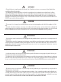 4
4
-
 5
5
-
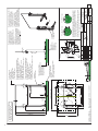 6
6
-
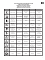 7
7
-
 8
8
-
 9
9
-
 10
10
-
 11
11
-
 12
12
-
 13
13
-
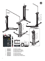 14
14
-
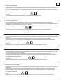 15
15
-
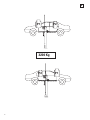 16
16
-
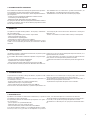 17
17
-
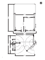 18
18
-
 19
19
-
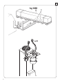 20
20
-
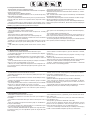 21
21
-
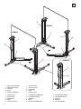 22
22
-
 23
23
-
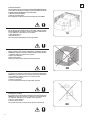 24
24
-
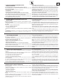 25
25
-
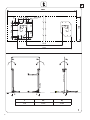 26
26
-
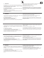 27
27
-
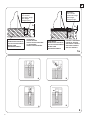 28
28
-
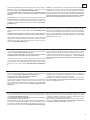 29
29
-
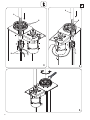 30
30
-
 31
31
-
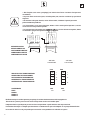 32
32
-
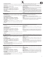 33
33
-
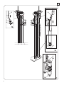 34
34
-
 35
35
-
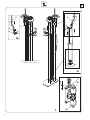 36
36
-
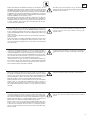 37
37
-
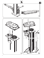 38
38
-
 39
39
-
 40
40
-
 41
41
-
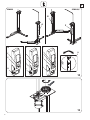 42
42
-
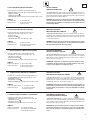 43
43
-
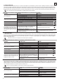 44
44
-
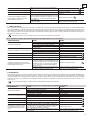 45
45
-
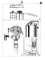 46
46
-
 47
47
-
 48
48
-
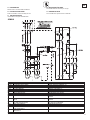 49
49
-
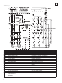 50
50
-
 51
51
-
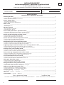 52
52
-
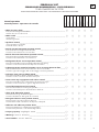 53
53
-
 54
54
-
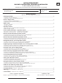 55
55
-
 56
56
-
 57
57
-
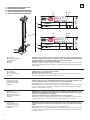 58
58
-
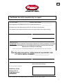 59
59
-
 60
60
-
 61
61
-
 62
62
-
 63
63
-
 64
64


Rotary SPMA32-SC El manual del propietario
- Tipo
- El manual del propietario
- Este manual también es adecuado para
en otros idiomas
- français: Rotary SPMA32-SC Le manuel du propriétaire
- italiano: Rotary SPMA32-SC Manuale del proprietario
- English: Rotary SPMA32-SC Owner's manual
- Deutsch: Rotary SPMA32-SC Bedienungsanleitung
Artículos relacionados
-
Rotary SPM40 El manual del propietario
-
-
-
-
-
-
Otros documentos
-
 Ravaglioli KPN345WE Manual de usuario
-
MAHA MA STAR 3.5 | 5.5 | 6.5 Instrucciones de operación
-
Blitz BP 65 Operating Instructions Manual
-
-
-
Genius LG 2119 Instrucciones de operación
-
Hilti DD-HD XC Instrucciones de operación
-
3M PROTECTA® PRO™ Automatic Escape Device, Manual Retract AG360AS, 1 EA Instrucciones de operación
-
Munters EM-EMS-ED-EDS-EC Use & Maintenance Manual
-
 probst SRG-UNI-3-K Manual de usuario

