
OPERATOR'S MANUAL
®
INDUSTRIAL CANOPY
DANGER is used to indicate a hazardous situation which,
if not avoided, wit__Jiresult in serious injury or death.
WARNING z_ indicates a hazardous situation which,
if not avoided, could result in serious injury or death.
CAUTION is used to indicate a hazardous situation which, if not
avoided, _ result in minor injury, moderate injury, or property
damage.
CAUTION: Read and follow all Safety Rules and Operating
instructions before first use of this product.
DANGER
- DO NOT stand on this product. You may fatt or cause product
to tip.
DO NOT mount this product on a truck bed or any other moving
object.
WARNING A
- Use appropriate safety equipment when using power and hand
tools.
- DO NOT alter this product in any manner. For example, do not
weld externat iockbars or attach electrical equipment.
- Use adequate manpower when assembling and moving this
unit.
- Keep the product on ievei surfaces. The product may become
unstable and tip if stored or moved on an uneven surface.
- BE CAREFUL when closing the cover. Remove hands before
the cover closes completely.
- DO NOT step on the shelves.
CAUTION
- Appropriately secure this product before moving it with a
forklift.
CALL 1-800-833-4405 FOR SERVICE PARTS. Refer to Service
Parts Drawing for fuji listing of Service Parts.
LOCATING MODEL # iNFORMATiON
Model numbers and other information required for service parts is
located on a label on the interior right side.
Lubricate the slides with grease or equivaient,(twice yearly.)
Lubricate lock with graphite, (yearly).
Periodically surfaces should be cleaned with a mild detergent
and water.
Auto wax wiii preserve the unit's luster finish. Apply the wax
as to a car. The wax wiii also help protect the unit against
scratches.
Grease and oil can be removed with most standard
cleaning fluids. For safety, use a nonflammable cleaning fluid.
Waterloo Industries, 139 West Forest Hill Avenue, Oak Creek, WI 53154, USA F1996

TOOLS REQUIRED:
Socket Wrench Hammer
5/16-in Socket Center Punch
3/8-in Socket Ddil
1/2-in Socket 1!2-in Drill Bit
Cross-tip Screwdriver Tape Measure
Torx Screwdriver
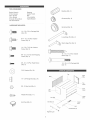
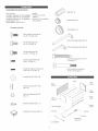
HARDWARE INCLUDED:
1/4 - 20 x 5/8-in Carriage Bolt
(Qty: 20)
#14 - 10 x 5/8 Hex Washer
Screw (Qty: 4)
1/4 - 20 x 7/16 Hex Washer
Screw (Qty: 8)
Bushing (Qty: 2)
Grommet (Qty: 2)
Grommet (Qty: 2)
Long Hinge Pin (Qty: 2)
Short Hinge Pin (Qty: 2)
©
©
#8 - 32 x 1/2 Torx Self Tapping
Screw (Qty: 4)
#6 - 32 x 1/2 Pan Head Screw
(Qty: 2)
5/16 Washer (Qty: 24)
1/4 - 20 Flange Nut (Qty: 24)
#6 - 32 Hex Nut (Qty: 4)
Plastic Rivet (Qty: 11)
End Cap (Qty: 2)
14 - 10 x 1-1/2 Hex Washer
Screw (Qty: 7)
1/4 - 20 x 2-1/4 Carriage Bolt
(Qty: 4)
Top
Right
Back / S!de
Top
Pane!
Left
S!de
Lower
Lock Rod Door
Gas Strut (2) _:_ ..........................Outlet
Corner Brace (4)
Magnetic Light

+
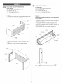
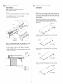
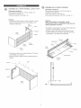
BACK, SIDE AND TOP CONSTRUCTION
Items Needed:
1/4 - 20 x 5/8-in Carriage Bolt (Qty: 15)
5/16 Washer (Qty: 15)
1/4 - 20 Flange Nut (Qty: 15)
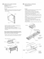
UPPER DOOR ASSEMBLY
Items Needed:
1/4 - 20 x 5/8-in Carriage Bolt (Qty: 5)
5/16 Washer (Qty: 9)
1/4 - 20 Flange Nut (Qty: 9)
1/4 - 20 x 2-1/4 Carriage Bolt (Qty: 4)
PrOCeSS:
+Assemble back to left side and right side using (4) bolts,
(4) washers, and (4) nuts in each side.
Front
Left Side Flange
Nut
Back
Washer
Carriage
Bolt
Back
Right
Side
+Attach top to unit using (7) bolts, (7) washers, and (7)
nuts.
Square the unit and wrench tighten all fasteners.
Process:
NOTE: Finger tighten all fasteners until instructed to
wrench tighten.
Assemble top panel and front panel using (5) bolts, (5)
washers and (5) nuts.
The top panel should be outside of the front panel.
Install (4) corner braces using (2) bolts, (2) washers, and
(2) nuts in each set.
Square the unit and wrench tighten all fasteners
Corner
Brace _ l_
Front Panel _ U_,_
Bolt "_"-. J_ _---_"_----- Coa[;dage
_e_ _'N F_ang_ :_shern
Bolt
Washer
Nut
Top
Front
D
i .......
L................... ,
i
o
.........+..............€

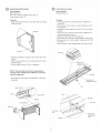
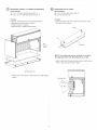
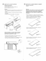
MOUNTING UPPER DOOR
items Needed:
Bushing (Qty: 2)
#14 - 10 x 5/8 Hex Washer Screw (Qty: 2)
Long Hinge Pin (Qty: 2)
PrOCeSS:
- Snap shaft ends of struts (J) over bail studs on canopy
sides as shown.
Ball Stud
LOCK INSTALLATION
Items Needed:
Grommet (Qty: 2)
Process:
- InstatJ (2) grommets in outside hoJes of stiffeners on
lower door.
Mount lock to door as shown, using mounting nut and
two brackets.
insert the key and rotate the lock 90° CCW to the lock
position.
insert one end of the lock rod through a stiffener and
through grommet as shown.
Repeat for the other end of the lock rod.
Attach lock rod to the lock using adaptor nut as shown.
Because Jockis in "Lock" position, rotate lock CW 180°
to "UnJock."
Return the key to the middle position and remove key.
Gas Strut
Grommet
- install (2) bushings in square holes in sides of unit as
shown.
Attach door assembly to unit using (2) tong pivot pins
and (2) screws.
Wrench tighten screws. Do not overtighten.
NOTE: The ball studs for the door assembly are
located on the outside of the stiffener on the door,
near the hinge pins.
Snap piston end of struts over bah studs on the door
assembly.
Screw Square Hole
Bushing
Ball Stud Doo_
Mounting
Nut
Lock
Washer
Adaptor Nut
Supplied with Lock
.1
Rod
/S _ " MounttngNut
"_ Supplied w_th Lock
X
Lock
Brackets
Lock Rod
@tor Nut
Supplied with
Lock

@
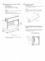
MOUNTING LOWER DOOR
items Needed:
Plastic Rivet (Qty: 11)
#14 - 10 x 5/8 Hex Washer Screw (Qty: 2)
Short Hinge Pin (Qty: 2)
PrOCeSS:
- Attach lower door assembly to unit as shown, using (2)
short pivot pins and (2) screws.
- Wrench tighten screws. Do not overtighten.
- Close canopy and test lock.
Short Pivot Pin
\
Screw
Lower Door
Assembly
MOUNTING CANOPY TO CABINET
items Needed:
Hote Template
PrOCeSS:
NOTE: To prevent drilling into the metal cabinet top,
take the removable top off of the cabinet or move
the part to be dallied away from the meta_ cabinet top
before drilling.
Mark centers of clearance holes to be drilled in
removable cabinet top using template provided.
Atign corner (A) of the template and mark the holes
tabeted (1). Corner A
Front of Cabinet
Align corner (B) of the template and mark the holes
tabeted (2).
Corner B
NOTE: To install plastic rivet, fully seat the rivet in the
ho_e then depress the plunger to ho_d in place.
Instait (4) plastic rivets in the front flange of each side
on the unit as shown.
install (3) plastic rivets in hotes along bottom edge of the
tower door as shown.
Front of Cabinet
Align corner (C) of the template and mark the holes
tabeted (3).
Corne_
Front of Cabinet
Align corner (D) of the template and mark the holes
tabeted (4).
L.___ Front of Cabinet

@
MOUNTING CANOPY TO CABINET (CONTINUED) MOUNTING OUTLET STRIP
Items Needed: Items Needed:
14 - 10 x 1-1/2 Hex Washer Screw (Qty: 7) #6 - 32 x 1/2 Pan Head Screw (Qty: 2)
#8 - 32 x 1/2 Torx Self Tapping Screw (Qty: 4) #6 - 32 Hex Nut (Qty: 2)
PrOCeSS:
Drill 1/2" clearance hole in each marked location.
Reposition removable top on cabinet.
Position canopy on cabinet.
Attach canopy to cabinet using screws.
Process:
Insert (2) screws into slots in back of outlet strip, using
(2) nuts to hotd in place.
Screw
Nut
aex
Washer
Screw
Outlet Strip
NOTE: The outlet strip may be mounted on the left or
the right side of the unit. Mounting shown on left.
Attach outlet strip through mounting holes in back watt as
shown, using (2) nuts to hold in place.
Self Tapping Screw
Install Corner Trim pieces to both sides using self tapping
screws.
Mounting Hole
Nut

MANUAL DE USUARIO
®
PABELLON DE TIPO INDUSTRIAL
PEUGRO _ se utiliza para indicar una situaci6n
peligrosa que, de no evitarse, resultar_ en lesiones graves o la muerte.
ADVERTENOIA A indica una situaci6n peligrosa que, de no
evitarse, podria producir lesionesgraves o la muerte.
PREOAUOI6N se utilizapara indicaruna situaci6n peligrosaque, de
no evitarse, puede derivar en lesiones leveso moderadas, o en da_o a la
propiedad.
ATENOI6N: Lea y siga todas las Normas de Seguridady las
Instrucciones de Funcionamiento antes de utilizar por primera vez este
producto.
PELIGRO
- NO se ponga de pie sobre ta unidad. Puede caerse y provocar
que et producto se vuelque.
- NO monte esta unidad en la plataforma de carga de ta
camioneta ni en ningQn otto objeto mOvit.
ADVERTENClA Z_
- Utitice el equipo de seguridad adecuado cuando emptee
herramientas el6ctricas.
NO altere la unidad en modo alguno. Pot ejemplo, no suelde tas
barras de sujeciOn externas nile incorpore equipos el6ctricos.
Utitice el personal adecuado para et montaje y et trastado de
esta unidad.
Mantenga et producto en superficies niveladas. La unidad
puede tomarse inestable y votcarse si se atmacena o mueve en
superficies no niveladas.
TENGA CUIDADO cuando cierre ta tapa. Quite tas manos
antes de que ta tapa cierre comptetamente.
NO se pare en tas batdas. Se puede caer y tesionar.
EN ESTADOS UNIDOS LLAME AL 1-800-833-4405 PARA
PIEZAS DE REPUESTO. FUERA DE ESTADOS UNIDOS LLAME
A SU DISTRIBUIDOR LOCAL. Suministre ei nOmerode modeio ai
comunicarse.
UBICACKSN DE INFORMACION DEL NO. DE MODELO
El nQmero de modeto y demos informaci6n requerida para tas
partes de servicio se encuentra en una etiqueta en et tado interior
derecho.
- Lubrique tas guias con grasa o equivatente (dos veces pot a_o).
- Lubdque la cerradura con grafito (anuatmente).
- Las superficies deben set timpiadas periOdicamente con
detergente suave y agua.
- La cera para automOviles preservar_ et acabado bdltoso de la
unidad. Aplique la cera como Io haria at carro. La cera tambi6n
ayudar_ a proteger la unidad contra raspones.
- La grasa y el aceite pueden retirarse con la mayoda de los tiqui=
dos est_ndar para timpieza. Pot razones de seguridad, utitice
un tiquido incombustible para timpieza.
PRECAUCKSN
- Asegure adecuadamente ta unidad antes de moveda con un
montacargas.
Waterloo Industries, 13g West Forest Hill Avenue, Oak Creek, WI 53154, USA F1996

HERRAMIENTAS NECESARIAS:
Llave de tubo
Casquitto adaptador de 5/16 pulgadas
Casquitto adaptador de 3/8 putgadas
Casquillo adaptador de 1/2 putgadas
Destomiltador, Torx
DestomiHador, punta de cruz
Martitlo
Perfore en et centro
TaHadro
Broca de 1/2 de puJgada
Cinta m6trica
Ferreter_a Inc_uida:
Pemo cabeza de bongo de
1/4-20 X 5/8 (Qty: 20)
TornHJoHexagonal de
14-10 X 5/8 (Qty: 4)
Tornillo HexagonaJ de
1/4-20 X 7/16 (Qty: 8)
Buje (Qty: 2)
Arandeta (Qty: 2)
Arandeta (Qty: 2)
Pemo de bisagra targo (Qty: 2)
Pemo de bisagra corto (Qty: 2)
©
©
TornHlo autoperforante N°
8-32 X 1/2 (Qty: 4)
TomHto de Cabeza Troncoconi-
ca de 6-32 X 1/2 (Qty: 2)
Arandeta de 5/16 (Qty: 24)
Tuerca con brida de 1/4-20
(Qty: 24)
Tuerca Hexagonal de 6-32
(Qty: 4)
Remache pt_stico (Qty: 11)
CasquiHo de extremo (Qty: 2)
TomiHo Hexagonal de 14-10 X
1-1/2 (Qty: 7)
Pemo cabeza de hongo de
1/4-20 X 2-1/4 (Qty: 4)
Parte
posterior-__
Tapa
Lado
_ derecho
Panel
superior
Lade
izquierdo
_ Panel
frontal
2

Q ENSAMBLEDELAPARTETRASERA,LADOSYTAPA
Elementosnecesarios:
Pemocabezadehongode1/4=20X5/8(Qty:15)
Arandelade5/16(Qty:15)
Tuercaconbddade1/4-20(Qty:15)
Q NSAMBLEDELAPUERTASUPERIOR
Elementosnecesarios:
Pernocabezadehongode1/4-20X5/8(Qty:5)
Arandetade5/16(Qty:9)
Tuercaconbddade1/4-20(Qty:9)
Pemocabezadehongode1/4-20X2-1/4(Qty:4)
Proceso:
- Ensambte ta parte posterior al tado izquierdo y al lade
derecho utilizando (4) pemos, (4) arandetas, y (4)
tuercas en cads tado.
Lade
izquierdo Tuerca
Parte
frontal
Rondana
Tornillo
Proceso:
NOTA: Pars facilitar el ensamblaje, apriete
manualmente redes los sujetadores hasta que se le
instruya apretar_os con Have.
- EnsambJe et panel superior y el panel frontal utitizando
(5) pemos, (5) arandeJas y (5) tuemas.
Et panel superior debe estar fuera deJ panel frontal.
- InstaJe (4) refuerzos de esquina utHizando (2) pemos,
(2) arandelas, y (2) tuercas en cads juego.
Parte
trasera
Lade
derecho
Parte
posterior
- File ta parte superior a ta unidad utitizando (7) pemos,
(7) arandelas, y (7) tuercas.
Ajuste ta unidad y apnete con ttave inglesa todos los
seguros.
Rondana
Tuerca
Pa_e
frontal
Taps
Refuerzo
Panel Frontal "">_/_Jl 71I .._
._ PanelSupekaparte riot
superior
Olo
Ir- ......

WIONTAJE DE LA PUERTA SUPERIOR
Elementos necesarios:
Bu]e (Qty: 2)
TorniJJoHexagonaJ de 14-10 X 5/8 (Qty: 2)
Pemo de bisagra targo (Qty: 2)
Proceso:
- CoJoque a presiOn tos extremos deJeje de tos montantes
sobre los pemos esf6dcos en tos tados de ta cubierta
como se itustra.
R6tula
Q DE LA CERRADURA
JNSTALACJON
Elementos necesarios:
Arandeia (Qty: 2)
PrOC@SO:
- InstaJe (2) arandetas aisiantes en los agujeros extemos
de los refuerzos en Japuerta inferior.
- Monte Jacerradura a Japuerta como se iJustra,
utiHzando Jatuerca de montaje y dos soportes.
- Inserte Ja Havey gire Jacerradura 90 °en el sentido
antihorado hacia ta posiciOn de traba.
- Inserte un extremo de JavadJta de ta cerradura a trav6s
de un refuerzo y de una arandeJa aisJante (NN) como se
itustra.
- Repita para eJotto extremo de JavadJJade ta cerradura.
- Fije ta vadtta de ta cerradura a Jacerradura utitizando
ta tuerca adaptadora como se iJustra.
- Debido a que Jacerradura est_ en ta posiciOn "Lock"
(trabada), gire ia cerradura 180° en el sentido horatio
para "destrabar'.
- Regrese ta tJave a ta posiciOn centraI para retirar ta tJave.
- Instate (2) cojinetes en tos agujeros cuadrados en tos
tados de ta unidad como se iiustra.
- Fije et ensambJe de ia puerta a ta unidad utiiizando (2)
pasadores pivotantes largos y (2) tomiJJos.
Apdete los tomiiJos con una tiave de tuercas. No apnete
demasiado.
Nota: Los pemos esfericos de_ ensambJe de _apuerta
estan ubicados en _aparte de afuera del refuerzo en _a
puerta, cerca de _asc_avijas de _as bisagras.
- Encaje a presi6n el extremo tipo pist6n de Jos montantes
sobre tos pemos esf6dcos en el ensambJe de ta puerta.
Tornillo
Perno de bisagra largo
_ erforaci6n
rectangular
Bu]e
Montaje \puerta\'_dela
R6tuia , , _""_-_
Arandela
adaptador
suministrada la cerradura
7J_ID
de
y_ bloqueo
_'JS _ " Tuerca de montaie
-_ suministrada la
/ X cerradura
Cerradura
Soportes
Barra de
Moqueo
Tuerca de
montaje
Washer
del
adaptador
suministrada
la cerradura

MONTAJE DE LA PUERTA INFERIOR
Elementos necesarios:
Remache pi_stico (Qty: 11)
Tornitto Hexagonal de 14-10 X 5/8 (Qty: 2)
Pemo de bisagra corto (Qty: 2)
Proceso:
- Fije el ensambb de Japuerta inferior a Jaunidad como se
ilustra, utitizando (2) pasadores pivotantes cortes y (2)
tornittos.
- Apriete Jostornittos con una Have de tuercas. No apdete
demasiado.
- Cerradura cercana deI pabeHOn y de ta prueba.
Perno corto
\
Tornillo
Baje el montaje
de la puerta
Nota: Para insta_ar el remache plastico, ins_rtelo
completamente en el agujero y _uego optima el
embo_o para sostenedo en su _ugar.
Instale (4) remaches pJ_sticos en Jabdda frontal de
cada tado de Jaunidad como se itustra.
Instab (3) remaches pi_sticos en los agujeros det borde
de ta base de ta puerta inferior come se itustra.
:::::::::::::::::::::::::::::
'_ MONTAJE DE LA UNIDAD SOBRE EL GABiNETE
Elementos necesarios:
Piantitta
Proceso:
Nota: Para evitar taladrar en Japarte superior metaJica
del gabinete saque la parte superior desprendibJe
del gabinete o mueva la pieza que va a taJadrar,
apartandola de Japarte superior deJ gabinete antes
de taJadrar.
Pegue ta pJantiJJaen su Jugar para asegurarse de que
marca Josagujeros correctamente. UtiJice un punz6n de
perforar y un martiJJopara marcar Josagujeros.
Atinee Jaesquina (A) de JapJantitJay marque tos
agujeros etiquetados come (1).
Esquina (A)
Parte frontal del
gabinete
- Atinee Jaesquina (B) de JapJantitJay marque tos
agujeros etiquetados come (2).
Esquina (B)
Parte frontal del
gabinete
- Atinee Jaesquina (C) de JapiantitJa y marque tos
agujeros etiquetados come (3).
Esqui__
f!ont f
"____ gabinete
Atinee Jaesquina (D) de Ja piantiiJa y marque tos
agujeros etiquetados come (4).
I___!ontaf dei
"__ gabinete

MONTAJE DE LA UNiDAD SOBRE EL GABINETE
(CONTtNUACION)
E_ementos necesarios:
Torniiio Hexagonal de 14-10 X 1-1/2 (Qty: 7)
TorniHo autoperforante N° 8-32 X 1/2 (Qty: 4)
Proceso:
Taladre agu]eros de paso de ½" (1,3 cm) en cada tugar
marcado.
Coloque Japieza superior en el gabinete.
Ate el pabeJtOn at gabinete usando tos torniHos (SS).
@
ENSAMBLE DEL ENCHUFE
E_ementos necesarios:
TorniJJode Cabeza Troncoconica de 6-32 X 1/2 (Qty: 2)
Tuerca Hexagonal de 6-32 (Qty: 2)
Proceso:
- Inserte (2) torniJJosen Jasranuras en Japarte posterior
de JaregJeta, utitizando (2) tuercas para sosteneda en
su tugar.
Tornil!o
Tuerca
Tornillo
exagonaJ
con
arandela
Enchufe
Nora: La regleta puede montarse a_ _ado izquierdo o
at derecho de _aunidad. Se muestra el montaje aJ _ado
izquierdo.
Fije JaregJeta a trav6s de Josagujeros de montaje en Ja
pared posterior como se itustra, utitizando (2) tuercas
para sosteneda en su tugar.
Tornillo autoperforante
InstaJe Jospedazos de ta esquina det ajuste a ambos
tados usando tos tomiiios.
Agujero para montar
Tueraa
-
 1
1
-
 2
2
-
 3
3
-
 4
4
-
 5
5
-
 6
6
-
 7
7
-
 8
8
-
 9
9
-
 10
10
-
 11
11
-
 12
12


Craftsman 706452700 El manual del propietario
- Tipo
- El manual del propietario
- Este manual también es adecuado para
En otros idiomas
- English: Craftsman 706452700 Owner's manual
Documentos relacionados
-
Craftsman 706385580 El manual del propietario
-
-
-
-
-
-
Craftsman 351.217450 El manual del propietario
-
-