
OPERATOR'S MANUAL
HEAVY DUTY TOOL CHESTS
• Periodically the drawer fronts, drawer trim, and other surfaces
should be cleaned with a mild detergent and water.
• Auto wax will preserve the unit's luster finish. Apply the wax
as to a car. The wax will also help protect the unit against
scratches.
• Grease and oil can be removed with most standard
cleaning fluids. For safety, use a nonflammable cleaning fluid.
• If drawer liners are supplied, it is recommended they are used
to protect the finish inside the drawers and to make the drawers
easier to clean. The drawer liners may be cleaned
with soap and water.
MODEL 45252 / 45253 MODEL 45255 / 45256
CALL 1-800-833-4405 FOR SERVICE PARTS. Refer to Service
Parts Drawing for full listing of Service Parts.
LOCATING MODEL # iNFORMATiON
Model numbers and other information required for service parts is
located on a label on the interior right side of the top most drawer.
• The maximum weight for each drawer should be no more than
85 Ibs.
• The maximum product weight for both models, including con-
tents, should be no more than 1,000 Ibs.
• For casters, use high quality bearing grease, (yearly).
• Lubricate the slides with grease or equivalent,(twice yearly.)
• Lubricate lock with graphite, (yearly).
Waterloo Industries, 139 West Forest Hill Avenue, Oak Creek, WI 53154, USA
DANGER A_, is used to indicate a hazardous situation which,
if not avoided, wil___[result in serious injury or death.
WARNING Z_ indicates a hazardous situation which,
if not avoided, could result in serious injury or death.
CAUTION is used to indicate a hazardous situation which, if not
avoided, m_m_a_y_result in minor injury, moderate injury, or property
damage.
CAUTION: Read and follow all Safety Rules and Operating
Instructions before first use of this product.
DANGER _,
° DO NOT stand on this product. You may fall or cause product
to tip.
° DO NOT open more than one drawer. The product may be-
come unstable and tip.
° DO NOT step in the drawers. You may fall or cause product to
tip.
° DO NOT mount this product on a truck bed or any other mov-
ing object.
° DO NOT move the product prior to closing and locking all the
drawers and chest lid. The drawers could come open and
make the product unstable and tip.
° DO NOT place any objects on top of chest lid. Remove all
objects from chest lid before opening.
WARNING Z_
° WEAR SAFETY GLASSES when removing or repositioning
the slides.
° DO NOT pull the unit, push it when moving
° USE THE BRAKES when not moving this product. This will
prevent the product from rolling.
° DO NOT alter this product in any manner. For example, do not
weld external Iockbars or attach electrical equipment.
° Keep the product on level surfaces. The product may become
unstable and tip if stored or moved on an uneven surface.
° BE CAREFUL when closing the cover. Remove hands before
the cover closes completely.
CAUTION
• This product is not designed to be directly lifted with a fork lift,
or to be towed with any mechanical devices.
• The maximum weight for each drawer should never be
exceeded.
• Only transport this product empty. Properly secure when
transporting.
• DO NOT exceed maximum product weight, including contents.
See Capacities for more information.
F1989

TOOLSREQUIRED:
3/8-inWrench
1/2-inWrench
Cross4ipScrewdriver
HARDWAREINCLUDED:
CABINETHARDWARE
E__ #14-10x5/8-inHexScrews(Qty:16)
#14-10x3/4Cross4ipScrew
(Qty:4)
CHESTHARDWARE
NOTE:NotaJJassemblyinstructionswillrelatetoyourmodel
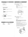
SIDE HANDLE ATTACHMENT
items Needed:
#14 - 10 x 3/4 Cross-tip Screw (Qty: 4)
Cross-tip Screwdriver
Process:
- Attach the side handle using (4) #14 - 10 x 3/4 Cross-tip
screws.
- Hand tighten. Do not overtighten.
5/16 - 18 Ball Stud (Qty: 4)
5/16 - 18 Clip-on Nut (Qty: 4)
Cabinet: Chest:
Literature Hardware Bag Assembly
Caster pack Cover Label
Handle pack Literature
@
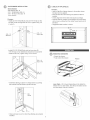
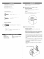
CASTER INSTALLATION
Items Needed:
#14 - 10 x 5/8-in Hex Screws (Qty: 16)
3/8-in Wrench
Process:
NOTE: Use adequate personnel for this operation.
NOTE: Failure to install easter angles may result in
premature cabinet failure.
Place the unit on its top. Use packaging material to
protect the paint finish.
Position caster angles on the cabinet. Flanges should be
toward the inside and pointed up.
Attach casters and caster angles using (4) #14 - 10 x 5/8
Hex Screws for each casten Mount both swivel casters
on the same side of the cabinet as the side handle.
Wrench tighten all screws. Do not overtighten.
Return the unit to its upright position.
Caster angles
(flanges inside)

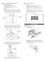
GASSPRINGSINSTALLATION
itemsNeeded:
GasSprings(Qty:2)
5/16- 18 Ball Studs (Qty: 4)
5/16 - 18 Clip-on Nut (Qty: 4)
1!2-in Wrench
PrOCeSS:
Install (2) 5/16-18 Ball Studs and (2) 5/16-18 Clip-on Nut
into slot on left and right side of cover. Tighten using 1!2-
in wrench.
.......................5/16- 18
5/16 - 18 ......
Clip-on Nut
Ball Stud
- Install (2) 5/16-18 Batt Studs into top tray using (2)
5/16-18 Clip-on Nut. (Ball Studs should face towards the
middle of the unit.) Tighten using 1!2-in wrench.
5/16 - 18
Clip-on Nut
LABELS (iF APPLICABLE)
PrOCeSS:
Appty a tight film of glass cleaner to the surface where
the tabel is to be applied.
Peel the label from the backing and place the tabet in
position.
Check alignment of the label and adjust accordingly.
Hotd the labet in position and squeegee off excess tiquid
with a towet, working from the center toward each end of
the tabel.
Suggested tabet tocation is shown.
2-3/4
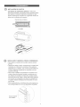
Q REMOVING DRAWERS
Empty the drawer.
Futty extend the drawer.
Release
5/16- 18
Bail Stud
install Gas Spring as shown in image below by pushing
the sockets onto Bait Studs (cylinder side up).
Lever Style - Lift or lower (depending on the slide) the
release lever on both sides, (this allows the stides to ride
over the stops). Putt out to remove.
Gas
Spring
Close and open cover to check Gas Springs are properly
installed.
3

IIp _± 0
INSTALLING DRAWERS
Ball bearing slide =Putt slides and slide carrier out to fully
extended position (see illustration.) Hold the slide on the
cabinet while aligning it with the slide on drawer. Slightly
insert one side and repeat for the other side. Slowly push
drawer to its fully closed position to engage slide. Open
drawer and rectose to ensure proper operation.
Slide carrier
Slide
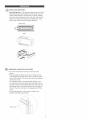
REMOVING AND INSTALLING SLIDES
, To remove the slide from the unit, first remove the
drawer.
After removing the drawer check to see if the unit has
rivets located on the front of the slide. To drill out rivets,
use a 5/32=in drill bit. The rivets wilt need to be replaced
with 5/32=in rivets.
To reinstall the slide in the appropriate position in the
unit, align front and back lances with mounting holes in
the side of the unit. Pull towards the front of the unit and
downwards until rivet holes in slide line up with holes in
the unit. The rivets wilt need to be replaced with 5/32=in
rivets.
For smooth operation, make sure the drawers are
matched with their original slides.
\\
\\
\\\\\
\
\
\
Drill out rivet
/
f
J

MANUAL DE USUARIO
CAJAS DE HERRAMIENTAS DE TRABAJO PESADO
• Lubrique la cerradura con grafito (anualmente).
• Limpie con detergente suave y agua los frontales y los bordes laterales
de los cajones y las demSs superficies.
La cera para autom6viles preservar8 el acabado brilloso de la unidad.
Aplique la cera como Io haria al carro. La cera tambi6n ayudar8 a pro°
teger la unidad contra raspones.
La grasa y el aceite pueden retirarse con la mayoria de los liquidos
est_ndar para limpieza. Por razones de seguridad, utilice un liquido
incombustible para limpieza.
Si se suministran forros para las gavetas, se recomienda que se utilicen
para proteger el acabado interno de las mismas y para facilitar la limpo
ieza. Los forros para gavetas pueden limpiarse con agua y jab6n.
PELIGRO A se utiliza para indicar una situaci6n
peligrosa que, de no evitarse, resultar_ en lesiones graves o la muerte.
ADVERTENOIA _ indica una situaci6n peligrosa que, de no
evitarse, podria producir lesiones graves o la muerte.
PREOAUOI6N se utiliza para indicar una situaci6n peligrosa que, de
no evitarse, puede derivar en lesiones leves o moderadas, o en dafio a la
propiedad.
ATENOK)N: Lea y siga todas las Normas de Seguridad y las
Instrucciones de Funcionamiento antes de utilizar por primera vez este producto.
MODELO NO. 45252 / 45253 MODELO NO. 45255 / 45256
O H
EN ESTADOS UNtDOS LLAME AL 1-800-833-4405 PARA
PIEZAS DE REPUESTO. FUERA DE ESTADOS UNIDOS
LLAME A SU EHSTRJBUIDOR LOCAL. Suministre el nQmero de
modelo al comunicarse.
UBICACI6N DE INFORMACI6N DEL NO. DE MODELO
El nOmero de modelo y demos informaci6n requerida para las piezas de
servicio se encuentran en una etiqueta en el lado interior derecho de la
gaveta superior.
• El peso mSximo en cada gaveta no debe ser mayor de 38,59 kg.
• El peso mSximo del producto para ambos modelos, incluyendo su con°
tenido, no debe ser mayor de 454,0 kg.
q
• Para las ruedas, utilice grasa para rodamientos de alta calidad
(anualmente).
• Lubrique las guias con grasa o equivalente (dos veces por afio).
PEUGRO
• NO se ponga de pie sobre esta unidad. Puede caerse u ocasionar que
el producto se vuelque.
• NO abra m_s de una gaveta. El producto podria quedar inestable y
volcarse.
• NO utilice las gavetas como peldafios. Puede caerse u ocasionar que
el producto se vuelque.
• NO monte este producto en una cama de carro o ninguin otro objeto
m6vil.
• NO mueva la unidad antes de cerrar y asegurar todas las gavetas y
la tapa del baOl. Las gavetas podrian abrirse y hacer que la unidad se
vuelva inestable y se vuelque.
• NO coloques ningQn objeto sobre la tapa del baOl. Quita todos los objeo
tos de la tapa del baOl antes de abrido.
ADVERTENCIA Z_
• USE GAFAS DE SEGURIDAD al quitar o volver a poner las
correderas.
• NO hale la unidad, empQjela cuando la mueva.
• UTILICE LOS FRENOS cuando el producto no est6 en movimiento.
Esto impedir8 que se deslice.
• NO altere la unidad en modo alguno. Por ejemplo, no suelde las barras
de sujeci6n externas nile incorpore equipos el6ctricos.
• Mantenga la unidad en superficies niveladas. La unidad puede tornarse
inestable y volcarse si se almacena o se moviliza en una superficie no
nivelada.
TENGA cuidado cuando cierre la tapa. Quite las manos antes de que la
tapa cierre completamente.
PRECAUCK)N
Este producto no est_ disefiado para ser levantado directamente con un
montacargas, ni para ser remolcado con unidades mecanizadas.
Nunca debe exceder el peso mSximo de cada gaveta.
$61o transporte esta unidad cuando est6 vacia. AsegOrela
adecuadamente cuando la transporte.
NO exceda el peso m_ximo del producto, incluyendo el contenido.
Refi6rase a las Capacidades para m_s informaci6n.
Waterloo Industries, 139 West Forest Hill Avenue, Oak Creek, WI 53154, USA F1989

HERRAMIENTAS NECESARIAS:
Llave Ingtesa de 3/8 inch
Llave Inglesa de 1/2 inch
Destomittador de Punta en Cruz
PIEZAS INCLUIDAS:
GABINETE DE HARDWARE
Tornillo Hexagonal de No. 14 - 10x 5/8 (Cant: 16)
NOTA: No todas las instrucciones de ensambtaje se
refieren a tu modelo.
INSTALACION DE LA MANIJA LATERAL
Elementos necesarios:
Tomillos Phillips de No. 14 - 10 x 3/4 (Cant.: 4)
Destomittador de Punta en Cruz
Proceso:
File ta manija lateral usando 4 tomittos de Punta en
Cruz de No. 14 - 10 x 3/4.
DApriete a mane. No apriete demasiado.
Tuerca Phillips de No. 14 - 10 x
3/4 (Cant: 4)
BAUL DE HARDWARE
Pemo Esf6rico de 5/16 - 18 (Cant: 4)
Tuerca de Abrazadera de 5/16 - 18
(Cant: 4)
Gabinete:
Material impreso
Paquete de ruedas
Paquete de Manijas
BaQI:
Hardware y Asamblea de Bolso
Etiqueta de Cubierta
Literatura
INSTALACION DEL TIRADOR
Elementos necesarios:
Tomitto Hexagonal de No. 14 - 10 x 5/8 (Cant.: 16)
Ltave Allen de 3/8 ptg
NOTA: UtiHce personal adecuado para esta operaci6n.
NOTA: No instaJar los angulos de las ruedas giratorias
puede ocasionar falla prematura del gabinete.
DColoque ta unidad sobre su parte superior. Utilice el mate-
rial de empaque para protegaer el acabado de la pintura.
DUbique los _ngutos de tas ruedas giratorias en el gabinete.
Las pestaSas deben ir hacia et interior y apuntando hacia
ardba.
DFije tas ruedas giratorias y los _ngulos de tas ruedas gira-
torias utitizando (4) tomillos hexagonal No. 14 - 10 x 5/8
para cada rueda giratoria. Monte ambas ruedas pivotantes
en et mismo lado det gabinete donde se encuentra ta
manija lateral.
DApriete todos los tomittos con una ttave. No apriete de-
masiado.
DVuetva a colocar ta unidad en su posiciOn vertical.
Angulos de ruedas giratoriea
(pestanas hacia adentro)

INSTALACI6NDEPRIMAVERASDEGAS
Elementos necesarios:
Amortiguador neum_ticoes (Cant: 2)
Pemo Esf6rico de 5/16 - 18 (Cant: 4)
Tuerca de Abrazadera de 5/16 - 18 (Cant: 4)
Uave Allen de 1/4 pig
Proceso:
- Instala (2) Pemos Esf6ricos de 5/16 - 18 y (2) Tuercas
de Abrazadera de 5/16 - 18 en ta ranura de tos lados
derecho e izquierdo de ta cubierta. Ajusta con una Have
AtJen de 1/2 pig. Ajusta con una HaveAllen de 1/2 pig.
Perno
Esf@ico de
5/16-18
J
.............................Tuerca de
Clip 5/16-18
Instata (2) Pernos Esf6ricos de 5/16 -18 en ia bande]a
superior con (2) Tuercas de Abrazadera de 5/16 = 18.
(Los Pernos Esf@icos deben quedar de frente aJcentro
de ta unidad). Ajusta con una ttave Allen de 1/2 pig.
ETJQUETAS (SJ APUCA)
Proceso:
- Aptica una capa fina de Jimpiador para vidrios en ta
superficie donde se colocar_ ta etiqueta.
- Quite el revestimiento de ta etiqueta y coJOquela en su
sitio.
Revise el aJineamiento de ta etiqueta y ajQsteto segQn
sea negesano.
Sostenga Jaetiqueta en su Jugar y etimine eJexceso de
tiquido con una toaJJa,empujando desde eJcentro hacia
cada extremo de ta etiqueta.
2-3/4
@ REMOCION DE GAVETAS
- Vacie Jagaveta.
- Abra compietamente ta gaveta.
Libere
Tuerca de
Ciip 5/16-18
Perno
Esf@ico de
5/16-18
- InstaJa eJAmortiguador Neum_tico como se muestra en
ta siguiente itustraciOn empujando tos casquittos en tos
Pemos Esf6dcos (con el citindro hacia ardba).
Amortigua( )r
neumStico
EstiJo pa_anca - Levante o baje (dependiendo de la
corredera) ta paJanca de liberaciOn en ambos lados (esto
permite que las correderas pasen sobre tos topes.) JaJe
hacia afuera para retirar.
\.
- Cierra y abre Jacubierta para comprobar que tos Amor-
tiguadores est6n instatados correctamente.

INSTALACIONDEGAVETAS
Correderasderodamientosesf6ricos- hale hacia
afuera tas correderas y et soporte de las correderas hasta
que queden en posiciOn totatmente extendida (ver itus-
traci6n). Sostenga ta corredera en et gabinete mientras to
atinea con ta corredera de ta gaveta.
Soporte de las correderas
/
Corredera
/
/
y
INSTALACION Y DEStNSTALCtON DE CORREDERAS
- Para quitar ta corredera de ta unidad, primero quite ta
gaveta.
- Despu6s de quitar el cajOn, comprueba si ta unidad tiene
remaches en et frente de la corredera. Para quitar los
remaches con un taladro, usa una broca para tatadro de
5/32 pig. Deber_s reemptazar los remaches con rem-
aches de 5/32 ptg.
- Para velvet a instatar correctamente ta corredera en la
unidad, atinea tas lancetas frontales y postedores con
los orificios de montaje en et lade de ta unidad. Et tir0n
hacia et frente de la unidad y hacia abajo hasta agujeros
de remache en la diapositiva se atinea con agujeros en
ta unidad. Deber_s reemptazar los remaches con unos
de 5/32 plg.
- Para ta operaciOn lisa, cerciOrese de que los cajones es-
t6n correspondidos con con sus diapositivas originates.
con eltaladro =
-
 1
1
-
 2
2
-
 3
3
-
 4
4
-
 5
5
-
 6
6
-
 7
7
-
 8
8


Craftsman 706452530 El manual del propietario
- Tipo
- El manual del propietario
- Este manual también es adecuado para
en otros idiomas
- English: Craftsman 706452530 Owner's manual
Artículos relacionados
-
Craftsman 706596194 El manual del propietario
-
-
-
-
Craftsman 706183911 El manual del propietario
-
-
-
-
Craftsman 706105950 El manual del propietario
-

