
OPERATOR'S MANUAL • Periodically the drawer fronts, drawer trim, and other surfaces
should be cleaned with a mild detergent and water.
• Auto wax will preserve the unit's luster finish. Apply the wax as to
a car. The wax will also help protect the unit against scratches.
• Grease and oil can be removed with most standard cleaning
fluids. For safety, use a nonflammable cleaning fluid.
• If drawer liners are supplied, it is recommended they are used
to protect the finish inside the drawers and to make the drawers
easier to clean. The drawer liners may be cleaned with soap and
water.
MODEL # 45277 36" 5-DRAWER CHEST
MODEL # 45287 46" 10=DRAWER CHEST
MODEL # 45289 56" 10-DRAWER CHEST
CALL 1-800-833-4405 FOR SERVICE PARTS. Refer to Service
Parts Drawing for full listing of Service Parts.
LOCATING MODEL # INFORMATION
Model numbers and other information required for service parts is
located on a label on the interior right side of the top most drawer.
• Empty weight of 36" chest is 195 Ibs.
• Empty weight of 46" chest is 290 Ibs.
• Empty weight of 56" chest is 390 Ibs.
• The maximum product weight, including contents, for the 36" model
should be no more than 1800 pounds.
• The maximum product weight, including contents, for the 46" model
should be no more than 3000 pounds.
• The maximum product weight, including contents, for the 56" model
should be no more than 5400 pounds.
• The maximum weight for each (2) inch deep drawer is (120) pounds.
• The maximum weight for each (3) inch deep drawer is (200) pounds.
• The maximum weight for each (4) - (6) inch deep drawer is (320)
pounds.
• The maximum weight for each drawer (9) inches deep or more is (400)
pounds.
• Lubricate the slides with grease or equivalent,(twice yearly.)
• Lubricate lock and locking system components with graphite,
(yearly).
DANGER _, is used to indicate a hazardous situation which,
if not avoided, will result in serious injury or death.
WARNING Z_ indicates a hazardous situation which, if not
avoided, could result in serious injury or death.
CAUTION is used to indicate a hazardous situation which, if not
avoided, _ result in minor injury, moderate injury, or property
damage.
CAUTION: Read and follow all Safety Rules and Operating
Instructions before first use of this product.
DANGER ,_
• DO NOT stand on this product. You may fall or cause product
to tip.
• DO NOT open more than one drawer. The product may be-
come unstable and tip.
• DO NOT step in the drawers. You may fall or cause product to
tip.
• DO NOT mount this product on a truck bed or any other moving
object.
• DO NOT move the product prior to closing and locking all the
drawers. The drawers could come open and make the product
unstable and tip.
WARNING z_
• WEAR SAFETY GLASSES when removing or repositioning
the slides.
° DO NOT pull this product when moving it. Push the product to
prevent personal injury.
• USE THE BRAKES when not moving this product. This will
prevent the product from rolling.
• DO NOT alter this product in any manner. For example, do not
weld external Iockbars or attach electrical equipment.
• Keep the product on level surfaces. The product may become
unstable and tip if stored or moved on an uneven surface.
• BE CAREFUL when closing the cover. Remove hands before
the cover closes completely.
CAUTION
This product is not designed to be directly lifted with a fork lift,
or to be towed with any mechanical devices.
• The maximum weight for each drawer should never be ex-
ceeded.
• Only transport this product empty. Properly secure when
transporting.
• DO NOT exceed maximum product weight, including contents.
See Operations Sections: Capacities for more information.
USE ADEQUATE MANPOWER WHEN LIFTING OR
MOVING THE CHEST OR CABINET.
Waterloo Industries, 139 West Forest Hill Avenue, Oak Creek, WI 53154, USA F1992

iii+++++++.....
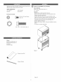
Hardware and other included contents can be found in the
bottom drawer (unless otherwise noted).
TOOLS REQUIRED:
1/2" Wrench 5/16" Wrench
Scissors Screwdriver
Hardware Included:
10+24 x 5/16 Hex Screw
(Qty: 24)
5/16 +18 x 1 Hex Screw (Qty: 4)
Chest:
Drawer Liner Roll (Qty: 1)
Drawer Dividers (Qty: 6)
Literature
Hardware bag
CHEST ATTACHMENT (if purchased)
Items Needed:
5/16 + 18 x 1 Hex Screw (Qty.: 4)
1/2" Wrench
Process:
+Remove the wooden top from the cart.
+Remove the top two drawers of the cart (refer to the
drawer removal instructions).
Lift the chest onto the cart. Line up the holes in the
bottom of the chest with the holes in the top of the cart.
Attach the chest using (4) screws inserted from the
underside of the top of the cart. (See Figure 8)
Wrench tighten all screws.
Replace the drawer (refer to drawer installation instruc+
tions).
+To remove, reverse procedure.
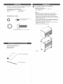
Figure 1
Drawer Liner Roll
Drawer Divider
Figure 2

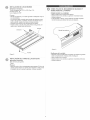
DIVIDERINSTALLATION
ItemsNeeded:
10-24x5/16HexScrew(Qty:24)
Dividers(Qty:6)
5/16"Wrench
PrOCeSS:
- Decide which position and in which drawers they would
best serve your needs.
The dividers are cut to fit right to left in the drawers. If you
prefer to run them front to back, they may be trimmed in
length to do so.
Position the dividers in the desired locations.
Thread screws through the bottom of the drawer and into
each divider. Tighten all the screws.
Dividers
Drawer
DRAWER LINER INSTALLATION
Items Needed:
Drawer Liner Roll
Scissors
Process:
- Remove the non-slip drawewr liner from the roll. The
drawer liner may be cut with scissors to fit each drawer
and around the drawer divideres, if necessary.
LOCKING AND UNLOCKING THE UNIT
Locking the Unit:
Pull handle lever out.
Insert the key into the lock and turn it clockwise.
Release lever.
If the drawers do not open, push all the drawers com-
pletely closed to release the tockbars
Figure 3
Unlocking the Unit:
Always check the unit to make sure all the drawers are
completely closed before locking.
Putt the handle lever.
Insert key into the lock and turn it counterclockwise.
Release lever.

0 _ _± 0
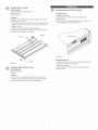
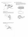
REMOVING AND INSTALLING DRAWERS
- Empty the drawer.
Fully extend the drawer.
Release Left
Figure 4
Release Right
REINSTALL DRAWERS
Ball bearing slide - Putt slides and slide carrier out to futty
extended position (see illustration.) Hold the slide on the
cabinet while aligning it with the slide on drawer. Slightly
insert one side and repeat for the other side. Slowly push
drawer to its fully closed position to engage slide. Open
drawer and rectose to ensure proper operation.
slide carrier
slide
BALL BEARING SLIDES
Lever Style - Lift or lower (depending on the slide) the
release lever on both sides, (this allows the slides to ride
over the stops.) Putt out to remove.
)
/
/
\\
\
Tab Style - Depress the release tabs on both sides,
(this allows the slides to ride over the stops).
Pull out to remove.

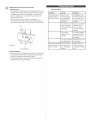
REMOVINGANDiNSTALLiNGSLIDES
SlideRemoval-
- The drawers in these units can be rearranged to fit your
specific needs. This means that drawers may be moved
or replaced as desired. For example, a 6-inch drawer
may be replaced by a 2dnch and a 4-inch drawer, or
three 2dnch drawers.
First remove the drawer (Refer to Operation A).
Lift and hold the spring retainer, and push the slide to-
ward the rear of the unit. The slide may now be removed.
Figure 5
Spring Retainer
Slide Installation °
Place the slide in the appropriate position in the unit and
pull toward the front of the unit until the spring retainer
snaps into position and secures the slide.
For smooth operation, make sure that the drawers are
matched with their original slides.
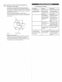
LOCK SYSTEM
Problem
The unit unlocks
but the drawers
still wilt not open.
The unit locks but
some drawers still
are not locked.
Cause
One or more
of the drawers
are holding the
tockbars from
releasing.
The cover on the
chest is holding
the tockbars from
releasing.
The release
cables are not
working.
The unit is leaning
too far forward.
One or more of
the drawers are
not competetly
closed.
Solution
Completely close
all the drawers and
the lockbars will
release to open the
drawers.
Apply a downward-
pressure to the
top of the cover
to let the tockbars
release.
In an UNLOCKED
position and pull
the lock lever sev-
eral times.
Position the unit on
a level area.
Unlock the unit.
Close all drawers
completely. Retock
unit.

MANUAL DE USUARIO
• Limpie con detergente suave y agua los frontales y los bordes laterales
de los cajones y las demos superficies,
• La cera para autom6viles preservar_ el acabado brilloso de la unidad.
Aplique la cera como Io harla al carro. La cera tambiCn ayudar8 a proteo
ger la unidad contra raspones.
• La grasa y el aceite pueden retirarse con la mayorla de los Ilquidos
est_ndar para limpieza. Por razones de seguridad, utilice un Ilquido
incombustible para limpieza.
• Si se suministran forros para las gavetas, se recomienda que se utilicen
para proteger el acabado interno de las mismas y para facilitar la limpo
ieza. Los forros para gavetas pueden limpiarse con agua y jab6n.
MODELO NO 45277 CAJA DE 361N (91,4 CM)
CON 5 CA JONES
MODELO NO 45287 CAJA DE 461N (116,8 CM)
CON 10 CA JONES
MODELO NO 45289 CAJA DE 561N (142,2 CM)
CON 10 CA JONES
EN ESTABOS UNtDOS LLAME AL 1-800-833-4405 PARA
PIEZAS DE REPUESTO. FUERA BE ESTADOS UNIDOS
LLAME A SU DtSTRtBUIBOR LOCAL. Suministre el nQmero de
modelo al comunicarse.
UBtCACION DE INFORMACI6N DEL NO. DE MODELO
El nQmero de modelo y demos informaci6n requerida para las piezas de
servicio se encuentran en una etiqueta en el lado interior derecho de la
gaveta superior.
• El peso vac{o del caja de 36" (91,4 cm) es 195 Ibs (88,5 Kg.)
• El peso vac{o del caja de 46" (116,8 cm) es 290 Ibs (131,7 Kg.)
• El peso vac{o del caja de 56" (142,2 cm) es 390 Ibs (177,1 Kg.)
• El peso mSximo del producto, incluyendo el contenido, para el modelo
de 36" (91,4 cm) no debe ser mayor de 1800 libras (816,5 Kg.).
El peso mSximo del producto, incluyendo el contenido, para el modelo
de 46" (116,8 cm) no debe ser mayor de 3000 libras (1360,8 Kg.).
El peso m&ximo del producto, incluyendo el contenido, para el modelo
de 56" (142,2 cm) no debe ser mayor de 5400 libras (2451,6 Kg.).
El peso maxlmo para cada gaveta es 2" (5cm) de profundidad es 120
libras (54,4 Kg.).
El peso maxlmo para cada gaveta de 3" (7,6 cm) de profundidad es
200 libras (90,7 Kg.).
El peso maxlmo para cada gaveta de 4" (10,2 cm) o6" (15,2 cm) de
profundidad es 320 libras (145,1 Kg.).
El peso maxlmo por cada gaveta de 9" (22,9 cm) de profundidad o
mSs es 400 libras (90,7 Kg.).
q
• Lubrique las diapositivas con grasa o equivalente, (dos veces cada a_o.)
• Lubrique la cerradura y la fijaci6n de componentes de sistema con el
grafito, (anualmente).
PELIGRO _, se utiliza para indicar una situaci6n
peligrosa que, de no evitarse, resultar_ en lesiones graves o la muerte.
ABVERTENOIA z_ indica una situaci6n peligrosa que, de no
evitarse, podria producir lesiones graves o la muerte.
PREOAUOION se utiliza para indicar una situaci6n peligrosa que, de
no evitarse, puede derivar en lesiones leves o moderadas, o en da_o a la
propiedad.
ATENOK)N: Lea y siga todas las Normas de Seguridad y las
Instrucciones de Funcionamiento antes de utilizar por primera vez este
producto.
PELIGRO ,_
• NO se ponga'de pie sobre esta unidad. Puede caerse u ocasionar que
el producto se vuelque.
NO abra m_s de una gaveta. El producto podria quedar inestable y
volcarse.
NO utilice las gavetas como pelda_os. Puede caerse u ocasionar que
el producto se vuelque.
NO monte este producto en una cama de carro o ninguin otro objeto
mCvil.
NO mueva la unidad antes de cerrar y asegurar todas las gavetas. Las
gavetas podrian abrirse y hacer que la unidad se vuelva inestable y se
vuelque.
ADVERTENCIA A
USE GAFAS DE SEGURIDAD al quitar o volver a poner las corredo
eras.
• NO hale la unidad, empQjela cuando la mueva.
UTILICE LOS FRENOS cuando el producto no est6 en movimiento Esto
impedir_ que se deslice.
NO altere la unidad en modo alguno. Por ejemplo, no suelde las barras
de sujeci6n externas nile incorpore equipos elCctricos.
Mantenga la unidad en superficies niveladas. La unidad puede tornarse
inestable y volcarse si se almacena o se moviliza en una superficie no
nivelada.
TENGA cuidado cuando cierre la tap& Quite las manos antes de que la
tapa cierre completamente.
PRECAUCION
• Este producto no est_ dise_ado para ser levantado directamente con un
montacargas, ni para ser remolcado con unidades mecanizadas.
• Nunca debe exceder el peso m_ximo de cada gaveta.
• $61o transporte esta unidad cuando est6 vacia. AsegOrela adecuadao
mente cuando la transporte.
• NO exceda el peso m_ximo del producto, incluyendo el contenido. Reo
fi6rase a las Capacidades para mSs informaci6n.
UTILICE EL PERSONAL ADECUADO PARA LEVANTAR O
MOVER EL BAUL O EL GABINETE.
Cojinetes de bolas
Waterloo Industries, 139 West Forest Hill Avenue, Oak Creek, WI 53154, USA
F1992

Elhardwareyotroscontenidoincluidospuedenserencontrados
enelajuar(amenosqueseindiqueIocontrario),
HERRAMIENTASNECESARIAS:
LlaveInglesade5/16" LlaveInglesade1/2"
Tijeras Destornillador
FERRETERIAINCLUIDAS:
TornilloHexagonalde10-24
x5/16(Cant:24)
TornilloHexagonalde5/16-18x1(Cant:4)
Rollodeforroparagaveta(Cant.:1)
Divisoresdegaveta(Cant.:6)
Bolsadeaccesorios
Materialimpreso
O ACCESORIODEBAUL(SlLOADQUIERE}
Elernentosneceserios:
Tornillohexagonalde5/16-18x1(Cant.:4)
LlaveInglesade1/2"
Pi*oeeeo:
Retire la parte superior de madera de la unidad rodante.
• Retire las dos gavetas superiores de la unidad rodante (re-
fi6rase alas instrucciones para remoci6n de gavetas).
• Levante el baQI y col6quelo en la unidad rodante. Alinee los
agujeros en la parte inferior del baQI con los de la parte supe-
rior de la unidad rodante.
• Fije el baQl utilizando (4) tornillos insertados desde abajo de la
parte superior de la unidad rodante. (Refi6rase ala figura 8).
• Apriete todos los tornillos con una Ilave.
Vuelva a colocar la gaveta (refi6rase alas instrucciones de
instalaci6n de la gaveta).
• Pare retirar, invierta el procedimiento.
i
i
i j,
Figura 1
Rollo de forro para gaveta
Divisor de gavetas

JNSTALACJONDELOSDJVJSORES
EJementoeneceearioe:
Tornillohexagonalde10o24x5/16(Cant.:24)
Divisores(Cant.:6)
LlaveInglesade5/16"
Proceso:
• Decida qu6 posici6n yen curies gavetas se adaptar_n mejor a
sus necesidades.
• Los divisores est_n cortados para encajar de derecha a izquio
erda en Jas gavetas. Si prefJere coJocarJos deJ frente hacia Ja
parte posterior, pueden recortarse a Io largo tambi6n.
• Coloque los divisores en las ubicaciones que desee.
Inserte tornillos a trav6s de la parte inferior de la gaveta yen
cada divisor. Apriete todos los tornillos.
Gaveta
Divisores
INSTALACI6N DEL FORRO DE LAS GAVETAS
EJementos necesarios:
Rollo de forro para gaveta
Tijeras
Prooeeo:
• Retire del rollo el forro antirresbalante para gavetas. El forro de
gaveta puede cortarse con tijeras para adaptarlo a cada gaveta
y alrededor de los divisores de gavetas, si fuese necesario.
Q
_ COMO UTlUZAR EL MECANISMO DE BLOQUEO Y
DESBLOQUEO DE LA UNJDAD
PONER SEGURO A LA UNJDAD:
• Hale la palanca de la manija hacia afuera.
• Inserte la Ilave en la cerradura y girela en el sentido horario.
Suelte la palanca.
Si las gavetas no abren, empuje todas las gavetas completao
mente cerradas para liberar las barras de sujeci6n.
/
Figura 3
DeebJoqueo de Jaunidad:
• Siempre revise la unidad para comprobar que todas las gavetas
est6n completamente cerradas antes de asegurar.
Hale la palanca de la manija.
Inserte la Ilave en la cerradura y girela en el sentido antihorario.
Suelte la palanca.

REMOCIONEINSTALA,CJONDEGAVETAS INSTALACI6NDEGAVETAS
Vacielagaveta.
Abracompletamentelagaveta.
Libere la izquierda
Correderas de rodamientos esfericos - hale hacia
afuera las correderas y el soporte de las correderas hasta que
queden en posici6n totalmente extendida (ver ilustraci6n).
Sostenga la corredera en el gabinete mientras Io alinea con la
corredera de la gaveta.
Figura 4
Libere la derecha
Soporte de las correderas
Corredera
COJJNETES DE BOLAS
Esti_o pa_anca - Levante o baje (dependiendo de la corredera)
la palanca de liberaci6n en ambos lados (esto permite que las
correderas pasen sobre los topes). Jale hacia afuera para refirar.
\\\\\
\\
\\
Estilo leng{ieta - Oprima las lengOetas de liberaci6n en ambos
lados (esto permite que las correderas pasen sobre los topes).
Jale hacia afuera para retirar.
\\\4\\\

QUITANDO E INSTALACKSN DE DtAPOSITIVAS
Remoci6n de la corredera -
• Las gavetas de estas unidades pueden disponerse de otro
modo para que se adapten a sus necesidades especificas.
Esto significa que ias gavetas pueden moverse o reempiazarse
como Io desee. Por ejemplo, una gaveta de 6" (15,2 cm) puede
reemplazarse por una gaveta de 2" (5 cm) y de 4" (10,2 cm), o
tres gavetas de 2" (5 cm).
Primero retire la gaveta (Refi6rase a la Operaci6n A).
Levante y sostenga el retenedor con muelle y presione la corre-
dera hacia la parte posterior de la unidad. La corredera podr8
retirarse ahora.
®
Figura 5
Reten flexible
InstalaciSn de Ja corredera =
Coloque la corredera en la posici6n adecuada en la unidad
y hale hacia el frente de la misma hasta que el retenedor de
resorte encaje en su posici6n y asegure la corredera.
Para un funcionamiento suave, cerci6rese de que las gavetas
correspondan con sus correderas originales.
DEL SlSTEMA DE ClERRE
Prob_ema Causa So_uci6n
La unidad puede Una o m_s de las Cierre completamente
desbloquearse pero las gavetas est,(n) todas las gavetas y
gavetas no abren, evitando que las las barras de sujeci6n
barras de sujeci6n se liberarSn para abrir
se liberen, las gavetas.
La unidad se ase-
gura pero algunas
gavetas a0n no est_n
bloqueadas.
La cubierta del
ba01est_ evitando
que las barras de
sujeci6n puedan
liberarase.
Los cables de
liberaci6n no est_n
funcionando.
La unidad se inclina
demadiado hacia
delante.
Una o m_s gavetas
no est_n completa-
mente cerradas.
Aplique una presi6n
hacia abajo en la
parte uperior de la
cubierta para permitir
que las barras de
fijaci6n puedan liber=
arse.
En la posici6n DES-
BLOQUEADA hale la
palacea de asegura-
miento varias veces.
Coloque la unidad en
un area nivelada.
Desbloquee la unidad.
Cierre todas las gave=
tas completamente.
Vuelva a asegurar la
unidad.
-
 1
1
-
 2
2
-
 3
3
-
 4
4
-
 5
5
-
 6
6
-
 7
7
-
 8
8
-
 9
9
-
 10
10


Craftsman 706452870 El manual del propietario
- Tipo
- El manual del propietario
en otros idiomas
- English: Craftsman 706452870 Owner's manual
Artículos relacionados
-
Craftsman 109648 Guía del usuario
-
-
Craftsman 706182500 El manual del propietario
-
-
-
-
-
Craftsman 706105950 El manual del propietario
-
-