Craftsman 706407630 El manual del propietario
- Tipo
- El manual del propietario

OPERATOR'S MANUAL
®
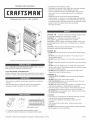
PREMIUM HEAVY DUTY TOOL CHESTS
* Product you purchased may vary from picture shown
CALL 1o800o366o7278 FOR SERVICE PARTS. Refer to Service
Parts Drawing for futt listing of Service Parts.
LOCATING MODEL # iNFORMATION
Model numbers and other information required for service parts is
located on a tabet on the interior right side of the top most drawer.
The maximum weight for each drawer should be no more than
100 tbs.
The maximum product weight for each modet combination,
including contents, should be no more than 1,200 tbs.
Batt bearing slides
For casters, use high quality bearing grease, (yearly).
Lubricate the slides with grease or equivatent,(twice yearly.)
Lubricate tock with graphite, (yearly).
Periodically the drawer fronts, drawer trim, and other surfaces
should be cleaned with a mitd detergent and water.
Auto wax witt preserve the unit's luster finish. Apply the wax
as to a car. The wax witt atso hetp protect the unit against
scratches.
Grease and oit can be removed with most standard
cleaning fluids. For safety, use a nonflammable cteaning fluid.
if drawer liners are supplied, it is recommended they are used
to protect the finish inside the drawers and to make the drawers
easier to clean. The drawer liners may be cleaned
with soap and water.
DANGER is used to indicate a hazardous situation which,
if not avoided, wJ_Jresult in serious injury or death.
WARNING z:_ indicates a hazardous situation which,
if not avoided, could resutt in serious injury or death.
CAUTION is used to indicate a hazardous situation which, if not
avoided, _ result in minor injury, moderate injury, or property
damage.
CAUTION: Read and follow all Safety Rules and Operating
instructions before first use of this product.
DANGER
- DO NOT stand on this product. You may fatt or cause product
to tip.
- DO NOT open more than one drawer. The product may be-
come unstabte and tip.
- DO NOT step in the drawers. You may fatt or cause product to
tip.
DO NOT mount this product on a truck bed or any other moving
object.
DO NOT move the product prior to closing and locking att the
drawers and chest lid. The drawers could come open and make
the product unstable and tip.
DO NOT place any objects on top of chest tid. Remove att
objects from chest tid before opening.
WARNING Z_
* WEAR SAFETY GLASSES when removing or repositioning
the stides.
- DO NOT puii the unit, push it when moving
- USE THE BRAKES when not moving this product. This wiii
prevent the product from roiling.
- DO NOT atter this product in any manner. For example, do not
wetd externat iockbars or attach electrical equipment.
- Keep the product on ievet surfaces. The product may become
unstable and tip if stored or moved on an uneven surface.
- BE CAREFUL when ctosing the cover. Remove hands before
the cover closes completely.
CAUTION
- This product is not designed to be directly lifted with a fork lift,
or to be towed with any mechanical devices.
- The maximum weight for each drawer should never be
exceeded.
- Only transport this product empty. Properly secure when
transporting.
- DO NOT exceed maximum product weight, including contents.
See Capacities for more information.
Distributed by Sears Brands Management Corporation, Hoffman Estates, IL 60179 F1947

TOOLS REQUIRED:
3/8-in Wrench
7/16-in Wrench
Cross4ip Screwdriver
HARDWARE iNCLUDED:
26-INCH CABINET HARDWARE
#14 - 10 x 5/8-in Hex Screws
(Qty: 16)
#14 - 10 x 3/4 Cross4ip Screw
(Qty: 4)
HARDWARE iNCLUDED:
40° & 524NCH CABINET HARDWARE
#14 - 10 x 3/4-in Screws
(Qty: 16)
1/4 - 20 x 5/8 Screw (Qty: 16)
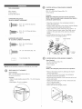
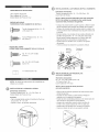
CASTER iNSTALLATiON (26-iNCH CABINET}
items Needed:
#14 - 10 x 5/8qn Hex Screws (Qty: 16)
3/8-in Wrench
Process:
NOTE: Use adequate personnel for this operation.
NOTE: Failure to instaR_easter channels may result in
premature cabinet failure.
Place the unit on its top. Use packaging materiat to
protect the paint finish.
Position caster channels on the cabineL Notched flanges
should be toward the outside and pointed up.
Attach casters and caster channels using (4) #14 - 10
x 5/8 Hex Screws for each caster. Mount both swivet
casters on the same side of the cabinet as the side
handle.
Wrench tighten all screws. Do not overtighten.
Return the unit to its upright position.
Notches Caster channels
in back
\
Notches
in front
1!4-in Nut (Qty: 16)
NOTE: Not att assembly instructions wilt relate to your model.
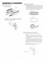
SiDE HANDLE ATTACHMENT
Items Needed:
#14 - 10 x 3/4 Cross-tip Screw (Qty: 4)
Cross-tip Screwdriver
Process:
- Attach the side handle using (4) #14 - 10 x 3/4 Cross-tip
screws.
- Hand tighten. Do not overtighten.
CASTER iNSTALLATION (40-INCH CABINET)
Items Needed:
1/4 - 20 x 5/8 Screw (Qty: 16)
1!4-in Nut (Qty: 16)
7/16-in Wrench
Process:
NOTE: Use adequate personne_ for this operation.
Remove the bottom drawer by following the drawer
removal instructions.
Lay the cabinet down on its back. Use packaging
materiat to protect the paint finish.
Mount both swivet casters on the same side of the cart
as the side handle.
Attach each caster using (4) 1/4-20 x 5/8 screws and
(4) 1/4" nuts per caster.
Wrench tighten atl screws.
Return the cart to its upright position.

O _ _± 0 7
@ REMOVING DRAWERS
Empty the drawer.
Fully extend the drawer.
Release
@
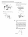
iNSTALLiNG DRAWERS
Ball bearing slide - PuJJsJides and sJide carrier out to fuJJy
extended position (see illustration.) Hold the slide on the
cabinet while aligning it with the sJide on drawer. SJightly
insert one side and repeat for the other side. Slowly push
drawer to its fully closed position to engage slide. Open
drawer and rectose to ensure proper operation.
Slide carrier
Slide
Lever Style - Lift or lower (depending on the slide) the
release lever on both sides, (this allows the sJides to ride
over the stops). Putt out to remove.
/
Q
U
REMOVING AND INSTALLING SLIDES
, To remove the slide from the unit, first remove the
drawer.
After removing the drawer check to see if the unit has
rivets located on the front of the slide. To drill out rivets,
use a 5/32dn drill bit. The rivets witt need to be replaced
with 5/32dn rivets.
To reinstall the slide in the appropriate position in the
unit, align front and back lances with mounting holes in
the side of the unit. Pull towards the front of the unit and
downwards until rivet holes in slide tine up with holes in
the unit. The rivets will need to be replaced with 5/32dn
rivets.
- For smooth operation, make sure the drawers are
matched with their originaJ sJides.
Drill out rivet


MANUAL DE USUARIO
T °
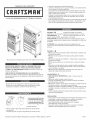
CAJAS DE HERRAMIENTAS DE TRABAJO PESADO
• Lubrique la cerradura con grafito (anualmente).
• Limpie con detergente suave y agua los frontales y los bordes laterales
de los cajones y las demSs superficies.
La cera para autom6viles preservar8 el acabado brilloso de la unidad.
Aplique la cera como Io haria al carro. La cera tambi6n ayudar8 a pro-
teger la unidad contra raspones.
La grasa y el aceite pueden retirarse con la mayoria de los liquidos
est_ndar para limpieza. Por razones de seguridad, utilice un liquido
incombustible para limpieza.
Si se suministran forros para las gavetas, se recomienda que se utilicen
para proteger el acabado interno de las mismas y para facilitar la limpo
ieza. Los forros para gavetas pueden limpiarse con agua y jab6n.
* El producto que compraste puede variar de la imagen que se muestra
O H
EN ESTADOS UNtDOS LLAME AL 1-800-659-7084 PARA
PIEZAS DE REPUESTO. FUERA DE ESTADOS UNIDOS
LLAME A SU [:)ISTRJBUI[:)OR LOCAL. Suministre el nQmero de
modelo al comunicarse.
UBICACI6N DE INFORMACION DEL NO. DE MODELO
El n0mero de modelo y demos informaci6n requerida para ias piezas de
servicio se encuentran en una etiqueta en el lado interior derecho de la
gaveta superior.
• El peso mSximo en cada gaveta no debe ser mayor de 45,4 kg.
• El peso m_ximo del producto para cada combinaci6n de modelo,
incluyendo su contenido, no debe ser mayor de 544,3 kg.
q
Cojinetes de bolas
• Para las ruedas, utilice grasa para rodamientos de alta calidad
(anualmente).
• Lubrique las guias con grasa o equivalente (dos veces por a_o).
PELIGRO _I_ se utiliza para indicar una situaci6n
peligrosa que, de no evitarse, resultar_ en lesiones graves o la muerte.
ADVERTENCIA A indica una situaci6n peligrosa que, de no
evitarse, podria producir lesiones graves o la muerte.
PREOAUOION se utiliza para indicar una situaci6n peligrosa que, de
no evitarse, puede derivar en lesiones leves o moderadas, o en da_o a la
propiedad.
ATENOION: Lea y siga todas ias Normas de Seguridad y las
Instrucciones de Funcionamiento antes de utilizar por primera vez este
producto.
PEUGRO
• NO se ponga de pie sobre esta unidad. Puede caerse u ocasionar que
el producto se vuelque.
NO abra m_s de una gaveta. El producto podria quedar inestable y
volcarse.
NO utilice las gavetas como pelda_os. Puede caerse u ocasionar que
el producto se vuelque.
NO monte este producto en una cama de carro o ningQn otro objeto
m6viL
NO mueva la unidad antes de cerrar y asegurar todas las gavetas y
la tapa del baOL Las gavetas podrian abrirse y hacer que la unidad se
vuelva inestable y se vuelque.
NO coloque ningOn objeto sobre la tapa del baOl. Quite todos los
objetos de la tapa del baQI antes de abrido.
ADVERTENCIA A
• USE GAFAS DE SEGURIDAD al quitar o volver a poner las
correderas.
NO jaie ia unidad, empOjeia cuando ia mueva.
UTILICE LOS FRENQS cuando el producto no est6 en movimiento.
Esto impedir8 que se desiice.
NO aitere la unidad en modo aiguno. Por ejempio, no sueide ias barras
de sujeci6n externas niie incorpore equipos ei6ctricos.
Mantenga la unidad en superficies niveiadas. La unidad puede tornarse
inestabie y voicarse si se aimacena o se moviiiza en una superficie no
niveiada.
TENGA cuidado cuando cierre ia tapa. Quite ias manos antes de que ia
tapa cierre compietamente.
PRECAUCION
Este producto no est_ dise_ado para ser levantado directamente con un
montacargas, ni para ser remolcado con unidades mecanizadas.
Nunca debe exceder el peso mSximo de cada gaveta.
$61o transporte esta unidad cuando est6 vacia. AsegOrela
adecuadamente cuando la transporte.
NO exceda el peso m_ximo del producto, incluyendo el contenido.
Refi6rase alas Capacidades para m_s informaci6n.
Distribuido cerca Sears Brands Management Corporation, Hoffman Estates IL 60179
F1947

HERRAMIENTAS NECESARIAS:
Llave IngJesa de 3/8 inch
Llave Inglesa de 7/16 inch
Destornittador de Punta en Cruz
PIEZAS INOLUIDAS:
FERRETERIA PARA GABJNETE DE 2{} PULG,
Tornillo Hexagonal de No. 14 - 10x 5/8 (Cant: 16)
Tuerca PNlips de No. 14 - 10 x
3/4 (Cant: 4)
PIEZAS INCLUIDAS:
FERRETERIA PARA GABJNETE DE 40 Y 52 PULG,
No. 14 - 10 x 3/4 TomiHo
(Cant: 4)
No. 1/4 - 20 x 5/8 TomiHo
(Cant: 16)
1/4 Tuerca (Cant: 16)
NOTA: No todas las instrucciones de ensambtaje se
refieren a tu modeto.
@
INSTALACION DE LA MANIJA LATERAL
E_ementos necesarios:
Tornillos Phillips de No. 14 - 10 x 3/4 (Cant.: 4)
DestomiHador de Punta en Cruz
Proceso:
Fije JamanUa tateral usando 4 torniHos de Punta en
Cruz de No. 14 - 10 x 3/4.
Apnete a mano. No apriete demasiado.
Q INSTALACION DEL LAS RUEDAS PULG,
(26 GABINETE)
Elementos necesarios:
TorniIto Hexagonal de No. 14 - 10 x 5/8 (Cant.: 16)
Ltave Alien de 3/8 ptg
NOTA: Uti_ice personal adecuado para esta operacion.
NOTA: No instatar _os canales de _asruedas puede
ocasionar faHa prematura de_gabinete,
Cotoque ta unidad sobre su parte superior. Utitice et mate-
rial de empaque para proteger et acabado de la pintura.
Coloque los canates para las ruedas sobre la unidad. Las
muescas deben estar orientadas hacia ta parte extema de
ta unidad.
- Fije las ruedas y los canates de las ruedas utitizando (4)
torniIIos hexagonal No. 14 - 10 x 5/8 para cada rued&
Monte ambas ruedas giratodas en et mismo tado det
gabinete donde se encuentra ta manija taterat.
- Apriete todos tos tomittos con una ttave. No apriete
demasiado.
- Vuetva a colocar ta unidad en su posiciOn vertical.
Muescas Canales de
en la parte las ruedas
_ posterior
\
Muescas
a! frente
INSTALACION DE LAS RUEDECILLAS:
(40 PULG, GABJNETE)
Emementos necesarios:
No. 1/4 - 20 x 5/8 Tomitto (Cant: 16)
1/4 Tuerca (Cant: 16)
Ltave Inglesa de 7/16 inch
NOTA: Use _aayuda de otras personas
para esta operaci6n,
Quite ta gaveta inferior siguiendo tas instrucciones para
retirar las gavetas.
Acueste el carro sobre su parte trasera. Proteja et
acabado con et materiat de empaque.
Instate las dos ruedeciIIas giratorias en el mismo tado det
carro donde se encuantra ta manija lateral.
Asegure tas ruedeciIIas usando cuatro tomitlos de
1/4-20 x 5/8 y cuatro tuercas de 1/4" en cada una.
Apriete todos los tornitlos con una IIave de tuercas.
Vuetva a colocar el carro en su posiciOn vertical.

Q REMOCIONDEGAVETAS
Vacie Jagaveta.
Abra comptetamente ta gaveta.
Libere
INSTALACION DE GAVETAS
Correderas de rodamientos esfericos ojate hacia afuera
tas correderas y et soporte de Jascorrederas hasta que
queden en posiciOn totatmente extendida (ver iJustraciOn).
Sostenga ta corredera en el gabinete mientras to atinea
con ta corredera de ta gaveta.
Soporte de las correderas
/
Corredera
EstiRo palanca - Levante o baje (dependiendo de la
corredera) Japatanca de liberaciOn en ambos lados (esto
permite que las correderas pasen sobre tos topes.) Jate
hacia afuera para retirar.
INSTALACION Y DEStNSTALCION DE CORREDERAS
- Para quitar ia corredera de ia unidad, pnmero quite ia
gaveta.
Despu6s de quitar el cajOn, comprueba si ta unidad tiene
remaches en et frente de la corredera. Para quitar los
remaches con un tatadro, usa una broca para tatadro de
5/32 pig. Deber_s reemptazar tos remaches con rem-
aches de 5/32 pig.
Para volver a instatar correctamente ta corredera en la
unidad, alinea las lancetas frontales y posteriores con
los orificios de montaje en et tado de ta unidad. Et tirOn
hacia et frente de la unidad y hacia aba]o hasta agujeros
de remache en Jadiapositiva se atinea con agujeros en
ta unidad. Deber_s reemptazar tos remaches con unos
de 5/32 plg.
Para et buen funcionamiento, asegurese de que Jos
cajones hacen juego con sus correderas odginaJes.

-
 1
1
-
 2
2
-
 3
3
-
 4
4
-
 5
5
-
 6
6
-
 7
7
-
 8
8


Craftsman 706407630 El manual del propietario
- Tipo
- El manual del propietario
en otros idiomas
- English: Craftsman 706407630 Owner's manual
Artículos relacionados
-
Craftsman 706586400 El manual del propietario
-
-
-
-
-
-
-
Craftsman 706105950 El manual del propietario
-
-