
OPERATOR'S MANUAL
CRRFTSMRN°
i PROFESSIONAL i
PROFESSIONAL SERIES CANOPY
Caution" Read and follow all Safety Rules and Operating Instructions before first use of this
product. Retain this document for future reference.
Distributed by Sears Brands Management Corporation., Hoffman Estates, IL 60179
F1677

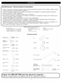
AFETY WARNINGS AND CAUTIONS:
Use appropriate safety equipment when using power and hand tools. Failure to do so may cause personal injury or
product damage.
Use adequate manpower when assembling and moving this unit. Failure to do so may cause personal injury or
product damage.
DO NOT stand on this product. You may fall which may cause personal injury.
DO NOT mount this product on a truck bed or any other moving object. This may cause personal injury or
product damage.
Appropriately secure this product before moving it with a forklift.
DO NOT alter this product in any manner. For example, do not weld external lockbars or attach electrical
equipment. This may cause product damage or personal injury.
Keep the product on level surfaces. The product may become unstable and tip if stored or moved on an un-level
surface, Which may cause personal injury or product damage.
DO NOT step on the shelves. You may fall which may cause personal injury.
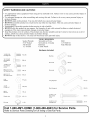
TOOLS REQUIRED:
Socket Wrench Screwdriver, Torx Drill
5/16" Socket Screwdriver, Crosstip 1/2" Drill bit
3/8" Socket Hammer Tape Measure
1/2" Socket Center Punch
Hardware Included
1/4-20 X 5/8
(20)
Carriage bolt
14-10 X 5/8
Hex washer BB (4)
screw
Bushing
Grommet
MM (2)
NN (2)
1/4-20 X 7/16
Hex washer CC (8)
screw S-_
(
#8-32 X ½ Torx DE) (4) Grommet "
Self tapping screw ,,:!,,, _,, OO (4)
#6-32 X 1/2 ......
Pan head screw EE (2)
5/16
Washer
FF (24)
Long hinge pin PP (2)
1/4-20 GG (24)
Flange nut
#6-32
Hex nut HH (4)
Short hinge pin
14-10 X 1-1/2
Hex washer
Plastic rivet KK (11) screw
RR (2)
SS (7)
End cap
1/4-20 X 2-1/4
LL (2) Carriage bolt
JJ (4)
Call 1-800-4MY-HOME (1-800-469-4663) for Service Parts.
efer to Service Parts Drawing for full listing of Service Parts.

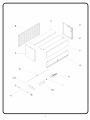
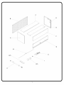
C
B
E
A
G
H

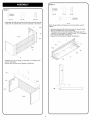
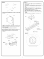
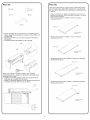
_STEP 2: _'_
fSTEP 1 :
/ sf" "\
AA (15) FF (15) GG (15)
Assemble back (B) to left side (A) and right side (D) using (4)
bolts (AA), (4) washers (FF), and (4) nuts (GG) in each side.
Front
Back
"a
• Attach top (C) to unit using (7) bolts (AA), (7) washers (FF),
and (7) nuts (GG).
• Square the unit and wrench tighten all fasteners.
AA .... T C
'j \\
GG
i ....
Front
_llll
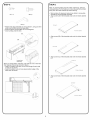
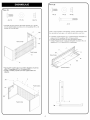
AA (5) FF (9) GG (9)
JJ (4)
Note: Finger tighten all fasteners until instructed to wrench
tighten.
• Assemble top panel (E) and front panel (F) using (5) bolts
(AA), (5) washers (FF) and (5) nuts (GG).
• The top panel (E) should be outside of the front panel (F).
• Install (4) corner braces (J) using (2) bolts (TT), (2) washers
(FF), and (2) nuts (GG)in each set.
• Square the unit and wrench tighten all fasteners.
Front
R
AA
..... FF
GG
E
Top
©
i
J

_'STEP 3:
MM (2) BB (2)
PP (2)
Snap shaft ends of struts (J) over ball studs on canopy sides
as shown.
//
/
/
Ball stud
d
• Install (2) bushings (MM) in square in sides of unit as
shown.
• Attach door assembly to unit using (2) long pivot pins (PP)
and (2) screws (BB).
• Wrench tighten screws (BB). Do not overtighten.
Note: The ball studs for the door assembly are located on the
outside of the stiffener on the door, near the hinge pins.
• Snap piston end of struts over ball studs on the door
assembly.
Ball stud
PP
Door
assembly
quare
hole
/
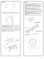
fSTEP 4: "_
• Install (2) grommets (NN)in outside holes of stiffeners on
lower door (G).
• Mount lock (I) to door (G) as shown, using mounting nut. The
access notch on the lock should be toward the top of the
door.
• Insert the key and rotate the lock 90° CCW to the lock
position.
• Insert one end of the lock rod (M) through a stiffener and
through grommet (NN) as shown.
• Repeat for the other end of the lock rod (M).
• Attach lock rod (M) to the lock (I) using adaptor nut as
shown.
• Because lock is in "Lock" position, rotate lock CW 180° to
"Unlock."
• Return the key to the middle position and remove key.
NN
-- _............ _,_^'4a_÷or
nut
/'
/ Supplied with lock
/
/'
Top
Access Notch
toward t_
/
/
f
_"\\\\\\\\
M
Mounting nut
supplied with lock
\\\\\\\\
MASTER LOCK ®
ONE-KEY TMLOCK
\\ //
\\\ ///
_11111 J
J

_"STEP 5:
KK (11) BB (2)
RR (2)
• Attach lower door assembly to unit as shown, using (2) short
pivot pins (2) (RR) and (2) screws (BB).
• Wrench tighten screws (BB). Do not overtighten.
• Close canopy and test lock.
RR
\\\\\
/
BB-. i
X,
Lowerdoor
assembly
Note: To install plastic rivet (KK), fully seat the rivet in the hole
then depress the plunger to hold in place.
• Install (4) plastic rivets (KK) in the front flange of each side
on the unit as shown.
• Install (3) plastic rivets in holes along bottom edge of the
lower door as shown.
fSTEP 6:
Note: To prevent drilling into the metal cabinet top, take the
removable top off of the cabinet or move the part to be drilled
away from the metal cabinet top before drilling.
• Mark centers of clearance holes to be drilled in removable
cabinet top using template provided.
• Align corner (A) of the template and mark the holes labeled
(1).
Corner A
Front of cabinet
• Align corner (B) of the template and mark the holes labeled
(2).
Corner B
_cabinet
• Align corner (C) of the template and mark the holes labeled
(3).
Corner C
nt of cabinet
• Align corner (D) of the template and mark the holes labeled
(4).
Corner D
Front of cabinet
_11111 J
J

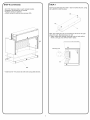
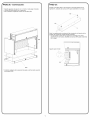
_'STEP 6 (continued):
• Drill 1/2" clearance hole in each marked location.
• Reposition removable top on cabinet.
• Position canopy on cabinet.
• Attach canopy to cabinet using screws (SS).
\
\
i
DD
• Install Corner Trim pieces to both sides using (DD) Screws.
fSTEP 7:
Insert (2) screws (EE) into slots in back of outlet strip (H), using
(2) nuts (HH) to hold in place.
EE
HH
H
Note: The outlet strip may be mounted on the left or the right
side of the unit. Mounting shown on left.
• Attach outlet strip through mounting holes in back wall as
shown, using (2) nuts (HH) to hold in place.
Mounting hole
HH
o ........................
J
J


MANUAL DE USUARIO
(RRFT$MRN '°
i PROFESSIONAL i
PABELLON PROFESIONAL DE LA SERIE
Precauci6n: Lea y siga todas las reglas de seguridad e instrucciones para el manejo antes de usar la
unidad por primera vez. Conserve este manual para referencia futura.
Distribuido por Sears Brands Management Corporation, Hoffman Estates, IL 60179
F1677

fADVERTENCIAS Y PRECAUCIONES DE SEGURIDAD:
• Utilice el equipo de seguridad adecuado cuando emplee herramientas eldctricas. De lo contrario, podria causarle
lesiones personales u ocasionar dafios al producto.
• Utilice el personal adecuado para el montaje y el traslado de esta unidad. De lo contrario podria ocasionarse
lesiones personales o dafiar el producto.
• NO se ponga de pie sobre la unidad. Podria caerse y lesionarse.
• NO monte esta unidad en la plataforma de carga de la camioneta ni en ningOn otro objeto mdvil. Podria causar
lesiones personales o dafio a la unidad.
• Asegure adecuadamente la unidad antes de moverla con un montacargas.
• NO altere la unidad en modo alguno. Por ejemplo, no suelde las barras de sujecidn externas nile incorpore
equipos eldctricos. Podria causar dafio a la unidad o lesiones personales.
• Mantenga el producto sobre superficies planas. E1 producto puede desestabilizarse y volcar si se almacena o se
mueve en superficies no llanas, lo cual podria causar lesiones personales o dafiar el producto.
NO se pare en las baldas. Se puede caer y lesionar.
HERRAMIENTAS NECASARIAS:
Llave de tubo Destornillador, Torx Talladro
Casquillo adaptador de 5/16 pulgadas Destornillador, punta de cruz Broca de 1/2 de pulgada
Casquillo adaptador de 3/8 pulgadas Martillo Cinta mdtrica
Casquillo adaptador de 1/2 pulgadas Perfore en el centro
Ferreteria incluida
Pemo cabeza de AA (20)
hongo de 1/4-20 X 5/8
TORNILLO
HEXAGONAL DE BB (4)
14-10 X 5/8
Tornilto Hexagonal de CO (8)
1/4-20 X 7/16
Tornillo autoperforante No ,,
8-32 X 1/2 DD (4)
Tornillo de Cabeza
Trencecenica de 6-32 X EE (2)
1/2
arandela de 5/16 FF (24)
Buje
Grommet
ARANDELA
Perno de bisagra largo
MM (2)
NN (2)
O0 (4)
PP (2)
Tuerca con brida de GG (24)
1/4-20 Perno de bisagra corto
Tuerca Hexagonal de HH (4)
6-32
TORNILLO
HEXAGONAL
Remacheptastico KK (11) DE 14-10 X 1-1/2
_J
RR (2)
SS (7)
Casquillo de extreme
Perno cabeza de
hongo de 1/4-20
EL (2) X 2-1/4
JJ (4)
Llame al 1-800-659-7084 para las piezas de repuesto.
efidrase al plano de piezas de repuesto para la lista completa de repuestos.
2

!r _I
C
B
D
/
/
E
A
G
K

9aso (1):
6aso (2):
AA (15) FF (15) GG (15)
• Ensamble la parle posterior (B) al lado izquierdo (A) y al lado
derecho (D) utilizando (4)pernos (AA), (4) arandelas (FF), y (4)
tuercas (GG) en cada lado.
Parte frontal
Parte trasera
'B
" D
Fije la parte superior (C) a la unidad utilizando (7) pernos
(AA), (7) arandelas (FF), y (7) tuercas (GG).
Ajuste la unidad y apriete con Ilave inglesa todos los
seguros.
GG
Parte frontal
Parte trasera
4
AA (5) FF (9) GG (9)
JJ (4)
NOTA: Para facilitar el ensamblaje, apriete manualmente todos
los sujetadores hasta que se le instruya apretarlos con llave.
• Ensamble el panel superior (E) y el panel frontal (F) utilizando (5)
pernos (AA), (5) arandelas (FF) y (5) tuercas (GG).
• El panel superior (E) debe estar fuera del panel frontal (F).
• Instale (4) refuerzos de esquina (J) utilizando (2) pernos (TT), (2)
arandelas (FF), y (2) tuercas (GG) en cada juego.
AA
Parte frontal
J
..... FF
GG
E
la parte supenor
©
i
J

rPaso (3):
MM (2) BB (2)
PP (2)
Coloque a presi6n los extremos del eje de los montantes (J) sobre
los pernos esfericos en los lados de la cubierta como se ilustra.
R6tula
/
• Instale (2) cojinetes (MM) en los agujeros cuadrados en los lados de
la unidad como se ilustra.
• Fije el ensamble de la puerta a la unidad utilizando (2) pasadores
pivotantes largos (PP) y (2) tornillos (BB).
• Apriete los tornillos con una Ilave de tuercas. No apriete demasiado.
Nota: Los pernos esfericos del ensamble de la puerta estan ubicados
en la parte de afuera del refuerzo en la puerta, cerca de las clavijas de
las bisagras.
• Encaje a presi6n el extremo tipo pist6n de los montantes sobre los
pernos esfericos en el ensamble de la puerta.
PP
Montaje de la
puerta
i
i / Perforaci6n
rectangular
./
"'\ MM
\\\
R6tula
fPaso (4): "_
• Instate (2) arandelas aistantes (NN) en los agujeros externos
de los refuerzos en la puerta inferior (G).
• Monte ta cerradura (I) a ta puerta (G) como se itustra,
utitizando la tuerca de montaje. La muesca de acceso en ta
cerradura debe estar orientada hacia la parte superior de la
puerta.
• Inserte la ltave y gire la cerradura 90° en el sentido
antihorario hacia ta posici6n de traba,
• Inserte un extremo de ta varitla de la cerradura (M) a trav6s
de un refuerzo y de una arandela aislante (NN) como se
ilustra.
• Repita para el otro extremo de la varilla de la cerradura (M).
• Fije la varilla de la cerradura (M) a la cerradura (I) utilizando
la tuerca adaptadora como se ilustra.
• Debido a que la cerradura est_ en la posici6n "Lock"
(trabada), gire la cerradura 180° en el sentido horario para
"destrabar".
• Regrese la Ilave a la posici6n central para retirar la Ilave.
NN.
/
Tuerca deladaptador
suministrada la cerradura
la parte superior
\\\\\\\\
Tenga acceso a la
muesca hacia tapa
M
Tuerca de montaje
suministrada la cerradura
CERRADURA MASTER
LOCK ® ONE-KEY TM
\
\
"\\
\\\\\\\
7
\X J"
\\\ /_"
.J
.J
.J
j-
J
J

fPaso (5):
KK (11) BB (2)
RR (2)
• Fije et ensambte de la puerta inferior a la unidad como se
ilustra, utitizando (2) pasadores pivotantes cortos (RR) y (2)
tornillos (BB).
• Apriete los torniltos con una Ilave de tuercas. No apriete
demasiado.
• Cerradura cercana del pabell6n y de la prueba.
RR
BB f
f
'\, /
Baje el
montaje de la f
puerta
Nota: Para instalar et remache plastico (KK), ins6rtelo
comptetamente en et agujero y luego oprima el 6mboto para
sostenerto en su tugar.
• Instate (4) remaches ptasticos (KK) en ta brida frontal de
cada lado de la unidad como se ilustra.
• Instate (3) remaches plasticos en los agujeros del borde de
la base de la puerta inferior como se ilustra.
fPaso (6):
Nota: Para evitar taladrar en la parte superior metalica del gabinete
saque la parte superior desprendible del gabinete o mueva la pieza
que va a taladrar, apartandola de la parte superior del gabinete antes
de taladrar.
• Pegue la plantilla en su lugar para asegurarse de que marca los
agujeros correctamente. Utilice un punz6n de perforar y un martillo
para marcar los agujeros.
• Alinee la esquina (A) de la plantilla y marque los agujeros
etiquetados como (1).
Esquina (A) ontal del
gabinete
• Alinee la esquina (B) de la plantilla y marque los agujeros
etiquetados como (2).
J
Esuna
_: _ /f Parte frontal del
__ gabmeto
• Alinee la esquina (C) de la plantitla y marque los agujeros
etiquetados como (3).
Esquina (C)
Parte frontal del
gabinete
• Alinee la esquina (D) de la plantitla y marque los agujeros
etiquetados como (4).
Esquina (D)
Parte frontal del
gabinete
J
6
J

_'PASO (6) - Continuacion:
• Taladre agujeros de paso de ½" (1,3 cm) en cada lugar marcado.
• Coloque la pieza superior en el gabinete.
• Ate el pabell6n al gabinete usando los tomillos (SS).
SS
/
\\\\\
\\\\
DD
Instale los pedazos de la esquina del ajuste a ambos lados usando
los tornillos (DD).
fPASO (7):
Inserte (2) tornillos (EE) en las ranuras en la parte posterior de la
regleta (H), utilizando (2) tuercas (HH) para sostenerla en su lugar.
EE
HH
H
Nota: La regleta puede montarse al lado izquierdo o al derecho de la
unidad. Se muestra el montaje al lado izquierdo.
• Fije la regleta a traves de los agujeros de montaje en la pared
posterior como se ilustra, utilizando (2) tuercas (HH) para sostenerla
en su lugar.
Agujero para montar
!
HH
J
7
J

-
 1
1
-
 2
2
-
 3
3
-
 4
4
-
 5
5
-
 6
6
-
 7
7
-
 8
8
-
 9
9
-
 10
10
-
 11
11
-
 12
12
-
 13
13
-
 14
14
-
 15
15
-
 16
16


Craftsman 706385580 El manual del propietario
- Tipo
- El manual del propietario
en otros idiomas
- English: Craftsman 706385580 Owner's manual