La página se está cargando...

Installation Instructions | Installationsanleitung | Notice d’installation
Instrucciones de instalación | Istruzioni per l’installazione
Minebea Intec
YDO01C-232 (A1)
YDO01C-485 (A2 | A3)
YDA01C-20MA (A4)
YDO01C-DP (B1)
YDO01C-EN (B9)
Data Output Port for Combics UniCOM Interface
Datenausgang für Combics-Schnittstelle UniCOM
Port de sortie pour interface Combics UniCOM
Salida de datos para interfaz UniCOM de Combics
Porta uscita dati per interfaccia Combics UniCOM
98647-003-29

2 YDO01C
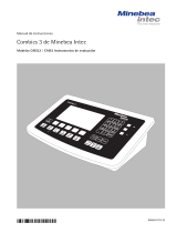
Contents Intended Use
English – page 3
In cases involving questions of interpretation, the German-language version shall prevail.
Deutsch – Seite 20
Im Auslegungsfall ist die deutsche Sprache maßgeblich.
Français – page 38
En cas de questions concernant l’interprétation, la version en langue allemande fera autorité.
Español – página 56
En caso de interpretación, la versión en lengua alemana será determinante.
Italiano – pagina 74
In caso di interpretazione, fa testo la versione in lingua tedesca.

YDO01C
3
Contents Intended Use
Intended Use
The YD.01C-... data output port
(YDO01C-232: Option A1,
YDO01C-485: Option A2/A3,
YDA01C-20MA: Option A4,
YDO01C-DP: Option B1, YDO01C-EN:
Option B9) is designed for installation
in Combics indicators and complete
scales, models CISL., CIS., CW.P and
CW.S as an optional UniCOM universal
data interface.
The YD.01C-... data output port can be
configured for use as one of the follow-
ing types of interface:
– YDO01C-232 (Option A1):
Bi-directional RS-232 data interface.
The YDO01C-232 module enables con-
nection of any of a number of printers
(YDP01IS, YDP02, YDP03, YDP02IS,
YDP04IS or a universal printer driver) or
a second weighing platform or digital
compact scale (WP2)1) for use in either
SBI or xBPI mode, data exchange with
a PC (in SBI, xBPI or SMA mode), or for
connection of an alibi memory.
– YDO01C-485 (Options A2 and A3):
Bi-directional data interface, electri-
cally isolated, for use with the RS-422
(Option A2) or RS-485 (Option A3)
protocol.
The YDO01C-485 module enables
connection of a second weighing plat-
form or digital compact scale (WP2)1)
(IS weighing platform or YCO02IS) or
data exchange with a PC (in xBPI or SBI
mode).
– YDA01C-20MA (Option A4):
Analog output port for use as a cur-
rent interface (0/4 to 20 mA) or voltage
interface (0 to 5 volts).
The YDA01C-20MA module enables
connection of a PLC system or a remote
analog display unit.
– YDO01C-DP (Option B1):
Profibus DP interface (slave) for field
bus applications (e.g. enables connec-
tion to a PLC system).
– YDO01C-EN (Option B9) 2):
Ethernet interface for field bus applica-
tions (e.g., for connection to a PLC).
1) Connection of a second weighing instrument
or platform not possible on Combics 1 models
2) Operation and configuration only with Combics
indicators without 25-pin interfaces.
Symbols
The following symbols are used in
these instructions:
§ Indicates required steps
$ Indicates steps required only under
certain conditions
> Describes what happens after you have
performed a certain step
! Indicates a hazard
Contents
3 Intended Use
4 Configuring the Interface Module
4 YDO01C-232
4 YDO01C-485
5 YDA01C-20mA
7 YDO01C-DP
7 YDO01E-EN (B9)
8 Installation in the Indicator
11 Pin Assignment Charts
14 Configuring the UniCOM Interface
18 Display: Initialization Completed
18 Ethernet Interface: Features
19 Analog Interface Extension
YDA01C-20mA

4 YDO01C
Confi guring the Interface Module Confi guring the Interface Module
1 2
3
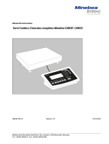
Configuration of the solder bridges
1 2a
2b
2c
3a
3b
3c
Configuring the Interface Modulet
YDO01C-232 (Option A1)
The YDO01C-232 interface module (RS-232 serial interface) is installed directly on the
digital PCB in the Combics indicator (models CISL., CIS., CW.P, CW.S); no further
configuration is required. For details, please see “Installation in the Indicator.”
YDO01C-485 (Options A2 and A3)
The YDO01C-485 module (serial RS-485/RS-422 interface, electrically isolated1)) can be
operated in your choice of the RS-485 or RS-422 mode. Configuring the module for
the intended use involves opening and closing certain solder bridges. In addition to
defining whether RS-485 or RS-422 is used, certain terminating resistors (120 O)
and/or bias resistors may have to be activated or deactivated, depending on whether
a network or point-to-point connection is used.
The positions of the relevant solder bridges are shown in the drawing on the left.
The arrow (1) points to the solder bridge that determines the operating mode (RS-485
or RS-422). When the solder bridge is closed, the interface is configured for RS-422
operation. Arrows (2) and (3) each mark a row of three solder bridges: 2a, 2b, 2c and
3a, 3b, 3c. When the a and b solder bridges are closed, the bias resistors for the RS-422
(2a and 2b) or the RS-485 (3a and 3b) operating mode are activated. When the c sol -
der bridges are closed, the 120 O terminating resistors are active (2c: RS-422 mode;
3c: RS-485 mode).
The factory defaults are as follows:
– RS-485 operating mode is active (solder bridge 1, RS-485/RS-422 setting: open).
– Solder bridges 2a and 2b, for activating the RS-422 bias resistors are closed (i.e., both
bias resistors are activated).
– Solder bridge 2c, for the RS-422 terminating resistor (120 O) is closed (i.e., the termi -
nat ing resistor for operation in RS-422 mode is activated).
– Solder bridges 3a and 3b, for activating the RS-485 bias resistors, are closed (i.e., both
bias resistors are activated).
– Solder bridge 3c, for the RS-485 terminating resistor (120 O) is closed (i.e., the termi -
nating resistor for operation in RS-485 mode is activated).
Operation as an RS-485 Interface (Option A3):
§ Solder bridge 1, for the RS-485/RS-422 setting, must be open (factory setting).
§ Deactivate both RS-485 bias resistors (if active). To do this, open the solder bridges
(factory setting: both bias resistors are activated; i.e., the solder bridges are closed).
The bias resistors must occur no more than once per data transmission path (whether
over a network or in a point-to-point connection); otherwise, transmission errors may
occur. Please refer to the specifications or wiring diagram for the remote station or
network node in question for detailed information. Always activate or deactivate bias
resistors in pairs.
§ Deactivate the terminating resistor (120 O) for operation in RS-485 mode (3c),
if active. To do this, open the solder bridge (factory setting: terminating resistor
activated; i.e., solder bridge is closed).
The terminating resistor must be activated if the device is at either end of an RS-485
bus system, or when connected point-to-point with another device. The remote
station must also have a 120 O terminating resistor. If the device is not at either end
of an RS-485 bus system, deactivate the terminating resistor by opening the solder
bridge.
§ The configuration of solder bridges 2a, 2b and 2c is not relevant for operation in
RS-485 mode.
§ The YDO01C-485 module configured as an RS-485 interface is installed directly on
the digital PCB in the Combics indicator (models CISL., CIS., CW.P, CW.S). For details,
please see “Installation in the Indicator.”
1) The shielding in the connecting cable is connected at one end to the housing of the indicator.
The indicator is connected to the protective grounding conductor.

YDO01C
5
Confi guring the Interface Module Confi guring the Interface Module
1
2
4
3
Configuration of the solder bridges
1 2a
2b
2c
3a
3b
3c
Configuration of the solder bridges
(factory setting)
1 2
3 4
Operation as an RS-422 Interface (Option A2):
§ Solder bridge 1, for the RS-485/RS-422 setting, must be closed (factory setting: solder
bridge open, for operation as an RS-485 interface).
§ Deactivate both RS-422 bias resistors (if active). To do this, open the solder bridges
(factory setting: both bias resistors are activated, i.e., the solder bridges are closed).
The bias resistors must occur no more than once per data transmission path (whether
over a network or in a point-to-point connection); otherwise, transmission errors may
occur. Please refer to the specifications or wiring diagram for the remote station or
network node in question for detailed information. Always activate or deactivate bias
resistors in pairs.
§ Deactivate the terminating resistor (120 O) for operation in RS-422 mode (2c),
if active. To do this, open the solder bridge (factory setting: terminating resistor
activated; i.e., solder bridge is closed).
The terminating resistor must be activated if the device is at either end of an RS-422
bus system, or when connected point-to-point with another device. The remote
station must also have a 120 O terminating resistor. If the device is not at either end
of an RS-422 bus system, deactivate the terminating resistor by opening the solder
bridge.
§ Deactivate both bias resistors and the terminating resistor required for configuration
as an RS-485 interface. To do this, open solder bridges 3a, 3b and 3c (factory setting:
both bias resistors and the terminating resistor are activated; i.e., all three solder
bridges are closed).
§ The YDO01C-485 module configured as an RS-485 interface is installed directly on
the digital PCB in the Combics indicator (models CISL., CIS., CW.P, CW.S). For details,
please see “Installation in the Indicator.”
YDA01C-20MA (Option A4)
The YDA01C-20MA interface module is an analog output port. This module can be
operated as either a current interface (0/4 to 20 mA) or a voltage interface (0 to 5 V).
Voltage can be supplied internally or externally (electrically isolated1)). Configuring the
module for the intended use involves opening and closing certain solder bridges.
The positions of the relevant solder bridges are shown in the drawing on the left.
The interface module can be configured for any of the following 3 operating states:
– Voltage interface, 0 to 5 V
– Current interface, 0 to 20 mA
– Current interface, 4 to 20 mA
The operating state is defined by the configuration of solder bridges 1 and 2. Solder
bridge 1 has 3 settings: “0 to 5 V,” “0 to 20 mA” and “4 to 20 mA.” Solder bridge 2
defines whether the module is used as a voltage interface or a current interface.
! Make sure that the settings for solder bridges 1 and 2 are compatible; for example,
if solder bridge 1 is configured for one of the current interface settings, solder bridge 2
must be set to “current interface.” Conversely, if solder bridge 1 is set to “0 to 5 V,”
solder bridge 2 must be set to “voltage interface.”
The voltage supply setting (“internal” or “external”; factory setting: internal) is defined
by solder bridges 3 and 4 (see the illustration on the left).
! Make sure the settings for solder bridges 3 and 4 are compatible; i.e., either both for
internal or both for external voltage supply.
1) The shielding in the connecting cable is connected at one end to the housing of the indicator.
The indicator is connected to the protective grounding conductor.

6 YDO01C
Confi guring the Interface Module Confi guring the Interface Modulet
The factory defaults are as follows (see the illustration on the left):
– Operation as a current interface
– Range of current intensity: 4 to 20 mA
– Voltage supply: internal
t
Operation as a Current Interface in the 4 to 20 mA Range (Factory Setting):
§ Solder bridges 1 and 2 must be configured as shown in the illustration on the left.
Operation as a Current Interface in the 0 to 20 mA Range:
§ Re-solder bridge 1 as shown in the illustration on the left.
§ Solder bridge 2 must be configured as shown in the illustration on the left. This
corresponds to the factory default configuration.
Operation as a Voltage Interface (0 to 5 V):
§ Open solder bridge 1 so that the setting corresponds to that shown here on the left.
§ Re-solder bridge 2 as shown in the illustration.
Operation with Internal Voltage Supply (Factory Setting):
§ Solder bridges 3 and 4 must be configured as shown in the illustration on the left.
Operation with External Voltage Supply:
§ Open solder bridge 3.
§ Re-solder bridge 4 as shown in the illustration.
Operation as an Electrically Isolated Interface:
§ Configure solder bridges 3 and 4 for “external supply.” To do this, open solder bridge
3 and re-solder bridge 4 as shown in the illustration.
§ If the interface is powered by an external AC adapter, it must be electrically isolated.
Be sure to comply with the requirements of CE conformity.
Notes
– The shielding in the current interface connecting cable is connected at one end to the
housing of the indicator.
– The indicator is connected to the protective grounding conductor.
– The current interface cannot be operated when the indicator is powered by the external
rechargeable battery pack.
§ The YDA01C-20MA interface module (Option A4) is installed directly on the digital PCB
in the Combics indicator (models CISL., CIS., CW.P, CW.S). For details, please see
“Installation in the Indicator.”
Configuration of the solder bridges
Current interface, 4 to 20 mA
1 2
Current interface, 0 to 20 mA
1 2
Voltage interface, 0 to 5 V
1 2
Operation with internal voltage supply
3 4
Operation with external voltage supply
3 4
Operation as an electrically isolated
interface
3 4
1
2
4
3

YDO01C
7
Confi guring the Interface Module Confi guring the Interface Modulet
YDO01C-DP (Option B1)
Equipment Supplied
– YDO01C-DP interface module
– Disk with GSD file
– Operating instructions (this document)
– Software interface description
Installation
The YDO01C-DP interface module (Profibus interface) is installed directly on the digital
PCB in the Combics indicator (models CISL., CIS., CW.P, CW.S); no further configura tion
is required. For details, please see “Installation in the Indicator.” Any terminating resistors
that may be necessary for the bus system must be installed outside the indicator.
The required voltage is supplied internally by the indicator. A bus connection is required
at both ends of the bus system. This is done by either:
– Termination at the connecting plug (at baud rates > 1.5 Mbit/s with inductances)
or
– Active bus termination.
Notes:
! Only use cables and plugs with profibus specifications.
! Connect the connecting cable shield to the housing.
YDO01C-EN (Option B9)
Equipment Supplied
– YDO01C-EN interface module
– Operating instructions (this manual)
– Software interface description
Installation
Connect the YDO01C-EN interface module (Ethernet interface) directly to the digital PCB
in the Combics indicator (CIS. or CW.S model) without further configuration. For details,
please see “Installation in the Indicator.” Connect the male connector of the Minebea
Intec YCC... Ethernet cable (Option M38) to the female connector of the interface mod-
ule.
Note:
! Use only cables and connectors that conform to Ethernet specifications (CAT5 or better);
use Minebea Intec order number YCC .... (Option M38) to order an Ethernet cable with
cable gland
The interface module can be installed only in the following devices:
– CIS.. indicators (IP67)
– CW..S complete scales (IP67)
Terminating resistors
for Profibus
GND
390 O
A
220 O
B
390 O
VP

8 YDO01C
Installation in the Indicator Installation in the Indicator
Installation in the Indicator
If the customer ordered the Combics indicator with the desired interfaces installed
at the factory, it is not necessary to install the interface module; nor is it necessary
to install the additional cable gland and attach the connecting cables to the screw
terminal strip on model CIS. and CW.S (IP67 protected) indicators.
Notes
§ The interface module should be installed by a certified technician who has received
specialized training from Minebea Intec .
§ CIS. and CW.S Devices (IP67-protected):
Make sure to use the connecting cable with screw-lock hardware designed for the
inter face module in question (see “Accessories”).
! Disconnect the equipment from power before beginning.
! Any installation work that does not conform to the instructions in this manual results
in forfeiture of all claims under the manufacturer’s warranty.
! CIS. and CW.S Devices:
Installation work that affects the IP67 protection rating must be performed with
extreme care. The cable gland (IP67 protection) for installing the interface module inside
the indicator is sealed by protective caps. Please use extreme caution when performing
any work on the equipment that affects this cable gland.
§ Remove the four screws as indicated in the illustration and then remove the front panel
from the indicator.
§ Install your configured interface module (YDO01C-232, YDO01C-485, YDA01C-20MA,
YDO01C-DP or YDO01C-EN) on the digital PCB of the Combics indicator. To do this,
attach the female terminal strips on the interface module to the corresponding male
terminal strips on the digital PCB.
YDO01C-232, YDO01C-485, YDA01C-20MA, YDO01C-DP:
The interface module is electrically connected through plug-in connections to the external
elements provided for this purpose (25-pin data output socket on CISL. and CW.P devic-
es, or terminal screw strip on the digital PCB for the YDO01C-232 and YDO01C-485 serial
interface modules on CIS. and CW.S devices). The YDA01C-20MA (analog current/
voltage interface) and YDO01C-DP (Profibus) interface modules are equipped with their
own terminal screw strips. For installation in an IP67-protected device, attach the
connecting cable to this strip.
§ CISL. and CW.P Devices (IP44-protected):
The connectors for the interface module (YDO01C-232, YDO01C-485, YDA01C-20MA
or YDO01C-DP) on the digital PCB are on the 25-contact female data output con nector,
which is labeled “UniCOM” on CISL1, CISL2, CW1P and CW2P devices, and “COM2” on
CISL3 and CW3P devices.
This female data output connector has other connectors in addition to those provided for
the interface module. For a description of the other connectors, please see the Combics
operating instructions (under “Pin Assignment Chart” in the chapter entitled “Operating
the Combics”).

YDO01C
9
Installation in the Indicator Installation in the Indicator
§ CIS. and CW.S Devices (IP67-protected):
– Interface modules YDO01C-232 (serial RS-232 interface) and YDO01C-485 (serial
RS-485/422 interface):
The screw terminal strips are on the right-hand side of the digital PCB (see the illustra -
tion on the left and refer to the pin assignment chart in the operating instructions,
in the chapter entitled “Operating the Combics”).
– On CIS1, CIS2, CW1S and CW2S devices, use the 10-pin terminal screw strip LV2
for UniCOM.
– On CIS3 and CW3S devices, use the right-hand 4-pin terminal screw strip LV4
for UniCOM. If required, connect the corresponding grounding potential on the
neighboring 10-pin terminal screw strip LV2 to terminals 2 and 3.
– YDA01C-20MA Interface Module (Analog Current/Voltage Interface) and YDO01C-DP
Interface Module (Profibus Interface):
The connectors are on the terminal screw strip on the interface module.
– YD001C-EN interface module (Ethernet interface):
– for use only in CIS.. and CW..S devices
– Use the cable gland of the YCC02-RJ45M7 cable (Option M38) to connect the cable
shield to the Combics housing.
– Do not lay the YCC02-RJ45M7 cable (Option M38) over the A/D converter PCB.
§ For details on pin assignments, please see “Pin Assignment Charts” in this manual.
§ For further information, refer also to the Combics operating instructions
(under “Pin Assignment Chart”, in the chapter entitled “Operating the Combics”).
CISL. and CW.P Devices (IP44-protected):
§ Close the indicator. Make sure that the rubber seal between the front panel and the
housing is correctly positioned.
CIS. and CW.S Devices (IP67-protected):
§ Use the cable gland to connect the peripheral device to the indicator.
§ YDO01C-DP interface module (Option B1, Profibus interface):
If multiple devices are connected in a bus system (as opposed to point-to-point
connections), install 2 separate connecting cables with cable glands, using separate bore
holes. Connect the individual wires of both cables to the terminals (on the module) in
pairs to conduct the signals from one device to the next.
! Please observe the information given above under “Notes.”
! The connecting cable is prepared at the factory for installation in the Combics indicator,
with a preassembled cable gland in position.
! Please use extreme caution when performing any work on the equipment that affects this
cable gland. Use a torque wrench. Torque applied to this cable gland: 5 Nm.
UniCOM Combics1/2: 10-pin screw termi-
nal strip LV2 for serial interfaces.
UniCOM Combics3: 4-pin screw terminal
strip LV4 for serial interfaces.

10 YDO01C
Installation in the Indicator Installation in the Indicator
§ Installing the connecting cable:
– Remove the plug from the bore hole on the indicator.
If the same cable is used for COM1 connections (terminal screw LV1), use the bore hole
in the middle of the housing.
– Guide the cable with the attached cable gland through the bore hole.
– Close and tighten the cable gland in accordance with the applicable standards.
– Make sure the shielding has contact with the clamps, as the shielding provides the
grounding connection.
§ Connecting the wires inside the indicator:
– Connect the wires securely in accordance with the terminal assignments.
§ Close the indicator. Make sure that the rubber seal between the front panel and the
housing is correctly positioned.
§ After you close the housing again, use a pressure gauge to check the integrity of the
IP67-protection. For details, contact the Minebea Intec Service Center.
Configuring the UniCOM Interface for Operation
After configuring the desired operating mode and installing the interface module in the
indicator, configure the interface by selecting the settings in the operating menu that
correspond to your requirements. For details on the settings available in the operating
menu, see “Configuring the UniCOM Interface” below. For additional information, see
also the chapter entitled “Settings” in the Combics operating instructions.

YDO01C 11
Installation in the Indicator Installation in the Indicator
Pin Assignment Charts
CISL. and CW.P Devices
(IP44-protected):
25-contact D-Sub connector (DB25S)
with screw lock hardware
Front view
Male interface connector used (please
use connectors with the same specifi -
cations):
25-pin D-Sub (DB25) with shielded
cable clamp assembly (Amp type
826 985-1C) and fastening screws
(Amp type 164868-1)
Pin assignments in the UniCOM
interface (CISL1, CISL2, CW1P and
CW2P devices):
The tables below show only the pin
assignments for the YDO01C-232,
YDO01C-485, YDA01C-20MA and
YDO01C-DP interface ports.
The pins for connecting the external
battery pack and the bar code scanner
(not on Combics 1 models) are marked
“Internally connected.” For further
information, please see the Combics
operating instructions (under “Pin
Assignment Chart” in the chapter
entitled “Operating the Combics”).
YDO01C-232 (Option A1):
Pin 1: Shield
Pin 2: Data output (TxD)
Pin 3: Data input (RxD)
Pin 4: Internal ground (GND_INT)
Pin 5: Clear to send (CTS)
Pin 6: Not connected
Pin 7: Signal ground (SGN_GND)
Pin 8: Not connected
Pin 9: Not connected
Pin 10: Not connected
Pin 11: Internally connected
Pin 12: Internally connected
Pin 13: Internally connected
Pin 14: Internal ground (GND_INT)
Pin 15: Internally connected
Pin 16: Not connected
Pin 17: Not connected
Pin 18: Not connected
Pin 19: Internally connected
Pin 20: Data terminal ready (DTR)
Pin 21: Internally connected
Pin 22: Internally connected
Pin 23: Internally connected
Pin 24: Internally connected
Pin 25: +5V
YDO01C-485
(Option A2, RS-422 operating mode):
Pin 1: Shield
Pin 2: Data output + (TxD+)
Pin 3: Data input + (RxD+)
Pin 4: Internal ground (GND_INT)
Pin 5: Data input - (RxD-)
Pin 6: Not connected
Pin 7: Electrical ground (GND_GALV)
Pin 8: Electrical ground (GND_GALV)
Pin 9: Not connected
Pin 10: Not connected
Pin 11: Internally connected
Pin 12: Internally connected
Pin 13: Internally connected
Pin 14: Internal ground (GND_INT)
Pin 15: Internally connected
Pin 16: Not connected
Pin 17: Not connected
Pin 18: Not connected
Pin 19: Internally connected
Pin 20: Data output - (TxD-)
Pin 21: Internally connected
Pin 22: Internally connected
Pin 23: Internally connected
Pin 24: Internally connected
Pin 25: +5V
YDO01C-485
(Option A3, RS-485 operating mode):
Pin 1: Shield
Pin 2: Data + (TxD-RxD+)
Pin 3: Not connected
Pin 4: Internal ground (GND_INT)
Pin 5: Not connected
Pin 6: Not connected
Pin 7: Electrical ground (GND_GALV)
Pin 8: Electrical ground (GND_GALV)
Pin 9: Not connected
Pin 10: Not connected
Pin 11: Internally connected
Pin 12: Internally connected
Pin 13: Internally connected
Pin 14: Internal ground (GND_INT)
Pin 15: Internally connected
Pin 16: Not connected
Pin 17: Not connected
Pin 18: Not connected
Pin 19: Internally connected
Pin 20: Data - (TxD-RxD-)
Pin 21: Internally connected
Pin 22: Internally connected
Pin 23: Internally connected
Pin 24: Internally connected
Pin 25: +5V
YDA01C-20MA (Option A4: current/
voltage interface):
Pin 1: Shield
Pin 2: Not connected
Pin 3: Not connected
Pin 4: Internal ground (GND_INT)
Pin 5: Not connected
Pin 6: Not connected
Pin 7: Not connected
Pin 8: Not connected
Pin 9: Current/voltage output
(4-20mA_VOUT)
Pin 10: Ground (GND_VOUT)
Pin 11: Internally connected
Pin 12: Internally connected
Pin 13: Internally connected
Pin 14: Internal ground (GND_INT)
Pin 15: Internally connected
Pin 16: External supply
(V_EXTERN)
Pin 17: External ground
(GND_EXTERN)
Pin 18: Not connected
Pin 19: Internally connected
Pin 20: Not connected
Pin 21: Internally connected
Pin 22: Internally connected
Pin 23: Internally connected
Pin 24: Internally connected
Pin 25: +5V
YDO01C-DP (Option B1: Profibus inter-
face):
Pin 1: Shield
Pin 2: Not connected
Pin 3: Not connected
Pin 4: Internal ground (GND_INT)
Pin 5: Not connected
Pin 6: Not connected
Pin 7: Signal ground (SGN_GND)
Pin 8: GND (electrically isolated)
Pin 9: LINE_A
Pin 10: 5V_BUS (VP)
(electrically isolated)
Pin 11: Internally connected
Pin 12: Internally connected
Pin 13: Internally connected
Pin 14: Internal ground (GND_INT)
Pin 15: Internally connected
Pin 16: LINE_B
Pin 17: RTS
Pin 18: IC (Internally connected)
Pin 19: Internally connected
Pin 20: Not connected
Pin 21: Internally connected
Pin 22: Internally connected
Pin 23: Internally connected
Pin 24: Internally connected
Pin 25: +5V

12 YDO01C
Installation in the Indicator Installation in the Indicator
Pin assignments in the UniCOM
interface (CISL3 and CW3P devices):
The tables below show only the pin
assignments for the YDO01C-232,
YDO01C-485, YDA01C-20MA and
YDO01C-DP interface ports.
The pins for connecting the external
battery pack, the bar code scanner and
the built-in COM2 interface are marked
“Internally connected.” For further
information, please see the Combics
operating instructions (under “Pin
Assignment Chart” in the chapter
entitled “Operating the Combics”).
YDO01C-232 (Option A1):
Pin 1: Shield
Pin 2: Internally connected
Pin 3: Internally connected
Pin 4: Internal ground (GND_INT)
Pin 5: Internally connected
Pin 6: Internally connected
Pin 7: Signal ground (SGN_GND)
Pin 8: Signal ground (SGN_GND)
Pin 9: Data terminal ready (DTR)
Pin 10: Not connected
Pin 11: Internally connected
Pin 12: Internally connected
Pin 13: Internally connected
Pin 14: Internal ground (GND_INT)
Pin 15: Internally connected
Pin 16: Data output (TxD)
Pin 17: Data input (RxD)
Pin 18: Clear to send (CTS)
Pin 19: Internally connected
Pin 20: Internally connected
Pin 21: Internally connected
Pin 22: Internally connected
Pin 23: Internally connected
Pin 24: Internally connected
Pin 25: +5V
YDO01C-485
(Option A2, RS-422 operating mode):
Pin 1: Shield
Pin 2: Internally connected
Pin 3: Internally connected
Pin 4: Internal ground (GND_INT)
Pin 5: Internally connected
Pin 6: Internally connected
Pin 7: Signal ground (GND_INT)
Pin 8: Signal ground (GND_GALV)
Pin 9: Data output - (TxD-)
Pin 10: Not connected
Pin 11: Internally connected
Pin 12: Internally connected
Pin 13: Internally connected
Pin 14: Internal ground (GND_INT)
Pin 15: Internally connected
Pin 16: Data output + (TxD+)
Pin 17: Data input + (RxD+)
Pin 18: Data input - (RxD-)
Pin 19: Internally connected
Pin 20: Internally connected
Pin 21: Internally connected
Pin 22: Internally connected
Pin 23: Internally connected
Pin 24: Internally connected
Pin 25: +5V
YDO01C-485
(Option A3, RS-485 operating mode):
Pin 1: Shield
Pin 2: Internally connected
Pin 3: Internally connected
Pin 4: Internal ground (GND_INT)
Pin 5: Internally connected
Pin 6: Internally connected
Pin 7: Signal ground (GND_INT)
Pin 8: Signal ground (GND_GALV)
Pin 9: Data - (TxD-RxD-)
Pin 10: Not connected
Pin 11: Internally connected
Pin 12: Internally connected
Pin 13: Internally connected
Pin 14: Internal ground (GND_INT)
Pin 15: Internally connected
Pin 16: Data + (TxD-RxD+)
Pin 17: Not connected
Pin 18: Not connected
Pin 19: Internally connected
Pin 20: Internally connected
Pin 21: Internally connected
Pin 22: Internally connected
Pin 23: Internally connected
Pin 24: Internally connected
Pin 25: +5V
YDA01C-20MA (Option A4: current/
voltage interface):
Pin 1: Shield
Pin 2: Internally connected
Pin 3: Internally connected
Pin 4: Internal ground (GND_INT)
Pin 5: Internally connected
Pin 6: Internally connected
Pin 7: Signal ground (SGN_GND)
Pin 8: Not connected
Pin 9: Current/voltage interface
(4-20mA_VOUT)
Pin 10: Masse (GND_VOUT)
Pin 11: Internally connected
Pin 12: Internally connected
Pin 13: Internally connected
Pin 14: Internal ground (GND_INT)
Pin 15: Internally connected
Pin 16: External supply
(V_EXTERN)
Pin 17: External ground
(GND_EXTERN)
Pin 18: Not connected
Pin 19: Internally connected
Pin 20: Internally connected
Pin 21: Internally connected
Pin 22: Internally connected
Pin 23: Internally connected
Pin 24: Internally connected
Pin 25: +5V
YDO01C-DP (Option B1: Profibus
interface):
Pin 1: Shield
Pin 2: Internally connected
Pin 3: Internally connected
Pin 4: Internal ground (GND_INT)
Pin 5: Internally connected
Pin 6: Not connected
Pin 7: Signal ground (SGN_GND)
Pin 8: GND (electrically isolated)
Pin 9: LINE_A
Pin 10: 5V_BUS (VP)
(electrically isolated)
Pin 11: Internally connected
Pin 12: Internally connected
Pin 13: Internally connected
Pin 14: Internal ground (GND_INT)
Pin 15: Internally connected
Pin 16: LINE_B
Pin 17: RTS
Pin 18: Not connected
Pin 19: Internally connected
Pin 20: Internally connected
Pin 21: Internally connected
Pin 22: Internally connected
Pin 23: Internally connected
Pin 24: Internally connected
Pin 25: +5V

YDO01C 13
Installation in the Indicator Installation in the Indicator
CIS. and CW.S Devices
(IP67-protected):
– YDO01C-232 and YDO01C-485:
The terminal strip is on the right-hand
side of the digital PCB (on CIS1, CIS2,
CW1S and CW2S devices: the 10-pin
terminal screw strip LV2; on CIS3 and
CW3S devices: the right-hand 4-pin
terminal screw strip LV4). For CIS1,
CIS2, CW1S and CW2S devices, the
chart below shows only signals from
the UniCOM. The terminals for con -
necting the bar code scanner (not on
Combics 1 models) are marked “Inter
-nally connected.” For further informa-
tion, please see the Combics operating
instructions (under “Pin Assignment
Chart” in the chapter entitled “Operat-
ing the Combics”). On CIS3 and CW3S
devices, grounding potential is availa -
ble on terminals 2 and 3 of the 10-pin
terminal screw strip LV2.
– YDA01C-20MA (current/voltage inter-
face) and YDO01DP (Profibus interface):
The 6-pin terminal screw strip is on the
interface module.
CIS1, CIS2, CW1S and CW2S devices:
Pin assignments in the 10-pin terminal
screw strip LV2:
1
2345689
76 10
YDO01C-232:
Pin 1: Not connected
Pin 2: Ground (GND)
Pin 3: Ground (GND)
Pin 4: Internally connected
Pin 5: Data terminal ready (DTR)
Pin 6: Internally connected
Pin 7: Internally connected
Pin 8: Clear to send (CTS)
Pin 9: Data input (RxD)
Pin 10: Data output (TxD)
YDO01C-485 (RS422 operating mode):
Pin 1: Signal ground, elec trically
isolated (GND_GALV)
Pin 2: Ground (GND)
Pin 3: Ground (GND)
Pin 4: Internally connected
Pin 5: Data output - (TxD-)
Pin 6: Internally connected
Pin 7: Internally connected
Pin 8: Data input - (RxD-)
Pin 9: Data input + (RxD+)
Pin 10: Data output + (TxD+)
YDA01C-20MA (current/voltage inter-
face):
6-pin terminal screw strip on the inter-
face module
Pin 1: GND
(electrically isolated ground)
Pin 2: 4-20mA_VOUT
(current interface, source)
Pin 3: GND_VOUT
(current interface, sink)
Pin 4: V_EXTERN
(external supply: +24V)
Pin 5: GND_EXTERN
(external supply: ground)
Pin 6: GND, electrically isolated
(electrically isolated ground)
YDO01C-DP (Profibus interface):
6-pin terminal screw strip on the inter-
face module
Pin 1: GND
(electrically isolated ground)
Pin 2: +5 V (VP)
Pin 3: LINE_A
Pin 4: LINE_B
Pin 5: RTS
Pin 6: IC (reserved)
YDO01C-485 (RS485 operating mode):
Pin 1: Signal ground, electrically
isolated (GND_GALV)
Pin 2: Ground (GND)
Pin 3: Ground (GND)
Pin 4: Internally connected
Pin 5: Data - (TxD-RxD-)
Pin 6: Internally connected
Pin 7: Internally connected
Pin 8: Not connected
Pin 9: Not connected
Pin 10: Data + (TxD+RxD+)
CIS3 and CW3S devices:
Pin assignments in the 4-pin terminal
screw strip LV4:
YDO01C-232:
Pin 1: Clear to send (CTS)
Pin 2: Data input (RxD)
Pin 3: Data output (TxD)
Pin 4: Data terminal ready (DTR)
YDO01C-485 (RS422 operating mode):
Pin 1: Data input - (RxD-)
Pin 2: Data input + (RxD+)
Pin 3: Data output + (TxD+)
Pin 4: Data output - (TxD-)
YDO01C-485 (RS485 operating mode):
Pin 1: Not connected
Pin 2: Not connected
Pin 3: Data + (TxD-RxD+)
Pin 4: Data - (TxD-RxD-)
1
234
1
234566
1
234566

14 YDO01C
Confi guring the UniCOM Interface Confi guring the UniCOM Interface
Configuring the UniCOM Interface
Configuring Combics 1 and Combics 2 Models
Operating Menu Overview for the UniCOM Interface
(also refer to the operating menu overview in the Combics operating instructions, in the chapter entitled “Operating the Combics”)
Appl
Fn-Key
Setup WP1
COM1
UniCOM Off *
WP2 1) RS-232 SBI standard version
SBI trade version
XBPI-232 *
ADC-232
RS-485 IS-485 *
ADC-485
Data protocol SBI *
XBPI-232
XBPI-485
SMA
Profibus Addr. 0
...
Addr. 126 *
Ethernet Source IP: 192.168.0.1 *
Source name
Listen port: 49155 *
Subnet mask:255.255.255.0 *
Gateway IP: 0.0.0.0 *
DNS IP: 0.0.0.0 *
Target IP: 0.0.0.0 *
Target port: 49155 *
Protocol TCP *
UDP
Mode SBI * 6. 1. Data output/printout,
manual/automatic
6. 1. 1 Manual without stability
6. 1. 2 * Manual after stability
6. 1. 4 Automatic without stability
6. 1. 5 Automatic at stability
6. 1. 7 Output of record to PC
xBPI 6. 3. Time-dependent automatic output
SMA 6. 3. 1 * 1 display update
Modbus/TCP 6. 3. 2 2 display updates
6. 3. 4 10 display updates
6. 3. 7 100 display updates
Printer YDP01IS Line *
Label 7. 2. Data output: line format
Label, man. form feed 7. 2. 1 For raw data: 16 characters
YDP02 7. 2. 2 * For other apps: 22 characters
YDP03
YDP02IS Line *
Label
UNIVERSAL (universal printer)
YDP04IS Line *
Label
Label, man. form feed
YAM01IS (Alibi memory)
Analog output
* = Factory setting
1) Not on Combics 1 models

YDO01C 15
Confi guring the UniCOM Interface Confi guring the UniCOM Interface
Configuring the Interface
Configure the UniCOM universal data
interface for connection of either a
peripheral device or a second weigh-
ing platform/digital compact scale by
selecting the corresponding settings in
the operating menu. The diagram on
the left shows the relevant section of
the operating menu.
RS-485/422 Interface
If the PCB is configured for use in the
RS-422 operating mode, you can select
menu item “SBI” and “XBPI-232”.
Analog Interface
You can configure the following param-
eters in the operating menu:
– Output value (menu line 8-12):
8-12-1: Net value (factory setting)
8-12-2: Gross value
– Error display (menu line 8-13):
8-13-1: High level (20 mA)
(factory setting)
8-13-2: Low level (0/4 mA):
5 V on this interface during
operation.
– Output mode (menu line 8-14):
8-14-1: zero to max. load
(factory setting)
8-14-2: min./max. values
– Output of min./max. values
(menu line 8-15):
8-15-1: min. (0/4 mA) input in kg
8-15-2: max. (20 mA) input in kg
Profibus Interface
In the UNICOM menu, under PROFIB
set the bus address (0 to 126; factory
setting: 126).
Ethernet Interface
Enter the required numbers in the
UNICOM menu under Ethernet >
Source IP, Ethernet > ListenPort, etc.
Under “Source name” you can enter
letters and numbers. Enter up to
15 characters.
Port numbers
Range: 0 – 65535
Because many of the ports up to 49150
are already allocated, we recommend
using numbers higher than 49150.
This does not apply for Modbus/TCP,
as port number 502 is used here (see
the operating instructions for the field
bus module).

16 YDO01C
Confi guring the UniCOM Interface Confi guring the UniCOM Interface
Configuring Combics 3 Models
Operating Menu Overview for the UniCOM interface
(also refer to the operating menu overview in the Combics operating instructions, in the
chapter entitled “Operating the Combics”)
Appl
Fn-Key
Setup WP1
COM1
COM2
UniCOM Off *
DATA COM. SBI *
XBPI-232 Data communication
XBPI-485 as for COM1
SMA
Profibus Address 0
...
126 *
Ethernet IP address Device IP 1)
and port Dev. name1)
number Dev. port 1)
Subnet.Mask1)
Gateway IP 1)
DNS IP 1)
Target IP 1)
Target port 1)
Protocol TCP *
UDP
Mode SBI client* Data output:
On request,
without stability
On request,
with stability
Automatic without stability
1 display update*
SMA client 2 display updates
XBPI client 10 display updates
Modbus/ 100 display updates
TCP server
Printer 1 1) YDP01IS Automatic at stability
YDP02 1 display update*
YDP03 Printer 1 2 display updates
YDP02IS as for COM1 10 display updates
UNIVERSAL 100 display updates
YDP04IS
Printer 2 1) YDP01IS Printout from printer 1
YDP02 Printout from printer 2
YDP03 Printer 2
YDP02IS as for COM1 Line format
UNIVERSAL For raw data (16 characters)
YDP04IS For other applications (22 characters)*
Analog output Value output Net value * Zero to maximum capacity *
Min. (0/4 mA) input
Max. (20 mA) input
Gross value Zero to maximum capacity *
Min. (0/4 mA) input
Max. (20 mA) input
Error signal High (20 mA) *
YAM01IS (Alibi memory) Low (0/4 mA)
* factory setting
1) factory setting: see previous page
2) you can configure a maximum of 2 printersv
}
}
}

YDO01C 17
Confi guring the UniCOM Interface Confi guring the UniCOM Interface
Configuring the Interface
Configure the UniCOM universal data
interface for the desired operating
mode by selecting the corresponding
settings in the operating menu of
the indicator (i.e., for connection of
a peripheral device or printer).
The illustration on the left shows the
relevant section of the operating menu.
RS-485/RS-422 Interface
If the PCB is configured for the
RS-422 operating mode, the “SBI” and
“xBPI-232” menu items are available.
Analog Interface
Select menu settings to define which
value is output and how error messages
are shown.
– Output value:
Net value (factory setting)
or
Gross value
– Error display:
High level (20 mA) (factory setting)
or
Low level (0/4 mA): With this setting,
there are 5 V on this interface during
operation
The selection of Min. and Max. values
lets you define the weighing range for
output from the 0/4 to 20mA current
interface.
The Min. and Max. values are always
defined in kilograms. You can enter
negative values if desired. You can also
specify a Min. value that is greater than
the Max. value, if descending current
output is desired.
Examples:
Ascending current curve
Min. value, net: -1 kg
Max. value, net: 4 kg
Descending current curve for
xBPI balance
Min. value: 5 kg
Max. value: 1 kg
Descending current curve for
SBI balance
Min. value: 5 kg
Max. value: 1 kg
Profibus Interface
Set the bus address in the operating
menu (0 to 126, factory setting: 126).
Ethernet Interface
Enter the required numbers in the
UNICOM menu under Ethernet
> Source IP, Ethernet > ListenPort, etc.
Under “Source name” you can enter
letters and numbers. Enter up to
15 characters.
Port numbers
Range: 0 – 65535
Because many of the ports up to 49150
are already allocated, we recommend
using numbers higher than 49150.
This does not apply for Modbus/TCP,
as port number 502 is used here (see the
operating instructions for the field bus
module). Profibus/ Ethernet Interface:
Initialization

18 YDO01C
Confi guring the UniCOM Interface Combics Analog Interface
Display: Initialization Completed
Once initialization of the Ethernet or Profi-
bus module has been completed success-
fully, the display shows “=”.
Network module initialized
=
If initialization was not successful, no
symbol is displayed. The symbol does not
indicate whether or not a network connec-
tion is active.
TCP Connections:
In the SBI operating mode, the Combics
breaks the connection automatically,
whether it is operating as a client or a
server.
In other operating modes; e.g.,
SMA, xBPI or Modbus/TCP, the connection
remains active until the computer (client)
disconnects it. Only one connection can
be active at any given time.
Combics 3: Initialization
Once initialization of the
Ethernet or Profibus module
has been completed successfully,
the symbol shown here is dis-
played continuously. When this
symbol is shown, the initializa-
tion has been completed and the
device is ready for operation.
This symbol does not indicate
whether or not a network
connection is active.
Ethernet Interface: Features
Source IP: IP address of the Combics indicator
If the address 0.0.0.0 is selected, an IP address should be allocated
dynamically by a DHCP server.
Source name: This parameter is optional. You can enter a name of up to 15 characters
for identification of the Combics. The name is passed to the domain name
system (DNS) server if:
– an IP address has been entered under DNS IP,
or
– an IP address has been allocated by a DHCP server.
Device port: Port number on which the Combics listens for server operation.
Subnet mask: IP address mask for activating addresses in a subnet. If the mask is allocated
by a DHCP server, enter 0.0.0.0 here.
Gateway IP: IP address of the gateway
Use the Target IP field to address a server in another network.
If the IP address is allocated by a DHCP server, enter 0.0.0.0 here.
DNS IP: To address a DNS server explicitly, enter the IP address of that server.
If the address 0.0.0.0 is selected, the address will either be allocated by
a DHCP server or ignored.
Target IP: Address of the server that receives data from the Combics.
This is important when the Combics is operating as client in SBI mode and
automatic data output is active. If you are using UDP, an address must be
entered here.
Target port: Number of the port over which the server with the target IP receives data
from the Combics.
Protocol: Select the transport protocol for transmitting data over Ethernet.
You can choose from the following:
– TCP: connection oriented; high data security
– UDP: connection independent (does not work with Modbus/TCP)
Mode: Select the format used to embed user data in TCP or UDP (SMA for example,
will tunnel data over Ethernet when using TCP or UDP).
When using the XBPI or SMA protocol, Combics operates exclusively as
server. If SBI is used, the Combics is both server and client. In this case, the
Combics acts as client when the p [Print] key is pressed and when auto-
matic data output is active; for other operations, the Combics acts as server.
When Modbus/TCP is used, the Combics operates exclusively as server
(see also the operating instructions for the field bus module).
Power-up
response: If the interface module is active, the display may take up to 20 seconds
longer to respond.

YDO01C 19
Confi guring the UniCOM Interface Combics Analog Interface
Combics Analog Interface Extension YDA01C-20mA (Option A4)
- Function of the Extension:
The customer now has the option of accurately trimming a 4–20 mA current interface. By entering the signals in the 4 or 20 mA menu, the
output signals for the current interface can be changed.
If, for example, only 3.96 mA is actually measured for the 4mA output signal, by entering this value the output signal is trimmed to exactly
4.00 mA. Once this value has been entered, exactly 4.00 mA is output by the current interface.
- Hardware Requirements:
The data output is configured via solder links for the mode: 0–24 mA.
- Menu Settings for Combics 1, 1Plus, 2:
UniCom
Analog
8.12.
„
8.16.
8.16.1 Selected entry of the 4mA signal
_ flashing cursor Entry of signal: e.g. 3.96 mA 4 mA is output at the current interface, so that the multimeter
can now be used to measure the current to be input.
8.16.2 Selected entry of the 20mA signal Entry of signal: e.g. 19.96 mA.
_ flashing cursor 20 mA is output at the current interface.
- Menu Settings for Combics 3 H0, H3, H4, H6, I2:
UniCom
Analog output
Output signal
Error output
Trim
4mA trim Selected entry of the 4mA signal
4-mA signal Entry of signal: e.g. 3.96 mA 4 mA is output at the current interface.
20 mA trim Selected entry of the 20mA signal
20 mA signal Entry of signal: e.g. 19.96 mA 20 mA is output at the current interface.
- Special Features:
The trim values can be deleted by entering „0“ in the menu. All other entries, such as „0.“ or „0.0“ will be rejected as impermissible.
If no trimming parameters are entered, the interface operates as configured on the hardware, i.e. if the hardware is configured as 0–24mA,
the minimum value is output as 0 mA and the maximum value is output as 24 mA. The output is only set to 4–20 mA by entering at least
one trimming value.
If the menu item „4 mA signal:“ or „20 mA signal:“ is enabled, the untrimmed current values are output, although a trimming value may
already be displayed. The trimmed signal is only displayed after a signal is entered, e.g.: The menu item is enabled and „3.98“ is displayed.
The current interface now outputs „3.98 mA“. After again entering „3.98“ the interface outputs exactly „4.00 mA“.
The trimmed 4mA signal is displayed on exiting the menu items.
- Attention:
During the switch-on procedure for the Combics terminal the current interface may briefly output 24 mA.
Please note that the customer may only connect analog interfaces which can withstand a maximum current of 24 mA to the Combics cur-
rent interface.

20 YDO01C
Verwendungszweck / Inhalt Modul konfi gurieren
Verwendungszweck
Der Datenausgang YD.01C-...
(YDO01C-232: Option A1,
YDO01C-485: Option A2/A3,
YDA01C-20MA: Option A4,
YDO01C-DP: Option B1) wird ein-
gesetzt zum Einbau in Aus werte geräte
und Kom plett waa gen der Modelle
Combics CISL., CIS., CW.P und CW.S als
optionale Uni ver sal-Datenschnitt stelle
UniCOM.
Der Datenausgang YD.01C-... stellt eine
der vier folgenden Funk ti ons ein hei ten
dar:
– YDO01C-232 (Option A1):
Bidirektionale RS232-Datenschnitt stelle.
Das Modul YDO01C-232 ermöglicht
den Anschluss verschiedener Drucker
(YDP01IS, YDP02, YDP03, YDP02IS,
YDP04IS, Universal-Dru cker trei ber), den
Anschluss einer 2. Wäge plattform oder
digitaler Kom pakt waa ge WP2 1) im SBI-
oder xBPI-Be trieb, den Daten austausch
mit einem PC (SBI-, xBPI- oder SMA-
Betrieb) oder den Anschluss eines
Ali bi spei chers.
– YDO01C-485 (Optionen A2 und A3):
Bidirektionale Datenschnittstelle, gal -
valnisch getrennt, wahlweise ein setzbar
im RS422-Betrieb (Option A2) oder im
RS485-Betrieb (Option A3).
Das Modul YDO01C-485 ermöglicht
den Anschluss einer 2. Wägeplattform
oder digitaler Kompaktwaage WP2 1)
(IS-Wägeplattform oder YCO02IS) oder
den Da ten aus tausch mit einem PC im
xBPI- oder SBI-Betrieb).
– YDA01C-20MA (Option A4):
Analogausgang, wahlweise einsetzbar
als Strom schnitt stel le (0/4 bis 20 mA)
oder als Spannungsschnittstelle
(0 bis 5 V).
Das Modul YDA01-20MA ermöglicht
den Anschluss einer SPS oder einer
externen Analoganzeige.
– YDO01C-DP (Option B1):
Profibus DP-Schnittstelle (Slave) für
Feld bus an wen dun gen (z.B. Anschluss
an eine SPS).
– YDO01C-EN (Option B9) 2):
Ethernet-Schnittstelle für Feld bus an-
wen dun gen (z.B. An schluss an eine
SPS).
1) Modelle Combics 1: kein Anschluss einer
2. Waage oder Plattform möglich.
2) Betrieb und Konfiguration nur mit Combics
Auswertegeräten ohne 25-pol. Schnittstellen
Zeichenerklärung
Folgende Symbole werden in dieser
Anleitung verwendet:
§ steht vor Handlungsanweisungen
$ steht vor Handlungsanweisungen,
die nur unter bestimmten Vo r aus set-
zun gen ausgeführt werden sollen
> beschreibt das, was nach einer aus-
ge führ ten Handlung geschieht
! weist auf eine Gefahr hin
Inhalt
20 Verwendungszweck
20 Inhalt
21 Modul konfigurieren
21 YDO01C-232
21 YDO01C-485
22 YDA01C-20MA
24 YDO01C-DP
24 YDO01C-EN
25 Einbau in Auswertegerät
28 Steckerbelegungsplan
31 Voreinstellungen UniCOM
35 Profibus-/Ethernet-Schnittstelle: Ini-
tialisierung
35 Ethernet-Schnittstelle: Merkmale
36 Combics-Analog-Interface YDA01C-
20mA

YDO01C 21
Verwendungszweck / Inhalt Modul konfi gurieren
Modul konfigurieren
YDO01C-232 (Option A1)
Das Schnittstellenmodul YDO01C-232 (serielle RS232-Schnittstelle) wird ohne Kon fi gu-
ra ti on direkt auf die Di gi tal pla ti ne der Combics Auswertege rä te (CISL., CIS., CW.P, CW.S)
aufgesteckt. Siehe dazu das Kapitel »Einbau in Auswertegerät«.
YDO01C-485 (Optionen A2 und A3)
Das Schnittstellenmodul YDO01C-485 (serielle RS485/RS422-Schnittstelle, galvanisch
getrennt1)) kann ent weder im RS485- oder im RS422-Betrieb eingesetzt werden.
Die Kon figuration für die vorgesehene Verwendung erfolgt durch das Schließen und
Öffnen von Lötbrücken. Zu sätz lich zur Einstellung für den vorgesehenen Betrieb als
eine RS485- oder RS422-Schnitt stelle müssen je nach Einsatzbereich (Netzwerk oder
Punkt-zu-Punkt-Ver bin dung) die auf der Plati ne vorhandenen Ab schluss wi der stän de
(120 O) und die Bias-Wi der stän de aktiviert oder deaktiviert werden.
Die Anordnung der Lötbrücken ist aus der nebenstehenden Strichzeichnung ersichtlich.
Der Pfeil (1) markiert die Lötbrücke zur Betriebsartenumschaltung (RS422-/ RS485-
Betrieb). Bei geschlossener Lötbrücke ist die Schnittstelle für RS422-Betrieb konfiguriert.
Die Pfeile (2) und (3) markieren je 3 untereinander an ge ord ne te Lötbrücken:
2a, 2b, 2c und 3a, 3b, 3c. Die Lötbrücken a und b aktivieren, wenn geschlossen, die
Bi as wi der stän de für den Betrieb als RS422-Schnittstelle (2a, 2b) bzw. für den Betrieb als
RS485-Schnitt stelle (3a, 3b). Die Lötbrücken c aktivieren, wenn geschlossen, die
120 O-Ab schluss wi der stän de (2c: RS422-Betrieb, 3c: RS485-Betrieb).
Die Platine ist werkseitig wie folgt voreingestellt:
– RS485-Betrieb (Lötbrücke (1) für RS485/RS422-Einstellung offen).
– Beide Lötbrücken (2a, 2b) für die Aktivierung der RS422-Biaswiderstände ge schlos sen
(d.h. beide Biaswiderstände sind aktiviert).
– Lötbrücke (2c) für RS422-Abschlusswiderstand (120 O) geschlossen (d.h. der Ab schluss -
widerstand für den Betrieb als RS422-Schnittstelle ist aktiviert).
– Beide Lötbrücken (3a, 3b) für die Aktivierung der RS485-Biaswiderstände ge schlos sen
(d.h. beide Biaswiderstände sind aktiviert).
– Lötbrücke (3c) für RS485-Abschlusswiderstand (120 O) geschlossen (d.h. der Ab schluss-
wi der stand für den Betrieb als RS485-Schnittstelle ist aktiviert).
Betrieb als RS485-Schnittstelle (Option A3):
§ Die Lötbrücke (1) für die Umschaltung RS485-/RS422-Betrieb muss geöffnet sein (Werks-
vor ein stel lung).
§ Beide Biaswiderstände für den RS485-Betrieb (3: 3a, 3b) ggf. deaktivieren. Dazu die
Löt brücken öffnen (werkseitige Vor ein stel lung: beide Biaswiderstände sind aktiviert,
d.h. die Lötbrücken sind geschlossen).
Die Biaswiderstände dürfen in einer Übertragungsstrecke (Netzwerk oder Punkt-zu-
Punkt-Verbindung) nur einmal vorkommen, sonst besteht die Gefahr von Übertra gungs -
fehlern. Dazu ggf. Da ten blät ter oder Schal tungs un ter la gen der Ge gen stel le bzw. der
Netz werk kno ten punk te einsehen. Biaswiderstände immer paarweise aktivieren oder
deaktivieren.
§ Abschlusswiderstand (120 O) für den RS485-Betrieb (3: 3c) ggf. deaktivieren. Dazu die
Löt brücke öffnen (werkseitige Vor ein stel lung: Abschlusswiderstand aktiviert, d.h. die
Löt brücke ist geschlossen).
Der Abschlusswiderstand muss aktiviert sein, wenn sich das Gerät an einem der beiden
Enden eines RS485-Bussystems befindet oder wenn es mit einem anderen Gerät mit
einer Punkt-zu-Punkt-Leitung verbunden ist. In der Gegenstelle muss sich ebenfalls ein
Abschlusswiderstand von 120 O befinden. Befindet sich das Gerät nicht an einem der
beiden Enden des RS485-Bussystems, den Abschlusswiderstand durch Öffnen der
Löt brücke deaktivieren.
§ Die Konfiguration der Lötbrücken (2: 2a, 2b, 2c) ist im RS485-Betrieb nicht relevant.
§ Das als RS485-Schnittstelle konfigurierte Schnittstellenmodul YDO01C-485 wird direkt
auf die Di gi tal pla ti ne der Combics Auswertegeräte (CISL., CIS., CW.P, CW.S) auf ge steckt.
Siehe dazu das Kapitel »Einbau in Auswertegerät«.
1) Der Schirm des Anschlusskabels ist einseitig mit dem Gehäuse des Auswertegerätes verbunden.
Das Aus werte gerät ist mit dem Schutzleiter verbunden.
1 2
3
Konfiguration der Lötbrücken
1 2a
2b
2c
3a
3b
3c

22 YDO01C
Modul konfi gurieren Modul konfi gurieren
22
Betrieb als RS422-Schnittstelle (Option A2):
§ Die Lötbrücke (1) für die Umschaltung RS485-/RS422-Betrieb schließen (Werks vor ein-
stellung: Lötbrücke geöffnet für den Betrieb als RS485-Schnittstelle).
§ Beide Biaswiderstände für den RS422-Betrieb (2: 2a, 2b) ggf. deaktivieren. Dazu die
Löt brücken öffnen (werkseitige Vor ein stel lung: beide Bi as wi der stän de sind aktiviert,
d.h. die Lötbrücken sind geschlossen).
Die Biaswiderstände dürfen in einer Übertragungsstrecke (Netzwerk oder Punkt-zu-
Punkt-Verbindung) nur einmal vorkommen, sonst besteht die Gefahr von Über tra gungs -
fehlern. Dazu ggf. Da ten blät ter oder Schal tungs un ter la gen der Ge gen stel le bzw. der
Netz werk kno ten punk te einsehen. Biaswiderstände immer paarweise aktivieren oder
deaktivieren.
§ Abschlusswiderstand (120 O) für den RS422-Betrieb (2: 2c) ggf. deaktivieren. Dazu die
Löt brücke öffnen (werkseitige Vor ein stel lung: Ab schluss wi der stand aktiviert, d.h. die
Lötbrücke ist geschlossen).
Der Abschlusswiderstand muss aktiviert sein, wenn sich das Gerät an einem der beiden
Enden eines RS422-Bussystems befindet oder wenn es mit einem anderen Gerät mit
einer Punkt-zu-Punkt-Leitung verbunden ist. In der Gegenstelle muss sich ebenfalls ein
Ab schluss wi der stand von 120 O befinden. Befindet sich das Gerät nicht an einem der
beiden Enden des RS422-Bussystems, den Abschlusswiderstand durch Öffnen der
Löt -brücke deaktivieren.
§ Beide Biaswiderstände und den Abschlusswiderstand für die Kon fi gu ra ti on als RS485-
Schnitt stel le deaktivieren. Dazu alle drei Lötbrücken (3: 3a, 3b, 3c) öffnen (Werks vor ein-
stel lung: beide Bi as wi der stän de und der Abschlusswiderstand sind aktiviert, d.h. alle drei
Lötbrücken sind geschlossen).
§ Das als RS422-Schnittstelle konfigurierte Schnittstellenmodul YDO01C-485 wird direkt
auf die Di gi tal pla ti ne der Combics Auswertegeräte (CISL., CIS., CW.P, CW.S) auf ge steckt.
Siehe dazu das Kapitel »Einbau in Auswertegerät«.
YDA01C-20MA (Option A4)
Das Schnittstellenmodul YDA01C-20MA ist ein Analogausgang. Es kann ent weder als
Stromschnittstelle (0/4 bis 20 mA) oder als Spannungsschnittstelle (0 bis 5 V) betrieben
werden. Die Spannungsversorgung kann sowohl intern als auch extern (galvanisch ge--
trennt1)) erfolgen. Die Kon fi gu ra ti on für die vor ge se he ne Ver wen dung erfolgt durch das
Schlie ßen und Öffnen von Lötbrücken.
Die Anordnung der Lötbrücken ist aus der nebenstehenden Strichzeichnung ersichtlich.
Das Schnittstellenmodul kann auf einen der drei folgenden Betriebszustände eingestellt
werden:
– Spannungsschnittstelle, 0 bis 5 V,
– Stromschnittstelle, 0 bis 20 mA,
– Strom schnitt stelle, 4 bis 20 mA.
Die Einstellung auf den jeweiligen Betriebszustand erfolgt durch die Einstellung der Löt-
brücken (1) und (2). Die Lötbrücke (1) besitzt 3 Ein stell mög lich kei ten (»0 bis 5V«,
»0 bis 20 mA« und »4 bis 20 mA«). Die Lötbrücke (2) besitzt nur die bei den Einstell mög-
lichkeiten »Span nungs schnitt stel le« und »Stromschnittstelle«.
! Darauf achten, dass die Lötbrücken (1) und (2) gleichartig eingestellt sind, d.h., ist Löt -
brücke (1) in einer der beiden Einstellungen für den Betrieb als Stromschnitt stelle kon -
figuriert, so muss auch die Lötbrücke (2) die Einstellung »Stromschnittstelle« an neh men.
Oder anderenfalls, ist Lötbrücke (1) für den Betrieb als Spannungs schnitt stelle
(0 bis 5 V) konfiguriert, so muss auch die Lötbrücke (2) die Einstellung »Span nungs-
schnitt stel le« annehmen.
Die Einstellung der Spannungsversorgung (intern / extern, Werksvoreinstellung: intern)
erfolgt durch die Ein stel lung der Lötbrücken (3) und (4) (siehe Bild links).
! Darauf achten, dass beide Lötbrücken (3) und (4) gleichartig eingestellt sind, d.h. ent -
weder beide für interne oder beide für externe Spannungs versor gung.
1) Der Schirm des Anschlusskabels ist einseitig mit dem Gehäuse des Auswertegerätes verbunden.
Das Aus werte gerät ist mit dem Schutzleiter verbunden.
Konfiguration der Lötbrücken
1 2a
2b
2c
3a
3b
3c
Konfiguration der Lötbrücken
(Werksvoreinstellung)
1 2
3 4
1
2
3
4

YDO01C 23
Modul konfi gurieren Modul konfi gurieren
23
Die Platine ist werkseitig wie folgt voreingestellt (siehe Bild links):
– Betrieb als Stromschnittstelle,
– Stromstärken-Bereich: 4 bis 20 mA,
– Spannungsversorgung: intern.
Betrieb als Stromschnittstelle im Bereich 4 bis 20 mA (Werksvoreinstellung):
§ Die Lötbrücken (1) und (2) müssen der in der Abbildung links dar gestellten Konfigura tion
entsprechen.
Betrieb als Stromschnittstelle im Bereich 0 bis 20 mA:
§ Die Lötbrücke (1) entsprechend der in der Ab bil dung links dargestellten Kon fi gu ra ti on
umlöten.
§ Die Lötbrücke (2) muss der in der Ab bil dung links dargestellten Konfiguration ent spre chen.
Dies ist gleichzeitig auch die Werksvoreinstellung.
Betrieb als Spannungsschnittstelle (0 bis 5 V):
§ Die Lötbrücke (1) entfernen, so dass sie der Ab bil dung links entspricht.
§ Die Lötbrücke (2) entsprechend der in der Ab bil dung links dargestellten Kon fi gu ra ti on
umlöten.
Betrieb mit interner Spannungsversorgung (Werksvoreinstellung):
§ Die Lötbrücken (3) und (4) müssen der in der Abbildung links dar gestellten Konfigura tion
entsprechen.
Betrieb mit externer Spannungsversorgung:
§ Die Lötbrücke (3) öffnen.
§ Die Lötbrücke (4) entsprechend der in der Ab bil dung links dar ge stell ten Konfiguration
umlöten.
Betrieb als galvanisch getrennte Schnittstelle:
§ Die Lötbrücken (3) und (4) auf den Betriebszustand »externe Versorgung« einstellen,
d.h. Lötbrücke (3) öffnen und Lötbrücke (4) entsprechend der in der Ab bil dung links
dar ge stell ten Konfiguration um lö ten.
§ Die Schnittstelle galvanisch getrennt zum Auswertegerät mittels externem AC/DC-Adapter
versorgen, dabei die CE-Konformität beachten.
Hinweise
– Der Schirm des Anschlusskabels der Stromschnittstelle ist einseitig mit dem Gehäuse des
Auswertegerätes verbunden.
– Das Auswertegerät ist mit dem Schutzleiter verbunden.
– Wird das Auswertegerät mittels Akkupack versorgt, ist ein Betrieb der Stromschnittstelle
nicht möglich.
§ Das Schnittstellenmodul YDA01C-20MA wird direkt auf die Di gi tal pla ti ne der Combics
Auswerte ge rä te (CISL., CIS., CW.P, CW.S) aufgesteckt. Siehe dazu das Kapitel »Einbau in
Auswertegerät«.
Konfiguration der Lötbrücken
Stromschnittstelle, 4 bis 20 mA
1 2
Stromschnittstelle, 0 bis 20 mA
1 2
Spannungsschnittstelle, 0 bis 5 V
1 2
Betrieb mit interner Spannungs-
versorgung
3 4
Betrieb mit externer Span nungs-
versorgung
3 4
Betrieb als galvanisch getrennte
Schnittstelle
3 4
1
2
3
4

24 YDO01C
Modul konfi gurieren Einbau in das Auswertegerät
YDO01C-DP (Option B1)
Lieferumfang
– Schnittstellenmodul YDO01C-DP
– Diskette mit GSD-Datei
– Betriebsanleitung (dieses Dokument)
– Software-Schnittstellenbeschreibung
Montage
Das Schnittstellenmodul YDO01C-DP (Profibus-Schnittstelle) wird ohne Kon fi gu ra ti on
direkt auf die Di gi tal pla ti ne der Combics Auswertegeräte (CISL., CIS., CW.P, CW.S)
auf gesteckt. Siehe dazu das Kapitel »Einbau in Auswertegerät«. Evtl. erforderliche
Ab schluss widerstände für das Bussystem müssen außerhalb des Auswertegerätes mon tiert
werden. Die dafür notwendige Spannungsversor gung wird vom Auswertegerät geliefert.
Ein Busabschluss ist an beiden Enden des Bussystems erforderlich. Er erfolgt entweder
durch
– Abschluss in den Anschlusssteckern (bei Baudraten > 1,5 Mbit/s mit Induktivitäten)
oder durch
– Aktive Busabschlüsse.
Hinweise:
! Nur Kabel und Stecker gemäß der Profibus-Spezifikation verwenden.
! Schirm des Anschlusskabels mit dem Gehäuse verbinden.
YDO01C-EN (Option B9)
Lieferumfang
– Schnittstellenmodul YDO01C-EN
– Betriebsanleitung (dieses Dokument)
– Software-Schnittstellenbeschreibung
Montage
Das Schnittstellenmodul YDO01C-EN (Ethernet-Schnittstelle) wird ohne Kon fi gu ra ti on
direkt auf die Di gi tal pla ti ne der Combics Auswertegeräte (CIS., CW.S) auf gesteckt.
Siehe dazu das Kapitel »Einbau in Auswertegerät«. Stecker des Minebea Intec Ethernet-
Kabels YCC... (Option M38) in die Buchse des Schnittstellenmoduls stecken.
Hinweis:
! Nur Kabel und Stecker gemäß der Ethernet-Spezifikation verwenden (CAT5 oder höher):
Ethernet-Kabel mit Kabelverschraubung Minebea Intec Bestell-Nr. YCC .... (Option M38)
Schnittstellnmodul nur in folgenden Geräten einsetzbar:
– Indikator CIS.. (IP67)
– Komplettwaage CW..S (IP67)
Ab schluss wi der stän de
für Profibus
GND
390 O
A
220 O
B
390 O
VP

YDO01C 25
Modul konfi gurieren Einbau in das Auswertegerät
Einbau in das Auswertegerät
Der Einbau des Schnittstellenmoduls in das Combics-Auswertegerät (bei Geräten CIS. und
CW.S (IP67-Schutz) zusätzlich der Einbau der Kabelverschraubung und der An schluss
der Verbindungskabel an die Schraubklemmenleiste) ist nur dann er for der lich, wenn das
Combics-Aus wer te ge rät nicht bereits werksseitig auf Kun den be stel lung mit dem betref-
fenden Datenausgang ausgerüstet ist.
Hinweise
§ Der Einbau des Schnittstellenmoduls sollte nur von einem geschulten und au to ri sier ten
Minebea Intec -Fach mann aus ge führt werden.
§ Geräte CIS. und CW.S (IP67-Schutz):
Entsprechendes Anschlusskabel mit Kabelverschraubung für das jeweilige Schnittstellen-
modul verwenden (Zubehör).
! Vor Beginn der Arbeiten das Gerät vom Netz trennen.
! Bei unsachgemäßer Installation entfällt die Gewährleistung.
! Geräte CIS. und CW.S:
IP67-Schutzart beeinflussende Arbeiten sind äußerst sorg fältig durchzuführen.
Die Kabeldurchführung (IP67-Schutz) für den Anschluss der Schnittstelle am Aus werte-
gerät ist durch Blindstopfen verschlossen. Alle Arbeiten an der Kabelverschraubung sehr
sorg fäl tig aus füh ren.
§ Frontplatte abnehmen: 4 Schrauben der Frontplatte lösen.
§ Das für den Einsatz konfigurierte Schnittstellenmodul (YDO01C-232, YDO01C-485,
YDA01C-20MA, YDO01C-DP oder YDO01C-EN) auf die Di gi tal pla ti ne des Combics
Aus wer te ge rä tes auf ste cken. Dazu die Buchsenleisten des Schnittstellenmoduls in die
kor re s pon die ren den Ste cker leis ten der Digitalplatine stecken.
YDO01C-232, YDO01C-485, YDA01C-20MA, YDO01C-DP:
Das Schnittstellenmodul ist durch die Steckverbindungen galvanisch mit den dafür
vorgesehenen externen An schluss ele men ten (25-pol. Datenausgangsbuchse bei Geräten
CISL. und CW.P bzw. Schraub klem men leis te auf der Digitalplatine für die seriellen Schnitt -
stel len mo du le YDO01C-232 und YDO01C-485 bei Geräten CIS. und CW.S) verbunden.
Die Schnittstellenmodule YDA01C-20MA (Analoge Strom-/Span nungs schnitt stel le) und
YDO01C-DP (Profibus-Schnittstelle) sind mit eigenen Schraub klem men leis ten aus ge -
rüstet. Beim Einbau in Geräte mit IP67-Schutz werden die An schluss ka bel an diese
Klemmenleisten an ge schlos sen.
§ Geräte CISL. und CW.P (IP44-Schutz):
Die Anschlüsse des auf der Digitalplatine aufgesteckten Schnittstellenmoduls
(YDO01C-232, YDO01C-485, YDA01C-20MA oder YDO01C-DP) stehen an der 25-pol.
Datenaus gangs buchse zur Verfügung. Bei den Geräten CISL1, CISL2, CW1P, CW2P ist
diese mit »UniCOM«, bei den Geräten CISL3 und CW3P mit »COM2« bezeichnet.
Zusätzlich zu den Anschlüssen für das eingebaute Schnittstellenmodul sind an dieser
Daten ausgangsbuchse weitere Anschlüsse belegt. Siehe dazu die Combics-Betriebsanlei-
tung (Kapitel »Betrieb«, Ab schnitt »Steckerbelegungsplan«).

26 YDO01C
Einbau in das Auswertegerät Einbau in das Auswertegerät
§ Geräte CIS. und CW.S (IP67-Schutz):
– Schnittstellenmodule YDO01C-232 (serielle RS232-Schnittstelle) und YDO01C-485
(serielle RS485-/RS422-Schnittstelle):
Die zugehörigen Schraubklemmenleisten befinden sich auf der rechten Seite der Di gi tal-
pla ti ne (siehe dazu die Abbildungen links und in der zugehörigen Betriebs anleitung im
Kapitel »Be trieb«, Ab schnitt »Steckerbelegungsplan«):
– Bei den Geräten CIS1, CIS2, CW1S und CW2S die 10-pol. Schraub klem men leiste LV2 für
UniCOM.
– Bei den Geräten CIS3 und CW3S die rechte der beiden 4-pol. Schraubklemmenleisten LV4
für UniCOM. Falls benötigt, steht das zugehörige Massepotential auf der be nach bar ten
10-pol. Schraubklemmenleiste LV2 an den Klemmen 2 und 3 zur Verfügung.
– Schnittstellenmodul YDA01C-20MA (Analoge Strom-/Spannungsschnittstelle) oder
YDO01C-DP (Profibus-Schnittstelle):
Die Anschlüsse stehen an der Schraub klem men leis te auf dem Schnittstellenmodul zur
Verfügung.
– Schnittstellenmodul YD001C-EN (Ethernet-Schnittstelle):
– nur in CIS.. und CW..S-Geräten einsetzbar
– Mit Kabelverschraubung des Kabels YCC02-RJ45M7 (Option M38) die
Verbindung des Kabelschirms zum Combics-Gehäuse herstellen.
– Kabel YCC02-RJ45M7 (Option M38) nicht über die ADU-Platine führen.
§ Anschlussbelegung: siehe Abschnitt »Steckerbelegungsplan«.
§ Weitere Erläuterungen enthält die Combics-Betriebsanleitung (Kapitel »Betrieb«, Ab schnitt
»Steckerbelegungsplan«).
Geräte CISL. und CW.P (IP44-Schutz):
§ Auswertegerät wieder verschließen. Darauf achten, dass der Dicht ring zwischen Gehäuse
und Frontplatte richtig aufliegt.
Geräte CIS. und CW.S (IP67-Schutz):
§ Anschlusskabel des Peripheriegerätes mittels Kabelverschraubung mit dem Aus wer te ge rät
verbinden.
§ Modul YDO01C-DP (Option B1, Profibusschnittstelle):
Bei Anschluss mehrerer Geräte zu einem Bussystem (keine Punkt-zu-Punkt-Ver bin dung)
zwei separate Anschlusskabel verwenden und jedes Kabel mittels einer eigenen Kabel-
verschraubung in das Gerät einführen. An den Anschlussklemmen (auf dem Modul) die
ein zel nen Adern der bei den An schluss ka bel paarweise zusammenklemmen, um so
die Signale von einem Gerät zum nächsten durch zu schlei fen.
! Hinweise am Beginn dieses Abschnitts beachten.
! Das Verbindungskabel ist bereits für den Einbau in das Combics-Auswertegerät vorbereitet.
Die Kabelverschraubung ist bereits auf das Kabel aufgesteckt und vor mon tiert.
! Alle Arbeiten an der Kabelverschraubung sehr sorg fäl tig aus füh ren. Einen Dreh mo ment-
schlüs sel ver wen den. Dreh mo ment dieser Kabelverschraubung: 5 Nm.
UniCOM Combics1/2: 10-pol. Schraub-
klem me LV2 für serielle Schnittstellen.
UniCOM Combics3: 4-pol. Schraub klem me
LV4 für serielle Schnittstellen.

YDO01C 27
Einbau in das Auswertegerät Einbau in das Auswertegerät
§ Verbindungskabel montieren:
– Blindstopfen an der vorgesehenen Bohrung des Auswertegerätes entfernen.
Falls das Kabel zusätzlich auch Anschlüsse von COM1 (Schraubklemme LV1) verwendet,
die Vorzugsbohrungen in der Mitte des Gehäuses verwenden.
– Kabel mit der bereits aufsteckten Kabelverschraubung durch die Bohrung führen.
– Kabelverschraubung fachgerecht montieren.
– Kontakt der Klemmen mit der Schirmung kontrollieren. Die Mas se ver bin dung erfolgt über
die Ab schir mung!
§ Verbindungskabel anschließen:
– Adern entsprechend den Klemmenbelegungsplänen fest an den Klemmen ver schrau ben.
§ Auswertegerät wieder verschließen. Darauf achten, dass der Dicht ring zwischen Gehäuse
und Frontplatte richtig aufliegt.
§ Nach Beendigung der Montagearbeiten den IP67-Schutz überprüfen. Dazu Druck ma no-
me ter verwenden. Weitere Informationen dazu sind beim Minebea Intec Service zu erfra-
gen.
Schnittstelle UniCOM für Betrieb einstellen
Nach Konfiguration und Einbau des Schnittstellenmoduls in das Auswertegerät die
Schnitt stelle UniCOM mit Hilfe des Bedienmenüs für die vor ge se he ne Funktion ein stellen.
Siehe dazu das Kapitel »Vor ein stel lun gen UniCOM«. Weitere Er läu te run gen
dazu enthält das Kapitel »Vor ein stel lun gen« der Combics-Be triebs an lei tung.

28 YDO01C
Einbau in das Auswertegerät Einbau in das Auswertegerät
YDO01C-485
(Option A2, RS422-Betrieb):
Pin 1: Schirm
Pin 2: Datenausgang + (TxD+)
Pin 3: Dateneingang + (RxD+)
Pin 4: Masse intern (GND_INT)
Pin 5: Dateneingang - (RxD-)
Pin 6: nicht belegt
Pin 7: galvan. Masse (GND_GALV)
Pin 8: galvan. Masse (GND_GALV)
Pin 9: nicht belegt
Pin 10: nicht belegt
Pin 11: intern belegt
Pin 12: intern belegt
Pin 13: intern belegt
Pin 14: Masse intern (GND_INT)
Pin 15: intern belegt
Pin 16: nicht belegt
Pin 17: nicht belegt
Pin 18: nicht belegt
Pin 19: intern belegt
Pin 20: Datenausgang - (TxD-)
Pin 21: intern belegt
Pin 22: intern belegt
Pin 23: intern belegt
Pin 24: intern belegt
Pin 25: +5V
YDO01C-485
(Option A3, RS485-Betrieb):
Pin 1: Schirm
Pin 2: Daten + (TxD-RxD+)
Pin 3: nicht belegt
Pin 4: Masse intern (GND_INT)
Pin 5: nicht belegt
Pin 6: nicht belegt
Pin 7: galvan. Masse (GND_GALV)
Pin 8: galvan. Masse (GND_GALV)
Pin 9: nicht belegt
Pin 10: nicht belegt
Pin 11: intern belegt
Pin 12: intern belegt
Pin 13: intern belegt
Pin 14: Masse intern (GND_INT)
Pin 15: intern belegt
Pin 16: nicht belegt
Pin 17: nicht belegt
Pin 18: nicht belegt
Pin 19: intern belegt
Pin 20: Daten - (TxD-RxD-)
Pin 21: intern belegt
Pin 22: intern belegt
Pin 23: intern belegt
Pin 24: intern belegt
Pin 25: +5V
Steckerbelegungsplan
Geräte CISL. und CW.P (IP44-Schutz):
25-pol. D-Subminiaturbuchse DB25S
mit Schraubverbindung
Ansicht von vorne
Erforderlicher Schnittstellenstecker
(Empfehlung):
25-pol. D-Subminiaturstecker DB25
mit integrierter Abschirmkappe und
Schirmblech (Amp Typ 826 985-1C)
und Ver rie ge lungs schrau ben (Amp Typ
164868-1)
Pinbelegung der Schnittstelle UniCOM
(Geräte CISL1, CISL2, CW1P, CW2P):
Dargestellt sind nur die Anschluss -
belegungen für die Datenausgänge
YDO01C-232, YDO01C-485,
YDA01C-20MA und YDO01C-DP.
Die Pins zum An schluss des externen
Akkus und des Barcodelesers (nicht
für Modell Combics 1) sind mit »intern
belegt« ge kenn zeich net. Siehe dazu
die Combics-Betriebsanleitung (Kapitel
»Betrieb«, Abschnitt »Steckerbele gungs -
plan«).
YDO01C-232 (Option A1):
Pin 1: Schirm
Pin 2: Datenausgang (TxD)
Pin 3: Dateneingang (RxD)
Pin 4: Masse intern (GND_INT)
Pin 5: Clear to Send (CTS)
Pin 6: nicht belegt
Pin 7: Signal Masse (SGN_GND)
Pin 8: nicht belegt
Pin 9: nicht belegt
Pin 10: nicht belegt
Pin 11: intern belegt
Pin 12: intern belegt
Pin 13: intern belegt
Pin 14: Masse intern (GND_INT)
Pin 15: intern belegt
Pin 16: nicht belegt
Pin 17: nicht belegt
Pin 18: nicht belegt
Pin 19: intern belegt
Pin 20: Data Terminal Ready (DTR)
Pin 21: intern belegt
Pin 22: intern belegt
Pin 23: intern belegt
Pin 24: intern belegt
Pin 25: +5V
YDA01C-20MA (Option A4: Strom- /
Span nungs schnitt stel le):
Pin 1: Schirm
Pin 2: nicht belegt
Pin 3: nicht belegt
Pin 4: Masse intern (GND_INT)
Pin 5: nicht belegt
Pin 6: nicht belegt
Pin 7: nicht belegt
Pin 8: nicht belegt
Pin 9: Strom- / Spannungsausgang
(4-20mA_VOUT)
Pin 10: Masse (GND_VOUT)
Pin 11: intern belegt
Pin 12: intern belegt
Pin 13: intern belegt
Pin 14: Masse intern (GND_INT)
Pin 15: intern belegt
Pin 16: Versorgung extern
(V_EXTERN)
Pin 17: Masse extern (GND_EXTERN)
Pin 18: nicht belegt
Pin 19: intern belegt
Pin 20: nicht belegt
Pin 21: intern belegt
Pin 22: intern belegt
Pin 23: intern belegt
Pin 24: intern belegt
Pin 25: +5V
YDO01C-DP (Option B1: Pro fi bus-
schnitt stel le):
Pin 1: Schirm
Pin 2: nicht belegt
Pin 3: nicht belegt
Pin 4: Masse intern (GND_INT)
Pin 5: nicht belegt
Pin 6: nicht belegt
Pin 7: Signal Masse (SGN_GND)
Pin 8: GND (galv. getrennt)
Pin 9: LINE_A
Pin 10: 5V_BUS (VP) (galv. getrennt)
Pin 11: intern belegt
Pin 12: intern belegt
Pin 13: intern belegt
Pin 14: Masse intern (GND_INT)
Pin 15: intern belegt
Pin 16: LINE_B
Pin 17: RTS
Pin 18: IC (intern belegt)
Pin 19: intern belegt
Pin 20: nicht belegt
Pin 21: intern belegt
Pin 22: intern belegt
Pin 23: intern belegt
Pin 24: intern belegt
Pin 25: +5V

YDO01C 29
Einbau in das Auswertegerät Einbau in das Auswertegerät
Pinbelegung der Schnittstelle UniCOM
(Geräte CISL3, CW3P):
Dargestellt sind nur die Anschluss -
belegungen für die Datenausgänge
YDO01C-232, YDO01C-485,
YDA01C-20MA und YDO01C-DP.
Die Pins zum An schluss des externen
Akkus, des Barcodelesers und der ein-
gebauten Schnittstelle COM2 sind mit
»intern belegt« ge kenn zeich net. Siehe
dazu die Combics-Be triebs an lei tung
(Kapitel »Betrieb«, Abschnitt »Stecker-
bele gungs plan«).
YDO01C-232 (Option A1):
Pin 1: Schirm
Pin 2: intern belegt
Pin 3: intern belegt
Pin 4: Masse intern (GND_INT)
Pin 5: intern belegt
Pin 6: intern belegt
Pin 7: Signal Masse (SGN_GND)
Pin 8: Signal Masse (SGN_GND)
Pin 9: Data Terminal Ready (DTR)
Pin 10: nicht belegt
Pin 11: intern belegt
Pin 12: intern belegt
Pin 13: intern belegt
Pin 14: Masse intern (GND_INT)
Pin 15: intern belegt
Pin 16: Datenausgang (TxD)
Pin 17: Dateneingang (RxD)
Pin 18: Clear to Send (CTS)
Pin 19: intern belegt
Pin 20: intern belegt
Pin 21: intern belegt
Pin 22: intern belegt
Pin 23: intern belegt
Pin 24: intern belegt
Pin 25: +5V
YDO01C-485
(Option A2, RS422-Betrieb):
Pin 1: Schirm
Pin 2: intern belegt
Pin 3: intern belegt
Pin 4: Masse intern (GND_INT)
Pin 5: intern belegt
Pin 6: intern belegt
Pin 7: Signal Masse (GND_INT)
Pin 8: Signal Masse (GND_GALV)
Pin 9: Datenausgang - (TxD-)
Pin 10: nicht belegt
Pin 11: intern belegt
Pin 12: intern belegt
Pin 13: intern belegt
Pin 14: Masse intern (GND_INT)
Pin 15: intern belegt
Pin 16: Datenausgang + (TxD+)
Pin 17: Dateneingang + (RxD+)
Pin 18: Dateneingang - (RxD-)
Pin 19: intern belegt
Pin 20: intern belegt
Pin 21: intern belegt
Pin 22: intern belegt
Pin 23: intern belegt
Pin 24: intern belegt
Pin 25: +5V
YDO01C-485
(Option A3, RS485-Betrieb):
Pin 1: Schirm
Pin 2: intern belegt
Pin 3: intern belegt
Pin 4: Masse intern (GND_INT)
Pin 5: intern belegt
Pin 6: intern belegt
Pin 7: Signal Masse (GND_INT)
Pin 8: Signal Masse (GND_GALV)
Pin 9: Daten - (TxD-RxD-)
Pin 10: nicht belegt
Pin 11: intern belegt
Pin 12: intern belegt
Pin 13: intern belegt
Pin 14: Masse intern (GND_INT)
Pin 15: intern belegt
Pin 16: Daten + (TxD-RxD+)
Pin 17: nicht belegt
Pin 18: nicht belegt
Pin 19: intern belegt
Pin 20: intern belegt
Pin 21: intern belegt
Pin 22: intern belegt
Pin 23: intern belegt
Pin 24: intern belegt
Pin 25: +5V
YDA01C-20MA (Option A4: Strom- /
Span nungs schnitt stel le):
Pin 1: Schirm
Pin 2: intern belegt
Pin 3: intern belegt
Pin 4: Masse intern (GND_INT)
Pin 5: intern belegt
Pin 6: intern belegt
Pin 7: Signal Masse (SGN_GND)
Pin 8: nicht belegt
Pin 9: Strom- / Spannungsausgang
(4-20mA_VOUT)
Pin 10: Masse (GND_VOUT)
Pin 11: intern belegt
Pin 12: intern belegt
Pin 13: intern belegt
Pin 14: Masse intern (GND_INT)
Pin 15: intern belegt
Pin 16: Versorgung extern
(V_EXTERN)
Pin 17: Masse extern (GND_EXTERN)
Pin 18: nicht belegt
Pin 19: intern belegt
Pin 20: intern belegt
Pin 21: intern belegt
Pin 22: intern belegt
Pin 23: intern belegt
Pin 24: intern belegt
Pin 25: +5V
YDO01C-DP (Option B1: Pro fi bus-
schnitt stel le):
Pin 1: Schirm
Pin 2: intern belegt
Pin 3: intern belegt
Pin 4: Masse intern (GND_INT)
Pin 5: intern belegt
Pin 6: nicht belegt
Pin 7: Signal Masse (SGN_GND)
Pin 8: GND (galv. getrennt)
Pin 9: LINE_A
Pin 10: 5V_BUS (VP) (galv. getrennt)
Pin 11: intern belegt
Pin 12: intern belegt
Pin 13: intern belegt
Pin 14: Masse intern (GND_INT)
Pin 15: intern belegt
Pin 16: LINE_B
Pin 17: RTS
Pin 18: nicht belegt
Pin 19: intern belegt
Pin 20: intern belegt
Pin 21: intern belegt
Pin 22: intern belegt
Pin 23: intern belegt
Pin 24: intern belegt
Pin 25: +5V

30 YDO01C
Einbau in das Auswertegerät Voreinstellungen UniCOM
YDA01C-20MA (Strom- / Span nungs-
schnitt stel le):
6-pol. Schraubklemmenleiste auf dem
Schnitt stellen modul
Pin 1: GND
(galvanisch getrennte Masse)
Pin 2: 4-20mA_VOUT
(Stromschnittstelle, Quelle)
Pin 3: GND_VOUT
(Stromschnittstelle, Senke)
Pin 4: V_EXTERN
(Externe Versorgung: +24V)
Pin 5: GND_EXTERN
(Externe Versorgung: Masse)
Pin 6: GND, galvanisch getrennt
(galvanisch getrennte Masse)
YDO01C-DP (Profibusschnittstelle):
6-pol. Schraubklemmenleiste auf dem
Schnitt stellen modul
Pin 1: GND
(galvanisch getrennte Masse)
Pin 2: +5 V (VP)
Pin 3: LINE_A
Pin 4: LINE_B
Pin 5: RTS
Pin 6: IC (reserviert)
Geräte CIS. und CW.S
(IP67-Schutz):
– YDO01C-232 und YDO01C-485:
Die Schraubklemmenleiste befindet
sich auf der rechten Seite der Di gi-
tal pla ti ne (Geräte CIS1, CIS2, CW1S,
CW2S: die 10-pol. Schraubklemmen-
leiste LV2, Geräte CIS3 und CW3S: die
rechte der beiden 4-pol. Schraubklem-
menleisten LV4). Für die Geräte CIS1,
CIS2, CW1S und CW2S berücksichtigt
die unten dargestellte Pinbelegung nur
die Signale von UniCOM. Die Klem men
zum An schluss des Bar co de le sers (nicht
für Modell Combics 1) sind hierbei mit
»intern belegt« ge kenn zeich net. Siehe
dazu die Combics-Be triebs an lei tung
(Kapitel »Betrieb«, Abschnitt »Stecker-
bele gungsplan«). Bei den Geräten CIS3
und CW3S steht das Massepoten tial,
falls benötigt, an den Klemmen 2 und 3
der 10-pol. Schraub klem men leis te LV2
zur Verfügung.
– YDA01C-20MA (Strom- / Spannungs-
schnittstelle) und YDO01C-DP (Pro fi-
bus schnitt stel le):
Die 6-pol. Schraubklemmenleiste
befindet sich auf dem Schnitt stel len-
mo dul.
Geräte CIS1, CIS2, CW1S, CW2S: Pinbe-
legung der 10-pol. Schraub klem men-
leis te LV2:
1
2345689
76 10
YDO01C-232:
Pin 1: nicht belegt
Pin 2: Masse (GND)
Pin 3: Masse (GND)
Pin 4: intern belegt
Pin 5: Data Terminal Ready (DTR)
Pin 6: intern belegt
Pin 7: intern belegt
Pin 8: Clear to Send (CTS)
Pin 9: Dateneingang (RxD)
Pin 10: Datenausgang (TxD)
YDO01C-485 (RS422-Betrieb):
Pin 1: Signal Masse, galvanisch
getrennt (GND_GALV)
Pin 2: Masse (GND)
Pin 3: Masse (GND)
Pin 4: intern belegt
Pin 5: Datenausgang - (TxD-)
Pin 6: intern belegt
Pin 7: intern belegt
Pin 8: Dateneingang - (RxD-)
Pin 9: Dateneingang + (RxD+)
Pin 10: Datenausgang + (TxD+)
YDO01C-485 (RS485-Betrieb):
Pin 1: Signal Masse, galvanisch
getrennt (GND_GALV)
Pin 2: Masse (GND)
Pin 3: Masse (GND)
Pin 4: intern belegt
Pin 5: Daten - (TxD-RxD-)
Pin 6: intern belegt
Pin 7: intern belegt
Pin 8: nicht belegt
Pin 9: nicht belegt
Pin 10: Daten + (TxD+RxD+)
Geräte CIS3 und CW3S: Pinbelegung
der 4-pol. Schraub klem men leis te LV4:
YDO01C-232:
Pin 1: Clear to Send (CTS)
Pin 2: Dateneingang (RxD)
Pin 3: Datenausgang (TxD)
Pin 4: Data Terminal Ready (DTR)
YDO01C-485 (RS422-Betrieb):
Pin 1: Dateneingang - (RxD-)
Pin 2: Dateneingang + (RxD+)
Pin 3: Datenausgang + (TxD+)
Pin 4: Datenausgang - (TxD-)
YDO01C-485 (RS485-Betrieb):
Pin 1: nicht belegt
Pin 2: nicht belegt
Pin 3: Daten + (TxD-RxD+)
Pin 4: Daten - (TxD-RxD-)
1
234566
1
234
1
234566

YDO01C 31
Einbau in das Auswertegerät Voreinstellungen UniCOM
Voreinstellungen UniCOM
Voreinstellungen für Modelle Combics1 und Combics2
Bedienmenü-Übersicht für die Schnittstelle »UniCOM«
(siehe dazu auch die Bedienmenü-Übersicht im Kapitel »Voreinstellungen« der Combics-Betriebsanleitung)
Appl
Fn-Key
Setup WP1
COM1
UniCOM Off *
WP2 1) RS-232 SBI-Standardversion
SBI-Eichversion
XBPI-232 *
ADC-232
RS-485 IS-485 *
ADC-485
Data Protokoll SBI *
XBPI-232
XBPI-485
SMA
PROFIBUS Adr. 0
...
Adr. 126 *
ETHERNET Source-IP: 192.168.0.1 *
Source-Name
Listen Port: 49155 *
Subnet-Mask:255.255.255.0 *
Gate-IP: 0.0.0.0 *
DNS-IP: 0.0.0.0 *
Ziel IP: 0.0.0.0 *
Ziel-Port: 49155 *
Protokoll TCP *
UDP
Modus SBI * 6.1. Datenausgabe manuell/
automatisch
6.1.1 Manuell ohne Stillstand
6.1.2 * Manuell nach Stillstand
6.1.4 Autom. ohne Stillstand
6.1.5 Autom. mit Stillstand
6.1.7 Protokollprint für PC
xBPI 6.3. Zeitabhän. autom. Ausgabe
SMA 6.3.1 * 1 Anzeigezyklus
Modbus/TCP 6.3.2 2 Anzeigezyklen
6.3.4 10 Anzeigezyklen
6.3.7 100 Anzeigezyklen
Printer YDP01IS Line *
Label 7.2. Ausgabe: Zeilenformat
Label, man. Form-Feed 7.2.1 Für Rohdaten: 16 Zeichen
YDP02 7.2.2 * Für sonstige Anw.: 22Zeich.
YDP03
YDP02IS Line *
Label
UNIVERSAL (Universaldrucker)
YDP04IS Line *
Label
Label, man. Form-Feed
YAM01IS (Alibispeicher)
Analog Output
* = Werksvoreinstellung
1) nicht für Modell Combics 1

32 YDO01C
Voreinstellungen UniCOM Voreinstellungen UniCOM
Schnittstelle konfigurieren
Die universale Datenschnittstelle
UniCOM im Betriebsmenü des Aus-
wertege rä tes für den vor ge se he nen
Be triebs zu stand (An schluss eines Peri-
phe riegerätes oder 2. Wä ge platt form /
digitale Kom pakt waa ge) einstellen. Der
zugehörige Ausschnitt des Me nü baums
ist im Bild links dargestellt.
Weitere Erläuterungen dazu enthält das
Kapitel »Voreinstellungen« der Combics-
Betriebsanleitung.
RS485- / RS422-Schnittstelle
Ist die Platine für RS422-Betrieb kon -
figuriert, so können die Ein stel lun gen
»SBI« und »XBPI-232« im Menü ver -
wendet werden.
Analogschnittstelle
Im Menü ist konfigurierbar:
– Ausgabewert (Menüpunkt 8-12):
8-12-1: Nettowert
(Werksvoreinstellung)
8-12-2: Bruttowert
– Fehlerdarstellung (Menüpunkt 8-13):
8-13-1: High-Pegel (20 mA)
(Werksvoreinstellung)
8-13-2: Low-Pegel (0/4 mA):
Während des Betriebs liegt eine
Spannung von 5 V auf dieser
Schnittstelle
– Ausgabe-Modus (Menüpunkt 8-14):
8-14-1: Null bis Maximallast
(Werksvoreinstellung)
8-14-2: Min./Max.-Werte
– Ausgabe Min./Max.-Werte
(Menüpunkt 8-15):
8-15-1: Min. (0/4 mA) Eingabe in kg
8-15-2: Max. (20 mA) Eingabe in kg
Profibus-Schnittstelle
Im Menü »UNICOM« über »PROFIB.«
die Busadresse einstellen (0 bis 126,
Werks voreinstellung: 126).
Ethernet-Schnittstelle
Im Menü »UNICOM« über »Ethernet.«
unter Source-IP, ListenPort, usw. Zah-
leneingaben vornehmen. Bei Source-
Name können Buchstaben und Zahlen
verwendet werden. Es können maximal
15 Zeichen eingegeben werden.
Portnummern
Gültigkeitsbereich: 0 – 65535
Da viele der Ports bis 49150 bereits
vergeben sind, empfehlen wir Port-
Nummern oberhalb von 49150 zu
verwenden. Gilt nicht für ModBus/TCP,
denn hier gilt die Portnummer: 502
(siehe Broschüre: Feldbus)

YDO01C 33
Voreinstellungen UniCOM Voreinstellungen UniCOM
Voreinstellungen für Modell Combics3
Bedienmenü-Übersicht für die Schnittstelle »UniCOM«
(siehe dazu auch die Bedienmenü-Übersicht im Kapitel »Voreinstellungen« der Combics-Betriebsanleitung)
Appl
Fn-Key
Setup WP1
COM1
COM2
UniCOM Aus *
DAT.KOMM. SBI *
XBPI-232 Datenkommunikation
XBPI-485 wie bei COM1
SMA
PROFIBUS Adresse 0
...
126 *
ETHERNET IP-Adress. Geräte-IP 1)
und Port- Ger.-Name 1)
Nummern Ger.-Port 1)
Subnet.Mas. 1)
Gateway-IP 1)
DNS-IP 1)
Ziel-IP 1)
Ziel-Port 1)
Protokoll TCP *
UDP
Modus SBI Client * Datenausgabe
Auf Anforderung,
ohne Stillstand
Auf Anforderung,
mit Stillstand
Autom. ohne Stillstand
1 Anzeigezyklus *
SMA Client 2 Anzeigezyklen
xBPI Client 10 Anzeigezyklen
Modbus/ 100 Anzeigezyklen
TCP Server
DRUCKER 1 2) YDP01IS Autom. bei Stillstand
YDP02 1 Anzeigezyklus *
YDP03 Drucker 1 2 Anzeigezyklen
YDP02IS wie bei COM1 10 Anzeigezyklen
UNIVERSAL 100 Anzeigezyklen
YDP04IS
DRUCKER 2 2) YDP01IS Druckprotokoll Drucker 1
YDP02 Druckprotokoll Drucker 2
YDP03 Drucker 2
YDP02IS wie bei COM1 Zeilenformat
UNIVERSAL Für Rohdaten (16 Zeichen)
YDP04IS Für sontige Anwend. (22 Zeichen) *
ANALOG-AUS AUSGABE Netto-Wert * Null bis Maximallast *
Analog-Ausgang Min. (0/4 mA) Eingabe
Max. (20 mA) Eingabe
Brutto-Wert Null bis Maximallast *
Min. (0/4 mA) Eingabe
Max. (20 mA) Eingabe
FEHLER-AUSG. High (20 mA) *
Low (0/4 mA)
YAM01IS (Alibispeicher)
* = Werksvoreinstellung
1) Werksvoreinstellungen siehe vorherige Seite
2) Es können max. 2 Drucker konfiguriert werden
}
}
}

34 YDO01C
Voreinstellungen UniCOM Voreinstellungen UniCOM
Schnittstelle konfigurieren
Die universale Datenschnittstelle Uni-
COM im Betriebsmenü des Aus wer te ge-
rä tes für den vor ge se he nen Be triebs zu-
stand (An schluss eines Peri phe riegerätes
oder Druckers) ein stel len. Der zugehörige
Ausschnitt des Me nü baums ist im Bild
links dargestellt.
Weitere Erläuterungen, insbesondere
zur Konfiguration von Druckern, ent-
hält das Kapitel »Vor ein stel lun gen« der
Combics-Be triebs an lei tung.
RS485- / RS422-Schnittstelle
Ist die Platine für RS422-Betrieb kon -
figuriert, so können die Ein stel lun gen
»SBI« und »XBPI-232« im Menü ver -
wendet werden.
Analogschnittstelle
Im Menü konfigurieren, welcher Aus -
gabewert und wie ein Fehler dar ge stellt
werden soll.
– Ausgabewert:
Nettowert (Werksvoreinstellung)
oder
Bruttowert
– Fehlerdarstellung:
High-Pegel (20 mA)
(Werksvoreinstellung)
oder
Low-Pegel (0/4 mA): Während des
Betriebs liegt eine Spannung von 5 V
auf dieser Schnittstelle.
Über die Wahl: Min./Max.-Werte kann
der Wägebereich für die Ausgabe der
0/4 bis 20mA frei gewählt werden.
Diese Wahl gilt auch für eine SBI-Waa-
ge, aber nur für den Netto-Wert.
Die Eingabe der Min.-, Max-Werte
erfolgt immer in der Einheit ‚Kilo-
gramm’. Die Eingabe von negativen
Gewichtswerten ist möglich. Auch kann
der Min.-Wert größer dem Max.-Wert
sein, wenn man eine fallende Stromaus-
gabe haben möchte.
Beispiele:
Steigende Stromkurve
Min.Wert Netto: -1 kg
Max.-Wert Netto: 4 kg
Fallende Stromkurve für XBPI-Waage
Min.Wert: 5 kg
Max.-Wert: 1 kg
Fallende Stromkurve für SBI-Waage
Min.Wert: 5 kg
Max.-Wert: 1 kg
Profibus-Schnittstelle
Im Menü die Busadresse einstellen
(0 bis 126, Werks voreinstellung: 126).
Ethernet-Schnittstelle
Im Menü »UNICOM« über »Ethernet.«
unter Source-IP, ListenPort, usw. Zah-
leneingaben vornehmen. Bei Source-
Name können Buchstaben und Zahlen
verwendet werden. Es können maximal
15 Zeichen eingegeben werden.
Portnummern
Gültigkeitsbereich: 0 – 65535
Da viele der Ports bis 49150 bereits
vergeben sind, empfehlen wir Port-
Nummern oberhalb von 49150 zu
verwenden. Gilt nicht für ModBus/TCP,
denn hier gilt die Portnummer: 502
(siehe Broschüre: Feldbus)

YDO01C 35
Voreinstellungen UniCOM Voreinstellungen UniCOM
Profibus-/Ethernet-Schnittstelle:
Initialisierung
Anzeige: Initialisierung beendet
Wenn die Initialisierung des Ethernet- oder
Profibus-Moduls erfolgreich beendet
wurde, wird das Symbol »=« angezeigt.
Netzwerkmodul initialisiert
=
War die Initialisierung nicht erfolgreich,
wird kein Symbol angezeigt. Das Symbol
sagt nichts über einen Verbindungszustand
zum Netzwerk aus!
TCP-Verbindungen:
Bei Betriebsart SBI trennt das Combics die
Ver bin dung immer selbstständig. Egal ob
es als Client oder Server verwendet wird.
Bei den anderen Betriebsarten:
SMA, XBPI, ModBus/TCP bleibt die
Verbindung bestehen bis sie der PC (Cli-
ent) trennt. Es kann nur eine Verbindung
gleichzeitig aufgebaut werden.
Combics 3: Initialisierung
Ist die Initialisierung vom
Ethernet- oder Profibus-Modul
erfolgreich beendet worden, wird
nebenstehendes Symbol dauer-
haft an ge zeigt. Wenn dieses
Symbol erscheint, ist die Initia-
lisierung beendet und das Gerät
ein satz be reit. Dieses Symbol sagt
nichts über den Ver bin dungs -
zustand zum Netzwerk aus!
Ethernet-Schnittstelle: Merkmale
Source IP: IP-Adresse des Combics-Indikator
Wird die Adresse 0.0.0.0 gewählt, soll über einen im Netzwerk vor han de nen
DHCP-Server eine IP-Adresse dy na misch vergeben werden.
Source Name: Dieser Parameter ist optional. Es kann ein Name ein ge tra gen werden, der
15 Zeichen lang ist und zur Benennung des Combics dient. Der Name wird
dem Domain-Name-Server (DNS) be kannt ge ge ben, wenn
– unter DNS-IP eine IP-Adresse ein ge ge ben wurde
oder
– über DHCP eine IP-Adresse vergeben wurde.
Geräte-Port: Port-Nummer an der das Combics für den Server-Betrieb lauscht.
Subnet-Mask: IP-Adress-Maske zur Aktivierung von IP-Adressen in einem Unternetz.
Soll die Maske über einen DHCP-Server vergeben werden, muss 0.0.0.0
eingetragen werden.
Gateway-IP: IP-Adresse eines Gateways
Über Ziel-IP gewünschten Server ansprechen, der in einem anderen Netz
liegt. Soll die IP-Adresse dynamisch über einen DHCP-Server ver ge ben
werden, muss 0.0.0.0 ein ge tra gen werden.
DNS-IP: Soll explizit ein Domain-Name-Server angesprochen werden:
Die IP-Adresse des Servers eintragen.
Wird die Adresse 0.0.0.0 gewählt, wird die Adresse über einen im Netz vor-
handenen DHCP-Server vergeben oder ignoriert.
Ziel-IP: Adresse des Servers, der die Daten des Combics empfangen soll.
Wichtig für den Client-Betrieb des Combics, wenn Modus SBI mit Daten-
ausgabe »automatisch« gewählt wurde. Bei Verwendung von UDP muss hier
auch eine IP-Adresse eingetragen werden.
Ziel-Port: Portnummer an der ein Server mit der »Ziel-IP« lauscht, um Daten vom
Combics zu empfangen.
Protokoll: Das Transport-Protokoll auswählen, mit dem die Daten über das Ethernet
verschickt werden.
Bitte wählen zwischen:
– TCP, verbindungsorientiert mit hoher Datensicherheit
oder
– UDP, verbindungslos (für Modbus/TCP wirkungslos)
Modus: Das Datenformat wählen, welches die Nutzdaten enthält, die in TCP oder
UDP eingebettet werden (z.B. SMA wird mit TCP oder UDP über Ethernet
getunnelt).
Bei den Protokollen XBPI und SMA ist das Combics immer als Server zu
sehen. Bei SBI ist das Combics Server und Client zugleich. Client-Betrieb
liegt vor, wenn die Taste p [Print] betätigt wird oder der Pa ra me ter
»Datenausgabe« auf »Au to ma tisch« gestellt wurde. Für die anderen Fälle ist
das Combics ein Server. Bei ModBus/TCP ist das Combics immer als Server
aktiv (siehe auch Broschüre Feldbus).
Einschalt-
verhalten: Bei aktiviertem Schnittstellen-Modul kann die Anzeige des Ge wichts wer tes
bis 20 Sekunden verzögert werden.

36 YDO01C
Erweiterung Combics-Analog-Interface Erweiterung Combics-Analog-Interface
Erweiterung Combics-Analog-Interface YDA01C-20mA (Option A4)
- Funktion der Erweiterung:
Der Kunde hat nun die Möglichkeit eine 4 – 20 mA Stromschnittstelle genau ab zu gleichen. Dabei können über Eingabe der Messwerte im
Menü für den „4 bzw.20 mA“-Wert die Aus- gangswerte der Stromschnittstelle verändert werden.
Werden z.B. für den „4mA“-Ausgangswert nur 3,96 mA real gemessen, wird durch die Eingabe dieses gemessenen Wertes der Ausgangswert
auf genau 4,00 mA abglichen! Nach Eingabe des gemessenen Wertes werden genau 4,00 mA durch die Stromschnitt- stelle ausgegeben.
- Hardware-Voraussetzungen:
Der Datenausgang ist mittels Lötbrücken auf den Mode: 0 – 24 mA zu konfi gurieren.
- Menü-Einstellungen Combics 1, 1Plus, 2:
UniCom
Analog
8.12.
““
8.16.
8.16.1 Auswahl Eingabe des 4mA Messwertes
_ blinkender Cursor Eingabe des Messwertes: z.B. 3,96 mA. Auf der Stromschnittstelle werden
4 mA ausgegeben, so dass jetzt mit Multimeter der einzugebende
Strom- gemessen werden kann.
8.16.2 Auswahl Eingabe des 20mA Messwertes
_ blinkender Cursor Eingabe des Messwertes: z.B. 19.96 mA.
Auf der Stromschnittstelle werden 20 mA ausgegeben
- Menü-Einstellungen Combics 3 H0, H3, H4, H6, I2:
UniCom
Analog-Ausgang
Ausgabewert
Fehlerausgabe
Abgleich
4 mA Abgleich Auswahl Eingabe des 4mA Messwertes
4-mA Messwert Eingabe des Messwertes: z.B. 3,96 mA. Auf der Stromschnittstelle werden
4 mA ausgegeben
20 mA Abgleich Auswahl Eingabe des 20mA Messwertes
20 mA-Messwert Eingabe des Messwertes: z.B. 19.96 mA.
Auf der Stromschnittstelle werden 20 mA ausgegeben

YDO01C 37
Erweiterung Combics-Analog-Interface Erweiterung Combics-Analog-Interface
- Besonderheiten:
Die Abgleichwerte können durch Eingabe einer „0“ im Menü gelöscht werden. Alle anderen
Eingaben wie „0.“ oder „0.0“ werden als unzulässig abgewiesen.
Sind keine Abgleichparameter eingegeben worden, arbeitet die Schnittstelle wie auf der Hardware konfi guriert. D.h. ist die Hardware als
0-24mA konfi guriert, dann wird als minimaler Wert die 0 mA und als maximaler die 24 mA ausgegeben! Erst durch die Eingabe minde-
stens eines Abgleichwertes wird die Ausgabe auf 4-20mA fi xiert.
Ist der Menü-Punkt „4mA-Messert:“ oder „20mA-Messwert:“ aktiv, werden die unabgeglichenen Stromwerte ausgegeben, obwohl evtl.
schon ein Abgleichwert angezeigt wird! Erst mit der Eingabe eines Messwertes wird der abgeglichene Messwert angezeigt. Z.B.: Menü-
Punkt ist aktiv, in der Anzeige wird „3.98“ angezeigt. Die Stromschnittstelle gibt jetzt „3.98 mA“ aus. Nach der erneuten Eingabe von
„3.98“ gibt die Schnittstelle genau „4.00 mA“ aus.
Werden die Menü-Punkte verlassen wird der abgeglichene 4mA-Wert angezeigt
- Achtung:
Während des Einschaltens des Combics-Terminals kann es vorkommen, dass die Strom- schnittstelle kurzzeitig 24 mA ausgibt.
Bitte darauf hinweisen, dass der Kunde an die Combics-Stromschnittstelle nur solche Analog- Schnittstellen anschließen darf, die einen
maximalen Strom von 24 mA standhalten!

38 YDO01C
Description générale / Sommaire Confi guration du module
Description générale
Le port de sortie des données YD.01C-...
(YDO01C-232 : option A1,
YDO01C-485 : option A2/A3,
YDA01C-20MA : option A4,
YDO01C-DP : option B1,YDO01C-EN:
option B9) est destiné
à être intégré dans des indicateurs et des
balances complètes des modèles Com-
bics CISL., CIS., CW.P et CW.S comme
interface de données universelle UniCOM
optionnelle.
Le port de sortie des données YD.01C-...
représente une des unités
fonctionnelles suivantes :
– YDO01C-232 (option A1) :
Interface de données RS232 bidirection-
nelle.
Le module YDO01C-232 permet
de raccorder différentes imprimantes
(YDP01IS, YDP02, YDP03, YDP02IS,
YDP04IS, pilote d’imprimante universelle),
de raccorder une 2ème plate-forme de
pesée ou une balance compacte numé-
rique PP2 1) en mode d’exploitation SBI
ou xBPI, d’échanger les données avec
un ordinateur (mode d’exploitation
SBI, xBPI ou SMA) ou de raccorder une
mémoire alibi.
– YDO01C-485 (options A2 et A3) :
Interface de données bidirectionnelle,
isolée électriquement, utilisable au choix
dans le mode d’exploitation RS422
(option A2) ou dans le mode d’exploita-
tion RS485 (option A3).
Le module YDO01C-485 permet de
raccorder une 2ème plate-forme de pesée
ou une balance compacte numérique
PP2 1) (plate-forme de pesée IS
ou YCO02IS) ou d’échanger les données
avec un ordinateur dans le mode
d’exploitation xBPI ou SBI).
– YDA01C-20MA (option A4) :
Sortie analogique, utilisable au choix
comme interface de courant
(0/4 à 20 mA) ou comme interface
de tension (0 à 5 V).
Le module YDA01-20MA permet
de raccorder un système PLC ou un
afficheur analogique externe.
– YDO01C-DP (option B1) :
Interface Profibus DP (esclave) pour des
applications de bus de terrain (par ex.
raccordement à un système PLC).
– YDO01C-EN (option B9) 2) :
Interface Ethernet pour des applications
de bus de terrain (par ex. raccordement
à un système PLC).
1) Modèles Combics 1 : pas possible de raccorder une
2ème balance ou plate-forme.
2) Fonctionnement et configuration uniquement avec
les indicateurs Combics sans interfaces à 25 pôles
Explication des symboles
Les symboles suivants sont utilisés dans
cette notice :
§ indique une action qu’il est conseillé
d’effectuer,
$ indique une action qu’il est conseillé
d’effectuer uniquement sous certaines
conditions,
> décrit ce que provoque l’action que
vous venez d’effectuer,
! indique un danger.
Sommaire
38 Description générale
38 Sommaire
39 Configuration du module
39 YDO01C-232
39 YDO01C-485
40 YDA01C-20MA
42 YDO01C-DP
42 YDO01C-EN
43 Montage dans l’indicateur
47 Schéma d’affectation des
connecteurs
49 Réglages UniCOM
53 Interface Profibus / Ethernet
53 Interface Ethernet :
caractéristiques
54 Extension de l‘interface analogique
Combics YDA01C-20mA

YDO01C 39
Description générale / Sommaire Confi guration du module
1 2
3
Configuration des straps de soudure
1 2a
2b
2c
3a
3b
3c
Configuration du module
YDO01C-232 (option A1)
Le module d’interface YDO01C-232 (interface sérielle RS232) est branché sans configu-
ration directement sur la carte numérique de circuits imprimés des indicateurs Combics
(CISL., CIS., CW.P, CW.S). Voir à ce propos le chapitre «Montage dans l’indicateur».
YDO01C-485 (options A2 et A3)
Le module d’interface YDO01C-485 (interface sérielle RS485/RS422, isolée
électriquement1)) peut être utilisé en mode d’exploitation RS485 ou RS422.
La configuration pour l’utilisation prévue s’effectue en fermant et en ouvrant des straps
de soudure. En plus du réglage pour l’exploitation prévue comme interface RS485 ou
RS422, les résistances de terminaison (120 O) et les résistances de polarisation (bias) se
trouvant sur la carte doivent être activées ou désactivées en fonction du domaine d’utili-
sation (réseau ou liaison point à point).
Le schéma ci-contre montre la disposition des straps de soudure. La flèche (1) indique
le strap de soudure pour la commutation du mode d’exploitation (mode exploitation
RS422/RS485). Lorsque le strap de soudure est fermé, l’interface est configurée pour
le mode d’exploitation RS422. Les flèches (2) et (3) indiquent chacune 3 straps de soudure
disposés les uns sous les autres : 2a, 2b, 2c et 3a, 3b, 3c. Les straps de soudure a et b
activent, lorsqu’ils sont fermés, les résistances de polarisation (bias) pour l’exploitation
comme interface RS422 (2a, 2b) ou pour l’exploitation comme interface RS485 (3a, 3b).
Les straps de soudure c activent, lorsqu’ils sont fermés, les résistances de terminaison
120 O (2c : mode d’exploitation RS422, 3c : mode d’exploitation RS485).
La carte de circuits imprimés est réglée en usine de la manière suivante :
– Mode d’exploitation RS485 (strap de soudure (1) pour réglage RS485/RS422 ouvert).
– Les deux straps de soudure (2a, 2b) pour activer les résistances de polarisation (bias)
RS422 sont fermés (c.-à-d. les deux résistances bias sont activées).
– Le strap de soudure (2c) pour la résistance de terminaison RS422 (120 O) est fermé
(c.-à-d. la résistance de terminaison pour l’exploitation comme interface RS422 est activée).
– Les deux straps de soudure (3a, 3b) pour activer les résistances bias RS485 sont fermés
(c.-à-d. les deux résistances bias sont activées).
– Le strap de soudure (3c) pour la résistance de terminaison RS485 (120 O) est fermé
(c.-à-d. la résistance de terminaison pour l’exploitation comme interface RS485 est activée).
Exploitation comme interface RS485 (option A3) :
§ Le strap de soudure (1) pour la commutation RS485/RS422 doit être ouvert (réglage
d’usine).
§ Le cas échéant, désactiver les deux résistances bias pour le mode d’exploitation RS485
(3 : 3a, 3b). A cet effet, ouvrir les straps de soudure (réglage d’usine : les deux résistances
bias sont activées, c.-à-d. les straps de soudure sont fermés).
Les résistances bias ne doivent être présentes qu’une seule fois dans une liaison de trans-
mission (réseau ou liaison point à point), sinon il y a un risque d’erreur de transmission.
A cet effet, consulter le cas échéant les fiches techniques ou les schémas de connexion du
poste terminal ou des nœuds du réseau. Activer ou désactiver les résistances bias toujours
par deux.
§ Le cas échéant, désactiver la résistance de terminaison (120 O) pour le mode d’exploita-
tion RS485 (3 : 3c). À cet effet, ouvrir le strap de soudure (réglage d’usine : résistance
de terminaison activée, c.-à-d. le strap de soudure est fermé).
La résistance de terminaison doit être activée si l’appareil se trouve à l’une des deux
extrémités d’un système de bus RS485 ou s’il est relié à un autre appareil par une ligne
point à point. Une résistance de terminaison de 120 O doit également se trouver dans le
poste terminal. Si l’appareil ne se trouve pas à l’une des deux extrémités du système de
bus RS485, désactiver la résistance de terminaison en ouvrant le strap de soudure.
§ La configuration des straps de soudure (2 : 2a, 2b, 2c) n’est pas importante dans le mode
d’exploitation RS485.
§ Le module d’interface YDO01C-485 configuré comme interface RS485 est directement
branché sur la carte numérique des indicateurs Combics (CISL., CIS., CW.P, CW.S).
Voir à ce propos le chapitre «Montage dans l’indicateur».
1) La prise de terre du câble de raccordement est reliée d’un côté au boîtier de l’indicateur.
L’indicateur est relié au conducteur de protection.

40 YDO01C
Confi guration du module Confi guration du module
Configuration des straps de soudure
1 2a
2b
2c
3a
3b
3c
Configuration des straps de soudure
(réglage d’usine)
1 2
3 4
Exploitation comme interface RS422 (option A2) :
§ Fermer le strap de soudure (1) pour la commutation RS485/RS422 (réglage d’usine : strap
de soudure ouvert pour l’exploitation comme interface RS485).
§ Le cas échéant, désactiver les deux résistances bias pour le mode d’exploitation RS422
(2 : 2a, 2b). A cet effet, ouvrir les straps de soudure (réglage d’usine : les deux résistances
bias sont activées, c.-à-d. les straps de soudure sont fermés).
Les résistances bias ne doivent être présentes qu’une seule fois dans une liaison de trans-
mission (réseau ou liaison point à point), sinon il y a un risque d’erreur de transmission.
A cet effet, consulter le cas échéant les fiches techniques ou les schémas de connexion du
poste terminal ou des nœuds du réseau. Activer ou désactiver les résistances bias toujours
par deux.
§ Le cas échéant, désactiver la résistance de terminaison (120 O) pour le mode d’exploita-
tion RS422 (2 : 2c). A cet effet, ouvrir le strap de soudure (réglage d’usine : résistance de
terminaison activée, c.-à-d. le strap de soudure est fermé).
La résistance de terminaison doit être activée si l’appareil se trouve à l’une des deux
extrémités d’un système de bus RS422 ou s’il est relié à un autre appareil par une ligne
point à point. Une résistance de terminaison de 120 O doit également se trouver dans le
poste
terminal. Si l’appareil ne se trouve pas à l’une des deux extrémités du système de bus
RS422, désactiver la résistance de terminaison en ouvrant le strap de soudure.
§ Désactiver les deux résistances bias et la résistance de terminaison pour la configuration
comme interface RS485. A cet effet, ouvrir les trois straps de soudure (3 : 3a, 3b, 3c)
(réglage d’usine : les deux résistances bias et la résistance de terminaison sont activées,
c.-à-d. les trois straps de soudure sont fermés).
§ Le module d’interface YDO01C-485 configuré comme interface RS422 est directement
branché sur la carte numérique des indicateurs Combics (CISL., CIS., CW.P, CW.S).
Voir à ce propos le chapitre «Montage dans l’indicateur».
YDA01C-20MA (option A4)
Le module d’interface YDA01C-20MA est une sortie analogique. Il peut être exploité
comme interface de courant (0/4 à 20 mA) ou comme interface de tension (0 à 5 V).
L’alimentation électrique s’effectue aussi bien de manière interne qu’externe (isolée
électriquement1)). La configuration pour l’utilisation prévue a lieu en fermant et en
ouvrant des straps de soudure.
Le schéma ci-contre montre la disposition des straps de soudure.
Le module d’interface peut être réglé sur l’un des trois états de fonctionnement suivants :
– Interface de tension, 0 à 5V,
– Interface de courant, 0 à 20 mA,
– Interface de courant, 4 à 20 mA.
Le réglage sur l’état de fonctionnement correspondant s’effectue par le réglage des straps
de soudure (1) et (2). Le strap de soudure (1) possède 3 possibilités de réglage («0 à 5V»,
«0 à 20mA» et «4 à 20 mA»). Le strap de soudure (2) ne possède que les deux possibilités
de réglage «Interface de tension» et «Interface de courant».
! Veiller à ce que les straps de soudure (1) et (2) soient réglés de manière similaire,
c.-à-d. que si le strap de soudure (1) est configuré dans l’un des deux réglages pour
l’exploitation comme interface de courant, le strap de soudure (2) doit également avoir
le réglage «Interface de courant». Sinon, si le strap de soudure (1) est configuré pour
l’exploitation comme interface de tension (0 à 5 V), le strap de soudure (2) doit
également avoir le réglage «Interface de tension».
Le réglage de l’alimentation électrique (interne / externe, réglage d’usine : interne)
s’effectue en réglant les straps de soudure (3) et (4) (voir le croquis de gauche).
! Veiller à ce que les deux straps de soudure (3) et (4) soient réglés de manière similaire,
c.-à-d. tous les deux pour l’alimentation électrique interne ou bien tous les deux pour
alimentation électrique externe.
1) La prise de terre du câble de raccordement est reliée d’un côté au boîtier de l’indicateur.
L’indicateur est relié au conducteur de protection.
1
2
3
4

YDO01C 41
Confi guration du module Confi guration du module
Configuration des straps de soudure
Interface de courant, 4 à 20 mA
1 2
Interface de courant, 0 à 20 mA
1 2
Interface de tension, 0 à 5 V
1 2
Fonctionnement avec alimentation
électrique interne
3 4
Fontionnement avec alimentation
électrique externe
3 4
Fonctionnement comme interface
isolée électriquement
3 4
La carte de circuits imprimés est réglée en usine de la manière suivante (voir le schéma de
gauche) :
– Exploitation comme interface de courant,
– Gamme d’intensité : 4 à 20 mA,
– Alimentation électrique : interne.
Exploitation comme interface de courant dans la gamme 4 à 20 mA (réglage d’usine) :
§ Les straps de soudure (1) et (2) doivent correspondre à la configuration représentée sur le
croquis de gauche.
Exploitation comme interface de courant dans la gamme 0 à 20 mA :
§ Modifier la soudure du strap de soudure (1) en fonction de la configuration représentée
sur le croquis de gauche.
§ Le strap de soudure (2) doit correspondre à la configuration représentée sur le croquis
de gauche. Ceci est également le réglage d’usine.
Exploitation comme interface de tension (0 à 5V) :
§ Retirer le strap de soudure (1) afin qu’il corresponde au croquis de gauche.
§ Modifier la soudure du strap de soudure (2) en fonction de la configuration représentée
sur le croquis de gauche.
Exploitation avec alimentation électrique interne (réglage d’usine) :
§ Les straps de soudure (3) et (4) doivent correspondre à la configuration représentée sur le
croquis de gauche.
Exploitation avec alimentation électrique externe :
§ Ouvrir le strap de soudure (3).
§ Modifier la soudure du strap de soudure (4) en fonction de la configuration représentée
sur le croquis de gauche.
Exploitation comme interface isolée électriquement :
§ Régler les straps de soudure (3) et (4) sur l’état d’exploitation «alimentation externe»,
c.-à-d. ouvrir le strap de soudure (3) et modifier la soudure du strap de soudure (4)
en fonction de la configuration représentée sur le croquis de gauche.
§ Alimenter l’interface isolée électriquement à l’indicateur à l’aide de l’adaptateur externe
AC/DC en respectant la conformité CE.
Remarques
– La prise de terre du câble de raccordement de l’interface est reliée d’un côté au boîtier
de l’indicateur.
– L’indicateur est relié au conducteur de protection.
– Si l’indicateur est alimenté à l’aide d’un accumulateur, l’interface de courant ne peut pas
fonctionner.
§ Le module d’interface YDA01C-20MA est directement branché sur la carte numérique des
indicateurs Combics (CISL., CIS., CW.P, CW.S). Voir à ce propos le chapitre «Mon ta ge dans
l’indicateur».
1
2
3
4

42 YDO01C
Confi guration du module Montage dans l’indicateur
YDO01C-DP (option B1)
Contenu de la livraison
– Module d’interface YDO01C-DP
– Disquette avec fichier GSD
– Mode d’emploi (ce document)
– Description de l’interface du logiciel
Montage
Le module d’interface YDO01C-DP (interface Profibus) est branché sans configuration
directement sur la carte numérique des indicateurs Combics (CISL., CIS., CW.P, CW.S).
Voir à cet effet le chapitre « Montage dans l’indicateur ». Des résistances de terminaison
éventuellement nécessaires pour le système de bus doivent être montées à l’extérieur de
l’indicateur. L’alimentation électrique nécessaire à cela est fournie par l’indicateur. Une
terminaison de bus est obligatoire aux extrémités du système de bus. Elle a lieu soit par
– une terminaison dans les fiches de raccordement (pour des vitesses de transmission
> 1,5 Mbit/s avec inductances)
ou par
– des terminaisons de bus activées.
Remarques :
! Utiliser uniquement des câbles et des connecteurs conformément aux spécifications
Profibus.
! Relier le blindage du câble de raccordement au boîtier.
YDO01C-EN (option B9)
Contenu de la livraison
– Module d’interface YDO01C-EN
– Mode d’emploi (ce document)
– Description de l’interface du logiciel
Montage
Le module d’interface YDO01C-EN (interface Ethernet) est branché sans configuration
directement sur la carte numérique des indicateurs Combics (CIS., CW.S). Voir à cet effet
le chapitre « Montage dans l’indicateur ». Raccorder le connecteur mâle du câble Ethernet
Minebea Intec YCC... (option M38) au connecteur femelle du module d’interface.
Remarque :
! Utiliser uniquement des câbles et des connecteurs conformément aux spécifications
Ethernet (CAT5 ou supérieur) :
câble Ethernet avec passe-câble à vis Minebea Intec référence. YCC .... (option M38)
Le module d’interface ne peut être utilisé que dans les appareils suivants :
– Indicateur CIS.. (IP67)
– Balance complète CW..S (IP67)
Résistances de terminaison
pour Profibus
GND
390 O
A
220 O
B
390 O
VP

YDO01C 43
Confi guration du module Montage dans l’indicateur
Montage dans l’indicateur
Le montage du module d’interface dans l’indicateur Combics (sur les appareils CIS.
et CW.S (indice de protection IP67) en plus du montage du passe-câble à vis et de la
connexion des câbles de raccordement à la réglette à bornes à vis) est nécessaire unique-
ment si l’indicateur Combics n’a pas déjà été équipé en usine de la sortie de données
correspondante à la demande du client.
Remarques
§ Le montage du module d’interface doit être réalisé uniquement par des techniciens
qualifiés agréés par Minebea Intec .
§ Appareils CIS. et CW.S (indice de protection IP67) :
Utiliser le câble de raccordement correspondant avec passe-câble à vis pour le module
d’interface respectif (accessoires).
! Avant de commencer les travaux, débranchez l’appareil de la tension d’alimentation.
! Toute installation non conforme fait perdre tout droit à la garantie.
! Appareils CIS. et CW.S :
Tous les travaux subordonnés à la norme de protection IP67 doivent être exécutés
avec un soin tout particulier. Le passe-câble (protection IP67) pour le raccordement
de l’interface à l’indicateur est obturé par un capuchon. Tous les travaux sur
le passe-câble à vis doivent être effectués avec le plus grand soin.
§ Retirer la plaque avant : desserrer les 4 vis de la plaque avant.
§ Connecter le module d’interface (YDO01C-232, YDO01C-485, YDA01C-20MA,
YDO01C-DP ou YD001C-EN) configuré pour l’utilisation à la carte numérique de l’indi-
cateur Combics. À cet effet, connecter les réglettes à douilles du module d’interface aux
connecteurs multipoints correspondants de la carte numérique.
YDO01C-232, YDO01C-485, YDA01C-20MA, YDO01C-DP :
Le module d’interface est couplé galvaniquement par les fiches de raccordement
aux éléments de raccordement externes prévus à cet effet (fiche de sortie de données
à 25 pôles sur les appareils CISL. et CW.P ou réglette à bornes à vis sur la carte numé-
rique pour les modules d’interface série YDO01C-232 et YDO01C-485 sur les appareils
CIS. et CW.S). Les modules d’interface YDA01C-20MA (interface de courant/de tension
analogique) et YDO01C-DP (interface Profibus) sont équipés de leurs propres réglettes à
bornes à vis. Lors du montage dans des appareils ayant l’indice de protection IP67, les
câbles de raccordement sont connectés à ces réglettes à bornes.
§ Appareils CISL. et CW.P (indice de protection IP44) :
Les raccordements du module d’interface connecté à la carte numérique
(YDO01C-232, YDO01C-485, YDA01C-20MA ou YDO01C-DP) sont disponibles sur
la fiche de sortie des données à 25 pôles. Sur les appareils CISL1, CISL2, CW1P, CW2P,
elle est désignée par «UniCOM», sur les appareils CISL3 et CW3P par «COM2».
En plus des raccordements pour le module d’interface intégré, d’autres raccordements
sont affectés à cette fiche de sortie des données. Voir à ce sujet le mode d’emploi de
l’indicateur Combics (chapitre « Fonctionnement », paragraphe « Affectation des broches
de connecteurs »).

44 YDO01C
Montage dans l’indicateur Montage dans l’indicateur
§ Appareils CIS. et CW.S (indice de protection IP67) :
– Modules d’interface YDO01C-232 (interface série RS232) et YDO01C-485
(interface série RS485-/RS422) :
Les réglettes à bornes à vis correspondantes se trouvent sur le côté droit de la carte
numérique (voir à ce sujet les figures représentées à gauche et le mode d’emploi cor-
respondant au chapitre « Fonctionnement », paragraphe « Affectation des broches de
connecteurs ») :
– Sur les appareils CIS1, CIS2, CW1S et CW2S, la réglette à bornes à vis à 10 pôles LV2 pour
UniCOM.
– Sur les appareils CIS3 et CW3S, la réglette droite des deux réglettes à bornes à vis
à 4 pôles LV4 pour UniCOM. Si nécessaire, le potentiel de masse correspondant est
disponible sur la réglette à bornes à vis voisine à 10 pôles LV2 sur les bornes 2 et 3.
– Module d’interface YDA01C-20MA (interface de courant/de tension analogique)
ou module d’interface YDO01C-DP (interface Profibus) :
Les raccordements sont disponibles sur la réglette à bornes à vis sur le module d’interface.
– Module d’interface YD001C-EN (interface Ethernet) :
– Utilisable uniquement dans les appareils CIS.. et CW..S
– Connecter le blindage du câble au boîtier Combics à l’aide du passe-câble à vis du
câble YCC02-RJ45M7 (option M38).
– Ne pas passer le câble YCC02-RJ45M7 (option M38) sur la carte du convertisseur A/N.
§ Affectation des broches : voir le paragraphe «Schéma d’affectation des connecteurs».
§ Vous trouverez d’autres explications dans le mode d’emploi Combics
(Chapitre «Fonctionnement», Paragraphe «Schéma d’affectation des connecteurs»).
Appareils CISL. et CW.P (indice de protection IP44) :
§ Refermer l’indicateur. Veiller à ce que la bague d’étanchéité entre le boîtier et la plaque
avant soit bien placée.
Appareils CIS. et CW.S (indice de protection IP67) :
§ Relier le câble de raccordement de l’appareil périphérique à l’indicateur à l’aide d’un
passe-câble à vis.
§ Module YDO01C-DP (option B1, interface Profibus) :
Lors du raccordement de plusieurs appareils à un système bus (pas de liaison point
à point), utiliser deux câbles de raccordement séparés et introduire chaque câble dans
l’appareil à l’aide d’un passe-câble à vis. Connecter les différents conducteurs des deux
câbles de raccordement deux par deux aux bornes de connexion (sur le module) afin
d’établir le contact des signaux d’un appareil au suivant.
! Respecter les remarques se trouvant au début de ce paragraphe.
! Le câble de raccordement est déjà prêt à être monté dans l’indicateur Combics.
Le passe-câble à vis est déjà monté sur le câble et préassemblé.
! Tous les travaux de raccordement sur le passe-câble à vis doivent être effectués avec
le plus grand soin. Utiliser une clé dynamométrique. Couple de ce passe-câble à vis :
5 Nm.
UniCOM Combics1/2 : borne à vis
à 10 pôles LV2 pour interfaces série.
UniCOM Combics3: borne à vis à 4 pôles
LV4 pour interfaces série.

YDO01C 45
Montage dans l’indicateur Montage dans l’indicateur
§ Monter le câble de raccordement :
– Enlever le bouchon d’obturation de l’orifice prévu sur l’indicateur.
Si le câble utilise également des raccords de COM1 (borne à vis LV1), utiliser les orifices
au milieu du boîtier.
– Passer le câble avec le passe-câble à vis déjà monté à travers l’orifice.
– Monter le passe-câble à vis comme il se doit.
– Contrôler le contact des bornes de connexion avec le blindage. La mise à la masse
s’effectue par le blindage !
§ Connecter le câble de raccordement :
– Visser les conducteurs aux bornes selon les schémas d’affectation des bornes.
§ Refermer l’indicateur. Veiller à ce que la bague d’étanchéité entre le boîtier et la plaque
avant soit bien placée.
§ Après avoir fini les travaux de montage, contrôler la protection IP67. À cet effet, utiliser
un manomètre de pression. Pour obtenir davantage d’informations à ce sujet, veuillez
vous adresser au service après-vente Minebea Intec .
Régler l’interface UniCOM pour l’exploitation
Après la configuration et le montage du module d’interface dans l’indicateur, régler
l’interface UniCOM pour la fonction prévue à l’aide du menu d’exploitation. Voir à ce
propos le chapitre « Réglages UniCOM ». Pour obtenir d’autres explications à ce sujet,
voir le chapitre « Réglages » dans le mode d’emploi Combics.

46 YDO01C
Montage dans l’indicateur Montage dans l’indicateur
Schéma d’affectation des connecteurs
Appareils CISL. et CW.P
(indice de protection IP44) :
Raccordement par l’intermédiaire du
connecteur femelle D-Subminiature à
25 pôles DB25S avec raccord vissé
Vue de face
Connecteur mâle nécessaire
(recommandé) :
D-Subminiature à 25 pôles DB25 avec
capot de blindage intégré, tôle de
protection (type Amp 826 985-1C) et
vis de verrouillage (typ Amp 164868-1)
Affectation des broches de l’interface
UniCOM (appareils CISL1, CISL2, CW1P,
CW2P) :
Ne sont représentées que les affecta-
tions des broches pour les interfaces
de données YDO01C-232, YDO01C-485,
YDA01C-20MA et YDO01C-DP.
Les broches pour le raccordement
de l’accumulateur externe et du lec-
teur de codes-barres (par sur le modèle
Combics 1) sont identifiées par «con-
nexion interne». Voir à ce sujet
le mode d’emploi Combics (chapitre
«Fonctionnement», paragraphe «Affec-
tation des broches de connecteurs»).
YDO01C-232 (option A1) :
Broche 1 : prise de terre
Broche 2 : sortie de données (TxD)
Broche 3 : entrée de données (RxD)
Broche 4 : masse interne (GND_INT)
Broche 5 : Clear to Send (CTS)
Broche 6 : non occupée
Broche 7 : signal Masse (SGN_GNDI)
Broche 8 : non occupée
Broche 9 : non occupée
Broche 10 : non occupée
Broche 11 : connexion interne
Broche 12 : connexion interne
Broche 13 : connexion interne
Broche 14 : masse interne (GND_INT)
Broche 15 : connexion interne
Broche 16 : non occupée
Broche 17 : non occupée
Broche 18 : non occupée
Broche 19 : connexion interne
Broche 20 : Data Terminal Ready (DTR)
Broche 21 : connexion interne
Broche 22 : connexion interne
Broche 23 : connexion interne
Broche 24 : connexion interne
Broche 25 : +5V
YDO01C-485 (option A2,
mode d’exploitation RS422) :
Broche 1 : prise de terre
Broche 2 : sortie de données + (TxD+)
Broche 3 : entrée de données + (RxD+)
Broche 4 : masse interne (GND_INT)
Broche 5 : entrée de données - (RxD-)
Broche 6 : non occupée
Broche 7 : masse galvan. (GND_GALV)
Broche 8 : masse galvan. (GND_GALV)
Broche 9 : non occupée
Broche 10 : non occupée
Broche 11 : connexion interne
Broche 12 : connexion interne
Broche 13 : connexion interne
Broche 14 : masse interne (GND_INT)
Broche 15 : connexion interne
Broche 16 : non occupée
Broche 17 : non occupée
Broche 18 : non occupée
Broche 19 : connexion interne
Broche 20 : sortie de données - (TxD-)
Broche 21 : connexion interne
Broche 22 : connexion interne
Broche 23 : connexion interne
Broche 24 : connexion interne
Broche 25 : +5V
YDO01C-485 (option A3,
mode d’exploitation RS485) :
Broche 1 : prise de terre
Broche 2 : données + (TxD-RxD+)
Broche 3 : non occupée
Broche 4 : masse interne (GND_INT)
Broche 5 : non occupée
Broche 6 : non occupée
Broche 7 : masse galvan. (GND_GALV)
Broche 8 : masse galvan. (GND_GALV)
Broche 9 : non occupée
Broche 10 : non occupée
Broche 11 : connexion interne
Broche 12 : connexion interne
Broche 13 : connexion interne
Broche 14 : masse interne (GND_INT)
Broche 15 : connexion interne
Broche 16 : non occupée
Broche 17 : non occupée
Broche 18 : non occupée
Broche 19 : connexion interne
Broche 20 : données - (TxD-RxD-)
Broche 21 : connexion interne
Broche 22 : connexion interne
Broche 23 : connexion interne
Broche 24 : connexion interne
Broche 25 : +5V
YDA01C-20MA (option A4 : interface de
courant/de tension) :
Broche 1 : prise de terre
Broche 2 : non occupée
Broche 3 : non occupée
Broche 4 : masse interne (GND_INT)
Broche 5 : non occupée
Broche 6 : non occupée
Broche 7 : non occupée
Broche 8 : non occupée
Broche 9 : Sortie de courant /
de tension (4-20 mA_VOUT)
Broche 10 : masse (GND_VOUT)
Broche 11 : connexion interne
Broche 12 : connexion interne
Broche 13 : connexion interne
Broche 14 : masse interne (GND_INT)
Broche 15 : connexion interne
Broche 16 : alimentation externe
(V_EXTERN)
Broche 17 : masse externe
(GND_EXTERN)
Broche 18 : non occupée
Broche 19 : connexion interne
Broche 20 : non occupée
Broche 21 : connexion interne
Broche 22 : connexion interne
Broche 23 : connexion interne
Broche 24 : connexion interne
Broche 25 : +5V
YDO01C-DP (option B1 : interface
Profibus) :
Broche 1 : prise de terre
Broche 2 : non occupée
Broche 3 : non occupée
Broche 4 : masse interne (GND_INT)
Broche 5 : non occupée
Broche 6 : non occupée
Broche 7 : signal masse (SGN_GND)
Broche 8 : GND (isolée électr.)
Broche 9 : LINE_A
Broche 10 : 5V_BUS (VP) (isolée électr.)
Broche 11 : connexion interne
Broche 12 : connexion interne
Broche 13 : connexion interne
Broche 14 : masse interne (GND_INT)
Broche 15 : connexion interne
Broche 16 : LINE_B
Broche 17 : RTS
Broche 18 : IC (connexion interne)
Broche 19 : connexion interne
Broche 20 : non occupée
Broche 21 : connexion interne
Broche 22 : connexion interne
Broche 23 : connexion interne
Broche 24 : connexion interne
Broche 25 : +5V

YDO01C 47
Montage dans l’indicateur Montage dans l’indicateur
Affectation des broches de l’interface
UniCOM (appareils CISL3, CW3P) :
Ne sont représentées que les affecta-
tions des broches pour les interfaces de
données YDO01C-232, YDO01C-485,
YDA01C-20MA et YDO01C-DP.
Les broches pour le raccordement
de l’accumulateur externe et du lec-
teur de codes-barres et de l’interface
intégrée COM2 sont identifiées par
«connexion interne». Voir à ce sujet
le mode d’emploi Combics (chapitre
«Fonctionnement», paragraphe «Affec-
tation des broches de connecteurs»).
YDO01C-232 (option A1) :
Broche 1 : prise de terre
Broche 2 : connexion interne
Broche 3 : connexion interne
Broche 4 : masse interne (GND_INT)
Broche 5 : connexion interne
Broche 6 : connexion interne
Broche 7 : signal masse (SGN_GND)
Broche 8 : signal masse (SGN_GND)
Broche 9 : Data Terminal Ready (DTR)
Broche 10 : non occupée
Broche 11 : connexion interne
Broche 12 : connexion interne
Broche 13 : connexion interne
Broche 14 : masse interne (GND_INT)
Broche 15 : connexion interne
Broche 16 : sortie de données (TxD)
Broche 17 : entrée de données (RxD)
Broche 18 : Clear to Send (CTS)
Broche 19 : connexion interne
Broche 20 : connexion interne
Broche 21 : connexion interne
Broche 22 : connexion interne
Broche 23 : connexion interne
Broche 24 : connexion interne
Broche 25 : +5V
YDO01C-485 (option A2,
mode d’exploitation RS422) :
Broche 1 : prise de terre
Broche 2 : connexion interne
Broche 3 : connexion interne
Broche 4 : masse interne (GND_INT)
Broche 5 : connexion interne
Broche 6 : connexion interne
Broche 7 : signal masse (GND_INT)
Broche 8 : signal masse (GND_GALV)
Broche 9 : sortie de données - (TxD-)
Broche 10 : non occupée
Broche 11 : connexion interne
Broche 12 : connexion interne
Broche 13 : connexion interne
Broche 14 : masse interne (GND_INT)
Broche 15 : connexion interne
Broche 16 : sortie de données + (TxD+)
Broche 17 : entrée de données + (RxD+)
Broche 18 : entrée de données - (RxD-)
Broche 19 : connexion interne
Broche 20 : connexion interne
Broche 21 : connexion interne
Broche 22 : connexion interne
Broche 23 : connexion interne
Broche 24 : connexion interne
Broche 25 : +5V
YDO01C-485 (option A3,
mode d’exploitation RS485) :
Broche 1 : prise de terre
Broche 2 : connexion interne
Broche 3 : connexion interne
Broche 4 : masse interne (GND_INT)
Broche 5 : connexion interne
Broche 6 : connexion interne
Broche 7 : signal masse (GND_INT)
Broche 8 : signal masse (GND_GALV)
Broche 9 : données - (TxD-RxD-)
Broche 10 : non occupée
Broche 11 : connexion interne
Broche 12 : connexion interne
Broche 13 : connexion interne
Broche 14 : masse interne (GND_INT)
Broche 15 : connexion interne
Broche 16 : données + (TxD-RxD+)
Broche 17 : non occupée
Broche 18 : non occupée
Broche 19 : connexion interne
Broche 20 : connexion interne
Broche 21 : connexion interne
Broche 22 : connexion interne
Broche 23 : connexion interne
Broche 24 : connexion interne
Broche 25 : +5V
YDA01C-20MA (option A4 :
interface de courant/de tension) :
Broche 1 : prise de terre
Broche 2 : connexion interne
Broche 3 : connexion interne
Broche 4 : masse interne (GND_INT)
Broche 5 : connexion interne
Broche 6 : connexion interne
Broche 7 : signal masse (SGN_GND)
Broche 8 : non occupée
Broche 9 : sortie de courant/
de tension (4-20 mA_VOUT)
Broche 10 : masse (GND_VOUT)
Broche 11 : connexion interne
Broche 12 : connexion interne
Broche 13 : connexion interne
Broche 14 : masse interne (GND_INT)
Broche 15 : connexion interne
Broche 16 : alimentation externe
(V_EXTERN)
Broche 17 : masse externe
(GND_EXTERN)
Broche 18 : non occupée
Broche 19 : connexion interne
Broche 20 : connexion interne
Broche 21 : connexion interne
Broche 22 : connexion interne
Broche 23 : connexion interne
Broche 24 : connexion interne
Broche 25 : +5V
YDO01C-DP (option B1 :
interface Profibus) :
Broche 1 : prise de terre
Broche 2 : connexion interne
Broche 3 : connexion interne
Broche 4 : masse interne (GND_INT)
Broche 5 : connexion interne
Broche 6 : non occupée
Broche 7 : signal masse (SGN_GND)
Broche 8 : GND (isolée électr.)
Broche 9 : LINE_A
Broche 10 : 5V_BUS (VP) (isolée électr.)
Broche 11 : connexion interne
Broche 12 : connexion interne
Broche 13 : connexion interne
Broche 14 : masse interne (GND_INT)
Broche 15 : connexion interne
Broche 16 : LINE_B
Broche 17 : RTS
Broche 18 : non occupée
Broche 19 : connexion interne
Broche 20 : connexion interne
Broche 21 : connexion interne
Broche 22 : connexion interne
Broche 23 : connexion interne
Broche 24 : connexion interne
Broche 25 : +5V

48 YDO01C
Montage dans l’indicateur Réglages UniCOM
Appareils CIS. et CW.S
(indice de protection IP67) :
– YDO01C-232 et YDO01C-485 :
La réglette à borne à vis se trouve sur
le côté droit de la carte numérique
(appareils CIS1, CIS2, CW1S, CW2S :
réglette à borne à vis à 10 pôles LV2,
appareils CIS3 et CW3S : la réglette
à bornes à vis à 4 pôles LV4 droite). Pour
les appareils CIS1, CIS2, CW1S
et CW2S, l’affectation des broches
représentée ci-dessous prend en compte
uniquement les signaux d’UniCOM.
Les bornes pour le raccordement du
lecteur de codes-barres (pas pour le
modèle Combics 1) sont identifiées par
«connexion interne». Voir à ce sujet
le mode d’emploi Combics (chapitre
«Fonctionnement», paragraphe «Affecta-
tion des broches de connecteurs»).
Sur les appareils CIS3 et CW3S, le poten-
tiel de masse est disponible, si néces-
saire, sur les bornes 2 et 3 de la réglette
à bornes à vis à 10 pôles LV2.
– YDA01C-20MA (interface de courant/
de tension) et YDO01C-DP (interface
Profibus) :
La réglette à bornes à vis à 6 pôles
se trouve sur le module d’interface.
Appareils CIS1, CIS2, CW1S, CW2S :
affectation des broches de la réglette
à bornes à vis à 10 pôles LV2 :
1
2345689
76 10
YDO01C-232 :
Broche 1 : non occupée
Broche 2 : masse (GND)
Broche 3 : masse (GND)
Broche 4 : connexion interne
Broche 5 : Data Terminal Ready (DTR)
Broche 6 : connexion interne
Broche 7 : connexion interne
Broche 8 : Clear to Send (CTS)
Broche 9 : entrée de données (RxD)
Broche 10 : sortie de données (TxD)
YDO01C-485
(mode d’exploitation RS422) :
Broche 1 : signal masse, isolée
électriquement (GND_GALV)
Broche 2 : masse (GND)
Broche 3 : masse (GND)
Broche 4 : connexion interne
Broche 5 : sortie de données - (TxD-)
Broche 6 : connexion interne
Broche 7 : connexion interne
Broche 8 : entrée de données - (RxD-)
Broche 9 : entrée de données + (RxD+)
Broche 10 : sortie de données + (TxD+)
YDO01C-485
(mode d’exploitation RS485) :
Broche 1 : signal masse, isolée
électriquement (GND_GALV)
Broche 2 : masse (GND)
Broche 3 : masse (GND)
Broche 4 : connexion interne
Broche 5 : données - (TxD-RxD-)
Broche 6 : connexion interne
Broche 7 : connexion interne
Broche 8 : non occupée
Broche 9 : non occupée
Broche 10 : données + (TxD+RxD+)
Appareils CIS3 et CW3S : affectation des
broches de la réglette à bornes
à vis à 4 pôles LV4 :
1
234
YDO01C-232 :
Broche 1 : Clear to Send (CTS)
Broche 2 : entrée de données (RxD)
Broche 3 : sortie de données (TxD)
Broche 4 : Data Terminal Ready (DTR)
YDO01C-485 (mode d’exploitation
RS422) :
Broche 1 : entrée de données - (RxD-)
Broche 2 : entrée de données + (RxD+)
Broche 3 : sortie de données + (TxD+)
Broche 4 : sortie de données - (TxD-)
YDO01C-485 (mode d’exploitation
RS485) :
Broche 1 : non occupée
Broche 2 : non occupée
Broche 3 : données + (TxD-RxD+)
Broche 4 : données - (TxD-RxD-)
YDA01C-20MA (interface de courant/de
tension) :
Réglette à borne à vis à 6 pôles sur le
module d’interface
1
234566
Broche 1 : GND
(masse isolée
électriquement)
Broche 2 : 4-20mA_VOUT
(interface de courant,
source)
Broche 3 : GND_VOUT
(interface de courant,
source négative)
Broche 4 : V_EXTERN
(alimentation externe :
+24V)
Broche 5 : GND_EXTERN
(alimentation externe :
masse)
Broche 6 : GND, isolée électriquement
(masse isolée
électriquement)
YDO01C-DP (interface Profibus) :
Réglette à borne à vis à 6 pôles sur le
module d’interface
1
234566
Broche 1 : GND
(masse isolée
électriquement)
Broche 2 : +5 V (VP)
Broche 3 : LINE_A
Broche 4 : LINE_B
Broche 5 : RTS
Broche 6 : IC (réservée)

YDO01C 49
Montage dans l’indicateur Réglages UniCOM
Réglages UniCOM
Réglages pour les modèles Combics 1 et Combics 2
Vue d’ensemble du menu d’exploitation pour l’interface «UniCOM»
(voir également à ce sujet la vue d’ensemble du menu dans le chapitre «Réglages» du mode d’emploi Combics)
Appl
Touche Fn
Setup PP1
COM1
UniCOM Hors service *
PP2 1) RS232 Version SBI standard
Version SBI vérifiée
XBPI-232 *
ADC-232
RS485 IS-485 *
Convert. analog.-numér.-485
Protocole SBI *
de données XBPI-232
XBPI-485
SMA
PROFIBUS Adr. 0
...
Adr. 126 *
ETHERNET IP source : 192.168.0.1 *
Nom source
Port d’écoute : 49155 *
Masque subnet : 255.255.255.0*
IP Gateway : 0.0.0.0 *
IP DNS : 0.0.0.0 *
IP destination : 0.0.0.0 *
Port destination : 49155 *
Protocole TCP *
UDP
Mode SBI * 6.1. Edition des données manuelle/
automatique
6.1.1 Manuelle sans stabilité
6.1.2 * Manuelle après stabilité
6.1.4 Autom. sans stabilité
6.1.5 Autom. avec stabilité
6.1.7 Impression de procès-verbal
pour PC
xBPI 6.3. Edition autom. en fonction d’un critère de temps
SMA 6.3.1 * 1 cycle d’affichage
Modbus/TCP 6.3.2 2 cycles d’affichage
6.3.4 10 cycles d’affichage
Imprimante YDP01IS Bande * 6.3.7 100 cycles d’affichage
Etiquettes
Etiquettes, avance man. 7.2. Edition : format des lignes
YDP02 7.2.1 Pour données brutes :
YDP03 16 caractères
YDP02IS Bande * 7.2.2 * Pour autres applic. :
Etiquettes 22 caractères
UNIVERSAL (imprimante universelle)
YDP04IS Bande *
Etiquettes
Etiquettes, avance man.
YAM01IS (mémoire alibi)
Sortie analogique
* = Réglage d’usine
1) pas pour le modèle Combics 1

50 YDO01C
Réglages UniCOM Réglages UniCOM
Configuration de l’interface
Régler l’interface de données universelle
UniCOM dans le menu d’exploitation
de l’indicateur pour l’état d’exploitation
prévu (raccordement d’un appareil
périphérique ou 2ème plate-forme de
pesée / balance compacte numérique).
La vue éclatée correspondante de l’arbre
du menu est représentée sur le schéma
de gauche.
Pour obtenir davantage d’explications,
voir le chapitre « Réglages » dans le
mode d’emploi Combics.
Interface RS485 / RS422
Si la carte de circuits imprimés est
configurée pour le mode d’exploitation
RS422, les réglages «SBI» et «XBPI-232»
peuvent être utilisés dans le menu.
Interface analogique
Il est possible de configurer les para-
mètres suivants dans le menu d’exploi-
tation :
– Valeur d’édition (option du menu 8–12) :
8-12-1 : Valeur nette (réglage d’usine)
8-12-2 : Valeur brute
– Représentation d’erreur
(option du menu 8-13) :
8-13-1 : Niveau élevé (20 mA)
(réglage d’usine)
8-13-2 : Niveau bas (0/4 mA) :
tension de 5 V sur cette
interface pendant le
fonctionnement
– Mode de sortie (option du menu 8–14) :
8-14-1 : Zéro jusqu’à charge maximale
(réglage d’usine)
8-14-2 : Valeurs min./max.
– Sortie valeurs min./max.
(option du menu 8-15) :
8-15-1 : Entrée min. (0/4 mA) en kg
8-15-2 : Entrée max. (20 mA) en kg
Interface Profibus
Régler l’adresse de bus dans le menu
UNICOM sous PROFIB. (0 à 126, réglage
d’usine : 126).
Interface Ethernet
Entrer les nombre requis dans le menu
UNICOM sous Ethernet., IP source,
Port d’écoute, etc. Sous «Nom source»,
il est possible d’utiliser des lettres et des
chiffres. Entrer au maximum 15 carac-
tères.
Numéros de port
Domaine de validité : 0 – 65535
Etant donné que beaucoup de ports
sont déjà affectés jusqu’à 49150, nous
conseillons d’utiliser des numéros de
port supérieurs à 49150. Cela n’est pas
valable pour ModBus/TCP car le numéro
de port 502 est utilisé ici (voir le mode
d’emploi du module bus de terrain).

YDO01C 51
Réglages UniCOM Réglages UniCOM
Réglages pour le modèle Combics3
Vue d’ensemble du menu pour l’interface «UniCOM»
(voir également à ce sujet la vue d’ensemble du menu dans le chapitre «Réglages» du mode d’emploi Combics)
Appl
Touche Fn
Setup PP1
COM1
COM2
UniCOM Hors service *
COMM.DONN. SBI * Communication
XBPI-232 des données
XBPI-485 comme pour COM1
SMA
PROFIBUS Adresse 0
...
126 *
ETHERNET Adresses IP IP appareil 1)
et numéros Nom appareil 1)
de port Port appareil 1)
Masque subnet1)
IP Gateway 1)
IP DNS 1)
IP destination 1)
Port destination
1)
Protocole TCP *
UDP
Mode Client SBI * Edition des données
Sur demande,
sans stabilité
Sur demande,
avec stabilité
Autom. sans stabilité
1 cycle d’affichage*
Client SMA 2 cycles d’affichage
Client xBPI 10 cycles d’affichage
Modbus/ 100 cycles d’affichage
Serveur TCP
IMPRIMANTE 1
2) YDP01IS Autom. avec stabilité
YDP02 1 cycle d’affichage*
YDP03 Imprimante 1 2 cycles d’affichage
YDP02IS comme pour COM1 10 cycles d’affichage
UNIVERSAL 100 cycles d’affichage
YDP04IS
IMPRIMANTE
2
2) YDP01IS Procès-verbal d’impression imprimante 1
YDP02 Procès-verbal d’impression imprimante 2
YDP03 Imprimante 2
YDP02IS comme pour COM1 Format des lignes
UNIVERSAL Pour données brutes (16 caractères)
YDP04IS Pour autres applic. (22 caractères) *
SORT.ANALO EDITION Valeur nette * Zéro jusqu’à charge maximale *
Sortie Entrée min. (0/4 mA)
analogique Entrée max. (20 mA)
Valeur brute Zéro jusqu’à charge maximale *
Entrée min. (0/4 mA)
Entrée max. (20 mA)
SIGN.ERREUR Haut (20 mA) *
Bas (0/4 mA)
YAM01IS (mémoire alibi)
* = réglage d’usine
1) Réglages d’usine : voir page précédente
2) Il est possible de configurer au maximum 2 imprimantes.
}
}
}

52 YDO01C
Réglages UniCOM Réglages UniCOM
Configuration de l’interface
Régler l’interface de données universelle
UniCOM dans le menu d’exploitation de
l’indicateur pour le mode d’exploitation
prévu (raccordement d’un appareil
périphérique ou d’une imprimante).
L’extrait correspondant de l’arbre du
menu est représenté à gauche.
Vous trouverez d’autres explications,
notamment en ce qui concerne la
configuration d’imprimantes, dans le
chapitre «Réglages» du mode d’emploi
Combics.
Interface RS485 / RS422
Si la platine est configurée pour
le mode d’exploitation RS422,
les réglages «SBI» et «XBPI-232»
peuvent être utilisés dans le menu.
Interface analogique
Sélectionner les réglages du menu
permettant de définir la valeur à éditer
et la manière de représenter une erreur.
– Valeur d’édition :
valeur nette (réglage d’usine)
ou
valeur brute
– Représentation de l’erreur :
niveau élevé (20 mA) (réglage d’usine)
ou
niveau bas (0/4 mA) :
tension de 5 V sur cette interface
pendant le fonctionnement
Sortie de données analogique
(YDA01C-20MA)
Par l’intermédiaire de la sélection
«Valeurs min./max.», l’étendue de pesée
peut être librement sélectionée pour
l’édition de 0/4 à 20mA. Cette sélection
est également valable pour une balance
SBI, mais uniquement pour la valeur
nette.
L’entrée des valeurs Min., Max. a tour-
jours lieu dans l’unité «Philogramme».
Il est possible d’entrée des valeurs
pondérales négatives. La valeur Min.
peut également être supérieure à la
valeur Max. si on souhaite avoir une
courbe de courant décroissante.
Exemples :
Courbe de courant croissante
Valeur min. nette : -1 kg
Valeur max. nette : 4 kg
Courbe de courant décroissante pour
balances XBPI
Valeur min. : 5 kg
Valeur max. : 1 kg
Courbe de courant décroissante pour
balances SBI
Valeur min. : 5 kg
Valeur max. : 1 kg
Interface Profibus
Régler l’adresse de bus dans le menu
d’exploitation (0 à 126, réglage
d’usine : 126).
Interface Ethernet
Entrer les nombre requis dans le menu
UNICOM sous Ethernet., IP source,
Port d’écoute, etc. Sous « Nom source »,
il est possible d’utiliser des lettres et des
chiffres. Entrer au maximum 15 carac-
tères.
Numéros de port
Domaine de validité : 0 – 65535
Etant donné que beaucoup de ports
sont déjà affectés jusqu’à 49150, nous
conseillons d’utiliser des numéros de
port supérieurs à 49150. Cela n’est pas
valable pour ModBus/TCP car le numéro
de port 502 est utilisé ici (voir le mode
d’emploi du module bus de terrain).

YDO01C 53
Réglages UniCOM Réglages UniCOM
Interface Profibus/Ethernet :
Initialisation
Affichage : initialisation terminée
Si l’initialisation du module Ethernet ou
Profibus a été terminée avec succès,
le symbole « = » apparaît.
Si l’initialisation n’est pas réussie, aucun
symbole n’apparaît. Ce symbole n’apporte
aucune indication sur l’état de connexion
avec le réseau.
Connexions TCP :
Dans le mode d’exploitation SBI, l’indi-
cateur Combics interrompt toujours lui-
même la connexion, qu’il soit utilisé en
tant que client ou en tant que serveur.
Dans les autres modes d’exploitation :
SMA, XBPI, ModBus/TCP, la connexion
demeure jusqu’à ce que l’ordinateur (client)
l’interrompe. On ne peut établir qu’une
seule connexion à la fois.
Combics 3 : Initialisation
Si l’initialisation du module
Ethernet ou Profibus a été
terminée avec succès, le symbole
ci-contre reste affiché en perma-
nence. Lorsque ce symbole appa-
raît, l’initialisation est achevée et
l’appareil est prêt à fonctionner.
Ce symbole n’apporte aucune
indication sur l’état de connexion
avec le réseau.
Interface Ethernet : caractéristiques
IP source : Adresse IP de l’indicateur Combics
Si l’adresse 0.0.0.0 est sélectionnée, une adresse IP doit être attribuée
de manière dynamique par un serveur DHCP disponible dans le réseau.
Nom source : Ce paramètre est optionnel. Il est possible d’entrer un nom de 15 carac-
tères max. pour identifier l’indicateur Combics. Le nom est communiqué
au Domain-Name-Server (DNS) si
– une adresse IP a été entrée sous IP DNS
ou
– une adresse IP a été attribuée par un serveur DHCP.
Port appareil : Numéro de port sur lequel Combics se met à l’écoute pour le mode ser-
veur.
Masque subnet : Masque de l’adresse IP pour activer des adresses IP dans un sous-réseau.
Si le masque a été attribué par un serveur DHCP, il faut entrer 0.0.0.0.
IP gateway : Adresse IP d’un gateway
Utiliser la zone IP destination pour accéder au serveur souhaité dans un
autre réseau. Si l’adresse IP doit être attribuée de manière dynamique par
un serveur DHCP, il faut entrer 0.0.0.0.
IP DNS : Si l’on doit accéder de manière explicite à un Domain-Name-Server :
entrer l’adresse IP de ce serveur.
Si l’adresse 0.0.0.0 est sélectionnée, l’adresse sera attribuée par un serveur
DHCP disponible dans le réseau ou elle sera ignorée.
IP destination : Adresse du serveur qui doit recevoir les données de Combics.
Cela est important si Combics fonctionne en tant que client dans le mode
SBI et si l’édition automatique des données est activée. Si l’on utilise UDP,
il faut également entrer une adresse IP ici.
Port destination : Numéro de port par lequel le serveur avec l’IP destination reçoit les
données de Combics.
Protocole : Sélectionner le protocole de transport permettant de transmettre les
données via Ethernet.
Il est possible de choisir entre :
– TCP : orienté connexion ; sécurité élevée des données
ou
– UDP : sans connexion (ne fonctionne pas avec Modbus/TCP)
Mode : Sélectionner le format utilisé pour intégrer les données de l’utilisateur
dans TCP ou dans UDP (par ex. SMA tunnelle des données via Ethernet
lorsqu’on utilise TCP ou UDP).
Avec les protocoles XBPI et SMA, Combics fonctionne exclusivement
comme serveur. Avec SBI, Combics est à la fois serveur et client. Dans ce
cas, Combics agit en tant que client lorsque l’on appuie sur la touche p
[Print] et lorsque l’édition automatique des données est activée ;
dans les autres cas, Combics agit en tant que serveur. Lorsqu’on utilise
ModBus/TCP, Combics fonctionne exclusivement comme serveur (voir
également le mode d’emploi du module bus de terrain).
Réponse après
la mise sous
tension : Si le module d’interface est activé, il se peut que l’affichage de la valeur
pondérale ait besoin de 20 secondes supplémentaires pour répondre.

54 YDO01C
Réglages UniCOM Réglages UniCOM
Extension de l‘interface analogique Combics YDA01C-20mA (option A4)
- Fonction de l‘extension :
Le client a maintenant la possibilité de régler précisément une interface de courant 4 – 20 mA. En entrant les signaux dans le
menu pour la valeur „4 ou 20 mA“, les valeurs de sortie de l‘interface de courant peuvent être modifiées.
Par ex., si pour la valeur de sortie „4mA“, on mesure en réalité seulement 3,96 mA, la saisie de cette valeur mesurée règle la valeur de sortie
précisément sur 4,00 mA ! Après avoir saisi la valeur mesurée, l‘interface de courant émet précisément 4,00 mA.
- Conditions matérielles requises :
Configurer la sortie de données à l‘aide de ponts à souder sur le mode : 0 – 24 mA.
- Paramètres du menu Combics 1, 1Plus, 2 :
UniCom
Analogique
8.12.
““
8.16.
8.16.1 Sélection saisie du signal 4 mA
curseur clignotant Saisie du signal : par ex. 3,96 mA
L‘interface de courant émet 4 mA, afin de
pouvoir mesurer le courant à entrer avec le multimètre.
8.16.2 Sélection saisie du signal 20mA
curseur clignotant Saisie du signal : par ex. 19,96 mA.
L‘interface de courant émet 20 mA
- Paramètres du menu Combics 3 H0, H3, H4, H6, I2 :
UniCom
Sortie analogique
Valeur d‘émission
Signal d‘erreur
Réglage
Réglage de précision 4 mA Sélection saisie du signal 4 mA
Signal 4-mA Saisie du signal : par ex. 3,96 mA
L‘interface de courant émet 4 mA
Réglage de précision 20 mA Sélection saisie du signal 20mA
Signal 20 mA Saisie du signal : par ex. 19,96 mA.
L‘interface de courant émet 20 mA

YDO01C 55
Réglages UniCOM Réglages UniCOM
- Particularités :
Les valeurs de réglage peuvent être effacées en entrant „0“ dans le menu. Toutes les autres entrées, comme „0.“ ou „0.0“ seront rejetées car
considérées comme non autorisées.
Si aucun paramètre de réglage n‘a été saisi, l‘interface fonctionne telle qu‘elle est configurée sur le matériel. En effet, si le matériel est confi-
guré sur 0-24mA, la valeur minimale est 0 mA et la valeur maximale 24 mA ! Ce n‘est qu‘en saisissant au moins une valeur de réglage que
l‘émission est fixée à 4-20mA.
Si l‘option de menu „Signal 4mA :“ ou „Signal 20 mA :“ est active, les valeurs de courant non réglées sont émises, bien qu‘une valeur de
réglage soit éventuellement déjà affichée ! Ce n‘est qu‘en entrant un signal que le signal réglé s‘affiche. Par ex. : l‘option de menu est active,
„3,98“ s‘affiche. L‘interface de courant émet maintenant „3,98 mA“. Après une nouvelle saisie de „3,98“, l‘interface émet précisément „4,00
mA“. La valeur réglée 4 mA s‘affiche en quittant les options de menu.
- Attention :
Pendant la connexion du terminal Combics, il peut arriver que l‘interface de courant émette brièvement 24 mA.
Attirer l‘attention sur le fait que le client ne peut raccorder à l‘interface Combics que les interfaces analogiques qui supportent un courant
max. de 24 mA!

56 YDO01C
Uso previsto / Contenido Confi gurar el módulo
Uso previsto
La salida de datos YD.01C-...
(YDO01C-232: opción A1,
YDO01C-485: opción A2/A3),
YDA01C-20MA: opción A4,
YDO01C-DP: opción B1, YDO01C-EN
(opción B9)) se emplea
para equipar visores y básculas comple-
tas de los modelos Combics CISL., CIS.,
CW.P y CW.S como interfaz de datos
universal UniCOM opcional.
La salida de datos YD.01C-... representa
una entre unidades funcionales siguien-
tes:
– YDO01C-232 (opción A1):
Interfaz de datos bidireccional RS232.
El módulo YDO01C-232 permite la
conexión de diferentes impresoras
(YDP01IS, YDP02, YDP03, YDP02IS,
YDP04IS, activador universal de impre-
sora), la conexión de una 2. plata forma
de pesaje, o bien, de una báscula digital
compacta WP2 1) en modo funciona-
miento SBI o xBPI, el intercambio de
datos con PC (modos SBI, xBPI o SMA),
o bien, la conexión de una memoria
Alibi.
– YDO01C-485 (opciones A2 y A3):
Interfaz de datos bidireccional, separada
galvánicamente, utilizable opcional-
mente en modo RS422 (opción A2), o
bien, en modo RS485 (opción A3).
El módulo YDO01C-485 permite la
conexión de una 2. plataforma de pesa-
je, o bien, de una báscula digital com-
pacta WP2 1) (Plataforma de pesaje IS, o
bien YCO02IS), o bien el inter cambio de
datos con PC en modo xBPI o SBI).
– YDA01C-20MA (opción A4):
Salida analógica, utilizable opcional-
mente como interfaz de corriente
(0/4 hasta 20 mA), o bien como inter -
faz de tensión (0 hasta 5 V).
El módulo YDA01-20MA permite
la conexión de un PLC (Proces Logic
Controller), o bien de un visor
analógico externo.
– YDO01C-DP (opción B1):
La interfaz (Slave) Profibus DP para las
aplicaciones Fieldbus (p. ej. conexión
con PLC.)
– YDO01C-EN (opción B9) 2):
– Interfaz Ethernet para aplicaciones Fiel-
dbus (p. ej. conexión con PLC.)
1) Modelos Combics 1: no es posible la conexión
de una 2. báscula o plataforma de pesaje.
2) Funcionamiento y configuración sólo con visores
Combics sin interfaces de 25 pines
Explicación de símbolos
Los siguientes símbolos se utilizan
en estas instrucciones:
§ frente a párrafos que indican realizar
una acción
$ frente a párrafos que indican realizar
una acción sólo bajo determinadas
condiciones
> describe lo que pasa después de
realizada una acción
! previene sobre un peligro
Contenido
56 Uso previsto
56 Contenido
57 Configurar el módulo
57 YDO01C-232
57 YDO01C-485
57 YDA01C-20MA
57 YDO01C-DP
60 YDO01C-EN
61 Montaje en el visor
64 Diagrama asignación de terminales
67 Ajustes previos UniCOM
71 Interfaz Profibus/Ethernet:
Inicialización
71 Interfaz Ethernet: Características
72 Ampliación interfaz analógica
Combics YDA01C-20mA

YDO01C 57
Uso previsto / Contenido Confi gurar el módulo
1 2
3
Configuración de los puentes
de soldadura
1 2a
2b
2c
3a
3b
3c
Configurar el módulo
YDO01C-232 (opción A1)
El módulo de interfaz YDO01C-232 (interfaz serial RS232) se inserta, sin configuración,
directamente en la placa (de circuitos impresos) digital de los visores Combics (CISL.,
CIS., CW.P, CW.S). Para esto, ver el capítulo “Montaje en el visor”.
YDO01C-485 (opciones A2 y A3)
El módulo interfaz YDO01C-485 (interfaz serial RS485/RS422, separada galvánica mente1))
puede utilizarse en modo RS485 o RS422. La configuración para la aplicación prevista
se realiza cerrando y abriendo puentes de soldadura. Adicionalmente, para el ajuste del
modo previsto –como interfaz RS485 o RS422– tienen que activarse o desactivarse, según
el rango de uso (conexión en red, o bien, conexión de punto a punto), las
impedancias terminales (120 O) e impedancias Bias existentes en la placa de circuitos
impresos.
El orden de los puentes de soldadura se aprecia en la ilustración adjunta. La flecha (1)
marca el puente de soldadura para la conmutación de modo (modo RS422/RS485).
Con puente de soldadura cerrado, la interfaz está configurada para el funcionamiento en
modo RS422. Las flechas (2) y (3) marcan 3 puentes de soldadura en orden consecutivo,
respectivamente: 2a, 2b, 2c y 3a, 3b, 3c. Los puentes de soldadura a y b, si están cerrados,
activan las impedancias Bias para el funcionamiento en modo interfaz RS422 (2a, 2b),
o bien, para el funcionamiento en modo interfaz RS485 (3a, 3b). Los puentes de
soldadura c, si están cerrados, activan las impedancias terminales 120 O (2c: modo
RS422, 3c: modo RS485).
Ajuste de fábrica de la placa digital:
– Modo RS485 (puente soldadura (1) para ajuste RS485/RS422 abierto).
– Ambos puentes de soldadura (2a, 2b) para activar las impedancias Bias RS422 cerradas
(es decir, ambas impedancias Bias están activadas).
– Puente de soldadura (2c) para impedancia terminal (120 O) RS422 cerrada (es decir,
la impedancia terminal para el modo interfaz RS422 está activada).
– Ambos puentes de soldadura (3a, 3b) para activar las impedancias Bias RS485 cerradas
(es decir, ambas impedancias Bias están activadas).
– Puente de soldadura (3c) para impedancia terminal (120 O) RS485 cerrada (es decir,
la impedancia terminal para el modo interfaz RS485 está activada).
Modo interfaz RS485 (opción A3):
§ El puente de soldadura (1), para la conmutación al modo RS485/RS422, tiene que estar
abierto (ajuste de fábrica).
§ En caso dado, desactivar ambas impedancias Bias para el modo RS485 (3: 3a, 3b).
Para esto, abrir el puente de soldadura (ajuste de fábrica: ambas impedancias Bias están
activadas, es decir, los puentes de soldadura están cerrados).
Las impedancias Bias deben producirse sólo una vez en un tramo de transferencia
(conexión en red, o bien, conexión de punto a punto), de lo contrario existe el peligro
de errores de transferencia. Para esto, en caso dado, consultar las hojas de datos o los
esquemas de conexión de la parte opuesta, es decir, de los nodos de red. Activar o des-
activar
siempre las impedancias Bias en pares.
§ En caso dado, desactivar resistencia terminal (120 O) para el modo RS485 (3: 3c).
Para esto, abrir el puente de soldadura (ajuste de fábrica: impedancia terminal activada,
es decir, el puente de soldadura está cerrado).
La impedancia terminal tiene que estar activada, si el aparato se encuentra en una
de ambas salidas de un sistema de bus RS485, o bien, si está conectado con otro
aparato con línea de punto a punto. En la parte opuesta también tiene que existir una
impedancia terminal de 120 O. Si el aparato no se encuentra en una de ambas salidas del
sistema de bus RS485, hay que desactivar la impedancia terminal, abriendo el puente de
soldadura.
§ La configuración de los puentes de soldadura (2: 2a, 2b, 2c) no es relevante en el modo
RS485.
§ El módulo de interfaz YDO01C-485 configurado como modo interfaz RS485 se inserta
directamente en la placa digital de los visores Combics (CISL., CIS., CW.P, CW.S).
Para esto, ver el capítulo “Montaje en el visor”.
1) El blindaje del cable de conexión se encuentra conectado, unilateralmente, con la carcasa del visor.
El visor está conectado con el conductor protector.

58 YDO01C
Confi gurar el módulo Confi gurar el módulo
Configuración de los puentes
de soldadura
1 2a
2b
2c
3a
3b
3c
Configuración de los puentes
de soldadura (ajuste de fábrica)
1 2
3 4
Modo interfaz RS422 (opción A2):
§ Cerrar el puente de soldadura (1) para la conmutación a modo RS485/RS422
(ajuste de fábrica: puente de soldadura abierto para el modo interfaz RS485).
§ En caso dado, desactivar ambas impedancias Bias para el modo RS422 (2: 2a, 2b).
Para esto, abrir los puentes de soldadura (ajuste de fábrica: ambas impedancias Bias están
activadas, es decir, los puentes de soldadura están cerrados).
Las impedancias Bias han de producirse sólo una vez en un tramo de transferencia
(conexión de red o conexión de punto a punto), de lo contrario existe el peligro de erro-
res de transferencia. Para esto, en caso dado, consultar las hojas de datos o los esquemas
de conexión de la parte opuesta, es decir, de los nodos de red. Activar o desactivar
siempre las impedancias Bias en pares.
§ En caso dado, desactivar resistencia terminal (120 O) para el modo RS422 (2: 2c).
Para esto, abrir el puente de soldadura (ajuste de fábrica: impedancia terminal activada,
es decir, el puente de soldadura está cerrado).
La impedancia terminal tiene que estar activada, si el aparato se encuentra en una de
ambas salidas de un sistema de bus RS422, o bien, si está conectado con otro aparato
con línea de punto a punto. En la parte opuesta también tiene que existir una impedan-
cia terminal de 120 O. Si el aparato no se encuentra en una de ambas salidas del sistema
de bus RS422, hay que desactivar la impedancia terminal, abriendo el puente de soldadura.
§ Desactivar ambas impedancias Bias y la impedancia terminal para la configuración como
interfaz RS485. Para esto, abrir los tres puentes de soldadura (3: 3a, 3b, 3c) (ajuste de
fábrica: ambas impedancias Bias y la impedancia terminal están activadas, es decir,
los tres puentes de soldadura están cerrados).
§ El módulo de interfaz YDO01C-485 configurado como modo interfaz RS422 se inserta
directamente en la placa digital de los visores Combics (CISL., CIS., CW.P, CW.S).
Para esto, ver el capítulo “Montaje en el visor”.
YDA01C-20MA (opción A4)
El módulo de interfaz YDA01C-20MA es una salida analógica. Puede operar ya sea como
interfaz de corriente (0/4 hasta 20 mA), o bien, como interfaz de tensión (0 hasta 5 V).
La alimentación de tensión puede realizarse tanto interna como externamente (separa-
da galvánicamente 1)). La configuración para la aplicación prevista se realiza abriendo y
cerrando puentes de soldadura.
El orden de los puentes de soldadura puede verse en la ilustración adjunta.
El módulo de interfaz puede ajustarse a uno de los tres estados de funcionamiento
siguientes:
– Interfaz de tensión, 0 hasta 5 V,
– Interfaz de corriente, 0 hasta 20 mA,
– Interfaz de corriente, 4 hasta 20 mA.
El modo de funcionamiento correspondiente se realiza ajustando los puentes de
soldadura (1) y (2). El puente de soldadura (1) presenta 3 posibilidades de ajuste
(“0 hasta 5 V”, “0 hasta 20 mA” y “4 hasta 20 mA”). El puente (2) tiene sólo las posibili-
dades de ajuste “interfaz de tensión” e “interfaz de corriente”.
! Tener en cuenta que los puentes de soldadura (1) y (2) estén ajustados similarmente,
es decir, si el puente (1) está configurado en uno de ambos ajustes para el funcionamien-
to como interfaz de corriente, entonces, también el puente (2) tiene que adoptar el ajuste
“interfaz de corriente”. Por otra parte, si el puente (1) está configurado para el funciona-
miento como interfaz de tensión (0 hasta 5 V), luego, puente (2) también debe aceptar
el ajuste “interfaz de tensión”.
El ajuste de la alimentación de tensión (interno / externo, ajuste de fábrica: interno)
se realiza ajustando los puentes de soldadura (3) y (4) (ver la ilustración, a la izquierda).
! Tener en cuenta que ambos puentes de soldadura (3) y (4) estén ajustados similar mente,
es decir, ambos para alimentación de tensión interna, o bien, ambos para alimentación de
tensión externa.
1) El blindaje del cable de conexión está conectado, unilateralmente, con la carcasa del visor.
El visor está conectado con el conductor protector.
1
2
3
4

YDO01C 59
Confi gurar el módulo Confi gurar el módulo
1
2
4
3
La placa de circuitos impresos tiene el siguiente ajuste de fábrica (ver ilustración, a la
izquierda):
– Modo interfaz de corriente,
– Rango potencia de corriente: 4 hasta 20 mA,
– Alimentación de tensión: interna.
Modo interfaz de corriente en el rango 4 hasta 20 mA (ajuste de fábrica):
§ Los puentes de soldadura (1) y (2) tienen que corresponder con la configuración que
presenta la ilustración adjunta, a la izquierda.
Modo interfaz de corriente en el rango 0 hasta 20 mA:
§ Soldar el puente (1) según la configuración presentada en la ilustración adjunta, a la
izquierda.
§ El puente de soldadura (2) tiene que corresponder con la configuración presentada
en la ilustración adjunta, a la izquierda. Esta es también, al mismo tiempo, el ajuste
de fábrica.
Modo interfaz de tensión (0 hasta 5 V):
§ Separar el puente de soldadura (1), de manera que éste corresponda con la ilustración
adjunta, a la izquierda.
§ Invertir el puente de soldadura (2) según la configuración presentada en la ilustración
adjunta, a la izquierda.
Funcionamiento con alimentación de tensión interna (ajuste de fábrica):
§ Los puentes de soldadura (3) y (4) tienen que concordar con la configuración representada
en la ilustración adjunta, a la izquierda.
Funcionamiento con alimentación de tensión externa:
§ Abrir puente de soldadura (3).
§ Invertir el puente de soldadura (4) según la configuración representada en la ilustración
adjunta, a la izquierda.
Funcionamiento como interfaz galvánicamente separada:
§ Ajustar los puentes de soldadura (3) y (4) al estado de funcionamiento “alimentación
externa”, es decir, abrir puente de soldadura (3) e invertir puente (4) según la configura-
ción representada en la ilustración adjunta, a la izquierda.
§ Alimentar la interfaz, galvánicamente separada, hacia el visor mediante adaptador
CA/CC externo; observar aquí la declaración de conformidad.
§ Alimentar la interfaz, galvánicamente separada, hacia el visor mediante adaptador
CA/CC externo; observar aquí la declaración de conformidad.
Advertencias:
– El blindaje del cable de conexión de la interfaz de corriente está conectada, unilateral-
mente, con la carcasa del visor.
– El visor está conectado con el conductor protector.
– Al alimentarse el visor a través del equipo de baterías externo, no es posible un funciona-
miento de la interfaz de corriente.
§ El módulo de interfaz YDA01C-20MA se inserta directamente en la placa de circuitos
impresos digital de los visores Combics (CISL., CIS., CW.P, CW.S). Ver aquí el capítulo
“Montaje en el visor”.
Configuración de los puentes
de soldadura
Interfaz de corriente, 4 hasta 20 mA
1 2
Interfaz de corriente, 0 hasta 20 mA
1 2
Interfaz de tensión, 0 hasta 5 V
1 2
Funcionamiento con alimentación
de tensión interna
3 4
Funcionamiento con alimentación
de tensión externa
3 4
Funcionamiento como interfaz galváni-
camente separada
3 4

60 YDO01C
Confi gurar el módulo Montaje en el visor
YDO01C-DP (opción B1)
Suministro
– Módulo de interfaz YDO01C-DP
– Disquete con archivo GSD
– Instrucciones de funcionamiento (este documento)
– Descripción del software de interfaz
Montaje
El módulo de interfaz YDO01C-DP (interfaz Profibus) se inserta directamente, sin con-
figuración, en la tarjeta de circuitos impresos digital de los visores Combics (CISL., CIS.,
CW.P, CW.S). Para esto, Ud. también puede ver el capítulo: Montaje en el visor. Resisten-
cias terminales eventualmente requeridas para el sistema bus tienen que realizarse fuera
del visor; el visor suministra la alimentación de tensión necesaria. Un cierre de bus se
requiere en ambas salidas del sistema de bus. Esto se realiza como
– cierre en las clavijas conectoras (a velocidades baudios >1,5 mbits/s con inductancias)
o bien, como
– cierres activos de bus.
Advertencia:
! Utilizar solamente cables y conectores según las especificaciones de Profibus.
! Conectar blindaje del cable conector con la carcasa.
YDO01C-EN (opción B9)
Suministro
– Módulo de interfaz YDO01C-EN
– Instrucciones de funcionamiento (este documento)
– Descripción software-interfaz
Montaje
El módulo de interfaz YDO01C-EN (interfaz Ethernet) se conecta directamente, sin con-
figuración, en la tarjeta digital del visor Combics (CIS., CW.S). Para esto, ver el capítulo:
Montaje en el visor. Enchufar conector del cable Ethernet Minebea Intec YCC... (opción
M38) en la hembrilla del módulo de interfaz.
Advertencia:
! Utilizar solamente cable y conector según la especificación Ethernet (CAT5 o superior):
Cable Ethernet con borna atornillable Minebea Intec , Nro. de referencia YCC .... (opción
M38)
Módulo de interfaz utilizable sólo en los siguientes aparatos:
– visor CIS.. (IP67)
– báscula completa CW..S (IP67)
Resistencias termimales
para Profibus
GND
390 O
A
220 O
B
390 O
VP

YDO01C 61
Confi gurar el módulo Montaje en el visor
Montaje en el visor
El montaje del módulo de interfaz en el visor Combics (aparatos CIS. y CW.S -grado pro-
tección IP67- adicionalmente el montaje de la borna atornillable de cable y la conexión
del cable de unión a la barra de bornes) sólo se requiere, si el cliente no ordenó el pedido
del visor Combics con montaje de fábrica para la salida de datos respectiva.
Advertencias
§ El montaje del módulo de interfaz debería ser realizado solamente por un técnico
cualificado y autorizado Minebea Intec .
§ Aparatos CIS. y CW.S (grado de protección IP67):
Utilizar cable de conexión correspondiente con borna atornillable para el módulo de
interfaz respectivo (accesorio).
! Separar el aparato de la red, antes de comenzar los trabajos.
! Con instalación incorrecta se anulan los derechos de garantía.
! Aparatos CIS. y CW.S:
Trabajos que influyan en el grado de protección IP67 han de realizarse prolijamente.
El paso del cable (grado protección IP67), para la conexión de la interfaz en el visor,
está cerrado por tapón ciego. ¡Realizar con mucho cuidado todos los trabajos en la borna
atornillable para cable!
§ Quitar la placa frontal: aquí, aflojar 4 tornillos.
§ Para el empleo, insertar el módulo de interfaz configurado (YDO01C-232, YDO01C-485,
YDA01C-20MA, YDO01C-DP, o bien YDO01C-EN) en la tarjeta de circuitos impresos
digital del visor Combics. Para esto, enchufar las regletas de hembrilla del módulo de
interfaz en las regletas insertables correspondientes de la tarjeta digital.
YDO01C-232, YDO01C-485, YDA01C-20MA, YDO01C-DP:
El módulo de interfaz está unido galvánicamente a través de las uniones insertables
con los elementos de conexión externos aquí previstos (hembrilla salida de datos
de 25 contactos en los aparatos CISL. y CW.P , o bien regleta conectora de bornes en
la tarjeta de circuitos impresos digital para los módulos de interfaz digital seriales
YDO01C-232 e YDO01C-485 en aparatos CIS. y CW.S). Los módulos de interfaz
YDA01C-20MA (interfaz analógica corriente/tensión) e YDO01C-DP (interfaz Profibus)
están equipados con regletas de bornes propias. Al montar en aparatos con grado de
protección IP67 se conectan los cables de unión en estas regletas de bornes.
§ Aparatos CISL. y CW.P (grado protección IP44):
Las conexiones del módulo de interfaz insertable en la tarjeta de circuitos impresos
digital (YDO01C-232, YDO01C-485, YDA01C-20MA o bien YDO01C-DP) están
a disposición en la hembrilla salida de datos de 25 contactos, identificada en los apara-
tos CISL1, CISL2, CW1P, CW2P como “UniCOM”, y en los aparatos CISL3 y CW3P como
“COM2”.
Adicionalmente a las conexiones para el módulo de interfaz incorporado existen otras
asignaciones de conexión en esta hembrilla de salida de datos. Ver aquí las instrucciones
de funcionamiento Combics (capítulo: Funcionamiento, párrafo: Diagrama asignación
de terminales).

62 YDO01C
Montaje en el visor Montaje en el visor
§ Aparatos CIS. y CW.S (grado protección IP67):
– Módulos de interfaz YDO01C-232 (interfaz serial RS232) e YDO01C-485 (interfaz serial
RS485-/RS422):
Las regletas de bornes correspondientes se encuentran al lado derecho de la tarjeta de
circuitos impresos digital (ver aquí la ilustración a la izquierda e instrucciones de funcio-
namiento respectivas, en el capítulo: Funcionamiento, párrafo: Diagrama de asignación
de terminales):
– En los aparatos CIS1, CIS2, CW1S y CW2S la regleta de bornes de 10 contactos LV2 para
UniCOM.
– En los aparatos CIS3 y CW3S una de ambas regletas de bornes – la regleta de la derecha
– de 4 contactos LV4 para UniCOM. En caso necesario, está a disposición el respectivo
potencial de masa en la regleta de bornes vecina de 10 contactos LV2 –en los bornes
2 y 3.
– Módulo de interfaz YDA01C-20MA (interfaz de corriente/tensión) y módulo de interfaz
YDO01C-DP (interfaz Profibus):
Los conectores están disponibles en la regleta conectora de bornes en el módulo de
interfaz.
– Módulo de interfaz YD001C-EN (interfaz Ethernet):
– Utilizable sólo en los aparatos CIS.. y CW..S
– Con borna atornillable para el cable YCC02-RJ45M7 (opción M38), realizar conexión
del blindaje de cable hacia carcasa Combics.
– No conducir el cable YCC02-RJ45M7 (opción M38) sobre la tarjeta CAD.
§ Asignación de conectores: ver el párrafo: Diagrama de asignación de terminales.
§ Para más aclaraciones al respecto, ver en las instrucciones de funcionamiento Combics
(capítulo: Funcionamiento, párrafo: Diagrama de conexión).
Aparatos CISL. y CW.P (grado de protección IP44):
§ Cerrar nuevamente el visor. Aquí hay que tener en cuenta que el anillo obturador entre
carcasa y placa frontal esté puesto correctamente.
Aparatos CIS. y CW.S (grado protección IP67):
§ Unir cable de conexión del aparato periférico mediante borna atornillable con el visor.
§ Módulo YDO01C-DP (opción B1, interfaz Profibus):
Al conectar varios aparatos a un sistema de bus (ninguna unión de punto a punto)
utilizar dos cables conectores separados y pasar cada cable a través de borna atornillable
propia para cable. En los bornes de conexión (en el módulo), vincular en pares los con-
ductores individuales de ambos cables de conexión, para el paso de señales de un aparato
a otro.
! Observar las advertencias al comienzo de este párrafo.
! El cable de unión ya está preconfeccionado para el montaje en el visor Combics.
La borna atornillable para cable está ya premontada e insertada.
! Todos los trabajos en la prensa estopas han de realizarse con el debido cuidado.
Utilizar llave dinamométrica. Momento de torsión de la prensa estopas: 5 Nm.
UniCOM Combics1/2: 10 contactos de
regleta bornes LV2 para interfaces seriales.
UniCOM Combics3: 4 contactos de regleta
bornes LV4 para interfaces seriales.

YDO01C 63
Montaje en el visor Montaje en el visor
§ Montar el cable de unión:
– Quitar los tapones ciegos del agujero previsto en el visor.
En caso que el cable también utilice adicionalmente conexiones de COM1
(borne LV1), utilizar los agujeros de preferencia en el centro del visor.
– Pasar cable a través del agujero con borna atornillable ya preparada.
– montar prensa estopas correctamente;
– controlar el contacto de los bornes con el blindaje; ¡la conexión a masa está garantizada
por el blindaje!
§ Conectar el cable de unión:
– atornillar firmemente los conductores según diagrama asignación de bornes.
§ Volver a cerrar el visor. Aquí hay que tener en cuenta que el anillo obturador entre
carcasa y placa frontal esté puesto correctamente.
§ Después de finalizar los trabajos de montaje, controlar el grado protección IP67.
Para esto, utilizar manómetro de aire comprimido. Más informaciones al respecto,
consultar al servicio técnico Minebea Intec .
Ajustar interfaz UniCOM para el funcionamiento
Después de configurar y montar el módulo de interfaz en el visor, ajustar la interfaz
UniCOM con ayuda del menú de manejo, para la función prevista. Para esto, ver el
capítulo “Ajustes previos UniCOM”. Más aclaraciones al respecto, consultar el capítulo
“Ajustes previos” en las instrucciones de funcionamiento Combics.

64 YDO01C
Montaje en el visor Montaje en el visor
Diagrama de asignación de terminales
Aparatos CISL. y CW.P
(grado de protección IP44):
Hembrilla D-sub 25 contactos DB25S
con unión de rosca
Vista de frente
Conector macho requerido
(recomendación):
D-subminiatura para 25 contactos
DB25 con equipo de grampa de cable
apantallado que consta de cubiertas y
una placa apantalladora (Amp tipo 826
985-1C) y tornillos de apriete (Amp tipo
164868-1)
Asignación de pines interfaz UniCOM
(aparatos CISL1, CISL2, CW1P, CW2P):
Se representan sólo las asignaciones
de conexión para las salidas de datos
YDO01C-232, YDO01C-485,
YDA01C-20MA e YDO01C-DP.
Los pines para la conexión del equi-
po batería externo y lector código de
barras (excepto para modelo Combics 1)
están identificados con “asign. interna”.
Ver aquí instrucciones de funcionamiento
Combics (capítulo “Funcionamiento”,
párrafo “Diagrama de asignación de
terminales”).
YDO01C-232 (opción A1):
Pin 1: blindaje
Pin 2: salida datos (TxD)
Pin 3: entrada datos (RxD)
Pin 4: masa interna (GND_INT)
Pin 5: clear to send (CTS)
Pin 6: no asignado
Pin 7: señal masa (SGN_GNDI)
Pin 8: no asignado
Pin 9: no asignado
Pin 10: no asignado
Pin 11: asign. interna
Pin 12: asign. interna
Pin 13: asign. interna
Pin 14: masa interna (GND_INT)
Pin 15: asign. interna
Pin 16: no asignado
Pin 17: no asignado
Pin 18: no asignado
Pin 19: asign. interna
Pin 20: data terminal ready (DTR)
Pin 21: asign. interna
Pin 22: asign. interna
Pin 23: asign. interna
Pin 24: asign. interna
Pin 25: +5V
YDO01C-485
(opción A2, modo RS422):
Pin 1: blindaje
Pin 2: salida datos + (TxD+)
Pin 3: entrada datos + (RxD+)
Pin 4: masa interna (GND_INT)
Pin 5: entrada datos - (RxD-)
Pin 6: no asignado
Pin 7: masa galvánica (GND_GALV)
Pin 8: masa galvánica (GND_GALV)
Pin 9: no asignado
Pin 10: no asignado
Pin 11: asign. interna
Pin 12: asign. interna
Pin 13: asign. interna
Pin 14: masa interna (GND_INT)
Pin 15: asign. interna
Pin 16: no asignado
Pin 17: no asignado
Pin 18: no asignado
Pin 19: asign. interna
Pin 20: salida datos - (TxD-)
Pin 21: asign. interna
Pin 22: asign. interna
Pin 23: asign. interna
Pin 24: asign. interna
Pin 25: +5V
YDO01C-485
(opción A3, modo RS485):
Pin 1: blindaje
Pin 2: datos + (TxD-RxD+)
Pin 3: no asignado
Pin 4: masa interna (GND_INT)
Pin 5: no asignado
Pin 6: no asignado
Pin 7: masa galvánica (GND_GALV)
Pin 8: masa galvánica (GND_GALV)
Pin 9: no asignado
Pin 10: no asignado
Pin 11: asign. interna
Pin 12: asign. interna
Pin 13: asign. interna
Pin 14: masa interna (GND_INT)
Pin 15: asign. interna
Pin 16: no asignado
Pin 17: no asignado
Pin 18: no asignado
Pin 19: asign. interna
Pin 20: datos - (TxD-RxD-)
Pin 21: asign. interna
Pin 22: asign. interna
Pin 23: asign. interna
Pin 24: asign. interna
Pin 25: +5V
YDA01C-20MA (opción A4:
interfaz de corriente / tensión):
Pin 1: blindaje
Pin 2: no asignado
Pin 3: no asignado
Pin 4: masa interna (GND_INT)
Pin 5: no asignado
Pin 6: no asignado
Pin 7: no asignado
Pin 8: no asignado
Pin 9: salida corr. / tensión
(4-20mA_VOUT)
Pin 10: masa (GND_VOUT)
Pin 11: asign. interna
Pin 12: asign. interna
Pin 13: asign. interna
Pin 14: masa interna (GND_INT)
Pin 15: asign. interna
Pin 16: alimentación externa
(V_EXTERN)
Pin 17: masa externa (GND_EXTERN)
Pin 18: no asignado
Pin 19: asign. interna
Pin 20: no asignado
Pin 21: asign. interna
Pin 22: asign. interna
Pin 23: asign. interna
Pin 24: asign. interna
Pin 25: +5V
YDO01C-DP
(opción B1: interfaz Profibus):
Pin 1: blindaje
Pin 2: no asignado
Pin 3: no asignado
Pin 4: masa interna (GND_INT)
Pin 5: no asignado
Pin 6: no asignado
Pin 7: señal masa (SGN_GND)
Pin 8: GND
(separado galvánicamente)
Pin 9: LINE_A
Pin 10: 5V_BUS (VP)
(separado galvánicamente)
Pin 11: asignación interna
Pin 12: asignación interna
Pin 13: asignación interna
Pin 14: masa interna (GND_INT)
Pin 15: asignación interna
Pin 16: LINE_B
Pin 17: RTS
Pin 18: IC (asignación interna)
Pin 19: asignación interna
Pin 20: no asignado
Pin 21: asignación interna
Pin 22: asignación interna
Pin 23: asignación interna
Pin 24: asignación interna
Pin 25: +5V

YDO01C 65
Montaje en el visor Montaje en el visor
Asignación de pines interfaz UniCOM
(aparatos CISL3, CW3P):
Se representan sólo las asignaciones
de conexión para las salidas de datos
YDO01C-232, YDO01C-485,
YDA01C-20MA e YDO01C-DP.
Los pines para conectar el equipo
batería externo, lector código de barras
e interfaz incorporada COM2 están
identificados con “asign. interna”. Ver
aquí instrucciones de funcionamiento
Combics (capítulo “Funcionamiento”,
párrafo “Diagrama de asignación de
terminales”).
YDO01C-232 (opción A1):
Pin 1: blindaje
Pin 2: asign. interna
Pin 3: asign. interna
Pin 4: masa interna (GND_INT)
Pin 5: asign. interna
Pin 6: asign. interna
Pin 7: señal masa (SGN_GND)
Pin 8: señal masa (SGN_GND)
Pin 9: Data Terminal Ready (DTR)
Pin 10: no asignado
Pin 11: asign. interna
Pin 12: asign. interna
Pin 13: asign. interna
Pin 14: masa interna (GND_INT)
Pin 15: asign. interna
Pin 16: salida datos (TxD)
Pin 17: entrada datos (RxD)
Pin 18: Clear to Send (CTS)
Pin 19: asign. interna
Pin 20: asign. interna
Pin 21: asign. interna
Pin 22: asign. interna
Pin 23: asign. interna
Pin 24: asign. interna
Pin 25: +5V
YDO01C-485
(opción A2, modo RS422):
Pin 1: blindaje
Pin 2: asign. interna
Pin 3: asign. interna
Pin 4: masa interna (GND_INT)
Pin 5: asign. interna
Pin 6: asign. interna
Pin 7: señal masa (GND_INT)
Pin 8: señal masa (GND_GALV)
Pin 9: salida datos - (TxD-)
Pin 10: no asignado
Pin 11: asign. interna
Pin 12: asign. interna
Pin 13: asign. interna
Pin 14: masa interna (GND_INT)
Pin 15: asign. interna
Pin 16: salida datos + (TxD+)
Pin 17: entrada datos + (RxD+)
Pin 18: entrada datos - (RxD-)
Pin 19: asign. interna
Pin 20: asign. interna
Pin 21: asign. interna
Pin 22: asign. interna
Pin 23: asign. interna
Pin 24: asign. interna
Pin 25: +5V
YDO01C-485
(opción A3, modo RS485):
Pin 1: blindaje
Pin 2: asign. interna
Pin 3: asign. interna
Pin 4: masa interna (GND_INT)
Pin 5: asign. interna
Pin 6: asign. interna
Pin 7: señal masa (GND_INT)
Pin 8: señal masa (GND_GALV)
Pin 9: datos- (TxD-RxD-)
Pin 10: no asignado
Pin 11: asign. interna
Pin 12: asign. interna
Pin 13: asign. interna
Pin 14: masa interna (GND_INT)
Pin 15: asign. interna
Pin 16: datos + (TxD-RxD+)
Pin 17: no asignado
Pin 18: no asignado
Pin 19: asign. interna
Pin 20: asign. interna
Pin 21: asign. interna
Pin 22: asign. interna
Pin 23: asign. interna
Pin 24: asign. interna
Pin 25: +5V
YDA01C-20MA (opción A4:
interfaz corriente / tensión):
Pin 1: blindaje
Pin 2: asign. interna
Pin 3: asign. interna
Pin 4: masa interna (GND_INT)
Pin 5: asign. interna
Pin 6: asign. interna
Pin 7: señal masa (SGN_GND)
Pin 8: no asignado
Pin 9: salida corriente / tensión
(4-20mA_VOUT)
Pin 10: masa (GND_VOUT)
Pin 11: asign. interna
Pin 12: asign. interna
Pin 13: asign. interna
Pin 14: masa interna (GND_INT)
Pin 15: asign. interna
Pin 16: alimentación externa
(V_EXTERN)
Pin 17: masa externa (GND_EXTERN)
Pin 18: no asignado
Pin 19: asign. interna
Pin 20: asign. interna
Pin 21: asign. interna
Pin 22: asign. interna
Pin 23: asign. interna
Pin 24: asign. interna
Pin 25: +5V
YDO01C-DP
(opción B1: interfaz Profibus):
Pin 1: blindaje
Pin 2: asign. interna
Pin 3: asign. interna
Pin 4: masa interna (GND_INT)
Pin 5: asign. interna
Pin 6: no asignado
Pin 7: señal masa (SGN_GND)
Pin 8: GND (separado galv.)
Pin 9: LINE_A
Pin 10: 5V_BUS (VP) (separado galv.)
Pin 11: asign. interna
Pin 12: asign. interna
Pin 13: asign. interna
Pin 14: masa interna (GND_INT)
Pin 15: asign. interna
Pin 16: LINE_B
Pin 17: RTS
Pin 18: no asignado
Pin 19: asign. interna
Pin 20: asign. interna
Pin 21: asign. interna
Pin 22: asign. interna
Pin 23: asign. interna
Pin 24: asign. interna
Pin 25: +5V

66 YDO01C
Montaje en el visor Ajustes previos UniCOM
Aparatos CIS. y CW.S
(grado protección IP67):
– YDO01C-232 y YDO01C-485:
La regleta de bornes atornillables se
encuentra al lado derecho de la tarjeta
digital (aparatos CIS1, CIS2, CW1S,
CW2S: la regleta de bornes de 10 con -
tactos LV2, aparatos CIS3 y CW3S:
la derecha de ambas regletas de bornes
de 4 contactos LV4). Para los aparatos
CIS1, CIS2, CW1S y CW2S la asignación
de pines que se representa más abajo
considera sólo las señales de UniCOM.
Los bornes para conectar el lector códi-
go de barras (excepto para el modelo
Combics 1) están aquí identificados con
“asign. interna”. Ver aquí instrucciones
de funcionamiento Combics (capítulo
“Funcionamiento”, párrafo “Diagrama
de asignaciones de terminales”). En los
aparatos CIS3 y CW3S el potencial de
masa está disponible, en caso necesario,
en los bornes 2 y 3 de la regleta de
bornes de 10 contactos LV2.
– YDA01C-20MA (interfaz de corriente /
tensión) e YDO01C-DP (interfaz Profi-
bus):
La regleta de bornes de 6 contactos
se encuentra en el módulo de interfaz.
Aparatos CIS1, CIS2, CW1S, CW2S:
asignación de pines de la regleta
de bornes de 10 contactos LV2:
1
2345689
76 10
YDO01C-232:
Pin 1: no asignado
Pin 2: masa (GND)
Pin 3: masa (GND)
Pin 4: asign. interna
Pin 5: Data Terminal Ready (DTR)
Pin 6: asign. interna
Pin 7: asign. interna
Pin 8: Clear to Send (CTS)
Pin 9: entrada datos (RxD)
Pin 10: salida datos (TxD)
YDO01C-485 (modo RS422):
Pin 1: señal masa, galvánicamente
separada (GND_GALV))
Pin 2: masa (GND)
Pin 3: masa (GND)
Pin 4: asign. interna
Pin 5: salida datos - (TxD-)
Pin 6: asign. interna
Pin 7: asign. interna
Pin 8: entrada datos – (RxD-)
Pin 9: entrada datos + (RxD+)
Pin 10: salida datos + (TxD+)
YDO01C-485 (modo RS485):
Pin 1: señal masa, galvánicamente
separada (GND_GALV)
Pin 2: masa (GND)
Pin 3: masa (GND)
Pin 4: asign. interna
Pin 5: datos - (TxD-RxD-)
Pin 6: asign. interna
Pin 7: asign. interna
Pin 8: no asignado
Pin 9: no asignado
Pin 10: datos + (TxD+RxD+)
Aparatos CIS3 y CW3S: asignación
de pines de la regleta de bornes de
4 contactos LV4:
1
234
YDO01C-232:
Pin 1: Clear to Send (CTS)
Pin 2: entrada datos (RxD)
Pin 3: salida datos (TxD)
Pin 4: Data Terminal Ready (DTR)
YDO01C-485 (modo RS422):
Pin 1: entrada datos - (RxD-)
Pin 2: entrada datos + (RxD+)
Pin 3: salida datos + (TxD+)
Pin 4: salida datos - (TxD-)
YDO01C-485 (funcionamiento RS485):
Pin 1: no asignado
Pin 2: no asignado
Pin 3: datos + (TxD-RxD+)
Pin 4: datos - (TxD-RxD-)
YDA01C-20MA (interfaz corriente /ten-
sión):
Regleta de bornes de 6 contactos
en el módulo de interfaz
Pin 1: GND
(masa galvánicam. separada)
Pin 2: 4-20mA_VOUT
(interfaz de corriente, fuente)
Pin 3: GND_VOUT
(interfaz de corriente, fuente)
Pin 4: V_EXTERN
(alimentación externa: +24V)
Pin 5: GND_EXTERN
(alimentación externa: masa)
Pin 6: GND, galvánicam. separada
(masa galvánicam. separada)
YDO01C-DP (interfaz Profibus):
Regleta de bornes de 6 contactos
en el módulo de interfaz
1
234566
Pin 1: GND
(masa separada
galvánicamente)
Pin 2: +5 V (VP)
Pin 3: LINE_A
Pin 4: LINE_B
Pin 5: RTS
Pin 6: IC (reservado)
1
234566

YDO01C 67
Montaje en el visor Ajustes previos UniCOM
Ajustes previos UniCOM
Ajustes previos para modelos Combics1 y Combics2
Sinopsis de menú operador para la interfaz “UniCOM”
(aquí ver también Sinopsis de menú operador, en el capítulo “Ajustes previos” de las instrucciones de funcionamiento Combics)
Appl
Fn-Key
Setup WP1
COM1
UniCOM Off *
WP2 1) RS-232 SBI-versión estándar
SBI-versión verificada
XBPI-232 *
ADC-232
RS-485 IS-485 *
ADC-485
Data Protokoll SBI *
(Protocolo XBPI-232
datos) XBPI-485
SMA
PROFIBUS Adr. 0 (direcc.)
...
Adr. 126 * (direcc.)
ETHERNET Source-IP : 192.168.0.1 *
Source-Name
Listen Port : 49155 *
Subnet.Mas. : 255.255.255.0 *
Gateway-IP : 0.0.0.0 *
IP DNS : 0.0.0.0 *
IP/nim. des : 0.0.0.0 *
Puerto dest. : 49155 *
Protocolo TCP *
UDP
Modo Cliente SBI * 6. 1. Salida datos manual/
autom.
6. 1. 1 Manual sin estabil.
6. 1. 2 * Manual después de estabil.
6. 1. 4 Autom. sin estabil
6. 1. 5 Autom. con estabil.
6. 1. 7 Impresión protocolo para PC
Cliente SMA 6.3. Salia autom. según tiempo
Cliente xBPI 6.3.1 * 1 ciclo lectura
Servidor 6.3.2 2 ciclos lectura
Modbus/TCP 6.3.4 10 ciclos lectura
Printer YDP01IS Line (Cinta) * 6.3.7 100 ciclos lectura
(Impresora) Label (Etiqueta)
Label, man. Form-Feed 7.2. Salida: Formato de línea
YDP02 (Etiqueta, form-feed man.) 7.2.1 Para datos brutos: 16 caract.
YDP03 7.2.2 * Para datos brutos: 22 caract.
YDP02IS Line (Cinta) *
Label (Etiqueta)
UNIVERSAL (impresora)
YDP04IS Line (Cinta) *
Label (Etiqueta)
Label, man. Form-Feed
(Etiqueta, form-feed man.)
YAM01IS (Memoria Alibi)
Analog Output
(Output analógica)
* = ajuste de fábrica
1) excepto para modelo Combics 1

68 YDO01C
Ajustes previos UniCOM Ajustes previos UniCOM
Configurar interfaz
Ajustar la interfaz de datos universal
UniCOM en el menú de funcionamiento
del visor para el estado de funciona-
miento previsto (conexión de un peri-
férico o de una 2. plataforma de pesaje
/ báscula digital compacta). La parte
correspondiente del árbol de menú se
representa en la ilustración, a la izquier-
da.
Más explicaciones al respecto, en el
capítulo: Ajustes previos, de las Instruc-
ciones de funcionamiento Combics.
Interfaz RS485 / RS422
Si la tarjeta de circuitos impresos está
configurada para el modo RS422,
pueden emplearse los ajustes SBI y
XBPI-232 del menú.
Interfaz analógica
Configurable en el menú:
– Valor de salida (ítem de menú 8-12):
8-12-1: valor neto (ajuste fábrica)
8-12-2: valor bruto
– Representación de error
(ítem de menú 8-13):
8-13-1: nivel alto (20 mA)
(ajuste fábrica)
8-13-2: nivel bajo (0/4 mA):
durante el funcionamiento
la tensión en esta interfaz
es de 5 V
– Modo de salida (ítem de menú 8-14):
8-14-1: cero hasta capacidad máx.
(ajuste de fábrica)
8-14-2: valores Min./Max.
– Salida valores Min./Max.
(ítem de menú 8-15):
8-15-1: Min. (0/4 mA) entrada en kg
8-15-2: Max. (20 mA) entrada en kg
Interfaz Profibus
Ajustar en el menú la dirección de bus
UNICOM bajo PROFIB.
(0 hasta 126, ajuste de fábrica: 126).
Interfaz Ethernet
En el menú UNICOM vía Ethernet.
realizar entradas numéricas bajo Sour-
ce-IP, ListenPort, etc. En Source-Name
pueden utilizarse letras y cifras, hasta
un máximo de 15 caracteres de entrada.
Números de puerto
Rango de validez: 0 – 65535
Dado que muchos de los Puertos,
hasta 49150, ya han sido asignados,
recomendamos utilizar Números de
puerto por sobre 49150. No válido para
ModBus/TCP, ya que aquí es válido
Número de puerto: 502 (ver folleto:
Fieldbus).

YDO01C 69
Ajustes previos UniCOM Ajustes previos UniCOM
Ajustes previos para modelo Combics3
Sinopsis menú de operador para interfaz “UniCOM”
(aquí, ver también Sinopsis menú de operador en el capítulo “Ajustes previos” de las instrucciones de funcionamiento Combics)
Appl
Fn-Key
Setup WP1
COM1
COM2
UniCOM Off *
Prot. datos SBI *
XBPI-232 Comunicación
XBPI-485 igual que COM1
SMA
PROFIBUS Dirección 0
...
126 *
ETHERNET Direcciones IP aparato1)
IP y Nombre apar.1)
números Puerto apar.1)
de puerto Subnet.Mas.1)
Gateway-IP1)
IP DNS1)
IP des1)
Puerto dest.1)
Protocolo TCP *
UDP
Modo Cliente SBI * Salida datos
A requerim;
sin estabil.
A requerim;
con estabil.
Autom. sin estabil
1 ciclo lectura *
Cliente SMA 2 ciclos lectura
Cliente xBPI 10 ciclos lectura
Servidor 100 ciclos lectura
Modbus/TCP
IMPRESORA 11) YDP01IS Autom. con estabil.
YDP02 1 ciclo lectura *
YDP03 Impresora 1 2 ciclos lectura
YDP02IS igual que COM1 10 ciclos lectura
UNIVERSAL 100 ciclos lectura
YDP04IS
IMPRESORA 21) YDP01IS Protocolo impreso: impresora 1
YDP02 Protocolo impreso: impresora 2
YDP03 Impresora 2
YDP02IS igual que COM1 Formato de linea
UNIVERSAL Para datos brutos (16 caract.)
YDP04IS Para datos brutos (22 caract.) *
ANALOG-OFF SALIDA Valor neto * Cero hasta capac. máx. *
Output Entrada Min. (0/4 mA)
analógica Entrada Max. (20 mA)
Valor bruto Cero hasta capac. máx. *
Entrada Min. (0/4 mA)
Entrada Max. (20 mA)
SALIDA ERROR Alto (20 mA) *
Bajo (0/4 mA)
YAM01IS (Memoria Alibi)
* = ajuste de fábrica
1) ajustes de fábrica, ver pág. anterior
2) pueden configurarse 2 impresoras, máximo
}
}
}

70 YDO01C
Ajustes previos UniCOM Ajustes previos UniCOM
Configurar interfaz
Ajustar la interfaz de datos universal
UniCOM en el menú de funcionamiento
del visor para el estado de funciona-
miento previsto (conexión de un peri-
férico o de una impresora). La parte
correspondiente del árbol de menú se
representa en la ilustración, a la
izquierda.
Más explicaciones al respecto, en espe-
cial para la configuración de impresoras,
se entrega en el capítulo: Ajustes previos,
de las Instrucciones de funcionamiento
Combics.
Interfaz RS485 / RS422
Si la tarjeta de circuitos impresos está
configurada para el funcionamiento
en modo RS422, pueden utilizarse los
ajustes del menú SBI y XBPI-232.
Interfaz analógica
Configurar en el menú, qué valor de
salida y qué error ha de representarse.
– Valor salida:
Valor neto (ajuste de fábrica)
o bien,
Valor bruto
– Representación del error:
Nivel alto (20 mA) (ajuste de fábrica)
o bien,
Nivel bajo (0/4 mA): durante el funcio-
namiento la tensión en esta interfaz es
de 5 V
Con la selección Min/Max puede selec-
cionarse libremente el rango de pesaje
para la salida 0/4 hasta 20 mA. Esta
selección vale también para una báscula
SBI, pero sólo para el valor neto.
La entrada de los valores Min/Max se
realiza siempre en la unidad “kg”. Es
posible la entrada de valores de peso
negativos. También el valor Min puede
ser > valor Max, si se desea tener una
salida de corriente en disminución
(descendente).
Ejemplos:
Curva corr. ascendente
Valor neto Min: -1 kg
Valor neto Max: 4 kg
Curva de corr. descendente para
XBPI báscula
Valor Min: 5 kg
Valor Max: 1 kg
Curva de corr. descendente para
SBI báscula
Valor Min: 5 kg
Valor Max: 1 kg
Interfaz Profibus
Ajustar en el menú la dirección para bus
(0 hasta 126, ajuste de fábrica: 126).
Interfaz Ethernet
En el menú UNICOM vía Ethernet.
realizar entradas numéricas bajo
Source-IP, ListenPort, etc. En Source-
Name pueden utilizarse letras y cifras,
hasta un máximo de 15 caracteres de
entrada.
Números de puerto
Rango de validez: 0 – 65535
Dado que muchos de los Puertos,
hasta 49150, ya han sido asignados,
recomendamos utilizar Números de
puerto por sobre 49150. No válido para
ModBus/TCP, ya que aquí es válido
Número de puerto: 502 (ver folleto:
Fieldbus)

YDO01C 71
Ajustes previos UniCOM Ajustes previos UniCOM
Interfaz Profibus/Ethernet: Inicialización
Lectura: fin de inicialización
Si la inicialización del módulo Ethernet
o Profibus ha finalizado exitosamente,
aparece el símbolo “=”
Si la inicialización no ha sido exitosa,
no aparece el símbolo. ¡El símbolo no
expresa nada con respecto a un estado
de conexión en modo red!
Conexiones TCP:
En el modo funcionamiento SBI, Combics
separa la conexión siempre automáti-
camente, bien se trate de una conexión
usada como Cliente, o bien como Servidor.
En los otros modos de funcionamiento:
SMA, XBPI, ModBus/TCP la conexión se
mantiene hasta que el PC (Cliente) se sepa-
re. Puede realizarse sólo una conexión a un
mismo tiempo.
Combics 3: Inicialización
Si la inicialización del módulo
Ethernet o Profibus ha finalizado
exitosamente, el símbolo se man-
tiene permanentemente. Si aparece
este símbolo, la inicialización ha
finalizado y el aparato está listo
para el uso. ¡Este símbolo no
expresa nada con respecto a un
estado de conexión en modo red!
Interfaz Ethernet: Características
Source IP: Dirección IP del visor Combics
Si se selecciona la Dirección 0.0.0.0, ha de asignarse dinámicamente una
Dirección IP a través de un Servidor DHCP existente en red.
Source Name: Este parámetro es opcional. Puede entrarse un nombre, con 15 caracteres,
para la designación de Combics. El nombre se da a conocer al Domain-
Name-Server (DNS), si
- bajo IP DNS se ha entrado una Dirección IP,
o bien
- si se ha asignado una Dirección IP a través de DHCP.
Puerto apar.: Número de puerto en el que se vincula Combics para el funcionamiento
del Servidor.
Subnet-Mask: Máscara Dirección IP para activar Direcciones IP en una red secundaria.
Si la máscara ha de asignarse a través de un Servidor DHCP, tiene que
entrarse 0.0.0.0
Gateway-IP: Dirección IP de un Gateway
A través de IP destino, contactar con un Servidor deseado, que se encuentra
en otra red. Si la Dirección IP se asigna dinámicamente a través de un Servi-
dor DHCP, tiene que entrarse 0.0.0.0
IP DNS: Si ha de contactarse explícitamente un Domain-Name-Server:
Entrar la Dirección IP del Servidor.
Si se selecciona la Dirección 0.0.0.0, la Dirección es asignada o ignorada a
través de un Servidor DHCP existente en red.
IP dest.: Dirección del Servidor, que ha de recibir los datos de Combics.
Importante para el funcionamiento del Cliente de Combics, si se ha seleccio-
nado Modo SBI con salida de datos “automática”. Al usarse UDP, hay que
utilizar aquí una Dirección IP.
Puerto dest.: Número de puerto en el que se vincula un Servidor con “IP dest.”, para
recibir datos de Combics.
Protocolo: Seleccionar Protocolo Transporte, con el que han de enviarse datos vía
Ethernet.
Seleccionar entre:
- TCP, orientado a la conexión con más alta fiabilidad de datos,
o bien
- UDP, no conectado (para Modbus/TCP, sin efecto)
Modo: Seleccionar formato de datos, que contiene datos útiles, que se intercalan
en TCP o UDP (p. ej. SMA es vinculado con TCP o UDP vía Ethernet).
En los Protocolos XBPI y SMA, Combics ha de considerarse siempre como
Servidor. En SBI, Combics es al mismo tiempo Servidor y Cliente. Modo
Cliente existe, si la tecla p [Print] es activada, o bien si el parámetro “Salida
de datos” ha sido ajustado en “Automática”. Para los otros casos, Combics
es un Servidor. En ModBus/TCP, Combics está siempre activo como Servidor
(ver también en el Folleto Fieldbus).
Modo
activación: Con módulo de interfaz activado, la lectura del valor de peso puede aparecer
con un retardo de hasta 20 segundos.

72 YDO01C
Ajustes previos UniCOM Ajustes previos UniCOM
- Función de la ampliación:
El cliente tiene ahora la posibilidad de compensar de forma precisa una interfaz de corriente eléctrica de 4 – 20 mA.
Mediante la introducción de los valores de medición en el menú para el valor de «4 o, en su caso, 20 mA», es posible modificar
los valores de salida de la interfaz.
Si p. ej. para el valor de salida de «4 mA» la lectura real de medición es de solo 3,96 mA, mediante la introducción de este
valor medido, el valor de salida se compensa a exactamente 4,00 mA. Tras la introducción del valor medido, la interfaz de
corriente eléctrica emite exactamente 4,00 mA.
- Requisitos del hardware:
La salida de datos debe configurarse al modo: 0 – 24 mA soldando puentes.
- Ajustes de menú Combics 1, 1Plus, 2:
UniCom
Analógico
8.12.
““
8.16.
8.16.1 Selección introducción de la señal de 4 mA
Cursor parpadeando Introducción de la señal: p. ej. 3,96 mA En la interfaz
de corriente eléctrica se emiten 4 mA, de forma que ahora es
posible medir la corriente a introducir mediante un multímetro.
8.16.2 Selección introducción de la señal de 20 mA
Cursor parpadeando Introducción de la señal: p. ej. 19,96 mA.
En la interfaz de corriente eléctrica se emiten 20 mA.
- Ajustes de menú Combics 3 H0, H3, H4, H6, I2:
UniCom
Salida analogical
Valor de salida
Mensaje de error
Compensación
Compensación de 4 mA Selección introducción de la señal de 4mA
Señal de 4 mA Introducción del valor de medición: p. ej. 3,96 mA
En la interfaz de corriente eléctrica se emiten 4 mA
Compensación de 20 mA Selección introducción de la señal de 20 mA
Señal de 20 mA Introducción del valor de medición: p. ej. 19,96 mA.
En la interfaz de corriente eléctrica se emiten 20 mA:

YDO01C 73
Ajustes previos UniCOM Ajustes previos UniCOM
- Particularidades:
Los valores de compensación pueden borrarse introduciendo «0» en el menú. Todas las demás introducciones
como «0.» o «0.0» se rechazan como no válidas.
Si no se ha introducido ningún parámetro de compensación, la interfaz trabaja tal y como se ha configurado en
el hardware. Esto es, si se ha configurado el hardware como 0-24 mA, el valor mínimo emitido será 0 mA y el máximo
20 mA. Solo cuando se introduzca al menos un valor de compensación, la salida emitida quedará fijada en 4-20 mA.
Si se activa el punto de menú «Señal de 4 mA»: o «Señal de 20 mA»: activada, se emitirán los valores de corriente no
compensados, incluso en el caso de que ya se haya mostrado un valor de compensación. Solo se mostrará el valor de
medición compensado al introducir un valor medido. P. ej.: Con el punto de menú activado, la pantalla muestra «3.98».
Ahora la interfaz emite «3.98 mA». Después de volver a introducir «3.98», la interfaz emitirá exactamente «4.00 mA».
Al salir de los puntos de menú se muestra el valor de 4mA compensado.
- Atención:
Al encender el terminal Combics puede ocurrir que la interfaz de corriente emita brevemente 24 mA.
No olvide indicar al cliente que solo deben conectarse a la interfaz de corriente Combics puertos analógicos
que soporten una corriente máxima de 24 mA.

74 YDO01C
Impiego previsto / Indice Confi gurazione del modulo
Impiego previsto
La porta uscita dati YD.01C-...
(YDO01C-232: opzione A1,
YDO01C-485: opzione A2/A3),
YDA01C-20MA: opzione A4,
YDO01C-DP: opzione B1, YDO01C-EN
(opzione B9)) è destinata all’installa-
zione in indicatori e bilance complete
modello Combics CISL., CIS., CW.P e
CW.S come interfaccia dati universale
UniCOM opzionale.
La porta uscita dati YD.01C-... rappre-
senta una delle seguenti unità funzio-
nali:
– YDO01C-232 (opzione A1):
interfaccia dati bidirezionale RS232.
Il modulo YDO01C-232 permette il
collegamento di diverse stampanti
(YDP01IS, YDP02, YDP03, YDP02IS,
YDP04IS, driver per stampante univer-
sale), il collegamento di una 2ª piatta-
forma di pesata o bilancia digitale com-
patta PP2 1) in modalità SBI o xBPI, lo
scambio di dati con un PC (modalità
SBI, xBPI o SMA) o il collegamento di
una memoria alibi.
– YDO01C-485 (opzioni A2 e A3):
interfaccia dati bidirezionale, con sepa-
razione galvanica, utilizzabile
a piacere in modalità RS422
(opzione A2) o RS485 (opzione A3).
Il modulo YDO01C-485 permette il
collegamento di una 2ª piattaforma di
pesata o bilancia digitale compatta
PP2 1) (piattaforma di pesata IS
o YCO02IS) o lo scambio di dati con un
PC (in modalità xBPI o SBI).
– YDA01C-20MA (opzione A4):
uscita analogica, utilizzabile a piacere
come interfaccia di corrente
(0/4 - 20 mA) o di tensione (0 – 5 V).
Il modulo YDA01-20MA permette
il collegamento di un PLC o di un
display analogico esterno.
– YDO01C-DP (opzione B1):
Interfaccia DP Profibus (Slave)
per applicazioni fieldbus (per es. con-
nessione ad un PLC).
– YDO01C-EN (opzione B9) 2):
interfaccia Ethernet per applicazioni
fieldbus (per es. connessione ad un
PLC).
1) Modelli Combics 1: non permettono il collegamento
di una 2ª bilancia o piattaforma.
2) Funzionamento e configurazione solo con indicatori
Combics senza interfacce a 25 pin
Legenda dei simboli
Nel presente documento vengono uti-
lizzati i seguenti simboli:
§ precede le istruzioni operative
$ precede le istruzioni operative relative
ad operazioni che vanno eseguite sol-
tanto in determinate condizioni
> descrive cosa accade dopo l’esecuzione
di un’operazione
! richiama l’attenzione su un pericolo
Indice
74 Impiego previsto
74 Indice
75 Configurazione del modulo
75 YDO01C-232
75 YDO01C-485
76 YDA01C-20MA
78 YDO01C-DP
78 YDO01C-EN
79 Montaggio nell’indicatore
82 Schema di assegnazione dei pin
85 Impostazioni UniCOM
89 Interfaccia Profibus/Ethernet
inizializzazione
90 Estensione dell’interfaccia analogica
Combics YDA01C-20mA

YDO01C 75
Impiego previsto / Indice Confi gurazione del modulo
1 2
3
Configurazione dei ponticelli
1 2a
2b
2c
3a
3b
3c
Configurazione del modulo
YDO01C-232 (opzione A1)
Il modulo di interfaccia YDO01C-232 (interfaccia seriale RS232) si innesta direttamente
sulla scheda digitale degli indicatori Combics (CISL., CIS., CW.P, CW.S) senza configura-
zione. Vedere in proposito il capitolo «Montaggio nell’indicatore».
YDO01C-485 (opzioni A2 e A3)
Il modulo di interfaccia YDO01C-485 (interfaccia seriale RS485/RS422, con separazione
galvanica 1)) può essere utilizzato in modalità RS485 o RS422. La con figurazione per
il tipo d’impiego previsto si effettua chiudendo o aprendo i relativi ponticelli saldati.
In aggiunta all’impostazione della modalità prevista (interfaccia RS485 o RS422) occorre
anche, in funzione del campo d’impiego (rete o collegamento punto-punto), attivare
o disattivare le resistenze di terminazione (120 O) e di bias presenti sulla scheda.
La disposizione dei ponticelli saldati può essere desunta dal disegno riportato a lato.
La freccia (1) indica il ponticello per la commutazione della modalità operativa (RS422/
RS485). Quando il ponticello è chiuso, l’interfaccia è configurata per la modalità RS422.
Le frecce (2) e (3) indicano ciascuna 3 ponticelli disposti uno sopra l’altro:
2a, 2b, 2c e 3a, 3b, 3c. Quando sono chiusi, i ponticelli a e b attivano le resistenze di bias
per il funzionamento come interfaccia RS422 (2a, 2b) o come interfaccia RS485 (3a, 3b).
I ponticelli c attivano, quando sono chiusi, le resistenze di terminazione 120 O
(2c: modalità RS422, 3c: modalità RS485).
L’impostazione di fabbrica della scheda è la seguente:
– Modalità RS485 (il ponticello (1) per l’impostazione RS485/RS422 è aperto).
– Entrambi i ponticelli (2a, 2b) di attivazione delle resistenze di bias RS422 sono chiusi
(cioè entrambe le resistenze di bias sono attive).
– Il ponticello (2c) per la resistenza di terminazione RS422 (120 O) è chiuso (cioè la resi-
stenza di terminazione per il funzionamento come interfaccia RS422 è attiva).
– Entrambi i ponticelli (3a, 3b) di attivazione delle resistenze di bias RS485 sono chiusi
(cioè entrambe le resistenze di bias sono attive).
– Il ponticello (3c) per la resistenza di terminazione RS485 (120 O) è chiuso (cioè la resi-
stenza di terminazione per il funzionamento come interfaccia RS485 è attiva).
Funzionamento come interfaccia RS485 (opzione A3):
§ Il ponticello (1) per la commutazione RS485/RS422 deve essere aperto (impostazione
di fabbrica).
§ Eventualmente disattivare entrambe le resistenze di bias per la modalità RS485
(3: 3a, 3b), aprendo allo scopo i ponticelli (impostazione di fabbrica: entrambe
le resistenze di bias sono attive, cioè i ponticelli sono chiusi).
Le resistenze di bias non devono comparire più di una volta sullo stesso tratto di trasmis-
sione (rete o collegamento punto-punto), poiché in caso contrario possono verificarsi
errori di trasmissione. Consultare in proposito le schede tecniche o la documentazione di
connessione del dispositivo al capo opposto del collegamento o dei nodi di rete.
Attivare o disattivare le resistenze di bias sempre a coppie.
§ Eventualmente disattivare la resistenza di terminazione (120 O) per la modalità RS485
(3: 3c), aprendo allo scopo il ponticello (impostazione di fabbrica: resistenza di termina-
zione attiva, cioè ponticello chiuso).
La resistenza di terminazione deve essere attiva se il dispositivo si trova ad uno dei due
capi di un sistema bus RS485 o se è collegato punto-punto con un altro dispositivo.
Anche sul capo opposto deve essere disponibile una resistenza di terminazione di 120 O.
Se il dispositivo non si trova ad uno dei due capi di un sistema bus RS485, disattivare la
resistenza di terminazione, aprendo il relativo ponticello.
§ La configurazione dei ponticelli (2: 2a, 2b, 2c) non è determinante in modalità RS485.
§ Il modulo YDO01C-485 configurato come interfaccia RS485 si innesta direttamente sulla
scheda digitale degli indicatori Combics (CISL., CIS., CW.P, CW.S). Vedere in proposito il
capitolo «Montaggio nell’indicatore».
1) La schermatura del cavo di collegamento è collegata da un lato con l’alloggiamento dell’indicatore.
L’indicatore è collegato al conduttore di protezione.

76 YDO01C
Confi gurazione del modulo Confi gurazione del modulo
Configurazione dei ponticelli
1 2a
2b
2c
3a
3b
3c
Configurazione dei ponticelli
(impostazione di fabbrica)
1 2
3 4
Funzionamento come interfaccia RS422 (opzione A2):
§ Chiudere il ponticello (1) per la commutazione RS485/RS422 (impostazione di fabbrica:
ponticello aperto per il funzionamento come interfaccia RS485).
§ Eventualmente disattivare entrambe le resistenze di bias per la modalità RS422
(2: 2a, 2b), aprendo allo scopo i ponticelli (impostazione di fabbrica: entrambe
le resistenze di bias sono attive, cioè i ponticelli sono chiusi).
Le resistenze di bias non devono comparire più di una volta sullo stesso tratto
di trasmissione (rete o collegamento punto-punto), poiché in caso contrario possono
verificarsi errori di trasmissione. Consultare in proposito le schede tecniche o la documen-
tazione di connessione del capo opposto del collegamento o dei nodi di rete. Attivare o
disattivare le resistenze di bias sempre a coppie.
§ Eventualmente disattivare la resistenza di terminazione (120 O) per la modalità
RS422 (2: 2c), aprendo allo scopo il ponticello (impostazione di fabbrica: resistenza
di terminazione attiva, cioè ponticello chiuso).
La resistenza di terminazione deve essere attiva se il dispositivo si trova ad uno dei due
capi di un sistema bus RS422 o se è collegato punto-punto con un altro dispositivo.
Anche sul capo opposto deve essere disponibile una resistenza di terminazione di 120 O.
Se il dispositivo non si trova ad uno dei due capi di un sistema bus RS422, disattivare la
resistenza di terminazione aprendo il relativo ponticello.
§ Per la configurazione come interfaccia RS485 disattivare entrambe le resistenze di bias
e la resistenza di terminazione. A tale scopo aprire tutti e tre i ponticelli (3: 3a, 3b, 3c)
(impostazione di fabbrica: entrambe le resistenze di bias e la resistenza di terminazione
sono attive, cioè tutti e tre i ponticelli sono chiusi).
§ Il modulo YDO01C-485 configurato come interfaccia RS422 si innesta direttamente sulla
scheda digitale degli indicatori Combics (CISL., CIS., CW.P, CW.S). Vedere in proposito
il capitolo «Montaggio nell’indicatore».
YDA01C-20MA (opzione A4)
Il modulo d’interfaccia YDA01C-20MA è un’uscita analogica. Esso può essere utilizzato
come interfaccia di corrente (0/4 - 20 mA) o di tensione (0 - 5V). L’alimentazione può
essere sia interna sia esterna (separazione galvanica 1)). La configurazione per il tipo
di impiego previsto si effettua chiudendo o aprendo i relativi ponticelli saldati.
La disposizione dei ponticelli saldati può essere desunta dal disegno riportato a lato.
Il modulo d’interfaccia può essere configurato per uno dei tre seguenti stati operativi:
– interfaccia di tensione, 0 – 5 V,
– interfaccia di corrente, 0 – 20 mA,
– interfaccia di corrente, 4 – 20 mA.
Lo stato operativo si configura impostando i ponticelli (1) e (2). Il ponticello (1) offre
3 possibilità d’impostazione («0 - 5 V», «0 - 20 mA» e «4 - 20 mA»). Il ponticello (2) offre
soltanto le due possibilità d’impostazione «Interfaccia di tensione» e «Interfaccia di cor-
rente».
! Assicurarsi che i due ponticelli (1) e (2) siano impostati allo stesso modo; se cioè si
è configurato il ponticello (1) per una delle due impostazioni previste per il funzionamen-
to come interfaccia di corrente, anche il ponticello (2) deve avere l’impostazione «Inter-
faccia
di corrente». Se, viceversa, si è configurato il ponticello (1) per il funzionamento come
interfaccia di tensione (0 – 5 V), anche il ponticello (2) deve avere l’impostazione «Inter-
faccia di tensione».
L’alimentazione di tensione (interna/esterna, impostazione di fabbrica: interna)
si effettua impostando i ponticelli (3) e (4) (vedere la figura a sinistra).
! Assicurarsi che i due ponticelli (3) e (4) siano impostati allo stesso modo, vale a dire
o entrambi per alimentazione interna o entrambi per alimentazione esterna.
1) La schermatura del cavo di collegamento è collegata da un lato con l’alloggiamento dell’indicatore.
L’indicatore è collegato al conduttore di protezione.
1
2
3
4

YDO01C 77
Confi gurazione del modulo Confi gurazione del modulo
L’impostazione di fabbrica della scheda è la seguente (vedere la figura a sinistra):
– Funzionamento come interfaccia di corrente,
– Amperaggio: 4 - 20 mA,
– Alimentazione: interna.
Funzionamento come interfaccia di corrente nell’intervallo 4 - 20 mA (impostazione
di fabbrica):
§ I ponticelli (1) e (2) devono essere configurati come illustrato nella figura a sinistra.
Funzionamento come interfaccia di corrente nell’intervallo 0 - 20 mA:
§ Modificare la saldatura del ponticello (1) secondo la configurazione illustrata nella figura
di sinistra.
§ Il ponticello (2) deve essere configurato come illustrato nella figura a sinistra. Questa
è anche l’impostazione di fabbrica.
Funzionamento come interfaccia di tensione (0 - 5 V):
§ Eliminare il ponticello (1) in modo da ottenere la configurazione illustrata nella figura di
sinistra.
§ Modificare la saldatura del ponticello (2) secondo la configurazione illustrata nella figura
di sinistra.
Funzionamento con alimentazione interna (impostazione di fabbrica):
§ I ponticelli (3) e (4) devono essere configurati come illustrato nella figura a sinistra.
Funzionamento con alimentazione esterna:
§ Aprire il ponticello (3).
§ Modificare la saldatura del ponticello (4) secondo la configurazione illustrata nella figura
a sinistra.
Funzionamento come interfaccia con separazione galvanica:
§ Impostare i ponticelli (3) e (4) per lo stato operativo «Alimentazione esterna», aprire cioè
il ponticello (3) e modificare il ponticello (4) secondo la configurazione illustrata nella
figura a sinistra.
§ Per alimentare l’interfaccia separata galvanicamente dallo strumento di misurazione,
utilizzare un adattatore esterno AC/DC rispettando la conformità CE.
Avvertenze
– La schermatura del cavo di collegamento dell’interfaccia di corrente è collegata da un
lato con l’alloggiamento dell’indicatore.
– L’indicatore è collegato al conduttore di protezione.
– Se l’indicatore è alimentato da un’unità di batterie ricaricabili, l’interfaccia di corrente
non può funzionare.
§ Il modulo interfaccia YDA01C-20MA si innesta direttamente sulla scheda digitale degli
indicatori Combics (CISL., CIS., CW.P, CW.S). Vedere in proposito il capitolo «Montaggio
nell’indicatore».
Configurazione dei ponticelli
Interfaccia di corrente, 4 fino a 20 mA
1 2
Interfaccia di corrente, 0 fino a 20 mA
1 2
Interfaccia di tensione, 0 fino a 5 V
1 2
Funzionamento con alimentazione
interna
3 4
Funzionamento con alimentazione
esterna
3 4
Funzionamento come interfaccia
con separazione galvanica
3 4
1
2
3
4

78 YDO01C
Confi gurazione del modulo ontaggio nell’indicatore
YDO01C-DP (opzione B1)
Equipaggiamento fornito
– Modulo di interfaccia YDO01C-DP
– Dischetto con file GSD
– Istruzioni per l’uso (questo manuale)
– Descrizione dell’interfaccia del software
Montaggio
Il modulo d’interfaccia YDO01C-DP (interfaccia Profibus) viene inserito senza
configurazione direttamente sulla scheda digitale degli indicatori Combics (CISL., CIS.,
CW.P, CW.S). Vedi a riguardo il capitolo «Montaggio nell’indicatore». Eventualmente si
dovranno montare le resistenze di terminazione per il sistema bus all’esterno dell’indicatore.
L’alimentazione necessaria viene fornita dall’indicatore. Si richiede una terminazione bus
su entrambe le estremità del sistema bus. Questo si effettua mediante
– terminazione nelle spine di connessione (con baudrate > 1,5 Mbit/s con induttività)
oppure mediante
– terminazioni bus attive.
Avvertenze:
! Utilizzare solo cavi e connettori conformi alla specifica Profibus.
! Collegare la schermatura del cavo di connessione all’alloggiamento.
YDO01C-EN (opzione B9)
Equipaggiamento fornito
– Modulo d’interfaccia YDO01C-EN
– Istruzioni per l’uso (questo manuale)
– Descrizione dell’interfaccia del software
Montaggio
Il modulo d’interfaccia YDO01C-EN (interfaccia Ethernet) viene inserito senza configu-
razione direttamente sulla scheda digitale degli indicatori Combics (CIS., CW.S). Vedi a
riguardo il capitolo «Montaggio nell’indicatore». Inserire il connettore maschio del cavo
Minebea Intec Ethernet YCC... (opzione M38) nel connettore femmina del modulo d’in-
terfaccia.
Avvertenza:
! Utilizzare solo cavi e connettori conformi alla specifica Ethernet (CAT5 oppure più alta):
cavo Ethernet con passacavo a vite codice d’ordinazione Minebea Intec YCC .... (opzione
M38)
Il modulo d’interfaccia può essere usato solo nei seguenti apparecchi:
– Indicatore CIS.. (IP67)
– Bilancia completa CW..S (IP67)
Resistenze di terminazione
per Profibus
GND
390 O
A
220 O
B
390 O
VP

YDO01C 79
Confi gurazione del modulo ontaggio nell’indicatore
Montaggio nell’indicatore
Il montaggio del modulo di interfaccia nell’indicatore Combics (sugli apparecchi CIS.
e CW.S (livello di protezione IP67) in aggiunta il montaggio del passacavo a vite e il
collegamento del cavo alla striscia di morsetti a vite) è necessario solo se l’indicatore
Combics non è stato dotato in fabbrica su richiesta del Cliente dell’uscita dati
corrispondente.
Avvertenze
§ Il montaggio del modulo di interfaccia deve essere eseguito da un tecnico Minebea Intec
qualificato e autorizzato.
§ Apparecchi CIS. e CW.S (protezione IP67):
Utilizzare il cavo di collegamento con passacavo a vite per il modulo di interfaccia
interessato (accessorio).
! Prima d’iniziare i lavori scollegare il dispositivo dalla rete.
! In caso d’installazione impropria decade il diritto alla garanzia.
! Apparecchi CIS. e CW.S:
I lavori che influiscono sul grado di protezione IP67 devono essere eseguiti con
la massima cura. Il passacavo a vite (protezione IP67) per il collegamento dell’interfaccia
allo strumento di misurazione è chiuso da un tappo cieco. Eseguire con molta cura tutti
i lavori sul passacavo a vite.
§ Rimozione del pannello anteriore: svitare le 4 viti del pannello anteriore.
§ Innestare il modulo di interfaccia precedentemente configurato (YDO01C-232,
YDO01C-485, YDA01C-20MA, YDO01C-DP, oppure YDO01C-EN) sulla scheda digitale
dell’indicatore Combics. A tale scopo innestare i connettori femmina del modulo interfac-
cia nei corrispondenti connettori maschi della scheda digitale.
YDO01C-232, YDO01C-485, YDA01C-20MA, YDO01C-DP:
Le connessioni a innesto collegano galvanicamente il modulo interfaccia rispettivamente
con gli appositi elementi esterni di collegamento (connettore femmina dell’uscita dati a
25 pin UniCOM per gli apparecchi CISL.e CW.P e la striscia di morsetti a vite sulla scheda
digitale per il modulo d’interfaccia seriale YDO01C-232 e YDO01C-485 sugli apparecchi
CIS. e CW.S). Il modulo d’interfaccia YDA01C-20MA (interfaccia analogica di corrente/
tensione) e YDO01C-DP (interfaccia Profibus) sono dotati di morsettiere a vite proprie.
Durante il montaggio negli apparecchi con grado di protezione IP67, i cavi di collega-
mento vengono connessi a queste morsettiere.
§ Apparecchi CISL. und CW.P (protezione IP44)
Le connessioni del modulo di interfaccia inserito sulla scheda digitale (YDO01C-232,
YDO01C-485, YDA01C-20MA oppure YDO01C-DP) sono disponibili sul connettore fem-
mina dell’uscita dati a 25 pin. Sugli apparecchi CISL1, CISL2, CW1P, CW2P questi sono
contrassegnati con «UniCOM», mentre sugli apparecchi CISL3 e CW3P con «COM2».
Oltre alle connessioni per il modulo d’interfaccia integrato, sul connettore femmina
dell’uscita dati sono utilizzate altre connessioni. Vedi a riguardo le Istruzioni per l’uso
Combics (capitolo «Modo operativo» sezione«Schema di assegnazione dei pin»).

80 YDO01C
ontaggio nell’indicatore ontaggio nell’indicatore
§ Apparecchi CIS. e CW.S (protezione IP67):
– Modulo d’interfaccia YDO01C-232 (interfaccia RS232 seriale) e YDO01C-485 (interfaccia
RS485/RS422 seriale):
Le morsettiere a vite corrispondenti si trovano sul lato destro della scheda digitale
(vedi a riguardo le figure a sinistra nelle Istruzioni per l’uso relative, al capitolo
«Modo operativo» sezione «Schema di assegnazione dei pin»).
– Sugli apparecchi CIS1, CIS2, CW1S e CW2S la morsettiera a vite a 10 pin LV2 per
UniCOM.
– Sugli apparecchi CIS3 e CW3S la morsettiera a destra delle due a 4 pin LV4 per UniCOM.
Se necessario, il potenziale di massa corrispondente è disponibile sui morsetti 2 e 3 della
morsettiera a 10 pin adiacente LV2.
– Modulo d’interfaccia YDA01C-20MA (interfaccia di corrente/tensione analogica)
e modulo di interfaccia YDO01C-DP (interfaccia Profibus):
Le connessioni si trovano sulla morsettiera a vite sul modulo interfaccia.
– Modulo d’interfaccia YD001C-EN (interfaccia Ethernet):
– utilizzabile solo negli apparecchi CIS.. e CW..S
– eseguire la connessione della schermatura del cavo verso l’alloggiamento di Combics
per mezzo del passacavo a vite del cavo YCC02-RJ45M7 (opzione M38).
– non far passare il cavo YCC02-RJ45M7 (opzione M38) sulla scheda del convertitore A/D.
§ Destinazione dei pin: vedere il paragrafo «Schema di assegnazione dei pin».
§ Per maggiori informazioni si rimanda alle Istruzioni per l’uso Combics (capitolo «Modo
operativo», paragrafo «Schema di assegnazione dei pin»).
Apparecchi CISL. e CW.P (protezione IP44):
§ Chiudere di nuovo l’indicatore. Prestare attenzione al corretto posizionamento dell’anello
di tenuta tra l’alloggiamento e il pannello anteriore.
Apparecchi CIS. e CW.S (protezione IP67):
§ Collegare il cavo di collegamento della periferica con l’indicatore mediante un passa cavo
a vite.
§ Modulo YDO01C-DP (opzione B1, interfaccia Profibus):
Collegando diversi strumenti ad un sistema bus (nessun collegamento punto-punto) uti-
lizzare due cavi di collegamento separati e ogni cavo deve essere inserito nello strumento
mediante un proprio passacavo a vite. Sui terminali di cavo (sul modulo), allacciare a due
a due i singoli fili di entrambi i cavi di connessione al fine di tra s portare i segnali da uno
strumento all’altro.
! Rispettare le avvertenze riportate all’inizio di questo paragrafo.
! Il cavo di collegamento è già preparato per il montaggio nell’indicatore Combics.
Il passacavo a vite è già inserito e preinstallato sul cavo.
! Eseguire con molta cura tutti i lavori sul passacavo a vite. Utilizzare una chiave dinamo-
metrica. Coppia di serraggio del passacavo a vite: 5 Nm.
UniCOM Combics1/2: morsetto a vite
a 10 pin LV2 per interfacce seriali.
UniCOM Combics3: morsetto a vite
a 4 pin LV4 per interfacce seriali.

YDO01C 81
ontaggio nell’indicatore ontaggio nell’indicatore
§ Montaggio del cavo di collegamento:
– Togliere il tappo cieco dal foro presente sull’indicatore.
Se per il cavo si utilizzano anche le connessioni di COM1 (morsetto a vite LV1), utilizzare
i fori centrali dell’alloggiamento.
– Far passare il cavo con il passacavo a vite già inserito attraverso il foro.
– Montare il passacavo a vite a regola d’arte.
– Controllare che i morsetti facciano contatto con la schermatura. Il collegamento
a massa avviene per mezzo della schermatura!
§ Montare il cavo di collegamento:
– Avvitare saldamente i fili ai morsetti secondo lo schema di assegnazione dei morsetti.
§ Chiudere di nuovo l’indicatore. Prestare attenzione al corretto posizionamento dell’anello
di tenuta tra l’alloggiamento e il pannello anteriore.
§ Al termine dei lavori di montaggio controllare la protezione IP67. Utilizzare allo scopo
un manometro. Per maggiori informazioni in merito rivolgersi al Servizio Assistenza
Minebea Intec .
Impostazione dell’interfaccia UniCOM per l’esercizio
Dopo aver configurato e montato il modulo interfaccia nel display, impostare le funzioni
previste dell’interfaccia UniCOM con l’ausilio dei menu operativi. Vedere in merito il
capitolo «Impostazioni predefinite UniCOM». Per maggiori informazioni si rimanda al
capitolo «Impostazioni» delle Istruzioni per l’uso Combics.

82 YDO01C
ontaggio nell’indicatore ontaggio nell’indicatore
Schema di assegnazione dei pin
Apparecchi CISL. e CW.P
(protezione IP44):
Connettore femmina mini D-Sub a 25
pin DB25S con collegamento a vite
Vista da davanti
Connettore interfaccia necessario
(tipo raccomandato):
Connettore maschio mini D-Sub a 25
pin DB25 con cappuccio e lamierino
schermante integrati (Amp tipo 826
985-1C) e viti di bloccaggio (Amp tipo
164868-1)
Assegnazione dei pin dell’interfaccia
UniCOM (apparecchi CISL1, CISL2,
CW1P, CW2P):
È rappresentata soltanto l’assegnazione
dei pin delle uscite dati YDO01C-232,
YDO01C-485, YDA01C-20MA e
YDO01C-DP.
I pin destinati al collegamento di una
unità di batterie ricaricabili esterne e del
lettore di codici a barre (non per il
modello Combics 1) sono contrassegnati
dall’indicazione «uso interno». Vedi a
riguardo le Istruzioni per l’uso Combics
(capitolo «Modo operativo», sezione
«Schema di assegnazione dei pin»).
YDO01C-232 (opzione A1):
Pin 1: schermatura
Pin 2: uscita dati (TxD)
Pin 3: ingresso dati (RxD)
Pin 4: massa interna (GND_INT)
Pin 5: Clear to Send (CTS)
Pin 6: non utilizzato
Pin 7: segnale di massa (SGN_GNDI)
Pin 8: non utilizzato
Pin 9: non utilizzato
Pin 10: non utilizzato
Pin 11: uso interno
Pin 12: uso interno
Pin 13: uso interno
Pin 14: massa interna (GND_INT)
Pin 15: uso interno
Pin 16: non utilizzato
Pin 17: non utilizzato
Pin 18: non utilizzato
Pin 19: uso interno
Pin 20: Data Terminal Ready (DTR)
Pin 21: uso interno
Pin 22: uso interno
Pin 23: uso interno
Pin 24: uso interno
Pin 25: +5V
YDO01C-485
(opzione A2, modalità RS422):
Pin 1: schermatura
Pin 2: uscita dati + (TxD+)
Pin 3: ingresso dati + (RxD+)
Pin 4: massa interna (GND_INT)
Pin 5: ingresso dati - (RxD-)
Pin 6: non utilizzato
Pin 7: massa galvan. (GND_GALV)
Pin 8: massa galvan. (GND_GALV)
Pin 9: non utilizzato
Pin 10: non utilizzato
Pin 11: uso interno
Pin 12: uso interno
Pin 13: uso interno
Pin 14: massa interna (GND_INT)
Pin 15: uso interno
Pin 16: non utilizzato
Pin 17: non utilizzato
Pin 18: non utilizzato
Pin 19: uso interno
Pin 20: uscita dati - (TxD-)
Pin 21: uso interno
Pin 22: uso interno
Pin 23: uso interno
Pin 24: uso interno
Pin 25: +5V
YDO01C-485
(opzione A3, modalità RS485):
Pin 1: schermatura
Pin 2: dati + (TxD-RxD+)
Pin 3: non utilizzato
Pin 4: massa interna (GND_INT)
Pin 5: non utilizzato
Pin 6: non utilizzato
Pin 7: massa galvan. (GND_GALV)
Pin 8: massa galvan. (GND_GALV)
Pin 9: non utilizzato
Pin 10: non utilizzato
Pin 11: uso interno
Pin 12: uso interno
Pin 13: uso interno
Pin 14: massa interna (GND_INT)
Pin 15: uso interno
Pin 16: non utilizzato
Pin 17: non utilizzato
Pin 18: non utilizzato
Pin 19: uso interno
Pin 20: dati - (TxD-RxD-)
Pin 21: uso interno
Pin 22: uso interno
Pin 23: uso interno
Pin 24: uso interno
Pin 25: +5V
YDA01C-20MA (opzione A4: interfaccia
di corrente/tensione):
Pin 1: schermatura
Pin 2: non utilizzato
Pin 3: non utilizzato
Pin 4: massa interna (GND_INT)
Pin 5: non utilizzato
Pin 6: non utilizzato
Pin 7: non utilizzato
Pin 8: non utilizzato
Pin 9: uscita di corrente/tensione
(4-20mA_VOUT)
Pin 10: massa (GND_VOUT)
Pin 11: uso interno
Pin 12: uso interno
Pin 13: uso interno
Pin 14: massa interna (GND_INT)
Pin 15: uso interno
Pin 16: alimentazione esterna
(V_EXTERN)
Pin 17: massa esterna (GND_EXTERN)
Pin 18: non utilizzato
Pin 19: uso interno
Pin 20: non utilizzato
Pin 21: uso interno
Pin 22: uso interno
Pin 23: uso interno
Pin 24: uso interno
Pin 25: +5V
YDO01C-DP (opzione B1: interfaccia
Profibus):
Pin 1: Schermatura
Pin 2: non utilizzato
Pin 3: non utilizzato
Pin 4: massa interna (GND_INT)
Pin 5: non utilizzato
Pin 6: non utilizzato
Pin 7: segnale di massa (SGN_GND)
Pin 8: GND (isolato galv.)
Pin 9: LINE_A
Pin 10: 5V_BUS (VP)
(isolato galvanicamente)
Pin 11: uso interno
Pin 12: uso interno
Pin 13: uso interno
Pin 14: massa interna (GND_INT)
Pin 15: uso interno
Pin 16: LINE_B
Pin 17: RTS
Pin 18: IC (uso interno)
Pin 19: uso interno
Pin 20: non utilizzato
Pin 21: uso interno
Pin 22: uso interno
Pin 23: uso interno
Pin 24: uso interno
Pin 25: +5V

YDO01C 83
ontaggio nell’indicatore ontaggio nell’indicatore
Assegnazione dei pin dell’interfaccia
UniCOM (apparecchi CISL3, CW3P):
È rappresentata soltanto l’assegnazione
dei pin delle uscite dati YDO01C-232,
YDO01C-485, YDA01C-20MA
e YDO01C-DP.
Pin destinati al collegamento di
un’unità di batterie ricaricabili esterne,
del lettore di codici a barre e dell’inter-
faccia integrata COM2 sono contras-
segnati dall’indicazione «uso interno».
Vedi a riguardo le Istruzioni per l’uso
Combics (capitolo «Modo operativo»,
sezione «Schema di assegnazione dei
pin».
YDO01C-232 (Opzione A1):
Pin 1: schermatura
Pin 2: uso interno
Pin 3: uso interno
Pin 4: massa interna
(GND_INT)
Pin 5: uso interno
Pin 6: uso interno
Pin 7: segnale di massa
(SGN_GND)
Pin 8: segnale di massa
(SGN_GND)
Pin 9: Data Terminal Ready
(DTR)
Pin 10: non utilizzato
Pin 11: uso interno
Pin 12: uso interno
Pin 13: uso interno
Pin 14: massa interna
(GND_INT)
Pin 15: uso interno
Pin 16: uscita dati (TxD)
Pin 17: ingresso dati (RxD)
Pin 18: Clear to Send (CTS)
Pin 19: uso interno
Pin 20: uso interno
Pin 21: uso interno
Pin 22: uso interno
Pin 23: uso interno
Pin 24: uso interno
Pin 25: +5V
YDO01C-485
(Opzione A2, modalità RS422):
Pin 1: schermatura
Pin 2: uso interno
Pin 3: uso interno
Pin 4: massa interna (GND_INT)
Pin 5: uso interno
Pin 6: uso interno
Pin 7: segnale di massa (GND_INT)
Pin 8: segnale di massa (GND_GALV)
Pin 9: uscita dati - (TxD-)
Pin 10: non utilizzato
Pin 11: uso interno
Pin 12: uso interno
Pin 13: uso interno
Pin 14: massa interna (GND_INT)
Pin 15: uso interno
Pin 16: uscita dati + (TxD+)
Pin 17: ingresso dati + (RxD+)
Pin 18: ingresso dati - (RxD-)
Pin 19: uso interno
Pin 20: uso interno
Pin 21: uso interno
Pin 22: uso interno
Pin 23: uso interno
Pin 24: uso interno
Pin 25: +5V
YDO01C-485
(Opzione A3, modalità RS485):
Pin 1: schermatura
Pin 2: uso interno
Pin 3: uso interno
Pin 4: massa interna (GND_INT)
Pin 5: uso interno
Pin 6: uso interno
Pin 7: segnale di massa (GND_INT)
Pin 8: segnale di massa (GND_GALV)
Pin 9: dati - (TxD-RxD-)
Pin 10: non utilizzato
Pin 11: uso interno
Pin 12: uso interno
Pin 13: uso interno
Pin 14: massa interna (GND_INT)
Pin 15: uso interno
Pin 16: dati + (TxD-RxD+)
Pin 17: non utilizzato
Pin 18: non utilizzato
Pin 19: uso interno
Pin 20: uso interno
Pin 21: uso interno
Pin 22: uso interno
Pin 23: uso interno
Pin 24: uso interno
Pin 25: +5V
YDA01C-20MA (Opzione A4: interfaccia
di corrente/tensione):
Pin 1: schermatura
Pin 2: uso interno
Pin 3: uso interno
Pin 4: massa interna (GND_INT)
Pin 5: uso interno
Pin 6: uso interno
Pin 7: segnale di massa (GND_INT)
Pin 8: non utilizzato
Pin 9: uscita di corrente/tensione
(4-20mA_VOUT)
Pin 10: massa (GND_VOUT)
Pin 11: uso interno
Pin 12: uso interno
Pin 13: uso interno
Pin 14: massa interna (GND_INT)
Pin 15: uso interno
Pin 16: alimentazione esterna
(V_EXTERN)
Pin 17: massa esterna (GND_EXTERN)
Pin 18: non utilizzato
Pin 19: uso interno
Pin 20: uso interno
Pin 21: uso interno
Pin 22: uso interno
Pin 23: uso interno
Pin 24: uso interno
Pin 25: +5V
YDO01C-DP (Opzione B1: interfaccia
Profibus):
Pin 1: schermatura
Pin 2: uso interno
Pin 3: uso interno
Pin 4: massa interna (GND_INT)
Pin 5: uso interno
Pin 6: non utilizzato
Pin 7: segnale di massa (SGN_GND)
Pin 8: GND (isolato galv.)
Pin 9: LINE_A
Pin 10: 5V_BUS (VP) (isolato galv.)
Pin 11: uso interno
Pin 12: uso interno
Pin 13: uso interno
Pin 14: massa interna (GND_INT)
Pin 15: uso interno
Pin 16: LINE_B
Pin 17: RTS
Pin 18: non utilizzato
Pin 19: uso interno
Pin 20: uso interno
Pin 21: uso interno
Pin 22: uso interno
Pin 23: uso interno
Pin 24: uso interno
Pin 25: +5V

84 YDO01C
ontaggio nell’indicatore Impostazioni UniCOM
Apparecchi CIS. e CW.S
(protezione IP67):
– YDO01C-232 e YDO01C-485:
La morsettiera a vite si trova sulla parte
destra della scheda digitale (apparecchi
CIS1, CIS2, CW1S, CW2S: la morsettiera
a vite LV2 a 10 poli; apparecchi CIS3 e
CW3S: la morsettiera a destra delle due
LV4 a 4 poli). Per gli apparecchi CIS1,
CIS2, CW1S e CW2S l’assegnazione dei
pin rappresentata sotto tiene in con-
siderazione solo i segnali di UniCOM.
I morsetti destinati al collegamento
del lettore di codici a barre (non per il
modello Combics 1) sono contrassegna-
ti con «uso interno». Vedi a riguardo le
Istruzioni per l’uso Combics (capitolo
«Modo operativo», sezione «Schema di
assegnazione dei pin»). Per gli apparec-
chi CIS3 e CW3S
il potenziale di massa è disponibile,
se si necessita, sui morsetti 2 e 3 della
morsettiera LV2 a 10 pin.
– YDA01C-20MA (interfaccia di corrente/
tensione) e YDO01C-DP (interfaccia
Profibus):
La morsettiera a vite a 6 pin si trova sul
modulo di interfaccia.
Apparecchi CIS1, CIS2, CW1S, CW2S:
assegnazione dei pin della morsettiera
a vite LV2 a 10 pin:
1
2345689
76 10
YDO01C-232:
Pin 1: non utilizzato
Pin 2: massa (GND)
Pin 3: massa (GND)
Pin 4: uso interno
Pin 5: Data Terminal Ready (DTR)
Pin 6: uso interno
Pin 7: uso interno
Pin 8: Clear to Send (CTS)
Pin 9: ingresso dati (RxD)
Pin 10: uscita dati (TxD)
YDO01C-485 (modalità RS422):
Pin 1: segnale di massa,
con separazione galvanica
(GND_GALV)
Pin 2: massa (GND)
Pin 3: massa (GND)
Pin 4: uso interno
Pin 5: uscita dati - (TxD-)
Pin 6: uso interno
Pin 7: uso interno
Pin 8: ingresso dati - (RxD-)
Pin 9: ingresso dati + (RxD+)
Pin 10: uscita dati + (TxD+)
YDO01C-485 (modalità RS485):
Pin 1: segnale di massa,
con separazione galvanica
(GND_GALV)
Pin 2: massa (GND)
Pin 3: massa (GND)
Pin 4: uso interno
Pin 5: dati - (TxD-RxD-)
Pin 6: uso interno
Pin 7: uso interno
Pin 8: non utilizzato
Pin 9: non utilizzato
Pin 10: dati + (TxD+RxD+)
Apparecchi CIS3 e CW3S: assegnazione
dei pin della morsettiera a vite LV4
a 4 pin:
1
234
YDO01C-232:
Pin 1: Clear to Send (CTS)
Pin 2: ingresso dati (RxD)
Pin 3: uscita dati (TxD)
Pin 4: Data Terminal Ready (DTR)
YDO01C-485 (modalità RS422):
Pin 1: ingresso dati - (RxD-)
Pin 2: ingresso dati + (RxD+)
Pin 3: uscita dati + (TxD+)
Pin 4: uscita dati - (TxD-)
YDO01C-485 (modalità RS485):
Pin 1: non utilizzato
Pin 2: non utilizzato
Pin 3: dati + (TxD-RxD+)
Pin 4: dati - (TxD-RxD-)
YDA01C-20MA (interfaccia di corrente
tensione):
morsettiera a vite a 6 pin sul modulo
di interfaccia
1
234566
Pin 1: GND (massa con separazione
galvanica)
Pin 2: 4-20mA_VOUT (interfaccia
di corrente, sorgente)
Pin 3: GND_VOUT
(interfaccia di corrente, drain)
Pin 4: V_EXTERN
(alimentazione esterna: +24V)
Pin 5: GND_EXTERN
(alimentazione esterna: massa)
Pin 6: GND, con separazione
galvanica
(massa con separazione
galvanica)
YDO01C-DP (interfaccia Profibus):
morsettiera a vite a 6 pin sul modulo di
interfaccia
1
234566
Pin 1: GND (massa con separazione
galvanica)
Pin 2: +5 V (VP)
Pin 3: LINE_A
Pin 4: LINE_B
Pin 5: RTS
Pin 6: IC (riservato)

YDO01C 85
ontaggio nell’indicatore Impostazioni UniCOM
Impostazioni UniCOM
Impostazioni per i modelli Combics1 e Combics2
Prospetto del menu operativo dell’interfaccia «UniCOM»
(vedi a riguardo il prospetto del menu operativo nel capitolo «Impostazioni» delle istruzioni per l’uso Combics)
Appl
Tasto Fn
Setup PP1
COM1
UniCOM Off*
PP21) RS-232 Versione standard SBI
Versione legale SBI
XBPI-232*
C.A/D-232
RS-485 IS-485*
C.A/D-485
Protocollo dati SBI *
XBPI-232
XBPI-485
SMA
PROFIBUS Ind. 0
...
Ind. 126*
ETHERNET IP sorgente: 192.168.0.1*
Nome sorgente
Porta d’ascolto: 49155*
Masch. Subnet:255.255.255.0*
IP Gateway: 0.0.0.0 *
IP DNS: 0.0.0.0*
IP dest.: 0.0.0.0*
Porta destin.: 49155*
Protocollo TCP*
UDP
Modo SBI* 6. 1. Uscita dati manuale/
automatica
6. 1. 1 Manuale senza stabilità
6. 1. 2 * Manuale con stabilità
6. 1. 4 Automatica senza stabilità
6. 1. 5 Automatica con stabilità
6. 1. 7 Stampa protocollo per computer (PC)
xBPI 6. 3. Stampa automatica
SMA in funzione del tempo
Modbus/TCP 6. 3. 1 * 1 aggiornamento del lettore
6. 3. 2 2 aggiornamenti del lettore
Stampante YDP01IS Striscia * 6. 3. 4 10 aggiornamenti del lettore1
Etichette 6. 3. 7 100 aggiornamenti del lettore1
Etichette, avanzamento manuale
YDP02 7. 2. Uscita dei dati: Formato delle righe
YDP03 7. 2. 1 Per dati grezzi: 16 caratteri
YDP02IS Striscia * 7. 2. 2 * Per altre applicazioni: 22 caratteri
Etichette
UNIVERSAL (stampante universale)
YDP04IS Striscia *
Etichette
Etichette, avanzamento manuale
YAM01IS (memoria alibi)
Uscita analogica
* = impostazione di fabbrica
1) non per il modello Combics 1

86 YDO01C
Impostazioni UniCOM Impostazioni UniCOM
Configurazione dell’interfaccia
Configurare l’interfaccia dati universale
UniCOM con il menu operativo dell’in-
dicatore per lo stato operativo previsto
(collegamento di una periferica o di una
2ª piattaforma di pesata/bilancia com-
patta digitale). La parte interessata del
menu è illustrata nella figura a sinistra.
Per maggiori informazioni si rimanda al
capitolo «Impostazioni» delle Istruzioni
per l’uso Combics.
Interfaccia RS485 / RS422
Se la scheda è configurata per la moda-
lità RS422, si possono utilizzare le
impostazioni «SBI» e «XBPI-232» nel
menu.
Interfaccia analogica
Nel menu è possibile configurare:
– Valore di uscita (voce di menu 8-12):
8-12-1: Valore netto (impostazione
di fabbrica)
8-12-2: Valore lordo
– Rappresentazione degli errori
(voce di menù 8-13):
8-13-1: Livello alto (20 mA)
(impostazione di fabbrica)
8-13-2: Livello basso (0/4 mA):
in esercizio l’interfaccia presenta una
tensione di 5 V
– Modo di emissione
(voce di menu 8-14):
8-14-1: Zero fino alla portata max.
(impostazione di fabbrica)
8-14-2: Valori min./max.
– Emissione valori Min./Max.
(voce di menu 8-15):
8-15-1: Immissione min. (0/4 mA) in kg
8-15-2: Immissione max. (20 mA) in kg
Interfaccia Profibus
Impostare nel menu l’indirizzo bus
«UNICOM» tramite «PROFIB.» (0 fino
a 126, impostazione di fabbrica: 126).
Interfaccia Ethernet
Impostare le immissioni numeriche nel
menù «UNICOM» tramite «Ethernet.»
sotto IP sorgente, porta d’ascolto, ecc..
Per la voce Nome sorgente si possono
usare lettere e cifre. Si possono immette-
re un max. di 15 caratteri.
Numeri di porta
Campo di validità: 0 – 65535
Dato che molte delle porte fino a 49150
sono già assegnate, consigliamo di
usare numeri di porta superiori a 49150.
Ne è escluso ModBus/TCP, poiché qui
è usato il numero di porta: 502 (vedi
le istruzioni per l’uso per il modulo
fieldbus).

YDO01C 87
Impostazioni UniCOM Impostazioni UniCOM
Impostazioni per il modello Combics3
Prospetto del menu operativo per l’interfaccia «UniCOM»
(vedi a riguardo il prospetto del menù operativo nel capitolo «Impostazioni» delle Istruzioni per l’uso Combics)
Appl
Tasto Fn
Setup PP1
COM1
COM2
UniCOM Off *
COM. DATI SBI *
XBPI-232 Comunicazione dati
XBPI-485 come per COM1
SMA
PROFIBUS Indirizzo 0
...
126 *
ETHERNET Indirizzi IP
IP apparecchio1)
e numeri Nome appar.1)
delle porte Porta appar.1)
Masch. Subnet1)
IP Gateway1)
IP DNS1)
IP dest.1)
Porta destin.1)
Protocollo TCP *
UDP
Modo Client SBI* Emissione dei dati
Su richiesta, senza stabilità
Su richiesta, dopo la stabilità
Automatica senza stabilità
1 aggiornamento lettore *
Client SMA 2 aggiornamenti lettore
Client xBPI 10 aggiornamenti lettore
Modbus/ 100 aggiornamenti lettore
TCP Server
STAMPANTE 11) YDP01IS Automatica alla stabilità
YDP02 1 aggiornamento lettore *
YDP03 Stampante 1 2 aggiornamenti lettore
YDP02IS come per COM1 10 aggiornamenti lettore
UNIVERSAL 100 aggiornamenti lettore
YDP04IS
STAMPANTE 22) YDP01IS Protocollo di stampa stampante 1
YDP02 Protocollo di stampa stampante 2
YDP03 Stampante 2
YDP02IS come per COM1 Formato delle righe
UNIVERSAL Per dati grezzi (16 caratteri)
YDP04IS Per altre applicazioni (22 caratteri) *
USC. ANALOG VALORE Valore netto * Zero fino alla portata max. *
Uscita analogica DI USCITA Immissione min. (0/4 mA)
Immissione max. (20 mA)
Valore lordo Zero fino alla portata max. *
Immissione min. (0/4 mA)
Immissione max. (20 mA)
SEGNALE Livello High (20mA) *
DI ERRORE Livello Low (0/4 mA)
YAM01IS (memoria Alibi)
* = impostazione di fabbrica
1) Per le impostazioni di fabbrica, vedi pagina seguente
2) Si possono configurare al massimo 2 stampanti
}
}
}

88 YDO01C
Impostazioni UniCOM Impostazioni UniCOM
Configurazione dell’interfaccia
Configurare l’interfaccia dati universale
UniCOM con il menu operativo dell’in-
dicatore per lo stato operativo previsto
(collegamento di una periferica o stam-
pante). La parte interessata del menu è
illustrata nella figura a sinistra.
Per maggiori informazioni, in particola-
re per la configurazione delle stampan-
ti, si rimanda al capitolo «Impostazioni»
delle Istruzioni per l’uso Combics.
Interfaccia RS485 / RS422
Se la scheda è configurata per la
modalità RS422, si possono utilizzare
le impostazioni «SBI» e «XBPI-232»
nel menu.
Interfaccia analogica
Configurare nel menu il valore di uscita
che si vuole rappresentato e il modo di
rappresentazione dell’errore.
– Valore di uscita:
valore netto (impostazione di fabbrica)
oppure valore lordo
– Rappresentazione degli errori:
livello High (20 mA)
(impostazione di fabbrica)
oppure
livello Low (0/4 mA): in esercizio l’inter-
faccia presenta una tensione di 5 V
Selezionare tramite la voce: Valori min./
max. il campo di pesata per l’uscita de
0/4 a 20mA. La possibilità di
scelta è possibile anche per una bilancia
SBI, ma solo per il valore netto.
L’immissione dei valori min. e max.
avviene sempre nell’unità „Chilogram-
mo“. Si possono immettere valori nega-
tivi. Il valore min. può esse maggiore
del valore max. nel caso in cui si deside-
ra avere un’uscita di corrente in discesa.
Esempi:
Uscita di corrente in salita
Valore min. netto: -1 kg
Valore max. netto: 4 kg
Uscita di corrente in discesa per
bilancia XBPI
Valore min. netto: 5 kg
Valore max. netto: 1 kg
Uscita di corrente in discesa per
bilancia SBI
Valore min. netto: 5 kg
Valore max. netto: 1 kg
Interfaccia Profibus
Configurare nel menu l’indirizzo bus
(da 0 fino a 126 indirizzi, impostazione
di fabbrica: 126).
Interfaccia Ethernet
Impostare le immissioni numeriche nel
menù «UNICOM» tramite «Ethernet.»
sotto IP sorgente, liste porta, ecc..
Per la voce Nome sorgente si possono
usare lettere e cifre. Si possono immet-
tere un max. di 15 caratteri.
Numeri di porta
Campo di validità: 0 – 65535
Dato che molte delle porte fino a 49150
sono già assegnate, consigliamo di
usare numeri di porta superiori a 49150.
Ne è escluso ModBus/TCP,
poiché qui è usato il numero di porta:
502 (vedi le istruzioni per l’uso per il
modulo fieldbus).

YDO01C 89
Impostazioni UniCOM Impostazioni UniCOM
Interfaccia Profibus/Ethernet:
inizializzazione
Display: inizializzazione terminata
Se l’inizializzazione del modulo Ethernet
o Profibus è stata portata a termine con
successo, viene visualizzato il simbolo «=».
Se l’inizializzazione non è stata portata a
termine, il simbolo non viene visualizzato.
Il simbolo non indica se è attiva una
connessione della rete!
Connessioni TCP:
Nel modo operativo SBI, Combics termina
la connessione automaticamente, sia che
funzioni come apparecchio Client sia come
server.
Per tutti gli altri modi operativi:
SMA, XBPI, ModBus/TCP la connessione
rimane attiva fino a quando il computer
PC (Client) la sconnette. Si può creare solo
una connessione alla volta.
Combics 3: inizializzazione
Se l’inizializzazione del modulo
Ethernet o Profibus è stata
portata a termine con successo,
il simbolo qui accanto rimane
visualizzato in modo permanente.
Quando il simbolo appare signifi-
ca che l’inizializzazione è conclusa
e che l’apparecchio è pronto per
l’uso. Il simbolo non indica se è
attiva una connessione della rete!
Interfaccia Ethernet: caratteristiche
IP sorgente: Indirizzo IP dell’indicatore Combics
Se si seleziona l’indirizzo 0.0.0.0, si dovrebbe assegnare in modo
dinamico un indirizzo IP tramite un server DHCP disponibile nella rete.
Nome sorgente: Questo parametro è opzionale. Si può inserire un nome di 15 caratteri
per l’identificazione di Combics. Il nome verrà comunicato al Domain-
Name-Server (DNS) se
- un indirizzo IP è stato inserito sotto DNS-IP
oppure
- un indirizzo IP è stato assegnato tramite un server DHCP.
Porta apparecchio: Numero della porta attraverso la quale Combics ascolta la modalità
server.
Maschera Subnet: Maschera indirizzo IP per l’attivazione degli indirizzi IP in una sottorete.
Se la maschera deve essere assegnata tramite un server DHCP, si deve
inserire 0.0.0.0.
IP Gateway: Indirizzo IP di un Gateway
Tramite l’IP destinazione accedere al server desiderato che si trova in
un’altra rete. Se l’indirizzo IP deve essere assegnato tramite un server
DHCP, si deve inserire 0.0.0.0..
IP DNS: Se si vuole attivare esplicitamente un Domain-Name-Server:
inserire l’indirizzo IP del server.
Selezionando l’indirizzo 0.0.0.0, viene assegnato l’indirizzo IP tramite
un server DHCP disponibile nella rete oppure viene ignorato.
IP destinazione: Indirizzo del server che ricevere i dati di Combics.
Questo è importante se Combics funziona come Client nella modalità
SBI e l’emissione dati è impostata su «automatica». Se si utilizza UDP,
qui si deve inserire un indirizzo IP.
Porta destinazione: Numero della porta attraverso la quale il server con IP destinazione
riceve i dati da Combics.
Protocollo: Selezionare il protocollo di trasporto per trasmettere i dati tramite
Ethernet.
Si può scegliere tra:
- TCP, connessione orientata; protezione elevata dei dati
oppure
- UDP, connessione indipendente (non opera con Modbus/TCP)
Modo: Selezionare il formato dati per integrare i dati dell’utente in TCP oppure
UDP (per es. SMA tunnelizza i dati tramite Ethernet quando si usa TCP
o UDP).
Per i protocolli XBPI e SMA, Combics funziona sempre come server.
Per SBI, Combics è allo stesso tempo server e Client. In questo caso,
Combics funziona nella modalità Client se viene azionato il tasto p
[Print], oppure se l’emissione dei dati è impostata su «Automatica».
Per gli altri casi Combics funziona da server. Se si usa ModBus/TCP,
Combics opera esclusivamente come server (vedi anche le istruzioni per
l’uso per il modulo fieldbus).
Risposta
all’accensione: Se il modulo interfacce è attivo, la visualizzazione del valore di peso
può ritardare fino a 20 secondi.

90 YDO01C
Impostazioni UniCOM Impostazioni UniCOM
Estensione dell‘interfaccia analogica Combics YDA01C-20mA (opzione A4)
- Funzione dell‘estensione:
Ora il cliente ha la possibilità di tarare con precisione un‘interfaccia di corrente 4 - 20 mA. Sarà quindi possibile
modifi care i valori di uscita dell‘interfaccia di corrente inserendo i segnali (valori misurati) nel menu in corrispon-
denza del valore „4 o 20 mA“.
Per esempio, se per il valore di uscita „4 mA“ vengono misurati di fatto solo 3,96 mA, inserendo questo valore
misurato il valore di uscita viene tarato esattamente a 4,00 mA! Dopo aver immesso il valore misurato, vengono
emessi dall‘interfaccia di corrente esattamente 4,00 mA.
- Requisiti hardware:
L‘uscita dati è confi gurata tramite ponticelli sul modo: 0 – 24 mA.
- Menu di configurazione Combics 1, 1Plus, 2:
UniCom
Analogica
8.12.
““
8.16.
8.16.1 Opzioni immissione del segnale 4 mA
Cursore lampeggiante Immissione del segnale: per es. 3,96 mA
L‘interfaccia di corrente emette 4 mA; sarà quindi possibile
misurare con il multimetro la corrente da immettere.
8.16.2 Opzioni immissione del segnale 20 mA
Cursore lampeggiante Immissione del segnale: per es. 19,96 mA
L‘interfaccia emette 20 mA
- Menu di configurazione Combics 3 H0, H3, H4, H6, I2:
UniCom
Uscita analogical
Valore di uscita
Uscita errore
Taratura
Taratura 4 mA Opzioni immissione del segnale 4 mA
Segnale 4 mA Immissione del segnale: per es. 3,96 mA
L‘interfaccia emette 4 mA
Taratura 20 mA Opzioni immissione del segnale 20 mA
Segnale 20 mA Immissione del segnale: per es. 19,96 mA
L‘interfaccia emette 20 mA

YDO01C 91
Impostazioni UniCOM Impostazioni UniCOM
- Particolarità:
È possibile cancellare i valori di calibrazione immettendo „0“ nel menu. Non è ammesso nessun altro inserimen-
to di valori pari a „0.“ o „0.0“.
Se non viene immesso nessun altro parametro di calibrazione, l‘interfaccia funziona come confi gurato nell‘
hardware; vale a dire, se la confi gurazione hardware corrisponde a 0-24 mA, il valore minimo emesso è 0 mA,
mentre il valore massimo emesso è 24 mA. Solo immettendo almeno un valore di calibrazione, l‘uscita è regolata
a 4-20 mA.
Se è attiva l‘opzione di menu „Segnale 4 mA:“ o „Segnale 20 mA:“ vengono emessi i valori di corrente non
calibrati, sebbene possa essere già visualizzato un valore di calibrazione! Solo immettendo un segnale, viene
visualizzato il segnale calibrato. Per esempio: se l‘opzione di menu è attiva, viene visualizzato il valore „3,98“.
L‘interfaccia di corrente emette ora „3,98 mA“. Dopo la nuova immissione del valore „3,98“, l‘interfaccia emette
esattamente „4,00 mA“.
Se si esce dalle opzioni di menu, viene visualizzato il valore 4 mA calibrato
- Attenzione:
Durante l‘attivazione del terminale Combics, l‘interfaccia di corrente potrebbe emettere per breve tempo 24 mA.
Notare che l‘utente può collegare all‘interfaccia di corrente Combics solo interfacce analogiche che sopportano
una corrente massima pari a 24 mA!

Minebea Intec Bovenden GmbH & Co. KG
Leinetal 2
37120 Bovenden, Germany
Phone: 49.551.309.83.0
Fax: 49.551.309.83.190
www.minebea-intec.com
Copyright by Minebea Intec , Bovenden,
Germany.
No part of this publication may be
reprinted or translated in any form or by
any means without prior written permission
from Minebea Intec .
All rights reserved by Minebea Intec in
accordance with copyright law. The
information and figures contained in these
instructions correspond to the version date
specified below. Minebea Intec reserves the
right to make changes to the technology,
features, specifications, and design of the
equipment without notice.
Date: February 2017
Printed in Germany.
Printed on bleached, chlorine-free paper
KT- RS
Publication No.: WYD6110-p17028
/