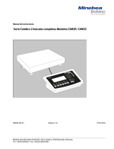
Minebea Intec Relaisbox YSB01 El manual del propietario
- Tipo
- El manual del propietario

Installation Instructions | Installationsanleitung | Notice d’installation
Instrucciones de instalación | Istruzioni per l’installazione
Minebea Intec Relay Box YSB01
Relay card with IP66-protected housing, with 6 relay outputs and one electrically
isolated input
Minebea Intec Relaisbox YSB01
Relaiskarte im IP66-Gehäuse mit 6 Relaisausgängen und einem galvanisch
getrennten Eingang
Boîtier relais Minebea Intec YSB01
Carte relais dans le boîtier IP66 avec 6 sorties relais et une entrée isolée
électriquement
Caja de relé YSB01 Minebea Intec
Tarjeta de relé en caja con grado de protección IP66, 6 salidas y una entrada
separada galvánicamente.
Minebea Intec Scatola relè YSB01
Scheda relè nell’alloggiamento IP66 con 6 uscite relè e un ingresso isolato
elettricamente
98647-003-47
98647-003-47

Installation Instructions | Installationsanleitung 3
English - page 3
Deutsch - Seite 13
Français – page 23
Español – página 33
Italiano - pagina 43

Installation Instructions | Installationsanleitung 3
Contents
3 Contents
3 Warnings and Safety Precautions
4 Intended Use
6 Installation
7 Wiring Diagram for Operating
Mode 1
8 Wiring Diagram for Operating
Mode 2
9 Cabling Diagram for Optional
YCC02-RELAIS01 Cable
10 Cabling Diagram for Optional
YCC02-RELAIS02 Cable
11 Cabling Diagram for Optional
YCCDI-03M5 Cable
12 Specifications
– Do not use this equipment in hazar-
dous areas/locations.
– Disconnect equipment from power
before opening the relay box.
– When using an external power supply,
the surge capacity in accordance with
EN 61326 must be ensured by the
power source.
– If the YSB01 is connected to
a power source that is not
safely electrically isolated from
the mains supply (IEC 364-4-41), the
enclosed warning label indicating ha-
zardous voltage must be affixed to the
YSB01 in a highly visible location.
– Non-permissible operating status:
If the relay module is connected to a
power supply and the control device
(scale or indicator) is not, this may
result in an undefined relay status. For
this reason, it is essential to make sure
both the relay module and the control
device are connected to power.
Warnings and
Safety Precautions

4 Installation Instructions | Installationsanleitung Installation Instructions | Installationsanleitung 5
Intended Use
Servo-components
UNI_IN 6 relay outputs
Power supply
provided by
customer
(+10 V to
+30 V DC)
The YSB01 relay box is
designed for connecting
peripheral devices with
higher output levels to
a Minebea Intec control
device (Combics 2/3,
QC..., QCT01, FC...,
SEB..., SEBT01).
The relay box can be
operated in either of two
modes:
– Operating mode 1 (non-
encoded data):
Up to 4 output relays
are switched directly
by 4 control signals.
An electrically isolated
(optoisolated) input is
available.
– Operating mode 2 (enco-
ded data):
Up to 5 output relays
are switched by com-
binations of 3 signals
from the control device
(as with the Combics
“Classification” applica-
tion, for example). One
output relay is switched
directly by a control
signal. An electrically
isolated (optoisolated)
input is available.
Relay box YSB01
UNI_IN 4 signal lines
Power supply
Control device
(scale, indicator)

Installation Instructions | Installationsanleitung 5
The closed status of an output relay is
indicated by an LED.
The YSB01 relay box has been prepared
at the factory for installation on a top-
hat rail.
The relay outputs are to be wired
directly to the control elements.
The connection of the relay box to the
control device (scale or indicator) is to
be performed by the customer using
one of the following cables (available
from Minebea Intec):
– YCC02-RELAIS01 for connection to
Combics (CISL2/3, CAISL2/3)
– YCC02-RELAIS02 for connection to
Combics (CIS2/3, CAIS2/3)
– YCCDI-03M5 for connection to QC...,
QCT01, FC..., SEB..., SEBT01
Opto-input with
separate power supply Relay outputs
(connections: A1 to A10)
Control device connection DIP switch LED Power supply
(scale, indicator) (connections: C1 to C4)
(connections: B1 to B6)

6 Installation Instructions | Installationsanleitung Installation Instructions | Installationsanleitung 7
Installation
§ Disconnect the YSB01 relay box from
power before opening the housing.
§ To open the relay box, remove the four
screws from the cover plate.
§ Installing the cable gland and cable:
– Prepare the cable opening by breaking
out the pre-punched M20 chip.
– Guide the enclosed cable gland
(M20 x 1.5) through the opening and
secure it inside the housing with the
counternut (1).
– Route the cable (2) through the cable
gland. Tighten the screw-down nut
(3) until the sealing clamp (4) forms a
slight ridge between screw-down nut
and cable.
§ Mount the cable on the relay card in
accordance with the relevant wiring
diagram (see below).
12
3
4

Installation Instructions | Installationsanleitung 7
Wiring Diagram for Operating Mode 1
To operate the relay box in Operating Mode 1 (non-encoded data), all DIP switches (1
through 7) must be open (“Off”).
A10 Ground (customer installation)
A9 Supply voltage (customer installation)
A1 UNI-IN
Less than (<) 2
Equal to (=) 3
Greater than (>) 4
Set 5
B6 Ground (from control device) Power supply C1
B5 UNI (from control device)
B4 MINOR: Less than (<)
B3 PARES: Equal to (=) Ground C3
B2 MAJOR: Greater than (>) (from control device)
B1 SET
Combics application: “Basic Filling”
Coarse flow: Control signal: Less than (<) Relay 2
Fine flow: Control signal: Equal to (=) Relay 3
Within tolerance: Control signal: Greater than (>) Relay 4
Filling active: Control signal: Set Relay 5

8 Installation Instructions | Installationsanleitung Installation Instructions | Installationsanleitung 9
Wiring Diagram for Operating Mode 2
To operate the relay box in Operating Mode 2 (encoded data), DIP switches 1 through 3
and 5 through 7 must be open (“Off”) and DIP switch 4 closed (“On”).
B6 Ground (from control device) Power supply C1
B5 UNI (from control device)
B4 MINOR: Less than (<)
B3 PARES: Equal to (=) Ground C3
B2 MAJOR: Greater than (>) (from control device)
B1 SET
A10 Ground (customer installation)
A9 Supply voltage (customer installation)
A1 UNI-IN
Less than (<) 2
Less than (<) + Equal to (=) 3
Equal to (=) 4
Equal to (=) + Greater than (>) 5
Greater than (>) 6
Set 8
Combics application: “Classification” (5 classes)
Class 1: Control signal: Less than (<) Relay 2
Class 2: Control signal: Less than (<) + Equal to (=) Relay 3
Class 3: Control signal: Equal to (=) Relay 4
Class 4: Control signal: Equal to (=) + Greater than (>) Relay 5
Class 5 Control signal: Greater than (>) Relay 6
Ready/Set Control signal: Set Relay 8

Installation Instructions | Installationsanleitung 9
Cabling Diagram for Optional
YCC02-RELAIS01 Cable
Connecting the YSB01 relay box to the COM1 interface on a Combics (CISL2/3) or
Combics (CAISL2/3) indicator:
YSB01 YCC02-RELAIS01
Designation On: Cable Label 25-pin D-Sub male
ends connector
Not connected RS-485 + RS-485 + (TxD-RxD+) (2)
Ground B6 GND GND (7)
Not connected RS-485 - RS-485 - (TxD-RxD-) (20)
MINOR (less than <) B4 MINOR < (16)
PARES (equal to =) B3 PARES = (17)
MAJOR (greater than >) B2 MAJOR > (18)
SET B1 SET SET (19)
UNI B5 UNI_IN UNI_IN (15)
Ground C3 COM COM (21)
Supply voltage C1 LINE LINE (24)
(1)
Isolate unused cable ends in accordance with industry standards.

10 Installation Instructions | Installationsanleitung Installation Instructions | Installationsanleitung 11
Cabling Diagram for Optional
YCC02-RELAIS02 Cable
Connecting the YSB01 relay box to the COM1 interface on a Combics (CIS2/3) or Combics
(CAIS2/3) indicator:
YSB01 YCC02-RELAIS02
Designation On: Cable Label Label CISx CAISx
ends
Not connected RS-485+ RS-485+
Ground B6 GND GND (19) (4)
Not connected RS-485- RS-485-
MINOR (less than <) B4 MINOR MINOR (5) (17)
PARES (equal to =) B3 PARES PARES (4) (18)
MAJOR (greater >) B2 MAJOR MAJOR (3) (19)
SET B1 SET SET (2) (20)
UNI B5 UNI_IN UNI_IN (1) (16)
Ground C3 COM COM (14) (7)
Supply voltage C1 LINE LINE (12) (10)
Connect cables in accordance with the pin assignments specified for the particular Combics indi-
cator (CIS2/3 or CAIS2/3). Isolate unused cable ends in accordance with industry standards.

Installation Instructions | Installationsanleitung 11
Cabling Diagram for Optional
YCCDI-03M5 Cable
Connecting the YSB01 relay box to the COM1 interface on a scale from the QC..., QCT01,
FC..., SEB..., or SEBT01 series:
YSB01 YCC02-RELAIS02
Designation On: Cable Color Round male
ends connector
MAJOR (greater than >) B2 brown A
Not connected red B
Not connected magenta C
Not connected yellow D
Ground B6 and C3 green E
Not connected blue F
MINOR (less than <) B4 violet G
Not connected gray H
PARES (equal to =) B3 white J
UNI B5 black K
Set B1 gray/pink L
Supply voltage C1 red/blue M
Isolate unused cable ends in accordance with industry standards.

12 Installation Instructions | Installationsanleitung Installation Instructions | Installationsanleitung 13
Specifications
Opto-input:
– Polarity: Low active
– Input active: 0V to +5V
– Input inactive: +11 V to +30 V
– Supply voltage +10 V DC to+30 V DC
– Power consumption: 0.9 W maximum
Relay output unit 1 N/O (1 closer)
– Maximum charge: 250 V AC/3 A; 30 V DC/3 A
Power supply:
– Supply voltage: +10 V DC to +30 V DC
– Power consumption: 3.0 W maximum
Allowable storage temperature: -25°C to +80°C (-13°F to +176°F)
Operating temperature range: -10°C to +70°C (+14°F to +158°F)
Dimensions: 254 mm x 180 mm x 90 mm
Housing: Fiberglass reinforced polycarbonate housing (IP66),
impact resistant, temperature resistant, with
transparent cover
Cable glands (2): M20 x 1.5

Installation Instructions | Installationsanleitung 13
Inhalt
13 Inhalt
13 Warn- und Sicherheitshinweis
14 Verwendungszweck
16 Installation
17 Verdrahtungsplan für
Betriebsmodus 1
18 Verdrahtungsplan für
Betriebsmodus 2
19 Verbindungsplan für Zubehörkabel
YCC02-RELAIS01
20 Verbindungsplan für Zubehörkabel
YCC02-RELAIS02
21 Verbindungsplan für Zubehörkabel
YCCDI-03M5
22 Technische Daten
Warn- und
Sicherheitshinweis
– Gerät nicht in explplosionsgefärdeten
Bereichen einsetzen.
– Vor dem öffnen der Relaisbox Netz-
spannung trennen.
– Bei einer externen Spannungsversor-
gung von YSB01 muss eine Stoßspan-
nungsfestigkeit gemäß EN61326 durch
die Versorgungsquelle gewährleistet
sein.
– Beim Anschluss von
YSB01 an Spannungen die
nicht sicher vom Netz
getrennt sind
(IEC 364-4-41) muss das beiliegen-
de Haftetikett, das auf gefährliche
Spannungen hinweist, gut sichtbar an
YSB01 angebracht werden.
– Verbotener Betriebszustand:
Wird das Relaismodul mit Spannung
versorgt, und das Steuergerät (Waage,
Auswertegerät) nicht, können hieraus
undefinierte Zustände an den Relais
entstehen. Es ist daher stets darauf zu
achten, dass sowohl das Relaismodul
aus auch das Steuergerät versorgt sind.

14 Installation Instructions | Installationsanleitung Installation Instructions | Installationsanleitung 15
Verwendungszweck
Die Relaisbox YSB01
dient dem Anschluß von
Peripheriegeräten mit
größeren Leistungen
an ein Minebea Intec
Steuergerät (Combics
2/3, QC..., QCT01, FC...,
SEB..., SEBT01).
Die Relaisbox kann in
zwei unterschiedlichen
Modi betrieben werden:
– Betriebsmodus 1 (unko-
dierte Daten):
Bis zu 4 Output-Relais
werden direkt über 4
Steuersignale geschal-
tet. Ein galvanisch
getrennter Eingang
(optoisoliert) steht zur
Verfügung.
– Betriebsmodus 2 (ko-
dierte Daten):
Bis zu 5 Output-Relais
werden über die Kom-
bination von 3 Signalen
des Steuergerätes (z.B.
Combics »Klassieren«)
geschaltet. Ein Output-
Relais wird direkt (unko-
diert) über ein Steuer-
signal geschaltet. Ein
galvanisch getrennter
Eingang (optoisoliert)
steht zur Verfügung.
Stellglieder (z.B. Ventile)
UNI_IN 6 Relaisausgänge
Stromver-
sorgung
kundenseitig
(+10 V bis
+30 V DC)
Relaisbox YSB01
UNI_IN 4 Signalleitungen
Stromversorgung
Steuergerät
(Waage, Auswertegerät)

Installation Instructions | Installationsanleitung 15
Der geschlossene Zustand eines Output-
Relais wird durch eine LED angezeigt.
Das Relaisbox YSB01 ist für die Hut-
schienenmontage vorbereitet.
Die Relais-Ausgänge werden direkt mit
den Steuerelementen verdrahtet (Ver-
bindung erfolgt kundenseitig).
Die Verbindung zwischen der Relaisbox
und dem Steuergerät erfolgt kundensei-
tig über die von Minebea Intec lieferba-
ren Anschlusskabel:
– YCC02-RELAIS01 zum Anschluss an
Combics (CISL2/3, CAISL2/3)
– YCC02-RELAIS02 zum Anschluss an
Combics (CIS2/3, CAIS2/3)
– YCCDI-03M5 zum Anschluss an QC...,
QCT01, FC..., SEB..., SEBT01
OPTO-IN Eingang mit
seperater Stromversorgung
(Anschlüsse: A1 bis A10) Relais-OUT
Anschluss Steuergerät DIP-Schalter LED Stromversorgung
(Waage, Auswertegerät) (Anschlüsse: C1 bis C4)
(Anschlüsse: B1 bis B6)

16 Installation Instructions | Installationsanleitung Installation Instructions | Installationsanleitung 17
Installation
§ Vor dem öffnen der Relaisbox YSB01
Gerät vom Netz trennen.
§ Zum Öffnen der Relaisbox die vier
Schrauben am Deckel lösen. Deckel
abnehmen.
§ Kabelverschraubung und Kabel montie-
ren:
– Vorprägung M20 am Gehäuse ausbre-
chen.
– Beiliegende Kabelverschraubung
M20 x 1,5 durch Ausbruch stecken
und mit Gegenmutter (1) von innen
sichern.
– Kabel (2) durch die Kabelverschrau-
bung stecken. Druckmutter (3) anzie-
hen bis der Dichteinsatz (4) zwischen
Druckmutter und Kabel einen kleinen
Wulst bildet.
§ Kabel entsprechend der Verdrahtungs-
pläne an der Relaiskarte montieren.
12
3
4

Installation Instructions | Installationsanleitung 17
Verdrahtungsplan für Betriebsmodus 1
Um die Relaisbox im Modus 1 (unkodierte Daten) betreiben zu können, müssen die DIP-
Schalter 1-7 offen (auf »OFF«) sein.
A10 Ground (kundenseitig)
A9 Versorgungsspannung (kundenseitig)
A1 UNI-IN
kleiner (<) 2
gleich (=) 3
größer (>) 4
SET 5
B6 Ground (von Steuergerät) Versorgungs- C1
B5 UNI spannung
B4 MINOR: kleiner (<) (von Steuergerät)
B3 PARES: gleich (=) Ground C3
B2 MAJOR: größer (>) (von Steuergerät)
B1 SET
Combics »Dosieren Basic«:
Grobstrom: Steuersignal: kleiner (<) Relais 2
Feinstrom: Steuersignal: gleich (=) Relais 3
In Toleranz: Steuersignal: größer (>) Relais 4
Dosieren aktiv: Steuersignal: SET Relais 5

18 Installation Instructions | Installationsanleitung Installation Instructions | Installationsanleitung 19
Um die Relaiskarte im Modus 2 (kodierte Daten) betreiben zu können müssen die DIP-
Schalter 1-3 und 5-7 offen (auf »OFF«) und der Schalter 4 geschlossen (auf »ON«) sein.
Verdrahtungsplan für Betriebsmodus 2
B6 Ground (von Steuergerät) Versorgungs- C1
B5 UNI spannung
B4 MINOR: kleiner (<) (von Steuergerät)
B3 PARES: gleich (=) Ground C3
B2 MAJOR: größer (>) (von Steuergerät)
B1 SET
A10 Ground (kundenseitig)
A9 Versorgungsspannung (kundenseitig)
A1 UNI-IN
kleiner (<) 2
kleiner (<) + gleich (=) 3
gleich (=) 4
gleich (=) + größer (>) 5
größer (>) 6
SET 8
Combics »5 Klassen Klassieren«:
Klasse 1: Steuersignal: kleiner (<) Relais 2
Klasse 2: Steuersignal: kleiner (<) + gleich (=) Relais 3
Klasse 3: Steuersignal: gleich (=) Relais 4
Klasse 4: Steuersignal: gleich (=) + größer (>) Relais 5
Klasse 5 Steuersignal: größer (>) Relais 6
Bereit/SET Steuersignal: SET Relais 8

Installation Instructions | Installationsanleitung 19
Verbindungsplan für Zubehörkabel
YCC02-RELAIS01
Verbindung zwischen YSB01 und der COM1 Schnittstelle von Combics (CISL2/3) oder
Combics (CAISL2/3):
YSB01 YCC02-RELAIS01
Bezeichnung Anschluss Kabel Label 25-pol. D-Sub-Stecker
enden
nicht belegt RS485+ RS485+ (TxD-RxD+) (2)
Ground B6 GND GND (7)
nicht belegt RS485- RS485- (TxD-RxD-) (20)
MINOR (kleiner <) B4 MINOR < (16)
PARES (gleich =) B3 PARES = (17)
MAJOR (größer >) B2 MAJOR > (18)
SET B1 SET SET (19)
UNI B5 UNI_IN UNI_IN (15)
Ground C3 COM COM (21)
Versorgungsspann. C1 LINE LINE (24)
(1)
Nicht belegte Kabelenden fachgerecht isolieren.

20 Installation Instructions | Installationsanleitung Installation Instructions | Installationsanleitung 21
Verbindungsplan für Zubehörkabel
YCC02-RELAIS02
Verbindung zwischen YSB01 und der COM1 Schnittstelle von Combics (CIS2/3) oder Combics
(CAIS2/3):
YSB01 YCC02-RELAIS02
Bezeichnung Anschluss Kabel Label Label CISx CAISx
enden
nicht belegt RS485+ RS485+
Ground B6 GND GND (19) (4)
nicht belegt RS485- RS485-
MINOR (kleiner <) B4 MINOR MINOR (5) (17)
PARES (gleich =) B3 PARES PARES (4) (18)
MAJOR (größer >) B2 MAJOR MAJOR (3) (19)
SET B1 SET SET (2) (20)
UNI B5 UNI_IN UNI_IN (1) (16)
Ground C3 COM COM (14) (7)
Versorgungsspann. C1 LINE LINE (12) (10)
Die Kabel entsprechend der Belegungspläne des Steuergerät (Combics-Auswertegerätes CIS2/3
oder CAIS2/3) auflegen. Nicht belegte Kabelenden fachgerecht isolieren.

Installation Instructions | Installationsanleitung 21
Verbindungsplan für Zubehörkabel
YCCDI-03M5
Verbindung zwischen YSB01 und der COM1 Schnittstelle von Waagen mit den Bezeich-
nungen QC..., QCT01 und FC..., SEB..., SEBT01):
YSB01 YCC02-RELAIS01
Bezeichnung Anschluss Kabel Farbe Rundsteckverbindung
enden
MAJOR (größer >) B2 braun A
nicht belegt rot B
nicht belegt pink C
nicht belegt gelb D
Ground B6 und C3 grün E
nicht belegt blau F
MINOR (kleiner <) B4 violett G
nicht belegt grau H
PARES (gleich =) B3 weiß J
UNI B5 schwarz K
SET B1 grau/rosa L
Versorgungsspann. C1 rot/blau M
Nicht belegte Kabelenden fachgerecht isolieren.

22 Installation Instructions | Installationsanleitung Installation Instructions | Installationsanleitung 23
Technische Daten
OPTO-IN Eingang:
– Polarität: Low aktiv
– Eingang aktiv: 0V bis +5V
– Eingang inaktiv: +11V bis +30V
– Versorgunsspannung +10VDC bis +30VDC
– Leistungsaufnahme: 0,9 W maximal
Relais-OUT-Einheit 1 N/O (1 Schließer)
– Maximale Belastung: 250VAC/3A; 30VDC/3A
– max. Schaltspiele 1 Mil.
Stromversorgung:
– Versorgunsspannung: +10 V DC bis +30 V DC
– Leistungsaufnahme: 3,0 W maximal
Lagertemperatur: -25° C bis +80° C
Einsatztemperatur: -10° C bis +70° C
Abmessungen: 254 mm x 180 mm x 90 mm
Gehäuse: Glasfaserverstärktes Polycarbonat-Gehäuse (IP66),
schlagfest, temperaturbeständig mit transparentem
Deckel
Kabeldurchführungen 2x: M20 x 1,5

Installation Instructions | Installationsanleitung 23
Sommaire
23 Sommaire
23 Conseils de sécurité
24 Description générale
26 Installation
27 Schéma de connexion pour le mode
d’exploitation 1
28 Schéma de connexion pour le mode
d’exploitation 2
29 Schéma de câblage pour le câble
accessoire YCC02-RELAIS01
30 Schéma de câblage pour le câble
accessoire YCC02-RELAIS02
31 Schéma de câblage pour le câble
accessoire YCCDI-03M5
32 Caractéristiques techniques
Conseils de sécurité
– Ne pas utiliser l’appareil dans des do-
maines à risques d’explosions.
– Avant d’ouvrir le boîtier relais, le dé-
brancher de l’alimentation en courant.
– Si le YSB01 est alimenté par une source
d’alimentation électrique externe, la
résistance aux ondes de surtension con-
formément à EN61326 doit être assurée
par la source d’alimentation.
– Lors du raccordement de
YSB01 à des tensions qui
ne sont pas séparés du
réseau de manière sûre
(IEC 364-4-41), l’étiquette adhésive ci-
jointe qui indique des tensions dange-
reuses doit être apposée sur le YSB01
de manière à être parfaitement visible.
– Etat de fonctionnement interdit :
Si le module relais est alimenté en
courant et que l’appareil de commande
(balance, indicateur) ne l’est pas, il peut
en résulter des états non définis sur le
relais. Il faut donc constamment veiller
à ce que le module relais ainsi que
l’appareil de commande soient alimen-
tés en courant.

24 Installation Instructions | Installationsanleitung Installation Instructions | Installationsanleitung 25
Description générale
Le boîtier relais YSB01
sert à raccorder des
appareils périphériques
de très grandes puis-
sances à un appareil de
commande Minebea In-
tec (Combics 2/3, QC...,
QCT01, FC..., SEB...,
SEBT01).
Le boîtier relais peut
fonctionner en deux
modes différents :
– Mode d’exploitation 1
(données non codées) :
Jusqu’à 4 sorties relais
sont directement acti-
vées via 4 signaux de
commande. Une entrée
isolée électriquement
(optoisolée) est dispo-
nible.
– Mode d’exploitation 2
(données codées) :
Jusqu’à 5 sorties relais
sont activées via la
combinaison de 3
signaux de l’appareil
de commande (par ex.
«Classement» Combics).
Une sortie relais est
directement (non codée)
activée via un signal de
commande. Une entrée
isolée électriquement
(optoisolée) est dispo-
nible.
Eléments de réglage
UNI_IN 6 sorties relais
Alimentation
en courant
du client
(+10 V à
+30 V DC)
Boîtier relais YSB01
UNI_IN 4 lignes de signaux
Alimentation électrique
Appareil de commande
(balance, indicateur)

Installation Instructions | Installationsanleitung 25
L’état fermé d’une sortie relais est
indiqué à l’affichage par un voyant
lumineux.
Le boîtier relais YSB01 est prêt pour un
montage sur profilé chapeau.
Les sorties relais sont directement
câblées avec les éléments de commande
(la liaison est effectuée par le client).
La liaison entre le boîtier relais et
l’appareil de commande est effectuée
par le client à l’aide des câbles de rac-
cordement livrés par Minebea Intec :
– YCC02-RELAIS01 pour le raccordement
à Combics 2/3 (CISL, CAISL)
– YCC02-RELAIS02 pour le raccordement
à Combics 2/3 (CIS, CAIS)
– YCCDI-03M5 pour le raccordement à
QC..., QCT01, FC..., SEB..., SEBT01
Entrée OPTO-IN avec
alimentation électrique séparée
(connecteurs : A1 à A10) Relais-OUT
Connexion appareil Commutateur DIP Voyant Alimentation électrique
de commande lumineux (connecteurs : C1 à C4)
(balance, indicateur)
(connecteurs : B1 à B6)

26 Installation Instructions | Installationsanleitung Installation Instructions | Installationsanleitung 27
Installation
§ Avant d’ouvrir le boîtier relais YSB01,
débrancher l’appareil du secteur.
§ Pour ouvrir le boîtier relais, dévisser les
quatre vis se trouvant sur le couvercle.
Enlever le couvercle.
§ Montage du passe-câble à vis et du
câble :
– Ouvrir l’orifice préparé M20 sur le
boîtier.
– Passer le passe-câble à vis M20 x 1,5 ci-
joint à travers l’orifice et le bloquer de
l’intérieur avec le contre-écrou (1).
– Passer le câble (2) à travers le passe-
câble à vis. Serrer l’écrou de serrage (3)
jusqu’à ce que l’élément d’étanchéité
(4) entre l’écrou de serrage et le câble
forme un petit bourrelet.
§ Monter le câble sur la carte relais con-
formément aux schémas de connexion.
12
3
4

Installation Instructions | Installationsanleitung 27
Schéma de connexion pour le mode
d’exploitation 1
Pour que le boîtier relais puisse être utilisé dans le mode 1 (données non codées), il faut
que les commutateurs DIP 1-7 soient ouverts (sur «OFF»).
A10 Masse (du client)
A9 Tension d’alimentation (du client)
A1 UNI-IN
inférieur (<) 2
égal (=) 3
supérieur (>) 4
SET 5
B6 Masse Tension C1
(de l’appareil de commande) d’alimentation
B5 UNI (de l’appareil de commande)
B4 MINOR : inférieur (<) Masse C3
B3 PARES : égal (=) (de l’appareil de commande)
B2 MAJOR : supérieur (>)
B1 SET
«Dosage Basic» Combics :
Débit grossier : Signal de commande : inférieur (<) Relais 2
Débit fin : Signal de commande : égal (=) Relais 3
En tolérance : Signal de commande : supérieur (>) Relais 4
Dosage actif : Signal de commande : SET Relais 5

28 Installation Instructions | Installationsanleitung Installation Instructions | Installationsanleitung 29
Schéma de connexion pour le mode
d’exploitation 2
Pour que le boîtier relais puisse être utilisé dans le mode 2 (données codées) ), il faut que
les commutateurs DIP 1-3 et 5-7 soient ouverts (sur «OFF») et que le commutateur 4 soit
fermé (sur «ON»).
A10 Masse (du client)
A9 Tension d’alimentation (du client)
A1 UNI-IN
inférieur (<) 2
inférieur (<) + égal (=) 3
égal (=) 4
égal (=) + supérieur (>) 5
supérieur (>) 6
SET 8
«Classement avec 5 classes» Combics :
Classe 1 : Signal de commande : inférieur (<) Relais 2
Classe 2 : Signal de commande : inférieur (<) + égal (=) Relais 3
Classe 3 : Signal de commande : égal (=) Relais 4
Classe 4 : Signal de commande : égal (=) + supérieur (>) Relais 5
Classe 5 Signal de commande : supérieur (>) Relais 6
Prêt/SET Signal de commande : SET Relais 8
B6 Masse Tension C1
(de l’appareil de commande) d’alimentation
B5 UNI (de l’appareil de commande)
B4 MINOR : inférieur (<) Masse C3
B3 PARES : égal (=) (de l’appareil de commande)
B2 MAJOR : supérieur (>)
B1 SET

Installation Instructions | Installationsanleitung 29
Schéma de câblage pour le câble accessoire
YCC02-RELAIS01
Connexion entre YSB01 et l’interface COM1 de Combics (CISL2/3) ou de Combics
(CAISL2/3) :
YSB01 YCC02-RELAIS01
Désignation Connecteur Extrémités Label Connecteur D-sub à 25
de câble pôles
Non occupé RS485+ RS485+ (TxD-RxD+) (2)
Masse B6 GND GND (7)
Non occupé RS485- RS485- (TxD-RxD-) (20)
MINOR (inférieur <) B4 MINOR < (16)
PARES (égal =) B3 PARES = (17)
MAJOR (supérieur >) B2 MAJOR > (18)
SET B1 SET SET (19)
UNI B5 UNI_IN UNI_IN (15)
Masse C3 COM COM (21)
Tension C1 LINE LINE (24)
d’alimentation (1)
Isoler les extrémités de câble non occupées de manière appropriée.

30 Installation Instructions | Installationsanleitung Installation Instructions | Installationsanleitung 31
Schéma de câblage pour le câble accessoire
YCC02-RELAIS02
Connexion entre YSB01 et l’interface COM1 de Combics (CIS2/3) ou de Combics (CAIS2/3) :
YSB01 YCC02-RELAIS02
Désignation Connecteur Extrémités Label Label CISx CAISx
de câble
Non occupé RS485+ RS485+
Masse B6 GND GND (19) (4)
Non occupé RS485- RS485-
MINOR (inférieur <) B4 MINOR MINOR (5) (17)
PARES (égal =) B3 PARES PARES (4) (18)
MAJOR (supérieur >) B2 MAJOR MAJOR (3) (19)
SET B1 SET SET (2) (20)
UNI B5 UNI_IN UNI_IN (1) (16)
Masse C3 COM COM (14) (7)
Tension C1 LINE LINE (12) (10)
d’alimentation
Connecter les câbles conformément aux schémas d’affectation de l’appareil de commande (indica-
teur Combics CIS2/3 ou CAIS2/3). Isoler les extrémités de câble non occupées de manière appro-
priée.

Installation Instructions | Installationsanleitung 31
Schéma de câblage pour le câble accessoire
YCCDI-03M5
Connexion entre YSB01 et l’interface COM1 de balances avec les désignations QC...,
QCT01 et FC..., SEB..., SEBT01:
YSB01 YCC02-RELAIS01
Désignation Connecteur Extrémités Couleur Connecteur
rond
de câble
MAJOR (supérieur >) B2 marron A
Non occupé rouge B
Non occupé rose fuchsia C
Non occupé jaune D
Masse B6 et C3 vert E
Non occupé bleu F
MINOR (inférieur <) B4 violet G
Non occupé gris H
PARES (égal =) B3 blanc J
UNI B5 noir K
SET B1 gris/rose L
Tension d’alimentation C1 rouge/bleu M
Isoler les extrémités de câble non occupées de manière appropriée.

32 Installation Instructions | Installationsanleitung Installation Instructions | Installationsanleitung 33
Caractéristiques techniques
Entrée OPTO-IN :
– Polarité : Bas active
– Entrée active : 0V à +5V
– Entrée inactive : +11V à +30V
– Tension d’alimentation +10VDC à +30VDC
– Consommation : 0,9 W maximum
Unité Relais-OUT 1 N/O (1 contact à fermeture)
– Charge maximale : 250VAC/3A ; 30VDC/3A
– Hystérésis 1 million
Alimentation électrique :
– Tension d’alimentation : +10 V DC à +30 V DC
– Consommation : 3,0 W maximum
Température de stockage : -25° C à +80° C
Conditions réglementaires
d’utilisation : -10° C à +70° C
Dimensions : 254 mm x 180 mm x 90 mm
Boîtier : Boîtier en polycarbonate renforcé par fibres de
verre (IP66), résistant aux chocs, résistant à la
chaleur avec couvercle transparent
passe-câbles: M20 x 1,5

Installation Instructions | Installationsanleitung 33
Contenido
33 Contenido
33 Advertencias de seguridad
34 Uso previsto
36 Instalación
37 Esquema del cableado para modo
de funcionamiento 1
38 Esquema del cableado para modo
de funcionamiento 2
39 Diagrama de conexión para cable
accesorio YCC02-RELÉ 01
40 Diagrama de conexión para cable
accesorio YCC02-RELÉ 02
41 Diagrama de conexión para cable
accesorio YCCDI-03M5
42 Especificaciones técnicas
Advertencias
de seguridad
– El aparato no debe utilizarse en zonas
con riesgo de explosión.
– Antes de abrir la caja de relé, separar la
tensión de red.
– Con alimentación de tensión externa
del YSB01, la fuente de alimentación
tiene que garantizar una resistencia a
sobretensión, según EN61326.
– Al conectar YSB01
a tensiones que no
están separadas
fiablemente de la red
(IEC 364-4-41), la etiqueta autoad-
hesiva adjunta, que hace referencia a
tensiones de riesgo, tiene que ser fijada
perfectamente visible en la caja de
YSB01.
– Estado de funcionamiento no permiti-
do:
Si el módulo de relé es alimentado con
tensión y, en cambio, el aparato de
control (báscula, visor) no es alimen-
tado con tensión, se pueden producir
estados no definidos en el relé. Por tal
razón, hay que observar siempre que el
módulo de relé y el aparato de control
estén alimentados con tensión.

34 Installation Instructions | Installationsanleitung Installation Instructions | Installationsanleitung 35
Uso previsto
La caja de relé YSB01
sirve para la conexión de
periféricos con potencias
superiores (Combics 2/3,
QC..., QCT01, FC..., SEB...,
SEBT01) a un aparato de
control Minebea Intec.
La caja de relé puede
funcionar en dos modos
diferentes:
– Modo de funcionamiento 1
(especificaciones no codi-
ficadas):
Se activan directamente 4
salidas de relé, máximo,
mediante 4 señales de
control. Existe a disposi-
ción una entrada separada
galvánicamente (optoaisla-
da).
– Modo de funcionamiento 2
(especificaciones codifica-
das):
Se activan 5 salidas de
relé, máximo, mediante la
combinación de 3 señales
del aparato de control (p.
ej. Combics “Clasificación”).
Una salida de relé se activa
directamente (no codifica-
da) mediante una señal de
control. Existe a disposi-
ción una entrada separada
galvánicamente (optoaisla-
da).
Componentes de regulación
UNI_IN 6 salidas de relé
Alimentación
de corriente:
cliente
(+10 V hasta
+30 V CC)
Caja de relé YSB01
UNI_IN
Aparato de control
(báscula, visor)
4 líneas de señal
alimentación de
corriente

Installation Instructions | Installationsanleitung 35
El estado cerrado de una salida de relé
es indicado por un LED.
La caja de relé YSB01 está preparada
para un montaje en riel de perfil de
sombrero.
Las salidas de relé se cablean directa-
mente con los elementos de control
(conexión a realizar por cuenta del
cliente).
El enlace entre la caja de relé y el
aparato de control lo realiza el cliente,
con cable conector suministrable por
Minebea Intec:
– YCC02-RELÉ 01 para conectar a Com-
bics (CISL2/3, CAISL2/3
– YCC02-RELÉ 02 para conectar a Com-
bics (CIS2/3, CAIS2/3)
– YCCDI-03M5 para conectar a QC...,
QCT01, FC..., SEB..., SEBT01
Entrada OPTO-IN con
alimentación separada de corriente
(conexiones: A1 hasta A10) Relé OUT
Conexión aparato de Interruptor DIP LED Alimentación de corriente
control (báscula, visor) (conexiones: C1 hasta C4)
(conexiones: B1 hasta B6)

36 Installation Instructions | Installationsanleitung Installation Instructions | Installationsanleitung 37
Instalación
§ Antes de abrir la caja de relé YSB01,
separar el aparato de la tensión de red.
§ Para abrir la caja de relé, aflojar los
cuatro tornillos de la tapa. Quitar la
tapa.
§ Montar la borna atornillable y el cable:
– Romper la selladura M20 en la carcasa.
– Meter la borna atornillable del cable
M20 x 1,5 a través de la abertura y
fijarla con contratuerca (1) desde el
interior.
– Pasar el cable (2) a través de la borna
atornillable. Apretar tuerca (3) hasta
que la junta (4) entre tuerca de apriete
y cable se abulte levemente.
§ Conectar el cable en la tarjeta de relé
según los esquemas de cableado.
12
3
4

Installation Instructions | Installationsanleitung 37
Esquema del cableado para modo de
funcionamiento 1
Para utilizar la caja de relé en modo de funcionamiento1 (especificaciones no codifica-
das), los interruptores DIP 1-7 tienen que estar abiertos (en OFF).
A10 Tierra (por el cliente)
A9 Tensión de alimentación (por el cliente)
A1 UNI-IN
menor (<) 2
igual (=) 3
mayor (>) 4
SET (debido) 5
B6 Tierra (del aparato Tensión de C1
de control) alimentación
B5 UNI (del aparato de control)
B4 MINOR: menor (<) Tierra C3
B3 PARES: igual (=) (del aparato de control)
B2 MAJOR: mayor (>)
B1 SET
Combics “Dosificación básica”:
Caudal grueso: Señal de control: menor (<) relé 2
Caudal fino: Señal de control: igual (=) relé 3
En tolerancia: Señal de control: mayor (>) relé 4
Dosificación activa: Señal de control: SET relé 5

38 Installation Instructions | Installationsanleitung Installation Instructions | Installationsanleitung 39
Esquema del cableado para modo de
funcionamiento 2
Para utilizar la tarjeta de relé en modo de funcionamiento 2 (especificaciones codifica-
das), los interruptores DIP 1-3 y 5-7 tienen que estar abiertos (en OFF) y el interruptor 4
cerrado (en ON).
A10 Tierra (por el cliente)
A9 Tensión de alimentación (por el cliente)
A1 UNI-IN
menor (<) 2
menor (<) + igual (=) 3
igual (=) 4
igual (=) + mayor (>) 5
mayor (>) 6
SET (debido) 8
Combics “Clasificación 5 clases” :
Clase 1: Señal de control: menor (<) relé 2
Clase 2: Señal de control: menor (<) + igual (=) relé 3
Clase 3: Señal de control: igual (=) relé 4
Clase 4: Señal de control: igual (=) + mayor (>) relé 5
Clase 5 Señal de control: mayor (>) relé 6
Listo/SET Señal de control: SET relé 8
B6 Tierra (del aparato Tensión de C1
(del aparato de control)
B5 UNI
B4 MINOR: menor (<) Tierra C3
B3 PARES: igual (=) (del aparato de control)
B2 MAJOR: mayor (>)
B1 SET

Installation Instructions | Installationsanleitung 39
Diagrama de conexión para cable accesorio
YCC02-RELÉ 01
Enlace entre YSB01 y la interfaz COM1 de Combics (CISL2/3) o Combics (CAISL2/3):
YSB01 YCC02-RELÉ 01
Identificación Conexión Extremos Label Conector 25
de cable cont. D-Sub
No asignado RS485+ RS485+ (TxD-RxD+) (2)
Tierra B6 GND GND (7)
No asignado RS485- RS485- (TxD-RxD-) (20)
MINOR (menor <) B4 MINOR < (16)
PARES (igual =) B3 PARES = (17)
MAJOR (mayor >) B2 MAJOR > (18)
SET B1 SET SET (19)
UNI B5 UNI_IN UNI_IN (15)
Tierra C3 COM COM (21)
Tensión aliment. C1 LINE LINE (24)
(1)
Aislar correctamente los extremos de cable no asignados.

40 Installation Instructions | Installationsanleitung Installation Instructions | Installationsanleitung 41
Diagrama de conexión para cable accesorio
YCC02-RELÉ02
Enlace entre YSB01 y la interfaz COM1 de Combics (CIS2/3) o Combics (CAIS2/3):
YSB01 YCC02-RELÉ02
Identificación Conexión Extremos Label Label CISx CAISx
de cable
No asignado RS485+ RS485+
Tierra B6 GND GND (19) (4)
No asignado RS485- RS485-
MINOR (menor <) B4 MINOR MINOR (5) (17)
PARES (igual =) B3 PARES PARES (4) (18)
MAJOR (mayor >) B2 MAJOR MAJOR (3) (19)
SET B1 SET SET (2) (20)
UNI B5 UNI_IN UNI_IN (1) (16)
Tierra C3 COM COM (14) (7)
Tensión de aliment. C1 LINE LINE (12) (10)
Conectar los cables según los diagramas de asignación del aparato de control (visor Combics CIS2/3
o CAIS2/3). Aislar correctamente los extremos de cable no asignados.

Installation Instructions | Installationsanleitung 41
Diagrama de conexión para cable accesorio
YCCDI-03M5
Enlace entre YSB01 y la interfaz COM1 de básculas con las identificaciones QC...,
QCT01 y FC..., SEB..., SEBT01):
YSB01 YCC02-RELÉ 01
Identificación Conexión Extremos Color Conector
de cable redondo
MAJOR (mayor >) B2 marrón A
No asignado rojo B
No asignado rosa C
No asignado amarillo D
Tierra B6 y C3 verde E
No asignado azul F
MINOR (menor <) B4 violeta G
No asignado gris H
PARES (igual =) B3 blanco J
UNI B5 negro K
SET B1 gris/rosa L
Tensión de aliment. C1 rojo/azul M
Aislar correctamente extremos de cable no asignados.

42 Installation Instructions | Installationsanleitung Installation Instructions | Installationsanleitung 43
Especificaciones técnicas
Entrada OPTO-IN:
– Polaridad: baja activa
– Entrada activa: 0V hasta +5V
– Entrada inactiva: +11V hasta +30V
– Tensión de alimentación +10VCC hasta +30VCC
– Consumo eléctrico: 0,9 W máximo
Unidad de relé OUT 1 N/O (1 cierre)
– Carga máxima: 250VCA/3A; 30VCC/3A
– Histéresis máxima 1 millón
Alimentación de corriente:
– Tensión de alimentación: +10 V CC hasta +30 V CC
– Consumo eléctrico: 3,0 W máximo
Temperatura de almacenamiento: -25° C hasta +80° C
Temperatura de empleo: -10° C hasta +70° C
Dimensiones: 254 mm x 180 mm x 90 mm
Caja: Policarbonato reforzado con fibra de vidrio (IP66),
resistente a los golpes y a la temperatura, con tapa
transparente
Pasos de cable, 2: M20 x 1,5

Installation Instructions | Installationsanleitung 43
Indice Istruzioni di sicurezza
e avvertenza
43 Indice
43 Istruzioni di sicurezza e avvertenza
44 Uso previsto
46 Installazione
47 Schema di cablaggio per il modo di
funzionamento 1
48 Schema di cablaggio per il modo di
funzionamento 2
49 Schema di collegamento per il cavo
accessorio YCC02-RELAIS01
50 Schema di collegamento per il cavo
accessorio YCC02-RELAIS02
51 Schema di collegamento per il cavo
accessorio YCCDI-03M5
52 Dati tecnici
– Non impiegare l’apparecchio in aree a
rischio di esplosione.
– Staccare la tensione di rete prima di
aprire la scatola relè.
– Se il YSB01 è alimentato con una
tensione esterna, deve essere garanti-
ta una resistenza alle sovratensioni a
impulso secondo la norma EN61326
mediante la fonte di alimentazione.
– Collegando l’YSB01
a tensioni che non sono
isolate dalla rete in modo
sicuro (IEC 364-4-41), si deve
applicare all’YSB01 un’etichetta ben
visibile che indica la presenza di
tensioni pericolose.
– Condizione di funzionamento vietata:
se è alimentato solo il modulo relè e
non l’apparecchio di comando (bilancia,
indicatore), si possono presentare sul
relè degli stati operativi non definiti.
Pertanto si deve fare attenzione che
sia il modulo relè sia l’apparecchio di
comando siano alimentati di corrente.

44 Installation Instructions | Installationsanleitung Installation Instructions | Installationsanleitung 45
Uso previsto
La scatola relè YSB01 serve a
collegare strumenti periferici
con potenze maggiori ad
un apparecchio di comando
Minebea Intec (Combics 2/3,
QC..., QCT01, FC..., SEB...,
SEBT01).
La scatola relè può
funzionare in due modi
diversi:
– Modo di funzionamento
1 (dati cifrati):
Vengono collegate fino a
4 uscite relè direttamente
tramite 4 segnali di co-
mando. È disponibile un
ingresso isolato elettrica-
mente (optoisolato).
– Modo di funzionamento
2 (dati cifrati):
Vengono collegate fino
a 5 uscite relè mediante
la combinazione di 3
segnali dell’apparecchio
di comando (per es.
Combics «Classificazio-
ne»). Viene collegata una
uscita relè direttamente
(non in modo cifrato)
attraverso un segnale di
comando. È disponibile
un ingresso isolato elett-
ricamente (optoisolato).
Elemento di regolazione
UNI_IN 6 uscite relè
Alimentazione
da parte
dell’utente
(+10 V -
+30 V DC)
Scatola relè YSB01
UNI_IN
4 fili
Apparecchio di comando
(bilancia, indicatore)
4 fili di segnale
Alimentazione
elettrica

Installation Instructions | Installationsanleitung 45
Lo stato chiuso di una uscita relè viene
indicato da un LED.
La scatola relè YSB01 è preparata per il
montaggio su guida DIN.
Le uscite relè vengono cablate diretta-
mente con gli elementi di comando
(il collegamento avviene da parte
dell’utente).
Il collegamento tra la scatola relè e
l’apparecchio di comando avviene da
parte dell’utente mediante il cavo di
collegamento fornito dalla Minebea
Intec:
– YCC02-RELAIS01 per il collegamento a
Combics (CISL2/3, CAISL2/3)
– YCC02-RELAIS02 per il collegamento a
(CIS2/3, CAIS2/3)
– YCCDI-03M5 per il collegamento a
QC..., QCT01, FC..., SEB..., SEBT01
Ingresso OPTO-IN
con alimentazione separata
(attacchi: A1 - A10) Relè OUT
Connessione Commutatori DIP LED Alimentazione
apparecchio di (attacchi: C1 - C4)
comando (bilancia,
indicatore)
(attacchi: B1 - B6)

46 Installation Instructions | Installationsanleitung Installation Instructions | Installationsanleitung 47
Installazione
§ Staccare la tensione di rete prima di
aprire la scatola relè YSB01.
§ Per aprire la scatola relè, svitare le quat-
tro viti poste sulla copertura. Togliere la
copertura.
§ Montare il passacavo a vite e il cavo:
– Rompere il contrassegno a stampo M20
presente sull’alloggiamento.
– Inserire il passacavo a vite fornito
M20 x 1,5 attraverso il foro e avvitare il
controdado (1) dall’interno.
– Inserire il cavo (2) attraverso il passa-
cavo a vite. Serrare il dado di pressione
(3) fino a quando l’anello di tenuta (4),
che si trova tra il dado di pressione e il
cavo, forma un piccolo rigonfiamento.
§ Montare il cavo sulla scheda relè secon-
do gli schemi di cablaggio.
12
3
4

Installation Instructions | Installationsanleitung 47
Schema di cablaggio per il modo di
2funzionamento 1
Per il funzionamento della scatola relè nel modo 1 (dati non cifrati), i commutatori DIP
1-7 devono essere aperti (su «OFF»).
A10 Massa (da parte dell’utente)
A9 Tensione di alimentazione (da parte dell’utente)
A1 UNI-IN
Minore (<) 2
Uguale (=) 3
Maggiore (>) 4
SET 5
B6 Massa (dall’apparecchio Tensione di C1
di comando) alimentazione
B5 UNI (dall’apparecchio di comando)
B4 MINOR: minore (<) Massa C3
B3 PARES: uguale (=) (dall’apparecchio di comando)
B2 MAJOR: maggiore (>)
B1 SET
Combics «Dosaggio Base»:
Flusso grossolano: Segnale di comando: minore (<) Relè 2
Flusso fine: Segnale di comando: uguale (=) Relè 3
In tolleranza: Segnale di comando: maggiore (>) Relè 4
Dosaggio attivo: Segnale di comando: SET Relè 5

48 Installation Instructions | Installationsanleitung Installation Instructions | Installationsanleitung 49
Schema di cablaggio per il modo di
funzionamento 2
Per il funzionamento della scheda relè nel modo 2 (dati cifrati), i commutatori DIP 1-3 e
5-7 devono essere aperti (su «OFF») ed il commutatore 4 deve essere chiuso (su «ON»).
A10 Massa (da parte dell’utente)
A9 Tensione di alimentazione (da parte dell’utente)
A1 UNI-IN
Minore(<) 2
Minore (<) + uguale (=) 3
Uguale (=) 4
Uguale (=) + maggiore (>) 5
Maggiore (>) 6
SET 8
B6 Massa (dall’apparecchio Tensione di C1
di comando) alimentazione
B5 UNI (dall’apparecchio di comando)
B4 MINOR: minore (<) Massa C3
B3 PARES: uguale (=) (dall’apparecchio di comando)
B2 MAJOR: maggiore (>)
B1 SET
Combics «Classificazione a 5 classi»:
Classe 1: Segnale di comando: minore (<) Relè 2
Classe 2: Segnale di comando: minore (<) + uguale (=) Relè 3
Classe 3: Segnale di comando: uguale (=) Relè 4
Classe 4: Segnale di comando: uguale (=) + maggiore (>) Relè 5
Classe 5 Segnale di comando: maggiore (>) Relè 6
Pronto/SET Segnale di comando: SET Relè 8

Installation Instructions | Installationsanleitung 49
Schema di collegamento per il cavo accessorio
YCC02-RELAIS01
Collegamento tra YSB01 e l’interfaccia COM1 di Combics (CISL2/3) oppure Combics
(CAISL2/3):
YSB01 YCC02-RELAIS01
Indicazione Attacco Estremità Label Connettore maschio D-Sub
del cavo a 25 pin
Non assegnato RS485+ RS485+ (TxD-RxD+) (2)
Massa B6 GND GND (7)
Non assegnato RS485- RS485- (TxD-RxD-) (20)
MINOR (minore <) B4 MINOR < (16)
PARES (uguale =) B3 PARES = (17)
MAJOR (maggiore >) B2 MAJOR > (18)
SET B1 SET SET (19)
UNI B5 UNI_IN UNI_IN (15)
Massa C3 COM COM (21)
Tensione di C1 LINE LINE (24)
alimentazione (1)
Isolare in modo appropriato le estremità non assegnate.

50 Installation Instructions | Installationsanleitung Installation Instructions | Installationsanleitung 51
Schema di collegamento per il cavo accessorio
YCC02-RELAIS02
Collegamento tra YSB01 e l’interfaccia COM1 di Combics (CISL2/3) oppure Combics (CAIS2/3):
YSB01 YCC02-RELAIS02
Indicazione Attacco Estremità Label Label CISx CAISx
del cavo
Non assegnato RS485+ RS485+
Massa B6 GND GND (19) (4)
Non assegnato RS485- RS485-
MINOR (minore <) B4 MINOR MINOR (5) (17)
PARES (uguale =) B3 PARES PARES (4) (18)
MAJOR (maggiore >) B2 MAJOR MAJOR (3) (19)
SET B1 SET SET (2 (20)
UNI B5 UNI_IN UNI_IN (1) (16)
Massa C3 COM COM (14) (7)
Tensione di C1 LINE LINE (12) (10)
alimentazione
Allacciare i cavi secondo gli schemi di assegnazione dell’apparecchio di comando (indicatore Combics
CIS2/3 oppure CAIS2/3). Isolare in modo appropriato estremità non assegnate.

Installation Instructions | Installationsanleitung 51
Collegamento tra YSB01 e l’interfaccia COM1 delle bilance contrassegnate con QC...,
QCT01 e FC..., SEB..., SEBT01):
YSB01 YCC02-RELAIS01
Indicazione Attacco Estremità Colore Connettore rotondo
del cavo
MAJOR (maggiore >) B2 Marrone A
Non assegnato Rosso B
Non assegnato Rosa C
Non assegnato Giallo D
Massa B6 e C3 Verde E
Non assegnato Blu F
MINOR (minore <) B4 Viola G
Non assegnato Grigio H
PARES (uguale =) B3 Bianco J
UNI B5 Nero K
SET B1 Grigio/rosa L
Tensione di C1 Rosso/blu M
alimentazione
Isolare in modo appropriato le estremità non assegnate.
Schema di collegamento per il cavo accessorio
YCCDI-03M5

52 Installation Instructions | Installationsanleitung Installation Instructions | Installationsanleitung 53
Dati tecnici
Ingresso OPTO-IN:
– Polarità: Low attivo
– Ingresso attivo: 0 V fino a +5 V
– Ingresso non attivo: +11 V fino a+30 V
– Tensione di alimentazione +10 VDC fino a +30 VDC
– Potenza assorbita: 0,9 W massimo
Unità relè OUT 1 N/O (1 contatto di chiusura)
– Carico massimo: 250 VAC/3A; 30 VDC/3 A
– Isteresi max. 1 milione
Alimentazione:
– Tensione di alimentazione: +10 V DC fino a +30 V DC
– Potenza assorbita: 3,0 W massimo
Temperatura di stoccaggio: -25° C fino a +80° C
Temperatura di funzionamento: -10° C fino a +70° C
Dimensioni: 254 mm x 180 mm x 90 mm
Alloggiamento: policarbonato in vetroresina (IP66),
materiale antiurto, termostabile con copertura
trasparente
2 passacavi a vite: M20 x 1,5

Installation Instructions | Installationsanleitung 53

Minebea Intec Bovenden GmbH & Co. KG
Leinetal 2
37120 Bovenden, Germany
Phone +49.551.309.83.0
Fax +49.551.309.83.190
www.minebea-intec.com
Copyright by Minebea Intec ,Bovenden,
Germany.
No part of this publication may be reprinted or
translated in any form or by any means without
prior written permission from Minebea Intec . All
rights reserved. The status of the information,
specifications and illustrations in this manual
is indicated by the date given below. Minebea
Intec reserves the right to make changes to the
technology, features, specifications, and design
oftheequipment without notice.
Date: February 2017
Printed in Germany on paper that has been
bleached without any use of chlorine.
RS · KT
Publication No.: WYS6059-p17025
-
 1
1
-
 2
2
-
 3
3
-
 4
4
-
 5
5
-
 6
6
-
 7
7
-
 8
8
-
 9
9
-
 10
10
-
 11
11
-
 12
12
-
 13
13
-
 14
14
-
 15
15
-
 16
16
-
 17
17
-
 18
18
-
 19
19
-
 20
20
-
 21
21
-
 22
22
-
 23
23
-
 24
24
-
 25
25
-
 26
26
-
 27
27
-
 28
28
-
 29
29
-
 30
30
-
 31
31
-
 32
32
-
 33
33
-
 34
34
-
 35
35
-
 36
36
-
 37
37
-
 38
38
-
 39
39
-
 40
40
-
 41
41
-
 42
42
-
 43
43
-
 44
44
-
 45
45
-
 46
46
-
 47
47
-
 48
48
-
 49
49
-
 50
50
-
 51
51
-
 52
52
-
 53
53
-
 54
54


Minebea Intec Relaisbox YSB01 El manual del propietario
- Tipo
- El manual del propietario
en otros idiomas
Artículos relacionados
-
 Minebea Intec Combics 3 Dosificación Basic (opción H3) y Dosificación Plus (opción H4) Modelos CAISL3 | CAIS3 | CAW3P | CAW3S Dosificación automática de un componente El manual del propietario
-
 Minebea Intec Combics 3 CAISL3 | CAIS3 Instrumentos de evaluación El manual del propietario
-
 Minebea Intec Combics Básculas completas CAW1P | CAW1S | CAS1 El manual del propietario
-
 Minebea Intec Combics Básculas completas CAW2P | CAW2S El manual del propietario
-
 Minebea Intec Data Output Port for Combics UniCOM Interface YDO01, YDA01 El manual del propietario
-
 Minebea Intec YDO07-X Datenausgang für Combics-Ex El manual del propietario
-
 Minebea Intec Combics CAIXS2 Para uso en áreas potencialmente explosivas El manual del propietario
-
 Minebea Intec YAS02CI (Option: L8) 24V Industrial Power Grid Module El manual del propietario
-
 Minebea Intec Midrics MW1 | MW2 Básculas completas El manual del propietario
-
 Minebea Intec Midrics MIS1 | MIS2 Visores El manual del propietario


