
EN
DE
FR
ES
PT
RU
JA
ZH
M212264EN-B
Quick Guide
HMD60 Series Humidity and Temperature
Transmitters for Ducts in HVAC
HMD65

PUBLISHED BY
Vaisala Oyj
Vanha Nurmijärventie 21, FI-01670 Vantaa, Finland
P.O. Box 26, FI-00421 Helsinki, Finland
+358 9 8949 1
Visit our Internet pages at www.vaisala.com.
No part of this document may be
reproduced, published or publicly
displayed in any form or by any means,
electronic or mechanical (including
photocopying), nor may its contents be
modified, translated, adapted, sold or
disclosed to a third party without prior
written permission of the copyright holder.
Translated documents and translated
portions of multilingual documents are
based on the original English versions. In
ambiguous cases, the English versions are
applicable, not the translations.
The contents of this document are subject
to change without prior notice.
Local rules and regulations may vary and
they shall take precedence over the
information contained in this document.
Vaisala makes no representations on this
document’s compliance with the local
rules and regulations applicable at any
given time, and hereby disclaims any and
all responsibilities related thereto.
This document does not create any legally
binding obligations for Vaisala towards
customers or end users. All legally binding
obligations and agreements are included
exclusively in the applicable supply
contract or the General Conditions of Sale
and General Conditions of Service of
Vaisala.

Table of Contents
English.............................................................................................................................................5
Deutsch........................................................................................................................................ 23
Français.........................................................................................................................................41
Español.........................................................................................................................................59
Português.................................................................................................................................... 77
Русский........................................................................................................................................95
日本語.............................................................................................................117
中文................................................................................................................ 135
3

4 M212264EN-B

Introduction to HMD60 Series
The duct mounted HMD60 HUMICAPâ Humidity and Temperature Transmitters are designed
for monitoring humidity and temperature in demanding HVAC and light industrial applications.
HMD60 series transmitters provide stable, reliable, and highly accurate (up to ±1.5 %RH and
±0.1 °C (0.18 °F)) measurements, and are resistant to chemicals and dust.
HMD60 series transmitter options include the HMD62 and TMD62 analog output transmitters
with loop powered 4 … 20 mA current output, and the analog and digital output transmitter
HMD65 with analog voltage output (0 … 10 V) and digital Modbus RTU and Bacnet output
(RS-485).
Thanks to easy access to electronics also when the transmitter is installed to a duct,
configuration and adjustment can be carried out quickly and conveniently. Available
configuration and adjustment interface options range from physical trimmers and DIP switches
on the transmitter's circuit board to Modbus, BACnet, and Vaisala Insight PC software for
Windowsâ.
HMD65 Basic Features and Options
• Humidity and temperature measurement:
• available humidity parameters: RH, T
d
, T
df
, A, X, T
w
, H
• T measurement in °C or °F
• Analog output: 2 analog 0 … 10 V output channels for humidity and temperature
measurements
• Digital output (RS-485): Modbus RTU and BACnet MS/TP
• Power supply input: 15 … 35 VDC / 16 … 24 VAC
• Configuration and adjustment options:
• RH and T measurement field adjustment with trimmers
• Humidity output parameter selection and Modbus/BACnet serial setting configuration
with DIP switches
• Configuration and adjustment with Vaisala Insight PC software
• Configuration with Modbus and BACnet
• Field adjustment with MI70 hand-held indicator
Output Parameter Scaling
• Default temperature analog output scale: -20 … +80 °C (-4 … +176 °F)
• Default scaling for humidity parameters: see Table 2 (page 15).
• To change the default scaling of an analog output parameter, use Vaisala Insight PC
software. See the instructions in HMD65 User Guide.
More Information
For more detailed instructions for installing, configuring, and maintaining the HMD60 series
transmitters, see HMD62 and TMD62 User Guide in English M212016EN and HMD65 User Guide
in English M212243EN available at www.vaisala.com/HMD60.
5
ENGLISH

Transmitter Parts
1
2
3
4
5
6
7
8
9
Figure 1 HMD65 Transmitter Parts Overview
1
Captive screw (2 pcs, cross-head) for attaching the lid of the transmitter.
2 Screw (2 pcs) for mounting the transmitter on the installation surface.
3 Transmitter lid. Open the captive screws of the lid to access input and output electronics.
4 Transmitter base. Contains the input and output connectors on the transmitter board: see
Transmitter Board (page 10).
5 Cable gland (M16 x 1.5 lead-through) for leading wires into the transmitter. See HMD65
User Guide for cable gland and conduit options.
6 Alternative lead-through (M20 x 1.5) for wiring.
7 Probe body. Long (shown) and short probe options available: see Transmitter Dimensions
(page 7).
8 Probe filter (default option: AISI 316L stainless steel). See HMD65 User Guide for filter
options.
9 HUMICAPâ sensor inside the probe filter.
Do not touch the sensor element.CAUTION!
6 M212264EN-B

Installation
Transmitter Dimensions
The dimensions are given in millimeters and [inches].
299 [11.77]
49 [1.92]
250 [9.84]
101 [3.97]
mm
[in]
101 [3.97]
82[3.23]
82 [3.23]
Ø 12 [0.47]
19.5 [0.77]
149 [5.87]
49 [1.92]
100 [3.94]
101 [3.97]
Ø 12 [0.47]
19.5 [0.77]
Figure 2 Dimensions with Long and Short Probe
7
ENGLISH

Duct Mounting Overview
90°
1
4
3
2
5
6
7
Figure 3 Duct Installation Overview
1
Make sure there is a minimum clearance of 5 m (16.5 ft) between the probe body and any
possible humidifier.
2 When installing the transmitter, drill a second hole approximately 30 cm (12 in) from the
installation hole, towards the direction of the air flow, and plug it with a removable seal.
This second hole is intended for later use in reference measurement with another device
when calibrating or adjusting the transmitter.
3 Check that the duct diameter is suitable for the probe body (see Transmitter Dimensions
(page 7)). Ideally, the sensor (probe head) should be installed in the middle of the duct.
4 Maximum air flow speed: 50 m/s (with sintered filter).
5 Avoid installing the transmitter in dead legs. Supersaturation can occur in areas where
there is no air flow.
6 Do not install the probe in a downward angle. Condensation can travel to the sensor along
the probe body if the probe points down.
7 Install the probe in a 90° angle so that the sensor is placed as close to the middle of the
duct as possible.
Avoid installing in a location where condensation can fall on the
sensor inside the duct.
CAUTION!
8 M212264EN-B

Installing into Duct
• Medium size crosshead screwdriver for mounting screws and lid screws.
• Small slotted screwdriver for screw terminals.
• Drill with 3.5 mm (0.14 in) and 13 … 15 mm (0.51 … 0.59 in) bits for making the
installation holes.
• Tools for cutting and stripping wires.
2 x Ø 3.5 [0.14]
Ø 13 ... 15 [0.51 ... 0.59]
Ø 12 [0.47]
82 [3.23]
82 [3.23]
mm
[in]
Ø 3.5 [0.14]
Ø 3.5 [0.14]
3.1 ... 3.4 Nm [2.3 ... 2.5 ft-lbs]
Figure 4 Drilling and Mounting Screws
1. Select an installation location for the transmitter on the duct surface and drill a
Ø 13 … 15 mm (0.51 … 0.59 in) hole for inserting the probe.
2. Push the probe through the hole on the duct until the transmitter body meets the duct.
3. Attach the transmitter body to the duct with 2 Ø 3.5 mm (0.14 in) screws.
Check that the insulation ring sits tightly over the installation hole. If the duct
has a negative pressure, external air can be drawn into the duct and aect
the measurement if the installation hole is not sealed tightly.
4. Optional: Drill a second hole for reference measurements approximately 30 cm (12 in)
from the transmitter installation hole. See Figure 3 (page 8).
5. Open the 2 captive screws on the transmitter body and remove the lid.
6. Attach the input/output wiring to the screw terminals on the transmitter component
board. See Wiring (page 11). Tighten cable glands firmly after wiring.
7. Check that the DIP switches and trimmers are in the correct position. See Transmitter
Board (page 10) for more information on DIP switches and trimmers.
8. Close the transmitter lid and switch on the transmitter's power supply input.
9
ENGLISH

Transmitter Board
4
5
6
7
8
3
2
1
9
10
11
12
13
Figure 5 HMD65 Transmitter Board: Service Port, DIP switches, Trimmers, and Screw Terminals
1
RS-485 termination (120 Ω resistor) ON/OFF switch.
2 RS-485 (Modbus/BACnet) screw terminals.
3 Power supply input (15 … 35 VDC or 16 … 24 VAC) screw terminals.
4 Service port for MI70 hand-held indicator and Insight PC software cable connection.
5 DIP switches for setting the HMD65 Modbus RTU or BACnet MS/TP MAC address.
6 DIP switches for selecting Modbus/BACnet communication bit rate and parity (Modbus
only).
7 DIP switches for humidity output parameter selection.
8 DIP switch for selecting either Modbus or BACnet mode.
9 Trimmer for humidity measurement adjustment.
10 Screw terminals for humidity measurement output.
11 Screw terminals for temperature measurement output.
12 Trimmer for temperature measurement adjustment.
13 Indicator LEDs: flash when there is RS-485 transmit (TX) or receive (RX) activity.
10 M212264EN-B

Wiring
0 ... 10 V ANALOG OUTPUT WIRING
DIGITAL (RS-485) COMMUNICATION WIRING
CONTROLLER
RS-485 +
RS-485 -
RSGND
HMD65
HMD65
+
-
V
V
POWER SUPPLY
(16 ... 24 VAC)
15 ...35 VDC
1)
1)
1) HMD65 GROUNDING SCREW TERMINALS ARE INTERNALLY
CONNECTED TO HMD65 CHASSIS GROUNDING.
CONNECT GROUNDING AS APPLICABLE
TO INSTALLATION SITE WIRING IMPLEMENTATION.
1)
CONTROLLER
+
-
POWER SUPPLY
(16 ... 24 VAC)
15 ...35 VDC
ANALOG INPUT
ANALOG INPUT GROUND
ANALOG INPUT
ANALOG INPUT GROUND
Figure 6 HMD65 Wiring Diagrams (Analog and Digital Output Options)
Make sure that you prepare or connect only de-energized wires.WARNING!
11
ENGLISH

Inputs and Outputs
Table 1 HMD65 Inputs and Outputs
Property Specification
Analog output
• 1 x RH output
1)
, 0 … 10 V
• 1 x T output, 0 … 10 V
• Load resistance: 10 kΩ min.
Digital output (RS-485) Isolated, supports Modbus RTU and BACnet
MS/TP protocols
BACnet MS/TP Address range: 0 … 127 (master mode only)
Modbus RTU Address range: 1 … 247
Power supply input
Using a power supply with
overload protection is
recommended for electrical
safety.
15 … 35 VDC
16 … 24 VAC
Power consumption 1.0 W (typical, for both AC and DC)
Service port connector M8 4-pin male connector for MI70 hand-held
indicator (requires cable accessory 219980SP)
or Vaisala Insight PC software cable connection
(requires USB cable accessory 219690)
2)
Cable lead-throughs • M16 x 1.5 lead-through, options available from
Vaisala:
• Cable Gland M16x1.5 (Vaisala order code:
254280SP). This is the default option
delivered with the transmitter.
• Conduit Fitting M16x1.5, ½”NPT (Vaisala
order code: 210675SP)
• Alternative M20 x 1.5 lead-through
Screw terminal wire size
0.5 ... 2.5 mm
2
1) Available calculated parameters for HMD65 include T
d
, T
df
, A, X, T
w
, and H.
2) Vaisala Insight software for Windows available at www.vaisala.com/insight.
Do not modify the unit or use it in ways not described in the
documentation. Improper modification may lead to safety hazards, equipment
damage, failure to perform according to specification, or decreased equipment
lifetime.
CAUTION!
12 M212264EN-B

Configuration Options
Vaisala Insight Software
Vaisala Insight software is a configuration software for Vaisala Indigo-compatible probes and
transmitters. The supported operating systems are Windows 7 (64-bit), Windows 8.1 (64-bit),
and Windows 10 (64-bit).
To ensure support for your HMD60 series transmitter, download the latest version
of Insight at www.vaisala.com/insight.
With the Insight software, you can:
• See real-time measurements, device information and status.
• Configure outputs and scaling.
• Calibrate and adjust the device.
HMD60 can be connected to Insight using a Vaisala USB cable (order code 219690).
Connecting to Insight Software
Figure 7 Connecting Transmitter to Insight
1. Open the Insight software.
2. Connect the USB cable to a free USB port on the PC.
3. Connect the USB cable to the service port of the transmitter.
4. Wait for Insight software to detect the transmitter.
13
ENGLISH

Trimmers
1
Figure 8 Component Board Adjustment
Trimmer
1 Use a Phillips head screwdriver to
rotate the RH or T adjustment trimmer.
To increase the measurement output
value, rotate the trimmer clockwise. To
decrease, rotate counterclockwise.
Note that there is a slight delay before
the measurement output changes
after rotating the trimmer.
You can adjust the transmitter's RH or T measurement output with the trimmers on the
component board. During trimmer adjustment, the output of the transmitter is corrected using
the trimmers until the output matches the known value of a reference.
In order to make an adjustment with the trimmers, you need a reference measurement source.
You can either insert a reference instrument into the environment that HMD65 is installed in
and compare the readings of the instruments, or remove HMD65 from the installation
environment and use a calibration and adjustment tool (for example, Vaisala Humidity
Calibrator HMK15) to generate an environment with a known value.
±0 %RH
−1 %RH
−2 %RH
−3 %RH
−4 %RH
−5 %RH
+1 %RH
+2 %RH
+3 %RH
+4 %RH
+5 %RH
±0 °C
−0.06 °C
−0.12 °C
−0.18 °C
−0.24 °C
−0.3 °C
+0.06 °C
+0.12 °C
+0.18 °C
+0.24 °C
+0.3 °C
RH: −5 %RH ... +5 %RH T: −0.3 °C ... +0.3 °C
RH T
Figure 9 RH and T Trimmer Adjustment Ranges (Indicative)
You can only calibrate the relative humidity measurement (RH) and temperature
measurement (T). Other parameters are calculated internally based on RH and T.
Check that the output selection DIP switch is set to RH when making adjustments
with the physical trimmer; when using the Insight PC software, set all DIP
switches to the OFF position. For further information on using the adjustment
trimmers, see HMD65 User Guide.
If you use the Insight PC software to adjust the measurement or to
restore the factory settings, always return the physical trimmer to the middle
position before starting. When you make an adjustment with Insight, the
position in which the trimmer is at that point is set as the ±0 point.
CAUTION!
14 M212264EN-B

DIP Switch Humidity Output Selection
Figure 10 HMD65 DIP Switch Example: T
df
Output Selected
RH Relative humidity
Td Dew point temperature
Tdf Dew point/frost point temperature
A Absolute humidity
X Mixing ratio
Tw Wet-bulb temperature
H Enthalpy
You can change the humidity parameter that is output on the RH channel of HMD65 with the
DIP switches on the component board. Select the parameter you want the transmitter to
output by sliding the parameter's DIP switch to the right (ON). In the example in Figure 10
(page 15), the selected output parameter is dew point/frost point temperature (T
df
). Keep the
other DIP switches in the OFF position (left).
The selected parameter uses the default scaling shown in Table 2 (page 15).
Table 2 HMD65 Default Parameter Scaling
Parameter Default Scaling for 0 … 10 V Output Range
RH 0 … 100 %RH
T
d
-40 ... +80 °C (-40 ... +176 °F)
T
df
-40 ... +80 °C (-40 ... +176 °F)
A
0 … 300 g/m
3
(0 … 131.1 gr/ft
3
)
X 0 … 600 g/kg (0 … 4200 gr/lb)
T
w
-40 ... +80 °C (-40 ... +176 °F)
H -40 … 1600 kJ/kg (-9.5 ... 695.6 Btu/lb)
If you need to change the default scaling of a parameter, configure the output
with Vaisala Insight PC software. See the instructions in HMD65 User Guide.
If you use the Insight software to further configure the output, note
that the DIP switch selections override the Insight configuration. When using
Insight to configure the output, set all humidity parameter DIP switches to the
OFF position (left) to ensure they do not cause a conflict with the Insight
settings.
CAUTION!
15
ENGLISH

Modbus and BACnet Communication (RS-485)
3
2
1
7
4 5 6
Figure 11 Modbus and BACnet DIP Switches and Screw Terminals
1 DIP switch for setting RS-485 termination (120 Ω resistor) ON/OFF
2 Screw terminals for RS-485 (Modbus/BACnet) communication
3 Screw terminals for power supply input wiring (15 … 35 VDC / 16 … 24 VAC)
4 DIP switches for setting the device MAC address: see Figure 12 (page 16)
5 DIP switches for setting the communication bitrate (4800 … 115200 bps) and parity (N/E)
6 DIP switch for selecting either Modbus RTU or BACnet MS/TP mode
7 LED indicators for RS-485 transmit/receive activity
Setting Device MAC Address with DIP Switches
Figure 12 MAC Address DIP Switch Example
DIP
switches 32,
8, and 1 set
to ON
The MAC address is
encoded in eight bit binary
form, with each numbered
switch representing a single
bit. This example shows
address 41 selected: DIP
switches 32, 8, and 1
(decimal: 41, binary:
00101001) are set to ON.
Modbus and BACnet MAC Address Ranges
The BACnet MS/TP MAC address range for the transmitter is 0 … 127 (master mode only).
16 M212264EN-B

The Modbus RTU MAC address range for the transmitter is 1 … 247.
Configuring an address above the range maximum results in the address defaulting back to
the maximum address (127 or 247). Addresses below the range minimum default to the
minimum address (0 or 1).
Bit Rate and Parity Options
• The bit rate 4800 is used only for Modbus RTU (use 9600 and above for BACnet MS/TP).
• If the bit rate DIP switches are all set to OFF (left), the following defaults are used:
• Modbus RTU: 19200
• BACnet MS/TP: 38400
• The parity selection (N/E) only has an eect on Modbus RTU communication.
Additional Configuration Options and Further Information
For HMD65 Modbus registers, see Modbus Registers (page 18).
For a description of the HMD65 BACnet protocol implementation and further information on
configuring BACnet, see the BACnet reference documentation in HMD65 User Guide available
at www.vaisala.com/hmd60.
To configure Modbus and BACnet settings beyond the communication settings available with
DIP switch selections, use Vaisala Insight PC software (see Connecting to Insight Software
(page 13) and instructions in HMD65 User Guide).
17
ENGLISH

Modbus Registers
The Modbus registers available for HMD65 include measurement output registers in metric and
non-metric units, pressure compensation setpoint configuration, status registers, and
communication test registers. For status registers, see HMD65 User Guide.
The Modbus communication settings are configured using the DIP switches on HMD65
component board: see Modbus and BACnet Communication (RS-485) (page 16).
Registers are numbered in decimal, starting from one. Register
addresses in actual Modbus messages (Modbus Protocol Data Unit (PDU)) start
from zero.
Please check the reference documentation of your Modbus host (PLC) for the
notation of Modbus register addresses.
CAUTION!
16-bit integers have a maximum value of +32767. Certain measurement
parameters can exceed this value when x100 scaling is used (see measurement
registers 0100
hex
… 0107
hex
and 0180
hex
… 0187
hex
). Whenever possible, it is
recommended to use 32-bit float values.
Measurement Data Registers
Table 3 Modbus Measurement Data Registers (Read-Only)
Register
Number
(Decimal)
Address
(Hexadecimal)
Register Description Data Format Unit
Floating Point Values (Metric)
1 0000
hex
Relative humidity 32-bit float %RH
0001
hex
3 0002
hex
Temperature 32-bit float °C
0003
hex
5 0004
hex
Dew point temperature 32-bit float °C
0005
hex
7 0006
hex
Dew/frost point
temperature
32-bit float °C
0007
hex
9 0008
hex
Absolute humidity 32-bit float
g/m
3
0009
hex
11 000A
hex
Mixing ratio 32-bit float g/kg
000B
hex
18 M212264EN-B

Register
Number
(Decimal)
Address
(Hexadecimal)
Register Description Data Format Unit
Floating Point Values (Metric)
13 000C
hex
Wet-bulb temperature 32-bit float °C
000D
hex
15 000E
hex
Enthalpy 32-bit float kJ/kg
000F
hex
Floating Point Values (Non-metric)
129 0080
hex
Relative humidity 32-bit float %RH
0081
hex
131 0082
hex
Temperature 32-bit float °F
0083
hex
133 0084
hex
Dew point temperature 32-bit float °F
0085
hex
135 0086
hex
Dew/frost point
temperature
32-bit float °F
0087
hex
137 0088
hex
Absolute humidity 32-bit float
gr/ft
3
0089
hex
139 008A
hex
Mixing ratio 32-bit float gr/lb
008B
hex
141 008C
hex
Wet-bulb temperature 32-bit float °F
008D
hex
143 008E
hex
Enthalpy 32-bit float Btu/lb
008F
hex
Integer Values (x100, Metric)
1)
257 0100
hex
Relative humidity 16-bit signed
integer
%RH
258 0101
hex
Temperature 16-bit signed
integer
°C
259 0102
hex
Dew point temperature 16-bit signed
integer
°C
260 0103
hex
Dew/frost point
temperature
16-bit signed
integer
°C
19
ENGLISH

Integer Values (x100, Metric)
1)
261 0104
hex
Absolute humidity 16-bit signed
integer
g/m
3
262 0105
hex
Mixing ratio 16-bit signed
integer
g/kg
263 0106
hex
Wet-bulb temperature 16-bit signed
integer
°C
264 0107
hex
Enthalpy 16-bit signed
integer
kJ/kg
Integer Values (x100, Non-metric)
1)
385 0180
hex
Relative humidity 16-bit signed
integer
%RH
386 0181
hex
Temperature 16-bit signed
integer
°F
387 0182
hex
Dew point temperature 16-bit signed
integer
°F
388 0183
hex
Dew/frost point
temperature
16-bit signed
integer
°F
389 0184
hex
Absolute humidity 16-bit signed
integer
gr/ft
3
390 0185
hex
Mixing ratio 16-bit signed
integer
gr/lb
391 0186
hex
Wet-bulb temperature 16-bit signed
integer
°F
392 0187
hex
Enthalpy 16-bit signed
integer
Btu/lb
1) NOTE: 16-bit integers have a maximum value of +32767. Certain measurement parameters
(for example, mixing ratio and enthalpy) can exceed this value in x100 scaling. In such cases,
the value of the parameter is cut o at +32767, and measurements above this value are not
reported. Verify that the measurement ranges in your application are suitable for the 16-bit
integer format with x100 scaling; whenever possible, it is recommended to use 32-bit float
values.
20 M212264EN-B

Configuration Registers
Table 4 Modbus Configuration Data Registers (Writable)
Register
Number
(Decimal)
Address
(Hexadecimal)
Register Description Data Format Unit
769 0300
hex
Pressure compensation
setpoint
32-bit float Unit: hPA
Range: 500 …
5000
Default: 1013.25
hPa
0301
hex
Communication Test Registers
Table 5 Modbus Communication Test Registers (Read-only)
Register
Number
(Decimal)
Address
(Hexadecimal)
Register Description Data Format Unit
7937 1F00
hex
Signed integer
communication test
register
16-bit signed
integer
Constant value:
-123.45×100
(CFC7
h
)
7938 1F01
hex
Floating point
communication test
register
32-bit float Constant value:
-123.45 (C2F6
E666
h
)
1F02
hex
7940 1F03
hex
Text string
communication test
register
8-byte string Constant text:
"-123.45" (2D31
3233 2E34
3500
h
)
1F04
hex
1F05
hex
1F06
hex
21
ENGLISH

22 M212264EN-B

Einführung zur Baureihe HMD60
Die leitungsmontierten Feuchte- und Temperaturmesswertgeber der Baureihe HMD60
HUMICAPâ sind darauf ausgelegt, Feuchte und Temperatur in anspruchsvollen HLK-
Installationen und leichten industriellen Anwendungen zu überwachen. Messwertgeber der
Baureihe HMD60 sorgen für stabile, zuverlässige und hochpräzise Messungen (bis zu ±1,5 % rF
und ±0,1 °C) und sind chemikalien- und staubbeständig.
Zu den Messwertgebern der Baureihe HMD60 zählen die Messwertgeber HMD62 und TMD62
mit Analogausgang und schleifengespeistem Stromausgang mit 4 ... 20 mA sowie der
Messwertgeber HMD65 mit Analog- und Digitalausgang, der mit analogem
Spannungsausgang (0 ... 10 V) und digitalem Modbus RTU- und BACnet-Ausgang (RS-485)
ausgestattet ist.
Dank des einfachen Zugris auf die Elektronik, auch wenn der Messwertgeber in einer Leitung
installiert ist, lassen sich Konfiguration und Einstellung schnell und bequem vornehmen. Die
verfügbaren Schnittstellenoptionen für Konfiguration und Einstellung reichen von physischen
Trimmern und DIP-Schaltern auf der Platine des Messwertgebers für Modbus und BACnet bis
hin zur PC-Software Vaisala Insight für Windowsâ.
HMD65 – Grundlegende Merkmale und Optionen
• Feuchte- und Temperaturmessung:
• verfügbare Feuchteparameter: rF, T
d
, T
df
, A, X, T
w
, H
• Temperaturmessung in °C oder °F
• Analogausgang: 2 analoge Ausgangskanäle (0 ... 10 V) für Feuchte- und
Temperaturmessungen
• Digitalausgang (RS-485): Modbus RTU und BACnet MS/TP
• Versorgungsspannung: 15 ... 35 VDC/16 ... 24 VAC
• Optionen für Konfiguration und Einstellung:
• rF- und T-Messfeldanpassungen mit Trimmern
• Auswahl der Feuchteausgangsparameter und serielle Modbus/BACnet-
Konfigurationseinstellungen mit DIP-Schaltern
• Konfiguration und Einstellung mit der PC-Software Vaisala Insight
• Konfiguration mit Modbus und BACnet
• Feldanpassung mit tragbarem Anzeigegerät MI70
Ausgangsparameterskalierung
• Standardskala für Temperatur-Analogausgang: –20 … +80 °C
• Standardskalierung für Feuchteparameter: siehe Tabelle 7 (Seite 34).
• Verwenden Sie die PC-Software Vaisala Insight, um die Standardskalierung eines
Analogausgangparameters zu ändern. Anleitungen dazu finden Sie im HMD65 User Guide.
Weitere Informationen
Detaillierte Anleitungen zu Installation, Konfiguration und Wartung von Messwertgebern der
Baureihe HMD60 siehe HMD62 and TMD62 User Guide in English M212016EN und HMD65 User
Guide in English M212243EN unter www.vaisala.com/HMD60.
23
DEUTSCH

Messwertgeber-Teile
1
2
3
4
5
6
7
8
9
Abbildung 13 Komponenten des Messwertgebers HMD65 im Überblick
1
Unverlierbare Kreuzschlitzschrauben (2 Stück) zur Befestigung des
Messwertgeberdeckels.
2 Schrauben (2 Stück) zur Anbringung des Messwertgebers auf der Montagefläche.
3 Messwertgeberdeckel. Önen Sie die unverlierbaren Schrauben des Deckels, um Zugri
auf die Eingabe- und Ausgabe-Elektronik zu erhalten.
4 Messwertgebersockel. Enthält die Ein- und Ausgangsanschlüsse auf der Platine des
Messwertgebers: siehe Platine des Messwertgebers (Seite 29).
5 Kabeldurchführung (M16 x 1,5) zur Verlegung von Kabeln ins Innere des Messwertgebers.
Optionen für Kabeldurchführung und Kabelkanäle finden Sie im HMD65 User Guide.
6 Alternative Durchführung (M20 x 1,5) für Verdrahtung.
7 Sondenkörper. Lange (abgebildet) und kurze Sonden erhältlich: siehe Abmessungen des
Messwertgebers (Seite 25).
8 Sondenfilter (Standardoption: Edelstahl AISI 316L). Filteroptionen finden Sie im HMD65
User Guide.
9 HUMICAPâ-Sensor im Inneren des Sondenfilters.
Berühren Sie das Sensorelement nicht.ACHTUNG
24 M212264EN-B

Montage
Abmessungen des Messwertgebers
Die Abmessungen sind in Millimeter und in [Zoll] angegeben.
299 [11.77]
49 [1.92]
250 [9.84]
101 [3.97]
mm
[in]
101 [3.97]
82[3.23]
82 [3.23]
Ø 12 [0.47]
19.5 [0.77]
149 [5.87]
49 [1.92]
100 [3.94]
101 [3.97]
Ø 12 [0.47]
19.5 [0.77]
Abbildung 14 Abmessungen mit langer und kurzer Sonde
25
DEUTSCH

Übersicht zur Leitungsmontage
90°
1
4
3
2
5
6
7
Abbildung 15 Übersicht zur Leitungsinstallation
1
Achten Sie auf einen Freiraum von mindestens 5 m (16,5 Fuß) zwischen dem
Sondenkörper und vorhandenen Befeuchtern.
2 Bohren Sie beim Einbauen des Messwertgebers ein zweites Loch etwa 30 cm in Richtung
des Luftstroms von der Einbaubohrung entfernt und verschließen Sie es mit einem
Stopfen. Die zweite Bohrung wird später für Referenzmessungen mit einem anderen Gerät
verwendet, wenn Sie den Messwertgeber kalibrieren oder einstellen.
3 Stellen Sie sicher, dass der Leitungsdurchmesser für den Sondenkörper ausreicht (siehe
Abmessungen des Messwertgebers (Seite 25)). Im Idealfall sollte der Sensor (Sondenkopf)
in der Mitte des Rohrs angebracht werden.
4 Maximale Geschwindigkeit des Luftstroms: 50 m/s (mit Sinterfilter).
5 Vermeiden Sie den Einbau der Sonde in Totleitungen. In Bereichen, in denen kein
Luftstrom vorliegt, kann es zu Übersättigung kommen.
6 Installieren Sie die Sonde nicht in nach unten geneigter Position. Wenn die Sonde nach
unten zeigt, kann Kondenswasser am Sondenkörper entlang zum Sensor fließen.
7 Installieren Sie die Sonde in einem Winkel von 90°, damit der Sensor sich so nahe wie
möglich in der Mitte der Leitung befindet.
Vermeiden Sie die Anbringung an einem Ort, an dem sich
Kondenswasser auf dem Sensor in der Leitung absetzen kann.
ACHTUNG
26 M212264EN-B

Installation in einer Leitung
• Mittelgroßer Kreuzschlitzschraubendreher für Befestigungs- und
Deckelschrauben.
• Kleiner Schlitzschraubendreher für die Schraubklemmen.
• Bohren Sie die Installationsönungen mit Bohrkronen von 3,5 mm (0,14 Zoll)
und 13–15 mm (0,51–0,59 Zoll).
• Werkzeuge zum Schneiden und Abisolieren von Kabeln.
2 x Ø 3.5 [0.14]
Ø 13 ... 15 [0.51 ... 0.59]
Ø 12 [0.47]
82 [3.23]
82 [3.23]
mm
[in]
Ø 3.5 [0.14]
Ø 3.5 [0.14]
3.1 ... 3.4 Nm [2.3 ... 2.5 ft-lbs]
Abbildung 16 Bohren und Befestigungsschrauben
1. Wählen Sie auf der Leitungsoberfläche eine Einbauposition für den Messwertgeber aus
und bohren Sie eine Önung mit einem Durchmesser von 13–15 mm (0,51–0,59 Zoll) zum
Einfügen der Sonde.
2. Schieben Sie die Sonde durch die Önung in der Leitung, bis das Gehäuse des
Messwertgebers mit der Leitung in Berührung kommt.
3. Befestigen Sie das Gehäuse des Messwertgebers mit 2 Schrauben mit einem Durchmesser
von 3,5 mm (0,14 Zoll) an der Leitung.
Achten Sie darauf, dass der Isolierring fest über der Installationsönung sitzt.
Wenn in der Leitung negativer Druck vorliegt, kann Außenluft in die Leitung
gesogen werden und das Messergebnis beeinflussen, falls die
Installationsönung nicht fest genug abgedichtet ist.
4. Optional: Bohren Sie ein zweites Loch für Referenzmessungen ca. 30 cm von der
Einbaubohrung des Messwertgebers entfernt. Siehe Abbildung 15 (Seite 26).
5. Lösen Sie die 2 unverlierbaren Schrauben am Gehäuse des Messwertgebers und nehmen
Sie den Deckel ab.
6. Befestigen Sie die Eingabe-/Ausgabekabel an den Schraubklemmen auf der Platine des
Messwertgebers. Siehe Verdrahtung (Seite 30). Ziehen Sie die Kabeldurchführungen fest
an, nachdem Sie die Kabel verlegt haben.
27
DEUTSCH

7. Stellen Sie sicher, dass sich die DIP-Schalter und die Trimmer in der richtigen Position
befinden. Platine des Messwertgebers (Seite 29) enthält weitere Informationen zu DIP-
Schaltern und Trimmern.
8. Schließen Sie den Deckel des Messwertgebers und stellen Sie die Stromzufuhr zum
Messwertgeber her.
28 M212264EN-B

Platine des Messwertgebers
4
5
6
7
8
3
2
1
9
10
11
12
13
Abbildung 17 Platine des Messwertgebers HMD65: Serviceschnittstelle, DIP-Schalter, Trimmer und
Schraubklemmen
1
RS-485-Abschluss (120 Ω-Widerstand): Ein/Aus-Schalter.
2 RS-485-Schraubklemmen (Modbus/BACnet).
3 Schraubklemmen für Versorgungsspannung (15 ... 35 V oder 16 ... 24 V).
4 Serviceschnittstelle für tragbares Anzeigegerät MI70 und Kabelanschluss für PC-Software
Insight.
5 DIP-Schalter zum Einstellen der Modbus RTU- oder BACnet MS/TP-MAC-Adresse des
HMD65.
6 DIP-Schalter zum Einstellen von Baudrate und Parität für die Modbus-/BACnet-
Kommunikation (nur Modbus).
7 DIP-Schalter zur Auswahl der Feuchteausgangsparameter.
8 DIP-Schalter zur Auswahl des Modbus- oder des BACnet-Modus.
9 Trimmer für Feuchtemessungen.
10 Schraubklemmen für den Ausgang für Feuchtemessungen.
11 Schraubklemmen für den Ausgang für Temperaturmessungen.
12 Trimmer zur Einstellung der Temperaturmessung.
13 LEDs: blinken, wenn über RS-485 gesendet (TX) wird empfangen (RX) wird.
29
DEUTSCH

Verdrahtung
VERDRAHTUNG DES 0 ... 10-V-ANALOGAUSGANGS
DIGITALE KOMMUNIKATIONSVERDRAHTUNG (RS-485)
CONTROLLER
RS-485 +
RS-485 –
RSGND
HMD65
HMD65
+
-
V
V
STROMVERSORGUNG
(16 ... 24 VAC)
15 ... 35 VDC
1)
1)
1) HMD65-ERDUNGSSCHRAUBKLEMMEN SIND INTERN
MIT HMD65-CHASSISMASSE VERBUNDEN.
MASSE UNTER BERÜCKSICHTIGUNG DER
VERKABELUNG AM INSTALLATIONSORT VERBINDEN.
1)
CONTROLLER
+
-
STROMVERSORGUNG
(16 ... 24 VAC)
15 ... 35 VDC
ANALOGEINGANG
ANALOGEINGANG MASSE
ANALOGEINGANG
ANALOGEINGANG MASSE
Abbildung 18 HMD65-Schaltpläne (Analog- und Digitalausgangsoptionen)
Sie dürfen nur Kabel vorbereiten oder anschließen, an denen
keine Spannung anliegt.
WARNUNG
30 M212264EN-B

Ein- und Ausgänge
Tabelle 6 Ein- und Ausgänge des HMD65
Eigenschaft Spezifikation
Analogausgang
• 1 x rF-Ausgang
1)
, 0 … 10 V
• 1 x T-Ausgang, 0 … 10 V
• Lastwiderstand: ≥ 10 kΩ
Digitalausgang (RS-485) Isoliert, unterstützt die Protokolle Modbus RTU
und BACnet MS/TP
BACnet MS/TP Adressbereich: 0 ... 127 (nur Master-Modus)
Modbus RTU Adressbereich: 1 … 247
Versorgungsspannung
Für die elektrische Sicherheit
wird ein Stromanschluss mit
Überlastschutz empfohlen.
15 … 35 V DC
16 … 24 VAC
Leistungsaufnahme 1,0 W (typisch, für AC und DC)
Anschluss der Serviceschnittstelle 4-poliger M8-Steckverbinder für tragbares An-
zeigegerät MI70 (Kabelzubehör 219980SP wird
benötigt) oder Kabelanschluss für PC-Software
Vaisala Insight (USB-Kabelzubehör 219690 wird
benötigt)
2)
Kabeldurchführungen • Durchführung M16 x 1,5, von Vaisala erhältliche
Optionen:
• Kabelverschraubung M16x1.5 (Vaisala-Be-
stellnummer: 254280SP). Dies ist die im
Lieferumfang des Messwertgebers enthal-
tene Standardoption.
• Rohrformteil M16 x 1,5, ½" NPT (Vaisala-Be-
stellnummer: 210675SP)
• Alternative M20 x 1,5-Durchführung
Kabelquerschnitt
0.5 ... 2,5 mm
2
1) Abgeleitete Größen beim HMD65: T
d
, T
df
, A, X, T
w
und H.
2) Software Vaisala Insight für Windows erhältlich unter www.vaisala.com/insight.
Modifizieren Sie die Einheit nicht und setzen Sie sie ausschließlich in
der Weise ein, die in der Dokumentation beschrieben ist. Unsachgemäße
Modifikationen können zu Sicherheitsrisiken Geräteschäden, Abweichung von
den Spezifikationen im Betrieb oder verkürzter Lebensdauer der Anlage führen.
ACHTUNG
31
DEUTSCH

Konfigurationsoptionen
Software Vaisala Insight
Die Software Vaisala Insight ist eine Konfigurationssoftware für Sonden und Messwertgeber,
die mit Vaisala Indigo kompatibel sind. Die unterstützten Betriebssysteme sind Windows 7 (64
Bit), Windows 8.1 (64 Bit) und Windows 10 (64 Bit).
Um den Support für Ihren Messwertgeber der Baureihe HMD60 sicherzustellen,
laden Sie die neueste Version von Insight unter www.vaisala.com/insight herunter.
Die Software Insight bietet folgende Möglichkeiten:
• Anzeige von Messungen, Geräteinformationen und Gerätestatus in Echtzeit.
• Konfiguration von Ausgängen und Skalierung.
• Kalibrierung und Einstellung des Geräts.
HMD60 kann über ein Vaisala USB-Kabel (Bestellnummer 219690) mit Insight verbunden
werden.
Herstellen der Verbindung zur Software Insight
Abbildung 19 Verbinden des Messwertgebers mit Insight
1. Starten Sie die Software Insight.
2. Verbinden Sie das USB-Kabel mit einem freien USB-Anschluss am PC.
3. Schließen Sie das USB-Kabel an die Serviceschnittstelle des Messwertgebers an.
4. Warten Sie, bis Insight den Messwertgeber erkannt hat.
32 M212264EN-B

Trimmer
1
Abbildung 20 Einstellungstrimmer auf der
Komponentenplatine
1 Drehen Sie den rF- oder T-
Einstellungstrimmer mit einem
Kreuzschlitzschraubendreher. Zur
Erhöhung des Ausgabewerts der
Messung drehen Sie den Trimmer im
Uhrzeigersinn. Zur Verringerung
drehen Sie ihn gegen den
Uhrzeigersinn.
Beachten Sie, dass es nach der
Drehung des Trimmers zu einer
geringfügigen Verzögerung kommt,
bevor sich die Datenausgabe ändert.
Sie können den rF- oder T-Ausgang des Messwertgebers mit den Trimmern auf der Platine
einstellen. Bei der Einstellung mit den Trimmern wird der Ausgang des Messwertgebers
justiert, bis die Ausgabe einem bekannten Bezugswert entspricht.
Für die Einstellung mit den Trimmern benötigen Sie eine Referenzquelle für Messwerte. Sie
können entweder ein Referenzinstrument in die Umgebung des HMD65 einsetzen und die
Messwerte der Geräte miteinander vergleichen oder den HMD65 aus der
Installationsumgebung entfernen und mit einem Werkzeug zur Kalibrierung und Einstellung
(z. B. Vaisala Feuchtekalibrator HMK15) eine Umgebung mit einem bekannten Wert schaen.
±0 %RH
−1 %RH
−2 %RH
−3 %RH
−4 %RH
−5 %RH
+1 %RH
+2 %RH
+3 %RH
+4 %RH
+5 %RH
±0 °C
−0.06 °C
−0.12 °C
−0.18 °C
−0.24 °C
−0.3 °C
+0.06 °C
+0.12 °C
+0.18 °C
+0.24 °C
+0.3 °C
RH: −5 %RH ... +5 %RH T: −0.3 °C ... +0.3 °C
RH T
Abbildung 21 rF- und T-Trimmereinstellungsbereiche (indikativ)
Sie können nur die Messung der relativen Feuchte (rF) und der Temperatur (T)
kalibrieren. Andere Parameter werden intern auf der Grundlage von rF und T
berechnet. Achten Sie darauf, dass der DIP-Schalter zur Auswahl des Ausgangs
auf rF eingestellt ist, wenn Sie Anpassungen mit dem Trimmer vornehmen. Falls
Sie die PC-Software Insight verwenden, müssen alle DIP-Schalter auf OFF stehen.
Weitere Informationen zur Verwendung der Einstellungstrimmer finden Sie unter
HMD65 User Guide
33
DEUTSCH

Wenn Sie mit der PC-Software Insight die Messungen justieren oder
die Werkseinstellungen wiederherstellen, setzen Sie die Trimmer vor Beginn des
Verfahrens immer in die Mittelstellung zurück. Wenn Sie eine Einstellung mit
Insight vornehmen, wird die Position, in der sich der Trimmer zu dem Zeitpunkt
befindet, als Punkt ±0 interpretiert.
ACHTUNG
DIP-Schalter zur Auswahl des Feuchteausgangs
Abbildung 22 Beispiel für DIP-Schalter beim
HMD65: Ausgang T
df
ausgewählt
rF Relative Feuchte
Td Taupunkttemperatur
Tdf Taupunkt-/Frostpunkttemperatur
A Absolute Feuchte
X Mischungsverhältnis
Tw Feuchttemperatur
H Enthalpie
Mit dem DIP-Schalter auf der Platine können Sie den Feuchteparameter ändern, der auf dem
rF-Kanal von HMD65 ausgegeben wird. Wählen Sie den Parameter, den der Messwertgeber
ausgeben soll, indem Sie den DIP-Schalter des Parameters nach rechts schieben (ON). Im
Beispiel in Abbildung 22 (Seite 34) ist die Taupunkt-/Frostpunkttemperatur (T
df
der gewählte
Ausgangsparameter. Lassen Sie die anderen DIP-Schalter in der Position OFF (links).
Der ausgewählte Parameter verwendet die in Tabelle 7 (Seite 34) gezeigte
Standardskalierung.
Tabelle 7 Parameter-Standardskalierung des HMD65
Parameter Standardskalierung für den Ausgangsbereich 0 ... 10 V
rF 0 ... 100 % rF
T
d
-40 ... +80 °C
T
df
-40 ... +80 °C (-40 bis +176 °F)
A
0–300 g/m
3
(0–131,1 gr/ft
3
)
X 0–600 g/kg (0–4200 gr/lb)
T
w
-40 ... +80 °C (-40 bis +176 °F)
H -40–1600 kJ/kg (-9,5–695,6 Btu/lb)
Wenn Sie die Standardskalierung eines Parameters ändern müssen, konfigurieren
Sie die Ausgabe mit der PC-Software Vaisala Insight. Anleitungen dazu finden Sie
im HMD65 User Guide.
34 M212264EN-B

Wenn Sie die Ausgänge weiter mit der Software Insight
konfigurieren, müssen Sie beachten, dass die Auswahl mit den DIP-Schaltern die
Insight-Konfiguration überschreibt. Wenn der Ausgang mit Insight konfiguriert
wird, stellen Sie alle DIP-Schalter für Feuchteparameter auf OFF (links), damit
sie nicht mit den Insight-Einstellungen konfligieren.
ACHTUNG
Modbus- und BACnet-Kommunikation (RS-485)
3
2
1
7
4 5 6
Abbildung 23 Modbus- und BACnet-DIP-Schalter und -Schraubklemmen
1
DIP-Schalter zum Einstellen des RS-485-Abschlusses (120 Ω-Widerstand): ON/OFF
2 Schraubklemmen für RS-485-Kommunikation (Modbus/BACnet)
3 Schraubklemmen für Spannungsversorgung (15 ... 35 VDC/16 ... 24 VAC)
4 DIP-Schalter zum Einstellen der MAC-Adresse des Geräts: siehe Abbildung 24 (Seite 36)
5 DIP-Schalter zum Einstellen der Baudrate für die Kommunikation (4800 ... 115200 bps)
und der Parität (N/E)
6 DIP-Schalter zum Auswählen des Modbus RTU- oder des BACnet MS/TP-Modus
7 LEDs für Sende-/Empfangsaktivität über RS-485
35
DEUTSCH

Einstellen der MAC-Adresse des Geräts mit DIP-Schaltern
Abbildung 24 Beispiel zum MAC-Adressen-
DIP-Schalter
DIP-
Schalter
32, 8 und 1
auf ON
Die MAC-Adresse wird als
binärer 8-Bit-Wert codiert.
Jeder der nummerierten
Schalter repräsentiert ein
Bit. In diesem Beispiel ist die
Adresse 41 ausgewählt: DIP-
Schalter 32, 8 und 1
(dezimal: 41, binär:
00101001) auf ON.
Modbus- und BACnet--MAC-Adressbereiche
Der MAC-Adressbereich des Messwertgebers für BACnet MS/TP ist 0 ... 127 (nur Master-
Modus).
Der MAC-Adressbereich des Messwertgebers für Modbus RTU ist 1 ... 247.
Das Konfigurieren einer Adresse über dem Maximalwert führt standardmäßig zur Auswahl des
höchsten Adresswerts (127 oder 247). Für Adressen unter dem Minimalwert wird
standardmäßig die kleinste Adresse (0 oder 1) ausgewählt.
Optionen für Baudrate und Parität
• Die Baudrate 4800 wird nur für Modbus RTU verwendet (für BACnet MS/TP werden
Werte ab 9600 verwendet).
• Wenn alle DIP-Schalter für die Baudrate auf OFF (links) gestellt sind, werden die
folgenden Standardwerte verwendet:
• Modbus RTU: 19200
• BACnet MS/TP: 38400
• Die Auswahl der Parität (N/E) wirkt sich nur auf die Modbus RTU-Kommunikation aus.
Weitere Konfigurationsoptionen und weiterführende Informationen
Zu den Modbus-Registern des HMD65 siehe Modbus-Register (Seite 37).
Eine Beschreibung der Implementierung des BACnet-Protokolls im HMD65 und weitere
Informationen zum Konfigurieren von BACnet siehe die BACnet-Referenzdokumentation im
HMD65 User Guide unter www.vaisala.com/hmd60.
Verwenden Sie zum Konfigurieren der Modbus- und BACnet-Einstellungen, die nicht mit den
DIP-Schaltern konfiguriert werden können, die PC-Software Vaisala Insight (siehe Herstellen
der Verbindung zur Software Insight (Seite 32) und die Anweisungen im HMD65 User Guide).
36 M212264EN-B

Modbus-Register
Die für den HMD65 verfügbaren Modbus-Register umfassen Messwert-Ausgangsregister für
metrische und nicht-metrische Einheiten, die Konfiguration des Einstellpunkts für
Druckkompensation, Statusregister und Kommunikationstestregister. Informationen zu
Statusregistern siehe HMD65 User Guide.
Die Modbus-Kommunikationseinstellungen werden mit DIP-Schaltern auf der
Komponentenplatine des HMD65 konfiguriert: siehe Modbus- und BACnet-Kommunikation
(RS-485) (Seite 35).
Register werden – beginnend bei 1 – mit Dezimalzahlen nummeriert.
Registeradressen in den eigentlichen Modbus-Meldungen (Modbus Protocol
Data Unit, PDU) beginnen bei 0.
Informationen zur Notation der Modbus-Registeradressen enthält die
Referenzdokumentation des Modbus-Hosts (PLC).
ACHTUNG
16-Bit-Ganzzahlen haben einen Maximalwert von +32767. Verschiedene
Messparameter können diesen Wert überschreiten, wenn die Skalierung x100
verwendet wird (siehe Messwertregister 0100
hex
... 0107
hex
und 0180
hex
...
0187
hex
). Wann immer möglich, sollten 32-Bit-Gleitkommawerte verwendet
werden.
Messdatenregister
Tabelle 8 Modbus-Messdatenregister (schreibgeschützt)
Registernum-
mer (Dezimal)
Adresse (Hexa-
dezimal)
Registerbeschreibung Datenformat Einheit
Gleitkommawerte (Metrisch)
1 0000
hex
Relative Feuchte 32-Bit-Gleit-
kommawert
% rF
0001
hex
3 0002
hex
Lufttemperatur 32-Bit-Gleit-
kommawert
°C
0003
hex
5 0004
hex
Taupunkttemperatur 32-Bit-Gleit-
kommawert
°C
0005
hex
7 0006
hex
Taupunkt-/Frostpunkt-
temperatur
32-Bit-Gleit-
kommawert
°C
0007
hex
9 0008
hex
Absolute Feuchte 32-Bit-Gleit-
kommawert
g/m
3
0009
hex
37
DEUTSCH

Registernum-
mer (Dezimal)
Adresse (Hexa-
dezimal)
Registerbeschreibung Datenformat Einheit
Gleitkommawerte (Metrisch)
11 000A
hex
Mischungsverhältnis 32-Bit-Gleit-
kommawert
g/kg
000B
hex
13 000C
hex
Feuchtkugeltemperatur 32-Bit-Gleit-
kommawert
°C
000D
hex
15 000E
hex
Enthalpie 32-Bit-Gleit-
kommawert
kJ/kg
000F
hex
Gleitkommawerte (nicht metrisch)
129 0080
hex
Relative Feuchte 32-Bit-Gleit-
kommawert
% rF
0081
hex
131 0082
hex
Lufttemperatur 32-Bit-Gleit-
kommawert
°F
0083
hex
133 0084
hex
Taupunkttemperatur 32-Bit-Gleit-
kommawert
°F
0085
hex
135 0086
hex
Taupunkt-/Frostpunkt-
temperatur
32-Bit-Gleit-
kommawert
°F
0087
hex
137 0088
hex
Absolute Feuchte 32-Bit-Gleit-
kommawert
g/ft
3
0089
hex
139 008A
hex
Mischungsverhältnis 32-Bit-Gleit-
kommawert
g/lb
008B
hex
141 008C
hex
Feuchtkugeltemperatur 32-Bit-Gleit-
kommawert
°F
008D
hex
143 008E
hex
Enthalpie 32-Bit-Gleit-
kommawert
Btu/lb
008F
hex
Ganzzahlige Werte (x100, metrisch)
1)
257 0100
hex
Relative Feuchte 16-Bit-Ganzzahl,
vorzeichenbe-
haftet
% rF
258 0101
hex
Lufttemperatur 16-Bit-Ganzzahl,
vorzeichenbe-
haftet
°C
38 M212264EN-B

Ganzzahlige Werte (x100, metrisch)
1)
259 0102
hex
Taupunkttemperatur 16-Bit-Ganzzahl,
vorzeichenbe-
haftet
°C
260 0103
hex
Taupunkt-/Frostpunkt-
temperatur
16-Bit-Ganzzahl,
vorzeichenbe-
haftet
°C
261 0104
hex
Absolute Feuchte 16-Bit-Ganzzahl,
vorzeichenbe-
haftet
g/m
3
262 0105
hex
Mischungsverhältnis 16-Bit-Ganzzahl,
vorzeichenbe-
haftet
g/kg
263 0106
hex
Feuchtkugeltemperatur 16-Bit-Ganzzahl,
vorzeichenbe-
haftet
°C
264 0107
hex
Enthalpie 16-Bit-Ganzzahl,
vorzeichenbe-
haftet
kJ/kg
Ganzzahlige Werte (x100, nicht metrisch)
1)
385 0180
hex
Relative Feuchte 16-Bit-Ganzzahl,
vorzeichenbe-
haftet
% rF
386 0181
hex
Lufttemperatur 16-Bit-Ganzzahl,
vorzeichenbe-
haftet
°F
387 0182
hex
Taupunkttemperatur 16-Bit-Ganzzahl,
vorzeichenbe-
haftet
°F
388 0183
hex
Taupunkt-/Frostpunkt-
temperatur
16-Bit-Ganzzahl,
vorzeichenbe-
haftet
°F
389 0184
hex
Absolute Feuchte 16-Bit-Ganzzahl,
vorzeichenbe-
haftet
g/ft
3
390 0185
hex
Mischungsverhältnis 16-Bit-Ganzzahl,
vorzeichenbe-
haftet
g/lb
391 0186
hex
Feuchtkugeltemperatur 16-Bit-Ganzzahl,
vorzeichenbe-
haftet
°F
39
DEUTSCH

Ganzzahlige Werte (x100, nicht metrisch)
1)
392 0187
hex
Enthalpie 16-Bit-Ganzzahl,
vorzeichenbe-
haftet
Btu/lb
1) HINWEIS: 16-Bit-Ganzzahlen haben einen Maximalwert von +32767. Verschiedene
Messgrößen (beispielsweise Mischungsverhältnis und Enthalpie) können diesen Wert in der
Skalierung x100 überschreiten. In solchen Fällen ist der Wert des Parameters auf +32767
begrenzt, höhere Messwerte werden nicht gemeldet. Verifizieren Sie, dass die
Messwertbereiche in der Anwendung bei Verwendung der Skalierung x100 für das 16-Bit-
Ganzzahlformat geeignet sind. Empfohlen wird – wann immer dies möglich ist – die
Verwendung von 32-Bit-Gleitkommawerten.
Konfigurationsregister
Tabelle 9 Modbus-Konfigurationsdatenregister (beschreibbar)
Registernum-
mer (Dezimal)
Adresse (Hexa-
dezimal)
Registerbeschreibung Datenformat Einheit
769 0300
hex
Einstellpunkt der Druck-
kompensation
32-Bit-Gleit-
kommawert
Einheit: hPa
Bereich: 500 …
5000
Standard:
1013,25 hPa
0301
hex
Kommunikationstestregister
Tabelle 10 Modbus-Kommunikationstestregister (schreibgeschützt)
Registernum-
mer (Dezimal)
Adresse (Hexa-
dezimal)
Registerbeschreibung Datenformat Einheit
7937 1F00
hex
Kommunikationstestre-
gister, vorzeichenbehaf-
tete Ganzzahl
16-Bit-Ganzzahl,
vorzeichenbe-
haftet
Konstanter
Wert:
–123,45 × 100
(CFC7
h
)
7938 1F01
hex
Kommunikationstestre-
gister, Gleitkommawert
32-Bit-Gleit-
kommawert
Konstanter
Wert:
–123,45 (C2F6
E666
h
)
1F02
hex
7940 1F03
hex
String-Kommunikations-
testregister
8-Byte-String Konstanter Text:
"-123,45" (2D31
3233 2E34
3500
h
)
1F04
hex
1F05
hex
1F06
hex
40 M212264EN-B

Présentation de la série HMD60
Les transmetteurs d’humidité et de température Les HUMICAPâ HMD60 pour montage sur
gaine sont conçus pour surveiller l’humidité et la température dans les applications
industrielles HVAC les plus exigeantes. Outre leur résistance aux produits chimiques et à la
poussière, les transmetteurs de la série HMD60 assurent des mesures stables, fiables et
extrêmement précises (jusqu’à ±1,5 % d’HR et ±0,1 °C (0,18 °F)).
Les options du transmetteur de série HMD60 incluent les transmetteurs à sortie analogique
HMD62 et TMD62 avec courant de sortie en 4 à 20 mA alimenté par la boucle, mais aussi le
transmetteur à sortie analogique et numérique HMD65 doté de sorties analogiques (0 à 10 V)
et d'une sortie Bacnet et Modbus RTU numérique (RS-485).
L’accès aux composants électroniques est facile même lorsque le transmetteur est monté sur
la gaine, la configuration et le réglage peuvent être eectués rapidement et de manière
pratique. La configuration et le réglage se font par des potentiomètres et commutateurs DIP
physiques sur la carte électronique pour les communications Modbus, BACnet et par le logiciel
pour PC Vaisala Insight pour Windowsâ.
Caractéristiques de base et options du transmet-
teur HMD65
• Mesure de l’humidité et de la température :
• paramètres d'humidité disponibles : HR, T
d
, T
df
, A, X, T
w
, H
• Mesure de la température en °C ou en °F
• Sortie analogique : 2 canaux de sortie analogique en 0 à 10 V pour les mesures d’humidité
et de température
• Sortie numérique (RS-485) : BACnet MS/TP et Modbus RTU
• Alimentation électrique : 15 à 35 VCC / 16 à 24 VCA
• Options de configuration et de réglage :
• Réglage sur le terrain de mesure RH et T avec des potentiomètres
• Sélection des paramètres de sortie d'humidité et configuration des paramètres série
de Modbus/BACnet avec les commutateurs DIP
• Configuration et réglage avec le logiciel pour PC Vaisala Insight
• Configuration avec Modbus et BACnet
• Réglage sur le terrain avec l’indicateur portable MI70
Mise à l'échelle des paramètres de sortie
• Échelle de sortie analogique de température par défaut : -20 … +80 °C (-4 … +176 °F)
• Mise à l'échelle par défaut pour les paramètres d'humidité : consultez la section Tableau 12
(page 52).
• Pour modifier la mise à l'échelle par défaut d'un paramètre de sortie analogique, utilisez le
logiciel Vaisala Insight pour PC. Reportez-vous aux instructions du HMD65 User Guide.
Plus d’informations
Pour les instructions d’installation, de configuration et de maintenance plus détaillées sur les
transmetteurs de la série HMD60, reportez-vous au HMD62 and TMD62 User Guide in English
M212016EN et au HMD65 User Guide in English M212243EN disponibles sur le site
www.vaisala.com/HMD60.
41
FRANÇAIS

Composition du transmetteur
1
2
3
4
5
6
7
8
9
Figure 25 Présentation des éléments du transmetteur HMD65
1
Vis captive (2 pièces, tête cruciforme) pour fixer le couvercle du transmetteur.
2 Vis (2 pièces) pour monter le transmetteur sur la paroi d’installation.
3 Couvercle du transmetteur. Desserrez les vis captives du couvercle pour accéder aux
composants électroniques d’entrée et de sortie.
4 Base du transmetteur. Contient les connecteurs d’entrée et de sortie sur la carte du
transmetteur : consultez la section Carte du transmetteur (page 47).
5 Presse-étoupe (passe-câble M16 x 1,5) pour l’acheminement des fils dans le transmetteur.
Reportez-vous au guide HMD65 User Guide pour connaître les options de presse-étoupe
et de gaine.
6 Passe-câble alternatif (M20 x 1,5) pour le câblage.
7 Corps de la sonde. Sondes longue (illustrée) et courte disponibles : consultez la section
Dimension du corps du transmetteur (page 43).
8 Filtre de la sonde (option par défaut : acier inoxydable AISI 316L). Reportez-vous au
HMD65 User Guide pour les options de filtre.
9 Capteur HUMICAPâ dans le filtre de la sonde.
Ne touchez pas le capteur.ATTENTION
42 M212264EN-B

Installation
Dimension du corps du transmetteur
Les dimensions sont exprimées en millimètres et [pouces].
299 [11.77]
49 [1.92]
250 [9.84]
101 [3.97]
mm
[in]
101 [3.97]
82[3.23]
82 [3.23]
Ø 12 [0.47]
19.5 [0.77]
149 [5.87]
49 [1.92]
100 [3.94]
101 [3.97]
Ø 12 [0.47]
19.5 [0.77]
Figure 26 Dimensions avec une sonde longue/courte
43
FRANÇAIS

Présentation du montage sur gaine
90°
1
4
3
2
5
6
7
Figure 27 Présentation de l’installation sur gaine
1
Assurez-vous de laisser un espace minimum de 5 m (16,5 pieds) entre le corps de la sonde
et tout éventuel humidificateur.
2 Lors de l’installation du transmetteur, percez un second orifice à environ 30 cm
(12 pouces) de l’orifice d’installation, dans la direction du flux d’air, et bouchez-le avec un
joint amovible. Ce deuxième orifice sera utilisé ultérieurement pour la mesure de référence
avec un autre appareil lors de l’étalonnage ou du réglage du transmetteur.
3 Vérifiez que le diamètre de la gaine peut accueillir le corps de la sonde (consultez la
section Dimension du corps du transmetteur (page 43)). Idéalement, le capteur (situé sur
la tête de la sonde) doit être installé au centre de la gaine.
4 Débit maximal d’air : 50 m/s (avec filtre fritté).
5 Évitez d’installer le transmetteur dans des zones mortes. Une sursaturation peut se
produire dans les zones où il n’y a pas de flux d’air.
6 N’installez pas la sonde orientée vers le bas. La condensation peut descendre jusqu’au
capteur le long du corps de la sonde si la sonde pointe vers le bas.
7 Installez la sonde à un angle de 90°, de sorte que le capteur se trouve aussi près que
possible du centre de la gaine.
Évitez d’installer le transmetteur à un emplacement où la
condensation peut retomber sur le capteur à l’intérieur de la gaine.
ATTENTION
44 M212264EN-B

Installation dans la gaine
• Tournevis cruciforme pour les vis de montage et les vis du couvercle.
• Petit tournevis pour écrou pour les bornes à vis.
• Perceuse avec mèches de 3,5 mm (0,14 pouce) et 13 à 15 mm (0,51 à
0,59 pouce) pour percer les orifices d’installation.
• Outils pour couper et dénuder les fils.
2 x Ø 3.5 [0.14]
Ø 13 ... 15 [0.51 ... 0.59]
Ø 12 [0.47]
82 [3.23]
82 [3.23]
mm
[in]
Ø 3.5 [0.14]
Ø 3.5 [0.14]
3.1 ... 3.4 Nm [2.3 ... 2.5 ft-lbs]
Figure 28 Orifices et vis de montage
1. Sélectionnez un emplacement d’installation pour le transmetteur sur la paroi de la gaine
et percez un orifice de 13 à 15 mm (0,51 à 0,59 pouce) de diamètre pour insérer la sonde.
2. Insérez la sonde dans l’orifice sur la gaine jusqu’à ce que le corps du transmetteur soit en
contact avec la gaine.
3. Fixez le corps du transmetteur à la gaine avec deux vis de 3,5 mm (0,14 pouce) de
diamètre.
Vérifiez que la bague d’isolation est parfaitement posée sur l’orifice
d’installation. Dans une gaine à pression négative, l’air externe peut être
aspiré dans la gaine et aecter la mesure si l’orifice d’installation n’est pas
scellé correctement.
4. En option : Percez un second orifice pour les mesures de référence à environ 30 cm
(12 pouces) de l’orifice d’installation du transmetteur. consultez la section Figure 27
(page 44).
5. Desserrez les 2 vis captives sur le corps du transmetteur et retirez le couvercle.
6. Branchez le câblage d’entrée/sortie aux bornes à vis de la carte de composants du
transmetteur. consultez la section Câblage (page 48). Serrez les presse-étoupes
fermement après le câblage.
45
FRANÇAIS

7. Vérifiez que les commutateurs DIP et les potentiomètres sont correctement positionnés.
consultez la section section Carte du transmetteur (page 47) pour de plus amples
informations sur les commutateurs DIP et les potentiomètres.
8. Refermez le couvercle du transmetteur et activez l’entrée d’alimentation électrique du
transmetteur.
46 M212264EN-B

Carte du transmetteur
4
5
6
7
8
3
2
1
9
10
11
12
13
Figure 29 Carte du transmetteur HMD65 : port de service, commutateurs DIP, potentiomètres et
bornes à vis
1
Commutateur Marche/Arrêt (résistance de 120 Ω) de la borne du RS-485.
2 Bornes à vis (Modbus/BACnet) du RS-485.
3 Bornes à vis de l'entrée d'alimentation électrique (15 à 35 VCC ou 16 à 24 VCA).
4 Port de service pour la connexion du câble de l’indicateur portable MI70 et du logiciel
pour PC Insight.
5 Commutateurs DIP permettant de configurer l'adresse MAC BACnet MS/TP ou Modbus
RTU du HMD65.
6 Commutateurs DIP permettant de sélectionner le débit binaire et la parité de
communication Modbus/BACnet (Modbus uniquement).
7 Commutateurs DIP pour la sélection des paramètres de sortie d’humidité.
8 Commutateur DIP permettant de sélectionner le mode Modbus ou BACnet.
9 Potentiomètre permettant d'eectuer le réglage de la mesure d’humidité.
10 Bornes à vis pour la sortie de mesure d’humidité.
11 Bornes à vis pour la sortie de mesure de la température.
12 Potentiomètre pour le réglage de la mesure de la température.
13 Voyants DEL : clignote lors de la présence d'une transmission RS-485 (TX) ou d'une
réception (RX).
47
FRANÇAIS

Câblage
CÂBLAGE DE SORTIE ANALOGIQUE 0 ... 10V
CÂBLAGE POUR COMMUNICATION NUMÉRIQUE (RS-485)
CONTRÔLEUR
RS-485 +
RS-485 -
RSGND
HMD65
HMD65
+
-
V
V
ALIMENTATION
ÉLECTRIQUE
(16 ... 24VCA)
15 à 35VCC
1)
1)
1) LES BORNES À VIS DE MISE À LA TERRE DU HMD65 SONT
CONNECTÉES EN INTERNE À LA MISE À LA TERRE DU CHÂSSIS.
CONNECTEZ LA MISE À LA TERRE SELON LES BESOINS SUR LE SITE.
1)
CONTRÔLEUR
+
-
ALIMENTATION
ÉLECTRIQUE
(16 ... 24VCA)
15 à 35VCC
ENTRÉE ANALOGIQUE
ENTRÉE DE TERRE
ANALOGIQUE
ENTRÉE ANALOGIQUE
ENTRÉE DE TERRE
ANALOGIQUE
Figure 30 Schémas de câblage du HMD65 (options de sortie analogique et numérique)
Veillez à ne préparer ou raccorder que des câbles hors
tension.
AVERTISSEMENT
48 M212264EN-B

Entrées et sorties
Tableau 11 Entrées et sorties du HMD65
Propriétés Caractéristique
Sortie analogique
• 1 x sortie HR
1)
, tension de 0 à 10 V
• 1 x sortie T, tension de 0 à 10 V
• Résistance de charge : 10 kΩ min.
Sortie numérique (RS-485) Isolée, prend en charge les protocoles Mod-
bus RTU et BACnet MS/TP
BACnet MS/TP Plage d’adresses : 0 à 127 (mode maître unique-
ment)
Modbus RTU Plage d’adresses : 1 … 247
Alimentation électrique
Il est recommandé d’utiliser une
alimentation électrique avec
protection contre les surcharges
afin de garantir la sécurité élec-
trique.
15 à 35 VCC
16 à 24 VCA
Consommation d'énergie 1,0 W (typique, pour les modes CA et CC)
Connecteur du port de service Connecteur mâle à 4 broches M8 pour conne-
xion du câble de l’indicateur portable MI70 (né-
cessite l’accessoire de câble 219980SP) ou du
logiciel pour PC Vaisala Insight (nécessite le câ-
ble USB 219690)
2)
Passe-câbles • Passe-câble M16 x 1,5, options disponibles
chez Vaisala :
• Presse-étoupe M16 x 1,5 (code de comman-
de Vaisala : 254280SP). Il s’agit de l’option
par défaut livrée avec le transmetteur.
• Raccord pour gaine M16x1,5, ½" NPT (code
de commande Vaisala : 210675SP)
• Passe-câble M20 x 1,5 alternatif
Bornier à vis, taille des fils
0.5 ... 2,5 mm
2
1) Les paramètres calculés disponibles pour le modèle HMD65 incluent T
d
, T
df
, A, X, T
w
et H.
2) Logiciel Vaisala Insight pour Windows disponible à l’adresse : www.vaisala.com/insight.
N’apportez aucune modification à l’appareil et ne l’utilisez pas
d’une quelconque autre manière que celle décrite dans la documentation. Toute
modification inadéquate est susceptible d’entraîner des risques pour la sécurité,
des dommages sur l’équipement, des performances non conformes aux
spécifications ou une durée de vie raccourcie de l’équipement.
ATTENTION
49
FRANÇAIS

Options de configuration
Logiciel Vaisala Insight
Le logiciel Vaisala Insight est un logiciel de configuration pour les sondes et transmetteurs
compatibles Indigo de Vaisala. Les systèmes d’exploitation pris en charge sont : Windows 7
(64 bits), Windows 8.1 (64 bits) et Windows 10 (64 bits).
Pour garantir la prise en charge de votre transmetteur de la série HMD60,
téléchargez la dernière version d’Insight à l’adresse : www.vaisala.com/insight.
Avec le logiciel Insight, vous pouvez :
• Consulter les mesures en temps réel, les informations sur l’appareil et les statuts.
• Configurer les sorties et la mise à l’échelle.
• Étalonner et régler le dispositif.
Le HMD60 peut être connecté à Insight via un câble USB Vaisala (code de commande 219690).
Connexion au logiciel Insight
Figure 31 Connexion du transmetteur à Insight
1. Ouvrez le logiciel Insight.
2. Branchez le câble USB à un port USB libre sur le PC.
3. Branchez le câble USB au port de service du transmetteur.
4. Attendez que le logiciel Insight détecte le transmetteur.
50 M212264EN-B

Potentiomètres
1
Figure 32 Potentiomètre de réglage de la
carte électronique
1 Utilisez un tournevis à tête cruciforme
pour faire tourner le potentiomètre de
réglage HR ou T. Pour accroître la
valeur de sortie de mesure, faites
tourner le potentiomètre dans le sens
horaire. Pour la réduire, tournez dans le
sens antihoraire.
Veuillez noter qu’il y a un léger
décalage avant l’application des
changements de sortie de mesure
après avoir tourné le potentiomètre.
Vous pouvez régler la sortie de mesure de HR ou T du transmetteur avec les potentiomètres
sur la carte composants. Lors du réglage du potentiomètre, la sortie du transmetteur est
corrigée à l’aide des potentiomètres jusqu’à correspondre à la valeur connue d’une référence.
Pour eectuer un réglage avec les potentiomètres, vous devez disposer d’une mesure de
référence. Vous pouvez insérer un instrument de référence dans l’environnement dans lequel le
HMD65 est installé et comparer les relevés des instruments, ou retirer le HMD65 de
l’environnement d’installation et utiliser un outil d’étalonnage et de réglage (par exemple,
l’étalonneur d’humidité HMK15 de Vaisala) pour générer un environnement avec une valeur
connue.
±0 %RH
−1 %RH
−2 %RH
−3 %RH
−4 %RH
−5 %RH
+1 %RH
+2 %RH
+3 %RH
+4 %RH
+5 %RH
±0 °C
−0.06 °C
−0.12 °C
−0.18 °C
−0.24 °C
−0.3 °C
+0.06 °C
+0.12 °C
+0.18 °C
+0.24 °C
+0.3 °C
RH: −5 %RH ... +5 %RH T: −0.3 °C ... +0.3 °C
RH T
Figure 33 Plages de réglage des potentiomètres HR et T (indicatives)
Vous ne pouvez étalonner que la mesure de l’humidité relative (HR) et la mesure
de la température (T). Les autres paramètres sont calculés en interne en fonction
des valeurs de HR et T. Vérifiez que le commutateur DIP de sélection de sortie est
paramétré sur HR lorsque vous procédez à des réglages avec le potentiomètre
physique. Lorsque vous utilisez le logiciel pour PC Insight, réglez tous les
commutateurs DIP sur la position OFF. Pour plus d’informations sur l’utilisation
des potentiomètres de réglage, reportez-vous au HMD65 User Guide.
51
FRANÇAIS

Si vous utilisez le logiciel pour PC Insight pour régler la mesure ou
pour restaurer les paramètres d’usine, replacez toujours le potentiomètre
physique sur la position du milieu avant de commencer. Lorsque vous eectuez
un réglage avec Insight, la position du potentiomètre à ce stade est définie
comme étant le point ±0.
ATTENTION
Sélection de la sortie d'humidité par commutateur
DIP
Figure 34 Exemple de commutateur DIP
HMD65 : Sortie T
df
sélectionnée
RH Humidité relative
Td Température du point de rosée
Tdf Température de point de rosée/de
gelée
A Humidité absolue
X Rapport de mélange
Tw Température au thermomètre
mouillé
H Enthalpie
Vous pouvez modifier le paramètre d’humidité dont la sortie est sur le canal HR du HMD65
avec les commutateurs DIP sur la carte de composants. Sélectionnez le paramètre de sortie du
transmetteur souhaité en faisant glisser le commutateur DIP du paramètre vers la droite (ON).
Dans l’exemple de la section Figure 34 (page 52), le paramètre de sortie sélectionné est la
température du point de rosée / point de gelée (T
df
). Laissez les autres commutateurs DIP en
position OFF (gauche).
Le paramètre sélectionné utilise la mise à l’échelle par défaut présentée dans Tableau 12
(page 52).
Tableau 12 Mise à l’échelle par défaut du paramètre du HMD65
Paramètre Mise à l’échelle par défaut pour la plage de sortie de 0 à 10 V
RH 0 … 100 % HR
T
d
-40 ... +80 °C (-40 à +176 °F)
T
df
-40 ... +80 °C (-40 à +176 °F)
A
0 à 300 g/m
3
(0 à 131,1 gr/ft
3
)
X 0 à 600 g/kg (0 à 4 200 gr/lb)
T
w
-40 ... +80 °C (-40 à +176 °F)
H -40 à 1 600 kJ/kg (-9,5 à +695,6 Btu/lb)
52 M212264EN-B

Si vous devez modifier la mise à l’échelle par défaut d’un paramètre, configurez la
sortie avec le logiciel pour PC Vaisala Insight. Reportez-vous aux instructions du
HMD65 User Guide.
Si vous utilisez le logiciel Insight pour configurer la sortie, notez
que les sélections des commutateurs DIP prévalent sur la configuration Insight.
Lorsque vous utilisez Insight pour configurer la sortie, réglez tous les
commutateurs DIP des paramètres d'humidité sur la position OFF (gauche) pour
éviter tout conflit avec les paramètres Insight.
ATTENTION
Communication BACnet et Modbus (RS-485)
3
2
1
7
4 5 6
Figure 35 Bornes à vis et commutateurs DIP Modbus et BACnet
1
Commutateur Marche/Arrêt du commutateur DIP pour le réglage de la borne RS-485
(résistance de 120 Ω)
2 Bornes à vis pour la communication RS-485 (Modbus/BACnet)
3 Bornes à vis pour le câblage de l'entrée d'alimentation électrique (15 à 35 VCC / 16 à
24 VCA)
4 Commutateurs DIP pour la configuration de l'adresse MAC du périphérique : consultez la
section section Figure 36 (page 54).
5 Commutateurs DIP pour le réglage du débit binaire (4 800 à 115 200 bps) et la parité
(N/E) de communication
6 Commutateur DIP pour la sélection du mode Modbus RTU ou BACnet MS/TP
7 Voyants DEL indiquant les transmissions/réceptions RS-485
53
FRANÇAIS

Configuration de l'adresse MAC du périphérique avec les commutateurs DIP
Figure 36 Exemple de commutateur DIP et
d'adresse MAC
Les
commutateurs
DIP 32, 8, et
1 sont définis sur
ON
L'adresse MAC est
codée au format
binaire huit bits,
chaque commutateur
numéroté représentant
un bit. Cet exemple
présente la sélection
de l'adresse 41 :
Commutateurs DIP 32,
8, et 1 (décimale : 41,
binaire : 00101001)
sont définis sur ON.
Plages d'adresses MAC Modbus et BACnet
La plage d'adresses MAC BACnet MS/TP pour le transmetteur est comprise entre 0 et 127
(mode maître uniquement).
La plage d'adresses MAC Modbus RTU pour le transmetteur est comprise entre 1 et 247.
La configuration d'une adresse au-dessus des résultats maximum de la plage dans l'adresse
entraîne automatiquement la saisie de l'adresse maximale (127 ou 247). Les adresses
inférieures à la valeur minimum de la plage par défaut seront automatiquement définies sur
l'adresse minimale (0 ou 1).
Options de débit binaire et de parité
• Le débit binaire de 4 800 est uniquement utilisé pour le Modbus RTU (un débit de 9 600
et supérieur sera utilisé pour BACnet MS/TP).
• Si les commutateurs DIP de débit binaire sont définis sur OFF (gauche), les valeurs par
défaut suivantes sont utilisées :
• Modbus RTU : 19200
• BACnet MS/TP : 38400
• Seule la sélection de la parité (N/E) aura un eet sur la communication Modbus RTU.
Options de configuration supplémentaires et informations complémentaires
Pour les registres Modbus du HMD65, consultez le document Registres Modbus (page 55).
Pour une description de l'intégration du protocole BACnet du HMD65 et davantage
d'informations sur la manière de configurer BACnet, consultez la documentation de référence
BACnet du HMD65 User Guide disponible à l'adresse www.vaisala.com/hmd60.
Pour configurer les paramètres de Modbus et BACnet au-delà des paramètres de
communication disponibles en eectuant des sélections avec le commutateur DIP, utilisez le
logiciel Vaisala Insight pour PC (consultez la section Connexion au logiciel Insight (page 50) et
les instructions contenues dans le HMD65 User Guide).
54 M212264EN-B

Registres Modbus
Les registres Modbus disponibles pour le HMD65 comprennent les registres de sortie de
mesure en unités métriques et non métriques, la configuration de compensation en pression,
les registres d'état et les registres de test de communication. Pour les registres d'état,
consultez le HMD65 User Guide.
Les paramètres de communication Modbus peuvent être configurés en utilisant les
commutateurs DIP figurant sur la carte composants du HMD65 : consultez la section
Communication BACnet et Modbus (RS-485) (page 53).
Les registres sont numérotés au format décimal, en commençant
à partir de 1. Les adresses de registre dans les messages Modbus (Modbus
Protocol Data Unit (PDU)) commencent à partir de zéro.
Veuillez vérifier la documentation de référence de votre hôte Modbus (PLC)
pour davantage d'informations sur la notation des adresses de registre Modbus.
ATTENTION
Les nombres entiers de 16 bits ont une valeur maximum de +32767. Certains
paramètres de mesure peuvent dépasser cette valeur lorsque l'échelle de x100 est
utilisée (consultez les registres de mesure 0100
hex
à 0107
hex
et 0180
hex
à 0187
hex
).
Nous vous recommandons d'utiliser les valeurs de virgule flottante 32 bits lorsque
cela est possible.
Registres de données de mesure
Tableau 13 Registres de données de mesure Modbus (lecture seule)
Numéro de re-
gistre (décimal)
Adresse (hexa-
décimale)
Description du registre Format de don-
nées
Unité
Valeurs à virgule flottante (métriques)
1 0000
hex
Humidité relative Flottante 32 bits %RH
0001
hex
3 0002
hex
Temperature (Tempéra-
ture)
Flottante 32 bits °C
0003
hex
5 0004
hex
Température du point de
rosée
Flottante 32 bits °C
0005
hex
7 0006
hex
Température de point de
rosée / point de givre
Flottante 32 bits °C
0007
hex
9 0008
hex
Humidité absolue Flottante 32 bits
g/m
3
0009
hex
55
FRANÇAIS

Numéro de re-
gistre (décimal)
Adresse (hexa-
décimale)
Description du registre Format de don-
nées
Unité
Valeurs à virgule flottante (métriques)
11 000A
hex
Rapport de mélange Flottante 32 bits g/kg
000B
hex
13 000C
hex
Température au thermo-
mètre mouillé
Flottante 32 bits °C
000D
hex
15 000E
hex
Enthalpie Flottante 32 bits kJ/kg
000F
hex
Valeurs à virgule flottante (non métriques)
129 0080
hex
Humidité relative Flottante 32 bits %RH
0081
hex
131 0082
hex
Temperature (Tempéra-
ture)
Flottante 32 bits °F
0083
hex
133 0084
hex
Température du point de
rosée
Flottante 32 bits °F
0085
hex
135 0086
hex
Température de point de
rosée / point de givre
Flottante 32 bits °F
0087
hex
137 0088
hex
Humidité absolue Flottante 32 bits
gr/ft
3
0089
hex
139 008A
hex
Rapport de mélange Flottante 32 bits gr/lb
008B
hex
141 008C
hex
Température au thermo-
mètre mouillé
Flottante 32 bits °F
008D
hex
143 008E
hex
Enthalpie Flottante 32 bits Btu/lb
008F
hex
Valeurs d'entier (x100, métriques)
1)
257 0100
hex
Humidité relative Entier signé 16-
bits
%RH
258 0101
hex
Temperature (Tempéra-
ture)
Entier signé 16-
bits
°C
259 0102
hex
Température du point de
rosée
Entier signé 16-
bits
°C
56 M212264EN-B

Valeurs d'entier (x100, métriques)
1)
260 0103
hex
Température de point de
rosée / point de givre
Entier signé 16-
bits
°C
261 0104
hex
Humidité absolue Entier signé 16-
bits
g/m
3
262 0105
hex
Rapport de mélange Entier signé 16-
bits
g/kg
263 0106
hex
Température au thermo-
mètre mouillé
Entier signé 16-
bits
°C
264 0107
hex
Enthalpie Entier signé 16-
bits
kJ/kg
Valeurs d'entier (x100, non métriques)
1)
385 0180
hex
Humidité relative Entier signé 16-
bits
%RH
386 0181
hex
Temperature (Tempéra-
ture)
Entier signé 16-
bits
°F
387 0182
hex
Température du point de
rosée
Entier signé 16-
bits
°F
388 0183
hex
Température de point de
rosée / point de givre
Entier signé 16-
bits
°F
389 0184
hex
Humidité absolue Entier signé 16-
bits
gr/ft
3
390 0185
hex
Rapport de mélange Entier signé 16-
bits
gr/lb
391 0186
hex
Température au thermo-
mètre mouillé
Entier signé 16-
bits
°F
392 0187
hex
Enthalpie Entier signé 16-
bits
Btu/lb
1) REMARQUE : Les nombres entiers de 16 bits ont une valeur maximum de +32767. Certains
paramètres de mesure (par exemple, le rapport de mélange et l’enthalpie) peuvent dépasser
cette valeur dans une mise à l'échelle de x100. Dans ce cas, la valeur du paramètre est
limitée à +32767 et les mesures supérieures à cette valeur ne sont pas signalées. Vérifiez que
les plages de mesure dans votre application conviennent au format entier 16 bits avec la
mise à l'échelle x100 ; il est recommandé d'utiliser les valeurs à virgule flottantes 32 bits
autant que possible.
57
FRANÇAIS

Registres de configuration
Tableau 14 Registres de données de configuration Modbus (inscriptibles)
Numéro de re-
gistre (décimal)
Adresse (hexa-
décimale)
Description du registre Format de don-
nées
Unité
769 0300
hex
Point de réglage de la
compensation de la pres-
sion
Flottante 32 bits Unité : hPA
Range: (Plage :)
500 … 5000
Par défaut :
1013.25 hPa
0301
hex
Registres de test de communication
Tableau 15 Registres de test de communication Modbus (lecture seule)
Numéro de re-
gistre (décimal)
Adresse (hexa-
décimale)
Description du registre Format de don-
nées
Unité
7937 1F00
hex
Registre de test de com-
munication d'entier signé
Entier signé 16-
bits
Valeur constan-
te :
-123,45 × 100
(CFC7
h
)
7938 1F01
hex
Registre de test de com-
munication avec virgule
flottante
Flottante 32 bits Valeur constan-
te :
-123,45 (C2F6
E666
h
)
1F02
hex
7940 1F03
hex
Registre de test de com-
munication avec chaînes
de texte
chaîne de 8 oc-
tets
Texte fixe :
« -123,45 »
(2D31 3233
2E34 3500
h
)
1F04
hex
1F05
hex
1F06
hex
58 M212264EN-B

Introducción a la serie HMD60
Los transmisores de humedad y temperatura HMD60 HUMICAPâ montados en conducto
están diseñados para monitorear la humedad y la temperatura en aplicaciones exigentes de
CVAA e industriales ligeras. Los transmisores de la serie HMD60 proporcionan mediciones
estables, confiables y altamente precisas (hasta ±1,5 % HR y ±0,1 °C (0,18 °F)), y son resistentes
a los productos químicos y al polvo.
Las opciones de transmisor de la serie HMD60 incluyen: transmisores de salida analógica
HMD62 y TMD62 con salida de corriente con alimentación de bucle de 4 a 20 mA, un
transmisor de salida analógica y digital HMD65 con salida de voltaje analógica (0 a 10 V) y
salida digital Modbus RTU y Bacnet (RS-485).
Gracias al fácil acceso a la electrónica, incluso cuando el transmisor está instalado en un
conducto, la configuración y el ajuste se pueden realizar de forma rápida y cómoda. Las
opciones disponibles de la interfaz de configuración y ajuste van desde potenciómetros físicos
e interruptores DIP en la placa de circuito del transmisor hasta el software Insight PC de
Vaisala, Modbus y BACnet para Windowsâ.
Características y opciones básicas del HMD65
• Medición de humedad y temperatura;
• parámetros de humedad disponibles: HR, T
d
, T
df
, A, X, T
w
, H
• Medición T en °C o °F
• Salida analógica: 2 canales de salida analógica de 0 a 10 V para mediciones de humedad y
temperatura
• Salida digital (RS-485): Modbus RTU y BACnet MS/TP
• Entrada del sistema de alimentación: 15 a 35 VCC / 16 a 24 VCA
• Opciones de configuración y ajuste:
• Ajuste del campo de medición HR y T con potenciómetros
• Selección de parámetros de salida de humedad y ajuste de configuración en serie
Modbus/BACnet con interruptores DIP
• Configuración y ajuste con el software Insight PC de Vaisala
• Configuración con Modbus y BACnet
• Ajuste de campo con indicador portátil MI70
Escalamiento de parámetro de salida
• Escala predeterminada de salida analógica de temperatura: -20 a +80 °C (-4 a +176 °F)
• Escalamiento predeterminado para los parámetros de humedad: consulte Tabla 17
(página 70).
• Para cambiar el escalamiento predeterminado de un parámetro de salida analógica, utilice
el software Insight PC de Vaisala. Consulte las instrucciones en HMD65 User Guide.
Más información
Para obtener instrucciones más detalladas sobre la instalación, la configuración y el
mantenimiento de los transmisores de la serie HMD60, consulte HMD62 and TMD62 User Guide
in English M212016EN y HMD65 User Guide in English M212243EN, disponible en
www.vaisala.com/HMD60.
59
ESPAÑOL

Piezas del transmisor
1
2
3
4
5
6
7
8
9
Figura 37 Información general de las piezas del transmisor HMD65
1
Tornillo cautivo (2 unidades, estrella) para fijar la tapa del transmisor.
2 Tornillo (2 unidades) para montar el transmisor en la superficie de instalación.
3 Tapa del transmisor. Abra los tornillos cautivos de la tapa para acceder a la electrónica de
entrada y salida.
4 Base del transmisor. Contiene los conectores de entrada y salida del panel del transmisor:
consulte Panel del transmisor (página 65).
5 Prensacables (conducto de guía M16 x 1,5) para conducir cables al transmisor. Consulte en
HMD65 User Guide las opciones de prensacables y conductos.
6 Conducto de guía alternativo (M20 x 1,5) para cableado.
7 Cuerpo de la sonda. Opciones de sondas cortas y largas (mostradas) disponibles: consulte
Dimensiones del transmisor (página 61).
8 Filtro de la sonda (opción predeterminada: acero inoxidable AISI 316L). Consulte en
HMD65 User Guide las opciones de filtro.
9 Sensor HUMICAPâ en el interior del filtro de la sonda.
No toque el elemento del sensor.PRECAUCIÓN
60 M212264EN-B

Instalación
Dimensiones del transmisor
Las dimensiones se indican en milímetros y [pulgadas].
299 [11.77]
49 [1.92]
250 [9.84]
101 [3.97]
mm
[in]
101 [3.97]
82[3.23]
82 [3.23]
Ø 12 [0.47]
19.5 [0.77]
149 [5.87]
49 [1.92]
100 [3.94]
101 [3.97]
Ø 12 [0.47]
19.5 [0.77]
Figura 38 Dimensiones con sondas largas y cortas
61
ESPAÑOL

Información general del montaje en conducto
90°
1
4
3
2
5
6
7
Figura 39 Información general de la instalación en conductos
1
Asegúrese de que haya un espacio libre mínimo de 5 m (16,5 pies) entre el cuerpo de la
sonda y cualquier humidificador posible.
2 Al instalar el transmisor, taladre un segundo orificio aproximadamente a 30 cm (12 pulg.)
del orificio de instalación, en la dirección del flujo de aire, y tápelo con un sello extraíble.
Este segundo orificio está destinado para usarse posteriormente en la medición de
referencia con otro dispositivo al calibrar o ajustar el transmisor.
3 Compruebe que el diámetro del conducto es adecuado para el cuerpo de la sonda
(consulte Dimensiones del transmisor (página 61)). Lo ideal es que el sensor (cabezal de la
sonda) se instale en el centro del conducto.
4 Velocidad máxima del flujo de aire: 50 m/s (con filtro sinterizado).
5 Evite instalar el transmisor en sumideros. La sobresaturación puede ocurrir en áreas donde
no hay flujo de aire.
6 No instale la sonda en un ángulo descendente. La condensación puede desplazarse al
sensor a lo largo del cuerpo de la sonda si esta apunta hacia abajo.
7 Instale la sonda en un ángulo de 90° para que el sensor se coloque lo más cerca posible
del centro del conducto.
Evite la instalación en un lugar donde pueda caer la
condensación sobre el sensor dentro del conducto.
PRECAUCIÓN
62 M212264EN-B

Instalación en conducto
• Destornillador de cruz de tamaño mediano para los tornillos de montaje y los
tornillos de la tapa.
• Destornillador ranurado pequeño para terminales de tornillo.
• Taladre con brocas de 3,5 mm (0,14 pulg.) y 13 ... 15 mm (0,51 ... 0,59 pulg.) para
realizar los orificios de instalación.
• Herramientas para cortar y pelar cables.
2 x Ø 3.5 [0.14]
Ø 13 ... 15 [0.51 ... 0.59]
Ø 12 [0.47]
82 [3.23]
82 [3.23]
mm
[in]
Ø 3.5 [0.14]
Ø 3.5 [0.14]
3.1 ... 3.4 Nm [2.3 ... 2.5 ft-lbs]
Figura 40 Perforación y montaje de tornillos
1. Seleccione una ubicación de instalación para el transmisor en la superficie del conducto y
taladre un orificio de Ø 13 … 15 mm (0,51 ... 0,59 pulg.) para insertar la sonda.
2. Empuje la sonda a través del orificio del conducto hasta que el cuerpo del transmisor
llegue al conducto.
3. Fije el cuerpo del transmisor al conducto con 2 tornillos de Ø 3,5 mm (0,14 pulg.).
Compruebe que el anillo aislante se asienta firmemente sobre el orificio de
instalación. Si el conducto tiene una presión negativa, el aire exterior puede
entrar en el conducto y afectar a la medición si el orificio de instalación no
está sellado de un modo firme.
4. Opcional: Taladre un segundo orificio para mediciones de referencia de aproximadamente
30 cm (12 pulg.) desde el orificio de instalación del transmisor. Consulte Figura 39
(página 62).
5. Abra los 2 tornillos cautivos del cuerpo del transmisor y quite la tapa.
6. Fije el cableado de entrada/salida en los terminales de tornillo en el panel de
componentes del transmisor. Consulte Cableado (página 66). Apriete firmemente los
prensacables después del cableado.
63
ESPAÑOL

7. Compruebe que los interruptores DIP y los potenciómetros están en la posición correcta.
Consulte Panel del transmisor (página 65) para obtener más información sobre los
potenciómetros e interruptores DIP.
8. Cierre la tapa del transmisor y conecte la entrada del sistema de alimentación del
transmisor.
64 M212264EN-B

Panel del transmisor
4
5
6
7
8
3
2
1
9
10
11
12
13
Figura 41 Panel del transmisor HMD65: puerto de servicio, interruptores DIP, potenciómetros y ter-
minales de tornillo
1
Interruptor de encendido/apagado de terminación RS-485 (resistor de 120 Ω).
2 Terminales roscados RS-485 (Modbus/BACnet).
3 Terminales roscados de la entrada del sistema de alimentación (15 a 35 VCC o 16 a 24
VCA).
4 Puerto de servicio para el indicador portátil MI70 y conexión del cable del software
Insight PC.
5 Interruptores DIP para configurar la dirección MAC BACnet MS/TP o Modbus RTU HMD65.
6 Interruptores DIP para seleccionar la paridad y la tasa de bits de comunicación Modbus/
BACnet (solo Modbus).
7 Interruptores DIP para la selección de parámetros de salida de humedad.
8 Interruptor DIP para seleccionar el modo Modbus o BACnet.
9 Potenciómetro para el ajuste de la medición de humedad.
10 Terminales de tornillo para la salida de la medición de humedad.
11 Terminales de tornillo para la salida de la medición de temperatura.
12 Potenciómetro para el ajuste de la medición de temperatura.
13 LEDs indicadores: parpadean cuando hay actividad de transmisión (TX) o recepción (RX)
RS-485.
65
ESPAÑOL

Cableado
CABLEADO DE SALIDA ANALÓGICA 0 ... 10 V
CABLEADO DE COMUNICACIÓN DIGITAL (RS-485)
CONTROLADOR
RS-485 +
RS-485 -
RSGND
HMD65
HMD65
+
-
V
V
SISTEMA DE
ALIMENTACIÓN
(16 ... 24VCA)
15 a 35 VCC
1)
1)
1) LOS TERMINALES ROSCADOS CON CONEXIÓN A TIERRA DEL HMD65
ESTÁN CONECTADOS INTERNACIONALMENTE A LA CONEXIÓN A
TIERRA DEL CHASIS HMD65. CONECTE LA CONEXIÓN A TIERRA,
SEGÚN CORRESPONDA A LA IMPLEMENTACIÓN DE CABLEADO
DEL SITIO DE INSTALACIÓN.
1)
CONTROLADOR
+
-
ENTRADA ANALÓGICA
CONEXIÓN A TIERRA DE
ENTRADA ANALÓGICA
ENTRADA ANALÓGICA
CONEXIÓN A TIERRA DE
ENTRADA ANALÓGICA
SISTEMA DE
ALIMENTACIÓN
(16 ... 24VCA)
15 a 35 VCC
Figura 42 Diagramas de cableado HMD65 (opciones de salida analógica y digital)
Asegúrese de preparar o conectar solo los cables desenergizados.AVISO
66 M212264EN-B

Entradas y salidas
Tabla 16 Entradas y salidas de HMD65
Características Especificación
Salida analógica
• 1 x salida HR
1)
, 0 a 10 V
• 1 x salida T, 0 a 10 V
• Resistencia de la carga: 10 kΩ min.
Salida digital (RS-485) Aislado, soporta los protocolos BACnet MS/TP y
Modbus RTU
BACnet MS/TP Rango de dirección: 0 a 127 (solo en módulo
maestro)
Modbus RTU Rango de dirección: 1 … 247
Entrada del sistema de alimentación
Se recomienda el uso de un sis-
tema de alimentación con pro-
tección de sobrecarga para la
seguridad eléctrica.
15 a 35 VDC
16 a 24 VCA
Consumo de energía 1,0 W (típico, para CA y CC)
Conector de puerto de servicio Conector macho M8 de 4 clavijas para el indica-
dor portátil MI70 (requiere el accesorio de cable
219980SP) o conexión de cable del software In-
sight PC de Vaisala (requiere el accesorio de ca-
ble USB 219690)
2)
Conductos de guía para cables • Conducto de guía M16 x 1,5, opciones disponi-
bles en Vaisala:
• Prensacables M16x1,5 (código de pedido de
Vaisala: 254280SP). Es la opción predeter-
minada que se suministra con el transmisor.
• Conexión de conducto M16 x 1,5, ½" NPT
(código de pedido de Vaisala: 210675SP)
• Conducto de guía M20 x 1,5 alternativo
Tamaño del cable del terminal roscado
0.5 ... 2,5 mm
2
1) Los parámetros calculados disponibles para HMD65 incluyen T
d
, T
df
, A, X, T
w
y H.
2) El software Insight de Vaisala para Windows está disponible en www.vaisala.com/insight.
No modifique la unidad y no la utilice de ninguna manera que
no esté descripta en la documentación. Una modificación inadecuada puede
provocar peligros de seguridad, dañar el equipo, impedir el funcionamiento de
acuerdo con la especificación o reducir la duración del equipo.
PRECAUCIÓN
67
ESPAÑOL

Opciones de configuración
Software Insight de Vaisala
Insight de Vaisala es un software de configuración para sondas y transmisores compatibles con
Indigo de Vaisala. Los sistemas operativos compatibles son Windows 7 (64 bits), Windows 8.1
(64 bits) y Windows 10 (64 bits).
Para garantizar la compatibilidad con su transmisor de la serie HMD60, descargue
la última versión de Insight en www.vaisala.com/insight.
Con el software Insight puede:
• Ver las mediciones, la información del dispositivo y su estado en tiempo real.
• Configurar salidas y escalas.
• Calibrar y ajustar el dispositivo.
HMD60 se puede conectar a Insight mediante un cable USB de Vaisala (código de pedido
219690).
Conexión al software Insight
Figura 43 Conexión del transmisor a Insight
1. Abra el software Insight.
2. Conecte el cable USB a un puerto USB libre de la computadora.
3. Conecte el cable USB al puerto de servicio del transmisor.
4. Espere a que el software Insight detecte el transmisor.
68 M212264EN-B

Potenciómetros
1
Figura 44 Potenciómetro de ajuste del pa-
nel del componente
1 Use un destornillador de cabeza
Phillips para girar la cortadora de
ajuste HR o T. Para aumentar el valor
de salida de la medición, gire el
potenciómetro en el sentido de las
agujas del reloj. Para disminuirlo, gírela
en sentido contrario a las agujas del
reloj.
Tenga en cuenta que hay un ligero
retraso antes de que la salida de
medición cambie después de girar el
potenciómetro.
Puede ajustar la salida de medición HR o T del transmisor con los potenciómetros del panel de
componentes. Durante el ajuste del potenciómetro, la salida del transmisor se corrige
utilizando las cortadoras hasta que la salida coincida con el valor conocido de una referencia.
Para realizar un ajuste con los potenciómetros, necesita un origen de medición de referencia.
Puede insertar un instrumento de referencia en el entorno en el que está instalado el HMD65 y
comparar las lecturas de los instrumentos, o quitar el HMD65 del entorno de instalación y
utilizar una herramienta de calibración y ajuste (por ejemplo, el calibrador de humedad HMK15
de Vaisala) para generar un entorno con un valor conocido.
±0 %RH
−1 %RH
−2 %RH
−3 %RH
−4 %RH
−5 %RH
+1 %RH
+2 %RH
+3 %RH
+4 %RH
+5 %RH
±0 °C
−0.06 °C
−0.12 °C
−0.18 °C
−0.24 °C
−0.3 °C
+0.06 °C
+0.12 °C
+0.18 °C
+0.24 °C
+0.3 °C
RH: −5 %RH ... +5 %RH T: −0.3 °C ... +0.3 °C
RH T
Figura 45 Rangos del potenciómetro de HR y T (indicativo)
Solo puede calibrar la medición de humedad relativa (HR) y la medición de
temperatura (T). Otros parámetros se calculan internamente en función de HR y T.
Compruebe que el interruptor DIP de selección de salida está ajustado en HR al
realizar los ajustes con el potenciómetro físico; cuando utilice el software Insight
PC, coloque todos los interruptores DIP en la posición OFF. Para más información
sobre el uso de las cortadoras de ajuste, consulte HMD65 User Guide.
69
ESPAÑOL

Si utiliza el software Insight PC para ajustar la medición o para
restaurar la configuración predeterminada, siempre vuelva a colocar el
potenciómetro físico en la posición central antes de comenzar. Cuando realice
un ajuste con Insight, la posición en la que se encuentra el potenciómetro en ese
punto se establece como el punto ±0.
PRECAUCIÓN
Selección de salida de humedad de interruptores
DIP
Figura 46 Ejemplo de interruptor DIP de
HMD65: T
df
salida seleccionada
HR Humedad relativa
Td Temperatura de punto de rocío
Tdf Temperatura del punto de rocío/
punto de escarcha
A Humedad absoluta
X Índice de mezclado
Tw Temperatura de bulbo húmedo
H Entalpía
Puede cambiar el parámetro de humedad que se envía en el canal derecho del HMD65 con los
interruptores DIP del panel de componentes. Seleccione el parámetro que desea que el
transmisor emita deslizando el interruptor DIP del parámetro hacia la derecha (ON). En el
ejemplo de Figura 46 (página 70), el parámetro de salida seleccionado es la temperatura de
punto de rocío/punto de escarcha (T
df
). Mantenga los demás interruptores DIP en la posición
OFF (izquierda).
El parámetro seleccionado utiliza la escala predeterminada que se muestra en Tabla 17
(página 70).
Tabla 17 Escala de parámetros predeterminados de HMD65
Parámetro Escala predeterminada para el rango de salida 0 a 10 V
HR 0 … 100 % HR
T
d
-40 ... +80 °C (-40 a +176 °F)
T
df
-40 ... +80 °C (-40 a +176 °F)
A (alarmas)
0 … 300 g/m
3
(0 … 131,1 gr/pies
3
)
X 0 … 600 g/kg (0 … 4200 gr/lb)
T
w
-40 ... +80 °C (-40 a +176 °F)
H -40 … 1600 kJ/kg (-9,5 ... 695,6 Btu/lb)
70 M212264EN-B

Si necesita cambiar la escala predeterminada de un parámetro, configure la salida
con el software Insight PC de Vaisala. Consulte las instrucciones en HMD65 User
Guide.
Si utiliza el software Insight para configurar la salida, tenga en
cuenta que las selecciones de los interruptores DIP anulan la configuración de
Insight. Cuando utilice Insight para configurar la salida, coloque todos los
interruptores DIP de los parámetros de humedad en la posición OFF (izquierda)
para asegurarse de que no provoquen un conflicto con la configuración de
Insight.
PRECAUCIÓN
Comunicación BACnet y Modbus (RS-485)
3
2
1
7
4 5 6
Figura 47 Interruptores DIP Modbus y BACnet y terminales roscados
1
Interruptor DIP para configurar la terminación RS-485 (resistor de 120 Ω) en encendido/
apagado
2 Terminales roscados para comunicación RS-485 (Modbus/BACnet)
3 Terminales roscados para el cableado de entrada del sistema de alimentación (15 a 35
VCC / 16 a 24 VCA)
4 Interruptores DIP para configurar la dirección MAC del dispositivo: consulte Figura 48
(página 72)
5 Interruptores DIP para configurar la tasa de bits de comunicación (4800 a 115200 bps) y
paridad (N/E)
6 Interruptor DIP para seleccionar el modo Modbus RTU o BACnet MS/TP
7 Indicadores LED para la actividad de transmisión y recepción RS-485
71
ESPAÑOL

Configuración de la Dirección MAC del dispositivo con interruptores DIP
Figura 48 Ejemplo de interruptor DIP de Di-
rección MAC
Interruptores
DIP de 32, 8 y 1
en ON
La Dirección MAC se
codifica en forma
binaria de ocho bits y
cada interruptor
numerado representa un
solo bit. Este ejemplo
muestra la dirección 41
seleccionada:
Interruptores DIP de 32,
8 y 1 (decimal: 41,
binario: 00101001) se
establecen en ON.
Rangos de Dirección MAC de Modbus y BACnet
El rango de Dirección MAC de BACnet MS/TP para el transmisor es de 0 a 127 (solo en módulo
maestro).
El rango de Dirección MAC de Modbus RTU para el transmisor es de 1 a 247.
Configurar una dirección por encima del rango máximo provoca que la dirección vuelva de
forma predeterminada a la dirección máxima (127 o 247). Direcciones por debajo del rango
mínimo predeterminado a la dirección mínima (0 o 1).
Opciones de paridad y tasa de bits
• La velocidad de bits 4800 se utiliza solo para Modbus RTU (utilice 9600 y superior para
BACnet MS/TP).
• Si todos los interruptores DIP de tasa de bits están configurados en OFF (izquierda), se
utilizan los siguientes valores predeterminados:
• Modbus RTU: 19200
• BACnet MS/TP: 38400
• La selección de paridad (N/E) solo tiene efecto en la comunicación Modbus RTU.
Opciones de Configuración adicional y Más información
Para los registros Modbus HMD65, consulte Registros Modbus (página 73).
Para obtener una descripción de la implementación del protocolo BACnet HMD65 e
información adicional sobre la configuración de BACnet, consulte la documentación de
referencia de BACnet en HMD65 User Guide disponible en www.vaisala.com/hmd60.
Para configurar los ajustes de Modbus y BACnet más allá de los ajustes de comunicación
disponibles con las selecciones del interruptor DIP, utilice el software Insight PC de Vaisala
(consulte Conexión al software Insight (página 68) y las instrucciones en HMD65 User Guide).
72 M212264EN-B

Registros Modbus
Los registros Modbus disponibles para HMD65 incluyen registros de salida de medición en
unidades métricas y no métricas, configuración de punto de referencia de compensación de
presión, registros de estado y registros de prueba de comunicación. Para los registros de
estado, consulte HMD65 User Guide.
La configuración de comunicación Modbus se configura con los interruptores DIP en el panel
del componente HMD65: consulte Comunicación BACnet y Modbus (RS-485) (página 71).
Los registros se enumeran en decimales, comenzando desde
uno. Las direcciones de registro en los mensajes reales Modbus (Unidad de
datos del protocolo Modbus (PDU)) comienzan desde cero.
Consulte la documentación de referencia de su host Modbus (PLC) para ver la
notación de las direcciones de registro Modbus.
PRECAUCIÓN
Los enteros de 16 bits tienen un valor máximo de +32767. Ciertos parámetros de
medición pueden exceder este valor cuando se utiliza la escala x100 (consulte los
registros de medición 0100
hex
a 0107
hex
y 0180
hex
a 0187
hex
). Siempre que sea
posible, se recomienda utilizar valores flotantes de 32 bits.
Registros de datos de medición
Tabla 18 Registros de datos de medición Modbus (solo lectura)
Número de re-
gistro (decimal)
Dirección (he-
xadecimal)
Descripción de registro Formato de da-
tos
Unidad
Valores de punto flotante (métrica)
1 0000
hex
Humedad relativa flotante de 32
bits
% HR
0001
hex
3 0002
hex
Temperatura flotante de 32
bits
°C
0003
hex
5 0004
hex
Temperatura de punto de
rocío
flotante de 32
bits
°C
0005
hex
7 0006
hex
Temperatura de punto de
rocío/punto de escarcha
flotante de 32
bits
°C
0007
hex
9 0008
hex
Humedad absoluta flotante de 32
bits
g/m
3
0009
hex
11 000A
hex
Índice de mezclado flotante de 32
bits
g/kg
000B
hex
73
ESPAÑOL

Número de re-
gistro (decimal)
Dirección (he-
xadecimal)
Descripción de registro Formato de da-
tos
Unidad
Valores de punto flotante (métrica)
13 000C
hex
Temperatura de bulbo
húmedo
flotante de 32
bits
°C
000D
hex
15 000E
hex
Entalpía flotante de 32
bits
kJ/kg
000F
hex
Valores de punto flotante (no métrica)
129 0080
hex
Humedad relativa flotante de 32
bits
% HR
0081
hex
131 0082
hex
Temperatura flotante de 32
bits
°F
0083
hex
133 0084
hex
Temperatura de punto de
rocío
flotante de 32
bits
°F
0085
hex
135 0086
hex
Temperatura de punto de
rocío/punto de escarcha
flotante de 32
bits
°F
0087
hex
137 0088
hex
Humedad absoluta flotante de 32
bits
gr/ft
3
0089
hex
139 008A
hex
Índice de mezclado flotante de 32
bits
gr/lb
008B
hex
141 008C
hex
Temperatura de bulbo
húmedo
flotante de 32
bits
°F
008D
hex
143 008E
hex
Entalpía flotante de 32
bits
Btu/lb
008F
hex
Valores enteros (x100, métrica)
1)
257 0100
hex
Humedad relativa Entero con sig-
no de 16 bits
% HR
258 0101
hex
Temperatura Entero con sig-
no de 16 bits
°C
259 0102
hex
Temperatura de punto de
rocío
Entero con sig-
no de 16 bits
°C
260 0103
hex
Temperatura de punto de
rocío/punto de escarcha
Entero con sig-
no de 16 bits
°C
261 0104
hex
Humedad absoluta Entero con sig-
no de 16 bits
g/m
3
74 M212264EN-B

Valores enteros (x100, métrica)
1)
262 0105
hex
Índice de mezclado Entero con sig-
no de 16 bits
g/kg
263 0106
hex
Temperatura de bulbo
húmedo
Entero con sig-
no de 16 bits
°C
264 0107
hex
Entalpía Entero con sig-
no de 16 bits
kJ/kg
Valores enteros (x100, no métrica)
1)
385 0180
hex
Humedad relativa Entero con sig-
no de 16 bits
% HR
386 0181
hex
Temperatura Entero con sig-
no de 16 bits
°F
387 0182
hex
Temperatura de punto de
rocío
Entero con sig-
no de 16 bits
°F
388 0183
hex
Temperatura de punto de
rocío/punto de escarcha
Entero con sig-
no de 16 bits
°F
389 0184
hex
Humedad absoluta Entero con sig-
no de 16 bits
gr/ft
3
390 0185
hex
Índice de mezclado Entero con sig-
no de 16 bits
gr/lb
391 0186
hex
Temperatura de bulbo
húmedo
Entero con sig-
no de 16 bits
°F
392 0187
hex
Entalpía Entero con sig-
no de 16 bits
Btu/lb
1) NOTA: Los enteros de 16 bits tienen un valor máximo de +32767. Ciertos parámetros de
medición (por ejemplo, proporción de mezcla y entalpía) pueden exceder este valor en la
escala x100. En tales casos, el valor del parámetro se corta en +32767, y las mediciones por
encima de este valor no se informan. Verifique que los rangos de medición en su aplicación
sean adecuados para el formato de entero de 16 bits con escala x100; siempre que sea
posible, se recomienda utilizar valores flotantes de 32 bits.
Registros de configuración
Tabla 19 Registros de datos de configuración Modbus (grabable)
Número de re-
gistro (decimal)
Dirección (he-
xadecimal)
Descripción de registro Formato de da-
tos
Unidad
769 0300
hex
Punto de referencia de
compensación de presión
flotante de 32
bits
Unidad: hPA
Rango: 500 …
5000
Predetermina-
do: 1013.25 hPa
0301
hex
75
ESPAÑOL

Registros de prueba de comunicación
Tabla 20 Registros de prueba de comunicación Modbus (solo lectura)
Número de re-
gistro (decimal)
Dirección (he-
xadecimal)
Descripción de registro Formato de da-
tos
Unidad
7937 1F00
hex
Registro entero de prue-
ba de comunicación con
signo
Entero con sig-
no de 16 bits
Valor constante:
-123,45×100
(CFC7
h
)
7938 1F01
hex
Registro de prueba de
comunicación de punto
flotante
flotante de 32
bits
Valor constante:
-123,45 (C2F6
E666
h
)
1F02
hex
7940 1F03
hex
Registro de prueba de
comunicación de cadena
de texto
cadena de
8 bytes
Texto constante:
"-123,45" (2D31
3233 2E34
3500
h
)
1F04
hex
1F05
hex
1F06
hex
76 M212264EN-B

Introdução à Série HMD60
Os transmissores de umidade e temperatura HUMICAPâ HMD60 montados no duto são
projetados para monitorar a umidade e a temperatura em aplicações industriais exigentes de
iluminação e HVAC. Os transmissores da série HMD60 proporcionam medições estáveis,
confiáveis e altamente precisas (até ±1,5 %U.R. e ±0,1 °C [0,18 °F]), além de serem resistentes a
produtos químicos e poeira.
As opções de transmissores da série HMD60 incluem os transmissores de saída analógicas
HMD62 e TMD62 com saída de corrente de alimentação em loop de 4 ... 20 mA., e os
transmissores de saída analógicos e digitais HMD65 com tensão analógica (0 ... 10 V) e saída
digital Modbus RTU e Bacnet (RS-485).
Graças ao acesso facilitado à eletrônica também quando o transmissor está instalado em um
duto, a configuração e o ajuste podem ser executados de forma rápida e conveniente. As
opções de interface de ajuste e configuração disponíveis vão desde chaves DIP e trimmers na
placa de circuito do transmissor ao Modbus, BACnet e software Insight da Vaisala para PC
Windowsâ.
Recursos e opções básicos do HMD65
• Medição de temperatura e umidade:
• parâmetros de umidade disponíveis: U.R., T
d
, T
df
, A, X, T
w
, H
• Medição T em °C ou °F
• Saída analógica: 2 canais de saída analógicos de 0 … 10 V para medições de umidade e
temperatura
• Saída digital (RS-485): Modbus RTU e BACnet MS/TP
• Entrada para fonte de alimentação: 15 … 35 VCC / 16 … 24 VCA
• Opções de configuração e ajuste:
• Ajuste de campo de medição U.R. e T com trimmers
• Seleção de parâmetros de saída de umidade e configuração de definição de serial do
Modbus/BACnet com chaves DIP
• Configuração e ajuste com o software Insight para PC da Vaisala
• Configuração com Modbus e BACnet
• Ajuste de campo com indicador portátil MI70
Escala de parâmetro de saída
• Escala de saída analógica de temperatura padrão: -20 … +80 °C (-4 … +176 °F)
• Escala padrão para parâmetros de umidade: consulte a seção Tabela 22 (página 87).
• Para alterar a escala padrão de um parâmetro de saída analógico, use o software Insight
para PC da Vaisala. Consulte as instruções em HMD65 User Guide.
Mais informações
Para obter mais instruções detalhadas de instalação, configuração e manutenção dos
transmissores da série HMD60, consulte HMD62 and TMD62 User Guide in English M212016EN
e HMD65 User Guide in English M212243EN disponíveis em www.vaisala.com/HMD60.
77
PORTUGUÊS

Componentes do transmissor
1
2
3
4
5
6
7
8
9
Figura 49 Visão geral dos componentes dos transmissores HMD65
1
Parafuso cativo (2 unidades, Phillips) para prender a tampa do transmissor.
2 Parafuso (2 unidades) para montagem do transmissor na superfície de instalação.
3 Tampa do transmissor. Abras os parafusos cativos da tampa para acessar a eletrônica de
saída e de entrada.
4 Base do transmissor. Contém os conectores de entrada e saída da placa do transmissor:
consulte a seção Placa do transmissor (página 82).
5 Prensa-cabo (guia de M16 x 1,5) para fios frontais no transmissor. Consulte HMD65 User
Guide para obter informações sobre a prensa-cabo e os conduítes.
6 Guia alternativa (M20 x 1,5) para fiação.
7 Corpo da sonda. Opções de sondas longas (mostradas) e curtas disponíveis: consulte a
seção Dimensões do transmissor (página 79).
8 Filtro da sonda (opção padrão: aço inoxidável AISI 316L). Consulte HMD65 User Guide para
obter as opções de filtros.
9 Sensor HUMICAPâ no interior do filtro.
Não toque no elemento do sensor.CUIDADO
78 M212264EN-B

Instalação
Dimensões do transmissor
As dimensões são fornecidas em milímetros e [polegadas].
299 [11.77]
49 [1.92]
250 [9.84]
101 [3.97]
mm
[in]
101 [3.97]
82[3.23]
82 [3.23]
Ø 12 [0.47]
19.5 [0.77]
149 [5.87]
49 [1.92]
100 [3.94]
101 [3.97]
Ø 12 [0.47]
19.5 [0.77]
Figura 50 Dimensões com sondas longas e curtas
79
PORTUGUÊS

Visão geral de montagem dos dutos
90°
1
4
3
2
5
6
7
Figura 51 Visão geral de instalação dos dutos
1
Certifique-se de que existe uma distância mínima de 5 m (16,5 pés) entre o corpo da
sonda e qualquer possível umidificador.
2 Ao instalar o transmissor, faça um segundo furo a aproximadamente 30 cm (12 polegadas)
de distância do orifício de instalação, na direção do fluxo de ar, e conecte-a usando uma
vedação removível. Esse segundo orifício é feito para uso posterior na medição de
referência com outro dispositivo ao calibrar ou ajustar o transmissor.
3 Verifique se o diâmetro do duto é adequado para o corpo da sonda (consulte Dimensões
do transmissor (página 79)). O ideal é que o sensor (cabeça da sonda) seja instalado no
meio do duto.
4 Velocidade máxima do fluxo de ar: 50 m/s (com filtro sinterizado).
5 Evite instalar o transmissor em trechos de duto inoperantes. A supersaturação pode
ocorrer em áreas onde não existe fluxo de ar.
6 Não instale a sonda em um ângulo voltado para baixo. A condensação pode alcançar o
sensor pelo corpo da sonda se ela estiver apontando para baixo.
7 Instale a sonda em um ângulo de 90° para que o sensor seja colocado perto do meio do
duto o máximo possível.
Evite instalar em um local onde a condensação possa cair dentro do
sensor no interior do duto.
CUIDADO
80 M212264EN-B

Instalação nos dutos
• Chave de fenda Phillips tamanho médio para montagem de parafusos e
parafusos da tampa.
• Chave de fenda para terminais de parafusos.
• Perfure com brocas de 3,5 mm (0,14 pol) e 13 … 15 mm (0,51 … 0,59 pol) para
fazer os orifícios de instalação.
• Ferramentas para cortar e descascar fios.
2 x Ø 3.5 [0.14]
Ø 13 ... 15 [0.51 ... 0.59]
Ø 12 [0.47]
82 [3.23]
82 [3.23]
mm
[in]
Ø 3.5 [0.14]
Ø 3.5 [0.14]
3.1 ... 3.4 Nm [2.3 ... 2.5 ft-lbs]
Figura 52 Inserindo e montando parafusos
1. Selecione um local de instalação para o transmissor na superfície do duto e faça um
orifício de Ø 13 … 15 mm (0,51 … 0,59 pol) para inserir a sonda.
2. Insira a sonda através do orifício no duto até que o corpo do transmissor encontre o duto.
3. Prenda o corpo do transmissor no duto com dois parafusos de Ø 3,5 mm (0,14 pol).
Verifique se o anel de isolamento está bem assentado no orifício de
instalação. Se o duto tiver uma pressão negativa, o ar externo pode entrar no
duto e afetar a medição se o orifício de instalação não estiver vedado com
firmeza.
4. Opcional: Faça um segundo furo para medições de referência a aproximadamente 30 cm
(12 polegadas) de distância do orifício de instalação do transmissor. Consulte Figura 51
(página 80).
5. Abras os dois parafusos escravos no corpo do transmissor e remova a tampa.
6. Prenda a fiação de entrada/saída nos terminais de parafusos da placa do componente do
transmissor. Consulte Fiação (página 83). Prenda as prensas-cabo com firmeza após
colocar a fiação.
7. Verifique se as chaves DIP e os trimmers estão na posição correta. Consulte Placa do
transmissor (página 82) para obter mais informações sobre as chaves DIP e os trimmers.
81
PORTUGUÊS

8. Feche a tampa do transmissor e ligue a entrada da fonte de alimentação do transmissor.
Placa do transmissor
4
5
6
7
8
3
2
1
9
10
11
12
13
Figura 53 Placa do transmissor HMD65: Porta de serviço, chaves DIP, trimmers e terminais de para-
fusos
1
Botão Liga/Desliga de terminação RS-485 (resistor de 120 Ω)
2 Terminais de parafusos RS-485 (Modbus/BACnet).
3 Terminais de parafusos de entrada da fonte de alimentação (15 … 35 VCC ou 16 … 24
VCA).
4 Porta de serviço para o indicador portátil MI70 e conexão do cabo do software Insight
para PC.
5 Chaves DIP para configuração do endereço MAC do HMD65 Modbus RTU ou BACnet
MS/TP.
6 Chaves DIP para seleção de paridade e taxa de bits de comunicação do Modbus/BACnet
(somente para Modbus).
7 Chaves DIP para seleção de parâmetros de saída de umidade.
8 Chave DIP para seleção do modo Modbus ou BACnet.
9 Trimmer para ajuste de medição de umidade.
10 Terminais de parafusos para saída de medição de umidade.
11 Terminais de parafusos para saída de medição de temperatura.
12 Trimmer para ajuste de medição de temperatura.
13 LEDs indicadores: piscam quando há atividade de transmissão (TX) ou de recebimento
(RX) RS-485.
82 M212264EN-B

Fiação
FIAÇÃO DE SAÍDA ANALÓGICA DE 0 ... 10 V
FIAÇÃO DE COMUNICAÇÃO DIGITAL (RS-485)
CONTROLADOR
RS-485 +
RS-485 -
RSGND
HMD65
HMD65
+
-
V
V
FONTE DE
ALIMENTAÇÃO
(16 ... 24 VCA)
15 ...35 VCC
1)
1)
1) OS TERMINAIS DOS PARAFUSOS DE ATERRAMENTO HMD65
ESTÃO CONECTADOS INTERNAMENTE AO ATERRAMENTO DO
CHASSI HMD65. CONECTE O ATERRAMENTO CONFORME APLICÁVEL
À IMPLEMENTAÇÃO DA FIAÇÃO DO LOCAL DE INSTALAÇÃO.
1)
CONTROLADOR
+
-
ENTRADA ANALÓGICA
ATERRAMENTO DE
ENTRADA ANALÓGICA
ENTRADA ANALÓGICA
ATERRAMENTO DE
ENTRADA ANALÓGICA
FONTE DE
ALIMENTAÇÃO
(16 ... 24 VCA)
15 ...35 VCC
Figura 54 Diagramas de fiação do HMD65 (opções de saída analógicas e digitais)
Certifique-se de preparar ou conectar somente fios desenergizados.AVISO
83
PORTUGUÊS

Entradas e Saídas
Tabela 21 Entradas e Saídas do HMD65
Propriedade Especificação
Saída analógica
• 1 x saída U.R.
1)
, 0 … 10 V
• 1 x T saída, 0 … 10 V
• Resistência de carga: 10 kΩ min.
Saída digital (RS-485) Isolada, suporta os protocolos Modbus RTU e
BACnet MS/TP
BACnet MS/TP Faixa de endereços: 0 … 127 (somente modo
mestre)
Modbus RTU Faixa de endereços: 1 … 247
Entrada para fonte de alimentação
Recomendamos utilizar uma
fonte de alimentação com prote-
ção de sobrecarga para segu-
rança elétrica.
15 … 35 VCC
16 … 24 VCA
Consumo de energia 1,0 W (típico, para CA e CC)
Conector da porta de serviço O conector macho de quatro pinos M8 do indi-
cador portátil MI70 (requer acessório de cabo
219980SP) ou conexão de cabo de software In-
sight para PC da Vaisala (exige acessório de ca-
bo USB 219690)
2)
Guias de cabos • Guias de M16 x 1,5, opções disponíveis da Vai-
sala:
• Prensa-cabo M16x1,5 (código para pedido
Vaisala: 254280SP). Essa é a opção padrão
entregue com o transmissor.
• Encaixe do conduíte M16x1,5, ½"NPT (códi-
go para pedido Vaisala: 210675SP)
• Guia alternativa M20 x 1,5
Tamanho do fio do terminal de parafuso
0.5 ... 2,5 mm
2
1) Parâmetros calculados disponíveis para o HMD65 incluem T
d
, T
df
, A, X, T
w
e H.
2) O software Insight da Vaisala para Windows está disponível em www.vaisala.com/insight.
Não modifique a unidade ou use-a de formas não descritas na
documentação. Modificações inadequadas podem levar a riscos de segurança,
danos no equipamento, funcionamento em desacordo com as especificações ou
redução da vida útil do equipamento.
CUIDADO
84 M212264EN-B

Opções de configuração
Software Insight da Vaisala
O software Insight da Vaisala é um software de configuração para sondas e transmissores
compatíveis com Indigo. Os sistemas operacionais suportados são Windows 7 (64 bits),
Windows 8.1 (64 bits) e Windows 10 (64 bits).
Para garantir suporte para o transmissor da série HMD60, baixe a versão mais
recente do Insight em www.vaisala.com/insight.
Com o software Insight, você pode:
• Consulte medições, informações do dispositivo e status em tempo real.
• Configure saídas e escalas.
• Calibre e ajuste o dispositivo.
O HMD60 pode ser conectado ao Insight usando um cabo USB Vaisala (código para pedido
219690).
Conexão com o software Insight
Figura 55 Conexão do transmissor ao Insight
1. Abra o software Insight.
2. Conecte o cabo USB a uma porta USB livre no PC.
3. Conecte o cabo USB à porta de serviço do transmissor.
4. Aguarde o software Insight detectar o transmissor.
85
PORTUGUÊS

Trimmers
1
Figura 56 Trimmers de ajuste na placa de
componentes
1 Use uma chave de fenda Phillips para
girar o trimmer de ajuste de U.R. ou T.
Para aumentar o valor de saída de
medição, gire o trimmer no sentido
horário. Para diminuir, gire no sentido
anti-horário.
Observe que existe um pequeno atraso
antes que a saída de medição mude
depois que o trimmer for girado.
Você pode ajustar a saída de medição de U.R. ou T do transmissor com os trimmers na placa
do componente. Durante o ajuste do trimmer, a saída do transmissor é corrigida usando os
trimmers até que a saída corresponda ao valor conhecido de uma referência.
Para fazer um ajuste com os trimmers, você precisa de uma fonte de medição de referência.
Você pode inserir um instrumento de referência no ambiente em que o HMD65 estiver
instalado e comparar as leituras dos instrumentos ou remover o HMD65 do ambiente de
instalação e usar uma ferramenta de calibração e ajuste (por exemplo, Calibrador de Umidade
Vaisala HMK15) para gerar um ambiente com um valor conhecido.
±0 %RH
−1 %RH
−2 %RH
−3 %RH
−4 %RH
−5 %RH
+1 %RH
+2 %RH
+3 %RH
+4 %RH
+5 %RH
±0 °C
−0.06 °C
−0.12 °C
−0.18 °C
−0.24 °C
−0.3 °C
+0.06 °C
+0.12 °C
+0.18 °C
+0.24 °C
+0.3 °C
RH: −5 %RH ... +5 %RH T: −0.3 °C ... +0.3 °C
RH T
Figura 57 Faixas de ajuste com Trimmer de U.R. e T (indicativas)
Você pode calibrar somente a medição de umidade relativa (U.R.) e a medição de
temperatura (T). Os outros parâmetros são calculados com base em U.R. e T.
Verifique se a chave DIP de seleção de saída está definida como U.R. ao fazer os
ajustes com o trimmer físico; ao usar o software Insight para PC, coloque todas as
chaves DIP na posição OFF (Desligada). Para obter mais informações usando os
trimmers de ajuste, consulte HMD65 User Guide.
Se você usa o software para PC Insight para ajustar a medição ou
para restaurar as configurações de fábrica, sempre recoloque o trimmer físico na
posição intermediária antes de iniciar. Quando você faz um ajuste com o Insight,
a posição em que o trimmer está nesse ponto é definida como ponto ±0.
CUIDADO
86 M212264EN-B

Seleção de saída de umidade da chave DIP
Figura 58 Exemplo de chave DIP do HMD65:
Saída selecionada de T
df
U.R. Umidade relativa
Td Temperatura de ponto de orvalho
Tdf Temperatura de ponto de orvalho/
ponto de congelamento
A Umidade absoluta
X Taxa de mistura
Tw Temperatura de bulbo úmido
H Entalpia
Você pode alterar o parâmetro de umidade fornecido pelo canal de U.R. do HMD65 com as
chaves DIP na placa do componente. Selecione o parâmetro que deseja que o transmissor
retorne deslizando a chave DIP do parâmetro para a direita (ON). No exemplo em Figura 58
(página 87), o parâmetro de saída selecionado é temperatura de ponto de orvalho/ponto de
congelamento (T
df
). Mantenha as outras chaves DIP na posição OFF (esquerda).
O parâmetro selecionado usa a escala padrão mostrada em Tabela 22 (página 87).
Tabela 22 Escala de parâmetro padrão do HMD65
Parâmetro Escala padrão para faixa de saída de 0 … 10 V
U.R. 0 … 100% U.R.
T
d
-40 ... +80 °C (-40 ... +176 °F)
T
df
-40 ... +80 °C (-40 ... +176 °F)
A
0 … 300 g/m
3
(0 … 131,1 gr/ft
3
)
X 0 … 600 g/kg (0 … 4200 gr/lb)
T
w
-40 ... +80 °C (-40 ... +176 °F)
H -40 … 1600 kJ/kg (-9,5 ... 695,6 Btu/lb)
Se precisar alterar a escala padrão de um parâmetro, configure a saída com o
software Insight para PC da Vaisala. Consulte as instruções em HMD65 User
Guide.
Se você usar o software Insight para configurar ainda mais a saída,
observe que as seleções da chave DIP substituem a configuração do Insight. Ao
usar o Insight para configurar a saída, coloque todas as chaves DIP de
parâmetros de umidade na posição OFF (esquerda) para garantir que isso não
provoque um conflito com as configurações do Insight.
CUIDADO
87
PORTUGUÊS

Comunicação do Modbus e do BACnet (RS-485)
3
2
1
7
4 5 6
Figura 59 Chaves DIP e terminais de parafusos do Modbus e do BACnet
1 Chave DIP para configuração do botão Liga/Desliga de terminação RS-485 (resistor de
120 Ω)
2 Terminais de parafusos paracomunicação RS-485 (Modbus/BACnet)
3 Terminais de parafusos para fiação de entrada da fonte de alimentação (15 … 35 VCC/16 …
24 VCA)
4 Chaves DIP para configuração de endereço MAC do dispositivo: consulte a seção Figura
60 (página 89)
5 Chaves DIP para configuração de paridade e taxa de bits (4800 … 115200 bps) de
comunicação (N/E)
6 Chave DIP para seleção do modo Modbus RTU ou BACnet MS/TP.
7 Indicadores de LED para atividade de transmissão/recebimento RS-485
88 M212264EN-B

Configuração de endereço MAC do dispositivo com chaves DIP
Figura 60 Exemplo de chave DIP do endere-
ço MAC
Chaves DIP
32, 8 e 1
definidas
como ON
O endereço MAC é
codificado em um formato
binário com oito dígitos,
onde cada chave numerada
representa um único bit.
Esse exemplo mostra o
endereço 41 selecionado:
Chaves DIP 32, 8 e 1
(decimal: 41, binário:
00101001) definidas como
ON.
Faixas de endereço MAC do Modbus e do BACnet MAC
A faixa de endereços MAC do BACnet MS/TP para o transmissor é 0 … 127 (somente modo
mestre).
A faixa de endereços MAC do Modbus RTU para o transmissor é 1 ... 247.
Configurando um endereço acima dos resultados máximos de intervalo no endereço de volta
ao padrão para o endereço máximo (127 ou 247). Endereços abaixo do padrão mínimo de
intervalo para o endereço mínimo (0 ou 1).
Opções de paridade e taxa de bits
• A taxa de bits 4.800 é usado apenas para o Modbus RTU (use 9.600 e superior para
BACnet MS/TP).
• Se as chaves DIP de taxa de bits estiverem todas definidas como OFF (esquerda), os
seguintes padrões serão usados:
• Modbus RTU: 19200
• BACnet MS/TP: 38400
• A seleção de paridade (N/E) tem apenas efeito na comunicação Modbus RTU.
Opções de configurações adicionais e informações adicionais
Para os registros HMD65 Modbus, consulte Registros do Modbus (página 90).
Para uma descrição de uma implementação de protocolo HMD65 BACnet e informações
adicionais sobre a configuração do BACnet, consulte a documentação de referência do BACnet
em HMD65 User Guide available at www.vaisala.com/hmd60.
Para definir as configurações do Modbus e do BACnet além das configurações de
comunicação disponíveis com seleções de chaves DIP, use o software Insight para PC da
Vaisala (consulte Conexão com o software Insight (página 85) e as instruções em HMD65 User
Guide).
89
PORTUGUÊS

Registros do Modbus
Os registros do Modbus disponíveis para o HMD65 incluem registros de saída de medições em
unidades métricas e não métricas, configuração de ponto de ajuste de compensação de
pressão, registros de status e registros de testes de comunicação. Para os registros de status,
consulte HMD65 User Guide.
As configurações de comunicação do Modbus estão definidas usando as chaves DIP na placa
de componentes HMD65: consulte a seção Comunicação do Modbus e do BACnet (RS-485)
(página 88).
Os registros estão numerados em decimais, a partir de um.
Endereços de registros em mensagens do Modbus reais (Unidade de dados do
protocolo [PDU] do Modbus) a partir de zero.
Consulte a documentação de referência do host do Modbus (PLC) para ver a
numeração dos endereços de registros do Modbus.
CUIDADO
Inteiros de 16 bits têm um valor máximo de +32767. Determinados parâmetros de
medição podem exceder esse valor quando a escala x100 é usada (consulte os
registros de medições 0100
hex
... 0107
hex
e 0180
hex
... 0187
hex
). Sempre que
possível, recomenda-se o uso de valores de flutuação de 32 bits.
Registros de dados de medição
Tabela 23 Registros de dados de medição do Modbus (somente leitura)
Número de re-
gistro (decimal)
Endereço (he-
xadecimal)
Descrição de registro Formato de da-
dos
Unidade
Valores de pontos flutuantes (métrico)
1 0000
hex
Umidade relativa Flutuação de 32
bits
%U.R.
0001
hex
3 0002
hex
Temperatura Flutuação de 32
bits
°C
0003
hex
5 0004
hex
Temperatura de ponto de
orvalho
Flutuação de 32
bits
°C
0005
hex
7 0006
hex
Temperatura de ponto de
orvalho/congelamento
Flutuação de 32
bits
°C
0007
hex
9 0008
hex
Umidade absoluta Flutuação de 32
bits
g/m
3
0009
hex
90 M212264EN-B

Número de re-
gistro (decimal)
Endereço (he-
xadecimal)
Descrição de registro Formato de da-
dos
Unidade
Valores de pontos flutuantes (métrico)
11 000A
hex
Taxa de mistura Flutuação de 32
bits
g/kg
000B
hex
13 000C
hex
Temperatura de bulbo
úmido
Flutuação de 32
bits
°C
000D
hex
15 000E
hex
Entalpia Flutuação de 32
bits
kJ/kg
000F
hex
Valores de pontos flutuantes (não métrico)
129 0080
hex
Umidade relativa Flutuação de 32
bits
%U.R.
0081
hex
131 0082
hex
Temperatura Flutuação de 32
bits
°F
0083
hex
133 0084
hex
Temperatura de ponto de
orvalho
Flutuação de 32
bits
°F
0085
hex
135 0086
hex
Temperatura de ponto de
orvalho/congelamento
Flutuação de 32
bits
°F
0087
hex
137 0088
hex
Umidade absoluta Flutuação de 32
bits
gr/ft
3
0089
hex
139 008A
hex
Taxa de mistura Flutuação de 32
bits
gr/lb
008B
hex
141 008C
hex
Temperatura de bulbo
úmido
Flutuação de 32
bits
°F
008D
hex
143 008E
hex
Entalpia Flutuação de 32
bits
Btu/lb
008F
hex
Valores inteiros (x100, métrico)
1)
257 0100
hex
Umidade relativa Inteiros subscri-
tos de 16 bits
%U.R.
258 0101
hex
Temperatura Inteiros subscri-
tos de 16 bits
°C
259 0102
hex
Temperatura de ponto de
orvalho
Inteiros subscri-
tos de 16 bits
°C
91
PORTUGUÊS

Valores inteiros (x100, métrico)
1)
260 0103
hex
Temperatura de ponto de
orvalho/congelamento
Inteiros subscri-
tos de 16 bits
°C
261 0104
hex
Umidade absoluta Inteiros subscri-
tos de 16 bits
g/m
3
262 0105
hex
Taxa de mistura Inteiros subscri-
tos de 16 bits
g/kg
263 0106
hex
Temperatura de bulbo
úmido
Inteiros subscri-
tos de 16 bits
°C
264 0107
hex
Entalpia Inteiros subscri-
tos de 16 bits
kJ/kg
Valores de inteiros (x100 não métrico)
1)
385 0180
hex
Umidade relativa Inteiros subscri-
tos de 16 bits
%U.R.
386 0181
hex
Temperatura Inteiros subscri-
tos de 16 bits
°F
387 0182
hex
Temperatura de ponto de
orvalho
Inteiros subscri-
tos de 16 bits
°F
388 0183
hex
Temperatura de ponto de
orvalho/congelamento
Inteiros subscri-
tos de 16 bits
°F
389 0184
hex
Umidade absoluta Inteiros subscri-
tos de 16 bits
gr/ft
3
390 0185
hex
Taxa de mistura Inteiros subscri-
tos de 16 bits
gr/lb
391 0186
hex
Temperatura de bulbo
úmido
Inteiros subscri-
tos de 16 bits
°F
392 0187
hex
Entalpia Inteiros subscri-
tos de 16 bits
Btu/lb
1) OBSERVAÇÃO: Inteiros de 16 bits têm um valor máximo de +32767. Determinados
parâmetros de medição (por exemplo, taxa de mistura e entalpia) podem exceder esse valor
na escala x100. Nesses casos, o valor do parâmetro é cortado em +32767, e as medições
acima desse valor não são informadas. Verifique se as faixas de medição são adequadas
para o formato de inteiros de 16 bits com escala x100. Sempre que possível, recomenda-se o
uso de valores de flutuação de 32 bits.
92 M212264EN-B

Registros de configuração
Tabela 24 Registros de dados de configuração do Modbus (graváveis)
Número de re-
gistro (decimal)
Endereço (he-
xadecimal)
Descrição de registro Formato de da-
dos
Unidade
769 0300
hex
Ponto de ajuste de com-
pensação de pressão
Flutuação de 32
bits
Unidade: hPA
Intervalo: 500 …
5000
Padrão: 1013,25
hPa
0301
hex
Registros de teste de comunicação
Tabela 25 Registros de teste de comunicação do Modbus (somente leitura)
Número de re-
gistro (decimal)
Endereço (he-
xadecimal)
Descrição de registro Formato de da-
dos
Unidade
7937 1F00
hex
Registros de teste de co-
municação de inteiros
com sinal
Inteiros subscri-
tos de 16 bits
Valor constante:
-123,45×100
(CFC7
h
)
7938 1F01
hex
Registros de teste de co-
municação de ponto flu-
tuante
Flutuação de 32
bits
Valor constante:
-123,45 (C2F6
E666
h
)
1F02
hex
7940 1F03
hex
Registros de teste de co-
municação de string de
texto
String de 8 by-
tes
Texto constante:
"-123,45" (2D31
3233 2E34
3500
h
)
1F04
hex
1F05
hex
1F06
hex
93
PORTUGUÊS

94 M212264EN-B

Общие сведения о серии HMD60
Измерительные преобразователи параметров влажности и температуры HUMICAPâ
серии HMD60, устанавливаемые в воздуховодах, предназначены для контроля
влажности и температуры в системах HVAC (ОВКВ) и легкой промышленности с
жесткими требованиями. Преобразователи серии HMD60 обеспечивают устойчивые,
надежные и высокоточные измерения (до ±1,5 % относит. влажности и ±0,1 °C) и
обладают стойкостью к воздействию пыли и химических веществ.
Серия преобразователей HMD60 включает преобразователи HMD62 и TMD62 с
аналоговыми выходами и токовым выходом 4–20 мА с питанием от контура, а также
преобразователь HMD65 с аналоговым и цифровым выходом, при этом выходное
напряжение на аналоговом выходе составляет от 0 до 10 В, а цифровой выход
поддерживает технологии Modbus RTU и Bacnet (RS-485).
Благодаря простому доступу к электронике, даже когда преобразователь установлен в
воздуховод, возможно быстрое и удобное выполнение настройки. Доступные варианты
интерфейса настройки и регулировки варьируются от физических подстроечных
элементов и DIP-переключателей на печатной плате преобразователя до систем Modbus,
BACnet и программного обеспечения Vaisala Insight PC для Windowsâ.
Основные функции и возможности HMD65
• Измерение влажности и температуры:
• доступные параметры влажности: RH, T
d
, T
df
, A, X, T
w
, H
• Измерение температуры в °C или °F
• Аналоговый выход: два аналоговых выходных канала с напряжением от 0 до 10 В
для измерения влажности и температуры
• Цифровой выход (RS-485): Modbus RTU и BACnet MS/TP
• Электропитание: 15–35 В пост. тока/16–24 В пер. тока
• Варианты настройки и регулировки:
• Область измерения RH и T настраивается с помощью подстроечных элементов
• Выбор выходных параметров влажности и конфигурация настроек
последовательного соединения Modbus/BACnet осуществляются с помощью
DIP-переключателей
• Настройка и регулировка с помощью программного обеспечения
Vaisala Insight PC
• Конфигурация с помощью Modbus и BACnet
• Настройка на месте эксплуатации выполняется с помощью ручного индикатора
Vaisala MI70
Масштабирование выходных параметров
• Масштабирование аналогового выхода температуры по умолчанию: –20 … +80 °C
• Масштабирование параметров влажности по умолчанию: см. Табл. 27 (страница 107).
• Чтобы изменить масштабирование параметров аналогового выхода по умолчанию,
воспользуйтесь программным обеспечением Vaisala Insight PC. Инструкции
приведены в HMD65 User Guide.
95
РУССКИЙ

Дополнительные сведения
Более подробные инструкции по установке, настройке и обслуживанию
преобразователей серии HMD60 см. в HMD62 and TMD62 User Guide in English M212016EN
иHMD65 User Guide in English M212243EN, доступных на сайте www.vaisala.com/HMD60.
Компоненты преобразователя
1
2
3
4
5
6
7
8
9
Рис. 61 Обзор компонентов преобразователей HMD65
1
Невыпадающий винт (2 шт. с крестообразным шлицем) для крепления крышки
преобразователя.
2 Винт (2 шт.) для монтажа преобразователя на установочной поверхности.
3 Крышка преобразователя. Открутите невыпадающие винты крышки для доступа к
входам и выходам электроники.
4 База преобразователя. Содержит входные и выходные разъемы на плате
преобразователя: см. Печатная плата преобразователя (страница 102).
5 Кабельный ввод (М16 × 1,5) для входящих в преобразователь проводов. Варианты
кабельных вводов и каналов см. в HMD65 User Guide.
6 Альтернативный вход (M20 × 1,5) для подключения.
7 Корпус зонда. Доступны варианты с длинным (показано на рисунке) и коротким
зондом: см. Размеры преобразователя (страница 98).
8 Фильтр зонда (опция по умолчанию: нержавеющая сталь AISI316). Варианты фильтра
см. в HMD65 User Guide.
9 Датчик HUMICAPâ внутри фильтра зонда.
96 M212264EN-B

Запрещается прикасаться к чувствительному элементу.ОСТОРОЖНО
97
РУССКИЙ

Установка
Размеры преобразователя
Размеры указаны в миллиметрах и [дюймах].
299 [11.77]
49 [1.92]
250 [9.84]
101 [3.97]
mm
[in]
101 [3.97]
82[3.23]
82 [3.23]
Ø 12 [0.47]
19.5 [0.77]
149 [5.87]
49 [1.92]
100 [3.94]
101 [3.97]
Ø 12 [0.47]
19.5 [0.77]
Рис. 62 Размеры устройства с длинным и коротким зондом
98 M212264EN-B

Обзор монтажа в воздуховоде
90°
1
4
3
2
5
6
7
Рис. 63 Общие сведения об установке в воздуховод
1
Убедитесь, что между корпусом зонда и любым возможным увлажнителем воздуха
имеется минимальный зазор в 5 м.
2 При установке преобразователя просверлите второе отверстие примерно на
расстоянии 30 см от установочного отверстия в направлении потока воздуха и
вставьте в него съемный уплотнитель. Второе отверстие предназначено для
последующего использования в контрольных измерениях с помощью другого
устройства при калибровке или настройке преобразователя.
3 Убедитесь, что диаметр воздуховода соответствует размеру корпуса зонда (см.
Размеры преобразователя (страница 98)). Предпочтительно устанавливать датчик
(головку зонда) в середине воздуховода.
4 Максимальная скорость потока воздуха: 50 м/с (со спеченным фильтром).
5 Старайтесь не устанавливать зонд в тупиковых отводах. Перенасыщение может
происходить в областях с отсутствием воздушного потока.
6 Не устанавливайте зонд под наклоном вниз. Конденсат может стекать к датчику
вдоль корпуса зонда, если зонд направлен вниз.
7 Установите зонд под углом 90°, чтобы датчик располагался как можно ближе к
середине воздуховода.
Избегайте установки в месте, где конденсат может капать
на датчик внутри воздуховода.
ОСТОРОЖНО
99
РУССКИЙ

Установка в воздуховод
• Крестовая отвертка среднего размера для крепежных винтов и винтов
крышки.
• Шлицевая отвертка малого размера для винтовых зажимов.
• Дрель со сверлами диаметром 3,5 мм и 13–15 мм для сверления монтажных
отверстий.
• Инструменты для резки и зачистки проводов.
2 x Ø 3.5 [0.14]
Ø 13 ... 15 [0.51 ... 0.59]
Ø 12 [0.47]
82 [3.23]
82 [3.23]
mm
[in]
Ø 3.5 [0.14]
Ø 3.5 [0.14]
3.1 ... 3.4 Nm [2.3 ... 2.5 ft-lbs]
Рис. 64 Сверление отверстий и установка винтов
1. Выберите место установки преобразователя на поверхности воздуховода и
просверлите отверстие Ø 13–15 мм для установки зонда.
2. Вводите зонд через отверстие до вхождения корпуса преобразователя в
воздуховод.
3. Прикрепите корпус преобразователя к воздуховоду с помощью двух винтов
Ø 3,5 мм.
Убедитесь, что изоляционное кольцо плотно прилегает к установочному
отверстию. Если в воздуховоде отрицательное давление, в него может
втягиваться наружный воздух и влиять на измерение при условии
недостаточного уплотнения установочного отверстия.
4. Дополнительно: Просверлите второе отверстие для контрольных измерений
приблизительно на расстоянии 30 см от установочного отверстия преобразователя.
См. Рис. 63 (страница 99).
5. Открутите два невыпадающих винта на корпусе преобразователя и снимите крышку.
6. Присоедините провода ввода/вывода к винтовым зажимам на монтажной плате
преобразователя. См. Подключение (страница 103). Аккуратно затяните кабельные
вводы после подключения.
100 M212264EN-B


Печатная плата преобразователя
4
5
6
7
8
3
2
1
9
10
11
12
13
Рис. 65 Плата преобразователя HMD65: сервисный порт, DIP-переключатели, подстроечные
элементы и винтовые зажимы.
1
Переключатель согласующего резистора RS-485 (резистор 120 Ом).
2 Винтовой зажим RS-485 (Modbus/BACnet).
3 Винтовые зажимы на входе источника питания (15–35 В пост. тока или 16–24 В пер.
тока).
4 Сервисный порт задействуется для ручного индикатора MI70 и кабельного
подключения программного обеспечения Insight PC.
5 DIP-переключатели для настройки MAC-адреса Modbus RTU или BACnet MS/TP
преобразователя HMD65.
6 DIP-переключатели для выбора скорости связи Modbus/BACnet и четности (только
Modbus).
7 DIP-переключатели для выбора выходных параметров влажности.
8 DIP-переключатель для выбора режима Modbus или BACnet.
9 Подстроечный элемент используется для регулировки измерения влажности
воздуха.
10 Винтовые зажимы применяются для вывода результатов измерения влажности.
11 Винтовые зажимы используются для вывода результатов измерения температуры.
12 Подстроечный элемент служит для регулировки измерения температуры.
13 Индикаторные светодиоды: мигают, когда по каналу RS-485 происходит отправка
или получение данных.
102 M212264EN-B

Подключение
РАЗВОДКА АНАЛОГОВОГО ВЫХОДА 0 ... 10В
СХЕМА ПОДКЛЮЧЕНИЯ ДЛЯ СОЕДИНЕНИЙ ЦИФРОВОЙ СВЯЗИ
(RS-485)
КОНТРОЛЛЕР
RS-485 +
RS-485 –
ЗЕМЛЯ RS
HMD65
HMD65
+
-
В
В
ИСТОЧНИК ПИТАНИЯ
(16 ... 24 В ПЕР. ТОКА)
15...35 В ПОСТ. ТОКА
1)
1)
1) СУЩЕСТВУЕТ ВНУТРЕННЕЕ ПОДКЛЮЧЕНИЕ МЕЖДУ ВИНТОВЫМИ
ЗАЖИМАМИ ЗАЗЕМЛЕНИЯ HMD65 И ЗАЗЕМЛЕНИЕМ КОРПУСА HMD65.
ПОДКЛЮЧИТЕ ЗАЗЕМЛЕНИЕ К ПРОВОДАМ НА ОБЪЕКТЕ УСТАНОВКИ
ДОЛЖНЫМ ОБРАЗОМ.
1)
КОНТРОЛЛЕР
+
-
ИСТОЧНИК ПИТАНИЯ
(16 ... 24 В ПЕР. ТОКА)
15...35 В ПОСТ. ТОКА
АНАЛОГОВЫЙ ВХОД
ЗАЗЕМЛЕНИЕ АНАЛОГОВОГО
ВХОДА
АНАЛОГОВЫЙ ВХОД
ЗАЗЕМЛЕНИЕ АНАЛОГОВОГО
ВХОДА
Рис. 66 Схемы подключений HMD65 (аналоговые и цифровые выходы)
Следует удостовериться в том, что приготовленные к
соединению или соединяемые провода не находятся под напряжением.
Внимание
103
РУССКИЙ

Входы и выходы
Табл. 26 Входы и выходы HMD65
Характеристика Спецификация
Аналоговый выход
• 1 × вывод RH
1)
, 0–10 В
• 1 × вывод T 0–10 В
• Сопротивление нагрузки: Мин. 10 кОм
Цифровой выход (RS-485) Изолированный, поддерживает протоколы
Modbus RTU и BACnet MS/TP
BACnet MS/TP Диапазон адресов: 0–127 (только в режиме
Master)
Modbus RTU Диапазон адресов: 1 … 247
Электропитание
Для обеспечения электриче-
ской безопасности рекомен-
дуется использовать источник
питания с защитой от пере-
грузки.
15–35 В пост. тока
16–24 В пер. тока
Потребляемая мощность 1,0 Вт (стандарт, пер. и пост. ток)
Коннектор сервисного порта 4-контактный штекерный разъем M8 для руч-
ного индикатора MI70 (требуется кабель
219980SP) или кабельного подключения про-
граммного обеспечения Vaisala Insight PC
(требуется USB-кабель 219690)
2)
Кабельные вводы • Вход M16 × 1,5, доступные к заказу опции от
Vaisala:
• Кабельный ввод M16 × 1,5 (код заказа
Vaisala: 254280SP). Данная опция по-
ставляется с преобразователем по умол-
чанию.
• Фитинг для кабелепровода M16 × 1,5, ½"
NPT (код заказа Vaisala: 210675SP)
• Альтернативный вход (M20 × 1,5)
Размер провода винтового зажима
0.5 ... 2,5 мм
2
1) Доступные расчетные параметры для HMD65 содержат T
d
, T
df
, A, X, T
w
и H.
2) Программное обеспечение Vaisala Insight для Windows доступно по адресу
www.vaisala.com/insight.
Не модифицируйте изделие и не используйте его не
описанным в документации образом. Неправильная модификация может
привести к угрозам безопасности, повреждению оборудования,
неспособности функционировать согласно спецификации или сокращению
срока службы оборудования.
ОСТОРОЖНО
104 M212264EN-B

Варианты настройки
Программное обеспечение Vaisala Insight
Программное обеспечение Vaisala Insight служит для настройки зондов и
преобразователей, совместимых с Vaisala Indigo. Поддерживаемые операционные
системы: Windows 7 (64-разрядная), Windows 8.1 (64-разрядная) и Windows 10 (64-
разрядная).
Чтобы обеспечить поддержку вашего преобразователя серии HMD60,
загрузите последнюю версию Insight с веб-сайта www.vaisala.com/insight.
Программное обеспечение Insight предоставляет следующие возможности:
• Просматривать измерения в реальном времени, информацию об устройстве и его
состояние.
• Настраивать выводы и масштабирование.
• Калибровать и настраивать устройство.
HMD60 можно подключить к Insight с помощью USB-кабеля Vaisala (код заказа 219690).
Подключение к программному обеспечению Insight
Рис. 67 Подключение преобразователя к программному обеспечению Insight
1. Откройте программное обеспечение Insight.
2. Подключите USB-кабель к свободному порту USB на ПК.
3. Подключите кабель USB к сервисному порту преобразователя.
4. Подождите, пока программное обеспечение Insight обнаружит преобразователь.
105
РУССКИЙ

Подстроечные элементы
1
Рис. 68 Подстроечный элемент на мон-
тажной плате
1 С помощью крестообразной
отвертки поверните подстроечный
элемент RH или T. Чтобы увеличить
выходное значение результата
измерений, поверните
подстроечный элемент по часовой
стрелке. Чтобы уменьшить выходное
значение, поверните против часовой
стрелки.
Обратите внимание, что после
вращения подстроечного элемента
присутствует небольшая задержка
до момента изменения результатов
измерения.
Вы можете регулировать результаты измерения преобразователя RH или T с помощью
подстроечных элементов на монтажной плате. При регулировке подстроечного элемента
выходной сигнал преобразователя корректируется с помощью подстроечных элементов
до его соответствия известному опорному значению.
Чтобы выполнить настройку с помощью подстроечных элементов, необходим источник
опорного измерения. Вы можете вставить эталонный измерительный прибор в среду, где
установлен HMD65, и сравнить показания приборов или убрать HMD65 из среды
установки и использовать инструмент калибровки и регулировки (например, калибратор
влажности Vaisala HMK15) для создания среды с известным опорным значением.
±0 %RH
−1 %RH
−2 %RH
−3 %RH
−4 %RH
−5 %RH
+1 %RH
+2 %RH
+3 %RH
+4 %RH
+5 %RH
±0 °C
−0.06 °C
−0.12 °C
−0.18 °C
−0.24 °C
−0.3 °C
+0.06 °C
+0.12 °C
+0.18 °C
+0.24 °C
+0.3 °C
RH: −5 %RH ... +5 %RH T: −0.3 °C ... +0.3 °C
RH T
Рис. 69 Диапазоны регулирования подстроечного элемента для RH и T (индикаторный)
106 M212264EN-B

Вы можете калибровать только измерение относительной влажности (RH) и
измерение температуры (T). Другие параметры рассчитываются прибором
на основании RH и T. Убедитесь, что DIP-переключатель выбора вывода
установлен на RH при настройке с помощью физического подстроечного
элемента; при использовании программного обеспечения Insight PC
установите все DIP-переключатели в положение OFF (ВЫКЛ.).
Дополнительные сведения об использовании подстроечных элементов см. в
HMD65 User Guide.
Если вы используете программное обеспечение Insight для
настройки измерения или для восстановления заводских настроек, всегда
возвращайте физический подстроечный элемент в среднее положение
перед запуском. При выполнении настройки с помощью Insight среднее
положение подстроечного элемента устанавливается как точка ±0.
ОСТОРОЖНО
DIP-переключатель выбора вывода влажности
Рис. 70 Пример DIP-переключателя
HMD65: Выбран вывод T
df
RH Относительная влажность
Td Температура точки росы
Tdf Температура точки росы/точки
образования инея
A Абсолютная влажность
X Влагосодержание воздуха
Tw Температура по влажному
термометру
H Энтальпия
Вы можете изменить параметр влажности, который выводится на канал RH HMD65 с
помощью DIP-переключателей на плате компонентов. Выберите параметр вывода
преобразователя, сдвинув DIP-переключатель параметра вправо (ON — положение
ВКЛ.). В примере Рис. 70 (страница 107) выбранным выходным параметром является
температура точки росы/точки образования инея (T
df
). Остальные DIP-переключатели
должны быть установлены в положение OFF (ВЫКЛ.) (левое положение).
Выбранный параметр использует масштабирование по умолчанию, показанное в Табл. 27
(страница 107).
Табл. 27 Масштабирование параметра HMD65 по умолчанию
Параметр Масштабирование по умолчанию для диапазона выхода 0–10 В
RH 0–100 % относительной влажности
T
d
-40 ... +80 °C
T
df
-40 ... +80 °C
A
0–300
г/м
3
107
РУССКИЙ

Параметр Масштабирование по умолчанию для диапазона выхода 0–10 В
X 0–600 г/кг
T
w
-40 ... +80 °C
H –40… 1600 кДж/кг
Если требуется изменить для параметра масштабирование по умолчанию,
настройте вывод с помощью программного обеспечения Vaisala Insight PC.
Инструкции приведены в HMD65 User Guide.
Если вы используете программное обеспечение Insight для
дальнейшей настройки вывода, обратите внимание, что выбор DIP-
переключателя перезапишет настройку Insight. При использовании Insight
для настройки вывода установите все DIP-переключатели параметров
влажности в положение OFF (ВЫКЛ.) (левое положение), чтобы исключить
вероятность конфликта с настройками Insight.
ОСТОРОЖНО
108 M212264EN-B

Связь Modbus и BACnet (RS-485)
3
2
1
7
4 5 6
Рис. 71 DIP-переключатели Modbus и BACnet и винтовые зажимы
1 DIP-переключатель для включения/выключения согласующего резистора RS-485
(резистор 120 Ом).
2 Винтовые зажимы для связи RS-485 (Modbus/BACnet)
3 Винтовые зажимы для проводов на входе источника питания (15–35 В пост. тока или
16–24 В пер. тока).
4 DIP-переключатели для настройки MAC-адреса устройства: см. Рис. 72
(страница 110)
5 DIP-переключатели для настройки скорости связи (4800–115 200 бит/с) и четности
(не оценено)
6 DIP-переключатель для выбора режима Modbus RTU или BACnet MS/TP.
7 Светодиодные индикаторы отправки или получения данных по каналу RS-485
109
РУССКИЙ

Настройка MAC-адреса устройства с помощью DIP-переключателей
Рис. 72 Пример DIP-переключателя для
настройки MAC-адреса
DIP-
переключатели
32, 8 и 1
включены
MAC-адрес
кодируется в 8-
битной двоичной
форме, где каждый
нумерованный
переключатель
представляет 1 бит. В
этом примере
показано, что
выбран 41 адрес: DIP-
переключатели 32, 8
и 1 (десятичный: 41,
двоичный) 00101001)
ВКЛЮЧЕНЫ.
Диапазоны MAC-адресов Modbus и BACnet
Диапазон MAC-адресов BACnet MS/TP для преобразователя — от 0 до 127 (только в
режиме Master).
Диапазон MAC-адресов Modbus RTU для преобразователя — от 1 до 247.
При настройке адреса выше указанного диапазона адрес по умолчанию преобразуется в
максимальный (127 или 247). Адреса ниже указанного диапазона по умолчанию
преобразуются в минимальный (0 или 1).
Варианты скорости передачи данных и четности
• Скорость передачи данных 4800 используется только для Modbus RTU (9600 и выше
используется для BACnet MS/TP).
• Если все DIP-переключатели скорости передачи данных ВЫКЛЮЧЕНЫ (левое
положение), используются следующие значения по умолчанию:
• Modbus RTU: 19200
• BACnet MS/TP: 38400
• Выбор четности (не оценено) влияет только на связь Modbus RTU.
Дополнительные параметры конфигурации и дополнительная информация
Информацию о регистрах Modbus HMD65 см. в разделе Регистры Modbus (страница 111).
Описание реализации протокола BACnet в HMD65 и дополнительные сведения о
настройке BACnet см. в справочной документации к BACnet в разделе HMD65 User Guide
на сайте www.vaisala.com/hmd60.
Для настройки параметров Modbus и BACnet за пределами значений параметров связи,
доступных с помощью DIP-переключателей, используйте программное обеспечение
Vaisala Insight PC (см. раздел Подключение к программному обеспечению Insight
(страница 105) и инструкции в разделе HMD65 User Guide).
110 M212264EN-B

Регистры Modbus
Доступные для HMD65 регистры Modbus включают регистры вывода измерений в
метрических и неметрических единицах измерения, конфигурацию значения
компенсации давления, регистры состояния и регистры тестирования связи. Сведения о
регистрах состояния см. в разделе HMD65 User Guide.
Параметры связи Modbus настраиваются с помощью DIP-переключателей на монтажной
плате HMD65: см. Связь Modbus и BACnet (RS-485) (страница 109).
Регистры нумеруются в десятичном виде, начиная с одного.
Адреса регистров в фактических сообщениях Modbus (модуль данных
протокола Modbus) начинаются с нуля.
Сведения о представлении адресов регистров Modbus см. в справочной
документации к узлу Modbus (ПЛК).
ОСТОРОЖНО
16-битовые целые числа имеют максимальное значение +32 767.
Определенные параметры измерений могут превышать это значение, если
используется масштабирование x100 (см. регистры измерений 0100
шестнадц.
… 0107
шестнадц.
и 0180
шестнадц.
… 0187
шестнадц.
). По возможности рекомендуется
использовать 32-битные значения с плавающей запятой.
Регистры с данными измерения
Табл. 28 Регистры данных измерений Modbus (только чтение)
Номер реги-
стра (десятич-
ное)
Адрес (шест-
надцатерич-
ное)
Описание регистра Формат дан-
ных
Единица изме-
рения
Значения с плавающей запятой (метрические)
1 0000
шестнадц.
Относительная влаж-
ность
32-битное с
плавающей за-
пятой
% отн. влажно-
сти
0001
шестнадц.
3 0002
шестнадц.
Температура 32-битное с
плавающей за-
пятой
°C
0003
шестнадц.
5 0004
шестнадц.
Температура точки ро-
сы
32-битное с
плавающей за-
пятой
°C
0005
шестнадц.
7 0006
шестнадц.
Температура точки ро-
сы/инея
32-битное с
плавающей за-
пятой
°C
0007
шестнадц.
9 0008
шестнадц.
Абсолютная влажность 32-битное с
плавающей за-
пятой
г/м
3
0009
шестнадц.
111
РУССКИЙ

Номер реги-
стра (десятич-
ное)
Адрес (шест-
надцатерич-
ное)
Описание регистра Формат дан-
ных
Единица изме-
рения
Значения с плавающей запятой (метрические)
11 000A
шестнадц.
Влагосодержание воз-
духа
32-битное с
плавающей за-
пятой
г/кг
000B
шестнадц.
13 000C
шестнадц.
Температура по влаж-
ному термометру
32-битное с
плавающей за-
пятой
°C
000D
шестнадц.
15 000E
шестнадц.
Энтальпия 32-битное с
плавающей за-
пятой
кДж/кг
000F
шестнадц.
Значения с плавающей запятой (неметрические)
129 0080
шестнадц.
Относительная влаж-
ность
32-битное с
плавающей за-
пятой
% отн. влажно-
сти
0081
шестнадц.
131 0082
шестнадц.
Температура 32-битное с
плавающей за-
пятой
°F
0083
шестнадц.
133 0084
шестнадц.
Температура точки ро-
сы
32-битное с
плавающей за-
пятой
°F
0085
шестнадц.
135 0086
шестнадц.
Температура точки ро-
сы/инея
32-битное с
плавающей за-
пятой
°F
0087
шестнадц.
137 0088
шестнадц.
Абсолютная влажность 32-битное с
плавающей за-
пятой
г/фт
3
0089
шестнадц.
139 008A
шестнадц.
Влагосодержание воз-
духа
32-битное с
плавающей за-
пятой
г/фунт
008B
шестнадц.
141 008C
шестнадц.
Температура по влаж-
ному термометру
32-битное с
плавающей за-
пятой
°F
008D
шестнадц.
143 008E
шестнадц.
Энтальпия 32-битное с
плавающей за-
пятой
ВТЕ/фунт
008F
шестнадц.
Целочисленные значения (x100, метрические)
1)
257 0100
шестнадц.
Относительная влаж-
ность
16-разрядное
целое со зна-
ком
% отн. влажно-
сти
258 0101
шестнадц.
Температура 16-разрядное
целое со зна-
ком
°C
112 M212264EN-B

Целочисленные значения (x100, метрические)
1)
259 0102
шестнадц.
Температура точки ро-
сы
16-разрядное
целое со зна-
ком
°C
260 0103
шестнадц.
Температура точки ро-
сы/инея
16-разрядное
целое со зна-
ком
°C
261 0104
шестнадц.
Абсолютная влажность 16-разрядное
целое со зна-
ком
г/м
3
262 0105
шестнадц.
Влагосодержание воз-
духа
16-разрядное
целое со зна-
ком
г/кг
263 0106
шестнадц.
Температура по влаж-
ному термометру
16-разрядное
целое со зна-
ком
°C
264 0107
шестнадц.
Энтальпия 16-разрядное
целое со зна-
ком
кДж/кг
Целочисленные значения (x100, неметрические)
1)
385 0180
шестнадц.
Относительная влаж-
ность
16-разрядное
целое со зна-
ком
% отн. влажно-
сти
386 0181
шестнадц.
Температура 16-разрядное
целое со зна-
ком
°F
387 0182
шестнадц.
Температура точки ро-
сы
16-разрядное
целое со зна-
ком
°F
388 0183
шестнадц.
Температура точки ро-
сы/инея
16-разрядное
целое со зна-
ком
°F
389 0184
шестнадц.
Абсолютная влажность 16-разрядное
целое со зна-
ком
г/фт
3
390 0185
шестнадц.
Влагосодержание воз-
духа
16-разрядное
целое со зна-
ком
г/фунт
391 0186
шестнадц.
Температура по влаж-
ному термометру
16-разрядное
целое со зна-
ком
°F
113
РУССКИЙ

Целочисленные значения (x100, неметрические)
1)
392 0187
шестнадц.
Энтальпия 16-разрядное
целое со зна-
ком
ВТЕ/фунт
1) ПРИМЕЧАНИЕ. 16-битовые целые числа имеют максимальное значение +32 767.
Определенные параметры измерений (например, коэффициент турбулентного
перемешивания и энтальпия) могут превышать это значение, если используется
масштабирование x100. В таких случаях значение параметра отсекается на уровне
+32 767 и измерения выше этого значения не учитываются. Убедитесь, что диапазоны
измерений в вашем приложении подходят для 16-битного целочисленного формата с
масштабированием x100; по возможности рекомендуется использовать 32-битные
значения с плавающей запятой.
Регистры конфигурации
Табл. 29 Регистры данных конфигурации Modbus (с возможностью записи)
Номер реги-
стра (десятич-
ное)
Адрес (шест-
надцатерич-
ное)
Описание регистра Формат дан-
ных
Единица изме-
рения
769 0300
шестнадц.
Точка компенсации да-
вления
32-битное с
плавающей за-
пятой
Единица изме-
рения: гПа
Диапазон: 500
… 5000
По умолчанию:
1013,25 гПа
0301
шестнадц.
Регистры тестирования связи
Табл. 30 Регистры тестирования связи Modbus (только чтение)
Номер реги-
стра (десятич-
ное)
Адрес (шест-
надцатерич-
ное)
Описание регистра Формат дан-
ных
Единица изме-
рения
7937 1F00
шестнадц.
Регистр тестирования
связи (целое число со
знаком)
16-разрядное
целое со зна-
ком
Константа:
–123,45 × 100
(CFC7
h
)
7938 1F01
шестнадц.
Регистр тестирования
связи (число с плаваю-
щей запятой)
32-битное с
плавающей за-
пятой
Константа:
–123,45 (C2F6
E666
h
)
1F02
шестнадц.
114 M212264EN-B

Номер реги-
стра (десятич-
ное)
Адрес (шест-
надцатерич-
ное)
Описание регистра Формат дан-
ных
Единица изме-
рения
7940 1F03
шестнадц.
Регистр тестирования
связи (текстовая стро-
ка)
8-байтная
строка
Текст-констан-
та:
"–123,45" (2D31
3233 2E34
3500
h
)
1F04
шестнадц.
1F05
шестнадц.
1F06
шестнадц.
115
РУССКИЙ

116 M212264EN-B

HMD60 シリーズの説明
ダクト取り付けタイプの HMD60 HUMICAPâ 湿度温度変換器は、高精度が求められる
HVAC や軽工業用途における湿度と温度のモニタリング用に設計されています。HMD60 シ
リーズ変換器は、安定し、信頼のできる高精度(最大±1.5%RH および±0.1°C(0.18°F))
の測定を行い、化学物質や粉塵に耐性があります。
HMD60 シリーズ変換器のオプションには、4~20mA の電流出力によるループ電源を備え
た HMD62/TMD62 アナログ出力変換器と、アナログ電圧出力(0~10V)および Modbus
RTU/BACnet デジタル出力(RS-485)を備えたアナログ/デジタル出力変換器 HMD65 をご
用意しています。
変換器をダクトに取り付けた状態でも電子回路部に簡単にアクセスでき、設定や調整を迅
速かつ手軽に実施できます。設定および調整のために利用可能なインターフェースオプ
ションは、変換器の回路基板上の物理トリマーや DIP スイッチから Modbus、BACnet、
Windowsâ 用の Vaisala Insight PC ソフトウェアまで、豊富に用意されています。
HMD65 の基本機能とオプション
• 湿度および温度測定:
• 利用可能な湿度パラメーター: RH、T
d
、T
df
、A、X、T
w
、H
• T 測定(°C または°F)
• アナログ出力: 2 つの湿度/温度測定用アナログ出力チャネル(0~10V)
• デジタル出力(RS-485):Modbus RTU、BACnet MS/TP
• 供給電源: 15~35VDC/16~24VAC
• 設定および調整のオプション:
• トリマーによる RH と T の測定用フィールド調整
• DIP スイッチを使用した湿度出力パラメーターの選択および Modbus/BACnet シ
リアル設定の構成
• Vaisala Insight PC ソフトウェアによる設定と調整
• Modbus/BACnet による設定
• MI70 ハンディタイプ指示計による現場での調整
出力パラメーターのスケーリング
• 初期設定温度アナログ出力スケール: -20~+80°C(-4~+176°F)
• 湿度パラメーターの初期設定のスケーリング: 「表 32 (ページ 127)」を参照してくださ
い。
• アナログ出力パラメーターの初期設定のスケーリングを変更するには、Vaisala Insight
PC ソフトウェアを使用します。『HMD65 User Guide』の手順を参照してください。
詳細
HMD60 シリーズ変換器の取り付け、設定、およびメンテナンスについては、
www.vaisala.com/HMD60 にある『HMD62 and TMD62 User Guide in English
M212016EN』および『HMD65 User Guide in English M212243EN』を参照してください。
117
日本語

変換器の部品
1
2
3
4
5
6
7
8
9
図 73 HMD65 変換器の部品の概要
1 拘束ネジ(2 本、プラス)。変換器の蓋を取り付けます。
2 ネジ(2 本)。変換器を取り付け面に取り付けます。
3 変換器の蓋。蓋の拘束ネジを開くと入出力電子回路部にアクセスできます。
4 変換器基盤。変換器の基板上には入出力コネクタがあります。「変換器基板 (ペー
ジ 122)」を参照してください。
5 ケーブルグランド(M16x1.5 導入口)。ワイヤを変換器に導入します。ケーブルグラン
ドと導管のオプションについては、『HMD65 User Guide』を参照してください。
6 代替配線導入口(M20x1.5)。
7 プローブ本体。ロングプローブ(上図)/ショートプローブのオプションがあります。
「変換器の寸法 (ページ 119)」を参照してください。
8 プローブフィルタ(初期設定のオプション: AISI 316L ステンレス)。フィルタオプショ
ンについては、『HMD65 User Guide』を参照してください。
9 プローブフィルタ内部の HUMICAPâ センサ。
センサ素子には手で触れないでください。注意
118 M212264EN-B

取り付け
変換器の寸法
寸法はミリメートルおよびインチ単位です。
299 [11.77]
49 [1.92]
250 [9.84]
101 [3.97]
mm
[in]
101 [3.97]
82[3.23]
82 [3.23]
Ø 12 [0.47]
19.5 [0.77]
149 [5.87]
49 [1.92]
100 [3.94]
101 [3.97]
Ø 12 [0.47]
19.5 [0.77]
図 74 ロングプローブ/ショートプローブの寸法
119
日本語

ダクト取り付けの概要
90°
1
4
3
2
5
6
7
図 75 ダクト取り付けの概要
1 加湿器がある場合、プローブ本体と少なくとも 5m(16.5ft)以上の距離をおいてくだ
さい。
2 変換器を取り付ける際は、取り付け穴から気流の向きに約 30cm(12 インチ)離れた
場所にドリルを使って別の穴をあけ、取り外し可能なシールで塞ぎます。この 2 つ目の
穴は、後で変換器を校正または調整する際に他のデバイスを使用して基準測定を行うた
めに使用します。
3 プローブ本体に対してダクトの直径が適切であることを確認します(「変換器の寸法
(ページ 119)」を参照)。センサ(プローブヘッド)の取り付け位置がダクトの中央にく
ることが理想です。
4 最大気流速度: 50m/秒(焼結フィルタ使用)
5 溜りができる突出部分に変換器を取り付けないでください。気流がない場所では過飽
和が発生する可能性があります。
6 プローブを下向きに取り付けないでください。プローブが下を向いていると、結露がプ
ローブ本体を伝ってセンサに上に落下する可能性があります。
7 センサができるだけダクトの中央に近づくように、プローブを 90°の角度で取り付けて
ください。
ダクト内のセンサ上に結露が落下する可能性がある場所には取り付けな
いでください。
注意
120 M212264EN-B

ダクトへの取り付け
• 取り付けネジと蓋のネジ用の中型プラスドライバー。
• ネジ端子用の小型マイナスドライバー。
• 取り付け穴をあけるためのドリルと 3.5mm(0.14 インチ)と 13~15mm
(0.51~0.59 インチ)のビット。
• 配線を切断したり被覆を剥いだりするための工具。
2 x Ø 3.5 [0.14]
Ø 13 ... 15 [0.51 ... 0.59]
Ø 12 [0.47]
82 [3.23]
82 [3.23]
mm
[in]
Ø 3.5 [0.14]
Ø 3.5 [0.14]
3.1 ... 3.4 Nm [2.3 ... 2.5 ft-lbs]
図 76 穴あけおよび取り付けネジ
1. ダクトの表面上で変換器の取り付け場所を選択し、ドリルでプローブ挿入用の Ø 13~
15mm(0.51~0.59 インチ)の穴をあけます。
2. 変換器本体がダクトに当たるまで、プローブをダクトの穴に押し込みます。
3. Ø 3.5mm(0.14 インチ)のネジ 2 本で変換器本体をダクトに固定します。
取り付け穴に絶縁リングがしっかり当たっていることを確認します。取
り付け穴が確実に密封されていないと、ダクトに負圧が発生した場合にダ
クトに外気が流れ込み、測定に影響を与える可能性があります。
4. オプション: 変換器の取り付け穴から約 30cm(12 インチ)離れた場所に、ドリルを
使って基準測定用の別の穴をあけます。「図 75 (ページ 120)」を参照してください。
5. 変換器本体の 2 本の拘束ネジを緩め、蓋を取り外します。
6. 入力/出力配線を変換器の基板のネジ端子に接続します。「配線 (ページ 123)」を参照し
てください。配線が完了したら、ケーブルグランドを固く締め付けます。
7. DIP スイッチとトリマーが正しい位置にあることを確認します。DIP スイッチおよび
トリマーの詳細については、「変換器基板 (ページ 122)」を参照してください。
8. 変換器の蓋を閉じ、変換器の電源入力をオンにします。
121
日本語

変換器基板
4
5
6
7
8
3
2
1
9
10
11
12
13
図 77 HMD65 変換器基板: サービスポート、DIP スイッチ、トリマー、およびネジ端子
1 RS-485 終端(120Ω 抵抗器)オン/オフスイッチ。
2 RS-485(Modbus/BACnet)ネジ端子。
3 電源入力(15~35VDC/16~24VAC)用のネジ端子。
4 MI70 ハンディタイプ指示計および Insight PC ソフトウェアのケーブル接続用のサー
ビスポート。
5 HMD65 Modbus RTU または BACnet MS/TP の MAC アドレス設定用の DIP スイッチ。
6 Modbus/BACnet 通信ビットレートおよびパリティ(Modbus のみ)選択用の DIP ス
イッチ。
7 湿度出力パラメーター選択用の DIP スイッチ。
8 Modbus/BACnet モード選択用の DIP スイッチ。
9 湿度測定調整用のトリマー。
10 湿度測定値出力用のネジ端子。
11 温度測定値出力用のネジ端子。
12 温度測定調整用のトリマー。
13 インジケーター LED: RS-485 送信(TX)または受信(RX)があった場合に点滅。
122 M212264EN-B

配線
0 ...10V
RS-485
RS-485 +
RS-485 -
RSGND
HMD65
HMD65
+
-
V
V
(16 ...24VAC
1535VDC
1)
1)
1 HMD65
HMD65
1)
+
-
(16 ...24VAC
1535VDC
GND
GND
図 78 HMD65 の配線図(アナログ/デジタル出力オプション)
通電していない配線のみを用意または接続するようにしてください。
警告
123
日本語

入力および出力
表 31 HMD65 入出力
特性 仕様
アナログ出力
• RH 出力、1 個
1)
(0~10V)
• T 出力、1 個(0~10V)
• 負荷抵抗: 10kΩ
デジタル出力(RS-485) 絶縁、Modbus RTU および BACnet MS/TP プ
ロトコルをサポート
BACnet MS/TP アドレスレンジ: 0~127(マスター方式のみ)
Modbus RTU アドレスレンジ: 1 … 247
供給電源
電気を安全に使用するために、
過負荷保護機能付きの電源を使
用することをお勧めします。
15~35VDC
16~24VAC
消費電力 1.0W(標準、AC および DC の両方)
サービスポートコネクタ MI70 ハンディタイプ指示計接続用(ケーブル
アクセサリ 219980SP が必要)または Vaisala
Insight PC ソフトウェアのケーブル接続用
(USB ケーブルアクセサリ 219690 が必要)の
M8 4 ピンオスコネクタ
2)
ケーブル導入口 • M16x1.5 導入口、Vaisala から入手できるオ
プション:
• ケーブルグランド M16x1.5(ヴァイサラ注
文コード: 254280SP)。これは、変換器に
付属している初期設定のオプションです。
• 導管取り付け具 M16x1.5、½”NPT(ヴァ
イサラ注文コード: 210675SP)
• 代替 M20x1.5 導入口
ネジ端子の配線サイズ
0.5 ...2.5mm
2
1) HMD65 で利用可能な計測パラメーターには、T
d
、T
df
、A、X、T
w
、H などがあります。
2) Windows 用 Vaisala Insight ソフトウェアは、www.vaisala.co.jp/insight で入手可能で
す。
ユニットを改変したり、本書に記載されていない方法で使用したりしな
いでください。不適切な改変は、安全上の問題や機器の損傷に加えて、仕様
に準じた動作が行われなくなったり、機器の寿命が短くなったりする原因と
なる場合があります。
注意
124 M212264EN-B

設定オプション
Vaisala Insight ソフトウェア
Vaisala Insight ソフトウェアは、Vaisala Indigo 互換プローブおよび変換器の設定ソフト
ウェアです。サポートされているオペレーティングシステムは、Windows 7(64 ビット)、
Windows 8.1(64 ビット)、Windows 10(64 ビット)です。
HMD60 シリーズ変換器で確実に機能するように、www.vaisala.co.jp/insight
で Insight の最新バージョンをダウンロードしてください。
Insight ソフトウェアを使用すると、以下を行うことができます。
• 測定状況、デバイス情報、状態のリアルタイム表示。
• 出力とスケーリングの設定。
• デバイスの校正と調整。
HMD60 は、ヴァイサラ製 USB ケーブル(注文コード 219690)を使用して、Insight に接
続できます。
Insight ソフトウェアへの接続
図 79 Insight への変換器の接続
1. Insight ソフトウェアを開きます。
2. USB ケーブルを PC の空いている USB ポートに接続します。
3. USB ケーブルを変換器のサービスポートに接続します。
4. Insight ソフトウェアで変換器が検出されるのを待ちます。
125
日本語

トリマー
1
図 80 回路基板調整トリマー
1 プラスドライバーを使用して RH ま
たは T 調整トリマーを回転させます。
測定の出力値を高くするには、トリ
マーを時計回りに回します。低くす
るには、反時計回りに回します。
トリマーを回した後、測定値出力が変
わるまでに少し時間がかかります。
基板上のトリマーで、変換器の RH または T 測定値出力を調整できます。トリマー調整で
は、出力が既知の基準値に一致するまでトリマーを使用して変換器の出力を修正します。
トリマーを使用して調整を行うには、基準測定ソースが必要です。HMD65 が取り付けられ
ている環境に基準計器を挿入して計器の指示値を比較するか、または HMD65 を取り付け環
境から取り外し、校正および調整ツール(Vaisala の湿度校正器 HMK15 など)を使用して
既知の値で環境を用意することができます。
±0 %RH
−1 %RH
−2 %RH
−3 %RH
−4 %RH
−5 %RH
+1 %RH
+2 %RH
+3 %RH
+4 %RH
+5 %RH
±0 °C
−0.06 °C
−0.12 °C
−0.18 °C
−0.24 °C
−0.3 °C
+0.06 °C
+0.12 °C
+0.18 °C
+0.24 °C
+0.3 °C
RH: −5 %RH ... +5 %RH T: −0.3 °C ... +0.3 °C
RH T
図 81 RH と T のトリマー調整範囲(指標値)
校正できるのは、相対湿度測定(RH)と温度測定(T)のみです。その他のパ
ラメーターは RH と T に基づいて内部計算されます。物理トリマーを使用し
て調整する場合は、出力選択 DIP スイッチが RH に設定されていることを確認
してください。Insight PC ソフトウェアを使用する場合は、すべての DIP ス
イッチを OFF の位置に設定してください。調整トリマーを使用する方法の詳
細については、『HMD65 User Guide』を参照してください。
Insight PC ソフトウェアを使用して測定を調整したり工場出荷時の設定
に戻したりする場合は、開始前に必ず物理トリマーを中央の位置に戻してく
ださい。Insight で調整する場合、その時点でのトリマーの位置が±0 ポイン
トに設定されます。
注意
126 M212264EN-B

DIP スイッチの湿度出力の選択
図 82 HMD65 の DIP スイッチの例: T
df
出
力を選択中
RH 相対湿度
Td 露点温度
Tdf 露点/霜点温度
A 絶対湿度
X 混合比
Tw 湿球温度
H エンタルピー
HMD65 の RH チャネルに出力される湿度パラメーターを、基板の DIP スイッチで変更でき
ます。変換器で出力するパラメーターを選択するには、そのパラメーターの DIP スイッチ
を右(ON)にスライドさせます。図 82 (ページ 127)の例において、選択されている出力パ
ラメーターは露点/霜点温度(T
df
)です。その他の DIP スイッチは OFF の位置(左)のま
まにします。
選択したパラメーターには、表 32 (ページ 127)に示す初期設定のスケーリングが使用され
ます。
表 32 HMD65 のパラメーターの初期設定のスケーリング
パラメーター 0~10V の出力範囲における初期設定のスケーリング
RH 0~100%RH
T
d
-40 ... +80°C(-40~+176°F)
T
df
-40 ... +80°C(-40~+176°F)
A
0~300g/m
3
(0~131.1gr/ft
3
)
X 0~600g/kg(0~4200gr/lb)
T
w
-40 ... +80°C(-40~+176°F)
H -40~1600kJ/kg(-9.5~695.6Btu/lb)
パラメーターの初期設定のスケーリングを変更する必要がある場合は、Vaisala
Insight PC ソフトウェアで出力を設定します。『HMD65 User Guide』の手順を
参照してください。
Insight ソフトウェアを使用して出力をより詳細に設定する場合は、DIP
スイッチの選択内容が Insight の設定より優先されることに注意してくださ
い。Insight を使用して出力を設定する場合、すべての湿度パラメーター DIP
スイッチを OFF の位置(左)に設定し、Insight の設定と競合しないように
してください。
注意
127
日本語

Modbus/BACnet 通信(RS-485)
3
2
1
7
4 5 6
図 83 Modbus/BACnet の DIP スイッチ、およびネジ端子
1 RS-485 終端(120Ω 抵抗器)オン/オフ設定用の DIP スイッチ
2 RS-485(Modbus/BACnet)通信用のネジ端子
3 電源入力配線(15~35VDC/16~24VAC)用のネジ端子
4 デバイスの MAC アドレス設定用の DIP スイッチ。「図 84 (ページ 128)」を参照してく
ださい。
5 通信ビットレート(4800~115200bps)およびパリティ(N/E)設定用の DIP スイッチ
6 Modbus RTU または BACnet MS/TP モード選択用の DIP スイッチ
7 RS-485 送信/受信アクティビティ 用の LED インジケーター
DIP スイッチを使用したデバイスの MAC アドレスの設定
図 84 MAC アドレス用の DIP スイッチの
例
DIP ス
イッチ
32、8、
1 がオ
ンに設
定され
ている
MAC アドレスは、8 ビットの
バイナリ形式でエンコードさ
れ、番号の付いた各スイッチ
が 1 つのビットを表します。
この例では、DIP スイッチ 32、
8、1(10 進数: 41、2 進数:
00101001)をオンに設定する
ことで、アドレス 41 が選択さ
れています。
128 M212264EN-B

Modbus/BACnet の MAC アドレスレンジ
変換器の BACnet MS/TP の MAC アドレスレンジは 0~127(マスター方式のみ)です。
変換器の Modbus RTU の MAC アドレスレンジは 1~247 です。
レンジの上限を超えてアドレスを設定すると、初期設定の上限(127 または 247)に従った
アドレスに修正されます。レンジの下限を下回るアドレスについては、初期設定の下限(0
または 1)に従ったアドレスになります。
ビットレート/パリティのオプション
• ビットレート 4800 は、Modbus RTU にのみ使用されます(BACnet MS/TP には 9600
以上を使用します)。
• ビットレート DIP スイッチがすべてオフ(左)に設定されている場合、以下の初期設
定が使用されます。
• Modbus RTU: 19200
• BACnet MS/TP: 38400
• パリティの選択(N/E)は、Modbus RTU 通信に影響を及ぼします。
その他の設定オプションおよび情報
HMD65 Modbus レジスターについては、「Modbus レジスター (ページ 130)」を参照してく
ださい。
HMD65 の BACnet プロトコルの実装内容の説明および BACnet の設定の詳細については、
www.vaisala.com/hmd60 にある『HMD65 User Guide』の BACnet に関する取扱説明書を
参照してください。
Modbus および BACnet について DIP スイッチで選択できる通信設定以外の設定を行うに
は、Vaisala Insight PC ソフトウェア(「Insight ソフトウェアへの接続 (ページ 125)」およ
び『HMD65 User Guide』の手順を参照)を使用します。
129
日本語

Modbus レジスター
HMD65 で使用できる Modbus レジスターには、メートル単位および非メートル単位での測
定値出力レジスター、圧力補正設定値の設定、状態レジスター、および通信テストレジス
ターが含まれています。状態レジスターについては、『HMD65 User Guide』を参照してく
ださい。
Modbus の通信設定は、HMD65 回路基板の DIP スイッチを使用して設定します。
「Modbus/BACnet 通信(RS-485) (ページ 128)」を参照してください。
レジスターには 1 で始まる 10 進数が適用されます。実際の Modbus
メッセージ(Modbus プロトコルデータユニット(PDU))のレジスターアド
レスはゼロから始まります。
Modbus レジスターアドレスの表記については、Modbus ホスト(PLC)の取
扱説明書をご確認ください。
注意
16 ビットの整数の最大値は+32767 です。x100 のスケーリングを使用する場
合、一部の測定パラメーターではこの値を超える場合があります(測定レジス
ター 0100
hex
~0107
hex
および 0180
hex
~0187
hex
を参照)。可能な限り、32
ビットの浮動値を使用することを推奨します。
計測データレジスター
表 33 Modbus 計測データレジスター(読み取り専用)
レジスター番号
(10 進数)
アドレス(16 進
数)
レジスターの説明 データ形式 単位
浮動小数点値(メートル)
1 0000
hex
相対湿度 32 ビット浮動
小数点
%RH
0001
hex
3 0002
hex
温度 32 ビット浮動
小数点
°C
0003
hex
5 0004
hex
露点温度 32 ビット浮動
小数点
°C
0005
hex
7 0006
hex
露点/霜点温度 32 ビット浮動
小数点
°C
0007
hex
9 0008
hex
絶対湿度 32 ビット浮動
小数点
g/m
3
0009
hex
11 000A
hex
混合比 32 ビット浮動
小数点
g/kg
000B
hex
130 M212264EN-B

レジスター番号
(10 進数)
アドレス(16 進
数)
レジスターの説明 データ形式 単位
浮動小数点値(メートル)
13 000C
hex
湿球温度 32 ビット浮動
小数点
°C
000D
hex
15 000E
hex
エンタルピー 32 ビット浮動
小数点
kJ/kg
000F
hex
浮動小数点値(非メートル)
129 0080
hex
相対湿度 32 ビット浮動
小数点
%RH
0081
hex
131 0082
hex
温度 32 ビット浮動
小数点
°F
0083
hex
133 0084
hex
露点温度 32 ビット浮動
小数点
°F
0085
hex
135 0086
hex
露点/霜点温度 32 ビット浮動
小数点
°F
0087
hex
137 0088
hex
絶対湿度 32 ビット浮動
小数点
gr/ft
3
0089
hex
139 008A
hex
混合比 32 ビット浮動
小数点
gr/lb
008B
hex
141 008C
hex
湿球温度 32 ビット浮動
小数点
°F
008D
hex
143 008E
hex
エンタルピー 32 ビット浮動
小数点
Btu/lb
008F
hex
整数値(x100、メートル)
1)
257 0100
hex
相対湿度 16 ビット符号
付き整数
%RH
258 0101
hex
温度 16 ビット符号
付き整数
°C
259 0102
hex
露点温度 16 ビット符号
付き整数
°C
260 0103
hex
露点/霜点温度 16 ビット符号
付き整数
°C
261 0104
hex
絶対湿度 16 ビット符号
付き整数
g/m
3
131
日本語

整数値(x100、メートル)
1)
262 0105
hex
混合比 16 ビット符号
付き整数
g/kg
263 0106
hex
湿球温度 16 ビット符号
付き整数
°C
264 0107
hex
エンタルピー 16 ビット符号
付き整数
kJ/kg
整数値(x100、非メートル)
1)
385 0180
hex
相対湿度 16 ビット符号
付き整数
%RH
386 0181
hex
温度 16 ビット符号
付き整数
°F
387 0182
hex
露点温度 16 ビット符号
付き整数
°F
388 0183
hex
露点/霜点温度 16 ビット符号
付き整数
°F
389 0184
hex
絶対湿度 16 ビット符号
付き整数
gr/ft
3
390 0185
hex
混合比 16 ビット符号
付き整数
gr/lb
391 0186
hex
湿球温度 16 ビット符号
付き整数
°F
392 0187
hex
エンタルピー 16 ビット符号
付き整数
Btu/lb
1) 注記: 16 ビットの整数の最大値は+32767 です。x100 のスケーリングを使用する場合、
一部の測定パラメーター(混合比、エンタルピーなど)ではこの値を超える場合があり
ます。この場合、パラメーターの値は+32767 で切り捨てられ、この値を超える測定値は
報告されません。お客様の用途における測定範囲が、x100 のスケーリングを適用した
16 ビット整数形式に適しているか確認してください。可能な限り、32 ビットの浮動値
を使用することを推奨します。
設定レジスター
表 34 Modbus 設定データレジスター(書き込み可能)
レジスター番号
(10 進数)
アドレス(16 進
数)
レジスターの説明 データ形式 単位
769 0300
hex
圧力補正設定値 32 ビット浮動
小数点
単位: hPA
範囲: 500 …
5000
初期設定:
1013.25hPa
0301
hex
132 M212264EN-B

通信テストレジスター
表 35 Modbus 通信テストレジスター(読み取り専用)
レジスター番号
(10 進数)
アドレス(16 進
数)
レジスターの説明 データ形式 単位
7937 1F00
hex
符号付き整数通信テス
トレジスター
16 ビット符号
付き整数
定数値:
-123.45×100
(CFC7
h
)
7938 1F01
hex
浮動小数点通信テスト
レジスター
32 ビット浮動
小数点
定数値:
-123.45(C2F6
E666
h
)
1F02
hex
7940 1F03
hex
テキスト文字列通信テ
ストレジスター
8 バイト文字列 定文字列:
"-123.45"
(2D31 3233
2E34 3500
h
)
1F04
hex
1F05
hex
1F06
hex
133
日本語

134 M212264EN-B

HMD60 系列简介
管道安装式 HMD60 HUMICAPâ 湿度和温度变送器专门设计用于在苛刻的暖通空调和轻工业
应用中监测湿度和温度。HMD60 系列变送器提供稳定、可靠和高度精确(高达 ±1.5 %RH
和 ±0.1 °C (0.18 °F))的测量,并且耐受化学物质和灰尘。
HMD60 系列变送器选件包括 HMD62 和 TMD62 模拟输出变送器(使用回路供电 4 ... 20 mA
电流输出),以及模拟和数字输出变送器 HMD65(使用模拟电压输出 (0 … 10 V) 及数字
Modbus RTU 和 Bacnet 输出 (RS-485))。
由于在将变送器安装到管道时还可以很容易地接触到电子部件主板,因此可以快速、方便地
执行配置和调整。可用的配置和调整接口选件的范围包括变送器电路板上的物理微调电容和
DIP 开关、Modbus、BACnet 以及适用于 Windowsâ 的 Vaisala Insight PC 软件。
HMD65 基本功能和选项
• 湿度和温度测量:
• 可用的湿度参数:RH、T
d
、T
df
、A、X、T
w
、H
• 以 °C 或 °F 为单位的温度 T 测量值
• 模拟输出:2 个用于测量湿度和温度的模拟 0 … 10 V 输出通道
• 数字输出 (RS-485):Modbus RTU 和 BACnet MS/TP
• 供电电源:15 … 35 VDC / 16 … 24 VAC
• 配置和调整选项:
• 使用微调电容进行 RH 和 T 测量现场调整
• 湿度输出参数选择和 Modbus/BACnet 串行设置配置(使用 DIP 开关)
• 使用 Vaisala Insight PC 软件进行配置和调整
• 使用 Modbus 和 BACnet 进行配置
• 使用 MI70 手持式显示表头进行现场调整
输出参数量程
• 默认温度模拟输出量程:-20 … +80 °C (-4 … +176 °F)
• 湿度参数的默认量程:请参见表 37 (第 145 页)。
• 要更改模拟输出参数的默认量程,请使用 Vaisala Insight PC 软件。请参见 HMD65
User Guide 中的说明。
更多信息
有关安装、配置和维护 HMD60 系列变送器的更多详细说明,请参见 HMD62 and TMD62
User Guide in English M212016EN 和 HMD65 User Guide in English M212243EN,网址为
www.vaisala.com/HMD60。
135
中文

变送器部件
1
2
3
4
5
6
7
8
9
图 85 HMD65 变送器部件概览
1 紧固螺钉(2 个,十字头),用于连接变送器盒盖。
2 螺钉(2 个),用于将变送器固定到安装面上。
3 变送器盒盖。打开盒盖的紧固螺钉可以接触输入和输出电子器件。
4 变送器基座。包含变送器主板上的输入和输出接头:请参见变送器主板 (第 140 页)。
5 电缆套管(M16 x 1.5 导通),用于将电线引入变送器。有关电缆套管和导管选件,请参
见 HMD65 User Guide。
6 替代接线导管 (M20 x 1.5)。
7 探头主体。可用的长探头选件(如图所示)和短探头选件:请参见变送器尺寸 (第 137
页)。
8 探头过滤器(默认选项:AISI 316L 不锈钢)。有关过滤器选项,请参见 HMD65 User
Guide。
9 探头过滤器内的 HUMICAPâ 传感器。
不要触摸传感器元件。警告
136 M212264EN-B

安装
变送器尺寸
尺寸以毫米和 [英寸] 为单位。
299 [11.77]
49 [1.92]
250 [9.84]
101 [3.97]
mm
[in]
101 [3.97]
82[3.23]
82 [3.23]
Ø 12 [0.47]
19.5 [0.77]
149 [5.87]
49 [1.92]
100 [3.94]
101 [3.97]
Ø 12 [0.47]
19.5 [0.77]
图 86 长探头和短探头的尺寸
137
中文

管道安装概览
90°
1
4
3
2
5
6
7
图 87 管道安装概述
1 确保探头主体与任何可能的加湿器之间的最小净空为 5 米(16.5 英尺)。
2 在安装变送器时,从安装孔中钻出第二个孔(约为 30 厘米(12 英寸)),孔朝向气流
方向,并用可拆卸的密封件塞住此孔。以后在校准或调整变送器时,将使用这第二个孔
作为其他设备的参考测量。
3 检查管道直径是否适合探头主体(请参见变送器尺寸 (第 137 页))。理想情况下,传感
器(探头)应安装在管道的中间。
4 最大气流速度:50 m/s(使用烧结过滤器)。
5 避免将变送器安装在盲管段中。在没有气流的区域可能会发生过饱和。
6 请勿以向下的角度安装探头。如果探头方向朝下,则冷凝水可能沿着探头主体流到传感
器。
7 以 90° 角安装探头,以便将传感器放在尽量接近管道中间的位置。
避免安装在冷凝水滴可能落在导管内传感器上的位置。警告
138 M212264EN-B

安装到管道中
• 用于安装螺钉和盒盖螺钉的中型十字头螺丝刀。
• 用于螺钉端子的小型一字螺丝刀。
• 用于钻出安装孔的 3.5 毫米(0.14 英寸)和 13 … 15 毫米(0.51 … 0.59 英
寸)的钻头。
• 用于切割和剥线的工具。
2 x Ø 3.5 [0.14]
Ø 13 ... 15 [0.51 ... 0.59]
Ø 12 [0.47]
82 [3.23]
82 [3.23]
mm
[in]
Ø 3.5 [0.14]
Ø 3.5 [0.14]
3.1 ... 3.4 Nm [2.3 ... 2.5 ft-lbs]
图 88 钻孔和安装螺钉
1. 在管道表面上选择变送器的安装位置,然后钻出一个直径为 13 … 15 毫米
(0.51 … 0.59 英寸)的孔用于插入探头。
2. 将探头推入管道上的孔中,直至变送器主体接触到管道。
3. 使用 2 颗直径为 3.5 毫米(0.14 英寸)的螺钉将变送器主体连接到管道上。
检查绝缘环是否紧密地贴在安装孔上方。如果管道具有负压,则当安装孔
未紧密密封时,外部空气可能会吸入管道中而影响测量。
4. 可选:从变送器安装孔中钻出第二个孔(约为 30 厘米(12 英寸))用于参考测量。请
参见图 87 (第 138 页)。
5. 打开变送器本体上的 2 个紧固螺钉,然后卸下盒盖。
6. 将输入/输出接线连接到变送器部件板上的螺钉端子。请参见接线 (第 141 页)。接线后
牢固地拧紧电缆套管。
7. 检查 DIP 开关和微调电容是否处于正确的位置。有关 DIP 开关和微调电容的更多信息,
请参见变送器主板 (第 140 页)。
8. 合上变送器盒盖和变送器电源输入上的开关。
139
中文

变送器主板
4
5
6
7
8
3
2
1
9
10
11
12
13
图 89 HMD65 变送器主板:服务端口、DIP 开关、微调电容和螺钉端子
1 RS-485 终端(120 Ω 电阻)打开/关闭开关。
2 RS-485 (Modbus/BACnet) 螺钉端子
3 电源输入(15 … 35 VDC 或 16 … 24 VAC)螺钉端子。
4 用于 MI70 手持式显示表头和 Insight PC 软件电缆连接的服务端口
5 用于设置 HMD65 Modbus RTU 或 BACnet MS/TP MAC 地址的 DIP 开关。
6 用于选择 Modbus/BACnet 通信比特率和奇偶校验(仅限 Modbus)的 DIP 开关。
7 用于湿度输出参数选择的 DIP 开关。
8 用于选择 Modbus 或 BACnet 模式的 DIP 开关。
9 用于调整湿度测量的微调电容。
10 用于湿度测量输出的螺钉端子。
11 用于温度测量输出的螺钉端子。
12 用于调整温度测量的微调电容。
13 指示灯 LED:如果有 RS-485 发射 (TX) 或接收 (RX) 活动则闪烁。
140 M212264EN-B

接线
0 ...10 V 模拟输出接线
数字 (RS-485) 通信接线
控制器
RS-485 +
RS-485 -
RSGND
HMD65
HMD65
+
-
V
V
电源
(16 ...24 VAC)
15 ...35 VDC
1)
1)
1) HMD65 接地螺钉端子已在内部
连接到 HMD65 接地外壳。
仪表接地可以连接到安装现场的布线接地中。
1)
控制器
+
-
电源
(16 ...24 VAC)
15 ...35 VDC
模拟输入
模拟输入接地
模拟输入
模拟输入接地
图 90 HMD65 接线图(模拟和数字输出选项)
请确保您准备的或连接的只是去磁电线。
警告
141
中文

输入和输出
表 36 HMD65 输入和输出
参数 规格
模拟输出
• 1 x RH 输出
1)
,0 … 10 V
• 1 x T 输出,0 … 10 V
• 负载电阻:最小 10 kΩ
数字输出 (RS-485) 隔离,支持 Modbus RTU 和 BACnet MS/TP 协
议
BACnet MS/TP 地址范围:0 … 127(仅限主模式)
Modbus RTU 地址范围:1 … 247
电源输入
推荐使用有过载保护的电源,以
确保用电安全。
15 … 35 VDC
16 … 24 VAC
功率消耗 1.0 W(典型,同时用于交流和直流)
服务端口接头 MI70 手持式显示表头的 M8 4 针凸式接头(需
要电缆附件 219980SP)或 Vaisala Insight PC
软件电缆连接(需要 USB 电缆附件 219690)
2)
电缆导管 • M16 x 1.5 导管,Vaisala 提供的选件:
• 电缆套管 M16x1.5(Vaisala 订货代码:
254280SP)。这是随变送器提供的默认选
件。
• 导管配件 M16x1.5,½ 英寸 NPT(Vaisala
订货代码:210675SP)
• 替代 M20 x 1.5 导通
螺钉端子接线尺寸
0.5 ...2.5 mm
2
1) 可用于 HMD65 的计算参数包括 T
d
、T
df
、A、X、T
w
和 H。
2) 提供适用于 Windows 的 Vaisala Insight 软件,网址为 www.vaisala.com/insight。
不要改动设备或者在使用设备时采用未在文档中描述的方式。不正确的改
动可能导致安全危险、设备损坏、不能达到产品样本中承诺的性能或者缩短设
备使用寿命。
警告
142 M212264EN-B

配置选项
Vaisala Insight 软件
Vaisala Insight 软件是用于 Vaisala Indigo 兼容探头和变送器的配置软件。支持的操作系统
是 Windows 7(64 位)、Windows 8.1(64 位)和 Windows 10(64 位)。
为了确保支持 HMD60 系列变送器,请通过 www.vaisala.com/insight 下载最新
版本的 Insight。
使用 Insight 软件,您可以:
• 查看实时测量值、设备信息和状态。
• 配置输出和量程。
• 校准和调教设备。
可以使用 Vaisala USB 电缆(订货代码 219690)连接到 HMD60。
连接到 Insight 软件
图 91 将变送器连接到 Insight
1. 打开 Insight 软件。
2. 将 USB 电缆连接到 PC 上的空闲 USB 端口。
3. 将 USB 电缆连接到变送器的服务端口。
4. 等待 Insight 软件检测变送器。
143
中文

微调电容
1
图 92 部件板调整微调电容
1 使用十字螺丝刀旋转 RH 或 T 调整微
调电容。要增加测量输出值,请顺时
针旋转微调电容。要降低此值,则逆
时针旋转。
请注意,在旋转微调电容后,稍有延
迟,测量输出才会改变。
您可以使用部件板上的微调电容调整变送器的 RH 或 T 测量输出。在微调电容调整期间,使
用微调电容调整变送器的输出,直至输出与已知的参考值相符。
为了使用微调电容进行调整,您需要一个参考测量源。您可以将参考仪器插入到安装了
HMD65 的环境中并比较仪器的读数,或者从安装环境中取出 HMD65 并使用校准和调整工具
(例如,Vaisala 湿度校准仪 HMK15)以生成具有已知值的环境。
±0 %RH
−1 %RH
−2 %RH
−3 %RH
−4 %RH
−5 %RH
+1 %RH
+2 %RH
+3 %RH
+4 %RH
+5 %RH
±0 °C
−0.06 °C
−0.12 °C
−0.18 °C
−0.24 °C
−0.3 °C
+0.06 °C
+0.12 °C
+0.18 °C
+0.24 °C
+0.3 °C
RH: −5 %RH ... +5 %RH T: −0.3 °C ... +0.3 °C
RH T
图 93 RH 和 T 微调电容调整范围(图示)
您只能校准相对湿度测量 (RH) 和温度测量 (T)。其他参数在内部根据 RH 和 T 计
算得出。当使用物理微调电容进行调整时,检查输出选择 DIP 开关是否设置为
RH;当使用 Insight PC 软件时,将所有 DIP 开关设置为关闭位置。有关使用调
整微调电容的进一步信息,请参见 HMD65 User Guide。
如果您使用 Insight PC 软件调整测量值或还原出厂设置,在启动前,应始
终将物理微调电容返回为中间位置。当使用 Insight 进行调整时,微调电容此
刻所在的位置设置为 ±0 点。
警告
144 M212264EN-B

DIP 开关,湿度输出选择
图 94 HMD65 DIP 开关示例:选择了 T
df
输
出
RH 相对湿度
Td 露点温度
Tdf 露点温度/霜点温度
A 绝对湿度
X 混合比
Tw 湿球温度
H 焓值
您可以使用电路板上的 DIP 开关更改 HMD65 的 RH 通道上输出的湿度参数。通过将参数的
DIP 开关向右滑动(开启),选择想要变送器输出的参数。在图 94 (第 145 页)的示例中,变
送器的所选输出参数为露点温度/霜点温度 (T
df
)。将其他 DIP 开关保持在关闭位置(左
侧)。
所选参数使用表 37 (第 145 页)中所示的默认量程。
表 37 HMD65 默认参数量程
参数 0 … 10 V 输出范围的默认量程
RH 0 … 100% RH
T
d
-40 ... +80 °C (-40 ... +176 °F)
T
df
-40 ... +80 °C (-40 ... +176 °F)
A
0 … 300 g/m
3
(0 … 131.1 gr/ft
3
)
X 0 … 600 g/kg (0 … 4200 gr/lb)
T
w
-40 ... +80 °C (-40 ... +176 °F)
H -40 … 1600 kJ/kg (-9.5 ... 695.6 Btu/lb)
如果您需要更改参数的默认量程,则使用 Vaisala Insight PC 软件配置输出。请
参见 HMD65 User Guide 中的说明。
如果您使用 Insight 软件进一步配置输出,请注意 DIP 开关选择将覆盖
Insight 配置。当使用 Insight 配置输出时,将所有湿度参数 DIP 开关设置为关
闭位置(左侧),以确保它们不会导致与 Insight 设置冲突。
警告
145
中文

Modbus 和 BACnet 通信 (RS-485)
3
2
1
7
4 5 6
图 95 Modbus 和 BACnet DIP 开关以及螺钉端子
1 用于设置 RS-485 终端(120 Ω 电阻)打开/关闭的 DIP 开关
2 用于 RS-485 (Modbus/BACnet) 通信的螺钉端子
3 用于电源输入接线(15 … 35 VDC / 16 … 24 VAC)的螺钉端子
4 用于设置设备 MAC 地址的 DIP 开关:请参见图 96 (第 146 页)
5 用于设置通信比特率 (4800 … 115200 bps) 和奇偶校验 (N/E) 的 DIP 开关
6 用于选择 Modbus RTU 或 BACnet MS/TP 模式的 DIP 开关
7 用于 RS-485 发射/接收活动的 LED 指示灯
使用 DIP 开关设置设备 MAC 地址
图 96 MAC 地址 DIP 开关示例
DIP 开
关 32、
8 和 1 设
置为
“打
开”
MAC 地址采用八位二进制格式
编码,每个编号开关表示单个
位。该示例显示已选定地址
41:DIP 开关 32、8 和 1(十
进制:41,二进制:
00101001)设置为“打
开”。
Modbus 和 BACnet MAC 地址范围
变送器的 BACnet MS/TP MAC 地址范围为 0 … 127(仅限主模式)。
146 M212264EN-B

变送器的 Modbus RTU MAC 地址范围为 1 … 247。
配置高于范围最大值的地址将导致地址默认设置回最大地址(127 或 247)。低于范围最小
值的地址默认为最小地址(0 或 1)。
比特率和奇偶校验选项
• 比特率 4800 仅用于 Modbus RTU(对 BACnet MS/TP 使用 9600 和更高比特率)。
• 如果比特率 DIP 开关全部设置为“关闭”(左侧),则使用以下默认值:
• Modbus RTU:19200
• BACnet MS/TP:38400
• 奇偶校验选择 (N/E) 仅对 Modbus RTU 通信有影响。
附加配置选项和进一步信息
有关 HMD65 Modbus 寄存器的信息,请参见 Modbus 寄存器 (第 148 页)。
有关 HMD65 BACnet 协议实现的说明和配置 BACnet 的进一步信息,请参见 HMD65 User
Guide 中的 BACnet 参考文档,网址为 www.vaisala.com/hmd60。
要将 Modbus 和 BACnet 设置配置为 DIP 开关选择所提供的通信设置之外的设置,请使用
Vaisala Insight PC 软件(请参见连接到 Insight 软件 (第 143 页)和 HMD65 User Guide 中的
说明)。
147
中文

Modbus 寄存器
可用于 HMD65 的 Modbus 寄存器包括采用公制和非公制单位的测量输出寄存器、压力补偿
设置点配置、状态寄存器和通信测试寄存器。有关状态寄存器的信息,请参见 HMD65 User
Guide。
使用 HMD65 部件板上的 DIP 开关来配置 Modbus 通信设置:请参见 Modbus 和 BACnet 通
信 (RS-485) (第 146 页)。
寄存器采用从 1 开始的十进制数字编号。实际 Modbus 消息中的寄存器
地址(Modbus 协议数据单元 (PDU))从 0 开始。
请查看您的 Modbus 主机 (PLC) 的参考文档,了解 Modbus 寄存器地址的符
号。
警告
16 位整数的最大值为 +32767。使用 x100 量程时,某些测量参数可能会超过此
值(请参见测量寄存器 0100
hex
… 0107
hex
和 0180
hex
… 0187
hex
)。推荐尽可
能使用 32 位浮点值。
测量数据寄存器
表 38 Modbus 测量数据寄存器(只读)
寄存器编号(十
进制)
地址(十六进
制)
寄存器说明 数据格式 单位
浮点值(公制)
1 0000
hex
相对湿度 32 位浮点 %RH
0001
hex
3 0002
hex
气温 32 位浮点 °C
0003
hex
5 0004
hex
露点温度 32 位浮点 °C
0005
hex
7 0006
hex
露/霜点温度 32 位浮点 °C
0007
hex
9 0008
hex
绝对湿度 32 位浮点
g/m
3
0009
hex
11 000A
hex
混合比 32 位浮点 g/kg
000B
hex
13 000C
hex
湿球温度 32 位浮点 °C
000D
hex
148 M212264EN-B

寄存器编号(十
进制)
地址(十六进
制)
寄存器说明 数据格式 单位
浮点值(公制)
15 000E
hex
焓值 32 位浮点 kJ/kg
000F
hex
浮点值(非公制)
129 0080
hex
相对湿度 32 位浮点 %RH
0081
hex
131 0082
hex
气温 32 位浮点 °F
0083
hex
133 0084
hex
露点温度 32 位浮点 °F
0085
hex
135 0086
hex
露/霜点温度 32 位浮点 °F
0087
hex
137 0088
hex
绝对湿度 32 位浮点
gr/ft
3
0089
hex
139 008A
hex
混合比 32 位浮点 gr/lb
008B
hex
141 008C
hex
湿球温度 32 位浮点 °F
008D
hex
143 008E
hex
焓值 32 位浮点 Btu/lb
008F
hex
整数值(x100,公制)
1)
257 0100
hex
相对湿度 16 位带符号整
数
%RH
258 0101
hex
气温 16 位带符号整
数
°C
259 0102
hex
露点温度 16 位带符号整
数
°C
260 0103
hex
露/霜点温度 16 位带符号整
数
°C
261 0104
hex
绝对湿度 16 位带符号整
数
g/m
3
262 0105
hex
混合比 16 位带符号整
数
g/kg
149
中文

整数值(x100,公制)
1)
263 0106
hex
湿球温度 16 位带符号整
数
°C
264 0107
hex
焓值 16 位带符号整
数
kJ/kg
整数值(x100,非公制)
1)
385 0180
hex
相对湿度 16 位带符号整
数
%RH
386 0181
hex
气温 16 位带符号整
数
°F
387 0182
hex
露点温度 16 位带符号整
数
°F
388 0183
hex
露/霜点温度 16 位带符号整
数
°F
389 0184
hex
绝对湿度 16 位带符号整
数
gr/ft
3
390 0185
hex
混合比 16 位带符号整
数
gr/lb
391 0186
hex
湿球温度 16 位带符号整
数
°F
392 0187
hex
焓值 16 位带符号整
数
Btu/lb
1) 注意:16 位整数的最大值为 +32767。使用 x100 量程时,某些测量参数(例如,混合比
和焓值)可能会超过此值。这种情况下,参数值将在 +32767 截断,不报告高于此值的测
量值。确认您应用程序中的测量范围适合采用 x100 量程的 16 位整数格式;推荐尽可能
使用 32 位浮点值。
配置寄存器
表 39 Modbus 配置数据寄存器(可写)
寄存器编号(十
进制)
地址(十六进
制)
寄存器说明 数据格式 单位
769 0300
hex
压力补偿设置点 32 位浮点 单位:hPA
范围:500 …
5000
默认值:
1013.25 hPa
0301
hex
150 M212264EN-B

通信测试寄存器
表 40 Modbus 通信测试寄存器(只读)
寄存器编号(十
进制)
地址(十六进
制)
寄存器说明 数据格式 单位
7937 1F00
hex
带符号通信测试寄存器 16 位带符号整
数
恒定值:
-123.45×100
(CFC7
h
)
7938 1F01
hex
浮点通信测试寄存器 32 位浮点 恒定值:
-123.45 (C2F6
E666
h
)
1F02
hex
7940 1F03
hex
文本字符串通信测试寄
存器
8 字节字符串 固定文本:
"-123.45"
(2D31 3233
2E34 3500
h
)
1F04
hex
1F05
hex
1F06
hex
151
中文

152 M212264EN-B


-
 1
1
-
 2
2
-
 3
3
-
 4
4
-
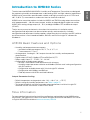 5
5
-
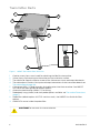 6
6
-
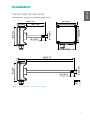 7
7
-
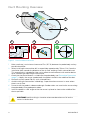 8
8
-
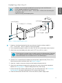 9
9
-
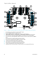 10
10
-
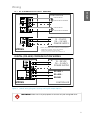 11
11
-
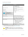 12
12
-
 13
13
-
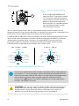 14
14
-
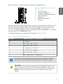 15
15
-
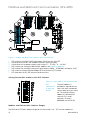 16
16
-
 17
17
-
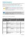 18
18
-
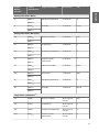 19
19
-
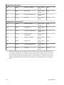 20
20
-
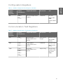 21
21
-
 22
22
-
 23
23
-
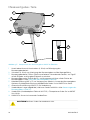 24
24
-
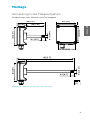 25
25
-
 26
26
-
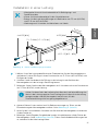 27
27
-
 28
28
-
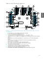 29
29
-
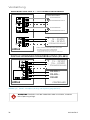 30
30
-
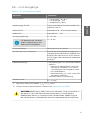 31
31
-
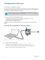 32
32
-
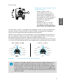 33
33
-
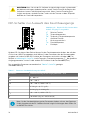 34
34
-
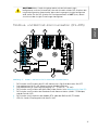 35
35
-
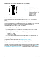 36
36
-
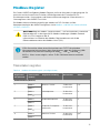 37
37
-
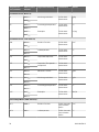 38
38
-
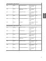 39
39
-
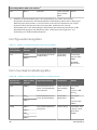 40
40
-
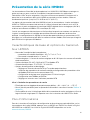 41
41
-
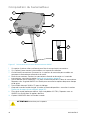 42
42
-
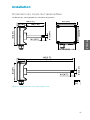 43
43
-
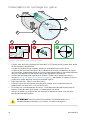 44
44
-
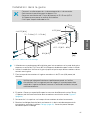 45
45
-
 46
46
-
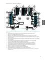 47
47
-
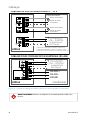 48
48
-
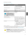 49
49
-
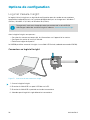 50
50
-
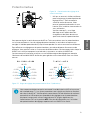 51
51
-
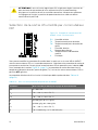 52
52
-
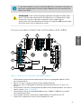 53
53
-
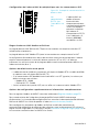 54
54
-
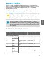 55
55
-
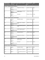 56
56
-
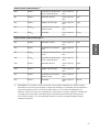 57
57
-
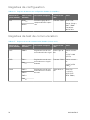 58
58
-
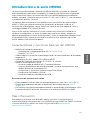 59
59
-
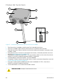 60
60
-
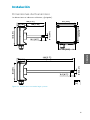 61
61
-
 62
62
-
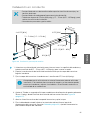 63
63
-
 64
64
-
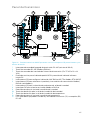 65
65
-
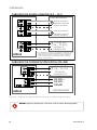 66
66
-
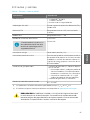 67
67
-
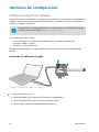 68
68
-
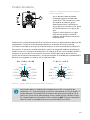 69
69
-
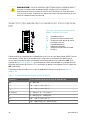 70
70
-
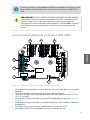 71
71
-
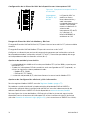 72
72
-
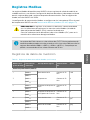 73
73
-
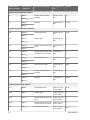 74
74
-
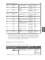 75
75
-
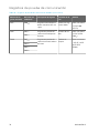 76
76
-
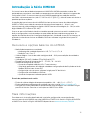 77
77
-
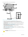 78
78
-
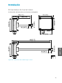 79
79
-
 80
80
-
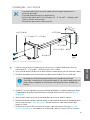 81
81
-
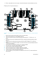 82
82
-
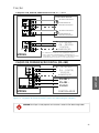 83
83
-
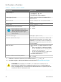 84
84
-
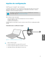 85
85
-
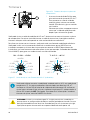 86
86
-
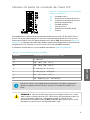 87
87
-
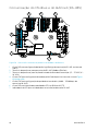 88
88
-
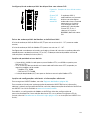 89
89
-
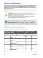 90
90
-
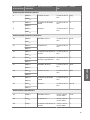 91
91
-
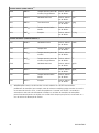 92
92
-
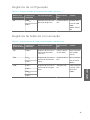 93
93
-
 94
94
-
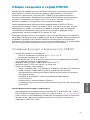 95
95
-
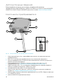 96
96
-
 97
97
-
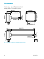 98
98
-
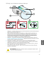 99
99
-
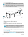 100
100
-
 101
101
-
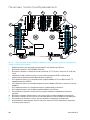 102
102
-
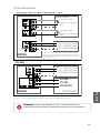 103
103
-
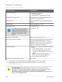 104
104
-
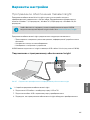 105
105
-
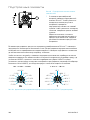 106
106
-
 107
107
-
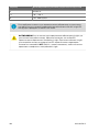 108
108
-
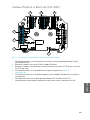 109
109
-
 110
110
-
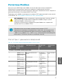 111
111
-
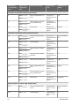 112
112
-
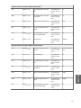 113
113
-
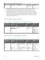 114
114
-
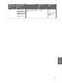 115
115
-
 116
116
-
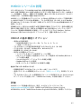 117
117
-
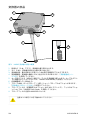 118
118
-
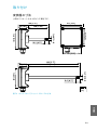 119
119
-
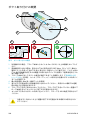 120
120
-
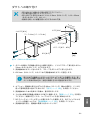 121
121
-
 122
122
-
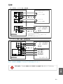 123
123
-
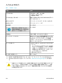 124
124
-
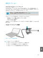 125
125
-
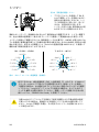 126
126
-
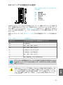 127
127
-
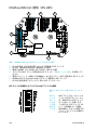 128
128
-
 129
129
-
 130
130
-
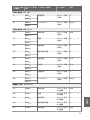 131
131
-
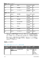 132
132
-
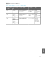 133
133
-
 134
134
-
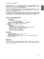 135
135
-
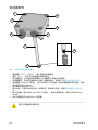 136
136
-
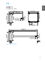 137
137
-
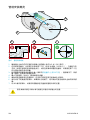 138
138
-
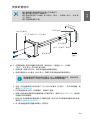 139
139
-
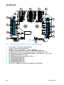 140
140
-
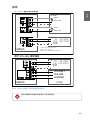 141
141
-
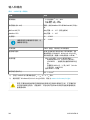 142
142
-
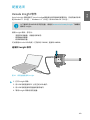 143
143
-
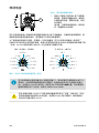 144
144
-
 145
145
-
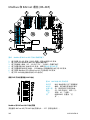 146
146
-
 147
147
-
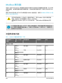 148
148
-
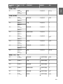 149
149
-
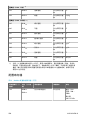 150
150
-
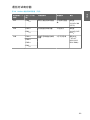 151
151
-
 152
152
-
 153
153
-
 154
154


En otros idiomas
- français: Vaisala HMD65 Manuel utilisateur
- português: Vaisala HMD65 Manual do usuário
- 日本語: Vaisala HMD65 ユーザーマニュアル
Documentos relacionados
-
Vaisala HMD62 Manual de usuario
-
-
-
-
-
-
-
-
-