
EN
DE
FR
ES
PT
JA
ZH
RU
M211247EN-E
Quick Guide
Vaisala HUMICAP
â
Humidity and Temperature
Transmitter Series
HMT120

PUBLISHED BY
Vaisala Oyj
Street address: Vanha Nurmijärventie 21, FI-01670 Vantaa, Finland
Mailing address: P.O. Box 26, FI-00421 Helsinki, Finland
Phone: +358 9 8949 1
Visit our Internet pages at www.vaisala.com.
No part of this manual may be
reproduced, published or publicly
displayed in any form or by any
means, electronic or mechanical
(including photocopying), nor
may its contents be modified,
translated, adapted, sold or
disclosed to a third party without
prior written permission of the
copyright holder. Translated
manuals and translated portions
of multilingual documents are
based on the original English
versions. In ambiguous cases, the
English versions are applicable,
not the translations.
The contents of this manual are
subject to change without prior
notice.
Local rules and regulations may
vary and they shall take
precedence over the information
contained in this manual. Vaisala
makes no representations on this
manual’s compliance with the
local rules and regulations
applicable at any given time, and
hereby disclaims any and all
responsibilities related thereto.
This manual does not create any
legally binding obligations for
Vaisala towards customers or end
users. All legally binding
obligations and agreements are
included exclusively in the
applicable supply contract or the
General Conditions of Sale and
General Conditions of Service of
Vaisala.
This product contains software
developed by Vaisala or third
parties. Use of the software is
governed by license terms and
conditions included in the
applicable supply contract or, in
the absence of separate license
terms and conditions, by the
General License Conditions of
Vaisala Group.

Table of Contents
English............................................................................................................................
5
Deutsch......................................................................................................................... 17
Français........................................................................................................................29
Español..........................................................................................................................41
Português.....................................................................................................................53
日本語.......................................................................................................................... 65
中文...............................................................................................................................77
Русский........................................................................................................................89
3
Drilling Template........................................................................................................102

4 M211247EN-E

Product Overview
Vaisala HUMICAPâ Humidity and Temperature Transmitter Series HMT120 measures relative
humidity (RH) and temperature (T) and outputs the measurements to analog current loop
outputs. Other quantities, such as dewpoint (T
d
) can be calculated from the basic RH and T
values according to the device configuration.
HMT120 is available either with a fixed probe directly attached to the transmitter housing, or
with a remote probe with dierent (3/5/10/20m) cable lengths.
HMT120 can also be ordered with an optional LCD display without backlight.
HMT120 is typically installed mounted on the wall with up to four screws (not included). Rain
and radiation shields and a duct installation kit are available as accessories. A drilling template
is available at the end of this guide to help you position the screws correctly.
5
ENGLISH

Dimensions
14572
120
37
124
Ø 12
116
46
39
M4
;
4 pcs
91
92
78
Wall Assembly Dimensions
It is possible to damage the display when tightening the screws, as
there is not much room between the upper fastening holes and the exposed
display component. Be particularly careful when using a cordless drill.
CAUTION!
6 M211247EN-E

Opening the Transmitter Cover
To open the transmitter cover:
1. If the transmitter is not mounted already, hold it against a
flat surface.
2. Push on the cover with your thumb, and pull the bottom part of the cover towards
yourself.
7
ENGLISH

Duct Installation Kit
A = Probe (HMP110)
B = Duct installation kit
C = Probe Cable
1. Pass the probe cable through the plastic pipe of the duct installation kit.
2. Connect the probe cable to the HMP110.
3. Use a 24mm drill bit to make a hole in the duct wall.
4. Use a 3.2mm drill bit to make four holes for the installation screws
(ST4.2x16-C-Z DIN7981 screw, 4pcs). The holes should be arranged
in a square around the 24mm hole, at a distance of 42mm from each other.
5. Mount the probe holder using the screws (D).
6. Adjust the depth of the plastic pipe and tighten the screw (E) to lock the probe in place.
A
B
C
42
F
D
E
D = Installation screw
E = Pipe locking screw
F = Probe (HMP110)
Ø 24
Ø 3,2x 4 pcs
29
59
20
Ø 15
205
42
53
Ø 22
6
Ø12
266
42
42
8 M211247EN-E

Wiring
1) Wiring Diagram
Service Port
LCD
Display
Cable Gland /
Cable Grommet
Field Wire Terminals
Test points
CH1/ CH2
2) Analog output test
SHLD
CH1-
CH1+
CH2-
CH2+
mA
mA
+ -
CH1 TEST
CH2 TEST
1 SHLD
2 CH1-
3 CH1+
4 CH2-
5 CH2+
10...30VDC
10...30VDC
mA
mA
-
+
+ -
-
+
9
ENGLISH

Adjusting Humidity and Temperature with
Push Buttons
The instructions here apply to both 1-point and 2-point calibration.
To make a humidity or temperature adjustment:
1. Open the transmitter cover. There are 3 buttons marked ADJ, + and - on the motherboard.
There are also two indicator LEDs, one green and one red.
2. Press the ADJ button and hold it down until the green indicator LED begins to blink slowly
(800ms cycle time).
3. The transmitter is now in RH calibration state. Analog output and optional display will still
follow the actual measured RH value.
If you do not wish to perform the RH adjustment at this time, press the ADJ
button one more time. The green indicator LED turns o and the red
indicator LED begins to blink slowly (800ms cycle time) to indicate T
calibration state. To calibrate T, follow the instructions starting from step 7.
4. Remove the filter and insert the probe into a measurement hole of the dry end reference
chamber (for example, LiCl: 11 % RH) to do the low humidity oset adjustment.
Do not touch the adjustment buttons before the conditions have stabilized.
This takes approximately 30 minutes.
5. Press either the - or + button at least once, make sure that the I
out
current is correct,
adjust using the - and + buttons if needed, and press the ADJ button again. The green
indicator LED begins to blink faster (400ms cycle time).
If you do not wish to perform the two-point RH adjustment at this time, press
the ADJ button one more time. The green indicator LED turns o and the red
indicator LED begins to blink slowly (800ms cycle time) to indicate T
calibration state. To calibrate T, follow the instructions starting from step 7.
If one-point calibration is done at more than 50% RH, a gain adjustment is
done instead of an oset adjustment.
6. Insert the probe into the high end reference chamber (for example, NaCl: 75 % RH
chamber in the humidity calibrator HMK15) and do the high humidity gain adjustment by
using the - and + buttons to make sure the I
out
current is correct (you have to press either
- or + at least once even if the value is correct). To
finish the RH calibration, press the ADJ
button. The green LED is now turned
o and the red indicator LED begins to blink slowly
(800ms cycle time).
10 M211247EN-E

7. The transmitter is now in T calibration state. Analog output and optional display will still
follow the actual measured T value.
If you do not wish to perform the T adjustment at this time, press ADJ button
one more time. The red indicator LED is turned o and the transmitter
returns to normal mode. The calibration procedure is now finished.
8. Insert the probe into a known reference temperature (if Vaisala Humidity Calibrator
HMK15 is not used) and let the temperature reading stabilize.
Do not touch the adjustment buttons before the conditions have stabilized.
9. Using the - and + buttons, make the temperature oset adjustment by making sure the
I
out
current is correct (you have to press either - or + at least once even if the value is
correct) and press the ADJ button. The red indicator LED begins to blink faster (400ms
cycle time).
If you do not wish to perform the two-point T adjustment at this time, press
the ADJ button one more time. The red indicator LED is turned o and the
transmitter returns to normal mode. The calibration procedure is now
finished.
10. Insert the probe into another reference temperature.
Do not touch the adjustment buttons before the conditions have stabilized.
11. Using the - and + buttons, make the temperature gain adjustment by making sure the I
out
current is correct (you have to press either - or + at least once even if the value is correct).
12. Press the ADJ button one more time. The red indicator LED turns o and the transmitter
returns to normal mode. The calibration procedure is now finished.
In case of calibration error, both LEDs blink alternately at a very fast rate (cycle
time 200ms) for a period of 2s after which the transmitter returns to normal
mode.
11
ENGLISH

If your transmitter has the optional display, the following notifications are shown
on the display during calibration:
• Probe cal: RH 1 (corresponding the green LED blinking slowly)
• Probe cal: RH 2 (corresponding the green LED blinking fast)
• Probe cal: T1 (corresponding the red LED blinking slowly)
• Probe cal: T2 (corresponding the red LED blinking fast)
• Probe cal: Error (corresponding both LEDs blinking alternately at very fast
rate)
12 M211247EN-E

Troubleshooting
Table 1 Error Codes, Descriptions and Texts
Code Description Error Text
1 Probe T measurement error Probe T meas
2 Probe RH measurement error Probe RA meas
3 Probe communication error Probe communication
4 Probe checksum error Probe checksum
5 Probe message form error Probe message form
6 Program's flash checksum error Program code checksum
7 Current settings checksum
error (RAM)
Settings checksum
8 Factory FLASH not initialised Factory defaults empty
9 User FLASH not initialised User defaults empty
10 Voltage is too low to operate
correctly
Voltage too low
11 Measurements not available Measurements not available
12 Oscillator fault bit active HW fault 1
13 Analog output quantity invalid Analog output quantity invalid
14 Display quantity invalid Display quantity invalid
13
ENGLISH

Technical Data
Table 2 Relative Humidity Measurement Specifications
Property Description/Value
Measurement range 0 ... 100 %RH
Accuracy (including non-linearity, hysteresis, and repeatability) at 0 … +40 °C (+32 … +104 °F):
0 … 90 %RH
90 … 100 %RH
±1.5 %RH
±2.5 %RH
Accuracy (including non-linearity, hysteresis, and repeatability) at -40 … 0 °C, +40 … +80 °C
(-40 … 32 °F, 104 … 176 °F):
0 … 90 %RH
90 … 100 %RH
±3.0 %RH
±4.0 %RH
Factory calibration uncertainty at +20 °C (+68 °F):
0 … 90 %RH
90 … 100 %RH
±1.1 %RH
±1.8 %RH
Humidity sensor Vaisala HUMICAPâ 180R
Table 3 Temperature Measurement Specifications
Property Description/Value
Measurement range -40 … +80 °C (-40 … 176 °F)
Temperature sensor Pt1000 RTD Class F0.1 IEC 60751
Accuracy over temperature range:
At +15 … +25 °C (59 … 77 °F) ±0.2 °C (±0.36 °F)
At 0 … +15 °C and at +25 … +40 °C
(at 32 … 59 °F and at 77 … 104 °F)
±0.25 °C (±0.45 °F)
At -40 … +0 °C and at +40 … +80 °C
(at -40 … 32 °F and at 104 … 176 °F)
±0.4 °C (±0.72 °F)
Table 4 Operating Environment Specifications
Property Description/Value
Operating temperature of transmitter body, no
display
-40 … +60 °C (-40 … 140 °F)
Operating temperature of transmitter body with
display
-20 … +60 °C (-4 … 140 °F)
Operating temperature, HMP110 probe -40 … +80 °C (-40 … 176 °F)
Storage temperature -50 … +70 °C (-58 … 158 °F)
EMC compliance EN 61326-1 and EN 55022
14 M211247EN-E

Table 5 Inputs and Outputs
Property Description/Value
Current output signals 4 … 20 mA
External loop voltage 10 … 30 VDC (R
L
= 0 Ω)
20 … 30 VDC (R
L
< 500 Ω)
Max. additional error caused by the analog
outputs after calibration at +20 °C (68 °F)
ambient temperature
±0.1 % of FS output signal
Temperature dependence of the analog outputs ±0.005 % of FS output signal
Table 6 Mechanical Specifications
Property Description/Value
Material
Transmitter housing PBT plastic
Display window PC plastic
Probe body Stainless steel (AISI 316)
Probe grid filter Chrome coated ABS plastic
IP rating IP65
Connections
Inputs and outputs
Screw terminals 0.5 … 1.5 mm
2
Probe interface 4-pin M8 female panel connector
Probe cable lengths 3 m, 5 m, 10 m, 20 m: cables can be cascaded up
to 50 m
Display (optional) LCD display without backlight
Weight (wall model, including probe) 270 g
Weight (10 m cable model) 540 g
15
ENGLISH

Warranty
For standard warranty terms and conditions, see www.vaisala.com/warranty.
Please observe that any such warranty may not be valid in case of damage due to normal wear
and tear, exceptional operating conditions, negligent handling or installation, or unauthorized
modifications. Please see the applicable supply contract or Conditions of Sale for details of the
warranty for each product.
Technical Support
Contact Vaisala technical support at helpdesk@vaisala.com. Provide at least the
following supporting information:
• Product name, model, and serial number
• Name and location of the installation site
• Name and contact information of a technical person who can provide further
information on the problem
For more information, see www.vaisala.com/support.
Recycling
Recycle all applicable material.
Follow the statutory regulations for disposing of the product and packaging.
16 M211247EN-E

Produktübersicht
Der Vaisala HUMICAPâ Feuchte- und Temperaturmesswertgeber der Serie HMT120 misst die
relative Luftfeuchte und/oder die Temperatur und wandelt die Messwerte in analoge
Stromschleifenausgänge um. Andere Größen wie der Taupunkt (Td) können je nach
Gerätekonfiguration über die Basiswerte für rF und T berechnet werden.
Der HMT120 ist wahlweise mit einer direkt am Messwertgebergehäuse befestigten Sonde oder
mit einer dezentralen Sonde mit unterschiedlichen Kabellängen (3/5/10/20 m) erhältlich.
Für den HMT120 steht auch eine optionale LCD-Anzeige ohne Hintergrundbeleuchtung zur
Verfügung.
Der HMT120 wird in der Regel mit bis zu vier Schrauben (nicht im Lieferumfang enthalten) an
der Wand montiert. Ein Regen- und Strahlungsschutzgehäuse und ein Kanalinstallationssatz
sind als Zubehör erhältlich. Die Bohrschablone auf der hinteren Umschlaginnenseite dieses
Handbuchs hilft Ihnen bei der korrekten Positionierung der Schrauben.
17
DEUTSCH

Abmessungen
14572
120
37
124
Ø 12
116
46
39
M4
;
4 st
ck.
91
92
78
Abmessungen für die Wandmontage
Die Anzeige kann beim Festziehen der Schrauben beschädigt
werden, weil zwischen den oberen Bohrungen und der freiliegenden
Anzeigekomponente nur wenig Platz ist. Seien Sie besonders vorsichtig, wenn
Sie mit einem Akkuschrauber arbeiten.
ACHTUNG
18 M211247EN-E

Abdeckung das Messwertgebers önen
1. Wenn der Messwertgeber noch nicht montiert ist, halten Sie ihn gegen eine ebene Fläche.
2. Drücken Sie mit dem Daumen auf die Abdeckung und ziehen Sie den unteren Teil der
Abdeckung zu sich.
19
DEUTSCH

Kanalinstallationssatz
20 M211247EN-E

Verdrahtung
1) Verdrahtungsdiagramm
Serviceschnittstelle
LCD-
Anzeige
Kabelverschraubung /
Durchführungstülle
Leiterklemmen
Testpunkte
CH1/CH2
2) Analogausgangstest
SHLD
CH1-
CH1+
CH2-
CH2+
mA
mA
+ -
CH1 TEST
CH2 TEST
1 SHLD
2 CH1-
3 CH1+
4 CH2-
5 CH2+
10...30VDC
10...30VDC
mA
mA
-
+
+ -
-
+
21
DEUTSCH

Justierung von Feuchte und Temperatur
So können Sie die Feuchte oder Temperatur justieren (die Anweisungen gelten gleichermaßen
für die Ein-Punkt- und die Zwei-Punkt-Justierung):
1. Önen Sie die Abdeckung des Messwertgebers. Die drei Tasten mit den Symbolen ADJ, +
und – sind nun zu sehen. Es gibt außerdem eine grüne und eine rote LED auf der HMT120-
Hauptplatine.
2. Drücken Sie die Taste ADJ und halten Sie sie gedrückt, bis die grüne LED langsam blinkt
(Zykluszeit: 800 ms).
3. Der HMT120-Messwertgeber befindet sich jetzt im rF-Kalibrierungsmodus. Über den
Analogausgang und die optionale Anzeige wird weiterhin der tatsächlich gemessene rF-
Wert ausgegeben.
Wenn Sie an dieser Stelle keine rF-Justierung vornehmen möchten, drücken
Sie erneut die Taste ADJ. Die grüne LED wird ausgeschaltet und die rote LED
blinkt langsam (Zykluszeit: 800 ms), um zu melden, dass der T-
Kalibrierungsmodus aktiviert wurde. Nun können Sie mit den Anweisungen
ab Schritt 7 fortfahren.
4. Entfernen Sie den Filter, und führen Sie die Sonde in eine Kalibrierönung der
Referenzkammer für den niedrigsten Wert ein (z. B. LiCl: 11 % rF), um die Justierung des
Oset für den niedrigsten Wert vorzunehmen.
Betätigen Sie die Justierungstasten erst, wenn sich die Bedingungen
stabilisiert haben. Dies wird etwa 30 Minuten in Anspruch nehmen.
5. Drücken Sie mindestens einmal die Taste – oder +, stellen Sie sicher, dass der Stromwert
IAusg. korrekt ist, nehmen Sie gegebenenfalls über die Tasten – und + eine Justierung vor
und drücken Sie erneut die Taste ADJ. Die grüne LED blinkt jetzt schneller (Zykluszeit:
400 ms).
Wenn Sie an dieser Stelle keine Zwei-Punkt-rF-Justierung vornehmen
möchten, drücken Sie erneut die Taste ADJ. Die grüne LED wird
ausgeschaltet und die rote LED blinkt langsam (Zykluszeit: 800 ms), um zu
melden, dass der T-Kalibrierungsmodus aktiviert wurde. Nun können Sie mit
den Anweisungen ab Schritt 7 fortfahren.
Wenn die Ein-Punkt-Kalibrierung bei einer rF von mehr als 50 %
vorgenommen wird, wird nicht der Oset, sondern der Verstärkungsfaktor
eingestellt
6. Führen Sie die Sonde in die obere Referenzkammer (z. B. NaCl: 75 % rF im
Feuchtekalibrator HMK15) ein und stellen Sie über die Tasten – und + den
Verstärkungsfaktor der Feuchtemessung ein, sodass der Stromwert IAusg. korrekt ist. (Sie
müssen mindestens einmal – oder + drücken, auch wenn der Wert korrekt ist.) Um die rF-
Kalibrierung zu beenden, drücken Sie die Taste ADJ. Die grüne LED wird jetzt
ausgeschaltet und die rote LED blinkt langsam (Zykluszeit: 800 ms).
22 M211247EN-E

7. Der HMT120-Messwertgeber befindet sich jetzt im T-Kalibrierungsmodus. Über den
Analogausgang und die optionale Anzeige wird weiterhin der tatsächlich gemessene T-
Wert ausgegeben.
Wenn Sie an dieser Stelle keine T-Justierung vornehmen möchten, drücken
Sie erneut die Taste ADJ. Die rote LED wird ausgeschaltet, und der
Messwertgeber kehrt in den normalen Modus zurück. Der
Kalibrierungsvorgang ist jetzt beendet.
8. Führen Sie die Sonde in eine Referenzkammer mit bekannter Temperatur (wenn der
HMK15-Feuchtekalibrator nicht verwendet wird) ein und warten Sie, bis sich der Messwert
stabilisiert hat.
Betätigen Sie die Justierungstasten erst, wenn sich die Bedingungen
stabilisiert haben.
9. Stellen Sie über die Tasten
– und + den
Temperatur-Oset ein, sodass der Stromwert
IAusg. korrekt ist. (Sie müssen mindestens einmal – oder + drücken, auch wenn der Wert
korrekt ist.) Drücken Sie dann die Taste ADJ. Die rote LED blinkt jetzt schneller
(Zykluszeit: 400 ms).
Wenn Sie an dieser Stelle keine Zwei-Punkt-T-Justierung vornehmen
möchten, drücken Sie erneut die Taste ADJ. Die rote LED wird ausgeschaltet,
und der Messwertgeber kehrt in den normalen Modus zurück. Der
Kalibrierungsvorgang ist jetzt beendet.
10. Führen Sie die Sonde in eine andere Referenztemperaturkammer ein.
Betätigen Sie die Justierungstasten erst, wenn sich die Bedingungen
stabilisiert haben.
11. Stellen Sie über die Tasten – und + den Temperatur-Verstärkungsfaktor ein, sodass der
Stromwert IAusg. korrekt ist. (Sie müssen mindestens einmal – oder + drücken, auch wenn
der Wert korrekt ist.)
12. Drücken Sie erneut die Taste ADJ. Die rote LED wird ausgeschaltet, und der
Messwertgeber kehrt in den normalen Modus zurück. Der Kalibrierungsvorgang ist jetzt
beendet.
Bei einem Kalibrierungsfehler blinken beide LEDs 2 Sekunden lang abwechselnd
sehr schnell (Zykluszeit: 200 ms). Anschließend kehrt der Messwertgeber in den
normalen Modus zurück.
23
DEUTSCH

Bei Verwendung eines HMT120-Messwertgebers mit Anzeigeoption werden
während der Kalibrierung folgende Meldungen auf der Anzeige angezeigt:
• Probe cal: RH 1 entspricht dem langsamen Blinken der grünen LED
• Probe cal: RH 2 entspricht dem schnellen Blinken der grünen LED
• Probe cal: T1 entspricht dem langsamen Blinken der roten LED
• Probe cal: T2 entspricht dem schnellen Blinken der roten LED
• Probe cal: Error entspricht dem sehr schnellen abwechselnden Blinken beider
LEDs
24 M211247EN-E

Fehlerbeseitigung
Tabelle 7 Fehlercodes und -meldungen
Code Beschreibung Fehlermeldung
1 Messungsfehler der T-Sonde Probe T meas
2 Messungsfehler der rF-Sonde Probe RA meas
3 Kommunikationsfehler der Sonde Probe communication
4 Prüfsummenfehler der Sonde Probe checksum
5 Fehler der Sondenmeldungsform Probe message form
6 Programm-Flash – Prüfsummenfehler Program code checksum
7 Prüfsummenfehler der aktuellen Ein-
stellungen (RAM)
Settings checksum
8 Werks-Flash nicht initialisiert Factory defaults empty
9 Benutzer-Flash nicht initialisiert User defaults empty
10 Spannung für korrekten Betrieb zu
niedrig
Voltage too low
11 Messwerte nicht verfügbar Measurements not available
12 Oszillator-Fehlerbit aktiv HW fault 1
13 Ungültige Analogausgangsgröße Analog output quantity invalid
14 Ungültige Anzeigegröße Display quantity invalid
25
DEUTSCH

Technische Daten
Tabelle 8 Spezifikationen für die Messung der relativen Luftfeuchte
Eigenschaft Beschreibung/Wert
Messbereich 0 bis 100 % rF
Genauigkeit (einschl. Nichtlinearität, Hysterese und Wiederholbarkeit) bei 0 bis +40 °C (+32 bis
+104 °F):
0 bis 90 % rF
90 bis 100 % rF
±1,5 % rF
±2,5 % rF
Genauigkeit (einschl. Nichtlinearität, Hysterese und Wiederholbarkeit) bei -40 bis 0 °C und +40 bis
+80 °C (-40 bis +32 °F und +104 bis +176 °F):
0 bis 90 % rF
90 … 100 %RH
±3,0 % rF
±4,0 % rF
Unsicherheit der Werkskalibrierung bei 20 °C (+68 °F):
0 … 90 % rF
90 … 100 % rF
±1.1 % rF
±1.8 % rF
Luftfeuchtesensor Vaisala HUMICAPâ 180R
Tabelle 9 Temperature Measurement Specifications
Eigenschaft Beschreibung/Wert
Messbereich -40 … +80 °C (-40 … 176 °F)
Temperatursensor Pt1000 RTD Klasse F0.1 IEC 60751
Genauigkeit über Temperaturbereich:
bei +15 bis +25 °C (+59 bis +77 °F) ±0.2 °C (±0.36 °F)
bei 0 bis +15 °C und +25 bis +40 °C
(+32 bis +59 °F und +77 bis +104 °F)
±0.25 °C (±0.45 °F)
bei -40 bis 0 °C und +40 bis +80 °C
(-40 bis +32 °F und +104 bis +176 °F)
±0.4 °C (±0.72 °F)
Tabelle 10 Spezifikationen für die Betriebsumgebung
Eigenschaft Beschreibung/Wert
Betriebstemperaturbereich, Messwertgeberge-
häuse ohne Anzeige
-40 bis +60 °C (-40 bis +140 °F)
Betriebstemperaturbereich, Messwertgeberge-
häuse mit Anzeige
-20 bis +60 °C (-4 bis +140 °F)
Betriebstemperaturbereich, Operating tempera-
ture, HMP110 probe
-40 bis +80 °C (-40 bis +176 °F)
26 M211247EN-E

Eigenschaft Beschreibung/Wert
Lagertemperaturbereich -50 bis +70 °C (-58 bis +158 °F)
Elektromagnetische Verträglichkeit (EMV) EN 61326-1, EN 55022
Tabelle 11 Ein- und Ausgänge
Eigenschaft Beschreibung/Wert
Ausgangssignal über zwei Leiter 4 bis 20 mA (Stromschleife)
Externe Schleifenspannung 10 bis 30 VDC (R
L
= 0 Ω)
20 bis 30 VDC (R
L
< 500 Ω)
Max. zusätzlicher Fehler durch Analogausgänge
nach der Kalibrierung bei einer Umgebungstem-
peratur von +20 °C
±0,1 % des Ausgangsstroms v. Ew.
Temperaturabhängigkeit des Analogausgangs ±0,005 %/°C des Ausgangsstroms v. Ew.
Tabelle 12 Mechanikspezifikationen
Eigenschaft Beschreibung/Wert
Material
Messwertgebergehäuse PBT-Kunststo
Anzeigefenster PC-Kunststo
Sondenkörper Edelstahl (AISI 316)
Sondengitterfilter Verchromter ABS-Kunststo
Gehäuseschutzart IP65
Anschlüsse
Stromschleifenausgänge
Schraubklemmen 0,5 bis 1.5 mm
2
Sondenschnittstelle 4-polige Steckerbuchse M8
Sondenkabellängen 3 m, 5 m, 10 m, 20 m Kabel können bis zu 50 m
lang in Kaskade geschaltet werden
Anzeige (optional) LCD-Anzeige ohne Hintergrundbeleuchtung
Gewicht (Wandmodell, einschließlich Sonde) 270 g
Gewicht (Modell mit 10-m-Kabel) 540 g
27
DEUTSCH

Gewährleistung
Unsere Standardgarantiebedingungen finden Sie unter www.vaisala.com/warranty.
Diese Garantie deckt keine Verschleißschäden, Schäden infolge außergewöhnlicher
Betriebsbedingungen, Schäden infolge unzulässiger Verwendung oder Montage oder Schäden
infolge nicht genehmigter
Modifikationen ab. Einzelheiten zum Gewährleistungsumfang für
bestimmte Produkte enthalten der zugehörige Liefervertrag und die Verkaufsbedingungen.
Technischer Support
Wenden Sie sich an den technischen Support von Vaisala unter
helpdesk@vaisala.com. Geben Sie mindestens folgende Informationen an:
• Produktname, Modell und Seriennummer
• Name und Standort der Installation
• Name und Kontaktinformationen eines Technikers für weitere Auskünfte
Weitere Informationen
finden Sie unter www.vaisala.com/support.
Recycling
Recyceln Sie alle wiederverwertbaren Materialien.
Beachten Sie bei der Entsorgung von Produkten und Verpackung die gesetzlichen
Regelungen.
28 M211247EN-E

Présentation du produit
Le transmetteur d’humidité et de température Vaisala HUMICAPâ de la série HMT120 permet
de mesurer l’humidité relative et /ou la température, puis de convertir ces données en sorties
de boucle de courant analogique. Les autres valeurs comme le point de rosée (Td) peuvent
être calculées à partir des valeurs HR et T de base, et ce en fonction de la
configuration de
l’appareil.
Le HMT120 est disponible soit avec une sonde fixée directement sur le boîtier du transmetteur,
soit avec une sonde distante munie de câbles de
diérentes longueurs (3/5/10/20 m).
Le HMT120 est également disponible avec un écran LCD sans rétroéclairage (en option).
Le HMT120 est en général fixé au mur à l’aide de quatre vis (non fournies). Un système de
protection contre la pluie, un bouclier anti-rayonnement et un kit d’installation sur gaine sont
également disponibles en accessoires. A l’intérieur de la quatrième de couverture de ce guide,
vous trouverez un gabarit de perçage qui vous permettra de placer correctement les vis.
29
FRANÇAIS

Dimensions
14572
120
37
124
Ø 12
116
46
39
M4
; 4 pi
è
c
e
s
91
92
78
Dimensions du dispositif de montage mural
Il existe un risque d'endommager l'écran lors du serrage des vis
car l'espace entre les trous de fixation supérieurs et la partie exposée de l'écran
est réduit. Faites particulièrement attention si vous utilisez une visseuse sans fil.
ATTENTION
30 M211247EN-E

Ouverture du capot du transmetteur
1. Si le transmetteur n'est pas déjà en place, tenez-le contre une surface plate.
2. Appuyez sur le capot avec votre pousse et tirez la partie inférieure vers vous.
31
FRANÇAIS

Kit d’installation sur gaine
32 M211247EN-E

Câblage
1) Schéma de câblage
Port de service
Ecran
LCD
Presse-étoupe /
passe-fil
Bornes du câble à la terre
Points
d’essai
CH1/CH2
2) Test de la sortie analogique
SHLD
CH1-
CH1+
CH2-
CH2+
mA
mA
+ -
CH1 TEST
CH2 TEST
1 SHLD
2 CH1-
3 CH1+
4 CH2-
5 CH2+
10...30VDC
10...30VDC
mA
mA
-
+
+ -
-
+
33
FRANÇAIS

Réglage de la température et de l’humi-
dité
Pour eectuer un réglage de l'humidité ou de la température, procédez comme suit (les
instructions sont les mêmes pour l'étalonnage en un point et l'étalonnage en deux points) :
1. Ouvrez le capot du transmetteur, qui contient trois boutons marqués respectivement ADJ,
+ et -. Vous verrez également deux témoins à DEL, un vert et un rouge sur la carte mère
HMT120.
2. Appuyez sur le bouton ADJ et maintenez-le enfoncé jusqu'à ce que la DEL de couleur
verte commence à clignoter lentement (temps de cycle : 800 ms).
3. Le transmetteur HMT120 est désormais en mode d'étalonnage de l'humidité relative. La
sortie analogique et l'écran proposé en option continueront à prendre en compte la valeur
réelle mesurée pour l'humidité relative.
Si vous ne souhaitez pas eectuer le réglage de l'humidité relative à ce
moment, appuyez de nouveau sur le bouton ADJ. La DEL de couleur verte
s'éteint et la DEL rouge commence à clignoter lentement (temps de cycle :
800 ms) pour indiquer le mode d'étalonnage de la température. Vous pouvez
maintenant continuer en suivant les instructions à partir de l'étape 7.
4. Pour eectuer le réglage du décalage pour les environnements à faible taux d'humidité,
retirez le filtre et insérez la sonde dans une encoche de mesure de la chambre de
référence à extrémité sèche (par exemple, LiCl : 11 % HR).
Ne touchez pas les boutons de réglage avant que les conditions ne soient
stabilisées. Cela prend environ 30 minutes.
5. Appuyez au moins une fois sur le bouton - ou +, assurez-vous que la courant I
out
est
correcte, réglez-la si nécessaire à l’aide des boutons - et +, puis appuyez à nouveau sur le
bouton ADJ. La DEL de couleur verte commence à clignoter plus vite (temps de cycle :
400 ms).
Si vous ne souhaitez pas eectuer le réglage de l'humidité relative en deux
points à ce moment, appuyez de nouveau sur le bouton ADJ. La DEL de
couleur verte s'éteint et la DEL rouge commence à clignoter lentement
(temps de cycle : 800 ms) pour indiquer le mode d'étalonnage de la
température. Vous pouvez maintenant continuer en suivant les instructions à
partir de l'étape 7.
Si l'étalonnage en un point est réalisé à plus de 50 % d’humidité relative, un
réglage du gain est eectué en lieu et place du réglage du décalage.
34 M211247EN-E

6. Insérez la sonde dans la chambre de référence de limite supérieure (par exemple, NaCl :
chambre 75 % HR dans l’étalon d'humidité HMK15). Utilisez ensuite les boutons - et + pour
eectuer le réglage du gain relatif aux situations de forte humidité en vérifiant que la
tension Uout est correcte (même si la valeur est correcte, vous devez appuyer au moins
une fois sur – ou sur +). Pour terminer l'étalonnage de l'humidité relative, appuyez sur le
bouton ADJ. La DEL de couleur verte est désormais éteinte, et la DEL de couleur rouge
commence à clignoter lentement (temps de cycle : 800 ms).
7. Le transmetteur HMT120 est désormais en mode d'étalonnage de la température. La sortie
analogique et l'écran proposé en option continueront à prendre en compte la valeur réelle
mesurée pour la température.
Si vous ne souhaitez pas eectuer le réglage de la température à ce moment,
appuyez de nouveau sur le bouton ADJ. La DEL de couleur rouge s'éteint et
l'émetteur revient en mode normal. La procédure d'étalonnage est désormais
terminée.
8. Insérez la sonde dans une température de référence connue (si vous n'utilisez pas l'étalon
d'humidité HMK15), puis laissez le résultat se stabiliser.
Ne touchez pas les boutons de réglage avant que les conditions ne soient
stabilisées.
9. Utilisez les boutons
– et + pour
eectuer le réglage du décalage de température en
vérifiant que la courant I
out
est correcte (même si la valeur est correcte, vous devez
appuyer au moins une fois sur – ou sur +). Appuyez ensuite le bouton ADJ. La DEL de
couleur rouge commence à clignoter plus vite (temps de cycle : 400 ms).
Si vous ne souhaitez pas eectuer le réglage de la température en deux
points à ce moment, appuyez de nouveau sur le bouton ADJ. La DEL de
couleur rouge s'éteint et l'émetteur revient en mode normal. La procédure
d'étalonnage est désormais terminée.
10. Insérez la sonde dans une autre température de référence.
Ne touchez pas les boutons de réglage avant que les conditions ne soient
stabilisées.
11. Utilisez les boutons – et + pour eectuer le réglage du gain de température en vérifiant
que la courant I
out
est correcte (même si la valeur est correcte, vous devez appuyer au
moins une fois sur – ou +).
12. Appuyez de nouveau sur le bouton ADJ. La DEL de couleur rouge s'éteint et le
transmetteur revient en mode normal. La procédure d'étalonnage est désormais terminée.
En cas d'erreur d'étalonnage, les deux DEL clignotent en alternance très
rapidement (temps de cycle : 200 ms), et ce pendant 2 s. Le transmetteur revient
ensuite en mode normal.
35
FRANÇAIS

Si vous utilisez un transmetteur HMT120 avec l'écran proposé en option, vous
verrez les messages suivants s'acher à l'écran pendant la procédure
d'étalonnage :
• Probe cal: RH 1 qui correspond au moment où la DEL de couleur verte clignote
lentement
• Probe cal: RH 2 qui correspond au moment où la DEL de couleur verte clignote
rapidement
• Probe cal: T1 qui correspond au moment où la DEL de couleur rouge clignote
lentement
• Probe cal: T2 qui correspond au moment où la DEL de couleur rouge clignote
rapidement
• Probe cal: Error qui correspond au moment où les deux DEL clignotent en
alternance très rapidement
36 M211247EN-E

Dépannage
Tableau 13 Codes et messages d’erreur
Code Description Error Text
1 Erreur de mesure de la sonde de tem-
pérature
Probe T meas
2 Erreur de mesure de la sonde d’humi-
dité relative
Probe RA meas
3 Erreur de communication au niveau
de la sonde
Probe communication
4 Erreur de total de contrôle au niveau
de la sonde
Probe checksum
5 Erreur au niveau de la forme du mes-
sage de la sonde
Probe message form
6 Erreur de total de contrôle flash au ni-
veau du programme
Program code checksum
7 Erreur de total de contrôle au niveau
des paramètres actuels (RAM)
Settings checksum
8 Valeurs flash réglées en usine non ini-
tialisées
Factory defaults empty
9 Flash utilisateur non initialisé User defaults empty
10 La tension n’est pas susamment éle-
vée pour permettre un fonctionne-
ment correct
Voltage too low
11 Mesures non disponibles Measurements not available
12 Bit erroné actif au niveau de l’oscilla-
teur
HW fault 1
13 Valeur de la sortie analogique non va-
lide
Analog output quantity invalid
14 Valeur achée non valide Display quantity invalid
37
FRANÇAIS

Données techniques
Tableau 14 Spécifications relatives à la mesure de l'humidité relative
Propriété Description/Valeur
Plage de mesure 0 … 100 % d'humidité relative
Précision (y compris la non‑linéarité, l'hystérésis et la répétabilité) à -0 … +40 °C (+32 … +104 °F) :
0 ... 90 % d'HR
90 ... 100 % d'HR
±1.5 % d'HR
±2.5 % d'HR
Précision (y compris la non‑linéarité, l'hystérésis et la répétabilité) à -40 ... 0 °C et +40 ... +80 °C
(-40 ... +32 °F et +104...+176 °F) :
0 ... 90 % d'HR
90 ... 100 % d'HR
±3.0 % d'HR
±4.0 % d'HR
Incertitude de l'étalonnage d'usine à 20 °C (+68 °F) :
0 ... 90 % d'HR
90 ... 100 % d'HR
±1.1 % d'HR
±1.8 % d'HR
Capteur d'humidité Vaisala HUMICAPâ 180R
Tableau 15 Spécifications relatives à la mesure de la température
Propriété Description/Valeur
Plage de mesure -40 … +80 °C (-40 … 176 °F)
Capteur de température Pt1000 RTD Classe F0.1 IEC 60751
Précision au‑delà de la plage de température :
à +15 ... +25 °C (+59 ... +77 °F) ±0.2 °C (±0.36 °F)
à 0 …+15 °C et +25 …+40 °C
(+32 ... +59 °F et +77...+104 °F)
±0.25 °C (±0.45 °F)
à -40 ... 0 °C et +40 ... +80 °C
(-40 ... +32 °F et +104...+176 °F)
±0.4 °C (±0.72 °F)
Tableau 16 Spécifications relatives à l'environnement d'exploitation
Propriété Description/Valeur
Plage des températures de fonctionnement,
corps du transmetteur, sans écran
-40 … +60 °C (-40 … 140 °F)
Plage des températures de fonctionnement,
corps du transmetteur, avec écran
-20 … +60 °C (-4 … 140 °F)
Plage des températures de fonctionnement,
sonde HMP110
-40 … +80 °C (-40 … 176 °F)
Plage des températures de stockage -50 … +70 °C (-58 … 158 °F)
38 M211247EN-E

Propriété Description/Valeur
Compatibilité électromagnétique EN 61326-1, EN 55022
Tableau 17 Entrées et sorties
Propriété Description/Valeur
Signal de sortie bifilaire 4 ... 20 mA (alimentation par boucle)
Tension de la boucle externe 10 … 30 VCC (R
L
= 0 Ω)
20 … 30 VCC (R
L
< 500 Ω)
Erreur de valeur maximale provoquée par les
sorties analogiques, après étalonnage eectué à
une température ambiante de +20° C (68 °F)
±0,1 % du signal de sortie de déviation maximale
Dépendance à la température des sorties analo-
giques
±0,005 % du signal de sortie de déviation maxi-
male
Tableau 18 Spécifications mécaniques
Propriété Description/Valeur
Matériel
Boîtier du transmetteur Plastique PBT
Fenêtre d’achage Plastique PC
Corps de la sonde Acier inoxydable (AISI 316)
Filtre à grille de la sonde Plastique ABS revêtu de chrome
Classification du boîtier IP65
Connexions
Sorties de la boucle de courant
Bornes à vis 0.5 … 1.5 mm
2
Interface de la sonde Connecteur femelle du panneau (4 broches M8)
Longueurs du câble de la sonde 3 m, 5 m, 10 m, 20 m, les câbles peuvent avoir
une longueur allant jusqu’à 50 m
Ecran (en option) Ecran LCD sans rétroéclairage
Poids (modèle pour montage mural, sonde in-
cluse)
270 g
Poids (modèle avec câble 10 m) 540 g
39
FRANÇAIS

Garantie
Pour connaître nos conditions de garantie standard, rendez-vous sur la page
www.vaisala.com/warranty.
Veuillez noter qu'une telle garantie ne s’applique pas en cas de dommage dû à l’usure normale,
à des conditions de fonctionnement exceptionnelles, à une négligence lors de la manipulation
ou de l’installation, ou à des
modifications non autorisées. Veuillez consulter le contrat
d'approvisionnement applicable ou les Conditions de vente pour obtenir des détails sur la
garantie de chaque produit.
Assistance technique
Vous pouvez contacter l'assistance technique Vaisala à l'adresse suivante :
helpdesk@vaisala.com. Veuillez nous communiquer au minimum les informations
suivantes :
• Nom du produit, modèle et numéro de série
• Nom et emplacement du site d'installation
• Nom et coordonnées d'une personne compétente sur le plan technique
capable de fournir des informations complémentaires sur le problème
Pour plus d'informations, consultez le site Web www.vaisala.com/support.
Recyclage
Recyclez tous les matériaux qui peuvent l'être.
Mettez au rebut le produit et son emballage en respectant la réglementation en
vigueur.
40 M211247EN-E

Descripción general del producto
El transmisor de temperatura y humedad HUMICAPâ Serie HMT120 de Vaisala mide la
humedad relativa y/o la temperatura y la convierte en salidas analógicas de cresta de
corriente. Se pueden calcular otras cantidades, por ejemplo el punto de rocío (Td), a partir de
los valores básicos de humedad relativa (Relative Humidity, RH) y temperatura (T), según la
configuración del dispositivo.
El HMT120 está disponible con una sonda fija conectada directamente a la caja del transmisor
o con una sonda remota con longitudes de cable diferentes (3/5/10/20 m).
El HMT120 también está disponible con una pantalla LCD sin luz de fondo.
En general, el HMT120 se
fija a la pared con hasta cuatro tornillos (no incluidos). Se encuentran
disponibles como accesorios el protector contra radiación y lluvia y un kit de instalación de
conductos. Se incluye una plantilla de taladrado al dorso de esta guía para ayudarlo a colocar
los tornillos correctamente.
41
ESPAÑOL

Dimensiones
14572
120
37
124
Ø 12
116
46
39
M4
;
4 unid.
91
92
78
Dimensiones del ensamblaje en la pared
Es posible dañar la pantalla al ajustar los tornillos, ya que no
existe demasiado espacio entre los orificios de ajuste superiores y el
componente expuesto de la pantalla. Tenga especial precaución si usa un
taladro inalámbrico.
PRECAUCIÓN
42 M211247EN-E

Abrir la cubierta del transmisor
1. Si el transmisor aún no está montado, sujételo contra una superficie plana.
2. Presione la cubierta con el pulgar y tire la parte inferior de la cubierta hacia usted.
43
ESPAÑOL

Kit de instalación de conductos
44 M211247EN-E

Cableado
1) Diagrama de cableado
Puerto de Servicio
Pantalla
LCD
Casquillo
prensacable / ojal
Terminales de cable de campo
Puntos
de prueba
CH1/CH2
2) Pruebas de salida analógica
SHLD
CH1-
CH1+
CH2-
CH2+
mA
mA
+ -
CH1 TEST
CH2 TEST
1 SHLD
2 CH1-
3 CH1+
4 CH2-
5 CH2+
10...30VDC
10...30VDC
mA
mA
-
+
+ -
-
+
45
ESPAÑOL

Ajustes de humedad y temperatura
Para realizar un ajuste de humedad o temperatura (las mismas instrucciones se aplican para la
calibración de un punto y de dos puntos):
1. Abra la tapa del transmisor, y allí podrá observar tres botones marcados ADJ, + y -.
También existen dos indicadores LED, uno verde y otro rojo, en la placa madre HMT120.
2. Presione el botón ADJ y manténgalo pulsado hasta que el indicador LED verde comience
a parpadear lentamente (tiempo de ciclo de 800 ms).
3. El transmisor HMT120 está ahora en el estado de calibración de RH. La salida analógica y
la pantalla opcional todavía seguirán los valores actuales de RH medidos.
Si no desea realizar el ajuste de RH en este momento, presione el botón ADJ
una vez más. El indicador LED verde se apaga y el indicador LED rojo
comienza a parpadear lentamente (tiempo de ciclo de 800 ms) para indicar
el estado de calibración de T. Ahora puede continuar con las instrucciones a
partir del paso 7.
4. Extraiga el filtro e introduzca la sonda en un orificio de medición de la cámara de
referencia del extremo seca (por ejemplo, LiCl: 11% RH) para realizar el ajuste de
compensación de humedad baja.
No toque los botones de ajuste antes de que las condiciones se estabilicen.
Esto tarda 30 minutos aproximadamente.
5. Presione el botón - o + por lo menos una vez, asegúrese de que la corriente Iout sea
correcta, si es necesario ajuste usando los botones - y +, y presione nuevamente el botón
ADJ. El indicador LED verde comienza a parpadear más rápido (tiempo de ciclo de 400
ms).
Si no desea realizar el ajuste de RH de dos puntos en este momento, presione
el botón ADJ una vez más. El indicador LED verde se apaga y el indicador
LED rojo comienza a parpadear lentamente (tiempo de ciclo de 800 ms)
para indicar el estado de calibración de T. Ahora puede continuar con las
instrucciones a partir del paso 7.
Si la calibración de un punto se realiza a más de 50 % RH, se realiza un ajuste
de ganancia en lugar de un ajuste de compensación.
6. Introduzca la sonda en la cámara de referencia del extremo superior (por ejemplo, cámara
de NaCl: 75 % RH en el calibrador de humedad HMK15) y realice el ajuste de ganancia de
humedad alta usando los botones - y + para asegurarse de que la corriente Iout sea
correcta (debe presionar - o + por lo menos una vez aun cuando el valor sea correcto).
Para terminar la calibración de RH, presione el botón ADJ. El LED verde ahora está
apagado y el indicador LED rojo comienza a parpadear lentamente (tiempo de ciclo de
800 ms).
46 M211247EN-E

7. El transmisor está ahora en el estado de calibración de T. La salida analógica y la pantalla
opcional todavía seguirán el valor real de T medido.
Si no desea realizar el ajuste de T en este momento, presione el botón ADJ
una vez más. El indicador LED rojo se apaga y el transmisor regresa al modo
normal. El proceso de calibración se completó.
8. Introduzca la sonda en una temperatura de referencia conocida (si el calibrador de
humedad HMK15 no se usa) y permita que la lectura de temperatura se estabilice.
No toque los botones de ajuste antes de que las condiciones se estabilicen.
9. Mediante los botones - y +, realice los ajustes de compensación de temperatura
asegurándose de que la corriente Iout sea correcta (debe presionar - o + por lo menos
una vez aun cuando el valor sea correcto) y presione el botón ADJ. El indicador LED rojo
comienza a parpadear más rápido (tiempo de ciclo de 400 ms).
Si no desea realizar el ajuste de T de dos puntos en este momento, presione
el botón ADJ una vez más. El indicador LED rojo se apaga y el transmisor
regresa al modo normal. El proceso de calibración se completó.
10. Introduzca la sonda en otra temperatura de referencia.
No toque los botones de ajuste antes de que las condiciones se estabilicen.
11. Mediante los botones - y +, realice el ajuste de ganancia de temperatura asegurándose de
que la corriente Iout sea correcta (debe presionar - o + por lo menos una vez aun cuando
el valor sea correcto).
12. Vuelva a presionar el botón ADJ. El indicador LED rojo se apaga y el transmisor regresa al
modo normal. El proceso de calibración se completó.
Si se produce un error de calibración, ambos LED parpadean de forma alterna
muy rápidamente (tiempo de ciclo de 200 ms) durante un período de 2 s después
del cual el transmisor regresa al modo normal.
En caso de usar un transmisor HMT120 con opción de visualización, se muestran
los siguientes textos en la pantalla durante la calibración:
• Probe cal: RH 1 correspondiente al LED verde que parpadea lentamente
• Probe cal: RH 2 correspondiente al LED verde que parpadea rápido
• Probe cal: T1 correspondiente al LED rojo que parpadea lentamente
• Probe cal: T2 correspondiente al LED rojo que parpadea rápidamente
• Probe cal: Errorcorrespondiente a ambos LED que parpadean muy
rápidamente
47
ESPAÑOL

Solución de problemas
Tabla 19 Códigos de error y textos
Código Descripción Texto del error
1 Error de medición de la T de la sonda Probe T meas
2 Error de medición de la RH de la son-
da
Probe RA meas
3 Error de comunicación de la sonda Probe communication
4 Error de suma de verificación de la
sonda
Probe checksum
5 Error de forma de mensaje de la son-
da
Probe message form
6 Error de suma de verificación de me-
moria del programa
Program code checksum
7 Error de suma de verificación de con-
figuración actual (RAM)
Settings checksum
8 No se inicializó memoria de fábrica Factory defaults empty
9 No se inicializó memoria del usuario User defaults empty
10 El voltaje es muy bajo para funcionar
correctamente
Voltage too low
11 Mediciones no disponibles Measurements not available
12 Bit de falla del oscilador activo HW fault 1
13 Cantidad de salida analógica no válida Analog output quantity invalid
14 Cantidad visualizada no válida Display quantity invalid
48 M211247EN-E

Información técnica
Tabla 20 Especificaciones de medición de la humedad relativa
Característica Descripción/Valor
Intervalo de medición 0 ... 100 %RH
Precisión (incluidos falta de linealidad, histéresis y repetibilidad a 0 … +40 °C (+32 … +104 °F):
0 … 90 %RH
90 … 100 %RH
±1.5 %RH
±2.5 %RH
Precisión (incluidos falta de linealidad, histéresis y repetibilidad a -40 … 0 °C, +40 … +80 °C
(-40 … 32 °F, 104 … 176 °F):
0 … 90 %RH
90 … 100 %RH
±3.0 %RH
±4.0 %RH
Incertidumbre de calibración de fábrica a +20 °C (+68 °F):
0 … 90 %RH
90 … 100 %RH
±1.1 %RH
±1.8 %RH
Sensor de humedad Vaisala HUMICAPâ 180R
Tabla 21 Especificaciones de medición de la temperatura
Característica Descripción/Valor
Intervalo de medición -40 … +80 °C (-40 … 176 °F)
Sensor de temperatura Pt1000 RTD Clase F0.1 IEC 60751
Precisión sobre el rango de temperatura:
a +15 … +25 °C (59 … 77 °F) ±0.2 °C (±0.36 °F)
a 0 … +15 °C y +25 … +40 °C
(32 … 59 °F y 77 … 104 °F)
±0.25 °C (±0.45 °F)
a -40 … +0 °C y +40 … +80 °C
(-40 … 32 °F y 104 … 176 °F)
±0.4 °C (±0.72 °F)
Tabla 22 Especificaciones del entorno de funcionamiento
Característica Descripción/Valor
Intervalo de temperaturas de funcionamiento,
cuerpo del transmisor, sin pantalla
-40 … +60 °C (-40 … 140 °F)
Intervalo de temperaturas de funcionamiento,
cuerpo del transmisor, con pantalla
-20 … +60 °C (-4 … 140 °F)
Intervalo de temperaturas de funcionamiento,
sonda HMP110
-40 … +80 °C (-40 … 176 °F)
Intervalo de temperaturas de almacenamiento -50 … +70 °C (-58 … 158 °F)
49
ESPAÑOL

Característica Descripción/Valor
Compatibilidad electromagnética EN 61326-1, EN 55022
Tabla 23 Entradas y salidas
Característica Descripción/Valor
Señal de salida de dos cables 4 ... 20 mA (alimentación por bucle)
Voltaje de bucle externo 10 … 30 V CC (R
L
= 0 Ω)
20 … 30 V CC (R
L
< 500 Ω)
Error adicional de máxima causado por las sali-
das analógicas luego de la calibración a tempe-
ratura ambiente +20 °C (68 °F)
±0.1% de la señal de salida de escala completa
Dependencia de la temperatura de las salidas
analógicas
±0.005% de la señal de salida de escala comple-
ta
Tabla 24 Especificaciones mecánicas
Característica Descripción/Valor
Material
Caja del transmisor Plástico PBT
Visor Plástico de PC
Cuerpo de la sonda Acero inoxidable (AISI 316)
Filtro de rejilla de la sonda Plástico ABS cromado
Clasificación de la caja IP65
Conexiones
Entradas y salidas
Terminales de tornillo 0.5 … 1.5 mm
2
Interfaz de la sonda Conector hembra de panel de 4-clavijas M8
Longitudes de cable de la sonda 3 m, 5 m, 10 m, 20 m, los cables pueden estar en
cascada hasta 50 m
Pantalla (opcional) Pantalla LCD sin luz de fondo
Peso (modelo de pared, con sonda) 270 g
Peso (Modelo de cable 10 m) 540 g
50 M211247EN-E

Garantía
Para obtener nuestros términos y condiciones estándar de garantía, consulte
www.vaisala.com/warranty.
Tenga presente que dicha garantía puede perder su validez en caso de daño debido al
desgaste normal, a condiciones de operación excepcionales, a manipulación o instalación
negligente, o a
modificaciones no autorizadas. Para conocer los detalles de la garantía de cada
producto, consulte el contrato de suministro o las condiciones de venta correspondientes.
Soporte técnico
Comuníquese con el servicio técnico de Vaisala en [email protected].
Proporcione, al menos, la siguiente información complementaria:
• Nombre del producto, modelo y número de serie
• Nombre y ubicación del lugar de instalación
• Nombre e información de contacto del técnico que pueda proporcionar más
información sobre el problema
Para obtener más información, consulte www.vaisala.com/support.
Reciclaje
Recicle todo el material que corresponda.
Siga las normas establecidas para desechar el producto y el empaque.
51
ESPAÑOL

52 M211247EN-E

Visão geral do produto
O Transmissor de Umidade e Temperatura Vaisala HUMICAPâ Série HMT120 mede a umidade
relativa e/ou a temperatura e as converte para saídas loop analógicas em uso. Outras medidas,
como ponto de condensação (Td), podem ser calculadas a partir dos valores básicos T e RH de
acordo com a
configuração do dispositivo.
O HMT120 está disponível com uma sonda fixa presa diretamente ao invólucro do transmissor
ou com uma sonda remota com comprimentos de cabo diferentes (3/5/10/20 m).
O HMT120 também está disponível com um display LCD opcional sem luz de fundo.
O HMT120 normalmente é preso à parede por até quatro parafusos (não incluídos). As
proteções contra chuva e radiação e um kit de instalação de duto estão disponíveis como
acessórios. Há um modelo de perfuração na contracapa deste guia para ajudá-lo a posicionar
os parafusos corretamente.
53
PORTUGUÊS

Dimensões
14572
120
37
124
Ø 12
116
46
39
M4
;
4 pcs
91
92
78
Dimensões de montagem de parede
É possível que o visor seja danificado durante o aperto dos
parafusos, já que não há muito espaço entre os orifícios de aperto superiores e o
componente do visor exposto. Seja particularmente cuidadoso ao usar uma
parafusadeira sem fio.
CUIDADO
54 M211247EN-E

Abrindo a tampa do transmissor
1. Se o transmissor ainda não estiver montado, segure-o contra uma superfície plana.
2. Pressione a tampa com o dedo e puxe a parte inferior da tampa na sua direção.
55
PORTUGUÊS

Kit de instalação de duto
56 M211247EN-E

Fiação
SHLD
CH1-
CH1+
CH2-
CH2+
mA
mA
+ -
CH1 TEST
CH2 TEST
1 SHLD
2 CH1-
3 CH1+
4 CH2-
5 CH2+
10...30VDC
10...30VDC
mA
mA
-
+
1) Diagrama da fiação
Porta de serviço
Display
LCD
Tubo de vedação
do cabo/ anel do cabo
Terminais de fio de campo
Pontos
de teste
CH1/CH2
2) Teste da saída analógica
+ -
-
+
57
PORTUGUÊS

Ajuste de temperatura e umidade
Para fazer um ajuste de umidade ou de temperatura (as mesmas instruções se aplicam para
calibrações de ponto único e de dois pontos):
1. Abra a tampa do transmissor e você verá três botões marcados ADJ, + e -. Há também
dois LEDs indicadores, um verde e outro vermelho na placa-mãe do HMT120.
2. Pressione o botão ADJ e segure até que o LED verde do indicador comece a piscar
devagar (tempo de ciclo de 800 ms).
3. O transmissor HMT120 agora encontra-se no estado de calibração RH. A saída analógica e
o display opcional ainda acompanharão o valor real de RH calculado.
Se não desejar executar o ajuste de RH neste momento, pressione o botão
ADJ mais uma vez. O LED indicador verde apaga e o LED indicador vermelho
a piscar lentamente (tempo de ciclo 800 ms) para indicar o estado de
calibração T. Você agora pode continuar a seguir as instruções da etapa 7 em
diante.
4. Remova o filtro e insira a sonda em um orifício de medição na extremidade seca da
câmara de referência (por exemplo, LiCl: 11 %RH) para fazer o ajuste de deslocamento de
baixa umidade.
Não toque nos botões de ajuste antes da estabilização das condições. Isso
levará aproximadamente 30 minutos.
5. Pressione os botões - ou + pelo menos uma vez, certifique-se de que a corrente Iout
esteja correta, faça os ajustes usando os botões - e +, se necessário, e pressione o botão
ADJ novamente. O LED indicador verde começa a piscar mais rápido (tempo de ciclo de
400 ms).
Se não desejar executar o ajuste de RH de dois pontos neste momento,
pressione o botão ADJ mais uma vez. O LED indicador verde apaga e o LED
indicador vermelho a piscar lentamente (tempo de ciclo 800 ms) para
indicar o estado de calibração T. Você agora pode continuar a seguir as
instruções da etapa 7 em diante.
Se a calibração de um ponto for feita em mais de 50 %RH, um ajuste de
ganho será feito no lugar de um ajuste de deslocamento.
6. Insira a sonda na extremidade alta da câmara de combustão de referência (por exemplo,
câmara de combustão: 75 %RH de NaCl no calibrador de umidade HMK15) e faça o ajuste
de ganho de alta umidade usando os botões - e + para se
certificar de que o Iout atual
esteja correto (é necessário pressionar - ou + ao menos uma vez, mesmo que o valor
esteja correto). Para concluir a calibração de RH, pressione o botão ADJ. O LED verde
agora apaga e o LED indicador vermelho começa a piscar devagar (tempo de ciclo 800
ms).
58 M211247EN-E

7. O transmissor HMT120 encontra-se agora no estado de calibração T. A saída analógica e o
display opcional ainda acompanharão o valor real de T calculado.
Se não desejar executar o ajuste de T neste momento, pressione o botão ADJ
mais uma vez. O LED indicador vermelho apaga e o transmissor retorna ao
modo normal. O procedimento de calibração foi concluído.
8. Insira a sonda em uma temperatura de referência conhecida (se o calibrador de umidade
HMK15 não for usado) e espere a estabilização da leitura da temperatura.
Não toque nos botões de ajuste antes da estabilização das condições.
9. Usando os botões - e +, faça o ajuste de deslocamento da temperatura certificando-se de
que a corrente Iout esteja correta (é necessário pressionar - ou + ao menos uma vez,
mesmo que o valor esteja correto) e pressione o botão ADJ. O LED indicador vermelho
começa a piscar mais rápido (tempo de ciclo de 400 ms).
Se não desejar executar o ajuste de T de dois pontos neste momento,
pressione o botão ADJ mais uma vez. O LED indicador vermelho apaga e o
transmissor retorna ao modo normal. O procedimento de calibração foi
concluído.
10. Insira a sonda em outra temperatura de referência.
Não toque nos botões de ajuste antes da estabilização das condições.
11. Usando os botões - e +, faça o ajuste de ganho de temperatura certificando-se de que a
corrente Iout esteja está correta (é necessário pressionar - ou + ao menos uma vez,
mesmo que o valor esteja correto).
12. Pressione o botão ADJ mais uma vez. O LED indicador vermelho apaga e o transmissor
retorna ao modo normal. O procedimento de calibração foi concluído.
No caso de erro de a calibração, ambos os LEDs piscarão alternadamente de
forma muito rápida (tempo de ciclo 200 ms) por um período de 2 segundos,
tempo após o qual o transmissor retornará ao modo normal.
Quando o transmissor HMT120 é usado com a opção de display, os textos a seguir
são exibidos no display durante a calibração:
• Probe cal: RH 1 corresponde ao LED verde piscando devagar
• Probe cal: RH 2 corresponde ao LED verde piscando rápido
• Probe cal: T1 corresponde ao LED vermelho piscando devagar
• Probe cal: T2 corresponde ao LED vermelho piscando rápido
• Probe cal: Error corresponde aos LEDs piscando alternadamente muito rápido
59
PORTUGUÊS

Solução de Problemas
Tabela 25 Códigos de erro e textos
Código Descrição Texto de erro
1 Erro de medição de sonda T Probe T meas
2 Erro de medição de sonda RH Probe RH meas
3 Erro de comunicação de sonda Probe communication
4 Erro de teste de soma de sonda Probe checksum
5 Erro de formato de mensagem da
sonda
Probe message form
6 Erro de teste de soma da memória
flash do programa
Program code checksum
7 Erro de teste de soma das configura-
ções atuais (RAM)
Settings checksum
8 Memória flash de fábrica não iniciali-
zada
Factory defaults empty
9 Memória flash do usuário não iniciali-
zada
User defaults empty
10 Tensão muito baixa para operar corre-
tamente
Voltage too low
11 Medições indisponíveis Measurements not available
12 Bit de falha de oscilador ativo HW fault 1
13 Medida da saída analógica inválida Analog output quantity invalid
14 Medida do display inválida Display quantity invalid
60 M211247EN-E

Dados técnicos
Tabela 26 Especificações de medição de umidade relativa
Propriedade Descrição / valor
Faixa de medição RH 0 ... 100 %
Precisão (incluindo não linearidade, histerese e repetitividade) a 0 … +40 °C (+32 … +104 °F):
RH 0 … 90 %
RH 90 … 100 %
±1.5 %RH
±2.5 %RH
Precisão (incluindo não linearidade, histerese e repetitividade) a -40 … 0 °C, +40 … +80 °C
(-40 … 32 °F, 104 … 176 °F):
RH 0 … 90 %
RH 90 … 100 %RH
±3.0 %RH
±4.0 %RH
Incerteza da calibração de fábrica em 20 °C (+68 °F):
RH 0 … 90 %
RH 90 … 100 %
±1.1 %RH
±1.8 %RH
Sensor de umidade Vaisala HUMICAPâ 180R
Tabela 27 Especificações de medição de temperatura
Propriedade Descrição / valor
Faixa de medição -40 … +80 °C (-40 … 176 °F)
Sensor de temperatura Pt1000 RTD Classe F0.1 IEC 60751
Precisão na faixa de temperatura:
a +15 … +25 °C (59 … 77 °F) ±0.2 °C (±0.36 °F)
a 0 … +15 °C e +25 … +40 °C
(32 … 59 °F e 77 … 104 °F)
±0.25 °C (±0.45 °F)
a -40 … +0 °C e +40 … +80 °C
(-40 … 32 °F e 104 … 176 °F)
±0.4 °C (±0.72 °F)
Tabela 28 Especificações de ambiente operacional
Propriedade Descrição / valor
Faixa de temperatura operacional, corpo do
transmissor, sem display
-40 … +60 °C (-40 … 140 °F)
Faixa de temperatura operacional, corpo do
transmissor, com display
-20 … +60 °C (-4 … 140 °F)
Faixa de temperatura operacional, sonda
HMP110
-40 … +80 °C (-40 … 176 °F)
Faixa de temperatura de armazenamento -50 … +70 °C (-58 … 158 °F)
61
PORTUGUÊS

Propriedade Descrição / valor
Compatibilidade eletromagnética EN 61326-1, EN 55022
Tabela 29 Entradas e saídas
Propriedade Descrição / valor
Sinal de saída de dois fios 4 ... 20 mA (acionado por loop)
Tensão de loop externo 10 … 30 VDC (R
L
= 0 Ω)
20 … 30 VDC (R
L
< 500 Ω)
Erro adicional máximo causado pelas saídas
analógicas após a calibração na temperatura
ambiente de 20 °C (68 °F)
±0,1% de saída de escala atual
Temperatura dependa das saídas analógicas ±0,005% /°C de saída de escala atual
Tabela 30 Especificações mecânicas
Propriedade Descrição / valor
Material
Invólucro do transmissor Plástico PBT
Janela do display Plástico PC
Corpo da sonda Aço inoxidável (AISI 316)
Filtro de grade de sonda Plástico ABS envolto por cromo
Classificação de invólucro IP65
Conexões
Entradas e saídas
Terminais de parafuso 0.5 … 1.5 mm
2
Interface da sonda Conector de painel oco 4-pin M8
Comprimentos de cabo de sonda 3 m, 5 m, 10 m, 20 m, os cabos podem ser esten-
didos até 50 m
Display (opcional) Display LCD sem luz de fundo
Peso (modelo de parede, incluindo a sonda) 270 g
Peso (modelo de cabo de 10m) 540 g
62 M211247EN-E

Garantia
Para obter os termos e condições de garantia padrão, consulte www.vaisala.com/warranty.
Tenha em atenção que a referida garantia poderá não ser válida em caso de danos resultantes
da utilização e desgaste normais, condições de funcionamento excecionais, manuseamento ou
instalação negligente ou de
modificações não autorizadas. Para obter detalhes relativos à
garantia de cada produto, consulte o contrato de fornecimento aplicável ou as Condições de
Venda.
Suporte técnico
Contate o suporte técnico da Vaisala em [email protected]om. Forneça as
seguintes informações de suporte:
• Nome, modelo e número de série do produto
• Nome e endereço do local de instalação
• Nome e informações de contato de um técnico que possa fornecer
informações adicionais sobre o problema
Para obter mais informações, consulte www.vaisala.com/support.
Reciclagem
Recicle todos os materiais aplicáveis.
Cumpra as normas legais aplicáveis à eliminação do produto e da embalagem.
63
PORTUGUÊS

64 M211247EN-E

製品概要
Vaisala HUMICAPâ 湿度温度変換器 HMT120 シリーズは、相対湿 度および温度を測定し、
アナログ電流ループ出力に変換します。露点(Td)などのその他の測定項目は、機器の選
定の際に、 RH 値および T 値から計算して出力させることもできます。
HMT120 は、変換器のハウジングに直接取り付けた固定プローブ、またはさまざまなケー
ブル長(3、5、10、20 m)のリモートプローブと共に使用できます。
また、オプションでバックライトなしの LCD ディスプレイも使用できます。
HMT120 は、通常、最大 4 つのねじ(付属していません)で壁に取り付けて設置します。
レインシールド、ラジエーションシールド、およびダクト取り付けキットは、アクセサリー
として入手できます。 このガイドの裏表紙には穴あけ用テンプレートが付属しています。
このテンプレートを使用すると、ねじの正しい位置を決めることができます。
65
日本語

寸法
14572
120
37
124
Ø 12
116
46
39
M4
;
4
ಶ
91
92
78
ቨࢭࣥࣈࣜࡢᑍἲ
上側の固定用の穴と露出したディスプレイコンポーネントの間はあまり
空いていないため、ねじを締める際にディスプレイが損傷する可能性があり
ます。 コードレスドリルを使用する場合は特に注意してください。
注意
66 M211247EN-E

変換器カバーを開ける
1. 変換器がまだ取り付けられていない場合は、平面に置いて保持します。
2. 親指でカバーを押し、カバーの底部を手前に引きます。
67
日本語

ダクト取り付けキット
A = ࣉ࣮ࣟࣈ㸦HMP110㸧
B = ࢲࢡࢺྲྀࡾࡅ࢟ࢵࢺ
C = ࣉ࣮ࣟࣈࢣ࣮ࣈࣝ
1. ࢲࢡࢺྲྀࡾࡅ࢟ࢵࢺࡢࣉࣛࢫࢳࢵࢡ〇ࣃࣉBࣉ࣮ࣟࣈࢣ࣮ࣈࣝ
Cࢆ㏻ࡋࡲࡍࠋ
2. ࢣ࣮ࣈࣝࢆࣉ࣮ࣟࣈA᥋⥆ࡋࡲࡍࠋ
3. ࣉ࣮ࣟࣈࢆࣉࣛࢫࢳࢵࢡ〇ࣃࣉࡢࡡࡌྲྀࡾࡅࡲࡍࠋ
4. 24 mm ࡢࢻࣜࣝࣅࢵࢺࢆ⏝ࡋ࡚ࠊࢲࢡࢺࡢቨ㠃✰ࢆ࠶ࡅࡲࡍࠋ
5. 3.2 mm ࡢࢻࣜࣝࣅࢵࢺࢆ⏝ࡋ࡚ࠊྲྀࡾࡅࡡࡌ㸦ST4.2x16-C-Z DIN7981 ࡡࡌࠊ4 ಶ㸧
⏝ࡢ✰ࢆ4ࡘ࠶ࡅࡲࡍࠋ✰ࡣࠊ24 mm ✰ࡢ࿘ࡾྛ㎶ 42 mm ࡢṇ᪉ᙧ࡞ࡿࡼ࠺㓄⨨
ࡍࡿᚲせࡀ࠶ࡾࡲࡍࠋ
6. ࡡࡌDࢆ⏝ࡋ࡚ࣉ࣮ࣟࣈ࣍ࣝࢲ࣮ࢆྲྀࡾࡅࡲࡍࠋ
7. ࣉࣛࢫࢳࢵࢡ〇ࣃࣉࡢ῝ࡉࢆㄪ⠇ࡋࠊࡡࡌEࢆ⥾ࡵࡅ࡚ࣉ࣮ࣟࣈࢆᡤᐃࡢ
⨨ᅛᐃࡋࡲࡍࠋ
A
B
C
42
F
D
E
D = ྲྀࡾࡅࡡࡌ
E = ࣃࣉṆࡵࡡࡌ
F = ࣉ࣮ࣟࣈ㸦HMP110㸧
Ø 24
Ø 3ࠊ2x4 ಶ
29
59
20
Ø 15
205
42
53
Ø 22
6
Ø12
266
42
42
68 M211247EN-E

配線
10 30VDC
10 30VDC
1) 㓄⥺ᅗ
ࢧ࣮ࣅࢫ࣏࣮ࢺ
LCD ࢹࢫࣉࣞ
ࢣ࣮ࣈࣝࢢࣛࣥࢻ
ࢣ࣮ࣈࣝࢢ࣓ࣟࢵࢺ
ࣇ࣮ࣝࢻ㓄⥺➃Ꮚ
ࢸࢫࢺ࣏ࣥࢺ
CH1/CH2
2) ࢼࣟࢢฟຊࢸࢫࢺ
SHLD
CH1-
CH1+
CH2-
CH2+
mA
mA
+ -
CH1 TEST
CH2 TEST
1 SHLD
2 CH1-
3 CH1+
4 CH2-
5 CH2+
mA
mA
-
+
+ -
-
+
69
日本語

湿度温度調整
湿度または温度の調整を行うには、次の手順を実行します(1 点校正と 2 点校正の両方に同
じ手順が適用されます)。
1. 変換器カバーを開けます。ADJ、+、- と記された 3 つのボタンを確認できます。
HMT120 のマザーボードには、この他に緑と赤の 2 つのインジケータ LED があります。
2. ADJ ボタンを押し、緑のインジケータ LED がゆっくり点滅(サイクル時間:800 ms)
するまで押し続けます。
3. HMT120 変換器が RH 校正状態になっています。 アナログ出力とオプションのディス
プレイには、実際の RH 測定値が引き続き示されます。
RH 調整を実施しない場合、もう一度 ADJ ボタンを押します。 緑のインジ
ケータ LED が消灯し、赤のインジケータ LED がゆっくりと点滅(サイク
ル時間:800 ms)し始め、T 校正状態であることが示されます。 手順 7 以
降の指示に従って、作業を続行します。
4. フィルターを取り外して低湿側の基準チャンバー(たとえば、LiCl:11% RH)にプロー
ブを挿入し、低湿オフセット調整を行います。
状態が安定するまでは、調整ボタンに触れないでください。 安定するま
で、約 30 分かかります。
5. - - または + ボタンを少なくとも 1 回押して、Iout 電流が正しいことを確認します。必
要に応じて - または + ボタンを使用して調整を行い、もう一度 ADJ ボタンを押しま
す。 緑のインジケータ LED の点滅が速くなります(サイクル時間:400 ms)。
2 点 RH 調整を実施しない場合、もう一度 ADJ ボタンを押します。 緑のイ
ンジケータ LED が消灯し、赤のインジケータ LED がゆっくりと点滅(サ
イクル時間:800 ms)し始め、T 校正状態であることが示されます。 手順
7 以降の指示に従って、作業を続行します。
1 点校正を 50% RH を超える相対湿度で実施した場合、オフセット調整の
代わりにゲイン調整が行われます。
6. プローブを高湿側の基準チャンバー(たとえば、湿度校正器 HMK15 の NaCl:75% RH
チャンバー)に挿入し、高湿ゲイン調整を行います。この際、- または + ボタンを使用
して、Iout 電流が正しいことを確認します(値が正しい場合でも、少なくとも 1 回は
いずれかのボタンを押す必要があります)。 RH 校正を終了するには、ADJ ボタンを押
します。 緑の LED が消灯し、赤のインジケータ LED がゆっくり点滅(サイクル時間:
800 ms)し始めます。
7. HMT130 変換器が T 校正状態になっています。 アナログ出力とオプションのディスプ
レイには、実際の T 測定値が引き続き示されます。
T 調整を実施しない場合、もう一度
ADJ ボタンを押します。 赤のインジ
ケータ LED が消灯し、変換器は通常モードに戻ります。 これで、校正手
順は完了です。
70 M211247EN-E

8. プローブを既知の基準温度内に挿入し(HMK15 湿度校正器を使用していない場合)、
温度指示値が安定するまで待ちます。
状態が安定するまでは、調整ボタンに触れないでください。
9. - または + ボタンを使用し、Iout 電流が正しいことを確認することで温度オフセット調
整を行います(値が正しい場合でも、少なくとも 1 回はいずれかのボタンを押す必要
があります)。ADJ ボタンを押します。 赤のインジケータ LED の点滅が速くなります
(サイクル時間:400 ms)。
2 点 T 調整を実施しない場合、もう一度 ADJ ボタンを押します。 赤のイン
ジケータ LED が消灯し、変換器は通常モードに戻ります。 これで、校正
手順は完了です。
10. プローブを別の基準温度内に挿入します。
状態が安定するまでは、調整ボタンに触れないでください。
11. - または + ボタンを使用し、Iout 電流が正しいことを確認することで温度ゲイン調整を
行います(値が正しい場合でも、少なくとも 1 回はいずれかのボタンを押す必要があ
ります)。
12. もう一度 ADJ ボタンを押します。 赤のインジケータ LED が消灯し、変換器は通常モー
ドに戻ります。 これで、校正手順は完了です。
校正エラーが発生した場合、両方の LED が非常に速い速度(サイクル時間:
200 ms)で 2 秒間交互に点滅し、その後変換器は通常モードに戻ります。
HMT120 変換器をディスプレイオプション付きで使用している場合、校正時に
ディスプレイに次のテキストが表示されます。
• Probe cal: RH 1 (プローブ校正:RH 1):緑の LED がゆっくり点滅するこ
とに対応
• Probe cal: RH 2(プローブ校正:RH 2):緑の LED が速く点滅することに
対応
• Probe cal: T1(プローブ校正:T 1):赤の LED がゆっくり点滅することに
対応
• Probe cal: T2(プローブ校正:T 2):赤の LED が速く点滅することに対応
• Probe cal: Error(プローブ校正:エラー):両方の LED が交互に非常に早
く点滅することに対応
71
日本語

トラブルシューティング
表 31 エラーコードおよびテキスト
コード 説明 エラーテキスト
1 プローブ T 測定エラー Probe T meas
2 プローブ RH 測定エラー Probe RA meas
3 プローブ通信エラー Probe communication
4 プローブチェックサムエラー Probe checksum
5 プローブメッセージ書式エラー Probe message form
6 プログラムのフラッシュ メモリーの
チェックサムエラー
Program code checksum
7 現在の設定のチェックサ ムエラー
(RAM)
Settings checksum
8 工場フラッシュメモリーが 初期化さ
れていない
Factory defaults empty
9 ユーザーフラッシュメモリーが初期
化されていない
User defaults empty
10 電圧が低すぎて、正しく 動作しない Voltage too low
11 測定不可 Measurements not available
12 発振器の障害ビットがオン HW fault 1
13 アナログ出力項目が無効 Analog output quantity invalid
14 ディスプレイ項目が無効 Display quantity invalid
72 M211247EN-E

技術データ
表 32 相対湿度測定の仕様
特性 説明/値
測定範囲 0 ~ 100 %RH
精度(非直線性、ヒステリシス、再現性を含む) 0 ~ +40 °C (+32 ~ +104 °F) の場合 :
0 ~ 90 %RH
90 ~ 100 %RH
±1.5 %RH
±2.5 %RH
精度(非直線性、ヒステリシス、再現性を含む) -40 ~ 0 °C, +40 ~ +80 °C (-40 ~ 32 °F,
104 ~ 176 °F)の場合 :
0 ~ 90 %RH
90 ~ 100 %RH
±3.0 %RH
±4.0 %RH
工場校正の不確かさ(+20 °C(+68 °F)):
0 ~ 90 %RH
90 ~ 100 %RH
±1.1 %RH
±1.8 %RH
湿度センサ Vaisala HUMICAPâ 180R
表 33 温度測定の仕様
特性 説明/値
測定範囲 -40 ~ +80 °C (-40 ~ 176 °F)
温度センサ Pt1000 RTD Class F0.1 IEC 60751
精度(非直線性、ヒステリシス、再現性を含む):
+15 ~ +25 °C (59 ~ 77 °F) の場合 ±0.2 °C (±0.36 °F)
0 ~ +15 °C および +25 ~ +40 °C
(32 ~ 59 °F および 77 ~ 104 °F) の場合
±0.25 °C (±0.45 °F)
-40 ~ +0 °C および+40 ~ +80 °C
(-40 ~ 32 °F および 104 ~ 176 °F) の場合
±0.4 °C (±0.72 °F)
表 34 使用環境の仕様
特性 説明/値
動作温度範囲 変換器本体、ディスプレイなし -40 ~ +60 °C (-40 ~ 140 °F)
動作温度範囲 変換器本体、ディスプレイ付き -20 ~ +60 °C (-4 ~ 140 °F)
動作温度範囲 HMP110 プローブ -40 ~ +80 °C (-40 ~ 176 °F)
保管温度範囲 -50 ~ +70 °C (-58 ~ 158 °F)
電磁適合性 EN 61326-1 および EN 55022
73
日本語

表 35 電源と出力
特性 説明/値
2 線出力信号 4~20 mA(ループ電源)
外部ループ電圧 10 ~ 30 VDC (R
L
= 0 Ω)
20 ~ 30 VDC (R
L
< 500 Ω)
周囲温度 +20 °C での校正 後にアナログ出力が
原因で 発生する最大追加誤差
フルスケール出力電流の ±0.1%
アナログ出力の温度依存性 フルスケール出力電流の ±0.005 %/°C
表 36 機械の仕様
特性 説明/値
材料
変換器のハウジング PBT プラスチック
ディスプレイウィンドウ PC プラスチック
プローブ本体 ステンレス鋼 (AISI 316)
プローブグリッドフィルター クロムめっきの ABS プラスチック
ハウジング等級 IP65
接続
電源と出力
ねじ端子、 0.5 ~ 1.5 mm
2
プローブインターフェース 4 ピン M8 メスパネルコネクター
プローブケーブル 長さ 3 m、5 m、10 m、20 m。ケーブルは最大 50
m までつなぎあわせることが可能
ディスプレイ(オプション) バックライトなしの LCD ディスプレイ
重量(壁取り付けモデル、
プローブ含む)
270 g
重量(10 m ケーブルモデル) 540 g
74 M211247EN-E

保証
標準的な保証条件については、www.vaisala.com/warranty を参照してください。
通常の損耗、例外的な条件下での使用、過失的な取り扱いまたは据え付け、もしくは許可
を受けない改造に起因する損傷に対しては、上記保証は無効です。各製品の保証の詳細に
ついては、適用される供給契約または販売条件を参照してください。
技術サポート
ヴァイサラ社技術サポート(helpdesk@vaisala.com)までお問い合わせくだ
さい。最低限、サポートに必要な以下の情報をご提供ください。
• 製品の名前、モデル、シリアル番号
• 設置場所の名前と場所
• 問題に関する詳細情報をご提供いただける技術担当者様の氏名および連絡
先情報
詳細については、www.vaisala.com/support を参照してください。
リサイクル
リサイクル可能な材料はすべてリサイクルしてください 。
製品および梱包は法定規則に従って廃棄してください。
75
日本語

76 M211247EN-E

产品简介
Vaisala HUMICAPâ 温湿度变送器系列 HMT120 用于测量相对湿度和/或温度,并将其转换
为模拟电流环输出。其他参数(如露点 (Td))可以根据设备配置使用基本 RH 和 T 值计算得
到。
HMT120 有两种:一种带有一个直接连接到变送器外壳的固定探头;另一种带有一个电缆长
度不同(3/5/10/20 米)的远程探头。
HMT120 还可以配有一个不带背景灯的可选 LCD 显示屏。
HMT120 通常最多用四根螺钉(不附送)安装在墙面上。防雨罩、辐射防护罩和管道安装套
件以附件的形式提供。本指南封底中提供了一个钻孔模板,有助于您正确确定螺钉的位置。
77
中文

尺寸
14572
120
37
124
Ø 12
116
46
39
M4
; 4 Ѡ
91
92
78
ᕅᆿ㻻Ⲻተሮ
由于上方紧固孔和暴露在外的显示屏部件之间的空间较小,拧紧螺钉时可
能会损坏显示屏。 使用充电钻时请务必小心。
警告
78 M211247EN-E

打开变送器外盖
1. 如果变送器尚未安装,请将其靠在一个平面上。
2. 用拇指推动外盖,然后将外盖下部向您身体方向拉。
79
中文

管道安装套件
A = ᧘ཪ (HMP110)
B = ㇗䚉ᆿ㻻ྍԬ
C = ᧘ཪ⭫㔼
1. ሼ᧘ཪ⭫㔼 (C) サ䗽㇗䚉ᆿ㻻ྍԬⲺງᯏ㇗ (B)Ⱦ
2. ሼ⭫㔼䘔ࡦ᧘ཪ (A)Ⱦ
3. ሼ᧘ཪരᇐࡦງᯏ㇗ѣⲺ㷰㓯ѣȾ
4. ֵ⭞ 24 ∡㊩䫱ཪ൞㇗䚉р䫱жѠᆊȾ
5. ֵ⭞ 3.2 ∡㊩䫱ཪѰᆿ㻻㷰䪿δST4.2x16-C-Z DIN7981 㷰䪿θ4 Ѡε䫱ѠᆊȾ
䘏ӑᆊᓊ䈛ԛ 24 ∡㊩ᆊѰѣᗹᖘᡆжѠ↙ᯯᖘθᖲ↚䐓 42 ∡㊩Ⱦ
6. ֵ⭞㷰䪿 (D) ᆿ㻻᧘ཪരᇐᷬȾ
7. 䈹᮪ງᯏ㇗Ⲻᓜᒬ㍝ര㷰䪿 (E)θሼ᧘ཪ䬷ᇐ൞䘸ᖉⲺփ㖤Ⱦ
A
B
C
42
F
D
E
D = ᆿ㻻㷰䪿
E = ㇗䬷ᇐ㷰䪿
F = ᧘ཪ (HMP110)
Ø 24
Ø 3 2x4
29
59
20
Ø 15
205
42
53
Ø 22
6
Ø12
266
42
42
80 M211247EN-E

配线
1) 䞃㓵ഴ
ᵃࣗㄥਙ
LCD ᱴ⽰ኅ
⭫㔼ྍ㇗⭫㔼ᣚྍ
㻡㾼㓵ㄥᆆ
⎁䈋⛯ CH1/CH2
2) ⁗ᤕ䗉࠰⎁䈋
SHLD
CH1-
CH1+
CH2-
CH2+
mA
mA
+ -
CH1 TEST
CH2 TEST
1 SHLD
2 CH1-
3 CH1+
4 CH2-
5 CH2+
10...30VDC
10...30VDC
mA
mA
-
+
+ -
-
+
81
中文

湿度和温度调整
要进行湿度或温度调整,请执行以下操作(本说明同样适用于单点和两点校准):
1. 打开变送器外盖,您会看到三个标记为 ADJ、+ 和 – 的按钮。 HMT120 母板上还有两个
颜色分别为绿色和红色的 LED 指示灯。
2. 按住 ADJ 按钮,直到绿色 LED 指示灯开始缓慢闪烁(周期为 800 毫秒)。
3. HMT120 变送器此时处于 RH 校准状态。 模拟输出和可选显示屏仍将按照实际测量的
RH 值显示。
如果此时您不希望进行 RH 调整,请再按一次 ADJ 按钮。 绿色 LED 指示灯
关闭,红色 LED 指示灯开始缓慢闪烁(周期为 800 毫秒),表示处于 T 校
准状态。 现在,您可以继续按照从步骤 7 起的说明进行操作。
4. 拆下过滤器并将探头插入干燥端基准室(例如 LiCl: 11 % RH)的测量孔中,进行低湿
度偏移调整。
条件稳定之前不要触摸调整按钮。 这大约需要 30 分钟时间。
5. 至少按一次 – 或 + 按钮,确保 Iout 电流正确无误,必要时使用 – 和 + 按钮进行调整,然
后再次按 ADJ 按钮。 绿色 LED 指示灯开始较快地闪烁(周期为 400 毫秒)。
如果您不希望在此时进行两点 RH 调整,请再按一次 ADJ 按钮。 绿色 LED
指示灯关闭,红色 LED 指示灯开始缓慢闪烁(周期为 800 毫秒),表示处
于 T 校准状态。 现在,您可以继续按照从步骤 7 开始的说明进行操作。
如果在 RH 超过 50% 时进行单点校准,则进行的是增益调整,而不是偏移
调整。
6. 将探头插入高端基准室(例如 湿度校准仪 HMK15 中的 NaCl: 75% RH 室),然后使用
– 和 + 按钮进行高湿度增益调整,确保 Iout 电流正确无误(即使值正确,您也必须至少
按一次 – 或 + 按钮)。 要完成 RH 校准,请按 ADJ 按钮。 绿色 LED 指示灯此时将关
闭,红色 LED 指示灯开始缓慢闪烁(周期为 800 毫秒)。
7. HMT120 变送器此时处于 T 校准状态。 模拟输出和可选显示屏仍将按照实际测量的 T 值
显示。
如果您不希望在此时进行 T 调整,请再按一次
ADJ 按钮。 红色 LED 指示灯
将关闭,变送器返回正常模式。 校准过程现已完成。
82 M211247EN-E

8. 将探头插入已知的基准温度环境(如果未使用 HMK15 湿度校准仪),并让温度读数稳
定下来。
条件稳定之前不要触摸调整按钮。
9. 通过使用 – 和 + 按钮确保 Iout 电流正确无误(即使值正确,您也必须至少按一次 – 或 +
按钮)来进行温度偏移调整,然后按 ADJ 按钮。 红色 LED 指示灯开始较快地闪烁(周
期为 400 毫秒)。
如果您不希望在此时进行两点 T 调整,请再按一次 ADJ 按钮。 红色 LED 指
示灯将关闭,变送器返回正常模式。 校准过程现已完成。
10. 将探头插入另一个基准温度环境。
条件稳定之前不要触摸调整按钮
11. 通过使用 – 和 + 按钮确保 Iout 电流正确无误(即使值正确,您也必须至少按一次 – 或 +
按钮)来进行温度增益调整。
12. 再按一次 ADJ 按钮。 红色 LED 指示灯将关闭,变送器返回正常模式。 校准过程现已完
成。
如果出现校准错误,两个 LED 指示灯会以非常快的速率(周期为 200 毫秒)交
替闪烁 2 秒钟,之后变送器将返回正常模式。
如果使用带有显示屏选项的 HMT120 变送器,校准期间显示屏上会显示以下文
本:
• Probe cal: RH 1 是指绿色 LED 指示灯较慢地闪烁
• Probe cal: RH 2 是指绿色 LED 指示灯较快地闪烁
• Probe cal: T1 是指红色 LED 指示灯较慢地闪烁
• Probe cal: T2 是指红色 LED 指示灯较快地闪烁
• Probe cal: Error 是指两个 LED 指示灯以非常快的速率交替闪烁
83
中文

故障排除
表 37 错误代码和文本
代码 说明 错误文本
1 探头 T 测量错误 Probe T meas
2 探头 RH 测量错误 Probe RA meas
3 探头通信错误 Probe communication
4 探头校验和错误 Probe checksum
5 探头消息格式错误 Probe message form
6 程序的闪存校验和错误 Program code checksum
7 当前设置校验和错误 (RAM) Settings checksum
8 未初始化出厂闪存 Factory defaults empty
9 未初始化用户闪存 User defaults empty
10 电压太低,无法正常操作 Voltage too low
11 测量不可用 Measurements not available
12 震荡器的故障位处于活动状态 HW fault 1
13 模拟输出参数无效 Analog output quantity invalid
14 显示屏参数无效 Display quantity invalid
84 M211247EN-E

技术数据
表 38 相对湿度测量规格
参数 说明/值
测量范围 0 — 100 %RH
精确度(包括非线性、磁滞现象和重复性)在 0 — +40 °C (+32 — +104 °F) :
0 — 90 %RH
90 — 100 %RH
±1.5 %RH
±2.5 %RH
精确度(包括非线性、磁滞现象和重复性)在 -40 — 0 °C, +40 — +80 °C (-40 — 32 °F,
104 — 176 °F):
0 — 90 %RH
90 — 100 %RH
±3.0 %RH
±4.0 %RH
出厂校准不确定性 (20 °C) (+68 °F) :
0 — 90 %RH
90 — 100 %RH
±1.1 %RH
±1.8 %RH
湿度传感器 Vaisala HUMICAPâ 180R
表 39 温度测量规格
参数 说明/值
测量范围 -40 — +80 °C (-40 — 176 °F)
温度传感器 Pt1000 RTD Class F0.1 IEC 60751
全温度量程精确度:
在 +15 — +25 °C (59 — 77 °F) ±0.2 °C (±0.36 °F)
在 0 — +15 °C 和 +25 — +40 °C
(在 32 — 59 °F 和 77 — 104 °F)
±0.25 °C (±0.45 °F)
在 -40 — +0 °C 和 +40 — +80 °C
(在 -40 — 32 °F 和 104 — 176 °F)
±0.4 °C (±0.72 °F)
表 40 工作环境规格
参数 说明/值
工作温度范围, 变送器主体,无显示屏 -40 — +60 °C (-40 — 140 °F)
工作温度范围,变送器主体,带显示屏 -20 — +60 °C (-4 — 140 °F)
工作温度范围,HMP110 探头 -40 — +80 °C (-40 — 176 °F)
储存温度范围 -50 — +70 °C (-58 — 158 °F)
电磁兼容性 EN 61326-1,EN 55022
85
中文

表 41 输入和输出
参数 说明/值
2 線出力信号 4 — 20 mA
外部回路电压 10 — 30 VDC (R
L
= 0 Ω)
20 — 30 VDC (R
L
< 500 Ω)
在周围温度为 +20 °C 时进行校准后由模拟输出
产生的最大额外误差
满标输出信号的 ±0.1%
模拟输出的温度依赖度 满标输出信号的 ±0.005%
表 42 结构规格
参数 说明/值
材料
变送器外壳 PBT 塑料
显示屏框架 PC 塑料
探头主体 不锈钢 (AISI 316)
探头栅格过滤器 镀铬 ABS 塑料
外壳等级 IP65
连接
输入和输出
螺纹接线端子 0.5 — 1.5 mm
2
探头接口 4 针 M8 凹式面板接头
探头电缆长度 3 米、5 米、10 米或 20 米,电缆最长可以连接
到 50 米
显示屏(可选) 不带背景灯的 LCD 显示屏
重量(壁式型号,包括探头) 270 克
重量(10 米电缆型号) 540 克
86 M211247EN-E

质保
有关标准质保条款和条件,请参见 www.vaisala.com/warranty。
请注意,因正常磨损、异常工作环境、操作或安装疏忽或未经授权的改动导致的设备损坏,
不在任何此类质保的范围之列。 有关每种产品质保的详细信息,请参见适用的供货合同或销
售条款。
技术支持
请与 Vaisala 技术支持部门联系:helpdesk@vaisala.com。请至少提供以下支
持信息:
• 产品名称、型号和序列号
• 安装地点的名称和位置
• 可对问题提供更多信息的技术人员的姓名和联系信息
有关详细信息,请参见 www.vaisala.com/support。
产品回收
回收再利用所有可用材料。
请遵守有关处置产品和包装的法律规定。
87
中文

88 M211247EN-E

Обзор изделия
Трансмиттеры влажности и температуры Vaisala HUMICAPâ серии HMT120 измеряют
относительную влажность и/или температуру и преобразуют их в аналоговые сигналы в
петле тока. Другие показатели, например, точка росы (Td), могут быть вычислены на
основе базисных значений относительной влажности (RH) и температуры (T) в
соответствии с конфигурацией устройства.
Приборы HMT120 поставляются либо с фиксированным датчиком, закрепленным
непосредственно на корпусе трансмиттера, либо с отдельным датчиком, снабженным
соединительным кабелем различной (3/5/10/20 м) длины.
Трансмиттер HMT120 может оснащаться дополнительным ЖК-монитором без подсветки.
Обычно трансмиттер HMT120 закрепляется на стене с помощью нескольких (не более
четырех) винтов (в комплект поставки не входят). В качестве аксессуаров доступны
щиты для защиты от дождя и излучений, а также комплект для установки в
воздуховодах. Внутри задней обложки данного руководства имеется шаблон для
сверления, помогающий правильно расположить крепежные винты.
89
РУССКИЙ

Размеры
14572
120
37
124
Ø 12
Размеры настенного варианта
116
46
39
M4; 4 шт.
91
92
78
Возможно повреждение экрана при затяжке винтов,
поск
ольку между верхними отверстиями и наружным дисплеем
недостаточно пространства. Будьте крайне внимательны при
использовании беспроводной дрели.
ОСТОРОЖНО
90 M2112
47EN-E

Снятие крышки передатчика
1. Если передатчик ещё не установлен, осуществляйте операции с ним на плоской
поверхности.
2. Надавите на крышку большим пальцем и потяните её нижнюю часть на себя.
91
РУССКИЙ

Комплект для монтажа в воздуховодах
A = Датчик (HMP110)
B = Комплект для
монтажа в воздуховодах
C = Кабель датчика
1. Пропустите кабель датчика (C) через пластиковую трубку (B)
комплекта для монтажа в воздуховодах.
2. Подсоедините кабель к датчику (A).
3. Просверлите 24-мм сверлом отверстие в стенке воздуховода.
4. Просверлите 3,2-мм сверлом четыре отверстия для монтажных винтов (винт
ST4,2х16-C-Z DIN 7981, 4 шт.). Отверстия должны быть расположены в вер-
шинах квадрата вокруг отверстия 24 мм на расстоянии 42 мм друг от друга.
5. Закрепите держатель датчика с помощью винтов (D).
6. Подрегулируйте глубину установки пластиковой трубки и затяните винт (E),
чтобы зафиксировать положение датчика.
A
B
C
42
F
D
E
D = Монтажный винт
E = Винт блокировки канала
F = Датчик (HMP110)
Ø24
Ø3,2 x 4 шт.
29
59
20
Ø 15
205
42
53
Ø22
6
Ø12
266
42
42
92 M211247EN-E

Схема соединений
1) Монтажная схема
Сервисный
порт
ЖК-монитор
Проходная изо-
ляционная втул-
ка кабеля (рези-
новая пробка)
Кабельный вход:
клемма кабеля, про-
ходная изоляционная
втулка кабеля или
разъем кабелепровода
Клеммы внешнего подключения
Точки проверки
CH1/CH2
2) Тестирование аналоговых выходов
SHLD
CH1-
CH1+
CH2-
CH2+
mA
mA
+ -
CH1 TEST
CH2 TEST
1 SHLD
2 CH1-
3 CH1+
4 CH2-
5 CH2+
10...30VDC
10...30VDC
mA
mA
-
+
+ -
-
+
93
РУССКИЙ

Регулировка температуры и влажности
Для того, чтобы настроить температуру или влажность, необходимо (для одноточечной и
двухточечной калибровок следует выполнять одинаковые указания):
1. Открыв крышку передатчика, вы увидите три кнопки: ADJ, + и -. На материнской
плате HMT120 также есть два светодиодных индикатора: зелёный и красный.
2. Нажмите кнопку ADJ и держите её до тех пор, пока зелёный светодиодный
индикатор не начнёт медленно мигать (с периодом в 800 мс).
3. Передатчик HMT130 теперь находится в статусе калибровки RH. Аналоговый выход и
дополнительный дисплей будут следовать действительному измеренному значению
RH.
В случае, если в данный момент нет необходимости в настройке RH,
нажмите ADJ ещё раз. Зелёный светодиодный индикатор погаснет, и
начнёт мигать красный светодиод (с периодом в 800 мс), указывая на
статус калибровки T. Теперь вы можете продолжить выполнение
указаний с шага 7.
4. Снимите фильтр и вставьте зонд в измерительное отверстие сушильную часть
камеры опорного давления (например, LiCl: 11 % RH) для настройки смещения низкой
влажности.
Не нажимайте кнопки регулировки до того, как условия
стабилизируются. Процесс займёт приблизительно 30 минут.
5. Нажмите кнопку - или + как минимум один раз, убедитесь, что параметры выходного
тока верно настроены, при необходимости отрегулируйте их с помощью кнопок - и +
и нажмите кнопку ADJ ещё раз. Зелёный индикатор начнёт мигать быстрее (с
периодом в 400 мс).
В случае, если в данный момент нет необходимости в двухточечной
настройке RH, нажмите ADJ ещё раз. Зелёный светодиодный индикатор
погаснет, и начнёт мигать красный светодиод (с периодом в 800 мс),
указывая на статус калибровки T. Теперь вы можете продолжить
выполнение указаний с шага 7.
Если одноточечная калибровка завершена при 50 % RH, следует
выполнить настройку усиления вместо настройки смещения.
6. Вставьте зонд в верхнюю сторону камеры опорного давления (например, NaCl: 75 %
RH, с калибратором влажности HMK15) и произведите настройку усиления при
высокой влажности с помощью кнопок - и +, для того, чтобы убедиться, что
выходной ток настроен верно (хотя бы один раз нажмите + или -, чтобы убедиться,
что настройка верна). Для завершения настройки RH нажмите кнопку ADJ. Зелёный
светодиодный индикатор погаснет, и начнёт мигать красный светодиод (с периодом
в 800 мс).
94 M211247EN-E

7. Передатчик HMT120 теперь находится в статусе калибровки T. Аналоговый выход и
дополнительный дисплей будут следовать действительному измеренному значению
T.
В случае, если в данный момент нет необходимости в регулировке T,
нажмите ADJ ещё раз. Красный светодиодный индикатор погаснет, и
передатчик перейдёт в нормальный режим. Процедура калибровки
завершена.
8. Поместите зонд в известную базовую температуру (в случае, если калибратор
влажности HMK15 не используется), и подождите, пока показания температуры
стабилизируются.
Не нажимайте кнопки регулировки до того, как условия
стабилизируются.
9. Используя кнопки
- и +, выполните регулировку смещения температуры,
убедившись, что выходной ток настроен верно (необходимо хотя бы один раз
нажать + или -, даже если значение верно), затем нажмите кнопку ADJ. Красный
индикатор начнёт мигать быстрее (с периодом в 400 мс).
В случае, если в данный момент нет необходимости в двухточечной
настройке T, нажмите ADJ ещё раз. Красный светодиодный индикатор
погаснет, и передатчик перейдёт в нормальный режим. Процедура
калибровки завершена.
10. Поместите зонд в другую базовую температуру.
Не нажимайте кнопки регулировки до того, как условия
стабилизируются.
11. Используя кнопки - и +, выполните регулировку усиления температуры, убедившись,
что выходной ток настроен верно (необходимо хотя бы один раз нажать + или -,
даже если значение верно), затем нажмите кнопку ADJ.
12. Ещё раз нажмите кнопку ADJ. Красный светодиодный индикатор погаснет, и
передатчик перейдёт в нормальный режим. Процедура калибровки завершена.
В случае сбоев при калибровке, оба светодиодных индикатора будут мигать
вразнобой с высокой частотой (с периодом в 200 мс). Через 2 секунды
передатчик перейдёт в нормальный режим.
95
РУССКИЙ

В случае использования передатчика HMT130 с дисплеем, во время
к
алибровки на экране будет отображаться следующий текст.
• Probe cal: RH 1 – соответствующий зелёный светодиодный индикатор
мигает медленно.
• Probe cal: RH 2 – соответствующий зелёный индикатор быстро мигает
• Probe cal: T1 – соответствующий красный светодиодный индикатор мигает
медленно
• Probe cal: T2 соответствующий красный индикатор быстро мигает
• Probe cal: ErrorОшибка: оба светодиода мигают вразнобой с очень
большой скоростью
96 M2112
47EN-E

Поиск и устранение неисправностей
Табл. 43 Коды ошибок и тексты
Код Описание Текст ошибки
1 Ошибка измерения датчика T Probe T meas
2 Ошибка измерения датчика RH Probe RA meas
3 Ошибка связи датчика Probe communication
4 Ошибка в контрольной сумме дат-
чик
а
Probe checksum
5 Ошибка формы сообщения датчика Probe message form
6 Ошибка в контрольной сумме
ф
лэш-памяти программы
Program code checksum
7 Ошибка в контрольной сумме теку-
щих настроек (RAM)
Settings checksum
8 З аво
дская флэш-память не иниции-
рована
Factory defaults empty
9 Пользовательская флэш-память не
инициирована
User defaults empty
10 Напр
яжение слишком низкое для
нормальной работы
Voltage too low
11 Измерения нево
зможны Measurements not available
12 Активный бит ошибки генератора HW fault 1
13 Неверное зна
чение аналогового вы-
хода
Analog output quantity invalid
14 Неверное значение на мониторе Display quantity invalid
97
РУССКИЙ

Технические характеристики
Табл. 44 Специфик
ации измерения относительной влажности
Свойство Описание/значение
Диапазон измерений 0 ... 100 % RH
Точность (вкл. нелинейность, гистерезис и повторяемость) при 0 … +40 °C (+32 … +104 °F):
0 … 90 % RH
90 … 100 % RH
±1.5 % RH
±2.5 % RH
Точность (вкл. нелинейность, гистерезис и повторяемость) при -40 … 0 °C, +40 … +80 °C
(-40 … 3
2 °F, 104 … 176 °F):
0 … 90 % RH
90 … 100 % RH
±3.0 % RH
±4
.0 % RH
Неопре
деленность заводской калибровки при 20 °C (+68 °F):
0 … 90 % RH
90 … 100 % RH
±1.1 % RH
±1.8 % RH
Датчик влажности Vaisala HUMICAPâ 180R
Табл. 45 Специфик
ации измерения температуры
Свойство Описание/значение
Диапазон измерений -40 … +80 °C (-40 … 176 °F)
Датчик температуры Pt1000 RTD Class F0.1 IEC 60751
Точность по диапазону температур:
при +15 … +25 °C (59 … 77 °F) ±0.2 °C (±0.36 °F)
при 0 … +15 °C и +25 … +40 °C
(при 3
2 … 59 °F и 77 … 104 °F)
±0.25 °C (±0.45 °F)
при -40 … +0 °C и +40 … +80 °C
(при -40 … 3
2 °F и 104 … 176 °F)
±0.4 °C (±0.72 °F)
Табл. 46 Характеристики среды эксплуатации
Свойство Описание/значение
Диапазон рабочих температур, Корпус транс-
митт
ера, без монитора
-40 … +60 °C (-40 … 140 °F)
Диапазон рабочих температур, Корпус транс-
митт
ера, с монитором
-20 … +60 °C (-4 … 140 °F)
Диапазон рабочих температур, Датчик
HMP110
-40 … +80 °C (-40 … 176 °F)
Диапазон температур (хранение) -50 … +70 °C (-58 … 158 °F)
98 M2112
47EN-E

Свойство Описание/значение
Электромагнитная совместимость EN 61326-1, EN 55022
Табл. 47 Входы и выходы
Свойство Описание/значение
Двухпроводный выходной сигнал 4 ... 20 мА (подключенная петля)
Напряжение внешней петли 10 ... 30 В пост. тока (RL = 0 Ом)
20 ... 30 В пост. тока (RL = 500 Ом)
Макс. дополнительная ошибка, вызванная
аналоговыми выходами после калибровки
при окружающей температуре +20 °C (68 °F)
±0,1 % от полной шкалы выходного сигнала
Температурная зависимость аналоговых вы-
ходов
±0,005 % от полной шкалы выходного сигна-
ла
Табл. 48 Механические характеристики
Свойство Описание/значение
Материал
Корпус трансмиттера Пластик PBT
Окно дисплея Пластик PC
Корпус датчика Нержавеющая сталь (AISI 316)
Сеточный фильтр датчика Хромированный АБС-пластик
Классификация корпуса IP65
Подключения
Входы и выходы Винтовые зажимы 0,5 ... 1,5 мм
Интерфейс датчика Гнездовой 4-контактный разъем M8
Длины кабелей датчика 3 м, 5 м, 10 м, 20 м возможно последователь-
ное наращивание кабелей до длины 50 м
Дисплей (дополнительно) ЖК-монитор без подсветки
Вес (настенная модель, включая датчик) 270 г
Вес (модель с 10-метровым кабелем) 540 г
99
РУССКИЙ

Гарантия
Для получения информации о сроках и условиях стандартной гарантии перейдите по
ссылке www.vaisala.com/warranty.
Следует иметь в виду, что любая подобная гарантия может оказаться недействительной в
случае повреждений из-за естественного износа, исключительных условий эксплуатации,
небрежного обращения, ненадлежащей установки или несанкционированных
изменений. Подробная информация о гарантиях на каждое изделие содержится в
соответствующем контракте или договоре о поставке.
Техническая поддержка
Обращайтесь в службу технической поддержки компании Vaisala по
электронной почте helpdesk@vaisala.com. Предоставьте как минимум
следующие данные:
• название, версия и серийный номер продукта;
• название и местоположение места установки;
• имя и контактную информацию технического специалиста, который может
предоставить дополнительную информацию о проблеме.
Дополнительная информация приведена на веб-сайте www.vaisala.com/
support.
Утилизация
Утилизируйте все пригодные для этого материалы.
Утилизируйте изделие и упаковку в соответствии с нормативными
документами.
100 M211247EN-E


Drilling Template
Ø16.5
Ø4.2
46
39
91
92
78
56 36
5.5

-
 1
1
-
 2
2
-
 3
3
-
 4
4
-
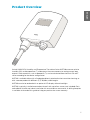 5
5
-
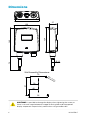 6
6
-
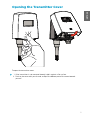 7
7
-
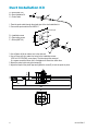 8
8
-
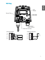 9
9
-
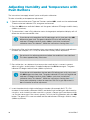 10
10
-
 11
11
-
 12
12
-
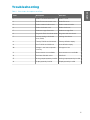 13
13
-
 14
14
-
 15
15
-
 16
16
-
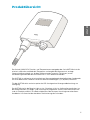 17
17
-
 18
18
-
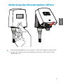 19
19
-
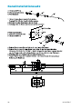 20
20
-
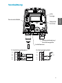 21
21
-
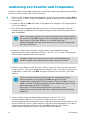 22
22
-
 23
23
-
 24
24
-
 25
25
-
 26
26
-
 27
27
-
 28
28
-
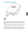 29
29
-
 30
30
-
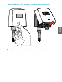 31
31
-
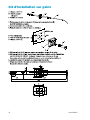 32
32
-
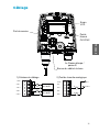 33
33
-
 34
34
-
 35
35
-
 36
36
-
 37
37
-
 38
38
-
 39
39
-
 40
40
-
 41
41
-
 42
42
-
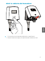 43
43
-
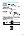 44
44
-
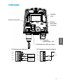 45
45
-
 46
46
-
 47
47
-
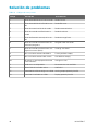 48
48
-
 49
49
-
 50
50
-
 51
51
-
 52
52
-
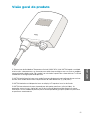 53
53
-
 54
54
-
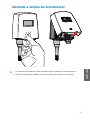 55
55
-
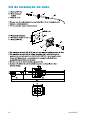 56
56
-
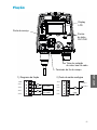 57
57
-
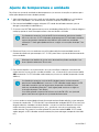 58
58
-
 59
59
-
 60
60
-
 61
61
-
 62
62
-
 63
63
-
 64
64
-
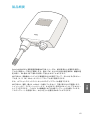 65
65
-
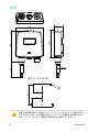 66
66
-
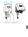 67
67
-
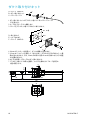 68
68
-
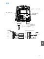 69
69
-
 70
70
-
 71
71
-
 72
72
-
 73
73
-
 74
74
-
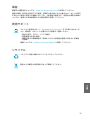 75
75
-
 76
76
-
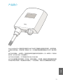 77
77
-
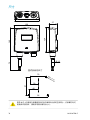 78
78
-
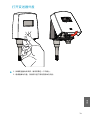 79
79
-
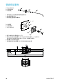 80
80
-
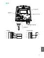 81
81
-
 82
82
-
 83
83
-
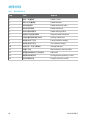 84
84
-
 85
85
-
 86
86
-
 87
87
-
 88
88
-
 89
89
-
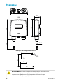 90
90
-
 91
91
-
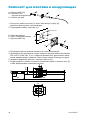 92
92
-
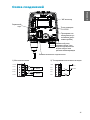 93
93
-
 94
94
-
 95
95
-
 96
96
-
 97
97
-
 98
98
-
 99
99
-
 100
100
-
 101
101
-
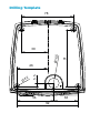 102
102
-
 103
103


En otros idiomas
- français: Vaisala HMT120 Manuel utilisateur
- português: Vaisala HMT120 Manual do usuário
- 日本語: Vaisala HMT120 ユーザーマニュアル
Documentos relacionados
-
Vaisala HMT130 Manual de usuario
-
-
-
-
-
-
-
-
-
