
USER´S MANUAL
BEDIENUNGSANLEITUNG
MANUEL D´UTILISATION
MANUAL DE USUARIO
INSTRUKCJA OBSŁUGI
MANUALE D´USO
U300
®
SERIES
DIVERSITY WIRELESS SYSTEMS

CONTENTS / INHALTSVERZEICHNIS / CONTENU / CONTENIDO / TREŚĆ / CONTENUTO
ENGLISH
PREVENTIVE MEASURES 3
INTRODUCTION 5
CONNECTIONS, OPERATING AND DISPLAY ELEMENTS 6
PIN ALLOCATION FOR MINI XLR CONNECTOR
(POCKET TRANSMITTER) 10
TROUBLESHOOTING 11
OPTIONAL ACCESSORIES 11
TECHNICAL DATA 13
MANUFACTURER’S DECLARATIONS 17
DEUTSCH
SICHERHEITSHINWEISE 18
EINFÜHRUNG 19
ANSCHLÜSSE, BEDIEN- UND ANZEIGEELEMENTE 20
BELEGUNG MINI-XLR-ANSCHLUSS (TASCHENSENDER) 25
FEHLERSUCHE 26
OPTIONALES ZUBEHÖR 26
TECHNISCHE DATEN 28
HERSTELLERERKLÄRUNGEN 32
FRANCAIS
MESURES PRÉVENTIVES 33
INTRODUCTION 34
RACCORDEMENTS, ÉLÉMENTS DE COMMANDE ET
D’AFFICHAGE 35
AFFECTATION DU CONNECTEUR MINI-XLR
(ÉMETTEUR DE POCHE) 40
DIAGNOSTIC DES PANNES 41
ACCESSOIRES DISPONIBLES EN OPTION 41
CARACTÉRISTIQUES TECHNIQUES 43
DÉCLARATIONS DU FABRICANT 47
ESPAÑOL
MEDIDAS DE SEGURIDAD 48
INTRODUCCIÓN 49
CONEXIONES, ELEMENTOS DE MANEJO Y ELEMENTOS
DE VISUALIZACIÓN 50
ASIGNACIÓN DE PINES PARA CONEXIÓN MINI XLR
(TRANSMISOR DE PETACA) 55
BÚSQUEDA DE ERRORES 56
ACCESORIOS OPCIONALES 56
DATOS TÉCNICOS 58
DECLARACIONES DEL FABRICANTE 62
POLSKI
ŚRODKI OSTROŻNOŚCI 63
WPROWADZENIE 64
PRZYŁĄCZA, ELEMENTY OBSŁUGI I WSKAŹNIKI 65
SCHEMAT ZŁĄCZA MINI XLR (NADAJNIK KIESZONKOWY) 70
ZNAJDOWANIE BŁĘDU 71
AKCESORIA OPCJONALNE 71
DANE TECHNICZNE 73
OŚWIADCZENIA PRODUCENTA 78
ITALIANO
MISURE PRECAUZIONALI 79
INTRODUZIONE 80
CONNETTORI, ELEMENTI DI COMANDO E DI VISUALIZZAZIONE 81
CONFIGURAZIONE DEL COLLEGAMENTO MINI XLR
(TRASMETTITORE TASCABILE) 86
RICERCA ERRORI 87
ACCESSORI OPZIONALI 87
DATI TECNICI 89
DICHIARAZIONI DEL PRODUTTORE 94

3
DEUTSCHFRANCAIS
ESPAÑOL
ENGLISH
ITALIANO POLSKI
ENGLISH
YOU‘VE MADE THE RIGHT CHOICE!
We have designed this product to operate reliably over many years. LD Systems stands for this with its name and many years of experience as a
manufacturer of high-quality audio products. Please read this User‘s Manual carefully, so that you can begin making optimum use of your LD
Systems product quickly. You can nd more information about LD-SYSTEMS at our Internet site WWW.LD-SYSTEMS.COM
PREVENTIVE MEASURES
1. Please read these instructions carefully.
2. Keep all information and instructions in a safe place.
3. Follow the instructions.
4. Observe all safety warnings. Never remove safety warnings or other information from the equipment.
5. Use the equipment only in the intended manner and for the intended purpose.
6. Use only sufciently stable and compatible stands and/or mounts (for xed installations). Make certain that wall mounts are properly installed and
secured. Make certain that the equipment is installed securely and cannot fall down.
7. During installation, observ e the applicable safety regulations for your country.
8. Never install and operate the equipment near radiators, heat registers, ovens or other sources of heat. Make certain that the equipment is always installed
so that is cooled sufciently and cannot overheat.
9. Never place sources of ignition, e.g., burning candles, on the equipment.
10. Ventilation slits must not be blocked.
11. Keep a minimum distance of 20 cm around and above the device.
12. Do not use this equipment in the immediate vicinity of water (does not apply to special outdoor equipment - in this case, observe the special
instructions noted below. Do not expose this equipment to ammable materials, uids or gases. Avoid direct sunlight!
13. Make certain that dripping or splashed water cannot enter the equipment. Do not place containers lled with liquids, such as vases or drinking
vessels, on the equipment.
14. Make certain that objects cannot fall into the device.
15. Use this equipment only with the accessories recommended and intended by the manufacturer.
16. Do not open or modify this equipment.
17. After connecting the equipment, check all cables in order to prevent damage or accidents, e.g., due to tripping hazards.
18. During transport, make certain that the equipment cannot fall down and possibly cause property damage and personal injuries.
19. If your equipment is no longer functioning properly, if uids or objects have gotten inside the equipment or if it has been damaged in anot her way,
switch it off immediately and unplug it from the mains outlet (if it is a powered device). This equipment may only be repaired by authorized, qualied
personnel.
20. Clean the equipment using a dry cloth.
21. Comply with all applicable disposal laws in your country. During disposal of packaging, please separate plastic and paper/cardboard.
22. Plastic bags must be kept out of reach of children.
23. Please note that changes or modications not expressly approved by the party responsible for compliance could void the user´s authority to
operate the equipment.
FOR EQUIPMENT THAT CONNECTS TO THE POWER MAINS
24. CAUTION: If the power cord of the device is equipped with an earthing contact, then it must be connected to an outlet with a protective ground.
Never deactivate the protective ground of a power cord.
25. If the equipment has been exposed to strong uctuations in temperature (for example, after transport), do not switch it on immediately. Mois-
ture and condensation could damage the equipment. Do not switch on the equipment until it has reached room temperature.
26. Before connecting the equipment to the power outlet, rst verify that the mains voltage and frequency match the values specied on the equip-
ment. If the equipment has a voltage selection switch, connect the equipment to the power outlet only if the equipment values and the mains
power values match. If the included power cord or power adapter does not t in your wall outlet, contact your electrician.
27. Do not step on the power cord. Make certain that the power cable does not become kinked, especially at the mains outlet and/or power adapter
and the equipment connector.
28. When connecting the equipment, make certain that the power cord or power adapter is always freely accessible. Always disconnect the equip-
ment from the power supply if the equipment is not in use or if you want to clean the equipment. Always unplug the power cord and power adapter
from the power outlet at the plug or adapter and not by pulling on the cord. Never touch the power cord and power adapter with wet hands.
29. Whenever possible, avoid switching the equipment on and off in quick succession because otherwise this can shorten the useful life of the
equipment.
30. IMPORTANT INFORMATION: Replace fuses only with fuses of the same type and rating. If a fuse blows repeatedly, please contact an authorised
service centre.
31. To disconnect the equipment from the power mains completely, unplug the power cord or power adapter from the power outlet.
32. If your device is equipped with a Volex power connector, the mating Volex equipment connector must be unlocked before it can be removed. Howe-
ver, this also means that the equipment can slide and fall down if the power cable is pulled, which can lead to personal injuries and/or other damage.
For this reason, always be careful when laying cables.
33. Unplug the power cord and power adapter from the power outlet if there is a risk of a lightning strike or before extended periods of disuse.

4
ITALIANO
POLSKI
ESPAÑOL
FRANCAIS
DEUTSCHENGLISH
CAUTION:
To reduce the risk of electric shock, do not remove cover (or back). There are no user serviceable parts inside.
Maintenance and repairs should be exclusively carried out by qualied service personnel.
The warning triangle with lightning symbol indicates dangerous uninsulated voltage inside the unit, which may cause an electrical
shock.
The warning triangle with exclamation mark indicates important operating and maintenance instructions.
Warning! This symbol indicates a hot surface. Certain parts of the housing can become hot during operation. After use, wait for a
cool-down period of at least 10 minutes before handling or transporting the device.
Warning! This device is designed for use below 2000 metres in altitude.
Warning! This product is not intended for use in tropical climates.
CAUTION! HIGH VOLUMES IN AUDIO PRODUCTS!
This device is meant for professional use. Therefore, commercial use of this equipment is subject to the respectively applicable national accident
prevention rules and regulations. As a manufacturer, Adam Hall is obligated to notify you formally about the existence of potential health risks.
Hearing damage due to high volume and prolonged exposure: When in use, this product is capable of producing high sound-pressure levels (SPL)
that can lead to irreversible hearing damage in performers, employees, and audience members. For this reason, avoid prolonged exposure to
volumes in excess of 90 dB.
NOTE: This equipment has been tested and found to comply with the limits for a Class B digital device, pursuant to Part 15 of the FCC
Rules. These limits are designed to provide reasonable protection against harmful interference in a residential installation. This equipment
generates, uses and can radiate radio frequency energy and, if not installed and used in accordance with the instructions, may cause
harmful interference to radio communications. However, there is no guarantee that interference will not occur in a particular installation. If
this equipment does cause harmful interference to radio or television reception, which can be determined by turning the equipment off and
on, the user is encouraged to try to correct the interference by one or more of the following measures:
- Reorient or relocate the receiving antenna.
- Increase the separation between the equipment and receiver.
- Connect the equipment into an outlet on a circuit different from that to which the receiver is connected.
- Consult the dealer or an experienced radio/TV technician for help.

5
DEUTSCHFRANCAIS
ESPAÑOL
ENGLISH
ITALIANO POLSKI
INTRODUCTION
Developed in Germany, the UHF Diversity wireless systems from the U300® series deliver excellent audio performance. They achieve a range of 100
meters in ideal conditions and are available in 5 frequency bands. Up to six U300® systems can be used simultaneously for each frequency band.
Convenient one-touch synchronisation of transmitter and receiver via infrared facilitates fast, trouble-free wireless connection and the squelch function
with pilot tone ensures fail-safe operation.
• Available with hand or pocket transmitter
• ASC infrared frequency synchronisation
• Fail-safe operation provided by pilot tone
• 12 channels
• Up to 6 systems can be used simultaneously (up to 3 twin receivers)
• Belt-pack transmitter with gain control and status LED
• Dynamic hand-held microphone with status LED
• U500® microphone heads also suitable for U300® hand-held transmitter
• Long battery life
• Available in the following frequencies:
470 - 490 MHz (LDU3047)
514 - 542 MHz (LDU3051)
584 - 608 MHz (LDU305)
655 - 679 MHz (LDU306)
823 - 832 MHz and 863–865 MHz (LDU308)
Please note: The use of the wireless microphone system may require a license, depending on the country of use. For detailed information please
contact the relevant authority in your country.
Pilot tone
The pilot tone function protects a wireless microphone system against interference, for example, unwanted signals from other radio transmission
systems. The transmitter adds a second, inaudible signal (the pilot tone) to the actual signal which is to be transmitted. The receiver identies it as
the matching pilot tone and frees the associated signal. Signals without a matching pilot tone remain muted.
Included
LDU30xHHD: Receiver plus hand-held transmitter with dynamic capsule (cardioid), power supply, 2 x AA batteries, audio cable, manual
LDU30xBPH: Receiver plus pocket transmitter and headset (black), power supply, 2 x AA batteries, audio cable, manual
LDU30xBPG: Receiver plus pocket transmitter and guitar cable, power supply, 2 x AA batteries, audio cable, manual
LDU30xBPL: Receiver plus pocket transmitter and Lavalier microphone, power supply, 2 x AA batteries, audio cable, manual
LDU30xBPW: Receiver plus pocket transmitter and clip-on microphone for wind instruments, power supply, 2 x AA batteries, audio cable, manual
LDU30xHHD2: Twin receiver plus 2 x hand-held transmitters with dynamic capsules (cardioid), power supply, 4 x AA batteries, 2 x audio cables, rack kit, manual
LDU30xBPH2: Twin receiver plus 2 x pocket transmitters and 2 x headsets (black), power supply, 4 x AA batteries, 2 x audio cables, rack kit, manual

6
ITALIANO
POLSKI
ESPAÑOL
FRANCAIS
DEUTSCHENGLISH
9
1
22
33 77
55
66
44
9
88
9
1 2
3 7 5
6
4
9
8
1
POWER
On/off switch. Press and hold the button for approximately 1 seconds to turn the device on or off.
2
CHANNEL DISPLAY
Illuminated LC display to show the radio channel.
3
CHANNEL + / -
Push buttons to select the radio channel 01 to 12. To establish a wireless connection between the transmitter and the receiver, the radio frequency
on both receivers must match (synchronisation process as described under point 6. ASC).
Note: Both receivers cannot be set to the same radio channel on the twin receiver.
4
VOL
Rotary knob to adjust the output volume.
5
IR INTERFACE
Infrared interface for synchronising the receiver’s radio channel with the transmitter.
6
ASC
To synchronise the transmitter with the radio channel set in the receiver, position the infra-red port of the transmitter directly in line with the infra-red
interface of the receiver and switch on the transmitter and receiver (distance about 10 cm, IR interface of the hand transmitter is below the status LED,
IR interface of the pocket transmitter on the front side). Now press the ASC button to start the synchronisation process. A red LED indicator will light up
in the window of the IR interface during the process. After a few seconds, the process is completed and one of the LED indicators ANTENNA A and B will
light up (= wireless connection exists).
7
LEVEL INDICATOR
5-segment LED chain to display the audio signal level.
CONNECTIONS, OPERATING AND DISPLAY ELEMENTS
RECEIVER

7
DEUTSCHFRANCAIS
ESPAÑOL
ENGLISH
ITALIANO POLSKI
11
10
12 15 1217
1613 13
14 14
11
10
12
13
14
8
ANTENNA A - B
Indicator LEDs for the antenna systems A and B. The antenna system with the stronger radio signal is activated and the corresponding indicator LED
lights up.
9
RECEPTION ANTENNAS A - B
For optimum reception, please position the antennas in an upward-facing V-position.
10
DC SOCKET
Low-voltage socket for the power supply to the device. Please use only the supplied mains adapter.
11
CABLE STRAIN-RELIEF
Cable strain relief for power adapter cable.
12
UNBALANCED OUTPUT
Unbalanced audio output via 6.3mm jack socket.
13
INSTRUMENT/LINE (UNBALANCED OUTPUT)
Switch for level and impedance-matching to instruments or line inputs of an amplier or mixer. Using a suitable tool (e.g. a ballpoint pen), push the
switch into the depressed INSTRUMENT position for connection to the input of an instrument amplier (guitar or bass amp) and for connection to
the line-input of a mixer or amplier, select the non-depressed position LINE.
14
BALANCED OUTPUT
Balanced audio output via 3-pin XLR jack.
15
UNBALANCED OUTPUT MIX OUT
Unbalanced audio output via 6.3mm jack socket (twin receiver only, mix of signals from channels 1 and 2).
16
INSTRUMENT/LINE MIX OUT (UNBALANCED OUTPUT)
Switch for adjusting the level and impedance of the jack output to the instrument or line inputs of an amplier or mixer. Using a suitable tool (e.g. a
ballpoint pen), push the switch into the depressed INSTRUMENT position for connecting the receiver to the input of an instrument amplier (guitar
or bass amp). To connect to the line-input of a mixer or amplier, select the non-depressed position LINE.

8
ITALIANO
POLSKI
ESPAÑOL
FRANCAIS
DEUTSCHENGLISH
23
22
19
20
21
18
18
MICROPHONE HEAD
The microphone head is interchangeable, the hand-held transmitter is compatible with the microphone heads from the LD U500® series, available
separately.
19
ON / OFF
On/off switch. Move the switch to the ON position to turn on the hand-held transmitter, and to the OFF position to turn it off.
20
STATUS LED
If the charge status of the batteries is sufcient, the LED lights up green when the hand transmitter is switched on. If the LED lights up red, the charge
status is weak. In this case, replace the batteries (2 x AA/LR6 type, alkaline). During the synchronisation process, the LED ashes green and amber.
21
IR INTERFACE
Infra-red interface for synchronising the radio channel from receiver and transmitter.
22
BATTERY COMPARTMENT COVER
To replace the batteries, open the hand transmitter battery compartment by rotating it anti-clockwise and pulling it from the housing. Remove the used
batteries and replace with new batteries (AA), following the diagram in the battery compartment. Replace the battery compartment cover and rotate it
clockwise to close the battery compartment. If the transmitter is not used for a long period, remove the batteries to avoid damage to the transmitter from
leaking batteries.
23
BATTERY COMPARTMENT
Battery compartment for two AA batteries. Please use only leak-proof brand products.
HAND-HELD TRANSMITTER
17
BALANCED OUTPUT MIX OUT
Balanced audio output via 3-pole XLR socket (twin receiver only, mix of signals from channels 1 and 2).

9
DEUTSCHFRANCAIS
ESPAÑOL
ENGLISH
ITALIANO POLSKI
25
24
29
27
26
28
30
POCKET TRANSMITTER
24
ANTENNA
Pocket transmitter antenna. For optimum reception, do not cover or kink.
25
IR INTERFACE
Infra-red interface for synchronising the radio channel from receiver and transmitter.
26
INPUT
3-pin mini XLR socket to connect a headset, Lavalier or instrument microphone and guitar cable.
27
ON / STANDBY / OFF
Switch to activate or deactivate the pocket transmitter (ON = transmitter is switched on, OFF = transmitter is switched off). In the STANDBY position,
the transmitter is in operation but the audio signal is muted.
28
STATUS LED
If the charge status of the batteries is sufcient, the LED lights up green when the pocket transmitter is switched on. If the LED lights up red, the charge
status is weak. In this case, replace the batteries (2 x AA/LR6 type, alkaline). During the synchronisation process, the LED ashes green and amber.
29
MIC / 0dB / -10dB
For setting the input sensitivity. Adjust the sensitivity so that an active signal (speech, vocals, guitar...) causes the amber-coloured level-LED on the
receiver to light up. If the red PEAK LED lights up or ashes, reduce the sensitivity on the 3-position switch MIC/0dB/-10dB to the next lower value to
prevent otherwise unwanted distortion. (Examples: Headset = MIC, guitar with passive pickups = 0dB, guitar with active pickups = -10dB).
30
BATTERY COMPARTMENT
To replace the batteries, open the battery compartment of the pocket transmitter by simultaneously pressing both markers on the sides of the battery
cover and opening it forwards. Remove the used batteries and replace with new batteries (AA/LR6, alkaline), following the diagram in the battery
compartment. Replace the battery compartment cover on the housing and click it into place. If the transmitter is not used for a long period, remove the
batteries to avoid damage to the transmitter from leaking batteries.

10
ITALIANO
POLSKI
ESPAÑOL
FRANCAIS
DEUTSCHENGLISH
ATTACHING THE POCKET TRANSMITTER
Attach the transmitter to a belt or strap as shown.
1
2
3
MINI-XLR
sleeve tip
6,3 mm jack
1
2
3
MINI-XLR
1
2
3
MINI-XLR
R
2,2k
PIN ALLOCATION FOR MINI XLR CONNECTOR (POCKET TRANSMITTER)
Guitar, bass and other high-impedance signal sources.
Condenser microphone with internal pull-up resistor.
Condenser microphone without internal pull-up resistor.

11
DEUTSCHFRANCAIS
ESPAÑOL
ENGLISH
ITALIANO POLSKI
TROUBLESHOOTING
PROBLEM SYMPTOM SOLUTION
No audio signal or level
too low
Receiver: No reception displayed on either antenna
A or B.
Check if the transmitter is turned on.
Check the batteries in the transmitter.
Receiver: Display lighting is switched off Check the power supply for the receiver and whether
the receiver is switched on.
Receiver: No reception displayed on either antenna
A or B.
Transmitter: Device is switched on. Charge status of the
batteries is ok.
Check whether radio frequency of the transmitter and
the receiver are matching.
Reduce the distance between transmitter and receiver.
Ensure that there is a direct line of sight between the
transmitter and the receiver.
Ensure that the antennas on the receiver are posi-
tioned in an upward V-shape.
Receiver: Reception on antenna A or B is displayed. Increase the signal level or increase the input sensitivi-
ty on the pocket transmitter.
Distortion and interference Receiver: Radio signal is displayed Remove possible sources of interference (digital
devices, other radio systems).
Distorted sound Transmitter: Status LED is lit up red.
Receiver: Peak LED on the receiver is lit.
Replace the batteries in the transmitter.
Reduce the signal level or reduce the input sensitivity
on the pocket transmitter.
OPTIONAL ACCESSORIES
LDU500CH – microphone head with condenser capsule and hypercardioid pickup pattern (for hand-held transmitters, matt black)
LDU500DH – microphone head with dynamic capsule and hypercardioid pickup pattern (for hand-held transmitters, matt black)
LDU500CC – microphone head with condenser capsule and cardioid pickup pattern (for hand-held transmitters, matt silver)
LDU500DC – microphone head with dynamic capsule and cardioid pickup pattern (for hand-held transmitters, matt silver)
LDWS100MH3 – beige-coloured headset with condenser microphone (for pocket transmitters)
LDWS100MH1 – black headset with condenser microphone (for pocket transmitters)
LDWS1000MW – clip microphone for wind instruments (for pocket transmitters)
LDWS100ML – Lavalier microphone (for pocket transmitters)
LDWS100GC – guitar cable (for pocket transmitters)
LDU300RK – 19" rack mounting kit for the installation of a single receiver (2 rack-mount brackets, 2 caps and 1 set of screws included).

12
ITALIANO
POLSKI
ESPAÑOL
FRANCAIS
DEUTSCHENGLISH
1 2 3
LDU500RK2 – 19" rack mounting kit for the installation of two single receivers (2 rack-mount brackets, 2 connectors and 1 set of screws included).
Installation
1. Attach connectors (receiver A on the right-hand side, receiver B on the left-hand side).
2. Screw both receivers together.
3. Attach brackets (receiver A on the left-hand side, receiver B on the right-hand side).
LDU300RK2 – 19” rack mounting kit for the installation of a dual receiver (includes blanking plugs and mounting screws).

13
DEUTSCHFRANCAIS
ESPAÑOL
ENGLISH
ITALIANO POLSKI
RECEIVER
Itemnumber: LDU3047R LDU3051R LDU305R LDU306R LDU308R
Receiver type: UHF diversity UHF diversity UHF diversity UHF diversity UHF diversity
Modulation: FM FM FM FM FM
Frequency range: 470 - 490 MHz 514 - 542 MHz 584–608 MHz 655–679 MHz 823–832 MHz &
863–865 MHz
Channels: 12 12 12 12 12
Antenna connectors: 2 x xed antennas 2 x xed antennas 2 x xed antennas 2 x xed antennas 2 x xed antennas
Frequency response: 25–16000 Hz 25–16000 Hz 25–16000 Hz 25–16000 Hz 25–16000 Hz
Noise reduction: Squelch, xed level Squelch, xed level Squelch, xed level Squelch, xed level Squelch, xed level
THD (system): <0.3% <0.3% <0.3% <0.3% <0.3%
Signal-to-noise ratio
(system):
>104dB >104dB >104dB >104dB >104dB
Balanced output: XLR XLR XLR XLR XLR
Unbalanced output: 6.3 mm jack 6.3 mm jack 6.3 mm jack 6.3 mm jack 6.3 mm jack
Audio output level
(balanced):
+10dBu +10dBu +10dBu +10dBu +10dBu
Audio output level
(unbalanced):
+7dBV/+2.5dBV
(switchable line/
instrument)
+7dBV/+2.5dBV
(switchable line/
instrument)
+7dBV/+2.5dBV
(switchable line/
instrument)
+7dBV/+2.5dBV
(switchable line/
instrument)
+7dBV/+2.5dBV
(switchable line/
instrument)
Controls: POWER, + / - channel
select, ASC, VOL vol-
ume control, switch
INSTRUMENT/LINE
POWER, + / - channel
select, ASC, VOL vol-
ume control, switch
INSTRUMENT/LINE
POWER, + / - channel
select, ASC, VOL vol-
ume control, switch
INSTRUMENT/LINE
POWER, + / - channel
select, ASC, VOL vol-
ume control, switch
INSTRUMENT/LINE
POWER, + / - channel
select, ASC, VOL vol-
ume control, switch
INSTRUMENT/LINE
Indicators: 2 digit LC display,
5-segment LED level
meter, antenna A/B
LEDs
2 digit LC display,
5-segment LED level
meter, antenna A/B
LEDs
2 digit LC display,
5-segment LED level
meter, antenna A/B
LEDs
2 digit LC display,
5-segment LED level
meter, antenna A/B
LEDs
2 digit LC display,
5-segment LED level
meter, antenna A/B
LEDs
Operating voltage: 12V DC, 500 mA 12V DC, 500 mA 12V DC, 500 mA 12V DC, 500 mA 12V DC, 500 mA
Ambient temperature
(in operation):
5°C to 40°C 5°C to 40°C 5°C to 40°C 5°C to 40°C 5°C to 40°C
Relative humidity: 20% to 80%
(non-condensing)
20% to 80%
(non-condensing)
20% to 80%
(non-condensing)
20% to 80%
(non-condensing)
20% to 80%
(non-condensing)
Dimensions
(W x H x D):
211 x 43 x 120 mm 211 x 43 x 120 mm 211 x 43 x 120 mm 211 x 43 x 120 mm 211 x 43 x 120 mm
Weight: 0.7 kg 0.7 kg 0.7 kg 0.7 kg 0.7 kg
Accessories included: power adapter power adapter power adapter power adapter power adapter
Features: infra-red frequency
synchronisation,
pilot tone
infra-red frequency
synchronisation,
pilot tone
infra-red frequency
synchronisation,
pilot tone
infra-red frequency
synchronisation,
pilot tone
infra-red frequency
synchronisation,
pilot tone
TECHNICAL DATA

14
ITALIANO
POLSKI
ESPAÑOL
FRANCAIS
DEUTSCHENGLISH
DUAL RECEIVER
Itemnumber: LDU3047R2 LDU3051R2 LDU305R2 LDU306R2 LDU308R2
Receiver type: UHF diversity UHF diversity UHF diversity UHF diversity UHF diversity
Modulation: FM FM FM FM FM
Frequency range: 470 - 490 MHz 514 - 542 MHz 584–608 MHz 655–679 MHz 823–832 MHz &
863–865 MHz
Channels: 12 12 12 12 12
Antenna connectors: 2 x xed antennas 2 x xed antennas 2 x xed antennas 2 x xed antennas 2 x xed antennas
Frequency response: 25–16000 Hz 25–16000 Hz 25–16000 Hz 25–16000 Hz 25–16000 Hz
Noise reduction: Squelch, xed level Squelch, xed level Squelch, xed level Squelch, xed level Squelch, xed level
THD (system): <0.3% <0.3% <0.3% <0.3% <0.3%
Signal-to-noise ratio
(system):
>104dB >104dB >104dB >104dB >104dB
Balanced output: 2x XLR 2x XLR 2x XLR 2x XLR 2x XLR
Unbalanced output: 2x 6.3 mm jack 2x 6.3 mm jack 2x 6.3 mm jack 2x 6.3 mm jack 2x 6.3 mm jack
Balanced output
MIX OUT:
XLR XLR XLR XLR XLR
Unbalanced output
MIX OUT:
6.3 mm jack 6.3 mm jack 6.3 mm jack 6.3 mm jack 6.3 mm jack
Audio output level
(balanced):
+10dBu +10dBu +10dBu +10dBu +10dBu
Audio output level
(unbalanced):
+7dBV/+2.5dBV
(switchable line/
instrument)
+7dBV/+2.5dBV
(switchable line/
instrument)
+7dBV/+2.5dBV
(switchable line/
instrument)
+7dBV/+2.5dBV
(switchable line/
instrument)
+7dBV/+2.5dBV
(switchable line/
instrument)
Controls: POWER, 2x + / -
channel select, 2x
ASC, 2x VOL Volume
control, 2x switch
INSTRUMENT/LINE
POWER, 2x + / -
channel select, 2x
ASC, 2x VOL Volume
control, 2x switch
INSTRUMENT/LINE
POWER, 2x + / -
channel select, 2x
ASC, 2x VOL Volume
control, 2x switch
INSTRUMENT/LINE
POWER, 2x + / -
channel select, 2x
ASC, 2x VOL Volume
control, 2x switch
INSTRUMENT/LINE
POWER, 2x + / -
channel select, 2x
ASC, 2x VOL Volume
control, 2x switch
INSTRUMENT/LINE
Indicators: 2x 2 digit LC display,
2x 5-segment LED
level meter, 2x
antenna A / B LEDs
2x 2 digit LC display,
2x 5-segment LED
level meter, 2x
antenna A / B LEDs
2x 2 digit LC display,
2x 5-segment LED
level meter, 2x
antenna A / B LEDs
2x 2 digit LC display,
2x 5-segment LED
level meter, 2x
antenna A / B LEDs
2x 2 digit LC display,
2x 5-segment LED
level meter, 2x
antenna A / B LEDs
Operating voltage: 12V DC, 500 mA 12V DC, 500 mA 12V DC, 500 mA 12V DC, 500 mA 12V DC, 500 mA
Ambient temperature
(in operation):
5°C to 40°C 5°C to 40°C 5°C to 40°C 5°C to 40°C 5°C to 40°C
Relative humidity: 20% to 80%
(non-condensing)
20% to 80%
(non-condensing)
20% to 80%
(non-condensing)
20% to 80%
(non-condensing)
20% to 80%
(non-condensing)
Dimensions
(W x H x D):
410 x 43 x 120mm 410 x 43 x 120mm 410 x 43 x 120mm 410 x 43 x 120mm 410 x 43 x 120mm
Weight: 1.3 kg 1.3 kg 1.3 kg 1.3 kg 1.3 kg

15
DEUTSCHFRANCAIS
ESPAÑOL
ENGLISH
ITALIANO POLSKI
HAND-HELD TRANSMITTER
Item number: LDU3047MD LDU3051MD LDU305MD LDU306MD LDU308MD
Modulation: FM FM FM FM FM
Frequency range: 470 - 490 MHz 514 - 542 MHz 584–608 MHz 655–679 MHz 823–832 MHz &
863–865 MHz
Channels: 12 12 12 12 12
Microphone type: Dynamic Dynamic Dynamic Dynamic Dynamic
Polar pattern: Cardioid Cardioid Cardioid Cardioid Cardioid
Frequency response: 55–16000 Hz 55–16000 Hz 55–16000 Hz 55–16000 Hz 55–16000 Hz
RF output power: 10 mW PEP 10 mW PEP 10 mW PEP 10 mW PEP 10 mW PEP
Antenna gain: 0.5 dBi 0.5 dBi 0.5 dBi 0.5 dBi 0.5 dBi
Controls: Power on/off Power on/off Power on/off Power on/off Power on/off
Indicators: Status LED Status LED Status LED Status LED Status LED
Power supply: 2 x AA batteries 2 x AA batteries 2 x AA batteries 2 x AA batteries 2 x AA batteries
Operating time: up to 10 h
(depending on
batteries)
up to 10 h
(depending on
batteries)
up to 10 h
(depending on
batteries)
up to 10 h
(depending on
batteries)
up to 10 h
(depending on
batteries)
Ambient temperature
(in operation):
5°C to 40°C 5°C to 40°C 5°C to 40°C 5°C to 40°C 5°C to 40°C
Relative humidity: 20% to 80%
(non-condensing)
20% to 80%
(non-condensing)
20% to 80%
(non-condensing)
20% to 80%
(non-condensing)
20% to 80%
(non-condensing)
Dimensions (L x Ø): 257 x 50 mm 257 x 50 mm 257 x 50 mm 257 x 50 mm 257 x 50 mm
Weight
(without batteries):
0.235 kg 0.235 kg 0.235 kg 0.235 kg 0.235 kg
Accessories included: 2 x AA batteries 2 x AA batteries 2 x AA batteries 2 x AA batteries 2 x AA batteries
Features: infra-red frequency
synchronisation,
pilot tone,
microphone head
interchangeable
infra-red frequency
synchronisation,
pilot tone,
microphone head
interchangeable
infra-red frequency
synchronisation,
pilot tone,
microphone head
interchangeable
infra-red frequency
synchronisation,
pilot tone,
microphone head
interchangeable
infra-red frequency
synchronisation,
pilot tone,
microphone head
interchangeable
BODY PACK TRANSMITTER
Item number: LDU3047BP LDU3051BP LDU305BP LDU306BP LDU308BP
Modulation: FM FM FM FM FM
Frequency range: 470 - 490 MHz 514 - 542 MHz 584–608 MHz 655–679 MHz 823–832 MHz &
863–865 MHz
Accessories included: Power adapter,
audio cable, rack kit
Power adapter,
audio cable, rack kit
Power adapter,
audio cable, rack kit
Power adapter,
audio cable, rack kit
Power adapter,
audio cable, rack kit
Features: Infrared frequency
synchronisation,
pilot tone
Infrared frequency
synchronisation,
pilot tone
Infrared frequency
synchronisation,
pilot tone
Infrared frequency
synchronisation,
pilot tone
Infrared frequency
synchronisation,
pilot tone

16
ITALIANO
POLSKI
ESPAÑOL
FRANCAIS
DEUTSCHENGLISH
MICROPHONES FOR BODY PACK TRANSMITTER
Item number: LDWS100MH1 LDWS100ML LDWS1000MW
Microphone type: Headset Lavalier
microphone
Wind instrument
microphone
Capsule: Back-electret
condenser
Back-electret
condenser
Back-electret
condenser
Polar pattern: Cardioid Cardioid Cardioid
Frequency response: 20–20000 Hz 20–20000 Hz 20–18000 Hz
Connector: 3-pin mini-XLR 3-pin mini-XLR 3-pin mini-XLR
Accessories included: Foam windscreen Foam windscreen Foam windscreen
Channels: 12 12 12 12 12
Input: 3-pin mini-XLR
(low-Z + phantom
power/high-Z)
3-pin mini-XLR
(low-Z + phantom
power/high-Z)
3-pin mini-XLR
(low-Z + phantom
power/high-Z)
3-pin mini-XLR
(low-Z + phantom
power/high-Z)
3-pin mini-XLR
(low-Z + phantom
power/high-Z)
Frequency response: 25–16,000 Hz 25–16,000 Hz 25–16,000 Hz 25–16,000 Hz 25–16,000 Hz
RF output power: 10 mW PEP 10 mW PEP 10 mW PEP 10 mW PEP 10 mW PEP
Antenna gain: 0.5 dBi 0.5 dBi 0.5 dBi 0.5 dBi 0.5 dBi
Controls: ON/STANDBY/OFF,
MIC/0/-10
ON/STANDBY/OFF,
MIC/0/-10
ON/STANDBY/OFF,
MIC/0/-10
ON/STANDBY/OFF,
MIC/0/-10
ON/STANDBY/OFF,
MIC/0/-10
Indicators: Status LED Status LED Status LED Status LED Status LED
Power supply: 2 x AA batteries 2 x AA batteries 2 x AA batteries 2 x AA batteries 2 x AA batteries
Operating time: Up to 10 h
(depending on
batteries)
Up to 10 h
(depending on
batteries)
Up to 10 h
(depending on
batteries)
Up to 10 h
(depending on
batteries)
Up to 10 h
(depending on
batteries)
Ambient temperature
(in operation):
5°C to 40°C 5°C to 40°C 5°C to 40°C 5°C to 40°C 5°C to 40°C
Relative humidity: 20% to 80%
(non-condensing)
20% to 80%
(non-condensing)
20% to 80%
(non-condensing)
20% to 80%
(non-condensing)
20% to 80%
(non-condensing)
Dimensions
(W x H x D):
65 x 91 x 25 mm 65 x 91 x 25 mm 65 x 91 x 25 mm 65 x 91 x 25 mm 65 x 91 x 25 mm
Weight
(without batteries):
0.085 kg 0.085 kg 0.085 kg 0.085 kg 0.085 kg
Accessories included: 2 x AA batteries 2 x AA batteries 2 x AA batteries 2 x AA batteries 2 x AA batteries
Features: infra-red frequency
synchronisation,
pilot tone
infra-red frequency
synchronisation,
pilot tone
infra-red frequency
synchronisation,
pilot tone
infra-red frequency
synchronisation,
pilot tone
infra-red frequency
synchronisation,
pilot tone

17
DEUTSCHFRANCAIS
ESPAÑOL
ENGLISH
ITALIANO POLSKI
GUITAR CABLE FOR BODY PACK TRANSMITTER
Item number: LDWS100GC
Connector 1: 3-pin mini-XLR
Connector 2: 6.3 mm jack
Cable length: 1.5 m
MANUFACTURER´S DECLARATIONS
MANUFACTURER‘S WARRANTY & LIMITATIONS OF LIABILITY
You can nd our current warranty conditions and limitations of liability at: https://cdn-shop.adamhall.com/media/pdf/MANUFACTURERS-DECLARA-
TIONS_LD_SYSTEMS.pdf To request warranty service for a product, please contact Adam Hall GmbH, Adam-Hall-Str. 1,
61267 Neu Anspach / Email: [email protected] / +49 (0)6081 / 9419-0.
CORRECT DISPOSAL OF THIS PRODUCT
(valid in the European Union and other European countries with a differentiated waste collection system)
This symbol on the product, or on its documents indicates that the device may not be treated as household waste. This is to avoid environ-
mental damage or personal injury due to uncontrolled waste disposal. Please dispose of this product separately from other waste and have it
recycled to promote sustainable economic activity. Household users should contact either the retailer where they purchased this product, or their
local government ofce, for details on where and how they can recycle this item in an environmentally friendly manner. Business users should
contact their supplier and check the terms and conditions of the purchase contract. This product should not be mixed with other commercial waste
for disposal.
FCC STATEMENT
This device complies with Part 15 of the FCC Rules. Operation is subject to the following two conditions:
(1) This device may not cause harmful interference, and
(2) This device must accept any interference received, including interference that may cause undesired operation
CE Compliance
Adam Hall GmbH states that this product meets the following guidelines (where applicable):
R&TTE (1999/5/EC) or RED (2014/53/EU) from June 2017
Low voltage directive (2014/35/EU)
EMV directive (2014/30/EU)
RoHS (2011/65/EU)
The complete declaration of conformity can be found at www.adamhall.com.
Furthermore, you may also direct your enquiry to [email protected].
EU DECLARATION OF CONFORMITY
Hereby, Adam Hall GmbH declares that this radio equipment type is in compliance with Directive 2014/53/EU.
The full text of the EU declaration of conformity is available at the following
internet address: www.adamhall.com/compliance/
NOTE: This equipment has been tested and found to comply with the limits for a Class B digital device, pursuant to Part 15 of the FCC
Rules. These limits are designed to provide reasonable protection against harmful interference in a residential installation. This equipment
generates, uses and can radiate radio frequency energy and, if not installed and used in accordance with the instructions, may cause
harmful interference to radio communications. However, there is no guarantee that interference will not occur in a particular installation. If
this equipment does cause harmful interference to radio or television reception, which can be determined by turning the equipment off and
on, the user is encouraged to try to correct the interference by one or more of the following measures:
- Reorient or relocate the receiving antenna.
- Increase the separation between the equipment and receiver.
- Connect the equipment into an outlet on a circuit different from that to which the receiver is connected.
- Consult the dealer or an experienced radio/TV technician for help.

18
ITALIANO
POLSKI
ESPAÑOL
FRANCAIS
DEUTSCHENGLISH
DEUTSCH
SIE HABEN DIE RICHTIGE WAHL GETROFFEN!
Dieses Gerät wurde unter hohen Qualitätsanforderungen entwickelt und gefertigt, um viele Jahre einen reibungslosen Betrieb zu gewährleisten. Dafür
steht LD Systems mit seinem Namen und der langjährigen Erfahrung als Hersteller hochwertiger Audioprodukte. Bitte lesen Sie diese Bedienungsanlei-
tung sorgfältig, damit Sie Ihr neues Produkt von LD Systems schnell optimal einsetzen können.
Mehr Informationen zu LD SYSTEMS nden Sie auf unserer Internetseite WWW.LD-SYSTEMS.COM
SICHERHEITSHINWEISE
1. Lesen Sie diese Anleitung bitte sorgfältig durch.
2. Bewahren Sie alle Informationen und Anleitungen an einem sicheren Ort auf.
3. Befolgen Sie die Anweisungen.
4. Beachten Sie alle Warnhinweise. Entfernen Sie keine Sicherheitshinweise oder andere Informationen vom Gerät.
5. Verwenden Sie das Gerät nur in der vorgesehenen Art und Weise.
6. Verwenden Sie ausschließlich stabile und passende Stative bzw. Befestigungen (bei Festinstallationen). Stellen Sie sicher, dass Wandhalterungen
ordnungsgemäß installiert und gesichert sind. Stellen Sie sicher, dass das Gerät sicher installiert ist und nicht herunterfallen kann.
7. Beachten Sie bei der Installation die für Ihr Land geltenden Sicherheitsvorschriften.
8. Installieren und betreiben Sie das Gerät nicht in der Nähe von Heizkörpern, Wärmespeichern, Öfen oder sonstigen Wärmequellen. Sorgen Sie dafür,
dass das Gerät immer so installiert ist, dass es ausreichend gekühlt wird und nicht überhitzen kann.
9. Platzieren Sie keine Zündquellen wie z.B. brennende Kerzen auf dem Gerät.
10. Lüftungsschlitze dürfen nicht blockiert werden.
11. Halten Sie einen Mindestabstand von 20 cm seitlich und oberhalb des Geräts ein.
12. Betreiben Sie das Gerät nicht in unmittelbarer Nähe von Wasser. Bringen Sie das Gerät nicht mit brennbaren Materialien, Flüssigkeiten oder
Gasen in Berührung. Direkte Sonneneinstrahlung vermeiden!
13. Sorgen Sie dafür, dass kein Tropf- oder Spritzwasser in das Gerät eindringen kann. Stellen Sie keine mit Flüssigkeit gefüllten Behältnisse wie
Vasen oder Trinkgefäße auf das Gerät.
14. Sorgen Sie dafür, dass keine Gegenstände in das Gerät fallen können.
15. Betreiben Sie das Gerät nur mit dem vom Hersteller empfohlenen und vorgesehenen Zubehör.
16. Öffnen Sie das Gerät nicht und verändern Sie es nicht.
17. Überprüfen Sie nach dem Anschluss des Geräts alle Kabelwege, um Schäden oder Unfälle, z. B. durch Stolperfallen zu vermeiden.
18. Achten Sie beim Transport darauf, dass das Gerät nicht herunterfallen und dabei möglicherweise Sach- und Personenschäden verursachen kann.
19. Wenn Ihr Gerät nicht mehr ordnungsgemäß funktioniert, Flüssigkeiten oder Gegenstände in das Geräteinnere gelangt sind, oder das Gerät an-
derweitig beschädigt wurde, schalten Sie es sofort aus und trennen es von der Netzsteckdose (sofern es sich um ein aktives Gerät handelt). Dieses
Gerät darf nur von autorisiertem Fachpersonal repariert werden.
20. Verwenden Sie zur Reinigung des Geräts ein trockenes Tuch.
21. Beachten Sie alle in Ihrem Land geltenden Entsorgungsgesetze. Trennen Sie bei der Entsorgung der Verpackung bitte Kunststoff und Papier bzw.
Kartonagen voneinander.
22. Kunststoffbeutel müssen außer Reichweite von Kindern aufbewahrt werden.
23. Sämtliche vom Benutzer vorgenommenen Änderungen und Modikationen, denen die für die Einhaltung der Richtlinien verantwortliche Partei
nicht ausdrücklich zugestimmt hat, können zum Entzug der Betriebserlaubnis für das Gerät führen.
BEI GERÄTEN MIT NETZANSCHLUSS
24. ACHTUNG: Wenn das Netzkabel des Geräts mit einem Schutzkontakt ausgestattet ist, muss es an einer Steckdose mit Schutzleiter angeschlossen
werden. Deaktivieren Sie niemals den Schutzleiter eines Netzkabels.
25. Schalten Sie das Gerät nicht sofort ein, wenn es starken Temperaturschwankungen ausgesetzt war (beispielsweise nach dem Transport). Feuch-
tigkeit und Kondensat könnten das Gerät beschädigen. Schalten Sie das Gerät erst ein, wenn es Zimmertemperatur erreicht hat.
26. Bevor Sie das Gerät an die Steckdose anschließen, prüfen Sie zuerst, ob die Spannung und die Frequenz des Stromnetzes mit den auf dem Gerät
angegebenen Werten übereinstimmen. Verfügt das Gerät über einen Spannungswahlschalter, schließen Sie das Gerät nur an die Steckdose an,
wenn die Gerätewerte mit den Werten des Stromnetzes übereinstimmen. Wenn das mitgelieferte Netzkabel bzw. der mitgelieferte Netzadapter
nicht in Ihre Netzsteckdose passt, wenden Sie sich an Ihren Elektriker.
27. Treten Sie nicht auf das Netzkabel. Sorgen Sie dafür, dass spannungsführende Kabel speziell an der Netzbuchse bzw. am Netzadapter und der
Gerätebuchse nicht geknickt werden.
28. Achten Sie bei der Verkabelung des Geräts immer darauf, dass das Netzkabel bzw. der Netzadapter stets frei zugänglich ist. Trennen Sie das Gerät
stets von der Stromzuführung, wenn das Gerät nicht benutzt wird, oder Sie das Gerät reinigen möchten. Ziehen Sie Netzkabel und Netzadapter immer am
Stecker bzw. am Adapter und nicht am Kabel aus der Steckdose. Berühren Sie Netzkabel und Netzadapter niemals mit nassen Händen.
29. Schalten Sie das Gerät möglichst nicht schnell hintereinander ein und aus, da sonst die Lebensdauer des Geräts beeinträchtigt werden könnte.
30. WICHTIGER HINWEIS: Ersetzen Sie Sicherungen ausschließlich durch Sicherungen des gleichen Typs und Wertes. Sollte eine Sicherung wiederholt
auslösen, wenden Sie sich bitte an ein autorisiertes Servicezentrum.
31. Um das Gerät vollständig vom Stromnetz zu trennen, entfernen Sie das Netzkabel bzw. den Netzadapter aus der Steckdose.
32. Wenn Ihr Gerät mit einem verriegelbaren Netzanschluss bestückt ist, muss der passende Gerätestecker entsperrt werden, bevor er entfernt werden
kann. Das bedeutet aber auch, dass das Gerät durch ein Ziehen am Netzkabel verrutschen und herunterfallen kann, wodurch Personen verletzt werden
und/oder andere Schäden auftreten können. Verlegen Sie Ihre Kabel daher immer sorgfältig.
33. Entfernen Sie Netzkabel und Netzadapter aus der Steckdose bei Gefahr eines Blitzschlags oder wenn Sie das Gerät länger nicht verwenden.

19
DEUTSCHFRANCAIS
ESPAÑOL
ENGLISH
ITALIANO POLSKI
ACHTUNG
Entfernen Sie niemals die Abdeckung, da sonst das Risiko eines elektrischen Schlages besteht. Im Inneren
des Geräts benden sich keine Teile, die vom Bediener repariert oder gewartet werden können. Lassen Sie
Wartung und Reparaturen ausschließlich von qualiziertem Servicepersonal durchführen.
Das gleichseitige Dreieck mit Blitzsymbol warnt vor nichtisolierten, gefährlichen Spannungen im Geräteinneren, die einen elektrischen
Schlag verursachen können.
Das gleichseitige Dreieck mit Ausrufungszeichen kennzeichnet wichtige Bedienungs- und Wartungshinweise.
Warnung! Dieses Symbol kennzeichnet heiße Oberächen. Während des Betriebs können bestimmte Teile des Gehäuses heiß werden.
Berühren oder transportieren Sie das Gerät nach einem Einsatz erst nach einer Abkühlzeit von mindestens 10 Minuten.
Warnung! Dieses Gerät ist für eine Nutzung bis zu einer Höhe von maximal 2000 Metern über dem Meeresspiegel bestimmt.
Warnung! Dieses Gerät ist nicht für den Einsatz in tropischen Klimazonen bestimmt.
ACHTUNG HOHE LAUTSTÄRKEN BEI AUDIOPRODUKTEN!
Dieses Gerät ist für den professionellen Einsatz vorgesehen. Der kommerzielle Betrieb dieses Geräts unterliegt den jeweils gültigen nationalen
Vorschriften und Richtlinien zur Unfallverhütung. Als Hersteller ist Adam Hall gesetzlich verpichtet, Sie ausdrücklich auf mögliche Gesundheitsrisik-
en hinzuweisen. Gehörschäden durch hohe Lautstärken und Dauerbelastung: Bei der Verwendung dieses Produkts können hohe Schalldruckpegel
(SPL) erzeugt werden, die bei Künstlern, Mitarbeitern und Zuschauern zu irreparablen Gehörschäden führen können. Vermeiden Sie länger anhalten-
de Belastung durch hohe Lautstärken über 90 dB.
EINFÜHRUNG
In Deutschland entwickelt, bieten die UHF-Diversity-Funksysteme der U300®-Serie eine überzeugende Audio-Performance. Sie erzielen eine Reichweite
von 100 m bei idealen Bedingungen und sind zum Betrieb in 5 Frequenzbändern erhältlich. Dabei lassen sich jeweils bis zu sechs U300®-Systeme gleich-
zeitig einsetzen. Zur schnellen, problemlosen Funkverbindung dient eine bequeme One-Touch-Synchronisation von Sender und Empfänger über Infrarot,
und die Rauschsperre mit Pilotton gewährleistet eine störungssichere Funktion.
• Lieferbar mit Hand- oder Taschensender
• Infrarot Frequenzsynchronisierung
• Störungsfreier Betrieb durch Pilotton
• 12 Kanäle
• Bis 6 Systeme simultan einsetzbar (bis zu 3 Doppelempfänger)
• Beltpack Sender mit Gain-Schalter und Status-LED
• Dynamisches Handmikrofon mit Status-LED
• U500®-Mikrofonköpfe auch für U300®-Handsender geeignet
• Lange Batterielaufzeit
• Lieferbar in den Frequenzen
470 - 490 MHz (LDU3047)
514 - 542 MHz (LDU3051)
584 - 608 MHz (LDU305)
655 - 679 MHz (LDU306)
823 - 832 MHz and 863–865 MHz (LDU308)

20
ITALIANO
POLSKI
ESPAÑOL
FRANCAIS
DEUTSCHENGLISH
Hinweis: Der Einsatz des Funkmikrofon-Systems kann je nach Verwendungsland eine Lizenz erfordern. Für ausführliche Informationen wenden Sie
sich bitte an die zuständige Behörde Ihres Landes.
Pilotton
Die Pilotton-Einrichtung schützt eine drahtlose Mikrofonanlage vor Einstreuungen unerwünschter Signale, beispielsweise die von anderen Funkanla-
gen. Der Sender fügt dem eigentlich zu übertragenden Signal ein zweites, unhörbares Signal, den Pilotton, hinzu. Der Empfänger identiziert diesen
als den übereinstimmenden Pilotton und gibt das dazugehörige Signal frei. Signale ohne übereinstimmenden Pilotton bleiben stumm geschaltet.
Lieferumfang
LDU30xHHD: Empfänger plus Handsender mit dynamischer Kapsel (cardioid), Netzteil, 2x AA Batterien, Audiokabel, Anleitung
LDU30xBPH: Empfänger plus Taschensender und Headset (schwarz), Netzteil, 2x AA Batterien, Audiokabel, Anleitung
LDU30xBPG: Empfänger plus Taschensender und Gitarrenkabel, Netzteil, 2x AA Batterien, Audiokabel, Anleitung
LDU30xBPL: Empfänger plus Taschensender und Lavalier-Mikrofon, Netzteil, 2x AA Batterien, Audiokabel, Anleitung
LDU30xBPW: Empfänger plus Taschensender und Clip-Mikrofon für Blasinstrumente, Netzteil, 2x AA Batterien, Audiokabel, Anleitung
LDU30xHHD2: Doppelempfänger plus 2 Handsender mit dynamischer Kapsel (cardioid), Netzteil, 4x AA Batterien, 2x Audiokabel, Rack-Kit, Anleitung
LDU30xBPH2: Doppelempfänger plus 2 Taschensender und 2 Headsets (schwarz), Netzteil, 4x AA Batterien, 2x Audiokabel, Rack-Kit, Anleitung
ANSCHLÜSSE, BEDIEN- UND ANZEIGEELEMENTE
EMPFÄNGER
9
1
22
33 77
55
66
44
9
88
9
1 2
3 7 5
6
4
9
8

21
DEUTSCHFRANCAIS
ESPAÑOL
ENGLISH
ITALIANO POLSKI
1
POWER
Ein- bzw. Ausschalter. Drücken und halten Sie den Taster für die Dauer von circa 1 Sekunde, um das Gerät ein- bzw. auszuschalten.
2
CHANNEL DISPLAY
Beleuchtetes LC-Display für die Anzeige des Funkkanals.
11
10
12 15 1217
1613 13
14 14
11
10
12
13
14
3
CHANNEL + / -
Taster zum Einstellen des Funkkanals 01 bis 12. Um eine Funkverbindung zwischen Sender und Empfänger herzustellen, muss die Funkfrequenz
beider Geräte übereinstimmen (Synchronisierungsvorgang wie unter Punkt 6. ASC beschrieben).
Hinweis: Beim Doppelempfänger ist es nicht möglich, beide Empfangsteile auf den gleichen Funkkanal einzustellen.
4
VOL
Drehregler zum Einstellen der Ausgangslautstärke.
5
IR-SCHNITTSTELLE
Infrarot-Schnittstelle zum Synchronisieren des Funkkanals des Empfängers mit dem Sender.
6
ASC
Um den Sender mit dem im Empfänger eingestellten Funkkanal zu synchronisieren, bringen Sie die Infrarot-Schnittstelle des Senders in direkten Sicht-
kontakt zur Infrarot-Schnittstelle des Empfängers und schalten Sender und Empfänger ein (Distanz ca. 10cm, IR-Schnittstelle des Handsenders unterhalb
der Status-LED, IR-Schnittstelle des Taschensenders auf der Vorderseite). Drücken Sie nun auf den ASC-Taster, um den Synchronisierungsvorgang zu
starten, eine rote Anzeige-LED im Fenster der IR-Schnittstelle leuchtet während des Vorgangs. Nach wenigen Sekunden ist der Vorgang abgeschlossen
und eine der Anzeige-LEDs ANTENNA A und B beginnt zu leuchten (= Funkverbindung besteht).
7
PEGELANZEIGE
5-Segment LED-Kette zur Anzeige des Audio-Signalpegels.

22
ITALIANO
POLSKI
ESPAÑOL
FRANCAIS
DEUTSCHENGLISH
8
ANTENNA A - B
Anzeige-LEDs für die Antennensysteme A und B. Das Antennensystem, an dem das stärkere Funksignal anliegt, wird aktiv geschaltet und die
entsprechende Anzeige-LED leuchtet.
9
EMPFANGSANTENNEN A - B
Für einen optimalen Empfang richten Sie bitte die Antennen nach oben in V-Anordnung.
10
DC-BUCHSE
Kleinspannungsbuchse für die Spannungsversorgung des Geräts. Verwenden Sie bitte ausschließlich den mitgelieferten Netzadapter.
11
KABEL-ZUGENTLASTUNG
Kabel-Zugentlastung für Netzadapterkabel.
12
UNBALANCED OUTPUT
Unsymmetrischer Audio-Ausgang mit 6,3mm Klinkenbuchse.
13
INSTRUMENT / LINE (UNBALANCED OUTPUT)
Schalter für die Pegel- und Impedanzanpassung an Instrumenten- bzw. Line-Eingänge eines Verstärkers oder Mischpults. Bringen Sie den Schalter
mit einem geeigneten Werkzeug (z.B. Kugelschreiber) in die heruntergedrückte Position INSTRUMENT, wenn Sie den Empfänger am Eingang eines
Instrumentenverstärkers anschließen (Gitarrenverstärker, Bassverstärker) und in die nicht heruntergedrückte Position LINE zum Anschließen an
den Line-Eingang eines Mischpults oder Verstärkers.
14
BALANCED OUTPUT
Symmetrischer Audio-Ausgang mit 3-Pol XLR-Buchse.
15
UNBALANCED OUTPUT MIX OUT
Unsymmetrischer Audio-Ausgang mit 6,3mm Klinkenbuchse (nur Doppelempfänger, Mix aus Signalen der Kanäle 1 und 2).
16
INSTRUMENT / LINE MIX OUT (UNBALANCED OUTPUT)
Schalter für die Pegel- und Impedanzanpassung des Klinkenausgangs an Instrumenten- bzw. Line-Eingänge eines Verstärkers oder Mischpults. Brin-
gen Sie den Schalter mit einem geeigneten Werkzeug (z.B. Kugelschreiber) in die heruntergedrückte Position INSTRUMENT, wenn Sie den Empfänger
am Eingang eines Instrumentenverstärkers anschließen (Gitarrenverstärker, Bassverstärker) und in die nicht heruntergedrückte Position LINE zum
Anschließen an den Line-Eingang eines Mischpults oder Verstärkers.
17
BALANCED OUTPUT MIX OUT
Symmetrischer Audio-Ausgang mit 3-poliger XLR-Buchse (nur Doppelempfänger, Mix aus Signalen der Kanäle 1 und 2).

23
DEUTSCHFRANCAIS
ESPAÑOL
ENGLISH
ITALIANO POLSKI
23
22
19
20
21
18
18
MIKROFONKOPF
Der Mikrofonkopf ist austauschbar, der Handsender ist kompatibel mit den optional erhältlichen Mikrofonköpfen der LD U500® Serie.
19
ON / OFF
Ein- bzw. Ausschalter. Bringen Sie den Schalter in Position ON, um den Handsender einzuschalten, in Position OFF, um ihn auszuschalten.
20
STATUS-LED
Ist der Ladestatus der eingelegten Batterien ausreichend, leuchtet die LED bei eingeschaltetem Handsender grün. Leuchtet die LED rot, ist der La-
destatus schwach. Ersetzen Sie nun umgehend die verbrauchten Batterien (2x Typ AA / LR6, Alkaline). Beim Synchronisierungsvorgang leuchtet die LED
abwechsenld grün und amberfarben.
21
IR-SCHNITTSTELLE
Infrarot-Schnittstelle zum Synchronisieren des Funkkanals von Empfänger und Sender.
22
BATTERIEFACHABDECKUNG
Zum Austauschen der Batterien öffnen Sie das Batteriefach des Handsenders, indem Sie die Batteriefachabdeckung durch Linksdrehung lösen und vom
Gehäuse ziehen. Entnehmen Sie die verbrauchten Batterien und setzen frische Batterien (AA, Mignon) gemäß der Abbildungen im Batteriefach ein. Setzen
Sie die Batteriefachabdeckung auf das Gehäuse und verschließen das Batteriefach durch Rechtsdrehung. Nutzen Sie den Sender für längere Zeit nicht,
entnehmen Sie bitte die Batterien, um Beschädigungen am Sender durch auslaufende Batterien zu vermeiden.
23
BATTERIEFACH
Batteriefach für zwei AA Batterien. Verwenden Sie bitte ausschließlich auslaufsichere Markenware.
HANDSENDER

24
ITALIANO
POLSKI
ESPAÑOL
FRANCAIS
DEUTSCHENGLISH
TASCHENSENDER
24
ANTENNE
Antenne des Taschensenders. Für einen optimalen Empfang nicht verdecken oder knicken.
25
IR-SCHNITTSTELLE
Infrarot-Schnittstelle zum Synchronisieren des Funkkanals von Empfänger und Sender.
26
INPUT
3-polige Mini-XLR-Buchse zum Anschließen eines Headsets oder Lavalier- bzw. Instrumentenmikrofons sowie eines Gitarrenkabels.
27
ON / STANDBY / OFF
Schalter zum Ein- bzw. Ausschalten des Taschensenders (ON = Sender eingeschaltet, OFF = Sender ausgeschaltet). In Stellung STANDBY ist der Sender
in Betrieb, das Audio-Signal aber stumm geschaltet.
28
STATUS LED
Ist der Ladestatus der eingelegten Batterien ausreichend, leuchtet die LED bei eingeschaltetem Taschensender grün. Leuchtet die LED rot, ist der
Ladestatus schwach. Ersetzen Sie nun umgehend die verbrauchten Batterien (2x Typ AA / LR6, Alkaline). Beim Synchronisierungsvorgang leuchtet die
LED abwechsenld grün und amberfarben.
29
MIC / 0dB / -10dB
Einstellen der Eingangsempndlichkeit. Stellen Sie die Empndlichkeit so ein, dass bei anliegendem Signal (Sprache, Gesang, Gitarre...) maximal die
amberfarbene Pegel-LED des Empfängers leuchtet. Sobald die rote PEAK-LED leuchtet bzw. aufblinkt, reduzieren Sie die Empndlichkeit, indem Sie den
3-stugen Schalter MIC / 0dB / -10dB auf den nächstniedrigeren Wert stellen, da andernfalls unerwünschte Verzerrungen auftreten können (Beispiele:
Headset = MIC, Gitarre mit passivem Tonabnehmer = 0dB, Gitarre mit aktivem Tonabnehmer = -10dB).
25
24
29
27
26
28
30

25
DEUTSCHFRANCAIS
ESPAÑOL
ENGLISH
ITALIANO POLSKI
30
BATTERIEFACH
Zum Austauschen der Batterien öffnen Sie das Batteriefach des Taschensenders, indem Sie gleichzeitig auf beide Markierungen an den Seiten des Bat-
teriefachdeckels drücken und ihn nach vorne klappen. Entnehmen Sie die verbrauchten Batterien und setzen frische Batterien (2x Typ AA / LR6, Alkaline)
gemäß der Abbildungen im Batteriefach ein. Klappen Sie die Batteriefachabdeckung nun wieder auf das Gehäuse, bis die Abdeckung einrastet. Nutzen
Sie den Sender für längere Zeit nicht, entnehmen Sie bitte die Batterien, um Beschädigungen am Sender durch auslaufende Batterien zu vermeiden.
BEFESTIGEN DES TASCHENSENDERS
Befestigen Sie den Sender wie abgebildet an einem Gürtel oder Gurt.
1
2
3
MINI-XLR
sleeve tip
6,3 mm jack
Gitarre, Bass und andere hochohmige Signalquellen.
1
2
3
MINI-XLR
Kondensatormikrofon mit internem Pull-up-Widerstand.
1
2
3
MINI-XLR
R
2,2k
Kondensatormikrofon ohne internem Pull-up-Widerstand.
BELEGUNG MINI-XLR-ANSCHLUSS (TASCHENSENDER)

26
ITALIANO
POLSKI
ESPAÑOL
FRANCAIS
DEUTSCHENGLISH
FEHLERSUCHE
PROBLEM ANZEIGE LÖSUNG
Kein Audiosignal oder zu
niedriger Pegel
Empfänger: Empfang wird weder auf Antenne A noch
B angezeigt.
Überprüfen Sie, ob der Sender eingeschaltet ist.
Überprüfen Sie die Batterien des Senders.
Empfänger: Displaybeleuchtung ist abgeschaltet Überprüfen Sie die Stromversorgung des Empfängers
und ob der Empfänger eingeschaltet ist.
Empfänger: Empfang wird weder auf Antenne A noch
B angezeigt.
Sender: Gerät ist eingeschaltet. Ladestatus der
Batterien ist ok.
Überprüfen, ob Funkfrequenz von Sender und Emp-
fänger übereinstimmt.
Verringern Sie den Abstand zwischen Sender und
Empfänger.
Stellen Sie sicher, dass zwischen Sender und Emp-
fänger eine direkte Sichtverbindung besteht.
Stellen Sie sicher, dass die Antennen des Empfängers
nach oben und in V-Form ausgerichtet sind.
Empfänger: Empfang auf Antenne A bzw. Antenne B
wird angezeigt.
Erhöhen Sie den Signal-Pegel bzw. erhöhen Sie die
Eingangsempndlichkeit im Taschensender.
Verzerrungen und
Störgeräusche
Empfänger: Funksignal wird angezeigt Entfernen Sie mögliche Quellen für Interferenzen
(Digitalgeräte, andere Funksysteme).
Verzerrter Klang Sender: Status-LED leuchtet rot.
Empfänger: Peak-LED im Empfänger leuchtet.
Ersetzen Sie die Batterien im Sender.
Verringern Sie den Signal-Pegel bzw. verringern Sie die
Eingangsempndlichkeit im Taschensender.
OPTIONALES ZUBEHÖR
LDU500CH - Mikrofonkopf mit Kondensatorkapsel und hypercardioider Richtcharakteristik (für Handsender, matt schwarz)
LDU500DH - Mikrofonkopf mit dynamischer Kapsel und hypercardioider Richtcharakteristik (für Handsender, matt schwarz)
LDU500CC - Mikrofonkopf mit Kondensatorkapsel und cardioider Richtcharakteristik (für Handsender, matt silber)
LDU500DC - Mikrofonkopf mit dynamischer Kapsel und cardioider Richtcharakteristik (für Handsender, matt silber)
LDWS100MH3 - Beigefarbenes Headset mit Kondensatormikrofon (für Taschensender)
LDWS100MH1 - Schwarzes Headset mit Kondensatormikrofon (für Taschensender)
LDWS1000MW - Clip-Mikrofon für Blasinstrumente (für Taschensender)
LDWS100ML - Lavaliermikrofon (für Taschensender)
LDWS100GC - Gitarrenkabel (für Taschensender)
LDU300RK - 19“ Rackeinbau-Kit für den Einbau eines Einzelempfängers (2 Rackwinkel, 2 Abdeckkappen und 1 Satz Schrauben inklusive).

27
DEUTSCHFRANCAIS
ESPAÑOL
ENGLISH
ITALIANO POLSKI
LDU500RK2 - 19“ Rackeinbau-Kit für den Einbau zweier Einzelempfänger (2 Rackwinkel, 2 Verbindungselemente und 1 Satz Schrauben inklusive).
Montage
1. Verbindungselemente anschrauben (Empfänger A rechte Seite, Empfänger B linke Seite).
2. Beide Empfänger zusammenführen und verschrauben.
3. Rackwinkel anschrauben (Empfänger A linke Seite, Empfänger B rechte Seite).
1 2 3
LDU300RK2 – 19“ Rackeinbau-Kit für den Einbau eines Dualempfängers (Inklusive Blindstopfen und Schrauben).

28
ITALIANO
POLSKI
ESPAÑOL
FRANCAIS
DEUTSCHENGLISH
TECHNISCHE DATEN
EMPFÄNGER
Artikelbezeichnung: LDU3047R LDU3051R LDU305R LDU306R LDU308R
Empfängertyp: UHF-Diversity UHF-Diversity UHF-Diversity UHF-Diversity UHF-Diversity
Modulation: FM FM FM FM FM
Frequenzbereich: 470 - 490 MHz 514 - 542 MHz 584 – 608 MHz 655 – 679 MHz 823 – 832 MHz &
863 – 865 MHz
Kanäle: 12 12 12 12 12
Antennenanschlüsse: 2 feste Antennen 2 feste Antennen 2 feste Antennen 2 feste Antennen 2 feste Antennen
Frequenzgang: 25 – 16000 Hz 25 – 16000 Hz 25 – 16000 Hz 25 – 16000 Hz 25 – 16000 Hz
Rauschunter-
drückung:
Squelch (fester
Squelch-Wert)
Squelch (fester
Squelch-Wert)
Squelch (fester
Squelch-Wert)
Squelch (fester
Squelch-Wert)
Squelch (fester
Squelch-Wert)
Klirrfaktor (THD,
System):
<0,3% <0,3% <0,3% <0,3% <0,3%
Rauschabstand
(System):
>104 dB >104 dB >104 dB >104 dB >104 dB
Symmetrischer
Ausgang:
XLR XLR XLR XLR XLR
Unsymmetrischer
Ausgang:
6,3-mm-Klinken-
buchse
6,3-mm-Klinken-
buchse
6,3-mm-Klinken-
buchse
6,3-mm-Klinken-
buchse
6,3-mm-Klinken-
buchse
Audio-Ausgangspe-
gel (symmetrisch):
+10 dBu +10 dBu +10 dBu +10 dBu +10 dBu
Audio-Ausgangs-
pegel (unsymme-
trisch):
+7 dBV / +2,5 dBV
(Line/Instrument
umschaltbar)
+7 dBV / +2,5 dBV
(Line/Instrument
umschaltbar)
+7 dBV / +2,5 dBV
(Line/Instrument
umschaltbar)
+7 dBV / +2,5 dBV
(Line/Instrument
umschaltbar)
+7 dBV / +2,5 dBV
(Line/Instrument
umschaltbar)
Bedienelemente: Ein/Aus-Schalter
(POWER), Kanalwahl
(+/-), ASC,
Lautstärkeregler
(VOL),
INSTRUMENT/
LINE-Schalter
Ein/Aus-Schalter
(POWER), Kanalwahl
(+/-), ASC,
Lautstärkeregler
(VOL),
INSTRUMENT/
LINE-Schalter
Ein/Aus-Schalter
(POWER), Kanalwahl
(+/-), ASC,
Lautstärkeregler
(VOL),
INSTRUMENT/
LINE-Schalter
POWER (Ein/
Aus-Schalter),
Kanalwahl (+/-), ASC,
Lautstärkeregler
(VOL),
INSTRUMENT/
LINE-Schalter
Ein/Aus-Schalter
(POWER), Kanalwahl
(+/-), ASC,
Lautstärkeregler
(VOL),
INSTRUMENT/
LINE-Schalter
Anzeigeelemente: 2-stelliges
LC-Display,
LED-Aussteuerungs-
anzeige (5 Segmen-
te), LED-Anzeigen
Antenne A/B
2-stelliges
LC-Display,
LED-Aussteuerungs-
anzeige (5 Segmen-
te), LED-Anzeigen
Antenne A/B
2-stelliges
LC-Display,
LED-Aussteuerungs-
anzeige (5 Segmen-
te), LED-Anzeigen
Antenne A/B
2-stelliges
LC-Display,
LED-Aussteuerungs-
anzeige
(5 Segmente),
LED-Anzeigen
Antenne A/B
2-stelliges
LC-Display,
LED-Aussteuerungs-
anzeige (5 Segmen-
te), LED-Anzeigen
Antenne A/B
Betriebsspannung: 12 V DC, 500 mA 12 V DC, 500 mA 12 V DC, 500 mA 12 V DC, 500 mA 12 V DC, 500 mA
Umgebungstempe-
ratur (Betrieb):
5°C … 40°C 5°C … 40°C 5°C … 40°C 5°C … 40°C 5°C … 40°C
Relative
Luftfeuchtigkeit:
20% … 80%
(nicht kondensie-
rend)
20% … 80%
(nicht kondensie-
rend)
20% … 80%
(nicht kondensie-
rend)
20% … 80%
(nicht kondensie-
rend)
20% … 80%
(nicht kondensie-
rend)

29
DEUTSCHFRANCAIS
ESPAÑOL
ENGLISH
ITALIANO POLSKI
DUAL EMPFÄNGER
Artikelbezeichnung: LDU3047R2 LDU3051R2 LDU305R2 LDU306R2 LDU308R2
Empfängertyp: UHF-Diversity UHF-Diversity UHF-Diversity UHF-Diversity UHF-Diversity
Modulation: FM FM FM FM FM
Frequenzbereich: 470 - 490 MHz 514 - 542 MHz 584 – 608 MHz 655 – 679 MHz 823 – 832 MHz &
863 – 865 MHz
Kanäle: 12 12 12 12 12
Antennenanschlüsse: 2 feste Antennen 2 feste Antennen 2 feste Antennen 2 feste Antennen 2 feste Antennen
Frequenzgang: 25 – 16000 Hz 25 – 16000 Hz 25 – 16000 Hz 25 – 16000 Hz 25 – 16000 Hz
Rauschunter-
drückung:
Squelch (fester
Squelch-Wert)
Squelch (fester
Squelch-Wert)
Squelch (fester
Squelch-Wert)
Squelch (fester
Squelch-Wert)
Squelch (fester
Squelch-Wert)
Klirrfaktor (THD,
System):
<0,3% <0,3% <0,3% <0,3% <0,3%
Rauschabstand
(System):
>104 dB >104 dB >104 dB >104 dB >104 dB
Symmetrischer
Ausgang:
2x XLR 2x XLR 2x XLR 2x XLR 2x XLR
Unsymmetrischer
Ausgang:
2x 6,3-mm-Klinken-
buchse
2x 6,3-mm-Klinken-
buchse
2x 6,3-mm-Klinken-
buchse
2x 6,3-mm-Klinken-
buchse
2x 6,3-mm-Klinken-
buchse
Symmetrischer
Ausgang MIX OUT:
XLR XLR XLR XLR XLR
Unsymmetrischer
Ausgang MIX OUT:
6,3-mm-Klinken-
buchse
6,3-mm-Klinken-
buchse
6,3-mm-Klinken-
buchse
6,3-mm-Klinken-
buchse
6,3-mm-Klinken-
buchse
Audio-Ausgangspe-
gel (symmetrisch):
+10 dBu +10 dBu +10 dBu +10 dBu +10 dBu
Audio-Ausgangs-
pegel (unsymme-
trisch):
+7 dBV / +2,5 dBV
(Line/Instrument
umschaltbar)
+7 dBV / +2,5 dBV
(Line/Instrument
umschaltbar)
+7 dBV / +2,5 dBV
(Line/Instrument
umschaltbar)
+7 dBV / +2,5 dBV
(Line/Instrument
umschaltbar)
+7 dBV / +2,5 dBV
(Line/Instrument
umschaltbar)
Bedienelemente: Ein/Aus-Schalter
(POWER), 2x Kanal-
wahl (+/-), 2x ASC,
2x Lautstärkeregler
(VOL),
2x INSTRUMENT/
LINE-Schalter
Ein/Aus-Schalter
(POWER), 2x Kanal-
wahl (+/-), 2x ASC,
2x Lautstärkeregler
(VOL),
2x INSTRUMENT/
LINE-Schalter
Ein/Aus-Schalter
(POWER), 2x Kanal-
wahl (+/-), 2x ASC,
2x Lautstärkeregler
(VOL),
2x INSTRUMENT/
LINE-Schalter
Ein/Aus-Schalter
(POWER), 2x Kanal-
wahl (+/-), 2x ASC,
2x Lautstärkeregler
(VOL),
2x INSTRUMENT/
LINE-Schalter
Ein/Aus-Schalter
(POWER), 2x Kanal-
wahl (+/-), 2x ASC,
2x Lautstärkeregler
(VOL),
2x INSTRUMENT/
LINE-Schalter
Abmessungen
(B x H x T):
211 x 43 x 120 mm 211 x 43 x 120 mm 211 x 43 x 120 mm 211 x 43 x 120 mm 211 x 43 x 120 mm
Gewicht: 0,7 kg 0,7 kg 0,7 kg 0,7 kg 0,7 kg
Zubehör
(im Lieferumfang):
Netzadapter Netzadapter Netzadapter Netzadapter Netzadapter
Features: IR-Frequenzsynchro-
nisation, Pilotton
IR-Frequenzsynchro-
nisation, Pilotton
IR-Frequenzsynchro-
nisation, Pilotton
IR-Frequenzsynchro-
nisation, Pilotton
IR-Frequenzsynchro-
nisation, Pilotton

30
ITALIANO
POLSKI
ESPAÑOL
FRANCAIS
DEUTSCHENGLISH
HANDSENDER
Artikelbezeichnung: LDU3047MD LDU3051MD LDU305MD LDU306MD LDU308MD
Modulation: FM FM FM FM FM
Frequenzbereich: 470 - 490 MHz 514 - 542 MHz 584 – 608 MHz 655 – 679 MHz 823 – 832 MHz &
863 – 865 MHz
Kanäle: 12 12 12 12 12
Mikrofontyp: dynamisch dynamisch dynamisch dynamisch dynamisch
Richtcharakteristik: Niere Niere Niere Niere Niere
Frequenzgang: 55 – 16000 Hz 55 – 16000 Hz 55 – 16000 Hz 55 – 16000 Hz 55 – 16000 Hz
Sendeleistung: 10 mW (PEP) 10 mW (PEP) 10 mW (PEP) 10 mW (PEP) 10 mW (PEP)
Antennengewinn 0,5 dBi 0,5 dBi 0,5 dBi 0,5 dBi 0,5 dBi
Bedienelemente: Ein/Aus-Schalter
(Power On/Off)
Ein/Aus-Schalter
(Power On/Off)
Ein/Aus-Schalter
(Power On/Off)
Ein/Aus-Schalter
(Power On/Off)
Ein/Aus-Schalter
(Power On/Off)
Anzeigeelemente: Status-LED Status-LED Status-LED Status-LED Status-LED
Stromversorgung: 2 x AA-Batterien
(Mignon-Zellen)
2 x AA-Batterien
(Mignon-Zellen)
2 x AA-Batterien
(Mignon-Zellen)
2 x AA-Batterien
(Mignon-Zellen)
2 x AA-Batterien
(Mignon-Zellen)
Betriebsdauer: bis zu 10 Stunden
(je nach Batterietyp)
bis zu 10 Stunden
(je nach Batterietyp)
bis zu 10 Stunden
(je nach Batterietyp)
bis zu 10 Stunden
(je nach Batterietyp)
bis zu 10 Stunden
(je nach Batterietyp)
Umgebungstempe-
ratur (Betrieb):
5°C … 40°C 5°C … 40°C 5°C … 40°C 5°C … 40°C 5°C … 40°C
Relative
Luftfeuchtigkeit:
20% … 80%
(nicht kondensie-
rend)
20% … 80%
(nicht kondensie-
rend)
20% … 80%
(nicht kondensie-
rend)
20% … 80%
(nicht kondensie-
rend)
20% … 80%
(nicht kondensie-
rend)
Anzeigeelemente: 2x 2-stelliges
LC-Display,
2x LED-Aus-
steuerungsanzeige
(5 Segmente),
2x LED-Anzeigen
Antenne A/B
2x 2-stelliges
LC-Display,
2x LED-Aus-
steuerungsanzeige
(5 Segmente),
2x LED-Anzeigen
Antenne A/B
2x 2-stelliges
LC-Display,
2x LED-Aus-
steuerungsanzeige
(5 Segmente),
2x LED-Anzeigen
Antenne A/B
2x 2-stelliges
LC-Display,
2x LED-Aus-
steuerungsanzeige
(5 Segmente),
2x LED-Anzeigen
Antenne A/B
2x 2-stelliges
LC-Display,
2x LED-Aus-
steuerungsanzeige
(5 Segmente),
2x LED-Anzeigen
Antenne A/B
Betriebsspannung: 12 V DC, 500 mA 12 V DC, 500 mA 12 V DC, 500 mA 12 V DC, 500 mA 12 V DC, 500 mA
Umgebungstempe-
ratur (Betrieb):
5°C … 40°C 5°C … 40°C 5°C … 40°C 5°C … 40°C 5°C … 40°C
Relative
Luftfeuchtigkeit:
20% … 80%
(nicht kondensie-
rend)
20% … 80%
(nicht kondensie-
rend)
20% … 80%
(nicht kondensie-
rend)
20% … 80%
(nicht kondensie-
rend)
20% … 80%
(nicht kondensie-
rend)
Abmessungen
(B x H x T):
410 x 43 x 120mm 410 x 43 x 120mm 410 x 43 x 120mm 410 x 43 x 120mm 410 x 43 x 120mm
Gewicht: 1,3 kg 1,3 kg 1,3 kg 1,3 kg 1,3 kg
Zubehör
(im Lieferumfang):
Netzadapter, Audio-
kabel, Rack-Kit
Netzadapter, Audio-
kabel, Rack-Kit
Netzadapter, Audio-
kabel, Rack-Kit
Netzadapter, Audio-
kabel, Rack-Kit
Netzadapter, Audio-
kabel, Rack-Kit
Features: IR-Frequenzsynchro-
nisation, Pilotton
IR-Frequenzsynchro-
nisation, Pilotton
IR-Frequenzsynchro-
nisation, Pilotton
IR-Frequenzsynchro-
nisation, Pilotton
IR-Frequenzsynchro-
nisation, Pilotton

31
DEUTSCHFRANCAIS
ESPAÑOL
ENGLISH
ITALIANO POLSKI
Abmessungen
(L x Ø):
257 x 50 mm 257 x 50 mm 257 x 50 mm 257 x 50 mm 257 x 50 mm
Gewicht
(ohne Batterien):
0,235 kg 0,235 kg 0,235 kg 0,235 kg 0,235 kg
Zubehör
(im Lieferumfang):
2 x AA-Batterien
(Mignon-Zellen)
2 x AA-Batterien
(Mignon-Zellen)
2 x AA-Batterien
(Mignon-Zellen)
2 x AA-Batterien
(Mignon-Zellen)
2 x AA-Batterien
(Mignon-Zellen)
Features: IR-Frequenzsynchro-
nisation,
Pilotton, Mikrofon-
kapsel
austauschbar
IR-Frequenzsynchro-
nisation,
Pilotton, Mikrofon-
kapsel
austauschbar
IR-Frequenzsynchro-
nisation,
Pilotton, Mikrofon-
kapsel
austauschbar
IR-Frequenzsynchro-
nisation,
Pilotton, Mikrofon-
kapsel
austauschbar
IR-Frequenzsynchro-
nisation,
Pilotton, Mikrofon-
kapsel
austauschbar
TASCHENSENDER
Artikelbezeichnung: LDU3047BP LDU3051BP LDU305BP LDU306BP LDU308BP
Modulation: FM FM FM FM FM
Frequenzbereich: 470 - 490 MHz 514 - 542 MHz 584 – 608 MHz 655 – 679 MHz 823 – 832 MHz &
863 – 865 MHz
Kanäle: 12 12 12 12 12
Eingang: 3-Pol-Mini-XLR (Low-Z
+ Phantomspeisung
/ High-Z)
3-Pol-Mini-XLR (Low-Z
+ Phantomspeisung
/ High-Z)
3-Pol-Mini-XLR (Low-Z
+ Phantomspeisung
/ High-Z)
3-Pol-Mini-XLR (Low-Z
+ Phantomspeisung
/ High-Z)
3-Pol-Mini-XLR (Low-Z
+ Phantomspeisung
/ High-Z)
Frequenzgang: 25 – 16000 Hz 25 – 16000 Hz 25 – 16000 Hz 25 – 16000 Hz 25 – 16000 Hz
Sendeleistung: 10 mW (PEP) 10 mW (PEP) 10 mW (PEP) 10 mW (PEP) 10 mW (PEP)
Antennengewinn 0,5 dBi 0,5 dBi 0,5 dBi 0,5 dBi 0,5 dBi
Bedienelemente: ON (An) / STANDBY
/ OFF (Aus), MIC /
0 / -10
ON (An) / STANDBY
/ OFF (Aus), MIC /
0 / -10
ON (An) / STANDBY
/ OFF (Aus), MIC /
0 / -10
ON (An) / STANDBY
/ OFF (Aus), MIC /
0 / -10
ON (An) / STANDBY
/ OFF (Aus), MIC /
0 / -10
Anzeigeelemente: Status-LED Status-LED Status-LED Status-LED Status-LED
Stromversorgung: 2 x AA-Batterien
(Mignon-Zellen)
2 x AA-Batterien
(Mignon-Zellen)
2 x AA-Batterien
(Mignon-Zellen)
2 x AA-Batterien
(Mignon-Zellen)
2 x AA-Batterien
(Mignon-Zellen)
Betriebsdauer: bis zu 10 Stunden
(je nach Batterietyp)
bis zu 10 Stunden
(je nach Batterietyp)
bis zu 10 Stunden
(je nach Batterietyp)
bis zu 10 Stunden
(je nach Batterietyp)
bis zu 10 Stunden
(je nach Batterietyp)
Umgebungstempe-
ratur (Betrieb):
5°C … 40°C 5°C … 40°C 5°C … 40°C 5°C … 40°C 5°C … 40°C
Relative Luftfeuch-
tigkeit:
20% … 80%
(nicht
kondensierend)
20% … 80%
(nicht
kondensierend)
20% … 80%
(nicht
kondensierend)
20% … 80%
(nicht
kondensierend)
20% … 80%
(nicht
kondensierend)
Abmessungen (B x
H x T):
65 x 91 x 25 mm 65 x 91 x 25 mm 65 x 91 x 25 mm 65 x 91 x 25 mm 65 x 91 x 25 mm
Gewicht (ohne
Batterien):
0,085 kg 0,085 kg 0,085 kg 0,085 kg 0,085 kg
Zubehör (im Liefer-
umfang):
2 x AA-Batterien
(Mignon-Zellen)
2 x AA-Batterien
(Mignon-Zellen)
2 x AA-Batterien
(Mignon-Zellen)
2 x AA-Batterien
(Mignon-Zellen)
2 x AA-Batterien
(Mignon-Zellen)
Features: IR-Frequenzsynchro-
nisation, Pilotton
IR-Frequenzsynchro-
nisation, Pilotton
IR-Frequenzsynchro-
nisation, Pilotton
IR-Frequenzsynchro-
nisation, Pilotton
IR-Frequenzsynchro-
nisation, Pilotton

32
ITALIANO
POLSKI
ESPAÑOL
FRANCAIS
DEUTSCHENGLISH
HERSTELLERERKLÄRUNGEN
HERSTELLERGARANTIE & HAFTUNGSBESCHRÄNKUNG
Unsere aktuellen Garantiebedingungen und Haftungsbeschränkung nden Sie unter: https://cdn-shop.adamhall.com/media/pdf/MANUFACTU-
RERS-DECLARATIONS_LD_SYSTEMS.pdf. Im Service Fall wenden Sie sich bitte an Adam Hall GmbH, Adam-Hall-Str. 1,
61267 Neu Anspach / E-Mail [email protected] / +49 (0)6081 / 9419-0.
KORREKTE ENTSORGUNG DIESES PRODUKTS
(Gültig in der Europäischen Union und anderen europäischen Ländern mit Mülltrennung) Dieses Symbol auf dem Produkt oder dazugehörigen Do-
kumenten weist darauf hin, dass das Gerät am Ende der Produktlebenszeit nicht zusammen mit dem normalen Hausmüll entsorgt werden darf,
um Umwelt- oder Personenschäden durch unkontrollierte Abfallentsorgung zu vermeiden. Bitte entsorgen Sie dieses Produkt getrennt von anderen
Abfällen und führen es zur Förderung nachhaltiger Wirtschaftskreisläufe dem Recycling zu. Als Privatkunde erhalten Sie Informationen zu umweltfreund-
lichen Entsorgungsmöglichkeiten über den Händler, bei dem das Produkt erworben wurde, oder über die entsprechenden regionalen Behörden. Als
gewerblicher Nutzer kontaktieren Sie bitte Ihren Lieferanten und prüfen die ggf. vertraglich vereinbarten Konditionen zur Entsorgung der Geräte. Dieses
Produkt darf nicht zusammen mit anderen gewerblichen Abfällen entsorgt werden.
CE-Konformität
Hiermit erklärt die Adam Hall GmbH, dass dieses Produkt folgenden Richtlinien entspricht (soweit zutreffend):
R&TTE (1999/5/EG) bzw. RED (2014/53/EU) ab Juni 2017
Niederspannungsrichtlinie (2014/35/EU)
EMV-Richtlinie (2014/30/EU)
RoHS (2011/65/EU)
Die vollständige Konformitätserklärung nden Sie unter www.adamhall.com.
Des Weiteren können Sie diese auch unter [email protected] anfragen.
EG-KONFORMITÄTSERKLÄRUNG
Hiermit erklärt die Adam Hall GmbH, dass dieser Funkanlagentyp der Richtlinie 2014/53/EU entspricht.
Der vollständige Text der EU-Konformitätserklärung ist unter der folgenden
Internetadresse verfügbar: www.adamhall.com/compliance/
MIKROFONE FÜR TASCHENSENDER
Artikelbezeichnung: LDWS100MH1 LDWS100ML LDWS1000MW
Mikrofontyp: Headset Ansteckmikrofon Blasinstrumenten-
mikrofon
Kapsel: Back-Elektret-Kon-
densator
Back-Elektret-Kon-
densator
Back-Elektret-Kon-
densator
Richtcharakteristik: Niere Niere Niere
Frequenzgang: 20 – 20000 Hz 20 – 20000 Hz 50 – 18000 Hz
Anschluss: 3-Pol-Mini-XLR 3-Pol-Mini-XLR 3-Pol-Mini-XLR
Zubehör
(im Lieferumfang):
Windschutz aus
Schaumstoff
Windschutz aus
Schaumstoff
Windschutz aus
Schaumstoff
GITARRENKABEL FÜR TASCHENSENDER
Artikelbezeichnung: LDWS100GC
Steckverbinder 1: 3-Pol-Mini-XLR
Steckverbinder 2: 6,3-mm-Klinke
Kabellänge: 1,5 m

33
DEUTSCHFRANCAIS
ESPAÑOL
ENGLISH
ITALIANO POLSKI
FRANCAIS
VOUS AVEZ FAIT LE BON CHOIX!
Cet appareil a été développé et fabriqué en appliquant des exigences de qualité très élevées : il garantit des années de fonctionnement sans problème.
Grâce à de nombreuses années d‘expérience, LD Systems est un nom connu dans le domaine des produits audio haut de gamme. Veuillez lire attenti-
vement ce Manuel Utilisateur : vous apprendrez rapidement à utiliser votre appareil LD Systems de façon optimale.
Pour plus d‘informations sur LD Systems, visitez notre site Web, WWW.LD-SYSTEMS.COM
MESURES PRÉVENTIVES
1. Veuillez lire attentivement ce manuel.
2. Rangez tous les documents d‘information et d‘instructions en lieu sûr.
3. Veuillez suivre toutes les instructions
4. Observez tous les messages d‘avertissement N‘enlevez pas de l‘appareil les étiquettes de sécurité ou autres informations.
5. N‘utilisez l‘appareil que pour des applications et de la façon appropriées.
6. Utilisez exclusivement des pieds et des dispositifs de xation stables et adaptés lorsque l‘appareil est utilisé en installation xe. Assurez-vous que
les xations murales ont été montées correctement, et qu‘elles sont sécurisées. Vériez que l‘appareil est installé en toute sécurité, et qu‘il ne peut pas
tomber.
7. Lors de l‘installation, observez les règlementations de sécurité en vigueur dans votre pays.
8. N‘installez et n‘utilisez pas l‘appareil à proximité de radiateurs, d‘accumulateurs de chaleur, de fours ou de toute autre source de chaleur. Vériez que
l‘appareil est installé de façon à bénécier en permanence d‘un refroidissement efcace et qu‘il ne peut pas chauffer de façon excessive.
9. Ne placez aucune source de amme sur l‘appareil – par exemple, une bougie allumée.
10. Ne bloquez pas les ouïes d‘aération. Éviter toute exposition directe aux rayons du soleil !
11. Gardez une distance minimale de 20 cm autour et au-dessus de l‘appareil.
12. N‘utilisez pas l‘appareil à proximité immédiate d‘eau (à moins qu‘il ne s‘agisse d‘un appareil conçu pour une utilisation en extérieur – dans ce cas,
respectez les instructions correspondantes ci après) Ne mettez pas l‘appareil en contact avec des matériaux, des liquides ou des gaz inammables.
13. Vériez qu‘aucune projection ou liquide ne puisse s‘introduire dans l‘appareil. Ne posez sur l‘appareil aucun objet renfermant du liquide : vase,
verre d‘eau...
14. Vériez qu‘aucun petit objet ne puisse tomber à l‘intérieur de l‘appareil.
15. N‘utilisez avec cet appareil que des accessoires recommandés et approuvés par le fabricant.
16. N‘ouvrez pas l‘appareil, et n‘essayez pas de le modier.
17. Lors du branchement de l‘appareil, sécurisez le passage du câble secteur, an d‘éviter tout dommage ou accident, par exemple quelqu‘un qui
trébuche sur le câble.
18. Lors du transport, vériez que l‘appareil ne peut tomber, ce qui pourrait provoquer des dommages matériels et/ou corporels.
19. Si votre appareil ne fonctionne plus correctement, que de l‘eau ou des objets ont pénétré à l‘intérieur, ou qu‘il a été endommagé de quelque
façon que ce soit, éteignez-le immédiatement et débranchez sa prise secteur (s‘il s‘agit d‘un appareil alimenté). Cet appareil ne doit être réparé que
par un personnel autorisé.
20. Pour le nettoyage de l‘appareil, utilisez un chiffon sec/
21. Observez toutes les réglementations en vigueur dans votre pays pour mettre l‘appareil au rebut. Lorsque vous jetez l‘emballage de l‘appareil,
veuillez séparer plastique, papier et carton.
22. Les lms plastique doivent être mis hors de portée des enfants.
23. Veuillez noter que les changements ou modications n‘ayant pas été expressément approuvés par la partie responsable de la conformité
pourraient annuler le droit accordé à l‘utilisateur de faire fonctionner l‘équipement.
APPAREILS RELIÉS AU SECTEUR
24. ATTENTION : Si le câble de l‘appareil est muni d‘un l de terre, il doit être relié à une prise murale avec terre. Ne désactivez jamais la mise à la
terre d‘un appareil.
25. N‘allumez pas l‘appareil immédiatement s‘il a subi une grande différence de température ambiante (par exemple, lors du transport). L‘humidité et la
condensation pourraient l‘endommager. Ne mettez l‘appareil sous tension que lorsqu‘il est parvenu à la température de la pièce.
26. Avant de relier l‘appareil à la prise murale, vériez que la valeur et la fréquence de tension secteur sur laquelle il est réglé correspondent bien
à la valeur et à la fréquence de la tension secteur locale. Si l‘appareil possède un sélecteur de tension, ne le branchez sur la prise murale qu‘après
avoir vérié que la valeur réglée correspond à la valeur effective de la tension secteur. Si la che du cordon secteur ou du bloc adaptateur livré avec
votre appareil ne correspond pas au format de votre prise murale, veuillez consulter un électricien.
27. Ne piétinez pas le câble secteur. Assurez-vous que le câble secteur n‘est pas trop pincé, notamment au niveau de l‘arrière de l‘appareil (ou de son
adaptateur secteur) et de la prise murale.
28. Lors du branchement de l‘appareil, vériez que l‘accès au câble secteur ou au bloc adaptateur reste facile. Sortez la che secteur de la prise murale
dès que vous n‘utilisez pas l‘appareil pendant un certain temps, ou si vous désirez nettoyer l‘appareil. Pour ce faire, tirez toujours sur la che elle-même,
ou sur le bloc secteur lui-même ; ne tirez jamais sur le câble. Ne manipulez jamais le câble secteur ou l‘adaptateur secteur avec des mains mouillées.
29. N‘éteignez/rallumez pas l‘appareil rapidement plusieurs fois de suite : vosu risquez de réduire la longévité de ses composants internes.
30. CONSEIL IMPORTANT : Ne remplacez le fusible que par un fusible de même type et du même calibre. Si le fusible fond de façon répétée, veuillez
consulter un centre de réparations agréé.
31. Pour séparer complètement l‘appareil du secteur, débranchez le cordon secteur ou l‘adaptateur de la prise murale.
32. Si votre appareil est muni d‘un connecteur secteur verrouillable (Volex), il faut d‘abord déverrouiller le mécanisme avant d‘enlever le cordon sec-
teur. Attention, lorsque vous retirez le câble secteur, à ne pas faire bouger l‘appareil, ce qui pourrait se traduire par un risque de chute, de blesser
quelqu‘un, ou tout autre dommage. Manipulez toujours le cordon secteur avec soin.
33. Débranchez la che secteur ou l‘adaptateur de la prise murale en cas d‘orage, ou si vous n‘utilisez pas l‘appareil pendant une longue période.

34
ITALIANO
POLSKI
ESPAÑOL
FRANCAIS
DEUTSCHENGLISH
ATTENTION :
Ne démontez jamais le couvercle de l‘appareil, vous risquez de recevoir un choc électrique. L‘appareil
ne renferme aucune pièce ni composant réparable ou remplaçable par l‘utilisateur. Ne conez l‘entreti-
en et la réparation qu‘à un personnel qualié.
Le pictogramme en forme de triangle équilatéral contenant un éclair terminé d‘une èche avertit l‘utilisateur de la présence d‘une
tension dangereuse à l‘intérieur de l‘appareil, tension susceptible de provoquer un choc électrique.
Le pictogramme en forme de triangle équilatéral renfermant un point d‘exclamation signale à l‘utilisateur la présence d‘instructions
importantes concernant l‘utilisation ou l‘entretien de l‘appareil.
ATTENTION ! Ce symbole correspond à des surfaces chaudes. En cours de fonctionnement, certaines parties de l’appareil peuvent devenir
chaudes. Après utilisation, ne manipulez ou ne transportez l’appareil qu’au bout de 10 minutes de refroidissement.
Attention ! Cet appareil est conçu pour une utilisation à une altitude maximale de 2000 m au-dessus du niveau de la mer.
Attention ! Ce produit ne convient pas à une utilisation dans les climats tropicaux.
ATTENTION ! NIVEAUX SONORES ÉLEVÉS SUR LES PRODUITS AUDIO
Cet appareil a été conçu en vue d‘une utilisation professionnelle. L‘utilisation commerciale de cet appareil est soumise aux réglementations et
directives en vigueur dans votre pays en matière de prévention d‘accident. En tant que fabricant, Adam Hall est tenu de vous avertir formellement
des risques relatifs à la santé. Risques provoqués par une exposition prolongée à des niveaux sonores élevés : Lors de
l‘utilisation de ce produit, il est possible d‘atteindre des niveaux de pression sonore (exprimés en dB SPL) élevés, susceptibles de provoquer des
dommages auditifs irréparables chez les artistes, les techniciens et le public. Évitez toute exposition prolongée à des niveaux de pression sonore
élevés (supérieurs à 90 dB SPL).
INTRODUCTION
Développés en Allemagne, les systèmes sans l UHF Diversity de la sérieU300® offrent des performances audio convaincantes. Ils permettent d’at-
teindre une portée de 100m dans des conditions idéales et sont disponibles en 5 versions utilisant les bandes de fréquences suivantes. Il est possible
d’utiliser jusqu’à six systèmes U300® en même temps. La liaison radio s’établit rapidement en toute simplicité grâce à une seule touche permettant
de synchroniser facilement l’émetteur et le récepteur par infrarouge, tandis que le circuit de squelch à signal pilote assure un fonctionnement sans
perturbations.
• Disponibles avec émetteur à main ou de poche
• Synchronisation des fréquences par infrarouge
• Fonctionnement sans perturbations grâce au signal pilote
• 12canaux
• Jusqu’à 6 systèmes pouvant être utilisés simultanément (jusqu’à 3 récepteurs doubles)
• Émetteur ceinture avec interrupteur de gain et LED d’état
• Micro à main dynamique avec LED d’état
• Têtes de microU500® également adaptées aux émetteurs à mainU300®
• Grande autonomie
• Disponibles pour les fréquences
470 - 490 MHz (LDU3047)
514 - 542 MHz (LDU3051)
584 - 608 MHz (LDU305)
655 - 679 MHz (LDU306)
823 - 832 MHz and 863–865 MHz (LDU308)
Remarque: Selon le pays, l’utilisation d’un système de micro sans l peut requérir une licence. Pour obtenir des informations détaillées, veuillez
vous adresser aux autorités compétentes de votre pays.

35
DEUTSCHFRANCAIS
ESPAÑOL
ENGLISH
ITALIANO POLSKI
9
1
22
33 77
55
66
44
9
88
9
1 2
3 7 5
6
4
9
8
Signal pilote
La fonction de signal pilote protège le système de micro sans l des interférences occasionnées par des signaux indésirables, provenant par
exemple d’autres équipements sans l. L’émetteur superpose au signal qu’il transmet un signal inaudible, le signal pilote. Le récepteur identie
ce dernier comme signal pilote concordant et restitue le signal correspondant. En l’absence de signal pilote concordant, les signaux restent en
sourdine.
Contenu de la livraison:
LDU30xHHD: Récepteur et émetteur à main avec capsule dynamique (cardioïde), bloc d’alimentation, 2piles AA, câble audio, notice
LDU30xBPH: Récepteur, émetteur de poche et micro serre-tête (noir), bloc d’alimentation, 2piles AA, câble audio, notice
LDU30xBPG: Récepteur, émetteur de poche et câble de guitare, bloc d’alimentation, 2piles AA, câble audio, notice
LDU30xBPL: Récepteur, émetteur de poche et micro cravate, bloc d’alimentation, 2piles AA, câble audio, notice
LDU30xBPW: Récepteur, émetteur de poche et micro à pince pour instruments à vent, bloc d’alimentation, 2piles AA, câble audio, notice
LDU30xHHD2 : Récepteur double et 2 émetteurs à main avec capsule dynamique (cardioïde), bloc secteur, 4 piles AA, 2 câbles audio,
kit de montage sur rack, notice
LDU30xBPH2 : Récepteur double avec 2 émetteurs de poche et 2 micros serre-tête (noirs), bloc secteur, 4 piles AA, 2 câbles audio,
kit de montage sur rack, notice
RACCORDEMENTS, ÉLÉMENTS DE COMMANDE ET D’AFFICHAGE
RÉCEPTEUR
1
POWER
Interrupteur marche/arrêt. Appuyez sur la touche et maintenez-la enfoncée durant 1seconde environ pour mettre l’appareil en marche ou l’arrêter.
2
ÉCRAN D’AFFICHAGE DU CANAL (CHANNEL)
Écran LCD rétroéclairé afchant le canal radio.

36
ITALIANO
POLSKI
ESPAÑOL
FRANCAIS
DEUTSCHENGLISH
3
CANAL + / -
Touches de réglage des canaux radio de 01 à 12. Pour établir une liaison radio entre l’émetteur et le récepteur, la fréquence radio des deux appareils
doit être identique (conformément au processus de synchronisation décrit à la section6. «ASC»).
Remarque : Il est impossible de régler les deux entités de réception du récepteur double sur le même canal radio.
4
VOL
Potentiomètre de réglage du volume de sortie.
5
INTERFACE INFRAROUGE
Interface infrarouge pour la synchronisation du canal radio du récepteur avec l’émetteur.
6
ASC
An de synchroniser l’émetteur avec le canal radio conguré sur le récepteur, dirigez l’interface infrarouge de l’émetteur en contact visuel direct vers
l’interface infrarouge du récepteur, puis mettez en marche l’émetteur et le récepteur (distance d’environ 10cm, interface infrarouge de l’émetteur
à main en dessous de la LED d’état, interface infrarouge de l’émetteur de poche sur la face avant). Appuyez ensuite sur la touche ASC pour lancer le
processus de synchronisation; une LED d’afchage rouge s’allume dans la fenêtre de l’interface infrarouge durant le processus. Le processus prend n
au bout de quelques secondes et l’une des LED d’afchage ANTENNA A et B s’allume (=liaison radio établie).
7
AFFICHAGE DU NIVEAU
Rangée de LED à 5segments afchant le niveau du signal audio.
8
ANTENNA A - B
LED d’afchage pour les systèmes d’antenneA etB. Le système d’antenne qui reçoit le signal radio le plus puissant est activé et la LED d’afchage
correspondante s’allume.
9
ANTENNES DE RÉCEPTION A - B
Pour une réception optimale, veuillez orienter les antennes en forme deV vers le haut.
10
PRISE DC
Prise basse tension pour l’alimentation de l’appareil. Utilisez exclusivement l’adaptateur secteur fourni.
11
DÉCHARGE DE TRACTION DE CÂBLE
Câble anti-traction pour câble d’alimentation.
12
UNBALANCED OUTPUT (SORTIE ASYMÉTRIQUE)
Sortie audio asymétrique avec prise jack de 6,3mm.
13
INSTRUMENT / LINE (SORTIE ASYMÉTRIQUE)
Interrupteur pour adapter le niveau et l’impédance aux entrées d’instrument ou de ligne d’un amplicateur ou d’une console de mixage. À l’aide
d’un outil adapté (par ex. un stylo bille), appuyez sur l’interrupteur pour le mettre en position enfoncée INSTRUMENT, si vous raccordez le récepteur
à l’entrée d’un amplicateur d’instrument (amplicateur de guitare, amplicateur de basse), et en position non enfoncée LINE pour le raccorder à
l’entrée de ligne d’une console de mixage ou d’un amplicateur.

37
DEUTSCHFRANCAIS
ESPAÑOL
ENGLISH
ITALIANO POLSKI
11
10
12 15 1217
1613 13
14 14
11
10
12
13
14
14
BALANCED OUTPUT (SORTIE SYMÉTRIQUE)
Sortie audio symétrique avec connecteur XLR à 3broches.
15
UNBALANCED OUTPUT MIX OUT (SORTIE ASYMÉTRIQUE)
Sortie audio asymétrique avec prise jack de 6,3 mm (récepteur double uniquement, signaux de sortie de mixage des canaux 1 et 2).
16
INSTRUMENT / LINE MIX OUT (SORTIE ASYMÉTRIQUE)
Interrupteur pour adapter le niveau et l’impédance de la sortie jack aux entrées d’instrument ou de ligne d’un amplicateur ou d’une console de
mixage. À l’aide d’un outil adapté (par ex. un stylo bille), appuyez sur l’interrupteur pour le mettre en position enfoncée INSTRUMENT, si vous raccor-
dez le récepteur à l’entrée d’un amplicateur d’instrument (amplicateur de guitare, amplicateur de basse), et en position non enfoncée LINE pour
le raccorder à l’entrée de ligne d’une console de mixage ou d’un amplicateur.
17
BALANCED OUTPUT MIX OUT (SORTIE SYMÉTRIQUE)
Sortie audio symétrique avec connecteur XLR à 3 broches (récepteur double uniquement, signaux de sortie de mixage des canaux 1 et 2).

38
ITALIANO
POLSKI
ESPAÑOL
FRANCAIS
DEUTSCHENGLISH
23
22
19
20
21
18
18
TÊTE DE MICRO
La tête de micro est interchangeable; l’émetteur à main est compatible avec les têtes de micro de la série LDU500®, disponibles en option.
19
ON/OFF
Interrupteur marche/arrêt. Poussez l’interrupteur en position ON pour mettre en marche l’émetteur à main, en position OFF pour l’arrêter.
20
LED D’ÉTAT
Si le niveau de charge des piles insérées est sufsant, la LED s’allume en vert lorsque l’émetteur à main est en marche. Si la LED s’allume en rouge, le
niveau de charge est faible. Remplacez alors immédiatement les piles déchargées (2pilesAA / LR6, alcalines). Lors du processus de synchronisation, la
LED passe alternativement du vert à l’ambre.
21
INTERFACE INFRAROUGE
Interface infrarouge pour la synchronisation du canal radio du récepteur et de l’émetteur.
22
COUVERCLE DU COMPARTIMENT À PILES
Pour changer les piles, ouvrez le compartiment à piles de l’émetteur à main en tournant le couvercle du compartiment à piles en sens antihoraire avant de
l’ôter du boîtier. Retirez les piles déchargées et insérez les nouvelles piles (AA, mignon) conformément aux schémas gurant dans le compartiment à piles.
Replacez le couvercle du compartiment à piles sur le boîtier et refermez le compartiment à piles en tournant le couvercle en sens horaire. Si vous n’utilisez
pas l’émetteur pendant une longue période, veuillez retirer les piles an d’éviter qu’une éventuelle fuite ne l’endommage.
23
COMPARTIMENT À PILES
Compartiment à piles pour deux piles AA. Utilisez exclusivement des produits de marque garantis anti-coulures.
ÉMETTEUR À MAIN

39
DEUTSCHFRANCAIS
ESPAÑOL
ENGLISH
ITALIANO POLSKI
25
24
29
27
26
28
30
ÉMETTEUR DE POCHE
24
ANTENNE
Antenne de l’émetteur de poche. Pour une réception optimale, ne pas la couvrir ou la plier.
25
INTERFACE INFRAROUGE
Interface infrarouge pour la synchronisation du canal radio du récepteur et de l’émetteur.
26
INPUT (ENTRÉE)
Connecteur mini-XLR à 3broches pour raccorder un micro serre-tête, un micro cravate, un micro d’instrument ou un câble de guitare.
27
ON / STANDBY / OFF
Interrupteur pour mise en marche et arrêt de l’émetteur de poche (ON =émetteur en marche, OFF =émetteur à l’arrêt). En position STANDBY,
l’émetteur fonctionne mais le signal audio est mis en sourdine.
28
LED D’ÉTAT
Si le niveau de charge des piles insérées est sufsant, la LED s’allume en vert lorsque l’émetteur de poche est en marche. Si la LED s’allume en rouge, le
niveau de charge est faible. Remplacez alors immédiatement les piles déchargées (2pilesAA / LR6, alcalines). Lors du processus de synchronisation, la
LED passe alternativement du vert à l’ambre.
29
MIC / 0dB / -10dB
Réglage de la sensibilité d’entrée. Réglez la sensibilité de sorte qu’en présence d’un signal (discours, chant, guitare...), la LED ambre afchant le niveau
sur le récepteur s’allume au maximum. Dès que la LED crête rouge s’allume ou clignote, réduisez la sensibilité en positionnant l’interrupteur à 3posi-
tions MIC / 0dB / -10dB sur la valeur immédiatement inférieure, à défaut de quoi pourraient survenir des distorsions indésirables (exemple: micro
serre-tête =MIC, guitare avec transducteur passif =0dB, guitare avec transducteur actif =-10dB).

40
ITALIANO
POLSKI
ESPAÑOL
FRANCAIS
DEUTSCHENGLISH
30
COMPARTIMENT À PILES
Pour changer les piles, ouvrez le compartiment à piles de l’émetteur de poche en appuyant simultanément sur les deux marquages apparaissant sur
les côtés du couvercle du compartiment à piles avant de l’incliner vers l’avant. Retirez les piles déchargées et insérez les nouvelles piles (2piles AA,
LR6, alcalines) conformément aux schémas gurant dans le compartiment à piles. Rabattez ensuite le couvercle du compartiment à piles sur le boîtier
jusqu’à ce que le couvercle soit encliqueté. Si vous n’utilisez pas l’émetteur pendant une longue période, veuillez retirer les piles an d’éviter qu’une
éventuelle fuite ne l’endommage.
FIXATION DE L’ÉMETTEUR DE POCHE
Fixez l’émetteur sur une sangle ou une ceinture comme illustré ci-dessous.
1
2
3
MINI-XLR
sleeve tip
6,3 mm jack
1
2
3
MINI-XLR
1
2
3
MINI-XLR
R
2,2k
AFFECTATION DU CONNECTEUR MINI-XLR (ÉMETTEUR DE POCHE)
Guitare, basse et autres sources de signaux à haute impédance.
Micro à condensateur avec résistance pull-up interne.
Micro à condensateur sans résistance pull-up interne.

41
DEUTSCHFRANCAIS
ESPAÑOL
ENGLISH
ITALIANO POLSKI
DIAGNOSTIC DES PANNES
PROBLÈME AFFICHAGE SOLUTION
Pas de signal audio ou
niveau trop faible
Récepteur: La réception ne s’afche pas sur l’an-
tenneA ni B.
Vériez si l’émetteur est en marche.
Contrôlez les piles de l’émetteur.
Récepteur: L’éclairage de l’écran est coupé. Contrôlez l’alimentation électrique du récepteur et
vériez si le récepteur est en marche.
Récepteur: La réception ne s’afche pas sur l’an-
tenneA ni B.
Émetteur: L’appareil est en marche. Le niveau de
charge des piles est correct.
Vériez si la fréquence radio de l’émetteur et du
récepteur est identique.
Réduisez la distance entre l’émetteur et le récepteur.
Assurez-vous que l’émetteur et le récepteur sont en
contact visuel direct.
Assurez-vous que les antennes du récepteur sont
orientées en forme deV vers le haut.
Récepteur: La réception s’afche sur l’antenneA ou
l’antenneB.
Augmentez le niveau de signal ou augmentez la
sensibilité d’entrée sur l’émetteur de poche.
Distorsions et sons parasites Récepteur: Le signal radio s’afche. Éloignez les éventuelles sources d’interférences (appa-
reils numériques, autres systèmes sans l).
Son distordu Émetteur: La LED d’état s’allume en rouge.
Récepteur: La LED crête s’allume sur le récepteur.
Remplacez les piles de l’émetteur.
Réduisez le niveau de signal ou réduisez la sensibilité
d’entrée sur l’émetteur de poche.
ACCESSOIRES DISPONIBLES EN OPTION
LDU500CH - Tête de micro avec capsule à condensateur et directivité hypercardioïde (pour émetteur à main, noir mat)
LDU500DH - Tête de micro avec capsule dynamique et directivité hypercardioïde (pour émetteur à main, noir mat)
LDU500CC - Tête de micro avec capsule à condensateur et directivité cardioïde (pour émetteur à main, argenté mat)
LDU500DC - Tête de micro avec capsule dynamique et directivité cardioïde (pour émetteur à main, argenté mat)
LDWS100MH3 - Micro serre-tête de couleur beige avec micro à condensateur (pour émetteur de poche)
LDWS100MH1 - Micro serre-tête noir avec micro à condensateur (pour émetteur de poche)
LDWS1000MW - Micro à pince pour instruments à vent (pour émetteur de poche)
LDWS100ML - Micro cravate (pour émetteur de poche)
LDWS100GC - Câble de guitare (pour émetteur de poche)
LDU300RK - Kit d’installation en rack 19“ pour l’installation d’un récepteur simple (2équerres de rack, 2caches de protection et 1jeu de vis fournis).

42
ITALIANO
POLSKI
ESPAÑOL
FRANCAIS
DEUTSCHENGLISH
1 2 3
LDU500RK2 - Kit d’installation en rack 19“ pour l’installation de deux récepteurs simples (2équerres de rack, 2éléments de raccordement et 1jeu de
vis fournis).
Montage
1. Visser les éléments de raccordement (récepteurA côté droit, récepteurB côté gauche).
2. Assembler et visser les deux récepteurs.
3. Visser les équerres de rack (récepteurA côté gauche, récepteurB côté droit).
LDU300RK2 – Kit d’installation en rack 19“ pour l’installation d’un récepteur double (Y compris chevilles et vis aveugles).

43
DEUTSCHFRANCAIS
ESPAÑOL
ENGLISH
ITALIANO POLSKI
CARACTÉRISTIQUES TECHNIQUES
RÉCEPTEUR
Référence de
l’article:
LDU3047R LDU3051R LDU305R LDU306R LDU308R
Type de récepteur: UHF Diversity UHF Diversity UHF Diversity UHF Diversity UHF Diversity
Modulation: FM FM FM FM FM
Bande de fré-
quences:
470 - 490 MHz 514 - 542 MHz 584 - 608MHz 655 - 679MHz 823 - 832MHz &
863 - 865MHz
Canaux: 12 12 12 12 12
Connecteurs
d’antenne:
2antennes xes 2antennes xes 2antennes xes 2antennes xes 2antennes xes
Réponse en
fréquence:
25 - 16000Hz 25 - 16000Hz 25 - 16000Hz 25 - 16000Hz 25 - 16000Hz
Réduction du bruit: Squelch, niveau xe Squelch, niveau xe Squelch, niveau xe Squelch, niveau xe Squelch, niveau xe
THD (système): <0,3% <0,3% <0,3% <0,3% <0,3%
Rapport signal sur
bruit (système):
>104dB >104dB >104dB >104dB >104dB
Sortie symétrique: XLR XLR XLR XLR XLR
Sortie asymétrique: Jack de 6,3mm Jack de 6,3mm Jack de 6,3mm Jack de 6,3mm Jack de 6,3mm
Niveau de sortie
audio (symétrique):
+10dBu +10dBu +10dBu +10dBu +10dBu
Niveau de
sortie audio
(asymétrique):
+7dBV / +2.5dBV
(positions Line /
Instrument commu-
tables)
+7dBV / +2.5dBV
(positions Line /
Instrument commu-
tables)
+7dBV / +2.5dBV
(positions Line /
Instrument commu-
tables)
+7dBV / +2.5dBV
(positions Line /
Instrument commu-
tables)
+7dBV / +2.5dBV
(positions Line /
Instrument commu-
tables)
Dispositifs de
commande:
POWER, + / -
sélection du canal,
ASC, VOL réglage du
volume, interrupteur
INSTRUMENT/LINE
POWER, + / -
sélection du canal,
ASC, VOL réglage du
volume, interrupteur
INSTRUMENT/LINE
POWER, + / -
sélection du canal,
ASC, VOL réglage du
volume, interrupteur
INSTRUMENT/LINE
POWER, + / -
sélection du canal,
ASC, VOL réglage du
volume, interrupteur
INSTRUMENT/LINE
POWER, + / -
sélection du canal,
ASC, VOL réglage du
volume, interrupteur
INSTRUMENT/LINE
Indicateurs: Écran LCD à
2caractères, rangée
de LED à 5segments
afchant le niveau,
LED de l’antenne A/B
Écran LCD à
2caractères, rangée
de LED à 5segments
afchant le niveau,
LED de l’antenne A/B
Écran LCD à
2caractères, rangée
de LED à 5segments
afchant le niveau,
LED de l’antenne A/B
Écran LCD à
2caractères, rangée
de LED à 5segments
afchant le niveau,
LED de l’antenne A/B
Écran LCD à
2caractères, rangée
de LED à 5segments
afchant le niveau,
LED de l’antenne A/B
Tension de fonction-
nement:
12V CC, 500mA 12V CC, 500mA 12V CC, 500mA 12V CC, 500mA 12V CC, 500mA
Température
ambiante (en
fonctionnement):
5°C ... 40°C 5°C ... 40°C 5°C ... 40°C 5°C ... 40°C 5°C ... 40°C
Humidité relative: 20% … 80%
(sans condensation)
20% … 80%
(sans condensation)
20% … 80%
(sans condensation)
20% … 80%
(sans condensation)
20% … 80%
(sans condensation)
Dimensions
(l x H x P):
211 x 43 x 120mm 211 x 43 x 120mm 211 x 43 x 120mm 211 x 43 x 120mm 211 x 43 x 120mm
Poids: 0,7kg 0,7kg 0,7kg 0,7kg 0,7kg

44
ITALIANO
POLSKI
ESPAÑOL
FRANCAIS
DEUTSCHENGLISH
DUAL RÉCEPTEUR
Référence de
l’article:
LDU3047R2 LDU3051R2 LDU305R2 LDU306R2 LDU308R2
Type de récepteur: UHF Diversity UHF Diversity UHF Diversity UHF Diversity UHF Diversity
Modulation: FM FM FM FM FM
Bande de fré-
quences:
470 - 490 MHz 514 - 542 MHz 584 - 608MHz 655 - 679MHz 823 - 832MHz &
863 - 865MHz
Canaux: 12 12 12 12 12
Connecteurs
d’antenne:
2antennes xes 2antennes xes 2antennes xes 2antennes xes 2antennes xes
Réponse en
fréquence:
25 - 16000Hz 25 - 16000Hz 25 - 16000Hz 25 - 16000Hz 25 - 16000Hz
Réduction du bruit: Squelch, niveau xe Squelch, niveau xe Squelch, niveau xe Squelch, niveau xe Squelch, niveau xe
THD (système): <0,3% <0,3% <0,3% <0,3% <0,3%
Rapport signal sur
bruit (système):
>104dB >104dB >104dB >104dB >104dB
Sortie symétrique: 2x XLR 2x XLR 2x XLR 2x XLR 2x XLR
Sortie asymétrique: 2x Jack de 6,3mm 2x Jack de 6,3mm 2x Jack de 6,3mm 2x Jack de 6,3mm 2x Jack de 6,3mm
Sortie symétrique
MIX OUT:
XLR XLR XLR XLR XLR
Sortie asymétrique
MIX OUT:
Jack de 6,3mm Jack de 6,3mm Jack de 6,3mm Jack de 6,3mm Jack de 6,3mm
Niveau de sortie
audio (symétrique):
+10dBu +10dBu +10dBu +10dBu +10dBu
Niveau de sortie au-
dio (asymétrique):
+7dBV / +2.5dBV
(positions Line /
Instrument commu-
tables)
+7dBV / +2.5dBV
(positions Line /
Instrument commu-
tables)
+7dBV / +2.5dBV
(positions Line /
Instrument commu-
tables)
+7dBV / +2.5dBV
(positions Line /
Instrument commu-
tables)
+7dBV / +2.5dBV
(positions Line /
Instrument commu-
tables)
Dispositifs de
commande:
POWER, 2x + / -
sélection du canal,
2x ASC, 2x VOL
réglage du volume,
2x interrupteur
INSTRUMENT/LINE
POWER, 2x + / -
sélection du canal,
2x ASC, 2x VOL
réglage du volume,
2x interrupteur
INSTRUMENT/LINE
POWER, 2x + / -
sélection du canal,
2x ASC, 2x VOL
réglage du volume,
2x interrupteur
INSTRUMENT/LINE
POWER, 2x + / -
sélection du canal,
2x ASC, 2x VOL
réglage du volume,
2x interrupteur
INSTRUMENT/LINE
POWER, 2x + / -
sélection du canal,
2x ASC, 2x VOL
réglage du volume,
2x interrupteur
INSTRUMENT/LINE
Indicateurs: 2x Écran LCD à 2ca-
ractères, 2x rangée
de LED à 5segments
afchant le niveau,
2x LED de l’antenne
A/B
2x Écran LCD à 2ca-
ractères, 2x rangée
de LED à 5segments
afchant le niveau,
2x LED de l’antenne
A/B
2x Écran LCD à 2ca-
ractères, 2x rangée
de LED à 5segments
afchant le niveau,
2x LED de l’antenne
A/B
2x Écran LCD à 2ca-
ractères, 2x rangée
de LED à 5segments
afchant le niveau,
2x LED de l’antenne
A/B
2x Écran LCD à 2ca-
ractères, 2x rangée
de LED à 5segments
afchant le niveau,
2x LED de l’antenne
A/B
Accessoires fournis: Adaptateur secteur Adaptateur secteur Adaptateur secteur Adaptateur secteur Adaptateur secteur
Fonctions supplé-
mentaires:
Synchronisation
fréquentielle par
infrarouge, signal
pilote
Synchronisation
fréquentielle par
infrarouge, signal
pilote
Synchronisation
fréquentielle par
infrarouge, signal
pilote
Synchronisation
fréquentielle par
infrarouge, signal
pilote
Synchronisation
fréquentielle par
infrarouge, signal
pilote

45
DEUTSCHFRANCAIS
ESPAÑOL
ENGLISH
ITALIANO POLSKI
ÉMETTEUR À MAIN
Référence de
l’article:
LDU3047MD LDU3051MD LDU305MD LDU306MD LDU308MD
Modulation: FM FM FM FM FM
Bande de fré-
quences:
470 - 490 MHz 514 - 542 MHz 584 - 608MHz 655 - 679MHz 823 - 832MHz &
863 - 865MHz
Canaux: 12 12 12 12 12
Type de micro: Dynamique Dynamique Dynamique Dynamique Dynamique
Courbe de
directivité:
Cardioïde Cardioïde Cardioïde Cardioïde Cardioïde
Réponse en
fréquence:
55 - 16000Hz 55 - 16000Hz 55 - 16000Hz 55 - 16000Hz 55 - 16000Hz
Puissance de sortie
RF:
10mW PEP 10mW PEP 10mW PEP 10mW PEP 10mW PEP
Gain d’antenne : 0,5 dBi 0,5 dBi 0,5 dBi 0,5 dBi 0,5 dBi
Dispositifs de
commande:
Power on/off Power on/off Power on/off Power on/off Power on/off
Indicateurs: LED d’état LED d’état LED d’état LED d’état LED d’état
Alimentation
électrique:
2piles AA 2piles AA 2piles AA 2piles AA 2piles AA
Durée de fonctionne-
ment:
Jusqu’à 10h (selon
les piles)
Jusqu’à 10h (selon
les piles)
Jusqu’à 10h (selon
les piles)
Jusqu’à 10h (selon
les piles)
Jusqu’à 10h (selon
les piles)
Température
ambiante (en
fonctionnement):
5°C ... 40°C 5°C ... 40°C 5°C ... 40°C 5°C ... 40°C 5°C ... 40°C
Humidité relative: 20% … 80%
(sans condensation)
20% … 80%
(sans condensation)
20% … 80%
(sans condensation)
20% … 80%
(sans condensation)
20% … 80%
(sans condensation)
Dimensions (L x Ø): 257 x 50mm 257 x 50mm 257 x 50mm 257 x 50mm 257 x 50mm
Tension de fonction-
nement:
12V CC, 500mA 12V CC, 500mA 12V CC, 500mA 12V CC, 500mA 12V CC, 500mA
Température
ambiante (en fonc-
tionnement):
5°C ... 40°C 5°C ... 40°C 5°C ... 40°C 5°C ... 40°C 5°C ... 40°C
Humidité relative: 20% … 80%
(sans condensation)
20% … 80%
(sans condensation)
20% … 80%
(sans condensation)
20% … 80%
(sans condensation)
20% … 80%
(sans condensation)
Dimensions
(l x H x P):
410 x 43 x 120mm 410 x 43 x 120mm 410 x 43 x 120mm 410 x 43 x 120mm 410 x 43 x 120mm
Poids: 1,3 kg 1,3 kg 1,3 kg 1,3 kg 1,3 kg
Accessoires fournis: Adaptateur secteur,
câble audio, kit rack
Adaptateur secteur,
câble audio, kit rack
Adaptateur secteur,
câble audio, kit rack
Adaptateur secteur,
câble audio, kit rack
Adaptateur secteur,
câble audio, kit rack
Fonctions supplé-
mentaires:
Synchronisation
fréquentielle par
infrarouge, signal
pilote
Synchronisation
fréquentielle par
infrarouge, signal
pilote
Synchronisation
fréquentielle par
infrarouge, signal
pilote
Synchronisation
fréquentielle par
infrarouge, signal
pilote
Synchronisation
fréquentielle par
infrarouge, signal
pilote

46
ITALIANO
POLSKI
ESPAÑOL
FRANCAIS
DEUTSCHENGLISH
Poids
(sans les piles):
0,235kg 0,235kg 0,235kg 0,235kg 0,235kg
Accessoires fournis: 2piles AA 2piles AA 2piles AA 2piles AA 2piles AA
Fonctions
supplémentaires:
Synchronisation
fréquentielle par
infrarouge, signal
pilote, tête de micro
interchangeable
Synchronisation
fréquentielle par
infrarouge, signal
pilote, tête de micro
interchangeable
Synchronisation
fréquentielle par
infrarouge, signal
pilote, tête de micro
interchangeable
Synchronisation
fréquentielle par
infrarouge, signal
pilote, tête de micro
interchangeable
Synchronisation
fréquentielle par
infrarouge, signal
pilote, tête de micro
interchangeable
ÉMETTEUR CEINTURE
Référence de
l’article:
LDU3047BP LDU3051BP LDU305BP LDU306BP LDU308BP
Modulation: FM FM FM FM FM
Bande de
fréquences:
470 - 490 MHz 514 - 542 MHz 584 - 608MHz 655 - 679MHz 823 - 832MHz &
863 - 865MHz
Canaux: 12 12 12 12 12
Entrée: Mini-XLR à 3broches
(basse impédance
+ alimentation
fantôme/haute
impédance)
Mini-XLR à 3broches
(basse impédance
+ alimentation
fantôme/haute
impédance)
Mini-XLR à 3broches
(basse impédance
+ alimentation
fantôme/haute
impédance)
Mini-XLR à 3broches
(basse impédance
+ alimentation
fantôme/haute
impédance)
Mini-XLR à 3broches
(basse impédance
+ alimentation
fantôme/haute
impédance)
Réponse en
fréquence:
25 - 16000Hz 25 - 16000Hz 25 - 16000Hz 25 - 16000Hz 25 - 16000Hz
Puissance de
sortie RF:
10mW PEP 10mW PEP 10mW PEP 10mW PEP 10mW PEP
Gain d’antenne : 0,5 dBi 0,5 dBi 0,5 dBi 0,5 dBi 0,5 dBi
Dispositifs de
commande:
ON / STANDBY / OFF,
MIC / 0 / -10
ON / STANDBY / OFF,
MIC / 0 / -10
ON / STANDBY / OFF,
MIC / 0 / -10
ON / STANDBY / OFF,
MIC / 0 / -10
ON / STANDBY / OFF,
MIC / 0 / -10
Indicateurs: LED d’état LED d’état LED d’état LED d’état LED d’état
Alimentation
électrique:
2piles AA 2piles AA 2piles AA 2piles AA 2piles AA
Durée de
fonctionnement:
Jusqu’à 10h (selon
les piles)
Jusqu’à 10h (selon
les piles)
Jusqu’à 10h (selon
les piles)
Jusqu’à 10h (selon
les piles)
Jusqu’à 10h (selon
les piles)
Température
ambiante (en
fonctionnement):
5°C ... 40°C 5°C ... 40°C 5°C ... 40°C 5°C ... 40°C 5°C ... 40°C
Humidité relative: 20% … 80%
(sans condensation)
20% … 80%
(sans condensation)
20% … 80%
(sans condensation)
20% … 80%
(sans condensation)
20% … 80%
(sans condensation)
Dimensions
(l x H x P):
65 x 91 x 25mm 65 x 91 x 25mm 65 x 91 x 25mm 65 x 91 x 25mm 65 x 91 x 25mm
Poids
(sans les piles):
0,085kg 0,085kg 0,085kg 0,085kg 0,085kg
Accessoires fournis: 2piles AA 2piles AA 2piles AA 2piles AA 2piles AA
Fonctions
supplémentaires:
Synchronisation
fréquentielle par
infrarouge, signal
pilote
Synchronisation
fréquentielle par
infrarouge, signal
pilote
Synchronisation
fréquentielle par
infrarouge, signal
pilote
Synchronisation
fréquentielle par
infrarouge, signal
pilote
Synchronisation
fréquentielle par
infrarouge, signal
pilote

47
DEUTSCHFRANCAIS
ESPAÑOL
ENGLISH
ITALIANO POLSKI
CÂBLE DE GUITARE POUR ÉMETTEUR CEINTURE
Référence de l’article: LDWS100GC
Connecteur1: Mini-XLR à 3broches
Connecteur2: Jack de 6,3mm
Longueur du câble: 1,5m
DECLARATIONS
GARANTIE FABRICANT & LIMITATION DE RESPONSABILITÉ
Nos conditions actuelles de garantie et de limitation de responsabilité sont disponibles à l‘adresse suivante : https://cdn-shop.adamhall.com/media/
pdf/MANUFACTURERS-DECLARATIONS_LD_SYSTEMS.pdf. Pour les réparations, veuillez contacter Adam Hall GmbH, Adam-Hall-Str. 1, 61267 Neu Anspach /
E-Mail [email protected] / +49 (0)6081 / 9419-0.
TRI ET MISE AUX DÉCHETS CORRECTE DE CE PRODUIT
(Valid in the European Union and other European countries with waste separation)
(Applicable dans l‘Union Européenne et les autres pays européens pratiquant le tri des déchets) La présence de ce symbole sur le produit
ou sur la documentation correspondante indique qu‘en n de vie, le produit ne doit pas être jeté avec les déchets normaux, an d‘éviter tout
dommage à l‘environnement ou aux personnes consécutive à une élimination non contrôlée des déchets. Séparez-le des autres types de déchets
et recyclez-le, an de promouvoir la réutilisation durable des ressources naturelles. Nous conseillons aux utilisateurs non professionnels de
contacter le revendeur chez qui ils ont acheté le produit, ou un représentant gouvernemental local, pour plus de détails sur le lieu de collecte et la
façon de recycler cet appareil dans le meilleur respect de l‘environnement possible.. Nous invitons les utilisateurs professionnels à contacter leur
fournisseur et à vérier les termes et conditions de leur contrat d‘achat. Ce produit ne doit pas être mélangé à d‘autres déchets commerciaux lors
de la collecte.
Conformité CE
La société Adam Hall GmbH déclare par la présente que ce produit est compatible avec les régulations suivantes (le cas échéant) :
R&TTE (1999/5/EG) et RED (2014/53/EU) à partir de juin 2017
Directive basse tension (2014/35/EU)
Directive CEM (2014/30/EU)
RoHS (2011/65/EU)
La Déclaration de Conformité complète est disponible sur le site Web www.adamhall.com.
Pour toute information complémentaire, contactez-nous : [email protected].
DÉCLARATION DE CONFORMITÉ CE
Adam Hall GmbH déclare par la présente que ce type d‘équipement radio est conforme à la directive 2014/53/EU.
Le texte intégral de la déclaration de conformité CE est disponible à l‘adresse suivante
Adresse Internet disponible : www.adamhall.com/compliance/
MICROS POUR ÉMETTEUR CEINTURE
Référence de
l’article:
LDWS100MH1 LDWS100ML LDWS1000MW
Type de micro: Micro serre-tête Micro cravate Micro pour
instrument à vent
Capsule: Condensateur à
électret arrière
Condensateur à
électret arrière
Condensateur à
électret arrière
Courbe de
directivité:
Cardioïde Cardioïde Cardioïde
Réponse en
fréquence:
20 - 20000Hz 20 - 20000Hz 50 - 18000Hz
Connecteur: Mini-XLR à 3broches Mini-XLR à 3broches Mini-XLR à 3broches
Accessoires fournis: Bonnette anti-vent
en mousse
Bonnette anti-vent
en mousse
Bonnette anti-vent
en mousse

48
ITALIANO
POLSKI
ESPAÑOL
FRANCAIS
DEUTSCHENGLISH
ESPAÑOL
¡GRACIAS POR ELEGIR LD-SYSTEMS!
Este equipo está diseñado y fabricado con los estándares de calidad más exigentes, para garantizar un correcto funcionamiento durante muchos
años. Los productos de LD-Systems se caracterizan por su gran calidad, avalada por el prestigio de la marca y una dilatada experiencia como fabri-
cante. Lea atentamente este manual de usuario para poder aprovechar rápidamente toda la funcionalidad de su nuevo producto de LD Systems.
Si desea obtener información sobre LD-SYSTEMS, visite nuestro sitio web WWW.LD-SYSTEMS.COM
MEDIDAS DE SEGURIDAD
1. Lea atentamente las instrucciones de este manual.
2. Guarde toda la información en un lugar seguro para futuras consultas.
3. Siga las instrucciones indicadas.
4. Siga todas las advertencias. No quite las instrucciones de seguridad ni cualquier otra información indicada en el equipo.
5. Utilice el equipo únicamente según la nalidad prevista.
6. Utilice solo soportes y jaciones que sean robustos y adecuados cuando instale el equipo en instalaciones jas. Asegúrese de que los soportes de pared
están correctamente instalados y rmemente jados. Asegúrese de que el equipo está sólidamente instalado y no se puede caer.
7. Al instalar el equipo, respete las normas de seguridad aplicables en su país.
8. Evite instalar el equipo cerca de radiadores, acumuladores de calor, estufas o cualquier otra fuente de calor. Asegúrese de que el equipo esté instalado en
un lugar con ventilación suciente para evitar cualquier sobrecalentamiento.
9. No coloque sobre el equipo fuentes de llamas sin protección, por ejemplo, velas encendidas.
10. Evite bloquear las rejillas de ventilación. ¡Evite la luz solar directa!
11. Mantenga una distancia mínima de 20 cm alrededor y encima del equipo.
12. No utilice este equipo cerca del agua (excepto los equipos especícamente diseñados para uso en exterior, en cuyo caso tenga en cuenta las indicacio-
nes mencionadas a continuación). No exponga este equipo a materiales, líquidos o gases inamables.
13. Evite exponer el equipo a gotas o salpicaduras que puedan caer dentro del mismo. No coloque recipientes llenos de líquido, como oreros o vasos, sobre
el equipo.
14. Asegúrese de no dejar caer ningún objeto dentro del equipo.
15. Emplee el equipo únicamente con los accesorios recomendados por el fabricante.
16. No abra el equipo ni intente modicarlo.
17. Una vez conectado el equipo, compruebe que en toda la longitud del cableado no hay peligro de que provoque una caída, por ejemplo.
18. Durante el transporte, asegúrese de que el equipo no se caiga y pueda causar daños personales o materiales.
19. Si el equipo no funciona correctamente, o si se ha vertido líquido sobre él, o si un objeto ha caído en su interior o si ha sufrido algún desperfecto,
apague inmediatamente el equipo y desenchufe el cable eléctrico (si se trata de un equipo activo). Únicamente un técnico especialista debe
reparar el equipo.
20. Para limpiar el equipo utilice un paño seco.
21. Procure seguir las normas vigentes en su país sobre reciclaje de desechos. Separe los componentes de plástico, papel y cartón del paquete para reciclar-
los en sus contenedores respectivos.
22. No deje las bolsas de plástico al alcance de los niños.
23. Tenga en cuenta que la realización de cambios o modicaciones que no estén expresamente autorizados por el responsable de cumplimiento normativo
podría anular la autoridad del usuario para utilizar el equipo.
PARA LOS EQUIPOS CON TOMA ELÉCTRICA
24. ADVERTENCIA: Si el cable eléctrico está provisto de un contacto de protección, debe conectarse a una toma eléctrica con conexión a tierra. No desactivar
nunca esta conexión de protección a tierra del cable eléctrico.
25. Si el equipo ha estado expuesto a un cambio brusco de temperatura (por ejemplo, después del transporte), no lo encienda inmediatamente. La con-
densación o la humedad podrían dañar el equipo. Deje que el equipo alcance la temperatura ambiente antes de encenderlo.
26. Antes de conectar el cable eléctrico a la toma de corriente, compruebe si la tensión y la frecuencia del suministro eléctrico coinciden con
las especicaciones de este equipo. Si el equipo dispone de un selector de tensión, antes de enchufarlo a la red eléctrica, asegúrese de que el
valor seleccionado coincide con la tensión de suministro. Si el enchufe o el adaptador de corriente no encajan en la toma eléctrica, consulte a un
electricista.
27. Asegúrese de que el cable eléctrico no está pinzado. Evite que el cable resulte pellizcado, sobre todo en los extremos de conexión al equipo y en la toma
eléctrica.
28. Al conectar el equipo, asegúrese de que el cable eléctrico o el adaptador de corriente estén siempre accesibles. Desconecte el equipo de la toma de
corriente cuando no esté en uso o antes de limpiarlo. Para ello, desconecte el cable eléctrico y el adaptador de corriente del conector del equipo en vez de
desenchufar el cable de la toma eléctrica. No tocar el cable eléctrico ni el adaptador de corriente con las manos húmedas.
29. No encienda y apague el equipo en cortos intervalos de tiempo, ya que se reduce así la vida útil del sistema.
30. NOTA IMPORTANTE: Sustituya los fusibles únicamente por otros del mismo tipo y de las mismas características. Si el fusible se funde continuamente,
póngase en contacto con un servicio técnico autorizado.
31. Para desconectar completamente el equipo de la tensión eléctrica, desenchufe el cable eléctrico o el adaptador de corriente de la toma eléctrica.
32. Si el equipo dispone de un enchufe eléctrico Volex, deberá desbloquearse el Volex del equipo para desenchufarlo. Esto implica que un tirón en el cable
eléctrico puede desplazar el equipo y provocar daños personales o materiales. Por tanto, asegúrese de instalar los cables con sumo cuidado.
33. Si es probable que caiga un rayo por una tormenta eléctrica o si no va a emplear el equipo durante mucho tiempo, desenchufe el cable eléctrico y el
adaptador de corriente.

49
DEUTSCHFRANCAIS
ESPAÑOL
ENGLISH
ITALIANO POLSKI
ATENCIÓN:
Para evitar el riesgo de descarga eléctrica, no retire la tapa. El equipo no contiene elementos que el
usuario pueda reparar o sustituir. Para cualquier tarea de mantenimiento o reparación, acuda a un
técnico cualicado.
El símbolo de rayo dentro de un triángulo equilátero advierte al usuario de la presencia de tensiones peligrosas sin aislamiento
dentro del equipo que pueden causar una descarga eléctrica.
El símbolo de exclamación dentro de un triángulo equilátero advierte al usuario de la existencia de importantes instrucciones de uso
y mantenimiento.
¡Advertencia! Este símbolo indica la presencia de supercies calientes. Durante el funcionamiento, algunas partes de la carcasa
pueden llegar a calentarse bastante. Por ello, una vez apagado el equipo, espere al menos 10 minutos antes de manipularlo o
transportarlo.
¡Advertencia! Este equipo está diseñado para ser utilizado a una altura que no supere los 2000metros sobre el nivel del mar.
¡Advertencia! Este equipo no está diseñado para funcionar en climas tropicales.
¡ADVERTENCIA: ALTO VOLUMEN!
Este equipo se destina a un uso profesional. Por consiguiente, si se aplica a un uso comercial, estará sujeto a las normas y reglamentos de la
Asociación para la prevención de accidentes de su sector profesional. Como fabricante, Adam Hall tiene la obligación de informar formalmente a
los usuarios de la existencia de posibles riesgos para la salud. Daños auditivos por exposición prolongada a un nivel SPL alto: este equipo puede
generar fácilmente un nivel de presión sonora (SPL) lo sucientemente elevado como para causar daños auditivos permanentes a los artistas, el
personal de producción y el público. Deben tomarse precauciones para evitar la exposición prolongada a un SPL de más de 90dB.
INTRODUCCIÓN
Desarrollados en Alemania, los sistemas inalámbricos Diversity UHF de la serie U300® ofrecen un rendimiento acústico convincente. Logran un alcance
de 100m en condiciones ideales y están disponibles para funcionar en 5 bandas de frecuencia. Además, se pueden utilizar simultáneamente hasta seis
sistemas U300®. Para una conexión inalámbrica rápida y sin problemas cuenta con una cómoda sincronización de un solo toque por infrarrojos entre
transmisor y receptor. Además, el silenciador con tono piloto asegura un funcionamiento impecable.
• Puede suministrarse con transmisor portátil o transmisor de petaca
• Sincronización de frecuencias por infrarrojos
• Funcionamiento impecable gracias al tono piloto
• 12 canales
• Pueden utilizarse hasta 6 sistemas simultáneamente (hasta 3 receptores dobles)
• Transmisor de petaca con conmutador de ganancia y LED de estado
• Micrófono de mano dinámico con LED de estado
• Las cabezas de micrófono de la serie U500® también son adecuadas para los transmisores portátiles de la serie U300®
• Larga duración de las pilas
• Se suministra con las siguientes frecuencias
470 - 490 MHz (LDU3047)
514 - 542 MHz (LDU3051)
584 - 608 MHz (LDU305)
655 - 679 MHz (LDU306)
823 - 832 MHz and 863–865 MHz (LDU308)
Nota: Dependiendo del país, puede ser necesario tener una licencia para emplear el sistema de micrófono inalámbrico. Si desea información
detallada, consulte con la autoridad competente en su país.

50
ITALIANO
POLSKI
ESPAÑOL
FRANCAIS
DEUTSCHENGLISH
Tono piloto
El ajuste del tono piloto protege un sistema de micrófono inalámbrico frente a las interferencias de señales no deseadas, por ejemplo: las señales
de otros sistemas inalámbricos. El transmisor añade a la señal que se debe transmitir realmente una segunda señal inaudible, llamada tono piloto.
El receptor identica esta señal como el tono piloto coincidente y permite aceptar la señal correspondiente. Se silencian las señales que no tienen
un tono piloto coincidente.
Volumen de suministro
LDU30xHHD: Receptor más transmisor portátil con cápsula dinámica (cardioide), fuente de alimentación, 2 pilas AA, cable de audio, manual de
instrucciones
LDU30xBPH: Receptor más transmisor de petaca y micrófono de diadema (negro), fuente de alimentación, 2 pilas AA, cable de audio, manual de
instrucciones
LDU30xBPG: Receptor más transmisor de petaca y cable para guitarra, fuente de alimentación, 2 pilas AA, cable de audio, manual de instrucciones
LDU30xBPL: Receptor más transmisor de petaca y micrófono Lavalier, fuente de alimentación, 2 pilas AA, cable de audio, manual de instrucciones
LDU30xBPW: Receptor más transmisor de petaca y micrófono clip para instrumentos de viento, fuente de alimentación, 2 pilas AA, cable de audio,
manual de instrucciones
LDU30xHHD2: Receptor doble más 2 transmisores portátiles con cápsula dinámica (cardioide), fuente de alimentación, 4 pilas AA, 2 cables de audio,
kit de racks, manual de instrucciones
LDU30xBPH2: Receptor doble más 2 transmisores de petaca y 2 auriculares (negro), fuente de alimentación, 4 pilas AA, 2 cables de audio, kit de
racks, manual de instrucciones
CONEXIONES, ELEMENTOS DE MANEJO Y ELEMENTOS DE VISUALIZACIÓN
RECEPTOR
1
POWER
Interruptor de encendido/apagado. Pulse y mantenga pulsado este botón durante un segundo aproximadamente para encender o apagar el equipo.
2
CHANNEL DISPLAY
Pantalla LCD iluminada para indicar el canal de radio.
9
1
22
33 77
55
66
44
9
88
9
1 2
3 7 5
6
4
9
8

51
DEUTSCHFRANCAIS
ESPAÑOL
ENGLISH
ITALIANO POLSKI
3
CHANNEL + / -
Botón para ajustar el canal de radio del 01 al 12. Para establecer una conexión inalámbrica entre el transmisor y el receptor, la frecuencia de radio
de ambos dispositivos debe ser la misma (el proceso de sincronización se efectúa según se describe en el apartado 6 ASC).
Nota: Con el receptor doble, no es posible congurar las dos partes receptoras en el mismo canal de radio.
4
VOL
Mando giratorio para ajustar el volumen de salida.
5
INTERFAZ DE INFRARROJOS
Interfaz de infrarrojos para sincronizar el canal de radio del receptor con el del transmisor.
6
ASC
Para sincronizar el transmisor con el canal de radio ajustado en el receptor, oriente la interfaz de infrarrojos del transmisor estableciendo un contacto
visual directo con la interfaz de infrarrojos del receptor y encienda el transmisor y el receptor (una distancia de aprox. 10 cm, la interfaz de infrarrojos
del transmisor portátil está situada debajo del LED de estado; la interfaz de infrarrojos del transmisor de petaca está en la parte frontal). Pulse ahora
el botón ASC para iniciar el proceso de sincronización, un LED indicador rojo en la ventana de la interfaz de infrarrojos se ilumina durante este proceso.
Tras algunos segundos, el proceso concluye y uno de los indicadores LED de la ANTENA A y B comienza a iluminarse (es decir, se establece la conexión
inalámbrica).
7
VÚMETRO
Cadena de LED de 5 segmentos para indicar el nivel de la señal de audio.
8
ANTENA A - B
Los indicadores LED para los sistemas de antena A y B. El sistema de antena en el cual haya la señal de radio más fuerte se activa y el indicador LED
correspondiente se ilumina.
9
ANTENAS RECEPTORAS A - B
Para una recepción óptima, oriente las antenas hacia arriba adoptando una disposición en V.
10
TOMA DE CC
Toma de baja tensión para la alimentación eléctrica del equipo. Utilice exclusivamente el adaptador de corriente suministrado.
11
DESCARGA DE TRACCIÓN DEL CABLE
Alivio de tensión del cable para el cable del adaptador de potencia.
12
SALIDA NO BALANCEADA
Salida de audio no balanceada con toma jack de 6,3mm.

52
ITALIANO
POLSKI
ESPAÑOL
FRANCAIS
DEUTSCHENGLISH
13
INSTRUMENTO / LÍNEA (SALIDA NO BALANCEADA)
Interruptor para la adaptación de nivel e impedancia a las entradas de instrumento o de línea de un amplicador o mesa de mezclas. Con un
objeto adecuado (por ejemplo, un bolígrafo), ponga el interruptor en la posición pulsada INSTRUMENT si conecta el receptor en la entrada de un
amplicador de instrumento (amplicador de guitarra o amplicador de bajo) y en la posición no pulsada LINE para la conexión a la entrada Line de
una mesa de mezclas o de un amplicador.
14
SALIDA BALANCEADA
Salida de audio balanceada con conector XLR de 3 pines.
15
SALIDA MIX OUT NO BALANCEADA
Salida de audio no balanceada con toma jack de 6,3 mm (solo receptor doble, mezcla de señales de los canales 1 y 2).
16
INSTRUMENTO / LÍNEA MIX OUT (SALIDA NO BALANCEADA)
Interruptor para la adaptación de nivel e impedancia de salida de jack a las entradas de instrumento o de línea de un amplicador o mesa de
mezclas. Con un objeto adecuado (por ejemplo, un bolígrafo), ponga el interruptor en la posición pulsada INSTRUMENT si conecta el receptor en la
entrada de un amplicador de instrumento (amplicador de guitarra o amplicador de bajo) y en la posición no pulsada LINE para la conexión a la
entrada Line de una mesa de mezclas o de un amplicador.
17
SALIDA MIX OUT BALANCEADA
Salida de audio balanceada con conector XLR de 3 pines (solo receptor doble, mezcla de señales de los canales 1 y 2).
11
10
12 15 1217
1613 13
14 14
11
10
12
13
14

53
DEUTSCHFRANCAIS
ESPAÑOL
ENGLISH
ITALIANO POLSKI
18
CABEZA DE MICRÓFONO
La cabeza de micrófono es intercambiable, el transmisor portátil es compatible con las cabezas de micrófono disponibles opcionalmente de la serie
U500® de LD Systems.
19
ON / OFF
Interruptor de encendido/apagado. Ponga el interruptor en la posición ON para encender el transmisor portátil; póngalo en la posición OFF para
apagarlo.
20
LED DE ESTADO
Si el estado de carga de las pilas instaladas es suciente, el LED se ilumina con color verde al encenderse el transmisor portátil. Si el LED se ilumina con
color rojo, el estado de carga de las pilas es deciente. Sustituya inmediatamente las pilas agotadas (2 pilas tipo AA / LR6 alcalinas). Durante el proceso
de sincronización, el LED se ilumina de forma alterna con color verde y color ámbar.
21
INTERFAZ DE INFRARROJOS
Interfaz de infrarrojos para sincronizar el canal de radio del receptor y el del transmisor.
22
TAPA DEL COMPARTIMENTO DE PILAS
Para cambiar las pilas, abra el compartimento de pilas del transmisor portátil aojando la tapa del compartimento mediante un giro hacia la izquierda y
separándola de la carcasa. Extraiga las pilas agotadas y sustitúyalas por pilas nuevas (AA, Mignon) siguiendo las ilustraciones en el compartimento de pilas.
Coloque la tapa del compartimento de pilas en la carcasa y ciérrelo mediante un giro hacia la derecha. Si no va a usar el transmisor durante largo tiempo,
extraiga las pilas para evitar daños en el transmisor causados por la fuga del líquido de las pilas.
23
COMPARTIMENTO DE PILAS
Compartimento para dos pilas AA. Utilice exclusivamente los productos de marca a prueba de fugas.
TRANSMISOR PORTÁTIL
23
22
19
20
21
18

54
ITALIANO
POLSKI
ESPAÑOL
FRANCAIS
DEUTSCHENGLISH
TRANSMISOR DE PETACA
24
ANTENA
Antena del transmisor de petaca. Para asegurar una recepción óptima, evite cubrirla o doblarla.
25
INTERFAZ DE INFRARROJOS
Interfaz de infrarrojos para sincronizar el canal de radio del receptor y el del transmisor.
26
ENTRADA
Toma Mini XLR de 3 pines para conectar un micrófono de diadema o un micrófono Lavalier o un micrófono de instrumento, así como un cable para
guitarra.
27
ON / STANDBY / OFF
Interruptor de encendido/apagado del transmisor de petaca (ON = transmisor encendido; OFF = transmisor apagado). En la posición STANDBY, el
transmisor está en funcionamiento, pero con la señal de audio silenciada.
28
LED DE ESTADO
Si el estado de carga de las pilas instaladas es suciente, el LED se ilumina con color verde al encenderse el transmisor de petaca. Si el LED se ilumina
con color rojo, el estado de carga de las pilas es deciente. Sustituya inmediatamente las pilas agotadas (2 pilas tipo AA / LR6 alcalinas). Durante el
proceso de sincronización, el LED se ilumina de forma alterna con color verde y color ámbar.
29
MIC / 0dB / -10dB
Ajuste de la sensibilidad de la entrada. Ajuste la sensibilidad de tal modo que si hay señal (vocal, canto, guitarra...) como máximo se ilumine el LED de
nivel de color ámbar del receptor. En el momento en que se ilumine o parpadee el LED de PICO de color rojo, reduzca la sensibilidad, ajustando el conmu-
tador de 3 etapas MIC / 0 dB / -10 dB al siguiente nivel más bajo, pues en caso contrario pueden ocurrir distorsiones no deseadas (ejemplos: micrófono
de diadema = MIC, guitarra con fonocaptores pasivos = 0dB, guitarra con fonocaptor activo = -10dB).
25
24
29
27
26
28
30

55
DEUTSCHFRANCAIS
ESPAÑOL
ENGLISH
ITALIANO POLSKI
30
COMPARTIMENTO DE PILAS
Para cambiar las pilas, abra el compartimento de pilas del transmisor de petaca, oprimiendo al mismo tiempo ambas marcas en los laterales de la tapa
del compartimento de pilas y sáquela hacia delante. Extraiga las pilas agotadas y sustitúyalas por pilas nuevas (2 pilas tipo AA, LR6, alcalinas) siguiendo
las ilustraciones en el compartimento de pilas. Vuelva a plegar la tapa del compartimento de pilas en la carcasa hasta que la tapa encaje a presión en
su sitio. Si no va a usar el transmisor durante largo tiempo, extraiga las pilas para evitar daños en el transmisor causados por la fuga del líquido de las
pilas.
FIJACIÓN DEL TRANSMISOR DE PETACA
Fije el transmisor como se muestra en la imagen en un cinturón.
1
2
3
MINI-XLR
sleeve tip
6,3 mm jack
1
2
3
MINI-XLR
1
2
3
MINI-XLR
R
2,2k
ASIGNACIÓN DE PINES PARA CONEXIÓN MINI XLR (TRANSMISOR DE PETACA)
Guitarras, bajos y otras fuentes de señales de alta impedancia.
Micrófono de condensador con resistencia interna.
Micrófono de condensador sin resistencia interna.

56
ITALIANO
POLSKI
ESPAÑOL
FRANCAIS
DEUTSCHENGLISH
BÚSQUEDA DE ERRORES
PROBLEMA INDICACIÓN SOLUCIÓN
No hay señal de audio o el
nivel es demasiado bajo
Receptor: No se indica recepción en la antena A ni
en la B.
Compruebe que el transmisor está encendido.
Revise las pilas del transmisor.
Receptor: La iluminación de la pantalla está apagada Compruebe la alimentación eléctrica del receptor y
verique que el receptor está encendido.
Receptor: No se indica recepción en la antena A ni
en la B.
Transmisor: El equipo está encendido. El estado de
carga de las pilas es correcto.
Compruebe que la frecuencia de radio del transmisor
coincide con la del receptor.
Reduzca la distancia entre el transmisor y el receptor.
Verique que entre el transmisor y el receptor hay una
línea de visión directa.
Compruebe que las antenas del receptor están orien-
tadas hacia arriba y en forma de V.
Receptor: Se indica la recepción en la antena A o en
la antena B.
Aumente el nivel de señal o aumente la sensibilidad
de la entrada en el transmisor de petaca.
Distorsiones e interferencias Receptor: Se indica la señal de radio. Elimine la posible fuente de interferencias (equipos
digitales, otros sistemas inalámbricos).
Sonido distorsionado Transmisor: El LED de estado se ilumina con color rojo.
Receptor: El LED indicador de pico en el receptor se
ilumina.
Sustituya las pilas en el transmisor.
Disminuya el nivel de señal o disminuya la sensibilidad
de la entrada en el transmisor de petaca.
ACCESORIOS OPCIONALES
LDU500CH - Cabeza de micrófono con cápsula de condensador y directividad hipercardioide (para transmisor portátil, negro mate)
LDU500DH - Cabeza de micrófono con cápsula dinámica y directividad hipercardioide (para transmisor portátil, negro mate)
LDU500CC - Cabeza de micrófono con cápsula de condensador y directividad cardioide (para transmisor portátil, plateado mate)
LDU500DC - Cabeza de micrófono con cápsula dinámica y directividad cardioide (para transmisor portátil, plateado mate)
LDWS100MH3 - Micrófono de diadema de color beis con micrófono de condensador (para transmisores de petaca)
LDWS100MH1 - Micrófono de diadema de color negro con micrófono de condensador (para transmisores de petaca)
LDWS1000MW - Micrófono clip para instrumentos de viento (para transmisores de petaca)
LDWS100ML - Micrófono Lavalier (para transmisores de petaca)
LDWS100GC - Cable para guitarra (para transmisores de petaca)
LDU300RK - Kit de montaje en bastidor de 19" para la integración de un receptor individual (2 ángulos para montaje en bastidor, 2 cubiertas y 1
juego de tornillos incluidos).

57
DEUTSCHFRANCAIS
ESPAÑOL
ENGLISH
ITALIANO POLSKI
1 2 3
LDU500RK2 - Kit de montaje en bastidor de 19" para la integración de dos receptores individuales (2 ángulos para montaje en bastidor, 2 elementos de
unión y 1 juego de tornillos incluidos).
Montaje
1. Atornillar los elementos de unión (receptor A en el lado derecho; receptor B en el lado izquierdo).
2. Juntar ambos receptores y atornillar.
3. Atornillar los ángulos para montaje en bastidor (receptor A en el lado izquierdo; receptor B en el lado derecho).
LDU300RK2 – Kit de montaje en bastidor de 19” para la integración de un doble receptor (Incluye tacos ciegos y tornillos).

58
ITALIANO
POLSKI
ESPAÑOL
FRANCAIS
DEUTSCHENGLISH
DATOS TÉCNICOS
RECEPTOR
Número de artículo: LDU3047R LDU3051R LDU305R LDU306R LDU308R
Tipo de receptor: Diversity UHF Diversity UHF Diversity UHF Diversity UHF Diversity UHF
Modulación: FM FM FM FM FM
Rango de frecuen-
cias:
470 - 490 MHz 514 - 542 MHz 584 - 608 MHz 655 - 679 MHz 823 - 832 MHz &
863 - 865 MHz
Canales: 12 12 12 12 12
Conectores de
antena:
2 antenas jas 2 antenas jas 2 antenas jas 2 antenas jas 2 antenas jas
Respuesta en
frecuencia:
25 - 16000 Hz 25 - 16000 Hz 25 - 16000 Hz 25 - 16000 Hz 25 - 16000 Hz
Reducción de ruido: silenciación, nivel
jo
silenciación, nivel
jo
silenciación, nivel
jo
silenciación, nivel
jo
silenciación, nivel
jo
THD (sistema): <0,3% <0,3% <0,3% <0,3% <0,3%
Relación señal/ruido
(sistema):
>104dB >104dB >104dB >104dB >104dB
Salida balanceada: XLR XLR XLR XLR XLR
Salida no balanceada: jack de 6,3 mm jack de 6,3 mm jack de 6,3 mm jack de 6,3 mm jack de 6,3 mm
Nivel de salida de
audio (balanceada):
+10dBu +10dBu +10dBu +10dBu +10dBu
Nivel de salida
de audio (no
balanceada):
+7dBV / +2,5dBV
(conmutable Línea /
Instrumento)
+7dBV / +2,5dBV
(conmutable Línea /
Instrumento)
+7dBV / +2,5dBV
(conmutable Línea /
Instrumento)
+7dBV / +2,5dBV
(conmutable Línea /
Instrumento)
+7dBV / +2,5dBV
(conmutable Línea /
Instrumento)
Controles: POWER, selección
de canal + / -, ASC,
control de volumen
VOL, conmutador
INSTRUMENTO/LÍNEA
POWER, selección
de canal + / -, ASC,
control de volumen
VOL, conmutador
INSTRUMENTO/LÍNEA
POWER, selección
de canal + / -, ASC,
control de volumen
VOL, conmutador
INSTRUMENTO/LÍNEA
POWER, selección
de canal + / -, ASC,
control de volumen
VOL, conmutador
INSTRUMENTO/LÍNEA
POWER, selección
de canal + / -, ASC,
control de volumen
VOL, conmutador
INSTRUMENTO/LÍNEA
Indicadores: pantalla LCD de 2
dígitos, vúmetro de
5 segmentos, LED de
antena A / B
pantalla LCD de 2
dígitos, vúmetro de
5 segmentos, LED de
antena A / B
pantalla LCD de 2
dígitos, vúmetro de
5 segmentos, LED de
antena A / B
pantalla LCD de 2
dígitos, vúmetro de
5 segmentos, LED de
antena A / B
pantalla LCD de 2
dígitos, vúmetro de
5 segmentos, LED de
antena A / B
Tensión operativa: 12V CC, 500 mA 12V CC, 500 mA 12V CC, 500 mA 12V CC, 500 mA 12V CC, 500 mA
Temperatura
ambiente (en funcio-
namiento):
5°C … 40°C 5°C … 40°C 5°C … 40°C 5°C … 40°C 5°C … 40°C
Humedad relativa: 20% … 80% (sin
condensación)
20% … 80% (sin
condensación)
20% … 80% (sin
condensación)
20% … 80% (sin
condensación)
20% … 80% (sin
condensación)
Dimensiones
(anchura x altura x
profundidad):
211x43x120 mm 211x43x120 mm 211x43x120 mm 211x43x120 mm 211x43x120 mm
Peso: 0,7kg 0,7kg 0,7kg 0,7kg 0,7kg

59
DEUTSCHFRANCAIS
ESPAÑOL
ENGLISH
ITALIANO POLSKI
DUAL RECEPTOR
Número de artículo: LDU3047R2 LDU3051R2 LDU305R2 LDU306R2 LDU308R2
Tipo de receptor: Diversity UHF Diversity UHF Diversity UHF Diversity UHF Diversity UHF
Modulación: FM FM FM FM FM
Rango de frecuen-
cias:
470 - 490 MHz 514 - 542 MHz 584 - 608 MHz 655 - 679 MHz 823 - 832 MHz &
863 - 865 MHz
Canales: 12 12 12 12 12
Conectores de
antena:
2 antenas jas 2 antenas jas 2 antenas jas 2 antenas jas 2 antenas jas
Respuesta en
frecuencia:
25 - 16000 Hz 25 - 16000 Hz 25 - 16000 Hz 25 - 16000 Hz 25 - 16000 Hz
Reducción de ruido: silenciación, nivel
jo
silenciación, nivel
jo
silenciación, nivel
jo
silenciación, nivel
jo
silenciación, nivel
jo
THD (sistema): <0,3% <0,3% <0,3% <0,3% <0,3%
Relación señal/ruido
(sistema):
>104dB >104dB >104dB >104dB >104dB
Salida balanceada: 2x XLR 2x XLR 2x XLR 2x XLR 2x XLR
Salida no balanceada: 2x jack de 6,3 mm 2x jack de 6,3 mm 2x jack de 6,3 mm 2x jack de 6,3 mm 2x jack de 6,3 mm
Salida balanceada
MIX OUT:
XLR XLR XLR XLR XLR
Salida no balanceada
MIX OUT:
jack de 6,3 mm jack de 6,3 mm jack de 6,3 mm jack de 6,3 mm jack de 6,3 mm
Nivel de salida de
audio (balanceada):
+10dBu +10dBu +10dBu +10dBu +10dBu
Nivel de salida
de audio (no
balanceada):
+7dBV / +2,5dBV
(conmutable Línea /
Instrumento)
+7dBV / +2,5dBV
(conmutable Línea /
Instrumento)
+7dBV / +2,5dBV
(conmutable Línea /
Instrumento)
+7dBV / +2,5dBV
(conmutable Línea /
Instrumento)
+7dBV / +2,5dBV
(conmutable Línea /
Instrumento)
Controles: POWER, 2x selección
de canal + / -, 2x
ASC, 2x control de
volumen VOL, 2x
conmutador INSTRU-
MENTO/LÍNEA
POWER, 2x selección
de canal + / -, 2x
ASC, 2x control de
volumen VOL, 2x
conmutador INSTRU-
MENTO/LÍNEA
POWER, 2x selección
de canal + / -, 2x
ASC, 2x control de
volumen VOL, 2x
conmutador INSTRU-
MENTO/LÍNEA
POWER, 2x selección
de canal + / -, 2x
ASC, 2x control de
volumen VOL, 2x
conmutador INSTRU-
MENTO/LÍNEA
POWER, 2x selección
de canal + / -, 2x
ASC, 2x control de
volumen VOL, 2x
conmutador INSTRU-
MENTO/LÍNEA
Indicadores: 2x pantalla LCD de 2
dígitos, 2x vúmetro
de 5 segmentos, 2x
LED de antena A / B
2x pantalla LCD de 2
dígitos, 2x vúmetro
de 5 segmentos, 2x
LED de antena A / B
2x pantalla LCD de 2
dígitos, 2x vúmetro
de 5 segmentos, 2x
LED de antena A / B
2x pantalla LCD de 2
dígitos, 2x vúmetro
de 5 segmentos, 2x
LED de antena A / B
2x pantalla LCD de 2
dígitos, 2x vúmetro
de 5 segmentos, 2x
LED de antena A / B
Tensión operativa: 12V CC, 500 mA 12V CC, 500 mA 12V CC, 500 mA 12V CC, 500 mA 12V CC, 500 mA
Accesorios incluidos: adaptador de
corriente
adaptador de
corriente
adaptador de
corriente
adaptador de
corriente
adaptador de
corriente
Características: sincronización de
frecuencias por
infrarrojos, tono
piloto
sincronización de
frecuencias por
infrarrojos, tono
piloto
sincronización de
frecuencias por
infrarrojos, tono
piloto
sincronización de
frecuencias por
infrarrojos, tono
piloto
sincronización de
frecuencias por
infrarrojos, tono
piloto

60
ITALIANO
POLSKI
ESPAÑOL
FRANCAIS
DEUTSCHENGLISH
TRANSMISOR PORTÁTIL
Número de artículo: LDU3047MD LDU3051MD LDU305MD LDU306MD LDU308MD
Modulación: FM FM FM FM FM
Rango de frecuen-
cias:
470 - 490 MHz 514 - 542 MHz 584 - 608 MHz 655 - 679 MHz 823 - 832 MHz &
863 - 865 MHz
Canales: 12 12 12 12 12
Tipo de micrófono: dinámico dinámico dinámico dinámico dinámico
Patrón polar: cardioide cardioide cardioide cardioide cardioide
Respuesta en
frecuencia:
55 - 16000 Hz 55 - 16000 Hz 55 - 16000 Hz 55 - 16000 Hz 55 - 16000 Hz
Rango de salida RF: 10mW PEP 10mW PEP 10mW PEP 10mW PEP 10mW PEP
Ganancia de antena: 0,5 dBi 0,5 dBi 0,5 dBi 0,5 dBi 0,5 dBi
Controles: interruptor de en-
cendido/apagado
interruptor de en-
cendido/apagado
interruptor de en-
cendido/apagado
interruptor de en-
cendido/apagado
interruptor de en-
cendido/apagado
Indicadores: LED de estado LED de estado LED de estado LED de estado LED de estado
Alimentación
eléctrica:
2 pilas AA 2 pilas AA 2 pilas AA 2 pilas AA 2 pilas AA
Tiempo de
funcionamiento:
hasta 10 h
(dependiendo de
las pilas)
hasta 10 h
(dependiendo de
las pilas)
hasta 10 h
(dependiendo de
las pilas)
hasta 10 h
(dependiendo de
las pilas)
hasta 10 h
(dependiendo de
las pilas)
Temperatura
ambiente (en funcio-
namiento):
5°C … 40°C 5°C … 40°C 5°C … 40°C 5°C … 40°C 5°C … 40°C
Humedad relativa: 20% … 80% (sin
condensación)
20% … 80% (sin
condensación)
20% … 80% (sin
condensación)
20% … 80% (sin
condensación)
20% … 80% (sin
condensación)
Dimensiones
(longitud x
diámetro):
257 x 50mm 257 x 50mm 257 x 50mm 257 x 50mm 257 x 50mm
Temperatura
ambiente (en funcio-
namiento):
5°C … 40°C 5°C … 40°C 5°C … 40°C 5°C … 40°C 5°C … 40°C
Humedad relativa: 20% … 80% (sin
condensación)
20% … 80% (sin
condensación)
20% … 80% (sin
condensación)
20% … 80% (sin
condensación)
20% … 80% (sin
condensación)
Dimensiones
(anchura x altura x
profundidad):
410 x 43 x 120mm 410 x 43 x 120mm 410 x 43 x 120mm 410 x 43 x 120mm 410 x 43 x 120mm
Peso: 1,3kg 1,3kg 1,3kg 1,3kg 1,3kg
Accesorios incluidos: adaptador de
corriente, cable de
audio, kit de rack
adaptador de
corriente, cable de
audio, kit de rack
adaptador de
corriente, cable de
audio, kit de rack
adaptador de
corriente, cable de
audio, kit de rack
adaptador de
corriente, cable de
audio, kit de rack
Características: sincronización de
frecuencias por
infrarrojos, tono
piloto
sincronización de
frecuencias por
infrarrojos, tono
piloto
sincronización de
frecuencias por
infrarrojos, tono
piloto
sincronización de
frecuencias por
infrarrojos, tono
piloto
sincronización de
frecuencias por
infrarrojos, tono
piloto

61
DEUTSCHFRANCAIS
ESPAÑOL
ENGLISH
ITALIANO POLSKI
Peso (sin pilas): 0,235 kg 0,235 kg 0,235 kg 0,235 kg 0,235 kg
Accesorios incluidos: 2 pilas AA 2 pilas AA 2 pilas AA 2 pilas AA 2 pilas AA
Características: sincronización de
frecuencias por in-
frarrojos, tono piloto,
cabeza de micrófono
intercambiable
sincronización de
frecuencias por in-
frarrojos, tono piloto,
cabeza de micrófono
intercambiable
sincronización de
frecuencias por in-
frarrojos, tono piloto,
cabeza de micrófono
intercambiable
sincronización de
frecuencias por in-
frarrojos, tono piloto,
cabeza de micrófono
intercambiable
sincronización de
frecuencias por in-
frarrojos, tono piloto,
cabeza de micrófono
intercambiable
TRANSMISOR DE PETACA
Número de artículo: LDU3047BP LDU3051BP LDU305BP LDU306BP LDU308BP
Modulación: FM FM FM FM FM
Rango de frecuen-
cias:
470 - 490 MHz 514 - 542 MHz 584 - 608 MHz 655 - 679 MHz 823 - 832 MHz &
863 - 865 MHz
Canales: 12 12 12 12 12
Entrada: Mini XLR de 3
pines (Low Z +
alimentación fantas-
ma/High Z)
Mini XLR de 3
pines (Low Z +
alimentación fantas-
ma/High Z)
Mini XLR de 3
pines (Low Z +
alimentación fantas-
ma/High Z)
Mini XLR de 3
pines (Low Z +
alimentación fantas-
ma/High Z)
Mini XLR de 3
pines (Low Z +
alimentación fantas-
ma/High Z)
Respuesta en
frecuencia:
25 - 16.000 Hz 25 - 16.000 Hz 25 - 16.000 Hz 25 - 16.000 Hz 25 - 16.000 Hz
Rango de salida RF: 10mW PEP 10mW PEP 10mW PEP 10mW PEP 10mW PEP
Ganancia de antena: 0,5 dBi 0,5 dBi 0,5 dBi 0,5 dBi 0,5 dBi
Controles: ON / STANDBY / OFF,
MIC / 0 / -10
ON / STANDBY / OFF,
MIC / 0 / -10
ON / STANDBY / OFF,
MIC / 0 / -10
ON / STANDBY / OFF,
MIC / 0 / -10
ON / STANDBY / OFF,
MIC / 0 / -10
Indicadores: LED de estado LED de estado LED de estado LED de estado LED de estado
Alimentación
eléctrica:
2 pilas AA 2 pilas AA 2 pilas AA 2 pilas AA 2 pilas AA
Tiempo de
funcionamiento:
hasta 10 h
(dependiendo de
las pilas)
hasta 10 h
(dependiendo de
las pilas)
hasta 10 h
(dependiendo de
las pilas)
hasta 10 h
(dependiendo de
las pilas)
hasta 10 h
(dependiendo de
las pilas)
Temperatura
ambiente (en funcio-
namiento):
5°C … 40°C 5°C … 40°C 5°C … 40°C 5°C … 40°C 5°C … 40°C
Humedad relativa: 20% … 80% (sin
condensación)
20% … 80% (sin
condensación)
20% … 80% (sin
condensación)
20% … 80% (sin
condensación)
20% … 80% (sin
condensación)
Dimensiones
(anchura x altura x
profundidad):
65x91x25 mm 65x91x25 mm 65x91x25 mm 65x91x25 mm 65x91x25 mm
Peso (sin pilas): 0,085 kg 0,085 kg 0,085 kg 0,085 kg 0,085 kg
Accesorios incluidos: 2 pilas AA 2 pilas AA 2 pilas AA 2 pilas AA 2 pilas AA
Características: sincronización de
frecuencias por
infrarrojos, tono
piloto
sincronización de
frecuencias por
infrarrojos, tono
piloto
sincronización de
frecuencias por
infrarrojos, tono
piloto
sincronización de
frecuencias por
infrarrojos, tono
piloto
sincronización de
frecuencias por
infrarrojos, tono
piloto

62
ITALIANO
POLSKI
ESPAÑOL
FRANCAIS
DEUTSCHENGLISH
DECLARACIÓN DEL FABRICANTE
GARANTÍA DEL FABRICANTE Y LIMITACIÓN DE RESPONSABILIDAD
Consulte nuestras condiciones de garantía y limitaciones de responsabilidad en: https://cdn-shop.adamhall.com/media/pdf/MANUFACTURERS-DECLARA-
TIONS_LD_SYSTEMS.pdf. En caso de necesitar servicio técnico, póngase en contacto con Adam Hall GmbH, Adam-Hall-Str. 1, 61267 Neu Anspach (Alemania);
correo electrónico [email protected]; +49 (0)6081 / 9419-0.
ELIMINACIÓN CORRECTA DE ESTE PRODUCTO
(Aplicable en la Unión Europea y en los países europeos que dispongan de un sistema de recogida selectiva) El símbolo que aparece sobre el
producto o en la documentación adjunta indica que al nal de la vida útil del equipo, no deberá desecharlo con los demás residuos
domésticos, con el n de evitar posibles efectos negativos en el medio ambiente y en la salud humana debidos al vertido incontrolado de desechos.
La recogida selectiva ayuda a su posterior reciclaje y fomenta la reutilización sostenible de los componentes de este equipo. Si es un particular,
póngase en contacto con el distribuidor donde adquirió este producto, o con el ayuntamiento, para informarse sobre el reciclaje adecuado de este
equipo. Si es una empresa, póngase en contacto con su proveedor para informarse sobre los términos y condiciones de su contrato de
compra-venta. Este producto no debe mezclarse con otros residuos industriales.
CONFORMIDAD CE
Adam Hall GmbH declara por la presente que este producto es conforme con las siguientes directivas (según sea aplicable):
R&TTE (1999/5/CE) o RED (2014/53/UE) a partir de junio de 2017
Directiva de baja tensión (2014/35/UE)
Directiva EMC (2014/30/UE)
RoHS (2011/65/UE)
Puede consultar la declaración de conformidad completa en www.adamhall.com.
También puede solicitarla a [email protected].
DECLARACIÓN CE DE CONFORMIDAD
Adam Hall GmbH declara por la presente que este tipo de equipo de radio cumple con la Directiva 2014/53/UE.
El texto completo de la declaración de conformidad de la UE está disponible en la siguiente dirección
Dirección de Internet disponible: www.adamhall.com/compliance/
MICRÓFONOS PARA TRANSMISOR DE PETACA
Número de artículo: LDWS100MH1 LDWS100ML LDWS1000MW
Tipo de micrófono: micrófono de
diadema
micrófono Lavalier micrófono para
instrumentos de
viento
Cápsula: condensador back
electret
condensador back
electret
condensador back
electret
Patrón polar: cardioide cardioide cardioide
Respuesta en
frecuencia:
20 - 20000 Hz 20 - 20000 Hz 50 - 18000 Hz
Conector: Mini XLR de 3 pines Mini XLR de 3 pines Mini XLR de 3 pines
Accesorios incluidos: espuma antiviento espuma antiviento espuma antiviento
CABLE PARA GUITARRA PARA TRANSMISOR DE PETACA
Número de artículo: LDWS100GC
Conector 1: Mini XLR de 3 pines
Conector 2: jack de 6,3 mm
Longitud del cable: 1,5 m

63
DEUTSCHFRANCAIS
ESPAÑOL
ENGLISH
ITALIANO POLSKI
POLSKI
GRATULUJEMY WYBORU!
To urządzenie zostało zaprojektowane i wyprodukowane przy zastosowaniu najwyższych kryteriów jakościowych w celu zapewnienia wieloletniej
bezawaryjnej eksploatacji. Firma LD Systems gwarantuje to swoją marką i wieloletnim doświadczeniem w wytwarzaniu wysokiej jakości produktów
audio. Proszę starannie przeczytać niniejszą instrukcję obsługi, aby móc jak najszybciej zacząć użytkować ten produkt marki LD Systems.
Dalsze informacje na temat rmy LD SYSTEMS dostępne są na naszej stronie internetowej WWW.LD-SYSTEMS.COM
ŚRODKI OSTROŻNOŚCI
1. Należy dokładnie przeczytać niniejszą instrukcję.
2. Wszystkie informacje i instrukcje przechowywać w bezpiecznym miejscu.
3. Należy przestrzegać zaleceń.
4. Należy przestrzegać wszystkich wskazówek ostrzegawczych. Nie wolno usuwać wskazówek bezpieczeństwa ani innych informacji znajdujących się
na urządzeniu.
5. Używać urządzenia wyłącznie w sposób zgodny z jego przeznaczeniem.
6. Stosować wyłącznie stabilne i pasujące statywy, ew. elementy mocujące (w przypadku instalacji stałych). Należy zadbać o prawidłową instalację uchwytów
ściennych i ich odpowiednie zabezpieczenie. Zapewnić bezpieczną instalację urządzenia i upewnić się, że urządzenie nie spadnie.
7. Podczas instalacji przestrzegać obowiązujących w danym kraju przepisów bezpieczeństwa.
8. Urządzenie instalować i eksploatować z dala od grzejników, zasobników ciepła, pieców i innych źródeł ciepła. Zadbać o zainstalowanie urządzenia w taki sposób,
aby zawsze było ono wystarczająco chłodzone i nie mogło ulec przegrzaniu.
9. Nie umieszczać na urządzeniu źródeł zapłonu, takich jak np. palące się świece.
10. Nie wolno blokować szczelin wentylacyjnych. Unikać bezpośredniego działania promieni słonecznych!
11. Zachowaj odległość co najmniej 20 cm wokół i nad urządzeniem.
12. Nie używać urządzenia w bezpośrednim sąsiedztwie wody (nie dotyczy specjalnych urządzeń do stosowania na zewnątrz – w takim przypadku
należy przestrzegać podanych poniżej wskazówek specjalnych). Urządzenie nie może mieć kontaktu z palnymi materiałami, płynami ani gazami.
13. Zabezpieczyć urządzenie przed wniknięciem kapiącej lub pryskającej wody. Nie wolno stawiać na urządzeniu pojemników napełnionych płynami,
takich jak wazony czy naczynia z piciem.
14. Należy zadbać o to, aby do urządzenia nie wpadały żadne przedmioty.
15. Urządzenie można eksploatować tylko przy użyciu akcesoriów zalecanych i przewidzianych przez producenta.
16. Nie otwierać urządzenia ani nie dokonywać w nim zmian.
17. Po podłączeniu urządzenia sprawdzić wszystkie ciągi kablowe, aby zapobiec szkodom lub wypadkom np. w wyniku potknięcia.
18. Podczas transportu zadbać o to, aby urządzenie nie upadło, gdyż może to spowodować uszkodzenie mienia i obrażenia ciała.
19. Jeśli urządzenie nie działa prawidłowo, do jego wnętrza dostały się płyny lub przedmioty lub jeśli urządzenie zostało uszkodzone w inny sposób, należy
je natychmiast wyłączyć i odłączyć od gniazda sieciowego (jeśli urządzenie jest aktywne). Naprawę takiego urządzenia może wykonać tylko autoryzowa-
ny personel specjalistyczny.
20. Do czyszczenia urządzenia stosować suchą ściereczkę.
21. Przestrzegać obowiązujących w danym kraju przepisów dotyczących usuwania odpadów. Podczas utylizacji opakowania oddzielić tworzywo
sztuczne od papieru i tektury.
22. Worki z tworzywa sztucznego należy przechowywać w miejscu niedostępnym dla dzieci.
23. Wszelkie zmiany czy modykacje urządzeń, które nie zostały wyraźnie zatwierdzone przez stronę odpowiedzialną za zgodność, mogą spowodować
utratę przez użytkownika prawa do posługiwania się tym sprzętem.
DOTYCZY URZĄDZEŃ Z ZASILANIEM SIECIOWYM
24. UWAGA: jeśli kabel sieciowy urządzenia jest wyposażony w zestyk ochronny, należy go podłączyć do gniazda z przewodem uziemiającym. Nigdy
nie wolno dezaktywować przewodu uziemiającego kabla sieciowego.
25. Nie włączać urządzenia bezpośrednio po narażeniu go na silne wahania temperatury (np. po transporcie). Wilgoć i skropliny mogą uszkodzić urządze-
nie. Włączyć urządzenie dopiero wtedy, gdy osiągnie temperaturę pokojową.
26. Przed podłączeniem urządzenia do gniazda elektrycznego należy sprawdzić, czy napięcie i częstotliwość sieci elektrycznej odpowiada wartościom
podanym na urządzeniu. Jeśli urządzenie jest wyposażone w przełącznik napięcia, należy podłączyć je do gniazda tylko wówczas, gdy wartości
urządzenia odpowiadają wartościom sieci elektrycznej. Jeśli dołączony kabel sieciowy lub dołączony adapter sieciowy nie pasuje do gniazda elektry-
cznego, należy skontaktować się z elektrykiem.
27. Nie stawać na kablu sieciowym. Należy zadbać o to, aby kable przewodzące napięcie nie były zagięte przy gnieździe sieciowym, przy adapterze
sieciowym ani przy gnieździe urządzenia.
28. Przy podłączaniu urządzenia zawsze należy zadbać o to, aby kabel sieciowy lub adapter sieciowy był zawsze łatwo dostępny. Odłączyć urządzenie
od źródła zasilania, gdy nie jest ono używane lub gdy ma zostać poddane czyszczeniu. Zawsze należy wyjmować kabel sieciowy i adapter sieciowy z
gniazda, chwytając za wtyczkę lub adapter, a nie za kabel. Nigdy nie dotykać kabla sieciowego i adaptera sieciowego mokrymi dłońmi.
29. W miarę możliwości nie włączać i wyłączać urządzenia w krótkich odstępach czasu, gdyż może to mieć negatywny wpływ na jego żywotność.
30. WAŻNA INFORMACJA: bezpieczniki należy wymieniać wyłącznie na bezpieczniki tego samego typu i o takich samych wartościach. Jeśli bezpiecznik stale się
przepala, należy skontaktować się z autoryzowanym centrum serwisowym.
31. Aby całkowicie odłączyć urządzenie od sieci, należy wyjąć kabel sieciowy lub adapter sieciowy z gniazda.
32. Jeśli urządzenie jest wyposażone w przyłącze sieciowe Volex, konieczne jest odblokowanie odpowiedniej wtyczki urządzenia Volex, zanim będzie
możliwe jej odłączenie. Oznacza to także, iż w wyniku pociągnięcia za kabel urządzenie może się przesunąć i spaść, co może spowodować obrażenia ciała i/
lub inne szkody, dlatego ważne jest, aby przewody były odpowiednio poprowadzone.
33. W przypadku zagrożenia uderzeniem pioruna lub jeśli urządzenie przez dłuższy czas nie jest używane, należy wyjąć kabel sieciowy i adapter
sieciowy z gniazda.

64
ITALIANO
POLSKI
ESPAÑOL
FRANCAIS
DEUTSCHENGLISH
UWAGA:
Nigdy nie zdejmować pokrywy, gdyż grozi to porażeniem prądem. We wnętrzu urządzenia nie ma żadnych
części, które mogłyby zostać naprawione bądź poddane czynnościom konserwacyjnym przez użytkownika.
Czynności konserwacyjne i naprawy może przeprowadzać wyłącznie wykwalikowany personel serwisowy.
Trójkąt równoboczny z symbolem błyskawicy sygnalizuje nieizolowane, niebezpieczne napięcie we wnętrzu urządzenia, które może
spowodować porażenie prądem.
Trójkąt równoboczny z wykrzyknikiem oznacza ważne wskazówki dotyczące obsługi i konserwacji.
Ostrzeżenie! Ten symbol ostrzega przed gorącymi powierzchniami. Podczas użytkowania niektóre elementy mogą się nagrzać.
Urządzenie można dotykać lub transportować dopiero po jego ostygnięciu (po odczekaniu co najmniej 10 minut).
Ostrzeżenie! To urządzenie przeznaczone jest do użytku do maksymalnej wysokości 2000 m n.p.m.
Ostrzeżenie! To urządzenie nie jest przewidziane do użytku w tropikalnych strefach klimatycznych.
UWAGA! WYSOKI POZIOM GŁOŚNOŚCI PRODUKTÓW AUDIO!
To urządzenie przewidziane jest do zastosowań profesjonalnych. Komercyjne stosowanie tego urządzenia podlega obowiązującym w danym kraju
przepisom i wytycznym dotyczącym zapobiegania wypadkom. Firma Adam Hall jest jako producent zobowiązana do wyraźnego informowania o
potencjalnym zagrożeniu dla zdrowia. Utrata słuchu w wyniku wysokiego poziomu głośności i długotrwałego narażenia: podczas stosowania tego
produktu może powstać wysoki poziom ciśnienia akustycznego (SPL), który może doprowadzić do nieodwracalnego uszkodzenia słuchu u artystów,
pracowników i widzów. Należy unikać długotrwałego narażenia na wysoki poziom głośności powyżej 90 dB.
WPROWADZENIE
Zaprojektowane w Niemczech systemy bezprzewodowe UHF diversity z serii U300® gwarantują doskonałe brzmienie. Ich zasięg wynosi w idealnych
warunkach 100 m; systemy mogą być eksploatowane w 5 pasmach częstotliwości. Jednocześnie można korzystać z maksymalnie sześciu systemów
U300®. Wygodna synchronizacja one touch nadajnika i odbiornika przez port podczerwieni umożliwia szybkie i bezproblemowe nawiązanie połączenia
radiowego. Sygnał pilotujący nadajnika redukuje szumy i eliminuje zakłócenia.
• Dostępne z nadajnikiem ręcznym lub kieszonkowym
• Synchronizacja częstotliwości przez port podczerwieni
• Eliminacja zakłóceń dzięki sygnałowi pilotującemu
• 12 kanałów
• Możliwość jednoczesnej pracy maks. 6 systemów (maks. 3 podwójnych odbiorników)
• Nadajnik kieszonkowy z przyciskiem gain i diodą stanu baterii
• Dynamiczny mikrofon ręczny z diodą stanu baterii
• Kapsuły mikrofonowe U500® odpowiednie także do nadajników ręcznych U300®
• Długi czas pracy baterii
• Dostępne dla następujących pasm częstotliwości:
470 - 490 MHz (LDU3047)
514 - 542 MHz (LDU3051)
584 - 608 MHz (LDU305)
655 - 679 MHz (LDU306)
823 - 832 MHz and 863–865 MHz (LDU308)
Uwaga! W niektórych krajach stosowanie bezprzewodowego systemu mikrofonowego może wymagać posiadania licencji. Szczegółowe informacje
otrzymasz we właściwym urzędzie swojego kraju.

65
DEUTSCHFRANCAIS
ESPAÑOL
ENGLISH
ITALIANO POLSKI
9
1 2
3 7 5
6
4
9
8
Sygnał pilotujący
Sygnał pilotujący chroni bezprzewodowy system mikrofonowy przed zakłóceniami sygnału, powodowanymi np. przez inne systemy bezprzewodowe.
Nadajnik dodaje do sygnału właściwego, który przekazuje, niesłyszalny sygnał pilotujący. Odbiornik rozpoznaje sygnał pilotujący i przepuszcza
zgodny z nim sygnał właściwy. Wszelkie sygnały, którym nie towarzyszy zgodny z nimi sygnał pilotujący, zostają wyciszone.
Zakres dostawy
LDU30xHHD: Odbiornik plus nadajnik ręczny z dynamiczną kapsułą (kardioidalną), zasilacz, 2 baterie AA, kabel audio, instrukcja obsługi
LDU30xBPH: Odbiornik plus nadajnik kieszonkowy i słuchawki (czarne), zasilacz, 2 baterie AA, kabel audio, instrukcja obsługi
LDU30xBPG: Odbiornik plus nadajnik kieszonkowy i kabel gitarowy, zasilacz, 2 baterie AA, kabel audio, instrukcja obsługi
LDU30xBPL: Odbiornik plus nadajnik kieszonkowy i mikrofon przypinany, zasilacz, 2 baterie AA, kabel audio, instrukcja obsługi
LDU30xBPW: Odbiornik plus nadajnik kieszonkowy i mikrofon clip on do instrumentów dętych, zasilacz, 2 baterie AA, kabel audio, instrukcja obsługi
LDU30xHHD2: Podwójny odbiornik plus 2 nadajniki ręczne z kapsułą dynamiczną (kardioidalną), zasilacz, 4 baterie AA, 2 przewody audio,
zestaw do montażu w racku, instrukcja
LDU30xBPH2: Podwójny odbiornik plus 2 nadajniki kieszonkowe i 2 zestawy nagłowne (czarne), zasilacz, 4 baterie AA, 2 przewody audio,
zestaw do montażu w racku, instrukcja
PRZYŁĄCZA, ELEMENTY OBSŁUGI I WSKAŹNIKI
ODBIORNIK
1
POWER
Włącznik/ wyłącznik. Aby włączyć lub wyłączyć urządzenie, naciśnij i przytrzymaj przycisk przez ok. 1 sekundy.
2
CHANNEL DISPLAY
Podświetlany wyświetlacz LCD, pokazujący aktualny kanał radiowy.
9
1
22
33 77
55
66
44
9
88

66
ITALIANO
POLSKI
ESPAÑOL
FRANCAIS
DEUTSCHENGLISH
3
CHANNEL + / -
Przycisk wyboru kanałów radiowych od 01 do 12. Aby możliwe było nawiązanie połączenia między nadajnikiem a odbiornikiem, częstotliwość obu
urządzeń musi być zgodna (synchronizacja – zob. punkt 6 ASC).
Uwaga: W przypadku podwójnego odbiornika oba moduły nie mogą pracować na tym samym kanale radiowym.
4
VOL
Pokrętło regulacji głośności wyjściowej.
5
INTERFEJS PODCZERWIENI
Interfejs podczerwieni, umożliwiający synchronizację kanału odbiornika i nadajnika.
6
ASC
Aby zsynchronizować nadajnik z kanałem radiowym ustawionym w odbiorniku, skieruj interfejs podczerwieni nadajnika bezpośrednio na interfejs
podczerwieni odbiornika, a następnie włącz nadajnik i odbiornik (odległość ok. 10 cm, interfejs podczerwieni nadajnika ręcznego znajduje się pod diodą
stanu baterii, interfejs podczerwieni nadajnika kieszonkowego – na przodzie urządzenia). Naciśnij przycisk ASC, aby rozpocząć synchronizację. W trakcie
procesu synchronizacji w okienku interfejsu podczerwieni świeci czerwona dioda LED. Po kilku sekundach, po zakończeniu procesu synchronizacji,
zaświeci się jedna z diod LED: ANTENNA A lub B (= połączenie radiowe zostało nawiązane).
7
WSKAŹNIK POZIOMU SYGNAŁU
Szereg pięciu diod LED, wskazujących poziom sygnału audio.
8
ANTENNA A - B
Diody LED systemów antenowych A i B. Aktywowany zostaje ten system antenowy, który odbiera silniejszy sygnał radiowy. Świecąca się dioda LED
sygnalizuje, który system antenowy jest aktualnie aktywny.
9
ANTENY ODBIORCZE A - B
Aby uzyskać optymalny odbiór, skieruj anteny w górę i ustaw je w kształcie litery V.
10
GNIAZDO DC
Gniazdo napięcia bezpiecznego, służące do zasilania urządzenia. Używaj wyłącznie zawartego w zestawie adaptera sieciowego.
11
UCHWYT ZABEZPIECZAJĄCY PRZED WYRWANIEM KABLA
Odciążenie kabla kabla zasilającego.
12
UNBALANCED OUTPUT
Niesymetryczne wyjście audio z gniazdem jack 6,3 mm.

67
DEUTSCHFRANCAIS
ESPAÑOL
ENGLISH
ITALIANO POLSKI
13
INSTRUMENT / LINE (UNBALANCED OUTPUT)
Przełącznik umożliwiający dostosowanie poziomu sygnału i impedancji do wejść instrumentalnych/ liniowych wzmacniacza lub miksera. Jeśli chcesz
podłączyć odbiornik do wejścia wzmacniacza gitarowego lub basowego, wciśnij włącznik (do pozycji INSTRUMENT) odpowiednim przedmiotem, np.
długopisem. Aby podłączyć odbiornik do wejścia liniowego miksera lub wzmacniacza, pozostaw włącznik niewciśnięty (pozycja LINE).
14
BALANCED OUTPUT
Symetryczne wyjście audio z 3-pinowym gniazdem XLR.
15
UNBALANCED OUTPUT MIX OUT
Niesymetryczne wyjście audio z gniazdem jack 6,3 mm (tylko odbiornik podwójny, miks sygnałów z kanałów 1 i 2).
16
INSTRUMENT / LINE MIX OUT (UNBALANCED OUTPUT)
Przełącznik umożliwiający dostosowanie poziomu sygnału i impedancji wyjścia jack do wejść instrumentalnych/ liniowych wzmacniacza lub miksera.
Jeśli chcesz podłączyć odbiornik do wejścia wzmacniacza gitarowego lub basowego, wciśnij włącznik np. długopisem (do pozycji INSTRUMENT). Aby
podłączyć odbiornik do wejścia liniowego miksera lub wzmacniacza, pozostaw włącznik niewciśnięty (pozycja LINE).
17
BALANCED OUTPUT MIX OUT
Symetryczne wyjście audio z 3-pinowym gniazdem XLR (tylko odbiornik podwójny, miks sygnałów z kanałów 1 i 2).
11
10
12 15 1217
1613 13
14 14
11
10
12
13
14

68
ITALIANO
POLSKI
ESPAÑOL
FRANCAIS
DEUTSCHENGLISH
18
KAPSUŁA MIKROFONOWA
Wymienna kapsuła mikrofonowa; nadajnik ręczny jest kompatybilny z dostępnymi jako opcja kapsułami z serii LD U500®.
19
ON / OFF
Włącznik/ wyłącznik. Ustaw przełącznik w pozycji ON, aby włączyć nadajnik ręczny, w pozycji OFF – aby go wyłączyć.
20
DIODA STANU BATERII
Jeśli baterie w urządzeniu są wystarczająco naładowane, dioda LED we włączonym nadajniku ręcznym świeci na zielono. Gdy dioda LED świeci na czerwo-
no, baterie są bliskie wyczerpania. Niezwłocznie wymień zużyte baterie (2 x typ AA / LR6, alkaliczne). Podczas procesu synchronizacji dioda LED świeci na
zmianę na zielono i bursztynowo.
21
INTERFEJS PODCZERWIENI
Interfejs podczerwieni, umożliwiający synchronizację kanału odbiornika i nadajnika.
22
POKRYWA BATERII
Aby wymienić baterie w nadajniku ręcznym, poluzuj pokrywę baterii, przekręcając ją w lewo, a następnie zdejmij ją z obudowy. Wyjmij zużyte baterie i włóż
świeże (AA, paluszki) zgodnie z oznaczeniami w komorze na baterie. Załóż pokrywę na obudowę urządzenia i zamocuj ją, przekręcając w prawo. W razie
dłuższej przerwy w używaniu nadajnika wyjmij baterie, by nie dopuścić do uszkodzenia urządzenia wskutek wycieku elektrolitu.
23
KOMORA NA BATERIE
Komora na dwie baterie AA. Używaj wyłącznie markowych baterii, aby nie doszło do wycieku elektrolitu.
NADAJNIK RĘCZNY
23
22
19
20
21
18

69
DEUTSCHFRANCAIS
ESPAÑOL
ENGLISH
ITALIANO POLSKI
NADAJNIK KIESZONKOWY
24
ANTENA
Antena nadajnika kieszonkowego. Dla zapewnienia optymalnego odbioru nie zakrywaj ani nie zginaj anteny.
25
INTERFEJS PODCZERWIENI
Interfejs podczerwieni, umożliwiający synchronizację kanału odbiornika i nadajnika.
26
INPUT
3-pinowe gniazdo mini XLR do podłączenia słuchawek, mikrofonu przypinanego/ instrumentalnego lub kabla gitarowego.
27
ON / STANDBY / OFF
Włącznik/ wyłącznik nadajnika kieszonkowego (ON = nadajnik jest włączony, OFF = nadajnik jest wyłączony). W pozycji STANDBY nadajnik jest włączo-
ny, lecz sygnał audio jest wyciszony.
28
DIODA STANU BATERII
Jeśli baterie w urządzeniu są wystarczająco naładowane, dioda LED we włączonym nadajniku kieszonkowym świeci na zielono. Gdy dioda LED świeci na
czerwono, baterie są bliskie wyczerpania. Niezwłocznie wymień zużyte baterie (2 x typ AA / LR6, alkaliczne). Podczas procesu synchronizacji dioda LED
świeci na zmianę na zielono i bursztynowo.
29
MIC / 0dB / -10dB
Regulacja czułości wejściowej. Ustaw czułość tak, aby sygnał (mowy, śpiewu, gitary...) powodował zaświecenie się maksymalnie bursztynowej diody
LED na odbiorniku. Jeśli zaświeci się lub zabłyśnie czerwona dioda PEAK, zmniejsz czułość, ustawiając 3-stopniowy przełącznik MIC / 0dB / -10dB o jedną
pozycję niżej; w przeciwnym razie może dojść do niepożądanych zniekształceń dźwięku (przykłady: słuchawki = MIC, gitara z przetwornikami pasywnymi =
0dB, gitara z przetwornikami aktywnymi = -10dB).
25
24
29
27
26
28
30

70
ITALIANO
POLSKI
ESPAÑOL
FRANCAIS
DEUTSCHENGLISH
30
KOMORA NA BATERIE
Aby wymienić baterie w nadajniku kieszonkowym, naciśnij jednocześnie oba oznaczone miejsca na krawędziach pokrywy baterii i przesuń pokrywę
do przodu. Wyjmij zużyte baterie i włóż świeże (2 x typ AA / LR6, alkaliczne) zgodnie z oznaczeniami w komorze na baterie. Ponownie przyłóż pokrywę
do obudowy, aby się zatrzasnęła. W razie dłuższej przerwy w używaniu nadajnika wyjmij baterie, by nie dopuścić do uszkodzenia urządzenia wskutek
wycieku elektrolitu.
ZAMOCOWANIE NADAJNIKA KIESZONKOWEGO
Zamocuj nadajnik na pasku zgodnie ze zdjęciem.
1
2
3
MINI-XLR
sleeve tip
6,3 mm jack
1
2
3
MINI-XLR
1
2
3
MINI-XLR
R
2,2k
SCHEMAT ZŁĄCZA MINI XLR (NADAJNIK KIESZONKOWY)
Gitara, bas i inne źródła sygnału o wysokiej impedancji.
Mikrofon pojemnościowy z wbudowanym rezystorem pull-up.
Mikrofon pojemnościowy bez wbudowanego rezystora pull-up.

71
DEUTSCHFRANCAIS
ESPAÑOL
ENGLISH
ITALIANO POLSKI
ZNAJDOWANIE BŁĘDU
PROBLEM KOMUNIKAT ROZWIĄZANIE
Brak sygnału audio lub zbyt
niski poziom sygnału
Odbiornik: Diody nie pokazują sygnału ani na antenie A,
ani na antenie B.
Sprawdź, czy nadajnik jest włączony.
Sprawdź baterie w nadajniku.
Odbiornik: Oświetlenie wyświetlacza jest wyłączone Sprawdź, czy odbiornik jest podłączony do zasilania i
czy jest włączony.
Odbiornik: Diody nie pokazują sygnału ani na antenie A,
ani na antenie B.
Nadajnik: Urządzenie jest włączone. Baterie są
wystarczająco naładowane.
Sprawdź, czy częstotliwość nadajnika i odbiornika jest
zgodna.
Zmniejsz odległość między nadajnikiem i odbiornikiem.
Upewnij się, że nadajnik jest skierowany bezpośrednio
na odbiornik.
Upewnij się, że anteny odbiornika są skierowane w
górę i ustawione w kształcie litery V.
Odbiornik: Dioda pokazuje sygnał na antenie A lub na
antenie B.
Zwiększ poziom sygnału lub czułość wejściową nadajni-
ka kieszonkowego.
Zniekształcenia i szumy Odbiornik: Wskaźnik pokazuje sygnał radiowy Usuń wszelkie ewentualne źródła zakłóceń (urządzenia
cyfrowe, inne systemy bezprzewodowe).
Zniekształcony dźwięk Nadajnik: Dioda stanu baterii świeci na czerwono.
Odbiornik: Dioda PEAK na odbiorniku świeci.
Wymień baterie w nadajniku.
Zmniejsz poziom sygnału lub czułość wejściową
nadajnika kieszonkowego.
AKCESORIA OPCJONALNE
LDU500CH - kapsuła mikrofonowa pojemnościowa o charakterystyce hiperkardioidalnej (do nadajników ręcznych, matowoczarna)
LDU500DH - kapsuła mikrofonowa dynamiczna o charakterystyce hiperkardioidalnej (do nadajników ręcznych, matowoczarna)
LDU500CC - kapsuła mikrofonowa pojemnościowa o charakterystyce kardioidalnej (do nadajników ręcznych, matowosrebrna)
LDU500DC - kapsuła mikrofonowa dynamiczna o charakterystyce kardioidalnej (do nadajników ręcznych, matowosrebrna)
LDWS100MH3 - beżowe słuchawki z mikrofonem pojemnościowym (do nadajników kieszonkowych)
LDWS100MH1 - czarne słuchawki z mikrofonem pojemnościowym (do nadajników kieszonkowych)
LDWS1000MW - mikrofon clip on do instrumentów dętych (do nadajników kieszonkowych)
LDWS100ML - mikrofon przypinany (do nadajników kieszonkowych)
LDWS100GC - kabel gitarowy (do nadajników kieszonkowych)
LDU300RK - zestaw do zamocowania pojedynczego odbiornika w szae rack 19” (w tym 2 uchwyty mocujące, 2 elementy łączące i 1 zestaw śrub).

72
ITALIANO
POLSKI
ESPAÑOL
FRANCAIS
DEUTSCHENGLISH
1 2 3
LDU500RK2 - ZESTAW DO ZAMOCOWANIA DWÓCH ODBIORNIKÓW W SZAFIE RACK 19” (W TYM 2 UCHWYTY MOCUJĄCE, 2 ELEMENTY ŁĄCZĄCE I 1 ZESTAW ŚRUB).
MONTAŻ
1. PRZYKRĘĆ ŚRUBAMI ELEMENTY ŁĄCZĄCE (W ODBIORNIKU A PO PRAWEJ STRONIE, W ODBIORNIKU B PO LEWEJ STRONIE)
2. POŁĄCZ OBA ODBIORNIKI ŚRUBAMI.
3. PRZYKRĘĆ ŚRUBAMI UCHWYTY MOCUJĄCE (W ODBIORNIKU A PO LEWEJ STRONIE, W ODBIORNIKU B PO PRAWEJ STRONIE).
LDU300RK2 – zestaw do zamocowania podwójny odbiornik w szae rack 19” (W tym zaślepki i śruby zaślepiające).

73
DEUTSCHFRANCAIS
ESPAÑOL
ENGLISH
ITALIANO POLSKI
DANE TECHNICZNE
ODBIORNIK
Nazwa artykułu: LDU3047R LDU3051R LDU305R LDU306R LDU308R
Typ odbiornika: UHF diversity UHF diversity UHF diversity UHF diversity UHF diversity
Modulacja: FM FM FM FM FM
Pasmo częstotli-
wości:
470 - 490 MHz 514 - 542 MHz 584 – 608 MHz 655 – 679 MHz 823 – 832 MHz & 863
– 865 MHz
Kanały: 12 12 12 12 12
Przyłącza antenowe: 2 stałe anteny 2 stałe anteny 2 stałe anteny 2 stałe anteny 2 stałe anteny
Charakterystyka
częstotliwościowa:
25 – 16000 Hz 25 – 16000 Hz 25 – 16000 Hz 25 – 16000 Hz 25 – 16000 Hz
Redukcja szumów: Squelch (stała
wartość squelch)
Squelch (stała
wartość squelch)
Squelch (stała
wartość squelch)
Squelch (stała
wartość squelch)
Squelch (stała
wartość squelch)
Współczynnik
odkształcenia
harmonicznego (THD,
system):
<0.3% <0.3% <0.3% <0.3% <0.3%
Stosunek sygnału do
szumu (system):
>104 dB >104 dB >104 dB >104 dB >104 dB
Wyjście symetryczne: XLR XLR XLR XLR XLR
Wyjście
niesymetryczne:
Gniazdo jack 6,3 mm Gniazdo jack 6,3 mm Gniazdo jack 6,3 mm Gniazdo jack 6,3 mm Gniazdo jack 6,3 mm
Poziom sygnału na
wyjściu audio
(symetrycznym):
+10 dBu +10 dBu +10 dBu +10 dBu +10 dBu
Poziom sygnału na
wyjściu audio
(niesymetrycznym):
+7 dBV / +2,5 dBV
(przełączany: linio-
wy/ instrumentalny)
+7 dBV / +2,5 dBV
(przełączany: linio-
wy/ instrumentalny)
+7 dBV / +2,5 dBV
(przełączany: linio-
wy/ instrumentalny)
+7 dBV / +2,5 dBV
(przełączany: linio-
wy/ instrumentalny)
+7 dBV / +2,5 dBV
(przełączany: linio-
wy/ instrumentalny)
Elementy obsługi: Włącznik/ wyłącznik
(POWER), wybór
kanałów (+/-), ASC,
regulator głośności
(VOL), przełącznik
INSTRUMENT/ LINE
Włącznik/ wyłącznik
(POWER), wybór
kanałów (+/-), ASC,
regulator głośności
(VOL), przełącznik
INSTRUMENT/ LINE
Włącznik/ wyłącznik
(POWER), wybór
kanałów (+/-), ASC,
regulator głośności
(VOL), przełącznik
INSTRUMENT/ LINE
Włącznik/ wyłącznik
(POWER), wybór
kanałów (+/-), ASC,
regulator głośności
(VOL), przełącznik
INSTRUMENT/ LINE
Włącznik/ wyłącznik
(POWER), wybór
kanałów (+/-), ASC,
regulator głośności
(VOL), przełącznik
INSTRUMENT/ LINE
Wskaźniki: 2-znakowy wyświe-
tlacz LCD, wskaźnik
wysterowania LED (5
segmentów), wskaź-
niki LED anten A/B
2-znakowy wyświe-
tlacz LCD, wskaźnik
wysterowania LED (5
segmentów), wskaź-
niki LED anten A/B
2-znakowy wyświe-
tlacz LCD, wskaźnik
wysterowania LED (5
segmentów), wskaź-
niki LED anten A/B
2-znakowy wyświe-
tlacz LCD, wskaźnik
wysterowania LED (5
segmentów), wskaź-
niki LED anten A/B
2-znakowy wyświe-
tlacz LCD, wskaźnik
wysterowania LED (5
segmentów), wskaź-
niki LED anten A/B
Napięcie robocze: 12 V DC, 500 mA 12 V DC, 500 mA 12 V DC, 500 mA 12 V DC, 500 mA 12 V DC, 500 mA
Temperatura
otoczenia (w czasie
pracy):
5°C – 40°C 5°C – 40°C 5°C – 40°C 5°C – 40°C 5°C – 40°C
Wilgotność
względna:
20% – 80% (bez
kondensacji)
20% – 80% (bez
kondensacji)
20% – 80% (bez
kondensacji)
20% – 80% (bez
kondensacji)
20% – 80% (bez
kondensacji)

74
ITALIANO
POLSKI
ESPAÑOL
FRANCAIS
DEUTSCHENGLISH
DUAL ODBIORNIK
Nazwa artykułu: LDU3047R2 LDU3051R2 LDU305R2 LDU306R2 LDU308R2
Typ odbiornika: UHF diversity UHF diversity UHF diversity UHF diversity UHF diversity
Modulacja: FM FM FM FM FM
Pasmo częstotli-
wości:
470 - 490 MHz 514 - 542 MHz 584 – 608 MHz 655 – 679 MHz 823 – 832 MHz & 863
– 865 MHz
Kanały: 12 12 12 12 12
Przyłącza antenowe: 2 stałe anteny 2 stałe anteny 2 stałe anteny 2 stałe anteny 2 stałe anteny
Charakterystyka
częstotliwościowa:
25 – 16000 Hz 25 – 16000 Hz 25 – 16000 Hz 25 – 16000 Hz 25 – 16000 Hz
Redukcja szumów: Squelch (stała
wartość squelch)
Squelch (stała
wartość squelch)
Squelch (stała
wartość squelch)
Squelch (stała
wartość squelch)
Squelch (stała
wartość squelch)
Współczynnik
odkształcenia
harmonicznego (THD,
system):
<0.3% <0.3% <0.3% <0.3% <0.3%
Stosunek sygnału do
szumu (system):
>104 dB >104 dB >104 dB >104 dB >104 dB
Wyjście symetryczne: 2x XLR 2x XLR 2x XLR 2x XLR 2x XLR
Wyjście
niesymetryczne:
2x Gniazdo jack
6,3 mm
2x Gniazdo jack
6,3 mm
2x Gniazdo jack
6,3 mm
2x Gniazdo jack
6,3 mm
2x Gniazdo jack
6,3 mm
Wyjście symetryczne
MIX OUT:
XLR XLR XLR XLR XLR
Wyjście niesyme-
tryczne MIX OUT:
Gniazdo jack 6,3 mm Gniazdo jack 6,3 mm Gniazdo jack 6,3 mm Gniazdo jack 6,3 mm Gniazdo jack 6,3 mm
Poziom sygnału na
wyjściu audio
(symetrycznym):
+10 dBu +10 dBu +10 dBu +10 dBu +10 dBu
Poziom sygnału na
wyjściu audio
(niesymetrycznym):
+7 dBV / +2,5 dBV
(przełączany: linio-
wy/ instrumentalny)
+7 dBV / +2,5 dBV
(przełączany: linio-
wy/ instrumentalny)
+7 dBV / +2,5 dBV
(przełączany: linio-
wy/ instrumentalny)
+7 dBV / +2,5 dBV
(przełączany: linio-
wy/ instrumentalny)
+7 dBV / +2,5 dBV
(przełączany: linio-
wy/ instrumentalny)
Wymiary
(szer. x wys. x gł.):
211 x 43 x 120 mm 211 x 43 x 120 mm 211 x 43 x 120 mm 211 x 43 x 120 mm 211 x 43 x 120 mm
Waga: 0,7 kg 0,7 kg 0,7 kg 0,7 kg 0,7 kg
Akcesoria (w
zestawie):
Adapter sieciowy Adapter sieciowy Adapter sieciowy Adapter sieciowy Adapter sieciowy
Funkcje: Synchronizacja
częstotliwości przez
podczerwień, sygnał
pilotujący
Synchronizacja
częstotliwości przez
podczerwień, sygnał
pilotujący
Synchronizacja
częstotliwości przez
podczerwień, sygnał
pilotujący
Synchronizacja
częstotliwości przez
podczerwień, sygnał
pilotujący
Synchronizacja
częstotliwości przez
podczerwień, sygnał
pilotujący

75
DEUTSCHFRANCAIS
ESPAÑOL
ENGLISH
ITALIANO POLSKI
NADAJNIK RĘCZNY
Nazwa artykułu: LDU3047MD LDU3051MD LDU305MD LDU306MD LDU308MD
Modulacja: FM FM FM FM FM
Pasmo częstotli-
wości:
470 - 490 MHz 514 - 542 MHz 584 – 608 MHz 655 – 679 MHz 823 – 832 MHz & 863
– 865 MHz
Kanały: 12 12 12 12 12
Typ mikrofonu: dynamiczny dynamiczny dynamiczny dynamiczny dynamiczny
Charakterystyka
kierunkowa:
kardioidalna kardioidalna kardioidalna kardioidalna kardioidalna
Charakterystyka
częstotliwościowa:
55 – 16000 Hz 55 – 16000 Hz 55 – 16000 Hz 55 – 16000 Hz 55 – 16000 Hz
Moc transmisji: 10 mW (PEP) 10 mW (PEP) 10 mW (PEP) 10 mW (PEP) 10 mW (PEP)
Zysk anteny: 0,5 dBi 0,5 dBi 0,5 dBi 0,5 dBi 0,5 dBi
Elementy obsługi: Włącznik/ wyłącznik
(Power On/Off)
Włącznik/ wyłącznik
(Power On/Off)
Włącznik/ wyłącznik
(Power On/Off)
Włącznik/ wyłącznik
(Power On/Off)
Włącznik/ wyłącznik
(Power On/Off)
Wskaźniki: Dioda LED stanu Dioda LED stanu Dioda LED stanu Dioda LED stanu Dioda LED stanu
Elementy obsługi: Włącznik/ wyłącznik
(POWER), 2x wybór
kanałów (+/-), 2x
ASC, 2x regulator
głośności (VOL), 2x
przełącznik INSTRU-
MENT/ LINE
Włącznik/ wyłącznik
(POWER), 2x wybór
kanałów (+/-), 2x
ASC, 2x regulator
głośności (VOL), 2x
przełącznik INSTRU-
MENT/ LINE
Włącznik/ wyłącznik
(POWER), 2x wybór
kanałów (+/-), 2x
ASC, 2x regulator
głośności (VOL), 2x
przełącznik INSTRU-
MENT/ LINE
Włącznik/ wyłącznik
(POWER), 2x wybór
kanałów (+/-), 2x
ASC, 2x regulator
głośności (VOL), 2x
przełącznik INSTRU-
MENT/ LINE
Włącznik/ wyłącznik
(POWER), 2x wybór
kanałów (+/-), 2x
ASC, 2x regulator
głośności (VOL), 2x
przełącznik INSTRU-
MENT/ LINE
Wskaźniki: 2x 2-znakowy
wyświetlacz
LCD, 2x wskaźnik
wysterowania LED
(5 segmentów), 2x
wskaźniki LED anten
A/B
2x 2-znakowy
wyświetlacz
LCD, 2x wskaźnik
wysterowania LED
(5 segmentów), 2x
wskaźniki LED anten
A/B
2x 2-znakowy
wyświetlacz
LCD, 2x wskaźnik
wysterowania LED
(5 segmentów), 2x
wskaźniki LED anten
A/B
2x 2-znakowy
wyświetlacz
LCD, 2x wskaźnik
wysterowania LED
(5 segmentów), 2x
wskaźniki LED anten
A/B
2x 2-znakowy
wyświetlacz
LCD, 2x wskaźnik
wysterowania LED
(5 segmentów), 2x
wskaźniki LED anten
A/B
Napięcie robocze: 12 V DC, 500 mA 12 V DC, 500 mA 12 V DC, 500 mA 12 V DC, 500 mA 12 V DC, 500 mA
Temperatura
otoczenia (w czasie
pracy):
5°C – 40°C 5°C – 40°C 5°C – 40°C 5°C – 40°C 5°C – 40°C
Wilgotność
względna:
20% – 80% (bez
kondensacji)
20% – 80% (bez
kondensacji)
20% – 80% (bez
kondensacji)
20% – 80% (bez
kondensacji)
20% – 80% (bez
kondensacji)
Wymiary
(szer. x wys. x gł.):
410 x 43 x 120mm 410 x 43 x 120mm 410 x 43 x 120mm 410 x 43 x 120mm 410 x 43 x 120mm
Waga: 1.3 kg 1.3 kg 1.3 kg 1.3 kg 1.3 kg
Akcesoria (w
zestawie):
Adapter sieciowy,
zestaw do montażu
w szae typu Rack
Adapter sieciowy,
zestaw do montażu
w szae typu Rack
Adapter sieciowy,
zestaw do montażu
w szae typu Rack
Adapter sieciowy,
zestaw do montażu
w szae typu Rack
Adapter sieciowy,
zestaw do montażu
w szae typu Rack
Funkcje: Synchronizacja
częstotliwości przez
podczerwień, sygnał
pilotujący
Synchronizacja
częstotliwości przez
podczerwień, sygnał
pilotujący
Synchronizacja
częstotliwości przez
podczerwień, sygnał
pilotujący
Synchronizacja
częstotliwości przez
podczerwień, sygnał
pilotujący
Synchronizacja
częstotliwości przez
podczerwień, sygnał
pilotujący

76
ITALIANO
POLSKI
ESPAÑOL
FRANCAIS
DEUTSCHENGLISH
Zasilanie: 2 baterie AA
(paluszki)
2 baterie AA
(paluszki)
2 baterie AA
(paluszki)
2 baterie AA
(paluszki)
2 baterie AA
(paluszki)
Czas pracy: do 10 godzin
(zależnie od typu
baterii)
do 10 godzin
(zależnie od typu
baterii)
do 10 godzin
(zależnie od typu
baterii)
do 10 godzin
(zależnie od typu
baterii)
do 10 godzin
(zależnie od typu
baterii)
Temperatura
otoczenia (w czasie
pracy):
5°C – 40°C 5°C – 40°C 5°C – 40°C 5°C – 40°C 5°C – 40°C
Wilgotność
względna:
20% – 80% (bez
kondensacji)
20% – 80% (bez
kondensacji)
20% – 80% (bez
kondensacji)
20% – 80% (bez
kondensacji)
20% – 80% (bez
kondensacji)
Wymiary (L x Ø): 257 x 50 mm 257 x 50 mm 257 x 50 mm 257 x 50 mm 257 x 50 mm
Waga (bez baterii): 0,235 kg 0,235 kg 0,235 kg 0,235 kg 0,235 kg
Akcesoria (w
zestawie):
2 baterie AA
(paluszki)
2 baterie AA
(paluszki)
2 baterie AA
(paluszki)
2 baterie AA
(paluszki)
2 baterie AA
(paluszki)
Funkcje: Synchronizacja
częstotliwości
przez podczerwień,
sygnał pilotujący,
wymienna kapsuła
mikrofonowa
Synchronizacja
częstotliwości
przez podczerwień,
sygnał pilotujący,
wymienna kapsuła
mikrofonowa
Synchronizacja
częstotliwości
przez podczerwień,
sygnał pilotujący,
wymienna kapsuła
mikrofonowa
Synchronizacja
częstotliwości
przez podczerwień,
sygnał pilotujący,
wymienna kapsuła
mikrofonowa
Synchronizacja
częstotliwości
przez podczerwień,
sygnał pilotujący,
wymienna kapsuła
mikrofonowa
NADAJNIK KIESZONKOWY
Nazwa artykułu: LDU3047BP LDU3051BP LDU305BP LDU306BP LDU308BP
Modulacja: FM FM FM FM FM
Pasmo częstotli-
wości:
470 - 490 MHz 514 - 542 MHz 584 – 608 MHz 655 – 679 MHz 823 – 832 MHz & 863
– 865 MHz
Kanały: 12 12 12 12 12
Wejście: 3-stykowe złącze
mini-XLR (Low-Z +
zasilanie fantomowe
/ High-Z)
3-stykowe złącze
mini-XLR (Low-Z +
zasilanie fantomowe
/ High-Z)
3-stykowe złącze
mini-XLR (Low-Z +
zasilanie fantomowe
/ High-Z)
3-stykowe złącze
mini-XLR (Low-Z +
zasilanie fantomowe
/ High-Z)
3-stykowe złącze
mini-XLR (Low-Z +
zasilanie fantomowe
/ High-Z)
Charakterystyka
częstotliwościowa:
25 – 16000 Hz 25 – 16000 Hz 25 – 16000 Hz 25 – 16000 Hz 25 – 16000 Hz
Moc transmisji: 10 mW (PEP) 10 mW (PEP) 10 mW (PEP) 10 mW (PEP) 10 mW (PEP)
Zysk anteny: 0,5 dBi 0,5 dBi 0,5 dBi 0,5 dBi 0,5 dBi
Elementy obsługi: ON (włączone) /
STANDBY / OFF
(wyłączone), MIC /
0 / -10
ON (włączone) /
STANDBY / OFF
(wyłączone), MIC /
0 / -10
ON (włączone) /
STANDBY / OFF
(wyłączone), MIC /
0 / -10
ON (włączone) /
STANDBY / OFF
(wyłączone), MIC /
0 / -10
ON (włączone) /
STANDBY / OFF
(wyłączone), MIC /
0 / -10
Wskaźniki: Dioda LED stanu Dioda LED stanu Dioda LED stanu Dioda LED stanu Dioda LED stanu
Zasilanie: 2 baterie AA
(paluszki)
2 baterie AA
(paluszki)
2 baterie AA
(paluszki)
2 baterie AA
(paluszki)
2 baterie AA
(paluszki)
Czas pracy: do 10 godzin (zależ-
nie od typu baterii)
do 10 godzin (zależ-
nie od typu baterii)
do 10 godzin (zależ-
nie od typu baterii)
do 10 godzin (zależ-
nie od typu baterii)
do 10 godzin (zależ-
nie od typu baterii)

77
DEUTSCHFRANCAIS
ESPAÑOL
ENGLISH
ITALIANO POLSKI
MIKROFONY DO NADAJNIKA KIESZONKOWEGO
Nazwa artykułu: LDWS100MH1 LDWS100ML LDWS1000MW
Typ mikrofonu: Mikrofon nagłowny Mikrofon krawatowy Mikrofon do instru-
mentów dętych
Kapsuła: Back electret
condenser
Back electret
condenser
Back electret
condenser
Charakterystyka
kierunkowa:
kardioidalna kardioidalna kardioidalna
Charakterystyka
częstotliwościowa:
20 – 20000 Hz 20 – 20000 Hz 50 – 18000 Hz
Przyłącza: 3-stykowe gniazdo
mini-XLR
3-stykowe gniazdo
mini-XLR
3-stykowe gniazdo
mini-XLR
Akcesoria (w
zestawie):
Piankowa osłona
przed wiatrem
Piankowa osłona
przed wiatrem
Piankowa osłona
przed wiatrem
KABEL GITAROWY DO NADAJNIKA KIESZONKOWEGO
Nazwa artykułu: LDWS100GC
Wtyk śrubowy 1: 3-stykowe gniazdo mini-XLR
Wtyk śrubowy 2: Gniazdo jack 6,3 mm
Długość kabla: 1,5 m
Temperatura
otoczenia (w czasie
pracy):
5°C – 40°C 5°C – 40°C 5°C – 40°C 5°C – 40°C 5°C – 40°C
Wilgotność
względna:
20% – 80% (bez
kondensacji)
20% – 80% (bez
kondensacji)
20% – 80% (bez
kondensacji)
20% – 80% (bez
kondensacji)
20% – 80% (bez
kondensacji)
Wymiary (szer. x wys.
x gł.):
65 x 91 x 25 mm 65 x 91 x 25 mm 65 x 91 x 25 mm 65 x 91 x 25 mm 65 x 91 x 25 mm
Waga (bez baterii): 0,085 kg 0,085 kg 0,085 kg 0,085 kg 0,085 kg
Akcesoria (w
zestawie):
2 baterie AA
(paluszki)
2 baterie AA
(paluszki)
2 baterie AA
(paluszki)
2 baterie AA
(paluszki)
2 baterie AA
(paluszki)
Funkcje: Synchronizacja
częstotliwości przez
podczerwień, sygnał
pilotujący
Synchronizacja
częstotliwości przez
podczerwień, sygnał
pilotujący
Synchronizacja
częstotliwości przez
podczerwień, sygnał
pilotujący
Synchronizacja
częstotliwości przez
podczerwień, sygnał
pilotujący
Synchronizacja
częstotliwości przez
podczerwień, sygnał
pilotujący

78
ITALIANO
POLSKI
ESPAÑOL
FRANCAIS
DEUTSCHENGLISH
DEKLARACJE PRODUCENTA
GWARANCJA PRODUCENTA I OGRANICZENIE ODPOWIEDZIALNOŚCI
Nasze aktualne warunki gwarancji i informacje dotyczące ograniczenia odpowiedzialności znajdą Państwo na stronie: https://cdn-shop.adamhall.
com/media/pdf/MANUFACTURERS-DECLARATIONS_LD_SYSTEMS.pdf. W razie konieczności skorzystania z serwisu proszę skontaktować się z rmą Adam
Hall GmbH, Adam-Hall-Str. 1, 61267 Neu Anspach / e-mail [email protected] / +49 (0)6081 / 9419-0.
PRAWIDŁOWA UTYLIZACJA NINIEJSZEGO PRODUKTU
(Obowiązuje w Unii Europejskiej i innych krajach europejskich stosujących system sortowania odpadów) Niniejszy symbol na produkcie lub związan-
ych z nim dokumentach wskazuje, iż urządzenie po zakończeniu okresu użytkowania nie może być utylizowane razem ze standardowymi odpadami
domowymi, aby uniknąć szkód w środowisku lub szkód na osobie powstałych w wyniku niekontrolowanego usuwania odpadów. Niniejszy produkt należy
utylizować oddzielnie od innych odpadów i przekazać do punktu recyklingu w celu ponownego wykorzystania użytych w nim materiałów w ramach idei
zrównoważonego rozwoju. Klienci prywatni otrzymują informacje w zakresie przyjaznych dla środowiska możliwości usuwania odpadów od sprzedawcy, u
którego produkt został zakupiony, lub w odpowiednich placówkach regionalnych. Użytkownicy będący przedsiębiorcami proszeni są o kontakt ze swoimi
dostawcami i ewentualne sprawdzenie uzgodnionych umownie warunków utylizacji urządzeń. Niniejszy produkt nie może być utylizowany razem z innymi
odpadami przemysłowymi.
Deklaracja zgodności CE
Firma Adam Hall GmbH niniejszym oświadcza, że produkt ten jest zgodny z następującymi dyrektywami (o ile mają zastosowanie):
dyrektywa w sprawie urządzeń radiowych i końcowych urządzeń telekomunikacyjnych (1999/5/WE) lub dyrektywa w sprawie urządzeń radiowych
(2014/53/UE) od czerwca 2017 r.
dyrektywa niskonapięciowa (2014/35/UE)
dyrektywa w sprawie kompatybilności elektromagnetycznej (2014/30/UE)
dyrektywa w sprawie ograniczenia stosowania niektórych niebezpiecznych substancji w sprzęcie elektrycznym i elektronicznym (2011/65/UE)
Pełna wersja deklaracji zgodności znajduje się na stronie internetowej www.adamhall.com.
Ponadto zapytania w tej sprawie można przesyłać na adres e-mail [email protected].
DEKLARACJA ZGODNOŚCI WE
Adam Hall GmbH niniejszym oświadcza, że ten typ sprzętu radiowego jest zgodny z dyrektywą 2014/53/UE.
Pełny tekst deklaracji zgodności UE jest dostępny pod następującym adresem
Dostępny adres internetowy: www.adamhall.com/compliance/

79
DEUTSCHFRANCAIS
ESPAÑOL
ENGLISH
ITALIANO POLSKI
ITALIANO
AVETE FATTO LA SCELTA GIUSTA!
Quest‘apparecchio è stato sviluppato e prodotto secondo elevati standard qualitativi che garantiscono un funzionamento regolare per molti anni.
Per questo motivo LD Systems, con il suo nome e la pluriennale esperienza, rappresenta un‘azienda produttrice di prodotti audio di qualità. Leggete
attentamente questo manuale d‘uso per utilizzare al meglio il vostro nuovo prodotto LD Systems.
Per maggiori informazioni su LD SYSTEMS, consultate la nostra pagina web WWW.LD-SYSTEMS.COM
MISURE PRECAUZIONALI
1. Leggere attentamente il presente manuale di istruzioni.
2. Conservare tutte le indicazioni e le istruzioni in un luogo sicuro.
3. Seguire le istruzioni.
4. Rispettare tutte le avvertenze. Non rimuovere dal dispositivo le indicazioni sulla sicurezza o altre informazioni.
5. Utilizzare il dispositivo solo nei modi previsti dal manuale.
6. Utilizzare esclusivamente stativi e ssaggi stabili e adatti (per installazioni sse). Vericare che i supporti a parete siano installati e ssati a regola
d‘arte. Vericare che il dispositivo sia installato in modo stabile e non possa cadere.
7. Durante l‘installazione, osservare le normative sulla sicurezza in vigore nel proprio Paese.
8. Non installare né azionare il dispositivo in prossimità di radiatori, accumulatori termici, stufe o altre fonti di calore. Accertarsi che il dispositivo sia
sempre installato in modo che venga raffreddato a sufcienza e non possa surriscaldarsi.
9. Non appoggiare sul dispositivo fonti di combustione, quali candele accese.
10. Le fessure di areazione non devono essere bloccate. Evitare l‘esposizione diretta ai raggi solari.
11. Mantenere una distanza minima di 20 cm intorno e sopra al dispositivo.
12. Non attivare il dispositivo nelle immediate vicinanze di acqua (questo punto non interessa i dispositivi specici per l‘esterno, per i quali valgono
le speciali indicazioni riportate di seguito). Non portare mai il dispositivo a contatto con materiali, liquidi o gas inammabili.
13. Accertarsi che all‘interno del dispositivo non possa penetrare acqua per gocciolamento o spruzzo. Non collocare sul dispositivo oggetti contenen-
ti liquidi, quali vasi, tazze o bicchieri.
14. Assicurarsi che non sia possibile la caduta di oggetti nel dispositivo.
15. Azionare il dispositivo esclusivamente con gli accessori appositamente consigliati e previsti dal produttore.
16. Non aprire né modicare il dispositivo.
17. Una volta collegato il dispositivo, vericare tutti i cavi per evitare danni o incidenti, ad esempio per inciampo.
18. Durante il trasporto, assicurarsi che il dispositivo non possa cadere e causare possibili danni a cose e/o persone.
19. Se il dispositivo non funzionasse più correttamente, vi fosse caduto sopra del liquido o un oggetto o fosse stato danneggiato in altro modo, speg-
nerlo immediatamente e staccare la spina (se si tratta di un dispositivo attivo). La riparazione del dispositivo deve essere afdata esclusivamente a
personale qualicato autorizzato.
20. Per la pulizia del dispositivo utilizzare un panno pulito.
21. Rispettare le leggi sullo smaltimento in vigore nel Paese di installazione. Al momento di smaltire l‘imballo, separare la plastica dalla carta e dal
cartone.
22. I sacchetti di plastica devono essere tenuti lontani dalla portata dei bambini.
23. Notare che eventuali modiche o alterazioni non espressamente approvate dal responsabile della conformità possono annullare la facoltà
dell‘utente di utilizzare l‘apparecchiatura.
DISPOSITIVI CON ALLACCIAMENTO DI RETE
24. ATTENZIONE: se il cavo di rete è dotato di contatto di protezione, deve essere collegato a una presa di rete con messa a terra. Non disattivare mai
la connessione di messa a terra di un cavo di rete.
25. Non accendere il dispositivo subito dopo essere stato sottoposto a forti variazioni di temperatura (ad esempio dopo il trasporto). Umidità e
condensa potrebbero danneggiare il dispositivo. Accendere il dispositivo solo dopo che ha raggiunto la temperatura ambiente.
26. Prima di collegare il dispositivo alla presa, controllare innanzitutto se la tensione e la frequenza della rete elettrica coincidono con i valori
indicati sul dispositivo stesso. Nel caso di dispositivo munito di selettore di tensione, collegarlo alla presa unicamente se i valori del dispositivo
coincidono con quelli della rete elettrica. Se il cavo di rete o l‘adattatore di rete forniti in dotazione non sono compatibili con la presa, rivolgersi a un
elettricista.
27. Non calpestare il cavo di rete. Accertarsi che i cavi sotto tensione, in particolare della presa di rete o dell‘adattatore di rete,
non vengano pizzicati.
28. Durante il cablaggio del dispositivo, vericare sempre che il cavo di rete e l‘adattatore di rete siano costantemente accessibili. Staccare sempre il dis-
positivo dall‘alimentazione di rete quando non è utilizzato o durante la pulizia. Per staccare dalla presa il cavo di rete e l‘adattatore di rete, tirare sempre
dalla spina o dall‘adattatore e non dal cavo. Non toccare mai il cavo di alimentazione e l’alimentatore con le mani umide.
29. Evitare per quanto possibile di accendere e spegnere velocemente il dispositivo per non pregiudicarne la durata.
30. NOTA IMPORTANTE: Sostituire i fusibili esclusivamente con fusibili dello stesso tipo e valore. Se un fusibile continua a saltare, rivolgersi a un
centro di assistenza autorizzato.
31. Per staccare completamente il dispositivo dalla rete elettrica, rimuovere il cavo di rete o l‘adattatore di rete dalla presa.
32. Per staccare un dispositivo provvisto di presa Volex, è prima necessario sbloccare la relativa spina Volex del dispositivo stesso. Tirando il cavo di
rete, però, il dispositivo potrebbe spostarsi e cadere, provocando danni alle persone o di altro genere. Prestare quindi la più scrupolosa attenzione
durante la posa dei cavi.
33. In caso di pericolo di caduta di fulmine, o se il dispositivo rimane inutilizzato a lungo, staccare sempre il cavo di rete e l‘adattatore di rete
dalla presa.

80
ITALIANO
POLSKI
ESPAÑOL
FRANCAIS
DEUTSCHENGLISH
ATTENZIONE:
non togliere mai il coperchio di protezione perché sussiste il pericolo di scosse elettriche.
L‘interno del dispositivo non contiene parti che possono essere riparate o sottoposte a manutenzione
da parte dell‘utente. Per gli interventi di manutenzione e di riparazione rivolgersi esclusivamente a
personale qualicato.
Il triangolo equilatero con il simbolo del lampo segnala la presenza di tensioni pericolose non isolate all‘interno
dell‘apparecchio che possono causare scosse elettriche.
Il triangolo equilatero con punto esclamativo segnala la presenza di importanti informazioni relative all’uso e alla manutenzione.
Avvertimento! Questo simbolo indica superci calde. Alcune parti della cassa potrebbero scaldarsi durante l‘impiego. Dopo aver usato
l‘apparecchiatura, lasciarla raffreddare per almeno 10 minuti prima di toccarla o trasportarla.
Avvertimento! Questo dispositivo è destinato per l’utilizzo a un’altitudine non superiore ai 2.000metri sul livello del mare.
Avvertimento! Questo dispositivo non è destinato all’uso nei climi tropicali.
ATTENZIONE! PRODOTTI AUDIO con LIVELLI SONORI ELEVATI!
Questo dispositivo è destinato a uso professionale. Il suo utilizzo in ambito commerciale è soggetto alle normative e alle direttive nazionali vigenti
in materia di prevenzione di infortuni. In qualità di produttore, Adam Hall è tenuto per legge a informare espressamente gli utenti degli eventuali
rischi per la salute. Danni all‘udito provocati da un’esposizione prolungata a un livello sonoro elevato: l‘utilizzo di questo prodotto può generare
elevati livelli di pressione sonora (SPL) che possono provocare danni irreparabili all‘udito di artisti, collaboratori e spettatori. Evitare l‘esposizione
prolungata a livelli sonori elevati, superiori a 90dB.
INTRODUZIONE
Sviluppati in Germania, i sistemi radio Diversity UHF della serie U300® offrono prestazioni audio convincenti. Raggiungono una portata di 100 m in
condizioni ideali e sono disponibili in commercio con 5 bande di frequenza. È possibile utilizzare contemporaneamente no a sei sistemi U300®. Il
collegamento radio e senza problemi è garantito dalla comoda sincronizzazione one touch di trasmettitore e ricevitore tramite infrarossi, mentre il ltro
di soppressione del rumore con tono pilota assicura un funzionamento a prova di guasti.
• Disponibili con trasmettitore manuale o tascabile
• Sincronizzazione frequenza IR
• Funzionamento senza interferenze grazie al tono pilota
• 12 canali
• Fino a 6 sistemi utilizzabili simultaneamente (no a 3 ricevitori doppi)
• Trasmettitore da cintura con interruttore gain e LED di stato
• Microfono a mano dinamico con LED di stato
• Le teste per microfoni U500 U500® si adattano anche ai trasmettitori manuali U300®
• Batteria di lunga durata
• Bande di frequenza disponibili:
470 - 490 MHz (LDU3047)
514 - 542 MHz (LDU3051)
584 - 608 MHz (LDU305)
655 - 679 MHz (LDU306)
823 - 832 MHz and 863–865 MHz (LDU308)
Nota: l’impiego del sistema radiomicrofono può essere soggetto a licenza a seconda del Paese d’uso. Per informazioni dettagliate, rivolgersi alle
autorità competenti del proprio Paese.

81
DEUTSCHFRANCAIS
ESPAÑOL
ENGLISH
ITALIANO POLSKI
Tono pilota
La congurazione del tono pilota protegge l’impianto del microfono senza li dall’interferenza di segnali indesiderati, ad esempio di altri impianti
radio. Al segnale da inviare, il trasmettitore aggiunge un secondo segnale impercettibile all’orecchio umano, il tono pilota. Il ricevitore lo identica
come tono pilota e libera il segnale corrispondente. I segnali senza tono pilota rimangono silenziati.
In dotazione
LDU30xHHD: ricevitore più trasmettitore manuale con capsula dinamica (cardioide), alimentatore, cavo audio, 2batterie AA, manuale di istruzioni
LDU30xBPH: ricevitore più trasmettitore tascabile e microfono ad archetto (nero), alimentatore, cavo audio, 2batterie AA, manuale di istruzioni
LDU30xBPG: ricevitore più trasmettitore tascabile e cavi per chitarra, alimentatore, cavo audio, 2batterie AA, manuale di istruzioni
LDU30xBPL: ricevitore più trasmettitore tascabile e microfono Lavalier, alimentatore, cavo audio, 2batterie AA, manuale di istruzioni
LDU30xBPW: ricevitore più trasmettitore tascabile e microfono a clip per strumenti a ato, alimentatore, cavo audio, 2batterie AA, manuale di
istruzioni
LDU30xHHD2: Ricevitore doppio più 2 trasmettitori manuali con capsula dinamica (cardioide), alimentatore, 4 batterie AA, 2 cavi audio,
kit rack, manuale di istruzioni
LDU30xBPH2: Ricevitore doppio più 2 trasmettitori tascabili e 2 microfoni ad archetto (colore nero), alimentatore, 4 batterie AA, 2 cavi audio,
kit rack, manuale di istruzioni
CONNETTORI, ELEMENTI DI COMANDO E DI VISUALIZZAZIONE
RICEVITORE
1
POWER
Interruttore di accensione/spegnimento. Per accendere o spegnere il dispositivo, tenere premuto il tasto per circa 1secondo.
2
CHANNEL DISPLAY
Display LC illuminato per la visualizzazione del canale radio.
9
1
22
33 77
55
66
44
9
88
9
1 2
3 7 5
6
4
9
8

82
ITALIANO
POLSKI
ESPAÑOL
FRANCAIS
DEUTSCHENGLISH
3
CHANNEL + / -
Tasto per l’impostazione del canale radio da 01 a 12. Per stabilire un collegamento radio fra trasmettitore e ricevitore, i due dispositivi devono avere
la stessa frequenza radio (procedura di sincronizzazione descritta al punto 6. ASC).
Nota: con il ricevitore doppio è possibile impostare entrambe le antenne di ricezione sullo stesso canale radio.
4
VOL
Manopola per l’impostazione del volume in uscita.
5
INTERFACCIA IR
Interfaccia a infrarossi per sincronizzare il canale radio del ricevitore con il trasmettitore.
6
ASC
Per sincronizzare il trasmettitore con il canale radio impostato sul ricevitore, orientare l’interfaccia a infrarossi del trasmettitore direttamente verso
quella del ricevitore e accendere trasmettitore e ricevitore (distanza ca. 10 cm, interfaccia a infrarossi del trasmettitore manuale sotto al LED di stato,
interfaccia a infrarossi del trasmettitore tascabile rivolta verso il pannello frontale). Premere il tasto ASC per avviare il processo di sincronizzazione,
durante tale processo si illumina l’indicatore LED rosso nella nestra dell’interfaccia a infrarossi. Dopo pochi secondi la procedura è terminata e una
delle spie a LED ANTENNA A e B inizia ad accendersi (=collegamento radio stabilito).
7
INDICATORE DEL LIVELLO
Catena LED a 5 segmenti per l’indicazione del livello del segnale audio.
8
ANTENNA A - B
Indicatori LED per i sistemai antenna A e B. Si attiva il sistema antenna su cui si trova il segnale radio più forte e l’indicatore LED corrispondente
lampeggia.
9
ANTENNE DI RICEZIONE A - B
Per una ricezione ottimale, orientare le antenne verso l’alto disponendole a “V”.
10
PRESA DC
Presa di bassa tensione per l’alimentazione elettrica del dispositivo. Utilizzare esclusivamente l’adattatore di rete in dotazione.
11
SCARICO DELLA TRADIZIONE DEI CAVI
Pressacavo per cavo adattatore di alimentazione.
12
UNBALANCED OUTPUT
Uscita audio non bilanciata con presa jack da 6,3mm.

83
DEUTSCHFRANCAIS
ESPAÑOL
ENGLISH
ITALIANO POLSKI
11
10
12 15 1217
1613 13
14 14
11
10
12
13
14
13
INSTRUMENT / LINE (UNBALANCED OUTPUT)
Interruttore per la regolazione del livello e dell’impedenza sugli ingressi degli strumenti e di linea di un amplicatore o mixer. Con uno strumento
idoneo (come una penna) premere l’interruttore su INSTRUMENT per collegare il ricevitore all’ingresso di un amplicatore dello strumento (ampli-
catore chitarra, amplicatore bassi) e nella posizione non premuta LINE per collegarlo all’ingresso di linea di un mixer o amplicatore.
14
BALANCED OUTPUT
Uscita di linea bilanciata con presa XLR maschio a 3poli.
15
UNBALANCED OUTPUT MIX OUT
Uscita audio non bilanciata con jack da 6,3 mm (solo ricevitore doppio, mix dai segnali dei canali 1 e 2).
16
INSTRUMENT / LINE MIX OUT (UNBALANCED OUTPUT)
Interruttore per la regolazione del livello e dell’impedenza dell’uscita jack sugli ingressi degli strumenti e di linea di un amplicatore o mixer.
Con uno strumento idoneo (come una penna) premere l’interruttore su INSTRUMENT per collegare il ricevitore all’ingresso di un amplicatore
dello strumento (amplicatore chitarra, amplicatore bassi) e nella posizione non premuta LINE per collegarlo all’ingresso di linea di un
mixer o amplicatore.
17
BALANCED OUTPUT MIX OUT
Uscita audio bilanciata con connettore XLR a 3 poli (solo ricevitore doppio, mix dai segnali dei canali 1 e 2).

84
ITALIANO
POLSKI
ESPAÑOL
FRANCAIS
DEUTSCHENGLISH
18
TESTA PER MICROFONO
La testa per microfono è sostituibile, il trasmettitore manuale è compatibile con le teste per microfoni della serie LD U500®.
19
ON / OFF
Interruttore di accensione/spegnimento. Posizionare l'interruttore su ON per accendere il trasmettitore manuale, su OFF per spegnerlo.
20
LED di stato
Se le batterie inserite sono sufcientemente cariche, quando il trasmettitore tascabile è acceso il LED è acceso in verde. Se il LED si accende in rosso,
signica che il livello di carica è basso. In questo caso sostituire immediatamente le batterie scariche (2 del tipo AA / LR6, alcaline). Durante il processo
di sincronizzazione, il LED si accende in verde e in ambra.
21
INTERFACCIA IR
Interfaccia infrarossi per sincronizzare il canale radio da ricevitore e trasmettitore manuale.
22
COPERCHIO DELLO SCOMPARTO BATTERIE
Aprire lo scomparto batterie del trasmettitore manuale (allentare il coperchio ruotando verso sinistra ed estrarre dalla cassa). Togliere le batterie scariche
e sostituirle con batterie nuove (AA, stilo) seguendo le immagini nello scomparto batterie. Rimettere il coperchio dello scomparto batterie sulla cassa e
chiuderlo girando verso destra. Se il trasmettitore non viene utilizzato per un periodo prolungato, togliere le pile per evitare che danneggino il dispositivo.
23
SCOMPARTO BATTERIE
Vano batterie per due batterie AA. Utilizzare esclusivamente prodotti di marca a tenuta stagna.
TRASMETTITORE MANUALE
23
22
19
20
21
18

85
DEUTSCHFRANCAIS
ESPAÑOL
ENGLISH
ITALIANO POLSKI
TRASMETTITORE TASCABILE
24
ANTENNA
Antenna del trasmettitore tascabile. Per una ricezione ottimale, non coprire o piegare.
25
INTERFACCIA IR
Interfaccia infrarossi per sincronizzare il canale radio da ricevitore e trasmettitore manuale.
26
INPUT
Presa mini-XLR a 3poli per il collegamento di un microfono ad archetto o di un microfono Lavalier o di un microfono per strumenti e di un cavo per
chitarra.
27
ON / STANDBY / OFF
Interruttore per accendere e spegnere il trasmettitore tascabile (ON= trasmettitore acceso, OFF= trasmettitore spento). Nella posizione STANDBY il
trasmettitore è in funzione ma con segnale audio silenziato.
28
LED di stato
Se le batterie inserite sono sufcientemente cariche, quando il trasmettitore tascabile è acceso il LED è acceso in verde. Se il LED si accende in rosso,
signica che il livello di carica è basso. In questo caso sostituire immediatamente le batterie scariche (2 del tipo AA / LR6, alcaline). Durante il processo
di sincronizzazione, il LED si accende in verde e in ambra.
29
MIC / 0dB / -10dB
Impostazione della sensibilità di ingresso. Impostare la sensibilità in modo che in presenza di segnale (voce, canto, chitarra...) il LED ambra del livello del
ricevitore si accenda. Non appena il LED PEAK rosso si accende o lampeggia, ridurre la sensibilità impostando l’interruttore a tre livelli MIC/0dB/-10dB sul
valore immediatamente più basso per evitare distorsioni indesiderate (Esempi: microfono ad archetto= MIC, chitarra con pick-up passivo= 0dB, chitarra
con pick-up attivo= -10dB).
25
24
29
27
26
28
30

86
ITALIANO
POLSKI
ESPAÑOL
FRANCAIS
DEUTSCHENGLISH
30
SCOMPARTO BATTERIE
Per la sostituzione delle batterie aprire il relativo scomparto del trasmettitore tascabile premendo contemporaneamente sulle due marcature laterali
del coperchio e sollevare in avanti. Togliere le batterie scariche e sostituirle con batterie nuove (2 del tipo AA, LR6, alcaline) osservando le immagini
nello scomparto batterie. Ora richiudere il coperchio dello scomparto batterie no a percepire lo scatto d’innesto. Se il trasmettitore non viene utilizzato
per un periodo prolungato, togliere le pile per evitare che danneggino il dispositivo.
USO DEL TRASMETTITORE TASCABILE
Fissare il trasmettitore a una cintura o alla tracolla come mostrato in gura.
1
2
3
MINI-XLR
sleeve tip
6,3 mm jack
1
2
3
MINI-XLR
1
2
3
MINI-XLR
R
2,2k
CONFIGURAZIONE DEL COLLEGAMENTO MINI XLR (TRASMETTITORE TASCABILE)
Chitarra, basso e altre fonti di segnali ad elevata impedenza.
Microfono a condensatore con resistenza pull-up interna.
Microfono a condensatore senza resistenza pull-up interna.

87
DEUTSCHFRANCAIS
ESPAÑOL
ENGLISH
ITALIANO POLSKI
RICERCA ERRORI
PROBLEMA DISPLAY SOLUZIONE
Assenza di segnale audio o
livello troppo basso
Ricevitore: la ricezione non viene visualizzata sull'an-
tenna A né B.
Vericare se il trasmettitore è acceso.
Controllare le batterie del trasmettitore.
Ricevitore: illuminazione display spenta. Controllare l'alimentazione del ricevitore e che il
ricevitore sia acceso.
Ricevitore: la ricezione non viene visualizzata sull'an-
tenna A né B.
Trasmettitore: il dispositivo è acceso. Livello di carica
delle batterie OK.
Vericare se la banda di frequenze del trasmettitore e
del ricevitore coincidono.
Ridurre la distanza tra il trasmettitore e il ricevitore.
Accertarsi che tra il trasmettitore e il ricevitore vi sia
un "contatto visivo" diretto.
Vericare che le antenne del ricevitore siano rivolte
verso l'alto e disposte a V.
Ricevitore: appare se la ricezione è sull'antenna A o B. Aumentare il livello del segnale o aumentare la sensi-
bilità di ingresso del trasmettitore tascabile.
Distorsioni e interferenze Ricevitore: viene visualizzato il segnale radio. Allontanare le possibili sorgenti di interferenza (dispos-
itivi digitali, altri sistemi radio).
Distorsione del suono Trasmettitore: il LED di stato si accende in rosso.
Ricevitore: il LED PEAK del ricevitore si accende.
Sostituire le batterie del trasmettitore.
Diminuire il livello del segnale o diminuire la sensibilità
di ingresso del trasmettitore tascabile.
ACCESSORI OPZIONALI
LDU500CH - Testa per microfono con capsula condensatore e caratteristica direzionale ipercardioide (per trasmettitori manuali, nero opaco)
LDU500DH - Testa per microfono con capsula dinamica e caratteristica direzionale ipercardioide (per trasmettitori manuali, nero opaco)
LDU500CC - Testa per microfono con capsula condensatore e caratteristica direzionale ipercardioide (per trasmettitori manuali, argento opaco)
LDU500DC - Testa per microfono con capsula dinamica e caratteristica direzionale ipercardioide (per trasmettitori manuali, argento opaco)
LDWS100MH3 - Microfono ad archetto beige con microfono a condensatore (per trasmettitori tascabili)
LDWS100MH1 - Microfono ad archetto nero con microfono a condensatore (per trasmettitori tascabili)
LDWS1000MW - Microfono a clip per strumenti a ato (per trasmettitori tascabili)
LDWS100ML - Microfono Lavalier (per trasmettitori tascabili)
LDWS100GC - Cavo per chitarra (per trasmettitori tascabili)
LDU300RK - Kit di installazione a rack 19" per l'installazione di un ricevitore singolo (2angolari rack, 2elementi di raccordo e 1set di viti in dotazione).

88
ITALIANO
POLSKI
ESPAÑOL
FRANCAIS
DEUTSCHENGLISH
1 2 3
LDU500RK2 - Kit di installazione a rack 19" per l'installazione di due ricevitori singoli (2angolari rack, 2elementi di raccordo e 1set di viti in dotazione).
Montaggio
1. Avvitare gli elementi di raccordo (ricevitore A a destra, ricevitore B a sinistra).
2. Collegare i due ricevitori e avvitare.
3° Avvitare gli angolari rack (ricevitore A a sinistra, ricevitore B a destra).
LDU300RK2 – Kit di installazione a rack 19” per l’installazione di un ricevitore doppio (Inclusi i tappi ciechi e le viti).

89
DEUTSCHFRANCAIS
ESPAÑOL
ENGLISH
ITALIANO POLSKI
DATI TECNICI
RICEVITORE
Denominazione
articolo:
LDU3047R LDU3051R LDU305R LDU306R LDU308R
Tipo di ricevitore: UHF diversity UHF diversity UHF diversity UHF diversity UHF diversity
Modulazione: FM FM FM FM FM
Intervallo di
frequenza:
470 - 490 MHz 514 - 542 MHz 584 - 608 MHz 655 - 679 MHz 823 – 832 MHz & 863
– 865 MHz
Canali: 12 12 12 12 12
Prese dell'antenna: 2 antenne sse 2 antenne sse 2 antenne sse 2 antenne sse 2 antenne sse
Risposta in fre-
quenza:
25 - 16000 Hz 25 - 16000 Hz 25 - 16000 Hz 25 - 16000 Hz 25 - 16000 Hz
Soppressione del
rumore:
Squelch (valore
Squelch sso)
Squelch (valore
Squelch sso)
Squelch (valore
Squelch sso)
Squelch (valore
Squelch sso)
Squelch (valore
Squelch sso)
Fattore di
distorsione armoni-
ca (THD, sistema):
<0,3% <0,3% <0,3% <0,3% <0,3%
Rapporto segnale/
rumore (sistema):
>104 dB >104 dB >104 dB >104 dB >104 dB
Uscita bilanciata: XLR XLR XLR XLR XLR
Uscita sbilanciata: presa jack da 6,3 mm presa jack da 6,3 mm presa jack da 6,3 mm presa jack da 6,3 mm presa jack da 6,3 mm
Livello di uscita
audio (bilanciato):
+10 dBu +10 dBu +10 dBu +10 dBu +10 dBu
Livello di uscita
audio (sbilanciato):
+7 dBV / +2,5 dBV
(commutabile Line/
Instrument)
+7 dBV / +2,5 dBV
(commutabile Line/
Instrument)
+7 dBV / +2,5 dBV
(commutabile Line/
Instrument)
+7 dBV / +2,5 dBV
(commutabile Line/
Instrument)
+7 dBV / +2,5 dBV
(commutabile Line/
Instrument)
Elementi di
comando:
interruttore on/off
(POWER),
selezione canali
(+/-), ASC, regolatore
del volume (VOL),
interruttore INSTRU-
MENT/LINE
interruttore on/off
(POWER),
selezione canali
(+/-), ASC, regolatore
del volume (VOL),
interruttore INSTRU-
MENT/LINE
interruttore on/off
(POWER),
selezione canali
(+/-), ASC, regolatore
del volume (VOL),
interruttore INSTRU-
MENT/LINE
interruttore on/off
(POWER),
selezione canali
(+/-), ASC, regolatore
del volume (VOL),
interruttore INSTRU-
MENT/LINE
interruttore on/off
(POWER),
selezione canali
(+/-), ASC, regolatore
del volume (VOL),
interruttore INSTRU-
MENT/LINE
Elementi di
visualizzazione:
display LCD a 2 cifre,
indicatore di livello
(5 segmenti), spie
LED antenna A/B
display LCD a 2 cifre,
indicatore di livello
(5 segmenti), spie
LED antenna A/B
display LCD a 2 cifre,
indicatore di livello
(5 segmenti), spie
LED antenna A/B
display LCD a 2 cifre,
indicatore di livello
(5 segmenti), spie
LED antenna A/B
display LCD a 2 cifre,
indicatore di livello
(5 segmenti), spie
LED antenna A/B
Tensione di
esercizio:
12 V DC, 500 mA 12 V DC, 500 mA 12 V DC, 500 mA 12 V DC, 500 mA 12 V DC, 500 mA
Temperatura am-
biente (in esercizio):
5°C … 40°C 5°C … 40°C 5°C … 40°C 5°C … 40°C 5°C … 40°C
Umidità relativa
dell'aria:
20% … 80% (senza
condensa)
20% … 80% (senza
condensa)
20% … 80% (senza
condensa)
20% … 80% (senza
condensa)
20% … 80% (senza
condensa)
Ingombro (L x H x P): 211 x 43 x 120 mm 211 x 43 x 120 mm 211 x 43 x 120 mm 211 x 43 x 120 mm 211 x 43 x 120 mm
Peso: 0,7 kg 0,7 kg 0,7 kg 0,7 kg 0,7 kg

90
ITALIANO
POLSKI
ESPAÑOL
FRANCAIS
DEUTSCHENGLISH
DUAL RICEVITORE
Denominazione
articolo:
LDU3047R2 LDU3051R2 LDU305R2 LDU306R2 LDU308R2
Tipo di ricevitore: UHF diversity UHF diversity UHF diversity UHF diversity UHF diversity
Modulazione: FM FM FM FM FM
Intervallo di
frequenza:
470 - 490 MHz 514 - 542 MHz 584 - 608 MHz 655 - 679 MHz 823 – 832 MHz & 863
– 865 MHz
Canali: 12 12 12 12 12
Prese dell'antenna: 2 antenne sse 2 antenne sse 2 antenne sse 2 antenne sse 2 antenne sse
Risposta in fre-
quenza:
25 - 16000 Hz 25 - 16000 Hz 25 - 16000 Hz 25 - 16000 Hz 25 - 16000 Hz
Soppressione del
rumore:
Squelch (valore
Squelch sso)
Squelch (valore
Squelch sso)
Squelch (valore
Squelch sso)
Squelch (valore
Squelch sso)
Squelch (valore
Squelch sso)
Fattore di
distorsione armoni-
ca (THD, sistema):
<0,3% <0,3% <0,3% <0,3% <0,3%
Rapporto segnale/
rumore (sistema):
>104 dB >104 dB >104 dB >104 dB >104 dB
Uscita bilanciata: 2x XLR 2x XLR 2x XLR 2x XLR 2x XLR
Uscita sbilanciata: 2x presa jack da
6,3 mm
2x presa jack da
6,3 mm
2x presa jack da
6,3 mm
2x presa jack da
6,3 mm
2x presa jack da
6,3 mm
Uscita bilanciata
MIX OUT:
XLR XLR XLR XLR XLR
Uscita sbilanciata
MIX OUT:
presa jack da 6,3 mm presa jack da 6,3 mm presa jack da 6,3 mm presa jack da 6,3 mm presa jack da 6,3 mm
Livello di uscita
audio (bilanciato):
+10 dBu +10 dBu +10 dBu +10 dBu +10 dBu
Livello di uscita
audio (sbilanciato):
+7 dBV / +2,5 dBV
(commutabile Line/
Instrument)
+7 dBV / +2,5 dBV
(commutabile Line/
Instrument)
+7 dBV / +2,5 dBV
(commutabile Line/
Instrument)
+7 dBV / +2,5 dBV
(commutabile Line/
Instrument)
+7 dBV / +2,5 dBV
(commutabile Line/
Instrument)
Elementi di
comando:
interruttore on/off
(POWER), 2x selezio-
ne canali (+/-), 2x
ASC, 2x regolatore
del volume (VOL),
2x interruttore
INSTRUMENT/LINE
interruttore on/off
(POWER), 2x selezio-
ne canali (+/-), 2x
ASC, 2x regolatore
del volume (VOL),
2x interruttore
INSTRUMENT/LINE
interruttore on/off
(POWER), 2x selezio-
ne canali (+/-), 2x
ASC, 2x regolatore
del volume (VOL),
2x interruttore
INSTRUMENT/LINE
interruttore on/off
(POWER), 2x selezio-
ne canali (+/-), 2x
ASC, 2x regolatore
del volume (VOL),
2x interruttore
INSTRUMENT/LINE
interruttore on/off
(POWER), 2x selezio-
ne canali (+/-), 2x
ASC, 2x regolatore
del volume (VOL),
2x interruttore
INSTRUMENT/LINE
Accessori (forniti in
dotazione):
Adattatore di rete Adattatore di rete Adattatore di rete Adattatore di rete Adattatore di rete
Caratteristiche: sincronizzazione di
frequenza a infrarossi,
tono pilota
sincronizzazione di
frequenza a infrarossi,
tono pilota
sincronizzazione di
frequenza a infrarossi,
tono pilota
sincronizzazione di
frequenza a infrarossi,
tono pilota
sincronizzazione di
frequenza a infrarossi,
tono pilota

91
DEUTSCHFRANCAIS
ESPAÑOL
ENGLISH
ITALIANO POLSKI
TRASMETTITORE MANUALE
Denominazione
articolo:
LDU3047MD LDU3051MD LDU305MD LDU306MD LDU308MD
Modulazione: FM FM FM FM FM
Intervallo di
frequenza:
470 - 490 MHz 514 - 542 MHz 584 - 608 MHz 655 - 679 MHz 823 – 832 MHz &
863 – 865 MHz
Canali: 12 12 12 12 12
Tipo di microfono: dinamico dinamico dinamico dinamico dinamico
Caratteristica
direzionale:
cardioide cardioide cardioide cardioide cardioide
Risposta in
frequenza:
55 - 16000 Hz 55 - 16000 Hz 55 - 16000 Hz 55 - 16000 Hz 55 - 16000 Hz
Potenza di
trasmissione:
10 mW (PEP) 10 mW (PEP) 10 mW (PEP) 10 mW (PEP) 10 mW (PEP)
Guadagno
dell’antenna:
0,5 dBi 0,5 dBi 0,5 dBi 0,5 dBi 0,5 dBi
Elementi di
comando:
interruttore on/off
(power on/off)
interruttore on/off
(power on/off)
interruttore on/off
(power on/off)
interruttore on/off
(power on/off)
interruttore on/off
(power on/off)
Elementi di
visualizzazione:
LED di stato LED di stato LED di stato LED di stato LED di stato
Alimentazione: 2 batterie AA (stilo) 2 batterie AA (stilo) 2 batterie AA (stilo) 2 batterie AA (stilo) 2 batterie AA (stilo)
Durata d'uso: no a 10 ore (a
seconda del tipo di
batteria)
no a 10 ore (a
seconda del tipo di
batteria)
no a 10 ore (a
seconda del tipo di
batteria)
no a 10 ore (a
seconda del tipo di
batteria)
no a 10 ore (a
seconda del tipo di
batteria)
Temperatura am-
biente (in esercizio):
5°C … 40°C 5°C … 40°C 5°C … 40°C 5°C … 40°C 5°C … 40°C
Elementi di
visualizzazione:
2x display LCD a 2
cifre, 2x indicatore di
livello (5 segmenti),
2x spie LED antenna
A/B
2x display LCD a 2
cifre, 2x indicatore di
livello (5 segmenti),
2x spie LED antenna
A/B
2x display LCD a 2
cifre, 2x indicatore di
livello (5 segmenti),
2x spie LED antenna
A/B
2x display LCD a 2
cifre, 2x indicatore di
livello (5 segmenti),
2x spie LED antenna
A/B
2x display LCD a 2
cifre, 2x indicatore di
livello (5 segmenti),
2x spie LED antenna
A/B
Tensione di
esercizio:
12 V DC, 500 mA 12 V DC, 500 mA 12 V DC, 500 mA 12 V DC, 500 mA 12 V DC, 500 mA
Temperatura am-
biente (in esercizio):
5°C … 40°C 5°C … 40°C 5°C … 40°C 5°C … 40°C 5°C … 40°C
Umidità relativa
dell'aria:
20% … 80% (senza
condensa)
20% … 80% (senza
condensa)
20% … 80% (senza
condensa)
20% … 80% (senza
condensa)
20% … 80% (senza
condensa)
Ingombro (L x H x P): 410 x 43 x 120mm 410 x 43 x 120mm 410 x 43 x 120mm 410 x 43 x 120mm 410 x 43 x 120mm
Peso: 1,3 kg 1,3 kg 1,3 kg 1,3 kg 1,3 kg
Accessori (forniti in
dotazione):
Adattatore di rete,
cavo audio, kit rack
Adattatore di rete,
cavo audio, kit rack
Adattatore di rete,
cavo audio, kit rack
Adattatore di rete,
cavo audio, kit rack
Adattatore di rete,
cavo audio, kit rack
Caratteristiche: sincronizzazione di
frequenza a infraros-
si, tono pilota
sincronizzazione di
frequenza a infraros-
si, tono pilota
sincronizzazione di
frequenza a infraros-
si, tono pilota
sincronizzazione di
frequenza a infraros-
si, tono pilota
sincronizzazione di
frequenza a infraros-
si, tono pilota

92
ITALIANO
POLSKI
ESPAÑOL
FRANCAIS
DEUTSCHENGLISH
Umidità relativa
dell'aria:
20% … 80% (senza
condensa)
20% … 80% (senza
condensa)
20% … 80% (senza
condensa)
20% … 80% (senza
condensa)
20% … 80% (senza
condensa)
Dimensioni (L x Ø): 257 x 50 mm 257 x 50 mm 257 x 50 mm 257 x 50 mm 257 x 50 mm
Peso (senza
batterie):
0,235 kg 0,235 kg 0,235 kg 0,235 kg 0,235 kg
Accessori (forniti in
dotazione):
2 batterie AA (stilo) 2 batterie AA (stilo) 2 batterie AA (stilo) 2 batterie AA (stilo) 2 batterie AA (stilo)
Caratteristiche: sincronizzazione di
frequenza a infra-
rossi, tono pilota,
capsula microfono
sostituibile
sincronizzazione di
frequenza a infra-
rossi, tono pilota,
capsula microfono
sostituibile
sincronizzazione di
frequenza a infra-
rossi, tono pilota,
capsula microfono
sostituibile
sincronizzazione di
frequenza a infra-
rossi, tono pilota,
capsula microfono
sostituibile
sincronizzazione di
frequenza a infra-
rossi, tono pilota,
capsula microfono
sostituibile
TRASMETTITORE TASCABILE
Denominazione
articolo:
LDU3047BP LDU3051BP LDU305BP LDU306BP LDU308BP
Modulazione: FM FM FM FM FM
Intervallo di
frequenza:
470 - 490 MHz 514 - 542 MHz 584 - 608 MHz 655 - 679 MHz 823 – 832 MHz &
863 – 865 MHz
Canali: 12 12 12 12 12
Ingresso: mini XLR a 3 poli
(Low-Z + alimenta-
zione phantom /
High-Z)
mini XLR a 3 poli
(Low-Z + alimenta-
zione phantom /
High-Z)
mini XLR a 3 poli
(Low-Z + alimenta-
zione phantom /
High-Z)
mini XLR a 3 poli
(Low-Z + alimenta-
zione phantom /
High-Z)
mini XLR a 3 poli
(Low-Z + alimenta-
zione phantom /
High-Z)
Risposta in
frequenza:
25 - 16.000 Hz 25 - 16.000 Hz 25 - 16.000 Hz 25 - 16.000 Hz 25 - 16.000 Hz
Potenza di
trasmissione:
10 mW (PEP) 10 mW (PEP) 10 mW (PEP) 10 mW (PEP) 10 mW (PEP)
Guadagno
dell’antenna:
0,5 dBi 0,5 dBi 0,5 dBi 0,5 dBi 0,5 dBi
Elementi di
comando:
ON / STANDBY / OFF,
MIC / 0 / -10
ON / STANDBY / OFF,
MIC / 0 / -10
ON / STANDBY / OFF,
MIC / 0 / -10
ON / STANDBY / OFF,
MIC / 0 / -10
ON / STANDBY / OFF,
MIC / 0 / -10
Elementi di
visualizzazione:
LED di stato LED di stato LED di stato LED di stato LED di stato
Alimentazione: 2 batterie AA (stilo) 2 batterie AA (stilo) 2 batterie AA (stilo) 2 batterie AA (stilo) 2 batterie AA (stilo)
Durata d'uso: no a 10 ore (a
seconda del tipo di
batteria)
no a 10 ore (a
seconda del tipo di
batteria)
no a 10 ore (a
seconda del tipo di
batteria)
no a 10 ore (a
seconda del tipo di
batteria)
no a 10 ore (a
seconda del tipo di
batteria)
Temperatura am-
biente (in esercizio):
5°C … 40°C 5°C … 40°C 5°C … 40°C 5°C … 40°C 5°C … 40°C
Umidità relativa
dell'aria:
20% … 80% (senza
condensa)
20% … 80% (senza
condensa)
20% … 80% (senza
condensa)
20% … 80% (senza
condensa)
20% … 80% (senza
condensa)
Ingombro (L x H x P): 65 x 91 x 25 mm 65 x 91 x 25 mm 65 x 91 x 25 mm 65 x 91 x 25 mm 65 x 91 x 25 mm
Peso (senza
batterie):
0,085 kg 0,085 kg 0,085 kg 0,085 kg 0,085 kg

93
DEUTSCHFRANCAIS
ESPAÑOL
ENGLISH
ITALIANO POLSKI
CAVO PER CHITARRA PER TRASMETTITORE TASCABILE
Denominazione articolo: LDWS100GC
Connettore a innesto 1: mini XLR a 3 poli
Connettore a innesto 2: jack da 6,3 mm
Lunghezza cavo: 1,5 m
MICROFONI PER TRASMETTITORI TASCABILI
Denominazione
articolo:
LDWS100MH1 LDWS100ML LDWS1000MW
Tipo di microfono: microfono ad
archetto
microfono a clip microfono per
strumenti a ato
Capsula: condensatore
Back-Electret
condensatore
Back-Electret
condensatore
Back-Electret
Caratteristica
direzionale:
cardioide cardioide cardioide
Risposta in
frequenza:
20 - 20000 Hz 20 - 20000 Hz 20 - 18000 Hz
Collegamento: mini XLR a 3 poli mini XLR a 3 poli mini XLR a 3 poli
Accessori (forniti in
dotazione):
protezione antivento
in materiale espanso
protezione antivento
in materiale espanso
protezione antivento
in materiale espanso
Accessori (forniti in
dotazione):
2 batterie AA (stilo) 2 batterie AA (stilo) 2 batterie AA (stilo) 2 batterie AA (stilo) 2 batterie AA (stilo)
Caratteristiche: sincronizzazione di
frequenza a infraros-
si, tono pilota
sincronizzazione di
frequenza a infraros-
si, tono pilota
sincronizzazione di
frequenza a infraros-
si, tono pilota
sincronizzazione di
frequenza a infraros-
si, tono pilota
sincronizzazione di
frequenza a infraros-
si, tono pilota

94
ITALIANO
POLSKI
ESPAÑOL
FRANCAIS
DEUTSCHENGLISH
DICHIARAZIONI DEL PRODUTTORE
GARANZIA DEL PRODUTTORE E LIMITAZIONE DI RESPONSABILITÀ
Le nostre attuali condizioni di garanzia e la limitazione di responsabilità sono consultabili alla pagina: https://cdn-shop.adamhall.com/media/pdf/
MANUFACTURERS-DECLARATIONS_LD_SYSTEMS.pdf. In caso di assistenza, rivolgersi a Adam Hall GmbH, Adam-Hall-Str. 1,
61267 Neu Anspach / E-mail [email protected] / +49 (0)6081 / 9419-0.
CORRETTO SMALTIMENTO DEL PRODOTTO
(In vigore nell‘Unione Europea e in altri Paesi europei in cui si attui la raccolta differenziata) Questo simbolo apposto sul prodotto o sui rela-
tivi documenti indica che, per evitare danni all‘ambiente e alle persone causati da uno smaltimento incontrollato dei riuti, alla ne del suo
ciclo di vita l‘apparecchio non deve essere smaltito insieme ai normali riuti domestici. Il prodotto deve quindi essere smaltito separatamente da
altri riuti e riciclato nell‘ottica dell‘incentivazione di cicli economici sostenibili. I clienti privati possono richiedere informazioni sulle possibilità di
smaltimento ecosostenibile al rivenditore presso il quale è stato acquistato il prodotto o presso le autorità regionali competenti. I clienti aziendali
devono invece contattare il proprio fornitore e controllare le eventuali condizioni contrattuali inerenti allo smaltimento degli apparecchi. Questo
prodotto non deve essere smaltito assieme ad altri riuti industriali.
Conformità CE
Con la presente Adam Hall GmbH dichiara che questo prodotto soddisfa le seguenti direttive (ove pertinente):
Direttiva R&TTE (1999/5/CE) e RED (2014/53/UE) da giugno 2017
Direttiva bassa tensione (2014/35/CE)
Direttiva CEM (2014/30/UE)
RoHS (2011/65/UE)
La dichiarazione di conformità completa è reperibile al sito www.adamhall.com.
Per ulteriori informazioni è inoltre possibile scrivere a [email protected].
DICHIARAZIONE CE DI CONFORMITÀ
Adam Hall GmbH dichiara che questo tipo di apparecchiature radio è conforme alla direttiva 2014/53/UE.
Il testo integrale della dichiarazione di conformità UE è disponibile al seguente indirizzo
Indirizzo Internet: www.adamhall.com/compliance/


Adam Hall GmbH | Adam-Hall-Str. 1 | 61267 Neu-Anspach | Germany
Phone: +49 6081 9419-0 | adamhall.com
LD-SYSTEMS.COM
REV: 02
Transcripción de documentos
USER´S MANUAL BEDIENUNGSANLEITUNG MANUEL D´UTILISATION MANUAL DE USUARIO INSTRUKCJA OBSŁUGI MANUALE D´USO U300 SERIES ® DIVERSITY WIRELESS SYSTEMS CONTENTS / INHALTSVERZEICHNIS / CONTENU / CONTENIDO / TREŚĆ / CONTENUTO ENGLISH PREVENTIVE MEASURES INTRODUCTION CONNECTIONS, OPERATING AND DISPLAY ELEMENTS PIN ALLOCATION FOR MINI XLR CONNECTOR (POCKET TRANSMITTER) TROUBLESHOOTING OPTIONAL ACCESSORIES TECHNICAL DATA MANUFACTURER’S DECLARATIONS DEUTSCH SICHERHEITSHINWEISE EINFÜHRUNG ANSCHLÜSSE, BEDIEN- UND ANZEIGEELEMENTE BELEGUNG MINI-XLR-ANSCHLUSS (TASCHENSENDER) FEHLERSUCHE OPTIONALES ZUBEHÖR TECHNISCHE DATEN HERSTELLERERKLÄRUNGEN FRANCAIS MESURES PRÉVENTIVES INTRODUCTION RACCORDEMENTS, ÉLÉMENTS DE COMMANDE ET D’AFFICHAGE AFFECTATION DU CONNECTEUR MINI-XLR (ÉMETTEUR DE POCHE) DIAGNOSTIC DES PANNES ACCESSOIRES DISPONIBLES EN OPTION CARACTÉRISTIQUES TECHNIQUES DÉCLARATIONS DU FABRICANT 3 5 6 10 11 11 13 17 ESPAÑOL MEDIDAS DE SEGURIDAD INTRODUCCIÓN CONEXIONES, ELEMENTOS DE MANEJO Y ELEMENTOS DE VISUALIZACIÓN ASIGNACIÓN DE PINES PARA CONEXIÓN MINI XLR (TRANSMISOR DE PETACA) BÚSQUEDA DE ERRORES ACCESORIOS OPCIONALES DATOS TÉCNICOS DECLARACIONES DEL FABRICANTE 18 19 20 25 26 26 28 32 POLSKI 33 34 ITALIANO 35 40 41 41 43 47 ŚRODKI OSTROŻNOŚCI WPROWADZENIE PRZYŁĄCZA, ELEMENTY OBSŁUGI I WSKAŹNIKI SCHEMAT ZŁĄCZA MINI XLR (NADAJNIK KIESZONKOWY) ZNAJDOWANIE BŁĘDU AKCESORIA OPCJONALNE DANE TECHNICZNE OŚWIADCZENIA PRODUCENTA MISURE PRECAUZIONALI INTRODUZIONE CONNETTORI, ELEMENTI DI COMANDO E DI VISUALIZZAZIONE CONFIGURAZIONE DEL COLLEGAMENTO MINI XLR (TRASMETTITORE TASCABILE) RICERCA ERRORI ACCESSORI OPZIONALI DATI TECNICI DICHIARAZIONI DEL PRODUTTORE 48 49 50 55 56 56 58 62 63 64 65 70 71 71 73 78 79 80 81 86 87 87 89 94 ENGLISH ENGLISH YOU‘VE MADE THE RIGHT CHOICE! We have designed this product to operate reliably over many years. LD Systems stands for this with its name and many years of experience as a manufacturer of high-quality audio products. Please read this User‘s Manual carefully, so that you can begin making optimum use of your LD Systems product quickly. You can find more information about LD-SYSTEMS at our Internet site WWW.LD-SYSTEMS.COM PREVENTIVE MEASURES 3 ITALIANO FOR EQUIPMENT THAT CONNECTS TO THE POWER MAINS 24. CAUTION: If the power cord of the device is equipped with an earthing contact, then it must be connected to an outlet with a protective ground. Never deactivate the protective ground of a power cord. 25. If the equipment has been exposed to strong fluctuations in temperature (for example, after transport), do not switch it on immediately. Moisture and condensation could damage the equipment. Do not switch on the equipment until it has reached room temperature. 26. Before connecting the equipment to the power outlet, first verify that the mains voltage and frequency match the values specified on the equipment. If the equipment has a voltage selection switch, connect the equipment to the power outlet only if the equipment values and the mains power values match. If the included power cord or power adapter does not fit in your wall outlet, contact your electrician. 27. Do not step on the power cord. Make certain that the power cable does not become kinked, especially at the mains outlet and/or power adapter and the equipment connector. 28. When connecting the equipment, make certain that the power cord or power adapter is always freely accessible. Always disconnect the equipment from the power supply if the equipment is not in use or if you want to clean the equipment. Always unplug the power cord and power adapter from the power outlet at the plug or adapter and not by pulling on the cord. Never touch the power cord and power adapter with wet hands. 29. Whenever possible, avoid switching the equipment on and off in quick succession because otherwise this can shorten the useful life of the equipment. 30. IMPORTANT INFORMATION: Replace fuses only with fuses of the same type and rating. If a fuse blows repeatedly, please contact an authorised service centre. 31. To disconnect the equipment from the power mains completely, unplug the power cord or power adapter from the power outlet. 32. If your device is equipped with a Volex power connector, the mating Volex equipment connector must be unlocked before it can be removed. However, this also means that the equipment can slide and fall down if the power cable is pulled, which can lead to personal injuries and/or other damage. For this reason, always be careful when laying cables. 33. Unplug the power cord and power adapter from the power outlet if there is a risk of a lightning strike or before extended periods of disuse. POLSKI ESPAÑOL FRANCAIS DEUTSCH 1. Please read these instructions carefully. 2. Keep all information and instructions in a safe place. 3. Follow the instructions. 4. Observe all safety warnings. Never remove safety warnings or other information from the equipment. 5. Use the equipment only in the intended manner and for the intended purpose. 6. Use only sufficiently stable and compatible stands and/or mounts (for fixed installations). Make certain that wall mounts are properly installed and secured. Make certain that the equipment is installed securely and cannot fall down. 7. During installation, observ e the applicable safety regulations for your country. 8. Never install and operate the equipment near radiators, heat registers, ovens or other sources of heat. Make certain that the equipment is always installed so that is cooled sufficiently and cannot overheat. 9. Never place sources of ignition, e.g., burning candles, on the equipment. 10. Ventilation slits must not be blocked. 11. Keep a minimum distance of 20 cm around and above the device. 12. Do not use this equipment in the immediate vicinity of water (does not apply to special outdoor equipment - in this case, observe the special instructions noted below. Do not expose this equipment to flammable materials, fluids or gases. Avoid direct sunlight! 13. Make certain that dripping or splashed water cannot enter the equipment. Do not place containers filled with liquids, such as vases or drinking vessels, on the equipment. 14. Make certain that objects cannot fall into the device. 15. Use this equipment only with the accessories recommended and intended by the manufacturer. 16. Do not open or modify this equipment. 17. After connecting the equipment, check all cables in order to prevent damage or accidents, e.g., due to tripping hazards. 18. During transport, make certain that the equipment cannot fall down and possibly cause property damage and personal injuries. 19. If your equipment is no longer functioning properly, if fluids or objects have gotten inside the equipment or if it has been damaged in anot her way, switch it off immediately and unplug it from the mains outlet (if it is a powered device). This equipment may only be repaired by authorized, qualified personnel. 20. Clean the equipment using a dry cloth. 21. Comply with all applicable disposal laws in your country. During disposal of packaging, please separate plastic and paper/cardboard. 22. Plastic bags must be kept out of reach of children. 23. Please note that changes or modifications not expressly approved by the party responsible for compliance could void the user´s authority to operate the equipment. ENGLISH CAUTION: To reduce the risk of electric shock, do not remove cover (or back). There are no user serviceable parts inside. Maintenance and repairs should be exclusively carried out by qualified service personnel. The warning triangle with lightning symbol indicates dangerous uninsulated voltage inside the unit, which may cause an electrical shock. The warning triangle with exclamation mark indicates important operating and maintenance instructions. DEUTSCH Warning! This symbol indicates a hot surface. Certain parts of the housing can become hot during operation. After use, wait for a cool-down period of at least 10 minutes before handling or transporting the device. Warning! This device is designed for use below 2000 metres in altitude. FRANCAIS Warning! This product is not intended for use in tropical climates. ESPAÑOL CAUTION! HIGH VOLUMES IN AUDIO PRODUCTS! This device is meant for professional use. Therefore, commercial use of this equipment is subject to the respectively applicable national accident prevention rules and regulations. As a manufacturer, Adam Hall is obligated to notify you formally about the existence of potential health risks. Hearing damage due to high volume and prolonged exposure: When in use, this product is capable of producing high sound-pressure levels (SPL) that can lead to irreversible hearing damage in performers, employees, and audience members. For this reason, avoid prolonged exposure to volumes in excess of 90 dB. POLSKI NOTE: This equipment has been tested and found to comply with the limits for a Class B digital device, pursuant to Part 15 of the FCC Rules. These limits are designed to provide reasonable protection against harmful interference in a residential installation. This equipment generates, uses and can radiate radio frequency energy and, if not installed and used in accordance with the instructions, may cause harmful interference to radio communications. However, there is no guarantee that interference will not occur in a particular installation. If this equipment does cause harmful interference to radio or television reception, which can be determined by turning the equipment off and on, the user is encouraged to try to correct the interference by one or more of the following measures: - Reorient or relocate the receiving antenna. - Increase the separation between the equipment and receiver. - Connect the equipment into an outlet on a circuit different from that to which the receiver is connected. - Consult the dealer or an experienced radio/TV technician for help. ITALIANO 4 INTRODUCTION ENGLISH Developed in Germany, the UHF Diversity wireless systems from the U300® series deliver excellent audio performance. They achieve a range of 100 meters in ideal conditions and are available in 5 frequency bands. Up to six U300® systems can be used simultaneously for each frequency band. Convenient one-touch synchronisation of transmitter and receiver via infrared facilitates fast, trouble-free wireless connection and the squelch function with pilot tone ensures fail-safe operation. • Available with hand or pocket transmitter • ASC infrared frequency synchronisation • Fail-safe operation provided by pilot tone • 12 channels DEUTSCH • Up to 6 systems can be used simultaneously (up to 3 twin receivers) • Belt-pack transmitter with gain control and status LED • Dynamic hand-held microphone with status LED • U500® microphone heads also suitable for U300® hand-held transmitter • Long battery life • Available in the following frequencies: FRANCAIS 470 - 490 MHz (LDU3047) 514 - 542 MHz (LDU3051) 584 - 608 MHz (LDU305) 655 - 679 MHz (LDU306) 823 - 832 MHz and 863–865 MHz (LDU308) ESPAÑOL Please note: The use of the wireless microphone system may require a license, depending on the country of use. For detailed information please contact the relevant authority in your country. Pilot tone The pilot tone function protects a wireless microphone system against interference, for example, unwanted signals from other radio transmission systems. The transmitter adds a second, inaudible signal (the pilot tone) to the actual signal which is to be transmitted. The receiver identifies it as the matching pilot tone and frees the associated signal. Signals without a matching pilot tone remain muted. Included POLSKI LDU30xHHD: Receiver plus hand-held transmitter with dynamic capsule (cardioid), power supply, 2 x AA batteries, audio cable, manual LDU30xBPH: Receiver plus pocket transmitter and headset (black), power supply, 2 x AA batteries, audio cable, manual LDU30xBPG: Receiver plus pocket transmitter and guitar cable, power supply, 2 x AA batteries, audio cable, manual LDU30xBPL: Receiver plus pocket transmitter and Lavalier microphone, power supply, 2 x AA batteries, audio cable, manual LDU30xBPW: Receiver plus pocket transmitter and clip-on microphone for wind instruments, power supply, 2 x AA batteries, audio cable, manual LDU30xHHD2: Twin receiver plus 2 x hand-held transmitters with dynamic capsules (cardioid), power supply, 4 x AA batteries, 2 x audio cables, rack kit, manual ITALIANO LDU30xBPH2: Twin receiver plus 2 x pocket transmitters and 2 x headsets (black), power supply, 4 x AA batteries, 2 x audio cables, rack kit, manual 5 CONNECTIONS, OPERATING AND DISPLAY ELEMENTS RECEIVER ENGLISH DEUTSCH 9 2 3 7 4 5 8 4 2 3 7 5 8 6 1 9 6 FRANCAIS 1 2 ESPAÑOL 9 3 7 5 8 6 4 9 1 POWER On/off switch. Press and hold the button for approximately 1 seconds to turn the device on or off. 2 CHANNEL DISPLAY Illuminated LC display to show the radio channel. POLSKI 3 CHANNEL + / Push buttons to select the radio channel 01 to 12. To establish a wireless connection between the transmitter and the receiver, the radio frequency on both receivers must match (synchronisation process as described under point 6. ASC). Note: Both receivers cannot be set to the same radio channel on the twin receiver. 4 VOL ITALIANO Rotary knob to adjust the output volume. 5 IR INTERFACE Infrared interface for synchronising the receiver’s radio channel with the transmitter. 6 ASC To synchronise the transmitter with the radio channel set in the receiver, position the infra-red port of the transmitter directly in line with the infra-red interface of the receiver and switch on the transmitter and receiver (distance about 10 cm, IR interface of the hand transmitter is below the status LED, IR interface of the pocket transmitter on the front side). Now press the ASC button to start the synchronisation process. A red LED indicator will light up in the window of the IR interface during the process. After a few seconds, the process is completed and one of the LED indicators ANTENNA A and B will light up (= wireless connection exists). 7 LEVEL INDICATOR 5-segment LED chain to display the audio signal level. 6 8 ANTENNA A - B ENGLISH Indicator LEDs for the antenna systems A and B. The antenna system with the stronger radio signal is activated and the corresponding indicator LED lights up. 9 RECEPTION ANTENNAS A - B For optimum reception, please position the antennas in an upward-facing V-position. 10 DC SOCKET DEUTSCH Low-voltage socket for the power supply to the device. Please use only the supplied mains adapter. 11 CABLE STRAIN-RELIEF Cable strain relief for power adapter cable. 12 UNBALANCED OUTPUT Unbalanced audio output via 6.3mm jack socket. FRANCAIS 13 INSTRUMENT/LINE (UNBALANCED OUTPUT) Switch for level and impedance-matching to instruments or line inputs of an amplifier or mixer. Using a suitable tool (e.g. a ballpoint pen), push the switch into the depressed INSTRUMENT position for connection to the input of an instrument amplifier (guitar or bass amp) and for connection to the line-input of a mixer or amplifier, select the non-depressed position LINE. ESPAÑOL 14 BALANCED OUTPUT Balanced audio output via 3-pin XLR jack. 15 UNBALANCED OUTPUT MIX OUT Unbalanced audio output via 6.3mm jack socket (twin receiver only, mix of signals from channels 1 and 2). POLSKI 16 INSTRUMENT/LINE MIX OUT (UNBALANCED OUTPUT) Switch for adjusting the level and impedance of the jack output to the instrument or line inputs of an amplifier or mixer. Using a suitable tool (e.g. a ballpoint pen), push the switch into the depressed INSTRUMENT position for connecting the receiver to the input of an instrument amplifier (guitar or bass amp). To connect to the line-input of a mixer or amplifier, select the non-depressed position LINE. 10 12 13 15 14 16 17 12 13 14 ITALIANO 11 11 12 13 14 10 7 17 BALANCED OUTPUT MIX OUT Balanced audio output via 3-pole XLR socket (twin receiver only, mix of signals from channels 1 and 2). ENGLISH HAND-HELD TRANSMITTER 18 DEUTSCH 19 20 FRANCAIS 21 23 22 ESPAÑOL 18 MICROPHONE HEAD POLSKI The microphone head is interchangeable, the hand-held transmitter is compatible with the microphone heads from the LD U500® series, available separately. 19 ON / OFF On/off switch. Move the switch to the ON position to turn on the hand-held transmitter, and to the OFF position to turn it off. 20 STATUS LED ITALIANO If the charge status of the batteries is sufficient, the LED lights up green when the hand transmitter is switched on. If the LED lights up red, the charge status is weak. In this case, replace the batteries (2 x AA/LR6 type, alkaline). During the synchronisation process, the LED flashes green and amber. 21 IR INTERFACE Infra-red interface for synchronising the radio channel from receiver and transmitter. 22 BATTERY COMPARTMENT COVER To replace the batteries, open the hand transmitter battery compartment by rotating it anti-clockwise and pulling it from the housing. Remove the used batteries and replace with new batteries (AA), following the diagram in the battery compartment. Replace the battery compartment cover and rotate it clockwise to close the battery compartment. If the transmitter is not used for a long period, remove the batteries to avoid damage to the transmitter from leaking batteries. 23 BATTERY COMPARTMENT Battery compartment for two AA batteries. Please use only leak-proof brand products. 8 ENGLISH POCKET TRANSMITTER DEUTSCH 24 28 29 27 26 FRANCAIS 30 ESPAÑOL 25 24 ANTENNA Pocket transmitter antenna. For optimum reception, do not cover or kink. 25 IR INTERFACE Infra-red interface for synchronising the radio channel from receiver and transmitter. POLSKI 26 INPUT 3-pin mini XLR socket to connect a headset, Lavalier or instrument microphone and guitar cable. 27 ON / STANDBY / OFF Switch to activate or deactivate the pocket transmitter (ON = transmitter is switched on, OFF = transmitter is switched off). In the STANDBY position, the transmitter is in operation but the audio signal is muted. ITALIANO 28 STATUS LED If the charge status of the batteries is sufficient, the LED lights up green when the pocket transmitter is switched on. If the LED lights up red, the charge status is weak. In this case, replace the batteries (2 x AA/LR6 type, alkaline). During the synchronisation process, the LED flashes green and amber. 29 MIC / 0dB / -10dB For setting the input sensitivity. Adjust the sensitivity so that an active signal (speech, vocals, guitar...) causes the amber-coloured level-LED on the receiver to light up. If the red PEAK LED lights up or flashes, reduce the sensitivity on the 3-position switch MIC/0dB/-10dB to the next lower value to prevent otherwise unwanted distortion. (Examples: Headset = MIC, guitar with passive pickups = 0dB, guitar with active pickups = -10dB). 30 BATTERY COMPARTMENT To replace the batteries, open the battery compartment of the pocket transmitter by simultaneously pressing both markers on the sides of the battery cover and opening it forwards. Remove the used batteries and replace with new batteries (AA/LR6, alkaline), following the diagram in the battery compartment. Replace the battery compartment cover on the housing and click it into place. If the transmitter is not used for a long period, remove the batteries to avoid damage to the transmitter from leaking batteries. 9 ATTACHING THE POCKET TRANSMITTER Attach the transmitter to a belt or strap as shown. ENGLISH DEUTSCH FRANCAIS ESPAÑOL PIN ALLOCATION FOR MINI XLR CONNECTOR (POCKET TRANSMITTER) MINI-XLR 6,3 mm jack sleeve tip 2 POLSKI 3 1 Guitar, bass and other high-impedance signal sources. MINI-XLR 2 ITALIANO 1 3 Condenser microphone with internal pull-up resistor. MINI-XLR 2 R 2,2k 3 1 Condenser microphone without internal pull-up resistor. 10 SYMPTOM SOLUTION No audio signal or level too low Receiver: No reception displayed on either antenna A or B. Check if the transmitter is turned on. Check the batteries in the transmitter. Receiver: Display lighting is switched off Check the power supply for the receiver and whether the receiver is switched on. Receiver: No reception displayed on either antenna A or B. Transmitter: Device is switched on. Charge status of the batteries is ok. Check whether radio frequency of the transmitter and the receiver are matching. DEUTSCH PROBLEM ENGLISH TROUBLESHOOTING Reduce the distance between transmitter and receiver. Ensure that there is a direct line of sight between the transmitter and the receiver. Increase the signal level or increase the input sensitivity on the pocket transmitter. Distortion and interference Receiver: Radio signal is displayed Remove possible sources of interference (digital devices, other radio systems). Distorted sound Transmitter: Status LED is lit up red. Replace the batteries in the transmitter. Receiver: Peak LED on the receiver is lit. Reduce the signal level or reduce the input sensitivity on the pocket transmitter. ESPAÑOL Receiver: Reception on antenna A or B is displayed. FRANCAIS Ensure that the antennas on the receiver are positioned in an upward V-shape. OPTIONAL ACCESSORIES LDU500CH – microphone head with condenser capsule and hypercardioid pickup pattern (for hand-held transmitters, matt black) LDU500DH – microphone head with dynamic capsule and hypercardioid pickup pattern (for hand-held transmitters, matt black) LDU500CC – microphone head with condenser capsule and cardioid pickup pattern (for hand-held transmitters, matt silver) POLSKI LDU500DC – microphone head with dynamic capsule and cardioid pickup pattern (for hand-held transmitters, matt silver) LDWS100MH3 – beige-coloured headset with condenser microphone (for pocket transmitters) LDWS100MH1 – black headset with condenser microphone (for pocket transmitters) LDWS1000MW – clip microphone for wind instruments (for pocket transmitters) LDWS100ML – Lavalier microphone (for pocket transmitters) ITALIANO LDWS100GC – guitar cable (for pocket transmitters) LDU300RK – 19" rack mounting kit for the installation of a single receiver (2 rack-mount brackets, 2 caps and 1 set of screws included). 11 LDU300RK2 – 19” rack mounting kit for the installation of a dual receiver (includes blanking plugs and mounting screws). ENGLISH DEUTSCH LDU500RK2 – 19" rack mounting kit for the installation of two single receivers (2 rack-mount brackets, 2 connectors and 1 set of screws included). FRANCAIS ESPAÑOL POLSKI Installation 1. Attach connectors (receiver A on the right-hand side, receiver B on the left-hand side). 2. Screw both receivers together. 3. Attach brackets (receiver A on the left-hand side, receiver B on the right-hand side). 1 ITALIANO 12 2 3 TECHNICAL DATA LDU308R Receiver type: UHF diversity UHF diversity UHF diversity UHF diversity UHF diversity Modulation: FM FM FM FM FM Frequency range: 470 - 490 MHz 514 - 542 MHz 584–608 MHz 655–679 MHz 823–832 MHz & 863–865 MHz Channels: 12 12 12 12 12 Antenna connectors: 2 x fixed antennas 2 x fixed antennas 2 x fixed antennas 2 x fixed antennas 2 x fixed antennas Frequency response: 25–16000 Hz 25–16000 Hz 25–16000 Hz 25–16000 Hz 25–16000 Hz Noise reduction: Squelch, fixed level Squelch, fixed level Squelch, fixed level Squelch, fixed level Squelch, fixed level THD (system): <0.3% <0.3% <0.3% <0.3% <0.3% Signal-to-noise ratio (system): >104dB >104dB >104dB >104dB >104dB Balanced output: XLR XLR XLR XLR XLR Unbalanced output: 6.3 mm jack 6.3 mm jack 6.3 mm jack 6.3 mm jack 6.3 mm jack Audio output level (balanced): +10dBu +10dBu +10dBu +10dBu +10dBu Audio output level (unbalanced): +7dBV/+2.5dBV (switchable line/ instrument) +7dBV/+2.5dBV (switchable line/ instrument) +7dBV/+2.5dBV (switchable line/ instrument) +7dBV/+2.5dBV (switchable line/ instrument) +7dBV/+2.5dBV (switchable line/ instrument) Controls: POWER, + / - channel select, ASC, VOL volume control, switch INSTRUMENT/LINE POWER, + / - channel select, ASC, VOL volume control, switch INSTRUMENT/LINE POWER, + / - channel select, ASC, VOL volume control, switch INSTRUMENT/LINE POWER, + / - channel select, ASC, VOL volume control, switch INSTRUMENT/LINE POWER, + / - channel select, ASC, VOL volume control, switch INSTRUMENT/LINE Indicators: 2 digit LC display, 5-segment LED level meter, antenna A/B LEDs 2 digit LC display, 5-segment LED level meter, antenna A/B LEDs 2 digit LC display, 5-segment LED level meter, antenna A/B LEDs 2 digit LC display, 5-segment LED level meter, antenna A/B LEDs 2 digit LC display, 5-segment LED level meter, antenna A/B LEDs Operating voltage: 12V DC, 500 mA 12V DC, 500 mA 12V DC, 500 mA 12V DC, 500 mA 12V DC, 500 mA Ambient temperature (in operation): 5°C to 40°C 5°C to 40°C 5°C to 40°C 5°C to 40°C 5°C to 40°C Relative humidity: 20% to 80% (non-condensing) 20% to 80% (non-condensing) 20% to 80% (non-condensing) 20% to 80% (non-condensing) 20% to 80% (non-condensing) Dimensions (W x H x D): 211 x 43 x 120 mm 211 x 43 x 120 mm 211 x 43 x 120 mm 211 x 43 x 120 mm 211 x 43 x 120 mm Weight: 0.7 kg 0.7 kg 0.7 kg 0.7 kg 0.7 kg Accessories included: power adapter power adapter power adapter power adapter power adapter Features: infra-red frequency synchronisation, pilot tone infra-red frequency synchronisation, pilot tone infra-red frequency synchronisation, pilot tone infra-red frequency synchronisation, pilot tone infra-red frequency synchronisation, pilot tone DEUTSCH LDU306R FRANCAIS LDU305R ESPAÑOL LDU3051R POLSKI LDU3047R ITALIANO Itemnumber: ENGLISH RECEIVER 13 DUAL RECEIVER ENGLISH DEUTSCH FRANCAIS ESPAÑOL POLSKI ITALIANO 14 Itemnumber: LDU3047R2 LDU3051R2 LDU305R2 LDU306R2 LDU308R2 Receiver type: UHF diversity UHF diversity UHF diversity UHF diversity UHF diversity Modulation: FM FM FM FM FM Frequency range: 470 - 490 MHz 514 - 542 MHz 584–608 MHz 655–679 MHz 823–832 MHz & 863–865 MHz Channels: 12 12 12 12 12 Antenna connectors: 2 x fixed antennas 2 x fixed antennas 2 x fixed antennas 2 x fixed antennas 2 x fixed antennas Frequency response: 25–16000 Hz 25–16000 Hz 25–16000 Hz 25–16000 Hz 25–16000 Hz Noise reduction: Squelch, fixed level Squelch, fixed level Squelch, fixed level Squelch, fixed level Squelch, fixed level THD (system): <0.3% <0.3% <0.3% <0.3% <0.3% Signal-to-noise ratio (system): >104dB >104dB >104dB >104dB >104dB Balanced output: 2x XLR 2x XLR 2x XLR 2x XLR 2x XLR Unbalanced output: 2x 6.3 mm jack 2x 6.3 mm jack 2x 6.3 mm jack 2x 6.3 mm jack 2x 6.3 mm jack Balanced output MIX OUT: XLR XLR XLR XLR XLR Unbalanced output MIX OUT: 6.3 mm jack 6.3 mm jack 6.3 mm jack 6.3 mm jack 6.3 mm jack Audio output level (balanced): +10dBu +10dBu +10dBu +10dBu +10dBu Audio output level (unbalanced): +7dBV/+2.5dBV (switchable line/ instrument) +7dBV/+2.5dBV (switchable line/ instrument) +7dBV/+2.5dBV (switchable line/ instrument) +7dBV/+2.5dBV (switchable line/ instrument) +7dBV/+2.5dBV (switchable line/ instrument) Controls: POWER, 2x + / channel select, 2x ASC, 2x VOL Volume control, 2x switch INSTRUMENT/LINE POWER, 2x + / channel select, 2x ASC, 2x VOL Volume control, 2x switch INSTRUMENT/LINE POWER, 2x + / channel select, 2x ASC, 2x VOL Volume control, 2x switch INSTRUMENT/LINE POWER, 2x + / channel select, 2x ASC, 2x VOL Volume control, 2x switch INSTRUMENT/LINE POWER, 2x + / channel select, 2x ASC, 2x VOL Volume control, 2x switch INSTRUMENT/LINE Indicators: 2x 2 digit LC display, 2x 5-segment LED level meter, 2x antenna A / B LEDs 2x 2 digit LC display, 2x 5-segment LED level meter, 2x antenna A / B LEDs 2x 2 digit LC display, 2x 5-segment LED level meter, 2x antenna A / B LEDs 2x 2 digit LC display, 2x 5-segment LED level meter, 2x antenna A / B LEDs 2x 2 digit LC display, 2x 5-segment LED level meter, 2x antenna A / B LEDs Operating voltage: 12V DC, 500 mA 12V DC, 500 mA 12V DC, 500 mA 12V DC, 500 mA 12V DC, 500 mA Ambient temperature (in operation): 5°C to 40°C 5°C to 40°C 5°C to 40°C 5°C to 40°C 5°C to 40°C Relative humidity: 20% to 80% (non-condensing) 20% to 80% (non-condensing) 20% to 80% (non-condensing) 20% to 80% (non-condensing) 20% to 80% (non-condensing) Dimensions (W x H x D): 410 x 43 x 120mm 410 x 43 x 120mm 410 x 43 x 120mm 410 x 43 x 120mm 410 x 43 x 120mm Weight: 1.3 kg 1.3 kg 1.3 kg 1.3 kg 1.3 kg Power adapter, audio cable, rack kit Power adapter, audio cable, rack kit Power adapter, audio cable, rack kit Power adapter, audio cable, rack kit Power adapter, audio cable, rack kit Features: Infrared frequency synchronisation, pilot tone Infrared frequency synchronisation, pilot tone Infrared frequency synchronisation, pilot tone Infrared frequency synchronisation, pilot tone Infrared frequency synchronisation, pilot tone ENGLISH Accessories included: LDU306MD LDU308MD Modulation: FM FM FM FM FM Frequency range: 470 - 490 MHz 514 - 542 MHz 584–608 MHz 655–679 MHz 823–832 MHz & 863–865 MHz Channels: 12 12 12 12 12 Microphone type: Dynamic Dynamic Dynamic Dynamic Dynamic Polar pattern: Cardioid Cardioid Cardioid Cardioid Cardioid Frequency response: 55–16000 Hz 55–16000 Hz 55–16000 Hz 55–16000 Hz 55–16000 Hz RF output power: 10 mW PEP 10 mW PEP 10 mW PEP 10 mW PEP 10 mW PEP Antenna gain: 0.5 dBi 0.5 dBi 0.5 dBi 0.5 dBi 0.5 dBi Controls: Power on/off Power on/off Power on/off Power on/off Power on/off Indicators: Status LED Status LED Status LED Status LED Status LED Power supply: 2 x AA batteries 2 x AA batteries 2 x AA batteries 2 x AA batteries 2 x AA batteries Operating time: up to 10 h (depending on batteries) up to 10 h (depending on batteries) up to 10 h (depending on batteries) up to 10 h (depending on batteries) up to 10 h (depending on batteries) Ambient temperature (in operation): 5°C to 40°C 5°C to 40°C 5°C to 40°C 5°C to 40°C 5°C to 40°C Relative humidity: 20% to 80% (non-condensing) 20% to 80% (non-condensing) 20% to 80% (non-condensing) 20% to 80% (non-condensing) 20% to 80% (non-condensing) Dimensions (L x Ø): 257 x 50 mm 257 x 50 mm 257 x 50 mm 257 x 50 mm 257 x 50 mm Weight (without batteries): 0.235 kg 0.235 kg 0.235 kg 0.235 kg 0.235 kg Accessories included: 2 x AA batteries 2 x AA batteries 2 x AA batteries 2 x AA batteries 2 x AA batteries Features: infra-red frequency synchronisation, pilot tone, microphone head interchangeable infra-red frequency synchronisation, pilot tone, microphone head interchangeable infra-red frequency synchronisation, pilot tone, microphone head interchangeable infra-red frequency synchronisation, pilot tone, microphone head interchangeable infra-red frequency synchronisation, pilot tone, microphone head interchangeable Item number: LDU3047BP LDU3051BP LDU305BP LDU306BP LDU308BP Modulation: FM FM FM FM FM Frequency range: 470 - 490 MHz 514 - 542 MHz 584–608 MHz 655–679 MHz 823–832 MHz & 863–865 MHz FRANCAIS LDU305MD ESPAÑOL LDU3051MD POLSKI LDU3047MD ITALIANO Item number: DEUTSCH HAND-HELD TRANSMITTER BODY PACK TRANSMITTER 15 ENGLISH DEUTSCH FRANCAIS ESPAÑOL Channels: 12 12 12 12 12 Input: 3-pin mini-XLR (low-Z + phantom power/high-Z) 3-pin mini-XLR (low-Z + phantom power/high-Z) 3-pin mini-XLR (low-Z + phantom power/high-Z) 3-pin mini-XLR (low-Z + phantom power/high-Z) 3-pin mini-XLR (low-Z + phantom power/high-Z) Frequency response: 25–16,000 Hz 25–16,000 Hz 25–16,000 Hz 25–16,000 Hz 25–16,000 Hz RF output power: 10 mW PEP 10 mW PEP 10 mW PEP 10 mW PEP 10 mW PEP Antenna gain: 0.5 dBi 0.5 dBi 0.5 dBi 0.5 dBi 0.5 dBi Controls: ON/STANDBY/OFF, MIC/0/-10 ON/STANDBY/OFF, MIC/0/-10 ON/STANDBY/OFF, MIC/0/-10 ON/STANDBY/OFF, MIC/0/-10 ON/STANDBY/OFF, MIC/0/-10 Indicators: Status LED Status LED Status LED Status LED Status LED Power supply: 2 x AA batteries 2 x AA batteries 2 x AA batteries 2 x AA batteries 2 x AA batteries Operating time: Up to 10 h (depending on batteries) Up to 10 h (depending on batteries) Up to 10 h (depending on batteries) Up to 10 h (depending on batteries) Up to 10 h (depending on batteries) Ambient temperature (in operation): 5°C to 40°C 5°C to 40°C 5°C to 40°C 5°C to 40°C 5°C to 40°C Relative humidity: 20% to 80% (non-condensing) 20% to 80% (non-condensing) 20% to 80% (non-condensing) 20% to 80% (non-condensing) 20% to 80% (non-condensing) Dimensions (W x H x D): 65 x 91 x 25 mm 65 x 91 x 25 mm 65 x 91 x 25 mm 65 x 91 x 25 mm 65 x 91 x 25 mm Weight (without batteries): 0.085 kg 0.085 kg 0.085 kg 0.085 kg 0.085 kg Accessories included: 2 x AA batteries 2 x AA batteries 2 x AA batteries 2 x AA batteries 2 x AA batteries Features: infra-red frequency synchronisation, pilot tone infra-red frequency synchronisation, pilot tone infra-red frequency synchronisation, pilot tone infra-red frequency synchronisation, pilot tone infra-red frequency synchronisation, pilot tone POLSKI MICROPHONES FOR BODY PACK TRANSMITTER ITALIANO 16 Item number: LDWS100MH1 LDWS100ML LDWS1000MW Microphone type: Headset Lavalier microphone Wind instrument microphone Capsule: Back-electret condenser Back-electret condenser Back-electret condenser Polar pattern: Cardioid Cardioid Cardioid Frequency response: 20–20000 Hz 20–20000 Hz 20–18000 Hz Connector: 3-pin mini-XLR 3-pin mini-XLR 3-pin mini-XLR Accessories included: Foam windscreen Foam windscreen Foam windscreen LDWS100GC Connector 1: 3-pin mini-XLR Connector 2: 6.3 mm jack Cable length: 1.5 m DEUTSCH Item number: ENGLISH GUITAR CABLE FOR BODY PACK TRANSMITTER MANUFACTURER´S DECLARATIONS FRANCAIS MANUFACTURER‘S WARRANTY & LIMITATIONS OF LIABILITY You can find our current warranty conditions and limitations of liability at: https://cdn-shop.adamhall.com/media/pdf/MANUFACTURERS-DECLARATIONS_LD_SYSTEMS.pdf To request warranty service for a product, please contact Adam Hall GmbH, Adam-Hall-Str. 1, 61267 Neu Anspach / Email: [email protected] / +49 (0)6081 / 9419-0. CORRECT DISPOSAL OF THIS PRODUCT (valid in the European Union and other European countries with a differentiated waste collection system) This symbol on the product, or on its documents indicates that the device may not be treated as household waste. This is to avoid environmental damage or personal injury due to uncontrolled waste disposal. Please dispose of this product separately from other waste and have it recycled to promote sustainable economic activity. Household users should contact either the retailer where they purchased this product, or their local government office, for details on where and how they can recycle this item in an environmentally friendly manner. Business users should contact their supplier and check the terms and conditions of the purchase contract. This product should not be mixed with other commercial waste for disposal. ESPAÑOL FCC STATEMENT This device complies with Part 15 of the FCC Rules. Operation is subject to the following two conditions: (1) This device may not cause harmful interference, and (2) This device must accept any interference received, including interference that may cause undesired operation POLSKI NOTE: This equipment has been tested and found to comply with the limits for a Class B digital device, pursuant to Part 15 of the FCC Rules. These limits are designed to provide reasonable protection against harmful interference in a residential installation. This equipment generates, uses and can radiate radio frequency energy and, if not installed and used in accordance with the instructions, may cause harmful interference to radio communications. However, there is no guarantee that interference will not occur in a particular installation. If this equipment does cause harmful interference to radio or television reception, which can be determined by turning the equipment off and on, the user is encouraged to try to correct the interference by one or more of the following measures: - Reorient or relocate the receiving antenna. - Increase the separation between the equipment and receiver. - Connect the equipment into an outlet on a circuit different from that to which the receiver is connected. - Consult the dealer or an experienced radio/TV technician for help. ITALIANO CE Compliance Adam Hall GmbH states that this product meets the following guidelines (where applicable): R&TTE (1999/5/EC) or RED (2014/53/EU) from June 2017 Low voltage directive (2014/35/EU) EMV directive (2014/30/EU) RoHS (2011/65/EU) The complete declaration of conformity can be found at www.adamhall.com. Furthermore, you may also direct your enquiry to [email protected]. EU DECLARATION OF CONFORMITY Hereby, Adam Hall GmbH declares that this radio equipment type is in compliance with Directive 2014/53/EU. The full text of the EU declaration of conformity is available at the following internet address: www.adamhall.com/compliance/ 17 DEUTSCH ENGLISH SIE HABEN DIE RICHTIGE WAHL GETROFFEN! Dieses Gerät wurde unter hohen Qualitätsanforderungen entwickelt und gefertigt, um viele Jahre einen reibungslosen Betrieb zu gewährleisten. Dafür steht LD Systems mit seinem Namen und der langjährigen Erfahrung als Hersteller hochwertiger Audioprodukte. Bitte lesen Sie diese Bedienungsanleitung sorgfältig, damit Sie Ihr neues Produkt von LD Systems schnell optimal einsetzen können. Mehr Informationen zu LD SYSTEMS finden Sie auf unserer Internetseite WWW.LD-SYSTEMS.COM SICHERHEITSHINWEISE DEUTSCH FRANCAIS ESPAÑOL 1. Lesen Sie diese Anleitung bitte sorgfältig durch. 2. Bewahren Sie alle Informationen und Anleitungen an einem sicheren Ort auf. 3. Befolgen Sie die Anweisungen. 4. Beachten Sie alle Warnhinweise. Entfernen Sie keine Sicherheitshinweise oder andere Informationen vom Gerät. 5. Verwenden Sie das Gerät nur in der vorgesehenen Art und Weise. 6. Verwenden Sie ausschließlich stabile und passende Stative bzw. Befestigungen (bei Festinstallationen). Stellen Sie sicher, dass Wandhalterungen ordnungsgemäß installiert und gesichert sind. Stellen Sie sicher, dass das Gerät sicher installiert ist und nicht herunterfallen kann. 7. Beachten Sie bei der Installation die für Ihr Land geltenden Sicherheitsvorschriften. 8. Installieren und betreiben Sie das Gerät nicht in der Nähe von Heizkörpern, Wärmespeichern, Öfen oder sonstigen Wärmequellen. Sorgen Sie dafür, dass das Gerät immer so installiert ist, dass es ausreichend gekühlt wird und nicht überhitzen kann. 9. Platzieren Sie keine Zündquellen wie z.B. brennende Kerzen auf dem Gerät. 10. Lüftungsschlitze dürfen nicht blockiert werden. 11. Halten Sie einen Mindestabstand von 20 cm seitlich und oberhalb des Geräts ein. 12. Betreiben Sie das Gerät nicht in unmittelbarer Nähe von Wasser. Bringen Sie das Gerät nicht mit brennbaren Materialien, Flüssigkeiten oder Gasen in Berührung. Direkte Sonneneinstrahlung vermeiden! 13. Sorgen Sie dafür, dass kein Tropf- oder Spritzwasser in das Gerät eindringen kann. Stellen Sie keine mit Flüssigkeit gefüllten Behältnisse wie Vasen oder Trinkgefäße auf das Gerät. 14. Sorgen Sie dafür, dass keine Gegenstände in das Gerät fallen können. 15. Betreiben Sie das Gerät nur mit dem vom Hersteller empfohlenen und vorgesehenen Zubehör. 16. Öffnen Sie das Gerät nicht und verändern Sie es nicht. 17. Überprüfen Sie nach dem Anschluss des Geräts alle Kabelwege, um Schäden oder Unfälle, z. B. durch Stolperfallen zu vermeiden. 18. Achten Sie beim Transport darauf, dass das Gerät nicht herunterfallen und dabei möglicherweise Sach- und Personenschäden verursachen kann. 19. Wenn Ihr Gerät nicht mehr ordnungsgemäß funktioniert, Flüssigkeiten oder Gegenstände in das Geräteinnere gelangt sind, oder das Gerät anderweitig beschädigt wurde, schalten Sie es sofort aus und trennen es von der Netzsteckdose (sofern es sich um ein aktives Gerät handelt). Dieses Gerät darf nur von autorisiertem Fachpersonal repariert werden. 20. Verwenden Sie zur Reinigung des Geräts ein trockenes Tuch. 21. Beachten Sie alle in Ihrem Land geltenden Entsorgungsgesetze. Trennen Sie bei der Entsorgung der Verpackung bitte Kunststoff und Papier bzw. Kartonagen voneinander. 22. Kunststoffbeutel müssen außer Reichweite von Kindern aufbewahrt werden. 23. Sämtliche vom Benutzer vorgenommenen Änderungen und Modifikationen, denen die für die Einhaltung der Richtlinien verantwortliche Partei nicht ausdrücklich zugestimmt hat, können zum Entzug der Betriebserlaubnis für das Gerät führen. POLSKI ITALIANO BEI GERÄTEN MIT NETZANSCHLUSS 24. ACHTUNG: Wenn das Netzkabel des Geräts mit einem Schutzkontakt ausgestattet ist, muss es an einer Steckdose mit Schutzleiter angeschlossen werden. Deaktivieren Sie niemals den Schutzleiter eines Netzkabels. 25. Schalten Sie das Gerät nicht sofort ein, wenn es starken Temperaturschwankungen ausgesetzt war (beispielsweise nach dem Transport). Feuchtigkeit und Kondensat könnten das Gerät beschädigen. Schalten Sie das Gerät erst ein, wenn es Zimmertemperatur erreicht hat. 26. Bevor Sie das Gerät an die Steckdose anschließen, prüfen Sie zuerst, ob die Spannung und die Frequenz des Stromnetzes mit den auf dem Gerät angegebenen Werten übereinstimmen. Verfügt das Gerät über einen Spannungswahlschalter, schließen Sie das Gerät nur an die Steckdose an, wenn die Gerätewerte mit den Werten des Stromnetzes übereinstimmen. Wenn das mitgelieferte Netzkabel bzw. der mitgelieferte Netzadapter nicht in Ihre Netzsteckdose passt, wenden Sie sich an Ihren Elektriker. 27. Treten Sie nicht auf das Netzkabel. Sorgen Sie dafür, dass spannungsführende Kabel speziell an der Netzbuchse bzw. am Netzadapter und der Gerätebuchse nicht geknickt werden. 28. Achten Sie bei der Verkabelung des Geräts immer darauf, dass das Netzkabel bzw. der Netzadapter stets frei zugänglich ist. Trennen Sie das Gerät stets von der Stromzuführung, wenn das Gerät nicht benutzt wird, oder Sie das Gerät reinigen möchten. Ziehen Sie Netzkabel und Netzadapter immer am Stecker bzw. am Adapter und nicht am Kabel aus der Steckdose. Berühren Sie Netzkabel und Netzadapter niemals mit nassen Händen. 29. Schalten Sie das Gerät möglichst nicht schnell hintereinander ein und aus, da sonst die Lebensdauer des Geräts beeinträchtigt werden könnte. 30. WICHTIGER HINWEIS: Ersetzen Sie Sicherungen ausschließlich durch Sicherungen des gleichen Typs und Wertes. Sollte eine Sicherung wiederholt auslösen, wenden Sie sich bitte an ein autorisiertes Servicezentrum. 31. Um das Gerät vollständig vom Stromnetz zu trennen, entfernen Sie das Netzkabel bzw. den Netzadapter aus der Steckdose. 32. Wenn Ihr Gerät mit einem verriegelbaren Netzanschluss bestückt ist, muss der passende Gerätestecker entsperrt werden, bevor er entfernt werden kann. Das bedeutet aber auch, dass das Gerät durch ein Ziehen am Netzkabel verrutschen und herunterfallen kann, wodurch Personen verletzt werden und/oder andere Schäden auftreten können. Verlegen Sie Ihre Kabel daher immer sorgfältig. 33. Entfernen Sie Netzkabel und Netzadapter aus der Steckdose bei Gefahr eines Blitzschlags oder wenn Sie das Gerät länger nicht verwenden. 18 Das gleichseitige Dreieck mit Blitzsymbol warnt vor nichtisolierten, gefährlichen Spannungen im Geräteinneren, die einen elektrischen Schlag verursachen können. ENGLISH ACHTUNG Entfernen Sie niemals die Abdeckung, da sonst das Risiko eines elektrischen Schlages besteht. Im Inneren des Geräts befinden sich keine Teile, die vom Bediener repariert oder gewartet werden können. Lassen Sie Wartung und Reparaturen ausschließlich von qualifiziertem Servicepersonal durchführen. DEUTSCH Das gleichseitige Dreieck mit Ausrufungszeichen kennzeichnet wichtige Bedienungs- und Wartungshinweise. Warnung! Dieses Symbol kennzeichnet heiße Oberflächen. Während des Betriebs können bestimmte Teile des Gehäuses heiß werden. Berühren oder transportieren Sie das Gerät nach einem Einsatz erst nach einer Abkühlzeit von mindestens 10 Minuten. FRANCAIS Warnung! Dieses Gerät ist für eine Nutzung bis zu einer Höhe von maximal 2000 Metern über dem Meeresspiegel bestimmt. Warnung! Dieses Gerät ist nicht für den Einsatz in tropischen Klimazonen bestimmt. ESPAÑOL ACHTUNG HOHE LAUTSTÄRKEN BEI AUDIOPRODUKTEN! Dieses Gerät ist für den professionellen Einsatz vorgesehen. Der kommerzielle Betrieb dieses Geräts unterliegt den jeweils gültigen nationalen Vorschriften und Richtlinien zur Unfallverhütung. Als Hersteller ist Adam Hall gesetzlich verpflichtet, Sie ausdrücklich auf mögliche Gesundheitsrisiken hinzuweisen. Gehörschäden durch hohe Lautstärken und Dauerbelastung: Bei der Verwendung dieses Produkts können hohe Schalldruckpegel (SPL) erzeugt werden, die bei Künstlern, Mitarbeitern und Zuschauern zu irreparablen Gehörschäden führen können. Vermeiden Sie länger anhaltende Belastung durch hohe Lautstärken über 90 dB. EINFÜHRUNG POLSKI In Deutschland entwickelt, bieten die UHF-Diversity-Funksysteme der U300®-Serie eine überzeugende Audio-Performance. Sie erzielen eine Reichweite von 100 m bei idealen Bedingungen und sind zum Betrieb in 5 Frequenzbändern erhältlich. Dabei lassen sich jeweils bis zu sechs U300®-Systeme gleichzeitig einsetzen. Zur schnellen, problemlosen Funkverbindung dient eine bequeme One-Touch-Synchronisation von Sender und Empfänger über Infrarot, und die Rauschsperre mit Pilotton gewährleistet eine störungssichere Funktion. • Lieferbar mit Hand- oder Taschensender • Infrarot Frequenzsynchronisierung • Störungsfreier Betrieb durch Pilotton • 12 Kanäle ITALIANO • Bis 6 Systeme simultan einsetzbar (bis zu 3 Doppelempfänger) • Beltpack Sender mit Gain-Schalter und Status-LED • Dynamisches Handmikrofon mit Status-LED • U500®-Mikrofonköpfe auch für U300®-Handsender geeignet • Lange Batterielaufzeit • Lieferbar in den Frequenzen 470 - 490 MHz (LDU3047) 514 - 542 MHz (LDU3051) 584 - 608 MHz (LDU305) 655 - 679 MHz (LDU306) 823 - 832 MHz and 863–865 MHz (LDU308) 19 ENGLISH Hinweis: Der Einsatz des Funkmikrofon-Systems kann je nach Verwendungsland eine Lizenz erfordern. Für ausführliche Informationen wenden Sie sich bitte an die zuständige Behörde Ihres Landes. Pilotton Die Pilotton-Einrichtung schützt eine drahtlose Mikrofonanlage vor Einstreuungen unerwünschter Signale, beispielsweise die von anderen Funkanlagen. Der Sender fügt dem eigentlich zu übertragenden Signal ein zweites, unhörbares Signal, den Pilotton, hinzu. Der Empfänger identifiziert diesen als den übereinstimmenden Pilotton und gibt das dazugehörige Signal frei. Signale ohne übereinstimmenden Pilotton bleiben stumm geschaltet. DEUTSCH Lieferumfang LDU30xHHD: Empfänger plus Handsender mit dynamischer Kapsel (cardioid), Netzteil, 2x AA Batterien, Audiokabel, Anleitung LDU30xBPH: Empfänger plus Taschensender und Headset (schwarz), Netzteil, 2x AA Batterien, Audiokabel, Anleitung LDU30xBPG: Empfänger plus Taschensender und Gitarrenkabel, Netzteil, 2x AA Batterien, Audiokabel, Anleitung LDU30xBPL: Empfänger plus Taschensender und Lavalier-Mikrofon, Netzteil, 2x AA Batterien, Audiokabel, Anleitung LDU30xBPW: Empfänger plus Taschensender und Clip-Mikrofon für Blasinstrumente, Netzteil, 2x AA Batterien, Audiokabel, Anleitung LDU30xHHD2: Doppelempfänger plus 2 Handsender mit dynamischer Kapsel (cardioid), Netzteil, 4x AA Batterien, 2x Audiokabel, Rack-Kit, Anleitung FRANCAIS LDU30xBPH2: Doppelempfänger plus 2 Taschensender und 2 Headsets (schwarz), Netzteil, 4x AA Batterien, 2x Audiokabel, Rack-Kit, Anleitung ANSCHLÜSSE, BEDIEN- UND ANZEIGEELEMENTE EMPFÄNGER ESPAÑOL 9 2 3 7 4 5 8 4 2 3 7 5 8 6 6 POLSKI ITALIANO 1 9 20 2 3 7 5 8 6 4 9 1 9 1 POWER ENGLISH Ein- bzw. Ausschalter. Drücken und halten Sie den Taster für die Dauer von circa 1 Sekunde, um das Gerät ein- bzw. auszuschalten. 2 CHANNEL DISPLAY Beleuchtetes LC-Display für die Anzeige des Funkkanals. 3 CHANNEL + / Taster zum Einstellen des Funkkanals 01 bis 12. Um eine Funkverbindung zwischen Sender und Empfänger herzustellen, muss die Funkfrequenz beider Geräte übereinstimmen (Synchronisierungsvorgang wie unter Punkt 6. ASC beschrieben). DEUTSCH Hinweis: Beim Doppelempfänger ist es nicht möglich, beide Empfangsteile auf den gleichen Funkkanal einzustellen. 4 VOL Drehregler zum Einstellen der Ausgangslautstärke. 5 IR-SCHNITTSTELLE FRANCAIS Infrarot-Schnittstelle zum Synchronisieren des Funkkanals des Empfängers mit dem Sender. 6 ASC Um den Sender mit dem im Empfänger eingestellten Funkkanal zu synchronisieren, bringen Sie die Infrarot-Schnittstelle des Senders in direkten Sichtkontakt zur Infrarot-Schnittstelle des Empfängers und schalten Sender und Empfänger ein (Distanz ca. 10cm, IR-Schnittstelle des Handsenders unterhalb der Status-LED, IR-Schnittstelle des Taschensenders auf der Vorderseite). Drücken Sie nun auf den ASC-Taster, um den Synchronisierungsvorgang zu starten, eine rote Anzeige-LED im Fenster der IR-Schnittstelle leuchtet während des Vorgangs. Nach wenigen Sekunden ist der Vorgang abgeschlossen und eine der Anzeige-LEDs ANTENNA A und B beginnt zu leuchten (= Funkverbindung besteht). ESPAÑOL 7 PEGELANZEIGE 10 12 13 15 14 16 17 12 13 14 ITALIANO 11 POLSKI 5-Segment LED-Kette zur Anzeige des Audio-Signalpegels. 11 12 13 14 10 21 8 ANTENNA A - B ENGLISH Anzeige-LEDs für die Antennensysteme A und B. Das Antennensystem, an dem das stärkere Funksignal anliegt, wird aktiv geschaltet und die entsprechende Anzeige-LED leuchtet. 9 EMPFANGSANTENNEN A - B Für einen optimalen Empfang richten Sie bitte die Antennen nach oben in V-Anordnung. 10 DC-BUCHSE Kleinspannungsbuchse für die Spannungsversorgung des Geräts. Verwenden Sie bitte ausschließlich den mitgelieferten Netzadapter. DEUTSCH 11 KABEL-ZUGENTLASTUNG Kabel-Zugentlastung für Netzadapterkabel. 12 UNBALANCED OUTPUT Unsymmetrischer Audio-Ausgang mit 6,3mm Klinkenbuchse. FRANCAIS 13 INSTRUMENT / LINE (UNBALANCED OUTPUT) Schalter für die Pegel- und Impedanzanpassung an Instrumenten- bzw. Line-Eingänge eines Verstärkers oder Mischpults. Bringen Sie den Schalter mit einem geeigneten Werkzeug (z.B. Kugelschreiber) in die heruntergedrückte Position INSTRUMENT, wenn Sie den Empfänger am Eingang eines Instrumentenverstärkers anschließen (Gitarrenverstärker, Bassverstärker) und in die nicht heruntergedrückte Position LINE zum Anschließen an den Line-Eingang eines Mischpults oder Verstärkers. 14 BALANCED OUTPUT Symmetrischer Audio-Ausgang mit 3-Pol XLR-Buchse. ESPAÑOL 15 UNBALANCED OUTPUT MIX OUT Unsymmetrischer Audio-Ausgang mit 6,3mm Klinkenbuchse (nur Doppelempfänger, Mix aus Signalen der Kanäle 1 und 2). 16 INSTRUMENT / LINE MIX OUT (UNBALANCED OUTPUT) POLSKI Schalter für die Pegel- und Impedanzanpassung des Klinkenausgangs an Instrumenten- bzw. Line-Eingänge eines Verstärkers oder Mischpults. Bringen Sie den Schalter mit einem geeigneten Werkzeug (z.B. Kugelschreiber) in die heruntergedrückte Position INSTRUMENT, wenn Sie den Empfänger am Eingang eines Instrumentenverstärkers anschließen (Gitarrenverstärker, Bassverstärker) und in die nicht heruntergedrückte Position LINE zum Anschließen an den Line-Eingang eines Mischpults oder Verstärkers. 17 BALANCED OUTPUT MIX OUT Symmetrischer Audio-Ausgang mit 3-poliger XLR-Buchse (nur Doppelempfänger, Mix aus Signalen der Kanäle 1 und 2). ITALIANO 22 ENGLISH HANDSENDER DEUTSCH 18 19 20 21 FRANCAIS 23 ESPAÑOL 22 18 MIKROFONKOPF Der Mikrofonkopf ist austauschbar, der Handsender ist kompatibel mit den optional erhältlichen Mikrofonköpfen der LD U500® Serie. POLSKI 19 ON / OFF Ein- bzw. Ausschalter. Bringen Sie den Schalter in Position ON, um den Handsender einzuschalten, in Position OFF, um ihn auszuschalten. 20 STATUS-LED ITALIANO Ist der Ladestatus der eingelegten Batterien ausreichend, leuchtet die LED bei eingeschaltetem Handsender grün. Leuchtet die LED rot, ist der Ladestatus schwach. Ersetzen Sie nun umgehend die verbrauchten Batterien (2x Typ AA / LR6, Alkaline). Beim Synchronisierungsvorgang leuchtet die LED abwechsenld grün und amberfarben. 21 IR-SCHNITTSTELLE Infrarot-Schnittstelle zum Synchronisieren des Funkkanals von Empfänger und Sender. 22 BATTERIEFACHABDECKUNG Zum Austauschen der Batterien öffnen Sie das Batteriefach des Handsenders, indem Sie die Batteriefachabdeckung durch Linksdrehung lösen und vom Gehäuse ziehen. Entnehmen Sie die verbrauchten Batterien und setzen frische Batterien (AA, Mignon) gemäß der Abbildungen im Batteriefach ein. Setzen Sie die Batteriefachabdeckung auf das Gehäuse und verschließen das Batteriefach durch Rechtsdrehung. Nutzen Sie den Sender für längere Zeit nicht, entnehmen Sie bitte die Batterien, um Beschädigungen am Sender durch auslaufende Batterien zu vermeiden. 23 BATTERIEFACH Batteriefach für zwei AA Batterien. Verwenden Sie bitte ausschließlich auslaufsichere Markenware. 23 TASCHENSENDER ENGLISH 24 DEUTSCH 28 25 FRANCAIS 30 29 27 26 ESPAÑOL 24 ANTENNE Antenne des Taschensenders. Für einen optimalen Empfang nicht verdecken oder knicken. 25 IR-SCHNITTSTELLE Infrarot-Schnittstelle zum Synchronisieren des Funkkanals von Empfänger und Sender. POLSKI 26 INPUT 3-polige Mini-XLR-Buchse zum Anschließen eines Headsets oder Lavalier- bzw. Instrumentenmikrofons sowie eines Gitarrenkabels. 27 ON / STANDBY / OFF Schalter zum Ein- bzw. Ausschalten des Taschensenders (ON = Sender eingeschaltet, OFF = Sender ausgeschaltet). In Stellung STANDBY ist der Sender in Betrieb, das Audio-Signal aber stumm geschaltet. ITALIANO 28 STATUS LED Ist der Ladestatus der eingelegten Batterien ausreichend, leuchtet die LED bei eingeschaltetem Taschensender grün. Leuchtet die LED rot, ist der Ladestatus schwach. Ersetzen Sie nun umgehend die verbrauchten Batterien (2x Typ AA / LR6, Alkaline). Beim Synchronisierungsvorgang leuchtet die LED abwechsenld grün und amberfarben. 29 MIC / 0dB / -10dB Einstellen der Eingangsempfindlichkeit. Stellen Sie die Empfindlichkeit so ein, dass bei anliegendem Signal (Sprache, Gesang, Gitarre...) maximal die amberfarbene Pegel-LED des Empfängers leuchtet. Sobald die rote PEAK-LED leuchtet bzw. aufblinkt, reduzieren Sie die Empfindlichkeit, indem Sie den 3-stufigen Schalter MIC / 0dB / -10dB auf den nächstniedrigeren Wert stellen, da andernfalls unerwünschte Verzerrungen auftreten können (Beispiele: Headset = MIC, Gitarre mit passivem Tonabnehmer = 0dB, Gitarre mit aktivem Tonabnehmer = -10dB). 24 ENGLISH 30 BATTERIEFACH Zum Austauschen der Batterien öffnen Sie das Batteriefach des Taschensenders, indem Sie gleichzeitig auf beide Markierungen an den Seiten des Batteriefachdeckels drücken und ihn nach vorne klappen. Entnehmen Sie die verbrauchten Batterien und setzen frische Batterien (2x Typ AA / LR6, Alkaline) gemäß der Abbildungen im Batteriefach ein. Klappen Sie die Batteriefachabdeckung nun wieder auf das Gehäuse, bis die Abdeckung einrastet. Nutzen Sie den Sender für längere Zeit nicht, entnehmen Sie bitte die Batterien, um Beschädigungen am Sender durch auslaufende Batterien zu vermeiden. BEFESTIGEN DES TASCHENSENDERS ESPAÑOL FRANCAIS DEUTSCH Befestigen Sie den Sender wie abgebildet an einem Gürtel oder Gurt. BELEGUNG MINI-XLR-ANSCHLUSS (TASCHENSENDER) MINI-XLR 6,3 mm jack sleeve tip 3 POLSKI 2 1 Gitarre, Bass und andere hochohmige Signalquellen. ITALIANO MINI-XLR 2 1 3 Kondensatormikrofon mit internem Pull-up-Widerstand. MINI-XLR 2 R 2,2k 3 1 Kondensatormikrofon ohne internem Pull-up-Widerstand. 25 FEHLERSUCHE ENGLISH ANZEIGE LÖSUNG Kein Audiosignal oder zu niedriger Pegel Empfänger: Empfang wird weder auf Antenne A noch B angezeigt. Überprüfen Sie, ob der Sender eingeschaltet ist. Überprüfen Sie die Batterien des Senders. Empfänger: Displaybeleuchtung ist abgeschaltet Überprüfen Sie die Stromversorgung des Empfängers und ob der Empfänger eingeschaltet ist. Empfänger: Empfang wird weder auf Antenne A noch B angezeigt. Sender: Gerät ist eingeschaltet. Ladestatus der Batterien ist ok. Überprüfen, ob Funkfrequenz von Sender und Empfänger übereinstimmt. DEUTSCH PROBLEM Verringern Sie den Abstand zwischen Sender und Empfänger. Stellen Sie sicher, dass zwischen Sender und Empfänger eine direkte Sichtverbindung besteht. FRANCAIS Stellen Sie sicher, dass die Antennen des Empfängers nach oben und in V-Form ausgerichtet sind. Erhöhen Sie den Signal-Pegel bzw. erhöhen Sie die Eingangsempfindlichkeit im Taschensender. Verzerrungen und Störgeräusche Empfänger: Funksignal wird angezeigt Entfernen Sie mögliche Quellen für Interferenzen (Digitalgeräte, andere Funksysteme). Verzerrter Klang Sender: Status-LED leuchtet rot. Ersetzen Sie die Batterien im Sender. Empfänger: Peak-LED im Empfänger leuchtet. Verringern Sie den Signal-Pegel bzw. verringern Sie die Eingangsempfindlichkeit im Taschensender. ESPAÑOL Empfänger: Empfang auf Antenne A bzw. Antenne B wird angezeigt. OPTIONALES ZUBEHÖR LDU500CH - Mikrofonkopf mit Kondensatorkapsel und hypercardioider Richtcharakteristik (für Handsender, matt schwarz) LDU500DH - Mikrofonkopf mit dynamischer Kapsel und hypercardioider Richtcharakteristik (für Handsender, matt schwarz) POLSKI LDU500CC - Mikrofonkopf mit Kondensatorkapsel und cardioider Richtcharakteristik (für Handsender, matt silber) LDU500DC - Mikrofonkopf mit dynamischer Kapsel und cardioider Richtcharakteristik (für Handsender, matt silber) LDWS100MH3 - Beigefarbenes Headset mit Kondensatormikrofon (für Taschensender) LDWS100MH1 - Schwarzes Headset mit Kondensatormikrofon (für Taschensender) LDWS1000MW - Clip-Mikrofon für Blasinstrumente (für Taschensender) ITALIANO LDWS100ML - Lavaliermikrofon (für Taschensender) LDWS100GC - Gitarrenkabel (für Taschensender) LDU300RK - 19“ Rackeinbau-Kit für den Einbau eines Einzelempfängers (2 Rackwinkel, 2 Abdeckkappen und 1 Satz Schrauben inklusive). 26 DEUTSCH ENGLISH LDU300RK2 – 19“ Rackeinbau-Kit für den Einbau eines Dualempfängers (Inklusive Blindstopfen und Schrauben). POLSKI ESPAÑOL FRANCAIS LDU500RK2 - 19“ Rackeinbau-Kit für den Einbau zweier Einzelempfänger (2 Rackwinkel, 2 Verbindungselemente und 1 Satz Schrauben inklusive). Montage 1. Verbindungselemente anschrauben (Empfänger A rechte Seite, Empfänger B linke Seite). 2. Beide Empfänger zusammenführen und verschrauben. 3. Rackwinkel anschrauben (Empfänger A linke Seite, Empfänger B rechte Seite). 2 3 ITALIANO 1 27 TECHNISCHE DATEN ENGLISH EMPFÄNGER DEUTSCH FRANCAIS ESPAÑOL POLSKI ITALIANO 28 Artikelbezeichnung: LDU3047R LDU3051R LDU305R LDU306R LDU308R Empfängertyp: UHF-Diversity UHF-Diversity UHF-Diversity UHF-Diversity UHF-Diversity Modulation: FM FM FM FM FM Frequenzbereich: 470 - 490 MHz 514 - 542 MHz 584 – 608 MHz 655 – 679 MHz 823 – 832 MHz & 863 – 865 MHz Kanäle: 12 12 12 12 12 Antennenanschlüsse: 2 feste Antennen 2 feste Antennen 2 feste Antennen 2 feste Antennen 2 feste Antennen Frequenzgang: 25 – 16000 Hz 25 – 16000 Hz 25 – 16000 Hz 25 – 16000 Hz 25 – 16000 Hz Rauschunterdrückung: Squelch (fester Squelch-Wert) Squelch (fester Squelch-Wert) Squelch (fester Squelch-Wert) Squelch (fester Squelch-Wert) Squelch (fester Squelch-Wert) Klirrfaktor (THD, System): <0,3% <0,3% <0,3% <0,3% <0,3% Rauschabstand (System): >104 dB >104 dB >104 dB >104 dB >104 dB Symmetrischer Ausgang: XLR XLR XLR XLR XLR Unsymmetrischer Ausgang: 6,3-mm-Klinkenbuchse 6,3-mm-Klinkenbuchse 6,3-mm-Klinkenbuchse 6,3-mm-Klinkenbuchse 6,3-mm-Klinkenbuchse Audio-Ausgangspegel (symmetrisch): +10 dBu +10 dBu +10 dBu +10 dBu +10 dBu Audio-Ausgangspegel (unsymmetrisch): +7 dBV / +2,5 dBV (Line/Instrument umschaltbar) +7 dBV / +2,5 dBV (Line/Instrument umschaltbar) +7 dBV / +2,5 dBV (Line/Instrument umschaltbar) +7 dBV / +2,5 dBV (Line/Instrument umschaltbar) +7 dBV / +2,5 dBV (Line/Instrument umschaltbar) Bedienelemente: Ein/Aus-Schalter (POWER), Kanalwahl (+/-), ASC, Lautstärkeregler (VOL), INSTRUMENT/ LINE-Schalter Ein/Aus-Schalter (POWER), Kanalwahl (+/-), ASC, Lautstärkeregler (VOL), INSTRUMENT/ LINE-Schalter Ein/Aus-Schalter (POWER), Kanalwahl (+/-), ASC, Lautstärkeregler (VOL), INSTRUMENT/ LINE-Schalter POWER (Ein/ Aus-Schalter), Kanalwahl (+/-), ASC, Lautstärkeregler (VOL), INSTRUMENT/ LINE-Schalter Ein/Aus-Schalter (POWER), Kanalwahl (+/-), ASC, Lautstärkeregler (VOL), INSTRUMENT/ LINE-Schalter Anzeigeelemente: 2-stelliges LC-Display, LED-Aussteuerungsanzeige (5 Segmente), LED-Anzeigen Antenne A/B 2-stelliges LC-Display, LED-Aussteuerungsanzeige (5 Segmente), LED-Anzeigen Antenne A/B 2-stelliges LC-Display, LED-Aussteuerungsanzeige (5 Segmente), LED-Anzeigen Antenne A/B 2-stelliges LC-Display, LED-Aussteuerungsanzeige (5 Segmente), LED-Anzeigen Antenne A/B 2-stelliges LC-Display, LED-Aussteuerungsanzeige (5 Segmente), LED-Anzeigen Antenne A/B Betriebsspannung: 12 V DC, 500 mA 12 V DC, 500 mA 12 V DC, 500 mA 12 V DC, 500 mA 12 V DC, 500 mA Umgebungstemperatur (Betrieb): 5°C … 40°C 5°C … 40°C 5°C … 40°C 5°C … 40°C 5°C … 40°C Relative Luftfeuchtigkeit: 20% … 80% (nicht kondensierend) 20% … 80% (nicht kondensierend) 20% … 80% (nicht kondensierend) 20% … 80% (nicht kondensierend) 20% … 80% (nicht kondensierend) 211 x 43 x 120 mm 211 x 43 x 120 mm 211 x 43 x 120 mm 211 x 43 x 120 mm Gewicht: 0,7 kg 0,7 kg 0,7 kg 0,7 kg 0,7 kg Zubehör (im Lieferumfang): Netzadapter Netzadapter Netzadapter Netzadapter Netzadapter Features: IR-Frequenzsynchronisation, Pilotton IR-Frequenzsynchronisation, Pilotton IR-Frequenzsynchronisation, Pilotton IR-Frequenzsynchronisation, Pilotton IR-Frequenzsynchronisation, Pilotton LDU3047R2 LDU3051R2 LDU305R2 LDU306R2 LDU308R2 ENGLISH 211 x 43 x 120 mm DEUTSCH Abmessungen (B x H x T): UHF-Diversity UHF-Diversity UHF-Diversity UHF-Diversity FM FM FM FM Frequenzbereich: 470 - 490 MHz 514 - 542 MHz 584 – 608 MHz 655 – 679 MHz 823 – 832 MHz & 863 – 865 MHz Kanäle: 12 12 12 12 12 Antennenanschlüsse: 2 feste Antennen 2 feste Antennen 2 feste Antennen 2 feste Antennen 2 feste Antennen Frequenzgang: 25 – 16000 Hz 25 – 16000 Hz 25 – 16000 Hz 25 – 16000 Hz 25 – 16000 Hz Rauschunterdrückung: Squelch (fester Squelch-Wert) Squelch (fester Squelch-Wert) Squelch (fester Squelch-Wert) Squelch (fester Squelch-Wert) Squelch (fester Squelch-Wert) Klirrfaktor (THD, System): <0,3% <0,3% <0,3% <0,3% <0,3% Rauschabstand (System): >104 dB >104 dB >104 dB >104 dB >104 dB Symmetrischer Ausgang: 2x XLR 2x XLR 2x XLR 2x XLR 2x XLR Unsymmetrischer Ausgang: 2x 6,3-mm-Klinkenbuchse 2x 6,3-mm-Klinkenbuchse 2x 6,3-mm-Klinkenbuchse 2x 6,3-mm-Klinkenbuchse 2x 6,3-mm-Klinkenbuchse Symmetrischer Ausgang MIX OUT: XLR XLR XLR XLR XLR Unsymmetrischer Ausgang MIX OUT: 6,3-mm-Klinkenbuchse 6,3-mm-Klinkenbuchse 6,3-mm-Klinkenbuchse 6,3-mm-Klinkenbuchse 6,3-mm-Klinkenbuchse Audio-Ausgangspegel (symmetrisch): +10 dBu +10 dBu +10 dBu +10 dBu +10 dBu Audio-Ausgangspegel (unsymmetrisch): +7 dBV / +2,5 dBV (Line/Instrument umschaltbar) +7 dBV / +2,5 dBV (Line/Instrument umschaltbar) +7 dBV / +2,5 dBV (Line/Instrument umschaltbar) +7 dBV / +2,5 dBV (Line/Instrument umschaltbar) +7 dBV / +2,5 dBV (Line/Instrument umschaltbar) Bedienelemente: Ein/Aus-Schalter (POWER), 2x Kanalwahl (+/-), 2x ASC, 2x Lautstärkeregler (VOL), 2x INSTRUMENT/ LINE-Schalter Ein/Aus-Schalter (POWER), 2x Kanalwahl (+/-), 2x ASC, 2x Lautstärkeregler (VOL), 2x INSTRUMENT/ LINE-Schalter Ein/Aus-Schalter (POWER), 2x Kanalwahl (+/-), 2x ASC, 2x Lautstärkeregler (VOL), 2x INSTRUMENT/ LINE-Schalter Ein/Aus-Schalter (POWER), 2x Kanalwahl (+/-), 2x ASC, 2x Lautstärkeregler (VOL), 2x INSTRUMENT/ LINE-Schalter Ein/Aus-Schalter (POWER), 2x Kanalwahl (+/-), 2x ASC, 2x Lautstärkeregler (VOL), 2x INSTRUMENT/ LINE-Schalter ESPAÑOL UHF-Diversity FM POLSKI Empfängertyp: Modulation: ITALIANO Artikelbezeichnung: FRANCAIS DUAL EMPFÄNGER 29 2x 2-stelliges LC-Display, 2x LED-Aussteuerungsanzeige (5 Segmente), 2x LED-Anzeigen Antenne A/B 2x 2-stelliges LC-Display, 2x LED-Aussteuerungsanzeige (5 Segmente), 2x LED-Anzeigen Antenne A/B 2x 2-stelliges LC-Display, 2x LED-Aussteuerungsanzeige (5 Segmente), 2x LED-Anzeigen Antenne A/B 2x 2-stelliges LC-Display, 2x LED-Aussteuerungsanzeige (5 Segmente), 2x LED-Anzeigen Antenne A/B 2x 2-stelliges LC-Display, 2x LED-Aussteuerungsanzeige (5 Segmente), 2x LED-Anzeigen Antenne A/B Betriebsspannung: 12 V DC, 500 mA 12 V DC, 500 mA 12 V DC, 500 mA 12 V DC, 500 mA 12 V DC, 500 mA Umgebungstemperatur (Betrieb): 5°C … 40°C 5°C … 40°C 5°C … 40°C 5°C … 40°C 5°C … 40°C Relative Luftfeuchtigkeit: 20% … 80% (nicht kondensierend) 20% … 80% (nicht kondensierend) 20% … 80% (nicht kondensierend) 20% … 80% (nicht kondensierend) 20% … 80% (nicht kondensierend) Abmessungen (B x H x T): 410 x 43 x 120mm 410 x 43 x 120mm 410 x 43 x 120mm 410 x 43 x 120mm 410 x 43 x 120mm Gewicht: 1,3 kg 1,3 kg 1,3 kg 1,3 kg 1,3 kg Zubehör (im Lieferumfang): Netzadapter, Audiokabel, Rack-Kit Netzadapter, Audiokabel, Rack-Kit Netzadapter, Audiokabel, Rack-Kit Netzadapter, Audiokabel, Rack-Kit Netzadapter, Audiokabel, Rack-Kit Features: IR-Frequenzsynchronisation, Pilotton IR-Frequenzsynchronisation, Pilotton IR-Frequenzsynchronisation, Pilotton IR-Frequenzsynchronisation, Pilotton IR-Frequenzsynchronisation, Pilotton Artikelbezeichnung: LDU3047MD LDU3051MD LDU305MD LDU306MD LDU308MD Modulation: FM FM FM FM FM Frequenzbereich: 470 - 490 MHz 514 - 542 MHz 584 – 608 MHz 655 – 679 MHz 823 – 832 MHz & 863 – 865 MHz ENGLISH Anzeigeelemente: DEUTSCH FRANCAIS HANDSENDER ESPAÑOL POLSKI ITALIANO 30 Kanäle: 12 12 12 12 12 Mikrofontyp: dynamisch dynamisch dynamisch dynamisch dynamisch Richtcharakteristik: Niere Niere Niere Niere Niere Frequenzgang: 55 – 16000 Hz 55 – 16000 Hz 55 – 16000 Hz 55 – 16000 Hz 55 – 16000 Hz Sendeleistung: 10 mW (PEP) 10 mW (PEP) 10 mW (PEP) 10 mW (PEP) 10 mW (PEP) Antennengewinn 0,5 dBi 0,5 dBi 0,5 dBi 0,5 dBi 0,5 dBi Bedienelemente: Ein/Aus-Schalter (Power On/Off) Ein/Aus-Schalter (Power On/Off) Ein/Aus-Schalter (Power On/Off) Ein/Aus-Schalter (Power On/Off) Ein/Aus-Schalter (Power On/Off) Anzeigeelemente: Status-LED Status-LED Status-LED Status-LED Status-LED Stromversorgung: 2 x AA-Batterien (Mignon-Zellen) 2 x AA-Batterien (Mignon-Zellen) 2 x AA-Batterien (Mignon-Zellen) 2 x AA-Batterien (Mignon-Zellen) 2 x AA-Batterien (Mignon-Zellen) Betriebsdauer: bis zu 10 Stunden (je nach Batterietyp) bis zu 10 Stunden (je nach Batterietyp) bis zu 10 Stunden (je nach Batterietyp) bis zu 10 Stunden (je nach Batterietyp) bis zu 10 Stunden (je nach Batterietyp) Umgebungstemperatur (Betrieb): 5°C … 40°C 5°C … 40°C 5°C … 40°C 5°C … 40°C 5°C … 40°C Relative Luftfeuchtigkeit: 20% … 80% (nicht kondensierend) 20% … 80% (nicht kondensierend) 20% … 80% (nicht kondensierend) 20% … 80% (nicht kondensierend) 20% … 80% (nicht kondensierend) 257 x 50 mm 257 x 50 mm 257 x 50 mm 257 x 50 mm Gewicht (ohne Batterien): 0,235 kg 0,235 kg 0,235 kg 0,235 kg 0,235 kg Zubehör (im Lieferumfang): 2 x AA-Batterien (Mignon-Zellen) 2 x AA-Batterien (Mignon-Zellen) 2 x AA-Batterien (Mignon-Zellen) 2 x AA-Batterien (Mignon-Zellen) 2 x AA-Batterien (Mignon-Zellen) Features: IR-Frequenzsynchronisation, Pilotton, Mikrofonkapsel austauschbar IR-Frequenzsynchronisation, Pilotton, Mikrofonkapsel austauschbar IR-Frequenzsynchronisation, Pilotton, Mikrofonkapsel austauschbar IR-Frequenzsynchronisation, Pilotton, Mikrofonkapsel austauschbar IR-Frequenzsynchronisation, Pilotton, Mikrofonkapsel austauschbar Artikelbezeichnung: LDU3047BP LDU3051BP LDU305BP LDU306BP LDU308BP Modulation: FM FM FM FM FM Frequenzbereich: 470 - 490 MHz 514 - 542 MHz 584 – 608 MHz 655 – 679 MHz 823 – 832 MHz & 863 – 865 MHz Kanäle: 12 12 12 12 12 Eingang: 3-Pol-Mini-XLR (Low-Z + Phantomspeisung / High-Z) 3-Pol-Mini-XLR (Low-Z + Phantomspeisung / High-Z) 3-Pol-Mini-XLR (Low-Z + Phantomspeisung / High-Z) 3-Pol-Mini-XLR (Low-Z + Phantomspeisung / High-Z) 3-Pol-Mini-XLR (Low-Z + Phantomspeisung / High-Z) Frequenzgang: 25 – 16000 Hz 25 – 16000 Hz 25 – 16000 Hz 25 – 16000 Hz 25 – 16000 Hz ENGLISH 257 x 50 mm DEUTSCH Abmessungen (L x Ø): 10 mW (PEP) 10 mW (PEP) 10 mW (PEP) 0,5 dBi 0,5 dBi 0,5 dBi Bedienelemente: ON (An) / STANDBY / OFF (Aus), MIC / 0 / -10 ON (An) / STANDBY / OFF (Aus), MIC / 0 / -10 ON (An) / STANDBY / OFF (Aus), MIC / 0 / -10 ON (An) / STANDBY / OFF (Aus), MIC / 0 / -10 ON (An) / STANDBY / OFF (Aus), MIC / 0 / -10 Anzeigeelemente: Status-LED Status-LED Status-LED Status-LED Status-LED Stromversorgung: 2 x AA-Batterien (Mignon-Zellen) 2 x AA-Batterien (Mignon-Zellen) 2 x AA-Batterien (Mignon-Zellen) 2 x AA-Batterien (Mignon-Zellen) 2 x AA-Batterien (Mignon-Zellen) Betriebsdauer: bis zu 10 Stunden (je nach Batterietyp) bis zu 10 Stunden (je nach Batterietyp) bis zu 10 Stunden (je nach Batterietyp) bis zu 10 Stunden (je nach Batterietyp) bis zu 10 Stunden (je nach Batterietyp) Umgebungstemperatur (Betrieb): 5°C … 40°C 5°C … 40°C 5°C … 40°C 5°C … 40°C 5°C … 40°C Relative Luftfeuchtigkeit: 20% … 80% (nicht kondensierend) 20% … 80% (nicht kondensierend) 20% … 80% (nicht kondensierend) 20% … 80% (nicht kondensierend) 20% … 80% (nicht kondensierend) Abmessungen (B x H x T): 65 x 91 x 25 mm 65 x 91 x 25 mm 65 x 91 x 25 mm 65 x 91 x 25 mm 65 x 91 x 25 mm Gewicht (ohne Batterien): 0,085 kg 0,085 kg 0,085 kg 0,085 kg 0,085 kg Zubehör (im Lieferumfang): 2 x AA-Batterien (Mignon-Zellen) 2 x AA-Batterien (Mignon-Zellen) 2 x AA-Batterien (Mignon-Zellen) 2 x AA-Batterien (Mignon-Zellen) 2 x AA-Batterien (Mignon-Zellen) Features: IR-Frequenzsynchronisation, Pilotton IR-Frequenzsynchronisation, Pilotton IR-Frequenzsynchronisation, Pilotton IR-Frequenzsynchronisation, Pilotton IR-Frequenzsynchronisation, Pilotton ESPAÑOL 10 mW (PEP) 0,5 dBi POLSKI 10 mW (PEP) 0,5 dBi ITALIANO Sendeleistung: Antennengewinn FRANCAIS TASCHENSENDER 31 MIKROFONE FÜR TASCHENSENDER ENGLISH DEUTSCH Artikelbezeichnung: LDWS100MH1 LDWS100ML LDWS1000MW Mikrofontyp: Headset Ansteckmikrofon Blasinstrumentenmikrofon Kapsel: Back-Elektret-Kondensator Back-Elektret-Kondensator Back-Elektret-Kondensator Richtcharakteristik: Niere Niere Niere Frequenzgang: 20 – 20000 Hz 20 – 20000 Hz 50 – 18000 Hz Anschluss: 3-Pol-Mini-XLR 3-Pol-Mini-XLR 3-Pol-Mini-XLR Zubehör (im Lieferumfang): Windschutz aus Schaumstoff Windschutz aus Schaumstoff Windschutz aus Schaumstoff FRANCAIS GITARRENKABEL FÜR TASCHENSENDER Artikelbezeichnung: LDWS100GC Steckverbinder 1: 3-Pol-Mini-XLR Steckverbinder 2: 6,3-mm-Klinke Kabellänge: 1,5 m ESPAÑOL HERSTELLERERKLÄRUNGEN POLSKI HERSTELLERGARANTIE & HAFTUNGSBESCHRÄNKUNG Unsere aktuellen Garantiebedingungen und Haftungsbeschränkung finden Sie unter: https://cdn-shop.adamhall.com/media/pdf/MANUFACTURERS-DECLARATIONS_LD_SYSTEMS.pdf. Im Service Fall wenden Sie sich bitte an Adam Hall GmbH, Adam-Hall-Str. 1, 61267 Neu Anspach / E-Mail [email protected] / +49 (0)6081 / 9419-0. ITALIANO KORREKTE ENTSORGUNG DIESES PRODUKTS (Gültig in der Europäischen Union und anderen europäischen Ländern mit Mülltrennung) Dieses Symbol auf dem Produkt oder dazugehörigen Dokumenten weist darauf hin, dass das Gerät am Ende der Produktlebenszeit nicht zusammen mit dem normalen Hausmüll entsorgt werden darf, um Umwelt- oder Personenschäden durch unkontrollierte Abfallentsorgung zu vermeiden. Bitte entsorgen Sie dieses Produkt getrennt von anderen Abfällen und führen es zur Förderung nachhaltiger Wirtschaftskreisläufe dem Recycling zu. Als Privatkunde erhalten Sie Informationen zu umweltfreundlichen Entsorgungsmöglichkeiten über den Händler, bei dem das Produkt erworben wurde, oder über die entsprechenden regionalen Behörden. Als gewerblicher Nutzer kontaktieren Sie bitte Ihren Lieferanten und prüfen die ggf. vertraglich vereinbarten Konditionen zur Entsorgung der Geräte. Dieses Produkt darf nicht zusammen mit anderen gewerblichen Abfällen entsorgt werden. CE-Konformität Hiermit erklärt die Adam Hall GmbH, dass dieses Produkt folgenden Richtlinien entspricht (soweit zutreffend): R&TTE (1999/5/EG) bzw. RED (2014/53/EU) ab Juni 2017 Niederspannungsrichtlinie (2014/35/EU) EMV-Richtlinie (2014/30/EU) RoHS (2011/65/EU) Die vollständige Konformitätserklärung finden Sie unter www.adamhall.com. Des Weiteren können Sie diese auch unter [email protected] anfragen. EG-KONFORMITÄTSERKLÄRUNG Hiermit erklärt die Adam Hall GmbH, dass dieser Funkanlagentyp der Richtlinie 2014/53/EU entspricht. Der vollständige Text der EU-Konformitätserklärung ist unter der folgenden Internetadresse verfügbar: www.adamhall.com/compliance/ 32 FRANCAIS ENGLISH VOUS AVEZ FAIT LE BON CHOIX! Cet appareil a été développé et fabriqué en appliquant des exigences de qualité très élevées : il garantit des années de fonctionnement sans problème. Grâce à de nombreuses années d‘expérience, LD Systems est un nom connu dans le domaine des produits audio haut de gamme. Veuillez lire attentivement ce Manuel Utilisateur : vous apprendrez rapidement à utiliser votre appareil LD Systems de façon optimale. Pour plus d‘informations sur LD Systems, visitez notre site Web, WWW.LD-SYSTEMS.COM MESURES PRÉVENTIVES POLSKI ESPAÑOL FRANCAIS DEUTSCH 1. Veuillez lire attentivement ce manuel. 2. Rangez tous les documents d‘information et d‘instructions en lieu sûr. 3. Veuillez suivre toutes les instructions 4. Observez tous les messages d‘avertissement N‘enlevez pas de l‘appareil les étiquettes de sécurité ou autres informations. 5. N‘utilisez l‘appareil que pour des applications et de la façon appropriées. 6. Utilisez exclusivement des pieds et des dispositifs de fixation stables et adaptés lorsque l‘appareil est utilisé en installation fixe. Assurez-vous que les fixations murales ont été montées correctement, et qu‘elles sont sécurisées. Vérifiez que l‘appareil est installé en toute sécurité, et qu‘il ne peut pas tomber. 7. Lors de l‘installation, observez les règlementations de sécurité en vigueur dans votre pays. 8. N‘installez et n‘utilisez pas l‘appareil à proximité de radiateurs, d‘accumulateurs de chaleur, de fours ou de toute autre source de chaleur. Vérifiez que l‘appareil est installé de façon à bénéficier en permanence d‘un refroidissement efficace et qu‘il ne peut pas chauffer de façon excessive. 9. Ne placez aucune source de flamme sur l‘appareil – par exemple, une bougie allumée. 10. Ne bloquez pas les ouïes d‘aération. Éviter toute exposition directe aux rayons du soleil ! 11. Gardez une distance minimale de 20 cm autour et au-dessus de l‘appareil. 12. N‘utilisez pas l‘appareil à proximité immédiate d‘eau (à moins qu‘il ne s‘agisse d‘un appareil conçu pour une utilisation en extérieur – dans ce cas, respectez les instructions correspondantes ci après) Ne mettez pas l‘appareil en contact avec des matériaux, des liquides ou des gaz inflammables. 13. Vérifiez qu‘aucune projection ou liquide ne puisse s‘introduire dans l‘appareil. Ne posez sur l‘appareil aucun objet renfermant du liquide : vase, verre d‘eau... 14. Vérifiez qu‘aucun petit objet ne puisse tomber à l‘intérieur de l‘appareil. 15. N‘utilisez avec cet appareil que des accessoires recommandés et approuvés par le fabricant. 16. N‘ouvrez pas l‘appareil, et n‘essayez pas de le modifier. 17. Lors du branchement de l‘appareil, sécurisez le passage du câble secteur, afin d‘éviter tout dommage ou accident, par exemple quelqu‘un qui trébuche sur le câble. 18. Lors du transport, vérifiez que l‘appareil ne peut tomber, ce qui pourrait provoquer des dommages matériels et/ou corporels. 19. Si votre appareil ne fonctionne plus correctement, que de l‘eau ou des objets ont pénétré à l‘intérieur, ou qu‘il a été endommagé de quelque façon que ce soit, éteignez-le immédiatement et débranchez sa prise secteur (s‘il s‘agit d‘un appareil alimenté). Cet appareil ne doit être réparé que par un personnel autorisé. 20. Pour le nettoyage de l‘appareil, utilisez un chiffon sec/ 21. Observez toutes les réglementations en vigueur dans votre pays pour mettre l‘appareil au rebut. Lorsque vous jetez l‘emballage de l‘appareil, veuillez séparer plastique, papier et carton. 22. Les films plastique doivent être mis hors de portée des enfants. 23. Veuillez noter que les changements ou modifications n‘ayant pas été expressément approuvés par la partie responsable de la conformité pourraient annuler le droit accordé à l‘utilisateur de faire fonctionner l‘équipement. ITALIANO APPAREILS RELIÉS AU SECTEUR 24. ATTENTION : Si le câble de l‘appareil est muni d‘un fil de terre, il doit être relié à une prise murale avec terre. Ne désactivez jamais la mise à la terre d‘un appareil. 25. N‘allumez pas l‘appareil immédiatement s‘il a subi une grande différence de température ambiante (par exemple, lors du transport). L‘humidité et la condensation pourraient l‘endommager. Ne mettez l‘appareil sous tension que lorsqu‘il est parvenu à la température de la pièce. 26. Avant de relier l‘appareil à la prise murale, vérifiez que la valeur et la fréquence de tension secteur sur laquelle il est réglé correspondent bien à la valeur et à la fréquence de la tension secteur locale. Si l‘appareil possède un sélecteur de tension, ne le branchez sur la prise murale qu‘après avoir vérifié que la valeur réglée correspond à la valeur effective de la tension secteur. Si la fiche du cordon secteur ou du bloc adaptateur livré avec votre appareil ne correspond pas au format de votre prise murale, veuillez consulter un électricien. 27. Ne piétinez pas le câble secteur. Assurez-vous que le câble secteur n‘est pas trop pincé, notamment au niveau de l‘arrière de l‘appareil (ou de son adaptateur secteur) et de la prise murale. 28. Lors du branchement de l‘appareil, vérifiez que l‘accès au câble secteur ou au bloc adaptateur reste facile. Sortez la fiche secteur de la prise murale dès que vous n‘utilisez pas l‘appareil pendant un certain temps, ou si vous désirez nettoyer l‘appareil. Pour ce faire, tirez toujours sur la fiche elle-même, ou sur le bloc secteur lui-même ; ne tirez jamais sur le câble. Ne manipulez jamais le câble secteur ou l‘adaptateur secteur avec des mains mouillées. 29. N‘éteignez/rallumez pas l‘appareil rapidement plusieurs fois de suite : vosu risquez de réduire la longévité de ses composants internes. 30. CONSEIL IMPORTANT : Ne remplacez le fusible que par un fusible de même type et du même calibre. Si le fusible fond de façon répétée, veuillez consulter un centre de réparations agréé. 31. Pour séparer complètement l‘appareil du secteur, débranchez le cordon secteur ou l‘adaptateur de la prise murale. 32. Si votre appareil est muni d‘un connecteur secteur verrouillable (Volex), il faut d‘abord déverrouiller le mécanisme avant d‘enlever le cordon secteur. Attention, lorsque vous retirez le câble secteur, à ne pas faire bouger l‘appareil, ce qui pourrait se traduire par un risque de chute, de blesser quelqu‘un, ou tout autre dommage. Manipulez toujours le cordon secteur avec soin. 33. Débranchez la fiche secteur ou l‘adaptateur de la prise murale en cas d‘orage, ou si vous n‘utilisez pas l‘appareil pendant une longue période. 33 ENGLISH ATTENTION : Ne démontez jamais le couvercle de l‘appareil, vous risquez de recevoir un choc électrique. L‘appareil ne renferme aucune pièce ni composant réparable ou remplaçable par l‘utilisateur. Ne confiez l‘entretien et la réparation qu‘à un personnel qualifié. Le pictogramme en forme de triangle équilatéral contenant un éclair terminé d‘une flèche avertit l‘utilisateur de la présence d‘une tension dangereuse à l‘intérieur de l‘appareil, tension susceptible de provoquer un choc électrique. Le pictogramme en forme de triangle équilatéral renfermant un point d‘exclamation signale à l‘utilisateur la présence d‘instructions importantes concernant l‘utilisation ou l‘entretien de l‘appareil. DEUTSCH ATTENTION ! Ce symbole correspond à des surfaces chaudes. En cours de fonctionnement, certaines parties de l’appareil peuvent devenir chaudes. Après utilisation, ne manipulez ou ne transportez l’appareil qu’au bout de 10 minutes de refroidissement. Attention ! Cet appareil est conçu pour une utilisation à une altitude maximale de 2000 m au-dessus du niveau de la mer. FRANCAIS Attention ! Ce produit ne convient pas à une utilisation dans les climats tropicaux. ESPAÑOL ATTENTION ! NIVEAUX SONORES ÉLEVÉS SUR LES PRODUITS AUDIO Cet appareil a été conçu en vue d‘une utilisation professionnelle. L‘utilisation commerciale de cet appareil est soumise aux réglementations et directives en vigueur dans votre pays en matière de prévention d‘accident. En tant que fabricant, Adam Hall est tenu de vous avertir formellement des risques relatifs à la santé. Risques provoqués par une exposition prolongée à des niveaux sonores élevés : Lors de l‘utilisation de ce produit, il est possible d‘atteindre des niveaux de pression sonore (exprimés en dB SPL) élevés, susceptibles de provoquer des dommages auditifs irréparables chez les artistes, les techniciens et le public. Évitez toute exposition prolongée à des niveaux de pression sonore élevés (supérieurs à 90 dB SPL). INTRODUCTION Développés en Allemagne, les systèmes sans fil UHF Diversity de la série U300® offrent des performances audio convaincantes. Ils permettent d’atteindre une portée de 100 m dans des conditions idéales et sont disponibles en 5 versions utilisant les bandes de fréquences suivantes. Il est possible d’utiliser jusqu’à six systèmes U300® en même temps. La liaison radio s’établit rapidement en toute simplicité grâce à une seule touche permettant de synchroniser facilement l’émetteur et le récepteur par infrarouge, tandis que le circuit de squelch à signal pilote assure un fonctionnement sans perturbations. POLSKI • Disponibles avec émetteur à main ou de poche • Synchronisation des fréquences par infrarouge • Fonctionnement sans perturbations grâce au signal pilote • 12 canaux • Jusqu’à 6 systèmes pouvant être utilisés simultanément (jusqu’à 3 récepteurs doubles) • Émetteur ceinture avec interrupteur de gain et LED d’état ITALIANO • Micro à main dynamique avec LED d’état • Têtes de micro U500® également adaptées aux émetteurs à main U300® • Grande autonomie • Disponibles pour les fréquences 470 - 490 MHz (LDU3047) 514 - 542 MHz (LDU3051) 584 - 608 MHz (LDU305) 655 - 679 MHz (LDU306) 823 - 832 MHz and 863–865 MHz (LDU308) Remarque : Selon le pays, l’utilisation d’un système de micro sans fil peut requérir une licence. Pour obtenir des informations détaillées, veuillez vous adresser aux autorités compétentes de votre pays. 34 Signal pilote ENGLISH La fonction de signal pilote protège le système de micro sans fil des interférences occasionnées par des signaux indésirables, provenant par exemple d’autres équipements sans fil. L’émetteur superpose au signal qu’il transmet un signal inaudible, le signal pilote. Le récepteur identifie ce dernier comme signal pilote concordant et restitue le signal correspondant. En l’absence de signal pilote concordant, les signaux restent en sourdine. Contenu de la livraison : LDU30xHHD : Récepteur et émetteur à main avec capsule dynamique (cardioïde), bloc d’alimentation, 2 piles AA, câble audio, notice LDU30xBPH : Récepteur, émetteur de poche et micro serre-tête (noir), bloc d’alimentation, 2 piles AA, câble audio, notice DEUTSCH LDU30xBPG : Récepteur, émetteur de poche et câble de guitare, bloc d’alimentation, 2 piles AA, câble audio, notice LDU30xBPL : Récepteur, émetteur de poche et micro cravate, bloc d’alimentation, 2 piles AA, câble audio, notice LDU30xBPW : Récepteur, émetteur de poche et micro à pince pour instruments à vent, bloc d’alimentation, 2 piles AA, câble audio, notice LDU30xHHD2 : Récepteur double et 2 émetteurs à main avec capsule dynamique (cardioïde), bloc secteur, 4 piles AA, 2 câbles audio, kit de montage sur rack, notice FRANCAIS LDU30xBPH2 : Récepteur double avec 2 émetteurs de poche et 2 micros serre-tête (noirs), bloc secteur, 4 piles AA, 2 câbles audio, kit de montage sur rack, notice RACCORDEMENTS, ÉLÉMENTS DE COMMANDE ET D’AFFICHAGE ESPAÑOL RÉCEPTEUR 9 2 3 7 4 5 8 4 2 3 7 5 8 9 6 1 9 2 3 7 5 8 6 ITALIANO POLSKI 6 1 4 9 1 POWER Interrupteur marche/arrêt. Appuyez sur la touche et maintenez-la enfoncée durant 1 seconde environ pour mettre l’appareil en marche ou l’arrêter. 2 ÉCRAN D’AFFICHAGE DU CANAL (CHANNEL) Écran LCD rétroéclairé affichant le canal radio. 35 3 CANAL + / - ENGLISH Touches de réglage des canaux radio de 01 à 12. Pour établir une liaison radio entre l’émetteur et le récepteur, la fréquence radio des deux appareils doit être identique (conformément au processus de synchronisation décrit à la section 6. « ASC »). Remarque : Il est impossible de régler les deux entités de réception du récepteur double sur le même canal radio. 4 VOL Potentiomètre de réglage du volume de sortie. 5 INTERFACE INFRAROUGE DEUTSCH Interface infrarouge pour la synchronisation du canal radio du récepteur avec l’émetteur. 6 ASC Afin de synchroniser l’émetteur avec le canal radio configuré sur le récepteur, dirigez l’interface infrarouge de l’émetteur en contact visuel direct vers l’interface infrarouge du récepteur, puis mettez en marche l’émetteur et le récepteur (distance d’environ 10 cm, interface infrarouge de l’émetteur à main en dessous de la LED d’état, interface infrarouge de l’émetteur de poche sur la face avant). Appuyez ensuite sur la touche ASC pour lancer le processus de synchronisation ; une LED d’affichage rouge s’allume dans la fenêtre de l’interface infrarouge durant le processus. Le processus prend fin au bout de quelques secondes et l’une des LED d’affichage ANTENNA A et B s’allume (= liaison radio établie). FRANCAIS 7 AFFICHAGE DU NIVEAU Rangée de LED à 5 segments affichant le niveau du signal audio. 8 ANTENNA A - B LED d’affichage pour les systèmes d’antenne A et B. Le système d’antenne qui reçoit le signal radio le plus puissant est activé et la LED d’affichage correspondante s’allume. ESPAÑOL 9 ANTENNES DE RÉCEPTION A - B Pour une réception optimale, veuillez orienter les antennes en forme de V vers le haut. 10 PRISE DC Prise basse tension pour l’alimentation de l’appareil. Utilisez exclusivement l’adaptateur secteur fourni. POLSKI 11 DÉCHARGE DE TRACTION DE CÂBLE Câble anti-traction pour câble d’alimentation. 12 UNBALANCED OUTPUT (SORTIE ASYMÉTRIQUE) Sortie audio asymétrique avec prise jack de 6,3 mm. 13 INSTRUMENT / LINE (SORTIE ASYMÉTRIQUE) ITALIANO Interrupteur pour adapter le niveau et l’impédance aux entrées d’instrument ou de ligne d’un amplificateur ou d’une console de mixage. À l’aide d’un outil adapté (par ex. un stylo bille), appuyez sur l’interrupteur pour le mettre en position enfoncée INSTRUMENT, si vous raccordez le récepteur à l’entrée d’un amplificateur d’instrument (amplificateur de guitare, amplificateur de basse), et en position non enfoncée LINE pour le raccorder à l’entrée de ligne d’une console de mixage ou d’un amplificateur. 36 ENGLISH 11 12 13 15 14 16 17 12 13 14 DEUTSCH 10 12 13 14 FRANCAIS 11 ESPAÑOL 10 14 BALANCED OUTPUT (SORTIE SYMÉTRIQUE) Sortie audio symétrique avec connecteur XLR à 3 broches. 15 UNBALANCED OUTPUT MIX OUT (SORTIE ASYMÉTRIQUE) Sortie audio asymétrique avec prise jack de 6,3 mm (récepteur double uniquement, signaux de sortie de mixage des canaux 1 et 2). 16 INSTRUMENT / LINE MIX OUT (SORTIE ASYMÉTRIQUE) POLSKI Interrupteur pour adapter le niveau et l’impédance de la sortie jack aux entrées d’instrument ou de ligne d’un amplificateur ou d’une console de mixage. À l’aide d’un outil adapté (par ex. un stylo bille), appuyez sur l’interrupteur pour le mettre en position enfoncée INSTRUMENT, si vous raccordez le récepteur à l’entrée d’un amplificateur d’instrument (amplificateur de guitare, amplificateur de basse), et en position non enfoncée LINE pour le raccorder à l’entrée de ligne d’une console de mixage ou d’un amplificateur. 17 BALANCED OUTPUT MIX OUT (SORTIE SYMÉTRIQUE) ITALIANO Sortie audio symétrique avec connecteur XLR à 3 broches (récepteur double uniquement, signaux de sortie de mixage des canaux 1 et 2). 37 ÉMETTEUR À MAIN ENGLISH 18 DEUTSCH 19 20 21 23 FRANCAIS 22 ESPAÑOL 18 TÊTE DE MICRO La tête de micro est interchangeable ; l’émetteur à main est compatible avec les têtes de micro de la série LD U500®, disponibles en option. POLSKI 19 ON / OFF Interrupteur marche/arrêt. Poussez l’interrupteur en position ON pour mettre en marche l’émetteur à main, en position OFF pour l’arrêter. 20 LED D’ÉTAT Si le niveau de charge des piles insérées est suffisant, la LED s’allume en vert lorsque l’émetteur à main est en marche. Si la LED s’allume en rouge, le niveau de charge est faible. Remplacez alors immédiatement les piles déchargées (2 piles AA / LR6, alcalines). Lors du processus de synchronisation, la LED passe alternativement du vert à l’ambre. ITALIANO 21 INTERFACE INFRAROUGE Interface infrarouge pour la synchronisation du canal radio du récepteur et de l’émetteur. 22 COUVERCLE DU COMPARTIMENT À PILES Pour changer les piles, ouvrez le compartiment à piles de l’émetteur à main en tournant le couvercle du compartiment à piles en sens antihoraire avant de l’ôter du boîtier. Retirez les piles déchargées et insérez les nouvelles piles (AA, mignon) conformément aux schémas figurant dans le compartiment à piles. Replacez le couvercle du compartiment à piles sur le boîtier et refermez le compartiment à piles en tournant le couvercle en sens horaire. Si vous n’utilisez pas l’émetteur pendant une longue période, veuillez retirer les piles afin d’éviter qu’une éventuelle fuite ne l’endommage. 23 COMPARTIMENT À PILES Compartiment à piles pour deux piles AA. Utilisez exclusivement des produits de marque garantis anti-coulures. 38 ENGLISH ÉMETTEUR DE POCHE DEUTSCH 24 28 29 27 26 FRANCAIS 30 ESPAÑOL 25 24 ANTENNE Antenne de l’émetteur de poche. Pour une réception optimale, ne pas la couvrir ou la plier. 25 INTERFACE INFRAROUGE Interface infrarouge pour la synchronisation du canal radio du récepteur et de l’émetteur. POLSKI 26 INPUT (ENTRÉE) Connecteur mini-XLR à 3 broches pour raccorder un micro serre-tête, un micro cravate, un micro d’instrument ou un câble de guitare. 27 ON / STANDBY / OFF Interrupteur pour mise en marche et arrêt de l’émetteur de poche (ON = émetteur en marche, OFF = émetteur à l’arrêt). En position STANDBY, l’émetteur fonctionne mais le signal audio est mis en sourdine. ITALIANO 28 LED D’ÉTAT Si le niveau de charge des piles insérées est suffisant, la LED s’allume en vert lorsque l’émetteur de poche est en marche. Si la LED s’allume en rouge, le niveau de charge est faible. Remplacez alors immédiatement les piles déchargées (2 piles AA / LR6, alcalines). Lors du processus de synchronisation, la LED passe alternativement du vert à l’ambre. 29 MIC / 0 dB / -10 dB Réglage de la sensibilité d’entrée. Réglez la sensibilité de sorte qu’en présence d’un signal (discours, chant, guitare...), la LED ambre affichant le niveau sur le récepteur s’allume au maximum. Dès que la LED crête rouge s’allume ou clignote, réduisez la sensibilité en positionnant l’interrupteur à 3 positions MIC / 0 dB / -10 dB sur la valeur immédiatement inférieure, à défaut de quoi pourraient survenir des distorsions indésirables (exemple : micro serre-tête = MIC, guitare avec transducteur passif = 0 dB, guitare avec transducteur actif = -10 dB). 39 30 COMPARTIMENT À PILES ENGLISH Pour changer les piles, ouvrez le compartiment à piles de l’émetteur de poche en appuyant simultanément sur les deux marquages apparaissant sur les côtés du couvercle du compartiment à piles avant de l’incliner vers l’avant. Retirez les piles déchargées et insérez les nouvelles piles (2 piles AA, LR6, alcalines) conformément aux schémas figurant dans le compartiment à piles. Rabattez ensuite le couvercle du compartiment à piles sur le boîtier jusqu’à ce que le couvercle soit encliqueté. Si vous n’utilisez pas l’émetteur pendant une longue période, veuillez retirer les piles afin d’éviter qu’une éventuelle fuite ne l’endommage. FIXATION DE L’ÉMETTEUR DE POCHE Fixez l’émetteur sur une sangle ou une ceinture comme illustré ci-dessous. DEUTSCH FRANCAIS ESPAÑOL AFFECTATION DU CONNECTEUR MINI-XLR (ÉMETTEUR DE POCHE) MINI-XLR 6,3 mm jack POLSKI sleeve tip 2 3 1 Guitare, basse et autres sources de signaux à haute impédance. MINI-XLR ITALIANO 2 1 3 Micro à condensateur avec résistance pull-up interne. MINI-XLR 2 R 2,2k 40 3 1 Micro à condensateur sans résistance pull-up interne. AFFICHAGE SOLUTION Pas de signal audio ou niveau trop faible Récepteur : La réception ne s’affiche pas sur l’antenne A ni B. Vérifiez si l’émetteur est en marche. Contrôlez les piles de l’émetteur. Récepteur : L’éclairage de l’écran est coupé. Contrôlez l’alimentation électrique du récepteur et vérifiez si le récepteur est en marche. Récepteur : La réception ne s’affiche pas sur l’antenne A ni B. Émetteur : L’appareil est en marche. Le niveau de charge des piles est correct. Vérifiez si la fréquence radio de l’émetteur et du récepteur est identique. DEUTSCH PROBLÈME ENGLISH DIAGNOSTIC DES PANNES Réduisez la distance entre l’émetteur et le récepteur. Assurez-vous que l’émetteur et le récepteur sont en contact visuel direct. Augmentez le niveau de signal ou augmentez la sensibilité d’entrée sur l’émetteur de poche. Distorsions et sons parasites Récepteur : Le signal radio s’affiche. Éloignez les éventuelles sources d’interférences (appareils numériques, autres systèmes sans fil). Son distordu Émetteur : La LED d’état s’allume en rouge. Remplacez les piles de l’émetteur. Récepteur : La LED crête s’allume sur le récepteur. Réduisez le niveau de signal ou réduisez la sensibilité d’entrée sur l’émetteur de poche. ESPAÑOL Récepteur : La réception s’affiche sur l’antenne A ou l’antenne B. FRANCAIS Assurez-vous que les antennes du récepteur sont orientées en forme de V vers le haut. ACCESSOIRES DISPONIBLES EN OPTION LDU500CH - Tête de micro avec capsule à condensateur et directivité hypercardioïde (pour émetteur à main, noir mat) LDU500DH - Tête de micro avec capsule dynamique et directivité hypercardioïde (pour émetteur à main, noir mat) LDU500CC - Tête de micro avec capsule à condensateur et directivité cardioïde (pour émetteur à main, argenté mat) POLSKI LDU500DC - Tête de micro avec capsule dynamique et directivité cardioïde (pour émetteur à main, argenté mat) LDWS100MH3 - Micro serre-tête de couleur beige avec micro à condensateur (pour émetteur de poche) LDWS100MH1 - Micro serre-tête noir avec micro à condensateur (pour émetteur de poche) LDWS1000MW - Micro à pince pour instruments à vent (pour émetteur de poche) LDWS100ML - Micro cravate (pour émetteur de poche) ITALIANO LDWS100GC - Câble de guitare (pour émetteur de poche) LDU300RK - Kit d’installation en rack 19“ pour l’installation d’un récepteur simple (2 équerres de rack, 2 caches de protection et 1 jeu de vis fournis). 41 LDU300RK2 – Kit d’installation en rack 19“ pour l’installation d’un récepteur double (Y compris chevilles et vis aveugles). ENGLISH DEUTSCH LDU500RK2 - Kit d’installation en rack 19“ pour l’installation de deux récepteurs simples (2 équerres de rack, 2 éléments de raccordement et 1 jeu de vis fournis). FRANCAIS ESPAÑOL POLSKI Montage 1. Visser les éléments de raccordement (récepteur A côté droit, récepteur B côté gauche). 2. Assembler et visser les deux récepteurs. 3. Visser les équerres de rack (récepteur A côté gauche, récepteur B côté droit). 1 ITALIANO 42 2 3 CARACTÉRISTIQUES TECHNIQUES LDU308R Type de récepteur : UHF Diversity UHF Diversity UHF Diversity UHF Diversity UHF Diversity Modulation : FM FM FM FM FM Bande de fréquences : 470 - 490 MHz 514 - 542 MHz 584 - 608 MHz 655 - 679 MHz 823 - 832 MHz & 863 - 865 MHz Canaux : 12 12 12 12 12 Connecteurs d’antenne : 2 antennes fixes 2 antennes fixes 2 antennes fixes 2 antennes fixes 2 antennes fixes Réponse en fréquence : 25 - 16000 Hz 25 - 16000 Hz 25 - 16000 Hz 25 - 16000 Hz 25 - 16000 Hz Réduction du bruit : Squelch, niveau fixe Squelch, niveau fixe Squelch, niveau fixe Squelch, niveau fixe Squelch, niveau fixe THD (système) : <0,3 % <0,3 % <0,3 % <0,3 % <0,3 % Rapport signal sur bruit (système) : >104 dB >104 dB >104 dB >104 dB >104 dB Sortie symétrique : XLR XLR XLR XLR XLR Sortie asymétrique : Jack de 6,3 mm Jack de 6,3 mm Jack de 6,3 mm Jack de 6,3 mm Jack de 6,3 mm Niveau de sortie audio (symétrique) : +10 dBu +10 dBu +10 dBu +10 dBu +10 dBu Niveau de sortie audio (asymétrique) : +7 dBV / +2.5 dBV (positions Line / Instrument commutables) +7 dBV / +2.5 dBV (positions Line / Instrument commutables) +7 dBV / +2.5 dBV (positions Line / Instrument commutables) +7 dBV / +2.5 dBV (positions Line / Instrument commutables) +7 dBV / +2.5 dBV (positions Line / Instrument commutables) Dispositifs de commande : POWER, + / sélection du canal, ASC, VOL réglage du volume, interrupteur INSTRUMENT/LINE POWER, + / sélection du canal, ASC, VOL réglage du volume, interrupteur INSTRUMENT/LINE POWER, + / sélection du canal, ASC, VOL réglage du volume, interrupteur INSTRUMENT/LINE POWER, + / sélection du canal, ASC, VOL réglage du volume, interrupteur INSTRUMENT/LINE POWER, + / sélection du canal, ASC, VOL réglage du volume, interrupteur INSTRUMENT/LINE Indicateurs : Écran LCD à 2 caractères, rangée de LED à 5 segments affichant le niveau, LED de l’antenne A/B Écran LCD à 2 caractères, rangée de LED à 5 segments affichant le niveau, LED de l’antenne A/B Écran LCD à 2 caractères, rangée de LED à 5 segments affichant le niveau, LED de l’antenne A/B Écran LCD à 2 caractères, rangée de LED à 5 segments affichant le niveau, LED de l’antenne A/B Écran LCD à 2 caractères, rangée de LED à 5 segments affichant le niveau, LED de l’antenne A/B Tension de fonctionnement : 12 V CC, 500 mA 12 V CC, 500 mA 12 V CC, 500 mA 12 V CC, 500 mA 12 V CC, 500 mA Température ambiante (en fonctionnement) : 5 °C ... 40 °C 5 °C ... 40 °C 5 °C ... 40 °C 5 °C ... 40 °C 5 °C ... 40 °C Humidité relative : 20 % … 80 % (sans condensation) 20 % … 80 % (sans condensation) 20 % … 80 % (sans condensation) 20 % … 80 % (sans condensation) 20 % … 80 % (sans condensation) Dimensions (l x H x P) : 211 x 43 x 120 mm 211 x 43 x 120 mm 211 x 43 x 120 mm 211 x 43 x 120 mm 211 x 43 x 120 mm Poids : 0,7 kg 0,7 kg 0,7 kg 0,7 kg 0,7 kg DEUTSCH LDU306R FRANCAIS LDU305R ESPAÑOL LDU3051R POLSKI LDU3047R ITALIANO Référence de l’article : ENGLISH RÉCEPTEUR 43 ENGLISH Accessoires fournis : Adaptateur secteur Adaptateur secteur Adaptateur secteur Adaptateur secteur Adaptateur secteur Fonctions supplémentaires : Synchronisation fréquentielle par infrarouge, signal pilote Synchronisation fréquentielle par infrarouge, signal pilote Synchronisation fréquentielle par infrarouge, signal pilote Synchronisation fréquentielle par infrarouge, signal pilote Synchronisation fréquentielle par infrarouge, signal pilote Référence de l’article : LDU3047R2 LDU3051R2 LDU305R2 LDU306R2 LDU308R2 Type de récepteur : UHF Diversity UHF Diversity UHF Diversity UHF Diversity UHF Diversity DUAL RÉCEPTEUR DEUTSCH FRANCAIS ESPAÑOL POLSKI ITALIANO 44 Modulation : FM FM FM FM FM Bande de fréquences : 470 - 490 MHz 514 - 542 MHz 584 - 608 MHz 655 - 679 MHz 823 - 832 MHz & 863 - 865 MHz Canaux : 12 12 12 12 12 Connecteurs d’antenne : 2 antennes fixes 2 antennes fixes 2 antennes fixes 2 antennes fixes 2 antennes fixes Réponse en fréquence : 25 - 16000 Hz 25 - 16000 Hz 25 - 16000 Hz 25 - 16000 Hz 25 - 16000 Hz Réduction du bruit : Squelch, niveau fixe Squelch, niveau fixe Squelch, niveau fixe Squelch, niveau fixe Squelch, niveau fixe THD (système) : <0,3 % <0,3 % <0,3 % <0,3 % <0,3 % Rapport signal sur bruit (système) : >104 dB >104 dB >104 dB >104 dB >104 dB Sortie symétrique : 2x XLR 2x XLR 2x XLR 2x XLR 2x XLR Sortie asymétrique : 2x Jack de 6,3 mm 2x Jack de 6,3 mm 2x Jack de 6,3 mm 2x Jack de 6,3 mm 2x Jack de 6,3 mm Sortie symétrique MIX OUT: XLR XLR XLR XLR XLR Sortie asymétrique MIX OUT: Jack de 6,3 mm Jack de 6,3 mm Jack de 6,3 mm Jack de 6,3 mm Jack de 6,3 mm Niveau de sortie audio (symétrique) : +10 dBu +10 dBu +10 dBu +10 dBu +10 dBu Niveau de sortie audio (asymétrique) : +7 dBV / +2.5 dBV (positions Line / Instrument commutables) +7 dBV / +2.5 dBV (positions Line / Instrument commutables) +7 dBV / +2.5 dBV (positions Line / Instrument commutables) +7 dBV / +2.5 dBV (positions Line / Instrument commutables) +7 dBV / +2.5 dBV (positions Line / Instrument commutables) Dispositifs de commande : POWER, 2x + / sélection du canal, 2x ASC, 2x VOL réglage du volume, 2x interrupteur INSTRUMENT/LINE POWER, 2x + / sélection du canal, 2x ASC, 2x VOL réglage du volume, 2x interrupteur INSTRUMENT/LINE POWER, 2x + / sélection du canal, 2x ASC, 2x VOL réglage du volume, 2x interrupteur INSTRUMENT/LINE POWER, 2x + / sélection du canal, 2x ASC, 2x VOL réglage du volume, 2x interrupteur INSTRUMENT/LINE POWER, 2x + / sélection du canal, 2x ASC, 2x VOL réglage du volume, 2x interrupteur INSTRUMENT/LINE Indicateurs : 2x Écran LCD à 2 caractères, 2x rangée de LED à 5 segments affichant le niveau, 2x LED de l’antenne A/B 2x Écran LCD à 2 caractères, 2x rangée de LED à 5 segments affichant le niveau, 2x LED de l’antenne A/B 2x Écran LCD à 2 caractères, 2x rangée de LED à 5 segments affichant le niveau, 2x LED de l’antenne A/B 2x Écran LCD à 2 caractères, 2x rangée de LED à 5 segments affichant le niveau, 2x LED de l’antenne A/B 2x Écran LCD à 2 caractères, 2x rangée de LED à 5 segments affichant le niveau, 2x LED de l’antenne A/B 12 V CC, 500 mA 12 V CC, 500 mA 12 V CC, 500 mA Température ambiante (en fonctionnement) : 5 °C ... 40 °C 5 °C ... 40 °C 5 °C ... 40 °C 5 °C ... 40 °C 5 °C ... 40 °C Humidité relative : 20 % … 80 % (sans condensation) 20 % … 80 % (sans condensation) 20 % … 80 % (sans condensation) 20 % … 80 % (sans condensation) 20 % … 80 % (sans condensation) Dimensions (l x H x P) : 410 x 43 x 120mm 410 x 43 x 120mm 410 x 43 x 120mm 410 x 43 x 120mm 410 x 43 x 120mm Poids : 1,3 kg 1,3 kg 1,3 kg 1,3 kg 1,3 kg Accessoires fournis : Adaptateur secteur, câble audio, kit rack Adaptateur secteur, câble audio, kit rack Adaptateur secteur, câble audio, kit rack Adaptateur secteur, câble audio, kit rack Adaptateur secteur, câble audio, kit rack Fonctions supplémentaires : Synchronisation fréquentielle par infrarouge, signal pilote Synchronisation fréquentielle par infrarouge, signal pilote Synchronisation fréquentielle par infrarouge, signal pilote Synchronisation fréquentielle par infrarouge, signal pilote Synchronisation fréquentielle par infrarouge, signal pilote Référence de l’article : LDU3047MD LDU3051MD LDU305MD LDU306MD LDU308MD Modulation : FM FM FM FM FM Bande de fréquences : 470 - 490 MHz 514 - 542 MHz 584 - 608 MHz 655 - 679 MHz 823 - 832 MHz & 863 - 865 MHz Canaux : 12 12 12 12 12 Type de micro : Dynamique Dynamique Dynamique Dynamique Dynamique Courbe de directivité : Cardioïde Cardioïde Cardioïde Cardioïde Cardioïde Réponse en fréquence : 55 - 16 000 Hz 55 - 16 000 Hz 55 - 16 000 Hz 55 - 16 000 Hz 55 - 16 000 Hz Puissance de sortie RF : 10 mW PEP 10 mW PEP 10 mW PEP 10 mW PEP 10 mW PEP Gain d’antenne : 0,5 dBi 0,5 dBi 0,5 dBi 0,5 dBi 0,5 dBi Dispositifs de commande : Power on/off Power on/off Power on/off Power on/off Power on/off Indicateurs : LED d’état LED d’état LED d’état LED d’état LED d’état Alimentation électrique : 2 piles AA 2 piles AA 2 piles AA 2 piles AA 2 piles AA Durée de fonctionnement : Jusqu’à 10 h (selon les piles) Jusqu’à 10 h (selon les piles) Jusqu’à 10 h (selon les piles) Jusqu’à 10 h (selon les piles) Jusqu’à 10 h (selon les piles) Température ambiante (en fonctionnement) : 5 °C ... 40 °C 5 °C ... 40 °C 5 °C ... 40 °C 5 °C ... 40 °C 5 °C ... 40 °C Humidité relative : 20 % … 80 % (sans condensation) 20 % … 80 % (sans condensation) 20 % … 80 % (sans condensation) 20 % … 80 % (sans condensation) 20 % … 80 % (sans condensation) Dimensions (L x Ø) : 257 x 50 mm 257 x 50 mm 257 x 50 mm 257 x 50 mm 257 x 50 mm ENGLISH 12 V CC, 500 mA DEUTSCH 12 V CC, 500 mA FRANCAIS Tension de fonctionnement : ITALIANO POLSKI ESPAÑOL ÉMETTEUR À MAIN 45 ENGLISH Poids (sans les piles) : 0,235 kg 0,235 kg 0,235 kg 0,235 kg 0,235 kg Accessoires fournis : 2 piles AA 2 piles AA 2 piles AA 2 piles AA 2 piles AA Fonctions supplémentaires : Synchronisation fréquentielle par infrarouge, signal pilote, tête de micro interchangeable Synchronisation fréquentielle par infrarouge, signal pilote, tête de micro interchangeable Synchronisation fréquentielle par infrarouge, signal pilote, tête de micro interchangeable Synchronisation fréquentielle par infrarouge, signal pilote, tête de micro interchangeable Synchronisation fréquentielle par infrarouge, signal pilote, tête de micro interchangeable Référence de l’article : LDU3047BP LDU3051BP LDU305BP LDU306BP LDU308BP Modulation : FM FM FM FM FM Bande de fréquences : 470 - 490 MHz 514 - 542 MHz 584 - 608 MHz 655 - 679 MHz 823 - 832 MHz & 863 - 865 MHz Canaux : 12 12 12 12 12 Entrée : Mini-XLR à 3 broches (basse impédance + alimentation fantôme/haute impédance) Mini-XLR à 3 broches (basse impédance + alimentation fantôme/haute impédance) Mini-XLR à 3 broches (basse impédance + alimentation fantôme/haute impédance) Mini-XLR à 3 broches (basse impédance + alimentation fantôme/haute impédance) Mini-XLR à 3 broches (basse impédance + alimentation fantôme/haute impédance) Réponse en fréquence : 25 - 16000 Hz 25 - 16000 Hz 25 - 16000 Hz 25 - 16000 Hz 25 - 16000 Hz Puissance de sortie RF : 10 mW PEP 10 mW PEP 10 mW PEP 10 mW PEP 10 mW PEP Gain d’antenne : 0,5 dBi 0,5 dBi 0,5 dBi 0,5 dBi 0,5 dBi Dispositifs de commande : ON / STANDBY / OFF, MIC / 0 / -10 ON / STANDBY / OFF, MIC / 0 / -10 ON / STANDBY / OFF, MIC / 0 / -10 ON / STANDBY / OFF, MIC / 0 / -10 ON / STANDBY / OFF, MIC / 0 / -10 Indicateurs : LED d’état LED d’état LED d’état LED d’état LED d’état Alimentation électrique : 2 piles AA 2 piles AA 2 piles AA 2 piles AA 2 piles AA Durée de fonctionnement : Jusqu’à 10 h (selon les piles) Jusqu’à 10 h (selon les piles) Jusqu’à 10 h (selon les piles) Jusqu’à 10 h (selon les piles) Jusqu’à 10 h (selon les piles) Température ambiante (en fonctionnement) : 5 °C ... 40 °C 5 °C ... 40 °C 5 °C ... 40 °C 5 °C ... 40 °C 5 °C ... 40 °C Humidité relative : 20 % … 80 % (sans condensation) 20 % … 80 % (sans condensation) 20 % … 80 % (sans condensation) 20 % … 80 % (sans condensation) 20 % … 80 % (sans condensation) Dimensions (l x H x P) : 65 x 91 x 25 mm 65 x 91 x 25 mm 65 x 91 x 25 mm 65 x 91 x 25 mm 65 x 91 x 25 mm Poids (sans les piles) : 0,085 kg 0,085 kg 0,085 kg 0,085 kg 0,085 kg Accessoires fournis : 2 piles AA 2 piles AA 2 piles AA 2 piles AA 2 piles AA Fonctions supplémentaires : Synchronisation fréquentielle par infrarouge, signal pilote Synchronisation fréquentielle par infrarouge, signal pilote Synchronisation fréquentielle par infrarouge, signal pilote Synchronisation fréquentielle par infrarouge, signal pilote Synchronisation fréquentielle par infrarouge, signal pilote DEUTSCH ÉMETTEUR CEINTURE FRANCAIS ESPAÑOL POLSKI ITALIANO 46 LDWS100ML LDWS1000MW Type de micro : Micro serre-tête Micro cravate Micro pour instrument à vent Capsule : Condensateur à électret arrière Condensateur à électret arrière Condensateur à électret arrière Courbe de directivité : Cardioïde Cardioïde Cardioïde Réponse en fréquence : 20 - 20000 Hz 20 - 20000 Hz 50 - 18000 Hz Connecteur : Mini-XLR à 3 broches Mini-XLR à 3 broches Mini-XLR à 3 broches Accessoires fournis : Bonnette anti-vent en mousse Bonnette anti-vent en mousse Bonnette anti-vent en mousse DEUTSCH LDWS100MH1 FRANCAIS Référence de l’article : ENGLISH MICROS POUR ÉMETTEUR CEINTURE Référence de l’article : LDWS100GC Connecteur 1 : Mini-XLR à 3 broches Connecteur 2 : Jack de 6,3 mm Longueur du câble : 1,5 m ESPAÑOL CÂBLE DE GUITARE POUR ÉMETTEUR CEINTURE DECLARATIONS POLSKI GARANTIE FABRICANT & LIMITATION DE RESPONSABILITÉ Nos conditions actuelles de garantie et de limitation de responsabilité sont disponibles à l‘adresse suivante : https://cdn-shop.adamhall.com/media/ pdf/MANUFACTURERS-DECLARATIONS_LD_SYSTEMS.pdf. Pour les réparations, veuillez contacter Adam Hall GmbH, Adam-Hall-Str. 1, 61267 Neu Anspach / E-Mail [email protected] / +49 (0)6081 / 9419-0. ITALIANO TRI ET MISE AUX DÉCHETS CORRECTE DE CE PRODUIT (Valid in the European Union and other European countries with waste separation) (Applicable dans l‘Union Européenne et les autres pays européens pratiquant le tri des déchets) La présence de ce symbole sur le produit ou sur la documentation correspondante indique qu‘en fin de vie, le produit ne doit pas être jeté avec les déchets normaux, afin d‘éviter tout dommage à l‘environnement ou aux personnes consécutive à une élimination non contrôlée des déchets. Séparez-le des autres types de déchets et recyclez-le, afin de promouvoir la réutilisation durable des ressources naturelles. Nous conseillons aux utilisateurs non professionnels de contacter le revendeur chez qui ils ont acheté le produit, ou un représentant gouvernemental local, pour plus de détails sur le lieu de collecte et la façon de recycler cet appareil dans le meilleur respect de l‘environnement possible.. Nous invitons les utilisateurs professionnels à contacter leur fournisseur et à vérifier les termes et conditions de leur contrat d‘achat. Ce produit ne doit pas être mélangé à d‘autres déchets commerciaux lors de la collecte. Conformité CE La société Adam Hall GmbH déclare par la présente que ce produit est compatible avec les régulations suivantes (le cas échéant) : R&TTE (1999/5/EG) et RED (2014/53/EU) à partir de juin 2017 Directive basse tension (2014/35/EU) Directive CEM (2014/30/EU) RoHS (2011/65/EU) La Déclaration de Conformité complète est disponible sur le site Web www.adamhall.com. Pour toute information complémentaire, contactez-nous : [email protected]. DÉCLARATION DE CONFORMITÉ CE Adam Hall GmbH déclare par la présente que ce type d‘équipement radio est conforme à la directive 2014/53/EU. Le texte intégral de la déclaration de conformité CE est disponible à l‘adresse suivante Adresse Internet disponible : www.adamhall.com/compliance/ 47 ESPAÑOL ENGLISH ¡GRACIAS POR ELEGIR LD-SYSTEMS! Este equipo está diseñado y fabricado con los estándares de calidad más exigentes, para garantizar un correcto funcionamiento durante muchos años. Los productos de LD-Systems se caracterizan por su gran calidad, avalada por el prestigio de la marca y una dilatada experiencia como fabricante. Lea atentamente este manual de usuario para poder aprovechar rápidamente toda la funcionalidad de su nuevo producto de LD Systems. Si desea obtener información sobre LD-SYSTEMS, visite nuestro sitio web WWW.LD-SYSTEMS.COM MEDIDAS DE SEGURIDAD DEUTSCH FRANCAIS ESPAÑOL 1. Lea atentamente las instrucciones de este manual. 2. Guarde toda la información en un lugar seguro para futuras consultas. 3. Siga las instrucciones indicadas. 4. Siga todas las advertencias. No quite las instrucciones de seguridad ni cualquier otra información indicada en el equipo. 5. Utilice el equipo únicamente según la finalidad prevista. 6. Utilice solo soportes y fijaciones que sean robustos y adecuados cuando instale el equipo en instalaciones fijas. Asegúrese de que los soportes de pared están correctamente instalados y firmemente fijados. Asegúrese de que el equipo está sólidamente instalado y no se puede caer. 7. Al instalar el equipo, respete las normas de seguridad aplicables en su país. 8. Evite instalar el equipo cerca de radiadores, acumuladores de calor, estufas o cualquier otra fuente de calor. Asegúrese de que el equipo esté instalado en un lugar con ventilación suficiente para evitar cualquier sobrecalentamiento. 9. No coloque sobre el equipo fuentes de llamas sin protección, por ejemplo, velas encendidas. 10. Evite bloquear las rejillas de ventilación. ¡Evite la luz solar directa! 11. Mantenga una distancia mínima de 20 cm alrededor y encima del equipo. 12. No utilice este equipo cerca del agua (excepto los equipos específicamente diseñados para uso en exterior, en cuyo caso tenga en cuenta las indicaciones mencionadas a continuación). No exponga este equipo a materiales, líquidos o gases inflamables. 13. Evite exponer el equipo a gotas o salpicaduras que puedan caer dentro del mismo. No coloque recipientes llenos de líquido, como floreros o vasos, sobre el equipo. 14. Asegúrese de no dejar caer ningún objeto dentro del equipo. 15. Emplee el equipo únicamente con los accesorios recomendados por el fabricante. 16. No abra el equipo ni intente modificarlo. 17. Una vez conectado el equipo, compruebe que en toda la longitud del cableado no hay peligro de que provoque una caída, por ejemplo. 18. Durante el transporte, asegúrese de que el equipo no se caiga y pueda causar daños personales o materiales. 19. Si el equipo no funciona correctamente, o si se ha vertido líquido sobre él, o si un objeto ha caído en su interior o si ha sufrido algún desperfecto, apague inmediatamente el equipo y desenchufe el cable eléctrico (si se trata de un equipo activo). Únicamente un técnico especialista debe reparar el equipo. 20. Para limpiar el equipo utilice un paño seco. 21. Procure seguir las normas vigentes en su país sobre reciclaje de desechos. Separe los componentes de plástico, papel y cartón del paquete para reciclarlos en sus contenedores respectivos. 22. No deje las bolsas de plástico al alcance de los niños. 23. Tenga en cuenta que la realización de cambios o modificaciones que no estén expresamente autorizados por el responsable de cumplimiento normativo podría anular la autoridad del usuario para utilizar el equipo. POLSKI ITALIANO PARA LOS EQUIPOS CON TOMA ELÉCTRICA 24. ADVERTENCIA: Si el cable eléctrico está provisto de un contacto de protección, debe conectarse a una toma eléctrica con conexión a tierra. No desactivar nunca esta conexión de protección a tierra del cable eléctrico. 25. Si el equipo ha estado expuesto a un cambio brusco de temperatura (por ejemplo, después del transporte), no lo encienda inmediatamente. La condensación o la humedad podrían dañar el equipo. Deje que el equipo alcance la temperatura ambiente antes de encenderlo. 26. Antes de conectar el cable eléctrico a la toma de corriente, compruebe si la tensión y la frecuencia del suministro eléctrico coinciden con las especificaciones de este equipo. Si el equipo dispone de un selector de tensión, antes de enchufarlo a la red eléctrica, asegúrese de que el valor seleccionado coincide con la tensión de suministro. Si el enchufe o el adaptador de corriente no encajan en la toma eléctrica, consulte a un electricista. 27. Asegúrese de que el cable eléctrico no está pinzado. Evite que el cable resulte pellizcado, sobre todo en los extremos de conexión al equipo y en la toma eléctrica. 28. Al conectar el equipo, asegúrese de que el cable eléctrico o el adaptador de corriente estén siempre accesibles. Desconecte el equipo de la toma de corriente cuando no esté en uso o antes de limpiarlo. Para ello, desconecte el cable eléctrico y el adaptador de corriente del conector del equipo en vez de desenchufar el cable de la toma eléctrica. No tocar el cable eléctrico ni el adaptador de corriente con las manos húmedas. 29. No encienda y apague el equipo en cortos intervalos de tiempo, ya que se reduce así la vida útil del sistema. 30. NOTA IMPORTANTE: Sustituya los fusibles únicamente por otros del mismo tipo y de las mismas características. Si el fusible se funde continuamente, póngase en contacto con un servicio técnico autorizado. 31. Para desconectar completamente el equipo de la tensión eléctrica, desenchufe el cable eléctrico o el adaptador de corriente de la toma eléctrica. 32. Si el equipo dispone de un enchufe eléctrico Volex, deberá desbloquearse el Volex del equipo para desenchufarlo. Esto implica que un tirón en el cable eléctrico puede desplazar el equipo y provocar daños personales o materiales. Por tanto, asegúrese de instalar los cables con sumo cuidado. 33. Si es probable que caiga un rayo por una tormenta eléctrica o si no va a emplear el equipo durante mucho tiempo, desenchufe el cable eléctrico y el adaptador de corriente. 48 ENGLISH ATENCIÓN: Para evitar el riesgo de descarga eléctrica, no retire la tapa. El equipo no contiene elementos que el usuario pueda reparar o sustituir. Para cualquier tarea de mantenimiento o reparación, acuda a un técnico cualificado. El símbolo de rayo dentro de un triángulo equilátero advierte al usuario de la presencia de tensiones peligrosas sin aislamiento dentro del equipo que pueden causar una descarga eléctrica. DEUTSCH El símbolo de exclamación dentro de un triángulo equilátero advierte al usuario de la existencia de importantes instrucciones de uso y mantenimiento. ¡Advertencia! Este símbolo indica la presencia de superficies calientes. Durante el funcionamiento, algunas partes de la carcasa pueden llegar a calentarse bastante. Por ello, una vez apagado el equipo, espere al menos 10 minutos antes de manipularlo o transportarlo. ¡Advertencia! Este equipo está diseñado para ser utilizado a una altura que no supere los 2000 metros sobre el nivel del mar. FRANCAIS ¡Advertencia! Este equipo no está diseñado para funcionar en climas tropicales. ESPAÑOL ¡ADVERTENCIA: ALTO VOLUMEN! Este equipo se destina a un uso profesional. Por consiguiente, si se aplica a un uso comercial, estará sujeto a las normas y reglamentos de la Asociación para la prevención de accidentes de su sector profesional. Como fabricante, Adam Hall tiene la obligación de informar formalmente a los usuarios de la existencia de posibles riesgos para la salud. Daños auditivos por exposición prolongada a un nivel SPL alto: este equipo puede generar fácilmente un nivel de presión sonora (SPL) lo suficientemente elevado como para causar daños auditivos permanentes a los artistas, el personal de producción y el público. Deben tomarse precauciones para evitar la exposición prolongada a un SPL de más de 90 dB. INTRODUCCIÓN Desarrollados en Alemania, los sistemas inalámbricos Diversity UHF de la serie U300® ofrecen un rendimiento acústico convincente. Logran un alcance de 100 m en condiciones ideales y están disponibles para funcionar en 5 bandas de frecuencia. Además, se pueden utilizar simultáneamente hasta seis sistemas U300®. Para una conexión inalámbrica rápida y sin problemas cuenta con una cómoda sincronización de un solo toque por infrarrojos entre transmisor y receptor. Además, el silenciador con tono piloto asegura un funcionamiento impecable. • Puede suministrarse con transmisor portátil o transmisor de petaca POLSKI • Sincronización de frecuencias por infrarrojos • Funcionamiento impecable gracias al tono piloto • 12 canales • Pueden utilizarse hasta 6 sistemas simultáneamente (hasta 3 receptores dobles) • Transmisor de petaca con conmutador de ganancia y LED de estado • Micrófono de mano dinámico con LED de estado • Las cabezas de micrófono de la serie U500® también son adecuadas para los transmisores portátiles de la serie U300® ITALIANO • Larga duración de las pilas • Se suministra con las siguientes frecuencias 470 - 490 MHz (LDU3047) 514 - 542 MHz (LDU3051) 584 - 608 MHz (LDU305) 655 - 679 MHz (LDU306) 823 - 832 MHz and 863–865 MHz (LDU308) Nota: Dependiendo del país, puede ser necesario tener una licencia para emplear el sistema de micrófono inalámbrico. Si desea información detallada, consulte con la autoridad competente en su país. 49 Tono piloto ENGLISH El ajuste del tono piloto protege un sistema de micrófono inalámbrico frente a las interferencias de señales no deseadas, por ejemplo: las señales de otros sistemas inalámbricos. El transmisor añade a la señal que se debe transmitir realmente una segunda señal inaudible, llamada tono piloto. El receptor identifica esta señal como el tono piloto coincidente y permite aceptar la señal correspondiente. Se silencian las señales que no tienen un tono piloto coincidente. Volumen de suministro LDU30xHHD: Receptor más transmisor portátil con cápsula dinámica (cardioide), fuente de alimentación, 2 pilas AA, cable de audio, manual de instrucciones DEUTSCH LDU30xBPH: Receptor más transmisor de petaca y micrófono de diadema (negro), fuente de alimentación, 2 pilas AA, cable de audio, manual de instrucciones LDU30xBPG: Receptor más transmisor de petaca y cable para guitarra, fuente de alimentación, 2 pilas AA, cable de audio, manual de instrucciones LDU30xBPL: Receptor más transmisor de petaca y micrófono Lavalier, fuente de alimentación, 2 pilas AA, cable de audio, manual de instrucciones LDU30xBPW: Receptor más transmisor de petaca y micrófono clip para instrumentos de viento, fuente de alimentación, 2 pilas AA, cable de audio, manual de instrucciones LDU30xHHD2: Receptor doble más 2 transmisores portátiles con cápsula dinámica (cardioide), fuente de alimentación, 4 pilas AA, 2 cables de audio, kit de racks, manual de instrucciones FRANCAIS LDU30xBPH2: Receptor doble más 2 transmisores de petaca y 2 auriculares (negro), fuente de alimentación, 4 pilas AA, 2 cables de audio, kit de racks, manual de instrucciones CONEXIONES, ELEMENTOS DE MANEJO Y ELEMENTOS DE VISUALIZACIÓN RECEPTOR ESPAÑOL 9 2 3 7 8 4 2 3 7 ITALIANO 2 9 5 8 6 POLSKI 1 4 5 3 7 5 8 6 1 9 6 4 9 1 POWER Interruptor de encendido/apagado. Pulse y mantenga pulsado este botón durante un segundo aproximadamente para encender o apagar el equipo. 2 CHANNEL DISPLAY Pantalla LCD iluminada para indicar el canal de radio. 50 3 CHANNEL + / - ENGLISH Botón para ajustar el canal de radio del 01 al 12. Para establecer una conexión inalámbrica entre el transmisor y el receptor, la frecuencia de radio de ambos dispositivos debe ser la misma (el proceso de sincronización se efectúa según se describe en el apartado 6 ASC). Nota: Con el receptor doble, no es posible configurar las dos partes receptoras en el mismo canal de radio. 4 VOL Mando giratorio para ajustar el volumen de salida. 5 INTERFAZ DE INFRARROJOS DEUTSCH Interfaz de infrarrojos para sincronizar el canal de radio del receptor con el del transmisor. 6 ASC FRANCAIS Para sincronizar el transmisor con el canal de radio ajustado en el receptor, oriente la interfaz de infrarrojos del transmisor estableciendo un contacto visual directo con la interfaz de infrarrojos del receptor y encienda el transmisor y el receptor (una distancia de aprox. 10 cm, la interfaz de infrarrojos del transmisor portátil está situada debajo del LED de estado; la interfaz de infrarrojos del transmisor de petaca está en la parte frontal). Pulse ahora el botón ASC para iniciar el proceso de sincronización, un LED indicador rojo en la ventana de la interfaz de infrarrojos se ilumina durante este proceso. Tras algunos segundos, el proceso concluye y uno de los indicadores LED de la ANTENA A y B comienza a iluminarse (es decir, se establece la conexión inalámbrica). 7 VÚMETRO Cadena de LED de 5 segmentos para indicar el nivel de la señal de audio. 8 ANTENA A - B ESPAÑOL Los indicadores LED para los sistemas de antena A y B. El sistema de antena en el cual haya la señal de radio más fuerte se activa y el indicador LED correspondiente se ilumina. 9 ANTENAS RECEPTORAS A - B Para una recepción óptima, oriente las antenas hacia arriba adoptando una disposición en V. 10 TOMA DE CC Toma de baja tensión para la alimentación eléctrica del equipo. Utilice exclusivamente el adaptador de corriente suministrado. POLSKI 11 DESCARGA DE TRACCIÓN DEL CABLE Alivio de tensión del cable para el cable del adaptador de potencia. 12 SALIDA NO BALANCEADA ITALIANO Salida de audio no balanceada con toma jack de 6,3 mm. 51 ENGLISH 11 12 10 13 15 14 16 17 12 13 14 DEUTSCH FRANCAIS 11 12 13 14 10 13 INSTRUMENTO / LÍNEA (SALIDA NO BALANCEADA) ESPAÑOL Interruptor para la adaptación de nivel e impedancia a las entradas de instrumento o de línea de un amplificador o mesa de mezclas. Con un objeto adecuado (por ejemplo, un bolígrafo), ponga el interruptor en la posición pulsada INSTRUMENT si conecta el receptor en la entrada de un amplificador de instrumento (amplificador de guitarra o amplificador de bajo) y en la posición no pulsada LINE para la conexión a la entrada Line de una mesa de mezclas o de un amplificador. 14 SALIDA BALANCEADA Salida de audio balanceada con conector XLR de 3 pines. POLSKI 15 SALIDA MIX OUT NO BALANCEADA Salida de audio no balanceada con toma jack de 6,3 mm (solo receptor doble, mezcla de señales de los canales 1 y 2). 16 INSTRUMENTO / LÍNEA MIX OUT (SALIDA NO BALANCEADA) Interruptor para la adaptación de nivel e impedancia de salida de jack a las entradas de instrumento o de línea de un amplificador o mesa de mezclas. Con un objeto adecuado (por ejemplo, un bolígrafo), ponga el interruptor en la posición pulsada INSTRUMENT si conecta el receptor en la entrada de un amplificador de instrumento (amplificador de guitarra o amplificador de bajo) y en la posición no pulsada LINE para la conexión a la entrada Line de una mesa de mezclas o de un amplificador. ITALIANO 17 SALIDA MIX OUT BALANCEADA Salida de audio balanceada con conector XLR de 3 pines (solo receptor doble, mezcla de señales de los canales 1 y 2). 52 ENGLISH TRANSMISOR PORTÁTIL DEUTSCH 18 19 20 21 FRANCAIS 23 ESPAÑOL 22 18 CABEZA DE MICRÓFONO POLSKI La cabeza de micrófono es intercambiable, el transmisor portátil es compatible con las cabezas de micrófono disponibles opcionalmente de la serie U500® de LD Systems. 19 ON / OFF Interruptor de encendido/apagado. Ponga el interruptor en la posición ON para encender el transmisor portátil; póngalo en la posición OFF para apagarlo. 20 LED DE ESTADO ITALIANO Si el estado de carga de las pilas instaladas es suficiente, el LED se ilumina con color verde al encenderse el transmisor portátil. Si el LED se ilumina con color rojo, el estado de carga de las pilas es deficiente. Sustituya inmediatamente las pilas agotadas (2 pilas tipo AA / LR6 alcalinas). Durante el proceso de sincronización, el LED se ilumina de forma alterna con color verde y color ámbar. 21 INTERFAZ DE INFRARROJOS Interfaz de infrarrojos para sincronizar el canal de radio del receptor y el del transmisor. 22 TAPA DEL COMPARTIMENTO DE PILAS Para cambiar las pilas, abra el compartimento de pilas del transmisor portátil aflojando la tapa del compartimento mediante un giro hacia la izquierda y separándola de la carcasa. Extraiga las pilas agotadas y sustitúyalas por pilas nuevas (AA, Mignon) siguiendo las ilustraciones en el compartimento de pilas. Coloque la tapa del compartimento de pilas en la carcasa y ciérrelo mediante un giro hacia la derecha. Si no va a usar el transmisor durante largo tiempo, extraiga las pilas para evitar daños en el transmisor causados por la fuga del líquido de las pilas. 23 COMPARTIMENTO DE PILAS Compartimento para dos pilas AA. Utilice exclusivamente los productos de marca a prueba de fugas. 53 TRANSMISOR DE PETACA ENGLISH 24 DEUTSCH 28 25 FRANCAIS 30 29 27 26 ESPAÑOL 24 ANTENA Antena del transmisor de petaca. Para asegurar una recepción óptima, evite cubrirla o doblarla. 25 INTERFAZ DE INFRARROJOS Interfaz de infrarrojos para sincronizar el canal de radio del receptor y el del transmisor. POLSKI 26 ENTRADA Toma Mini XLR de 3 pines para conectar un micrófono de diadema o un micrófono Lavalier o un micrófono de instrumento, así como un cable para guitarra. 27 ON / STANDBY / OFF Interruptor de encendido/apagado del transmisor de petaca (ON = transmisor encendido; OFF = transmisor apagado). En la posición STANDBY, el transmisor está en funcionamiento, pero con la señal de audio silenciada. ITALIANO 28 LED DE ESTADO Si el estado de carga de las pilas instaladas es suficiente, el LED se ilumina con color verde al encenderse el transmisor de petaca. Si el LED se ilumina con color rojo, el estado de carga de las pilas es deficiente. Sustituya inmediatamente las pilas agotadas (2 pilas tipo AA / LR6 alcalinas). Durante el proceso de sincronización, el LED se ilumina de forma alterna con color verde y color ámbar. 29 MIC / 0dB / -10dB Ajuste de la sensibilidad de la entrada. Ajuste la sensibilidad de tal modo que si hay señal (vocal, canto, guitarra...) como máximo se ilumine el LED de nivel de color ámbar del receptor. En el momento en que se ilumine o parpadee el LED de PICO de color rojo, reduzca la sensibilidad, ajustando el conmutador de 3 etapas MIC / 0 dB / -10 dB al siguiente nivel más bajo, pues en caso contrario pueden ocurrir distorsiones no deseadas (ejemplos: micrófono de diadema = MIC, guitarra con fonocaptores pasivos = 0 dB, guitarra con fonocaptor activo = -10 dB). 54 30 COMPARTIMENTO DE PILAS ENGLISH Para cambiar las pilas, abra el compartimento de pilas del transmisor de petaca, oprimiendo al mismo tiempo ambas marcas en los laterales de la tapa del compartimento de pilas y sáquela hacia delante. Extraiga las pilas agotadas y sustitúyalas por pilas nuevas (2 pilas tipo AA, LR6, alcalinas) siguiendo las ilustraciones en el compartimento de pilas. Vuelva a plegar la tapa del compartimento de pilas en la carcasa hasta que la tapa encaje a presión en su sitio. Si no va a usar el transmisor durante largo tiempo, extraiga las pilas para evitar daños en el transmisor causados por la fuga del líquido de las pilas. FIJACIÓN DEL TRANSMISOR DE PETACA ESPAÑOL FRANCAIS DEUTSCH Fije el transmisor como se muestra en la imagen en un cinturón. ASIGNACIÓN DE PINES PARA CONEXIÓN MINI XLR (TRANSMISOR DE PETACA) 6,3 mm jack sleeve tip POLSKI MINI-XLR 2 3 1 Guitarras, bajos y otras fuentes de señales de alta impedancia. ITALIANO MINI-XLR 2 1 3 Micrófono de condensador con resistencia interna. MINI-XLR 2 R 2,2k 3 1 Micrófono de condensador sin resistencia interna. 55 BÚSQUEDA DE ERRORES ENGLISH INDICACIÓN SOLUCIÓN No hay señal de audio o el nivel es demasiado bajo Receptor: No se indica recepción en la antena A ni en la B. Compruebe que el transmisor está encendido. Revise las pilas del transmisor. Receptor: La iluminación de la pantalla está apagada Compruebe la alimentación eléctrica del receptor y verifique que el receptor está encendido. Receptor: No se indica recepción en la antena A ni en la B. Transmisor: El equipo está encendido. El estado de carga de las pilas es correcto. Compruebe que la frecuencia de radio del transmisor coincide con la del receptor. DEUTSCH PROBLEMA Reduzca la distancia entre el transmisor y el receptor. Verifique que entre el transmisor y el receptor hay una línea de visión directa. Compruebe que las antenas del receptor están orientadas hacia arriba y en forma de V. FRANCAIS ESPAÑOL Receptor: Se indica la recepción en la antena A o en la antena B. Aumente el nivel de señal o aumente la sensibilidad de la entrada en el transmisor de petaca. Distorsiones e interferencias Receptor: Se indica la señal de radio. Elimine la posible fuente de interferencias (equipos digitales, otros sistemas inalámbricos). Sonido distorsionado Transmisor: El LED de estado se ilumina con color rojo. Sustituya las pilas en el transmisor. Receptor: El LED indicador de pico en el receptor se ilumina. Disminuya el nivel de señal o disminuya la sensibilidad de la entrada en el transmisor de petaca. ACCESORIOS OPCIONALES LDU500CH - Cabeza de micrófono con cápsula de condensador y directividad hipercardioide (para transmisor portátil, negro mate) LDU500DH - Cabeza de micrófono con cápsula dinámica y directividad hipercardioide (para transmisor portátil, negro mate) LDU500CC - Cabeza de micrófono con cápsula de condensador y directividad cardioide (para transmisor portátil, plateado mate) POLSKI LDU500DC - Cabeza de micrófono con cápsula dinámica y directividad cardioide (para transmisor portátil, plateado mate) LDWS100MH3 - Micrófono de diadema de color beis con micrófono de condensador (para transmisores de petaca) LDWS100MH1 - Micrófono de diadema de color negro con micrófono de condensador (para transmisores de petaca) LDWS1000MW - Micrófono clip para instrumentos de viento (para transmisores de petaca) LDWS100ML - Micrófono Lavalier (para transmisores de petaca) ITALIANO LDWS100GC - Cable para guitarra (para transmisores de petaca) LDU300RK - Kit de montaje en bastidor de 19" para la integración de un receptor individual (2 ángulos para montaje en bastidor, 2 cubiertas y 1 juego de tornillos incluidos). 56 DEUTSCH ENGLISH LDU300RK2 – Kit de montaje en bastidor de 19” para la integración de un doble receptor (Incluye tacos ciegos y tornillos). ESPAÑOL FRANCAIS LDU500RK2 - Kit de montaje en bastidor de 19" para la integración de dos receptores individuales (2 ángulos para montaje en bastidor, 2 elementos de unión y 1 juego de tornillos incluidos). POLSKI Montaje 1. Atornillar los elementos de unión (receptor A en el lado derecho; receptor B en el lado izquierdo). 2. Juntar ambos receptores y atornillar. 3. Atornillar los ángulos para montaje en bastidor (receptor A en el lado izquierdo; receptor B en el lado derecho). 2 3 ITALIANO 1 57 DATOS TÉCNICOS ENGLISH RECEPTOR DEUTSCH FRANCAIS ESPAÑOL LDU3047R LDU3051R LDU305R LDU306R LDU308R Tipo de receptor: Diversity UHF Diversity UHF Diversity UHF Diversity UHF Diversity UHF Modulación: FM FM FM FM FM Rango de frecuencias: 470 - 490 MHz 514 - 542 MHz 584 - 608 MHz 655 - 679 MHz 823 - 832 MHz & 863 - 865 MHz Canales: 12 12 12 12 12 Conectores de antena: 2 antenas fijas 2 antenas fijas 2 antenas fijas 2 antenas fijas 2 antenas fijas Respuesta en frecuencia: 25 - 16000 Hz 25 - 16000 Hz 25 - 16000 Hz 25 - 16000 Hz 25 - 16000 Hz Reducción de ruido: silenciación, nivel fijo silenciación, nivel fijo silenciación, nivel fijo silenciación, nivel fijo silenciación, nivel fijo THD (sistema): <0,3 % <0,3 % <0,3 % <0,3 % <0,3 % Relación señal/ruido (sistema): >104 dB >104 dB >104 dB >104 dB >104 dB Salida balanceada: XLR XLR XLR XLR XLR Salida no balanceada: jack de 6,3 mm jack de 6,3 mm jack de 6,3 mm jack de 6,3 mm jack de 6,3 mm Nivel de salida de audio (balanceada): +10 dBu +10 dBu +10 dBu +10 dBu +10 dBu Nivel de salida de audio (no balanceada): +7 dBV / +2,5 dBV (conmutable Línea / Instrumento) +7 dBV / +2,5 dBV (conmutable Línea / Instrumento) +7 dBV / +2,5 dBV (conmutable Línea / Instrumento) +7 dBV / +2,5 dBV (conmutable Línea / Instrumento) +7 dBV / +2,5 dBV (conmutable Línea / Instrumento) Controles: POWER, selección de canal + / -, ASC, control de volumen VOL, conmutador INSTRUMENTO/LÍNEA POWER, selección de canal + / -, ASC, control de volumen VOL, conmutador INSTRUMENTO/LÍNEA POWER, selección de canal + / -, ASC, control de volumen VOL, conmutador INSTRUMENTO/LÍNEA POWER, selección de canal + / -, ASC, control de volumen VOL, conmutador INSTRUMENTO/LÍNEA POWER, selección de canal + / -, ASC, control de volumen VOL, conmutador INSTRUMENTO/LÍNEA Indicadores: pantalla LCD de 2 dígitos, vúmetro de 5 segmentos, LED de antena A / B pantalla LCD de 2 dígitos, vúmetro de 5 segmentos, LED de antena A / B pantalla LCD de 2 dígitos, vúmetro de 5 segmentos, LED de antena A / B pantalla LCD de 2 dígitos, vúmetro de 5 segmentos, LED de antena A / B pantalla LCD de 2 dígitos, vúmetro de 5 segmentos, LED de antena A / B Tensión operativa: 12 V CC, 500 mA 12 V CC, 500 mA 12 V CC, 500 mA 12 V CC, 500 mA 12 V CC, 500 mA Temperatura ambiente (en funcionamiento): 5 °C … 40 °C 5 °C … 40 °C 5 °C … 40 °C 5 °C … 40 °C 5 °C … 40 °C Humedad relativa: 20 % … 80 % (sin condensación) 20 % … 80 % (sin condensación) 20 % … 80 % (sin condensación) 20 % … 80 % (sin condensación) 20 % … 80 % (sin condensación) Dimensiones (anchura x altura x profundidad): 211 x 43 x 120 mm 211 x 43 x 120 mm 211 x 43 x 120 mm 211 x 43 x 120 mm 211 x 43 x 120 mm Peso: 0,7 kg 0,7 kg 0,7 kg 0,7 kg 0,7 kg POLSKI Número de artículo: ITALIANO 58 adaptador de corriente adaptador de corriente adaptador de corriente adaptador de corriente adaptador de corriente Características: sincronización de frecuencias por infrarrojos, tono piloto sincronización de frecuencias por infrarrojos, tono piloto sincronización de frecuencias por infrarrojos, tono piloto sincronización de frecuencias por infrarrojos, tono piloto sincronización de frecuencias por infrarrojos, tono piloto Número de artículo: LDU3047R2 LDU3051R2 LDU305R2 LDU306R2 LDU308R2 Tipo de receptor: Diversity UHF Diversity UHF Diversity UHF Diversity UHF Diversity UHF ENGLISH Accesorios incluidos: FM FM 584 - 608 MHz 655 - 679 MHz 823 - 832 MHz & 863 - 865 MHz Canales: 12 12 12 12 12 Conectores de antena: 2 antenas fijas 2 antenas fijas 2 antenas fijas 2 antenas fijas 2 antenas fijas Respuesta en frecuencia: 25 - 16000 Hz 25 - 16000 Hz 25 - 16000 Hz 25 - 16000 Hz 25 - 16000 Hz Reducción de ruido: silenciación, nivel fijo silenciación, nivel fijo silenciación, nivel fijo silenciación, nivel fijo silenciación, nivel fijo THD (sistema): <0,3 % <0,3 % <0,3 % <0,3 % <0,3 % Relación señal/ruido (sistema): >104 dB >104 dB >104 dB >104 dB >104 dB Salida balanceada: 2x XLR 2x XLR 2x XLR 2x XLR 2x XLR Salida no balanceada: 2x jack de 6,3 mm 2x jack de 6,3 mm 2x jack de 6,3 mm 2x jack de 6,3 mm 2x jack de 6,3 mm Salida balanceada MIX OUT: XLR XLR XLR XLR XLR Salida no balanceada MIX OUT: jack de 6,3 mm jack de 6,3 mm jack de 6,3 mm jack de 6,3 mm jack de 6,3 mm Nivel de salida de audio (balanceada): +10 dBu +10 dBu +10 dBu +10 dBu +10 dBu Nivel de salida de audio (no balanceada): +7 dBV / +2,5 dBV (conmutable Línea / Instrumento) +7 dBV / +2,5 dBV (conmutable Línea / Instrumento) +7 dBV / +2,5 dBV (conmutable Línea / Instrumento) +7 dBV / +2,5 dBV (conmutable Línea / Instrumento) +7 dBV / +2,5 dBV (conmutable Línea / Instrumento) Controles: POWER, 2x selección de canal + / -, 2x ASC, 2x control de volumen VOL, 2x conmutador INSTRUMENTO/LÍNEA POWER, 2x selección de canal + / -, 2x ASC, 2x control de volumen VOL, 2x conmutador INSTRUMENTO/LÍNEA POWER, 2x selección de canal + / -, 2x ASC, 2x control de volumen VOL, 2x conmutador INSTRUMENTO/LÍNEA POWER, 2x selección de canal + / -, 2x ASC, 2x control de volumen VOL, 2x conmutador INSTRUMENTO/LÍNEA POWER, 2x selección de canal + / -, 2x ASC, 2x control de volumen VOL, 2x conmutador INSTRUMENTO/LÍNEA Indicadores: 2x pantalla LCD de 2 dígitos, 2x vúmetro de 5 segmentos, 2x LED de antena A / B 2x pantalla LCD de 2 dígitos, 2x vúmetro de 5 segmentos, 2x LED de antena A / B 2x pantalla LCD de 2 dígitos, 2x vúmetro de 5 segmentos, 2x LED de antena A / B 2x pantalla LCD de 2 dígitos, 2x vúmetro de 5 segmentos, 2x LED de antena A / B 2x pantalla LCD de 2 dígitos, 2x vúmetro de 5 segmentos, 2x LED de antena A / B Tensión operativa: 12 V CC, 500 mA 12 V CC, 500 mA 12 V CC, 500 mA 12 V CC, 500 mA 12 V CC, 500 mA FRANCAIS FM ESPAÑOL FM 514 - 542 MHz POLSKI FM 470 - 490 MHz ITALIANO Modulación: Rango de frecuencias: DEUTSCH DUAL RECEPTOR 59 ENGLISH Temperatura ambiente (en funcionamiento): 5 °C … 40 °C 5 °C … 40 °C 5 °C … 40 °C 5 °C … 40 °C 5 °C … 40 °C Humedad relativa: 20 % … 80 % (sin condensación) 20 % … 80 % (sin condensación) 20 % … 80 % (sin condensación) 20 % … 80 % (sin condensación) 20 % … 80 % (sin condensación) Dimensiones (anchura x altura x profundidad): 410 x 43 x 120mm 410 x 43 x 120mm 410 x 43 x 120mm 410 x 43 x 120mm 410 x 43 x 120mm DEUTSCH FRANCAIS Peso: 1,3 kg 1,3 kg 1,3 kg 1,3 kg 1,3 kg Accesorios incluidos: adaptador de corriente, cable de audio, kit de rack adaptador de corriente, cable de audio, kit de rack adaptador de corriente, cable de audio, kit de rack adaptador de corriente, cable de audio, kit de rack adaptador de corriente, cable de audio, kit de rack Características: sincronización de frecuencias por infrarrojos, tono piloto sincronización de frecuencias por infrarrojos, tono piloto sincronización de frecuencias por infrarrojos, tono piloto sincronización de frecuencias por infrarrojos, tono piloto sincronización de frecuencias por infrarrojos, tono piloto LDU3047MD LDU3051MD LDU305MD LDU306MD LDU308MD TRANSMISOR PORTÁTIL Número de artículo: ESPAÑOL POLSKI ITALIANO 60 Modulación: FM FM FM FM FM Rango de frecuencias: 470 - 490 MHz 514 - 542 MHz 584 - 608 MHz 655 - 679 MHz 823 - 832 MHz & 863 - 865 MHz Canales: 12 12 12 12 12 Tipo de micrófono: dinámico dinámico dinámico dinámico dinámico Patrón polar: cardioide cardioide cardioide cardioide cardioide Respuesta en frecuencia: 55 - 16000 Hz 55 - 16000 Hz 55 - 16000 Hz 55 - 16000 Hz 55 - 16000 Hz Rango de salida RF: 10 mW PEP 10 mW PEP 10 mW PEP 10 mW PEP 10 mW PEP Ganancia de antena: 0,5 dBi 0,5 dBi 0,5 dBi 0,5 dBi 0,5 dBi Controles: interruptor de encendido/apagado interruptor de encendido/apagado interruptor de encendido/apagado interruptor de encendido/apagado interruptor de encendido/apagado Indicadores: LED de estado LED de estado LED de estado LED de estado LED de estado Alimentación eléctrica: 2 pilas AA 2 pilas AA 2 pilas AA 2 pilas AA 2 pilas AA Tiempo de funcionamiento: hasta 10 h (dependiendo de las pilas) hasta 10 h (dependiendo de las pilas) hasta 10 h (dependiendo de las pilas) hasta 10 h (dependiendo de las pilas) hasta 10 h (dependiendo de las pilas) Temperatura ambiente (en funcionamiento): 5 °C … 40 °C 5 °C … 40 °C 5 °C … 40 °C 5 °C … 40 °C 5 °C … 40 °C Humedad relativa: 20 % … 80 % (sin condensación) 20 % … 80 % (sin condensación) 20 % … 80 % (sin condensación) 20 % … 80 % (sin condensación) 20 % … 80 % (sin condensación) Dimensiones (longitud x diámetro): 257 x 50 mm 257 x 50 mm 257 x 50 mm 257 x 50 mm 257 x 50 mm 0,235 kg 0,235 kg 0,235 kg 0,235 kg 2 pilas AA 2 pilas AA 2 pilas AA 2 pilas AA Características: sincronización de frecuencias por infrarrojos, tono piloto, cabeza de micrófono intercambiable sincronización de frecuencias por infrarrojos, tono piloto, cabeza de micrófono intercambiable sincronización de frecuencias por infrarrojos, tono piloto, cabeza de micrófono intercambiable sincronización de frecuencias por infrarrojos, tono piloto, cabeza de micrófono intercambiable sincronización de frecuencias por infrarrojos, tono piloto, cabeza de micrófono intercambiable ENGLISH 0,235 kg 2 pilas AA DEUTSCH Peso (sin pilas): Accesorios incluidos: LDU305BP LDU306BP LDU308BP Modulación: FM FM FM FM FM Rango de frecuencias: 470 - 490 MHz 514 - 542 MHz 584 - 608 MHz 655 - 679 MHz 823 - 832 MHz & 863 - 865 MHz Canales: 12 12 12 12 12 Entrada: Mini XLR de 3 pines (Low Z + alimentación fantasma/High Z) Mini XLR de 3 pines (Low Z + alimentación fantasma/High Z) Mini XLR de 3 pines (Low Z + alimentación fantasma/High Z) Mini XLR de 3 pines (Low Z + alimentación fantasma/High Z) Mini XLR de 3 pines (Low Z + alimentación fantasma/High Z) Respuesta en frecuencia: 25 - 16.000 Hz 25 - 16.000 Hz 25 - 16.000 Hz 25 - 16.000 Hz 25 - 16.000 Hz Rango de salida RF: 10 mW PEP 10 mW PEP 10 mW PEP 10 mW PEP 10 mW PEP Ganancia de antena: 0,5 dBi 0,5 dBi 0,5 dBi 0,5 dBi 0,5 dBi Controles: ON / STANDBY / OFF, MIC / 0 / -10 ON / STANDBY / OFF, MIC / 0 / -10 ON / STANDBY / OFF, MIC / 0 / -10 ON / STANDBY / OFF, MIC / 0 / -10 ON / STANDBY / OFF, MIC / 0 / -10 Indicadores: LED de estado LED de estado LED de estado LED de estado LED de estado Alimentación eléctrica: 2 pilas AA 2 pilas AA 2 pilas AA 2 pilas AA 2 pilas AA Tiempo de funcionamiento: hasta 10 h (dependiendo de las pilas) hasta 10 h (dependiendo de las pilas) hasta 10 h (dependiendo de las pilas) hasta 10 h (dependiendo de las pilas) hasta 10 h (dependiendo de las pilas) Temperatura ambiente (en funcionamiento): 5 °C … 40 °C 5 °C … 40 °C 5 °C … 40 °C 5 °C … 40 °C 5 °C … 40 °C Humedad relativa: 20 % … 80 % (sin condensación) 20 % … 80 % (sin condensación) 20 % … 80 % (sin condensación) 20 % … 80 % (sin condensación) 20 % … 80 % (sin condensación) Dimensiones (anchura x altura x profundidad): 65 x 91 x 25 mm 65 x 91 x 25 mm 65 x 91 x 25 mm 65 x 91 x 25 mm 65 x 91 x 25 mm Peso (sin pilas): 0,085 kg 0,085 kg 0,085 kg 0,085 kg 0,085 kg Accesorios incluidos: 2 pilas AA 2 pilas AA 2 pilas AA 2 pilas AA 2 pilas AA Características: sincronización de frecuencias por infrarrojos, tono piloto sincronización de frecuencias por infrarrojos, tono piloto sincronización de frecuencias por infrarrojos, tono piloto sincronización de frecuencias por infrarrojos, tono piloto sincronización de frecuencias por infrarrojos, tono piloto ESPAÑOL LDU3051BP POLSKI LDU3047BP ITALIANO Número de artículo: FRANCAIS TRANSMISOR DE PETACA 61 MICRÓFONOS PARA TRANSMISOR DE PETACA ENGLISH DEUTSCH Número de artículo: LDWS100MH1 LDWS100ML LDWS1000MW Tipo de micrófono: micrófono de diadema micrófono Lavalier micrófono para instrumentos de viento Cápsula: condensador back electret condensador back electret condensador back electret Patrón polar: cardioide cardioide cardioide Respuesta en frecuencia: 20 - 20000 Hz 20 - 20000 Hz 50 - 18000 Hz Conector: Mini XLR de 3 pines Mini XLR de 3 pines Mini XLR de 3 pines Accesorios incluidos: espuma antiviento espuma antiviento espuma antiviento FRANCAIS CABLE PARA GUITARRA PARA TRANSMISOR DE PETACA Número de artículo: LDWS100GC Conector 1: Mini XLR de 3 pines Conector 2: jack de 6,3 mm Longitud del cable: 1,5 m ESPAÑOL DECLARACIÓN DEL FABRICANTE POLSKI GARANTÍA DEL FABRICANTE Y LIMITACIÓN DE RESPONSABILIDAD Consulte nuestras condiciones de garantía y limitaciones de responsabilidad en: https://cdn-shop.adamhall.com/media/pdf/MANUFACTURERS-DECLARATIONS_LD_SYSTEMS.pdf. En caso de necesitar servicio técnico, póngase en contacto con Adam Hall GmbH, Adam-Hall-Str. 1, 61267 Neu Anspach (Alemania); correo electrónico [email protected]; +49 (0)6081 / 9419-0. ITALIANO ELIMINACIÓN CORRECTA DE ESTE PRODUCTO (Aplicable en la Unión Europea y en los países europeos que dispongan de un sistema de recogida selectiva) El símbolo que aparece sobre el producto o en la documentación adjunta indica que al final de la vida útil del equipo, no deberá desecharlo con los demás residuos domésticos, con el fin de evitar posibles efectos negativos en el medio ambiente y en la salud humana debidos al vertido incontrolado de desechos. La recogida selectiva ayuda a su posterior reciclaje y fomenta la reutilización sostenible de los componentes de este equipo. Si es un particular, póngase en contacto con el distribuidor donde adquirió este producto, o con el ayuntamiento, para informarse sobre el reciclaje adecuado de este equipo. Si es una empresa, póngase en contacto con su proveedor para informarse sobre los términos y condiciones de su contrato de compra-venta. Este producto no debe mezclarse con otros residuos industriales. CONFORMIDAD CE Adam Hall GmbH declara por la presente que este producto es conforme con las siguientes directivas (según sea aplicable): R&TTE (1999/5/CE) o RED (2014/53/UE) a partir de junio de 2017 Directiva de baja tensión (2014/35/UE) Directiva EMC (2014/30/UE) RoHS (2011/65/UE) Puede consultar la declaración de conformidad completa en www.adamhall.com. También puede solicitarla a [email protected]. DECLARACIÓN CE DE CONFORMIDAD Adam Hall GmbH declara por la presente que este tipo de equipo de radio cumple con la Directiva 2014/53/UE. El texto completo de la declaración de conformidad de la UE está disponible en la siguiente dirección Dirección de Internet disponible: www.adamhall.com/compliance/ 62 POLSKI ENGLISH GRATULUJEMY WYBORU! To urządzenie zostało zaprojektowane i wyprodukowane przy zastosowaniu najwyższych kryteriów jakościowych w celu zapewnienia wieloletniej bezawaryjnej eksploatacji. Firma LD Systems gwarantuje to swoją marką i wieloletnim doświadczeniem w wytwarzaniu wysokiej jakości produktów audio. Proszę starannie przeczytać niniejszą instrukcję obsługi, aby móc jak najszybciej zacząć użytkować ten produkt marki LD Systems. Dalsze informacje na temat firmy LD SYSTEMS dostępne są na naszej stronie internetowej WWW.LD-SYSTEMS.COM ŚRODKI OSTROŻNOŚCI POLSKI ESPAÑOL FRANCAIS DEUTSCH 1. Należy dokładnie przeczytać niniejszą instrukcję. 2. Wszystkie informacje i instrukcje przechowywać w bezpiecznym miejscu. 3. Należy przestrzegać zaleceń. 4. Należy przestrzegać wszystkich wskazówek ostrzegawczych. Nie wolno usuwać wskazówek bezpieczeństwa ani innych informacji znajdujących się na urządzeniu. 5. Używać urządzenia wyłącznie w sposób zgodny z jego przeznaczeniem. 6. Stosować wyłącznie stabilne i pasujące statywy, ew. elementy mocujące (w przypadku instalacji stałych). Należy zadbać o prawidłową instalację uchwytów ściennych i ich odpowiednie zabezpieczenie. Zapewnić bezpieczną instalację urządzenia i upewnić się, że urządzenie nie spadnie. 7. Podczas instalacji przestrzegać obowiązujących w danym kraju przepisów bezpieczeństwa. 8. Urządzenie instalować i eksploatować z dala od grzejników, zasobników ciepła, pieców i innych źródeł ciepła. Zadbać o zainstalowanie urządzenia w taki sposób, aby zawsze było ono wystarczająco chłodzone i nie mogło ulec przegrzaniu. 9. Nie umieszczać na urządzeniu źródeł zapłonu, takich jak np. palące się świece. 10. Nie wolno blokować szczelin wentylacyjnych. Unikać bezpośredniego działania promieni słonecznych! 11. Zachowaj odległość co najmniej 20 cm wokół i nad urządzeniem. 12. Nie używać urządzenia w bezpośrednim sąsiedztwie wody (nie dotyczy specjalnych urządzeń do stosowania na zewnątrz – w takim przypadku należy przestrzegać podanych poniżej wskazówek specjalnych). Urządzenie nie może mieć kontaktu z palnymi materiałami, płynami ani gazami. 13. Zabezpieczyć urządzenie przed wniknięciem kapiącej lub pryskającej wody. Nie wolno stawiać na urządzeniu pojemników napełnionych płynami, takich jak wazony czy naczynia z piciem. 14. Należy zadbać o to, aby do urządzenia nie wpadały żadne przedmioty. 15. Urządzenie można eksploatować tylko przy użyciu akcesoriów zalecanych i przewidzianych przez producenta. 16. Nie otwierać urządzenia ani nie dokonywać w nim zmian. 17. Po podłączeniu urządzenia sprawdzić wszystkie ciągi kablowe, aby zapobiec szkodom lub wypadkom np. w wyniku potknięcia. 18. Podczas transportu zadbać o to, aby urządzenie nie upadło, gdyż może to spowodować uszkodzenie mienia i obrażenia ciała. 19. Jeśli urządzenie nie działa prawidłowo, do jego wnętrza dostały się płyny lub przedmioty lub jeśli urządzenie zostało uszkodzone w inny sposób, należy je natychmiast wyłączyć i odłączyć od gniazda sieciowego (jeśli urządzenie jest aktywne). Naprawę takiego urządzenia może wykonać tylko autoryzowany personel specjalistyczny. 20. Do czyszczenia urządzenia stosować suchą ściereczkę. 21. Przestrzegać obowiązujących w danym kraju przepisów dotyczących usuwania odpadów. Podczas utylizacji opakowania oddzielić tworzywo sztuczne od papieru i tektury. 22. Worki z tworzywa sztucznego należy przechowywać w miejscu niedostępnym dla dzieci. 23. Wszelkie zmiany czy modyfikacje urządzeń, które nie zostały wyraźnie zatwierdzone przez stronę odpowiedzialną za zgodność, mogą spowodować utratę przez użytkownika prawa do posługiwania się tym sprzętem. ITALIANO DOTYCZY URZĄDZEŃ Z ZASILANIEM SIECIOWYM 24. UWAGA: jeśli kabel sieciowy urządzenia jest wyposażony w zestyk ochronny, należy go podłączyć do gniazda z przewodem uziemiającym. Nigdy nie wolno dezaktywować przewodu uziemiającego kabla sieciowego. 25. Nie włączać urządzenia bezpośrednio po narażeniu go na silne wahania temperatury (np. po transporcie). Wilgoć i skropliny mogą uszkodzić urządzenie. Włączyć urządzenie dopiero wtedy, gdy osiągnie temperaturę pokojową. 26. Przed podłączeniem urządzenia do gniazda elektrycznego należy sprawdzić, czy napięcie i częstotliwość sieci elektrycznej odpowiada wartościom podanym na urządzeniu. Jeśli urządzenie jest wyposażone w przełącznik napięcia, należy podłączyć je do gniazda tylko wówczas, gdy wartości urządzenia odpowiadają wartościom sieci elektrycznej. Jeśli dołączony kabel sieciowy lub dołączony adapter sieciowy nie pasuje do gniazda elektrycznego, należy skontaktować się z elektrykiem. 27. Nie stawać na kablu sieciowym. Należy zadbać o to, aby kable przewodzące napięcie nie były zagięte przy gnieździe sieciowym, przy adapterze sieciowym ani przy gnieździe urządzenia. 28. Przy podłączaniu urządzenia zawsze należy zadbać o to, aby kabel sieciowy lub adapter sieciowy był zawsze łatwo dostępny. Odłączyć urządzenie od źródła zasilania, gdy nie jest ono używane lub gdy ma zostać poddane czyszczeniu. Zawsze należy wyjmować kabel sieciowy i adapter sieciowy z gniazda, chwytając za wtyczkę lub adapter, a nie za kabel. Nigdy nie dotykać kabla sieciowego i adaptera sieciowego mokrymi dłońmi. 29. W miarę możliwości nie włączać i wyłączać urządzenia w krótkich odstępach czasu, gdyż może to mieć negatywny wpływ na jego żywotność. 30. WAŻNA INFORMACJA: bezpieczniki należy wymieniać wyłącznie na bezpieczniki tego samego typu i o takich samych wartościach. Jeśli bezpiecznik stale się przepala, należy skontaktować się z autoryzowanym centrum serwisowym. 31. Aby całkowicie odłączyć urządzenie od sieci, należy wyjąć kabel sieciowy lub adapter sieciowy z gniazda. 32. Jeśli urządzenie jest wyposażone w przyłącze sieciowe Volex, konieczne jest odblokowanie odpowiedniej wtyczki urządzenia Volex, zanim będzie możliwe jej odłączenie. Oznacza to także, iż w wyniku pociągnięcia za kabel urządzenie może się przesunąć i spaść, co może spowodować obrażenia ciała i/ lub inne szkody, dlatego ważne jest, aby przewody były odpowiednio poprowadzone. 33. W przypadku zagrożenia uderzeniem pioruna lub jeśli urządzenie przez dłuższy czas nie jest używane, należy wyjąć kabel sieciowy i adapter sieciowy z gniazda. 63 ENGLISH UWAGA: Nigdy nie zdejmować pokrywy, gdyż grozi to porażeniem prądem. We wnętrzu urządzenia nie ma żadnych części, które mogłyby zostać naprawione bądź poddane czynnościom konserwacyjnym przez użytkownika. Czynności konserwacyjne i naprawy może przeprowadzać wyłącznie wykwalifikowany personel serwisowy. Trójkąt równoboczny z symbolem błyskawicy sygnalizuje nieizolowane, niebezpieczne napięcie we wnętrzu urządzenia, które może spowodować porażenie prądem. Trójkąt równoboczny z wykrzyknikiem oznacza ważne wskazówki dotyczące obsługi i konserwacji. DEUTSCH Ostrzeżenie! Ten symbol ostrzega przed gorącymi powierzchniami. Podczas użytkowania niektóre elementy mogą się nagrzać. Urządzenie można dotykać lub transportować dopiero po jego ostygnięciu (po odczekaniu co najmniej 10 minut). Ostrzeżenie! To urządzenie przeznaczone jest do użytku do maksymalnej wysokości 2000 m n.p.m. Ostrzeżenie! To urządzenie nie jest przewidziane do użytku w tropikalnych strefach klimatycznych. FRANCAIS UWAGA! WYSOKI POZIOM GŁOŚNOŚCI PRODUKTÓW AUDIO! To urządzenie przewidziane jest do zastosowań profesjonalnych. Komercyjne stosowanie tego urządzenia podlega obowiązującym w danym kraju przepisom i wytycznym dotyczącym zapobiegania wypadkom. Firma Adam Hall jest jako producent zobowiązana do wyraźnego informowania o potencjalnym zagrożeniu dla zdrowia. Utrata słuchu w wyniku wysokiego poziomu głośności i długotrwałego narażenia: podczas stosowania tego produktu może powstać wysoki poziom ciśnienia akustycznego (SPL), który może doprowadzić do nieodwracalnego uszkodzenia słuchu u artystów, pracowników i widzów. Należy unikać długotrwałego narażenia na wysoki poziom głośności powyżej 90 dB. ESPAÑOL WPROWADZENIE Zaprojektowane w Niemczech systemy bezprzewodowe UHF diversity z serii U300® gwarantują doskonałe brzmienie. Ich zasięg wynosi w idealnych warunkach 100 m; systemy mogą być eksploatowane w 5 pasmach częstotliwości. Jednocześnie można korzystać z maksymalnie sześciu systemów U300®. Wygodna synchronizacja one touch nadajnika i odbiornika przez port podczerwieni umożliwia szybkie i bezproblemowe nawiązanie połączenia radiowego. Sygnał pilotujący nadajnika redukuje szumy i eliminuje zakłócenia. • Dostępne z nadajnikiem ręcznym lub kieszonkowym • Synchronizacja częstotliwości przez port podczerwieni POLSKI • Eliminacja zakłóceń dzięki sygnałowi pilotującemu • 12 kanałów • Możliwość jednoczesnej pracy maks. 6 systemów (maks. 3 podwójnych odbiorników) • Nadajnik kieszonkowy z przyciskiem gain i diodą stanu baterii • Dynamiczny mikrofon ręczny z diodą stanu baterii • Kapsuły mikrofonowe U500® odpowiednie także do nadajników ręcznych U300® • Długi czas pracy baterii ITALIANO • Dostępne dla następujących pasm częstotliwości: 470 - 490 MHz (LDU3047) 514 - 542 MHz (LDU3051) 584 - 608 MHz (LDU305) 655 - 679 MHz (LDU306) 823 - 832 MHz and 863–865 MHz (LDU308) Uwaga! W niektórych krajach stosowanie bezprzewodowego systemu mikrofonowego może wymagać posiadania licencji. Szczegółowe informacje otrzymasz we właściwym urzędzie swojego kraju. 64 Sygnał pilotujący ENGLISH Sygnał pilotujący chroni bezprzewodowy system mikrofonowy przed zakłóceniami sygnału, powodowanymi np. przez inne systemy bezprzewodowe. Nadajnik dodaje do sygnału właściwego, który przekazuje, niesłyszalny sygnał pilotujący. Odbiornik rozpoznaje sygnał pilotujący i przepuszcza zgodny z nim sygnał właściwy. Wszelkie sygnały, którym nie towarzyszy zgodny z nimi sygnał pilotujący, zostają wyciszone. Zakres dostawy LDU30xHHD: Odbiornik plus nadajnik ręczny z dynamiczną kapsułą (kardioidalną), zasilacz, 2 baterie AA, kabel audio, instrukcja obsługi LDU30xBPH: Odbiornik plus nadajnik kieszonkowy i słuchawki (czarne), zasilacz, 2 baterie AA, kabel audio, instrukcja obsługi LDU30xBPG: Odbiornik plus nadajnik kieszonkowy i kabel gitarowy, zasilacz, 2 baterie AA, kabel audio, instrukcja obsługi DEUTSCH LDU30xBPL: Odbiornik plus nadajnik kieszonkowy i mikrofon przypinany, zasilacz, 2 baterie AA, kabel audio, instrukcja obsługi LDU30xBPW: Odbiornik plus nadajnik kieszonkowy i mikrofon clip on do instrumentów dętych, zasilacz, 2 baterie AA, kabel audio, instrukcja obsługi LDU30xHHD2: Podwójny odbiornik plus 2 nadajniki ręczne z kapsułą dynamiczną (kardioidalną), zasilacz, 4 baterie AA, 2 przewody audio, zestaw do montażu w racku, instrukcja FRANCAIS LDU30xBPH2: Podwójny odbiornik plus 2 nadajniki kieszonkowe i 2 zestawy nagłowne (czarne), zasilacz, 4 baterie AA, 2 przewody audio, zestaw do montażu w racku, instrukcja PRZYŁĄCZA, ELEMENTY OBSŁUGI I WSKAŹNIKI 9 2 3 7 4 5 8 4 2 3 7 5 8 1 9 6 1 9 2 3 7 5 8 6 ITALIANO POLSKI 6 ESPAÑOL ODBIORNIK 4 9 1 POWER Włącznik/ wyłącznik. Aby włączyć lub wyłączyć urządzenie, naciśnij i przytrzymaj przycisk przez ok. 1 sekundy. 2 CHANNEL DISPLAY Podświetlany wyświetlacz LCD, pokazujący aktualny kanał radiowy. 65 3 CHANNEL + / - ENGLISH Przycisk wyboru kanałów radiowych od 01 do 12. Aby możliwe było nawiązanie połączenia między nadajnikiem a odbiornikiem, częstotliwość obu urządzeń musi być zgodna (synchronizacja – zob. punkt 6 ASC). Uwaga: W przypadku podwójnego odbiornika oba moduły nie mogą pracować na tym samym kanale radiowym. 4 VOL Pokrętło regulacji głośności wyjściowej. 5 INTERFEJS PODCZERWIENI DEUTSCH Interfejs podczerwieni, umożliwiający synchronizację kanału odbiornika i nadajnika. 6 ASC Aby zsynchronizować nadajnik z kanałem radiowym ustawionym w odbiorniku, skieruj interfejs podczerwieni nadajnika bezpośrednio na interfejs podczerwieni odbiornika, a następnie włącz nadajnik i odbiornik (odległość ok. 10 cm, interfejs podczerwieni nadajnika ręcznego znajduje się pod diodą stanu baterii, interfejs podczerwieni nadajnika kieszonkowego – na przodzie urządzenia). Naciśnij przycisk ASC, aby rozpocząć synchronizację. W trakcie procesu synchronizacji w okienku interfejsu podczerwieni świeci czerwona dioda LED. Po kilku sekundach, po zakończeniu procesu synchronizacji, zaświeci się jedna z diod LED: ANTENNA A lub B (= połączenie radiowe zostało nawiązane). FRANCAIS 7 WSKAŹNIK POZIOMU SYGNAŁU Szereg pięciu diod LED, wskazujących poziom sygnału audio. 8 ANTENNA A - B Diody LED systemów antenowych A i B. Aktywowany zostaje ten system antenowy, który odbiera silniejszy sygnał radiowy. Świecąca się dioda LED sygnalizuje, który system antenowy jest aktualnie aktywny. ESPAÑOL 9 ANTENY ODBIORCZE A - B Aby uzyskać optymalny odbiór, skieruj anteny w górę i ustaw je w kształcie litery V. 10 GNIAZDO DC Gniazdo napięcia bezpiecznego, służące do zasilania urządzenia. Używaj wyłącznie zawartego w zestawie adaptera sieciowego. POLSKI 11 UCHWYT ZABEZPIECZAJĄCY PRZED WYRWANIEM KABLA Odciążenie kabla kabla zasilającego. 12 UNBALANCED OUTPUT Niesymetryczne wyjście audio z gniazdem jack 6,3 mm. ITALIANO 66 ENGLISH 11 12 13 15 14 16 17 12 13 14 DEUTSCH 10 12 13 14 FRANCAIS 11 10 13 INSTRUMENT / LINE (UNBALANCED OUTPUT) ESPAÑOL Przełącznik umożliwiający dostosowanie poziomu sygnału i impedancji do wejść instrumentalnych/ liniowych wzmacniacza lub miksera. Jeśli chcesz podłączyć odbiornik do wejścia wzmacniacza gitarowego lub basowego, wciśnij włącznik (do pozycji INSTRUMENT) odpowiednim przedmiotem, np. długopisem. Aby podłączyć odbiornik do wejścia liniowego miksera lub wzmacniacza, pozostaw włącznik niewciśnięty (pozycja LINE). 14 BALANCED OUTPUT Symetryczne wyjście audio z 3-pinowym gniazdem XLR. 15 UNBALANCED OUTPUT MIX OUT POLSKI Niesymetryczne wyjście audio z gniazdem jack 6,3 mm (tylko odbiornik podwójny, miks sygnałów z kanałów 1 i 2). 16 INSTRUMENT / LINE MIX OUT (UNBALANCED OUTPUT) Przełącznik umożliwiający dostosowanie poziomu sygnału i impedancji wyjścia jack do wejść instrumentalnych/ liniowych wzmacniacza lub miksera. Jeśli chcesz podłączyć odbiornik do wejścia wzmacniacza gitarowego lub basowego, wciśnij włącznik np. długopisem (do pozycji INSTRUMENT). Aby podłączyć odbiornik do wejścia liniowego miksera lub wzmacniacza, pozostaw włącznik niewciśnięty (pozycja LINE). ITALIANO 17 BALANCED OUTPUT MIX OUT Symetryczne wyjście audio z 3-pinowym gniazdem XLR (tylko odbiornik podwójny, miks sygnałów z kanałów 1 i 2). 67 NADAJNIK RĘCZNY ENGLISH 18 DEUTSCH 19 20 21 23 FRANCAIS 22 ESPAÑOL 18 KAPSUŁA MIKROFONOWA Wymienna kapsuła mikrofonowa; nadajnik ręczny jest kompatybilny z dostępnymi jako opcja kapsułami z serii LD U500®. POLSKI 19 ON / OFF Włącznik/ wyłącznik. Ustaw przełącznik w pozycji ON, aby włączyć nadajnik ręczny, w pozycji OFF – aby go wyłączyć. 20 DIODA STANU BATERII Jeśli baterie w urządzeniu są wystarczająco naładowane, dioda LED we włączonym nadajniku ręcznym świeci na zielono. Gdy dioda LED świeci na czerwono, baterie są bliskie wyczerpania. Niezwłocznie wymień zużyte baterie (2 x typ AA / LR6, alkaliczne). Podczas procesu synchronizacji dioda LED świeci na zmianę na zielono i bursztynowo. ITALIANO 21 INTERFEJS PODCZERWIENI Interfejs podczerwieni, umożliwiający synchronizację kanału odbiornika i nadajnika. 22 POKRYWA BATERII Aby wymienić baterie w nadajniku ręcznym, poluzuj pokrywę baterii, przekręcając ją w lewo, a następnie zdejmij ją z obudowy. Wyjmij zużyte baterie i włóż świeże (AA, paluszki) zgodnie z oznaczeniami w komorze na baterie. Załóż pokrywę na obudowę urządzenia i zamocuj ją, przekręcając w prawo. W razie dłuższej przerwy w używaniu nadajnika wyjmij baterie, by nie dopuścić do uszkodzenia urządzenia wskutek wycieku elektrolitu. 23 KOMORA NA BATERIE Komora na dwie baterie AA. Używaj wyłącznie markowych baterii, aby nie doszło do wycieku elektrolitu. 68 ENGLISH NADAJNIK KIESZONKOWY DEUTSCH 24 28 29 27 26 FRANCAIS 30 ESPAÑOL 25 24 ANTENA Antena nadajnika kieszonkowego. Dla zapewnienia optymalnego odbioru nie zakrywaj ani nie zginaj anteny. 25 INTERFEJS PODCZERWIENI Interfejs podczerwieni, umożliwiający synchronizację kanału odbiornika i nadajnika. POLSKI 26 INPUT 3-pinowe gniazdo mini XLR do podłączenia słuchawek, mikrofonu przypinanego/ instrumentalnego lub kabla gitarowego. 27 ON / STANDBY / OFF Włącznik/ wyłącznik nadajnika kieszonkowego (ON = nadajnik jest włączony, OFF = nadajnik jest wyłączony). W pozycji STANDBY nadajnik jest włączony, lecz sygnał audio jest wyciszony. ITALIANO 28 DIODA STANU BATERII Jeśli baterie w urządzeniu są wystarczająco naładowane, dioda LED we włączonym nadajniku kieszonkowym świeci na zielono. Gdy dioda LED świeci na czerwono, baterie są bliskie wyczerpania. Niezwłocznie wymień zużyte baterie (2 x typ AA / LR6, alkaliczne). Podczas procesu synchronizacji dioda LED świeci na zmianę na zielono i bursztynowo. 29 MIC / 0dB / -10dB Regulacja czułości wejściowej. Ustaw czułość tak, aby sygnał (mowy, śpiewu, gitary...) powodował zaświecenie się maksymalnie bursztynowej diody LED na odbiorniku. Jeśli zaświeci się lub zabłyśnie czerwona dioda PEAK, zmniejsz czułość, ustawiając 3-stopniowy przełącznik MIC / 0dB / -10dB o jedną pozycję niżej; w przeciwnym razie może dojść do niepożądanych zniekształceń dźwięku (przykłady: słuchawki = MIC, gitara z przetwornikami pasywnymi = 0dB, gitara z przetwornikami aktywnymi = -10dB). 69 30 KOMORA NA BATERIE ENGLISH Aby wymienić baterie w nadajniku kieszonkowym, naciśnij jednocześnie oba oznaczone miejsca na krawędziach pokrywy baterii i przesuń pokrywę do przodu. Wyjmij zużyte baterie i włóż świeże (2 x typ AA / LR6, alkaliczne) zgodnie z oznaczeniami w komorze na baterie. Ponownie przyłóż pokrywę do obudowy, aby się zatrzasnęła. W razie dłuższej przerwy w używaniu nadajnika wyjmij baterie, by nie dopuścić do uszkodzenia urządzenia wskutek wycieku elektrolitu. ZAMOCOWANIE NADAJNIKA KIESZONKOWEGO Zamocuj nadajnik na pasku zgodnie ze zdjęciem. DEUTSCH FRANCAIS ESPAÑOL SCHEMAT ZŁĄCZA MINI XLR (NADAJNIK KIESZONKOWY) MINI-XLR 6,3 mm jack sleeve tip POLSKI 2 3 1 Gitara, bas i inne źródła sygnału o wysokiej impedancji. MINI-XLR ITALIANO 2 1 3 Mikrofon pojemnościowy z wbudowanym rezystorem pull-up. MINI-XLR 2 R 2,2k 70 3 1 Mikrofon pojemnościowy bez wbudowanego rezystora pull-up. KOMUNIKAT ROZWIĄZANIE Brak sygnału audio lub zbyt niski poziom sygnału Odbiornik: Diody nie pokazują sygnału ani na antenie A, ani na antenie B. Sprawdź, czy nadajnik jest włączony. Sprawdź baterie w nadajniku. Odbiornik: Oświetlenie wyświetlacza jest wyłączone Sprawdź, czy odbiornik jest podłączony do zasilania i czy jest włączony. Odbiornik: Diody nie pokazują sygnału ani na antenie A, ani na antenie B. Nadajnik: Urządzenie jest włączone. Baterie są wystarczająco naładowane. Sprawdź, czy częstotliwość nadajnika i odbiornika jest zgodna. DEUTSCH PROBLEM ENGLISH ZNAJDOWANIE BŁĘDU Zmniejsz odległość między nadajnikiem i odbiornikiem. Upewnij się, że nadajnik jest skierowany bezpośrednio na odbiornik. Zwiększ poziom sygnału lub czułość wejściową nadajnika kieszonkowego. Zniekształcenia i szumy Odbiornik: Wskaźnik pokazuje sygnał radiowy Usuń wszelkie ewentualne źródła zakłóceń (urządzenia cyfrowe, inne systemy bezprzewodowe). Zniekształcony dźwięk Nadajnik: Dioda stanu baterii świeci na czerwono. Wymień baterie w nadajniku. Odbiornik: Dioda PEAK na odbiorniku świeci. Zmniejsz poziom sygnału lub czułość wejściową nadajnika kieszonkowego. ESPAÑOL Odbiornik: Dioda pokazuje sygnał na antenie A lub na antenie B. FRANCAIS Upewnij się, że anteny odbiornika są skierowane w górę i ustawione w kształcie litery V. AKCESORIA OPCJONALNE LDU500CH - kapsuła mikrofonowa pojemnościowa o charakterystyce hiperkardioidalnej (do nadajników ręcznych, matowoczarna) LDU500DH - kapsuła mikrofonowa dynamiczna o charakterystyce hiperkardioidalnej (do nadajników ręcznych, matowoczarna) LDU500CC - kapsuła mikrofonowa pojemnościowa o charakterystyce kardioidalnej (do nadajników ręcznych, matowosrebrna) POLSKI LDU500DC - kapsuła mikrofonowa dynamiczna o charakterystyce kardioidalnej (do nadajników ręcznych, matowosrebrna) LDWS100MH3 - beżowe słuchawki z mikrofonem pojemnościowym (do nadajników kieszonkowych) LDWS100MH1 - czarne słuchawki z mikrofonem pojemnościowym (do nadajników kieszonkowych) LDWS1000MW - mikrofon clip on do instrumentów dętych (do nadajników kieszonkowych) LDWS100ML - mikrofon przypinany (do nadajników kieszonkowych) ITALIANO LDWS100GC - kabel gitarowy (do nadajników kieszonkowych) LDU300RK - zestaw do zamocowania pojedynczego odbiornika w szafie rack 19” (w tym 2 uchwyty mocujące, 2 elementy łączące i 1 zestaw śrub). 71 LDU300RK2 – zestaw do zamocowania podwójny odbiornik w szafie rack 19” (W tym zaślepki i śruby zaślepiające). ENGLISH DEUTSCH LDU500RK2 - ZESTAW DO ZAMOCOWANIA DWÓCH ODBIORNIKÓW W SZAFIE RACK 19” (W TYM 2 UCHWYTY MOCUJĄCE, 2 ELEMENTY ŁĄCZĄCE I 1 ZESTAW ŚRUB). FRANCAIS ESPAÑOL POLSKI MONTAŻ 1. PRZYKRĘĆ ŚRUBAMI ELEMENTY ŁĄCZĄCE (W ODBIORNIKU A PO PRAWEJ STRONIE, W ODBIORNIKU B PO LEWEJ STRONIE) 2. POŁĄCZ OBA ODBIORNIKI ŚRUBAMI. 3. PRZYKRĘĆ ŚRUBAMI UCHWYTY MOCUJĄCE (W ODBIORNIKU A PO LEWEJ STRONIE, W ODBIORNIKU B PO PRAWEJ STRONIE). 1 ITALIANO 72 2 3 DANE TECHNICZNE LDU308R Typ odbiornika: UHF diversity UHF diversity UHF diversity UHF diversity UHF diversity Modulacja: FM FM FM FM FM Pasmo częstotliwości: 470 - 490 MHz 514 - 542 MHz 584 – 608 MHz 655 – 679 MHz 823 – 832 MHz & 863 – 865 MHz Kanały: 12 12 12 12 12 Przyłącza antenowe: 2 stałe anteny 2 stałe anteny 2 stałe anteny 2 stałe anteny 2 stałe anteny Charakterystyka częstotliwościowa: 25 – 16000 Hz 25 – 16000 Hz 25 – 16000 Hz 25 – 16000 Hz 25 – 16000 Hz Redukcja szumów: Squelch (stała wartość squelch) Squelch (stała wartość squelch) Squelch (stała wartość squelch) Squelch (stała wartość squelch) Squelch (stała wartość squelch) Współczynnik odkształcenia harmonicznego (THD, system): <0.3% <0.3% <0.3% <0.3% <0.3% Stosunek sygnału do szumu (system): >104 dB >104 dB >104 dB >104 dB >104 dB Wyjście symetryczne: XLR XLR XLR XLR XLR Wyjście niesymetryczne: Gniazdo jack 6,3 mm Gniazdo jack 6,3 mm Gniazdo jack 6,3 mm Gniazdo jack 6,3 mm Gniazdo jack 6,3 mm Poziom sygnału na wyjściu audio (symetrycznym): +10 dBu +10 dBu +10 dBu +10 dBu +10 dBu Poziom sygnału na wyjściu audio (niesymetrycznym): +7 dBV / +2,5 dBV (przełączany: liniowy/ instrumentalny) +7 dBV / +2,5 dBV (przełączany: liniowy/ instrumentalny) +7 dBV / +2,5 dBV (przełączany: liniowy/ instrumentalny) +7 dBV / +2,5 dBV (przełączany: liniowy/ instrumentalny) +7 dBV / +2,5 dBV (przełączany: liniowy/ instrumentalny) Elementy obsługi: Włącznik/ wyłącznik (POWER), wybór kanałów (+/-), ASC, regulator głośności (VOL), przełącznik INSTRUMENT/ LINE Włącznik/ wyłącznik (POWER), wybór kanałów (+/-), ASC, regulator głośności (VOL), przełącznik INSTRUMENT/ LINE Włącznik/ wyłącznik (POWER), wybór kanałów (+/-), ASC, regulator głośności (VOL), przełącznik INSTRUMENT/ LINE Włącznik/ wyłącznik (POWER), wybór kanałów (+/-), ASC, regulator głośności (VOL), przełącznik INSTRUMENT/ LINE Włącznik/ wyłącznik (POWER), wybór kanałów (+/-), ASC, regulator głośności (VOL), przełącznik INSTRUMENT/ LINE Wskaźniki: 2-znakowy wyświetlacz LCD, wskaźnik wysterowania LED (5 segmentów), wskaźniki LED anten A/B 2-znakowy wyświetlacz LCD, wskaźnik wysterowania LED (5 segmentów), wskaźniki LED anten A/B 2-znakowy wyświetlacz LCD, wskaźnik wysterowania LED (5 segmentów), wskaźniki LED anten A/B 2-znakowy wyświetlacz LCD, wskaźnik wysterowania LED (5 segmentów), wskaźniki LED anten A/B 2-znakowy wyświetlacz LCD, wskaźnik wysterowania LED (5 segmentów), wskaźniki LED anten A/B Napięcie robocze: 12 V DC, 500 mA 12 V DC, 500 mA 12 V DC, 500 mA 12 V DC, 500 mA 12 V DC, 500 mA Temperatura otoczenia (w czasie pracy): 5°C – 40°C 5°C – 40°C 5°C – 40°C 5°C – 40°C 5°C – 40°C Wilgotność względna: 20% – 80% (bez kondensacji) 20% – 80% (bez kondensacji) 20% – 80% (bez kondensacji) 20% – 80% (bez kondensacji) 20% – 80% (bez kondensacji) DEUTSCH LDU306R FRANCAIS LDU305R ESPAÑOL LDU3051R POLSKI LDU3047R ITALIANO Nazwa artykułu: ENGLISH ODBIORNIK 73 ENGLISH DEUTSCH Wymiary (szer. x wys. x gł.): 211 x 43 x 120 mm 211 x 43 x 120 mm 211 x 43 x 120 mm 211 x 43 x 120 mm 211 x 43 x 120 mm Waga: 0,7 kg 0,7 kg 0,7 kg 0,7 kg 0,7 kg Akcesoria (w zestawie): Adapter sieciowy Adapter sieciowy Adapter sieciowy Adapter sieciowy Adapter sieciowy Funkcje: Synchronizacja częstotliwości przez podczerwień, sygnał pilotujący Synchronizacja częstotliwości przez podczerwień, sygnał pilotujący Synchronizacja częstotliwości przez podczerwień, sygnał pilotujący Synchronizacja częstotliwości przez podczerwień, sygnał pilotujący Synchronizacja częstotliwości przez podczerwień, sygnał pilotujący Nazwa artykułu: LDU3047R2 LDU3051R2 LDU305R2 LDU306R2 LDU308R2 Typ odbiornika: UHF diversity UHF diversity UHF diversity UHF diversity UHF diversity Modulacja: FM FM FM FM FM Pasmo częstotliwości: 470 - 490 MHz 514 - 542 MHz 584 – 608 MHz 655 – 679 MHz 823 – 832 MHz & 863 – 865 MHz Kanały: 12 12 12 12 12 Przyłącza antenowe: 2 stałe anteny 2 stałe anteny 2 stałe anteny 2 stałe anteny 2 stałe anteny Charakterystyka częstotliwościowa: 25 – 16000 Hz 25 – 16000 Hz 25 – 16000 Hz 25 – 16000 Hz 25 – 16000 Hz Redukcja szumów: Squelch (stała wartość squelch) Squelch (stała wartość squelch) Squelch (stała wartość squelch) Squelch (stała wartość squelch) Squelch (stała wartość squelch) Współczynnik odkształcenia harmonicznego (THD, system): <0.3% <0.3% <0.3% <0.3% <0.3% Stosunek sygnału do szumu (system): >104 dB >104 dB >104 dB >104 dB >104 dB DUAL ODBIORNIK FRANCAIS ESPAÑOL POLSKI ITALIANO 74 Wyjście symetryczne: 2x XLR 2x XLR 2x XLR 2x XLR 2x XLR Wyjście niesymetryczne: 2x Gniazdo jack 6,3 mm 2x Gniazdo jack 6,3 mm 2x Gniazdo jack 6,3 mm 2x Gniazdo jack 6,3 mm 2x Gniazdo jack 6,3 mm Wyjście symetryczne MIX OUT: XLR XLR XLR XLR XLR Wyjście niesymetryczne MIX OUT: Gniazdo jack 6,3 mm Gniazdo jack 6,3 mm Gniazdo jack 6,3 mm Gniazdo jack 6,3 mm Gniazdo jack 6,3 mm Poziom sygnału na wyjściu audio (symetrycznym): +10 dBu +10 dBu +10 dBu +10 dBu +10 dBu Poziom sygnału na wyjściu audio (niesymetrycznym): +7 dBV / +2,5 dBV (przełączany: liniowy/ instrumentalny) +7 dBV / +2,5 dBV (przełączany: liniowy/ instrumentalny) +7 dBV / +2,5 dBV (przełączany: liniowy/ instrumentalny) +7 dBV / +2,5 dBV (przełączany: liniowy/ instrumentalny) +7 dBV / +2,5 dBV (przełączany: liniowy/ instrumentalny) Włącznik/ wyłącznik (POWER), 2x wybór kanałów (+/-), 2x ASC, 2x regulator głośności (VOL), 2x przełącznik INSTRUMENT/ LINE Włącznik/ wyłącznik (POWER), 2x wybór kanałów (+/-), 2x ASC, 2x regulator głośności (VOL), 2x przełącznik INSTRUMENT/ LINE Wskaźniki: 2x 2-znakowy wyświetlacz LCD, 2x wskaźnik wysterowania LED (5 segmentów), 2x wskaźniki LED anten A/B 2x 2-znakowy wyświetlacz LCD, 2x wskaźnik wysterowania LED (5 segmentów), 2x wskaźniki LED anten A/B 2x 2-znakowy wyświetlacz LCD, 2x wskaźnik wysterowania LED (5 segmentów), 2x wskaźniki LED anten A/B 2x 2-znakowy wyświetlacz LCD, 2x wskaźnik wysterowania LED (5 segmentów), 2x wskaźniki LED anten A/B 2x 2-znakowy wyświetlacz LCD, 2x wskaźnik wysterowania LED (5 segmentów), 2x wskaźniki LED anten A/B Napięcie robocze: 12 V DC, 500 mA 12 V DC, 500 mA 12 V DC, 500 mA 12 V DC, 500 mA 12 V DC, 500 mA Temperatura otoczenia (w czasie pracy): 5°C – 40°C 5°C – 40°C 5°C – 40°C 5°C – 40°C 5°C – 40°C Wilgotność względna: 20% – 80% (bez kondensacji) 20% – 80% (bez kondensacji) 20% – 80% (bez kondensacji) 20% – 80% (bez kondensacji) 20% – 80% (bez kondensacji) Wymiary (szer. x wys. x gł.): 410 x 43 x 120mm 410 x 43 x 120mm 410 x 43 x 120mm 410 x 43 x 120mm 410 x 43 x 120mm Waga: 1.3 kg 1.3 kg 1.3 kg 1.3 kg 1.3 kg Akcesoria (w zestawie): Adapter sieciowy, zestaw do montażu w szafie typu Rack Adapter sieciowy, zestaw do montażu w szafie typu Rack Adapter sieciowy, zestaw do montażu w szafie typu Rack Adapter sieciowy, zestaw do montażu w szafie typu Rack Adapter sieciowy, zestaw do montażu w szafie typu Rack Funkcje: Synchronizacja częstotliwości przez podczerwień, sygnał pilotujący Synchronizacja częstotliwości przez podczerwień, sygnał pilotujący Synchronizacja częstotliwości przez podczerwień, sygnał pilotujący Synchronizacja częstotliwości przez podczerwień, sygnał pilotujący Synchronizacja częstotliwości przez podczerwień, sygnał pilotujący ENGLISH Włącznik/ wyłącznik (POWER), 2x wybór kanałów (+/-), 2x ASC, 2x regulator głośności (VOL), 2x przełącznik INSTRUMENT/ LINE DEUTSCH Włącznik/ wyłącznik (POWER), 2x wybór kanałów (+/-), 2x ASC, 2x regulator głośności (VOL), 2x przełącznik INSTRUMENT/ LINE FRANCAIS Włącznik/ wyłącznik (POWER), 2x wybór kanałów (+/-), 2x ASC, 2x regulator głośności (VOL), 2x przełącznik INSTRUMENT/ LINE ESPAÑOL Elementy obsługi: LDU3047MD LDU3051MD LDU305MD LDU306MD LDU308MD FM FM FM FM FM Pasmo częstotliwości: 470 - 490 MHz 514 - 542 MHz 584 – 608 MHz 655 – 679 MHz 823 – 832 MHz & 863 – 865 MHz Kanały: 12 12 12 12 12 Typ mikrofonu: dynamiczny dynamiczny dynamiczny dynamiczny dynamiczny Charakterystyka kierunkowa: kardioidalna kardioidalna kardioidalna kardioidalna kardioidalna Charakterystyka częstotliwościowa: 55 – 16000 Hz 55 – 16000 Hz 55 – 16000 Hz 55 – 16000 Hz 55 – 16000 Hz Moc transmisji: 10 mW (PEP) 10 mW (PEP) 10 mW (PEP) 10 mW (PEP) 10 mW (PEP) Zysk anteny: 0,5 dBi 0,5 dBi 0,5 dBi 0,5 dBi 0,5 dBi Elementy obsługi: Włącznik/ wyłącznik (Power On/Off) Włącznik/ wyłącznik (Power On/Off) Włącznik/ wyłącznik (Power On/Off) Włącznik/ wyłącznik (Power On/Off) Włącznik/ wyłącznik (Power On/Off) Wskaźniki: Dioda LED stanu Dioda LED stanu Dioda LED stanu Dioda LED stanu Dioda LED stanu ITALIANO Nazwa artykułu: Modulacja: POLSKI NADAJNIK RĘCZNY 75 ENGLISH DEUTSCH Zasilanie: 2 baterie AA (paluszki) 2 baterie AA (paluszki) 2 baterie AA (paluszki) 2 baterie AA (paluszki) 2 baterie AA (paluszki) Czas pracy: do 10 godzin (zależnie od typu baterii) do 10 godzin (zależnie od typu baterii) do 10 godzin (zależnie od typu baterii) do 10 godzin (zależnie od typu baterii) do 10 godzin (zależnie od typu baterii) Temperatura otoczenia (w czasie pracy): 5°C – 40°C 5°C – 40°C 5°C – 40°C 5°C – 40°C 5°C – 40°C Wilgotność względna: 20% – 80% (bez kondensacji) 20% – 80% (bez kondensacji) 20% – 80% (bez kondensacji) 20% – 80% (bez kondensacji) 20% – 80% (bez kondensacji) FRANCAIS Wymiary (L x Ø): 257 x 50 mm 257 x 50 mm 257 x 50 mm 257 x 50 mm 257 x 50 mm Waga (bez baterii): 0,235 kg 0,235 kg 0,235 kg 0,235 kg 0,235 kg Akcesoria (w zestawie): 2 baterie AA (paluszki) 2 baterie AA (paluszki) 2 baterie AA (paluszki) 2 baterie AA (paluszki) 2 baterie AA (paluszki) Funkcje: Synchronizacja częstotliwości przez podczerwień, sygnał pilotujący, wymienna kapsuła mikrofonowa Synchronizacja częstotliwości przez podczerwień, sygnał pilotujący, wymienna kapsuła mikrofonowa Synchronizacja częstotliwości przez podczerwień, sygnał pilotujący, wymienna kapsuła mikrofonowa Synchronizacja częstotliwości przez podczerwień, sygnał pilotujący, wymienna kapsuła mikrofonowa Synchronizacja częstotliwości przez podczerwień, sygnał pilotujący, wymienna kapsuła mikrofonowa NADAJNIK KIESZONKOWY ESPAÑOL LDU3047BP LDU3051BP LDU305BP LDU306BP LDU308BP Modulacja: FM FM FM FM FM Pasmo częstotliwości: 470 - 490 MHz 514 - 542 MHz 584 – 608 MHz 655 – 679 MHz 823 – 832 MHz & 863 – 865 MHz Kanały: 12 12 12 12 12 Wejście: 3-stykowe złącze mini-XLR (Low-Z + zasilanie fantomowe / High-Z) 3-stykowe złącze mini-XLR (Low-Z + zasilanie fantomowe / High-Z) 3-stykowe złącze mini-XLR (Low-Z + zasilanie fantomowe / High-Z) 3-stykowe złącze mini-XLR (Low-Z + zasilanie fantomowe / High-Z) 3-stykowe złącze mini-XLR (Low-Z + zasilanie fantomowe / High-Z) Charakterystyka częstotliwościowa: 25 – 16000 Hz 25 – 16000 Hz 25 – 16000 Hz 25 – 16000 Hz 25 – 16000 Hz Moc transmisji: 10 mW (PEP) 10 mW (PEP) 10 mW (PEP) 10 mW (PEP) 10 mW (PEP) POLSKI Nazwa artykułu: ITALIANO 76 Zysk anteny: 0,5 dBi 0,5 dBi 0,5 dBi 0,5 dBi 0,5 dBi Elementy obsługi: ON (włączone) / STANDBY / OFF (wyłączone), MIC / 0 / -10 ON (włączone) / STANDBY / OFF (wyłączone), MIC / 0 / -10 ON (włączone) / STANDBY / OFF (wyłączone), MIC / 0 / -10 ON (włączone) / STANDBY / OFF (wyłączone), MIC / 0 / -10 ON (włączone) / STANDBY / OFF (wyłączone), MIC / 0 / -10 Wskaźniki: Dioda LED stanu Dioda LED stanu Dioda LED stanu Dioda LED stanu Dioda LED stanu Zasilanie: 2 baterie AA (paluszki) 2 baterie AA (paluszki) 2 baterie AA (paluszki) 2 baterie AA (paluszki) 2 baterie AA (paluszki) Czas pracy: do 10 godzin (zależnie od typu baterii) do 10 godzin (zależnie od typu baterii) do 10 godzin (zależnie od typu baterii) do 10 godzin (zależnie od typu baterii) do 10 godzin (zależnie od typu baterii) 5°C – 40°C 5°C – 40°C 5°C – 40°C Wilgotność względna: 20% – 80% (bez kondensacji) 20% – 80% (bez kondensacji) 20% – 80% (bez kondensacji) 20% – 80% (bez kondensacji) 20% – 80% (bez kondensacji) Wymiary (szer. x wys. x gł.): 65 x 91 x 25 mm 65 x 91 x 25 mm 65 x 91 x 25 mm 65 x 91 x 25 mm 65 x 91 x 25 mm Waga (bez baterii): 0,085 kg 0,085 kg 0,085 kg 0,085 kg 0,085 kg Akcesoria (w zestawie): 2 baterie AA (paluszki) 2 baterie AA (paluszki) 2 baterie AA (paluszki) 2 baterie AA (paluszki) 2 baterie AA (paluszki) Funkcje: Synchronizacja częstotliwości przez podczerwień, sygnał pilotujący Synchronizacja częstotliwości przez podczerwień, sygnał pilotujący Synchronizacja częstotliwości przez podczerwień, sygnał pilotujący Synchronizacja częstotliwości przez podczerwień, sygnał pilotujący Synchronizacja częstotliwości przez podczerwień, sygnał pilotujący ENGLISH 5°C – 40°C DEUTSCH 5°C – 40°C FRANCAIS Temperatura otoczenia (w czasie pracy): LDWS100MH1 LDWS100ML LDWS1000MW Typ mikrofonu: Mikrofon nagłowny Mikrofon krawatowy Mikrofon do instrumentów dętych Kapsuła: Back electret condenser Back electret condenser Back electret condenser Charakterystyka kierunkowa: kardioidalna kardioidalna kardioidalna Charakterystyka częstotliwościowa: 20 – 20000 Hz 20 – 20000 Hz 50 – 18000 Hz Przyłącza: 3-stykowe gniazdo mini-XLR 3-stykowe gniazdo mini-XLR 3-stykowe gniazdo mini-XLR Akcesoria (w zestawie): Piankowa osłona przed wiatrem Piankowa osłona przed wiatrem Piankowa osłona przed wiatrem POLSKI Nazwa artykułu: ESPAÑOL MIKROFONY DO NADAJNIKA KIESZONKOWEGO Nazwa artykułu: LDWS100GC Wtyk śrubowy 1: 3-stykowe gniazdo mini-XLR Wtyk śrubowy 2: Gniazdo jack 6,3 mm Długość kabla: 1,5 m ITALIANO KABEL GITAROWY DO NADAJNIKA KIESZONKOWEGO 77 DEKLARACJE PRODUCENTA ENGLISH GWARANCJA PRODUCENTA I OGRANICZENIE ODPOWIEDZIALNOŚCI Nasze aktualne warunki gwarancji i informacje dotyczące ograniczenia odpowiedzialności znajdą Państwo na stronie: https://cdn-shop.adamhall. com/media/pdf/MANUFACTURERS-DECLARATIONS_LD_SYSTEMS.pdf. W razie konieczności skorzystania z serwisu proszę skontaktować się z firmą Adam Hall GmbH, Adam-Hall-Str. 1, 61267 Neu Anspach / e-mail [email protected] / +49 (0)6081 / 9419-0. DEUTSCH PRAWIDŁOWA UTYLIZACJA NINIEJSZEGO PRODUKTU (Obowiązuje w Unii Europejskiej i innych krajach europejskich stosujących system sortowania odpadów) Niniejszy symbol na produkcie lub związanych z nim dokumentach wskazuje, iż urządzenie po zakończeniu okresu użytkowania nie może być utylizowane razem ze standardowymi odpadami domowymi, aby uniknąć szkód w środowisku lub szkód na osobie powstałych w wyniku niekontrolowanego usuwania odpadów. Niniejszy produkt należy utylizować oddzielnie od innych odpadów i przekazać do punktu recyklingu w celu ponownego wykorzystania użytych w nim materiałów w ramach idei zrównoważonego rozwoju. Klienci prywatni otrzymują informacje w zakresie przyjaznych dla środowiska możliwości usuwania odpadów od sprzedawcy, u którego produkt został zakupiony, lub w odpowiednich placówkach regionalnych. Użytkownicy będący przedsiębiorcami proszeni są o kontakt ze swoimi dostawcami i ewentualne sprawdzenie uzgodnionych umownie warunków utylizacji urządzeń. Niniejszy produkt nie może być utylizowany razem z innymi odpadami przemysłowymi. FRANCAIS Deklaracja zgodności CE Firma Adam Hall GmbH niniejszym oświadcza, że produkt ten jest zgodny z następującymi dyrektywami (o ile mają zastosowanie): dyrektywa w sprawie urządzeń radiowych i końcowych urządzeń telekomunikacyjnych (1999/5/WE) lub dyrektywa w sprawie urządzeń radiowych (2014/53/UE) od czerwca 2017 r. dyrektywa niskonapięciowa (2014/35/UE) dyrektywa w sprawie kompatybilności elektromagnetycznej (2014/30/UE) dyrektywa w sprawie ograniczenia stosowania niektórych niebezpiecznych substancji w sprzęcie elektrycznym i elektronicznym (2011/65/UE) Pełna wersja deklaracji zgodności znajduje się na stronie internetowej www.adamhall.com. Ponadto zapytania w tej sprawie można przesyłać na adres e-mail [email protected]. ESPAÑOL DEKLARACJA ZGODNOŚCI WE Adam Hall GmbH niniejszym oświadcza, że ten typ sprzętu radiowego jest zgodny z dyrektywą 2014/53/UE. Pełny tekst deklaracji zgodności UE jest dostępny pod następującym adresem Dostępny adres internetowy: www.adamhall.com/compliance/ POLSKI ITALIANO 78 ITALIANO ENGLISH AVETE FATTO LA SCELTA GIUSTA! Quest‘apparecchio è stato sviluppato e prodotto secondo elevati standard qualitativi che garantiscono un funzionamento regolare per molti anni. Per questo motivo LD Systems, con il suo nome e la pluriennale esperienza, rappresenta un‘azienda produttrice di prodotti audio di qualità. Leggete attentamente questo manuale d‘uso per utilizzare al meglio il vostro nuovo prodotto LD Systems. Per maggiori informazioni su LD SYSTEMS, consultate la nostra pagina web WWW.LD-SYSTEMS.COM 79 FRANCAIS ESPAÑOL POLSKI DISPOSITIVI CON ALLACCIAMENTO DI RETE 24. ATTENZIONE: se il cavo di rete è dotato di contatto di protezione, deve essere collegato a una presa di rete con messa a terra. Non disattivare mai la connessione di messa a terra di un cavo di rete. 25. Non accendere il dispositivo subito dopo essere stato sottoposto a forti variazioni di temperatura (ad esempio dopo il trasporto). Umidità e condensa potrebbero danneggiare il dispositivo. Accendere il dispositivo solo dopo che ha raggiunto la temperatura ambiente. 26. Prima di collegare il dispositivo alla presa, controllare innanzitutto se la tensione e la frequenza della rete elettrica coincidono con i valori indicati sul dispositivo stesso. Nel caso di dispositivo munito di selettore di tensione, collegarlo alla presa unicamente se i valori del dispositivo coincidono con quelli della rete elettrica. Se il cavo di rete o l‘adattatore di rete forniti in dotazione non sono compatibili con la presa, rivolgersi a un elettricista. 27. Non calpestare il cavo di rete. Accertarsi che i cavi sotto tensione, in particolare della presa di rete o dell‘adattatore di rete, non vengano pizzicati. 28. Durante il cablaggio del dispositivo, verificare sempre che il cavo di rete e l‘adattatore di rete siano costantemente accessibili. Staccare sempre il dispositivo dall‘alimentazione di rete quando non è utilizzato o durante la pulizia. Per staccare dalla presa il cavo di rete e l‘adattatore di rete, tirare sempre dalla spina o dall‘adattatore e non dal cavo. Non toccare mai il cavo di alimentazione e l’alimentatore con le mani umide. 29. Evitare per quanto possibile di accendere e spegnere velocemente il dispositivo per non pregiudicarne la durata. 30. NOTA IMPORTANTE: Sostituire i fusibili esclusivamente con fusibili dello stesso tipo e valore. Se un fusibile continua a saltare, rivolgersi a un centro di assistenza autorizzato. 31. Per staccare completamente il dispositivo dalla rete elettrica, rimuovere il cavo di rete o l‘adattatore di rete dalla presa. 32. Per staccare un dispositivo provvisto di presa Volex, è prima necessario sbloccare la relativa spina Volex del dispositivo stesso. Tirando il cavo di rete, però, il dispositivo potrebbe spostarsi e cadere, provocando danni alle persone o di altro genere. Prestare quindi la più scrupolosa attenzione durante la posa dei cavi. 33. In caso di pericolo di caduta di fulmine, o se il dispositivo rimane inutilizzato a lungo, staccare sempre il cavo di rete e l‘adattatore di rete dalla presa. ITALIANO 1. Leggere attentamente il presente manuale di istruzioni. 2. Conservare tutte le indicazioni e le istruzioni in un luogo sicuro. 3. Seguire le istruzioni. 4. Rispettare tutte le avvertenze. Non rimuovere dal dispositivo le indicazioni sulla sicurezza o altre informazioni. 5. Utilizzare il dispositivo solo nei modi previsti dal manuale. 6. Utilizzare esclusivamente stativi e fissaggi stabili e adatti (per installazioni fisse). Verificare che i supporti a parete siano installati e fissati a regola d‘arte. Verificare che il dispositivo sia installato in modo stabile e non possa cadere. 7. Durante l‘installazione, osservare le normative sulla sicurezza in vigore nel proprio Paese. 8. Non installare né azionare il dispositivo in prossimità di radiatori, accumulatori termici, stufe o altre fonti di calore. Accertarsi che il dispositivo sia sempre installato in modo che venga raffreddato a sufficienza e non possa surriscaldarsi. 9. Non appoggiare sul dispositivo fonti di combustione, quali candele accese. 10. Le fessure di areazione non devono essere bloccate. Evitare l‘esposizione diretta ai raggi solari. 11. Mantenere una distanza minima di 20 cm intorno e sopra al dispositivo. 12. Non attivare il dispositivo nelle immediate vicinanze di acqua (questo punto non interessa i dispositivi specifici per l‘esterno, per i quali valgono le speciali indicazioni riportate di seguito). Non portare mai il dispositivo a contatto con materiali, liquidi o gas infiammabili. 13. Accertarsi che all‘interno del dispositivo non possa penetrare acqua per gocciolamento o spruzzo. Non collocare sul dispositivo oggetti contenenti liquidi, quali vasi, tazze o bicchieri. 14. Assicurarsi che non sia possibile la caduta di oggetti nel dispositivo. 15. Azionare il dispositivo esclusivamente con gli accessori appositamente consigliati e previsti dal produttore. 16. Non aprire né modificare il dispositivo. 17. Una volta collegato il dispositivo, verificare tutti i cavi per evitare danni o incidenti, ad esempio per inciampo. 18. Durante il trasporto, assicurarsi che il dispositivo non possa cadere e causare possibili danni a cose e/o persone. 19. Se il dispositivo non funzionasse più correttamente, vi fosse caduto sopra del liquido o un oggetto o fosse stato danneggiato in altro modo, spegnerlo immediatamente e staccare la spina (se si tratta di un dispositivo attivo). La riparazione del dispositivo deve essere affidata esclusivamente a personale qualificato autorizzato. 20. Per la pulizia del dispositivo utilizzare un panno pulito. 21. Rispettare le leggi sullo smaltimento in vigore nel Paese di installazione. Al momento di smaltire l‘imballo, separare la plastica dalla carta e dal cartone. 22. I sacchetti di plastica devono essere tenuti lontani dalla portata dei bambini. 23. Notare che eventuali modifiche o alterazioni non espressamente approvate dal responsabile della conformità possono annullare la facoltà dell‘utente di utilizzare l‘apparecchiatura. DEUTSCH MISURE PRECAUZIONALI ENGLISH ATTENZIONE: non togliere mai il coperchio di protezione perché sussiste il pericolo di scosse elettriche. L‘interno del dispositivo non contiene parti che possono essere riparate o sottoposte a manutenzione da parte dell‘utente. Per gli interventi di manutenzione e di riparazione rivolgersi esclusivamente a personale qualificato. Il triangolo equilatero con il simbolo del lampo segnala la presenza di tensioni pericolose non isolate all‘interno dell‘apparecchio che possono causare scosse elettriche. Il triangolo equilatero con punto esclamativo segnala la presenza di importanti informazioni relative all’uso e alla manutenzione. DEUTSCH Avvertimento! Questo simbolo indica superfici calde. Alcune parti della cassa potrebbero scaldarsi durante l‘impiego. Dopo aver usato l‘apparecchiatura, lasciarla raffreddare per almeno 10 minuti prima di toccarla o trasportarla. Avvertimento! Questo dispositivo è destinato per l’utilizzo a un’altitudine non superiore ai 2.000 metri sul livello del mare. FRANCAIS Avvertimento! Questo dispositivo non è destinato all’uso nei climi tropicali. ESPAÑOL ATTENZIONE! PRODOTTI AUDIO con LIVELLI SONORI ELEVATI! Questo dispositivo è destinato a uso professionale. Il suo utilizzo in ambito commerciale è soggetto alle normative e alle direttive nazionali vigenti in materia di prevenzione di infortuni. In qualità di produttore, Adam Hall è tenuto per legge a informare espressamente gli utenti degli eventuali rischi per la salute. Danni all‘udito provocati da un’esposizione prolungata a un livello sonoro elevato: l‘utilizzo di questo prodotto può generare elevati livelli di pressione sonora (SPL) che possono provocare danni irreparabili all‘udito di artisti, collaboratori e spettatori. Evitare l‘esposizione prolungata a livelli sonori elevati, superiori a 90 dB. INTRODUZIONE Sviluppati in Germania, i sistemi radio Diversity UHF della serie U300® offrono prestazioni audio convincenti. Raggiungono una portata di 100 m in condizioni ideali e sono disponibili in commercio con 5 bande di frequenza. È possibile utilizzare contemporaneamente fino a sei sistemi U300®. Il collegamento radio e senza problemi è garantito dalla comoda sincronizzazione one touch di trasmettitore e ricevitore tramite infrarossi, mentre il filtro di soppressione del rumore con tono pilota assicura un funzionamento a prova di guasti. • Disponibili con trasmettitore manuale o tascabile POLSKI • Sincronizzazione frequenza IR • Funzionamento senza interferenze grazie al tono pilota • 12 canali • Fino a 6 sistemi utilizzabili simultaneamente (fino a 3 ricevitori doppi) • Trasmettitore da cintura con interruttore gain e LED di stato • Microfono a mano dinamico con LED di stato ITALIANO • Le teste per microfoni U500 U500® si adattano anche ai trasmettitori manuali U300® • Batteria di lunga durata • Bande di frequenza disponibili: 470 - 490 MHz (LDU3047) 514 - 542 MHz (LDU3051) 584 - 608 MHz (LDU305) 655 - 679 MHz (LDU306) 823 - 832 MHz and 863–865 MHz (LDU308) Nota: l’impiego del sistema radiomicrofono può essere soggetto a licenza a seconda del Paese d’uso. Per informazioni dettagliate, rivolgersi alle autorità competenti del proprio Paese. 80 Tono pilota ENGLISH La configurazione del tono pilota protegge l’impianto del microfono senza fili dall’interferenza di segnali indesiderati, ad esempio di altri impianti radio. Al segnale da inviare, il trasmettitore aggiunge un secondo segnale impercettibile all’orecchio umano, il tono pilota. Il ricevitore lo identifica come tono pilota e libera il segnale corrispondente. I segnali senza tono pilota rimangono silenziati. In dotazione LDU30xHHD: ricevitore più trasmettitore manuale con capsula dinamica (cardioide), alimentatore, cavo audio, 2 batterie AA, manuale di istruzioni LDU30xBPH: ricevitore più trasmettitore tascabile e microfono ad archetto (nero), alimentatore, cavo audio, 2 batterie AA, manuale di istruzioni LDU30xBPG: ricevitore più trasmettitore tascabile e cavi per chitarra, alimentatore, cavo audio, 2 batterie AA, manuale di istruzioni DEUTSCH LDU30xBPL: ricevitore più trasmettitore tascabile e microfono Lavalier, alimentatore, cavo audio, 2 batterie AA, manuale di istruzioni LDU30xBPW: ricevitore più trasmettitore tascabile e microfono a clip per strumenti a fiato, alimentatore, cavo audio, 2 batterie AA, manuale di istruzioni LDU30xHHD2: Ricevitore doppio più 2 trasmettitori manuali con capsula dinamica (cardioide), alimentatore, 4 batterie AA, 2 cavi audio, kit rack, manuale di istruzioni FRANCAIS LDU30xBPH2: Ricevitore doppio più 2 trasmettitori tascabili e 2 microfoni ad archetto (colore nero), alimentatore, 4 batterie AA, 2 cavi audio, kit rack, manuale di istruzioni CONNETTORI, ELEMENTI DI COMANDO E DI VISUALIZZAZIONE 9 2 3 7 4 5 8 4 2 3 ESPAÑOL RICEVITORE 7 5 8 9 6 1 2 3 9 7 5 8 6 ITALIANO POLSKI 6 1 4 9 1 POWER Interruttore di accensione/spegnimento. Per accendere o spegnere il dispositivo, tenere premuto il tasto per circa 1 secondo. 2 CHANNEL DISPLAY Display LC illuminato per la visualizzazione del canale radio. 81 3 CHANNEL + / - ENGLISH Tasto per l’impostazione del canale radio da 01 a 12. Per stabilire un collegamento radio fra trasmettitore e ricevitore, i due dispositivi devono avere la stessa frequenza radio (procedura di sincronizzazione descritta al punto 6. ASC). Nota: con il ricevitore doppio è possibile impostare entrambe le antenne di ricezione sullo stesso canale radio. 4 VOL Manopola per l’impostazione del volume in uscita. 5 INTERFACCIA IR DEUTSCH Interfaccia a infrarossi per sincronizzare il canale radio del ricevitore con il trasmettitore. 6 ASC Per sincronizzare il trasmettitore con il canale radio impostato sul ricevitore, orientare l’interfaccia a infrarossi del trasmettitore direttamente verso quella del ricevitore e accendere trasmettitore e ricevitore (distanza ca. 10 cm, interfaccia a infrarossi del trasmettitore manuale sotto al LED di stato, interfaccia a infrarossi del trasmettitore tascabile rivolta verso il pannello frontale). Premere il tasto ASC per avviare il processo di sincronizzazione, durante tale processo si illumina l’indicatore LED rosso nella finestra dell’interfaccia a infrarossi. Dopo pochi secondi la procedura è terminata e una delle spie a LED ANTENNA A e B inizia ad accendersi (= collegamento radio stabilito). FRANCAIS 7 INDICATORE DEL LIVELLO Catena LED a 5 segmenti per l’indicazione del livello del segnale audio. 8 ANTENNA A - B Indicatori LED per i sistemai antenna A e B. Si attiva il sistema antenna su cui si trova il segnale radio più forte e l’indicatore LED corrispondente lampeggia. ESPAÑOL 9 ANTENNE DI RICEZIONE A - B Per una ricezione ottimale, orientare le antenne verso l’alto disponendole a “V”. 10 PRESA DC Presa di bassa tensione per l’alimentazione elettrica del dispositivo. Utilizzare esclusivamente l’adattatore di rete in dotazione. POLSKI 11 SCARICO DELLA TRADIZIONE DEI CAVI Pressacavo per cavo adattatore di alimentazione. 12 UNBALANCED OUTPUT Uscita audio non bilanciata con presa jack da 6,3 mm. ITALIANO 82 ENGLISH 11 12 13 15 14 16 17 12 13 14 DEUTSCH 10 12 13 14 FRANCAIS 11 10 13 INSTRUMENT / LINE (UNBALANCED OUTPUT) ESPAÑOL Interruttore per la regolazione del livello e dell’impedenza sugli ingressi degli strumenti e di linea di un amplificatore o mixer. Con uno strumento idoneo (come una penna) premere l’interruttore su INSTRUMENT per collegare il ricevitore all’ingresso di un amplificatore dello strumento (amplificatore chitarra, amplificatore bassi) e nella posizione non premuta LINE per collegarlo all’ingresso di linea di un mixer o amplificatore. 14 BALANCED OUTPUT Uscita di linea bilanciata con presa XLR maschio a 3 poli. 15 UNBALANCED OUTPUT MIX OUT POLSKI Uscita audio non bilanciata con jack da 6,3 mm (solo ricevitore doppio, mix dai segnali dei canali 1 e 2). 16 INSTRUMENT / LINE MIX OUT (UNBALANCED OUTPUT) Interruttore per la regolazione del livello e dell’impedenza dell’uscita jack sugli ingressi degli strumenti e di linea di un amplificatore o mixer. Con uno strumento idoneo (come una penna) premere l’interruttore su INSTRUMENT per collegare il ricevitore all’ingresso di un amplificatore dello strumento (amplificatore chitarra, amplificatore bassi) e nella posizione non premuta LINE per collegarlo all’ingresso di linea di un mixer o amplificatore. ITALIANO 17 BALANCED OUTPUT MIX OUT Uscita audio bilanciata con connettore XLR a 3 poli (solo ricevitore doppio, mix dai segnali dei canali 1 e 2). 83 TRASMETTITORE MANUALE ENGLISH 18 DEUTSCH 19 20 21 23 FRANCAIS 22 ESPAÑOL 18 TESTA PER MICROFONO La testa per microfono è sostituibile, il trasmettitore manuale è compatibile con le teste per microfoni della serie LD U500®. POLSKI 19 ON / OFF Interruttore di accensione/spegnimento. Posizionare l'interruttore su ON per accendere il trasmettitore manuale, su OFF per spegnerlo. 20 LED di stato Se le batterie inserite sono sufficientemente cariche, quando il trasmettitore tascabile è acceso il LED è acceso in verde. Se il LED si accende in rosso, significa che il livello di carica è basso. In questo caso sostituire immediatamente le batterie scariche (2 del tipo AA / LR6, alcaline). Durante il processo di sincronizzazione, il LED si accende in verde e in ambra. ITALIANO 21 INTERFACCIA IR Interfaccia infrarossi per sincronizzare il canale radio da ricevitore e trasmettitore manuale. 22 COPERCHIO DELLO SCOMPARTO BATTERIE Aprire lo scomparto batterie del trasmettitore manuale (allentare il coperchio ruotando verso sinistra ed estrarre dalla cassa). Togliere le batterie scariche e sostituirle con batterie nuove (AA, stilo) seguendo le immagini nello scomparto batterie. Rimettere il coperchio dello scomparto batterie sulla cassa e chiuderlo girando verso destra. Se il trasmettitore non viene utilizzato per un periodo prolungato, togliere le pile per evitare che danneggino il dispositivo. 23 SCOMPARTO BATTERIE Vano batterie per due batterie AA. Utilizzare esclusivamente prodotti di marca a tenuta stagna. 84 ENGLISH TRASMETTITORE TASCABILE DEUTSCH 24 28 29 27 26 FRANCAIS 30 ESPAÑOL 25 24 ANTENNA Antenna del trasmettitore tascabile. Per una ricezione ottimale, non coprire o piegare. 25 INTERFACCIA IR Interfaccia infrarossi per sincronizzare il canale radio da ricevitore e trasmettitore manuale. POLSKI 26 INPUT Presa mini-XLR a 3 poli per il collegamento di un microfono ad archetto o di un microfono Lavalier o di un microfono per strumenti e di un cavo per chitarra. 27 ON / STANDBY / OFF ITALIANO Interruttore per accendere e spegnere il trasmettitore tascabile (ON = trasmettitore acceso, OFF = trasmettitore spento). Nella posizione STANDBY il trasmettitore è in funzione ma con segnale audio silenziato. 28 LED di stato Se le batterie inserite sono sufficientemente cariche, quando il trasmettitore tascabile è acceso il LED è acceso in verde. Se il LED si accende in rosso, significa che il livello di carica è basso. In questo caso sostituire immediatamente le batterie scariche (2 del tipo AA / LR6, alcaline). Durante il processo di sincronizzazione, il LED si accende in verde e in ambra. 29 MIC / 0dB / -10dB Impostazione della sensibilità di ingresso. Impostare la sensibilità in modo che in presenza di segnale (voce, canto, chitarra...) il LED ambra del livello del ricevitore si accenda. Non appena il LED PEAK rosso si accende o lampeggia, ridurre la sensibilità impostando l’interruttore a tre livelli MIC/0dB/-10dB sul valore immediatamente più basso per evitare distorsioni indesiderate (Esempi: microfono ad archetto = MIC, chitarra con pick-up passivo = 0dB, chitarra con pick-up attivo = -10dB). 85 30 SCOMPARTO BATTERIE ENGLISH Per la sostituzione delle batterie aprire il relativo scomparto del trasmettitore tascabile premendo contemporaneamente sulle due marcature laterali del coperchio e sollevare in avanti. Togliere le batterie scariche e sostituirle con batterie nuove (2 del tipo AA, LR6, alcaline) osservando le immagini nello scomparto batterie. Ora richiudere il coperchio dello scomparto batterie fino a percepire lo scatto d’innesto. Se il trasmettitore non viene utilizzato per un periodo prolungato, togliere le pile per evitare che danneggino il dispositivo. USO DEL TRASMETTITORE TASCABILE Fissare il trasmettitore a una cintura o alla tracolla come mostrato in figura. DEUTSCH FRANCAIS ESPAÑOL CONFIGURAZIONE DEL COLLEGAMENTO MINI XLR (TRASMETTITORE TASCABILE) MINI-XLR 6,3 mm jack sleeve tip POLSKI 2 3 1 Chitarra, basso e altre fonti di segnali ad elevata impedenza. MINI-XLR ITALIANO 2 1 3 Microfono a condensatore con resistenza pull-up interna. MINI-XLR 2 R 2,2k 86 3 1 Microfono a condensatore senza resistenza pull-up interna. DISPLAY SOLUZIONE Assenza di segnale audio o livello troppo basso Ricevitore: la ricezione non viene visualizzata sull'antenna A né B. Verificare se il trasmettitore è acceso. Controllare le batterie del trasmettitore. Ricevitore: illuminazione display spenta. Controllare l'alimentazione del ricevitore e che il ricevitore sia acceso. Ricevitore: la ricezione non viene visualizzata sull'antenna A né B. Trasmettitore: il dispositivo è acceso. Livello di carica delle batterie OK. Verificare se la banda di frequenze del trasmettitore e del ricevitore coincidono. DEUTSCH PROBLEMA ENGLISH RICERCA ERRORI Ridurre la distanza tra il trasmettitore e il ricevitore. Accertarsi che tra il trasmettitore e il ricevitore vi sia un "contatto visivo" diretto. Aumentare il livello del segnale o aumentare la sensibilità di ingresso del trasmettitore tascabile. Distorsioni e interferenze Ricevitore: viene visualizzato il segnale radio. Allontanare le possibili sorgenti di interferenza (dispositivi digitali, altri sistemi radio). Distorsione del suono Trasmettitore: il LED di stato si accende in rosso. Sostituire le batterie del trasmettitore. Ricevitore: il LED PEAK del ricevitore si accende. Diminuire il livello del segnale o diminuire la sensibilità di ingresso del trasmettitore tascabile. ESPAÑOL Ricevitore: appare se la ricezione è sull'antenna A o B. FRANCAIS Verificare che le antenne del ricevitore siano rivolte verso l'alto e disposte a V. ACCESSORI OPZIONALI LDU500CH - Testa per microfono con capsula condensatore e caratteristica direzionale ipercardioide (per trasmettitori manuali, nero opaco) LDU500DH - Testa per microfono con capsula dinamica e caratteristica direzionale ipercardioide (per trasmettitori manuali, nero opaco) LDU500CC - Testa per microfono con capsula condensatore e caratteristica direzionale ipercardioide (per trasmettitori manuali, argento opaco) POLSKI LDU500DC - Testa per microfono con capsula dinamica e caratteristica direzionale ipercardioide (per trasmettitori manuali, argento opaco) LDWS100MH3 - Microfono ad archetto beige con microfono a condensatore (per trasmettitori tascabili) LDWS100MH1 - Microfono ad archetto nero con microfono a condensatore (per trasmettitori tascabili) LDWS1000MW - Microfono a clip per strumenti a fiato (per trasmettitori tascabili) LDWS100ML - Microfono Lavalier (per trasmettitori tascabili) ITALIANO LDWS100GC - Cavo per chitarra (per trasmettitori tascabili) LDU300RK - Kit di installazione a rack 19" per l'installazione di un ricevitore singolo (2 angolari rack, 2 elementi di raccordo e 1 set di viti in dotazione). 87 LDU300RK2 – Kit di installazione a rack 19” per l’installazione di un ricevitore doppio (Inclusi i tappi ciechi e le viti). ENGLISH DEUTSCH LDU500RK2 - Kit di installazione a rack 19" per l'installazione di due ricevitori singoli (2 angolari rack, 2 elementi di raccordo e 1 set di viti in dotazione). FRANCAIS ESPAÑOL POLSKI Montaggio 1. Avvitare gli elementi di raccordo (ricevitore A a destra, ricevitore B a sinistra). 2. Collegare i due ricevitori e avvitare. 3° Avvitare gli angolari rack (ricevitore A a sinistra, ricevitore B a destra). 1 ITALIANO 88 2 3 DATI TECNICI LDU308R Tipo di ricevitore: UHF diversity UHF diversity UHF diversity UHF diversity UHF diversity Modulazione: FM FM FM FM FM Intervallo di frequenza: 470 - 490 MHz 514 - 542 MHz 584 - 608 MHz 655 - 679 MHz 823 – 832 MHz & 863 – 865 MHz Canali: 12 12 12 12 12 Prese dell'antenna: 2 antenne fisse 2 antenne fisse 2 antenne fisse 2 antenne fisse 2 antenne fisse Risposta in frequenza: 25 - 16000 Hz 25 - 16000 Hz 25 - 16000 Hz 25 - 16000 Hz 25 - 16000 Hz Soppressione del rumore: Squelch (valore Squelch fisso) Squelch (valore Squelch fisso) Squelch (valore Squelch fisso) Squelch (valore Squelch fisso) Squelch (valore Squelch fisso) Fattore di distorsione armonica (THD, sistema): <0,3% <0,3% <0,3% <0,3% <0,3% Rapporto segnale/ rumore (sistema): >104 dB >104 dB >104 dB >104 dB >104 dB Uscita bilanciata: XLR XLR XLR XLR XLR Uscita sbilanciata: presa jack da 6,3 mm presa jack da 6,3 mm presa jack da 6,3 mm presa jack da 6,3 mm presa jack da 6,3 mm Livello di uscita audio (bilanciato): +10 dBu +10 dBu +10 dBu +10 dBu +10 dBu Livello di uscita audio (sbilanciato): +7 dBV / +2,5 dBV (commutabile Line/ Instrument) +7 dBV / +2,5 dBV (commutabile Line/ Instrument) +7 dBV / +2,5 dBV (commutabile Line/ Instrument) +7 dBV / +2,5 dBV (commutabile Line/ Instrument) +7 dBV / +2,5 dBV (commutabile Line/ Instrument) Elementi di comando: interruttore on/off (POWER), selezione canali (+/-), ASC, regolatore del volume (VOL), interruttore INSTRUMENT/LINE interruttore on/off (POWER), selezione canali (+/-), ASC, regolatore del volume (VOL), interruttore INSTRUMENT/LINE interruttore on/off (POWER), selezione canali (+/-), ASC, regolatore del volume (VOL), interruttore INSTRUMENT/LINE interruttore on/off (POWER), selezione canali (+/-), ASC, regolatore del volume (VOL), interruttore INSTRUMENT/LINE interruttore on/off (POWER), selezione canali (+/-), ASC, regolatore del volume (VOL), interruttore INSTRUMENT/LINE Elementi di visualizzazione: display LCD a 2 cifre, indicatore di livello (5 segmenti), spie LED antenna A/B display LCD a 2 cifre, indicatore di livello (5 segmenti), spie LED antenna A/B display LCD a 2 cifre, indicatore di livello (5 segmenti), spie LED antenna A/B display LCD a 2 cifre, indicatore di livello (5 segmenti), spie LED antenna A/B display LCD a 2 cifre, indicatore di livello (5 segmenti), spie LED antenna A/B Tensione di esercizio: 12 V DC, 500 mA 12 V DC, 500 mA 12 V DC, 500 mA 12 V DC, 500 mA 12 V DC, 500 mA Temperatura ambiente (in esercizio): 5°C … 40°C 5°C … 40°C 5°C … 40°C 5°C … 40°C 5°C … 40°C Umidità relativa dell'aria: 20% … 80% (senza condensa) 20% … 80% (senza condensa) 20% … 80% (senza condensa) 20% … 80% (senza condensa) 20% … 80% (senza condensa) Ingombro (L x H x P): 211 x 43 x 120 mm 211 x 43 x 120 mm 211 x 43 x 120 mm 211 x 43 x 120 mm 211 x 43 x 120 mm Peso: 0,7 kg 0,7 kg 0,7 kg 0,7 kg 0,7 kg DEUTSCH LDU306R FRANCAIS LDU305R ESPAÑOL LDU3051R POLSKI LDU3047R ITALIANO Denominazione articolo: ENGLISH RICEVITORE 89 ENGLISH Accessori (forniti in dotazione): Adattatore di rete Adattatore di rete Adattatore di rete Adattatore di rete Adattatore di rete Caratteristiche: sincronizzazione di frequenza a infrarossi, tono pilota sincronizzazione di frequenza a infrarossi, tono pilota sincronizzazione di frequenza a infrarossi, tono pilota sincronizzazione di frequenza a infrarossi, tono pilota sincronizzazione di frequenza a infrarossi, tono pilota Denominazione articolo: LDU3047R2 LDU3051R2 LDU305R2 LDU306R2 LDU308R2 Tipo di ricevitore: UHF diversity UHF diversity UHF diversity UHF diversity UHF diversity Modulazione: FM FM FM FM FM Intervallo di frequenza: 470 - 490 MHz 514 - 542 MHz 584 - 608 MHz 655 - 679 MHz 823 – 832 MHz & 863 – 865 MHz Canali: 12 12 12 12 12 DUAL RICEVITORE DEUTSCH FRANCAIS ESPAÑOL POLSKI ITALIANO 90 Prese dell'antenna: 2 antenne fisse 2 antenne fisse 2 antenne fisse 2 antenne fisse 2 antenne fisse Risposta in frequenza: 25 - 16000 Hz 25 - 16000 Hz 25 - 16000 Hz 25 - 16000 Hz 25 - 16000 Hz Soppressione del rumore: Squelch (valore Squelch fisso) Squelch (valore Squelch fisso) Squelch (valore Squelch fisso) Squelch (valore Squelch fisso) Squelch (valore Squelch fisso) Fattore di distorsione armonica (THD, sistema): <0,3% <0,3% <0,3% <0,3% <0,3% Rapporto segnale/ rumore (sistema): >104 dB >104 dB >104 dB >104 dB >104 dB Uscita bilanciata: 2x XLR 2x XLR 2x XLR 2x XLR 2x XLR Uscita sbilanciata: 2x presa jack da 6,3 mm 2x presa jack da 6,3 mm 2x presa jack da 6,3 mm 2x presa jack da 6,3 mm 2x presa jack da 6,3 mm Uscita bilanciata MIX OUT: XLR XLR XLR XLR XLR Uscita sbilanciata MIX OUT: presa jack da 6,3 mm presa jack da 6,3 mm presa jack da 6,3 mm presa jack da 6,3 mm presa jack da 6,3 mm Livello di uscita audio (bilanciato): +10 dBu +10 dBu +10 dBu +10 dBu +10 dBu Livello di uscita audio (sbilanciato): +7 dBV / +2,5 dBV (commutabile Line/ Instrument) +7 dBV / +2,5 dBV (commutabile Line/ Instrument) +7 dBV / +2,5 dBV (commutabile Line/ Instrument) +7 dBV / +2,5 dBV (commutabile Line/ Instrument) +7 dBV / +2,5 dBV (commutabile Line/ Instrument) Elementi di comando: interruttore on/off (POWER), 2x selezione canali (+/-), 2x ASC, 2x regolatore del volume (VOL), 2x interruttore INSTRUMENT/LINE interruttore on/off (POWER), 2x selezione canali (+/-), 2x ASC, 2x regolatore del volume (VOL), 2x interruttore INSTRUMENT/LINE interruttore on/off (POWER), 2x selezione canali (+/-), 2x ASC, 2x regolatore del volume (VOL), 2x interruttore INSTRUMENT/LINE interruttore on/off (POWER), 2x selezione canali (+/-), 2x ASC, 2x regolatore del volume (VOL), 2x interruttore INSTRUMENT/LINE interruttore on/off (POWER), 2x selezione canali (+/-), 2x ASC, 2x regolatore del volume (VOL), 2x interruttore INSTRUMENT/LINE 2x display LCD a 2 cifre, 2x indicatore di livello (5 segmenti), 2x spie LED antenna A/B 2x display LCD a 2 cifre, 2x indicatore di livello (5 segmenti), 2x spie LED antenna A/B 2x display LCD a 2 cifre, 2x indicatore di livello (5 segmenti), 2x spie LED antenna A/B Tensione di esercizio: 12 V DC, 500 mA 12 V DC, 500 mA 12 V DC, 500 mA 12 V DC, 500 mA 12 V DC, 500 mA Temperatura ambiente (in esercizio): 5°C … 40°C 5°C … 40°C 5°C … 40°C 5°C … 40°C 5°C … 40°C Umidità relativa dell'aria: 20% … 80% (senza condensa) 20% … 80% (senza condensa) 20% … 80% (senza condensa) 20% … 80% (senza condensa) 20% … 80% (senza condensa) Ingombro (L x H x P): 410 x 43 x 120mm 410 x 43 x 120mm 410 x 43 x 120mm 410 x 43 x 120mm 410 x 43 x 120mm Peso: 1,3 kg 1,3 kg 1,3 kg 1,3 kg 1,3 kg Accessori (forniti in dotazione): Adattatore di rete, cavo audio, kit rack Adattatore di rete, cavo audio, kit rack Adattatore di rete, cavo audio, kit rack Adattatore di rete, cavo audio, kit rack Adattatore di rete, cavo audio, kit rack Caratteristiche: sincronizzazione di frequenza a infrarossi, tono pilota sincronizzazione di frequenza a infrarossi, tono pilota sincronizzazione di frequenza a infrarossi, tono pilota sincronizzazione di frequenza a infrarossi, tono pilota sincronizzazione di frequenza a infrarossi, tono pilota ENGLISH 2x display LCD a 2 cifre, 2x indicatore di livello (5 segmenti), 2x spie LED antenna A/B DEUTSCH 2x display LCD a 2 cifre, 2x indicatore di livello (5 segmenti), 2x spie LED antenna A/B FRANCAIS Elementi di visualizzazione: LDU3051MD LDU305MD LDU306MD LDU308MD Modulazione: FM FM FM FM FM Intervallo di frequenza: 470 - 490 MHz 514 - 542 MHz 584 - 608 MHz 655 - 679 MHz 823 – 832 MHz & 863 – 865 MHz Canali: 12 12 12 12 12 Tipo di microfono: dinamico dinamico dinamico dinamico dinamico Caratteristica direzionale: cardioide cardioide cardioide cardioide cardioide Risposta in frequenza: 55 - 16000 Hz 55 - 16000 Hz 55 - 16000 Hz 55 - 16000 Hz 55 - 16000 Hz Potenza di trasmissione: 10 mW (PEP) 10 mW (PEP) 10 mW (PEP) 10 mW (PEP) 10 mW (PEP) Guadagno dell’antenna: 0,5 dBi 0,5 dBi 0,5 dBi 0,5 dBi 0,5 dBi Elementi di comando: interruttore on/off (power on/off) interruttore on/off (power on/off) interruttore on/off (power on/off) interruttore on/off (power on/off) interruttore on/off (power on/off) Elementi di visualizzazione: LED di stato LED di stato LED di stato LED di stato LED di stato Alimentazione: 2 batterie AA (stilo) 2 batterie AA (stilo) 2 batterie AA (stilo) 2 batterie AA (stilo) 2 batterie AA (stilo) Durata d'uso: fino a 10 ore (a seconda del tipo di batteria) fino a 10 ore (a seconda del tipo di batteria) fino a 10 ore (a seconda del tipo di batteria) fino a 10 ore (a seconda del tipo di batteria) fino a 10 ore (a seconda del tipo di batteria) Temperatura ambiente (in esercizio): 5°C … 40°C 5°C … 40°C 5°C … 40°C 5°C … 40°C 5°C … 40°C POLSKI LDU3047MD ITALIANO Denominazione articolo: ESPAÑOL TRASMETTITORE MANUALE 91 ENGLISH DEUTSCH Umidità relativa dell'aria: 20% … 80% (senza condensa) 20% … 80% (senza condensa) 20% … 80% (senza condensa) 20% … 80% (senza condensa) 20% … 80% (senza condensa) Dimensioni (L x Ø): 257 x 50 mm 257 x 50 mm 257 x 50 mm 257 x 50 mm 257 x 50 mm Peso (senza batterie): 0,235 kg 0,235 kg 0,235 kg 0,235 kg 0,235 kg Accessori (forniti in dotazione): 2 batterie AA (stilo) 2 batterie AA (stilo) 2 batterie AA (stilo) 2 batterie AA (stilo) 2 batterie AA (stilo) Caratteristiche: sincronizzazione di frequenza a infrarossi, tono pilota, capsula microfono sostituibile sincronizzazione di frequenza a infrarossi, tono pilota, capsula microfono sostituibile sincronizzazione di frequenza a infrarossi, tono pilota, capsula microfono sostituibile sincronizzazione di frequenza a infrarossi, tono pilota, capsula microfono sostituibile sincronizzazione di frequenza a infrarossi, tono pilota, capsula microfono sostituibile TRASMETTITORE TASCABILE FRANCAIS ESPAÑOL POLSKI ITALIANO 92 Denominazione articolo: LDU3047BP LDU3051BP LDU305BP LDU306BP LDU308BP Modulazione: FM FM FM FM FM Intervallo di frequenza: 470 - 490 MHz 514 - 542 MHz 584 - 608 MHz 655 - 679 MHz 823 – 832 MHz & 863 – 865 MHz Canali: 12 12 12 12 12 Ingresso: mini XLR a 3 poli (Low-Z + alimentazione phantom / High-Z) mini XLR a 3 poli (Low-Z + alimentazione phantom / High-Z) mini XLR a 3 poli (Low-Z + alimentazione phantom / High-Z) mini XLR a 3 poli (Low-Z + alimentazione phantom / High-Z) mini XLR a 3 poli (Low-Z + alimentazione phantom / High-Z) Risposta in frequenza: 25 - 16.000 Hz 25 - 16.000 Hz 25 - 16.000 Hz 25 - 16.000 Hz 25 - 16.000 Hz Potenza di trasmissione: 10 mW (PEP) 10 mW (PEP) 10 mW (PEP) 10 mW (PEP) 10 mW (PEP) Guadagno dell’antenna: 0,5 dBi 0,5 dBi 0,5 dBi 0,5 dBi 0,5 dBi Elementi di comando: ON / STANDBY / OFF, MIC / 0 / -10 ON / STANDBY / OFF, MIC / 0 / -10 ON / STANDBY / OFF, MIC / 0 / -10 ON / STANDBY / OFF, MIC / 0 / -10 ON / STANDBY / OFF, MIC / 0 / -10 Elementi di visualizzazione: LED di stato LED di stato LED di stato LED di stato LED di stato Alimentazione: 2 batterie AA (stilo) 2 batterie AA (stilo) 2 batterie AA (stilo) 2 batterie AA (stilo) 2 batterie AA (stilo) Durata d'uso: fino a 10 ore (a seconda del tipo di batteria) fino a 10 ore (a seconda del tipo di batteria) fino a 10 ore (a seconda del tipo di batteria) fino a 10 ore (a seconda del tipo di batteria) fino a 10 ore (a seconda del tipo di batteria) Temperatura ambiente (in esercizio): 5°C … 40°C 5°C … 40°C 5°C … 40°C 5°C … 40°C 5°C … 40°C Umidità relativa dell'aria: 20% … 80% (senza condensa) 20% … 80% (senza condensa) 20% … 80% (senza condensa) 20% … 80% (senza condensa) 20% … 80% (senza condensa) Ingombro (L x H x P): 65 x 91 x 25 mm 65 x 91 x 25 mm 65 x 91 x 25 mm 65 x 91 x 25 mm 65 x 91 x 25 mm Peso (senza batterie): 0,085 kg 0,085 kg 0,085 kg 0,085 kg 0,085 kg 2 batterie AA (stilo) 2 batterie AA (stilo) 2 batterie AA (stilo) 2 batterie AA (stilo) 2 batterie AA (stilo) Caratteristiche: sincronizzazione di frequenza a infrarossi, tono pilota sincronizzazione di frequenza a infrarossi, tono pilota sincronizzazione di frequenza a infrarossi, tono pilota sincronizzazione di frequenza a infrarossi, tono pilota sincronizzazione di frequenza a infrarossi, tono pilota ENGLISH Accessori (forniti in dotazione): LDWS100ML LDWS1000MW Tipo di microfono: microfono ad archetto microfono a clip microfono per strumenti a fiato Capsula: condensatore Back-Electret condensatore Back-Electret condensatore Back-Electret Caratteristica direzionale: cardioide cardioide cardioide Risposta in frequenza: 20 - 20000 Hz 20 - 20000 Hz 20 - 18000 Hz Collegamento: mini XLR a 3 poli mini XLR a 3 poli mini XLR a 3 poli Accessori (forniti in dotazione): protezione antivento in materiale espanso protezione antivento in materiale espanso protezione antivento in materiale espanso FRANCAIS LDWS100MH1 ESPAÑOL Denominazione articolo: DEUTSCH MICROFONI PER TRASMETTITORI TASCABILI LDWS100GC Connettore a innesto 1: mini XLR a 3 poli Connettore a innesto 2: jack da 6,3 mm Lunghezza cavo: 1,5 m ITALIANO Denominazione articolo: POLSKI CAVO PER CHITARRA PER TRASMETTITORE TASCABILE 93 DICHIARAZIONI DEL PRODUTTORE ENGLISH GARANZIA DEL PRODUTTORE E LIMITAZIONE DI RESPONSABILITÀ Le nostre attuali condizioni di garanzia e la limitazione di responsabilità sono consultabili alla pagina: https://cdn-shop.adamhall.com/media/pdf/ MANUFACTURERS-DECLARATIONS_LD_SYSTEMS.pdf. In caso di assistenza, rivolgersi a Adam Hall GmbH, Adam-Hall-Str. 1, 61267 Neu Anspach / E-mail [email protected] / +49 (0)6081 / 9419-0. DEUTSCH CORRETTO SMALTIMENTO DEL PRODOTTO (In vigore nell‘Unione Europea e in altri Paesi europei in cui si attui la raccolta differenziata) Questo simbolo apposto sul prodotto o sui relativi documenti indica che, per evitare danni all‘ambiente e alle persone causati da uno smaltimento incontrollato dei rifiuti, alla fine del suo ciclo di vita l‘apparecchio non deve essere smaltito insieme ai normali rifiuti domestici. Il prodotto deve quindi essere smaltito separatamente da altri rifiuti e riciclato nell‘ottica dell‘incentivazione di cicli economici sostenibili. I clienti privati possono richiedere informazioni sulle possibilità di smaltimento ecosostenibile al rivenditore presso il quale è stato acquistato il prodotto o presso le autorità regionali competenti. I clienti aziendali devono invece contattare il proprio fornitore e controllare le eventuali condizioni contrattuali inerenti allo smaltimento degli apparecchi. Questo prodotto non deve essere smaltito assieme ad altri rifiuti industriali. FRANCAIS Conformità CE Con la presente Adam Hall GmbH dichiara che questo prodotto soddisfa le seguenti direttive (ove pertinente): Direttiva R&TTE (1999/5/CE) e RED (2014/53/UE) da giugno 2017 Direttiva bassa tensione (2014/35/CE) Direttiva CEM (2014/30/UE) RoHS (2011/65/UE) La dichiarazione di conformità completa è reperibile al sito www.adamhall.com. Per ulteriori informazioni è inoltre possibile scrivere a [email protected]. DICHIARAZIONE CE DI CONFORMITÀ Adam Hall GmbH dichiara che questo tipo di apparecchiature radio è conforme alla direttiva 2014/53/UE. Il testo integrale della dichiarazione di conformità UE è disponibile al seguente indirizzo Indirizzo Internet: www.adamhall.com/compliance/ ESPAÑOL POLSKI ITALIANO 94 LD-SYSTEMS.COM Adam Hall GmbH | Adam-Hall-Str. 1 | 61267 Neu-Anspach | Germany Phone: +49 6081 9419-0 | adamhall.com REV: 02-
 1
1
-
 2
2
-
 3
3
-
 4
4
-
 5
5
-
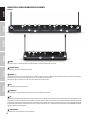 6
6
-
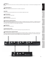 7
7
-
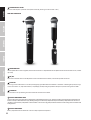 8
8
-
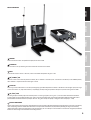 9
9
-
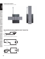 10
10
-
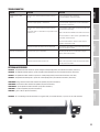 11
11
-
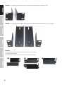 12
12
-
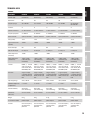 13
13
-
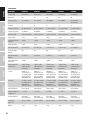 14
14
-
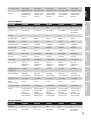 15
15
-
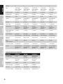 16
16
-
 17
17
-
 18
18
-
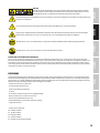 19
19
-
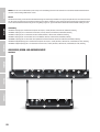 20
20
-
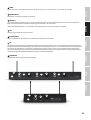 21
21
-
 22
22
-
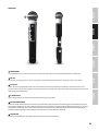 23
23
-
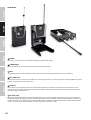 24
24
-
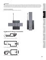 25
25
-
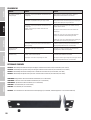 26
26
-
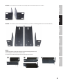 27
27
-
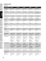 28
28
-
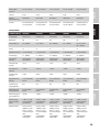 29
29
-
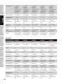 30
30
-
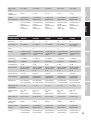 31
31
-
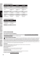 32
32
-
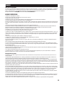 33
33
-
 34
34
-
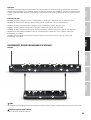 35
35
-
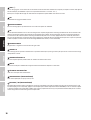 36
36
-
 37
37
-
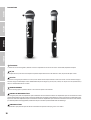 38
38
-
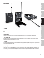 39
39
-
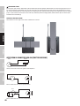 40
40
-
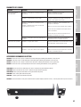 41
41
-
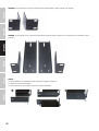 42
42
-
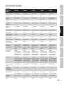 43
43
-
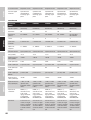 44
44
-
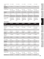 45
45
-
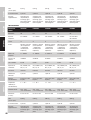 46
46
-
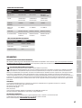 47
47
-
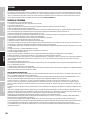 48
48
-
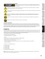 49
49
-
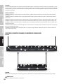 50
50
-
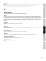 51
51
-
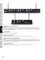 52
52
-
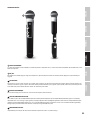 53
53
-
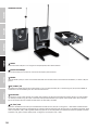 54
54
-
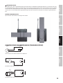 55
55
-
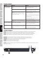 56
56
-
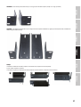 57
57
-
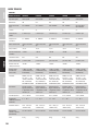 58
58
-
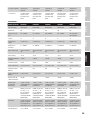 59
59
-
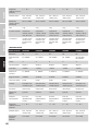 60
60
-
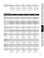 61
61
-
 62
62
-
 63
63
-
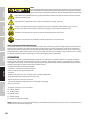 64
64
-
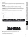 65
65
-
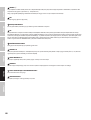 66
66
-
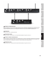 67
67
-
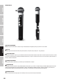 68
68
-
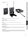 69
69
-
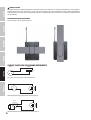 70
70
-
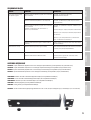 71
71
-
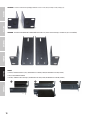 72
72
-
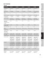 73
73
-
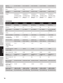 74
74
-
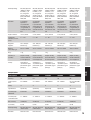 75
75
-
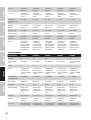 76
76
-
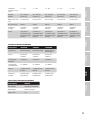 77
77
-
 78
78
-
 79
79
-
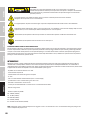 80
80
-
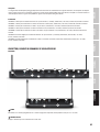 81
81
-
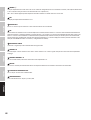 82
82
-
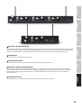 83
83
-
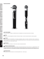 84
84
-
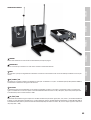 85
85
-
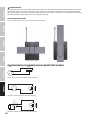 86
86
-
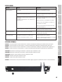 87
87
-
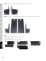 88
88
-
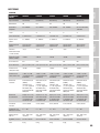 89
89
-
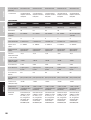 90
90
-
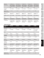 91
91
-
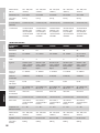 92
92
-
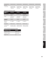 93
93
-
 94
94
-
 95
95
-
 96
96


LD Systems U305.1 R2 El manual del propietario
- Tipo
- El manual del propietario
en otros idiomas
Artículos relacionados
-
LD Systems U306 HHD Wireless Handheld Microphone System El manual del propietario
-
LD Systems U308 BPL Manual de usuario
-
LD Systems WS 1000 MW Manual de usuario
-
LD Systems LDFX300 El manual del propietario
-
-
-
-
LD Systems LD System U506HHC2 Dual Wireless Condenser Microphone System Manual de usuario
-
-
LD Systems Roadman Slave Manual de usuario
Otros documentos
-
Sennheiser ew500 Manual de usuario
-
Work-pro WRD 250/1 Manual de usuario
-
AKG D 542 E User Instructions
-
-
Omnitronic TM-1000 Manual de usuario
-
Omnitronic HM-115 Manual de usuario
-
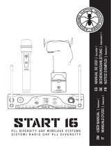 ADVANCED NATIVE TECHNOLOGIES Start 16 HDM Manual de usuario
-
SE V2 SWITCH Manual de usuario
