LD Systems LD System U506HHC2 Dual Wireless Condenser Microphone System Manual de usuario
- Tipo
- Manual de usuario

U500® SERIES
TRUE DIVERSITY WIRELESS SYSTEM
USER´S MANUAL
BEDIENUNGSANLEITUNG
MANUEL D´UTILISATION
MANUAL DE USUARIO
INSTRUKCJA OBSŁUGI
MANUALE D´USO

CONTENTS / INHALTSVERZEICHNIS / CONTENU / CONTENIDO / TREŚĆ / CONTENUTO
ENGLISH
PREVENTIVE MEASURES 3
INTRODUCTION 4
SCOPE OF DELIVERY 4
CONNECTIONS, CONTROLS AND INDICATORS 5
BELTPACK MINI-XLR PIN ASSIGNMENT 7
RECEIVER OPERATION 8
TRANSMITTER OPERATION 11
BATTERY REPLACEMENT 12
TROUBLESHOOTING 13
OPTIONAL ACCESSORIES 13
SPECIFICATIONS 14
MANUFACTURER´S DECLARATIONS 17
DEUTSCH
SICHERHEITSHINWEISE 18
EINFÜHRUNG 19
LIEFERUMFANG 19
ANSCHLÜSSE, BEDIEN- UND ANZEIGEELEMENTE 20
BELEGUNG MINI-XLR-ANSCHLUSS (TASCHENSENDER) 23
BEDIENUNG EMPFÄNGER 23
BEDIENUNG SENDER 26
BATTERIEWECHSEL 27
FEHLERSUCHE 28
OPTIONALES ZUBEHÖR 28
TECHNISCHE DATEN 29
HERSTELLERERKLÄRUNGEN 32
FRANCAIS
MESURES PRÉVENTIVES 33
INTRODUCTION 34
CONTENU DU CARTON 34
CONNECTEURS, CONTRÔLES ET INDICATEURS 35
BROCHAGE TRANSMETTEUR CEINTURE MINI-XLR 37
UTILISATION DU RÉCEPTEUR 38
UTILISATION DE L’ÉMETTEUR 41
REMPLACEMENT DES PILES 42
EN CAS DE PROBLÈME 43
ACCESSOIRES OPTIONNELS 43
CARACTÉRISTIQUES TECHNIQUES 44
DECLARATIONS 47
ESPAÑOL
MEDIDAS DE SEGURIDAD 48
INTRODUCCIÓN 49
ELEMENTOS SUMINISTRADOS 49
CONEXIONES, CONTROLES E INDICADORES 50
PINEADO DEL MINI-XLR DE LA PETACAA 53
USO DEL RECEPTOR 53
USO DEL TRANSMISOR 56
SUSTITUCIÓN DE LAS PILAS 57
SOLUCIÓN DE PROBLEMAS 58
ACCESORIOS OPCIONALES 58
CARACTERÍSTICAS TÉCNICAS 59
DECLARACIÓN DEL FABRICANTE 62
POLSKI
ŚRODKI OSTROŻNOŚCI 63
WPROWADZENIE 64
ZAKRES DOSTAWY 64
PRZYŁĄCZA, ELEMENTY OBSŁUGI I WSKAŹNIKI 65
UKŁAD STYKÓW WEJŚCIA MINI-XLR W NADAJNIKU BELTPACK 67
OBSŁUGA ODBIORNIKA 68
INSTRUKCJA NADAJNIKA 71
WYMIANA BATERII 72
WYSZUKIWANIE BŁĘDÓW 73
AKCESORIA OPCJONALNE 73
SPECYFIKACJE 74
DEKLARACJE PRODUCENTA 77
ITALIANO
MISURE PRECAUZIONALI 78
INTRODUZIONE 79
IN DOTAZIONE 79
CONNESSIONI, COMANDI E INDICATORI 80
ASSEGNAZIONE PIN BELTPACK MINI-XLR 82
USO DEL RICEVITORE 83
USO DEL TRASMETTITORE 86
SOSTITUZIONE DELLE BATTERIE 87
RICERCA ERRORI 88
ACCESSORI OPZIONALI 88
DATI TECNICI 89
DICHIARAZIONI DEL PRODUTTORE 92

ENGLISH
You‘ve made the right choice!
We have designed this product to operate reliably over many years. LD Systems stands for this with its name and many years of experience as a
manufacturer of high-quality audio products. Please read this User‘s Manual carefully, so that you can begin making optimum use of your
LD Systems product quickly.
You can nd more information about LD-SYSTEMS at our Internet site WWW.LD-SYSTEMS.COM
PREVENTIVE MEASURES
1. Please read these instructions carefully.
2. Keep all information and instructions in a safe place.
3. Follow the instructions.
4. Observe all safety warnings. Never remove safety warnings or other information from the equipment.
5. Use the equipment only in the intended manner and for the intended purpose.
6. Use only sufciently stable and compatible stands and/or mounts (for xed installations). Make certain that wall mounts are properly installed and
secured. Make certain that the equipment is installed securely and cannot fall down.
7. During installation, observe the applicable safety regulations for your country.
8. Never install and operate the equipment near radiators, heat registers, ovens or other sources of heat. Make certain that the equipment is always installed
so that is cooled sufciently and cannot overheat.
9. Never place sources of ignition, e.g., burning candles, on the equipment.
10. Ventilation slits must not be blocked.
11. Do not use this equipment in the immediate vicinity of water (does not apply to special outdoor equipment - in this case, observe the special
instructions noted below. Do not expose this equipment to ammable materials, uids or gases. Avoid direct sunlight!
12. Make certain that dripping or splashed water cannot enter the equipment. Do not place containers lled with liquids, such as vases or drinking
vessels, on the equipment.
13. Make certain that objects cannot fall into the device.
14. Use this equipment only with the accessories recommended and intended by the manufacturer.
15. Do not open or modify this equipment.
16. After connecting the equipment, check all cables in order to prevent damage or accidents, e.g., due to tripping hazards.
17. During transport, make certain that the equipment cannot fall down and possibly cause property damage and personal injuries.
18. If your equipment is no longer functioning properly, if uids or objects have gotten inside the equipment or if it has been damaged in another way,
switch it off immediately and unplug it from the mains outlet (if it is a powered device). This equipment may only be repaired by authorized, qualied
personnel.
19. Clean the equipment using a dry cloth.
20. Comply with all applicable disposal laws in your country. During disposal of packaging, please separate plastic and paper/cardboard.
21. Plastic bags must be kept out of reach of children.
FOR EQUIPMENT THAT CONNECTS TO THE POWER MAINS
22. CAUTION: If the power cord of the device is equipped with an earthing contact, then it must be connected to an outlet with a protective ground.
Never deactivate the protective ground of a power cord.
23. If the equipment has been exposed to strong uctuations in temperature (for example, after transport), do not switch it on immediately.
Moisture and condensation could damage the equipment. Do not switch on the equipment until it has reached room temperature.
24. Before connecting the equipment to the power outlet, rst verify that the mains voltage and frequency match the values specied on the
equipment. If the equipment has a voltage selection switch, connect the equipment to the power outlet only if the equipment values and the mains
power values match. If the included power cord or power adapter does not t in your wall outlet, contact your electrician.
25. Do not step on the power cord. Make certain that the power cable does not become kinked, especially at the mains outlet and/or power adapter
and the equipment connector.
26. When connecting the equipment, make certain that the power cord or power adapter is always freely accessible. Always disconnect the equip-
ment from the power supply if the equipment is not in use or if you want to clean the equipment. Always unplug the power cord and power adapter
from the power outlet at the plug or adapter and not by pulling on the cord. Never touch the power cord and power adapter with wet hands.
27. Whenever possible, avoid switching the equipment on and off in quick succession because otherwise this can shorten the useful life of the
equipment.
28. IMPORTANT INFORMATION: Replace fuses only with fuses of the same type and rating. If a fuse blows repeatedly, please contact an authorised
service centre.
29. To disconnect the equipment from the power mains completely, unplug the power cord or power adapter from the power outlet.
30. If your device is equipped with a Volex power connector, the mating Volex equipment connector must be unlocked before it can be removed.
However, this also means that the equipment can slide and fall down if the power cable is pulled, which can lead to personal injuries and/or other
damage. For this reason, always be careful when laying cables.
31. Unplug the power cord and power adapter from the power outlet if there is a risk of a lightning strike or before extended periods of disuse.
3
DEUTSCHFRANCAIS
ESPAÑOL
ENGLISH
ITALIANO POLSKI

CAUTION:
To reduce the risk of electric shock, do not remove cover (or back). There are no user serviceable parts inside.
Maintenance and repairs should be exclusively carried out by qualied service personnel.
The warning triangle with lightning symbol indicates dangerous uninsulated voltage inside the unit, which may cause an electrical shock.
The warning triangle with exclamation mark indicates important operating and maintenance instructions.
Warning! This symbol indicates a hot surface. Certain parts of the housing can become hot during operation. After use, wait for a
cool-down period of at least 10 minutes before handling or transporting the device.
CAUTION! HIGH VOLUMES IN AUDIO PRODUCTS!
This device is meant for professional use. Therefore, commercial use of this equipment is subject to the respectively applicable national accident
prevention rules and regulations. As a manufacturer, Adam Hall is obligated to notify you formally about the existence of potential health risks.
Hearing damage due to high volume and prolonged exposure: When in use, this product is capable of producing high sound-pressure levels (SPL)
that can lead to irreversible hearing damage in performers, employees, and audience members. For this reason, avoid prolonged exposure to
volumes in excess of 90 dB.
INTRODUCTION
The radio transmission systems of the LD U500 Series offer professional performance and features including the automatic channel search and the
convenient one-touch infrared synchronisation for easy set-up. With switchable RF power, pilot tone transmission, and a selection of dynamic and
condenser microphones, U500 systems deliver excellent sound with advanced dynamics.
• Wireless True Diversity UHF microphone system
• Automatic channel scan for interference-free operation
• Frequency sync via infrared technology
• Individual user name
• Pilot tone for noise-free transmission
• Adjustable squelch
• Switchable transmission power (2, 10, or 30 mW)
• Hand-held and belt pack transmitter with comfortable Gain setting
• Mechanically decoupled capsules
• High-contrast OLED graphics display
• Simultaneous operation of up to 4 systems (LDU518) /up to 6 systems (LDU508 and LDU506UK) / up to 12 systems (LDU505 and LDU506)
The use of wireless microphone systems may require a license according to country-specic regulations. Please contact your local appropriate authority
for more information.
SCOPE OF DELIVERY
Scope of delivery
LDU5xxHHC: Single receiver plus hand-held transmitter and condenser capsule (cardioid), power supply, 2 x BNC antennas, audio cable,
2 x AA batteries, carrying case, instructions
LDU5xxHHD: Single receiver plus hand-held transmitter and dynamic capsule (cardioid), power supply, 2 x BNC antennas, audio cable, 2 x AA batteries,
carrying case, instructions
LDU5xxBPH: Single receiver plus hand-held transmitter and headset (black), power supply, 2 x BNC antennas, audio cable, 2 x AA batteries, carrying
case, instructions
LDU5xxBPHH: Single receiver plus hand-held transmitter and headset (skin coloured), power supply, 2 x BNC antennas, audio cable, 2 x AA batteries,
carrying case, instructions
LDU5xxBPG: Single receiver plus hand-held transmitter and guitar cable, power supply, 2 x BNC antennas, audio cable, 2 x AA batteries,
carrying case, instructions
LDU5xxBPL: Single receiver plus hand-held transmitter and lavalier microphone, power supply, 2 x BNC antennas, audio cable, 2 x AA batteries,
carrying case, instructions
LDU5xxBPW: Single receiver plus hand-held transmitter and clip microphone for brass instruments, power supply, 2 x BNC antennas, audio cable,
2 x AA batteries, carrying case, instructions
4
ITALIANO
POLSKI
ESPAÑOL
FRANCAIS
DEUTSCHENGLISH

LDU5xxHHC2: Dual receiver plus 2 x hand-held transmitter and condenser capsule (cardioid), power supply, 2 x BNC antennas, audio cable, 4 x AA
batteries, carrying case, rack kit, instructions
LDU5xxHHD2: Dual receiver plus 2 x hand-held transmitter and dynamic capsule (cardioid), power supply, 2 x BNC antennas, audio cable, 4 x AA
batteries, carrying case, rack kit, instructions
LDU5xxBPH2: Dual receiver plus 2 x hand-held transmitter and headset (black), power supply, 2 x BNC antennas, audio cable, 4 x AA batteries, carrying
case, rack kit, instructions
LDU5xxBPHH2: Dual receiver plus 2 x hand-held transmitter and headset (skin coloured), power supply, 2 x BNC antennas, audio cable, 4 x AA batteries,
carrying case, rack kit, instructions
An extensive selection of suitable LD U500 single components and accessories can be found at www.LD-SYSTEMS.COM
CONNECTIONS, CONTROLS AND INDICATORS
1
2
5
3 4
9
8
1
2
3
4
5
6
7
2
3
4
9
8
RECEIVER
1
POWER
On / Off switch. Press and hold the switch for approx. 2 seconds to turn the device on or off.
2
DISPLAY
Multi-functional OLED graphics display for displaying information such as radio frequency, radio signal level and audio signal level. Also indicates the
menu items in order to adjust system settings as desired.
3
MENU
Combined pressure rotary encoder to access the Edit menu and to select and edit individual menu items.
4
VOL
Rotary encoder to adjust the audio signal volume of the audio outputs. As soon as volume changes are made, the volume setting will be shown im-
mediately on the display (VOLUME 00 - 100). After approximately 3 seconds of inactivity, the display will automatically return to to the main screen.
5
Infrared interface for synchronising the relevant system settings of the receiver and the transmitter (e.g. transmission frequency).
6
HEADPHONE OUTPUT
6.3 mm jack socket for connecting a headphone (dual receiver only).
7
HEADPHONE VOLUME LEVEL
Drehregler zum Einstellen der Kopfhörerlautstärke (nur Doppelempfänger).
8
Device for attaching the antennas for rack installation. Remove the covers, attach the BNC adapter to the front panel and connect the BNC antenna
connectors (Fig. 11, dual receiver) to the BNC adapters on the front panel (short antenna cable and BNC adapter included). Now, the antennas can be
attached to the front of the receiver.
5
DEUTSCHFRANCAIS
ESPAÑOL
ENGLISH
ITALIANO POLSKI

9
Screw holes for 19” rack mounting.
11
15
16
17
12
13 14
12
13
14
11
10
12
13
14
11
11
10
10
DC SOCKET
Low-voltage socket for the power supply of the device. (Single receiver: DC 12V Plus internal/ 500 mA, Dual receiver: DC 12 V Plus internal/ 1000 mA).
Please only use the power adapter included.
11
ANTENNA A/B
BNC antenna connector A and B. For optimal reception, please connect the supplied antenna to the connectors A and B and point them upward in
“V” formation.
12
BALANCED OUTPUT
Balanced audio output with 3-pin XLR socket.
13
UNBALANCED OUTPUT
Unbalanced audio output with 6.3 mm jack socket.
14
INSTRUMENT / LINE
Level and impedance adjustment to instruments or line inputs for the unbalanced jack output. Using a suitable tool (e.g. a ball point pen), set the
switch to the down position INSTRUMENT, when connecting the receiver to the input of an instrument amplier (guitar amplier, bass amplier) and
to the opposite position LINE, when connecting to the line input of a mixer or amplier
15
BALANCED OUTPUT MIX OUT
Balanced audio output with 3-pin XLR socket (dual receiver only, signals from channels 1 and 2 are mixed).
16
UNBALANCED OUTPUT MIX OUT
Unbalanced audio output with 6.3 mm jack socket (dual receiver only, signals from channels 1 and 2 are mixed).
17
INSTRUMENT / LINE MIX OUT
Level and impedance adjustment to instruments or line inputs for the unbalanced jack output MIX OUT (dual receiver only). Using a suitable tool
(e.g. a ball point pen), set the switch to the down position INSTRUMENT, when connecting the receiver to the input of an instrument amplier (guitar
amplier, bass amplier) and to the opposite position LINE, when connecting to the line input of a mixer or amplier.
6
ITALIANO
POLSKI
ESPAÑOL
FRANCAIS
DEUTSCHENGLISH

HANDHELD TRANSMITTER
22
21
20
19
18
BELT PACK TRANSMITTER
18
24
21
22
20
19
23
18
ON / OFF
On / Off switch. Set the switch to the ON position to turn the receiver on, and to the OFF position to turn it off.
19
DISPLAY
Multi-functional OLED graphics display for displaying the frequency group and channel, the username and battery status. Also indicates the menu
items in order to adjust transmitter settings as desired.
20
Infrared interface for synchronising the relevant system settings with the receiver (e.g. transmission frequency).
21
MENU / SEL
Switch to access the Edit menu and to select individual menu items.
22
Switch to edit the individual menu options on the Edit menu.
23
ANTENNA
Interchangeable antenna of the belt pack transmitter. For optimal reception, please do not obstruct or bend (belt pack transmitter only).
24
INPUT
3-pin mini XLR socket to connect a headset, lavalier or instrument microphone, as well as a guitar cable (belt pack transmitter only).
BELTPACK MINI-XLR PIN ASSIGNMENT
1
2
3
MINI-XLR
sleeve tip
6,3 mm jack
Guitar & Bass and other high impendance sources.
7
DEUTSCHFRANCAIS
ESPAÑOL
ENGLISH
ITALIANO POLSKI

1
2
ava3
MINI-XLR
Condenser with internal pull up resistor.
1
2
3
MINI-XLR
R
2,2k
Condenser without internal pull up resistor.
RECEIVER OPERATION
When operating the wireless transmission system, be sure to place the receiver in the line of sight of the transmitter. For optimal reception,
perform the automatic frequency search after switching on the receiver. Leave the corresponding transmitter off, but other radio systems turned
on, if necessary. For the operating steps, see FREQ AUTO RUN.
DISPLAY
After switching on the receiver, “WELCOME” appears for a short time, then the main screen displays the following information: individual username,
battery status, radio signal level (RF), active antenna (A / B), level of the audio signal, frequency group and channel (GR.xx and CH.xx) and the radio
frequency in MHz.
IR SYNC RUN
To synchronize the transmitter with the radio frequency set in the receiver and the individual username, bring the infrared port of the transmitter
in direct visual contact with the infrared port of the receiver (distance approx. 10 cm) and turn on the transmitter. Now press the pressure rotary
encoder of the receiver (MENU) to access the Edit menu and select the menu item IR SYNC RUN by rotating the encoder (light background). Press
again on MENU to initiate the synchronization process. After a few seconds, the process is completed and the display of the transmitter switches for
a short time to “IR SYNC ”, conrming successful synchronization. To cancel the operation, press MENU. Press briey(!) on POWER to return directly
to the main display. After about 10 seconds of inactivity, the main display is automatically shown.
FREQ AUTO RUN
Automatic frequency search (frequency scan) to determine an interference-free radio frequency in the current environment and to allow for
optimal reception. For this purpose, leave the corresponding transmitter off, but other radio systems turned on, if necessary. Press the pressure
rotary encoder (MENU) to access the Edit menu and select the menu item FREQ AUTO RUN by rotating the encoder (light background). To initiate
the process, press again on MENU. Progress is now indicated on the display by an animation and the scanning process is completed after approx. 30
seconds (to cancel, press MENU). The resulting frequency is automatically enabled and, as in “IR SYNC RUN”, you can now switch on the transmitter
and synchronize it with the receiver. Press briey(!) on POWER to return directly to the main display. After about 10 seconds of inactivity, the main
display is automatically shown.
· Individual username
· Radio signal level and active antenna
· Frequency group and channel
· Battery status of the transmitter
· Audio signal level / Peak (PK)
· Radio frequency in MHz
8
ITALIANO
POLSKI
ESPAÑOL
FRANCAIS
DEUTSCHENGLISH

GROUP
Menu item to adjust the frequency group. The LD U500 wireless system has 8 frequency groups, which can be selected as desired. Press the
pressure rotary encoder (MENU) to access the Edit menu and select the menu item GROUP by rotating the encoder (light background). Press MENU
again and select one of the groups 01 to 08 by rotating the encoder. To conrm, press MENU. Pressing MENU once more will take you up one level
in the menu structure. Press briey(!) on POWER to return directly to the main display. After about 10 seconds of inactivity, the main display is
automatically shown.
CHANNEL
Menu item to adjust the frequency channel. The LD U500 wireless system has 8 frequency groups featuring 12 channels each, which can be selected
as desired. Press the pressure rotary encoder (MENU) to access the Edit menu and select the menu item CHANNEL by rotating the encoder (light
background). Press MENU again and select one of the channels 01 to 12 by rotating the encoder. To conrm, press MENU. Pressing MENU once more
will take you up one level in the menu structure. Press briey(!) on POWER to return directly to the main display. After about 10 seconds of inactivity,
the main display is automatically shown.
FREQ MAN
Manual adjustment of the radio frequency in 25 kHz increments. Press the pressure rotary encoder (MENU) to access the Edit menu and select the
menu item FREQ MAN by rotating the encoder (light background). Press MENU and adjust the frequency in the MHz range by rotating the encoder.
Press MENU again and adjust the frequency in the kHz range in 25 kHz increments by rotating the encoder. To conrm, press MENU. Pressing MENU
once more will take you up one level in the menu structure. Press briey(!) on POWER to return directly to the main display. After about 10 seconds
of inactivity, the main display is automatically shown. The display will now show U for user under group GR. and CH.1 under channel.
NAME
To clearly assign transmitters and receivers to a specic performer, you have the ability to show names, numbers, or characters on the display.
Press the pressure rotary encoder (MENU) to access the Edit menu and select the menu item NAME by rotating the encoder (light background).
Press MENU and then, as desired, select the letter, number or symbol for the rst of the 8 digits provided by rotating the encoder and conrming
with MENU; now, the second digit can be set as desired, etc.. Once the last digit has been conrmed, pressing MENU again will take you to a higher
level in the menu structure. Press briey(!) on POWER to return directly to the main display. After about 10 seconds of inactivity, the main display is
automatically shown. In addition to the radio frequency, the name is also transferred to the transmitter when synchronizing.
PILOT TONE
The pilot tone feature protects a wireless microphone system against interference of unwanted signals, for example from other radio equipment.
The transmitter adds a second inaudible signal, the pilot tone, to the signal to be transmitted. The receiver identies this as the matching pilot tone
and frees the corresponding signal. Signals without pilot tone remain muted. Press the pressure rotary encoder (MENU) to access the Edit menu and
select the menu item PILOT TONE by rotating the encoder (light background). Press again on MENU and using the encoder, select ON, for initiating
pilot tone (right turn), or OFF for pilot tone equipment switched off (turn left). To conrm, press MENU. Pressing MENU once more will take you
up one level in the menu structure. Press briey(!) on POWER to return directly to the main display. After about 10 seconds of inactivity, the main
display is automatically shown.
· Battery status of the transmitter
· Audio signal level / Peak (PK)
· Radio frequency in MHz
9
DEUTSCHFRANCAIS
ESPAÑOL
ENGLISH
ITALIANO POLSKI

SQUELCH
The squelch control prevents unwanted background noise when the transmitter is turned off. In addition, sudden background noises are sup-
pressed when the signal transmitted from the transmitter to the receiver is not strong enough (for instance because of excessive distance) Set
the squelch control (with the transmitter switched off) to the lowest setting, which still effectively suppresses background noises. In unfavourable
conditions, in the “HIGH” setting, the transmission range may decrease. Press the pressure rotary encoder (MENU) to access the Edit menu and
select the menu item SQUELCH by rotating the encoder (light background). Press MENU again and select the optimum setting for your application
by rotating the encoder (LOW = low, MID= mid and HIGH = high threshold). To conrm, press MENU. Pressing MENU once more will take you up one
level in the menu structure. Press briey(!) on POWER to return directly to the main display. After about 10 seconds of inactivity, the main display is
automatically shown.
BRIGHTNESS
Menu item to adjust the brightness of the display illumination. Press the pressure rotary encoder (MENU) to access the Edit menu and select the
menu item BRIGHTNESS by rotating the encoder (light background). Press MENU again and select the optimum setting for your application by
rotating the encoder (LOW = low, MID= mid and HIGH = high brightness). To conrm, press MENU. Pressing MENU once more will take you up one
level in the menu structure. Press briey(!) on POWER to return directly to the main display. After about 10 seconds of inactivity, the main display is
automatically shown.
PANEL LOCK
To protect the receiver against accidental and unauthorised operation, it is possible to initiate an automatic locking of the controls. Press the
pressure rotary encoder (MENU) to access the Edit menu and select the menu item PANEL LOCK by rotating the encoder (light background). Press
again on MENU and using the encoder, select ON, for initiating the automatic lock (right turn), or OFF to switch it off (turn left). To conrm, press
MENU. Pressing MENU once more will take you up one level in the menu structure. Press briey(!) on POWER to return directly to the main display. If
the automatic lock is activated, after approx. 10 seconds, “DISPLAY IS LOCKED” is displayed for a short time and also if one of the controls is activated;
a change to the settings of the receiver via the control elements is then not possible. Press and hold the pressure rotary encoder for approx. 3
seconds to unlock the control elements (“DISPLAY IS UNLOCKED” is displayed for about 1 second).
EXIT
To exit the Edit menu and return to the main display, select EXIT (light background) by rotating the pressure rotary encoder and press MENU.
Alternatively, press briey(!) on POWER to return directly to the main display. After about 10 seconds of inactivity, the main display is automatically
shown.
BATTERY STATUS
The battery status of the corresponding transmitter will appear on the display and is constantly updated. When the battery is fully charged, the icon
( = approx. 70%, = approx. 30%) will appear. As soon as the icon for “low battery” is displayed, the display changes to
“LOW BATTERY” and shows approximately every 5 seconds. Replace the batteries immediately.
10
ITALIANO
POLSKI
ESPAÑOL
FRANCAIS
DEUTSCHENGLISH

TRANSMITTER OPERATION
MAIN DISPLAY
After switching on the transmitter, the main screen displays the following information: username, frequency group and channel (GR.xx and CH.xx)
and battery status. Remove the battery compartment cover on the transmitter to release the controls SEL and arrow buttons (hand-held
transmitter: remove the screwable cover shell by rotating it to the left, belt pack transmitter: pull cover shell by pressing on the markings on the
sides of the housing). Now press the arrow button, and the radio frequency, gain and transmission power are displayed (back with arrow button).
GAIN
To avoid distortions and to adjust the transmitter optimally to the input audio signal, it is possible to adjust the audio levels in 3dB increments
from 0dB to -27dB. Open the battery compartment cover as previously described to reveal the controls. Press SEL to access the Edit menu and press
SEL repeatedly, if necessary, to select the menu item GAIN (light background). Now lower the audio level if necessary by repeatedly pressing the
arrow button until you have no more distortion and the peak indicator AF PK in the display of the receiver goes out (watch out for peak levels). To
exit the menu item, press SEL, call up the menu item EXIT by pressing SEL repeatedly if necessary, and conrm by pressing the arrow button. After
approximately 10 seconds of inactivity, the display will automatically return to the main screen.
RF POWER
Adjust the output power of the transmitter according to the application (recommendation: outdoors = 30mW, stage = 10mW, conference setting
= 2mW). Open the battery compartment cover as previously described to reveal the controls. Press SEL to access the Edit menu and press SEL
repeatedly, if necessary, to select the menu item RF POWER (light background). Now, using the arrow keys, select the desired output power (30mW,
10mW, 2mW - in the frequency range of 863 – 865 MHz, the output power is automatically reduced to 10 mW in accordance with legal requirements).
To exit the menu item, press SEL, call up the menu item EXIT by pressing SEL repeatedly if necessary, and conrm by pressing the arrow button. After
approximately 10 seconds of inactivity, the display will automatically return to the main screen.
EXIT
In order to exit the Edit menu and return to the main display, call up the menu item EXIT and conrm by pressing the arrow button.
After approximately 10 seconds of inactivity, the display will automatically return to the main screen.
BATTERY STATUS
The battery status of the transmitter will appear in the display and is constantly updated. When the battery is fully charged, the icon
(
= approx. 70%,
= approx. 30%) will appear. As soon as the icon for “low battery” is displayed, the display changes to “LOW BATTERY” and
shows approximately every 5 seconds. Replace the batteries immediately.
11
DEUTSCHFRANCAIS
ESPAÑOL
ENGLISH
ITALIANO POLSKI

ATTACHING THE PACK TRANSMITTER
Attach the transmitter to a belt or strap as shown below.
BATTERY REPLACEMENT
Open the battery compartment of the hand-held transmitter by turning the battery compartment cover counter-clockwise and pull it from the
housing. Remove the used batteries and insert new batteries (AA, Mignon) as shown on the illustration inside the battery compartment. Replace
the battery compartment cover on the housing and close the battery compartment by turning clockwise. If the transmitter is not in use for a long
period of time, remove the batteries from the battery compartment on the transmitter to avoid damage caused by defective batteries.
Open the battery compartment of the hand-held transmitter by pressing on both markings on the sides of the battery compartment cover (Fig.
A) and pull it away until it stops. Remove the used batteries and insert new batteries (AA, Mignon) as shown on the illustration inside the battery
compartment. Slide the battery compartment cover back onto the housing until the cover clicks into place. If the transmitter is not in use for a long
period of time, remove the batteries from the battery compartment on the transmitter to avoid damage caused by defective batteries.
A
12
ITALIANO
POLSKI
ESPAÑOL
FRANCAIS
DEUTSCHENGLISH

TROUBLESHOOTING
PROBLEM DISPLAY SOLUTION
No audio signal or
low level
Receiver: Reception is not displayed on antenna A or B. Verify that the transmitter is turned on.
Check the batteries in the transmitter.
Receiver: Display light is off Check the power supply in the transmitter.
Receiver: Reception is not displayed on antenna A or B.
Transmitter: Device is turned on. Charge status of the
batteries is ok.
Check whether radio frequency of transmitter and receiver
match.
Check the transmission output.
Reduce the distance between transmitter and receiver.
Make sure that there is a direct line of sight between the
transmitter and receiver.
Make sure that the antennas of the receiver are aligned
upward and into a V-shape.
Reduce the amount of noise reduction (SQUELCH)
Receiver: Neither antenna A nor antenna B LED is
displayed.
Increase the signal level or check the GAIN setting on the
transmitter.
Distortion and
interference
Receiver: Radio signal is displayed Remove possible sources of interference (digital devices,
other wireless systems).
Increase the level of noise reduction (MUTE level) on the
receiver.
Distorted sound Transmitter and Receiver: "LOW BATTERY" is displayed.
Receiver: AF PK peak indicator is displayed on the receiver
display.
Replace the batteries in the transmitter.
Increase the signal level or lower the audio level GAIN on
the transmitter.
OPTIONAL ACCESSORIES
LDU500CH - Microphone head with condenser capsule and hyper cardioid directivity (matt black)
LDU500DH - Microphone head with dynamic capsule and hyper cardioid directivity (matt black)
LDU500CC - Microphone head with condenser capsule and hyper cardioid directivity (matt silver)
LDU500DC - Microphone head with dynamic capsule and hyper cardioid directivity (matt silver)
LDU500RK - 19” rack installation kit for mounting a single receiver (2 rack brackets, 2 BNC adapters, 2 short antenna cables and 1 set of screws included).
LDU500RK2 - 19” rack installation kit for mounting a dual receiver (2 rack brackets, 2 connectors and 1 set of screws included).
13
DEUTSCHFRANCAIS
ESPAÑOL
ENGLISH
ITALIANO POLSKI

MOUNTING
1 2 3
1
Screw the connectors (receiver A right, receiver B left).
2
Place both receivers together and screw into place.
3
Screw the rack brackets (receiver A right, receiver B left).
An extensive selection of suitable LD U500 wireless systems and further accessories can be found at www.LD-SYSTEMS.COM
SPECIFICATIONS
Receiver
Model name: LDU50xR LDU50xR2
Receiver type: true diversity
Modulation: FM
Frequency range: 823 - 832 MHz & 863 - 865 MHz (LDU508), 584 - 607 MHz (LDU505), 655 - 679 MHz (LDU506), 604 - 614 MHz
(LDU506UK), 1785 - 1800 MHz (LDU518)
Channels: 96 (8 x 12)
Groups: 8
Antenna connectors: 2 x BNC
Antenna Gain: 2.15 dBi
Frequency response: 30 - 16.000 Hz
Noise Reduction: adjustable squelch
THD: <0.1%
Signal-to-noise ratio: >100dB
Balanced output: XLR 2 x XLR
Balanced mix output: XLR
Unbalanced output: 6.3 mm jack 2x 6.3mm jack
Unbalanced mix output: 6.3 mm jack
14
ITALIANO
POLSKI
ESPAÑOL
FRANCAIS
DEUTSCHENGLISH

Headphones output: 6.3 mm stereo jack
Audio output level (balanced): +10dBu
Audio output level
(unbalanced):
+6dBV / 0dBV (Switchable Line / Instrument)
Controls: POWER on/off, MENU push-turn-control, VOL
Volume control, switch INSTRUMENT/LINE
POWER on/off, 2x MENU push-turn-control, 2x
VOL Volume control, 2x switch INSTRUMENT/LINE,
headphones volume control
Indicators: multifunctional OLED-graphic display, 2 x multifunctional OLED-graphic display
Operating voltage: 12V DC, 500 mA 12V DC, 1000 mA
Operating temperature range: 5°C … 40°C
Relative humidity in operation: 20% … 80% (non condensing)
Dimensions (W x H x D): 212 x 44 x 159mm 484 x 44 x 200mm
Weight: 0.95kg 2.05 kg
Accessories included: power adapter, 2 x antenna, audio cable power adapter, 2 x antenna, audio cable, rack kit
Features: channel scan function, infrared frequency synchronisation, pilot tone
Handheld transmitter
Model name: LDU50xMD LDU50xMC
Modulation: FM
Frequency range: 823 - 832 MHz & 863 - 865 MHz (LDU508), 584 - 607 MHz (LDU505), 655 - 679 MHz (LDU506),
604 - 614 MHz (LDU506UK), 1785 - 1800 MHz (LDU518)
Channels: 96 (8 x 12)
Groups: 8
Microphone type: dynamic condenser
Polar pattern: cardioid cardioid
Frequency response: 60 - 16.000 Hz
THD: <0.2% @ 1kHz
Signal-to-noise ratio: >95 dB
RF output power: 2mW, 10mW, 30mW switchable and depending on the RF -Range
Antenna Gain: 0.5 dBi
Controls: Power on/off, Select, Arrow button
Indicators: multifunctional OLED-graphic display
Power supply: 2 x AA battery
Operating time: up to 10 h (depending on batteries)
Operating temperature range: 5°C … 40°C
Relative humidity range in operation: 20% … 80% (non condensing)
Dimensions (L x Ø): 257 x 51mm 257 x 50mm
Weight (without batteries): 0.2 kg 0.21kg
Accessories included: 2 x AA battery
Features: infrared frequency synchronisation
Bodypack transmitter
Model name: LDU50xBP
Modulation: FM
Frequency range: 823 - 832 MHz & 863 - 865 MHz (LDU508), 584 - 607 MHz (LDU505), 655 - 679 MHz (LDU506), 604 - 614 MHz
(LDU506UK), 1785 - 1800 MHz (LDU518)
15
DEUTSCHFRANCAIS
ESPAÑOL
ENGLISH
ITALIANO POLSKI

Microphones
Model name: LDWS100MH1 LDWS100MH3 LDWS100ML LDWS1000MW
Microphone type: headset headset lavalier microphone wind instrument
microphone
Capsule: back-electret condenser back-electret condenser back-electret condenser back-electret condenser
Polar pattern: cardioid cardioid cardioid cardioid
Frequency response: 20 - 20.000 Hz 70 - 16.000 Hz 20 - 20.000 Hz 50 - 18.000 Hz
Connector: 3-pin mini-XLR 3-pin mini-XLR 3-pin mini-XLR 3-pin mini-XLR
Accessories included: foam windscreen foam windscreen foam windscreen foam windscreen
Features: skin coloured
Model name: LDU500CC LDU500DC LDU500CH LDU500DH
Microphone type: Microphone head for
U500 handheld
Microphone head for
U500 handheld
Microphone head for
U500 handheld
Microphone head for
U500 handheld
Capsule: back-electret condenser dynamic back-electret condenser dynamic
Polar pattern: cardioid cardioid hyper cardioid hyper cardioid
Connector: LDU500 screw connection LDU500 screw connection LDU500 screw connection
LDU500 screw
connection
Colour: matt silver matt silver matt black matt black
Features: low noise -FET impedan-
ce converter, customized
shock mount, gold
contacts
shock mount, gold
contacts
low noise -FET impedan-
ce converter, customized
shock mount, gold
contacts
shock mount, gold
contacts
Channels: 96 (8 x 12)
Groups: 8
Input: 3-pin mini-XLR (Low-Z/High-Z)
Frequency response: 30 - 16.000 Hz
THD: <0.1% @ 1kHz
Signal-to-noise ratio: >90 dB
RF output power: 2mW, 10mW, 30mW switchable and depending on the RF -Range
Antenna Gain: 0.5 dBi
Controls: Power on/off, Select, Arrow button
Indicators: multifunctional OLED-graphic display
Power supply: 2 x AA batteries
Operating time: up to 10 h (depending on batteries)
Operating temperature range: 5°C … 40°C
Relative humidity range in operation: 20% … 80% (non condensing)
Dimensions (W x H x D): 65 x 86 x 23 mm
Weight (without batteries): 0,09 kg
Accessories included: 2 x AA battery
Features: infrared frequency synchronisation
16
ITALIANO
POLSKI
ESPAÑOL
FRANCAIS
DEUTSCHENGLISH

Guitar cable
Model name: LDU500GC
Connector 1: 3-pin mini-XLR
Connector 2: 6.3 mm jack
Length: 0.8 m
MANUFACTURER´S DECLARATIONS
MANUFACTURER‘S WARRANTY & LIMITATIONS OF LIABILITY
You can nd our current warranty conditions and limitations of liability at: https://cdn-shop.adamhall.com/media/pdf/MANUFACTURERS-DECLARA-
TIONS_LD_SYSTEMS.pdf To request warranty service for a product, please contact Adam Hall GmbH, Adam-Hall-Str. 1,
61267 Neu Anspach / Email: [email protected] / +49 (0)6081 / 9419-0.
CORRECT DISPOSAL OF THIS PRODUCT
(valid in the European Union and other European countries with a differentiated waste collection system)
This symbol on the product, or on its documents indicates that the device may not be treated as household waste. This is to avoid environ-
mental damage or personal injury due to uncontrolled waste disposal. Please dispose of this product separately from other waste and have it
recycled to promote sustainable economic activity. Household users should contact either the retailer where they purchased this product, or their
local government ofce, for details on where and how they can recycle this item in an environmentally friendly manner. Business users should
contact their supplier and check the terms and conditions of the purchase contract. This product should not be mixed with other commercial waste
for disposal.
FCC STATEMENT
This device complies with Part 15 of the FCC Rules. Operation is subject to the following two conditions:
(1) This device may not cause harmful interference, and
(2) This device must accept any interference received, including interference that may cause undesired operation
CE Compliance
Adam Hall GmbH states that this product meets the following guidelines (where applicable):
R&TTE (1999/5/EC) or RED (2014/53/EU) from June 2017
Low voltage directive (2014/35/EU)
EMV directive (2014/30/EU)
RoHS (2011/65/EU)
The complete declaration of conformity can be found at www.adamhall.com.
Furthermore, you may also direct your enquiry to [email protected].
EU DECLARATION OF CONFORMITY
Hereby, Adam Hall GmbH declares that this radio equipment type is in compliance with Directive 2014/53/EU.
The full text of the EU declaration of conformity is available at the following
internet address: www.adamhall.com/compliance/
17
DEUTSCHFRANCAIS
ESPAÑOL
ENGLISH
ITALIANO POLSKI

DEUTSCH
Sie haben die richtige Wahl getroffen!
Dieses Gerät wurde unter hohen Qualitätsanforderungen entwickelt und gefertigt, um viele Jahre einen reibungslosen Betrieb zu gewährleisten.
Dafür steht LD Systems mit seinem Namen und der langjährigen Erfahrung als Hersteller hochwertiger Audioprodukte. Bitte lesen Sie diese Bedie-
nungsanleitung sorgfältig, damit Sie Ihr neues Produkt von LD Systems schnell optimal einsetzen können.
Mehr Informationen zu LD SYSTEMS nden Sie auf unserer Internetseite www.LD-SYSTEMS.COM
SICHERHEITSHINWEISE
1. Lesen Sie diese Anleitung bitte sorgfältig durch.
2. Bewahren Sie alle Informationen und Anleitungen an einem sicheren Ort auf.
3. Befolgen Sie die Anweisungen.
4. Beachten Sie alle Warnhinweise. Entfernen Sie keine Sicherheitshinweise oder andere Informationen vom Gerät.
5. Verwenden Sie das Gerät nur in der vorgesehenen Art und Weise.
6. Verwenden Sie ausschließlich stabile und passende Stative bzw. Befestigungen (bei Festinstallationen). Stellen Sie sicher, dass Wandhalterungen
ordnungsgemäß installiert und gesichert sind. Stellen Sie sicher, dass das Gerät sicher installiert ist und nicht herunterfallen kann.
7. Beachten Sie bei der Installation die für Ihr Land geltenden Sicherheitsvorschriften.
8. Installieren und betreiben Sie das Gerät nicht in der Nähe von Heizkörpern, Wärmespeichern, Öfen oder sonstigen Wärmequellen. Sorgen Sie dafür,
dass das Gerät immer so installiert ist, dass es ausreichend gekühlt wird und nicht überhitzen kann.
9. Platzieren Sie keine Zündquellen wie z.B. brennende Kerzen auf dem Gerät.
10. Lüftungsschlitze dürfen nicht blockiert werden.
11. Betreiben Sie das Gerät nicht in unmittelbarer Nähe von Wasser. Bringen Sie das Gerät nicht mit brennbaren Materialien, Flüssigkeiten oder Gasen
in Berührung. Direkte Sonneneinstrahlung vermeiden!
12. Sorgen Sie dafür, dass kein Tropf- oder Spritzwasser in das Gerät eindringen kann. Stellen Sie keine mit Flüssigkeit gefüllten Behältnisse wie
Vasen oder Trinkgefäße auf das Gerät.
13. Sorgen Sie dafür, dass keine Gegenstände in das Gerät fallen können.
14. Betreiben Sie das Gerät nur mit dem vom Hersteller empfohlenen und vorgesehenen Zubehör.
15. Öffnen Sie das Gerät nicht und verändern Sie es nicht.
16. Überprüfen Sie nach dem Anschluss des Geräts alle Kabelwege, um Schäden oder Unfälle, z. B. durch Stolperfallen zu vermeiden.
17. Achten Sie beim Transport darauf, dass das Gerät nicht herunterfallen und dabei möglicherweise Sach- und Personenschäden verursachen kann.
18. Wenn Ihr Gerät nicht mehr ordnungsgemäß funktioniert, Flüssigkeiten oder Gegenstände in das Geräteinnere gelangt sind, oder das Gerät an-
derweitig beschädigt wurde, schalten Sie es sofort aus und trennen es von der Netzsteckdose (sofern es sich um ein aktives Gerät handelt). Dieses
Gerät darf nur von autorisiertem Fachpersonal repariert werden.
19. Verwenden Sie zur Reinigung des Geräts ein trockenes Tuch.
20. Beachten Sie alle in Ihrem Land geltenden Entsorgungsgesetze. Trennen Sie bei der Entsorgung der Verpackung bitte Kunststoff und Papier bzw.
Kartonagen voneinander.
21. Kunststoffbeutel müssen außer Reichweite von Kindern aufbewahrt werden.
BEI GERÄTEN MIT NETZANSCHLUSS
22. ACHTUNG: Wenn das Netzkabel des Geräts mit einem Schutzkontakt ausgestattet ist, muss es an einer Steckdose mit Schutzleiter angeschlossen
werden. Deaktivieren Sie niemals den Schutzleiter eines Netzkabels.
23. Schalten Sie das Gerät nicht sofort ein, wenn es starken Temperaturschwankungen ausgesetzt war (beispielsweise nach dem Transport). Feuch-
tigkeit und Kondensat könnten das Gerät beschädigen. Schalten Sie das Gerät erst ein, wenn es Zimmertemperatur erreicht hat.
24. Bevor Sie das Gerät an die Steckdose anschließen, prüfen Sie zuerst, ob die Spannung und die Frequenz des Stromnetzes mit den auf dem Gerät
angegebenen Werten übereinstimmen. Verfügt das Gerät über einen Spannungswahlschalter, schließen Sie das Gerät nur an die Steckdose an,
wenn die Gerätewerte mit den Werten des Stromnetzes übereinstimmen. Wenn das mitgelieferte Netzkabel bzw. der mitgelieferte Netzadapter
nicht in Ihre Netzsteckdose passt, wenden Sie sich an Ihren Elektriker.
25. Treten Sie nicht auf das Netzkabel. Sorgen Sie dafür, dass spannungsführende Kabel speziell an der Netzbuchse bzw. am Netzadapter und der
Gerätebuchse nicht geknickt werden.
26. Achten Sie bei der Verkabelung des Geräts immer darauf, dass das Netzkabel bzw. der Netzadapter stets frei zugänglich ist. Trennen Sie das Gerät
stets von der Stromzuführung, wenn das Gerät nicht benutzt wird, oder Sie das Gerät reinigen möchten. Ziehen Sie Netzkabel und Netzadapter immer am
Stecker bzw. am Adapter und nicht am Kabel aus der Steckdose. Berühren Sie Netzkabel und Netzadapter niemals mit nassen Händen.
27. Schalten Sie das Gerät möglichst nicht schnell hintereinander ein und aus, da sonst die Lebensdauer des Geräts beeinträchtigt werden könnte.
28. WICHTIGER HINWEIS: Ersetzen Sie Sicherungen ausschließlich durch Sicherungen des gleichen Typs und Wertes. Sollte eine Sicherung wiederholt
auslösen, wenden Sie sich bitte an ein autorisiertes Servicezentrum.
29. Um das Gerät vollständig vom Stromnetz zu trennen, entfernen Sie das Netzkabel bzw. den Netzadapter aus der Steckdose.
30. Wenn Ihr Gerät mit einem verriegelbaren Netzanschluss bestückt ist, muss der passende Gerätestecker entsperrt werden, bevor er entfernt wer-
den kann. Das bedeutet aber auch, dass das Gerät durch ein Ziehen am Netzkabel verrutschen und herunterfallen kann, wodurch Personen verletzt
werden und/oder andere Schäden auftreten können. Verlegen Sie Ihre Kabel daher immer sorgfältig.
31. Entfernen Sie Netzkabel und Netzadapter aus der Steckdose bei Gefahr eines Blitzschlags oder wenn Sie das Gerät länger nicht verwenden.
ACHTUNG
Entfernen Sie niemals die Abdeckung, da sonst das Risiko eines elektrischen Schlages besteht. Im Inneren
des Geräts benden sich keine Teile, die vom Bediener repariert oder gewartet werden können. Lassen Sie
Wartung und Reparaturen ausschließlich von qualiziertem Servicepersonal durchführen.
18
ITALIANO
POLSKI
ESPAÑOL
FRANCAIS
DEUTSCHENGLISH

Das gleichseitige Dreieck mit Blitzsymbol warnt vor nichtisolierten, gefährlichen Spannungen im Geräteinneren, die einen elektrischen
Schlag verursachen können.
Das gleichseitige Dreieck mit Ausrufungszeichen kennzeichnet wichtige Bedienungs- und Wartungshinweise.
Warnung! Dieses Symbol kennzeichnet heiße Oberächen. Während des Betriebs können bestimmte Teile des Gehäuses heiß werden.
Berühren oder transportieren Sie das Gerät nach einem Einsatz erst nach einer Abkühlzeit von mindestens 10 Minuten.
ACHTUNG HOHE LAUTSTÄRKEN BEI AUDIOPRODUKTEN!
Dieses Gerät ist für den professionellen Einsatz vorgesehen. Der kommerzielle Betrieb dieses Geräts unterliegt den jeweils gültigen nationalen Vorschriften
und Richtlinien zur Unfallverhütung. Als Hersteller ist Adam Hall gesetzlich verpichtet, Sie ausdrücklich auf mögliche Gesundheitsrisiken hinzuweisen.
Gehörschäden durch hohe Lautstärken und Dauerbelastung: Bei der Verwendung dieses Produkts können hohe Schalldruckpegel (SPL) erzeugt werden, die
bei Künstlern, Mitarbeitern und Zuschauern zu irreparablen Gehörschäden führen können. Vermeiden Sie länger
anhaltende Belastung durch hohe Lautstärken über 90 dB.
EINFÜHRUNG
Die Funkübertragungssysteme der LD U500 Serie bieten professionelle Leistung und Funktionen einschließlich der automatischen Kanalsuche und
der bequemen One-Touch-Infrarot-Synchronisierung für einfache Einrichtung. Mit schaltbarer HF-Leistung, Pilotton-Übertragung und einer Auswahl
von dynamischen und Kondensatormikrofonen liefern U500 Systeme hervorragenden Klang mit erweiterter Dynamik.
• Drahtloses True Diversity UHF Mikrofon System
• Automatischer Kanal-Scan für interferenzfreie Funktion
• Frequenz-Sync via Infrarot-Technik
• Individueller Benutzername
• Pilot-Ton für störgeräuschfreie Übertragung
• Einstellbare Rauschsperre (Squelch)
• Schaltbare Sendeleistung (2, 10 oder 30 mW)
• Hand- und Taschensender mit komfortabler Gain-Einstellung
• Mechanisch entkoppelte Kapseln
• Kontrastreiches OLED-Grakdisplay
• Simultaner Betrieb von bis zu 4 Systemen (LDU518) / bis zu 6 Systemen (LDU508 und DU506UK) / bis zu 12 Systemen (LDU505 und LDU506)
Die Verwendung von drahtlosen Mikrofonsystemen kann eine Genehmigung erfordern - je nach landesspezischen Bestimmungen. Bitte kontaktier-
en Sie Ihre zuständigen Behörde für weitere Informationen.
LIEFERUMFANG
LDU5xxHHC: Einzelempfänger plus Handsender und Kondensatorkapsel (cardioid), Netzteil, 2x BNC-Antennen, Audiokabel, 2x AA Batterien, Transport-
koffer, Anleitung
LDU5xxHHD: Einzelempfänger plus Handsender und dynamischer Kapsel (cardioid), Netzteil, 2x BNC-Antennen, Audiokabel, 2x AA Batterien, Trans-
portkoffer, Anleitung
LDU5xxBPH: Einzelempfänger plus Taschensender und Headset (schwarz), Netzteil, 2x BNC-Antennen, Audiokabel, 2x AA Batterien,
Transportkoffer, Anleitung
LDU5xxBPHH: Einzelempfänger plus Taschensender und Headset (hautfarben), Netzteil, 2x BNC-Antennen, Audiokabel, 2x AA Batterien,
Transportkoffer, Anleitung
LDU5xxBPG: Einzelempfänger plus Taschensender und Gitarrenkabel, Netzteil, 2x BNC-Antennen, Audiokabel, 2x AA Batterien,
Transportkoffer, Anleitung
LDU5xxBPL: Einzelempfänger plus Taschensender und Lavalier-Mikrofon, Netzteil, 2x BNC-Antennen, Audiokabel, 2x AA Batterien,
Transportkoffer, Anleitung
LDU5xxBPW: Einzelempfänger plus Taschensender und Clip-Mikrofon für Blasinstrumente, Netzteil, 2x BNC-Antennen, Audiokabel, 2x AA Batterien,
Transportkoffer, Anleitung
LDU5xxHHC2: Doppelempfänger plus 2x Handsender und Kondensatorkapsel (cardioid), Netzteil, 2x BNC-Antennen, Audiokabel, 4x AA Batterien,
Transportkoffer, Rack-Kit, Anleitung
LDU5xxHHD2: Doppelempfänger plus 2x Handsender und dynamischer Kapsel (cardioid), Netzteil, 2x BNC-Antennen, Audiokabel, 4x AA Batterien,
Transportkoffer, Rack-Kit, Anleitung
19
DEUTSCHFRANCAIS
ESPAÑOL
ENGLISH
ITALIANO POLSKI

ANSCHLÜSSE, BEDIEN- UND ANZEIGEELEMENTE
LDU5xxBPH2: Doppelempfänger plus 2x Taschensender und Headset (schwarz), Netzteil, 2x BNC-Antennen, Audiokabel, 4x AA Batterien,
Transportkoffer, Rack-Kit, Anleitung
LDU5xxBPHH2: Doppelempfänger plus 2x Taschensender und Headset (hautfarben), Netzteil, 2x BNC-Antennen, Audiokabel, 4x AA Batterien,
Transportkoffer, Rack-Kit, Anleitung
Eine umfangreiche Auswahl an LD U500 Einzelkomponenten und Zubehör nden Sie auf www.LD-SYSTEMS.COM
1
2
5
3
4
9
8
1
2
3
4
5
6
7
2
3
4
9
8
EMPFÄNGER
1
POWER
Ein- bzw. Ausschalter. Drücken und halten Sie den Taster für die Dauer von ca. 2 Sekunden, um das Gerät ein- bzw. auszuschalten.
2
DISPLAY
Ein- bzw. Ausschalter. Drücken und halten Sie den Taster für die Dauer von ca. 2 Sekunden, um das Gerät ein- bzw. auszuschalten.
3
MENU
Kombinierter Drück-Dreh-Geber, um in das Bearbeitungsmenü zu gelangen und die einzelnen Menüpunkte auszuwählen und zu editieren.
4
VOL
Dreh-Geber zum Einstellen der Lautstärke des an den Audio-Ausgängen anliegenden Audio-Signals. Sobald Lautstärkeänderungen vorgenommen
werden, wird die Lautstärkeeinstellung augenblicklich im Display angezeigt (VOLUME 00 - 100). Nach ca. 3 Sekunden Inaktivität kehrt das Display zur
Hauptanzeige zurück.
5
Infrarot-Schnittstelle zum Synchronisieren der relevanten Systemeinstellungen des Empfängers mit dem Sender (z.B. Sendefrequenz).
6
KOPFHÖRERAUSGANG
6,3mm Klinkenbuchse zum Anschließen eines Kopfhörers (nur Doppelempfänger).
7
KOPFHÖRERLAUTSTÄRKE
Drehregler zum Einstellen der Kopfhörerlautstärke (nur Doppelempfänger).
8
Vorrichtung zum Anbringen der Antennen beim Rackeinbau. Entfernen Sie die Abdeckkappen, befestigen die BNC-Adapter an der Frontblende und
verbinden die BNC-Antennenanschlüsse (Abb. 11, Doppelempfänger) mit den BNC-Adaptern in der Frontblende (kurze Antennenkabel und BNC-Adap-
ter im Lieferumfang). Nun können die Antennen an der Vorderseite des Empfängers befestigt werden.
9
Schraublöcher für den 19“ Rackeinbau.
20
ITALIANO
POLSKI
ESPAÑOL
FRANCAIS
DEUTSCHENGLISH

10
DC BUCHSE
Kleinspannungsbuchse für die Spannungsversorgung des Geräts (Einzelempfänger: DC 12V Plus innen, 500mA, Doppelempfänger: DC 12V Plus innen,
1000mA). Verwenden Sie bitte ausschließlich den mitgelieferten Netzadapter.
11
15
16
17
12
13 14
12
13
14
11
10
12
13
14
11
11
10
11
ANTENNE A/B
BNC-Antennenanschluß A und B. Für einen optimalen Empfang schließen Sie bitte jeweils eine mitgelieferte Antenne an den Anschlüssen A und B
an und richten sie nach oben in „V“ Anordnung.
12
BALANCED OUTPUT
Symmetrischer Audio-Ausgang mit 3-poliger XLR-Buchse.
13
UNBALANCED OUTPUT
Unsymmetrischer Audio-Ausgang mit 6,3mm Klinkenbuchse.
14
INSTRUMENT / LINE
Pegel- und Impedanzanpassung an Instrumenten- bzw. Line-Eingänge für den unsymmetrischen Klinken-Ausgang. Bringen Sie den Schalter mit
einem geeigneten Werkzeug (z.B. Kugelschreiber) in die heruntergedrückte Position INSTRUMENT, wenn Sie den Empfänger am Eingang eines
Instrumentenverstärkers anschließen (Gitarrenverstärker, Bassverstärker) und in die nicht heruntergedrückte Position LINE zum Anschließen an
den Line-Eingang eines Mischpults oder Verstärkers.
15
BALANCED OUTPUT MIX OUT
Symmetrischer Audio-Ausgang mit 3-poliger XLR-Buchse (nur Doppelempfänger, Mix aus Signalen der Kanäle 1 und 2).
16
UNBALANCED OUTPUT MIX OUT
Unsymmetrischer Audio-Ausgang mit 6,3mm Klinkenbuchse (nur Doppelempfänger, Mix aus Signalen der Kanäle 1 und 2).
17
INSTRUMENT / LINE MIX OUT
Pegel- und Impedanzanpassung an Instrumenten- bzw. Line-Eingänge für den unsymmetrischen Klinken-Ausgang MIX OUT (nur Doppelempfänger).
Bringen Sie den Schalter mit einem geeigneten Werkzeug (z.B. Kugelschreiber) in die heruntergedrückte Position INSTRUMENT, wenn Sie den
Empfänger am Eingang eines Instrumentenverstärkers anschließen (Gitarrenverstärker, Bassverstärker) und in die nicht heruntergedrückte
Position LINE zum Anschließen an den Line-Eingang eines Mischpults oder Verstärkers.
21
DEUTSCHFRANCAIS
ESPAÑOL
ENGLISH
ITALIANO POLSKI

HANDSENDER
22
21
20
19
18
TASCHENSENDER
18
24
21
22
20
19
23
18
ON / OFF
Ein- bzw. Ausschalter. Bringen Sie den Schalter in Position ON, um den Sender einzuschalten, in Position OFF, um ihn auszuschalten.
19
DISPLAY
Multifunktionales OLED-Grakdisplay für die Anzeige von Frequenz-Gruppe und -Kanal, Nutzernamen und Batteriestatus. Zeigt weiterhin die Menü-
punkte an, um Sendereinstellungen nach Wunsch vorzunehmen.
20
Infrarot-Schnittstelle zum Synchronisieren der relevanten Systemeinstellungen mit dem Empfänger (z.B. Sendefrequenz).
21
MENU / SEL
Taster, um in das Bearbeitungsmenü zu gelangen und die einzelnen Menüpunkte auszuwählen.
22
Taster, um im Bearbeitungsmenü die einzelnen Menüpunkte zu editieren.
23
ANTENNA
Austauschbare Antenne des Taschensenders. Für einen optimalen Empfang bitte nicht verdecken oder knicken (nur Taschensender).
24
INPUT
3-polige Mini-XLR-Buchse zum Anschließen von Headsets, Lavalier-, Instrumentenmikrofonen und Gitarrenkabeln (nur Taschensender).
- Individueller Benutzername
- Funksignalpegel und aktive Antenne
- Frequenzgruppe und Kanal
22
ITALIANO
POLSKI
ESPAÑOL
FRANCAIS
DEUTSCHENGLISH

BELEGUNG MINI-XLR-ANSCHLUSS (TASCHENSENDER)
1
2
3
MINI-XLR
sleeve tip
6,3 mm jack
Gitarre, Bass und andere hochohmige Signalquellen.
1
2
3
MINI-XLR
Kondensatormikrofon mit internem Pull-up-Widerstand.
1
2
3
MINI-XLR
R
2,2k
Kondensatormikrofon ohne internem Pull-up-Widerstand.
BEDIENUNG EMPFÄNGER
Achten Sie bei der Inbetriebnahme des drahtlosen Übertragungssystems darauf, den Empfänger in direktem Sichtkontakt mit dem Sender zu posi-
tionieren. Führen Sie nach dem Einschalten des Empfängers die automatische Frequenzsuche durch, um einen optimalen Empfang zu ermöglichen.
Lassen Sie dabei den dazugehörigen Sender aus-, gegebenenfalls weitere Funksysteme aber eingeschaltet. Die Bedienschritte hierzu nden Sie
unter FREQ AUTO RUN.
DISPLAY
Nach dem Einschalten des Empfängers wird als Begrüßungstext für kurz Zeit „WELCOME“ angezeigt, danach erscheint die Hauptanzeige mit
folgenden Informationen: Individueller Benutzername, Batteriestatus, Funksignal-Pegel (RF), aktive Antenne (A / B), Pegel des Audio-Signals,
Frequenz-Gruppe und -Kanal (GR.xx und CH.xx) und die Funkfrequenz in MHz.
IR SYNC RUN
Um den Sender mit der im Empfänger eingestellten Funkfrequenz und dem individuellen Benutzernamen zu synchronisieren, bringen Sie die
Infrarot-Schnittstelle des Senders in direkten Sichtkontakt zur Infrarot-Schnittstelle des Empfängers (Distanz ca. 10cm) und schalten den Sender ein.
Drücken Sie nun auf den Drück-Dreh-Geber des Empfängers (MENU), um in das Bearbeitungsmenü zu gelangen und wählen dann durch Drehen des
Gebers den Menüpunkt IR SYNC RUN aus (hell hinterlegt). Drücken Sie wiederum auf MENU, um den Synchronisierungsvorgang auszulösen. Nach we-
nigen Sekunden ist der Vorgang abgeschlossen und die Anzeige im Display des Senders wechselt für kurze Zeit auf „IR SYNC “, als Bestätigung für
die erfolgreiche Synchronisierung. Zum Abbrechen des Vorgangs drücken Sie auf MENU. Drücken Sie kurz (!) auf POWER, um direkt zur Hauptanzeige
zurückzukehren, nach ca. 10 Sekunden Inaktivität wird automatisch auf die Hauptanzeige gewechselt.
- Individueller Benutzername
- Funksignalpegel und aktive Antenne
- Frequenzgruppe und Kanal
- Batteriestatus des Senders
- Audiosignalpegel / Spitze (PK)
- Funkfrequenz in MHz
23
DEUTSCHFRANCAIS
ESPAÑOL
ENGLISH
ITALIANO POLSKI

FREQ AUTO RUN
Automatische Frequenzsuche (Frequenz-Scan), um in der aktuellen Umgebung eine interferenzfreie Funkfrequenz zu ermitteln und einen optimalen
Empfang zu ermöglichen. Lassen Sie bei dem Vorgang den dazugehörigen Sender aus-, gegebenenfalls weitere Funksysteme aber eingeschaltet.
Drücken Sie auf den Drück-Dreh-Geber MENU, um in das Bearbeitungsmenü zu gelangen und wählen dann durch Drehen des Gebers den Menüpunkt
FREQ AUTO RUN aus (hell hinterlegt). Um den Vorgang auszulösen, drücken Sie abermals auf MENU, das Stadium des Vorgangs wird nun animiert im
Display angezeigt und der Scan-Prozess ist nach ca. 30 Sekunden abgeschlossen (zum Abbrechen auf MENU drücken).
Die so ermittelte Frequenz wird automatisch aktiviert und Sie können nun, wie unter „IR SYNC RUN“ beschrieben, den Sender einschalten und mit
dem Empfänger synchronisieren. Drücken Sie kurz (!) auf POWER, um direkt zur Hauptanzeige zurückzukehren, nach ca. 10 Sekunden Inaktivität wird
automatisch auf die Hauptanzeige gewechselt.
GROUP
Menüpunkt zum Einstellen der Frequenz-Gruppe. Das LD U500 Funksystem verfügt über 8 Frequenz-Gruppen, die nach Wunsch ausgewählt werden
können. Drücken Sie auf den Drück-Dreh-Geber MENU, um in das Bearbeitungsmenü zu gelangen und wählen dann durch Drehen des Gebers den
Menüpunkt GROUP aus (hell hinterlegt). Drücken Sie abermals auf MENU und wählen eine der Gruppen 01 bis 08 durch Drehen des Gebers aus. Zum
Bestätigen drücken Sie auf MENU. Durch nochmaliges Drücken auf MENU gelangen Sie eine Ebene höher in der Menüstruktur. Drücken Sie kurz (!) auf
POWER, um direkt zur Hauptanzeige zurückzukehren, nach ca. 10 Sekunden Inaktivität wird automatisch auf die Hauptanzeige gewechselt.
CHANNEL
Menüpunkt zum Einstellen der Frequenz-Kanals. Das LD U500 Funksystem verfügt über 8 Frequenz-Gruppen mit je 12 Kanälen, die nach Wunsch aus-
gewählt werden können. Drücken Sie auf den Drück-Dreh-Geber MENU, um in das Bearbeitungsmenü zu gelangen und wählen dann durch Drehen des
Gebers den Menüpunkt CHANNEL aus (hell hinterlegt). Drücken Sie abermals auf MENU und wählen einen der Kanäle 01 bis 12 durch Drehen des Gebers
aus. Zum Bestätigen drücken Sie auf MENU. Durch nochmaliges Drücken auf MENU gelangen Sie eine Ebene höher in der Menüstruktur. Drücken Sie kurz
(!) auf POWER, um direkt zur Hauptanzeige zurückzukehren, nach ca. 10 Sekunden Inaktivität wird automatisch auf die Hauptanzeige gewechselt.
FREQ MAN
Manuelle Einstellung der Funkfrequenz in 25kHz Schritten. Drücken Sie auf den Drück-Dreh-Geber MENU, um in das Bearbeitungsmenü zu gelangen
und wählen dann durch Drehen des Gebers den Menüpunkt FREQ MAN aus (hell hinterlegt). Drücken Sie auf MENU und stellen die Frequenz im MHz
Bereich in 1MHz Schritten durch Drehen des Gebers ein. Drücken Sie abermals auf MENU und stellen die Frequenz im kHz Bereich in 25kHz Schritten
durch Drehen des Gebers ein. Zum Bestätigen drücken Sie auf MENU. Durch nochmaliges Drücken auf MENU gelangen Sie eine Ebene höher in der
Menüstruktur. Drücken Sie kurz (!) auf POWER, um direkt zur Hauptanzeige zurückzukehren, nach ca. 10 Sekunden Inaktivität wird automatisch auf
die Hauptanzeige gewechselt. Im Display wird unter Gruppe GR. nun U für User und unter Kanal CH. 1 angezeigt.
NAME
Um Sender und Empfänger eindeutig einem Künstler zuordnen zu können, besteht die Möglichkeit, Namen, Zahlen oder Zeichen in den Displays
anzeigen zu lassen. Drücken Sie auf den Drück-Dreh-Geber MENU, um in das Bearbeitungsmenü zu gelangen und wählen dann durch Drehen des Ge-
bers den Menüpunkt NAME aus (hell hinterlegt). Drücken Sie auf MENU und wählen dann wie gewünscht den Buchstaben, die Zahl oder das Zeichen
für die erste Stelle der 8 zur Verfügung stehenden Stellen durch Drehen des Gebers aus und bestätigen mit MENU, gleichzeitig kann nun die zweite
Stelle nach Wunsch eingestellt werden, usw.. Nachdem die letzte Stelle bestätigt wurde, drücken Sie nochmals auf MENU, um eine Ebene höher in
der Menüstruktur zu gelangen. Drücken Sie kurz (!) auf POWER, um direkt zur Hauptanzeige zurückzukehren, nach ca. 10 Sekunden Inaktivität wird
automatisch auf die Hauptanzeige gewechselt. Neben der Funkfrequenz wird auch der Name beim Synchronisieren auf den Sender übertragen.
24
ITALIANO
POLSKI
ESPAÑOL
FRANCAIS
DEUTSCHENGLISH

PILOT TONE
Die Pilot-Ton-Einrichtung schützt eine drahtlose Mikrofonanlage vor Einstreuungen unerwünschter Signale, beispielsweise die von anderen Funk-
anlagen. Der Sender fügt dem eigentlich zu übertragenden Signal ein zweites, unhörbares Signal, den Pilot-Ton, hinzu. Der Empfänger identiziert
diesen als den übereinstimmenden Pilot-Ton und gibt das dazugehörige Signal frei. Signale ohne Pilot-Ton bleiben stummgeschaltet. Drücken Sie
auf den Drück-Dreh-Geber MENU, um in das Bearbeitungsmenü zu gelangen und wählen dann durch Drehen des Gebers den Menüpunkt PILOT TONE
aus (hell hinterlegt). Drücken Sie abermals auf MENU und wählen ON, für Pilot-Ton-Einrichtung eingeschaltet (Drehung nach rechts), oder OFF, für Pi-
lot-Ton-Einrichtung ausgeschaltet (Drehung nach links) mit Hilfe des Gebers aus. Zum Bestätigen drücken Sie auf MENU. Durch nochmaliges Drücken
auf MENU gelangen Sie eine Ebene höher in der Menüstruktur. Drücken Sie kurz (!) auf POWER, um direkt zur Hauptanzeige zurückzukehren, nach ca.
10 Sekunden Inaktivität wird automatisch auf die Hauptanzeige gewechselt.
SQUELCH
Die Rauschsperre verhindert unerwünschte Nebengeräusche, wenn der Sender ausgeschaltet ist. Darüber hinaus werden auch plötzlich auftretende
Störgeräusche unterdrückt, falls das vom Sender an den Empfänger übertragene Signal nicht stark genug ist (z.B. durch zu große Distanz). Stellen
Sie die Rauschsperre (bei ausgeschaltetem Sender) auf die niedrigste Einstellung ein, bei der Nebengeräusche noch wirksam unterdrückt werden.
In der Einstellung „HIGH“ kann sich unter ungünstigen Umständen die Übertragungsreichweite verringern. Drücken Sie auf den Drück-Dreh-Geber
MENU, um in das Bearbeitungsmenü zu gelangen und wählen dann durch Drehen des Gebers den Menüpunkt SQUELCH aus (hell hinterlegt). Drücken
Sie abermals auf MENU und wählen die für Ihren Einsatzbereich optimale Einstellung durch Drehen des Gebers aus (LOW = niedriger, MID = mittlerer
und HIGH = hoher Schwellenwert). Zum Bestätigen drücken Sie auf MENU. Durch nochmaliges Drücken auf MENU gelangen Sie eine Ebene höher in
der Menüstruktur. Drücken Sie kurz (!) auf POWER, um direkt zur Hauptanzeige zurückzukehren, nach ca. 10 Sekunden Inaktivität wird automatisch
auf die Hauptanzeige gewechselt.
BRIGHTNESS
Menüpunkt zum Einstellen der Helligkeit der Displaybeleuchtung. Drücken Sie auf den Drück-Dreh-Geber MENU, um in das Bearbeitungsmenü zu
gelangen und wählen dann durch Drehen des Gebers den Menüpunkt BRIGHTNESS aus (hell hinterlegt). Drücken Sie abermals auf MENU und wählen
die für Ihren Einsatzbereich optimale Einstellung durch Drehen des Gebers aus (LOW = geringe, MID = mittlere und HIGH = maximale Helligkeit ). Zum
Bestätigen drücken Sie auf MENU. Durch nochmaliges Drücken auf MENU gelangen Sie eine Ebene höher in der Menüstruktur. Drücken Sie kurz (!) auf
POWER, um direkt zur Hauptanzeige zurückzukehren, nach ca. 10 Sekunden Inaktivität wird automatisch auf die Hauptanzeige gewechselt.
PANEL LOCK
Um den Empfänger vor versehentlicher und unbefugter Bedienung zu schützen, besteht die Möglichkeit, die automatische Sperrung der Bedienelemen-
te zu aktivieren. Drücken Sie auf den Drück-Dreh-Geber MENU, um in das Bearbeitungsmenü zu gelangen und wählen dann durch Drehen des Gebers den
Menüpunkt PANEL LOCK aus (hell hinterlegt). Drücken Sie abermals auf MENU und wählen ON, um die automatische Sperrung zu aktivieren (Drehung
nach rechts), OFF, um sie zu deaktivieren (Drehung nach links). Zum Bestätigen drücken Sie auf MENU. Durch nochmaliges Drücken auf MENU gelangen
Sie eine Ebene höher in der Menüstruktur. Drücken Sie kurz (!) auf POWER, um direkt zur Hauptanzeige zurückzukehren. Ist die automatische Sperrung
aktiviert, wird nach ca. 10 Sekunden für kurze Dauer „DISPLAY IS LOCKED“ angezeigt, ebenfalls, wenn nun eines der Bedienelemente betätigt wird und eine
Änderung der Einstellungen des Empfängers über die Bedienelemente ist nicht mehr möglich. Zum Entsperren der Bedienelemente drücken und halten
Sie den Drück-Dreh-Geber MENU für die Dauer von ca. 3 Sekunden (Anzeige „DISPLAY IS UNLOCKED“ für ca. 1 Sekunde).
EXIT
Zum Verlassen des Bearbeitungsmenüs und um damit zur Hauptanzeige zurückzukehren, wählen Sie durch Drehen des Drück-Dreh-Gebers MENU den
Menüpunkt EXIT aus (hell hinterlegt) und drücken auf MENU. Alternativ drücken Sie kurz (!) auf POWER, um direkt zur Hauptanzeige zurückzukehren,
nach ca. 10 Sekunden Inaktivität wird automatisch auf die Hauptanzeige gewechselt.
25
DEUTSCHFRANCAIS
ESPAÑOL
ENGLISH
ITALIANO POLSKI

BATTERY STATUS
Der Batteriestatus des entsprechenden Senders wird im Display angezeigt und stetig aktualisiert. Bei voll geladener Batterie erscheint das Symbol
( = ca. 70%, = ca. 30%). Sobald das Symbol für „Batterie schwach“ angezeigt wird, wechselt das Display etwa alle 5
Sekunden die Anzeige auf „LOW BATTERY“. Ersetzen Sie nun umgehend die verbrauchten Batterien.
BEDIENUNG SENDER
HAUPTANZEIGE
Nach dem Einschalten des Senders erscheint im Display die Hauptanzeige mit folgenden Informationen: Benutzername, Frequenz-Gruppe und
-Kanal (GR.xx und CH.xx) und der Batteriestatus. Lösen Sie die Batteriefachabdeckung vom Sender, um die Bedienelemente SEL und Pfeiltaster
freizugeben (Handsender: Schraubbare Abdeckhülse durch Linksdrehung entfernen, Taschensender: Abdeckschale durch Drücken auf die
Markierungen an den Seiten vom Gehäuse ziehen). Drücken Sie nun auf den Pfeiltaster, werden Funkfrequenz, Gain und Sendeleistung angezeigt
(zurück mit Pfeiltaster).
GAIN
Um Verzerrungen zu vermeiden und den Sender optimal an das anliegende Audio-Signal anzupassen, besteht die Möglichkeit, den Audio-Pegel in
3dB Schritten von 0dB auf bis zu -27dB abzusenken. Öffnen Sie, wie zuvor beschrieben, die Batteriefachabdeckung, um die Bedienelemente freizu-
geben. Drücken Sie nun auf SEL, um ins Bearbeitungsmenü zu gelangen und wiederum ggf. mehrfach auf SEL, um den Menüpunkt GAIN aufzurufen
(hell hinterlegt). Senken Sie nun den Audio-Pegel durch ggf. mehrmaliges Drücken auf den Pfeiltaster so weit ab, bis Verzerrungen nicht mehr
auftreten und die Peak-Anzeige AF PK im Display des Empfängers erlischt (auf Pegelspitzen achten). Zum Verlassen des Menüpunkts drücken Sie auf
SEL, rufen den Menüpunkt EXIT durch ggf. mehrfaches Drücken auf SEL aus und bestätigen durch Drücken auf den Pfeiltaster. Nach ca. 10 Sekunden
Inaktivität wechselt die Anzeige automatisch zur Hauptanzeige.
RF POWER
Passen Sie die Sendeleistung des Senders entsprechend der Anwendung an (Empfehlung: Außenbereich = 30mW, Bühne = 10mW, Konferenzan-
wendung = 2mW). Öffnen Sie, wie zuvor beschrieben, die Batteriefachabdeckung, um die Bedienelemente freizugeben. Drücken Sie nun auf SEL, um
ins Bearbeitungsmenü zu gelangen und wiederum ggf. mehrfach auf SEL, um den Menüpunkt RF POWER aufzurufen (hell hinterlegt). Wählen Sie
nun mit Hilfe der Pfeiltaste die gewünschte Sendeleistung aus (30mW, 10mW, 2mW - im Frequenzband von 863 - 865 MHz wird die Sendeleistung
automatisch nach gesetzlichen Vorgaben auf maximal 10mW reduziert). Zum Verlassen des Menüpunkts drücken Sie auf SEL, rufen den Menüpunkt
EXIT durch ggf. mehrfaches Drücken auf SEL aus und bestätigen durch Drücken auf den Pfeiltaster. Nach ca. 10 Sekunden Inaktivität wechselt die
Anzeige automatisch zur Hauptanzeige.
EXIT
Um das Bearbeitungsmenü zu verlassen und zur Hauptanzeige zurückzukehren, rufen Sie den Menüpunkt EXIT auf und bestätigen durch Drücken
auf den Pfeiltaster. Nach ca. 10 Sekunden Inaktivität wechselt die Anzeige automatisch zur Hauptanzeige.
26
ITALIANO
POLSKI
ESPAÑOL
FRANCAIS
DEUTSCHENGLISH

BATTERIESTATUS
Der Batteriestatus des Senders wird im Display angezeigt und stetig aktualisiert. Bei voll geladener Batterie erscheint das Symbol
(
= ca. 70%,
= ca. 30%). Sobald das Symbol für „Batterie schwach“ angezeigt wird, wechselt das Display etwa alle 5 Sekunden die Anzeige
auf „LOW BATTERY“. Ersetzen Sie nun umgehend die verbrauchten Batterien.
BEFESTIGEN DES TASCHENSENDERS
Befestigen Sie den Sender an einem Gürtel oder Gurt wie untenstehend abgebildet.
BATTERIEWECHSEL
Öffnen Sie das Batteriefach des Handsenders, indem Sie die Batteriefachabdeckung durch Linksdrehung lösen und vom Gehäuse ziehen. Entnehmen
Sie die verbrauchten Batterien und setzen frische Batterien (AA, Mignon) gemäß der Abbildungen im Batteriefach ein. Setzen Sie die Batteriefach-
abdeckung auf das Gehäuse und verschließen das Batteriefach durch Rechtsdrehung. Nutzen Sie den Sender für längere Zeit nicht, entnehmen Sie
bitte die Batterien, um Beschädigungen am Sender durch auslaufende Batterien zu vermeiden.
Öffnen Sie das Batteriefach des Taschensenders, indem Sie auf beide Markierungen an den Seiten des Batteriefachdeckels (Abb. A) drücken und ihn
bis zum Anschlag vom Gehäuse ziehen. Entnehmen Sie die verbrauchten Batterien und setzen frische Batterien (AA, Mignon) gemäß der Abbildun-
gen im Batteriefach ein. Schieben Sie die Batteriefachabdeckung nun wieder auf das Gehäuse, bis die Abdeckung hörbar einrastet. Nutzen Sie den
Sender für längere Zeit nicht, entnehmen Sie bitte die Batterien, um Beschädigungen am Sender durch auslaufende Batterien zu vermeiden.
A
27
DEUTSCHFRANCAIS
ESPAÑOL
ENGLISH
ITALIANO POLSKI

FEHLERSUCHE
PROBLEM ANZEIGE LÖSUNG
Kein Audiosignal oder
zu niedriger Pegel
Empfänger: Empfang wird weder auf Antenne A noch
B angezeigt.
Überprüfen Sie, ob der Sender eingeschaltet ist.
Überprüfen Sie die Batterien des Senders.
Empfänger: Displaybeleuchtung ist abgeschaltet Überprüfen Sie die Stromversorgung des Empfängers
Empfänger: Empfang wird weder auf Antenne A noch
B angezeigt.
Sender: Gerät ist eingeschaltet. Ladezustand der
Batterien ist ok.
Überprüfen, ob Funkfrequenz von Sender und Empfänger
übereinstimmt.
Überprüfen der Sendeleistung.
Verringern Sie den Abstand zwischen Sender und Empfänger.
Stellen Sie sicher, dass zwischen Sender und Empfänger eine
direkte Sichtverbindung besteht.
Stellen Sie sicher, dass die Antennen des Empfängers nach
oben und in V-Form ausgerichtet sind.
Verringern Sie die Stärke der Rauschunterdrückung (SQUELCH)
Empfänger: Empfang auf Antenne A bzw. Antenne B
wird angezeigt.
Erhöhen Sie den Signal-Pegel bzw. überprüfen Sie die GAIN-Ein-
stellung im Sender.
Verzerrungen und
Störgeräusche
Empfänger: Funksignal wird angezeigt Entfernen Sie mögliche Quellen für Interferenzen (Digitalgerä-
te, andere Funksysteme).
Erhöhen Sie die Stärke der Rauschunterdrückung (MUTE LEVEL)
am Empfänger.
OPTIONALES ZUBEHÖR
LDU500CH - Mikrofonkopf mit Kondensatoskapsel und hypercardioider Richtcharakteristik (matt schwarz)
LDU500DH - Mikrofonkopf mit dynamischer Kapsel und hypercardioider Richtcharakteristik (matt schwarz)
LDU500CC - Mikrofonkopf mit Kondensatoskapsel und cardioider Richtcharakteristik (matt silber)
LDU500DC - Mikrofonkopf mit dynamischer Kapsel und cardioider Richtcharakteristik (matt silber)
LDU500RK - 19“ Rackeinbau-Kit für den Einbau eines Einzelempfängers (2 Rackwinkel, 2 BNC-Adapter, 2 kurze Antennenkabel und 1 Satz Schrauben inklusive).
LDU500RK2 - 19“ Rackeinbau-Kit für den Einbau zweier Einzelempfänger (2 Rackwinkel, 2 Verbindungselemente und 1 Satz Schrauben inklusive).
28
ITALIANO
POLSKI
ESPAÑOL
FRANCAIS
DEUTSCHENGLISH

MONTAGE
1 2 3
1
Verbindungselemente anschrauben (Empfänger A rechts, Empfänger B links).
2
Beide Empfänger zusammenführen und verschrauben.
3
Rackwinkel anschrauben (Empfänger A links, Empfänger B rechts).
Eine umfangreiche Auswahl an LD U500 Funksystemen und weiterem Zubehör nden Sie auf www.LD-SYSTEMS.COM
TECHNISCHE DATEN
Empfänger
Modellbezeichnung: LDU50xR LDU50xR2
Empfängertyp: True Diversity
Modulation: FM
Frequenzbereich: 823 - 832 MHz & 863 - 865 MHz (LDU508), 584 - 607 MHz (LDU505), 655 - 679 MHz (LDU506), 604 - 614 MHz
(LDU506UK), 1785 - 1800 MHz (LDU518)
Kanäle: 96 (8 x 12)
Gruppen: 8
Antennenanschlüsse: 2 x BNC
Antennengewinn: 2,15 dBi
Frequenzgang: 30 – 16.000 Hz
Rauschunterdrückung: Regelbare Rauschsperre
Klirrfaktor (THD): <0,1%
Rauschabstand: >100dB
Symmetrische Ausgänge: XLR 2 x XLR
Symmetrischer Mix-Ausgang: XLR
Unsymmetrische Ausgänge: 6,3-mm-Klinkenbuchse 2x 6,3-mm-Klinkenbuchse
Unsymmetrischer Mix-Ausgang: 6,3-mm-Klinkenbuchse
Kopfhörerausgang: 6,3-mm-Stereoklinkenbuchse
Max. Audio-Ausgangspegel (symmetrisch): +10dBu
Max. Audio-Ausgangspegel
(unsymmetrisch):
+6dBV 0dBV (umschaltbar Line / Instrument)
Bedienelemente: POWER On/Off, MENU Drehregler mit Tasten-
funktion, VOL Lautstärkeregler, INSTRUMENT/
LINE Schalter
POWER On/Off, 2x MENU Drehregler mit Tastenfunk-
tion, 2x VOL Lautstärkeregler, 2x INSTRUMENT/LINE
Schalter
Anzeigeelemente: Multifunktionales OLED-Grakdisplay 2 x Multifunktionales OLED-Grakdisplay
Betriebsspannung: 12V DC, 500mA 12V DC, 1000 mA
Temperaturbereich: 5°C … 40°C
Relative Luftfeuchte während Betrieb: 20% … 80% (nicht kondensierend)
29
DEUTSCHFRANCAIS
ESPAÑOL
ENGLISH
ITALIANO POLSKI

Handsender:
Modellbezeichnung: LDU50xMD LDU50xMC
Modulation: FM
Frequenzbereich: 823 - 832 MHz & 863 - 865 MHz (LDU508), 584 - 607 MHz (LDU505), 655 - 679 MHz (LDU506), 604 - 614 MHz
(LDU506UK), 1785 - 1800 MHz (LDU518)
Kanäle: 96 (8 x 12)
Gruppen: 8
Mikrofontyp: Mikrofon Kondensatormikrofon
Richtcharakteristik: Niere Niere
Frequenzgang: 60 – 16.000 Hz
Klirrfaktor (THD): <0,2% @ 1kHz
Rauschabstand: >95 dB
Sendeleistung: 2mW, 10mW, 30mW umschaltbar und abhängig vom HF-Band
Antennengewinn: 0,5 dBi
Bedienelemente: Power On/Off, Select, Pfeiltaste
Anzeigeelemente: Multifunktionales OLED-Grakdisplay
Stromversorgung: 2 x AA-Batterien (Mignon-Zellen)
Betriebsdauer: bis zu 10 h (je nach Batterietyp)
Temperaturbereich: 5°C … 40°C
Relative Luftfeuchte während Betrieb: 20% … 80% (nicht kondensierend)
Abmessungen (L x Ø): 257 x 51mm 257 x 50mm
Gewicht (ohne Batterien): 0,2 kg 0,21kg
Zubehör (im Lieferumfang): 2 x AA-Batterien (Mignon-Zellen)
Features: IR-Frequenzsynchronisation
Taschensender
Modellbezeichnung: LDU50xBP
Modulation: FM
Frequenzbereich: 823 - 832 MHz & 863 - 865 MHz (LDU508), 584 - 607 MHz (LDU505), 655 - 679 MHz (LDU506), 604 - 614 MHz
(LDU506UK), 1785 - 1800 MHz (LDU518)
Kanäle: 96 (8 x 12)
Gruppen: 8
Eingänge: 3-Pol-Mini-XLR (Low-Z/High-Z)
Frequenzgang: 30 – 16.000 Hz
Klirrfaktor (THD): <0,1% @ 1kHz
Rauschabstand: >90 dB
Sendeleistung: 2mW, 10mW, 30mW umschaltbar und abhängig vom HF-Band
Abmessungen (B x H x T): 212 x 44 x 159mm 484 x 44 x 200mm
Gewicht: 0,95kg 2,05 kg
Zubehör (im Lieferumfang): Netzadapter, 2 x Antennen, Audiokabel Netzadapter, 2 x Antennen, Audiokabel, Rack Kit
Features: Automatische Kanalsuche, IR-Frequenzsynchronisation, Pilotton
30
ITALIANO
POLSKI
ESPAÑOL
FRANCAIS
DEUTSCHENGLISH

Mikrofone
Modellbezeichnung: LDWS100MH1 LDWS100MH3 LDWS100ML LDWS1000MW
Mikrofontyp: Headset Headset Lavalier-Mikrofon Blasinstrumentenmi-
krofon
Kapsel: Back-Elektret-Kon-
densator
Back-Elektret-Konden-
sator Back-Elektret-Kondensator
Back-Elektret-Kon-
densator
Richtcharakteristik: Niere Niere Niere Niere
Frequenzgang: 20 – 20.000 Hz 70 – 16.000 Hz 20 – 20.000 Hz 50 – 18.000 Hz
Anschlüsse: 3-Pol-Mini-XLR 3-Pol-Mini-XLR 3-Pol-Mini-XLR 3-Pol-Mini-XLR
Zubehör (im Lieferumfang): Windschutz aus
Schaumstoff
Windschutz aus Schaum-
stoff
Windschutz aus Schaum-
stoff
Windschutz aus
Schaumstoff
Features: Hautfarben
Modellbezeichnung: LDU500CC LDU500DC LDU500CH LDU500DH
Mikrofontyp: Mikrofonkopf für U500
Handsender
Mikrofonkopf für U500
Handsender
Mikrofonkopf für U500
Handsender
Mikrofonkopf für
U500 Handsender
Kapsel: Back-Elektret-Kon-
densator Mikrofon Back-Elektret-Kondensator Mikrofon
Richtcharakteristik: Niere Niere Hyperniere Hyperniere
Anschlüsse: LDU500 Schrauban-
schluss
LDU500 Schrauban-
schluss LDU500 Schraubanschluss
LDU500 Schrauban-
schluss
Farbe: Silber matt Silber matt Schwarz matt Schwarz matt
Features: Rauscharmer FET-Impe-
danzwandler, spezielle
elastische Halterung,
Goldkontakte
elastische Halterung,
Goldkontakte
Rauscharmer FET-Impe-
danzwandler, spezielle
elastische Halterung,
Goldkontakte
elastische Halterung,
Goldkontakte
Gitarrenkabel
Modellbezeichnung: LDU500GC
Steckverbinder 1: 3-Pol-Mini-XLR
Steckverbinder 2: 6,3-mm-Klinkenbuchse
Länge: 0,8 m
Antennengewinn: 0,5 dBi
Bedienelemente: Power On/Off, Select, Pfeiltaste
Anzeigeelemente: Multifunktionales OLED-Grakdisplay
Stromversorgung: 2 AA-Batterien (Mignon-Zellen)
Betriebsdauer: bis zu 10 h (je nach Batterietyp)
Temperaturbereich: 5°C … 40°C
Relative Luftfeuchte während Betrieb: 20% … 80% (nicht kondensierend)
Abmessungen (B x H x T): 65 x 86 x 23 mm
Gewicht (ohne Batterien): 0,09 kg
Zubehör (im Lieferumfang): 2 x AA-Batterien (Mignon-Zellen)
Features: IR-Frequenzsynchronisation
31
DEUTSCHFRANCAIS
ESPAÑOL
ENGLISH
ITALIANO POLSKI

HERSTELLERERKLÄRUNGEN
HERSTELLERGARANTIE & HAFTUNGSBESCHRÄNKUNG
Unsere aktuellen Garantiebedingungen und Haftungsbeschränkung nden Sie unter: https://cdn-shop.adamhall.com/media/pdf/MANUFACTU-
RERS-DECLARATIONS_LD_SYSTEMS.pdf. Im Service Fall wenden Sie sich bitte an Adam Hall GmbH, Adam-Hall-Str. 1,
61267 Neu Anspach / E-Mail [email protected] / +49 (0)6081 / 9419-0.
KORREKTE ENTSORGUNG DIESES PRODUKTS
(Gültig in der Europäischen Union und anderen europäischen Ländern mit Mülltrennung) Dieses Symbol auf dem Produkt oder dazugehörigen Do-
kumenten weist darauf hin, dass das Gerät am Ende der Produktlebenszeit nicht zusammen mit dem normalen Hausmüll entsorgt werden darf,
um Umwelt- oder Personenschäden durch unkontrollierte Abfallentsorgung zu vermeiden. Bitte entsorgen Sie dieses Produkt getrennt von anderen
Abfällen und führen es zur Förderung nachhaltiger Wirtschaftskreisläufe dem Recycling zu. Als Privatkunde erhalten Sie Informationen zu umweltfreund-
lichen Entsorgungsmöglichkeiten über den Händler, bei dem das Produkt erworben wurde, oder über die entsprechenden regionalen Behörden. Als
gewerblicher Nutzer kontaktieren Sie bitte Ihren Lieferanten und prüfen die ggf. vertraglich vereinbarten Konditionen zur Entsorgung der Geräte. Dieses
Produkt darf nicht zusammen mit anderen gewerblichen Abfällen entsorgt werden.
CE-Konformität
Hiermit erklärt die Adam Hall GmbH, dass dieses Produkt folgenden Richtlinien entspricht (soweit zutreffend):
R&TTE (1999/5/EG) bzw. RED (2014/53/EU) ab Juni 2017
Niederspannungsrichtlinie (2014/35/EU)
EMV-Richtlinie (2014/30/EU)
RoHS (2011/65/EU)
Die vollständige Konformitätserklärung nden Sie unter www.adamhall.com.
Des Weiteren können Sie diese auch unter [email protected] anfragen.
EG-KONFORMITÄTSERKLÄRUNG
Hiermit erklärt die Adam Hall GmbH, dass dieser Funkanlagentyp der Richtlinie 2014/53/EU entspricht.
Der vollständige Text der EU-Konformitätserklärung ist unter der folgenden
Internetadresse verfügbar: www.adamhall.com/compliance/
32
ITALIANO
POLSKI
ESPAÑOL
FRANCAIS
DEUTSCHENGLISH

FRANCAIS
Vous avez fait le bon choix!
Cet appareil a été développé et fabriqué en appliquant des exigences de qualité très élevées : il garantit des années de fonctionnement sans
problème. Grâce à de nombreuses années d‘expérience, LD Systems est un nom connu dans le domaine des produits audio haut de gamme. Veuillez
lire attentivement ce Manuel Utilisateur : vous apprendrez rapidement à utiliser votre appareil LD Systems de façon optimale.
Pour plus d‘informations sur LD Systems, visitez notre site Web, WWW.LD-SYSTEMS.COM
MESURES PRÉVENTIVES
1. Veuillez lire attentivement ce manuel.
2. Rangez tous les documents d‘information et d‘instructions en lieu sûr.
3. Veuillez suivre toutes les instructions
4. Observez tous les messages d‘avertissement N‘enlevez pas de l‘appareil les étiquettes de sécurité ou autres informations.
5. N‘utilisez l‘appareil que pour des applications et de la façon appropriées.
6. Utilisez exclusivement des pieds et des dispositifs de xation stables et adaptés lorsque l‘appareil est utilisé en installation xe. Assurez-vous que
les xations murales ont été montées correctement, et qu‘elles sont sécurisées. Vériez que l‘appareil est installé en toute sécurité, et qu‘il ne peut
pas tomber.
7. Lors de l‘installation, observez les règlementations de sécurité en vigueur dans votre pays.
8. N‘installez et n‘utilisez pas l‘appareil à proximité de radiateurs, d‘accumulateurs de chaleur, de fours ou de toute autre source de chaleur. Vériez que
l‘appareil est installé de façon à bénécier en permanence d‘un refroidissement efcace et qu‘il ne peut pas chauffer de façon excessive.
9. Ne placez aucune source de amme sur l‘appareil – par exemple, une bougie allumée.
10. Ne bloquez pas les ouïes d‘aération. Éviter toute exposition directe aux rayons du soleil !
11. N‘utilisez pas l‘appareil à proximité immédiate d‘eau (à moins qu‘il ne s‘agisse d‘un appareil conçu pour une utilisation en extérieur – dans ce cas,
respectez les instructions correspondantes ci après) Ne mettez pas l‘appareil en contact avec des matériaux, des liquides ou des gaz inammables.
12. Vériez qu‘aucune projection ou liquide ne puisse s‘introduire dans l‘appareil. Ne posez sur l‘appareil aucun objet renfermant du liquide : vase, verre d‘eau...
13. Vériez qu‘aucun petit objet ne puisse tomber à l‘intérieur de l‘appareil.
14. N‘utilisez avec cet appareil que des accessoires recommandés et approuvés par le fabricant.
15. N‘ouvrez pas l‘appareil, et n‘essayez pas de le modier.
16. Lors du branchement de l‘appareil, sécurisez le passage du câble secteur, an d‘éviter tout dommage ou accident, par exemple quelqu‘un qui
trébuche sur le câble.
17. Lors du transport, vériez que l‘appareil ne peut tomber, ce qui pourrait provoquer des dommages matériels et/ou corporels.
18. Si votre appareil ne fonctionne plus correctement, que de l‘eau ou des objets ont pénétré à l‘intérieur, ou qu‘il a été endommagé de quelque
façon que ce soit, éteignez-le immédiatement et débranchez sa prise secteur (s‘il s‘agit d‘un appareil alimenté). Cet appareil ne doit être réparé que
par un personnel autorisé.
19. Pour le nettoyage de l‘appareil, utilisez un chiffon sec/
20. Observez toutes les réglementations en vigueur dans votre pays pour mettre l‘appareil au rebut. Lorsque vous jetez l‘emballage de l‘appareil,
veuillez séparer plastique, papier et carton.
21. Les lms plastique doivent être mis hors de portée des enfants.
APPAREILS RELIÉS AU SECTEUR
22. ATTENTION : Si le câble de l‘appareil est muni d‘un l de terre, il doit être relié à une prise murale avec terre. Ne désactivez jamais la mise à la
terre d‘un appareil.
23. N‘allumez pas l‘appareil immédiatement s‘il a subi une grande différence de température ambiante (par exemple, lors du transport). L‘humidité
et la condensation pourraient l‘endommager. Ne mettez l‘appareil sous tension que lorsqu‘il est parvenu à la température de la pièce.
24. Avant de relier l‘appareil à la prise murale, vériez que la valeur et la fréquence de tension secteur sur laquelle il est réglé correspondent bien
à la valeur et à la fréquence de la tension secteur locale. Si l‘appareil possède un sélecteur de tension, ne le branchez sur la prise murale qu‘après
avoir vérié que la valeur réglée correspond à la valeur effective de la tension secteur. Si la che du cordon secteur ou du bloc adaptateur livré avec
votre appareil ne correspond pas au format de votre prise murale, veuillez consulter un électricien.
25. Ne piétinez pas le câble secteur. Assurez-vous que le câble secteur n‘est pas trop pincé, notamment au niveau de l‘arrière de l‘appareil (ou de
son adaptateur secteur) et de la prise murale.
26. Lors du branchement de l‘appareil, vériez que l‘accès au câble secteur ou au bloc adaptateur reste facile. Sortez la che secteur de la prise murale
dès que vous n‘utilisez pas l‘appareil pendant un certain temps, ou si vous désirez nettoyer l‘appareil. Pour ce faire, tirez toujours sur la che elle-même,
ou sur le bloc secteur lui-même ; ne tirez jamais sur le câble. Ne manipulez jamais le câble secteur ou l‘adaptateur secteur avec des mains mouillées.
27. N‘éteignez/rallumez pas l‘appareil rapidement plusieurs fois de suite : vosu risquez de réduire la longévité de ses composants internes.
28. CONSEIL IMPORTANT : Ne remplacez le fusible que par un fusible de même type et du même calibre. Si le fusible fond de façon répétée, veuillez
consulter un centre de réparations agréé.
29. Pour séparer complètement l‘appareil du secteur, débranchez le cordon secteur ou l‘adaptateur de la prise murale.
30. Si votre appareil est muni d‘un connecteur secteur verrouillable (Volex), il faut d‘abord déverrouiller le mécanisme avant d‘enlever le cordon sec-
teur. Attention, lorsque vous retirez le câble secteur, à ne pas faire bouger l‘appareil, ce qui pourrait se traduire par un risque de chute, de blesser
quelqu‘un, ou tout autre dommage. Manipulez toujours le cordon secteur avec soin.
31. Débranchez la che secteur ou l‘adaptateur de la prise murale en cas d‘orage, ou si vous n‘utilisez pas l‘appareil pendant une longue période.
33
DEUTSCHFRANCAIS
ESPAÑOL
ENGLISH
ITALIANO POLSKI

ATTENTION :
Ne démontez jamais le couvercle de l‘appareil, vous risquez de recevoir un choc électrique. L‘appareil
ne renferme aucune pièce ni composant réparable ou remplaçable par l‘utilisateur. Ne conez l‘entreti-
en et la réparation qu‘à un personnel qualié.
Le pictogramme en forme de triangle équilatéral contenant un éclair terminé d‘une èche avertit l‘utilisateur de la présence d‘une
tension dangereuse à l‘intérieur de l‘appareil, tension susceptible de provoquer un choc électrique.
Le pictogramme en forme de triangle équilatéral renfermant un point d‘exclamation signale à l‘utilisateur la présence d‘instructions
importantes concernant l‘utilisation ou l‘entretien de l‘appareil.
ATTENTION ! Ce symbole correspond à des surfaces chaudes. En cours de fonctionnement, certaines parties de l’appareil peuvent devenir
chaudes. Après utilisation, ne manipulez ou ne transportez l’appareil qu’au bout de 10 minutes de refroidissement.
ATTENTION ! NIVEAUX SONORES ÉLEVÉS SUR LES PRODUITS AUDIO
Cet appareil a été conçu en vue d‘une utilisation professionnelle. L‘utilisation commerciale de cet appareil est soumise aux réglementations et
directives en vigueur dans votre pays en matière de prévention d‘accident. En tant que fabricant, Adam Hall est tenu de vous avertir formellement
des risques relatifs à la santé. Risques provoqués par une exposition prolongée à des niveaux sonores élevés : Lors de
l‘utilisation de ce produit, il est possible d‘atteindre des niveaux de pression sonore (exprimés en dB SPL) élevés, susceptibles de provoquer des
dommages auditifs irréparables chez les artistes, les techniciens et le public. Évitez toute exposition prolongée à des niveaux de pression sonore
élevés (supérieurs à 90 dB SPL).
INTRODUCTION
Les systèmes HF LD Systems de la Série U500 offrent une puissance et des fonctionnalités professionnelles, parmi lesquelles la recherche automa-
tique de canaux et la synchronisation des fréquences en infrarouge, via une touche, ce qui facilité la conguration système. Outre une puissance
d’émission HF commutable, une liaison par signal pilote et le choix entre capsules dynamiques ou statiques, les systèmes U500 possèdent un son
d’une qualité exceptionnelle, avec une dynamique étendue.
• Système HF True Diversity, travaillant en UHF
• Scan automatique des canaux, pour un fonctionnement sans interférences
• Synchronisation des fréquences via liaison infrarouge
• Entrée de noms d’utilisateur
• Fréquence pilote assurant une transmission sans parasites
• Squelch réglable
• Puissance d’émission HF commutable (2, 10 ou 30 mW)
• Émetteur à man et émetteur de poche avec réglage de gain confortable
• Découplage mécanique des capsules
• Afcheur OLED, interface graphique bien contrastée
• Le LD U500 permet d’utiliser simultanément jusqu’à 4 systèmes (LDU518) / jusqu’à 6 systèmes (LDU508 et LDU506UK) /
jusqu’à 12 systèmes (LDU505 et LDu506)
L‘utilisation de microphones sans l peut être l‘objet d‘une licence, selon les lois des différents pays. Mettez vous en contact avec les autorités
locales pour plus d‘informations.
CONTENU DU CARTON
LDU5xxHHC : Récepteur 1 canal, plus émetteur à main et capsule statique (cardioïde), bloc secteur, 2 antennes BNC, câble audio, 2 piles AA, mallette
de transport, mode d’emploi
LDU5xxHHD : Récepteur 1 canal, plus émetteur à main et capsule statique (dynamique), bloc secteur, 2 antennes BNC, câble audio, 2 piles AA, mallette
de transport, mode d’emploi
LDU5xxBPH : Récepteur 1 canal, plus émetteur de poche et serre-tête (noir), bloc secteur, 2 antennes BNC, câble audio, 2 piles AA, mallette de trans-
port, mode d’emploi
LDU5xxBPHH : Récepteur 1 canal, plus émetteur de poche et serre-tête (couleur chair), bloc secteur, 2 antennes BNC, câble audio, 2 piles AA, mallette
de transport, mode d’emploi
LDU5xxBPG : Récepteur 1 canal, plus émetteur de poche et câble pour guitare, bloc secteur, 2 antennes BNC, câble audio, 2 piles AA, mallette de
transport, mode d’emploi
LDU5xxBPL : Récepteur 1 canal, plus émetteur de poche et micro cravate, bloc secteur, 2 antennes BNC, câble audio, 2 piles AA, mallette de transport,
mode d’emploi
34
ITALIANO
POLSKI
ESPAÑOL
FRANCAIS
DEUTSCHENGLISH

CONNECTEURS, CONTRÔLES ET INDICATEURS
LDU5xxBPW : Récepteur 1 canal, plus émetteur de poche et micro sur pince pour cuivres, bloc secteur, 2 antennes BNC, câble audio, 2 piles AA, mallette
de transport, mode d’emploi
LDU5xxHHC2 : Récepteur 2 canaux, plus 2 émetteurs à main et capsules statiques (cardioïdes), bloc secteur, 2 antennes BNC, câble audio, 4 piles AA,
mallette de transport, kit de montage en rack, mode d’emploi
LDU5xxHHD2 : Récepteur 2 canaux, plus 2 émetteurs à main et capsules dynamiques (cardioïdes), bloc secteur, 2 antennes BNC, câble audio, 4 piles
AA, mallette de transport, kit de montage en rack, mode d’emploi
LDU5xxBPH2 : Récepteur 2 canaux, plus 2 émetteurs portables et 2 serre-têtes (noirs), bloc secteur, 2 antennes BNC, câble audio, 4 piles AA, mallette
de transport, kit de montage en rack, mode d’emploi
LDU5xxBPHH2 : Récepteur 2 canaux, plus 2 émetteurs portables et 2 serre-têtes (couleur chair), bloc secteur, 2 antennes BNC, câble audio, 4 piles AA,
mallette de transport, kit de montage en rack, mode d’emploi
Vous trouverez un choix étendu de composants séparés et d’accessoires pour le système LD U500 sur le site www.LD-SYSTEMS.COM
1
2
5
3
4
9
8
1
2
3
4
5
6
7
2
3
4
9
8
RÉCEPTEUR
1
POWER
Interrupteur marche/arrêt. Maintenez la touche enfoncée pendant environ 2 secondes pour allumer ou éteindre l’appareil.
2
DISPLAY
Afcheur graphique OLED multifonctions, pour visualisation des informations telles que la fréquence HF utilisée, le niveau du signal HF et le niveau
du signal audio. Afchage des éléments de menu pour réglage système.
3
MENU
Encodeur rotatif avec touche intégrée, pour accès à l’élément de menu, validation puis édition des valeurs.
4
VOL
Potentiomètre de réglage de niveau du signal audio envoyé sur les sorties audio. Dès que le niveau de sortie est modié, sa valeur apparaît dans
l’afcheur (VOLUME 00 - 100). Au bout d’environ 3 secondes, l’afcheur revient à l’écran principa
5
Port infrarouge pour synchronisation de paramètres système entre le récepteur et l’émetteur (par exemple, valeur de fréquence UHF utilisée).
6
SORTIE CASQUE
Sortie jack 6,35 mm pour connexion d’un casque (récepteur 2 canaux uniquement).
7
VOLUME CASQUE
Potentiomètre de réglage de volume de la sortie casque (récepteur 2 canaux uniquement).
8
Trou de xation d’antenne en cas de montage en rack Démontez les caches, xez les adaptateurs BNC en face avant et reliez les embases BNC pour
antenne (Fig.11, récepteur 2 canaux) aux adaptateurs BNC de la face avant (câbles d’antenne courts et adaptateurs BNC sont livrés). Vous pouvez
alors xer les antennes en face avant du récepteur.
35
DEUTSCHFRANCAIS
ESPAÑOL
ENGLISH
ITALIANO POLSKI

9
Trous pour xation en rack 19 pouces.
10
EMBASE DC
Cette embase reçoit la tension continue d’alimentation extérieure de l’appareil (récepteur 1 canal : tension continue 12 V, Plus au centre, intensité
500 mA. Récepteur 2 canaux : tension continue 12 V, Plus au centre, intensité 1000 mA. Veuillez n’utiliser que le bloc secteur livré.
11
ANTENNE A/B
Embases BNC pour antennes A et B. Pour une réception optimale, veuillez xer les antennes livrées sur les embases A et B, et orientez les vers le
haut, en «V».
12
BALANCED OUTPUT
Sortie audio symétrique sur embase XLR 3 points.
13
UNBALANCED OUTPUT
Sortie ligne asymétrique sur jack 6,35 mm.
14
INSTRUMENT / LINE
Sélecteur de niveau et d’impédance de sortie Ligne ou Instrument pour la sortie asymétrique sur jack. Avec un outil approprié (par exemple, la
pointe d’un stylo), placez le sélecteur en position enfoncée, INSTRUMENT, si vous reliez le récepteur à l’entrée d’un ampli pour instrument (ampli de
guitare, de basse...), ou en position non enfoncée, LINE, si vous reliez le récepteur à l’entrée Ligne d’une table de mixage ou d’un amplicateur.
15
BALANCED OUTPUT MIX OUT
Sortie audio symétrique sur embase XLR 3 points (récepteur 2 canaux uniquement, mixage des signaux des canaux 1 et 2).
16
UNBALANCED OUTPUT MIX OUT
Sortie audio asymétrique sur jack 6,35 mm (récepteur 2 canaux uniquement, mixage des signaux des canaux 1 et 2).
17
INSTRUMENT / LINE MIX OUT
Sélecteur de niveau et d’impédance de sortie Ligne ou Instrument pour la sortie asymétrique MIX OUT sur jack (récepteur 2 canaux uniquement).
Avec un outil approprié (par exemple, la pointe d’un stylo), placez le sélecteur en position enfoncée, INSTRUMENT, si vous reliez le récepteur à
l’entrée d’un ampli pour instrument (ampli de guitare, de basse...), ou en position non enfoncée, LINE, si vous reliez le récepteur à l’entrée Ligne
d’une table de mixage ou d’un amplicateur.
MICRÓFONO TRANSMISOR DE MANO
22
21
20
19
18
11
15
16
17
12
13 14
12
13
14
11
10
12
13
14
11
1110
36
ITALIANO
POLSKI
ESPAÑOL
FRANCAIS
DEUTSCHENGLISH

ÉMETTEUR DE POCHE
18
24
21
22
20
19
23
18
ON / OFF
Interrupteur marche/arrêt. Placez l’interrupteur en position ON pour allumer l’émetteur, en position OFF pour l’éteindre.
19
DISPLAY
Afcheur graphique OLED multifonctions, visualisation du groupe de fréquences et de la fréquence du canal, du nom de l’utilisateur et de l’état des
piles. Afchage des éléments de menu permettant de régler les paramètres de l’émetteur.
20
Port infrarouge pour synchronisation des paramètres système avec le récepteur (par exemple, fréquence d’émission).
21
MENU / SEL
Cette touche permet d’appeler le menu de paramétrage et de choisir les éléments de menu.
22
Cette touche permet de modier les valeurs dans les éléments de menu.
23
ANTENNA
Antenne amovible de l’émetteur de poche. Pour une réception optimale, veuillez ne pas masquer ni plier l’antenne (émetteur de poche uniquement)
24
INPUT
Embase mini-XLR 3 points pour connexion de serre-tête, micro cravate, micro instrument ou câble pour guitare (émetteur de poche uniquement).
BROCHAGE TRANSMETTEUR CEINTURE MINI-XLR
1
2
3
MINI-XLR
sleeve tip
6,3 mm jack
Guitare, basse et autres sources de haute impédance.
1
2
3
MINI-XLR
Condensateur avec résistance d’excursion interne.
37
DEUTSCHFRANCAIS
ESPAÑOL
ENGLISH
ITALIANO POLSKI

1
2
3
MINI-XLR
R
2,2k
Condensateur sans résistance d’excursion interne.
UTILISATION DU RÉCEPTEUR
Lors de l’utilisation de votre système HF, assurez-vous que l’émetteur se trouve en contact visuel direct avec le récepteur. Après mise sous tension
du récepteur, lancez la recherche automatique de fréquences, an d’obtenir une réception optimale. Pour ce faire, laissez allumés tous les autres
émetteurs HF voisins, mais éteignez l’émetteur de votre système HF. La procédure à suivre est expliquée dans la partie FREQ AUTO RUN.
ÉCRAN PRINCIPAL
Après la mise sous tension du récepteur, apparaît brièvement le message de bienvenue «WELCOME», puis l’écran principal apparaît, regroupant
les informations suivantes : Nom de l’utilisateur, état des piles, niveau du signal HF (RF) antenne active (A / B), niveau du signal audio, numéro du
groupe de fréquence et du canal (GR.xx et CH.xx), ainsi que la valeur de la fréquence HF, en MHz.
IR SYNC RUN
Pour synchroniser l’émetteur avec la fréquence HF et le nom de l’utilisateur réglés dans le récepteur, amenez le port infrarouge de l’émetteur
en contact visuel direct avec le port infrarouge du récepteur (distance : environ 10 cm), puis allumez l’émetteur. Appuyez sur l’encodeur/touche
du récepteur (MENU) pour accéder au menu d’utilisation, et sélectionnez, en tournant l’encodeur, l’élément de menu IR SYNC RUN (il passe en
surbrillance). Appuyez de nouveau sur MENU pour lancer la procédure de synchronisation. Au bout de quelques secondes, la procédure de synchro-
nisation est terminée, et l’afcheur de l’émetteur indique brièvement «IR SYNC »an de conrmer que la synchronisation a réussi. Pour annuler la
procédure, appuyez sur MENU. Appuyez brièvement (!) sur POWER pour revenir directement à l’écran principal ; sinon, au bout d’environ 10 secondes
d’inactivité, l’écran principal revient à l’afchage.
FREQ AUTO RUN
Recherche automatique de fréquences (Scan), pour trouver dans la conguration en cours une fréquence HF sans interférence, assurant ainsi une
réception optimale. Laissez allumés tous les autres émetteurs HF voisins, mais éteignez l’émetteur de votre système HF. Appuyez sur l’encodeur/
touche du récepteur (MENU) pour accéder au menu d’utilisation, et sélectionnez, en tournant l’encodeur, l’élément de menu FREQ AUTO RUN (il
passe en surbrillance). Appuyez de nouveau sur MENU pour lancer la procédure de Scan. L’avancement de la procédure apparaît sous forme animée
à l’écran. Au bout d’environ 30 s, le Scan est terminé (pour l’interrompre, appuyez sur MENU). La fréquence ainsi trouvée est activée automatique-
ment, et vous pouvez alors, comme décrit dans la section «IR SYNC RUN», allumer l’émetteur et le synchroniser avec l’émetteur. Appuyez brièvement
(!) sur POWER pour revenir directement à l’écran principal ; sinon, au bout d’environ 10 secondes d’inactivité, l’écran principal revient à l’afchage.
GROUP
Choix du groupe de fréquences. Le système HF LD U500 offre 8 groupes de fréquences, sélectionnables à volonté. Appuyez sur l’encodeur/touche du
récepteur (MENU) pour accéder au menu d’utilisation, et sélectionnez, en tournant l’encodeur, l’élément de menu GROUP (il passe en surbrillance).
Appuyez de nouveau sur MENU, puis choisissez l’un des Groupes 01 à 08 en tournant l’encodeur. Pour valider, appuyez sur MENU. Appuyer de nouveau
sur MENU fait remonter d’un niveau dans la structure du menu. Appuyez brièvement (!) sur POWER pour revenir directement à l’écran principal ;
sinon, au bout d’environ 10 secondes d’inactivité, l’écran principal revient à l’afchage.
- Nom d’utilisateur individuel
- Niveau du signal radio et antenne active
- Groupe de fréquences et canal
- État de la pile de l’émetteur
- Niveau du signal audio / Pic (PK)
- Fréquence radio en MHz
38
ITALIANO
POLSKI
ESPAÑOL
FRANCAIS
DEUTSCHENGLISH

CHANNEL
Choix d’une fréquence de canal Le système HF LD U500 propose 8 groupes de fréquences contenant 12 canaux chacun, sélectionnables à volonté.
Appuyez sur l’encodeur/touche du récepteur (MENU) pour accéder au menu d’utilisation, et sélectionnez, en tournant l’encodeur, l’élément de
menu CHANNEL (il passe en surbrillance). Appuyez de nouveau sur MENU, puis choisissez l’un des canaux 01 à 12 en tournant l’encodeur. Pour valider,
appuyez sur MENU. Appuyer de nouveau sur MENU fait remonter d’un niveau dans la structure du menu. Appuyez brièvement (!) sur POWER pour
revenir directement à l’écran principal ; sinon, au bout d’environ 10 secondes d’inactivité, l’écran principal revient à l’afchage.
FREQ MAN
Réglage manuel de la fréquence HF, par pas de 25 kHz Appuyez sur l’encodeur/touche du récepteur (MENU) pour accéder au menu d’utilisation,
et sélectionnez, en tournant l’encodeur, l’élément de menu FREQ MAN (il passe en surbrillance). Appuyez sur MENU, puis réglez grossièrement
la fréquence, par pas de 1 MHz, en tournant l’encodeur. Appuyez de nouveau sur MENU, puis réglez nement la fréquence, par pas de 25 kHz, en
tournant l’encodeur. Pour valider, appuyez sur MENU. Appuyer de nouveau sur MENU fait remonter d’un niveau dans la structure du menu. Appuyez
brièvement (!) sur POWER pour revenir directement à l’écran principal ; sinon, au bout d’environ 10 secondes d’inactivité, l’écran principal revient à
l’afchage. Dans l’écran apparaît, sous la mention GR (Groupe), le U pour User (Utilisateur) et, sous la mention CH, la valeur 1.
NAME
An d’attribuer de façon simple un émetteur et un récepteur à un artiste, le système U500 permet de faire apparaître à l’afchage des noms, des
chiffres ou des caractères. Appuyez sur l’encodeur/touche du récepteur (MENU) pour accéder au menu d’utilisation, et sélectionnez, en tournant
l’encodeur, l’élément de menu NAME (il passe en surbrillance). Appuyez sur MENU et choisissez ensuite la première lettre, chiffre ou caractère sur
les 8 cases à votre disposition pour le nom, en tournant l’encodeur. Validez-la par MENU : vous pouvez alors choisir le contenu de la deuxième case,
et ainsi de suite. Une fois que vous avez validé la dernière case du nom, appuyez de nouveau sur MENU, an de remonter d’un niveau dans la
structure du menu. Appuyez brièvement (!) sur POWER pour revenir directement à l’écran principal ; sinon, au bout d’environ 10 secondes
d’inactivité, l’écran principal revient à l’afchage. Lors de la procédure de synchronisation infrarouge, le nom est transmis à l’émetteur en même
temps que la fréquence HF utilisée.
PILOT TONE
La fonction Pilot Tone (signal pilote) protège une conguration de micro HF de toute intrusion de signaux non désirés, par exemple issus d’autres
systèmes HF. Le principe consiste à superposer au signal «utile» à transporter par l’émetteur un second signal, inaudible en tant que tel : le signal
pilote. Le récepteur l’identie comme signal pilote valide, et restitue le signal «utile». S’ils ne sont pas accompagnés d’un signal pilote, les signaux
reçus ne sont pas restitués. Appuyez sur l’encodeur/touche du récepteur (MENU) pour accéder au menu d’utilisation, et sélectionnez, en tournant
l’encodeur, l’élément de menu PILOT TONE (il passe en surbrillance). Appuyez de nouveau sur MENU puis choisissez ON pour activer la fonction de
signal pilote (en tournant l’encodeur vers la droite) ou OFF pour désactiver la fonction de signal pilote (en tournant l’encodeur vers la gauche). Pour
valider, appuyez sur MENU. Appuyer de nouveau sur MENU fait remonter d’un niveau dans la structure du menu. Appuyez brièvement (!) sur POWER
pour revenir directement à l’écran principal ; sinon, au bout d’environ 10 secondes d’inactivité, l’écran principal revient à l’afchage.
- État de la pile de l’émetteur
- Niveau du signal audio / Pic (PK)
- Fréquence radio en MHz
39
DEUTSCHFRANCAIS
ESPAÑOL
ENGLISH
ITALIANO POLSKI

SQUELCH
La fonction Squelch permet d’éviter des bruits parasites indésirables lorsque l’émetteur est éteint. Même principe si le niveau HF reçu devient trop
faible (par exemple, à cause d’une distance excessive entre émetteur et récepteur). L’émetteur étant éteint, réglez le niveau de Squelch au minimum
: les bruits parasites sont alors audibles en sortie du récepteur. En position «HIGH», si les conditions HF sont défavorables, la portée du système est
réduite. Appuyez sur l’encodeur/touche du récepteur (MENU) pour accéder au menu d’utilisation, et sélectionnez, en tournant l’encodeur, l’élément de
menu SQUELCH (il passe en surbrillance). Appuyez de nouveau sur MENU puis choisissez, en fonction de vos conditions d’utilisation, la position optimale
en tournant l’encodeur (LOW = valeur de Squelch basse, MID = moyenne, HIGH = élevée). Pour valider, appuyez sur MENU. Appuyer de nouveau sur MENU
fait remonter d’un niveau dans la structure du menu. Appuyez brièvement (!) sur POWER pour revenir directement à l’écran principal ; sinon, au bout
d’environ 10 secondes d’inactivité, l’écran principal revient à l’afchage.
BRIGHTNESS
Réglage du rétro-éclairage de l’afcheur Appuyez sur l’encodeur/touche du récepteur (MENU) pour accéder au menu d’utilisation, et sélectionnez,
en tournant l’encodeur, l’élément de menu BRIGHTNESS (il passe en surbrillance). Appuyez de nouveau sur MENU puis choisissez, en fonction de vos
conditions d’utilisation, la position optimale en tournant l’encodeur (LOW = valeur de luminosité basse, MID = moyenne, HIGH = élevée). Pour valider,
appuyez sur MENU. Appuyer de nouveau sur MENU fait remonter d’un niveau dans la structure du menu. Appuyez brièvement (!) sur POWER pour
revenir directement à l’écran principal ; sinon, au bout d’environ 10 secondes d’inactivité, l’écran principal revient à l’afchage.
PANEL LOCK
An de protéger le récepteur de toute manipulation accidentelle ou non autorisée, vous pouvez activer un verrouillge automatique de ses commandes.
Appuyez sur l’encodeur/touche du récepteur (MENU) pour accéder au menu d’utilisation, et sélectionnez, en tournant l’encodeur, l’élément de menu PA-
NEL LOCK (il passe en surbrillance). Appuyez de nouveau sur MENU puis choisissez ON pour activer le verrouilage automatique (tournez l’encodeur vers la
droite) ou OFF pour le désactiver (tournez l’encodeur vers la gauche). Pour valider, appuyez sur MENU. Appuyer de nouveau sur MENU fait remonter d’un
niveau dans la structure du menu. Appuyez brièvement (!) sur POWER pour revenir directement à l’écran principal. Si le verrouillage automatique est
activé, au bout de 10 secondes apparaît brièvement dans l’afchage la mention «DISPLAY IS LOCKED». Dès lors, si on essaie d’utiliser l’un des contrôles
du récepteur, la valeur du paramètre correspondant n’est pas modiée. Pour déverrouiller les commandes de l’appareil, maintenez enfoncé l’encodeur/
touche MENU pendant environ 3 secondes (la mention «DISPLAY IS UNLOCKED» apparaît alors pendant environ 1 seconde).
EXIT
Pour quitter le menu de conguration et revenir à l’écran principal, sélectionnez, en tournant l’encodeur/touche MENU, l’élément de menu EXIT (il
passe en surbrillance), puis appuyez sur MENU. Autre possibilité : appuyez brièvement (!) sur POWER pour revenir directement à l’écran principal ;
sinon, au bout d’environ 10 secondes d’inactivité, l’écran principal revient à l’afchage.
ÉTAT DES PILES
L’état des piles de l’émetteur associé au récepteur est visualisé dans l’afchage, et actualisé régulièrement. Pour des piles neuves ou chargées à
100% apparaît le symbole
( = env. 70%, = env. 30%). Dès que le symbole de «niveau de piles faible» apparaît, l’afcheur
indique, toutes les 5 secondes, la mention «LOW BATTERY». Remplacez alors immédiatement les piles usées.
40
ITALIANO
POLSKI
ESPAÑOL
FRANCAIS
DEUTSCHENGLISH

UTILISATION DE L’ÉMETTEUR
ÉCRAN PRINCIPAL
Lors de l’allumage de l’émetteur, apparaît dans l’afcheur l’écran principal, qui rassemble les informations suivantes : Nom de l’utilisateur, groupe
de fréquences et canal (GR.xx et CH.xx) , état des piles. Pour accéder aux touches SEL et Flèche de l’émetteur, dégagez le capot du compartiment
à piles. (émetteur à main : dévisser la partie inférieure, émetteur de poche : faire glisser le capot de protection en appuyant sur les marquages
latéraux du boîtier). Appuyer sur la touche Flèche fait apparaître successivement la fréquence HF, le gain et la puissance d’émission.
GAIN
An d’éviter toute distorsion et d’obtenir une adaptation optimale de l’émetteur au signal audio entrant, vous pouvez atténuer le signal de 0 à -27
dB, par pas de 3 dB. Ouvrez, comme décrit précédemment, le compartiment à piles an d’accéder aux commandes. Appuyez alors sur SEL pour entrer
dans le menu de conguration, puis encore plusieurs fois an d’accéder à l’élément de menu GAIN (il passe en surbrillance). Appuyez alors sur la
touche Flèche pour atténuer le signal audio, jusqu’à ne plus percevoir de distorsion. L’indicateur d’écrêtage AF PK ne doit s’activer à l’écran que sur
les crêtes de signal. Pour quitter l’élément de menu, appuyez sur SEL, puis allez jusqu’à l’élément de menu EXIT en appuyant plusieurs fois sur SEL, et
validez en appuyant sur la touche Flèche. Au bout d’environ 10 secondes, l’afchage revient à l’écran principal.
RF POWER
Choix de la puissance d’émission HF en fonction de l’utilisation (conseil : en extérieur = 30 mW, sur scène = 10 mW, en conférence = 2 mW). Ouvrez,
comme décrit précédemment, le compartiment à piles an d’accéder aux commandes. Appuyez alors sur SEL pour entrer dans le menu de
conguration, puis encore plusieurs fois an d’accéder à l’élément de menu RF POWER (il passe en surbrillance). Appuyez alors sur la touche Flèche
pour sélectionner la puissance HF désirée (30 mW, 10 mW, 2 mW – dans la bande de fréquences 863 - 865 MHz, la puissance HF maximale est de
10 mW, conformément à la législation en vigueur). Pour quitter l’élément de menu, appuyez sur SEL, puis allez jusqu’à l’élément de menu EXIT en
appuyant plusieurs fois sur SEL, et validez en appuyant sur la touche Flèche. Au bout d’environ 10 secondes, l’afchage revient à l’écran principal.
EXIT
Pour quitter le menu de conguration et revenir à l’écran principal, choisissez l’élément de menu EXIT puis validez en appuyant sur la touche
Flèche. Au bout d’environ 10 secondes, l’afchage revient à l’écran principal.
ÉTAT DES PILES
L’état des piles de l’émetteur est visualisé dans l’afchage, et actualisé régulièrement. Pour des piles neuves ou chargées à 100% apparaît le
symbole
( = env. 70%, = env. 30%). Dès que le symbole de «niveau de piles faible» apparaît, l’afcheur indique, toutes
les 5 secondes, la mention «LOW BATTERY». Remplacez alors immédiatement les piles usées.
41
DEUTSCHFRANCAIS
ESPAÑOL
ENGLISH
ITALIANO POLSKI

FIXATION DE L’ÉMETTEUR DE POCHE
Vous pouvez accrocher l’émetteur à une ceinture ou à une sangle de guitare comme indiqué sur le schéma ci-dessous.
REMPLACEMENT DES PILES
Pour accéder aux piles de l’émetteur à main, il suft de dévisser sa partie inférieure, puis de la dégager. Enlevez alors les piles usées, puis placez
deux piles alcalines de type AA (LR06, Mignon) conformément aux indications gurant sur le fond du compartiment à piles. Remettez la partie
inférieure sur le corps de l’émetteur à main, puis revissez-le. Si l’émetteur ne doit pas servir pendant quelque temps, nous vous recommandons
d’enlever les piles, an d’éviter tout dommage en cas de fuite par exemple.
Pour accéder aux piles de l’émetteur de poche, il suft d’appuyer sur les repères marqués sur les côtés du compartiment à piles, puis de tirer sur
le capot, jusqu’à dégager les piles. Placez deux piles alcalines de type AA (LR06, Mignon) conformément aux indications gurant sur le fond du
compartiment à piles. Refaites glisser le capot sur le compartiment à piles, jusqu’à enclenchement des sécurités latérales. Si l’émetteur ne doit pas
servir pendant quelque temps, nous vous recommandons d’enlever les piles, an d’éviter tout dommage en cas de fuite par exemple.
A
42
ITALIANO
POLSKI
ESPAÑOL
FRANCAIS
DEUTSCHENGLISH

EN CAS DE PROBLÈME
PROBLÈME SYMPTÔME SOLUTION
Pas de signal audio,
ou niveau très faible
Récepteur: Il est indiqué si la réception s'effectue via
l'antenne A ou l'antenne B.
Vériez si l'émetteur est allumé.
Vériez les piles de l'émetteur.
Récepteur: Le rétro-éclairage de l'écran est désactivé. Vériez l'alimentation secteur du récepteur.
Récepteur: Il est indiqué si la réception s'effectue via
l'antenne A ou l'antenne B.
Émetteur: L'appareil est allumé. L'état des piles est
correct.
Vériez si les fréquences utilisées par l'émetteur et le récep-
teur correspondent.
Vériez la puissance d'émission.
Réduisez la distance séparant l'émetteur du récepteur.
Vériez que l'émetteur et le récepteur se trouvent en contact
visuel direct.
Vériez que les antennes du récepteur sont orientées vers le
haut et forment un V.
Réduisez le seuil de Squelch.
Récepteur: Il est indiqué si la réception s'effectue via
l'antenne A ou l'antenne B.
Augmentez le niveau du signal ou modiez la sensibilité
d'entrée (GAIN) au niveau de l'émetteur.
Distorsion et bruits
parasites
Récepteur: Le niveau du signal HF reçu est visualisé. Éloignez les éventuelles sources d'interférences (appareils
numériques, autres appareils HF).
Augmentez la valeur de Squelch sur le récepteur.
Distorsion sonore Émetteur et récepteur : La mention "LOW BATTERY"
apparaît.
Récepteur: L'indicateur AF PK est allumé sur l'écran
du récepteur.
Remplacez les piles de l'émetteur.
Réduisez le niveau du signal audio, en modiant le GAIN sur
l'émetteur.
ACCESSOIRES OPTIONNELS
LDU500CH - Tête microphone avec capsule statique de directivité hypercardioïde (noir mat)
LDU500DH - Tête microphone avec capsule dynamique de directivité hypercardioïde (noir mat)
LDU500CC - Tête microphone avec capsule statique de directivité cardioïde (nickel mat)
LDU500DC - Tête microphone avec capsule dynamique de directivité cardioïde (nickel mat)
LDU500RK - Kit de montage en rack 19» autorisant le montage en rack d’un récepteur 1 canal (livré 2 équerres de rack, 2 adaptateurs BNC, 2 câbles
antenne courts et 1 jeu de vis).
LDU500RK2 - Kit de montage en rack 19» autorisant le montage en rack de 2 récepteurs 1 canal (livré 2 équerres de rack, 2 adaptateurs BNC, 2 câbles
antenne courts et 1 jeu de vis).
43
DEUTSCHFRANCAIS
ESPAÑOL
ENGLISH
ITALIANO POLSKI

Récepteur
Référence : LDU50xR LDU50xR2
Type de récepteur : True Diversity
Modulation: FM
Gammes de Fréquence HF : 823 - 832 MHz & 863 - 865 MHz (LDU508), 584 - 607 MHz (LDU505), 655 - 679 MHz (LDU506), 604 - 614 MHz
(LDU506UK), 1785 - 1800 MHz (LDU518)
Nombre de canaux : 96 (8 x 12)
Nombre de Groupes : 8
Connecteurs antenne : 2 x BNC
Gain d‘antenne : 2,15 dBi
Réponse en Fréquence : 30 - 16000 Hz
Atténuation du bruit HF : Squelch réglable
Taux de Distorsion Harmonique : < 0,1%
Rapport Signal/Bruit: > 100 dB
Sortie symétrique : XLR 2 x XLR
Sortie Mix symétrique : XLR
Sortie asymétrique : Jack 6,35 mm 2 x Jack 6,35 mm
Sortie Mix asymétrique : Jack 6,35 mm
Sortie casque Jack 6,35 mm stéréo
MONTAJE
1 2
3
1
Visser les éléments de liaison (récepteur A à gauche, récepteur B à droite).
2
Rapprocher et visser ensemble les deux récepteurs.
3
Visser les équerres de mise en rack (récepteur A à gauche, récepteur B à droite).
Vous trouverez un large choix de systèmes HF LD U500 et d’accessoires supplémentaires à l’adresse www.LD-SYSTEMS.COM
CARACTÉRISTIQUES TECHNIQUES
44
ITALIANO
POLSKI
ESPAÑOL
FRANCAIS
DEUTSCHENGLISH

Émetteur à main :
Référence : LDU50xMD LDU50xMC
Modulation: FM
Gammes de Fréquences HF : 823 - 832 MHz & 863 - 865 MHz (LDU508), 584 - 607 MHz (LDU505), 655 - 679 MHz (LDU506),
604 - 614 MHz (LDU506UK), 1785 - 1800 MHz (LDU518)
Nombre de canaux : 96 (8 x 12)
Nombre de Groupes : 8
Type de microphone : dynamique statique
Directivité : cardioïde cardioïde
Réponse en Fréquence : 60 - 16000 Hz
Taux de Distorsion Harmonique : < 0,2% à 1 kHz
Rapport Signal/Bruit: > 95 dB
Puissance de sortie HF : commutable 2 mW / 10 mW / 30 mW, selon la gamme de fréquences HF utilisée
Gain d‘antenne : 0,5 dBi
Contrôles : Touche POWER ON / OFF, touche Select, touche Flèche
Indicateurs : Afcheur graphique OLED multifonction
Alimentation : 2 piles AA
Autonomie : jusqu'à 10 h, selon les piles
Température de fonctionnement : 5°C … 40°C
Taux d'humidité relatif : 20% - 80% rel. (sans condensation)
Dimensions (L x Ø): 257 x 51 mm 257 x 50 mm
Poids (sans les piles) : 0,2 kg 0,21kg
Accessoires livrés : 2 piles AA (LR06)
Points forts : Synchronisation de la fréquence HF par liaison infrarouge
Niveau de sortie audio (symétrique) +10 dBu
Niveau de sortie audio
(asymétrique)
+6 dBV / 0 dBV (commutation Line / Instrument)
Contrôles : Touche POWER on/off, encodeur/touche
MENU, potentiomètre VOL, sélecteur
INSTRUMENT/LINE
Touche POWER on/off, 2 x encodeur/touche MENU,
2 x potentiomètre VOL, 2 x sélecteur INSTRUMENT/
LINE, réglage volume casque
Indicateurs : afcheur graphique OLED multifonctions, 2 x afcheur graphique OLED multifonctions
Tension alimentation : 12 V cont., 500 mA 12 V cont., 1000 mA
Température de fonctionnement : 5°C … 40°C
Taux d'hygrométrie relative en fonctionne-
ment : 20% - 80% rel. (sans condensation)
Dimensions (L x H x P) : 212 x 44 x 159 mm 484 x 44 x 200 mm
Masse : 0,95 kg 2,05 kg
Accessoires livrés : Bloc secteur, 2 x antennes, câble audio Bloc secteur, 2 x antennes, câble audio, kit montage
en rack
Points forts : Fonction de balayage de fréquences (Channel Scan), synchronisation des fréquences par liaison
infrarouge, fréquence pilote
45
DEUTSCHFRANCAIS
ESPAÑOL
ENGLISH
ITALIANO POLSKI

Microphones
Référence : LDWS100MH1 LDWS100MH3 LDWS100ML LDWS1000MW
Type de microphone : serre-tête serre-tête micro cravate micro instrument pour
vents
Capsule : à électret (statique) à électret (statique) à électret (statique) à électret (statique)
Directivité : cardioïde cardioïde cardioïde cardioïde
Réponse en Fréquence : 20 - 20000 Hz 70 - 16000 Hz 20 - 20000 Hz 50 - 18000 Hz
Connecteur : Mini-XLR 3 points Mini-XLR 3 points Mini-XLR 3 points Mini-XLR 3 points
Accessoires livrés : Bonnette mousse Bonnette mousse Bonnette mousse Bonnette mousse
Points forts : Couleur chair
Référence : LDU500CC LDU500DC LDU500CH LDU500DH
Type de microphone : Tête microphone pour
émetteur à main U500
Tête microphone pour
émetteur à main U500
Tête microphone pour
émetteur à main U500
Tête microphone pour
émetteur à main U500
Capsule : à électret (statique) dynamique à électret (statique) dynamique
Directivité : cardioïde cardioïde hypercardioïde hypercardioïde
Connecteur :
Pas de vis pour émet-
teur à main LDU500
Pas de vis pour émet-
teur à main LDU500
Pas de vis pour émet-
teur à main LDU500
Pas de vis pour émetteur à
main LDU500
Finition : Nickel mat Nickel mat Noir mat Noir mat
Émetteur de poche (Bodypack)
Référence : LDU50xBP
Modulation: FM
Gammes de Fréquences HF : 823 - 832 MHz & 863 - 865 MHz (LDU508), 584 - 607 MHz (LDU505), 655 - 679 MHz (LDU506),
604 - 614 MHz (LDU506UK), 1785 - 1800 MHz (LDU518)
Nombre de canaux : 96 (8 x 12)
Nombre de Groupes : 8
Entrée : Mini-XLR 3 points (Low-Z/High-Z)
Réponse en Fréquence : 30 - 16000 Hz
Taux de Distorsion Harmonique : < 0,1% à 1 kHz
Rapport Signal/Bruit: > 90 dB
Puissance de sortie HF : commutable 2 mW / 10 mW / 30 mW, selon la gamme de fréquences HF utilisée
Gain d‘antenne : 0,5 dBi
Contrôles : Touche POWER ON / OFF, touche Select, touche Flèche
Indicateurs : Afcheur graphique OLED multifonctions
Alimentation : 2 piles LR06 (AA)
Autonomie : jusqu'à 10 h, selon les piles
Température de fonctionnement : 5°C … 40°C
Taux d'humidité relatif : 20% - 80% rel. (sans condensation)
Dimensions (L x H x P) : 65 x 86 x 23 mm
Poids (sans les piles) 0,09 kg
Accessoires livrés : 2 piles AA
Points forts : Synchronisation de la fréquence HF par liaison infrarouge
46
ITALIANO
POLSKI
ESPAÑOL
FRANCAIS
DEUTSCHENGLISH

Câble Guitare
Référence : LDU500GC
Connecteur 1 : Mini-XLR 3 points
Connecteur 2 : Jack 6,35 mm
Longueur de câble : 0,8 m
DECLARATIONS
GARANTIE FABRICANT & LIMITATION DE RESPONSABILITÉ
Nos conditions actuelles de garantie et de limitation de responsabilité sont disponibles à l‘adresse suivante : https://cdn-shop.adamhall.com/media/
pdf/MANUFACTURERS-DECLARATIONS_LD_SYSTEMS.pdf. Pour les réparations, veuillez contacter Adam Hall GmbH, Adam-Hall-Str. 1, 61267 Neu Anspach /
E-Mail [email protected] / +49 (0)6081 / 9419-0.
TRI ET MISE AUX DÉCHETS CORRECTE DE CE PRODUIT
(Valid in the European Union and other European countries with waste separation)
(Applicable dans l‘Union Européenne et les autres pays européens pratiquant le tri des déchets) La présence de ce symbole sur le produit
ou sur la documentation correspondante indique qu‘en n de vie, le produit ne doit pas être jeté avec les déchets normaux, an d‘éviter tout
dommage à l‘environnement ou aux personnes consécutive à une élimination non contrôlée des déchets. Séparez-le des autres types de déchets
et recyclez-le, an de promouvoir la réutilisation durable des ressources naturelles. Nous conseillons aux utilisateurs non professionnels de
contacter le revendeur chez qui ils ont acheté le produit, ou un représentant gouvernemental local, pour plus de détails sur le lieu de collecte et la
façon de recycler cet appareil dans le meilleur respect de l‘environnement possible.. Nous invitons les utilisateurs professionnels à contacter leur
fournisseur et à vérier les termes et conditions de leur contrat d‘achat. Ce produit ne doit pas être mélangé à d‘autres déchets commerciaux lors
de la collecte.
Conformité CE
La société Adam Hall GmbH déclare par la présente que ce produit est compatible avec les régulations suivantes (le cas échéant) :
R&TTE (1999/5/EG) et RED (2014/53/EU) à partir de juin 2017
Directive basse tension (2014/35/EU)
Directive CEM (2014/30/EU)
RoHS (2011/65/EU)
La Déclaration de Conformité complète est disponible sur le site Web www.adamhall.com.
Pour toute information complémentaire, contactez-nous : [email protected].
DÉCLARATION DE CONFORMITÉ CE
Adam Hall GmbH déclare par la présente que ce type d‘équipement radio est conforme à la directive 2014/53/EU.
Le texte intégral de la déclaration de conformité CE est disponible à l‘adresse suivante
Adresse Internet disponible : www.adamhall.com/compliance/
Points forts : Convertisseur d'impé-
dance FET à faible bruit
de fond, suspension
optimisée, contacts or
Suspension, contacts or Convertisseur d'impé-
dance FET à faible bruit
de fond, suspension
optimisée, contacts or
Suspension, contacts or
47
DEUTSCHFRANCAIS
ESPAÑOL
ENGLISH
ITALIANO POLSKI

ESPAÑOL
¡Gracias por elegir LD-Systems!
Este equipo está diseñado y fabricado con los estándares de calidad más exigentes, para garantizar un correcto funcionamiento durante muchos
años. Los productos de LD-Systems se caracterizan por su gran calidad, avalada por el prestigio de la marca y una dilatada experiencia como fabri-
cante. Lea atentamente este manual de usuario para poder aprovechar rápidamente toda la funcionalidad de su nuevo producto de LD Systems.
Si desea obtener información sobre LD-SYSTEMS, visite nuestro sitio web WWW.LD-SYSTEMS.COM
MEDIDAS DE SEGURIDAD
1. Lea atentamente las instrucciones de este manual.
2. Guarde toda la información en un lugar seguro para futuras consultas.
3. Siga las instrucciones indicadas.
4. Siga todas las advertencias. No quite las instrucciones de seguridad ni cualquier otra información indicada en el equipo.
5. Utilice el equipo únicamente según la nalidad prevista.
6. Utilice solo soportes y jaciones que sean robustos y adecuados cuando instale el equipo en instalaciones jas. Asegúrese de que los soportes de pared
están correctamente instalados y rmemente jados. Asegúrese de que el equipo está sólidamente instalado y no se puede caer.
7. Al instalar el equipo, respete las normas de seguridad aplicables en su país.
8. Evite instalar el equipo cerca de radiadores, acumuladores de calor, estufas o cualquier otra fuente de calor. Asegúrese de que el equipo esté instalado en
un lugar con ventilación suciente para evitar cualquier sobrecalentamiento.
9. No coloque sobre el equipo fuentes de llamas sin protección, por ejemplo, velas encendidas.
10. Evite bloquear las rejillas de ventilación. ¡Evite la luz solar directa!
11. No utilice este equipo cerca del agua (excepto los equipos especícamente diseñados para uso en exterior, en cuyo caso tenga en cuenta las indicaciones
mencionadas a continuación). No exponga este equipo a materiales, líquidos o gases inamables.
12. Evite exponer el equipo a gotas o salpicaduras que puedan caer dentro del mismo. No coloque recipientes llenos de líquido, como oreros o vasos, sobre
el equipo.
13. Asegúrese de no dejar caer ningún objeto dentro del equipo.
14. Emplee el equipo únicamente con los accesorios recomendados por el fabricante.
15. No abra el equipo ni intente modicarlo.
16. Una vez conectado el equipo, compruebe que en toda la longitud del cableado no hay peligro de que provoque una caída, por ejemplo.
17. Durante el transporte, asegúrese de que el equipo no se caiga y pueda causar daños personales o materiales.
18. Si el equipo no funciona correctamente, o si se ha vertido líquido sobre él, o si un objeto ha caído en su interior o si ha sufrido algún desperfecto, apague
inmediatamente el equipo y desenchufe el cable eléctrico (si se trata de un equipo activo). Únicamente un técnico especialista debe reparar el equipo.
19. Para limpiar el equipo utilice un paño seco.
20. Procure seguir las normas vigentes en su país sobre reciclaje de desechos. Separe los componentes de plástico, papel y cartón del paquete para reciclar-
los en sus contenedores respectivos.
21. No deje las bolsas de plástico al alcance de los niños.
PARA LOS EQUIPOS CON TOMA ELÉCTRICA
22. ADVERTENCIA: Si el cable eléctrico está provisto de un contacto de protección, debe conectarse a una toma eléctrica con conexión a tierra. No desactivar
nunca esta conexión de protección a tierra del cable eléctrico.
23. Si el equipo ha estado expuesto a un cambio brusco de temperatura (por ejemplo, después del transporte), no lo encienda inmediatamente. La con-
densación o la humedad podrían dañar el equipo. Deje que el equipo alcance la temperatura ambiente antes de encenderlo.
24. Antes de conectar el cable eléctrico a la toma de corriente, compruebe si la tensión y la frecuencia del suministro eléctrico coinciden con las especicaci-
ones de este equipo. Si el equipo dispone de un selector de tensión, antes de enchufarlo a la red eléctrica, asegúrese de que el valor seleccionado coincide
con la tensión de suministro. Si el enchufe o el adaptador de corriente no encajan en la toma eléctrica, consulte a un electricista.
25. Asegúrese de que el cable eléctrico no está pinzado. Evite que el cable resulte pellizcado, sobre todo en los extremos de conexión al equipo y en la toma
eléctrica.
26. Al conectar el equipo, asegúrese de que el cable eléctrico o el adaptador de corriente estén siempre accesibles. Desconecte el equipo de la toma de
corriente cuando no esté en uso o antes de limpiarlo. Para ello, desconecte el cable eléctrico y el adaptador de corriente del conector del equipo en vez de
desenchufar el cable de la toma eléctrica. No tocar el cable eléctrico ni el adaptador de corriente con las manos húmedas.
27. No encienda y apague el equipo en cortos intervalos de tiempo, ya que se reduce así la vida útil del sistema.
28. NOTA IMPORTANTE: Sustituya los fusibles únicamente por otros del mismo tipo y de las mismas características. Si el fusible se funde continuamente,
póngase en contacto con un servicio técnico autorizado.
29. Para desconectar completamente el equipo de la tensión eléctrica, desenchufe el cable eléctrico o el adaptador de corriente de la toma eléctrica.
30. Si el equipo dispone de un enchufe eléctrico Volex, deberá desbloquearse el Volex del equipo para desenchufarlo. Esto implica que un tirón en el cable
eléctrico puede desplazar el equipo y provocar daños personales o materiales. Por tanto, asegúrese de instalar los cables con sumo cuidado.
31. Si es probable que caiga un rayo por una tormenta eléctrica o si no va a emplear el equipo durante mucho tiempo, desenchufe el cable eléctrico y el
adaptador de corriente.
ATENCIÓN:
Para evitar el riesgo de descarga eléctrica, no retire la tapa. El equipo no contiene elementos que el
usuario pueda reparar o sustituir. Para cualquier tarea de mantenimiento o reparación, acuda a un
técnico cualicado.
El símbolo de rayo dentro de un triángulo equilátero advierte al usuario de la presencia de tensiones peligrosas sin aislamiento
dentro del equipo que pueden causar una descarga eléctrica.
48
ITALIANO
POLSKI
ESPAÑOL
FRANCAIS
DEUTSCHENGLISH

El símbolo de exclamación dentro de un triángulo equilátero advierte al usuario de la existencia de importantes instrucciones de uso
y mantenimiento.
¡Advertencia! Este símbolo indica la presencia de supercies calientes. Durante el funcionamiento, algunas partes de la carcasa
pueden llegar a calentarse bastante. Por ello, una vez apagado el equipo, espere al menos 10 minutos antes de manipularlo o
transportarlo.
¡ADVERTENCIA: ALTO VOLUMEN!
Este equipo se destina a un uso profesional. Por consiguiente, si se aplica a un uso comercial, estará sujeto a las normas y reglamentos de la
Asociación para la prevención de accidentes de su sector profesional. Como fabricante, Adam Hall tiene la obligación de informar formalmente a
los usuarios de la existencia de posibles riesgos para la salud. Daños auditivos por exposición prolongada a un nivel SPL alto: este equipo puede
generar fácilmente un nivel de presión sonora (SPL) lo sucientemente elevado como para causar daños auditivos permanentes a los artistas, el
personal de producción y el público. Deben tomarse precauciones para evitar la exposición prolongada a un SPL de más de 90dB.
INTRODUCCIÓN
Los sistemas inalámbricos de la serie LD U500 cuentan con un rendimiento y unas prestaciones profesionales, como la búsqueda automática de
canales o la sincronización de un solo toque por infrarrojos, lo que facilita la conguración. Con su potencia RF seleccionable, la transmisión del tono
piloto y toda una gama de micrófonos dinámicos y de condensador, los sistemas U500 ofrecen un sonido excelente con una gran dinámica.
• Sistema de micrófono inalámbrico True Diversity en UHF
• Búsqueda automática de canales sin interferencias
• Sincronización de frecuencia por infrarrojos
• Nombre identicativo
• Función de tono piloto que evita las interferencias
• Silenciador (squelch) ajustable
• Potencia de transmisión seleccionable (2, 10 o 30 mW)
• Micrófono transmisor de mano o petaca transmisora con ajuste de ganancia
• Cápsula aislada mecánicamente del cuerpo
• Pantalla gráca OLED de alto contraste
• Posibilidad de usar simultáneamente hasta 4 sistemas (LDU518) / hasta 6 sistemas (LDU508 y and LDU506UK) / hasta 12 sistemas (LDU505 y LDU506)
El uso de sistemas de micrófonos inalámbricos puede requerir una licencia de acuerdo con la normativa especíca del país. Por favor, póngase en
contacto con su autoridad local apropiada para obtener más información..
ELEMENTOS SUMINISTRADOS
LDU5xxHHC: Receptor simple con micrófono transmisor de mano y cápsula de condensador (cardioide), adaptador de corriente, 2antenas BNC, cable
de audio, 2pilas AA, maletín de transporte, manual de usuario
LDU5xxHHD: Receptor simple con micrófono transmisor de mano y cápsula dinámica (cardioide), adaptador de corriente, 2antenas BNC, cable de
audio, 2pilas AA, maletín de transporte, manual de usuario
LDU5xxBPH: Receptor simple con petaca transmisora y micrófono de diadema (color negro), adaptador de corriente, 2antenas BNC, cable de audio,
2pilas AA, maletín de transporte, manual de usuario
LDU5xxBPHH: Receptor simple con petaca transmisora y micrófono de diadema (color piel), adaptador de corriente, 2antenas BNC, cable de audio,
2pilas AA, maletín de transporte, manual de usuario
LDU5xxBPG: Receptor simple con petaca transmisora y cable de guitarra, adaptador de corriente, 2antenas BNC, cable de audio, 2pilas AA, maletín
de transporte, manual de usuario
LDU5xxBPL: Receptor simple con petaca transmisora y micrófono Lavalier, adaptador de corriente, 2antenas BNC, cable de audio, 2pilas AA, maletín
de transporte, manual de usuario
LDU5xxBPW: Receptor simple con petaca transmisora y micrófono con pinza para instrumentos de viento, adaptador de corriente, 2antenas BNC,
cable de audio, 2pilas AA, maletín de transporte, manual de usuario
LDU5xxHHC2: Receptor doble con 2 micrófonos transmisores de mano y cápsulas de condensador (cardioide), adaptador de corriente, 2antenas BNC,
cable de audio, 4pilas AA, maletín de transporte, kit de rack, manual de usuario
LDU5xxHHD2: Receptor doble con 2 micrófonos transmisores de mano y cápsulas dinámicas (cardioide), adaptador de corriente, 2antenas BNC, cable
de audio, 4pilas AA, maletín de transporte, kit de rack, manual de usuario
LDU5xxBPH2: Receptor doble con 2 petacas transmisoras y micrófonos de diadema (color negro), adaptador de corriente, 2antenas BNC, cable de
audio, 4pilas AA, maletín de transporte, kit de rack, manual de usuario
LDU5xxBPHH2: Receptor doble con 2 petacas transmisoras y micrófonos de diadema (color piel), adaptador de corriente, 2antenas BNC, cable de
audio, 4pilas AA, maletín de transporte, kit de rack, manual de usuario
Encontrará una amplia selección de componentes y accesorios de la serie LD U500 en la web www.LD-SYSTEMS.COM
49
DEUTSCHFRANCAIS
ESPAÑOL
ENGLISH
ITALIANO POLSKI

CONEXIONES, CONTROLES E INDICADORES
1
2
5
3
4
9
8
1
2
3
4
5
6
7
2
3
4
9
8
RÉCEPTEUR
1
POWER
Botón de encendido/apagado. Mantenga pulsado durante 2 segundos para encender o apagar el equipo.
2
DISPLAY
Pantalla gráca OLED multifuncional en la que se muestra información como la frecuencia de radio, el nivel de la señal de RF y el nivel de la señal de
audio. También se visualizan las opciones de menú para poder cambiar fácilmente los ajustes del sistema.
3
MENU
Botón que combina un control giratorio y un pulsador, y que permite acceder al menú de ajustes para seleccionar y modicar las opciones de menú.
4
VOL
Este botón giratorio permite ajustar el nivel de la señal de audio presente en las salidas de audio. Al realizar un cambio en el volumen se mostrará
momentáneamente en la pantalla (VOLUME 00 - 100). Después de 3segundos de inactividad, se volverá a la pantalla principal.
5
Sensor de infrarrojos para sincronizar ajustes de sistema entre el receptor y el transmisor (por ejemplo, la frecuencia de transmisión).
6
SORTIE CASQUE
Jack de 6,3mm para conectar los auriculares (solo receptor doble).
7
VOLUME CASQUE
Mando que permite ajustar el volumen de los auriculares (solo receptor doble).
8
Mecanismo para montar las antenas al instalar el equipo en un rack. Retire los embellecedores, je los adaptadores BNC al panel frontal y conecte
las tomas de las antenas BNC (véase 11, receptor doble) a los adaptadores BNC del panel frontal (los latiguillos de antena y los adaptadores BNC
están incluidos). Ahora ya puede montar las antenas en el frontal del receptor.
50
ITALIANO
POLSKI
ESPAÑOL
FRANCAIS
DEUTSCHENGLISH

11
15
16
17
12
13 14
12
13
14
11
10
12
13
14
11
11
10
9
Oricios de los tornillos para el montaje en rack de 19”.
10
TOMA DE ALIMENTACIÓN DE CONTINUA
Toma de alimentación eléctrica del equipo (receptor único: DC 12V con positivo en el contacto central, 500mA; receptor doble: DC 12V con positivo
en el contacto central, 1000mA). Utilice únicamente el adaptador de corriente suministrado.
11
ANTENNE A/B
Tomas BNC de las antenas A y B. Para obtener una recepción óptima, conecte las antenas suministradas en los conectores A y B y colóquelas en
forma de «V».
12
BALANCED OUTPUT
Salida de audio balanceada por XLR de 3 pines.
13
UNBALANCED OUTPUT
Salida de audio no balanceada por jack de 6,3mm.
14
INSTRUMENT / LINE
Conmutador que permite adaptar la impedancia y el nivel de la salida no balanceada por jack a las entradas de instrumento o de línea. Utilizando
una herramienta adecuada (por ejemplo, la punta de un bolígrafo) ponga el conmutador en la posición pulsada INSTRUMENT si conecta un
amplicador de instrumento (ampli de guitarra o de bajo) a la entrada del receptor, y póngalo en la posición sin pulsar LINE si conecta una mesa de
mezclas o un amplicador con entrada de línea.
15
BALANCED OUTPUT MIX OUT
Salida de audio balanceada por XLR de 3pines (solo receptor doble, se mezclan las señales de los canales1 y 2).
16
UNBALANCED OUTPUT MIX OUT
Salida de audio no balanceada por jack de 6,3mm (solo receptor doble, se mezclan las señales de los canales1 y 2).
17
INSTRUMENT / LINE MIX OUT
Conmutador que permite adaptar la impedancia y el nivel de la salida no balanceada por jack MIX OUT a las entradas de instrumento o de línea
(solo receptor doble. Utilizando una herramienta adecuada (por ejemplo, la punta de un bolígrafo) ponga el conmutador en la posición pulsada
INSTRUMENT si conecta un amplicador de instrumento (ampli de guitarra o de bajo) a la entrada del receptor, y póngalo en la posición sin pulsar
LINE si conecta una mesa de mezclas o un amplicador con entrada de línea.
51
DEUTSCHFRANCAIS
ESPAÑOL
ENGLISH
ITALIANO POLSKI

MICRÓFONO TRANSMISOR DE MANO
22
21
20
19
18
PETACA TRANSMISORA
18
24
21
22
20
19
23
18
ON / OFF
Interruptor de encendido/apagado. Sitúe el conmutador en la posición ON para encender el transmisor y sitúelo en la posición OFF para apagarlo.
19
DISPLAY
Pantalla gráca OLED multifuncional en la que se muestra el grupo y el canal de la frecuencia sintonizada, el nombre del usuario y el estado de la
batería. También se visualizan las opciones de menú para poder cambiar fácilmente los ajustes del transmisor.
20
Sensor de infrarrojos para sincronizar ajustes de sistema con el receptor (por ejemplo, la frecuencia de transmisión).
21
MENU / SEL
Botón que permite acceder al menú de ajustes para seleccionar las opciones de menú.
22
Botón que permite modicar las opciones de menú seleccionadas.
23
ANTENNA
Antena extraíble de la petaca transmisora. Para que la transmisión sea óptima, no tape ni doble la antena (solo petaca).
24
INPUT
Mini-XLR de 3 pines para conectar un micrófono de diadema, Lavalier o de instrumento, o un cable de guitarra (solo petaca).
52
ITALIANO
POLSKI
ESPAÑOL
FRANCAIS
DEUTSCHENGLISH

PINEADO DEL MINI-XLR DE LA PETACAA
1
2
3
MINI-XLR
sleeve tip
6,3 mm jack
Guitarra, bajo y otras fuentes de alta impedancia.
1
2
3
MINI-XLR
Condensador con resistencia interna.
1
2
3
MINI-XLR
R
2,2k
Condensador sin resistencia interna.
USO DEL RECEPTOR
Al poner en marcha el sistema de transmisión inalámbrica, asegúrese de que haya una línea visual directa entre el receptor y el transmisor.
Después de encender el receptor, ejecute la búsqueda automática de frecuencias para conseguir una recepción óptima. Además, deje apagado
el transmisor correspondiente, aunque puede dejar encendidos los demás sistemas inalámbricos. Para ver el procedimiento correspondiente,
consulte la sección FREQ AUTO RUN.
DESCRIPCIÓN DE LA PANTALLA
Tras encender el receptor, se mostrará brevemente el mensaje de bienvenida «WELCOME» y luego se abrirá la pantalla principal con la siguiente
información: nombre personalizado, estado de la batería, nivel de la señal de RF, antena activa (A o B), nivel de la señal de audio, grupo y canal (GR.
xx y CH.xx), y la frecuencia de radio en MHz.
IR SYNC RUN
Para sincronizar el transmisor con los parámetros de frecuencia y nombre congurados en el receptor, coloque el sensor de infrarrojos del
transmisor frente al sensor de infrarrojos del receptor (a una distancia de 10cm) y encienda el transmisor. A continuación, pulse el control MENU
del receptor para acceder al menú de ajustes y, girando el control, seleccione la opción IR SYNC RUN (quedará resaltada). Pulse de nuevo el control
MENU para iniciar el proceso de sincronización. Al cabo de unos segundos, el proceso habrá nalizado y en la pantalla del transmisor se mostrará el
mensaje «IR SYNC » para conrmar que la sincronización se ha realizado correctamente. Para cancelar la sincronización pulse MENU. Pulse muy
brevemente el botón POWER para volver directamente a la pantalla principal. Tras 10segundos de inactividad, también se vuelve automáticamente
a la pantalla principal.
- Nombre de usuario individual
- Nivel de señal de radio y antena activa
- Grupo de frecuencia y canal
- Estado de la batería del transmisor
- Nivel de señal de audio / Pico (PK)
- Frecuencia de radio en MHz
53
DEUTSCHFRANCAIS
ESPAÑOL
ENGLISH
ITALIANO POLSKI

FREQ AUTO RUN
Realice una búsqueda automática de frecuencias (barrido de frecuencias) para detectar en el entorno actual una frecuencia de radio que no tenga
interferencias y poder obtener una recepción óptima. Deje apagado el transmisor correspondiente, aunque puede dejar encendidos los demás
sistemas inalámbricos. Pulse el control MENU para acceder al menú de ajustes y, girando el control, seleccione la opción FREQ AUTO RUN (quedará
resaltada). Para iniciar el proceso, pulse de nuevo el control MENU, el progreso se mostrará con una animación en la pantalla y la búsqueda de
frecuencias nalizará al cabo de unos 30segundos (para cancelar el proceso, pulse MENU). La frecuencia detectada se activará automáticamente
y, a continuación, podrá encender el transmisor para sincronizarlo con el receptor como se describe en la sección «IR SYNC RUN». Pulse muy
brevemente el botón POWER para volver directamente a la pantalla principal. Tras 10segundos de inactividad, también se vuelve automáticamente
a la pantalla principal.
GROUP
Utilice esta opción de menú para congurar los grupos de frecuencias. El sistema inalámbrico LD U500 dispone de 8grupos de frecuencias. Pulse
el control MENU para acceder al menú de ajustes y, girando el control, seleccione la opción GROUP (quedará resaltada). Pulse de nuevo el control
MENU y, girando el control, seleccione uno de los ocho grupos (de 01 a 08). Pulse MENU para conrmar. Pulse de nuevo el control MENU para ir al
nivel anterior del menú. Pulse muy brevemente el botón POWER para volver directamente a la pantalla principal. Tras 10segundos de inactividad,
también se vuelve automáticamente a la pantalla principal.
CHANNEL
Utilice esta opción de menú para congurar los canales de frecuencias. El sistema inalámbrico LD U500 dispone de 8grupos de frecuencias con
12canales cada uno. Pulse el control MENU para acceder al menú de ajustes y, girando el control, seleccione la opción CHANNEL (quedará resaltada).
Pulse de nuevo el control MENU y, girando el control, seleccione uno de los doce canales (de 01 a 12). Pulse MENU para conrmar. Pulse de nuevo
el control MENU para ir al nivel anterior del menú. Pulse muy brevemente el botón POWER para volver directamente a la pantalla principal. Tras
10segundos de inactividad, también se vuelve automáticamente a la pantalla principal.
FREQ MAN
Utilice esta opción de menú para congurar manualmente la frecuencia de radio en incrementos de 25kHz. Pulse el control MENU para acceder al
menú de ajustes y, girando el control, seleccione la opción FREQ MAN (quedará resaltada). Pulse el control MENU y, girando el control, congure la
frecuencia en MHz, en incrementos de 1MHz. Pulse de nuevo el control MENU y, girando el control, congure la frecuencia en kHz, en incrementos de
25kHz. Pulse MENU para conrmar. Pulse de nuevo el control MENU para ir al nivel anterior del menú. Pulse muy brevemente el botón POWER para
volver directamente a la pantalla principal. Tras 10segundos de inactividad, también se vuelve automáticamente a la pantalla principal. Ahora en la
pantalla aparece U (de User) para el grupo GR. y 1 para el canal CH.
NAME
An d’attribuer de façon simple un émetteur et un récepteur à un artiste, le système U500 permet de faire apparaître à l’afchage des noms, des
chiffres ou des caractères. Appuyez sur l’encodeur/touche du récepteur (MENU) pour accéder au menu d’utilisation, et sélectionnez, en tournant
l’encodeur, l’élément de menu NAME (il passe en surbrillance). Appuyez sur MENU et choisissez ensuite la première lettre, chiffre ou caractère sur
les 8 cases à votre disposition pour le nom, en tournant l’encodeur. Validez-la par MENU : vous pouvez alors choisir le contenu de la deuxième case,
et ainsi de suite. Une fois que vous avez validé la dernière case du nom, appuyez de nouveau sur MENU, an de remonter d’un niveau dans la struc-
ture du menu. Appuyez brièvement (!) sur POWER pour revenir directement à l’écran principal ; sinon, au bout d’environ 10 secondes d’inactivité,
l’écran principal revient à l’afchage. Lors de la procédure de synchronisation infrarouge, le nom est transmis à l’émetteur en même temps que la
fréquence HF utilisée.
54
ITALIANO
POLSKI
ESPAÑOL
FRANCAIS
DEUTSCHENGLISH

PILOT TONE
El tono piloto protege un sistema de micrófono inalámbrico contra las interferencias de señales no deseadas, como las ocasionadas por otros equi-
pos inalámbricos. El transmisor añade a la señal transmitida una segunda señal inaudible, conocida como tono piloto. El receptor detecta esta señal
como la del tono piloto e identica como correcta la señal asociada. El resto de transmisiones sin tono piloto quedan silenciadas. Pulse el control
MENU para acceder al menú de ajustes y, girando el control, seleccione la opción PILOT TONE (quedará resaltada). Pulse de nuevo el control MENU y,
girando el control, seleccione ON para activar la transmisión del tono piloto (girar hacia la derecha), o seleccione OFF para desactivar el tono piloto
(girar hacia la izquierda). Pulse MENU para conrmar. Pulse de nuevo el control MENU para ir al nivel anterior del menú. Pulse muy brevemente el
botón POWER para volver directamente a la pantalla principal. Tras 10segundos de inactividad, también se vuelve automáticamente a la pantalla
principal.
SQUELCH
El silenciador (o squelch) permite eliminar el ruido no deseado cuando el transmisor está apagado. Además, elimina el ruido de fritura cuando el
receptor no recibe una señal lo sucientemente fuerte desde el transmisor (por ejemplo, porque la distancia que los separa es demasiado grande).
Con el transmisor apagado, ajuste el nivel de silenciador hasta que desaparezca el ruido. En la posición «HIGH» es posible que en circunstancias
desfavorables disminuya el alcance efectivo de transmisión. Pulse el control MENU para acceder al menú de ajustes y, girando el control, seleccione
la opción SQUELCH (quedará resaltada). Pulse de nuevo MENU y, girando el control, seleccione el valor óptimo (LOW= umbral bajo, MID= intermedio,
HIGH= máximo) en función de su entorno. Pulse MENU para conrmar.
Pulse de nuevo el control MENU para ir al nivel anterior del menú. Pulse muy brevemente el botón POWER para volver directamente a la pantalla
principal. Tras 10segundos de inactividad, también se vuelve automáticamente a la pantalla principal.
BRIGHTNESS
Opción para ajustar el brillo de la pantalla. Pulse el control MENU para acceder al menú de ajustes y, girando el control, seleccione la opción
BRIGHTNESS (quedará resaltada). Pulse de nuevo MENU y, girando el control, seleccione el valor óptimo (LOW= brillo bajo, MID= intermedio, HIGH=
máximo) en función de su entorno. Pulse MENU para conrmar. Pulse de nuevo el control MENU para ir al nivel anterior del menú. Pulse muy
brevemente el botón POWER para volver directamente a la pantalla principal. Tras 10segundos de inactividad, también se vuelve automáticamente
a la pantalla principal.
PANEL LOCK
Para evitar el funcionamiento accidental o no autorizado del receptor, puede activar el bloqueo automático de los controles. Pulse el control MENU
para acceder al menú de ajustes y, girando el control, seleccione la opción PANEL LOCK (quedará resaltada). Pulse de nuevo ENTER y seleccione
ON para activar el bloqueo automático (girar a la derecha), OFF para desactivarlo (girar a la izquierda). Pulse MENU para conrmar. Pulse de nuevo
el control MENU para ir al nivel anterior del menú. Pulse muy brevemente el botón POWER para volver directamente a la pantalla principal. Si el
bloqueo automático está activado, al cabo de unos 10segundos se mostrará brevemente el mensaje «DISPLAY IS LOCKED» (PANTALLA BLOQUEADA) y
también si se pulsa alguno de los controles, no siendo posible ya cambiar la conguración del receptor. Para desbloquear los controles, mantenga
pulsado durante unos 3segundos el control MENU (se mostrará el mensaje de pantalla desbloqueada «DISPLAY IS UNLOCKED» durante 1segundo
aprox.).
EXIT
Para salir del menú de ajustes y volver a la pantalla principal, gire el control MENU para seleccionar la opción EXIT (quedará resaltada) y pulse MENU
para conrmar. También se puede volver directamente a la pantalla principal pulsando muy brevemente el botón POWER o no realizando ninguna
acción durante 10segundos.
55
DEUTSCHFRANCAIS
ESPAÑOL
ENGLISH
ITALIANO POLSKI

ESTADO DE LA BATERÍA
En la pantalla se muestra el estado actual de la batería del transmisor correspondiente. Cuando las pilas están completamente cargadas, se indica
con el icono
( = 70% aprox., = 30% aprox.). Cuando se muestre el icono de nivel de batería bajo , la pantalla cambiará
cada 5segundos al mensaje «LOW BATTERY». Sustituya inmediatamente las pilas.
USO DEL TRANSMISOR
DESCRIPCIÓN DE LA PANTALLA
Tras encender el transmisor, se abrirá la pantalla principal con la siguiente información: nombre personalizado, grupo y canal (GR.xx y CH.xx), y el
estado de la batería. Retire la tapa del compartimento de pilas del transmisor para que queden al descubierto el control SEL y el botón de echa
(micrófono de mano: desenrosque girando la tapa del compartimento hacia la izquierda. Petaca: retire la tapa presionando las marcas de los
laterales de la petaca). Pulse ahora el botón de echa para ajustar la frecuencia de RF, la ganancia y la potencia de transmisión (también con el
botón de echa).
GAIN
Para evitar distorsiones y que el transmisor funcione en el punto óptimo de la señal de audio, puede disminuir el nivel de audio en pasos de 3dB,
desde 0dB hasta −27dB. Como se describió anteriormente, abra la tapa del compartimento de pilas para dejar al descubierto los controles. Pulse
SEL para entrar en el menú de ajustes y pulse varias veces SEL hasta llegar a la opción GAIN (quedará resaltada). Pulse el botón de echa para
disminuir el nivel de audio hasta que no haya distorsión y desaparezca el indicador de pico AF PK de la pantalla del receptor (preste atención a los
picos de la señal). Para salir del menú, pulse SEL varias veces hasta llegar a la opción EXIT y conrme con el botón de echa. Al cabo de 10segundos
de inactividad, se volverá automáticamente a la pantalla principal.
RF POWER
Ajuste la potencia del transmisor en función de la situación actual (valores recomendados: en exterior= 30mW, escenarios= 10mW, conferencias=
2mW). Como se describió anteriormente, abra la tapa del compartimento de pilas para dejar al descubierto los controles. Pulse SEL para entrar
en el menú de ajustes y pulse varias veces SEL hasta llegar a la opción RF POWER (quedará resaltada). Mediante el botón de echa, seleccione la
potencia de transmisión (30mW, 10mW, 2mW). Por requisitos legales, en la banda de 863 a 865MHz, el equipo reduce automáticamente la potencia
máxima a 10mW. Para salir del menú, pulse SEL varias veces hasta llegar a la opción EXIT y conrme con el botón de echa. Al cabo de 10segundos
de inactividad, se volverá automáticamente a la pantalla principal.
56
ITALIANO
POLSKI
ESPAÑOL
FRANCAIS
DEUTSCHENGLISH

EXIT
Para salir del menú de ajustes y volver a la pantalla principal, seleccione la opción EXIT y conrme con el botón de echa. Al cabo de 10segundos de
inactividad, se volverá automáticamente a la pantalla principal.
ESTADO DE LA BATERÍA
En la pantalla se muestra el estado actual de la batería del transmisor. Cuando las pilas están completamente cargadas, se indica con el icono
( = 70% aprox., = 30% aprox.). Cuando se muestre el icono de nivel de batería bajo , la pantalla cambiará cada 5segundos
al mensaje «LOW BATTERY». Sustituya inmediatamente las pilas.
USO DE LA PETACA TRANSMISORA
Cuelgue la petaca del cinturón o de la cinta de la guitarra como se muestra en la gura.
SUSTITUCIÓN DE LAS PILAS
Abra el compartimento de batería del micrófono de mano. Para ello, gire la tapa del compartimento hacia la izquierda y tire hacia fuera para
retirarla. Quite las pilas y sustitúyalas por otras nuevas de tipo AA (consulte la gura grabada en el compartimiento de baterías para conrmar
la polaridad). Coloque de nuevo la tapa del compartimento de pilas del equipo y ciérrela girando hacia la derecha. Si no va a usar el transmisor
durante mucho tiempo, para evitar averías del transmisor, no olvide quitar las pilas.
Para abrir el compartimento de pilas de la petaca transmisora, presione en los dos puntos marcados a ambos lados de la tapa del compartimento
de pilas (Fig.A) y tire de ella. Quite las pilas y sustitúyalas por otras nuevas de tipo AA (consulte la gura grabada en el compartimiento de baterías
para conrmar la polaridad). Deslice la tapa del compartimento de pilas hasta que quede perfectamente encajada en su sitio. Si no va a usar el
transmisor durante mucho tiempo, para evitar averías del transmisor, no olvide quitar las pilas.
A
57
DEUTSCHFRANCAIS
ESPAÑOL
ENGLISH
ITALIANO POLSKI

SOLUCIÓN DE PROBLEMAS
PROBLEMA INDICACIONES SOLUCIÓN
No hay audio o es
demasiado bajo
Receptor: no indica recepción ni por la antena A ni
por la B.
Compruebe que está encendido el transmisor.
Compruebe las pilas del transmisor.
Receptor: la pantalla está apagada. Compruebe la alimentación eléctrica del receptor.
Receptor: no indica recepción ni por la antena A ni
por la B.
Transmisor: el equipo está encendido. Las pilas están
bien cargadas.
Compruebe si la frecuencia de RF del transmisor coincide con
la del receptor.
Compruebe la potencia de transmisión.
Disminuya la distancia entre el transmisor y el receptor.
Asegúrese de que entre el transmisor y el receptor existe una
línea directa sin obstáculos.
Compruebe que las antenas del receptor están desplegadas
hacia arriba y en forma de V.
Disminuya el nivel de reducción de ruido (SQUELCH).
Receptor: indica recepción por la antena A o por la B. Suba el nivel de señal o compruebe el ajuste de ganancia GAIN
del transmisor.
Audio distorsionado y
con ruido
Receptor: indica señal de RF. Elimine las posibles fuentes de interferencia (equipos digitales,
otros sistemas inalámbricos).
Suba el nivel de reducción de ruido (MUTE LEVEL) en el receptor.
ACCESORIOS OPCIONALES
LDU500CH: cabeza de micrófono con cápsula de condensador y patrón polar hipercardioide (negro mate)
LDU500DH: cabeza de micrófono con cápsula dinámica y patrón polar hipercardioide (negro mate)
LDU500CC: cabeza de micrófono con cápsula de condensador y patrón polar cardioide (plata mate)
LDU500DC: cabeza de micrófono con cápsula dinámica y patrón polar cardioide (plata mate)
LDU500RK: kit para montaje en rack de 19” de un receptor simple (se incluyen 2orejas de rack, 2adaptadores BNC, 2latiguillos de antena y 1juego
de tornillos).
LDU500RK2: kit para montaje en rack de 19” de dos receptores simples (se incluyen 2orejas de rack, 2elementos de conexión y 1juego de tornillos).
58
ITALIANO
POLSKI
ESPAÑOL
FRANCAIS
DEUTSCHENGLISH

Receptor
Modelo: LDU50xR LDU50xR2
Tipo de receptor: True Diversity
Modulación: FM
Banda de frecuencias: 823 - 832 MHz & 863 - 865 MHz (LDU508), 584 - 607 MHz (LDU505), 655 - 679 MHz (LDU506), 604 - 614 MHz
(LDU506UK), 1785 - 1800 MHz (LDU518)
Canales: 96 (8 x 12)
Grupos: 8
Conectores de antena: 2 BNC
Ganancia de antena: 2,15 dBi
Respuesta en frecuencia: 30 - 16.000 Hz
Reducción de ruido: Squelch ajustable
THD: < 0,1%
Relación señal a ruido: > 100 dB
Salida balanceada: XLR 2 XLR
Salida balanceada de mezcla: XLR
Salida no balanceada: Jack de 6,3 mm 2 jacks de 6,3 mm
Salida no balanceada de mezcla: Jack de 6,3 mm
Salida de auriculares: Jack estéreo de 6,3 mm
Nivel de salida de audio (balanceado): + 10 dBu
Nivel de salida de audio (no balanceado): + 6 dBV/0 dBV (línea/instrumento conmutable)
Controles: Botón de encendido/apagado POWER, botón
giratorio MENU, control de volumen VOL, selec-
tor de instrumento/línea INSTRUMENT/LINE
Botón de encendido/apagado POWER,
2botones giratorios MENU, control de volumen
VOL, 2selectores de instrumento/línea INSTRU-
MENT/LINE, control de volumen de auriculares
Indicadores: Pantalla gráca OLED multifuncional, 2 pantallas grácas OLED multifuncionales
Tensión eléctrica: 12 VDC, 500 mA 12 VDC, 1000 mA
1 2 3
1
Atornillar los elementos de conexión (receptorA a la derecha, receptorB a la izquierda).
2
Se colocan juntos ambos receptores y se atornillan.
3
Atornillar las orejas de rack (receptorA a la izquierda, receptorB a la derecha).
En la web www.LD-SYSTEMS.COM encontrará una amplia selección de sistemas inalámbricos y más accesorios de la serie LD U500.
CARACTERÍSTICAS TÉCNICAS
MOUNTING
59
DEUTSCHFRANCAIS
ESPAÑOL
ENGLISH
ITALIANO POLSKI

Micrófono de mano transmisor
Modelo: LDU50xMD LDU50xMC
Modulación: FM
Banda de frecuencias: 823 - 832 MHz & 863 - 865 MHz (LDU508), 584 - 607 MHz (LDU505), 655 - 679 MHz (LDU506), 604 - 614
MHz (LDU506UK), 1785 - 1800 MHz (LDU518)
Canales: 96 (8 x 12)
Grupos: 8
Tipo de micrófono: Dinámico Condensador
Patrón polar: Cardioide Cardioide
Respuesta en frecuencia: 60 - 16.000 Hz
THD: < 0,2% a 1 kHz
Relación señal a ruido: > 95 dB
Potencia de salida RF: 2 / 10 / 30 mW, seleccionable en función del alcance de radiofrecuencia
Ganancia de antena: 0,5 dBi
Controles: Botón de encendido, botón SEL, botón de echa
Indicadores: Pantalla gráca OLED multifuncional
Alimentación eléctrica: 2 baterías de tipo AA
Autonomía: Hasta 10 horas (en función de las baterías)
Rango de temperatura operativa: 5 °C a 40 °C
Humedad relativa operativa: 20% a 80% (sin condensación)
Dimensiones (L x Ø): 257 x 51 mm 257 x 50 mm
Peso (sin baterías): 0,2 kg 0,21 kg
Accesorios incluidos: 2 baterías de tipo AA
Características: Sincronización de frecuencia por infrarrojos
Rango de temperatura operativa: 5 °C a 40 °C
Humedad relativa operativa: 20% a 80% (sin condensación)
Dimensiones (An x Al x F): 212 x 44 x 159 mm 484 x 44 x 200 mm
Peso: 0,95 kg 2,05 kg
Accesorios incluidos: Adaptador de corriente, 2 antenas, cable de
audio
Adaptador de corriente, 2 antenas, cable de
audio, kit de montaje en rack
Características: Búsqueda de canales, sincronización de frecuencia por infrarrojos, tono piloto
60
ITALIANO
POLSKI
ESPAÑOL
FRANCAIS
DEUTSCHENGLISH

Transmisor de petaca
Modelo: LDU50xBP
Modulación: FM
Banda de frecuencias:
823 - 832 MHz & 863 - 865 MHz (LDU508), 584 - 607 MHz (LDU505), 655 - 679 MHz (LDU506), 604 - 614 MHz
(LDU506UK), 1785 - 1800 MHz (LDU518)
Canales: 96 (8 x 12)
Grupos: 8
Entrada: Mini-XLR de 3 pines (baja y alta impedancia)
Respuesta en frecuencia: 30 - 16.000 Hz
THD: < 0,1% a 1 kHz
Relación señal a ruido: > 90 dB
Potencia de salida RF: 2 / 10 / 30 mW, seleccionable en función del alcance de radiofrecuencia
Ganancia de antena: 0,5 dBi
Controles: Botón de encendido, botón SEL, botón de echa
Indicadores: Pantalla gráca OLED multifuncional
Alimentación eléctrica: 2 baterías de tipo AA
Autonomía: Hasta 10 horas (en función de las baterías)
Rango de temperatura operativa: 5 °C a 40 °C
Humedad relativa operativa: 20% a 80% (sin condensación)
Dimensiones (An x Al x F): 65 x 86 x 23 mm
Peso (sin baterías): 0,09 kg
Accesorios incluidos: 2 baterías de tipo AA
Características: Sincronización de frecuencia por infrarrojos
Micrófonos
Modelo: LDWS100MH1 LDWS100MH3 LDWS100ML LDWS1000MW
Tipo de micrófono: Diadema Diadema Micrófono Lavalier Micrófono de instrumento
de viento
Cápsula: Condensador back
electret Condensador back electret Condensador back electret Condensador back electret
Patrón polar: Cardioide Cardioide Cardioide Cardioide
Respuesta en frecu-
encia: 20 a 20.000 Hz 70 a 16.000 Hz 20 a 20.000 Hz 50 a 18.000 Hz
Conector: Mini-XLR de 3 pines Mini-XLR de 3 pines Mini-XLR de 3 pines Mini-XLR de 3 pines
Accesorios incluidos: Bola antiviento Bola antiviento Bola antiviento Bola antiviento
Características: Color piel
Modelo: LDU500CC LDU500DC LDU500CH LDU500DH
Tipo de micrófono: Cabeza de micrófono
para micro de mano
U500
Cabeza de micrófono para
micro de mano U500
Cabeza de micrófono para
micro de mano U500
Cabeza de micrófono para
micro de mano U500
Cápsula: Condensador back
electret Dinámico Condensador back electret Dinámico
Patrón polar: Cardioide Cardioide Hipercardioide Hipercardioide
61
DEUTSCHFRANCAIS
ESPAÑOL
ENGLISH
ITALIANO POLSKI

Cable de guitarra
Modelo: LDU500GC
Conector 1: Mini-XLR de 3 pines
Conector 2: Jack de 6,3 mm
Longitud: 0,8 m
DECLARACIÓN DEL FABRICANTE
GARANTÍA DEL FABRICANTE Y LIMITACIÓN DE RESPONSABILIDAD
Consulte nuestras condiciones de garantía y limitaciones de responsabilidad en: https://cdn-shop.adamhall.com/media/pdf/MANUFACTURERS-DECLARA-
TIONS_LD_SYSTEMS.pdf. En caso de necesitar servicio técnico, póngase en contacto con Adam Hall GmbH, Adam-Hall-Str. 1, 61267 Neu Anspach (Alemania);
correo electrónico [email protected]; +49 (0)6081 / 9419-0.
ELIMINACIÓN CORRECTA DE ESTE PRODUCTO
(Aplicable en la Unión Europea y en los países europeos que dispongan de un sistema de recogida selectiva) El símbolo que aparece sobre el
producto o en la documentación adjunta indica que al nal de la vida útil del equipo, no deberá desecharlo con los demás residuos
domésticos, con el n de evitar posibles efectos negativos en el medio ambiente y en la salud humana debidos al vertido incontrolado de desechos.
La recogida selectiva ayuda a su posterior reciclaje y fomenta la reutilización sostenible de los componentes de este equipo. Si es un particular,
póngase en contacto con el distribuidor donde adquirió este producto, o con el ayuntamiento, para informarse sobre el reciclaje adecuado de este
equipo. Si es una empresa, póngase en contacto con su proveedor para informarse sobre los términos y condiciones de su contrato de
compra-venta. Este producto no debe mezclarse con otros residuos industriales.
Conector: Conexión roscada
LDU500 Conexión roscada LDU500 Conexión roscada LDU500 Conexión roscada LDU500
Color: Plata mate Plata mate Negro mate Negro mate
Características: Adaptador de impe-
dancias FET de bajo
ruido, elemento anti-
choque personalizado,
contactos dorados
Elemento antichoque, contac-
tos dorados
Adaptador de impedancias
FET de bajo ruido, elemento
antichoque personalizado,
contactos dorados
Elemento antichoque, contac-
tos dorados
CONFORMIDAD CE
Adam Hall GmbH declara por la presente que este producto es conforme con las siguientes directivas (según sea aplicable):
R&TTE (1999/5/CE) o RED (2014/53/UE) a partir de junio de 2017
Directiva de baja tensión (2014/35/UE)
Directiva EMC (2014/30/UE)
RoHS (2011/65/UE)
Puede consultar la declaración de conformidad completa en www.adamhall.com.
También puede solicitarla a [email protected].
DECLARACIÓN CE DE CONFORMIDAD
Adam Hall GmbH declara por la presente que este tipo de equipo de radio cumple con la Directiva 2014/53/UE.
El texto completo de la declaración de conformidad de la UE está disponible en la siguiente dirección
Dirección de Internet disponible: www.adamhall.com/compliance/
62
ITALIANO
POLSKI
ESPAÑOL
FRANCAIS
DEUTSCHENGLISH

POLSKI
Gratulujemy wyboru!
To urządzenie zostało zaprojektowane i wyprodukowane przy zastosowaniu najwyższych kryteriów jakościowych w celu zapewnienia wieloletniej
bezawaryjnej eksploatacji. Firma LD Systems gwarantuje to swoją marką i wieloletnim doświadczeniem w wytwarzaniu wysokiej jakości produktów
audio. Proszę starannie przeczytać niniejszą instrukcję obsługi, aby móc jak najszybciej zacząć użytkować ten produkt marki LD Systems.
Dalsze informacje na temat rmy LD SYSTEMS dostępne są na naszej stronie internetowej WWW.LD-SYSTEMS.COM
ŚRODKI OSTROŻNOŚCI
1. Należy dokładnie przeczytać niniejszą instrukcję.
2. Wszystkie informacje i instrukcje przechowywać w bezpiecznym miejscu.
3. Należy przestrzegać zaleceń.
4. Należy przestrzegać wszystkich wskazówek ostrzegawczych. Nie wolno usuwać wskazówek bezpieczeństwa ani innych informacji znajdujących się
na urządzeniu.
5. Używać urządzenia wyłącznie w sposób zgodny z jego przeznaczeniem.
6. Stosować wyłącznie stabilne i pasujące statywy, ew. elementy mocujące (w przypadku instalacji stałych). Należy zadbać o prawidłową instalację
uchwytów ściennych i ich odpowiednie zabezpieczenie. Zapewnić bezpieczną instalację urządzenia i upewnić się, że urządzenie nie spadnie.
7. Podczas instalacji przestrzegać obowiązujących w danym kraju przepisów bezpieczeństwa.
8. Urządzenie instalować i eksploatować z dala od grzejników, zasobników ciepła, pieców i innych źródeł ciepła. Zadbać o zainstalowanie urządzenia w taki sposób,
aby zawsze było ono wystarczająco chłodzone i nie mogło ulec przegrzaniu.
9. Nie umieszczać na urządzeniu źródeł zapłonu, takich jak np. palące się świece.
10. Nie wolno blokować szczelin wentylacyjnych. Unikać bezpośredniego działania promieni słonecznych!
11. Nie używać urządzenia w bezpośrednim sąsiedztwie wody (nie dotyczy specjalnych urządzeń do stosowania na zewnątrz – w takim przypadku
należy przestrzegać podanych poniżej wskazówek specjalnych). Urządzenie nie może mieć kontaktu z palnymi materiałami, płynami ani gazami.
12. Zabezpieczyć urządzenie przed wniknięciem kapiącej lub pryskającej wody. Nie wolno stawiać na urządzeniu pojemników napełnionych płynami,
takich jak wazony czy naczynia z piciem.
13. Należy zadbać o to, aby do urządzenia nie wpadały żadne przedmioty.
14. Urządzenie można eksploatować tylko przy użyciu akcesoriów zalecanych i przewidzianych przez producenta.
15. Nie otwierać urządzenia ani nie dokonywać w nim zmian.
16. Po podłączeniu urządzenia sprawdzić wszystkie ciągi kablowe, aby zapobiec szkodom lub wypadkom np. w wyniku potknięcia.
17. Podczas transportu zadbać o to, aby urządzenie nie upadło, gdyż może to spowodować uszkodzenie mienia i obrażenia ciała.
18. Jeśli urządzenie nie działa prawidłowo, do jego wnętrza dostały się płyny lub przedmioty lub jeśli urządzenie zostało uszkodzone w inny sposób, należy
je natychmiast wyłączyć i odłączyć od gniazda sieciowego (jeśli urządzenie jest aktywne). Naprawę takiego urządzenia może wykonać tylko autoryzowa-
ny personel specjalistyczny.
19. Do czyszczenia urządzenia stosować suchą ściereczkę.
20. Przestrzegać obowiązujących w danym kraju przepisów dotyczących usuwania odpadów. Podczas utylizacji opakowania oddzielić tworzywo
sztuczne od papieru i tektury.
21. Worki z tworzywa sztucznego należy przechowywać w miejscu niedostępnym dla dzieci.
DOTYCZY URZĄDZEŃ Z ZASILANIEM SIECIOWYM
22. UWAGA: jeśli kabel sieciowy urządzenia jest wyposażony w zestyk ochronny, należy go podłączyć do gniazda z przewodem uziemiającym. Nigdy
nie wolno dezaktywować przewodu uziemiającego kabla sieciowego.
23. Nie włączać urządzenia bezpośrednio po narażeniu go na silne wahania temperatury (np. po transporcie). Wilgoć i skropliny mogą uszkodzić urządze-
nie. Włączyć urządzenie dopiero wtedy, gdy osiągnie temperaturę pokojową.
24. Przed podłączeniem urządzenia do gniazda elektrycznego należy sprawdzić, czy napięcie i częstotliwość sieci elektrycznej odpowiada wartościom
podanym na urządzeniu. Jeśli urządzenie jest wyposażone w przełącznik napięcia, należy podłączyć je do gniazda tylko wówczas, gdy wartości
urządzenia odpowiadają wartościom sieci elektrycznej. Jeśli dołączony kabel sieciowy lub dołączony adapter sieciowy nie pasuje do gniazda elektry-
cznego, należy skontaktować się z elektrykiem.
25. Nie stawać na kablu sieciowym. Należy zadbać o to, aby kable przewodzące napięcie nie były zagięte przy gnieździe sieciowym, przy adapterze
sieciowym ani przy gnieździe urządzenia.
26. Przy podłączaniu urządzenia zawsze należy zadbać o to, aby kabel sieciowy lub adapter sieciowy był zawsze łatwo dostępny. Odłączyć urządzenie
od źródła zasilania, gdy nie jest ono używane lub gdy ma zostać poddane czyszczeniu. Zawsze należy wyjmować kabel sieciowy i adapter sieciowy z
gniazda, chwytając za wtyczkę lub adapter, a nie za kabel. Nigdy nie dotykać kabla sieciowego i adaptera sieciowego mokrymi dłońmi.
9. W miarę możliwości nie włączać i wyłączać urządzenia w krótkich odstępach czasu, gdyż może to mieć negatywny wpływ na jego żywotność.
28. WAŻNA INFORMACJA: bezpieczniki należy wymieniać wyłącznie na bezpieczniki tego samego typu i o takich samych wartościach. Jeśli bezpiecznik stale się
przepala, należy skontaktować się z autoryzowanym centrum serwisowym.
29. Aby całkowicie odłączyć urządzenie od sieci, należy wyjąć kabel sieciowy lub adapter sieciowy z gniazda.
30. Jeśli urządzenie jest wyposażone w przyłącze sieciowe Volex, konieczne jest odblokowanie odpowiedniej wtyczki urządzenia Volex, zanim będzie
możliwe jej odłączenie. Oznacza to także, iż w wyniku pociągnięcia za kabel urządzenie może się przesunąć i spaść, co może spowodować obrażenia ciała i/
lub inne szkody, dlatego ważne jest, aby przewody były odpowiednio poprowadzone.
31. W przypadku zagrożenia uderzeniem pioruna lub jeśli urządzenie przez dłuższy czas nie jest używane, należy wyjąć kabel sieciowy i adapter
sieciowy z gniazda.
63
DEUTSCHFRANCAIS
ESPAÑOL
ENGLISH
ITALIANO POLSKI

UWAGA:
Nigdy nie zdejmować pokrywy, gdyż grozi to porażeniem prądem. We wnętrzu urządzenia nie ma żadnych
części, które mogłyby zostać naprawione bądź poddane czynnościom konserwacyjnym przez użytkownika.
Czynności konserwacyjne i naprawy może przeprowadzać wyłącznie wykwalikowany personel serwisowy.
Trójkąt równoboczny z symbolem błyskawicy sygnalizuje nieizolowane, niebezpieczne napięcie we wnętrzu urządzenia, które może
spowodować porażenie prądem.
Trójkąt równoboczny z wykrzyknikiem oznacza ważne wskazówki dotyczące obsługi i konserwacji.
Ostrzeżenie! Ten symbol ostrzega przed gorącymi powierzchniami. Podczas użytkowania niektóre elementy mogą się nagrzać.
Urządzenie można dotykać lub transportować dopiero po jego ostygnięciu (po odczekaniu co najmniej 10 minut).
UWAGA! WYSOKI POZIOM GŁOŚNOŚCI PRODUKTÓW AUDIO!
To urządzenie przewidziane jest do zastosowań profesjonalnych. Komercyjne stosowanie tego urządzenia podlega obowiązującym w danym kraju
przepisom i wytycznym dotyczącym zapobiegania wypadkom. Firma Adam Hall jest jako producent zobowiązana do wyraźnego informowania o
potencjalnym zagrożeniu dla zdrowia. Utrata słuchu w wyniku wysokiego poziomu głośności i długotrwałego narażenia: podczas stosowania tego
produktu może powstać wysoki poziom ciśnienia akustycznego (SPL), który może doprowadzić do nieodwracalnego uszkodzenia słuchu u artystów,
pracowników i widzów. Należy unikać długotrwałego narażenia na wysoki poziom głośności powyżej 90 dB.
WPROWADZENIE
System transmisji radiowej serii LD U500 oferuje profesjonalną wydajność i funkcje włącznie z automatycznym wyszukiwaniem kanałów i wygodną syn-
chronizacją One–Touch przez podczerwień służącą łatwemu ustawieniu urządzenia. Dzięki przełącznikowi mocy HF, transmisji tonu pilotującego i możliwoś-
ci wyboru mikrofonów dynamicznych oraz pojemnościowych systemy U500 zapewniają doskonały dźwięk z rozszerzonym zakresem dynamiki.
• Bezprzewodowy system mikrofonowy True Diversity UHF
• Automatyczne skanowanie kanału zapewniające funkcjonowanie bez interferencji
• Synchronizacja częstotliwości przez podczerwień
• Indywidualna nazwa użytkownika
• Ton pilotujący zapewniający transmisję bez zakłóceń
• Możliwość włączenia blokady szumów (Squelch)
• Możliwość przełączenia mocy nadajnika (2, 10 lub 30 mW)
• Nadajnik ręczny i kieszonkowy z komfortowym ustawianiem wzmocnienia (Gain)
• Mechanicznie ściągane kapsuły
• Wyświetlacz graczny OLED charakteryzujący się wysokim kontrastem
• Możliwość równoległej pracy aż do 4 systemów (LDU518) / aż do 6 systemów (LDU508 i DU506UK) / aż do 12 systemów (LDU505 i LDU506)
Uzywanie systemów bezprzewodowych moze wymagac specjalnego zezwolenia, w zaleznosci od przepisów obowiazujacych w danym kraju. W celu
uzyskania dalszych informacji prosimy o kontakt z odpowiednimi organami lokalnymi.
ZAKRES DOSTAWY
LDU5xxHHC: Pojedynczy odbiornik oraz ręczny nadajnik i pojemnościowa kapsuła (kardioid), zasilacz, 2 anteny BNC, kabel audio, 2 baterie AA, walizka
transportowa, instrukcja
LDU5xxHHD: Pojedynczy odbiornik oraz ręczny nadajnik i dynamiczna kapsuła (kardioid), zasilacz, 2 anteny BNC, kabel audio, 2 baterie AA, walizka
transportowa, instrukcja
LDU5xxBPH: Pojedynczy odbiornik oraz kieszonkowy nadajnik i zestaw nagłowny (czarny), zasilacz, 2 anteny BNC, kabel audio, 2 baterie AA, walizka
transportowa, instrukcja
LDU5xxBPHH: Pojedynczy odbiornik oraz kieszonkowy nadajnik i zestaw nagłowny (w kolorze skóry), zasilacz, 2 anteny BNC, kabel audio, 2 baterie AA,
walizka transportowa, instrukcja
LDU5xxBPG: Pojedynczy odbiornik oraz kieszonkowy nadajnik i kabel do gitary, zasilacz, 2 anteny BNC, kabel audio, 2 baterie AA, walizka transportowa,
instrukcja
LDU5xxBPL: Pojedynczy odbiornik oraz kieszonkowy nadajnik i mikrofon przypinany, zasilacz, 2 anteny BNC, kabel audio, 2 baterie AA, walizka trans-
portowa, instrukcja
LDU5xxBPW: Pojedynczy odbiornik oraz kieszonkowy nadajnik i mikrofon do instrumentów dętych, zasilacz, 2 anteny BNC, kabel audio, 2 baterie AA,
walizka transportowa, instrukcja
LDU5xxHHC2: Podwójny odbiornik oraz 2 ręczne nadajniki i pojemnościowa kapsuła (kardioid), zasilacz, 2 anteny BNC, kabel audio, 4 baterie AA, walizka
transportowa, zestaw montażowy rack, instrukcja
64
ITALIANO
POLSKI
ESPAÑOL
FRANCAIS
DEUTSCHENGLISH

PRZYŁĄCZA, ELEMENTY OBSŁUGI I WSKAŹNIKI
LDU5xxHHD2: Podwójny odbiornik oraz 2 ręczne nadajniki i dynamiczna kapsuła (kardioid), zasilacz, 2 anteny BNC, kabel audio, 4 baterie AA, walizka
transportowa, zestaw montażowy rack, instrukcja
LDU5xxBPH2: Podwójny odbiornik oraz 2 kieszonkowe nadajniki i zestaw nagłowny (czarny), zasilacz, 2 anteny BNC, kabel audio, 4 baterie AA, walizka
transportowa, zestaw montażowy rack, instrukcja
LDU5xxBPHH2: Podwójny odbiornik oraz 2 kieszonkowe nadajniki i zestaw nagłowny (w kolorze skóry), zasilacz, 2 anteny BNC, kabel audio, 4 baterie
AA, walizka transportowa, zestaw montażowy rack, instrukcja
Szeroki wybór pojedynczych komponentów i akcesoriów do systemu LD U500 dostępny na stronie www.LD-SYSTEMS.COM
1
2
5
3
4
9
8
1
2
3
4
5
6
7
2
3
4
9
8
RECEPTOR
1
POWER
Włącznik/Wyłącznik. Nacisnąć i przytrzymać przycisk przez ok. 2 sekundy w celu włączenia lub wyłączenia urządzenia.
2
DISPLAY
Wielofunkcyjny wyświetlacz graczny OLED informujący np. o częstotliwości, poziomie sygnału radiowego i poziomie sygnału audio. Dodatkowo
wyświetla opcje menu, za pomocą których można zmieniać ustawienia.
3
MENU
Wielofunkcyjny pokrętło-przycisk służy do poruszania się w menu i wyboru poszczególnych opcji w celu ich edycji.
4
VOL
Pokrętło służy do ustawienia głośności sygnału audio podłączonego do poszczególnych wyjść audio. W przypadku zmiany głośności na wyświetlaczu
natychmiast pojawi się ustawienie głośności (VOLUME 00 – 100). Po ok. 3 sekundach bezczynności urządzenie powróci do widoku głównego.
5
Interfejs podczerwieni służy do synchronizacji istotnych ustawień systemowych między odbiornikiem a nadajnikiem (np. częstotliwość transmisji).
6
HEADPHONE OUTPUT
Gniazdo 6,3 mm służy do podłączenia słuchawek (wyłącznie w podwójnym odbiorniku).
7
HEADPHONE VOLUME LEVEL
Regulator służy do ustawienia głośności słuchawek (wyłącznie w podwójnym odbiorniku).
8
Stelaż do montażu anten w szae typu rack. Należy usunąć pokrywy, zamontować adapter BNC na przedniej obudowie i połączyć złącza antenowe
BNC (rys. 11, podwójny odbiornik) z adapterem BNC w przedniej obudowie (krótki kabel antenowy i adapter BNC w zestawie). Następnie należy
zamontować anteny na przedniej części odbiornika.
65
DEUTSCHFRANCAIS
ESPAÑOL
ENGLISH
ITALIANO POLSKI

11
15
16
17
12
13 14
12
13
14
11
10
12
13
14
11
11
10
9
Otwory na śruby 19” służące do montażu w szae rack.
10
GNIAZDO DC
Gniazdo niskiego napięcia służące do zasilania urządzenia (pojedynczy odbiornik: DC 12 V plus wewnątrz, 500 mA, podwójny odbiornik: DC 12 V plus
wewnątrz, 1000 mA). Należy używać wyłącznie adaptera dołączonego do zestawu.
11
ANTENNA A/B
Złącze antenowe BNC A i B. Aby uzyskać optymalny odbiór, należy podłączyć zawartą w zestawie antenę do złączy A i B oraz ustawić w pozycji „V”.
12
BALANCED OUTPUT
Symetryczne wyjście audio z 3-stykowym gniazdem XLR.
13
UNBALANCED OUTPUT
Niesymetryczne wyjście audio z gniazdem 6,3 mm.
14
INSTRUMENT / LINE
Dopasowanie poziomu i impedancji do wejść instrumentalnych lub liniowych dla niesymetrycznego gniazda wyjściowego. W przypadku podłączenia
odbiornika do wejścia wzmacniacza instrumentu (wzmacniacz do gitary lub basu) należy ustawić przełącznik odpowiednim narzędziem (np. długopi-
sem) w pozycji INSTRUMENT, a w przypadku podłączenia do wejścia liniowego pulpitu mikserskiego lub wzmacniacza w pozycji LINE.
15
BALANCED OUTPUT MIX OUT
Wyjście symetryczne audio z 3-stykowym gniazdem XLR (wyłącznie podwójny odbiornik, miks sygnałów z kanałów 1 i 2).
16
UNBALANCED OUTPUT MIX OUT
Wyjście niesymetryczne audio z gniazdem 6,3 mm (wyłącznie podwójny odbiornik, miks sygnałów z kanałów 1 i 2).
17
INSTRUMENT / LINE MIX OUT
Dopasowanie poziomu i impedancji do wejść instrumentalnych lub liniowych dla niesymetrycznego gniazda wyjściowego MIX OUT (wyłącznie
podwójny odbiornik). W przypadku podłączenia odbiornika do wejścia wzmacniacza instrumentu (wzmacniacz do gitary lub basu) należy ustawić
przełącznik odpowiednim narzędziem (np. długopisem) w pozycji INSTRUMENT, a w przypadku podłączenia do wejścia liniowego pulpitu mikserskiego
lub wzmacniacza w pozycji LINE.
NADAJNIK RĘCZNY
22
21
20
19
18
66
ITALIANO
POLSKI
ESPAÑOL
FRANCAIS
DEUTSCHENGLISH

NADAJNIK KIESZONKOWY
18
24
21
22
20
19
23
18
ON / OFF
Włącznik/Wyłącznik. Ustawić przełącznik w pozycji ON w celu włączenia urządzenia, a w pozycji OFF w celu jego wyłączenia.
19
DISPLAY
Wielofunkcyjny wyświetlacz graczny OLED wskazujący grupę częstotliwości i kanał częstotliwości, nazwę użytkownika i poziom naładowania baterii.
Dodatkowo wyświetla opcje menu, za pomocą których można zmieniać ustawienia dotyczące transmisji.
20
Interfejs podczerwieni służy do synchronizacji istotnych ustawień systemowych z odbiornikiem (np. częstotliwość transmisji).
21
MENU / SEL
Przycisk służący do poruszania się w menu i wyboru poszczególnych opcji.
22
Przycisk służący do edycji poszczególnych opcji menu.
23
ANTENNA
Wymienna antena nadajnika kieszonkowego. W celu osiągnięcia najlepszego odbioru nie należy jej zakrywać ani zginać (wyłącznie nadajnik kieszonkowy).
24
INPUT
3-stykowe gniazdo mini XLR służące do podłączenia zestawów nagłownych, mikrofonów przypinanych i instrumentalnych oraz kabli do gitary
(wyłącznie nadajnik kieszonkowy).
UKŁAD STYKÓW WEJŚCIA MINI-XLR W NADAJNIKU BELTPACK
1
2
3
MINI-XLR
sleeve tip
6,3 mm jack
Gitara, bas oraz inne źródła wysokiej impedancji.
1
2
3
MINI-XLR
Kondensator z wewnętrznym rezystorem podciągającym.
67
DEUTSCHFRANCAIS
ESPAÑOL
ENGLISH
ITALIANO POLSKI

1
2
3
MINI-XLR
R
2,2k
Kondensator bez wewnętrznego rezystora podciągającego.
OBSŁUGA ODBIORNIKA
Uruchamiając bezprzewodowy system transmisyjny należy umieścić odbiornik w bezpośrednim „kontakcie wzrokowym” z nadajnikiem. Po włączeniu od-
biornika należy włączyć automatyczne przeszukiwanie częstotliwości w celu zapewnienia optymalnego odbioru. Dołączony do zestawu nadajnik należy
wyłączyć, a ewentualne systemy radiowe pozostawić włączone. Instrukcja obsługi dotycząca odbiornika znajduje się w punkcie FREQ AUTO RUN.
WYŚWIETLACZ – WIDOK GŁÓWNY
Po włączeniu odbiornika na krótki czas na ekranie pojawi się tekst powitania „WELCOME”, a po chwili widok główny z następującymi informacjami:
indywidualna nazwa użytkownika, poziom naładowania baterii, poziom sygnału radiowego (RF), aktywna antena (A/B), poziom sygnału audio, grupa
i kanał częstotliwości (GR.xx i CH.xx) i częstotliwość radiowa w MHz.
IR SYNC RUN
Aby zsynchronizować nadajnik z ustawioną w odbiorniku częstotliwością radiową i indywidualną nazwą użytkownika, należy umieścić interfejs pod-
czerwieni nadajnika w bezpośrednim „kontakcie wzrokowym” z interfejsem podczerwieni odbiornika (odległość ok. 10 cm) i włączyć nadajnik. Należy
nacisnąć pokrętło-przycisk odbiornika (MENU), aby przejść do menu z opcjami i wybrać poprzez ruch pokrętłem opcję IR SYNC RUN (jasne
podświetlenie). Przycisk MENU uruchamia z kolei proces synchronizacji. Po kilku sekundach proces zostanie zakończony, a na wyświetlaczu nadajnika
na krótką chwilę pojawi się informacja „IR SYNC ”, jako potwierdzenie poprawnej synchronizacji. W celu przerwania procesu należy nacisnąć
przycisk MENU. Należy krótko (!) nacisnąć przycisk POWER, aby wrócić do widoku głównego, po 10 sekundach bezczynności system przechodzi
automatycznie do widoku głównego.
FREQ AUTO RUN
Automatyczne wyszukiwanie częstotliwości (Frequenz-Scan) służące do przeszukania otoczenia w celu znalezienia częstotliwości pozbawionej zakłóceń i
zapewniającej optymalny odbiór. Na czas tego procesu należy wyłączyć dołączony do zestawu nadajnik, a ewentualne systemy radiowe pozostawić włą-
czone. Należy nacisnąć pokrętło-przycisk odbiornika MENU, aby przejść do menu z opcjami i wybrać poprzez ruch pokrętłem opcję FREQ AUTO RUN (jasne
podświetlenie). Aby uruchomić proces należy ponownie nacisnąć MENU, na wyświetlaczu pojawi się animacja prezentująca postęp procesu skanowania,
który zakończy się po ok. 30 sekundach (aby przerwać proces należy nacisnąć MENU). W ten sposób wyszukana częstotliwość zostanie automatycznie
aktywowana, po czym należy, tak jak opisano w punkcie „IR SYNC RUN”, włączyć nadajnik i zsynchronizować go z odbiornikiem. Należy krótko (!) nacisnąć
przycisk POWER, aby wrócić do widoku głównego, po 10 sekundach bezczynności system automatycznie przechodzi do widoku głównego.
- Indywidualna nazwa użytkownika
- Poziom sygnału radiowego i aktywna antena
- Grupa częstotliwości i kanał
- Stan naładowania baterii nadajnika
- Poziom sygnału audio /
Wartość szczytowa (PK)
- Częstotliwość radiowa w MHz
68
ITALIANO
POLSKI
ESPAÑOL
FRANCAIS
DEUTSCHENGLISH

GROUP
Opcja w menu służąca do ustawienia grupy częstotliwości. System radiowy LD U500 obsługuje 8 grup częstotliwości, które można wedle żądania wybrać.
Należy nacisnąć pokrętło-przycisk MENU, aby przejść do menu z opcjami i wybrać poprzez ruch pokrętłem opcję GROUP (jasne podświetlenie). Następnie
należy ponownie nacisnąć MENU i poprzez ruch pokrętłem wybrać grupę od 01 do 08. W celu potwierdzenia nacisnąć przycisk ENTER. Po ponownym na-
ciśnięciu przycisku MENU system przechodzi do wyższego poziomu w strukturze menu. Należy krótko (!) nacisnąć przycisk POWER, aby wrócić do widoku
głównego, po 10 sekundach bezczynności system automatycznie przechodzi do widoku głównego.
CHANNEL
Opcja w menu służąca do ustawienia kanału częstotliwości. System radiowy LD U500 obsługuje 8 grup częstotliwości zawierających po 12 kanałów, które
można wybrać wedle żądania. Należy nacisnąć pokrętło-przycisk MENU, aby przejść do menu z opcjami i wybrać poprzez ruch pokrętłem opcję CHANNEL
(jasne podświetlenie). Następnie należy ponownie nacisnąć MENU i poprzez ruch pokrętłem wybrać kanał od 01 do 12. W celu potwierdzenia nacisnąć
przycisk ENTER. Po ponownym naciśnięciu przycisku MENU system przechodzi do wyższego poziomu w strukturze menu. Należy krótko (!) nacisnąć
przycisk POWER, aby wrócić do widoku głównego, po 10 sekundach bezczynności system automatycznie przechodzi do widoku głównego.
FREQ MAN
Utilice esta opción de menú para congurar manualmente la frecuencia de radio en incrementos de 25kHz. Pulse el control MENU para acceder al
menú de ajustes y, girando el control, seleccione la opción FREQ MAN (quedará resaltada). Pulse el control MENU y, girando el control, congure la
frecuencia en MHz, en incrementos de 1MHz. Pulse de nuevo el control MENU y, girando el control, congure la frecuencia en kHz, en incrementos de
25kHz. Pulse MENU para conrmar. Pulse de nuevo el control MENU para ir al nivel anterior del menú. Pulse muy brevemente el botón POWER para
volver directamente a la pantalla principal. Tras 10segundos de inactividad, también se vuelve automáticamente a la pantalla principal. Ahora en la
pantalla aparece U (de User) para el grupo GR. y 1 para el canal CH.
NAME
Aby jednoznacznie przyporządkować nadajnik i odbiornik do jednego kanału, istnieje możliwość wyświetlania nazw, liczb lub znaków na wyświe-
tlaczu urządzenia. Należy nacisnąć pokrętło-przycisk MENU, aby przejść do menu z opcjami i wybrać poprzez ruch pokrętłem opcję NAME (jasne
podświetlenie). Należy nacisnąć MENU i wybrać za pomocą pokrętła żądaną literę, liczbę lub znak pierwszej spośród 8 dostępnych pozycji i zatwier-
dzić przyciskiem MENU, po czym można ustawić drugą pozycję itd. Po zatwierdzeniu ostatniej pozycji należy nacisnąć MENU, aby przejść do wyższego
poziomu w strukturze menu. Należy krótko (!) nacisnąć przycisk POWER, aby wrócić do widoku głównego, po 10 sekundach bezczynności system
automatycznie przechodzi do widoku głównego. W trakcie synchronizacji oprócz częstotliwości zostanie przeniesiona również nazwa na nadajnik.
PILOT TONE
Funkcja tonu pilotującego chroni bezprzewodowy system mikrofonowy przed przesłuchami niepożądanych sygnałów, np. z innych systemów radio-
wych. Nadajnik dodaje do właściwego sygnału drugi niesłyszalny sygnał, tzw. ton pilotujący. Odbiornik identykuje ton pilotujący i przyjmuje pokry-
wający się z nim sygnał. Sygnały bez tonu pilotującego zostają wygłuszone. Należy nacisnąć pokrętło-przycisk MENU, aby przejść do menu z opcjami
i wybrać poprzez ruch pokrętłem opcję PILOT TONE (jasne podświetlenie). Należy ponownie nacisnąć MENU, a następnie, aby włączyć ton pilotujący,
należy wybrać ON (obrót w prawo), natomiast aby wyłączyć ton pilotujący, należy wybrać OFF (obrót w lewo) używając pokrętła. W celu potwierdzenia
nacisnąć przycisk ENTER. Po ponownym naciśnięciu przycisku MENU system przechodzi do wyższego poziomu w strukturze menu. Należy krótko (!)
nacisnąć przycisk POWER, aby wrócić do widoku głównego, po 10 sekundach bezczynności system automatycznie przechodzi do widoku głównego.
- Stan naładowania baterii nadajnika
- Poziom sygnału audio /
Wartość szczytowa (PK)
- Częstotliwość radiowa w MHz
69
DEUTSCHFRANCAIS
ESPAÑOL
ENGLISH
ITALIANO POLSKI

SQUELCH
Blokada szumów eliminuje niepożądane dźwięki, gdy nadajnik jest wyłączony. Oprócz tego tłumione są także powstające nagle szumy w tle, gdy
sygnał przekazywany z nadajnika do odbiornika nie ma wystarczającej mocy (np. z powodu zbyt dużej odległości). Blokadę szumów należy ustawić
(przy wyłączonym nadajniku) na najniższym poziomie, który skutecznie tłumi niepożądane dźwięki. Przy najwyższym ustawieniu „HIGH” i niekorzyst-
nych warunkach zasięg transmisji może być mniejszy. Należy nacisnąć pokrętło-przycisk MENU, aby przejść do menu z opcjami i wybrać poprzez
ruch pokrętłem opcję SQUELCH (jasne podświetlenie). Należy ponownie nacisnąć MENU i wybrać optymalne w danej sytuacji ustawienie przez ruch
pokrętła (LOW = niska, MID = średnia i HIGH = wysoka wartość progowa). W celu potwierdzenia nacisnąć przycisk ENTER. Po ponownym naciśnięciu
przycisku MENU system przechodzi do wyższego poziomu w strukturze menu. Należy krótko (!) nacisnąć przycisk POWER, aby wrócić do widoku
głównego, po 10 sekundach bezczynności system automatycznie przechodzi do widoku głównego.
BRIGHTNESS
Opcja menu służąca do ustawienia jasności podświetlenia wyświetlacza. Należy nacisnąć pokrętło-przycisk MENU, aby przejść do menu z opcjami
i wybrać poprzez ruch pokrętłem opcję BRIGHTNESS (jasne podświetlenie). Należy ponownie nacisnąć MENU i wybrać optymalne w danej sytuacji
ustawienie przez ruch pokrętła (LOW = mała, MID = średnia i HIGH = wysoka jasność). W celu potwierdzenia nacisnąć przycisk ENTER. Po ponownym
naciśnięciu przycisku MENU system przechodzi do wyższego poziomu w strukturze menu. Należy krótko (!) nacisnąć przycisk POWER, aby wrócić do
widoku głównego, po 10 sekundach bezczynności system automatycznie przechodzi do widoku głównego.
PANEL LOCK
W celu zabezpieczenia odbiornika przed omyłkową i nieuprawnioną obsługą możliwe jest włączenie automatycznej blokady elementów obsługi.
Należy nacisnąć pokrętło-przycisk MENU, aby przejść do menu z opcjami i wybrać poprzez ruch pokrętłem opcję PANEL LOCK (jasne podświetlenie).
Należy ponownie nacisnąć MENU, a następnie, aby włączyć automatyczną blokadę, należy wybrać ON (obrót w prawo), natomiast aby wyłączyć au-
tomatyczną blokadę, należy wybrać OFF (obrót w lewo) używając pokrętła. W celu potwierdzenia nacisnąć przycisk ENTER. Po ponownym naciśnięciu
przycisku MENU system przechodzi do wyższego poziomu w strukturze menu. Należy krótko (!) nacisnąć przycisk POWER, aby wrócić do widoku
głównego. Jeżeli automatyczna blokada zostanie włączona, na wyświetlaczu po ok. 10 sekundach bezczynności pojawi się przez krótką chwilę napis
„DISPLAY IS LOCKED”, który będzie pojawiał się każdorazowo przy próbie włączenia elementów obsługi. Wprowadzenie jakichkolwiek zmian w ustawie-
niach odbiornika będzie niemożliwe. W celu odblokowania elementów obsługi należy nacisnąć i przytrzymać przez ok. 3 sekundy pokrętło-przycisk
MENU (widok „DISPLAY IS UNLOCKED” przez ok. 1 sekundę).
EXIT
Aby wyjść z menu i wrócić do widoku głównego, należy poprzez ruch pokrętłem wybrać opcję EXIT (jasne podświetlenie) i nacisnąć MENU. W razie
konieczności należy krótko (!) nacisnąć przycisk POWER, aby wrócić do widoku głównego, po 10 sekundach bezczynności system automatycznie
przechodzi do widoku głównego.
POZIOM NAŁADOWANIA BATERII
Poziom naładowania baterii danego nadajnika jest stale wyświetlany i aktualizowany. Przy pełnym naładowaniu widoczny jest symbol
(
= ok. 70%
= ok. 30%). Gdy pojawi się symbol „słabej baterii” wyświetlacz będzie co 5 sekund zmieniać widok na „LOW BATTERY”. Należy
niezwłocznie wymienić baterie.
70
ITALIANO
POLSKI
ESPAÑOL
FRANCAIS
DEUTSCHENGLISH

INSTRUKCJA NADAJNIKA
DESCRIPCIÓN DE LA PANTALLA
Po włączeniu nadajnika na wyświetlaczu pojawi się widok główny z następującymi informacjami: nazwa użytkownika, grupa i kanał częstotliwości
(GR.xx i CH.xx) oraz stan poziomu naładowania baterii. Należy ściągnąć pokrywę baterii nadajnika, aby udostępnić elementy obsługi SEL oraz strzałki
(nadajnik ręczny: ściągnąć dolną część obudowy, odkręcając ją w lewo; nadajnik kieszonkowy: ściągnąć pokrywę przez ściśnięcie oznaczonych miejsc
na obudowie). Następnie nacisnąć na strzałkę, na wyświetlaczu pojawią się częstotliwość radiowa, regulator wzmocnienia i moc nadajnika (opcja
„wstecz” za pomocą strzałki).
GAIN
Aby uniknąć zniekształceń i optymalnie dostosować nadajnik do przekazywanego sygnału audio, istnieje możliwość zmniejszenia poziomu audio
krokiem co 3 dB od 0 dB aż do -27 dB. Należy ściągnąć pokrywę baterii, tak jak opisano powyżej, aby odblokować elementy obsługi. Następnie należy
nacisnąć SEL, aby przejść do menu z opcjami. Kilkakrotnie nacisnąć przycisk SEL, aby wywołać opcję GAIN (jasne podświetlenie). W razie potrzeby
obniżyć poziom audio przez kilkakrotne naciśnięcie strzałki aż do wyeliminowania zniekształceń i zniknięcia wskaźnika szczytowego AF PK z wyświe-
tlacza odbiornika (zwrócić uwagę na wartości szczytowe). W celu opuszczenia tej opcji należy nacisnąć SEL, wywołać opcję EXIT przez kilkakrotne
naciśnięcie SEL i zatwierdzenie za pomocą strzałki. Po ok. 10 sekundach bezczynności wyświetlacz wraca do widoku głównego.
RF POWER
Należy dostosować moc nadajnika odpowiednio do warunków (zalecenia: na zewnątrz = 30 mW, scena = 10 mW, konferencja = 2 mW). Należy
ściągnąć pokrywę baterii, tak jak opisano powyżej, aby odblokować elementy obsługi. Następnie należy nacisnąć SEL, aby przejść do menu z opcjami.
Kilkakrotnie nacisnąć przycisk SEL, aby wywołać opcję RF POWER (jasne podświetlenie). Za pomocą strzałki należy następnie wybrać żądaną moc na-
dajnika (30 mW, 10 mW, 2 mW – w paśmie częstotliwości od 863 do 865 MHz moc nadajnika ze względów prawnych zostanie automatycznie obniżona
do maks. 10 mW). W celu opuszczenia tej opcji należy nacisnąć SEL, wywołać opcję EXIT przez kilkakrotne naciśnięcie SEL i zatwierdzenie za pomocą
strzałki. Po ok. 10 sekundach bezczynności wyświetlacz wraca do widoku głównego.
EXIT
W celu opuszczenia menu z opcjami i powrotu do widoku głównego należy wywołać opcję EXIT i zatwierdzić przez naciśnięcie strzałki. Po ok. 10
sekundach bezczynności wyświetlacz wraca do widoku głównego.
POZIOM NAŁADOWANIA BATERII
Poziom naładowania baterii danego nadajnika jest stale wyświetlany i aktualizowany. Przy pełnym naładowaniu widoczny jest symbol
(
= ok. 70%
= ok. 30%). Gdy pojawi się symbol „słabej baterii” wyświetlacz będzie co 5 sekund zmieniać widok na „LOW BATTERY”. Należy
niezwłocznie wymienić baterie.
71
DEUTSCHFRANCAIS
ESPAÑOL
ENGLISH
ITALIANO POLSKI

MOCOWANIE NADAJNIKA KIESZONKOWEGO
Nadajnik należy przymocować do paska spodni, jak przedstawiono na rysunku poniżej.
WYMIANA BATERII
Otworzyć komorę baterii nadajnika ręcznego przez obrót dolnej części obudowy w lewą stronę i oddzielenie od urządzenia. Wyjąć zużyte baterie i
włożyć nowe (AA Mignon) zgodnie z rysunkiem znajdującym się w komorze baterii. Założyć dolną część obudowy na swoje miejsce i zamknąć komorę
baterii przez obrót w prawą stronę. Jeżeli nadajnik nie jest używany przez dłuższy czas, należy wyjąć z niego baterie, aby zapobiec uszkodzeniu
nadajnika przez wyciek z baterii.
Otworzyć komorę baterii nadajnika kieszonkowego przez ściśnięcie oznaczonych miejsc na obudowie (rys. A) i pociągnięcie pokrywy w dół do oporu.
Wyjąć zużyte baterie i włożyć nowe (AA Mignon) zgodnie z rysunkiem znajdującym się w komorze baterii. Następnie wsunąć pokrywę komory baterii
z powrotem na obudowę aż do momentu kliknięcia zatrzasków. Jeżeli nadajnik nie jest używany przez dłuższy czas, należy wyjąć z niego baterie, aby
zapobiec uszkodzeniu nadajnika przez wyciek z baterii.
A
72
ITALIANO
POLSKI
ESPAÑOL
FRANCAIS
DEUTSCHENGLISH

WYSZUKIWANIE BŁĘDÓW
PROBLEM OPIS ROZWIĄZANIE
Brak sygnału audio lub za niski poziom Odbiornik: brak powiadomień dotyczących
odbioru anten A i B
Sprawdzić, czy nadajnik jest włączony.
Sprawdzić baterie nadajnika.
Odbiornik: podświetlenie wyświetlacza jest
wyłączone.
Sprawdzić zasilanie odbiornika.
Odbiornik: brak powiadomień dotyczących
odbioru anten A i B
Nadajnik: urządzenie jest włączone. Baterie są
naładowane.
Sprawdzić, czy częstotliwości radiowe nadajnika i
odbiornika się pokrywają.
Sprawdzić moc nadajnika.
Zmniejszyć odstęp między nadajnikiem a odbior-
nikiem.
Zadbać o to, aby między nadajnikiem a odbiornikiem
istniało bezpośrednie połączenie „w polu widzenia”.
Zadbać o to, aby anteny odbiornika były skierowane
w górę i ustawione w kształcie litery V.
Zmniejszyć moc tłumienia szumów (SQUELCH).
Odbiornik: powiadomienia dotyczące odbioru
anteny A lub B będą wyświetlane.
Zwiększyć poziom sygnału lub sprawdzić ustawienia
regulatora wzmocnienia w nadajniku.
Zakłócenia i szumy w tle Odbiornik: informacje dotyczące sygnału
radiowego zostaną wyświetlone
Usunąć możliwe źródła zakłóceń (urządzenia elektro-
niczne, inne systemy radiowe).
Zwiększyć moc tłumienia szumów (MUTE LEVEL) w
odbiorniku.
Zniekształcony dźwięk Nadajnik i odbiornik: powiadomienie „LOW
BATTERY”.
Odbiornik: wskaźnik szczytowy AF PK zostanie
wskazany na wyświetlaczu odbiornika.
Wymienić baterie w nadajniku.
Zmniejszyć poziom sygnału lub obniżyć poziom
audio wzmocnienia napięcia w nadajniku.
AKCESORIA OPCJONALNE
LDU500CH – główka mikrofonu z pojemnościową kapsułą i hiperkardioidalną charakterystyką kierunkową (matowy czarny)
LDU500DH – główka mikrofonu z dynamiczną kapsułą i hiperkardioidalną charakterystyką kierunkową (matowy czarny)
LDU500CC – główka mikrofonu z pojemnościową kapsułą i kardioidalną charakterystyką kierunkową (matowy czarny)
LDU500DC – główka mikrofonu z dynamiczną kapsułą i kardioidalną charakterystyką kierunkową (matowy czarny)
LDU500RK – 19” zestaw do montażu w szae typu rack do zabudowania pojedynczego odbiornika (2 kątowniki rack, 2 krótkie kable antenowe i 1
komplet śrub w zestawie).
LDU500RK2 – 19” zestaw do montażu w szae typu rack do zabudowania dwóch pojedynczych odbiorników (2 kątowniki rack, 2 elementy łączące i 1
komplet śrub w zestawie).
73
DEUTSCHFRANCAIS
ESPAÑOL
ENGLISH
ITALIANO POLSKI

Odbiornik
Nazwa modelu: LDU50xR LDU50xR2
Typ odbiornika: true diversity
Modulacja: FM
Zakres częstotliwości:
823 - 832 MHz & 863 - 865 MHz (LDU508), 584 - 607 MHz (LDU505), 655 - 679 MHz (LDU506),
604 - 614 MHz (LDU506UK), 1785 - 1800 MHz (LDU518)
Liczba kanałów: 96 (8 x 12)
Grupy: 8
Złącza anteny: 2 x BNC
Zysk anteny: 2,15 dBi
Charakterystyka częstotliwoś-
ciowa: 30–16 000 Hz
Redukcja szumów: regulowana blokada szumów
Zniekształcenia THD: < 0,1%
Stosunek sygnału do szumu: > 100 dB
Wyjście symetryczne: XLR 2 x XLR
Wyjście symetryczne mix: XLR
Wyjście niesymetryczne: jack 6,3 mm 2 x jack 6,3 mm
MONTAŻ
1 2 3
1
Atornillar los elementos de conexión (receptorA a la derecha, receptorB a la izquierda).
2
Połączyć oba odbiorniki i przykręcić.
3
Przykręcić kątowniki rack (odbiornik A po lewej stronie, odbiornik B po prawej stronie).
Szeroki wybór systemów radiowych LD U500 i pozostałych akcesoriów do systemu dostępny na stronie www.LD-SYSTEMS.COM
SPECYFIKACJE
MONTAŻ
74
ITALIANO
POLSKI
ESPAÑOL
FRANCAIS
DEUTSCHENGLISH

Nadajnik ręczny
Nazwa modelu: LDU50xMD LDU50xMC
Modulacja: FM
Zakres częstotliwości:
823 - 832 MHz & 863 - 865 MHz (LDU508), 584 - 607 MHz (LDU505), 655 - 679 MHz (LDU506), 604 - 614 MHz
(LDU506UK), 1785 - 1800 MHz (LDU518)
Liczba kanałów: 96 (8 x 12)
Grupy: 8
Typ mikrofonu: dynamiczny pojemnościowy
Charakterystyka kierunkowa: kardioidalna kardioidalna
Charakterystyka częstotliwościowa: 60–16 000 Hz
Zniekształcenia THD: < 0,2% przy 1 kHz
Stosunek sygnału do szumu: > 95 dB
Moc wyjściowa sygnału częstotliwości radiowej: 2 mW, 10 mW, 30 mW (przełączana i zależna od zasięgu częstotliwości radiowej)
Zysk anteny: 0,5 dBi
Regulacja: włącznik/wyłącznik zasilania, przycisk Select, przycisk-strzałka
Wskaźniki: wielofunkcyjny wyświetlacz graczny OLED
Zasilanie: 2 baterie AA
Czas pracy: do 10 godzin (w zależności od baterii)
Zakres temperatur pracy: od 5°C do 40°C
Zakres wilgotności względnej w środowisku pracy: 20%–80% (bez kondensacji)
Wymiary (dł. x Ø): 257 x 51 mm 257 x 50 mm
Waga (bez baterii): 0,2 kg 0,21 kg
Dołączone akcesoria: 2 baterie AA
Właściwości: synchronizacja częstotliwości poprzez port podczerwieni
Wyjście niesymetryczne mix: jack 6,3 mm
Wyjście słuchawkowe: jack 6,3 mm stereo
Poziom wyjściowy sygnału akus-
tycznego (zbalansowany): +10 dBu
Poziom wyjściowy sygnału
akustycznego
(niezbalansowany)
+6 dBV/0 dBV (przełączany: liniowy/instrument)
Regulacja: POWER (wł./wył), MENU (regulator „naciśnij i
obróć”), VOL (regulator głośności), przełącznik
INSTRUMENT/LINE
POWER (wł./wył), 2 x MENU (regulator „naciśnij i obróć”), 2 x
VOL (regulator głośności), 2 x przełącznik INSTRUMENT/LINE,
regulator poziomu sygnału na wyjściu słuchawkowym
Wskaźniki: wielofunkcyjny wyświetlacz graczny OLED 2 x wielofunkcyjny wyświetlacz graczny OLED
Napięcie robocze: 12 V DC, 500 mA 12 V DC, 1000 mA
Zakres temperatur pracy: od 5°C do 40°C
Wilgotności względna w środo-
wisku pracy: 20%–80% (bez kondensacji)
Wymiary (szer. x wys. x gł.): 212x44x159 mm 484x44x200 mm
Waga: 0,95 kg 2,05 kg
Dołączone akcesoria: zasilacz, 2 anteny, kabel audio zasilacz, 2 anteny, kabel audio, zestaw montażowy
Właściwości: funkcja przeszukiwania kanałów, synchronizacja częstotliwości poprzez port podczerwieni, ton pilotujący
75
DEUTSCHFRANCAIS
ESPAÑOL
ENGLISH
ITALIANO POLSKI

Nadajnik bodypack
Nazwa modelu: LDU50xBP
Modulacja: FM
Zakres częstotliwości:
823 - 832 MHz & 863 - 865 MHz (LDU508), 584 - 607 MHz (LDU505), 655 - 679 MHz (LDU506), 604 - 614
MHz (LDU506UK), 1785 - 1800 MHz (LDU518)
Liczba kanałów: 96 (8 x 12)
Grupy: 8
Wejścia: 3-stykowe mini-XLR (niska/wysoka impedancja)
Charakterystyka częstotliwościowa: 30–16 000 Hz
Zniekształcenia THD: < 0,1% przy 1 kHz
Stosunek sygnału do szumu: > 90 dB
Moc wyjściowa sygnału częstotliwości radiowej: 2 mW, 10 mW, 30 mW (przełączana i zależna od zasięgu częstotliwości radiowej)
Zysk anteny: 0,5 dBi
Regulacja: włącznik/wyłącznik zasilania, przycisk Select, przycisk-strzałka
Wskaźniki: wielofunkcyjny wyświetlacz graczny OLED
Zasilanie: 2 baterie AA
Czas pracy: do 10 godzin (w zależności od baterii)
Zakres temperatur pracy: od 5°C do 40°C
Zakres wilgotności względnej w środowisku pracy: 20%–80% (bez kondensacji)
Wymiary (szer. x wys. x gł.): 65x86x23 mm
Waga (bez baterii): 0,09 kg
Dołączone akcesoria: 2 baterie AA
Właściwości: synchronizacja częstotliwości poprzez port podczerwieni
Mikrofony
Nazwa modelu: LDWS100MH1 LDWS100MH3 LDWS100ML LDWS1000MW
Typ mikrofonu: nagłowny nagłowny mikrofon przypinany mikrofon do instru-
mentów dętych
Kapsuła: pojemnościowo-elek-
tretowa tylna
pojemnościowo-elek-
tretowa tylna
pojemnościowo-elek-
tretowa tylna
pojemnościowo-elektre-
towa tylna
Charakterystyka kierunkowa: kardioidalna kardioidalna kardioidalna kardioidalna
Charakterystyka częstotliwościowa: 20–20 000Hz 70–16 000 Hz 20–20 000Hz 50–16 000 Hz
Złącze: 3-stykowe mini-XLR 3-stykowe mini-XLR 3-stykowe mini-XLR 3-stykowe mini-XLR
Dołączone akcesoria: gąbka mikrofonowa gąbka mikrofonowa gąbka mikrofonowa gąbka mikrofonowa
Właściwości: w kolorze skóry
Nazwa modelu: LDU500CC LDU500DC LDU500CH LDU500DH
Typ mikrofonu: kapsuła mikrofonowa
dla mikrofonu
ręcznego U500
kapsuła mikrofonowa
dla mikrofonu ręczne-
go U500
kapsuła mikrofonowa
dla mikrofonu
ręcznego U500
kapsuła mikrofonowa dla
mikrofonu ręcznego U500
Kapsuła: pojemnościowo-elek-
tretowa tylna dynamiczny
pojemnościowo-elek-
tretowa tylna dynamiczny
Charakterystyka kierunkowa: kardioidalna kardioidalna hiperkardioidalna hiperkardioidalna
76
ITALIANO
POLSKI
ESPAÑOL
FRANCAIS
DEUTSCHENGLISH

Kabel gitarowy
Nazwa modelu: LDU500GC
Złącze 1: 3-stykowe mini-XLR
Złącze 2: jack 6,3 mm
Długość: 0,8 m
DEKLARACJE PRODUCENTA
GWARANCJA PRODUCENTA I OGRANICZENIE ODPOWIEDZIALNOŚCI
Nasze aktualne warunki gwarancji i informacje dotyczące ograniczenia odpowiedzialności znajdą Państwo na stronie: https://cdn-shop.adamhall.
com/media/pdf/MANUFACTURERS-DECLARATIONS_LD_SYSTEMS.pdf. W razie konieczności skorzystania z serwisu proszę skontaktować się z rmą Adam
Hall GmbH, Adam-Hall-Str. 1, 61267 Neu Anspach / e-mail [email protected] / +49 (0)6081 / 9419-0.
PRAWIDŁOWA UTYLIZACJA NINIEJSZEGO PRODUKTU
(Obowiązuje w Unii Europejskiej i innych krajach europejskich stosujących system sortowania odpadów) Niniejszy symbol na produkcie lub związan-
ych z nim dokumentach wskazuje, iż urządzenie po zakończeniu okresu użytkowania nie może być utylizowane razem ze standardowymi odpadami
domowymi, aby uniknąć szkód w środowisku lub szkód na osobie powstałych w wyniku niekontrolowanego usuwania odpadów. Niniejszy produkt należy
utylizować oddzielnie od innych odpadów i przekazać do punktu recyklingu w celu ponownego wykorzystania użytych w nim materiałów w ramach idei
zrównoważonego rozwoju. Klienci prywatni otrzymują informacje w zakresie przyjaznych dla środowiska możliwości usuwania odpadów od sprzedawcy, u
którego produkt został zakupiony, lub w odpowiednich placówkach regionalnych. Użytkownicy będący przedsiębiorcami proszeni są o kontakt ze swoimi
dostawcami i ewentualne sprawdzenie uzgodnionych umownie warunków utylizacji urządzeń. Niniejszy produkt nie może być utylizowany razem z innymi
odpadami przemysłowymi.
Deklaracja zgodności CE
Firma Adam Hall GmbH niniejszym oświadcza, że produkt ten jest zgodny z następującymi dyrektywami (o ile mają zastosowanie):
dyrektywa w sprawie urządzeń radiowych i końcowych urządzeń telekomunikacyjnych (1999/5/WE) lub dyrektywa w sprawie urządzeń radiowych
(2014/53/UE) od czerwca 2017 r.
dyrektywa niskonapięciowa (2014/35/UE)
dyrektywa w sprawie kompatybilności elektromagnetycznej (2014/30/UE)
dyrektywa w sprawie ograniczenia stosowania niektórych niebezpiecznych substancji w sprzęcie elektrycznym i elektronicznym (2011/65/UE)
Pełna wersja deklaracji zgodności znajduje się na stronie internetowej www.adamhall.com.
Ponadto zapytania w tej sprawie można przesyłać na adres e-mail [email protected].
DEKLARACJA ZGODNOŚCI WE
Adam Hall GmbH niniejszym oświadcza, że ten typ sprzętu radiowego jest zgodny z dyrektywą 2014/53/UE.
Pełny tekst deklaracji zgodności UE jest dostępny pod następującym adresem
Dostępny adres internetowy: www.adamhall.com/compliance/
Złącze: połączenie śrubowe
LDU500
połączenie śrubowe
LDU500
połączenie śrubowe
LDU500
połączenie śrubowe
LDU500
Kolor: srebrny matowy srebrny matowy czarny matowy czarny matowy
Właściwości: przetwornik
impedancji z
niskoszumowym
tranzystorem
polowym, indywi-
dualne mocowanie
przeciwwstrząsowe,
pozłacane styki
mocowanie
przeciwwstrząsowe,
pozłacane styki
przetwornik
impedancji z niskos-
zumowym tranzys-
torem polowym, indy-
widualne mocowanie
przeciwwstrząsowe,
pozłacane styki
mocowanie przeciwws-
trząsowe, pozłacane styki
77
DEUTSCHFRANCAIS
ESPAÑOL
ENGLISH
ITALIANO POLSKI

ITALIANO
Avete fatto la scelta giusta!
Quest‘apparecchio è stato sviluppato e prodotto secondo elevati standard qualitativi che garantiscono un funzionamento regolare per molti anni. Per questo
motivo LD Systems, con il suo nome e la pluriennale esperienza, rappresenta un‘azienda produttrice di prodotti audio di qualità. Leggete attentamente
questo manuale d‘uso per utilizzare al meglio il vostro nuovo prodotto LD Systems.
Per maggiori informazioni su LD SYSTEMS, consultate la nostra pagina web WWW.LD-SYSTEMS.COM
MISURE PRECAUZIONALI
1. Leggere attentamente il presente manuale di istruzioni.
2. Conservare tutte le indicazioni e le istruzioni in un luogo sicuro.
3. Seguire le istruzioni.
4. Rispettare tutte le avvertenze. Non rimuovere dal dispositivo le indicazioni sulla sicurezza o altre informazioni.
5. Utilizzare il dispositivo solo nei modi previsti dal manuale.
6. Utilizzare esclusivamente stativi e ssaggi stabili e adatti (per installazioni sse). Vericare che i supporti a parete siano installati e ssati a regola
d‘arte. Vericare che il dispositivo sia installato in modo stabile e non possa cadere.
7. Durante l‘installazione, osservare le normative sulla sicurezza in vigore nel proprio Paese.
8. Non installare né azionare il dispositivo in prossimità di radiatori, accumulatori termici, stufe o altre fonti di calore. Accertarsi che il dispositivo sia
sempre installato in modo che venga raffreddato a sufcienza e non possa surriscaldarsi.
9. Non appoggiare sul dispositivo fonti di combustione, quali candele accese.
10. Le fessure di areazione non devono essere bloccate. Evitare l‘esposizione diretta ai raggi solari.
11. Non attivare il dispositivo nelle immediate vicinanze di acqua (questo punto non interessa i dispositivi specici per l‘esterno, per i quali valgono
le speciali indicazioni riportate di seguito). Non portare mai il dispositivo a contatto con materiali, liquidi o gas inammabili.
12. Accertarsi che all‘interno del dispositivo non possa penetrare acqua per gocciolamento o spruzzo. Non collocare sul dispositivo oggetti contenen-
ti liquidi, quali vasi, tazze o bicchieri.
13. Assicurarsi che non sia possibile la caduta di oggetti nel dispositivo.
14. Azionare il dispositivo esclusivamente con gli accessori appositamente consigliati e previsti dal produttore.
15. Non aprire né modicare il dispositivo.
16. Una volta collegato il dispositivo, vericare tutti i cavi per evitare danni o incidenti, ad esempio per inciampo.
17. Durante il trasporto, assicurarsi che il dispositivo non possa cadere e causare possibili danni a cose e/o persone.
18. Se il dispositivo non funzionasse più correttamente, vi fosse caduto sopra del liquido o un oggetto o fosse stato danneggiato in altro modo,
spegnerlo immediatamente e staccare la spina (se si tratta di un dispositivo attivo). La riparazione del dispositivo deve essere afdata esclusiva-
mente a personale qualicato autorizzato.
19. Per la pulizia del dispositivo utilizzare un panno pulito.
20. Rispettare le leggi sullo smaltimento in vigore nel Paese di installazione. Al momento di smaltire l‘imballo, separare la plastica dalla carta e dal
cartone.
21. I sacchetti di plastica devono essere tenuti lontani dalla portata dei bambini.
DISPOSITIVI CON ALLACCIAMENTO DI RETE
22. ATTENZIONE: se il cavo di rete è dotato di contatto di protezione, deve essere collegato a una presa di rete con messa a terra. Non disattivare mai
la connessione di messa a terra di un cavo di rete.
23. Non accendere il dispositivo subito dopo essere stato sottoposto a forti variazioni di temperatura (ad esempio dopo il trasporto). Umidità e
condensa potrebbero danneggiare il dispositivo. Accendere il dispositivo solo dopo che ha raggiunto la temperatura ambiente.
24. Prima di collegare il dispositivo alla presa, controllare innanzitutto se la tensione e la frequenza della rete elettrica coincidono con i valori
indicati sul dispositivo stesso. Nel caso di dispositivo munito di selettore di tensione, collegarlo alla presa unicamente se i valori del dispositivo
coincidono con quelli della rete elettrica. Se il cavo di rete o l‘adattatore di rete forniti in dotazione non sono compatibili con la presa, rivolgersi a un
elettricista.
25. Non calpestare il cavo di rete. Accertarsi che i cavi sotto tensione, in particolare della presa di rete o dell‘adattatore di rete, non vengano
pizzicati.
26. Durante il cablaggio del dispositivo, vericare sempre che il cavo di rete e l‘adattatore di rete siano costantemente accessibili. Staccare sempre
il dispositivo dall‘alimentazione di rete quando non è utilizzato o durante la pulizia. Per staccare dalla presa il cavo di rete e l‘adattatore di rete,
tirare sempre dalla spina o dall‘adattatore e non dal cavo. Non toccare mai il cavo di alimentazione e l’alimentatore con le mani umide.
27. Evitare per quanto possibile di accendere e spegnere velocemente il dispositivo per non pregiudicarne la durata.
28. NOTA IMPORTANTE: Sostituire i fusibili esclusivamente con fusibili dello stesso tipo e valore. Se un fusibile continua a saltare, rivolgersi a un
centro di assistenza autorizzato.
29. Per staccare completamente il dispositivo dalla rete elettrica, rimuovere il cavo di rete o l‘adattatore di rete dalla presa.
30. Per staccare un dispositivo provvisto di presa Volex, è prima necessario sbloccare la relativa spina Volex del dispositivo stesso. Tirando il cavo di
rete, però, il dispositivo potrebbe spostarsi e cadere, provocando danni alle persone o di altro genere. Prestare quindi la più scrupolosa attenzione
durante la posa dei cavi.
31. In caso di pericolo di caduta di fulmine, o se il dispositivo rimane inutilizzato a lungo, staccare sempre il cavo di rete e l‘adattatore di rete dalla presa.
78
ITALIANO
POLSKI
ESPAÑOL
FRANCAIS
DEUTSCHENGLISH

ATTENZIONE:
non togliere mai il coperchio di protezione perché sussiste il pericolo di scosse elettriche.
L‘interno del dispositivo non contiene parti che possono essere riparate o sottoposte a manutenzione
da parte dell‘utente. Per gli interventi di manutenzione e di riparazione rivolgersi esclusivamente a
personale qualicato.
Il triangolo equilatero con il simbolo del lampo segnala la presenza di tensioni pericolose non isolate all‘interno
dell‘apparecchio che possono causare scosse elettriche.
Il triangolo equilatero con punto esclamativo segnala la presenza di importanti informazioni relative all’uso e alla manutenzione.
Avvertimento! Questo simbolo indica superci calde. Alcune parti della cassa potrebbero scaldarsi durante l‘impiego. Dopo aver usato
l‘apparecchiatura, lasciarla raffreddare per almeno 10 minuti prima di toccarla o trasportarla.
ATTENZIONE! PRODOTTI AUDIO con LIVELLI SONORI ELEVATI!
Questo dispositivo è destinato a uso professionale. Il suo utilizzo in ambito commerciale è soggetto alle normative e alle direttive nazionali vigenti
in materia di prevenzione di infortuni. In qualità di produttore, Adam Hall è tenuto per legge a informare espressamente gli utenti degli eventuali
rischi per la salute. Danni all‘udito provocati da un’esposizione prolungata a un livello sonoro elevato: l‘utilizzo di questo prodotto può generare
elevati livelli di pressione sonora (SPL) che possono provocare danni irreparabili all‘udito di artisti, collaboratori e spettatori. Evitare l‘esposizione
prolungata a livelli sonori elevati, superiori a 90dB.
INTRODUZIONE
I sistemi di trasmissione radio della serie LD U500 offrono prestazioni e funzioni professionali, come la ricerca automatica dei canali e la comoda
sincronizzazione One-Touch a infrarossi per una facile congurazione. Con la frequenza HF selezionabile, la trasmissione del tono pilota e la possibilità
di scegliere tra microfoni dinamici e a condensatore, i sistemi U500 assicurano un suono eccellente e una dinamica ampia.
• Sistema microfono senza li True Diversity UHF
• Scansione automatica dei canali per un funzionamento senza interferenze
• Sincronizzazione della frequenza tramite tecnica a infrarossi
• Nome utente personale
• Tono pilota per una trasmissione senza disturbi
• Soppressione regolabile del rumore (squelch)
• Potenza di trasmissione selezionabile (2, 10 o 30 mW)
• Trasmettitore a mano o tascabile con comoda impostazione del guadagno
• Capsule ad accoppiamento meccanico
• Display graco OLED a contrasto elevato
• Possibilità di utilizzare no a 4 sistemi contemporaneamente (LDU518) / no a 6 sistemi contemporaneamente (LDU508 e LDU506UK) /
no a 12 sistemi contemporaneamente (LDU505 e LDU506)
Per utilizzare sistemi microfono wireless potrebbe essere necessario possedere una licenza conforme alle disposizioni di legge vigenti nei diversi
paesi. Per maggiori informazioni contattate l‘autorità locale competente.
IN DOTAZIONE
LDU5xxHHC: Ricevitore singolo con trasmettitore a mano e capsula condensatore (cardioide), alimentatore, 2antenne BNC, cavo audio, 2batterie
AA, valigetta, manuale di istruzioni
LDU5xxHHD: Ricevitore singolo con trasmettitore a mano e capsula dinamica (cardioide), alimentatore, 2antenne BNC, cavo audio, 2batterie AA,
valigetta, manuale di istruzioni
LDU5xxBPH: Ricevitore singolo con trasmettitore tascabile e microfono ad archetto (nero), alimentatore, 2antenne BNC, cavo audio, 2batterie AA,
valigetta, manuale di istruzioni
LDU5xxBPHH: Ricevitore singolo con trasmettitore tascabile e microfono ad archetto (color carne), alimentatore, 2antenne BNC, cavo audio,
2batterie AA, valigetta, manuale di istruzioni
LDU5xxBPG: Ricevitore singolo con trasmettitore tascabile e cavo per chitarra, alimentatore, 2antenne BNC, cavo audio, 2batterie AA, valigetta,
manuale di istruzioni
LDU5xxBPL: Ricevitore singolo con trasmettitore tascabile e microfono per chitarra, alimentatore, 2antenne BNC, cavo audio, 2batterie AA,
valigetta, manuale
LDU5xxBPW: Ricevitore singolo con trasmettitore tascabile e microfono a clip per strumenti a ato, alimentatore, 2antenne BNC, cavo audio,
2batterie AA, valigetta, manuale di istruzioni
LDU5xxHHC2: Ricevitore doppio con 2trasmettitori a mano e capsula condensatore (cardioide), alimentatore, 2antenne BNC, cavo audio, 4batterie
AA, valigetta, kit rack, manuale di istruzioni
79
DEUTSCHFRANCAIS
ESPAÑOL
ENGLISH
ITALIANO POLSKI

LDU5xxHHD2: Ricevitore doppio con 2trasmettitori a mano e capsula dinamica (cardioide), alimentatore, 2antenne BNC, cavo audio, 4batterie AA,
valigetta, kit rack, manuale di istruzioni
LDU5xxBPH2: Ricevitore doppio con 2trasmettitori tascabili e microfono ad archetto (nero), alimentatore, 2antenne BNC, cavo audio, 4batterie AA,
valigetta, kit rack, manuale di istruzioni
LDU5xxBPHH2: Ricevitore doppio con 2trasmettitori tascabili e microfono ad archetto (color carne), alimentatore, 2antenne BNC, cavo audio, 4bat-
terie AA, valigetta, kit rack, manuale di istruzioni
Per un’ampia scelta di componenti e accessori LD U500 rimandiamo alla pagina WWW.LD-SYSTEMS.COM
CONNESSIONI, COMANDI E INDICATORI
1
2
5
3
4
9
8
1
2
3
4
5
6
7
2
3
4
9
8
RICEVITORE
1
POWER
Interruttore di accensione/spegnimento. Per accendere o spegnere il dispositivo, premere e tenere premuto il tasto per circa 2secondi.
2
DISPLAY
Display graco multifunzione OLED per la visualizzazione di informazioni quali la banda di frequenze, il livello del segnale radio e il livello del segnale
audio. Mostra inoltre le voci di menu con cui eseguire le impostazioni di sistema desiderate.
3
MENU
Manopola combinata a pressione/rotazione che consente di accedere al menu di elaborazione da cui selezionare e modicare le singole voci di menu.
4
VOL
Manopola per l’impostazione del volume del segnale audio presente sulle uscite audio. Non appena le impostazioni di volume vengono modicate,
sul display appare immediatamente l’impostazione del volume (VOLUME 00 - 100). Dopo circa 3secondi di inattività, il display torna alla videata
principale.
5
Interfaccia a infrarossi per sincronizzare le impostazioni di sistema del ricevitore con il trasmettitore(ad esempio la frequenza di trasmissione).
6
HEADPHONE OUTPUT
Jack da 6,3 mm per il collegamento delle cufe (solo ricevitore doppio).
7
HEADPHONE VOLUME LEVEL
Manopola per l’impostazione del volume delle cufe (solo ricevitore doppio).
8
Meccanismo di ssaggio delle antenne con installazione a rack. Rimuovere i cappucci, ssare l’adattatore BNC al pannello frontale e collegare le
prese delle antenne BNC (v.11, ricevitore doppio) agli adattatori BNC sul pannello frontale (i cavi per antenna corti e gli adattatori BNC sono forniti in
dotazione). Ora è possibile ssare le antenne sul lato anteriore del ricevitore.
80
ITALIANO
POLSKI
ESPAÑOL
FRANCAIS
DEUTSCHENGLISH

11
15
16
17
12
13 14
12
13
14
11
10
12
13
14
11
11
10
9
Fori viti per l’installazione a rack 19”.
10
PRESA DC
Presa di bassa tensione per l’alimentazione elettrica del dispositivo (ricevitore singolo: 12V DC con polo positivo al centro, 500mA, ricevitore doppio:
12V DC con polo positivo al centro, 1.000mA). Utilizzare esclusivamente l’adattatore di rete.
11
ANTENNA A/B
Connessione A e B per antenna BNC. Per una ricezione ottimale, collegare alle prese A e B le antenne in dotazione e orientarle verso l’alto disponen-
dole a “V”.
12
BALANCED OUTPUT
Uscita audio bilanciata con presa XLR a 3 poli.
13
UNBALANCED OUTPUT
Uscita audio non bilanciata con presa jack da 6,3mm.
14
INSTRUMENT / LINE
Adattamento del livello e dell’impedenza agli ingressi degli strumenti o di linea per l’uscita jack non bilanciata. Con uno strumento idoneo (come
una penna) premere l’interruttore su INSTRUMENT per collegare il ricevitore all’ingresso di un amplicatore dello strumento (amplicatore chitarra,
amplicatore bassi) e nella posizione non premuta LINE per collegarlo all’ingresso di linea di un mixer o amplicatore.
15
BALANCED OUTPUT MIX OUT
Uscita audio bilanciata con presa a 3 poli XLR (solo ricevitore doppio, mix dai segnali dei canali1 e 2).
16
UNBALANCED OUTPUT MIX OUT
Uscita audio non bilanciata con jack da 6,3mm (solo ricevitore doppio, mix dai segnali dei canali1 e 2).
17
INSTRUMENT / LINE MIX OUT
Adattamento di livello e impedenza agli ingressi degli strumenti o di linea per l’uscita jack non bilanciata MIX OUT (solo ricevitore doppio). Con uno
strumento idoneo (come una penna) premere l’interruttore su INSTRUMENT per collegare il ricevitore all’ingresso di un amplicatore dello strumen-
to (amplicatore chitarra, amplicatore bassi) e nella posizione non premuta LINE per collegarlo all’ingresso di linea di un mixer o amplicatore.
81
DEUTSCHFRANCAIS
ESPAÑOL
ENGLISH
ITALIANO POLSKI

TRASMETTITORE A MANO
22
21
20
19
18
TRASMETTITORE TASCABILE
18
24
21
22
20
19
23
18
ON / OFF
Interruttore di accensione/spegnimento. Posizionare l’interruttore su ON per per accendere il trasmettitore, su OFF per spegnerlo.
19
DISPLAY
Display graco multifunzione OLED per la visualizzazione del gruppo e del canale di frequenza, del nome utente e dello stato della batteria. Mostra
inoltre le voci di menu con cui eseguire le impostazioni del trasmettitore desiderate.
20
Interfaccia a infrarossi per sincronizzare le impostazioni di sistema rilevanti con il ricevitore (ad esempio frequenza di trasmissione).
21
MENU / SEL
Tasto che consente di accedere al menu di elaborazione da cui selezionare e modicare le singole voci di menu.
22
Tasto che consente di modicare le singole voci del menu di elaborazione.
23
ANTENNA
Antenna staccabile del trasmettitore tascabile. Per una ricezione ottimale, non coprire o piegare (solo trasmettitore tascabile).
24
INPUT
Presa mini XLR a 3 poli per il collegamento di microfoni ad archetto, Lavalier, per strumenti e cavi per chitarra (solo trasmettitore tascabile).
ASSEGNAZIONE PIN BELTPACK MINI-XLR
1
2
3
MINI-XLR
sleeve tip
6,3 mm jack
Chitarra, basso e altre sorgenti di alta impedenza.
82
ITALIANO
POLSKI
ESPAÑOL
FRANCAIS
DEUTSCHENGLISH

1
2
3
MINI-XLR
Condensatore con resistore interno di pull-up.
1
2
3
MINI-XLR
R
2,2k
Condensatore senza resistore interno di pull-up.
USO DEL RICEVITORE
Quando si mette in servizio il sistema di trasmissione senza li, aver cura che il ricevitore sia orientato direttamente verso il trasmettitore. Dopo
aver acceso il ricevitore, avviare la ricerca automatica per ottenere una ricezione ottimale. Lasciare spento il trasmettitore corrispondente, ma
eventualmente lasciare accesi altri sistemi radio. I passi da seguire per questa operazione sono riportati in FREQ AUTO RUN.
WYŚWIETLACZ – WIDOK GŁÓWNY
Po włączeniu odbiornika na krótki czas na ekranie pojawi się tekst powitania „WELCOME”, a po chwili widok główny z następującymi informacjami:
indywidualna nazwa użytkownika, poziom naładowania baterii, poziom sygnału radiowego (RF), aktywna antena (A/B), poziom sygnału audio, grupa
i kanał częstotliwości (GR.xx i CH.xx) i częstotliwość radiowa w MHz.
IR SYNC RUN
Per sincronizzare il trasmettitore con la banda di frequenze impostata nel ricevitore e il nome utente personale, orientare l’interfaccia a infrarossi
del trasmettitore direttamente verso quella del ricevitore (distanza circa 10cm) e accendere il trasmettitore. Premere ora la manopola a pressione/
rotazione del ricevitore (MENU) per accedere al menu di elaborazione e ruotandola selezionare la voce IR SYNC RUN (sfondo chiaro). Premere
di nuovo MENU per avviare la procedura di sincronizzazione. Dopo pochi secondi la procedura è terminata e il display del trasmettitore mostra
brevemente il messaggio “IR SYNC ” a conferma che la sincronizzazione è stata eseguita correttamente. Per interrompere la procedura premere
MENU. Premere brevemente (!) POWER per tornare direttamente alla videata principale; dopo circa 10secondi di inattività si apre automaticamente
la videata principale.
FREQ AUTO RUN
Ricerca automatica della frequenza (scansione frequenze), per rilevare una banda di frequenze senza interferenze nell’ambiente attuale e ottenere
una ricezione ottimale. Durante la procedura lasciare spento il trasmettitore corrispondente, ma eventualmente lasciare accesi altri sistemi radio.
Premere la manopola a pressione/rotazione del MENU per accedere al menu di elaborazione e ruotandola selezionare la voce FREQ AUTO RUN
(sfondo chiaro). Per avviare la procedura, premere di nuovo MENU: sul display appare un’animazione con lo stato di avanzamento della procedura e
il processo di scansione termina dopo circa 30secondi (per interrompere, premere MENU). La frequenza così determinata si attiva automaticamente
e ora - seguendo le indicazioni in “IR SYNC RUN” - è possibile accendere il trasmettitore e sincronizzarlo con il ricevitore. Premere brevemente (!)
POWER per tornare direttamente alla videata principale; dopo circa 10secondi di inattività si apre automaticamente la videata principale.
- Nome utente individuale
- Livello del segnale radio e antenna attiva
- Gruppo di frequenza e canale
- Stato della batteria del trasmettitore
- Livello del segnale audio / Picco (PK)
- Frequenza radio in MHz
83
DEUTSCHFRANCAIS
ESPAÑOL
ENGLISH
ITALIANO POLSKI

GROUP
Voce di menu per l’impostazione del gruppo di frequenza. Il sistema radio LD U500 dispone di 8gruppi di frequenza da selezionare a scelta. Premere
la manopola a pressione/rotazione del MENU per accedere al menu di elaborazione e ruotandola selezionare la voce GROUP (sfondo chiaro).
Premere di nuovo MENU e selezionare uno dei gruppi da 01 a 08 ruotando la manopola. Per confermare premere MENU. Premendo di nuovo MENU si
accede a un livello superiore della struttura del menu. Premere brevemente (!) POWER per tornare direttamente alla videata principale; dopo circa
10secondi di inattività si apre automaticamente la videata principale.
CHANNEL
Voce di menu per l’impostazione del canale di frequenza. Il sistema radio LD U500 dispone di 8gruppi di frequenza ciascuno dei quali è dotato
da 12canali che è possibile selezionare a scelta. Premere la manopola a pressione/rotazione del MENU per accedere al menu di elaborazione e
ruotandola selezionare la voce CHANNEL (sfondo chiaro). Premere di nuovo MENU e selezionare uno dei canali da 01 a 12 ruotando la manopola. Per
confermare premere MENU. Premendo di nuovo MENU si accede a un livello superiore della struttura del menu. Premere brevemente (!) POWER per
tornare direttamente alla videata principale; dopo circa 10secondi di inattività si apre automaticamente la videata principale.
FREQ MAN
Impostazione manuale della banda di frequenze in passi di 25kHz. Premere la manopola a pressione/rotazione del MENU per accedere al menu
di elaborazione e ruotandola selezionare la voce FREQ MAN (sfondo chiaro). Premere MENU e ruotando la manopola impostare la frequenza sulla
fascia MHz in passi da 1MHz. Premere di nuovo MENU e ruotando la manopola impostare la frequenza sulla fascia kHz in passi da 25kHz. Per confer-
mare premere MENU. Premendo di nuovo MENU si accede a un livello superiore della struttura del menu. Premere brevemente (!) POWER per tornare
direttamente alla videata principale; dopo circa 10secondi di inattività si apre automaticamente la videata principale. Ora sul display sotto il gruppo
GR. appare U per User (utente) e sotto il canale CH appare1.
NAME
Per assegnare in maniera univoca trasmettitore e ricevitore a un artista, esiste la possibilità di visualizzare sui display nomi, numeri o caratteri.
Premere la manopola a pressione/rotazione del MENU per accedere al menu di elaborazione e ruotandola selezionare la voce NAME (sfondo chiaro).
Premere MENU e ruotando la manopola selezionare la lettera, il numero o il carattere desiderato per la prima delle 8posizioni disponibili e confer-
mare con MENU; impostare la seconda posizione desiderata seguendo la stessa procedura no a denire il nome personale. Dopo aver confermato
l’ultima posizione, premere di nuovo MENU per accedere a un livello superiore della struttura del menu. Premere brevemente (!) POWER per tornare
direttamente alla videata principale; dopo circa 10secondi di inattività si apre automaticamente la videata principale. Con la sincronizzazione con il
trasmettitore, oltre alla banda di frequenze viene trasmesso anche il nome.
PILOT TONE
La congurazione del tono pilota protegge l’impianto del microfono senza li dall’interferenza di segnali indesiderati, ad esempio di altri impianti
radio. Al segnale da inviare il trasmettitore aggiunge un secondo segnale impercettibile all’orecchio umano, il tono pilota. Il ricevitore lo identica
come tono pilota e libera il segnale corrispondente. I segnali senza tono pilota restano silenziati. Premere la manopola a pressione/rotazione del
MENU per accedere al menu di elaborazione e ruotandola selezionare la voce PILOT TONE (sfondo chiaro). Premere di nuovo MENU e con la mano-
pola selezionare ON (congurazione tono pilota attivata - rotazione a destra) o OFF (congurazione tono pilota disattivata - rotazione a sinistra). Per
confermare premere MENU. Premendo di nuovo MENU si accede a un livello superiore della struttura del menu. Premere brevemente (!) POWER per
tornare direttamente alla videata principale; dopo circa 10secondi di inattività si apre automaticamente la videata principale.
84
ITALIANO
POLSKI
ESPAÑOL
FRANCAIS
DEUTSCHENGLISH

SQUELCH
La soppressione del rumore ostacola i rumori di fondo con il trasmettitore spento e sopprime inoltre interferenze improvvise che possono veri-
carsi se il segnale trasmesso dal trasmettitore al ricevitore non è sufcientemente forte (ad esempio per l’eccessiva distanza tra trasmettitore e
ricevitore). Con il trasmettitore spento, impostare la soppressione rumore sul livello più basso a cui i rumori di fondo possono essere efcacemente
soppressi. Se l’impostazione è “HIGH”, è possibile che in condizioni sfavorevoli la portata della trasmissione si riduca. Premere la manopola a
pressione/rotazione del MENU per accedere al menu di elaborazione e ruotandola selezionare la voce SQUELCH (sfondo chiaro). Premere di nuovo
MENU e ruotare la manopola per selezionare l’impostazione ottimale per l’ambito d’impiego (LOW= valore soglia basso, MID= medio HIGH= alto).
Per confermare premere MENU. Premendo di nuovo MENU si accede a un livello superiore della struttura del menu. Premere brevemente (!) POWER
per tornare direttamente alla videata principale; dopo circa 10secondi di inattività si apre automaticamente la videata principale.
BRIGHTNESS
Voce di menu per l’impostazione della luminosità dell’illuminazione del display. Premere la manopola a pressione/rotazione del MENU per accedere
al menu di elaborazione e ruotandola selezionare la voce BRIGHTNESS (sfondo chiaro). Premere di nuovo MENU e ruotare la manopola per selezio-
nare l’impostazione ottimale per l’ambito d’impiego (LOW= luminosità ridotta, MID= media HIGH= alta). Per confermare premere MENU. Premendo
di nuovo MENU si accede a un livello superiore della struttura del menu. Premere brevemente (!) POWER per tornare direttamente alla videata
principale; dopo circa 10secondi di inattività si apre automaticamente la videata principale.
PANEL LOCK
Per evitare che il ricevitore venga utilizzato senza autorizzazione o venga attivato involontariamente, è possibile abilitare il blocco automatico dei
comandi. Premere la manopola a pressione/rotazione del MENU per accedere al menu di elaborazione e ruotandola selezionare la voce PANEL
LOCK (sfondo chiaro). Premere di nuovo MENU e selezionare ON per attivare il blocco automatico (ruotare verso destra) o OFF per disattivarlo
(ruotare verso sinistra). Per confermare premere MENU. Premendo di nuovo MENU si accede a un livello superiore della struttura del menu. Premere
brevemente (!) POWER per tornare direttamente alla videata principale. Se il blocco automatico è attivo, dopo circa 10secondi appare brevemente il
messaggio “DISPLAY IS LOCKED” (display bloccato); lo stesso avviene se si attiva solo uno dei comandi e non è più possibile modicare le impostazio-
ni del ricevitore con i comandi. Per sbloccare i comandi premere e tenere premuta la manopola a pressione/rotazione del MENU per circa 3secondi
(appare “DISPLAY IS UNLOCKED” per circa 1secondo).
EXIT
Per uscire dal menu di elaborazione e quindi tornare alla videata principale, utilizzare la manopola a pressione/rotazione del MENU per selezionare
la voce EXIT (sfondo chiaro) e premere MENU. In alternativa, premere brevemente (!) POWER per tornare direttamente alla videata principale; dopo
circa 10secondi di inattività si apre automaticamente la videata principale.
STATO BATTERIE
Lo stato delle batterie del trasmettitore corrispondente appare sul display ed è sempre aggiornato. A batteria completamente carica viene visua-
lizzata l’icona
( = circa 70%, = circa 30%). Non appena appare l’icona indicante che la carica della batteria è bassa , sul
display appare ogni 5secondi circa il messaggio “LOW BATTERY”. In questo caso sostituire immediatamente le batterie scariche.
85
DEUTSCHFRANCAIS
ESPAÑOL
ENGLISH
ITALIANO POLSKI

USO DEL TRASMETTITORE
MAIN DISPLAY
Dopo l’accensione del trasmettitore, sul display appare la videata principale con le seguenti informazioni: nome utente, gruppo e canale di frequen-
za (GR.xx e CH.xx) e stato batterie. Staccare il coperchio dello scomparto batterie del trasmettitore per sbloccare i comandi SEL e i tasti freccia (tra-
smettitore a mano: svitare il coperchio ruotandolo verso sinistra, trasmettitore tascabile: estrarre il coperchio premendo sulle le marcature laterale
della cassa). Premere ora i tasti freccia per visualizzare la banda di frequenze, il guadagno e la potenza di trasmissione (indietro con i tasti freccia).
GAIN
Per evitare distorsioni e adattare il trasmettitore in modo ottimale al segnale audio presente, esiste la possibilità di ridurre il livello audio in passi di
3dB da 0dB no a −27dB. Per sbloccare i comandi, aprire il coperchio dello scomparto batteria seguendo le indicazioni precedenti. Premere ora SEL
per accedere al menu di elaborazione e ripetere - eventualmente più volte - per richiamare la voce di menu GAIN (sfondo chiaro). Abbassare ora il
livello audio premendo eventualmente più volte il tasto freccia no a eliminare le distorsioni e il messaggio di livello AF PK sul display del ricevitore
scompare (fare attenzione ai picchi di livello). Per uscire dalla voce di menu premere SEL; richiamare la voce di menu EXIT premendo eventualmente
più volte SEL e confermare premendo il tasto freccia. Dopo circa 10secondi di inattività sul display appare automaticamente la videata principale.
RF POWER
Adattare la potenza di trasmissione del trasmettitore in base al tipo di utilizzo (consiglio: esterni= 30mW, palcoscenico= 10mW, conferenze=
2mW). Per sbloccare i comandi, aprire il coperchio dello scomparto batteria seguendo le indicazioni precedenti. Premere ora SEL per accedere al
menu di elaborazione e ripetere - eventualmente più volte - per richiamare la voce di menu RF POWER (sfondo chiaro). Con il tasto freccia seleziona-
re la potenza di trasmissione desiderata (30mW, 10mW, 2mW - nella banda di frequenza compresa tra 863 e 865MHz la potenza di selezione viene
automaticamente ridotta, per disposizioni di legge, a 10mW). Per uscire dalla voce di menu premere SEL; richiamare la voce di menu EXIT premendo
eventualmente più volte SEL e confermare premendo il tasto freccia. Dopo circa 10secondi di inattività sul display appare automaticamente la
videata principale.
EXIT
Per uscire dal menu delle impostazioni e tornare alla videata principale, selezionare EXIT e confermare premendo i tasti freccia. Dopo circa 10secon-
di di inattività sul display appare automaticamente la videata principale.
STATO BATTERIE
Lo stato delle batterie del trasmettitore appare sul display ed è sempre aggiornato. A batteria completamente carica viene visualizzata l’icona
( = circa 70%, = circa 30%). Non appena appare l’icona indicante che la carica della batteria è bassa , sul display appare
ogni 5secondi circa il messaggio “LOW BATTERY”. In questo caso sostituire immediatamente le batterie scariche.
86
ITALIANO
POLSKI
ESPAÑOL
FRANCAIS
DEUTSCHENGLISH

USO DEL TRASMETTITORE TASCABILE
Fissare il trasmettitore alla cintura o alla tracolla, come illustrato in gura.
SOSTITUZIONE DELLE BATTERIE
Aprire lo scomparto batterie del trasmettitore a mano (allentare il coperchio ruotando verso sinistra ed estrarre dalla cassa). Togliere le batterie
scariche e sostituirle con batterie nuove (AA, stilo) seguendo le immagini nello scomparto batterie. Rimettere il coperchio dello scomparto batterie
sulla cassa e chiuderlo girando verso destra. Se il trasmettitore non viene utilizzato per un periodo prolungato, togliere le batterie per evitare che
danneggino il dispositivo.
Aprire lo scomparto batterie del trasmettitore tascabile premendo sulle due marcature laterali del coperchio (g.A) e trascinarlo no all’arresto
della cassa. Togliere le batterie scariche e sostituirle con batterie nuove (AA, stilo) seguendo le immagini nello scomparto batterie. Far scorrere ora
di nuovo sulla cassa il coperchio dello scomparto batterie no a percepire lo scatto d’innesto. Se il trasmettitore non viene utilizzato per un periodo
prolungato, togliere le batterie per evitare che danneggino il dispositivo.
A
87
DEUTSCHFRANCAIS
ESPAÑOL
ENGLISH
ITALIANO POLSKI

RICERCA ERRORI
PROBLEMA DISPLAY SOLUZIONE
Assenza di segnale audio o
livello troppo basso
Ricevitore: la ricezione non viene visualizzata
sull'antenna A né B.
Vericare se il trasmettitore è acceso.
Controllare le batterie del trasmettitore.
Ricevitore: illuminazione display spenta. Controllare l'alimentazione del trasmettitore.
Ricevitore: la ricezione non viene visualizzata
sull'antenna A né B.
Trasmettitore: il dispositivo è acceso. Condizioni
di carica delle batterie OK.
Vericare se la banda di frequenze del trasmettitore e del
ricevitore coincidono.
Verica della potenza di trasmissione.
Ridurre la distanza tra il trasmettitore e il ricevitore.
Accertarsi che tra il trasmettitore e il ricevitore sussista un
"contatto visivo" diretto.
Vericare che le antenne del ricevitore siano rivolte verso
l'alto e a V.
Ridurre il volume della soppressione del rumore (SQUELCH).
Ricevitore: viene visualizzata la ricezione
sull'antenna A e B.
Aumentare il livello del segnale o vericare l'impostazione
GAIN del trasmettitore.
Distorsioni e interferenze Ricevitore: viene visualizzato il segnale radio. Allontanare le possibili sorgenti di interferenza (dispositivi
digitali, altri sistemi radio).
Aumentare il volume della soppressione del rumore (MUTE
LEVEL) del trasmettitore.
Distorsione del suono Trasmettitore e ricevitore: appare "LOW
BATTERY".
Ricevitore: sul display del ricevitore appare
l'indicazione di picco AF PK.
Sostituire le batterie del trasmettitore.
Ridurre il livello del segnale o abbassare il livello audio GAIN
del trasmettitore.
ACCESSORI OPZIONALI
LDU500CH - Testa microfono con capsula condensatore e caratteristica direzionale ipercardioide (nero opaco)
LDU500DH - Testa microfono con capsula dinamica e caratteristica direzionale ipercardioide (nero opaco)
LDU500CC - Testa microfono con capsula condensatore e caratteristica direzionale cardioide (argento opaco)
LDU500DC - Testa microfono con capsula dinamica e caratteristica direzionale cardioide (argento opaco)
LDU500RK - Kit di installazione a rack 19” per l’installazione di un ricevitore singolo (2angolari rack, 2adattatori BNC, 2cavi per antenna corti e 1set
di viti in dotazione).
LDU500RK2 - Kit di installazione a rack 19” per l’installazione di due ricevitori singoli (2angolari rack, 2elementi di raccordo e 1set di viti in dotazione).
88
ITALIANO
POLSKI
ESPAÑOL
FRANCAIS
DEUTSCHENGLISH

Ricevitore
Denominazione del modello: LDU50xR LDU50xR2
Tipo di ricevitore: True Diversity
Modulazione: FM
Gamma di frequenze: 823 - 832 MHz & 863 - 865 MHz (LDU508), 584 - 607 MHz (LDU505), 655 - 679 MHz (LDU506), 604 - 614 MHz
(LDU506UK), 1785 - 1800 MHz (LDU518)
Canali: 96 (8 x 12)
Gruppi: 8
Connettori per l'antenna: 2 BNC
Guadagno dell‘antenna: 2,15 dBi
Risposta in frequenza: 30 - 16.000 Hz
Riduzione del rumore: Squelch regolabile
THD: < 0,1%
Rapporto segnale/rumore: > 100 dB
Uscita bilanciata: XLR 2 XLR
Uscita bilanciata mix: XLR
Uscita non bilanciata: Jack da 6,3 mm 2 jack da 6,3 mm
Uscita non bilanciata mix: Jack da 6,3 mm
Uscita cufe: Jack stereo da 6,3 mm
Livello audio in uscita (bilanciato): + 10 dBu
Livello audio in uscita (non bilanciato): + 6 dBV/0 dBV (linea/strumento commutabile)
Comandi: POWER on/off, manopola a pressione/
rotazione MENU, comando volume VOL,
interruttore strumento/linea INSTRUMENT/
LINE
POWER on/off, 2manopole a pressione/rotazione
MENU, 2comandi volume VOL, 2interruttori strumento/
linea INSTRUMENT/LINE, controllo volume cufe
Indicatori: Display graco multifunzione OLED, 2 display graco multifunzione OLED
Tensione di esercizio: 12 V DC, 500 mA 12 V DC, 1.000 mA
Intervallo temperatura di esercizio: 5 °C … 40 °C
1
2 3
1
Atornillar los elementos de conexión (receptorA a la derecha, receptorB a la izquierda).
2
Giuntare i due ricevitori e avvitare.
3
Avvitare gli angolari del rack (ricevitore A a sinistra, ricevitore B a destra).
La pagina web www.LD-SYSTEMS.COM offre un’ampia scelta di sistemi radio LD U500 e altri accessori.
DATI TECNICI
MONTAGGIO
89
DEUTSCHFRANCAIS
ESPAÑOL
ENGLISH
ITALIANO POLSKI

Umidità relativa in esercizio: 20% - 80% (senza condensa)
Dimensioni (L x H x P): 212 x 44 x 159 mm 484 x 44 x 200 mm
Peso: 0,95 kg 2,05 kg
Accessori in dotazione: Alimentatore, 2 antenne, cavo audio Alimentatore, 2 antenne, cavo audio, kit montaggio
in rack
Caratteristiche: Funzione di scansione canali, sincronizzazione frequenza a infrarossi, tono pilota
Microfono gelato
Denominazione del modello: LDU50xMD LDU50xMC
Modulazione: FM
Gamma di frequenze: 823 - 832 MHz & 863 - 865 MHz (LDU508), 584 - 607 MHz (LDU505), 655 - 679 MHz (LDU506), 604 - 614 MHz
(LDU506UK), 1785 - 1800 MHz (LDU518)
Canali: 96 (8 x 12)
Gruppi: 8
Tipo di microfono: Dinamico A condensatore
Diagramma polare: Cardioide Cardioide
Risposta in frequenza: 60 - 16.000 Hz
THD: < 0,2% a 1 kHz
Rapporto segnale/rumore: > 95 dB
Potenza RF in uscita: 2 mW, 10 mW, 30 mW commutabile e in base all'intervallo RF
Guadagno dell‘antenna: 0,5 dBi
Comandi: Accensione/spegnimento, pulsante SEL, pulsanti freccia
Indicatori: Display graco multifunzione OLED
Alimentazione: 2 batterie di tipo AA
Autonomia: Fino a 10 ore (a seconda delle batterie)
Intervallo temperatura di esercizio: 5 °C … 40 °C
Umidità relativa in esercizio: 20% - 80% (senza condensa)
Dimensioni (L x Ø): 257 x 51 mm 257 x 50 mm
Peso (senza batterie): 0,2 kg 0,21 kg
Accessori in dotazione: 2 batterie di tipo AA
Caratteristiche: Sincronizzazione della frequenza a infrarossi
90
ITALIANO
POLSKI
ESPAÑOL
FRANCAIS
DEUTSCHENGLISH

Trasmettitore bodypack
Denominazione del modello: LDU50xBP
Modulazione: FM
Gamma di frequenze: 823 - 832 MHz & 863 - 865 MHz (LDU508), 584 - 607 MHz (LDU505), 655 - 679 MHz (LDU506), 604 - 614 MHz
(LDU506UK), 1785 - 1800 MHz (LDU518)
Canali: 96 (8 x 12)
Gruppi: 8
Ingresso: Mini XLR a 3 pin (a bassa e alta impedenza)
Risposta in frequenza: 30 - 16.000 Hz
THD: < 0,1% a 1 kHz
Rapporto segnale/rumore: > 90 dB
Potenza RF in uscita: 2 mW, 10 mW, 30 mW commutabile e in base all'intervallo RF
Guadagno dell‘antenna: 0,5 dBi
Comandi: Accensione/spegnimento, pulsante SEL, pulsanti freccia
Indicatori: Display graco multifunzione OLED
Alimentazione: 2 batterie AA
Autonomia: Fino a 10 ore (a seconda delle batterie)
Intervallo temperatura di esercizio: 5 °C … 40 °C
Umidità relativa in esercizio: 20% - 80% (senza condensa)
Dimensioni (L x H x P): 65 x 86 x 23 mm
Peso (senza batterie): 0,09 kg
Accessori in dotazione: 2 batterie di tipo AA
Caratteristiche: Sincronizzazione della frequenza a infrarossi
Microfoni
Denominazione del modello: LDWS100MH1 LDWS100MH3 LDWS100ML LDWS1000MW
Tipo di microfono: Ad archetto Ad archetto Microfono Lavalier Microfono per strumenti
a ato
Capsula: A condensatore a
elettrete
A condensatore a
elettrete
A condensatore a
elettrete A condensatore a elettrete
Diagramma polare: Cardioide Cardioide Cardioide Cardioide
Risposta in frequenza: 20 - 20.000 Hz 70 - 16.000 Hz 20 - 20.000 Hz 50 - 18.000 Hz
Connettore: Mini XLR a 3 pin Mini XLR a 3 pin Mini XLR a 3 pin Mini XLR a 3 pin
Accessori in dotazione: Spugna antivento Spugna antivento Spugna antivento Spugna antivento
Caratteristiche: Color carne
Denominazione del modello: LDU500CC LDU500DC LDU500CH LDU500DH
Tipo di microfono: Testa microfono per
microfono a gelato
U500
Testa microfono per
microfono a gelato
U500
Testa microfono per
microfono a gelato
U500
Testa microfono per microfo-
no a gelato U500
Capsula: A condensatore a
elettrete Dinamico
A condensatore a
elettrete Dinamico
Diagramma polare: Cardioide Cardioide Ipercardioide Ipercardioide
91
DEUTSCHFRANCAIS
ESPAÑOL
ENGLISH
ITALIANO POLSKI

Cavo per chitarra
Denominazione del modello: LDU500GC
Connettore 1: Mini XLR a 3 pin
Connettore 2: Jack da 6,3 mm
Lunghezza: 0,6 m
DICHIARAZIONI DEL PRODUTTORE
GARANZIA DEL PRODUTTORE E LIMITAZIONE DI RESPONSABILITÀ
Le nostre attuali condizioni di garanzia e la limitazione di responsabilità sono consultabili alla pagina: https://cdn-shop.adamhall.com/media/pdf/
MANUFACTURERS-DECLARATIONS_LD_SYSTEMS.pdf. In caso di assistenza, rivolgersi a Adam Hall GmbH, Adam-Hall-Str. 1,
61267 Neu Anspach / E-mail [email protected] / +49 (0)6081 / 9419-0.
CORRETTO SMALTIMENTO DEL PRODOTTO
(In vigore nell‘Unione Europea e in altri Paesi europei in cui si attui la raccolta differenziata) Questo simbolo apposto sul prodotto o sui rela-
tivi documenti indica che, per evitare danni all‘ambiente e alle persone causati da uno smaltimento incontrollato dei riuti, alla ne del suo
ciclo di vita l‘apparecchio non deve essere smaltito insieme ai normali riuti domestici. Il prodotto deve quindi essere smaltito separatamente da
altri riuti e riciclato nell‘ottica dell‘incentivazione di cicli economici sostenibili. I clienti privati possono richiedere informazioni sulle possibilità di
smaltimento ecosostenibile al rivenditore presso il quale è stato acquistato il prodotto o presso le autorità regionali competenti. I clienti aziendali
devono invece contattare il proprio fornitore e controllare le eventuali condizioni contrattuali inerenti allo smaltimento degli apparecchi. Questo
prodotto non deve essere smaltito assieme ad altri riuti industriali.
Conformità CE
Con la presente Adam Hall GmbH dichiara che questo prodotto soddisfa le seguenti direttive (ove pertinente):
Direttiva R&TTE (1999/5/CE) e RED (2014/53/UE) da giugno 2017
Direttiva bassa tensione (2014/35/CE)
Direttiva CEM (2014/30/UE)
RoHS (2011/65/UE)
La dichiarazione di conformità completa è reperibile al sito www.adamhall.com.
Per ulteriori informazioni è inoltre possibile scrivere a [email protected].
DICHIARAZIONE CE DI CONFORMITÀ
Adam Hall GmbH dichiara che questo tipo di apparecchiature radio è conforme alla direttiva 2014/53/UE.
Il testo integrale della dichiarazione di conformità UE è disponibile al seguente indirizzo
Indirizzo Internet: www.adamhall.com/compliance/
Connettore: LDU500 avvitabile LDU500 avvitabile LDU500 avvitabile LDU500 avvitabile
Colore: Argento opaco Argento opaco Nero opaco Nero opaco
Caratteristiche: Livello di rumore
basso, convertitore
di impedenza FET,
supporto antivibrazi-
one personalizzato,
contatti dorati
Supporto antivibrazio-
ne, contatti dorati
Livello di rumore
basso, convertitore di
impedenza FET, sup-
porto antivibrazione
personalizzato, contatti
dorati
Supporto antivibrazione,
contatti dorati
92
ITALIANO
POLSKI
ESPAÑOL
FRANCAIS
DEUTSCHENGLISH


Adam Hall GmbH | Adam-Hall-Str. 1 | 61267 Neu-Anspach | Germany
Phone: +49 6081 9419-0 | adamhall.com
REV: 07
LD-SYSTEMS.COM
Transcripción de documentos
USER´S MANUAL BEDIENUNGSANLEITUNG MANUEL D´UTILISATION MANUAL DE USUARIO INSTRUKCJA OBSŁUGI MANUALE D´USO U500® SERIES TRUE DIVERSITY WIRELESS SYSTEM CONTENTS / INHALTSVERZEICHNIS / CONTENU / CONTENIDO / TREŚĆ / CONTENUTO ENGLISH PREVENTIVE MEASURES INTRODUCTION SCOPE OF DELIVERY CONNECTIONS, CONTROLS AND INDICATORS BELTPACK MINI-XLR PIN ASSIGNMENT RECEIVER OPERATION TRANSMITTER OPERATION BATTERY REPLACEMENT TROUBLESHOOTING OPTIONAL ACCESSORIES SPECIFICATIONS MANUFACTURER´S DECLARATIONS DEUTSCH SICHERHEITSHINWEISE EINFÜHRUNG LIEFERUMFANG ANSCHLÜSSE, BEDIEN- UND ANZEIGEELEMENTE BELEGUNG MINI-XLR-ANSCHLUSS (TASCHENSENDER) BEDIENUNG EMPFÄNGER BEDIENUNG SENDER BATTERIEWECHSEL FEHLERSUCHE OPTIONALES ZUBEHÖR TECHNISCHE DATEN HERSTELLERERKLÄRUNGEN FRANCAIS MESURES PRÉVENTIVES INTRODUCTION CONTENU DU CARTON CONNECTEURS, CONTRÔLES ET INDICATEURS BROCHAGE TRANSMETTEUR CEINTURE MINI-XLR UTILISATION DU RÉCEPTEUR UTILISATION DE L’ÉMETTEUR REMPLACEMENT DES PILES EN CAS DE PROBLÈME ACCESSOIRES OPTIONNELS CARACTÉRISTIQUES TECHNIQUES DECLARATIONS 3 4 4 5 7 8 11 12 13 13 14 17 18 19 19 20 23 23 26 27 28 28 29 32 33 34 34 35 37 38 41 42 43 43 44 47 ESPAÑOL MEDIDAS DE SEGURIDAD INTRODUCCIÓN ELEMENTOS SUMINISTRADOS CONEXIONES, CONTROLES E INDICADORES PINEADO DEL MINI-XLR DE LA PETACAA USO DEL RECEPTOR USO DEL TRANSMISOR SUSTITUCIÓN DE LAS PILAS SOLUCIÓN DE PROBLEMAS ACCESORIOS OPCIONALES CARACTERÍSTICAS TÉCNICAS DECLARACIÓN DEL FABRICANTE POLSKI ŚRODKI OSTROŻNOŚCI WPROWADZENIE ZAKRES DOSTAWY PRZYŁĄCZA, ELEMENTY OBSŁUGI I WSKAŹNIKI UKŁAD STYKÓW WEJŚCIA MINI-XLR W NADAJNIKU BELTPACK OBSŁUGA ODBIORNIKA INSTRUKCJA NADAJNIKA WYMIANA BATERII WYSZUKIWANIE BŁĘDÓW AKCESORIA OPCJONALNE SPECYFIKACJE DEKLARACJE PRODUCENTA ITALIANO MISURE PRECAUZIONALI INTRODUZIONE IN DOTAZIONE CONNESSIONI, COMANDI E INDICATORI ASSEGNAZIONE PIN BELTPACK MINI-XLR USO DEL RICEVITORE USO DEL TRASMETTITORE SOSTITUZIONE DELLE BATTERIE RICERCA ERRORI ACCESSORI OPZIONALI DATI TECNICI DICHIARAZIONI DEL PRODUTTORE 48 49 49 50 53 53 56 57 58 58 59 62 63 64 64 65 67 68 71 72 73 73 74 77 78 79 79 80 82 83 86 87 88 88 89 92 ENGLISH ENGLISH You‘ve made the right choice! We have designed this product to operate reliably over many years. LD Systems stands for this with its name and many years of experience as a manufacturer of high-quality audio products. Please read this User‘s Manual carefully, so that you can begin making optimum use of your LD Systems product quickly. You can find more information about LD-SYSTEMS at our Internet site WWW.LD-SYSTEMS.COM PREVENTIVE MEASURES ESPAÑOL FRANCAIS DEUTSCH 1. Please read these instructions carefully. 2. Keep all information and instructions in a safe place. 3. Follow the instructions. 4. Observe all safety warnings. Never remove safety warnings or other information from the equipment. 5. Use the equipment only in the intended manner and for the intended purpose. 6. Use only sufficiently stable and compatible stands and/or mounts (for fixed installations). Make certain that wall mounts are properly installed and secured. Make certain that the equipment is installed securely and cannot fall down. 7. During installation, observe the applicable safety regulations for your country. 8. Never install and operate the equipment near radiators, heat registers, ovens or other sources of heat. Make certain that the equipment is always installed so that is cooled sufficiently and cannot overheat. 9. Never place sources of ignition, e.g., burning candles, on the equipment. 10. Ventilation slits must not be blocked. 11. Do not use this equipment in the immediate vicinity of water (does not apply to special outdoor equipment - in this case, observe the special instructions noted below. Do not expose this equipment to flammable materials, fluids or gases. Avoid direct sunlight! 12. Make certain that dripping or splashed water cannot enter the equipment. Do not place containers filled with liquids, such as vases or drinking vessels, on the equipment. 13. Make certain that objects cannot fall into the device. 14. Use this equipment only with the accessories recommended and intended by the manufacturer. 15. Do not open or modify this equipment. 16. After connecting the equipment, check all cables in order to prevent damage or accidents, e.g., due to tripping hazards. 17. During transport, make certain that the equipment cannot fall down and possibly cause property damage and personal injuries. 18. If your equipment is no longer functioning properly, if fluids or objects have gotten inside the equipment or if it has been damaged in another way, switch it off immediately and unplug it from the mains outlet (if it is a powered device). This equipment may only be repaired by authorized, qualified personnel. 19. Clean the equipment using a dry cloth. 20. Comply with all applicable disposal laws in your country. During disposal of packaging, please separate plastic and paper/cardboard. 21. Plastic bags must be kept out of reach of children. ITALIANO POLSKI FOR EQUIPMENT THAT CONNECTS TO THE POWER MAINS 22. CAUTION: If the power cord of the device is equipped with an earthing contact, then it must be connected to an outlet with a protective ground. Never deactivate the protective ground of a power cord. 23. If the equipment has been exposed to strong fluctuations in temperature (for example, after transport), do not switch it on immediately. Moisture and condensation could damage the equipment. Do not switch on the equipment until it has reached room temperature. 24. Before connecting the equipment to the power outlet, first verify that the mains voltage and frequency match the values specified on the equipment. If the equipment has a voltage selection switch, connect the equipment to the power outlet only if the equipment values and the mains power values match. If the included power cord or power adapter does not fit in your wall outlet, contact your electrician. 25. Do not step on the power cord. Make certain that the power cable does not become kinked, especially at the mains outlet and/or power adapter and the equipment connector. 26. When connecting the equipment, make certain that the power cord or power adapter is always freely accessible. Always disconnect the equipment from the power supply if the equipment is not in use or if you want to clean the equipment. Always unplug the power cord and power adapter from the power outlet at the plug or adapter and not by pulling on the cord. Never touch the power cord and power adapter with wet hands. 27. Whenever possible, avoid switching the equipment on and off in quick succession because otherwise this can shorten the useful life of the equipment. 28. IMPORTANT INFORMATION: Replace fuses only with fuses of the same type and rating. If a fuse blows repeatedly, please contact an authorised service centre. 29. To disconnect the equipment from the power mains completely, unplug the power cord or power adapter from the power outlet. 30. If your device is equipped with a Volex power connector, the mating Volex equipment connector must be unlocked before it can be removed. However, this also means that the equipment can slide and fall down if the power cable is pulled, which can lead to personal injuries and/or other damage. For this reason, always be careful when laying cables. 31. Unplug the power cord and power adapter from the power outlet if there is a risk of a lightning strike or before extended periods of disuse. 3 ENGLISH CAUTION: To reduce the risk of electric shock, do not remove cover (or back). There are no user serviceable parts inside. Maintenance and repairs should be exclusively carried out by qualified service personnel. The warning triangle with lightning symbol indicates dangerous uninsulated voltage inside the unit, which may cause an electrical shock. The warning triangle with exclamation mark indicates important operating and maintenance instructions. DEUTSCH Warning! This symbol indicates a hot surface. Certain parts of the housing can become hot during operation. After use, wait for a cool-down period of at least 10 minutes before handling or transporting the device. FRANCAIS CAUTION! HIGH VOLUMES IN AUDIO PRODUCTS! This device is meant for professional use. Therefore, commercial use of this equipment is subject to the respectively applicable national accident prevention rules and regulations. As a manufacturer, Adam Hall is obligated to notify you formally about the existence of potential health risks. Hearing damage due to high volume and prolonged exposure: When in use, this product is capable of producing high sound-pressure levels (SPL) that can lead to irreversible hearing damage in performers, employees, and audience members. For this reason, avoid prolonged exposure to volumes in excess of 90 dB. INTRODUCTION The radio transmission systems of the LD U500 Series offer professional performance and features including the automatic channel search and the convenient one-touch infrared synchronisation for easy set-up. With switchable RF power, pilot tone transmission, and a selection of dynamic and condenser microphones, U500 systems deliver excellent sound with advanced dynamics. ESPAÑOL POLSKI • Wireless True Diversity UHF microphone system • Automatic channel scan for interference-free operation • Frequency sync via infrared technology • Individual user name • Pilot tone for noise-free transmission • Adjustable squelch • Switchable transmission power (2, 10, or 30 mW) • Hand-held and belt pack transmitter with comfortable Gain setting • Mechanically decoupled capsules • High-contrast OLED graphics display • Simultaneous operation of up to 4 systems (LDU518) /up to 6 systems (LDU508 and LDU506UK) / up to 12 systems (LDU505 and LDU506) The use of wireless microphone systems may require a license according to country-specific regulations. Please contact your local appropriate authority for more information. SCOPE OF DELIVERY Scope of delivery ITALIANO LDU5xxHHC: Single receiver plus hand-held transmitter and condenser capsule (cardioid), power supply, 2 x BNC antennas, audio cable, 2 x AA batteries, carrying case, instructions LDU5xxHHD: Single receiver plus hand-held transmitter and dynamic capsule (cardioid), power supply, 2 x BNC antennas, audio cable, 2 x AA batteries, carrying case, instructions LDU5xxBPH: Single receiver plus hand-held transmitter and headset (black), power supply, 2 x BNC antennas, audio cable, 2 x AA batteries, carrying case, instructions LDU5xxBPHH: Single receiver plus hand-held transmitter and headset (skin coloured), power supply, 2 x BNC antennas, audio cable, 2 x AA batteries, carrying case, instructions LDU5xxBPG: Single receiver plus hand-held transmitter and guitar cable, power supply, 2 x BNC antennas, audio cable, 2 x AA batteries, carrying case, instructions LDU5xxBPL: Single receiver plus hand-held transmitter and lavalier microphone, power supply, 2 x BNC antennas, audio cable, 2 x AA batteries, carrying case, instructions LDU5xxBPW: Single receiver plus hand-held transmitter and clip microphone for brass instruments, power supply, 2 x BNC antennas, audio cable, 2 x AA batteries, carrying case, instructions 4 LDU5xxHHD2: Dual receiver plus 2 x hand-held transmitter and dynamic capsule (cardioid), power supply, 2 x BNC antennas, audio cable, 4 x AA batteries, carrying case, rack kit, instructions LDU5xxBPH2: Dual receiver plus 2 x hand-held transmitter and headset (black), power supply, 2 x BNC antennas, audio cable, 4 x AA batteries, carrying case, rack kit, instructions ENGLISH LDU5xxHHC2: Dual receiver plus 2 x hand-held transmitter and condenser capsule (cardioid), power supply, 2 x BNC antennas, audio cable, 4 x AA batteries, carrying case, rack kit, instructions LDU5xxBPHH2: Dual receiver plus 2 x hand-held transmitter and headset (skin coloured), power supply, 2 x BNC antennas, audio cable, 4 x AA batteries, carrying case, rack kit, instructions An extensive selection of suitable LD U500 single components and accessories can be found at www.LD-SYSTEMS.COM 1 3 2 DEUTSCH CONNECTIONS, CONTROLS AND INDICATORS 4 5 1 2 3 4 9 5 6 7 2 3 4 8 FRANCAIS 8 9 RECEIVER 1 POWER ESPAÑOL On / Off switch. Press and hold the switch for approx. 2 seconds to turn the device on or off. 2 DISPLAY Multi-functional OLED graphics display for displaying information such as radio frequency, radio signal level and audio signal level. Also indicates the menu items in order to adjust system settings as desired. 3 MENU POLSKI Combined pressure rotary encoder to access the Edit menu and to select and edit individual menu items. 4 VOL Rotary encoder to adjust the audio signal volume of the audio outputs. As soon as volume changes are made, the volume setting will be shown immediately on the display (VOLUME 00 - 100). After approximately 3 seconds of inactivity, the display will automatically return to to the main screen. 5 ITALIANO Infrared interface for synchronising the relevant system settings of the receiver and the transmitter (e.g. transmission frequency). 6 HEADPHONE OUTPUT 6.3 mm jack socket for connecting a headphone (dual receiver only). 7 HEADPHONE VOLUME LEVEL Drehregler zum Einstellen der Kopfhörerlautstärke (nur Doppelempfänger). 8 Device for attaching the antennas for rack installation. Remove the covers, attach the BNC adapter to the front panel and connect the BNC antenna connectors (Fig. 11, dual receiver) to the BNC adapters on the front panel (short antenna cable and BNC adapter included). Now, the antennas can be attached to the front of the receiver. 5 9 ENGLISH Screw holes for 19” rack mounting. 10 11 15 16 12 17 13 12 11 11 14 13 14 12 13 14 10 11 DEUTSCH 10 DC SOCKET Low-voltage socket for the power supply of the device. (Single receiver: DC 12V Plus internal/ 500 mA, Dual receiver: DC 12 V Plus internal/ 1000 mA). Please only use the power adapter included. 11 ANTENNA A/B FRANCAIS BNC antenna connector A and B. For optimal reception, please connect the supplied antenna to the connectors A and B and point them upward in “V” formation. 12 BALANCED OUTPUT Balanced audio output with 3-pin XLR socket. 13 UNBALANCED OUTPUT ESPAÑOL Unbalanced audio output with 6.3 mm jack socket. 14 INSTRUMENT / LINE Level and impedance adjustment to instruments or line inputs for the unbalanced jack output. Using a suitable tool (e.g. a ball point pen), set the switch to the down position INSTRUMENT, when connecting the receiver to the input of an instrument amplifier (guitar amplifier, bass amplifier) and to the opposite position LINE, when connecting to the line input of a mixer or amplifier 15 BALANCED OUTPUT MIX OUT POLSKI Balanced audio output with 3-pin XLR socket (dual receiver only, signals from channels 1 and 2 are mixed). 16 UNBALANCED OUTPUT MIX OUT Unbalanced audio output with 6.3 mm jack socket (dual receiver only, signals from channels 1 and 2 are mixed). 17 INSTRUMENT / LINE MIX OUT ITALIANO Level and impedance adjustment to instruments or line inputs for the unbalanced jack output MIX OUT (dual receiver only). Using a suitable tool (e.g. a ball point pen), set the switch to the down position INSTRUMENT, when connecting the receiver to the input of an instrument amplifier (guitar amplifier, bass amplifier) and to the opposite position LINE, when connecting to the line input of a mixer or amplifier. 6 20 19 21 ENGLISH HANDHELD TRANSMITTER 18 22 18 24 20 19 22 23 FRANCAIS 21 DEUTSCH BELT PACK TRANSMITTER 18 ON / OFF On / Off switch. Set the switch to the ON position to turn the receiver on, and to the OFF position to turn it off. 19 DISPLAY ESPAÑOL Multi-functional OLED graphics display for displaying the frequency group and channel, the username and battery status. Also indicates the menu items in order to adjust transmitter settings as desired. 20 Infrared interface for synchronising the relevant system settings with the receiver (e.g. transmission frequency). 21 MENU / SEL Switch to access the Edit menu and to select individual menu items. POLSKI 22 Switch to edit the individual menu options on the Edit menu. 23 ANTENNA Interchangeable antenna of the belt pack transmitter. For optimal reception, please do not obstruct or bend (belt pack transmitter only). 24 INPUT ITALIANO 3-pin mini XLR socket to connect a headset, lavalier or instrument microphone, as well as a guitar cable (belt pack transmitter only). BELTPACK MINI-XLR PIN ASSIGNMENT MINI-XLR 6,3 mm jack sleeve tip 2 3 1 Guitar & Bass and other high impendance sources. 7 MINI-XLR ENGLISH 2 1 ava3 Condenser with internal pull up resistor. MINI-XLR DEUTSCH 2 R 2,2k 3 1 Condenser without internal pull up resistor. RECEIVER OPERATION FRANCAIS When operating the wireless transmission system, be sure to place the receiver in the line of sight of the transmitter. For optimal reception, perform the automatic frequency search after switching on the receiver. Leave the corresponding transmitter off, but other radio systems turned on, if necessary. For the operating steps, see FREQ AUTO RUN. DISPLAY After switching on the receiver, “WELCOME” appears for a short time, then the main screen displays the following information: individual username, battery status, radio signal level (RF), active antenna (A / B), level of the audio signal, frequency group and channel (GR.xx and CH.xx) and the radio frequency in MHz. ESPAÑOL · Individual username · Radio signal level and active antenna · Frequency group and channel · Battery status of the transmitter · Audio signal level / Peak (PK) · Radio frequency in MHz IR SYNC RUN POLSKI To synchronize the transmitter with the radio frequency set in the receiver and the individual username, bring the infrared port of the transmitter in direct visual contact with the infrared port of the receiver (distance approx. 10 cm) and turn on the transmitter. Now press the pressure rotary encoder of the receiver (MENU) to access the Edit menu and select the menu item IR SYNC RUN by rotating the encoder (light background). Press again on MENU to initiate the synchronization process. After a few seconds, the process is completed and the display of the transmitter switches for a short time to “IR SYNC ”, confirming successful synchronization. To cancel the operation, press MENU. Press briefly(!) on POWER to return directly to the main display. After about 10 seconds of inactivity, the main display is automatically shown. ITALIANO FREQ AUTO RUN Automatic frequency search (frequency scan) to determine an interference-free radio frequency in the current environment and to allow for optimal reception. For this purpose, leave the corresponding transmitter off, but other radio systems turned on, if necessary. Press the pressure rotary encoder (MENU) to access the Edit menu and select the menu item FREQ AUTO RUN by rotating the encoder (light background). To initiate the process, press again on MENU. Progress is now indicated on the display by an animation and the scanning process is completed after approx. 30 seconds (to cancel, press MENU). The resulting frequency is automatically enabled and, as in “IR SYNC RUN”, you can now switch on the transmitter and synchronize it with the receiver. Press briefly(!) on POWER to return directly to the main display. After about 10 seconds of inactivity, the main display is automatically shown. 8 GROUP ENGLISH Menu item to adjust the frequency group. The LD U500 wireless system has 8 frequency groups, which can be selected as desired. Press the pressure rotary encoder (MENU) to access the Edit menu and select the menu item GROUP by rotating the encoder (light background). Press MENU again and select one of the groups 01 to 08 by rotating the encoder. To confirm, press MENU. Pressing MENU once more will take you up one level in the menu structure. Press briefly(!) on POWER to return directly to the main display. After about 10 seconds of inactivity, the main display is automatically shown. DEUTSCH CHANNEL FRANCAIS Menu item to adjust the frequency channel. The LD U500 wireless system has 8 frequency groups featuring 12 channels each, which can be selected as desired. Press the pressure rotary encoder (MENU) to access the Edit menu and select the menu item CHANNEL by rotating the encoder (light background). Press MENU again and select one of the channels 01 to 12 by rotating the encoder. To confirm, press MENU. Pressing MENU once more will take you up one level in the menu structure. Press briefly(!) on POWER to return directly to the main display. After about 10 seconds of inactivity, the main display is automatically shown. FREQ MAN ESPAÑOL Manual adjustment of the radio frequency in 25 kHz increments. Press the pressure rotary encoder (MENU) to access the Edit menu and select the menu item FREQ MAN by rotating the encoder (light background). Press MENU and adjust the frequency in the MHz range by rotating the encoder. Press MENU again and adjust the frequency in the kHz range in 25 kHz increments by rotating the encoder. To confirm, press MENU. Pressing MENU once more will take you up one level in the menu structure. Press briefly(!) on POWER to return directly to the main display. After about 10 seconds of inactivity, the main display is automatically shown. The display will now show U for user under group GR. and CH.1 under channel. NAME POLSKI To clearly assign transmitters and receivers to a specific performer, you have the ability to show names, numbers, or characters on the display. Press the pressure rotary encoder (MENU) to access the Edit menu and select the menu item NAME by rotating the encoder (light background). Press MENU and then, as desired, select the letter, number or symbol for the first of the 8 digits provided by rotating the encoder and confirming with MENU; now, the second digit can be set as desired, etc.. Once the last digit has been confirmed, pressing MENU again will take you to a higher level in the menu structure. Press briefly(!) on POWER to return directly to the main display. After about 10 seconds of inactivity, the main display is automatically shown. In addition to the radio frequency, the name is also transferred to the transmitter when synchronizing. ITALIANO PILOT TONE The pilot tone feature protects a wireless microphone system against interference of unwanted signals, for example from other radio equipment. The transmitter adds a second inaudible signal, the pilot tone, to the signal to be transmitted. The receiver identifies this as the matching pilot tone and frees the corresponding signal. Signals without pilot tone remain muted. Press the pressure rotary encoder (MENU) to access the Edit menu and select the menu item PILOT TONE by rotating the encoder (light background). Press again on MENU and using the encoder, select ON, for initiating pilot tone (right turn), or OFF for pilot tone equipment switched off (turn left). To confirm, press MENU. Pressing MENU once more will take you up one level in the menu structure. Press briefly(!) on POWER to return directly to the main display. After about 10 seconds of inactivity, the main display is automatically shown. 9 SQUELCH ENGLISH The squelch control prevents unwanted background noise when the transmitter is turned off. In addition, sudden background noises are suppressed when the signal transmitted from the transmitter to the receiver is not strong enough (for instance because of excessive distance) Set the squelch control (with the transmitter switched off) to the lowest setting, which still effectively suppresses background noises. In unfavourable conditions, in the “HIGH” setting, the transmission range may decrease. Press the pressure rotary encoder (MENU) to access the Edit menu and select the menu item SQUELCH by rotating the encoder (light background). Press MENU again and select the optimum setting for your application by rotating the encoder (LOW = low, MID= mid and HIGH = high threshold). To confirm, press MENU. Pressing MENU once more will take you up one level in the menu structure. Press briefly(!) on POWER to return directly to the main display. After about 10 seconds of inactivity, the main display is automatically shown. DEUTSCH BRIGHTNESS Menu item to adjust the brightness of the display illumination. Press the pressure rotary encoder (MENU) to access the Edit menu and select the menu item BRIGHTNESS by rotating the encoder (light background). Press MENU again and select the optimum setting for your application by rotating the encoder (LOW = low, MID= mid and HIGH = high brightness). To confirm, press MENU. Pressing MENU once more will take you up one level in the menu structure. Press briefly(!) on POWER to return directly to the main display. After about 10 seconds of inactivity, the main display is automatically shown. FRANCAIS PANEL LOCK ESPAÑOL To protect the receiver against accidental and unauthorised operation, it is possible to initiate an automatic locking of the controls. Press the pressure rotary encoder (MENU) to access the Edit menu and select the menu item PANEL LOCK by rotating the encoder (light background). Press again on MENU and using the encoder, select ON, for initiating the automatic lock (right turn), or OFF to switch it off (turn left). To confirm, press MENU. Pressing MENU once more will take you up one level in the menu structure. Press briefly(!) on POWER to return directly to the main display. If the automatic lock is activated, after approx. 10 seconds, “DISPLAY IS LOCKED” is displayed for a short time and also if one of the controls is activated; a change to the settings of the receiver via the control elements is then not possible. Press and hold the pressure rotary encoder for approx. 3 seconds to unlock the control elements (“DISPLAY IS UNLOCKED” is displayed for about 1 second). POLSKI EXIT To exit the Edit menu and return to the main display, select EXIT (light background) by rotating the pressure rotary encoder and press MENU. Alternatively, press briefly(!) on POWER to return directly to the main display. After about 10 seconds of inactivity, the main display is automatically shown. ITALIANO BATTERY STATUS The battery status of the corresponding transmitter will appear on the display and is constantly updated. When the battery is fully charged, the icon ( = approx. 70%, = approx. 30%) will appear. As soon as the icon for “low battery” is displayed, the display changes to “LOW BATTERY” and shows approximately every 5 seconds. Replace the batteries immediately. 10 TRANSMITTER OPERATION ENGLISH MAIN DISPLAY DEUTSCH After switching on the transmitter, the main screen displays the following information: username, frequency group and channel (GR.xx and CH.xx) and battery status. Remove the battery compartment cover on the transmitter to release the controls SEL and arrow buttons (hand-held transmitter: remove the screwable cover shell by rotating it to the left, belt pack transmitter: pull cover shell by pressing on the markings on the sides of the housing). Now press the arrow button, and the radio frequency, gain and transmission power are displayed (back with arrow button). GAIN FRANCAIS To avoid distortions and to adjust the transmitter optimally to the input audio signal, it is possible to adjust the audio levels in 3dB increments from 0dB to -27dB. Open the battery compartment cover as previously described to reveal the controls. Press SEL to access the Edit menu and press SEL repeatedly, if necessary, to select the menu item GAIN (light background). Now lower the audio level if necessary by repeatedly pressing the arrow button until you have no more distortion and the peak indicator AF PK in the display of the receiver goes out (watch out for peak levels). To exit the menu item, press SEL, call up the menu item EXIT by pressing SEL repeatedly if necessary, and confirm by pressing the arrow button. After approximately 10 seconds of inactivity, the display will automatically return to the main screen. ESPAÑOL RF POWER POLSKI Adjust the output power of the transmitter according to the application (recommendation: outdoors = 30mW, stage = 10mW, conference setting = 2mW). Open the battery compartment cover as previously described to reveal the controls. Press SEL to access the Edit menu and press SEL repeatedly, if necessary, to select the menu item RF POWER (light background). Now, using the arrow keys, select the desired output power (30mW, 10mW, 2mW - in the frequency range of 863 – 865 MHz, the output power is automatically reduced to 10 mW in accordance with legal requirements). To exit the menu item, press SEL, call up the menu item EXIT by pressing SEL repeatedly if necessary, and confirm by pressing the arrow button. After approximately 10 seconds of inactivity, the display will automatically return to the main screen. EXIT ITALIANO In order to exit the Edit menu and return to the main display, call up the menu item EXIT and confirm by pressing the arrow button. After approximately 10 seconds of inactivity, the display will automatically return to the main screen. BATTERY STATUS ( The battery status of the transmitter will appear in the display and is constantly updated. When the battery is fully charged, the icon = approx. 30%) will appear. As soon as the icon for “low battery” is displayed, the display changes to “LOW BATTERY” and = approx. 70%, shows approximately every 5 seconds. Replace the batteries immediately. 11 ATTACHING THE PACK TRANSMITTER Attach the transmitter to a belt or strap as shown below. ENGLISH DEUTSCH BATTERY REPLACEMENT FRANCAIS Open the battery compartment of the hand-held transmitter by turning the battery compartment cover counter-clockwise and pull it from the housing. Remove the used batteries and insert new batteries (AA, Mignon) as shown on the illustration inside the battery compartment. Replace the battery compartment cover on the housing and close the battery compartment by turning clockwise. If the transmitter is not in use for a long period of time, remove the batteries from the battery compartment on the transmitter to avoid damage caused by defective batteries. Open the battery compartment of the hand-held transmitter by pressing on both markings on the sides of the battery compartment cover (Fig. A) and pull it away until it stops. Remove the used batteries and insert new batteries (AA, Mignon) as shown on the illustration inside the battery compartment. Slide the battery compartment cover back onto the housing until the cover clicks into place. If the transmitter is not in use for a long period of time, remove the batteries from the battery compartment on the transmitter to avoid damage caused by defective batteries. ESPAÑOL POLSKI A ITALIANO 12 PROBLEM DISPLAY SOLUTION No audio signal or low level Receiver: Reception is not displayed on antenna A or B. Verify that the transmitter is turned on. Check the batteries in the transmitter. Receiver: Display light is off Check the power supply in the transmitter. Receiver: Reception is not displayed on antenna A or B. Transmitter: Device is turned on. Charge status of the batteries is ok. Check whether radio frequency of transmitter and receiver match. ENGLISH TROUBLESHOOTING DEUTSCH Check the transmission output. Reduce the distance between transmitter and receiver. Make sure that there is a direct line of sight between the transmitter and receiver. Make sure that the antennas of the receiver are aligned upward and into a V-shape. Distortion and interference Receiver: Radio signal is displayed Remove possible sources of interference (digital devices, other wireless systems). Increase the level of noise reduction (MUTE level) on the receiver. Distorted sound Transmitter and Receiver: "LOW BATTERY" is displayed. Replace the batteries in the transmitter. Receiver: AF PK peak indicator is displayed on the receiver display. ESPAÑOL Increase the signal level or check the GAIN setting on the transmitter. FRANCAIS Reduce the amount of noise reduction (SQUELCH) Receiver: Neither antenna A nor antenna B LED is displayed. Increase the signal level or lower the audio level GAIN on the transmitter. OPTIONAL ACCESSORIES POLSKI LDU500CH - Microphone head with condenser capsule and hyper cardioid directivity (matt black) LDU500DH - Microphone head with dynamic capsule and hyper cardioid directivity (matt black) LDU500CC - Microphone head with condenser capsule and hyper cardioid directivity (matt silver) LDU500DC - Microphone head with dynamic capsule and hyper cardioid directivity (matt silver) ITALIANO LDU500RK - 19” rack installation kit for mounting a single receiver (2 rack brackets, 2 BNC adapters, 2 short antenna cables and 1 set of screws included). LDU500RK2 - 19” rack installation kit for mounting a dual receiver (2 rack brackets, 2 connectors and 1 set of screws included). 13 ENGLISH DEUTSCH MOUNTING 1 2 3 FRANCAIS 1 Screw the connectors (receiver A right, receiver B left). 2 Place both receivers together and screw into place. ESPAÑOL 3 Screw the rack brackets (receiver A right, receiver B left). An extensive selection of suitable LD U500 wireless systems and further accessories can be found at www.LD-SYSTEMS.COM SPECIFICATIONS POLSKI Receiver ITALIANO Model name: LDU50xR Receiver type: true diversity Modulation: FM Frequency range: 823 - 832 MHz & 863 - 865 MHz (LDU508), 584 - 607 MHz (LDU505), 655 - 679 MHz (LDU506), 604 - 614 MHz (LDU506UK), 1785 - 1800 MHz (LDU518) Channels: 96 (8 x 12) Groups: 8 Antenna connectors: 2 x BNC Antenna Gain: 2.15 dBi Frequency response: 30 - 16.000 Hz Noise Reduction: adjustable squelch THD: <0.1% Signal-to-noise ratio: >100dB Balanced output: XLR Balanced mix output: Unbalanced output: Unbalanced mix output: 14 LDU50xR2 2 x XLR XLR 6.3 mm jack 2x 6.3mm jack 6.3 mm jack Audio output level (unbalanced): +6dBV / 0dBV (Switchable Line / Instrument) Controls: POWER on/off, MENU push-turn-control, VOL Volume control, switch INSTRUMENT/LINE POWER on/off, 2x MENU push-turn-control, 2x VOL Volume control, 2x switch INSTRUMENT/LINE, headphones volume control Indicators: multifunctional OLED-graphic display, 2 x multifunctional OLED-graphic display Operating voltage: 12V DC, 500 mA 12V DC, 1000 mA Operating temperature range: 5°C … 40°C Relative humidity in operation: 20% … 80% (non condensing) Dimensions (W x H x D): 212 x 44 x 159mm 484 x 44 x 200mm Weight: 0.95kg 2.05 kg Accessories included: power adapter, 2 x antenna, audio cable power adapter, 2 x antenna, audio cable, rack kit Features: channel scan function, infrared frequency synchronisation, pilot tone DEUTSCH +10dBu ENGLISH 6.3 mm stereo jack Audio output level (balanced): FRANCAIS Headphones output: Handheld transmitter LDU50xMC Frequency range: 823 - 832 MHz & 863 - 865 MHz (LDU508), 584 - 607 MHz (LDU505), 655 - 679 MHz (LDU506), 604 - 614 MHz (LDU506UK), 1785 - 1800 MHz (LDU518) Channels: 96 (8 x 12) Groups: 8 Microphone type: dynamic condenser Polar pattern: cardioid cardioid Frequency response: 60 - 16.000 Hz THD: <0.2% @ 1kHz Signal-to-noise ratio: >95 dB RF output power: 2mW, 10mW, 30mW switchable and depending on the RF -Range Antenna Gain: 0.5 dBi Controls: Power on/off, Select, Arrow button Indicators: multifunctional OLED-graphic display Power supply: 2 x AA battery Operating time: up to 10 h (depending on batteries) Operating temperature range: 5°C … 40°C Relative humidity range in operation: 20% … 80% (non condensing) Dimensions (L x Ø): 257 x 51mm 257 x 50mm Weight (without batteries): 0.2 kg 0.21kg Accessories included: 2 x AA battery Features: infrared frequency synchronisation ESPAÑOL FM POLSKI LDU50xMD Modulation: ITALIANO Model name: Bodypack transmitter Model name: LDU50xBP Modulation: FM Frequency range: 823 - 832 MHz & 863 - 865 MHz (LDU508), 584 - 607 MHz (LDU505), 655 - 679 MHz (LDU506), 604 - 614 MHz (LDU506UK), 1785 - 1800 MHz (LDU518) 15 ENGLISH DEUTSCH FRANCAIS Channels: 96 (8 x 12) Groups: 8 Input: 3-pin mini-XLR (Low-Z/High-Z) Frequency response: 30 - 16.000 Hz THD: <0.1% @ 1kHz Signal-to-noise ratio: >90 dB RF output power: 2mW, 10mW, 30mW switchable and depending on the RF -Range Antenna Gain: 0.5 dBi Controls: Power on/off, Select, Arrow button Indicators: multifunctional OLED-graphic display Power supply: 2 x AA batteries Operating time: up to 10 h (depending on batteries) Operating temperature range: 5°C … 40°C Relative humidity range in operation: 20% … 80% (non condensing) Dimensions (W x H x D): 65 x 86 x 23 mm Weight (without batteries): 0,09 kg Accessories included: 2 x AA battery Features: infrared frequency synchronisation ESPAÑOL Microphones POLSKI Model name: LDWS100MH1 LDWS100MH3 LDWS100ML LDWS1000MW Microphone type: headset headset lavalier microphone wind instrument microphone Capsule: back-electret condenser back-electret condenser back-electret condenser back-electret condenser Polar pattern: cardioid cardioid cardioid cardioid Frequency response: 20 - 20.000 Hz 70 - 16.000 Hz 20 - 20.000 Hz 50 - 18.000 Hz Connector: 3-pin mini-XLR 3-pin mini-XLR 3-pin mini-XLR 3-pin mini-XLR Accessories included: foam windscreen foam windscreen foam windscreen foam windscreen Features: ITALIANO 16 skin coloured Model name: LDU500CC LDU500DC LDU500CH LDU500DH Microphone type: Microphone head for U500 handheld Microphone head for U500 handheld Microphone head for U500 handheld Microphone head for U500 handheld Capsule: back-electret condenser dynamic back-electret condenser dynamic Polar pattern: cardioid cardioid hyper cardioid hyper cardioid Connector: LDU500 screw LDU500 screw connection LDU500 screw connection LDU500 screw connection connection Colour: matt silver Features: low noise -FET impedan- shock mount, gold ce converter, customized contacts shock mount, gold contacts matt silver matt black matt black low noise -FET impedan- shock mount, gold ce converter, customized contacts shock mount, gold contacts Model name: LDU500GC Connector 1: 3-pin mini-XLR Connector 2: 6.3 mm jack Length: 0.8 m ENGLISH Guitar cable DEUTSCH MANUFACTURER´S DECLARATIONS MANUFACTURER‘S WARRANTY & LIMITATIONS OF LIABILITY You can find our current warranty conditions and limitations of liability at: https://cdn-shop.adamhall.com/media/pdf/MANUFACTURERS-DECLARATIONS_LD_SYSTEMS.pdf To request warranty service for a product, please contact Adam Hall GmbH, Adam-Hall-Str. 1, 61267 Neu Anspach / Email: [email protected] / +49 (0)6081 / 9419-0. FRANCAIS CORRECT DISPOSAL OF THIS PRODUCT (valid in the European Union and other European countries with a differentiated waste collection system) This symbol on the product, or on its documents indicates that the device may not be treated as household waste. This is to avoid environmental damage or personal injury due to uncontrolled waste disposal. Please dispose of this product separately from other waste and have it recycled to promote sustainable economic activity. Household users should contact either the retailer where they purchased this product, or their local government office, for details on where and how they can recycle this item in an environmentally friendly manner. Business users should contact their supplier and check the terms and conditions of the purchase contract. This product should not be mixed with other commercial waste for disposal. FCC STATEMENT This device complies with Part 15 of the FCC Rules. Operation is subject to the following two conditions: (1) This device may not cause harmful interference, and (2) This device must accept any interference received, including interference that may cause undesired operation ESPAÑOL CE Compliance Adam Hall GmbH states that this product meets the following guidelines (where applicable): R&TTE (1999/5/EC) or RED (2014/53/EU) from June 2017 Low voltage directive (2014/35/EU) EMV directive (2014/30/EU) RoHS (2011/65/EU) The complete declaration of conformity can be found at www.adamhall.com. Furthermore, you may also direct your enquiry to [email protected]. ITALIANO POLSKI EU DECLARATION OF CONFORMITY Hereby, Adam Hall GmbH declares that this radio equipment type is in compliance with Directive 2014/53/EU. The full text of the EU declaration of conformity is available at the following internet address: www.adamhall.com/compliance/ 17 DEUTSCH ENGLISH Sie haben die richtige Wahl getroffen! Dieses Gerät wurde unter hohen Qualitätsanforderungen entwickelt und gefertigt, um viele Jahre einen reibungslosen Betrieb zu gewährleisten. Dafür steht LD Systems mit seinem Namen und der langjährigen Erfahrung als Hersteller hochwertiger Audioprodukte. Bitte lesen Sie diese Bedienungsanleitung sorgfältig, damit Sie Ihr neues Produkt von LD Systems schnell optimal einsetzen können. Mehr Informationen zu LD SYSTEMS finden Sie auf unserer Internetseite www.LD-SYSTEMS.COM SICHERHEITSHINWEISE DEUTSCH FRANCAIS ESPAÑOL 1. Lesen Sie diese Anleitung bitte sorgfältig durch. 2. Bewahren Sie alle Informationen und Anleitungen an einem sicheren Ort auf. 3. Befolgen Sie die Anweisungen. 4. Beachten Sie alle Warnhinweise. Entfernen Sie keine Sicherheitshinweise oder andere Informationen vom Gerät. 5. Verwenden Sie das Gerät nur in der vorgesehenen Art und Weise. 6. Verwenden Sie ausschließlich stabile und passende Stative bzw. Befestigungen (bei Festinstallationen). Stellen Sie sicher, dass Wandhalterungen ordnungsgemäß installiert und gesichert sind. Stellen Sie sicher, dass das Gerät sicher installiert ist und nicht herunterfallen kann. 7. Beachten Sie bei der Installation die für Ihr Land geltenden Sicherheitsvorschriften. 8. Installieren und betreiben Sie das Gerät nicht in der Nähe von Heizkörpern, Wärmespeichern, Öfen oder sonstigen Wärmequellen. Sorgen Sie dafür, dass das Gerät immer so installiert ist, dass es ausreichend gekühlt wird und nicht überhitzen kann. 9. Platzieren Sie keine Zündquellen wie z.B. brennende Kerzen auf dem Gerät. 10. Lüftungsschlitze dürfen nicht blockiert werden. 11. Betreiben Sie das Gerät nicht in unmittelbarer Nähe von Wasser. Bringen Sie das Gerät nicht mit brennbaren Materialien, Flüssigkeiten oder Gasen in Berührung. Direkte Sonneneinstrahlung vermeiden! 12. Sorgen Sie dafür, dass kein Tropf- oder Spritzwasser in das Gerät eindringen kann. Stellen Sie keine mit Flüssigkeit gefüllten Behältnisse wie Vasen oder Trinkgefäße auf das Gerät. 13. Sorgen Sie dafür, dass keine Gegenstände in das Gerät fallen können. 14. Betreiben Sie das Gerät nur mit dem vom Hersteller empfohlenen und vorgesehenen Zubehör. 15. Öffnen Sie das Gerät nicht und verändern Sie es nicht. 16. Überprüfen Sie nach dem Anschluss des Geräts alle Kabelwege, um Schäden oder Unfälle, z. B. durch Stolperfallen zu vermeiden. 17. Achten Sie beim Transport darauf, dass das Gerät nicht herunterfallen und dabei möglicherweise Sach- und Personenschäden verursachen kann. 18. Wenn Ihr Gerät nicht mehr ordnungsgemäß funktioniert, Flüssigkeiten oder Gegenstände in das Geräteinnere gelangt sind, oder das Gerät anderweitig beschädigt wurde, schalten Sie es sofort aus und trennen es von der Netzsteckdose (sofern es sich um ein aktives Gerät handelt). Dieses Gerät darf nur von autorisiertem Fachpersonal repariert werden. 19. Verwenden Sie zur Reinigung des Geräts ein trockenes Tuch. 20. Beachten Sie alle in Ihrem Land geltenden Entsorgungsgesetze. Trennen Sie bei der Entsorgung der Verpackung bitte Kunststoff und Papier bzw. Kartonagen voneinander. 21. Kunststoffbeutel müssen außer Reichweite von Kindern aufbewahrt werden. POLSKI ITALIANO BEI GERÄTEN MIT NETZANSCHLUSS 22. ACHTUNG: Wenn das Netzkabel des Geräts mit einem Schutzkontakt ausgestattet ist, muss es an einer Steckdose mit Schutzleiter angeschlossen werden. Deaktivieren Sie niemals den Schutzleiter eines Netzkabels. 23. Schalten Sie das Gerät nicht sofort ein, wenn es starken Temperaturschwankungen ausgesetzt war (beispielsweise nach dem Transport). Feuchtigkeit und Kondensat könnten das Gerät beschädigen. Schalten Sie das Gerät erst ein, wenn es Zimmertemperatur erreicht hat. 24. Bevor Sie das Gerät an die Steckdose anschließen, prüfen Sie zuerst, ob die Spannung und die Frequenz des Stromnetzes mit den auf dem Gerät angegebenen Werten übereinstimmen. Verfügt das Gerät über einen Spannungswahlschalter, schließen Sie das Gerät nur an die Steckdose an, wenn die Gerätewerte mit den Werten des Stromnetzes übereinstimmen. Wenn das mitgelieferte Netzkabel bzw. der mitgelieferte Netzadapter nicht in Ihre Netzsteckdose passt, wenden Sie sich an Ihren Elektriker. 25. Treten Sie nicht auf das Netzkabel. Sorgen Sie dafür, dass spannungsführende Kabel speziell an der Netzbuchse bzw. am Netzadapter und der Gerätebuchse nicht geknickt werden. 26. Achten Sie bei der Verkabelung des Geräts immer darauf, dass das Netzkabel bzw. der Netzadapter stets frei zugänglich ist. Trennen Sie das Gerät stets von der Stromzuführung, wenn das Gerät nicht benutzt wird, oder Sie das Gerät reinigen möchten. Ziehen Sie Netzkabel und Netzadapter immer am Stecker bzw. am Adapter und nicht am Kabel aus der Steckdose. Berühren Sie Netzkabel und Netzadapter niemals mit nassen Händen. 27. Schalten Sie das Gerät möglichst nicht schnell hintereinander ein und aus, da sonst die Lebensdauer des Geräts beeinträchtigt werden könnte. 28. WICHTIGER HINWEIS: Ersetzen Sie Sicherungen ausschließlich durch Sicherungen des gleichen Typs und Wertes. Sollte eine Sicherung wiederholt auslösen, wenden Sie sich bitte an ein autorisiertes Servicezentrum. 29. Um das Gerät vollständig vom Stromnetz zu trennen, entfernen Sie das Netzkabel bzw. den Netzadapter aus der Steckdose. 30. Wenn Ihr Gerät mit einem verriegelbaren Netzanschluss bestückt ist, muss der passende Gerätestecker entsperrt werden, bevor er entfernt werden kann. Das bedeutet aber auch, dass das Gerät durch ein Ziehen am Netzkabel verrutschen und herunterfallen kann, wodurch Personen verletzt werden und/oder andere Schäden auftreten können. Verlegen Sie Ihre Kabel daher immer sorgfältig. 31. Entfernen Sie Netzkabel und Netzadapter aus der Steckdose bei Gefahr eines Blitzschlags oder wenn Sie das Gerät länger nicht verwenden. ACHTUNG Entfernen Sie niemals die Abdeckung, da sonst das Risiko eines elektrischen Schlages besteht. Im Inneren des Geräts befinden sich keine Teile, die vom Bediener repariert oder gewartet werden können. Lassen Sie Wartung und Reparaturen ausschließlich von qualifiziertem Servicepersonal durchführen. 18 Das gleichseitige Dreieck mit Ausrufungszeichen kennzeichnet wichtige Bedienungs- und Wartungshinweise. ACHTUNG HOHE LAUTSTÄRKEN BEI AUDIOPRODUKTEN! Dieses Gerät ist für den professionellen Einsatz vorgesehen. Der kommerzielle Betrieb dieses Geräts unterliegt den jeweils gültigen nationalen Vorschriften und Richtlinien zur Unfallverhütung. Als Hersteller ist Adam Hall gesetzlich verpflichtet, Sie ausdrücklich auf mögliche Gesundheitsrisiken hinzuweisen. Gehörschäden durch hohe Lautstärken und Dauerbelastung: Bei der Verwendung dieses Produkts können hohe Schalldruckpegel (SPL) erzeugt werden, die bei Künstlern, Mitarbeitern und Zuschauern zu irreparablen Gehörschäden führen können. Vermeiden Sie länger anhaltende Belastung durch hohe Lautstärken über 90 dB. EINFÜHRUNG Die Funkübertragungssysteme der LD U500 Serie bieten professionelle Leistung und Funktionen einschließlich der automatischen Kanalsuche und der bequemen One-Touch-Infrarot-Synchronisierung für einfache Einrichtung. Mit schaltbarer HF-Leistung, Pilotton-Übertragung und einer Auswahl von dynamischen und Kondensatormikrofonen liefern U500 Systeme hervorragenden Klang mit erweiterter Dynamik. Die Verwendung von drahtlosen Mikrofonsystemen kann eine Genehmigung erfordern - je nach landesspezifischen Bestimmungen. Bitte kontaktieren Sie Ihre zuständigen Behörde für weitere Informationen. LIEFERUMFANG POLSKI ESPAÑOL • Drahtloses True Diversity UHF Mikrofon System • Automatischer Kanal-Scan für interferenzfreie Funktion • Frequenz-Sync via Infrarot-Technik • Individueller Benutzername • Pilot-Ton für störgeräuschfreie Übertragung • Einstellbare Rauschsperre (Squelch) • Schaltbare Sendeleistung (2, 10 oder 30 mW) • Hand- und Taschensender mit komfortabler Gain-Einstellung • Mechanisch entkoppelte Kapseln • Kontrastreiches OLED-Grafikdisplay • Simultaner Betrieb von bis zu 4 Systemen (LDU518) / bis zu 6 Systemen (LDU508 und DU506UK) / bis zu 12 Systemen (LDU505 und LDU506) FRANCAIS DEUTSCH Warnung! Dieses Symbol kennzeichnet heiße Oberflächen. Während des Betriebs können bestimmte Teile des Gehäuses heiß werden. Berühren oder transportieren Sie das Gerät nach einem Einsatz erst nach einer Abkühlzeit von mindestens 10 Minuten. ENGLISH Das gleichseitige Dreieck mit Blitzsymbol warnt vor nichtisolierten, gefährlichen Spannungen im Geräteinneren, die einen elektrischen Schlag verursachen können. LDU5xxHHC: Einzelempfänger plus Handsender und Kondensatorkapsel (cardioid), Netzteil, 2x BNC-Antennen, Audiokabel, 2x AA Batterien, Transportkoffer, Anleitung ITALIANO LDU5xxHHD: Einzelempfänger plus Handsender und dynamischer Kapsel (cardioid), Netzteil, 2x BNC-Antennen, Audiokabel, 2x AA Batterien, Transportkoffer, Anleitung LDU5xxBPH: Einzelempfänger plus Taschensender und Headset (schwarz), Netzteil, 2x BNC-Antennen, Audiokabel, 2x AA Batterien, Transportkoffer, Anleitung LDU5xxBPHH: Einzelempfänger plus Taschensender und Headset (hautfarben), Netzteil, 2x BNC-Antennen, Audiokabel, 2x AA Batterien, Transportkoffer, Anleitung LDU5xxBPG: Einzelempfänger plus Taschensender und Gitarrenkabel, Netzteil, 2x BNC-Antennen, Audiokabel, 2x AA Batterien, Transportkoffer, Anleitung LDU5xxBPL: Einzelempfänger plus Taschensender und Lavalier-Mikrofon, Netzteil, 2x BNC-Antennen, Audiokabel, 2x AA Batterien, Transportkoffer, Anleitung LDU5xxBPW: Einzelempfänger plus Taschensender und Clip-Mikrofon für Blasinstrumente, Netzteil, 2x BNC-Antennen, Audiokabel, 2x AA Batterien, Transportkoffer, Anleitung LDU5xxHHC2: Doppelempfänger plus 2x Handsender und Kondensatorkapsel (cardioid), Netzteil, 2x BNC-Antennen, Audiokabel, 4x AA Batterien, Transportkoffer, Rack-Kit, Anleitung LDU5xxHHD2: Doppelempfänger plus 2x Handsender und dynamischer Kapsel (cardioid), Netzteil, 2x BNC-Antennen, Audiokabel, 4x AA Batterien, Transportkoffer, Rack-Kit, Anleitung 19 LDU5xxBPH2: Doppelempfänger plus 2x Taschensender und Headset (schwarz), Netzteil, 2x BNC-Antennen, Audiokabel, 4x AA Batterien, Transportkoffer, Rack-Kit, Anleitung ENGLISH LDU5xxBPHH2: Doppelempfänger plus 2x Taschensender und Headset (hautfarben), Netzteil, 2x BNC-Antennen, Audiokabel, 4x AA Batterien, Transportkoffer, Rack-Kit, Anleitung Eine umfangreiche Auswahl an LD U500 Einzelkomponenten und Zubehör finden Sie auf www.LD-SYSTEMS.COM ANSCHLÜSSE, BEDIEN- UND ANZEIGEELEMENTE DEUTSCH 1 3 2 4 5 8 1 2 3 4 9 5 6 7 2 3 4 8 9 FRANCAIS EMPFÄNGER 1 POWER Ein- bzw. Ausschalter. Drücken und halten Sie den Taster für die Dauer von ca. 2 Sekunden, um das Gerät ein- bzw. auszuschalten. 2 DISPLAY ESPAÑOL Ein- bzw. Ausschalter. Drücken und halten Sie den Taster für die Dauer von ca. 2 Sekunden, um das Gerät ein- bzw. auszuschalten. 3 MENU Kombinierter Drück-Dreh-Geber, um in das Bearbeitungsmenü zu gelangen und die einzelnen Menüpunkte auszuwählen und zu editieren. 4 VOL POLSKI Dreh-Geber zum Einstellen der Lautstärke des an den Audio-Ausgängen anliegenden Audio-Signals. Sobald Lautstärkeänderungen vorgenommen werden, wird die Lautstärkeeinstellung augenblicklich im Display angezeigt (VOLUME 00 - 100). Nach ca. 3 Sekunden Inaktivität kehrt das Display zur Hauptanzeige zurück. 5 Infrarot-Schnittstelle zum Synchronisieren der relevanten Systemeinstellungen des Empfängers mit dem Sender (z.B. Sendefrequenz). 6 KOPFHÖRERAUSGANG 6,3mm Klinkenbuchse zum Anschließen eines Kopfhörers (nur Doppelempfänger). ITALIANO 7 KOPFHÖRERLAUTSTÄRKE Drehregler zum Einstellen der Kopfhörerlautstärke (nur Doppelempfänger). 8 Vorrichtung zum Anbringen der Antennen beim Rackeinbau. Entfernen Sie die Abdeckkappen, befestigen die BNC-Adapter an der Frontblende und verbinden die BNC-Antennenanschlüsse (Abb. 11, Doppelempfänger) mit den BNC-Adaptern in der Frontblende (kurze Antennenkabel und BNC-Adapter im Lieferumfang). Nun können die Antennen an der Vorderseite des Empfängers befestigt werden. 9 Schraublöcher für den 19“ Rackeinbau. 20 10 DC BUCHSE 11 15 16 12 13 17 12 11 11 14 13 14 12 13 14 10 11 DEUTSCH 10 ENGLISH Kleinspannungsbuchse für die Spannungsversorgung des Geräts (Einzelempfänger: DC 12V Plus innen, 500mA, Doppelempfänger: DC 12V Plus innen, 1000mA). Verwenden Sie bitte ausschließlich den mitgelieferten Netzadapter. 11 ANTENNE A/B FRANCAIS BNC-Antennenanschluß A und B. Für einen optimalen Empfang schließen Sie bitte jeweils eine mitgelieferte Antenne an den Anschlüssen A und B an und richten sie nach oben in „V“ Anordnung. 12 BALANCED OUTPUT Symmetrischer Audio-Ausgang mit 3-poliger XLR-Buchse. 13 UNBALANCED OUTPUT Unsymmetrischer Audio-Ausgang mit 6,3mm Klinkenbuchse. 14 INSTRUMENT / LINE ESPAÑOL Pegel- und Impedanzanpassung an Instrumenten- bzw. Line-Eingänge für den unsymmetrischen Klinken-Ausgang. Bringen Sie den Schalter mit einem geeigneten Werkzeug (z.B. Kugelschreiber) in die heruntergedrückte Position INSTRUMENT, wenn Sie den Empfänger am Eingang eines Instrumentenverstärkers anschließen (Gitarrenverstärker, Bassverstärker) und in die nicht heruntergedrückte Position LINE zum Anschließen an den Line-Eingang eines Mischpults oder Verstärkers. 15 BALANCED OUTPUT MIX OUT Symmetrischer Audio-Ausgang mit 3-poliger XLR-Buchse (nur Doppelempfänger, Mix aus Signalen der Kanäle 1 und 2). POLSKI 16 UNBALANCED OUTPUT MIX OUT Unsymmetrischer Audio-Ausgang mit 6,3mm Klinkenbuchse (nur Doppelempfänger, Mix aus Signalen der Kanäle 1 und 2). 17 INSTRUMENT / LINE MIX OUT ITALIANO Pegel- und Impedanzanpassung an Instrumenten- bzw. Line-Eingänge für den unsymmetrischen Klinken-Ausgang MIX OUT (nur Doppelempfänger). Bringen Sie den Schalter mit einem geeigneten Werkzeug (z.B. Kugelschreiber) in die heruntergedrückte Position INSTRUMENT, wenn Sie den Empfänger am Eingang eines Instrumentenverstärkers anschließen (Gitarrenverstärker, Bassverstärker) und in die nicht heruntergedrückte Position LINE zum Anschließen an den Line-Eingang eines Mischpults oder Verstärkers. 21 HANDSENDER ENGLISH 20 19 21 18 22 DEUTSCH TASCHENSENDER 21 18 24 20 19 22 23 FRANCAIS 18 ON / OFF Ein- bzw. Ausschalter. Bringen Sie den Schalter in Position ON, um den Sender einzuschalten, in Position OFF, um ihn auszuschalten. 19 DISPLAY Multifunktionales OLED-Grafikdisplay für die Anzeige von Frequenz-Gruppe und -Kanal, Nutzernamen und Batteriestatus. Zeigt weiterhin die Menüpunkte an, um Sendereinstellungen nach Wunsch vorzunehmen. ESPAÑOL 20 Infrarot-Schnittstelle zum Synchronisieren der relevanten Systemeinstellungen mit dem Empfänger (z.B. Sendefrequenz). 21 MENU / SEL Taster, um in das Bearbeitungsmenü zu gelangen und die einzelnen Menüpunkte auszuwählen. POLSKI 22 Taster, um im Bearbeitungsmenü die einzelnen Menüpunkte zu editieren. 23 ANTENNA Austauschbare Antenne des Taschensenders. Für einen optimalen Empfang bitte nicht verdecken oder knicken (nur Taschensender). 24 INPUT ITALIANO 3-polige Mini-XLR-Buchse zum Anschließen von Headsets, Lavalier-, Instrumentenmikrofonen und Gitarrenkabeln (nur Taschensender). 22 MINI-XLR ENGLISH BELEGUNG MINI-XLR-ANSCHLUSS (TASCHENSENDER) 6,3 mm jack sleeve tip 2 3 1 DEUTSCH Gitarre, Bass und andere hochohmige Signalquellen. MINI-XLR 2 1 3 FRANCAIS Kondensatormikrofon mit internem Pull-up-Widerstand. MINI-XLR 2 R 2,2k 3 1 Kondensatormikrofon ohne internem Pull-up-Widerstand. ESPAÑOL BEDIENUNG EMPFÄNGER Achten Sie bei der Inbetriebnahme des drahtlosen Übertragungssystems darauf, den Empfänger in direktem Sichtkontakt mit dem Sender zu positionieren. Führen Sie nach dem Einschalten des Empfängers die automatische Frequenzsuche durch, um einen optimalen Empfang zu ermöglichen. Lassen Sie dabei den dazugehörigen Sender aus-, gegebenenfalls weitere Funksysteme aber eingeschaltet. Die Bedienschritte hierzu finden Sie unter FREQ AUTO RUN. DISPLAY - Individueller Benutzername - Funksignalpegel und aktive Antenne - Frequenzgruppe und Kanal POLSKI Nach dem Einschalten des Empfängers wird als Begrüßungstext für kurz Zeit „WELCOME“ angezeigt, danach erscheint die Hauptanzeige mit folgenden Informationen: Individueller Benutzername, Batteriestatus, Funksignal-Pegel (RF), aktive Antenne (A / B), Pegel des Audio-Signals, Frequenz-Gruppe und -Kanal (GR.xx und CH.xx) und die Funkfrequenz in MHz. - Batteriestatus des Senders - Audiosignalpegel / Spitze (PK) - Funkfrequenz in MHz ITALIANO IR SYNC RUN Um den Sender mit der im Empfänger eingestellten Funkfrequenz und dem individuellen Benutzernamen zu synchronisieren, bringen Sie die Infrarot-Schnittstelle des Senders in direkten Sichtkontakt zur Infrarot-Schnittstelle des Empfängers (Distanz ca. 10cm) und schalten den Sender ein. Drücken Sie nun auf den Drück-Dreh-Geber des Empfängers (MENU), um in das Bearbeitungsmenü zu gelangen und wählen dann durch Drehen des Gebers den Menüpunkt IR SYNC RUN aus (hell hinterlegt). Drücken Sie wiederum auf MENU, um den Synchronisierungsvorgang auszulösen. Nach wenigen Sekunden ist der Vorgang abgeschlossen und die Anzeige im Display des Senders wechselt für kurze Zeit auf „IR SYNC “, als Bestätigung für die erfolgreiche Synchronisierung. Zum Abbrechen des Vorgangs drücken Sie auf MENU. Drücken Sie kurz (!) auf POWER, um direkt zur Hauptanzeige zurückzukehren, nach ca. 10 Sekunden Inaktivität wird automatisch auf die Hauptanzeige gewechselt. 23 FREQ AUTO RUN ENGLISH Automatische Frequenzsuche (Frequenz-Scan), um in der aktuellen Umgebung eine interferenzfreie Funkfrequenz zu ermitteln und einen optimalen Empfang zu ermöglichen. Lassen Sie bei dem Vorgang den dazugehörigen Sender aus-, gegebenenfalls weitere Funksysteme aber eingeschaltet. Drücken Sie auf den Drück-Dreh-Geber MENU, um in das Bearbeitungsmenü zu gelangen und wählen dann durch Drehen des Gebers den Menüpunkt FREQ AUTO RUN aus (hell hinterlegt). Um den Vorgang auszulösen, drücken Sie abermals auf MENU, das Stadium des Vorgangs wird nun animiert im Display angezeigt und der Scan-Prozess ist nach ca. 30 Sekunden abgeschlossen (zum Abbrechen auf MENU drücken). Die so ermittelte Frequenz wird automatisch aktiviert und Sie können nun, wie unter „IR SYNC RUN“ beschrieben, den Sender einschalten und mit dem Empfänger synchronisieren. Drücken Sie kurz (!) auf POWER, um direkt zur Hauptanzeige zurückzukehren, nach ca. 10 Sekunden Inaktivität wird automatisch auf die Hauptanzeige gewechselt. DEUTSCH GROUP Menüpunkt zum Einstellen der Frequenz-Gruppe. Das LD U500 Funksystem verfügt über 8 Frequenz-Gruppen, die nach Wunsch ausgewählt werden können. Drücken Sie auf den Drück-Dreh-Geber MENU, um in das Bearbeitungsmenü zu gelangen und wählen dann durch Drehen des Gebers den Menüpunkt GROUP aus (hell hinterlegt). Drücken Sie abermals auf MENU und wählen eine der Gruppen 01 bis 08 durch Drehen des Gebers aus. Zum Bestätigen drücken Sie auf MENU. Durch nochmaliges Drücken auf MENU gelangen Sie eine Ebene höher in der Menüstruktur. Drücken Sie kurz (!) auf POWER, um direkt zur Hauptanzeige zurückzukehren, nach ca. 10 Sekunden Inaktivität wird automatisch auf die Hauptanzeige gewechselt. FRANCAIS CHANNEL ESPAÑOL Menüpunkt zum Einstellen der Frequenz-Kanals. Das LD U500 Funksystem verfügt über 8 Frequenz-Gruppen mit je 12 Kanälen, die nach Wunsch ausgewählt werden können. Drücken Sie auf den Drück-Dreh-Geber MENU, um in das Bearbeitungsmenü zu gelangen und wählen dann durch Drehen des Gebers den Menüpunkt CHANNEL aus (hell hinterlegt). Drücken Sie abermals auf MENU und wählen einen der Kanäle 01 bis 12 durch Drehen des Gebers aus. Zum Bestätigen drücken Sie auf MENU. Durch nochmaliges Drücken auf MENU gelangen Sie eine Ebene höher in der Menüstruktur. Drücken Sie kurz (!) auf POWER, um direkt zur Hauptanzeige zurückzukehren, nach ca. 10 Sekunden Inaktivität wird automatisch auf die Hauptanzeige gewechselt. FREQ MAN POLSKI Manuelle Einstellung der Funkfrequenz in 25kHz Schritten. Drücken Sie auf den Drück-Dreh-Geber MENU, um in das Bearbeitungsmenü zu gelangen und wählen dann durch Drehen des Gebers den Menüpunkt FREQ MAN aus (hell hinterlegt). Drücken Sie auf MENU und stellen die Frequenz im MHz Bereich in 1MHz Schritten durch Drehen des Gebers ein. Drücken Sie abermals auf MENU und stellen die Frequenz im kHz Bereich in 25kHz Schritten durch Drehen des Gebers ein. Zum Bestätigen drücken Sie auf MENU. Durch nochmaliges Drücken auf MENU gelangen Sie eine Ebene höher in der Menüstruktur. Drücken Sie kurz (!) auf POWER, um direkt zur Hauptanzeige zurückzukehren, nach ca. 10 Sekunden Inaktivität wird automatisch auf die Hauptanzeige gewechselt. Im Display wird unter Gruppe GR. nun U für User und unter Kanal CH. 1 angezeigt. ITALIANO NAME Um Sender und Empfänger eindeutig einem Künstler zuordnen zu können, besteht die Möglichkeit, Namen, Zahlen oder Zeichen in den Displays anzeigen zu lassen. Drücken Sie auf den Drück-Dreh-Geber MENU, um in das Bearbeitungsmenü zu gelangen und wählen dann durch Drehen des Gebers den Menüpunkt NAME aus (hell hinterlegt). Drücken Sie auf MENU und wählen dann wie gewünscht den Buchstaben, die Zahl oder das Zeichen für die erste Stelle der 8 zur Verfügung stehenden Stellen durch Drehen des Gebers aus und bestätigen mit MENU, gleichzeitig kann nun die zweite Stelle nach Wunsch eingestellt werden, usw.. Nachdem die letzte Stelle bestätigt wurde, drücken Sie nochmals auf MENU, um eine Ebene höher in der Menüstruktur zu gelangen. Drücken Sie kurz (!) auf POWER, um direkt zur Hauptanzeige zurückzukehren, nach ca. 10 Sekunden Inaktivität wird automatisch auf die Hauptanzeige gewechselt. Neben der Funkfrequenz wird auch der Name beim Synchronisieren auf den Sender übertragen. 24 PILOT TONE DEUTSCH ENGLISH Die Pilot-Ton-Einrichtung schützt eine drahtlose Mikrofonanlage vor Einstreuungen unerwünschter Signale, beispielsweise die von anderen Funkanlagen. Der Sender fügt dem eigentlich zu übertragenden Signal ein zweites, unhörbares Signal, den Pilot-Ton, hinzu. Der Empfänger identifiziert diesen als den übereinstimmenden Pilot-Ton und gibt das dazugehörige Signal frei. Signale ohne Pilot-Ton bleiben stummgeschaltet. Drücken Sie auf den Drück-Dreh-Geber MENU, um in das Bearbeitungsmenü zu gelangen und wählen dann durch Drehen des Gebers den Menüpunkt PILOT TONE aus (hell hinterlegt). Drücken Sie abermals auf MENU und wählen ON, für Pilot-Ton-Einrichtung eingeschaltet (Drehung nach rechts), oder OFF, für Pilot-Ton-Einrichtung ausgeschaltet (Drehung nach links) mit Hilfe des Gebers aus. Zum Bestätigen drücken Sie auf MENU. Durch nochmaliges Drücken auf MENU gelangen Sie eine Ebene höher in der Menüstruktur. Drücken Sie kurz (!) auf POWER, um direkt zur Hauptanzeige zurückzukehren, nach ca. 10 Sekunden Inaktivität wird automatisch auf die Hauptanzeige gewechselt. SQUELCH FRANCAIS Die Rauschsperre verhindert unerwünschte Nebengeräusche, wenn der Sender ausgeschaltet ist. Darüber hinaus werden auch plötzlich auftretende Störgeräusche unterdrückt, falls das vom Sender an den Empfänger übertragene Signal nicht stark genug ist (z.B. durch zu große Distanz). Stellen Sie die Rauschsperre (bei ausgeschaltetem Sender) auf die niedrigste Einstellung ein, bei der Nebengeräusche noch wirksam unterdrückt werden. In der Einstellung „HIGH“ kann sich unter ungünstigen Umständen die Übertragungsreichweite verringern. Drücken Sie auf den Drück-Dreh-Geber MENU, um in das Bearbeitungsmenü zu gelangen und wählen dann durch Drehen des Gebers den Menüpunkt SQUELCH aus (hell hinterlegt). Drücken Sie abermals auf MENU und wählen die für Ihren Einsatzbereich optimale Einstellung durch Drehen des Gebers aus (LOW = niedriger, MID = mittlerer und HIGH = hoher Schwellenwert). Zum Bestätigen drücken Sie auf MENU. Durch nochmaliges Drücken auf MENU gelangen Sie eine Ebene höher in der Menüstruktur. Drücken Sie kurz (!) auf POWER, um direkt zur Hauptanzeige zurückzukehren, nach ca. 10 Sekunden Inaktivität wird automatisch auf die Hauptanzeige gewechselt. ESPAÑOL BRIGHTNESS PANEL LOCK Um den Empfänger vor versehentlicher und unbefugter Bedienung zu schützen, besteht die Möglichkeit, die automatische Sperrung der Bedienelemente zu aktivieren. Drücken Sie auf den Drück-Dreh-Geber MENU, um in das Bearbeitungsmenü zu gelangen und wählen dann durch Drehen des Gebers den Menüpunkt PANEL LOCK aus (hell hinterlegt). Drücken Sie abermals auf MENU und wählen ON, um die automatische Sperrung zu aktivieren (Drehung nach rechts), OFF, um sie zu deaktivieren (Drehung nach links). Zum Bestätigen drücken Sie auf MENU. Durch nochmaliges Drücken auf MENU gelangen Sie eine Ebene höher in der Menüstruktur. Drücken Sie kurz (!) auf POWER, um direkt zur Hauptanzeige zurückzukehren. Ist die automatische Sperrung aktiviert, wird nach ca. 10 Sekunden für kurze Dauer „DISPLAY IS LOCKED“ angezeigt, ebenfalls, wenn nun eines der Bedienelemente betätigt wird und eine Änderung der Einstellungen des Empfängers über die Bedienelemente ist nicht mehr möglich. Zum Entsperren der Bedienelemente drücken und halten Sie den Drück-Dreh-Geber MENU für die Dauer von ca. 3 Sekunden (Anzeige „DISPLAY IS UNLOCKED“ für ca. 1 Sekunde). EXIT Zum Verlassen des Bearbeitungsmenüs und um damit zur Hauptanzeige zurückzukehren, wählen Sie durch Drehen des Drück-Dreh-Gebers MENU den Menüpunkt EXIT aus (hell hinterlegt) und drücken auf MENU. Alternativ drücken Sie kurz (!) auf POWER, um direkt zur Hauptanzeige zurückzukehren, nach ca. 10 Sekunden Inaktivität wird automatisch auf die Hauptanzeige gewechselt. 25 ITALIANO POLSKI Menüpunkt zum Einstellen der Helligkeit der Displaybeleuchtung. Drücken Sie auf den Drück-Dreh-Geber MENU, um in das Bearbeitungsmenü zu gelangen und wählen dann durch Drehen des Gebers den Menüpunkt BRIGHTNESS aus (hell hinterlegt). Drücken Sie abermals auf MENU und wählen die für Ihren Einsatzbereich optimale Einstellung durch Drehen des Gebers aus (LOW = geringe, MID = mittlere und HIGH = maximale Helligkeit ). Zum Bestätigen drücken Sie auf MENU. Durch nochmaliges Drücken auf MENU gelangen Sie eine Ebene höher in der Menüstruktur. Drücken Sie kurz (!) auf POWER, um direkt zur Hauptanzeige zurückzukehren, nach ca. 10 Sekunden Inaktivität wird automatisch auf die Hauptanzeige gewechselt. BATTERY STATUS ENGLISH Der Batteriestatus des entsprechenden Senders wird im Display angezeigt und stetig aktualisiert. Bei voll geladener Batterie erscheint das Symbol ( = ca. 70%, = ca. 30%). Sobald das Symbol für „Batterie schwach“ angezeigt wird, wechselt das Display etwa alle 5 Sekunden die Anzeige auf „LOW BATTERY“. Ersetzen Sie nun umgehend die verbrauchten Batterien. BEDIENUNG SENDER DEUTSCH HAUPTANZEIGE Nach dem Einschalten des Senders erscheint im Display die Hauptanzeige mit folgenden Informationen: Benutzername, Frequenz-Gruppe und -Kanal (GR.xx und CH.xx) und der Batteriestatus. Lösen Sie die Batteriefachabdeckung vom Sender, um die Bedienelemente SEL und Pfeiltaster freizugeben (Handsender: Schraubbare Abdeckhülse durch Linksdrehung entfernen, Taschensender: Abdeckschale durch Drücken auf die Markierungen an den Seiten vom Gehäuse ziehen). Drücken Sie nun auf den Pfeiltaster, werden Funkfrequenz, Gain und Sendeleistung angezeigt (zurück mit Pfeiltaster). FRANCAIS GAIN ESPAÑOL Um Verzerrungen zu vermeiden und den Sender optimal an das anliegende Audio-Signal anzupassen, besteht die Möglichkeit, den Audio-Pegel in 3dB Schritten von 0dB auf bis zu -27dB abzusenken. Öffnen Sie, wie zuvor beschrieben, die Batteriefachabdeckung, um die Bedienelemente freizugeben. Drücken Sie nun auf SEL, um ins Bearbeitungsmenü zu gelangen und wiederum ggf. mehrfach auf SEL, um den Menüpunkt GAIN aufzurufen (hell hinterlegt). Senken Sie nun den Audio-Pegel durch ggf. mehrmaliges Drücken auf den Pfeiltaster so weit ab, bis Verzerrungen nicht mehr auftreten und die Peak-Anzeige AF PK im Display des Empfängers erlischt (auf Pegelspitzen achten). Zum Verlassen des Menüpunkts drücken Sie auf SEL, rufen den Menüpunkt EXIT durch ggf. mehrfaches Drücken auf SEL aus und bestätigen durch Drücken auf den Pfeiltaster. Nach ca. 10 Sekunden Inaktivität wechselt die Anzeige automatisch zur Hauptanzeige. POLSKI RF POWER ITALIANO Passen Sie die Sendeleistung des Senders entsprechend der Anwendung an (Empfehlung: Außenbereich = 30mW, Bühne = 10mW, Konferenzanwendung = 2mW). Öffnen Sie, wie zuvor beschrieben, die Batteriefachabdeckung, um die Bedienelemente freizugeben. Drücken Sie nun auf SEL, um ins Bearbeitungsmenü zu gelangen und wiederum ggf. mehrfach auf SEL, um den Menüpunkt RF POWER aufzurufen (hell hinterlegt). Wählen Sie nun mit Hilfe der Pfeiltaste die gewünschte Sendeleistung aus (30mW, 10mW, 2mW - im Frequenzband von 863 - 865 MHz wird die Sendeleistung automatisch nach gesetzlichen Vorgaben auf maximal 10mW reduziert). Zum Verlassen des Menüpunkts drücken Sie auf SEL, rufen den Menüpunkt EXIT durch ggf. mehrfaches Drücken auf SEL aus und bestätigen durch Drücken auf den Pfeiltaster. Nach ca. 10 Sekunden Inaktivität wechselt die Anzeige automatisch zur Hauptanzeige. EXIT Um das Bearbeitungsmenü zu verlassen und zur Hauptanzeige zurückzukehren, rufen Sie den Menüpunkt EXIT auf und bestätigen durch Drücken auf den Pfeiltaster. Nach ca. 10 Sekunden Inaktivität wechselt die Anzeige automatisch zur Hauptanzeige. 26 BATTERIESTATUS ENGLISH ( Der Batteriestatus des Senders wird im Display angezeigt und stetig aktualisiert. Bei voll geladener Batterie erscheint das Symbol = ca. 30%). Sobald das Symbol für „Batterie schwach“ angezeigt wird, wechselt das Display etwa alle 5 Sekunden die Anzeige = ca. 70%, auf „LOW BATTERY“. Ersetzen Sie nun umgehend die verbrauchten Batterien. DEUTSCH BEFESTIGEN DES TASCHENSENDERS FRANCAIS Befestigen Sie den Sender an einem Gürtel oder Gurt wie untenstehend abgebildet. ESPAÑOL BATTERIEWECHSEL Öffnen Sie das Batteriefach des Handsenders, indem Sie die Batteriefachabdeckung durch Linksdrehung lösen und vom Gehäuse ziehen. Entnehmen Sie die verbrauchten Batterien und setzen frische Batterien (AA, Mignon) gemäß der Abbildungen im Batteriefach ein. Setzen Sie die Batteriefachabdeckung auf das Gehäuse und verschließen das Batteriefach durch Rechtsdrehung. Nutzen Sie den Sender für längere Zeit nicht, entnehmen Sie bitte die Batterien, um Beschädigungen am Sender durch auslaufende Batterien zu vermeiden. ITALIANO POLSKI Öffnen Sie das Batteriefach des Taschensenders, indem Sie auf beide Markierungen an den Seiten des Batteriefachdeckels (Abb. A) drücken und ihn bis zum Anschlag vom Gehäuse ziehen. Entnehmen Sie die verbrauchten Batterien und setzen frische Batterien (AA, Mignon) gemäß der Abbildungen im Batteriefach ein. Schieben Sie die Batteriefachabdeckung nun wieder auf das Gehäuse, bis die Abdeckung hörbar einrastet. Nutzen Sie den Sender für längere Zeit nicht, entnehmen Sie bitte die Batterien, um Beschädigungen am Sender durch auslaufende Batterien zu vermeiden. A 27 FEHLERSUCHE ENGLISH PROBLEM ANZEIGE Kein Audiosignal oder Empfänger: Empfang wird weder auf Antenne A noch zu niedriger Pegel B angezeigt. LÖSUNG Überprüfen Sie, ob der Sender eingeschaltet ist. Überprüfen Sie die Batterien des Senders. DEUTSCH Empfänger: Displaybeleuchtung ist abgeschaltet Überprüfen Sie die Stromversorgung des Empfängers Empfänger: Empfang wird weder auf Antenne A noch B angezeigt. Sender: Gerät ist eingeschaltet. Ladezustand der Batterien ist ok. Überprüfen, ob Funkfrequenz von Sender und Empfänger übereinstimmt. Überprüfen der Sendeleistung. Verringern Sie den Abstand zwischen Sender und Empfänger. Stellen Sie sicher, dass zwischen Sender und Empfänger eine direkte Sichtverbindung besteht. Stellen Sie sicher, dass die Antennen des Empfängers nach oben und in V-Form ausgerichtet sind. FRANCAIS Verringern Sie die Stärke der Rauschunterdrückung (SQUELCH) Verzerrungen und Störgeräusche Empfänger: Empfang auf Antenne A bzw. Antenne B wird angezeigt. Erhöhen Sie den Signal-Pegel bzw. überprüfen Sie die GAIN-Einstellung im Sender. Empfänger: Funksignal wird angezeigt Entfernen Sie mögliche Quellen für Interferenzen (Digitalgeräte, andere Funksysteme). Erhöhen Sie die Stärke der Rauschunterdrückung (MUTE LEVEL) am Empfänger. ESPAÑOL OPTIONALES ZUBEHÖR POLSKI LDU500CH - Mikrofonkopf mit Kondensatoskapsel und hypercardioider Richtcharakteristik (matt schwarz) LDU500DH - Mikrofonkopf mit dynamischer Kapsel und hypercardioider Richtcharakteristik (matt schwarz) LDU500CC - Mikrofonkopf mit Kondensatoskapsel und cardioider Richtcharakteristik (matt silber) LDU500DC - Mikrofonkopf mit dynamischer Kapsel und cardioider Richtcharakteristik (matt silber) LDU500RK - 19“ Rackeinbau-Kit für den Einbau eines Einzelempfängers (2 Rackwinkel, 2 BNC-Adapter, 2 kurze Antennenkabel und 1 Satz Schrauben inklusive). ITALIANO LDU500RK2 - 19“ Rackeinbau-Kit für den Einbau zweier Einzelempfänger (2 Rackwinkel, 2 Verbindungselemente und 1 Satz Schrauben inklusive). 28 MONTAGE 2 3 ENGLISH 1 1 DEUTSCH Verbindungselemente anschrauben (Empfänger A rechts, Empfänger B links). 2 Beide Empfänger zusammenführen und verschrauben. 3 FRANCAIS Rackwinkel anschrauben (Empfänger A links, Empfänger B rechts). Eine umfangreiche Auswahl an LD U500 Funksystemen und weiterem Zubehör finden Sie auf www.LD-SYSTEMS.COM TECHNISCHE DATEN Empfänger True Diversity Modulation: FM Frequenzbereich: 823 - 832 MHz & 863 - 865 MHz (LDU508), 584 - 607 MHz (LDU505), 655 - 679 MHz (LDU506), 604 - 614 MHz (LDU506UK), 1785 - 1800 MHz (LDU518) Kanäle: 96 (8 x 12) Gruppen: 8 Antennenanschlüsse: 2 x BNC Antennengewinn: 2,15 dBi Frequenzgang: 30 – 16.000 Hz Rauschunterdrückung: Regelbare Rauschsperre Klirrfaktor (THD): <0,1% Rauschabstand: >100 dB Symmetrische Ausgänge: XLR Unsymmetrische Ausgänge: 2 x XLR XLR 6,3-mm-Klinkenbuchse 2x 6,3-mm-Klinkenbuchse Unsymmetrischer Mix-Ausgang: 6,3-mm-Klinkenbuchse Kopfhörerausgang: 6,3-mm-Stereoklinkenbuchse ITALIANO Symmetrischer Mix-Ausgang: LDU50xR2 ESPAÑOL LDU50xR Empfängertyp: POLSKI Modellbezeichnung: Max. Audio-Ausgangspegel (symmetrisch): +10 dBu Max. Audio-Ausgangspegel (unsymmetrisch): +6 dBV 0 dBV (umschaltbar Line / Instrument) Bedienelemente: POWER On/Off, MENU Drehregler mit Tastenfunktion, VOL Lautstärkeregler, INSTRUMENT/ LINE Schalter POWER On/Off, 2x MENU Drehregler mit Tastenfunktion, 2x VOL Lautstärkeregler, 2x INSTRUMENT/LINE Schalter Anzeigeelemente: Multifunktionales OLED-Grafikdisplay 2 x Multifunktionales OLED-Grafikdisplay Betriebsspannung: 12 V DC, 500 mA 12 V DC, 1000 mA Temperaturbereich: 5°C … 40°C Relative Luftfeuchte während Betrieb: 20% … 80% (nicht kondensierend) 29 ENGLISH Abmessungen (B x H x T): 212 x 44 x 159 mm 484 x 44 x 200 mm Gewicht: 0,95 kg 2,05 kg Zubehör (im Lieferumfang): Netzadapter, 2 x Antennen, Audiokabel Netzadapter, 2 x Antennen, Audiokabel, Rack Kit Features: Automatische Kanalsuche, IR-Frequenzsynchronisation, Pilotton Handsender: DEUTSCH Modellbezeichnung: LDU50xMD Modulation: FM LDU50xMC Frequenzbereich: 823 - 832 MHz & 863 - 865 MHz (LDU508), 584 - 607 MHz (LDU505), 655 - 679 MHz (LDU506), 604 - 614 MHz (LDU506UK), 1785 - 1800 MHz (LDU518) Kanäle: 96 (8 x 12) Gruppen: 8 FRANCAIS ESPAÑOL POLSKI Mikrofontyp: Mikrofon Kondensatormikrofon Richtcharakteristik: Niere Niere Frequenzgang: 60 – 16.000 Hz Klirrfaktor (THD): <0,2% @ 1 kHz Rauschabstand: >95 dB Sendeleistung: 2 mW, 10 mW, 30 mW umschaltbar und abhängig vom HF-Band Antennengewinn: 0,5 dBi Bedienelemente: Power On/Off, Select, Pfeiltaste Anzeigeelemente: Multifunktionales OLED-Grafikdisplay Stromversorgung: 2 x AA-Batterien (Mignon-Zellen) Betriebsdauer: bis zu 10 h (je nach Batterietyp) Temperaturbereich: 5°C … 40°C Relative Luftfeuchte während Betrieb: 20% … 80% (nicht kondensierend) Abmessungen (L x Ø): 257 x 51 mm 257 x 50 mm 0,21 kg Gewicht (ohne Batterien): 0,2 kg Zubehör (im Lieferumfang): 2 x AA-Batterien (Mignon-Zellen) Features: IR-Frequenzsynchronisation Taschensender ITALIANO 30 Modellbezeichnung: LDU50xBP Modulation: FM Frequenzbereich: 823 - 832 MHz & 863 - 865 MHz (LDU508), 584 - 607 MHz (LDU505), 655 - 679 MHz (LDU506), 604 - 614 MHz (LDU506UK), 1785 - 1800 MHz (LDU518) Kanäle: 96 (8 x 12) Gruppen: 8 Eingänge: 3-Pol-Mini-XLR (Low-Z/High-Z) Frequenzgang: 30 – 16.000 Hz Klirrfaktor (THD): <0,1% @ 1 kHz Rauschabstand: >90 dB Sendeleistung: 2 mW, 10 mW, 30 mW umschaltbar und abhängig vom HF-Band Bedienelemente: Power On/Off, Select, Pfeiltaste Anzeigeelemente: Multifunktionales OLED-Grafikdisplay Stromversorgung: 2 AA-Batterien (Mignon-Zellen) Betriebsdauer: bis zu 10 h (je nach Batterietyp) Temperaturbereich: 5°C … 40°C Relative Luftfeuchte während Betrieb: 20% … 80% (nicht kondensierend) Abmessungen (B x H x T): 65 x 86 x 23 mm Gewicht (ohne Batterien): 0,09 kg Zubehör (im Lieferumfang): 2 x AA-Batterien (Mignon-Zellen) Features: IR-Frequenzsynchronisation ENGLISH 0,5 dBi DEUTSCH Antennengewinn: LDWS100MH1 LDWS100MH3 LDWS100ML LDWS1000MW Mikrofontyp: Headset Headset Lavalier-Mikrofon Blasinstrumentenmikrofon Kapsel: Back-Elektret-Kondensator Back-Elektret-Kondensator Back-Elektret-Kondensator Back-Elektret-Kondensator Richtcharakteristik: Niere Niere Niere Niere Frequenzgang: 20 – 20.000 Hz 70 – 16.000 Hz 20 – 20.000 Hz 50 – 18.000 Hz Anschlüsse: 3-Pol-Mini-XLR 3-Pol-Mini-XLR 3-Pol-Mini-XLR 3-Pol-Mini-XLR Zubehör (im Lieferumfang): Windschutz aus Schaumstoff Windschutz aus Schaumstoff Windschutz aus Schaumstoff Windschutz aus Schaumstoff Modellbezeichnung: LDU500CC LDU500DC LDU500CH LDU500DH Mikrofontyp: Mikrofonkopf für U500 Handsender Mikrofonkopf für U500 Handsender Mikrofonkopf für U500 Handsender Mikrofonkopf für U500 Handsender Kapsel: Back-Elektret-Kondensator Mikrofon Back-Elektret-Kondensator Mikrofon Richtcharakteristik: Niere Niere Hyperniere Hyperniere Anschlüsse: LDU500 Schraubanschluss LDU500 Schraubanschluss LDU500 Schraubanschluss LDU500 Schraubanschluss Farbe: Silber matt Silber matt Schwarz matt Schwarz matt Features: Rauscharmer FET-Impe- elastische Halterung, danzwandler, spezielle Goldkontakte elastische Halterung, Goldkontakte Rauscharmer FET-Impedanzwandler, spezielle elastische Halterung, Goldkontakte elastische Halterung, Goldkontakte POLSKI Hautfarben ITALIANO Features: ESPAÑOL Modellbezeichnung: FRANCAIS Mikrofone Gitarrenkabel Modellbezeichnung: LDU500GC Steckverbinder 1: 3-Pol-Mini-XLR Steckverbinder 2: 6,3-mm-Klinkenbuchse Länge: 0,8 m 31 HERSTELLERERKLÄRUNGEN ENGLISH HERSTELLERGARANTIE & HAFTUNGSBESCHRÄNKUNG Unsere aktuellen Garantiebedingungen und Haftungsbeschränkung finden Sie unter: https://cdn-shop.adamhall.com/media/pdf/MANUFACTURERS-DECLARATIONS_LD_SYSTEMS.pdf. Im Service Fall wenden Sie sich bitte an Adam Hall GmbH, Adam-Hall-Str. 1, 61267 Neu Anspach / E-Mail [email protected] / +49 (0)6081 / 9419-0. DEUTSCH KORREKTE ENTSORGUNG DIESES PRODUKTS (Gültig in der Europäischen Union und anderen europäischen Ländern mit Mülltrennung) Dieses Symbol auf dem Produkt oder dazugehörigen Dokumenten weist darauf hin, dass das Gerät am Ende der Produktlebenszeit nicht zusammen mit dem normalen Hausmüll entsorgt werden darf, um Umwelt- oder Personenschäden durch unkontrollierte Abfallentsorgung zu vermeiden. Bitte entsorgen Sie dieses Produkt getrennt von anderen Abfällen und führen es zur Förderung nachhaltiger Wirtschaftskreisläufe dem Recycling zu. Als Privatkunde erhalten Sie Informationen zu umweltfreundlichen Entsorgungsmöglichkeiten über den Händler, bei dem das Produkt erworben wurde, oder über die entsprechenden regionalen Behörden. Als gewerblicher Nutzer kontaktieren Sie bitte Ihren Lieferanten und prüfen die ggf. vertraglich vereinbarten Konditionen zur Entsorgung der Geräte. Dieses Produkt darf nicht zusammen mit anderen gewerblichen Abfällen entsorgt werden. FRANCAIS CE-Konformität Hiermit erklärt die Adam Hall GmbH, dass dieses Produkt folgenden Richtlinien entspricht (soweit zutreffend): R&TTE (1999/5/EG) bzw. RED (2014/53/EU) ab Juni 2017 Niederspannungsrichtlinie (2014/35/EU) EMV-Richtlinie (2014/30/EU) RoHS (2011/65/EU) Die vollständige Konformitätserklärung finden Sie unter www.adamhall.com. Des Weiteren können Sie diese auch unter [email protected] anfragen. EG-KONFORMITÄTSERKLÄRUNG Hiermit erklärt die Adam Hall GmbH, dass dieser Funkanlagentyp der Richtlinie 2014/53/EU entspricht. Der vollständige Text der EU-Konformitätserklärung ist unter der folgenden Internetadresse verfügbar: www.adamhall.com/compliance/ ESPAÑOL POLSKI ITALIANO 32 FRANCAIS ENGLISH Vous avez fait le bon choix! Cet appareil a été développé et fabriqué en appliquant des exigences de qualité très élevées : il garantit des années de fonctionnement sans problème. Grâce à de nombreuses années d‘expérience, LD Systems est un nom connu dans le domaine des produits audio haut de gamme. Veuillez lire attentivement ce Manuel Utilisateur : vous apprendrez rapidement à utiliser votre appareil LD Systems de façon optimale. Pour plus d‘informations sur LD Systems, visitez notre site Web, WWW.LD-SYSTEMS.COM MESURES PRÉVENTIVES ESPAÑOL FRANCAIS DEUTSCH 1. Veuillez lire attentivement ce manuel. 2. Rangez tous les documents d‘information et d‘instructions en lieu sûr. 3. Veuillez suivre toutes les instructions 4. Observez tous les messages d‘avertissement N‘enlevez pas de l‘appareil les étiquettes de sécurité ou autres informations. 5. N‘utilisez l‘appareil que pour des applications et de la façon appropriées. 6. Utilisez exclusivement des pieds et des dispositifs de fixation stables et adaptés lorsque l‘appareil est utilisé en installation fixe. Assurez-vous que les fixations murales ont été montées correctement, et qu‘elles sont sécurisées. Vérifiez que l‘appareil est installé en toute sécurité, et qu‘il ne peut pas tomber. 7. Lors de l‘installation, observez les règlementations de sécurité en vigueur dans votre pays. 8. N‘installez et n‘utilisez pas l‘appareil à proximité de radiateurs, d‘accumulateurs de chaleur, de fours ou de toute autre source de chaleur. Vérifiez que l‘appareil est installé de façon à bénéficier en permanence d‘un refroidissement efficace et qu‘il ne peut pas chauffer de façon excessive. 9. Ne placez aucune source de flamme sur l‘appareil – par exemple, une bougie allumée. 10. Ne bloquez pas les ouïes d‘aération. Éviter toute exposition directe aux rayons du soleil ! 11. N‘utilisez pas l‘appareil à proximité immédiate d‘eau (à moins qu‘il ne s‘agisse d‘un appareil conçu pour une utilisation en extérieur – dans ce cas, respectez les instructions correspondantes ci après) Ne mettez pas l‘appareil en contact avec des matériaux, des liquides ou des gaz inflammables. 12. Vérifiez qu‘aucune projection ou liquide ne puisse s‘introduire dans l‘appareil. Ne posez sur l‘appareil aucun objet renfermant du liquide : vase, verre d‘eau... 13. Vérifiez qu‘aucun petit objet ne puisse tomber à l‘intérieur de l‘appareil. 14. N‘utilisez avec cet appareil que des accessoires recommandés et approuvés par le fabricant. 15. N‘ouvrez pas l‘appareil, et n‘essayez pas de le modifier. 16. Lors du branchement de l‘appareil, sécurisez le passage du câble secteur, afin d‘éviter tout dommage ou accident, par exemple quelqu‘un qui trébuche sur le câble. 17. Lors du transport, vérifiez que l‘appareil ne peut tomber, ce qui pourrait provoquer des dommages matériels et/ou corporels. 18. Si votre appareil ne fonctionne plus correctement, que de l‘eau ou des objets ont pénétré à l‘intérieur, ou qu‘il a été endommagé de quelque façon que ce soit, éteignez-le immédiatement et débranchez sa prise secteur (s‘il s‘agit d‘un appareil alimenté). Cet appareil ne doit être réparé que par un personnel autorisé. 19. Pour le nettoyage de l‘appareil, utilisez un chiffon sec/ 20. Observez toutes les réglementations en vigueur dans votre pays pour mettre l‘appareil au rebut. Lorsque vous jetez l‘emballage de l‘appareil, veuillez séparer plastique, papier et carton. 21. Les films plastique doivent être mis hors de portée des enfants. ITALIANO POLSKI APPAREILS RELIÉS AU SECTEUR 22. ATTENTION : Si le câble de l‘appareil est muni d‘un fil de terre, il doit être relié à une prise murale avec terre. Ne désactivez jamais la mise à la terre d‘un appareil. 23. N‘allumez pas l‘appareil immédiatement s‘il a subi une grande différence de température ambiante (par exemple, lors du transport). L‘humidité et la condensation pourraient l‘endommager. Ne mettez l‘appareil sous tension que lorsqu‘il est parvenu à la température de la pièce. 24. Avant de relier l‘appareil à la prise murale, vérifiez que la valeur et la fréquence de tension secteur sur laquelle il est réglé correspondent bien à la valeur et à la fréquence de la tension secteur locale. Si l‘appareil possède un sélecteur de tension, ne le branchez sur la prise murale qu‘après avoir vérifié que la valeur réglée correspond à la valeur effective de la tension secteur. Si la fiche du cordon secteur ou du bloc adaptateur livré avec votre appareil ne correspond pas au format de votre prise murale, veuillez consulter un électricien. 25. Ne piétinez pas le câble secteur. Assurez-vous que le câble secteur n‘est pas trop pincé, notamment au niveau de l‘arrière de l‘appareil (ou de son adaptateur secteur) et de la prise murale. 26. Lors du branchement de l‘appareil, vérifiez que l‘accès au câble secteur ou au bloc adaptateur reste facile. Sortez la fiche secteur de la prise murale dès que vous n‘utilisez pas l‘appareil pendant un certain temps, ou si vous désirez nettoyer l‘appareil. Pour ce faire, tirez toujours sur la fiche elle-même, ou sur le bloc secteur lui-même ; ne tirez jamais sur le câble. Ne manipulez jamais le câble secteur ou l‘adaptateur secteur avec des mains mouillées. 27. N‘éteignez/rallumez pas l‘appareil rapidement plusieurs fois de suite : vosu risquez de réduire la longévité de ses composants internes. 28. CONSEIL IMPORTANT : Ne remplacez le fusible que par un fusible de même type et du même calibre. Si le fusible fond de façon répétée, veuillez consulter un centre de réparations agréé. 29. Pour séparer complètement l‘appareil du secteur, débranchez le cordon secteur ou l‘adaptateur de la prise murale. 30. Si votre appareil est muni d‘un connecteur secteur verrouillable (Volex), il faut d‘abord déverrouiller le mécanisme avant d‘enlever le cordon secteur. Attention, lorsque vous retirez le câble secteur, à ne pas faire bouger l‘appareil, ce qui pourrait se traduire par un risque de chute, de blesser quelqu‘un, ou tout autre dommage. Manipulez toujours le cordon secteur avec soin. 31. Débranchez la fiche secteur ou l‘adaptateur de la prise murale en cas d‘orage, ou si vous n‘utilisez pas l‘appareil pendant une longue période. 33 ENGLISH ATTENTION : Ne démontez jamais le couvercle de l‘appareil, vous risquez de recevoir un choc électrique. L‘appareil ne renferme aucune pièce ni composant réparable ou remplaçable par l‘utilisateur. Ne confiez l‘entretien et la réparation qu‘à un personnel qualifié. Le pictogramme en forme de triangle équilatéral contenant un éclair terminé d‘une flèche avertit l‘utilisateur de la présence d‘une tension dangereuse à l‘intérieur de l‘appareil, tension susceptible de provoquer un choc électrique. Le pictogramme en forme de triangle équilatéral renfermant un point d‘exclamation signale à l‘utilisateur la présence d‘instructions importantes concernant l‘utilisation ou l‘entretien de l‘appareil. DEUTSCH ATTENTION ! Ce symbole correspond à des surfaces chaudes. En cours de fonctionnement, certaines parties de l’appareil peuvent devenir chaudes. Après utilisation, ne manipulez ou ne transportez l’appareil qu’au bout de 10 minutes de refroidissement. FRANCAIS ATTENTION ! NIVEAUX SONORES ÉLEVÉS SUR LES PRODUITS AUDIO Cet appareil a été conçu en vue d‘une utilisation professionnelle. L‘utilisation commerciale de cet appareil est soumise aux réglementations et directives en vigueur dans votre pays en matière de prévention d‘accident. En tant que fabricant, Adam Hall est tenu de vous avertir formellement des risques relatifs à la santé. Risques provoqués par une exposition prolongée à des niveaux sonores élevés : Lors de l‘utilisation de ce produit, il est possible d‘atteindre des niveaux de pression sonore (exprimés en dB SPL) élevés, susceptibles de provoquer des dommages auditifs irréparables chez les artistes, les techniciens et le public. Évitez toute exposition prolongée à des niveaux de pression sonore élevés (supérieurs à 90 dB SPL). INTRODUCTION ESPAÑOL Les systèmes HF LD Systems de la Série U500 offrent une puissance et des fonctionnalités professionnelles, parmi lesquelles la recherche automatique de canaux et la synchronisation des fréquences en infrarouge, via une touche, ce qui facilité la configuration système. Outre une puissance d’émission HF commutable, une liaison par signal pilote et le choix entre capsules dynamiques ou statiques, les systèmes U500 possèdent un son d’une qualité exceptionnelle, avec une dynamique étendue. POLSKI • Système HF True Diversity, travaillant en UHF • Scan automatique des canaux, pour un fonctionnement sans interférences • Synchronisation des fréquences via liaison infrarouge • Entrée de noms d’utilisateur • Fréquence pilote assurant une transmission sans parasites • Squelch réglable • Puissance d’émission HF commutable (2, 10 ou 30 mW) • Émetteur à man et émetteur de poche avec réglage de gain confortable • Découplage mécanique des capsules • Afficheur OLED, interface graphique bien contrastée • Le LD U500 permet d’utiliser simultanément jusqu’à 4 systèmes (LDU518) / jusqu’à 6 systèmes (LDU508 et LDU506UK) / jusqu’à 12 systèmes (LDU505 et LDu506) L‘utilisation de microphones sans fil peut être l‘objet d‘une licence, selon les lois des différents pays. Mettez vous en contact avec les autorités locales pour plus d‘informations. ITALIANO CONTENU DU CARTON LDU5xxHHC : Récepteur 1 canal, plus émetteur à main et capsule statique (cardioïde), bloc secteur, 2 antennes BNC, câble audio, 2 piles AA, mallette de transport, mode d’emploi LDU5xxHHD : Récepteur 1 canal, plus émetteur à main et capsule statique (dynamique), bloc secteur, 2 antennes BNC, câble audio, 2 piles AA, mallette de transport, mode d’emploi LDU5xxBPH : Récepteur 1 canal, plus émetteur de poche et serre-tête (noir), bloc secteur, 2 antennes BNC, câble audio, 2 piles AA, mallette de transport, mode d’emploi LDU5xxBPHH : Récepteur 1 canal, plus émetteur de poche et serre-tête (couleur chair), bloc secteur, 2 antennes BNC, câble audio, 2 piles AA, mallette de transport, mode d’emploi LDU5xxBPG : Récepteur 1 canal, plus émetteur de poche et câble pour guitare, bloc secteur, 2 antennes BNC, câble audio, 2 piles AA, mallette de transport, mode d’emploi LDU5xxBPL : Récepteur 1 canal, plus émetteur de poche et micro cravate, bloc secteur, 2 antennes BNC, câble audio, 2 piles AA, mallette de transport, mode d’emploi 34 LDU5xxHHC2 : Récepteur 2 canaux, plus 2 émetteurs à main et capsules statiques (cardioïdes), bloc secteur, 2 antennes BNC, câble audio, 4 piles AA, mallette de transport, kit de montage en rack, mode d’emploi LDU5xxHHD2 : Récepteur 2 canaux, plus 2 émetteurs à main et capsules dynamiques (cardioïdes), bloc secteur, 2 antennes BNC, câble audio, 4 piles AA, mallette de transport, kit de montage en rack, mode d’emploi ENGLISH LDU5xxBPW : Récepteur 1 canal, plus émetteur de poche et micro sur pince pour cuivres, bloc secteur, 2 antennes BNC, câble audio, 2 piles AA, mallette de transport, mode d’emploi LDU5xxBPH2 : Récepteur 2 canaux, plus 2 émetteurs portables et 2 serre-têtes (noirs), bloc secteur, 2 antennes BNC, câble audio, 4 piles AA, mallette de transport, kit de montage en rack, mode d’emploi DEUTSCH LDU5xxBPHH2 : Récepteur 2 canaux, plus 2 émetteurs portables et 2 serre-têtes (couleur chair), bloc secteur, 2 antennes BNC, câble audio, 4 piles AA, mallette de transport, kit de montage en rack, mode d’emploi Vous trouverez un choix étendu de composants séparés et d’accessoires pour le système LD U500 sur le site www.LD-SYSTEMS.COM CONNECTEURS, CONTRÔLES ET INDICATEURS 1 3 2 4 8 1 9 2 3 4 5 6 7 2 3 4 FRANCAIS 5 8 9 ESPAÑOL RÉCEPTEUR 1 POWER Interrupteur marche/arrêt. Maintenez la touche enfoncée pendant environ 2 secondes pour allumer ou éteindre l’appareil. 2 DISPLAY Afficheur graphique OLED multifonctions, pour visualisation des informations telles que la fréquence HF utilisée, le niveau du signal HF et le niveau du signal audio. Affichage des éléments de menu pour réglage système. POLSKI 3 MENU Encodeur rotatif avec touche intégrée, pour accès à l’élément de menu, validation puis édition des valeurs. 4 VOL Potentiomètre de réglage de niveau du signal audio envoyé sur les sorties audio. Dès que le niveau de sortie est modifié, sa valeur apparaît dans l’afficheur (VOLUME 00 - 100). Au bout d’environ 3 secondes, l’afficheur revient à l’écran principa ITALIANO 5 Port infrarouge pour synchronisation de paramètres système entre le récepteur et l’émetteur (par exemple, valeur de fréquence UHF utilisée). 6 SORTIE CASQUE Sortie jack 6,35 mm pour connexion d’un casque (récepteur 2 canaux uniquement). 7 VOLUME CASQUE Potentiomètre de réglage de volume de la sortie casque (récepteur 2 canaux uniquement). 8 Trou de fixation d’antenne en cas de montage en rack Démontez les caches, fixez les adaptateurs BNC en face avant et reliez les embases BNC pour antenne (Fig.11, récepteur 2 canaux) aux adaptateurs BNC de la face avant (câbles d’antenne courts et adaptateurs BNC sont livrés). Vous pouvez alors fixer les antennes en face avant du récepteur. 35 9 ENGLISH Trous pour fixation en rack 19 pouces. 10 15 11 DEUTSCH 16 12 17 13 12 11 11 14 13 14 12 13 14 10 11 10 EMBASE DC Cette embase reçoit la tension continue d’alimentation extérieure de l’appareil (récepteur 1 canal : tension continue 12 V, Plus au centre, intensité 500 mA. Récepteur 2 canaux : tension continue 12 V, Plus au centre, intensité 1000 mA. Veuillez n’utiliser que le bloc secteur livré. FRANCAIS 11 ANTENNE A/B Embases BNC pour antennes A et B. Pour une réception optimale, veuillez fixer les antennes livrées sur les embases A et B, et orientez les vers le haut, en «V». 12 BALANCED OUTPUT Sortie audio symétrique sur embase XLR 3 points. 13 UNBALANCED OUTPUT ESPAÑOL Sortie ligne asymétrique sur jack 6,35 mm. 14 INSTRUMENT / LINE Sélecteur de niveau et d’impédance de sortie Ligne ou Instrument pour la sortie asymétrique sur jack. Avec un outil approprié (par exemple, la pointe d’un stylo), placez le sélecteur en position enfoncée, INSTRUMENT, si vous reliez le récepteur à l’entrée d’un ampli pour instrument (ampli de guitare, de basse...), ou en position non enfoncée, LINE, si vous reliez le récepteur à l’entrée Ligne d’une table de mixage ou d’un amplificateur. 15 BALANCED OUTPUT MIX OUT POLSKI Sortie audio symétrique sur embase XLR 3 points (récepteur 2 canaux uniquement, mixage des signaux des canaux 1 et 2). 16 UNBALANCED OUTPUT MIX OUT Sortie audio asymétrique sur jack 6,35 mm (récepteur 2 canaux uniquement, mixage des signaux des canaux 1 et 2). 17 INSTRUMENT / LINE MIX OUT ITALIANO Sélecteur de niveau et d’impédance de sortie Ligne ou Instrument pour la sortie asymétrique MIX OUT sur jack (récepteur 2 canaux uniquement). Avec un outil approprié (par exemple, la pointe d’un stylo), placez le sélecteur en position enfoncée, INSTRUMENT, si vous reliez le récepteur à l’entrée d’un ampli pour instrument (ampli de guitare, de basse...), ou en position non enfoncée, LINE, si vous reliez le récepteur à l’entrée Ligne d’une table de mixage ou d’un amplificateur. MICRÓFONO TRANSMISOR DE MANO 21 22 36 20 19 18 21 18 24 20 ENGLISH ÉMETTEUR DE POCHE 19 22 23 18 ON / OFF DEUTSCH Interrupteur marche/arrêt. Placez l’interrupteur en position ON pour allumer l’émetteur, en position OFF pour l’éteindre. 19 DISPLAY Afficheur graphique OLED multifonctions, visualisation du groupe de fréquences et de la fréquence du canal, du nom de l’utilisateur et de l’état des piles. Affichage des éléments de menu permettant de régler les paramètres de l’émetteur. 20 FRANCAIS Port infrarouge pour synchronisation des paramètres système avec le récepteur (par exemple, fréquence d’émission). 21 MENU / SEL Cette touche permet d’appeler le menu de paramétrage et de choisir les éléments de menu. 22 ESPAÑOL Cette touche permet de modifier les valeurs dans les éléments de menu. 23 ANTENNA Antenne amovible de l’émetteur de poche. Pour une réception optimale, veuillez ne pas masquer ni plier l’antenne (émetteur de poche uniquement) 24 INPUT Embase mini-XLR 3 points pour connexion de serre-tête, micro cravate, micro instrument ou câble pour guitare (émetteur de poche uniquement). MINI-XLR POLSKI BROCHAGE TRANSMETTEUR CEINTURE MINI-XLR 6,3 mm jack sleeve tip 2 3 1 ITALIANO Guitare, basse et autres sources de haute impédance. MINI-XLR 2 3 1 Condensateur avec résistance d’excursion interne. 37 MINI-XLR ENGLISH 2 R 2,2k 3 1 Condensateur sans résistance d’excursion interne. UTILISATION DU RÉCEPTEUR DEUTSCH Lors de l’utilisation de votre système HF, assurez-vous que l’émetteur se trouve en contact visuel direct avec le récepteur. Après mise sous tension du récepteur, lancez la recherche automatique de fréquences, afin d’obtenir une réception optimale. Pour ce faire, laissez allumés tous les autres émetteurs HF voisins, mais éteignez l’émetteur de votre système HF. La procédure à suivre est expliquée dans la partie FREQ AUTO RUN. ÉCRAN PRINCIPAL FRANCAIS Après la mise sous tension du récepteur, apparaît brièvement le message de bienvenue «WELCOME», puis l’écran principal apparaît, regroupant les informations suivantes : Nom de l’utilisateur, état des piles, niveau du signal HF (RF) antenne active (A / B), niveau du signal audio, numéro du groupe de fréquence et du canal (GR.xx et CH.xx), ainsi que la valeur de la fréquence HF, en MHz. - Nom d’utilisateur individuel - Niveau du signal radio et antenne active - Groupe de fréquences et canal - État de la pile de l’émetteur - Niveau du signal audio / Pic (PK) - Fréquence radio en MHz IR SYNC RUN ESPAÑOL Pour synchroniser l’émetteur avec la fréquence HF et le nom de l’utilisateur réglés dans le récepteur, amenez le port infrarouge de l’émetteur en contact visuel direct avec le port infrarouge du récepteur (distance : environ 10 cm), puis allumez l’émetteur. Appuyez sur l’encodeur/touche du récepteur (MENU) pour accéder au menu d’utilisation, et sélectionnez, en tournant l’encodeur, l’élément de menu IR SYNC RUN (il passe en surbrillance). Appuyez de nouveau sur MENU pour lancer la procédure de synchronisation. Au bout de quelques secondes, la procédure de synchronisation est terminée, et l’afficheur de l’émetteur indique brièvement «IR SYNC »afin de confirmer que la synchronisation a réussi. Pour annuler la procédure, appuyez sur MENU. Appuyez brièvement (!) sur POWER pour revenir directement à l’écran principal ; sinon, au bout d’environ 10 secondes d’inactivité, l’écran principal revient à l’affichage. POLSKI FREQ AUTO RUN ITALIANO Recherche automatique de fréquences (Scan), pour trouver dans la configuration en cours une fréquence HF sans interférence, assurant ainsi une réception optimale. Laissez allumés tous les autres émetteurs HF voisins, mais éteignez l’émetteur de votre système HF. Appuyez sur l’encodeur/ touche du récepteur (MENU) pour accéder au menu d’utilisation, et sélectionnez, en tournant l’encodeur, l’élément de menu FREQ AUTO RUN (il passe en surbrillance). Appuyez de nouveau sur MENU pour lancer la procédure de Scan. L’avancement de la procédure apparaît sous forme animée à l’écran. Au bout d’environ 30 s, le Scan est terminé (pour l’interrompre, appuyez sur MENU). La fréquence ainsi trouvée est activée automatiquement, et vous pouvez alors, comme décrit dans la section «IR SYNC RUN», allumer l’émetteur et le synchroniser avec l’émetteur. Appuyez brièvement (!) sur POWER pour revenir directement à l’écran principal ; sinon, au bout d’environ 10 secondes d’inactivité, l’écran principal revient à l’affichage. GROUP Choix du groupe de fréquences. Le système HF LD U500 offre 8 groupes de fréquences, sélectionnables à volonté. Appuyez sur l’encodeur/touche du récepteur (MENU) pour accéder au menu d’utilisation, et sélectionnez, en tournant l’encodeur, l’élément de menu GROUP (il passe en surbrillance). Appuyez de nouveau sur MENU, puis choisissez l’un des Groupes 01 à 08 en tournant l’encodeur. Pour valider, appuyez sur MENU. Appuyer de nouveau sur MENU fait remonter d’un niveau dans la structure du menu. Appuyez brièvement (!) sur POWER pour revenir directement à l’écran principal ; sinon, au bout d’environ 10 secondes d’inactivité, l’écran principal revient à l’affichage. 38 CHANNEL ENGLISH Choix d’une fréquence de canal Le système HF LD U500 propose 8 groupes de fréquences contenant 12 canaux chacun, sélectionnables à volonté. Appuyez sur l’encodeur/touche du récepteur (MENU) pour accéder au menu d’utilisation, et sélectionnez, en tournant l’encodeur, l’élément de menu CHANNEL (il passe en surbrillance). Appuyez de nouveau sur MENU, puis choisissez l’un des canaux 01 à 12 en tournant l’encodeur. Pour valider, appuyez sur MENU. Appuyer de nouveau sur MENU fait remonter d’un niveau dans la structure du menu. Appuyez brièvement (!) sur POWER pour revenir directement à l’écran principal ; sinon, au bout d’environ 10 secondes d’inactivité, l’écran principal revient à l’affichage. DEUTSCH FREQ MAN FRANCAIS Réglage manuel de la fréquence HF, par pas de 25 kHz Appuyez sur l’encodeur/touche du récepteur (MENU) pour accéder au menu d’utilisation, et sélectionnez, en tournant l’encodeur, l’élément de menu FREQ MAN (il passe en surbrillance). Appuyez sur MENU, puis réglez grossièrement la fréquence, par pas de 1 MHz, en tournant l’encodeur. Appuyez de nouveau sur MENU, puis réglez finement la fréquence, par pas de 25 kHz, en tournant l’encodeur. Pour valider, appuyez sur MENU. Appuyer de nouveau sur MENU fait remonter d’un niveau dans la structure du menu. Appuyez brièvement (!) sur POWER pour revenir directement à l’écran principal ; sinon, au bout d’environ 10 secondes d’inactivité, l’écran principal revient à l’affichage. Dans l’écran apparaît, sous la mention GR (Groupe), le U pour User (Utilisateur) et, sous la mention CH, la valeur 1. NAME ESPAÑOL Afin d’attribuer de façon simple un émetteur et un récepteur à un artiste, le système U500 permet de faire apparaître à l’affichage des noms, des chiffres ou des caractères. Appuyez sur l’encodeur/touche du récepteur (MENU) pour accéder au menu d’utilisation, et sélectionnez, en tournant l’encodeur, l’élément de menu NAME (il passe en surbrillance). Appuyez sur MENU et choisissez ensuite la première lettre, chiffre ou caractère sur les 8 cases à votre disposition pour le nom, en tournant l’encodeur. Validez-la par MENU : vous pouvez alors choisir le contenu de la deuxième case, et ainsi de suite. Une fois que vous avez validé la dernière case du nom, appuyez de nouveau sur MENU, afin de remonter d’un niveau dans la structure du menu. Appuyez brièvement (!) sur POWER pour revenir directement à l’écran principal ; sinon, au bout d’environ 10 secondes d’inactivité, l’écran principal revient à l’affichage. Lors de la procédure de synchronisation infrarouge, le nom est transmis à l’émetteur en même temps que la fréquence HF utilisée. POLSKI PILOT TONE ITALIANO La fonction Pilot Tone (signal pilote) protège une configuration de micro HF de toute intrusion de signaux non désirés, par exemple issus d’autres systèmes HF. Le principe consiste à superposer au signal «utile» à transporter par l’émetteur un second signal, inaudible en tant que tel : le signal pilote. Le récepteur l’identifie comme signal pilote valide, et restitue le signal «utile». S’ils ne sont pas accompagnés d’un signal pilote, les signaux reçus ne sont pas restitués. Appuyez sur l’encodeur/touche du récepteur (MENU) pour accéder au menu d’utilisation, et sélectionnez, en tournant l’encodeur, l’élément de menu PILOT TONE (il passe en surbrillance). Appuyez de nouveau sur MENU puis choisissez ON pour activer la fonction de signal pilote (en tournant l’encodeur vers la droite) ou OFF pour désactiver la fonction de signal pilote (en tournant l’encodeur vers la gauche). Pour valider, appuyez sur MENU. Appuyer de nouveau sur MENU fait remonter d’un niveau dans la structure du menu. Appuyez brièvement (!) sur POWER pour revenir directement à l’écran principal ; sinon, au bout d’environ 10 secondes d’inactivité, l’écran principal revient à l’affichage. 39 SQUELCH ENGLISH La fonction Squelch permet d’éviter des bruits parasites indésirables lorsque l’émetteur est éteint. Même principe si le niveau HF reçu devient trop faible (par exemple, à cause d’une distance excessive entre émetteur et récepteur). L’émetteur étant éteint, réglez le niveau de Squelch au minimum : les bruits parasites sont alors audibles en sortie du récepteur. En position «HIGH», si les conditions HF sont défavorables, la portée du système est réduite. Appuyez sur l’encodeur/touche du récepteur (MENU) pour accéder au menu d’utilisation, et sélectionnez, en tournant l’encodeur, l’élément de menu SQUELCH (il passe en surbrillance). Appuyez de nouveau sur MENU puis choisissez, en fonction de vos conditions d’utilisation, la position optimale en tournant l’encodeur (LOW = valeur de Squelch basse, MID = moyenne, HIGH = élevée). Pour valider, appuyez sur MENU. Appuyer de nouveau sur MENU fait remonter d’un niveau dans la structure du menu. Appuyez brièvement (!) sur POWER pour revenir directement à l’écran principal ; sinon, au bout d’environ 10 secondes d’inactivité, l’écran principal revient à l’affichage. DEUTSCH BRIGHTNESS Réglage du rétro-éclairage de l’afficheur Appuyez sur l’encodeur/touche du récepteur (MENU) pour accéder au menu d’utilisation, et sélectionnez, en tournant l’encodeur, l’élément de menu BRIGHTNESS (il passe en surbrillance). Appuyez de nouveau sur MENU puis choisissez, en fonction de vos conditions d’utilisation, la position optimale en tournant l’encodeur (LOW = valeur de luminosité basse, MID = moyenne, HIGH = élevée). Pour valider, appuyez sur MENU. Appuyer de nouveau sur MENU fait remonter d’un niveau dans la structure du menu. Appuyez brièvement (!) sur POWER pour revenir directement à l’écran principal ; sinon, au bout d’environ 10 secondes d’inactivité, l’écran principal revient à l’affichage. FRANCAIS PANEL LOCK ESPAÑOL Afin de protéger le récepteur de toute manipulation accidentelle ou non autorisée, vous pouvez activer un verrouillge automatique de ses commandes. Appuyez sur l’encodeur/touche du récepteur (MENU) pour accéder au menu d’utilisation, et sélectionnez, en tournant l’encodeur, l’élément de menu PANEL LOCK (il passe en surbrillance). Appuyez de nouveau sur MENU puis choisissez ON pour activer le verrouilage automatique (tournez l’encodeur vers la droite) ou OFF pour le désactiver (tournez l’encodeur vers la gauche). Pour valider, appuyez sur MENU. Appuyer de nouveau sur MENU fait remonter d’un niveau dans la structure du menu. Appuyez brièvement (!) sur POWER pour revenir directement à l’écran principal. Si le verrouillage automatique est activé, au bout de 10 secondes apparaît brièvement dans l’affichage la mention «DISPLAY IS LOCKED». Dès lors, si on essaie d’utiliser l’un des contrôles du récepteur, la valeur du paramètre correspondant n’est pas modifiée. Pour déverrouiller les commandes de l’appareil, maintenez enfoncé l’encodeur/ touche MENU pendant environ 3 secondes (la mention «DISPLAY IS UNLOCKED» apparaît alors pendant environ 1 seconde). POLSKI EXIT Pour quitter le menu de configuration et revenir à l’écran principal, sélectionnez, en tournant l’encodeur/touche MENU, l’élément de menu EXIT (il passe en surbrillance), puis appuyez sur MENU. Autre possibilité : appuyez brièvement (!) sur POWER pour revenir directement à l’écran principal ; sinon, au bout d’environ 10 secondes d’inactivité, l’écran principal revient à l’affichage. ITALIANO ÉTAT DES PILES L’état des piles de l’émetteur associé au récepteur est visualisé dans l’affichage, et actualisé régulièrement. Pour des piles neuves ou chargées à ( = env. 70%, = env. 30%). Dès que le symbole de «niveau de piles faible» apparaît, l’afficheur 100% apparaît le symbole indique, toutes les 5 secondes, la mention «LOW BATTERY». Remplacez alors immédiatement les piles usées. 40 UTILISATION DE L’ÉMETTEUR ENGLISH ÉCRAN PRINCIPAL DEUTSCH Lors de l’allumage de l’émetteur, apparaît dans l’afficheur l’écran principal, qui rassemble les informations suivantes : Nom de l’utilisateur, groupe de fréquences et canal (GR.xx et CH.xx) , état des piles. Pour accéder aux touches SEL et Flèche de l’émetteur, dégagez le capot du compartiment à piles. (émetteur à main : dévisser la partie inférieure, émetteur de poche : faire glisser le capot de protection en appuyant sur les marquages latéraux du boîtier). Appuyer sur la touche Flèche fait apparaître successivement la fréquence HF, le gain et la puissance d’émission. GAIN FRANCAIS Afin d’éviter toute distorsion et d’obtenir une adaptation optimale de l’émetteur au signal audio entrant, vous pouvez atténuer le signal de 0 à -27 dB, par pas de 3 dB. Ouvrez, comme décrit précédemment, le compartiment à piles afin d’accéder aux commandes. Appuyez alors sur SEL pour entrer dans le menu de configuration, puis encore plusieurs fois afin d’accéder à l’élément de menu GAIN (il passe en surbrillance). Appuyez alors sur la touche Flèche pour atténuer le signal audio, jusqu’à ne plus percevoir de distorsion. L’indicateur d’écrêtage AF PK ne doit s’activer à l’écran que sur les crêtes de signal. Pour quitter l’élément de menu, appuyez sur SEL, puis allez jusqu’à l’élément de menu EXIT en appuyant plusieurs fois sur SEL, et validez en appuyant sur la touche Flèche. Au bout d’environ 10 secondes, l’affichage revient à l’écran principal. RF POWER POLSKI ESPAÑOL Choix de la puissance d’émission HF en fonction de l’utilisation (conseil : en extérieur = 30 mW, sur scène = 10 mW, en conférence = 2 mW). Ouvrez, comme décrit précédemment, le compartiment à piles afin d’accéder aux commandes. Appuyez alors sur SEL pour entrer dans le menu de configuration, puis encore plusieurs fois afin d’accéder à l’élément de menu RF POWER (il passe en surbrillance). Appuyez alors sur la touche Flèche pour sélectionner la puissance HF désirée (30 mW, 10 mW, 2 mW – dans la bande de fréquences 863 - 865 MHz, la puissance HF maximale est de 10 mW, conformément à la législation en vigueur). Pour quitter l’élément de menu, appuyez sur SEL, puis allez jusqu’à l’élément de menu EXIT en appuyant plusieurs fois sur SEL, et validez en appuyant sur la touche Flèche. Au bout d’environ 10 secondes, l’affichage revient à l’écran principal. EXIT ITALIANO Pour quitter le menu de configuration et revenir à l’écran principal, choisissez l’élément de menu EXIT puis validez en appuyant sur la touche Flèche. Au bout d’environ 10 secondes, l’affichage revient à l’écran principal. ÉTAT DES PILES L’état des piles de l’émetteur est visualisé dans l’affichage, et actualisé régulièrement. Pour des piles neuves ou chargées à 100% apparaît le ( = env. 70%, = env. 30%). Dès que le symbole de «niveau de piles faible» apparaît, l’afficheur indique, toutes symbole les 5 secondes, la mention «LOW BATTERY». Remplacez alors immédiatement les piles usées. 41 FIXATION DE L’ÉMETTEUR DE POCHE Vous pouvez accrocher l’émetteur à une ceinture ou à une sangle de guitare comme indiqué sur le schéma ci-dessous. ENGLISH DEUTSCH REMPLACEMENT DES PILES FRANCAIS Pour accéder aux piles de l’émetteur à main, il suffit de dévisser sa partie inférieure, puis de la dégager. Enlevez alors les piles usées, puis placez deux piles alcalines de type AA (LR06, Mignon) conformément aux indications figurant sur le fond du compartiment à piles. Remettez la partie inférieure sur le corps de l’émetteur à main, puis revissez-le. Si l’émetteur ne doit pas servir pendant quelque temps, nous vous recommandons d’enlever les piles, afin d’éviter tout dommage en cas de fuite par exemple. Pour accéder aux piles de l’émetteur de poche, il suffit d’appuyer sur les repères marqués sur les côtés du compartiment à piles, puis de tirer sur le capot, jusqu’à dégager les piles. Placez deux piles alcalines de type AA (LR06, Mignon) conformément aux indications figurant sur le fond du compartiment à piles. Refaites glisser le capot sur le compartiment à piles, jusqu’à enclenchement des sécurités latérales. Si l’émetteur ne doit pas servir pendant quelque temps, nous vous recommandons d’enlever les piles, afin d’éviter tout dommage en cas de fuite par exemple. ESPAÑOL POLSKI A ITALIANO 42 PROBLÈME SYMPTÔME SOLUTION Pas de signal audio, ou niveau très faible Récepteur : Il est indiqué si la réception s'effectue via l'antenne A ou l'antenne B. Vérifiez si l'émetteur est allumé. Vérifiez les piles de l'émetteur. Récepteur : Le rétro-éclairage de l'écran est désactivé. Vérifiez l'alimentation secteur du récepteur. Récepteur : Il est indiqué si la réception s'effectue via l'antenne A ou l'antenne B. Émetteur : L'appareil est allumé. L'état des piles est correct. Vérifiez si les fréquences utilisées par l'émetteur et le récepteur correspondent. ENGLISH EN CAS DE PROBLÈME DEUTSCH Vérifiez la puissance d'émission. Réduisez la distance séparant l'émetteur du récepteur. Vérifiez que l'émetteur et le récepteur se trouvent en contact visuel direct. Vérifiez que les antennes du récepteur sont orientées vers le haut et forment un V. Distorsion et bruits parasites Récepteur : Le niveau du signal HF reçu est visualisé. Éloignez les éventuelles sources d'interférences (appareils numériques, autres appareils HF). Augmentez la valeur de Squelch sur le récepteur. Distorsion sonore Émetteur et récepteur : La mention "LOW BATTERY" apparaît. Remplacez les piles de l'émetteur. Récepteur : L'indicateur AF PK est allumé sur l'écran du récepteur. Réduisez le niveau du signal audio, en modifiant le GAIN sur l'émetteur. ESPAÑOL Augmentez le niveau du signal ou modifiez la sensibilité d'entrée (GAIN) au niveau de l'émetteur. FRANCAIS Réduisez le seuil de Squelch. Récepteur : Il est indiqué si la réception s'effectue via l'antenne A ou l'antenne B. ACCESSOIRES OPTIONNELS POLSKI LDU500CH - Tête microphone avec capsule statique de directivité hypercardioïde (noir mat) LDU500DH - Tête microphone avec capsule dynamique de directivité hypercardioïde (noir mat) LDU500CC - Tête microphone avec capsule statique de directivité cardioïde (nickel mat) LDU500DC - Tête microphone avec capsule dynamique de directivité cardioïde (nickel mat) ITALIANO LDU500RK - Kit de montage en rack 19» autorisant le montage en rack d’un récepteur 1 canal (livré 2 équerres de rack, 2 adaptateurs BNC, 2 câbles antenne courts et 1 jeu de vis). LDU500RK2 - Kit de montage en rack 19» autorisant le montage en rack de 2 récepteurs 1 canal (livré 2 équerres de rack, 2 adaptateurs BNC, 2 câbles antenne courts et 1 jeu de vis). 43 ENGLISH DEUTSCH MONTAJE 1 2 3 FRANCAIS 1 Visser les éléments de liaison (récepteur A à gauche, récepteur B à droite). 2 Rapprocher et visser ensemble les deux récepteurs. ESPAÑOL 3 Visser les équerres de mise en rack (récepteur A à gauche, récepteur B à droite). Vous trouverez un large choix de systèmes HF LD U500 et d’accessoires supplémentaires à l’adresse www.LD-SYSTEMS.COM CARACTÉRISTIQUES TECHNIQUES Récepteur POLSKI ITALIANO Référence : LDU50xR Type de récepteur : True Diversity Modulation: FM Gammes de Fréquence HF : 823 - 832 MHz & 863 - 865 MHz (LDU508), 584 - 607 MHz (LDU505), 655 - 679 MHz (LDU506), 604 - 614 MHz (LDU506UK), 1785 - 1800 MHz (LDU518) Nombre de canaux : 96 (8 x 12) Nombre de Groupes : 8 Connecteurs antenne : 2 x BNC Gain d‘antenne : 2,15 dBi Réponse en Fréquence : 30 - 16000 Hz Atténuation du bruit HF : Squelch réglable Taux de Distorsion Harmonique : < 0,1% Rapport Signal/Bruit : > 100 dB Sortie symétrique : XLR Sortie Mix symétrique : Sortie asymétrique : 44 LDU50xR2 2 x XLR XLR Jack 6,35 mm 2 x Jack 6,35 mm Sortie Mix asymétrique : Jack 6,35 mm Sortie casque Jack 6,35 mm stéréo Contrôles : Touche POWER on/off, encodeur/touche MENU, potentiomètre VOL, sélecteur INSTRUMENT/LINE Touche POWER on/off, 2 x encodeur/touche MENU, 2 x potentiomètre VOL, 2 x sélecteur INSTRUMENT/ LINE, réglage volume casque Indicateurs : afficheur graphique OLED multifonctions, 2 x afficheur graphique OLED multifonctions Tension alimentation : 12 V cont., 500 mA 12 V cont., 1000 mA Température de fonctionnement : 5°C … 40°C Taux d'hygrométrie relative en fonctionnement : 20% - 80% rel. (sans condensation) Dimensions (L x H x P) : 212 x 44 x 159 mm 484 x 44 x 200 mm Masse : 0,95 kg 2,05 kg Accessoires livrés : Bloc secteur, 2 x antennes, câble audio Bloc secteur, 2 x antennes, câble audio, kit montage en rack Points forts : Fonction de balayage de fréquences (Channel Scan), synchronisation des fréquences par liaison infrarouge, fréquence pilote ENGLISH +6 dBV / 0 dBV (commutation Line / Instrument) DEUTSCH +10 dBu Niveau de sortie audio (asymétrique) FRANCAIS Niveau de sortie audio (symétrique) Émetteur à main : Modulation: FM Gammes de Fréquences HF : 823 - 832 MHz & 863 - 865 MHz (LDU508), 584 - 607 MHz (LDU505), 655 - 679 MHz (LDU506), 604 - 614 MHz (LDU506UK), 1785 - 1800 MHz (LDU518) Nombre de canaux : 96 (8 x 12) Nombre de Groupes : 8 Type de microphone : dynamique statique Directivité : cardioïde cardioïde Réponse en Fréquence : 60 - 16000 Hz Taux de Distorsion Harmonique : < 0,2% à 1 kHz Rapport Signal/Bruit : > 95 dB Puissance de sortie HF : commutable 2 mW / 10 mW / 30 mW, selon la gamme de fréquences HF utilisée Gain d‘antenne : 0,5 dBi Contrôles : Touche POWER ON / OFF, touche Select, touche Flèche Indicateurs : Afficheur graphique OLED multifonction Alimentation : 2 piles AA Autonomie : jusqu'à 10 h, selon les piles Température de fonctionnement : 5°C … 40°C Taux d'humidité relatif : 20% - 80% rel. (sans condensation) Dimensions (L x Ø): 257 x 51 mm 257 x 50 mm Poids (sans les piles) : 0,2 kg 0,21kg Accessoires livrés : 2 piles AA (LR06) Points forts : Synchronisation de la fréquence HF par liaison infrarouge ESPAÑOL LDU50xMC POLSKI LDU50xMD ITALIANO Référence : 45 Émetteur de poche (Bodypack) ENGLISH DEUTSCH FRANCAIS ESPAÑOL Référence : LDU50xBP Modulation: FM Gammes de Fréquences HF : 823 - 832 MHz & 863 - 865 MHz (LDU508), 584 - 607 MHz (LDU505), 655 - 679 MHz (LDU506), 604 - 614 MHz (LDU506UK), 1785 - 1800 MHz (LDU518) Nombre de canaux : 96 (8 x 12) Nombre de Groupes : 8 Entrée : Mini-XLR 3 points (Low-Z/High-Z) Réponse en Fréquence : 30 - 16000 Hz Taux de Distorsion Harmonique : < 0,1% à 1 kHz Rapport Signal/Bruit : > 90 dB Puissance de sortie HF : commutable 2 mW / 10 mW / 30 mW, selon la gamme de fréquences HF utilisée Gain d‘antenne : 0,5 dBi Contrôles : Touche POWER ON / OFF, touche Select, touche Flèche Indicateurs : Afficheur graphique OLED multifonctions Alimentation : 2 piles LR06 (AA) Autonomie : jusqu'à 10 h, selon les piles Température de fonctionnement : 5°C … 40°C Taux d'humidité relatif : 20% - 80% rel. (sans condensation) Dimensions (L x H x P) : 65 x 86 x 23 mm Poids (sans les piles) 0,09 kg Accessoires livrés : 2 piles AA Points forts : Synchronisation de la fréquence HF par liaison infrarouge Microphones POLSKI Référence : LDWS100MH1 LDWS100MH3 LDWS100ML LDWS1000MW Type de microphone : serre-tête serre-tête micro cravate micro instrument pour vents Capsule : à électret (statique) à électret (statique) à électret (statique) à électret (statique) Directivité : cardioïde cardioïde cardioïde cardioïde Réponse en Fréquence : 20 - 20000 Hz 70 - 16000 Hz 20 - 20000 Hz 50 - 18000 Hz ITALIANO Connecteur : Mini-XLR 3 points Mini-XLR 3 points Mini-XLR 3 points Mini-XLR 3 points Accessoires livrés : Bonnette mousse Bonnette mousse Bonnette mousse Bonnette mousse Points forts : 46 Couleur chair Référence : LDU500CC LDU500DC LDU500CH LDU500DH Type de microphone : Tête microphone pour émetteur à main U500 Tête microphone pour émetteur à main U500 Tête microphone pour émetteur à main U500 Tête microphone pour émetteur à main U500 Capsule : à électret (statique) dynamique à électret (statique) dynamique Directivité : cardioïde cardioïde hypercardioïde hypercardioïde Connecteur : Pas de vis pour émetteur à main LDU500 Pas de vis pour émetteur à main LDU500 Pas de vis pour émetteur à main LDU500 Pas de vis pour émetteur à main LDU500 Finition : Nickel mat Nickel mat Noir mat Noir mat Convertisseur d'impé- Suspension, contacts or dance FET à faible bruit de fond, suspension optimisée, contacts or Convertisseur d'impé- Suspension, contacts or dance FET à faible bruit de fond, suspension optimisée, contacts or ENGLISH Points forts : Référence : LDU500GC Connecteur 1 : Mini-XLR 3 points Connecteur 2 : Jack 6,35 mm Longueur de câble : 0,8 m DEUTSCH Câble Guitare DECLARATIONS FRANCAIS GARANTIE FABRICANT & LIMITATION DE RESPONSABILITÉ Nos conditions actuelles de garantie et de limitation de responsabilité sont disponibles à l‘adresse suivante : https://cdn-shop.adamhall.com/media/ pdf/MANUFACTURERS-DECLARATIONS_LD_SYSTEMS.pdf. Pour les réparations, veuillez contacter Adam Hall GmbH, Adam-Hall-Str. 1, 61267 Neu Anspach / E-Mail [email protected] / +49 (0)6081 / 9419-0. ESPAÑOL TRI ET MISE AUX DÉCHETS CORRECTE DE CE PRODUIT (Valid in the European Union and other European countries with waste separation) (Applicable dans l‘Union Européenne et les autres pays européens pratiquant le tri des déchets) La présence de ce symbole sur le produit ou sur la documentation correspondante indique qu‘en fin de vie, le produit ne doit pas être jeté avec les déchets normaux, afin d‘éviter tout dommage à l‘environnement ou aux personnes consécutive à une élimination non contrôlée des déchets. Séparez-le des autres types de déchets et recyclez-le, afin de promouvoir la réutilisation durable des ressources naturelles. Nous conseillons aux utilisateurs non professionnels de contacter le revendeur chez qui ils ont acheté le produit, ou un représentant gouvernemental local, pour plus de détails sur le lieu de collecte et la façon de recycler cet appareil dans le meilleur respect de l‘environnement possible.. Nous invitons les utilisateurs professionnels à contacter leur fournisseur et à vérifier les termes et conditions de leur contrat d‘achat. Ce produit ne doit pas être mélangé à d‘autres déchets commerciaux lors de la collecte. POLSKI Conformité CE La société Adam Hall GmbH déclare par la présente que ce produit est compatible avec les régulations suivantes (le cas échéant) : R&TTE (1999/5/EG) et RED (2014/53/EU) à partir de juin 2017 Directive basse tension (2014/35/EU) Directive CEM (2014/30/EU) RoHS (2011/65/EU) La Déclaration de Conformité complète est disponible sur le site Web www.adamhall.com. Pour toute information complémentaire, contactez-nous : [email protected]. ITALIANO DÉCLARATION DE CONFORMITÉ CE Adam Hall GmbH déclare par la présente que ce type d‘équipement radio est conforme à la directive 2014/53/EU. Le texte intégral de la déclaration de conformité CE est disponible à l‘adresse suivante Adresse Internet disponible : www.adamhall.com/compliance/ 47 ESPAÑOL ENGLISH ¡Gracias por elegir LD-Systems! Este equipo está diseñado y fabricado con los estándares de calidad más exigentes, para garantizar un correcto funcionamiento durante muchos años. Los productos de LD-Systems se caracterizan por su gran calidad, avalada por el prestigio de la marca y una dilatada experiencia como fabricante. Lea atentamente este manual de usuario para poder aprovechar rápidamente toda la funcionalidad de su nuevo producto de LD Systems. Si desea obtener información sobre LD-SYSTEMS, visite nuestro sitio web WWW.LD-SYSTEMS.COM MEDIDAS DE SEGURIDAD DEUTSCH FRANCAIS ESPAÑOL 1. Lea atentamente las instrucciones de este manual. 2. Guarde toda la información en un lugar seguro para futuras consultas. 3. Siga las instrucciones indicadas. 4. Siga todas las advertencias. No quite las instrucciones de seguridad ni cualquier otra información indicada en el equipo. 5. Utilice el equipo únicamente según la finalidad prevista. 6. Utilice solo soportes y fijaciones que sean robustos y adecuados cuando instale el equipo en instalaciones fijas. Asegúrese de que los soportes de pared están correctamente instalados y firmemente fijados. Asegúrese de que el equipo está sólidamente instalado y no se puede caer. 7. Al instalar el equipo, respete las normas de seguridad aplicables en su país. 8. Evite instalar el equipo cerca de radiadores, acumuladores de calor, estufas o cualquier otra fuente de calor. Asegúrese de que el equipo esté instalado en un lugar con ventilación suficiente para evitar cualquier sobrecalentamiento. 9. No coloque sobre el equipo fuentes de llamas sin protección, por ejemplo, velas encendidas. 10. Evite bloquear las rejillas de ventilación. ¡Evite la luz solar directa! 11. No utilice este equipo cerca del agua (excepto los equipos específicamente diseñados para uso en exterior, en cuyo caso tenga en cuenta las indicaciones mencionadas a continuación). No exponga este equipo a materiales, líquidos o gases inflamables. 12. Evite exponer el equipo a gotas o salpicaduras que puedan caer dentro del mismo. No coloque recipientes llenos de líquido, como floreros o vasos, sobre el equipo. 13. Asegúrese de no dejar caer ningún objeto dentro del equipo. 14. Emplee el equipo únicamente con los accesorios recomendados por el fabricante. 15. No abra el equipo ni intente modificarlo. 16. Una vez conectado el equipo, compruebe que en toda la longitud del cableado no hay peligro de que provoque una caída, por ejemplo. 17. Durante el transporte, asegúrese de que el equipo no se caiga y pueda causar daños personales o materiales. 18. Si el equipo no funciona correctamente, o si se ha vertido líquido sobre él, o si un objeto ha caído en su interior o si ha sufrido algún desperfecto, apague inmediatamente el equipo y desenchufe el cable eléctrico (si se trata de un equipo activo). Únicamente un técnico especialista debe reparar el equipo. 19. Para limpiar el equipo utilice un paño seco. 20. Procure seguir las normas vigentes en su país sobre reciclaje de desechos. Separe los componentes de plástico, papel y cartón del paquete para reciclarlos en sus contenedores respectivos. 21. No deje las bolsas de plástico al alcance de los niños. POLSKI ITALIANO PARA LOS EQUIPOS CON TOMA ELÉCTRICA 22. ADVERTENCIA: Si el cable eléctrico está provisto de un contacto de protección, debe conectarse a una toma eléctrica con conexión a tierra. No desactivar nunca esta conexión de protección a tierra del cable eléctrico. 23. Si el equipo ha estado expuesto a un cambio brusco de temperatura (por ejemplo, después del transporte), no lo encienda inmediatamente. La condensación o la humedad podrían dañar el equipo. Deje que el equipo alcance la temperatura ambiente antes de encenderlo. 24. Antes de conectar el cable eléctrico a la toma de corriente, compruebe si la tensión y la frecuencia del suministro eléctrico coinciden con las especificaciones de este equipo. Si el equipo dispone de un selector de tensión, antes de enchufarlo a la red eléctrica, asegúrese de que el valor seleccionado coincide con la tensión de suministro. Si el enchufe o el adaptador de corriente no encajan en la toma eléctrica, consulte a un electricista. 25. Asegúrese de que el cable eléctrico no está pinzado. Evite que el cable resulte pellizcado, sobre todo en los extremos de conexión al equipo y en la toma eléctrica. 26. Al conectar el equipo, asegúrese de que el cable eléctrico o el adaptador de corriente estén siempre accesibles. Desconecte el equipo de la toma de corriente cuando no esté en uso o antes de limpiarlo. Para ello, desconecte el cable eléctrico y el adaptador de corriente del conector del equipo en vez de desenchufar el cable de la toma eléctrica. No tocar el cable eléctrico ni el adaptador de corriente con las manos húmedas. 27. No encienda y apague el equipo en cortos intervalos de tiempo, ya que se reduce así la vida útil del sistema. 28. NOTA IMPORTANTE: Sustituya los fusibles únicamente por otros del mismo tipo y de las mismas características. Si el fusible se funde continuamente, póngase en contacto con un servicio técnico autorizado. 29. Para desconectar completamente el equipo de la tensión eléctrica, desenchufe el cable eléctrico o el adaptador de corriente de la toma eléctrica. 30. Si el equipo dispone de un enchufe eléctrico Volex, deberá desbloquearse el Volex del equipo para desenchufarlo. Esto implica que un tirón en el cable eléctrico puede desplazar el equipo y provocar daños personales o materiales. Por tanto, asegúrese de instalar los cables con sumo cuidado. 31. Si es probable que caiga un rayo por una tormenta eléctrica o si no va a emplear el equipo durante mucho tiempo, desenchufe el cable eléctrico y el adaptador de corriente. ATENCIÓN: Para evitar el riesgo de descarga eléctrica, no retire la tapa. El equipo no contiene elementos que el usuario pueda reparar o sustituir. Para cualquier tarea de mantenimiento o reparación, acuda a un técnico cualificado. El símbolo de rayo dentro de un triángulo equilátero advierte al usuario de la presencia de tensiones peligrosas sin aislamiento dentro del equipo que pueden causar una descarga eléctrica. 48 ENGLISH El símbolo de exclamación dentro de un triángulo equilátero advierte al usuario de la existencia de importantes instrucciones de uso y mantenimiento. ¡Advertencia! Este símbolo indica la presencia de superficies calientes. Durante el funcionamiento, algunas partes de la carcasa pueden llegar a calentarse bastante. Por ello, una vez apagado el equipo, espere al menos 10 minutos antes de manipularlo o transportarlo. DEUTSCH ¡ADVERTENCIA: ALTO VOLUMEN! Este equipo se destina a un uso profesional. Por consiguiente, si se aplica a un uso comercial, estará sujeto a las normas y reglamentos de la Asociación para la prevención de accidentes de su sector profesional. Como fabricante, Adam Hall tiene la obligación de informar formalmente a los usuarios de la existencia de posibles riesgos para la salud. Daños auditivos por exposición prolongada a un nivel SPL alto: este equipo puede generar fácilmente un nivel de presión sonora (SPL) lo suficientemente elevado como para causar daños auditivos permanentes a los artistas, el personal de producción y el público. Deben tomarse precauciones para evitar la exposición prolongada a un SPL de más de 90 dB. Los sistemas inalámbricos de la serie LD U500 cuentan con un rendimiento y unas prestaciones profesionales, como la búsqueda automática de canales o la sincronización de un solo toque por infrarrojos, lo que facilita la configuración. Con su potencia RF seleccionable, la transmisión del tono piloto y toda una gama de micrófonos dinámicos y de condensador, los sistemas U500 ofrecen un sonido excelente con una gran dinámica. ESPAÑOL • Sistema de micrófono inalámbrico True Diversity en UHF • Búsqueda automática de canales sin interferencias • Sincronización de frecuencia por infrarrojos • Nombre identificativo • Función de tono piloto que evita las interferencias • Silenciador (squelch) ajustable • Potencia de transmisión seleccionable (2, 10 o 30 mW) • Micrófono transmisor de mano o petaca transmisora con ajuste de ganancia • Cápsula aislada mecánicamente del cuerpo • Pantalla gráfica OLED de alto contraste • Posibilidad de usar simultáneamente hasta 4 sistemas (LDU518) / hasta 6 sistemas (LDU508 y and LDU506UK) / hasta 12 sistemas (LDU505 y LDU506) FRANCAIS INTRODUCCIÓN El uso de sistemas de micrófonos inalámbricos puede requerir una licencia de acuerdo con la normativa específica del país. Por favor, póngase en contacto con su autoridad local apropiada para obtener más información.. LDU5xxHHC: Receptor simple con micrófono transmisor de mano y cápsula de condensador (cardioide), adaptador de corriente, 2 antenas BNC, cable de audio, 2 pilas AA, maletín de transporte, manual de usuario LDU5xxHHD: Receptor simple con micrófono transmisor de mano y cápsula dinámica (cardioide), adaptador de corriente, 2 antenas BNC, cable de audio, 2 pilas AA, maletín de transporte, manual de usuario POLSKI ELEMENTOS SUMINISTRADOS LDU5xxBPH: Receptor simple con petaca transmisora y micrófono de diadema (color negro), adaptador de corriente, 2 antenas BNC, cable de audio, 2 pilas AA, maletín de transporte, manual de usuario LDU5xxBPG: Receptor simple con petaca transmisora y cable de guitarra, adaptador de corriente, 2 antenas BNC, cable de audio, 2 pilas AA, maletín de transporte, manual de usuario LDU5xxBPL: Receptor simple con petaca transmisora y micrófono Lavalier, adaptador de corriente, 2 antenas BNC, cable de audio, 2 pilas AA, maletín de transporte, manual de usuario LDU5xxBPW: Receptor simple con petaca transmisora y micrófono con pinza para instrumentos de viento, adaptador de corriente, 2 antenas BNC, cable de audio, 2 pilas AA, maletín de transporte, manual de usuario LDU5xxHHC2: Receptor doble con 2 micrófonos transmisores de mano y cápsulas de condensador (cardioide), adaptador de corriente, 2 antenas BNC, cable de audio, 4 pilas AA, maletín de transporte, kit de rack, manual de usuario LDU5xxHHD2: Receptor doble con 2 micrófonos transmisores de mano y cápsulas dinámicas (cardioide), adaptador de corriente, 2 antenas BNC, cable de audio, 4 pilas AA, maletín de transporte, kit de rack, manual de usuario LDU5xxBPH2: Receptor doble con 2 petacas transmisoras y micrófonos de diadema (color negro), adaptador de corriente, 2 antenas BNC, cable de audio, 4 pilas AA, maletín de transporte, kit de rack, manual de usuario LDU5xxBPHH2: Receptor doble con 2 petacas transmisoras y micrófonos de diadema (color piel), adaptador de corriente, 2 antenas BNC, cable de audio, 4 pilas AA, maletín de transporte, kit de rack, manual de usuario Encontrará una amplia selección de componentes y accesorios de la serie LD U500 en la web www.LD-SYSTEMS.COM 49 ITALIANO LDU5xxBPHH: Receptor simple con petaca transmisora y micrófono de diadema (color piel), adaptador de corriente, 2 antenas BNC, cable de audio, 2 pilas AA, maletín de transporte, manual de usuario CONEXIONES, CONTROLES E INDICADORES ENGLISH 1 3 2 4 5 8 1 2 3 4 9 5 6 7 2 3 4 8 9 DEUTSCH RÉCEPTEUR 1 POWER Botón de encendido/apagado. Mantenga pulsado durante 2 segundos para encender o apagar el equipo. 2 DISPLAY FRANCAIS Pantalla gráfica OLED multifuncional en la que se muestra información como la frecuencia de radio, el nivel de la señal de RF y el nivel de la señal de audio. También se visualizan las opciones de menú para poder cambiar fácilmente los ajustes del sistema. 3 MENU Botón que combina un control giratorio y un pulsador, y que permite acceder al menú de ajustes para seleccionar y modificar las opciones de menú. 4 VOL ESPAÑOL Este botón giratorio permite ajustar el nivel de la señal de audio presente en las salidas de audio. Al realizar un cambio en el volumen se mostrará momentáneamente en la pantalla (VOLUME 00 - 100). Después de 3 segundos de inactividad, se volverá a la pantalla principal. 5 Sensor de infrarrojos para sincronizar ajustes de sistema entre el receptor y el transmisor (por ejemplo, la frecuencia de transmisión). 6 SORTIE CASQUE Jack de 6,3 mm para conectar los auriculares (solo receptor doble). POLSKI 7 VOLUME CASQUE Mando que permite ajustar el volumen de los auriculares (solo receptor doble). 8 ITALIANO Mecanismo para montar las antenas al instalar el equipo en un rack. Retire los embellecedores, fije los adaptadores BNC al panel frontal y conecte las tomas de las antenas BNC (véase 11, receptor doble) a los adaptadores BNC del panel frontal (los latiguillos de antena y los adaptadores BNC están incluidos). Ahora ya puede montar las antenas en el frontal del receptor. 50 9 11 15 16 12 17 13 12 11 11 14 13 14 12 13 14 10 11 DEUTSCH 10 ENGLISH Orificios de los tornillos para el montaje en rack de 19”. 10 TOMA DE ALIMENTACIÓN DE CONTINUA Toma de alimentación eléctrica del equipo (receptor único: DC 12V con positivo en el contacto central, 500 mA; receptor doble: DC 12V con positivo en el contacto central, 1000 mA). Utilice únicamente el adaptador de corriente suministrado. FRANCAIS 11 ANTENNE A/B Tomas BNC de las antenas A y B. Para obtener una recepción óptima, conecte las antenas suministradas en los conectores A y B y colóquelas en forma de «V». 12 BALANCED OUTPUT Salida de audio balanceada por XLR de 3 pines. 13 UNBALANCED OUTPUT ESPAÑOL Salida de audio no balanceada por jack de 6,3 mm. 14 INSTRUMENT / LINE Conmutador que permite adaptar la impedancia y el nivel de la salida no balanceada por jack a las entradas de instrumento o de línea. Utilizando una herramienta adecuada (por ejemplo, la punta de un bolígrafo) ponga el conmutador en la posición pulsada INSTRUMENT si conecta un amplificador de instrumento (ampli de guitarra o de bajo) a la entrada del receptor, y póngalo en la posición sin pulsar LINE si conecta una mesa de mezclas o un amplificador con entrada de línea. POLSKI 15 BALANCED OUTPUT MIX OUT Salida de audio balanceada por XLR de 3 pines (solo receptor doble, se mezclan las señales de los canales 1 y 2). 16 UNBALANCED OUTPUT MIX OUT Salida de audio no balanceada por jack de 6,3 mm (solo receptor doble, se mezclan las señales de los canales 1 y 2). ITALIANO 17 INSTRUMENT / LINE MIX OUT Conmutador que permite adaptar la impedancia y el nivel de la salida no balanceada por jack MIX OUT a las entradas de instrumento o de línea (solo receptor doble. Utilizando una herramienta adecuada (por ejemplo, la punta de un bolígrafo) ponga el conmutador en la posición pulsada INSTRUMENT si conecta un amplificador de instrumento (ampli de guitarra o de bajo) a la entrada del receptor, y póngalo en la posición sin pulsar LINE si conecta una mesa de mezclas o un amplificador con entrada de línea. 51 MICRÓFONO TRANSMISOR DE MANO ENGLISH 20 19 21 18 22 DEUTSCH PETACA TRANSMISORA 21 18 24 20 19 22 23 FRANCAIS 18 ON / OFF Interruptor de encendido/apagado. Sitúe el conmutador en la posición ON para encender el transmisor y sitúelo en la posición OFF para apagarlo. 19 DISPLAY ESPAÑOL Pantalla gráfica OLED multifuncional en la que se muestra el grupo y el canal de la frecuencia sintonizada, el nombre del usuario y el estado de la batería. También se visualizan las opciones de menú para poder cambiar fácilmente los ajustes del transmisor. 20 Sensor de infrarrojos para sincronizar ajustes de sistema con el receptor (por ejemplo, la frecuencia de transmisión). 21 MENU / SEL Botón que permite acceder al menú de ajustes para seleccionar las opciones de menú. POLSKI 22 Botón que permite modificar las opciones de menú seleccionadas. 23 ANTENNA Antena extraíble de la petaca transmisora. Para que la transmisión sea óptima, no tape ni doble la antena (solo petaca). ITALIANO 24 INPUT Mini-XLR de 3 pines para conectar un micrófono de diadema, Lavalier o de instrumento, o un cable de guitarra (solo petaca). 52 MINI-XLR ENGLISH PINEADO DEL MINI-XLR DE LA PETACAA 6,3 mm jack sleeve tip 2 3 1 DEUTSCH Guitarra, bajo y otras fuentes de alta impedancia. MINI-XLR 2 1 3 FRANCAIS Condensador con resistencia interna. MINI-XLR 2 R 2,2k 3 1 Condensador sin resistencia interna. ESPAÑOL USO DEL RECEPTOR Al poner en marcha el sistema de transmisión inalámbrica, asegúrese de que haya una línea visual directa entre el receptor y el transmisor. Después de encender el receptor, ejecute la búsqueda automática de frecuencias para conseguir una recepción óptima. Además, deje apagado el transmisor correspondiente, aunque puede dejar encendidos los demás sistemas inalámbricos. Para ver el procedimiento correspondiente, consulte la sección FREQ AUTO RUN. DESCRIPCIÓN DE LA PANTALLA - Nombre de usuario individual - Nivel de señal de radio y antena activa - Grupo de frecuencia y canal POLSKI Tras encender el receptor, se mostrará brevemente el mensaje de bienvenida «WELCOME» y luego se abrirá la pantalla principal con la siguiente información: nombre personalizado, estado de la batería, nivel de la señal de RF, antena activa (A o B), nivel de la señal de audio, grupo y canal (GR. xx y CH.xx), y la frecuencia de radio en MHz. - Estado de la batería del transmisor - Nivel de señal de audio / Pico (PK) - Frecuencia de radio en MHz ITALIANO IR SYNC RUN Para sincronizar el transmisor con los parámetros de frecuencia y nombre configurados en el receptor, coloque el sensor de infrarrojos del transmisor frente al sensor de infrarrojos del receptor (a una distancia de 10 cm) y encienda el transmisor. A continuación, pulse el control MENU del receptor para acceder al menú de ajustes y, girando el control, seleccione la opción IR SYNC RUN (quedará resaltada). Pulse de nuevo el control MENU para iniciar el proceso de sincronización. Al cabo de unos segundos, el proceso habrá finalizado y en la pantalla del transmisor se mostrará el mensaje «IR SYNC » para confirmar que la sincronización se ha realizado correctamente. Para cancelar la sincronización pulse MENU. Pulse muy brevemente el botón POWER para volver directamente a la pantalla principal. Tras 10 segundos de inactividad, también se vuelve automáticamente a la pantalla principal. 53 FREQ AUTO RUN ENGLISH Realice una búsqueda automática de frecuencias (barrido de frecuencias) para detectar en el entorno actual una frecuencia de radio que no tenga interferencias y poder obtener una recepción óptima. Deje apagado el transmisor correspondiente, aunque puede dejar encendidos los demás sistemas inalámbricos. Pulse el control MENU para acceder al menú de ajustes y, girando el control, seleccione la opción FREQ AUTO RUN (quedará resaltada). Para iniciar el proceso, pulse de nuevo el control MENU, el progreso se mostrará con una animación en la pantalla y la búsqueda de frecuencias finalizará al cabo de unos 30 segundos (para cancelar el proceso, pulse MENU). La frecuencia detectada se activará automáticamente y, a continuación, podrá encender el transmisor para sincronizarlo con el receptor como se describe en la sección «IR SYNC RUN». Pulse muy brevemente el botón POWER para volver directamente a la pantalla principal. Tras 10 segundos de inactividad, también se vuelve automáticamente a la pantalla principal. DEUTSCH GROUP Utilice esta opción de menú para configurar los grupos de frecuencias. El sistema inalámbrico LD U500 dispone de 8 grupos de frecuencias. Pulse el control MENU para acceder al menú de ajustes y, girando el control, seleccione la opción GROUP (quedará resaltada). Pulse de nuevo el control MENU y, girando el control, seleccione uno de los ocho grupos (de 01 a 08). Pulse MENU para confirmar. Pulse de nuevo el control MENU para ir al nivel anterior del menú. Pulse muy brevemente el botón POWER para volver directamente a la pantalla principal. Tras 10 segundos de inactividad, también se vuelve automáticamente a la pantalla principal. FRANCAIS CHANNEL ESPAÑOL Utilice esta opción de menú para configurar los canales de frecuencias. El sistema inalámbrico LD U500 dispone de 8 grupos de frecuencias con 12 canales cada uno. Pulse el control MENU para acceder al menú de ajustes y, girando el control, seleccione la opción CHANNEL (quedará resaltada). Pulse de nuevo el control MENU y, girando el control, seleccione uno de los doce canales (de 01 a 12). Pulse MENU para confirmar. Pulse de nuevo el control MENU para ir al nivel anterior del menú. Pulse muy brevemente el botón POWER para volver directamente a la pantalla principal. Tras 10 segundos de inactividad, también se vuelve automáticamente a la pantalla principal. FREQ MAN POLSKI Utilice esta opción de menú para configurar manualmente la frecuencia de radio en incrementos de 25 kHz. Pulse el control MENU para acceder al menú de ajustes y, girando el control, seleccione la opción FREQ MAN (quedará resaltada). Pulse el control MENU y, girando el control, configure la frecuencia en MHz, en incrementos de 1 MHz. Pulse de nuevo el control MENU y, girando el control, configure la frecuencia en kHz, en incrementos de 25 kHz. Pulse MENU para confirmar. Pulse de nuevo el control MENU para ir al nivel anterior del menú. Pulse muy brevemente el botón POWER para volver directamente a la pantalla principal. Tras 10 segundos de inactividad, también se vuelve automáticamente a la pantalla principal. Ahora en la pantalla aparece U (de User) para el grupo GR. y 1 para el canal CH. ITALIANO NAME Afin d’attribuer de façon simple un émetteur et un récepteur à un artiste, le système U500 permet de faire apparaître à l’affichage des noms, des chiffres ou des caractères. Appuyez sur l’encodeur/touche du récepteur (MENU) pour accéder au menu d’utilisation, et sélectionnez, en tournant l’encodeur, l’élément de menu NAME (il passe en surbrillance). Appuyez sur MENU et choisissez ensuite la première lettre, chiffre ou caractère sur les 8 cases à votre disposition pour le nom, en tournant l’encodeur. Validez-la par MENU : vous pouvez alors choisir le contenu de la deuxième case, et ainsi de suite. Une fois que vous avez validé la dernière case du nom, appuyez de nouveau sur MENU, afin de remonter d’un niveau dans la structure du menu. Appuyez brièvement (!) sur POWER pour revenir directement à l’écran principal ; sinon, au bout d’environ 10 secondes d’inactivité, l’écran principal revient à l’affichage. Lors de la procédure de synchronisation infrarouge, le nom est transmis à l’émetteur en même temps que la fréquence HF utilisée. 54 PILOT TONE DEUTSCH ENGLISH El tono piloto protege un sistema de micrófono inalámbrico contra las interferencias de señales no deseadas, como las ocasionadas por otros equipos inalámbricos. El transmisor añade a la señal transmitida una segunda señal inaudible, conocida como tono piloto. El receptor detecta esta señal como la del tono piloto e identifica como correcta la señal asociada. El resto de transmisiones sin tono piloto quedan silenciadas. Pulse el control MENU para acceder al menú de ajustes y, girando el control, seleccione la opción PILOT TONE (quedará resaltada). Pulse de nuevo el control MENU y, girando el control, seleccione ON para activar la transmisión del tono piloto (girar hacia la derecha), o seleccione OFF para desactivar el tono piloto (girar hacia la izquierda). Pulse MENU para confirmar. Pulse de nuevo el control MENU para ir al nivel anterior del menú. Pulse muy brevemente el botón POWER para volver directamente a la pantalla principal. Tras 10 segundos de inactividad, también se vuelve automáticamente a la pantalla principal. SQUELCH FRANCAIS El silenciador (o squelch) permite eliminar el ruido no deseado cuando el transmisor está apagado. Además, elimina el ruido de fritura cuando el receptor no recibe una señal lo suficientemente fuerte desde el transmisor (por ejemplo, porque la distancia que los separa es demasiado grande). Con el transmisor apagado, ajuste el nivel de silenciador hasta que desaparezca el ruido. En la posición «HIGH» es posible que en circunstancias desfavorables disminuya el alcance efectivo de transmisión. Pulse el control MENU para acceder al menú de ajustes y, girando el control, seleccione la opción SQUELCH (quedará resaltada). Pulse de nuevo MENU y, girando el control, seleccione el valor óptimo (LOW = umbral bajo, MID = intermedio, HIGH = máximo) en función de su entorno. Pulse MENU para confirmar. Pulse de nuevo el control MENU para ir al nivel anterior del menú. Pulse muy brevemente el botón POWER para volver directamente a la pantalla principal. Tras 10 segundos de inactividad, también se vuelve automáticamente a la pantalla principal. ESPAÑOL BRIGHTNESS POLSKI Opción para ajustar el brillo de la pantalla. Pulse el control MENU para acceder al menú de ajustes y, girando el control, seleccione la opción BRIGHTNESS (quedará resaltada). Pulse de nuevo MENU y, girando el control, seleccione el valor óptimo (LOW = brillo bajo, MID = intermedio, HIGH = máximo) en función de su entorno. Pulse MENU para confirmar. Pulse de nuevo el control MENU para ir al nivel anterior del menú. Pulse muy brevemente el botón POWER para volver directamente a la pantalla principal. Tras 10 segundos de inactividad, también se vuelve automáticamente a la pantalla principal. PANEL LOCK ITALIANO Para evitar el funcionamiento accidental o no autorizado del receptor, puede activar el bloqueo automático de los controles. Pulse el control MENU para acceder al menú de ajustes y, girando el control, seleccione la opción PANEL LOCK (quedará resaltada). Pulse de nuevo ENTER y seleccione ON para activar el bloqueo automático (girar a la derecha), OFF para desactivarlo (girar a la izquierda). Pulse MENU para confirmar. Pulse de nuevo el control MENU para ir al nivel anterior del menú. Pulse muy brevemente el botón POWER para volver directamente a la pantalla principal. Si el bloqueo automático está activado, al cabo de unos 10 segundos se mostrará brevemente el mensaje «DISPLAY IS LOCKED» (PANTALLA BLOQUEADA) y también si se pulsa alguno de los controles, no siendo posible ya cambiar la configuración del receptor. Para desbloquear los controles, mantenga pulsado durante unos 3 segundos el control MENU (se mostrará el mensaje de pantalla desbloqueada «DISPLAY IS UNLOCKED» durante 1 segundo aprox.). EXIT Para salir del menú de ajustes y volver a la pantalla principal, gire el control MENU para seleccionar la opción EXIT (quedará resaltada) y pulse MENU para confirmar. También se puede volver directamente a la pantalla principal pulsando muy brevemente el botón POWER o no realizando ninguna acción durante 10 segundos. 55 ESTADO DE LA BATERÍA ENGLISH En la pantalla se muestra el estado actual de la batería del transmisor correspondiente. Cuando las pilas están completamente cargadas, se indica ( = 70% aprox., = 30% aprox.). Cuando se muestre el icono de nivel de batería bajo , la pantalla cambiará con el icono cada 5 segundos al mensaje «LOW BATTERY». Sustituya inmediatamente las pilas. USO DEL TRANSMISOR DEUTSCH DESCRIPCIÓN DE LA PANTALLA Tras encender el transmisor, se abrirá la pantalla principal con la siguiente información: nombre personalizado, grupo y canal (GR.xx y CH.xx), y el estado de la batería. Retire la tapa del compartimento de pilas del transmisor para que queden al descubierto el control SEL y el botón de flecha (micrófono de mano: desenrosque girando la tapa del compartimento hacia la izquierda. Petaca: retire la tapa presionando las marcas de los laterales de la petaca). Pulse ahora el botón de flecha para ajustar la frecuencia de RF, la ganancia y la potencia de transmisión (también con el botón de flecha). FRANCAIS GAIN ESPAÑOL Para evitar distorsiones y que el transmisor funcione en el punto óptimo de la señal de audio, puede disminuir el nivel de audio en pasos de 3 dB, desde 0 dB hasta −27 dB. Como se describió anteriormente, abra la tapa del compartimento de pilas para dejar al descubierto los controles. Pulse SEL para entrar en el menú de ajustes y pulse varias veces SEL hasta llegar a la opción GAIN (quedará resaltada). Pulse el botón de flecha para disminuir el nivel de audio hasta que no haya distorsión y desaparezca el indicador de pico AF PK de la pantalla del receptor (preste atención a los picos de la señal). Para salir del menú, pulse SEL varias veces hasta llegar a la opción EXIT y confirme con el botón de flecha. Al cabo de 10 segundos de inactividad, se volverá automáticamente a la pantalla principal. POLSKI RF POWER Ajuste la potencia del transmisor en función de la situación actual (valores recomendados: en exterior = 30 mW, escenarios = 10 mW, conferencias = 2 mW). Como se describió anteriormente, abra la tapa del compartimento de pilas para dejar al descubierto los controles. Pulse SEL para entrar en el menú de ajustes y pulse varias veces SEL hasta llegar a la opción RF POWER (quedará resaltada). Mediante el botón de flecha, seleccione la potencia de transmisión (30 mW, 10 mW, 2 mW). Por requisitos legales, en la banda de 863 a 865 MHz, el equipo reduce automáticamente la potencia máxima a 10 mW. Para salir del menú, pulse SEL varias veces hasta llegar a la opción EXIT y confirme con el botón de flecha. Al cabo de 10 segundos de inactividad, se volverá automáticamente a la pantalla principal. ITALIANO 56 EXIT ENGLISH Para salir del menú de ajustes y volver a la pantalla principal, seleccione la opción EXIT y confirme con el botón de flecha. Al cabo de 10 segundos de inactividad, se volverá automáticamente a la pantalla principal. FRANCAIS En la pantalla se muestra el estado actual de la batería del transmisor. Cuando las pilas están completamente cargadas, se indica con el icono ( = 70% aprox., = 30% aprox.). Cuando se muestre el icono de nivel de batería bajo , la pantalla cambiará cada 5 segundos al mensaje «LOW BATTERY». Sustituya inmediatamente las pilas. DEUTSCH ESTADO DE LA BATERÍA USO DE LA PETACA TRANSMISORA ESPAÑOL Cuelgue la petaca del cinturón o de la cinta de la guitarra como se muestra en la figura. POLSKI SUSTITUCIÓN DE LAS PILAS Abra el compartimento de batería del micrófono de mano. Para ello, gire la tapa del compartimento hacia la izquierda y tire hacia fuera para retirarla. Quite las pilas y sustitúyalas por otras nuevas de tipo AA (consulte la figura grabada en el compartimiento de baterías para confirmar la polaridad). Coloque de nuevo la tapa del compartimento de pilas del equipo y ciérrela girando hacia la derecha. Si no va a usar el transmisor durante mucho tiempo, para evitar averías del transmisor, no olvide quitar las pilas. ITALIANO Para abrir el compartimento de pilas de la petaca transmisora, presione en los dos puntos marcados a ambos lados de la tapa del compartimento de pilas (Fig. A) y tire de ella. Quite las pilas y sustitúyalas por otras nuevas de tipo AA (consulte la figura grabada en el compartimiento de baterías para confirmar la polaridad). Deslice la tapa del compartimento de pilas hasta que quede perfectamente encajada en su sitio. Si no va a usar el transmisor durante mucho tiempo, para evitar averías del transmisor, no olvide quitar las pilas. A 57 SOLUCIÓN DE PROBLEMAS ENGLISH DEUTSCH PROBLEMA INDICACIONES SOLUCIÓN No hay audio o es demasiado bajo Receptor: no indica recepción ni por la antena A ni por la B. Compruebe que está encendido el transmisor. Compruebe las pilas del transmisor. Receptor: la pantalla está apagada. Compruebe la alimentación eléctrica del receptor. Receptor: no indica recepción ni por la antena A ni por la B. Transmisor: el equipo está encendido. Las pilas están bien cargadas. Compruebe si la frecuencia de RF del transmisor coincide con la del receptor. Compruebe la potencia de transmisión. Disminuya la distancia entre el transmisor y el receptor. Asegúrese de que entre el transmisor y el receptor existe una línea directa sin obstáculos. Compruebe que las antenas del receptor están desplegadas hacia arriba y en forma de V. FRANCAIS Disminuya el nivel de reducción de ruido (SQUELCH). Receptor: indica recepción por la antena A o por la B. Audio distorsionado y Receptor: indica señal de RF. con ruido Suba el nivel de señal o compruebe el ajuste de ganancia GAIN del transmisor. Elimine las posibles fuentes de interferencia (equipos digitales, otros sistemas inalámbricos). Suba el nivel de reducción de ruido (MUTE LEVEL) en el receptor. ESPAÑOL ACCESORIOS OPCIONALES LDU500CH: cabeza de micrófono con cápsula de condensador y patrón polar hipercardioide (negro mate) LDU500DH: cabeza de micrófono con cápsula dinámica y patrón polar hipercardioide (negro mate) LDU500CC: cabeza de micrófono con cápsula de condensador y patrón polar cardioide (plata mate) LDU500DC: cabeza de micrófono con cápsula dinámica y patrón polar cardioide (plata mate) POLSKI LDU500RK: kit para montaje en rack de 19” de un receptor simple (se incluyen 2 orejas de rack, 2 adaptadores BNC, 2 latiguillos de antena y 1 juego de tornillos). ITALIANO LDU500RK2: kit para montaje en rack de 19” de dos receptores simples (se incluyen 2 orejas de rack, 2 elementos de conexión y 1 juego de tornillos). 58 1 2 ENGLISH MOUNTING 3 1 DEUTSCH Atornillar los elementos de conexión (receptor A a la derecha, receptor B a la izquierda). 2 Se colocan juntos ambos receptores y se atornillan. 3 FRANCAIS Atornillar las orejas de rack (receptor A a la izquierda, receptor B a la derecha). En la web www.LD-SYSTEMS.COM encontrará una amplia selección de sistemas inalámbricos y más accesorios de la serie LD U500. CARACTERÍSTICAS TÉCNICAS Receptor True Diversity Modulación: FM Banda de frecuencias: 823 - 832 MHz & 863 - 865 MHz (LDU508), 584 - 607 MHz (LDU505), 655 - 679 MHz (LDU506), 604 - 614 MHz (LDU506UK), 1785 - 1800 MHz (LDU518) Canales: 96 (8 x 12) Grupos: 8 Conectores de antena: 2 BNC Ganancia de antena: 2,15 dBi Respuesta en frecuencia: 30 - 16.000 Hz Reducción de ruido: Squelch ajustable THD: < 0,1% Relación señal a ruido: > 100 dB Salida balanceada: XLR Salida no balanceada: 2 XLR ITALIANO Salida balanceada de mezcla: LDU50xR2 ESPAÑOL LDU50xR Tipo de receptor: POLSKI Modelo: XLR Jack de 6,3 mm Salida no balanceada de mezcla: 2 jacks de 6,3 mm Jack de 6,3 mm Salida de auriculares: Jack estéreo de 6,3 mm Nivel de salida de audio (balanceado): + 10 dBu Nivel de salida de audio (no balanceado): + 6 dBV/0 dBV (línea/instrumento conmutable) Controles: Botón de encendido/apagado POWER, botón giratorio MENU, control de volumen VOL, selector de instrumento/línea INSTRUMENT/LINE Botón de encendido/apagado POWER, 2 botones giratorios MENU, control de volumen VOL, 2 selectores de instrumento/línea INSTRUMENT/LINE, control de volumen de auriculares Indicadores: Pantalla gráfica OLED multifuncional, 2 pantallas gráficas OLED multifuncionales Tensión eléctrica: 12 VDC, 500 mA 12 VDC, 1000 mA 59 ENGLISH Rango de temperatura operativa: 5 °C a 40 °C Humedad relativa operativa: 20% a 80% (sin condensación) Dimensiones (An x Al x F): 212 x 44 x 159 mm 484 x 44 x 200 mm Peso: 0,95 kg 2,05 kg Accesorios incluidos: Adaptador de corriente, 2 antenas, cable de audio Adaptador de corriente, 2 antenas, cable de audio, kit de montaje en rack Características: Búsqueda de canales, sincronización de frecuencia por infrarrojos, tono piloto DEUTSCH Micrófono de mano transmisor FRANCAIS ESPAÑOL POLSKI ITALIANO 60 Modelo: LDU50xMD Modulación: FM LDU50xMC Banda de frecuencias: 823 - 832 MHz & 863 - 865 MHz (LDU508), 584 - 607 MHz (LDU505), 655 - 679 MHz (LDU506), 604 - 614 MHz (LDU506UK), 1785 - 1800 MHz (LDU518) Canales: 96 (8 x 12) Grupos: 8 Tipo de micrófono: Dinámico Condensador Cardioide Patrón polar: Cardioide Respuesta en frecuencia: 60 - 16.000 Hz THD: < 0,2% a 1 kHz Relación señal a ruido: > 95 dB Potencia de salida RF: 2 / 10 / 30 mW, seleccionable en función del alcance de radiofrecuencia Ganancia de antena: 0,5 dBi Controles: Botón de encendido, botón SEL, botón de flecha Indicadores: Pantalla gráfica OLED multifuncional Alimentación eléctrica: 2 baterías de tipo AA Autonomía: Hasta 10 horas (en función de las baterías) Rango de temperatura operativa: 5 °C a 40 °C Humedad relativa operativa: 20% a 80% (sin condensación) Dimensiones (L x Ø): 257 x 51 mm 257 x 50 mm Peso (sin baterías): 0,2 kg 0,21 kg Accesorios incluidos: 2 baterías de tipo AA Características: Sincronización de frecuencia por infrarrojos LDU50xBP Modulación: FM Banda de frecuencias: 823 - 832 MHz & 863 - 865 MHz (LDU508), 584 - 607 MHz (LDU505), 655 - 679 MHz (LDU506), 604 - 614 MHz (LDU506UK), 1785 - 1800 MHz (LDU518) Canales: 96 (8 x 12) Grupos: 8 Entrada: Mini-XLR de 3 pines (baja y alta impedancia) Respuesta en frecuencia: 30 - 16.000 Hz THD: < 0,1% a 1 kHz Relación señal a ruido: > 90 dB Potencia de salida RF: 2 / 10 / 30 mW, seleccionable en función del alcance de radiofrecuencia Ganancia de antena: 0,5 dBi Controles: Botón de encendido, botón SEL, botón de flecha Indicadores: Pantalla gráfica OLED multifuncional Alimentación eléctrica: 2 baterías de tipo AA Autonomía: Hasta 10 horas (en función de las baterías) Rango de temperatura operativa: 5 °C a 40 °C Humedad relativa operativa: 20% a 80% (sin condensación) Dimensiones (An x Al x F): 65 x 86 x 23 mm Peso (sin baterías): 0,09 kg Accesorios incluidos: 2 baterías de tipo AA Características: Sincronización de frecuencia por infrarrojos ESPAÑOL FRANCAIS DEUTSCH Modelo: ENGLISH Transmisor de petaca LDWS100MH1 LDWS100MH3 LDWS100ML LDWS1000MW Tipo de micrófono: Diadema Diadema Micrófono Lavalier Micrófono de instrumento de viento Cápsula: Condensador back electret Condensador back electret Condensador back electret Condensador back electret Patrón polar: Cardioide Cardioide Cardioide Cardioide Respuesta en frecuencia: 20 a 20.000 Hz 70 a 16.000 Hz 20 a 20.000 Hz 50 a 18.000 Hz Conector: Mini-XLR de 3 pines Mini-XLR de 3 pines Mini-XLR de 3 pines Mini-XLR de 3 pines Accesorios incluidos: Bola antiviento Bola antiviento Bola antiviento Bola antiviento Características: ITALIANO Modelo: POLSKI Micrófonos Color piel Modelo: LDU500CC LDU500DC LDU500CH LDU500DH Tipo de micrófono: Cabeza de micrófono para micro de mano U500 Cabeza de micrófono para micro de mano U500 Cabeza de micrófono para micro de mano U500 Cabeza de micrófono para micro de mano U500 Cápsula: Condensador back electret Dinámico Condensador back electret Dinámico Patrón polar: Cardioide Cardioide Hipercardioide Hipercardioide 61 Conector: Conexión roscada LDU500 Conexión roscada LDU500 Conexión roscada LDU500 Conexión roscada LDU500 ENGLISH Color: Plata mate Plata mate Negro mate Negro mate Características: Adaptador de impedancias FET de bajo ruido, elemento antichoque personalizado, contactos dorados Elemento antichoque, contac- Adaptador de impedancias tos dorados FET de bajo ruido, elemento antichoque personalizado, contactos dorados DEUTSCH Cable de guitarra Modelo: LDU500GC Conector 1: Mini-XLR de 3 pines Conector 2: Jack de 6,3 mm Longitud: 0,8 m Elemento antichoque, contactos dorados FRANCAIS DECLARACIÓN DEL FABRICANTE GARANTÍA DEL FABRICANTE Y LIMITACIÓN DE RESPONSABILIDAD Consulte nuestras condiciones de garantía y limitaciones de responsabilidad en: https://cdn-shop.adamhall.com/media/pdf/MANUFACTURERS-DECLARATIONS_LD_SYSTEMS.pdf. En caso de necesitar servicio técnico, póngase en contacto con Adam Hall GmbH, Adam-Hall-Str. 1, 61267 Neu Anspach (Alemania); correo electrónico [email protected]; +49 (0)6081 / 9419-0. ESPAÑOL ELIMINACIÓN CORRECTA DE ESTE PRODUCTO (Aplicable en la Unión Europea y en los países europeos que dispongan de un sistema de recogida selectiva) El símbolo que aparece sobre el producto o en la documentación adjunta indica que al final de la vida útil del equipo, no deberá desecharlo con los demás residuos domésticos, con el fin de evitar posibles efectos negativos en el medio ambiente y en la salud humana debidos al vertido incontrolado de desechos. La recogida selectiva ayuda a su posterior reciclaje y fomenta la reutilización sostenible de los componentes de este equipo. Si es un particular, póngase en contacto con el distribuidor donde adquirió este producto, o con el ayuntamiento, para informarse sobre el reciclaje adecuado de este equipo. Si es una empresa, póngase en contacto con su proveedor para informarse sobre los términos y condiciones de su contrato de compra-venta. Este producto no debe mezclarse con otros residuos industriales. POLSKI CONFORMIDAD CE Adam Hall GmbH declara por la presente que este producto es conforme con las siguientes directivas (según sea aplicable): R&TTE (1999/5/CE) o RED (2014/53/UE) a partir de junio de 2017 Directiva de baja tensión (2014/35/UE) Directiva EMC (2014/30/UE) RoHS (2011/65/UE) Puede consultar la declaración de conformidad completa en www.adamhall.com. También puede solicitarla a [email protected]. ITALIANO DECLARACIÓN CE DE CONFORMIDAD Adam Hall GmbH declara por la presente que este tipo de equipo de radio cumple con la Directiva 2014/53/UE. El texto completo de la declaración de conformidad de la UE está disponible en la siguiente dirección Dirección de Internet disponible: www.adamhall.com/compliance/ 62 POLSKI ENGLISH Gratulujemy wyboru! To urządzenie zostało zaprojektowane i wyprodukowane przy zastosowaniu najwyższych kryteriów jakościowych w celu zapewnienia wieloletniej bezawaryjnej eksploatacji. Firma LD Systems gwarantuje to swoją marką i wieloletnim doświadczeniem w wytwarzaniu wysokiej jakości produktów audio. Proszę starannie przeczytać niniejszą instrukcję obsługi, aby móc jak najszybciej zacząć użytkować ten produkt marki LD Systems. Dalsze informacje na temat firmy LD SYSTEMS dostępne są na naszej stronie internetowej WWW.LD-SYSTEMS.COM ŚRODKI OSTROŻNOŚCI ESPAÑOL FRANCAIS DEUTSCH 1. Należy dokładnie przeczytać niniejszą instrukcję. 2. Wszystkie informacje i instrukcje przechowywać w bezpiecznym miejscu. 3. Należy przestrzegać zaleceń. 4. Należy przestrzegać wszystkich wskazówek ostrzegawczych. Nie wolno usuwać wskazówek bezpieczeństwa ani innych informacji znajdujących się na urządzeniu. 5. Używać urządzenia wyłącznie w sposób zgodny z jego przeznaczeniem. 6. Stosować wyłącznie stabilne i pasujące statywy, ew. elementy mocujące (w przypadku instalacji stałych). Należy zadbać o prawidłową instalację uchwytów ściennych i ich odpowiednie zabezpieczenie. Zapewnić bezpieczną instalację urządzenia i upewnić się, że urządzenie nie spadnie. 7. Podczas instalacji przestrzegać obowiązujących w danym kraju przepisów bezpieczeństwa. 8. Urządzenie instalować i eksploatować z dala od grzejników, zasobników ciepła, pieców i innych źródeł ciepła. Zadbać o zainstalowanie urządzenia w taki sposób, aby zawsze było ono wystarczająco chłodzone i nie mogło ulec przegrzaniu. 9. Nie umieszczać na urządzeniu źródeł zapłonu, takich jak np. palące się świece. 10. Nie wolno blokować szczelin wentylacyjnych. Unikać bezpośredniego działania promieni słonecznych! 11. Nie używać urządzenia w bezpośrednim sąsiedztwie wody (nie dotyczy specjalnych urządzeń do stosowania na zewnątrz – w takim przypadku należy przestrzegać podanych poniżej wskazówek specjalnych). Urządzenie nie może mieć kontaktu z palnymi materiałami, płynami ani gazami. 12. Zabezpieczyć urządzenie przed wniknięciem kapiącej lub pryskającej wody. Nie wolno stawiać na urządzeniu pojemników napełnionych płynami, takich jak wazony czy naczynia z piciem. 13. Należy zadbać o to, aby do urządzenia nie wpadały żadne przedmioty. 14. Urządzenie można eksploatować tylko przy użyciu akcesoriów zalecanych i przewidzianych przez producenta. 15. Nie otwierać urządzenia ani nie dokonywać w nim zmian. 16. Po podłączeniu urządzenia sprawdzić wszystkie ciągi kablowe, aby zapobiec szkodom lub wypadkom np. w wyniku potknięcia. 17. Podczas transportu zadbać o to, aby urządzenie nie upadło, gdyż może to spowodować uszkodzenie mienia i obrażenia ciała. 18. Jeśli urządzenie nie działa prawidłowo, do jego wnętrza dostały się płyny lub przedmioty lub jeśli urządzenie zostało uszkodzone w inny sposób, należy je natychmiast wyłączyć i odłączyć od gniazda sieciowego (jeśli urządzenie jest aktywne). Naprawę takiego urządzenia może wykonać tylko autoryzowany personel specjalistyczny. 19. Do czyszczenia urządzenia stosować suchą ściereczkę. 20. Przestrzegać obowiązujących w danym kraju przepisów dotyczących usuwania odpadów. Podczas utylizacji opakowania oddzielić tworzywo sztuczne od papieru i tektury. 21. Worki z tworzywa sztucznego należy przechowywać w miejscu niedostępnym dla dzieci. ITALIANO POLSKI DOTYCZY URZĄDZEŃ Z ZASILANIEM SIECIOWYM 22. UWAGA: jeśli kabel sieciowy urządzenia jest wyposażony w zestyk ochronny, należy go podłączyć do gniazda z przewodem uziemiającym. Nigdy nie wolno dezaktywować przewodu uziemiającego kabla sieciowego. 23. Nie włączać urządzenia bezpośrednio po narażeniu go na silne wahania temperatury (np. po transporcie). Wilgoć i skropliny mogą uszkodzić urządzenie. Włączyć urządzenie dopiero wtedy, gdy osiągnie temperaturę pokojową. 24. Przed podłączeniem urządzenia do gniazda elektrycznego należy sprawdzić, czy napięcie i częstotliwość sieci elektrycznej odpowiada wartościom podanym na urządzeniu. Jeśli urządzenie jest wyposażone w przełącznik napięcia, należy podłączyć je do gniazda tylko wówczas, gdy wartości urządzenia odpowiadają wartościom sieci elektrycznej. Jeśli dołączony kabel sieciowy lub dołączony adapter sieciowy nie pasuje do gniazda elektrycznego, należy skontaktować się z elektrykiem. 25. Nie stawać na kablu sieciowym. Należy zadbać o to, aby kable przewodzące napięcie nie były zagięte przy gnieździe sieciowym, przy adapterze sieciowym ani przy gnieździe urządzenia. 26. Przy podłączaniu urządzenia zawsze należy zadbać o to, aby kabel sieciowy lub adapter sieciowy był zawsze łatwo dostępny. Odłączyć urządzenie od źródła zasilania, gdy nie jest ono używane lub gdy ma zostać poddane czyszczeniu. Zawsze należy wyjmować kabel sieciowy i adapter sieciowy z gniazda, chwytając za wtyczkę lub adapter, a nie za kabel. Nigdy nie dotykać kabla sieciowego i adaptera sieciowego mokrymi dłońmi. 9. W miarę możliwości nie włączać i wyłączać urządzenia w krótkich odstępach czasu, gdyż może to mieć negatywny wpływ na jego żywotność. 28. WAŻNA INFORMACJA: bezpieczniki należy wymieniać wyłącznie na bezpieczniki tego samego typu i o takich samych wartościach. Jeśli bezpiecznik stale się przepala, należy skontaktować się z autoryzowanym centrum serwisowym. 29. Aby całkowicie odłączyć urządzenie od sieci, należy wyjąć kabel sieciowy lub adapter sieciowy z gniazda. 30. Jeśli urządzenie jest wyposażone w przyłącze sieciowe Volex, konieczne jest odblokowanie odpowiedniej wtyczki urządzenia Volex, zanim będzie możliwe jej odłączenie. Oznacza to także, iż w wyniku pociągnięcia za kabel urządzenie może się przesunąć i spaść, co może spowodować obrażenia ciała i/ lub inne szkody, dlatego ważne jest, aby przewody były odpowiednio poprowadzone. 31. W przypadku zagrożenia uderzeniem pioruna lub jeśli urządzenie przez dłuższy czas nie jest używane, należy wyjąć kabel sieciowy i adapter sieciowy z gniazda. 63 ENGLISH UWAGA: Nigdy nie zdejmować pokrywy, gdyż grozi to porażeniem prądem. We wnętrzu urządzenia nie ma żadnych części, które mogłyby zostać naprawione bądź poddane czynnościom konserwacyjnym przez użytkownika. Czynności konserwacyjne i naprawy może przeprowadzać wyłącznie wykwalifikowany personel serwisowy. Trójkąt równoboczny z symbolem błyskawicy sygnalizuje nieizolowane, niebezpieczne napięcie we wnętrzu urządzenia, które może spowodować porażenie prądem. Trójkąt równoboczny z wykrzyknikiem oznacza ważne wskazówki dotyczące obsługi i konserwacji. DEUTSCH Ostrzeżenie! Ten symbol ostrzega przed gorącymi powierzchniami. Podczas użytkowania niektóre elementy mogą się nagrzać. Urządzenie można dotykać lub transportować dopiero po jego ostygnięciu (po odczekaniu co najmniej 10 minut). UWAGA! WYSOKI POZIOM GŁOŚNOŚCI PRODUKTÓW AUDIO! To urządzenie przewidziane jest do zastosowań profesjonalnych. Komercyjne stosowanie tego urządzenia podlega obowiązującym w danym kraju przepisom i wytycznym dotyczącym zapobiegania wypadkom. Firma Adam Hall jest jako producent zobowiązana do wyraźnego informowania o potencjalnym zagrożeniu dla zdrowia. Utrata słuchu w wyniku wysokiego poziomu głośności i długotrwałego narażenia: podczas stosowania tego produktu może powstać wysoki poziom ciśnienia akustycznego (SPL), który może doprowadzić do nieodwracalnego uszkodzenia słuchu u artystów, pracowników i widzów. Należy unikać długotrwałego narażenia na wysoki poziom głośności powyżej 90 dB. FRANCAIS WPROWADZENIE System transmisji radiowej serii LD U500 oferuje profesjonalną wydajność i funkcje włącznie z automatycznym wyszukiwaniem kanałów i wygodną synchronizacją One–Touch przez podczerwień służącą łatwemu ustawieniu urządzenia. Dzięki przełącznikowi mocy HF, transmisji tonu pilotującego i możliwości wyboru mikrofonów dynamicznych oraz pojemnościowych systemy U500 zapewniają doskonały dźwięk z rozszerzonym zakresem dynamiki. ESPAÑOL • Bezprzewodowy system mikrofonowy True Diversity UHF • Automatyczne skanowanie kanału zapewniające funkcjonowanie bez interferencji • Synchronizacja częstotliwości przez podczerwień • Indywidualna nazwa użytkownika • Ton pilotujący zapewniający transmisję bez zakłóceń • Możliwość włączenia blokady szumów (Squelch) • Możliwość przełączenia mocy nadajnika (2, 10 lub 30 mW) • Nadajnik ręczny i kieszonkowy z komfortowym ustawianiem wzmocnienia (Gain) • Mechanicznie ściągane kapsuły • Wyświetlacz graficzny OLED charakteryzujący się wysokim kontrastem • Możliwość równoległej pracy aż do 4 systemów (LDU518) / aż do 6 systemów (LDU508 i DU506UK) / aż do 12 systemów (LDU505 i LDU506) POLSKI Uzywanie systemów bezprzewodowych moze wymagac specjalnego zezwolenia, w zaleznosci od przepisów obowiazujacych w danym kraju. W celu uzyskania dalszych informacji prosimy o kontakt z odpowiednimi organami lokalnymi. ZAKRES DOSTAWY LDU5xxHHC: Pojedynczy odbiornik oraz ręczny nadajnik i pojemnościowa kapsuła (kardioid), zasilacz, 2 anteny BNC, kabel audio, 2 baterie AA, walizka transportowa, instrukcja ITALIANO LDU5xxHHD: Pojedynczy odbiornik oraz ręczny nadajnik i dynamiczna kapsuła (kardioid), zasilacz, 2 anteny BNC, kabel audio, 2 baterie AA, walizka transportowa, instrukcja LDU5xxBPH: Pojedynczy odbiornik oraz kieszonkowy nadajnik i zestaw nagłowny (czarny), zasilacz, 2 anteny BNC, kabel audio, 2 baterie AA, walizka transportowa, instrukcja LDU5xxBPHH: Pojedynczy odbiornik oraz kieszonkowy nadajnik i zestaw nagłowny (w kolorze skóry), zasilacz, 2 anteny BNC, kabel audio, 2 baterie AA, walizka transportowa, instrukcja LDU5xxBPG: Pojedynczy odbiornik oraz kieszonkowy nadajnik i kabel do gitary, zasilacz, 2 anteny BNC, kabel audio, 2 baterie AA, walizka transportowa, instrukcja LDU5xxBPL: Pojedynczy odbiornik oraz kieszonkowy nadajnik i mikrofon przypinany, zasilacz, 2 anteny BNC, kabel audio, 2 baterie AA, walizka transportowa, instrukcja LDU5xxBPW: Pojedynczy odbiornik oraz kieszonkowy nadajnik i mikrofon do instrumentów dętych, zasilacz, 2 anteny BNC, kabel audio, 2 baterie AA, walizka transportowa, instrukcja LDU5xxHHC2: Podwójny odbiornik oraz 2 ręczne nadajniki i pojemnościowa kapsuła (kardioid), zasilacz, 2 anteny BNC, kabel audio, 4 baterie AA, walizka transportowa, zestaw montażowy rack, instrukcja 64 LDU5xxBPH2: Podwójny odbiornik oraz 2 kieszonkowe nadajniki i zestaw nagłowny (czarny), zasilacz, 2 anteny BNC, kabel audio, 4 baterie AA, walizka transportowa, zestaw montażowy rack, instrukcja LDU5xxBPHH2: Podwójny odbiornik oraz 2 kieszonkowe nadajniki i zestaw nagłowny (w kolorze skóry), zasilacz, 2 anteny BNC, kabel audio, 4 baterie AA, walizka transportowa, zestaw montażowy rack, instrukcja ENGLISH LDU5xxHHD2: Podwójny odbiornik oraz 2 ręczne nadajniki i dynamiczna kapsuła (kardioid), zasilacz, 2 anteny BNC, kabel audio, 4 baterie AA, walizka transportowa, zestaw montażowy rack, instrukcja Szeroki wybór pojedynczych komponentów i akcesoriów do systemu LD U500 dostępny na stronie www.LD-SYSTEMS.COM 1 3 2 DEUTSCH PRZYŁĄCZA, ELEMENTY OBSŁUGI I WSKAŹNIKI 4 5 1 9 2 3 4 5 6 7 2 3 4 8 FRANCAIS 8 9 RECEPTOR 1 POWER ESPAÑOL Włącznik/Wyłącznik. Nacisnąć i przytrzymać przycisk przez ok. 2 sekundy w celu włączenia lub wyłączenia urządzenia. 2 DISPLAY Wielofunkcyjny wyświetlacz graficzny OLED informujący np. o częstotliwości, poziomie sygnału radiowego i poziomie sygnału audio. Dodatkowo wyświetla opcje menu, za pomocą których można zmieniać ustawienia. 3 MENU Wielofunkcyjny pokrętło-przycisk służy do poruszania się w menu i wyboru poszczególnych opcji w celu ich edycji. POLSKI 4 VOL Pokrętło służy do ustawienia głośności sygnału audio podłączonego do poszczególnych wyjść audio. W przypadku zmiany głośności na wyświetlaczu natychmiast pojawi się ustawienie głośności (VOLUME 00 – 100). Po ok. 3 sekundach bezczynności urządzenie powróci do widoku głównego. 5 Interfejs podczerwieni służy do synchronizacji istotnych ustawień systemowych między odbiornikiem a nadajnikiem (np. częstotliwość transmisji). ITALIANO 6 HEADPHONE OUTPUT Gniazdo 6,3 mm służy do podłączenia słuchawek (wyłącznie w podwójnym odbiorniku). 7 HEADPHONE VOLUME LEVEL Regulator służy do ustawienia głośności słuchawek (wyłącznie w podwójnym odbiorniku). 8 Stelaż do montażu anten w szafie typu rack. Należy usunąć pokrywy, zamontować adapter BNC na przedniej obudowie i połączyć złącza antenowe BNC (rys. 11, podwójny odbiornik) z adapterem BNC w przedniej obudowie (krótki kabel antenowy i adapter BNC w zestawie). Następnie należy zamontować anteny na przedniej części odbiornika. 65 9 ENGLISH Otwory na śruby 19” służące do montażu w szafie rack. 10 15 DEUTSCH 11 16 12 17 13 12 11 11 14 13 14 12 13 14 10 11 10 GNIAZDO DC Gniazdo niskiego napięcia służące do zasilania urządzenia (pojedynczy odbiornik: DC 12 V plus wewnątrz, 500 mA, podwójny odbiornik: DC 12 V plus wewnątrz, 1000 mA). Należy używać wyłącznie adaptera dołączonego do zestawu. FRANCAIS 11 ANTENNA A/B Złącze antenowe BNC A i B. Aby uzyskać optymalny odbiór, należy podłączyć zawartą w zestawie antenę do złączy A i B oraz ustawić w pozycji „V”. 12 BALANCED OUTPUT Symetryczne wyjście audio z 3-stykowym gniazdem XLR. 13 UNBALANCED OUTPUT ESPAÑOL Niesymetryczne wyjście audio z gniazdem 6,3 mm. 14 INSTRUMENT / LINE Dopasowanie poziomu i impedancji do wejść instrumentalnych lub liniowych dla niesymetrycznego gniazda wyjściowego. W przypadku podłączenia odbiornika do wejścia wzmacniacza instrumentu (wzmacniacz do gitary lub basu) należy ustawić przełącznik odpowiednim narzędziem (np. długopisem) w pozycji INSTRUMENT, a w przypadku podłączenia do wejścia liniowego pulpitu mikserskiego lub wzmacniacza w pozycji LINE. 15 BALANCED OUTPUT MIX OUT POLSKI Wyjście symetryczne audio z 3-stykowym gniazdem XLR (wyłącznie podwójny odbiornik, miks sygnałów z kanałów 1 i 2). 16 UNBALANCED OUTPUT MIX OUT Wyjście niesymetryczne audio z gniazdem 6,3 mm (wyłącznie podwójny odbiornik, miks sygnałów z kanałów 1 i 2). 17 INSTRUMENT / LINE MIX OUT ITALIANO Dopasowanie poziomu i impedancji do wejść instrumentalnych lub liniowych dla niesymetrycznego gniazda wyjściowego MIX OUT (wyłącznie podwójny odbiornik). W przypadku podłączenia odbiornika do wejścia wzmacniacza instrumentu (wzmacniacz do gitary lub basu) należy ustawić przełącznik odpowiednim narzędziem (np. długopisem) w pozycji INSTRUMENT, a w przypadku podłączenia do wejścia liniowego pulpitu mikserskiego lub wzmacniacza w pozycji LINE. NADAJNIK RĘCZNY 21 22 66 20 19 18 21 18 24 20 ENGLISH NADAJNIK KIESZONKOWY 19 22 23 18 ON / OFF DEUTSCH Włącznik/Wyłącznik. Ustawić przełącznik w pozycji ON w celu włączenia urządzenia, a w pozycji OFF w celu jego wyłączenia. 19 DISPLAY Wielofunkcyjny wyświetlacz graficzny OLED wskazujący grupę częstotliwości i kanał częstotliwości, nazwę użytkownika i poziom naładowania baterii. Dodatkowo wyświetla opcje menu, za pomocą których można zmieniać ustawienia dotyczące transmisji. 20 FRANCAIS Interfejs podczerwieni służy do synchronizacji istotnych ustawień systemowych z odbiornikiem (np. częstotliwość transmisji). 21 MENU / SEL Przycisk służący do poruszania się w menu i wyboru poszczególnych opcji. 22 ESPAÑOL Przycisk służący do edycji poszczególnych opcji menu. 23 ANTENNA Wymienna antena nadajnika kieszonkowego. W celu osiągnięcia najlepszego odbioru nie należy jej zakrywać ani zginać (wyłącznie nadajnik kieszonkowy). 24 INPUT 3-stykowe gniazdo mini XLR służące do podłączenia zestawów nagłownych, mikrofonów przypinanych i instrumentalnych oraz kabli do gitary (wyłącznie nadajnik kieszonkowy). MINI-XLR POLSKI UKŁAD STYKÓW WEJŚCIA MINI-XLR W NADAJNIKU BELTPACK 6,3 mm jack sleeve tip 2 1 ITALIANO 3 Gitara, bas oraz inne źródła wysokiej impedancji. MINI-XLR 2 3 1 Kondensator z wewnętrznym rezystorem podciągającym. 67 MINI-XLR ENGLISH 2 R 2,2k 3 1 Kondensator bez wewnętrznego rezystora podciągającego. OBSŁUGA ODBIORNIKA DEUTSCH Uruchamiając bezprzewodowy system transmisyjny należy umieścić odbiornik w bezpośrednim „kontakcie wzrokowym” z nadajnikiem. Po włączeniu odbiornika należy włączyć automatyczne przeszukiwanie częstotliwości w celu zapewnienia optymalnego odbioru. Dołączony do zestawu nadajnik należy wyłączyć, a ewentualne systemy radiowe pozostawić włączone. Instrukcja obsługi dotycząca odbiornika znajduje się w punkcie FREQ AUTO RUN. WYŚWIETLACZ – WIDOK GŁÓWNY Po włączeniu odbiornika na krótki czas na ekranie pojawi się tekst powitania „WELCOME”, a po chwili widok główny z następującymi informacjami: indywidualna nazwa użytkownika, poziom naładowania baterii, poziom sygnału radiowego (RF), aktywna antena (A/B), poziom sygnału audio, grupa i kanał częstotliwości (GR.xx i CH.xx) i częstotliwość radiowa w MHz. FRANCAIS - Indywidualna nazwa użytkownika - Poziom sygnału radiowego i aktywna antena - Grupa częstotliwości i kanał - Stan naładowania baterii nadajnika - Poziom sygnału audio / Wartość szczytowa (PK) - Częstotliwość radiowa w MHz IR SYNC RUN ESPAÑOL Aby zsynchronizować nadajnik z ustawioną w odbiorniku częstotliwością radiową i indywidualną nazwą użytkownika, należy umieścić interfejs podczerwieni nadajnika w bezpośrednim „kontakcie wzrokowym” z interfejsem podczerwieni odbiornika (odległość ok. 10 cm) i włączyć nadajnik. Należy nacisnąć pokrętło-przycisk odbiornika (MENU), aby przejść do menu z opcjami i wybrać poprzez ruch pokrętłem opcję IR SYNC RUN (jasne podświetlenie). Przycisk MENU uruchamia z kolei proces synchronizacji. Po kilku sekundach proces zostanie zakończony, a na wyświetlaczu nadajnika na krótką chwilę pojawi się informacja „IR SYNC ”, jako potwierdzenie poprawnej synchronizacji. W celu przerwania procesu należy nacisnąć przycisk MENU. Należy krótko (!) nacisnąć przycisk POWER, aby wrócić do widoku głównego, po 10 sekundach bezczynności system przechodzi automatycznie do widoku głównego. POLSKI FREQ AUTO RUN Automatyczne wyszukiwanie częstotliwości (Frequenz-Scan) służące do przeszukania otoczenia w celu znalezienia częstotliwości pozbawionej zakłóceń i zapewniającej optymalny odbiór. Na czas tego procesu należy wyłączyć dołączony do zestawu nadajnik, a ewentualne systemy radiowe pozostawić włączone. Należy nacisnąć pokrętło-przycisk odbiornika MENU, aby przejść do menu z opcjami i wybrać poprzez ruch pokrętłem opcję FREQ AUTO RUN (jasne podświetlenie). Aby uruchomić proces należy ponownie nacisnąć MENU, na wyświetlaczu pojawi się animacja prezentująca postęp procesu skanowania, który zakończy się po ok. 30 sekundach (aby przerwać proces należy nacisnąć MENU). W ten sposób wyszukana częstotliwość zostanie automatycznie aktywowana, po czym należy, tak jak opisano w punkcie „IR SYNC RUN”, włączyć nadajnik i zsynchronizować go z odbiornikiem. Należy krótko (!) nacisnąć przycisk POWER, aby wrócić do widoku głównego, po 10 sekundach bezczynności system automatycznie przechodzi do widoku głównego. ITALIANO 68 GROUP ENGLISH Opcja w menu służąca do ustawienia grupy częstotliwości. System radiowy LD U500 obsługuje 8 grup częstotliwości, które można wedle żądania wybrać. Należy nacisnąć pokrętło-przycisk MENU, aby przejść do menu z opcjami i wybrać poprzez ruch pokrętłem opcję GROUP (jasne podświetlenie). Następnie należy ponownie nacisnąć MENU i poprzez ruch pokrętłem wybrać grupę od 01 do 08. W celu potwierdzenia nacisnąć przycisk ENTER. Po ponownym naciśnięciu przycisku MENU system przechodzi do wyższego poziomu w strukturze menu. Należy krótko (!) nacisnąć przycisk POWER, aby wrócić do widoku głównego, po 10 sekundach bezczynności system automatycznie przechodzi do widoku głównego. DEUTSCH CHANNEL FRANCAIS Opcja w menu służąca do ustawienia kanału częstotliwości. System radiowy LD U500 obsługuje 8 grup częstotliwości zawierających po 12 kanałów, które można wybrać wedle żądania. Należy nacisnąć pokrętło-przycisk MENU, aby przejść do menu z opcjami i wybrać poprzez ruch pokrętłem opcję CHANNEL (jasne podświetlenie). Następnie należy ponownie nacisnąć MENU i poprzez ruch pokrętłem wybrać kanał od 01 do 12. W celu potwierdzenia nacisnąć przycisk ENTER. Po ponownym naciśnięciu przycisku MENU system przechodzi do wyższego poziomu w strukturze menu. Należy krótko (!) nacisnąć przycisk POWER, aby wrócić do widoku głównego, po 10 sekundach bezczynności system automatycznie przechodzi do widoku głównego. FREQ MAN ESPAÑOL Utilice esta opción de menú para configurar manualmente la frecuencia de radio en incrementos de 25 kHz. Pulse el control MENU para acceder al menú de ajustes y, girando el control, seleccione la opción FREQ MAN (quedará resaltada). Pulse el control MENU y, girando el control, configure la frecuencia en MHz, en incrementos de 1 MHz. Pulse de nuevo el control MENU y, girando el control, configure la frecuencia en kHz, en incrementos de 25 kHz. Pulse MENU para confirmar. Pulse de nuevo el control MENU para ir al nivel anterior del menú. Pulse muy brevemente el botón POWER para volver directamente a la pantalla principal. Tras 10 segundos de inactividad, también se vuelve automáticamente a la pantalla principal. Ahora en la pantalla aparece U (de User) para el grupo GR. y 1 para el canal CH. NAME POLSKI Aby jednoznacznie przyporządkować nadajnik i odbiornik do jednego kanału, istnieje możliwość wyświetlania nazw, liczb lub znaków na wyświetlaczu urządzenia. Należy nacisnąć pokrętło-przycisk MENU, aby przejść do menu z opcjami i wybrać poprzez ruch pokrętłem opcję NAME (jasne podświetlenie). Należy nacisnąć MENU i wybrać za pomocą pokrętła żądaną literę, liczbę lub znak pierwszej spośród 8 dostępnych pozycji i zatwierdzić przyciskiem MENU, po czym można ustawić drugą pozycję itd. Po zatwierdzeniu ostatniej pozycji należy nacisnąć MENU, aby przejść do wyższego poziomu w strukturze menu. Należy krótko (!) nacisnąć przycisk POWER, aby wrócić do widoku głównego, po 10 sekundach bezczynności system automatycznie przechodzi do widoku głównego. W trakcie synchronizacji oprócz częstotliwości zostanie przeniesiona również nazwa na nadajnik. ITALIANO PILOT TONE Funkcja tonu pilotującego chroni bezprzewodowy system mikrofonowy przed przesłuchami niepożądanych sygnałów, np. z innych systemów radiowych. Nadajnik dodaje do właściwego sygnału drugi niesłyszalny sygnał, tzw. ton pilotujący. Odbiornik identyfikuje ton pilotujący i przyjmuje pokrywający się z nim sygnał. Sygnały bez tonu pilotującego zostają wygłuszone. Należy nacisnąć pokrętło-przycisk MENU, aby przejść do menu z opcjami i wybrać poprzez ruch pokrętłem opcję PILOT TONE (jasne podświetlenie). Należy ponownie nacisnąć MENU, a następnie, aby włączyć ton pilotujący, należy wybrać ON (obrót w prawo), natomiast aby wyłączyć ton pilotujący, należy wybrać OFF (obrót w lewo) używając pokrętła. W celu potwierdzenia nacisnąć przycisk ENTER. Po ponownym naciśnięciu przycisku MENU system przechodzi do wyższego poziomu w strukturze menu. Należy krótko (!) nacisnąć przycisk POWER, aby wrócić do widoku głównego, po 10 sekundach bezczynności system automatycznie przechodzi do widoku głównego. 69 SQUELCH ENGLISH Blokada szumów eliminuje niepożądane dźwięki, gdy nadajnik jest wyłączony. Oprócz tego tłumione są także powstające nagle szumy w tle, gdy sygnał przekazywany z nadajnika do odbiornika nie ma wystarczającej mocy (np. z powodu zbyt dużej odległości). Blokadę szumów należy ustawić (przy wyłączonym nadajniku) na najniższym poziomie, który skutecznie tłumi niepożądane dźwięki. Przy najwyższym ustawieniu „HIGH” i niekorzystnych warunkach zasięg transmisji może być mniejszy. Należy nacisnąć pokrętło-przycisk MENU, aby przejść do menu z opcjami i wybrać poprzez ruch pokrętłem opcję SQUELCH (jasne podświetlenie). Należy ponownie nacisnąć MENU i wybrać optymalne w danej sytuacji ustawienie przez ruch pokrętła (LOW = niska, MID = średnia i HIGH = wysoka wartość progowa). W celu potwierdzenia nacisnąć przycisk ENTER. Po ponownym naciśnięciu przycisku MENU system przechodzi do wyższego poziomu w strukturze menu. Należy krótko (!) nacisnąć przycisk POWER, aby wrócić do widoku głównego, po 10 sekundach bezczynności system automatycznie przechodzi do widoku głównego. DEUTSCH BRIGHTNESS Opcja menu służąca do ustawienia jasności podświetlenia wyświetlacza. Należy nacisnąć pokrętło-przycisk MENU, aby przejść do menu z opcjami i wybrać poprzez ruch pokrętłem opcję BRIGHTNESS (jasne podświetlenie). Należy ponownie nacisnąć MENU i wybrać optymalne w danej sytuacji ustawienie przez ruch pokrętła (LOW = mała, MID = średnia i HIGH = wysoka jasność). W celu potwierdzenia nacisnąć przycisk ENTER. Po ponownym naciśnięciu przycisku MENU system przechodzi do wyższego poziomu w strukturze menu. Należy krótko (!) nacisnąć przycisk POWER, aby wrócić do widoku głównego, po 10 sekundach bezczynności system automatycznie przechodzi do widoku głównego. FRANCAIS PANEL LOCK ESPAÑOL W celu zabezpieczenia odbiornika przed omyłkową i nieuprawnioną obsługą możliwe jest włączenie automatycznej blokady elementów obsługi. Należy nacisnąć pokrętło-przycisk MENU, aby przejść do menu z opcjami i wybrać poprzez ruch pokrętłem opcję PANEL LOCK (jasne podświetlenie). Należy ponownie nacisnąć MENU, a następnie, aby włączyć automatyczną blokadę, należy wybrać ON (obrót w prawo), natomiast aby wyłączyć automatyczną blokadę, należy wybrać OFF (obrót w lewo) używając pokrętła. W celu potwierdzenia nacisnąć przycisk ENTER. Po ponownym naciśnięciu przycisku MENU system przechodzi do wyższego poziomu w strukturze menu. Należy krótko (!) nacisnąć przycisk POWER, aby wrócić do widoku głównego. Jeżeli automatyczna blokada zostanie włączona, na wyświetlaczu po ok. 10 sekundach bezczynności pojawi się przez krótką chwilę napis „DISPLAY IS LOCKED”, który będzie pojawiał się każdorazowo przy próbie włączenia elementów obsługi. Wprowadzenie jakichkolwiek zmian w ustawieniach odbiornika będzie niemożliwe. W celu odblokowania elementów obsługi należy nacisnąć i przytrzymać przez ok. 3 sekundy pokrętło-przycisk MENU (widok „DISPLAY IS UNLOCKED” przez ok. 1 sekundę). POLSKI EXIT Aby wyjść z menu i wrócić do widoku głównego, należy poprzez ruch pokrętłem wybrać opcję EXIT (jasne podświetlenie) i nacisnąć MENU. W razie konieczności należy krótko (!) nacisnąć przycisk POWER, aby wrócić do widoku głównego, po 10 sekundach bezczynności system automatycznie przechodzi do widoku głównego. ITALIANO POZIOM NAŁADOWANIA BATERII ( Poziom naładowania baterii danego nadajnika jest stale wyświetlany i aktualizowany. Przy pełnym naładowaniu widoczny jest symbol = ok. 30%). Gdy pojawi się symbol „słabej baterii” wyświetlacz będzie co 5 sekund zmieniać widok na „LOW BATTERY”. Należy = ok. 70% niezwłocznie wymienić baterie. 70 INSTRUKCJA NADAJNIKA ENGLISH DESCRIPCIÓN DE LA PANTALLA DEUTSCH Po włączeniu nadajnika na wyświetlaczu pojawi się widok główny z następującymi informacjami: nazwa użytkownika, grupa i kanał częstotliwości (GR.xx i CH.xx) oraz stan poziomu naładowania baterii. Należy ściągnąć pokrywę baterii nadajnika, aby udostępnić elementy obsługi SEL oraz strzałki (nadajnik ręczny: ściągnąć dolną część obudowy, odkręcając ją w lewo; nadajnik kieszonkowy: ściągnąć pokrywę przez ściśnięcie oznaczonych miejsc na obudowie). Następnie nacisnąć na strzałkę, na wyświetlaczu pojawią się częstotliwość radiowa, regulator wzmocnienia i moc nadajnika (opcja „wstecz” za pomocą strzałki). GAIN FRANCAIS Aby uniknąć zniekształceń i optymalnie dostosować nadajnik do przekazywanego sygnału audio, istnieje możliwość zmniejszenia poziomu audio krokiem co 3 dB od 0 dB aż do -27 dB. Należy ściągnąć pokrywę baterii, tak jak opisano powyżej, aby odblokować elementy obsługi. Następnie należy nacisnąć SEL, aby przejść do menu z opcjami. Kilkakrotnie nacisnąć przycisk SEL, aby wywołać opcję GAIN (jasne podświetlenie). W razie potrzeby obniżyć poziom audio przez kilkakrotne naciśnięcie strzałki aż do wyeliminowania zniekształceń i zniknięcia wskaźnika szczytowego AF PK z wyświetlacza odbiornika (zwrócić uwagę na wartości szczytowe). W celu opuszczenia tej opcji należy nacisnąć SEL, wywołać opcję EXIT przez kilkakrotne naciśnięcie SEL i zatwierdzenie za pomocą strzałki. Po ok. 10 sekundach bezczynności wyświetlacz wraca do widoku głównego. ESPAÑOL RF POWER POLSKI Należy dostosować moc nadajnika odpowiednio do warunków (zalecenia: na zewnątrz = 30 mW, scena = 10 mW, konferencja = 2 mW). Należy ściągnąć pokrywę baterii, tak jak opisano powyżej, aby odblokować elementy obsługi. Następnie należy nacisnąć SEL, aby przejść do menu z opcjami. Kilkakrotnie nacisnąć przycisk SEL, aby wywołać opcję RF POWER (jasne podświetlenie). Za pomocą strzałki należy następnie wybrać żądaną moc nadajnika (30 mW, 10 mW, 2 mW – w paśmie częstotliwości od 863 do 865 MHz moc nadajnika ze względów prawnych zostanie automatycznie obniżona do maks. 10 mW). W celu opuszczenia tej opcji należy nacisnąć SEL, wywołać opcję EXIT przez kilkakrotne naciśnięcie SEL i zatwierdzenie za pomocą strzałki. Po ok. 10 sekundach bezczynności wyświetlacz wraca do widoku głównego. EXIT ITALIANO W celu opuszczenia menu z opcjami i powrotu do widoku głównego należy wywołać opcję EXIT i zatwierdzić przez naciśnięcie strzałki. Po ok. 10 sekundach bezczynności wyświetlacz wraca do widoku głównego. POZIOM NAŁADOWANIA BATERII ( Poziom naładowania baterii danego nadajnika jest stale wyświetlany i aktualizowany. Przy pełnym naładowaniu widoczny jest symbol = ok. 30%). Gdy pojawi się symbol „słabej baterii” wyświetlacz będzie co 5 sekund zmieniać widok na „LOW BATTERY”. Należy = ok. 70% niezwłocznie wymienić baterie. 71 MOCOWANIE NADAJNIKA KIESZONKOWEGO Nadajnik należy przymocować do paska spodni, jak przedstawiono na rysunku poniżej. ENGLISH DEUTSCH WYMIANA BATERII FRANCAIS Otworzyć komorę baterii nadajnika ręcznego przez obrót dolnej części obudowy w lewą stronę i oddzielenie od urządzenia. Wyjąć zużyte baterie i włożyć nowe (AA Mignon) zgodnie z rysunkiem znajdującym się w komorze baterii. Założyć dolną część obudowy na swoje miejsce i zamknąć komorę baterii przez obrót w prawą stronę. Jeżeli nadajnik nie jest używany przez dłuższy czas, należy wyjąć z niego baterie, aby zapobiec uszkodzeniu nadajnika przez wyciek z baterii. Otworzyć komorę baterii nadajnika kieszonkowego przez ściśnięcie oznaczonych miejsc na obudowie (rys. A) i pociągnięcie pokrywy w dół do oporu. Wyjąć zużyte baterie i włożyć nowe (AA Mignon) zgodnie z rysunkiem znajdującym się w komorze baterii. Następnie wsunąć pokrywę komory baterii z powrotem na obudowę aż do momentu kliknięcia zatrzasków. Jeżeli nadajnik nie jest używany przez dłuższy czas, należy wyjąć z niego baterie, aby zapobiec uszkodzeniu nadajnika przez wyciek z baterii. ESPAÑOL POLSKI A ITALIANO 72 PROBLEM OPIS ROZWIĄZANIE Brak sygnału audio lub za niski poziom Odbiornik: brak powiadomień dotyczących odbioru anten A i B Sprawdzić, czy nadajnik jest włączony. Sprawdzić baterie nadajnika. Odbiornik: podświetlenie wyświetlacza jest wyłączone. Sprawdzić zasilanie odbiornika. Odbiornik: brak powiadomień dotyczących odbioru anten A i B Nadajnik: urządzenie jest włączone. Baterie są naładowane. Sprawdzić, czy częstotliwości radiowe nadajnika i odbiornika się pokrywają. ENGLISH WYSZUKIWANIE BŁĘDÓW DEUTSCH Sprawdzić moc nadajnika. Zmniejszyć odstęp między nadajnikiem a odbiornikiem. Zadbać o to, aby między nadajnikiem a odbiornikiem istniało bezpośrednie połączenie „w polu widzenia”. FRANCAIS Zadbać o to, aby anteny odbiornika były skierowane w górę i ustawione w kształcie litery V. Zwiększyć poziom sygnału lub sprawdzić ustawienia regulatora wzmocnienia w nadajniku. Zakłócenia i szumy w tle Odbiornik: informacje dotyczące sygnału radiowego zostaną wyświetlone Usunąć możliwe źródła zakłóceń (urządzenia elektroniczne, inne systemy radiowe). Zwiększyć moc tłumienia szumów (MUTE LEVEL) w odbiorniku. Zniekształcony dźwięk Nadajnik i odbiornik: powiadomienie „LOW BATTERY”. Wymienić baterie w nadajniku. Odbiornik: wskaźnik szczytowy AF PK zostanie wskazany na wyświetlaczu odbiornika. Zmniejszyć poziom sygnału lub obniżyć poziom audio wzmocnienia napięcia w nadajniku. ESPAÑOL Zmniejszyć moc tłumienia szumów (SQUELCH). Odbiornik: powiadomienia dotyczące odbioru anteny A lub B będą wyświetlane. AKCESORIA OPCJONALNE POLSKI LDU500CH – główka mikrofonu z pojemnościową kapsułą i hiperkardioidalną charakterystyką kierunkową (matowy czarny) LDU500DH – główka mikrofonu z dynamiczną kapsułą i hiperkardioidalną charakterystyką kierunkową (matowy czarny) LDU500CC – główka mikrofonu z pojemnościową kapsułą i kardioidalną charakterystyką kierunkową (matowy czarny) LDU500DC – główka mikrofonu z dynamiczną kapsułą i kardioidalną charakterystyką kierunkową (matowy czarny) ITALIANO LDU500RK – 19” zestaw do montażu w szafie typu rack do zabudowania pojedynczego odbiornika (2 kątowniki rack, 2 krótkie kable antenowe i 1 komplet śrub w zestawie). LDU500RK2 – 19” zestaw do montażu w szafie typu rack do zabudowania dwóch pojedynczych odbiorników (2 kątowniki rack, 2 elementy łączące i 1 komplet śrub w zestawie). 73 ENGLISH DEUTSCH MONTAŻ 1 2 3 FRANCAIS 1 Atornillar los elementos de conexión (receptor A a la derecha, receptor B a la izquierda). 2 Połączyć oba odbiorniki i przykręcić. ESPAÑOL 3 Przykręcić kątowniki rack (odbiornik A po lewej stronie, odbiornik B po prawej stronie). Szeroki wybór systemów radiowych LD U500 i pozostałych akcesoriów do systemu dostępny na stronie www.LD-SYSTEMS.COM SPECYFIKACJE Odbiornik POLSKI ITALIANO Nazwa modelu: LDU50xR Typ odbiornika: true diversity Modulacja: FM Zakres częstotliwości: 823 - 832 MHz & 863 - 865 MHz (LDU508), 584 - 607 MHz (LDU505), 655 - 679 MHz (LDU506), 604 - 614 MHz (LDU506UK), 1785 - 1800 MHz (LDU518) Liczba kanałów: 96 (8 x 12) Grupy: 8 Złącza anteny: 2 x BNC Zysk anteny: 2,15 dBi Charakterystyka częstotliwościowa: 30–16 000 Hz Redukcja szumów: regulowana blokada szumów Zniekształcenia THD: < 0,1% Stosunek sygnału do szumu: > 100 dB Wyjście symetryczne: XLR Wyjście symetryczne mix: Wyjście niesymetryczne: 74 LDU50xR2 2 x XLR XLR jack 6,3 mm 2 x jack 6,3 mm jack 6,3 mm Wyjście słuchawkowe: jack 6,3 mm stereo +10 dBu +6 dBV/0 dBV (przełączany: liniowy/instrument) Regulacja: POWER (wł./wył), MENU (regulator „naciśnij i obróć”), VOL (regulator głośności), przełącznik INSTRUMENT/LINE POWER (wł./wył), 2 x MENU (regulator „naciśnij i obróć”), 2 x VOL (regulator głośności), 2 x przełącznik INSTRUMENT/LINE, regulator poziomu sygnału na wyjściu słuchawkowym Wskaźniki: wielofunkcyjny wyświetlacz graficzny OLED 2 x wielofunkcyjny wyświetlacz graficzny OLED Napięcie robocze: 12 V DC, 500 mA 12 V DC, 1000 mA Zakres temperatur pracy: od 5°C do 40°C Wilgotności względna w środowisku pracy: 20%–80% (bez kondensacji) Wymiary (szer. x wys. x gł.): 212 x 44 x 159 mm 484 x 44 x 200 mm Waga: 0,95 kg 2,05 kg Dołączone akcesoria: zasilacz, 2 anteny, kabel audio zasilacz, 2 anteny, kabel audio, zestaw montażowy Właściwości: funkcja przeszukiwania kanałów, synchronizacja częstotliwości poprzez port podczerwieni, ton pilotujący DEUTSCH Poziom wyjściowy sygnału akustycznego (niezbalansowany) FRANCAIS Poziom wyjściowy sygnału akustycznego (zbalansowany): ENGLISH Wyjście niesymetryczne mix: Nadajnik ręczny Zakres częstotliwości: 823 - 832 MHz & 863 - 865 MHz (LDU508), 584 - 607 MHz (LDU505), 655 - 679 MHz (LDU506), 604 - 614 MHz (LDU506UK), 1785 - 1800 MHz (LDU518) Liczba kanałów: 96 (8 x 12) Grupy: 8 Typ mikrofonu: dynamiczny pojemnościowy Charakterystyka kierunkowa: kardioidalna kardioidalna Charakterystyka częstotliwościowa: 60–16 000 Hz Zniekształcenia THD: < 0,2% przy 1 kHz Stosunek sygnału do szumu: > 95 dB Moc wyjściowa sygnału częstotliwości radiowej: 2 mW, 10 mW, 30 mW (przełączana i zależna od zasięgu częstotliwości radiowej) Zysk anteny: 0,5 dBi Regulacja: włącznik/wyłącznik zasilania, przycisk Select, przycisk-strzałka Wskaźniki: wielofunkcyjny wyświetlacz graficzny OLED Zasilanie: 2 baterie AA Czas pracy: do 10 godzin (w zależności od baterii) Zakres temperatur pracy: od 5°C do 40°C ESPAÑOL LDU50xMC POLSKI LDU50xMD FM ITALIANO Nazwa modelu: Modulacja: Zakres wilgotności względnej w środowisku pracy: 20%–80% (bez kondensacji) Wymiary (dł. x Ø): 257 x 51 mm 257 x 50 mm Waga (bez baterii): 0,2 kg 0,21 kg Dołączone akcesoria: 2 baterie AA Właściwości: synchronizacja częstotliwości poprzez port podczerwieni 75 Nadajnik bodypack ENGLISH Nazwa modelu: LDU50xBP DEUTSCH FRANCAIS ESPAÑOL Modulacja: FM Zakres częstotliwości: 823 - 832 MHz & 863 - 865 MHz (LDU508), 584 - 607 MHz (LDU505), 655 - 679 MHz (LDU506), 604 - 614 MHz (LDU506UK), 1785 - 1800 MHz (LDU518) Liczba kanałów: 96 (8 x 12) Grupy: 8 Wejścia: 3-stykowe mini-XLR (niska/wysoka impedancja) Charakterystyka częstotliwościowa: 30–16 000 Hz Zniekształcenia THD: < 0,1% przy 1 kHz Stosunek sygnału do szumu: > 90 dB Moc wyjściowa sygnału częstotliwości radiowej: 2 mW, 10 mW, 30 mW (przełączana i zależna od zasięgu częstotliwości radiowej) Zysk anteny: 0,5 dBi Regulacja: włącznik/wyłącznik zasilania, przycisk Select, przycisk-strzałka Wskaźniki: wielofunkcyjny wyświetlacz graficzny OLED Zasilanie: 2 baterie AA Czas pracy: do 10 godzin (w zależności od baterii) Zakres temperatur pracy: od 5°C do 40°C Zakres wilgotności względnej w środowisku pracy: 20%–80% (bez kondensacji) Wymiary (szer. x wys. x gł.): 65 x 86 x 23 mm Waga (bez baterii): 0,09 kg Dołączone akcesoria: 2 baterie AA Właściwości: synchronizacja częstotliwości poprzez port podczerwieni Mikrofony POLSKI ITALIANO Nazwa modelu: LDWS100MH1 LDWS100MH3 LDWS100ML LDWS1000MW Typ mikrofonu: nagłowny nagłowny mikrofon przypinany mikrofon do instrumentów dętych Kapsuła: pojemnościowo-elek- pojemnościowo-elektretowa tylna tretowa tylna pojemnościowo-elek- pojemnościowo-elektretretowa tylna towa tylna Charakterystyka kierunkowa: kardioidalna kardioidalna kardioidalna kardioidalna Charakterystyka częstotliwościowa: 20–20 000 Hz 70–16 000 Hz 20–20 000 Hz 50–16 000 Hz Złącze: 3-stykowe mini-XLR 3-stykowe mini-XLR 3-stykowe mini-XLR 3-stykowe mini-XLR Dołączone akcesoria: gąbka mikrofonowa gąbka mikrofonowa gąbka mikrofonowa gąbka mikrofonowa LDU500CH LDU500DH Właściwości: 76 w kolorze skóry Nazwa modelu: LDU500CC LDU500DC Typ mikrofonu: kapsuła mikrofonowa kapsuła mikrofonowa kapsuła mikrofonowa dla mikrofonu dla mikrofonu ręczne- dla mikrofonu kapsuła mikrofonowa dla ręcznego U500 go U500 ręcznego U500 mikrofonu ręcznego U500 Kapsuła: pojemnościowo-elektretowa tylna dynamiczny pojemnościowo-elektretowa tylna dynamiczny Charakterystyka kierunkowa: kardioidalna hiperkardioidalna kardioidalna hiperkardioidalna połączenie śrubowe LDU500 połączenie śrubowe LDU500 połączenie śrubowe LDU500 Kolor: srebrny matowy srebrny matowy czarny matowy czarny matowy Właściwości: przetwornik impedancji z niskoszumowym tranzystorem polowym, indywidualne mocowanie przeciwwstrząsowe, pozłacane styki mocowanie przeciwwstrząsowe, pozłacane styki przetwornik mocowanie przeciwwsimpedancji z niskos- trząsowe, pozłacane styki zumowym tranzystorem polowym, indywidualne mocowanie przeciwwstrząsowe, pozłacane styki ENGLISH połączenie śrubowe LDU500 DEUTSCH Złącze: Nazwa modelu: LDU500GC Złącze 1: 3-stykowe mini-XLR Złącze 2: jack 6,3 mm Długość: 0,8 m FRANCAIS Kabel gitarowy DEKLARACJE PRODUCENTA ESPAÑOL GWARANCJA PRODUCENTA I OGRANICZENIE ODPOWIEDZIALNOŚCI Nasze aktualne warunki gwarancji i informacje dotyczące ograniczenia odpowiedzialności znajdą Państwo na stronie: https://cdn-shop.adamhall. com/media/pdf/MANUFACTURERS-DECLARATIONS_LD_SYSTEMS.pdf. W razie konieczności skorzystania z serwisu proszę skontaktować się z firmą Adam Hall GmbH, Adam-Hall-Str. 1, 61267 Neu Anspach / e-mail [email protected] / +49 (0)6081 / 9419-0. POLSKI PRAWIDŁOWA UTYLIZACJA NINIEJSZEGO PRODUKTU (Obowiązuje w Unii Europejskiej i innych krajach europejskich stosujących system sortowania odpadów) Niniejszy symbol na produkcie lub związanych z nim dokumentach wskazuje, iż urządzenie po zakończeniu okresu użytkowania nie może być utylizowane razem ze standardowymi odpadami domowymi, aby uniknąć szkód w środowisku lub szkód na osobie powstałych w wyniku niekontrolowanego usuwania odpadów. Niniejszy produkt należy utylizować oddzielnie od innych odpadów i przekazać do punktu recyklingu w celu ponownego wykorzystania użytych w nim materiałów w ramach idei zrównoważonego rozwoju. Klienci prywatni otrzymują informacje w zakresie przyjaznych dla środowiska możliwości usuwania odpadów od sprzedawcy, u którego produkt został zakupiony, lub w odpowiednich placówkach regionalnych. Użytkownicy będący przedsiębiorcami proszeni są o kontakt ze swoimi dostawcami i ewentualne sprawdzenie uzgodnionych umownie warunków utylizacji urządzeń. Niniejszy produkt nie może być utylizowany razem z innymi odpadami przemysłowymi. ITALIANO Deklaracja zgodności CE Firma Adam Hall GmbH niniejszym oświadcza, że produkt ten jest zgodny z następującymi dyrektywami (o ile mają zastosowanie): dyrektywa w sprawie urządzeń radiowych i końcowych urządzeń telekomunikacyjnych (1999/5/WE) lub dyrektywa w sprawie urządzeń radiowych (2014/53/UE) od czerwca 2017 r. dyrektywa niskonapięciowa (2014/35/UE) dyrektywa w sprawie kompatybilności elektromagnetycznej (2014/30/UE) dyrektywa w sprawie ograniczenia stosowania niektórych niebezpiecznych substancji w sprzęcie elektrycznym i elektronicznym (2011/65/UE) Pełna wersja deklaracji zgodności znajduje się na stronie internetowej www.adamhall.com. Ponadto zapytania w tej sprawie można przesyłać na adres e-mail [email protected]. DEKLARACJA ZGODNOŚCI WE Adam Hall GmbH niniejszym oświadcza, że ten typ sprzętu radiowego jest zgodny z dyrektywą 2014/53/UE. Pełny tekst deklaracji zgodności UE jest dostępny pod następującym adresem Dostępny adres internetowy: www.adamhall.com/compliance/ 77 ITALIANO ENGLISH Avete fatto la scelta giusta! Quest‘apparecchio è stato sviluppato e prodotto secondo elevati standard qualitativi che garantiscono un funzionamento regolare per molti anni. Per questo motivo LD Systems, con il suo nome e la pluriennale esperienza, rappresenta un‘azienda produttrice di prodotti audio di qualità. Leggete attentamente questo manuale d‘uso per utilizzare al meglio il vostro nuovo prodotto LD Systems. Per maggiori informazioni su LD SYSTEMS, consultate la nostra pagina web WWW.LD-SYSTEMS.COM MISURE PRECAUZIONALI DEUTSCH FRANCAIS ESPAÑOL 1. Leggere attentamente il presente manuale di istruzioni. 2. Conservare tutte le indicazioni e le istruzioni in un luogo sicuro. 3. Seguire le istruzioni. 4. Rispettare tutte le avvertenze. Non rimuovere dal dispositivo le indicazioni sulla sicurezza o altre informazioni. 5. Utilizzare il dispositivo solo nei modi previsti dal manuale. 6. Utilizzare esclusivamente stativi e fissaggi stabili e adatti (per installazioni fisse). Verificare che i supporti a parete siano installati e fissati a regola d‘arte. Verificare che il dispositivo sia installato in modo stabile e non possa cadere. 7. Durante l‘installazione, osservare le normative sulla sicurezza in vigore nel proprio Paese. 8. Non installare né azionare il dispositivo in prossimità di radiatori, accumulatori termici, stufe o altre fonti di calore. Accertarsi che il dispositivo sia sempre installato in modo che venga raffreddato a sufficienza e non possa surriscaldarsi. 9. Non appoggiare sul dispositivo fonti di combustione, quali candele accese. 10. Le fessure di areazione non devono essere bloccate. Evitare l‘esposizione diretta ai raggi solari. 11. Non attivare il dispositivo nelle immediate vicinanze di acqua (questo punto non interessa i dispositivi specifici per l‘esterno, per i quali valgono le speciali indicazioni riportate di seguito). Non portare mai il dispositivo a contatto con materiali, liquidi o gas infiammabili. 12. Accertarsi che all‘interno del dispositivo non possa penetrare acqua per gocciolamento o spruzzo. Non collocare sul dispositivo oggetti contenenti liquidi, quali vasi, tazze o bicchieri. 13. Assicurarsi che non sia possibile la caduta di oggetti nel dispositivo. 14. Azionare il dispositivo esclusivamente con gli accessori appositamente consigliati e previsti dal produttore. 15. Non aprire né modificare il dispositivo. 16. Una volta collegato il dispositivo, verificare tutti i cavi per evitare danni o incidenti, ad esempio per inciampo. 17. Durante il trasporto, assicurarsi che il dispositivo non possa cadere e causare possibili danni a cose e/o persone. 18. Se il dispositivo non funzionasse più correttamente, vi fosse caduto sopra del liquido o un oggetto o fosse stato danneggiato in altro modo, spegnerlo immediatamente e staccare la spina (se si tratta di un dispositivo attivo). La riparazione del dispositivo deve essere affidata esclusivamente a personale qualificato autorizzato. 19. Per la pulizia del dispositivo utilizzare un panno pulito. 20. Rispettare le leggi sullo smaltimento in vigore nel Paese di installazione. Al momento di smaltire l‘imballo, separare la plastica dalla carta e dal cartone. 21. I sacchetti di plastica devono essere tenuti lontani dalla portata dei bambini. POLSKI ITALIANO DISPOSITIVI CON ALLACCIAMENTO DI RETE 22. ATTENZIONE: se il cavo di rete è dotato di contatto di protezione, deve essere collegato a una presa di rete con messa a terra. Non disattivare mai la connessione di messa a terra di un cavo di rete. 23. Non accendere il dispositivo subito dopo essere stato sottoposto a forti variazioni di temperatura (ad esempio dopo il trasporto). Umidità e condensa potrebbero danneggiare il dispositivo. Accendere il dispositivo solo dopo che ha raggiunto la temperatura ambiente. 24. Prima di collegare il dispositivo alla presa, controllare innanzitutto se la tensione e la frequenza della rete elettrica coincidono con i valori indicati sul dispositivo stesso. Nel caso di dispositivo munito di selettore di tensione, collegarlo alla presa unicamente se i valori del dispositivo coincidono con quelli della rete elettrica. Se il cavo di rete o l‘adattatore di rete forniti in dotazione non sono compatibili con la presa, rivolgersi a un elettricista. 25. Non calpestare il cavo di rete. Accertarsi che i cavi sotto tensione, in particolare della presa di rete o dell‘adattatore di rete, non vengano pizzicati. 26. Durante il cablaggio del dispositivo, verificare sempre che il cavo di rete e l‘adattatore di rete siano costantemente accessibili. Staccare sempre il dispositivo dall‘alimentazione di rete quando non è utilizzato o durante la pulizia. Per staccare dalla presa il cavo di rete e l‘adattatore di rete, tirare sempre dalla spina o dall‘adattatore e non dal cavo. Non toccare mai il cavo di alimentazione e l’alimentatore con le mani umide. 27. Evitare per quanto possibile di accendere e spegnere velocemente il dispositivo per non pregiudicarne la durata. 28. NOTA IMPORTANTE: Sostituire i fusibili esclusivamente con fusibili dello stesso tipo e valore. Se un fusibile continua a saltare, rivolgersi a un centro di assistenza autorizzato. 29. Per staccare completamente il dispositivo dalla rete elettrica, rimuovere il cavo di rete o l‘adattatore di rete dalla presa. 30. Per staccare un dispositivo provvisto di presa Volex, è prima necessario sbloccare la relativa spina Volex del dispositivo stesso. Tirando il cavo di rete, però, il dispositivo potrebbe spostarsi e cadere, provocando danni alle persone o di altro genere. Prestare quindi la più scrupolosa attenzione durante la posa dei cavi. 31. In caso di pericolo di caduta di fulmine, o se il dispositivo rimane inutilizzato a lungo, staccare sempre il cavo di rete e l‘adattatore di rete dalla presa. 78 ENGLISH ATTENZIONE: non togliere mai il coperchio di protezione perché sussiste il pericolo di scosse elettriche. L‘interno del dispositivo non contiene parti che possono essere riparate o sottoposte a manutenzione da parte dell‘utente. Per gli interventi di manutenzione e di riparazione rivolgersi esclusivamente a personale qualificato. Il triangolo equilatero con il simbolo del lampo segnala la presenza di tensioni pericolose non isolate all‘interno dell‘apparecchio che possono causare scosse elettriche. DEUTSCH Il triangolo equilatero con punto esclamativo segnala la presenza di importanti informazioni relative all’uso e alla manutenzione. Avvertimento! Questo simbolo indica superfici calde. Alcune parti della cassa potrebbero scaldarsi durante l‘impiego. Dopo aver usato l‘apparecchiatura, lasciarla raffreddare per almeno 10 minuti prima di toccarla o trasportarla. FRANCAIS ATTENZIONE! PRODOTTI AUDIO con LIVELLI SONORI ELEVATI! Questo dispositivo è destinato a uso professionale. Il suo utilizzo in ambito commerciale è soggetto alle normative e alle direttive nazionali vigenti in materia di prevenzione di infortuni. In qualità di produttore, Adam Hall è tenuto per legge a informare espressamente gli utenti degli eventuali rischi per la salute. Danni all‘udito provocati da un’esposizione prolungata a un livello sonoro elevato: l‘utilizzo di questo prodotto può generare elevati livelli di pressione sonora (SPL) che possono provocare danni irreparabili all‘udito di artisti, collaboratori e spettatori. Evitare l‘esposizione prolungata a livelli sonori elevati, superiori a 90 dB. INTRODUZIONE ESPAÑOL I sistemi di trasmissione radio della serie LD U500 offrono prestazioni e funzioni professionali, come la ricerca automatica dei canali e la comoda sincronizzazione One-Touch a infrarossi per una facile configurazione. Con la frequenza HF selezionabile, la trasmissione del tono pilota e la possibilità di scegliere tra microfoni dinamici e a condensatore, i sistemi U500 assicurano un suono eccellente e una dinamica ampia. POLSKI • Sistema microfono senza fili True Diversity UHF • Scansione automatica dei canali per un funzionamento senza interferenze • Sincronizzazione della frequenza tramite tecnica a infrarossi • Nome utente personale • Tono pilota per una trasmissione senza disturbi • Soppressione regolabile del rumore (squelch) • Potenza di trasmissione selezionabile (2, 10 o 30 mW) • Trasmettitore a mano o tascabile con comoda impostazione del guadagno • Capsule ad accoppiamento meccanico • Display grafico OLED a contrasto elevato • Possibilità di utilizzare fino a 4 sistemi contemporaneamente (LDU518) / fino a 6 sistemi contemporaneamente (LDU508 e LDU506UK) / fino a 12 sistemi contemporaneamente (LDU505 e LDU506) Per utilizzare sistemi microfono wireless potrebbe essere necessario possedere una licenza conforme alle disposizioni di legge vigenti nei diversi paesi. Per maggiori informazioni contattate l‘autorità locale competente. LDU5xxHHC: Ricevitore singolo con trasmettitore a mano e capsula condensatore (cardioide), alimentatore, 2 antenne BNC, cavo audio, 2 batterie AA, valigetta, manuale di istruzioni LDU5xxHHD: Ricevitore singolo con trasmettitore a mano e capsula dinamica (cardioide), alimentatore, 2 antenne BNC, cavo audio, 2 batterie AA, valigetta, manuale di istruzioni LDU5xxBPH: Ricevitore singolo con trasmettitore tascabile e microfono ad archetto (nero), alimentatore, 2 antenne BNC, cavo audio, 2 batterie AA, valigetta, manuale di istruzioni LDU5xxBPHH: Ricevitore singolo con trasmettitore tascabile e microfono ad archetto (color carne), alimentatore, 2 antenne BNC, cavo audio, 2 batterie AA, valigetta, manuale di istruzioni LDU5xxBPG: Ricevitore singolo con trasmettitore tascabile e cavo per chitarra, alimentatore, 2 antenne BNC, cavo audio, 2 batterie AA, valigetta, manuale di istruzioni LDU5xxBPL: Ricevitore singolo con trasmettitore tascabile e microfono per chitarra, alimentatore, 2 antenne BNC, cavo audio, 2 batterie AA, valigetta, manuale LDU5xxBPW: Ricevitore singolo con trasmettitore tascabile e microfono a clip per strumenti a fiato, alimentatore, 2 antenne BNC, cavo audio, 2 batterie AA, valigetta, manuale di istruzioni LDU5xxHHC2: Ricevitore doppio con 2 trasmettitori a mano e capsula condensatore (cardioide), alimentatore, 2 antenne BNC, cavo audio, 4 batterie AA, valigetta, kit rack, manuale di istruzioni ITALIANO IN DOTAZIONE 79 ENGLISH LDU5xxHHD2: Ricevitore doppio con 2 trasmettitori a mano e capsula dinamica (cardioide), alimentatore, 2 antenne BNC, cavo audio, 4 batterie AA, valigetta, kit rack, manuale di istruzioni LDU5xxBPH2: Ricevitore doppio con 2 trasmettitori tascabili e microfono ad archetto (nero), alimentatore, 2 antenne BNC, cavo audio, 4 batterie AA, valigetta, kit rack, manuale di istruzioni LDU5xxBPHH2: Ricevitore doppio con 2 trasmettitori tascabili e microfono ad archetto (color carne), alimentatore, 2 antenne BNC, cavo audio, 4 batterie AA, valigetta, kit rack, manuale di istruzioni Per un’ampia scelta di componenti e accessori LD U500 rimandiamo alla pagina WWW.LD-SYSTEMS.COM DEUTSCH CONNESSIONI, COMANDI E INDICATORI 1 3 2 4 5 8 1 2 3 4 FRANCAIS 9 5 6 7 2 3 4 8 9 RICEVITORE 1 POWER Interruttore di accensione/spegnimento. Per accendere o spegnere il dispositivo, premere e tenere premuto il tasto per circa 2 secondi. ESPAÑOL 2 DISPLAY Display grafico multifunzione OLED per la visualizzazione di informazioni quali la banda di frequenze, il livello del segnale radio e il livello del segnale audio. Mostra inoltre le voci di menu con cui eseguire le impostazioni di sistema desiderate. 3 MENU Manopola combinata a pressione/rotazione che consente di accedere al menu di elaborazione da cui selezionare e modificare le singole voci di menu. POLSKI 4 VOL Manopola per l’impostazione del volume del segnale audio presente sulle uscite audio. Non appena le impostazioni di volume vengono modificate, sul display appare immediatamente l’impostazione del volume (VOLUME 00 - 100). Dopo circa 3 secondi di inattività, il display torna alla videata principale. 5 Interfaccia a infrarossi per sincronizzare le impostazioni di sistema del ricevitore con il trasmettitore(ad esempio la frequenza di trasmissione). ITALIANO 6 HEADPHONE OUTPUT Jack da 6,3 mm per il collegamento delle cuffie (solo ricevitore doppio). 7 HEADPHONE VOLUME LEVEL Manopola per l’impostazione del volume delle cuffie (solo ricevitore doppio). 8 Meccanismo di fissaggio delle antenne con installazione a rack. Rimuovere i cappucci, fissare l’adattatore BNC al pannello frontale e collegare le prese delle antenne BNC (v. 11, ricevitore doppio) agli adattatori BNC sul pannello frontale (i cavi per antenna corti e gli adattatori BNC sono forniti in dotazione). Ora è possibile fissare le antenne sul lato anteriore del ricevitore. 80 9 11 15 16 12 17 13 12 11 11 14 13 14 12 13 14 10 11 DEUTSCH 10 ENGLISH Fori viti per l’installazione a rack 19”. 10 PRESA DC Presa di bassa tensione per l’alimentazione elettrica del dispositivo (ricevitore singolo: 12 V DC con polo positivo al centro, 500 mA, ricevitore doppio: 12 V DC con polo positivo al centro, 1.000 mA). Utilizzare esclusivamente l’adattatore di rete. FRANCAIS 11 ANTENNA A/B Connessione A e B per antenna BNC. Per una ricezione ottimale, collegare alle prese A e B le antenne in dotazione e orientarle verso l’alto disponendole a “V”. 12 BALANCED OUTPUT Uscita audio bilanciata con presa XLR a 3 poli. 13 UNBALANCED OUTPUT ESPAÑOL Uscita audio non bilanciata con presa jack da 6,3 mm. 14 INSTRUMENT / LINE Adattamento del livello e dell’impedenza agli ingressi degli strumenti o di linea per l’uscita jack non bilanciata. Con uno strumento idoneo (come una penna) premere l’interruttore su INSTRUMENT per collegare il ricevitore all’ingresso di un amplificatore dello strumento (amplificatore chitarra, amplificatore bassi) e nella posizione non premuta LINE per collegarlo all’ingresso di linea di un mixer o amplificatore. 15 BALANCED OUTPUT MIX OUT POLSKI Uscita audio bilanciata con presa a 3 poli XLR (solo ricevitore doppio, mix dai segnali dei canali 1 e 2). 16 UNBALANCED OUTPUT MIX OUT Uscita audio non bilanciata con jack da 6,3 mm (solo ricevitore doppio, mix dai segnali dei canali 1 e 2). 17 INSTRUMENT / LINE MIX OUT ITALIANO Adattamento di livello e impedenza agli ingressi degli strumenti o di linea per l’uscita jack non bilanciata MIX OUT (solo ricevitore doppio). Con uno strumento idoneo (come una penna) premere l’interruttore su INSTRUMENT per collegare il ricevitore all’ingresso di un amplificatore dello strumento (amplificatore chitarra, amplificatore bassi) e nella posizione non premuta LINE per collegarlo all’ingresso di linea di un mixer o amplificatore. 81 TRASMETTITORE A MANO ENGLISH 20 19 21 18 22 DEUTSCH TRASMETTITORE TASCABILE 21 18 24 20 19 22 23 FRANCAIS 18 ON / OFF Interruttore di accensione/spegnimento. Posizionare l’interruttore su ON per per accendere il trasmettitore, su OFF per spegnerlo. 19 DISPLAY Display grafico multifunzione OLED per la visualizzazione del gruppo e del canale di frequenza, del nome utente e dello stato della batteria. Mostra inoltre le voci di menu con cui eseguire le impostazioni del trasmettitore desiderate. ESPAÑOL 20 Interfaccia a infrarossi per sincronizzare le impostazioni di sistema rilevanti con il ricevitore (ad esempio frequenza di trasmissione). 21 MENU / SEL Tasto che consente di accedere al menu di elaborazione da cui selezionare e modificare le singole voci di menu. POLSKI 22 Tasto che consente di modificare le singole voci del menu di elaborazione. 23 ANTENNA Antenna staccabile del trasmettitore tascabile. Per una ricezione ottimale, non coprire o piegare (solo trasmettitore tascabile). 24 INPUT ITALIANO Presa mini XLR a 3 poli per il collegamento di microfoni ad archetto, Lavalier, per strumenti e cavi per chitarra (solo trasmettitore tascabile). ASSEGNAZIONE PIN BELTPACK MINI-XLR MINI-XLR 6,3 mm jack sleeve 2 3 1 Chitarra, basso e altre sorgenti di alta impedenza. 82 tip MINI-XLR ENGLISH 2 1 3 Condensatore con resistore interno di pull-up. MINI-XLR 3 DEUTSCH 2 R 2,2k 1 Condensatore senza resistore interno di pull-up. USO DEL RICEVITORE FRANCAIS Quando si mette in servizio il sistema di trasmissione senza fili, aver cura che il ricevitore sia orientato direttamente verso il trasmettitore. Dopo aver acceso il ricevitore, avviare la ricerca automatica per ottenere una ricezione ottimale. Lasciare spento il trasmettitore corrispondente, ma eventualmente lasciare accesi altri sistemi radio. I passi da seguire per questa operazione sono riportati in FREQ AUTO RUN. WYŚWIETLACZ – WIDOK GŁÓWNY - Nome utente individuale - Livello del segnale radio e antenna attiva - Gruppo di frequenza e canale - Stato della batteria del trasmettitore - Livello del segnale audio / Picco (PK) - Frequenza radio in MHz ESPAÑOL Po włączeniu odbiornika na krótki czas na ekranie pojawi się tekst powitania „WELCOME”, a po chwili widok główny z następującymi informacjami: indywidualna nazwa użytkownika, poziom naładowania baterii, poziom sygnału radiowego (RF), aktywna antena (A/B), poziom sygnału audio, grupa i kanał częstotliwości (GR.xx i CH.xx) i częstotliwość radiowa w MHz. IR SYNC RUN POLSKI Per sincronizzare il trasmettitore con la banda di frequenze impostata nel ricevitore e il nome utente personale, orientare l’interfaccia a infrarossi del trasmettitore direttamente verso quella del ricevitore (distanza circa 10 cm) e accendere il trasmettitore. Premere ora la manopola a pressione/ rotazione del ricevitore (MENU) per accedere al menu di elaborazione e ruotandola selezionare la voce IR SYNC RUN (sfondo chiaro). Premere di nuovo MENU per avviare la procedura di sincronizzazione. Dopo pochi secondi la procedura è terminata e il display del trasmettitore mostra brevemente il messaggio “IR SYNC ” a conferma che la sincronizzazione è stata eseguita correttamente. Per interrompere la procedura premere MENU. Premere brevemente (!) POWER per tornare direttamente alla videata principale; dopo circa 10 secondi di inattività si apre automaticamente la videata principale. ITALIANO FREQ AUTO RUN Ricerca automatica della frequenza (scansione frequenze), per rilevare una banda di frequenze senza interferenze nell’ambiente attuale e ottenere una ricezione ottimale. Durante la procedura lasciare spento il trasmettitore corrispondente, ma eventualmente lasciare accesi altri sistemi radio. Premere la manopola a pressione/rotazione del MENU per accedere al menu di elaborazione e ruotandola selezionare la voce FREQ AUTO RUN (sfondo chiaro). Per avviare la procedura, premere di nuovo MENU: sul display appare un’animazione con lo stato di avanzamento della procedura e il processo di scansione termina dopo circa 30 secondi (per interrompere, premere MENU). La frequenza così determinata si attiva automaticamente e ora - seguendo le indicazioni in “IR SYNC RUN” - è possibile accendere il trasmettitore e sincronizzarlo con il ricevitore. Premere brevemente (!) POWER per tornare direttamente alla videata principale; dopo circa 10 secondi di inattività si apre automaticamente la videata principale. 83 GROUP ENGLISH Voce di menu per l’impostazione del gruppo di frequenza. Il sistema radio LD U500 dispone di 8 gruppi di frequenza da selezionare a scelta. Premere la manopola a pressione/rotazione del MENU per accedere al menu di elaborazione e ruotandola selezionare la voce GROUP (sfondo chiaro). Premere di nuovo MENU e selezionare uno dei gruppi da 01 a 08 ruotando la manopola. Per confermare premere MENU. Premendo di nuovo MENU si accede a un livello superiore della struttura del menu. Premere brevemente (!) POWER per tornare direttamente alla videata principale; dopo circa 10 secondi di inattività si apre automaticamente la videata principale. DEUTSCH CHANNEL Voce di menu per l’impostazione del canale di frequenza. Il sistema radio LD U500 dispone di 8 gruppi di frequenza ciascuno dei quali è dotato da 12 canali che è possibile selezionare a scelta. Premere la manopola a pressione/rotazione del MENU per accedere al menu di elaborazione e ruotandola selezionare la voce CHANNEL (sfondo chiaro). Premere di nuovo MENU e selezionare uno dei canali da 01 a 12 ruotando la manopola. Per confermare premere MENU. Premendo di nuovo MENU si accede a un livello superiore della struttura del menu. Premere brevemente (!) POWER per tornare direttamente alla videata principale; dopo circa 10 secondi di inattività si apre automaticamente la videata principale. FRANCAIS FREQ MAN ESPAÑOL Impostazione manuale della banda di frequenze in passi di 25 kHz. Premere la manopola a pressione/rotazione del MENU per accedere al menu di elaborazione e ruotandola selezionare la voce FREQ MAN (sfondo chiaro). Premere MENU e ruotando la manopola impostare la frequenza sulla fascia MHz in passi da 1 MHz. Premere di nuovo MENU e ruotando la manopola impostare la frequenza sulla fascia kHz in passi da 25 kHz. Per confermare premere MENU. Premendo di nuovo MENU si accede a un livello superiore della struttura del menu. Premere brevemente (!) POWER per tornare direttamente alla videata principale; dopo circa 10 secondi di inattività si apre automaticamente la videata principale. Ora sul display sotto il gruppo GR. appare U per User (utente) e sotto il canale CH appare 1. NAME POLSKI Per assegnare in maniera univoca trasmettitore e ricevitore a un artista, esiste la possibilità di visualizzare sui display nomi, numeri o caratteri. Premere la manopola a pressione/rotazione del MENU per accedere al menu di elaborazione e ruotandola selezionare la voce NAME (sfondo chiaro). Premere MENU e ruotando la manopola selezionare la lettera, il numero o il carattere desiderato per la prima delle 8 posizioni disponibili e confermare con MENU; impostare la seconda posizione desiderata seguendo la stessa procedura fino a definire il nome personale. Dopo aver confermato l’ultima posizione, premere di nuovo MENU per accedere a un livello superiore della struttura del menu. Premere brevemente (!) POWER per tornare direttamente alla videata principale; dopo circa 10 secondi di inattività si apre automaticamente la videata principale. Con la sincronizzazione con il trasmettitore, oltre alla banda di frequenze viene trasmesso anche il nome. ITALIANO PILOT TONE La configurazione del tono pilota protegge l’impianto del microfono senza fili dall’interferenza di segnali indesiderati, ad esempio di altri impianti radio. Al segnale da inviare il trasmettitore aggiunge un secondo segnale impercettibile all’orecchio umano, il tono pilota. Il ricevitore lo identifica come tono pilota e libera il segnale corrispondente. I segnali senza tono pilota restano silenziati. Premere la manopola a pressione/rotazione del MENU per accedere al menu di elaborazione e ruotandola selezionare la voce PILOT TONE (sfondo chiaro). Premere di nuovo MENU e con la manopola selezionare ON (configurazione tono pilota attivata - rotazione a destra) o OFF (configurazione tono pilota disattivata - rotazione a sinistra). Per confermare premere MENU. Premendo di nuovo MENU si accede a un livello superiore della struttura del menu. Premere brevemente (!) POWER per tornare direttamente alla videata principale; dopo circa 10 secondi di inattività si apre automaticamente la videata principale. 84 SQUELCH DEUTSCH ENGLISH La soppressione del rumore ostacola i rumori di fondo con il trasmettitore spento e sopprime inoltre interferenze improvvise che possono verificarsi se il segnale trasmesso dal trasmettitore al ricevitore non è sufficientemente forte (ad esempio per l’eccessiva distanza tra trasmettitore e ricevitore). Con il trasmettitore spento, impostare la soppressione rumore sul livello più basso a cui i rumori di fondo possono essere efficacemente soppressi. Se l’impostazione è “HIGH”, è possibile che in condizioni sfavorevoli la portata della trasmissione si riduca. Premere la manopola a pressione/rotazione del MENU per accedere al menu di elaborazione e ruotandola selezionare la voce SQUELCH (sfondo chiaro). Premere di nuovo MENU e ruotare la manopola per selezionare l’impostazione ottimale per l’ambito d’impiego (LOW = valore soglia basso, MID = medio HIGH = alto). Per confermare premere MENU. Premendo di nuovo MENU si accede a un livello superiore della struttura del menu. Premere brevemente (!) POWER per tornare direttamente alla videata principale; dopo circa 10 secondi di inattività si apre automaticamente la videata principale. BRIGHTNESS FRANCAIS Voce di menu per l’impostazione della luminosità dell’illuminazione del display. Premere la manopola a pressione/rotazione del MENU per accedere al menu di elaborazione e ruotandola selezionare la voce BRIGHTNESS (sfondo chiaro). Premere di nuovo MENU e ruotare la manopola per selezionare l’impostazione ottimale per l’ambito d’impiego (LOW = luminosità ridotta, MID = media HIGH = alta). Per confermare premere MENU. Premendo di nuovo MENU si accede a un livello superiore della struttura del menu. Premere brevemente (!) POWER per tornare direttamente alla videata principale; dopo circa 10 secondi di inattività si apre automaticamente la videata principale. PANEL LOCK ESPAÑOL Per evitare che il ricevitore venga utilizzato senza autorizzazione o venga attivato involontariamente, è possibile abilitare il blocco automatico dei comandi. Premere la manopola a pressione/rotazione del MENU per accedere al menu di elaborazione e ruotandola selezionare la voce PANEL LOCK (sfondo chiaro). Premere di nuovo MENU e selezionare ON per attivare il blocco automatico (ruotare verso destra) o OFF per disattivarlo (ruotare verso sinistra). Per confermare premere MENU. Premendo di nuovo MENU si accede a un livello superiore della struttura del menu. Premere brevemente (!) POWER per tornare direttamente alla videata principale. Se il blocco automatico è attivo, dopo circa 10 secondi appare brevemente il messaggio “DISPLAY IS LOCKED” (display bloccato); lo stesso avviene se si attiva solo uno dei comandi e non è più possibile modificare le impostazioni del ricevitore con i comandi. Per sbloccare i comandi premere e tenere premuta la manopola a pressione/rotazione del MENU per circa 3 secondi (appare “DISPLAY IS UNLOCKED” per circa 1 secondo). POLSKI EXIT ITALIANO Per uscire dal menu di elaborazione e quindi tornare alla videata principale, utilizzare la manopola a pressione/rotazione del MENU per selezionare la voce EXIT (sfondo chiaro) e premere MENU. In alternativa, premere brevemente (!) POWER per tornare direttamente alla videata principale; dopo circa 10 secondi di inattività si apre automaticamente la videata principale. STATO BATTERIE Lo stato delle batterie del trasmettitore corrispondente appare sul display ed è sempre aggiornato. A batteria completamente carica viene visua( = circa 70%, = circa 30%). Non appena appare l’icona indicante che la carica della batteria è bassa , sul lizzata l’icona display appare ogni 5 secondi circa il messaggio “LOW BATTERY”. In questo caso sostituire immediatamente le batterie scariche. 85 USO DEL TRASMETTITORE ENGLISH MAIN DISPLAY Dopo l’accensione del trasmettitore, sul display appare la videata principale con le seguenti informazioni: nome utente, gruppo e canale di frequenza (GR.xx e CH.xx) e stato batterie. Staccare il coperchio dello scomparto batterie del trasmettitore per sbloccare i comandi SEL e i tasti freccia (trasmettitore a mano: svitare il coperchio ruotandolo verso sinistra, trasmettitore tascabile: estrarre il coperchio premendo sulle le marcature laterale della cassa). Premere ora i tasti freccia per visualizzare la banda di frequenze, il guadagno e la potenza di trasmissione (indietro con i tasti freccia). DEUTSCH GAIN FRANCAIS Per evitare distorsioni e adattare il trasmettitore in modo ottimale al segnale audio presente, esiste la possibilità di ridurre il livello audio in passi di 3 dB da 0 dB fino a −27 dB. Per sbloccare i comandi, aprire il coperchio dello scomparto batteria seguendo le indicazioni precedenti. Premere ora SEL per accedere al menu di elaborazione e ripetere - eventualmente più volte - per richiamare la voce di menu GAIN (sfondo chiaro). Abbassare ora il livello audio premendo eventualmente più volte il tasto freccia fino a eliminare le distorsioni e il messaggio di livello AF PK sul display del ricevitore scompare (fare attenzione ai picchi di livello). Per uscire dalla voce di menu premere SEL; richiamare la voce di menu EXIT premendo eventualmente più volte SEL e confermare premendo il tasto freccia. Dopo circa 10 secondi di inattività sul display appare automaticamente la videata principale. RF POWER ESPAÑOL Adattare la potenza di trasmissione del trasmettitore in base al tipo di utilizzo (consiglio: esterni = 30 mW, palcoscenico = 10 mW, conferenze = 2 mW). Per sbloccare i comandi, aprire il coperchio dello scomparto batteria seguendo le indicazioni precedenti. Premere ora SEL per accedere al menu di elaborazione e ripetere - eventualmente più volte - per richiamare la voce di menu RF POWER (sfondo chiaro). Con il tasto freccia selezionare la potenza di trasmissione desiderata (30 mW, 10 mW, 2 mW - nella banda di frequenza compresa tra 863 e 865 MHz la potenza di selezione viene automaticamente ridotta, per disposizioni di legge, a 10 mW). Per uscire dalla voce di menu premere SEL; richiamare la voce di menu EXIT premendo eventualmente più volte SEL e confermare premendo il tasto freccia. Dopo circa 10 secondi di inattività sul display appare automaticamente la videata principale. POLSKI EXIT Per uscire dal menu delle impostazioni e tornare alla videata principale, selezionare EXIT e confermare premendo i tasti freccia. Dopo circa 10 secondi di inattività sul display appare automaticamente la videata principale. ITALIANO STATO BATTERIE Lo stato delle batterie del trasmettitore appare sul display ed è sempre aggiornato. A batteria completamente carica viene visualizzata l’icona ( = circa 70%, = circa 30%). Non appena appare l’icona indicante che la carica della batteria è bassa , sul display appare ogni 5 secondi circa il messaggio “LOW BATTERY”. In questo caso sostituire immediatamente le batterie scariche. 86 USO DEL TRASMETTITORE TASCABILE DEUTSCH ENGLISH Fissare il trasmettitore alla cintura o alla tracolla, come illustrato in figura. SOSTITUZIONE DELLE BATTERIE FRANCAIS Aprire lo scomparto batterie del trasmettitore a mano (allentare il coperchio ruotando verso sinistra ed estrarre dalla cassa). Togliere le batterie scariche e sostituirle con batterie nuove (AA, stilo) seguendo le immagini nello scomparto batterie. Rimettere il coperchio dello scomparto batterie sulla cassa e chiuderlo girando verso destra. Se il trasmettitore non viene utilizzato per un periodo prolungato, togliere le batterie per evitare che danneggino il dispositivo. POLSKI ESPAÑOL Aprire lo scomparto batterie del trasmettitore tascabile premendo sulle due marcature laterali del coperchio (fig. A) e trascinarlo fino all’arresto della cassa. Togliere le batterie scariche e sostituirle con batterie nuove (AA, stilo) seguendo le immagini nello scomparto batterie. Far scorrere ora di nuovo sulla cassa il coperchio dello scomparto batterie fino a percepire lo scatto d’innesto. Se il trasmettitore non viene utilizzato per un periodo prolungato, togliere le batterie per evitare che danneggino il dispositivo. ITALIANO A 87 RICERCA ERRORI ENGLISH PROBLEMA DISPLAY SOLUZIONE Assenza di segnale audio o livello troppo basso Ricevitore: la ricezione non viene visualizzata sull'antenna A né B. Verificare se il trasmettitore è acceso. Controllare le batterie del trasmettitore. Ricevitore: illuminazione display spenta. Controllare l'alimentazione del trasmettitore. DEUTSCH Ricevitore: la ricezione non viene visualizzata Verificare se la banda di frequenze del trasmettitore e del sull'antenna A né B. ricevitore coincidono. Trasmettitore: il dispositivo è acceso. Condizioni di carica delle batterie OK. Verifica della potenza di trasmissione. Ridurre la distanza tra il trasmettitore e il ricevitore. Accertarsi che tra il trasmettitore e il ricevitore sussista un "contatto visivo" diretto. Verificare che le antenne del ricevitore siano rivolte verso l'alto e a V. FRANCAIS Ridurre il volume della soppressione del rumore (SQUELCH). ESPAÑOL Ricevitore: viene visualizzata la ricezione sull'antenna A e B. Aumentare il livello del segnale o verificare l'impostazione GAIN del trasmettitore. Distorsioni e interferenze Ricevitore: viene visualizzato il segnale radio. Allontanare le possibili sorgenti di interferenza (dispositivi digitali, altri sistemi radio). Aumentare il volume della soppressione del rumore (MUTE LEVEL) del trasmettitore. Distorsione del suono Trasmettitore e ricevitore: appare "LOW BATTERY". Sostituire le batterie del trasmettitore. Ricevitore: sul display del ricevitore appare l'indicazione di picco AF PK. Ridurre il livello del segnale o abbassare il livello audio GAIN del trasmettitore. ACCESSORI OPZIONALI POLSKI LDU500CH - Testa microfono con capsula condensatore e caratteristica direzionale ipercardioide (nero opaco) LDU500DH - Testa microfono con capsula dinamica e caratteristica direzionale ipercardioide (nero opaco) LDU500CC - Testa microfono con capsula condensatore e caratteristica direzionale cardioide (argento opaco) LDU500DC - Testa microfono con capsula dinamica e caratteristica direzionale cardioide (argento opaco) LDU500RK - Kit di installazione a rack 19” per l’installazione di un ricevitore singolo (2 angolari rack, 2 adattatori BNC, 2 cavi per antenna corti e 1 set di viti in dotazione). ITALIANO LDU500RK2 - Kit di installazione a rack 19” per l’installazione di due ricevitori singoli (2 angolari rack, 2 elementi di raccordo e 1 set di viti in dotazione). 88 MONTAGGIO 2 3 ENGLISH 1 1 DEUTSCH Atornillar los elementos de conexión (receptor A a la derecha, receptor B a la izquierda). 2 Giuntare i due ricevitori e avvitare. 3 FRANCAIS Avvitare gli angolari del rack (ricevitore A a sinistra, ricevitore B a destra). La pagina web www.LD-SYSTEMS.COM offre un’ampia scelta di sistemi radio LD U500 e altri accessori. DATI TECNICI Ricevitore True Diversity Modulazione: FM Gamma di frequenze: 823 - 832 MHz & 863 - 865 MHz (LDU508), 584 - 607 MHz (LDU505), 655 - 679 MHz (LDU506), 604 - 614 MHz (LDU506UK), 1785 - 1800 MHz (LDU518) Canali: 96 (8 x 12) Gruppi: 8 Connettori per l'antenna: 2 BNC Guadagno dell‘antenna: 2,15 dBi Risposta in frequenza: 30 - 16.000 Hz Riduzione del rumore: Squelch regolabile THD: < 0,1% Rapporto segnale/rumore: > 100 dB Uscita bilanciata: XLR Uscita non bilanciata: 2 XLR XLR Jack da 6,3 mm Uscita non bilanciata mix: ITALIANO Uscita bilanciata mix: LDU50xR2 ESPAÑOL LDU50xR Tipo di ricevitore: POLSKI Denominazione del modello: 2 jack da 6,3 mm Jack da 6,3 mm Uscita cuffie: Jack stereo da 6,3 mm Livello audio in uscita (bilanciato): + 10 dBu Livello audio in uscita (non bilanciato): + 6 dBV/0 dBV (linea/strumento commutabile) Comandi: POWER on/off, manopola a pressione/ POWER on/off, 2 manopole a pressione/rotazione rotazione MENU, comando volume VOL, MENU, 2 comandi volume VOL, 2 interruttori strumento/ interruttore strumento/linea INSTRUMENT/ linea INSTRUMENT/LINE, controllo volume cuffie LINE Indicatori: Display grafico multifunzione OLED, 2 display grafico multifunzione OLED Tensione di esercizio: 12 V DC, 500 mA 12 V DC, 1.000 mA Intervallo temperatura di esercizio: 5 °C … 40 °C 89 ENGLISH Umidità relativa in esercizio: 20% - 80% (senza condensa) Dimensioni (L x H x P): 212 x 44 x 159 mm 484 x 44 x 200 mm Peso: 0,95 kg 2,05 kg Accessori in dotazione: Alimentatore, 2 antenne, cavo audio Alimentatore, 2 antenne, cavo audio, kit montaggio in rack Caratteristiche: Funzione di scansione canali, sincronizzazione frequenza a infrarossi, tono pilota Microfono gelato DEUTSCH FRANCAIS ESPAÑOL POLSKI ITALIANO 90 Denominazione del modello: LDU50xMD Modulazione: FM LDU50xMC Gamma di frequenze: 823 - 832 MHz & 863 - 865 MHz (LDU508), 584 - 607 MHz (LDU505), 655 - 679 MHz (LDU506), 604 - 614 MHz (LDU506UK), 1785 - 1800 MHz (LDU518) Canali: 96 (8 x 12) Gruppi: 8 Tipo di microfono: Dinamico A condensatore Diagramma polare: Cardioide Cardioide Risposta in frequenza: 60 - 16.000 Hz THD: < 0,2% a 1 kHz Rapporto segnale/rumore: > 95 dB Potenza RF in uscita: 2 mW, 10 mW, 30 mW commutabile e in base all'intervallo RF Guadagno dell‘antenna: 0,5 dBi Comandi: Accensione/spegnimento, pulsante SEL, pulsanti freccia Indicatori: Display grafico multifunzione OLED Alimentazione: 2 batterie di tipo AA Autonomia: Fino a 10 ore (a seconda delle batterie) Intervallo temperatura di esercizio: 5 °C … 40 °C Umidità relativa in esercizio: 20% - 80% (senza condensa) Dimensioni (L x Ø): 257 x 51 mm 257 x 50 mm 0,21 kg Peso (senza batterie): 0,2 kg Accessori in dotazione: 2 batterie di tipo AA Caratteristiche: Sincronizzazione della frequenza a infrarossi LDU50xBP Modulazione: FM Gamma di frequenze: 823 - 832 MHz & 863 - 865 MHz (LDU508), 584 - 607 MHz (LDU505), 655 - 679 MHz (LDU506), 604 - 614 MHz (LDU506UK), 1785 - 1800 MHz (LDU518) Canali: 96 (8 x 12) Gruppi: 8 Ingresso: Mini XLR a 3 pin (a bassa e alta impedenza) Risposta in frequenza: 30 - 16.000 Hz THD: < 0,1% a 1 kHz Rapporto segnale/rumore: > 90 dB Potenza RF in uscita: 2 mW, 10 mW, 30 mW commutabile e in base all'intervallo RF Guadagno dell‘antenna: 0,5 dBi Comandi: Accensione/spegnimento, pulsante SEL, pulsanti freccia Indicatori: Display grafico multifunzione OLED Alimentazione: 2 batterie AA Autonomia: Fino a 10 ore (a seconda delle batterie) Intervallo temperatura di esercizio: 5 °C … 40 °C Umidità relativa in esercizio: 20% - 80% (senza condensa) Dimensioni (L x H x P): 65 x 86 x 23 mm Peso (senza batterie): 0,09 kg Accessori in dotazione: 2 batterie di tipo AA Caratteristiche: Sincronizzazione della frequenza a infrarossi ESPAÑOL FRANCAIS DEUTSCH Denominazione del modello: ENGLISH Trasmettitore bodypack LDWS100MH1 LDWS100MH3 LDWS100ML LDWS1000MW Tipo di microfono: Ad archetto Ad archetto Microfono Lavalier Microfono per strumenti a fiato Capsula: A condensatore a elettrete A condensatore a elettrete A condensatore a elettrete A condensatore a elettrete Diagramma polare: Cardioide Cardioide Cardioide Cardioide Risposta in frequenza: 20 - 20.000 Hz 70 - 16.000 Hz 20 - 20.000 Hz 50 - 18.000 Hz Connettore: Mini XLR a 3 pin Mini XLR a 3 pin Mini XLR a 3 pin Mini XLR a 3 pin Accessori in dotazione: Spugna antivento Spugna antivento Spugna antivento Spugna antivento Caratteristiche: ITALIANO Denominazione del modello: POLSKI Microfoni Color carne Denominazione del modello: LDU500CC LDU500DC LDU500CH LDU500DH Tipo di microfono: Testa microfono per microfono a gelato U500 Testa microfono per microfono a gelato U500 Testa microfono per microfono a gelato U500 Testa microfono per microfono a gelato U500 Capsula: A condensatore a elettrete Dinamico A condensatore a elettrete Dinamico Diagramma polare: Cardioide Cardioide Ipercardioide Ipercardioide 91 ENGLISH Connettore: LDU500 avvitabile LDU500 avvitabile LDU500 avvitabile LDU500 avvitabile Colore: Argento opaco Argento opaco Nero opaco Nero opaco Caratteristiche: Livello di rumore basso, convertitore di impedenza FET, supporto antivibrazione personalizzato, contatti dorati Supporto antivibrazio- Livello di rumore Supporto antivibrazione, ne, contatti dorati basso, convertitore di contatti dorati impedenza FET, supporto antivibrazione personalizzato, contatti dorati DEUTSCH Cavo per chitarra Denominazione del modello: LDU500GC Connettore 1: Mini XLR a 3 pin Connettore 2: Jack da 6,3 mm Lunghezza: 0,6 m FRANCAIS DICHIARAZIONI DEL PRODUTTORE GARANZIA DEL PRODUTTORE E LIMITAZIONE DI RESPONSABILITÀ Le nostre attuali condizioni di garanzia e la limitazione di responsabilità sono consultabili alla pagina: https://cdn-shop.adamhall.com/media/pdf/ MANUFACTURERS-DECLARATIONS_LD_SYSTEMS.pdf. In caso di assistenza, rivolgersi a Adam Hall GmbH, Adam-Hall-Str. 1, 61267 Neu Anspach / E-mail [email protected] / +49 (0)6081 / 9419-0. ESPAÑOL CORRETTO SMALTIMENTO DEL PRODOTTO (In vigore nell‘Unione Europea e in altri Paesi europei in cui si attui la raccolta differenziata) Questo simbolo apposto sul prodotto o sui relativi documenti indica che, per evitare danni all‘ambiente e alle persone causati da uno smaltimento incontrollato dei rifiuti, alla fine del suo ciclo di vita l‘apparecchio non deve essere smaltito insieme ai normali rifiuti domestici. Il prodotto deve quindi essere smaltito separatamente da altri rifiuti e riciclato nell‘ottica dell‘incentivazione di cicli economici sostenibili. I clienti privati possono richiedere informazioni sulle possibilità di smaltimento ecosostenibile al rivenditore presso il quale è stato acquistato il prodotto o presso le autorità regionali competenti. I clienti aziendali devono invece contattare il proprio fornitore e controllare le eventuali condizioni contrattuali inerenti allo smaltimento degli apparecchi. Questo prodotto non deve essere smaltito assieme ad altri rifiuti industriali. POLSKI Conformità CE Con la presente Adam Hall GmbH dichiara che questo prodotto soddisfa le seguenti direttive (ove pertinente): Direttiva R&TTE (1999/5/CE) e RED (2014/53/UE) da giugno 2017 Direttiva bassa tensione (2014/35/CE) Direttiva CEM (2014/30/UE) RoHS (2011/65/UE) La dichiarazione di conformità completa è reperibile al sito www.adamhall.com. Per ulteriori informazioni è inoltre possibile scrivere a [email protected]. ITALIANO DICHIARAZIONE CE DI CONFORMITÀ Adam Hall GmbH dichiara che questo tipo di apparecchiature radio è conforme alla direttiva 2014/53/UE. Il testo integrale della dichiarazione di conformità UE è disponibile al seguente indirizzo Indirizzo Internet: www.adamhall.com/compliance/ 92 LD-SYSTEMS.COM Adam Hall GmbH | Adam-Hall-Str. 1 | 61267 Neu-Anspach | Germany Phone: +49 6081 9419-0 | adamhall.com REV: 07-
 1
1
-
 2
2
-
 3
3
-
 4
4
-
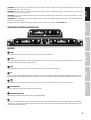 5
5
-
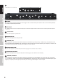 6
6
-
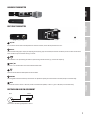 7
7
-
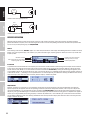 8
8
-
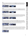 9
9
-
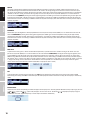 10
10
-
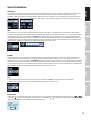 11
11
-
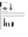 12
12
-
 13
13
-
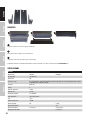 14
14
-
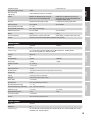 15
15
-
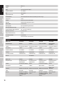 16
16
-
 17
17
-
 18
18
-
 19
19
-
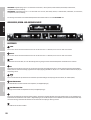 20
20
-
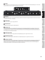 21
21
-
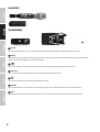 22
22
-
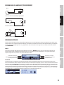 23
23
-
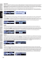 24
24
-
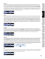 25
25
-
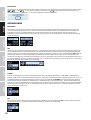 26
26
-
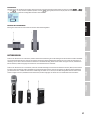 27
27
-
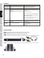 28
28
-
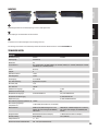 29
29
-
 30
30
-
 31
31
-
 32
32
-
 33
33
-
 34
34
-
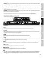 35
35
-
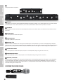 36
36
-
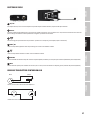 37
37
-
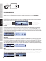 38
38
-
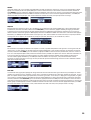 39
39
-
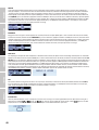 40
40
-
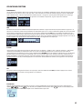 41
41
-
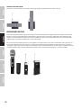 42
42
-
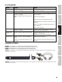 43
43
-
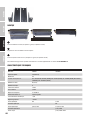 44
44
-
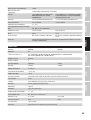 45
45
-
 46
46
-
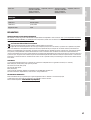 47
47
-
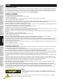 48
48
-
 49
49
-
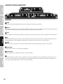 50
50
-
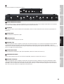 51
51
-
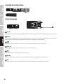 52
52
-
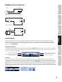 53
53
-
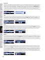 54
54
-
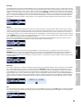 55
55
-
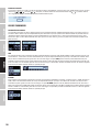 56
56
-
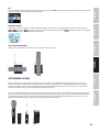 57
57
-
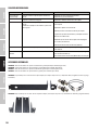 58
58
-
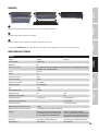 59
59
-
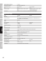 60
60
-
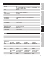 61
61
-
 62
62
-
 63
63
-
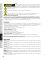 64
64
-
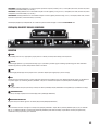 65
65
-
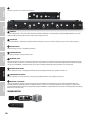 66
66
-
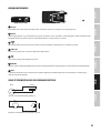 67
67
-
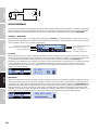 68
68
-
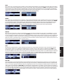 69
69
-
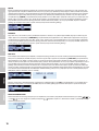 70
70
-
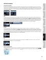 71
71
-
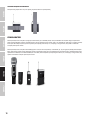 72
72
-
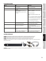 73
73
-
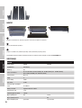 74
74
-
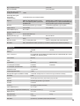 75
75
-
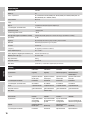 76
76
-
 77
77
-
 78
78
-
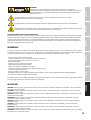 79
79
-
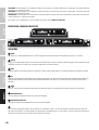 80
80
-
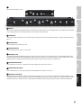 81
81
-
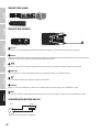 82
82
-
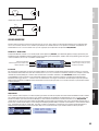 83
83
-
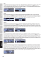 84
84
-
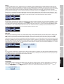 85
85
-
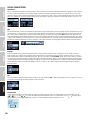 86
86
-
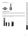 87
87
-
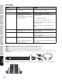 88
88
-
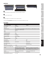 89
89
-
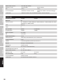 90
90
-
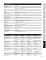 91
91
-
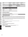 92
92
-
 93
93
-
 94
94
-
 95
95
-
 96
96


LD Systems LD System U506HHC2 Dual Wireless Condenser Microphone System Manual de usuario
- Tipo
- Manual de usuario
en otros idiomas
- français: LD Systems LD System U506HHC2 Dual Wireless Condenser Microphone System Manuel utilisateur
- italiano: LD Systems LD System U506HHC2 Dual Wireless Condenser Microphone System Manuale utente
- English: LD Systems LD System U506HHC2 Dual Wireless Condenser Microphone System User manual
- Deutsch: LD Systems LD System U506HHC2 Dual Wireless Condenser Microphone System Benutzerhandbuch
- polski: LD Systems LD System U506HHC2 Dual Wireless Condenser Microphone System Instrukcja obsługi
Artículos relacionados
-
LD Systems CURV 500 STS Manual de usuario
-
LD Systems U508 BPH Manual de usuario
-
LD Systems MEI 100 G2 Manual de usuario
-
LD Systems U506 CST Manual de usuario
-
LD Systems WS 1000 MW Manual de usuario
-
-
-
-
LD Systems U305.1 BPW Manual de usuario
-

