Carel humiSonic UU06 Manual de usuario
- Categoría
- Medir, probar
- Tipo
- Manual de usuario
Este manual también es adecuado para

High Efficiency Solutions
NO POWER
& SIGNAL
CABLES
TOGETHER
READ CAREFULLY IN THE TEXT!
Manual del usuario
User manual
Ultrasonic humidifi ers
direct version for room application
Humidifi cadores por ultrasonidos
versión direct para ambiente


3
SPA
Direct version for room applic. +0300062EE - rel. 1.3 - 15.07.2019
ADVERTENCIA
Los humidifi cadores CAREL son productos avanzados, cuyo funcionamiento se especifi ca en la documentación
técnica suministrada con el producto o descargable, incluso antes de la adquisición, desde el sitio de internet
www.carel.com. Cualquier producto CAREL, por su avanzado nivel tecnológico, necesita de una fase de
califi cación/confi guración/programación para que pueda funcionar lo mejor posible para la aplicación específi ca.
La falta de dicha fase de estudio, como se indica en el manual, puede generar malos funcionamientos en los
productos fi nales de los que CAREL no será responsable. El cliente (fabricante, proyectista o instalador del equipo
fi nal) asume cualquier responsabilidad y riesgo sobre la confi guración del producto para alcanzar los resultados
previstos para la instalación y/o el equipo fi nal específi co. CAREL en este caso, previos acuerdos específi cos, puede
intervenir como consultor para el buen fi n de la instalación/puesta en marcha de la máquina/uso, pero en ningún
caso puede ser considerada responsable del buen funcionamiento del humidifi cador y la instalación fi nal si no se
han seguido las advertencias o recomendaciones descritas en este manual, o en otra documentación técnica del
producto. En particular, sin exclusión de la obligación de observar las antedichas advertencias o recomendaciones,
para un uso correcto del producto se recomienda prestar atención a las siguientes advertencias:
• PELIGRO DE DESCARGAS ELÉCTRICAS: El humidifi cador contiene componentes bajo tensión eléctrica.
Quitar la alimentación de la red antes de acceder a las partes internas, en caso de mantenimiento y
durante la instalación.
• PELIGRO DE FUGAS DE AGUA: El humidifi cador carga/descarga automáticamente y constantemente
cantidad de agua. Malos funcionamientos en las conexiones o en el humidifi cador pueden provocar fugas.
Atención:
• Las condiciones ambientales y la tensión de alimentación deben ser conformes con los valores especifi cados
en las etiquetas de ‘datos de placa’ del producto.
• El producto está diseñado exclusivamente para humectar ambientes de forma directa.
• La instalación, el uso y el mantenimiento deben ser realizados por personal cualifi cado, conocedor de las
precauciones necesarias y capaz de efectuar correctamente las operaciones necesarias.
• Para la producción de agua nebulizada se debe utilizar exclusivamente agua con las características
indicadas en el presente manual.
• Todas las operaciones en el producto deben ser realizadas según las instrucciones contenidas en el presente
manual y en las etiquetas aplicadas al producto. Los usos y las modifi caciones no autorizadas por el productor
se considerarán inadecuadas. CAREL no asume ninguna responsabilidad por dichos usos no autorizados.
• No intentar abrir el humidifi cador de formas distintas de las indicadas en el manual.
• Atenerse a las normativas vigentes en el lugar en el que se instala el humidifi cador.
• Mantener el humidifi cador fuera del alcance de los niños y los animales.
• No instalar y utilizar el producto en las proximidades de objetos que pueden dañarse en contacto con el
agua (o la condensación). CAREL declina cualquier responsabilidad por daños indirectos o directos como
consecuencia de pérdidas de agua del humidifi cador.
• No utilizar productos químicos corrosivos, disolventes o detergentes agresivos para limpiar las partes
internas y externas del humidifi cador, salvo que se especifi que en los manuales del usuario.
• No dejar caer, golpear o agitar el humidifi cador, porque las partes internas y de revestimiento podrían sufrir
daños irreparables.
CAREL adopta una política de desarrollo continuo. Por lo tanto, se reserva el derecho de efectuar modifi caciones
y mejoras a cualquier producto descrito en el presente documento sin previo aviso. Los datos técnicos presentes
en el manual pueden sufrir modifi caciones sin obligación de previo aviso. La responsabilidad de CAREL sobre su
producto está regulada por las condiciones generales del contrato CAREL publicadas en el sitio www.carel.com
y/o por acuerdos específi cos con los clientes; en particular, en la medida permitida por la normativa aplicable, en
ningún caso CAREL, y sus dependientes o sus fi liales/afi liadas serán responsables de eventuales faltas de ganancias
o ventas, pérdidas de datos y de informaciones, costes de materiales o servicios sustitutivos, daños a cosas o
personas, interrupciones de actividades, o eventuales daños directos, indirectos, incidentales, patrimoniales, de
cobertura, punitivos, especiales o consecuenciales causados de cualquier forma, sean estos contractuales, extra
contractuales o debidos a negligencia u otras responsabilidades derivadas del uso del producto o de su instalación,
incluso si CAREL o sus fi liales/afi liadas hayan sido avisadas de la posibilidad de daños.
DESECHADO
El humidifi cador está compuesto por partes de metal y piezas de plástico. En referencia a la Directiva 2002/96/
CE del Parlamento Europeo y del Consejo del 27 de enero de 2003 y a las correspondientes normativas
nacionales de actuación, informamos que:
1. Subsiste la obligación de no desechar los RAEE como residuos urbanos y de efectuar, para dichos residuos, una
recogida separada;
2. Para el desechado se utilizan los sistemas de recogida públicos o privados previstos por las leyes locales.
Además es posible devolver al distribuidor el aparato al fi nal de su vida en caso de adquisición de uno nuevo;
3. Este aparato puede contener sustancias peligrosas: un uso inadecuado o un desechado incorrecto podría
tener efectos negativos en la salud humana y sobre el ambiente;
4. El símbolo (contenedor de basura con ruedas tachado) indicado en el producto o en el embalaje y en la
hoja de instrucciones indica que el aparato ha sido introducido en el mercado después del 13 de Agosto
de 2005 y que debe ser objeto de recogida separada;
5. En caso de desechado abusivo de los residuos eléctricos y electrónicos están previstas sanciones
establecidas por las vigentes normativas locales en materia de desechado.
Garantía sobre los materiales: 2 años (de la fecha de producción, excluidos los consumibles).
Homologaciones: la calidad y la seguridad de los productos CAREL están garantizadas por el sistema de diseño
y producción certifi cado por la ISO 9001, y por la marca
.
WARNINGS
CAREL humidifi ers are advanced products, whose operation is specifi ed in the technical documentation
supplied with the product or can be downloaded, even prior to purchase, from the website www.carel.
com. Each CAREL product, in relation to its advanced level of technology, requires setup/confi guration/
programming/commissioning to be able to operate in the best possible way for the specifi c application. The
failure to complete such operations, which are required/indicated in the user manual, may cause the fi nal
product to malfunction; CAREL accepts no liability in such cases.
The customer (manufacturer, developer or installer of the fi nal equipment) accepts all liability and risk
relating to the confi guration of the product in order to reach the expected results in relation to the specifi c
fi nal installation and/or equipment. CAREL may, based on specifi c agreements, act as a consultant for the
installation/commissioning/use of the unit, however in no case does it accept liability for the correct operation
of the humidifi er and the fi nal installation if the warnings or suggestions provided in this manual or in other
product technical documents are not heeded. In addition to observing the above warnings and suggestions,
the following warnings must be heeded for the correct use of the product:
•
DANGER OF ELECTRIC SHOCK : The humidifi er contains live electrical components. Disconnect the
mains power supply before accessing inside parts or during maintenance and installation.
•
DANGER OF WATER LEAKS:
The humidifi er automatically and constantly fi lls/drains certain quantities
of water. Malfunctions in the connections or in the humidifi er may cause leaks.
Important:
•
Environmental and power supply conditions must conform to the values specifi ed on the product rating labels.
•
The product is designed exclusively to humidify rooms directly.
•
Only qualifi ed personnel who are aware of the necessary precautions and able to perform the required
operations correctly may install, operate or carry out technical service on the product.
•
Only water with the characteristics indicated in this manual must be used for atomized water production.
•
All operations on the product must be carried out according to the instructions provided in this manual and
on the labels applied to the product. Any uses or modifi cations that are not authorised by the manufacturer
are considered improper. CAREL declines all liability for any such unauthorised use.
•
Do not attempt to open the humidifi er in ways other than those specifi ed in the manual.
•
Observe the standards in force in the place where the humidifi er is installed.
•
Keep the humidifi er out of the reach of children and animals.
•
Do not install and use the product near objects that may be damaged when in contact with water (or
condensate). CAREL declines all liability for direct or indirect damage following water leaks from the
humidifi er.
•
Do not use corrosive chemicals, solvents or aggressive detergents to clean the inside and outside parts of
the humidifi er, unless specifi cally indicated in the user manual.
•
Do not drop, hit or shake the humidifi er, as the inside parts and the linings may be irreparably damaged.
CAREL adopts a policy of continual development. Consequently, CAREL reserves the right to make changes and
improvements to any product described in this document without prior warning. The technical specifi cations
shown in the manual may be changed without prior warning.The liability of CAREL in relation to its products is
specifi ed in the CAREL general contract conditions, available on the website www.carel.com and/or by specifi c
agreements with customers; specifi cally, to the extent where allowed by applicable legislation, in no case will
CAREL, its employees or subsidiaries be liable for any lost earnings or sales, losses of data and information,
costs of replacement goods or services, damage to things or people, downtime or any direct, indirect,
incidental, actual, punitive, exemplary, special or consequential damage of any kind whatsoever, whether
contractual, extra-contractual or due to negligence, or any other liabilities deriving from the installation, use or
impossibility to use the product, even if CAREL or its subsidiaries are warned of the possibility of such damage.
DISPOSAL
The humidifi er is made up of metal parts and plastic parts. In reference to European Union directive 2002/96/
EC issued on 27 January 2003 and the related national legislation, please note that:
1.
WEEE cannot be disposed of as municipal waste and such waste must be collected and disposed of separately;
2.
the public or private waste collection systems defi ned by local legislation must be used. In addition, the
equipment can be returned to the distributor at the end of its working life when buying new equipment;
3.
the equipment may contain hazardous substances: the improper use or incorrect disposal of such may
have negative eff ects on human health and on the environment;
4.
the symbol (crossed-out wheeled bin) shown on the product or on the packaging and on the instruction
sheet indicates that the equipment has been introduced onto the market after 13 August 2005 and that
it must be disposed of separately;
5.
in the event of illegal disposal of electrical and electronic waste, the penalties are specifi ed by local waste
disposal legislation.
Warranty on materials: 2 years (from the date of production, excluding consumables).
Approval: the quality and safety of CAREL products are guaranteed by the ISO 9001 certifi ed design and
production system, as well as by the
mark.


5
SPA
Direct version for room applic. +0300062EE - rel. 1.3 - 15.07.2019
7. PARÁMETROS DE CONFIGURACIÓN 18
7.1 Parámetros básicos ..............................................................................................18
7.2 Parámetros avanzados ........................................................................................18
7.3 Parámetros de conexión serie ........................................................................21
7.4 Parámetros de sólo lectura ...............................................................................21
8. CONTROL DEL HUMIDIFIC ADOR VÍA RED 22
8.1 Lista de variables de supervisión ..................................................................22
8.2 Control de producción vía red ......................................................................23
8.3 Activación de lavado vía red ...........................................................................23
9. ALARMAS 24
9.1 Resolución de los problemas ..........................................................................25
10. MANTENIMIENTO Y PIEZAS DE RECAMBIO 26
10.1 Componentes eléctricos ...................................................................................26
10.2 Componentes mecánicos ................................................................................26
10.3 Mantenimiento ........................................................................................................27
10.4 Mantenimiento ordinario ..................................................................................27
10.5 Mantenimiento extraordinario ......................................................................27
10.6 Sustitución de los componentes .................................................................27
10.7 Limpieza de la bandeja .......................................................................................29
11. ESQUEMA ELÉCTRICO 30
11.1 Esquema .....................................................................................................................30
12. CARAC TER ÍS TICAS GENERALES Y MODELOS 31
12.1 Modelos de humidifi cadores por ultrasonidos y
características eléctricas .................................................................................31
12.2 Características técnicas ....................................................................................31
12.3 Tabla de fusibles ......................................................................................................31
13. CONEXIÓN EN RED 32
13.1 Predisposiciones .....................................................................................................32
13.2 Lógica de control....................................................................................................32
13.3 Gestión de los esclavos desde el terminal (máster) ..........................32
13.4 Alarmas .........................................................................................................................32
13.5 Control desde la supervisión (Carel/Modbus®) ...................................32
13.6 Unidad secundaria con función de respaldo
de la unidad principal ..........................................................................................34
Index
1. INTRODUCCIÓN Y MONTAJE 7
1.1 humiSonic (UU0*R) ..................................................................................................7
1.2 Códigos ...........................................................................................................................7
1.3 Dimensiones y pesos ..............................................................................................7
1.4 Apertura del embalaje ..........................................................................................7
1.5 Material incluido ........................................................................................................7
1.6 Preparación para el montaje ..............................................................................7
1.7 Montaje en pared......................................................................................................8
1.8 Etiqueta identifi cativa .............................................................................................8
1.9 Esquema funcional ...................................................................................................8
1.10 Principio de funcionamiento .............................................................................8
1.11 Estructura .......................................................................................................................9
2. CONEXIONES HIDRÁULICAS 9
2.1 Advertencias .................................................................................................................9
2.2 Conex. hidráulicas (partes no incluidas) .....................................................9
2.3 Humidif. instalado en soporte horizontal ...............................................10
2.4 Agua de alimentación .........................................................................................10
2.5 Agua de descarga ..................................................................................................11
3. CONEXIONES ELÉCTRICAS 11
3.1 Prepar. del paso de los cables eléctricos..................................................11
3.2 Predisposiciones eléctricas...............................................................................11
3.3 Conexiones de la tarjeta principal ..............................................................12
3.4 Conexiones de la tarjeta auxiliar ...................................................................12
4. PUESTA EN MARCHA, INTERFAZ D EL USUARIO Y
FUNCIONES BÁSICAS 13
4.1 Puesta en marcha ...................................................................................................13
4.2 Apagado/Stand by ................................................................................................13
4.3 Autotest ........................................................................................................................13
4.4 Luces del interruptor ON/OFF ........................................................................13
4.5 Deshabilitaciones ...................................................................................................13
4.6 Reseteo del contador de horas de la bandeja .....................................13
4.7 Lavado automático ...............................................................................................13
4.8 Lavado por inactividad .......................................................................................13
5. TERMINAL LCD (OPCIONAL) 14
5.1 Terminal de display remoto (UUKDI00000) ............................................14
5.2 Signifi cado de los símbolos .............................................................................14
5.3 Teclado ........................................................................................................................14
5.4 Visualización principal ........................................................................................14
5.5 Visualización de la versión del Software ..................................................15
5.6 Acceso y modifi cación de parámetros .....................................................15
5.7 Parám.: Reseteo de los valores de fábrica................................................15
5.8 Res. contador de horas desde el display..................................................15
6. PRINCIPIOS DE FUNCIONAMIENTO 15
6.1 Nebulización por ultrasonidos .......................................................................15
6.2 Principios de regulación ....................................................................................15
6.3 Modulación del caudal en paralelo (Dipswitch 8 a Off ) ................16
6.4 Modulación del caudal en serie (Dipswitch 8 a On).........................16
6.5 Gestión automática de la falta de agua de alimentación .............16
6.6 Control automático de la producción de agua nebulizada ........16
6.7 Control automático de fugas de la electroválvula de
descarga y caudal de la electroválvula de carga ................................17
6.8 Protección automática de los transductores piezoeléctricos ....17

6
SPA
Direct version for room applic. +0300062EE - rel. 1.3 - 15.07.2019

7
SPA
Direct version for room applic. +0300062EE - rel. 1.3 - 15.07.2019
1. INTRODUCCIÓN Y MONTAJE
1.1 humiSonic (UU0*R)
Gama de humidifi cadores adiabáticos por ultrasonidos para la
humectación directa en ambiente, con ventiladores incorporados que
permiten una distribución homogénea del agua nebulizada. El humiSonic
es particularmente adecuado para múltiples aplicaciones como: la
humectación en ambientes de producción, centros de tratamiento de
datos, almacenes, tipografías, museos, laboratorios de restauración,
teatros, etc., en los cuales la optimización de la humedad ambiental es un
factor esencial para el confort de bienes y personas.
1.2 Códigos
Código Descripción
UU0(X)R(*)0001
sin tarjeta auxiliar, sin sonda de humedad
UU0(X)R(*)AS01
con tarjeta auxiliar y con sonda de humedad
Tab. 1.a
(X) = 2 à 2 kg/h (4.4 lbs/h), 4 à 4 kg/h (8.8 lbs/h), 6 à 6 kg/h (13.2 lbs/h),
8 à 8 kg/h (17.6 lbs/h)
(*) = D à Alimentación 230 Vac, 1 à Alimentación 110 Vac
1.3 Dimensiones y pesos
317
274
A
Fig. 1.a
Modelos UU02 UU04 UU06 UU08
Producción kg/h (lbs/h)
2 (4.4) 4 (8.8) 6 (13.2) 8 (17.6)
Altura mm (in) 317 (12.5)
Profundidad mm (in) 274 (10.8)
Longitud A mm (in)
483 (19) 608 (24) 733 (28.9) 858 (33.8)
Pesos kg (lb)
embalado
11 (24.2) 14 (30.9) 17 (37.5) 21 (46.3)
vacío
9,5 (20.9) 12,5 (27.6) 15,5 (34.2) 18,5 (40.8)
instalado*
10,3 (22.7) 14,1 (31.1) 17,9 (39.5) 21,7 (47.8)
Tab. 1.b
* en condiciones operativas, lleno de agua.
1.4 Apertura del embalaje
□ Controlar la integridad del embalaje a la recepción y notifi car
inmediatamente al transportista, por escrito, cualquier daño que
pueda ser atribuido a un transporte descuidado o inadecuado;
□ Transportar el humidifi cador en el lugar de instalación antes de
sacarlo del embalaje, agarrando el cuello por debajo;
□ Abrir la tapa de cartón, quitar los separadores de material anti golpes
y sacar el humidifi cador,
□ La unidad se debe poner siempre en un local seco antes de la instalación.
1.5 Material incluido
Verifi car la presencia de:
1. Pletina de fi jación en pared;
2. Kit de tornillos con tacos;
3. 1 pasacables;
4. N° 4 patas;
5. Manual del usuario.
1.6 Preparación para el montaje
• La unidad está diseñada para el montaje en soporte horizontal o en
pared y es idóneo para soportar el peso en condiciones operativas (ver
el párr. “Montaje en pared”);
• Instalar el humidifi cador en un lugar seguro donde no pueda ser
manipulado, lo más distante posible da eventuales corrientes de aire;
• Posicionar el humidifi cador horizontalmente utilizando un nivel,
observando los espacios mínimos en mm (ver Fig. 1.b) para asegurar el
fl ujo del aire de entrada y permitir las operaciones de mantenimiento
necesarias.
<0,5°
≥ 500
(19.7”)
≥ 450
(17.7”)
≥ 500
(19.7”)
≥ 200...300
(19.7”)
Fig. 1.b
Nota: la distancia mínima posterior se recomienda en el caso de
montaje en soporte horizontal.
Atención: en la instalación en soporte horizontal/en pared:
1. El humidifi cador absorbe el aire por las ranuras del panel posterior/
inferior respectivamente;
2. Las patas/separadores van montadas por debajo/posteriormente;
3. Los tubos de carga/descarga salen posteriormente/por el fondo;
4. El pasacables de los cables de alimentación está montado
posteriormente/en el fondo;
5. Quitar la pletina posterior en caso de montaje en soporte horizontal.
Montaje en soporte horizontal
1
1
2
2
3
4
AIR
Fig. 1.c
Montaje en pared
2
2
1
4
3
AIR
AIR
1
Fig. 1.d

8
SPA
Direct version for room applic. +0300062EE - rel. 1.3 - 15.07.2019
1.7 Montaje en pared
Atención: montar la unidad sólo en una pared de mampostería
Montar el humidifi cador en la pared por medio de la pletina de soporte
ya fi jada en el humidifi cador, utilizando el kit de tornillos suministrado
(para las dimensiones y los pesos ver el párrafo anterior).
Instrucción para la fi jación:
• Fijar la pletina en la pared, controlando con un nivel la posición
horizontal. Realizar los taladros en el muro utilizando como plantilla la
propia pletina. Si el montaje se realiza en una pared de mampostería,
se pueden utilizar los tacos de plástico (Ø 8 mm, Ø 0.31 in) y los tornillos
(Ø 5 mm x L= 50 mm, Ø 0.19 in x L= 1.97 in) suministrados;
• Utilizar un alicate de puntas para perforar el cuadro siguiendo las pre
perforaciones;
Fig. 1.e
• Colgar el humidifi cador de la pletina;
X
Fig. 1.f
Dimensiones mm (in) UU02 UU04 UU06 UU08
X 198 (7.8) 323 (12.7) 448 (17.6) 573 (22.5)
Tab. 1.c
• Regular, por medio de las patas de regulación posteriores y utilizando un
nivel, la inclinación del humidifi cador de forma que quede paralelo al suelo.
> 2 m
(6.56 ft)
> 3,5 m (11.48 ft)
> 0,45 m
(1.47 ft)
Fig. 1.g
1.8 Etiqueta identifi cativa
Los humidifi cadores son identifi cables por medio de la etiqueta del embalaje
y la etiqueta identifi cativa accesible después de haber quitado la cubierta.
Rev. 2.0
S.N.
A00020 66
Date
04-Nov-2014
Code
UU02RD0000
..
S.N.
A00020
Date
04-No
Code
UU02RD0000
Fig. 1.h
Nota: la manipulación, la eliminación, la falta de las etiquetas de
identifi cación o todo lo que no permita la identifi cación segura del
producto, difi culta cualquier operación de instalación y mantenimiento.
1.9 Esquema funcional
M
M
7
8
6
2
3
3
4
5
9
10
11
11
13
5
5
9
5
15
14
1
4
12
Fig. 1.i
Leyenda
1 Filtro de aire 9 Sensor de nivel de fl otador
2 Ventiladores posteriores 10 Bandeja
3 Agua nebulizada 11 Driver
4 Difusor 12 Transductor piezoeléctrico
5 Cámara de atomización 13 Alimentador
6 Válvula de carga 14 Ventiladores anteriores
7 Tubo de demasiado lleno 15 Ranura de aire
8 Válvula de descarga
1.10 Principio de funcionamiento
Los humidifi cadores Humisonic se basan en el principio de la nebulización
de agua desmineralizada por medio de tecnología de ultrasonidos. El
principio de funcionamiento del humidifi cador se resume a continuación:
• Carga de agua por medio de electroválvula de carga hasta el alcance
del nivel requerido por el fl otador;
• Si está previsto el autotest (predeterminado), la electroválvula de
descarga se abre y vacía la bandeja (función prevista para limpiar el
depósito de eventuales residuos/suciedad);
• Nueva carga de agua hasta el nivel requerido;
• Inicio de la nebulización por ultrasonidos (los ventiladores instalados
en el humidifi cador permiten expeler las partículas de humedad y
difundirlas en el ambiente circundante);
• El reintegro de agua se produce a demanda del fl otador, después
de que percibe que el nivel ha descendido por debajo del valor
aconsejado.
La tecnología por ultrasonidos es generada por una tensión en la entrada
que es transformada por medio de un circuito oscilante en una señal de
alta frecuencia de 1,7 MHz. La señal se transmite a un transductor, con
la parte superior en contacto con el agua, que se pone en vibración a alta
frecuencia. La superfi cie del transductor oscila a altísima velocidad (1,7
millones de veces por segundo), tal que impide al agua moverse a causa de
su inercia de masa. Consecuentemente, se genera una columna de agua
sobre los transductores. Durante la amplitud negativa del transductor, se
crea un vacío repentino, no llenado por el agua imposibilitada a seguir los
movimientos del transductor, demasiado elevados. La cavidad así creada
permite la producción de burbujas que son empujadas hacia el borde
de la columna de agua durante la fase de amplitud positiva, entrando
así en colisión. Durante este proceso, partículas fi nísimas de agua son
atomizadas en el borde de la columna de agua. A causa de las ondas

9
SPA
Direct version for room applic. +0300062EE - rel. 1.3 - 15.07.2019
sonoras, se producen, directamente bajo la superfi cie del agua, ondas
cruzadas, en cuyo centro se separan pequeñísimas gotas de agua, con
la consiguiente formación de una sutil vaporización, inmediatamente
absorbida por el fl ujo de aire.
Dopo l'accensione
After switching on
Trasduttore / Transducer
Ampiezza negativa
Negative amplitude
Vuoto / Vacum
Trasduttore / Transducer
Ampiezza positiva
Positive amplitude
Trasduttore / Transducer
Fig. 1.j
1.11 Estructura
La fi gura muestra el cuerpo del humidifi cador, una vez quitadas las
cubiertas laterales y el panel de cobertura (ver el cap. “Mantenimiento y
piezas de recambio”).
R
1
3
5
6
11
8
9
13
10
6
5
F
2
4
7
12
14
A
C
E
B
D
L
N
PE
Fig. 1.k
Leyenda
F Frente 10 Alimentador (48 V)
R Trasera 11 Ventilador anterior
1 Difusor posterior 12 Ventilador posterior
2 Difusor anterior 13 Regleta de terminales
3 Válvula de carga A Terminal de tierra (PE)
4 Válvula de descarga B Terminales de alimentación
(L, N) con portafusibles
5 Transductor piezoeléctrico C Terminales de relé de alarma
6 Driver D Terminal alimentador (48 V) con
portafusible
7 Interruptor ON/OFF E Reservado
8 Tarjeta electrónica de control 14 Sonda de humedad (si está prevista)
9 Transformador (24 V)
2. CONEXIONES HIDRÁULICAS
Aten. antes de proceder con las conexiones hidráulicas asegurarse
de que el humidi cador no está conectado a la red eléctrica.
2.1 Advertencias
1. Usar exclusiv. agua desmineralizada. Instalar una válvula de interceptación
para cada humidifi cador. Presión del agua admitida: de 1 a 6 bar (de 14.5
a 87 psi);
2. Los tubos y las conexiones entre los tubos sometidos al contacto con el
agua desmineralizada y el humidifi cador deben ser realizadas en material
resistente y adecuadas para dicho uso (por ej. PVC o acero inoxidable):
presión nominal ≥ 6 bar (87 psi), temperatura de funcionamiento al
menos 1…40°C (33.8…104°F);
3. Las líneas del agua no deben ser ensuciadas por partículas de polvo
o de otras sustancias. Limpiar cuidadosamente las líneas antes de
conectarlas al humidifi cador;
4. Todos los humidifi cadores por ultrasonidos humiSonic son suministrados
con racor rápido para la conexión al tubo de carga φe/φi = 8/6 mm (OD
5/16”, ID 15/64”).
2.2 Conex. hidráulicas (partes no incluidas)
• Instalar una válvula manual de interceptación aguas arriba de
la instalación (para poder asegurar la interrupción del agua de
alimentación); la válvula debe ser adecuada para el uso de agua
desmineralizada.
• Predisponer un fi ltro mecánico (10 m) aguas abajo de la válvula
manual de interceptación para retener eventuales impurezas sólidas;
el fi ltro debe estar dotado de los órganos de interceptación para
permitir las operaciones de limpieza.
Atención:
• Con la instalación terminada, purgar la tubería de alimentación
durante 30 minutos conduciendo el agua directamente a la descarga
sin introducirla en el humidifi cador. Después de la instalación de
la válvula, hacer correr agua para eliminar eventuales residuos de
montaje y aceite e impedir que entren en el humidifi cador;
• El tubo de descarga debe tener un diámetro interno minimo de 6 mm
(15/64”); no debe presentar curvas que impidan el paso del agua; la
línea de descarga debe respetar las normativas nacionales y locales
vigentes y debe incluir un embudo para garantizar la interrupción de
continuidad y un sifón para evitar el retorno de olores. La línea fi nal
debe estar inclinada hacia abajo para facilitar el desagüe;
• No obstruir la salida del agua nebulizada o las tomas del aire de
aspiración;
• Si existe riesgo de congelación del agua de alimentación, prever el
aislamiento o el uso de cables calefactores sur tubos.
water drain
water inlet
Fig. 2.a

10
SPA
Direct version for room applic. +0300062EE - rel. 1.3 - 15.07.2019
2.3 Humidif. instalado en soporte horizontal
Si el humidifi cador se instala en soporte horizontal:
1. Los tubos de carga/ descarga se hacen salir por el panel posterior;
2. El pasacables del cable de alimentación va instalado en el panel posterior.
Para montar los tubos de carga/ descarga:
A
B
C
a
rico/ Fill
Scar
i
c
o
/ Drain
Fig. 2.b
A. Desenroscar el tornillo para quitar la cubierta derecha;
B. Cortar los precortados para obtener los taladros donde insertar los
tubos de carga/descarga;
C
1
2
Insert
Extract
Fig. 2.c
C. Insertar los tubos en los racores de conexión rápida para la conexión
a las válvulas de carga y descarga.
1. Pulsar el anillo de bloqueo de la conexión rápida;
2. Extraer el tubo.
Humidifi cador instalado en la pared
Si el humidifi cador se instala en la pared, operar como en el párrafo
anterior para desmontar las cubiertas e instalar:
1. Los tubos de carga/ descarga, que se hacen salir por el panel inferior;
2. El pasacables del cable de alimentación, que va instalado en el panel
inferior.
Fig. 2.d
2.4 Agua de alimentación
Para garantizar el correcto funcionamiento, el humiSonic necesita usar
agua desmineralizada, por las características químicas y físicas indicadas
en la tabla. Para obtener dichos valores de calidad del agua, se utiliza
normalmente un sistema de desmineralización, que aprovecha la
tecnología de la ósmosis inversa.
Agua de alimentación
Conexión rápida ext. Ø 8 mm (OD 5/16”)
Límites de temperatura °C (°F) 1…40 (33.8…104)
Límite de presión MPa bar (psi) 1…6 (14.5…87)
Conductividad específi ca a 20°C 0…80 µS/cm
Dureza total 0…25 mg/l CaCO3
Dureza temporal 0…15 mg/l CaCO3
Cantidad total de sólidos disueltos (cR) Dependiente de la conductividad espec.(1)
Residuo solido a 180°C Dependiente de la conductividad espec.(1)
Hierro + manganeso 0 mg/l Fe+Mn
Cloruros 0...10 ppm Cl
Dióxido de silicio 0...1 mg/l SiO2
Iones de cloro 0 mg/l Cl
Sulfato de calcio mg/l CaSO4
Caudal instantáneo EV carga l/min (gpm) 0.6 (0.16)
Tab. 2.a
(1) = en general C
R
=0,65 * σ
R,20
°C; R
180
= 0,93 * σ
R,20 °C
Para evitar un excesivo sobredimensionamiento del sistema por ósmosis
inversa, se aconseja evitar que el dimensionamiento del sistema sea
sufi ciente para cubrir el caudal instantáneo. Es aconsejable a tal fi n,
interponer entre el sistema de tratamiento del agua y el humiSonic
un vaso de expansión. Se debe tener en cuenta un consumo de agua
discontinuo, constituido por las siguientes fases:
• Rellenado (válvula de carga abierta);
• Producción (válvula de carga cerrada);
• Lavado (válvula de carga abierta).
En la tabla siguiente se sugieren los tamaños mínimos para el
acoplamiento con un sistema genérico por ósmosis inversa.
Mod. Acumulación
l (gal)
Volumen total l (gal) vaso de
expansión (pre-carga 1,5 bar/22 psi)
Sistema por ósmosis
inversa l/h (gph)
UU02 2,8 (0.62) 11,2 (2.46) 4,8 (1.27)
UU04 3,6 (0.79) 14,4 (3.17) 7,6 (2.01)
UU06 4,4 (0.97) 17,6 (3.87) 10,4 (2.75)
UU08 5,2 (1.14) 20,8 (4.56) 13,2 (3.49)
Tab. 2.b
En el caso de que no exista alguna clase de acumulación el sistema por
ósmosis inversa debe garantizar el caudal instantáneo de la EV de carga,
igual a 0.6 l/min (0.16 gpm).
Acoplamiento humiSonic con WTS Compact de Carel
En la gama de los productos Carel, están a disposición una serie de
instalaciones por ósmosis (“WTS Compact”) adecuadas para producir
agua según las especifi caciones listadas en la tabla del agua de
alimentación y para optimizar el acoplamiento y el funcionamiento con
humiSonic (ver los manuales +0300017IT y +0300019IT).
Todos los sistemas WTS Compact (código ROC%) están siempre dotados
de un vaso de expansión, que mantiene la presión en el circuito aguas
abajo. El funcionamiento del sistema está gestionado por presostatos
en el circuito de impulsión. La regla base para el acoplamiento es que
el agua contenida en el vaso de acumulación debe satisfacer la fase
de rellenado inicial y eventualmente la fase de lavado, mientras que
la producción horaria del WTS debe cubrir la producción horaria del
humiSonic y rellenar el vaso en el más breve tiempo posible.
En la tabla siguiente se sugieren los consumos de agua y los acoplamientos
para todos los tamaños de humidifi cadores.
Mod. Produc.
l/h (gph)
Capacidad
depósito l (gal)
Lavado (*)
l/h (gph)
Codigo WTS
(mercados no USA)
UU02 2 (0.53) 0,8 (0.18) 2,8 (0.74) ROC025500N
UU04 4 (1.06) 1,6 (0.35) 3,6 (0.95) ROC025500N
UU06 6 (1.59) 2,4 (0.53) 4,4 (1.16) ROC025500N
UU08 8 (2.11) 3,2 (0.70) 5,2 (1.37) ROC025500N
Tab. 2.c
(*) El consumo de agua durante el lavado es calculado por las confi guraciones
predeterminadas (n°1 lavado cada 12 h, de 1 minuto de duración, que
concluye con la carga y descarga total del volumen de la bandeja). El
consumo es función del caudal de la electroválvula de carga, que es igual
a 0.6 litros/minuto (0.16 gpm). La duración y la frecuencia de lavado son
parámetros confi gurables por el usuario, e inciden signifi cativamente en el
dimensionamiento del sistema WTS.

11
SPA
Direct version for room applic. +0300062EE - rel. 1.3 - 15.07.2019
Los lavados periódicos se aconsejan también para mantener en buen estado
el sistema WTS que alimenta el humidifi cador. El agua dentro del sistema de
ósmosis necesita ser movida periódicamente para evitar el excesivo depósito
de minerales sobre las membranas.
Atención:
• No añadir sustancias desinfectantes o compuestos anticorrosivos en el
agua, porque son potencialmente irritantes;
• Está absolutamente prohibido el uso de agua de pozo, industrial
o tomada de circuitos de refrigeración y, en general, de agua
potencialmente contaminada (químicamente o bacteriológicamente).
2.5 Agua de descarga
No es tóxica y puede ser descargada en el sistema de recogida de las aguas
blancas, como está defi nido en la directiva 91/271/CEE concerniente al
tratamiento de las aguas residuales urbanas.
Agua de descarga
Conexión rápida ext. Ø 8 mm (0,32”)
Temperatura típica °C (°F) 1…40 (33.8…104)
3. CONEXIONES ELÉCTRICAS
3.1 Prepar. del paso de los cables eléctricos
A
B
D
C
Fig. 3.a
1. Desenroscar el tornillo (A) y quitar la cubierta (B);
2. Si el humidifi cador va instalado en la pared/en soporte horizontal
quitar la tapa de chapa correspondiente con un alicate de puntas en
el panel inferior/posterior (C);
3. Montar el pasacables (D).
3.2 Predisposiciones eléctricas
Atención:
• Antes de proceder a la realización de las conexiones eléctricas,
asegurarse de que la máquina esté desconectada de la red eléctrica;
• Verifi car que la tensión de alimentación del aparato corresponda
al valor indicado en los datos de placa indicados en la etiqueta del
producto;
• No alimentar el aparato si está plegado o volteado: se pueden producir
daños en los transductores.
Conectar el cable de alimentación a la regleta de terminales a través del
pasacables.
L
N
PE
Fig. 3.b
Nota: para evitar interferencias no deseadas, se aconseja mantener
los cables de alimentación separados de los de señal procedentes de las
sondas.
La tarjeta electrónica de control de humiSonic está compuesta por dos
tarjetas, una principal (1) dispuesta horizontalmente y una auxiliar (2)
dispuesta verticalmente.
J8
M9
M10
M15
M11 M14
SOTTO/ BOTTOM
SCHEDA/BOARD
1
SCHEDA/BOARD
2
J17
Fig. 3.c
TARJETA PRINCIPAL
C A
B
D
F
G
N
E
M 11M 15
M 14
G
G0
Fig. 3.d
Leyenda:
A Entrada de alimentación eléctrica a la tarjeta de transformador 24V
B Control de transductores;
C Alimentación de válvulas (SX Descarga / DX Carga)
D Dip switch de confi guración
E Reservado
F Alimentación de Luces del interruptor ON/OFF
G Conexión de sonda de humedad TH (serie digital de tipo IIC, cód:
HYHU000000) integrada en los códigos UU**R*AS*1..
M14 ON/OFF remoto (M14.1-M14.2)
M11 Serie RS4845 (M11)
M15 Alimentación de ventiladores anteriores
N Conexión de tarjeta auxiliar
TARJETA AUXILIAR
M9
M10J8
123 45
J17
COMMON
NO
Tx/Rx
GND
tLan
Fig. 3.e
J8 Conexión de terminal tLAN (opcional)
M9 Conector serie tLAN auxiliar
M10 M10.1 - + señal de control proporcional/sonda/humidostato
M10.2 - GND referencia de la señal
M10.3 - +21 Vcc para alimentación de sondas activas
M10.4 - Relé de alarma - CO
M10.5 - Relé de alarma - NO
J17 Reservado
Tab. 3.a
Confi guración de Dip switch: la confi guración debe ser realizada antes
de poner en funcionamiento el humidifi cador (posición predeterminada
representada en la Fig. 3.f).

12
SPA
Direct version for room applic. +0300062EE - rel. 1.3 - 15.07.2019
2
3
64
7
5
1
8
ON
Fig. 3.f
1. Comunicación 5-6 Setpoint de Humedad
OFF Serie 485 Carel/Modbus OFF/OFF 50 %HR
ON tLAN OFF/ON 30 %HR
2-3 Dirección tLAN (si 1 es ON) ON/OFF 40 %HR
OFF/OFF - - ON/ON 60 %HR
OFF/ON dirección 1 7 Reservado
ON/OFF dirección 2 8 Gestión producción transductores
ON/ON dirección 3 OFF en paralelo
4 Baud rate Serie 485 / tLan ON en serie
OFF 19200
ON 9600
Tab. 3.b
3.3 Conexiones de la tarjeta principal
Según el tipo de señal utilizado es posible obtener distintos tipos de
habilitación y/o gestión de la producción de agua nebulizada.
HUMIDOSTATO O CONTACTO REMOTO (acción ON/OFF)
La puesta en marcha de la producción se obtiene cerrando el terminal
M14. Es posible conectar a M14 un interruptor, un humidostato o un
controlador (contacto seco, máx 5Vcc abierto, máx 7 mA cerrado).
M 14
Remote
ON/OFF
+ GND
G
G0
Fig. 3.g
SONDA DE HUMEDAD TH (integrada en los códigos UU**R*AS01)
Si en el terminal G se conecta la sonda de humedad TH la producción de
agua nebulizada se pone en marcha si:
• El contacto M14 está cerrado;
• El valor de humedad detectada por la sonda es inferior al setpoint
(preajustado al 50%HR y modifi cable por medio de los dip 5-6).
Conexión Serie 485
Protocolo Carel/Modbus
RS 485
-
+
GND
M 11
Fig. 3.h
Atención: para las conexiones RS485 en el ámbito doméstico (CEI
EN 55014-1) y residencial (CEI EN 61000-6-3) utilizar un cable apantallado
(con pantalla conectada a PE tanto por el lado del terminal como por el
lado del control) con longitud máxima especifi cada por el protocolo EIA
RS-485 equivalente al estándar Europeo CCITT V11, utilizando cable
bipolar apantallado AWG26 de par trenzado; la impedancia de entrada
del estadio 485 es de 1/8 unit-load ( 96 kOhm ). Con esta confi guración se
pueden conectar hasta un máx de 256 dispositivos con montaje en
canaleta separada de los cables de potencia.
RELÉ DE ALARMA
Preparación para la señalización a distancia de la presencia de una o más
alarmas o del alcance del setpoint de humedad (ver tabla parámetro b0).
M9
M10J8
123 45
J17
COMMON
NO
Fig. 3.i
Nota: en el ámbito industrial (CEI EN61000-6-2) los cables de señal
que salen de la máquina no deben superar los 10 m (33 ft)
(1)
de longitud:
la entrada digital ON/OFF remoto (terminales M14.1...M14.2) y del cable
apantallado para la comunicación RS485.
3.4 Conexiones de la tarjeta auxiliar
Ver el cap. ”Parámetros de confi guración” para la descripción de los
parámetros A0, A1, A2.
M9
M10J8
123 45
J17
COMMON
NO
12
OUT
GND
21 Vdc
Fig. 3.j
La tarjeta auxiliar prevé las siguientes conexiones:
REGULACIÓN DE TIPO ON/OFF (humidostato o contacto remoto)
• Puentear el terminal M14.1 y M14.2 (habilitación) en la tarjeta base;
• Conectar los terminales M10.1 y M10.2 a un humidostato o contacto
remoto (contacto seco)
• Confi gurar el parámetro A0 = 0 para habilitar la acción On/Off .
REGULADOR PROPORCIONAL EXTERNO (acción modulante)
• Puentear el terminal M14.1 y M14.2 (habilitación) en la tarjeta base;
• Conectar los terminales M10.1 y M10.2 (demanda de producción) a un
regulador externo;
• Confi gurar el parámetro A0=1 para habilitar la acción modulante y el
parámetro A2 según la señal elegida (0...10V, 2...10V, 0...20, 4...20mA).
REGULACIÓN CON SONDA AMBIENTE CAREL
• Puentear el terminal M14.1 y M14.2 (habilitación) en la tarjeta base;
• Conectar la sonda a los terminales M10.1, M10.2. El terminal de
alimentación M10.3 puede ser conectado con cable de longitud máxima
de 2 m (6,6 ft); para longitudes mayores utilizar una alimentación externa
con masa eléctricamente conectada a la masa del control.
• Confi gurar el parámetro A0=2 para habilitar la regulación de la sonda y
el parámetro A2 según la señal elegida (0...10V, 2...10V, 0...20, 4...20mA)
Si se utilizan sondas distintas de las de CAREL indicadas, verifi car:
• Señal en tensión 0…10 Vcc, 2…10 Vcc, terminal M10.1 (GND: M10.2);
• Señal en corriente: 4…20, 0…20 mA, terminal M10.1 (GND: M10.2).
HABILITACIÓN DE LA SONDA TH COMO LÍMITE DE HUMEDAD
En los modos de regulación A0=0, A0=1, A0=2, es posible habilitar
la sonda de humedad TH integrada como sonda límite mediante la
confi guración del parámetro bH=1. Set point límite y la correspondiente
banda proporcional son los parámetros SL y bL.
Verifi caciones fi nales
Las siguientes condiciones satisfacen una correcta conexión eléctrica:
□ La tensión de red del humidifi cador corresponde a la tensión de
placa;
□ Se ha instalado un seccionador de línea para poder interruptor la
tensión al humidifi cador;
□ Los terminales M14.1, M14.2 son puenteados o conectados a un
contacto de habilitación del funcionamiento;
□ Si el humidifi cador es controlado desde un regulador externo (tarjeta
auxiliar), la masa de la señal es conectada eléctricamente a la masa
del control.

13
SPA
Direct version for room applic. +0300062EE - rel. 1.3 - 15.07.2019
4.5 Deshabilitaciones
El humidifi cador puede ser deshabilitado de formas diferentes:
• Abriendo el contacto M14.1 y M14.2 (OFF desde contacto);
• Desde el terminal del usuario mediante la presión de la tecla Esc
durante 5 s (OFF desde el teclado);
• Desde el supervisor vía serie RS485
• En presencia de alarmas.
4.6 Reseteo del contador de horas de la
bandeja
El humidifi cador está dotado de un contador de horas que se incrementa
en funcionamiento. Al transcurrir un número de horas preajustado
(5.000) se emite una señalización para indicar que se aconseja efectuar
el mantenimiento de la bandeja y la verifi cación del funcionamiento
de los transductores piezoeléctricos (ver el capítulo “Mantenimiento y
piezas de recambio”). Para resetear dicho contador de horas, en cualquier
momento, es necesario efectuar las siguientes operaciones:
• Apagar el humidifi cador;
• Cerrar el grifo de alimentación del agua y realizar el vaciado completo
de la bandeja;
• Desconectar el conector Lumberg (ver la Fig. 4.a) insertado en la tarjeta
de control;
• Abrir el contacto ON/OFF;
• Encender el humidifi cador (con el conector Lumberg desconectado de
la tarjeta de control). Ambas luces, blanca y roja, parpadearán;
• Cerrar el contacto ON/OFF, las luces blanca y roja permanecerán
encendidas fi jas;
• Apagar el humidifi cador;
• Insertar el conector Lumberg (ver Fig. 4.a) en la tarjeta, prestando
atención a la posición de inserción;
• Encender el humidifi cador.
Fig. 4.a
4.7 Lavado automático
El humidifi cador efectúa automáticamente un ciclo de lavado en
cualquier periodo de tiempo, durante el que se produce agua nebulizada,
confi gurado por el parámetro b1 (predeterminado 12 horas, por medio
del parámetro b0 es posible convertir la unidad de medida de b1 de horas
a minutos, ver en la tabla el parámetro b0). El ciclo de lavado consiste en
una descarga completa, en una fase durante la cual carga y descarga se
activan simultáneamente (predeterminado 1 minuto, parámetro b3) para
permitir el desagüe de eventuales residuos presentes en la bandeja, una
carga completa y fi nalmente una descarga completa. Durante esta fase
la producción de agua nebulizada se interrumpe.
4.8 Lavado por inactividad
Si el humidifi cador permanece inactivo (encendido pero en standby)
durante un largo periodo (parámetro b2, predeterminado 24 horas)
efectuará un lavado, como se describe en el párrafo anterior. Esto sirve para
volver a limpiar la bandeja de eventuales residuos (ej. polvo) que se pueden
crear en el periodo de inactividad. Por medio del parámetro b0 es posible
modifi car el instante en el que se realiza este lavado. Por defecto, el lavado
se produce al transcurrir 24 horas (continuas) de inactividad, mientras que
el humidifi cador está todavía en standby. Esto es así porque, normalmente,
el humidifi cador está asociado a un sistema de alimentación por ósmosis
inversa, que requiere un uso frecuente para evitar malos funcionamientos.
Por medio de b0 (ver tabla, parámetro b0, Ósmosis) es posible actuar de
modo que el lavado se produzca en el primer rearranque siguiente a las
horas de inactividad continuas, confi guradas en b2.
4. PUESTA EN MARCHA, INTERFAZ DEL USUARIO Y FUNCIONES BÁSICAS
Antes de poner en marcha el humidifi cador verifi car:
□ Conexiones hidráulicas: en caso de pérdidas de agua no poner en
marcha el humidifi cador antes de haber reapretado las conexiones;
□ Conexiones eléctricas.
4.1 Puesta en marcha
Ver el cap. “Conexiones eléctricas”
1
El humidifi cador, una vez alimentado y con el permiso habilitado
(ON/OFF remoto/humidostato, terminal M14; ON/OFF desde el
terminal del usuario; ON/OFF desde la serie), está listo para el uso.
2
Si no hay ninguna otra conexión externa, el humidifi cador entrará
en funcionamiento, el funcionamiento será interrumpido sólo si el
permiso (M14) se interrumpe.
3
Si la sonda de humedad TH (opcional) es conectada al terminal G el
humidifi cador entrará en funcionamiento hasta que se alcance el
setpoint de humedad (preajustado al 50% HR). Ver el cap. “Principios
de funcionamiento”.
4.2 Apagado/Stand by
1
Para apagar el humidifi cador, quitar la tensión
2
El humidifi cador se pone en standby si:
• El contacto ON/OFF remoto está abierto
• Si existe una sonda TH y se alcanza el set point de humedad
• Contacto ON/OFF abierto o deshabilitación desde la serie a
0 (ver el capítulo “Control del humidifi cador vía red”) o bien
deshabilitación desde el teclado
• Si hay presencia de señal modulante (tarjeta opcional) y
demanda nula
Con el humidifi cador puesto en stand by, la bandeja se vacía
automáticamente. En caso de stand by el ventilador permanece
encendido durante 5 min.
4.3 Autotest
El humidifi cador, en cualquier primera puesta en marcha (desde parado),
si está habilitado y hay demanda de humedad, efectúa un ciclo de test. Se
realiza una carga completa y una descarga completa durante las cuales se
monitoriza el sensor de nivel, si dicho test es satisfactorio, la producción
de agua nebulizada comienza correctamente. En caso de errores la
producción se inhibe. (ver la tabla de alarmas).
4.4 Luces del interruptor ON/OFF
Dentro del interruptor ON/OFF existen 2 luces: blanca y roja:
Luz AZUL
Fijo Nebulización en curso
Parpadeo Lento* Unidad deshabilitada
Parpadeo Lento Atenuado Setpoint Alcanzado
Parpadeo Rápido** Estado transitorio con nebulización
temporalmente en pausa
(ej. autotest, lavado)
*Parpadeo Lento: 1s ON y 1s OFF
**Parpadeo Rápido: 0,2s ON y 0,2s OFF
La luz roja tiene el signifi cado de alarma presente. Para la tabla de alarmas,
consultar el capítulo dedicado.

14
SPA
Direct version for room applic. +0300062EE - rel. 1.3 - 15.07.2019
5. TERMINAL LCD OPCIONAL
5.1 Terminal de display remoto
(UUKDI00000)
El terminal LCD es una opción y es utilizable sólo si existe la tarjeta auxiliar,
ya integrada en los modelos UU**R*AS01.
esc
Fig. 5.a
El terminal visualiza el estado del humidifi cador y puede ser utilizado para
personalizar su funcionamiento por medio de parámetros modifi cables.
Conexión:
esc
Fig. 5.b
Leyenda:
1 Cable telefónico de 6 vías cód. S90CONN000 o equiv. con longitud máx 2 m
(6,6 ft)
(1)
2 Terminal de display remoto
3
Tarjeta
auxiliar
Conexión remota del terminal hasta 200 m
humiSonic
A
J14
1 2 3 1 2 3
J15
B
C
SC
A
J14
1 2 3 1 2 3
J15
B
C
SC
5
esc
1
2
3
4
3
2
6
Fig. 5.c
Leyenda:
1 Cable telefónico (hasta 0,8 m de distancia);
2 Tarjeta CAREL TCONN6J000;
3 Pin strip J14 y J15 en posición 1-2 (alimentación eléctrica disponible
sobre los conectores telefónicos A, B y C y de tornillo SC);
4
Cable
AWG20-22 apantallado de tres pares trenzados para llevar el
Terminal de display hasta 200m. Conexión con la tarjeta TCONN6J00:
Terminal SC Función Terminal SC Función
0 Tierra (calza) 4 RX/TX+
1 +VRL 5 GND
2 GND 6 +VRL
3 RX/TX-
5 Terminal de display remoto
6 Tarjeta auxiliar
5.2 Signifi cado de los símbolos
Alimentación (LED verde)
Humidifi cador en funcionamiento (LED amarillo)
Fijo: producción de humedad
en curso
Parpadeante: estado transitorio con nebulización temporalmente
en pausa
Alarma (LED rojo). A la activación de una alarma: led parpadeante y
zumbador activo. Si hay alarma activa, pulsando ESC, el zumbador se
apaga y el LED se queda fi jo, una pulsación adicional de la tecla ESC
resetea las alarmas (ver cap. “Alarmas”)
Tiempo en segundos
Contador de horas
Producción porcentual de humedad respecto de la capacidad nominal
Necesidad de mantenimiento (alarma en curso)
Encendido fi jo: ventilador del humidifi cador activo.
Parpadeante: ventilador encendido durante la fase de apagado
3 dígitos, después del 999 el display visualiza para indicar 1.000 (se
visualizan 3 cifras con un punto arriba entre la primera y la segunda cifra)
Producción de humedad en curso
Rellenado de la bandeja en curso
Presencia de agua en la bandeja
Descarga de agua de la bandeja en curso (también se muestra cuando
la unidad está en modo de espera porque la válvula de descarga está
normalmente abierta)
Tab. 5.a
5.3 Teclado
Tecla Función
Retorno a la visualización anterior
UP desde pantalla principal: visualización de los valores de la
humectación, ver párrafo siguiente
Desde la lista de los parámetros: navegación en sentido circular de
los parámetros y modifi cación de los valores de los parámetros
DOWN Desde la pantalla principal: visualiz. de los valores de la
humectación
Desde la lista de los parámetros: navegación en sentido circular de
los parámetros y modifi cación de los valores de los parámetros
ENTER
(PRG)
Durante 2 segundos: acceso a la lista de parámetros
Dentro de la lista de los parámetros: función de selección y
confi rmación (como la tecla “enter” de los teclados del ordenador)
drain
Drenaje forzado: pulsar simultán. UP y DOWN
Tab. 5.b
5.4 Visualización principal
El display del humidifi cador visualiza normalmente el estado de la señal
de control. Si hay señal de entrada ON/OFF o proporcional (A0=0, A0=1,
A0=3 y sonda Th desconectada):
• Visualización de la señal de entrada;
• Contador de horas de la bandeja (h);
• Regulación de la producción máx. de agua nebulizada (parám. P0) (*);
• Histéresis de regulación (parámetro P1);
• Estado del humidifi cador (Enb = habilitado): pulsando ENTER se
desactiva el humidifi cador y aparece dIS en la pantalla principal.
Si hay señal de entrada de sonda de humedad (A0=2, A0=3 y sonda Th
conectada):
• Visualización de lectura de la sonda de humedad;
• Visualización de temperatura (sólo Th);
• Contador de horas de la bandeja (h);
• Regulación de la producción máxima de agua nebulizada (par. P0) (*);
• banda proporcional (parámetro bP)(*);
• Setpoint de humedad (parámetro SP)(*);
• Estado del humidifi cador (Enb = habilitado): pulsando ENTER se
desactiva el humidifi cador y aparece dIS en la pantalla principal.
La eventual habilitación de la sonda TH como límite de humedad (bH=1)
en los modos de regulación A0=0, A0=1, A0=3 conlleva la adición en la
pantalla principal de los parámetros:
• setpoint límite de humedad (parámetro SL) (*);
• banda proporcional límite (parámetro bL) (*)
Para volver a la visualización básica, pulsar ESC. Por medio del parámetro
C0 (cap. “Parámetros de confi guración”) es posible cambiar el valor de la
visualización básica (predeterminado: visualización de la señal de entrada).
Desactivaciones posibles:
• desde remoto (contacto ON-OFF abierto), el display visualiza “C - -”
alternativamente a la pantalla principal;
• desde el display pulsando ENTER sobre el Enb correspondiente, el
display mostrará dIS (para activar de nuevo, pulsar ENTER). En el caso
de la red máster/esclavo, esta desactivación únicamente tiene efecto
en cada humidifi cador individualmente;
• desde el display (presión de la tecla Esc durante 5 s), el display
visualiza “t - -” alternativamente a la pantalla principal. En el caso de
la red máster/esclavo, esta desactivación tiene efecto sobre todos los
humidifi cadores de la red. Para restablecer el ON, pulsar la tecla ESC
durante 5 segundos hasta que desaparezca t - -;

15
SPA
Direct version for room applic. +0300062EE - rel. 1.3 - 15.07.2019
6. PRINCIPIOS DE FUNCIONAMIENTO
6.1 Nebulización por ultrasonidos
Los humidifi cadores por ultrasonidos nebulizan el agua mediante la
propagación de ondas generada por un piezoeléctrico hacia la superfi cie del
agua. En el polo libre del agua se forman gotas de agua y las más pequeñas
se eliminan por medio del aire forzado. La cantidad de agua nebulizada
depende del nivel del agua, de la temperatura del agua y de la distribución
en el aire. El nivel del agua se mantiene constante mediante el uso de
válvulas de carga y descarga y de un sensor de nivel. Se recomienda utilizar
agua desmineralizada: si se utiliza agua de red, las sales que se depositan
en el tiempo son causa de la incrustación progresiva en el transductor
piezoeléctrico, comprometiendo su nebulización. Para evitar una excesiva
acumulación de cal, el humidifi cador periódicamente descarga y sustituye
automáticamente el agua contenida (lavado periódico).
6.2 Principios de regulación
El humidifi cador puede ser controlado por las siguientes señales:
• ON/OFF remoto;
• Señal proporcional externa (sólo con tarjeta auxiliar);
• Sonda de humedad;
• Serie.
Regulación ON/OFF
La acción, de tipo “todo o nada”, se activa desde un contacto externo
que determina el set point y el diferencial de regulación. El contacto
externo puede ser un humidostato, que según el estado determina el
funcionamiento del humidifi cador:
• Contacto cerrado: el humidifi cador produce agua nebulizada, si el
contacto de ON/OFF remoto está cerrado;
• Contacto abierto: la producción de agua nebulizada termina.
Regulación proporcional (sólo con tarjeta auxiliar)
• La producción de agua nebulizada es proporcional al valor de una señal
“Y” procedente de un dispositivo externo. El tipo de señal es seleccionable
entre las siguientes: 0...10 Vcc, 2...10 Vcc, 0...20 mA, 4...20 mA;
• La producción máxima del humidifi cador, correspondiente al valor
máximo de la señal externa, puede ser programada entre el Pn (predet.
10%) y 100% del valor nominal del humidifi cador (parámetro P0).
La producción mínima tiene histéresis de activación dada por el valor P1
(predeterminado 2% del recorrido completo de la banda proporcional de
la señal externa “Y”).
ONOFF
P1P1
P0
Pn
Y
Produzione Acqua nebulizzata
Atomized water production
Fig. 6.a
Regulación automática con sonda de humedad
La producción de humedad está ligada a la lectura de la sonda de humedad
relativa conectada. (TH o conexión a tarjeta opcional).
El humidifi cador producirá a plena carga si la humedad medida es inferior
al set point menos la banda proporcional, mientras que modulará la
nebulización dentro de la banda proporcional (parámetro bP editable,
predet. 10%HR).
La producción mínima tiene histéresis de activación fi ja igual al 10% del
recorrido de la banda proporcional bP.
• desde el supervisor (RS 485 Carel/Modbus) el display visualiza “S - -”
alternativamente a la pantalla principal.
Si hay varias deshabilitaciones al mismo tiempo, las visualizaciones se
alternan cíclicamente con la pantalla principal.
Si el display visualiza “---” existe un error de comunicación entre display
y humidifi cador: controlar el cable de conexión. Si el problema persiste,
contactar con la asistencia.
(*) Para modifi car el parámetro visualizado, pulsar:
• ENTER (display: );
• UP o DOWN para modifi car el valor
• ENTER para confi rmar el nuevo valor.
Pulsar ESC para volver a la pantalla principal. Es posible acceder a los
parámetros también desde la lista de los parámetros (cap. “Parámetros de
confi guración”).
5.5 Visualización de la versión del Software
1) Al encendido de la máquina, en el display aparece “rel. x.y” (p. ej., rel. 1.2);
2) Durante el funcionamiento:
• En el display: desde la pantalla principal, pulsar simultáneamente ESC y
UP, aparecen en secuencia : el tamaño del humidifi cador, la tensión de
alimentación, el número de fases y la versión del software;
• Vía red por medio de la variable entera 81. Ej. formato “## = #.#” (p.ej.,
12 = versión 1.2)”.
5.6 Acceso y modifi cación de parámetros
Los parámetros de confi guración permiten confi gurar y controlar las
funciones y el estado del humidifi cador. Desde la pantalla principal pulsar:
• ENTER durante 2 segundos;
• insertar la contraseña 77 con las teclas UP o DOWN;
• ENTER para confi rmar y acceder a la lista de los parámetros;
• UP o DOWN para recorrer la lista de forma circular;
• ENTER para seleccionar un parámetro (display: ‘set’);
• UP para modifi car (aumentando) el valor del parámetro. Para un
desplazamiento más rápido añadir la pulsación de DOWN;
• DOWN para modifi car (disminuyendo) el valor del parámetro. Para un
desplazamiento más rápido añadir la pulsación de UP;
• ENTER para memorizar el nuevo valor y volver a la lista de parámetros
o ESC para volver a dicha lista sin memorizar el valor.
Pulsar ESC para volver a la pantalla principal.
5.7 Parám.: Reseteo de los valores de fábrica
Desde la pantalla principal existe la posibilidad de resetear en cualquier
momento los valores de fábrica parám. Desde la pantalla principal pulsar:
• ENTER durante 2 segundos;
• Insertar la contraseña 50 con las teclas UP o DOWN y pulsar ENTER;
• Aparece dFt, presar ENTER y dFt parpadea: para recuperar los valores
de fábrica, presione ENTER nuevamente, o ESC para salir.
Si no se pulsa ninguna tecla durante 30 segundos la visualización vuelve
a la pantalla principal sin realizar reseteo alguno.
5.8 Res. contador de horas desde el display
Contador de horas de la bandeja
• Acceder al parámetro ‘d3’ (ver cap. “Parámetros de confi guración”);
• pulsar UP y DOWN durante 5 segundos;
Cuando se ha completado el reseteo aparece ‘res’ en el display.
Contador de horas interno de los transductores piezoeléctricos:
• Acceder al parámetro ‘d6’ (ver cap. “Parámetros de confi guración”);
• pulsar UP y DOWN durante 5 segundos
Cuando el reseteo está completado aparece ‘res’ en el display (d6 vuelve
a valer AF = 9999 predeterminado).

16
SPA
Direct version for room applic. +0300062EE - rel. 1.3 - 15.07.2019
%rH
OFFON
Pn
P0
Production %
10% bP
SP
bP
Fig. 6.b
Habilitación de la sonda TH como límite de humedad
Cuando la sonda TH se conecta a la entrada de tarjeta dedicada (códigos
UU**R*AS*1), es posible controlar la unidad mediante el contacto ON/
OFF (A0=0), señal proporcional externa o RS485 (A0=1) o bien sonda
activa externa (A0=2) y habilitar la sonda TH como límite de humedad
ajustando el parámetro bH = 1. El acercamiento al set point de límite
(parámetro SL editable, predet. 70%HR) dentro de la banda proporcional
bL conlleva una parcialización de la nebulización cada vez más creciente,
hasta interrumpir la producción al alcanzar el set límite. La histéresis para
la reactivación de la producción mínima es fi ja e igual al 10% del recorrido
de la banda proporcional bL.
%rH
OFFON
Pn
P0
Production %
10% bL
SL
bL
Fig. 6.c
6.3 Modulación del caudal en paralelo
(Dipswitch 8 a Off )
El caudal de agua nebulizada puede ser variado porcentualmente del 5% al
100% (parámetros Pm y P0) del valor nominal con encendidos y apagados
alternos de los transductores en un periodo prefi jado (parámetro b7,
predeterminado 1 segundo). El caudal se establece en base al parámetro
P0 (predeterminado 100%) y a la eventual demanda establecida por la
señal externa (si hay tarjeta opcional y regulación proporcional).
ON
t
OFF
Periodo / Period (b7)
T
rasduttore / Transducer
Portata / Flow rate 10%
Fig. 6.d
ON
t
OFF
Periodo / Period (b7)
Portata / Flow rate 50%
Trasduttore / Transducer
Fig. 6.e
ON
t
OFF
Portata / Flow rate 75%
Periodo / Period (b7)
Trasduttore / Transducer
Fig. 6.f
Si el caudal es del 100% los transductores están siempre encendidos.
6.4 Modulación del caudal en serie
(Dipswitch 8 a On)
El caudal de agua nebulizada puede ser variado porcentualmente entre
el 10% y el 100% del nominal. Cualquier humidifi cador está equipado
con 2 líneas de transductores (frontal y posterior) y cada línea se emplea
para generar el 50% de la producción total. Si la demanda establecida
por la señal externa (si hay tarjeta opcional y regulación proporcional)
y el parámetro P0 están al 100%, ambas líneas de transductores serán
activadas. Para producciones inferiores, la producción será repartida entre
los dos pares de transductores del siguiente modo:
• 51% - 99%: un par de transductores está siempre activado para generar
el 50% de la producción demandada, el otro modula como en el
párrafo anterior para generar el porcentaje restante de producción. (Ej.
Demanda al 75%: un par de transductores está siempre activado, el
otro modula al 50% como en la fi g. 6.d)
• 10% - 50%: un par de transductores está siempre apagado, el otro
modula como en el párrafo anterior para generar el porcentaje de
producción demandado. (Ej. demanda al 25%: un par de transductores
está siempre apagado, el otro modula al 50% como en la fi g. 6.d).
La distribución de la producción entre los dos pares de transductores
rota cada hora de funcionamiento para evitar un envejecimiento no
homogéneo.
6.5 Gestión automática de la falta de agua
de alimentación
El humidifi cador detecta la falta de agua de alimentación (o una
cantidad demasiado baja), controlando el estado del sensor de nivel
después de la apertura de la electroválvula de carga. En el caso de que
no se detecte una activación del sensor dentro del tiempo confi gurado
por el parámetro bA (predet. in minutos, variable según el tamaño) la
humectación se interrumpe, se activa la descarga y se espera un número
de minutos establecidos por el parámetro AA (predeterminado 10),
durante los cuales se visualiza en el display el mensaje “Rty” (Retry),
después del cual se intenta una carga de agua adicional. Si esta llega a
buen fi n la producción se reanuda, si no, se esperan otros AA minutos.
El proceso se repite hasta que el sensor detecta de nuevo la presencia
de agua. Los dos primeros intentos, no se genera ninguna alarma, si al
tercer intento el procedimiento no llega a buen fi n se genera la alarma
EF, que se reseteará automáticamente cuando el humidifi cador detecte
nuevamente la presencia de agua.
6.6 Control automático de la producción de
agua nebulizada
El humidifi cador controla el nivel del agua dentro de la bandeja durante
la fase de producción de agua nebulizada. Si el nivel no desciende,
podrían haber ocurrido las siguientes condiciones de avería:
• Mal funcionamiento de los transductores piezoeléctricos
• Fuga en la electroválvula de carga
• Mal funcionamiento del ventilador
Si después del tiempo confi gurado en la variable A8 (en minutos,
predeterminado 30) el agua no ha descendido por debajo del nivel bajo,
se bloquea la producción de agua nebulizada y se espera un tiempo igual
a AA minutos (predeterminado 10), durante los cuales se visualiza en el
display el mensaje “Rty”, tras lo cual el control reactiva la producción.
Si la condición se presenta nuevamente, se genera la alarma bloqueante

17
SPA
Direct version for room applic. +0300062EE - rel. 1.3 - 15.07.2019
EP. Si después de un porcentaje de tiempo de A8, establecido en el
parámetro Ab (predeterminado 70%) el agua está por encima del nivel
alto se bloquea la producción de agua nebulizada, se genera el warning
EL y se espera un tiempo igual a AA minutos (predeterminado 10), durante
los cuales se visualiza en el display el mensaje “Rty”, tras lo cual el control
reactiva la producción. La señalización EL es reseteada al fi nal de un ciclo
de producción terminado de forma correcta.
6.7 Control automático de fugas de la
electroválvula de descarga y caudal de
la electroválvula de carga
El parámetro A9 impone un tiempo mínimo de producción
(predeterminado 1 minuto), si el ciclo de producción dura menos de este
tiempo, es posible que la electroválvula de descarga tenga fugas o que
el caudal de la electroválvula de carga sea bajo. El control, en este caso,
realiza las siguientes operaciones:
1. Al fi nal del primer ciclo, terminado con un tiempo inferior a A9,
se incrementa el tiempo de reintegro de agua (+50% respecto al
parámetro bb).
2. Al fi nal del segundo ciclo, terminado con un tiempo inferior a A9,
se incrementa adicionalmente el tiempo de reintegro de agua
(+100% respecto al parámetro bb) y se activa el chattering* de
la electroválvula de descarga, que se efectuará al primer lavado
automático.
3. Al fi nal del tercer ciclo, terminado con un tiempo inferior a A9, se
incrementa adicionalmente el tiempo de reintegro de agua (+150%
respecto al parámetro bb) y se efectúa un ciclo de lavado, en el cual
será efectuado el chattering*, activado en el paso anterior. En esta
fase será generado el warning Y.
4. Después de esta última fase, se realizará un nuevo ciclo de producción.
En el caso de que persista la causa del error, el control se reiniciará
desde la fase anterior, hasta que se complete satisfactoriamente un
ciclo en los tiempos previstos. En este caso también será reseteado
el eventual warning.
*Chattering: serie de aperturas/cierres rápidos de la electroválvula de
descarga, realizados para tratar de quitar eventuales residuos (cal, polvo,
etc.) que impiden su cierre correcto.
6.8 Protección automática de los
transductores piezoeléctricos
Los transductores piezoeléctricos, por su naturaleza, si se hacen funcionar
sin agua, se degradan rápidamente hasta averiarse. Para evitar que esto
ocurra, la tarjeta de control trata de asegurarse, por medio del sensor de
nivel, que incluso en caso de anomalías los transductores no sean nunca
activados sin agua. En la fase de puesta en marcha con la bandeja vacía,
los transductores se activan sólo cuando se detecta el nivel bajo.
Durante las fases de reintegro en funcionamiento, es decir después
de que el nivel bajo ha descendido a causa del consumo de agua por
nebulización, con la consiguiente activación de la electroválvula de carga,
si el nivel no se recupera en el tiempo mínimo AC, los transductores se
apagan, mientras que la carga continua hasta que el nivel se haya
recuperado o hayan transcurrido bA minutos desde la activación de la
carga de agua. Si el nivel se recupera correctamente, los transductores
piezoeléctricos son reactivados inmediatamente.

18
SPA
Direct version for room applic. +0300062EE - rel. 1.3 - 15.07.2019
7. PARÁMETROS DE CONFIGURACIÓN
Para el acceso y la modifi cación de los siguientes parámetros, ver los
capítulos 6 y 12.
7.1 Parámetros básicos
Parámetro UM rango pred. notas
A0 Modo de funcionamiento
0 = Modo On/Off desde entrada de sonda de la tarjeta auxiliar
1 = Modo proporcional desde entrada de sonda auxiliar
2 = Modo de sonda de humedad desde entrada de sonda de la tarjeta auxiliar
3 = Modo AUTO: si existe, se utiliza la lectura de la sonda de humedad TH, si no, modo
On/Off desde contacto en la tarjeta base. El parámetro A2 no se utiliza
- 0...3 3
A1 Unidad de medida 0 = Celsius ; 1= Fahreneith - 0...1 0
A2 Tipo de sonda externa (tarjeta opcional) (0 = On/Off ; 1 = 0-10V; 2 = 2-10V; 3 = 0-20mA; 4 = 4-20mA) - 0...4 1
P0 Máxima producción % Pn...100 100
sólo si hay terminal conectado, si no,
valores confi gurados en los dipswitch
P1 Histéresis de regulación de humedad % 2...20 2
Pn Producción mínima % 5...P0 10
SP Setpoint límite de humedad %HR 20…80 50
sólo si hay terminal conectado, si no,
valores confi gurados en los dipswitch
SL Setpoint límite de humedad %HR 0…80 70
bP Banda proporcional para regulación con sonda %HR
2…20 10
bL Banda proporcional para límite de humedad %HR
2…20 10
C0 Visualización predeterminada (Terminal)
0 = Lectura de la sonda/Señal de control;
1 = Contador de horas
- 0...1 0
Tab. 7.a
7.2 Parámetros avanzados
Parámetro UM rango pred notas
A3 Mínimo sonda %HR 0…100 0
A4 Máximo sonda %HR 0…100 100
A5 Off set sonda %HR -99…100 0
A6 Tiempo de retardo de apagado del ventilador min 0…15 5
A7 Velocidad del ventilador % 40…100 50
A8 Tiempo máximo de evaporación para alarma de producción reducida min 0…200 30
A9 Tiempo mínimo de evaporación para alarma de producción reducida min 0…A8 1
AA Tiempo de espera para reintentar min 1…60 10
Ab Porcentaje de A8 en el que efectuar el test de nivel % 50…90 70
AC Tiempo máximo de detección de nivel en reposición s 1…240 40 (UU02) - 60 (UU04) -
80 (UU06) - 100 (UU08)
Ad Tiempo máximo de detección de alto nivel s 1…60 10
AE Tiempo de rearranque del ventilador en standby por lectura de la sonda integrada min 0…120 10(**)
AF Vida útil de los transductores piezoeléctricos h 0...9999 9999 con agua desmineralizada
b0 Opciones de funcionamiento (ver la tabla del parámetro b0) - 0…255 135
b1 Tiempo que transcurre entre dos lavados min/h 0…120 12
b2 Tiempo de inactividad para lavado h 0…240 24
b3 Tiempo de lavado (llenado +vaciado) min 0…10 1
b4 Tiempo de retardo de arranque s 0…120 10
b5 Horas de funcionamiento para alarma de CL h 0…9999(*) 5000
b6 Tiempo de nueva visualización de alarma CL tras el reset desde teclado (sin reset del
contador)
min 0…240 60
b7 Periodo de regulación modulante de los transductores s 0…10 1
b8 Retardo de sonda desconectada s 0…200 30
b9 Retardo de OFF desde TAM s 0…60 2
bA Tiempo máximo de llenado min 0…30 6 (UU02) - 9 (UU04) -
12 (UU06) - 15 (UU08)
bb Tiempo de reposición de agua en producción s 0…120 20 (UU02) - 28 (UU04) -
40 (UU06) - 52 (UU08)
bC Tiempo máximo de vaciado s 0…1500 75 (UU02) - 100 (UU04) -
150 (UU06) - 200 (UU08)
bd Tiempo de apertura del vaciado para vaciado completo de la bandeja s 0…1500 60 (UU02) - 80 (UU04) -
120 (UU06) - 160 (UU08)
bE Tiempo de retardo da detección de bajo nivel para reposición s 1…20 10
bF Retardo activación del vaciado en stand-by (si la electroválvula de vaciado en stand-by =
OPEN)
h 0…48 1
bH Habilitación de la sonda TH como límite de humedad
- 0…1 0
la habilitación tiene
efecto en los modos A0
= 0, 1, 2
bL Banda proporcional para límite de humedad
%HR 2…20 10
bP Banda proporcional para regulación con sonda
%HR 2…20 10
P1 Histéresis de la regulación proporcional para modo A0=1 % 2…20 2
P2 Umbral de alarma de baja humedad %HR 0…100 20
P3 Umbral de alarma de alta humedad %HR 0…100 80
Tab. 7.b
(1) Para poder modifi car el valor desde el terminal es necesario que los dips correspondientes estén todos en Off . Para poder utilizar de nuevo el valor dado por los dips es necesario
establecer uno de los dips a On y quitar la alimentación. Al siguiente rearranque el control usará de nuevo los valores establecidos en los dips.
(*) tras el 999 el display muestra
para indicar 1000 (se visualizan tres cifras con un punto arriba entre la primera y la segunda cifra).
(**) el valor predeterminado vale 0 (cero), si el humidifi cador está sin tarjeta auxiliar y sin sonda de humedad/temperatura.

19
SPA
Direct version for room applic. +0300062EE - rel. 1.3 - 15.07.2019
Cambiando el valor del parámetro b0 de 0 a 255 (predet. 7), es posible
variar las opciones de funcionamiento del humidifi cador por lo que
respecta a las preferencias siguientes:
1. Unidad de medida del parámetro b1 (tiempo que transcurre entre
dos lavados periódicos): M = minutos; H = horas;
2. Respaldo: ON = en presencia de dos humiSonic conectados, la
unidad secundaria asume el rol de respaldo de la unidad principal, es
decir, entra en producción sólo si la unidad principal está bloqueada
en estado de alarma; OFF = función de respaldo no habilitada;
3. Posición de la electroválvula de vaciado durante la fase de standby:
OPEN = standby vacío, la válvula NO no se alimenta y el depósito
del humidifi cador se vacía; CLOSED = standby lleno, la válvula NO
permanece alimentada manteniendo el depósito del humidifi cador
lleno durante todo el tiempo del standby;
4. Activación del relé de alarma: AL = señala la presencia de eventuales
alarmas; SP = señala el alcance del setpoint;
5. Lógica de funcionamiento del relé de alarma: NO = normalmente
abierto; NC = normalmente cerrado;
6. Habilitación del lavado por inactividad: ON/OFF;
7. Lavado por inactividad: ON = el humidifi cador efectúa el lavado
regularmente al transcurrir el tiempo entre dos lavados por
inactividad (parámetro b2); OFF = el humidifi cador efectúa el lavado
antes de iniciar un ciclo de producción (debe haber transcurrido ya
el tiempo b2);
8. Habilitación autotest al arranque desde máquina apagada: ON/OFF.
Nota: en caso de acoplamiento con sistema de ósmosis inversa se
recomienda mantener las preferencias 6 y 7 en ON.
b0 1. Unidad de medida
del parámetro b1
M = minutos;
H = horas
2. Habilitación
de la función de
respaldo
3. Electroválvula
de vaciado en
standby
4. Activación Relé alarma
AL= presencia de alarmas
SP= setpoint alcanzado
5. Lógica Relé Alarma
NO= norm. abierto
NC= norm. cerrado
6. Habilitación
de lavado por
inactividad
7. Off = lavado por inactividad se produce al
próximo arranque
On= lavado por inactividad se produce
regularmente
8. Auto- test
0 M OFF Open AL NO Off Off Off
1 M OFF Open AL NO Off Off On
2 M OFF Open AL NO On Off Off
3 M OFF Open AL NO On Off On
4 M OFF Open AL NO Off On Off
5 M OFF Open AL NO Off On On
6 M OFF Open AL NO On On Off
7 M OFF Open AL NO On On On
8 M OFF Open AL NC Off Off Off
9 M OFF Open AL NC Off Off On
10 M OFF Open AL NC On Off Off
11 M OFF Open AL NC On Off On
12 M OFF Open AL NC Off On Off
13 M OFF Open AL NC Off On On
14 M OFF Open AL NC On On Off
15 M OFF Open AL NC On On On
16 M OFF Open SP NO Off Off Off
17 M OFF Open SP NO Off Off On
18 M OFF Open SP NO On Off Off
19 M OFF Open SP NO On Off On
20 M OFF Open SP NO Off On Off
21 M OFF Open SP NO Off On On
22 M OFF Open SP NO On On Off
23 M OFF Open SP NO On On On
24 M OFF Open SP NC Off Off Off
25 M OFF Open SP NC Off Off On
26 M OFF Open SP NC On Off Off
27 M OFF Open SP NC On Off On
28 M OFF Open SP NC Off On Off
29 M OFF Open SP NC Off On On
30 M OFF Open SP NC On On Off
31 M OFF Open SP NC On On On
32 M OFF Closed AL NO Off Off Off
33 M OFF Closed AL NO Off Off On
34 M OFF Closed AL NO On Off Off
35 M OFF Closed AL NO On Off On
36 M OFF Closed AL NO Off On Off
37 M OFF Closed AL NO Off On On
38 M OFF Closed AL NO On On Off
39 M OFF Closed AL NO On On On
40 M OFF Closed AL NC Off Off Off
41 M OFF Closed AL NC Off Off On
42 M OFF Closed AL NC On Off Off
43 M OFF Closed AL NC On Off On
44 M OFF Closed AL NC Off On Off
45 M OFF Closed AL NC Off On On
46 M OFF Closed AL NC On On Off
47 M OFF Closed AL NC On On On
48 M OFF Closed SP NO Off Off Off
49 M OFF Closed SP NO Off Off On
50 M OFF Closed SP NO On Off Off
51 M OFF Closed SP NO On Off On
52 M OFF Closed SP NO Off On Off
53 M OFF Closed SP NO Off On On
54 M OFF Closed SP NO On On Off
55 M OFF Closed SP NO On On On
56 M OFF Closed SP NC Off Off Off
57 M OFF Closed SP NC Off Off On
58 M OFF Closed SP NC On Off Off
59 M OFF Closed SP NC On Off On
60 M OFF Closed SP NC Off On Off
61 M OFF Closed SP NC Off On On
62 M OFF Closed SP NC On On Off
63 M OFF Closed SP NC On On On
64 M ON Open AL NO Off Off Off
65 M ON Open AL NO Off Off On
66 M ON Open AL NO On Off Off
67 M ON Open AL NO On Off On
68 M ON Open AL NO Off
On Off
69 M ON Open AL NO Off On On
70 M ON Open AL NO On On Off
71 M ON Open AL NO On On On
72 M ON Open AL NC Off Off Off
73 M ON Open AL NC Off Off On
74 M ON Open AL NC On Off Off
75 M ON Open AL NC On Off On
76 M ON Open AL NC Off On Off
77 M ON Open AL NC Off On On
78 M ON Open AL NC On On Off
79 M ON Open AL NC On On On
80 M ON Open SP NO Off Off Off
81 M ON Open SP NO Off Off On
82 M ON Open SP NO On Off Off
83 M ON Open SP NO On Off On
84 M ON Open SP NO Off On Off

20
SPA
Direct version for room applic. +0300062EE - rel. 1.3 - 15.07.2019
b0 1. Unidad de medida
del parámetro b1
M = minutos;
H = horas
2. Habilitación
de la función de
respaldo
3. Electroválvula
de vaciado en
standby
4. Activación Relé alarma
AL= presencia de alarmas
SP= setpoint alcanzado
5. Lógica Relé Alarma
NO= norm. abierto
NC= norm. cerrado
6. Habilitación
de lavado por
inactividad
7. Off = lavado por inactividad se produce al
próximo arranque
On= lavado por inactividad se produce
regularmente
8. Auto- test
85 M ON Open SP NO Off On On
86 M ON Open SP NO On On Off
87 M ON Open SP NO On On On
88 M ON Open SP NC Off Off Off
89 M ON Open SP NC Off Off On
90 M ON Open SP NC On Off Off
91 M ON Open SP NC On Off On
92 M ON Open SP NC Off On Off
93 M ON Open SP NC Off On On
94 M ON Open SP NC On On Off
95 M ON Open SP NC On On On
96 M ON Closed AL NO Off Off Off
97 M ON Closed AL NO Off Off On
98 M ON Closed AL NO On Off Off
99 M ON Closed AL NO On Off On
100 M ON Closed AL NO Off On Off
101 M ON Closed AL NO Off On On
102 M ON Closed AL NO On On Off
103 M ON Closed AL NO On On On
104 M ON Closed AL NC Off Off Off
105 M ON Closed AL NC Off Off On
106 M ON Closed AL NC On Off Off
107 M ON Closed AL NC On Off On
108 M ON Closed AL NC Off On Off
109 M ON Closed AL NC Off On On
110 M ON Closed AL NC On On Off
111 M ON Closed AL NC On On On
112 M ON Closed SP NO Off Off Off
113 M ON Closed SP NO Off Off
On
114 M ON Closed SP NO On Off Off
115 M ON Closed SP NO On Off On
116 M ON Closed SP NO Off On Off
117 M ON Closed SP NO Off On On
118 M ON Closed SP NO On On Off
119 M ON Closed SP NO On On On
120 M ON Closed SP NC Off Off Off
121 M ON Closed SP NC Off Off On
122 M ON Closed SP NC On Off Off
123 M ON Closed SP NC On Off On
124 M ON Closed SP NC Off On Off
125 M ON Closed SP NC Off On On
126 M ON Closed SP NC On On Off
127 M ON Closed SP NC On On On
128 H OFF Open AL NO Off Off Off
129 H OFF Open AL NO Off Off On
130 H OFF Open AL NO On Off Off
131 H OFF Open AL NO On Off On
132 H OFF Open AL NO Off On Off
133 H OFF Open AL NO Off On On
134 H OFF Open AL NO On On Off
135 H OFF Open AL NO On On On
136 H OFF Open AL NC Off Off Off
137 H OFF Open AL NC Off Off On
138 H OFF Open AL NC On Off Off
139 H OFF Open AL NC On Off On
140 H OFF Open AL NC Off On Off
141 H OFF Open AL NC Off On On
142 H OFF Open AL NC On On Off
143 H OFF Open AL NC On On On
144 H OFF Open SP NO Off Off Off
145 H OFF Open SP NO Off Off On
146 H OFF Open SP NO On Off Off
147 H OFF Open SP NO On Off On
148 H OFF Open SP NO Off On Off
149 H OFF Open SP NO Off On On
150 H OFF Open SP NO On On Off
151 H OFF Open SP NO On On On
152 H OFF Open SP NC Off Off Off
153 H OFF Open SP NC Off Off On
154 H OFF Open SP NC On Off
Off
155 H OFF Open SP NC On Off On
156 H OFF Open SP NC Off On Off
157 H OFF Open SP NC Off On On
158 H OFF Open SP NC On On Off
159 H OFF Open SP NC On On On
160 H OFF Closed AL NO Off Off Off
161 H OFF Closed AL NO Off Off On
162 H OFF Closed AL NO On Off Off
163 H OFF Closed AL NO On Off On
164 H OFF Closed AL NO Off On Off
165 H OFF Closed AL NO Off On On
166 H OFF Closed AL NO On On Off
167 H OFF Closed AL NO On On On
168 H OFF Closed AL NC Off Off Off
169 H OFF Closed AL NC Off Off On
170 H OFF Closed AL NC On Off Off
171 H OFF Closed AL NC On Off On
172 H OFF Closed AL NC Off On Off
173 H OFF Closed AL NC Off On On
174 H OFF Closed AL NC On On Off
175 H OFF Closed AL NC On On On
176 H OFF Closed SP NO Off Off Off
177 H OFF Closed SP NO Off Off On
178 H OFF Closed SP NO On Off Off
179 H OFF Closed SP NO On Off On
180 H OFF Closed SP NO Off On Off
181 H OFF Closed SP NO Off On On
182 H OFF Closed SP NO On On Off
183 H OFF Closed SP NO On On On
184 H OFF Closed SP NC Off Off Off
185 H OFF Closed SP NC Off Off On
186 H OFF Closed SP NC On Off Off
187 H OFF Closed SP NC On Off On
188 H OFF Closed SP NC Off On Off
189 H OFF Closed SP NC Off On On
190 H OFF Closed SP NC On On Off
191 H OFF Closed SP NC On On On

21
SPA
Direct version for room applic. +0300062EE - rel. 1.3 - 15.07.2019
b0 1. Unidad de medida
del parámetro b1
M = minutos;
H = horas
2. Habilitación
de la función de
respaldo
3. Electroválvula
de vaciado en
standby
4. Activación Relé alarma
AL= presencia de alarmas
SP= setpoint alcanzado
5. Lógica Relé Alarma
NO= norm. abierto
NC= norm. cerrado
6. Habilitación
de lavado por
inactividad
7. Off = lavado por inactividad se produce al
próximo arranque
On= lavado por inactividad se produce
regularmente
8. Auto- test
192 H ON Open AL NO Off Off Off
193 H ON Open AL NO Off Off On
194 H ON Open AL NO On Off Off
195 H ON Open AL NO On Off On
196 H ON Open AL NO Off On Off
197 H ON Open AL NO Off On On
198 H ON Open AL NO On On Off
199 H ON Open AL NO On On On
200 H ON Open AL NC Off Off Off
201 H ON Open AL NC Off Off On
202 H ON Open AL NC On Off Off
203 H ON Open AL NC On Off On
204 H ON Open AL NC Off On Off
205 H ON Open AL NC Off On On
206 H ON Open AL NC On On Off
207 H ON Open AL NC On On On
208 H ON Open SP NO Off Off Off
209 H ON Open SP NO Off Off On
210 H ON Open SP NO On Off Off
211 H ON Open SP NO On Off On
212 H ON Open SP NO Off On Off
213 H ON Open SP NO Off On On
214 H ON Open SP NO On On Off
215 H ON Open SP NO On On On
216 H ON Open SP NC Off Off Off
217 H ON Open SP NC Off Off On
218 H ON Open SP NC On Off Off
219 H ON Open SP NC On Off
On
220 H ON Open SP NC Off On Off
221 H ON Open SP NC Off On On
222 H ON Open SP NC On On Off
223 H ON Open SP NC On On On
224 H ON Closed AL NO Off Off Off
225 H ON Closed AL NO Off Off On
226 H ON Closed AL NO On Off Off
227 H ON Closed AL NO On Off On
228 H ON Closed AL NO Off On Off
229 H ON Closed AL NO Off On On
230 H ON Closed AL NO On On Off
231 H ON Closed AL NO On On On
232 H ON Closed AL NC Off Off Off
233 H ON Closed AL NC Off Off On
234 H ON Closed AL NC On Off Off
235 H ON Closed AL NC On Off On
236 H ON Closed AL NC Off On Off
237 H ON Closed AL NC Off On On
238 H ON Closed AL NC On On Off
239 H ON Closed AL NC On On On
240 H ON Closed SP NO Off Off Off
241 H ON Closed SP NO Off Off On
242 H ON Closed SP NO On Off Off
243 H ON Closed SP NO On Off On
244 H ON Closed SP NO Off On Off
245 H ON Closed SP NO Off On On
246 H ON Closed SP NO On On Off
247 H ON Closed SP NO On On On
248 H ON Closed SP NC Off Off Off
249 H ON Closed SP NC Off Off On
250 H ON Closed SP NC On Off Off
251 H ON Closed SP NC On Off On
252 H ON Closed SP NC Off On Off
253 H ON Closed SP NC Off On On
254 H ON Closed SP NC On On Off
255 H ON Closed SP NC On On On
Tab. 7.c
7.3 Parámetros de conexión serie
Parámetro UM rango pred. notas
C0 Visualización predeterminada (Terminal) - 0...5 0
C1 Indice de baudios
0 = 4.800 bps; 1 = 9.600 bps; 2 = 19.200 bps; 3 = 38.400 bps
- 0...3 2
C2 Dirección tLan (si 0 = máster)
C3 Dirección serie - 1...207 1
Tab. 7.d
7.4 Parámetros de sólo lectura
Parámetro UM rango pred. notas
d0 lectura de temperatura sonda TH °C/°F 0-1000 0
d1 lectura de humedad sonda TH %HR 0-1000 0
d2 lectura de entrada confi gurable (tarjeta opcional) % / %HR 0-100 0
d3 contador de funcionamiento de la bandeja (reseteable, ver 5.5) h 0-9999(*) 0
d4 contador de la máquina (sólo lectura) h 0-9999(*) 0
d5 Producción instantánea kg/h 0...8 0
d6 Tiempo residual de fi n de vida de los transductores piezoeléctricos h 0...9999(*) 9999 igual a AF - contador de horas de los transductores
piezoeléctricos
d7 Gestión de la producción de la unidad esclava - 0...1 0 parámetro R/W:
0 = la unidad esclava reproduce de manera exacta la
producción de la unidad máster ya que está condicionada
por la confi guración del parámetro P0 de la misma;
1 = la producción de la unidad esclava depende de la
solicitud que proviene del máster y de la confi guración de
su propio parámetro P0, sin estar infl uenciada por el P0 del
máster.
Tab. 7.e
(*) después del 999 el display muestra
para indicar 1000 (se muestran tres cifras con un punto arriba entre la primera y la segunda cifra).

22
SPA
Direct version for room applic. +0300062EE - rel. 1.3 - 15.07.2019
8. CONTROL DEL HUMIDIFICADOR VÍA RED
Las variables indicadas en la lista son sólo un conjunto de todas las
variables internas. NO CONFIGURAR VARIABLES QUE NO EXISTAN EN
LA TABLA, DE OTRO MODO EXISTE EL RIESGO DE COMPROMETER EL
FUNCIONAMIENTO DEL HUMIDIFICADOR.
La serie (conector M11) es confi gurada por defecto con los siguientes
parámetros:
- Dirección 1
- Baud rate 19.200 bps
- Frame 8, N, 2
Nota: se recomienda confi gurar en el supervisor (master) el tiempo
máximo de espera de la respuesta del humiSonic – previa interrogación del
supervisor – igual a al menos 500 ms.
8.1 Lista de variables de supervisión
“A”
variables analógicas* (Modbus®: REGISTERS) R/W
CAREL Modbus®
10
param. d0: Lectura de temperatura sonda TH R
21
param. d1: Lectura de humedad sondaTH R
32
param. d2: Lectura de sonda R
43
param. d5: Producción instantánea R
“I”
variables enteras (Modbus®: REGISTERS) R/W
CAREL Modbus®
1 128 Contraseña de acceso a los niveles R/W
7 134 Estado del humidifi cador
0: desactivado/standby 3: carga 6: reset
1: autotest 4: producción 7: lavado
2: inicialización 5: descarga 8: procedimiento de
limpieza
R
2 129 Versión del fi rmware R
15 142 Alarmas, consultar el Cap.8 Alarmas:
bit0: Alarma E0 bit4: Alarma EP bit8: Alarma EE bit12: Alarma ES3
bit1: Alarma Et bit5: Alarma PU bit9: Alarma CL bit13: Alarma OFL
bit2: Alarma EF bit6: Alarma H ¯ bit10: Alarma ES1 bit14: Alarma EL
bit3: Alarma Ed bit7: Alarma H_ bit11: Alarma ES2 bit15: Alarma EtL
R/W
20 147 Parámetro A0: Modo de funcionamiento R/W
21 148 Parámetro A2: Tipo de sonda exterior R/W
22 149 Parámetro A3: Mínimo de sonda R/W
23 150 Parámetro A4: Máximo de sonda R/W
24 151 Parámetro A5: Off set de sonda R/W
25 152 Parámetro A6: Tiempo de retardo de apagado del ventilador R/W
26 153 Parámetro A7: Velocidad del ventilador R/W
27 154 Parámetro A8: Tiempo máximo de evaporación para alarma de falta de producción R/W
28 155 Parámetro A9: Tiempo mínimo de evaporación para alarma de falta de producción R/W
29 156 Parámetro b0: Opciones de funcionamiento R/W
30 157 Parámetro b1: Tiempo que transcurre entre dos lavados R/W
31 158 Parámetro b2: Tiempo de inactividad para lavado al próximo arranque R/W
32 159 Parámetro b3: Tiempo de lavado (llenado+vaciado) R/W
33 160 Parámetro b4: Tiempo de retardo de arranque R/W
34 161 Parámetro b5: Horas de funcionamiento para alarma de CL R/W
35 162 Parámetro b6: Tiempo de nueva visualización de alarma CL en minutos R/W
36 163 Parámetro b7: Intervalo para regulación OnOff de las pastillas R/W
37 164 Parámetro b8: Retardo de sonda desconectada R/W
38 165 Parámetro b9 Retardo OFF Tam R/W
39 166 Parámetro bA: Tiempo máximo de llenado R/W
40 167 Parámetro bb: Tiempo de reposición en evaporación R/W
41 168 Parámetro bC: Tiempo máximo de vaciado R/W
42 169 Parámetro bd: Tiempo de apertura del vaciado para vaciado completo de la bandeja R/W
43 170 Parámetro bE: Tiempo de retardo de activación de bajo nivel para reposición R/W
44 171 Parámetro C0: Visualización predeterminada (Terminal) R/W
45 172 Parámetro C1: Parámetro A0: Baud rate R/W
46 173 Parámetro C2: Dirección Tlan (Si 0 control Máster) R/W
47 174 Parámetro C3: Dirección serie R/W
48 175 Parámetro P0: Caudal máximo R/W
49 176 Parámetro P1: Histéresis de regulación de humedad R/W
50 177 Parámetro P2: Umbral de alarma de baja humedad R/W
51 178 Parámetro P3: Umbral de alarma de alta humedad R/W
52 179 Parámetro SP: Setpoint de humedad R/W
53 180 Parámetro d3: Contador de funcionamiento R
54 181 Parámetro d4: Contador de la máquina (no reseteable) R/W
60 187 Demanda desde serie (si está confi gurada la digital 37) R/W
62 189 Identifi cación de la variable de la unidad esclavo sobre la que leer/escribir desde el supervisor (ver el párrafo 14.4) R/W
63 190 Valor de la variable de la unidad esclavo identifi cada mediante la entera 62 (ver el párrafo 14.4) R/W
65 192 Parámetro C4: Timeout para offl ine máster serie R/W
69 196 AA: Tiempo de espera para reintento R/W
70 197 Ab: Porcentaje de A8 al que efectuar el test de nivel R/W
71 198 Pn: Producción mínima R/W
72 199 bF: Retardo de activación del vaciado en stand-by R/W
73 200 AC: Tiempo máximo de detección de nivel en reposición R/W
74 201 A: Tiempo máximo de detección de nivel alto R/W

23
SPA
Direct version for room applic. +0300062EE - rel. 1.3 - 15.07.2019
“I”
variables enteras (Modbus®: REGISTERS) R/W
CAREL Modbus®
82 209 AE: Tiempo de rearranque del ventilador en standby por lectura de la sonda integrada R
87 214 Versión de fi rmware esclavo 1 R
89 216 Estado del humidifi cador esclavo 1 R
92 219 Parámetro d3 esclavo 1: Contador de horas de funcionamiento R/W
93 220 Versión de fi rmware esclavo 2 R
95 222 Estado del humidifi cador esclavo 2 R
98 225 Parámetro d3 esclavo 2: Contador de horas de funcionamiento R/W
99 226 Versión de fi rmware esclavo 3 R
101 228 Estado del humidifi cador esclavo 3 R
104 231 Parámetro d3 esclavo 3: Contador de horas de funcionamiento R/W
105 232 Contador de horas de funcionamiento de los transductores piezoeléctricos R
106 233 Parámetro d6: Tiempo restante para fi n de vida de los transductores piezoeléctricos R/W
107 234 Parámetro AF: Vida útil de los transductores piezoeléctricos R/W
112 239 Parámetro bH: Habilitación de la sonda TH como límite de humedad R/W
113 240 Parámetro SL: Set point límite de humedad R/W
114 241 Parámetro bP: banda proporcional para regulación con sonda TH o externa R/W
115 242 Parámetro bL: banda proporcional límite R/W
Tab. 8.a
“D”
variables digitales (Modbus®:
COILS)
R/W
“D”
variables digitales (Modbus®: COILS) R/W
CAREL Modbus® CAREL Modbus®
21
Flag de recién arrancado
R 26 25
Vaciado Manual
R/W
32
Humidifi cador listo para producir
R 27 26
Deshabilitación desde serie
R/W
43
Setpoint de humedad alcanzado
R 28 27
Reseteo del contador
R/W
54
Led verde
R 29 28
Reseteo de alarmas
R/W
65
Led Rojo
R 30 29
Lavado por inactividad activado
R
76
Led Amarillo
R 30 31 Estado dipswitch 8: modulación en paralelo/serie R
87
OnOff remoto
R 31 30
Test funcional efectuado
R
98
Nivel Bajo
R 33 31
Unidad de medida
R/W
10 9
Nivel Alto
R 34 33
Esclavo 1 online
R
11 10
Nivel Aux
R 35 34
Esclavo 2 online
R
12 11
Autotest Completado
R 36 35
Esclavo 3 online
R
14 12
Serie BMS en modo Tlan
R 37 36
Habilitación del control desde serie (escritura del valor de
la sonda)
R/W
15 14
TAM habilitada
R 38 37
Activación del lavado desde serie
R/W
16 15
Lectura de TAM
R 39 38 Salta Autotest o lavado mientras son realizados
17 16
Terminal Conectado
R 43 42
Reseteo del contador de horas de los transductores
piezoeléctricos
R/W
18 17
Producción en curso
R 44 43 Unidad de respaldo lista para producir R
19 18
Llenado
R 46 45
Limitación de la producción en curso (funcionalidad de la
sonda límite)
R
20 19
Vaciado
R 47 46
Comando on/off desde el teclado para red máster/
esclavo
R/W
21 20
Trasductor1
R 49 48 Comando on/off desde el teclado de la unidad máster R/W
22 21
Trasductor2
R 50 49
Comando on/off desde el teclado de la unidad esclava 1
R/W
23 22
Ventilador
R 51 50
Comando on/off desde el teclado de la unidad esclava 1
R/W
24 23
Relé de alarma
R 52 51
Comando on/off desde el teclado de la unidad esclava 1
R/W
25 24
Relé Auxiliar
R
Tab. 8.b
8.2 Control de producción vía red
Para controlar la producción vía red es necesario predisponer al
humidifi cador utilizando las siguientes variables:
Digital 27, Digital 37 y Entera 60 (Modbus 188)
Cuando la D37 está a 1, el humidifi cador puentea las señales externas de
comando (regulador externo o sondas) y utiliza como señal de comando
el valor de la Entera 60. La producción de humedad puede ser gestionada
de las dos formas siguientes:
Para gestionar el nivel de producción de forma porcentual es necesario:
• Confi gurar D37 = 1;
• Confi gurar el parámetro A0 = 1 (Carel 20, Modbus 148, Modalidad
Regulación Proporcional);
• Confi gurar la variable entera 60 Carel (188 Modbus) al nivel deseado
(0-1000 = 0-100,0%).
Para gestionar la produc. con una sonda de humedad leída desde el máster:
• Confi gurar D37 = 1;
• Confi gurar el parámetro A0 = 2 (Carel 20, Modbus 148, Modo de
Regulación de Sonda de humedad);
• Confi gurar la variable entera 60 Carel (188 Modbus) al valor de
humedad leído por la sonda (0-1000 = 0-100,0 %HR);
• Confi gurar la variable entera 52 Carel (180 Modbus) al punto de
consigna de humedad deseado.
Cuando la D37 está a 1, si la comunicación se interrumpe durante los
segundos confi gurados en el parámetro b8, se genera la alarme de
“Máster Offl ine” (ver tabla de alarmas) y la producción se interrumpe.
La producción puede ser activada/desactivada por medio del parámetro
digital D27 (ver tabla de parámetros).
Si D27 = 1 el humidifi cador está deshabilitado y la producción se para,
Si D27 = 0 el humidifi cador está habilitado y la producción se activa.
D27 es independiente del estado de D37.
8.3 Activación de lavado vía red
Es posible activar en cualquier momento un ciclo de lavado por medio
de la variable digital 38.
Estableciendo a 1 dicha variable, el control efectuará inmediatamente un
ciclo de lavado, incluso si se encuentra en el estado de standby e incluso
si los lavados, automáticos y por inactividad, están deshabilitados por
medio de los parámetros correspondientes.
La variable se mantendrá a 1 durante la duración del lavado y se pondrá
a cero automáticamente al fi nalizar el mismo.

24
SPA
Direct version for room applic. +0300062EE - rel. 1.3 - 15.07.2019
9. ALARMAS
Señalización
LED rojo (*)
Código y símbolo
en display
(parpadeo)
Signifi cado Causas Solución Activ. relé
de alarma
Acción Rearme
2 parpadeos
rápidos
Et - Autotest fallido - Llenado no conectado o
insufi ciente
- vaciado abierto
- fl otador defectuoso
Verifi car:
• alimentación de agua y la
válvula de llenado;
• colmatación del fi ltro en la
electroválvula de llenado;
• verifi car electroválvula de
vaciado y conexión de
vaciado;
si humectación
interrumpida
ESC / Digital 29
5 parpadeos
rápidos
EP
falta de producción funcionamiento
anómalo de los
transductores
piezoeléctricos
Proceder al mantenimiento de
la bandeja
si humectación
interrumpida
ESC / Digital 29
3 parpadeos
rápidos
EF
falta de agua Interrupción de la
red hidráulica o mal
funcionamiento de la
electroválvula de llenado
Verifi car:
• alimentación de agua y la
válvula de llenado;
• colmatación del fi ltro en la
electroválvula de llenado;
si
(en los 10
minutos
de espera )
humectación
interrumpida
sólo durante 10
minutos
automático
(tras los 10
minutos de
espera, ver cap.
5.8)
4 parpadeos
rápidos
Ed vaciado defectuoso Mal funcionamiento
electroválvula/circuito de
vaciado
verifi car válvula de vaciado y
conexión de vaciado
si humectación
interrumpida
ESC / Digital 29
5 parpadeos lentos CL señal de necesidad
de mantenimiento
bandeja
Superación de las b5
horas de funcionamiento
para mantenimiento
aconsejadas
Efectuar mantenimiento de la
bandeja y de los transductores
(cap. 9)
no sólo señalización Reseteo del
contador (Ver
cap 5.6 o 6.8)
6 parpadeos
rápidos
PU - Señal de control
externa no conectada
correctamente
Cable cortado/
desconectado/no
conectado correctamente.
Verifi car la señal de referencia en
modalidad (4...20mA o 2...10V).
si humectación
interrumpida
AUTO
2 parpadeos lentos H ¯ Alta humedad La señal procedente de la
sonda indica una humedad
superior al 80%HR
Verifi car señal/cable de la sonda
de humedad
si humectación
interrumpida
AUTO
3 parpadeos lentos H_ Baja Humedad La señal procedente de la
sonda indica una humedad
inferior al 20%HR
Verifi car señal/cable de la sonda
de humedad
si humectación
interrumpida
AUTO
4 parpadeos lentos EE Alarma EEprom problemas en la EEPROM si el problema persiste, contactar
con el centro de asistencia
CAREL
si humectación
interrumpida
Si persiste
contactar con
la asistencia
1 parpadeo rápido E0 Test funcional no
efectuado
Test funcional no efectuado
en fábrica /problemas en la
EEPROM
si el problema persiste, contactar
con el centro de asistencia
CAREL
si humectación
interrumpida
Si persiste
contactar con
la asistencia
7 parpadeos lentos OFL Máster Offl ine Pérdida de comunicación
con el máster serie (si D37
= 1)
Verifi car estado del Máster /
cable de comunicación
si humectación
interrumpida
AUTO
8 parpadeos
rápidos
EL
Alarma de nivel de
agua
Nivel demasiado alto
durante la producción de
agua nebulizada por:
• fuga de EV de llenado
• transductores no
funcionan
• ventiladores no
funcionan
Verifi car:
• EV de llenado
• transductores
• ventiladores
si humectación
interrumpida
AUTO
6 parpadeos lentos ES1
ES2
ES3
Unidad esclavo 1/2/3
en alarma
Visualizar la unidad esclavo
desde el terminal para
conocer el detalle de la
alarma
ver el código alarma específi co,
ver capítulo “Conexión en red”
si sólo señalización AUTO
1 parpadeo lento -bu Unidad de respaldo no
disponible
La unidad de respaldo
está sin alimentación o en
alarma: el contacto J17 de
la unidad principal está
abierto
Verifi car la conexión del relé de
alarma de la unidad de respaldo
en la entrada J17 de la unidad
principal.
no sólo señalización AUTO
9 parpadeos
rápidos
EtL Fin de vida de
los transductores
piezoeléctricos
La unidad ha alcanzado AF
horas de trabajo (predet.
9999 h)
Sustituir los transductores
piezoeléctricos para garantizar
la producción nominal de la
unidad
si sólo señalización Reseteo del
contador de
horas interno
transductores
piezoeléctricos
mediante el
reseteo del
parámetro d6
(Ver cap. 5.8)
Tab. 9.a
Para el reseteo de las alarmas, pulsar una vez la tecla ESC para apagar
el zumbador de señalización acústica, pulsar una segunda vez ESC para
resetear la alarma.
(*) Parpadeo rápido: 0,2 segundos ON y 0,2 segundos OFF
Parpadeo lento: 1 segundo ON y 1 segundo OFF

25
SPA
Direct version for room applic. +0300062EE - rel. 1.3 - 15.07.2019
9.1 Resolución de los problemas
Nota: si el problema detectado no se resuelve por medio de las
indicaciones siguientes, contactar con el centro técnico de Asistencia CAREL.
1. Lo primero, verifi car el humidifi cador y el área circundante.
Problema Causa Verifi cación Remedio
Nula producción de agua
nebulizada
Sistema de alimentación eléctrica Interruptor del humidifi cador en
posición OFF
Verifi cación visual del interruptor Conmutar el interruptor a la
posición ON
No llega alimentación Medir la tensión a los terminales de
entrada del humidifi cador
Dar la alimentación
Alimentación averiada Medir la tensión en los terminales de
salida del alimentador
Sustituir el alimentador
Sistema de alimentación de agua Válvula aguas arriba cerrada Verifi car Abrir la válvula
La cantidad de agua
nebulizada es demasiado baja
Sistema de alimentación eléctrica La tensión de alimentación es
baja
Verifi car la tensión a los terminales
de salida de la alimentación
Sustituir el alimentador si está
dañado
Sistema de alimentación de agua El nivel de agua durante la
producción es alto y desbordante
Verifi cación visual Ver tabla 2)
Otra El humidifi cador no está
montado horizontalmente
Verifi cación visual Corregir
Nula producción de agua
nebulizada
Polvo y material extraño acumulados en la bandeja (*) Limpiar el interior de la bandeja
Deterioro del transductor La vida media del transductor es
de unas 10.000…15.000 horas de
funcionamiento
Sustituir
La cantidad de agua
nebulizada es demasiado baja
Polvo y material extraño acumulados en la bandeja (*) Verifi car visualmente el interior de
la bandeja
Limpiar el interior de la bandeja y
sustituir los transductores
Incrustaciones de cal depositada en la superfi cie de los
transductores piezoeléctricos (*)
Tab. 9.b
(*) Estas causas de mal funcionamiento pueden ser evitadas por medio del
mantenimiento preventivo.
2. Si la causa no se ha detectado con las verifi caciones anteriores,
algunos componentes pueden resultar averiados. Verifi car el interior
del humidifi cador.
Problema Causa Verifi cación Remedio
Nula producción de agua
nebulizada
Sistema de alimentación de agua Sensor de nivel de fl otador está
averiado
Vaciar la bandeja, quitar la
tarjeta electrónica y verifi car la
continuidad del sensor de nivel
Contactar con la asistencia para
sustitución del sensor de nivel
Sensor de nivel de fl otador
bloqueado
Limpiar el sensor. Si la funcionalidad
no se recupera, sustituirlo
La válvula de carga está averiada No hay carga de agua ni siquiera si
la bandeja se ha vaciado
Sustituir la válvula
Limpiar el sensor. Si la funcionalidad
no se recupera, sustituirlo
Otro Los cables de los ventiladores
están sueltos o desconectados
Verifi car la conexión quitando la
cubierta del humidifi cador
Conexión correcta a los terminales
La cantidad de agua
nebulizada es demasiado baja
El nivel de agua se desborda Sensor de nivel de fl otador
bloqueado
Si el nivel de agua en la bandeja ha
alcanzado el tubo de demasiado
lleno, quitar el conector de la
tarjeta de control y verifi car la
continuidad del sensor de nivel
Si hay continuidad, contactar con
la asistencia para sustitución del
sensor de nivel
La válvula de carga está averiada El rellenado se produce incluso
después del apagado del aparato
Sustituir la válvula de carga
Tab. 9.c

26
SPA
Direct version for room applic. +0300062EE - rel. 1.3 - 15.07.2019
10. MANTENIMIENTO Y PIEZAS DE RECAMBIO
10.1 Componentes eléctricos
1
3
3a
5
6
2
4
Fig. 10.a
Nº Descripción Cód. recambio
1 Alimentador UUKA300000
tamaño 2-4 kg/h
(4.4-8.8 lbs/h)
UUKA600000
tamaño 6-8 kg/h
(13.2-17.6 lbs/h)
2 Tarjeta driver UUKDE00000
3 Tarjeta básica UUF0(X)R0000
3a Tarjeta Auxiliar UUKAX00000
4 Interruptor
ON/OFF
-
5 Regleta de terminales -
6 Transformador MCKTR00000
Tab. 10.a
(X) = 2 à 2 kg/h (4.4 lbs/h),
4 à 4 kg/h (8.8 lbs/h),
6 à 6 kg/h (13.2 lbs/h),
8 à 8 kg/h (17.6 lbs/h)
10.2 Componentes mecánicos
2
3
5
8
9
4
7
11
10
1
12
6
Nº Descripción Cód. recambio
1Cárter -
2 Pletina de fi jación
en pared
-
3 Panel posterior -
4 Difusor anterior UUKRA00000
5 Difusor posterior UUKRR00000
6 Ventilador trasero UUKFN00000
7 Ventilador frontal UUKFF00000
8 Cierre del lado
derecho
-
9 Kit electroválvula
de descarga
UUKDN00000
10 Kit electroválvula
de carga
UUKFR00000
11 Transductor
piezoeléctrico
UUKTP00000
12 Cierre del lado
izquierdo
-
13 Sensor interno del
nivel del tanque
UUKLV00000
Tab. 10.b
13
Fig. 10.b

27
SPA
Direct version for room applic. +0300062EE - rel. 1.3 - 15.07.2019
10.3 Mantenimiento
El mantenimiento del humidifi cador debe ser efectuado por el Servicio
Técnico de Asistencia CAREL o por personal profesionalmente cualifi cado.
Atención: antes de efectuar cualquier operación:
• Quitar la alimentación eléctrica posicionando el interruptor del aparato
en “apagado”;
• Realizar el vaciado completo del agua presente en la bandeja del
humidifi cador.
La válvula de carga está normalmente cerrada y la válvula de descarga
está normalmente abierta, de forma que si se quita la alimentación al
humidifi cador, este se descarga automáticamente.
Nota: el mantenimiento preventivo del humidifi cador se recomienda
para garantizar las prestaciones óptimas del sistema y comprende:
• La verifi cación del apriete de los conectores eléctricos;
• La limpieza e inspección visual de los componentes;
• La verifi cación del nivel de agua y de la ausencia de fugas.
Atención:
• El transductor piezoeléctrico es muy delicado: durante la limpieza del
interior de la bandeja, prestar atención a no rayarlo, por ejemplo con
un destornillador;
• Apretar los dados con el par máximo admitido (8 ± 0,5 kg·cm). Un par
de apriete excesivo puede dañar el humidifi cador.
10.4 Mantenimiento ordinario
El mantenimiento ordinario de los humidifi cadores prevé la limpieza de
todas las partes en contacto con el agua:
1. Tubos de carga/descarga;
2. Bandeja de agua.
El intervalo de mantenimiento depende de la calidad del agua y
de las horas de funcionamiento del humidifi cador. El uso de agua
desmineralizada reduce al mínimo la frecuencia de intervenciones de
mantenimiento.
Nota: se recomienda realizar el mantenimiento ordinario al menos
1 vez al año, independientemente de la calidad del agua y de las horas de
funcionamiento del humidifi cador.
Se recomienda verifi car periódicamente el funcionamiento de los
transductores piezoeléctricos, de las respectivas tarjetas driver y de los
ventiladores mediante un control visual:
1. Verifi car la presencia de columna de agua sobre cada uno de
los transductores piezoeléctricos durante el funcionamiento del
humidifi cador;
2. Verifi car que los LED de la tarjetas driver están encendidos y de color
amarillo durante el funcionamiento del humidifi cador;
3. Verifi car que los ventiladores estén en rotación durante el
funcionamiento del humidifi cador.
10.5 Mantenimiento extraordinario
El mantenimiento extraordinario puede prever la sustitución de:
1. Electroválvula de carga/descarga;
2. Tarjeta driver;
3. Transductor piezoeléctrico;
4. Ventilador;
5. Tarjeta electrónica de control;
6. Alimentador.
10.6 Sustitución de los componentes
Para acceder al solenoide de carga / descarga, simplemente retire el
cierre del lado derecho
A
B
Fig. 10.c
1. Afl ojar y quitar el tornillo (A);
2. Quitar la cubierta (B).
Electroválvula de descarga
1. Quitar los conectores eléctricos y actuar sobre los racores de muelle
para sacar los tubos y extraer el grupo (D): racor acodado, válvula de
descarga, racor en T.
Fig. 10.d
Electroválvula de carga
1. Afl ojar y quitar los tornillos (fl echas) para quitar la pletina (E);
Fig. 10.e
Fig. 10.f
2. Quitar los conectores eléctricos y actuar sobre los racores de muelle
para sacar los tubos y extraer el grupo (F): racor acodado, válvula de
carga, racor.

28
SPA
Direct version for room applic. +0300062EE - rel. 1.3 - 15.07.2019
Desmontaje del panel posterior (para acceso a los ventiladores trasero)
Atención: Desconecte la fuente de alimentación aguas arriba del
humidifi cador antes de continuar con las siguientes operaciones.
Para quitar el panel posterior, quitar antes la cubierta lateral izquierda:
1. Afl ojar y quitar el tornillo (A);
2. Quitar la cubierta (B);
3. Desenroscar los tornillos (C) para desconectar el cable de
alimentación de la regleta de terminales y los tornillos (D) para quitar
el panel posterior (E).
A
B
D
E
C
Fig. 10.g
Difusores
Los difusores están insertados solamente en la cubierta superior. Una vez
desmontado el cárter, para la sustitución basta simplemente levantarlos
y quitarlos.
Ventilador/ tarjeta driver posterior
Para acceder a los ventiladores frontales y los controladores con el
humidifi cador montado en la pared, simplemente retire el cárter,
desconectando la fuente de alimentación hidráulica y eléctrica. Si desea
realizar un mantenimiento extraordinario en un banco de trabajo, siga el
procedimiento a continuación.
1. Desconectar los cables eléctricos que salen por el ventilador y están
conectados a la tarjeta driver;
2. Quitar los tornillos de fi jación con un destornillador;
3. Extraer el ventilador;
4. Para quitar la tarjeta driver anterior afl ojar los dos dados de fi jación y
quitarlos con una llave de tubo;
5
.
5
Fig. 10.h
Ventilador/ tarjeta driver anterior
1. Desenroscar los tornillos bajo el panel inferior;
Fig. 10.i
2. Desenganchar el cárter de los dos largueros verticales;
Fig. 10.j
3. Hacer deslizar y extraer el cuerpo del humidifi cador;
Fig. 10.k
4. Para quitar la tarjeta driver anterior afl ojar los dos dados de fi jación y
quitarlos con una llave de tubo.
5
.
5
Fig. 10.l
Nota: se aconseja sustituir junto a la tarjeta driver también el
transductor piezoeléctrico correspondiente.
Transductor piezoeléctrico
Se puede acceder a todos los transductores, tanto delanteros como
traseros, retirando el cárter y el humidifi cador montado en la pared,
después de desconectar el suministro hidráulico y eléctrico.
Nota la capacidad de nebulización del transductor piezoeléctrico
decrece gradualmente con el uso. Se recomienda el reemplazo después
de 10.000 horas de funcionamiento cuando el agua en uso está
desmineralizada, aunque la unidad puede continuar funcionando
siempre que la capacidad real cumpla con los requisitos. Con agua
drenada o drenada, las horas de operación se pueden reducir
dependiendo de la calidad del agua.

29
SPA
Direct version for room applic. +0300062EE - rel. 1.3 - 15.07.2019
Para quitar el transductor piezoeléctrico:
1. Deslizar el cuerpo del humidifi cador e identifi car el transductor
piezoeléctrico a sustituir;
2. Quitar el terminal de los cables eléctricos de la tarjeta driver
conectada;
3. Con una llave de tubo (5,5) afl ojar los dados de fi jación, quitar el
transductor y sustituirlo;
4. Para volver a montar el transductor, prestar atención a la marca
blanca (fl echa): la fi la de transductores superior tiene la marca a la
derecha y la fi la inferior tiene la marca a la izquierda. El transductor
debe tener la marca situada como los transductores adyacentes.
Atención:
Si el transductor se monta girado 180°, el montaje equivocado
conlleva una reducción de la producción de agua nebulizada y un
potencial mal funcionamiento del humidifi cador.
Fig. 10.m
Fig. 10.n Fig. 10.o
Nota: el par de apriete de los dados que bloquean el transductor
debe ser de 8±0,5 kg cm.
Tarjeta de control y alimentador
Para acceder a la placa de control electrónica y a la fuente de alimentación,
simplemente retire el bloqueo del lado izquierdo (Fig. 10.g). Para quitar la
tarjeta de control (fi g 10.p):
1. Desenroscar y quitar los dados y sacar la tarjeta de control;
2. Para quitar el alimentador (fi g. 10.q), desenroscar los tornillos y
extraerlo hacia arriba.
5.
5
Fig. 10.p
Fig. 10.q
10.7 Limpieza de la bandeja
Para acceder a la bandeja y efectuar las operaciones de limpieza:
A. Desenroscar los tornillos que bloquean la cubierta y quitar las
pletinas de bloqueo;
B. Desenroscar los tornillos que fi jan los ventiladores;
C. Eventualmente desenroscar los tornillos para separar los ventiladores
y limpiar los fi ltros de aire;
D. Levantar la cubierta de su sitio para tener acceso a la bandeja.
Para la limpieza de la bandeja, utilizar una espátula suave.
A
A
B
C
D
Fig. 10.r

30
SPA
Direct version for room applic. +0300062EE - rel. 1.3 - 15.07.2019
11. ESQUEMA ELÉCTRICO
11.1 Esquema
GND
GND
+21V
F
Level ow
switch
Rear fan
+
-
230/ 110 Vac
24 Vac
L
N
+ GND
1...
4
Piezoelectric
transducer
Pool
Driver
48 Vdc
Power Supply
D
G
G0
Driver
Driver
Driver
Front fan
Control
board
Drain
valve
Fill
valve
LEVEL FLOW
SWITCH
FAN
HIGH LEV.
LOW LEV.
LEVEL FLOW SWITCH
GND
Fig. 11.a

31
SPA
Direct version for room applic. +0300062EE - rel. 1.3 - 15.07.2019
12. CARACTERÍSTICAS GENERALES Y MODELOS
12.1 Modelos de humidifi cadores por
ultrasonidos y características eléctricas
En la tabla siguiente se resumen los datos eléctricos correspondientes
a las tensiones de alimentación de los distintos modelos y a las
características funcionales de cada uno de ellos. Observar que algunos
modelos pueden ser alimentados con tensiones distintas, obviamente
con distintos consumos y producciones de agua nebulizada.
Alimentação
Modelo Producción de humedad
(2,4)
kg/h (lbs/h) Potencia
(2)
(W) Tensión
(1)
(V – type) Corriente
(2)
(A) de alimentación Cabo
(3)
(mm
2
- AWG)
UU02RD% 2 (4.4) 180 230 0,8
0,823 - 18
UU02R1% 2 (4.4) 180 110 1,65
UU04RD% 4 (8.8) 330 230 1,5
UU04R1% 4 (8.8) 330 110 3
UU06RD% 6 (13.2) 480 230 2,1
UU06R1% 6 (13.2) 480 110 4,4
UU08RD% 8 (17.6) 690 230 3
UU08R1% 8 (17.6) 690 110 6,3
Tab. 12.a
(1) tolerancia admitida en la tensión nominal de red: -15%, +10%;
(2) tolerancia sobre los valores nominales: +5%, -10% (EN 60335-1);
(3) valores aconsejados, referidos a la tirada del cable de PVC o goma en canaleta cerrada para una longitud de 10 m (32.8 ft); es, por tanto, necesario respetar las Normativas
vigentes;
(4) producción de agua nebulizada instantánea nominal máx: la producción media de agua nebulizada puede estar infl uida por factores externos como: temperatura
ambiente, calidad del agua, sistema de distribución del agua nebulizada.
Atención: para evitar interferencias, se aconseja mantener los
cables de alimentación separados de los de las sondas.
12.2 Características técnicas
Modelo UU02R* UU04R* UU06R* UU08R*
Cauda kg/h (lbs/h) 2 (4.4) 4 (8.8) 6 (13.2) 8 (17.6)
Nº Transductores 4 8 12 16
Potencia nominal (W) (2) 180 330 480 600
Aplicación ambiente
Presión de alimentación de agua bar (psi) 1 … 6 (14.5...87)
Temperatura de agua de alimentación °C (°F) 5 … 40 (41...104)
Grado de protección IP20
Control electrónico
Tensión/ frecuencia de los auxiliares (V/ Hz) 24V/50 – 60 Hz
Potencia máxima de los auxiliares (VA) 3
Entradas de sondas (características generales) Seleccionables para señales: 0…10 Vcc, 2…10 Vcc, 0…20 mA, 4…20 mA
Impedancia de entrada: 20 kΩ con señales: 0…10 Vcc, 2…20 Vcc
100 Ω con señales: 0…20 mA, 4…20 mA
Alimentaciones para sondas activas (características generales) 21 Vcc, máx 150 mA
Salida de relé de alarma (características generales) 24 V (máx 3 W)
Entrada de habilitación remota (características generales) Contacto seco. Resistencia máx 100 Ω; máx 5 Vcc abierto, 7 mA cerrado
Comunicación serie RS485 (Protocolos Carel/Modbus) 1/8 unit load (96 kΩ)
Condiciones ambientales
Temperatura ambiente de funcionamiento °C (°F) 1…40 (33,8…104)
Humedad ambiente de funcionamiento (% HR) 10…80
Tab. 12.b
12.3 Tabla de fusibles
Cód.
humidif.
Fusible alimentador 48 Vcc
(1 fusible tipo 10,3 x 38)
Fusibles alimentación
(2 fusibles tipo 5 x 20)
Fusible transformador 250 Vca
(1 fusible tipo 6,3 x 32 T)
UU02RD% 4 A 2.5 A 3,15 A
UU02R1% 4 A 2.5 A 3,15 A
UU04RD% 6 A 2.5 A 3,15 A
UU04R1% 6 A 3.15 A 3,15 A
UU06RD% 10 A 2.5 A 3,15 A
UU06R1% 10 A 5 A 3,15 A
UU08RD% 12 A 3.15 A 3,15 A
UU08R1% 12 A 6.3 A 3,15 A
Tab. 12.c

32
SPA
Direct version for room applic. +0300062EE - rel. 1.3 - 15.07.2019
13. CONEXIÓN EN RED
13.1 Predisposiciones
La unidad Máster es capaz de controlar el funcionamiento de un máximo
de 3 unidades Esclavo conectadas a través de la red tLan. Para las
conexiones eléctricas consultar el esquema de la página siguiente. Los
microinterruptores 1-3 de la unidad Máster deben ser establecidos todos
a OFF. Cualquier unidad Esclavo debe ser confi gurada oportunamente
por medio de los siguientes microinterruptores:
1: Confi gurar a ON para la conversión del puerto serie (M11) de RS485 a tLAN;
2/3: Dirección Esclavo, como en la fi g. siguiente.
13.2 Lógica de control
La unidad Máster controla cualquier unidad Esclavo conectada a ella, por
medio de los siguientes parámetros:
• Habilitación/deshabilitación del funcionamiento;
• Nivel de producción del agua nebulizada.
Las señales de control (sondas / humidostato / regulador externo) son
leídas y gestionadas sólo por la unidad Máster que procede después a
regular el funcionamiento de los Esclavos. El nivel de producción del
Máster se pasa a todos los Esclavos:
Ej.1: Máster confi gurado en regulación proporcional (ver cap. “Conexiones
eléctricas”) y demanda al 90%: el Máster y cualquier Esclavo modularán
el 90% de su propia capacidad (ver cap. “Principios de funcionamiento”).
Ej.2: Máster confi gurado en regulación por sonda ambiente, setpoint 50
%HR: al alcanzar el setpoint, el Máster y todos los Esclavos interrumpirán
la producción de agua nebulizada.
Cualquier unidad (Máster o Esclavo) es autónoma en lo que respecta a
la lógica de control de la producción de agua nebulizada y de todas las
demás funciones.
13.3 Gestión de los esclavos desde el terminal
(máster)
En la pantalla principal, pulsar la tecla PRG durante 3 segundos y teclear la
contraseña: 90. El terminal visualizará el estado de los esclavos conectados
según la siguiente lógica - a partir del dígito de la izquierda:
Estado Unidad 1, Estado Unidad 2, Estado Unidad 3.
El símbolo 1 signifi ca “unidad online”, mientras que el símbolo
signifi ca
“unidad offl ine”. En la
Fig.1
se muestra el ejemplo de la Unidad 1 online
(Dígito de la izquierda a 1) mientras que las Unidades 2 y 3 offl ine (dígitos
central y de la derecha a
).
Pulsando la tecla ENTER, el terminal va al menú de selección de la unidad
que se desea controlar, con las teclas UP y DOWN es posible seleccionar
la unidad deseada. En la
Fig.2
se muestra la pantalla de selección de la
unidad.
Pulsando ENTER se accede al menú de control de la unidad deseada, con
las teclas UP y DOWN se pueden recorrer las siguientes visualizaciones:
• Porcentaje de demanda pasada por el Máster
(Fig.3)
.
• Contador de horas de funcionamiento
(Fig.4)
, reseteable pulsando
UP+DOWN durante 5 segundos (ver “parámetro d3”).
• Alarmas de la unidad (
Fig.5
, si no hay se visualiza --), reseteables
pulsando UP+DOWN durante 5 segundos.
• Estado del humidifi cador (Enb = habilitado): pulsando ENTER se
desactiva el humidifi cador y aparece dIS en la pantalla principal. Para
volver a activarlo, pulsar de nuevo ENTER.
• Set point y franja proporcional de la sonda límite (SL, bL): si se habilita
confi gurando bH = 1, el parámetro bH estará disponible en la lista de
parámetros Par.
• Acceso al menú de confi guración de parámetros
(Fig.6)
.
Los iconos, en esta visualización, indican el estado el esclavo seleccionado
(Fig.9)
Pulsando ENTER en la pantalla de acceso al menú de confi guración
de parámetros, se accede a la lista de parámetros que es posible modifi car
(Fig.7)
. Para el signifi cado de los parámetros consultar el cap. Parámetros
de confi guración.
El parámetro b8 se utiliza como timeout para el reconocimiento de
una unidad offl ine, según el número de esclavos conectados podría ser
necesario variar dicho parámetro, confi gurado por defecto a 10 s.
13.4 Alarmas
Desde la pantalla principal el Máster visualiza la presencia de alarmas en
un determinado esclavo con el código ESX. La X indica la dirección del
esclavo que tiene la alarma activa (Fig. 8, Alarma Esclavo 1).
Para el detalle de la alarma en curso es necesario acceder al menú del
esclavo correspondiente. Cualquier unidad es autónoma en la gestión de
sus alarmas, a excepción de las correspondientes a las señales de control
conectados al Máster que inhiben la red completa de humidifi cadores
(ver Tab.13.a).
13.5 Control desde la supervisión (Carel/
Modbus®)
Por medio de las variables de supervisión I62 y I63 (Modbus® 189 y 190) es
posible visualizar y confi gurar los parámetros de los esclavos. La variable
I62 (Modbus 189) debe ser escrita como en la Tab.13.b.
Si la variable se pide en lectura el valor estará presente en la variable
I63 (Modbus 190) después de la escritura de I62, si la variable se pide en
escritura el valor escrito será el presente en la variable I63, que debe por
lo tanto ser escrita anteriormente.
Ej: Escritura del parámetro P0 del Esclavo 2 a 70
• Escritura I63 a 70
• Escritura I62 a 50224 (Ver ejemplo de la Tab. 13.b).
Fig. 1 Fig. 2 Fig. 3
Fig. 4 Fig. 5 Fig. 6
Production
Fill
Water presence
Drain
Fig. 7 Fig. 8
Fig. 9
Código Descripción
PU Señal de control externo no conectado
OFL Supervisor desconectado y Máster en modo demanda desde serie
Tab. 13.a
Bit 15
Modo
Bit 13-14
Dirección
esclavo
Bit 8-12
Tipo variable
Bit 0-7
Dirección supervisión CAREL
0=Lectura
1=Escritura
01 = Esclavo 1
10 = Esclavo 2
11 = Esclavo 3
00100=Ent.
01000=Analog
10000=Dig
Ej.: 0000 1000=8
Tab. 13.b
Ejemplo:
Escritura Esclavo
2
Variable
entera
P0=
dirección 48
1 10 00100 00110000 =1100010000110000=50224

33
esc
M9
M10J8
(5)
tLan
GND
TX/RX
(3)
12345
Sonda attiva/ Regolatore esterno
Active probe/ Ext. Regulator
+
GND
+21V
Connessioni scheda ausiliaria:
Auxiliary card Connections:
M 11
+
–
GND
+ GND
(1)
RS485
Supervisore
Supervisor
ON/OFF
(4)
Connessioni scheda Base:
Main Board Connections:
UNITÀ MASTER : Connessioni
MASTER UNIT: Connections
M 11
TX/RX
GND
+ GND
(1)
RS485
Supervisore
Supervisor
ON/OFF
(4)
Connessioni scheda Base:
Main Board Connections:
UNITÀ SLAVE : Connessioni
SLAVE UNIT : Connections
2
3
64
7
5
1
8
ON
M9
M 11
M 11
M 11
(6)
(6)
(6)
TLan (*)
(2)
Supervisore
Supervisor
(1)
Terminale
Terminal
(3)
Sonda Attiva
Active Probe
(3)
Regolatore Esterno
Ext. Regulator
TH probe (HYHU000000)
(5)
(4)
2
3
64
7
5
1
8
ON
2
3
64
7
5
1
8
ON
2
3
64
7
5
1
8
ON
Terminale /
Terminal
M 14
M 14
tLan
SPA
Direct version for room applic. +0300062EE - rel. 1.3 - 15.07.2019
Nota: conectar la pantalla del cable serie al terminal de tierra (PE) del humidifi cador
Cable apantallado AWG 20/22 máx 10 m

34
SPA
Direct version for room applic. +0300062EE - rel. 1.3 - 15.07.2019
13.6 Unidad secundaria con función de
respaldo de la unidad principal
Para las aplicaciones “mission critical” en las que la continuidad de
funcionamiento debe ser asegurada, es posible prever un humiSonic
secundario que haga el papel de respaldo de la unidad humiSonic
principal. La unidad de respaldo entrará en funcionamiento solamente
para suplir al eventual bloqueo (alarma) de la unidad principal,
produciendo según la señal de demanda conectado a la unidad principal.
Se deben seguir los siguientes puntos para activar correctamente la
función de respaldo:
• presencia de la tarjeta auxiliar tanto en la unidad principal como en la
unidad esclavo de respaldo;
• cableado eléctrico de salida del relé de alarma de la unidad principal
hacia la entrada auxiliar J17 de la secundaria, y viceversa, desde la
salida del relé de alarma de la secundaria hacia la entrada auxiliar J17
de la unidad principal;
Auxiliary board
Backup unit
Auxiliary board
Main unit
J17J17
Auxiliary board
Main unit
Auxiliary board
Backup unit
Alarm
relay
J17J17
Alarm
relay
Fig. 13.a
• dip switch 1 en la unidad principal y en la de respaldo en posición OFF;
• dip switch 2 o 3 en la unidad de respaldo en posición ON;
• señal de solicitud también enviada a la unidad de respaldo;
• la oportuna confi guración del parámetro b0 (ver el cap. “Parámetros
de confi guración” Tab. 7.c) tanto en el principal como en el de respaldo
para:
1. habilitar en ambos la función de respaldo;
2. activar en ambos el relé de alarma en presencia de alarmas.
Nota: el cuerpo conector necesario para la entrada J17 es de tipo
Molex Minifi t macho de dos vías que incluye terminales de tipo Molex
5556-T hembra.
Cuando la unidad principal no está desconectada ni en alarma (contacto
del relé de alarma cerrado), en el display de la unidad de respaldo
aparecerá el mensaje de desactivación “b - -” alternando con la señal de
solicitud/medida de humedad. Por el contrario, cuando el contacto del
relé de alarma de la unidad principal está abierto, la unidad de respaldo
recibirá el consentimiento para la producción.
Cuando la unidad de respaldo está desconectada o en alarma, en el display
de la unidad principal aparecerá la señal “-bu” (ver tabla de alarmas) que
signifi ca que la unidad de respaldo no está disponible.

3
Direct version for room applic. +0300062IE - rel. 1.3 - 15.07.2019
AVVERTENZE
Questo prodotto è conforme alle direttive Europee e alle altre normative indicate nella dichiarazione
di conformità CE. È onere del Cliente veri care opportunamente qualsiasi utilizzo del prodotto che
implichi l’applicazione di normative relative ad ambienti e/o processi particolari (e.g. industria
pesante, ambiente medicale, ambiente navale, ambiente ferroviario, etc.), diverse da quelle indicate
da Carel.
Gli umidifi catori CAREL sono prodotti avanzati, il cui funzionamento è specifi cato nella documentazione tecnica fornita
col prodotto o scaricabile, anche anteriormente all’acquisto, dal sito internet www.carel.com. Ogni prodotto CAREL,
in relazione al suo avanzato livello tecnologico, necessita di una fase di qualifi ca/confi gurazione/programmazione
affi nché possa funzionare al meglio per l’applicazione specifi ca. La mancanza di tale fase di studio, come indicata nel
manuale, può generare malfunzionamenti nei prodotti fi nali di cui CAREL non potrà essere ritenuta responsabile. Il
cliente (costruttore, progettista o installatore dell’equipaggiamento fi nale) si assume ogni responsabilità e rischio in
relazione alla confi gurazione del prodotto per il raggiungimento dei risultati previsti in relazione all’installazione e/o
equipaggiamento fi nale specifi co. CAREL in questo caso, previo accordi specifi ci, può intervenire come consulente per
la buona riuscita della installazione/start-up macchina/utilizzo, ma in nessun caso può essere ritenuta responsabile
per il buon funzionamento dell’umidifi catore ed impianto fi nale qualora non siano state seguite le avvertenze o
raccomandazioni descritte in questo manuale, o in altra documentazione tecnica del prodotto. In particolare, senza
esclusione dell’obbligo di osservare le anzidette avvertenze o raccomandazioni, per un uso corretto del prodotto si
raccomanda di prestare attenzione alle seguenti avvertenze:
• PERICOLO SCOSSE ELETTRICHE: L’umidifi catore contiene componenti sotto tensione elettrica. Togliere
l’alimentazione di rete prima di accedere a parti interne, in caso di manutenzione e durante l’installazione.
• PERICOLO PERDITE D’ACQUA: L’umidifi catore carica/scarica automaticamente e costantemente quantità d’acqua.
Malfunzionamenti nei collegamenti o nell’umidifi catore possono causare perdite.
Attenzione:
• Condizioni ambientali e tensione di alimentazione devono essere conformi ai valori specifi cati nelle etichette ‘dati
di targa’ del prodotto.
• Il prodotto è progettato esclusivamente per umidifi care ambienti in modo diretto .
• Installazione, utilizzo e manutenzione devono essere eseguite da personale qualifi cato, consapevole delle
precauzioni necessarie e in grado di eff ettuare correttamente le operazioni richieste.
• Per la produzione di acqua nebulizzata si deve utilizzare esclusivamente acqua con caratteristiche indicate nel
presente manuale.
• Tutte le operazioni sul prodotto devo essere eseguite secondo le istruzioni contenute nel presente manuale e nelle
etichette applicate al prodotto. Usi e modifi che non autorizzati dal produttore sono da considerarsi impropri.
CAREL non si assume alcuna responsabilità per tali utilizzi non autorizzati.
• Non tentare di aprire l’umidifi catore in modi diversi da quelli indicati nel manuale.
• Attenersi alle normative vigenti nel luogo in cui si installa l’umidifi catore.
• Tenere l’umidifi catore fuori dalla portata di bambini e animali.
• Non installare e utilizzare il prodotto nelle vicinanze di oggetti che possono danneggiarsi a contatto con l’acqua (o
condensa d’acqua). CAREL declina ogni responsabilità per danni conseguiti o diretti a seguito di perdite d’acqua
dell’umidifi catore.
• Non utilizzare prodotti chimici corrosivi, solventi o detergenti aggressivi per pulire le parti Interne ed esterne
dell’umidifi catore, salvo non vi siano indicazioni specifi che nei manuali d’uso.
• Non fare cadere, battere o scuotere l’umidifi catore, poiché le parti interne e di rivestimento potrebbero subire
danni irreparabili.
CAREL adotta una politica di continuo sviluppo. Pertanto si riserva il diritto di eff ettuare modifi che e miglioramenti
a qualsiasi prodotto descritto nel presente documento senza preavviso. I dati tecnici presenti nel manuale possono
subire modifi che senza obbligo di preavviso. La responsabilità di CAREL in relazione al proprio prodotto è regolata
dalle condizioni generali di contratto CAREL pubblicate nel sito www.carel.com e/o da specifi ci accordi con i clienti;
in particolare, nella misura consentita dalla normativa applicabile, in nessun caso CAREL, i suoi dipendenti o le sue
fi liali/affi liate saranno responsabili di eventuali mancati guadagni o vendite, perdite di dati e di informazioni, costi di
merci o servizi sostitutivi, danni a cose o persone, interruzioni di attività, o eventuali danni diretti, indiretti, incidentali,
patrimoniali, di copertura, punitivi, speciali o consequenziali in qualunque modo causati, siano essi contrattuali, extra
contrattuali o dovuti a negligenza o altra responsabilità derivanti dall’ utilizzo del prodotto o dalla sua installazione,
anche se CAREL o le sue fi liali/affi liate siano state avvisate della possibilità di danni.
SMALTIMENTO
L’umidifi catore è composto da parti di metallo e parti di plastica. In riferimento alla Direttiva 2002/96/CE del Parlamento Europeo
e del Consiglio del 27 gennaio 2003 e alle relative normative nazionali di attuazione, informiamo che:
1. sussiste l’obbligo di non smaltire i RAEE come rifi uti urbani e di eff ettuare, per detti rifi uti, una raccolta separata;
2. per lo smaltimento vanno utilizzati i sistemi di raccolta pubblici o privati previsti dalla leggi locali. È inoltre
possibile riconsegnare al distributore l’apparecchiatura a fi ne vita in caso di acquisto di una nuova;
3. questa apparecchiatura può contenere sostanze pericolose: un uso improprio o uno smaltimento non corretto
potrebbe avere eff etti negativi sulla salute umana e sull’ambiente;
4. il simbolo (contenitore di spazzatura su ruote barrato) riportato sul prodotto o sulla confezione e sul foglio
istruzioni indica che l’apparecchiatura è stata immessa sul mercato dopo il 13 Agosto 2005 e che deve essere
oggetto di raccolta separata;
5. in caso di smaltimento abusivo dei rifi uti elettrici ed elettronici sono previste sanzioni stabilite dalle vigenti
normative locali in materia di smaltimento.
Garanzia sui materiali: 2 anni (dalla data di produzione, escluse le parti di consumo).
Omologazioni: la qualità e la sicurezza dei prodotti CAREL sono garantite dal sistema di progettazione e produzione
certifi cato ISO 9001, nonché dal marchio
.
WARNINGS
This product is compliant with the European directives and other standards speci ed on the EC
declaration of conformity. The customer is responsible for suitably verifying any use of the product
that implies application of standards relating to any special environments and/or processes (e.g.
heavy industry, medical environments, maritime environments, railway environments, etc.) other
than those speci ed by Carel.
CAREL humidifi ers are advanced products, whose operation is specifi ed in the technical documentation supplied with
the product or can be downloaded, even prior to purchase, from the website www.carel.com. Each CAREL product,
in relation to its advanced level of technology, requires setup/confi guration/programming/commissioning to be able
to operate in the best possible way for the specifi c application. The failure to complete such operations, which are
required/indicated in the user manual, may cause the fi nal product to malfunction; CAREL accepts no liability in such
cases.. The customer (manufacturer, developer or installer of the fi nal equipment) accepts all liability and risk relating
to the confi guration of the product in order to reach the expected results in relation to the specifi c fi nal installation
and/or equipment. CAREL may, based on specifi c agreements, act as a consultant for the installation/commissioning/
use of the unit, however in no case does it accept liability for the correct operation of the humidifi er and the fi nal
installation if the warnings or suggestions provided in this manual or in other product technical documents are not
heeded. In addition to observing the above warnings and suggestions, the following warnings must be heeded for
the correct use of the product:
•
DANGER OF ELECTRIC SHOCK : The humidifi er contains live electrical components. Disconnect the mains power
supply before accessing inside parts or during maintenance and installation.
•
DANGER OF WATER LEAKS: The humidifi er automatically and constantly fi lls/drains certain quantities
of water. Malfunctions in the connections or in the humidifi er may cause leaks.
Important:
•
Environmental and power supply conditions must conform to the values specifi ed on the product rating labels.
•
The product is designed exclusively to humidify rooms directly.
•
Only qualifi ed personnel who are aware of the necessary precautions and able to perform the required operations
correctly may install, operate or carry out technical service on the product.
•
Only water with the characteristics indicated in this manual must be used for atomized water production.
•
All operations on the product must be carried out according to the instructions provided in this manual and on
the labels applied to the product. Any uses or modifi cations that are not authorised by the manufacturer are
considered improper. CAREL declines all liability for any such unauthorised use.
•
Do not attempt to open the humidifi er in ways other than those specifi ed in the manual.
•
Observe the standards in force in the place where the humidifi er is installed.
•
Keep the humidifi er out of the reach of children and animals.
•
Do not install and use the product near objects that may be damaged when in contact with water (or condensate).
CAREL declines all liability for direct or indirect damage following water leaks from the humidifi er.
•
Do not use corrosive chemicals, solvents or aggressive detergents to clean the inside and outside parts of the
humidifi er, unless specifi cally indicated in the user manual.
•
Do not drop, hit or shake the humidifi er, as the inside parts and the linings may be irreparably damaged.
CAREL adopts a policy of continual development. Consequently, CAREL reserves the right to make changes and
improvements to any product described in this document without prior warning. The technical specifi cations shown
in the manual may be changed without prior warning.The liability of CAREL in relation to its products is specifi ed in
the CAREL general contract conditions, available on the website www.carel.com and/or by specifi c agreements with
customers; specifi cally, to the extent where allowed by applicable legislation, in no case will CAREL, its employees
or subsidiaries be liable for any lost earnings or sales, losses of data and information, costs of replacement goods or
services, damage to things or people, downtime or any direct, indirect, incidental, actual, punitive, exemplary, special
or consequential damage of any kind whatsoever, whether contractual, extra-contractual or due to negligence, or any
other liabilities deriving from the installation, use or impossibility to use the product, even if CAREL or its subsidiaries
are warned of the possibility of such damage.
DISPOSAL
The humidifi er is made up of metal parts and plastic parts. In reference to European Union directive 2002/96/EC issued
on 27 January 2003 and the related national legislation, please note that:
1.
WEEE cannot be disposed of as municipal waste and such waste must be collected and disposed of separately;
2.
the public or private waste collection systems defi ned by local legislation must be used. In addition, the
equipment can be returned to the distributor at the end of its working life when buying new equipment;
3.
the equipment may contain hazardous substances: the improper use or incorrect disposal of such may have
negative eff ects on human health and on the environment;
4.
the symbol (crossed-out wheeled bin) shown on the product or on the packaging and on the instruction sheet
indicates that the equipment has been introduced onto the market after 13 August 2005 and that it must be
disposed of separately;
5.
in the event of illegal disposal of electrical and electronic waste, the penalties are specifi ed by local waste disposal
legislation.
Warranty on materials: 2 years (from the date of production, excluding consumables).
Approval: the quality and safety of CAREL products are guaranteed by the ISO 9001 certifi ed design and production
system, as well as by the
mark.


5
ENG
Direct version for room applic. +0300062IE - rel. 1.3 - 15.07.2019
Content
1. INTRODUCTION AND ASSEMBLY 7
1.1 humiSonic (UU0*R) ..................................................................................................7
1.2 Part numbers ...............................................................................................................7
1.3 Dimensions and weights ......................................................................................7
1.4 Opening the packaging .......................................................................................7
1.5 Material supplied .......................................................................................................7
1.6 Preparing for assembly ..........................................................................................7
1.7 Wall-mounting ............................................................................................................7
1.8 Identifi cation label ....................................................................................................8
1.9 Functional diagram ..................................................................................................8
1.10 Operating principle ..................................................................................................8
1.11 Structure .........................................................................................................................9
2. WATER CONNECTIONS 9
2.1 Warnings .........................................................................................................................9
2.2 Water connections (parts not included) .....................................................9
2.3 Humidifi er installed on a horiz. support ..................................................10
2.4 Humidifi er mounted on the wall ..................................................................10
2.5 Feedwater ...................................................................................................................10
2.6 Drain water .................................................................................................................11
3. ELECTRICAL CONNECTIONS 11
3.1 Preparing to connect the power cables ..................................................11
3.2 Electrical installation .............................................................................................11
3.3 Main board connections ..................................................................................12
3.4 Auxiliary card connections ...............................................................................12
4. STARTING, USER INTERFACE
AND BASIC FUNCTIONS 13
4.1 Starting .........................................................................................................................13
4.2 Shutdown/Standby ..............................................................................................13
4.3 Autotest ........................................................................................................................13
4.4 ON/OFF switch lights ...........................................................................................13
4.5 Disabling ......................................................................................................................13
4.6 Reset tank hour counter ....................................................................................13
4.7 Automatic washing ...............................................................................................13
4.8 Washing due to inactivity .................................................................................13
5. LCD TERMINAL OPTIONAL 14
5.1 Remote display terminal (UUKDI00000) ..................................................14
5.2 Meaning of the symbols ....................................................................................14
5.3 Keypad .........................................................................................................................14
5.4 Main display ...............................................................................................................14
5.5 Display software release.....................................................................................15
5.6 Accessing and setting parameters ..............................................................15
5.7 Parameters: Recall default values .................................................................15
5.8 Reset hour counter from display ..................................................................15
6. OPERATING PRINCIPLES 15
6.1 Ultrasonic atomisation ........................................................................................15
6.2 Control principles ...................................................................................................15
6.3 Flow-rate modulation (Dipswitch 8 and Off ) ......................................16
6.4 Series fl ow-rate modulation (Dipswitch 8 ON) ....................................16
6.5 Automatic insuffi cient supply water management .........................16
6.6 Automatic control of atomised water production ............................16
6.7 Automatic control of leaking drain solenoid valve and fi ll
solenoid valve fl ow-rate .....................................................................................17
6.8 Automatic protection of the piezoelectric transducers .................17
7. CONFIGURATION PA RAMETERS 18
7.1 Basic parameters ...................................................................................................18
7.2 Advanced parameters .........................................................................................18
7.3 Serial connection parameters ........................................................................21
7.4 Read-only parameters .........................................................................................21
8. HUMIDIFIER CONTROL VIA NETWOR K 22
8.1 Supervisor variable list ........................................................................................22
8.2 Production control via network ...................................................................23
8.3 Washing cycle activation via network .......................................................23
9. ALARMS 24
9.1 Troubleshooting .....................................................................................................25
10. MAINTENANCE AND SPARE PAR TS 26
10.1 Electrical components ........................................................................................26
10.2 Mechanical components ..................................................................................26
10.3 Maintenance ............................................................................................................27
10.4 Routine maintenance ..........................................................................................27
10.5 Special maintenance and repairs .................................................................27
10.6 Replacing the components .............................................................................27
10.7 Cleaning the tank ...................................................................................................29
11. W IRING D IAGRAM 30
11.1 Diagram ......................................................................................................................30
12. GENERAL FEATURES AND MODELS 31
12.1 Ultrasonic humidifi er models for fan coils and electrical
specifi cations ......................................................................................................31
12.2 Technical specifi cations ...................................................................................31
12.3 Fuse table ....................................................................................................................31
13. NETWORK CONNECTION 32
13.1 Setup ..............................................................................................................................32
13.2 Control logic ..............................................................................................................32
13.3 Management of slave by terminal (master) ...........................................32
13.4 Alarms............................................................................................................................32
13.5 Control via Supervisor (Carel/Modbus®) ..................................................32
13.6 Secondary unit acting as backup for the main unit .........................34

6
ENG
Direct version for room applic. +0300062IE - rel. 1.3 - 15.07.2019

7
ENG
Direct version for room applic. +0300062IE - rel. 1.3 - 15.07.2019
1. INTRODUCTION AND ASSEMBLY
1.1 humiSonic (UU0*R)
Range of ultrasonic adiabatic humidifi ers for direct humidifi cation in rooms,
with built-in fans for uniform atomised water distribution. humiSonic is
suitable for many applications, such as: the humidifi cation in production
plants, datacenters, warehouses, printing facilities, museums, restoration
workshops, theatres, etc., where optimisation of room humidity is essential
in ensuring personal comfort and safeguarding goods.
1.2 Part numbers
P/N Description
UU0(X)R(*)0001
without auxiliary card, without humidity probe
UU0(X)R(*)AS01
with auxiliary card and with humidity probe
Tab. 1.a
(X) = 2 à 2 kg/h (4.4 lbs/h), 4 à 4 kg/h (8.8 lbs/h), 6 à 6 kg/h (13.2 lbs/h),
8 à 8 kg/h (17.6 lbs/h)
(*) = D à power supply 230 Vac, 1 à power supply110 Vac
1.3 Dimensions and weights
317
274
A
Fig. 1.a
Models
UU02 UU04 UU06 UU08
Production kg/h (lbs/h)
2 (4.4) 4 (8.8) 6 (13.2) 8 (17.6)
Width A mm (in) 317 (12.5)
Height mm (in) 274 (10.8)
Depth mm (in)
483 (19) 608 (24) 733 (28.9) 858 (33.8)
Weight kg (lb)
packaged 11 (24.2) 14 (30.9) 17 (37.5) 21 (46.3)
empty 9,5 (20.9) 12,5 (27.6) 15,5 (34.2) 18,5 (40.8)
installed* 10,3 (22.7) 14,1 (31.1) 17,9 (39.5) 21,7 (47.8)
Tab. 1.b
* in operating conditions, fi lled with water.
1.4 Opening the packaging
□ Make sure the package is intact upon delivery and immediately notify
the transporter, in writing, of any damage that may be due to careless
or improper transport;
□ move the humidifi er to the site of installation before removing from
the packaging, grasping the neck from underneath;
□ open the cardboard box, remove the protective material and remove
the humidifi er,
□ the unit must be always stored in a dry place before installation.
1.5 Material supplied
Make sure the following are included:
1. wall-mounting bracket;
2. kit of screws and anchors;
3. 1 cable gland;
4. 4 feet;
5. user manual.
1.6 Preparing for assembly
• The unit is designed to be assembled on a horizontal support or wall
that can support its weight in normal operating conditions (see par.
“Wall-mounting”);
• Install the humidifi er in a safe place where it cannot be tampered with,
as far as possible from any air fl ows;
• Position the humidifi er horizontally using a spirit level, observing the
minimum clearances in mm (see Fig. 1.b) to ensure the correct fl ow of
supply air and allow the required maintenance operations.
<0,5°
≥ 500
(19.7”)
≥ 450
(17.7”)
≥ 500
(19.7”)
≥ 200...300
(19.7”)
Fig. 1.b
Note: the minimum distance at the rear is recommended for
assembly on a horizontal support.
Important:
Important: for installation on a horizontal support/wall:
1. the humidifi er takes in air through by the slits at the back/bottom
respectively;
2. the feet/spacers are fi tted at the bottom/rear;
3. the fi ll/drain hoses are attached at the rear/on the bottom;
4. the power cable gland is fi tted at the rear/on the bottom;
5. remove the rear bracket for assembly on a horizontal support.
ASSEMBLY ON A HORIZONTAL SUPPORT
1
1
2
2
3
4
AIR
Fig. 1.c
WALL-MOUNTING
2
2
1
4
3
AIR
AIR
1
Fig. 1.d
1.7 Wall-mounting
ATTENTION: mount the unit only to a masonry wall.
Fit the humidifi er to the wall using the support bracket already fi xed to
the humidifi er, and the kit of screws supplied (for the dimensions and
weights see the previous paragraph).

8
ENG
Direct version for room applic. +0300062IE - rel. 1.3 - 15.07.2019
Assembly instructions:
• fasten the wall bracket, checking horizontal position with a spirit level.
Drill the holes in the wall using the bracket as a template. If mounting
on a masonry wall, use the plastic anchors (Ø 8 mm, Ø 0.31 in) and
screws (Ø 5 mm x L= 50 mm, Ø 0.19 in x L= 1.97 in) supplied;
• use cutting nippers to open the knock-outs on the panel;
Fig. 1.e
• attach the humidifi er to the bracket;
X
Fig. 1.f
Dimensions mm (in) UU02 UU04 UU06 UU08
X 198 (7.8) 323 (12.7) 448 (17.6) 573 (22.5)
Tab. 1.c
• adjust the feet at the rear to make sure the humidifi er is parallel to the
fl oor, using a spirit level.
> 2 m
(6.56 ft)
> 3,5 m (11.48 ft)
> 0,45 m
(1.47 ft)
Fig. 1.g
1.8 Identifi cation label
The humidifi ers are identifi able from the packaging label and the
identifi cation label accessible after having removed the cover.
Rev. 2.0
S.N.
A000 2066
Date
04-Nov-2014
Code
UU02RD0000
..
S.N.
A00020
Date
04-No
Code
UU02RD0000
Fig. 1.h
Note: tampering with, removing or failing to reattach the
identifi cation labels or anything else that prevents certain identifi cation
of the product will make installation and maintenance operations more
diffi cult.
1.9 Functional diagram
M
M
7
8
6
2
3
3
4
5
9
10
11
11
13
5
5
9
5
15
14
1
4
12
Fig. 1.i
Key
1 Air fi lter 9 Float level sensor
2 Rear fans 10 Tank
3 Atomised water 11 Driver
4 Diff user 12 Piezoelectric transducer
5 Atomisation chamber 13 Power supply
6 Fill valve 14 Front fans
7 Overfl ow pipe 15 Laminar air fl ow
8 Drain valve
1.10 Operating principle
The operation of humiSonic humidifi ers is based on the principle of
atomisation of demineralised water using ultrasound technology. The
humidifi er operating principle can be summarised as follows:
• water fi ll via a fi ll solenoid valve until reaching the required level,
measured by the fl oat;
• if the autotest is enabled (default), the drain solenoid valve opens and
empties the tank (function designed to clean the tank of any residues/dirt);
• water fi lled again to the required level;
• start ultrasonic atomisation (the fans installed on the humidifi er expel
the particles of moisture and distribute them into the surrounding
environment);
• water refi ll based on the fl oat measures that the level has fallen below
the recommended value.
Ultrasound technology uses a voltage input signal that is transformed
via an oscillating circuit into a high frequency signal (1.7 MHz). This signal
supplies a transducer, the top of which is in contact with the water, which
starts vibrating at high frequency. The surface of the transducer vibrates
at very high speed (1.7 million times a second), a speed that does not
allow the water to move, due to its inertial mass. Consequently, a column
of water is created above the transducer. During the negative amplitude
of the transducer cycle, a void is created that is not fi lled by the water (as
this cannot respond to the extremely fast movements of the transducer).
The cavity thus created leads to the production of bubbles that are
pushed to the edge of the water column during the positive amplitude
of the cycle, thus colliding. During this process, very fi ne particles of water
are atomised on the edge of the water column. The resulting intersecting
sound waves created directly underneath the surface of the water cause
very small droplets of water to separate, forming a fi ne mist of water that
is immediately absorbed by the fl ow of air.

9
ENG
Direct version for room applic. +0300062IE - rel. 1.3 - 15.07.2019
Dopo l'accensione
After switching on
Trasduttore / Transducer
Ampiezza negativa
Negative amplitude
Vuoto / Vacum
Trasduttore / Transducer
Ampiezza positiva
Positive amplitude
Trasduttore / Transducer
Fig. 1.j
1.11 Structure
The fi gure shows the body of the humidifi er, once having removed the
side panels and the cover (see chap. “Maintenance and Spare parts”).
R
1
3
5
6
11
8
9
13
10
6
5
F
2
4
7
12
14
A
C
E
B
D
L
N
PE
Fig. 1.k
Key
F Front 10 Power supply (48 V)
R Rear 11 Front fan
1 Rear diff user 12 Rear fan
2 Front diff user 13 Terminal block
3 Fill valve A Earth terminal (PE)
4 Drain valve B Power terminals (L, N) with
fuse carrier
5 Piezoelectric transducer C Alarm relay terminals
6 Driver D Power supply (48 V)
terminal with fuse carrier
7 ON/OFF switch E Reserved
8 Electronic control board 14 Humidity probe (where featured)
9 Transformer (24 V)
2. WATER CONNECTIONS
IMPORTANT: before proceeding with the water
connections, make sure that the humidifi er is not connected to
the mains power supply.
2.1 Warnings
1. Only use demineralised water. Install a shut-off valve for each
humidifi er. Allowable water pressure: from 1 to 6 bars (from 14.5 to
87 psi);
2. The pipes/hoses and connections between the pipes/hoses in
contact with demineralised water and the humidifi er must be made
from resistant material suitable for this use (e.g. PVC or stainless
steel): nominal pressure ≥ 6 bar (87 psi), working temperature at least
1…40°C (33.8…104°F);
3. The water lines must not be fouled by dust particles or other
substances. Carefully clean the lines before connecting to the
humidifi er;
4. All humiSonic ultrasonic humidifi ers are supplied with quick
couplings for connecting the fi ll hose φe/φi = 8/6 mm (OD 5/16”, ID
15/64”);
2.2 Water connections (parts not included)
• Install a manual shut-off valve upstream of the installation (so as to
shut off the water supply); the valve must be suitable for use with
demineralised water.
• Install a mechanical fi lter (10 m) downstream of the manual shut-off
valve to trap any solid impurities; the fi lter must be fi tted with shut-off
devices to allow cleaning.
Important:
• When installation is completed, fl ush the supply hose for around 30
minutes by piping water directly into the drain, without sending it into
the humidifi er. After installing the valve, fl ush with water to eliminate
any processing residues and oil and prevent that enter the humidifi er;
• the drain hose must have a minimum internal diameter of 6 mm
(15/64”); it must not have any bends that block water fl ow; the drain
line must comply with national and local standards in force and must
include a funnel to ensure interruption of continuity and a drain trap
to prevent the return of bad odours. The end of the line must have a
downwards slope to assist drainage;
• do not obstruct the atomised water outlet or air intake openings;
• if there is the risk of the feedwater freezing, insulate or using heating
cables on water pipes.
water drain
water inlet
Fig. 2.a

10
ENG
Direct version for room applic. +0300062IE - rel. 1.3 - 15.07.2019
2.3 Humidifi er installed on a horiz. support
If the humidifi er is installed on a horizontal support:
1. the fi ll/drain lines are connected through the rear panel;
2. the power cable gland is installed on the rear panel.
To connect the fi ll/drain lines:
A
B
C
arico/ Fill
Sc
a
r
ico
/
D
r
a
in
Fig. 2.b
A. Unscrew the screw and remove the right-side panel;
B. Cut the knock-outs to make openings for the fi ll/drain lines;
C
1
2
Insert
Extract
Fig. 2.c
C. Attach the piping to the quick couplings so as to connect the fi ll and
drain valves.
1. press the quick coupling locking ring;
2. insert the pipe.
2.4 Humidifi er mounted on the wall
If the humidifi er is wall-mounted, proceed as described in the previous
paragraph to remove the covers, and then install:
1. the fi ll/drain lines, connected through the bottom panel;
2. the power cable gland, on the bottom panel.
Fig. 2.d
2.5 Feedwater
To ensure correct operation, humiSonic requires the use of demineralised
water, with the chemical and physical characteristics specifi ed in the table.
To ensure these water quality values, a reverse-osmosis demineralisation
system is typically used.
FEEDWATER
Quick coupling OD 8 mm (OD 5/16”)
Temperature limits °C (°F) 1…40 (33.8 to 104)
Pressure limits MPa bar (psi) 1…6 (14.5…87)
Specifi c conductivity at 20°C 0…80 µS/cm
Total hardness 0…25 mg/l CaCO3
Temporary hardness 0…15 mg/l CaCO3
Total quantity of dissolved solids (cR) Depending on - specifi c
conductivity (1)
Dry residue at 180°C Depending on specifi c
conductivity (1)
Iron + manganese 0 mg/l Fe+Mn
Chlorides 0 to 10 ppm Cl
Silicon dioxide 0 to 1 mg/l SiO2
Chlorine ions 0 mg/l Cl
Calcium sulphate mg/l CaSO4
Instant fl ow- sill SV l/min (gpm) 0.6 (0.16)
Tab. 2.a
(1) = in general C
R
=0.65 * σ
R,20
°C; R
180
= 0.93 * σ
R,20 °C
To avoid excessive oversizing of the reverse osmosis system, it is
recommended to avoid sizing the system based on instant fl ow-rate.
Rather, an expansion vessel should be installed between the water
treatment system and humiSonic.
The sizing calculations need to consider discontinuous water
consumption, comprising the following stages:
• fi lling (fi ll valve open);
• production (fi ll valve closed);
• washing (fi ll valve open).
The table below suggests the minimum sizes for connection to a generic
reverse osmosis system.
Mod. Storage
l (gal)
Total expansion l (gal) vessel volume
(pre-charge 1.5 bars/22 psi)
Reverse osmosis
system l/h (gph)
UU02 2,8 (0.62) 11,2 (2.46) 4,8 (1.27)
UU04 3,6 (0.79) 14,4 (3.17) 7,6 (2.01)
UU06 4,4 (0.97) 17,6 (3.87) 10,4 (2.75)
UU08 5,2 (1.14) 20,8 (4.56) 13,2 (3.49)
Tab. 2.a
If no storage vessel is available, the reverse osmosis system must
guarantee the instant fl ow-rate of the fi ll SV, equal to 0.6 l/min (0.16 gpm)..
Connecting humiSonic to the Carel WTS Compact
The Carel product range includes a series of reverse osmosis systems
(“WTS Compact”) designed to produce water according to the feedwater
specifi cations and optimise connection to and operation with humiSonic
(see manuals +0300017 and +0300019). All WTS Compact systems (P/N
ROC%) always come with an expansion vessel, that maintains the required
pressure in the circuit downstream. Operation of the system is managed
by pressure switches in the outlet circuit. The basic rule for connection
to the humidifi er is that the water contained in the expansion vessel
must be suffi cient to satisfy initial fi lling and, if necessary, the washing
cycle, while the WTS production time must cover humiSonic production
demand and fi ll the vessel as quickly as possible.
The table below suggests the water consumption values and connections
for all sizes of humidifi ers.
Model Prod.
l/h (gph)
Tank capacity
l (gal)
Wash (*)
l/h (gph)
WTS P/N
(only for not
American market)
UU02 2 (0.53) 0,8 (0.18) 2,8 (0.74) ROC025500N
UU04 4 (1.06) 1,6 (0.35) 3,6 (0.95) ROC0255000
UU06 6 (1.59) 2,4 (0.53) 4,4 (1.16) ROC0255000
UU08 8 (2.11) 3,2 (0.70) 5,2 (1.37) ROC0255000
Tab. 2.b
(*) Water consumption during the washing cycle is calculated based on the
default settings (1 wash every 12 h, lasting 1 minutes, which ends by totalling
fi lling and emptying the volume of the tank). Consumption depends on the
fi ll solenoid valve fl ow-rate, which is 0.6 litres/minute (0.16 gpm). The duration
and frequency of the washing cycles are parameters that can be set by the
user, and these have a signifi cant impact on the sizing of the WTS system.

11
ENG
Direct version for room applic. +0300062IE - rel. 1.3 - 15.07.2019
Periodical washing is also recommended so as to maintain the WTS that
supplies the humidifi er in good working condition. The water inside the
reverse osmosis system needs to be stirred periodically to avoid excessive
build-up of minerals on the membranes.
Important:
• do not add disinfectants or anticorrosive compounds to the water, as
these are potential irritants;
• the use of well water, industrial water or water from cooling circuits
and, in general, any potentially chemically or bacteriologically
contaminated water is prohibited.
2.6 Drain water
This is not toxic and can be drained into the sewerage system.
(Council Directive 91/271/EEC on Urban Waste Treatmen).
DRAIN WATER
Quick coupling OD 8 mm (0,32”)
Typical temperature °C (°F) 1-40 (33.8-104)
3. ELECTRICAL CONNECTIONS
3.1 Preparing to connect the power cables
A
B
D
C
Fig. 3.a
1. Unscrew the screw (A) and remove the cover (B);
2. If the humidifi er is wall-mounted/installed on a horizontal support,
remove the corresponding metal knock-out using cutting nippers on
the bottom/rear panel (C);
3. Fit the cable gland (D).
3.2 Electrical installation
Important:
• before proceeding with the electrical connections, ensure that the unit
is disconnected from the mains power supply;
• check that the unit’s power supply voltage corresponds to the rated
data shown on the product label;
• do not power on the unit if tilted or upside down: the transducers may
be damaged.
Connect the power cable to the terminal block through the cable gland.
L
N
PE
Fig. 3.b
Note: to avoid unwanted interference, power cables should be kept
separate from probe signal cables.
The humiSonic electronic control board in fact comprises two boards,
a main board (1) installed horizontally, and an auxiliary card (2) installed
vertically.
J8
M9
M10
M15
M11 M14
SOTTO/ BOTTOM
SCHEDA/BOARD
1
SCHEDA/BOARD
2
J17
Fig. 3.c
MAIN BOARD
C A
B
D
F
G
N
E
M 11M 15
M 14
G
G0
Fig. 3.d
Key:
A board power supply input from transformer 24 V
B transducer control;
C valve power cables (L drain / R fi ll)
D confi guration dipswitch
E RESERVED
F
Power ON/OFF switch lights
G TH humidity probe connection (IIC digital serial, part no.:
HYHU000000) built-in on part numbers UU**R*AS*1.
M14 remote ON/OFF (M14.1-M14.2)
M11 RS4845 serial (M11)
M15
front fan power
N auxiliary card connection
AUXILIARY CARD
M9
M10J8
123 45
J17
COMMON
NO
Tx/Rx
GND
tLan
Fig. 3.e
J8 tLAN terminal connection (optional)
M9 tLAN AUX serial connector
M10 M10.1 - + proportional control signal/probe/humidistat
M10.2 - GND reference signal
M10.3 - +21 Vdc for power to active probes
M10.4 - Alarm relay - CO
M10.5 - Alarm relay - NO
J17 Reserved
Tab. 3.a
Dipswitch confi guration: confi guration must be performed before
switching on the humidifi er (default position shown in Fig. 3.f).

12
ENG
Direct version for room applic. +0300062IE - rel. 1.3 - 15.07.2019
2
3
64
7
5
1
8
ON
Fig. 3.f
1.
Communication
5-6
Humidity Setpoint
OFF Serial 485 Carel/Modbus OFF/OFF 50 %rH
ON tLAN OFF/ON 30 %rH
2-3
tLAN address (if 1 is ON) ON/OFF 40 %rH
OFF/OFF - - ON/ON 60 %rH
OFF/ON address 1
7
RESERVED
ON/OFF address 2
8
Production transducer managem.
ON/ON address 3 OFF parallel
4
Serial 485 / tLAN baud rate ON in series
OFF 19200
ON 9600
Tab. 3.b
3.3 Main board connections
Depending on the type of signal used, atomized water production can
be enabled and/or managed in diff erent ways (ON/OFF or modulating).
HUMIDISTAT OR REMOTE CONTACT (ON/OFF action)
Production is enabled by closing terminal M14.
M14 can be connected to a switch, a humidistat or a controller (voltage-
free contact, max 5 Vdc open, max 7 mA closed).
M 14
Remote
ON/OFF
+ GND
G
G0
Fig. 3.g
TH HUMIDITY PROBE (built-in on part numbers UU**R*AS01)
If the TH humidity probe is connected to the G terminal atomized water
production starts ifi :
• The terminal M14 is closed;
• The humidity value measured by the probe is below the setpoint
(preset at 50%rH and modifi ed via dipswitches 5-6).
485 SERIAL CONNECTION
Carel/Modbus protocol
RS 485
-
+
GND
M 11
Fig. 3.h
Important: for RS485 connections in household (IEC EN 55014-1)
and residential (IEC EN 61000-6-3) environments, use shielded cable (with
shield connected to PE both on the terminal and controller ends),
maximum length specifi ed by the EIA RS485 protocol, equivalent to
European standard CCITT V11, using AWG26 twisted pair cable;
the input impedance of the 485 stage is 1/8 unit-load (96 kOhm). This
confi guration allows a maximum of 256 devices to be connected, with
cables in separate conduits from the power cable.
ALARM RELAY
The connections can be used to directly control a light or an auxiliary
relay coil or signal when reaching the humidity set point (see table of
parameter b0 values).
M9
M10J8
123 45
J17
COMMON
NO
Fig. 3.i
Note: in industrial environments (IEC EN61000-6-2) the signal cables
leaving the unit must not exceed 10 m (33 ft)
(1)
in length: remote on/off
digital input (terminals M14.1...M14.2) and shielded cable for RS485
communication.
3.4 Auxiliary card connections
See chap. ”Confi guration parameters” for the description of parameters
A0, A1, A2.
M9
M10J8
123 45
J17
NO
12
GND
21 Vdc
Fig. 3.j
The auxiliary card features the following connections
ON/OFF CONTROLLER (humidistat or remote switch)
• jumper inputs M14.1 and M14.2 (enable) on the main board;
• connect terminals M10.1 and M10.2 to a humidistat or a remote switch
(voltage-free contact);
• set parameter A0=0 to enable On/Off operation.
EXTERNAL PROPORTIONAL CONTROLLER (modulating)
• jumper inputs M14.1 and M14.2 (enable) on the main board;
• connect terminals M10.1 and M10.2 (production request) to an
external controller;
• set parameter A0=1 to enable modulating control and parameter A2
depending on the chosen signal (0 to 10 V, 2 to 10V, 0 to 20, 4 to 20 mA).
CONTROL WITH CAREL HUMIDITY PROBE
• jumper inputs M14.1 and M14.2 (enable) on the main board;
• connect the probe to terminals M10.1, M10.2. The power line M10.3
can be connected with cable of maximum length of 2 m (6,6 ft); for
greater lengths use an external power supply with the signal earth
electrically connected to the signal earth of the controller;
• set parameter A0=2 to enable probe control and parameter A2
depending on the chosen signal (0 to 10 V, 2 to 10V, 0 to 20, 4 to 20 mA).
If non-CAREL probes are used, check:
• voltage signal: 0 to 10 Vdc, 2 to 10 Vdc, terminal M10.1 (GND: M10.2);
• current signal: 4 to 20, 0 to 20 mA, terminal M10.1 (GND: M10.2).
ENABLE PROBE TH AS HUMIDITY LIMIT
In control modes A0=0, A0=1, A0=2, the built-in humidity probe TH can
be used as a limit probe, setting parameter bH=1. The limit set point and
proportional band are set by parameters SL and bL.
Final checks
The following conditions represent correct electrical connection:
□ mains power to the humidifi er corresponds to the voltage shown on
the rating plate;
□ a mains disconnect switch has been installed so as to be able to
disconnect power to the humidifi er;
□ terminals M14.1, M14.2 are jumpered or connected to a contact to
enable operation;
□ if the humidifi er is controlled by an external controller (with auxiliary
card), the signal earth is electrically connected to the controller earth.

13
ENG
Direct version for room applic. +0300062IE - rel. 1.3 - 15.07.2019
4.5 Disabling
The humidifi er can be disabled in diff erent ways:
• Opening contact M14.1 and M14.2 (OFF from contact)
• From user terminal by pressing Esc for 5 s (OFF from keypad);
• From supervisor via RS485 serial
• There are active alarms.
4.6 Reset tank hour counter
The humidifi er is fi tted with an hour counter that records operation.
After a set number of hours (5000), a signal is activated to indicate
maintenance should be performed on the tank and operation of the
piezoelectric elements checked (see ...). To reset the hour counter at any
time, proceed as follows:
• Switch the humidifi er OFF;
• Close the water-tap and wait for the tank to empty completely;
• Disconnect the Lumberg (see Fig. 4.a) connector on the control board;
• Open the ON/OFF contact;
• Switch the humidifi er (with the Lumberg connector disconnected
from the control board). White and red lights will be fl ashing;
• Close the ON/OFF contact, white and red lights remain on steady;
• Switch the humidifi er OFF;
• Plug the Lumberg connector (see Fig. 4.a) onto the board, making sure
it is inserted in the correct direction;
• Switch the humidifi er ON.
Fig. 4.a
4.7 Automatic washing
The humidifi er automatically runs a washing cycle at intervals in
operating time set by parameter b1 (default 12 hours, parameter b0 can
be used to convert the unit of measure of b1 from hours to minutes, see
b0 parameter table). The washing cycle involves a complete drain cycle,
a phase in which fi ll and drain are activated together (default 1 minute,
parameter b3) to fl ush out any residues in the tank, a complete fi ll cycle
and fi nally another complete drain cycle.
During this operation, atomized water production is stopped.
4.8 Washing due to inactivity
If the humidifi er remains inactive (on but in standby) for an extended
period (parameter b2, default 24 hours) a washing cycle is performed, as
described in the previous paragraph. This cleans the tank of any residues
(e.g. dust) that may have accumulated during the period of inactivity.
Parameter b0 can be used to set the time when this washing cycle is
performed. By default, the washing cycle is run after 24 hours (continuous)
of no operation, i.e. the humidifi er is in standby. This is because the
humidifi er is normally connected to a reverse osmosis system, which
needs to operate frequently in order to avoid malfunctions. B0 (see
parameter b0 reverse osmosis) can be set so that the washing cycle is
performed when fi rst restarting after a period of continuous inactivity set
by b2.
4. STARTING, USER INTERFACE AND BASIC FUNCTIONS
Before starting the humidifi er, check:
□ water connections: in the event of water leaks, do not start the
humidifi er before having restored the connections;
□ electrical connections
4.1 Starting
See chap. Electrical connections
1
The humidifi er, once powered and enabled for production (remote
on-off /humidistat, terminal M14; ON/OFF from user terminal; ON/
OFF from serial), is ready for operation
2
If there are no other external connections, the humidifi er will start,
and operation will only stop if the enabling signal (M14) is no longer
present.
3
If TH humidity probe (optional) is connected to terminal G, the
humidifi er will operate until reaching the humidity set point (default
50%rH). See chap. Operating principles
4.2 Shutdown/Standby
1
To switch the humidifi er off , disconnect power
2
The humidifi er goes into standby when:
• the remote ON/OFF contact is open
• TH probe is fi tted and the humidity set point has been reached
• ON/OFF contact open or disabled via serial (see chap.
“Humidifi er control via network”) or disabled from keypad
• a modulating signal is used (optional card) and there is no
request
When the humidifi er is in standby, the unit is emptied
automatically. When in standby the fan stays on for 5 min.
4.3 Autotest
Whenever the humidifi er is fi rst started (from off ), if enabled and humidity
production is required, a test cycle is run. A complete fi ll and drain cycle
is performed, during which the level sensor is monitored; if the test is
successful, regular atomized water production will start. If the test fails,
production is disabled (see the alarm table).
4.4 ON/OFF switch lights
The ON/OFF switch has 2 lights: white and red:
BLUE LIGHT
Steady Atomisation in progress
Flashing slowly* Unit disabled
Flashing slowly and dimmed Set point reached
Flashing quickly* Transitory status with atomisation
temporarily paused
(e.g. autotest, washing)
*Flashing slowly: 1s ON and 1s OFF
** Flashing quickly: 0.2s ON and 0.2s OFF
The red LIGHT means an alarm is active. See Alarm table for information
on alarms.

14
ENG
Direct version for room applic. +0300062IE - rel. 1.3 - 15.07.2019
5. LCD TERMINAL OPTIONAL
5.1 Remote display terminal (UUKDI00000)
The LCD terminal is an option and can only be used if the auxiliary card is
fi tted, alreay built-in on models UU**R*AS01.
esc
Fig. 5.a
The terminal displays humidifi er status and can be used to customise
operation by setting the parameters.
CONNECTION:
esc
Fig. 5.b
Key:
1 6-wire telephone cable P/N S90CONN000 or equiv., max. length 2 m (6,6
ft)
(1)
;
2 remote display terminal.
3 auxiliary card
(1)
For lengths exceeding 2 m (6,6 ft), use shielded cable with the shield
connected to the PE both at the terminal and controller end.
Remote connection of the terminal up to 200 m
humiSonic
A
J14
1 2 3 1 2 3
J15
B
C
SC
A
J14
1 2 3 1 2 3
J15
B
C
SC
5
esc
1
2
3
4
3
2
6
Fig. 5.a
Key:
1 telephone cable (up to 0.8 m distance);
2 CAREL TCONN6J000 board;
3 pin strip J14 and J15 in position 1-2 (power supply available on the
telephone connectors A, B and C and screw SC);
4 WG20-22 shielded cable with 3 twisted pairs to move the display
terminal up to 200 m away. Connection to the TCONN6J00 board:
SC terminal function SC terminal function
0 EARTH (shield) 4 RX/TX+
1 +VRL 5 GND
2 GND 6 +VRL
3 RX/TX-
5 remote display terminal
6 auxiliary card
5.2 Meaning of the symbols
Power supply (Green LED)
Humidifi er operating (yellow LED)
Steady: humidity production in progress
Flashing: transitory status, atomisation temporarily paused
Alarm (red LED)
On activation of an alarm: LED fl ashing and buzzer active. When an
alarm is active, pressing ESC mutes the buzzer and the LED comes
on steady, pressing ESC again resets the alarms (see chap. “Alarms”)
Time in seconds
Hour counter
Humidity production as a percentage of rated capacity
Maintenance request (active alarm)
On steady: humidifi er fan operating.
Flashing: fan on during deactivation phase
3 digits, after 999 the display shows to indicated the 1000s (the
three digits are displayed with a dot at the top between the fi rst
and second digit).
Humidity production in progress
Tank fi lling
Water in the tank
Water draining from the tank (showned even if unit is in stand-by
mode, because drain valve is normally open)
Tab. 5.a
5.3 Keypad
Button Function
return to the previous display
UP from the main screen: display the humidifi cation values, see
the following paragraph
from the list of parameters: scroll the parameters and set the
values
DOWN from the main screen: display the humidifi cation values
from the list of parameters: scroll the parameters and set the
values
ENTER
(PRG)
for 2 seconds: access the list of parameters
inside the list of parameters: select and confi rm (like “Enter” on
a computer keyboard)
drain
manual drain: press UP and DOWN together
Tab. 5.b
5.4 Main display
The humidifi er display normally shows control signal status. For ON/
OFF or proportional input signal (A0=0, A0=1, A0=3 and Th probe
disconnected):
• display input signal;
• tank hour counter (h);
• maximum atomized water production control (parameter P0) (*);
• control hysteresis (parameter P1) (*);
• humidifi er status (Enb = enabled): pressing ENTER disables the
humidifi er and dIS is shown on the main screen.
For humidity probe input signal (A0=2, A0=3 and Th probe connected):
• display humidity probe reading;
• display temperature (Th only);
• tank hour counter (h);
• maximum atomized water production control (parameter P0) (*);
• proportional band (parameter bP)(*);
• humidity Setpoint (parameter SP)(*);
• humidifi er status (Enb = enabled): pressing ENTER disables the
humidifi er and dIS is shown on the main screen.
If enabling probe TH as a humidity limit probe (bH=1) in contorl modes
A0=0, A0=1, A0=3, the following parameters will be added to the main
screen:
• humidity limit set point (parameter SL) (*);
• limit proportional band (parameter bL) (*)
To return to the main display press ESC. Parameter C0 (see chap.
“Confi guration parameters”) can be used to change the value shown on
the main display (default: display input signal).
Disabling options:
• from remote (ON-OFF contact open), the display shows “C - -”
alternating with the main screen;
• on the display, by pressing ENTER on Enb, the display will then show
dIS (to enable it again, press ENTER); for a master/slave network, this
only disables the individual humidifi er in question;

15
ENG
Direct version for room applic. +0300062IE - rel. 1.3 - 15.07.2019
• from display (pressing Esc for 5 s), the display shows “t - -” alternating
with the main screen, for a master/slave network, this will disable all
of the humidifi ers in the network; to switch back ON, press ESC for 5 s
until t - - is no longer shown;
• from supervisor (RS 485 Carel/Modbus) the display shows “S - -”
alternating with the main screen.
If there are multiple-disabling concurrently, they are alternated cyclically
on the main screen.
If the display shows “
---”, it means a communication error between
display and humidifi er: control connection cable. If the problem persists,
call for service.
(*) To modify the parameter displayed press:
• ENTER (display: );
• UP or DOWN to set the value
• ENTER to confi rm the new value.
Press ESC to return to the main screen. The parameters can also be
accessed from the list of parameters (see chap. “Confi guration parameter”).
5.5 Display software release
1) on power-up the display shows “rel. x.y” (e.g. rel. 1.2);
2) during operation;
• on the display: from the main screen press ESC and UP together, the
following are shown in sequence: humidifi er size, supply, number of
phases and software release;
• via network on integer variable 81. Format “## = #.#” (e.g. 12 = release
1.2)”
5.6 Accessing and setting parameters
The confi guration parameters can be used to set and control humidifi er
functions and status. From the main screen press:
• ENTER for 2 seconds;
• enter the password 77 using UP or DOWN;
• ENTER to confi rm and access the list of parameters;
• UP or DOWN to scroll the list;
• ENTER to select a parameter (display: ‘set’);
• UP to modify (increase) the value of the parameter. To scroll faster press
DOWN together;
• DOWN to modify (decrease) the value of the parameter. To scroll faster
press UP together;
• ENTER to save the new value and return to the list of parameters, or ESC
to return to the list without saving the value.
Press ESC to return to the main screen.
5.7 Parameters: Recall default values
The default values of the parameters can be recalled at any time from the
main screen. From the main screen press:
• ENTER for 2 seconds;
• enter the password 50 using UP or DOWN and press ENTER;
• dFt appears, press ENTER and dFt is fl ashing: press ENTER again to have
up the factory settings, or ESC to exit.
If no button is pressed for 30 seconds, the display returns to the main
screen without recalling the default values.
5.8 Reset hour counter from display
Tank hour counter
• Access parameter ‘d3’ (see chapt. “Confi guration parameter”);
• press UP and DOWN for 5 seconds.
When reset is complete, ‘res’ is shown on the display.
Internal piezoelectric transducer hour counter:
• Access parameter ‘d6’ (see chap. “Confi guration parameters”);
• press UP & DOWN for 5 seconds
When reset is complete, ‘res’ is shown on the display (d6 returns to the
value fo AF = 9999 default).
6. OPERATING PRINCIPLES
6.1 Ultrasonic atomisation
Ultrasonic humidifi ers atomise water through propagation of a wave
generated by a piezoelectric element to the surface of the water. Droplets
of water thus form on the surface, with the smaller ones being carried
air by the forced air fl ow. The quantity of atomised water depends on
water level, water temperature and distribution in the air. Water level is
kept constant using fi ll and drain valves, and a level sensor. Demineralised
water is recommended: if using mains water, the scale that accumulates
over time will foul the piezoelectric transducer, aff ecting atomisation. To
avoid excessive scaling, humidifi er periodically drains and automatically
refi lls the water (periodical washing)
6.2 Control principles
The humidifi er can be controlled using the following signals:
• remote ON/OFF;
• External proportional signal (only with auxiliary cared);
• Humidity probe;
• Serial.
ON/OFF control
The action is all or nothing, activated by an external contact that
consequently determines the control set point and diff erential. The
external contact may be a humidistat, whose status determines the
operation of the humidifi er:
• contact closed: the humidifi er produces atomized water if the remote
ON/OFF contact is also closed;
• contact open: atomized water production ends.
Proportional control (only with auxiliary card)
• Atomized water production is proportional to the value of a signal “Y”
from an external device. The type of signal can be selected between
the following standards: 0 to 10 Vdc, 2 to 10 Vdc, 0 to 20 mA, 4 to 20 mA;
• Maximum humidifi er production, corresponding to the maximum
value of the external signal, can be set from Pn (default 10%) to 100%
of the rated value of the humidifi er (parameter P0).
Minimum production has an activation hysteresis, equal to the value of
P1 (default 2% of the proportional band of external signal “Y”).
ONOFF
P1P1
P0
Pn
Y
Produzione Acqua nebulizzata
Atomized water production
Fig. 6.a
Automatic control with humidity probe
Humidity production is controlled based on the reading of the relative
humidity probe (TH or connection via optional card).
The humidifi er will work at maximum capacity if the humidity measured is
less than the set point minus the proportional band, hile it will modulate
production inside the proportional band, parameter bP modifi able,
default 10%rH).
The minimum production has a fi xed activation hysterisis of 10% of the
the proportional band amplitude bP.

16
ENG
Direct version for room applic. +0300062IE - rel. 1.3 - 15.07.2019
%rH
OFFON
Pn
P0
Production %
10% bP
SP
bP
Fig. 6.e
Enable probe TH as humidity limit
When probe TH is connected to the dedicated card input (P/N
UU**R*AS*1), the unit can be controlled via ON/OFF contact (A0=0),
external proportional signal or RS485 (A0=1) or external active probe
(A0=2) and probe TH can be enabled as a humidity limit probe, setting
parameter bH = 1. When approaching the limit set point (parameter SL,
modifi able, default 70% rH) inside the proportional band bL, atomisation
is increasingly modulated, until stopping at the limit set point. The
hysteresis for reactivation of minimum production is fi xed and equal to
10% of the proportional band amplitude bL.
%rH
OFFON
Pn
P0
Production %
10% bL
SL
bL
Fig. 6.f
6.3 Flow-rate modulation (Dipswitch 8 and
Off )
Atomised water fl ow-rate can be varied from 5% to 100% (parameters Pm
and P0) by alternating on-off cycles of the transducers over a set period
(parameter b7, default 1 second).
Flow-rate is set based on parameter P0 (default 100%) and the request
from the external signal (with optional card and proportional control).
ON
t
OFF
Periodo / Period (b7)
T
rasduttore / Transducer
Portata / Flow rate 10%
Fig. 6.g
ON
t
OFF
Periodo / Period (b7)
Portata / Flow rate 50%
Trasduttore / Transducer
Fig. 6.h
ON
t
OFF
Portata / Flow rate 75%
Periodo / Period (b7)
Trasduttore / Transducer
Fig. 6.b
If the fl ow-rate is 100%, the transducers are always on.
6.4 Series fl ow-rate modulation
(Dipswitch 8 ON)
Atomised water fl ow-rate can be modulated as a percentage of rated
production, from 10% to 100%. Each humidifi er is managed with two
transducer lines (front and rear) and each line generates 50% of total
production. If humidity demand from the external signal (when using the
optional card and proportional control) and parameter P0 are both 100%,
both transducer lines will be activated. For lower demand, production
will be split between the two pairs of transducers as follows:
• 51% - 99%: one pair of transducers is always activated to generate 50%
of required production, while the other pair modulates - as described
in the previous paragraph - to generate the remaining percentage
of production. (e.g. 75% demand: one pair of transducers is always
activated, the other modulates at 50%, as shown in Fig. 6.d)
• 10% - 50%: one pair of transducers is always off , the other modulates
- as described in the previous paragraph - to generate the required
percentage of production. (e.g. 25% demand: one pair of transducers is
always off , the other modulates at 50%, as shown in Fig. 6.d)
Distribution of production between the two pairs of transducers is rotated
every hour of operation, to avoid uneven ageing of the transducers.
6.5 Automatic insuffi cient supply water
management
The humidifi er detects if the water supply is interrupted (or insuffi cient)
by monitoring the status of the level sensor after opening the fi ll solenoid
valve. If the sensor is not activated within the time set for parameter bA
(default in minuts, depending of the size), humidifi cation is interrupted,
the drain is activated and the appliance waits a set number of minutes
(parameter AA, default 10), during which the display shows “Rty” (Retry),
before attempting to fi ll with water again.. If this attempt succeeds,
production will resume, otherwise the appliance waits a further AA
minutes. The process is repeated until the water supply returns, as
measured by the sensor. For the fi rst two attempts, no alarm is generated,
while if on the third attempt the procedure is not successful, alarm EF is
generated, which is reset automatically when the humidifi er verifi es that
the water supply is available again.
6.6 Automatic control of atomised water
production
The humidifi er monitors the water level inside the tank during production
of atomised water. If the level does not fall, it means one of the following
faults may have occurred:
• Malfunction of the piezoelectric transducers
• Leaky fi ll solenoid valve
• Fan malfunction
If after the set time for variable A8 (in minutes, default 30) the water level
does not fall below the low level threshold, atomised water production
stops and the appliance waits a set number of minutes (parameter
AA, default 10), during which the display shows “Rty” (Retry), before
attempting to resume production. If the situation is repeated, alarm EP is
activated, which shuts down the unit.

17
ENG
Direct version for room applic. +0300062IE - rel. 1.3 - 15.07.2019
If after a percentage of A8, set by parameter Ab (default 70%) the water
is above the high level threshold, atomised water production stops,
warning EL is generated and the appliance waits AA minutes (default
10), during which the display shows “Rty” (Retry), before attempting
to resume production. The warning signal EL is reset at the end of a
production cycle that is completed correctly.
6.7 Automatic control of leaking drain
solenoid valve and fi ll solenoid valve
fl ow-rate
Parameter A9 sets a minimum production time (default 1 minute); if the
production cycle lasts less than this time, it may mean that the drain
solenoid valve is leaking or that the fi ll solenoid valve fl ow-rate is too low.
In this case, the controller carries out the following operations:
1. At the end of the fi rst cycle that ends after a time less than A9, the
water refi ll time is increased (50% higher than parameter bb).
2. At the end of the second cycle that ends after a time less than A9,
the water refi ll time is increased further (100% higher than parameter
bb) and a chattering* cycle is activated on the drain solenoid valve,
performed during the fi rst automatic wash cycle.
3. At the end of the third cycle that ends after a time less than A9, the
water refi ll time is increased further (150% higher than parameter
bb) and a washing cycle is performed, during which chattering* is
applied, as enabled in the previous step. Warning Ed is also generated.
4. After the fi nal step, a new production cycle will be activated. If the
problem persists, the controller will restart the procedure from the
fi rst step, until completing a cycle in the expected time. In this case,
any warnings will be reset.
*Chattering: a sequence in which the drain solenoid valve is opened/
closed in rapid succession, with the aim of removing any residues (scale,
dust, etc.) that prevent it from closing correctly.
6.8 Automatic protection of the
piezoelectric transducers
The piezoelectric transducers will, by nature, be rapidly damaged
and eventually break if operated without water. To prevent this from
happening, the control board makes sure, via the level sensor, that even
in the event of anomalies the transducers are never activated when no
water is present. When starting with the tank empty, the transducers are
only activated when the low level is measured. When refi lling during
operation, i.e. after the water level has fallen below the minimum as a
result of consumption due to atomisation, with consequent activation of
the fi ll solenoid valve, if the level does not rise in the minimum time (AC),
the transducers are switched off , while the fi lling cycle continues until the
level has been replenished or bA minutes have elapsed since the water
fi ll cycle started. If the level is replenished correctly, the piezoelectric
transducers are immediately restarted.

18
ENG
Direct version for room applic. +0300062IE - rel. 1.3 - 15.07.2019
7. CONFIGURATION PARAMETERS
To access and set the following parameters, see chapters 6 and 12.
7.1 Basic parameters
Parameter UOM range def note
A0 Operating mode
0 = On/Off mode from auxiliary card probe input
1 = Proportional mode from auxiliary probe input
2 = Humidity probe mode from auxiliary card probe input
3 = Auto mode: if fi tted, humidity probe TH reading is used, otherwise On/Off mode from contact on main
board. Parameter A2 is not used
- 0...3 3
A1 Unit of measure 0 = Celsius ; 1= Fahrenheit - 0...1 0
A2 Type of external sensor (optional card) (0 = On/Off ; 1 = 0-10V; 2 = 2-10V; 3 = 0-20 mA; 4 = 4-20 mA) - 0...4 1
P0 Maximum production
% Pn...100 100
P1 Proportional control hysteresis for mode A0=1
% 2...20 2
Pn Minimum production
% 5...P0 10
SP Humidity set point %rH 20…80 50
only if terminal connected,
otherwise values set by dipswitch
SL Humidity limit set point %rH 0…80 70
bP
Proportional band for control with probe
%rH
2…20 10
bL
Proportional band for humidity limit
%rH
2…20 10
C0 Default display (Terminal)
0 = Probe reading/control signal;
1 = Hour counter
- 0...1 0
Tab. 7.a
7.2 Advanced parameters
Parameter UOM range def note
A3 Probe minimum %rH 0…100 0
A4 Probe maximum %rH 0…100 100
A5 Probe off set %rH -99…100 0
A6 Fan off delay time min 0…15 5
A7 Fan speed % 40…100 50
A8 Maximum evaporation time for reduced production alarm min 0…200 30
A9 Minimum evaporation time for reduced production alarm min 0…A8 1
AA Waiting time for retry min 1…60 10
Ab Percentage of A8 to carry out level test % 50…90 70
AC Maximum time to measure level when refi lling s 1…240 40 (UU02) - 60 (UU04) -
80 (UU06) - 100 (UU08)
Ad Maximum time to measure high level s 1…60 10
AE Restart fan time in standby for integrated probe reading min 0…120 10(**)
AF Piezoelectric transducer working life h 0...9999 9999 with demineralised water
b0 Operating options (see table for parameter b0) - 0…255 135
b1 Time between two washing cycles min/h 0…120 12
b2 Inactivity time for washing h 0…240 24
b3 Washing time (fi ll + drain) min 0…10 1
b4 Start delay time s 0…120 10
b5 Operating hours for CL alarm h 0…9999(*) 5000
b6 Time to display new CL alarm after reset from keypad (without resetting hour counter) min 0…240 60
b7 Transducer modulating control period s 0…10 1
b8 Probe disconnected delay s 0…200 30
b9 OFF delay from TAM s 0…60 2
bA Maximum fi ll time min 0…30 6 (UU02) - 9 (UU04) -
12 (UU06) - 15 (UU08)
bb Water refi ll time in production s 0…120 20 (UU02) - 28 (UU04) -
40 (UU06) - 52 (UU08)
bC Maximum drain time s 0…1500 75 (UU02) - 100 (UU04) -
150 (UU06) - 200 (UU08)
bd Drain opening time to completely empty tank s 0…1500 60 (UU02) - 80 (UU04) -
120 (UU06) - 160 (UU08)
bE Delay time after measuring low level for refi lling s 1…20 10
bF Drain activation delay in standby (if drain solenoid valve in standby = OPEN) h 0…48 1
bH Enable probe TH as humidity limit
- 0…1 0
if enabled, applies to
modes A0 = 0, 1, 2
bL Proportional band for humidity limit
%rH 2…20 10
bP Proportional band for control with probe
%rH 2…20 10
P1 Proportional control hysteresis for mode A0=1 % 2…20 2
P2 Low humidity alarm threshold %rH 0…100 20
P3 High humidity alarm threshold %rH 0…100 80
Tab. 7.f
(1) To be able to modify the value on the terminal, the corresponding dipswitches must all be Off . To be able to use the value set by the dipswitches again, set one of the dipswitches to
On and power off . When powering on again, the controller will use the values set by the dipswitches.
(*) after 999 the display shows
to indicate the 1000s (the three digits are displayed with a dot at the top between the fi rst and second digit).
(**) the default is 0 (zero), for humidifi ers without auxiliary card and without humidity/temperature probe.

19
ENG
Direct version for room applic. +0300062IE - rel. 1.3 - 15.07.2019
Setting the value of parameter b0 in the range from 0 to 255 (default
7) changes the humidifi er operating options as regards the following
preferences:
1. Unit of measure of parameter b1 (time between two periodical
washing cycles): M = minutes; H = hours;
2. Backup: ON = if two humiSonic units are connected together, the
secondary unit becomes the backup unit for the main unit, i.e. it
starts production only if the main unit has shut down due to an
alarm; OFF = backup function disabled;
3. Position of the drain solenoid valve in standby: OPEN = standby
empty, the NO valve is not powered and the humidifi er tank is
emptied; CLOSED = standby full, the NO valve remains powered,
keeping the humidifi er tank full during standby;
4. Alarm relay activation: AL = signals alarms are present; SP = signals
the set point has been reached;
5. Alarm relay operating logic: NO = normally open; NC = normally
closed;
6. Enable washing due to inactivity: ON/OFF;
7. Washing due to inactivity: ON = the humidifi er performs the washing
cycle regularly when the time between two washing cycles due to
inactivity expires (parameter b2); OFF = the humidifi er performs the
washing cycle before starting production (the time b2 must have
already elapsed);
8. Enable autotest when starting from unit off : ON/OFF.
Note: if connecting to a reverse osmosis system, it is recommended
to leave preferences 6 and 7 ON.
b0 1. Unit of measure of
parameter b1
M = minutes; H = hours
2. Enable backup
function
3. Drain solenoid
valve in standby
4. Alarm relay activation AL=
alarms present
SP= set point reached
5. Alarm relay logic
NO= norm. open
NC= norm. closed
6. Enable wash due
to inactivity
7. Off = wash due to inactivity
at next start
On= standard wash due to inactivity
8. Auto- test
0 M OFF Open AL NO Off Off Off
1 M OFF Open AL NO Off Off On
2 M OFF Open AL NO On Off Off
3 M OFF Open AL NO On Off On
4 M OFF Open AL NO Off On Off
5 M OFF Open AL NO Off On On
6 M OFF Open AL NO On On Off
7 M OFF Open AL NO On On On
8 M OFF Open AL NC Off Off Off
9 M OFF Open AL NC Off Off On
10 M OFF Open AL NC On Off Off
11 M OFF Open AL NC On Off On
12 M OFF Open AL NC Off On Off
13 M OFF Open AL NC Off On On
14 M OFF Open AL NC On On Off
15 M OFF Open AL NC On On On
16 M OFF Open SP NO Off Off Off
17 M OFF Open SP NO Off Off On
18 M OFF Open SP NO On Off Off
19 M OFF Open SP NO On Off On
20 M OFF Open SP NO Off On Off
21 M OFF Open SP NO Off On On
22 M OFF Open SP NO On On Off
23 M OFF Open SP NO On On On
24 M OFF Open SP NC Off Off Off
25 M OFF Open SP NC Off Off On
26 M OFF Open SP NC On Off Off
27 M OFF Open SP NC On Off On
28 M OFF Open SP NC Off
On Off
29 M OFF Open SP NC Off On On
30 M OFF Open SP NC On On Off
31 M OFF Open SP NC On On On
32 M OFF Closed AL NO Off Off Off
33 M OFF Closed AL NO Off Off On
34 M OFF Closed AL NO On Off Off
35 M OFF Closed AL NO On Off On
36 M OFF Closed AL NO Off On Off
37 M OFF Closed AL NO Off On On
38 M OFF Closed AL NO On On Off
39 M OFF Closed AL NO On On On
40 M OFF Closed AL NC Off Off Off
41 M OFF Closed AL NC Off Off On
42 M OFF Closed AL NC On Off Off
43 M OFF Closed AL NC On Off On
44 M OFF Closed AL NC Off On Off
45 M OFF Closed AL NC Off On On
46 M OFF Closed AL NC On On Off
47 M OFF Closed AL NC On On On
48 M OFF Closed SP NO Off Off Off
49 M OFF Closed SP NO Off Off On
50 M OFF Closed SP NO On Off Off
51 M OFF Closed SP NO On Off On
52 M OFF Closed SP NO Off On Off
53 M OFF Closed SP NO Off On On
54 M OFF Closed SP NO On On Off
55 M OFF Closed SP NO On On On
56 M OFF Closed SP NC Off Off Off
57 M OFF Closed SP NC Off Off On
58 M OFF Closed SP NC On Off Off
59 M OFF Closed SP NC On Off On
60 M OFF Closed SP NC Off On Off
61 M OFF Closed SP NC Off On On
62 M OFF Closed SP NC On On Off
63 M OFF Closed SP NC On On On
64 M ON Open AL NO Off Off Off
65 M ON Open AL NO Off Off On
66 M ON Open AL NO On Off Off
67 M ON Open AL NO On Off On
68 M ON Open AL NO Off On Off
69 M ON Open AL NO Off
On On
70 M ON Open AL NO On On Off
71 M ON Open AL NO On On On
72 M ON Open AL NC Off Off Off
73 M ON Open AL NC Off Off On
74 M ON Open AL NC On Off Off
75 M ON Open AL NC On Off On
76 M ON Open AL NC Off On Off
77 M ON Open AL NC Off On On
78 M ON Open AL NC On On Off
79 M ON Open AL NC On On On
80 M ON Open SP NO Off Off Off
81 M ON Open SP NO Off Off On
82 M ON Open SP NO On Off Off
83 M ON Open SP NO On Off On
84 M ON Open SP NO Off On Off

20
ENG
Direct version for room applic. +0300062IE - rel. 1.3 - 15.07.2019
b0 1. Unit of measure of
parameter b1
M = minutes; H = hours
2. Enable backup
function
3. Drain solenoid
valve in standby
4. Alarm relay activation AL=
alarms present
SP= set point reached
5. Alarm relay logic
NO= norm. open
NC= norm. closed
6. Enable wash due
to inactivity
7. Off = wash due to inactivity
at next start
On= standard wash due to inactivity
8. Auto- test
85 M ON Open SP NO Off On On
86 M ON Open SP NO On On Off
87 M ON Open SP NO On On On
88 M ON Open SP NC Off Off Off
89 M ON Open SP NC Off Off On
90 M ON Open SP NC On Off Off
91 M ON Open SP NC On Off On
92 M ON Open SP NC Off On Off
93 M ON Open SP NC Off On On
94 M ON Open SP NC On On Off
95 M ON Open SP NC On On On
96 M ON Closed AL NO Off Off Off
97 M ON Closed AL NO Off Off On
98 M ON Closed AL NO On Off Off
99 M ON Closed AL NO On Off On
100 M ON Closed AL NO Off On Off
101 M ON Closed AL NO Off On On
102 M ON Closed AL NO On On Off
103 M ON Closed AL NO On On On
104 M ON Closed AL NC Off Off Off
105 M ON Closed AL NC Off Off On
106 M ON Closed AL NC On Off Off
107 M ON Closed AL NC On Off On
108 M ON Closed AL NC Off On Off
109 M ON Closed AL NC Off On On
110 M ON Closed AL NC On On Off
111 M ON Closed AL NC On On On
112 M ON Closed SP NO Off Off Off
113 M ON Closed SP NO Off Off On
114 M ON Closed SP NO On Off Off
115 M ON Closed SP NO On Off
On
116 M ON Closed SP NO Off On Off
117 M ON Closed SP NO Off On On
118 M ON Closed SP NO On On Off
119 M ON Closed SP NO On On On
120 M ON Closed SP NC Off Off Off
121 M ON Closed SP NC Off Off On
122 M ON Closed SP NC On Off Off
123 M ON Closed SP NC On Off On
124 M ON Closed SP NC Off On Off
125 M ON Closed SP NC Off On On
126 M ON Closed SP NC On On Off
127 M ON Closed SP NC On On On
128 H OFF Open AL NO Off Off Off
129 H OFF Open AL NO Off Off On
130 H OFF Open AL NO On Off Off
131 H OFF Open AL NO On Off On
132 H OFF Open AL NO Off On Off
133 H OFF Open AL NO Off On On
134 H OFF Open AL NO On On Off
135 H OFF Open AL NO On On On
136 H OFF Open AL NC Off Off Off
137 H OFF Open AL NC Off Off On
138 H OFF Open AL NC On Off Off
139 H OFF Open AL NC On Off On
140 H OFF Open AL NC Off On Off
141 H OFF Open AL NC Off On On
142 H OFF Open AL NC On On Off
143 H OFF Open AL NC On On On
144 H OFF Open SP NO Off Off Off
145 H OFF Open SP NO Off Off On
146 H OFF Open SP NO On Off Off
147 H OFF Open SP NO On Off On
148 H OFF Open SP NO Off On Off
149 H OFF Open SP NO Off On On
150 H OFF Open SP NO On On Off
151 H OFF Open SP NO On On On
152 H OFF Open SP NC Off Off Off
153 H OFF Open SP NC Off Off On
154 H OFF Open SP NC On Off Off
155 H OFF Open SP NC On Off On
156 H OFF Open SP NC Off On Off
157 H OFF Open SP NC Off On On
158 H OFF Open SP NC On On Off
159 H OFF Open SP NC On On On
160 H OFF Closed AL NO Off Off Off
161 H OFF Closed AL NO Off Off On
162 H OFF Closed AL NO On Off Off
163 H OFF Closed AL NO On Off On
164 H OFF Closed AL NO Off On Off
165 H OFF Closed AL NO Off On On
166 H OFF Closed AL NO On On Off
167 H OFF Closed AL NO On On On
168 H OFF Closed AL NC Off Off Off
169 H OFF Closed AL NC Off Off On
170 H OFF Closed AL NC On Off Off
171 H OFF Closed AL NC On Off On
172 H OFF Closed AL NC Off On Off
173 H OFF Closed AL NC Off On On
174 H OFF Closed AL NC On On Off
175 H OFF Closed AL NC On On On
176 H OFF Closed SP NO Off Off Off
177 H OFF Closed SP NO Off Off On
178 H OFF Closed SP NO On Off Off
179 H OFF Closed SP NO On Off On
180 H OFF Closed SP NO Off On Off
181 H OFF Closed SP NO Off On On
182 H OFF Closed SP NO On On Off
183 H OFF Closed SP NO On On On
184 H OFF Closed SP NC Off Off Off
185 H OFF Closed SP NC Off Off On
186 H OFF Closed SP NC On Off Off
187 H OFF Closed SP NC On Off On
188 H OFF Closed SP NC Off On Off
189 H OFF Closed SP NC Off On On
190 H OFF Closed SP NC On On Off
191 H OFF Closed SP NC On On On
192 H ON Open AL NO Off Off Off

21
ENG
Direct version for room applic. +0300062IE - rel. 1.3 - 15.07.2019
b0 1. Unit of measure of
parameter b1
M = minutes; H = hours
2. Enable backup
function
3. Drain solenoid
valve in standby
4. Alarm relay activation AL=
alarms present
SP= set point reached
5. Alarm relay logic
NO= norm. open
NC= norm. closed
6. Enable wash due
to inactivity
7. Off = wash due to inactivity
at next start
On= standard wash due to inactivity
8. Auto- test
193 H ON Open AL NO Off Off On
194 H ON Open AL NO On Off Off
195 H ON Open AL NO On Off On
196 H ON Open AL NO Off On Off
197 H ON Open AL NO Off On On
198 H ON Open AL NO On On Off
199 H ON Open AL NO On On On
200 H ON Open AL NC Off Off Off
201 H ON Open AL NC Off Off On
202 H ON Open AL NC On Off Off
203 H ON Open AL NC On Off On
204 H ON Open AL NC Off On Off
205 H ON Open AL NC Off On On
206 H ON Open AL NC On On Off
207 H ON Open AL NC On On On
208 H ON Open SP NO Off Off Off
209 H ON Open SP NO Off Off On
210 H ON Open SP NO On Off Off
211 H ON Open SP NO On Off On
212 H ON Open SP NO Off On Off
213 H ON Open SP NO Off On On
214 H ON Open SP NO On On Off
215 H ON Open SP NO On On On
216 H ON Open SP NC Off Off Off
217 H ON Open SP NC Off Off On
218 H ON Open SP NC On Off Off
219 H ON Open SP NC On Off On
220 H ON Open SP NC Off On Off
221 H ON Open SP NC Off On On
222 H ON Open SP NC On On Off
223 H ON Open SP NC On On On
224 H ON Closed AL NO Off Off Off
225 H ON Closed AL NO Off Off On
226 H ON Closed AL NO On Off Off
227 H ON Closed AL NO On Off On
228 H ON Closed AL NO Off On Off
229 H ON Closed AL NO Off On On
230 H ON Closed AL NO On On Off
231 H ON Closed AL NO On On On
232 H ON Closed AL NC Off Off Off
233 H ON Closed AL NC Off Off On
234 H ON Closed AL NC On Off Off
235 H ON Closed AL NC On Off On
236 H ON Closed AL NC Off On Off
237 H ON Closed AL NC Off On On
238 H ON Closed AL NC On On Off
239 H ON Closed AL NC On On On
240 H ON Closed SP NO Off Off Off
241 H ON Closed SP NO Off Off On
242 H ON Closed SP NO On Off Off
243 H ON Closed SP NO On Off On
244 H ON Closed SP NO Off On Off
245 H ON Closed SP NO Off On On
246 H ON Closed SP NO On On Off
247 H ON Closed SP NO On On On
248 H ON Closed SP NC Off Off Off
249 H ON Closed SP NC Off Off On
250 H ON Closed SP NC On Off Off
251 H ON Closed SP NC On Off On
252 H ON Closed SP NC Off On Off
253 H ON Closed SP NC Off On On
254 H ON Closed SP NC On On Off
255 H ON Closed SP NC On On On
Tab. 7.b
7.3 Serial connection parameters
Parameter UOM range def note
C0 Default display (Terminal) - 0-5 0
C1 Baud rate: 0 = 4800 bps; 1 = 9600 bps; 2 = 19200 bps; 3 = 38400 bps - 0-3 2
C2 tLAN address (if 0 = master)
C3 Serial address - 1-207 1
C4 Timeout for master offl ine alarm s 0-240 30 The alarm is only generated if online production control is
active (see chap. 12.2)
Tab. 7.c
7.4 Read-only parameters
Parameter UOM range def note
d0 Th probe temperature reading °C/°F 0-1000 0
d1 Th probe humidity reading %rH 0-1000 0
d2 Confi gurable input reading (optional card) % / %rH 0-100 0
d3 Tank operating hour counter (resettable, see 5.5) h 0-9999(*) 0
d4 Unit hour counter (read-only) h 0-9999(*) 0
d5
Instant production kg/h 0...8 0
d6
Time remaining to end of piezoelectric transducer life h 0...9999(*) 9999 equal to AF - piezoelectric transducer hour counter
d7 Manage slave unit production - 0...1 0 R/W parameter:
0 = the slave exactly replicates the production of the master,
as it depends on the setting of parameter P0 on the master;
1 = the slave produces according to the request sent by the
master and its own P0 setting; it is not aff ected by the setting
of P0 on the master
Tab. 7.d
(*) after 999 the display shows to indicate the 1000s (the three digits are displayed with a dot at the top between the fi rst and second digit).

22
ENG
Direct version for room applic. +0300062IE - rel. 1.3 - 15.07.2019
8. HUMIDIFIER CONTROL VIA NETWORK
The variables shown in the list are a set of all the internal variables. DO
NOT CONFIGURE ANY VARIABLES THAT ARE NOT SHOWN IN THE TABLE,
OTHERWISE HUMIDIFIER OPERATION MAY BE AFFECTED.
The serial connection (M11) is confi gured by default with the following
parameters:
- Address 1
- Baud rate 19200 bps
- Frame 8,N,2
Note: it is recommended to set on the supervisor (master) the maximum
waiting time for a response from humiSonic - after being queried by the
supervisor - of at least 500 ms.
8.1 Supervisor variable list
“A”
analogue variables* (Modbus®: REGISTERS) R/W
CAREL Modbus®
10
param. d0: Th probe temperature reading R
21
param. d1: Th probe humidity reading R
32
param. d2: Probe reading R
43
param. d5: Instant production R
“I”
integer variables (Modbus®: REGISTERS) R/W
CAREL Modbus®
1 128 Level access password R/W
7 134 Humidifi er status
0: disabled/standby 3: fi l l 6: reset
1: autotest 4: production 7: wash
2: initialisation 5: drain 8: cleaning procedure
R
2 129 Firmware release R
15 142 Alarms, refer to Chap.8 ALARMS:
bit0: Alarm E0 bit4: Alarm EP bit8: Alarm EE bit12: Alarm ES3
bit1: Alarm Et bit5: Alarm PU bit9: Alarm CL bit13: Alarm OFL
bit2: Alarm EF bit6: Alarm H ¯ bit10: Alarm ES1 bit14: Alarm EL
bit3: Alarm Ed bit7: Alarm H_ bit11: Alarm ES2 bit15: Alarm EtL
R/W
20 147 Parameter A0: Operating mode R/W
21 148 Parameter A2: Type of external probe R/W
22 149 Parameter A3: Probe minimum R/W
23 150 Parameter A4: Probe maximum R/W
24 151 Parameter A5: Probe off set R/W
25 152 Parameter A6: Fan off delay time R/W
26 153 Parameter A7: Fan speed R/W
27 154 Parameter A8: Maximum evaporation time for no production alarm R/W
28 155 Parameter A9: Minimum evaporation time for no production alarm R/W
29 156 Parameter b0: Operating options R/W
30 157 Parameter b1: Time between two washing cycles R/W
31 158 Parameter b2: Inactivity time for washing on next start R/W
32 159 Parameter b3: Washing time (fi ll + drain) R/W
33 160 Parameter b4: Start delay time R/W
34 161 Parameter b5: Operating hours for CL alarm R/W
35 162 Parameter b6: Time to display new CL alarm in minutes R/W
36 163 Parameter b7: Transducer On/Off control interval R/W
37 164 Parameter b8: Probe delay disconnected R/W
38 165 Parameter b9 TAM OFF delay R/W
39 166 Parameter bA: Maximum fi ll time R/W
40 167 Parameter bb: Refi ll time in evaporation R/W
41 168 Parameter bC: Maximum drain time R/W
42 169 Parameter bd: Drain opening time to completely empty tank R/W
43 170 Parameter bE: Delay time after measuring low level for refi lling R/W
44 171 Parameter C0: Default display (Terminal) R/W
45 172 Parameter C1: Parameter A0: Baud rate R/W
46 173 Parameter C2: tLAN address (If 0 Master controller) R/W
47 174 Parameter C3: Serial address R/W
48 175 Parameter P0: Maximum fl ow-rate R/W
49 176 Parameter P1: Humidity control hysteresis R/W
50 177 Parameter P2: Low humidity alarm threshold R/W
51 178 Parameter P3: High humidity alarm threshold R/W
52 179 Parameter SP: Humidity set point R/W
53 180 Parameter d3: Operating hour counter R
54 181 Parameter d4: Unit hour counter (not resettable) R/W
60 187 Request via serial (if digital 37 set) R/W
62 189 Identifi cation of variable on slave unit to read/write from supervisor (see paragraph 14.4) R/W
63 190 Value of variable on slave unit identifi ed by integer 62 (see paragraph 14.4) R/W
65 192 Parameter C4: Timeout for master serial offl ine R/W
69 196 AA: Waiting time for retry R/W
70 197 Ab: Percentage of A8 for carrying out level test R/W
71 198 Pn: Minimum production R/W
72 199 bF: Drain activation delay in standby
R/W
73 200 AC: Maximum time to measure level when refi lling R/W
74 201 Ad: Maximum time to measure high level R/W

23
ENG
Direct version for room applic. +0300062IE - rel. 1.3 - 15.07.2019
“I”
integer variables (Modbus®: REGISTERS) R/W
CAREL Modbus®
82 209 AE: Restart fan time in standby for integrated probe reading R
87 214 Slave 1 fi rmware release R
89 216 Slave 1 humidifi er status R
92 219 Parameter d3, slave 1: Operating hour counter R/W
93 220 Slave 2 fi rmware release R
95 222 Slave 2 humidifi er status R
98 225 Parameter d3, slave 2: Operating hour counter R/W
99 226 Slave 3 fi rmware release R
101 228 Slave 3 humidifi er status R
104 231 Parameter d3, slave 3: Operating hour counter R/W
105 232 Piezoelectric transducer operating hour counter R
106 233 Parameter d6 Time remaining to end of piezoelectric transducer life R/W
107 234 Parameter AF: Piezoelectric transducer working life R/W
112 239 Parameter bH: Enable probe TH as humidity limit R/W
113 240 Parameter SL: Humidity limit set point R/W
114 241 Parameter bP: proportional band for control with probe TH or external probe R/W
115 242 Parameter bL: limit proportional band R/W
Tab. 8.e
“D”
digital variables (Modbus®: COILS) R/W
“D”
digital variables (Modbus®: COILS) R/W
CAREL Modbus® CAREL Modbus®
21
Just started fl ag
R 26 25
Manual drain
R/W
32Humidifi er ready to produce R 27 26 Disable from serial R/W
43
Humidity set point reached
R 28 27
Reset hour counter
R/W
54Green LED R 29 28 Reset alarms R/W
65Red LED R 30 29 Washing due to inactivity activated R
76
Yellow LED
R 30 31 Status of dipswitch 8: parallel/series modulation R
87Remote On/Off R31 30 Functional test performed R
98Low level R 33 31 Unit of measure R/W
10 9 High level R 34 33 Slave 1 online R
11 10 Aux level R 35 34 Slave 2 online R
12 11 Autotest completed R 36 35 Slave 3 online R
14 12 BMS serial in tLAN mode R 37 36 Enable control from serial (write probe value) R/W
15 14 TAM enabled R 38 37 Wash activation from serial R/W
16 15
TAM reading
R 39 38 Skip Autotest or washing while in progress
17 16 Terminal connected R 43 42 Reset piezoelectric transducer hour counter R/W
18 17 Production in progress R 44 43 Backup unit ready for production R
19 18 Fill R 46 45 Production limiting in progress (limit probe function) R
20 19 Drain R 47 46 On/Off control from keypad for master/slave network R/W
21 20 Transducer 1 R 49 48 On/off control from master unit keypad R/W
22 21 Transducer 2 R 50 49 On/off control from slave unit 1 keypad R/W
23 22 Fan R 51 50
On/off control from slave unit 1 keypad R/W
24 23 Alarm relay R 52 51 On/off control from slave unit 1 keypad R/W
25 24
Auxiliary relay
R
Tab. 8.b
8.2 Production control via network
To control production via a he connection, confi gure the humidifi er using
following parameters:
Digital 27, Digital 37 and Integer 60 (Modbus 188)
When the D37 is at 1, the humidifi er excludes the external command
signals (external regulator or probes) and uses the value of Integer 60
(modbus 188) as like comand signal. The humidity production can be
managed in two modes:
To manage the production level in percentual mode:
• Set D 37 = 1;
• Set parameter A0 = 1 (Carel 20, Modbus 148, Proportional Mode);
• Set integer variable 60 Carel (188 Modbus) to the desired level
(0-1000 = 0-100.0%).
To manage the production with a humidity probe managed by the
master:
• Set D 37 = 1;
• Set parameter A0 = 2 (Carel 20, Modbus 148, Humidity probe Mode);
• Set integer variable 60 Carel (188 Modbus) to the desired level
(0-1000 = 0-100.0 rH%);
• Set integer variable 52 Carel (180 Modbus) to the desired humidity
setpoin.
When the D37 is at 1, if the communication is lost for the seconds settled
by parameter C4, is generated the “Master Offl ine” alarm (see alarms
table) and the production stops.
Production is activated/deactivated via digital parameter D27 (see
parameter table).
If D27 = 1 the humidifi er is disabled and production stops
if D27 = 0 the humidifi er is enabled and production is activated.
D27 is independent from the state of D37.
8.3 Washing cycle activation via network
A washing cycle can be performed at any time by managing digital
variable 38.
Setting the variable to 1 will immediately activate a washing cycle, even
if the unit is in standby, and even if both automatic washing and washing
due to inactivity are disabled by their corresponding parameters.
The variable will keep the value 1 throughout the duration of the washing
cycle, and will automatically be reset at the end of the cycle.

24
ENG
Direct version for room applic. +0300062IE - rel. 1.3 - 15.07.2019
9. ALARMS
red LED signal
(*)
code and
symbol
on display
(fl ashing)
meaning cause solution alarm relay
activation
action reset
2 fast fl ashes Et - Autotest failed - Fill not connected or
insuffi cient
- drain open
- faulty fl oat
Check:
• water supply and
fi ll valve;
• blockage of fi lter on
fi ll solenoid valve;
• check drain
solenoid valve and
drain connection;
yes humidifi cation
interrupted
ESC / Digital 29
5 fast fl ashes EP
No production Malfunction of piezoelectric
transducers
Carry out
maintenance on tank
yes humidifi cation
interrupted
ESC / Digital 29
3 fast fl ashes EF
No water Interruption to water supply or
fi ll solenoid valve malfunction
Check:
• water supply and
fi ll valve;
• blockage of fi lter on
fi ll solenoid valve
yes
(in the 10
min. waiting
period)
humidifi cation
interrupted
only per 10
minutes
automatic (after
10 minute wait,
see Chap. 5.8)
4 fast fl ashes Ed
No drain Drain solenoid valve/circuit
malfunction
Check drain valve and
drain connection
yes humidifi cation
interrupted
ESC / Digital 29
5 slow fl ashes CL
Tank maintenance
request signal
b5 operating hours for
recommended maintenance
exceeded
Carry out
maintenance on
tank and transducers
(cap. 9)
no signal only Reset hour
counter (See
Chap 5.6 or 6.8)
6 fast fl ashes PU - External control
signal not
connected correctly
Cable interrupted/
disconnected/not connected
correctly.
Check the reference
signal (4 to 20 mA or 2
to 10V).
yes humidifi cation
interrupted
AUTO
2 slow fl ashes H^ High humidity The signal from the probe
indicates humidity above
80%rH
Check humidity probe
signal/cable
yes humidifi cation
interrupted
AUTO
3 slow fl ashes H_ Low humidity The signal from the probe
indicates humidity less than
20%rH
Check humidity probe
signal/cable
yes humidifi cation
interrupted
AUTO
4 slow fl ashes EE EEPROM alarm Problems in the EEPROM If the problem persists,
contact the CAREL
service centre
yes humidifi cation
interrupted
If this persists
contact service
1 fast fl ash E0 Functional test not
performed
Functional test not performed
by manufacturer/EEPROM
problems
If the problem persists,
contact the CAREL
service centre
yes humidifi cation
interrupted
If this persists
contact service
7 slow fl ashes OFL Master Offl ine Loss of connection from the
serial master (If D37=1)
Check state of the
Master / Cable
yes humidifi cation
interrupted
AUTO
8 fast fl ash EL
Water level alarm Level too high during atomised
water production due to:
• fi ll SV leak
• transducer malfunction
• fan malfunction
Check:
• fi ll SV
• transducers
• fans
yes humidifi cation
interrupted
AUTO
6 slow fl ashes ES1
ES2
ES3
Alarm on slave unit
1/2/3
Display slave unit from terminal
for details of the alarm
see specifi c alarm
code, chapter
“Network connection”
yes signal only AUTO
1 slow fl ash -bu Backup unit not
available
The backup unit is off or has an
alarm: contact J17 on the main
unit is open
Check the connection
from the alarm relay
on the backup unit to
input J17 on the main
unit.
no signal only AUTO
9 fast fl ashes EtL End of piezoelectric
transducer life
The unit has reached AF
working hours (default 9999 h)
Replace the
piezoelectric
transducers to
guarantee rated unit
production
yes signal only Reset internal
piezoelectric
transducer
counter
by setting
parameter d6 to
zero (See chapter
5.8)
Tab. 9.a
To reset the alarms, press ESC once to mute the buzzer, press ESC a
second time to completely reset the alarm.
(*) Fast fl ash: 0.2 seconds ON and 0.2 seconds OFF
Slow fl ash: 1 second ON and 1 second OFF

25
ENG
Direct version for room applic. +0300062IE - rel. 1.3 - 15.07.2019
9.1 Troubleshooting
Note: if the problem identifi ed cannot be solved using the following
guide, contact CAREL technical service.
1. Firstly, check the humidifi er and the surrounding area.
Problem Cause Check Solution
No atomised water
production
Power supply Humidifi er switch in the OFF
position
Check the switch Switch ON
No power Measure the voltage at the humidifi er
input terminals
Connect power
Power supply fault Measure the voltage at the power supply
output terminals
Replace the power supply
Feedwater system Valve closed upstream Check Open the valve
The quantity of atomised
water is too low
Power supply Low power supply voltage Check the voltage at the power supply
output terminals
Replace the power supply, if
damaged
Feedwater system Water level during production
is too high and overfl owing
Check visually See table 2)
Other The humidifi er is not installed
horizontally
Check visually Adjust
No atomised water
production
Dust and foreign matter accumulated in the tank (*) Clean the inside of the tank
Transducer deterioration The average life of the transducer is
around 10,000 to 15,000 operating hours
Replace
The quantity of atomised
water is too low
Dust and foreign matter accumulated in the tank (*) Check a view the inside of the tank Clean the inside of the tank
and replace the transducers
Scale build-up on the surface of the piezoelectric transducers (*)
Tab. 9.b
(*) These malfunctions can be avoided by carrying out preventive
maintenance.
2. If the cause has not been identifi ed with the previous checks, there
may be faulty components. Check the inside of the humidifi er.
Problem Cause Check Solution
No atomised water
production
Feedwater system Float level sensor fault Empty the tank, remove the electronic board
and check continuity of the level sensor
Contact service to replace the
level sensor
Float level sensor blocked Clean the sensor. If normal
operation is not restored, replace
Fill valve fault No water fi lled even when the tank has been
emptied
Replace the valve
Clean the sensor. If normal
operation is not restored, replace
Other The fan cables are loose or
detached
Check connection after removing the
humidifi er cover
Restore correct connection to the
terminals
The quantity of atomised
water is too low
Water level overfl ow Float level sensor blocked If the water level in the tank reaches the
overfl ow pipe, remove the connector from
the control board and check continuity of the
level sensor
If there is continuity, contact
service to replace the level sensor
Fill valve fault Water is fi lled even after switching off the
appliance
Replace the fi ll valve
Tab. 9.c

26
ENG
Direct version for room applic. +0300062IE - rel. 1.3 - 15.07.2019
10. MAINTENANCE AND SPARE PARTS
10.1 Electrical components
1
3
3a
5
6
2
4
n. description Spare part number
1 Power supply UUKA300000
size 2-4 kg/h (4.4-8.8 lbs/h)
UUKA600000
size 6-8 kg/h (13.2-17.6 lbs/h)
2 Driver board UUKDE00000
3 Based board UUF0(X)R0000
3a Auxiliary board UUKAX00000
4 ON/OFF switch -
5 Terminal block -
6 Transformer MCKTR00000
Tab. 10.a
(X) = 2 à 2 kg/h (4.4 lbs/h),
4 à 4 kg/h (8.8 lbs/h),
6 à 6 kg/h (13.2 lbs/h),
8 à 8 kg/h (17.6 lbs/h)
Fig. 10.a
10.2 Mechanical components
2
3
5
8
9
4
7
11
10
1
12
6
n. description Spare part
number
1 Cover -
2 Wall-mounting
bracket
-
3 Rear panel -
4 Front diff user UUKRA00000
5 Rear diff user UUKRR00000
6 Rear fan UUKFN00000
7 Front fan UUKFF00000
8 Right side
closure
-
9 Drain solenoid
valve kit
UUKDN00000
10 Fill solenoid
valve kit
UUKFR00000
11 Piezoelectric
transducer
UUKTP00000
12 Left side closure -
13 Internal tank
level sensor
UUKLV00000
Tab. 10.b
13
Fig. 10.b

27
ENG
Direct version for room applic. +0300062IE - rel. 1.3 - 15.07.2019
10.3 Maintenance
Maintenance on the humidifi er must be carried out by CAREL technical
service or other professionally qualifi ed personnel.
Important: before performing any operations:
• power the unit off at the switch (off );
• wait for all of the water to be emptied from the humidifi er tank.
The fi ll valve is normally closed and the drain valve is normally open,
consequently, when powering down the humidifi er, the unit is drained
automatically.
Note: preventive maintenance on the humidifi er is recommended
to ensure optimum system performance. Maintenance includes:
• checking tightness of the electrical connectors;
• cleaning and visual inspection of the components;
• checking water level and making sure there are no leaks.
Important:
• the piezoelectric transducer is very delicate: when cleaning the inside
of the tank, make sure not to scratch it, for example with a screwdriver;
• tighten the nuts applying the maximum allowed torque (8 ± 0.5
kg·cm). Excessive tightening torque may damage the humidifi er.
10.4 Routine maintenance
Routine maintenance on humidifi ers involves cleaning all the parts in
contact with the water:
1. fi ll/drain lines;
2. water tank.
Maintenance intervals depend on water quality and humidifi er
operating hours. The use of demineralised water minimises maintenance
requirements.
Note: it is recommended to perform routine maintenance at least
once a year, irrespective of water quality and humidifi er operating hours.
It is recommended to periodically check operation of the piezoelectric
transducers, the corresponding driver boards and the fans, by carrying
out a visual inspection:
1. make sure there a water column above each of the piezoelectric
transducers during humidifi er operation;
2. check that the LEDs on the driver boards are on and are yellow during
humidifi er operation;
3. check that the fans are running during humidifi er operation.
10.5 Special maintenance and repairs
Special maintenance and repairs may involve replacement of:
1. fi ll/drain solenoid valve;
2. driver board;
3. piezoelectric transducer;
4. fan;
5. electronic control board;
6. power supply.
10.6 Replacing the components
To access the load/drain solenoid, remove the right side closure
A
B
Fig. 10.c
1. loosen and remove the screw (A);
2. remove the cover (B).
Drain solenoid valve
1. remove the electrical connectors and move the spring fasteners so
as to remove the hoses, then remove the block (D): elbow connector,
drain valve, T-connector.
Fig. 10.d
Fill solenoid valve
1. loosen and remove the screws (arrows) so as to remove the bracket (E);
Fig. 10.e
Fig. 10.f
2. remove the electrical connectors and move the spring fasteners so
as to remove the hoses, then remove the block (F): elbow connector,
fi ll valve, connector.

28
ENG
Direct version for room applic. +0300062IE - rel. 1.3 - 15.07.2019
Dismantling the rear panel (to access the rear fans
Warning: disconnect the main power supply of the humidifi er
before proceeding with the following operations.
To remove the rear panel, fi rst take off the left side cover:
1. loosen and remove the screw (A);
2. remove the cover (B);
3. unscrew the screws (C) to disconnect the power cable from the
terminal block, and the screws (D) to remove the rear panel (E).
A
B
D
E
C
Fig. 10.g
Diff users
The diff users are only attached to the top cover. Once the cover has been
removed, to replace the diff users simply lift them off .
Rear fan/driver board
To access to the front fans and drivers with the wall-mounted humidifi er,
remove the carter, before disconnecting the hydraulic and electrical
power supply. If you would like to perform extraordinary maintenance on
a workbench, follow the procedure below.
1. disconnect the electrical cables running from the fan to the driver
board;
2. remove the fastening screws using a screwdriver;
3. remove the fan;
4. to remove the front driver board, loosen and remove the two
fastening nuts with a tube spanner;
5
.
5
Fig. 10.h
Front fan/driver board
1. Unscrew the screws under the bottom panel;
Fig. 10.i
Remove the cover from the two uprights;
Fig. 10.j
2. Slide out the humidifi er body;
Fig. 10.k
3. To remove the front driver board, loosen and remove the two
fastening nuts with a tube spanner.
5
.
5
Fig. 10.l
Note: together with the driver board, it is recommended to also
replace the corresponding piezoelectric transducer.

29
ENG
Direct version for room applic. +0300062IE - rel. 1.3 - 15.07.2019
Piezoelectric transducer
All transducers, both front and rear, can be inspectable by removing
the carter and the wall-mounted humidifi er, before disconnecting the
hydraulic and electrical supply.
Note: the atomisation capacity of the piezoelectric transducer
gradually decreases with use. It is recommended the replacement after
10,000 operating hours, if the water in use is demineralized, although the
unit can continue to operate as long as the actual capacity corresponds
to the requirements. With drained or tap water, operating hours can be
reduced depending on the water quality.
To remove the piezoelectric transducer:
1. turn the humidifi er body over and identify the piezoelectric
transducer to be replaced;
2. remove electrical cable terminals from the corresponding driver
board;
3. using a tube spanner (5.5), loosen the fastening nuts, remove the
transducer and replace it;
4. when replacing the transducer, pay attention to the white markings
(arrow): the top line of transducers has the markings on the right, and
the bottom line has the markings on the left. The transducer must
have the markings positioned in the same ways as the adjacent ones.
Important:
if the transducer is fi tted rotated 180°; incorrect assembly will cause
a reduction in atomised water production and potential humidifi er
malfunctions.
Fig. 10.m
Fig. 10.n Fig. 10.o
Note: the tightening torque of the nuts that fasten the transducer
must be 8±0.5 kg cm.
Control board and power supply
To access the electronic control board and power supply, just remove the
left side lock (Fig. 10.g). To remove the control board (Fig 10.p):
1. unscrew and remove the nuts and remove the control board;
2. to remove the power supply (Fig. 10.q), unscrew the screws and lift
it out from above.
5.
5
Fig. 10.p
Fig. 10.q
10.7 Cleaning the tank
To access the tank and carry out the cleaning operations:
A. unscrew the screws that secure the cover and remove the fastening
brackets;
B. unscrew the screws that fi x the fans;
C. if necessary, unscrew the screws to detach the fans and clean the
air fi lters;
D. lift the cover out to access the tank.
To clean the tank, use a soft brush.
A
A
B
C
D
Fig. 10.r

30
ENG
Direct version for room applic. +0300062IE - rel. 1.3 - 15.07.2019
11. WIRING DIAGRAM
11.1 Diagram
GND
GND
+21V
F
Level ow
switch
Rear fan
+
-
230/ 110 Vac
24 Vac
L
N
+ GND
1...
4
Piezoelectric
transducer
Pool
Driver
48 Vdc
Power Supply
D
G
G0
Driver
Driver
Driver
Front fan
Control
board
Drain
valve
Fill
valve
LEVEL FLOW
SWITCH
FAN
HIGH LEV.
LOW LEV.
LEVEL FLOW SWITCH
GND
Fig. 11.a

31
ENG
Direct version for room applic. +0300062IE - rel. 1.3 - 15.07.2019
12. GENERAL FEATURES AND MODELS
12.1 Ultrasonic humidifi er models for fan coils
and electrical specifi cations
The table below summarises the electrical data (power supply voltages)
of the various models, as well as their functional characteristics. Note
that some models can be powered at diff erent voltages, obviously with
diff erent current and humidity production values.
Power supply
model Humidity production
(2,4)
kg/h (lbs/h) Power
(2)
(W) Voltage
(1)
(V – type) Current draw
(2)
(A) Cable
(3)
(mm
2
- AWG)
UU02RD% 2 (4.4) 180 230 0,8
0,823 - 18
UU02R1% 2 (4.4) 180 110 1,65
UU04RD% 4 (8.8) 330 230 1,5
UU04R1% 4 (8.8) 330 110 3
UU06RD% 6 (13.2) 480 230 2,1
UU06R1% 6 (13.2) 480 110 4,4
UU08RD% 8 (17.6) 690 230 3
UU08R1% 8 (17.6) 690 110 6,3
Tab. 12.a
(1) tolerance allowed on rated mains voltage: -15%, +10%;
(2) tolerance on rated values: +5%, -10% (EN 60335-1);
(3) recommended values, referring to PVC or rubber cable in a closed conduit, 10 m
(32.8 ft) long; compliance with standards in force is always required;
(4) max instant rated atomised water production: average atomized water production may
depend on external factors, such as: room temperature, water quality, atomised
water production distribution system
Important: to avoid interference, keep power cables separate
from probe cables.
12.2 Technical specifi cations
Model UU02R* UU04R* UU06R* UU08R*
Flow-rate kg/h (lbs/h) 2 (4.4) 4 (8.8) 6 (13.2) 8 (17.6)
No. of transducers 4 8 12 16
Rated power (W) (2) 180 330 480 600
Application room
Feedwater pressure bar (psi) 1 … 6 (14.5...87)
Feedwater temperature °C (°F) 5 … 40 (41...104)
Ingress protection IP20
Electronic controller
Auxiliary voltage / frequency (V/ Hz) 24V/50 – 60 Hz
Maximum auxiliary power (VA) 3
Probe inputs (general features) Can be selected for these signals: 0 to 10 Vdc, 2 to 10 Vdc, 0 to 20 mA, 4 to 20 mA
Input impedance: 20 kΩ with signals: 0 to 10 Vdc, 2 to 20 Vdc
100 Ω with signals: 0 to 20 mA, 4 to 20 mA
Power supply to active probes (general features) 21 Vdc, max 150 mA
Alarm relay output (general features) 24 V (max 3 W)
Remote enabling signal input (general features) Voltage-free contact. Max resistance 100 Ω; max 5 Vdc open, 7 mA closed
Serial communication RS485 (Carel/Modbus protocols) 1/8 unit load (96 kΩ)
Environmental conditions
Ambient operating temperature °C (°F) 1 to 40 (33.8 to 104)
Ambient operating humidity (% rH) 10…80
Tab. 12.b
12.3 Fuse table
Humidifi er P/N 48 Vdc power supply fuse
(1 fuse type 10.3 x 38)
Power supply fuse
(2 fuses type 5 x 20)
250 Vac transformer fuse (1
fuse type 6.3 x 32 T)
UU02RD% 4 A 2.5 A 3.15 A
UU02R1% 4 A 2.5 A 3.15 A
UU04RD% 6 A 2.5 A 3.15 A
UU04R1% 6 A 3.15 A 3.15 A
UU06RD% 10 A 2.5 A 3.15 A
UU06R1% 10 A 5 A 3.15 A
UU08RD% 12 A 3.15 A 3.15 A
UU08R1% 12 A 6.3 A 3.15 A
Tab. 12.c

32
ENG
Direct version for room applic. +0300062IE - rel. 1.3 - 15.07.2019
13. NETWORK CONNECTION
13.1 Setup
The Master unit is able to control the operation of a maximum of 3 Slave
units connected via tLAN network . For electrical connections refer to
diagram on following.
The Master unit’s dipswitches 1-3 must be all set to OFF.
Each slave unit must be properly confi gured via the following dipswitches:
1: Set to ON for the conversion of the serial port (M11) from 485 to tLAN;
2/3: Slave address, as shown in the following fi gure.
13.2 Control logic
The master unit controls each Slave unit, through the following
parameters:
• enable / disable the operation;
• level of production of atomized water.
The control signals (probes / humidistat / external regulator) are read and
handled only by the Master who shall then adjust the operation of the
slave. The production level of the Master is passed to all the Slaves:
Es.1: Master confi gured proportional control (see cap.4.4 the manual)
and 90% of request: The master and each slave modulate 90% of its
capacity (see chap. “Operating principles”).
ES.2: Master confi gured in the control room sensor, set point 50% rH: The
setpoint is reached the Master and all Slave interrupt the production of
waterspray.
Each unit (Master or Slave) is autonomous as regards the control logic of
the production of atomized water and all the other functions.
13.3 Management of slave by terminal
(master)
From the main screen press the PRG button for 3 seconds and enter
the password 90. The terminal displays the status of slaves connected
according to the following logic:
a digit from the left: Unit 1 Status, Unit 2 Status, Unit 3 Status.
The symbol 1 means “online unit” and the symbol
means “unit offl ine”.
In Fig.1 is the example of online Unit 1 (left Digit to1) while Unit 2 and 3
Offl ine(middle digit and the right to
).
Pressing the ENTER key on the terminal goes into the selection menu of
the drive you want to check with the UP and DOWN to select the desired
unit. Fig.2 shows the selection screen of Unit 1.
Press ENTER to access the control menu of the desired unit, with UP and
DOWN you can scroll through the following views:
• Percentage of demand from the master (Fig. 3).
• Operating hour counter (Fig. 4), resettable by pressing UP + DOWN for 5
seconds (see parameter d3).
• Units alarms (Fig. 5, if absent --is displayed), can be reset by pressing UP
+ DOWN for 5 seconds.
• humidifi er status (Enb = enabled): pressing ENTER disables the
humidifi er and dIS is shown on the main screen; to enable the unit
press ENTER again;
• limit probe set point and proportional band (SL, bL), if enabled by
setting bH=1, parameter bH available in the list of parameters Par
• Access to confi guration parameters menu (Fig. 6).
In this view, the icons show the status of the selected unit (Fig.9)
Press ENTER at the login screen of the confi guration parameters menu to
access the list of parameters (Fig. 7).
For the meaning of the parameters, see chap. “Confi guration parameters”.
Parameter b8 is used as a timeout for the recognition of a unit offl ine.
According to the number of connected slaves it may be necessary change
this parameter (default is 10 seconds).
13.4 Alarms
From the main screen, the Master displays the presence of alarms, of a
given slave, trough the code ESX.
With X meant as the slave address that the alarm is active (Fig. 8, alarm
slave 1).
For details of the alarm being you must enter the menu on the slave.
Each unit is autonomous in managing their alarms, except those related
to control signals connected to the Master that inhibit the entire network
of humidifi ers (See Table 13.a)
13.5 Control via Supervisor (Carel/Modbus®)
Using supervision variables I62 and I63 (Modbus 189 and 190) you can
view and set the parameters of the slave.
The variable I62 (Modbus 189) must be written as in table 13.b. If the
variable is required for reading the value will be present in the variable
I63 (Modbus 190) after writing the I62, if the variable is required for
writing, the value written will be present in the variable I63, which must
be written fi rst.
Ex: Write the parameter P0 Slave 2 to 70
• Writing I63 into 70;
• Writing I62 into 50224 (See table 13.b for example):
Fig. 1 Fig. 2 Fig. 3
Fig. 4 Fig. 5 Fig. 6
Production
Fill
Water presence
Drain
Fig. 7 Fig. 8
Fig. 9
Code Description
PU
External Signal not connected
OFL
Supervisor unconnected and Master Unit with serial request
enabled
Tab. 13.a
Bit 15
Mode
Bit 13-14
Slave Address
Bit 8-12
Variable Type
Bit 0-7
Carel Supervisor Address
0=Reading
1=Writing
01 = Slave 1
10 = Slave 2
11 = Slave 3
00100=Int.
01000=Analog
10000=Dig
Es.: 0000 1000=8
Tab. 13.b
Example:
Writing Slave 2 Int.
variable
P0=
Address 48
1 10 00100 00110000 =1100010000110000=50224

33
esc
M9
M10J8
(5)
tLan
GND
TX/RX
(3)
12345
Sonda attiva/ Regolatore esterno
Active probe/ Ext. Regulator
+
GND
+21V
Connessioni scheda ausiliaria:
Auxiliary card Connections:
M 11
+
–
GND
+ GND
(1)
RS485
Supervisore
Supervisor
ON/OFF
(4)
Connessioni scheda Base:
Main Board Connections:
UNITÀ MASTER : Connessioni
MASTER UNIT: Connections
M 11
TX/RX
GND
+ GND
(1)
RS485
Supervisore
Supervisor
ON/OFF
(4)
Connessioni scheda Base:
Main Board Connections:
UNITÀ SLAVE : Connessioni
SLAVE UNIT : Connections
2
3
64
7
5
1
8
ON
M9
M 11
M 11
M 11
(6)
(6)
(6)
TLan (*)
(2)
Supervisore
Supervisor
(1)
Terminale
Terminal
(3)
Sonda Attiva
Active Probe
(3)
Regolatore Esterno
Ext. Regulator
TH probe (HYHU000000)
(5)
(4)
2
3
64
7
5
1
8
ON
2
3
64
7
5
1
8
ON
2
3
64
7
5
1
8
ON
Terminale /
Terminal
M 14
M 14
tLan
ENG
Direct version for room applic. +0300062IE - rel. 1.3 - 15.07.2019
Note: connect the shield of the serial cable to the humidifi er earth terminal (PE)
Shielded cable AWG 20/22 max. 10 m/33 ft

34
ENG
Direct version for room applic. +0300062IE - rel. 1.3 - 15.07.2019
13.6 Secondary unit acting as backup for the
main unit
For “mission critical” applications in which service continuity must
be guaranteed, a secondary humiSonic can be set as backup for the
humiSonic main unit. The backup unit will be activated only if the main
unit shuts down (due to an alarm), operating based on the request signal
sent to the main unit. Observe the following points to correctly enable
the backup function:
• auxiliary card also fi tted on the both main unit and backup;
• electrical wiring from alarm relay output on the main unit to auxiliary
input J17 on the secondary, and vice-versa from alarm relay output on
the secondary to auxiliary input J17 on the main unit;
Auxiliary board
Backup unit
Auxiliary board
Main unit
J17J17
Auxiliary board
Main unit
Auxiliary board
Backup unit
Alarm
relay
J17J17
Alarm
relay
Fig. 13.a
• dipswitch 1 on the main unit and the backup unit in the OFF position;
• dipswitch 2 or 3 on a backup unit in the ON position;
• request signal also sent to the backup unit;
• parameter b0 confi gured suitably (see chap. “Confi guration parameters”
Tab. 7.c) both on the main unit and backup, so as to:
1. enable the backup function on both;
2. activate the alarm relay for active alarms on both.
Note: the connector body needed for input J17 is a Molex two-pin
male Minifi t housing Molex 5556-T female terminals.
When the main unit is not powered off and has no alarms (alarm relay
contact closed), the display on the backup unit will show the disabled
message “b - -” on the main screen, alternating with the humidity request
signal/measurement; vice-versa, when the alarm relay contact on the
main unit is open, the backup unit will be enabled for production.
When the backup unit is powered down or has an alarm, “-bu” (see alarm
table) will be shown on the display on the main unit, meaning the backup
unit is not available.


CAREL INDUSTRIES HQs
Via dell’Industria, 11 - 35020 Brugine - Padova (Italy)
Tel. (+39) 049.9716611 - Fax (+39) 049.9716600
e-mail: [email protected] - www.carel.com
Agenzia / Agency:
Direct version for room applic. +0300062EE - rel. 1.3 - 15.07.2019
Transcripción de documentos
Humidificadores por ultrasonidos versión direct para ambiente Ultrasonic humidifiers direct version for room application Manual del usuario User manual NO POWER & SIGNAL CABLES TOGETHER READ CAREFULLY IN THE TEXT! H i g h E f f i c i e n c y S o l u t i o n s SPA WARNINGS ADVERTENCIA Los humidificadores CAREL son productos avanzados, cuyo funcionamiento se especifica en la documentación técnica suministrada con el producto o descargable, incluso antes de la adquisición, desde el sitio de internet www.carel.com. Cualquier producto CAREL, por su avanzado nivel tecnológico, necesita de una fase de calificación/configuración/programación para que pueda funcionar lo mejor posible para la aplicación específica. La falta de dicha fase de estudio, como se indica en el manual, puede generar malos funcionamientos en los productos finales de los que CAREL no será responsable. El cliente (fabricante, proyectista o instalador del equipo final) asume cualquier responsabilidad y riesgo sobre la configuración del producto para alcanzar los resultados previstos para la instalación y/o el equipo final específico. CAREL en este caso, previos acuerdos específicos, puede intervenir como consultor para el buen fin de la instalación/puesta en marcha de la máquina/uso, pero en ningún caso puede ser considerada responsable del buen funcionamiento del humidificador y la instalación final si no se han seguido las advertencias o recomendaciones descritas en este manual, o en otra documentación técnica del producto. En particular, sin exclusión de la obligación de observar las antedichas advertencias o recomendaciones, para un uso correcto del producto se recomienda prestar atención a las siguientes advertencias: • PELIGRO DE DESCARGAS ELÉCTRICAS: El humidificador contiene componentes bajo tensión eléctrica. Quitar la alimentación de la red antes de acceder a las partes internas, en caso de mantenimiento y durante la instalación. • PELIGRO DE FUGAS DE AGUA: El humidificador carga/descarga automáticamente y constantemente cantidad de agua. Malos funcionamientos en las conexiones o en el humidificador pueden provocar fugas. CAREL humidifiers are advanced products, whose operation is specified in the technical documentation supplied with the product or can be downloaded, even prior to purchase, from the website www.carel. com. Each CAREL product, in relation to its advanced level of technology, requires setup/configuration/ programming/commissioning to be able to operate in the best possible way for the specific application. The failure to complete such operations, which are required/indicated in the user manual, may cause the final product to malfunction; CAREL accepts no liability in such cases. The customer (manufacturer, developer or installer of the final equipment) accepts all liability and risk relating to the configuration of the product in order to reach the expected results in relation to the specific final installation and/or equipment. CAREL may, based on specific agreements, act as a consultant for the installation/commissioning/use of the unit, however in no case does it accept liability for the correct operation of the humidifier and the final installation if the warnings or suggestions provided in this manual or in other product technical documents are not heeded. In addition to observing the above warnings and suggestions, the following warnings must be heeded for the correct use of the product: • DANGER OF ELECTRIC SHOCK : The humidifier contains live electrical components. Disconnect the mains power supply before accessing inside parts or during maintenance and installation. • DANGER OF WATER LEAKS: The humidifier automatically and constantly fills/drains certain quantities of water. Malfunctions in the connections or in the humidifier may cause leaks. Atención: • • • • • • • • • • • Important: Las condiciones ambientales y la tensión de alimentación deben ser conformes con los valores especificados en las etiquetas de ‘datos de placa’ del producto. El producto está diseñado exclusivamente para humectar ambientes de forma directa. La instalación, el uso y el mantenimiento deben ser realizados por personal cualificado, conocedor de las precauciones necesarias y capaz de efectuar correctamente las operaciones necesarias. Para la producción de agua nebulizada se debe utilizar exclusivamente agua con las características indicadas en el presente manual. Todas las operaciones en el producto deben ser realizadas según las instrucciones contenidas en el presente manual y en las etiquetas aplicadas al producto. Los usos y las modificaciones no autorizadas por el productor se considerarán inadecuadas. CAREL no asume ninguna responsabilidad por dichos usos no autorizados. No intentar abrir el humidificador de formas distintas de las indicadas en el manual. Atenerse a las normativas vigentes en el lugar en el que se instala el humidificador. Mantener el humidificador fuera del alcance de los niños y los animales. No instalar y utilizar el producto en las proximidades de objetos que pueden dañarse en contacto con el agua (o la condensación). CAREL declina cualquier responsabilidad por daños indirectos o directos como consecuencia de pérdidas de agua del humidificador. No utilizar productos químicos corrosivos, disolventes o detergentes agresivos para limpiar las partes internas y externas del humidificador, salvo que se especifique en los manuales del usuario. No dejar caer, golpear o agitar el humidificador, porque las partes internas y de revestimiento podrían sufrir daños irreparables. • Environmental and power supply conditions must conform to the values specified on the product rating labels. • The product is designed exclusively to humidify rooms directly. • Only qualified personnel who are aware of the necessary precautions and able to perform the required operations correctly may install, operate or carry out technical service on the product. • Only water with the characteristics indicated in this manual must be used for atomized water production. • All operations on the product must be carried out according to the instructions provided in this manual and • • • • • • on the labels applied to the product. Any uses or modifications that are not authorised by the manufacturer are considered improper. CAREL declines all liability for any such unauthorised use. Do not attempt to open the humidifier in ways other than those specified in the manual. Observe the standards in force in the place where the humidifier is installed. Keep the humidifier out of the reach of children and animals. Do not install and use the product near objects that may be damaged when in contact with water (or condensate). CAREL declines all liability for direct or indirect damage following water leaks from the humidifier. Do not use corrosive chemicals, solvents or aggressive detergents to clean the inside and outside parts of the humidifier, unless specifically indicated in the user manual. Do not drop, hit or shake the humidifier, as the inside parts and the linings may be irreparably damaged. CAREL adopta una política de desarrollo continuo. Por lo tanto, se reserva el derecho de efectuar modificaciones y mejoras a cualquier producto descrito en el presente documento sin previo aviso. Los datos técnicos presentes en el manual pueden sufrir modificaciones sin obligación de previo aviso. La responsabilidad de CAREL sobre su producto está regulada por las condiciones generales del contrato CAREL publicadas en el sitio www.carel.com y/o por acuerdos específicos con los clientes; en particular, en la medida permitida por la normativa aplicable, en ningún caso CAREL, y sus dependientes o sus filiales/afiliadas serán responsables de eventuales faltas de ganancias o ventas, pérdidas de datos y de informaciones, costes de materiales o servicios sustitutivos, daños a cosas o personas, interrupciones de actividades, o eventuales daños directos, indirectos, incidentales, patrimoniales, de cobertura, punitivos, especiales o consecuenciales causados de cualquier forma, sean estos contractuales, extra contractuales o debidos a negligencia u otras responsabilidades derivadas del uso del producto o de su instalación, incluso si CAREL o sus filiales/afiliadas hayan sido avisadas de la posibilidad de daños. CAREL adopts a policy of continual development. Consequently, CAREL reserves the right to make changes and improvements to any product described in this document without prior warning. The technical specifications shown in the manual may be changed without prior warning.The liability of CAREL in relation to its products is specified in the CAREL general contract conditions, available on the website www.carel.com and/or by specific agreements with customers; specifically, to the extent where allowed by applicable legislation, in no case will CAREL, its employees or subsidiaries be liable for any lost earnings or sales, losses of data and information, costs of replacement goods or services, damage to things or people, downtime or any direct, indirect, incidental, actual, punitive, exemplary, special or consequential damage of any kind whatsoever, whether contractual, extra-contractual or due to negligence, or any other liabilities deriving from the installation, use or impossibility to use the product, even if CAREL or its subsidiaries are warned of the possibility of such damage. DESECHADO DISPOSAL El humidificador está compuesto por partes de metal y piezas de plástico. En referencia a la Directiva 2002/96/ CE del Parlamento Europeo y del Consejo del 27 de enero de 2003 y a las correspondientes normativas nacionales de actuación, informamos que: 1. Subsiste la obligación de no desechar los RAEE como residuos urbanos y de efectuar, para dichos residuos, una recogida separada; 2. Para el desechado se utilizan los sistemas de recogida públicos o privados previstos por las leyes locales. Además es posible devolver al distribuidor el aparato al final de su vida en caso de adquisición de uno nuevo; 3. Este aparato puede contener sustancias peligrosas: un uso inadecuado o un desechado incorrecto podría tener efectos negativos en la salud humana y sobre el ambiente; 4. El símbolo (contenedor de basura con ruedas tachado) indicado en el producto o en el embalaje y en la hoja de instrucciones indica que el aparato ha sido introducido en el mercado después del 13 de Agosto de 2005 y que debe ser objeto de recogida separada; 5. En caso de desechado abusivo de los residuos eléctricos y electrónicos están previstas sanciones establecidas por las vigentes normativas locales en materia de desechado. The humidifier is made up of metal parts and plastic parts. In reference to European Union directive 2002/96/ EC issued on 27 January 2003 and the related national legislation, please note that: 1. WEEE cannot be disposed of as municipal waste and such waste must be collected and disposed of separately; 2. the public or private waste collection systems defined by local legislation must be used. In addition, the equipment can be returned to the distributor at the end of its working life when buying new equipment; 3. the equipment may contain hazardous substances: the improper use or incorrect disposal of such may have negative effects on human health and on the environment; 4. the symbol (crossed-out wheeled bin) shown on the product or on the packaging and on the instruction sheet indicates that the equipment has been introduced onto the market after 13 August 2005 and that it must be disposed of separately; 5. in the event of illegal disposal of electrical and electronic waste, the penalties are specified by local waste disposal legislation. Warranty on materials: 2 years (from the date of production, excluding consumables). Garantía sobre los materiales: 2 años (de la fecha de producción, excluidos los consumibles). Approval: the quality and safety of CAREL products are guaranteed by the ISO 9001 certified design and Homologaciones: la calidad y la seguridad de los productos CAREL están garantizadas por el sistema de diseño production system, as well as by the y producción certificado por la ISO 9001, y por la marca mark. . 3 Direct version for room applic. +0300062EE - rel. 1.3 - 15.07.2019 SPA Index 1. INTRODUCCIÓN Y MONTAJE 1.1 1.2 1.3 1.4 1.5 1.6 1.7 1.8 1.9 1.10 1.11 8.1 8.2 8.3 9.1 11 Prepar. del paso de los cables eléctricos..................................................11 Predisposiciones eléctricas...............................................................................11 Conexiones de la tarjeta principal ..............................................................12 Conexiones de la tarjeta auxiliar ...................................................................12 5.1 5.2 5.3 5.4 5.5 5.6 5.7 5.8 6.1 6.2 6.3 6.4 6.5 6.6 6.7 6.8 Componentes eléctricos ...................................................................................26 Componentes mecánicos ................................................................................26 Mantenimiento........................................................................................................27 Mantenimiento ordinario ..................................................................................27 Mantenimiento extraordinario ......................................................................27 Sustitución de los componentes .................................................................27 Limpieza de la bandeja.......................................................................................29 12. CARACTERÍSTICAS GENERALES Y MODELOS 30 31 12.1 Modelos de humidificadores por ultrasonidos y características eléctricas .................................................................................31 12.2 Características técnicas ....................................................................................31 12.3 Tabla de fusibles......................................................................................................31 13. CONEXIÓN EN RED 13.1 13.2 13.3 13.4 13.5 13.6 14 Terminal de display remoto (UUKDI00000)............................................14 Significado de los símbolos .............................................................................14 Teclado ........................................................................................................................14 Visualización principal ........................................................................................14 Visualización de la versión del Software ..................................................15 Acceso y modificación de parámetros .....................................................15 Parám.: Reseteo de los valores de fábrica................................................15 Res. contador de horas desde el display..................................................15 6. PRINCIPIOS DE FUNCIONAMIENTO 26 11.1 Esquema .....................................................................................................................30 Puesta en marcha...................................................................................................13 Apagado/Stand by ................................................................................................13 Autotest........................................................................................................................13 Luces del interruptor ON/OFF........................................................................13 Deshabilitaciones ...................................................................................................13 Reseteo del contador de horas de la bandeja .....................................13 Lavado automático ...............................................................................................13 Lavado por inactividad .......................................................................................13 5. TERMINAL LCD (OPCIONAL) Resolución de los problemas..........................................................................25 11. ESQUEMA ELÉCTRICO 4. PUESTA EN MARCHA, INTERFAZ DEL USUARIO Y FUNCIONES BÁSICAS 13 4.1 4.2 4.3 4.4 4.5 4.6 4.7 4.8 24 10. MANTENIMIENTO Y PIEZAS DE RECAMBIO 10.1 10.2 10.3 10.4 10.5 10.6 10.7 22 Lista de variables de supervisión ..................................................................22 Control de producción vía red ......................................................................23 Activación de lavado vía red ...........................................................................23 9. ALARMAS 9 18 Parámetros básicos ..............................................................................................18 Parámetros avanzados ........................................................................................18 Parámetros de conexión serie ........................................................................21 Parámetros de sólo lectura...............................................................................21 8. CONTROL DEL HUMIDIFICADOR VÍA RED Advertencias.................................................................................................................9 Conex. hidráulicas (partes no incluidas) .....................................................9 Humidif. instalado en soporte horizontal ...............................................10 Agua de alimentación .........................................................................................10 Agua de descarga ..................................................................................................11 3. CONEXIONES ELÉCTRICAS 3.1 3.2 3.3 3.4 7.1 7.2 7.3 7.4 humiSonic (UU0*R) ..................................................................................................7 Códigos ...........................................................................................................................7 Dimensiones y pesos ..............................................................................................7 Apertura del embalaje ..........................................................................................7 Material incluido ........................................................................................................7 Preparación para el montaje ..............................................................................7 Montaje en pared......................................................................................................8 Etiqueta identificativa .............................................................................................8 Esquema funcional...................................................................................................8 Principio de funcionamiento .............................................................................8 Estructura .......................................................................................................................9 2. CONEXIONES HIDRÁULICAS 2.1 2.2 2.3 2.4 2.5 7. PARÁMETROS DE CONFIGURACIÓN 7 32 Predisposiciones .....................................................................................................32 Lógica de control....................................................................................................32 Gestión de los esclavos desde el terminal (máster)..........................32 Alarmas .........................................................................................................................32 Control desde la supervisión (Carel/Modbus®) ...................................32 Unidad secundaria con función de respaldo de la unidad principal..........................................................................................34 15 Nebulización por ultrasonidos .......................................................................15 Principios de regulación ....................................................................................15 Modulación del caudal en paralelo (Dipswitch 8 a Off ) ................16 Modulación del caudal en serie (Dipswitch 8 a On).........................16 Gestión automática de la falta de agua de alimentación .............16 Control automático de la producción de agua nebulizada ........16 Control automático de fugas de la electroválvula de descarga y caudal de la electroválvula de carga ................................17 Protección automática de los transductores piezoeléctricos ....17 5 Direct version for room applic. +0300062EE - rel. 1.3 - 15.07.2019 SPA Direct version for room applic. +0300062EE - rel. 1.3 - 15.07.2019 6 SPA 1. INTRODUCCIÓN Y MONTAJE 1.1 humiSonic (UU0*R) 1.6 Preparación para el montaje Gama de humidificadores adiabáticos por ultrasonidos para la humectación directa en ambiente, con ventiladores incorporados que permiten una distribución homogénea del agua nebulizada. El humiSonic es particularmente adecuado para múltiples aplicaciones como: la humectación en ambientes de producción, centros de tratamiento de datos, almacenes, tipografías, museos, laboratorios de restauración, teatros, etc., en los cuales la optimización de la humedad ambiental es un factor esencial para el confort de bienes y personas. • La unidad está diseñada para el montaje en soporte horizontal o en pared y es idóneo para soportar el peso en condiciones operativas (ver el párr. “Montaje en pared”); • Instalar el humidificador en un lugar seguro donde no pueda ser manipulado, lo más distante posible da eventuales corrientes de aire; • Posicionar el humidificador horizontalmente utilizando un nivel, observando los espacios mínimos en mm (ver Fig. 1.b) para asegurar el flujo del aire de entrada y permitir las operaciones de mantenimiento necesarias. 1.2 Códigos Código Descripción UU0(X)R(*)0001 sin tarjeta auxiliar, sin sonda de humedad UU0(X)R(*)AS01 con tarjeta auxiliar y con sonda de humedad ≥ 450 (17.7”) Tab. 1.a (X) = 2 à 2 kg/h (4.4 lbs/h), 4 à 4 kg/h (8.8 lbs/h), 6 à 6 kg/h (13.2 lbs/h), 8 à 8 kg/h (17.6 lbs/h) (*) = D à Alimentación 230 Vac, 1 à Alimentación 110 Vac ≥ 200...300 (19.7”) ≥ 500 (19.7”) ≥ 500 (19.7”) 1.3 Dimensiones y pesos <0,5° Fig. 1.b Nota: la distancia mínima posterior se recomienda en el caso de montaje en soporte horizontal. 317 Atención: en la instalación en soporte horizontal/en pared: 1. El humidificador absorbe el aire por las ranuras del panel posterior/ A 274 inferior respectivamente; 2. Las patas/separadores van montadas por debajo/posteriormente; 3. Los tubos de carga/descarga salen posteriormente/por el fondo; 4. El pasacables de los cables de alimentación está montado Fig. 1.a Modelos Producción kg/h (lbs/h) Altura mm (in) Profundidad mm (in) Longitud A mm (in) Pesos kg (lb) embalado vacío instalado* UU02 2 (4.4) 483 (19) UU04 UU06 4 (8.8) 6 (13.2) 317 (12.5) 274 (10.8) 608 (24) 733 (28.9) posteriormente/en el fondo; UU08 8 (17.6) 5. Quitar la pletina posterior en caso de montaje en soporte horizontal. Montaje en soporte horizontal 858 (33.8) 11 (24.2) 14 (30.9) 17 (37.5) 21 (46.3) 9,5 (20.9) 12,5 (27.6) 15,5 (34.2) 18,5 (40.8) 10,3 (22.7) 14,1 (31.1) 17,9 (39.5) 21,7 (47.8) Tab. 1.b 1 * en condiciones operativas, lleno de agua. 3 1.4 Apertura del embalaje 1 2 2 □ Controlar la integridad del embalaje a la recepción y notificar inmediatamente al transportista, por escrito, cualquier daño que pueda ser atribuido a un transporte descuidado o inadecuado; □ Transportar el humidificador en el lugar de instalación antes de sacarlo del embalaje, agarrando el cuello por debajo; □ Abrir la tapa de cartón, quitar los separadores de material anti golpes y sacar el humidificador, □ La unidad se debe poner siempre en un local seco antes de la instalación. 4 AIR Fig. 1.c Montaje en pared 2 1.5 Material incluido Verificar la presencia de: 1. Pletina de fijación en pared; 2. Kit de tornillos con tacos; 3. 1 pasacables; 4. N° 4 patas; 5. Manual del usuario. 1 AIR 3 2 1 AIR 4 Fig. 1.d 7 Direct version for room applic. +0300062EE - rel. 1.3 - 15.07.2019 SPA 1.7 Montaje en pared Nota: la manipulación, la eliminación, la falta de las etiquetas de identificación o todo lo que no permita la identificación segura del producto, dificulta cualquier operación de instalación y mantenimiento. Atención: montar la unidad sólo en una pared de mampostería Montar el humidificador en la pared por medio de la pletina de soporte ya fijada en el humidificador, utilizando el kit de tornillos suministrado (para las dimensiones y los pesos ver el párrafo anterior). 1.9 Esquema funcional Instrucción para la fijación: • Fijar la pletina en la pared, controlando con un nivel la posición horizontal. Realizar los taladros en el muro utilizando como plantilla la propia pletina. Si el montaje se realiza en una pared de mampostería, se pueden utilizar los tacos de plástico (Ø 8 mm, Ø 0.31 in) y los tornillos (Ø 5 mm x L= 50 mm, Ø 0.19 in x L= 1.97 in) suministrados; • Utilizar un alicate de puntas para perforar el cuadro siguiendo las pre perforaciones; 4 3 4 3 14 15 1 2 6 M 5 11 Fig. 1.e 9 11 10 M • Colgar el humidificador de la pletina; 7 8 12 13 Fig. 1.i X Leyenda 1 2 3 4 5 6 7 8 Fig. 1.f Dimensiones mm (in) X UU02 198 (7.8) UU04 323 (12.7) UU06 448 (17.6) UU08 573 (22.5) Tab. 1.c Filtro de aire Ventiladores posteriores Agua nebulizada Difusor Cámara de atomización Válvula de carga Tubo de demasiado lleno Válvula de descarga 9 10 11 12 13 14 15 Sensor de nivel de flotador Bandeja Driver Transductor piezoeléctrico Alimentador Ventiladores anteriores Ranura de aire • Regular, por medio de las patas de regulación posteriores y utilizando un nivel, la inclinación del humidificador de forma que quede paralelo al suelo. 1.10 Principio de funcionamiento > 0,45 m (1.47 ft) Los humidificadores Humisonic se basan en el principio de la nebulización de agua desmineralizada por medio de tecnología de ultrasonidos. El principio de funcionamiento del humidificador se resume a continuación: • Carga de agua por medio de electroválvula de carga hasta el alcance del nivel requerido por el flotador; • Si está previsto el autotest (predeterminado), la electroválvula de descarga se abre y vacía la bandeja (función prevista para limpiar el depósito de eventuales residuos/suciedad); • Nueva carga de agua hasta el nivel requerido; • Inicio de la nebulización por ultrasonidos (los ventiladores instalados en el humidificador permiten expeler las partículas de humedad y difundirlas en el ambiente circundante); • El reintegro de agua se produce a demanda del flotador, después de que percibe que el nivel ha descendido por debajo del valor aconsejado. > 3,5 m (11.48 ft) >2m (6.56 ft) Fig. 1.g 1.8 Etiqueta identificativa Los humidificadores son identificables por medio de la etiqueta del embalaje y la etiqueta identificativa accesible después de haber quitado la cubierta. Date Date La tecnología por ultrasonidos es generada por una tensión en la entrada que es transformada por medio de un circuito oscilante en una señal de alta frecuencia de 1,7 MHz. La señal se transmite a un transductor, con la parte superior en contacto con el agua, que se pone en vibración a alta frecuencia. La superficie del transductor oscila a altísima velocidad (1,7 millones de veces por segundo), tal que impide al agua moverse a causa de su inercia de masa. Consecuentemente, se genera una columna de agua sobre los transductores. Durante la amplitud negativa del transductor, se crea un vacío repentino, no llenado por el agua imposibilitada a seguir los movimientos del transductor, demasiado elevados. La cavidad así creada permite la producción de burbujas que son empujadas hacia el borde de la columna de agua durante la fase de amplitud positiva, entrando así en colisión. Durante este proceso, partículas finísimas de agua son atomizadas en el borde de la columna de agua. A causa de las ondas 04-Nov-2014 Rev. 2.0 S.N. A 0 00 20 66 Code UU02RD0000 04-No . . S.N. A 0 00 20 Code UU02RD0000 Fig. 1.h Direct version for room applic. +0300062EE - rel. 1.3 - 15.07.2019 8 SPA sonoras, se producen, directamente bajo la superficie del agua, ondas cruzadas, en cuyo centro se separan pequeñísimas gotas de agua, con la consiguiente formación de una sutil vaporización, inmediatamente absorbida por el flujo de aire. 1.11 Estructura La figura muestra el cuerpo del humidificador, una vez quitadas las cubiertas laterales y el panel de cobertura (ver el cap. “Mantenimiento y piezas de recambio”). 1 Dopo l'accensione After switching on F 2 8 9 3 7 14 6 R Trasduttore / Transducer 11 PE 6 5 12 D B Ampiezza negativa Negative amplitude 10 13 A 4 5 L N C E Fig. 1.k Vuoto / Vacum Leyenda Trasduttore / Transducer F R 1 2 3 4 Ampiezza positiva Positive amplitude Frente Trasera Difusor posterior Difusor anterior Válvula de carga Válvula de descarga 5 Transductor piezoeléctrico 6 Driver 7 Interruptor ON/OFF 8 Tarjeta electrónica de control 9 Transformador (24 V) Trasduttore / Transducer 10 11 12 13 Alimentador (48 V) Ventilador anterior Ventilador posterior Regleta de terminales A Terminal de tierra (PE) B Terminales de alimentación (L, N) con portafusibles C Terminales de relé de alarma D Terminal alimentador (48 V) con portafusible E Reservado 14 Sonda de humedad (si está prevista) Fig. 1.j 2. CONEXIONES HIDRÁULICAS Aten. antes de proceder con las conexiones hidráulicas asegurarse de que el humidificador no está conectado a la red eléctrica. Atención: • Con la instalación terminada, purgar la tubería de alimentación durante 30 minutos conduciendo el agua directamente a la descarga sin introducirla en el humidificador. Después de la instalación de la válvula, hacer correr agua para eliminar eventuales residuos de montaje y aceite e impedir que entren en el humidificador; • El tubo de descarga debe tener un diámetro interno minimo de 6 mm (15/64”); no debe presentar curvas que impidan el paso del agua; la línea de descarga debe respetar las normativas nacionales y locales vigentes y debe incluir un embudo para garantizar la interrupción de continuidad y un sifón para evitar el retorno de olores. La línea final debe estar inclinada hacia abajo para facilitar el desagüe; • No obstruir la salida del agua nebulizada o las tomas del aire de aspiración; • Si existe riesgo de congelación del agua de alimentación, prever el aislamiento o el uso de cables calefactores sur tubos. 2.1 Advertencias 1. Usar exclusiv. agua desmineralizada. Instalar una válvula de interceptación para cada humidificador. Presión del agua admitida: de 1 a 6 bar (de 14.5 a 87 psi); 2. Los tubos y las conexiones entre los tubos sometidos al contacto con el agua desmineralizada y el humidificador deben ser realizadas en material resistente y adecuadas para dicho uso (por ej. PVC o acero inoxidable): presión nominal ≥ 6 bar (87 psi), temperatura de funcionamiento al menos 1…40°C (33.8…104°F); 3. Las líneas del agua no deben ser ensuciadas por partículas de polvo o de otras sustancias. Limpiar cuidadosamente las líneas antes de conectarlas al humidificador; 4. Todos los humidificadores por ultrasonidos humiSonic son suministrados con racor rápido para la conexión al tubo de carga φe/φi = 8/6 mm (OD 5/16”, ID 15/64”). 2.2 Conex. hidráulicas (partes no incluidas) • Instalar una válvula manual de interceptación aguas arriba de water inlet la instalación (para poder asegurar la interrupción del agua de alimentación); la válvula debe ser adecuada para el uso de agua desmineralizada. • Predisponer un filtro mecánico (10 μm) aguas abajo de la válvula manual de interceptación para retener eventuales impurezas sólidas; el filtro debe estar dotado de los órganos de interceptación para permitir las operaciones de limpieza. water drain Fig. 2.a 9 Direct version for room applic. +0300062EE - rel. 1.3 - 15.07.2019 SPA 2.3 Humidif. instalado en soporte horizontal 2.4 Agua de alimentación Si el humidificador se instala en soporte horizontal: 1. Los tubos de carga/ descarga se hacen salir por el panel posterior; 2. El pasacables del cable de alimentación va instalado en el panel posterior. Para garantizar el correcto funcionamiento, el humiSonic necesita usar agua desmineralizada, por las características químicas y físicas indicadas en la tabla. Para obtener dichos valores de calidad del agua, se utiliza normalmente un sistema de desmineralización, que aprovecha la tecnología de la ósmosis inversa. Para montar los tubos de carga/ descarga: Agua de alimentación A Car ico / Fil Sca rico B Conexión rápida Límites de temperatura °C (°F) Límite de presión MPa bar (psi) Conductividad específica a 20°C Dureza total Dureza temporal Cantidad total de sólidos disueltos (cR) Residuo solido a 180°C Hierro + manganeso Cloruros Dióxido de silicio Iones de cloro Sulfato de calcio Caudal instantáneo EV carga l/min (gpm) l / Dr ain ext. Ø 8 mm (OD 5/16”) 1…40 (33.8…104) 1…6 (14.5…87) 0…80 μS/cm 0…25 mg/l CaCO3 0…15 mg/l CaCO3 Dependiente de la conductividad espec.(1) Dependiente de la conductividad espec.(1) 0 mg/l Fe+Mn 0...10 ppm Cl 0...1 mg/l SiO2 0 mg/l Cl mg/l CaSO4 0.6 (0.16) Tab. 2.a (1) = en general CR =0,65 * σR,20 °C; R180 = 0,93 * σR,20 °C Fig. 2.b Para evitar un excesivo sobredimensionamiento del sistema por ósmosis inversa, se aconseja evitar que el dimensionamiento del sistema sea suficiente para cubrir el caudal instantáneo. Es aconsejable a tal fin, interponer entre el sistema de tratamiento del agua y el humiSonic un vaso de expansión. Se debe tener en cuenta un consumo de agua discontinuo, constituido por las siguientes fases: • Rellenado (válvula de carga abierta); • Producción (válvula de carga cerrada); • Lavado (válvula de carga abierta). A. Desenroscar el tornillo para quitar la cubierta derecha; B. Cortar los precortados para obtener los taladros donde insertar los En la tabla siguiente se sugieren los tamaños mínimos para el acoplamiento con un sistema genérico por ósmosis inversa. tubos de carga/descarga; Mod. Acumulación Volumen total l (gal) vaso de Sistema por ósmosis l (gal) expansión (pre-carga 1,5 bar/22 psi) inversa l/h (gph) UU02 2,8 (0.62) 11,2 (2.46) 4,8 (1.27) UU04 3,6 (0.79) 14,4 (3.17) 7,6 (2.01) UU06 4,4 (0.97) 17,6 (3.87) 10,4 (2.75) UU08 5,2 (1.14) 20,8 (4.56) 13,2 (3.49) Insert C Tab. 2.b En el caso de que no exista alguna clase de acumulación el sistema por ósmosis inversa debe garantizar el caudal instantáneo de la EV de carga, igual a 0.6 l/min (0.16 gpm). Extract Acoplamiento humiSonic con WTS Compact de Carel En la gama de los productos Carel, están a disposición una serie de instalaciones por ósmosis (“WTS Compact”) adecuadas para producir agua según las especificaciones listadas en la tabla del agua de alimentación y para optimizar el acoplamiento y el funcionamiento con humiSonic (ver los manuales +0300017IT y +0300019IT). 2 1 Fig. 2.c Todos los sistemas WTS Compact (código ROC%) están siempre dotados de un vaso de expansión, que mantiene la presión en el circuito aguas abajo. El funcionamiento del sistema está gestionado por presostatos en el circuito de impulsión. La regla base para el acoplamiento es que el agua contenida en el vaso de acumulación debe satisfacer la fase de rellenado inicial y eventualmente la fase de lavado, mientras que la producción horaria del WTS debe cubrir la producción horaria del humiSonic y rellenar el vaso en el más breve tiempo posible. C. Insertar los tubos en los racores de conexión rápida para la conexión a las válvulas de carga y descarga. 1. Pulsar el anillo de bloqueo de la conexión rápida; 2. Extraer el tubo. Humidificador instalado en la pared Si el humidificador se instala en la pared, operar como en el párrafo anterior para desmontar las cubiertas e instalar: 1. Los tubos de carga/ descarga, que se hacen salir por el panel inferior; 2. El pasacables del cable de alimentación, que va instalado en el panel inferior. En la tabla siguiente se sugieren los consumos de agua y los acoplamientos para todos los tamaños de humidificadores. Mod. UU02 UU04 UU06 UU08 Capacidad depósito l (gal) 0,8 (0.18) 1,6 (0.35) 2,4 (0.53) 3,2 (0.70) Lavado (*) l/h (gph) 2,8 (0.74) 3,6 (0.95) 4,4 (1.16) 5,2 (1.37) Codigo WTS (mercados no USA) ROC025500N ROC025500N ROC025500N ROC025500N Tab. 2.c (*) El consumo de agua durante el lavado es calculado por las configuraciones predeterminadas (n°1 lavado cada 12 h, de 1 minuto de duración, que concluye con la carga y descarga total del volumen de la bandeja). El consumo es función del caudal de la electroválvula de carga, que es igual a 0.6 litros/minuto (0.16 gpm). La duración y la frecuencia de lavado son parámetros configurables por el usuario, e inciden significativamente en el dimensionamiento del sistema WTS. Fig. 2.d Direct version for room applic. +0300062EE - rel. 1.3 - 15.07.2019 Produc. l/h (gph) 2 (0.53) 4 (1.06) 6 (1.59) 8 (2.11) 10 SPA Los lavados periódicos se aconsejan también para mantener en buen estado el sistema WTS que alimenta el humidificador. El agua dentro del sistema de ósmosis necesita ser movida periódicamente para evitar el excesivo depósito de minerales sobre las membranas. 2.5 Agua de descarga No es tóxica y puede ser descargada en el sistema de recogida de las aguas blancas, como está definido en la directiva 91/271/CEE concerniente al tratamiento de las aguas residuales urbanas. Agua de descarga Atención: • No añadir sustancias desinfectantes o compuestos anticorrosivos en el Conexión rápida Temperatura típica °C (°F) agua, porque son potencialmente irritantes; • Está absolutamente prohibido el uso de agua de pozo, industrial o tomada de circuitos de refrigeración y, en general, de agua potencialmente contaminada (químicamente o bacteriológicamente). ext. Ø 8 mm (0,32”) 1…40 (33.8…104) 3. CONEXIONES ELÉCTRICAS 3.1 Prepar. del paso de los cables eléctricos M10 M9 J8 J17 A SCHEDA/BOARD 2 SCHEDA/BOARD 1 M15 M11 M14 SOTTO/ BOTTOM Fig. 3.c TARJETA PRINCIPAL B C C D G G0 Fig. 3.a M 15 quitar la tapa de chapa correspondiente con un alicate de puntas en el panel inferior/posterior (C); 3. Montar el pasacables (D). M 11 M 14 Fig. 3.d Leyenda: A B C D E F G Entrada de alimentación eléctrica a la tarjeta de transformador 24V Control de transductores; Alimentación de válvulas (SX Descarga / DX Carga) Dip switch de configuración Reservado Alimentación de Luces del interruptor ON/OFF Conexión de sonda de humedad TH (serie digital de tipo IIC, cód: HYHU000000) integrada en los códigos UU**R*AS*1.. M14 ON/OFF remoto (M14.1-M14.2) M11 Serie RS4845 (M11) M15 Alimentación de ventiladores anteriores N Conexión de tarjeta auxiliar 3.2 Predisposiciones eléctricas Atención: • Antes de proceder a la realización de las conexiones eléctricas, asegurarse de que la máquina esté desconectada de la red eléctrica; • Verificar que la tensión de alimentación del aparato corresponda al valor indicado en los datos de placa indicados en la etiqueta del producto; • No alimentar el aparato si está plegado o volteado: se pueden producir daños en los transductores. TARJETA AUXILIAR M9 J8 Conectar el cable de alimentación a la regleta de terminales a través del pasacables. L D F G E N 1. Desenroscar el tornillo (A) y quitar la cubierta (B); 2. Si el humidificador va instalado en la pared/en soporte horizontal PE B A M10 1 tLan N 2 3 J17 4 5 NO Tx/Rx GND COMMON Fig. 3.e J8 M9 M10 Fig. 3.b J17 Nota: para evitar interferencias no deseadas, se aconseja mantener los cables de alimentación separados de los de señal procedentes de las sondas. La tarjeta electrónica de control de humiSonic está compuesta por dos tarjetas, una principal (1) dispuesta horizontalmente y una auxiliar (2) dispuesta verticalmente. Conexión de terminal tLAN (opcional) Conector serie tLAN auxiliar M10.1 - + señal de control proporcional/sonda/humidostato M10.2 - GND referencia de la señal M10.3 - +21 Vcc para alimentación de sondas activas M10.4 - Relé de alarma - CO M10.5 - Relé de alarma - NO Reservado Tab. 3.a Configuración de Dip switch: la configuración debe ser realizada antes de poner en funcionamiento el humidificador (posición predeterminada representada en la Fig. 3.f ). 11 Direct version for room applic. +0300062EE - rel. 1.3 - 15.07.2019 SPA ON M9 J8 1 2 3 4 5 6 7 Comunicación OFF Serie 485 Carel/Modbus ON tLAN 2-3 Dirección tLAN (si 1 es ON) OFF/OFF - OFF/ON dirección 1 ON/OFF dirección 2 ON/ON dirección 3 4 Baud rate Serie 485 / tLan OFF 19200 ON 9600 J17 8 1 Fig. 3.f 1. M10 5-6 Setpoint de Humedad OFF/OFF 50 %HR OFF/ON 30 %HR ON/OFF 40 %HR ON/ON 60 %HR 7 Reservado 8 Gestión producción transductores OFF en paralelo ON en serie 2 3 4 5 NO COMMON Fig. 3.i Nota: en el ámbito industrial (CEI EN61000-6-2) los cables de señal que salen de la máquina no deben superar los 10 m (33 ft)(1) de longitud: la entrada digital ON/OFF remoto (terminales M14.1...M14.2) y del cable apantallado para la comunicación RS485. Tab. 3.b 3.4 Conexiones de la tarjeta auxiliar Ver el cap. ”Parámetros de configuración” para la descripción de los parámetros A0, A1, A2. 3.3 Conexiones de la tarjeta principal J8 Según el tipo de señal utilizado es posible obtener distintos tipos de habilitación y/o gestión de la producción de agua nebulizada. M9 1 HUMIDOSTATO O CONTACTO REMOTO (acción ON/OFF) La puesta en marcha de la producción se obtiene cerrando el terminal M14. Es posible conectar a M14 un interruptor, un humidostato o un controlador (contacto seco, máx 5Vcc abierto, máx 7 mA cerrado). M10 J17 2 1 2 3 4 5 21 Vdc NO GND OUT COMMON Fig. 3.j G G0 La tarjeta auxiliar prevé las siguientes conexiones: REGULACIÓN DE TIPO ON/OFF (humidostato o contacto remoto) • Puentear el terminal M14.1 y M14.2 (habilitación) en la tarjeta base; • Conectar los terminales M10.1 y M10.2 a un humidostato o contacto remoto (contacto seco) • Configurar el parámetro A0 = 0 para habilitar la acción On/Off. M 14 Remote ON/OFF + GND REGULADOR PROPORCIONAL EXTERNO (acción modulante) • Puentear el terminal M14.1 y M14.2 (habilitación) en la tarjeta base; • Conectar los terminales M10.1 y M10.2 (demanda de producción) a un regulador externo; • Configurar el parámetro A0=1 para habilitar la acción modulante y el parámetro A2 según la señal elegida (0...10V, 2...10V, 0...20, 4...20mA). Fig. 3.g SONDA DE HUMEDAD TH (integrada en los códigos UU**R*AS01) Si en el terminal G se conecta la sonda de humedad TH la producción de agua nebulizada se pone en marcha si: • El contacto M14 está cerrado; • El valor de humedad detectada por la sonda es inferior al setpoint (preajustado al 50%HR y modificable por medio de los dip 5-6). REGULACIÓN CON SONDA AMBIENTE CAREL • Puentear el terminal M14.1 y M14.2 (habilitación) en la tarjeta base; • Conectar la sonda a los terminales M10.1, M10.2. El terminal de alimentación M10.3 puede ser conectado con cable de longitud máxima de 2 m (6,6 ft); para longitudes mayores utilizar una alimentación externa con masa eléctricamente conectada a la masa del control. • Configurar el parámetro A0=2 para habilitar la regulación de la sonda y el parámetro A2 según la señal elegida (0...10V, 2...10V, 0...20, 4...20mA) Conexión Serie 485 Protocolo Carel/Modbus M 11 Si se utilizan sondas distintas de las de CAREL indicadas, verificar: • Señal en tensión 0…10 Vcc, 2…10 Vcc, terminal M10.1 (GND: M10.2); • Señal en corriente: 4…20, 0…20 mA, terminal M10.1 (GND: M10.2). RS 485 GND HABILITACIÓN DE LA SONDA TH COMO LÍMITE DE HUMEDAD En los modos de regulación A0=0, A0=1, A0=2, es posible habilitar la sonda de humedad TH integrada como sonda límite mediante la configuración del parámetro bH=1. Set point límite y la correspondiente banda proporcional son los parámetros SL y bL. +- Fig. 3.h Atención: para las conexiones RS485 en el ámbito doméstico (CEI EN 55014-1) y residencial (CEI EN 61000-6-3) utilizar un cable apantallado (con pantalla conectada a PE tanto por el lado del terminal como por el lado del control) con longitud máxima especificada por el protocolo EIA RS-485 equivalente al estándar Europeo CCITT V11, utilizando cable bipolar apantallado AWG26 de par trenzado; la impedancia de entrada del estadio 485 es de 1/8 unit-load ( 96 kOhm ). Con esta configuración se pueden conectar hasta un máx de 256 dispositivos con montaje en canaleta separada de los cables de potencia. Verificaciones finales Las siguientes condiciones satisfacen una correcta conexión eléctrica: □ La tensión de red del humidificador corresponde a la tensión de placa; □ Se ha instalado un seccionador de línea para poder interruptor la tensión al humidificador; □ Los terminales M14.1, M14.2 son puenteados o conectados a un contacto de habilitación del funcionamiento; □ Si el humidificador es controlado desde un regulador externo (tarjeta auxiliar), la masa de la señal es conectada eléctricamente a la masa del control. RELÉ DE ALARMA Preparación para la señalización a distancia de la presencia de una o más alarmas o del alcance del setpoint de humedad (ver tabla parámetro b0). Direct version for room applic. +0300062EE - rel. 1.3 - 15.07.2019 12 SPA 4. PUESTA EN MARCHA, INTERFAZ DEL USUARIO Y FUNCIONES BÁSICAS Antes de poner en marcha el humidificador verificar: 4.5 Deshabilitaciones □ Conexiones hidráulicas: en caso de pérdidas de agua no poner en marcha el humidificador antes de haber reapretado las conexiones; □ Conexiones eléctricas. El humidificador puede ser deshabilitado de formas diferentes: • Abriendo el contacto M14.1 y M14.2 (OFF desde contacto); • Desde el terminal del usuario mediante la presión de la tecla Esc durante 5 s (OFF desde el teclado); • Desde el supervisor vía serie RS485 • En presencia de alarmas. 4.1 Puesta en marcha 4.6 Reseteo del contador de horas de la bandeja Ver el cap. “Conexiones eléctricas” 1 El humidificador, una vez alimentado y con el permiso habilitado (ON/OFF remoto/humidostato, terminal M14; ON/OFF desde el terminal del usuario; ON/OFF desde la serie), está listo para el uso. 2 Si no hay ninguna otra conexión externa, el humidificador entrará en funcionamiento, el funcionamiento será interrumpido sólo si el permiso (M14) se interrumpe. 3 Si la sonda de humedad TH (opcional) es conectada al terminal G el humidificador entrará en funcionamiento hasta que se alcance el setpoint de humedad (preajustado al 50% HR). Ver el cap. “Principios de funcionamiento”. El humidificador está dotado de un contador de horas que se incrementa en funcionamiento. Al transcurrir un número de horas preajustado (5.000) se emite una señalización para indicar que se aconseja efectuar el mantenimiento de la bandeja y la verificación del funcionamiento de los transductores piezoeléctricos (ver el capítulo “Mantenimiento y piezas de recambio”). Para resetear dicho contador de horas, en cualquier momento, es necesario efectuar las siguientes operaciones: • Apagar el humidificador; • Cerrar el grifo de alimentación del agua y realizar el vaciado completo de la bandeja; • Desconectar el conector Lumberg (ver la Fig. 4.a) insertado en la tarjeta de control; • Abrir el contacto ON/OFF; • Encender el humidificador (con el conector Lumberg desconectado de la tarjeta de control). Ambas luces, blanca y roja, parpadearán; • Cerrar el contacto ON/OFF, las luces blanca y roja permanecerán encendidas fijas; • Apagar el humidificador; • Insertar el conector Lumberg (ver Fig. 4.a) en la tarjeta, prestando atención a la posición de inserción; • Encender el humidificador. 4.2 Apagado/Stand by 1 2 Para apagar el humidificador, quitar la tensión El humidificador se pone en standby si: • El contacto ON/OFF remoto está abierto • Si existe una sonda TH y se alcanza el set point de humedad • Contacto ON/OFF abierto o deshabilitación desde la serie a 0 (ver el capítulo “Control del humidificador vía red”) o bien deshabilitación desde el teclado • Si hay presencia de señal modulante (tarjeta opcional) y demanda nula Con el humidificador puesto en stand by, la bandeja se vacía automáticamente. En caso de stand by el ventilador permanece encendido durante 5 min. 4.3 Autotest El humidificador, en cualquier primera puesta en marcha (desde parado), si está habilitado y hay demanda de humedad, efectúa un ciclo de test. Se realiza una carga completa y una descarga completa durante las cuales se monitoriza el sensor de nivel, si dicho test es satisfactorio, la producción de agua nebulizada comienza correctamente. En caso de errores la producción se inhibe. (ver la tabla de alarmas). Fig. 4.a 4.7 Lavado automático El humidificador efectúa automáticamente un ciclo de lavado en cualquier periodo de tiempo, durante el que se produce agua nebulizada, configurado por el parámetro b1 (predeterminado 12 horas, por medio del parámetro b0 es posible convertir la unidad de medida de b1 de horas a minutos, ver en la tabla el parámetro b0). El ciclo de lavado consiste en una descarga completa, en una fase durante la cual carga y descarga se activan simultáneamente (predeterminado 1 minuto, parámetro b3) para permitir el desagüe de eventuales residuos presentes en la bandeja, una carga completa y finalmente una descarga completa. Durante esta fase la producción de agua nebulizada se interrumpe. 4.4 Luces del interruptor ON/OFF Dentro del interruptor ON/OFF existen 2 luces: blanca y roja: Fijo Parpadeo Lento* Parpadeo Lento Atenuado Parpadeo Rápido** Luz AZUL Nebulización en curso Unidad deshabilitada Setpoint Alcanzado Estado transitorio con nebulización temporalmente en pausa (ej. autotest, lavado) 4.8 Lavado por inactividad Si el humidificador permanece inactivo (encendido pero en standby) durante un largo periodo (parámetro b2, predeterminado 24 horas) efectuará un lavado, como se describe en el párrafo anterior. Esto sirve para volver a limpiar la bandeja de eventuales residuos (ej. polvo) que se pueden crear en el periodo de inactividad. Por medio del parámetro b0 es posible modificar el instante en el que se realiza este lavado. Por defecto, el lavado se produce al transcurrir 24 horas (continuas) de inactividad, mientras que el humidificador está todavía en standby. Esto es así porque, normalmente, el humidificador está asociado a un sistema de alimentación por ósmosis inversa, que requiere un uso frecuente para evitar malos funcionamientos. Por medio de b0 (ver tabla, parámetro b0, Ósmosis) es posible actuar de modo que el lavado se produzca en el primer rearranque siguiente a las horas de inactividad continuas, configuradas en b2. *Parpadeo Lento: 1s ON y 1s OFF **Parpadeo Rápido: 0,2s ON y 0,2s OFF La luz roja tiene el significado de alarma presente. Para la tabla de alarmas, consultar el capítulo dedicado. 13 Direct version for room applic. +0300062EE - rel. 1.3 - 15.07.2019 SPA 5. TERMINAL LCD OPCIONAL 5.1 Terminal de display remoto (UUKDI00000) Contador de horas Producción porcentual de humedad respecto de la capacidad nominal Necesidad de mantenimiento (alarma en curso) El terminal LCD es una opción y es utilizable sólo si existe la tarjeta auxiliar, ya integrada en los modelos UU**R*AS01. Encendido fijo: ventilador del humidificador activo. Parpadeante: ventilador encendido durante la fase de apagado 3 dígitos, después del 999 el display visualiza para indicar 1.000 (se visualizan 3 cifras con un punto arriba entre la primera y la segunda cifra) Producción de humedad en curso Rellenado de la bandeja en curso Presencia de agua en la bandeja Descarga de agua de la bandeja en curso (también se muestra cuando la unidad está en modo de espera porque la válvula de descarga está normalmente abierta) esc Fig. 5.a El terminal visualiza el estado del humidificador y puede ser utilizado para personalizar su funcionamiento por medio de parámetros modificables. Tab. 5.a 5.3 Teclado Conexión: Tecla Función Retorno a la visualización anterior UP desde pantalla principal: visualización de los valores de la humectación, ver párrafo siguiente Desde la lista de los parámetros: navegación en sentido circular de los parámetros y modificación de los valores de los parámetros DOWN Desde la pantalla principal: visualiz. de los valores de la humectación Desde la lista de los parámetros: navegación en sentido circular de los parámetros y modificación de los valores de los parámetros ENTER Durante 2 segundos: acceso a la lista de parámetros (PRG) Dentro de la lista de los parámetros: función de selección y confirmación (como la tecla “enter” de los teclados del ordenador) drain Drenaje forzado: pulsar simultán. UP y DOWN esc Fig. 5.b Leyenda: 1 Cable telefónico de 6 vías cód. S90CONN000 o equiv. con longitud máx 2 m (6,6 ft)(1) 2 Terminal de display remoto 3 Tarjeta auxiliar Tab. 5.b Conexión remota del terminal hasta 200 m 5.4 Visualización principal humiSonic 1 El display del humidificador visualiza normalmente el estado de la señal de control. Si hay señal de entrada ON/OFF o proporcional (A0=0, A0=1, A0=3 y sonda Th desconectada): • Visualización de la señal de entrada; • Contador de horas de la bandeja (h); • Regulación de la producción máx. de agua nebulizada (parám. P0) (*); • Histéresis de regulación (parámetro P1); • Estado del humidificador (Enb = habilitado): pulsando ENTER se desactiva el humidificador y aparece dIS en la pantalla principal. 2 SC A J14 C B 6 J15 1 2 3 1 2 3 3 4 2 esc SC A J14 C 5 B Si hay señal de entrada de sonda de humedad (A0=2, A0=3 y sonda Th conectada): • Visualización de lectura de la sonda de humedad; • Visualización de temperatura (sólo Th); • Contador de horas de la bandeja (h); • Regulación de la producción máxima de agua nebulizada (par. P0) (*); • banda proporcional (parámetro bP)(*); • Setpoint de humedad (parámetro SP)(*); • Estado del humidificador (Enb = habilitado): pulsando ENTER se desactiva el humidificador y aparece dIS en la pantalla principal. J15 1 2 3 1 2 3 3 Fig. 5.c Leyenda: 1 Cable telefónico (hasta 0,8 m de distancia); 2 Tarjeta CAREL TCONN6J000; 3 Pin strip J14 y J15 en posición 1-2 (alimentación eléctrica disponible sobre los conectores telefónicos A, B y C y de tornillo SC); 4 Cable AWG20-22 apantallado de tres pares trenzados para llevar el Terminal de display hasta 200m. Conexión con la tarjeta TCONN6J00: Terminal SC 0 1 2 3 5 6 Función Tierra (calza) +VRL GND RX/TX- Terminal SC 4 5 6 La eventual habilitación de la sonda TH como límite de humedad (bH=1) en los modos de regulación A0=0, A0=1, A0=3 conlleva la adición en la pantalla principal de los parámetros: • setpoint límite de humedad (parámetro SL) (*); • banda proporcional límite (parámetro bL) (*) Función RX/TX+ GND +VRL Terminal de display remoto Tarjeta auxiliar Para volver a la visualización básica, pulsar ESC. Por medio del parámetro C0 (cap. “Parámetros de configuración”) es posible cambiar el valor de la visualización básica (predeterminado: visualización de la señal de entrada). Desactivaciones posibles: • desde remoto (contacto ON-OFF abierto), el display visualiza “C - -” alternativamente a la pantalla principal; • desde el display pulsando ENTER sobre el Enb correspondiente, el display mostrará dIS (para activar de nuevo, pulsar ENTER). En el caso de la red máster/esclavo, esta desactivación únicamente tiene efecto en cada humidificador individualmente; • desde el display (presión de la tecla Esc durante 5 s), el display visualiza “t - -” alternativamente a la pantalla principal. En el caso de la red máster/esclavo, esta desactivación tiene efecto sobre todos los humidificadores de la red. Para restablecer el ON, pulsar la tecla ESC durante 5 segundos hasta que desaparezca t - -; 5.2 Significado de los símbolos Alimentación (LED verde) Humidificador en funcionamiento (LED amarillo) Fijo: producción de humedad en curso Parpadeante: estado transitorio con nebulización temporalmente en pausa Alarma (LED rojo). A la activación de una alarma: led parpadeante y zumbador activo. Si hay alarma activa, pulsando ESC, el zumbador se apaga y el LED se queda fijo, una pulsación adicional de la tecla ESC resetea las alarmas (ver cap. “Alarmas”) Tiempo en segundos Direct version for room applic. +0300062EE - rel. 1.3 - 15.07.2019 14 SPA • desde el supervisor (RS 485 Carel/Modbus) el display visualiza “S - -” • UP o DOWN para recorrer la lista de forma circular; • ENTER para seleccionar un parámetro (display: ‘set’); • UP para modificar (aumentando) el valor del parámetro. Para un alternativamente a la pantalla principal. Si hay varias deshabilitaciones al mismo tiempo, las visualizaciones se alternan cíclicamente con la pantalla principal. Si el display visualiza “---” existe un error de comunicación entre display y humidificador: controlar el cable de conexión. Si el problema persiste, contactar con la asistencia. desplazamiento más rápido añadir la pulsación de DOWN; • DOWN para modificar (disminuyendo) el valor del parámetro. Para un desplazamiento más rápido añadir la pulsación de UP; • ENTER para memorizar el nuevo valor y volver a la lista de parámetros o ESC para volver a dicha lista sin memorizar el valor. Pulsar ESC para volver a la pantalla principal. (*) Para modificar el parámetro visualizado, pulsar: • ENTER (display: ); • UP o DOWN para modificar el valor • ENTER para confirmar el nuevo valor. Pulsar ESC para volver a la pantalla principal. Es posible acceder a los parámetros también desde la lista de los parámetros (cap. “Parámetros de configuración”). 5.7 Parám.: Reseteo de los valores de fábrica Desde la pantalla principal existe la posibilidad de resetear en cualquier momento los valores de fábrica parám. Desde la pantalla principal pulsar: • ENTER durante 2 segundos; • Insertar la contraseña 50 con las teclas UP o DOWN y pulsar ENTER; • Aparece dFt, presar ENTER y dFt parpadea: para recuperar los valores de fábrica, presione ENTER nuevamente, o ESC para salir. Si no se pulsa ninguna tecla durante 30 segundos la visualización vuelve a la pantalla principal sin realizar reseteo alguno. 5.5 Visualización de la versión del Software 1) Al encendido de la máquina, en el display aparece “rel. x.y” (p. ej., rel. 1.2); 2) Durante el funcionamiento: • En el display: desde la pantalla principal, pulsar simultáneamente ESC y UP, aparecen en secuencia : el tamaño del humidificador, la tensión de alimentación, el número de fases y la versión del software; • Vía red por medio de la variable entera 81. Ej. formato “## = #.#” (p.ej., 12 = versión 1.2)”. 5.8 Res. contador de horas desde el display Contador de horas de la bandeja • Acceder al parámetro ‘d3’ (ver cap. “Parámetros de configuración”); • pulsar UP y DOWN durante 5 segundos; Cuando se ha completado el reseteo aparece ‘res’ en el display. Contador de horas interno de los transductores piezoeléctricos: • Acceder al parámetro ‘d6’ (ver cap. “Parámetros de configuración”); • pulsar UP y DOWN durante 5 segundos Cuando el reseteo está completado aparece ‘res’ en el display (d6 vuelve a valer AF = 9999 predeterminado). 5.6 Acceso y modificación de parámetros Los parámetros de configuración permiten configurar y controlar las funciones y el estado del humidificador. Desde la pantalla principal pulsar: • ENTER durante 2 segundos; • insertar la contraseña 77 con las teclas UP o DOWN; • ENTER para confirmar y acceder a la lista de los parámetros; 6. PRINCIPIOS DE FUNCIONAMIENTO Regulación proporcional (sólo con tarjeta auxiliar) 6.1 Nebulización por ultrasonidos • La producción de agua nebulizada es proporcional al valor de una señal Los humidificadores por ultrasonidos nebulizan el agua mediante la propagación de ondas generada por un piezoeléctrico hacia la superficie del agua. En el polo libre del agua se forman gotas de agua y las más pequeñas se eliminan por medio del aire forzado. La cantidad de agua nebulizada depende del nivel del agua, de la temperatura del agua y de la distribución en el aire. El nivel del agua se mantiene constante mediante el uso de válvulas de carga y descarga y de un sensor de nivel. Se recomienda utilizar agua desmineralizada: si se utiliza agua de red, las sales que se depositan en el tiempo son causa de la incrustación progresiva en el transductor piezoeléctrico, comprometiendo su nebulización. Para evitar una excesiva acumulación de cal, el humidificador periódicamente descarga y sustituye automáticamente el agua contenida (lavado periódico). “Y”procedente de un dispositivo externo. El tipo de señal es seleccionable entre las siguientes: 0...10 Vcc, 2...10 Vcc, 0...20 mA, 4...20 mA; • La producción máxima del humidificador, correspondiente al valor máximo de la señal externa, puede ser programada entre el Pn (predet. 10%) y 100% del valor nominal del humidificador (parámetro P0). La producción mínima tiene histéresis de activación dada por el valor P1 (predeterminado 2% del recorrido completo de la banda proporcional de la señal externa “Y”). Produzione Acqua nebulizzata Atomized water production P0 6.2 Principios de regulación El humidificador puede ser controlado por las siguientes señales: • ON/OFF remoto; • Señal proporcional externa (sólo con tarjeta auxiliar); • Sonda de humedad; • Serie. P1 P1 Pn OFF Regulación ON/OFF La acción, de tipo “todo o nada”, se activa desde un contacto externo que determina el set point y el diferencial de regulación. El contacto externo puede ser un humidostato, que según el estado determina el funcionamiento del humidificador: • Contacto cerrado: el humidificador produce agua nebulizada, si el contacto de ON/OFF remoto está cerrado; • Contacto abierto: la producción de agua nebulizada termina. ON Y Fig. 6.a Regulación automática con sonda de humedad La producción de humedad está ligada a la lectura de la sonda de humedad relativa conectada. (TH o conexión a tarjeta opcional). El humidificador producirá a plena carga si la humedad medida es inferior al set point menos la banda proporcional, mientras que modulará la nebulización dentro de la banda proporcional (parámetro bP editable, predet. 10%HR). La producción mínima tiene histéresis de activación fija igual al 10% del recorrido de la banda proporcional bP. 15 Direct version for room applic. +0300062EE - rel. 1.3 - 15.07.2019 SPA Trasduttore / Transducer Production % P0 ON Portata / Flow rate 75% Pn ON bP OFF OFF %rH 10% bP Periodo / Period (b7) Fig. 6.f SP Fig. 6.b Si el caudal es del 100% los transductores están siempre encendidos. Habilitación de la sonda TH como límite de humedad Cuando la sonda TH se conecta a la entrada de tarjeta dedicada (códigos UU**R*AS*1), es posible controlar la unidad mediante el contacto ON/ OFF (A0=0), señal proporcional externa o RS485 (A0=1) o bien sonda activa externa (A0=2) y habilitar la sonda TH como límite de humedad ajustando el parámetro bH = 1. El acercamiento al set point de límite (parámetro SL editable, predet. 70%HR) dentro de la banda proporcional bL conlleva una parcialización de la nebulización cada vez más creciente, hasta interrumpir la producción al alcanzar el set límite. La histéresis para la reactivación de la producción mínima es fija e igual al 10% del recorrido de la banda proporcional bL. 6.4 Modulación del caudal en serie (Dipswitch 8 a On) El caudal de agua nebulizada puede ser variado porcentualmente entre el 10% y el 100% del nominal. Cualquier humidificador está equipado con 2 líneas de transductores (frontal y posterior) y cada línea se emplea para generar el 50% de la producción total. Si la demanda establecida por la señal externa (si hay tarjeta opcional y regulación proporcional) y el parámetro P0 están al 100%, ambas líneas de transductores serán activadas. Para producciones inferiores, la producción será repartida entre los dos pares de transductores del siguiente modo: • 51% - 99%: un par de transductores está siempre activado para generar el 50% de la producción demandada, el otro modula como en el párrafo anterior para generar el porcentaje restante de producción. (Ej. Demanda al 75%: un par de transductores está siempre activado, el otro modula al 50% como en la fig. 6.d) • 10% - 50%: un par de transductores está siempre apagado, el otro modula como en el párrafo anterior para generar el porcentaje de producción demandado. (Ej. demanda al 25%: un par de transductores está siempre apagado, el otro modula al 50% como en la fig. 6.d). Production % P0 Pn ON bL OFF 10% bL %rH La distribución de la producción entre los dos pares de transductores rota cada hora de funcionamiento para evitar un envejecimiento no homogéneo. SL Fig. 6.c 6.5 Gestión automática de la falta de agua de alimentación 6.3 Modulación del caudal en paralelo (Dipswitch 8 a Off ) El humidificador detecta la falta de agua de alimentación (o una cantidad demasiado baja), controlando el estado del sensor de nivel después de la apertura de la electroválvula de carga. En el caso de que no se detecte una activación del sensor dentro del tiempo configurado por el parámetro bA (predet. in minutos, variable según el tamaño) la humectación se interrumpe, se activa la descarga y se espera un número de minutos establecidos por el parámetro AA (predeterminado 10), durante los cuales se visualiza en el display el mensaje “Rty” (Retry), después del cual se intenta una carga de agua adicional. Si esta llega a buen fin la producción se reanuda, si no, se esperan otros AA minutos. El proceso se repite hasta que el sensor detecta de nuevo la presencia de agua. Los dos primeros intentos, no se genera ninguna alarma, si al tercer intento el procedimiento no llega a buen fin se genera la alarma EF, que se reseteará automáticamente cuando el humidificador detecte nuevamente la presencia de agua. El caudal de agua nebulizada puede ser variado porcentualmente del 5% al 100% (parámetros Pm y P0) del valor nominal con encendidos y apagados alternos de los transductores en un periodo prefijado (parámetro b7, predeterminado 1 segundo). El caudal se establece en base al parámetro P0 (predeterminado 100%) y a la eventual demanda establecida por la señal externa (si hay tarjeta opcional y regulación proporcional). Trasduttore / Transducer ON Portata / Flow rate 10% OFF Periodo / Period (b7) t 6.6 Control automático de la producción de agua nebulizada Fig. 6.d Trasduttore / Transducer ON t El humidificador controla el nivel del agua dentro de la bandeja durante la fase de producción de agua nebulizada. Si el nivel no desciende, podrían haber ocurrido las siguientes condiciones de avería: • Mal funcionamiento de los transductores piezoeléctricos • Fuga en la electroválvula de carga • Mal funcionamiento del ventilador Si después del tiempo configurado en la variable A8 (en minutos, predeterminado 30) el agua no ha descendido por debajo del nivel bajo, se bloquea la producción de agua nebulizada y se espera un tiempo igual a AA minutos (predeterminado 10), durante los cuales se visualiza en el display el mensaje “Rty”, tras lo cual el control reactiva la producción. Si la condición se presenta nuevamente, se genera la alarma bloqueante Portata / Flow rate 50% OFF Periodo / Period (b7) t Fig. 6.e Direct version for room applic. +0300062EE - rel. 1.3 - 15.07.2019 16 SPA EP. Si después de un porcentaje de tiempo de A8, establecido en el parámetro Ab (predeterminado 70%) el agua está por encima del nivel alto se bloquea la producción de agua nebulizada, se genera el warning EL y se espera un tiempo igual a AA minutos (predeterminado 10), durante los cuales se visualiza en el display el mensaje “Rty”, tras lo cual el control reactiva la producción. La señalización EL es reseteada al final de un ciclo de producción terminado de forma correcta. 6.7 Control automático de fugas de la electroválvula de descarga y caudal de la electroválvula de carga El parámetro A9 impone un tiempo mínimo de producción (predeterminado 1 minuto), si el ciclo de producción dura menos de este tiempo, es posible que la electroválvula de descarga tenga fugas o que el caudal de la electroválvula de carga sea bajo. El control, en este caso, realiza las siguientes operaciones: 1. Al final del primer ciclo, terminado con un tiempo inferior a A9, se incrementa el tiempo de reintegro de agua (+50% respecto al parámetro bb). 2. Al final del segundo ciclo, terminado con un tiempo inferior a A9, se incrementa adicionalmente el tiempo de reintegro de agua (+100% respecto al parámetro bb) y se activa el chattering* de la electroválvula de descarga, que se efectuará al primer lavado automático. 3. Al final del tercer ciclo, terminado con un tiempo inferior a A9, se incrementa adicionalmente el tiempo de reintegro de agua (+150% respecto al parámetro bb) y se efectúa un ciclo de lavado, en el cual será efectuado el chattering*, activado en el paso anterior. En esta fase será generado el warning Y. 4. Después de esta última fase, se realizará un nuevo ciclo de producción. En el caso de que persista la causa del error, el control se reiniciará desde la fase anterior, hasta que se complete satisfactoriamente un ciclo en los tiempos previstos. En este caso también será reseteado el eventual warning. *Chattering: serie de aperturas/cierres rápidos de la electroválvula de descarga, realizados para tratar de quitar eventuales residuos (cal, polvo, etc.) que impiden su cierre correcto. 6.8 Protección automática de los transductores piezoeléctricos Los transductores piezoeléctricos, por su naturaleza, si se hacen funcionar sin agua, se degradan rápidamente hasta averiarse. Para evitar que esto ocurra, la tarjeta de control trata de asegurarse, por medio del sensor de nivel, que incluso en caso de anomalías los transductores no sean nunca activados sin agua. En la fase de puesta en marcha con la bandeja vacía, los transductores se activan sólo cuando se detecta el nivel bajo. Durante las fases de reintegro en funcionamiento, es decir después de que el nivel bajo ha descendido a causa del consumo de agua por nebulización, con la consiguiente activación de la electroválvula de carga, si el nivel no se recupera en el tiempo mínimo AC, los transductores se apagan, mientras que la carga continua hasta que el nivel se haya recuperado o hayan transcurrido bA minutos desde la activación de la carga de agua. Si el nivel se recupera correctamente, los transductores piezoeléctricos son reactivados inmediatamente. 17 Direct version for room applic. +0300062EE - rel. 1.3 - 15.07.2019 SPA 7. PARÁMETROS DE CONFIGURACIÓN Para el acceso y la modificación de los siguientes parámetros, ver los capítulos 6 y 12. 7.1 Parámetros básicos Parámetro A0 Modo de funcionamiento 0 = Modo On/Off desde entrada de sonda de la tarjeta auxiliar 1 = Modo proporcional desde entrada de sonda auxiliar 2 = Modo de sonda de humedad desde entrada de sonda de la tarjeta auxiliar 3 = Modo AUTO: si existe, se utiliza la lectura de la sonda de humedad TH, si no, modo On/Off desde contacto en la tarjeta base. El parámetro A2 no se utiliza A1 Unidad de medida 0 = Celsius ; 1= Fahreneith A2 Tipo de sonda externa (tarjeta opcional) (0 = On/Off ; 1 = 0-10V; 2 = 2-10V; 3 = 0-20mA; 4 = 4-20mA) P0 Máxima producción UM - rango 0...3 pred. 3 % 0...1 0...4 Pn...100 0 1 100 P1 Pn SP Histéresis de regulación de humedad Producción mínima Setpoint límite de humedad % % %HR 2...20 5...P0 20…80 2 10 50 SL bP bL C0 Setpoint límite de humedad Banda proporcional para regulación con sonda Banda proporcional para límite de humedad Visualización predeterminada (Terminal) 0 = Lectura de la sonda/Señal de control; 1 = Contador de horas %HR %HR %HR - 0…80 70 2…20 2…20 10 10 0...1 0 notas sólo si hay terminal conectado, si no, valores configurados en los dipswitch sólo si hay terminal conectado, si no, valores configurados en los dipswitch Tab. 7.a 7.2 Parámetros avanzados Parámetro A3 Mínimo sonda A4 Máximo sonda A5 Offset sonda A6 Tiempo de retardo de apagado del ventilador A7 Velocidad del ventilador A8 Tiempo máximo de evaporación para alarma de producción reducida A9 Tiempo mínimo de evaporación para alarma de producción reducida AA Tiempo de espera para reintentar Ab Porcentaje de A8 en el que efectuar el test de nivel AC Tiempo máximo de detección de nivel en reposición UM %HR %HR %HR min % min min min % s rango 0…100 0…100 -99…100 0…15 40…100 0…200 0…A8 1…60 50…90 1…240 Ad AE AF b0 b1 b2 b3 b4 b5 b6 s min h min/h h min s h min 1…60 0…120 0...9999 0…255 0…120 0…240 0…10 0…120 0…9999(*) 0…240 s s s min 0…10 0…200 0…60 0…30 pred notas 0 100 0 5 50 30 1 10 70 40 (UU02) - 60 (UU04) 80 (UU06) - 100 (UU08) 10 10(**) 9999 con agua desmineralizada 135 12 24 1 10 5000 60 b7 b8 b9 bA Tiempo máximo de detección de alto nivel Tiempo de rearranque del ventilador en standby por lectura de la sonda integrada Vida útil de los transductores piezoeléctricos Opciones de funcionamiento (ver la tabla del parámetro b0) Tiempo que transcurre entre dos lavados Tiempo de inactividad para lavado Tiempo de lavado (llenado +vaciado) Tiempo de retardo de arranque Horas de funcionamiento para alarma de CL Tiempo de nueva visualización de alarma CL tras el reset desde teclado (sin reset del contador) Periodo de regulación modulante de los transductores Retardo de sonda desconectada Retardo de OFF desde TAM Tiempo máximo de llenado bb Tiempo de reposición de agua en producción s 0…120 bC Tiempo máximo de vaciado s 0…1500 bd Tiempo de apertura del vaciado para vaciado completo de la bandeja s 0…1500 bE bF s h 1…20 0…48 bH Tiempo de retardo da detección de bajo nivel para reposición Retardo activación del vaciado en stand-by (si la electroválvula de vaciado en stand-by = OPEN) Habilitación de la sonda TH como límite de humedad 1 30 2 6 (UU02) - 9 (UU04) 12 (UU06) - 15 (UU08) 20 (UU02) - 28 (UU04) 40 (UU06) - 52 (UU08) 75 (UU02) - 100 (UU04) 150 (UU06) - 200 (UU08) 60 (UU02) - 80 (UU04) 120 (UU06) - 160 (UU08) 10 1 - 0…1 0 bL bP P1 P2 P3 Banda proporcional para límite de humedad Banda proporcional para regulación con sonda Histéresis de la regulación proporcional para modo A0=1 Umbral de alarma de baja humedad Umbral de alarma de alta humedad %HR %HR 2…20 2…20 10 10 % %HR %HR 2…20 0…100 0…100 2 20 80 la habilitación tiene efecto en los modos A0 = 0, 1, 2 Tab. 7.b (1) Para poder modificar el valor desde el terminal es necesario que los dips correspondientes estén todos en Off. Para poder utilizar de nuevo el valor dado por los dips es necesario establecer uno de los dips a On y quitar la alimentación. Al siguiente rearranque el control usará de nuevo los valores establecidos en los dips. para indicar 1000 (se visualizan tres cifras con un punto arriba entre la primera y la segunda cifra). (*) tras el 999 el display muestra (**) el valor predeterminado vale 0 (cero), si el humidificador está sin tarjeta auxiliar y sin sonda de humedad/temperatura. Direct version for room applic. +0300062EE - rel. 1.3 - 15.07.2019 18 SPA 4. Activación del relé de alarma: AL = señala la presencia de eventuales Cambiando el valor del parámetro b0 de 0 a 255 (predet. 7), es posible variar las opciones de funcionamiento del humidificador por lo que respecta a las preferencias siguientes: 1. Unidad de medida del parámetro b1 (tiempo que transcurre entre dos lavados periódicos): M = minutos; H = horas; 2. Respaldo: ON = en presencia de dos humiSonic conectados, la unidad secundaria asume el rol de respaldo de la unidad principal, es decir, entra en producción sólo si la unidad principal está bloqueada en estado de alarma; OFF = función de respaldo no habilitada; 3. Posición de la electroválvula de vaciado durante la fase de standby: OPEN = standby vacío, la válvula NO no se alimenta y el depósito del humidificador se vacía; CLOSED = standby lleno, la válvula NO permanece alimentada manteniendo el depósito del humidificador lleno durante todo el tiempo del standby; b0 0 1 2 3 4 5 6 7 8 9 10 11 12 13 14 15 16 17 18 19 20 21 22 23 24 25 26 27 28 29 30 31 32 33 34 35 36 37 38 39 40 41 42 43 44 45 46 47 48 49 50 51 52 53 54 55 56 57 58 59 60 61 62 63 64 65 66 67 68 69 70 71 72 73 74 75 76 77 78 79 80 81 82 83 84 1. Unidad de medida del parámetro b1 M = minutos; H = horas M M M M M M M M M M M M M M M M M M M M M M M M M M M M M M M M M M M M M M M M M M M M M M M M M M M M M M M M M M M M M M M M M M M M M M M M M M M M M M M M M M M M M alarmas; SP = señala el alcance del setpoint; 5. Lógica de funcionamiento del relé de alarma: NO = normalmente abierto; NC = normalmente cerrado; 6. Habilitación del lavado por inactividad: ON/OFF; 7. Lavado por inactividad: ON = el humidificador efectúa el lavado regularmente al transcurrir el tiempo entre dos lavados por inactividad (parámetro b2); OFF = el humidificador efectúa el lavado antes de iniciar un ciclo de producción (debe haber transcurrido ya el tiempo b2); 8. Habilitación autotest al arranque desde máquina apagada: ON/OFF. Nota: en caso de acoplamiento con sistema de ósmosis inversa se recomienda mantener las preferencias 6 y 7 en ON. 2. Habilitación de la función de respaldo 3. Electroválvula de vaciado en standby 4. Activación Relé alarma AL= presencia de alarmas SP= setpoint alcanzado 5. Lógica Relé Alarma NO= norm. abierto NC= norm. cerrado 6. Habilitación de lavado por inactividad 7. Off = lavado por inactividad se produce al próximo arranque On= lavado por inactividad se produce regularmente 8. Auto- test OFF OFF OFF OFF OFF OFF OFF OFF OFF OFF OFF OFF OFF OFF OFF OFF OFF OFF OFF OFF OFF OFF OFF OFF OFF OFF OFF OFF OFF OFF OFF OFF OFF OFF OFF OFF OFF OFF OFF OFF OFF OFF OFF OFF OFF OFF OFF OFF OFF OFF OFF OFF OFF OFF OFF OFF OFF OFF OFF OFF OFF OFF OFF OFF ON ON ON ON ON ON ON ON ON ON ON ON ON ON ON ON ON ON ON ON ON Open Open Open Open Open Open Open Open Open Open Open Open Open Open Open Open Open Open Open Open Open Open Open Open Open Open Open Open Open Open Open Open Closed Closed Closed Closed Closed Closed Closed Closed Closed Closed Closed Closed Closed Closed Closed Closed Closed Closed Closed Closed Closed Closed Closed Closed Closed Closed Closed Closed Closed Closed Closed Closed Open Open Open Open Open Open Open Open Open Open Open Open Open Open Open Open Open Open Open Open Open AL AL AL AL AL AL AL AL AL AL AL AL AL AL AL AL SP SP SP SP SP SP SP SP SP SP SP SP SP SP SP SP AL AL AL AL AL AL AL AL AL AL AL AL AL AL AL AL SP SP SP SP SP SP SP SP SP SP SP SP SP SP SP SP AL AL AL AL AL AL AL AL AL AL AL AL AL AL AL AL SP SP SP SP SP NO NO NO NO NO NO NO NO NC NC NC NC NC NC NC NC NO NO NO NO NO NO NO NO NC NC NC NC NC NC NC NC NO NO NO NO NO NO NO NO NC NC NC NC NC NC NC NC NO NO NO NO NO NO NO NO NC NC NC NC NC NC NC NC NO NO NO NO NO NO NO NO NC NC NC NC NC NC NC NC NO NO NO NO NO Off Off On On Off Off On On Off Off On On Off Off On On Off Off On On Off Off On On Off Off On On Off Off On On Off Off On On Off Off On On Off Off On On Off Off On On Off Off On On Off Off On On Off Off On On Off Off On On Off Off On On Off Off On On Off Off On On Off Off On On Off Off On On Off Off Off Off Off On On On On Off Off Off Off On On On On Off Off Off Off On On On On Off Off Off Off On On On On Off Off Off Off On On On On Off Off Off Off On On On On Off Off Off Off On On On On Off Off Off Off On On On On Off Off Off Off On On On On Off Off Off Off On On On On Off Off Off Off On Off On Off On Off On Off On Off On Off On Off On Off On Off On Off On Off On Off On Off On Off On Off On Off On Off On Off On Off On Off On Off On Off On Off On Off On Off On Off On Off On Off On Off On Off On Off On Off On Off On Off On Off On Off On Off On Off On Off On Off On Off On Off On Off 19 Direct version for room applic. +0300062EE - rel. 1.3 - 15.07.2019 SPA b0 85 86 87 88 89 90 91 92 93 94 95 96 97 98 99 100 101 102 103 104 105 106 107 108 109 110 111 112 113 114 115 116 117 118 119 120 121 122 123 124 125 126 127 128 129 130 131 132 133 134 135 136 137 138 139 140 141 142 143 144 145 146 147 148 149 150 151 152 153 154 155 156 157 158 159 160 161 162 163 164 165 166 167 168 169 170 171 172 173 174 175 176 177 178 179 180 181 182 183 184 185 186 187 188 189 190 191 1. Unidad de medida del parámetro b1 M = minutos; H = horas M M M M M M M M M M M M M M M M M M M M M M M M M M M M M M M M M M M M M M M M M M M H H H H H H H H H H H H H H H H H H H H H H H H H H H H H H H H H H H H H H H H H H H H H H H H H H H H H H H H H H H H H H H H 2. Habilitación de la función de respaldo 3. Electroválvula de vaciado en standby 4. Activación Relé alarma AL= presencia de alarmas SP= setpoint alcanzado 5. Lógica Relé Alarma NO= norm. abierto NC= norm. cerrado 6. Habilitación de lavado por inactividad 7. Off = lavado por inactividad se produce al próximo arranque On= lavado por inactividad se produce regularmente 8. Auto- test ON ON ON ON ON ON ON ON ON ON ON ON ON ON ON ON ON ON ON ON ON ON ON ON ON ON ON ON ON ON ON ON ON ON ON ON ON ON ON ON ON ON ON OFF OFF OFF OFF OFF OFF OFF OFF OFF OFF OFF OFF OFF OFF OFF OFF OFF OFF OFF OFF OFF OFF OFF OFF OFF OFF OFF OFF OFF OFF OFF OFF OFF OFF OFF OFF OFF OFF OFF OFF OFF OFF OFF OFF OFF OFF OFF OFF OFF OFF OFF OFF OFF OFF OFF OFF OFF OFF OFF OFF OFF OFF OFF OFF Open Open Open Open Open Open Open Open Open Open Open Closed Closed Closed Closed Closed Closed Closed Closed Closed Closed Closed Closed Closed Closed Closed Closed Closed Closed Closed Closed Closed Closed Closed Closed Closed Closed Closed Closed Closed Closed Closed Closed Open Open Open Open Open Open Open Open Open Open Open Open Open Open Open Open Open Open Open Open Open Open Open Open Open Open Open Open Open Open Open Open Closed Closed Closed Closed Closed Closed Closed Closed Closed Closed Closed Closed Closed Closed Closed Closed Closed Closed Closed Closed Closed Closed Closed Closed Closed Closed Closed Closed Closed Closed Closed Closed SP SP SP SP SP SP SP SP SP SP SP AL AL AL AL AL AL AL AL AL AL AL AL AL AL AL AL SP SP SP SP SP SP SP SP SP SP SP SP SP SP SP SP AL AL AL AL AL AL AL AL AL AL AL AL AL AL AL AL SP SP SP SP SP SP SP SP SP SP SP SP SP SP SP SP AL AL AL AL AL AL AL AL AL AL AL AL AL AL AL AL SP SP SP SP SP SP SP SP SP SP SP SP SP SP SP SP NO NO NO NC NC NC NC NC NC NC NC NO NO NO NO NO NO NO NO NC NC NC NC NC NC NC NC NO NO NO NO NO NO NO NO NC NC NC NC NC NC NC NC NO NO NO NO NO NO NO NO NC NC NC NC NC NC NC NC NO NO NO NO NO NO NO NO NC NC NC NC NC NC NC NC NO NO NO NO NO NO NO NO NC NC NC NC NC NC NC NC NO NO NO NO NO NO NO NO NC NC NC NC NC NC NC NC Off On On Off Off On On Off Off On On Off Off On On Off Off On On Off Off On On Off Off On On Off Off On On Off Off On On Off Off On On Off Off On On Off Off On On Off Off On On Off Off On On Off Off On On Off Off On On Off Off On On Off Off On On Off Off On On Off Off On On Off Off On On Off Off On On Off Off On On Off Off On On Off Off On On Off Off On On Off Off On On On On On Off Off Off Off On On On On Off Off Off Off On On On On Off Off Off Off On On On On Off Off Off Off On On On On Off Off Off Off On On On On Off Off Off Off On On On On Off Off Off Off On On On On Off Off Off Off On On On On Off Off Off Off On On On On Off Off Off Off On On On On Off Off Off Off On On On On Off Off Off Off On On On On Off Off Off Off On On On On On Off On Off On Off On Off On Off On Off On Off On Off On Off On Off On Off On Off On Off On Off On Off On Off On Off On Off On Off On Off On Off On Off On Off On Off On Off On Off On Off On Off On Off On Off On Off On Off On Off On Off On Off On Off On Off On Off On Off On Off On Off On Off On Off On Off On Off On Off On Off On Off On Off On Off On Off On Off On Off On Direct version for room applic. +0300062EE - rel. 1.3 - 15.07.2019 20 SPA b0 192 193 194 195 196 197 198 199 200 201 202 203 204 205 206 207 208 209 210 211 212 213 214 215 216 217 218 219 220 221 222 223 224 225 226 227 228 229 230 231 232 233 234 235 236 237 238 239 240 241 242 243 244 245 246 247 248 249 250 251 252 253 254 255 1. Unidad de medida del parámetro b1 M = minutos; H = horas H H H H H H H H H H H H H H H H H H H H H H H H H H H H H H H H H H H H H H H H H H H H H H H H H H H H H H H H H H H H H H H H 2. Habilitación de la función de respaldo 3. Electroválvula de vaciado en standby 4. Activación Relé alarma AL= presencia de alarmas SP= setpoint alcanzado 5. Lógica Relé Alarma NO= norm. abierto NC= norm. cerrado 6. Habilitación de lavado por inactividad 7. Off = lavado por inactividad se produce al próximo arranque On= lavado por inactividad se produce regularmente ON ON ON ON ON ON ON ON ON ON ON ON ON ON ON ON ON ON ON ON ON ON ON ON ON ON ON ON ON ON ON ON ON ON ON ON ON ON ON ON ON ON ON ON ON ON ON ON ON ON ON ON ON ON ON ON ON ON ON ON ON ON ON ON Open Open Open Open Open Open Open Open Open Open Open Open Open Open Open Open Open Open Open Open Open Open Open Open Open Open Open Open Open Open Open Open Closed Closed Closed Closed Closed Closed Closed Closed Closed Closed Closed Closed Closed Closed Closed Closed Closed Closed Closed Closed Closed Closed Closed Closed Closed Closed Closed Closed Closed Closed Closed Closed AL AL AL AL AL AL AL AL AL AL AL AL AL AL AL AL SP SP SP SP SP SP SP SP SP SP SP SP SP SP SP SP AL AL AL AL AL AL AL AL AL AL AL AL AL AL AL AL SP SP SP SP SP SP SP SP SP SP SP SP SP SP SP SP NO NO NO NO NO NO NO NO NC NC NC NC NC NC NC NC NO NO NO NO NO NO NO NO NC NC NC NC NC NC NC NC NO NO NO NO NO NO NO NO NC NC NC NC NC NC NC NC NO NO NO NO NO NO NO NO NC NC NC NC NC NC NC NC Off Off On On Off Off On On Off Off On On Off Off On On Off Off On On Off Off On On Off Off On On Off Off On On Off Off On On Off Off On On Off Off On On Off Off On On Off Off On On Off Off On On Off Off On On Off Off On On Off Off Off Off On On On On Off Off Off Off On On On On Off Off Off Off On On On On Off Off Off Off On On On On Off Off Off Off On On On On Off Off Off Off On On On On Off Off Off Off On On On On Off Off Off Off On On On On 8. Auto- test Off On Off On Off On Off On Off On Off On Off On Off On Off On Off On Off On Off On Off On Off On Off On Off On Off On Off On Off On Off On Off On Off On Off On Off On Off On Off On Off On Off On Off On Off On Off On Off On Tab. 7.c 7.3 Parámetros de conexión serie Parámetro C0 Visualización predeterminada (Terminal) C1 Indice de baudios 0 = 4.800 bps; 1 = 9.600 bps; 2 = 19.200 bps; 3 = 38.400 bps C2 C3 Dirección tLan (si 0 = máster) Dirección serie UM - rango 0...5 0...3 pred. 0 2 - 1...207 1 notas Tab. 7.d 7.4 Parámetros de sólo lectura Parámetro d0 lectura de temperatura sonda TH d1 lectura de humedad sonda TH d2 lectura de entrada configurable (tarjeta opcional) d3 contador de funcionamiento de la bandeja (reseteable, ver 5.5) d4 contador de la máquina (sólo lectura) d5 Producción instantánea d6 Tiempo residual de fin de vida de los transductores piezoeléctricos d7 Gestión de la producción de la unidad esclava UM °C/°F %HR % / %HR h h kg/h h rango 0-1000 0-1000 0-100 0-9999(*) 0-9999(*) 0...8 0...9999(*) pred. 0 0 0 0 0 0 9999 - 0...1 0 notas igual a AF - contador de horas de los transductores piezoeléctricos parámetro R/W: 0 = la unidad esclava reproduce de manera exacta la producción de la unidad máster ya que está condicionada por la configuración del parámetro P0 de la misma; 1 = la producción de la unidad esclava depende de la solicitud que proviene del máster y de la configuración de su propio parámetro P0, sin estar influenciada por el P0 del máster. Tab. 7.e (*) después del 999 el display muestra para indicar 1000 (se muestran tres cifras con un punto arriba entre la primera y la segunda cifra). 21 Direct version for room applic. +0300062EE - rel. 1.3 - 15.07.2019 SPA 8. CONTROL DEL HUMIDIFICADOR VÍA RED Las variables indicadas en la lista son sólo un conjunto de todas las variables internas. NO CONFIGURAR VARIABLES QUE NO EXISTAN EN LA TABLA, DE OTRO MODO EXISTE EL RIESGO DE COMPROMETER EL FUNCIONAMIENTO DEL HUMIDIFICADOR. Nota: se recomienda configurar en el supervisor (master) el tiempo máximo de espera de la respuesta del humiSonic – previa interrogación del supervisor – igual a al menos 500 ms. La serie (conector M11) es configurada por defecto con los siguientes parámetros: - Dirección 1 - Baud rate 19.200 bps - Frame 8, N, 2 8.1 Lista de variables de supervisión CAREL 1 2 3 4 CAREL 1 7 2 15 20 21 22 23 24 25 26 27 28 29 30 31 32 33 34 35 36 37 38 39 40 41 42 43 44 45 46 47 48 49 50 51 52 53 54 60 62 63 65 69 70 71 72 73 74 “A” Modbus® variables analógicas* (Modbus®: REGISTERS) 0 param. d0: Lectura de temperatura sonda TH 1 param. d1: Lectura de humedad sondaTH 2 param. d2: Lectura de sonda 3 param. d5: Producción instantánea R/W R R R R “I” variables enteras (Modbus®: REGISTERS) Modbus® 128 Contraseña de acceso a los niveles 134 Estado del humidificador 0: desactivado/standby 3: carga 1: autotest 4: producción 2: inicialización 5: descarga R/W R/W R 6: reset 7: lavado 8: procedimiento de limpieza 129 142 Versión del firmware Alarmas, consultar el Cap.8 Alarmas: R R/W 147 148 149 150 151 152 153 154 155 156 157 158 159 160 161 162 163 164 165 166 167 168 169 170 171 172 173 174 175 176 177 178 179 180 181 187 189 190 192 196 197 198 199 200 201 bit0: Alarma E0 bit4: Alarma EP bit8: Alarma EE bit12: Alarma ES3 bit1: Alarma Et bit5: Alarma PU bit9: Alarma CL bit13: Alarma OFL bit2: Alarma EF bit6: Alarma H ¯ bit10: Alarma ES1 bit14: Alarma EL bit3: Alarma Ed bit7: Alarma H_ bit11: Alarma ES2 bit15: Alarma EtL Parámetro A0: Modo de funcionamiento Parámetro A2: Tipo de sonda exterior Parámetro A3: Mínimo de sonda Parámetro A4: Máximo de sonda Parámetro A5: Offset de sonda Parámetro A6: Tiempo de retardo de apagado del ventilador Parámetro A7: Velocidad del ventilador Parámetro A8: Tiempo máximo de evaporación para alarma de falta de producción Parámetro A9: Tiempo mínimo de evaporación para alarma de falta de producción Parámetro b0: Opciones de funcionamiento Parámetro b1: Tiempo que transcurre entre dos lavados Parámetro b2: Tiempo de inactividad para lavado al próximo arranque Parámetro b3: Tiempo de lavado (llenado+vaciado) Parámetro b4: Tiempo de retardo de arranque Parámetro b5: Horas de funcionamiento para alarma de CL Parámetro b6: Tiempo de nueva visualización de alarma CL en minutos Parámetro b7: Intervalo para regulación OnOff de las pastillas Parámetro b8: Retardo de sonda desconectada Parámetro b9 Retardo OFF Tam Parámetro bA: Tiempo máximo de llenado Parámetro bb: Tiempo de reposición en evaporación Parámetro bC: Tiempo máximo de vaciado Parámetro bd: Tiempo de apertura del vaciado para vaciado completo de la bandeja Parámetro bE: Tiempo de retardo de activación de bajo nivel para reposición Parámetro C0: Visualización predeterminada (Terminal) Parámetro C1: Parámetro A0: Baud rate Parámetro C2: Dirección Tlan (Si 0 control Máster) Parámetro C3: Dirección serie Parámetro P0: Caudal máximo Parámetro P1: Histéresis de regulación de humedad Parámetro P2: Umbral de alarma de baja humedad Parámetro P3: Umbral de alarma de alta humedad Parámetro SP: Setpoint de humedad Parámetro d3: Contador de funcionamiento Parámetro d4: Contador de la máquina (no reseteable) Demanda desde serie (si está configurada la digital 37) Identificación de la variable de la unidad esclavo sobre la que leer/escribir desde el supervisor (ver el párrafo 14.4) Valor de la variable de la unidad esclavo identificada mediante la entera 62 (ver el párrafo 14.4) Parámetro C4: Timeout para offline máster serie AA: Tiempo de espera para reintento Ab: Porcentaje de A8 al que efectuar el test de nivel Pn: Producción mínima bF: Retardo de activación del vaciado en stand-by AC: Tiempo máximo de detección de nivel en reposición A: Tiempo máximo de detección de nivel alto R/W R/W R/W R/W R/W R/W R/W R/W R/W R/W R/W R/W R/W R/W R/W R/W R/W R/W R/W R/W R/W R/W R/W R/W R/W R/W R/W R/W R/W R/W R/W R/W R/W R R/W R/W R/W R/W R/W R/W R/W R/W R/W R/W R/W Direct version for room applic. +0300062EE - rel. 1.3 - 15.07.2019 22 SPA CAREL 82 87 89 92 93 95 98 99 101 104 105 106 107 112 113 114 115 “I” Modbus® 209 214 216 219 220 222 225 226 228 231 232 233 234 239 240 241 242 variables enteras (Modbus®: REGISTERS) R/W AE: Tiempo de rearranque del ventilador en standby por lectura de la sonda integrada Versión de firmware esclavo 1 Estado del humidificador esclavo 1 Parámetro d3 esclavo 1: Contador de horas de funcionamiento Versión de firmware esclavo 2 Estado del humidificador esclavo 2 Parámetro d3 esclavo 2: Contador de horas de funcionamiento Versión de firmware esclavo 3 Estado del humidificador esclavo 3 Parámetro d3 esclavo 3: Contador de horas de funcionamiento Contador de horas de funcionamiento de los transductores piezoeléctricos Parámetro d6: Tiempo restante para fin de vida de los transductores piezoeléctricos Parámetro AF: Vida útil de los transductores piezoeléctricos Parámetro bH: Habilitación de la sonda TH como límite de humedad Parámetro SL: Set point límite de humedad Parámetro bP: banda proporcional para regulación con sonda TH o externa Parámetro bL: banda proporcional límite R R R R/W R R R/W R R R/W R R/W R/W R/W R/W R/W R/W Tab. 8.a CAREL 2 3 4 5 6 7 8 9 10 11 12 14 “D” Modbus® 1 2 3 4 5 6 7 8 9 10 11 12 15 16 14 15 17 16 18 17 19 18 20 19 21 22 23 24 25 20 21 22 23 24 variables digitales (Modbus®: COILS) Flag de recién arrancado Humidificador listo para producir Setpoint de humedad alcanzado Led verde Led Rojo Led Amarillo OnOff remoto Nivel Bajo Nivel Alto Nivel Aux Autotest Completado Serie BMS en modo Tlan R/W R R R R R R R R R R R R TAM habilitada Lectura de TAM Terminal Conectado R R Producción en curso Llenado R Vaciado Trasductor1 Trasductor2 Ventilador Relé de alarma Relé Auxiliar R R R R R R R R “D” variables digitales (Modbus®: COILS) CAREL Modbus® Vaciado Manual 26 25 Deshabilitación desde serie 27 26 Reseteo del contador 28 27 Reseteo de alarmas 29 28 Lavado por inactividad activado 30 29 30 31 Estado dipswitch 8: modulación en paralelo/serie Test funcional efectuado 31 30 Unidad de medida 33 31 Esclavo 1 online 34 33 Esclavo 2 online 35 34 Esclavo 3 online 36 35 Habilitación del control desde serie (escritura del valor de 37 36 la sonda) Activación del lavado desde serie 38 37 39 38 Salta Autotest o lavado mientras son realizados Reseteo del contador de horas de los transductores 43 42 piezoeléctricos 44 43 Unidad de respaldo lista para producir Limitación de la producción en curso (funcionalidad de la 46 45 sonda límite) Comando on/off desde el teclado para red máster/ 47 46 esclavo 49 48 Comando on/off desde el teclado de la unidad máster Comando on/off desde el teclado de la unidad esclava 1 50 49 Comando on/off desde el teclado de la unidad esclava 1 51 50 Comando on/off desde el teclado de la unidad esclava 1 52 51 R/W R/W R/W R/W R/W R R R R/W R R R R/W R/W R/W R R R/W R/W R/W R/W R/W Tab. 8.b 8.2 Control de producción vía red Cuando la D37 está a 1, si la comunicación se interrumpe durante los segundos configurados en el parámetro b8, se genera la alarme de “Máster Offline” (ver tabla de alarmas) y la producción se interrumpe. Para controlar la producción vía red es necesario predisponer al humidificador utilizando las siguientes variables: Digital 27, Digital 37 y Entera 60 (Modbus 188) Cuando la D37 está a 1, el humidificador puentea las señales externas de comando (regulador externo o sondas) y utiliza como señal de comando el valor de la Entera 60. La producción de humedad puede ser gestionada de las dos formas siguientes: La producción puede ser activada/desactivada por medio del parámetro digital D27 (ver tabla de parámetros). Si D27 = 1 el humidificador está deshabilitado y la producción se para, Si D27 = 0 el humidificador está habilitado y la producción se activa. D27 es independiente del estado de D37. Para gestionar el nivel de producción de forma porcentual es necesario: • Configurar D37 = 1; • Configurar el parámetro A0 = 1 (Carel 20, Modbus 148, Modalidad Regulación Proporcional); • Configurar la variable entera 60 Carel (188 Modbus) al nivel deseado (0-1000 = 0-100,0%). 8.3 Activación de lavado vía red Es posible activar en cualquier momento un ciclo de lavado por medio de la variable digital 38. Para gestionar la produc. con una sonda de humedad leída desde el máster: • Configurar D37 = 1; • Configurar el parámetro A0 = 2 (Carel 20, Modbus 148, Modo de Regulación de Sonda de humedad); • Configurar la variable entera 60 Carel (188 Modbus) al valor de humedad leído por la sonda (0-1000 = 0-100,0 %HR); • Configurar la variable entera 52 Carel (180 Modbus) al punto de consigna de humedad deseado. Estableciendo a 1 dicha variable, el control efectuará inmediatamente un ciclo de lavado, incluso si se encuentra en el estado de standby e incluso si los lavados, automáticos y por inactividad, están deshabilitados por medio de los parámetros correspondientes. La variable se mantendrá a 1 durante la duración del lavado y se pondrá a cero automáticamente al finalizar el mismo. 23 Direct version for room applic. +0300062EE - rel. 1.3 - 15.07.2019 SPA 9. ALARMAS Señalización LED rojo (*) 2 parpadeos rápidos Código y símbolo Significado en display (parpadeo) Et Autotest fallido 5 parpadeos rápidos EP falta de producción 3 parpadeos rápidos EF falta de agua 4 parpadeos rápidos Ed vaciado defectuoso 5 parpadeos lentos CL 6 parpadeos rápidos PU 2 parpadeos lentos H¯ 3 parpadeos lentos H_ 4 parpadeos lentos EE 1 parpadeo rápido E0 7 parpadeos lentos OFL 8 parpadeos rápidos EL 6 parpadeos lentos ES1 ES2 ES3 1 parpadeo lento -bu 9 parpadeos rápidos EtL - Causas Solución - Llenado no conectado o insuficiente - vaciado abierto - flotador defectuoso funcionamiento anómalo de los transductores piezoeléctricos Interrupción de la red hidráulica o mal funcionamiento de la electroválvula de llenado Mal funcionamiento electroválvula/circuito de vaciado señal de necesidad Superación de las b5 de mantenimiento horas de funcionamiento bandeja para mantenimiento aconsejadas Señal de control Cable cortado/ externa no conectada desconectado/no correctamente conectado correctamente. Alta humedad La señal procedente de la sonda indica una humedad superior al 80%HR Baja Humedad La señal procedente de la sonda indica una humedad inferior al 20%HR Alarma EEprom problemas en la EEPROM Activ. relé de alarma Acción Rearme Verificar: alimentación de agua y la válvula de llenado; • colmatación del filtro en la electroválvula de llenado; • verificar electroválvula de vaciado y conexión de vaciado; Proceder al mantenimiento de la bandeja si humectación interrumpida ESC / Digital 29 si humectación interrumpida ESC / Digital 29 Verificar: alimentación de agua y la válvula de llenado; • colmatación del filtro en la electroválvula de llenado; si (en los 10 minutos de espera ) humectación interrumpida sólo durante 10 minutos verificar válvula de vaciado y conexión de vaciado si humectación interrumpida automático (tras los 10 minutos de espera, ver cap. 5.8) ESC / Digital 29 Efectuar mantenimiento de la bandeja y de los transductores (cap. 9) no sólo señalización Reseteo del contador (Ver cap 5.6 o 6.8) Verificar la señal de referencia en modalidad (4...20mA o 2...10V). si humectación interrumpida AUTO Verificar señal/cable de la sonda de humedad si humectación interrumpida AUTO Verificar señal/cable de la sonda de humedad si humectación interrumpida AUTO si humectación interrumpida si humectación interrumpida si humectación interrumpida Si persiste contactar con la asistencia Si persiste contactar con la asistencia AUTO si humectación interrumpida si sólo señalización AUTO no sólo señalización AUTO si sólo señalización Reseteo del contador de horas interno transductores piezoeléctricos mediante el reseteo del parámetro d6 (Ver cap. 5.8) • • si el problema persiste, contactar con el centro de asistencia CAREL Test funcional no Test funcional no efectuado si el problema persiste, contactar en fábrica /problemas en la con el centro de asistencia efectuado EEPROM CAREL Máster Offline Pérdida de comunicación Verificar estado del Máster / con el máster serie (si D37 cable de comunicación = 1) Alarma de nivel de Nivel demasiado alto Verificar: agua durante la producción de • EV de llenado agua nebulizada por: • transductores • fuga de EV de llenado • ventiladores • transductores no funcionan • ventiladores no funcionan Unidad esclavo 1/2/3 Visualizar la unidad esclavo ver el código alarma específico, en alarma desde el terminal para ver capítulo “Conexión en red” conocer el detalle de la alarma Unidad de respaldo no La unidad de respaldo Verificar la conexión del relé de disponible está sin alimentación o en alarma de la unidad de respaldo alarma: el contacto J17 de en la entrada J17 de la unidad la unidad principal está principal. abierto Fin de vida de La unidad ha alcanzado AF Sustituir los transductores los transductores horas de trabajo (predet. piezoeléctricos para garantizar piezoeléctricos 9999 h) la producción nominal de la unidad AUTO Tab. 9.a Para el reseteo de las alarmas, pulsar una vez la tecla ESC para apagar el zumbador de señalización acústica, pulsar una segunda vez ESC para resetear la alarma. (*) Parpadeo rápido: 0,2 segundos ON y 0,2 segundos OFF Parpadeo lento: 1 segundo ON y 1 segundo OFF Direct version for room applic. +0300062EE - rel. 1.3 - 15.07.2019 24 SPA 9.1 Resolución de los problemas Nota: si el problema detectado no se resuelve por medio de las indicaciones siguientes, contactar con el centro técnico de Asistencia CAREL. 1. Lo primero, verificar el humidificador y el área circundante. Problema Nula producción de agua nebulizada Causa Verificación Sistema de alimentación eléctrica Interruptor del humidificador en Verificación visual del interruptor posición OFF No llega alimentación Medir la tensión a los terminales de entrada del humidificador Alimentación averiada Medir la tensión en los terminales de salida del alimentador Sistema de alimentación de agua Válvula aguas arriba cerrada Verificar La cantidad de agua Sistema de alimentación eléctrica La tensión de alimentación es Verificar la tensión a los terminales nebulizada es demasiado baja baja de salida de la alimentación Sistema de alimentación de agua El nivel de agua durante la Verificación visual producción es alto y desbordante Otra El humidificador no está Verificación visual montado horizontalmente Nula producción de agua Polvo y material extraño acumulados en la bandeja (*) Deterioro del transductor La vida media del transductor es nebulizada de unas 10.000…15.000 horas de funcionamiento La cantidad de agua Polvo y material extraño acumulados en la bandeja (*) Verificar visualmente el interior de Incrustaciones de cal depositada en la superfi cie de los nebulizada es demasiado baja la bandeja transductores piezoeléctricos (*) Remedio Conmutar el interruptor a la posición ON Dar la alimentación Sustituir el alimentador Abrir la válvula Sustituir el alimentador si está dañado Ver tabla 2) Corregir Limpiar el interior de la bandeja Sustituir Limpiar el interior de la bandeja y sustituir los transductores Tab. 9.b (*) Estas causas de mal funcionamiento pueden ser evitadas por medio del mantenimiento preventivo. 2. Si la causa no se ha detectado con las verificaciones anteriores, algunos componentes pueden resultar averiados. Verificar el interior del humidificador. Problema Nula producción de agua nebulizada Causa Sistema de alimentación de agua Sensor de nivel de flotador está averiado Sensor de nivel de flotador bloqueado La válvula de carga está averiada Otro La cantidad de agua El nivel de agua se desborda nebulizada es demasiado baja Verificación Vaciar la bandeja, quitar la tarjeta electrónica y verificar la continuidad del sensor de nivel Remedio Contactar con la asistencia para sustitución del sensor de nivel Limpiar el sensor. Si la funcionalidad no se recupera, sustituirlo No hay carga de agua ni siquiera si Sustituir la válvula Limpiar el sensor. Si la funcionalidad la bandeja se ha vaciado no se recupera, sustituirlo Los cables de los ventiladores Verificar la conexión quitando la Conexión correcta a los terminales están sueltos o desconectados cubierta del humidificador Sensor de nivel de flotador Si el nivel de agua en la bandeja ha Si hay continuidad, contactar con bloqueado alcanzado el tubo de demasiado la asistencia para sustitución del lleno, quitar el conector de la sensor de nivel tarjeta de control y verificar la continuidad del sensor de nivel La válvula de carga está averiada El rellenado se produce incluso Sustituir la válvula de carga después del apagado del aparato Tab. 9.c 25 Direct version for room applic. +0300062EE - rel. 1.3 - 15.07.2019 SPA 10. MANTENIMIENTO Y PIEZAS DE RECAMBIO 10.1 Componentes eléctricos Nº Descripción 1 Alimentador 1 Cód. recambio UUKA300000 tamaño 2-4 kg/h (4.4-8.8 lbs/h) UUKA600000 tamaño 6-8 kg/h (13.2-17.6 lbs/h) UUKDE00000 UUF0(X)R0000 UUKAX00000 - 2 3 3a 4 Tarjeta driver Tarjeta básica Tarjeta Auxiliar Interruptor ON/OFF 5 Regleta de terminales 6 Transformador MCKTR00000 6 Tab. 10.a 3 (X) = 2 à 2 kg/h (4.4 lbs/h), 4 à 4 kg/h (8.8 lbs/h), 6 à 6 kg/h (13.2 lbs/h), 8 à 8 kg/h (17.6 lbs/h) 2 3a 5 4 Fig. 10.a 10.2 Componentes mecánicos 2 1 3 12 4 5 6 13 7 10 9 Fig. 10.b Direct version for room applic. +0300062EE - rel. 1.3 - 15.07.2019 Cód. recambio UUKRA00000 UUKRR00000 UUKFN00000 UUKFF00000 UUKDN00000 UUKFR00000 UUKTP00000 UUKLV00000 Tab. 10.b 8 11 Nº Descripción 1 Cárter 2 Pletina de fijación en pared 3 Panel posterior 4 Difusor anterior 5 Difusor posterior 6 Ventilador trasero 7 Ventilador frontal 8 Cierre del lado derecho 9 Kit electroválvula de descarga 10 Kit electroválvula de carga 11 Transductor piezoeléctrico 12 Cierre del lado izquierdo 13 Sensor interno del nivel del tanque 26 SPA 10.3 Mantenimiento 10.6 Sustitución de los componentes El mantenimiento del humidificador debe ser efectuado por el Servicio Técnico de Asistencia CAREL o por personal profesionalmente cualificado. Para acceder al solenoide de carga / descarga, simplemente retire el cierre del lado derecho Atención: antes de efectuar cualquier operación: A • Quitar la alimentación eléctrica posicionando el interruptor del aparato en “apagado”; • Realizar el vaciado completo del agua presente en la bandeja del humidificador. La válvula de carga está normalmente cerrada y la válvula de descarga está normalmente abierta, de forma que si se quita la alimentación al humidificador, este se descarga automáticamente. B Nota: el mantenimiento preventivo del humidificador se recomienda para garantizar las prestaciones óptimas del sistema y comprende: • La verificación del apriete de los conectores eléctricos; • La limpieza e inspección visual de los componentes; • La verificación del nivel de agua y de la ausencia de fugas. Fig. 10.c 1. Aflojar y quitar el tornillo (A); 2. Quitar la cubierta (B). Atención: • El transductor piezoeléctrico es muy delicado: durante la limpieza del Electroválvula de descarga interior de la bandeja, prestar atención a no rayarlo, por ejemplo con un destornillador; • Apretar los dados con el par máximo admitido (8 ± 0,5 kg·cm). Un par de apriete excesivo puede dañar el humidificador. 1. Quitar los conectores eléctricos y actuar sobre los racores de muelle para sacar los tubos y extraer el grupo (D): racor acodado, válvula de descarga, racor en T. 10.4 Mantenimiento ordinario El mantenimiento ordinario de los humidificadores prevé la limpieza de todas las partes en contacto con el agua: 1. Tubos de carga/descarga; 2. Bandeja de agua. El intervalo de mantenimiento depende de la calidad del agua y de las horas de funcionamiento del humidificador. El uso de agua desmineralizada reduce al mínimo la frecuencia de intervenciones de mantenimiento. Fig. 10.d Electroválvula de carga 1. Aflojar y quitar los tornillos (flechas) para quitar la pletina (E); Nota: se recomienda realizar el mantenimiento ordinario al menos 1 vez al año, independientemente de la calidad del agua y de las horas de funcionamiento del humidificador. Se recomienda verificar periódicamente el funcionamiento de los transductores piezoeléctricos, de las respectivas tarjetas driver y de los ventiladores mediante un control visual: 1. Verificar la presencia de columna de agua sobre cada uno de los transductores piezoeléctricos durante el funcionamiento del humidificador; 2. Verificar que los LED de la tarjetas driver están encendidos y de color amarillo durante el funcionamiento del humidificador; 3. Verificar que los ventiladores estén en rotación durante el funcionamiento del humidificador. Fig. 10.e 10.5 Mantenimiento extraordinario El mantenimiento extraordinario puede prever la sustitución de: 1. Electroválvula de carga/descarga; 2. Tarjeta driver; 3. Transductor piezoeléctrico; 4. Ventilador; 5. Tarjeta electrónica de control; 6. Alimentador. Fig. 10.f 2. Quitar los conectores eléctricos y actuar sobre los racores de muelle para sacar los tubos y extraer el grupo (F): racor acodado, válvula de carga, racor. 27 Direct version for room applic. +0300062EE - rel. 1.3 - 15.07.2019 SPA 2. Desmontaje del panel posterior (para acceso a los ventiladores trasero) Desenganchar el cárter de los dos largueros verticales; Atención: Desconecte la fuente de alimentación aguas arriba del humidificador antes de continuar con las siguientes operaciones. Para quitar el panel posterior, quitar antes la cubierta lateral izquierda: 1. Aflojar y quitar el tornillo (A); 2. Quitar la cubierta (B); 3. Desenroscar los tornillos (C) para desconectar el cable de alimentación de la regleta de terminales y los tornillos (D) para quitar el panel posterior (E). A Fig. 10.j D 3. Hacer deslizar y extraer el cuerpo del humidificador; E B C Fig. 10.g Difusores Los difusores están insertados solamente en la cubierta superior. Una vez desmontado el cárter, para la sustitución basta simplemente levantarlos y quitarlos. Fig. 10.k Ventilador/ tarjeta driver posterior Para acceder a los ventiladores frontales y los controladores con el humidificador montado en la pared, simplemente retire el cárter, desconectando la fuente de alimentación hidráulica y eléctrica. Si desea realizar un mantenimiento extraordinario en un banco de trabajo, siga el procedimiento a continuación. 1. Desconectar los cables eléctricos que salen por el ventilador y están conectados a la tarjeta driver; 2. Quitar los tornillos de fijación con un destornillador; 3. Extraer el ventilador; 4. Para quitar la tarjeta driver anterior aflojar los dos dados de fijación y quitarlos con una llave de tubo; 4. Para quitar la tarjeta driver anterior aflojar los dos dados de fijación y quitarlos con una llave de tubo. 5.5 Fig. 10.l Nota: se aconseja sustituir junto a la tarjeta driver también el transductor piezoeléctrico correspondiente. 5.5 Transductor piezoeléctrico Se puede acceder a todos los transductores, tanto delanteros como traseros, retirando el cárter y el humidificador montado en la pared, después de desconectar el suministro hidráulico y eléctrico. Fig. 10.h Ventilador/ tarjeta driver anterior 1. Desenroscar los tornillos bajo el panel inferior; Nota la capacidad de nebulización del transductor piezoeléctrico decrece gradualmente con el uso. Se recomienda el reemplazo después de 10.000 horas de funcionamiento cuando el agua en uso está desmineralizada, aunque la unidad puede continuar funcionando siempre que la capacidad real cumpla con los requisitos. Con agua drenada o drenada, las horas de operación se pueden reducir dependiendo de la calidad del agua. Fig. 10.i Direct version for room applic. +0300062EE - rel. 1.3 - 15.07.2019 28 SPA Para quitar el transductor piezoeléctrico: 1. Deslizar el cuerpo del humidificador e identificar el transductor piezoeléctrico a sustituir; 2. Quitar el terminal de los cables eléctricos de la tarjeta driver conectada; 3. Con una llave de tubo (5,5) aflojar los dados de fijación, quitar el transductor y sustituirlo; 4. Para volver a montar el transductor, prestar atención a la marca blanca (flecha): la fila de transductores superior tiene la marca a la derecha y la fila inferior tiene la marca a la izquierda. El transductor debe tener la marca situada como los transductores adyacentes. Tarjeta de control y alimentador Para acceder a la placa de control electrónica y a la fuente de alimentación, simplemente retire el bloqueo del lado izquierdo (Fig. 10.g). Para quitar la tarjeta de control (fig 10.p): 1. Desenroscar y quitar los dados y sacar la tarjeta de control; 2. Para quitar el alimentador (fig. 10.q), desenroscar los tornillos y extraerlo hacia arriba. 5.5 Atención: Si el transductor se monta girado 180°, el montaje equivocado conlleva una reducción de la producción de agua nebulizada y un potencial mal funcionamiento del humidificador. Fig. 10.p Fig. 10.q Fig. 10.m 10.7 Limpieza de la bandeja Para acceder a la bandeja y efectuar las operaciones de limpieza: A. Desenroscar los tornillos que bloquean la cubierta y quitar las pletinas de bloqueo; B. Desenroscar los tornillos que fijan los ventiladores; C. Eventualmente desenroscar los tornillos para separar los ventiladores y limpiar los filtros de aire; D. Levantar la cubierta de su sitio para tener acceso a la bandeja. Para la limpieza de la bandeja, utilizar una espátula suave. Fig. 10.n A Fig. 10.o D B C Nota: el par de apriete de los dados que bloquean el transductor debe ser de 8±0,5 kg cm. A Fig. 10.r 29 Direct version for room applic. +0300062EE - rel. 1.3 - 15.07.2019 FAN LEVEL FLOW SWITCH Direct version for room applic. +0300062EE - rel. 1.3 - 15.07.2019 HIGH LEV. GND +21V L 230/ 110 Vac N 24 Vac F Fill valve Front fan D Drain valve Fig. 11.a 30 + GND 48 Vdc Power Supply - + LEVEL FLOW SWITCH GND G0 G Control board LOW LEV. GND 4 Driver Driver 1... Driver Pool Driver Level flow switch Rear fan Piezoelectric transducer SPA 11. ESQUEMA ELÉCTRICO 11.1 Esquema SPA 12. CARACTERÍSTICAS GENERALES Y MODELOS 12.1 Modelos de humidificadores por ultrasonidos y características eléctricas En la tabla siguiente se resumen los datos eléctricos correspondientes a las tensiones de alimentación de los distintos modelos y a las características funcionales de cada uno de ellos. Observar que algunos modelos pueden ser alimentados con tensiones distintas, obviamente con distintos consumos y producciones de agua nebulizada. Modelo UU02RD% UU02R1% UU04RD% UU04R1% UU06RD% UU06R1% UU08RD% UU08R1% Producción de humedad (2,4) kg/h (lbs/h) 2 (4.4) 2 (4.4) 4 (8.8) 4 (8.8) 6 (13.2) 6 (13.2) 8 (17.6) 8 (17.6) Alimentação Potencia (2) (W) Tensión (1) (V – type) 180 230 180 110 330 230 330 110 480 230 480 110 690 230 690 110 Corriente (2) (A) de alimentación Cabo (3) (mm2 - AWG) 0,8 1,65 1,5 3 0,823 - 18 2,1 4,4 3 6,3 Tab. 12.a (1) tolerancia admitida en la tensión nominal de red: -15%, +10%; (2) tolerancia sobre los valores nominales: +5%, -10% (EN 60335-1); (3) valores aconsejados, referidos a la tirada del cable de PVC o goma en canaleta cerrada para una longitud de 10 m (32.8 ft); es, por tanto, necesario respetar las Normativas vigentes; (4) producción de agua nebulizada instantánea nominal máx: la producción media de agua nebulizada puede estar influida por factores externos como: temperatura ambiente, calidad del agua, sistema de distribución del agua nebulizada. Atención: para evitar interferencias, se aconseja mantener los cables de alimentación separados de los de las sondas. 12.2 Características técnicas Modelo Cauda kg/h (lbs/h) Nº Transductores Potencia nominal (W) (2) Aplicación Presión de alimentación de agua bar (psi) Temperatura de agua de alimentación °C (°F) Grado de protección UU02R* 2 (4.4) 4 180 UU04R* 4 (8.8) 8 330 UU06R* 6 (13.2) 12 480 UU08R* 8 (17.6) 16 600 ambiente 1 … 6 (14.5...87) 5 … 40 (41...104) IP20 Control electrónico Tensión/ frecuencia de los auxiliares (V/ Hz) Potencia máxima de los auxiliares (VA) Entradas de sondas (características generales) 24V/50 – 60 Hz 3 Seleccionables para señales: 0…10 Vcc, 2…10 Vcc, 0…20 mA, 4…20 mA Impedancia de entrada: 20 kΩ con señales: 0…10 Vcc, 2…20 Vcc 100 Ω con señales: 0…20 mA, 4…20 mA 21 Vcc, máx 150 mA 24 V (máx 3 W) Contacto seco. Resistencia máx 100 Ω; máx 5 Vcc abierto, 7 mA cerrado RS485 (Protocolos Carel/Modbus) 1/8 unit load (96 kΩ) Alimentaciones para sondas activas (características generales) Salida de relé de alarma (características generales) Entrada de habilitación remota (características generales) Comunicación serie Condiciones ambientales Temperatura ambiente de funcionamiento °C (°F) Humedad ambiente de funcionamiento (% HR) 1…40 (33,8…104) 10…80 Tab. 12.b 12.3 Tabla de fusibles Cód. humidif. UU02RD% UU02R1% UU04RD% UU04R1% UU06RD% UU06R1% UU08RD% UU08R1% Fusible alimentador 48 Vcc (1 fusible tipo 10,3 x 38) 4A 4A 6A 6A 10 A 10 A 12 A 12 A Fusibles alimentación (2 fusibles tipo 5 x 20) 2.5 A 2.5 A 2.5 A 3.15 A 2.5 A 5A 3.15 A 6.3 A Fusible transformador 250 Vca (1 fusible tipo 6,3 x 32 T) 3,15 A 3,15 A 3,15 A 3,15 A 3,15 A 3,15 A 3,15 A 3,15 A Tab. 12.c 31 Direct version for room applic. +0300062EE - rel. 1.3 - 15.07.2019 SPA 13. CONEXIÓN EN RED El parámetro b8 se utiliza como timeout para el reconocimiento de una unidad offline, según el número de esclavos conectados podría ser necesario variar dicho parámetro, configurado por defecto a 10 s. 13.1 Predisposiciones La unidad Máster es capaz de controlar el funcionamiento de un máximo de 3 unidades Esclavo conectadas a través de la red tLan. Para las conexiones eléctricas consultar el esquema de la página siguiente. Los microinterruptores 1-3 de la unidad Máster deben ser establecidos todos a OFF. Cualquier unidad Esclavo debe ser configurada oportunamente por medio de los siguientes microinterruptores: 1: Configurar a ON para la conversión del puerto serie (M11) de RS485 a tLAN; 2/3: Dirección Esclavo, como en la fig. siguiente. 13.4 Alarmas Desde la pantalla principal el Máster visualiza la presencia de alarmas en un determinado esclavo con el código ESX. La X indica la dirección del esclavo que tiene la alarma activa (Fig. 8, Alarma Esclavo 1). Para el detalle de la alarma en curso es necesario acceder al menú del esclavo correspondiente. Cualquier unidad es autónoma en la gestión de sus alarmas, a excepción de las correspondientes a las señales de control conectados al Máster que inhiben la red completa de humidificadores (ver Tab.13.a). 13.2 Lógica de control La unidad Máster controla cualquier unidad Esclavo conectada a ella, por medio de los siguientes parámetros: • Habilitación/deshabilitación del funcionamiento; • Nivel de producción del agua nebulizada. 13.5 Control desde la supervisión (Carel/ Modbus®) Las señales de control (sondas / humidostato / regulador externo) son leídas y gestionadas sólo por la unidad Máster que procede después a regular el funcionamiento de los Esclavos. El nivel de producción del Máster se pasa a todos los Esclavos: Por medio de las variables de supervisión I62 y I63 (Modbus® 189 y 190) es posible visualizar y configurar los parámetros de los esclavos. La variable I62 (Modbus 189) debe ser escrita como en la Tab.13.b. Ej.1: Máster configurado en regulación proporcional (ver cap. “Conexiones eléctricas”) y demanda al 90%: el Máster y cualquier Esclavo modularán el 90% de su propia capacidad (ver cap. “Principios de funcionamiento”). Si la variable se pide en lectura el valor estará presente en la variable I63 (Modbus 190) después de la escritura de I62, si la variable se pide en escritura el valor escrito será el presente en la variable I63, que debe por lo tanto ser escrita anteriormente. Ej.2: Máster configurado en regulación por sonda ambiente, setpoint 50 %HR: al alcanzar el setpoint, el Máster y todos los Esclavos interrumpirán la producción de agua nebulizada. Ej: Escritura del parámetro P0 del Esclavo 2 a 70 • Escritura I63 a 70 • Escritura I62 a 50224 (Ver ejemplo de la Tab. 13.b). Cualquier unidad (Máster o Esclavo) es autónoma en lo que respecta a la lógica de control de la producción de agua nebulizada y de todas las demás funciones. 13.3 Gestión de los esclavos desde el terminal (máster) En la pantalla principal, pulsar la tecla PRG durante 3 segundos y teclear la contraseña: 90. El terminal visualizará el estado de los esclavos conectados según la siguiente lógica - a partir del dígito de la izquierda: Estado Unidad 1, Estado Unidad 2, Estado Unidad 3. El símbolo 1 significa “unidad online”, mientras que el símbolo significa “unidad offline”. En la Fig.1 se muestra el ejemplo de la Unidad 1 online (Dígito de la izquierda a 1) mientras que las Unidades 2 y 3 offline (dígitos central y de la derecha a ). Fig. 2 Fig. 3 Fig. 4 Fig. 5 Fig. 6 Production Fill Pulsando la tecla ENTER, el terminal va al menú de selección de la unidad que se desea controlar, con las teclas UP y DOWN es posible seleccionar la unidad deseada. En la Fig.2 se muestra la pantalla de selección de la unidad. Fig. 7 Fig. 8 Water presence Drain Pulsando ENTER se accede al menú de control de la unidad deseada, con las teclas UP y DOWN se pueden recorrer las siguientes visualizaciones: • Porcentaje de demanda pasada por el Máster (Fig.3). • Contador de horas de funcionamiento (Fig.4), reseteable pulsando UP+DOWN durante 5 segundos (ver “parámetro d3”). • Alarmas de la unidad (Fig.5, si no hay se visualiza --), reseteables pulsando UP+DOWN durante 5 segundos. • Estado del humidificador (Enb = habilitado): pulsando ENTER se desactiva el humidificador y aparece dIS en la pantalla principal. Para volver a activarlo, pulsar de nuevo ENTER. • Set point y franja proporcional de la sonda límite (SL, bL): si se habilita configurando bH = 1, el parámetro bH estará disponible en la lista de parámetros Par. • Acceso al menú de configuración de parámetros (Fig.6). Fig. 9 Código Descripción PU Señal de control externo no conectado OFL Supervisor desconectado y Máster en modo demanda desde serie Tab. 13.a Bit 15 Modo 0=Lectura 1=Escritura Bit 13-14 Bit 8-12 Bit 0-7 Dirección Tipo variable Dirección supervisión CAREL esclavo 01 = Esclavo 1 00100=Ent. 10 = Esclavo 2 01000=Analog Ej.: 0000 1000=8 11 = Esclavo 3 10000=Dig Tab. 13.b Ejemplo: Los iconos, en esta visualización, indican el estado el esclavo seleccionado (Fig.9) Pulsando ENTER en la pantalla de acceso al menú de configuración de parámetros, se accede a la lista de parámetros que es posible modificar (Fig.7). Para el significado de los parámetros consultar el cap. Parámetros de configuración. Direct version for room applic. +0300062EE - rel. 1.3 - 15.07.2019 Fig. 1 Escritura Esclavo 2 1 10 32 Variable P0= entera dirección 48 00100 00110000 =1100010000110000=50224 M9 33 RS485 Supervisore Supervisor (1) 3 5 (3) GND + M 11 – + GND M 14 RS485 Supervisore Supervisor GND TX/RX tLan M 11 + GND M 14 ON/OFF (4) ON/OFF (4) Sonda attiva/ Regolatore esterno Active probe/ Ext. Regulator 4 Connessioni scheda Base: Main Board Connections: UNITÀ SLAVE : Connessioni SLAVE UNIT : Connections (1) 2 +21V GND + 1 M10 Connessioni scheda Base: Main Board Connections: tLan (5) GND Terminale / Terminal TX/RX J8 Connessioni scheda ausiliaria: Auxiliary card Connections: UNITÀ MASTER : Connessioni MASTER UNIT: Connections 1 ON 2 1 ON (1) Supervisore Supervisor 3 2 4 3 5 4 6 5 7 6 8 7 8 ON 2 3 4 5 6 7 8 ON 1 1 2 3 4 5 6 7 8 (6) M 11 (6) M 11 (6) TLan (*) TH probe (HYHU000000) (4) M 11 M9 (5) (3) Regolatore Esterno Ext. Regulator (3) Sonda Attiva Active Probe (2) Terminale Terminal esc SPA Nota: conectar la pantalla del cable serie al terminal de tierra (PE) del humidificador Cable apantallado AWG 20/22 máx 10 m Direct version for room applic. +0300062EE - rel. 1.3 - 15.07.2019 SPA 13.6 Unidad secundaria con función de respaldo de la unidad principal Para las aplicaciones “mission critical” en las que la continuidad de funcionamiento debe ser asegurada, es posible prever un humiSonic secundario que haga el papel de respaldo de la unidad humiSonic principal. La unidad de respaldo entrará en funcionamiento solamente para suplir al eventual bloqueo (alarma) de la unidad principal, produciendo según la señal de demanda conectado a la unidad principal. Se deben seguir los siguientes puntos para activar correctamente la función de respaldo: • presencia de la tarjeta auxiliar tanto en la unidad principal como en la unidad esclavo de respaldo; • cableado eléctrico de salida del relé de alarma de la unidad principal hacia la entrada auxiliar J17 de la secundaria, y viceversa, desde la salida del relé de alarma de la secundaria hacia la entrada auxiliar J17 de la unidad principal; Auxiliary board Main unit Auxiliary board Backup unit J17 J17 Alarm relay Auxiliary board Backup unit Auxiliary board Main unit J17 J17 Alarm relay Fig. 13.a • • • • dip switch 1 en la unidad principal y en la de respaldo en posición OFF; dip switch 2 o 3 en la unidad de respaldo en posición ON; señal de solicitud también enviada a la unidad de respaldo; la oportuna configuración del parámetro b0 (ver el cap. “Parámetros de configuración” Tab. 7.c) tanto en el principal como en el de respaldo para: 1. habilitar en ambos la función de respaldo; 2. activar en ambos el relé de alarma en presencia de alarmas. Nota: el cuerpo conector necesario para la entrada J17 es de tipo Molex Minifit macho de dos vías que incluye terminales de tipo Molex 5556-T hembra. Cuando la unidad principal no está desconectada ni en alarma (contacto del relé de alarma cerrado), en el display de la unidad de respaldo aparecerá el mensaje de desactivación “b - -” alternando con la señal de solicitud/medida de humedad. Por el contrario, cuando el contacto del relé de alarma de la unidad principal está abierto, la unidad de respaldo recibirá el consentimiento para la producción. Cuando la unidad de respaldo está desconectada o en alarma, en el display de la unidad principal aparecerá la señal “-bu” (ver tabla de alarmas) que significa que la unidad de respaldo no está disponible. Direct version for room applic. +0300062EE - rel. 1.3 - 15.07.2019 34 WARNINGS AVVERTENZE Questo prodotto è conforme alle direttive Europee e alle altre normative indicate nella dichiarazione di conformità CE. È onere del Cliente verificare opportunamente qualsiasi utilizzo del prodotto che implichi l’applicazione di normative relative ad ambienti e/o processi particolari (e.g. industria pesante, ambiente medicale, ambiente navale, ambiente ferroviario, etc.), diverse da quelle indicate da Carel. This product is compliant with the European directives and other standards specified on the EC declaration of conformity. The customer is responsible for suitably verifying any use of the product that implies application of standards relating to any special environments and/or processes (e.g. heavy industry, medical environments, maritime environments, railway environments, etc.) other than those specified by Carel. Gli umidificatori CAREL sono prodotti avanzati, il cui funzionamento è specificato nella documentazione tecnica fornita col prodotto o scaricabile, anche anteriormente all’acquisto, dal sito internet www.carel.com. Ogni prodotto CAREL, in relazione al suo avanzato livello tecnologico, necessita di una fase di qualifica/configurazione/programmazione affinché possa funzionare al meglio per l’applicazione specifica. La mancanza di tale fase di studio, come indicata nel manuale, può generare malfunzionamenti nei prodotti finali di cui CAREL non potrà essere ritenuta responsabile. Il cliente (costruttore, progettista o installatore dell’equipaggiamento finale) si assume ogni responsabilità e rischio in relazione alla configurazione del prodotto per il raggiungimento dei risultati previsti in relazione all’installazione e/o equipaggiamento finale specifico. CAREL in questo caso, previo accordi specifici, può intervenire come consulente per la buona riuscita della installazione/start-up macchina/utilizzo, ma in nessun caso può essere ritenuta responsabile per il buon funzionamento dell’umidificatore ed impianto finale qualora non siano state seguite le avvertenze o raccomandazioni descritte in questo manuale, o in altra documentazione tecnica del prodotto. In particolare, senza esclusione dell’obbligo di osservare le anzidette avvertenze o raccomandazioni, per un uso corretto del prodotto si raccomanda di prestare attenzione alle seguenti avvertenze: • PERICOLO SCOSSE ELETTRICHE: L’umidificatore contiene componenti sotto tensione elettrica. Togliere l’alimentazione di rete prima di accedere a parti interne, in caso di manutenzione e durante l’installazione. • PERICOLO PERDITE D’ACQUA: L’umidificatore carica/scarica automaticamente e costantemente quantità d’acqua. Malfunzionamenti nei collegamenti o nell’umidificatore possono causare perdite. CAREL humidifiers are advanced products, whose operation is specified in the technical documentation supplied with the product or can be downloaded, even prior to purchase, from the website www.carel.com. Each CAREL product, in relation to its advanced level of technology, requires setup/configuration/programming/commissioning to be able to operate in the best possible way for the specific application. The failure to complete such operations, which are required/indicated in the user manual, may cause the final product to malfunction; CAREL accepts no liability in such cases.. The customer (manufacturer, developer or installer of the final equipment) accepts all liability and risk relating to the configuration of the product in order to reach the expected results in relation to the specific final installation and/or equipment. CAREL may, based on specific agreements, act as a consultant for the installation/commissioning/ use of the unit, however in no case does it accept liability for the correct operation of the humidifier and the final installation if the warnings or suggestions provided in this manual or in other product technical documents are not heeded. In addition to observing the above warnings and suggestions, the following warnings must be heeded for the correct use of the product: • • DANGER OF ELECTRIC SHOCK : The humidifier contains live electrical components. Disconnect the mains power supply before accessing inside parts or during maintenance and installation. DANGER OF WATER LEAKS: The humidifier automatically and constantly fills/drains certain quantities of water. Malfunctions in the connections or in the humidifier may cause leaks. Attenzione: • • • • • • • • • • • Important: Condizioni ambientali e tensione di alimentazione devono essere conformi ai valori specificati nelle etichette ‘dati di targa’ del prodotto. Il prodotto è progettato esclusivamente per umidificare ambienti in modo diretto . Installazione, utilizzo e manutenzione devono essere eseguite da personale qualificato, consapevole delle precauzioni necessarie e in grado di effettuare correttamente le operazioni richieste. Per la produzione di acqua nebulizzata si deve utilizzare esclusivamente acqua con caratteristiche indicate nel presente manuale. Tutte le operazioni sul prodotto devo essere eseguite secondo le istruzioni contenute nel presente manuale e nelle etichette applicate al prodotto. Usi e modifiche non autorizzati dal produttore sono da considerarsi impropri. CAREL non si assume alcuna responsabilità per tali utilizzi non autorizzati. Non tentare di aprire l’umidificatore in modi diversi da quelli indicati nel manuale. Attenersi alle normative vigenti nel luogo in cui si installa l’umidificatore. Tenere l’umidificatore fuori dalla portata di bambini e animali. Non installare e utilizzare il prodotto nelle vicinanze di oggetti che possono danneggiarsi a contatto con l’acqua (o condensa d’acqua). CAREL declina ogni responsabilità per danni conseguiti o diretti a seguito di perdite d’acqua dell’umidificatore. Non utilizzare prodotti chimici corrosivi, solventi o detergenti aggressivi per pulire le parti Interne ed esterne dell’umidificatore, salvo non vi siano indicazioni specifiche nei manuali d’uso. Non fare cadere, battere o scuotere l’umidificatore, poiché le parti interne e di rivestimento potrebbero subire danni irreparabili. • • • • • • • • • • • Environmental and power supply conditions must conform to the values specified on the product rating labels. The product is designed exclusively to humidify rooms directly. Only qualified personnel who are aware of the necessary precautions and able to perform the required operations correctly may install, operate or carry out technical service on the product. Only water with the characteristics indicated in this manual must be used for atomized water production. All operations on the product must be carried out according to the instructions provided in this manual and on the labels applied to the product. Any uses or modifications that are not authorised by the manufacturer are considered improper. CAREL declines all liability for any such unauthorised use. Do not attempt to open the humidifier in ways other than those specified in the manual. Observe the standards in force in the place where the humidifier is installed. Keep the humidifier out of the reach of children and animals. Do not install and use the product near objects that may be damaged when in contact with water (or condensate). CAREL declines all liability for direct or indirect damage following water leaks from the humidifier. Do not use corrosive chemicals, solvents or aggressive detergents to clean the inside and outside parts of the humidifier, unless specifically indicated in the user manual. Do not drop, hit or shake the humidifier, as the inside parts and the linings may be irreparably damaged. CAREL adopts a policy of continual development. Consequently, CAREL reserves the right to make changes and improvements to any product described in this document without prior warning. The technical specifications shown in the manual may be changed without prior warning.The liability of CAREL in relation to its products is specified in the CAREL general contract conditions, available on the website www.carel.com and/or by specific agreements with customers; specifically, to the extent where allowed by applicable legislation, in no case will CAREL, its employees or subsidiaries be liable for any lost earnings or sales, losses of data and information, costs of replacement goods or services, damage to things or people, downtime or any direct, indirect, incidental, actual, punitive, exemplary, special or consequential damage of any kind whatsoever, whether contractual, extra-contractual or due to negligence, or any other liabilities deriving from the installation, use or impossibility to use the product, even if CAREL or its subsidiaries are warned of the possibility of such damage. CAREL adotta una politica di continuo sviluppo. Pertanto si riserva il diritto di effettuare modifiche e miglioramenti a qualsiasi prodotto descritto nel presente documento senza preavviso. I dati tecnici presenti nel manuale possono subire modifiche senza obbligo di preavviso. La responsabilità di CAREL in relazione al proprio prodotto è regolata dalle condizioni generali di contratto CAREL pubblicate nel sito www.carel.com e/o da specifici accordi con i clienti; in particolare, nella misura consentita dalla normativa applicabile, in nessun caso CAREL, i suoi dipendenti o le sue filiali/affiliate saranno responsabili di eventuali mancati guadagni o vendite, perdite di dati e di informazioni, costi di merci o servizi sostitutivi, danni a cose o persone, interruzioni di attività, o eventuali danni diretti, indiretti, incidentali, patrimoniali, di copertura, punitivi, speciali o consequenziali in qualunque modo causati, siano essi contrattuali, extra contrattuali o dovuti a negligenza o altra responsabilità derivanti dall’ utilizzo del prodotto o dalla sua installazione, anche se CAREL o le sue filiali/affiliate siano state avvisate della possibilità di danni. DISPOSAL SMALTIMENTO The humidifier is made up of metal parts and plastic parts. In reference to European Union directive 2002/96/EC issued on 27 January 2003 and the related national legislation, please note that: 1. WEEE cannot be disposed of as municipal waste and such waste must be collected and disposed of separately; 2. the public or private waste collection systems defined by local legislation must be used. In addition, the equipment can be returned to the distributor at the end of its working life when buying new equipment; 3. the equipment may contain hazardous substances: the improper use or incorrect disposal of such may have negative effects on human health and on the environment; 4. the symbol (crossed-out wheeled bin) shown on the product or on the packaging and on the instruction sheet indicates that the equipment has been introduced onto the market after 13 August 2005 and that it must be disposed of separately; 5. in the event of illegal disposal of electrical and electronic waste, the penalties are specified by local waste disposal legislation. L’umidificatore è composto da parti di metallo e parti di plastica. In riferimento alla Direttiva 2002/96/CE del Parlamento Europeo e del Consiglio del 27 gennaio 2003 e alle relative normative nazionali di attuazione, informiamo che: 1. sussiste l’obbligo di non smaltire i RAEE come rifiuti urbani e di effettuare, per detti rifiuti, una raccolta separata; 2. per lo smaltimento vanno utilizzati i sistemi di raccolta pubblici o privati previsti dalla leggi locali. È inoltre possibile riconsegnare al distributore l’apparecchiatura a fine vita in caso di acquisto di una nuova; 3. questa apparecchiatura può contenere sostanze pericolose: un uso improprio o uno smaltimento non corretto potrebbe avere effetti negativi sulla salute umana e sull’ambiente; 4. il simbolo (contenitore di spazzatura su ruote barrato) riportato sul prodotto o sulla confezione e sul foglio istruzioni indica che l’apparecchiatura è stata immessa sul mercato dopo il 13 Agosto 2005 e che deve essere oggetto di raccolta separata; 5. in caso di smaltimento abusivo dei rifiuti elettrici ed elettronici sono previste sanzioni stabilite dalle vigenti normative locali in materia di smaltimento. Warranty on materials: 2 years (from the date of production, excluding consumables). Approval: the quality and safety of CAREL products are guaranteed by the ISO 9001 certified design and production system, as well as by the Garanzia sui materiali: 2 anni (dalla data di produzione, escluse le parti di consumo). Omologazioni: la qualità e la sicurezza dei prodotti CAREL sono garantite dal sistema di progettazione e produzione certificato ISO 9001, nonché dal marchio mark. . 3 Direct version for room applic. +0300062IE - rel. 1.3 - 15.07.2019 ENG Content 1. INTRODUCTION AND ASSEMBLY 1.1 1.2 1.3 1.4 1.5 1.6 1.7 1.8 1.9 1.10 1.11 6.8 Troubleshooting .....................................................................................................25 10.1 10.2 10.3 10.4 10.5 10.6 10.7 11 26 Electrical components ........................................................................................26 Mechanical components ..................................................................................26 Maintenance ............................................................................................................27 Routine maintenance ..........................................................................................27 Special maintenance and repairs .................................................................27 Replacing the components .............................................................................27 Cleaning the tank ...................................................................................................29 11. WIRING DIAGRAM 30 11.1 Diagram ......................................................................................................................30 12. GENERAL FEATURES AND MODELS 31 12.1 Ultrasonic humidifier models for fan coils and electrical specifications ......................................................................................................31 12.2 Technical specifications ...................................................................................31 12.3 Fuse table ....................................................................................................................31 13 13. NETWORK CONNECTION 13.1 13.2 13.3 13.4 13.5 13.6 14 32 Setup ..............................................................................................................................32 Control logic ..............................................................................................................32 Management of slave by terminal (master)...........................................32 Alarms............................................................................................................................32 Control via Supervisor (Carel/Modbus®) ..................................................32 Secondary unit acting as backup for the main unit .........................34 Remote display terminal (UUKDI00000) ..................................................14 Meaning of the symbols ....................................................................................14 Keypad .........................................................................................................................14 Main display...............................................................................................................14 Display software release.....................................................................................15 Accessing and setting parameters ..............................................................15 Parameters: Recall default values .................................................................15 Reset hour counter from display ..................................................................15 6. OPERATING PRINCIPLES 6.1 6.2 6.3 6.4 6.5 6.6 6.7 24 10. MAINTENANCE AND SPARE PARTS Starting .........................................................................................................................13 Shutdown/Standby ..............................................................................................13 Autotest........................................................................................................................13 ON/OFF switch lights...........................................................................................13 Disabling ......................................................................................................................13 Reset tank hour counter ....................................................................................13 Automatic washing...............................................................................................13 Washing due to inactivity .................................................................................13 5. LCD TERMINAL (OPTIONAL) 5.1 5.2 5.3 5.4 5.5 5.6 5.7 5.8 9.1 9 22 Supervisor variable list ........................................................................................22 Production control via network ...................................................................23 Washing cycle activation via network .......................................................23 9. ALARMS Preparing to connect the power cables ..................................................11 Electrical installation.............................................................................................11 Main board connections ..................................................................................12 Auxiliary card connections ...............................................................................12 4. STARTING, USER INTERFACE AND BASIC FUNCTIONS 4.1 4.2 4.3 4.4 4.5 4.6 4.7 4.8 8.1 8.2 8.3 18 Basic parameters ...................................................................................................18 Advanced parameters .........................................................................................18 Serial connection parameters ........................................................................21 Read-only parameters .........................................................................................21 8. HUMIDIFIER CONTROL VIA NETWORK Warnings .........................................................................................................................9 Water connections (parts not included) .....................................................9 Humidifier installed on a horiz. support ..................................................10 Humidifier mounted on the wall..................................................................10 Feedwater ...................................................................................................................10 Drain water .................................................................................................................11 3. ELECTRICAL CONNECTIONS 3.1 3.2 3.3 3.4 7.1 7.2 7.3 7.4 humiSonic (UU0*R) ..................................................................................................7 Part numbers ...............................................................................................................7 Dimensions and weights......................................................................................7 Opening the packaging .......................................................................................7 Material supplied .......................................................................................................7 Preparing for assembly ..........................................................................................7 Wall-mounting ............................................................................................................7 Identification label ....................................................................................................8 Functional diagram ..................................................................................................8 Operating principle..................................................................................................8 Structure .........................................................................................................................9 2. WATER CONNECTIONS 2.1 2.2 2.3 2.4 2.5 2.6 7. CONFIGURATION PARAMETERS 7 15 Ultrasonic atomisation ........................................................................................15 Control principles...................................................................................................15 Flow-rate modulation (Dipswitch 8 and Off ) ......................................16 Series flow-rate modulation (Dipswitch 8 ON) ....................................16 Automatic insufficient supply water management .........................16 Automatic control of atomised water production ............................16 Automatic control of leaking drain solenoid valve and fill solenoid valve flow-rate .....................................................................................17 Automatic protection of the piezoelectric transducers .................17 5 Direct version for room applic. +0300062IE - rel. 1.3 - 15.07.2019 ENG Direct version for room applic. +0300062IE - rel. 1.3 - 15.07.2019 6 ENG 1. INTRODUCTION AND ASSEMBLY • Install the humidifier in a safe place where it cannot be tampered with, 1.1 humiSonic (UU0*R) as far as possible from any air flows; Range of ultrasonic adiabatic humidifiers for direct humidification in rooms, with built-in fans for uniform atomised water distribution. humiSonic is suitable for many applications, such as: the humidification in production plants, datacenters, warehouses, printing facilities, museums, restoration workshops, theatres, etc., where optimisation of room humidity is essential in ensuring personal comfort and safeguarding goods. • Position the humidifier horizontally using a spirit level, observing the minimum clearances in mm (see Fig. 1.b) to ensure the correct flow of supply air and allow the required maintenance operations. ≥ 450 (17.7”) 1.2 Part numbers ≥ 200...300 (19.7”) ≥ 500 (19.7”) P/N Description UU0(X)R(*)0001 without auxiliary card, without humidity probe UU0(X)R(*)AS01 with auxiliary card and with humidity probe ≥ 500 (19.7”) Tab. 1.a (X) = 2 à 2 kg/h (4.4 lbs/h), 4 à 4 kg/h (8.8 lbs/h), 6 à 6 kg/h (13.2 lbs/h), 8 à 8 kg/h (17.6 lbs/h) (*) = D à power supply 230 Vac, 1 à power supply110 Vac <0,5° 1.3 Dimensions and weights Fig. 1.b Note: the minimum distance at the rear is recommended for assembly on a horizontal support. 317 Important: for installation on a horizontal support/wall: 1. the humidifier takes in air through by the slits at the back/bottom A 274 2. 3. 4. 5. Fig. 1.a Models Production kg/h (lbs/h) Width A mm (in) Height mm (in) Depth mm (in) Weight kg (lb) packaged empty installed* UU02 2 (4.4) 483 (19) UU04 UU06 UU08 4 (8.8) 6 (13.2) 8 (17.6) 317 (12.5) 274 (10.8) 608 (24) 733 (28.9) 858 (33.8) respectively; the feet/spacers are fitted at the bottom/rear; the fill/drain hoses are attached at the rear/on the bottom; the power cable gland is fitted at the rear/on the bottom; remove the rear bracket for assembly on a horizontal support. ASSEMBLY ON A HORIZONTAL SUPPORT 11 (24.2) 14 (30.9) 17 (37.5) 21 (46.3) 9,5 (20.9) 12,5 (27.6) 15,5 (34.2) 18,5 (40.8) 10,3 (22.7) 14,1 (31.1) 17,9 (39.5) 21,7 (47.8) Tab. 1.b 1 3 1 2 2 * in operating conditions, filled with water. 4 AIR Fig. 1.c 1.4 Opening the packaging WALL-MOUNTING □ Make sure the package is intact upon delivery and immediately notify the transporter, in writing, of any damage that may be due to careless or improper transport; □ move the humidifier to the site of installation before removing from the packaging, grasping the neck from underneath; □ open the cardboard box, remove the protective material and remove the humidifier, □ the unit must be always stored in a dry place before installation. 2 1 AIR 3 2 1.5 Material supplied 1 AIR 4 Fig. 1.d Make sure the following are included: 1. wall-mounting bracket; 2. kit of screws and anchors; 3. 1 cable gland; 4. 4 feet; 5. user manual. 1.7 Wall-mounting ATTENTION: mount the unit only to a masonry wall. Fit the humidifier to the wall using the support bracket already fixed to the humidifier, and the kit of screws supplied (for the dimensions and weights see the previous paragraph). 1.6 Preparing for assembly • The unit is designed to be assembled on a horizontal support or wall that can support its weight in normal operating conditions (see par. “Wall-mounting”); 7 Direct version for room applic. +0300062IE - rel. 1.3 - 15.07.2019 ENG Assembly instructions: • fasten the wall bracket, checking horizontal position with a spirit level. Drill the holes in the wall using the bracket as a template. If mounting on a masonry wall, use the plastic anchors (Ø 8 mm, Ø 0.31 in) and screws (Ø 5 mm x L= 50 mm, Ø 0.19 in x L= 1.97 in) supplied; • use cutting nippers to open the knock-outs on the panel; Note: tampering with, removing or failing to reattach the identification labels or anything else that prevents certain identification of the product will make installation and maintenance operations more difficult. 1.9 Functional diagram 4 3 4 3 Fig. 1.e 14 • attach the humidifier to the bracket; 15 1 2 6 M 5 9 X 11 11 10 M Fig. 1.f Dimensions mm (in) X UU02 198 (7.8) UU04 323 (12.7) UU06 448 (17.6) 8 12 UU08 573 (22.5) Tab. 1.c 7 13 Fig. 1.i • adjust the feet at the rear to make sure the humidifier is parallel to the Key floor, using a spirit level. 1 2 3 4 5 6 7 8 > 0,45 m (1.47 ft) > 3,5 m (11.48 ft) >2m (6.56 ft) Air filter Rear fans Atomised water Diffuser Atomisation chamber Fill valve Overflow pipe Drain valve 9 10 11 12 13 14 15 Float level sensor Tank Driver Piezoelectric transducer Power supply Front fans Laminar air flow 1.10 Operating principle The operation of humiSonic humidifiers is based on the principle of atomisation of demineralised water using ultrasound technology. The humidifier operating principle can be summarised as follows: • water fill via a fill solenoid valve until reaching the required level, measured by the float; • if the autotest is enabled (default), the drain solenoid valve opens and empties the tank (function designed to clean the tank of any residues/dirt); • water filled again to the required level; • start ultrasonic atomisation (the fans installed on the humidifier expel the particles of moisture and distribute them into the surrounding environment); • water refill based on the float measures that the level has fallen below the recommended value. Ultrasound technology uses a voltage input signal that is transformed via an oscillating circuit into a high frequency signal (1.7 MHz). This signal supplies a transducer, the top of which is in contact with the water, which starts vibrating at high frequency. The surface of the transducer vibrates at very high speed (1.7 million times a second), a speed that does not allow the water to move, due to its inertial mass. Consequently, a column of water is created above the transducer. During the negative amplitude of the transducer cycle, a void is created that is not filled by the water (as this cannot respond to the extremely fast movements of the transducer). The cavity thus created leads to the production of bubbles that are pushed to the edge of the water column during the positive amplitude of the cycle, thus colliding. During this process, very fine particles of water are atomised on the edge of the water column. The resulting intersecting sound waves created directly underneath the surface of the water cause very small droplets of water to separate, forming a fine mist of water that is immediately absorbed by the flow of air. Fig. 1.g 1.8 Identification label The humidifiers are identifiable from the packaging label and the identification label accessible after having removed the cover. Date Date 04-Nov-2014 S.N. A 0 00 20 66 Code UU02RD0000 Rev. 2.0 04-No . . S.N. A 0 00 20 Code UU02RD0000 Fig. 1.h Direct version for room applic. +0300062IE - rel. 1.3 - 15.07.2019 8 ENG 1.11 Structure Dopo l'accensione After switching on The figure shows the body of the humidifier, once having removed the side panels and the cover (see chap. “Maintenance and Spare parts”). 1 F 2 8 9 Trasduttore / Transducer 3 Ampiezza negativa Negative amplitude 7 14 6 R 11 D B PE 4 5 L N Vuoto / Vacum Trasduttore / Transducer 6 Ampiezza positiva Positive amplitude 5 12 10 13 A C E Fig. 1.k Key F R 1 2 3 4 Trasduttore / Transducer Front Rear Rear diffuser Front diffuser Fill valve Drain valve 10 11 12 13 5 Piezoelectric transducer 6 Driver Fig. 1.j 7 ON/OFF switch 8 Electronic control board 9 Transformer (24 V) Power supply (48 V) Front fan Rear fan Terminal block A Earth terminal (PE) B Power terminals (L, N) with fuse carrier C Alarm relay terminals D Power supply (48 V) terminal with fuse carrier E Reserved 14 Humidity probe (where featured) 2. WATER CONNECTIONS IMPORTANT: before proceeding with the water connections, make sure that the humidifier is not connected to the mains power supply. Important: • When installation is completed, flush the supply hose for around 30 minutes by piping water directly into the drain, without sending it into the humidifier. After installing the valve, flush with water to eliminate any processing residues and oil and prevent that enter the humidifier; • the drain hose must have a minimum internal diameter of 6 mm (15/64”); it must not have any bends that block water flow; the drain line must comply with national and local standards in force and must include a funnel to ensure interruption of continuity and a drain trap to prevent the return of bad odours. The end of the line must have a downwards slope to assist drainage; • do not obstruct the atomised water outlet or air intake openings; • if there is the risk of the feedwater freezing, insulate or using heating cables on water pipes. 2.1 Warnings 1. Only use demineralised water. Install a shut-off valve for each humidifier. Allowable water pressure: from 1 to 6 bars (from 14.5 to 87 psi); 2. The pipes/hoses and connections between the pipes/hoses in contact with demineralised water and the humidifier must be made from resistant material suitable for this use (e.g. PVC or stainless steel): nominal pressure ≥ 6 bar (87 psi), working temperature at least 1…40°C (33.8…104°F); 3. The water lines must not be fouled by dust particles or other substances. Carefully clean the lines before connecting to the humidifier; 4. All humiSonic ultrasonic humidifiers are supplied with quick couplings for connecting the fill hose φe/φi = 8/6 mm (OD 5/16”, ID 15/64”); 2.2 Water connections (parts not included) water inlet • Install a manual shut-off valve upstream of the installation (so as to water drain shut off the water supply); the valve must be suitable for use with demineralised water. • Install a mechanical filter (10 μm) downstream of the manual shut-off valve to trap any solid impurities; the filter must be fitted with shut-off devices to allow cleaning. Fig. 2.a 9 Direct version for room applic. +0300062IE - rel. 1.3 - 15.07.2019 ENG 2.3 Humidifier installed on a horiz. support 2.5 Feedwater If the humidifier is installed on a horizontal support: 1. the fill/drain lines are connected through the rear panel; 2. the power cable gland is installed on the rear panel. To ensure correct operation, humiSonic requires the use of demineralised water, with the chemical and physical characteristics specified in the table. To ensure these water quality values, a reverse-osmosis demineralisation system is typically used. To connect the fill/drain lines: FEEDWATER Quick coupling Temperature limits °C (°F) Pressure limits MPa bar (psi) Specific conductivity at 20°C Total hardness Temporary hardness Total quantity of dissolved solids (cR) A Dry residue at 180°C Car ico S ca rico B Iron + manganese Chlorides Silicon dioxide Chlorine ions Calcium sulphate Instant flow- sill SV l/min (gpm) / Fil l / Dr ain OD 8 mm (OD 5/16”) 1…40 (33.8 to 104) 1…6 (14.5…87) 0…80 μS/cm 0…25 mg/l CaCO3 0…15 mg/l CaCO3 Depending on - specific conductivity (1) Depending on specific conductivity (1) 0 mg/l Fe+Mn 0 to 10 ppm Cl 0 to 1 mg/l SiO2 0 mg/l Cl mg/l CaSO4 0.6 (0.16) Tab. 2.a (1) = in general CR =0.65 * σR,20 °C; R180 = 0.93 * σR,20 °C To avoid excessive oversizing of the reverse osmosis system, it is recommended to avoid sizing the system based on instant flow-rate. Rather, an expansion vessel should be installed between the water treatment system and humiSonic. The sizing calculations need to consider discontinuous water consumption, comprising the following stages: • filling (fill valve open); • production (fill valve closed); • washing (fill valve open). Fig. 2.b A. Unscrew the screw and remove the right-side panel; B. Cut the knock-outs to make openings for the fill/drain lines; The table below suggests the minimum sizes for connection to a generic reverse osmosis system. Insert Mod. C UU02 UU04 UU06 UU08 If no storage vessel is available, the reverse osmosis system must guarantee the instant flow-rate of the fill SV, equal to 0.6 l/min (0.16 gpm).. Extract 2 Connecting humiSonic to the Carel WTS Compact The Carel product range includes a series of reverse osmosis systems (“WTS Compact”) designed to produce water according to the feedwater specifications and optimise connection to and operation with humiSonic (see manuals +0300017 and +0300019). All WTS Compact systems (P/N ROC%) always come with an expansion vessel, that maintains the required pressure in the circuit downstream. Operation of the system is managed by pressure switches in the outlet circuit. The basic rule for connection to the humidifier is that the water contained in the expansion vessel must be sufficient to satisfy initial filling and, if necessary, the washing cycle, while the WTS production time must cover humiSonic production demand and fill the vessel as quickly as possible. 1 Fig. 2.c C. Attach the piping to the quick couplings so as to connect the fill and drain valves. 1. press the quick coupling locking ring; 2. insert the pipe. 2.4 Humidifier mounted on the wall If the humidifier is wall-mounted, proceed as described in the previous paragraph to remove the covers, and then install: 1. the fill/drain lines, connected through the bottom panel; 2. the power cable gland, on the bottom panel. The table below suggests the water consumption values and connections for all sizes of humidifiers. Model Prod. l/h (gph) Tank capacity l (gal) Wash (*) l/h (gph) UU02 UU04 UU06 UU08 2 (0.53) 4 (1.06) 6 (1.59) 8 (2.11) 0,8 (0.18) 1,6 (0.35) 2,4 (0.53) 3,2 (0.70) 2,8 (0.74) 3,6 (0.95) 4,4 (1.16) 5,2 (1.37) WTS P/N (only for not American market) ROC025500N ROC0255000 ROC0255000 ROC0255000 Tab. 2.b (*) Water consumption during the washing cycle is calculated based on the default settings (1 wash every 12 h, lasting 1 minutes, which ends by totalling filling and emptying the volume of the tank). Consumption depends on the fill solenoid valve flow-rate, which is 0.6 litres/minute (0.16 gpm). The duration and frequency of the washing cycles are parameters that can be set by the user, and these have a significant impact on the sizing of the WTS system. Fig. 2.d Direct version for room applic. +0300062IE - rel. 1.3 - 15.07.2019 Storage Total expansion l (gal) vessel volume Reverse osmosis l (gal) (pre-charge 1.5 bars/22 psi) system l/h (gph) 2,8 (0.62) 11,2 (2.46) 4,8 (1.27) 3,6 (0.79) 14,4 (3.17) 7,6 (2.01) 4,4 (0.97) 17,6 (3.87) 10,4 (2.75) 5,2 (1.14) 20,8 (4.56) 13,2 (3.49) Tab. 2.a 10 ENG Periodical washing is also recommended so as to maintain the WTS that supplies the humidifier in good working condition. The water inside the reverse osmosis system needs to be stirred periodically to avoid excessive build-up of minerals on the membranes. 2.6 Drain water This is not toxic and can be drained into the sewerage system. (Council Directive 91/271/EEC on Urban Waste Treatmen). DRAIN WATER Important: • do not add disinfectants or anticorrosive compounds to the water, as these are potential irritants; • the use of well water, industrial water or water from cooling circuits and, in general, any potentially chemically or bacteriologically contaminated water is prohibited. Quick coupling Typical temperature °C (°F) OD 8 mm (0,32”) 1-40 (33.8-104) 3. ELECTRICAL CONNECTIONS 3.1 Preparing to connect the power cables M10 M9 J8 J17 A SCHEDA/BOARD 2 SCHEDA/BOARD 1 M15 M11 M14 SOTTO/ BOTTOM Fig. 3.c MAIN BOARD B C C B A G G0 D N Fig. 3.a D F G E M 15 M 11 1. Unscrew the screw (A) and remove the cover (B); 2. If the humidifier is wall-mounted/installed on a horizontal support, M 14 Fig. 3.d Key: remove the corresponding metal knock-out using cutting nippers on the bottom/rear panel (C); 3. Fit the cable gland (D). A B C D E F G 3.2 Electrical installation board power supply input from transformer 24 V transducer control; valve power cables (L drain / R fill) configuration dipswitch RESERVED Power ON/OFF switch lights TH humidity probe connection (IIC digital serial, part no.: HYHU000000) built-in on part numbers UU**R*AS*1. M14 remote ON/OFF (M14.1-M14.2) M11 RS4845 serial (M11) M15 front fan power N auxiliary card connection Important: • before proceeding with the electrical connections, ensure that the unit is disconnected from the mains power supply; • check that the unit’s power supply voltage corresponds to the rated data shown on the product label; • do not power on the unit if tilted or upside down: the transducers may AUXILIARY CARD be damaged. L PE M9 J8 Connect the power cable to the terminal block through the cable gland. N M10 1 2 tLan 3 J17 4 5 NO Tx/Rx GND COMMON Fig. 3.e J8 M9 M10 Fig. 3.b Note: to avoid unwanted interference, power cables should be kept separate from probe signal cables. J17 tLAN terminal connection (optional) tLAN AUX serial connector M10.1 - + proportional control signal/probe/humidistat M10.2 - GND reference signal M10.3 - +21 Vdc for power to active probes M10.4 - Alarm relay - CO M10.5 - Alarm relay - NO Reserved Tab. 3.a The humiSonic electronic control board in fact comprises two boards, a main board (1) installed horizontally, and an auxiliary card (2) installed vertically. Dipswitch configuration: configuration must be performed before switching on the humidifier (default position shown in Fig. 3.f ). 11 Direct version for room applic. +0300062IE - rel. 1.3 - 15.07.2019 ENG ON J8 1 2 3 4 5 6 7 M9 Communication OFF Serial 485 Carel/Modbus ON tLAN 2-3 tLAN address (if 1 is ON) OFF/OFF - OFF/ON address 1 ON/OFF address 2 ON/ON address 3 4 Serial 485 / tLAN baud rate OFF 19200 ON 9600 J17 8 1 Fig. 3.f 5-6 Humidity Setpoint OFF/OFF 50 %rH OFF/ON 30 %rH ON/OFF 40 %rH ON/ON 60 %rH 7 RESERVED 8 Production transducer managem. OFF parallel ON in series 1. M10 2 3 4 5 NO COMMON Fig. 3.i Note: in industrial environments (IEC EN61000-6-2) the signal cables leaving the unit must not exceed 10 m (33 ft)(1) in length: remote on/off digital input (terminals M14.1...M14.2) and shielded cable for RS485 communication. 3.4 Auxiliary card connections Tab. 3.b See chap. ”Configuration parameters” for the description of parameters A0, A1, A2. 3.3 Main board connections J8 Depending on the type of signal used, atomized water production can be enabled and/or managed in different ways (ON/OFF or modulating). M9 1 HUMIDISTAT OR REMOTE CONTACT (ON/OFF action) M10 2 1 2 Production is enabled by closing terminal M14. M14 can be connected to a switch, a humidistat or a controller (voltagefree contact, max 5 Vdc open, max 7 mA closed). 3 21 Vdc GND G G0 J17 4 5 NO Fig. 3.j The auxiliary card features the following connections ON/OFF CONTROLLER (humidistat or remote switch) • jumper inputs M14.1 and M14.2 (enable) on the main board; • connect terminals M10.1 and M10.2 to a humidistat or a remote switch (voltage-free contact); • set parameter A0=0 to enable On/Off operation. M 14 Remote ON/OFF + GND EXTERNAL PROPORTIONAL CONTROLLER (modulating) • jumper inputs M14.1 and M14.2 (enable) on the main board; • connect terminals M10.1 and M10.2 (production request) to an external controller; • set parameter A0=1 to enable modulating control and parameter A2 depending on the chosen signal (0 to 10 V, 2 to 10V, 0 to 20, 4 to 20 mA). Fig. 3.g TH HUMIDITY PROBE (built-in on part numbers UU**R*AS01) If the TH humidity probe is connected to the G terminal atomized water production starts ifi: • The terminal M14 is closed; • The humidity value measured by the probe is below the setpoint (preset at 50%rH and modified via dipswitches 5-6). CONTROL WITH CAREL HUMIDITY PROBE • jumper inputs M14.1 and M14.2 (enable) on the main board; • connect the probe to terminals M10.1, M10.2. The power line M10.3 can be connected with cable of maximum length of 2 m (6,6 ft); for greater lengths use an external power supply with the signal earth electrically connected to the signal earth of the controller; • set parameter A0=2 to enable probe control and parameter A2 depending on the chosen signal (0 to 10 V, 2 to 10V, 0 to 20, 4 to 20 mA). 485 SERIAL CONNECTION Carel/Modbus protocol M 11 If non-CAREL probes are used, check: • voltage signal: 0 to 10 Vdc, 2 to 10 Vdc, terminal M10.1 (GND: M10.2); • current signal: 4 to 20, 0 to 20 mA, terminal M10.1 (GND: M10.2). RS 485 GND ENABLE PROBE TH AS HUMIDITY LIMIT In control modes A0=0, A0=1, A0=2, the built-in humidity probe TH can be used as a limit probe, setting parameter bH=1. The limit set point and proportional band are set by parameters SL and bL. +- Fig. 3.h Important: for RS485 connections in household (IEC EN 55014-1) and residential (IEC EN 61000-6-3) environments, use shielded cable (with shield connected to PE both on the terminal and controller ends), maximum length specified by the EIA RS485 protocol, equivalent to European standard CCITT V11, using AWG26 twisted pair cable; the input impedance of the 485 stage is 1/8 unit-load (96 kOhm). This configuration allows a maximum of 256 devices to be connected, with cables in separate conduits from the power cable. Final checks The following conditions represent correct electrical connection: □ mains power to the humidifier corresponds to the voltage shown on the rating plate; □ a mains disconnect switch has been installed so as to be able to disconnect power to the humidifier; □ terminals M14.1, M14.2 are jumpered or connected to a contact to enable operation; □ if the humidifier is controlled by an external controller (with auxiliary card), the signal earth is electrically connected to the controller earth. ALARM RELAY The connections can be used to directly control a light or an auxiliary relay coil or signal when reaching the humidity set point (see table of parameter b0 values). Direct version for room applic. +0300062IE - rel. 1.3 - 15.07.2019 12 ENG 4. STARTING, USER INTERFACE AND BASIC FUNCTIONS Before starting the humidifier, check: 4.5 Disabling The humidifier can be disabled in different ways: • Opening contact M14.1 and M14.2 (OFF from contact) • From user terminal by pressing Esc for 5 s (OFF from keypad); • From supervisor via RS485 serial • There are active alarms. □ water connections: in the event of water leaks, do not start the humidifier before having restored the connections; □ electrical connections 4.1 Starting 4.6 Reset tank hour counter See chap. Electrical connections The humidifier is fitted with an hour counter that records operation. After a set number of hours (5000), a signal is activated to indicate maintenance should be performed on the tank and operation of the piezoelectric elements checked (see ...). To reset the hour counter at any time, proceed as follows: 1 The humidifier, once powered and enabled for production (remote on-off/humidistat, terminal M14; ON/OFF from user terminal; ON/ OFF from serial), is ready for operation 2 If there are no other external connections, the humidifier will start, and operation will only stop if the enabling signal (M14) is no longer present. 3 If TH humidity probe (optional) is connected to terminal G, the humidifier will operate until reaching the humidity set point (default 50%rH). See chap. Operating principles • • • • • • • • 4.2 Shutdown/Standby 1 2 To switch the humidifier off, disconnect power The humidifier goes into standby when: • the remote ON/OFF contact is open • TH probe is fitted and the humidity set point has been reached • ON/OFF contact open or disabled via serial (see chap. “Humidifier control via network”) or disabled from keypad • a modulating signal is used (optional card) and there is no request • Switch the humidifier OFF; Close the water-tap and wait for the tank to empty completely; Disconnect the Lumberg (see Fig. 4.a) connector on the control board; Open the ON/OFF contact; Switch the humidifier (with the Lumberg connector disconnected from the control board). White and red lights will be flashing; Close the ON/OFF contact, white and red lights remain on steady; Switch the humidifier OFF; Plug the Lumberg connector (see Fig. 4.a) onto the board, making sure it is inserted in the correct direction; Switch the humidifier ON. When the humidifier is in standby, the unit is emptied automatically. When in standby the fan stays on for 5 min. Fig. 4.a 4.3 Autotest Whenever the humidifier is first started (from off ), if enabled and humidity production is required, a test cycle is run. A complete fill and drain cycle is performed, during which the level sensor is monitored; if the test is successful, regular atomized water production will start. If the test fails, production is disabled (see the alarm table). 4.7 Automatic washing The humidifier automatically runs a washing cycle at intervals in operating time set by parameter b1 (default 12 hours, parameter b0 can be used to convert the unit of measure of b1 from hours to minutes, see b0 parameter table). The washing cycle involves a complete drain cycle, a phase in which fill and drain are activated together (default 1 minute, parameter b3) to flush out any residues in the tank, a complete fill cycle and finally another complete drain cycle. During this operation, atomized water production is stopped. 4.4 ON/OFF switch lights The ON/OFF switch has 2 lights: white and red: BLUE LIGHT Steady Atomisation in progress Flashing slowly* Unit disabled Flashing slowly and dimmed Set point reached Flashing quickly* Transitory status with atomisation temporarily paused (e.g. autotest, washing) 4.8 Washing due to inactivity If the humidifier remains inactive (on but in standby) for an extended period (parameter b2, default 24 hours) a washing cycle is performed, as described in the previous paragraph. This cleans the tank of any residues (e.g. dust) that may have accumulated during the period of inactivity. Parameter b0 can be used to set the time when this washing cycle is performed. By default, the washing cycle is run after 24 hours (continuous) of no operation, i.e. the humidifier is in standby. This is because the humidifier is normally connected to a reverse osmosis system, which needs to operate frequently in order to avoid malfunctions. B0 (see parameter b0 reverse osmosis) can be set so that the washing cycle is performed when first restarting after a period of continuous inactivity set by b2. *Flashing slowly: 1s ON and 1s OFF ** Flashing quickly: 0.2s ON and 0.2s OFF The red LIGHT means an alarm is active. See Alarm table for information on alarms. 13 Direct version for room applic. +0300062IE - rel. 1.3 - 15.07.2019 ENG 5. LCD TERMINAL OPTIONAL 5.1 Remote display terminal (UUKDI00000) Alarm (red LED) On activation of an alarm: LED flashing and buzzer active. When an alarm is active, pressing ESC mutes the buzzer and the LED comes on steady, pressing ESC again resets the alarms (see chap. “Alarms”) Time in seconds Hour counter Humidity production as a percentage of rated capacity Maintenance request (active alarm) The LCD terminal is an option and can only be used if the auxiliary card is fitted, alreay built-in on models UU**R*AS01. esc On steady: humidifier fan operating. Flashing: fan on during deactivation phase 3 digits, after 999 the display shows to indicated the 1000s (the three digits are displayed with a dot at the top between the first and second digit). Humidity production in progress Tank filling Water in the tank Water draining from the tank (showned even if unit is in stand-by mode, because drain valve is normally open) Tab. 5.a Fig. 5.a The terminal displays humidifier status and can be used to customise operation by setting the parameters. CONNECTION: esc 5.3 Keypad Button Function return to the previous display UP from the main screen: display the humidification values, see the following paragraph from the list of parameters: scroll the parameters and set the values DOWN from the main screen: display the humidification values from the list of parameters: scroll the parameters and set the values ENTER for 2 seconds: access the list of parameters (PRG) inside the list of parameters: select and confirm (like “Enter” on a computer keyboard) Fig. 5.b Key: 1 6-wire telephone cable P/N S90CONN000 or equiv., max. length 2 m (6,6 ft)(1); 2 remote display terminal. 3 auxiliary card (1) For lengths exceeding 2 m (6,6 ft), use shielded cable with the shield connected to the PE both at the terminal and controller end. Remote connection of the terminal up to 200 m drain 1 Tab. 5.b 5.4 Main display 2 The humidifier display normally shows control signal status. For ON/ OFF or proportional input signal (A0=0, A0=1, A0=3 and Th probe disconnected): • display input signal; • tank hour counter (h); • maximum atomized water production control (parameter P0) (*); • control hysteresis (parameter P1) (*); • humidifier status (Enb = enabled): pressing ENTER disables the humidifier and dIS is shown on the main screen. SC A J14 C B 6 J15 1 2 3 1 2 3 3 4 2 esc SC A J14 C manual drain: press UP and DOWN together humiSonic 5 B J15 1 2 3 1 2 3 3 For humidity probe input signal (A0=2, A0=3 and Th probe connected): • display humidity probe reading; • display temperature (Th only); • tank hour counter (h); • maximum atomized water production control (parameter P0) (*); • proportional band (parameter bP)(*); • humidity Setpoint (parameter SP)(*); • humidifier status (Enb = enabled): pressing ENTER disables the humidifier and dIS is shown on the main screen. Fig. 5.a Key: 1 telephone cable (up to 0.8 m distance); 2 CAREL TCONN6J000 board; 3 pin strip J14 and J15 in position 1-2 (power supply available on the telephone connectors A, B and C and screw SC); 4 WG20-22 shielded cable with 3 twisted pairs to move the display terminal up to 200 m away. Connection to the TCONN6J00 board: SC terminal function SC terminal function 0 EARTH (shield) 4 RX/TX+ 1 +VRL 5 GND 2 GND 6 +VRL 3 RX/TX5 remote display terminal 6 auxiliary card If enabling probe TH as a humidity limit probe (bH=1) in contorl modes A0=0, A0=1, A0=3, the following parameters will be added to the main screen: • humidity limit set point (parameter SL) (*); • limit proportional band (parameter bL) (*) To return to the main display press ESC. Parameter C0 (see chap. “Configuration parameters”) can be used to change the value shown on the main display (default: display input signal). Disabling options: • from remote (ON-OFF contact open), the display shows “C - -” alternating with the main screen; • on the display, by pressing ENTER on Enb, the display will then show dIS (to enable it again, press ENTER); for a master/slave network, this only disables the individual humidifier in question; 5.2 Meaning of the symbols Power supply (Green LED) Humidifier operating (yellow LED) Steady: humidity production in progress Flashing: transitory status, atomisation temporarily paused Direct version for room applic. +0300062IE - rel. 1.3 - 15.07.2019 14 ENG • from display (pressing Esc for 5 s), the display shows “t - -” alternating • • • • • enter the password 77 using UP or DOWN; ENTER to confirm and access the list of parameters; UP or DOWN to scroll the list; ENTER to select a parameter (display: ‘set’); UP to modify (increase) the value of the parameter. To scroll faster press DOWN together; • DOWN to modify (decrease) the value of the parameter. To scroll faster press UP together; • ENTER to save the new value and return to the list of parameters, or ESC to return to the list without saving the value. Press ESC to return to the main screen. with the main screen, for a master/slave network, this will disable all of the humidifiers in the network; to switch back ON, press ESC for 5 s until t - - is no longer shown; • from supervisor (RS 485 Carel/Modbus) the display shows “S - -” alternating with the main screen. If there are multiple-disabling concurrently, they are alternated cyclically on the main screen. If the display shows “---”, it means a communication error between display and humidifier: control connection cable. If the problem persists, call for service. (*) To modify the parameter displayed press: • ENTER (display: ); • UP or DOWN to set the value • ENTER to confirm the new value. 5.7 Parameters: Recall default values The default values of the parameters can be recalled at any time from the main screen. From the main screen press: • ENTER for 2 seconds; • enter the password 50 using UP or DOWN and press ENTER; • dFt appears, press ENTER and dFt is flashing: press ENTER again to have up the factory settings, or ESC to exit. Press ESC to return to the main screen. The parameters can also be accessed from the list of parameters (see chap. “Configuration parameter”). 5.5 Display software release If no button is pressed for 30 seconds, the display returns to the main screen without recalling the default values. 1) on power-up the display shows “rel. x.y” (e.g. rel. 1.2); 2) during operation; • on the display: from the main screen press ESC and UP together, the following are shown in sequence: humidifier size, supply, number of phases and software release; • via network on integer variable 81. Format “## = #.#” (e.g. 12 = release 1.2)” 5.8 Reset hour counter from display Tank hour counter • Access parameter ‘d3’ (see chapt. “Configuration parameter”); • press UP and DOWN for 5 seconds. When reset is complete, ‘res’ is shown on the display. Internal piezoelectric transducer hour counter: • Access parameter ‘d6’ (see chap. “Configuration parameters”); • press UP & DOWN for 5 seconds When reset is complete, ‘res’ is shown on the display (d6 returns to the value fo AF = 9999 default). 5.6 Accessing and setting parameters The configuration parameters can be used to set and control humidifier functions and status. From the main screen press: • ENTER for 2 seconds; 6. OPERATING PRINCIPLES Minimum production has an activation hysteresis, equal to the value of P1 (default 2% of the proportional band of external signal “Y”). 6.1 Ultrasonic atomisation Ultrasonic humidifiers atomise water through propagation of a wave generated by a piezoelectric element to the surface of the water. Droplets of water thus form on the surface, with the smaller ones being carried air by the forced air flow. The quantity of atomised water depends on water level, water temperature and distribution in the air. Water level is kept constant using fill and drain valves, and a level sensor. Demineralised water is recommended: if using mains water, the scale that accumulates over time will foul the piezoelectric transducer, affecting atomisation. To avoid excessive scaling, humidifier periodically drains and automatically refills the water (periodical washing) Produzione Acqua nebulizzata Atomized water production P0 P1 P1 Pn 6.2 Control principles OFF The humidifier can be controlled using the following signals: • remote ON/OFF; • External proportional signal (only with auxiliary cared); • Humidity probe; • Serial. ON Y Fig. 6.a Automatic control with humidity probe Humidity production is controlled based on the reading of the relative humidity probe (TH or connection via optional card). The humidifier will work at maximum capacity if the humidity measured is less than the set point minus the proportional band, hile it will modulate production inside the proportional band, parameter bP modifiable, default 10%rH). The minimum production has a fixed activation hysterisis of 10% of the the proportional band amplitude bP. ON/OFF control The action is all or nothing, activated by an external contact that consequently determines the control set point and differential. The external contact may be a humidistat, whose status determines the operation of the humidifier: • contact closed: the humidifier produces atomized water if the remote ON/OFF contact is also closed; • contact open: atomized water production ends. Proportional control (only with auxiliary card) • Atomized water production is proportional to the value of a signal “Y” from an external device. The type of signal can be selected between the following standards: 0 to 10 Vdc, 2 to 10 Vdc, 0 to 20 mA, 4 to 20 mA; • Maximum humidifier production, corresponding to the maximum value of the external signal, can be set from Pn (default 10%) to 100% of the rated value of the humidifier (parameter P0). 15 Direct version for room applic. +0300062IE - rel. 1.3 - 15.07.2019 ENG Trasduttore / Transducer Production % P0 ON Portata / Flow rate 75% Pn ON bP OFF OFF %rH 10% bP Periodo / Period (b7) Fig. 6.b If the flow-rate is 100%, the transducers are always on. SP Fig. 6.e Enable probe TH as humidity limit When probe TH is connected to the dedicated card input (P/N UU**R*AS*1), the unit can be controlled via ON/OFF contact (A0=0), external proportional signal or RS485 (A0=1) or external active probe (A0=2) and probe TH can be enabled as a humidity limit probe, setting parameter bH = 1. When approaching the limit set point (parameter SL, modifiable, default 70% rH) inside the proportional band bL, atomisation is increasingly modulated, until stopping at the limit set point. The hysteresis for reactivation of minimum production is fixed and equal to 10% of the proportional band amplitude bL. 6.4 Series flow-rate modulation (Dipswitch 8 ON) Atomised water flow-rate can be modulated as a percentage of rated production, from 10% to 100%. Each humidifier is managed with two transducer lines (front and rear) and each line generates 50% of total production. If humidity demand from the external signal (when using the optional card and proportional control) and parameter P0 are both 100%, both transducer lines will be activated. For lower demand, production will be split between the two pairs of transducers as follows: Production % • 51% - 99%: one pair of transducers is always activated to generate 50% P0 of required production, while the other pair modulates - as described in the previous paragraph - to generate the remaining percentage of production. (e.g. 75% demand: one pair of transducers is always activated, the other modulates at 50%, as shown in Fig. 6.d) • 10% - 50%: one pair of transducers is always off, the other modulates - as described in the previous paragraph - to generate the required percentage of production. (e.g. 25% demand: one pair of transducers is always off, the other modulates at 50%, as shown in Fig. 6.d) Pn ON bL OFF 10% bL %rH Distribution of production between the two pairs of transducers is rotated every hour of operation, to avoid uneven ageing of the transducers. SL Fig. 6.f 6.5 Automatic insufficient supply water management 6.3 Flow-rate modulation (Dipswitch 8 and Off ) The humidifier detects if the water supply is interrupted (or insufficient) by monitoring the status of the level sensor after opening the fill solenoid valve. If the sensor is not activated within the time set for parameter bA (default in minuts, depending of the size), humidification is interrupted, the drain is activated and the appliance waits a set number of minutes (parameter AA, default 10), during which the display shows “Rty” (Retry), before attempting to fill with water again.. If this attempt succeeds, production will resume, otherwise the appliance waits a further AA minutes. The process is repeated until the water supply returns, as measured by the sensor. For the first two attempts, no alarm is generated, while if on the third attempt the procedure is not successful, alarm EF is generated, which is reset automatically when the humidifier verifies that the water supply is available again. Atomised water flow-rate can be varied from 5% to 100% (parameters Pm and P0) by alternating on-off cycles of the transducers over a set period (parameter b7, default 1 second). Flow-rate is set based on parameter P0 (default 100%) and the request from the external signal (with optional card and proportional control). Trasduttore / Transducer ON Portata / Flow rate 10% OFF Periodo / Period (b7) t 6.6 Automatic control of atomised water production Fig. 6.g Trasduttore / Transducer ON t The humidifier monitors the water level inside the tank during production of atomised water. If the level does not fall, it means one of the following faults may have occurred: Portata / Flow rate 50% • Malfunction of the piezoelectric transducers • Leaky fill solenoid valve • Fan malfunction OFF Periodo / Period (b7) If after the set time for variable A8 (in minutes, default 30) the water level does not fall below the low level threshold, atomised water production stops and the appliance waits a set number of minutes (parameter AA, default 10), during which the display shows “Rty” (Retry), before attempting to resume production. If the situation is repeated, alarm EP is activated, which shuts down the unit. t Fig. 6.h Direct version for room applic. +0300062IE - rel. 1.3 - 15.07.2019 16 ENG If after a percentage of A8, set by parameter Ab (default 70%) the water is above the high level threshold, atomised water production stops, warning EL is generated and the appliance waits AA minutes (default 10), during which the display shows “Rty” (Retry), before attempting to resume production. The warning signal EL is reset at the end of a production cycle that is completed correctly. 6.7 Automatic control of leaking drain solenoid valve and fill solenoid valve flow-rate Parameter A9 sets a minimum production time (default 1 minute); if the production cycle lasts less than this time, it may mean that the drain solenoid valve is leaking or that the fill solenoid valve flow-rate is too low. In this case, the controller carries out the following operations: 1. At the end of the first cycle that ends after a time less than A9, the water refill time is increased (50% higher than parameter bb). 2. At the end of the second cycle that ends after a time less than A9, the water refill time is increased further (100% higher than parameter bb) and a chattering* cycle is activated on the drain solenoid valve, performed during the first automatic wash cycle. 3. At the end of the third cycle that ends after a time less than A9, the water refill time is increased further (150% higher than parameter bb) and a washing cycle is performed, during which chattering* is applied, as enabled in the previous step. Warning Ed is also generated. 4. After the final step, a new production cycle will be activated. If the problem persists, the controller will restart the procedure from the first step, until completing a cycle in the expected time. In this case, any warnings will be reset. *Chattering: a sequence in which the drain solenoid valve is opened/ closed in rapid succession, with the aim of removing any residues (scale, dust, etc.) that prevent it from closing correctly. 6.8 Automatic protection of the piezoelectric transducers The piezoelectric transducers will, by nature, be rapidly damaged and eventually break if operated without water. To prevent this from happening, the control board makes sure, via the level sensor, that even in the event of anomalies the transducers are never activated when no water is present. When starting with the tank empty, the transducers are only activated when the low level is measured. When refilling during operation, i.e. after the water level has fallen below the minimum as a result of consumption due to atomisation, with consequent activation of the fill solenoid valve, if the level does not rise in the minimum time (AC), the transducers are switched off, while the filling cycle continues until the level has been replenished or bA minutes have elapsed since the water fill cycle started. If the level is replenished correctly, the piezoelectric transducers are immediately restarted. 17 Direct version for room applic. +0300062IE - rel. 1.3 - 15.07.2019 ENG 7. CONFIGURATION PARAMETERS To access and set the following parameters, see chapters 6 and 12. 7.1 Basic parameters Parameter A0 Operating mode 0 = On/Off mode from auxiliary card probe input 1 = Proportional mode from auxiliary probe input 2 = Humidity probe mode from auxiliary card probe input 3 = Auto mode: if fitted, humidity probe TH reading is used, otherwise On/Off mode from contact on main board. Parameter A2 is not used A1 Unit of measure 0 = Celsius ; 1= Fahrenheit A2 Type of external sensor (optional card) (0 = On/Off ; 1 = 0-10V; 2 = 2-10V; 3 = 0-20 mA; 4 = 4-20 mA) P0 Maximum production P1 Proportional control hysteresis for mode A0=1 Pn Minimum production SP Humidity set point UOM - range 0...3 % % % %rH 0...1 0 0...4 1 Pn...100 100 2...20 2 5...P0 10 20…80 50 SL bP bL C0 %rH %rH %rH - 0…80 70 2…20 2…20 10 10 0...1 0 Humidity limit set point Proportional band for control with probe Proportional band for humidity limit Default display (Terminal) 0 = Probe reading/control signal; 1 = Hour counter def 3 note only if terminal connected, otherwise values set by dipswitch Tab. 7.a 7.2 Advanced parameters Parameter A3 Probe minimum A4 Probe maximum A5 Probe offset A6 Fan off delay time A7 Fan speed A8 Maximum evaporation time for reduced production alarm A9 Minimum evaporation time for reduced production alarm AA Waiting time for retry Ab Percentage of A8 to carry out level test AC Maximum time to measure level when refilling UOM %rH %rH %rH min % min min min % s Ad AE AF b0 b1 b2 b3 b4 b5 b6 b7 b8 b9 bA Maximum time to measure high level Restart fan time in standby for integrated probe reading Piezoelectric transducer working life Operating options (see table for parameter b0) Time between two washing cycles Inactivity time for washing Washing time (fill + drain) Start delay time Operating hours for CL alarm Time to display new CL alarm after reset from keypad (without resetting hour counter) Transducer modulating control period Probe disconnected delay OFF delay from TAM Maximum fill time s min h min/h h min s h min s s s min bb Water refill time in production s bC Maximum drain time s bd Drain opening time to completely empty tank s bE bF bH Delay time after measuring low level for refilling Drain activation delay in standby (if drain solenoid valve in standby = OPEN) Enable probe TH as humidity limit s h bL bP P1 P2 P3 Proportional band for humidity limit Proportional band for control with probe Proportional control hysteresis for mode A0=1 Low humidity alarm threshold High humidity alarm threshold - range 0…100 0…100 -99…100 0…15 40…100 0…200 0…A8 1…60 50…90 1…240 def note 0 100 0 5 50 30 1 10 70 40 (UU02) - 60 (UU04) 80 (UU06) - 100 (UU08) 1…60 10 0…120 10(**) 0...9999 9999 with demineralised water 0…255 135 0…120 12 0…240 24 0…10 1 0…120 10 0…9999(*) 5000 0…240 60 0…10 1 0…200 30 0…60 2 0…30 6 (UU02) - 9 (UU04) 12 (UU06) - 15 (UU08) 0…120 20 (UU02) - 28 (UU04) 40 (UU06) - 52 (UU08) 0…1500 75 (UU02) - 100 (UU04) 150 (UU06) - 200 (UU08) 0…1500 60 (UU02) - 80 (UU04) 120 (UU06) - 160 (UU08) 1…20 10 0…48 1 if enabled, applies to 0…1 0 modes A0 = 0, 1, 2 %rH %rH 2…20 2…20 10 10 % %rH %rH 2…20 0…100 0…100 2 20 80 Tab. 7.f (1) To be able to modify the value on the terminal, the corresponding dipswitches must all be Off. To be able to use the value set by the dipswitches again, set one of the dipswitches to On and power off. When powering on again, the controller will use the values set by the dipswitches. to indicate the 1000s (the three digits are displayed with a dot at the top between the first and second digit). (*) after 999 the display shows (**) the default is 0 (zero), for humidifiers without auxiliary card and without humidity/temperature probe. Direct version for room applic. +0300062IE - rel. 1.3 - 15.07.2019 18 ENG 4. Alarm relay activation: AL = signals alarms are present; SP = signals Setting the value of parameter b0 in the range from 0 to 255 (default 7) changes the humidifier operating options as regards the following preferences: 1. Unit of measure of parameter b1 (time between two periodical washing cycles): M = minutes; H = hours; 2. Backup: ON = if two humiSonic units are connected together, the secondary unit becomes the backup unit for the main unit, i.e. it starts production only if the main unit has shut down due to an alarm; OFF = backup function disabled; 3. Position of the drain solenoid valve in standby: OPEN = standby empty, the NO valve is not powered and the humidifier tank is emptied; CLOSED = standby full, the NO valve remains powered, keeping the humidifier tank full during standby; b0 0 1 2 3 4 5 6 7 8 9 10 11 12 13 14 15 16 17 18 19 20 21 22 23 24 25 26 27 28 29 30 31 32 33 34 35 36 37 38 39 40 41 42 43 44 45 46 47 48 49 50 51 52 53 54 55 56 57 58 59 60 61 62 63 64 65 66 67 68 69 70 71 72 73 74 75 76 77 78 79 80 81 82 83 84 1. Unit of measure of parameter b1 M = minutes; H = hours M M M M M M M M M M M M M M M M M M M M M M M M M M M M M M M M M M M M M M M M M M M M M M M M M M M M M M M M M M M M M M M M M M M M M M M M M M M M M M M M M M M M M the set point has been reached; 5. Alarm relay operating logic: NO = normally open; NC = normally closed; 6. Enable washing due to inactivity: ON/OFF; 7. Washing due to inactivity: ON = the humidifier performs the washing cycle regularly when the time between two washing cycles due to inactivity expires (parameter b2); OFF = the humidifier performs the washing cycle before starting production (the time b2 must have already elapsed); 8. Enable autotest when starting from unit off : ON/OFF. Note: if connecting to a reverse osmosis system, it is recommended to leave preferences 6 and 7 ON. 2. Enable backup function 3. Drain solenoid valve in standby 4. Alarm relay activation AL= alarms present SP= set point reached OFF OFF OFF OFF OFF OFF OFF OFF OFF OFF OFF OFF OFF OFF OFF OFF OFF OFF OFF OFF OFF OFF OFF OFF OFF OFF OFF OFF OFF OFF OFF OFF OFF OFF OFF OFF OFF OFF OFF OFF OFF OFF OFF OFF OFF OFF OFF OFF OFF OFF OFF OFF OFF OFF OFF OFF OFF OFF OFF OFF OFF OFF OFF OFF ON ON ON ON ON ON ON ON ON ON ON ON ON ON ON ON ON ON ON ON ON Open Open Open Open Open Open Open Open Open Open Open Open Open Open Open Open Open Open Open Open Open Open Open Open Open Open Open Open Open Open Open Open Closed Closed Closed Closed Closed Closed Closed Closed Closed Closed Closed Closed Closed Closed Closed Closed Closed Closed Closed Closed Closed Closed Closed Closed Closed Closed Closed Closed Closed Closed Closed Closed Open Open Open Open Open Open Open Open Open Open Open Open Open Open Open Open Open Open Open Open Open AL AL AL AL AL AL AL AL AL AL AL AL AL AL AL AL SP SP SP SP SP SP SP SP SP SP SP SP SP SP SP SP AL AL AL AL AL AL AL AL AL AL AL AL AL AL AL AL SP SP SP SP SP SP SP SP SP SP SP SP SP SP SP SP AL AL AL AL AL AL AL AL AL AL AL AL AL AL AL AL SP SP SP SP SP 5. Alarm relay logic 6. Enable wash due to inactivity NO= norm. open NC= norm. closed NO NO NO NO NO NO NO NO NC NC NC NC NC NC NC NC NO NO NO NO NO NO NO NO NC NC NC NC NC NC NC NC NO NO NO NO NO NO NO NO NC NC NC NC NC NC NC NC NO NO NO NO NO NO NO NO NC NC NC NC NC NC NC NC NO NO NO NO NO NO NO NO NC NC NC NC NC NC NC NC NO NO NO NO NO 19 Off Off On On Off Off On On Off Off On On Off Off On On Off Off On On Off Off On On Off Off On On Off Off On On Off Off On On Off Off On On Off Off On On Off Off On On Off Off On On Off Off On On Off Off On On Off Off On On Off Off On On Off Off On On Off Off On On Off Off On On Off Off On On Off 7. Off = wash due to inactivity at next start On= standard wash due to inactivity 8. Auto- test Off Off Off Off On On On On Off Off Off Off On On On On Off Off Off Off On On On On Off Off Off Off On On On On Off Off Off Off On On On On Off Off Off Off On On On On Off Off Off Off On On On On Off Off Off Off On On On On Off Off Off Off On On On On Off Off Off Off On On On On Off Off Off Off On Off On Off On Off On Off On Off On Off On Off On Off On Off On Off On Off On Off On Off On Off On Off On Off On Off On Off On Off On Off On Off On Off On Off On Off On Off On Off On Off On Off On Off On Off On Off On Off On Off On Off On Off On Off On Off On Off On Off On Off On Off On Off On Off Direct version for room applic. +0300062IE - rel. 1.3 - 15.07.2019 ENG b0 85 86 87 88 89 90 91 92 93 94 95 96 97 98 99 100 101 102 103 104 105 106 107 108 109 110 111 112 113 114 115 116 117 118 119 120 121 122 123 124 125 126 127 128 129 130 131 132 133 134 135 136 137 138 139 140 141 142 143 144 145 146 147 148 149 150 151 152 153 154 155 156 157 158 159 160 161 162 163 164 165 166 167 168 169 170 171 172 173 174 175 176 177 178 179 180 181 182 183 184 185 186 187 188 189 190 191 192 1. Unit of measure of parameter b1 M = minutes; H = hours M M M M M M M M M M M M M M M M M M M M M M M M M M M M M M M M M M M M M M M M M M M H H H H H H H H H H H H H H H H H H H H H H H H H H H H H H H H H H H H H H H H H H H H H H H H H H H H H H H H H H H H H H H H H 2. Enable backup function 3. Drain solenoid valve in standby 4. Alarm relay activation AL= alarms present SP= set point reached ON ON ON ON ON ON ON ON ON ON ON ON ON ON ON ON ON ON ON ON ON ON ON ON ON ON ON ON ON ON ON ON ON ON ON ON ON ON ON ON ON ON ON OFF OFF OFF OFF OFF OFF OFF OFF OFF OFF OFF OFF OFF OFF OFF OFF OFF OFF OFF OFF OFF OFF OFF OFF OFF OFF OFF OFF OFF OFF OFF OFF OFF OFF OFF OFF OFF OFF OFF OFF OFF OFF OFF OFF OFF OFF OFF OFF OFF OFF OFF OFF OFF OFF OFF OFF OFF OFF OFF OFF OFF OFF OFF OFF ON Open Open Open Open Open Open Open Open Open Open Open Closed Closed Closed Closed Closed Closed Closed Closed Closed Closed Closed Closed Closed Closed Closed Closed Closed Closed Closed Closed Closed Closed Closed Closed Closed Closed Closed Closed Closed Closed Closed Closed Open Open Open Open Open Open Open Open Open Open Open Open Open Open Open Open Open Open Open Open Open Open Open Open Open Open Open Open Open Open Open Open Closed Closed Closed Closed Closed Closed Closed Closed Closed Closed Closed Closed Closed Closed Closed Closed Closed Closed Closed Closed Closed Closed Closed Closed Closed Closed Closed Closed Closed Closed Closed Closed Open SP SP SP SP SP SP SP SP SP SP SP AL AL AL AL AL AL AL AL AL AL AL AL AL AL AL AL SP SP SP SP SP SP SP SP SP SP SP SP SP SP SP SP AL AL AL AL AL AL AL AL AL AL AL AL AL AL AL AL SP SP SP SP SP SP SP SP SP SP SP SP SP SP SP SP AL AL AL AL AL AL AL AL AL AL AL AL AL AL AL AL SP SP SP SP SP SP SP SP SP SP SP SP SP SP SP SP AL Direct version for room applic. +0300062IE - rel. 1.3 - 15.07.2019 5. Alarm relay logic 6. Enable wash due to inactivity NO= norm. open NC= norm. closed NO NO NO NC NC NC NC NC NC NC NC NO NO NO NO NO NO NO NO NC NC NC NC NC NC NC NC NO NO NO NO NO NO NO NO NC NC NC NC NC NC NC NC NO NO NO NO NO NO NO NO NC NC NC NC NC NC NC NC NO NO NO NO NO NO NO NO NC NC NC NC NC NC NC NC NO NO NO NO NO NO NO NO NC NC NC NC NC NC NC NC NO NO NO NO NO NO NO NO NC NC NC NC NC NC NC NC NO 20 Off On On Off Off On On Off Off On On Off Off On On Off Off On On Off Off On On Off Off On On Off Off On On Off Off On On Off Off On On Off Off On On Off Off On On Off Off On On Off Off On On Off Off On On Off Off On On Off Off On On Off Off On On Off Off On On Off Off On On Off Off On On Off Off On On Off Off On On Off Off On On Off Off On On Off Off On On Off Off On On Off 7. Off = wash due to inactivity at next start On= standard wash due to inactivity 8. Auto- test On On On Off Off Off Off On On On On Off Off Off Off On On On On Off Off Off Off On On On On Off Off Off Off On On On On Off Off Off Off On On On On Off Off Off Off On On On On Off Off Off Off On On On On Off Off Off Off On On On On Off Off Off Off On On On On Off Off Off Off On On On On Off Off Off Off On On On On Off Off Off Off On On On On Off Off Off Off On On On On Off On Off On Off On Off On Off On Off On Off On Off On Off On Off On Off On Off On Off On Off On Off On Off On Off On Off On Off On Off On Off On Off On Off On Off On Off On Off On Off On Off On Off On Off On Off On Off On Off On Off On Off On Off On Off On Off On Off On Off On Off On Off On Off On Off On Off On Off On Off On Off On Off On Off On Off On Off On Off On Off On Off ENG b0 1. Unit of measure of parameter b1 M = minutes; H = hours 193 194 195 196 197 198 199 200 201 202 203 204 205 206 207 208 209 210 211 212 213 214 215 216 217 218 219 220 221 222 223 224 225 226 227 228 229 230 231 232 233 234 235 236 237 238 239 240 241 242 243 244 245 246 247 248 249 250 251 252 253 254 255 H H H H H H H H H H H H H H H H H H H H H H H H H H H H H H H H H H H H H H H H H H H H H H H H H H H H H H H H H H H H H H H 2. Enable backup function 3. Drain solenoid valve in standby 4. Alarm relay activation AL= alarms present SP= set point reached ON ON ON ON ON ON ON ON ON ON ON ON ON ON ON ON ON ON ON ON ON ON ON ON ON ON ON ON ON ON ON ON ON ON ON ON ON ON ON ON ON ON ON ON ON ON ON ON ON ON ON ON ON ON ON ON ON ON ON ON ON ON ON Open Open Open Open Open Open Open Open Open Open Open Open Open Open Open Open Open Open Open Open Open Open Open Open Open Open Open Open Open Open Open Closed Closed Closed Closed Closed Closed Closed Closed Closed Closed Closed Closed Closed Closed Closed Closed Closed Closed Closed Closed Closed Closed Closed Closed Closed Closed Closed Closed Closed Closed Closed Closed AL AL AL AL AL AL AL AL AL AL AL AL AL AL AL SP SP SP SP SP SP SP SP SP SP SP SP SP SP SP SP AL AL AL AL AL AL AL AL AL AL AL AL AL AL AL AL SP SP SP SP SP SP SP SP SP SP SP SP SP SP SP SP 5. Alarm relay logic 6. Enable wash due to inactivity NO= norm. open NC= norm. closed NO NO NO NO NO NO NO NC NC NC NC NC NC NC NC NO NO NO NO NO NO NO NO NC NC NC NC NC NC NC NC NO NO NO NO NO NO NO NO NC NC NC NC NC NC NC NC NO NO NO NO NO NO NO NO NC NC NC NC NC NC NC NC 7. Off = wash due to inactivity at next start On= standard wash due to inactivity 8. Auto- test Off Off Off On On On On Off Off Off Off On On On On Off Off Off Off On On On On Off Off Off Off On On On On Off Off Off Off On On On On Off Off Off Off On On On On Off Off Off Off On On On On Off Off Off Off On On On On On Off On Off On Off On Off On Off On Off On Off On Off On Off On Off On Off On Off On Off On Off On Off On Off On Off On Off On Off On Off On Off On Off On Off On Off On Off On Off On Off On Off On Off On Off On Off On Off On On Off Off On On Off Off On On Off Off On On Off Off On On Off Off On On Off Off On On Off Off On On Off Off On On Off Off On On Off Off On On Off Off On On Off Off On On Off Off On On Off Off On On Off Off On On Tab. 7.b 7.3 Serial connection parameters Parameter C0 C1 C2 C3 C4 Default display (Terminal) Baud rate: 0 = 4800 bps; 1 = 9600 bps; 2 = 19200 bps; 3 = 38400 bps tLAN address (if 0 = master) Serial address Timeout for master offline alarm UOM range def - 0-5 0-3 0 2 s 1-207 0-240 1 30 note The alarm is only generated if online production control is active (see chap. 12.2) Tab. 7.c 7.4 Read-only parameters Parameter d0 Th probe temperature reading d1 Th probe humidity reading d2 Configurable input reading (optional card) d3 Tank operating hour counter (resettable, see 5.5) d4 Unit hour counter (read-only) Instant production d5 Time remaining to end of piezoelectric transducer life d6 d7 Manage slave unit production UOM °C/°F %rH % / %rH h h range 0-1000 0-1000 0-100 0-9999(*) 0-9999(*) def 0 0 0 0 0 kg/h h - 0...8 0...9999(*) 0...1 0 9999 0 note equal to AF - piezoelectric transducer hour counter R/W parameter: 0 = the slave exactly replicates the production of the master, as it depends on the setting of parameter P0 on the master; 1 = the slave produces according to the request sent by the master and its own P0 setting; it is not affected by the setting of P0 on the master Tab. 7.d (*) after 999 the display shows to indicate the 1000s (the three digits are displayed with a dot at the top between the first and second digit). 21 Direct version for room applic. +0300062IE - rel. 1.3 - 15.07.2019 ENG 8. HUMIDIFIER CONTROL VIA NETWORK The variables shown in the list are a set of all the internal variables. DO NOT CONFIGURE ANY VARIABLES THAT ARE NOT SHOWN IN THE TABLE, OTHERWISE HUMIDIFIER OPERATION MAY BE AFFECTED. Note: it is recommended to set on the supervisor (master) the maximum waiting time for a response from humiSonic - after being queried by the supervisor - of at least 500 ms. The serial connection (M11) is configured by default with the following parameters: - Address 1 - Baud rate 19200 bps - Frame 8,N,2 8.1 Supervisor variable list CAREL 1 2 3 4 CAREL 1 7 2 15 20 21 22 23 24 25 26 27 28 29 30 31 32 33 34 35 36 37 38 39 40 41 42 43 44 45 46 47 48 49 50 51 52 53 54 60 62 63 65 69 70 71 72 73 74 “A” Modbus® 0 1 2 3 analogue variables* (Modbus®: REGISTERS) R/W param. d0: Th probe temperature reading param. d1: Th probe humidity reading param. d2: Probe reading param. d5: Instant production R R R R “I” integer variables (Modbus®: REGISTERS) Modbus® 128 Level access password 134 Humidifier status 0: disabled/standby 3: fill 1: autotest 4: production 2: initialisation 5: drain 129 Firmware release 142 Alarms, refer to Chap.8 ALARMS: 147 148 149 150 151 152 153 154 155 156 157 158 159 160 161 162 163 164 165 166 167 168 169 170 171 172 173 174 175 176 177 178 179 180 181 187 189 190 192 196 197 198 199 200 201 R/W R/W R 6: reset 7: wash 8: cleaning procedure R R/W bit0: Alarm E0 bit4: Alarm EP bit8: Alarm EE bit12: bit1: Alarm Et bit5: Alarm PU bit9: Alarm CL bit13: bit2: Alarm EF bit6: Alarm H ¯ bit10: Alarm ES1 bit14: bit3: Alarm Ed bit7: Alarm H_ bit11: Alarm ES2 bit15: Parameter A0: Operating mode Parameter A2: Type of external probe Parameter A3: Probe minimum Parameter A4: Probe maximum Parameter A5: Probe offset Parameter A6: Fan off delay time Parameter A7: Fan speed Parameter A8: Maximum evaporation time for no production alarm Parameter A9: Minimum evaporation time for no production alarm Parameter b0: Operating options Parameter b1: Time between two washing cycles Parameter b2: Inactivity time for washing on next start Parameter b3: Washing time (fill + drain) Parameter b4: Start delay time Parameter b5: Operating hours for CL alarm Parameter b6: Time to display new CL alarm in minutes Parameter b7: Transducer On/Off control interval Parameter b8: Probe delay disconnected Parameter b9 TAM OFF delay Parameter bA: Maximum fill time Parameter bb: Refill time in evaporation Parameter bC: Maximum drain time Parameter bd: Drain opening time to completely empty tank Parameter bE: Delay time after measuring low level for refilling Parameter C0: Default display (Terminal) Parameter C1: Parameter A0: Baud rate Parameter C2: tLAN address (If 0 Master controller) Parameter C3: Serial address Parameter P0: Maximum flow-rate Parameter P1: Humidity control hysteresis Parameter P2: Low humidity alarm threshold Parameter P3: High humidity alarm threshold Parameter SP: Humidity set point Parameter d3: Operating hour counter Parameter d4: Unit hour counter (not resettable) Request via serial (if digital 37 set) Identification of variable on slave unit to read/write from supervisor (see paragraph 14.4) Value of variable on slave unit identified by integer 62 (see paragraph 14.4) Parameter C4: Timeout for master serial offline AA: Waiting time for retry Ab: Percentage of A8 for carrying out level test Pn: Minimum production bF: Drain activation delay in standby AC: Maximum time to measure level when refilling Ad: Maximum time to measure high level Direct version for room applic. +0300062IE - rel. 1.3 - 15.07.2019 22 Alarm ES3 Alarm OFL Alarm EL Alarm EtL R/W R/W R/W R/W R/W R/W R/W R/W R/W R/W R/W R/W R/W R/W R/W R/W R/W R/W R/W R/W R/W R/W R/W R/W R/W R/W R/W R/W R/W R/W R/W R/W R/W R R/W R/W R/W R/W R/W R/W R/W R/W R/W R/W R/W ENG CAREL 82 87 89 92 93 95 98 99 101 104 105 106 107 112 113 114 115 “I” Modbus® 209 214 216 219 220 222 225 226 228 231 232 233 234 239 240 241 242 integer variables (Modbus®: REGISTERS) R/W AE: Restart fan time in standby for integrated probe reading Slave 1 firmware release Slave 1 humidifier status Parameter d3, slave 1: Operating hour counter Slave 2 firmware release Slave 2 humidifier status Parameter d3, slave 2: Operating hour counter Slave 3 firmware release Slave 3 humidifier status Parameter d3, slave 3: Operating hour counter Piezoelectric transducer operating hour counter Parameter d6 Time remaining to end of piezoelectric transducer life Parameter AF: Piezoelectric transducer working life Parameter bH: Enable probe TH as humidity limit Parameter SL: Humidity limit set point Parameter bP: proportional band for control with probe TH or external probe Parameter bL: limit proportional band R R R R/W R R R/W R R R/W R R/W R/W R/W R/W R/W R/W Tab. 8.e CAREL 2 3 4 5 6 7 8 9 10 11 12 14 15 16 17 18 19 20 21 22 23 24 25 “D” Modbus® 1 2 3 4 5 6 7 8 9 10 11 12 14 15 16 17 18 19 20 21 22 23 24 digital variables (Modbus®: COILS) R/W Just started flag Humidifier ready to produce Humidity set point reached Green LED Red LED Yellow LED Remote On/Off Low level High level Aux level Autotest completed BMS serial in tLAN mode TAM enabled TAM reading Terminal connected Production in progress Fill Drain Transducer 1 Transducer 2 Fan Alarm relay Auxiliary relay R R R R R R R R R R R R R R R R R R R R R R R CAREL 26 27 28 29 30 30 31 33 34 35 36 37 38 39 43 44 46 47 49 50 51 52 “D” Modbus® 25 26 27 28 29 31 30 31 33 34 35 36 37 38 42 43 45 46 48 49 50 51 digital variables (Modbus®: COILS) R/W Manual drain Disable from serial Reset hour counter Reset alarms Washing due to inactivity activated Status of dipswitch 8: parallel/series modulation Functional test performed Unit of measure Slave 1 online Slave 2 online Slave 3 online Enable control from serial (write probe value) Wash activation from serial Skip Autotest or washing while in progress Reset piezoelectric transducer hour counter Backup unit ready for production Production limiting in progress (limit probe function) On/Off control from keypad for master/slave network On/off control from master unit keypad On/off control from slave unit 1 keypad On/off control from slave unit 1 keypad On/off control from slave unit 1 keypad R/W R/W R/W R/W R R R R/W R R R R/W R/W R/W R R R/W R/W R/W R/W R/W Tab. 8.b 8.2 Production control via network To control production via a he connection, configure the humidifier using following parameters: When the D37 is at 1, if the communication is lost for the seconds settled by parameter C4, is generated the “Master Offline” alarm (see alarms table) and the production stops. Digital 27, Digital 37 and Integer 60 (Modbus 188) When the D37 is at 1, the humidifier excludes the external command signals (external regulator or probes) and uses the value of Integer 60 (modbus 188) as like comand signal. The humidity production can be managed in two modes: Production is activated/deactivated via digital parameter D27 (see parameter table). If D27 = 1 the humidifier is disabled and production stops if D27 = 0 the humidifier is enabled and production is activated. D27 is independent from the state of D37. To manage the production level in percentual mode: • Set D 37 = 1; • Set parameter A0 = 1 (Carel 20, Modbus 148, Proportional Mode); • Set integer variable 60 Carel (188 Modbus) to the desired level (0-1000 = 0-100.0%). 8.3 Washing cycle activation via network A washing cycle can be performed at any time by managing digital variable 38. To manage the production with a humidity probe managed by the master: • Set D 37 = 1; • Set parameter A0 = 2 (Carel 20, Modbus 148, Humidity probe Mode); • Set integer variable 60 Carel (188 Modbus) to the desired level (0-1000 = 0-100.0 rH%); • Set integer variable 52 Carel (180 Modbus) to the desired humidity setpoin. Setting the variable to 1 will immediately activate a washing cycle, even if the unit is in standby, and even if both automatic washing and washing due to inactivity are disabled by their corresponding parameters. The variable will keep the value 1 throughout the duration of the washing cycle, and will automatically be reset at the end of the cycle. 23 Direct version for room applic. +0300062IE - rel. 1.3 - 15.07.2019 ENG 9. ALARMS red LED signal (*) 2 fast flashes code and symbol on display (flashing) Et - Autotest failed - Fill not connected or insufficient - drain open - faulty float 5 fast flashes EP No production Malfunction of piezoelectric transducers 3 fast flashes EF No water 4 fast flashes Ed No drain Interruption to water supply or Check: fill solenoid valve malfunction • water supply and fill valve; • blockage of filter on fill solenoid valve Drain solenoid valve/circuit Check drain valve and malfunction drain connection 5 slow flashes CL Tank maintenance request signal b5 operating hours for recommended maintenance exceeded 6 fast flashes PU 2 slow flashes H^ External control signal not connected correctly High humidity 3 slow flashes H_ Low humidity 4 slow flashes EE EEPROM alarm Cable interrupted/ disconnected/not connected correctly. The signal from the probe indicates humidity above 80%rH The signal from the probe indicates humidity less than 20%rH Problems in the EEPROM 1 fast flash E0 7 slow flashes OFL 8 fast flash EL 6 slow flashes 1 slow flash ES1 ES2 ES3 -bu 9 fast flashes EtL - meaning cause solution yes Check: • water supply and fill valve; • blockage of filter on fill solenoid valve; • check drain solenoid valve and drain connection; Carry out yes maintenance on tank (*) Fast flash: 0.2 seconds ON and 0.2 seconds OFF Slow flash: 1 second ON and 1 second OFF Direct version for room applic. +0300062IE - rel. 1.3 - 15.07.2019 24 action reset humidification ESC / Digital 29 interrupted humidification ESC / Digital 29 interrupted yes (in the 10 min. waiting period) humidification automatic (after interrupted 10 minute wait, only per 10 see Chap. 5.8) minutes yes humidification ESC / Digital 29 interrupted Carry out no maintenance on tank and transducers (cap. 9) Check the reference yes signal (4 to 20 mA or 2 to 10V). Check humidity probe yes signal/cable humidification AUTO interrupted Check humidity probe yes signal/cable humidification AUTO interrupted If the problem persists, contact the CAREL service centre Functional test not Functional test not performed If the problem persists, performed by manufacturer/EEPROM contact the CAREL problems service centre Master Offline Loss of connection from the Check state of the serial master (If D37=1) Master / Cable Water level alarm Level too high during atomised Check: water production due to: • fill SV • fill SV leak • transducers • transducer malfunction • fans • fan malfunction Alarm on slave unit Display slave unit from terminal see specific alarm 1/2/3 for details of the alarm code, chapter “Network connection” Backup unit not The backup unit is off or has an Check the connection available alarm: contact J17 on the main from the alarm relay unit is open on the backup unit to input J17 on the main unit. End of piezoelectric The unit has reached AF Replace the transducer life working hours (default 9999 h) piezoelectric transducers to guarantee rated unit production To reset the alarms, press ESC once to mute the buzzer, press ESC a second time to completely reset the alarm. alarm relay activation signal only Reset hour counter (See Chap 5.6 or 6.8) humidification AUTO interrupted yes humidification If this persists interrupted contact service yes humidification If this persists interrupted contact service yes humidification AUTO interrupted humidification AUTO interrupted yes yes signal only AUTO no signal only AUTO yes signal only Reset internal piezoelectric transducer counter by setting parameter d6 to zero (See chapter 5.8) Tab. 9.a ENG 9.1 Troubleshooting Note: if the problem identified cannot be solved using the following guide, contact CAREL technical service. 1. Firstly, check the humidifier and the surrounding area. Problem No atomised water production Cause Power supply Humidifier switch in the OFF position No power Check Check the switch Solution Switch ON Measure the voltage at the humidifier Connect power input terminals Power supply fault Measure the voltage at the power supply Replace the power supply output terminals Feedwater system Valve closed upstream Check Open the valve The quantity of atomised Power supply Low power supply voltage Check the voltage at the power supply Replace the power supply, if water is too low output terminals damaged Feedwater system Water level during production Check visually See table 2) is too high and overflowing Other The humidifier is not installed Check visually Adjust horizontally No atomised water Dust and foreign matter accumulated in the tank (*) Clean the inside of the tank Transducer deterioration The average life of the transducer is Replace production around 10,000 to 15,000 operating hours The quantity of atomised Dust and foreign matter accumulated in the tank (*) Check a view the inside of the tank Clean the inside of the tank Scale build-up on the surface of the piezoelectric transducers (*) water is too low and replace the transducers Tab. 9.b (*) These malfunctions can be avoided by carrying out preventive maintenance. 2. If the cause has not been identified with the previous checks, there may be faulty components. Check the inside of the humidifier. Problem No atomised water production Cause Feedwater system Float level sensor fault Check Empty the tank, remove the electronic board and check continuity of the level sensor Float level sensor blocked Other The quantity of atomised Water level overflow water is too low Solution Contact service to replace the level sensor Clean the sensor. If normal operation is not restored, replace Replace the valve Clean the sensor. If normal operation is not restored, replace Restore correct connection to the terminals If there is continuity, contact service to replace the level sensor Fill valve fault No water filled even when the tank has been emptied The fan cables are loose or detached Float level sensor blocked Check connection after removing the humidifier cover If the water level in the tank reaches the overflow pipe, remove the connector from the control board and check continuity of the level sensor Water is filled even after switching off the Replace the fill valve appliance Fill valve fault Tab. 9.c 25 Direct version for room applic. +0300062IE - rel. 1.3 - 15.07.2019 ENG 10. MAINTENANCE AND SPARE PARTS 10.1 Electrical components n. description 1 Power supply 2 3 3a 4 5 6 1 Spare part number UUKA300000 size 2-4 kg/h (4.4-8.8 lbs/h) UUKA600000 size 6-8 kg/h (13.2-17.6 lbs/h) UUKDE00000 UUF0(X)R0000 UUKAX00000 MCKTR00000 Tab. 10.a Driver board Based board Auxiliary board ON/OFF switch Terminal block Transformer (X) = 2 à 2 kg/h (4.4 lbs/h), 4 à 4 kg/h (8.8 lbs/h), 6 à 6 kg/h (13.2 lbs/h), 8 à 8 kg/h (17.6 lbs/h) 6 3 2 3a 5 4 Fig. 10.a 10.2 Mechanical components 2 1 3 12 n. description 1 2 Cover Wall-mounting bracket Rear panel Front diffuser Rear diffuser Rear fan Front fan Right side closure Drain solenoid valve kit Fill solenoid valve kit Piezoelectric transducer Left side closure Internal tank level sensor 3 4 5 6 7 8 9 4 10 5 11 6 12 13 13 7 10 9 Fig. 10.b Direct version for room applic. +0300062IE - rel. 1.3 - 15.07.2019 UUKRA00000 UUKRR00000 UUKFN00000 UUKFF00000 UUKDN00000 UUKFR00000 UUKTP00000 UUKLV00000 Tab. 10.b 8 11 Spare part number - 26 ENG 10.3 Maintenance 10.6 Replacing the components Maintenance on the humidifier must be carried out by CAREL technical service or other professionally qualified personnel. To access the load/drain solenoid, remove the right side closure A Important: before performing any operations: • power the unit off at the switch (off ); • wait for all of the water to be emptied from the humidifier tank. The fill valve is normally closed and the drain valve is normally open, consequently, when powering down the humidifier, the unit is drained automatically. B Note: preventive maintenance on the humidifier is recommended to ensure optimum system performance. Maintenance includes: • checking tightness of the electrical connectors; • cleaning and visual inspection of the components; • checking water level and making sure there are no leaks. Fig. 10.c 1. loosen and remove the screw (A); 2. remove the cover (B). Important: • the piezoelectric transducer is very delicate: when cleaning the inside of the tank, make sure not to scratch it, for example with a screwdriver; • tighten the nuts applying the maximum allowed torque (8 ± 0.5 kg·cm). Excessive tightening torque may damage the humidifier. Drain solenoid valve 1. remove the electrical connectors and move the spring fasteners so as to remove the hoses, then remove the block (D): elbow connector, drain valve, T-connector. 10.4 Routine maintenance Routine maintenance on humidifiers involves cleaning all the parts in contact with the water: 1. fill/drain lines; 2. water tank. Maintenance intervals depend on water quality and humidifier operating hours. The use of demineralised water minimises maintenance requirements. Note: it is recommended to perform routine maintenance at least once a year, irrespective of water quality and humidifier operating hours. Fig. 10.d Fill solenoid valve 1. loosen and remove the screws (arrows) so as to remove the bracket (E); It is recommended to periodically check operation of the piezoelectric transducers, the corresponding driver boards and the fans, by carrying out a visual inspection: 1. make sure there a water column above each of the piezoelectric transducers during humidifier operation; 2. check that the LEDs on the driver boards are on and are yellow during humidifier operation; 3. check that the fans are running during humidifier operation. 10.5 Special maintenance and repairs Special maintenance and repairs may involve replacement of: 1. fill/drain solenoid valve; 2. driver board; 3. piezoelectric transducer; 4. fan; 5. electronic control board; 6. power supply. Fig. 10.e Fig. 10.f 2. remove the electrical connectors and move the spring fasteners so as to remove the hoses, then remove the block (F): elbow connector, fill valve, connector. 27 Direct version for room applic. +0300062IE - rel. 1.3 - 15.07.2019 ENG Remove the cover from the two uprights; Dismantling the rear panel (to access the rear fans Warning: disconnect the main power supply of the humidifier before proceeding with the following operations. To remove the rear panel, first take off the left side cover: 1. loosen and remove the screw (A); 2. remove the cover (B); 3. unscrew the screws (C) to disconnect the power cable from the terminal block, and the screws (D) to remove the rear panel (E). A D Fig. 10.j E B 2. Slide out the humidifier body; C Fig. 10.g Diffusers The diffusers are only attached to the top cover. Once the cover has been removed, to replace the diffusers simply lift them off. Rear fan/driver board To access to the front fans and drivers with the wall-mounted humidifier, remove the carter, before disconnecting the hydraulic and electrical power supply. If you would like to perform extraordinary maintenance on a workbench, follow the procedure below. 1. disconnect the electrical cables running from the fan to the driver board; 2. remove the fastening screws using a screwdriver; 3. remove the fan; 4. to remove the front driver board, loosen and remove the two fastening nuts with a tube spanner; Fig. 10.k 3. To remove the front driver board, loosen and remove the two fastening nuts with a tube spanner. 5.5 5.5 Fig. 10.h Fig. 10.l Front fan/driver board Note: together with the driver board, it is recommended to also replace the corresponding piezoelectric transducer. 1. Unscrew the screws under the bottom panel; Fig. 10.i Direct version for room applic. +0300062IE - rel. 1.3 - 15.07.2019 28 ENG Piezoelectric transducer All transducers, both front and rear, can be inspectable by removing the carter and the wall-mounted humidifier, before disconnecting the hydraulic and electrical supply. Control board and power supply To access the electronic control board and power supply, just remove the left side lock (Fig. 10.g). To remove the control board (Fig 10.p): 1. unscrew and remove the nuts and remove the control board; 2. to remove the power supply (Fig. 10.q), unscrew the screws and lift it out from above. Note: the atomisation capacity of the piezoelectric transducer gradually decreases with use. It is recommended the replacement after 10,000 operating hours, if the water in use is demineralized, although the unit can continue to operate as long as the actual capacity corresponds to the requirements. With drained or tap water, operating hours can be reduced depending on the water quality. To remove the piezoelectric transducer: 5.5 1. turn the humidifier body over and identify the piezoelectric transducer to be replaced; 2. remove electrical cable terminals from the corresponding driver board; 3. using a tube spanner (5.5), loosen the fastening nuts, remove the Fig. 10.p transducer and replace it; 4. when replacing the transducer, pay attention to the white markings (arrow): the top line of transducers has the markings on the right, and the bottom line has the markings on the left. The transducer must have the markings positioned in the same ways as the adjacent ones. Important: if the transducer is fitted rotated 180°; incorrect assembly will cause a reduction in atomised water production and potential humidifier malfunctions. Fig. 10.q 10.7 Cleaning the tank To access the tank and carry out the cleaning operations: A. unscrew the screws that secure the cover and remove the fastening brackets; B. unscrew the screws that fix the fans; C. if necessary, unscrew the screws to detach the fans and clean the air filters; D. lift the cover out to access the tank. To clean the tank, use a soft brush. Fig. 10.m A D B C A Fig. 10.n Fig. 10.r Fig. 10.o Note: the tightening torque of the nuts that fasten the transducer must be 8±0.5 kg cm. 29 Direct version for room applic. +0300062IE - rel. 1.3 - 15.07.2019 FAN LEVEL FLOW SWITCH Direct version for room applic. +0300062IE - rel. 1.3 - 15.07.2019 HIGH LEV. GND +21V L 230/ 110 Vac N 24 Vac F Fill valve Front fan D Drain valve Fig. 11.a 30 + GND 48 Vdc Power Supply - + LEVEL FLOW SWITCH GND G0 G Control board LOW LEV. GND 4 Driver Driver 1... Driver Pool Driver Level flow switch Rear fan Piezoelectric transducer ENG 11. WIRING DIAGRAM 11.1 Diagram ENG 12. GENERAL FEATURES AND MODELS 12.1 Ultrasonic humidifier models for fan coils and electrical specifications The table below summarises the electrical data (power supply voltages) of the various models, as well as their functional characteristics. Note that some models can be powered at different voltages, obviously with different current and humidity production values. model UU02RD% UU02R1% UU04RD% UU04R1% UU06RD% UU06R1% UU08RD% UU08R1% Humidity production (2,4) kg/h (lbs/h) 2 (4.4) 2 (4.4) 4 (8.8) 4 (8.8) 6 (13.2) 6 (13.2) 8 (17.6) 8 (17.6) Power supply Power (2) (W) Voltage (1) (V – type) 180 230 180 110 330 230 330 110 480 230 480 110 690 230 690 110 Current draw (2) (A) 0,8 1,65 1,5 3 2,1 4,4 3 6,3 Cable (3) (mm2 - AWG) 0,823 - 18 Tab. 12.a (1) (2) (3) (4) tolerance allowed on rated mains voltage: -15%, +10%; tolerance on rated values: +5%, -10% (EN 60335-1); recommended values, referring to PVC or rubber cable in a closed conduit, 10 m (32.8 ft) long; compliance with standards in force is always required; max instant rated atomised water production: average atomized water production may depend on external factors, such as: room temperature, water quality, atomised water production distribution system Important: to avoid interference, keep power cables separate from probe cables. 12.2 Technical specifications Model Flow-rate kg/h (lbs/h) No. of transducers Rated power (W) (2) Application Feedwater pressure bar (psi) Feedwater temperature °C (°F) Ingress protection UU02R* 2 (4.4) 4 180 UU04R* 4 (8.8) 8 330 UU06R* 6 (13.2) 12 480 UU08R* 8 (17.6) 16 600 room 1 … 6 (14.5...87) 5 … 40 (41...104) IP20 Electronic controller Auxiliary voltage / frequency (V/ Hz) Maximum auxiliary power (VA) Probe inputs (general features) Power supply to active probes (general features) Alarm relay output (general features) Remote enabling signal input (general features) Serial communication 24V/50 – 60 Hz 3 Can be selected for these signals: 0 to 10 Vdc, 2 to 10 Vdc, 0 to 20 mA, 4 to 20 mA Input impedance: 20 kΩ with signals: 0 to 10 Vdc, 2 to 20 Vdc 100 Ω with signals: 0 to 20 mA, 4 to 20 mA 21 Vdc, max 150 mA 24 V (max 3 W) Voltage-free contact. Max resistance 100 Ω; max 5 Vdc open, 7 mA closed RS485 (Carel/Modbus protocols) 1/8 unit load (96 kΩ) Environmental conditions Ambient operating temperature °C (°F) Ambient operating humidity (% rH) 1 to 40 (33.8 to 104) 10…80 Tab. 12.b 12.3 Fuse table Humidifier P/N 48 Vdc power supply fuse (1 fuse type 10.3 x 38) UU02RD% 4A UU02R1% 4A UU04RD% 6A UU04R1% 6A UU06RD% 10 A UU06R1% 10 A UU08RD% 12 A UU08R1% 12 A Power supply fuse (2 fuses type 5 x 20) 2.5 A 2.5 A 2.5 A 3.15 A 2.5 A 5A 3.15 A 6.3 A 250 Vac transformer fuse (1 fuse type 6.3 x 32 T) 3.15 A 3.15 A 3.15 A 3.15 A 3.15 A 3.15 A 3.15 A 3.15 A Tab. 12.c 31 Direct version for room applic. +0300062IE - rel. 1.3 - 15.07.2019 ENG 13. NETWORK CONNECTION 13.1 Setup 13.4 Alarms The Master unit is able to control the operation of a maximum of 3 Slave units connected via tLAN network . For electrical connections refer to diagram on following. The Master unit’s dipswitches 1-3 must be all set to OFF. Each slave unit must be properly configured via the following dipswitches: 1: Set to ON for the conversion of the serial port (M11) from 485 to tLAN; 2/3: Slave address, as shown in the following figure. From the main screen, the Master displays the presence of alarms, of a given slave, trough the code ESX. With X meant as the slave address that the alarm is active (Fig. 8, alarm slave 1). For details of the alarm being you must enter the menu on the slave. Each unit is autonomous in managing their alarms, except those related to control signals connected to the Master that inhibit the entire network of humidifiers (See Table 13.a) 13.2 Control logic The master unit controls each Slave unit, through the following parameters: • enable / disable the operation; • level of production of atomized water. 13.5 Control via Supervisor (Carel/Modbus®) Using supervision variables I62 and I63 (Modbus 189 and 190) you can view and set the parameters of the slave. The variable I62 (Modbus 189) must be written as in table 13.b. If the variable is required for reading the value will be present in the variable I63 (Modbus 190) after writing the I62, if the variable is required for writing, the value written will be present in the variable I63, which must be written first. The control signals (probes / humidistat / external regulator) are read and handled only by the Master who shall then adjust the operation of the slave. The production level of the Master is passed to all the Slaves: Es.1: Master configured proportional control (see cap.4.4 the manual) and 90% of request: The master and each slave modulate 90% of its capacity (see chap. “Operating principles”). Ex: Write the parameter P0 Slave 2 to 70 • Writing I63 into 70; • Writing I62 into 50224 (See table 13.b for example): ES.2: Master configured in the control room sensor, set point 50% rH: The setpoint is reached the Master and all Slave interrupt the production of waterspray. Each unit (Master or Slave) is autonomous as regards the control logic of the production of atomized water and all the other functions. 13.3 Management of slave by terminal (master) From the main screen press the PRG button for 3 seconds and enter the password 90. The terminal displays the status of slaves connected according to the following logic: a digit from the left: Unit 1 Status, Unit 2 Status, Unit 3 Status. The symbol 1 means “online unit” and the symbol means “unit offline”. Fig. 2 Fig. 3 Fig. 4 Fig. 5 Fig. 6 Production Fill Fig. 7 In Fig.1 is the example of online Unit 1 (left Digit to1) while Unit 2 and 3 Offline(middle digit and the right to ). Pressing the ENTER key on the terminal goes into the selection menu of the drive you want to check with the UP and DOWN to select the desired unit. Fig.2 shows the selection screen of Unit 1. Fig. 8 Water presence Drain Fig. 9 Press ENTER to access the control menu of the desired unit, with UP and DOWN you can scroll through the following views: • Percentage of demand from the master (Fig. 3). • Operating hour counter (Fig. 4), resettable by pressing UP + DOWN for 5 seconds (see parameter d3). • Units alarms (Fig. 5, if absent --is displayed), can be reset by pressing UP + DOWN for 5 seconds. • humidifier status (Enb = enabled): pressing ENTER disables the humidifier and dIS is shown on the main screen; to enable the unit press ENTER again; • limit probe set point and proportional band (SL, bL), if enabled by setting bH=1, parameter bH available in the list of parameters Par • Access to configuration parameters menu (Fig. 6). Code PU OFL Description External Signal not connected Supervisor unconnected and Master Unit with serial request enabled Tab. 13.a Bit 15 Mode 0=Reading 1=Writing Bit 13-14 Bit 8-12 Slave Address Variable Type 01 = Slave 1 00100=Int. 10 = Slave 2 01000=Analog 11 = Slave 3 10000=Dig Bit 0-7 Carel Supervisor Address Es.: 0000 1000=8 Tab. 13.b Example: In this view, the icons show the status of the selected unit (Fig.9) Press ENTER at the login screen of the configuration parameters menu to access the list of parameters (Fig. 7). For the meaning of the parameters, see chap. “Configuration parameters”. Parameter b8 is used as a timeout for the recognition of a unit offline. According to the number of connected slaves it may be necessary change this parameter (default is 10 seconds). Direct version for room applic. +0300062IE - rel. 1.3 - 15.07.2019 Fig. 1 32 Writing Slave 2 1 10 Int. variable 00100 P0= Address 48 00110000 =1100010000110000=50224 M9 33 RS485 Supervisore Supervisor (1) 3 5 (3) GND + M 11 – + GND M 14 RS485 Supervisore Supervisor GND TX/RX tLan M 11 + GND M 14 ON/OFF (4) ON/OFF (4) Sonda attiva/ Regolatore esterno Active probe/ Ext. Regulator 4 Connessioni scheda Base: Main Board Connections: UNITÀ SLAVE : Connessioni SLAVE UNIT : Connections (1) 2 +21V GND + 1 M10 Connessioni scheda Base: Main Board Connections: tLan (5) GND Terminale / Terminal TX/RX J8 Connessioni scheda ausiliaria: Auxiliary card Connections: UNITÀ MASTER : Connessioni MASTER UNIT: Connections 1 ON 2 1 ON (1) Supervisore Supervisor 3 2 4 3 5 4 6 5 7 6 8 7 8 ON 2 3 4 5 6 7 8 ON 1 1 2 3 4 5 6 7 8 (6) M 11 (6) M 11 (6) TLan (*) TH probe (HYHU000000) (4) M 11 M9 (5) (3) Regolatore Esterno Ext. Regulator (3) Sonda Attiva Active Probe (2) Terminale Terminal esc ENG Note: connect the shield of the serial cable to the humidifier earth terminal (PE) Shielded cable AWG 20/22 max. 10 m/33 ft Direct version for room applic. +0300062IE - rel. 1.3 - 15.07.2019 ENG 13.6 Secondary unit acting as backup for the main unit For “mission critical” applications in which service continuity must be guaranteed, a secondary humiSonic can be set as backup for the humiSonic main unit. The backup unit will be activated only if the main unit shuts down (due to an alarm), operating based on the request signal sent to the main unit. Observe the following points to correctly enable the backup function: • auxiliary card also fitted on the both main unit and backup; • electrical wiring from alarm relay output on the main unit to auxiliary input J17 on the secondary, and vice-versa from alarm relay output on the secondary to auxiliary input J17 on the main unit; Auxiliary board Main unit Auxiliary board Backup unit J17 J17 Alarm relay Auxiliary board Backup unit Auxiliary board Main unit J17 J17 Alarm relay Fig. 13.a • • • • dipswitch 1 on the main unit and the backup unit in the OFF position; dipswitch 2 or 3 on a backup unit in the ON position; request signal also sent to the backup unit; parameter b0 configured suitably (see chap. “Configuration parameters” Tab. 7.c) both on the main unit and backup, so as to: 1. enable the backup function on both; 2. activate the alarm relay for active alarms on both. Note: the connector body needed for input J17 is a Molex two-pin male Minifit housing Molex 5556-T female terminals. When the main unit is not powered off and has no alarms (alarm relay contact closed), the display on the backup unit will show the disabled message “b - -” on the main screen, alternating with the humidity request signal/measurement; vice-versa, when the alarm relay contact on the main unit is open, the backup unit will be enabled for production. When the backup unit is powered down or has an alarm, “-bu” (see alarm table) will be shown on the display on the main unit, meaning the backup unit is not available. Direct version for room applic. +0300062IE - rel. 1.3 - 15.07.2019 34 CAREL INDUSTRIES HQs Via dell’Industria, 11 - 35020 Brugine - Padova (Italy) Tel. (+39) 049.9716611 - Fax (+39) 049.9716600 e-mail: [email protected] - www.carel.com Direct version for room applic. +0300062EE - rel. 1.3 - 15.07.2019 Agenzia / Agency:-
 1
1
-
 2
2
-
 3
3
-
 4
4
-
 5
5
-
 6
6
-
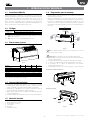 7
7
-
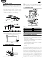 8
8
-
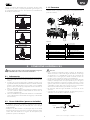 9
9
-
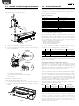 10
10
-
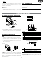 11
11
-
 12
12
-
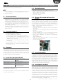 13
13
-
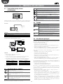 14
14
-
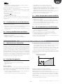 15
15
-
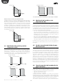 16
16
-
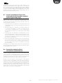 17
17
-
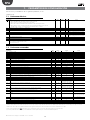 18
18
-
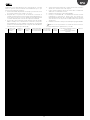 19
19
-
 20
20
-
 21
21
-
 22
22
-
 23
23
-
 24
24
-
 25
25
-
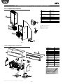 26
26
-
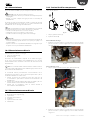 27
27
-
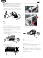 28
28
-
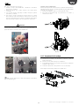 29
29
-
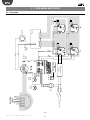 30
30
-
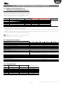 31
31
-
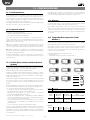 32
32
-
 33
33
-
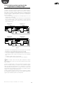 34
34
-
 35
35
-
 36
36
-
 37
37
-
 38
38
-
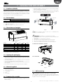 39
39
-
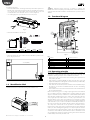 40
40
-
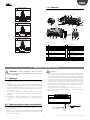 41
41
-
 42
42
-
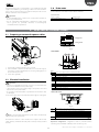 43
43
-
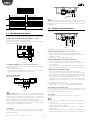 44
44
-
 45
45
-
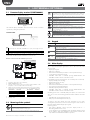 46
46
-
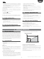 47
47
-
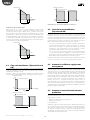 48
48
-
 49
49
-
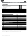 50
50
-
 51
51
-
 52
52
-
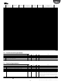 53
53
-
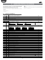 54
54
-
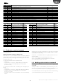 55
55
-
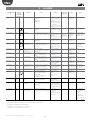 56
56
-
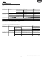 57
57
-
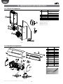 58
58
-
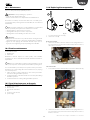 59
59
-
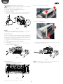 60
60
-
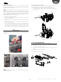 61
61
-
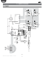 62
62
-
 63
63
-
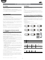 64
64
-
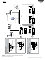 65
65
-
 66
66
-
 67
67
-
 68
68


Carel humiSonic UU06 Manual de usuario
- Categoría
- Medir, probar
- Tipo
- Manual de usuario
- Este manual también es adecuado para
En otros idiomas
- English: Carel humiSonic UU06 User manual
Documentos relacionados
-
Carel compactSteam CH Series Guía de inicio rápido
-
Carel E5V Manual de usuario
-
-
-
Carel UE009 Manual de usuario
-
-
-
-
-
Carel SD Guía del usuario
Otros documentos
-
FläktGroup humiDisk El manual del propietario
-
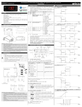 Evco EV3412M3 Instructions Sheet
-
EMKO ESM-3711-CN Manual de usuario
-
GCE E-MINISTAR Instrucciones de operación
-
Vemer Akuos 230 Bianco Manual de usuario
-
Grundfos Conex DIS-C Installation and Operating Instructions
-
Vornado EVHUM El manual del propietario
-
-
AKO Energy regulator depending on ambient temperature AKO-15301 Manual de usuario
-
