FläktGroup humiDisk El manual del propietario
- Tipo
- El manual del propietario

Integrated Control Solutions & Energy Savings
NO POWER
& SIGNAL
CABLES
TOGETHER
READ CAREFULLY IN THE TEXT!
humiDisk
Manual del usuario
humidificador centrífugo
User manual
centrifugal humidifier

Warning
L’installazione del prodotto deve obbligatoriamente
comprendere la connessione di messa a terra,
usando l’apposito morsetto giallo-verde in morsettiera.
Non utilizzare il neutro come connessione a terra.
The product must be installed with the earthconnected,
using the special yellow-green terminal on the terminal
block. Do not use the neutral for the earth connection.
Le produit doit être installé avec la connexion terre
branchée, en utilisant la signalisation et les bornes
spécifiques (jaune/vert) à la mise à la terre.
Ne pas utiliser le neutre comme mise à la terre.
Das Produkt muss geerdet werden. Verwenden Sie
hierfür den gelb-grün Anschluss an der Klemmleiste.
Verwenden Sie nicht den Null-Leiter für die Erdung.
La instalación del producto debe obligatoriamente
incluir la conexión de la toma de tierra,
utilizando el borne amarillo/verde del regletero.
No utilizar el neutro como conexión a tierra.

Manual del usuario

4 - rel. 2.4 - 24.10.2017
ESPAÑOL
humiDisk +030222022
ADVERTENCIAS IMPORTANTES
ANTES DE INSTALAR O INTERVENIR EN EL APARATO, LEA ATENTAMENTE Y SIGA LAS INSTRUCCIONES
CONTENIDAS EN ESTE MANUAL.
El presente dispositivo ha sido proyectado para humectar directamente en ambiente.
Asegúrese de que la instalación, el uso y el mantenimiento se realicen de acuerdo con las instrucciones
incluidas en el presente manual.
Cualquier otro uso del dispositivo y modificación efectuada en la unidad sin la autorización de CAREL S.p.A.
se considerará inapropiado.
Las condiciones ambientales y la alimentación deben ser conformes con las indicaciones especificadas.
Quitar la alimentación antes de intervenir directamente sobre las partes internas del humidificador. La
instalación de la unidad se realiza según las normativas vigentes.
La responsabilidad de los eventuales daños a cosas o personas debidas a un uso inadecuado del dispositi-
vo recaerá exclusivamente sobre el usuario.
Se ruega tener presente que la unidad contiene dispositivos alimentados eléctricamente.
Todas las operaciones ligadas al funcionamiento y/o al mantenimiento de la unidad deben ser realizadas
por personal experto y cualificado que conozca las precauciones necesarias.
Desechado del producto: el producto está compuesto por partes metálicas y por partes de
plástico.
De acuerdo con la Directiva 2002/96/CE del Parlamento Europeo y del Consejo del 27 de
enero de 2003 y a las correspondientes normativas nacionales de actuación, le informamos
de que:
1. Subsiste la obligación de no desechar los RAEE como residuos urbanos y realizar, para dichos residuos,
una recogida separada;
2. Para el desechado se utilizan los sistemas de recogida públicos o privados previstos por las leyes locales.
Además es posible reenviar al distribuidor el aparato al finalizar su vida, en el caso de adquisición de uno
nuevo.
3. Este aparato puede contener sustancias peligrosas: un uso inadecuado o un desechado incorrecto
podría tener efectos negativos sobre la salud humana y sobre el ambiente;
4. El símbolo (contenedor de basura con una aspa) estampado en el producto o en el paquete y en la hoja
de instrucciones indica que el aparato ha sido introducido en el mercado después del 13 de agosto de
2005 y que debe ser objeto de recogida separada;
5. En caso de un desechado abusivo de los residuos eléctricos y electrónicos están previstas sanciones
establecidas en las normativas locales vigentes en materia de desechos.

5 - rel. 2.4 - 24.10.2017
ESPAÑOL
humiDisk +030222022
Sommario
1. INTRODUCCIÓN 7
1.1 Normas generales de seguridad ........................................................................................................7
1.2 Aplicaciones ............................................................................................................................................7
1.3 HumiDisk ................................................................................................................................................. 7
1.4 Cuadros eléctricos para HumiDisk65 ................................................................................................7
1.5 Humidostato y sonda de humedad ..................................................................................................8
1.6 Accesorios para HumiDisk65 ...............................................................................................................8
1.7 Descripción de los componentes ......................................................................................................8
1. INSTALACIÓN 9
2.1 Material suministrado ........................................................................................................................... 9
2.2 Operaciones preliminares ...................................................................................................................9
2.3 Posicionamiento ....................................................................................................................................10
2.4 Instalación en pared .............................................................................................................................10
2.5 Instalación con el aparato colgado .................................................................................................... 11
2.6 Conexiones eléctricas ........................................................................................................................... 12
2.7 Conexiones hidráulicas ........................................................................................................................13
2.8 Operaciones finales ..............................................................................................................................14
3. ARRANQUE, CONTROL Y PARADA 15
3.1 Comprobaciones preliminares ...........................................................................................................15
3.2 Arranque .................................................................................................................................................15
3.3 Parada ......................................................................................................................................................15
4. EL CONTROLADOR ELECTRÓNCICO DEL HUMIDISK65 16
4.1 Tarjeta electrónica .................................................................................................................................. 16
4.2 I dip-switch ..............................................................................................................................................16
4.3 Regulación de la capacidad de humectación .................................................................................16
4.4 Ciclo de lavado/vaciado ....................................................................................................................... 16
4.5 Ciclo de lavado/vaciado utilizando cuadros eléctricos CAREL ....................................................16
5. DISPOSITIVO ANTIHIELO PARA HUMIDISK65 17
5.1 Montaje .................................................................................................................................................... 17
6. MANTENIMIENTO 18
6.1 Limpieza del filtro del aire ................................................................................................................... 18
6.2 Inspección y limpieza del sifón de drenaje .....................................................................................19
6.3 Inspección y limpieza de la electroválvula de llenado..................................................................19
6.4 Comprobación del ciclo de lavado/vaciado para HumiDisk65 ...................................................19
7. ALMACENAJE 20
7.1 Comprobaciones a realizar antes y después de un periodo de inactividad largo ..................20
7.2 Desechado del producto ...................................................................................................................... 20
8. CUADROS ELÉCTRICOS CAREL, OPCIONALES 21
8.1 Cuadro eléctrico UCQ065D100 para el control de un único humidificador centrífugo
UC0650D000 ó UC0650D100 ..................................................................................................................21
8.2 Cuadro eléctrico UCQ065D200 de control para dos humidificadores centrífugos
UC0650D000 ó UC0650D100. .................................................................................................................22

6 - rel. 2.4 - 24.10.2017
ESPAÑOL
humiDisk +030222022
9. HUMIDOSTATO DN33Z9HR20 PRESENTE
EN LOS CUADROS ELÉCTRICOS UCQ065D100 Y UCQ065D200 24
9.1 Configuración de los parámetros fundamentales .......................................................................... 25
9.2 Condiciones de alarma, causa y soluciones ...................................................................................25
10. DIMENSIONES Y PESOS 26
11. CARACTERÍSTICAS TÉCNICAS 26
11.1 Tabla de datos técnicos del HumiDisk10 ....................................................................................................26
11.2 Tabla de datos técnicos del HumiDisk65 ...................................................................................................26
11.3 Características eléctricas de los cuadros eléctricos UCQ065D100 y UCQ065D200 ............27
11.4 Características técnicas del humidostato DN33Z9HR20 CAREL ............................................... 27
11.5 Características técnicas del humidostato mecánico UCHUMM0000 ......................................27
11.6 Lista de piezas de repuesto para el HumiDisk10 ...................................................................................28
11.7 Lista de piezas de respuesto para el HumiDisk65 .................................................................................29
12. PROBLEMAS Y SOLUCIONES 30
12.1 El humidificador no arranca .............................................................................................................. 30
12.2 Sale aire del difusor, pero no sale agua atomizada ....................................................................30
12.3 El humidificador drena agua continuamente ...............................................................................30

7 - rel. 2.4 - 24.10.2017
ESPAÑOL
humiDisk +030222022
1. INTRODUCCIÓN
El HumDisk es un humidificador de aire que funciona según el principio de la pulverización del agua por me-
dio de la fuerza centrífuga. El aparato puede ser alimentado con agua potable o con agua desmineralizada.
El aparato se presenta en dos versiones:
HumiDisk10 con producción de 1 kg/h de agua atomizada, aproximadamente.
HumiDisk65 con producción de unos 6,5 kg/h de agua atomizada.
El HumiDisk10es un producto sencillo que puede ser accionado por un interruptor externo o por un hu-
midostato. Para impedir la formación de depósitos de agua estancada en el interior de la máquina y,
como consecuencia de ello, la proliferación de bacterias nocivas para la salud, se activan ciclos de lavado
automáticos regulares del tanque de alimentación.
El aparato puede funcionar a temperaturas de ≥1 °C.
El funcionamiento del HumiDisk65 está controlado por una tarjeta electrónica que, además de gestionar el
funcionamiento normal del aparato, asegura también que se realicen los ciclos de lavado automático del
tanque de alimentación que impiden que se formen depósitos de agua estancada en el interior del aparato
y, como consecuencia de ello, la proliferación de bacterias nocivas para la salud.
El HumiDisk65 , cód. UC0650D000 puede funcionar a temperaturas de >1 °C. El dispositivo antihielo (cód.
UCKH70W000), accesorio disponible bajo pedido con el UC0650D000, permite al HumiDisk65 funcionar a
una temperatura de –2 °C. Sin embargo el HumiDisk65, cód. UC0650D100 ya está equipado de serie con
dispositivo antihielo.
1.1 Normas generales de seguridad
¡Atención!
Antes de llevar a cabo cualquier tipo de reparación en el aparato, tome siempre las siguientes precauciones
para evitar problemas no deseados. Se recomienda, por lo tanto, leer atentamente el siguiente manual de
instrucciones.
• La unidad debe conectarse a una sistema eléctrico que cumpla con la normativa local vigente, mediante
un cuadro eléctrico que contenga todos los dispositivos de control y seguridad.
• Antes de llevar a cabo cualquier tipo de intervención en el aparato, acuérdese de desconectar la alimen-
tación eléctrica utilizando el interruptor principal del cuadro de control.
• En el caso de que fuese necesario intervenir en el aparato, asegúrese, una vez finalizado el trabajo, y
antes de arrancar de nuevo, que no se deja ningún tipo de herramienta dentro del aparato.
• La instalación y el mantenimiento del aparato debe ser realizado por personal experto y cualificado,
capaz de llevar a cabo el trabajo según las instrucciones proporcionadas en este manual.
• Este aparato ha sido diseñado para humectar el aire y, por lo tanto, no debe ser utilizado con ningún
otro fin.
• Cualquier otro uso que no sean los descritos en este manual se considera incorrecto, potencialmente
dañino y peligroso.
• Guarde cuidadosamente estas instrucciones para futuras consultas.
1.2 Aplicaciones
El HumiDisk es particularmente adecuado para utilizarlo en:
• Cámaras frigoríficas y almacenes frigoríficos de conservación de productos tales como frutas y verduras,
en los que la falta de humedad conlleva la pérdida de peso y el deterioro del producto.
• Industrias tipográficas, en las que se debe mantener una humedad correcta para evitar variaciones en el
tamaño del papel y los consiguientes errores en la impresión.
• Industrias textiles, en la que es fundamental el mantenimiento de la humedad en función del proceso
productivo y del tipo de material textil que se está procesando, y al mismo tiempo necesita eliminar el
calor producido por los telares.
Éstas representan sólo algunas de las posibles aplicaciones para las que se puede utilizar el humidificador
centrífugo.
1.3 HumiDisk
Código Descripción
UC0100D000 Humidificador por atomización de agua - 1,0 kg/h - 230 V 50 Hz
UC01001010 Humidificador por atomización de agua - 1,2 kg/h - 110 V 60 Hz
UC0650D000 Humidificador por atomización de agua - 6,5 kg/h - 230 V 50 Hz
UC06501010 Humidificador por atomización de agua - 6,5 kg/h - 110 V 60 Hz
UC0650D100 Humidificador por atomización de agua - 6,5 kg/h - con resistencia antihielo 230 V 50 Hz
UC06501110 Humidificador por atomización de agua - 6,5 kg/h - con resistencia antihielo 110 V 60 Hz
Tab. 1.a
1.4 Cuadros eléctricos para HumiDisk65
Código Descripción Notas
UCQ065D100 Cuadro eléctrico para humidificador
centrífugo de 6,5 kg/h
• Sólo para UC0650D000 y UC0650D100
• Con humidostato electrónico, sin sonda de humedad
UCQ065D200 Cuadro eléctrico para humidificador
de 6,5 kg/h
• Sólo para UC0650D000 y UC0650D100
• Con humidostato electrónico, sin sonda de humedad
Tab. 1.b

8 - rel. 2.4 - 24.10.2017
5
4
76
2
8
3
1
1
2
3
4
5
6
7
ESPAÑOL
humiDisk +030222022
1.5 Humidostato y sonda de humedad
Código Descripción Notas
UCHUMM0000 Humidostato mecánico de ambiente 20...90% H.R.
Tab. 1.d
Sondas de ambiente (sólo para HumiDisk65)
Código Descripción Notas
ASWH100000 Sonda de humedad ambiente 10...90% H.R.
Para utilizarse sólo con los cuadros
eléctricos con cód. UCQ065D100 y
UCQ065D200.
ASWC110000 Sonda de temperatura-humedad ambiente
0...50 °C 10...90% H.R.
ASWC111000 Sonda de temperatura (NTC res.) humedad
ambiente 0...50 °C 10...90% H.R. Tab. 1.e
De ambientes industriales (sólo para HumiDisk65)
Código Descripción Notas
ASPC110000 Sonda de temperatura-humedad ambiente
0...50 °C 10...90% H.R. Para utilizarse sólo con los cuadros eléctri-
cos con cód. UCQ065D100 y UCQ065D200
ASPC230000 Sondas de temperatura-humedad ambiente
-10...70 °C 0...100% H.R. Tab. 1.f
1.6 Accesorios para HumiDisk65
Código Descripción Notas
UCKH70W000 Calefactor compuesto por una resistencia de 70 W Sólo para UC0650D000 Tab. 1.c
1.7 Descripción de los componentes
HumiDisk10
Leyenda:
1. Difusor
2. Motor
3. Disco pulverizador
4. Cono con ventilador
5. Sifón de drenaje
6. Cuerpo principal
7. Filtro de aire
Fig. 1.a
HumiDisk65
Leyenda:
1. Filtro de aire
2. Sifón
3. Cono con ventilador
4. Motor
5. Difusor
6. Corona dentada
7. Disco pulverizador
8. Cuerpo principal
Fig. 1.b

9 - rel. 2.4 - 24.10.2017
B
D
C
A
A
B
DC
ESPAÑOL
humiDisk +030222022
2.1 Material suministrado
El siguiente material se suministra de serie con el aparato. Antes de comenzar el trabajo, compruebe que
va incluido en el paquete todo el material que se detalla a continuación.
Para HumiDisk10
• 1 humidificador modelo HumiDisk10.
• 1 manual técnico de instalación (este manual).
• 3 soportes para montaje del aparato colgado.
Para HumiDisk65
• El siguiente material se suministra de serie con el aparato. Antes de comenzar el trabajo, compruebe que
va incluido en el paquete todo el material que se detalla a continuación.
• 1 humidificador modelo HumiDisk65.
• 1 manual técnico de instalación (este manual).
• 4 tacos para pared, con tornillos (para instalación en pared).
• 1 soporte de fijación para montaje en pared.
• 3 soportes para montaje del aparato colgado.
• 1 tornillo de seguridad hexagonal M6x20.
• 1 arandela Ø 6x2.
• 1 manguera de alimentación del agua l=1,5 m, con conexiones roscadas G ¾.
• 1 manguera de drenaje del agua l=1,5 m Ø 10 interno;
• 3 tiras para cableado.
2.2 Operaciones preliminares
Para que el HumiDisk10 y el HumiDisk65 estén operativos es necesario lo siguiente:
• Red eléctrica a 230 Vca, 50 Hz (ó 110 Vca, 60 Hz) con tierra y dispositivos de protección.
• Conexión para agua de alimentación.
• Conexión para el drenaje del agua.
Nota: La instalación debe realizarse conforme a los requisitos de seguridad de la normativa local vigente.
Asegúrese de que se han realizado correctamente todas las conexiones necesarias para que el aparato
pueda funcionar.
Para el HumiDisk10, todas las entradas, ya sean eléctricas o hidráulicas, están situadas en la parte posterior,
como se indica en la fig 2.a. Antes de comenzar la instalación real, se recomienda realizar las operaciones
descritas a continuación. Tomando como referencia la fig. 2.a:
• Conecte la manguera del agua A, no suministrada de serie pero disponible con el cód. UCKTS00000,
al codo de drenaje B.
• Conecte el extremo C con el codo de la manguera de alimentación del agua, no suministrado de serie
pero disponible con el cód. UCKTA00000, a la electroválvula de alimentación D.
Las operaciones mencionadas anteriormente también se pueden realizar, en cualquier caso, con la unidad
instalada.
En el HumiDisk65, todas las conexiones, ya sean eléctricas o hidráulicas, están situadas en la parte posterior,
como se indica en la fig. 2.b. Antes de comenzar la instalación en sí, se recomienda realizar las operaciones
descritas a continuación. Tomando como referencia la fig. 2.b:
• Conecte la manguera para el drenaje del agua A, suministrada, al codo de drenaje B.
• Conecte el extremo C con el codo de la manguera de alimentación del agua, suministrado, a la electro-
válvula de alimentación D.
Las operaciones mencionadas anteriormente también se pueden realizar, en cualquier caso, con la unidad
instalada.
1. INSTALACIÓN
Fig. 2.a
Fig. 2.b

10 - rel. 2.4 - 24.10.2017
B
C
A
B
C
A
B
C
D D
80 mm
100 mm
ESPAÑOL
humiDisk +030222022
2.3 Posicionamiento
Nota: El HumiDisk se debe instalar en posición horizontal, con el filtro del aire hacia abajo, levantado sobre
el suelo como se indica en las figuras 2.c, 2.d, 2.e. Cualquier otra posición puede comprometer el buen
funcionamiento del aparato.
Para que se pueda llevar a cabo el mantenimiento cuando sea necesario y para que el aparato funcione correc-
tamente, el humidificador se debe colocar en una posición en la que se respeten las distancias mínimas reco-
mendadas. Elija, en función del tipo de instalación, la posición más adecuada para la humectación del local.
No coloque el humidificador en una espacio limitado para evitar la aspiración de aire saturado a
través del filtro, mojándolo.
Humidificador
Distancia (m)
A B C D
HumiDisk10 ≥2≥0,5 ≥1,5 ≥0,5
HumiDisk65 ≥3≥1≥1,5 ≥0,5
Tab. 2.a
Fig. 2.c Fig. 2.d Fig. 2.e
2.4 Instalación en pared
HumiDisk10
Para la instalación en pared, utilice el soporte opcional mostrado en la fig. 2.f y los tornillos suministrados.
Se puede utilizar el soporte como plantilla para marcar los agujeros en la pared, como se indica en la fig.
2.g. Respete las distancias mínimas indicadas en el párrafo 2.3, y asegúrese de que el soporte está a nivel
antes de taladrar los agujeros. Verifique que la pared puede soportar el peso del aparato en condiciones
de funcionamiento normales.
• Taladre en la pared tres agujeros de 8 mm de diámetro y 45 mm de profundidad, como se muestra en
la fig. 2.g.
• Limpie el agujero por dentro.
• Inserte los tres tornillos manteniendo las dos pestañas de expansión en vertical.
• Apriete (no totalmente) dos de los cuatro tornillos de fijación del HumiDisk10 al soporte, como se indica
en la fig. 2.h.
• Gire la unidad hasta hacer coincidir los otros dos agujeros: las mangueras y los cables deben ir entre el
humidificador y el soporte, en la hendidura especial.
• Enrosque los dos últimos tornillos y, a continuación, apriete totalmente los cuatro tornillos.
• Asegúrese de que la instalación es segura.
Fig. 2.f Fig. 2.g Fig. 2.h

11 - rel. 2.4 - 24.10.2017
120 mm
120 mm
<3 mm
L
>
12 mm
ESPAÑOL
humiDisk +030222022
HumiDisk65
Para instalar el humidificador en la pared, utilice el soporte y los tornillos suministrados. Se puede utilizar el
soporte como plantilla para marcar los agujeros en la pared. Respete las distancias indicadas en el párrafo
2.3, y antes de taladrar los agujeros, asegúrese de que el soporte está a nivel. Asegúrese de que la pared
puede soportar el peso del aparato en condiciones de funcionamiento normales.
• Taladre en la pared cuatro agujeros de 8 mm de diámetro y 45 mm de profundidad, como se muestra
en la fig. 2.i.
• Limpie el agujero por dentro.
• Inserte los 4 tornillos manteniendo las dos pestañas de expansión en vertical.
• Fije el soporte.
El soporte se debe montar como se indica en la Fig. 2.l. Una vez fijado el soporte a la pared con los cuatro
tornillos, realice las siguientes operaciones, como se indicia en la fig. 2.m:
• Levante el aparato e inclínelo ligeramente hacia la pared.
• Mueva la unidad hasta que encajen correctamente los dos soportes.
• Deje que gire el aparato, guiándolo, hasta la posición horizontal: en este punto los soportes deberán
estar perfectamente acoplados y encajados entre sí.
• Inserte el tornillo de seguridad suministrado que une los dos soportes y que evita que el aparato se
pueda desenganchar.
Fig. 2.i Fig. 2.l Fig. 2.m
2.5 Instalación con el aparato colgado
Este tipo de instalación, en la que el aparato se cuelga, se realiza utilizando los soportes suministrados de serie.
Es necesario preparar tres cadenas de soporte de las que colgar el aparato.
Las cadenas deben caer lo más recto posible partiendo de 3 puntos de enganche distintos capaces de
sostener el peso del aparato (ver fig. 2.n y párrafo 10).
Utilice cadenas metálicas, a ser posible de acero, y en todo caso que estén hechas de un material que no
sea sensible a la humedad. Respete las distancias mínimas indicadas en la tab. 2.a.
Para el HumiDisk10 utilice los soportes suministrados, enganchando un lado en los agujeros que están en
la parte inferior y el otro en las cadenas que cuelgan de lo alto.
En el HumiDisk65, desmonte el soporte posterior A, para la instalación en pared, como se muestra en la fig.
2.p, desatornillando los cuatro tornillos V.
Ahora debería haber cinco tornillos disponibles (4 tornillos quitados de la plancha A, 1 tornillo de seguri-
dad, suministrado) cada uno con su arandela correspondiente.
Vuelva a colocar los dos tornillos en los agujeros F como se indica en la fig. 2.p.
Utilice 3 tornillos para montar el soporte, en la instalación del aparato colgado, como se muestra en la fig. 2.q.
Los soportes están diseñados de modo que permitan el desmontaje del filtro y de este modo realizar las
operaciones normales de mantenimiento sin tener que desenganchar el aparato de las cadenas que lo
sujetan.
Cuelgue el aparato de las cadenas comprobando a la vez que está en posición horizontal.
Fig. 2.n
Fig. 2.o Fig. 2.p Fig. 2.q

12 - rel. 2.4 - 24.10.2017
+
230 V,
50/60 Hz
N F H H M M L L V V
M
1
4
A
B
2 3
1
2% r.H.
+
ELETTROVALVOLA
SOLENOID VALVE
LIVELLO
LEVEL
MOTORE
MOTOR
UMIDOSTATO
HUMIDOSTAT
1
ESTERNO
humiDisk 65
2
3
4
5
67
8
ON
123
N
L
LEVEL
230 V,
50 Hz
UMID
+
M
MOTORE
ELET. CARICO
% r.H.
+
ESPAÑOL
humiDisk +030222022
2.6 Conexiones eléctricas
La instalación requiere la utilización de un humidostato todo/nada que controle el funcionamiento del
humidificador: es posible sin embargo utilizar, en su lugar, un contacto simple todo/nada con la única
diferencia de que el aparato se debe arrancar y parar manualmente. La elección, no obstante, no influye en
el procedimiento de instalación descrito a continuación.
Importante: Se debe instalar un dispositivo de desconexión del aparato, en la red de alimentación eléctri-
ca, como se indica en la fig. 2.r y 2.s, También se debe instalar un fusible de protección de 2,5 A del tipo
retardado para arrancar el motor.
2.6.1 Esquema eléctrico UC10
Al seleccionar el interruptor o el humidostato que se ha de conectar a los teminales “HH”, compruebe la
compatibilidad de los valores de entrada de tensión y de corriente del humidificador indicados en las Tab.
11.a y 11.b de la página 26.
Leyenda:
1. Motor del humidificador
2. Interruptor de nivel
3. Electroválvula
4. Puente del humidostato externo (a quitar)
A. Humidostato todo/nada externo (a suministrar por el
instalador)
B. Protección de línea (a suministrar por el instalador)
Fig. 2.r
2.6.1 Esquema eléctrico UC65
Leyenda:
1. Humidostato todo/nada (a suministrar por el
instalador)
2. Flotador
3. Motor
4. Electroválvula
5. Calefactor (opcional)
6. Sonda de temperatura
7. Tarjeta electrónica
8. Protección de línea (a suministrar por el
instalador)
Fig. 2.s

13 - rel. 2.4 - 24.10.2017
ESPAÑOL
humiDisk +030222022
2.6.3 Cableado
Importante: El cable flexible que se ha de utilizar para las conexiones eléctricas debe estar protegido
por lo menos por una cubierta ordinaria de PVC y respetar la norma 227 IEC 53 (CENELEC H05VV-F o
H05VVH2-F o superior).
Cableado del HumiDisk10 (fig. 2.t):
• Abra la cubierta de la caja eléctrica, situada en la parte posterior del aparato, desatornillando los cuatro
tornillos V;
• Haga pasar el cable de alimentación a través del sujetacables P.
• Extraiga el bloque de terminales M de la caja.
• Cablee la fase al terminal F, el neutro al terminal N y la tierra al terminal marcado con el símbolo
correspondiente.
• Coloque de nuevo el bloque de terminales en la caja, deslizando la escuadrita de sujección en las guías
G.
• Cierre la caja.
Cableado del HumiDisk65 (fig. 2.u):
• Desmonte la caja eléctrica haciendo palanca sobre el muelle de bloqueo C. La caja baja: quite la cubierta
desatornillando los cuatro tornillos. En la caja hay dos sujetacables que servirán para pasar el cable de
alimentación y el cable del humidostato hasta la tarjeta electrónica.
• Pase el cable de alimentación a través del sujetacables 1a del aparato y, a continuación, a través del
sujetacables 1b de la caja eléctrica. Fije los cables de fase y neutro a los terminales N 230 F de la tarjeta
y el cable de tierra al terminal que está libre dentro de la caja.
• Del mismo modo, pase el cable del humidostato por el sujetacables 2a del aparato, después páselo por
el sujetacables 2b de la caja y conéctelo a los terminales UMID de la tarjeta.
• A continuación, utilice las 2 tiras suministradas, para fijar los dos cables que acaba de pasar a los cables
existentes: las tiras, se colocarán en la posición indicada por las flechas. Finalmente, apriete las cuatro
arandelas de los sujetacables.
Una vez realizadas las conexiones eléctricas, cierre con cuidado con los tornillos correspondientes la caja, y
vuelva a colocarla en su lugar, asegurándola mediante el muelle de fijación C.
Al término de la instalación, el interior del aparato debería verse como se muestra en la fig. 2.u.
Fig. 2.t
Fig. 2.u
2.7 Conexiones hidráulicas
Nota: Las mangueras de conexión del agua sólo se suministran de serie con el HumiDisk65. En el Humi-
Disk10 están disponibles como opción.
La instalación del humidificador también requiere que se conecte a las mangueras de alimentación y de
drenaje del agua. Las mangueras, suministradas, se deben conectar al aparato como se indica en la figura
2.v para el HumiDisk10 y en la figura 2.z para el HumiDisk65.
La manguera de alimentación A, suministrada de serie, tiene en ambos extremos una arandela roscada G
3/4: conecte el codo a la electroválvula del HumiDisk, conecte el otro extremo (el extremo recto) directa-
mente a la llave de paso B o a un alargador. Se recomienda instalar un filtro mecánico C aguas abajo de la
llave de paso B, como se muestra en las Fig. 2.v y 2.z.
Para el drenaje del agua, utilice la manguera de plástico D, suministrada de serie, o una manguera similar
con un diámetro interior de 10mm. La manguera debe instalarse como se indica en las figuras 2.v y 2.z
con una pendiente mínima de 10°, para garantizar el correcto drenaje del agua. Si se utiliza un sifón E,
debe estar situado en la línea de drenaje principal y no en la manguera de drenaje conectada al aparato.
Importante: Para garantizar un drenaje correcto del agua, asegúrese de que la manguera de drenaje está
colocada en pendiente y recta, sin dobleces ni estrangulamientos.

14 - rel. 2.4 - 24.10.2017
ED
A
CB
<10°
ESPAÑOL
humiDisk +030222022
Fig. 2.z
Conexiones hidráulicas del HumiDisk65
2.8 Operaciones finales
Asegúrese de que todos los cables están colocados correctamente dentro del aparato, como se muestra
en las figuras 2.t y 2.u.
En el HumiDisk65, verifique que la caja eléctrica está bien cerrada y colocada correctamente, y que el muelle
está apretado. La caja debe tener la superficie de la cubierta apoyada en los dos indicadores resaltados
en la fig. 2.w.
• Vuelva a poner el filtro del aire y apriete los tres tornillos de sujección.
• Ajuste la dirección de las salidas. Hágalo, soltando los tornillos que sujetan el difusor de la parte superior
del aparato; vea la posición 1 de la figura 1.a para el HumiDisk10 y la posición 5 de la figura 1.b para
HumiDisk65: cuando termine la operación apriete el tornillo de nuevo.
• Asegúrese de que las conexiones hidráulicas se han llevado a cabo correctamente. Abra la llave de paso
de alimentación de agua y verifique que no hay fugas a lo largo del circuito de alimentación.
Fig. 2.w
Fig. 2.v
Conexiones hidráulicas del HumiDisk10

15 - rel. 2.4 - 24.10.2017
ESPAÑOL
humiDisk +030222022
3.1 Comprobaciones preliminares
Antes de poner en funcionamiento el humidificador, compruebe que:
• Todas las conexiones eléctricas e hidráulicas se han conectado según las instrucciones descritas en este
manual.
• No hay fugas de agua en el circuito.
• Está montado el filtro del aire.
• La llave de paso del agua está abierta.
• Las salidas de distribución están orientadas correctamente.
3.2 Arranque
3.2.1 HumiDisk10
Para arrancar el humidificador, encienda el interruptor principal. La unidad arranca inmediatamente y, tras
unos segundos, empieza a atomizar.
Durante el funcionamiento, asegúrese de que el drenaje del agua no funciona de forma continua. Si eso
ocurre, lea las posibles soluciones en el párrafo 12.
3.2.2 HumiDisk65
Para poner en funcionamiento el humidificador encienda el interruptor principal. El aparato realizará un
ciclo de lavado de una duración de un minuto aproximadamente, como se describe detalladamente en
el párrafo 4.4: Ciclo de lavado/reseteo. Al finalizar el ciclo, si el contacto del humidostato está cerrado, el
humidificador arranca el motor y empieza a atomizar el agua.
Importante: Si se utiliza un contacto todo/nada en lugar del humidostato, éste se debe cerrar manualmen-
te para hacer funcionar el aparato ya que, de lo contrario, no arrancará al finalizar el ciclo de lavado/reseteo.
Durante el funcionamiento, compruebe que el drenaje de agua se realiza al final de cada ciclo productivo.
Si es necesario, regule la capacidad de humectación según las instrucciones del párrafo 4.3: Regulación de
la capacidad de humectación.
3.3 Parada
3.3.1 HumiDisk10
Para apagar la unidad, sólo tiene que abrir el interruptor general. El humidificador se ralentiza hasta pararse,
mientras que el agua contenida en la unidad desciende al tanque y ceba el sifón que, entonces, vacía el
tanque. Se recomienda cerrar la llave de paso de alimentación de agua.
Importante: Entre la parada y el siguiente arranque del humidificador debería transcurrir un tiempo de, al
menos, 30 segundos, de modo que permitiera al sifón drenar completamente el agua. En caso contrario,
el sifón drenará el agua de forma continua.
3.3.2 HumiDisk65
Para parar el humidificador:
1. Ponga el humidostato en el valor mínimo de % H.R. para que abra el contacto todo/nada correspon-
diente.
2. Espere aproximadamente 1 minuto para darle tiempo a la unidad para realizar el ciclo de vaciado.
3. Abra el interruptor principal de alimentación eléctrica.
4. Cierre la llave de paso de alimentación del agua.
Si el aparato está alimentado pero no atomiza agua, sólo tiene que realizar los pasos 3 y 4.
ATENCIÓN: Si el interruptor principal está abierto mientras el aparato sigue atomizando, el tanque no se
puede vaciar: el agua contenida en el aparato puede ser todavía suficiente para cebar el sifón y arrancar
el drenaje del tanque.
3. ARRANQUE, CONTROL Y PARADA

16 - rel. 2.4 - 24.10.2017
ON
1 2 3 A
ON
1 2 3
ESPAÑOL
humiDisk +030222022
4.1 Tarjeta electrónica
El funcionamiento del HumiDisk65 está controlado por una tarjeta electrónica, que tiene las siguientes
funciones:
• Control de la capacidad de humectación.
• Arranque y control del ciclo de lavado/reseteo.
4.2 I dip-switch
En la tarjeta de Fig. 4.a, la regulación de la capacidad se realiza mediante la combinación de la posición de
los dip-switch de acuerdo a la tab. a lado.
Nota: los valores reportados en la Tabla 4.a son aproximados. En Fábrica los DIP-switch están establecidos
en “máximo rendimiento”.
4.3 Regulación de la capacidad de humectación
La capacidad se puede regular durante la fase de instalación o después, por ejemplo para adaptar el fun-
cionamiento del aparato a las variaciones de las condiciones del ambiente en el que está instalado. En este
caso, proceda del siguiente modo:
• Realice el procedimiento de parada como se indica en el párrafo 3.3;
• Quite el filtro del aire desatornillando los tres tornillos de sujeción.
• Saque la caja de conexiones eléctricas liberando el muelle.
• Abra la caja eléctrica y regule la posición del potenciómetro como desee.
• Cierre el aparato como se describe en el párrafo 2.8 “Operaciones finales”.
Arranque el humidificador de nuevo.
4.4 Ciclo de lavado/vaciado
La tarjeta electrónica del HumiDisk65 está programada para llevar a cabo un ciclo de lavado/vaciado cada vez
que:
• Se arranca el aparato con el interruptor principal.
• El humidostato apaga el aparato porque se han alcanzado las condiciones de HR deseadas.
El fin de este ciclo es el de evitar la formación de depósitos de agua dentro del aparato cuando no está en
funcionamiento, impidiendo así la proliferación de bacterias.
El ciclo tiene una duración fija y consiste en:
• Parada del motor, con un periodo de espera de 40 segundos: este periodo de espera da al motor (y por
lo tanto al grupo ventilador/disco) tiempo para cerrarse completamente y permite que el agua que hay
en la unidad se recoja en el tanque.
• Activación de la electroválvula de llenado: el agua entra en el tanque hasta que se dispara el sensor de
nivel.
• Mantenimiento de la activación de la electroválvula de llenado durante un tiempo de 10” tras el disparo
del sensor de nivel: de este modo el nivel del agua del tanque supera el nivel normal de funcionamiento
y el sifón de drenaje se ceba, drenando de este modo el agua del tanque.
• Desactivación de la electroválvula de llenado.
• Espera de un tiempo fijo de 10”: este tiempo sirve para garantizar que se drene toda el agua que hay
en el tanque.
• Fin del ciclo de lavado/vaciado: al finalizar el ciclo de lavado/vaciado, el aparato espera a que se cierre
el contacto del humidostato o, si ya está cerrado, arranca el motor e inicia la humectación de nuevo.
4.5 Ciclo de lavado/vaciado utilizando cuadros eléctricos CAREL
Nota: Cuando se utilizan los cuadros eléctricos CAREL es posible ejecutar el ciclo de lavado aunque el
humidificador, en el estado de encendido, sea activado por la sonda de humedad para un nuevo ciclo de
producción. (leer el capítulo 9 del manual).
4. EL CONTROLADOR ELECTRÓNCICO DEL humiDisk65
Fig. 4.a
Fig. 4.b
max
rendimiento 4,48 L/horas
6,33 L/horas 3,36 L/horas
5,96 L/horas 2,24 L/horas
5,59 L/horas 0,96 L/horas
Tab. 4.a

17 - rel. 2.4 - 24.10.2017
ESPAÑOL
humiDisk +030222022
5. DISPOSITIVO ANTIHIELO PARA humiDisk65
El dispositivo antihielo es necesario cuando el HumiDisk65 está instalado en un ambiente en el que la
temperatura puede descender por debajo de 0 °C.
ATENCIÓN: Respete los límites de funcionamiento indicados en la Tab. 11.b.
En tal caso, de hecho, puede formarse hielo dentro del aparato y afectar al buen funcionamiento del mis-
mo. El aparato está ya preparado para la instalación del kit antihielo, que se instalará en unos minutos. El
dispositivo consta de una resistencia eléctrica, cuyo funcionamiento es controlado por la tarjeta electrónica
y por el sensor de temperatura al que está conectado. La resistencia se activa cuando la temperatura en el
interior del aparato se aproxima a 0 °C.
De esta manera, se genera un flujo de aire caliente, que impide la formación de hielo, permitiendo que el
HumiDisk65 funcione a temperaturas de hasta –2 °C.
Por debajo de esta temperatura se desaconseja la utilización del aparato, a causa del mismo principio de
funcionamiento.
Cuando la temperatura, en el interior del aparato, aumenta por encima de +2,5 °C, la tarjeta electrónica
desactiva la resistencia con el fin de ahorrar energía.
La resistencia está diseñada para seguridad y, en el caso de que el dispositivo termostático no funcionara
bién, no alcanzará temperaturas peligrosas.
ATENCIÓN: Las unidades con código UC0650D100 incluyen de serie el kit de resistencia antihielo ya
instalado, mientras que en las versiones con código UC0650D000, el código de resistencia UCKH70W000
se puede instalar como opción.
5.1 Montaje
Siga atentamente las instrucciones que se suministran con el kit de resistencia. Al finalizar la instalación,
consulte los procedimientos descritos en este manual antes del reinicio de la unidad.

18 - rel. 2.4 - 24.10.2017
F
R
V
ESPAÑOL
humiDisk +030222022
El HumiDisk está diseñado para garantizar un funcionamiento eficiente y exento de fallos durante un largo
periodo de tiempo. Sin embargo, es necesario llevar a cabo una serie de operaciones de mantenimiento
simples, cuya frecuencia depende de las condiciones del ambiente en el que está funcionando el HumiDisk
y de la calidad del agua de alimentación.
ATENCIÓN: Antes de realizar cualquier operación de mantenimiento, abra (apague) el interruptor principal
y espere a que se cierre completamente la unidad. Cierre la llave de paso de alimentación de agua. Siga
las instrucciones generales de seguridad descritas en el párrafo 1.1. Antes de arrancar de nuevo el aparato,
realice las debidas comprobaciones como se describe en este manual.
6.1 Limpieza del filtro del aire
El filtro debe limpiarse periódicamente ya que la acumulación de suciedad y de polvo reduce el caudal de
aire y con ello la eficiencia del aparato.
6.1.1 HumiDisk10
6. MANTENIMIENTO
Fig. 6.a
Tomando como referencia la Fig. 6.a:
• Desmonte el filtro desatornillando los dos tornillos V que lo sostienen.
• Desmonte la rejilla R y el filtro F;
• Limpie el filtro F con un aspirador o sumérjalo en agua ligeramente jabonosa y enjuague: seque sin
retorcer.
• Al finalizar, vuelva a montar el conjunto siguiendo el orden inverso, asegúrandose de que el filtro está
colocado correctamente en el interior del aparato y la rejilla está fijada con los tornillos.
ATENCIÓN: ¡No active el humidificador sin el filtro del aire F montado y la rejilla de protección R correcta-
mente asegurada con los tornillos V!
6.1.1 HumiDisk65
Tomando como referencia la fig. 6.b:
• Desmonte el filtro desatornillando los tres tornillos de fijación.
• Separe las dos rejillas de plástico A del material filtrante B;
• Limpie el filtro B con un aspirador o sumérjalo en agua ligeramente jabonosa, y enjuague: séquelo sin
retorcer.
ATENCIÓN: ¡No active nunca el humidificador sin el filtro de aire montado!. El filtro del aire está com-
puesto por tres partes que se deben montar de modo que el material filtrante B esté encerrado entre las
dos rejillas de plástico A (ver fig. 6.b).
Fig. 6.b

19 - rel. 2.4 - 24.10.2017
AE
S
V
R
T
ESPAÑOL
humiDisk +030222022
6.2 Inspección y limpieza del sifón de drenaje
Puede ser necesario limpiar periódicamente el sifón de drenaje: la acumulación de suciedad dentro del
sifón de drenaje puede comprometer el buen funcionamiento.
Cuando sea necesaria la limpieza, proceda del siguiente modo:
6.2.1 HumiDisk10 (fig. 6.c)
• Desmonte el filtro del aire.
• Quite la manguera T del tubo R.
• Desenrosque los tornillos V.
• Desmonte el tubo R.
• Limpie el tubo R y el tubo S, que se encuentra dentro del tanque.
• Al finalizar la limpieza vuelva a montar todas las piezas.
6.2.2 HumiDisk65 (fig. 6.d)
• Desmonte el filtro del aire.
• Quite la manguera B del sifón A;
• Desenrosque los tornillos C;
• Desmonte el componente A;
• Limpie la pieza A y el agujero en el que va insertada, a continuación vuelva a montar.
6.3 Inspección y limpieza de la electroválvula de llenado
La electroválvula de llenado está equipada con un filtro de entrada que se debe comprobar y limpiar
periódicamente.
6.3.1 HumiDisk10 (fig. 6.e)
Para acceder al filtro es necesario desenroscar el racor A de la manguera de alimentación: el filtro se en-
cuentra dentro de la arandela roscada E de la electroválvula.
En el caso de que la limpieza se vuelva demasiado frecuente, se aconseja instalar un filtro de cartucho en
la línea de alimentación del agua del aparato (ver: párrafo 2.7 y fig. 2.z).
6.3.2 HumiDisk65 (fig. 6.f)
Para acceder al filtro es necesario desenroscar el racor A de la manguera de alimentación: el filtro se en-
cuentra dentro de la arandela roscada B de la electroválvula.
En el caso de que la limpieza se vuelva demasiado frecuente, instale un filtro de cartucho en la línea de
alimentación de agua del aparato (leer párrafo 2.7 y fig. 2.z).
6.4 Comprobación del ciclo de lavado/vaciado para HumiDisk65
• Compruebe que el ciclo se realiza periódicamente.
Para hacerlo, proceda del siguiente modo:
• Quite el extremo de la manguera de drenaje que no está unido al aparato e insértelo en un recipiente
para recoger el agua de drenaje.
• Pare el humidificador, apagando el humidostato de control: de este modo se inicia el ciclo de lavado.
Si el ciclo no continúa normalmente, es necesario limpiar la bandeja del agua y el sifón de drenaje.
ATENCIÓN: El HumiDisk65 es un humidificador de aire, y cualquier otro uso diferente a aquel para el que
ha sido diseñado (por ejemplo la nebulización de insecticidas, desinfectantes, esencias o cualquier otro
producto que no sea agua) puede ser peligroso o afectar al correcto funcionamiento del aparato.
Fig. 6.d
Fig. 6.c
Fig. 6.f
Fig. 6.e

20 - rel. 2.4 - 24.10.2017
ESPAÑOL
humiDisk +030222022
• Conserve el aparato en un ambiente con temperatura comprendida entre -10°C y +60°C.
• Mientras el aparato esté embalado manténgalo en posición vertical.
• No poner encima de la caja otros objetos pesados.
7.1 Comprobaciones a realizar antes y después de un periodo de
inactividad largo
7.1.1 Antes
• Desconecte las conexiones eléctricas y cierre las llaves de paso del agua de alimentación.
• Cubra el aparato para protegerlo del polvo.
7.1.2 Después
• Compruebe el estado del filtro del aire, límpielo si es necesario.
• Verifique que el interruptor de flotador esté operativo, moviéndolo, y verifique que el ventilador/disco
puede girar libremente.
• Asegúrese de que todas las conexiones eléctricas se han conectado correctamente, según las instruc-
ciones.
• En el HumiDisk65, ejecute un ciclo de lavado/reseteo de prueba, como se describe en el párrafo 6.4 del
manual.
7.2 Desechado del producto
El aparato está compuesto principalmente por piezas de plástico y algunas piezas de metal, ambos mate-
riales son reciclables. Antes de deshacerse del producto, separe las piezas de plástico (casquete, ventilador,
lámina, etc...) de las piezas metálicas (motor, brida de instalación). Saque la tarjeta electrónica de la caja de
conexiones eléctricas y proceda al desechado según la normativa vigente.
7. ALMACENAJE

21 - rel. 2.4 - 24.10.2017
D03 D02 D04
D01
6
7
8
9
PE
HUMIDITY
PROBE
M
QS1
MAIN
SWITCH
6A
FU1
0.5A GL
POWER
NC
NO
C
4
5
1
2
3
+ (G)
OUT H
REMOTE
ON/OFF
CENTRIFUGAL HUMIDIFIER
ALLARM
OUTPUT
CARICO/FILL
RESISTENZA
HEATING
NTC
PE
N
F
DI2 GND -B2 +B2 B2 +12V
D11 GND -B1 +B1 B1 +5V
LEVEL UMID
ESPAÑOL
humiDisk +030222022
Además de los modos de funcionamiento descritos anteriormente, el HumiDisk65 puede ser controlado por
cuadros eléctricos especiales que incluyen los humidostatos CAREL.
Estos cuadros eléctricos permiten un control más preciso de la humedad deseada en el ambiente, dado
que se utilizan junto con las sondas de humedad CAREL y además permiten una gestión particular de los
ciclos de drenaje del agua introduciendo las funciones de lavado no sólo al final de cada ciclo de humec-
tación, sino también al inicio.
De este modo, el humidificador siempre lavará el tanque de alimentación cada vez que empiece a hu-
mectar.
Los cuadros eléctricos están disponibles en dos modelos:
• Para el control de un único HumiDisk65;
• Para el control de dos HumiDisk65 en paralelo.
8.1 Cuadro eléctrico UCQ065D100 para el control de un único
humidificador centrífugo UC0650D000 ó UC0650D100
8. CUADROS ELÉCTRICOS CAREL, OPCIONALES
Atención: Para las conexiones eléctricas, utilice conductores aislados con una sección mínima de 1,5 mm2.
Acceda a la caja de empalmes desmontando el filtro del aire, como se describe en el capítulo 6.
Los cuadros con n. de serie inferior a 148220 tienen un control IRDR, y superior a 148220 tienen un control
DN33
8.1.1 Conexión del cuadro eléctrico UCQ065D100 al humidificador UC0650D”X”00
Conecte:
• El terminal 6 del cuadro eléctrico al terminal F del humidificador.
• El terminal 7 del cuadro eléctrico al terminal N del humidificador.
• El terminal 8 del cuadro eléctrico al primer terminal UMID del humidificador.
• El terminal 9 del cuadro eléctrico al segundo terminal UMID del humidificador.
8.1.2 Conexión de la alimentación eléctrica
Conecte:
• El cable de la fase al terminal F del cuadro eléctrico.
• El cable del neutro al terminal N del cuadro eléctrico.
• El cable de tierra al terminal PE del cuadro eléctrico.
8.1.3 Conexión de la sonda activa de humedad DPPC11, DPPC21, DPWC111, DPWC11, DPWC111
Conexión:
• El terminal 1 del cuadro eléctrico al terminal M (referencia/tierra) de la sonda activa de humedad.
• El terminal 2 del cuadro eléctrico al terminal +(G) (alimentación) de la sonda activa de humedad.
• El terminal 3 del cuadro eléctrico al terminal out H (salida activa de humedad) de la sonda activa de
humedad.
El terminal 1 también se debería conectar a la pantalla del cable de sonda, si existe.
Fig. 8.a

22 - rel. 2.4 - 24.10.2017
PE
N
F
REMOTE
ON/OFF ALLARM
OUTPUT
CARICO/FILL
RESISTENZA
HEATING
NTC
CENTRIFUGAL HUMIDIFIER
CARICO/FILL
RESISTENZA
HEATING
NTC
D03 D02 D04
D01
6
7
8
9
PE
QS1
MAIN
SWITCH
6A
POWER
NC
NO
C
4
5
1
2
3
DI2 GND -B2 +B2 B2 +12V
D11 GND -B1 +B1 B1 +5V
FU1
0.5A GL
HUMIDITY
PROBE
M
+ (G)
OUT H
CENTRIFUGAL HUMIDIFIER
61
71
PE
81
91
QF1
MAIN
SWITCH
2A
QF2
MAIN
SWITCH
2A
LEVEL UMID
LEVEL UMID
ESPAÑOL
humiDisk +030222022
8.1.4 Salidas de alarma
En el cuadro eléctrico hay tres terminales para las salidas de relé (NC, C, NO) que se activan en los
siguientes casos:
• Alarma de sonda.
• Alarma de humedad baja.
• Alarma de humedad alta.
• Mal funcionamiento del controlador.
8.1.5 Marcha/paro remoto
Terminales 4 y 5 del cuadro eléctrico: el cuadro sale de fábrica con los terminales 4 y 5 puenteados y el
humidificador se puede controlar utilizando un contacto libre de tensión externo conectado a estos dos
terminales, después de haber quitado el puente.
8.2 Cuadro eléctrico UCQ065D200 de control para dos
humidificadores centrífugos UC0650D000 ó UC0650D100.
Fig. 8.b

23 - rel. 2.4 - 24.10.2017
ESPAÑOL
humiDisk +030222022
Atención: Para las conexiones eléctricas, utilice conductores aislados con una sección mínima de 1,5 mm2.
Acceda a la caja de empalmes desmontando el filtro del aire, como se describe en el capítulo 6.
Los cuadros con n. de serie inferior a 148220 tienen un control IRDR, y superior a 148220 tienen un control
DN33
8.2.1 Conexión del cuadro eléctrico UCQ065D200 al primer humidificador UC0650D”X”00
Conecte:
• El terminal 6 del cuadro eléctrico al terminal F del humidificador.
• El terminal 7 del cuadro eléctrico al terminal N del humidificador.
• El terminal 8 del cuadro eléctrico al primer terminal UMID del humidificador.
• El terminal 9 del cuadro eléctrico al segundo terminal UMID del humidificador.
8.2.2 Conexión del cuadro eléctrico UCQ065D200 al segundo humidificador UC0650D”X”00
Conecte:
• El terminal 61 del cuadro eléctrico al terminal F del humidificador.
• El terminal 71 del cuadro eléctrico al terminal N del humidificador.
• El terminal 81 del cuadro eléctrico al primer terminal UMID del humidificador.
• El terminal 91 del cuadro eléctrico al segundo terminal UMID del humidificador.
8.2.3 Conexión de la alimentación eléctrica
Conecte:
• El cable de la fase al terminal F del cuadro eléctrico.
• El cable del neutro al terminal N del cuadro eléctrico.
• El cable de tierra al terminal PE del cuadro eléctrico.
8.2.4 Conexión de la sonda activa de humedad DPPC11, DPPC21, DPWC111, DPWC11, DPWC111
Conecte:
• El terminal 1 del cuadro eléctrico al terminal M (referencia/tierra) de la sonda activa de humedad.
• El terminal 2 del cuadro eléctrico al terminal +(G) (alimentación) de la sonda activa de humedad.
• El terminal 3 del cuadro eléctrico al terminal out H (salida activa de humedad) de la sonda activa de
humedad.
El terminal 1 también se debería conectar a la pantalla del cable de la sonda, si existe.
8.2.5 Salida de alarmas
Están disponibles en el cuadro eléctrico tres terminales de salida del relé (NC, C, NO) que se activan en
el caso de:
• Alarma de sonda;
• Alarma de baja humedad;
• Alarma de alta humedad;
• Mal funcionamiento del propio controlador.
8.2.6 Marcha/Paro remoto
Terminales 4 y 5 del cuadro eléctrico: El cuadro sale de fábrica con los terminales 4 y 5 puenteados y el
humidificador se puede controlar utilizando un contacto libre de tensión externo conectado a estos dos
terminales, después de haber quitado el puente.

24 - rel. 2.4 - 24.10.2017
1
2
3
4
R
1
5
6
8
7
2 34
(P3)
OUTPUT 1
zona neutra
dead zone
differenziale (P1)
differential (P1)
OFF
ON
ESPAÑOL
humiDisk +030222022
El HumiDisk65 puede ser manejado por un cuadro eléctrico (cód. UCQ065D100; UCQ065D2000) que tiene
el controlador electrónico basado en microprocesador DN33Z9HR20. El controlador tiene un funciona-
miento todo/nada y puede mostrar constantemente el valor de la humedad leído por la sonda; además,
está disponible un contacto todo/nada remoto y una salida de alarma.
Leyenda:
1. Display: muestra el valor de la sonda conectada. En caso de alarmas aparece el valor leído por la sonda alternán-
dose con los códigos de las alarmas activas. Durante la programación, muestra los códigos de los parámetros y
sus valores.
2. LED decimal.
3. Simbolo Reverse: es activo si humectación està activada;
4. Salidas activas;
5. Botón Set: sirve para visualizar y/o ajustar el punto de consigna. Si se pulsa junto con el botón Prg durante 5
segundos, el usuario puede introducir la contraseña y acceder a los parámetros de configuración (parámetros
con código tipo “Cxx”);
6. Bontón Prg/mute: si se pulsa durante 5 segundos, da acceso al menú de los parámetros de uso más frecuente
(código tipo “Pxx”). Si hay alarmas activas, silencia el zumbador. Resetea las otras señales de alarma si se pulsa
cuando ya no existe la causa que las provocó.
7. Botón : aumenta el valor del punto de consigna o de cualquier otro parámetro seleccionado.
8. Botón : disminuye el valor del punto de consigna o de cualquier otro parámetro seleccionado.
El gráfico de al lado muestra los modos de funcionamiento del controlador.
Tabla con los valores de los parámetros predeterminados:
Parámetro Código Valores de fábrica
Punto de consigna de humedad relativa St1 50% H.R.
Diferencial de humedad relativa P1 5,0% H.R.
Zona neutra P3 0% H.R.
Alarma de humedad baja P25 0,0% H.R.
Alarma de humedad alta P26 99,9% H.R.
Diferencial de alarma P27 2,0% H.R.
Retardo de alarma P28 60
Modo de funcionamiento C0 2
Retardo entre la activación de dos relés diferentes C6 5
Gestión de entrada digital 1 C29 4
Funcionamiento especial C33 1
Dependencia C34 1
Tipo de salida C35 0
Activación C36 -100
Diferencial/lógica C37 +100
Dependencia C38 3
Dependencia C42 1
Tipo de salida C43 0
Activación C44 -100
Diferencial/lógica C45 +100
Dependencia C46 1
Tipo de salida C47 0
Activación C48 -100
Diferencial/lógica C49 +100
Tab. 9.a
9. HUMIDOSTATO DN33Z9HR20 PRESENTE
EN LOS CUADROS ELÉCTRICOS UCQ065D100 Y UCQ065D200
Fig. 9.a
Fig. 9.b

25 - rel. 2.4 - 24.10.2017
ESPAÑOL
humiDisk +030222022
9.1 Configuración de los parámetros fundamentales
Configuración del punto de consigna (St1)
• Pulse SEL durante unos segundos.
• En el display aparecerá St1.
• Suelte el botón SEL.
• En el display aparece el valor actual de SET 1, parpadeando.
• Pulse / hasta llegar al valor deseado.
• Pulse SEL para confirmar el nuevo valor de St1 y volver a la pantalla de funcionamiento normal.
Configuración del diferencial P1
• Pulse el botón PRG/mute durante 5 segundos.
• En el display aparece el primer parámetro “P1”.
• Pulse el botón SEL.
• En el display aparece el valor actual del parámetro P1.
• Pulse / hasta llegar al valor deseado.
• Pulse SEL para confirmar.
• Pulse el botón PRG/mute para guardar los cambios y volver a la pantalla de funcionamiento normal.
Configuración de alarmas de humedad baja P25, alarmas de humedad alta P26, diferencial de alarma
P27, retardo de alarma P28
• Pulse el botón PRG/mute durante 5 segundos.
• En el display aparece el primer parámetro “P1”;
• Pulse / hasta llegar al parámetro deseado, “P25” (valor absoluto), “P26”, “P27”, ó “P28”.
• Pulse el botón SEL.
• En el display aparece el valor actual del parámetro que se va a modificar.
• Pulse / hasta llegar al parámetro deseado.
• Pulse SEL para confirmar.
• Pulse el botón PRG/mute para confirmar los cambios realiza-
dos a los parámetros y volver a la pantalla de funcionamiento normal.
Configuración de los parámetros “C”
• Pulse los botones PRG/mute + SEL durante 5 segundos.
• Aparece “00”;
• Introduzca la contraseña 77 con / , pulse SEL;
• Aparece C0;
• Pulse / , hasta llegar al parámetro deseado (C0 ó C29);
• Pulse SEL;
• En el display aparece el valor actual del parámetro que se va a modificar.
• Pulse / hasta llegar al parámetro deseado.
• Pulse SEL para confirmar.
• Pulse el botón PRG/mute para confirmar los cambios del parámetro C y volver a la pantalla de funcio-
namiento normal.
9.2 Condiciones de alarma, causa y soluciones
Mensaje Descripción Causa Efecto sobre el control Reseteo Comprobaciones/soluciones
E01 Error de sonda Sonda averiada o desconectada Todas las entradas en OFF R: automático
V: manual
Comprobar las conexiones, comprobar la señal de
la sonda.
E08 Error de memoria Caída de tensión durante la programación.
Memoria estropeada por interferencia electromagné-
tica
Bloqueo total R: automático
V: manual
Restablecer los valores predeterminados, apagar
el instrumento y encenderlo de nuevo mientras
se mantiene pulsado “PRG”; si persiste, sustituir el
instrumento.
E04 Alarma de ALTA La entrada ha superado P26 durante un tiempo >P28 Ningún efecto R: automático
V: manual (*)
Comprobar los parámetros P26,P27 y P28
E05 Alarma de BAJA La entrada ha descendido por debajo de P25 durante
un tiempo >P28
Ningún efecto R: automático
V: manual (*)
Comprobar los parámetros P26,P27 y P28
Tab. 9.b
R= Control: El reseteo del control significa el restablecimiento de las condiciones de funcionamiento nor-
mal del controlador una vez que ya no existe la condición de alarma.
V= Visualización: Display y zumbador. El reseteo del display significa la vuelta al display normal.
(*): Para resetear una alarma manual, sólo hay que establecer un diferencial de alarma (P27) amplio.

26 - rel. 2.4 - 24.10.2017
BC
A
BC
A
ESPAÑOL
humiDisk +030222022
10.1 HumiDisk10
10. DIMENSIONES Y PESOS
A312 mm
B 302 mm
C 390 mm
Peso 4,3 Kg
Fig. 10.a
10.2 HumiDisk65
A 565 mm
B 505 mm
C 610 mm
Peso 17,6 Kg
Fig. 10.b
11. CARACTERÍSTICAS TÉCNICAS
11.1 Tabla de datos técnicos del HumiDisk10
Capacidad de humectación 1 kg/h (2,2 lb/h) a 230 V 50 Hz,
1.2 kg/h (2,6 lb/h) a 110 V 60 Hz
Alimentación eléctrica 230 V, 50 Hz / 110 V, 60 Hz
Potencia nominal 31 W
Caudal de aire 80 m³/hora (47 cfm)
Presión del agua de alimentación 100 kPa…1000 kPa
Contenido de agua en el tanque de alimentación 0,055 l (0,12 lb)
Grado de protección IPX4
Temperatura de funcionamiento +1 °C (+33,8 °F)...+35 °C (+95 °F)
Humedad de funcionamiento 0...100% U.R.
Agua de alimentación Temperatura +1 °C (+33,8 °F)...+50 °C (+122 °F)
Dureza Máx 30 °FH (máx 300 ppm CaCO3)
Conductividad 100...1200 μS/cm
Tab. 11.a
11.2 Tabla de datos técnicos del HumiDisk65
Capacidad de humectación 1,1...6,5 kg/h (2,4...14,3 lb/h)
Alimentación eléctrica 230 V, 50 Hz / 110 V, 60 Hz
Potencia nominal 0,23 kW (0,3 kW con resistencia)
Caudal de aire 280 m³/hora (165 cfm)
Presión del agua de alimentación 100 kPa...1000 kPa
Contenido de agua del tanque de alimentación 0,055 l (0,12 lb)
Grado de protección IPX4
Temperatura de funcionamiento +1 °C (+33,8 °F)...+35 °C (+95 °F)
Humedad de funcionamiento 0...100% U.R.
Agua de alimentación Temperatura +1 °C (+33,8 °F)...+50 °C (+122 °F)
Dureza Máx 30 °FH (máx 300 ppm CaCO3)
Conductividad 100...1200 μS/cm
Tab. 11.b
Nota para HumiDisk10 y HumiDisk65: La cantidad y calidad de los minerales disueltos en el agua influyen
en la frecuencia de las operaciones rutinarias de mantenimiento y en la cantidad de polvo generada. Para
un funcionamiento óptimo, utilice agua desmineralizada (no descalcificada, ya que ésta no reduce el con-
tenido de minerales disueltos en el agua).
Se sugiere seguir las especificaciones de la normativa UNI 8884 “Características y tratamiento del agua
de los circuitos de refrigeración y humectación”, conductividad <100 μS/cm dureza total <5° fH (50 ppm
CaCO3)“.

27 - rel. 2.4 - 24.10.2017
123
H %
3476
75
60
4
4,2
ESPAÑOL
humiDisk +030222022
11.3 Características eléctricas de los cuadros eléctricos
UCQ065D100 y UCQ065D200
Alimentación 230 Vca ±10%
Entrada de potencia 3 VA
Rango de funcionamiento 0...50 °C
Condiciones de almacenamiento -10T60 °C, <90 % H.R. sin condensación
Condiciones de funcionamiento 0T50 °C, <90 % H.R. sin condensación
Grado de protección IP55
Conexiones Terminales de muelle, sección 0,2…2,5 mm2
Montaje En pared
Caja Plástico
Contaminación ambiental Normal
Tab. 11.c
11.4 Características técnicas del humidostato DN33Z9HR20 CAREL
Alimentación 230 Vca ±10%
Entrada de potencia 3 VA
Rango de funcionamiento 0T50 °C
Resolución 0,1 % H.R.
Precisión del control ±0,5% de escala completa
Condiciones de almacenaje -10T70 °C, <90% H.R. sin condensación
Condiciones de funcionamiento 0T50 °C, <90% H.R. sin condensación
Montaje En carril DIN
Caja Plástico
Grado de protección IP40 con el aparato montado en cuadro
Conexiones Terminales a tornillo con sección 0.5…1,5 mm2
Entradas (sondas con señales de tensión) -0,5...1 Vcc
Salida de alimentación de sonda 5 Vdc, Imax= 20 mA
Salidas conmutables 2 relés SPDT: Vca máx = 250 V, potencia máx. conmutable = 2.000 VA
Máxima corriente de pico = 10 A
Tipo de acción-desconexión Desconexión tipo 1C (ECC EN 60730-1)
Aislamiento Las partes en tensión baja tienen aislamiento principal de las partes
de tensión muy baja, y doble aislamiento del cuadro frontal
Contaminación ambiental Normal
Conexión serie Mediante la tarjeta IRDRSER
Tab. 11.d
NOTA IMPORTANTE: Los cables que se utilicen deben resistir la máxima temperatura de funcionamiento,
es decir, la máxima temperatura ambiente prevista más el calor producido por el controlador, igual a 20 °C
con todas las salidas a la máxima capacidad.
11.5 Características técnicas del humidostato mecánico
UCHUMM0000
Capacidad máx. de contactos 3 A 250 V
Capacidad mín. de contactos 100 mA 24 V
Rango 20...90% H.R.
Tiempo constante (velocidad del aire 2
m/s)
Aprox. 5 min
Diferencial 6% H.R.
Precisión del control ± 5%
Coeficiente de temperatura +0,5 % H.R./K
Humedad de calibración 55% H.R. 23.°C
Temperatura de funcionamiento 0...40 °C
Protección IP20 (EN60529) clase (IEC 60730)
Fig. 11.a
Fig. 11.b

28 - rel. 2.4 - 24.10.2017
1
2
8
11
10
14
9
7
15
6
6a
3
3a
4
4a
13
13a
5
12
ESPAÑOL
humiDisk +030222022
11.6 Lista de piezas de repuesto para el HumiDisk10
Nº en el dibujo CAREL Descripción Código CAREL
1 Difusor UC10KD0000
2 Cubierta del motor UC10KC0000
3 Motor eléctrico 230 V 50 Hz UC10KM0000
4 Condensador del motor 230 V 50 Hz UC10KCM000
3a Motor eléctrico 110 V 60 Hz UC10KM0010
4a Condensador del motor 110 V 60 Hz UC10KCM010
5 Disco atomizador equilibrado UC10KDS000
6 Electroválvula con regulador 230 V 50 Hz UCKETV0000
6a Electroválvula con regulador110 V 60 Hz UCKETV0010
7 Colector de llenado de agua UC10KCCA00
8 Cuerpo principal UC10KCP000
9 Soporte para sujección en la pared UC10KSSP00
10 Rejilla de filtro de aire UC10KRFA00
11 Filtro de aire UC10KFA000
12 Colector de drenaje de agua UCKCSA0000
13 Regulador de nivel E.S.P.200 230 V 50 Hz UC10KRL000
13a Regulador de nivel E.S.P.200 110 V 60 Hz UCKRL00010
14 Manguera de alimentación de agua FWH3415000
15 Manguera de drenaje de agua UCKTS00000
Tab. 11.e
Fig. 11.a

29 - rel. 2.4 - 24.10.2017
1
2
3
3a
6a
7
8
9
6
5
11
17
15
16
14
4 13 14 15 15a 10
12
ESPAÑOL
humiDisk +030222022
11.7 Lista de piezas de respuesto para el HumiDisk65
Posición Descripción Código
1 Difusor UCKD000000
2 Cubierta del motor UCKC000000
3 Motor eléctrico 230 V 50 Hz UCKM000000
3a Motor eléctrico 110 V 60 Hz UCKM000010
4 Corona dentada UCKCD00000
5 Disco atomizador equilibrado UCKDS00000
6 Electroválvula con regulador UCKETV0000
6a Electroválvula con regulador
110 V 60 Hz
UCKETV0010
7 Colector de llenado de agua UCKCCA0000
8 Cuerpo principal UCKCP00000
9 Soporte para sujección a la pared UCKSSP0000
10 Caja de conexiones eléctricas UCKCCE0000
11 Rejilla de filtro de aire UCKRFA0000
12 Filtro de aire UCKFA00000
13 Sonda de temperatura UCKST00000
14 Colector de drenaje de agua UCKCSA0000
15 Controlador de nivel E.S.P. 200 UCKRL00000
15a Controlador de nivel E.S.P. 200
110 V 60 Hz
UCKRL00010
16 Tarjeta electrónica UCKSE00000
17 Tanque UCKV000000
Tab. 11.f
Fig. 11.b

30 - rel. 2.4 - 24.10.2017
ESPAÑOL
humiDisk +030222022
12. PROBLEMAS Y SOLUCIONES
12.1 El humidificador no arranca
Posibles causas Solución
No hay alimentación eléctrica Comprobar las conexiones eléctricas desde el
cuadro de control hasta el bloque de terminales del
humidificador.
El condensador de arranque del motor se ha
quemado
Sustituir el condensador por otro similar.
Tab. 12.a
12.2 Sale aire del difusor, pero no sale agua atomizada
Posibles causas Solución
No llega agua al tanque Compruebe que está abierta la alimentación del
agua. Compruebe que el filtro de la electroválvula
no está obstruido, que las mangueras no están
dobladas o desunidas. Finalmente, compruebe que
el flotador del interior del tanque está libre para
moverse.
El cono con ventilador está obstruido Limpie la suciedad que pueda haber en el interior
del cono con ventilador. Tab. 12.b
12.3 El humidificador drena agua continuamente
Posibles causas Solución
El sifón está sucio Cuando se forma suciedad dentro del sifón de dre-
naje, es posible que provoque el drenaje durante el
funcionamiento.
Desmonte el sifón y límpielo (leer párrafo 6.2
“Inspección y limpieza del sifón de drenaje”)
La unidad no está instalada correctamente Comprobar que el aparato se ha instalado como se
describe en el párrafo 2.3
No han transcurrido 30 s por lo menos entre la
parada del humidificador y el siguiente arranque
para que el sifón drene completamente el agua
Apague el humidificador y espere por lo menos 30
segundos para que el sifón pueda drenar comple-
tamente el agua. Tab. 12.c

User manual

4 - rel. 2.4 - 24.10.2017
ENGLISH
humiDisk +030222022
IMPORTANT WARNINGS
BEFORE INSTALLING OR HANDLING THE APPLIANCE PLEASE CAREFULLY READ AND FOLLOW THE IN-
STRUCTIONS DESCRIBED IN THIS MANUAL.
This device has been designed to humidify directly into the room.
The installation, operation and maintenance operations must be performed in compliance with the instruc-
tions provided in this manual.
All other uses and modifications made to the appliance that are not authorised by CAREL S.p.A. are con-
sidered incorrect.
The environmental conditions must comply with the specified values.
Disconnect the humidifier from the mains power supply before accessing any internal parts. The unit must
be installed according to the standards in force.
Liability for injury or damage caused by the incorrect use of the appliance lies exclusively with the user.
Please note that the unit contains live electrical devices.
All service and/or maintenance operations must be performed by specialist and qualified personnel who
are aware of the necessary precautions.
Disposing of the product: the product is made up of metal parts and plastic parts.
In reference to European Union directive 2002/96/EC issued on 27 January 2003 and the
related national legislation, please note that:
1. WEEE cannot be disposed of as municipal waste and such waste must be collected and
disposed of separately;
2. The public or private waste collection systems defined by local legislation must be used. In addition, the
equipment can be returned to the distributor at the end of its working life when buying new equipment.
3. The equipment may contain hazardous substances: the improper use or incorrect disposal of such may
have negative effects on human health and on the environment;
4. The symbol (crossed-out wheeled bin) shown on the product or on the packaging and on the instruc-
tion sheet indicates that the equipment has been introduced onto the market after 13 August 2005 and
that it must be disposed of separately;
5. In the event of illegal disposal of electrical and electronic waste, the penalties are specified by local waste
disposal legislation.

5 - rel. 2.4 - 24.10.2017
ENGLISH
humiDisk +030222022
Contents
1. INTRODUCTION 7
1.1 General safety instructions ..................................................................................................................7
1.2 Applications .............................................................................................................................................7
1.3 humiDisk .................................................................................................................................................7
1.4 Electrical panels for humiDisk65 ........................................................................................................7
1.5 Humidistat and humidity probes .......................................................................................................8
1.6 Accessores for humiDisk65 ................................................................................................................................................... 8
1.7 Description of the components .........................................................................................................8
1. INSTALLATION 9
2.1 Material supplied ...................................................................................................................................9
2.2 Preliminary operations ......................................................................................................................... 9
2.3 Positioning ..............................................................................................................................................10
2.4 Wall mounting .......................................................................................................................................10
2.5 Hanging installation ..............................................................................................................................11
2.6 Electrical connections ...........................................................................................................................12
2.7 Water connections ................................................................................................................................13
2.8 Final operations .....................................................................................................................................14
3. STARTING, CONTROL AND STOPPING 15
3.1 Preliminary checks.................................................................................................................................15
3.2 Starting .....................................................................................................................................................15
3.3 Stopping ..................................................................................................................................................15
4. ELECTRONIC CONTROLLER FOR HUMIDISK65 16
4.1 Electronic board ..................................................................................................................................... 16
4.2 Dip-switch ...............................................................................................................................................16
4.3 Adjusting the humidification capacity ............................................................................................... 16
4.4 Washing/emptying cycle .....................................................................................................................16
4.5 Washing/emptying cycle using CAREL electrical panels ..............................................................16
5. ANTIFREEZE DEVICE FOR HUMIDISK65 17
5.1 Assembly .................................................................................................................................................17
6. MAINTENANCE 18
6.1 Cleaning the air filter.............................................................................................................................18
6.2 Inspecting and cleaning the drain siphon .......................................................................................19
6.3 Inspecting and cleaning the fill solenoid valve ............................................................................... 19
6.4 Checking the washing/emptying cycle for humiDisk65...................................................................................19
7. STORAGE 20
7.1 Checks to be performed before and after an extended period of inactivity ............................20
7.2 Disposing of the product .....................................................................................................................20
8. OPTIONAL CAREL ELECTRICAL PANELS 21
8.1 Electrical panel UCQ065D100 for the control of one centrifugal humidifier, code
UC0650D000 or UC0650D100 ................................................................................................................. 21
8.2 Electrical panel UCQ065D200 for the control of two centrifugal humidifiers, code
UC0650D000 or UC0650D100 umidificatori centrifughi UC0650D000 o UC0650D100. ......... 22

6 - rel. 2.4 - 24.10.2017
ENGLISH
humiDisk +030222022
9. HUMIDISTAT DN33Z9HR20 ON ELECTRICAL PANELS
UCQ065D100 AND UCQ065D200 24
9.1 Setting the fundamental parameters ................................................................................................25
9.2 Alarms and troubleshooting ...............................................................................................................25
10. DIMENSIONS AND WEIGHTS 26
11.TECHNICAL SPECIFICATIONS 26
11.1 Table of technical specifications for humiDisk10 ....................................................................................26
11.2 Table of technical specifications for humiDisk65 ...................................................................................26
11.3 Electrical specifications of electrical panels UCQ065D100 .......................................................27
and UCQ065D200 ....................................................................................................................................... 27
11.4 Technical specifications of the CAREL DN33Z9HR20 humidistat ............................................. 27
11.5 Technical specifications of the UCHUMM0000 mechanical humidistat .................................27
11.6 List of spare parts for humiDisk10 ................................................................................................................28
11.7 List of spare parts for humiDisk65 ................................................................................................................ 29
12. TROUBLESHOOTING 30
12.1 The humidifier won’t start .................................................................................................................30
12.2 Air comes out of the distributor, but not atomised water .........................................................30
12.3 The humidifier continuously drains water ..................................................................................... 30

7 - rel. 2.4 - 24.10.2017
ENGLISH
humiDisk +030222022
1. INTRODUCTION
humiDisk is an air humidifier and operates on the principle of atomising water by centrifugal force. The
appliance can operate either on drinking or demineralised water.
The appliance s supplied in two versions:
humiDisk10 with production of around 1 kg/h of atomised water.
humiDisk65 with production of around 6.5 kg/h of atomised water.
humiDisk10 is a simple product that can be controlled by an external switch or humidistat. To prevent
stagnant water from depositing inside the appliance and, consequently, the proliferation of bacteria that is
dangerous to the health, automatic supply tank emptying cycles are activated.
The appliance can work at temperature ≥1 °C.
The operation of the humiDisk65 is controlled by an electronic board which, besides managing the normal
operations of the appliance, also ensures regular automatic washing cycles of the supply tank, so as to
prevent stagnant water from depositing inside the appliance and, consequently, the proliferation of bacteria
that is dangerous to the health.
humiDisk65 code UC0650D000 can operate at temperatures down to around 1°C. The antifreeze device
(code UCKH70W000), an accessory available upon request with the UC0650D000, allows humiDisk65 to
operate at temperatures down to-2°C. humiDisk65 code UC0650D100 is however already fitted as standard
with the antifreeze device.
1.1 General safety instructions
Caution!
Before carrying out any kind of repairs on the appliance, the following precautions should always be obser-
ved to avoid unwanted problems. Consequently, read the following instruction manual before proceeding.
• The appliance must be connected to an electrical system in compliance with the local standards in force,
via an electrical panel containing all the control and safety devices.
• Before carrying out any work on the appliance, always remember to disconnect the power supply using
the main switch on the control panel.
• When carrying out any work on the appliance, make sure, once the work has been completed, and
before starting again, that no tools of any kind have been left inside the appliance.
• Installation and maintenance of the appliance must be performed by expert and qualified personnel,
capable of carrying out the work according to the instructions provided in this manual.
• This appliance has been designed to humidify the air, and consequently must not be used for any other
purposes.
• Any uses other than those described in this manual are considered improper, potentially damaging and
dangerous.
• Carefully keep these instructions for future reference.
1.2 Applications
humiDisk is particularly suitable for use in:
• cold rooms and cold stores containing products such as fruit and vegetables, where a lack of humidity
leads to a loss in weight and the deterioration of the product;
• printing industries, where the correct humidity must be maintained to avoid variations in the size of the
paper and consequent printing errors;
• textile industries, where the correct humidity must be maintained according to the production process
and the type of textile being processed, and at the same time disposing of the heat produced by the
looms.
These represent just some of the possible applications for centrifugal humidifiers.
1.3 humiDisk
code description
UC0100D000 water spray humidifier - 1.0 kg/h - 230 V 50 Hz
UC01001010 water spray humidifier - 1.2 kg/h - 110 V 60 Hz
UC0650D000 water spray humidifier - 6.5 kg/h - 230 V 50 Hz
UC06501010 water spray humidifier - 6.5 kg/h - 110 V 60 Hz
UC0650D100 water spray humidifier - 6.5 kg/h - with antifreeze heater 230 V 50 Hz
UC06501110 water spray humidifier - 6.5 kg/h - with antifreeze heater 110 V 60 Hz Tab. 1.a
1.4 Electrical panels for humiDisk65
code description notes
UCQ065D100 electrical panel for one 6.5 kg/h centri-
fugal humidifier
• for UC0650D000 and UC0650D100 only
• with electronic humidistat, without humidity probe
UCQ065D200 electrical panel for two 6.5 kg/h centri-
fugal humidifiers
• for UC0650D000 and UC0650D100 only
• with electronic humidistat, without humidity probe
Tab. 1.b

8 - rel. 2.4 - 24.10.2017
5
4
76
2
8
3
1
1
2
3
4
5
6
7
ENGLISH
humiDisk +030222022
1.5 Humidistat and humidity probes
code description notes
UCHUMM0000 mechanical room humidistat 20 to 90% RH Tab. 1.d
Room probes (humiDisk65 only)
code description notes
ASWH100000 humidity room probe 10 to 90% RH
to be used only with electrical panels code
UCQ065D100 and UCQ065D200.
ASWC110000 room temperature-humidity probe
0 to 50 °C 10 to 90% RH
ASWC111000 room temperature (NTC res.) humidity probe
0 to 50 °C 10 to 90% RH Tab. 1.e
Industrial environments (humiDisk6 only 5)
code description notes
ASPC110000 room temperature-humidity probe
0 to 50 °C 10 to 90% RH to be used only with electrical panels code
UCQ065D100 and UCQ065D200
ASPC230000 room temperature-humidity probe
-10 to 70 °C 0 to 100% RH Tab. 1.f
1.6 Accessores for humiDisk65
code description notes
UCKH70W000 70 W heater only for UC0650D000 Tab. 1.c
1.7 Description of the components
humiDisk10
Key:
1. diffuser
2. motor
3. atomising disk
4. cone with fan
5. drain siphon
6. main body
7. air filter
Fig. 1.a
Fig. 1.b
humiDisk65
Key:
1. air filter
2. drain siphon
3. cone with fan
4. motor
5. diffuser
6. toothed ring
7. atomising disk
8. main body

9 - rel. 2.4 - 24.10.2017
B
D
C
A
A
B
DC
ENGLISH
humiDisk +030222022
2.1 Material supplied
The following materials are supplied as standard with the appliance. Check that all the material listed below
is included in the packaging before starting work.
For humiDisk10
• 1 humiDisk10 model humidifier;
• 1 technical installation manual (this manual);
• 3 brackets for hanging installation.
For humiDisk65
The following materials are supplied as standard with the appliance. Check that all the material listed below
is included in the packaging before starting work.
• 1 humiDisk65 model humidifier;
• 1 technical installation manual (this manual);
• 4 wall plugs with screws (for wall mounting);
• 1 bracket for wall-mounting;
• 3 brackets for hanging installation;
• 1 M6x20 hexagonal safety screw;
• 1 washer dia. 6x2;
• 1 water supply hose l=1.5 m, with G ¾ threaded fittings;
• 1 water drain hose l=1.5 m ID 10;
• 3 wiring clamps.
2.2 Preliminary operations
To make the humiDisk10 and humiDisk65 operative, the following are required:
• mains power supply, 230V, 50Hz, with an earth connection and protection devices
• water supply connection
• water drain connection.
Note: Installation must comply with the safety requirements of the local standards in force.
Then make sure that all the necessary connections to make the appliance operate properly have been
correctly prepared.
For the humiDisk10 all the connections, both electrical and water, are located at the rear, as shown in Fig
2.a. The operations listed below should be completed before starting actual installation. With reference to
Fig. 2.a:
• connect the water drain hose A, not supplied as standard but available on order, code UCKTS00000, to
the drain elbow B;
• connect end C with the elbow of the water supply hose, not supplied as standard but available on order
codeUCKTA00000, to the fill solenoid valve D.
The above-mentioned operations can in any case also be carried out with the unit installed.
For the humiDisk65 all the connections, both electrical and water, are also located at the rear, as shown in
Fig 2.b. The operations listed below should be completed before starting actual installation. With reference
to Fig. 2.b:
• connect the water drain hose A, supplied, to the drain elbow B;
• connect end C with the elbow of the water supply hose, supplied, to the fill solenoid valve D.
The above-mentioned operations can in any case also be carried out with the unit installed.
1. INSTALLATION
Fig. 2.a
Fig. 2.b

10 - rel. 2.4 - 24.10.2017
B
C
A
B
C
A
B
C
D D
80 mm
100 mm
ENGLISH
humiDisk +030222022
2.3 Positioning
Note: the humidisk must be installed in a horizontal position, with the air filter facing downwards, raised
above the ground, as shown in figures 2.c, 2.d, 2.e. Any other position will compromise the correct opera-
tion of the appliance.
To allow maintenance to be carried out where necessary and for the correct operation of the applian-
ce, the minimum suggested distances must be maintained when positioning the humidifier. Choose,
depending on the type of installation adopted, the most suitable position for humidifying the room.
Do not position the humidifier in a confined space to avoid drawing in saturated air through the filter,
and thus wetting it.
humidifier
Distance (m)
A B C D
humiDisk10 ≥2≥0,5 ≥1.5 ≥0,5
humiDisk65 ≥3≥1≥1.5 ≥0.5
Tab. 2.a
Fig. 2.c Fig. 2.d Fig. 2.e
2.4 Wall mounting
humiDisk10
To install the humidifier on the wall, use the optional bracket shown in Fig. 2.f and the screws supplied. The
bracket can be used as a template to mark the holes on the wall, as shown in Fig. 2.g. Maintain the distances
indicated in paragraph 2.3, and make sure that the bracket is level before drilling the holes. Make sure that
the wall can support the appliance in normal operating conditions.
• Drill three 8 mm dia. holes, 45 mm deep, in the wall as shown in Fig. 2.g;
• clean the inside of the holes;
• insert the three screw anchors while keeping the two expansion tabs vertical;
• Tighten (not fully) two of the screws fastening the humiDisk10 to the bracket, as shown in Fig. 2.h.
• Rotate the unit until the two other holes are lined up: the hoses and the wires must run between the
humidifier and the bracket, in the special groove.
• Tighten the last two screws, then fully tighten all four screws.
• Make sure the installation is secure.
Fig. 2.f Fig. 2.g Fig. 2.h

11 - rel. 2.4 - 24.10.2017
120 mm
120 mm
<3 mm
L
>
12 mm
ENGLISH
humiDisk +030222022
humiDisk65
To install the humidifier on the wall, use the bracket and the screws supplied. The bracket can be used
as a template to mark the holes on the wall. Maintain the distances indicated in paragraph 2.3, and make
sure that the bracket is level before drilling the holes. Make sure that the wall can support the appliance in
normal operating conditions.
• Drill four 8 mm dia. holes, 45 mm deep, in the wall as shown in Fig. 2.i;
• clean the inside of the holes;
• insert the four screw anchors while keeping the two expansion tabs vertical;
• fasten the bracket.
The bracket must be fitted as shown in Fig. 2.l.
Once the bracket has been fastened to the wall with the four screws, carry out the following operations,
as shown in Fig. 2.m:
• Lift the appliance and tilt it slightly towards the wall.
• Move the appliance until the brackets fit into place.
• Let the appliance roll down, while guiding it, to the horizontal position: at this point the brackets should
be perfectly coupled and interlocked.
• Insert the safety screw supplied that joins the two brackets and that prevents the appliance from acci-
dentally becoming dislodged.
Fig. 2.i Fig. 2.l Fig. 2.m
2.5 Hanging installation
Hanging installation is performed using the standard brackets supplied.
Three supporting chains must be prepared for hanging the appliance.
The chains must hang down as straight as possible and be attached to hooks that can bear the weight of
the appliance (see Fig. 2.n and paragraph 10).
Use metal, possibly steel chains, and at any rate material that is not affected by humidity. Maintain the
minimum distances indicated in Tab. 2.a.
For the humiDisk10 use the brackets supplied, hooking one side onto the holes at the bottom and the other
to the chains hanging from above.
For the humiDisk65 remove the rear bracket A, for wall mounting, as shown in Fig. 2.p, by unscrewing the
four screws V.
Now there should be five (5) screws available (4 screws removed from the plate A, and 1 safety screw,
supplied) each with its own washer.
Replace 2 screws in the holes F indicated in Fig. 2.p.
Use 3 screws to fit the brackets for hanging installation as shown in Fig. 2.q.
The brackets have been designed to allow the removal of the filter, so that normal maintenance operations
can be carried out without having to unhook the appliance from the supporting chains.
Hook the appliance to the chains and at the same time check that it is in a horizontal position.
Fig. 2.n
Fig. 2.o Fig. 2.p Fig. 2.q

12 - rel. 2.4 - 24.10.2017
+
230 V,
50/60 Hz
N F H H M M L L V V
M
1
4
A
B
2 3
1
2% r.H.
+
ELETTROVALVOLA
SOLENOID VALVE
LIVELLO
LEVEL
MOTORE
MOTOR
UMIDOSTATO
HUMIDOSTAT
1
ESTERNO
humiDisk 65
2
3
4
5
67
8
ON
123
N
L
LEVEL
230 V,
50 Hz
UMID
+
M
MOTORE
ELET. CARICO
% r.H.
+
ENGLISH
humiDisk +030222022
2.6 Electrical connections
Installation requires the use of an ON/OFF humidistat that controls the operation of the humidifier: in
place of this, however, a simple ON/OFF contact can be used, with the only difference that the appliance
must be started and stopped manually. This choice however does not in any way influence the installation
procedure described below.
Important: A device must be installed for isolating the appliance from the power supply, as shown in Fig.
Fig. 2.r and 2.s. A 2.5 A slow blow fuse must also be installed for staring the motor.
2.6.1 Wiring diagram, UC10
When selecting the switch or the humidistat to be connected to terminals “HH”, check the compatibility of
the humidifier power and current input values shown in Tab. 11.a and 11.b on page 26.
Key:
1. humidifier motor
2. level switch
3. solenoid valve
4. external humidistat jumper (to be removed)
A. external ON/OFF humidistat (to be provided by the installer)
B. line protector (to be provided by the installer)
Fig. 2.r
2.6.1 Wiring diagram, UC65
Key:
1. ON/OFF humidistat (to be provided by the
installer)
2. float
3. motor
4. solenoid valve
5. heater (optional)
6. temperature probe
7. electronic board
8. line protector (to be provided by the installer)
Fig. 2.s

13 - rel. 2.4 - 24.10.2017
ENGLISH
humiDisk +030222022
2.6.3 Wiring
Important: The flexible cable used for the electric connections must be at least protected by an ordinary
PVC sheath and comply with the 227 IEC 53 standards (CENELEC H05VV-F or H05VVH2-F or better).
Wiring humiDisk10 (Fig. 2.t):
• open the cover of the electrical junction box, located on the rear of the unit, by unscrewing the four
screws V;
• run the power cable through the cable gland P;
• remove terminal block M from the box;
• wire the phase to terminal F, the neutral to terminal N and the earth to the terminal marked with the
corresponding symbol;
• place the terminal block back in the box, sliding the support brackets into the guides G;
• close the box.
Wiring humiDisk65 (Fig. 2.u):
• Remove the electrical junction box by levering the locking spring C. The box comes down: remove the
cover by unscrewing the four screws. In the box there are two cable glands that will be used to pass the
power cable and the humidistat cable through to the electronic board;
• pass the power cable through the cable gland 1a on the appliance, and then through the cable gland 1b
on the junction box. Fasten the neutral and phase (live) wires to the terminals N 230 F on the board and
the earth wire to the free terminal inside the box;
• in the same way, pass the humidistat wire through the cable gland 2a on the appliance, then through the
cable gland 2b on the box and connect it to the UMID terminals of the board;
• then use the 2 clamps supplied to secure the two cables that have just been passed through the glands
to the existing cables: the clamps should be placed in the position shown by the arrows. Finally, tighten
the four bushings on the cable glands.
Once the electrical connections have been completed, carefully close the box with its screws, place it back
in position, and secure it with the locking spring C.
At the end of installation, the inside of the appliance should appear as shown in Fig. 2.u.
Fig. 2.t
Fig. 2.u
2.7 Water connections
Note: the water connection hoses are supplied as standard only for the humiDisk65, while for the humi-
Disk10 they are available as options.
The installation of the humidifier also requires the water supply and drain hoses to be connected. The
hoses, supplied, must be connected to the appliance as shown in Figure 2.v for the humiDisk10 and Figure
2.z for the humiDisk65.
The supply hose A, supplied as standard, has a threaded G 3/4 bushing at both ends: connect the elbow
to the solenoid valve on the humidisk, connect the free end (straight end) directly to water tap B, or to an
extension. A mechanical filter C should be fitted downstream of the tap B, as shown in Figs. 2.v and 2.z.
For the water drain, use the plastic hose D, supplied, or a similar hose with an inside diameter of 10 mm.
The hose must be installed as shown in Figs. 2.v and 2.z with a minimum slope of 10°, to guarantee the
correct drainage of the water. If used, a drain siphon E must be located on the main drain line and not on
the drain hose connected to the appliance.
Importat: To ensure the correct drainage of the water, make sure that the drain hose runs at a slope and is
straight, without any bends or choking.

14 - rel. 2.4 - 24.10.2017
ED
A
CB
<10°
ENGLISH
humiDisk +030222022
Fig. 2.z
Water connections on the humiDisk65
2.8 Final operations
Make sure that all the wires are positioned properly inside the appliance as shown in Figs 2.t and 2.u.
For the humiDisk65 check that the junction box is properly closed and positioned correctly, and that the
spring is tightened. The box must have the surface of the cover resting on the two surface locators, as
shown in Fig. 2.w.
• Replace the air filter and tighten the three supporting screws;
• adjust the direction of the outlets. To do this, loosen the screws that hold the diffuser on top of the
appliance; see position 1 in Fig. 1.a for humiDisk10 and position 5 in Fig. 1.b for humiDisk65: at the end
of the operation tighten the screw again.
• check that the water connections have been carried out correctly. Open the water supply tap and check
that there are no leaks along the supply circuit.
Fig. 2.w
Fig. 2.v
Water connections on the humiDisk10

15 - rel. 2.4 - 24.10.2017
ENGLISH
humiDisk +030222022
3.1 Preliminary checks
Before starting up the humidifier check that:
• all the electrical and water connections have been completed according to the instructions described
in this manual;
• there are no water leaks in the circuit;
• the air filter is fitted;
• the water supply tap is open;
• the distribution outlets are adjusted in the correct direction.
3.2 Starting
3.2.1 humiDisk10
To start the operation of the humidifier, turn on the main switch. The unit comes on immediately and after
a few seconds starts atomising.
During operation, make sure the water is not draining continuously. If this is the case, see the possible
solutions in par.12.
3.2.2 humiDisk65
To start the operation of the humidifier, turn on the main switch. The appliance will perform a washing cycle
lasting about one minute, as described in detail in par. 4.4 Washing/reset cycle. At the end of the cycle, if the
humidistat contact is closed, the humidifier starts the motor and starts atomising the water.
Important: if the ON/OFF contact is used instead of the humidistat, this must be closed manually to start
the appliance, as otherwise it will not start at the end of the washing/reset cycle.
During operation check that the water is drained correctly. If necessary, adjust the humidification capacity
as per the instructions shown in par. 4.3 Adjusting the humidification capacity.
3.3 Stopping
3.3.1 humiDisk10
To switch the unit off, simply open the main switch. The humidifier will slow down until stopping, while the
water contained in the unit runs down into the tank and primes the drain siphon which then empties the
tank. It is recommended to close the water supply tap.
Important: At least 30 seconds should elapse between when the humidifier is stopped and when it is
next started, so as to allow the siphon to completely drain the water. Otherwise the drain siphon will
continuously drain the water.
3.3.2 humiDisk65
To stop the humidifier:
1. set the humidistat to the minimum RH % value so as to open the corresponding ON/OFF contact;
2. wait for about one minute to allow the appliance time to complete the emptying cycle;
3. open the main power switch;
4. close the water supply tap.
If the appliance is on but is not atomising the water, simply complete steps 3 and 4.
IMPORTANT: if the main switch is opened while the appliance is still atomising, the tank may not be
emptied: the water contained in the appliance may still be sufficient to prime the siphon and start draining
the tank.
3. STARTING, CONTROL AND STOPPING

16 - rel. 2.4 - 24.10.2017
ON
1 2 3 A
ON
1 2 3
ENGLISH
humiDisk +030222022
4.1 Electronic board
The operation of the humiDisk65 is controlled by an electronic board, which has the following functions:
• Control the humidification capacity
• Start and control the washing/reset cycle.
4.2 Dip-switch
In the board (Fig. 4.a) capacity regulation is made by combining the position of the dip-switches accor-
ding to the table to the side.
Note: values report in the table 4.a, are indicative. The value factory of the dip-switch is “max capacity”.
4.3 Adjusting the humidification capacity
The capacity can be adjusted during the installation phase, or later, for example, to adapt the operation of
the appliance to variations in the conditions in the environment where it has been installed. In this case,
proceed as follows:
• complete the stopping procedure as shown in par. 3.3;
• remove the air filter by unscrewing the three fastening screws;
• remove the junction box by releasing the spring;
• open the junction box and adjust the position of the potentiometer as desired;
• close the appliance as described in par. 2.8 “Final operations”.
Start the humidifier again.
4.4 Washing/emptying cycle
The electronic board on the humiDisk65 is programmed to carry out a washing/emptying cycle whenever:
• the appliance is started using the main switch;
• the humidistat switches the appliance off because the desired RH conditions have been reached.
The purpose of this cycle is to prevent water depositing in the appliance when it is not in operation, in this
way preventing the proliferation of bacteria.
The cycle has a fixed duration, and involves:
• Stopping the motor, with a 40 second waiting period: this waiting period gives the motor (and thus the
fan/disk unit) time to stop completely, and allows the water in the appliance to collect at the bottom of
the tank.
• Activation of the water fill solenoid valve: the water enters the tank until tripping the level sensor.
• Maintaining the water fill solenoid valve enabled for 10 seconds after the level sensor has tripped: in this
way the water level in the tank exceeds the normal level of operation and the drain siphon is primed,
thus draining the water in the tank.
• Deactivation of the fill solenoid valve;
• Waiting for a fixed time of 10 seconds: this time period is needed to make sure that all the water in the
tank is drained.
• End of the washing/emptying cycle: at the end of the washing/emptying cycle the appliance waits for the
humidistat contact to be closed or, if it is already closed, starts the motor and starts humidifying again.
4.5 Washing/emptying cycle using CAREL electrical panels
Note: when using the CAREL electrical panels, the washing cycle can be extended when the humidifier, in
On status, is activated by the humidity probe for a new production cycle (see chapter 9 in the manual).
4. ELECTRONIC CONTROLLER FOR humiDisk65
Fig. 4.a
Fig. 4.b
max
capacity 4,48 L/hour
6,33 L/hour 3,36 L/hour
5,96 L/hour 2,24 L/hour
5,59 L/hour 0,96 L/hour
Tab. 4.a

17 - rel. 2.4 - 24.10.2017
ENGLISH
humiDisk +030222022
5. ANTIFREEZE DEVICE FOR humiDisk65
The antifreeze device is required when the humiDisk65 is installed in an environment where the tempera-
ture may drop below 0°C.
IMPORTANT: observe the operating limits shown Tab. 11.b.
If this happens, in fact, ice may form inside the appliance and affect correct operation. The appliance is
already designed to fit the antifreeze kit, and this can be installed in a few minutes. The device consists
of an electric heater, the operation of which is controlled by the electronic board and by the connected
temperature sensor. The heater is enabled when the temperature inside the appliance approaches 0°C.
In this way, a flow of warm air is generated, which prevents the formation of ice, allowing the humiDisk65 to
operate at temperatures of down to -2°C.
Below this temperature the use of the appliance is not advisable, due to the actual operating principle of
the unit.
When the temperature inside the appliance rises above +2.5°C, the electronic board disables the heater
so as to save energy.
The heater has been designed for safety, and if the thermostat device should malfunction, it will never reach
dangerous temperatures.
IMPORTANT: the units with code UC0650D100 already include the antifreeze heater kit as standard, while
for the code UC0650D000 versions, the heater kit code UCKH70W000 can be fitted as an option .
5.1 Assembly
Carefully follow the instructions supplied with the heater kit. When installation has been completed, refer
to the procedures described in this manual before restarting the unit.

18 - rel. 2.4 - 24.10.2017
F
R
V
ENGLISH
humiDisk +030222022
humiDisk is designed to ensure efficient and faultless operation for an extended time. However, a number
of simple maintenance operations need to be carried out, at a frequency that depends on the environmen-
tal conditions that the humiDisk operates in and on the quality of the supply water.
IMPORTANT: Before carrying out any maintenance, open (switch off) the main switch and wait for the
appliance to come to a complete stop. Close the water supply tap. Observe the general safety instructions
shown in par. 1.1. Before starting the appliance again, duly complete all the checks, as described in this
manual.
6.1 Cleaning the air filter
The filter must be cleaned periodically, as the accumulation of dirt and dust reduces air flow and thus the
efficiency of the appliance.
6.1.1 humiDisk10
6. MAINTENANCE
Fig. 6.a
With reference to Fig. 6.a:
• remove the filter by unscrewing the two fastening screws V;
• remove the grill R and the filter F;
• clean the filter F with a vacuum cleaner or alternatively dip it in slightly soapy water, and rinse: dry
without wringing;
• at the end replace the assembly in the reverse order, making sure that the filter is correctly positioned
inside the unit and the grill is fastened with the screws.
IMPORTANT: never start the humidifier without the air filter F fitted and the protective grill R correctly
secured with the screws V!
6.1.1 humiDisk65
With reference to Fig. 6.b:
• Remove the filter by unscrewing the three fastening screws;
• separate the two plastic grills A from the filter material B;
• clean the filter B with a vacuum cleaner or immerse it in slightly soapy water, and rinse: dry without
wringing
WARNING: never start the humidifier without the air filter fitted! The air filter is made up of three parts that
must be assembled so that the filtering material B is enclosed between the two plastic grills A (see Fig. 6.b).
Fig. 6.b

19 - rel. 2.4 - 24.10.2017
AE
S
V
R
T
ENGLISH
humiDisk +030222022
6.2 Inspecting and cleaning the drain siphon
The drain siphon may need to be cleaned periodically: the accumulation of dirt inside the siphon may
compromise operation.
When cleaning is required, proceed as follows:
6.2.1 humiDisk10 (Fig. 6.c)
• remove the air filter;
• remove the hose T from the tube R;
• unscrew the screws V;
• remove the tube R;
• clean both the tube R and the tube S, inside the tank;
• after cleaning replace all the parts.
6.2.2 humiDisk65 (Fig. 6.d)
• remove the air filter;
• slide out hose B from the drain siphon A;
• unscrew the screws C;
• remove component A;
• clean both part A and the hole it is inserted into, then reposition.
6.3 Inspecting and cleaning the fill solenoid valve
The fill solenoid valve is fitted with an inlet filter that must be checked and cleaned periodically.
6.3.1 humiDisk10 (Fig. 6.e)
To access the filter, unscrew the fitting A on the supply hose: the filter is found inside the threaded bushing
E on the solenoid valve.
If cleaning becomes too frequent, install a cartridge filter on the appliance water supply line (see: paragraph
2.7 and Fig. 2.z).
6.3.2 humiDisk65 (Fig. 6.f)
To reach the filter, unscrew the fitting A on the supply hose: the filter is found inside the threaded bushing
B on the solenoid valve.
If cleaning becomes too frequent, install a cartridge filter on the appliance water supply line (see: paragraph
2.7 and Fig. 2.z).
6.4 Checking the washing/emptying cycle for humiDisk65
• Check that the cycle is performed periodically.
To do this, proceed as follows:
• Remove the end of the drain hose not attached to the appliance and insert it into a container to collect
the water that is drained.
• Stop the humidifier by turning off the control humidistat: this starts the washing cycle.
If the cycle does not continue normally, the water basin and the drain siphon must be cleaned.
IMPORTANT: the humiDisk65 is an air humidifier, and so any other use that the unit is not intended for (for
example spraying insecticides, disinfectants, perfumes or any product other than water) may be dangerous
or affect the correct operation of the appliance.
Fig. 6.d
Fig. 6.c
Fig. 6.f
Fig. 6.e

20 - rel. 2.4 - 24.10.2017
ENGLISH
humiDisk +030222022
• Keep the appliance in an environment with a temperature range between -10°C and +60°C.
• When the appliance is still packaged, keep it upright.
• Do not stack any other heavy objects on the box.
7.1 Checks to be performed before and after an extended period
of inactivity
7.1.1 Before
• Disconnect the electrical connections and close the supply water taps;
• Cover the appliance to protect it against dust.
7.1.2 After
• Check the condition of the air filter and clean if necessary.
• Check that the float switch is operational by moving it, and check that the fan/disk unit turns freely.
• Make sure that all the connections have been completed correctly, according to the instructions.
• For humiDisk65, run a test washing/reset cycle, as described in par. 6.4 in the manual.
7.2 Disposing of the product
The appliance is mainly made from plastic parts, and some metal parts; both materials can be recycled.
Before disposing of the product, separate the plastic parts (cap, fan, fins, etc.) from the metal parts (motor,
installation flanges). Remove the electronic board from the electrical junction box and make sure it is dispo-
sed of according to the legislation in force.
7. STORAGE

21 - rel. 2.4 - 24.10.2017
D03 D02 D04
D01
6
7
8
9
PE
HUMIDITY
PROBE
M
QS1
MAIN
SWITCH
6A
FU1
0.5A GL
POWER
NC
NO
C
4
5
1
2
3
+ (G)
OUT H
REMOTE
ON/OFF
CENTRIFUGAL HUMIDIFIER
ALLARM
OUTPUT
CARICO/FILL
RESISTENZA
HEATING
NTC
PE
N
F
DI2 GND -B2 +B2 B2 +12V
D11 GND -B1 +B1 B1 +5V
LEVEL UMID
ENGLISH
humiDisk +030222022
As well as the operating modes described previously, the humiDisk65 can be controlled by the special
electrical panels using the CAREL humidistats.
These electrical panels allow more precise control of the desired humidity in the environment, given that
they are used together with the CAREL humidity probes, and in addition allow special management of the
water drain cycles by introducing the washing functions not only at the end of each humidification cycle,
but also at the start.
In this way, the humidifier will always wash the supply tank whenever starting to humidify.
Two models of electrical panels are available:
• For the control of one humiDisk65;
• For the control of two humiDisk65 units in parallel.
8.1 Electrical panel UCQ065D100 for the control of one centrifugal
humidifier, code UC0650D000 or UC0650D100
8. OPTIONAL CAREL ELECTRICAL PANELS
Important: make sure to use insulated wires with a minimum cross-section of 1.5 mm2 for the electrical
connections.
Access the humidifier junction box by removing the air filter, as described in chapter 6.
Panels with serial numbers up to 148220 have the IRDR controller, while higher numbers have the DN33
controller
8.1.1 Connecting the UCQ065D100 electrical panel to the UC0650D”X”00 humidifier
Connect:
• terminal 6 on the electrical panel to terminal F on the humidifier;
• terminal 7 on the electrical panel to terminal N on the humidifier;
• terminal 8 on the electrical panel to the first UMID terminal on the humidifier;
• terminal 9 on the electrical panel to the second UMID terminal on the humidifier.
8.1.2 Power connection
Connect:
• the phase wire to terminal F on the electrical panel;
• the neutral wire to terminal N on the electrical panel;
• the earth wire to terminal PE on the electrical panel.
8.1.3 Connecting the active humidity probes DPPC11, DPPC21, DPWC111, DPWC11, DPWC111
Connect:
• terminal 1 on the electrical panel to terminal M (reference/earth) on the active humidity probe;
• terminal 2 on the electrical panel to terminal +(G) (power supply) on the active humidity probe;
• terminal 3 on the electrical panel to terminal out H (active humidity output) on the active humidity probe.
Terminal 1 should also be connected to the shield on the probe cable, if present.
Fig. 8.a

22 - rel. 2.4 - 24.10.2017
PE
N
F
REMOTE
ON/OFF ALLARM
OUTPUT
CARICO/FILL
RESISTENZA
HEATING
NTC
CENTRIFUGAL HUMIDIFIER
CARICO/FILL
RESISTENZA
HEATING
NTC
D03 D02 D04
D01
6
7
8
9
PE
QS1
MAIN
SWITCH
6A
POWER
NC
NO
C
4
5
1
2
3
DI2 GND -B2 +B2 B2 +12V
D11 GND -B1 +B1 B1 +5V
FU1
0.5A GL
HUMIDITY
PROBE
M
+ (G)
OUT H
CENTRIFUGAL HUMIDIFIER
61
71
PE
81
91
QF1
MAIN
SWITCH
2A
QF2
MAIN
SWITCH
2A
LEVEL UMID
LEVEL UMID
ENGLISH
humiDisk +030222022
8.1.4 Alarm outputs
The electrical panel features three terminals for the outputs of the relay (NC, C, NO) that is activated in
the following events:
• probe alarm;
• low humidity alarm;
• high humidity alarm;
• malfunction of the controller.
8.1.5 Remote ON/OFF
Terminals 4 and 5 on the electrical panel: the panel leaves the factory with terminals 4 and 5 jumpered,
and the humidifier can be controlled using an external voltage-free contact connected to these two
terminals, after the jumper has been removed.
8.2 Electrical panel UCQ065D200 for the control of two centrifugal
humidifiers, code UC0650D000 or UC0650D100 umidificatori
centrifughi UC0650D000 o UC0650D100.
Fig. 8.b

23 - rel. 2.4 - 24.10.2017
ENGLISH
humiDisk +030222022
Important: make sure to use insulated wires with a minimum cross-section of 1.5 mm2 for the electrical
connections.
Access the humidifier junction box by removing the air filter, as described in chapter 6.
Panels with serial numbers up to 148220 have the IRDR controller, while higher numbers have the DN33
controller
8.2.1 Connecting the electrical panel UCQ065D200 to the first humidifier UC0650D”X”00
Connect:
• terminal 6 on the electrical panel to terminal F on the humidifier;
• terminal 7 on the electrical panel to terminal N on the humidifier;
• terminal 8 on the electrical panel to the first UMID terminal on the humidifier;
• terminal 9 on the electrical panel to the second UMID terminal on the humidifier.
8.2.2 Connecting the electrical panel UCQ065D200 to the second humidifier UC0650D”X”00
Connect:
• terminal 61 on the electrical panel to terminal F on the humidifier;
• terminal 71 on the electrical panel to terminal N on the humidifier;
• terminal 81 on the electrical panel to the first UMID terminal on the humidifier;
• terminal 91 on the electrical panel to the second UMID terminal on the humidifier.
8.2.3 Power connection
Connect
• the phase wire to terminal F on the electrical panel;
• the neutral wire to terminal N on the electrical panel;
• the earth wire to terminal PE on the electrical panel.
8.2.4 Connecting the active humidity probes DPPC11, DPPC21, DPWC111, DPWC11, DPWC111.
Connect:
• terminal 1 on the electrical panel to terminal M(reference/earth) on the active humidity probe;
• terminal 2 on the electrical panel to terminal +(G) (power supply) on the active humidity probe;
• terminal 3 on the electrical panel to terminal out H (active humidity output) on the active humidity
probe.
Terminal 1 should also be connected to the shield on the probe cable, if present.
8.2.5 Alarm outputs
The electrical panel features three terminals for the outputs of the relay (NC, C, NO) that is activated in the
following events:
• probe alarm;
• low humidity alarm;
• high humidity alarm;
• malfunction of the controller.
8.2.6 Remote ON/OFF
Terminals 4 and 5 on the electrical panel: the panel leaves the factory with terminals 4 and 5 jumpered, and
the humidifier can be controlled using an external voltage-free contact connected to these two terminals,
after the jumper has been removed.

24 - rel. 2.4 - 24.10.2017
1
2
3
4
R
1
5
6
8
7
2 34
(P3)
OUTPUT 1
zona neutra
dead zone
differenziale (P1)
differential (P1)
OFF
ON
ENGLISH
humiDisk +030222022
humiDisk65 can be managed by an electrical panel (code UCQ065D100; UCQ065D2000) featuring the
DN33Z9HR20 microprocessor electronic controller. The controller has ON/OFF operation and can con-
stantly display the humidity value read by the probe; in addition, a remote ON/OFF contact and an alarm
output are available.
Key:
1. Display: shows the value of the probe connected. In the event of alarms, the value read by the probe is displayed
alternating with the code/codes of the active alarms. When programming, shows the codes of the parameters
and their values.
2. Decimal LED
3. Reverse symbol: it is ON when humidification mode is active;
4. Output active;
5. Set button: used to display and/or set the set point. If pressed together with the Prg button for 5 seconds, the user
can enter the password and access the configuration parameters (parameters with code types “Cxx”).
6. Prg/mute button: pressed for 5 seconds, accesses the menu of the most frequent parameters (code type “Pxx”).
If there are active alarms, mutes the buzzer. Resets the other alarm signals if pressed when the causes are no
longer present;
7. button: increases the value of the set point or any other parameter selected;
8. button: decreases the value of the set point or any other parameter selected.
The graph to the side shows the operating modes of the controller.
Table of default parameter values:
parameter code Default values
relative humidity set point St1 50% RH
relative humidity differential P1 5.0% RH
dead zone P3 0% RH
low humidity alarm P25 0.0% RH
high humidity alarm P26 99.9% RH
alarm differential P27 2.0% RH
alarm delay P28 60
operating mode C0 2
delay between the activation of two different relays C6 5
management of digital input 1 C29 4
special operation C33 1
dependence C34 1
type of output C35 0
activation C36 -100
differential/logic C37 +100
dependence C38 3
dependence C42 1
type of output C43 0
activation C44 -100
differential/logic C45 +100
dependence C46 1
type of output C47 0
activation C48 -100
differential/logic C49 +100
Tab. 9.a
9. HUMIDISTAT DN33Z9HR20 ON ELECTRICAL PANELS
UCQ065D100 AND UCQ065D200
Fig. 9.a
Fig. 9.b

25 - rel. 2.4 - 24.10.2017
ENGLISH
humiDisk +030222022
9.1 Setting the fundamental parameters
Setting the set point (St1)
• press SEL for a few seconds;
• the display will show St1;
• release the SEL button;
• the display will show the current value of SET 1, flashing;
• press / until reaching the desired value;
• press SEL to confirm the new value of St1 and return to the normal operation screen.
Setting the differential P1
• press the PRG/mute button for 5 seconds;
• the display will show the first parameter “P1”;
• press the SEL button;
• the display will show the current value of the parameter P1;
• press / until reaching the desired value;
• press SEL to confirm;
• press the PRG/mute button to save the changes and return to the normal operation screen.
Setting the low humidity alarm P25, high humidity alarm P26, alarm differential P27, alarm delay
P28
• press the PRG/mute pbutton for 5 seconds;
• the display will show the first parameter “P1”;
• press / until reaching the desired parameter, “P25” (absolute value), “P26”, “P27”, or “P28”;
• press the SELbutton;
• the display will show the current value of the parameter to be modified;
• press / until reaching the desired parameter;
• press SEL to confirm;
• press the PRG/mute button to confirm the changes to the parameters and return to the normal
operation screen.
Setting the “C” parameters
• press the PRG/mute + SEL buttons for 5 seconds;
• “00” is displayed;
• enter the password 77 using / , press SEL;
• C0 is displayed;
• press / , until reaching the desired parameter (C0 or C29);
• press SEL;
• the display will show the current value of the parameter to be modified;
• press / until reaching the desired parameter;
• press SEL to confirm;
• press the PRG/mute button to confirm the changes to the type C parameters and return to the normal
operation screen.
9.2 Alarms and troubleshooting
message description causes effect on control reset checks/solutions
E01 probe error probe faulty or disconnected all outputs OFF R: automatic
V: manual
check the connections, check the probe signal
E08 memory error power failure during programming; memory damaged
by electromagnetic interference
complete shutdown R: automatic
V: manual
restore the default values, turn the instrument off
and on again while holding “PRG”; if the problem
persists, replace the instrument
E04 HIGH alarm the input has exceeded P26 for a time >P28 no effect R: automatic
V: manual; (*)
check parameters P26,P27 and P28
E05 LOW alarm the input has fallen below P25 for a time >P28 no effect R: automatic
V: manual; (*)
check parameters P26,P27 and P28
Tab. 9.b
R= Control: control reset means restoring normal operating conditions of the controller once the alarm
condition is no longer present;
V= Display: display and buzzer. Display reset means the return of the normal display;
(*): To reset a manual alarm, simply set a wide alarm differential (P27).

26 - rel. 2.4 - 24.10.2017
BC
A
BC
A
ENGLISH
humiDisk +030222022
10.1 humiDisk10
10. DIMENSIONS AND WEIGHTS
A312 mm
B 302 mm
C 390 mm
Weight 4.3 Kg
Fig. 10.a
10.2 humiDisk65
A 565 mm
B 505 mm
C 610 mm
Weight 17.6 Kg
Fig. 10.b
11.TECHNICAL SPECIFICATIONS
11.1 Table of technical specifications for humiDisk10
Humidification capacity 1 kg/h (2.2 lb/h) at 230 V 50 Hz,
1.2 kg/h (2.6 lb/h) at 110 V 60 Hz
Power supply 230 V, 50 Hz / 110 V, 60 Hz
Rated power 31 W
Air flow-rate 80 m³/hour (47 cfm)
Water supply pressure 100 kPa to 1000 kPa
Water content in supply tank 0.055 l (0.12 lb)
Index of protection IPX4
Operating temperature +1 °C (+33.8 °F) to +35 °C (+95 °F)
Operating humidity 0 to 100% RH
Supply water temperature +1 °C (+33.8 °F) to +50 °C (+122 °F)
hardness Max 30 °FH (max 300 ppm CaCO3)
conductivity conductivity
Tab. 11.a
11.2 Table of technical specifications for humiDisk65
Humidification capacity 1.1 to 6.5 kg/h (2.4 to 14.3 lb/h)
Power supply 230 V, 50 Hz / 110 V, 60 Hz
Rated power 0.23 kW (0.3 kW with heater)
Air flow-rate 280 m³/hour (165 cfm)
Water supply pressure 100 kPa to 1000 kPa
Water content in supply tank 0.055 l (0.12 lb)
Index of protection IPX4
Operating temperature +1 °C (+33.8 °F) to 35 °C (+95 °F)
Operating humidity 0 to 100% RH
Supply water temperature +1 °C (+33.8 °F) to +50 °C (+122 °F)
hardness Max 30 °FH (max 300 ppm CaCO3)
conductivity 100 to 1200 µS/cm
Tab. 11.b
Note for humiDisk10 and humiDisk65: The quantity and quality of the minerals dissolved in the water
affect the frequency of the routine maintenance operations and the amount of dust generated. For best
operation, use demineralised water (not softened, as this does not reduce the content of minerals dissolved
in the water).
At any rate, it is suggested to follow the specifications of the UNI 8884 standard, “Characteristics and
treatment of the water in cooling and humidification circuits”, conductivity <100 µS/cm; total hardness
<5 °fH (50 ppm CaCO3)“.

27 - rel. 2.4 - 24.10.2017
123
H %
3476
75
60
4
4,2
ENGLISH
humiDisk +030222022
11.3 Electrical specifications of electrical panels UCQ065D100
and UCQ065D200
Power supply 230 Vac ±10%
Power input 3 VA
Operating range 0 to 50 °C
Storage conditions -10T60 °C, <90 % RH non-condensing
Operating conditions 0T50 °C, <90 % RH non-condensing
Index of protection IP55
Connections spring terminals, cross-section 0.2 to 2.5 mm2
Assembly wall mounted
Case plastic
Environmental pollution normal
Tab. 11.c
11.4 Technical specifications of the CAREL DN33Z9HR20 humidistat
Power supply 230 Vac ±10%
Power input 3 VA
Operating range 0T50 °C
Resolution 0.1 % RH
Control precision ±0.5% of full scale
Storage conditions -10T70 °C, <90% RH non-condensing
Operating conditions 0T50 °C, <90% RH non-condensing
Assembly DIN rail
Case Plastic
Index of protection IP40 with panel mounted instrument
Connections screw terminals with cross-section 0.5 to 1.5 mm2
Inputs (probes with voltage signals) -0.5 to 1 Vdc
Probe power supply output 5 Vdc, Imax= 20 mA
Switching outputs 2 SPDT relays: Vac max= 250 V, max. switchable power = 2000 VA
maximum peak current = 10 A
Type of action-disconnection type 1C disconnection (EN 60730-1)
Insulation the low voltage parts have primary insulation from the very low
voltage parts, and double insulation from the front panel
Environmental pollution normal
Serial connection using IRDRSER board
Tab. 11.d
IMPORTANT NOTE: the cables used must resist up to the maximum operating temperature, that is, to the
maximum room temperature specified, plus the heat produced by the controller, equal to 20°C with all the
outputs at the maximum capacity.
11.5 Technical specifications of the UCHUMM0000 mechanical
humidistat
Max contact rating 3 A 250 V
Min contact rating 100 mA 24 V
Range 20 to 90% RH
Time constant (speed in air at 2 m/s) Approx. 5 min
Differential 6% RH
Control precision ± 5%
Temperature coefficient +0.5 % RH/K
Calibration humidity 55% RH 23°C
Operating temperature 0 to 40 °C
Protection IP20 (EN60529) class (IEC 60730)
Fig. 11.a
Fig. 11.b

28 - rel. 2.4 - 24.10.2017
1
2
8
11
10
14
9
7
15
6
6a
3
3a
4
4a
13
13a
5
12
ENGLISH
humiDisk +030222022
11.6 List of spare parts for humiDisk10
NO. ON CAREL DRAWING description CAREL CODE
1 diffuser UC10KD0000
2 motor cover UC10KC0000
3 electric motor, 230 V 50 Hz UC10KM0000
4 motor capacitor, 230 V 50 Hz UC10KCM000
3a electric motor, 110 V 60 Hz UC10KM0010
4a motor capacitor, 110 V 60 Hz UC10KCM010
5 balanced atomising disk UC10KDS000
6 solenoid valve with regulator, 230 V 50 Hz UCKETV0000
6a solenoid valve with regulator, 110 V 60 Hz UCKETV0010
7 water fill manifold UC10KCCA00
8 main body UC10KCP000
9 wall support bracket UC10KSSP00
10 air filter grill UC10KRFA00
11 air filter UC10KFA000
12 water drain manifold UCKCSA0000
13 E.S.P.200 level controller 230 V 50 Hz UC10KRL000
13a E.S.P.200 level controller 110 V 60 Hz UCKRL00010
14 water supply hose FWH3415000
15 water drain hose UCKTS00000
Tab. 11.e
Fig. 11.a
ENGLISH

29 - rel. 2.4 - 24.10.2017
1
2
3
3a
6a
7
8
9
6
5
11
17
15
16
14
4 13 14 15 15a 10
12
ENGLISH
humiDisk +030222022
11.7 List of spare parts for humiDisk65
posizione description code
1 diffuser UCKD000000
2 motor cover UCKC000000
3 electric motor, 230 V 50 Hz UCKM000000
3a electric motor, 110 V 60 Hz UCKM000010
4 toothed ring UCKCD00000
5 balanced atomising disk UCKDS00000
6 solenoid valve with regulator UCKETV0000
6a solenoid valve with regulator
110 V 60 Hz
UCKETV0010
7 water fill manifold UCKCCA0000
8 main body UCKCP00000
9 wall support bracket UCKSSP0000
10 junction box UCKCCE0000
11 air filter grill UCKRFA0000
12 air filter UCKFA00000
13 temperature probe UCKST00000
14 water drain manifold UCKCSA0000
15 E.S.P.200 level controller UCKRL00000
15a E.S.P.200 level controller110 V
60 Hz
UCKRL00010
16 electronic board UCKSE00000
17 tank UCKV000000
Tab. 11.f
Fig. 11.b

30 - rel. 2.4 - 24.10.2017
ENGLISH
humiDisk +030222022
12. TROUBLESHOOTING
12.1 The humidifier won’t start
Possible cause Solution
No power supply Check the electrical connections from the control
panel to the terminal block in the humidifier.
The motor start capacitor has blown Replace the capacitor with a similar part. Tab. 12.a
12.2 Air comes out of the distributor, but not atomised water
Possible cause Solution
No water reaches the tank Check that the water supply is open. Check that the
filter on the solenoid valve is not blocked, that the
hoses are not choked or detached. Finally, check
that the float inside the tank is free to move.
The cone with fan is clogged Clean the cone with fan from any impurities that
may have formed inside. Tab. 12.b
12.3 The humidifier continuously drains water
Possible cause Solution
The drain siphon is dirty When dirt forms inside the drain siphon, this may be
primed during operation. Remove the drain siphon
and clean (see: par. 6.2 Inspecting and cleaning the
drain siphon)
The unit is installed incorrectly Check that the unit is installed as described in par.
2.3
Less than 30 s have elapsed between stopping
the humidifier and staring again, not allowing the
siphon to completely drain the water
Turn the humidifier off and wait at least 30 s to allow
the siphon to completely drain the water
Tab. 12.c
ENGLISH


CAREL INDUSTRIES - HQs
Via dell’Industria, 11 - 35020 Brugine - Padova (Italy)
Tel. (+39) 049.9716611 - Fax (+39) 049.9716600
e-mail: [email protected] - www.carel.com
humiDisk +030222022 - rel. 2.4 - 24.10.2017
Agenzia / Agency:
Via dell’Industria, 11 CAREL Australia -
www.carelrussia.comCAREL South Africa -
www.carelcontrols.co.za
CAREL Sud America -
www.carel.com.br
CAREL U.K. - www.careluk.co.uk
CAREL U.S.A. - www.carelusa.com
CAREL Korea (for retail market) - www.carel.co.kr
FläktGroup Belgium
Tel. +32 2 240 61 61
sales.be@flaktgroup.com
www.flaktgroup.be
-
 1
1
-
 2
2
-
 3
3
-
 4
4
-
 5
5
-
 6
6
-
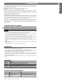 7
7
-
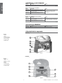 8
8
-
 9
9
-
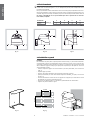 10
10
-
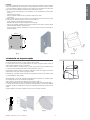 11
11
-
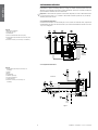 12
12
-
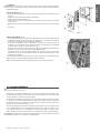 13
13
-
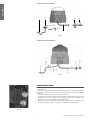 14
14
-
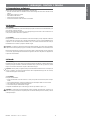 15
15
-
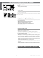 16
16
-
 17
17
-
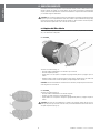 18
18
-
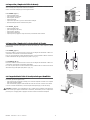 19
19
-
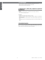 20
20
-
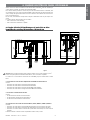 21
21
-
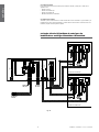 22
22
-
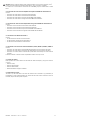 23
23
-
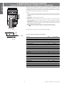 24
24
-
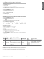 25
25
-
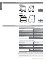 26
26
-
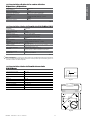 27
27
-
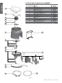 28
28
-
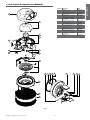 29
29
-
 30
30
-
 31
31
-
 32
32
-
 33
33
-
 34
34
-
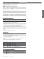 35
35
-
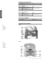 36
36
-
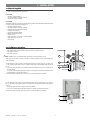 37
37
-
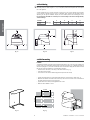 38
38
-
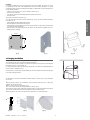 39
39
-
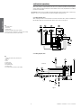 40
40
-
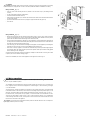 41
41
-
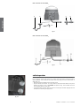 42
42
-
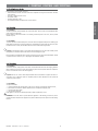 43
43
-
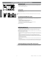 44
44
-
 45
45
-
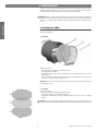 46
46
-
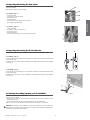 47
47
-
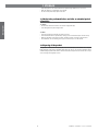 48
48
-
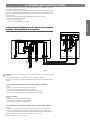 49
49
-
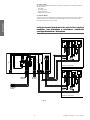 50
50
-
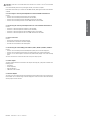 51
51
-
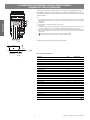 52
52
-
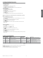 53
53
-
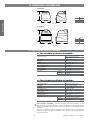 54
54
-
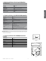 55
55
-
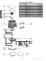 56
56
-
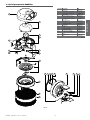 57
57
-
 58
58
-
 59
59
-
 60
60


FläktGroup humiDisk El manual del propietario
- Tipo
- El manual del propietario
Otros documentos
-
Carel UC0650D000 Manual de usuario
-
-
Carel humiSteam UE010 Manual de usuario
-
Carel UE009 Manual de usuario
-
-
Vemer SOLAR-3 Manual de usuario
-
-
-
-