Danfoss Oil Pump BFP 52E Guía de instalación
- Tipo
- Guía de instalación

DANSK ENGLISH DEUTSCH FRANCAIS ESPAÑOL ITALIANO SVENSKA NEDERLANDS SUOMEKSI
Symbol Symbol Légende des Legenda Symbol Merkkien
Symbols Símbolos Symbolen
forklaring erklärung symboles simboli förklaring selityk
set
Trykregu- Pressure Druck- Réglage de Regulación Regolazione Tryck- 1-portaan
Drukregelaar
P
1
lering regulation regelung für pression de presión pressione 1˚ reglering för paineen-
voor 1e trap
for trin 1 for stage 1 Stufe 1 allure 1 para etapa 1 stadio steg 1 säätö
Trykregu- Pressure Druck- Réglage de Regulación Regolazione Tryck- 2-portaan
Drukregelaar
P
2
lering regulation regelung für pression de presión pressione 2˚ reglering för paineen-
voor 2e trap
for trin 2 for stage 2 Stufe 2 allure 2 para etapa 2 stadio steg 2 säätö
Conduite Tubería de Tubazione di
Sugeledning Suction line Saugleitung Sugledning Zuigleiding Imuliitäntä
S d’aspirat. succión aspirazione
G
1
/4 G
1
/4 in G
1
/4 G
1
/4 G
1
/4 G
1
/4
G
1
/4 G
1
/4 pulg. G
1
/4
Rücklauf- Tubería de Tubazione di
Returledning Return line Conduite de Returledning Retourleiding Paluuliitäntä
leitung retorno ritorno
G G
1
/4 G
1
/4 in retour G
1
/4 G
1
/4 G
1
/4 G
1
/4
G
1
/4 G
1
/4 pulg. G
1
/4
Conexión de Attacco linea Munstycks Nozzle-
Dysetilslut- Nozzle conn. Düsenan- Raccordem. Suutinputki-
tobera ugello anslutning aansluiting
ning G
1
/8 G
1
/8 in schluss G
1
/8 gicleur G
1
/8 liitäntä G
1
/8
G
1
/8 pulg. G
1
/8 G
1
/8 G
1
/8
Patron- Cartridge Patronen- Rartouche Filtro de Filtro a Patron- Filter- Patruuna-
F
lter lter lter ltrante cartucho cartuccia lter patroon suodatin
Conexión de Vacuüm-
Tilslutning Vacuum Anschluss für Gaccordem. Attacco Anslutning Alipainemit-
medidor de meter-
for vacuum- meter conn. Vakuum- vacuomètre vuotometro för vakuum- tarin liitäntä
vacio aansluiting
meter G
1
/8 G
1
/8 in meter G
1
/8 G
1
/8 G
1
/8 meter
G
1
/8
G
1
/8
G
1
/8 pulg. G
1
/8
Tilslutning Pressure Anschluss für Raccordem. Conexión de Attacco Anslutning Manometer- Painemittarin
for mano- gauge conn. Manometer manomètre manómetro manometro för mano- aansluiting liitäntä
meter G
1
/8 G
1
/8 in G
1
/8 G
1
/8 G
1
/8 pulg. G
1
/8 meter
G
1
/8 G
1
/8 G
1
/8
520F0088 – DKBD.PI.011.L4.62
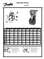
INSTRUCTIONS
BFP 52E
071R9810
071R9810
Fig. 1 Fig. 2
F
Fig. 3
DK 2-strengs system: isat skrue
GB 2-pipe operation: screw tted
D Zweirohrsystem: mit einsetzter Schraube
F Installation à deux tuyaux: vis
E Para operar en instalaciones de
2 tuberías: con el tornillo
I Funzionamento a 2 tubi: avvitare la vite
S 2-rörsanläggning: med skruv
NL 2-pijpssysteem: met schroef
SF 2-putkikäyttö: ruuvi paikalla
DK 1-strengs system: uden skrue
GB 1-pipe operation: without screw
D Einrohrsystem: ohne Schraube
F Installation à un tuyau: pas de vis
E Para operar en instalaciones de
1 tubería: Sin el tornillo
I Funzionamento monotubo: senza vite
S 1-rörsanläggning: utan skruv
NL 1-pijpssysteem: zonder schroef
SF 1-putkikäyttö: ruuvi pois

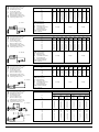
H ∅ 4 ∅ 5 ∅ 6 ∅ 4 ∅ 5 ∅ 6 ∅ 5 ∅ 6 ∅ 8
m mm mm mm mm mm mm mm mm mm
4,0 51 100 100 26 62 100 31 65 100
3,5 45 100 100 22 55 100 27 57 100
3,0 38 94 100 19 47 97 23 49 100
2,5 32 78 100 16 39 81 20 40 100
2,0 26 62 100 13 31 65 16 32 100
1,5 19 47 97 10 23 49 12 24 77
1,0 13 31 65 6 16 32 8 16 51
0,5 6 16 32 3 8 16 4 8 26
DK Dysekapacitet
GB Nozzle capacity
D Düsenleistung
F Débit du gicleur
E Capacidad de la tobera 2,5 kg/h 5 kg/h 10 kg/h
I Portata all’ugello
S Munstyckskapacitet
NL Verstuivercapaciteit
SF Suutinteho
DK Fyringsgasolie 6 mm
2
/s (cSt)
GB Fuel gas oil 6 mm
2
/s (cSt)
D Heizöl 6 mm
2
/s (cSt)
F Fioul 6 mm
2
/s (cSt)
E Fuel/oil 6 mm
2
/s (cSt)
I Gasolio 6 mm
2
/s (cSt)
S Eldningsolja 6 mm
2
/s (cSt)
NL Huisbrandolie 6 mm
2
/s (cSt)
SF Polttoöljy 6 mm
2
/s (cSt)
P
s
= 0 kPa
H ∅ 4 ∅ 5 ∅ 6 ∅ 4 ∅ 5 ∅ 6 ∅ 5 ∅ 6 ∅ 8
m mm mm mm mm mm mm mm mm mm
4,0 100 100 100 51 100 100 62 100 100
3,5 95 100 100 48 100 100 58 100 100
3,0 89 100 100 45 100 100 54 100 100
2,5 83 100 100 41 100 100 51 100 100
2,0 77 100 100 38 94 100 47 97 100
1,5 71 100 100 35 86 100 43 89 100
1,0 64 100 100 32 79 100 39 81 100
0,5 58 100 100 29 71 100 35 73 100
DK Dysekapacitet
GB Nozzle capacity
D Düsenleistung
F Débit du gicleur
E Capacidad de la tobera 2,5 kg/h 5 kg/h 10 kg/h
I Portata all’ugello
S Munstyckskapacitet
NL Verstuivercapaciteit
SF Suutinteho
DK Fyringsgasolie 6 mm
2
/s (cSt)
GB Fuel gas oil 6 mm
2
/s (cSt)
D Heizöl 6 mm
2
/s (cSt)
F Fioul 6 mm
2
/s (cSt)
E Fuel/oil 6 mm
2
/s (cSt)
I Gasolio 6 mm
2
/s (cSt)
S Eldningsolja 6 mm
2
/s (cSt)
NL Huisbrandolie 6 mm
2
/s (cSt)
SF Polttoöljy 6 mm
2
/s (cSt)
P
s
= 35 kPa
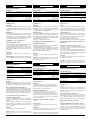
H ∅ 4 ∅ 5 ∅ 6 ∅ 4 ∅ 5 ∅ 6 ∅ 5 ∅ 6 ∅ 8
m mm mm mm mm mm mm mm mm mm
0 52 100 100 26 63 100 32 66 100
–0,5 46 100 100 23 56 100 28 58 100
–1,0 40 97 100 20 48 100 24 50 100
–1,5 33 81 100 17 41 84 20 42 100
–2,0 27 66 100 14 33 69 17 34 100
DK Dysekapacitet
GB Nozzle capacity
D Düsenleistung
F Débit du gicleur
E Capacidad de la tobera 2,5 kg/h 5 kg/h 10 kg/h
I Portata all’ugello
S Munstyckskapacitet
NL Verstuivercapaciteit
SF Suutinteho
DK Fyringsgasolie 6 mm
2
/s (cSt)
GB Fuel gas oil 6 mm
2
/s (cSt)
D Heizöl 6 mm
2
/s (cSt)
F Fioul 6 mm
2
/s (cSt)
E Fuel/oil 6 mm
2
/s (cSt)
I Gasolio 6 mm
2
/s (cSt)
S Eldningsolja 6 mm
2
/s (cSt)
NL Huisbrandolie 6 mm
2
/s (cSt)
SF Polttoöljy 6 mm
2
/s (cSt)
P
s
= 35 kPa
2800 min
–1
BFP 3 BFP 5
H ∅ 6 ∅ 8 ∅ 10 ∅ 6 ∅ 8 ∅ 10
m mm mm mm mm mm mm
4,0 33 100 100 21 67 100
3,5 31 98 100 20 63 100
3,0 29 91 100 19 59 100
2,5 27 85 100 17 55 100
2,0 25 79 100 16 51 100
1,5 23 72 100 15 46 100
1,0 21 66 100 13 42 100
0,5 19 60 100 12 38 94
0 17 53 100 11 34 84
–0,5 15 47 100 10 30 74
–1,0 13 41 99 8 26 64
–1,5 11 34 84 7 22 54
–2,0 9 28 68 6 18 44
–2,5 7 22 53 4 14 34
–3,0 5 15 37 3 10 24
–3,5 3 9 22 2 6 14
–4,0 1 3 6 1 2 4
DK Fyringsgasolie 6 mm
2
/s (cSt)
GB Fuel gas oil 6 mm
2
/s (cSt)
D Heizöl 6 mm
2
/s (cSt)
F Fioul 6 mm
2
/s (cSt)
E Fuel/oil 6 mm
2
/s (cSt)
I Gasolio 6 mm
2
/s (cSt)
S Eldningsolja 6 mm
2
/s (cSt)
NL Huisbrandolie 6 mm
2
/s (cSt)
SF Polttoöljy 6 mm
2
/s (cSt)
P
s
= 35 kPa
P
s
= 35 kPa

DANSK
Oliepumpe type BFP 52 E
1) Maks. 12 bar ved 1,3 cSt., maks. 15 bar ved 1,8 cSt.
Tilslutninger (g. 1)
Udluftning
Udluftning af oliepumpen er kun nødvendig ved 1-strengs
anlæg. Pumpen udluftes igennem P-porten. Ved 2-strengs
anlæg udlufter pumpen automatisk gennem returled-
ningen.
Filterskift (g. 2)
Filterproppen i dækslet skrues ud med en 4 mm nøgle
og patronlteret trækkes ud. Sæt evt. en skruetrækker
imellem lter og prop og vrid forsigtigt lteret af. Filteret
kasseres og erstattes med et nyt som presses på proppen!
Patronlteret genmonteres og spændes let til.
Omstilling fra 1- og 2-strengs drift (g. 3)
Sugeledningslængder i meter
Tabellerne gælder for en standard fyringsgasolie (Heizöl-EL)
af normal handelskvalitet iht. gældende normer.
Ved igangsætning af et anlæg med tomt rørsystem bør
oliepumpen ikke køre uden olie i mere end 5 minutter,
ligesom det forudsættes, at oliepumpen indeholder olie
før opstart.
Henvisning!
Oliepumperne er kun beregnet for anvendelse på olie-
brændere.
Bemærk venligst at magnetventilen skal udskiftes efter
250.000 koblinger eller 10 år (godkendt forventet levetid).
ENGLISH
Oil pump type BFP 52 E
1)
Max. 12 bar to 1.3 cSt., max. 15 bar to 1,8 cSt.
Connections (g. 1)
Bleeding
Bleeding the oil pump is only necessary on 1-pipe systems.
Bleeding is only possible at the P-port. On 2-pipe systems
the pump is automatically bled through the return pipe.
Filter replacement with cartridge lter (g. 2)
Unscrew the lter plug in the cover with a 4 mm key and
pull out the cartridge lter. Insert if necessary a screwdriver
between the lter and plug and carefully twist the lter
out. Scrap the lter and press a new lter onto the plug!
Reassemble the cartridge lter and tighten it slightly.
Conversion from 1 to 2-pipe operation (g. 3)
Suction line lengths in meters
The table is applicable for a standard gas oil (Heizöl-EL)
having a normal trade quality in accordance to applicable
standards.
When starting-up a system with an empty pipe, the oil
pump should not operate without oil for any more than
5 min. It is presumed that the pump contains some oil
before starting up.
Attention
The oil pumps are used only for oil burners.
Please note that the solenoid valve must be replaced
after 250.000 operations or 10 years (approved life
expectancy)
FRANCAIS
Pompe à oul BFP 52 E
1)
Max. 12 bar à 1,3 cSt., max. 15 bar à 1,8 cSt.
Raccordements (g. 1)
Purge d’air
La purge ne s’impose que pour les installations à un
tuyau : elle s’eectue par l’orice P. Dans les installations
à deux tuyaux, la purge d’air de la pompe se fait auto-
matiquement par la conduite de retour.
Remplacement du ltre (g. 2)
A l’aide d’une clé de 4 mm, dévisser et retirer du cou-
vercle le bouchon avec ltre. Si nécessaire, insérer
précautionneusement un tournevis entre le bouchon et
le ltre pour les séparer. Jeter le ltre usagé et presser le
nouveau sur le bouchon. Remonter la cartouche ltrante
et la serrer légèrement.
Du système à 1 tuyau au système à 2 tuyaux
Voir g. 3.
Avis important
Les pompes à oul conviennent uniquement aux brû-
leurs à oul !
Attention!
Les BFP 20 n'ont pas d'electrovanne. Ces pompes à oul
sont destinées uniquement aux brüleurs oul.
A note : la vanne solénoÏde e NC doit être remplacée après
250.000 opérations ou 10 ans (espérance de vie approuvée).
DEUTSCH
Ölpumpe Typ BFP 52 E
1)
Max. 12 bar bei 1,3 cSt., max. 15 bar bei 1,8 cSt.
Anschlüsse (Fig. 1)
Entlüftung
Eine Entlüftung ist nur an 1-Rohr-Anlagen erforderlich. Die
Entlüftung erfolgt am stirnseitigen Manometerstutzen.
Bei 2-Rohr-Anlagen erfolgt die Entlüftung der Pumpe
automatisch durch die Rücklaueitung.
Filterwechsel (Fig. 2)
Filterschraube im Deckel mit einem 4 mm Schlüssel lösen
und Patronenlter ziehen. Evtl. einen Schraubendreher
zwischen Filter und Schraube zum lösen des Filters stecken.
Einen neuen Filter auf die Schraube pressen! Patronenlter
montieren und leicht anziehen.
Wechsel des O-Ringes nicht vergessen.
Umstellung von Ein- auf Zweirohrbetrieb (Fig. 3)
Saugrohrlängen in Meter
Die Tabellen sind für (Heizöl-EL) einer normalen Handels-
qualität nach geltenden Normen gültig.
Bei der Inbetriebnahme einer Anlage mit leerem Rohr-
system sollte die Ölpumpe nicht länger als 5 Minuten
ohne Öl betrieben werden, vorausgesetzt, dass vor der
Inbetriebnahme Öl in der Pumpe ist.
Hinweis!
Die Ölpumpen sind ausschliesslich für Ölbrenner vor-
gesehen!
Achtung: Das NC-Magnetventil muss nach 250.000 Schal-
tungen oder 10 Jahren ausgetauscht werden (geprüfte
Lebensdauererwartung).
ESPAÑOL
Bomba para combustible líquido tipo BFP 52 E
1)
Max. 12 a 1,3 cSt., max. 15 bar a 1,8 cSt
Conexiones (g. 1)
Purga
La purga de la bomba para combustible líquido es necesaria
solo en sistemas de un tubo. La purga se realiza mediante
el tornillo de purga-P. En sistemas de dos tubos la bomba es
purgada automáticamente a través de la tubería de retorno.
Cambio de ltro (g. 2)
Aoje el tapón del ltro con una llave de 4 mm y extraiga
el ltro de cartucho. Introduzca, si es necesario, un destor-
nillador entre el ltro y el tapón y gire cuidadosamente el
ltro hasta extraerlo completamente.
Tire el ltro y presione uno nuevo al tapón.
Monte de nuevo el ltro de cartucho y tienselo ligeramente.
Conversión de funcionamiento de una tubería a dos
tuberías (g. 3)
Longitudes de tubería de succión en metros
Las tablas se aplican a combustible líquido standard
(Heizöl-EL) de calidad comercial normal de acuerdo con
las normas standard.
A la hora de poner en marcha un sistema en el cual la tubería
está vacía, no se permitirá que la bomba funcione más de 5
minutos, suponiendo que la bomba contenga combustible
líquido antes de la puesta en marcha.
¡Atención!
Las bombas de combustible líquido se emplean única-
mente para quemadores.
La vida útil de la válvula solenoide de la bomba esta
estimada en las 250.000 operaciones. A partir de dicho
número de operaciones se recomienda su sustitución.
ITALIANO
Pompa per gasolio tipo BFP 52 E
1)
Max. 12 bar a 1.3 cSt., max. 15 bar a 1,8 cSt.
Attacchi (g. 1)
Spurgo
Lo spurgo dell’aria è necessario solo in impianti mono-
tubo ed è possibile solo dall’attacco del manometro P. In
impianti a due tubi lo spurgo avviene automaticamente
attraverso il ritorno.
Sostituzione del ltro a cartuccia (g. 2)
Svitare il ltro con chiave da 4 mm e staccare la cartuccia
ltrante dal tappo. Se necessario, inserire un cacciavite tra
tappo e ltro; gettare il ltro usato e inserirne uno nuovo.
Rimontare sulla pompa il ltro e bloccarlo leggermente.
Conversione tra monotubo e due tubi
(g. 3)
Lunghezza della tubazione di aspirazione in metri
Le tabelle si applicano al normale gasolio reperibile sul
mercato. In fase di avviamento dell’impianto non fare
girare la pompa, senza gasolio, per più di 5 minuti sup-
ponendo che la pompa stessa contenga un po’ di gasolio
all’ di avviamento.
Tekniske data
Olietyper Standard fyringsolie og fyringsolie iht.
DIN V 51603-6 EL A Bio 10
Viskositetsområde
(1,3) 1,8 - 12 mm
2
/s (cSt)
Omdrejningstal 2400-3450 min
–1
Trykområde
1
7-25 bar
Fabriksindstilling Trin 1: 10 bar
Trin 2: 13 bar
Spolespænding Angivet på spolerne
Technical data
Oil types Standard fuel gas oil and fuel gas oil acc.
to DIN V 51603-6 EL A Bio 10
Viscosity range
(1,3) 1,8
- 12 mm
2
/s (cSt)
Speed 2400-3450 min
–1
Pressure range
1
7-25 bar
Factory setting Stage 1: 10 bar
Strage 2: 13 bar
Coil voltage Stated on coils
Technische Daten
Öltypen Standard Heizöl und Heizöl gemä
β
DIN V 51603-6 EL A Bio 10
Viskositätsbereich
(1,3) 1,8 - 12 mm
2
/s (cSt)
Drehzahlbereich 2400-3450 min
–1
(U/min)
Druckbereich
1
7-25 bar
Werkseinstellung Stufe 1: 10 bar
Stufe 2: 13 bar
Spulenspannung Auf den Spulen angegeben
Caractéristiques techniques
Types de combustible Fioul standard et oul selon la
norme DIN V 51603-6 EL A Bio 10
Gamme de viscosité
(1,3) 1,8 à 18 mm
2
/s (cSt)
Vitesse de rotation 2400-3450 min
–1
Plage de pression
1
7 à25 bar
Réglage départ usine Allure 1: 10 bar
Allure 2: 13 bar
Tension Indiquée sur la bobine
Características técnicas
Tipos de combustible Gasoil standars y gasoil hasta
DIN V 51603-6 EL A Bio 10
Gama de viscosidad
(1,3) 1,8 - 12 mm
2
/s (cSt)
Velocidad 2400-3450 min
–1
(r.p.m.)
Gama de presión
1
7-25 bar
Reglaj en fábrica Etapa 1: 10 bar
Etapa 2: 13 bar
Tensión de la bobina Indicada en bobinas
Caratteristiche tecnice
Tipi di olio Gasolio standard da riscaldamento e gasolio in
accordo con la norma DIN V 51603-6 EL A Bio 10
Campo di viscosità
(1,3) 1,8 - 12 mm
2
/s (cSt)
Velocità di rotazione 2400-3450 min
–1
Campo di pressione
1
7-25 bar
Taratura di fabbrica 1˚ Stadio: 10 bar
2˚ Stadio: 10 bar
Tensione bobina precisata sulla bobina
La página se está cargando...
Transcripción de documentos
INSTRUCTIONS 071R9810 071R9810 BFP 52E F Fig. 1 Fig. 2 DANSK Symbol forklaring Symbols DEUTSCH Symbol erklärung FRANCAIS Légende des symboles Símbolos ITALIANO Legenda simboli SVENSKA Symbol förklaring Symbolen P1 Trykregulering for trin 1 Pressure regulation for stage 1 Druckregelung für Stufe 1 Réglage de pression allure 1 Regulación de presión para etapa 1 Regolazione pressione 1˚ stadio Tryckreglering för steg 1 Drukregelaar voor 1e trap SUOMEKSI Merkkien selitykset 1-portaan paineensäätö P2 Trykregulering for trin 2 Pressure regulation for stage 2 Druckregelung für Stufe 2 Réglage de pression allure 2 Regulación de presión para etapa 2 Regolazione pressione 2˚ stadio Tryckreglering för steg 2 Drukregelaar voor 2e trap 2-portaan paineensäätö S Sugeledning G 1/4 Suction line G 1/4 in Saugleitung G 1/4 Conduite d’aspirat. G 1/4 Tubería de succión G 1/4 pulg. Tubazione di aspirazione G 1/4 Sugledning G 1/4 Zuigleiding G 1/4 Imuliitäntä G 1/4 G Returledning G 1/4 Return line G 1/4 in Rücklaufleitung G 1/4 Conduite de retour G 1/4 Tubería de retorno G 1/4 pulg. Tubazione di ritorno G 1/4 Returledning G 1/4 Retourleiding G 1/4 Paluuliitäntä G 1/4 Dysetilslutning G 1/8 Nozzle conn. G 1/8 in Düsenanschluss G 1/8 Raccordem. gicleur G 1/8 Conexión de tobera G 1/8 pulg. Attacco linea ugello G 1/8 Munstycks anslutning G 1/8 Nozzleaansluiting G 1/8 Suutinputkiliitäntä G 1/8 Patronfilter Cartridge filter Patronenfilter Rartouche filtrante Filtro de cartucho Filtro a cartuccia Patronfilter Filterpatroon Patruunasuodatin Tilslutning for vacuummeter G 1/8 Vacuum meter conn. G 1/8 in Anschluss für Vakuummeter G 1/8 Gaccordem. vacuomètre G 1/8 Attacco vuotometro G 1/8 Anslutning för vakuummeter G 1/8 Pressure gauge conn. G 1/8 in Anschluss für Manometer G 1/8 Raccordem. manomètre G 1/8 Attacco manometro G 1/8 Anslutning för manometer G 1/8 Vacuümmeteraansluiting G 1/8 Manometeraansluiting G 1/8 Alipainemittarin liitäntä G 1/8 Tilslutning for manometer G 1/8 Conexión de medidor de vacio G 1/8 pulg. Conexión de manómetro G 1/8 pulg. F ENGLISH DK GB D F E I S NL SF 1-strengs system: uden skrue 1-pipe operation: without screw Einrohrsystem: ohne Schraube Installation à un tuyau: pas de vis Para operar en instalaciones de 1 tubería: Sin el tornillo Funzionamento monotubo: senza vite 1-rörsanläggning: utan skruv 1-pijpssysteem: zonder schroef 1-putkikäyttö: ruuvi pois ESPAÑOL DK GB D F E I S NL SF NEDERLANDS Painemittarin liitäntä G 1/8 2-strengs system: isat skrue 2-pipe operation: screw fitted Zweirohrsystem: mit einsetzter Schraube Installation à deux tuyaux: vis Para operar en instalaciones de 2 tuberías: con el tornillo Funzionamento a 2 tubi: avvitare la vite 2-rörsanläggning: med skruv 2-pijpssysteem: met schroef 2-putkikäyttö: ruuvi paikalla Fig. 3 520F0088 – DKBD.PI.011.L4.62 DK GB D F E I S NL SF Fyringsgasolie 6 mm2/s (cSt) Fuel gas oil 6 mm2/s (cSt) Heizöl 6 mm2/s (cSt) Fioul 6 mm2/s (cSt) Fuel/oil 6 mm2/s (cSt) Gasolio 6 mm2/s (cSt) Eldningsolja 6 mm2/s (cSt) Huisbrandolie 6 mm2/s (cSt) Polttoöljy 6 mm2/s (cSt) DK GB D F E I S NL SF Ps = 0 kPa DK GB D F E I S NL SF Fyringsgasolie 6 mm2/s (cSt) Fuel gas oil 6 mm2/s (cSt) Heizöl 6 mm2/s (cSt) Fioul 6 mm2/s (cSt) Fuel/oil 6 mm2/s (cSt) Gasolio 6 mm2/s (cSt) Eldningsolja 6 mm2/s (cSt) Huisbrandolie 6 mm2/s (cSt) Polttoöljy 6 mm2/s (cSt) DK GB D F E I S NL SF Ps = 35 kPa DK GB D F E I S NL SF Fyringsgasolie 6 mm2/s (cSt) Fuel gas oil 6 mm2/s (cSt) Heizöl 6 mm2/s (cSt) Fioul 6 mm2/s (cSt) Fuel/oil 6 mm2/s (cSt) Gasolio 6 mm2/s (cSt) Eldningsolja 6 mm2/s (cSt) Huisbrandolie 6 mm2/s (cSt) Polttoöljy 6 mm2/s (cSt) Ps = 35 kPa DK GB D F E I S NL SF Fyringsgasolie 6 mm2/s (cSt) Fuel gas oil 6 mm2/s (cSt) Heizöl 6 mm2/s (cSt) Fioul 6 mm2/s (cSt) Fuel/oil 6 mm2/s (cSt) Gasolio 6 mm2/s (cSt) Eldningsolja 6 mm2/s (cSt) Huisbrandolie 6 mm2/s (cSt) Polttoöljy 6 mm2/s (cSt) Ps = 35 kPa Ps = 35 kPa DK GB D F E I S NL SF H m ∅4 mm ∅5 mm ∅6 mm ∅4 mm ∅5 mm ∅6 mm ∅5 mm ∅6 mm ∅8 mm 4,0 3,5 3,0 2,5 2,0 1,5 1,0 0,5 51 45 38 32 26 19 13 6 100 100 94 78 62 47 31 16 100 100 100 100 100 97 65 32 26 22 19 16 13 10 6 3 62 55 47 39 31 23 16 8 100 100 97 81 65 49 32 16 31 27 23 20 16 12 8 4 65 57 49 40 32 24 16 8 100 100 100 100 100 77 51 26 Dysekapacitet Nozzle capacity Düsenleistung Débit du gicleur Capacidad de la tobera Portata all’ugello Munstyckskapacitet Verstuivercapaciteit Suutinteho 2,5 kg/h 5 kg/h 10 kg/h H m ∅4 mm ∅5 mm ∅6 mm ∅4 mm ∅5 mm ∅6 mm ∅5 mm ∅6 mm ∅8 mm 4,0 3,5 3,0 2,5 2,0 1,5 1,0 0,5 100 95 89 83 77 71 64 58 100 100 100 100 100 100 100 100 100 100 100 100 100 100 100 100 51 48 45 41 38 35 32 29 100 100 100 100 94 86 79 71 100 100 100 100 100 100 100 100 62 58 54 51 47 43 39 35 100 100 100 100 97 89 81 73 100 100 100 100 100 100 100 100 Dysekapacitet Nozzle capacity Düsenleistung Débit du gicleur Capacidad de la tobera Portata all’ugello Munstyckskapacitet Verstuivercapaciteit Suutinteho 2,5 kg/h 5 kg/h 10 kg/h H m ∅4 mm ∅5 mm ∅6 mm ∅4 mm ∅5 mm ∅6 mm ∅5 mm ∅6 mm ∅8 mm 0 –0,5 –1,0 –1,5 –2,0 52 46 40 33 27 100 100 97 81 66 100 100 100 100 100 26 23 20 17 14 63 56 48 41 33 100 100 100 84 69 32 28 24 20 17 66 58 50 42 34 100 100 100 100 100 Dysekapacitet Nozzle capacity Düsenleistung Débit du gicleur Capacidad de la tobera Portata all’ugello Munstyckskapacitet Verstuivercapaciteit Suutinteho 2,5 kg/h 5 kg/h 10 kg/h 2800 min–1 BFP 3 BFP 5 H m ∅6 mm ∅8 mm ∅ 10 mm ∅6 mm ∅8 mm ∅ 10 mm 4,0 3,5 3,0 2,5 2,0 1,5 1,0 0,5 33 31 29 27 25 23 21 19 100 98 91 85 79 72 66 60 100 100 100 100 100 100 100 100 21 20 19 17 16 15 13 12 67 63 59 55 51 46 42 38 100 100 100 100 100 100 100 94 0 –0,5 –1,0 –1,5 –2,0 –2,5 –3,0 –3,5 –4,0 17 15 13 11 9 7 5 3 1 53 47 41 34 28 22 15 9 3 100 100 99 84 68 53 37 22 6 11 10 8 7 6 4 3 2 1 34 30 26 22 18 14 10 6 2 84 74 64 54 44 34 24 14 4 DEUTSCH DANSK ESPAÑOL Oliepumpe type BFP 52 E Ölpumpe Typ BFP 52 E Bomba para combustible líquido tipo BFP 52 E Tekniske data Technische Daten Características técnicas Olietyper Standard fyringsolie og fyringsolie iht. DIN V 51603-6 EL A Bio 10 (1,3) 1,8 - 12 mm2/s (cSt) 2400-3450 min–1 7-25 bar Trin 1: 10 bar Trin 2: 13 bar Angivet på spolerne Viskositetsområde Omdrejningstal Trykområde1 Fabriksindstilling Spolespænding Öltypen Standard Heizöl und Heizöl gemäβ DIN V 51603-6 EL A Bio 10 (1,3) 1,8 - 12 mm2/s (cSt) 2400-3450 min–1 (U/min) 7-25 bar Stufe 1: 10 bar Stufe 2: 13 bar Auf den Spulen angegeben Viskositätsbereich Drehzahlbereich Druckbereich1 Werkseinstellung Spulenspannung Max. 12 bar bei 1,3 cSt., max. 15 bar bei 1,8 cSt. Tipos de combustible Gasoil standars y gasoil hasta DIN V 51603-6 EL A Bio 10 (1,3) 1,8 - 12 mm2/s (cSt) 2400-3450 min–1 (r.p.m.) 7-25 bar Etapa 1: 10 bar Etapa 2: 13 bar Indicada en bobinas Gama de viscosidad Velocidad Gama de presión1 Reglaj en fábrica Tensión de la bobina 1) Maks. 12 bar ved 1,3 cSt., maks. 15 bar ved 1,8 cSt. 1) Tilslutninger (fig. 1) Anschlüsse (Fig. 1) Conexiones (fig. 1) Udluftning Udluftning af oliepumpen er kun nødvendig ved 1-strengs anlæg. Pumpen udluftes igennem P-porten. Ved 2-strengs anlæg udlufter pumpen automatisk gennem returledningen. Entlüftung Eine Entlüftung ist nur an 1-Rohr-Anlagen erforderlich. Die Entlüftung erfolgt am stirnseitigen Manometerstutzen. Bei 2-Rohr-Anlagen erfolgt die Entlüftung der Pumpe automatisch durch die Rücklaufleitung. Purga La purga de la bomba para combustible líquido es necesaria solo en sistemas de un tubo. La purga se realiza mediante el tornillo de purga-P. En sistemas de dos tubos la bomba es purgada automáticamente a través de la tubería de retorno. Filterskift (fig. 2) Filterproppen i dækslet skrues ud med en 4 mm nøgle og patronfilteret trækkes ud. Sæt evt. en skruetrækker imellem filter og prop og vrid forsigtigt filteret af. Filteret kasseres og erstattes med et nyt som presses på proppen! Patronfilteret genmonteres og spændes let til. Filterwechsel (Fig. 2) Filterschraube im Deckel mit einem 4 mm Schlüssel lösen und Patronenfilter ziehen. Evtl. einen Schraubendreher zwischen Filter und Schraube zum lösen des Filters stecken. Einen neuen Filter auf die Schraube pressen! Patronenfilter montieren und leicht anziehen. Wechsel des O-Ringes nicht vergessen. Cambio de filtro (fig. 2) Afloje el tapón del filtro con una llave de 4 mm y extraiga el filtro de cartucho. Introduzca, si es necesario, un destornillador entre el filtro y el tapón y gire cuidadosamente el filtro hasta extraerlo completamente. Tire el filtro y presione uno nuevo al tapón. Monte de nuevo el filtro de cartucho y tienselo ligeramente. Umstellung von Ein- auf Zweirohrbetrieb (Fig. 3) Conversión de funcionamiento de una tubería a dos tuberías (fig. 3) Omstilling fra 1- og 2-strengs drift (fig. 3) Sugeledningslængder i meter Tabellerne gælder for en standard fyringsgasolie (Heizöl-EL) af normal handelskvalitet iht. gældende normer. Ved igangsætning af et anlæg med tomt rørsystem bør oliepumpen ikke køre uden olie i mere end 5 minutter, ligesom det forudsættes, at oliepumpen indeholder olie før opstart. Henvisning! Oliepumperne er kun beregnet for anvendelse på oliebrændere. Bemærk venligst at magnetventilen skal udskiftes efter 250.000 koblinger eller 10 år (godkendt forventet levetid). ENGLISH Saugrohrlängen in Meter Die Tabellen sind für (Heizöl-EL) einer normalen Handelsqualität nach geltenden Normen gültig. Bei der Inbetriebnahme einer Anlage mit leerem Rohrsystem sollte die Ölpumpe nicht länger als 5 Minuten ohne Öl betrieben werden, vorausgesetzt, dass vor der Inbetriebnahme Öl in der Pumpe ist. Hinweis! Die Ölpumpen sind ausschliesslich für Ölbrenner vorgesehen! Achtung: Das NC-Magnetventil muss nach 250.000 Schaltungen oder 10 Jahren ausgetauscht werden (geprüfte Lebensdauererwartung). FRANCAIS Oil pump type BFP 52 E Viscosity range Speed Pressure range1 Factory setting Coil voltage 1) Max. 12 a 1,3 cSt., max. 15 bar a 1,8 cSt Longitudes de tubería de succión en metros Las tablas se aplican a combustible líquido standard (Heizöl-EL) de calidad comercial normal de acuerdo con las normas standard. A la hora de poner en marcha un sistema en el cual la tubería está vacía, no se permitirá que la bomba funcione más de 5 minutos, suponiendo que la bomba contenga combustible líquido antes de la puesta en marcha. ¡Atención! Las bombas de combustible líquido se emplean únicamente para quemadores. La vida útil de la válvula solenoide de la bomba esta estimada en las 250.000 operaciones. A partir de dicho número de operaciones se recomienda su sustitución. ITALIANO Pompe à fioul BFP 52 E Technical data Oil types 1) Standard fuel gas oil and fuel gas oil acc. to DIN V 51603-6 EL A Bio 10 (1,3) 1,8 - 12 mm2/s (cSt) 2400-3450 min–1 7-25 bar Stage 1: 10 bar Strage 2: 13 bar Stated on coils Max. 12 bar to 1.3 cSt., max. 15 bar to 1,8 cSt. Caractéristiques techniques Types de combustible Gamme de viscosité Vitesse de rotation Plage de pression1 Réglage départ usine Tension Max. 12 bar à 1,3 cSt., max. 15 bar à 1,8 cSt. Connections (fig. 1) 1) Bleeding Bleeding the oil pump is only necessary on 1-pipe systems. Bleeding is only possible at the P-port. On 2-pipe systems the pump is automatically bled through the return pipe. Raccordements (fig. 1) Filter replacement with cartridge filter (fig. 2) Unscrew the filter plug in the cover with a 4 mm key and pull out the cartridge filter. Insert if necessary a screwdriver between the filter and plug and carefully twist the filter out. Scrap the filter and press a new filter onto the plug! Reassemble the cartridge filter and tighten it slightly. Conversion from 1 to 2-pipe operation (fig. 3) Suction line lengths in meters The table is applicable for a standard gas oil (Heizöl-EL) having a normal trade quality in accordance to applicable standards. When starting-up a system with an empty pipe, the oil pump should not operate without oil for any more than 5 min. It is presumed that the pump contains some oil before starting up. Attention The oil pumps are used only for oil burners. Please note that the solenoid valve must be replaced after 250.000 operations or 10 years (approved life expectancy) Fioul standard et fioul selon la norme DIN V 51603-6 EL A Bio 10 (1,3) 1,8 à 18 mm2/s (cSt) 2400-3450 min–1 7 à25 bar Allure 1: 10 bar Allure 2: 13 bar Indiquée sur la bobine Purge d’air La purge ne s’impose que pour les installations à un tuyau : elle s’effectue par l’orifice P. Dans les installations à deux tuyaux, la purge d’air de la pompe se fait automatiquement par la conduite de retour. Remplacement du filtre (fig. 2) A l’aide d’une clé de 4 mm, dévisser et retirer du couvercle le bouchon avec filtre. Si nécessaire, insérer précautionneusement un tournevis entre le bouchon et le filtre pour les séparer. Jeter le filtre usagé et presser le nouveau sur le bouchon. Remonter la cartouche filtrante et la serrer légèrement. Du système à 1 tuyau au système à 2 tuyaux Voir fig. 3. Avis important Les pompes à fioul conviennent uniquement aux brûleurs à fioul ! Attention! Les BFP 20 n'ont pas d'electrovanne. Ces pompes à fioul sont destinées uniquement aux brüleurs fioul. A note : la vanne solénoÏde e NC doit être remplacée après 250.000 opérations ou 10 ans (espérance de vie approuvée). Pompa per gasolio tipo BFP 52 E Caratteristiche tecnice Tipi di olio Gasolio standard da riscaldamento e gasolio in accordo con la norma DIN V 51603-6 EL A Bio 10 Campo di viscosità (1,3) 1,8 - 12 mm2/s (cSt) Velocità di rotazione 2400-3450 min–1 Campo di pressione1 7-25 bar Taratura di fabbrica 1˚ Stadio: 10 bar 2˚ Stadio: 10 bar Tensione bobina precisata sulla bobina 1) Max. 12 bar a 1.3 cSt., max. 15 bar a 1,8 cSt. Attacchi (fig. 1) Spurgo Lo spurgo dell’aria è necessario solo in impianti monotubo ed è possibile solo dall’attacco del manometro P. In impianti a due tubi lo spurgo avviene automaticamente attraverso il ritorno. Sostituzione del filtro a cartuccia (fig. 2) Svitare il filtro con chiave da 4 mm e staccare la cartuccia filtrante dal tappo. Se necessario, inserire un cacciavite tra tappo e filtro; gettare il filtro usato e inserirne uno nuovo. Rimontare sulla pompa il filtro e bloccarlo leggermente. Conversione tra monotubo e due tubi (fig. 3) Lunghezza della tubazione di aspirazione in metri Le tabelle si applicano al normale gasolio reperibile sul mercato. In fase di avviamento dell’impianto non fare girare la pompa, senza gasolio, per più di 5 minuti supponendo che la pompa stessa contenga un po’ di gasolio all’ di avviamento.-
 1
1
-
 2
2
-
 3
3
-
 4
4


Danfoss Oil Pump BFP 52E Guía de instalación
- Tipo
- Guía de instalación
en otros idiomas
- français: Danfoss Oil Pump BFP 52E Guide d'installation
- italiano: Danfoss Oil Pump BFP 52E Guida d'installazione
- English: Danfoss Oil Pump BFP 52E Installation guide
- Deutsch: Danfoss Oil Pump BFP 52E Installationsanleitung
- Nederlands: Danfoss Oil Pump BFP 52E Installatie gids
- dansk: Danfoss Oil Pump BFP 52E Installationsvejledning
- svenska: Danfoss Oil Pump BFP 52E Installationsguide
- suomi: Danfoss Oil Pump BFP 52E Asennusohje
Artículos relacionados
-
Danfoss Oil Pump BFP 52E Guía de instalación
-
-
-
-
-
-
-
-