
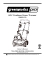
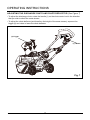
Read all safety rules and instructions carefully before operating this tool.
Owner’s Manual
TOLL-FREE HELPLINE: 1(855)345-3934
www.GreenWorksTools.com
60V Cordless Snow Thrower
SN60L00

2
Contents .............................................................................................................................. 2
Product specications .......................................................................................................... 2
Safety information ................................................................................................................ 3
Symbols ............................................................................................................................... 6
Know your snow thrower ...................................................................................................... 8
Assembly ............................................................................................................................. 9
Operation ........................................................................................................................... 16
Maintenance ...................................................................................................................... 19
Environmentally safe battery disposal ............................................................................... 22
Troubleshooting ................................................................................................................. 23
Warranty ............................................................................................................................ 24
Exploded View / Parts List ................................................................................................ 25
PRODUCT SPECIFICATIONS
60V CORDLESS SNOW THROWER
Motor ................................................................................................... 60 V brushless motor
Battery type ................................................................................................. 60 V Lithium-ion
No-load speed ..................................................................................................... 1, 9 0 0 RPM
Working width ............................................................................................................... 20 in.
Clearing depth ...............................................................................................................10 in.
Impeller size ..................................................................................................................16 in.
Wheels ............................................................................................................................ 7 in.
Weight (without battery) .............................................................................................33.5 lbs
Weight (with battery) .................................................................................................. 37.9 lbs
Discharge distance .......................................................................................................... 6 m
CONTENTS
Cold Weather Operation: Lithium Ion batteries can be safely used from temperatures ranging
from -17 degrees to 45 degrees Celsius. NOTE: Do not store or charge battery outside. Battery
must be charged and stored indoors prior to use of the snow thrower.
Battery may not properly start if it’s temperatures is -17˚C or lower. If unit does not start remove
battery from snow thrower. Place battery on charger and allow to charge for 10 minutes to allow
battery to warm. Remove from charger and install in Snow thrower for use.

3
SAFETY INFORMATION
FOLLOW THESE RULES WHILE OPERATING (THE POWER TOOL)
WARNING
READ AND UNDERSTAND ALL INSTRUCTIONS. Failure to follow all instructions listed below
may result in electric shock, re, and/or serious personal injury.
• Walk. Do not run.
• Verify that the power tool is not in contact with anything before turning it on.
• Stay away from impeller openings at all times. Keep face, hands, and feet away from
concealed, moving, or rotating parts.
• Be attentive when using the power tool, and stay alert for holes in the terrain and other hidden
hazards or trafc.
• Move up and down slopes when clearing snow. Do not go across a slope. Use caution when
changing direction. Do not use this power tool to clear snow from steep slopes.
• Do not operate the power tool if the guards, plates, and other safety protective devices are not
in place.
• Do not operate the power tool near glass enclosures, automobiles, trucks, window wells,
drop-offs, etc. without properly adjusting the angle of the snow discharge. Keep children and
pets away from the work area.
• Do not operate the power tool at high speeds on slippery surfaces. Look behind when backing
up and exercise caution.
• Wear safety glasses or goggles that meet ANSI Z87.1 standards.
• Use the power tool in daylight or in good articial light. If using at night, turn on the LED lights
and be aware of your surroundings.
• To avoid accidental start-ups, remain in the starting position when turning the power tool on.
The operator and the power tool must be in a stable position during start-up. See the section
titled Starting/Stopping Instructions.
• Use this power tool only for the purposes it was designed.
• Hold the power tool with both hands while it is in use. Keep a rm grip on the handles.
• If the impeller does not rotate freely due to ice, thaw the power tool thoroughly before
attempting to use it.
• Keep the impeller clear of debris.
• Do not attempt to clear the impeller while the motor is running.
• After striking a foreign object, turn the power tool off and remove the battery pack, and then
inspect it for damage. Repair any damage before restarting and using the power tool.
• If the power tool starts to vibrate abnormally, stop the power tool immediately and attempt to
determine the cause. Vibration is generally an indication of danger.
• Stop the motor and remove the battery pack whenever the operator is not in the operating
position, before unclogging the impeller, and before making any repairs, adjustments, or
inspections.
• Do not use on graveled surface unless the power tool is adjusted for such a surface in
accordance with the operator’s manual.

4
SAFETY INFORMATION
• Keep Children Away– All visitors should be kept a safe distance from work area.
• Dress Properly – Do not wear loose clothing or jewelry. They can be caught in moving parts.
• Wear rubber boots when operating the power tool. Do not operate the equipment when
barefoot or wearing open sandals. Always wear substantial footwear.
• Operation of the power tool in the hand-held position is unsafe, except in accordance with the
special instructions for such use provided in the operator’s manual.
• Keep guards in place and in working order.
• Don’t Force Power tool – It will perform better and safer at the rate for which it was designed.
• Don’t Overreach – Keep proper footing and balance at all times.
• If the power tool strikes a foreign object, follow these steps:
i) Stop the power tool.
ii) Inspect for damage.
iii) Repair any damage before restarting and operating the power tool.
• Store Idle Power tool Indoors – When not in use, power tools should be stored indoors in dry,
locked-up place – out of reach of children.
• Maintain Power tools With Care – Follow instructions for lubricating and changing
accessories.
• Allow the power tool to run for a few minutes after clearing snow in order to prevent moving
parts from freezing.
• Only use identical replacement parts and accessories for this power tool. The use of
nonidentical parts or accessories could lead to serious injury to the user or damage the power
tool, and will void the warranty.
• Do not pick up the power tool while it is running. The power tool is designed to travel along the
ground.
• Never allow children to operate a power tool. Keep the area of operation clear of all persons,
particularly small children, and pets.
• Thoroughly inspect the area where the equipment is to be used and remove all stones, sticks,
wires, bones, and other foreign objects.
• Stop the blade(s) when crossing gravel driveways, walkways, or roads.
• Read the operator’s manual carefully. Be thoroughly familiar with the controls and the proper
use of the equipment.

5
SAFETY INFORMATION
GENERAL SAFETY RULES
• Verify that the power tool is secure while transporting.
• Store the power tool in a dry area that will prevent unauthorized use or damage. Keep out of
the reach of children.
• Keep handles dry, clean, and free of debris. Clean the power tool after each use. Refer to the
Maintenance Section in this manual for more information.
• If the labels on the power tool become defaced or start to lift off, contact customer service at
1(855)345-3934.
• Keep these instructions in a safe place for future reference. Refer to them often, and use
them to instruct other users. Anyone who uses this power tool must read these instructions
carefully.
• Maintain the power tool with care. Follow the instructions for lubricating and changing
accessories.
CAUTION
USE ONLY GREENWORKS APPROVED REPLACEMENT BATTERIES, OTHER BATTERIES
MAY CAUSE INJURY OR DAMAGE TO THE SNOW THROWER. USE ONLY WITH
GREENWORKS 60V BATTERIES (Model#: LB60A00 / LB60A03 / LB60A01 / LB60A02) and
GREENWORKS 60V CHARGER (Model#: CH60A00).
WARNING(PROPOSITION65)
This product contains a chemical known to the state of California to cause cancer, birth defects
or other reproductive harm.
Some dust created by power sanding, sawing, grinding, drilling and other construction activities
contains chemicals known to cause cancer, birth defects or other reproductive harm. Some
examples of these chemicals are:
• Lead from lead-based paints,
• Crystalline silica from bricks and cement and other masonry products, and
• Arsenic and chromium from chemically-treated lumber.
Your risk of exposure to these chemicals varies depending on how often you do this type of
work. To reduce your exposure to these chemicals, work in a well-ventilated area, and work with
approved safety equipment, such as dust masks that are specially designed to lter out microscopic
particles.
SAVE THESE INSTRUCTIONS

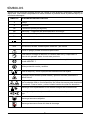
Some of the following symbols may be used on this product. Please study them and learn their
meaning. Proper interpretation of these symbols will allow you to operate the product better and safer.
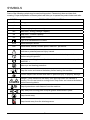
SYMBOLS
6
SYMBOL DESIGNATION/EXPLANATION
V Voltage
A Current
Hz Frequency (cycles per second)
Wh Watt Hour - Energy Storage Capacity
Ah Amp Hour - Current Capacity
DC Direct current
Type or a characteristic of current
RPM Revolutions per minute
/min Revolutions, strokes, surface speed, orbits etc., per minute
Indicates a potential personal injury hazard.
To reduce the risk of injury user must read and understand operator’s manual
before using this product.
Always wear safety glasses with side shields that are marked to comply with
ANSI Z87.1.
Wear eye and hearing protection.
STOP
STOP
Stop the motor and remove the battery before leaving the machine.
Thrown objects can ricochet and result in personal injury or property damage.
Danger – Keep hands and feet away from openings while the machine is
running. Do not use hands to unclog chute. Stop motor and remove the battery
before removing debris.
Keep bystanders a safe distance from the machine.
Stay away from moving parts. Keep all guards and shields in place.
Keep hands away.
Keep hands away from the discharge area.

7
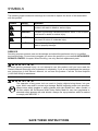
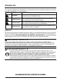
The following signal words and meanings are intended to explain the levels of risk associated
with this product.
SYMBOLS
SAVE THESE INSTRUCTIONS
SERVICE
Servicing requires extreme care and knowledge and should be performed only by a qualied
service technician. For service we suggest you return the product to your nearest AUTHORIZED
SERVICE CENTER for repair. When servicing, use only identical replacement parts.
WARNING
To avoid serious personal injury, do not attempt to use this product until you have read this
Owner's Manual thoroughly and understand it completely. If you do not understand the warnings
and instructions in this Owner's Manual, do not use this product. Call the Toll-free Helpline
(1-855-345-3934) for assistance.
WARNING
The operation of any power tool can result in foreign objects being thrown into your
eyes, which can result in severe eye damage. Before beginning power tool operation,
always wear safety goggles or safety glasses with side shields and, when needed, a
full face shield. We recommend Wide Vision Safety Mask for use over eyeglasses or
standard safety glasses with side shields. Always use eye protection which is marked
to comply with ANSI Z87.1.
SYMBOL SIGNAL MEANING
DANGER Indicates an imminently hazardous situation, which, if not
avoided, will result in death or serious injury.
WARNING Indicates a potentially hazardous situation, which, if not avoided,
could result in death or serious injury.
CAUTION Indicates a potentially hazardous situation, which, if not avoided,
may result in minor or moderate injury.
CAUTION (Without Safety Alert Symbol) Indicates a situation that may
result in property damage.

8
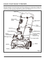
KNOW YOUR SNOW THROWER
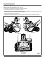
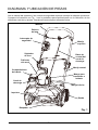
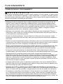
Fig. 1
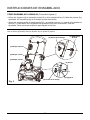
Read this operator's manual and safety rules before operating your snow thrower. Compare the
illustration in Figure 1 to your snow thrower in order to familiarize yourself with the location of
various controls and adjustments. Save this manual for future reference.
Battery
compartment
Upper handle
Middle handle
Carrying or lifting
handle (For
transport only)
Chute
control rod
Lower handle
Wheel
Handle bar
Bail lever
Impeller
Scraper
Chute deector
Cam lock
Discharge chute
Safety switch
button

9
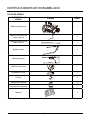
ASSEMBLY INSTRUCTIONS
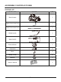
PART NAME FIGURE QTY
Snow thrower
1
Upper chute control rod
1
Lower chute control rod
1
Middle handle
1
Upper handle
1
Chute deector
1
Cam locks
2
Bolts
2
Handle knobs
4
Hitch pin
1
Owner's Manual
1
PACKING LIST

10
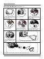
UNPACKING
• Carefully remove the product and any accessories from the box. Make sure that all items
listed in the packing list are included.
• Inspect the product carefully to make sure no breakage or damage occurred during shipping.
• Do not discard the packing material until you have carefully inspected and satisfactorily
operated the product.
• If any parts are damaged or missing, please call 1-855-345-3934 for assistance.
WARNING
If any parts are damaged or missing, do not operate this product until the parts are replaced.
Failure to heed this warning could result in serious personal injury.
WARNING
Do not install the battery until assembly is complete. Failure to comply could result in accidental
starting and possible serious personal injury.
WARNING
Do not attempt to modify this product or create accessories not recommended for use with this
product. Any such alteration or modication is misuse, and could result in a hazardous condition
leading to possible serious personal injury.
WARNING
Do not allow familiarity with this product to make you careless. Remember that a careless
fraction of a second is sufcient to inict serious injury.
WARNING
Do not use any attachments or accessories not recommended by the manufacturer of this product.
The use of attachments or accessories not recommended can result in serious personal injury.
ASSEMBLY INSTRUCTIONS

11
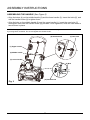
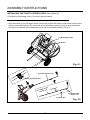
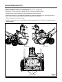
ASSEMBLING THE HANDLE (See Figure 2)
• Align the holes (4) on the middle handle (2) and the lower handle (3). Insert the bolts (5), and
use the handle knobs (6) to tighten them.
• Align the hole on the middle handle (2) and the upper handle (1). Insert the cam locks (7)
and tighten them with the handle knobs (8) provided. Once tightened, close the cam locks to
secure them in place.
NOTE: If the upper handle is loose or separated from the middle handle, tighten the cam lock handle knobs
by turning them clockwise. Do not overtighten the handle knobs.
ASSEMBLY INSTRUCTIONS
Fig. 2
(1) Upper handle
(2) Middle handle
(3) Lower handle
(6) Handle knob
(5) Bolt
(4) Holes
(8) Handle knob (7) Cam lock

12
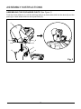
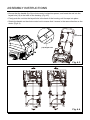
ASSEMBLING THE DISCHARGE CHUTE (See Figure 3)
Push the chute deector (1) until the latching tabs (2) on both sides click into the slots (3) and the
posts (4) on both sides click into the keyed holes (5).
ASSEMBLY INSTRUCTIONS
Fig. 3
1
2
5
42
5
3
3

13
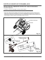
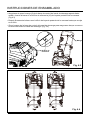
INSTALLING THE CHUTE CONTROL ROD (See Figure 4)
• Position the discharge chute (1) so that it faces forward.
NOTE: Align the arrow (2) on the discharge chute with the arrow on the housing.
(Fig. 4.1)
• Align the holes (3) on the upper chute control rod (4) with the holes on the lower chute control
rod (5). Insert the hitch pin (6). Insert the end of the chute control rod (7) through the keyed
hole (8) in the bracket that is attached to the top of the middle handle. (Fig.4.2)
ASSEMBLY INSTRUCTIONS
Fig. 4.1
Fig. 4.2
(1) Discharge chute
(2) Arrow
(7) Chute control rod
(8) Keyed hole
(4) Upper chute
control rod
(3) Holes
(6) Hitch pin
(5) Lower chute
control rod

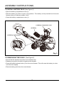
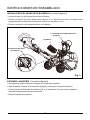
• Ensure that the handle (9) of the chute control rod points upward, and insert the rod into the
keyed hole (10) in the back of the housing. (Fig.4.3)
• Firmly push the rod into the keyed hole in the back of the housing until it snaps into place.
• Rotate the handle on the chute control rod to ensure that it moves in the same direction as the
chute. (Fig.4.4)
14
ASSEMBLY INSTRUCTIONS
Fig. 4.4
Fig. 4.3
(9) Handle
(10) Keyed hole

ASSEMBLY INSTRUCTIONS
15
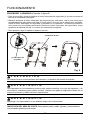
TO INSTALL BATTERY PACK (See Figure 5)
• Open the battery compartment cover (1).
• Slide the battery (2) down to lock it into position. The battery is fully inserted into the snow
thrower when you hear an audible "click".
• Close the battery compartment cover (1).
Fig. 5
TO REMOVE BATTERY PACK (See Figure 5)
• Ensure that the impeller has come to a complete stop.
• Release your grip on the bail to stop the snow thrower.
• Press the battery release button (3) on the snow thrower. This will cause the battery to raise
out of the tool slightly.
• Remove battery pack from the snow thrower.
(1) Battery compartment cover
(2) Battery
(3) Battery release button

OPERATING INSTRUCTIONS
16
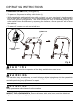
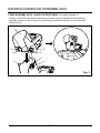
POWERING ON AND OFF (See Figure 6)
• To power on, rst press the safety switch button (1).
• While pressing the safety switch button with one hand, use your other hand to simultaneously
pull the bail lever (2) toward you. Once the machine powers on, release the safety switch
button and proceed with operation. The snow thrower can only be started by pressing the
safety switch button rst, followed by squeezing the bail lever; reverse operation will not start
the machine.
• To power off, release your grip on the bail lever.
CAUTION
Do not attempt to override the operation of the safety switch button or bar lever.
WARNING
The operation of any snow thrower can result in foreign objects being thrown into the eyes, which
can cause severe eye damage. Always wear safety glasses while operating the snow thrower
and while performing any adjustments or repairs.
WARNING
Keep bystanders a safe distance from the machine.
INSPECT THE CLEARING AREA. Remove all stones, sticks, wire, bones, and other debris that
might be thrown by the rotating impeller.
Fig. 6
(2) Bail lever
(1) Safety switch
button

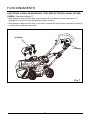
ADJUSTING THE DISCHARGE CHUTE AND CHUTE DEFLECTOR (See Figure 7)
• To adjust the discharge chute, rotate the handle (1) on the chute control rod in the direction
that you wish to direct the snow stream.
• To adjust the chute deector (and therefore the height of the snow stream), squeeze the
trigger (2) and raise or lower the chute deector.
OPERATING INSTRUCTIONS
17
Fig. 7
(1) Handle
(2) Trigger

OPERATING TIPS
WARNING
If the Snow Thrower hits a foreign object while it is in use, the object could be thrown in the
direction of the operator or a bystander. Thrown objects could cause serious personal injury.
Keep the area to be cleared free of all foreign objects that may be picked up and thrown by the
impeller.
• Keep the area of operation free of foreign objects that can become thrown by the impeller.
Perform a thorough inspection of the area since some objects may be hidden from view by
surrounding snow. lf the snow thrower hits an obstruction or picks up a foreign object during
use, stop the snow thrower, remove the battery, remove the obstruction, and inspect the unit
for damage. Repair or replace any damaged part before restarting and operating the unit.
• Keep children, pets, and bystanders away from the area of operation. Be aware that the
normal noise of the machine when turned on may make it difcult for you to hear approaching
people.
• When moving the snow thrower, use the wheels on one side as the pivot point. Slightly tilt the
snow thrower on this pivot point to move it forward or backward.
• Start your clearing path outward, throwing snow in a back and forth motion. To clear in the
opposite direction, pivot the snow thrower on its wheels. Make sure to overlap clearing paths.
• Note the wind direction. If possible, move in the same direction as the wind so that the snow
is not thrown against the wind (and thus back onto you and on the just cleared path).
• Do not push the snow thrower with excessive force. You should push the machine gently and
at a consistent speed in accordance with the unit's throw rate.
• Some parts of the snow thrower may freeze under extreme temperature conditions. Do not
attempt to operate the snow thrower with frozen parts. If the parts freeze while the snow
thrower is in use, stop the snow thrower, remove the battery, and inspect for frozen parts. Free
all parts before restarting or operating the snow thrower. Never force controls that are frozen.
• When working on pebbles, gravel, or unpaved surfaces, avoid throwing loose surface material
along with the snow by pushing down on the handle to raise the scraper at the base of the unit
above the pebbles or gravel.
• Cold Weather Operation: Lithium Ion batteries can be safely used from temperatures ranging
from -17 degrees to 45 degrees Celsius. NOTE: Do not store or charge battery outside.
Battery must be charged and stored indoors prior to use of the snow thrower.
• If the Snow thrower does not start initially remove battery from snow thrower. Place battery on
charger and allow to charge for 10 minutes. Remove from charger and install in Snowthrower
for use. The start-up issue may be caused from the battery being too cold. To avoid this issue,
ensure battery is stored in a dry cool place for storage and charging and leave indoors until
ready for use.
OPERATING INSTRUCTIONS
18

MAINTENANCE
SERVICING
Servicing should be performed by a qualied technician. Replacement parts for this snow
thrower must be identical to the parts that they replace. If repairs are necessary, contact the
toll-free helpline, at 1-855-345-3934.
Note: Identify the left and right sides of the snow thrower when standing in the normal operating position.
WARNING
If the battery pack is installed into the snow thrower, the snow thrower could start accidentally
while the operator is performing maintenance on it, which could cause serious personal injury.
Remove the battery pack before performing any maintenance.
STORAGE
• Run the snow thrower for a few minutes in order to melt any snow that may be left on the snow
thrower.
• Wipe the snow thrower off with a dry cloth before storage. This will help prevent ice building
up on the unit and parts freezing.
• Remove the battery and store it in a cool dry location, if possible. Charge the battery every six
months when not in use in order to increase its life.
• Inspect the snow thrower thoroughly for worn, loose, or damaged parts. If any parts must be
repaired or replaced, contact the Toll-Free Helpline, at 1-855-345-3934.
• Store the snow thrower in a clean, dry place. Cover it in order to provide added protection.
• Always store battery and charger indoors.
19

MAINTENANCE
20
REPLACING THE SCRAPER (See Figure 8)
The scraper is located at the bottom of the impeller housing.
• Ensure that the battery is not installed in the tool.
• Remove the screw (1) from each side plate that holds the scraper and 3 screws (2) from under
the machine that secure the scraper to the machine.
• Remove and discard the old scraper.
• Install the new scraper, and fasten it securely with 5 screws that you previously removed.
Fig. 8
(1) Screw
(1) Screw
(2) 3 Screws

MAINTENANCE
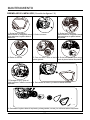
REPLACING THE IMPELLER (See Figures 1-9)
21
1. Remove the 5 screws and
side wear pad that secure the
right side cover.
2. Remove the nut.
3. Remove the 5 screws and
side wear pad that secure the
left side cover.
4. Remove the belt. 5. Using a socket wrench,
remove the the large pulley.
6. Remove the screws that
secure the left side plate.
7. Pull the axle and remove the
old impeller. Install the new
impeller.
8. Reinstall the nut and right side cover.
9. Reinstall the left side plate, large pulley, belt and left side cover.

ENVIRONMENTALLY SAFE BATTERY DISPOSAL
The following toxic and corrosive materials are in the batteries used in this tool battery pack:
Lithium-Ion, a toxic material.
WARNING
Toxic materials must be disposed of in a specied manner in order to prevent contamination of the
environment. Before disposing of damaged or worn out Lithium-Ion battery packs, contact your
local waste disposal agency for information and specic instructions. Take the battery to a local
recycling and/or disposal centre that is certied for disposal. If the battery pack cracks or breaks,
whether it leaks or not, do not recharge it and do not use it. Dispose of it and replace it with a new
battery pack. DO NOT ATTEMPT TO REPAIR IT!
Follow these instructions in order to avoid injury and the risk of re, explosion, or electric shock,
and to avoid damage to the environment:
• Cover the battery's terminals with heavy-duty adhesive tape.
• Do not attempt to remove or destroy any of the components of the battery pack.
• Do not attempt to open the battery pack.
• If a leak develops, the electrolytes that are released are corrosive and toxic. Do not get the
solution in the eyes or on the skin, and do not swallow it.
• Do not place batteries in regular household trash.
• DO NOT incinerate batteries.
• DO NOT place batteries where they will become part of any waste landll or municipal solid
waste stream.
• Dispose of batteries at a certied recycling or disposal center.
22

23
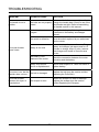
TROUBLESHOOTING
PROBLEM POSSIBLE CAUSE SOLUTION
The handle is not in
position.
The bolts are not properly
seated.
Make sure the bolts are correctly installed
through the handle bars. Check to see if the
hand knobs are tight. Refer to Assembling
the Handle section in this manual.
The snow thrower
doesn't start.
The battery is not
charged.
Charge the battery by following the
procedures in the battery and charger
manual.
The switch is defective.
Have the switch replaced by an authorized
service center.
Battery is too cold.
Remove battery from snow thrower. Bring
battery and charger into warm area for 15
minutes on charge. After 15 mins, remove
from charger and install in Snow thrower
for use.
The battery is not
attached to the motor.
Check the connection between the motor
connector and the battery.
Battery may require
service or replacement.
Call toll free helpline, at 1-855-345-3934 or
replace battery.
The motor is on, but the
impeller does not turn.
The belt is damaged.
Replace the belt (see the section entitled
Replacing the Drive Belt).
The snow thrower
leaves a thin layer of
snow behind.
The scraper is worn.
Inspect the scraper for wear or damage.
Replace the scraper (see the section
entitled Replacing the Scraper).

24
GREENWORKS™ hereby warranties this product, to the original purchaser with proof of
purchase, for a period of four (4) years against defects in materials, parts or workmanship.
GREENWORKS™, at its own discretion will repair or replace any and all parts found to be
defective, through normal use, free of charge to the customer. This warranty is valid only for
units which have been used for personal use that have not been hired or rented for industrial/
commercial use, and that have been maintained in accordance with the instructions in the
owners’ manual supplied with the product from new.
ITEMS NOT COVERED BY WARRANTY:
1. Any part that has become inoperative due to misuse, commercial use, abuse, neglect,
accident, improper maintenance, or alteration; or
2. The unit, if it has not been operated and/or maintained in accordance with the owner's
manual; or
3. Normal wear, except as noted below;
4. Routine maintenance items such as impeller, blade sharpening;
5. Normal deterioration of the exterior nish due to use or exposure.
GREENWORKS HELPLINE (
1-855-345-3934
):
Warranty service is available by calling our toll-free helpline at 1-855-345-3934.
TRANSPORTATION CHARGES:
Transportation charges for the movement of any power equipment unit or attachment are the
responsibility of the purchaser. It is the purchaser’s responsibility to pay transportation charges
for any part submitted for replacement under this warranty unless such return is requested in
writing by GREENWORKS.
LIMITED FOUR-YEAR WARRANTY

25
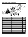
EXPLODED VIEW / PARTS LIST
1
2
3
4 5
6
7
8
10
11
12
13
14
15
16
18
19
20
9
17
21
22
26
24
2
23
25
27
28
29
30
31
ITEM NO. PART NO. DESCRIPTION QTY
1 333041463 Left side wear pad 1
2 32205877 Screw 20
3 332041205 Left side cover 1
4 329051205 Belt 1
5 32206575 Screw M5x8 6
6 3290250 Washer 6
7 311061485 Rear cover assembly 1
8 311061483 Motor 1
9 332031205 Motor clamp 1
10 3410801 Wire clamp 1
11 311031485 Front cover assembly 1
12 332021205 Wheel bracket assembly 1
13 32201699 Screw ST5*35 4
14 333031205 Lower handle 1
15 32222301A Nut M6 4
16 3410835-4 Knob 4
17 332051205 Right side cover 1
18 322011205AB Bolt M6*30 4
19 333051463 Right side wear pad 1
20 333041205 U bolt 4
21 32226121AB Screw M6*35 1
22 341021483AB Bracket for the chute control rod 1
23 32219121 Screw 1

26
EXPLODED VIEW / PARTS LIST
ITEM NO. PART NO. DESCRIPTION QTY
24 31102467 Cam lock assembly 1
25 333011462AC Upper handle 1
26 311021485 Safety switch button assembly 1
27 311081485 Upper chute control rod 1
28 341062325 Insulation sleeve 2
29 333021205BC Middle handle 1
30 311091485 7" wheel assembly 2
31 332151205 Wheel ring 2

27
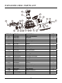
EXPLODED VIEW / PARTS LIST
11-1 11-2
11-3
11-4 11-5 11-6
11-7
11-8
11-11
11-13
11-14
11-15
11-16
11-17
11-18
11-19
11-20
11-21
11-10
11-7
11-9
11-12
11-22
11-23
11-24
ITEM NO. PART NO. DESCRIPTION QTY
11 311031485 Front cover assembly 1
11-1 332061205 Link block 1
11-2 341171205-1 Impeller 1
11-3 339011205 Right driving block 1
11-4 34109100-12 Drive wheel 1
11-5 32217100 Washer 1
11-6 33308100-12 Left side plate 1
11-7 332111205 Bushing 2
11-8 339021205 Left driving block 1
11-9 332011205 Motor xed plate 1
11-10 341111205 Scraper 1
11-11 341031205BD Discharge chute 1
11-12 311051485 Chute deector 1
11-13 341061205BD Discharge chute base 1
11-14 341071205 Small gear 1
11-15 341091205 Gear seat 1
11-16 339031205 Big gear 1
11-17 32902250A Nut M12 1
11-18 311131205 Right side plate 1
11-19 332121205 Axle for the impeller 1
11-20 362011483AB PCB board 1
11-21 332011463 Motor support 1
11-22 3220345 Screw ST3.5x12-C 4
11-23 341021466 Weather bar 1
11-24 341011205BT Front cover 1

28
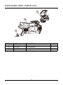
EXPLODED VIEW / PARTS LIST
7
-1
7
-2
7
-3
ITEM NO. PART NO. DESCRIPTION QTY
7 311061485 Rear cover assembly 1
7-1 341121205 Connecting base 1
7-2 341021205AH Rear cover 1
7-3 311071485 Battery compartment assembly 1

TOLL-FREE HELPLINE: 1-855-345-3934
Greenworks Tools
PO Box 1238
Mooresville, NC 28115
Rev: 01 (08-01-17) Printed in China on 100% recycle material

Máquina Quitanieve Inalámbrica de 60V
Manual Del Propietario
Línea Gratuita Línea De Ayuda: 1(855)345-3934
www.GreenWorksTools.com
Leer todas las normas de seguridad y las instrucciones cuidadosamente
antes de utilizar esta herramienta.
SN60L00

2
Contenidos........................................................................................................................... 2
Especicaciones .................................................................................................................. 2
Reglas de seguridad ............................................................................................................ 3
Símbolos .............................................................................................................................. 6
Diagrama y ubicación de piezas .......................................................................................... 8
Instrucciones de ensamblado .............................................................................................. 9
Funcionamiento ................................................................................................................. 16
Mantenimiento ................................................................................................................... 19
Eliminación de la batería que no daña el medio ambiente ................................................. 22
Corrección de problema .................................................................................................... 23
Garantía ............................................................................................................................. 24
Vista desarrollada / Lista de piezas ................................................................................... 25
ESPECIFICACIONES
MÁQUINA QUITANIEVE INALÁMBRICA DE 60V
Motor .............................................................................................. Motor sin escobillas 60V
Tipo de batería ..........................................................................................Ión de litio de 60 V
Velocidad sin carga ............................................................................................. 1,9 0 0 RPM
Ancho de trabajo ................................................................................................ 20 pulgadas
Profundidad de la limpieza ..................................................................................10 pulgadas
Tamaño Imeller ...................................................................................................16 pulgadas
Ruedas ................................................................................................................ 7 pulgadas
Peso (sin batería) .......................................................................................................33.5 lbs
Peso (con batería) ......................................................................................................37.9 lbs
Distancia de descarga ..................................................................................................... 6 m
CONTENIDO
Operación en Clima Frío: Baterías de ion de litio pueden ser utilizadas con seguridad entre
temperaturas de -17 grados a 45 grados celsius. TOME NOTA: No mantenga or carge la batería
afuera. La batería debe ser guardada y cargada adentro antes de ser usada con la quitanieve.
La batería no va iniciar correctamente si su temperatura esta menos de -17˚C. Si la máquina no
empieza, retire la batería. Coloque la batería en el cargador y deje cargar por 10 minutos para
permitir que la batería se entibie. Luego retire de el cargador para usar con la quitanieve.

3
REGLAS DE SEGURIDAD
LEA TODAS LAS INSTRUCC IONES ANTES DEL PRIMER USO (DEL APARATO)
IMPORTANTE
LEA TODAS LAS ADVERTENCIAS DE SEGURIDAD. El no seguir las advertencias e
instrucciones podrán resultar en descarga eléctrica, incendio y/o lesiones serias.
• Camine. No corra.
• Antes de encender la herramienta eléctrica, compruebe que no esté en contacto con nada.
• En todo momento manténgase alejado de la apertura para descarga. Aleje la cara, manos y
pies de las piezas ocultas, en movimiento o rotatorias.
• Preste atención cuando utilice la herramienta eléctrica, y permanezca alerta ante los posibles
agujeros en el terreno y otros peligros ocultos, así como al tráco.
• Al limpiar la nieve muévase de arriba abajo en las pendientes. No cruce las pendientes
lateralmente. Tenga precaución al cambiar de dirección. No use la máquina quitanieve para
quitar nieve de pendientes muy inclinadas.
• No utilice la herramienta eléctrica si no están colocados en su lugar los protectores, placas y
otros dispositivos de seguridad.
• No utilice la herramienta eléctrica cerca de cerramientos acristalados, automóviles,
camiones, pozos de ventanas, pendientes, etc. sin haber ajustado adecuadamente el ángulo
de descarga de nieve. Mantenga a los niños y mascotas lejos del área de trabajo.
• No utilice la herramienta eléctrica a altas velocidades en supercies resbaladizas. Mire hacia
atrás y tenga cuidado cuando retroceda.
• Al usar la máquina quitanieve use anteojos o gafas de seguridad que cumplan con las normas
ANSI Z87.1.
• Utilice la herramienta eléctrica solo a plena luz del día o cuando haya una iluminación
articial adecuada. Si la utiliza por la noche, encienda las luces LED y esté atento al entorno.
• Para evitar arranques accidentales, permanezca en la posición inicial cuando encienda la
herramienta. El usuario y la herramienta eléctrica deben estar en una posición estable al
arrancar. Consulte el apartado "Encendido y apagado".
• Use esta herramienta eléctrica solo para los nes para los que ha sido diseñada.
• Sujete la herramienta con las dos manos mientras la utiliza. Agarre el manillar rmemente.
• Si el impulsor no gira libremente porque hay hielo, descongele a fondo la herramienta antes
de usarla.
• Mantenga el propulsor libre de residuos.
• No intente limpiar el propulsor mientras el motor esté en marcha.
• Si se golpea un objeto extraño, apague la herramienta eléctrica, quite el paquete de baterías,
e inspeccione la herramienta para ver si se ha dañado. Repare cualquier daño antes de
volver a arrancar y usar la herramienta.
• Si la herramienta empieza a vibrar de forma inusual, párela inmediatamente e intente
averiguar la causa. Las vibraciones suelen indicar peligro.
• Pare el motor y retire la batería siempre que usted no opere con ella, antes de destapar el
propulsor y antes de proceder a cualquier tipo de reparación, ajuste o comprobación.

4
REGLAS DE SEGURIDAD
• No utilice la máquina en una supercie con grava, a menos que esté ajustada para este tipo
de supercies según el manual del usuario.
• Mantenga a los niños a distancia - Todos los visitantes deben mantenerse a una distancia
segura del área de trabajo.
• Vístase de manera adecuada - No use ropa suelta o joyas. Pueden quedar atrapados en las
piezas móviles.
• Lleve botas de goma cuando maneje la herramienta eléctrica. No use la herramienta estando
descalzo o con sandalias. Lleve siempre calzado robusto.
• No es seguro manejar la herramienta en la posición que se usa para sujetarla con la mano,
excepto conforme a las instrucciones especiales para tal uso que se indican en el manual del
usuario.
• Asegúrese siempre de utilizar la herramienta con todos sus dispositivos de protección
correctamente instalados y en buen estado.
• No fuerce la herramienta: funcionará mejor y de forma más segura a la velocidad de
funcionamiento para la que ha sido diseñada.
• No estire - Mantenga la postura y el equilibrio en todo momento.
• Si la herramienta golpea un objeto extraño, realice los pasos siguientes:
i) Pare la herramienta eléctrica.
ii) Inspeccione si hay daños.
iii) Repare cualquier daño antes de volver a arrancar y usar la herramienta.
• Guarde la herramienta en un lugar interior: cuando no se utilicen, las herramientas eléctricas
deben guardarse en un lugar interior, seco y cerrado con llave, fuera del alcance de los niños.
• Mantenga las herramientas eléctricas con cuidado: siga las instrucciones para la lubricación
y el cambio de accesorios.
• Deje que la herramienta siga funcionando durante algunos minutos después de quitar la
nieve, para que las piezas móviles no se congelen.
• Utilice solo piezas de recambio idénticas y accesorios adecuados para esta herramienta.
El uso de accesorios y piezas de recambio que no sean idénticos podría provocar lesiones
graves al usuario o dañar la herramienta, y se anulará la garantía.
• No levante la herramienta eléctrica mientras esté en funcionamiento. La herramienta ha sido
diseñada para desplazarse sobre el suelo.
• Nunca permita que los niños utilicen esta herramienta eléctrica. Mantenga alejadas de la
zona de utilización a todas las personas, en especial a los niños pequeños, así como a las
mascotas.
• Examine minuciosamente la zona donde vaya a utilizarse el aparato y elimine piedras, ramas,
cables, huesos o cualquier otro objeto extraño.
• Detenga la cuchilla o las cuchillas al cruzar con el aparato supercies de grava, caminos,
calles, etc.
• Lea el manual del operador con atención. Familiarícese por completo con los controles y el
uso de este equipo.

5
REGLAS DE SEGURIDAD
PRECAUCIÓN
UTILICE BATERÍAS DE REPUESTO APROBADAS ÚNICAMENTE. OTRAS BATERÍAS
PUEDEN OCASIONAR DAÑOS A LA PODADORA. ÚSESE CON BATERÍAS GREENWORKS
60V (Modelo#: LB60A00 / LB60A03 / LB60A01 / LB60A02) Y CARGADOR GREENWORKS 60V
(Modelo#: CH60A00).
ADVERTENCIA(PROPUESTA 65)
Este producto contiene un producto químico conocido en el Estado de California por: producir
cáncer, malformaciones de nacimiento/ anomalías congénitas u otros daños reproductivos.
El polvo creado al lijar, cortar, moler, perforar y otras actividades de construcción contiene
sustancias químicas que causan cáncer, defectos de nacimiento u otros daños reproductivos.
Algunos ejemplos de estos productos químicos son:
• El plomo de las pinturas a base de plomo
• La sílice cristalina de ladrillos y cemento y otros productos de albañilería, y
• El arsénico y el cromo de la madera tratada químicamente.
El riesgo de exposición a estos químicos varía en función de la frecuencia con que realiza este
tipo de trabajo. Para reducir su exposición a estas sustancias químicas, trabaje en un área bien
ventilada y con equipos de seguridad aprobados, como mascarillas contra el polvo especialmente
diseñadas para ltrar partículas microscópicas.
GUARDAR ESTAS INSTRUCCIONES
REGLAS GENE RALES DE SEGURIDAD
• Verique que la herramienta eléctrica esté segura durante el traslado.
• Almacene la herramienta eléctrica en un lugar seco para evitar el uso no autorizado o daños.
Manténgala alejada del alcance de los niños.
• Mantenga las manijas secas, limpias y libres de desechos. Limpie la herramienta eléctrica
después de cada uso. Para obtener más información, consulte la sección de Mantenimiento
de este manual.
• Si las etiquetas en la herramienta eléctrica se deterioran o comienzan a levantarse, póngase
en contacto con el Servicio al Cliente al 1(855)345-3934.
• Guarde estas instrucciones en un lugar seguro para referencia futura. Consúltelas
periódicamente y úselas para instruir a otros usuarios. Cualquier persona que use esta
herramienta eléctrica debe leer con atención estas instrucciones.
• Realice un mantenimiento adecuado de la herramienta eléctrica. Siga las instrucciones para
lubricar y reemplazar accesorios.

6
Algunos de los siguientes símbolos pueden ser usados en este producto. Obsérvelos y aprenda su
signi cado. Una correcta interpretación de estos símbolos le permitirá utilizar el producto mejor y de
una forma más segura.
SÍMBOLOS
6
SÍMBOLO DENOMINACIÓN/EXPLICACIÓN
V Voltaje
A Corriente
Hz Frecuencia (ciclos por segundo)
Wh Vatio/hora – Capacidad de almacenamiento de energía
Ah Amperio/hora – Capacidad de corriente
DC Corriente directa
Tipo o característica de corriente
RPM Revolutions per minute
/min Revolutions, strokes, surface speed, orbits etc., per minute
Indica un peligro posible de lesiones personales.
Para reducir el riesgo de lesiones, el usuario debe leer y comprender el
manual del operador antes de usar este producto.
Siempre póngase protección ocular con la marca de cumplimiento de la
norma ANSI Z87.1.
Utilice protección ocular y auditiva.
STOP
STOP
Pare la máquina y retire el paquete de baterías antes de dejarla.
Cualquier objeto lanzado puede rebotar y producir lesiones personales o
daños físicos.
Peligro – Mantenga las manos y los pies alejados de las ranuras, mientras
que la máquina esté en funcionamiento. No utilizar las manos para desatascar
el conducto. Parar el motor y retirar la batería antes de quitar los desechos.
Mantenga a los espectadores a una distancia segura de la herramienta.
Manténgase alejado de las piezas móviles, mantener todas las protecciones en su
luga.
Mantenga las manos alejados.
Mantenga las manos fuera del área de descarga.

7
SÍMBOLOS
SERVICIO
El servicio de la producto requiere extremo cuidado y conocimientos técnicos, por lo cual sólo
debe ser efectuado por un técnico de servicio calicado. Para dar servicio a la herramienta, le
sugerimos llevarla al ESTABLECIMIENTO DE SERVICIO AUTORIZADO de su preferencia para
que la reparen. Al dar servicio a la unidad, sólo utilice piezas de repuesto idénticas.
ADVERTENCIA
Para evitar lesiones corporales serias, no intente utilizar este producto sin haber leído y
comprendido totalmente el manual del operador. Si no comprende los avisos de advertencia y
las instrucciones del manual del operador, no utilice este producto. Llame al departamento de
atención al consumidor (1-855-345-3934), y le brindaremos asistencia.
ADVERTENCIA
Cualquier producto en funcionamiento puede lanzar objetos hacia los ojos, lo cual
puede causar serios daños a los mismos. Antes de iniciar la operación de herramientas
de corriente, siempre utilice gafas de seguridad, gafas de seguridad con protección
lateral, y en la medida en que sea necesario, un protector para toda la cara.
Recomendamos la careta protectora de visión amplia encima de los anteojos normales,
o los anteojos protectores estándar con protección lateral. Siempre póngase protección
ocular con la marca de cumplimiento de la norma ANSI Z87.1.
Las siguientes palabras de señalización y sus signicados tienen el objeto de explicar los niveles
de riesgo relacionados con este producto.
SÍMBOLO SEÑAL SIGNIFICADO
PELIGRO
Indica una situación peligrosa inminente, la cual, si no se evita,
causará la muerte o lesiones serias.
ADVERTENCIA
Indica una situación peligrosa posible, la cual, si no se evita,
podría causar la muerte o lesiones serias.
PRECAUCIÓN
Indica una situación potencialmente peligrosa la cual, si no se
evita, puede causar lesiones leves o moderadas.
PRECAUCIÓN
(Sin el símbolo de alerta de seguridad) Indica una situación que
puede producir daños materiales.
GUARDAR ESTAS INSTRUCCIONES

8
DIAGRAMA Y UBICACIÓN DE PIEZAS
Fig. 1
Compartimiento
de batería
Lea el manual del operador y las normas de seguridad antes de manejar la máquina quitanieve.
Compare la ilustración en Fig. 1 con la podadora para familiarizarse con la ubicación de los
diferentes controles y ajustes. Guarde este manual para referencia futura.
Barra de
control del
canal de
descarga
Manija
superior
Manija central
Mango para
transporte o
levante
Manija inferior
Rueda
Manillar
Palanca
del asa
Impulsor
Raspador
Deector
del canal
Sujetador
de leva
Canal de
descarga
Interruptor de
seguridad

9
INSTRUCCIONES DE ENSAMBLADO
NOMBRE DE LAS
PIEZAS
FIGURA CDAD.
Máquina quitanieve
1
Palanca de control de
canal superior
1
Palanca de control del
canal inferior
1
Manija central
1
Manija superior
1
Deector del canal
1
Sujetador de leva
2
Pernos
2
Perillas de la manija
4
Pasador del enganche
1
Manual
1
LISTA DE PIEZAS

10
DESEMPAQUETADO
• Extraiga cuidadosamente de la caja la herramienta y los accesorios. Asegúrese de que estén
presentes todos los artículos enumerados en la lista de empaquetado.
• Inspeccione cuidadosamente la herramienta para asegurarse de que no haya sufrido ninguna
rotura o daño durante el transporte.
• No deseche el material de empaquetado hasta que haya inspeccionado cuidadosamente la
herramienta y la haya utilizado satisfactoriamente.
• Si hay piezas dañadas o faltantes, le suplicamos llamar al 1-855-345-3934, donde le
brindaremos asistencia.
ADVERTENCIA
Si hay piezas dañadas o faltantes, no utilice este producto sin haber reemplazado todas las
piezas. La inobservancia de esta advertencia podría causar lesiones serias.
ADVERTENCIA
No introduzca la paquete de baterías sin haber terminado de armarla. De lo contrario la unidad
puede ponerse en marcha accidentalmente, con el consiguiente riesgo de lesiones serias.
ADVERTENCIA
No intente modificar este producto ni hacer accesorios no recomendados para el mismo.
Cualquier alteración o modicación constituye maltrato y puede causar una condición peligrosa,
y como consecuencia posibles lesiones serias.
ADVERTENCIA
No permita que su familarización con este producto le vuelva descuidado. Tenga presente que
un descuido de un instante es suciente para inigir una lesión grave.
ADVERTENCIA
No utilice ningún aditamento o accesorio no recomendado por el fabricante de este producto. El
empleo de aditamentos o accesorios no recomendandos podría causar lesiones serias.
INSTRUCCIONES DE ENSAMBLADO

CÓMO ENSAMBLAR LA MANIJA (Consulte la gura 2)
• Alinee los agujeros (4) de la manija central (2) y de la manija inferior (3). Meta los pernos (5) y
apriételos con las perillas (6) de la manija que se suministran.
• Alinee los agujeros entre la manija central (2) y la manija superior (1). Inserte los sujetadores
de leva (7) y apriételos con las perillas de la manija (8) que se suministran. Una vez
ajustadas, cierre las levas de jación para jarlas en su sitio.
NOTA : Si el mango superior está ojo o separado del mango central, apriete las perillas de la manija de la
leva de jación girándolas hacia la derecha. No las apriete en exceso.
INSTRUCCIONES DE ENSAMBLADO
Fig. 2
(1) Manija superior
(2) Manija central
(3) Manija inferior
(6) Perilla de la manija
(5) Perno
(8) Perilla de la manija
(7) Sujetadors
de leva
(4) Agujeros
11

12
INSTRUCCIONES DE ENSAMBLADO
CÓMO ENSAMBLAR EL CANAL DE DESCARGA (Consulte la gura 3)
• Empuje el deector del canal de descarga (1) hasta que las lengüetas de seguridad (2)
laterales encajen en las ranuras (3) y las postes (4) laterales encajen en los oricios de
referencia (5).
Fig. 3
1
2
5
42
5
3
3

13
INSTRUCCIONES DE ENSAMBLADO
INSTALACIÓN DE LA BARRA DE CONTROL DEL CANAL DE DESCARGA
(Consulte la gura 4)
• Coloque el canal de descarga (1) mirando hacia delante.
NOTA: Alinee la echa (2) del canal de descarga con la echa de la carcasa.(Fig.4.1)
• Alinee los oricios (3) de la palanca de control de canal superior (4) con los oricios de la
palanca de control del canal inferior (5). Inserte el pasador de enganche (6). Introduzca el
extremo de la Palanca de control del canal (7) en el oricio de referencia (8) del soporte que
está acoplado a la parte superior del mango central. (Fig.4.2)
Fig. 4.1
Fig. 4.2
(1) Canal de descarga
(2) Flecha
(7) Barra de control del
canal de descarga
(8) Oricio de
referencia
(4) Palanca de
control de
canal superior
(3) Oricios
(6) Pasador del
enganche
(5) Palanca de
control del
canal inferior

14
INSTRUCCIONES DE ENSAMBLADO
• Asegúrese de que el mango (9) de la barra de control del canal de descarga apunta hacia
arriba e inserte la barra en el oricio de referencia (10) de la parte posterior de la carcasa.
(Fig.4.3)
• Empuje rmemente la barra en el oricio de la parte posterior de la carcasa hasta que encaje
en su sitio.
• Gire el mango de la barra de control del canal de descarga para asegurarse de que se mueve
en dirección mismo al canal de descarga. (Fig. 4.4)
Fig. 4.4
Fig. 4.3
(9) Mango
(10) Oricio de
referencia

INSTRUCCIONES DE ENSAMBLADO
15
INSTALACIÓN DEL PAQUETE DE BATERÍAS (Consulte la gura 5)
• Levante la tape (1) del compartimiento de la batería.
• Deslice la batería (2) hacia abajo para trabarla en su posición correcta. La batería está
completamente insertada en el quitanieve cuando se escucha un “clic”.
• Cierre la cubierta (1) del compartimiento de la batería.
EXTRAER LA BATERÍA (Consulte la gura 5)
• Asegúrese de que el impulsor ha llegado a una parada completa.
• Deje de apretar la barra de encendido/ apagado y detenga la máquina quitanieve.
• Pulse el botón de liberación de la batería (3) en el quitanieve. De este modo, la batería
sobresaldrá ligeramente de la herramienta.
• Retire la batería del producto.
Fig. 5
(1) Cubierta del compartimiento de
la batería
(2) Batería
(3) Botón de liberación
de la batería

FUNCIONAMIENTO
16
ENCENDIDO Y APAGADO (Consulte la gura 6)
• Para el encendido, primero presione el botón interruptor de seguridad (1) que se encuentra al
lado de la carcasa del interruptor.
• Mientras presiona el botón interruptor de seguridad con una mano, use la otra mano para
simultáneamente jalar palanca del asa (2) hacia usted. Una vez que la máquina se encienda,
suelte el botón interruptor de seguridad y proceda con la operación. La máquina quitanieve
solo puede ser encendida presionando primero el botón interruptor de seguridad y luego
apretando la palanca del asa. Lo inverso no encenderá la máquina.
• Para apagarla, deje de apretar la palanca del asa.
PRECAUCIÓN
No intentar forzar el funcionamiento del interruptor y la palanca del resorte de sujeción.
ADVERTENCIA
Una operadora en funcionamiento puede arrojar objetos extraños a los ojos del operador y, de
esta manera, ocasionar graves daños oculares. Siempre use gafas de seguridad cuando use la
máquina quitanieve y realice ajustes o reparaciones.
ADVERTENCIA
Mantenga a los espectadores a una distancia segura de la herramienta.
INSPECCIÓN DEL ÁREA DE CORTE. Retire piedras, palos, cables, juguetes y otros desechos
que la impulsor giratoria pueda arrojar.
Fig. 6
(2) Palanca del asa
(1) Interruptor de
seguridad

AJUSTE DEL CANAL DE DESCARGA Y DEL DEFLECTOR DEL CANAL DE DES-
CARGA (Consulte la gura 7)
• Para ajustar el canal de descarga, gire el mango (1) de la barra de control del canal de
descarga en la dirección que desee dirigir el ujo de nieve.
• Para ajustar el deector del canal (y, por tanto, la altura del ujo de nieve), apriete el gatillo (2)
y suba o baje el deector del canal.
FUNCIONAMIENTO
17
Fig. 7
(1)
Mango
(2)
Gatillo

FUNCIONAMIENTO
18
CONSEJOS PARA EL FUNCIONAMIENTO
ADVERTENCIA
Si la máquina quitanieve golpea un objeto extraño cuando se le está usando, el objeto podría
ser lanzado en dirección del operador o algún espectador. Los objetos lanzados podrían
provocar lesiones personales graves. Mantenga el área a limpiar libre de objetos extraños que
pudieran ser tomados y lanzados por las impulsor.
• Mantenga el área de operación libre de objetos extraños que puedan ser arrojados por las
impulsor. Lleve a cabo una inspección completa del área, ya que algunos objetos pueden
estar ocultos por la nieve que los rodea. Si la máquina quitanieve golpea una obstrucción o
atrapa un objeto extraño durante su uso, detenga la máquina quitanieve, retire la batería, retire
la obstrucción e inspeccione la unidad en busca de daños. Repare o reemplace cualquier
parte dañada antes de volver a encender y operar la unidad.
• Mantenga a las mascotas, niños y espectadores alejados del área de operación. Tenga en
cuenta que el ruido normal de la máquina al estar encendida puede hacer difícil para usted el
oír a las personas o mascotas acercarse.
• Al mover la máquina quitanieve, use las ruedas en un lado como punto de pivote. Incline
ligeramente la máquina quitanieve sobre este punto de pivote para moverla hacia adelante o
hacia atrás.
• Empiece su ruta de limpieza hacia afuera, lanzando la nieve en un movimiento hacia adelante
y hacia atrás. Para limpiar en la dirección opuesta, pase por sobre el cordón y gire la máquina
quitanieve sobre sus ruedas. Asegúrese de superponer las rutas de limpieza.
• Tenga en cuenta la dirección del viento. De ser posible, muévase en la misma dirección del viento.
De ser posible, muévase en la misma dirección que el viento de manera que la nieve no sea
lanzada contra el viento (y por tanto lanzada hacia su cara y por sobre la ruta recién limpiada).
• No empuje la máquina quitanieve con demasiada fuerza. Usted debe empujar la máquina
cuidadosamente y de forma uniforme, de acuerdo con la velocidad de lanzamiento de la unidad.
• Algunas partes de la máquina quitanieve se pueden congelar bajo condiciones de
temperatura extremas. No intente operar la máquina quitanieve con partes congeladas. Si las
partes se congelan mientras la máquina quitanieve está siendo usada, detenga la máquina
quitanieve, desenchufe el condón de extensión e inspeccione las partes congeladas. Libere
todas las partes antes de volver a encender u operar la máquina quitanieve. Nunca fuerce los
controles que se hayan congelado.
• Al trabajar sobre piedras, grava o supercies sin pavimentar, evite lanzar material suelto de
supercie junto con la nieve empujando hacia abajo el mango para levantar el raspador en la
base de la unidad por sobre las piedras o grava.
• Operación en Clima Frío : Baterías de ion de litio pueden ser utilizadas con seguridad entre
temperaturas de -17 grados a 45 grados celsius. TOME NOTA: No mantenga or carge la batería
afuera. La batería debe ser guardada y cargada adentro antes de ser usada con la quitanieve.
• Si la máquina no empieza, retire la batería. Coloque la batería en el cargador y deje cargar
por 10 minutos para permitir que la batería se entibie. Luego retire de el cargador para usar
con la quitanieve.El problema de arranque puede deberse a que la batería está demasiado
fría. Para evitar este problema, asegúrese de guardar la batería en un lugar fresco y seco, así
como de cargarla y dejarla en el interior hasta que esté lista para usarla.

MANTENIMIENTO
REPARACIÓN
Las reparaciones las debe efectuar un técnico calicado. Los repuestos para este máquina
quitanieve deben ser idénticos a las piezas que reemplazan. Si necesita hacer reparaciones,
póngase en contacto con la línea telefónica gratis para ayuda, al 1-855-345-3934.
Nota: Las partes derecha e izquierda del máquina quitanieve deben observarse desde la posición normal del
operador.
ADVERTENCIA
Si la batería se está instalando en la máquina quitanieve, y la llave se encuentra en la manija,
la máquina quitanieve podría arrancar accidentalmente mientras el operador efectúa los
trabajos de mantenimiento, lo que podría provocar lesiones personales graves. Desconecte el
cordón de extensión antes de efectuar cualquier trabajo de mantenimiento. Presione la llave
hacia abajo, gírela en el sentido de las agujas del reloj y sáquela de la manija.
19
ALMACENAMIENTO
• Haga funcionar la máquina quitanieve por unos minutos para derretir cualquier nieve que
pudiera haber quedado en la máquina quitanieve.
• Limpie el quitanieves con un paño seco antes de guardarlo. Esto ayudará a prevenir la
formación de hielo sobre la unidad y el congelamiento de las piezas.
• Saque la batería y almacénela en un lugar fresco y seco, si es posible. Para aumentar la vida
útil de la batería cárguela cada seis semanas al no estar en uso.
• Compruebe detalladamente que la máquina quitanieve no tiene piezas desgastadas, sueltas
o dañadas. Si es necesario reparar o reemplazar cualquier pieza, póngase en contacto con la
línea telefónica gratis para ayuda, al 1-855-345-3934.
• Almacene la máquina quitanieve en un lugar limpio y seco. Cúbralo para protegerlo mejor.
• Guarde siempre la batería y el cargador en el interior.

MANTENIMIENTO
20
CÓMO REEMPLAZAR EL RASPADOR (Consulte la gura 8)
El raspador se encuentra en la parte inferior de la carcaza del impulsor.
• Asegúrese de que la batería no está instalada en la herramienta.
• Retire los tornillos (1) de cada placa lateral que sujeta la rasqueta y los 3 tornillos (2) de la
parte inferior de la máquina que sujetan la rasqueta a la máquina.
• Retire y deseche la rasqueta vieja.
• Instale la rasqueta nueva y sujétela rmemente apretando los 5 tornillos que había retirado
anteriormente.
Fig. 8
(1) Tornillo
(1) Tornillo
(2)
3
tornillos

MANTENIMIENTO
REEMPLAZO EL IMPULSOR (Consulte las guras 1-9)
1. Quite los 5 tornillos y
almohadilla de desgaste lateral
que aseguran la placa lateral
derecha.
2. Quite la tuerca.
3. Quite los 5 tornillos y
almohadilla de desgaste lateral
que aseguran la placa lateral
izquierda.
4. Retire la correa.
5. Con una llave, retire el de la
polea grande
6. Quite los tornillos que aseg-
uran la placa lateral izquierda.
7. Extraiga el eje y quite el
viejo impulsor. Instale la nueva
impulsor.
8. Reinstalar la tuerca y cubierta lateral derecha.
9. Reinstalar la placa lateral izquierda, polea grande, correa y la cubierta lateral izquierda.
21

22
ELIMINACIÓN DE BATERÍAS SIN DAÑO PARA EL AMBIENTE
Las baterías utilizadas en esta herramienta contienen los siguientes materiales tóxicos y
corrosivos: Litio-ión, un material tóxico.
ADVERTENCIA
Se debe desechar los materiales tóxicos de la forma especicada para evitar contaminar el medio
ambiente. Antes de desechar los paquetes de baterías de ión de litio dañados o desgastados,
póngase en contacto con su agencia local para eliminación de desechos para obtener información
e instrucciones específicas. Lleve las baterías a un centro local para reciclaje o eliminación,
certicado para eliminación. Si el paquete de baterías se raja o se quiebra, ya sea que tenga fugas
o no, no lo vuelva a cargar y no lo use. Deséchelo y reemplácelo con un paquete de baterías
nuevo. ¡NO INTENTE REPARARLA!
Obedezca las siguientes instrucciones para evitar lesiones y riesgos de incendio, explosión o
choques eléctricos y para evitar daños al medio ambiente:
• Para evitar lesiones y riesgo de incendio, explosión y descarga eléctrica, así como daños al
medio ambiente: Cubra las terminales de la batería con cinta adhesiva para trabajo pesado.
• NO intente retirar ni destruir ninguno de los componentes del paquete de batería.
• NO intente abrir el paquete de batería.
• Si se produce una fuga, los electrolitos liberados son corrosivos y tóxicos. NO introduzca el
líquido enlos ojos, no lo coloque en la cara ni lo trague.
• NO coloque las baterías en la basura común de su casa.
• NO las incinere.
• NO las coloque en lugares en los formarán parte de cualquier basural o ujo municipal de
residuos sólidos.
• Colóquelas en un centro de reciclaje o eliminación certicado.

23
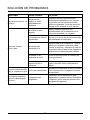
SOLUCIÓN DE PROBLEMAS
PROBLEMA CAUSA POSIBLE SOLUCIÓN
La manija no está en su
posición.
Los pernos de
soporte no están
apropiadamente
asentados.
Asegúrese de que los pernos están
orrectamente instalados en los mangos.
Compruebe que las perillas manuales
están bien ajustadas. Consulte la sección
Montaje de los mangos en este manual
The snow thrower
doesn't start.
La batería no está
cargada.
Cargue la batería siguiendo los
procedimientos que se describen en el
manual de la batería y el cargador.
El interruptor de control
está dañado.
Recurra a un centro de servicio autorizado
para reemplazar el interruptor.
La batería está
demasiado fría.
Saque la batería del quitanieves. Lleve la
batería y el cargador a una zona cálida
durante 15 minutos y cárguela. Al cabo de
15 minutos, retire la batería del cargador e
instálela en el quitanieves para utilizarlo.
La batería no es
conectada al motor
Revise la conexión entre el conector del
motor y la batería.
La batería puede
requerir servicio o
reemplazo.
Llame a la línea telefónica gratis para
ayuda 1-855-345-3934 o reemplace la
batería.
El motor está encendido,
pero el impulsor no gira.
La correa está dañada.
Remplace la correa (vea la sección titulada
Cómo inspeccionar o remplazar la correa
de impulsión).
La máquina quitanieve
deja una capa delgada
de nieve.
El raspador está
desgastado.
Compruebe que la rasqueta no está
desgastada ni presenta daños. Reemplace
el raspador (vea la sección titulada Cómo
reemplazar el raspador).

24
Por este medio y por un período de cuatro años GREENWORKS™ garantiza este producto
contra defectos en materiales, piezas o mano de obra al comprador original que cuente con
una prueba de compra. GREENWORKS™, a su sola discreción reparará o reemplazará, sin
costo alguno para el cliente, cualquier pieza defectuosa, siempre y cuando se haya hecho uso
normal de ella. Esta garantía es válida solamente para unidades utilizadas de manera personal
y que no hayan sido utilizadas o alquiladas para uso industrial o comercial, y que hayan recibido
mantenimiento de acuerdo a las instrucciones que aparecen en el manual del propietario que se
suministró con el producto nuevo.
ARTÍCULOS QUE NO CUBRE LA GARANTÍA:
1. Cualquier pieza que se haya vuelto inoperante debido a mal uso, uso comercial, abuso,
descuido, accidente, mantenimiento inapropiado o alteración; o
2. La unidad, si no ha sido operada o si no se le ha dado mantenimiento de acuerdo al
manual del propietario; o
3. Desgaste normal, excepto según se indica a continuación;
4. Artículos de mantenimiento rutinario tales como impulsor, alado de cuchillas;
5. Deterioro normal del acabado exterior debido al uso y la exposición al entorno.
LÍNEA TELEFÓNICA PARA AYUDA DE GREENWORKS (1-855-345-3934):
El servicio de garantía está disponible llamando a la línea de ayuda gratuita 1-855-345-3934.
CARGOS DE TRANSPORTE:
Los cargos de transporte por el traslado de cualquier unidad de equipo o accesorio eléctrico son
responsabilidad del comprador. El comprador es responsable de pagar los cargos de transporte
de cualquier pieza presentada para reemplazo de acuerdo a esta garantía a menos que
GREENWORKS solicite por escrito tal retorno.
GARANTÍA LIMITADA DE 4 AÑOS

25
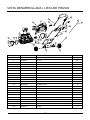
VISTA DESARROLLADA / LISTA DE PIEZAS
ARTÍCULO NO. PARTE NO. DESCRIPCIÓN CDAD.
1 333041463 Lado izquierdo de la almohadilla de desgaste 1
2 32205877 Tornillo 20
3 332041205 Cubierta lateral izquierda 1
4 329051205 Correa 1
5 32206575 Tornillo M5x8 6
6 3290250 Arandela 6
7 311061485 Cubierta trasera 1
8 311061483 Motor 1
9 332031205 Abrazadera del motor 1
10 3410801 Abrazadera de cableado 1
11 311031485 Montaje cubierta frontal 1
12 332021205 Soporte de la rueda 1
13 32201699 Tornillo ST5*35 4
14 333031205 Mango inferior 1
15 32222301A Tuerca M6 4
16 3410835-4 Botón 4
17 332051205 Cubierta lateral derecha 1
18 322011205AB Perno M6*30 4
19 333051463 Lado derecho de la almohadilla de desgaste 1
20 333041205 Perno en U 4
21 32226121AB Tornillo M6*35 1
22 341021483AB Soporte de la barra de control del canal de descarga 1
23 32219121 Tornillo 1
1
2
3
4 5
6
7
8
10
11
12
13
14
15
16
18
19
20
9
17
21
22
26
24
2
23
25
27
28
29
30
31

26
VISTA DESARROLLADA / LISTA DE PIEZAS
ARTÍCULO NO. PARTE NO. DESCRIPCIÓN CDAD.
24 31102467 Sujetadors de leva 1
25 333011462AC Manija superior 1
26 311021485 Interruptor de seguridad 1
27 311081485 Palanca de control de canal superior 1
28 341062325 Manguito de aislamiento 2
29 333021205BC Mango medio 1
30 311091485 Conjunto de rueda de 7 pulg. 2
31 332151205 Anillo de rueda 2

27
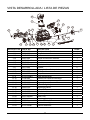
VISTA DESARROLLADA / LISTA DE PIEZAS
11-1 11-2
11-3
11-4 11-5 11-6
11-7
11-8
11-11
11-13
11-14
11-15
11-16
11-17
11-18
11-19
11-20
11-21
11-10
11-7
11-9
11-12
11-22
11-23
11-24
ARTÍCULO NO. PARTE NO. DESCRIPCIÓN CDAD.
11 311031485 Montaje cubierta frontal 1
11-1 332061205 Bloque de conexión 1
11-2 341171205-1 Impulsor 1
11-3 339011205 Bloque de dirección derecho 1
11-4 34109100-12 Volante 1
11-5 32217100 Arandela 1
11-6 33308100-12 Placa lateral izquierda 1
11-7 332111205 Cojinete 2
11-8 339021205 Bloque de dirección izquierdo 1
11-9 332011205 Placa ja del motor 1
11-10 341111205 Rasqueta 1
11-11 341031205BD Canal de descarga 1
11-12 311051485 Deector del canal de descarga 1
11-13 341061205BD Base del canal de descarga 1
11-14 341071205 Engranaje pequeño 1
11-15 341091205 Base del engranaje 1
11-16 339031205 Engranaje grande 1
11-17 32902250A Tuerca M12 1
11-18 311131205 Placa lateral derecha 1
11-19 332121205 Eje del impulsor 1
11-20 362011483AB Placa PCB 1
11-21 332011463 Soporte del motor 1
11-22 3220345 Tornillo ST3.5x12-C 4
11-23 341021466 Barra meteorológica 1
11-24 341011205BT Cubierta delantera 1

28
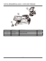
VISTA DESARROLLADA / LISTA DE PIEZAS
ARTÍCULO NO. PARTE NO. DESCRIPCIÓN CDAD.
7 311061485 Conjunto de la cubierta trasera 1
7-1 341121205 Conexión de la base 1
7-2 341021205AH Cubierta trasera 1
7-3 311071485 Ensamblaje del compartimento de la batería 1
7
-1
7
-2
7
-3

LÍNEA DE AYUDA GRATUITA: 1-855-345-3934
Impreso en China en papel reciclado de 100%Rev: 01 (08-01-17)
Greenworks Tools
PO Box 1238
Mooresville, NC 28115


-
 1
1
-
 2
2
-
 3
3
-
 4
4
-
 5
5
-
 6
6
-
 7
7
-
 8
8
-
 9
9
-
 10
10
-
 11
11
-
 12
12
-
 13
13
-
 14
14
-
 15
15
-
 16
16
-
 17
17
-
 18
18
-
 19
19
-
 20
20
-
 21
21
-
 22
22
-
 23
23
-
 24
24
-
 25
25
-
 26
26
-
 27
27
-
 28
28
-
 29
29
-
 30
30
-
 31
31
-
 32
32
-
 33
33
-
 34
34
-
 35
35
-
 36
36
-
 37
37
-
 38
38
-
 39
39
-
 40
40
-
 41
41
-
 42
42
-
 43
43
-
 44
44
-
 45
45
-
 46
46
-
 47
47
-
 48
48
-
 49
49
-
 50
50
-
 51
51
-
 52
52
-
 53
53
-
 54
54
-
 55
55
-
 56
56
-
 57
57
-
 58
58
-
 59
59
-
 60
60


Greenworks Pro SN60L410 El manual del propietario
- Tipo
- El manual del propietario
- Este manual también es adecuado para
en otros idiomas
Artículos relacionados
Otros documentos
-
Greenworks 40V Snow Thrower El manual del propietario
-
 GreenWorks Commercial GN 220 El manual del propietario
-
Craftsman 26011 El manual del propietario
-
-
Kobalt KSB 5080-06 Manual de usuario
-
-
Simplicity 1697185-00 Manual de usuario
-
Poulan 414949 Manual de usuario
-
-
