Poulan 414949 Manual de usuario
- Categoría
- Lanzadores de nieve
- Tipo
- Manual de usuario
Este manual también es adecuado para

OWNER'S MANUAL
MODEL NUMBER:
96194000600
SNOW THROWER
Always Wear Eye Protection During Operation
IMPORTANT MANUAL Do Not Throw Away
WARNING:
Read the Owner's Manual and
fol low all Warnings and Safety
In struc tions. Fail ure to do so
can result in serious injury.
414949 Rev 1 09.25.07 TH
Printed in U.S.A.

2
IMPORTANT
Safe Operation Practices for Walk-Behind Snow Throwers
This snow thrower is capable of amputating hands and feet and throwing objects.
Failure to observe the following safety instructions could result in serious injury.
WARNING: This snow thrower is for
use on sidewalks, driveways and other
ground level surfaces. Caution should
be exercised while using on sloping sur-
faces. Do not use snow thrower on
surfaces above ground level such as
roofs of residences, garages, porch es
or other such structures or buildings.
WARNING: Snow throwers have ex-
posed rotating parts, which can cause
severe injury from contact, or from ma-
terial thrown from the discharge chute.
Keep the area of operation clear of all
persons, small children and pets at all
times including startup.
WARNING: Always disconnect spark
plug wire and place it where it can not
con tact plug in order to pre vent ac ci -
den tal start ing when setting up, trans-
port ing, ad just ing or making re pairs.
Look for this symbol to point out im-
por tant safety precautions. It means
CAUTION!!! BE COME ALERT!!! YOUR
SAFE TY IS IN VOLVED.
CAUTION: Muffler and other engine
parts become extremely hot during
operation and remain hot after engine
has stopped. To avoid severe burns on
contact, stay away from these areas.
WARNING: Engine exhaust, some of
its con stit u ents, and certain vehicle
com po nents contain or emit chem i-
cals known to the State of Cal i for nia
to cause can cer and birth defects or
oth er re pro duc tive harm.
(f) Keep the nozzle in contact with the rim of the fuel
tank or container opening at all times, until refuel-
ing is complete. Do not use a nozzle lock-open
device.
(g) Replace gasoline cap securely and wipe up spilled
fuel.
(h) If fuel is spilled on clothing, change clothing im-
mediately.
5. Use extension cords and receptacles as specified by
the manufacturer for all units with electric drive motors
or electric starting motors.
6. Adjust the collector housing height to clear gravel or
crushed rock surface.
7. Never attempt to make any adjustments while the
engine (motor) is running (except when specifically
recommended by manufacturer).
8. Always wear safety glasses or eye shields during op-
eration or while performing an adjustment or repair to
protect eyes from foreign objects that may be thrown
from the machine.
Operation
1. Do not put hands or feet near or under rotating parts.
Keep clear of the discharge opening at all times.
2. Exercise extreme caution when operating on or cross-
ing gravel drives, walks, or roads. Stay alert for hidden
hazards or traffic.
3. After striking a foreign object, stop the engine (motor),
remove the wire from the spark plug, disconnect the
cord on electric motors, thoroughly inspect the snow
thrower for any damage, and repair the damage before
restarting and operating the snow thrower.
4. If the unit should start to vibrate abnormally, stop the
engine (motor) and check immediately for the cause.
Vibration is generally a warning of trouble.
5. Stop the engine (motor) whenever you leave the oper-
ating position, before unclogging the collector/impeller
housing or discharge chute, and when making any
repairs, adjustments or inspections.
Training
1. Read, understand and follow all instructions on the
machine and in the manual(s) before operating this
unit. Be thoroughly familiar with the controls and the
proper use of the equipment. Know how to stop the
unit and disengage the controls quickly.
2. Never allow children to operate the equipment. Never
allow adults to operate the equipment without proper
instruction.
3. Keep the area of operation clear of all persons, par-
ticularly small children.
4. Exercise caution to avoid slipping or falling, especially
when operating the snow thrower in reverse.
Preparation
1. Thoroughly inspect the area where the equipment is
to be used and remove all doormats, sleds, boards,
wires, and other foreign objects.
2. Disengage all clutches and shift into neutral before
starting the engine (motor).
3. Do not operate the equipment without wearing adequate
winter garments. Avoid loose fitting clothing that can
get caught in moving parts. Wear footwear that will
improve footing on slippery surfaces.
4. Handle fuel with care; it is highly flammable
(a) Use an approved fuel container.
(b) Never add fuel to a running engine or hot en-
gine.
(c) Fill fuel tank outdoors with extreme care. Never fill
fuel tank indoors.
(d) Never fill containers inside a vehicle or on a truck or
trailer bed with a plastic liner. Always place contain-
ers on the ground, away from your vehicle, before
filling.
(e) When practical, remove gas-powered equipment
from the truck or trailer and refuel it on the ground.
If this is not possible, then refuel such equipment
on a trailer with a portable container, rather than
from a gasoline dispenser nozzle.

3
6. When cleaning, repairing or inspecting the snow thrower,
stop the engine and make certain the collector/impeller
and all moving parts have stopped. Disconnect the
spark plug wire and keep the wire away from the plug
to prevent someone from accidentally starting the en-
gine.
7. Do not run the engine indoors, except when starting
the engine and for transporting the snow thrower in or
out of the building. Open the outside doors; exhaust
fumes are dangerous.
8. Exercise extreme caution when operating on slopes.
9. Never operate the snow thrower without proper guards,
and other safety protective devices in place and work-
ing.
10. Never direct the discharge toward people or areas
where property damage can occur. Keep children
and others away.
11. Do not overload the machine capacity by attempting
to clear snow at too fast a rate.
12. Never operate the machine at high transport speeds
on slippery surfaces. Look behind and use care when
operating in reverse.
13. Disengage power to the collector/impeller when snow
thrower is transported or not in use.
14. Use only attachments and accessories approved by
the manufacturer of the snow thrower (such as wheel
weights, counterweights, or cabs).
15. Never operate the snow thrower without good visibility
or light. Always be sure of your footing, and keep a firm
hold on the handles. Walk; never run.
16. Never touch a hot engine or muffler.
Clearing a Clogged Discharge Chute
Hand contact with the rotating impeller inside the discharge
chute is the most common cause of injury associated with
snow throwers. Never use your hand to clean out the dis-
charge chute. To clear the chute:
1. SHUT THE ENGINE OFF!
2. Wait 10 seconds to be sure the impeller blades have
stopped rotating.
3. Always use a clean-out tool, not your hands.
Maintenance and Storage
1. Check shear bolts and other bolts at frequent intervals
for proper tightness to be sure the equipment is in safe
working condition.
2. Never store the machine with fuel in the fuel tank
inside a building where ignition sources are present
such as hot water heaters, space heaters, or clothes
dryers. Allow the engine to cool before storing in any
enclosure.
3. Always refer to operator’s manual for important details
if the snow thrower is to be stored for an extended
period.
4. Maintain or replace safety and instruction labels, as
necessary.
5. Run the machine a few minutes after throwing snow
to prevent freeze-up of the collector/impeller.
MAINTENANCE SCHEDULE ..................................... 14
SERVICE AND AD JUST MENTS ........................... 16-18
STORAGE .............................................................. 18-19
TROU BLE SHOOT ING ................................................ 20
REPAIR PARTS ..................................................... 38-51
WARRANTY ................................................................ 52
SAFETY RULES ........................................................ 2-3
PRODUCT SPECIFICATIONS ...................................... 3
CUSTOMER RESPONSIBILITIES ................................ 3
ASSEMBLY / PRE-OPERATION ............................... 5-7
OPERATION ............................................................ 8-13
MAINTENANCE ..................................................... 14-15
TABLE OF CONTENTS
CONGRATULATIONS on your purchase of a new snow
thrower. It has been designed, engineered and man u fac tured
to give best possible dependability and per for mance.
Should you experience any problem you cannot easily
remedy, please contact your nearest authorized service
center. We have competent, well-trained tech ni cians and
the proper tools to service or repair this unit.
Please read and retain this manual. The instructions will
enable you to assemble and maintain your snow thrower
prop er ly. Always observe the “SAFETY RULES”.
SERIAL NUMBER: ___________________________
DATE OF PURCHASE: _______________________
THE MODEL AND SERIAL NUMBERS WILL BE FOUND
ON A DECAL ATTACHED TO THE REAR OF THE SNOW
THROWER HOUSING.
YOU SHOULD RECORD BOTH SERIAL NUMBER AND
DATE OF PURCHASE AND KEEP IN A SAFE PLACE
FOR FUTURE REFERENCE.
CUSTOMER RESPONSIBILITIES
• Read and observe the safety rules.
• Follow a regular schedule in maintaining, caring for
and using your snow thrower.
• Follow the instructions under “Maintenance” and “Stor-
age” sec tions of this own er’s manual.
PRODUCT SPECIFICATIONS
Gasoline Capacity 4.0 Quarts (4,54 Liters)
and Type: Unleaded Regular only
Oil Type SAE 30 (above 40°F)
(API SG–SL): SAE 5W-30 or 10W-30 (0° to +40°F)
SAE 0W-30 (below 0°F)
Oil Capacity: 26 Ounces (0,74 Liters)
Spark Plug: Champion RJ19LM
Gap: 0.030" (0,762 mm)

4
PARTS PACKED SEPARATELY IN CARTON

5
ASSEMBLY / PRE-OPERATION
SPEED CON TROL ROD
SPEED
CONTROL
BRACKET
RETAINER
SPRING
SPEED
CONTROL
LEVER
FIG. 2
SPEED
CONTROL
ROD
HANDLE
KNOB
LOWER
HANDLE
PLASTIC TIE
UPPER
HANDLE
FIG. 1
Read these instructions and this manual in its entirety
before you attempt to assemble or operate your new
snow thrower. Reading the entire manual will familiar-
ize you with the unit, which will assist you in assembly,
operation and maintenance of the product.
Your new snow thrower has been as sem bled at the factory
with the ex cep tion of those parts left unassembled for ship-
ping purposes. All parts such as nuts, washers, bolts, etc.,
necessary to com plete the as sem bly have been placed in
the parts bag. To ensure safe and proper operation of your
snow thrower, all parts and hard ware you assemble must
be tightened se cure ly. Use the correct tools as nec es sary
to ensure proper tightness.
REMOVE SNOW THROWER FROM CAR TON
1. Remove all accessible loose parts and parts boxes
from carton.
2. Cut down all four corners of carton and lay panels flat.
3. Remove the two (2) screws securing the auger housing
to the pallet.
4. Remove all packing materials ex cept plastic tie holding
speed control rod to lower handle.
5. Remove the two (2) plastic ties securing the upper
handle to the pallet.
6. Remove snow thrower from carton and check carton
thor ough ly for ad di tion al loose parts.
HOW TO SET UP YOUR SNOW THROWER
TOOL BOX (See Fig. 10)
A toolbox is provided on your snow thrower. The toolbox is
located on top of the belt cover. Store the extra shear bolts,
nuts and multi-wrench provided in parts bag in the toolbox.
NOTE: The multi-wrench may be used for assembly of the
chute rotator head to snow thrower and making ad just ments
to the skid plates.
UNFOLD UPPER HANDLE
1. Raise upper handle to the operating position and tight en
handle knobs securely.
INSTALL SPEED CONTROL ROD (See Figs. 1 and 2)
1. Remove plastic tie securing rod to lower handle.
2. Insert rod into speed control bracket and secure with
retainer spring.

6
AUGER
CONTROL
ROD
CONTROL
ARM
RUBBER
SLEEVE
LOOP
OPENING
UP
FIG. 5
AUGER
CONTROL
LEVER
AUGER CONTROL ROD
AUGER
CONTROL
BRACKET
RETAINER
SPRING
FIG. 6
INSTALL AUGER CONTROL ROD (See Figs. 5 and 6)
The auger control rod has the short loop on the end of the
spring as shown.
1. Slide rubber sleeve up rod and hook end of spring into
control arm with loop opening up as shown.
2. With top end of rod positioned under right side of
control panel, push down on rod and insert end of rod
into hole in auger control bracket. Secure with retainer
spring.
TRACTION
DRIVE
CON TROL
ROD
DRIVE
CONTROL
BRACKET
RETAINER
SPRING
TRACTION DRIVE
CON TROL LEVER
FIG. 4
INSTALL TRACTION DRIVE CONTROL ROD
(See Figs. 3 and 4)
The traction drive control rod has the long loop on the end
of the spring as shown.
1. Slide rubber sleeve up rod and hook end of spring into
pivot bracket with loop opening down as shown.
2. With top end of rod positioned under left side of control
panel, push rod down and insert top end of rod into hole
in drive control bracket. Secure with retainer spring.
ASSEMBLY / PRE-OPERATION
TRACTION DRIVE
CONTROL ROD
PIVOT
BRACKET
RUBBER
SLEEVE
LOOP
OPEN ING
DOWN
FIG. 3

7
ASSEMBLY / PRE-OPERATION
INSTALL CHUTE DEFLECTOR REMOTE CONTROL
(See Figs. 8 and 9)
1. Install remote cable bracket to discharge chute with
5/16-18 carriage bolt and 5/16-18 locknut as shown.
Tighten securely.
2. Install remote cable eyelet to chute deflector with
1/4-20 shoulder bolt, nylon washer and 1/4-20 locknut
as shown. Tighten securely.
3. Install spring hooks between hex nuts on chute rotater
head and into hole in chute deflector as shown.
INSTALL DISCHARGE CHUTE / CHUTE ROTATOR
HEAD (See Fig. 7)
NOTE: The multi-wrench provided in your parts bag may
be used to install the chute rotator head.
1. Place discharge chute assembly on top of chute base
with discharge opening toward front of snow thrower.
2. Position chute rotator head over chute bracket. If nec es -
sary, rotate chute assembly to align square and pin on un-
der side of chute rotator head with holes in chute brack et.
3. With chute rotator head and chute bracket aligned,
po si tion chute rotator head on pin and threaded stud
of mounting bracket.
4. Install 3/8 washer and locknut on threaded stud and
tighten securely.
CHUTE
ROTATOR
HEAD
3/8 WASHER
3/8 LOCKNUT
THREADED
STUD
PIN
ROTATOR HEAD
MOUNT ING
BRACKET
CHUTE
BRACKET
FIG. 7
ALIGN BEFORE
TIGHTENING LOCKNUT
CHUTE DEFLECTOR
CONTROL LEVER
FIG. 9
HOOK
BE TWEEN
HEX NUTS
ON CHUTE
ROTATER
HEAD
SPRING
CHUTE
DE FLEC TOR
5/16-18
CARRIAGE
BOLT
5/16-18
LOCKNUT
REMOTE
CABLE
BRACKET
1/4-20
LOCK NUT
CABLE
EYELET
NYLON
WASHER
1/4-20
SHOULDER
BOLT
FIG. 8
CHECK TIRE PRESSURE
The tires on your snow thrower were overinflated at the fac-
tory for shipping purposes. Correct and equal tire pres sure
is important for best snow throwing performance.
• Reduce tire pressure to 14-17 PSI (19-24.5 N-m).

8
OPERATION
KNOW YOUR SNOW THROWER
READ THIS OWNER'S MANUAL AND ALL SAFETY RULES BEFORE OPERATING YOUR SNOW THROWER. Compare
the illustrations with your snow thrower to familiarize yourself with the location of various controls and adjustments. Save
this manual for future reference.
These symbols may appear on your snow thrower or in literature supplied with the product. Learn and understand
their meaning.
FORWARD
PRIMER
IGNITION KEY.
INSERT TO START
AND RUN,
PULL OUT TO STOP.
READ AND FOLLOW ALL SAFETY INFORMATION
AND INSTRUCTIONS BEFORE USE OF THIS PRODUCT.
KEEP THESE INSTRUCTIONS FOR FUTURE REFERENCE
.
DANGER
OR WARNING
REVERSE
SNOW
DISCHARGE
TRACTION
DRIVE CONTROL
DISENGAGED
ENGAGED

9
OPERATION
Throttle/engine control - used to se lect either FAST or
SLOW engine speed and to STOP the engine.
Traction drive control lever - used to engage power-pro-
pelled for ward or reverse motion of snow thrower.
Auger control lever - used to engage auger motion (throw
snow).
Discharge chute control lever - used to change the
di rec tion the snow is thrown.
Skid plate - used to adjust height of scraper bar from the
ground.
Toolbox - to store spare shear bolts, locknuts and wrench.
Safety ignition key - must be inserted for the engine to
start and run. Remove when snow thrower is not in use.
Electric start button - used for starting the engine.
Recoil (auxiliary) starter handle - used for start ing en gine.
Primer - pumps additional fuel from the carburetor to the
cylinder for use when starting a cold engine.
LH and RH turn triggers - used to steer the snow thrower.
Choke control - used for starting a cold engine.
MEETS A.N.S.I. SAFETY REQUIREMENTS
Our snow throwers conform to the standards of the American National Standards Institute.
FIG.10
RECOIL
(AUXILIARY)
STARTER
HANDLE
THROTTLE
/ ENGINE
CONTROL
GAS O LINE
FILLER
CAP
ENGINE OIL CAP
WITH DIPSTICK
SPARK
PLUG
SAFETY
IGNITION
KEY
CHOKE
CON-
TROL
ELECTRIC
START
BUTTON
PRIM ER
FUEL
SHUT-OFF
VALVE
OIL DRAIN PLUG
POWER
CORD
PLUG
DEFLECTOR REMOTE
CONTROL LEVER
DISCHARGE CHUTE CONTROL LEVER
DRIVE SPEED
CON TROL LEVER
AUGER
CONTROL
LEVER
MUF FLER
TOOLBOX
HANDLE
KNOB
SKID PLATE
CHUTE
DE FLEC TOR
DISCHARGE
CHUTE
AU GERS
NOTE: ITEMS ABOVE
ARE SHOWN IN
THEIR TYPICAL
LOCATION ON THE
ENGINE. ACTUAL
LOCATION MAY
VARY WITH THE
ENGINE ON YOUR
UNIT.
LIGHT
LH TURN
TRIGGER
CLEAN-OUT TOOL
TRACTION
DRIVE
CONTROL
LEVER

10
TO CONTROL SNOW DISCHARGE (See Fig. 14)
WARNING: Snow throwers have ex-
posed rotating parts, which can cause
severe injury from contact, or from ma-
terial thrown from the discharge chute.
Keep the area of operation clear of all
persons, small children and pets at all
times including startup.
WARNING: If the discharge chute or
au ger become clogged, shut-off en gine
and wait for all moving parts to stop. Use
the clean-out tool, NOT YOUR HANDS,
to un clog the chute and/or auger.
The DIRECTION in which snow is to be thrown is controlled
by the discharge chute control lever.
• To change the discharge chute position, press down-
ward on discharge chute control lever and move lever
left or right until chute is in desired position. Be sure
lever springs back and locks into desired position.
The DISTANCE that snow is thrown is controlled by the
position of the chute deflector. Set the deflector low to
throw snow a short distance; set the deflector higher to
throw snow farther.
• Press downward on chute deflector control lever and
move lever forward to lower the deflector and decrease
the distance. Move lever back to raise the deflector
and increase the distance. Be sure lever springs back
and locks into desired position.
The operation of any snow thrower can result
in foreign objects thrown into the eyes, which
can result in severe eye damage. Always wear
safety glasses or eye shields while operating
your snow thrower or performing any ad just -
ments or repairs. We recommend standard safe ty glasses
or a wide vision safety mask worn over spectacles.
HOW TO USE YOUR SNOW THROWER
Know how to operate all controls before adding fuel or
attempting to start the engine.
STOPPING
TRACTION DRIVE
• Release traction drive control lever to stop the forward
or reverse movement of the snow thrower.
AUGER
• Release the auger control lever to stop throwing snow.
ENGINE
1. Move throttle control to “STOP” position.
2. Remove (do not turn) safety ignition key to prevent
unauthorized use.
NOTE: Never use choke to stop engine.
TO USE FUEL SHUT-OFF VALVE (See Fig. 11)
The fuel shut-off valve is located beneath the fuel tank on
the engine. Always op er ate the snow thrower with the fuel
shut-off valve in the OPEN position.
OPERATION
00155
TO USE THROTTLE CONTROL (See Fig. 12)
The throttle control is located on the engine. Always op er ate
the snow thrower with the engine at full throttle. Full throttle
offers the best snow thrower performance.
TO USE CHOKE CON TROL (See Fig. 13)
The choke con trol is located on the en gine. Use the choke
control when ev er you are starting a cold en gine. Do not
use to start a warm en gine.
• To engage choke, turn knob clockwise. Slowly turn
knob counterclockwise to disengage.
FIG. 12
FIG. 11
FIG. 13
FULLOFF
SLOW
FAST
OPEN
OFF
FIG. 14
DISCHARGE CHUTE
CONTROL LEVER
CHUTE DEFLECTOR
REMOTE CONTROL LEVER

11
TO MOVE FORWARD AND BACKWARD (See Fig. 17)
SELF-PROPELLING, forward and reverse movement of
the snow thrower, is controlled by the traction drive control
lever located on the left side handle.
• Squeeze traction drive control lever to handle to en gage
the drive system.
• Release traction drive control lever to stop the forward
or reverse movement of the snow thrower.
SPEED and DIRECTION are controlled by the drive speed
control lever.
• Press downward on the speed control lever and move
lever to de sired po si tion BE FORE engaging the trac-
tion drive control lever. Be sure lever springs back and
locks into desired position.
CAUTION: Do not move speed con trol le ver
when traction drive control lever is en gaged.
Damage to the snow thrower can result.
• Slower speeds are for heavier snow and faster speeds
are for light snow and transporting the snow thrower. It
is recommended that you use a slower speed until you
are familiar with the operation of the snow thrower.
NOTE: When both traction drive and auger control levers
are engaged, the traction drive control lever will lock the
auger control lever in the engaged position. This will allow
you to release your right hand from the handle and adjust
the discharge chute direction without interrupting the snow
throwing process.
TO THROW SNOW (See Fig. 15)
The auger rotation is controlled by the auger control lever
located on the right side handle.
• Squeeze auger control lever to handle to engage the
auger and throw snow.
• Release the auger control lever to stop throwing snow.
OPERATION
CLEAN-OUT
TOOL
FIG. 16
MOUNTING CLIP
DISCHARGE CHUTE
USING THE CLEAN-OUT TOOL (See Fig. 16)
In certain snow conditions, the discharge chute may be-
come clogged with ice and snow. Use the clean-out tool
to dislodge this blockage.
When cleaning, repairing, or in spect ing,
make certain all controls are disengaged and
the auger/impeller and all moving parts have
stopped. Disconnect the spark plug wire and
keep the wire away from the spark plug to pre-
vent accidental starting.
• Release the auger control lever and shut off the engine.
• Remove the clean-out tool from it's mounting clip. Grasp
the tool firmly by the handle and push and twist the tool
into the discharge chute to dislodge the blockage.
After the packed snow has been dislodged, return the clean-
out tool to it's mounting clip by pushing it into the clip.
• Make sure the discharge chute is pointed in a safe direc-
tion (no vehicles, buildings, people, or other objects are
in the direction of discharge) before restarting the engine.
• Restart the engine, then squeeze the auger control
lever to the handle to clear snow from the auger hous-
ing and the discharge chute.
AUGER
CONTROL
LEVER
FIG. 15
DRIVE SPEED
CONTROL LEVER
TRACTION DRIVE
CONTROL LEVER
FIG. 17
POWER STEERING OPERATION (See Fig. 18)
Steering triggers are used to assist in steering your snow throw-
er. The triggers are located on the underside of each handle.
When a trigger is squeezed, it disengages the drive wheel on
that side of snow thrower and allows it to turn in that direction.
• To turn left – squeeze left side trigger.
• To turn right – squeeze right side trigger.

12
TO ADJUST SKID PLATES (See Fig. 19)
NOTE: The wrench provided in your parts bag may be used
to adjust the skid plates.
Skid plates are located on each side of the auger housing
and adjust the clearance between the scraper bar and the
ground surface. Adjust skid plates evenly to proper height
for current surface conditions. For removal of snow in
normal con di tions, such as a paved driveway or side walk,
place skid plates in the highest position (lowest scraper
clear ance) to give a 1/8" clearance between the scraper
bar and the ground. Use a middle position if the surface
to be cleared is uneven.
NOTE: It is not recommended to operate the snow thrower
over gravel or rocky surfaces. Objects such as gravel, rocks
or other debris, can easily be picked up and thrown by the
impeller, which can cause serious personal injury, property
dam age or damage to the snow thrower.
• If snow thrower must be operated over gravel surface,
use extra caution and be sure skid plates are adjusted
to lowest (highest scraper clear ance) position.
1. Shut off engine and wait for all moving parts to stop.
2. Adjust skid plates by loosening the hex nuts, then mov-
ing skid plate to desired position. Be sure both plates
are adjusted evenly. Tighten securely.
SCRAPER BAR (See Fig. 19)
The scraper bar is not adjustable, but is reversible. After
con sid er able use it may become worn. When it has worn
almost to the edge of the housing, it can be reversed,
providing additional service before requiring replacement.
Replace a dam aged or worn scrap er bar.
OPERATION
BEFORE STARTING THE ENGINE
CHECK ENGINE OIL LEVEL (See Fig. 20)
The engine on your snow thrower has been shipped, from
the factory, already filled with oil.
1. Check engine oil with snow thrower on level ground.
2. Remove oil fill cap/dipstick and wipe clean, reinsert
the dipstick and screw tight, wait for a few seconds,
remove and read oil level. If necessary, add oil until
“FULL” mark on dipstick is reached. Do not overfill.
• To change engine oil, see “TO CHANGE ENGINE OIL”
in the Main te nance sec tion of this manual.
ADD GASOLINE (See Fig. 20)
• Fill fuel tank to bottom of tank filler neck. Do not over-
fill. Use fresh, clean, regular unleaded gasoline with
a minimum of 87 octane. Do not mix oil with gasoline.
Purchase fuel in quan ti ties that can be used within 30
days to assure fuel freshness.
WARNING: Wipe off any spilled oil or
fuel. Do not store, spill or use gasoline
near an open flame.
CAUTION: Alcohol blended fuels (called
gas o hol or using ethanol or methanol) can at-
tract moisture which leads to separation and
for ma tion of acids dur ing storage. Acidic gas
can damage the fuel system of an engine while
in storage. To avoid engine problems, the fuel
system should be emptied be fore stor age of
30 days or longer. Drain the gas tank, start
the engine and let it run until the fuel lines
and carburetor are empty. Use fresh fuel next
season. See Storage In struc tions for ad di tion al
information. Never use engine or car bu re tor
cleaner products in the fuel tank or per ma nent
damage may occur.
SKID PLATE
LOW POSITION (HIGH GROUND CLEAR ANCE)
HEX
NUTS
HIGH POSITION
(LOW GROUND
CLEARANCE)
AUGER
HOUSING
FIG. 19
SCRAPER BAR
ENGINE OIL
FILL CAP /
DIPSTICK
FUEL SHUT-
OFF VALVE
PRIM ER
SAFETY
IG NI TION
KEY
THROT TLECHOKE CONTROL
STARTER BUTTON
RECOIL
STARTER
HANDLE
GAS O LINE
FILLER CAP
NOTE: ALL ITEMS ARE SHOWN IN THEIR TYPICAL LOCATION.
ACTUAL LOCATION MAY VARY WITH ENGINE ON YOUR UNIT.
POWER CORD PLUG
FIG. 20
LH TURN
TRIGGER
RH TURN
TRIGGER
FIG. 18

13
OPERATION
TO START ENGINE
• Be sure fuel shut-off valve is in the “OPEN” position.
Your snow thrower engine is equipped with both a 120 Volt
A.C. electric starter and a recoil starter. The electric starter
is equipped with a three-wire power cord and plug and is
designed to operate on 120 Volt A.C. household current.
• Be sure your house is a 120 Volt A.C. three-wire
ground ed system. If you are uncertain, consult a
li censed electrician.
WARNING: Do not use the electric
start er if your house is not a 120 Volt
A.C. three-wire grounded system. Se-
ri ous per son al injury or damage to your
snow thrower could result.
COLD START - ELECTRIC STARTER
1. Insert safety ignition key (packed separately in parts
bag) into ignition slot until it clicks. DO NOT turn the key.
Keep the extra safety ignition key in a safe place.
2. Place throttle control in “FAST” position.
3. Rotate choke control to “FULL” position.
4. Connect the power cord to the engine.
5. Plug the other end of the power cord into a three-hole
grounded 120 Volt A.C. receptacle.
6. Push the primer three (3) times.
7. Push starter button until engine starts.
IMPORTANT: Do not crank engine more than five con-
tin u ous seconds between each time you try to start. Wait
5 to 10 seconds between each attempt.
8. When the engine starts, release the starter button and
slowly move the choke control to the “OFF” position.
9. Disconnect the power cord from the receptacle first,
then from the engine.
Allow the engine to warm up for a few minutes. Engine will
not develop full power until it has reached normal operat-
ing temperature.
WARM START - ELECTRIC STARTER
Follow the steps above, keeping the choke control in the
“OFF” position.
COLD START - RECOIL STARTER
1. Insert safety ignition key (packed separately in parts
bag) into ignition slot until it clicks. DO NOT turn the key.
Keep the extra safety ignition key in a safe place.
2. Place throttle control in “FAST” position.
3. Rotate choke control to “FULL” position.
4. Push the primer four (4) times if the temperature is
below 15°F, or two (2) times if temperature is between
15° and 50°F. If temperature is above 50°F, priming is
not nec es sary.
NOTE: Over priming may cause flooding, preventing the
engine from starting. If you do flood the engine, wait a few
minutes be fore at tempt ing to start and DO NOT push the
primer.
5. Pull recoil starter handle quickly. Do not allow starter
rope to snap back.
6. When the engine starts, release the recoil starter han dle
and slowly move the choke control to the “OFF” posi-
tion.
Allow the engine to warm up for a few minutes. Engine will
not develop full power until it has reached normal operat-
ing temperature.
WARM START - RECOIL STARTER
Follow the steps above, keeping the choke in the “OFF”
position. DO NOT push the primer.
BEFORE STOPPING
Run the engine for a few minutes to help dry off any mois-
ture on the engine.
IF RECOIL STARTER HAS FROZEN
If the recoil starter has frozen and will not turn the engine,
proceed as follows:
1. Grasp the recoil starter handle and slowly pull as much
rope out of the starter as possible.
2. Release the recoil starter handle and let it snap back
against the starter.
If the engine still fails to start, repeat the above steps or
use the electric starter.
SNOW THROWING TIPS
• Always operate the snow thrower with the engine at
full throttle. Full throttle offers the best performance.
• Go slower in deep, freezing or heavy wet snow. Use
the drive speed control, NOT the throttle, to adjust
speed.
• It is easier and more efficient to remove snow im me -
di ate ly after it falls.
• The best time to remove snow is the early morning. At
this time the snow is usually dry and has not been ex-
posed to the direct sun and warming tem per a tures.
• Slightly overlap each successive path to ensure all
snow will be removed.
• Throw snow downwind whenever possible.
• Ad just the skid plates to proper height for current snow
con di tions. See “TO ADJUST SKID PLATES” in this
section of this manual.
• For extremely heavy snow, re duce the width of snow
removal by over lap ping previous path and moving
slowly.
• Keep engine clean and clear of snow during use. This
will help air flow and extend engine life.
• After snow-throwing is completed, allow engine to run for
a few minutes to melt snow and ice off the engine.
• Clean the entire snow thrower thoroughly after each
use and wipe dry so it is ready for next use.
WARNING: Do not operate snow
thrower if weather conditions im pair vis-
ibility. Throwing snow dur ing a heavy,
windy snowstorm can blind you and be
hazardous to the safe operation of the
snow thrower.

14
GENERAL REC OM MEN DA TIONS
The warranty on this snow thrower does not cover items that
have been sub ject ed to operator abuse or negligence. To
receive full value from the warranty, operator must maintain
snow thrower as in struct ed in this manual. Some ad just -
ments will need to be made periodically to properly maintain
your snow thrower. All adjustments in the Service and
Ad just ments section of this manual should be checked at
least once each season.
• Once a year, you should replace the spark plug and
check belts for wear. A new spark plug will help your
engine run better and last longer.
• Follow the maintenance schedule in this manual.
NOTE: Use only Original Equipment Manufacturer (OEM)
parts to service this unit. Failure to do so can cause the unit
to malfunction and pose a risk of injury to the operator.
BEFORE EACH USE
1. Check engine oil level.
2. Check for loose fasteners.
3. Check controls to be sure they are functioning properly.
LUBRICATION
Keep your snow thrower well lubricated
(See “LU BRI CA TION CHART”).
MAINTENANCE
LUBRICATION CHART
SNOW THROWER
Always observe the safety rules when performing any
main te nance.
TIRES
• Maintain proper air pressure in both tires (14–17 P.S.I.
/ 19-24.5 N-m).
• Keep tires free of gasoline and oil, which can harm rubber.
NOTE: To seal tire punctures and prevent flat tires due to
slow leaks, tire sealant may be purchased from your local
parts dealer. Tire sealant also prevents tire dry rot and
cor ro sion.
V-BELTS
Check V-belts for deterioration and wear after every 50
hours of operation and replace if necessary. The belts
are not ad just able. Replace belts if they begin to slip from
wear. (See “TO REMOVE BELT COVER” in the Service
and Adjustments section of this manual).
The V-belts on your snow thrower are of special con struc tion
and should be replaced by original equipment man u fac tur er
(OEM) belts avail able from your nearest dealer. Using other
than OEM belts can cause personal injury or damage to
the snow thrower.
SAE 5W-30 Motor Oil
See “ENGINE”
in Maintenance
section
General
Purpose
Grease
Engine oil
Pivot
points
Auger
grease fittings

15
MAINTENANCE
AUGER GEAR CASE
• The gear case was filled with lubricant to the proper
level at the factory. The only time the lubricant needs
attention is if service has been performed on the gear
case.
• If lubricant is required, use only Ronex ED #1
grease.
TRACTION DRIVE SYSTEM
DO NOT lubricate the drive components inside the snow
thrower. The sprockets, hex shafts, drive disc and friction
wheel require no lubrication. The bearings and bushings
are lifetime lubricated and require no maintenance.
CAUTION: Any lubricating of the above com po -
nents can cause contamination of the friction
wheel and damage to the drive system of your
snow thrower.
ENGINE
See engine manual.
LUBRICATION
Use only high quality detergent oil rated with API service
classification SG–SL. Select the oil's SAE viscosity grade
according to your expected operating temperature.
• Oil will drain more freely when warm.
• Catch oil in a suitable container.
NOTE: The left side wheel may be removed from snow
thrower for easier access to the oil drain plug and place-
ment of a suitable container. The unit tilted, resting on the
frame with the left wheel removed, will help drain any oil
trapped inside the engine. (See “TO REMOVE WHEELS”
in the Service and Adjustments section of this manual).
1. Remove safety ignition key and disconnect spark plug
wire from spark plug. Place wire where it cannot come
in contact with spark plug.
2. Clean area around drain plug.
3. Remove drain plug and drain oil in a suitable container.
4. Install drain plug and tighten securely.
5. Wipe off any spilled oil from snow thrower and engine.
6. Install left wheel (if removed for draining oil). Be sure to
install klick pin into proper hole in wheel axle (See “TO
REMOVE WHEELS” in the Service and Adjustments
section of this manual).
7. Remove oil fill cap/dipstick. Be careful not to allow dirt
to enter the engine.
8. Refill engine with oil through oil dipstick tube. Pour
slowly. Do not overfill. For approximate capacity see
“PRODUCT SPECIFICATIONS” section of this man u al.
9. Use gauge on oil fill cap/dipstick for checking level. Be
sure dipstick cap is tightened securely for accurate
reading. Keep oil at “FULL” line on dipstick.
10. Wipe off any spilled oil.
MUFFLER
Inspect and replace corroded muffler as it could cre ate a
fire haz ard and/or dam age.
SPARK PLUG
Replace spark plug at the beginning of each season or after
every 100 hours of operation, whichever occurs first. Spark
plug type and gap setting are shown in the “PROD UCT
SPEC I FI CA TIONS” section of this manual.
CLEANING
IMPORTANT: For best performance, keep snow thrower
housing free of any dirt or trash. Clean the outside of your
snow thrower after each use.
WARNING: Remove safety ignition key
and disconnect spark plug wire from
spark plug. Place wire where it can not
come in contact with spark plug.
• Keep finished surfaces/wheels free of gasoline, oil, etc.
• We do not recommend using a garden hose to clean
your snow thrower unless the electrical system, muffler
and carburetor are covered to keep water out. Water
in engine can result in shortened engine life.
NOTE: Although multi-viscosity oils (5W30, 10W30 etc.)
improve starting in cold weather, these multi-viscosity oils
will result in increased oil consumption when used above
32°F. Check your engine oil level more frequently to avoid
possible engine damage from running low on oil.
Change the oil after every 25 hours of operation or at least once
a year if the snow thrower is not used for 25 hours in one year.
Check the crankcase oil level before starting the engine and
after each five (5) hours of continuous use. Tighten oil fill
cap / dipstick securely each time you check the oil level.
TO CHANGE ENGINE OIL
Determine temperature range anticipated before next oil
change. All oil must meet API service classification SG–SL.
• Be sure snow thrower is on level surface.

16
3. Align holes in impeller hub with holes in impeller shaft
and install two (2) new 1/4-20 x 1-5/8" capscrew/shear
bolts. Install 1/4-20 locknuts and tighten securely.
CAUTION: Do not substitute. Use only original
equip ment capscrew/shear bolts as sup plied
with your snow thrower.
4. Insert safety ignition key and reconnect spark plug wire
to spark plug.
WARNING: To avoid serious injury, before performing any service or ad just ments:
1. Be sure throttle is in STOP position.
2. Remove safety ignition key.
3. Make sure the augers and all mov ing parts have completely stopped.
4. Disconnect spark plug wire from spark plug and place wire where it can not contact plug.
SERVICE AND ADJUSTMENTS
SNOW THROWER
TO ADJUST SNOW THROWER HEIGHT
See “TO ADJUST SKID PLATES” and “SCRAPER BAR”
in the Operation section of this manual.
CHUTE DEFLECTOR
The chute deflector, attached to the top of the discharge
chute, is provided to direct discharging snow away from
the operator. If the deflector becomes damaged, it should
be re placed.
WARNING: To avoid serious injury,
nev er operate your snow thrower with
the deflector removed or damaged.
• To change direction and/or distance snow is dis charged,
see “TO CONTROL SNOW DISCHARGE” in the Op-
er a tion section of this manual.
SHEAR BOLTS (See Fig. 21)
AUGER SHEAR BOLTS
Both right and left-hand augers are secured to the auger
shaft with a shoulder/shear bolt and hex nut. Should a for-
eign object or ice become lodged in the augers, the shear
bolts are designed to break, preventing damage to any
other com po nents. If one or both augers do not turn when
auger control lever is engaged, check to see if one or both
of the bolts have sheared. To replace the shear bolts:
1. Disengage all controls and move throttle control to
STOP position. Wait for all moving parts to stop.
2. Remove safety ignition key and disconnect spark plug
wire from spark plug. Place wire where it cannot come
in contact with spark plug.
3. Align hole in auger hub with hole in auger shaft and install
a new 1/4-20 x 2" shoulder/shear bolt and spacer. Install
1/4-20 lock nut and tighten securely.
CAUTION: Do not sub sti tute. Use only original
equip ment shear bolts as sup plied with your
snow thrower.
4. Insert safety ignition key and reconnect spark plug wire
to spark plug.
IMPELLER SHEAR BOLTS
The impeller is secured to the impeller shaft with two (2)
capscrew/shear bolts and hex nuts. Should a foreign object
or ice become lodged in the impeller, the capscrews are
de signed to break, preventing damage to any other com-
po nents. If impeller does not turn when auger control lever
is engaged, check to see if the capscrews have sheared.
To replace the capscrew/shear bolts:
1. Disengage all controls and move throttle control to
STOP position. Wait for all moving parts to stop.
2. Remove safety ignition key and disconnect spark plug
wire from spark plug. Place wire where it cannot come
in contact with spark plug.
BELT COVER SCREWSFRAME
FIG. 22
TO REMOVE BELT COVER (See Fig. 22)
1. Remove the two screws securing belt cover to frame.
2. Remove belt cover.
• Replace belt cover by installing cover and screws and
tighten securely.
AUGER SHAFT
1/4-20 x 2
SHOULDER /
SHEAR BOLT
1/4-20
LOCK NUT
IMPELLER
SHAFT
1/4-20 x 1-5/8
CAPSCREW /
SHEAR BOLT
1/4-20
LOCKNUT
IMPELLER HUB
AUGER
HUB
AUGER HUB
FIG. 21
SPACER

17
SERVICE AND ADJUSTMENTS
1. REMOVE GASOLINE FROM FUEL TANK - Drain
gasoline from fuel tank into a suitable container, out-
doors, away from fire or flame. Wipe up any spilled
gasoline.
2. REMOVE DISCHARGE CHUTE - Loosen locknut
se cur ing chute rotator head to mounting bracket only
enough to allow chute rotator head to be raised and
dis charge chute to be removed from snow thrower.
3. REMOVE BELT COVER - See “TO REMOVE BELT
COVER” in this section of this manual.
4. REMOVE ENGINE PULLEY - Remove bolt, lock wash er
and flat washer securing pulley to engine crankshaft.
Remove outside (auger) pulley only from crank shaft.
5. SEPARATE SNOW THROWER - With your assistant
standing in the operating position holding the handles,
re move the two (2) bolts holding the auger housing and
frame together.
WARNING: As the last bolt is removed,
have your assistant carefully lower the
han dles down to the ground.
6. REMOVE HAIRPIN FROM CLUTCH ROD and remove
clutch rod from swing plate. Tip swing plate forward.
7. REMOVE AUGER BELT from around pulley.
TO REPLACE BELTS (See Fig. 23)
The auger and traction drive belts are not adjustable. If the
belts are damaged or begin to slip from wear, they should
be replaced. It is recommended that the belt(s) be replaced
by a Sears service centre/department.
NOTE: It is recommended that both the auger and traction
drive belt be replaced at the same time.
The V-belts on your snow thrower are of special con struc tion
and should be replaced by original equipment man u fac tur er
(OEM) belts avail able from your nearest Sears service
centre/department. Using other than OEM belts can cause
personal injury or damage to the snow thrower.
WARNING: Belt replacement requires
separation of the snow thrower. While
separating the auger housing from the
frame assembly, it is important that an
assistant stand in the operating po si tion
and hold the snow thrower han dles. Se-
rious personal injury and/or damage to
the unit could occur if the snow thrower
should fall during the belt chang ing
process.
8. RELIEVE TENSION ON TRACTION DRIVE BELT
IDLER and remove traction drive belt from around
pulleys.
HINT: Insert a 3/8" drive ratchet (in the “ON” position) into
the square hole in idler arm and rotate ratchet clockwise
to relieve tension.
9. With tension relieved on idler, install new traction drive
belt around pulleys and inside belt keepers.
10. Install clutch rod in swing plate; secure with hairpin.
11. Place auger belt around and inside the groove of auger
pulley only.
12. While your assistant slowly raises handles to rejoin
the auger hous ing and frame assembly, pull up on the
auger belt and squeeze sides together above pulley
so belt is fully seated in groove of pulley.
13. Bring snow thrower completely together and check
carefully for proper routing of belts. If auger belt has
become dislodged from the pulley (by catching the idler
arm bracket while bringing snow thrower together),
separate the snow thrower and re peat step 12. Belt
must be fully seated in pulley groove when bring ing
the snow thrower together.
14. Install the two (2) hex bolts and tighten securely.
15. INSTALL ENGINE PULLEY - Place belt in pulley groove
and slide pulley on crankshaft. Install flat washer,
lockwasher and bolt and tighten securely (41-47 N-m
torque). Make sure belt is inside belt keeper.
16. INSTALL BELT COVER and two (2) screws. Tighten
securely.
17. INSTALL DISCHARGE CHUTE – See “INSTALL DIS-
CHARGE CHUTE / CHUTE ROTATER HEAD” in the
As sem bly / Pre-Operation section of this manual.
FRAME
ASSEMBLY
AUGER
HOUS ING
HANDLES
BELT KEEPER
IDLER ARM
SQUARE
HOLE
BOLTS
TRACTION DRIVE BELT
CLUTCHING
IDLER ARM
BRACKET
AUGER
BELT
FLAT WASHER
AUGER PULLEY
AUGER
HOUSING
FRAME
ENGINE
PULLEY
LOCKWASHER
BOLT
FIG. 23

18
SERVICE AND ADJUSTMENTS
STORAGE
Immediately prepare your unit for storage at the end of the
season or if the unit will not be used for 30 days or more.
WARNING: Never store the snow
thrower with gaso line in the tank in side
a build ing where fumes may reach an
open flame, spark or pilot light as on a
fur nace, water heater, clothes dryer or
gas ap pli ance. Allow the engine to cool
be fore storing in any enclosure.
SNOW THROWER
When snow thrower is to be stored for a period of time,
clean it thor oughly, re move all dirt, grease, leaves, etc.
Store in a clean, dry area.
1. Clean entire snow thrower (See “CLEANING” in the
Main te nance section of this manual).
2. Inspect and replace belts, if necessary (See “TO RE-
PLACE BELTS” in the Service and Adjustments sec tion
of this manual).
3. Lubricate as shown in the Main te nance sec tion of this
man u al.
4. Be sure that all nuts, bolts, screws, and pins are securely
fas tened. Inspect moving parts for damage, breakage
and wear. Replace if nec es sary.
5. Touch up all rusted or chipped paint surfaces; sand
lightly before painting.
ENGINE
See engine manual.
TO REMOVE WHEELS (See Fig. 24)
• Remove the klik pin and remove wheel from axle.
IMPORTANT: When installing wheel, be sure to use the in-
nermost hole in axle and the wheel hub hole. To dis en gage
drive system from the wheels (for pushing or trans port ing
the snow thrower), remove klik pin from wheel hub and
insert pin into the outermost hole in axle only.
FUEL SYS TEM
IMPORTANT: It is important to prevent gum deposits from
forming in essential fuel system parts such as carburetor,
fuel hose, or tank during storage. Also, alcohol blended fuels
(called gasohol or using ethanol or methanol) can attract
moisture which leads to separation and formation of acids
during storage. Acidic gas can damage the fuel system of
an engine while in storage.
• Empty the fuel tank by starting the engine and letting
it run until the fuel lines and car bu re tor are empty.
• Never use engine or carburetor cleaner prod ucts in the
fuel tank or permanent damage may occur.
• Use fresh fuel next season.
NOTE: Fuel stabilizer is an acceptable alternative in min-
i miz ing the formation of fuel gum deposits during stor age.
Add stabilizer to gasoline in fuel tank or storage container.
Always follow the mix ratio found on stabilizer container.
Run engine at least 10 min utes after adding stabilizer to
allow the stabilizer to reach the carburetor. Do not drain the
gas tank and carburetor if using fuel stabilizer.
ENGINE OIL
Drain oil (with engine warm) and replace with clean en-
gine oil. (See “ENGINE” in the Maintenance section of
this man ual).
CYLINDER
1. Remove spark plug.
2. Pour one ounce (29 ml) of oil through spark plug hole
into cylinder.
3. Pull recoil starter handle slowly a few times to dis trib ute
oil.
4. Replace with new spark plug.
NOTE: To seal punctures or prevent flat tires due to slow
leaks, tire sealant may be purchased from your local parts
dealer. Tire sealant also prevents tire dry rot and cor ro sion.
ENGINE
See engine manual.
CARBURETOR
Your carburetor is not adjustable. Engine performance
should not be affected at altitudes up to 7,000 feet (2,134
meters). If your engine does not operate properly due to
suspected carburetor problems, take your snow thrower
to a qualified service centre.
ENGINE SPEED
Never tamper with the engine governor, which is factory set
for proper engine speed. Overspeeding the engine above
the factory high speed setting can be dangerous and will
void the warranty. If you think the engine-governed high
speed needs adjusting, contact a qualified service centre,
which has proper equipment and experience to make any
necessary ad just ments.
INNER
HOLE
KLIK PIN
OUTER HOLE
WHEEL HUBWHEEL
FIG. 24

19
Does not start 1. Fuel shut-off valve (if so 1. Turn fuel shut-off valve to OPEN position.
equipped) in OFF position.
2. Safety ignition switch OUT. 2. Push safety ignition switch IN.
3. Out of fuel. 3. Fill fuel tank with fresh, clean gasoline.
4. Throttle in STOP position. 4. Move throttle to FAST position.
5. Choke in OFF position. 5. Move to FULL position.
6. Primer not depressed. 6. Prime as instructed in the Operation section of this manual.
7. Engine is flooded. 7. Wait a few minutes before restarting, DO NOT prime.
8. Spark plug wire is 8. Connect wire to spark plug.
disconnected.
9. Bad spark plug. 9. Replace spark plug.
10. Stale fuel. 10. Empty fuel tank & carburetor, refill with fresh, clean gasoline.
11. Water in fuel. 11. Empty fuel tank & carburetor, refill with fresh, clean gasoline.
Loss of power 1. Spark plug wire loose. 1. Reconnect spark plug wire.
2. Throwing too much snow. 2. Reduce speed and width of swath.
3. Fuel tank cap is covered 3. Remove ice and snow on and around fuel tank cap.
with ice or snow.
4. Dirty or clogged muffler. 4. Clean or replace muffler.
Engine idles or 1. Choke is in FULL position. 1. Move choke to OFF position.
runs roughly 2. Blockage in fuel line. 2. Clean fuel line.
3. Stale fuel. 3. Empty fuel tank & carburetor, refill with fresh, clean gasoline.
4. Water in fuel. 4. Empty fuel tank & carburetor, refill with fresh, clean gasoline.
5. Carburetor is in need of 5. Contact a qualified service centre/department.
adjustment or overhaul.
Excessive 1. Loose parts or damaged 1. Tighten all fasteners. Replace damaged parts. If vibration
vibration augers or impeller. remains, contact a qualified service centre/department.
Recoil starter 1. Frozen recoil starter. 1. See “IF RECOIL STARTER HAS FROZEN”
is hard to pull in the Operation section of this manual.
Loss of traction 1. Drive belt is worn. 1. Check / replace drive belt.
drive / slowing 2. Drive belt is off of pulley. 2. Check / reinstall drive belt.
of drive speed 3. Friction drive wheel is worn. 3. Contact a qualified service centre/department.
Loss of snow 1. Auger belt is off of pulley. 1. Check / reinstall auger belt.
discharge or 2. Auger belt is worn. 2. Check / replace auger belt.
slowing of 3. Clogged discharge chute. 3. Clean snow chute.
snow discharge 4. Augers / impeller jammed. 4. Remove debris or foreign object from augers / impeller.
TROUBLESHOOTING
PROBLEM CAUSE CORRECTION
See appropriate section in manual unless directed to a qualified service centre/department.
STORAGE
OTHER
• Remove safety ignition key; store it in a safe place.
• Remove safety ignition key; store it in a safe place.
• Do not store gasoline from one season to another.
• Replace your gasoline can if your can starts to rust.
Rust and/or dirt in your gasoline will cause problems.
• If possible, store your snow thrower indoors and cover
it to protect it from dust and dirt.
• Cover your snow thrower with a suitable pro tec tive cover
that does not retain moisture. Do not use plastic. Plastic
cannot breathe, which allows con den sa tion to form and
will cause your snow thrower to rust.
IMPORTANT: Never cover snow thrower while engine/
exhaust area is still warm.

20
ADVERTENCIA: Siempre desconecte el
alambre de la bujía y póngalo donde no
pueda entrar en contacto con la bujía,
para evitar el arranque por accidente,
durante la preparación, el transporte, el
ajuste o cuando se hacen reparaciones.
ADVERTENCIA: Esta máquina quita-
nieves se puede utilizar en aceras,
vías de acceso y otras áreas a nivel
del suelo. Hay que tener precaución
usándola sobre pendientes. No usar la
máquina quitanieves en áreas sobre el
nivel del suelo, como techos de casas,
garajes, pórticos u otras estructuras o
edificios similares.
ADVERTENCIA: Las máquinas quita-
nieves tienen partes giratorias expues-
tas, que pueden causar heridas graves
por contacto, o por material lanzado
desde el conducto de eyección. Man-
tener siempre el área de operación li-
bre de toda persona, niños pequeños y
animales domésticos, incluso durante
la puesta en marcha.
IMPORTANTE
Procedimientos de Funcionamiento Seguro Para Máquinas Quitanieves
Esta máquina puede amputar manos y pies y lanzar objetos.
El no observar las siguientes instrucciones de seguridad puede dar lugar a heridas graves.
Busque este símbolo que se-
ñala las precauciones de segu-
ridad de importancia. Quiere decir
¡ATENCIÓN! ¡ESTE ALERTO! SU
SEGURIDAD ESTA COMPROMETIDA.
PRECAUCIÓN: El silenciador y otras
piezas del motor llegan a sre extrema-
damente calientes durante la operación
y siguen siendo calientes después de
que el motor haya parado. Para evitar
quemaduras severas, permanezca lejos
de estas áreas.
ADVERTENCIA: El tubo de escape del
motor, algunos de sus constituyentes y
algunos componentes del vehículo con-
tienen o desprenden productos quími-
cos conocidos en el Estado de Califor-
nia como causa de cáncer y defectos al
nacimiento u otros daños reproductivos.
Formación
1. Antes de hacer funcionar esta unidad hay que leer, compren-
der y seguir todas las instrucciones en al máquina y en el
manual(es). Familiarizarse completamente con los mandos
y el uso correcto de la máquina. Hay que saber como parar
la unidad y desconectar los mandos rápidamente.
2. No permitir nunca que menores de edad utilicen la maquina.
No permitir nunca que adultos sin adecuada instrucción previa
utilicen la maquina.
3. Mantener el área de operación libre de toda persona,
especialmente niños pequeños y animales domésticos.
4. Atención a evitar de resbalarse o caerse especialmente
cuando se va marcha atrás.
Preparación
1. Inspeccionar a fondo el área donde se va a utilizar la maquina
y quitar todos los felpudos, trineos, planchas, hilos y otros
objeto ajenos.
2. Desconectar todos los embragues en la posición neutra
antes de poner en marcha el motor.
3. No accionar la máquina sin llevar vestidos invernales adecua-
dos para el exterior. Evitar vestidos sueltos y colgantes que
puedan quedarse atrapados en las partes giratorias. Calzar
zapatos que mejoren la estabilidad en áreas resbaladizas.
4. Manejar el carburante con precaución; es altamente inflam-
able.
(a) Usar un contenedor aprobado para carburante.
(b) No añadir nunca carburante a un motor en marcha o
caliente.
(c) Llenar el depósito de carburante al aire libre con
extrema precaución. No llenar nunca el depósito de
carburante al interior de un edificio.
(d) No llenar nunca contenedores dentro un vehículo o en
un camión o remolque revestido con forro de plástico.
Posicionar siempre los contenedores en el suelo, lejos
de su vehículo antes de llenarlos.
(e) Cuando sea práctico, quitar los aparatos alimentados
por gas del camión o del remolque y abastecer en
el suelo. Si esto no fuera posible, entonces hay que
abastecer tales aparatos sobre un remolque mediante
contenedores portátiles, más bien que con un inyector
de distribución de gasolina.
(f) Mantener siempre la boquilla en contacto con el borde
de la apertura del depósito de carburante, hasta que
el reaprovisionamiento esté completo. No usar un
dispositivo de cierre de la boquilla.
(g) Reponer el tapón de carburante firmemente y secar el
carburante derramado.
(h) Si el carburante se derrama sobre vestidos, cambiarlos
inmediatamente.
5. Para todas las unidades con motores de mando eléctrico
o de encendido eléctrico, usar cables de prolongamiento y
receptáculos especificados por el fabricante.
6. Regular la altura de la máquina quitanieves para evitar áreas
de gravilla o de pedrisco.
7. No intentar nunca hacer regulaciones mientras el motor esté
en marcha (excepto cuando está recomendado específica-
mente por el fabricante).
8. Llevar siempre gafas de protección o máscaras para los
ojos durante la utilización de la máquina o mientras se haga
una regulación o una reparación para proteger los ojos de
objetos extraños que pueden ser lanzados por la máquina
quitanieves.
Funcionamiento
1. No meter las manos o los pies cerca o debajo de partes
giratorias. No acercarse nunca al área de apertura de eyec-
ción.
2. Tener extrema cautela mientras la máquina funcione en
avenidas, caminos, carreteras de gravilla o los cruce. Estar
alerta por peligros escondidos o tráfico.
3. Después de golpear un objeto ajeno, parar el motor, quitar
el cable de la bujía de encendido, desconectar el cable de
los motores eléctricos, inspeccionar a fondo la máquina qui-
tanieves para detectar daños y repararlos antes de volver a
encender y utilizar la máquina quitanieves.

21
4. Si la unidad empezara a vibrar de manera anormal, parar
el motor y controlar inmediatamente para detectar la causa.
Las vibraciones son generalmente indicio de problemas.
5. Parar el motor cada vez que se abandone la posición de
funcionamiento, antes de limpiar el alojamiento del colector
/ impulsor o el conducto de eyección y cuando se hagan
reparaciones, regulaciones o inspecciones.
6. Cuando se limpie, repare o inspeccione la máquina, cercior-
arse de que todos los mandos estén desconectados y que la
colector / impulsor y todas las partes móviles estén paradas.
Desconectar el cable de la bujía de encendido y mantener el
cable lejano de la bujía de encendido para prevenir puestas
en marcha accidentales.
7. No hacer funcionar el motor al interior, excepto en la puesta
en marcha y para transportar la máquina quitanieves dentro
o afuera del edificio. Abrir las puertas que dan al exterior;
los gases de escape son peligrosos.
8. Tener mucho cuidado cuando se trabaja en terrenos pendi-
entes.
9. Nunca hacer funcionar el quitanieves sin que sus protecciones
y los otros dispositivos de seguridad estén bien colocados y
funcionen.
10. No dirigir nunca la eyección hacia personas o áreas donde
se pueden producir daños. No permitir que los niños se
acerquen.
11. No sobrecargar la capacidad de la máquina intentando
despejar nieve a una velocidad demasiado alta.
12. No conducir la máquina demasiado rápidamente sobre su-
perficies resbaladizas. Mirar atrás y ser prudente durante la
marcha atrás.
13. Desconectar la alimentación de la barrena / impulsor cuando
se transporta o no se utiliza la máquina quitanieves.
14. Usar únicamente accesorios aprobados por el constructor
de la máquina quitanieves (como pesos para las ruedas,
contrapesos o cabinas).
15. No hacer funcionar nunca la máquina quitanieves sin una
buena visibilidad o iluminación. Hay que estar siempre
seguros de los propios pasos y agarrarse firmemente a la
empuñadura. Caminar; nunca correr.
16. Nunca tocar un motor o un silenciador de escape calien-
tes.
Limpiar un conducto de descarga obturado
El contacto de la mano con el impulsor giratorio al interior del
conducto de descarga es la causa más común de lesiones con
las máquinas quitanieve. Nunca usar las manos para limpiar el
conducto de descarga. Para limpiar el conducto:
1. ¡APAGAR EL MOTOR!
2. Esperar 10 segundos para asegurarse de que las hojas del
impulsor hayan parado de girar.
3. Usar siempre una herramienta para limpiar, nunca las ma-
nos.
Mantenimiento y conservación
1. Controlar frecuentemente que el perno de cizalla y los demás
pernos estén adecuadamente apretados para asegurar que
la máquina puede trabajar con seguridad.
2. No dejar nunca la máquina quitanieves con carburante en
su depósito dentro de un edificio donde hayan fuentes de
ignición, como agua caliente y calentadores de ambiente o
secadoras de ropa. Dejar enfriar el motor antes de guardar
la máquina al interior.
3. Hacer siempre referencia a la guía de instrucciones del
operador para detalles importantes si se tiene que guardar
la máquina quitanieves por un largo periodo.
4. Mantener o sustituir las etiquetas de seguridad e instrucción,
si fuera necesario.
5. Hacer funcionar la máquina quitanieves por algunos minutos
después de lanzar nieve, para limpiar la máquina y prevenir
el congelamiento de la colector / impulsor.
FELICITACIONES por la compra de su Máquina Quitanieves.
Ha sido diseñado, planificado y fabricado para darle la mejor
confiabilidad y el mejor rendimiento posible.
En el caso de que se encuentre con cualquier problema que
no pueda solucionar fácilmente, haga el favor de ponerse en
contacto con un Centro de Piezas y Reparación cualificado.
Cuenta con técnicos bien capacitados y com pe ten tes y con
las herramientas adecuadas para darle servicio o para reparar
este unidad.
Haga el favor de leer y de guardar este man u al. Estas instruc-
ciones le permitirán montar y mantener su unidad en forma
ade cua da. Siempre observe las “REGLAS DE SEGURIDAD.”
RESPONSABILIDADES DEL CLIENTE
• Lea y observe las reglas de seguridad.
• Siga un programa regular de mantenimiento, cuidado y uso
de su Máquina Quitanieves.
• Siga las instrucciones descritas en las secciones “Manten-
imiento” y “Almacenamiento” de este Manual del Dueño.
NÚMERO
DE SERIE: ____________________________________
FECHA DE COMPRA: ____________________________
EL NÚMERO DEL NODELO Y EL DE SERIE SE
ENCUENTRAN EN LA CALCOMANIA ADJUNTA A LA PARTE
TRASERA DE LA CAJA DE LA MÁQUINA QUITANIEVES.
DEBE REGISTRAR TANTO EL NÚMERO DE SERIE
COME LA FECHA DE COMPRA Y MANTENGALOS EN
UN LUGAR SEGURO PARA REFENCIA EN EL FUTURO.
PROGAMA DE MANTENIMIENTO ............................ 32
SERVICIO Y AJUSTES .........................................34-36
ALMACENAMIENTO .................................................. 36
IDENTIFICACION DE PROBLEMAS ......................... 37
PARTES DE REPUESTO ......................................38-51
GARANTIA .................................................................. 52
REGLAS DE SECURIDAD ....................................20-21
ESPECIFICACIONES DEL PRODUCTO ................... 21
RESPONSABILIDADES DEL CLIENTE .................... 21
MONTAJE / PRE-OPERACIÓN .............................22-25
OPERACIÓN ..........................................................26-32
MANTENIMIENTO .................................................32-33
TABLA DE MATERIAS
ESPECIFICACIONES DEL PRODUCTO
Capacidad y 2.0 Cuartos
Tipo de Gasolina: Regular sin Plomo
Tipo de Aceite SAE 5W-30 o 10W-30 (5° a -18°C)
(API SG–SL ): Sintético SAE 0W-30 (Debajo -18°C)
Capacidad de Aceite: 26 Onzas
Bujía: Champion RJ19LM
Abertura: 0.030"

22
PARTES EMPACADAS POR SEPARADO EL LA CAJA DE CARTÓN

23
MONTAJE / PRE-OPERACIÓN
Leer estas instrucciones y este manual completamente antes
de empezar a montar o hacer funcionar su nuevo quitanieves.
La lectura del manual le familiarizará con la unidad, lo cual
le asistirá en el montaje, la operación y el mantenimiento
del producto.
Su nuevo quitanieves se ha montado en la fábrica excepto aquel-
las partes que se han dejado sueltas por motivos de transporte.
Todas las partes como las tuercas, arandelas, pernos, etc., nec-
esarias para completar el ensamblaje se hallan en la bolsa de
las partes. Para asegurar un funcionamiento seguro y adecuado
de su quitanieves, todas estas partes que usted ensamblará
han de apretarse muy bien. Usar las herramientas correctas que
aseguren el apriete adecuado.
SACAR LA MÁQUINA QUITANIEVES
DEL CARTÓN
1. Sacar todas las partes sueltas y las cajas de partes del
cartón.
2. Cortar los cuatro ángulos del cartón y apoyar los paneles en
horizontal.
3. Desmontar los dos (2) tornillos que sujetan el bastidor del
barrenas a la plataforma.
4. Quitar todos los materiales de empaquetamiento excepto el
lazo de plástico que sujeta la biela del control de velocidad a
la empuñadura inferior.
5. Desmontar los dos (2) lazos de plástico que sujetan el em-
puñadura superior a la plataforma.
6. Sacar la máquina quitanieves del cartón y controlar a fondo
que no se hayan quedado en el cartón partes adicionales
sueltas.
COMO PREPARAR SU
MÁQUINA QUITANIEVES
PORTAHERRAMIENTAS (Ver Fig. 10)
Con su máquina quitanieves se le proporciona un portaherra-
mientas. El portaherramientas está situado sobre la cubierta de
la correa. Guarde los pernos de cizalla de recambio, tuercas y
llave de tuercas en la bolsa de partes del portaherramientas.
NOTA: La llave de apriete se puede usar para montar la cabeza
giratoria del conducto a la máquina quitanieves y para hacer
regulaciones de las placas de deslizamiento.
DESPLEGAR LA EMPUÑADURA SUPERIOR
1. Alzar la empuñadura superior hasta la posición de operación
y apretar fuerte el pomo de la empuñadura.
MONTAR LA BIELA
DEL CONTROL DE VELOCIDAD (Ver Figs. 1 y 2)
1. Quitar el lazo de plástico que sujeta la biela a la empuñadura
inferior.
2. Montar la biela en el soporte del control de velocidad y apretar
con el resorte de sujeción.
BIELA DE MANDO
DE LA VELOCIDAD
SOPORTE MANDO
DE LA VELOCIDAD
RESORTE DE
RETENCIÓN
PALANCA DE MANDO
DE LA VELOCIDAD
FIG. 2
BIELA DE
MANDO
VELOCIDAD
POMO ELA
EMPUÑADURA
EMPUÑADURA
INFERIOR
LAZO DE
PLÁSTICO
EMPU-
ÑADURA
SUPERIOR
FIG. 1

24
BIELA DE MANDO
DE TRACCIÓN
SOPORTE
PIVOTE
MANGUITO DE
CAUCHO
GANCHO
ABIERTO
HACIA
ABAJO
FIG. 3
MONTAJE DE LA BIELA
DE MANDO DE LA TRACCIÓN (Ver Figs. 3 y 4)
La biela de mando de la tracción tiene un gancho largo en el
extremo del resorte, como mostrado.
1. Deslizar el manguito de caucho sobre la biela y enganchar la
terminación del resorte en el soporte del pivote con el gancho
abierto hacia abajo como mostrado.
2. Con la extremidad superior de la biela colocada debajo del
lado izquierdo del panel de control, empujar la biela hacia
abajo e insertar el extremo de la biela en el orificio del soporte
del control. Apretar con el resorte de sujeción.
BIELA DE
MANDO DE
TRACCIÓN
SOPORTE
DE MANDO
DE TRACCIÓN
RESORTE DE
RETENCIÓN
PALANCA DE
MANDO DE
TRACCIÓN
FIG. 4
MONTAJE / PRE-OPERACIÓN
MONTAR LA BIELA
DE MANDO DE LA BARRENA (Ver Figs. 5 y 6)
La biela del mando de tracción tiene un gancho corto en la ex-
tremidad del resorte, como mostrado.
1. Deslizar el manguito de caucho sobre la biela y enganchar
la terminación del resorte al brazo de mando con el gancho
abierto hacia arriba como mostrado.
2. Con el extremo superior de la biela colocado debajo del lado
derecho del panel de control, empujar la biela hacia abajo
e insertar el extremo superior de la biela en el orificio en el
soporte de mando de la barrena. Apretar con el resorte de
sujeción.
BIELA DE
MANDO DE
LA BARRENA
BRAZO DE
MANDO
MANGUITO DE
CAUCHO
APERTURA
GANCHO
FIG. 5
PALANCA
MANDO
BARRENA
BIELA DE
MANDO
DE LA
BARRENA
RESORTE
DE RE-
TENCIÓN
FIG. 6
SOPORTE
MANDO
BARRENA

25
MONTAR EL MANDO A DISTANCIA DEL DEFLEC-
TOR DEL CONDUCTO (Ver Figs. 8 y 9)
1. Acoplar el soporte del cable remoto al conducto de eyección
con un perno de madera de 5/16-18 y una contratuerca de
5/16-18 como mostrado. Apretar firmemente.
2. Montar el ojal metálico del cable remoto al deflector del con-
ducto con un perno de collarín de 1/4-20, una arandela de
nylon, una arandela plana y una contratuerca de 1/4-20 como
mostrado. Apretar firmemente.
3. Colocar resortes de gancho entre las tuercas hexagonales en
la cabeza giratoria del conducto y en el orificio del deflector
del conducto, como mostrado.
PALANCA DE MANDO
DEL DEFLECTOR DE CONDUCTO
FIG. 9
GANCHO ENTRE
TURCAS HEX-
AGONALES EN
CABEZA GI-
RATORIA DEL
CONDUCTO
RESORTE
DEFLECTOR
DEL
CONDUCTO
5/16-18
PERNO DE
MADERA
5/16-18
CONTRATUERCA
SOPORTE
DEL CABLE
REMOTO
1/4-20
CONTRA-
TUERCA
OJAL
DEL
CABLE
ARANDELA
DE NYLON
1/4-20
PERNO DE
COLLARÍN
FIG. 8
MONTAJE / PRE-OPERACIÓN
MONTAR EL CONDUCTO DE EYECCIÓN / CABEZA
GIRATORIA DEL CONDUCTO (Ver Fig. 7)
NOTA: la llave de apriete proporcionada en su bolsa de partes se
puede utilizar para instalar la cabeza giratoria del conducto.
1. Colocar el grupo del conducto de eyección sobre la base del
conducto con la abertura de eyección hacia el frente de la
máquina quitanieves.
2. Posicionar la cabeza giratoria del conducto sobre el soporte del
conducto. Si fuera necesario, girar el grupo del conducto para
alinear la escuadra y la clavija debajo de la cabeza giratoria
del conducto con los orificios en el soporte del conducto.
3. Con la cabeza giratoria del conducto y el soporte del conducto
alineados, posicionar la cabeza giratoria del conducto sobre
la clavija y el perno con filete del soporte de montaje.
4. Colocar una arandela y una contratuerca de 3/8 sobre el perno
con filete y apretar firmemente.
CABEZA GIRATORIA
DEL CONDUCTO
3/8 ARANDELA
3/8
CONTRA-
TUERCA
PASADOR
ROSCADO
CLAVIJA
SOPORTE
CABEZA
GIRATORIA
SOPORTE
CONDUCTO
FIG. 7
ALINEE CABEZA GIRATORIA
DEL CONDUCTO Y
SOPORTE ANTES
DE APRETAR LA
CONTRA-TUERCA
CONTROLAR LA PRESIÓN DE LOS NEUMÁTICOS
Los neumáticos de su máquina quitanieves se han inflado más
de lo normal por motivos de envío. Una correcta e igual presión
de los neumáticos es importante para la mejor prestación en el
despeje de nieve.
• Reducir la presión de neumáticos a 14-17 PSI (19-24.5 N-m).

26
OPERACIÓN
FAMILIARÍCESE CON SU MÁQUINA QUITANIEVES
LEA ESTE MANUAL DEL DUEÑO Y LAS REGLAS DE SEGURIDAD ANTES DE OPERAR SU MÁQUINA QUITANIEVES.
Compare las ilustraciones con su segadora para familiarizarse con la ubicación de los diversos controles y ajustes. Guarde este manual
para referencia en el futuro.
Estos símbolos pueden apareser sobre su máquina quitanieves o en la literatura proporcionada con el producto. Aprenda y
comprenda sus significados.

27
OPERACIÓN
CUMPLE CON LOS REQUISITOS DE SEGURIDAD DE LA A.N.S.I.
Nuestras máquina quitanieves cumplen con los estándares de seguridad del American National Standards Institute.
FIG. 10
Portaherramientas – utilizada para guardar pernos varios y
tuercas de recambio y llave de tuercas.
Palanca de control de la velocidad de guía – utilizada para
seleccionar la marcha adelante o atrás y la velocidad de la
máquina quitanieves.
Palanca de control de la guía con tracción – utilizada para
accionar el movimiento propulsado de potencia adelante o
marcha atrás de la máquina quitanieves.
Palanca de control del conducto de eyección – utilizada
para cambiar la dirección de lanzamiento de la nieve.
Palanca de control del deflector a distancia – utilizada para
regular la distancia a la que se lanza la nieve.
Placas de deslizamiento – utilizada para regular la altura de la
barra de arrastre del suelo.
Llave de encendido de seguridad – tiene que introducirse para
que el motor arranque y funcione. Quítese cuando no se usa la
máquina quitanieves.
Botón de arranque eléctrico – utilizado para poner en marcha
el motor.
Mango de retroceso (auxiliar) de arranque – utilizado para
poner en marcha el motor.
Cebador – bombea más carburante desde el carburador al
cilindro para arranques con el motor frío.
Control de la estrangulación – para arrancar con motor frío.
Palanca de control de la barrena – utilizada para conectar el
movimiento de la barrena (lanza nieve).
Gatillos de vuelta a izquierda y derecha – utilizados para
dirigir la máquina quitanieves.
PALANCA DE CONTROL DEL
DEFLECTOR A DISTANCIA
PALANCA DE CONTROL DEL CONDUCTO DE EYECCIÓN
PALANCA DE
CONTROL DE LA
VELOCIDAD DE
GUÍA
PALANCA
DE
CONTROL
DE LA
BAR-
RENA
SILENCIADOR
PORTAHERRAMIENTAS
MANILLA
DEL MANGO
PLACAS DE
DESLIZAMIENTO
DEFLECTOR DE
DESCARGA
CONDUCTO DE
DESCARGA
BARRENAS
NOTA: LAS PARTES
MOSTRADAS ARRIBA
SE ENCUENTRAN EN
SU TÍPICA POSICIÓN
EN EL MOTOR. LA
POSICIÓN REAL
PUEDE VARIAR
DEPENDIENDO
DEL MOTOR EN
SU UNIDAD.
LUZ
GATILLO DE
VUELTA A
IZQUIERDA
HERRAMIENTA
PARA LIMPIAR
MANGO DE
RETROCESO
(AUXILIAR) DE
ARRANQUE
CONTROL DE
LA ACEL-
ERACIÓN /
MOTOR
TAPA DEL
DEPOSITO
DE GASO-
LINA
TAPA DEL DEPOSITO DE
ACEITE DEL MOTOR
CON VARILLA
INDICADORA
DE NIVEL
BUJÍA
LLAVE DE
ENCENDIDO DE
SEGURIDAD
CON-
TROL
DE LA
ESTRA-
NGU-
LACIÓN
BOTÓN DE
ARRANQUE
ELÉCTRICO
CEBADOR
VÁLVULA
DEL
COMBUS-
TIBLE
TAPA DE DRENAGE
ENCHUFE
CABLE DE
ALIMENT-
ACIÓN
PAL-
ANCA DE
CONTROL
DE LA
GUÍA CON
TRACCIÓN

28
OPERACIÓN
La operación de cualquier máquina quitanieves
puede hacer que salten objetos extraños dentro
de sus ojos, lo que puede producir daños graves
en éstos. Siempre use anteojos de seguridad o
protección para los ojos mientras opere su máquina
quitanieves o cuando haga ajustes o reparaciones.
Recomendamos gafas o una mascara de seguridad de visión
amplia de seguridad usada sobre las gafas.
COMO UTILIZAR SU MÁQUINA QUITANIEVES
Conozca como hacer funcionar todos los mandos antes de añadir
carburante o intentar poner en marcha el motor.
PARARSE
GUÍA CON TRACCIÓN
• Soltar la palanca de control de guía a tracción para parar
el movimiento hacia delante o marcha atrás de la máquina
quitanieves.
BARRENA
• Soltar la palanca de control de la barrena para parar de lanzar
nieve.
MOTOR
1. Poner el mando del acelerador en la posición de “STOP”.
2. Quitar (sin girar) la llave de encendido de seguridad para
prevenir un uso no autorizado.
NOTA: No usar nunca el cebador para parar el motor.
USAR EL CONTROL DE LA ESTRANGULACIÓN
(Ver Fig. 11)
El mando del cebador está en el motor. Utilizar el mando del
cebador siempre que se arranque con motor frío. No utilizar para
poner en marcha un motor caliente.
• Para conectar el cebador, girar el mando en el sentido inverso
de las agujas del reloj. Para desconectar, girar el mando poco
a poco en el sentido al de las agujas del reloj.
FIG. 11
ABIERTA
CERRADA
FIG. 13
CERRADA
ESTRANGULACIÓN
FIG. 12
LENTO
RÁPIDO
PARA USAR EL MANDO DEL ACELERADOR
(Ver Fig. 12)
El mando del acelerador está en el motor. Hacer funcionar siempre
la máquina quitanieves con el motor acelerado a todo gas. La
máxima aceleración ofrece la mejor prestación de la máquina
quitanieves.
USAR EL CONTROL DE LA ESTRANGULACIÓN
(Ver Fig. 13)
El mando del cebador está en el motor. Utilizar el mando del
cebador siempre que se arranque con motor frío. No utilizar para
poner en marcha un motor caliente.
• Para conectar el cebador, girar el mando en el sentido de
las agujas del reloj. Para desconectar, girar el mando poco a
poco en el sentido inverso al de las agujas del reloj.
CONTROLAR LA EYECCIÓN DE LA NIEVE
(Ver Fig. 14)
ADVERTENCIA: Las máquinas quitanieves
tienen partes giratorias expuestas, que pu-
eden causar heridas graves por contacto,
o por material lanzado desde el conducto
de eyección. Mantener siempre el área de
operación libre de toda persona, niños
pequeños y animales domésticos, incluso
durante la puesta en marcha.
ADVERTENCIA: Si el conducto de descarga
o la barrena se atascan, apagar el motor
y espera que las partes en movimiento
se hayan parado. Usar la herramienta de
limpieza, NO LAS MANOS, para liberar el
conducto y/o la barrena.
La DIRECCIÓN en la que se lanza la nieve se controla mediante
la palanca del mando del conducto de eyección.
• Para cambiar la posición del conducto de eyección, empujar
hacia abajo la palanca del mando del conducto de eyección y
mover la palanca hacia la izquierda o la derecha hasta que el
conducto esté en la posición deseada. Cerciorarse de que la
palanca se suelte y se quede bloqueada en la posición deseada.
La DISTANCIA a la que se lanza la nieve se controla mediante
la posición del deflector del conducto. Colocar el deflector bajo
para lanzar nieve a breve distancia; colocarlo más alto para lanzar
la nieve más lejos.
FIG. 14
PALANCA DE CONTROL DEL
CONDUCTO DE EYECCIÓN
PALANCA DE CONTROL
DEL DEFLECTOR A DISTANCIA

29
USAR LA HERRAMIENTA PARA LIMPIAR
(Ver Fig. 16)
En ciertas condiciones de la nieve, el conducto de descarga pu-
ede atascarse con hielo y nieve. Usar la herramienta de limpieza
para quitar el bloqueo.
Cuando se limpia, repara o se inspecciona la má-
quina, asegurarse de que todos los mandos estén
desconectados y que la barrena/impulsor y todas las
partes que se mueven estén parados. Desconectar el
cable de la clavija y mantener el cable alejado de la
bujía para evitar una puesta en marcha accidental.
• Soltar la palanca de mando de la barrena y apagar el motor.
• Quitar la herramienta para limpiar de su clip de soporte. Agarrar
la herramienta de modo firme por la empuñadura y empujar y
girar la herramienta en el conducto de descarga para eliminar
el atasco.
Después de eliminar la nieve acumulada, volver a colocar la
herramienta en su clip empujándolo en el clip.
• Asegurarse de que el conducto de descarga esté dirigido hacia
una dirección segura (no vehículos, edificios, personas u que
otros objetos estén en la dirección de la descarga) antes de
poner en marcha el motor.
PALANCA DE
CONTROL DE
LA BARRENA
FIG. 15
OPERACIÓN
• Presionar hacia abajo la palanca de mando del deflector del
conducto y mover la palanca hacia adelante para bajar el
deflector y disminuir la distancia. Mover la palanca del mando
del deflector del conducto hacia atrás para alzar el deflector
y aumentar la distancia. Asegurarse de que la palanca vaya
atrás y fijarla en la posición deseada.
LANZAR LA NIEVE (Ver Fig. 15)
La rotación de la barrena se controla con la palanca de mando
de la barrena posicionada en la empuñadura derecha.
• Apretar la palanca de mando de la barrena hacia la empuña-
dura para conectar la barrena y lanzar nieve.
• Soltar la palanca de mando de la barrena para parar de lanzar
nieve.
• Volver a poner en marcha el motor, luego oprimir la palanca
de mando de la barrena hacia la empuñadura para limpiar la
nieve del alojamiento de la barrena y el conducto de descarga.
MOVERSE ADELANTE Y ATRÁS (Ver Fig. 17)
El movimiento AUTO-PROPULSADO, hacia adelante y marcha
atrás de la máquina quitanieves, se controla mediante la palanca
de mando de la guía de tracción posicionada en la empuñadura
izquierda.
• Apretar la palanca de mando de la guía de tracción hacia la
empuñadura para conectar el sistema de guía.
• Soltar la palanca de mando de la guía de tracción para parar
el movimiento hacia delante o marcha atrás de la máquina
quitanieves.
VELOCIDAD y DIRECCIÓN se controlan con la palanca del
mando de velocidad de guía.
• Mover la palanca del mando de la velocidad en la posición
deseada ANTES de conectar la palanca del mando de guía
de tracción. Asegurarse de que la palanca vaya atrás y fijarla
en la posición deseada.
ATENCIÓN: No mover la palanca del mando de la
velocidad cuando la palanca del mando de la guía
de tracción esta conectada. Esto puede perjudicar
la máquina quitanieves.
• Velocidades más lentas son para nieve más pesada y ve-
locidades más altas para nieve ligera y para transportar la
máquina quitanieves. Se recomienda usar una velocidad más
baja hasta que se esté acostumbrado a las operaciones de
la máquina quitanieves.
NOTA: Cuando ambas palancas de mando de la guía de tracción
y de la barrena estén conectadas, la palanca del mando de guía
de tracción bloqueará la palanca de mando de la barrena en la
posición de conexión. Esto permitirá soltar la mano derecha de
la empuñadura y regular la dirección del conducto de eyección
sin interrumpir el proceso de lanzamiento de la nieve.
HERRAMIENTA
PARA LIMPIAR
FIG. 16
CLIP DE SOPORTE
CONDUCTO DE
DESCARGA
PALANCA DE CONTROL
DE LA VELOCIDAD DE GUÍA
PALANCA DE CONTROL
DE LA GUÍA CON TRACCIÓN
FIG. 17
FUNCIONAMIENTO DE LA DIRECCIÓN
(Ver Fig. 18)
Los activadores de dirección se utilizan para ayudar a dirigir su
máquina quitanieves. Los activadores están posicionados en la
parte inferior de cada empuñadura. Cuando se aprieta un activa-
dor, se desconecta la rueda motriz de aquel lado de la máquina
quitanieves y esto permite girar en esa dirección.
• Para girar hacia la izquierda, apretar el activador del lado
izquierdo.
• Para girar hacia la derecha, apretar el activador del lado
derecho.

30
TAPA DEL DEPOSITO DE
ACEITE DEL MOTOR CON
VARILLA INDICADORA
DE NIVEL
VÁLVULA DEL
COMBUSTIBLE
CEBADOR
LLAVE DE
ENCEN-
DIDO DE
SEGURI-
DAD
CONTROL DE LA
ACELERACIÓN
CONTROL DE LA
ESTRANGULACIÓN
MANGO DE
RETROCESO
(AUXILIAR)
DE ARRANQUE
TAPA DEL
DEPOSITO
DE GASO-
LINA
NOTA:
TODAS LAS
PARTES SE MUESTRAN EN SU POSICIÓN TÍPICA. LA POSICIÓN
REAL PUEDE CAMBIAR SEGÚN EL MOTOR DE SU UNIDAD.
FIG. 20
BOTÓN DE
ARRANQUE
ELÉCTRICO
ENCHUFE
CABLE DE
ALIMENTACIÓN
OPERACIÓN
REGULAR LAS PLACAS DE DESLIZAMIENTO
(Ver Fig. 19)
NOTA: la llave de apriete proporcionada en su bolsa de partes
puede utilizarse para regular las placas de deslizamiento.
Las placas de deslizamiento están posicionadas a cada lado del
alojamiento de la barrena y regulan la distancia entre la barra de
arrastre y el suelo. Regule las placas de deslizamiento uniforme-
mente a la altura apropiada a las condiciones de la superficie.
Para despejar nieve en condiciones normales, como en vías de
acceso adoquinadas o aceras, meter los placas de deslizamiento
en la posición más alta (menor distancia de barrido) para dar una
distancia de 1/8" entre la barra de arrastre y el suelo. Utilizar
una posición intermedia si la superficie que se debe despejar
no es uniforme.
NOTA: No hacer funcionar la máquina quitanieves sobre gravilla
o superficies rocosas. Objetos como gravilla, piedras u otros
escombros, pueden ser fácilmente recogidos y lanzados por el
impulsor, lo que puede causar heridas personales graves, daños
a propiedades o a la máquina quitanieves.
• Si se tiene que utilizar la máquina quitanieves sobre una
superficie de gravilla, cerciorarse de que las placas de desl-
izamiento estén reguladas en la posición más baja (mayor
distancia de barrido.
1. Apagar el motor y esperar a que todas las partes en movimiento
se hayan parado.
2. Regular los placas de deslizamiento destornillando tan los
tuercas, seguidamente mover la placa de deslizamiento en
la posición deseada. Asegurarse de que las dos placas estén
reguladas uniformemente. Apretar firmemente.
BARRA DE ARRASTRE (Ver Fig. 19)
La barra de arrastre no se puede regular, pero es reversible.
Después de un uso muy prolongado, puede desgastarse. Cuando
se haya consumido casi hasta el borde del alojamiento, se puede
usar por el otro lado, pudiéndola utilizar por más tiempo antes de
que sea necesario un recambio. Sustituir una barra de arrastre
dañada o desgastada.
PLACA DE
DESLIZAMIENTO
POSICIÓN BAJA (DISTANCIA ALTA DESDE EL SUELO)
TUERCAS
POSICIÓN ALTA
(DISTANCIA
BAJA DESDE
EL SUELO)
BASTIDOR
DEL BARRE-
NAS
FIG. 19
BARRA DE
ARRASTRE
ANTES DE PONER EN MARCHA EL MOTOR
CONTROLAR EL NIVEL DE ACEITE DEL MOTOR
(Ver Fig. 20)
El motor de su máquina quitanieves viene de la fábrica ya lleno
de aceite.
1. Controlar el aceite del motor con la máquina quitanieves sobre
un terreno llano.
2. Sacar el tapón / varilla de nivel del relleno de aceite y limpi-
arla, volver a poner la varilla y enroscar el tapón firmemente,
esperar algunos segundos, sacar la varilla y leer el nivel de
aceite. Si fuera necesario, añadir aceite hasta llegar a la marca
“FULL” (lleno) en la varilla. No llenar demasiado.
• Para cambiar el aceite del motor, ver “COMO CAMBIAR EL
ACEITE DEL MOTOR” en la sección de Mantenimiento de
este manual.
AGREGUE GASOLINA (Ver Fig. 20)
• Llene el estanque de combustible hasta la parte inferior
del cuello de relleno del estanque de gasolina. No lo llene
demasiado. Use gasolina regular, sin plomo, nueva y limpia
con el mínimo de 87 octanos. No mezcle el aceite con la
gasolina. Para asegurar que la gasolina utilizada sea fresca
compre estanques los cuales puedan ser utilizados durante
los primeros 30 días.
ADVERTENCIA: Limpie el aceite o el
combustible derramado. No al ma ce ne,
derrame o use gasolina cerca de una
llama expuesta.
PRECAUCIÓN: Los com bus ti bles mezclados
con alcohol (conocidos como gasohol, o el uso
de etanol o metanol) pueden atraer la humedad,
la que conduce a la separación y formación de
ácidos durante el almacenamiento. La gasolina
acídica puede dañar el sistema del combustible
de un motor durante el almacenamiento. Para
evitar los problemas con el motor, se debe
vaciar el sistema del combustible antes de
ACTIVADOR
VUELTA A
IZQ.
ACTIVADOR
VUELTA A
DCHA.
FIG. 18

31
OPERACIÓN
PUESTA EN MARCHA DEL MOTOR
• Asegurarse de que la válvula de interrupción del carburante
esté en posición abierta (OPEN).
El motor de su máquina quitanieves está equipado tanto con un
arrancador eléctrico de 120 Voltios A.C. como con un arrancador
de retroceso. El arrancador eléctrico está equipado con un cable
de potencia de tres hilos y un enchufe y está proyectado para
que funcione con corriente doméstica de 120 Voltios A.C.
• Asegúrese que la instalación eléctrica de su casa sea un
sistema de tres hilos puesta a tierra de 120 Voltios A.C. Si
no está seguro, consulte un electricista autorizado.
ADVERTENCIA: No use el arrancador
eléctrico si la instalación eléctrica de
su casa no es un sistema de tres hilos
puesta a tierra de 120 Voltios A.C. Po-
drían resultar heridas personal graves
o daños a su máquina quitanieves.
PUESTA EN MARCHA CON EL MOTOR FRÍO
– ARRANCADOR ELÉCTRICO
1. Insertar la llave de encendido de seguridad (embalado sepa-
rado en bolso de las piezas) en la posición de encendido hasta
que haga un ruido seco. NO girar la llave. Guardar la llave de
encendido de seguridad de recambio en un lugar seguro.
2. Meter el mando del acelerador en la posición FAST.
3. Girar el mando del obturador en la posición FULL.
4. Conectar el cable de potencia al motor.
5. Enchufar la otra extremidad del cable de potencia en un en-
chufe de tres hilos con puesta a tierra de 120 Voltios A.C.
6. Pulsar el cebador tres (3) veces.
7. Pulsar el botón de arranque hasta que el motor se enci-
ende.
IMPORTANTE: No hacer girar el motor por más de 5 segundos
continuativamente cada vez que intente poner en marcha el mo-
tor. Esperar de 5 a 10 segundos entre cada tentativa.
8. Cuando el motor se pone en marcha, soltar el botón de ar-
ranque y mover lentamente el mando del obturador hasta la
posición OFF.
9. Desconectar el cable de potencia antes del enchufe y después
del motor.
Dejar que el motor se caliente por algunos minutos. El motor no
proporcionará la plena potencia hasta que no haya alcanzado
la temperatura normal de funcionamiento.
PUESTA EN MARCHA CON EL MOTOR CALIENTE –
ARRANCADOR ELÉCTRICO
Seguir los pasos descritos arriba, manteniendo el mando del
obturador en la posición OFF.
PUESTA EN MARCHA CON EL MOTOR FRÍO –
ARRANCADOR DE RETROCESO
1. Insertar la llave de encendido de seguridad (embalado sepa-
rado en bolso de las piezas) en la posición de encendido hasta
que haga un ruido seco. NO girar la llave. Guardar la llave de
encendido de seguridad de recambio en un lugar seguro.
2. Meter el mando del acelerador en la posición FAST.
3. Girar el mando del obturador en la posición FULL.
4. Pulsar el cebador cuatro (4) veces si la temperatura está por
debajo de los 15°F, o dos (2) veces si la temperatura está
entre los 15° y los 50°F. Si la temperatura está por encima
de los 50°F, el cebador no es necesario.
NOTA: Utilizar demasiado el cebador puede ahogar el motor,
impidiendo el arranque. En caso de que se ahogue el motor,
esperar algunos minutos antes de intentar poner en marcha y
NO pulsar el cebador.
5. Tirar la empuñadura del arrancador de retroceso rápidamente.
No soltar de golpe la cuerda del arrancador.
6. Cuando el motor arranca, soltar la empuñadura del arranca-
dor de retroceso y mover lentamente el mando del obturador
hasta la posición OFF.
Dejar que el motor se caliente por algunos minutos. El motor no
proporcionará la plena potencia hasta que no haya alcanzado
la temperatura normal de funcionamiento.
PUESTA EN MARCHA CON EL MOTOR CALIENTE –
ARRANCADOR DE RETROCESO
Seguir los pasos descritos arriba, manteniendo el mando del
obturador en la posición OFF. NO pulsar el cebador.
ANTES DE PARAR
Hacer funcionar el motor por algunos minutos para ayudar a
secar toda humedad del motor.
SI EL ARRANCADOR DE RETROCESO
SE HA CONGELADO
Si el arrancador de retroceso se ha congelado y no pone en
marcha el motor, hacer lo siguiente:
1. Coger la empuñadura del arrancador de retroceso y tirar
lentamente cuanta más cuerda sea posible fuera del ar-
rancador.
2. Soltar la empuñadura del arrancador de retroceso y dejarla
ir contra el arrancador.
Si aun así el motor no arranca, repetir los pasos descritos arriba
o utilizar el arrancador eléctrico.
CONSEJOS PARA LANZAR LA NIEVE
• Hacer funcionar siempre la máquina quitanieves con el motor
acelerado a todo gas. La máxima aceleración ofrece la mejor
prestación de la máquina quitanieves.
• Ir más lentamente en nieve alta, helada o fuertemente mo-
jada. Para regular la velocidad con respecto al suelo, utilizar
el mando de velocidad de guía, y NO el acelerador.
• Es más fácil y eficiente despejar la nieve inmediatamente
después de que haya caído.
• El mejor momento para despejar la nieve es temprano por la
mañana. En este momento la nieve está normalmente seca
y no ha sido expuesta directamente al sol y a temperaturas
calientes.
• Hacer coincidir cada camino sucesivo para asegurar el despeje
de toda la nieve.
• Lanzar la nieve sotavento siempre que sea posible.
• Regular las placas de deslizamiento a la altura adecuada a
las actuales condiciones de la nieve. Ver “PARA REGULAR
LAS PLACAS DE DESLIZAMIENTO” en esta sección del
manual.
• Para nieve considerablemente pesada, reducir la anchura
del despeje de nieve sobreponiendo los caminos previos y
andando lentamente.
guardarlo por un período de 30 días o más. Vacíe
el estanque del combustible, haga arrancar el
motor y hágalo funcionar hasta que las líneas
del combustible y el carburador queden vacíos.
La próxima temporada use combustible nuevo.
Vea las Instrucciones Para El Almacenamiento
para más información. Nunca use productos de
limpieza para el motor o para el carburador en
el estanque del combustible pues se pueden
producir daños permanentes.

32
• Mantener el motor limpio y libre de nieve durante el uso. Esto
ayudará a hacer pasar aire y prolongará la vida del motor.
• Después de completar el trabajo de despejar nieve, dejar que
el motor gire por algunos minutos para derretir nieve y hielo
que puedan estar en el motor.
• Limpiar a fondo toda la máquina quitanieves después de cada
uso y secarla para que esté lista para el próximo uso.
ADVERTENCIA: No hacer funcionar la
máquina quitanieves si las condicio-
nes del tiempo deterioran la visibilidad.
Despejar nieve durante una fuerte y ven-
tosa tormenta de nieve puede ofuscarles
y ser peligroso para un funcionamiento
seguro de la máquina quitanieves.
MANTENAMIENTO
RECOMENDACIONES GENERALES
La garantía de esta maquina quitanieves no cubre los artículos
que han estado sujetos al abuso o a la negligencia del operador.
Para recibir todo el valor de la garantía, el operador tiene que
mantener la
maquina quitanieves según las instrucciones descritas
en este manual. Hay algunos ajustes que se tienen que hacer
en forma periódica para poder mantener su
maquina quitanieves
adecuadamente. Al menos una vez cada estación comprobar si
es necesario efectuar los ajustes descritos en las secciones de
Servicio y Ajustes de este manual.
• Una vez al año, cambie la bujía, limpie o cambie el elemento
del filtro de aire y revise si la cuchilla está desgastada. Una
bujía nueva y un elemento del filtro de aire limpio/nuevo ase-
guran la mezcla de aire-com bus ti ble adecuada y ayudan a
que su motor funcione mejor y que dure más.
• Siga el programa de mantenimiento en este manual.
NOTA: Usar solo parte originales del equipo del fabricante
(OEM) para realizar el mantenimiento de esta unidad. No hacer
esto puede causar el funcionamiento incorrecto de la unidad y
arriesgar la salud del operador.
ANTES DE CADA USO
1. Revise el nivel del aceite del motor.
2. Revise si hay sujetadores sueltos.
3. Controlar los mando para asegurarse de que funcionen ad-
ecuadamente.
LUBRICACIÓN
Mantenga el maquina quitanieves bien lubricada
(ver la “TABLA DE LUBRICACIÓN”).
MAQUINA QUITANIEVES
Siempre observe las reglas de seguridad cuando haga el man-
tenimiento.
LLANTAS
• Mantener la presión adecuada en ambos neumáticos (14–17
P.S.I. / 19-24.5 N-m).
TABLA DE LUBRICACIÓN
SAE 5W-30
Aceite del Motor
Vea "MOTOR"
en la seccion de
Mantenimiento
Grasa Para
Uso General
Aceite del
Motor
Puntos Pivote
Casquillos
Grasa Barrena
• Mantenga las llantas sin gasolina o aceite, que pueden dañar
la goma.
NOTA: Para sellar los neumáticos y prevenir neumáticos desin-
flados a causa de pérdidas ligeras, se puede comprar sellador al
efecto en el revendedor de partes local. El sellador para neumáticos
también previene grietas y corrosión del neumático.

33
MANTENAMIENTO
CORREAS EN V
Controlar el deterioro y el desgaste de las correas en V después
de 50 horas de funcionamiento y sustituir si fuera necesario. Las
correas no se pueden regular. Sustituir las correas si empiezan
a resbalar debido al desgaste. (Ver “ QUITAR EL CUBRE COR-
REAS” en la sección Mantenimiento y Regulaciones de este
manual).
Las correas en V de su quitanieve tienen una construcción especial
y han de ser sustituidos con correas originales (OEM) disponibles
en su revendedor más cercano. Usar otras correas no originales
puede causar heridas personales o dañar el quitanieve.
CAJA DE ENGRANAJES DE LA BARRENA
• La caja de engranajes fue llenada en la fábrica con lubricante
hasta el nivel. Se tiene que prestar atención al lubricante sólo si
se ha efectuado un mantenimiento a la caja de engranajes.
• Si se requiere lubricante, usar sólo grasa Ronex ED #1.
SISTEMA DE TRACCIÓN
NO lubricar las partes de guía dentro de la máquina quitanieves.
Las coronas dentadas, los árboles hexagonales, el disco de guía
y la rueda de fricción no necesitan lubricación. Los rodamientos
y cojinetes están lubricados a por vida y no necesitan manten-
imiento.
ATENCIÓN: Toda lubricación de las partes
descritas arriba puede causar contaminación
de la rueda de fricción y dañar el sistema de
guía de su máquina quitanieves.
MOTOR
LUBRICACIÓN
Use solamente aceite de detergente de alta calidad clasificado con
la clasificación SG–SL de servicio API. Seleccione la calidad de
viscosidad SAE según su temperatura de operación esperada.
GAMA DE TEMPERATURA ANTICIPADA ANTES DEL PROXIMO CAMBIO DE ACEITE
CALIDADES DE VISCOSIDAD DE SAE
AVISO: A pesar de que los aceites de multiviscosidad (5W30,
10W30, etc.) mejoran el arranque en clima frío, estos aceites de
multiviscosidad van ha aumentar el consumo de aceite cuando
se usan en temperaturas sobre 32° F. Revise el nivel del aceite
del motor más a menudo, para evitar un posible daño en el motor,
debido a que no tiene suficiente aceite.
Cambie el aceite después de 25 horas de operación o por lo
menos una vez al año si la
maquina quitanieves se utiliza menos
25 horas el año.
Revise el nivel del aceite del cárter antes de arrancar el motor
y después de cada cinco (5) horas de uso continuado. Apriete
el tapón del aceite en forma segura cada vez que revise el nivel
del aceite.
PARA CAMBIAR EL ACEITE DEL MOTOR
Determinar la temperatura anticipada antes de cambiar el aceite.
Todo el aceite ha de cumplir con la clasificación SG–SL de man-
tenimiento API.
• Asegúrese que la maquina quitanieves esté en una superficie
nivelada.
• El aceite se drenará más fácilmente si está caliente.
• Recoja el aceite en un envase adecuado.
NOTA: Es posible desmontar la rueda del lado izquierdo de la
máquina quitanieves para tener un acceso más fácil al tapón
de vacío del aceite y para colocar un apropiado contenedor. El
inclinar la unidad, que quedará apoyada a la carcasa con la rueda
izquierda desmontada, ayudará a vaciar el aceite atrapado dentro
el motor. (Ver “PARA DESMONTAR LAS RUEDAS” en la sección
de Mantenimiento y Regulaciones de este manual).
1. Quitar la llave de encendido de seguridad y desconecte el
alambre de la bujía y póngalo de modo que no pueda entrar
en contacto con ésta.
2. Limpiar el área alrededor del tapón de drenaje.
3. Remueva el tapón de drenaje del depósito de aceite y drenaje
el aceite en un envase adecuado.
4. Vuelva a poner el tapón de drenaje del depósito de aceite en
su lugar y apriételo en forma segura.
5. Limpie todo el aceite derramado en la
maquina quitanieves
y en el lado del motor.
6. Montar la rueda izquierda (si se ha desmontado para vaciar el
aceite). Asegurarse de que se coloque el pasador de lingüete
en el orificio apropiado del eje de la rueda (Ver “PARA DES-
MONTAR LAS RUEDAS” en al sección de Mantenimiento y
Regulaciones de este manual).
7. Sacar el tapón / varilla de nivel del depósito de aceite. Atención
a no dejar entrar suciedad en el motor.
8. Llenar de aceite el motor a través del tubo de la varilla de nivel
del aceite. Verter lentamente. No llenar demasiado. Para la
capacidad aproximada ver la sección “ESPECIFICACIONES
DEL PRODUCTO” de este manual.
9. Usar el indicador del tapón / varilla de nivel del depósito de
aceite para controlar el nivel. Asegurarse de que el tapón de
la varilla de nivel esta bien cerrado para una lectura precisa
del nivel. Mantener el nivel de aceite sobre la línea “FULL”
(lleno) de la varilla de nivel.
10. Limpie todo el aceite derramado.
SILENCIADOR
Inspeccione y cambie el silenciador si está corroído puede producir
un peligro de incendio y/o daño.
BUJÍA
Cambie el bujía al comienzo de cada temporada de siega o
después de cada 100 horas de operación, lo que suceda pri me ro.
El tipo de bujía y el ajuste de la abertura aparecen en “ES PE CI FI-
CA CIO NES DEL PRODUCTO” en la sección de Mantenimiento
de este manual.
LIMPIEZA
IMPORTANTE: Para obtener el mejor rendimiento, mantenga
la caja de la
maquina quitanieves sin acumulacion de suciedad
y basura. Limpin la parte de abajo de su
maquina quitanieves
despues de cada uso.
ADVERTENCIA: Quitar la llave de en-
cendido de seguridad y desconecte el
alambre de la bujía. Póngalo en donde
no pueda entrar en contacto con ésta.
• Mantenga las superficies pulidas y las ruedas sin gasolina,
aceite, etc.
• No recomendamos el uso de una manguera de jardín para
limpiar la
maquina quitanieves a menos que el sistema eléc-
trico, el silenciador y el carburador estén tapados para evitar
que les entre el agua. El agua en el motor puede acortar la
duración de éste.

34
SERVICIO Y ADJUSTES
ADVERTENCIA: Para evitar lesiónes serias, an-
tes de dar calquier servico o de hacer ajustes:
1. Asegurarse de que el acelerador esté
en posición STOP.
2. Quitar la llave de encendido de segu-
ridad.
3. Asegúrese que la barrenas y que todas
las partes movibles se hayan detenido
completamente.
4. Desconecte el alambre de la bujía y
póngalo en donde no pueda entrar en
contacto con ésta.
MÁQUINA QUITANIEVES
PARA AJUSTAR LA ALTURA
DE MÁQUINA QUITANIEVES
Ver “REGULAR LAS PLACAS DE DESLIZAMIENTO” y “BARRA
DE ARRASTRE” en la sección de Operación de este manual.
CONDUCTO DEFLECTOR
El conducto deflector, fijado a la parte superior del conducto de
eyección, tiene la función de dirigir la nieve de descarga lejos del
operador.
Si se daña el desviador debe cambiarse.
ADVERTENCIA: Para evitar heridas
graves, no haga funcionar nunca su
máquina quitanieves sin deflector o
con el deflector averiado.
• Para cambiar la dirección y / o la distancia a la que se descarga
la nieve, ver “PARA CONTROLAR LA EYECCIÓN DE LA
NIEVE” en la sección de Funcionamiento de este manual.
PERNOS DE SEGURIDAD (Ver Fig. 21)
PERNOS DE SEGURIDAD DE LA BARRENA
Ambas barrenas, derecha e izquierda, están sujetadas al eje de
la barrena por un perno de tope/seguridad y una tuerca hexago-
nal. Si un objeto extraño o hielo se metieran en las barrenas, los
pernos de seguridad están proyectados para romperse, evitando
daños a cualquier otra parte. Si una o ambas barrenas no giran
cuando se conecta la palanca del mando de la barrena, controlar
si uno o ambos pernos se han cortado. Para sustituir los pernos
de seguridad:
1. Desconectar todos los mandos y mover el mando del acel-
erador en la posición de STOP (parado). Atender que todas
las partes en movimiento se paren.
2. Quitar la llave de encendido de seguridad y desconecte el
alambre de la bujía. Póngalo en donde no pueda entrar en
contacto con ésta.
3. Alinear el orificio del cubo de la barrena con el orificio del eje
e instalar un nuevo perno de tope/seguridad de 1/4-20 x 2".
Colocar una contratuerca de 1/4-20 y apretar firmemente.
ATENCIÓN: No sustituir. Usar solamente los
pernos de seguridad originales entregados
con la máquina quitanieves.
4. Insertar la llave de encendido de seguridad y vuelva a conectar
el alambre de la bujía a ésta.
PERNOS DE SEGURIDAD DEL IMPULSOR
El impulsor está sujetado al eje del impulsor por dos (2) tornillos
de caperuza/pernos de seguridad y tuercas hexagonales. Si un
objeto extraño o hielo se metieran en el impulsor, los tornillos
de caperuza están proyectados para romperse, evitando daños
a cualquier otra parte. Si el impulsor no gira cuando se conecta
la palanca del mando de la barrena, controlar si los tornillos de
caperuza se han cortado. Para sustituir los tornillos de caperuza
/ pernos de seguridad:
1. Desconectar todos los mandos y mover el mando del acel-
erador en la posición de STOP (parado). Esperar que todas
las partes en movimiento se paren.
2. Quitar la llave de encendido de seguridad y desconecte el
alambre de la bujía. Póngalo en donde no pueda entrar en
contacto con ésta.
3. Alinear el orificio del impulsor con los orificios del eje del im-
pulsor e instalar dos (2) nuevos tornillos de caperuza / pernos
de seguridad de 1/4-20 x 1-5/8". Colocar contratuercas de
1/4-20 y apretar firmemente.
ATENCIÓN: No sustituir. Usar solamente los tor-
nillos de caperuza / pernos de seguridad origi-
nales entregados con la máquina quitanieves.
4. Insertar la llave de encendido de seguridad y vuelva a conectar
el alambre de la bujía a ésta.
DESMONTAR EL CUBRE CORREAS (Ver Fig. 22)
1. Desmontar los dos (2) tornillos que sujetan el cubre correas
a la carcasa.
2. Desmontar el cubre correas.
• Sustituir el cubre correas colocando la cubierta y los tornillos
y apretando firmemente.
CUBIERTA DE
LA CORREA
TORNILLOS
CHASIS
FIG. 22
EJE
BARRENA
1/4-20 x 2
PERNO
SOPORTE/
CIZALLA
1/4-20
TUERCA
DE
SEGURIDAD
EJE IMPULSOR
1/4-20 x 1-5/8
TORNILLO TAPÓN/
PERNO CIZALLA
1/4-20
TUERCA DE
SEGURIDAD
CUBO
IMPULSOR
CUBO
BARRENA
CUBO
BARRENA
FIG. 21
ESPACIA-
DOR

35
SERVICIO Y ADJUSTES
1. VACIAR LA GASOLINA DEL DEPÓSITO DE CARBURANTE
– Vaciar la gasolina del depósito del carburante en un con-
tenedor apropiado, al exterior, legos de fuego o llamas. Limpiar
toda gasolina derramada.
2. DESMONTAR EL CONDUCTO DE EYECCIÓN – Aflojar la
contratuerca que asegura la cabeza giratoria del conducto al
soporte de montaje lo suficiente para poder levantar la cabeza
giratoria del conducto y desmontar el conducto de eyección
de la máquina quitanieves.
3. DESMONTAR EL CUBRE CORREAS – Ver “DESMONTAR
EL CUBRE CORREAS” en esta sección del manual.
4. DESMONTAR LA POLEA DEL MOTOR - Desmontar el perno,
la arandela de freno y la arandela plana que aseguran la polea
de transmisión al árbol del motor. Desmontar del árbol sólo
la polea de transmisión externa (de la barrena).
5. DESMONTAR LA MÁQUINA QUITANIEVES – Con su ayudante
en la posición de operación y agarrando las empuñaduras,
desmontar los dos (2) pernos que sujetan el alojamiento de
la barrena a la carcasa.
ADVERTENCIA: Apenas se ha desmon-
tado el ultimo perno, el ayudante tiene
que bajar con atención las empuñadu-
ras a tierra.
6. VACIAR LA PERNO DEL BARRA DEL EMBRAGUE y vaciar
la barra embrague del placa del oscilación. Pivot la placa del
oscilación delantero.
7. DESMONTAR LA CORREA DE LA BARRENA de alrededor
de la polea de transmisión.
SUSTITUIR LAS CORREAS (Vea Fig. 23)
Las correas de la barrena y de la tracción no se pueden regular. Si
las correas están dañadas o empiezan a resbalar por el desgaste,
se tendrían que sustituir. Se recomienda que la(s) correa(s) sean
sustituidas por el Centro de Piezas y Reparación Sears.
NOTA: Se recomienda que se sustituyan al mismo tiempo las
correas de la barrena y de la tracción.
Las correas en V de su quitanieve tienen una construcción especial
y han de ser sustituidos con correas originales (OEM) disponibles
en su Centro de Piezas y Reparación Sears más cercano. Usar
otras correas no originales puede causar heridas personales o
dañar el quitanieve.
ADVERTENCIA: Para sustituir las cor-
reas, es necesario desmontar la máqui-
na quitanieves. Mientras se desmonta el
alojamiento de la barrena de la carcasa,
es importante que un ayudante se sitúe
en la posición de operación y agarre.
Heridas personales graves y/o averías
a la unidad podrían ocasionarse si la
máquina quitanieves cayera durante el
cambio de las correas.
ENSAMBLAJE
DEL CHASIS
ALOJAMIENTO
BARRENA
EMPUÑADURAS
8. AFLOJAR EL TENSOR DE LA CORREA DE TRACCIÓN y
desmontar la correa de tracción de alrededor de las poleas
de transmisión.
CONSEJO: Insertar un perforador de trinquete de 3/8” (en la
posición “ON”) en el orificio cuadrado del brazo del tensor y hacer
girar el perforador de trinquete en el sentido de las agujas del
reloj para aflojar el tensión.
9. Con la tensión aflojado, colocar una nueva correa de tracción
alrededor de la polea de transmisión y dentro de la protección
de la correa.
10. MONTAR la barra embrague del placa del oscilación; asegúrela
con la perno.
11. Colocar la correa de la barrena alrededor y dentro de la ranura
de la polea de transmisión de la barrena exclusivamente.
12. Mientras el ayudante levanta lentamente las empuñaduras
hasta acoplar nuevamente el alojamiento de la barrena y la
carcasa, levante la correa de la barrena y apretar los lados
juntos sobre la polea de transmisión así qué la correa se asiente
completamente en la ranura de la polea de transmisión.
13. Acabar de montar la máquina quitanieves completamente y
controlar atentamente el apropiado recorrido de las correas.
Si la correa de la barrena se ha separado de la polea de trans-
misión (atrapándose en el alojamiento del brazo del tensor
mientras se montaba la máquina quitanieves), desmontar la
máquina quitanieves y repetir el punto 12. La correa tiene que
estar completamente asentada en la ranura de la polea de
transmisión cuando se monta de nuevo la máquina quitanieves.
14. Colocar los dos (2) pernos hexagonales y arandelas de freno
y apretar firmemente.
15. MONTAR LA POLEA DE TRANSMISIÓN DEL MOTOR – Colo-
car la correa en la ranura de la polea y hacer deslizar la polea
sobre el árbol. Colocar la arandela plana, la arandela de freno
y el perno y apretar firmemente 35-40 ft. lbs. (41-47 N-m de
par). Asegurarse que la correa esté dentro de la protección
de la correa.
16. COLOCAR EL CUBRE CORREAS y dos (2) tornillos. Apretar
firmemente.
17. MONTAR EL CONDUCTO DE EYECCIÓN – Ver “MONTAR el
conducto de eyección / CABEZA giratoria DEL CONDUCTO”
en la sección de Montaje de este manual.
FIJADOR DE
LA CORREA
ORIFICIO
CUADRADO
BRAZO
NEUTRO
PERNOS
CORREA DE TRACCIÓN
SOPORTE
BRAZO
EMBRAGUE
NEUTRO
CORREA DE
BARRENA
ARANDELA
POLEA DE BARRENA
ALOJAMIENTO
BARRENA
CHASIS
POLEA DE
MOTOR
ARANDELA DE
SEGURIDAD
PERNO
FIG. 23

36
ALMACENIMIENTO
DESMONTAR LAS RUEDAS (Ver Fig. 24)
• Desmontar el perno de lingüete y desmontar la rueda del eje.
IMPORTANTE: Cuando se instala la rueda, asegurarse de usar
el orificio más interno en el eje y el orificio del cubo de la rueda.
Para desconectar el sistema de mando de las ruedas (para
empujar o transportar el quitanieve), quitar el perno de lingüete
del cubo de la rueda e introducir el perno en el orificio de más
externo del eje.
NOTA: Para arreglar pinchazos a los neumáticos y prevenir
neumáticos desinflados a causa de pérdidas lentas, se puede
comprar al representante de partes de recambio local un com-
puesto sellador para neumáticos. El compuesto sellador también
previene que los neumáticos se sequen o corrompan.
MOTOR
CARBURADOR
Su carburador no es ajustable. Las prestaciones del motor no
son afectadas por la altitud hasta 7000 pies (2,134 metros).
Si
su motor no está funcionando en forma adecuada debido a prob-
lemas que se sospecha vienen del carburador, lleve su máquina
quitanieves a contacto con su Centro de Piezas y Reparación
Sears para repararla y/o ajustarla.
ACELERACIÓN DE MOTOR
Nunca manipule el regulador del motor, el que ha sido ajustado
en la fábrica para la velocidad del motor adecuada. Puede ser
peligroso hacer funcionar el motor a una velocidad por sobre el
ajuste de alta velocidad de la fábrica. Si cree que la velocidad alta
regulada del motor necesita ajuste, contacto con su Centro de
Piezas y Reparación Sears, el que cuenta con el equipo adecuado
y la experiencia para hacer los ajustes necesarios.
Inmediatamente prepare su
máquina quitanieves para el alma-
cenamiento al final de cada temporada o si la unidad no se va a
usar por 30 días o más.
PRECAUCIÓN: Nunca almacene la má-
quina quitanieves con gasolina en el
depósito dentro de un edificio en donde
los gases pueden alcanzar una llama
expuesta o una chispa, una chispa o
una luz piloto como en un horno, calen-
tadores de agua, secadoras de ropa o
aparatos de gas. Permita que se enfríe
el motor antes de alma-cenarla en algún
recinto cerrado.
MÁQUINA QUITANIEVES
Cuando se va a guardar la máquina quitanieves por cierto período
de tiempo, límpiela cuidadosamente, remueva toda la mugre, la
grasa, las hojas, etc. Guárdela en un área limpia y seca.
1. Limpie toda la máquina quitanieves
(Ver “LIMPIEZA” en la
sección de Mantenimiento de este manual).
2. Inspeccionar y sustituir las correas, si es necesario (Ver “SUS-
TITUIR LAS CORREAS” en la sección de Mantenimiento y
Regulaciones de este manual).
3. Lubríquela según se muestra en la sección de Mantenimiento
de este manual.
4. Asegúrese de que todas las tuercas y clavijas y todos los per-
nos y tornillos estén apretados en forma segura. Inspeccione
las partes que se mueven para verificar si están dañadas,
quebradas o desgastadas. Cámbielas si es necesario.
5. Retoque todas las superficies que estén oxidadas o con la
pintura picada; use una lija antes de pintar.
MOTOR
SISTEMA DE COMBUSTIBLE
IMPORTANTE: Es importante evitar que se formen depósitos
de goma en partes fundamentales del sistema de combustible
tales como el carburador, el filtro del com bus ti ble, la manguera
del combustible o en el estanque durante el almacenamiento. Los
com bus ti bles mezclados con alcohol (conocido como gasohol
o que tienen etanol o metanol) pueden atraer humedad, lo que
conduce a la separacion y a la formacion de acidos durante el
almacenamiento. La gasolina acidica puede dañar el sistema de
combustible de un motor durante el periodo de almacenamiento.
• Vaciar el depósito del carburante poniendo en marcha el motor
y dejándolo funcionar hasta que el carburante termine y el
carburador esté vacío.
• Nunca use los productos para limpieza del carburador o del
motor en el estanque de combustible pues se pueden producir
daños permanentes.
• Use combustible nuevo la próxima temporada.
AVISO: El estabilizador de combustible es una alternativa acept-
able para reducir a un mínimo la formación de depósitos de goma
en el combustible durante el período de almacenamiento. Agregue
estabilizador a la gasolina en el estanque de combustible o en el
envase para el almacenamiento. Siempre siga la proporción de
mezcla que se encuentra en el envase del estabilizador. Haga
funcionar el motor por lo menos 10 minutos después de agregar
el estabilizador, para permitir que este llegue al carburador. No
drene la gasolina del estanque de gasolina y el carburador si se
está usando estabilizador de combustible.
ACEITE DEL MOTOR
Drene el aceite (con el motor caliente) y cámbielo con aceite de
motor limpio. (Ver “MOTOR” en la sección de Mantenimiento de
este manual.)
CILINDRO
1. Remueva la bujía.
2. Vacíe una onza (29 ml) de aceite a través del agujero de la
bujía en el cilindro.
3. Tire la manilla de arranque
retroceso lentamente unas cuantas
veces para distribuir el aceite.
4. Cambie por una bujía nueva.
OTROS
• Quitar la llave de encendido de seguridad; guardar en un lugar
seguro.
• No guarde la gasolina de una temporada a la otra.
• Cambie el envase de la gasolina si se empieza a oxidar. La oxi-
dación y/o la mugre en su gasolina producirán problemas.
• Si es posible, guarde su máquina quitanieves en un recinto cer-
rado y cúbrala para protegerla contra el polvo y la mugre.
• Cubra su máquina quitanieves con un forro protector adecuado
que no retenga la humedad. No use plástico. El plástico no
puede respirar, lo que permite la formación de condensación,
lo que producirá la oxidación de su máquina quitanieves.
IMPORTANTE: Nunca cubra la máquina quitanieves mientras el
motor y las areas de escape to davia estan calientes.
ORIFICIO
MÁS IN-
TERNO
PERNO DE
LINGÜETE
ORIFICIO
EXTERNO
CUBO DE
LA RUEDA RUEDA
FIG. 24

37
IDENTIFICACION DE PROBLEMAS
No arranca 1. Válvula del combustible está OFF. 1. Gire a la válvula del combustible a la posición ON.
2. La llave de encendido de 2. Poner la llave de encendido de seguridad.
seguridad no está puesta.
3. Sin combustible. 3. Llene el estanque de combustible.
4. Acelerador en posición de STOP (o 4. Meter el acelerador en posición FAST
interruptor de ON / OFF está OFF). (o meter el interruptor de ON / OFF en posición ON).
5. Obturador en posición OFF. 5. Poner en posición FULL.
6. El cebador no está presionado. 6. Usar el cebador como descrito en la sección
de Funcionamiento de este manual.
7. El motor está ahogado. 7. Esperar algunos minutos antes de volver a arrancar,
NO utilizar el cebador.
8. Alambre de la bujía desconectado. 8. Conecte el alambre a la bujía.
9. Bujía mala. 9. Cambie la bujía.
10. Combustible rancio. 10. Drene el estanque de combustible y vuelva
a llenar el estanque con gasolina nueva.
11. Agua en el combustible. 11. Drene el estanque de combustible y vuelva
a llenar el estanque con gasolina nueva.
Falta de 1. Bujía de encendido suelta. 1. Volver a conectar la bujía de encendido.
fuerza 2. Lanzamiento excesivo de nieve. 2. Reducir la velocidad y la anchura de barrido.
3. El tapón del depósito del carburante 3. Quitar hielo y nieve en y del tapón del depósito
está obstruido de hielo y nieve. de carburante.
4. Silenciador sucio u obstruido. 4. Limpiar o sustituir el silenciador.
El motor 1. El obturador está en la posición FULL. 1. Meter el obturador en la posición OFF.
marcha 2. Obstrucción en el conducto de carburante. 2. Limpiar el conducto de carburante.
lentamente o 3. Combustible rancio. 3. Drene el estanque de combustible y vuelva
de manera a llenar el estanque con gasolina nueva.
irregular 4. Agua en el combustible. 4. Drene el estanque de combustible y vuelva
a llenar el estanque con gasolina nueva.
5. Se necesita regular o revisar el carburador. 5. Contactar un centro de asistencia calificado.
Vibración 1. Partes sueltas o barrenas 1. Apretar todos los cerrojos. Sustituir las partes
excesiva o impulsor dañados. averiadas. Si la vibración persiste, contactar un
centro de asistencia calificado.
Cordón 1. Arrancador de retroceso 1. Vea “SI EL ARRANCADOR DE RETROCESO SE
arrancador congelado. HA CONGELADO” en la sección de Funcionamiento
difícil de tirar de este manual.
Pérdida de 1. Desgaste de la correa. 1. Re vise/cambie la correa de impulsión.
impulsión o 2. La correa de mando 2. Revise/vuelva a instalar la correa de impulsión.
retardase de está fuera de la polea.
la velocidad 3. La correa de guía se ha gastado. 3. Contactar un centro de asistencia calificado.
Pérdida de 1. La correa de las barrenas 1. Controlar / sustituir la correa de las barrenas.
eyección de está fuera de la polea.
nieve o 2. La correa de las barrenas 2. Controlar / sustituir la correa de las barrenas.
aflojamiento está desgastada.
de la eyección 3. Conducto de eyección obturado. 3. Limpiar el conducto de la nieve.
de nieve 4. Barrenas / impulsor atascados. 4. Quitar escombros u objetos extraños
de las barrenas / impulsor.
PROBLEMA CAUSA CORRECCIÓN
Vea la sección apropiada en el manual amenos que esté dirigido a un centro de asistencia calificado.

38
REPAIR PARTS SNOW THROWER - MODEL NUMBER 96194000600
AUGER HOUSING / IMPELLER ASSEMBLY
6
6
5
9
9
12
7
7
8
6
11
57
10
10
13
4
14
16
15
36
37
50
47
42
42
44
27
27
43
43
46
38
45
41
40
39
34
32
49
19
48
51
33
35
56
30
31
28
19
55
28
19
55
22
26
25
20
25
26
29
20
10
18
18
17
17
58
58

39
REPAIR PARTS SNOW THROWER - MODEL NUMBER 96194000600
AUGER HOUSING / IMPELLER ASSEMBLY
KEY PART
NO. NO. DESCRIPTION
4 191079 Pulley, Impeller
5 188909 Bearing Assembly, Flange
6 155377 Nut, Hex Flange 5/16-18
7 180355 Bolt, Flat Head, Carriage 5/16-18 x 5/8
8 72270505 Bolt, Carriage 5/16-18 x 5/8
9 163183 Bolt, Hex Head
10 404929X428 Housing, Auger
11 404932X479 Bar, Scraper
12 178675X008 Bracket, Corner Discharge
13 175322 Base, Discharge Chute
14 10040500 Washer, Lock 5/16
15 19111507 Washer, Flat
16 74940516 Screw, Hex Head 5/16-18 x 3/4
17 405637 Grease Fitting
18 179582 Screw, Hex Head 5/16 x 1
19 73800400 Nut, Hex Lock 1/4-20
20 155377 Nut, Hex Lock 5/16-18
22 178777X479 Skid Plate, RH
25 72270506 Bolt, Carriage 5/16-18 x 3/4
26 174658 Retainer, Plastic
27 174697 Washer, Thrust, 1"
28 198636 Bolt, Shear
29 174762X479 Skid Plate, LH
30 405977X479 Auger Assembly, RH
31 405976X479 Auger Assembly, LH
32 407768 O-Ring
33 407769 Bushing, Flange 3/4
34 174681 Washer, Thrust 3/4
35 174684 Bearing, Thrust 3/4
36 407757 Shaft, Impeller
37 174683 Washer, Thrust 5/8
38 407758 Bushing, Flange 5/8
39 407767 Screw, Hex Head 5/16-18 x 3/4
40 407760 Plug, Case
41 407761 Housing, Gearbox, RH
42 407770 Seal, Oil
43 407762 Bushing, Flange, 1"
44 189282 Key, Square 1/4 x 1/4 x 7/8
45 407763 Gear, Worm
46 407764 Shaft, Auger
47 407765 Housing, Gearbox, LH
48 175321X479 Impeller Assembly
49 74780426 Screw, Hex Head 1/4-20 x 1-5/8
50 407766 Gasket, Gearbox
51 7836M Pin, Roll 3/16 x 1-1/8
55 198638 Spacer
56 180684 Multi-Wrench
57 196710 Gearbox Assembly
58 411939 Plug, Bearing Hole
NOTE: All component dimensions given in U.S. inches. 1 inch = 25.4 mm
IMPORTANT: Use only Original Equipment Manufacturer (O.E.M.) replacement parts.
Failure to do so could be hazardous, damage your snow thrower and void your warranty.

40
REPAIR PARTS SNOW THROWER - MODEL NUMBER 96194000600
CONTROL PANEL / DISCHARGE CHUTE
3
2
1
2
6
19
2
2
26
28
27
27
25
20
29
7
4
5
6
8
8
16
18
17
10
14
3
13
15
9
11
12
22
23
22
23
31
32
30

41
REPAIR PARTS SNOW THROWER - MODEL NUMBER 96194000600
CONTROL PANEL / DISCHARGE CHUTE
KEY PART
NO. NO. DESCRIPTION
1 414280 Knob, Lever
2 17501010 Screw #10-24 x 5/8
3 198475 Control Assembly, Deflector
4 73800600 Nut, Lock 3/8-16
5 19131316 Washer, Flat 3/8
6 404974 Control Assembly, Chute Rotator
7 405784X479 Support, Pivot
8 150078 Screw, Hex Head 5/16-18 x 3/4
9 184505 Spring, Deflector
10 179829 Bolt, Shoulder
11 179246 Washer, Nylon, Friction
12 191730 Nut, Lock 1/4-20
13 72270505 Bolt, Carriage 5/16-18 x 5/8
14 751153 Nut, Lock 5/16-18
15 404770X428 Chute Assembly
16 178633X428 Deflector Assembly
17 179145 Seal, Deflector
18 128415 Rivet, Blind
19 414281 Knob, Speed Control Lever
20 72270506 Bolt, Carriage 5/16-18 x 3/4
22 74041024 Screw, Hex Head #10-24 x 1-1/2
23 188303 Control Assembly, Power Steering
25 155377 Nut, Lock 5/16-18
26 198474 Lever Assembly, Speed Control
27 169675 Retainer, Hairpin
28 180445 Rod, Upper, Speed Control
29 187716 Rod, Lower, Speed Control
30 405400 Clip, Clean-Out Tool
31 192199 Tool, Clean-Out
34 194189 Screw
NOTE: All component dimensions given in U.S. inches. 1 inch = 25.4 mm
IMPORTANT: Use only Original Equipment Manufacturer (O.E.M.) replacement parts.
Failure to do so could be hazardous, damage your snow thrower and void your warranty.

42
REPAIR PARTS SNOW THROWER - MODEL NUMBER 96194000600
HANDLES
10
11
15
23
22
27
27
22
11
15
12
12
13
15
49
49
48
47
16
17
16
17
15
14
32
31
32
30
31
38
39
37
33
35
35
34
34
42
43
44
45
46
46
7
6
36
2
5
5
1
4
4
4
4
8
28
28
9
18
19
26
24
24
25
5
5
40
29

43
REPAIR PARTS SNOW THROWER - MODEL NUMBER 96194000600
HANDLES
KEY PART
NO. NO. DESCRIPTION
1 405999X479 Lever, Auger Control, RH
2 405783X479 Lever, Traction Drive Control, LH
4 178888 Bushing, Flange
5 169675 Retainer, Hairpin
6 17060408 Screw, Hex Head 1/4-20 x 1/2
7 178652 Rod, Interlock
8 196333X008 Arm, Impeller Rod
9 196334X008 Arm, Traction Rod
10 196619X479 Panel, Control
11 74780524 Screw, Hex Head 5/16-18 x 1-1/2
12 74780512 Screw, Hex Head 5/16-18
13 414517X479 Handle Tube, LH (Includes Grip)
14 414516X479 Handle Tube, RH (Includes Grip)
15 751153 Nut, Lock 5/16-18
16 19131316 Washer, Flat 3/8
17 178899 Knob, Handle
18 180480 Rod, Auger Control
19 405740 Rod, Traction Control
22 72120618 Bolt, Carriage 3/8-16 x 2-1/4
23 401940X479 Handle Tube, Lower
24 180447 Sleeve, Spring
25 180926 Spring, Traction Drive
26 178669 Spring, Auger Control
27 17000616 Screw, Hex Head 3/8-16 x 1
28 412680 Spacer
29 408059 Screw, Grounding, Headlight to Blower Housing
30 182906 Console, Panel
31 175262 Screw, Hex Head, Tapping #10-24 x 1-1/4
32 184471 Screw, Hex Head, Tapping #10-24 x 1/2
33 196335X008 Latch, Interlock
34 401369 Bolt, Shoulder
35 68038 Locknut 1/4-20
36 178831 Spring, Torsion, Lever
37 193885 Spring, Interlock
38 180927 Headlight, Flood (Includes Bulb)
- - 183784 Bulb, Flood
39 178668 Bezel, Headlight
40 178770 Harness, Headlight (Flood)
42 196336X008 Lever, Interlock
43 199638 Rod, Latch, Interlock
44 196338 Rod, Arm, Interlock
45 700279 Clip
46 57079 Washer, Friction
47 196944 Mounting Bracket, Control Panel, RH
48 196943 Mounting Bracket, Control Panel, LH
49 199513 Grip, Handle
NOTE: All component dimensions given in U.S. inches. 1 inch = 25.4 mm
IMPORTANT: Use only Original Equipment Manufacturer (O.E.M.) replacement parts.
Failure to do so could be hazardous, damage your snow thrower and void your warranty.

44
REPAIR PARTS SNOW THROWER - MODEL NUMBER 96194000600
DRIVE
4
4
4
4
4
2
2
43
11
1
1
22
5
5
5
2
2
20
41
21
17
13
3
6
14
19
18
18
15
24
36
35
34
37
31
9
12
23
26
29
25
4
4
33
28
32
27
44

45
REPAIR PARTS SNOW THROWER - MODEL NUMBER 96194000600
DRIVE
KEY PART
NO. NO. DESCRIPTION
1 401619 Chain, Drive
2 751153 Nut, Lock 5/16-18
3 402882 Clip, Retainer
4 17490508 Bolt, Hex Head 5/16-18 x 1/2
5 408981 Bearing, Flange
6 12000007 E-Ring, Retainer
9 402855 Sprocket & Shaft Assembly
11 402568 Rod, Clutch
12 402187 Shaft, Hex
13 402310 Pivot Rod, Shifter
14 401732X479 Yoke, Shifter
15 175344 Trunnion Bearing Assembly
17 178613 Hub, Rubber Wheel
18 198176X479 Plate, Rubber Wheel
19 74760514 Screw, Hex Head 5/16-18 x 7/8
20 179831 Ring, Rubber Wheel
21 73930500 Nut, Lock 5/16-18
22 169675 Retainer, Hairpin
23 180135 Spring, Bias
24 402691 Sprocket, Axle Shaft
25 402652 Pivot Rod, Swing Plate
26 401820 Plate, Drive
27 404307 Axle Shaft Assembly
28 402504 Shaft, Friction Pulley
29 401984X479 Bracket, Shifter, Speed
31 17541008 Screw, Cap Head
32 189282 Key, Square
33 198791 Bearing, Ball
34 402394 Plate, Swing
35 402511 Spacer, Bearing
36 402393 Pulley, Friction
37 132010 Nut, Lock 5/16-18
41 12000012 Ring, Retaining
43 402878 Spring, Return
44 9465M Pin, Roll
NOTE: All component dimensions given in U.S. inches. 1 inch = 25.4 mm
IMPORTANT: Use only Original Equipment Manufacturer (O.E.M.) replacement parts.
Failure to do so could be hazardous, damage your snow thrower and void your warranty.

46
REPAIR PARTS SNOW THROWER - MODEL NUMBER 96194000600
CHASSIS / ENGINE / PULLEYS
6
19
17
10
21
22
23
2
3
4
6
42
8
9
12
13
15
27
26
25
24
18
7
20
14
5
40
46
44
49
50
51
52
35
34
33
38
37
39
43
11
32
32
36
36
44
45
41
30
29
31
31
11
11
1
5
5
5
16
56
47
53
10
21
28
57
6
58

47
REPAIR PARTS SNOW THROWER - MODEL NUMBER 96194000600
CHASSIS / ENGINE / PULLEYS
KEY PART
NO. NO. DESCRIPTION
1 414557 Spring, Traction Idler
2 180522 Pulley, Idler (2-1/4)
3 - - - Engine, Tecumseh, Model Number
LH358SA (For engine service and
replacement parts, call Tecumseh
Products at 1-800-558-5402)
4 74780520 Screw, Hex Head 5/16-18 x 1-1/4
5 150078 Screw
6 59289 Washer, Flat
7 166785 Nut, Jam, Lock 5/16-18
8 175330 Pin, Idler Pivot
9 416954 V-Belt, Traction Drive
10 10040500 Washer, Lock 5/16
11 17490508 Screw, Hex Washer Head
5/16-18 x 1/2
12 410420 Impeller Arm Assembly
13 85179 Retainer, Hairpin
14 178828 Spring, Brake
15 408007 V-Belt, Impeller Drive
16 150406 Screw, Hex Head 3/8-16 x 1-1/4
17 187786X008 Arm, Idler
18 74780524 Screw, Hex Head 5/16-18 x 1-1/2
19 175331 Bushing, Idler Pivot
20 180523 Pulley, Idler (2-3/4)
21 74610516 Screw, Hex Head 5/16-24 x 1
22 409475 Spacer, Engine Pulley
23 180478 Pulley, Engine, Traction Drive
24 179157 Pulley, Engine, Impeller Drive
25 400026 Washer, Flat 3/8
26 850263 Washer, Lock 3/8
KEY PART
NO. NO. DESCRIPTION
27 851084 Screw, Hex Head 3/8-24 x 1-3/8
28 155452 Guide, Belt
29 192213 Belt Cover Assembly
(Includes Toolbox Cover)
30 178830 Cover, Toolbox
31 17490408 Screw, Hex Head 1/4-20 x 1/2
32 402881 Bolt, Shoulder 5/16-18
33 403096X004 Bellcrank Shifter
34 198580 Clevis Pin
35 405485 Arm, Auger Control
36 191730 Locknut, Hex
37 402856X004 Plate, Clutch
38 187101 Link, Speed Control
39 402857X004 Bracket, Clutch
40 413429 Bracket, Traction
41 700279 Hairpin, Cotter 3/32 x 1/2
42 73930500 Locknut, Hex
43 403097X004 Plate, Shifter
44 17000616 Screw, Hex Head
45 175324X479 Pivot Bracket, Impeller Idler Arm
46 410877 Pan, Frame Bottom
47 184471 Screw
49 409345X428 Frame Assembly
50 402685X428 Plate, Frame End
51 406109 Shaft, Auger Control
52 57079 Washer, Hardened
53 35062 Key, Safety
56 417014X428 Mounting Plate, Engine
57 11050500 Washer, Lock, External Tooth
58 198563 Power Cord
NOTE: All component dimensions given in U.S. inches. 1 inch = 25.4 mm
IMPORTANT: Use only Original Equipment Manufacturer (O.E.M.) replacement parts.
Failure to do so could be hazardous, damage your snow thrower and void your warranty.

48
4
4
31
2
7
8
3
4
4
32
34
30
32
30
15
18
17
19
13
20
11
10
11
21
33
22
23
24
25
26
28
28
29
27
27
28
28
26
29
25
24
23
22
33
19
21
16
20
11
11
11
11
14
5
10
10
34
9
1
2
3
15
12
13
18
14
12
REPAIR PARTS SNOW THROWER - MODEL NUMBER 96194000600
WHEELS

49
REPAIR PARTS SNOW THROWER - MODEL NUMBER 96194000600
WHEELS
KEY PART
NO. NO. DESCRIPTION
1 192092X479 Wheel Assembly, 16", with Power Steering, LH
2 155443 Pin, Klik 1/4
3 405161 Cover, Power Steering
4 184471 Screw, Shoulder, Hex Head #10-24 x 1/2
7 17060410 Screw, Hex Head 3/8-16 x 1
8 410294 Bracket, Steering Cable, RH
9 410293 Bracket, Steering Cable, LH
10 17600406 Screw, Cap, Hex Head 5/16-18 x 3/4
11 17490508 Screw, Hex Head 5/16-18 x 1/2
12 405077 Link, Steering Lever
13 193506X479 Lever Assembly, Steering
14 182015 Pin, Steering Lever
15 194944X008 Bellcrank
16 194939X008 Bracket Assembly, LH Steering
17 194943X008 Bracket Assembly, RH Steering
18 181847 Pin, Steering Bellcrank
19 85179 Retainer, Hairpin
20 179148X479 Bracket, Lever Assembly
21 192126 Driver, Wheel
22 182466 Ring, Wire Retainer
23 187622 Lobe, Wheel
24 194941 Slide, Clutch
25 179139 Spring, Clutch Slide
26 194940 Lobe, Axle
27 189282 Key, Square 1/4 x 1/4 x 7/8
28 174697 Washer, Thrust (1")
29 179830 Bearing, Axle
30 193885 Spring, Return, Steering Latch
31 192093X417 Wheel Assembly, 16", with Power Steering, RH
32 700279 Clip, Retainer
33 12000045 Ring, Retaining
34 146315 Screw, Tapping, Hex Head 5/16-18 x 3/4
NOTE: All component dimensions given in U.S. inches. 1 inch = 25.4 mm
IMPORTANT: Use only Original Equipment Manufacturer (O.E.M.) replacement parts.
Failure to do so could be hazardous, damage your snow thrower and void your warranty.

50
REPAIR PARTS SNOW THROWER - MODEL NUMBER 96194000600
DECALS
11
1
2
3
4
5
6
9
1
10
12

51
REPAIR PARTS SNOW THROWER - MODEL NUMBER 96194000600
DECALS
NOTE: All component dimensions given in U.S. inches. 1 inch = 25.4 mm
IMPORTANT: Use only Original Equipment Manufacturer (O.E.M.) replacement parts.
Failure to do so could be hazardous, damage your snow thrower and void your warranty.
KEY PART
NO. NO. DESCRIPTION
1 181038 Decal, Danger
2 193262 Decal, Poulan, 10.5 HP / 27"
3 181034 Decal, Danger, Deflector
4 181041 Decal, Danger
5 183879 Decal, Poulan
6 181032 Decal, Instruction
9 415476 Decal, Speed Control
10 183729 Decal, Remote Deflector
11 415399 Decal, LH Trigger
12 415398 Decal, RH Trigger
- - 414949 Owner’s Manual, English / Spanish

LIMITED WARRANTY
The Manufacturer warrants to the original consumer purchaser that this product as manufactured is free from defects
in materials and work man ship. For a period of two (2) years from date of purchase by the original consumer pur-
chaser, we will repair or replace, at our option, without charge for parts or labor incurred in replacing parts, any part
which we find to be defective due to materials or workmanship. This Warranty is subject to the following limitations
and exclusions.
1. This warranty does not apply to the engine or components parts thereof. Please refer to the applicable manu-
facturer's warranty on these items.
2. Transportation charges for the movement of any power equipment unit or attachment are the responsibility of the
pur chaser. Transportation charges for any parts submitted for replacement under this warranty must be paid by
the purchaser unless such return is requested by the manufacturer.
3. The Warranty period for any products used for rental or commercial purposes is limited to 90 days from the date
of original purchase.
4. This Warranty applies only to products which have been properly assembled, adjusted, operated, and maintained
in ac cor dance with the instructions furnished. This Warranty does not apply to any product which has been sub-
jected to alteration, misuse, abuse, improper assembly or installation, delivery damage, or to normal wear of the
product.
5. Exclusions: Excluded from this Warranty are belts, shear pins, normal wear, normal adjustments, stan dard hard-
ware and normal maintenance.
6. In the event you have a claim under this Warranty, you must return the product to an authorized service dealer.
Should you have any unanswered questions concerning this Warranty, please contact:
giving the complete mfg. ID#, serial number and date of purchase of your product and the name and address of the
authorized dealer from whom it was purchased.
THIS WARRANTY DOES NOT APPLY TO INCIDENTAL OR CONSEQUENTIAL DAMAGES AND ANY IMPLIED
WAR RAN TIES ARE LIMITED TO THE SAME TIME PERIODS STATED HEREIN FOR OUR EXPRESSED WAR-
RANTIES. Some areas do not allow the limitation of consequential damages or limitations of how long an implied
Warranty may last, so the above limitations or exclusions may not apply to you. This Warranty gives you specific
legal rights, and you may have other rights which vary from locale to locale.
This is a limited Warranty within the meaning of that term as defined in the Magnuson-Moss Act of 1975.
In Canada contact:
Poulan, Customer Service Department
5855 Terry Fox Way
Mississauga, Ontario
L5V 3E4
Poulan
Customer Service Department
1030 Stevens Creek Road
Augusta, GA 30907 USA
-
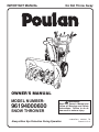 1
1
-
 2
2
-
 3
3
-
 4
4
-
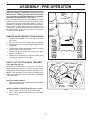 5
5
-
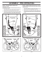 6
6
-
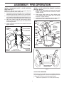 7
7
-
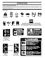 8
8
-
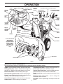 9
9
-
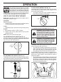 10
10
-
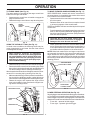 11
11
-
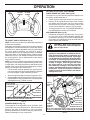 12
12
-
 13
13
-
 14
14
-
 15
15
-
 16
16
-
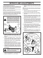 17
17
-
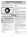 18
18
-
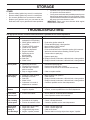 19
19
-
 20
20
-
 21
21
-
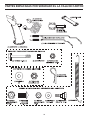 22
22
-
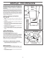 23
23
-
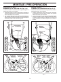 24
24
-
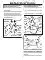 25
25
-
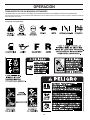 26
26
-
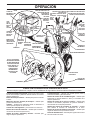 27
27
-
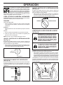 28
28
-
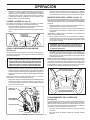 29
29
-
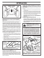 30
30
-
 31
31
-
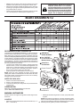 32
32
-
 33
33
-
 34
34
-
 35
35
-
 36
36
-
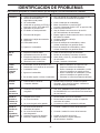 37
37
-
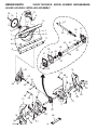 38
38
-
 39
39
-
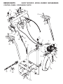 40
40
-
 41
41
-
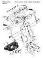 42
42
-
 43
43
-
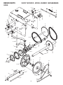 44
44
-
 45
45
-
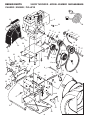 46
46
-
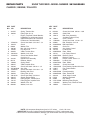 47
47
-
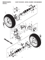 48
48
-
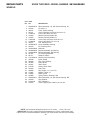 49
49
-
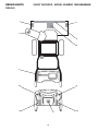 50
50
-
 51
51
-
 52
52


Poulan 414949 Manual de usuario
- Categoría
- Lanzadores de nieve
- Tipo
- Manual de usuario
- Este manual también es adecuado para
en otros idiomas
- English: Poulan 414949 User manual
Otros documentos
-
Craftsman 917881065 El manual del propietario
-
Craftsman 917881060 El manual del propietario
-
-
-
-
-
-
-
Husqvarna ST 324 Manual de usuario
-
 EarthWise SN72018 Manual de usuario
