Mitsubishi PCA-A24GA El manual del propietario
- Tipo
- El manual del propietario

B"_ EL.ECTRIC
Air-Conditioners
Indoor unit
PLA-A.AA
PKA-A.GA/PKA-A.GAL
PKA-A.FA/PKA-A.FAL
PCA-A.GA
OPERATION MANUAL
For safe and correct use, please read this operation manual thoroughly before operating the air-conditioner unit,
MANUAL DE INSTRUCCIONES
Lea este manual de instrucciones hasta el final antes de poner en marcha la unidad de aire acondicionado para
garantizar un uso seguro y correcto,

Contents
1. Safety Precautions .............................................................. 2
2. Parts Names ....................................................................... 2
3. Screen Configuration .......................................................... 6
4. Setting the Day of the Week and Time ............................... 6
5. Operation ............................................................................ 6
6. Timer ................................................................................... 8
7. Other Functions ................................................................ 11
8. Function Selection ............................................................ 12
9. Emergency Operation for Wireless Remote-controller ..... 16
10. Care and Cleaning ............................................................ 16
11. Trouble Shooting ............................................................... 16
12. Specifications .................................................................... 18
1. Safety Precautions
I_ Before installing the unit, make sure you read all the
"Safety Precautions".
I_ The"Safety Precautions" provide very important points
regarding safety. Make sure you follow them.
I_ Please report to or take consent by the supply author-
ity before connection to the system.
Symbols used in the text
/_ Warning:
Describes precautions that should be observed to prevent danger of
injury or death to the user.
z_ Caution:
Describes precautions that should be observed to prevent damage
to the unit.
Symbols used in the illustrations
(_ : Indicates a part which mustbe grounded.
/_ Warning:
• The unit must not be installed by the user. Ask the dealer or an
authorized company to install the unit. If the unit is installed im-
properly, water leakage, electric shock or fire may result.
• Do not stand on, or place any items on the unit.
• Do not splash water over the unit and do not touch the unit with
wet hands. An electric shock may result.
• Do not spray combustible gas close to the unit. Fire may result.
• Do not place a gas heater or any other open-flame appliance where
it will be exposed to the air discharged from the unit. Incomplete
combustion may result.
• Do not remove the front panel or the fan guard from the outdoor
unit when it is running.
Z_ Caution:
• Do not use any sharp object to push the buttons, as this may dam-
age the remote controller.
• Never block or cover the indoor or outdoor unit's intakes or out-
lets.
• When you notice exceptionally abnormal noise or vibration, stop
operation, turn off the power switch, and contact your dealer.
• Never insert fingers, sticks etc. into the intakes or outlets.
• If you detect odd smells, stop using the unit, turn off the power
switch and consult your dealer. Otherwise, a breakdown, electric
shock or fire may result.
• This air conditioner is NOT intended for use by children or infirm
persons without supervision.
• Young children must be supervised to ensure that they do not play
with the air conditioner.
• If the refrigeration gas blows out or leaks, stop the operation of the
air conditioner, thoroughly ventilate the room, and contact your
dealer.
Disposing of the unit
When you need to dispose of the unit, consult your dealer.
2. Parts Names
• Indoor Unit
PKA-A.GA PKA-A.FA PCA-A.GA
PLA-A.AA PKA-A.GAL PKA-A.FAL
Fan steps 4 steps 4 steps 2 steps 4 steps
Vane Auto with swing Auto with swing Auto with swing Auto with swing
Louver - Manual Manual Manual
Filter Long-life Normal Normal Long-life
Filter cleaning indication 2,500 hr 100 hr 100 hr 2,500 hr
2

2. Parts Names
• PLA-A.AA
4-way Ceiling Cassette
Air intake
Filter _Vane
Air outlet
• PKA-A.GA/PKA-A.GAL
Wall Mounted
Filter
Air intake
Louver
Vane
Air outlet
• PKA-A.FA/PKA-A.FAL
Wall Mounted
Filter
Air intake
Louver Air outlet
_ane
• PCA-A.GA
Ceiling Suspended
Louver
Air outlet
Vane r
Air intake
3

2. Parts Names
• Wired Remote-Controller
I Display Section I
Orpurposes of this explanation,_
IIparts of the display are shown I
lit.Duringactualoperation, only I
e relevant itemswill be lit. /
/
Identifies the current operation
Shows the operating mode, etc.
* Multilanguage display is sup-
ported.
"Centrally Controlled" indicator
Indicates that operation of the re-
mote controller has been prohib-
ited by a master controller.
"Timer is Off" indicator
Indicates that thetimer is off.
Temperature Setting
Shows the targettemperature.
Day-of-Week
Shows the current day of the week.
Time/Timer Display
Shows the current time, unless the simple or Auto Off
timer is set.
If the simple or Auto Off timer is set, shows the time
remaining.
_, MITSUBISHI ELEITRIC
TiME SUN MON TUE..WED THU FRI SAT I _ _[_]
TIMER El L/ " El L I Hr ON I
AFTER I II I " I II I AFTEROFF JOl
I
1 I
Up/Down Air Direction indica- Room Temperature display
tor Shows the room temperature. The room
The indicator '% shows the direc- temperature display range is 8-39°C.
tion of the outcoming airflow. The display flashes if the temperature
is less than 8 °C or 39 °C or more.
"One Hour Only" indicator
Displayed if the airflow is set to Louver display
weakand downward during COOL Indicates the action of the swing louver.
or DRY mode. (Operation varies Does not appear if the louver is station-
according to model.) ary.
The indicator goes off after one
hour, at which time the airflow di- (_) (Power On indicator)
rection also changes. Indicates that the power is on.
m
"Sensor" indication
Displayed when the remote controller
sensor is used.
"Locked" indicator
Indicates that remote controller but-
tons have been locked.
"Clean The Filter" indicator
Comes on when it is time to clean the
filter.
Timer indicators
The indicator comes on if the corre-
sponding timer is set.
Fan Speed indicator
Shows the selected fan speed.
Ventilation indicator
Appears when the unit is running in
Ventilation mode.
Operation Section
_Set Temperature buttons
Down
up
I Timer Menu button
(Monitor/Set button)
Mode button (Return button)
I
I Set Time buttons
Back
(_ Ahead
I imer On/Off button _}_(Set Day button)
Opening the
door.
MITSUBISHI ELECTRIC
J
@ 0 q/OFF
o
-- __ TEMP.
(2D
i
I_--!_00638_ C)MENU _ON/OFF FILTER
_. ONSETDAYI I :-_=_ 3_:.lJ CHECKTEST
Built-in temperature sensor
ON/OFF button
)eed button
Filter _ button
(<Enter> button)
%
Test Run button J
[__ heck button (Clear button)
Airflow Up/Down button ;
_ (L?VorpbeUatti°nnbutt°n)1
(_ To preceding operation
number.
--I (Vz_nt_)_P:°ntib°Lttbuntton)1
(_To next operation
number.
Note:
• "PLEASE WAIT" message
This message is displayed for approximately 3 minutes when power is supplied to the indoor unit or when the unit is recovering from a power failure,
• "NOT AVAILABLE" message
This message is displayed if a button is pressed to operate a function that the indoor unit does not have,
If a single remote controller is used to simultaneously operate multiple indoor units that are different models, this message will not be displayed if
any of the indoor units is equipped with the function,
4

2. Parts Names
• Wireless Remote-Controller
Transmission area
( Remote controller display
* For explanation purposes, all of the items
that appear in the display are shown.
* All items are displayed when the Reset
button is pressed.
(oN,OFFbutton)
I Set Temperature buttons
Fan Speed button (Changes fan speed) ,)
Airflow button (Changes up/down airflow direction) ")_
I Mode button (Changes operation mode)
Check button
( Test Run button _)
Transmission indicator
Timer indicator
Operation areas
Timer Off button 1
Timer On button 1
Hour button
Minute button
( Set Time button (Sets the time) _
Louver button (Changes left/right airflow direction))
• When using the wireless remote controller, point it towards the receiver on the indoor unit.
• If the remote controller is operated within approximately two minutes after power is supplied
to the indoor unit, the indoor unit may beep twice as the unit is performing the initial auto-
matic check.
• The indoor unit beeps to confirm that the signal transmitted from the remote controller has
been received. Signals can be received up to approximately 7 meters in a direct line from
the indoor unit in an area 45° to the left and right of the unit. However, illumination such as
fluorescent lights and strong light can affect the ability of the indoor unit to receive signals.
• If the operation lamp near the receiver on the indoor unit is flashing, the unit needs to be
inspected. Consult your dealer for service.
• Handle the remote controller carefully! Do not drop the remote controller or subject it to
strong shocks. In addition, do not get the remote controller wet or leave it in a location with
high humidity.
• To avoid misplacing the remote controller, install the holder included with the remote con-
troller on a wall and be sure to always place the remote controller in the holder after use.
• Outdoor unit
_iiiiiii1iiiiiiiiiii_ii_jiiiiIIjiiIIjiiIIjiiIIjiiIIjiiIIjiiWiiiijiiiijiiiijiiiijiiiijiiiijiiiijiiiijiiiijiiiijiiiiji_
Powe r
Ref. Pipes _
Indoor-Outdoor
Connection wire
Panel
iil Earth
///////_///////
Battery installation/replacement
1. Remove the top cover, insert two AAA batter-
ies, and then install the top cover.
Top cover r(_
Two AAA batteries
Insert the negative (-) 1
end of each battery I
first. Install the batter-
ies in the correct direc-
tons (+, -)
2. Press the Reset button.
Press the Reset button
with an object that has
a narrow end.
5

3. Screen Configuration
FunctionSelectionofremotecontroller Set Day/Time
l®l 1o
Standard Control Screens
<Screen Types>
For details on setting the language for the remote controller display, refer
to section 8. Function Selection.
The initial language setting is English.
• Function Selection of remote controller:
Set the functions and ranges available to the re-
mote controller (timer functions, operating restric-
tions, etc.)
• Set Day/Time: Set the current day of the week or time.
• Standard Control Screens:
View and set the air conditioning system's oper-
ating status
• Timer Monitor: View the currently set timer (weekly timer, sim-
ple timer, or Auto Off timer)
• Timer Setup: Set the operation of any of the timers (weekly
timer, simple timer, or Auto Off timer).
<How to change the screen>
@ :Hold down both the Mode button and the Timer On/Off button for 2
seconds.
(_ :Press the Timer Menu button.
©:Press the Mode (Return) button.
@ :Press either of the Set Time buttons (V or A).
4. Setting the Day of the Week and Time
®
_TEMP _ON/OFF
l@Iotl t)MINU _O_OFF _=1_ % FILTER
Q d_
DayoftheWeek &
Time display
®
Note:
The day and time will not appear if clock use has been disabled at Function
Selection of remote controller.
Day of theWeek Setting
.......... " -_'==--_t_;:i_ ....
=lm.e:=_:_,,=,,,=.,.,.u,_,.,_,,_..... I...........................] _ Time Setting
1. Press the V or A Set Time button @ to show display _.
2. Press the Timer On/Off (Set Day) button (_ to set the day.
* Each press advances the day shown at _: Sun -_ Mon -_ ... -_ Fri -_
Sat.
3. Press the appropriate Set Time button @ as necessary to set the time.
*As you hold the button down, the time (at _) will increment first in
minute intervals, then in ten-minute intervals, and then in one-hour in-
tervals.
4. After making the appropriate settings at Steps 2 and 3, press the Filter
button (_ to lock in the values.
5. Operation
%
®
%
%
%
5.1. Turning ON/OFF
<To Start Operation>
• Press the ON/OFF button (_.
• The ON lamp _ and the display area come on.
Note:
• When the unit is restarted initialsettings are as follows.
Remote Controller settings
Mode Last operation mode
Temperature setting Last set temperature
Fan speed Last set fan speed
COOL or DRY Horiz. outlet*
Airflow up/down Mode HEAT Last setting
FAN Horiz. outlet *
%
®
It will be set by last setting for wired remote controller.
6

5. Operation
<To Stop Operation>
• Press the ON/OFF button (_ again.
• The ON lamp _ and the display area go dark.
Note:
Even if you press the ON/OFF button immediately after shutting down the op-
eration is progress, the air conditioner will not start for about three minutes.
This is to prevent the internal components from being damaged.
5.2. Mode select
• Press the operation mode (l-I_a_0) button _) and select the opera-
tion mode [_.
-_ _ Cooling mode
6 Drying mode
Fan mode
Q Heating mode
I--I Automatic (cooling/heating) mode
-- _ Ventillation mode
Only indicated on the following condition
Wired remote controller used
LOSSNAY connected
Automatic operation
• According to a set temperature, cooling operation starts if the room tem-
perature is too hot and heating operation starts if the room temperature
is too cold.
• During automatic operation, if the room temperature changes and re-
mains 2 °C, 4 °F or more above the set temperature for 15 minutes, the
air conditioner switches to cooling mode. In the same way, if the room
temperature remains 2 °C, 4 °F or more below the set temperature for
15 minutes, the air conditioner switches to heating mode.
Cooling mode 15minutes (switches
._ from heating to cooling)
,--?t_' \ Set temperature+2°C, +4°F
Set temperature
!
_'_-._._ ........ Set temperature-2°C, -4°F
15 minutes (switches
fromcooling toheating)
• Because the room temperature is automatically adjusted in order to
maintain a fixed effective temperature, cooling operation is performed a
few degrees warmer and heating operation is performed a few degrees
cooler than the set room temperature once the temperature is reached
(automatic energy-saving operation).
5.3. Temperature setting
To decrease the room temperature:
Press QD button _) to set the desired temperature.
The selected temperature is displayed _.
To increase the room temperature:
Press _ button _) to set the desired temperature.
The selected temperature is displayed _.
• Available temperature ranges are as follows:
Cooling/Drying: 19 - 30 °C, 67 - 87 °F
Heating: 17 - 28 °C, 63 - 83 °F
Automatic: 19 - 28 °C, 67 - 83 °F
• The display flashes either 8 °C - 39 °C, 46 °F - 102 °F to inform you if the
room temperature is lower or higher than the displayed temperature.
5.4. Fan speed setting
• Press the Fan Speed button (_) as many times as necessary while the
system is running.
• Each press changes the force. The currently selected speed is shown
at _.
• The change sequence, and the available settings, are as follows.
FAN SPEED Display
Speed 1 Speed 2 Speed 3 Speed 4
4-speed
2-speedmodel _ _d" _dd||
Note:
• The number of available fan speeds depends on the type of unit connected.
Note also that some units do not provide an "Auto" setting.
• In the following cases, the actual fan speed generated by the unit will differ
from the speed shown the remote controller display.
1. While the display is showing "STAND BY" or "DEFROST".
2. When the temperature of the heat exchanger is low in the heating mode.
(e.g. immediately after heating operation starts)
3. In HEAT mode, when room temperature is higher than the temperature
setting.
4. When the unit is in DRY mode.
5.5. Airflow direction setting
<To Change the Airflow's Up/Down Direction>
• With the unit running, press the Airflow Up/Down button _) as necessary.
• Each press changes the direction. The current direction is shown at _.
• The change sequence, and the available settings, are as follows.
Display
Horiz. 1 2 3 Swing
Note that during swing operation, the directional indication on the
screen does not change in sync with the directional vanes on the unit.
* Some models do not support directional settings.
Note:
• Available directions depend on the type of unit connected. Note also that
some units do not provide an "Auto" setting.
• In the following cases, the actual air direction will differ from the direction
indicated on the remote controller display.
1. While the display is showing "STAND BY" or "DEFROST".
2. Immediately after starting heater mode (while the system is waiting for
the mode change to take effect).
3. In heat mode, when room temperature is higher than the temperature set-
ting.
7

5. Operation
<To Change the Right/Left Air Direction>
• Press the louver button (_ as necessary,
• The louver image _ appears,
Each press of the button switches the setting as follows,
_._%_ _ No display
(Stop)
(ON) (OFF)
During swing operation, the arrow dis-
play move to the left and right.
5.6. Ventillation
For LOSSNAY combination
5.6.1. For Wired Remote-controller
• To run the ventilator together with the indoor unit:
• Press the ON/OFF button (_.
• The Vent indication appears on the screen (at _). The ventilator will
now automatically operate whenever the indoor unit is running.
• To run the ventilator independently:
• Press the Mode button (_) until _ appears on the display. This will
cause the ventilator to start.
• To change the ventilator force:
• Press the Ventilation button (_ as necessary.
• Each press toggles the setting, as shown below.
.--'-"
Low High
5.6.2. For Wireless Remote-controller
• The ventillator will automatically operate when the indoor unit turns on.
• No indication on the wireless remote controller.
6. Timer
6.1. For Wired Remote-controller
You can use Function Selection of remote controller to select which of
three types of timer to use: (_ Weekly timer, _) Simple timer, or (_) Auto Off
timer.
6.1.1. Weekly Timer
• The weekly timer can be used to set up to eight operations for each day
of the week.
• Each operation may consist of any of the following: ON/OFF time
together with a temperature setting, or ON/OFF time only, or tempera-
ture setting only.
• When the current time reaches a time set at this timer, the air
conditioner carries out the action set by the timer.
• Time setting resolution for this timer is 1 minute.
Note:
"1. WeeklyTimer/SimpleTimer/Auto OffTimer cannot beused atthe same time.
*2. The weekly timer will not operate when any of the following conditions is in
effect.
The timer feature is off; the system is in an malfunction state; atest run is
in progress; the remote controller is undergoing self-check or remote con-
troller check; the user is in the process of setting afunction; the user is in
the process of setting the timer; the user is in the process of setting the
current day of the week or time; the system is under central control. (Spe-
cifically, the system will not carry out operations (unit on, unit off, or tem-
perature setting) that are prohibited during these conditions.)
OperationNo.
[] [] [] Day Setting
MITS IBISHI ELECTF C
_TEMP.
<How to Set the Weekly Timer>
1, Be sure that you are at a standard control screen, and that the weekly
timer indicator _ is shown in the display,
2, Press the Timer Menu button @, so that the "Set Up" appears on the
screen (at _), (Note that each press of the button toggles the display
between "Set Up" and "Monitor",)
3, Press the Timer On/Off (Set Day) button (_ to set the day, Each press
advances the display at _ to the next setting, in the following sequence:
"Sun Mon Tues Wed Thurs Fri Sat"-> "Sun" -> ...-> "Fri" -> "Sat" -> "Sun
Mon Tues Wed Thurs Fri Sat"...
4. Press the V or/k Operation button ((_ or (_) as necessary to select the
appropriate operation number (1 to 8) _.
* Your inputs at Steps 3 and 4 will select one of the cells from the matrix
illustrated below.
(The remote-controller display at left shows how the display would
appear when setting Operation 1 for Sunday to the values indicated
below.)
Setup Matrix
Op No Sunday Monday .. Saturday
• 8:30
No. 1 •ON
• 73 F
No. 8
<Operation 1 settings for Sunday> I
<Operation
2
settings
for
every day>
I
Start the air conditioner at 8:30, with I Turn off the air conditioner at 10:00.
the temperature set to 73 °E
i J
Note:
Bysetting the day to "Sun MonTuesWedThurs Fri Sat", you can set the same
operation to be carried out at the same time every day.
(Example: Operation 2 above, which isthe same for all days of the week.)
<Setting the Weekly Timer>
Showsthe time _ _ Shows theselected operation (ONor OFF)
setting / * Does notappear if operation is notset.
[
Showsthe temperature setting
Fn'3 / _ * Does notappeariftemperature is not
- set.
5. Press the appropriate Set Time button @ as necessary to set the
desired time (at _).
• As you hold the button down, the time first increments inminute inter-
vals, then in ten-minute intervals, and then in one-hour intervals.
6. Press the ON/OFF button (_ to select the desired operation (ON or
OFF), at _.
• Each press changes the next setting, in the following sequence:
No display (no setting) -> "ON" -> "OFF"
8

6. Timer
7, Press the appropriate Set Temperature button (_ to set the desired
temperature (at _),
* Each press changes the setting, in the following sequence: No
display (no setting) <=>75 <=>77 <=>,,, <_ 84 <=>86 <=>54 <=>,,, <_ 73
<=>No display.
(Available range: The range for the setting is 12 °C, 54 °F to 30 °C,
86 °E The actual range over which the temperature can be con-
trolled, however, will vary according to the type of the connected
unit,)
8, After making the appropriate settings at Steps 5, 6 and 7, press the
Filter _ button _) to lock in the values,
To clear the currently set values for the selected operation, press and
quickly release the Check (Clear) button _ once,
* The displayed time setting will change to "--:--", and the On/Off
and temperature settings will all disappear,
(To clear all weekly timer settings at once, hold down the Check
(Clear) button _ for two seconds or more, The display will begin
flashing, indicating that all settings have been cleared,)
Note:
Your new entries will be cancelled if you press the Mode (Return) button
(_) before pressing the Filter 4J button _).
If you have set two or more different operations for exactly the same
time, only the operation with the highest Operation No. will be carried
out.
9, Repeat Steps 3 to 8 as necessary to fill as many of the available cells
as you wish,
lO,Press the mode (Return) button (_ to return to the standard control
screen and complete the setting procedure,
11,To activate the timer, press the Timer On/Off button (_, so that the
"Timer Off" indication disappears from the screen, Be sure that the
"Timer Off" indication is no longer displayed.
* If there are no timer settings, the "Timer Off" indication will flash on
the screen,
<How to View the Weekly Timer Settings>
_ Timer Settings
1, Be sure that the weekly timer indicator is visible on the screen (at [_),
2, Press the Timer Menu button @ so that "Monitor" is indicated on the
screen (at [_),
3, Press the Timer On/Off (Set Day) button (_ as necessary to select
the day you wish to view,
4, Press the V or/k Operation button ((_ or (_))as necessary to change
the timer operation shown on the display (at [_),
* Each press will advance to the next timer operation, in order of
time setting,
5, To close the monitor and return to the standard control screen, press
the Mode (Return) button (_,
<To Turn Off the Weekly Timer>
Press the Timer On/Off button (_ so that "Timer Off" appears at _,
<To Turn On the Weekly Timer>
Press the Timer On/Off button (_ so that the "Timer Off" indication (at _)
goes dark,
6.1.2. SimpleTimer
• You can set the simple timer in any of three ways,
• Start time only:
The air conditioner starts when the set time has elapsed,
• Stop time only:
The air conditioner stops when the set time has elapsed,
• Start & stop times:
The air conditioner starts and stops at the respective elapsed times,
• The simple timer (start and stop) can be set only once within a 72-hour
period,
The time setting is made in hour increments,
Note:
"1. WeeklyTimer/SimpleTimer/Auto OffTimer cannot beused atthe same time.
*2. The simple timer will not operate when any of the following conditions is in
effect.
The timer is off; the system is in malfunction state; atest run is in progress;
the remote controller is undergoing self-check or remote controller check;
the user is in the process of selecting afunction; the user is in the process
of setting the timer; the system is under central control. (Under these con-
ditions, On/Off operation is prohibited.)
_ MITSUBISHI ELECTRIC
_,t[TEMP.
_ ON/OFF
U
J
<How toSet the SimpleTimer>
_ Timer Setting
J
Action (On or Off)
* "-- _" is displayed if there is no
setting.
1, Be sure that you are at a standard control screen, and that the simple
timer indicator is visible in the display (at _),
When something other than the Simple Timer is displayed, set it to
SIMPLE TIMER using the function selection of remote controller (see
8,[4]-3 (3)) timer function setting,
2, Press the Timer Menu button @, so that the "Set Up" appears on the
screen (at _), (Note that each press of the button toggles the display
between "Set Up" and "Monitor",)
3, Press the ON/OFF button (_ to display the current ON or OFF simple
timer setting, Press the button once to display the time remaining to ON,
and then again to display the time remaining to OFF, (The ON/OFF
indication appears at _).
• "ON" timer:
The air conditioner will start operation when the specified number of
hours has elapsed.
• "OFF" timer:
The air conditioner will stop operation when the specified number of
hours has elapsed.
4. With "ON" or "OFF" showing at _: Press the appropriate Set Time button
@ as necessary to set the hours to ON (if "ON" is displayed) or the hours
to OFF (if "OFF" is displayed) at _.
• Available Range: 1 to 72 hours
5. To set both the ON and OFF times, repeat Steps 3 and 4.
* Note that ON and OFF times cannot be set to the same value.
6. To clear the current ON or OFF setting: Display the ON or OFF setting
(see step 3) and then press the Check (Clear) button _ so that the time
setting clears to "--" at _. (If you want to use only an ON setting or only
an OFF setting, be sure that the setting you do not wish to use is shown
as "--',)
9

6. Timer
7, After completing steps 3 to 6 above, press the Filter _ button (_ to lock
in the value,
Note:
Your new settings will be cancelled if you press the Mode (Return) button (_)
before pressing the Filter _fJ button (_).
8. Press the Mode (Return) button _) to return to the standard control
screen.
9. Press the Timer On/Off button (_)to start the timer countdown. When the
timer is running, the timer value is visible on the display. Be sure that the
timer value is visible and appropriate.
<Viewing the Current Simple Timer Settings>
_ Timer Setting
1. Be sure that the simple timer indicator is visible on the screen (at _).
2. Press the Timer Menu button @, so that the "Monitor" appears on the
screen (at _).
• If the ON or OFF simple timer is running, the current timer value will
appear at _.
• If ON and OFF values have both been set, the two values appear
alternately.
3. Press the Mode (Return) button _) to close the monitor display and return
to the standard control screen.
<To Turn Off the Simple Timer...>
Press the Timer On/Off button (_ so that the timer setting no longer ap-
pears on the screen (at _).
%
1
. .... ..,
<To Turn On the Simple Timer...>
Press the Timer On/Off button (_ so that the timer setting becomes visible
ate.
,J,,
ICJ; L,C' ¢.d|i
qqoF
I"
Examples
If ON and OFF times have both been set at the simple timer, operation and
display are as indicated below.
Example 1:
Start the timer, with ON time set sooner than OFF time
ON Setting: 3 hours
OFF Setting: 7 hours
__//H, oN
A_ER
®J Q SIM_LE
-At Timer Start
Display shows the timer's ON setting (hours
remaining to ON).
_At_ hours a_er t_-mer_-art-')
- Display changes to show the timer's OFF set-
ting (hours remaining to OFF).
The time displayed is OFF setting (7 hours) -
ON setting (3 hours) = 4 hours.
At 7 hours after timer start
The air conditioner goes off, and will remain off
until someone restarts it.
Example 2:
Start the timer, with OFF time is sooner than ON time
ON Setting: 5 hours
OFF Setting: 2 hours
I
4
:,,_-/ AFaR ,
i
6.1.3. Auto OffTimer
-At Timer Start
Display shows the timer's OFF setting (hours
remaining to OFF).
At 2 hours after timieer s_art
"Display changes to show the timer's ON setting
(hours remaining to ON).
The time displayed is ON setting (5 hours) -
OFF setting (2 hours) = 3 hours.
At 5 hours after timer start
The air conditioner comes on, and will continue
to run until someone turns it of/.
• This timer begins countdown when the air conditioner starts, and shuts
the air conditioner off when the set time has elapsed.
• Available settings run from 30 minutes to 4 hours, in 30-minute intervals.
Note:
"1. WeeklyTimer/SimpleTimer/Auto OffTimer cannot be used at the same time.
*2. The Auto Off timer will not operate when any of the following conditions is
in effect.
The timer is off; the system is in malfunction state; a test run is in progress;
the remote controller is undergoing self-check or remote controller check;
the user is in the process of selecting a function; the user is in the process
of setting the timer; the system is under central control. (Under these con-
ditions, On/Off operation is prohibited.)
_ MITSUBISHI ELECTF_
I_TEMP. (_'ON/OFF
@
®
<How to Set the Auto Off Timer>
_ Timer Setting
1. Be sure that you are at a standard control screen, and that the Auto Off
timer indicator is visible in the display (at _).
When something other than the Auto Off Timer is displayed, set it to
AUTO OFF TIMER using the function selection of remote controller (see
8.[4]-3 (3)) timer function setting.
2. Hold down the Timer Menu button @ for 3 seconds, so that the "Set Up"
appears on the screen (at _).
(Note that each press of the button toggles the display between "Set Up"
and "Monitor".)
3. Press the appropriate Set Time button (_)as necessary to set the OFF
time (at _).
4. Press the Filter _ button (_ to lock in the setting.
Note:
Your entry will be cancelled if you press the Mode (Return) button (_) before
pressingthe Filter 4J button(_).
5. Press the Mode (Retu m) button (_)to complete the setting procedu re and
return to the standard control screen.
6. If the air conditioner is already running, the timer starts countdown
immediately. Be sure to check that the timer setting appears cor-
rectly on the display.
10

6. Timer
<Checking the Current Auto Off Timer Setting>
_ Timer Setting
1. Be sure that the "Auto Off" is visible on the screen (at _).
2. Hold down the Timer Menu button @ for 3 seconds, so that "Monitor" is
indicated on the screen (at _).
• The timer remaining to shutdown appears at _.
3. To close the monitor and return to the standard control screen, press the
Mode (Return) button _).
<To Turn Off the Auto Off Timer...>
• Hold down the Timer On/Off button (_ for 3 seconds, so that "Timer Off"
appears (at _) and the timer value (at _) disappears.
I
• Alternatively, turn off the air conditioner itself. The timer value (at _) will
disappear from the screen.
%
<To Turn On the Auto Off Timer...>
• Hold down the Timer On/Off button (_ for 3 seconds. The "Timer Off"
indication disappears (at _), and the timer setting comes on the display
(at _).
• Alternatively, turn on the air conditioner. The timer vahe will appear at _.
%
6.2. For wireless remote controller
AUTOSTOP AUTOSTART
(_ Press the _ or [_Z] button (TIMER SET).
Time can be set while the following symbol is blinking,
OFF timer: @ G_O is blinking,
ON timer: @ G_I is blinking,
h rain
(_) Use the [CCZ]and [ZCC]buttons to set the desired time,
(_) Canceling the timer,
AUTOSTOP
To cancel the OFF timer, press the _ button.
To cancel the ON timer, press the _ button.
• It is possible to combine both OFF and ON timers.
• Pressing the (_ ON/OFF button of the remote controller during timer
mode to stop the unit will cancel the timers.
• If the current time has not been set, the timer operation cannot be used.
7. Other Functions
7.1. Locking the Remote Controller Buttons (Operation
function limit controller)
• If you wish, you can lock the remote controller buttons. You can use the
Function Selection of remote controller to select which type of lock to use.
(For information about selecting the lock type, see section 8, item [4]-2
(1)).
Specifically, you can use either of the following two lock types.
(_ Lock All Buttons:
Locks all of the buttons on the remote controller.
(_) Lock All Except ON/OFF:
Locks all buttons other than the ON/OFF button.
Note:
The "Locked" indicator appears on the screen to indicate that buttons are cur-
rently locked.
_TEMP.
\.... J \
D'_O Oo_ OMENU CON/OFF _111 7_ FILER
BACK MONITOR_SFT DAY "_=_ _.10HEOK TEST
PAR21MAA _ _)OLOCK VOPERATIONA }:t_R
_) ON/OFF
[]
[]
Lock Indicator
®
<How to Lock the Buttons>
1. While holding down the Filter button _), press and hold down the ON/OFF
button (_ for 2 seconds. The "Locked" indication appears on the screen
(at _), indicating that the lock is now engaged.
* If locking has been disabled in Function Selection of remote controller,
the screen will display the "Not Available" message when you press the
buttons as described above.
• If you press a locked button, the "Locked" indication (at _) will blink on
the display.
<How to Unlock the Buttons>
1. While holding down the Filter button (_, press and hold down the ON/
OFF button (_ for 2 seconds--so that the "Locked" indication disappears
from the screen (at _).
/_/qF i
11

7. Other Functions
7.2. Error Codes indication
=_ MITSUBISHI ELECTRIC
.....:_ _1_ ,-- _-.
I II III I / I<.J
Indoor Unit's Refrig- Error Code Indoor Unit No.
erant Address I ]
Ifyouhaveenteredcontactnumbertobecanedintheeventofaproblem,thescreendisplaysthisnumber. AlternatingDisplay
(Youcan setthisup underFunctionSelectionofremotecontroller.Forinformationrefertosection8.)
ON lamp
(Flashing)
• If the ON lamp and error code are both flashing: This means that the air conditioner is out of order and operation has been stopped (and cannot resume),
Take note of the indicated unit number and error code, then switch off the power to the air conditioner and call your dealer or servicer,
MITSUBISHI ELECTFUC
_)ON/OFF
When the Check button is pressed:
_,L MITSUBISHI ELECTRIC
(_)ON/OFF
Error Code
• If only the error code is flashing (while the ON lamp remains lit): Operation is continuing, but there may be a problem with the system, In this case, you
should note down the error code and then call your dealer or servicer for advice,
* If you have entered contact number to be called in the event of a problem, push the Check button to display it on the screen, (You can set this up under
Function Selection of remote controller, For information, refer to section 8,)
8. Function Selection
Function selection of remote controller
The setting of the following remote controller functions can be changed using the remote controller function selection mode. Change the setting when
needed.
Item 1 Item 2 Item 3 (Setting content)
1.Change Language Language setting to display • Display in multiple languages is possible
("CHANGE
LANGUAGE")
2. Function limit (1) Operation function limit setting (operation lock) ("LOCKING • Setting the range of operation limit (operation lock)
("FUNCTION FUNCTION")
SELECTION")
(2) Use of automatic mode setting ("SELECT AUTO MODE") • Setting the use or non-use of "automatic" operation mode
(3) Temperature range limit setting ("LIMIT TEMP FUNCTION") • Setting the temperature adjustable range (maximum, minimum)
3. Mode selection (1) Remote controller main/sub setting ("CONTROLLER MAIN/ • Selecting main or sub remote controller
("MODE SELEC- SUB") * When two remote controllers are connected to one group, one controller
TION") must be set to sub.
(2) Use of clock setting ("CLOCK") • Setting the use or non-use of clock function
(3) Timer function setting ("WEEKLY TIMER") • Setting the timer type
(4) Contact number setting for error situation ("CALL.") • Contact number display in case of error
• Setting the telephone number
4. Display change (1) Temperature display °C/°F setting ("TEMP MODE °C/°F") • Setting the temperature unit (°C or °F) to display
("DISP MODE
SETTING") (2) Suction air temperature display setting ("ROOM TEMP DISP • Setting the use or non-use of the display of indoor (suction) air tempera-
SELECT") ture
(3) Automatic cooling/heating display setting ("AUTO MODE • Setting the use or non-use of the display of "Cooling" or "Heating" display
DISP C/H") during operation with automatic mode
12

8. Function Selection
[Function selection flowchart]
Setting language (English)
Change
Language
Function
selection
Mode
selection
Display
mode setting
Normal display |
(Display when the air condition is not running)
/
Hold down the (E} button and press the (_) button for 2 seconds. I
/
Remote controller function selection mode
F...........
Item1
=
i i
®
®
®
Item2
English
Germany
Spanish
Russian
Italy
Chinese
French
Japanesel
I
=
@
i
Item3
@
@
,@
il
i _ ii® °
@@
Hold down the _E_button and press the (_) button for 2 seconds.
_E_Press the operation mode button.
L_ Press the TIMER MENU button.
Press the TIMER ON/OFF button.
Dot display
d%
@-
Xb
4£
4b
®
Operation lock setting is not used.
(Initial setting value)
Operation lock setting is except On/Off button.
Operation lock setting is All buttons.
The automatic mode is displayed when the operation mode is
selected. (Initial setting value)
The automatic mode is not displayed when the operation mode
is selected.
The temperature range limit is not active. (Initial setting value)
The temperature range can be changed on cooling/dry mode.
The temperature range can be changed on heating mode.
The temperature range can be changed on automatic mode.
The remote controller will be the main controller. (Initial setting value)
The remote controller will be the sub controller.
The clock function can be used. (Initial setting value)
The clock function can not be used.
Weekly timer can be used. (initial setting value)
Auto off timer can be used.
Simple timer can be used.
Timer mode can not be used.
The set contact numbers are not displayed in case of error.
(Initial setting value)
The set contact numbers are displayed in case of error.
The temperature unit °C is used. (Initial setting value)
The temperature unit °F is used.
Room air temperature is displayed. (initial setting value)
Room air temperature is not displayed.
One of "Automatic cooling" and "Automatic heating" is displayed
under the automatic mode is running. (Initial setting value)
Only "Automatic" is displayed under the automatic mode.
13

8. Function Selection
[Detailed setting]
[4]-1. CHANGE LANGUAGE setting
The language that appears on the dot display can be selected.
• Press the [QMENU] button @ to change the language.
(_ English (GB), (_ German (D), (_ Spanish (E), @ Russian (RU),
(_ Italian (I), (_ Chinese (CH), (_ French (F), (_ Japanese (JP)
Refer to the dot display table.
[4]-2. Function limit
(1) Operation function limit setting (operation lock)
• To switch the setting, press the [QON/OFF] button @.
(_ no1 : Operation lock setting is made on all buttons other than the
[CON/OFF] button.
(_ no2: Operation lock setting is made on all buttons.
(_ OFF (Initial setting value): Operation lock setting is not made.
* To make the operation lock setting valid on the normal screen, it is
necessary to press buttons (Press and hold down the [FILTER] and
[(_ON/OFF] buttons at the same time for two seconds.) on the
normal screen after the above setting is made.
(2) Use of automatic mode setting
When the remote controller is connected to the unit that has automatic
operation mode, the following settings can be made.
• To switch the setting, press the [QON/OFF] button @.
(_ ON (Initial setting value):
The automatic mode is displayed when the operation mode is
selected.
(_ OFF:
The automatic mode is not displayed when the operation mode
is selected.
(3) Temperature ranqe limit settinq
After this setting is made, the temperature can be changed within the
set range.
• To switch the setting, press the [QON/OFF] button @.
(_ LIMIT TEMP COOL MODE:
The temperature range can be changed on cooling/dry mode.
(_ LIMIT TEMP HEAT MODE:
The temperature range can be changed on heating mode.
(_ LIMIT TEMP AUTO MODE:
The temperature range can be changed on automatic mode.
OFF (initial setting): The temperature range limit is not active.
* When the setting, other than OFF, is made, the temperature range
limit setting on cooling, heating and automatic mode is made at the
same time. However, the range cannot be limited when the set
temperature range has not changed.
• To increase or decrease the temperatu re, press the [ _ TEMP. (V)
or (A)] button (_.
• To switch the upper limit setting and the lower limit setting, press the
['t:'.,d] button (_). The selected setting will flash and the temperature
can be set.
• Settable range
Cooling/Dry mode:
Lower limit:19°C - 30°C, 67°F - 87°F
Upper limit:30°C _ 19°C, 87°F _ 67°F
Heating mode:
Lower limit:17°C _ 28°C, 63°F _ 83°F
Upper limit:28°C - 17°C, 83°F _ 63°F
Automatic mode:
Lower limit:19°C _ 28°C, 67°F _ 83°F
Upper limit:28°C _ 19°C, 83°F - 67°F
[4]-3. Mode selection setting
(1) Remote controller main/sub settinq
• To switch the setting, press the [QON/OFF] button @.
(_ Main: The controller will be the main controller.
(_ Sub: The controller will be the sub controller.
(2) Use of clock setting
• To switch the setting, press the [QON/OFF] button @.
(_ ON: The clock function can be used.
(_ OFF: The clock function cannot be used.
(3) Timer function setting
• To switch the setting, press the [ QON/OFF] button @ (Choose one
of the followings.).
(_ WEEKLY TIMER (initial setting value):
The weekly timer can be used.
_) AUTO OFF TIMER:
The auto off timer can be used.
(_) SIMPLE TIMER:
The simple timer can be used.
(_ TIMER MODE OFF:
The timer mode cannot be used.
* When the use of clock setting isOFF, the"WEEKLYTIMER" cannot
be used.
(4) Contact number settinq for error situation
• To switch the setting, press the [QON/OFF] button @.
(_ CALL OFF:
The set contact numbers are not displayed in case of error.
_) CALL ........... :
The set contact numbers are displayed in case of error.
CALL:
The contact number can be set when the display is as shown on
the left.
• Setting the contact numbers
To set the contact numbers, follow the following procedures.
Move the flashing cursor to set numbers. Press the [ _ TEMP.
(V) and ( A)] button (_ to move the cursor tothe right (left). Press
the [QCLOCK (V) and (A)] button © to set the numbers.
[4]-4. Display change setting
(1) Temperature display °C/°F settinq
• To switch the setting, press the [Q ON/OFF] button @.
(_ °C: The temperature unit °C is used.
_) °F: The temperature unit °F is used.
(2) Suction air temperature display setting
• To switch the setting, press the [QON/OFF] button @.
(_ ON: The suction air temperature is displayed.
(_ OFF: The suction air temperature is not displayed.
(3) Automatic cooling/heating display setting
• To switch the setting, press the [QON/OFF] button @.
(_ ON:
One of"Automatic cooling" and "Automatic heating" is displayed
under the automatic mode is running.
(_) OFF:
Only "Automatic" is displayed under the automatic mode.
14

8. Function Selection
[Dot display table]
Selecting language English Germany Spanish Russian Italy Chinese French Japanese
Waiting for start-up PLE_iEmniT
e- e- <-- <-- e-- <--- <--
operation mode
Set temperature
Fan speed
Not use button
Check (Error)
Test run
Self check
Cool
Dry
Heat
Auto
Auto(Cool)
Auto(Heat)
Fan
Ventilation
Stand by
(Hot adiust )
Defrost
TEmPERTUKn
VEHTILEIOI_I
Unit function selection ;DE:FUNCI,_H +
Setting of ventilation
_ENTHLRTH_H tR|A |_;EHN_:
Selecting language English Germany Spanish Russian Italy Chinese French Japanese
CHANGE LANGUAGE
<--- _ <--- <-- <-- <---
Function selection HI_IIN_I#BIJ _J_N_P]_t I].......... ..........
.....i
Operation function limit setting _tl
Use of automatic mode setting _,,_'h_
Temperature range limit setting +_t.+_ml_O:r;_He_iNe_++_mmmRAi+EiiiT_me_:__8 lt_lJ+
Limit temperatu re cooling/day _r_U_l_ :: _i_Zi_
mode _IXA|ItlI:!
Limit temperature heating mode LH_i_[_i_NE _:lJ _: a_:_i_:_am:_::
Limit temperature auto mode L_MiT_Zi_8 _,,_'h_._r_L_
Mode selection
Remote controller setting MAIN
Remote controller setting SUB
Use of clock setting
Setting the day of the week and
time _l_ill_lllll
Timer set
Timer monitor
Weekly timer
#:_:_|_8_
Timer mode off
Autoefftimer
Simple timer +
Contact number setting of error
situation <-- <---, <--- 4,--- 4--- 4---- 4-,--
Display change i_i_:_
Temperature display °C/°F setting
Room air temperature display _ TE_ H'I"T_P: TJI_I_U_ _|1_:|_:_!
TEH_ E::K_HH
setting
Automatic cooling/heating display
setting | 8_
15

9. Emergency Operation for Wireless Remote-controller
(_\ CO_OLHEAT
MITSUBISHI ELECTRIC)
When the remote controller cannot be used
When the batteries of the remote controller run out or the remote controller
malfunctions, the emergency operation can be done using the emergency
buttons on the grille.
@DEFROST/STAND BY lamp
(_Operation lamp
(_Emergency operation switch (heating)
@Emergency operation switch (cooling)
(_Receiver
Starting operation
• To operate the cooling mode, press the 0 button @.
• To operate the heating mode, press the _ button ©.
Note:
• Details of emergency mode are as shown below.
Details of EMERGENCY MODE are as shown below.
Operation mode COOL
Set temperature 24°C, 75°F
Fan speed Hiqh
Airflow direction Horizontal
Stopping operation
• To stop operation, press the 0 button @ or the 4;_button ©.
HEAT
24°C, 75°F
Hi,qh
Downward 4
10. Care and Cleaning
• Indicates that the filter needs cleaning.
Ask authorized people to clean the filter.
• When resetting "FILTER" display
When the [FILTER] button is pressed two times successively after
cleaning the filter, the display goes off and is reset.
11. Trouble Shooting
Note:
• When two or more different types of indoor unit are controlled, the cleaning
period differs with the type of filter. When the master unit cleaning period
arrives, "FILTER" is displayed. When the filter display goes off, the cumula-
tive time is reset.
• "FILTER" indicates the cleaning period when the air conditioner was used
under general indoor air conditions by criteria time. Since the degree of dirti-
ness depends on the environmental conditions, clean the filter accordingly.
• The filter cleaning period cumulative time differs with the model.
• This indication is not available for wireless remote controller.
Air conditioner does not heat or cool well. • Clean the filter. (Airflow is reduced when the filter is dirty or clogged.)
When heating operation starts, warm air does not blow from the indoor unit
soon.
During heating mode, the air conditioner stops before the set room tem-
)erature is reached.
Airflow direction changes during operation or airflow direction cannot be
set.
When the airflow direction is changed, the vanes always move up and down
)ast the set position before finally stopping at the position.
A flowing water sound or occasional hissing sound is heard.
A cracking or creaking sound is heard.
The room has an unpleasant odor.
A white mist or vapor is emitted from the indoor unit.
Water or vapor is emitted from the outdoor unit.
The operation indicator does not appear in the remote controller display.
• Check the temperature adjustment and adjust the set temperature.
• Make sure that there is plenty of space around the outdoor unit. Is the
indoor unit air intake or outlet blocked?
• Has a door or window been left open?
• Warm air does not blow until the indoor unit has sufficiently warmed up.
• When the outdoor temperature is low and the humidity is high, frost may
form on the outdoor unit. If this occurs, the outdoor unit performs a de-
frosting operation. Normal operation should begin after approximately 10
minutes.
• During cooling mode, the vanes automatically move to the horizontal
(down) position after 1 hour when the down (horizontal) airflow direction
is selected. This is to prevent water from forming and dripping from the
vanes.
• During heating mode, the vanes automatically move to the horizontal
airflow direction when the airflow temperature is low or during defrosting
mode.
• When the airflow direction is changed, the vanes move to the set position
after detecting the base position.
• These sounds can be heard when refrigerant is flowing in the air condi-
tioner or when the refrigerant flow is changing.
• These sounds can be heard when parts rub against each due to expan-
sion and contraction from temperature changes.
• The indoor unit draws in air that contains gases produced from the walls,
carpeting, and furniture as well as odors trapped in clothing, and then
blows this air back into the room.
• If the indoor temperature and the humidity are high, this condition may
occur when operation starts.
• During defrosting mode, cool airflow may blow down and appear like a
mist.
• During cooling mode, water may form and drip from the cool pipes and
joints.
• During heating mode, water may form and drip from the heat exchanger.
• During defrosting mode, water on the heat exchanger evaporates and
water vapor may be emitted.
• Turn on the power switch."®" will appear in the remote controller display.
16

11. Trouble Shooting
" "appears in the remote controller display. • During central control, "_" appears in the remote controller display and
air conditioner operation cannot be started or stopped using the remote
controller.
When restarting the air conditioner soon after stopping it, it does not oper-
ate even though the ON/OFF button is pressed.
Air conditioner operates without the ON/OFF button being pressed.
Air conditioner stops without the ON/OFF button being pressed.
Remote controller timer operation cannot be set.
"PLEASE WAIT" appears in the remote controller display. •
An error code appears in the remote controller display. •
Draining water or motor rotation sound is heard. •
Noise is louder than specifications. •
Nothing appears in the wireless remote controller display, the display is
faint, or signals are not received by the indoor unit unless the remote con-
troller is close.
The operation lamp near the receiver for the wireless remote controller on
the indoor unit is flashing.
• Wait approximately three minutes.
(Operation has stopped to protect the air conditioner.)
• Is the on timer set?
Press the ON/OFF button to stop operation.
• Is the air conditioner connected to a central remote controller?
Consult the concerned people who control the air conditioner.
• Does "_" appear in the remote controller display?
Consult the concerned people who control the air conditioner.
• Has the auto recovery feature from power failures been set?
Press the ON/OFF button to stop operation.
• Is the off timer set?
Press the ON/OFF button to restart operation.
• Is the air conditioner connected to a central remote controller?
Consult the concerned people who control the air conditioner.
• Does "_" appear in the remote controller display?
Consult the concerned people who control the air conditioner.
• Are timer settings invalid?
If the timer can be set, _, _, or _ appears in
the remote controller display.
The initial settings are being performed. Wait approximately 3 minutes.
The protection devices have operated to protect the air conditioner.
Do not attempt to repair this equipment by yourself.
Turn off the power switch immediately and consult your dealer. Be sure
to provide the dealer with the model name and information that appeared
in the remote controller display.
When cooling operation stops, the drain pump operates and then stops.
Wait approximately 3 minutes.
The indoor operation sound level is affected by the acoustics of the par-
ticular room as shown in the following table and will be higher than the
noise specification, which was measured in an echo-free room.
High sound- Normal rooms Low sound-
absorbing rooms absorbing rooms
Location Broadcasting Reception room, Office, hotel
examples studio, music hotel lobby, etc. room
room, etc.
Noise levels 3 to 7 dB 6 to 10 dB 9 to 13 dB
• The batteries are low.
Replace the batteries and press the Reset button.
• If nothing appears even after the batteries are replaced, make sure that
the batteries are installed in the correct directions (+, -).
• The self diagnosis function has operated to protect the air conditioner.
• Do not attempt to repair this equipment by yourself.
Turn off the power switch immediately and consult your dealer. Be sure
to provide the dealer with the model name.
17

12. Specifications
Model
Power source (Phase, Voltage <V>,
Frequency <Hz>)
Fan motor <FLA>
MCA <A>
MOCP <A>
Dimension (Height) <inch>
Dimension (Width) <inch>
Dimension (Depth) <inch>
Airflow [ DRY <CFM>
Low-Middle2-Middlel-High) I WET <CFM>
Noise level (Low-Middle2-Middlel-High) <dB>
Net weight <lbs>
"1 The figure in 0 indicates GRILLs.
PLA-A12AA J PLA-A18AA J PLA-A24AA J PLA-A3OAA J PLA-A36AA J PLA-A42AA
0.79 1.25
1 2 _ 2
15 15 ] 15
11-3/4(1-3/16)
Single 208/230, 60
0.79 0.79
1 1 1
15 15 15
10-3/16(1-3/16)
33-1/16(37-3/8)
33-1/16(37-3/8)
390-420-460-490
350-380-420-450
27-28-29-31
49(11 )
530-570-640-710 710-810-920-990
490-530-600-670 670-770-880-950
28-30-32-34 33-36-39-41
53(11) 66(11)
Model
Power source (Phase, Voltage <V>,
Frequency <Hz>)
Fan motor <FLA>
MCA <A>
MOCP <A>
Dimension (Height) <inch>
Dimension (Width) <inch>
Dimension (Depth) <inch>
Airflow DRY <CFM>
(Low-Middle2-Middlel -High) WET <CFM>
Noise level (Low-Middle2-Middlel-High or
Low-High) <dB>
Net weight <lbs>
PKA-A12GAI PKA-A18GAI PKA-A24FAI PKA-A3OFAI PKA-A36FA
Single 208/230, 60
0.52
1 1
15 15
66-1/8
0.33
1 1
15 15
13-3_
39
9-1/4
320-350-390-425
290-315-350-380
36-38-41-43
0.43
1
15
13-3/8
55-1_
9-1_
530-705
480-635
39-45
780-990
700-890
46-49
35 53 62
PKA-A12GALIPKA-A SGALIPKA-A24FALIPKA-ASOFALIPKA-ASeFAL
Single 208/230, 60
0.52
1
15
66-1/8
Model
Power source (Phase, Voltage <V>,
Frequency <Hz>)
Fan motor <FLA>
MCA <A>
MOCP <A>
Dimension (Height) <inch>
Dimension (Width) <inch>
Dimension (Depth) <inch>
Airflow DRY <CFM>
(Low-Middle2-Middlel -High) WET <CFM>
Noise level (Low-Middle2-Middlel-High or
Low-High)
Net weight
0.33
1 1
15 15
13-3_
39
9-1/4
320-350-390-425
290-315-350-380
36-38-41-43
0.43
1 1
15 15
13-3/8
55-1_
9-1_
530-705
480-635
39-45
780-990
700-890
<dB>
<lbs> 35 53 62
PCA-A24GA .[ PCA-A3OGA] PCA-A36GA ] PCA-A42GA
Single 208/230, 60
0.53 0.69
15 15 15 15
8-1/4 10-5/8
51-9/16
26-3/4
46-49
Model
Power source (Phase, Voltage <V>,
Frequency <Hz>)
Fan motor <FLA>
MCA <A>
MOCP <A>
Dimension (Height) <inch>
Dimension (Width) <inch>
Dimension (Depth) <inch>
Airflow | DRY <CFM>
(Low-Middle2-Middlel -High) [ WET <CFM>
Noise level (Low-Middle2-Middlel-High) <dB>
Net weight <lbs>
495-530-565-635
445-480-510-570
37-39-41-43
75
705-740-810-880
635-670-730-790
40-41-43-45
82
18


Contenido
1. Medidas de Seguridad ...................................................... 20
2. Nombres de las piezas ..................................................... 20
3. Configuraci6n de la pantalla ............................................. 24
4. Configuraci6n de dia de la semana y hora ....................... 24
5. Manejo .............................................................................. 24
6. Temporizador .................................................................... 26
7. Otras funciones ................................................................. 29
8. Selecci6n de funci6n ........................................................ 30
9. Funcionamientode emergenciadelcontroladorremotoinalambrico....34
10. Mantenimiento y limpieza ................................................. 34
11. Localizaci6n de fallos ........................................................ 34
12. Especificaciones ............................................................... 36
1. Medidas de Seguridad
I_ Antes de instalar la unidad, asegt_rese de haber leido el
capitulo de "Medidas de seguridad".
I_ Las "Medidas de seguridad" seSalan aspectos muy im-
portantes sobre seguridad. Es importante que se cum-
plan todos.
I_ Antes de conectar el sistema, informe al servicio de su-
ministro o pidale permiso para efectuar la conexi6n.
Simbolos utilizados en el texto
/!k Atencion:
Describe precauciones que deben tenerse en cuenta para evitar el
riesgo de lesiones o muerte del usuario.
Z_ Cuidado:
Describe las precauciones que se deben tener para evitar daSos en
la unidad.
Simbolos utilizados en las ilustraciones
(_ • Indica una pieza que debe estar conectada a tierra.
Z_ Atencion:
• La unidad no debe ser instalada por el usuario. Pida a su distribui-
dor o a una empresa debidamente autorizada que se Io instale. La
incorrecta instalacion de la unidad puede dar lugar a goteo de agua,
descarga electrica o fuego.
• No se suba encima ni coloque objetos sobre la unidad.
• No vierta agua sobre la unidad ni la toque con las manos ht_medas.
Puede producirse una descarga electrica.
• No rocie gases combustibles en las proximidades de la unidad.
Puede haber riesgo de incendio.
• No coloque calentadores de gas o cualquier otro aparato de llama
abierta expuestos a la corriente de aire descargada por la unidad.
Puede dar lugar a una combustion incompleta.
• No extraiga el panel frontal del ventilador de la unidad exterior mien-
tras este en funcionamiento.
• Cuando note ruidos o vibraciones que no sean normales, pare la
unidad, desconecte la fuente de alimentacion y pongase en con-
tacto con su proveedor.
• No inserte nunca dedos, palos, etc. en las tomas o salidas de aire.
• Si detecta olores raros pare la unidad, desconecte el interruptor de
red y consulte con su distribuidor. De Io contrario puede haber
una rotura, una descarga electrica o fuego.
• Este aparato de aire acondicionado NO debe ser utilizado por ni-
5os ni por personas invalidas sin el control de una persona adulta.
• Los niSos pequeSos deben estar vigilados por personas adultas
para impedir que jueguen con el equipo de aire acondicionado.
• Si se producen fugas de gas refrigerante, pare la unidad, ventile
bien la habitacion y avise a su proveedor.
Z_ Cuidado:
• No utilice objetos puntiagudos para apretar los botones ya que
podria daSarse el controlador remoto.
• No bloquee ni cubra nunca las tomas y salidas de las unidades
interior y exterior.
Eliminacibn de la unidad
Cuando deba eliminar la unidad, consulte con su distribuidor.
2. Nombres de las piezas
• Unidad interior
PKA-A.GA PKA-A.FA
PLA-A.AA PKA-A.GAL PKA-A.FAL PCA-A.GA
Pasos del ventilador 4 pasos 4 pasos 2 pasos 4 pasos
Deflector Automatico oscilante Automatico oscilante Automatico oscilante Automatico oscilante
Rejilla - Manual Manual Manual
Filtro Larga duraci6n Normal Normal Larga duraci6n
Indicaci6n de limpieza de filtro 2,500 horas 100 horas 100 horas 2,500 horas
20

2. Nombres de las piezas
• PLA-A.AA
Modelo empotrado en techo de 4 direcciones
Filtro
Entrada
de aire
de aire
• PKA-A.GA/PKA-A.GAL
Modelo montado en pared
Filtro
Entrada de aire
Rejilla
Deflector
Salida de aire
• PKA-A.FA/PKA-A.FAL
Modelo montado en pared
Filtro
Entrada de aire
Rejilla Salida de aire
• PCA-A.GA
Modelo montado en techo
Rejilla
(
Salida de aire /_
Deflector _ -"_I_
Filtro
N
Entrada de aire
21

2. Nombres de las piezas
• Para controlador remoto cableado
] Seccibn de pantalla ]
ara esta explicaci6n, se rnues-_
ran iluminadas todas las partes [
e la pantalla,Durante el funcio- [
amiento real s61oestaranilumi- [
ados los elementosrelevantes,J
Identifica el funcionamiento _--I
actual.
Muestra el mode de funcionamien-
to, etc.
* Admite visualizaci6n en mdlti-
pies idiomas.
Indicador "Centrally
Controlled"
Indica que el mando principal ha
desactivado el funcionamiento del
mando a distancia.
Indicador "Timer Is Off"
Indica que el temporizador esta.
desactivado.
Configuracion de temperatura
I
Muestra la temperatura objetivo.
Dia de la semana
Muestra el dia de la semana actual.
Pantalla Time/Timer
Muestra la hora actual, a menos que se haya confi-
gurado el temporizador simple o de apagado auto-
matico, en cuyo case, muestra el tiempo restante.
_l MITSUBISHI ELEITRIC
;,_R._,v_ TU_E,._T_FR,O._TI_ _]
AFTER I_1_ " I_1_ AFTER OFF L_
- _ROR_OT" I_._ _
o_or.ID. F/IF_/F/°F°CI I_,,d
-_ #3 #\-)# / ....
_ _ ONLY1Hr.q_ _ _" ®
/
l I
Indicador de direccion de aire Pantalla de temperatura ambiente
Arriba/Abajo Muestra la temperatura ambiente. El
El indicador _ muestra la direcci6n rango de temperatura ambiente que
de circulaci6n del aire de salida, muestra la pantalla va de 8 a 39 °C.
La pantalla parpadea sila ternperatu -
Indicador "One Hour Only" ra no Ilegaa 8 °C o supera los 39 °C.
Se muestra si lacirculaci6n delaire se Pantalla de rejilla
hafijado en d6bilyhacia abajo durante Indica la acci6n de la rejilla bascu-
el modo COOL o DRY. (El funciona- lante. No aparece si la rejilla se
miento varia seg0n el modelo), encuentra fija.
Elindicador seapaga despues de una
hora, momento en que cambia tam- _) (Indicador Power On)
bienladirecci6ndecirculaci6ndelaire. Indica que esta encendido.
Indicador "Sensor"
Aparece cuando se utiliza el sensor
del mando a distancia.
Indicador "Locked"
Indica que se han bloqueado los boto-
nes del mando a distancia.
Indicador "Clean The Filter"
Se enciende cuando debe limpiarse el
filtro.
Indicadores del temporizador
El indicador se enciende si se ha con-
figurado el temporizador correspon-
diente.
Indicador de velocidad del venti-
lador
Muestra la velocidad del ventilador
seleccionada.
Indicador de ventilacion
Aparece cuando la unidad funciona en
modo Ventilacion.
Seccibn de control
Botones SetTemperature
Down (Abajo)
Up (Arriba)
I Bot6n Timer Menu(botch Monitor/Set)
Bot6n Mode (bot6n Return)
I
I Botones Set Time )_
Back (Atr_.s)
Ahead (Adelante)
I Bot6n Timer On/Off(bot6n Set Day)
Apertura de
la puerta.
Bot6n ON/OFF 1
BotOn Fan Speed ]
Boton 4J Filter
(Bot6n ,J)
J
,_ MITSUBISHI ELECTRIC
J
(_) 0 q/OFF
CD
-- _TEMP.
i
I_--!_00038_ C)MENU _ON/OFF FILTER
_. OR/SETDAYI I ::,_ 3_:.1, CHECKTEST
Sensor de temperatura integrado
Bot6n Test Run .,j
_ ot6n Check (bot6n Clear) ._
Bot6n Airflow Up/Down
Bot6n Louver 1
(BotOn V Operation)
AI mimero de funciona-
miento anterior.
_ Bot6n Ventilation 1-- (bot6n A Operation)
AI mimero de funciona-
miento posterior.
Nota:
• Mensaje "PLEASE WAIT" (POR FAVOR, ESPERE)
Este mensaje aparece durante aprox. 3 minutos cuando la unidad interior recibe alimentaci6n o cuando la unidad se estA recuperando de una
cafda de tensi6n.
• Mensaje "NOT AVAILABLE" (NO DISPONIBLE)
Este mensaje aparece si se pulsa un bot6n para activar una funci6n que la unidad interior no presenta.
SiestA utilizando un controlador remoto para controlar simultAneamente distintos modelos de unidades interiores, este mensaje no aparecerA si
alguna de las unidades interiores dispone de la funci6n.
22

2. Nombres de las piezas
• Para controlador remoto inalambrico
_ _,rea de transmisi6n'_
( Pantalla del controlador remoto
* Por cuestiones de claridad, se muestran todos los
elementos que pueden aparecer en la pantalla.
* AI pulsar el boton Reset (Restablecer) aparecen
todos los elementos en pantalla.
(Bot0nO.,OFF)
I Botones SetTemperature
I BotOn Fan Speed (cambia la velocidad del ventilador)
,1
Bot6nAirflow (Flujode aire, cambia haciaarriba o _l
abajo la direccion del flujo)
J
I Boton Mode (cambia el modo de funcionamiento)
Bot6n Check
(Bot6nTestRun _
Indicador de transmision
Indicador Timer (Temporizador)
_,reas de funcionamiento I
Boton Timer Off (Desactivar temporizador)
BotonTimerOn (Activartemporizador) 1
Boton Hour (Hora) 1
Boton Minute (Minuto)
Boton Bet Time (ajusta la hera)
Boton Louver (cambia a derecha/izquierda la |
direcciOndel flujo de aire)
J
Boton Reset (Restablecer)
• Cuando utilice el controlador remoto inalambrico, apunte hacia el receptor de la unidad
interior.
• Si el controlador remoto se utilize unos dos minutos despues de encender la unidad inte-
rior, esta puede pitar dos veces, ya que estate realizando la comprobaci6n automatica
inicial.
• La unidad interior pitara pare confirmar que ha recibido la sehal transmitida desde el con-
trolador remoto. La unidad interior puede recibir sehales emitidas a un maximo de 7 metros
en linea recta en un tango de 45° a derecha e izquierda de la unidad. Sin embargo, ciertos
sistemas de iluminaci6n, con fluorescentes o luces fuertes, pueden afectar ala capacidad
de recepci6n de sehal de la unidad interior.
• Si la luz de funcionamiento situada cerca del receptor de la unidad interior parpadea, sere
necesario inspeccionar la unidad. Consulte a su representante del servicio tecnico.
• Trate el controlador remoto con cuidado. Procure que no se le caiga ni sulfa golpes. Ade-
mas, no Io moje ni Io deje en un lugar con un alto grado de humedad.
• Pare impedir que el controlador remoto se pierda, instale el soporte incluido con el contro-
lador remoto en una pared y asegt_rese de colocar el mando en su soporte tras su uso.
• Unidad exterior
Panel de servicio
Alimentaci6n
Ref. tuberias _
Cable de conexi6n
unidad interior/exterior
'1 Tierra
///////_///////
Instalacibnlsustitucibn de pilas
1. Retire la cubierta superior, inserte dos pilas AAA
y vuelva a colocar la cubierta.
Cub_el_ "(_Dos plies AAA
__s_2 las pilas co-
l menzando por el polo 1
I negativo (-). AI inset- I
I tar las piles, respete la I
I p°laridad (+'-)" i
2. Pulse el bot6n Reset (Restablecer).
Pulse el bot6n Reset
(Restablecer) con un
objeto terminado en
punta.
23

3. Configuracion de la pantalla
SelecciOn de Funcion
Set Day/Time
l®l 1o
Pantalias Standard Control
OFF ON
t® l°
Timer Monitor Timer Setup
4. Configuracion de dia de la semana y hora
<Tipos de pantallas>
El ajuste de idioma de la pantalla se puede cambiar a espahol utilizando la
selecci6n de funci6n del controlador remoto. Consulte la secci6n 8, punto
[4]-1 para cambiar el ajuste de idioma.
El ajuste inicial es ingles.
• Selecci6n de Funci6n:
configure las funciones y tangos disponibles para el
mando a distancia (funciones de temporizador, restric-
ciones de funcionamiento, etc.).
• Set Day/Time: configure el dia de la semana u hora actual.
• Pantallas Standard Control:
visualice y configure el estado de funcionamiento del sis-
tema de acondicionamiento de aire.
• Timer Monitor: visualice el temporizador configurado actualmente (se-
manal, temporizador simple o apagado automatico).
• Timer Setup: configure el funcionamiento de cualquiera de los
temporizadores (semanal, simple oapagado automatico).
<Come cambiar la pantalla>
Para dirigirse a @ : mantenga pulsado el bot6n Mode y el bot6n Timer On/
Off durante 2 segundos.
Para dirigirse a (_ : presione el bot6n Timer Menu.
Para dirigirse a © : presione el bot6n Mode (Return).
Para dirigirse a @ : presione cualquiera de los botones Set Time (V o A).
_TEMP. _ON/OFF
i
Visualizaci6n de dfa
de lasemana y hora
®
Nota:
El diay la hora no aparecerzin si se ha desactivado la utilizacion del reloj en la
Seleccibn de Funcibn.
5. Manejo
13] Configuraci6n del dfa de la
semana
/
14] Configuracion de la hora
1. Pulse V o A del bot6n Set Time (_)para que muestre el indicador _.
2. Pulse el bot6n Timer On/Off (Set Day) (_ para fijar el dia.
* Cada pulsaci6n avanza el dia que se muestra en _: Sun -_ Mon -_ ...
-_ Fri -_ Sat.
3. Pulse el bot6n Set Time apropiado (_) segt_n sea necesario para confi-
gurar la hora.
* Mientras mantiene presionado el bot6n, la hora (en _) avanzara pri-
mero en intervalos de minutos, luego en intervalos de diez minutos y
despues en intervalos de una hora.
4. Despues de realizar las configuraciones apropiadas en los Pasos 2 y 3,
pulse el bot6n _ Filter (_ para fijar los valores.
%
®
%
%
%
5.1. Encendido y apagado
<Para poner en marcha>
• Pulse el bot6n ON/OFF (_.
• Se encienden la lampara de encendido _ y la pantalla.
Nota:
• Cuandose reiniciala unidad,laeconfiguracionesinicialesson laeeiguientes.
Configuraciones del Mando a distancia
Modo
Configuraci6ndelatemperatura
Velocidad del ventilador
Circulaci6n del aire hacia
Arriba/Abajo
01timo valor configurado
01timo valor configurado
01timo valor configurado
COOL o DRY Salida horiz. *
Modo HEAT Ultim0val0rc0nfigurad0
FAN Salida horiz. *
* Se ajustara con el t_ltimo valor configurado para el controlador remoto
con cable.
%
%
®
24

5. Manejo
<Para detener el funcionamiento>
• Pulse de nuevo el bot6n ON/OFF (_.
• Se oscurecen la lampara de encendido _ y la pantalla.
Nota:
Aunque pulse una vez mzis el botbn de encendido ON/OFF inmediatamente
despues de apagar el aparato, el acondicionador de aire no se pondr_i en mar-
cha hasta pasados tres minutos. Esto tiene como fin evitar daSos en los com-
ponentes internos.
5.2. Seleccibn de modo
• Pulse el bot6n de modos de funcionamiento (I-I_OO6) _ Yseleccio-
ne el modo de funcionamiento _.
-I, O Modo de enfriamiento
6 Modo secado
Modo de ventilador
-_. Modo de calefacci6n
I_--IModo autom&tico (enfriamiento/calefacci6n
-- _ Modo de ventilaci6n
$61o indicado si se cumple Io siguiente
Uso de controlador remoto cableado
Combinaci6n LOSSNAY conectada
Funcionamiento autom_itico
• De acuerdo con la temperatura ajustada, el funcionamiento de refrigera-
ci6n comenzar& si la temperatura de la sala es demasiado alta. El modo de
calefacci6n comenzara si la temperatura de la sala es demasiado baja.
• Durante el funcionamiento autom&tico, si la temperatura de la sala cam-
bia y permanece 2 °C, 4 °F o m&s por encima de la temperatura ajusta-
da durante 15 minutos, el acondicionador de aire cambiar& a modo de
refrigeraci6n. Asimismo, si la temperatura permanece 2 °C, 4 °F o m&s
por debajo de la temperatura ajustada durante 15 minutos, el acondicio-
nador de aire cambiar& a modo de calefacci6n.
Modo de enfriamiento
, /
tt
ttl_ = _...._ ........
15 minutos (cambio de re-
frigeracion a calefacci6n)
15 minutos (cambio de
calefacci6n a refrigeraci6n)
Temperatura ajustada +2°C, +4°F
Temperatura ajustada
Temperatura ajustada -2°C, -4°F
• Como la temperatura ambiente se ajusta automaticamente para mante-
ner una temperatura efectiva fija, el modo de refrigeraci6n se activa un
par de grados por encima de la temperatura ajustada (y el modo de
calefacci6n, un par de grados por debajo) una vez alcanzada dicha tem-
peratura (modo automatico de ahorro de energia).
5.3. Ajuste de la temperatura
Para disminuir la temperatura de la habitacion:
Pulse el bot6n C£) (_) para fijar la temperatura deseada.
En el visor aparecera la temperatura seleccionada _.
Para aumentar la temperatura de la habitacion:
Pulse el bot6n CZ:)(_) para fijar la temperatura deseada.
En el visor aparecera la temperatura seleccionada _.
• Las gamas de ajuste de temperaturas disponibles son las siguientes:
Enfriamiento y secado: 19 - 30 °C, 67 - 87 °F
Calefacci6n: 17 - 28 °C, 63 - 83 °F
Automatico: 19 - 28 °C, 67 - 83 °F
• La pantalla parpadea 8 °C - 39 °C, 46 °F - 102 °F para informar si la
temperatura de la habitaci6n es inferior o superior a la temperatura que
se visualiza.
5.4. Ajuste de la velocidad del ventilador
• Pulse el bot6n Fan Speed (_)tantas veces como sea necesario con el
sistema en funcionamiento.
• Cada pulsaci6n cambia la potencia. La velocidad seleccionada ac-
tualmente se muestra en _.
• La secuencia de cambio y las configuraciones disponibles son las
siguientes.
FAN SPEED Pantalla
Velocidad 1 Velocidad 2 Velocidad 3 Velocidad 4
Modelo de 4
Modelo de 2 _ _dd _=__dllll
velocidades
Nota:
• El n_mero de velocidades del ventilador disponibles depende del tipo de
unidadconectada. Recuerde,ademas,quealgunas unidadesnoofrecenajus-
te "Automatico'.
• En los siguientes casos,lavelocidad real del ventilador generada por launi-
dad diferirzide lavelocidad mostrada en la pantalladel mandoa distancia.
1. Mientras la pantalla muestra"STAND BY"o "DEFROST".
2. Cuando latemperatura del intercambiador de calor es baja en modo de
calefaccibn (por ejemplo, inmediatamente despues de que se active el
modo de calefaccion).
3. Enmodo HEAT,cuando latemperatura ambiente de lahabitacibnessupe-
rior alvalor de configuracion de latemperatura.
4. Cuando la unidad esteen modo DRY.
5.5. Ajuste de la direccibn del flujo de aire
<Para cambiar la direccion de circulacion del aire hacia Arriba/Abajo>
• Con la unidad en funcionamiento, pulse el bot6n Airflow Up/Down (_
tantas veces como sea necesario.
• Cada pulsaci6n cambia la direcci6n. La direcci6n actual se muestra
enD.
• La secuencia de cambio y las configuraciones disponibles son las
siguientes.
Pantalla
Horiz. 1 2 3 Oscilacion
Recuerde que durante el funcionamiento oscilante (Swing), la indica-
ci6n direccional en la pantalla no cambia en sincronizaci6n con los
&labes direccionales en la unidad.
Algunos modelos no admiten configuraciones direccionales.
Nota:
• Las direcciones disponibles dependen del tipo de unidad conectada. Re-
cuerde, ademas, que algunas unidades no ofrecen una configuracion "Auto".
• En los siguientes casos, la direccibn real del aire diferira de la direccibn
indicada en la pantalla del mando a distancia.
1. Mientras la pantalla muestra "STAND BY" o "DEFROST".
2. Inmediatamente despues de iniciar el modo calentador (durante la espera
para la realizaci6n del cambio).
3. En modo calentador, cuando la temperatura ambiente de la sala sea supe-
rior a la configuracion de la temperatura.
25

5. Manejo
<Para cambiar la direccion del aire Derecha/Izquierda>
• Pulse el bot6n Louver (_ segL_nsea necesario.
• Aparece la imagen de la rejilla _.
Cada pulsaci6n del bot6n, cambia la configuraci6n segt_n se muestra
a continuaci6n.
_._, _ Sin indicador Durante el funcionamiento basculan-
_=.==
(Stop) te, la visualizaci6n de la flecha se
(ON) (OFF) mueve a izquierda y derecha.
5.6. Ventilacibn
1_Para combinacion LOSSNAY
5.6.1. Para controlador remoto cableado
• Para hacer funcionar el renovador de aire junto con la unidad interior:
• Pulse el bot6n ON/OFF (_.
• El indicador Vent aparece en la pantalla (en _). Ahora el renova-
dor de aire funcionara automaticamente cuando funcione la uni-
dad interior.
• Para hacer funcionar el renovador de aire de modo independiente:
• Pulse el bot6n Mode (_) hasta que aparezca en la pantalla _. Esto
hara que el renovador de aire comience a funcionar.
• Para cambiar la potencia del renovador de aire:
• Pulse el bot6n Ventilation (_ segt_n sea necesario.
• Cada pulsaci6n cambia la configuraci6n segt_n se muestra a conti-
nuaci6n.
Baja Alta
5.6.2. Para controlador remoto inalbmbrico
• El ventilador se activara automaticamente al encenderse la unidad inte-
rior.
• No aparecera ninguna indicaci6n en el controlador remoto inalambrico.
6. Temporizador
6.1. Para controlador remoto cableado
Puede utilizar la Selecci6n de Funci6n para seleccionar cual de los tres
tipos de temporizador utilizar: (_ temporizador semanal, (_) temporizador
simple o _ temporizador automatico.
6.1.1. Temporizador semanal
• El temporizador semanal puede utilizarse para configurar hasta ocho
funciones para cada dia de la semana.
• Cada funci6n puede consistir en cualquiera de las siguientes: hora de
encendido y apagado junto a una configuraci6n de la temperatura,
s61o hora de encendido y apagado o s61oconfiguraci6n de la tempe-
ratura.
• Cuando la hora actual alcanza la hora configurada en este
temporizador, el acondicionador de aire realiza la acci6n configurada
por el temporizador.
• El tiempo necesario para la configuraci6n de la hora para este
temporizador es de 1 minuto.
Nota:
"1. El temporizador semanal, el temporizador simple y el temporizador auto-
mziticono pueden utilizarse al mismo tiempo.
"2. El temporizador semanal no funcionar_isi se da alguna de las siguientes
condiciones.
Lafuncibnde temporizadorest_idesactivada;el sistemase encuentraen un
estado anomalo;hay unasesionde prueba en curso;se est_iIlevandoacabo
una autopruebaouna prueba del mandoa distancia;el usuarioest_iconfigu-
rando una funcion;el usuarioest_iconfigurandoeltemporizador; el usuario
est_iconfigurandoeldiaactualde lasemanao lahera;el sistemaseencuen-
trabajo elcontrolcentral.Enconcrete,elsistemano Ilevar_iacabooperacio-
nes (encendido o apagado de la unidad, configuracibnde la temperatura)
que esten desactivadascuandose produzcan estas condiciones.
N° de Funcionamiento
[] [] [] Configuraci6n del d[a
MITS IBISHI ELECTF C
_TEMP. _ON/OFF
U
26
<Como configurar el temporizador semanal>
1. AsegL_rese de que se encuentra en la pantalla de control estandar y de
que el indicador del temporizador semanal _ se muestra en la pantalla.
2. Pulse el bot6n Timer Menu @, de modo que aparezca en la pantalla
"Set Up" (en _). (Recuerde que cada pulsaci6n del bot6n cambia la
pantalla entre "Set Up" y "Monitor").
3. Pulse el bot6n Timer On/Off (Set Day) (_ para configurar el dia. Cada
pulsaci6n avanza la pantalla _ a la pr6xima configuraci6n en la se-
cuencia que se indica a continuaci6n: "Sun Mon Tues Wed Thurs Fri
Sat" -_ "Sun" -_ ... (Domingo Lunes Martes Miercoles Jueves Viernes
Sabado -_ Domingo) -_ "Fri" -_ "Sat" -_ "Sun Mon Tues Wed Thurs Fri
Sat"... (Viernes -_ Sabado -_ Domingo Lunes Martes Miercoles Jue-
ves Viernes Sabado).
4. Pulse el bot6n V o /k Operation ((_ o (_) segt_n sea necesario para
seleccionar el nt_mero de operaci6n apropiado (1 a 8) _.
* La informaci6n introducida en los Pasos 3 y 4 seleccionara una de
las celdas de la matriz ilustrada a continuaci6n.
(La pantalla del mando a distancia en la izquierda muestra c6mo se
mostraria la pantalla cuando se configura Operaci6n 1 para el do-
mingo con los valores indicados a continuaci6n).
Matriz de configuracion
N° de op. Sunday Monday ... Saturday
• 8:30
No. 1 • ON
• 73 F
No. 8
<Valores de Operaci6n 1 para el domingo> <Valores de Operaci6n 2 para todos los dias> ]
Iniciar el funcionamiento del acondicionador de aire Apagar e acond c onador de a re a as 10:00. /
/
a as 8:30, con a temperatura f ada en 73 _E
Nota:
Configurando el aliaa "Sun MenTues Wed Thurs Fri Sat", puede configurar la
misma operacion a la misma hora todos los alias.
(Por ejemplo: la Operacibn 2 arriba mencionada es la misma para todos los
dias de la semana).
<Configuracion del temporizador semanal>
Muestra la configu- _5-j [6] Muestra laoperaci6n seleccionada(encendi-
raci6nde la hora do oapagado)
l I * No aparece si no se ha configurado la operaci6n.
J
,_ °?"_i:=i;_"'O_nL...........'o_t
i:f_3":[/[: _ [77]Muestra a temperaturafjada
,-,o, I ......J--I°°N *Noaparecesinosehafijadolaternperatura.
5. Pulse el bot6n Set Time apropiado @ segt_n sea necesario para fijar la
hora deseada (en _).
* Durante su pulsaci6n, la hora avanza primero en intervalos de un
minuto, luego en intervalos de diez minutos y finalmente en intervalos
de una hora.
6. Pulse el bot6n ON/OFF (_ para seleccionar la operaci6n deseada (en-
cendido o apagado), en _.
* Cada pulsaci6n cambia al siguiente valor en la secuencia que se indi-
ca a continuaci6n: sin indicaci6n (sin configu raci6n) -_ "ON" -_ "OFF".

6. Temporizador
7. Pulse el bot6n Set Temperature apropiado (_) para fijar la temperatu-
ra deseada (en _).
* Cada pulsaci6n cambia la configuraci6n en la secuencia que se
indica a continuaci6n: sin indicaci6n (sin configuraci6n) <=>75 <=>
77 <=>... <=>84 <=>86 <=>54 <=>... <=>73 <=>sin indicaci6n.
(Rango disponible: el tango de configuraci6n es de 12 °C, 54 °F a
30 °C, 86 °E El tango real de control de temperatura, sin embargo,
variara segL_nel tipo de unidad conectada).
8. Despues de realizar las configuraciones apropiadas en los Pasos 5,
6 y 7, pulse el bot6n _ Filter @ para guardar los valores.
Para borrar los valores actualmente configurados para la operaci6n
seleccionada, pulse y suelte rapidamente el bot6n Check (Clear) (_)
una vez.
* El valor de la hora mostrada cambiara a "--:--" y desapareceran
tanto los valores de encendido/apagado como el de temperatura.
(Para borrar todas las configuraciones del temporizador semanal
de una vez, mantenga pulsado el bot6n Check (Clear) _ durante
dos o mas segundos. La pantalla comenzara a parpadear, indi-
cando que se han borrado todos los valores fijados).
Nota:
Sus datos nuevos se cancelarzin si pulsa el boton Mode (Return)(_) antes
de pulsar el boton ..J Filter (_).
Si ha configurado dos o mas operaciones diferentes para la misma hora
exactamente, solo se realizara la operacibn con el numero mas elevado.
9. Repita los Pasos 3 a 8 segL_n sea necesario para completar tantas
celdas disponibles como desee.
lO.Pulse el bot6n Mode (Return) (_) para regresar a la pantalla de con-
trol estandar y completar el procedimiento de configuraci6n.
11.Para activar el temporizador, pulse el bot6n Timer On/Off (_, de modo
que el indicador "Timer Off" desaparezca de la pantalla. Asegurese
de que ya no se muestre el indicador "Timer Off".
* Si no hay valores fijados del temporizador, el indicador"Timer Off"
parpadeara en la pantalla.
<Como visualizar los valores fijados del temporizador semanal>
Valoresfijados del temporizador
1. Asegt_rese de que se muestra en la pantalla el indicador del
temporizador semanal (en _).
2. Pulse el bot6n Timer Menu @ de modo que se indique en la pantalla
"Monitor" (en _).
3. Pulse el bot6n Timer On/Off (Set Day) @ segt_n sea necesario para
seleccionar el dia que desea visualizar.
4. Pulse el bot6n Operation V o/X ((Z) o(_)) segt_n sea necesario para
cambiar el funcionamiento del temporizador mostrado en la pantalla
(en _).
* Cada pulsaci6n, avanzara a la pr6xima operaci6n del temporizador,
en el orden de configuraci6n de la hora.
5. Para cerrar el monitor y regresar a la pantalla Standard Control, pul-
se el bot6n Mode (Return) de _).
<Para desactivar el temporizador semanal>
Pulse el bot6n Timer On/Off (_ de modo que aparezca "Timer Off" en _.
<Para activar el temporizador semanal>
Pulse el bot6n Timer On/Off (_ de modo que el indicador "Timer Off" (en
_) se oscurezca.
6.1.2. Temporizador simple
• Puede configu rat el temporizado rsimple de cualquie rade las tres formas
siguientes.
• S61o hora de puesta en marcha:
el acondicionador de aire comenzara a funcionar cuando haya
transcurrido el tiempo fijado.
• S61o hora de parada:
el acondicionador de aire se detendra cuando haya transcurrido
el tiempo fijado.
• Horas de puesta en marcha y de parada:
el acondicionador de aire comienza a funcionar y se detiene cuan-
do hayan transcurrido las horas respectivas.
• El temporizador simple (puesta en marcha y parada) puede configurar-
se s61o una vez en un periodo de 72 horas. La configuraci6n de la hora
se realiza en aumentos de una hora.
Nota:
"1. El temporizador semanal, el temporizador simple y el temporizador auto-
m_iticono pueden utilizarseal mismo tiempo.
*2. El temporizador simple nofuncionarzisi se da cualquiera de las condicio-
nes siguientes.
Eltemporizadorestzidesactivado,elsistemaestzienestadoanbmalo,estzirea-
lizandoseunapruebadefuncionamiento,elmandoadistanciaest_irealizando
unaautoevaluaciono diagnbstico,elusuarioest_iseleccionandounafunci6no
conflgurandoel temporizador,el sistemaest_ibajo controlcentral.(En estas
condiciones,laoperaciondeencendidoy apagadoest_ideshabilitada).
_,_ MITSUBISHI ELECTRIC
ii!i!iiiii i iiii iiiiiiiiii
_TE64P.
r-j\ -_
(i_ ON/OFF
\ J
<Como configurar el temporizador simple>
U
% /41 Configuracion del temporizador
,I
i:'_:,:i_(_!:_--------_3j Accion (encendido oapagado)
I I
* Se muestra "-- --" si no hay confi-
1. AsegL_rese de que se encuentra en una pantalla de control estandar y de
que el indicador de temporizador simple se muestra en la pantalla (en _).
Cuando aparezca una indicaci6n distinta de la del temporizador simple,
cAmbielo a SIMPLE TIMER (TEMPORIZADOR SIMPLE) utilizando la se-
lecci6n de funciones de la configuraci6n de funciones del temporizador del
mando a distancia (vease 8.[4]-3 (3)).
2. Pulse el bot6n Timer Menu @, de modo que aparezca en la pantalla
"Set Up" (en _). (Recuerde que cada pulsaci6n del bot6n cambia la
pantalla entre "Set Up" y "Monitor").
3. Pulse el bot6n ON!OFF (_ para mostrar los valores configurados actuales
de encendido o apagado del temporizador simple. Pulse el bot6n una vez
para vet el tiempo restante hasta el encendido y luego de nuevo para vet el
tiempo restante hasta el apagado. (El indicador ON!OFF aparece en _).
• Temporizador "ON": el acondicionador de aire comenzarA a funcio-
nat cuando haya transcurrido el nt_mero de ho-
ras especificado.
• Temporizador "0 FF": el acondicionador deaire se detendrA cuando haya
transcurrido el nL_merode horas especificado.
4. Mostrando "ON" u "OFF" en _: pulse el bot6n Set Time (_) apropiado
segL_nsea necesario para fijar las horas hasta el encendido (si se muestra
"ON") o las horas hasta el apagado (si se muestra "OFF" en _).
• Rango disponible: 1 a 72 horas
5. Para fijar las horas hasta el encendido y el apagado, repita los Pasos 3 y4.
* Recuerde que las horas de encendido y apagado no pueden fijarse
en el mismo valor.
6. Para borrar la configuraci6n de encendido o apagado actual: Muestre el
valor configurado de encendido o apagado (vease el paso 3) y luego
pulse el bot6n Check (Clear) _ para borrar la configuraci6n de la hora a
"--" en _. (Si desea utilizar s61o un valor de configuraci6n de encendido
o una configuraci6n de apagado, asegL_rese de que la configuraci6n
que no desea utilizar se muestra como "--").
27

6. Temporizador
7, Despues de completar los Pasos 3 y 6 arriba mencionados, pulse el
bot6n _ Filter (_ para fijar el valor,
Nota:
Sus configuraciones nuevas se cancelar_in si pulsa el bot6n Mode (Return) (_)
antes de pulsar el bot6n ,J Filter (_).
8, Pulse el bot6n Mode (Return) (_) para regresar a la pantalla de control
estandar,
9, Pulse el bot6n Timer On/Off (_ para iniciar la cuenta atras del
temporizador, Cuando el temporizador esta funcionando, su valor es
visible en la pantalla, Asequrese de que el valor del temporizador
sea visible y apropiado.
<Visualizacion de las configuraciones actuales del temporizador simple>
/SJ /6] Configuraci6n del temporizador
1, AsegLirese de que el indicador del temporizador simple esta visible en
la pantalla (en _),
2, Pulse el bot6n Timer Menu @, para que aparezca "Monitor" en la panta-
Ila (en _),
• Si el temporizador simple de encendido o apagado esta funcionando,
su valor actual aparecera en _,
• Si se han fijado ambos valores, encendido y apagado, aparecen al-
ternativamente ambos valores,
3, Pulse el bot6n Mode (Return) (_) para cerrar la pantalla del monitor y
regresar a la pantalla de control estandar,
<Para desactivar el temporizador simple...>
Pulse el bot6n Timer On/Off @ para que la configuraci6n del temporizador
ya no aparezca en la pantalla (en _),
I
<Para iniciar el temporizador simple...>
Pulse el bot6n Timer On/Off (_ para que la configuraci6n del temporizador
sea visible en _,
,J,
qqop
Ejemplos
Si se han configurado las horas de encendido y apagado en el temporizador
simple, el funcionamiento y la pantalla son segt_n se indica a continuaci6n,
Ejemplo 1:
Inicie el temporizador, con la hora de encendido fijada mas temprano
que la hora de apagado,
Configuraci6n de encendido: 3 horas
Configuraci6n de apagado: 7 horas
=_/H, oN
A_ER
®J Q SIM_CE
qq'F J_-_
-AI inicio del temporizador
La pantalla muestra la configuracion de encen-
dido del temporizador (las horas restantes para
Ilegar al encendido).
"-3h_-ras_-espu es del inicio eel tem_-ri z_-o r_
- La pantalla cambia para mostrar el valor de
apagado del temporizador (las horas restantes
para el apagado).
La hora mostrada es el valor configurado de
apagado (7 horas) "- el valo¢' configurado de
encendido (3 horas) = 4 horas.
-7 horas despues del inicio del
temporizador
El acondicionador de aire se desactiva y perma-
necera desactivado hasta que alguien Ioreinicie.
Ejemplo 2:
Inicie el temporizador, con la hora de apagado fijada mas temprano que
la hora de encendido
Configuraci6n de encendido: 5 horas
Configuraci6n de apagado: 2 horas
/% ,, o_,
',, _ AFTER •
!
J
-AI inicio del temporizador
La pantalla muestra el valor de apagado del
ternporizador (las horas restantes para el apa-
gado).
2horasdespuesdeliniciodeltemporizador)
- La pantalla cambia para mostrar el valor de
encendido del temporizador (las horas restan-
tes para el encendido).
La hora indicada es el valor configurado de
encendido (5 horas) "- el valo¢' configurado de
apagado (2 horas) = 3 horas.
_5 horasdespues del inicio del
temporizador
El acondicionador de aire comienza a funcionar y
continuar_tfuncionando hasta quealguien Iodetenga.
6.1.3. Temporizador de apagado autom&tico
• Este temporizador comienza la cuenta atras cuando el acondicionador
de aire comienza a funcionar y apaga el acondicionador cuando haya
transcurrido el tiempo fijado.
• Los valores disponibles abarcan desde 30 minutos a 4 horas, en inter-
valos de 30 minutos.
Nota:
"1. El temporizador semanal, el temporizador simple y el temporizador auto-
mziticono pueden utilizarse al mismo tiempo.
*2. El temporizador AutoOff no funcionara si sedan cualquiera de lassiguien-
tes condiciones.
Eltemporizador estzidesactivado, el sistemaestzien estado anbmalo,esta
realizandose una prueba defuncionamiento, el mandoadistancia esta rea-
lizando una autoevaluacion o diagnbstico, el usuario esta seleccionando
una funcion o configurando el temporizador, el sistema estzi bajo control
central. (En estas condiciones, laoperacion de encendido yapagado esta
deshabilitada).
M SUBISHI ELECTRIC
TEMP. (_ ON/OFF
'\ ..................)
@
®
<Como configurar el temporizador de apagado automatico>
.2] !3] Configuraci6n del temporizador
1. AsegtJrese de que usted se encuentre en una pantalla de control estandar y
que el indicador del temporizador de apagado automatico Auto Off se mues-
tre en la pantalla (en _).
Cuando aparezca una indicaci6n distinta de la del temporizador de apagado
automatico, cambielo a AUTO OFF TIMER (TEMPORIZADOR DE APAGA-
DO AUTOM,_,TICO) utilizando la selecci6n de funciones de la configuraci6n
de funciones del temporizador del mando a distancia (vease 8.[4]-3 (3)).
2. Mantenga pulsado el bot6n Timer Menu @ durante 3 segundos, para que
aparezca "Set Up" en la pantalla (en _).
(Recuerde que cada pulsaci6n del bot6n cambia la pantalla entre "Set Up"
y "Monitor").
3. Pulse el bot6n Set Time apropiado (_) segt_n sea necesario para configurar
la hora de apagado (en _).
4. Pulse el bot6n _ Filter (_ para fijar la configuraci6n.
Nota:
Los datos introducidos secancelaransi pulsa el botbn Mode (Return)_) antes
de pulsarel botbn ,J Filter(_).
5. Pulse el bot6n Mode (Return) (_) para completar el procedimiento de
configuraci6n y regresar a la pantalla de control estandar.
6. Si el acondicionador de aire ya esta funcionando, el temporizador comien-
za inmediatamente la cuenta atrAs. Asegurese de eomprobar que el
valor fijado del temporizador apareee eorreetamente en la pantalla.
28

6. Temporizador
<Comprobaciondelaconfiguracionactualdeltemporizadordeapagadoautomatico>
!51 Configuraci6n del temporizador
1.Aseg0rese de que "Auto Off" este visible en la pantalla (en _).
2. Mantenga pulsado el bot6n Timer Menu @ durante 3 segundos, para
que se indique en la pantalla "Monitor" (en _).
• El tiempo restante para el apagado aparece en _.
3. Para cerrar el monitor y regresar a la pantalla Standard Control, pulse el
bot6n Mode (Return) de _).
<Para desactivar temporizador de apagado automatico...>
• Mantenga pulsado el bot6n Timer On/Off (_ durante 3 segundos para
que aparezca "Timer Off" (en _) y desaparezca el valor del temporizador
(en _). /7]
• Alternativamente, desconecte el acondicionador de aire. El valor del
temporizador (en _) desaparecera de la pantalla.
<Para iniciar el temporizador de apagado automatico...>
• Mantenga pulsado el bot6n Timer On/Off (_ durante 3 segundos. Des-
aparece la indicaci6n "Timer Off" (en _) y la configuraci6n del
temporizador aparece en la pantalla (en _).
• Alternativamente, encienda el acondicionador de aire. El valor del
temporizador aparecera en _.
6.2. Para controlador remoto inalbmbrico
(_ Presione el bot6n _ o _ (TIMER SET).
Se puede fijar la hora mientras parpadee el simbolo siguiente.
Temporizador de apagado: Parpadea (_) ©_O.
Temporizador de encendido: Parpadea (_) (_H.
(_) Use los botones C_ Y CCC]'n"_para fijar la hora deseada.
(_) Cancelaci6n del temporizador.
AUTOSTOP
Para cancelar el temporizador de apagado, presione el bot6n [_.
AUTOSTART
Para cancelar el temporizador de encendido, presione el bot6n I_"
• Es posible combinar el temporizador de encendido con el de apagado.
• AI presionar el bot6n (_ ON/OFF del mando a distancia durante el modo
de temporizador para parar la unidad se cancelaran los temporizadores.
• Si no ha ajustado la hora actual, no podra utilizar la funci6n del
temporizador.
7. Otras funciones
7.1. Bloqueo de los botones del mando a distancia (l(-
mite de funcibn de Operacibn)
• Si Io desea, puede bloquear los botones del mando a distancia. Puede
utilizar la selecci6n de funciones del mando a distancia para elegir el
tipo de bloqueo que desea usar. (Para mas informaci6n sobre selecci6n
del tipo de bloqueo, consulte la secci6n 8, punto [4]-2 (1)).
Especificamente, puede utilizar cualquiera de los dos tipos de bloqueo
que se indican a continuaci6n.
(_Bloquear todos los botones:
bloquea todos los botones en el mando a distancia.
_) Bloquear todo excepto ON/OFF (encendido/apagado):
bloquea todos los botones excepto el bot6n ON/OFE
Nota:
Aparece en la pantalla el indicador "Locked" (bloqueado) para indicarque los
botones estan bloqueados en este momento.
TEMP. _) ON/OFF
\ c> \ ...................
2"_,000_ OMENU OON/O_F _111 7_ FILER
BACK MONITOP_SFT DAY -_ _ C,% _l 0HEOE TEST
(&? o o
PAR 21MAA _ _)OLOCK VOPERATIONA : :tEAR
[]
[]
Indicador
de bloqueo
®
<Como bloquear los botones>
1. Mientras pulsa el bot6n Filter _), pulse y mantenga pulsado el bot6n
ON/OFF (_ durante 2 segundos. Aparece en la pantalla el indicador
"Locked" (en _) indicando que estA activado el bloqueo.
* Si el bloqueo se ha deshabilitado en Function Selection, la pantalla
mostrar& el mensaje "Not Available" (no disponible) cuando pulse los
botones seg0n se describe anteriormente.
• Si pulsa un bot6n bloqueado, parpadeara en la pantalla el indicador
"Locked" (en _).
<Como desbloquear los botones>
1. Mientras pulsa el bot6n Filter _), pulse y mantenga pulsado el bot6n
ON/OFF (_ durante 2 segundos para que el indicador "Locked" des-
aparezca de la pantalla (en _).
/"7_ F i
29

7. Otras funciones
7.2. Indicacibn de cbdigos de error
=_ MITSUBISHI ELECTRIC
.....:_ _1_ ,-- _-.
# II 1#1 I / I_.J
C6digo de error N° de unidad interior
frigerantedelaunidadinterior I 1
Pantalla alternante
Si ha introducido un nL_merotelef6nico al cual Ilamar encaso de problemas, la pantalla mostrara este
nL_mero.(Puedeconfigurarlo en la Selecci6nde Funci6n.Para mas informaci6n,consulte la secci6n 8).
L_tmpara ON
(parpadeando)
• Si parpadean la lampara ON y el c6digo de error: esto significa que el acondicionador de aire esta estropeado y su funcionamiento se ha detenido (y
no puede reanudarse). Tome nota del numero de unidad indicado y del c6digo de error; luego desconecte la alimentaci6n del acondicionador de aire
y Ilame a su distribuidor o proveedor de servicio tecnico.
MITSUBISHI ELECTFUC
_)ON/OFF
Cuando se pulsa el bot6n Check:
_,L MITSUBISHI ELECTRIC
.-H
(_)ON/OFF
COdigode error
• Si S610 parpadea el c6digo de error (mientras la lampara ON permanece encendida): contint_a el funcionamiento, pero puede existir un problema en el
sistema. En este caso, debe anotar el c6digo de error y luego Ilamar a su distribuidor o proveedor de servicio tecnico para asesoramiento.
* Si ha introducido un numero de telefono al cual Ilamar en caso de problemas, pulse el bot6n Check para mostrarlo en la pantalla. (Puede configurarlo
en la Selecci6n de Funci6n. Para mas informaci6n, consulte la secci6n 8).
8. Seleccion de funcion
Seleccibn de funciones del controlador remoto
El ajuste de las siguientes funciones del controlador remoto se puede cambiar utilizando el modo Selecci6n de funci6n del controlador remoto. Cambie
el ajuste cuando sea necesario.
item 1 item 2 item 3 (Contenido de ajuste)
1.Cambio de idioma Ajuste del idioma que aparece en el indicador • El indicador puede aparecer en distintos idiomas
("CHANGE
LANGUAGE")
2. Lfmite de funciones (1) Ajuste del limite de funciones (bloqueo de funciones) ("FUN- • Ajuste del range de limite de funcionamiento (bloqueo de funcionamiento)
("SELECCION DE CION BLOQUEADA")
FUNCIONES")
(2) Use del ajuste de modo autom_.tico ("SELECCION MODO • Ajuste del uso (o no) del mode de funcionamiento "automa.tico"
AUTO")
(3) Ajuste del Ifmite de range de temperatura ("LIMIT TEMP CON- • Ajuste del range de temperatura (maximo, mfnimo)
SIGNA")
3. Selecci6n de mode (1) Ajuste del controlador remoto principal/secundario ("CONTROL • Selecci6n del controlador remoto principal o secundario
("SELECCION DE PRINCIPAL/SECUNDARIO") * Si se conectan dos controladores remotos a un grupo, uno de los
MODO") controladores debe seleccionarse como secundario.
(2) Uso del ajuste del reloj ("RELOJ") • Ajuste del uso (o no) de la funci6n de reloj
(3) Ajuste de la funci6n de temporizador ("TEMPORIZA-DOR SE- • Ajuste del tipo de temporizador
MANAL")
(4) Ajuste de nt_mero de contacto en caso de error ("CALL.") • Indicador del nOmero de contacto en caso de error
• Ajuste del nOmero de telefono
4.Cambio de indicador (1) Ajuste del indicador de temperatura °C/°F ("TEMR GRADOS • Ajuste de la unidad de temperatura (°C o °F) que debe aparecer en el
("MOSTRAR °C/°F") indicador
MODO")
(2) Ajuste del indicador de temperatura del aire de aspiraci6n • Ajuste del uso (o no) del indicador de temperatura del aire (aspiraci6n)
("MOSTRAR TEMP.") del interior
(3) Ajuste del indicador de refrigeraci6n/calefacci6n automatica • Ajuste del uso (o no) del indicador de "Cooling" (Refrigeraci6n) o "Heating"
("MOSTRAR F/C EN AUTO") (Calefacci6n) durante el funcionamiento en modo autom_.tico
3O

8. Seleccion de funcion
[Diagrama de flujo de selecci6n de funci6n] I lndicador normal (Indicador que aparece cuando el |
_acondicionador de aire ester apagado)
Idioma ajustado (ingles) Mantenga pulsado el botOn _ y presione el boton (_) durante dos I
/
segundos.
Cambio de
idioma
Seleccion de
funciOn
Seleccion de
modo
Cambio de
indicador
Modo de selecciOn de funcion del controlador remoto
r ...........
item 1
i
i i
®
r_L_&J
®
®
item 2
English
Germany
Spanish
Russian
Italy
Chinese
French
Japanese: ....... "..................
Item 3
@
: @
@
'' @_
il
i _ ii® 0
@@
Mantenga pulsado el boton _E_ypresione el boton (_)durante dos segundos.
_E_Pulse el boton de modo de funcionamiento.
L_ Pulse el boton TIMER MENU (MEN0 DE TEMPORIZADOR).
Pulse el botOn TIMER ON/OFF (ACTIVAR/DESACTIVAR
TEMPORIZADOR).
Indicador de puetos
d%
@-
Xb
4£
4b
®
El ajuste de funcion bloqueada no se utiliza
(valor de ajuste inicial).
El bloqueo de fuecionamiento esta ajustado excepto para los boton
On/Off (encendido y apagado).
El bloqueo de funcionamiento esta ajustado para todos los botones.
El modo automatico aparece al seleccionar el modo de funcionamien-
to (valor de ajuste inicial).
El modo automatico no aparece al seleccionar el modo de funciona-
miento.
El Ifmite de rango de temperatura no esta activo (valor de ajuste
ieicial).
El rango de temperatura se puede cambiar en modo de refrigeracion/
seoado.
El rango de temperatura se puede cambiar en modo de secado.
El rango de temperatura se puede cambiar en modo automatico.
El controlador remoto sera el controlador principal (valor de ajuste
ieicial).
El controlador remoto sera el controlador secundario.
Se puede utilizar la funcion de reloj (valor de ajuste inicial).
La funcion de reloj no se puede utilizar.
Se puede utilizar el temporizador semanal (valor de ajuste ieicial).
Se puede utilizar el temporizador de apagado automatico.
Se puede utilizar el temporizador simple.
No se puede utilizar el modo de temporizador.
Los ntJmeros de contacto ajustados no aparecen en caso de error
(valor de ajuste inicial).
Los ntJmeros de contacto ajustados aparecen en caso de error.
Se utiliza la unidad de temperatura °C (valor de ajuste inicial).
Se utiliza la unidad de temperatura °F.
Aparece la temperatura del aire de la habitacion (valor de ajuste
ieicial).
No aparece la temperatura del aire de la habitaciOn.
"Automatic cooling" (RefrigeraciOn automatica) o "Automatic heating"
(CalefacciOn automatica) aparece cuando esta en funcionamiento el
modo automatico (valor de ajuste ieicial).
En el modo automatico, s01o aparece "Automatic" (Automatico).
31

8. Seleccion de funcion
[Ajuste detallado]
[4]-1. Ajuste de Cambio de idioma
Se puede seleccionar el idioma que aparece en el indicador de puntos.
• Presione el bot6n [QMENU] (_) para cambiar el idioma.
(_ Ingles (GB), (_) Aleman (D), (_) Espahol (E), @ Ruso (RU),
_) Italiano (I), (_) Chino (CH), (_ Frances (F), (_ Japones (JP)
Consulte la tabla del indicador de puntos.
[4]-2. Limite de funciones
(1) Ajuste del limite de funciones (bloqueo de funciones)
• Para cambiar el ajuste, presione el bot6n [QON/OFF] @.
(_ no1 : Se realiza el ajuste de bloqueo de funcionamiento en to-
dos los botones salvo en el bot6n [DON/OFF].
(_) no2: Se realiza el ajuste de bloqueo de funcionamiento en to-
dos los botones.
(_) OFF (Valor del ajuste inicial):
No se realiza el bloqueo de funcionamiento.
* Para que el bloqueo de funcionamiento sea valido en la pantalla
normal, hay que presionar los botones (Presione y mantenga pul-
sados a la vez los botones [FILTER] y [(_ON/OFF] durante dos
segundos) en la pantalla normal una vez que se ha realizado el
ajuste anterior.
(2) Uso del ajuste de modo automatico
Cuando se conecta el controlador remoto a la unidad que tiene ajus-
tado el modo funcionamiento automatico, se pueden realizar los si-
guientes ajustes.
• Para cambiar el ajuste, presione el bot6n [QON/OFF] @.
(_ ON (Valor del ajuste inicial):
Aparece el modo automatico cuando se selecciona el
modo de funcionamiento.
(_)OFF: No aparece el modo automatico cuando se selecciona el
modo de funcionamiento.
(3) Ajuste del limite de rango de temperatura
Una vez que se realiza el ajuste, se puede cambiar la temperatura
dentro del rango establecido.
• Para cambiar el ajuste, presione el bot6n [QON/OFF] @.
(_LIMIT TEMP MODO FR[O:
El tango de temperatura se puede cambiar en modo refrigera-
ci6n/secado.
_)LIMIT TEMP MODO CALOR:
El tango de temperatura se puede cambiar en modo calefac-
ci6n.
_)LIMIT TEMP MODO AUTO:
El tango de temperatura se puede cambiar en modo automatico.
(_OFF (ajuste inicial):
No esta activo el limite de tango de temperatura.
* Cuando se ajusta una posici6n distinta de la de desactivaci6n
(OFF), se ajusta a la vez el limite de tango de temperatura en
modo refrigeraci6n, calefacci6n y automatico. No obstante, no se
puede limitar el tango cuando no ha cambiado el tango de tempe-
ratura establecido.
• Para disminuir o aumentar la temperatura, presione el bot6n
[ ,,_TEMR (V) o (A)] (_).
• Para cambiar el ajuste de limite superior y el ajuste de limite infe-
rior, presione el bot6n [¢.,d] (_). El ajuste seleccionado parpadea-
ray ya se puede ajustar la temperatura.
• Rango ajustable
Modo Refrige raci6n/Secado:
Limite inferior : 19°C a 30°C, 67°F a 87°F
Limite superior :30°C a 19°C, 87°F a 67°F
Modo Calefacci6n:
Limite inferior : 17°C a 28°C, 63°F a 83°F
Limite superior :28°C a 17°C, 83°F a 63°F
Modo Automatico:
Limite inferior : 19°C a 28°C, 67°F a 83°F
Limite superior :28°C a 19°C, 83°F a 67°F
[4]-3. Ajuste de selecci6n de modo
(1) Ajuste del controlador remoto principal/secundario
• Para cambiar el ajuste, presione el bot6n [QON/OFF] @.
(l_Principah El controlador sera el principal.
_)Secundario:EI controlador sera el secundario.
(2) Uso del ajuste del reloj
• Para cambiar el ajuste, presione el bot6n [QON/OFF] @.
(_ON: Se puede usar la funci6n de reloj.
(_)OFF: No se puede usar la funci6n de reloj.
(3) Ajuste de la funci6n de temporizador
• Para cambiar el ajuste, presione el bot6n [QON/OFF] @ (Elija
una de las siguientes funciones).
(_TEMPORIZADOR SEMANAL (Valor del ajuste inicial):
Se puede usar el temporizador semanal.
_)APAGADO AUTOM,_,TICO:
Se puede usar el temporizador de desactivaci6n automatica.
_)TEMPORIZADOR SIMPLEx
Se puede usar el temporizador simple.
(_TEMPORIZADOR APAGADO:
No se puede usar el modo temporizador.
* Cuando el uso del ajuste de reloj esta desactivado (OFF), no se
puede usar el "TEMPORIZADOR SEMANAI".
(4) Ajuste de nt_mero de contacto en caso de error
• Para cambiar el ajuste, presione el bot6n [QON/OFF] @.
(_CALL OFF:
Los ntJmeros de contacto establecidos no aparecen en el indi-
cador en caso de error.
_)CALL ........... :
Los nt_meros de contacto establecidos aparecen en el indica-
dot en caso de error.
CALL_:
El ntJmero de contacto se puede ajustar cuando el indicador
aparece segt_n se muestra a la izquierda.
• Ajuste de los ntJmeros de contacto
Para ajustar los nt_meros de contacto, proceda del siguiente
modo.
Mueva el cursor parpadeante para ajustar los nt_meros. Presio-
ne el bot6n [_ TEMR (V) Y (A)] (_ para mover el cursor a la
derecha (izquierda). Presione el bot6n [QCLOCK (V) Y (A)]
(Reloj) © para ajustar los nt_meros.
[4]-4. Ajuste del cambio de indicador
(1) Ajuste del indicador de temperatura °C/°F
• Para cambiar el ajuste, presione el bot6n [QON/OFF] @.
(_ °C: Se utiliza la unidad de temperatura en °C.
_) °F: Se utiliza la unidad de temperatura en °E
(2) Ajuste del indicador de temperatura del aire de aspiraci6n
• Para cambiar el ajuste, presione el bot6n [QON/OFF] @.
(_ ON: Aparece la temperatura del aire de aspiraci6n.
_) OFF: No aparece la temperatura del aire de aspiraci6n.
(3) Ajuste del indicador de refriqeraci6n/calefacci6n automatica
• Para cambiar el ajuste, presione el bot6n [QON/OFF] @.
(_ ON: Aparece la posici6n "Automatic cooling" (Refrigeraci6n
automatica) o "Automatic heating" (Calefacci6n automa-
tica) en el modo automatico.
_) OFF: S61o aparece la posici6n "Automatic" (Automatico) en el
modo automatico.
32

8. Seleccion de funcion
Tabla del indicador de puntos]
Idioma ajustado English Germany Spanish Russian Italy Chinese French Japanese
Tiempo de espera de arranque PLE_iEmniT
<--- <-- <-- e- <-- <--- <---
Modo de
funcionamiento
_ L_C|6:H
Enfriamiento
Secado
Calefacci6n
Autom_.tico
Autom_.tico
(Enfriamiento)
Autom_.tico
(Calefaccion)
Ventilador
Ventilacion
Espera
(calentando)
Descongelaci6n
Temperatura ajustada
Velocidad del ventilador
Bot6n no disponible
Comprobacion (error)
Prueba de funcionamiento
Auto-revisi6n
Selecci6n de funci6n en la unidad
Ajuste de ventilaci6n
TEmPERTUKn
VEHTILEIOI_I
_|NTHLRTH_N tR|A |_EHN_:
Idioma ajustado English Germany Spanish Russian Italy Chinese French Japanese
CambJo de JdJoma
Selecci6n de funci6n D|I_UH_I_HEJ _N_P._tJlJ....................
Ajuste de limite de funcionamiento .......i
de una operaeiOn P]_t,,_
Utilizacion del ajuste de modo au- _
toma.tico ----= ._r-
Ajuste_eraturadelimite de rango de tem- _I:T._MII|_ _|m_URIk_i_iT_ZI_I_E p,_ilJ
Lfmite de temperatura modo refri- _r_H_l_:: _i_Zi_
geracion/dia _XA|ItlI:|
Limite de temperatura modo de ca- LH_i_[_i_NE _lJ [] a_:__am:_::
lefacci6n _1_ C_[_
Lfmite de temperatura modo auto- L_MiT_Zi_8 _..T..'h_._r_L_
mat,co _ _,_ _l_J_
Seleeei6n de modo
Ajuste de controlador remoto MAIN
(PRINCIPAL)
Ajuste de controlador remoto SUB
SECUNDARIO) _U:_H_i_ _MH _I_,T
Utilizaeion del ajuste del reloj
Ajuste del dia de la semana y la
ho ra _ill_lllll
Ajuste del temporizador
Visualizaci6n del temporizador
Temporizador semanal
Medotemporiza orapa ade
Temporizador de apagado autom_.- _::
tico fU_K_h_U_
Temporizador simple
Ajuste de nOmero de contacto en
caso de aver[a <---- _ <--- 4-- 4-- 4.---- <---
Cambio de indicacion i_m_i_:_
Ajuste de visualizaci6n de tempe-
ratura °C/°F
Ajuste de visualizaci6n de la tem- It'T_P: TJ_I_U_ _|_:|_:_!
_eratura del aire de la habitacion TE_ E::K_H
Ajuste de visualizaciOn de refrige- H_ T,/'_ _
raci6n/calefacci6n autom_.tica _11_| I_1_
33

9. Funcionamiento de emergencia del controlador re_oto inalambrico
!9
MI_ISHI ELECT_ )
Cuando no puede utilizar el controlador remoto
Cuando se agoten las pilas del controlador remoto o este tenga algun
fallo, puede Ilevar a cabo el funcionamiento de emergencia mediante los
botones de emergencia que se encuentran en la rejilla del controlador,
@ Luz DEFROST/STAND BY (DESCONGELACION/RESERVA)
(_ Luz de funcionamiento
10. Mantenimiento y limpieza
© Interruptor de funcionamiento de emergencia (calefacci6n)
@ Interruptor de funcionamiento de emergencia (refrigeraci6n)
Receptor
Inicio del funcionamiento
• Para accionar el modo de enfriamiento, pulse el bot6n O @.
• Para accionar el modo de calefacci6n, pulse el bot6n _ ©.
Nota:
• Los detalles correspondientes al modo de emergencia aparecen a continua-
cion.
Los detalles correspondientes al MODO DE EMERGENCIA aparecen a
continuaci6n.
Modo de funcionamiento REFRIGERACION
Temperatura 24°C, 75°F
Velocidad del ventilador Alta
Direcci6n del flujo de aire Horizontal
Parada del funcionamiento
CALEFACCION
24°C, 75°F
Alta
Hacia abajo 4
• Para detener el funcionamiento, pulse el bot6n O @ o el bot6n _ ©.
_ MITSUBISHI ELECTRIC
OmT
• Indica que el filtro necesita una limpieza.
Solicite al personal autorizado que limpie el filtro.
• Cuando restablezca el indicador "FILTER" (Filtro)
Cuando presiona el bot6n [FILTER] (Filtro) dos veces sucesivamente des-
pues de haber limpiado el filtro, el indicador se apagara y se restablecer&
Nota:
• Cuando se controlan dos o mzis tipos diferentes de unidad interior, el perio-
do de limpieza diflere con el tipo de filtro. Cuando Ilega el momento de lim-
piar la unidad principal, aparece "FILTER" (Filtro). Cuando se apague el indi-
cador del filtro, el tiempo acumulado se reajustar&
• "FILTER" (Filtro) indica el periodo de limpieza en que se us6 el acondiciona-
dor de aire bajo las condiciones generales de aire interior por tiempo.Ya que
el grado de suciedad depende de las condiciones ambientales, limpie el fil-
tro de acuerdo con las circunstancias.
• El periodo acumulado de limpieza del filtro difiere segt_n el modelo.
• Esta indicaci6n no estzi disponible en el controlador remoto inalambrico.
11. Localizacion de fallos
ii i iiiiiii i iiiiiiiiiiiiiiiiiiiiiiiiiiiiiiiiiiiiiiiiiiiiiiiiiiiiiiiiiiiiiiiiiiiiiiiiiiiiiiiiiiiiiiiiiiiiiiiiiiiiiiiiiiiiiiiiiiiiiiiiiiiiiiiiiiiiiiiiiiiiiiiiiiiiiiiiiiiiiiiiiiiiiii i@i!! =, i i! iii !i @ i i ii:i i i i!iii ili @ii iiiiii ii@i
El acondicionador de aire no calienta o refrigera bien. • Limpie el filtro (el flujo de aire se reduce cuando el filtro esta sucio o
Cuando comienza el modo de calefacci6n, al principio no sale aire caliente
de la unidad interior.
Durante el modo de calefacci6n, el acondicionador de aire se detiene an-
tes de alcanzar la temperatura ajustada para la habitaci6n.
La direcci6n del aire cambia durante el funcionamiento o no es posible
cambiar la direcci6n del flujo de aire.
Cuando cambia la direcci6n del flujo de aire, los deflectores siempre se
mueven arriba y abajo antes de detenerse en la posici6n ajustada.
Se oye un sonido de agua fluyendo o, en ocasiones, una especie de silbi-
do.
Se oye un traqueteo o un chirrido.
Hay un olor desagradable en la sala.
La unidad interior expulsa un vahoo humo blanco.
La unidad exterior expulsa agua o vapor.
El indicador de operaci6n no aparece en lapantalla del controlador remoto.
34
atascado).
• Compruebe el ajuste de temperatu ray modifique la temperatura ajustada.
• AsegL_rese de que hay espacio suficiente alrededor de la unidad exte-
rior. _.Esta bloqueada la entrada o la salida de aire de la unidad interior?
• _.Ha dejado abierta una puerta o ventana?
• El aire caliente no empieza a salir hasta que la unidad interior se ha
calentado Io suficiente.
• Cuando la temperatura exterior es baja y la humedad es alta, puede
formarse escarcha en la unidad exterior. Si esto sucede, la unidad exte-
rior iniciara la operaci6n de descongelaci6n. Una vez transcurridos unos
10 minutos, se reanudara el funcionamiento normal.
• Durante el modo de refrigeraci6n, los deflectores se mueven
automaticamente a la posici6n horizontal (inferior) tras 1 hora cuando se
ha seleccionado la direcci6n de flujo de aire inferior (horizontal). De esta
forma se evita que se acumule agua y caiga desde los deflectores.
• Durante el modo de calefacci6n, los deflectores se mueven
automaticamente a la posici6n de flujo de aire horizontal si la temperatu-
ra del flujo de aire es baja o durante el modo de descongelaci6n.
• Cuando cambia la direcci6n del flujo de aire, los deflectores se mueven
a la posici6n ajustada tras haber detectado la posici6n base.
• Estos sonidos se pueden oir cuando el refrigerante fluye pot el acondi-
cionador de aire o cuando cambia el flujo del refrigerante.
• Estos ruidos se oyen cuando las piezas rozan entre si debido a la ex-
pansi6n y contracci6n provocadas pot los cambios de temperatura.
• La unidad interior recoge aire que contiene gases producidos pot las
paredes, moquetas y muebles, asi como olores atrapados en las ropas y
despues Io devuelve a la sala.
• Si la temperatura y la humedad de la unidad interior son altas, esto puede
suceder inmediatamente tras encender el acondicionador de aire.
• Durante el modo de descongelaci6n, el aire frio puede salir hacia abajo
con la apariencia de vaho.
• Durante el modo de refrigeraci6n, puede acumularse agua y gotear de
las tuberias y juntas de refrigeraci6n.
• Durante el modo de calefacci6n, puede acumularse agua y gotear del
intercambiador de calor.
• Durante el modo de descongelaci6n, el agua del intercambiador de ca-
lot se evapora, pot Io que se emite vapor de agua.
• Encienda el equipo. En la pantalla del controlador remoto aparecera el
indicador "®".

11. Localizacion de fallos
AI reiniciar el acondicionador de aire poco despues de apagarlo, no funcio-
na al pulsar el bot6n ON/OFF (ENCENDIDO/APAGADO).
El acondicionador de aire funciona sin haber pulsado el bot6n ON/OFF
ENCENDIDO/APAGADO).
En la pantalla del controlador remoto aparece "_". • Durante el control central, "_" aparece en la pantalla del controlador
remoto. El funcionamiento del acondicionador de aire no se puede ini-
ciar ni detener con el controlador remoto.
El acondicionador de aire se detiene sin haber pulsado el bot6n ON/OFF
ENCENDIDO/APAGADO).
No es posible ajustar el funcionamiento del temporizador del controlador
remoto.
En la pantalla del controlador remoto aparece "PLEASE WAIT" (POR FA-
VOR, ESPERE).
En la pantalla del controlador remoto aparece un c6digo de error.
Espere unos tres minutos.
(Elfuncionamiento se ha detenido para proteger el acondicionador de aire).
_,Esta ajustado el temporizador de encendido?
Pulse el bot6n ON/OFF (ENCENDIDO/APAGADO) para detener el fun-
cionamiento.
_,EIacondicionador de aire esta conectado a un controlador remoto central?
Consulte a la persona encargada de controlar el acondicionador de aire.
_,Aparece "_" en la pantalla del controlador remoto?
Consulte a la persona encargada de controlar el acondicionador de aire.
_,Se ha ajustado la funci6n de auto-recuperaci6n para caidas de tensi6n?
Pulse el bot6n ON/OFF (ENCENDIDO/APAGADO) para detener el fun-
cionamiento.
• _,Esta ajustado el temporizador de apagado?
Pulse el bot6n ON/OFF (ENCENDIDO/APAGADO) para reiniciar el fun-
cionamiento.
• _,EIacondicionador de aire esta conectado a un controlador remoto central?
Consulte a la persona encargada de controlar el acondicionador de aire.
• _,Aparece "[Y_J"en la pantalla del controlador remoto?
Consulte a la persona encargada de controlar el acondicionador de aire.
• _,Los ajustes del temporizador no son validos?
Si el temporizador se puede ajustar, (_, _ o
apareceran en la pantalla del controlador remoto.
Se han realizado los ajustes iniciales. Espere unos 3 minutos.
Se oye un ruido de drenaje de agua o rotaci6n de motor. •
El ruido es mayor de Io indicado en las especificaciones. •
No aparece nada en la pantalla del controlador remoto inalambrico, las
indicaciones apenas seven o la unidad interior no recibe las sefiales a
menos que el controlador remoto este muy cerca.
La luz de funcionamiento situada junto al receptor del controlador remoto
inalambrico de la unidad interior parpadea.
Los dispositivos de protecci6n se han activado para proteger el acondi-
cionador de aire.
No intente reparar el equipo usted mismo.
Apague inmediatamente el acondicionador de aire y p6ngase en contacto
con su distribuidor. Asegt_rese de indicar al distribuidor el nombre del mo-
delo y la informaci6n que aparecia en la pantalla del controlador remoto.
Cuando se detiene el funcionamiento de refrigeraci6n, la bomba de dre-
naje se activa y luego se detiene. Espere unos 3 minutos.
El nivel de ruido del funcionamiento interior depende de la act_stica de la
sala en cuesti6n tal y como se indica en la siguiente tabla, pot Io que
puede set superior a los valores de las especificaciones, que se midie-
ton en salas sin eco.
Salasdealta Salas normales Salasdebaja
abs0rbenciadels0nido absorbenciadels0nid0
Ejemplos de Estudi0de Sala de recep- Oficina, habita-
lugares radi0transmisi6n,sala,_ ci6n, hall de un ci6n de hotel
demezclas,etc. hotel, etc.
Nivelesde ruido 3a7dB 6al0dB 9a13dB
• Las pilas apenas tienen carga.
Sustitt_yalas y pulse el bot6n Reset (Restablecimiento).
• Si la situaci6n no cambia al sustituir las pilas, asegt_rese de que estan
colocadas con la polaridad correcta (+, -).
• La funci6n de autodiagn6stico se ha activado para proteger el acondi-
cionador de aire.
• No intente reparar el equipo usted mismo.
Apague inmediatamente el acondicionador de aire y p6ngase en con-
tacto con su distribuidor. Asegt_rese de indicar al distribuidor el nombre
del modelo.
35

12. Especificaciones
Modelo
Alimentaci6n
(Fase, Voltaje <V>/Frecuencia <Hz>)
Motor del ventilador <FLA> 0,79
MCA <A> 1
MOCP <A> 15
Dimensi6n (altura) <inch>
Dimensi6n (ancho) <inch>
Dimensi6n (profundidad) <inch>
Flujo de aire DRY <CFM>
(Bajo-Media 2-Media 1-Alto) WET <CFM>
Nivel de ruido (Bajo-Media 2-Media 1-Alto)<dB>
Peso neto <lbs>
"1 La figura entre parentesis 0 hace referencia a las REJILLAS.
PLA-A12AA I
390-420-460-490
350-380-420-450
27-28-29-31
49(11 )
PLA-A18AA I
0,79
1
15
PLA-A24AA I PLA-A30AA I PLA-A36AA I PLA-A42AA
Monofase 208/230, 60
0,79
1 1
15 15
10-3/16(1-3/16)
33-1/16(37-3_)
33-1/16(37-3_)
530-570-640-710
490-530-600-670
28-30-32-34
53(11)
1,25
2 2
15 15
11-3/4(1-3/16)
710-810-920-990
670-770-880-950
33-36-39-41
66(11)
Modelo
Alimentaci6n
(Fase, Voltaje <V>/Frecuencia <Hz>)
Motor del ventilador
MCA
MOCP
Dimensi6n (altura)
Dimensi6n (ancho)
Dimensi6n (profundidad)
Flujo de aire
(Bajo-Media 2-Media 1-Alto)
Nivel de ruido
(Bajo-Media 2-Media 1-Alto o Bajo-Alto)
Peso neto
<FLA>
<A>
<A>
<inch>
<inch>
<inch>
DRY <CFM>
WET <CFM>
PKA-A12GA I PKA-A18GA I PKA-A24FA I PKA-A3OFA I PKA-A36FA
Monofase 208/230, 60
0,52
1 1
15 15
66-1/8
0,33
1 1
15 15
13-3_
39
9-1/4
320-350-390-425
290-315-350-380
36-38-41-43
0,43
1
15
13-3/8
55-1_
9-1_
530-705
480-635
39-45
780-990
700-890
46-49
<dB>
<lbs> 35 53 62
PKA-A12GAL I PKA-A18GALI PKA-A24FAL I PKA-A3OFAL I PKA-A36FAL
Monofase 208/230, 60
0,52
1
15
66-1/8
Modelo
Alimentaci6n
(Fase, Voltaje <V>/Frecuencia <Hz>)
Motor del ventilador
MCA
MOCP
Dimensi6n (altura)
Dimensi6n (ancho)
Dimensi6n (profundidad)
Flujo de aire
(Bajo-Media 2-Media 1-Alto)
Nivel de ruido
(Bajo-Media 2-Media 1-Alto o Bajo-Alto)
Peso neto
<FLA>
<A>
<A>
<inch>
<inch>
<inch>
DRY <CFM>
WET <CFM>
0,33
1 1
15 15
13-3_
39
9-1/4
320-350-390-425
290-315-350-380
36-38-41-43
0,43
1 1
15 15
13-3/8
55-1_
9-1_
530-705
480-635
39-45
780-990
700-890
<dB>
<lbs> 35 53 62
PCA-A24GA I PCA-A3OGAI PCA-A36GA I PCA-A42GA
Monofase 208/230, 60
0,53 0,69
15 15 15 15
8-1/4 10-5/8
51-9/16
26-3/4
46-49
Modelo
Alimentaci6n
(Fase, Voltaje <V>/Frecuencia <Hz>)
Motor del ventilador <FLA>
MCA <A>
MOCP <A>
Dimensi6n (altura) <inch>
Dimensi6n (ancho) <inch>
Dimensi6n (profundidad) <inch>
Flujo de aire L DRY <CFM>
(Bajo-Media 2-Media 1-Alto) / WET <CFM>
Nivel de ruido (Bajo-Media 2-Media 1-Alto)<dB>
Peso neto <lbs>
495-530-565-635
445-480-510-570
37-39-41-43
75
705-740-810-880
635-670-730-790
40-41-43-45
82
36

HVAC Advanced
lEt
Products Division
3400 Lawrenceville Suwanee Road • Suwanee, Georgia 30024
Toll Free: 800-433-4822 • Toll Free Fax: 800-889-9904
www.mrslim.com
Specifications are subject to change without notice.
C
-
 1
1
-
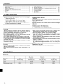 2
2
-
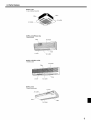 3
3
-
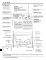 4
4
-
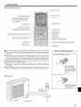 5
5
-
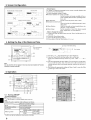 6
6
-
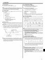 7
7
-
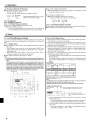 8
8
-
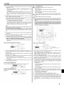 9
9
-
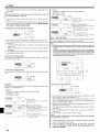 10
10
-
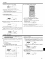 11
11
-
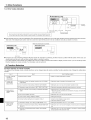 12
12
-
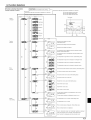 13
13
-
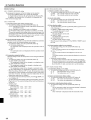 14
14
-
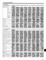 15
15
-
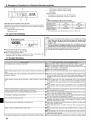 16
16
-
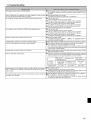 17
17
-
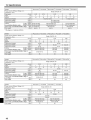 18
18
-
 19
19
-
 20
20
-
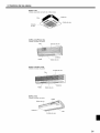 21
21
-
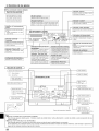 22
22
-
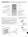 23
23
-
 24
24
-
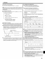 25
25
-
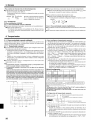 26
26
-
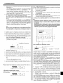 27
27
-
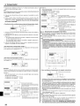 28
28
-
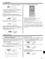 29
29
-
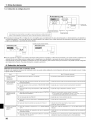 30
30
-
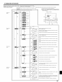 31
31
-
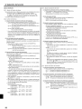 32
32
-
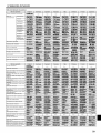 33
33
-
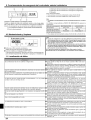 34
34
-
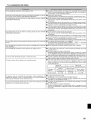 35
35
-
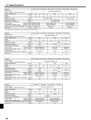 36
36
-
 37
37


Mitsubishi PCA-A24GA El manual del propietario
- Tipo
- El manual del propietario
en otros idiomas
- English: Mitsubishi PCA-A24GA Owner's manual
Artículos relacionados
Otros documentos
-
Mitsubishi Electric PAR-21MAA Instruction book
-
Panasonic S71KA1E5 Instrucciones de operación
-
mundoclima MUCNR-HLM “MultiSplit Console type” El manual del propietario
-
Mitsubishi Electronics PKA-AFA Manual de usuario
-
Friedrich C24YF Manual de usuario
-
Fujitsu UTB-UUB Manual de usuario
-
-
Mitsubishi Electric PUY-A12NKA7 Manual de usuario
-
-
Mitsubishi Electric PLA-A42EA7 El manual del propietario