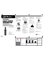
Orbit WaterMaster Voyager Guía de instalación
- Tipo
- Guía de instalación

READ ALL INSTRUCTIONS
PRIOR TO INSTALLATION
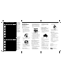
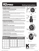
Set the Pattern
Before Installation
The Voyager can be set to rotate
between 40° and 360° (preset at 180°)
1. Turn the top of the head all the
way to the left until it stops and
then all the way to the right. This
is the starting point for the rotation
(Figure 1).
2. Insert a flat bladed screwdriver
into the pattern adjustment screw
(Figure 2).
3. Turn clockwise to increase rota-
tion; counterclockwise to decrease
rotation. Each full turn increases/
decreases rotation by 90˚.
Head Installation
1. Flush sprinkler lines.
2. Thread the sprinkler onto a riser
and set the head flush with the
finished turf height (Figure 3).
Note: DO NOT use pipe dope on the
threads. If necessary, use thread
seal tape.
3. Unscrew the cap and remove the
sprinkler stem from the canister—
be careful of debris falling in canis-
ter.
4. Position the sprinkler stem so that
the arrow points to the right edge
of the rotation.
5. Slide the sprinkler stem back into
the canister and tighten the cap.
Set the Spray Distance
After Installation
Set with water on under system’s nor-
mal operating pressure.
Note: Preinstalled nozzle (# 7) adjusts
from 25 ft. to 45 ft. depending on sys-
tem water pressure.
1. Insert a small flat bladed screw-
driver key into the distance adjust-
ment slot (Figure 2).
2. Turn clockwise to decrease
distance; counterclockwise to
increase distance.
Caution: DO NOT turn the adjust-
ment screw too far in either
direction—screw may come free
of threads.
Replace the Nozzle
See Nozzle Specs for other distance
ranges and replace the nozzle if
needed.
1. To access to the nozzle, insert a
flat blade screwdriver into the lift-
ing socket and lift upward (Figure
4)
2. Firmly grip the sprinkler stem—
Note: the spring inside the canister
is very strong.
3. Insert a small flat bladed screw-
driver into the distance adjustment
slot..
4. Turn the screw counterclockwise
until it is just clear of the nozzle.
Caution: DO NOT turn the adjust-
ment screw too far in either
direction—screw may come free
of threads.
5. Use pliers to grip the “ears” of the
nozzle and pull it out.
6. Insert the replacement nozzle with
the ears on top and turn the screw
back into place (Figure 5).
7. Adjust distance if necessary (see
Set the Spray Distance).
Clean the Filter
1. Remove grass and dirt around the
sprinkler head so you can see the
top 1 ½ in.
2. Unscrew the cap and remove the
stem assembly.
3. Use pliers to extract the filter from
the bottom of the stem assembly.
4. Clean out debris and replace filter.
5. Replace the stem assembly to the
sprinkler body and screw tightly.
p 801 295 9820
f 801 951 5815
www.fluid-studio.net
1065 South 500 West
Bountiful, Utah 84010
proof no: 8
date:
10.02.08
des: SM spck: XX
job no: NA
client: Orbit
sku: 55461
upc: NA
file name: 55461-24 rB.indd
software: InDesign CS3
colors
additional instructions:
· Translation Proofing code: LB403717
·
color
non printing
PMS
????
PMS
????
color
non printing
PMS
????
Registration
K
Printers are responsible for
meeting print production
requirements. Any changes
must be approved by the
client and Fluid Studio.
printed piece must meet
designated specifications
on this form.
dimensions:
flat: w: 11.25" h: 5.5"
finished (folded): w 3.75" d: 0" h 5.5"
© 2007 Fluid Studio. This
work is the property of Fluid
Studio, and cannot be used,
reproduced or distributed
in any way without their
express permission.
Voyager
®
gear DriVe
Sprinkler
Aspersor de
trAnsmisión por
engrAnAjes VoyAger
®
Orbit
®
Irrigation Products, Inc.
North Salt Lake, Utah 84054 USA
1-800-488-6156
www.orbitonline.com
© 2008 Orbit
®
Irrigation Products, Inc.
All rights reserved. All trade names are registered
trademarks of respective manufacturers listed.
ENGLISH
Figure 1
Figure 4
Figure 3
O r b i t
®
Figure 2
Pattern
adjustment
slot
Distance
adjustment
slot
Figure 5
PN 55461-24 Rev B
CAUTION
n
For outdoor use with cold water only.
n
Do not spray near electrical
connections.
CUSTOMER SERVICE
1-800-488-6156
www.orbitonline.com
No Special Key Required
No se requiere llave especial

ESPAÑOL
LOW ANGLE NOZZLES · BOQUILLAS DE ÁNGULO BAJO
Nozzle
Pressure
PSI
Radius
ft.
Flow
GPM
Precip in/hr.
L1
30 21 1.2 0.52 0.61
40 24 1.4 0.47 0.54
50 26 1.7 0.48 0.56
60 28 1.8 0.44 0.51
L2
30 28 1.8 0.44 0.51
40 32 2.1 0.39 0.46
50 34 2.4 0.40 0.46
60 36 2.5 0.37 0.43
L3
30 33 2.9 0.51 0.59
40 37 3.4 0.48 0.55
50 39 3.9 0.49 0.57
60 40 4.1 0.49 0.57
L4
30 32 3.8 0.71 0.83
40 35 4.4 0.69 0.80
50 37 5.0 0.70 0.81
60 39 5.4 0.68 0.79
STANDARD NOZZLES · BOQUILLAS ESTÁNDAR
Nozzle
Pressure
PSI
Radius
ft.
Flow
GPM
Precip in/hr.
1
30 27 0.8 0.21 0.24
40 28 1.1 0.27 0.31
50 29 1.2 0.27 0.32
60 29 1.3 0.30 0.34
2
30 35 1.5 0.24 0.27
40 38 1.7 0.23 0.26
50 38 2.0 0.27 0.31
60 39 2.1 0.27 0.31
4
30 39 3.4 0.43 0.50
40 42 3.9 0.43 0.49
50 44 4.5 0.45 0.52
60 44 4.8 0.48 0.55
7
Preinstalled
30 36 2.6 0.19 0.20
40 40 3.0 0.18 0.21
50 42 3.4 0.19 0.21
60 42 3.7 0.20 0.23
8
30 48 7.7 0.64 0.74
40 50 9.0 0.69 0.80
50 52 9.8 0.70 0.81
60 55 10.0 0.64 0.74
n s
n s
Note: All precipitation
rates calculated for
180 degree operation.
For the precipitation
rate for a 360 degree
sprinkler, divide by 2.
n Denotes square
spacing.
s Denotes
equilateral triangular
spacing.
Data represent test
results in zero wind.
Adjust for local
conditions.
Radius can be
reduced by up to 30%
with nozzle retaining
screw. (This may alter
the uniformity of the
spray pattern.)
Nota: Todas las tasas
de precipitación están
calculadas para un
funcionamiento a
180º. Para la tasa de
precipitación de un
aspersor de 360º,
divida por 2.
n Indica el área de
riego cuadrada.
s Indica el área de
riego triangular.
Los datos representan
los resultados
de la prueba sin
condiciones de viento.
Realice los ajustes
para las condiciones
locales.
El radio se puede
reducir en hasta
30% con el tornillo
de retención de la
boquilla. (Esto puede
alterar la uniformidad
del patrón de
aspersión).
LEA TODAS LAS
INSTRUCCIONES ANTES
DE LA INSTALACIÓN
Ajuste del patrón antes
de la instalación
Voyager se puede ajustar en giros
entre 40° y 360° (predeterminado en
180°)
1. Gire completamente la parte
superior del cabezal hacia la
izquierda hasta que se detenga y
luego hacia la derecha. Éste será
el punto de inicio de la rotación
(Figura 1).
2. Inserte un destornillador de paleta
en el tornillo de ajuste de patrón
(Figura 2)
3. Gire hacia la derecha para
aumentar la rotación y hacia la
izquierda para disminuirla. Cada
giro completo aumenta/disminuye
la rotación en 90º.
Instalación del cabezal
1. Purgue las tuberías del aspersor.
2. Rosque el aspersor en el tubo y
ajuste el cabezal al ras con la altura
del césped cortado (Figura 3).
Nota: NO use grasa para tuberías
en las roscas. Si fuese necesario,
utilice cinta adhesiva aislante para
roscas.
3. Desatornille la tapa y saque
el vástago del aspersor del
receptáculo; tenga cuidado de que
no caigan desechos dentro de éste.
4. Ubique el vástago del aspersor de
modo que la flecha apunte hacia el
borde derecho de rotación.
5. Coloque el vástago del aspersor
nuevamente en el receptáculo y
apriete la tapa.
Ajuste de la distancia de aspersión
después de la instalación
Ajuste con el agua corriendo a una
presión operativa normal del sistema.
Nota: La boquilla preinstalada
(Nº 7) se ajusta de 7,6 m a 13,7 m
dependiendo de la presión de agua
del sistema.
1. Inserte un destornillador de paleta
pequeño en la ranura de ajusta de
la distancia (Figura 2).
2. Gire hacia la derecha para
aumentar la distancia y hacia la
izquierda para disminuirla.
Precaución: NO gire demasiado
el tornillo de ajuste en ninguna
dirección pues puede salirse de
las roscas.
Reemplazo de la boquilla
Consulte las especificaciones de la
boquilla para obtener información
sobre otras distancias y cómo
reemplazar la boquilla.
1. Para acceder a la boquilla, inserte
un destornillador de paleta en el
casquillo de elevación y jale hacia
arriba (Figura 4)
2. Tome firmemente el vástago del
aspersor.
Nota: el resorte que se encuentra
en el interior del receptáculo es
muy resistente.
3. Inserte un destornillador de paleta
pequeño en la ranura de ajusta de
la distancia.
4. Gire el tornillo hacia la izquierda
hasta soltarlo.
Precaución: NO gire demasiado
el tornillo de ajuste en ninguna
dirección pues puede salirse de
las roscas.
5. Use alicates para tomar las “asas”
de la boquilla y retirarla.
6. Inserte la boquilla de reemplazo
con las asas en la parte superior y
coloque el tornillo nuevamente en
su lugar (Figura 5).
7. Ajuste la distancia si fuese
necesario (consulte Ajuste de la
distancia de aspersión).
Limpieza del filtro
1. Retire el césped y la suciedad
alrededor del cabezal del aspersor
para que la parte superior
sobresalga 3,8 cm.
2. Desatornille la tapa y retire el
conjunto de vástago.
3. Use alicates para sacar el filtro de
la parte inferior del conjunto de
vástago.
4. Elimine los desechos y reemplace
el filtro.
5. Reemplace el conjunto de vástago
en el cuerpo del aspersor y
atornille firmemente.
Figura 1
Figura 4
Figura 3
O r b i t
®
Figura 2
Ranura de
ajuste del
patrón
Ranura de
ajuste de la
distancia
Figura 5
PRECAUCIÓN
n
Para uso en exteriores con agua
fría solamente.
n
No rocíe cerca de conexiones
eléctricas.
CUSTOMER SERVICE
1-800-488-6156
www.orbitonline.com
-
 1
1
-
 2
2


Orbit WaterMaster Voyager Guía de instalación
- Tipo
- Guía de instalación
En otros idiomas
Documentos relacionados
-
Orbit 55070 Instrucciones de operación
-
-
-
-
Orbit 94882 Manual de usuario
-
-
Orbit Irrigation Product 57070 Manual de usuario
-
Otros documentos
-
 Orbit Manufacturing f 801 951 5815 Manual de usuario
-
Rain Bird 3500 Series El manual del propietario
-
 K-Rain 31031-THD Instrucciones de operación
-
Rain Bird AG5 Maxi-Paw Pop-Up Impact Sprinklers El manual del propietario
-
-
 K-Rain 10031 Instrucciones de operación
-
-
-


