SPX FLOW Viking Power Waste Water Pump Manual de usuario
- Tipo
- Manual de usuario

INSTRUCTION MANUAL
ORIGINAL INSTRUCTIONS/TRANSLATION OF ORIGINAL INSTRUCTIONS
READ AND UNDERSTAND THIS MANUAL PRIOR TO OPERATING OR SERVICING THIS
PRODUCT
IB-114 R05 (09/2017)
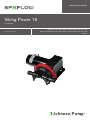
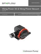
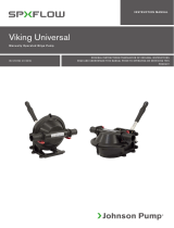
Viking Power 16
12/24 V DC

Recreational Craft Directive 94/25/EEC
ISO8849: 2003 Electrically operated bilge pumps
ISO 8846: 1990/Electrical devices -
Protection against ignition of surrounding flammable gases
EN ISO 10133: 2001/Electrical systems - Extra low-voltage DC installations
Electromagnetic Compatibility Directive 89/336/EEC
EN55014: 2000/Radio Disturbance
Garanti 3 år
Warranty 3 years
Garantie 3 Jahren
Garantie 3 ans
Garantía 3 años
Garanzia 3 anni
Index - Indice
Svenska .....................................................................................................................................3
English ......................................................................................................................................6
Deutsch .....................................................................................................................................9
Français .................................................................................................................................. 13
Español ....................................................................................................................................17
Italiano .................................................................................................................................... 21
Parts List ................................................................................................................................ 25
Accessories ........................................................................................................................... 26
Dimensions .............................................................................................................................27
SE: Besök www.spxflow.com för mer information om vår världsomspännande organisation, våra godkännanden, certifieringar och
lokala representanter. SPX FLOW, Inc. förbehåller sig rätten att ändra design och material utan föregående avisering. Designelement,
konstruktionsmaterial och dimensioner som beskrivs i denna bulletin gäller endast som information och skall alltid bekräftas skriftligt för att
vara gällande.
EN: For more information about our worldwide locations, approvals, certifications, and local representatives, please visit www.spxflow.
com. SPX FLOW, Inc. reserves the right to incorporate our latest design and material changes without notice or obligation. Design
features, materials of construction and dimensional data, as described in this bulletin,
are provided for your information only and should not be relied upon unless confirmed in writing.
DE: Für weitere Informationen über unsere weltweiten Standorte, Zulassungen, Zertifizierungen und unsere Vertreter vor Ort, besuchen
Sie bitte unsere Webseite: www.spxflow.com. Die SPX FLOW, Inc. behält sich das Recht vor, die neuesten Konstruktions- und
Werkstoffänderungen ohne vorherige Ankündigung und ohne Verpflichtung hierzu einfließen zu lassen. Konstruktive Ausgestaltungen,
Werkstoffe sowie Maßangaben, wie sie in dieser Mitteilung beschrieben sind, sind nur zur Information. Alle Angaben sind unverbindlich,
es sei denn, sie wurden schriftlich bestätigt.
FR: Pour plus d’information sur nos succursales internationales, nos approbations, nos certifications et nos représentants locaux, veuillez
consulter notre site Internet au www.spxflow.com. SPX FLOW, Inc. se réserve le droit d’incorporer nos plus récents concepts ainsi
que tout autre modification importante sans préavis ou obligation. Les éléments décoratifs, matériaux de construction et les données
dimensionnelles, tels qu’énoncés dans ce communiqué, sont fournis pour votre information seulement et ne doivent pas être considérés
comme officiels à moins d’avis contraire par écrit.
ES: Para más información sobre nuestras oficinas a nivel mundial, aprobaciones, certificaciones y representantes locales, por favor visite
www.spxflow.com. SPX FLOW, Inc. se reserva el derecho de incorporar nuestro diseño más reciente y cambios materiales sin necesidad
de notificación previa u obligación de ningún tipo. Características de diseño, materiales de construcción y dimensiones, tal y como están
descritas en este boletín, son proporcionadas sólo con fines informativos y no deben ser usados como referencia a menos que sean
confirmados por escrito.
IT: Per ottenere maggiori informazioni sulle nostre sedi nel mondo, autorizzazioni, certificazioni, e rappresentanti locali, potete visitare
il sito www.spxflow.com. La SPX FLOW, Inc. si riserva il diritto di apportare cambiamenti ai propri design e materiali senza preavviso o
vincolo. Le caratteristiche del design, i materiali di costruzione e i dati dimensionali, così come descritti nel presente bollettino, sono
forniti solo per vostra informazione e non saranno oggetto di obbligazione salvo autorizzazione confermata per iscritto.

Recreational Craft Directive 94/25/EEC
ISO8849: 2003 Electrically operated bilge pumps
ISO 8846: 1990/Electrical devices -
Protection against ignition of surrounding flammable gases
EN ISO 10133: 2001/Electrical systems - Extra low-voltage DC installations
Electromagnetic Compatibility Directive 89/336/EEC
EN55014: 2000/Radio Disturbance
Garanti 3 år
Warranty 3 years
Garantie 3 Jahren
Garantie 3 ans
Garantía 3 años
Garanzia 3 anni
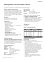
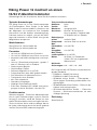
Typiska användningsområden
Viking Power 16 är en membran pump och det
perfekta valet för duschläns, länspumpning och
avfallsvatten. Den kompakta designen och flexibla
konfigurationen gör att pumpen kan installeras i
stort sett var som helst efter avloppet för gråvatten
eller som länspump.
Modeller
Viking Power 16 12V 10-13350-03
Viking Power 16 24V 10-13350-04
Egenskaper
• 16 L/min öppet flöde
• 15 L/min vid 0.1 bar
• Kompakt design
• Snabbanslutningar (1" el. ¾" rak slanganslut-
ning. 90° som tillbehör.)
• Tystgående
• Självsugande upp till 3 m
• Pumphuvudet kan rotera 360°
• Flexibel montering
• Kan torrköras
• Inget filter behövs
• Kullagerstödd kraftöverföring
• Låg strömförbrukning (30W)
• Uppfyller ISO15083 (Small Craft Bilge Pump
standard for boats up to 12 m/40 ft)
Funktionsprincip
Enkammars, självsugande membranpump. För att
uppnå god självsugande förmåga för en filterlös
pump är pumpen designad med ett stort membran
och ett långt slag. På detta sätt spolas mycket
vatten genom pumphuset vid varje slag och på så
sätt spolas smutspartiklar bort.
Teknisk beskrivning
Pumphus: Nylon
Ventil: Nitril
Membran: Armerad nitril
Anslutn.: KlickTite™ XL anslutning
1" el. ¾" rak slanganslutning.
90° som tillbehör.
Skruvar: Rostfritt stål
Fot: Målad galvaniseras plåt
Max. utloppshöjd: 3 m
Max. lyft höjd: 3 m
Max höjd+lyft: 4 m
Motor: 30 W vid 0,1 bar
12/24 V (Inbyggt termoskydd)
Säkring: 8 A – 12V / 4 A – 24V
Pumpen är CE-märkt enl följande standarder:
• EN55014-1:2000/Radiostörningar
• EN55014-2:1997/Radiostörningar
• ISO8846: Båtar – Elkomponenter – Skydd mot
antändning av omgivande brännbara gaser
• ISO8849:2003/Båtar – Elektriska länspumpar
• ISO10133:2001/Båtar – Elektriska system –
Klenspänningsinstallationer för likström
Sprängskiss
Se sidan 25
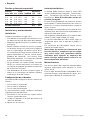
Tryck- och kapacitetsdata
Tryck Flöde Ampere
Bar kPa Psi l/min USGPM 12V 24V
0 0 0 16.2 4.2 2.0 1.0
0.1 10 1.5 15.1 4.0 2.3 1.2
0.2 20 2.9 13.7 3.6 2.8 1.4
0.3 30 4.4 12.5 3.3 3.4 1.7
0.4 40 5.8 11.3 3.0 4.0 1.9
Erforderlig säkring 8 A 4 A
Installation och skötsel
Installation
Montera pumpen i ett torrt utrymme.
• Om pumpen monteras vertikalt ska motorn vara
ovanför pumphuset.
• Märk ut skruvhålen och borra styrhål.
• Montera pumpen med rostfria skruvar, tillsam-
mans med de bifogade brickorna. Kontrollera
att distansbrickorna av plast är rätt placerade.
OBS! Dra inte åt de vibrationsdämpande gum-
mifötterna för hårt, (Skruvarna är för hårt dragna
om pumphuset har kontakt med fästytan).
• Armerad, böjlig slang rekommenderas.
OBS! Backventilerna monteras med den
spetsiga ändan i flödesriktningen. Se
sprängskiss.
• Använd rostfria slangklämmor för att fästa
slangen på snabbanslutningarna och andra
slangar i systemet.
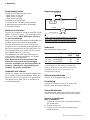
Viking Power 16 med 12/24 V motor
Läs igenom installationsanvisningen noga innan montering av pumpen.
3
Översättning av originalinstruktionerna
> Svenska

Pumpkonfiguration
Pumpen kan konfigureras på 3 sätt:
• Med motorn till vänster
• Med motorn till höger
• Med motorn rakt upp
Konfigureras enligt fäljande:
1. Lossa 6 skruvar som håller pumpen på foten.
2. Montera pumpen med motorn i önskat läge.
3. Fäst de 6 skruvarna.
Elektrisk installation
Pumpen ska installeras i enlighet med ISO 10133
(Båtar - Elektriska system _ klenspänningsinstall-
tioner för likström) OBS! Säkringen ska vara
av gnistskyddad typ.
Motorn har ett termiskt överbelastningsskydd som
skyddar motorn från överhettning. Skyddet
återställs automatiskt när motorn svalnat. Om
pumpen ansluts med separat jordningskabel ska
denna vara gul/grön och anslutas på motorns fot.
Se kopplingsschema (se nedan) för rätt installa-
tion. Negativ ledare ska vara svart.
Välj kabeldimension efter total kabellängd (se
tabell nedan). Kabelanslutningarna ska avtätas
med ett marint tätningsmedel.
Obs: Kontrollera före installation med
elektriska styrsystem att utrustningen
som ska användas har tillräcklig effekt för
motorns strömstyrka. Låg spänning kan
medföra att motorn överhettas.
Underhåll och skötsel
Ventilerna i pumphuset ska rengöras regelbundet
för att undvika reducerad pumpeffekt. Detta görs
genom att skruva loss klämmorna till pumphuset
och öppna huset. OBS! Se till att strömmen är
bruten då detta görs.
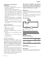
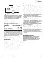
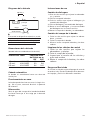
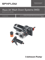
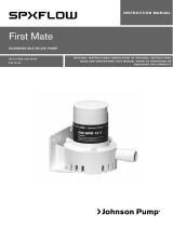
Kopplingsschema
Andra elektriska anordningar, t.ex. strömbry-
tare, reläer ska placeras mellan pump och
batteriets pluspol (+) (på den röda kabeln).
Pump
Terminal
fuse
Max 0.2 m
Red
Black
Green/yellow
Kabelarea
(baserat på 10% spänningsfall)
Kabelarea Max kabellängd* i m
12V 24V
1.0 mm² #18 AWG 13 56
1.5 mm² #16 AWG 20 84
2.5 mm² #14 AWG 34 140
* Kabellängden är det totala avståndet från
batteriet till pumpen och tillbaka till batteriet.
Använd gärna ett relä för att korta av de
strömförande ledarna.
Självsugningsförmåga
Pumpen är självsugande upp till 3 m.
Torrkörning
Pumpen kan torrköras utan att ta skada. Det
kommer dock att reducera batteriet.
Vinterförhållanden
Töm pumpen på vatten genom att pumpa tills den
suger luft och ingen vätska kommer från utloppet.
Service instruktioner
Byte av membran
1. Ta bort de två skruvarna som håller klämmorna
och ta bort dem
2. Ta bort pumphuset
3. Ta bort skruven som håller membranet och
membranbrickan.
4Översättning av originalinstruktionerna
> Svenska

4. Ta bort membranet och membranbrickan.
5. Montera det nya membranet och den nya
membranbrickan med dennya skruven.
6. Montera pumphuset och klämmorna.
Byte av pumphus
1. Ta bort de två skruvarna som håller klämmorna
och ta bort dem
2. Ta bort pumphuset
3. Montera det nya pumphuset och klämmorna.
Rengöring av ventilerna
1. Ta bort de två skruvarna som håller klämmorna
och ta bort dem
2. Ta bort pumphuset
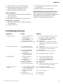
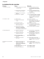
Felsökningsschema
Symptom Orsak Åtgärd
1. Pumpen går inte. 1.1 Utlöst termoskydd eller 1.1.1 Kontrollera säkringen. Låt motorn svalna
defekt säkring. före omstart om den är överhettad.
1.2 Felaktig kabelanslutning 1.2.1 Kontrollera batteriet/strömförsörjning
eller strömkälla. huvudsäkringen och kablar.
1.4 Motorn är ur funktion. 1.4.1 Byt pump
1.5 Pumpen/motoren är frusen. 1.5.1 Tina pumpen och systemet, syna efter
skador. Risk för skada vid start av frusen
pump/motor.
2. Pumpen självsuger inte. 2.1 Vattentanken är tom. 2.1.1 Fyll tanken.
2.2 Smuts under ventilerna. 2.2.1 Öppna pumpen genom att skruva loss de
två skruvarna och rengör ventilerna.
2.3 Perforerat membran. 2.3.1 Byt membran.
2.4 Läckage på pumpens 2.4.1 Kontrollera att slanganslutningarna.
inloppssida.
2.5 Igensättning i in- eller 2.5.1 Kontrollera ledningar och ventiler.
utloppsledningarna
3. Lågt flöde/tryck. 3.1 Läckage i pumpens 3.1.1 Kolla att anslutningarna är täta,
utloppssida. syna slangen avseende skada.
3.2 Läckage i pumpens 3.2.1 Kolla att anslutningarna är täta,
utloppssida. syna slangen avseende skada.
3.3 Perforerat membran. 3.3.1 Byt membran.
3.4 Motorn ur funktion. 3.4.1 Byt pump.
3.5 Smuts under ventilerna. 3.5.1 Öppna pumpen genom att skruva loss de
två skruvarna och rengör ventilerna.
4. Pumpen låter mer än. 4.1 In- eller utlopp är begränsat 4.1.1 Kontrollera rörsystemet
vanligt. Utlopp är begränsat/ för 4.1.2 Kontrollera att ventilerna är öppna.
högt tryck på pumpen
4.2 Pumphuset är löst på 4.2.1 Dra åt skruvarna.
motorn.
4.3 Defekt motor. 4.3.1 Byt pump.
4.4 Defekt strömöverföring 4.4.1 Byt pump.
3. Inspektera gummi beckventilerna och ta bort
ev. skräp/smuts.
4. Montera pumphuset och klämmorna.
Avfallshantering/materialåtervinning
Vid avfallshantering ska produkten lämnas för
destruktion/återvinning enligt gällande lagstiftning.
Vid tillämpliga fall demonteras och sorteras
produkten i ingående materialfraktioner.
5
Översättning av originalinstruktionerna
> Svenska

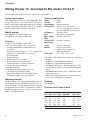
Typical applications
The Viking Power 16 is a single diaphragm DC-
pump. This pump is the ideal choice for shower
drain, waste water and bilge pumping. Its compact
design and flexible orientation give a very adapt-
able mounting and installation in the boat.
Model number
Viking Power 16 12V 10-13350-03
Viking Power 16 24V 10-13350-04
Features
• 16 L/min (4.2 GPM) at open flow
• 15 L/min (4.0 GPM) at 0.1 bar pressure
• Compact and flexible configuration and
installation
• Quick disconnect fittings (1" or ¾" straight hose
connectors included. 90° as accessory.
• Quiet operation
• Smooth flowing
• Self priming to 3 m (10 feet)
• Pump head can be rotated 360°
• Three alternatives to motor orientation
• Dry running without damage
• No filter required
• Ball-bearing supported transmission
• Low power consumption (30W)
• Meets ISO15083 Small Craft Bilge Pump
standard for boats up to 12 m/40 feet
Working principle
Single-chamber, self-priming diaphragm pump. To
obtain good self-prming ability and a filter-less so-
lution, the pump is designed with a large single dia-
phragm and a long stroke. This way a lot of water is
pushed through the valves in each stroke and any
debris is flushed through.
Technical description
Body: Nylon
Valves: Nitrile
Diaphragm: Reinforced nitrile
Connection: KlickTite™ XL connectors
1" or ¾" straight hose connec-
tors included. 90° as accessory
Fasteners: Stainless steel
Fot: Painted zink plated steel
Max. head: 3 meters (10 feet)
Max.
suction lift: 3 meters (10 feet)
Max head
& lift: 4 meters (13 feet)
Motor: 30 W at 1 m head
12/24 V DC (with built-in
thermal protection)
Fuse size: 8 A – 12V / 4 A – 24V
The pump is CE marked according to the following
standards:
• EN55014-1:2000/Radio disturbance
• EN55014-2:1997/Radio disturbance
• ISO8846: Small Craft – Electrical devices – Pro-
tection against ignition of surrounding flammable
gases
• ISO8849:2003/ Small craft – Electrically oper-
ated bilge pumps
• ISO10133: 2001/Small Craft – Electrical systems
– Extra-low voltage DC installations
Drawing
See page 25
Pressure and Capacity data
Pressure Flow Amp. draw
Bar kPa Psi L/min USGPM 12V 24V
0 0 0 16.2 4.2 2.0 1.0
0.1 10 1.5 15.1 4.0 2.3 1.2
0.2 20 2.9 13.7 3.6 2.8 1.4
0.3 30 4.4 12.5 3.3 3.4 1.7
0.4 40 5.8 11.3 3.0 4.0 1.9
Fuse required 8 A 4 A
Viking Power 16 mounted to DC motor 12/24 V
Please follow all instructions before attempting an installation.
6Original instructions
> English

Installation and maintenance
Installation
Locate the pump in a dry location.
• If the pump is mounted vertically, the motor must
be above the pump house
• Mark screw positions and drill pilot holes.
• Mount the pump using stainless steel screws
with the enclosed stainless steel washer. Make
sure that the plastic spacers are in their correct
position. Take care not to over compress the
vibration dampening rubber feet. (The screws
are too tight if the pump house is in contact with
the surface.)
• Reinforced flexible tubing is recommended.
NOTE: The anti-drainback valves are mounted with
the pointed end towards the flow direction. See the
drawing.
• Use stainless steel hose clamps to secure tubing
to quick disconnect fittings and other hose barbs
in the system.
Pump configuration
The pump can be configured in three different
ways:
• With the motor to the left
• With the motor to the right
• With the motor straight up
The set-up can easily be changed by following this
procedure:
1. Unscrew the six screws holding the pump to the
steel foot
2. Set the pump with the motor facing in the
desired direction
3. Fasten the six screws
Electrical installation
The pump must be installed according to ISO
10133 (Small craft – Electrical system – Extra low
voltage DC installation for continuous current).
Note: The fuse must be ignition protected.
The motor is equipped with built in thermal protec-
tion to prevent the motor from overheating. The
protection is automatically restored when the mo-
tor is cooled.
If the pump is connected with separate earth lead,
this should be yellow/green and connected to the
motor base. See the wiring table (next page) for
correct installation. Negative wire must be black.
Choose wire size in accordance with total wire
lenght (see table next page). The wire connections
must be sealed with a marine sealant.
Note: Before installation with electrical
control systems, check that equipment to
be used is of sufficient rated capacity to
accept amperage draw of motor. Low
voltage will cause motor to overheat.
Maintenance
The pumps valves inside the pump house should
be regularly cleared from debris to prevent reduced
performance.
This is done by unscrewing the house clamp
and opening the house. Make sure pump is
disconnected from the power supply.
Wiring diagram
Other electrical devices, eg switch, circuit
breaker, must be installed between the pump
and the positive (+) lead on the battery (on the
red wire).
Pump
Terminal
fuse
Max 0.2 m
Red
Black
Green/yellow
Wiring dimensions
(Based on 10% voltage drop)
Wire size Max wire length* in m
12V 24V
1.0 mm² #18 AWG 13 56
1.5 mm² #16 AWG 20 84
2.5 mm² #14 AWG 34 140
Self-priming
Pump is self-priming up to 3 m/10 feet.
Dry running
The pump can be run dry without any harm. It will
however unnecessary reduce your battery power.
7
Original instructions
> English

Winterizing
Drain the pump from water by pumping it until it
primes air and there is no fluid coming from the
outlet.
Service instructions
Change of diaphragm
1. Remove the two screws that hold the clamps,
and remove the two clamps
2. Remove the pump housing
3. Remove the screw that hold the diaphragm and
the diaphragm washer
4. Remove the diaphragm and the diaphragm
washer
5. Mount the new diaphragm and the new dia-
phragm washer with the new screw
6. Assemble the pump housing and the clamps
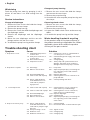
Trouble shooting chart
Symptom Cause Solution
1. Pump does not run. 1.1 Tripped thermal protector 1.1.1 Check fuse. If motor is overheated let it
or blown fuse. cool down prior to restart.
1.2 Faulty wire connection or 1.2.1 Check battery/power supply, main switch
or blown fuse. and wiring._
1.4 Motor malfunctioning. 1.4.1 Change pump._
1.5 Pump/motor frozen. 1.5.1 Thaw pump and system and check for
damage. The pump/ motor is liable to
damage when a frozen pump is started
2. Pump does not prime. 2.1 Tank empty. 2.1.1 Fill up tank.
2.2 Debris in check-valves. 2.2.1 Open the pump body by unscrewing the
two supporting screws and clean the
check-valves.
2.3 Perforated diaphragm. 2.3.1 Replace diaphragm.
2.4 Leak on inlet side of pump. 2.4.1 Check tightness of hose connections at
pump and tank.
2.5 Inlet or outlet plumbing 2.5.1 Check plumbing and valves
restricted.Restriction on
outlet side of pump/too
high pressure.
3. Low flow/pressure. 3.1 Leak on inlet side of pump. 3.1.1 Check tightness of hose connections,
check hose for possible damage
3.2 Leak on outlet side of pump. 6.2.1 Check tightness of hose connections,
check hose for possible damage.
3.3 Perforated diaphragm 3.3.1 Replace diaphragm
3.4 Motor malfunction 3.4.1 Change pump
3.5 Debris in check-valves 3.5.1 Open the pump body by unscrewing the
two supporting screws and clean the
check-valves.
4. Pump is excessively noisy. 4.1 Inlet or outlet plumbing 4.1.1 Check plumbing
restricted. Restriction on 4.1.2 Ensure that valves on inlet/outlet are open
outlet side of pump/too high
pressure.
4.2 Pump mounting is loose. 4.2.1 Tighten screws
4.3 Defective motor 4.3.1 Change pump
4.4 Defective transmission 4.4.1 Change pump
Change of pump housing
1. Remove the two screws that hold the clamps,
and remove the two clamps
2. Remove the pump housing
3. Assemble the new complete pump housing and
the clamps
Cleansing check valves
1. Remove the two screws that hold the clamps,
and remove the clamps
2. Remove the pump housing
3. Inspect the rubber check valves and remove any
debris
4. Assemble the pump housing and the clamps
Waste handling & material recycling
At the products end of life, please dispose of
the product according to applicable law. Where
applicable, please disassemble the product
and recycle the parts material.
8Original instructions
> English

Typische Anwendungen
Die Viking Power 16 ist eine Gleichstrompumpe
mit Einzelmembran. Diese Pumpe ist die ideale
Wahl für den Duschwasserabfluss, Abwasser und
das Abpumpen von Leckwasser. Ihre kompakte
Konstruktion und die flexiblen Anwendungsmög-
lichkeiten machen es möglich, sich bei ihrer Mon-
tage und Installation in einem Schiff sehr gut den
Möglichkeiten anzupassen.
Modellnummer
Viking Power 16 12V 10-13350-03
Viking Power 16 24V 10-13350-04
Parameter
• 16 l/min (4.2 GPM) bei freiem Durchfluss
• 15 l/min (4.0 GPM) bei einem Druck von 0,1 bar
• Kompakte und flexible Konfiguration und Instal-
lation
• inklusive Schnellwechselarmaturen, gerade 1"
oder ¾"-Schlauch. 90° als Zubehör
• Geräuscharmer Betrieb
• Gleichmäßiges Fließen
• Selbstansaugend bis 3 m (10 Fuß)
• Pumpenkopf kann über 360° gedreht werden
• Drei Alternativen für Motorenanschluss
• Trockenlaufen ohne Schaden
• Kein Filter erforderlich
• Getriebe mit Kugellager
• Niedriger Stromverbrauch (30W)
• Erfüllt den Standard ISO 15083 Leckwasser-
pumpen für kleine Schiffe bis 12 m/40 Fuß
Funktionsweise
Selbstansaugende Einkammer-Membranpumpe.
Um ein gutes Selbstansaugen und eine filterlose
Lösung zu erreichen, wurde die Pumpe mit einer
großen Einzelmembran und einem langen Hub kon-
struiert. Auf diese Weise wird eine Menge Wasser
bei jedem Hubvorgang durch die Ventile gedrückt
und alle Schmutzstoffe werden durchgespült.
Technische Beschreibung
Gehäuse: Nylon
Ventile: Nitril
Membran: verstärktes Nitril
Anschluss: KlickTite™ XL-Anschlüsse
inklusive gerade 1"-Schlauch oder
¾"-Schlauch. 90° als Zubehör
Befestigungs-
mittel: rostfreier Stahl
Pumpenfuß: verzinkter Stahl mit Anstrich
Max.
Förderhöhe: 3 m (10 Fuß)
Max.
Saughöhe: 3 m (10 Fuß)
Max. Förder-
und Saughöhe: 4 m (13 Fuß)
Motor: 30 W bei 1 m Förderhöhe
12/24 V DC (mit eingebautem
Wärmeschutz)
Größe der
Sicherungen: 8 A – 12V / 4 A – 24V
Die Pumpe hat das CE-Zeichen entsprechend fol-
genden Standards:
• EN55014-1:2000/Funkstörung
• EN55014-2:1997/ Funkstörung
• ISO8846: Kleine Schiffe – Elektrogeräte –
Schutz gegen Entzündung entflammbarer Um-
gebungsgase
• ISO8849:2003/ Kleine Schiffe – Elektrisch be-
triebene Leckwasserpumpen
• ISO10133:2001/Kleine Schiffe – Elektrische
Systeme – Gleichstrominstallationen mit extra
niedriger Spannung
Zeichnung
Siehe Seite 25
Viking Power 16 montiert an einen
12/24 V-Gleichstrommotor
Bitte befolgen Sie alle Instruktionen, bevor Sie die Installation vornehmen.
9
Übersetzung der Original-Betriebanleitungen
> Deutsch

Druck- und Leistungsparameter
Druck Durchfluss Stromverbrauch
Bar kPa Psi l/min USGPM 12V 24V
0 0 0 16.2 4.2 2.0 1.0
0.1 10 1.5 15.1 4.0 2.3 1.2
0.2 20 2.9 13.7 3.6 2.8 1.4
0.3 30 4.4 12.5 3.3 3.4 1.7
0.4 40 5.8 11.3 3.0 4.0 1.9
Erforderliche Sicherung 8 A 4 A
Installation und Wartung
Installation
Anordnung der Pumpe an einer trockenen Stelle
• Falls die Pumpe vertikal montiert ist, muss sich
der Motor über dem Pumpengehäuse befinden
• Markieren Sie die Schraubenpositionen und
bohren Sie Löcher
• Montieren Sie die Pumpe mit Schrauben aus
rostfreiem Stahl und den beigelegten Unter-
legscheiben aus rostfreiem Stahl. Vergewissern
Sie sich, dass die Abstandshalter aus Plastik an
der richtigen Position sind. Drücken Sie nicht zu
sehr auf die Gummifüßchen für die Vibrations-
dämpfung. (Die Schrauben sind zu fest, wenn
das Pumpengehäuse mit der Fläche in Berüh-
rung kommt.)
• Es werden verstärkte flexible Rohre empfohlen.
ANMERKUNG: Die Rückschlagventile werden
mit spitzem Ende in der Flussrichtung angebaut.
Siehe Zeichnung.
• Benutzen Sie Schlauchschellen aus rostfreiem
Stahl, um die Rohre an den Schnellwechselar-
maturen zu befestigen sowie andere Schlauch-
befestigungen im System.
Bauform der Pumpe
Die Pumpe kann dreierlei Bauformen haben:
• Mit dem Motor auf der linken Seite
• Mit dem Motor auf der rechten Seite
• Mit dem Motor nach oben
Die Einstellung kann auf diese Weise leicht geän-
dert werden:
1. Lösen Sie die sechs Schrauben, die die Pumpe
am Stahlfuß halten
2. Setzen Sie die Pumpe so, dass der Motor in die
gewünschte Richtung zeigt
3. Ziehen Sie die sechs Schrauben wieder fest
Elektroinstallation
Die Pumpe muss gemäß ISO 10133 (Kleine
Schiffe – Elektrische Systeme – Gleichstrominstal-
lation mit extra niedriger Spannung) installiert wer-
den. Anmerkung: Die Sicherung muss einen
Zündschutz auf-weisen.
Der Motor ist mit einem eingebauten Wärmeschutz
ausgestattet, um ihn vor Überhitzung zu schützen.
Der Schutz wird automatisch wiederhergestellt,
wenn der Motor sich abgekühlt hat.
Ist die Pumpe an eine separate Erdleitung ange-
schlossen, so muss diese gelb/grün sein und mit
dem Motorunterbau verbunden sein.
Siehe die Verdrahtungstabelle (nächste Seite) zur
richtigen Installation. Der negative Draht muss
schwarz sein.
Wählen Sie den Drahtdurchmesser entsprechend
der Gesamtlänge des Drahtes (siehe Tabelle näch-
ste Seite).
Die Drahtanschlüsse sind mit Bootsabdichter ab-
zudichten.
Anmerkung: Prüfen Sie vor dem Anschluss
an elektrische Steuersysteme, dass die zu
verwendende Ausrüstung genügend Nenn-
leistung hat, um das Abziehen des Stroms
vom Motor ausführen zu können. Durch zu
niedrige Spannung wird der Motor überhitzt.
Wartung
Die Pumpenventile im Pumpengehäuse sind regel-
mäßig von Schmutzteilchen zu befreien, damit eine
reduzierte Leistung verhindert wird.
Dies erfolgt durch Lösen der Gehäuse-klemme und
Öffnen des Gehäuses. Vergewissern sie sich, dass
die Pumpe von der Stromzufuhr getrennt wurde.
Verdrahtungsdiagramm
10 Übersetzung der Original-Betriebanleitungen
> Deutsch

Weitere elektrische Komponenten, z .B. Schalter
und Sicherungsautomat, müssen zwischen der
Pumpe und der positiven (+) Klemme der Bat-
terie (am roten Kabel) installiert werden.
Pumpe
Haupt-
sicherung
Max 0,2 m
Rot
Schwarz
Grün/gelb
Drahtabmessungen
(basierend auf 10% Spannungsabfall)
Drahtgröße Max. Drahtlänge * in
m
12V 24V
1.0 mm² #18 AWG 13 56
1.5 mm² #16 AWG 20 84
2.5 mm² #14 AWG 34 140
* Die Länge des Drahtes ist der Gesamtabstand
von der Batterie zur Pumpe und zurück zur Bat-
terie. Es wird empfohlen, ein Relais mit einem
Lichtdraht vom Hauptkabel zu verwenden, um die
Hauptanschlussleitungen zu verkürzen.
Selbstansaugung
Die Pumpe ist selbstansaugend bis 3 m/10 Fuß.
Trockenlaufen
Die Pumpe kann trockenlaufen, ohne dass sie be-
schädigt wird. Das reduziert jedoch unnötig die
Kraft Ihrer Batterie.
Winterfestmachung
Lassen Sie das Wasser aus der Pumpe ab, indem
sie es abpumpen, bis sie Luft ansaugt und keine
Flüssigkeit mehr aus dem Auslass kommt.
Serviceanweisungen
Austausch der Blende
1. Entfernen Sie die beiden Schrauben, die die
Schellen halten und entfernen Sie die beiden
Schellen
2. Nehmen Sie das Pumpengehäuse ab
3. Entfernen Sie die Schraube, die die Blende hält
sowie die Unterlegscheibe der Blende
4. Nehmen Sie die Blende und die Unterlegscheibe
der Blende heraus
5. Montieren Sie die neue Blende und die neue Un-
terlegscheibe mit der neuen Schraube
6. Montieren Sie das Pumpengehäuse und die
Schellen
Austausch des Pumpengehäuses
1. Entfernen Sie die beiden Schrauben, die die
Schellen halten und entfernen Sie die Schellen
2. Nehmen Sie das Pumpengehäuse ab
3. Montieren Sie das neue komplette Pumpenge-
häuse und die Schellen
Reinigen der Rückschlagventile
1. Entfernen Sie die beiden Schrauben, die die
Schellen halten und entfernen Sie die Schellen
2. Nehmen Sie das Pumpengehäuse ab
3. Inspizieren sie die Gummi-Rückschlagventile
und entfernen Sie jegliche Schmutzteilchen
4. Montieren Sie das Pumpengehäuse und die
Schellen
Entsorgung/Recycling
Nach Lebensdauerende entsorgen Sie die
Pumpe nach den örtlichen Vorschriften.
Nach Möglichkeit demontieren Sie Teile der
Pumpe um sie dem Recycling-Process zu-
zuführen.
11
Übersetzung der Original-Betriebanleitungen
> Deutsch

Liste zur Fehlersuche
Symptom Ursache Lösung
1. Pumpe läuft nicht. 1.1 Wärmeschutz hat ausgelöst 1.1.1 Sicherung prüfen. Ist der Motor überhitzt,
oder Sicherung ist durch- lassen Sie ihn abkühlen, bevor er wieder
gebrannt gestartet wird.
1.2 Falscher Drahtanschluss 1.2.1 Batterie/Stromquelle, Hauptschalter und
oder falsche Stromquelle Verdrahtung prüfen.
1.4 Fehlerhafter Betrieb 1.4.1 Pumpe auswechseln.
des Motors
1.5 Pumpe/Motor eingefroren. 1.5.1 Pumpe und System auftauen und auf
Schäden überprüfen. Pumpe/ Motor
werden beschädigt, wenn eine eingefrorene
Pumpe gestartet wird
2. Pumpe saugt nicht an. 2.1 Tank leer. 2.1.1 Tank befüllen.
2.2 Schmutz im Rückschlag- 2.2.1 Pumpengehäuse durch Lösen der zwei
ventil. Halteschrauben öffnen und Rückschlag-
ventile reinigen.
2.3 Perforierte Blende. 2.3.1 Blende austauschen.
2.4 Leck an der Einlaßseite 2.4.1 Dichtheit der Schlauchan-schlüsse an
der Pumpe. Pumpe und Tank überprüfen.
2.5 Installieren des Einlasses 2.5.1 Installation und Ventile prüfen
und Auslasses eingeschränkt.
Einschränkung auf Auslaß-
seite der Pumpe/zu hoher Druck.
3. Niedriger Durchfluss/Druck. 3.1 Leck auf der Einlaßseite 3.1.1 Dichtheit der Schlauchan-schlüsse
der Pumpe. überprüfen, Schlauch auf mögliche
Beschädigung prüfen
3.2 Leck auf der Auslaßseite 3.2.1 Dichtheit der Schlauchan-schlüsse
der Pumpe. überprüfen, Schlauch auf mögliche
Beschädigung prüfen
3.3 Perforierte Blende 3.3.1 Blende austauschen
3.4 Fehlerhafter Betrieb 3.4.1 Pumpe austauschen
des Motors
3.5 Schmutz in den Rückschlag- 3.5.1 Öffnen des Pumpengehäuses durch Lösen
ventilen der zwei Halteschrauben und Reinigen der
Rückschlagventile.
4. Pumpe ist übermäßig laut. 4.1 Einlass- oder Auslass- 4.1.1 Installation überprüfen
installation eingeschränkt. 4.1.2 Sicherstellen, dass die Ventile am Einlaß/
Ein-schränkung an der Auslaß geöffnet sind
Auslaßseite der Pumpe/
zu hoher Druck.
4.2 Pumpenhalterung ist lose. 4.2.1 Schrauben festziehen
4.3 Motor defekt 4.3.1 Pumpe auswechseln
4.4 Getriebe defekt 4.4.1 Pumpe auswechseln
12 Übersetzung der Original-Betriebanleitungen
> Deutsch

Applications standard
La Viking Power 16 est une pompe CC à membrane
unique. Ce produit est la solution idéale comme
pompe de vidange de bac à douche, d’évacuation
des eaux usées et d’assèchement de la cale. Son
volume compact et ses possibilités d’orientation
multiples, lui permettent une installation aisée.
Référence produit
Viking Power 16 12 V 10-13350-03
Viking Power 16 24 V 10-13350-04
Caractéristiques
• 16 l/min (4.2 GPM) en écoulement libre
• 15 l/min (4 GPM) à 0,1 bar de pression
• Configuration et Installation compacte et souple
• Raccord à déconnexion rapide tuyau 1" ou ¾"
droit fourni (raccord 90° livré en option)
• Fonctionnement silencieux
• Débit régulier
• Autoamorçante jusqu’à 3 mètres (10 pieds)
• Tête de pompe orientable sur 360°
• Trois orientations différentes du moteur
• Fonctionnement à sec sans dommages
• Aucun filtre nécessaire
• Transmission sur roulement à billes
• Faible consommation électrique (30 W)
• Conforme à la norme ISO 15083 sur les pompes
de cale pour bateaux jusqu’à 12 m (40’).
Principe de fonctionnement
Pompe à membrane autoamorçante à chambre
unique. Sa longue amplitude et son grand di-
aphragme permettent à la pompe de bonne qua-
lités d’amorçage.
L’utilisation d’un filtre n’est pas nécessaire grâce au
debit qui rince les clapets à chaque cycle.
Description technique
Corps : Nylon
Clapets : Nitrile
Membrane : Nitrile renforcé
Connexion : Connecteurs KlickTite™ XL
pour Tuyau 1" ou ¾" droit fourni
d’origine (coudé à 90° fourni en
option)
Fixations : Acier inoxydable
Embase: Acier zingué peint
Refoulement
maxi : 3 m (10’)
Aspiration
maxi : 3 m (10’)
Aspiration et refoule-
ment maxi : 4 m (13’)
Consommation
moteur : 30 W avec refoulement à 1 m,
Tension d’alimentation 12
ou 24 V CC (avec disjoncteur
thermique intégré)
Calibre du
fusible : 8 A – 12 V / 4 A – 24 V
La pompe est estampillée CE conformément aux
normes suivantes :
• EN55014-1 :2000/Perturbation Radioélec-
trique
• EN55014-2 :1997/Perturbation Radioélec-
trique
• ISO8846 :Petit bateau – Appareils Électriques
- Protection contre l’inflammation des gaz
ambiants
• ISO8849 :2003/Petit bateau – Pompes de
cale électriques
• ISO10133:2001/Petit bateau – Systèmes élec-
triques - Installation d’accessoires à très basse
tension CC
Schéma
Voir page 25
Viking Power 16 monté sur moteur 12/4 V CC
Veuillez lire attentivement le manuel avant d’entreprendre l’installation.
13
Traduction du manuel d'instruction d'origine
> Français

Données de pression et de capacité
Pression Débit Consommation
électrique(A)
Bars kPa Psi L/min USGPM 12 V 24 V
0 0 0 16,2 4,2 2 1
0,1 10 1,5 15,1 4 2,3 1,2
0,2 20 2,9 13,7 3,6 2,8 1,4
0,3 30 4,4 12,5 3,3 3,4 1,7
0,4 40 5,8 11,3 3 4 1,9
Fusible 8 A 4 A
Installation et entretien
Installation
Installez la pompe à un endroit sec.
• Si la pompe est installée verticalement, le mo-
teur doit être en haut
• Marquez la position des vis et percez des avant-
trous.
• Fixez la pompe à l’aide de vis en acier inoxydable
avec les rondelles en acier inoxydable fournies.
Vérifiez que les entretoises en plastique sont
correctement positionnées. Veillez à ne pas
comprimer exagérément les pieds anti-vibra-
tions en caoutchouc. (Les vis sont serrées si le
corps de pompe est en contact avec la surface
de montage.)
• Il est recommandé d’utiliser des tuyaux souples
haute pression.
REMARQUE: Les clapets anti-retour sont ins-
tallés avec l’extrémité conique dans la direction
du flux. Voir le plan.
• Utilisez des colliers de serrage en acier inoxy-
dable pour fixer la tuyauterie aux raccords à
déconnexion rapide et autres raccords cannelés
du système.
Montage de la pompe
La pompe peut être montée de trois manières
différentes :
• Avec le moteur à gauche
• Avec le moteur à droite
• Avec le moteur en haut
L’orientation est facilement modifiable comme indi-
qué ci-après :
1. Dévissez les six vis fixant la pompe au support
en acier
2. Placez la pompe avec le moteur orienté dans la
direction voulue
3. Reposez les six vis
Raccordement électrique
La pompe doit être installée en conformité à la
norme ISO 10133 (Petit bateau – Réseaux élec-
triques – Installation d’appareil très basse tension
en courant continu).
Remarque : Le fusible doit être antidéfla-
grant.
Pour éviter les risques de surchauffe, le moteur
est équipé d’un disjoncteur thermique intégré. La
protection est automatiquement réarmée quand le
moteur refroidit.
Si vous raccordez la pompe à la masse par un
câble séparé, utilisez un câble jaune/vert connecté
à l’embase du moteur.
Pour une installation correcte, veuillez respecter
le schéma de câblage (voir page suivante). Le fil
négatif doit être noir.
Sélectionnez la section des câbles en fonction de
la longueur totale de câblage (voir tableau en page
suivante).
Les connexions des fils doivent être protégées par
un mastic d’étanchéité marine.
Remarque : Avant d’entreprendre l’instal-
lation avec des systèmes de commandes
électriques, vérifiez que l’équipement prévu
a une capacité en ampères suffisante pour
supporter la consommation électrique du
moteur. Une tension trop faible peut provo-
quer la surchauffe du moteur.
Entretien
Pour garantir la durée dde vie de la pompe, éliminez
régulièrement les débris et salissures accumulés
sur les clapets à l’intérieur de la pompe.
Pour ce faire, desserrez le collier de fermeture
du corps de pompe et ouvrez le boîtier. Veillez à
déconnecter l’alimentation électrique de la pompe.
14 Traduction du manuel d'instruction d'origine
> Français

Schéma de câblage
Les autres équipements électriques, comme
un coupe-cirucit, doivent être installés entre
la pompe et le fil positif (+) de la batterie (sur
le fil rouge).
Pompe
Fusible
principal
Maxi. 0,2 m
Rouge
Noir
Vert/jaune
Calibre des fils
(basé sur la base d’une chute de tension de 10%)
Section des fils Longueur maxi
*des fils en m
AWG 12 V 24 V
1 mm² n° 18 13 56
1,5 mm² n° 16 20 84
2,5 mm² n° 14 34 140
Autoamorçante
La pompe est autoamorçante jusqu’à une hauteur
d’aspiration de 3 m (10’).
Fonctionnement à sec
La pompe peut fonctionner à sec sans risque d’être
endommagée.
Hivernage
Vidangez la pompe en la faisant fonctionner jusqu’à
ce qu’elle aspire de l’air et qu’aucun liquide n’en
sorte plus.
Consignes de réparation
Remplacement de la membrane
1. Déposez les deux vis de fixation des colliers, et
déposez les deux colliers
2. Déposez le corps de pompe
3. Déposez les vis de fixation de la membrane et de
la rondelle de membrane
4. Déposez la membrane et la rondelle de la mem-
brane
5. Fixez la membrane et la rondelle neuves avec les
nouvelles vis
6. Remontez le corps de pompe et les colliers
Remplacement du corps de pompe
1. Déposez les deux vis de fixation des colliers, et
déposez les deux colliers
2. Déposez le corps de pompe
3. Remontez le nouveau corps de pompe complet
et les colliers
Nettoyage du clapet anti-retour
1. Déposez les deux vis de fixation des colliers et
déposez les deux colliers
2. Déposez le corps de pompe
3. Inspectez les clapets en caoutchouc et éliminez
tout débris
4. Remontez le corps de pompe et les colliers.
Gestion des déchets/recyclage des
matériaux
Lorsque le matériel arrivera en fin de vie,
veuillez le mettre au rebut en fonction des lois
applicables. Lorsque c’est possible, veuillez
démonter le matériel et recycler les pièces
pouvant l’être.
15
Traduction du manuel d'instruction d'origine
> Français

Diagramme de dépannage rapide
Symptôme Cause Solution
1. La pompe ne fonctionne pas. 1.1 Disjoncteur thermique 1.1.1 Vérifiez le fusible. Si le moteur est
ouvert ou fusible sauté. en surchauffe, laissez-le refroidir
avant de redémarrer la pompe.
1.2 Connexion électrique ou 1.2.1 Vérifiez la batterie ou l’alimenta-
alimentation défectueuse tion, l’interrupteur général et le
câblage.
1.4 Dysfonctionnement du moteur. 1.4.1 Remplacez la pompe.
1.5 Pompe ou moteur gelé. 1.5.1 Dégelez la pompe et le système et
recherchez puis réparez les éven-
tuels dégâts du gel. Le démarrage
d’une pompe gelée peut endom-
mager la pompe et/ou le moteur
2. La pompe ne s’amorce pas. 2.1 Réservoir vide. 2.1.1 Remplissez le réservoir.
2.2 Débris dans les clapets. 2.2.1 Ouvrez le corps de pompe en
dévissant les deux vis de fixation
et nettoyez les clapets.
2.3 Membrane perforée. 2.3.1 Remplacez la membrane.
2.4 Fuite à l’entrée de la pompe. 2.4.1 Vérifiez que les connexions du
tuyau à la pompe et au réservoir
sont correctement serrées.
2.5 Tuyauterie d’aspiration ou de 2.5.1 Vérifiez la tuyauterie et les clapets
refoulement étranglée.
Etranglement sur le refoulement
de la pompe/pression trop forte.
3. Débit ou pression faible. 3.1 Fuite à l’aspiration. 3.1.1 Vérifiez l’étanchéité des raccorde-
ments du tuyau et recherchez
d’éventuels signe de dégradation
3.2 Fuite au refoulement. 3.2.1 Vérifiez l’étanchéité des raccorde-
ments du tuyau et recherchez
d’éventuels signe de dégradation.
3.3 Membrane perforée 3.3.1 Remplacez la membrane
3.4 Dysfonctionnement du moteur 3.4.1 Remplacez la pompe
3.5 Débris dans les clapets 3.5.1 Ouvrez le corps de pompe en
dévissant les deux vis de fixation
et nettoyez les clapets.
4. Pompe excessivement bruyante. 4.1 Tuyauterie d’aspiration ou de 4.1.1 Contrôlez la tuyauterie
refoulement étranglée. 4.1.2 Vérifiez que les clapets d’aspira-
Etranglement au refoulement/ tion et de refoulement s’ouvrent
pression trop forte. correctement
4.2 La fixation de la pompe 4.2.1 resserrez les vis
est desserrée.
4.3 Moteur défectueux 4.3.1 Remplacez la pompe
4.4 Transmission défectueuse 4.4.1 Remplacez la pompe
16 Traduction du manuel d'instruction d'origine
> Français

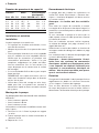
Aplicaciones típicas
La Viking Power 16 es una bomba de diafragma
simple de corriente continua (CC). Esta bomba es
la opción ideal para achicar la ducha, las aguas re-
siduales y la sentina. Su diseño compacto y orien-
tación flexible facilita el montaje e instalación en el
barco.
Número de modelo
Viking Power 16 12V 10-13350-03
Viking Power 16 24V 10-13350-04
Características
• 16 L/min (4.2 GPM) a cuadal abierto
• 15 L/min (4.0 GPM) a 0.1 baro de presión
• Instalación y configuración compacta y flexible
• Racores rectos de abertura rápida (1" ó ¾" tubo
flexible incluidos. 90° como accesorio).
• Funcionamiento silencioso
• Caudal fluido
• Autocebante hasta 3 metros (10 pies)
• La cabeza de bomba puede girarse en 360°.
• Tres orientaciones alternativas del motor.
• Funcionamiento en seco sin daños
• Filtro no necesario
• Cojinete de bolas de apoyo de transmisión
• Bajo consumo (30W)
• Cumple con la norma de calidad ISO15083: Pe-
queñas embarcaciones. Bombas de sentina para
barcos de más de 12m/40 pies.
Principio de trabajo
Bomba autocebante, de diafragma con simple cá-
mara.
Para conseguir una buena capacidad de cebado en
una solución sin filtro, la bomba esta diseñada con
una gran membrana y de desplazamiento largo. De
esta manera, una gran cuantidad de agua es expul-
sada por las válvulas a cada revolución, deshacién-
dose a su vez de cualquier residuo.
Descripción técnica
Cuerpo: Nilón
Válvulas: Nitrilo
Diafragma: Nitrilo reforzado
Conexión: Conectores KlickTite™
Tubo flexible 1” o tubo flexi-
ble 3/4” recto incluido. 90° como
accesorio.
Cierres: Acero inoxidable
Pedestal: Acero cincado pintado
Altura de
expulsión máx.: 3 m (10 pies)
Altura de
succión máx.: 3 m (10 pies)
Altura expulsión
+succión máx.: 4 metros (13 pies)
Motor: 30 W a 1 m cabeza
12/24V DC (con protección
térmica incorporada)
Tipo de fusible: 8 A – 12V / 4 A – 24V
La bomba tiene el certificado de conformidad CE
según las normas siguientes:
• EN55014-1:2000/Interferencias de Radio
• EN55014-2:1997/Interferencias de Radio
• ISO8846: Embarcaciones pequeñas _ Equipos
eléctricos _ Protección contra la inflamación de
los ambientes gaseosos inflamables
• ISO8849:2003/Embarcaciones pequeñas _
Bombas de sentina con motor eléctrico
• ISO10133:2001/Embarcaciones pequeñas _
Sistemas eléctricos – Instalaciones de corriente
continua a muy baja tensión.
Esquema
Vea la página 25
Viking Power 16 con motor 12/24 V CC
Por favor siga todas las instrucciones antes de empezar la instalación.
17
Traducción de instrucciones originales
> Español

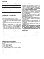
Presión y datos de capacidad
Presión Flujo Amperios
Baro kPa Psi L/min. USG PM 12V 24V
0 0 0 16.2 4.2 2.0 1.0
0.1 10 1.5 15.1 4.0 2.3 1.2
0.2 20 2.9 13.7 3.6 2.8 1.4
0.3 30 4.4 12.5 3.3 3.4 1.7
0.4 40 5.8 11.3 3.0 4.0 1.9
Fusible necesario 8 A 4 A
Instalación y mantenimiento
Instalación
Coloque la bomba en un lugar seco.
• Si la bomba está montada verticalmente, el mo-
tor debe estar encima del cuerpo de la bomba.
• Marque el lugar de los tornillos y taladre los agu-
jeros guías.
• Monte la bomba usando los tornillos y arande-
las de acero inox que se suministran. Asegúrese
que los espaciadores de plástico están pues-
tos correctamente.Tenga mucho cuidado en no
apretar demasiado los pies de caucho amorti-
guadores de vibraciones. (Los tornillos están
demasiado apretados si el cuerpo de la bomba
está en contacto con la superficie.)
• Se recomienda usar tubería flexible reforzada.
NOTA: Las válvulas antirretorno se instalan con
su extremo puntiagudo apuntando en dirección
de la corriente. Ver plano.
• Use abrazaderas de acero inox para sujetar la
tubería a los entronques de apertura rápida y
cualesquiera otros del sistema.
Configuración de la bomba
La bomba puede configurarse de tres maneras di-
ferentes:
• Con el motor a la izquierda
• Con el motor a la derecha
• Con el motor hacia delante
El posicionamiento puede cambiarse fácilmente
siguiendo este procedimiento:
1. Destornille los seis tornillos que sujetan la bom-
ba en el soporte de acero
2. Coloque la bomba con el perfil del motor en la
dirección deseada.
3. Apriete los seis tornillos
Instalación eléctrica
La bomba debe instalarse según la norma ISO
10133 ( Embarcaciones pequeñas _ Sistema eléc-
trico _ Instalaciones de corriente continua a muy
baja tensión). Nota: El fusible debe ser de en-
cendido protegido.
El motor está equipado de una protección térmica
para impedir el sobrecalentamiento del motor. La
protección se rearma automáticamente cuando el
motor se enfría.
Si la bomba está conectada con una toma de tierra
separada, ésta, de color amarillo/verde, deberá co-
nectarse a la base del motor.
Vea la tabla del cableado para una instalación ade-
cuada. El cable negativo debe ser negro.
La sección adecuada del cable variará según la
longitud de aquel (vea la tabla de la página si-
guiente).
Las conexiones de cable deben sellarse con un
material de sellado marino.
Nota: Antes de instalar los sistemas de pro-
tección eléctrica, asegúrese que el equipo
que usará, tenga una capacidad nominal
suficiente para soportar el amperaje del
motor. Un bajo voltaje puede causar el so-
brecalentamiento del motor.
Mantenimiento
Las válvulas dentro del cuerpo de la bomba deben
limpiarse regularmente para mantener su rendi-
miento inicial.
Esto se logra desatornillando la abrazadera de su-
jeción del cuerpo y luego abriendo el cuerpo. Ase-
gúrese que la bomba no esté bajo tensión.
18 Traducción de instrucciones originales
> Español

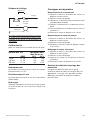
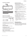
Diagrama del cableado
Dimensiones del cableado
(basado sobre una caída de tensión de 10%)
Tamaño del cable Longitud*máx.
del cable en m
12V 24V
1.0 mm² #18 AWG 13 56
1.5 mm² #16 AWG 20 84
2.5 mm² #14 AWG 34 140
Cebado automático
La bomba es autocebante hasta una altura de
3m/10 pies.
Funcionamiento en seco
La bomba puede funcionar en seco sin ningún ries-
go. No es, pues, necesario disminuir la potencia
de la batería.
Hibernación
Vacíe el agua del cuerpo de la bomba haciéndola
funcionar hasta que el aire salga por la boca de
desagüe.
Instrucciones de uso
Cambio de diafragma
1. Quite los dos tornillos que sujetan las abrazade-
ras, y retírelas.
2. Quite el cuerpo de la bomba
3. Quite los tornillos que sujetan el diafragma y la
arandela del diafragma
4. Quite el diafragma y la arandela del diafragma
5. Monte el nuevo diafragma y la nueva arandela
del diafragma con los nuevos tornillos
6. Monte el cuerpo de la bomba y las abrazaderas
Cambio del cuerpo de la bomba
1. Quite los dos tornillos que sujetan las abraza-
deras, y retírelas.
2. Quite el cuerpo de la bomba
3. Monte el nuevo cuerpo de la bomba y las abra-
zaderas
Limpieza de las válvulas de control
1. Quite los dos tornillos que sujetan las
abrazaderas, y retírelas.
2. Quite el cuerpo de la bomba
3. Inspeccione el caucho de las válvulas y
quite todo residuo
4. Monte el cuerpo de la bomba y las abra-
zaderas
Desguace/Reciclado
Al final de la vida del equipo disponga de este de
acuerdo a la ley. Donde sea de aplicación desmon-
te el equipo y recicle los diferentes materiales.
El resto de los dispositivos eléctricos, es de-
cir, el interruptor, el conmutador de circuito,
deberán instalarse entre la bomba y el polo
positivo de la batería (en el cable rojo).
Bomba
Fusible
principal
Máx 0,2 m
Rojo
Negro
Verde/amarillo
19
Traducción de instrucciones originales
> Español

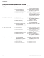
Localización de averías
Síntoma Causa Solución
1. La bomba no funciona. 1.1 Protector térmico desconectado 1.1.1 Controle el fusible. Si el motor
o fusible fundido. está demasiado caliente, déjelo
enfriar antes de volver a poner en
marcha.
1.2 Defecto de las conexiones de 1.2.1 Controle la batería/alimentación
los cables o de la corriente de energía, el interruptor principal
y el cableado.
1.4 Defecto en el funcionamiento 1.4.1 Cambie la bomba
del motor.
1.5 Bomba/motor congelada. 1.5.1 Descongele la bomba y el sistema
y controle si hay daños. La bomba/
motor está sujeta a ciertos daños
cuando se arranca una bomba
congelada.
2. La bomba no ceba. 2.1 Depósito vacio. 2.1.1 Rellene el depósito.
2.2 Residuos en la válvula de 2.2.1 Abra el cuerpo de la bomba
control. desatornillando los dos tornillos de
sujeción y limpie las válvulas de
control.
2.3 Diafragma perforado. 2.3.1 Sustituya el diafragma.
2.4 Fuga en el conducto de a 2.4.1 Controle que las conexiones del
dmisión de la bomba. tubo flexible a la bomba y depósito
estén bien apretadas.
2.5 Obturación del conducto 2.5.1 Controle la tubería y las válvulas
de admisión o de desagüe.
Obturación del desagüe de
la bomba/presión demasiada alta.
3. Caudal bajo/presión. 3.1 Fuga en el conducto de 3.1.1 Controle que las conexiones del
admisión de la bomba. tubo estén sujetas, verifique si el
tubo está dañado.
3.2 Fuga en el conducto de 3.2.1. Controle que las conexiones del
desagüe de la bomba. tubo estén sujetas, verifique si el
tubo está dañado.
3.3 Diafragma perforado. 3.3.1 Sustituya el diafragma.
3.4 Funcionamiento defectuoso 3.4.1 Cambie la bomba
del motor.
3.5 Residuos en las válvulas 3.5.1 Abra el cuerpo de la bomba
de control. desatornillando los dos tornillos de
sujeción y limpie las válvulas de
control.
4. La bomba es excesivamente 4.1 Obturación del conducto de 4.1.1 Controle la tubería
ruidosa. admisión o de desagüe. 4.2.1 Asegúrese que las válvulas de los
Obturación del conducto de conductos admisión/desagüe están
desagüe de la bomba/presión abiertas.
demasiada alta.
4.2 Montaje de la bomba está suelto. 4.2.1 Apriete los tornillos
4.3 Motor defectuoso 4.3.1 Cambie la bomba
4.4 Transmisión defectuosa 4.4.1 Cambie la bomba
20 Traducción de instrucciones originales
> Español

Applicazioni tipiche
La Viking Power 16 è una pompa a diaframma sin-
golo a corrente continua. Questa pompa è la scelta
ideale per le docce, per le acque di scarico e per
il pompaggio di sentina. Il suo design compatto e
l’orientamento flessibile garantiscono un montag-
gio ed una installazione molto adattabili sulla barca.
Numero di modello
Viking Power 16 12V 10-13350-03
Viking Power 16 24V 10-13350-04
Caratteristiche
• 16 Litri/minuto (4.2 GPM) a flusso pieno
• 15 Litri/minuto (4.0 GPM) ad una pressione di
0.1 bar
• Installazione e configurazione compatte e flessi-
bili
• Raccordi a scollegamento rapido (flessibile da
1" o ¾" diritti inclusi. 90° come accessori opzio-
nali
• Funzionamento silenzioso
• Flusso omogeneo
• Auto-adescante a 3 m (10 piedi)
• La testa della pompa può essere ruotata di 360°
• Tre alternative di orientamento del motore
• Funzionamento a secco senza danni
• Nessun filtro necessario
• Trasmissione su cuscinetti a sfera
• Basso consumo di energia (30W)
• Adempie allo standard ISO15083 relativo alle
Pompe di Sentina per piccole Imbarcazioni per
barche sino a 12 m/40 piedi
Principio di funzionamento
Pompa a diaframma a camera singola, auto-ade-
scante.
La pompa è progettata con un grande diaframma
singolo e un movimento ampio per ottenere una
buona capacità di auto-adescamento e una solu-
zione priva di filtro. In questo modo molta acqua
viene spinta attraverso le valvole in ogni movimento
e qualsiasi detrito viene espulso.
Descrizione tecnica
Corpo: Nylon
Valvole: Nitrile
Diaframma: Nitrile Rinforzato
Collegamenti: Raccordi KlickTite™ XL
Flessibile da 1" o ¾" flessibili
diritti inclusi. Flessibili a 90°
opzionali come accessorio
Fascette
stringitubo: Acciaio inossidabile
Fot: Acciaio verniciato con
placcatura allo zinco
Altezza
massima: 3 m (10 piedi)
Portanza
massima: 3 m (10 piedi)
Portanza e altezza
massime: 4 metri (13 piedi)
Motore: 30 W con testa a 1 metro
12/24 V DC (con protezione
termica incorporata)
Misura del
fusibile: 8 A – 12V / 4 A – 24V
La pompa è marchiata CE secondo i seguenti stan-
dard:
• EN55014-1:2000/Disturbi Radio
• EN55014-2:1997/Disturbi Radio
• ISO8846: Piccole Imbarcazioni – Apparecchi
elettrici – Protezione contro l’accensione di gas
infiammabili circostanti
• ISO8849:2003/Piccole Imbarcazioni – Pompe
di sentina a funzionamento elettrico
• ISO10133:2001/Piccole Imbarcazioni – Sistemi
elettrici – Installazioni a voltaggio DC extra-
basso
Schema
Vedere pagina 25
Viking Power 16 montati su motori a
corrente continua 12/24 V
Seguite tutte le istruzioni prima di tentare un’installazione.
21
Traduzione delle istruzioni originali
> Italiano

Dati sulla Pressione e sulla Capacità
Pressione Portata Assorbimento
Bar kPa Psi L/min. USGPM 12V 24V
0 0 0 16.2 4.2 2.0 1.0
0.1 10 1.5 15.1 4.0 2.3 1.2
0.2 20 2.9 13.7 3.6 2.8 1.4
0.3 30 4.4 12.5 3.3 3.4 1.7
0.4 40 5.8 11.3 3.0 4.0 1.9
Fusibile necessario 8 A 4 A
Installazione e manutenzione
Installazione
Posizionate la pompa un in luogo asciutto.
• Se la pompa viene montata verticalmente, il mo-
tore dovrebbe essere sopra l’alloggiamento della
pompa
• Segnate le posizioni delle viti e praticate i fori gui-
da.
• Montate la pompa usando viti di acciaio inossi-
dabile con la rondella di acciaio inossidabile in-
clusa. Assicuratevi che i distanziatori di plastica
siano nelle posizioni corrette. Fate attenzione a
non comprimere troppo i piedini ammortizzanti di
gomma per l’assorbimento delle vibrazioni. (Le
viti sono troppo strette se l’alloggiamento della
pompa è in contatto con la superficie.)
• Raccomandiamo l’uso di tubazioni flessibili e rin-
forzate.
NOTA: Le valvole anti-riflusso vanno montate con
l’estremità appuntita verso la direzione del flusso.
Vedi disegno.
• Usate fascette stringitubo di acciaio inossidabile
per assicurare le tubazioni ai raccordi a scollega-
mento rapido e ad altri flessibili con estremità a
gancio presenti nel sistema.
Configurazione della pompa
La pompa può essere configurata in tre modi dif-
ferenti:
• Con il motore a sinistra
• Con il motore a destra
• Con il motore verso l’alto
La configurazione può essere facilmente cambiata
seguendo questa procedura:
1. Svitate le sei viti che assicurano la pompa alla
base di acciaio
2. Sistemate la pompa con il motore nella posizione
desiderata
3. Stringete le sei viti
Installazione elettrica
La pompa deve essere installata in conformità con
le norme ISO 10133 (Piccole imbarcazioni – Siste-
mi elettrici – Installazioni a voltaggio DC extra-bas-
so per corrente continua) Nota: il fusibile deve
essere protetto contro le accensioni.
Il motore è dotato di protezione termica integrata
per prevenirne il surriscaldamento. La protezione
viene automaticamente ripristinata una volta che il
motore si è raffreddato.
Se la pompa viene connessa con la messa a terra
separata, questa dovrebbe essere gialla/verde e
collegata alla base del motore.
Vedere il diagramma di cablaggio (pagina seguen-
te) per una installazione corretta. Il cavo negativo
deve essere nero.
Scegliete la grandezza del cavo in relazione alla
lunghezza totale del cavo (vedere la tabella alla pa-
gina seguente).
I collegamenti elettrici devono essere sigillati con
un sigillante marino.
Nota: prima dell’installazione con sistemi di
controllo elettrico, verificate che l’apparec-
chio sia di capacità sufficiente per accetta-
re l’assorbimento di corrente del motore. Un
voltaggio basso farà surriscaldare il motore.
Manutenzione
Le valvole della pompa all’interno dell’alloggiamen-
to dovrebbero essere pulite con regolarità, elimi-
nando i detriti per prevenire prestazioni ridotte.
Potete farlo svitando il morsetto dell’alloggiamento
e aprendolo. Assicuratevi che la pompa sia scolle-
gata dall’alimentazione.
22 Traduzione delle istruzioni originali
> Italiano

Diagramma di cablaggio
Dimensioni del cablaggio
(Basate su una caduta di tensione del 10%)
Dimensione del cavo Massima lunghezza*
del cavo in metri
12V 24V
1.0 mm² #18 AWG 13 56
1.5 mm² #16 AWG 20 84
2.5 mm² #14 AWG 34 140
*La lunghezza del cavo è la distanza totale dalla
batteria alla pompa e indietro verso la batteria.
Vi raccomandiamo di usare un relè con un cavo
sottile dal cavo principale per accorciare i condut-
tori principali.
Auto-adescamento
La pompa è auto-adescante sino a 3 m/10 piedi.
Funzionamento a secco
La pompa può essere lasciata funzionare a secco
senza causare danni. Non sarà in ogni caso neces-
sario ridurre la potenza della batteria.
Messa a riposo invernale
Drenate tutta l’acqua dalla pompa facendola fun-
zionare sino a che non pompa aria e non fuoriesce
alcun liquido.
Istruzioni di servizio
Sostituzione del diaframma
1. Rimuovete le due viti che tengono fermi i mor-
setti e rimuoveteli.
2. Rimuovete l’alloggiamento della pompa
3. Rimuovete le viti che tengono stretti il diafram-
ma e la rondella del diaframma
4. Rimuovete il diaframma e la sua rondella
5. Montate il nuovo diaframma e la nuova rondella
con la nuova vite
6. Assemblate l’alloggiamento della pompa ed i
morsetti
Sostituzione dell’alloggiamento della
pompa
1. Rimuovete le due viti che tengono fermi i mor-
setti e rimuoveteli
2. Rimuovete l’alloggiamento della pompa
3. Assemblate il nuovo alloggiamento della pompa
completo ed i morsetti
Pulizia delle valvole di controllo
1. Rimuovete le due viti che tengono fermi i mor-
setti e rimuoveteli
2. Rimuovete l’alloggiamento della pompa
3. Verificate le valvole di controllo di gomma ed
eliminate qualsiasi detrito
4. Assemblate l’alloggiamento della pompa ed i
morsetti
Gestione dei rifiuti/
riciclaggio dei materiali
Al termine della vita del prodotto si prega di smaltire il
prodotto secondo le leggi in vigore per queste operazioni.
Quando possibile, si raccomanda di smontare il prodotto
e riciclare i materiali dei componenti.
Altre installazioni elettriche, ad esempio com-
mutatori, interruttori automatici, ecc., devono
essere installati tra la pompa e il positivo (+)
della batteria (filo rosso).
Pompa
Fusibile
Max 0,2 m
Rosso
Nero
Verde/giallo
23
Traduzione delle istruzioni originali
> Italiano

Soluzione dei problemi
Sintomo Causa Soluzione
1. La pompa non funziona. 1.1 Protezione termica inceppata 1.1.1 Controllate il fusibile. Se il motore
o fusibile saltato. è surriscaldato, lasciatelo raffred-
dare prima di riavviare
1.2 Cablaggio difettoso o 1.2.1 Controllate la batteria/alimenta-
alimentazione difettosa zione, l’interruttore generale ed il
cablaggio.
1.4 Malfunzionamento del motore 1.4.1 Sostituite la pompa.
1.5 Pompa/motore congelato. 1.5.1 Sbrinate la pompa ed il sistema e
controllate se si sono verificati
danni. L’insieme pompa/motore
potrebbe danneggiarsi se la pompa
viene avviata mentre è congelata.
2. La pompa non si adesca. 2.1 Serbatoio vuoto. 2.1.1 Riempite il serbatoio.
2.2 Detriti nelle valvole di controllo. 2.2.1 Aprite il corpo della pompa
svitando le due viti di supporto e
pulite le valvole di controllo.
2.3 Diaframma perforato. 2.3.1 Sostituite il diaframma.
2.4 Perdite sul lato ingresso 2.4.1 Controllate la tenuta dei raccordi
della pompa. dei flessibili verso la pompa ed il
serbatoio.
2.5 Tubazioni di ingresso o di uscita 2.5.1 Controllate le tubazioni e le
ristrette. Restringimento sul lato valvole
uscita della pompa/pressione
troppo alta.
3. Poco flusso/poca pressione. 3.1 Perdite sul lato ingresso della 3.1.1 Controllate la tenuta dei raccordi
pompa. dei flessibili, controllate che non
vi siano danni sui flessibili
3.2 Perdite sul lato uscita della 3.2.1 Controllate la tenuta dei raccordi
pompa. dei flessibili, controllate che non
vi siano danni sui flessibili.
3.3 Diaframma perforato 3.3.1 Sostituite il diaframma
3.4 Malfunzionamento del motore 3.4.1 Sostituite la pompa
3.5 Detriti nelle valvole di controllo 3.5.1 Aprite il corpo della pompa
svitando le due viti di supporto e
pulite le valvole di controllo.
4. La pompa è eccessivamente 4.1 Tubazioni di ingresso o di 4.1.1 Controllate le tubazioni
rumorosa. uscita ristrette. Restringimento 4.1.2 Assicuratevi che le valvole su
sul lato uscita della pompa/ ingresso/uscita siano aperte
pressione troppo alta.
4.2 Il montaggio della pompa è lasco. 4.2.1 Stringete le viti
4.3 Motore difettoso 4.3.1 Sostituite la pompa
4.4 Trasmissione difettosa 4.4.1 Sostituite la pompa
24 Traduzione delle istruzioni originali
> Italiano

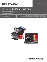
09-47149
09-47148
09-47263
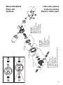
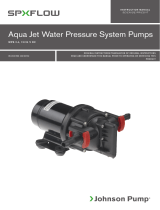
Reservdelslista
Parts list
Teilliste
Liste des pièces
Lista de piezas
Elenco delle parti
09-47148
Membran kit
Diaphragm kit
Blendenausstattung
Kit membrane
Kit de diafragma
Kit del Diaframma
09-47149
Pumphus komplett
Pump house cpl
Pumpengehäuse kpl.
Corps de pompe
Cuerpo de bomba
Alloggiamento della pompa completo
09-47263
Låsbygelkit
Clamp kit
Klemmplatte kpl.
Kit de bride
Kit de apretar
Corredo del serrare
25

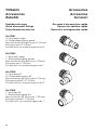
09-47491
¾" Hose barb straight
¾"-Schlauchbefestigung, gerade
Raccord cannelé droit pour tuyau ¾" (19 mm)
Entronque recto ¾" (19 mm)
Flessibili diritti con estremità a gancio da ¾"
09-47492
1" Hose barb straight
1"-Schlauchbefestigung, gerade
Raccord cannelé droit pour tuyau 1"(25 mm)
Entronque recto 1" (25 mm)
Flessibili diritti con estremità a gancio da 1"
09-47503
¾" Hose barb 90°
¾"-Schlauchbefestigung, 90°
Raccord cannelé 90° pour tuyau ¾" (19 mm)
Entronque codo 90° ¾" (19 mm)
Flessibili a 90°con estremità a gancio da ¾"
09-47502
1" Hose barb 90°
1"-Schlauchbefestigung, 90°
Raccord cannelé 90° pour tuyau 1" (25 mm)
Entronque codo 90° 1" (25 mm)
Flessibili a 90° con estremità a gancio da 1"
Tillbehör
Accessories
Zubehör
Accessoires
Accesorios
Accesori
Snabbanslutningar
Quick disconnect fittings
Schnellwechselarmaturen
Raccords à déconnexion rapide
Racores de abertura rápida
Raccordi a scollegamento rapido
26

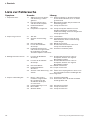
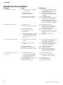
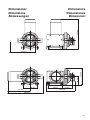
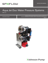
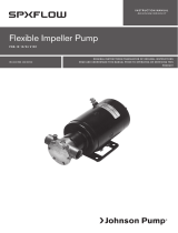
186 mm
90 mm 64 mm
90 mm
118 mm
60 mm 204 mm
163 mm
226 mm
144 mm
Dimensioner
Dimensions
Abmessungen
Dimensions
Dimensiones
Dimensioni
27

ISSUED 09/2017 IB-114 R06
COPYRIGHT ©2017 SPX FLOW, Inc.
Viking Power 16
12/24 V DC
Customer Service & Support - Johnson Pump Marine
SE +46 19 21 83 10
johnson-pump.marine@spxflow.com
US +1 847 671-7867
jp-customerservice@spxflow.com
AUS +61 03 9589 9222
ft.aus.cs@spxflow.com
For more information about our worldwide locations, approvals, certifications,
and local representatives, visit Johnson Pump - Marine at www.spxflow.com
SPX FLOW, Inc. reserves the right to incorporate our latest design and material changes without notice or obligation.
Design features, materials of construction and dimensional data, as described in this bulletin, are provided for your
information only and should not be relied upon unless confirmed in writing. Please contact your local sales representative
for product availability in your region. For more information visit www.spxflow.com.
The green “
”
and “
” are trademarks of SPX FLOW, Inc.
-
 1
1
-
 2
2
-
 3
3
-
 4
4
-
 5
5
-
 6
6
-
 7
7
-
 8
8
-
 9
9
-
 10
10
-
 11
11
-
 12
12
-
 13
13
-
 14
14
-
 15
15
-
 16
16
-
 17
17
-
 18
18
-
 19
19
-
 20
20
-
 21
21
-
 22
22
-
 23
23
-
 24
24
-
 25
25
-
 26
26
-
 27
27
-
 28
28


SPX FLOW Viking Power Waste Water Pump Manual de usuario
- Tipo
- Manual de usuario
en otros idiomas
Artículos relacionados
-
 SPX FLOW Viking Power Waste Water Pump Manual de usuario
-
 SPX FLOW Aqua Jet WD Pump Manual de usuario
-
 SPX FLOW Aqua jet WPS Manual de usuario
-
 SPX FLOW Control Panel Manual de usuario
-
 SPX FLOW Aqua Jet Manual de usuario
-
 SPX FLOW Viking Universal Manual de usuario
-
 SPX FLOW First Mate Manual de usuario
-
 SPX FLOW Aqua Jet Manual de usuario
-
 SPX FLOW Bilge Pump Float Switche Guía del usuario
-
 SPX FLOW Bilge, Deck Wash and Refueling pump Manual de usuario


Otros documentos
-
JABSCO 37202-2 Guía de inicio rápido
-
-
-
 Johnson Pump SPX FLOW 500 GPH Manual de usuario
-
-
-
 JOHNSON PUMP - SPX FLOW 36152 Manual de usuario
-
DAB Evosta2 11/85 SAN R 1/2 Instrucciones de operación
-
-
WHALE UF2425B Installation & User's Instructions

