McQuay IM-WMF-0501 Guía de instalación
- Tipo
- Guía de instalación

WALL MOUNTED
SPLIT TYPE AIR CONDITIONER
INSTALLATION MANUAL
Group: WALL MOUNTED
Part Number: A08019025515
Date: MAY 2001
IM-WMF-0501-McQuay
© 2001 McQuay International


i
All dimensions are in mm / (in)
Indoor Unit (WM)
OUTLINE AND DIMENSIONS
A
B
Front View
Top View
Installation Plate
C
SideView
Outdoor Unit (SL-B Series)
A
D
F
N
O
M
K
L
J
I
B
E
H
G
I
FOR PIPE HOLE POSITION
IN THE WALL
HOLE O 65.0mm
FOR PIPE HOLE POSITION
IN THE WALL
HOLE O 65.0mm
CENTER
LINE
All dimensions are in mm / (in)
Dimension A B C D E F G H I J K L M N O
07 / 10 / 15F / FR 815 (32,1) 291 (11,4) 181 (7,1) 719 (28,3) 278 (10,9) 47 (1,9) 47 (1,9) 12 (0,5) 32 (1,3) 35(1,4) 302 (11,9) 342 (13,5) 100 (3,9) 118 (4,6) 172 (6,8)
20 / 25F / FR 1060 (41,7) 310 (12,2) 200 (7,9) 912 (35,9) 294 (11,6) 99 (3,9) 51 (2,0) 8 (0,3) 48 (1,9) 43 (1,7) 354 (13,9) 403 (15,9) 160 (6,3) 138 (5,4) 160 (6,3)
Dimension A B C D E F G H J K L M N P Q R
07B / 07BR
740 494 270 266 233 474 47 55 65 166 92 348 318 129 482 68,5
10B / 10BR
(29,1) (19,4) (10,6) (10,5) (9,2) (18,7) (1,9) (2,2) (2,6) (6,5) (3,6) (13,7) (12,5) (5,1) (19,0) (2,7)
15B / 15BR
20B / 20BR 840 646 330 297 309 626 41 85 75 177 106 408 378 124 592 78,5
25B / 25BR (33,1) (25,4) (13,0) (11,7) (12,2) (24,6) (1,6) (3,3) (3,0) (7,0) (4,2) (16,1) (14,9) (4,9) (23,3) (3,1)
Q
N
E
15 (0.6)
39 (1.5)
A
M
P
P
840 (33.1)
D
15 (0.6)
39 (1.5)
5 (0.2)
C
20 (0.8)
20 (0.8)
2.5 (0.1)
F
B
C
5 (0.2)
160 (6.3)
H
G
141 (5.6)
K
J
(2.6)
65
L
20 (0.8)
R

ii
Outdoor Unit (SL071 & SL-C Series)
All dimensions are in mm / (in)
Dimension A B C D E F G H I J K L M N O
071 / 1R 600 (23,6) 475 (18,7) 245 (9,6) 418 (16,4) 177 (6,9) 35 (1,3) 93 (3,6) 81 (3,1) 83 (3,2) 55 (2,2) 398 (15,6) 101 (3,9) 97 (3,8) 17 (0,6) 22 (0,8)
10 / 15 C /CR 700 (27,5) 521 (20,5) 250 (9,8) 485 (19,1) 175 (6,8) 36 (1,4) 95 (3,7) 93 (3,6) 86 (3,3) 68 (2,6) 441 (17,3) 130 (5,1) 111 (4,3) 15 (0,5) 18 (0,7)
30
(1.2)
(0.1)
3
(0.7)
19
(2.6)
65
(3.1)
80
NOTICE
This product is subjected to Waste of Electrical and Electronic Equipment Regulations (WEE
E
Regulations). The waste product shall be separately collected by specific collection and treatment centre
.
P
lease refer to local authorithy for these centres. This is only applicable to European Union countries
.
Ce produit est soumis
à
la r
à
é
r
r
glementation concernant les
d
é
chets
d
es
é
quipements
é
lectriques e
t
é
lectroniques (r
é
r
r
é
ê
é
s
é
par
é
r
r
m
ent par un centre de collect
e
é
é
é
î
î
tre ces centres. Ceci
îî
é
enne
.
Questo prodotto
è
soggetto alle disposizioni RAEE (Rifiuti di apparecchiature elettriche ed elettroniche)
.
à
à
locali. Questa disposizione
à
è
valida solamente i paes
i
d
el
l
’
U.
E
.
é
ctrico y Electr
ó
n
ico en materia d
e
ñ
ñ
á
í
fico
í
í
de colecc
i
ó
solamente aplicable a los p
a
í
ses de la
U
n
i
ó
n
Europea
.
G
er
ä
ä
ä
tes
ää
getrennt vom Hausm
ü
ll bei Ihrer
ö
r
tlichen
M
ü
lldeponie bzw. Ihrem
ö
r
tliche
n
ä
ndiges Abfall-Amt. Dieser
ää
Hinweis gilt nur f
ü
f
f
rL
ä
nder der Europ
ää
ä
ischen Union
.
п
р
авилам
и
п
о
у
тилизаци
и
отхо
д
о
в
(WEEE Re
g
ulations).
и
.
,
.
Э
т
и
п
р
авил
а
Ев
р
опейског
о
.
Per preservarsi da eventuali ferite, evitare di toccare gli spigoli affilati e la superficie
dei serpentini.
! Cautela
Острые края и поверхности змеевиков являются потенциальными
местами нанесения травм. Остерегайтесь контакта с этими местами.
! Осторожно
Sharp edges and coil surfaces are potential locations which may cause injury
hazards. Avoid from being in contact with these places.
! Caution
Les bords coupants et les surfaces du refroidisseur tubulaire présentent
un risque de blessure. Mieux vaut éviter le contact avec ces endroits.
!
Avertissement
Scharfe Kanten und Wärmetauscherflächen stellen eine Gefahrenquelle dar. Jeglicher
Kontakt mit diesen Stellen ist zu vermeiden.
! Vorsicht
Los Bordes afilados y la superficie del serpentín pueden producir lesiones. Evite
tocarlos.
! Cuidado
NCN
KLL
M
A
D
B
EF
IJ
GH
C

1-1
English
This manual provides the procedures of installation to ensure a safe and good standard of operation for the air
conditioner unit.
Special adjustment may be necessary to suit local requirements.
Before using your air conditioner, please read this instruction manual carefully and keep it for future reference.
INSTALLATION MANUAL
WALL MOUNTED SPLIT TYPE AIR CONDITIONER
MODEL
COOLING UNIT
WM07F / MWM007F
SL07B / MLC007B
SL071 / MLC007C
4SL07B / M4LC007B
5SL071 / M5LC007C
WM10F / MWM010F
SL10B / MLC010B
SL10C / MLC010C
4SL10B / M4LC010B
5SL10C / M5LC010C
WM15F / MWM015F
SL15B / MLC015B
SL15C / MLC015C
4SL15B / M4LC015B
5SL15C / M5LC015C
WM20F / MWM020F
SL20B / MLC020B
4SL20B / M4LC020B
5SL20B / M5LC020B
WM25F / MWM025F
SL25B / MLC025B
4SL25B / M4LC025B
5SL25B / M5LC025B
Part No.:A08019025515
HEAT PUMP
WM07FR / MWM007FR
SL07BR / MLC007BR
SL071R / MLC007CR
4SL07BR / M4LC007BR
5SL071R / M5LC007CR
WM10FR / MWM010FR
SL10BR / MLC010BR
SL10CR / MLC010CR
4SL10BR / M4LC010BR
5SL10CR / M5LC010CR
WM15FR / MWM015FR
SL15BR / MLC015BR
SL15CR / MLC015CR
4SL15BR / M4LC015BR
5SL15CR / M5LC015CR
WM20FR / MWM020FR
SL20BR / MLC020BR
4SL20BR / M4LC020BR
WM25FR / MWM025FR
SL25BR / MLC025BR
4SL25BR / M4LC025BR
INVERTER HEAT PUMP UNIT
WMV10FR / MWMV010FR
SLV10BR / MLCV010BR
WMV15FR / MWMV015FR
SLV15BR / MLCV015BR
IM-WMF-0501 (2) - McQuay

1-2
CONTENTS
Before installing the air conditioner unit, please read the following safety precautions carefully.
SAFETY PRECAUTIONS
! Warning
• Installation and maintenance should be performed by qualified persons who are familiar with local code and
regulation, and experienced with this type of appliance.
• All field wiring must be installed in accordance with the national wiring regulation.
• Ensure that the rated voltage of the unit corresponds to that of the name plate before commencing wiring work
according to the wiring diagram.
• The unit must be GROUNDED to prevent possible hazards due to insulation failure.
• All electrical wiring must not touch the refrigerant piping, compressor or any moving parts of the fan motors.
• Confirm that the unit has been switched OFF before installing or servicing the unit.
- Outline And Dimensions page i-ii
- Safety Precautions page 2
- Installation Diagram page 3
- Installation Of The Outdoor Unit page 3
- Installation Of The Indoor Unit page 4
- Refrigerant Piping page 5
- Electrical Wiring Connection page 6
- Special Precautions When Dealing
with R410A Unit page 7
- Special Precautions When Dealing
with R407C Unit page 7
! Caution
Please take note of the following important points when installing.
• Do not install the unit where leakage of flammable gas may occur.
If gas leaks and accumulates around the unit, it may cause fire ignition.
• Ensure that the drainage piping is connected properly.
If the drainage piping is not connected properly, it may cause water leakage which will dampen the
furniture.
• Do not overcharge the unit.
This unit is factory pre-charged. Overcharge will cause over-current or damage to the compressor.
• Ensure that the units panel is closed after service or installation.
Unsecured panels will cause the unit to operate noisily.
- Vacuuming and Charging page 7
- Indicator Lights page 8
- Air Conditioner Unit Operation page 10
- Standard Operating Conditions page 10
- Electrostatic Filter page 10
- Auto Random Re-Start Function page 11
- Phase Protector (Optional) page 11
- Service And Maintenance page 12
- Troubleshooting page 12

1-3
English
INSTALLATION DIAGRAM
Indoor Unit
Refrigerant Piping
SLC
Air Discharge
Nozzle
Air Intake
Air
Intake
Drain Hose
Signal
Receiver
Indicator
Lights
Air Intake
Grille
Back Housing
ON/OFF Switch
Front Frame
Air Filters
Air Discharge Louver
Air Discharge Grille
Air Intake
Air Discharge
Nozzle
Outdoor Unit
SLB
Dimension A B C D
Minimum mm 300 1000 300 500
Distance, (in) (11.8) (39.4) (11.8) (19.7)
INSTALLATION OF THE OUTDOOR UNIT
The outdoor unit must be installed in such a way, so as to
prevent short circuit of the hot discharged air or obstruction
to the smooth air flow. Please follow the installation clear-
ance shown in the figure. Select the coolest possible place
where intake air temperature is not greater than the outside
air temperature (maximum 45°C).
Installation clearance
Note: If there is any obstacle higher than 2m, or if there is
any obstruction at the upper part of the unit, please allow
more space than the figure indicated in the above table.
Condensed Water Disposal of Outdoor Unit (Heat
Pump Unit Only)
• There are 2 holes on the base of Outdoor Unit for
condensed water to flow out. Insert the drain elbow to
one of the holes.
• To install the drain elbow, first insert one portion of the
hook to the base (portion A), then pull the drain elbow
in the direction shown by the arrow while inserting the
other portion to the base. After installation, check to
ensure that the drain elbow clings to base firmly.
• If the unit is installed in a snowy and chilly area, con-
densed water may freeze in the base. In such case, please
remove plug at the bottom of unit to smooth the drain-
age.
Obstacle
Return Air
Service
Access
Obstacle
Obstacle
Return Air
Discharge Air
Obstacle
Please remove side
plate when connect-
ing the piping and
connecting cord
PUSH & PULL UP
BASE
A
DRAIN
ELBOW
DRAIN
ELBOW
PLUG
A
B
C
D

1-4
INSTALLATION OF THE INDOOR UNIT
Mounting Installation Plate
Ensure that the wall is strong enough to withstand the weight
of the unit. Otherwise, it is necessary to reinforce the wall
with plates, beams or pillars.
Use the level gauge for horizontal mounting, and fix it with
4 suitable screws.
In case the rear piping draws out, drill a hole 65mm in
diameter with a cone drill, slightly lower on the outside wall
(see figure).
Mount The Unit Onto The Installation Plate
Hook the indoor unit onto the upper portion of the
installation plate (Engage the two hooks at the rear top of
the indoor unit with the upper edge of the installation plate).
Ensure that the hooks are properly seated on the
installation plate by moving it to the left and right.
Water Drainage Piping
The indoor drain pipe must be in a downward gradient for
smooth drainage. Avoid situations that are likely to cause
water to leak.
End
Dipped
Into
Water
Water
Leaking
Water
Leaking
Water
Leaking
The indoor unit must be installed in such a way so as to
prevent short circuit of the cool discharged air with the hot
return air. Please follow the installation clearance shown in
the figure. Do not place the indoor unit where there could be
direct sunlight shining on it. Also, this location must be
suitable for piping and drainage, and be away from doors or
windows.
Routing Of Piping
Remove the screw holding the front panel.
Maintenance &
Servicing Space
Air Flow
Direction
Higher Than
Eye Level
The refrigerant piping can be routed to the unit in a
number of ways (left or right from the back of the unit), by
using the cut-out holes on the casing of the unit (see figure).
Bend the pipes carefully to the required position in order to
aligned it with the holes. For the right hand and rear side
out, hold the bottom of the piping and then position it to the
required direction (see figure). The condensation drain hose
can be taped to the pipes.
Wrong
Wrong
Wrong
Correct
Drain
Water Drainage
1
2
3
4
5
Piping Routing
Right & Rear Side Routing
Drain hose
Fix with vinyl tape
Unit piping
1. Hook the unit onto the installation plate.
Hole With Cone Drill
Indoor Side
Outdoor Side
Plate Mounting Installation
Screw position in the wall
Ø 65.0 mm Hole in the wall

1-5
English
Piping Length & Elevation
If the pipe is too long, both the capacity and reliability of
the unit will drop. As the number of bends increases,
resistance to the flow of refrigerant system increases, thus
lowering cooling capacity. As a result, the compressor may
become defective. Always choose the shortest path and
follow the recommendations as tabulated below:
REFRIGERANT PIPING
Outdoor Unit
Indoor Unit
HL
Remove Burr
Cutting Copper Tube
Piping Works
• Do not use contaminated or damaged copper tubing. Do
not remove plastic, rubber plugs and brass nuts from the
valves, fittings, tubings and coils until you are ready to
connect suction or liquid line into valves or fittings.
• If any brazing work is required, ensure that the nitrogen
gas is passed through coil and joints while the brazing
work is being done. This will eliminate soot formation on
the inside walls of the copper tubings.
• Cut the connection pipe with a pipe cutter.
• Remove burrs from cut edges of the pipes with remover.
Hold the end of the pipe downwards to prevent metal chips
from entering the pipe.
• Insert the flare nuts, mounted on the connection parts of
both the indoor unit and outdoor unit onto the copper pipes.
• Flare the pipe with extra length above the flaring tool as
shown in the table.
• The flared edge must be even and not cracked or scratched.
1/4t
Copper Tube
Swaging Block
Ø Tube, D A (mm)
Inch mm Imperial Rigid
1/4" 6.35 1.3 0.7
3/8" 9.52 1.6 1.0
1/2" 12.70 1.9 1.3
5/8" 15.88 2.2 1.7
3/4" 19.05 2.5 2.0
Piping Connection To The Units
• Align the center of the piping and tighten the flare nut
sufficiently with fingers.
• Finally, tighten the flare nut with the torque wrench until
the wrench clicks.
Pipe Size mm / (in) Torque Nm / (ft - lb)
6.35 (1/4) 18(13.3)
9.53 (3/8) 42(31.0)
12.7 (1/2) 55(40.6)
15.88 (5/8) 65(48.0)
19.05 (3/4) 78(57.6)
Indoor Piping
Flare Nut
Flared Tube
Flare Joint
Spanar
Torque Wrench
Remark: The refrigerant pre-charged in the outdoor unit
is for piping length up to 7.62 m/25 ft.
Model
Maximum length, m (ft), L
Max. elevation, m (ft), H
Max. number of bends
Liquid pipe size
Gas pipe size
07 10 15 20 25
12 (39) 12 (39) 12 (39) 15 (49) 15 (49)
5 (16.4) 5 (16.4) 5 (16.4) 8 (26.2) 8 (26.2)
10 10 10 10 10
1/4" 1/4" 1/4" 1/4" 3/8"
3/8" 3/8" 1/2" 5/8" 5/8"

1-6
ELECTRICAL WIRING CONNECTION
Cooling unit
IMPORTANT : * The figures shown in the table are for information purpose only. They should be checked and selected
to comply with the local/national codes of regulations. This is also subject to the type of
installation and conductors used.
** The appropriate voltage range should be checked with label data on the unit. ETL listed is only applicable
to 60Hz power supply only.
COMP
N2
COMP
N
N1
L
Outdoor Unit
Terminal Block
Indoor Unit
Terminal Block
There must be a double pole switch
with a minimum 3mm contact gap and
fuse/circuit breaker as recommended
in the fixed installation circuit.
!
Power Supply Cable
!
There must be a double pole switch with a minimum 3mm
contact gap and fuse/circuit breaker as recommended in the
fixed installation circuit.
Terminal Block
Outdoor Unit
Indoor Unit
Terminal Block
N2
COMP
N1
L
COMP
N
L
T
N
S
R
Power Supply Cable
!
There must be a double pole switch
with a minimum 3mm contact gap and
fuse/circuit breaker as recommended in
the fixed installation circuit.
Outdoor Unit
Terminal Block
Indoor Unit
Terminal Block
Power Supply Cable
Outdoor coil sensor connection wire
(8m long) attached in the indoor unit
COMP
N2
OF
4WV
N1
L
COMP
OF
4WV
N
Model 07 / 10 / 15 20 / 25 20 / 25
Voltage range** 220V-240V / 1Ph / 50Hz +
380V-415V / 3Ph / 50Hz + N+
or 208V-230V / 1Ph / 60Hz+
Power supply cable size* mm
2
1.5 2.5 1.5
Number of wire 33 5
Interconnection cable size* mm
2
1.5 2.5 1.5
Number of wire 33 4
Recommended Fuse A 15 20 15
Outdoor Unit
Terminal Block
Indoor Unit
Terminal Block
Power Supply Cable
Outdoor coil sensor connection wire
(8m long) attached in the indoor unit
COMP
N2
OF
4WV
N1
L
COMP
OF
4WV
N
L
T
N
S
R
!
There must be a double pole switch with a minimum 3mm
contact gap and fuse/circuit breaker as recommended in the
fixed installation circuit.
Heat pump unit (single phase) Heat pump unit (3 phase)
Cooling unit (single phase) Cooling unit (3 phase)
Model 07 / 10 / 15 20 / 25 20 / 25
Voltage range** 220V-240V / 1Ph / 50Hz +
380V-415V / 3Ph / 50Hz + N+
or 208V-230V / 1Ph / 60Hz+
Power supply cable size* mm
2
1.5 2.5 1.5
Number of wire 33 5
Interconnection cable size* mm
2
1.5 2.5 1.5
Number of wire 55 6
Recommended Fuse A 15 20 15

1-7
English
• All wires must be firmly connected.
• All wires must not touch the refrigerant piping, compressor
or any moving parts of the fan motor.
• The connecting wires between the indoor unit and the
outdoor unit must be clamped on the wire clamps as shown
in the figure.
• The power supply cord must be equivalent to H05RN-F
(245IEC57) which is the minimum requirement.
SPECIAL PRECAUTIONS WHEN DEALING WITH R410A UNIT
R410A is a new HFC refrigerant which does not damage the
ozone layer. The working pressure of this new refrigerant is
1.6 times higher than conventional refrigerant (R22), thus
proper installation / servicing is essential.
• Never use refrigerant other than R410A in an air condi-
tioner which designed to operate with R410A.
• POE oil is used as lubricant for R410A compressor, which
is different from the mineral oil used for R22 compressor.
During installation or servicing, extra precaution must be
taken not to expose the R410A system too long to moist
air. Residual POE oil in the piping and components can
absorb moisture from the air.
• To prevent mischarging, the diameter of the service port
on the flare valve is different from that of R22.
SPECIAL PRECAUTIONS WHEN DEALING WITH R407C UNIT
• R407C is a zeotropic refrigerant mixture which has zero
ozone depletion potential and thus conformed to the
Montreal Protocol regulation. It requires Polyol ester oil
(POE) oil for its compressor's lubricant. Its refrigerant
capacity and performance are about the same as the
refrigerant R22.
• POE oil is used as lubricant for R407C compressor, which
is different from the mineral oil used for R22 compressor.
During installation or servicing, extra precaution must be
taken not to expose the R407C system too long to moist
air. Residual POE oil in the piping and components can
absorb moisture from the air.
• Refrigerant R407C is more easily affected by dust of
moisture compared with R22, make sure to temporarily
cover the ends of the tubing prior to installation.
• Use tools and materials exclusively for refrigerant R410A.
Tools exclusively for R410A are manifold valve, charging
hose, pressure gauge, gas leak detector, flare tools, torque
wrench, vacuum pump and refrigerant cylinder.
• As an R410A air conditioner incurs higher pressure than
R22 units, it is essential to choose the copper pipes cor-
rectly. Never use copper pipes thinner than 0.8mm even
though they are available in the market.
• If the refrigerant gas leakage occurs during installation /
servicing, be sure to ventilate fully. If the refrigerant gas
comes into contact with fire, a poisonous gas may occur.
• When installing or removing an air conditioner, do not
allow air or moisture to remain in the refrigerant cycle.
• No additional charge of compressor oil is permitted.
• No other refrigerant other than R407C.
• Tools specifically for R407C only (must not be used for
R22 or other refrigerant)
i) Manifold gauge and charging hose
ii) Gas leak detector
iii) Refrigerant cylinder/charging cylinder
iv) Vacuum pump c/w adapter
v) Flare tools
vi) Refrigerant recovery machine
• Filter-dryer must be installed along the liquid line for all
R407C air conditioners. This is to minimise the contamination
of moisture and dirt in the refrigerant system. Filter-dryer
must be of molecular sieve type. For a heat-pump system,
install a two-way flow filter dryer along the liquid line.
Wire Clamp
Interconnection
Cable
Power Supply
Cable
VACUUMING AND CHARGING
Purging the piping and the indoor unit
Except for the outdoor unit which is pre-charged with
refrigerant, the indoor unit and the refrigerant
connection pipes must be air-purged because the air
containing moisture that remains in the refrigerant cycle may cause
malfunction of the compressor.
•
Remove the caps from the valve and the service port.
•
Connect the center of the charging gauge to the vacuum pump.
•
Connect the charging gauge to the service port of the
3-way valve.
•
Start the vacuum pump. Evacuate for approximately
30 minutes. The evacuation time varies with different vacuum
pump capacity. Confirm that the charging gauge needle has
moved towards -760mmHg.
Caution
If the gauge needle does not move to -760mmHg, be sure to
check for gas leaks (using the refrigerant
detector) at flare type connection of the indoor and outdoor unit
and repair the leak before proceeding to the next step.
•
Close the valve of the changing gauge and stop the vacuum
pump.
•
On the outdoor unit, open the suction valve (3 way) and liquid
valve (2 way) (in anti-clockwise direction) with 4mm key for
hexagon sacked screw.
Service Port
Outdoor Unit
3 ways valve
Flare nut
Refrigerant
Piping
Allen key
Suction
valve
Discharge
Valve
Indoor Unit
Outdoor Unit
Liquid side
Gas side
Vacuum
pump
Open
Close
Close
Close
Hi
Low

1-8
Model
07F / 10F/ 15F
20F
25F
07FR / 10FR / 15FR
20FR
25FR
10m/32.8ft 12m/39.4ft 15m/49.2ft
35 65 –
35 65 110
90 165 280
50 90 –
60 110 185
120 220 370
Additional charge in gram (For R22/R407C models)
Open
Open
Suction
Valve
Discharge
Valvet
Indoor Unit
Outdoor Unit
Liquid side
Gas side
Check
Valve
Close
Hi
Low
Charge operation
This operation must be done by using a gas cylinder and a
precise weighing machine. The additional charge is topped-
up into the outdoor unit using the suction valve via the ser-
vice port.
• Remove the service port cap.
• Connect the low pressure side of the charging gauge to
the suction service port center of the cylinder tank and
close the high pressure side of the gauge. Purge the air
from the service hose.
• Start the air conditioner unit.
• Open the gas cylinder and low pressure charging valve.
• When the required refrigerant quantity is pumped into
the unit, close the low pressure side and the gas cylinder
valve.
• Disconnect the service hose from service port. Put back
the service port cap.
Model
07F / 10F/ 15F
20F
25F
07FR / 10FR / 15FR
20FR
25FR
10m/32.8ft 12m/39.4ft 15m/49.2ft
35 60 –
35 60 100
80 150 255
45 80 –
55 100 165
110 200 335
Additional charge in gram (For R410A models)
Additional charge
The refrigerant is pre-charged in the outdoor unit. If the
piping length is less than 7.62m (25ft), then additional charge
after vacuuming is not necessary. If the piping length is more
than 7.62m (25ft), then use the additional charge valve as
indicated in the table.
IR signal receiver
When an infrared remote control operating signal has
been transmitted, the signal receiver on the indoor unit
will make a <beep> sound to confirm acceptance of the
signal transmission.
Cooling unit
The table shows the LED indicator lights for the air condi-
tioner unit under normal operation and fault conditions.
The LED indicator lights are located at the bottom right
side of the air conditioner unit.
INDICATOR LIGHTS
LED indicator lights
IR Receiver
LED Indicator Lights for Cooling Unit
Timer
Sleep mode
Power ON
Dry mode
LED Indicator Lights : Normal Operation And Fault Conditions For Cooling Unit
Operation / Fault Indication Action
Timer on. –
Sleep mode on. –
Dry mode. –
Frost prevention. Clean the filter and switch to high fan.
Room air sensor contact loose/short. Call your dealer.
Indoor coil sensor contact loose/short. Call your dealer.
Sensor contact problem, compressor
overload protection trip or gas leak
Call your dealer.
Continuously
once every 2 sec.
twice every 2 sec.
3 times every 2 sec.
ON
ON or OFF Blinking

1-9
English
Heat pump unit
The table shows the LED indicator lights for the air condi-
tioner unit under normal operation and fault conditions.
The LED indicator lights are located at the bottom right
side of the air conditioner unit.
The heat pump units are equipped with an "auto" mode
sensor whereby it will provide reasonable room temperature
by switching automatically to either "cool" or "heat"
mode according to the temperature set by the user.
LED Indicator Lights For Heat Pump Unit
Cooling mode
Dry mode
Sleep mode
Heat / Fan mode
(red / green)
Cooling mode. –
Dry mode. –
Fan mode. –
Heat mode. –
Auto mode in heating operation. –
Auto mode in cooling operation. –
Defrost operation. –
Compressor overload protection. Call your dealer.
Indoor coil sensor contact loose /short. Call your dealer.
Outdoor coil sensor contact loose /short. Call your dealer.
Room air sensor contact loose /short. Call your dealer.
If the system is in cool mode or heat mode (with the sleep function off), the sensor
may have a contact problem, compressor overload protection trip or gas leak.
Normal Operation/Fault Condition
Action
Cool Dry Fan Heat Sleep
LED Indicator Lights : Normal Operation And Fault Conditions For Heat Pump Unit
ON ON or OFF Blinking
Inverter Heat Pump Unit
LED Indicator Lights For Inverter Heat Pump Unit
Cool / Dry
Stand-by / Fan
Timer
Heat
Cooling mode. –
Dry mode. –
Stand-by / Fan mode. –
Heat mode. –
Auto mode. –
Defrost operation. –
Compressor overload protection. Call your dealer.
Indoor temperature sensors contact loose / short. Call your dealer.
Outdoor temperature & current sensors contact loose / short. Call your dealer.
Gas leak / compressor overheat. Call your dealer.
Communication error between indoor and outdoor. Call your dealer.
Inverter error / PFC error. Call your dealer.
Outdoor total current trip / DC peak. Call your dealer.
Normal Operation/Fault Condition
Action
Cool Dry Heat Stand-by Timer
Green Red Red Red Green
LED Display
The LED in indoor and outdoor unit indicate operation modes / faults detected.
ON or OFF
ON
Blinking

1-10
Horizontal
Cooling
Dry
25°C / 77°F
STANDARD OPERATING CONDITIONS
Heat Pump Unit
Cooling unit
Temperature Ts °C / °F Th °C / °F
Minimum indoor
19.4 / 66.9 13.9 / 57.0
temperature
Maximum indoor
26.7 / 80.1 19.4 / 66.9
temperature
Minimum outdoor
19.4 / 66.9 13.9 / 57.0
temperature
Maximum outdoor
46 / 114.8 24 / 75.2
temperature
Ts: Dry bulb temperature. Th: Wet bulb temperature.
AIR CONDITIONER UNIT OPERATION
Dry mode
• When the air humidity is high, the unit can operate in
dry mode. Press <MODE> button and choose <DRY>.
• If the room temperature is 2°C/3.6°F higher than the set
temperature, the air conditioner will operate under
cooling mode until it reaches within the 2°C/3.6°F range
of difference compared to the set temperature before it
converts to dry mode.
• If the room temperature is within the 2°C/3.6°F range
of difference compared to the set temperature, it will
directly operate under dry mode.
• The unit will operate at LOW speed under dry mode.
Heat mode (for heat pump unit only)
• When the unit is switched on from cold start or
defrosting cycle, the indoor fan will start to operate only
after the coil reaches the desired temperature.
• When the set temperature is achieved, the indoor fan
will operate until the coil cannot provide anymore
additional heat.
Horizontal Air Flow Control
• For more effective air circulation, you can manually
adjust the air discharge grille to the left or right.
• During cool mode operation and dry mode operation,
do not direct the air discharge louver downwards for too
long. If operating continues in this way, condensation
may occur on the louver, thus resulting in drippings.
Hot Keep (for heat pump only)
• During compressor cut off, the indoor fan can be
switched to
(i) ON (default) or
(ii) OFF or
(iii) Interval on and off
by setting the slide switch shown in the diagram.
• The switch is located at the front frame cover (next to
the ON/OFF switch).
NOTE : When the option is selected, the power supply of
the unit need to be reset in order to activate the
function.
ON/OFF switch
HOT KEEP
OFF
INTERVAL
ON
Temperature Ts °C / °F Th °C / °F
Minimum indoor
10 / 50 –
temperature
Maximum indoor
26.7 / 80.1 –
temperature
Minimum outdoor
-8 / 17.6 -9 / 15.8
temperature
Maximum outdoor
24 / 75.2 18 / 64.4
temperature
Overheating protection (for heat pump unit only)
• In case the internal and/or the external temperature is to
high, or that the filter is dirty and clogged up, the
refrigerant may be overheated. The compressor will cut
out when the condensing temperature reaches 62°C/
143.6°F.
Frost prevention
• When the air filter is dirty, the evaporating temperature
will decrease and eventually cause frosting.
• The LED light will blink to indicate that the filter is
dirty. If the evaporating temperature reaches -1°C/33.8°F,
the unit will trip and defrost.
Fan speed and rated cooling capacity
• The rated cooling capacity is provided at the maximum
fan speed.
• The cooling capacity is lower when the unit is operating
at MEDIUM and LOW fan speed.
DUAL ACTION ELECTROSTATIC AIR PURIFYING
AND DEODORIZING FILTER MEDIA AND FILTER FRAME
ACTION 1-
ELECTROSTATIC AIR PURIFYING FILTER
Removes microscopic dust, smoke and small invisible
particles to keep the room air clean with pre-charged
electrostatic polypropylene filter.
ELECTROSTATIC FILTER
ACTION 2-
DEODORIZING FILTER
Removes unwanted smells and odors in the air and keeps
the room air fresh with activated carbon filter.

1-11
English
! Caution
1. The electrostatic air purifying and deodorizing filter
should be replaced once every 6 months or when the
filter changes color to brownish, whichever is sooner.
2. Used dusty filters should be disposed and shouldn't be
reused, even if it has been cleaned and washed.
3. The filter is a consumable part which you can purchase
from your air conditioner dealer.
4. Use the new filter immediately once it has been taken
out from its sealed packing. Do not unpack the new
filter too early before it is actually used as this may
decrease its deodorizing effect.
! Warning
• Disconnect from the main power supply before servicing the air conditioner unit.
• DO NOT pull out the power cord when the power is ON. This may cause serious electrical shocks which may result
in fire hazards.
AUTO RANDOM RE-START FUNCTION
If there is a power cut when the unit is operating, it will automatically resume the same operating mode when the power is
restored. (Applicable only to units with this feature.)
! Caution
Before turning off the power supply, set the remote controller’s ON/OFF switch to the “OFF” position to prevent the
nuisance tripping of the unit.
If this is not done, the unit’s fans will start turning automatically when power resumes, posing a hazard to service
personnel or the user.
HOW TO INSTALL
The unit with 3 phase Compressor can only rotate in one direction. For this reason, a protective device (phase protector) is
fitted to prevent incorrect wiring of the electrical phases. When the three phases are not connected correctly, the phase protector
operates, and the unit will not start. This devise is located in the control box of the outdoor unit.
The following table shows the LED indicator light for phase protector under normal operation and fault conditions.
PHASE PROTECTOR (OPTIONAL)
Normal operation
Reverse phase
T phase missing
S phase missing
R phase missing
S &T phase missing
+
Overload
+
Sensor missing
+
-
Switch off the unit. Check the 3 phase wiring.
Switch off the unit. Check the 3 phase wiring.
Switch off the unit. Check the 3 phase wiring.
Switch off the unit. Check the 3 phase wiring.
Switch off the unit. Check the 3 phase wiring.
High discharge temperature. Check the refrigerant system.
Switch off the unit. Plug in sensor.
LED
Description
PW
(Red)
P_R
(Yellow)
P_S
(Yellow)
P_T
(Yellow)
Actions
! Warning
• Trouble shooting must be performed by qualified personnel.
Notes : 1. “+” indicates additional functions for PP01 phase protector.
2.When R phase missing, no LED or buzzer will indicate the error, but relay 71 and relay 81 will cut off.
ON OFF Fast Blink

1-12
SERVICE AND MAINTENANCE
Maintenance Procedures
1. Remove any dust adhering to the filter by using a vacuum cleaner or wash in
lukewarm water (below 40°C/104°F) with a neutral cleaning detergent.
2. Rinse the filter well and dry before placing it back onto the unit.
3. Do not use gasoline, volatile substances or chemicals to clean the filter.
1. Clean any dirt or dust on the grille or panel by wiping it with a soft cloth
soaked in lukewarm water (below 40°C/104°F) and a neutral detergent
solution.
2. Do not use gasoline, volatile substances or chemicals to clean the
indoor unit.
Period
At least once
every 2 weeks.
More frequently if
necessary.
At least once
every 2 weeks.
More frequently if
necessary.
Service Parts
Indoor air filter
Indoor unit
! Caution
Do not operate any heating apparatus too close to the air conditioner unit. This may cause the plastic
panel to melt or deform as a result of the excessive heat.
When The Unit Is Not To Be Used For An Extended Long Period Of Time
Operate the unit for 2 hours
with the following setting.
Operating mode : cool
Temperature : 30°C/86°F
Remove the power plug.
If you are using an independent
electric circuit for your unit,
cut off the circuit.
Remove the batteries in the
remote control.
If any malfunction of the air conditioner unit is noted, immediately switch off the power supply to the unit.
Check the following fault conditions and causes for some simple troubleshooting tips.
TROUBLESHOOTING
Causes / Action
- Protection against frequent starting. Wait for 3 to 4 minutes for
the compressor to start operating.
- Power failure, or the fuse needs to be replaced.
- The power plug is disconnected.
- It is possible that your delay timer has been set incorrectly.
- If the fault persist after all these verifications, please
contact the air conditioner unit installer.
- The air filter is dirty.
- The doors or windows are open.
- The air suction and discharge are clogged.
- The regulated temperature is not high enough.
- Odors may be caused by cigarettes, smoke particles, perfume
etc. which might have adhered onto the coil.
- This is caused by air humidity after an extended long period of
operation.
- The set temperature is too low, increase the temperature setting
and operate the unit at high fan speed.
- Switch off unit and call dealer.
- Refrigerant fluid flowing into the evaporator coil.
Fault
1. The compressor does not operate 3 minutes after the air
conditioner unit is started.
2. The air conditioner unit does not operate.
3. The air flow is too low.
4. Discharge air flow has bad odor.
5. Condensation on the front air grille of the indoor unit.
6. Water flowing out from the air conditioner unit.
7. Hissing air flow sound from the air conditioner unit during
operation.
If the fault persists, please call your local dealer / serviceman.

English
2-1
Français
Ce manuel fournit les procédures d’installation pour assurer le bon fonctionnement et la sécurité de cet appareil.
Des ajustements peuvent être nécéssaires pour suivre les réglementations locales.
Avant d’installer et de faire fonctionner le climatiseur, lisez attentivement ce manuel et conservez le.
MANUEL D'INSTALLATION
CLIMATISEURS SPLIT SYSTEM MONTAGE MURAL
MODÈLE
FROID SEUL
WM07F / MWM007F
SL07B / MLC007B
SL071 / MLC007C
4SL07B / M4LC007B
5SL071 / M5LC007C
WM10F / MWM010F
SL10B / MLC010B
SL10C / MLC010C
4SL10B / M4LC010B
5SL10C / M5LC010C
WM15F / MWM015F
SL15B / MLC015B
SL15C / MLC015C
4SL15B / M4LC015B
5SL15C / M5LC015C
WM20F / MWM020F
SL20B / MLC020B
4SL20B / M4LC020B
5SL20B / M5LC020B
WM25F / MWM025F
SL25B / MLC025B
4SL25B / M4LC025B
5SL25B / M5LC025B
POMPE À CHALEUR
WM07FR / MWM007FR
SL07BR / MLC007BR
SL071R / MLC007CR
4SL07BR / M4LC007BR
5SL071R / M5LC007CR
WM10FR / MWM010FR
SL10BR / MLC010BR
SL10CR / MLC010CR
4SL10BR / M4LC010BR
5SL10CR / M5LC010CR
WM15FR / MWM015FR
SL15BR / MLC015BR
SL15CR / MLC015CR
4SL15BR / M4LC015BR
5SL15CR / M5LC015CR
WM20FR / MWM020FR
SL20BR / MLC020BR
4SL20BR / M4LC020BR
WM25FR / MWM025FR
SL25BR / MLC025BR
4SL25BR / M4LC025BR
UNITÉ DE POMPE À CHALEUR
D’INVERSEUR
WMV10FR / MWMV010FR
SLV10BR / MLCV010BR
WMV15FR / MWMV015FR
SLV15BR / MLCV015BR
Part No.:A08019025515 IM-WMF-0501 (2) - McQuay

2-2
SOMMAIRE
Avant de faire fonctionner l'appreil, veuillez bien lire les précautions de sécurité suivantes.
PRÉCAUTIONS DE SÉCURITÉ
! Attention
• L'installation et la maintenance doivent être exécutées par une personne qualifiée qui est familiarisée avec les lois
et réglementations en vigueur, et aussi expérimentée dans ce type d'équipements.
• Tous les câblages doivent répondre aux réglementations électriques nationales.
• Avant de commencer le raccordement suivant le schéma électrique, s’assurer que la tension nominale de l’appareil
corresponde bien à celle indiquée sur la plaque signalétique.
• L' unité doit être raccordée à la TERRE pour prévenir tous les risques possibles dûes à un défaut d'isolation.
• Aucun câble électrique ne doit toucher la tuyauterie du réfrigérant, le compresseur ou les pièces mobiles des moteurs
de ventilation.
• Avant l’installation ou l’entretien du climatiseur, s’assurer que l’appareil est éteint (OFF).
- Dimensions page i-ii
- Précautions de sécurité page 2
- Diagramme d’installation page 3
- Installation de l’unité extérieure page 3
- Installation de l’unité intérieure page 4
- Raccordement des tuyauteries page 5
- Raccordement électrique page 6
-
Précautions spéciales en traitant l’unité de R410A page 7
-
Précautions spéciales en traitant l’unité de
R407C page 7
! Avertissement
Vérifier les points suivants au cours de l’installation.
• Ne pas installer l'appareil où il peut se produire des fuites de gaz inflammable.
En cas de fuite et accumulation de gaz autour de l’appareil, il y a risque d’incendie.
• S’assurer que le tuyau d’évacuation du condensat est correctement branché.
Si le tuyau d’évacuation n’est pas correctement branché, les éventuelles fuites d’eau risquent de mouiller
le mobilier.
• Ne pas surcharger l'unité (en fluide frigorigène).
Cet appareil est préchargé en usine. Une charge trop importante risque de provoquer une surcharge
électrique ou d’endommager le compresseur.
• S’assurer que le panneau supérieur de l’appareil est remis en place après l’installation ou l’entretien.
Avec un panneau mal fixé l’appareil va fonctionner bruyamment.
- Aspiration et chargement page 7
- L’indicateur s’allume page 8
- Opération du climatiseur page 10
- Conditions standard de fonctionnement page 10
- Filtre électrostatique page 10
- Fonction de redemarrage au hasard automatique page 11
- Protecteur de phase (Facultatif) page 11
- Entretien ét maintenance page 12
- Analyse des causes de dysfonctionnement du
climatiseur page 12

English
2-3
Français
DIAGRAMME D’INSTALLATION
Unité Intérieure
Tuyauteries
Frigorifiques
SLC
Refoulement
d’air
Reprise
d'air
Reprise
d'air
Tuyau
D’evacuation
Led de
Visualisation
Récepteur
de Signal
Grilles de
Reprise d'air
Chassis Arriere
Interrupteur ON/OFF
Filtre à Air
Conduit de Ventilation
Grilles de Ventilation
Reprise
d'air
Refoulement
d’air
Unité Extérieure
SLB
Dimension A B C D
Minimum mm 300 1000 300 500
Distance, (pouce)
(11,8) (39,4) (11,8) (19.7)
INSTALLATION DE L’UNITÉ EXTÉRIEURE
L’unité extérieure (ou groupe de condensation) doit être
instalée dans un endroit où aucun obstacle ne doit perturber
la circulation de l’air, aussi bien à l’aspiration qu’au
refoulement du ventilateur (risque de recyclage d’air chaud).
Respecter les dégagements minimum prévus (voir tableau
ci-dessous). Choisir un emplacement le moins exposé
possible à l’ensoleillement; l’entré d’air sur l’unité extérieure
ne devra pas être supérieure à la température ambiante
(maximum 45°C).
Dégagements minimum
Remarques : En cas d’obstacles de part et d’autre de l’unité
d’une hauteur supérieure à 2 mètres ou toute obstruction d’air
sur le dessus de l’unité, augmenter sensibelment les
dégagements minimum prévus.
Disposition condensée de l'eau d'unité extérieure
(unité de pompe à chaleur seulement)
• Il y a 2 trous sur la base de l'unité extérieure pour que
l'eau condensée sorte. Insérez le coude de drain à un
des trous.
• Pour installer le coude de drain, première insertion une
partie du crochet sur la base (partie A), tirer alors le coude
de drain dans la direction montrée par la flèche tout en
insérant l'autre partie à la base. Après installation,
contrôle pour s'assurer que le coude de drain s'accrochent
à la base fermement.
• Si l'unité est installée dans un neigeux et chily un secteur,
l'eau condensée peut geler dans la base. Dans un tel cas,
enlevez svp la prise au fond de l'unité pour lisser le
drainage.
Veuillez enlever le
plat latéral en reliant
la tuyauterie et en
reliant la corde
POUSSEZ ET TIREZ VERS
LE HAUT
BASE
A
VIDANGEZ
LE
COUDE
VIDANGEZ
LE
COUDE
PRISE
Cadre Avant
Obstacle
Obstacle
Entrée d’air
Refoulement
Obstacle
Obstacle
Entrée d’air
Accès de service
AB
C
D

2-4
INSTALLATION DE L’UNITÉ INTÉRIEURE
Montage De La Platine Support
S’assurrer que le mur de support soit suffisamment résistant,
pour supporter le poids de l’unité et éviter toutes vibrations.
Selon la composition du mur, utiliser des vis chevilles
appropriées pour la fixation de la platine support.
Utiliser la jauge à niveau pour le montage horizontal, puis la
fixer avec 4 vis appropriées.
Dans le cas de sortie arrière des tuyauteries, percer le trou Ø
65mm pour les canalisations à l’aide d’une scie cloche. Le
trou aura une légère pente vers l’unité extérieure (Voir figure).
Mise En Place De L’unite De La Platine Support
Positionner dans un premier temps l’unité intérieure sur la
languette d’accrochage supérieure de support. Pour vous
assurer que les crochets sont correctement installés sur la
plaque d’installation, essayez de les faire légèrement bouger
de gauche à droite.
Évacuation Des Condensats
Le tube d’évacuation des condensats de l’unité devra être,
dans la mesure du possible, dirigé vers la sortie arriere des
tuyauteries a travers le mur de support. Evitez les situations
susceptibles de causer une fuite d’eau.
Evacuation
d’eau de
Conden-
sation
plongé
dans l’eau
Fuite
d’eau
Fuite
d’eau
Fuite
d’eau
Installer l’unité intérieure de traitement d’air de façon à ce
qu’il n’y ait aucun obstacle sur la circulation de l’air
(risque de recyclage de l’air refroidi au refoulement de l’unité
et l’air à l’entrée). Veuillez respecter l’écartement
d’installation illustré sur le diagramme. Ne pas exposer
l’unité intérieure à l’influence directe de l’éclairage.
L’emplacement de l’unité, doit permettre une évacuation
aisée des condensats, et permettre une evacuation aisee des
condensats, et doit être suffisamment loin des portes.
Orientation Des Tuyateries
Retirer les vis qui retiennent le panneau de devant.
Espace d’entretien et
de reparation
Direction de
la circulation
d’air
Plus naut
que le niveau
des yeux
L’unité d’évacuations des condensats de l’unité interieure
devra être, dans la mesure du possible, dirigé vers la sortie
arrière des tuyauteries à travers le mur de support (voir fig-
ure). Avant d’orienter le tubing, déclipser le support de tube.
Cintrer les tubes frigorifiques avec précaution et les diriger
vers la sorte choisie. Ne pas oublier de passer le câble
d’alimentation électrique dans l’unité intérieure à travers le
mur en même temps que les tuyauteries. Ne pas raccorder le
câble. Laisser une longueur de câble suffisante pour permettre
la connection ultérieure. Relier ensemble les tubes
frigorifiques, le flexible d’évacuation des condensats et le
câble électrique.
Incorrect
Incorrect
Incorrect
Correct
Drainage
Drainage De L’eau
1
2
3
4
5
Acheminement de la Tuyauterie
Acheminement de la Tuyauterie
Tuyau de drainage
Fixé avec ruban adhésif en vinyle
Tuyau de l’unité
1. Accrochez l’unité sur la plaque d’installation.
Trou Avec Perceuse En
Cône
Côté Intérieur
Côté Extérieur
Installation De La Plaque De Montage
Position de la vis dans le mur
Trou de 65,0mm de diamétre dans le mur
50,0mm
50,0mm
50,0mm

English
2-5
Français
Longueur Des Tuyauteries Et Différence De Niveau
Pour un bon fonctionnement des unités, il est impératif de
respecter la longueur maximum des tuyauteries indiquée
dans le tableau ci-dessours, de respecter le nombre de
coudes maximum autorisé, et de ne pas dépasser la
différence de niveau entre l’unite intérieure et l’unite
extérieure. Tableau des caracteristiques valables pour les
unites froid seul et reversibles:
RACCORDEMENT DES TUYAUTERIES
Unité Extérieure
Unité Intérieure
HL
Ebavurage
Coupe des tubes Cuivre
Travail Des Tuyauteries
•
Ne pas utiliser de tuyauteries en cuivre encrassé ou
endommagé. Ne pas retirer les bouchons en plastique ou
caoutchouc et les écrous en laiton des vannes, raccords, tubes
et serpentins jusqu’à ce que les tuyauteries d’apiration ou de
liquide soient prêtes à être connectées aux vannes et raccords.
•
S’il est nécessaire de braser, s’assurer que de l’azote passe
dans les serpentins et raccords pendant le brasage, pour éviter
les dépôts de suie sur les faces intérieures des tubes de cuivre.
• Couper le tuyau de raccordement avec un coupe-tube.
• Ébarber les bords coupés des tuyaux à l’aide d’un alésoir.
Tenir l’extrémité du tuyau vers le bas pour empêcher la
limaille d’entrer dans le tuyau.
• Relier les écrous ‘flare’ montés sur les connexions des
unités intérieure et extérieure aux tubes de cuivre.
• Évaser le tuyau avec longueur supplémentaire au-dessus
de l’outil à évaser comme indiqué sur le tableau.
• Le bord évasé doit être régulier et ne présenter aucune
craquelure ou éraflure.
1/4t
Tube Cuivre
Dudgeonniere
Ø Tube, D A (mm)
Pouce mm Impérial Normal
1/4" 6,35 1,3 0,7
3/8" 9,52 1,6 1,0
1/2" 12,70 1,9 1,3
5/8" 15,88 2,2 1,7
3/4" 19,05 2,5 2,0
Raccordement De La Tuyauterie Aux Unités
• Aligner les tubes et serrer l’écrou à la main d’abord.
• Enfin, serrer l’écrou à l’aide d’une clef dynamométrique
jusqu’au clic.
Ø Tuyau mm(pouce) Couple Nm/(ft-lb)
6,35 (1/4) 18(13,3)
9,53 (3/8) 42(31,0)
12,7 (1/2) 55(40,6)
15,88 (5/8) 65(48,0)
19,05 (3/4) 78(57,6)
Tube de l'unité
Intérieure
Ecrou
Tube avec dudgeon
Raccord à visser
Clef d'immobilisation
Clef Dynamométrique
Remarque: La charge complète de gaz se trouve dans l’unité
extérieure jusqe’à une longueur nominale de 7,62
mètres/25ft aucun complément en réfrigérant n’est
nécéssaire.
Modèle
Longueur max, m(ft), L
Elevation max, m(ft), H
Nombre de coude max
Ø racc. Tube liquide
Ø racc. Tube aspiration
07 10 15 20 25
12 (39) 12 (39) 12 (39) 15 (49) 15 (49)
5 (16,4) 5 (16,4) 5 (16,4) 8 (26,2) 8 (26,2)
10 10 10 10 10
1/4" 1/4" 1/4" 1/4" 3/8"
3/8" 3/8" 1/2" 5/8" 5/8"

2-6
RACCORDEMENT ÉLECTRIQUE
Module refroidisseur
IMPORTANT : * Ces valeurs sont données à titre indicatif seulement; elles doivent être vérifiées et ajustées en fonction
des normes et de la réglementations en vigueur. Elles dépendent aussi du type d’installation et du choix
des conducteurs utilisés.
** Le voltage adéquat doit être vérifié avec les données de l'étiquette sur l'appareil. ETL n'est applicable
que pour une alimentation électrique de 60Hz.
COMP
N2
COMP
N
N1
L
Bornier De L'unité
Extérieure
Bornier De
L'unité Intérieure
Il doit y avoir un interrupteur à double
pôles avec un intervalle de contact de
3mm minimum et un coupe-circuit/
fusible comme recommandé dans le
circuit d’installation fixe.
!
Cordon Electrique
!
Il doit y avoir un interrupteur à double pôles avec un intervalle
de contact de 3mm minimum et un coupe-circuit/fusible
comme recommandé dans le circuit d’installation fixe.
Bornier De L'unité
Extérieure
Bornier De
L'unité Intérieure
N2
COMP
N1
L
COMP
N
L
T
N
S
R
Cordon Electrique
!
Il doit y avoir un interrupteur à double
pôles avec un intervalle de contact de
3mm minimum et un coupe-circuit/
fusible comme recommandé dans le
circuit d’installation fixe.
Bornier De L'unité
Extérieure
Bornier De
L'unité
Intérieure
Cordon Electrique
Câble De Liaison De La Sonde De
Température Obligatoire (Longueur 8m)
Fourni Avec L’Unité Intérieure
COMP
N2
OF
4WV
N1
L
COMP
OF
4WV
N
Modèle 07 / 10 / 15 20 / 25 20 / 25
Tension d'alimentation** 220V-240V / 1Ph / 50Hz +
380V-415V / 3Ph / 50Hz + N+
or 208V-230V / 1Ph / 60Hz+
Section du câble d'alim* mm
2
1,5 2,5 1.5
Nombre de conducteurs 33 5
Section du câble de liaison *
mm
2
1,5 2,5 1.5
Nombre de conducteurs 33 4
Fusible aM A 15 20 15
Bornier De
L'unité Extérieure
Bornier De
L'unité
Intérieure
Cordon Electrique
Câble De Liaison De La Sonde De
Température Obligatoire (Longueur 8m)
Fourni Avec L’Unité Intérieure
COMP
N2
OF
4WV
N1
L
COMP
OF
4WV
N
L
T
N
S
R
!
Il doit y avoir un interrupteur à double pôles avec un intervalle
de contact de 3mm minimum et un coupe-circuit/fusible comme
recommandé dans le circuit d’installation fixe.
Module pompe à chaleur (Seul phase) Module pompe à chaleur (Trois phase)
Module refroidisseur (Seul phase)
Module refroidisseur
(Trois phase)
Modèle 07 / 10 / 15 20 / 25 20 / 25
Tension d'alimentation** 220V-240V / 1Ph / 50Hz +
380V-415V / 3Ph / 50Hz + N+
or 208V-230V / 1Ph / 60Hz+
Section du câble d'alim* mm
2
1,5 2,5 1,5
Nombre de conducteurs 33 5
Section du câble de liaison*
mm
2
1,5 2,5 1,5
Nombre de conducteurs 55 6
Fusible aM A 15 20 15

English
2-7
Français
• Tous les fils doivent être fermement connectés.
•
Aucun fils ne doivent toucher les tubes frigorifiques, le
compresseur ou une autre partie mobile du moteur de ventilateur.
• Le câble de liaison entre l’unité intérieure et extérieure
doit être fixé au boitier de raccordement à l’aide de
l’attache comme indiqué dans la figure ci-contre.
• Le cordon électrique doit être êquivalent à H05RN-
F (245IEC57) au minimum.
PRÉCAUTIONS SPÉCIALES EN TRAITANT L'UNITÉ DE R410A
R410A est un nouveau réfrigérant de HFC qui n'endommage
pas la couche d'ozone. La pression d'utilisation de ce nouveau
réfrigérant est 1.le réfrigérant 6 fois plus haut que
conventionnel (R22), ainsi installation/servicing approprié est
essentiel.
• Jamais réfrigérant de l'utilisation autre que R410A dans
un climatiseur qui est conçu pour fonctionner avec R410A.
• De l'huile de POE est employée comme lubrifiant pour le
copressor de R410A, qui est différent de l'huile minérale
utilisée pour le compresseur R22. Pendant l'installation
ou l'entretien, la précaution supplémentaire doit être prise
pour ne pas exposer le système de R410A trop long à l'air
moite. L'huile résiduelle de POE dans la tuyauterie et le
cn
de composants absorbent l'humidité de l'air.
• Pour empêcher mischarging, le diamètre du port de service sur
PRÉCAUTIONS SPÉCIALES EN TRAITANT L’UNITÉ DE R407C
• R407C est un mélange réfrigérant zeotropic qui a le potentiel nul
d'épuisement de l’ozone et conforme ainsi au règlement de protocole
de Montréal. Il exige l’huile de l’huile d’ester de polyol (POE)
pour le lubrifiant de son compresseur. Sa capacité et exécution
réfrigérantes sont plus ou moins comme le réfrigérant R22.
• De l’huile de POE est employée comme lubrifiant pour le
compresseur de R407C, qui est différent de l’huile minérale utilisée
pour le compresseur R22. Pendant l’installation ou l’entretien, la
précaution supplémentaire doit être prise pour ne pas exposer le
système de R407C trop long à l’air moite. L’huile résiduelle de
POE dans la tuyauterie et les composants peuvent absorber
l’humidité de l’air.
• Le réfrigérant R407C plus facilement est affecté par la poussière
de l’humidité comparée à R22, veillent à couvrir temporairement
les extrémités de la tuyauterie avant l’installation.
• Aucune charge additionnelle d’huile de compresseur n’est autorisée.
la valve de fusée est différent de celui de R22.
• Employez les outils et les matériaux exclusivement pour
le réfrigérant R410A. Les outils exclusivement pour
R410A sont valve diverse, tuyau de remplissage, indicateur
de pression, détecteur de fuite de gaz, outils de fusée, clé
dynamométrique, pompe de vide et cylindre de réfrigérant.
• Car un climatiseur de R410A encourt une pression plus
élevée que les unités R22, il est essentiel de choisir les
pipes de cuivre correctement. Jamais diluant de cuivre de
pipes d'utilisateur que 0.8mm quoiqu'ils soient disponibles
sur le marché.
• Si le gaz de réfrigérant fuit pendant l'installation /servic-
ing, soyez sûr d'aérer entièrement. Si le gaz réfrigérant
entre en contact avec le feu, un gaz toxique peut se produire.
• En installant ou en enlevant un climatiseur, ne laissez pas
l'air ou l'humidité rester dans le cycle réfrigérant.
• Aucun autre réfrigérant autre que R407C.
• Outils spécifiquement pour R407C seulement (ne doit pas être
employé pour R22 ou tout autre réfrigérant)
i) Mesure diverse et tuyau de remplissage
ii) Détecteur de fuite de gaz
iii) Cylindre réfrigérant de cylinder/charging
iv) Adapteur de la pompe de vide c/w
v) Outils de fusée
vi) Machine réfrigérante de rétablissement
• Le Filtre-dessiccateur doit être installé suivant la ligne liquide pour
tous les climatiseurs de R407C. Ce doit réduire au minimum la
contamination de l’humidité et de la saleté dans le système
réfrigérant.le Filtre-dessiccateur doit être de type de passoir
moléculaire. Pour un système de heat-pump, installez un
dessiccateur bi-directionnel de filtre d’écoulement suivant la ligne
liquide.
Pince A Fil
Cable De
Connection
Cordon
Electrique
ASPIRATION ET CHARGEMENT
Purge des tuyauteries et de l’unité intérieure
Excepté l’unité extérieure (groupe de condensation) qui
contient la charge complète de réfrigérant R22, l’unité
intérieure et les tubes des liaisons frigorifiques doivent être
purgés de l’air contenu dans le circuit.
• Enlever le bouchon central, ainsi que le bouchon de la prise
de pression sur chaque vanne.
•
Raccorder le centre de la jauge de chargement à la pompe à vide.
• Raccorder la jauge de chargement à l’orifice de service de la
valve à trois voies.
• Démarrer la pompe à vide. Évacuer pendant environ 30
minutes. La période d’évacuation varie selon la capacité de
la pompe à vide. S’assurer que l’aiguille de la jauge de
chargement se soit déplacée vers –760 mmHg.
Avertissement
Si l’aiguille de la jauge ne se déplace pas vers -760mmHg,
vérifier qu’il n’y ait pas de fuite de gaz (à l’aide d’un détecteur
de gaz) au niveau des raccordements évasés des unités
intérieures et extérieures, puis réparer la fuite avant de passer
à l’étape suivante.
• Fermer la valve de la jauge de chargement et éteindre la
pompe à vide.
• Sur l’unité extérieure, ouvrir la valve de succion (3 voies) et
la valve de liquide (2 voies) (dans le sens inverse des aiguilles
d’une montre) à l’aide d’une clé pour vis hexagonales de
4mm.
Prise de Pression
Unité Extérieure
Vannne 3 Voies
Ecrou
Tuyauteries
Frigorifiques
Cléf Allen
Valve De
Succion
Valve De
Deversement
Pompe a
vide
Ouvert
Ferm
Hi
Lo

2-8
Modèle
07F / 10F/ 15F
20F
25F
07FR / 10FR / 15FR
20FR
25FR
10m/32,8ft 12m/39,4ft 15m/49.2ft
35 65 –
35 65 110
50 165 280
48 90 –
60 110 185
120 220 370
Tableau de complément de charge en grammes
(Pour R22/R407C Modèles)
Opération de chargement
Cette opération nécessite impérativement l’utilisation d’un
cylindre de charge ou une balance de précision. Le comple-
ment de charge se fait sur l’unité extérieure par la vanne
d’aspiration via la prise de pression de la vanne de service.
• Enlever le bouchon de la vanne de service.
• Raccorder le côté de basse pression de la jauge de
chargement à l’orifice de succion du réservoir
cylindrique et fermer le côté de haute pression de la
jauge. Éliminer l’air du tuyau de service.
• Mettre le climatisateur en marche.
• Ouvrir le cylindre de gaz et la valve de chargement de
basse pression.
• Lorsqu’une quantité suffisante de réfrigérant est injectée
dans l’unité, fermer le côté basse pression et la valve du
cylindre de gaz.
• Débrancher le tuyau de service de l’orifice de service.
Remettre le bouchon de l’orifice de service.
Modèle
07F / 10F/ 15F
20F
25F
07FR / 10FR / 15FR
20FR
25FR
10m/32,8ft 12m/39,4ft 15m/49,2ft
35 60 –
35 60 100
80 150 255
45 80 –
55 100 165
110 200 335
Tableau de complément de charge en grammes
(Pour R410A Modèles)
Complément De Charge
La charge complète de gaz se trouve dans l’unité extérieure,
jusqu’à une longueur nominale de 7,62 mètres (25ft) aucun
complément de charge n’est nécéssaire. Si la longueur de la
liaison est supérieure à 7,62 mètres (25ft), utilisez alors la
valve de charge supplémentaire comme indiqué dans le
tableau ci-dessous.
IR Récepteur de signal
Lorsqu’un signal d’opération à infrarouge a été transmis,
le récepteur de signal de l’unité intérieure émet un <bip>
pour confirmer l’acceptation de transmission du signal.
Module refroidisseur
Le tableau montre que l’indicateur LED s’allume pour l’air
climatisé dans des conditions de fonctionnements normales
et par défaut.
L’INDICATEUR S’ALLUME
Led De Visualisation
IR Récepteur De Signal
L’indicateur LED s’allume pour l’unité de refroidissement
Minuterie
Mode de
sommeil
Interrupteur
Mode
déshumidification
L’indicateur LED s’allume: Conditions de fonctionnement normales et par défaut pour l’unité de refroidissement
LED allumée ou éteinte
LED allumée
LED clignotante
Opération / Indication de panne
Minuterie en marche
Mode de sommeil
Mode déshumidification.
Risque de prise en glace.
Défaut de la sonde de reprise d’air lâchement / court.
Défaut sonde de l’unité intérieure lâchement / court.
Détecteur de problèmes de contact, protection
de surcharge du compresseur ou fuite de gaz
Continuellement
uni fois toutes les
2 secondes
Action
–
–
–
Nettoyer le filtre puis passer en
grande vitesse.
Contacter votre revendeur.
Contacter votre revendeur.
Contacter votre revendeur.
deux fois toutes
les 2 secondes
trois fois toutes
les 2 secondes
gaz
Hi
Lo
Valve De
Deversement
Valve De
Succ ion
Valve De

English
2-9
Français
Module pompe à chaleur
Le tableau ci-dessous reprend en détail la visualisation par
LED, des conditions normales de fonctionnement, et
conditions de défaut du climatiseur.
Les LED de visualisation apparaissent lorsque le climatseur
est sous tension, dans la fenêtre de couleur bleu foncé située
dans la partie inférieure droite du climatiseur.
L’unité de pompe de chaleur est équipée d’un mode “auto”;
l’unité fournira une température ambiante raisonnable en
faisant passer l’unité automatiquement au mode
“refroidissement” ou au mode “chaleur”, selon la température
réglée par l’utilisateur.
L’indicateur LED s’allume pour l’unité de pompe à chaleur
Mode
refroidissement
Mode
déshumidification
Mode de
sommeil
Mode chaleur/ventilateur
(rouge/vert)
Mode refroidissement. –
Mode déshumidification. –
Mode ventilation. –
Mode chauffage. –
Mode chauffage automatique. –
Mode refroidissement automatique. –
Dégivrage. –
Défaut de protection thermique compresseur. Contacter votre revendeur.
Défaut sonde de l’unité intérieure. Contacter votre revendeur.
Défaut sonde de l’unité extérieure. Contacter votre revendeur.
Défaut de la sonde de reprise d’air. Contacter votre revendeur.
Si le climatiseur est en mode “ froid ” ou “chaud” (avec fonction “réduit de nuit” à l’arrêt) la sonde
peut avoir un problème de contact, la protection interne compresseur HS ou une fuite de réfrigérant.
Fonctionnement normales/défaut
Action
Froid
Déshumi-
Ventilation Chaleur Mode de
dification
Sommeil
L’indicateur LED s’allume: Conditions de fonctionnement normales et par défaut pour l’unité de pompe à chaleur
LED Allumée
LED Allumée Ou Éteinte LED clignotante
Unité De Pompe À Chaleur D’Inverseur
L’indicateur LED s’allume pour l’unité de pompe à
chaleur d’inverseur
Froid /
Déshumi-
dification
Réserve /
Ventilation
Minuterie
Chaleur
Mode refroidissement. –
Mode déshumidification. –
Réserve / Mode ventilation. –
Mode chauffage. –
Mode automatique. –
Dégivrage. –
Défaut de protection thermique compresseur.
Contacter votre revendeur.
Les capteurs de température d’intérieur entrent en contact
lâchement / court.
Contacter votre revendeur.
La température extérieure et les capteurs actuels entrent en contact lâchement / court.
Contacter votre revendeur.
Fuite de gaz / surchauffe de compresseur.
Contacter votre revendeur.
Erreur de transmission entre d’intérieur et extérieur.
Contacter votre revendeur.
Erreur d’inverseur / Erreur de PFC.
Contacter votre revendeur.
Coupure actuelle totale extérieure / Crête de DC.
Contacter votre revendeur.
Fonctionnement normales/défaut
Action
Froid Déshumi- Chaleur
Réserve Minuterie
Vert dification Rouge Rouge Vert
Rouge
Affichage De LED
La LED dans l’unité d’intérieur et extérieure indiquent des modes d’exécution/ défauts détectés.
LED Allumée Ou Éteinte
LED Allumée
LED clignotante

2-10
Horizontale
Refroidissement
Déshumidification
25°C/77
°F
CONDITIONS STANDARD DE FONCTIONNEMENT
Module pompe à chaleur
Module refroidisseur
Température Ts °C / °F Th °C / °F
Température
19,4 / 66,9 13,9 / 57,0
intérieure minimum
Température
26,7 / 80,1 19,4 / 66,9
intérieure maximum
Température
19,4 / 66,9 13,9 / 57,0
extérieure minimum
Température
46 / 114,8 24 / 75,2
extérieure maximum
Ts: Température au thermomètre sec. Th: Température au thermomètre mouillé.
OPERATION DU CLIMATISEUR
Déshumidification
•
Lorsque le taux d’humidité de l’air est élevé, le climatiseur peut
fonctionner en mode de déshumidification. Appuyer sur la touche
<MODE> et sélectionner <DRY>.
•
Au cas où la température de la pièce est de 2°C/3.6°F supérieure à
la température affichée, le climatiseur - avant de passer en mode
de déshumidification - fonctionnera en mode de refroidissement
jusqu’à ce que la température soit retombée dans la limite des 2°C/
3.6°F de différence par rapport à la température affichée.
•
Si la température de la pièce se trouve dans la limite des 2°C/
3.6°F de différence par rapport à la température affichée, l’appareil
fonctionnera directement en mode de déshumidification.
•
En mode de déshumidification, l’appareil fonctionne à faible vitesse
de ventilation.
Chauffage (concerne seulement la pompe à chaleur)
•
Lorsque l’appareil est mis en marche à froid ou après un cycle de
dégivrage, le ventilateur intérieur se mettra à tourner seulement
une fois que le serpentin aura atteint la température souhaitée.
•
Lorsque la température souhaitée est atteinte, le ventilateur intérieur
tournera jusqu’à ce que le serpentin ne puisse plus fournir de chaleur
supplémentaire.
Contrôle du débit d’air horizontal
• Pour obtenir une meilleure circulation d’air, vous
pouvez ajuster la grille de refoulement d’air froid vers la gauche
ou vers la droite à la main.
• Pendant le fonctionnement en mode froid ou déshumidification, il
n’y a pas un refoulement d’air froid pendant un long moment vers
le bas. Car il pourrait se produire de la condensation sur les volets
d’air suivi d un écoulement d’eau.
Subsitance Chaude (seulement pour la thermopompe)
• Durant la coupure du compresseur, le moteur du ventilateur
intérieur peut être mis en marche sur la position:
(i)
ON (Allume) (par défaut) ou
(ii)
OFF (Eteint) ou
(iii)
ON et OFF (Intervalle en Allume et Eteint)
par intermittence en réglant l’interrupteur à coulisse comme
indiqué sur le diagramme.
•
L'interrupteur est situé sur le cadre frontal (près de l'interrupteur
ON/OFF).
REMARQUES :Quand l’option est choisie, l’alimentation d’énergieen
nécessité d’unité d’être remis à zéro afin d’activer la
fonction.
l'interrupteur ON/OFF
HOT KEEP
OFF
INTERVAL
ON
Température Ts °C / °F Th °C / °F
Température
10 / 50 –
intérieure minimum
Température
26,7 / 80,1 –
intérieure maximum
Température
–8 / 17,6 -9 / 15,8
extérieure minimum
Température
24 / 75,2 18 / 64,4
extérieure maximum
Protection contre la surchauffe (concerne seulement la
pompe à chaleur)
• Au cas où la température intérieure et/ou extérieure est trop
élevée, ou que le filtre est encrassé et bouché, le réfrigérant
risque de surchauffer. C’est pourquoi le compresseur se coupe
lorsque la température de condensation atteint 62°C/143.6°F.
Prévention de givrage
• Quand le filtre à air est encrassé, le température d’évaporation
diminue et finit par causer la formation de givre.
• Le voyant lumineux correspondant va alors clignoter pour sig-
naler que le filtre est encrassé. Si la température d’évaporation
descend à -1°C/33.8°F, l’appareil se coupe et se met en mode
de dégivrage.
Vitesse de ventilation et capacité nominale de
refroidissement
• La capacité nominale de refroidissement peut être atteinte en
vitesse de ventilation maximum.
• La capacité de refroidissement est plus faible lorsque l’appareil
fonctionne en vitesse de ventilation moyenne ou faible.
CADRE A FILTRE ET MATÉRIEL DE FILTRE ÉLECTROSTATIQUE DOUBLE ACTION
PURIFICATEUR D’AIR ET DÉSODORISANT
ACTION 1-
FILTRE PURIFICATEUR D’AIR
ELECTROSTATIQUE
Otez la poussière microscopique, la fumée et les petites
particules invisibles à l’aide d’un filtre polypropylène
électrostatique pour garder l’air de la pièce proper.
FILTRE ÉLECTROSTATIQUE
ACTION 2-
FILTRE DESODORISANT
Débarrassez l’air des odeurs gênantes et conservez l’air de
la pièce frais à l’aide du filtre de carbone activé.

English
2-11
Français
! Avertissement
1. Le filtre désodorisant et purificateur d’air électrostatique
doit être remplacé tous les 6 mois ou quand la couleur
du filtre devient marron, suivant ce qui se produit en
premier.
2. Les filtres usagés poussiéreux doivent être jetés et ne
peuvent être réutilisés, même si le filtre a été nettoyé et
lavé.
3. Le filtre est une pièce de rechange que vous trouverez
chez votre détaillant d’unités d’air climatisé.
4. Utilisez le nouveau filtre immédiatement une fois qu’il
a été sorti de son emballage hermétique. Ne sortez pas
le nouveau filtre trop tôt avant de l’utiliser, ceci peut
diminuer son effet désodorisant.
• Couper l’alimentation du secteur avant d’effectuer l’entretien du climatiseur.
• NE PAS DÉBRANCHER le cordon électrique lorsqu’il y a du courant. Ceci pourrait provoquer des décharges
électriques avec pour résultat des risques d’incendie.
Fonction de redemarrage au hasard automatique
En cas de coupure de courant lorsque l’unité est en marche, celle-ci redémarre selon le même mode d’opération une fois que
le courant est rétabli. (Applicable seulement pour les unités munies de cette fonction.)
! Avertissement
Avant de débrancher l’unité, réglez l’interrupteur de la télécommande sur la position OFF afin d’éviter le déclenchement
inopportun de l’unité.
En cas d’oubli, le ventilateur se remet en marche automatiquement dès que le courant est rétabli, ce qui peut constituer
un risque pour le personnel d’entretien ou pour les usagers.
INSTALLATION
L’unité avec le compresseur de rouleau peut seulement tourner dans une direction. Pour cette raison, un dispositif protecteur
(protecteur de phase) est adapté pour empêcher le câblage incorrect des phases électriques. Quand les trois phases ne sont pas
reliées correctement, le protecteur de phase fonctionne et l’unité ne commencera pas. Le dispositif est situé dans la boîte de
commande de l’unité extérieure.
La table suivante montre les voyants de signalisation de LED pour le protecteur de phase dans l’opération normale et les
conditions de panne.
PROTECTEUR DE PHASE (FACULTATIF)
Opération normale
Phase renversée
Disparus de phase de T
Disparus de phase de S
Disparus de phase de R
Disparus de phase de T&S+
Surcharge+
Disparus de sonde+
-
Coupez l’unité. Vérifiez le câblage de 3 phases.
Coupez l’unité. Vérifiez le câblage de 3 phases.
Coupez l’unité. Vérifiez le câblage de 3 phases.
Coupez l’unité. Vérifiez le câblage de 3 phases.
Coupez l’unité. Vérifiez le câblage de 3 phases.
La température élevée de décharge. Vérifiez le système réfrigérant.
Coupez l’unité. Branchez la sonde.
LED
Description
PW
(Rouge)
P_R
(Jaune)
P_S
(Jaune)
P_T
(Jaune)
Actions
! Attention
• le dépannage doit être exécuté par le personnel qualifié.
Remarques : 1. “+” indique des fonctions additionnelles pour PP01protecteur de phases.
2. Quand la phase de R est absente, aucune LED ou vibreur n’indiquera l’erreur, mais transmet par relais 71 et le relais 81 découpera.
SUR OUTRE DE Jeûnent Le Clignotement.
! Attention
Ouverzle le
grillage du
cadre avant
Sortez les filtres
d'origine en les
faisant glisser
Replacez le
filtre d'origine
Inserez dans la fente
les filtres a double
action electrostatique
et desodorisant.

2-12
ENTRETIEN ET MAINTENANCE
Procédure D’Entretien
1. Enlever la poussière du filtre à l’aide d’un aspirateur ou en lavant le filtre à
l’eau tiède (moins de 40°C/104°F) avec un détergent neutre.
2. Bien rincer et sécher le filtre avant de le remettre en place.
3. Ne pas utiliser de gasoil, de substances volatiles ou autres produits chimiques
pour nettoyer le filtre.
1. Nettoyer la grille et le panneau en les essuyant avec un chiffon doux mouillé
à l’eau tiède (moins de 40°C/104°F) et un détergent neutre.
2. Ne pas utiliser de gasoil, de substances volatiles ou autres produits chimiques
pour nettoyer l’unité intérieure.
Périodicité
Au moins une fois
toutes les 2
semaines.
Plus souvent si
nécessaire.
Au moins une fois
toutes les 2
semaines.
Plus souvent si
nécessaire.
Pieces A Entretenir
Filtre à air intérieur
Unité intérieure
! Avertissement
Ne pas utiliser d’appareil de chauffage à proximité du climatiseur. La chaleur excessive pourrait faire fondre ou
déformer le panneau en plastique.
Mise A L’Arrêt Prolongue Du Climatiseur
Faites fonctionner l’unité
pendant 2 heures sur les
réglages suivants:
Mode de fonctionnement :
froid
Température : 30˚C/86°F
Retirer la prise du secteur.
Si vous utilisez un circuit
électrique unique pour le
climatiseur, coupez le circuit.
Enlever les piles de la
télécommande.
En cas de dysfonctionnement du climatiseur, couper aussitôt l’alimentation électrique. Vérifier ensuite les
points suivants pour détecter la nature et les causes de la panne.
ANALYSE DES CAUSES DE DYSFONCTIONNEMENT DU CLIMATISEUR
Causes / Action
- Protection contre les démarrages fréquents. Laisser 3 à 4
minutes au compresseur pour démarrer.
- Le circuit est peut être coupé ou un fusible est à changer.
- La prise de courant est peut être débranchée.
- La programmation de mise en marche/arrêt est peut-être mal
réglée.
- Si la panne persiste après ces vérifications, contacter
l’installateur.
- Le filtre à air est sale.
- Les portes ou les fenêtres sont ouvertes.
- Les entrées et sorties d’air sont bouchées.
- La température réglée n’est pas assez élevée.
- Les odeurs peuvent provenir de fumées de cigarettes, parfums ou
autres particules adhérants au refroidisseur.
- La condensation est due à l’humidité de l’air après une période
de fonctionnement prolongée.
- La température affichée est trop basse; augmenter la température
et faire tourner l’appareil à vitesse de ventilation élevée.
- Éteindre le climatisateur et appeler le concessionnaire.
- Le fluide réfrigérant coule dans le serpentin de l’évaporateur.
Defauts
1. Le compresseur ne démarre pas 3 minutes après la mise en
marche du climatiseur.
2. Le climatiseur ne fonctionne pas.
3. Le flux d’air est trop faible.
4. L’air dégagé a une mauvaise odeur.
5. Condensation sur la grille frontale de l’unité intérieure.
6. Ecoulement d’eau du climatiseur..
7. Bruit de chuintement venant du climatiseur.
Si les pannes persistent, appeler votre revendeur ou le service après-vente.

English
Deutsch
3-1
Das vorliegende Handbuch enthält die Installationsanweisungen für einen sicheren und ordnungsgemäßen Betrieb
dieser Anlage.
Je nach den örtlichen Gegebenheiten können spezielle Anpassungen notwendig sein.
Vor der Inbetriebnahme des Klimagerätes dieses Handbuch bitte aufmerksam zur Kenntnis nehmen und für
künftigen Bedarf aufbewahren.
MONTAGEANLEITUNG
DOPPELFUNKTIONS-KLIMAGERÄT, ANDMONTIERT
MODELL
KÜHLFUNKTION
WM07F / MWM007F
SL07B / MLC007B
SL071 / MLC007C
4SL07B / M4LC007B
5SL071 / M5LC007C
WM10F / MWM010F
SL10B / MLC010B
SL10C / MLC010C
4SL10B / M4LC010B
5SL10C / M5LC010C
WM15F / MWM015F
SL15B / MLC015B
SL15C / MLC015C
4SL15B / M4LC015B
5SL15C / M5LC015C
WM20F / MWM020F
SL20B / MLC020B
4SL20B / M4LC020B
5SL20B / M5LC020B
WM25F / MWM025F
SL25B / MLC025B
4SL25B / M4LC025B
5SL25B / M5LC025B
WÄRMEPUMPE
WM07FR / MWM007FR
SL07BR / MLC007BR
SL071R / MLC007CR
4SL07BR / M4LC007BR
5SL071R / M5LC007CR
WM10FR / MWM010FR
SL10BR / MLC010BR
SL10CR / MLC010CR
4SL10BR / M4LC010BR
5SL10CR / M5LC010CR
WM15FR / MWM015FR
SL15BR / MLC015BR
SL15CR / MLC015CR
4SL15BR / M4LC015BR
5SL15CR / M5LC015CR
WM20FR / MWM020FR
SL20BR / MLC020BR
4SL20BR / M4LC020BR
WM25FR / MWM025FR
SL25BR / MLC025BR
4SL25BR / M4LC025BR
INVERTER WÄRMEPUMPE
MAßEINHEIT
WMV10FR / MWMV010FR
SLV10BR / MLCV010BR
WMV15FR / MWMV015FR
SLV15BR / MLCV015BR
Part No.:A08019025515 IM-WMF-0501 (2) - McQuay

3-2
INHALT
Vor der Installation sind nachfolgende Sicherheitsmaßnahmen aufmerksam zur Kenntnis zu nehmen.
VORSICHTMAßNAHMEN
! Achtung
• Die Installation und Wartung muß durch qualifizietes Personal erfolgen, Welches mit den örtlichen Bestimmungen
und diesem Ausrüstungstyp vertraut ist.
• Die gesamte E-Verkabelung hat in Übereinstimmung mit den landesspezifischen Anschlußvorschriften zu erfolgen.
• Vor dem Kabelanschluß gemäß Schaltbild ist sicherzustellen, daß die Betriebsspannung mit der auf dem Datenschild
des Gerätes angegebenen Spannung übereinstimmt.
• Das Gerät ist zum Schutz gegen fehlerhafte Isolierungen und entsprechende Risiken zu ERDEN.
• Die Kabel dürfen weder mit der Kühlmittelleitung, noch mit dem Kompressor oder den beweglichen Teilen der
Gebläsemotoren in Berührung kommen.
• Vor der Installation oder Wartung der Anlage ist sicherzustellen, daß das Gerät ausgeschaltet ist (OFF).
- Auslegung und Abmessung seite i-ii
- Vorsichtmaßnahmen seite 2
- Installationsdiagramm seite 3
- Installation des Außengerätes seite 3
- Installation des Innengerätes seite 4
- Kühlmittelleitung seite 5
- Kabelanschluß seite 6
- Spezielle Vorkehrungen Beim
Beschäftigen R410A Maßeinheit seite 7
- Spezielle Vorkehrungen Beim
Beschäftigen R407C Maßeinheit seite 7
! Vorsicht
Vor der Installation sind folgende wichtige Punkte zu prüfen.
• Gerät nicht installieren, falls ein Leck entzündbaren Gases festgestellt wird.
Es besteht Feuergefahr, wenn Gas aus der Anlage entweicht und sich in der Umgebung ansammelt.
• Die Kondensat-Abflußleitung muß sachgemäß angeschlossen sein.
Ist die Abflußleitung nicht richtig angeschlossen, besteht Gefahr, daß durch auslaufendes Wasser
das Mobiliar feucht wird.
• Gerät nicht überlasten.
Das Gerät ist werkseitig vorgefüllt. Im Falle einer Überfüllung besteht die Gefahr einer Überbelastung
oder sonstigen Beschädigung des Kompressors.
• Nach Installation oder Wartung ist sicherzustellen, daß die Geräteabdeckung wieder montiert ist.
Eine mangelhafte Befestigung der Abdeckung führt zu Geräuschentwicklung während des Betriebs.
- Vakuum und Aufladen seite 7
- Betriebsleuchtanzeige seite 8
- Bedienung des Klimagerötes seite 10
- Standard–Betriebsbedingung seite 10
- Elektrostatikfilter seite 10
- Automatische nicht-zeitgebundene
Wiedereinschaltungsfunktion seite 11
- Phase schutz (Wahlweise Freigestellt) seite 11
- Instandhaltung und Wartung seite 12
- Störungsbehebung seite 12

English
Deutsch
3-3
INSTALLATIONSDIAGRAMM
Innen-Gerät
SLC
Luftauslassdüse
Lufteinlass
Lufteinlass
IR-
Empfänger
Leuchtanzeige
Rückwärtiges Gehäuse
EIN-/AUS-schalter
Vorderer Rahmen
Luftfilter
Abluftaufsatz
Abluftgitter
Lufteinlass
Luftauslassdüse
AuBen-Gerät
SLB
Abmessung A B C D
Mindest mm 300 1000 300 500
Entfernung, (in) (11,8) (39,4) (11,8) (19,7)
INSTALLATION DES AUSSENGERÄTES
Die Außenmontage-Einheit ist so zu installieren, daß die
Luftzirkulation an keiner Stelle beeinträchtigt oder durch ein
Hindernis am Abströmen gehindert wird. Auf Einhaltung der
nachstehend gezeigten Mindestabstände achten.
Auszuwählen ist die jeweils kühlste Stelle, an der die
Einlaßlufttemperatur nicht die Außentemperatur überschreitet
(maximal 45°C).
Montageabstand
Anmerkung: Bei einem Hindernis von über 2m oder soweit
sich irgendein Hindernis im oberen Bereich der Einheit
befindet, muß der in obenstehender Tabelle aufgeführte
Abstand entsprechend vergrößert werden.
Verkürzte Wasser-Beseitigung der im
Freienmaßeinheit (nur Wärmepumpe-Maßeinheit)
• Es gibt 2 Bohrungen auf der Unterseite der im
Freienmaßeinheit, damit verkürztes Wasser heraus
fließt.Setzen Sie das Abflußwinkelstück bis eine der
Bohrungen ein.
• Das Abflußwinkelstück, erster Einsatz ein Teil des
Hakens zur Unterseite (Teil A) anbringen, das
Abflußwinkelstück in der Richtung dann ziehen gezeigt
durch den Pfeil beim Einsetzen des anderen Teils zur
Unterseite. Nach Installation Überprüfung, zum
sicherzustellen, daß das Abflußwinkelstück Unterseite
fest anhaften.
• Wenn die Maßeinheit in ein schneebedecktes und chily
in einen Bereich angebracht wird, kann verkürztes
Wasser in der Unterseite einfrieren. In solchem Fall
entfernen Sie bitte Stecker an der Unterseite der
Maßeinheit, um die Entwässerung glatt zu machen.
Entfernen Sie bitte
seitliche Platte, wenn
Sie die Rohrleitung
anschließen und
Schnur anschließen.
RÜCKEN SIE U. ZIEHEN
SIE HOCH
UNTERSEITE
A
LASSEN SIE
WINKELSTÜCK AB
STECKER
Lufteinlassgitter
Ablaufschlauch
Kältemittelleitung
Luftzufuhr
Auslassluft
Wandelement
Luftzufuhr
Wartungs-Offnung
Wandelement
Wandelement
Wandelement
LASSEN SIE
WINKELSTÜCK AB
A
B
C
D

3-4
INSTALLATION DES INNENGERÄTES
MONTAGE DER INSTALLATIONS-
HALTERUNGSPLATTE
Sicherstellen, daß die Trägerwand ausreichend fest ist, um
das Gewicht aufnehmen zu können. Falls nicht, müssen
geeignete Vertärkungsplatten, Träger oder Stützen verwendet
werden.
Beim Anbringen des Geräts eine Wasserwaage benutzen,
sodann das Gerät mit 4 geeigneten Schrauben befestigen.
Bei Rohrleitungs-herausführung auf der Rückseite: Eine
Bohrung 65 mm mit einem Konusbohrer setzen. Hierbei die
Bohrung auf der wandungsaußenseite etwas tiefer
positionieren (seihe Abb.).
GERÄTEMONTAGE AUF DER
INSTALLATIONSPLATTE
Innenmontage-Gerät in den oberen Bereich der
Installationsplatte einhängen. (Die beiden hinteren oberen
Laschen der Innenmontage-Einheit in die obere Kante der
Installationsplatte einhängen). Bewegen Sie die
Montageplatte leicht nach links und rechts, um zu prüfen,
ob die Haken ordnungsgemäß eingegriffen haben.
Wasser-Entleerungsleitung
Zur problemlosen Kondensatabführung muß die
innenliegende Wasserentleerungsleitung Gefälle aufweisen.
Vermeiden Sie Umstände, die zum Austreten von Wasser
führen können.
Innengeräte sind so zu installieren, daß keine Interferenz
zwischen dem Kühlluftaustritt und der zurückgeführten Luft
besteht. Bei der Installation bitte die in der Zeichnung
angegebenen Abstände beachten. Ein Innenmontage-Gerät
darf nicht unter direkter Sonneneinstrahlung montiert
werden. Die Montageposition ist anhand der Rohrleitung und
der Drainage im gegebenen Abstand zu Türen oder Fenstern
zu gewährleisten.
Verlegungsrichtung Der Rohrleitungen
Die Schraube entfernen, die die Vorderabdeckung hält.
Die Kühlmittel-Rohrleitung kann an die Einheit auf
verschiedene Weise angeschlossen werden (auf der Rückseite
links oder rechts der Einheit). Hierzu sind die Aussparungen
der Gërateverkleidung zu verwenden (siehe Abb.). Die Rohre
vorsichtig auf die entsprechenden Lochpositionen biegen.
Bei einem rechtseitigen bzw. bei einem Anschluß auf der
Rückseite das Rohrleitungsende festhalten und in die
entsprechende Richtung positionsgerecht biegen (siehe
Abb.). Der Kondensat-Drainageschlauch ist an die
Rohrleitungen anzupassen.
1
2
3
4
5
Verlegungsrichtung Der Rohrleitungen
Verlegungsrichtung Rechts Und
Hinten
Zwischenraum Für
Wartung Und Pflege
Richtung Des
Luftstroms
Oberhalb der
Augenhöhe
Alaufschlauch
Montieren Von Vinyl-Band
Rohrleitungseinheit
Anbringen Der Montageplatte
Schraubposition In Der Wand
Durchmesser 65,0mm loch in der wand
Bohrung Durch
Konusbohrer
Innenseite
Aussenseite
1. Haken Sie das Gerät in die Montageplatte ein.
In Wasser
Eintau-
Chendes
Rohrende
Wasser-
Leck
Wasser-
Leck
Wasser-
Leck
FALSCH FALSCH FALSCHKORREKT
Ableitung
Wasserablauf
50,0mm
50,0mm
50,0mm

English
Deutsch
3-5
Leitungslänge und Höhenmaß
Bei zu langer Rohrleitung führt dies zu mangelnder
Kapazität und Zuverlässigkeit des Gerätes. Mit zunehmender
Bögenanzahl steigt der Kältemittelstrom im System an, führt
dadurch zu einer verminderten Kühlkapazität und verursacht
u.U. eine Störung des Kompressors. Immer den kürzesten
Leitungsweg unter Beachtung nachstehender Empfehlungen
wählen:
KÜHLMITTELLEITUNG
HL
Verlegen Und Anschliessen Der Leitungsrohre
• Keine verschmutzten oder beschädigten Kupferrohre
verwenden. Plastikabdeckungen, Gummistopfen oder
Messinggewinde sollen nicht von den Ventilen,
Armaturen, Rohrleitungen oder den Heiz- und
Kälteschlangen entfernt werden, bis die Ansaug- bzw.
Flüssigkeitsleitung anschlussbereit ist.
• Falls Lötarbeiten vorzunehmen sind, sicherstellen, daß
Während des Lötens Stickstoff durch die
Wärmetauscher und Kupplungen gerührt wird. Dadurch
werden Rußablagerungen auf den Kupferrohr-
Innenwandungen vermieden.
• Das Verbingungsrohr mit einem Rohrschneider
abschneiden.
• Die Rohrkanten mit einer Reibahle entgraten. Das
Rohrende dabei nach unten halten, damit keine
Metallpartikel in das Rohr gelangen.
• Die Gewindeüberwurfteile an den Armaturen des Innen-
und Außengerätes auf die Kupferrohre ziehen.
• Das hinter dem Aufweitungswekzeug überstehende
Rohrende soweit aufweiten, wie in der Tabelle gezeigt.
• Die aufgeweitete Kante soll glatt sein und weder Kratzer
noch Sprünge aufweisen.
Ø Rohr, D A (mm)
Zoll mm Aufgeweite Starr
1/4" 6,35 1,3 0,7
3/8" 9,52 1,6 1,0
1/2" 12,70 1,9 1,3
5/8" 15,88 2,2 1,7
3/4" 19,05 2,5 2,0
Geräte-rohranschluss
• Rohrleitung zentrieren und Gegenmutter des
aufgeweiteten Rohrstückes mit der Hand anziehen.
• Abschließend Gewindemutter und Moment-schlüssel bis
an die gewünschte Moment-Einraststelle anziehen.
Rohrgröße mm/(zoll) Anzugsmoment Nm/(ft-lb)
6,35 (1/4) 18(13,3)
9,53 (3/8) 42(31,0)
12,7 (1/2) 55(40,6)
15,88 (5/8) 65(48,0)
19,05 (3/4) 78(57,6)
Anmerkung: Für Außenmontage-Geräte wird werkseitig eine
Kältemittelcharge hinsichtlich einer
Rohrleitungslänge von 7,62 m/25ft
vorgenommen.
Modell
Maximale Länge, m(ft), L
Maximale Höhe, m(ft), H
Maximale Bogenanzahl
Flüssigkeitsleitungs-Durchm
Gasleitungs-Durchm
07 10 15 20 25
12 (39) 12 (39) 12 (39) 15 (49) 15 (49)
5 (16,4) 5 (16,4) 5 (16,4) 8 (26,2) 8 (26,2)
10 10 10 10 10
1/4" 1/4" 1/4" 1/4" 3/8"
3/8" 3/8" 1/2" 5/8" 5/8"
Außen-Gerät
Innen-Gerät
Zuschneiden Des Kupferrohres
1/4t
Rohrentgratung
Kupferrohr
Stauchblock
Anzugsschlüssel
Drehmomentschlüssel
Innenmontagerohr
Gewindeüberworf
Aufgeweitetes Rohr
Anzugsring

3-6
KABELANSCHLUSS
Inverter-Abkühlen
WICHTIG : * Die angegeben Werte sind lediglich Richtwerte. Sie sind zu überprüfen und ggf. den örtlichen und/
oderlandesspezifischen Vorschriften und Bestimmungen anzugleichen. Des weiteren sind sie abhängig von
der Installationsart und dem Adernquerschnitt.
** Der geeignete Spannungsbereich sollte den Etikettdaten auf der Einheit entnommen werden. ETL verzeichnete
Daten gelten nur für einen 60Hz Netzanschluss.
COMP
N2
COMP
N
N1
L
!
!
Die Stromversorgung muß mit Schutzeinrichtungen
ausgestattet sein (Lei-tungsunterbrecher oder Sicherung).
Vorzusehen ist ein 2-Pol-Schutzschalter (Phase + Nulleiter)
mit einem Mindestkontak-tabstand von 3mm.
N2
COMP
N1
L
COMP
N
L
T
N
S
R
!
COMP
N2
OF
4WV
N1
L
COMP
OF
4WV
N
Modell 07 / 10 / 15 20 / 25 20 / 25
Spannungsbereich** 220V-240V / 1Ph / 50Hz +
380V-415V / 3Ph / 50Hz + N+
or 208V-230V / 1Ph / 60Hz+
Zuleitungskabelquerschnitt* mm
2
1,5 2,5 1,5
Adernanzahl 33 5
Zwischenkabelquerschnitt
* mm
2
1,5 2,5 1,5
Adernanzahl 33 4
Empfohlene Sicherung A 15 20 15
COMP
N2
OF
4WV
N1
L
COMP
OF
4WV
N
L
T
N
S
R
!
Als Ein-/Ausschalter muß ein Zweiphasenschalter mit mindestens 3mm
Abstand zwischen den Schaltkontakten sowie eine Sicherung bzw. ein
Schaltschütz gemäß den Empfehlungen für die Festinstallation verwendet
werden.
Wärmepumpe (Einzinge phase) Wärmepumpe (Drei Phase)
Kühleinheit
(Einzinge phase) Kühleinheit (Drei Phase)
Modell 07 / 10 / 15 20 / 25 20 / 25
Spannungsbereich** 220V-240V / 1Ph / 50Hz +
380V-415V / 3Ph / 50Hz + N+
or 208V-230V / 1Ph / 60Hz+
Zuleitungskabelquerschnitt
* mm
2
1,5 2,5 1,5
Adernanzahl 33 5
Zwischenkabelquerschnitt* mm
2
1,5 2,5 1,5
Adernanzahl 55 6
Empfohlene Sicherung A 15 20 15
Innen-Gerät-
Klemmenblock
Außen-Gerät-
Klemmenblock
Anschluss-Kabel
Die Stromversorgung muß mit
Schutzeinrichtungen ausgestattet sein
(Lei-tungsunterbrecher oder Sicherung).
Vorzusehen ist ein 2-Pol-Schutzschalter
(Phase + Nulleiter) mit einem
Mindestkontak-tabstand von 3mm.
Innen-Gerät-
Klemmenblock
Außen-Gerät-
Klemmenblock
Anschluss-Kabel
Innen-Gerät-
Klemmenblock
Außen-Gerät-
Klemmenblock
Als Ein-/Ausschalter muß ein Zweiphasenschalter
mit mindestens 3mm Abstand zwischen den
Schaltkontakten sowie eine Sicherung bzw. ein
Schaltschütz gemäß den Empfehlungen für die
Festinstallation verwendet werden.
Aussen-Sensor-Spulenanschlussader
(Länge 8m), Verbunden Mit Dem
Innenmontagegerät.
Anschluss-Kabel
Anschluss-Kabel
Innen-Gerät-
Klemmenblock
Außen-Gerät-
Klemmenblock
Aussen-Sensor-Spulenanschlussader
(Länge 8m), Verbunden Mit Dem
Innenmontagegerät.

English
Deutsch
3-7
• Alle Adern sind fest zu verdrahten.
• Jeglicher Kontakt einer Elektrokabelader mit der
Kältemittelleitung, dem Kompressor oder anderen
beweglichen Teilen des Gebläsemotors ist zu vermeiden.
• Die Anschlußadern zwischen Außen- und Innenmontage-
Gerät sind gem. Klemmbrücke gegen Abziehen zu sichern.
• Das Anschlusskabel muss zumindest dem HO5RN-
F (245IEC57) entsprechen.
SPECIAL PRECAUTIONS WHEN DEALING WITH R410A UNIT
R410A ist ein neues HFC Kühlmittel, das nicht die Ozon-
Schicht beschädigt. Der Funktion Druck dieses neuen
Kühlmittels ist 1.ist 6mal stark als herkömmliches Kühlmittel
(R22), so korrektes installation/servicing wesentlich.
• Nie Kühlmittel des Gebrauches anders als R410A in einer
Klimaanlage, die entworfen ist, um mit R410A zu
funktionieren.
• POE Öl wird als Schmiermittel für R410A copressor
benutzt, das zu dem Mineralöl unterschiedlich ist, das für
Kompressor R22 benutzt wird. Während der Installation
oder der Wartung muß weitere Vorsichtsmaßnahme
genommen werden, um das R410A System auszusetzen,
das nicht feuchter Luft zu lang ist. Rest-POE Öl in der
Rohrleitung und Bestandteile cn saugen Feuchtigkeit von
der Luft auf.
• Dem Aufflackernventil zu dem von R22 unterschiedlich.
• Benutzen Sie Werkzeuge und Materialien ausschließlich
SPEZIELLE VORKEHRUNGEN BEIM BESCHÄFTIGEN R407C MAßEINHEIT
• R407C ist eine zeotropic abkühlende Mischung, die
nullozon-Entleerungpotential hat und folglich an die
Montreal Protokollregelung anpaßt. Es erfordert Öl des
Polyolester-Öls (POE) für Schmiermittel seines
Kompressors. Seine abkühlende Kapazität und Leistung
sind ungefähr das Gleiche wie das Kühlmittel R22.
• POE Öl wird als Schmiermittel für R407C Kompressor
benutzt, der zu dem Mineralöl unterschiedlich ist, das für
Kompressor R22 benutzt wird. Während der Installation
oder der Wartung muß weitere Vorsichtsmaßnahme
genommen werden, um das R407C System auszusetzen,
das nicht feuchter Luft zu lang ist. Rest-POE Öl in der
Rohrleitung und Bestandteile können Feuchtigkeit von der
Luft aufsaugen.
• Kühlmittel R407C wird leicht durch den Staub der
Feuchtigkeit verglichen mit R22, sicherstellen, die Enden
des Schläuche vor Installation vorübergehend zu umfassen
beeinflußt.
für Kühlmittel R410A. Werkzeuge ausschließlich für
R410A sind vielfältiges Ventil, aufladenschlauch,
Druckanzeiger,GasleckstellDetektor,
Aufflackernwerkzeuge,Drehkraftschlüssel, Vakuumpumpe
und Kühlmittelzylinder.
• Da eine R410A Klimaanlage auf höheren Druck als
Maßeinheiten R22 sich nimmt, ist es wesentlich, die
kupfernen Rohre richtig zu wählen. Nie kupferner
Rohrverdünner des Benutzers als 0.8mm obwohl sie im
Markt vorhanden sind.
• Wenn das Kühlmittelgas während der Installation /servic-
ing ausläuft, seien Sie sicher, völlig zu lüften. Wenn das
abkühlende Gas in Kontakt mit Feuer kommt, kann ein
giftiges Gas auftreten.
• Wenn Sie eine Klimaanlage, lassen Sie Luft oder
Feuchtigkeit nicht im abkühlenden Zyklus bleiben
anbringen oder entfernen.
• Keine zusätzliche Aufladung des Kompressoröls wird die
Erlaubnis gehabt.
• Kein anderes Kühlmittel anders als R407C.
• Werkzeuge spezifisch für nur R407C (darf nicht für R22
oder anderes Kühlmittel verwendet werden)
i) Vielfältige Lehre und aufladenschlauch
ii) Gasleckstelle Detektor
iii) Abkühlender cylinder/charging Zylinder
iv) Adapter der Vakuumpumpe c/w
v) Aufflackernwerkzeuge
vi) Abkühlende Wiederaufnahme Maschine
• Filter-Trockner muß entlang die flüssige Linie für alle R407C
Klimaanlagen angebracht werden. Dieses soll die
Verschmutzung der Feuchtigkeit und des Schmutzes im
abkühlenden System herabsetzen. Filter-Trockner muß von
der Molekularsiebart sein. Für ein Wärmepumpe System
bringen Sie einen Zweiwegflußfiltertrockner entlang der
flüssigen Linie an.
VAKUUM UND AUFLADEN
Entlüftung der leitung und des innenmontage Gerätes
Mit der Ausnahme des Außenmontage-Gerätes, welches mit
dem Kältemittel R22 vorbefüllt ist, müssen das Innenmontage-
Gerät sowie die Kältemittel-Anschlußleitungen entlüftet
werden, da Feuchtigkeit im Kühlkreis zu einer
Funktionsstörung des Kompressors führen kann.
•
Die Abdeckungen vom Ventil und dem Wartungsanschluß abnehmen.
•
Den Lademesser von der Mitte aus an die Vakuumpumpe anschliessen.
•
Den Lademesser an die Wartungsöffnung des 3-Weg-Ventils anschliessen
.
• Die Vakuumpumpe einschalten und etwa 30 Minuten
laufen lassen. Die Evakuierungszeiten sind je nach
Kapazität der Pumpe verschieden. Darauf achten, dass die
Nadel des Lademessers bei –760mmHg steht.
Achtung
Falls die Nadel des Lademessers nicht bei –760mmHg steht,
ist nachzuprüfen (mit dem Kältemittel-Anzeigegerät), ob
an der aus dem aufgeweiteten Rohr bestehenden
Verbindung zwischen Innen- und Außen-Gerät ein Gasleck
besteht. Vor Ausführen des nächsten Schrittes muss das
Leck behoben werden.
• Das Ventil des Lademessers schliessen und und die
Vakuumpumpe abschalten.
• Am Außen-Gerät das Saugventil (3-Weg-Ventil) und das
Flüssigkeitsventil (2-Weg-Ventil) mit einem 4mm-
Schlüssel für 6-kantige Sackschrauben öffnen (gegen den
Uhrzeigersinn).
Drahtklemme
Verbin-
Dungskabel
Anschluss-
Kabel
Wartungsanschluss
Außen-Gerät-3-
Wege-ventil
Gewinde-
Überwurf
Kältemittel-leitung
Sechskantsteckschlüssel
Ablaufventil
Außen-GerätInnen-Gerät
Vakuum-
Pumpe
Offen
Geschlossen
Hi
Lo
Flüssigkeitsleitung
Sauggasleitung
Gesch-
lossen
Gesch-
lossen
Saugventil

3-8
Modell
07F / 10F/ 15F
20F
25F
07FR / 10FR / 15FR
20FR
25FR
10m/32,8ft 12m/39,4ft 15m/49,2ft
35 65 –
35 65 110
90 165 280
50 90 –
60 110 185
120 220 370
Zusatzfüllung in Gramm (Für R22/R407C Modells)
Kältemittel-Zusatzbefüllung
Dieser Arbeitsgang erfordert unbedingt den Einsatzeines Gas-
Füllzylinders sowie einer Präzisionswaage. Die Zusatzbefüllung
erfolgt am Außenmontage-Gerät mithilfe des Ansaugventils und
dem Wartungsanschluß.
• Abdeckung der Wartungsöffnung entfernen.
• Die Niederdrucköffnung des Lademessers an den
Ansauganschluss des Gaszylinders anschliessen und die
Hochdrucköffnung des Lademessers schliessen. Die
verbleibende Luft aus dem Zulieferschlauch entfernen.
• Klimaanlage einschalten.
• Den Gaszylinder und das Niederdruck-Ladeventil öffnen.
• Sobald die benötigte Kältemittelmenge in das Gerät
eingepumpt ist, werden die Niederdrucköffnung des
Lademessers und der Gaszylinder geschlossen.
• Den Zulieferschlauch vom Gaszylinder entfernen und
dieZylinder-Abdeckung wieder anbringen.
Modell
07F / 10F/ 15F
20F
25F
07FR / 10FR / 15FR
20FR
25FR
10m/32,8ft 12m/39,4ft 15m/49,2ft
35 60 –
35 60 100
80 150 255
45 80 –
55 100 165
110 200 335
Zusatzfüllung in Gramm (Für R410A Modells)
Gesamttest
Das Außenmontage-Gerät ist bereits werkseitig mit
Kältemittel befüllt. Falls die Rohrleitung unter 7,62 m(25ft)
Länge aufweist, ist eine zusätzliche Kältemittelbefüllung
nach der Herstellung desVakuums nicht erforderlich. Wenn
die Rohrleitung länger als 7,62m(25ft) ist, sollte ein
zusätzliches Speiseventil gemäß den Angaben in der
untenstehenden Tabelle verwendet werden.
Infrarot-Signalempfänger
Wenn von der Infrarot-Fernbedienung ein Signal an das
Gerät gesendet wird, bestätigt das Innen-gerät den
Empfang mit einem Signalton.
Kühleinheit
Die Tabelle erläutert die Bedeutung der Leuchtdioden für
den normalen Betrieb und eventuelle Störungen des
Klimageräts.
Die LED-Anzeigeleuchten befinden sich auf der rechten
unteren Seite des Klimagerätes.
BETRIEBSLEUCHTANZEIGE
LED -Funktionsanzeige
Infrarot-Empfanger
Leuchtdiode für Kühlbetrieb
Zeitschalter
Schlafmodul
Strom AN
Entfeuchtungs-
Modus
Leuchtdioden : Normalbetrieb und Störungssituationen des Kühlgeräts
Betrieb/Falsche Anzeige
Zeitschalter AN.
Schlafmodul AN.
Entfeuchtungs-Modus.
Verhindern von Rauhreif
Raum-Luftsensorkontakt unterbrochen/
kurzgeschlossen.
Innenmontage-Sensorspule unterbrochen/
kurzgeschlossen.
Kontaktproblem der Sensoren Kompressoren-
Überlastschutz Schaltauslösung oder Gasleck
Maßnahme
–
–
–
Filter reinigen und auf hohe
Ventilator-Drehzahl umschalten.
Händler benachrichtigen.
Händler benachrichtigen.
Händler benachrichtigen.
Ununterbrochen
mindestens alle
2 Sekunden
zweimal alle
2 Sekunden
drei alle
2 Sekunden
Ein oder AusEin
Blinkend
Außen-Gerät
Offen
Offen
Hi
Lo
Ablaufventil
Geschlossen
Flüssigkeitsleitung
Sauggasleitung
Saugventil
Innen-Gerät
Ventil
Prufen

English
Deutsch
3-9
Wärmepumpe
Nachstehende Tabelle enhält die einzelnen LED-
Funktionsanzeigen für Normalbetrieb und die verschiedenen
Störungsmeldungen.
Die LED-Anzeigeleuchten befinden sich auf der rechten
unteren Seite des Klimagerätes.
Die Wärmepumpe kann auf automatischen Betrieb (“Auto”)
geschaltet werden, so daß sie zwecks Aufrechterhaltung der
vom Benutzer voreingestellten Raumtemperatur entweder auf
Kühl- oder Heizbetrieb schaltet.
Leuchtdiode für Wärmepumpe
Kühlmodus. –
Entfeuchtungs-Modus. –
Gebläsemodus. –
Heiz-Modus. –
Automatik-Modus in Heizfunktion. –
Automatik-Modus in Kühlfunktion. –
Enteisung –
Kompressor-Überlastungsschutz. Händler benachrichtigen.
Innenmontage-Sensorspule unterbrochen / kurzgeschlossen.
Händler benachrichtigen.
Aussenmontage-Sensorspule unterbrochen / kurzgeschlossen.
Händler benachrichtigen.
Raum-Luftsensorkontakt unterbrochen / kurzgeschlossen.
Händler benachrichtigen.
Befindet sich das System im Kühl- oder Heiz-Modus (mit abgeschalteter Sleep-Funktion) kann ein Kontaktproblem
beim Sensor, eine Auslösung des Kompressor-Überlastungsschutzes oder ein Gas-Leck-Problem bestehen.
Leuchtdioden : Normalbetrieb und Störungssituationen des Leuchtdiode für Wärmepumpe
Inverter Wärmepumpe Maßeinheit
Leuchtdiode für Inverter Wärmepumpe
Maßeinheit
Kühlen /
Trocknen
Einsatzbereitschaft /
Gebläse
Zeitschalter
Heizen
Kühlmodus. –
Entfeuchtungs-Modus. –
Einsatzbereitschaft / Gebläsemodus. –
Heiz-Modus. –
Selbstmodus. –
Enteisung –
Kompressor-Überlastungsschutz.
Händler benachrichtigen.
Innentemperaturfühler treten lose / kurz in Verbindung.
Händler benachrichtigen.
Im Freientemperatur u. aktuelle Sensoren treten lose / kurz in Verbindung. Händler benachrichtigen.
Gasleckstelle / Kompressorüberhitzung.
Händler benachrichtigen.
Kommunikationsfehler zwischen Innen-und im Freien.
Händler benachrichtigen.
Inverterfehler / PFC-Fehler.
Händler benachrichtigen.
Im Freien aktuelle totalabkürzung / Gleichstromspitze.
Händler benachrichtigen.
LED-Bildschirmanzeige
Die LED in der Innen-und im Freienmaßeinheit zeigen die ermittelten Operationsmodi/ -störungen an.
Kühlmodus
Entfeuchtungs-
Modus
Schlafmodul
Wärme/Gebläse
Modul (rot/grün)
Kühlen Trocknen Gebläse Heizen
Schlafmodul
Normalbetrieb und
Maßnahme
Störungssituationen
Ein oder Aus
Ein
Blinkend
Kühlen Trocknen Heizen Einsatzbe- Zeitschalter
reitschaft
Grün Rot Rot Rot Grün
Normalbetrieb und
Maßnahme
Störungssituationen
Ein oder AusEin Blinkend

3-10
STANDARD-BETRIEBSBEDINGUNG
Wärmepumpe
Kühleinheit
Temperatur Ts °C / °F Th °C / °F
Mindest-
19,4 / 66,9 13,9 / 57,0
Innentemperatur
Maximale
26,7 / 80,1 19,4 / 66,9
Innentemperatur
Mindest-
19,4 / 66,9 13,9 / 57,0
Außentemperatur
Maximale
46 / 114,8 24 / 75,2
Außentemperatur
Ts: Trockenkugel-Temperatur. Th: Feuchtkugeltemperatur.
BEDIENUNG DES KLIMAGERÄTES
Entfeuchten
• Bei hoher Luftfeuchtigkeit ist das Gerät zum Entfeuchten einsetzbar.
Dazu die MODE-Taste betätigen und DRY anwählen.
• Liegt die Raumtemperatur um 2°C/3.6°F höher als die eingestellte
Temperatur, arbeitet das Gerät im Kühlbetrieb, bis die
Raumtemperatur sich innerhalt von 2°C/3.6°F Unterschied
gegenüber der eingestellten Temperatur befindet, und schaltet
anschließend auf Entfeuchten um.
• Liegt die Raumtemperatur innerhalb von 2°C/3.6°F Unterschied
gegenüber der eingestellten Temperatur, schaltet sich das Gerät direkt
auf Entfeuchtung.
• Bei Entfeuchtung arbeitet das Gerät mit langsamer Gebläsedrehzahl.
Heizbetrieb (nur für Wärmepumpe)
• Wird das Gerät kalt gestartet oder nach Entfrostung eingeschaltet,
setzt das Gebläse am Innengerät sich erst in Gang, wenn der
Wärmetauscher die gewünschte Temperatur erreicht hat.
• Ist die eingestellte Temperatur erreicht, arbeitet das Innengebläse
so lange, bis der Wärmetauscher seine maximale Heizkapazität
erreicht hat.
Horizontale Luftstromsteuerung
• Zur verbesserten Luftzirkulation kann das Abluftgitter nach links
oder rechts mit der Hand verstellt werden.
• Während der KÜHL- oder ENTFEUCHTUNGS-Funktion
(COOLING/DRY) solte das Strömungsrichtungsgitter nicht über
einen längeren Zeitraum hin direkt nach unten gerichtet werden.
Bei einer längeren Funktion in dieser Einstellung kann sich
Kondensat an den Lamellen bilden. Bei einer Kondensatbildung
kann es dadurch zu einer Tropfenbildung kommen.
Heißer Unterhalt (nur in Bezug auf Wärmepumpe)
• Bei Stillsetzung des Kompressors kann das Kühlgebläse des
Innengeräts auf:
(i) EIN (Standardeinstellung), oder
(ii) AUS, oder
(iii) Abstand ein oder aus
geschaltet werden durch Einstellen des Gleitschalters, wie in der
Zeichnung dargestellt.
• Die Sprungschaltung ist an der vorderen Rahmenabdeckung
angebracht (zusammen mit dem AN/AUS Schalter).
ANMERKUNG: Wenn die Wahl vorgewählt wird, das
Spg.Versorgungsteil der Maßeinheit
Notwendigkeit zurückgestellt zu werden, um die
Funktion zu aktivieren.
HOT KEEP
OFF
INTERVAL
ON
Temperatur Ts °C / °F Th °C / °F
Mindest-
10 / 50 –
Innentemperatur
Maximale
26,7 / 80,1 –
Innentemperatur
Mindest-
8 / 17,6 -9 / 15,8
Außentemperatur
Maximale
24 / 75,2 18 / 64,4
Außentemperatur
Überhitzungsschutz (nur für Wärmepumpe)
• Wenn die Innen- und/oder Außentemperatur zu hoch liegt, oder
der Filter verschmutzt bzw. verstopft ist, besteht
Überhitzungsgefahr für das Kältemittel. Darum schaltet sich
der Kompressor aus, wenn die Kondenstemperatur 62°C/143.6°F
erreicht.
Vorbeugen von Frostbildung
• Wenn der Luftfilter verschmutzt ist, sinkt die
Verdunstungstemperatur und führt schließlich zu Frostbildung.
• Der Leuchtanzeiger blinkt, um zu melden, daß der
Filter verschmutzt ist. Wenn die Verdunstungstemperatur bis
auf -1°C/33.8°F fällt, schaltet sich das Gerät aus und entfrostet.
Gebläsedrehzahl und vorgesehene Kühlleistung
• Die vorgesehene Kühlleistung wird bei maximaler
Gebläsedrehzahl erreicht.
• Bei mittlerer bzw. langsamer Gebläsedrehzahl liegt die
Kühlleistung niedriger.
DOPPELT WIRKENDES FILTERMATERIAL UND FILTERRAHMEN FÜR
ELEKTROSTATIKBEHANDLUNG UND LUFTREINIGUNG
WIRKUNG 1-
ELEKTROSTATIKFILTER
Entfernt mikroskopisch feinen Staub, Rauch und unsichtbar
kleine Partikel und reinigt die Raumluft fortlaufend mit positiv
vorgeladenem elektrostatischem Polypropylenfilter.
ELEKTROSTATIKFILTER
WIRKUNG 2-
LUFTREINIGUNGSFILTER
Entfernt unangenehme Gerüche aus der Umgebungsluft und
erfrischt den Raum fortlaufend mit Aktivkohlefilter.
Horizontal
25°C/77°F
Kühlen/
Entfeuchtle
ON/OFF schalter

English
Deutsch
3-11
! Vorsicht
1. Der Filter für die Elektrostatikbehandlung und die
Luftreinigung sollte bei bräunlicher Verfärbung oder
spätestens nach 6 Monaten gewechselt werden.
2. Verbrauchte, staubige Filter sollten weggeworfen
werden. Sie können auch nach Reinigen und waschen
nicht wieder verwendet werden.
3. Der Filter ist ein Verbrauchsgegenstand, den Sie von ihrem
Kimagerätehändler beziehen können.
4
. Verwenden Sie das neue Filtermaterial sofort nach
Entnahme aus der versiegelten Verpackung. Packen Sie den
neuen Filter nicht zu früh vor der tatsächlichen Verwendung
aus, da er sonst seine Luftreinigungswirkung verliert.
! Achtung
• Vor Wartung des Klimagerätes das Stromkabel vom Netz trennen.
• Das Stromkabel nicht herausziehen, wenn das Gerät noch eingeschaltet ist. Ein elektrischer Schlag oder ein
Wohnungsbrand können die Folge sein.
AUTOMATISCHE NICHT-ZEITGEBUNDENE WIEDEREINSCHALTUNGSFUNKTION
Sollte es zu einem Stromausfall kommen, wenn das Gerät in Betrieb ist, dann läuft das Gerät nach Wiederherstellung der
Stromversorgung automatisch in der gleichen Betriebsart weiter. (Gilt nur für hier aufgelistete Geräte)
!Vorsicht
Vor Abschalten der Stromzufuhr muss der EIN/AUS-Schalter der Fernbedienung auf “AUS” gestellt werden, um eine
versehentliche Fehleinstellung zu vermeiden.
Andernafalls schaltet sich bei Wiederherstellung der Stromzufuhr das Kühlgebläse automatisch wieder ein und kann
somit für den Benutzer oder Wartungspersonal ein unerwartetes Risiko darstellen.
Die Maßeinheit mit Rolle-Kompressor kann in eine Richtung nur sich drehen. Aus diesem Grund wird eine schützende
Vorrichtung (Phase Schutz) gepaßt, um falsche Verdrahtung der elektrischen Phasen zu verhindern. Wenn die drei Phasen
nicht richtig angeschlossen werden, funktioniert der Phase Schutz und die Maßeinheit beginnt nicht. Die Vorrichtung ist im
Steuerkasten der im Freienmaßeinheit.
Die folgende Tabelle zeigt die LED Anzeigelampen für Phase Schutz unter Normalbetrieb und Störungszuständen.
PHASE SCHUTZ (WAHLWEISE FREIGESTELLT)
! Achtung
Anmerkungen : 1. “+” zeigt zusätzliche Funktionen für PP01 an. Phase Schutz.
2. Wenn R Phase fehlt, zeigen keine LED oder Summer die Störung an, aber legen 71 neu und Relais 81 schneidet ab.
INSTALLATIONSANLEITUNG
Normalbetrieb
Rückphase
T Phase Vermißte
S Phase Vermißte
R Phase Vermißte
S&T Phase Vermißte
+
Überlastung
+
Sensor-Vermißte
+
LED
Beschreibung
PW
(Rot)
P_R
(Gelb)
P_S
(Gelb)
P_T
(Gelb)
-
Schalten Sie die Maßeinheit aus. Überprüfen Sie die 3 Phase Verdrahtung.
Schalten Sie die Maßeinheit aus. Überprüfen Sie die 3 Phase Verdrahtung.
Schalten Sie die Maßeinheit aus. Überprüfen Sie die 3 Phase Verdrahtung.
Schalten Sie die Maßeinheit aus. Überprüfen Sie die 3 Phase Verdrahtung.
Schalten Sie die Maßeinheit aus. Überprüfen Sie die 3 Phase Verdrahtung.
Hohe Entladung Temperatur. Überprüfen Sie das abkühlende System.
Schalten Sie die Maßeinheit aus.. Schließen Sie Sensor an.
Tätigkeiten
AUF WEG VON Fastet Blinzeln.
Fehlersuche muss von qualifiziertem personal durchgeführt werden.
Öffnen sie das
vordere
rahmengitter
Schieben sie die
originalfilter
heraus
Schieben sie den originalfilter
zuruck.
Setzen sie den
doppelwirkungsfilter
fur die elektrostatikbehandlung
und die luftreinigung in den schlitzen.

3-12
INSTANDHALTUNG & WARTUNG
Wartungsverfahren
1. Luftfilter mit Staubsauger absaugen oder in lauwarmem Wasser (unter 40°C/
104°F) mit neutraler Seife auswaschen.
2. Sorgfältig ausspülen und vor dem Wiedereinsetzen trocknen.
3. Weder Benzin, noch Verdünner oder sonstige Chemikalien zum Reinigen
verwenden.
1. Staub oder Schmutz an Gitter und Abdeckung mit einem weichen Tuch
abwischen. Das Tuch vorher in lauwarmem Wasser (unter 40°C/104°F)
mit neutraler Seife anfeuchten.
2. Weder Benzin, noch Verdünner oder sonstige Chemikalien zum Reinigen
verwenden.
Intervall
Mindestens alle 2
Wochen.
Ggf. häufiger.
Mindestens alle 2
Wochen.
Ggf. häufiger.
Wartungsteile
Luftfilter
Innen-Gerät
Innen-Gerät
! Vorsicht
Keine Heizgeräte in der Nähe der Klimaanlage einschalten, sonst kann die Kunststoffabdeckung durch zu grosse
Wärme schmelzen oder beschädigt werden.
Bei Längerer Nichtbenutzung Des Klima-Gerätes
Betreiben Sie das Gerät 2
Stunden lang in folgender.
Einstellung
Betriebsmodus : KÜHLEN
Temperatur : 30˚C/86˚F
Netzstecker ziehen. Falls das
Klimagerät an einen eigenen
Stromkreis angeschlossen ist,
diesen Stromkreis unterbrechen
(Sicherung herausdrehen oder
Sicherungsautomat abschalten).
Batterien aus der Fernbedienung
nehmen.
Im Falle einer Funktionsstörung ist das Gerät sofort auszuschalten. Nachfolgend einige Hinweise zur
Behebung von einfachen Störungen.
STÖRUNGSBEHEBUNG
Ursache / MaBnanme
- Schutzeinrichtung gegen häufiges Anlassen. 3 bis 4 Minuten
warten, bevor der Kompressor anläuft.
- Stromversorgung fehlerhaft/ggf. Sicherung austaushen.
- Netzstecker nicht eingesteckt.
- Timer möglicherweise falsch programmiert.
- Falls die Störung nach diesen Kontrollen weiterhin besteht sollte
der Installateur benachrichtigt werden.
- Luftfilter verschmutzt.
- Türen order Fenster geöffnet.
- Lufteinlaß bzw. Luftauslaß verstopft.
- Regeltemperatur nicht hoch genug.
- Geruchsbildung möglicherweise durch Zigarettenrauch, Parfüm
usw. und entsprechenden Ablagerungen am Wärmetauscher.
- Bedingt durch Luftfeuchtigkeit nach längerem Betrieb des
Gerätes.
- Eingestellte Temperatur zu niedrig; Temperatureinstellung
erhöhen und das Gerät bei hoher Gebläsedrehzahl laufen lassen.
- Das Gerät ausschalten und den Reparaturservice benachrichtigen.
- Kälteflüssigkeit tritt in den Verdunster ein.
Störung
1. Der Kompressor setzt sich 3 Minuten nach Einschalten des
Klimagerätes nicht in Gang.
2. Das Klimagerät funktioniert nicht.
3. Der Luftstrom ist zu schwach.
4. Die ausgeblasene Luft riecht unangenehm.
5. Kondensation am Vordergitter des Innengerätes.
6. Wasser fließt aus dem Klimagerät.
7. Zischendes Geräusch während des Betriebs
Kann die Störung nicht behoben werden, sollte der örtliche Kundendienst bzw. der Installateur
benachrichtigt werden.

4-1
Italiano
Il presente manuale descrive come procedere all’installazione del condizionatore per assicurarne il corretto
funzionamento in condizioni di sicurezza.
Degli adattamenti possono rivelarsi necessari per rispondere a particolari esigenze locali.
Prima di utilizzare il condizionatore, leggere attentamente le presenti istruzioni. Conservarle per ogni evenienza
futura.
MANUALE D’INSTALLAZIONE
CONDIZIONATORE D'ARIA MURALE A FLUSSO RIPARTITO
MODELLO
RAFFREDDAMENTO
WM07F / MWM007F
SL07B / MLC007B
SL071 / MLC007C
4SL07B / M4LC007B
5SL071 / M5LC007C
WM10F / MWM010F
SL10B / MLC010B
SL10C / MLC010C
4SL10B / M4LC010B
5SL10C / M5LC010C
WM15F / MWM015F
SL15B / MLC015B
SL15C / MLC015C
4SL15B / M4LC015B
5SL15C / M5LC015C
WM20F / MWM020F
SL20B / MLC020B
4SL20B / M4LC020B
5SL20B / M5LC020B
WM25F / MWM025F
SL25B / MLC025B
4SL25B / M4LC025B
5SL25B / M5LC025B
RISCALDAMENTO
WM07FR / MWM007FR
SL07BR / MLC007BR
SL071R / MLC007CR
4SL07BR / M4LC007BR
5SL071R / M5LC007CR
WM10FR / MWM010FR
SL10BR / MLC010BR
SL10CR / MLC010CR
4SL10BR / M4LC010BR
5SL10CR / M5LC010CR
WM15FR / MWM015FR
SL15BR / MLC015BR
SL15CR / MLC015CR
4SL15BR / M4LC015BR
5SL15CR / M5LC015CR
WM20FR / MWM020FR
SL20BR / MLC020BR
4SL20BR / M4LC020BR
WM25FR / MWM025FR
SL25BR / MLC025BR
4SL25BR / M4LC025BR
UNITÀ DELLA POMPA TERMICA
DELL’INVERTITORE
WMV10FR / MWMV010FR
SLV10BR / MLCV010BR
WMV15FR / MWMV015FR
SLV15BR / MLCV015BR
Part No.:A08019025515 IM-WMF-0501 (2) - McQuay

4-2
SOMMARIO
Leggere attentamente le norme di sicurezza che seguono, prima di procedere all’installazione.
NORME DI SICUREZZA
! Avvertenza
• L’installazione e la manutenzione devono essere eseguite da personale qualificato, competente in questo genere di
apparecchi e al corrente delle leggi e regolamenti in vigore.
• Tutti gli allacciamenti elettrici devono essere eseguiti conformemente alla regolamentazione elettrica in vigore.
• Prima di procedere agli allacciamenti secondo lo schema elettrico presentato più avanti, accertarsi che il voltaggio
dell’apparecchio corrisponda a quello della rete.
• Dotare il condizionatore di una presa di TERRA al fine di prevenire i rischi originati da eventuali deficienze del
sistema di isolamento.
• Evitare chi i fili elettrici tocchino condotti del refrigerante, il compressore o un qualsiasi organo rotante dei motori
della ventola.
• Prima di installare il condizionatore o di procedere ad interventi di manutenzione, accertarsi che sia spento (OFF).
- Disegni e dimensioni pag. i-ii
- Norme di sicurezza pag. 2
- Diagramma per l’installazione pag. 3
- Installazione dell’unità esterna pag. 3
- Installazione dell’unità interna pag. 4
- Condotti del refrigerante pag. 5
- Allacciamenti elettrici pag. 6
- Precauzioni Speciali Quando Si Occupano
Dell'Unità di R410A pag.7
- Precauzioni Speciali Quando Si Occupano
Dell'Unità di R407C pag. 7
!Cautela
Durante l’installazione, verificare accuratamente i punti seguenti.
• Non procedere all’installazione in luoghi dove possano verificarsi fughe di gas.
Pericolo d’incendio in caso di fughe o di concentrazioni di gas intorno al condizionatore.
• Verificare che i condotti di drenaggio siano stati correttamente installati.
Un’installazione incorretta può causare delle perdite d’acqua e danneggiare il mobilio.
• Non sovraccaricare il condizionatore.
L’apparecchio è precaricato in fabbrica. Qualsiasi sovraccarico provoca una sovracorrente e può
danneggiare il compressore.
• Dopo l’installazione o gli interventi di manutenzione accertarsi di rimettere a posto il pannello di
chiusura.
Una difettosa chiusura del pannello è causa di rumori durante il funzionamento.
- Spurgo del condotto del refrigerante pag. 7
- Spie di controllo pag. 8
- Funzionamento del condizionatore d’aria pag. 10
- Condizioni di funzionamento e stándar pag. 10
- Filtro elettrostatico pag. 10
- Funzione di ri-accensione casuale automatica pag. 11
- Protezione di fase (Facoltativa) pag. 11
- Pulizia e manutenzione pag. 12
- Guasti e riparazioni pag. 12

4-3
Italiano
DIAGRAMMA PER L'INSTALLAZIONE
SLC
SLB
Dimensioni A B C D
Distanza mm 300 1000 300 500
minima, (in) (11,8) (39,4) (11,8) (19,7)
INSTALLAZIONE DELL’UNITÀ ESTERNA
Il blocco esterno deve essere installato in modo da evitare
che la circolazione dell’aria calda di scarico venga strozzata
o ostruita, diminuendone così il flusso normale. Rispettare
nell’installazione le distanze di sicurezza sotto indicate.
Scegliere il luogo più fresco possibile in modo che la
temperatura dell’aria in entrata non sia superiore a quella
esterna (massimo 45°C).
Distanze di sicurezza
Nota: Se esistono ostacoli di più di 2m di altezza o una
qualsiasi ostruzione al di sopra dell’apparecchiatura,
aumentare le distanze sopra indicate.
Eliminazione condensata dell'acqua dell'unità
esterna (unità della pompa termica soltanto)
• Ci sono 2 fori sulla base dell'unità esterna affinchè
l'acqua condensata escano.
Inserisca il gomito dello scolo ad uno dei fori.
• Per installare il gomito dello scolo, primo inserto una
parte del gancio alla base (parte A), allora tirare il gomito
dello scolo nel senso indicato dalla freccia mentre
inserendo l'altra parte alla base. Dopo installazione,
controllo per accertarsi che il gomito dello scolo aderisca
saldamente alla base.
• Se l'unità è installata in un nevoso e chily in una zona,
l'acqua condensata può congelare nella base. In tale caso,
rimuova prego la spina alla parte inferiore dell'unità per
lisciare il drenaggio.
BASE
A
VUOTI IL
GOMITO
VUOTI IL
GOMITO
SPINA
Griglia Dell’entrata
Dell’aria
Griglia D’ingresso Dell’aria
Condotti Del
Refrigerante
Tubo di drenaggio
Pannello Anteriore
Pannello Posteriore
Interruttore AVVIO/ARRESTO
Fitri Dell’aria
Rejilla de aire
de retorno
Spie Luminose
Feritoria di Ventilazione
Unità Esterno
Unità Interno
Ingresso
Dell’aria
Ingresso
dell’aria
Effusore
Della Ventola
di Aerazione
Effusore Della
Ventola di
Aerazione
Ingresso dell’aria
Ostacolo
Aria Di Ritorno
Aria Di Scarico
Ostacolo
Ostacolo
Aria Di Ritorno
Portello Di Servizio
Ostacolo
Rimuova prego la
piastra laterale quando
collegano le condutture e
collegando il cavo.
SPINGA & TIRI SU
A
C
D
B

4-4
INSTALLAZIONE DELL’UNITÀ INTERNA
Montaggio Dello Chassis
Accertarsi della capacità di tenuta della parete. Se il muro
non è in grado di sopportare il peso dell'apparecchio,
rinzorzarlo con delle piastre, delle travi o dei pilastrini di
sostegno.
Per il montaggio orizzontale, utilizzare il filo a piombo.
Fissare con 4 viti appropriate.
Nel caso in cui le tubazioni posteriori fuoriescano, praticare
sul muro un foro di 65 mm di diametro servendosi di una
perforatrice a cono. Il foro deve presentare all'esterno una
leggera inclinatura verso il basso (veder figura).
Montaggio Dell'unità Sullo Chassis
Agganciare l'unità alla parte superiore dello chassis
(inserire i due ganci posteriori dell'unità negli appositi fori
dello chassis). Per controllare se gli agganci sono
correttamente inseriti nella piastra d’installazione, spostare
l’unità leggermente verso destra e sinistra.
Tubo Di Drenaggio
Il tubo di drenaggio interno deve essere posizionato in leggera
pendenza per garantirne un buon funzionamento. Evitare
condizioni che possono causare perdite d’acqua.
Il blocco interno deve essere installato in modo che la
circolazione dell'aria fredda di scarico e dell'aria di ritorno
sia la più ampia possibile. Assicurarsi di mantenere le
distanze di sicurezza illustrate nella figura. Installare il blocco
interno in modo che non si trovi ad ess ere direttamente
esposto ai raggi del sole o in prossimità di porte e finestre.
Questa disposizione è la migliore anche per le tubazioni e il
sistema di drenaggio.
I condotti del refrigerante possono essere collegati
all’apparecchiatura in differenti modi (lato posteriore destro
o sinistro) utilizzando i fori predisposti sul rivestimento
esterno (vedere figura). Piegare accuratamente i tubi nel verso
richiesto per condurli al foro appropriato. Poiché dal lato
posteriore destro la conduttura deve fuoriuscire, sostenerla
opportunamente e fissarne la direzione (vedere figura).
Utilizzado un nastro adesivo, attaccarvi quindi il tubo di
drenaggio.
1
2
3
4
5
Collegamento Del
Condotto
Collegamento Dei Condotti
Rimuovere la vite che assicura il pannello anteriore.
Mantenimento e
Servicing spazio
Aria Flusso
Direzione
Piú alto del
livello degli
ocohi
Perforare un buco in la parete o in il muro della misura da 65,0mm
Montaggio Dello Chassis Perforare E Vite La
Posizione In La Parete O
In Il Muro
Foro Con
Perforatrice A Cono
Lato interno
Lato externo
1. Agganciare l’unità sulla piastra d’installazione.
Collegamento Posteriore Destro
Drenare il
condotto
o il tubo
Aggiustare e assicurare
con il tape da vinil
Unita della
tubazione
Il Tubo
Pesca
Nell'acqua
Perdite Di
Liquido
Perdite Di
Liquido
Perdite Di
Liquido
Errato Errato ErratoCorretto
Drenaggio
Drenaggio dell’acqua
50,0mm
50,0mm
50,0mm

4-5
Italiano
Lunghezza e Altezza Delle Condutture
Se la conduttura è troppo lunga, la capacità e l'affidabilità
dell'apparecchio risultano entrambe compromesse. Più grande
è il numero dei gomiti, maggiore è la resistenza al flusso del
sistema di raffreddamento. In tale situazione, le capacità di
raffreddamento diminuiscono e l'attività del compressore può
ridursi fino a diventare inefficace. Scegliere sempre il percorso
più breve e attenersi alle indicazioni fornite nella tabella che
segue:
CONDOTTI DEL REFRIGERANTE
HL
Condutture
• Non usare condotti di rame contaminati o danneggiati.
Non rimuovere le parti in plastica, i tappi in gomma e i
dadi di ottone da valvole, accessori vari, condutture e
serpentini fino a quando non si è pronti a collegare le
tubature di aspirazione e dei liquidi alle valvole ed altri
accessori.
• Se sono necessari degli interventi di brasatura, assicurarsi
di passare l’azoto sul serpentino e sui giunti mentre si
esegue l’intervento. Ciò eviterà la formazione di fuliggine
sulla parete interna dei tubi di rame.
• Tagliare il tubo col tagliatubi.
• Rimuovere le bavature dall’estremità del tubo utilizzando
l’apposito attrezzo. Tenere il tubo verso il basso per evitare
che le limature metalliche penetrino al suo interno.
• Inserire sui tubi di raome i dadi svasati che si trovano sulle
bocchette d’ingresso delle unità interna ed esterna.
• Svasare il tubo secondo le misure mostrate in tablella.
• L’estremità svasata del tubo deve essere omogenea e non
presentare fessure o graffiature.
Ø Tubo, D A (mm)
Pollici mm Imperiale Rigido
1/4" 6,35 1,3 0,7
3/8" 9,52 1,6 1,0
1/2" 12,70 1,9 1,3
5/8" 15,88 2,2 1,7
3/4" 19,05 2,5 2,0
Collegamento delle condutture alle unità
• Centrare la tubatura e stringere a mano il dado quanto
basta.
• A mezzo di una chiave torsiometrica, stringere quindi il
dado fino a che si produca lo scatto previsto.
Dimensioni del tubi mm/(pol)
Chiave Rsiometrica Nm/(ft/lb)
6,35 (1/4) 18 (13,3)
9,53 (3/8) 42 (31,0)
12,7 (1/2) 55 (40,6)
15,88 (5/8) 65 (48,0)
19,05 (3/4) 78 (57,6)
Attenzione: Il refrigerante precaricato in fabbrica nel
blocco esterno è calcolatoper una tubatura
di 7.62m/25ft di lunghezza.
Modello
Lunghezza massima, m(ft), L
Altezza massima, m(ft), H
Mass. num. di gomiti
Diametro tubi liquidi
Diametro tubi gas
07 10 15 20 25
12 (39) 12 (39) 12 (39) 15 (49) 15 (49)
5 (16,4) 5 (16,4) 5 (16,4) 8 (26,2) 8 (26,2)
10 10 10 10 10
1/4" 1/4" 1/4" 1/4" 3/8"
3/8" 3/8" 1/2" 5/8" 5/8"
Unità Esterno
Unità Interno
Togliere Sbavatura Del Tubo
Taglio del tubo di rame
1/4t
Tubo Di Rame
Estremità
Rastremata
Tubature Interne
Dadi Di Svaso
Tubo Svasato
Giunto Svasato
Chiave Fissa
Chiave Torsiometrica

4-6
ALLACCIAMENTI ELETTRICI
Raffreddamento
IMPORTANTE
: * I valori sopra indicati hanno solo un carattere indicativo. Devono quindi essere verificati e scelti in modo
da rispondere alle leggi vigenti e ai regolamenti locali. Inoltre, dipendono pure dal tipo di impianto e dai
conduttori utilizzati.
** L'appropriato intervallo di tensione deve essere confrontato con i dati della targa dell'apparecchio. ETL
unità elencata è soltanto applicabile ad alimentazione di 60Hz esclusivamente.
COMP
N2
COMP
N
N1
L
!
!
Nell’impianto elettrico esistente sono necessari un interruttore
bipolare con contatti separati da almeno 3mm e un fusibile/
interruttore automatico.
N2
COMP
N1
L
COMP
N
L
T
N
S
R
!
COMP
N2
OF
4WV
N1
L
COMP
OF
4WV
N
Modello 07 / 10 / 15 20 / 25 20 / 25
COMP
N2
OF
4WV
N1
L
COMP
OF
4WV
N
L
T
N
S
R
!
Nell’impianto elettrico esistente sono necessari un interruttore
bipolare con contatti separati da almeno 3mm e un fusibile/
interruttore automatico.
Riscaldamento (solo face) Riscaldamento (Tre face)
Raffreddamento
(solo face) Raffreddamento (Tre face)
Modello 07 / 10 / 15 20 / 25 20 / 25
Voltaggi ammessi** 220V-240V / 1Ph / 50Hz +
380V-415V / 3Ph / 50Hz + N+
or 208V-230V / 1Ph / 60Hz+
Dimensioni del cavetto di alimentazione* mm
2
1,5 2,5 1,5
Numero di fili 33 5
Dimensioni del cavetto di interconnessione
*
mm
2
1,5 2,5 1,5
Numero di fili 55 6
Fusibili consigliati A 15 20 15
Morsettiera
Dell'Unità Esterno
Morsettiera
Dell'Unità Interna
Nell’impianto elettrico esistente sono
necessari un interruttore bipolare con
contatti separati da almeno 3mm e un
fusibile/interruttore automatico.
Corda Di Alimentazione Di Corrente
Morsettiera
Dell'Unità Esterno
Morsettiera
Dell'Unità Interna
Corda Di Alimentazione Di
Corrente
Voltaggi ammessi**
380 V-415V / 3Ph / 50Hz + N+
Dimensioni del cavetto mm
2
1,5 2,5 1,5
di alimentazione*
Numero di fili
33 5
Dimensioni del cavetto mm
2
di interconnessione*
1,5 2,5 1,5
Numero di fili
33 4
Fusibili consigliati A 15 20 15
220V-240V / 1Ph / 50Hz +
or 208V-230V / 1Ph / 60Hz+
Morsettiera Dell'
Unità Esterno
Morsettiera
Dell'Unità Interna
Corda Di Alimentazione
Di Corrente
Filo Di Collegamento Del Sensore Del
Serpentino Esterno (8m Di Lunghezza)
Collegato Al Dell'Unità Interna
Nell’impianto elettrico esistente sono
necessari un interruttore bipolare con
contatti separati da almeno 3mm e un
fusibile/interruttore automatico.
Morsettiera Dell'
Unità Esterno
Morsettiera
Dell'Unità Interna
Filo Di Collegamento Del Sensore Del
Serpentino Esterno (8m Di Lunghezza)
Collegato Al Dell'Unità Interna
Corda Di Alimentazione
Di Corrente

4-7
Italiano
• Tutti i fili devono essere collegati saldamente.
• I fili non devono toccare né i condotti del refrigerante, ne
il compressore né gli organi rotanti del motore della
ventola.
• I fili di collegamento tra il blocco interno e quello esterno
devoso essere fissati alla morsettiera come indicato nella
figura.
• La corda di alimentazione di corrente deve equivalere
ad un minimo di H05RN-F (245IEC57).
PRECAUZIONI SPECIALI QUANDO SI OCCUPANO DELL'UNITÀ DI R410A
R410A è un nuovo refrigerante di HFC che non danneggia lo
strato di ozono. La pressione di esercizio di questo nuovo
refrigerante è 1.il refrigerante 6 volte più superiore
convenzionale (R22), così installation/servicing adeguato è
essenziale.
• Mai refrigerante di uso tranne R410A in un condizionatore
dell'aria che è destinato per funzionare con R410A.
• L'olio di POE è usato come lubrificante per il copressor di
R410A, che è differente dall'olio minerale usato per il
compressore R22. Durante installazione o l'assistenza, la
precauzione supplementare deve essere presa per non
esporre il sistema di R410A troppo lungo ad aria umida..
L'olio residuo di POE nelle condutture ed il cn dei
componenti assorbono l'umidità dall'aria.
• Impedire mischarging, il diametro dell'orificio di servizio
sulla valvola del chiarore è differente da quello di R22.
PRECAUZIONI SPECIALI QUANDO SI OCCUPANO DELL’UNITÀ DI R407C
• R407C è una miscela refrigerant zeotropic che ha
potenziale zero di svuotamento dell’ozono e stata conforme
così alla regolazione di protocollo de Montreal. Richiede
l’olio dell’olio dell’estere del polyol (POE) per il
lubrificante del relativo compressore. La relative capienza
e prestazioni refrigerant sono più o meno come il
refrigerante R22.
• L’olio di POE è usato come lubrificante per il compressore
di R407C, che è differente dall’olio minerale usato per il
compressore R22. Durante installazione o l’assistenza, la
precauzione supplementare deve essere presa per non
esporre il sistema di R407C troppo lungo ad aria umida.
L’olio residuo di POE nelle condutture ed i componenti
possono assorbire l’umidità dall’aria.
• Il refrigerante R407C è influenzato più facilmente da
polvere di umidità rispetto a R22, si assicura
temporaneamente riguardare le estremità della tubazione
prima di installazione.
• Usi gli attrezzi ed i materiali esclusivamente per il
refrigerante R410A. Gli attrezzi esclusivamente per
R410A sono valvola molteplice, tubo flessibile caricantesi,
manometro, rivelatore della perdita del gas, attrezzi del
chiarore, chiave da coppia di torsione, pulsometro e cilindro
del refrigerante.
• Poichè un condizionatore dell'aria di R410A subisce l'più
alta pressione che le unità R22, è essenziale per scegliere
correttamente i tubi di rame. Mai diluente di rame dei
tubi dell'utente che 0.8mm anche se sono disponibili nel
mercato.
• Se il gas del refrigerante propaga durante l'installazione /
servicing, sia sicuro arieggiare completamente. Se il gas
refrigerant entra in contatto con fuoco, un gas tossico può
accadere.
• Nell'installare o rimuovendo un condizionatore dell'aria,
non lasci che l'aria o l'umidità rimanga nel ciclo refrigerant.
• Nessuna carica supplementare dell’olio del compressore
è consentita.
• Nessun altro refrigerante tranne R407C.
• Attrezzi specificamente per R407C soltanto (non deve
essere usato per R22 o l’altro refrigerante)
i) Calibro molteplice e tubo flessibile caricantesi
ii) Rivelatore della perdita del gas
iii) Cilindro refrigerant di cylinder/charging
iv) Adattatore del pulsometro c/w
v) Attrezzi del chiarore
vi) Macchina refrigerant di recupero
• L’Filtro-essiccatore deve essere installato seguendo la linea
liquida per tutti i condizionatori dell’aria di R407C. Ciò
deve minimizzare la contaminazione di umidità e di
sporcizia nel sistema refrigerant. L’Filtro-essiccatore deve
essere del tipo del setaccio molecolare. Per un sistema del
heat-pump, installi un essiccatore bidirezionale del filtrante
di flusso seguendo la linea liquida.
SPURGO DEL CONDOTTO DEL REFRIGERANTE
Spurgo delle tubazioni el del unità interna
Fatta eccezione del unita esterno che è precaricato con il
refrigerante R22, il blocco interno e le tubature di collegamento
devono essere spurgate dell'aria. Essa contiene infatti dei residui
di umidità prodotti dal ciclo di raffreddamento che possono
provocare un malfunzionamento del compressore.
• Rimuovere i tappi della valvola e del porto di servizio.
• Collegare il centro della valvola del collettore alla pompa
di estrazione.
• Collegare la valvola del collettore alla bocchetta di servizio
della valvola a 3 vie.
• Avviare la pompa di estrazione. Far spurgare per 30 minuti
circa. Il tempo di spurgo varia a seconda della capacità della
pompa di estrazione. Controllare che l’ago della valvola del
collettore si sia portata su -760mmHg.
Attenzione
Se l’ago non si sposta su -760mmHg, controllare che non
ci siano perdite di gas (utilizzando il rivelatore di
refrigerante) in prossimità del collegamento svasato del
blocco interno ed esterno e riparare la perdita prima di
procedere.
• Chiudere la valvola del collettore e spegnere la pompa di
estrazione.
• Sul blocco esterno, aprire la valvola di aspirazione a 3 vie
e la valvola per il liquido a due vie in senso anti-orario con
una brugola di 4mm.
Morsa
Elettrica
Cavetto Di
Collegameno
Corda Di
Alimentazione
Di Corrente
Bocchetta di
servizio
Valvola a 3 vie del blocco
esterno
Dadi di
svaso
Condotti del
refrigerante
Brugola
Unità Esterno
Unità Interna
Per il liquido
Per il gas
Pompa Di
Estrazione
Aperto
Chiuso
Chiuso
Valvola
di scarico
Valvola Di
Aspirazione
Chiuso
Hi
Lo

4-8
Modello
07F / 10F/ 15F
20F
25F
07FR / 10FR / 15FR
20FR
25FR
10m/32,8ft 12m/39,4ft 15m/49,2ft
35 65 –
35 65 110
90 165 280
50 90 –
60 110 185
120 220 370
Ricarica Addizionale in grammi (Per R22/R407C modello)
Operazioni di ricarica
Tale operazione deve essere obbligatoriamente effettuata
utlizzando il cilindro del gas ed una bilancia di precisione. Il
gas refrigerante viene introdotto nel blocco esterno tramite la
bocchetta di servizio della valvola aspirante.
• Rimuovere il tappo della bocchetta di servizio.
• Collegare il collettore a bassa pressione alla bocchetta di
aspirazione del serbatoio cilindrico e chiudere il collettore
ad alta pressione. Spurgare l’aria dal tubo flessibile.
• Mettere in funzione il condizionatore.
• Aprire il cilindro del gas e la valvola del collettore a bassa
pressione.
• Quando la quantità richiesta di refrigerante è stata pompata
nell’impianto, chiudere la valvola del collettore a bassa
pressione e la valvola del cilindro del gas.
• Scollegare il tubo flessibile dalla bocchetta di servizio.
Rimettere il tappo della bocchetta di servizio.
Modello
07F / 10F/ 15F
20F
25F
07FR / 10FR / 15FR
20FR
25FR
10m/32,8ft 12m/39,4ft 15m/49,2ft
35 60 –
35 60 100
80 150 255
45 80 –
55 100 165
110 200 335
Ricarica Addizionale in grammi
(Per R410A modello)
Ricarica Addizionale
Il blocco esterno è provvisto del refrigerante, precaricato in
fabbrica. Se la lunghezza del tubo è inferiore a 7.62m(25ft),
dopo l'aspirazione non è necessaria alcuna ricarica
addizionale. Se la lunghezza dei condotti è superiore ai
7.62m(25ft), usare i valori di ricarica addizionale come
indicato nella tabella in basso.
Ricevitore a infrarossi
Il ricevitore segnali dell’unità interna emette un <bip>
per confermare il ricevimento di un segnale di
trasmissione dal telecomando.
Raffreddamento
La tabella mostra le spie luminose LED del condizionatore
d’aria durante il normale funzionamento e i guasti.
Le spie di controllo sono a diodi a emissione luminosa (LED)
e si trovano nella zona inferiore destra del condizionatore.
SPIE DI CONTROLLO
Spie luminose “LED” : Normale funzionamento e guasti dell’unità di raffreddamento.
Unità Esterno
Unità Interno
Per il liquido
Per il gas
Aperto
Aperto
Valvola
di scarico
Valvola Di
Aspirazione
Chiuso
Lo
Valvola di
controllo
Hi
Spie di Controllo Tipo LED
Ricevitore Infrarossi
Spie luminose “LED” dell’unità di raffreddamento.
Temporizzatore
Modalità
Riposo
Accensiones
Deumidificazione
Continuamente
ogni 2 secondi
due volte ogni
2 secondi
tre ogni 2 secondi
Indicatore operazione/difficoltà
Accensione timer.
Accensione modalità riposo.
Deumidificazione.
Anti-gelo.
Sensore aria ambiente in corto o falso
contatto.
Sensore serpentino interno in corto o falso
contatto.
Può esserci un problema di contatti a livello del sensore
o un sovraccarico del compressore o una fuga di gas.
Intervento
–
–
–
Pulire il filtro e commutare su
ventilazione.
Rivolgersi al servizio di assistenza.
Rivolgersi al servizio di assistenza.
Rivolgersi al servizio di assistenza.
ACCESO o SPENTO
ACCESO
Lampeggiante

4-9
Italiano
Riscaldamento
La tabella che segue indica la funzione della diverse spie di
controllo del condizionatore come pure gli interventi da
effettuare in caso di guasto.
Le spie di controllo sono a diodi a emissione luminosa (LED)
e si trovano nella zona inferiore destra del condizionatore.
I condizionatori provvisti di pompa di calore sono dotati di
una modalità automatica che,alternando automaticamente tra
modalità “freddo” e “caldo”, assicura una temperatura
ambiente confortevole, in corrispondenza della temperatura
impostata dall’utente.
Raffreddamento. –
Deumidificazione. –
Ventilazione. –
Riscaldamento. –
Riscaldamento automatico. –
Raffreddamento automatico. –
Sbrinamento. –
Sovraccarico del compressore. Rivolgersi al servizio di assistenza.
Sensore serpentino interno in corto o falso contatto.
Rivolgersi al servizio di assistenza.
Sensore serpentino esterno in corto o falso contatto. Rivolgersi al servizio di assistenza.
Sensore aria ambiente in corto o falso contatto. Rivolgersi al servizio di assistenza.
Se il sistema è su raffreddamento o riscaldamento (senza la marcia notturna inserita), può esserci
un problema di contatti a livello del sensore o un sovraccarico del compressore o una fuga di gas.
Spie luminose “LED” : Normale funzionamento e guasti dell’unità di riscaldamento.
Unità Della Pompa Termica Dell’Invertitore
Spie luminose “LED” dell’unità di Pompa Termica
Dell’Invertitore
Raffreddamento. –
Deumidificazione. –
Appoggio / Ventilazione. –
Riscaldamento. –
Modo automatico. –
Sbrinamento. –
Sovraccarico del compressore.
Rivolgersi al servizio di assistenza.
I sensori di temperatura dell’interno si mettono in contatto con liberamente / corto.
Rivolgersi al servizio di assistenza.
La temperatura esterna & i sensori correnti si mettono in contatto con liberamente / corto.
Rivolgersi al servizio di assistenza.
Perdita del gas / surriscaldamento del compressore.
Rivolgersi al servizio di assistenza.
Errore di comunicazione fra dell’interno ed esterno.
Rivolgersi al servizio di assistenza.
Errore dell’invertitore / Errore di PFC.
Rivolgersi al servizio di assistenza.
Taglio corrente totale esterno / Picco di DC.
Rivolgersi al servizio di assistenza.
Visualizzazione Del LED
Il LED nell’unità dell’interno ed esterna indica i modi / difetti di funzionamento rilevati.
Spie luminose “LED” dell’unità di riscaldamento.
Raffreddamento
Deumidificazione
Modalità
Riposo
Modalità calore/ventilatore
(Rosso/Verde)
Freddo Secco Ventola Cald Riposo
Azione in corso/indicazione del guasto Intervento
ACCESO o SPENTO
ACCESO
Lampeggiante
Freddo /
Secco
Appoggio /
Ventola
Temporizzatore
Cald
Freddo Secco Cald Appoggio
Temporizzatore
Verde Rosso Rosso Rosso Verde
Azione in corso/indicazione del guasto Intervento
ACCESO o SPENTO
ACCESO
Lampeggiante

4-10
25°C/77°F
CONDIZIONI DI FUNZIONAMENTO ESTANDAR
Unità di riscaldamento
Unità di raffreddamento
Temperatura Ts °C / °F Th °C / °F
Temperatura
19,4/66,9 13,9/57,0
interna minima
Temperatura
26,7/80,1 19,4/66,9
interna massima
Temperatura
19,4/66,9 13,9/57,0
esterna minima
Temperatura
46/114,8 24/75,2
esterna massima
Ts: Temperatura a termometro asciutto. Th: Temperatura a termometro bagnato.
FUNZIONAMENTO DEL CONDIZIONATORE D'ARIA
Modalità Secco
•
Quando c’e molta umidità si può attivare la modalità secco.
Premere il pulsante MODE e scegliere SECCO.
• Se la temperatura ambiente è più di 2ºC/3.6°F superiore alla
temperatura impostata, il condizionatore funzionerà in
modalità raffreddamento fino a che la differenza tra le due
temperature sarà minore di 2ºC/3.6°F e poi funzionerà in
modalità secco.
• Se la differenza tra la temperastura ambiente e la temperatura
impostata è minore di 2˚C/3.6°F, il condizionatore funzionerà
direttamente in modalità secco.
•
In funzione SECCO il condizionatore funzionerà a velocità
BASSA.
Funzione riscaldamento (solo per i condizionatori
provvisti di pompa di calore)
• Quando si avvia il condizionatore iniziaalmente o durante
il ciclo di scongelamento, il ventilatore interno si metterà
in funzione solo dopo che la bobina termica ha raggiunto
la temperatura desiderata.
• Una volta raggiunta la temperatura desiderata, il ventilatore
interno continuerà a funzionare fino a che la bobina termica
è in grado di provvedere calore.
Aggiustamento Orizzontale
•
Per una più efficace circolazione dell'aria, è possibile
aggiustare a mano verso destra o sinistra la griglia di
ventilazione.
•
Durante il funzionamento in modalità FREDDO e SECCO,
evitare di dirigere, per un lungo periodo di tempo, la feritoia
di ventilazione verso il basso. In caso contrario, è possibile
che sulla feritoia si formi della condensa che sgocciolerà sul
pavimento.
Conservazione Calda (solo per pompa di
Riscaldamento)
• Durante l’interdizione del compressore, la ventola
interva pud essere portata sulle posizioni:
(i) ON (Acceso) (posizione normale) o
(ii) OFF (spento) o
(iii) Intervallo (Accesò e Spento)
spostando l’interruttore come mostrato nel diagramma.
• L’interruttore è posizionato sulla copertura frontale
(vicino all’interruttore ON/OFF)
NOTA : Quando l’opzione è selezionata, il gruppo di alimentazione
della necessità dell’unità di essere ripristinato per attivare la
funzione.
HOT KEEP
OFF
INTERVAL
ON
Temperatura Ts °C / °F Th °C / °F
Temperatura
10/50 -
interna minima
Temperatura
26,7/80,1 -
interna massima
Temperatura
-8/17,6 -9/15,8
esterna minima
Temperatura
24/75,2 18/64,4
Protezione contro il surriscaldamento (solo per i
condizionatori provvisti di pompa di calore)
• Se la temperatura esterna e/o quella interna sono troppo
alte, o se il filtro è sporco e intasto, il refrigerante può
surriscaldarsi. In questi casi il compressore si spegnerà
automaticamente quando la temperatura raggiunge 62˚C/
143.6°F.
Prevenzione brina
• Quando il filtro è sporco, la temperatura di evaporazione
diminuisce e causa la formazione di brina.
• La spia luminos lampeggia per indicare che il filtro è
sporco. Se la temperatura di evaporazione scende a -1°C/
33.8°F, il condizionatore scatta e inizia l'operazione di
scongelamento automaticamente.
Velocità della ventola e capacità di raffreddamento
nominale
• La capacità di raffreddamento nominale è raggiungibile a
velocità massima del ventilatore.
• La capacità di raffreddamento è minore quando il
condizionatore funziona a velocità ventola MEDIA o
BASSA.
FILTRO DEODORIZZANTE E PURIFICATORE D’ARIA A DOPPIA
AZIONE ELETTROSTATICA E INTELAIATURA FILTRO.
AZIONE 1-
FILTRO PURIFICATORE D’ARIA ELETTROSTATICO
l filtro in polipropilene precaricato elettrostaticamente rimuove particelle
di polvere microscopiche, fumo ed altre particelle invisibili in modo da
mantenere l’aria pulita.
FILTRO ELETTROSTATICO
AZIONE 2-
FILTRO DEODORIZZANTE
Il filtro di carbone attivato rimuove odori sgradevoli
nell’aria e mantiene l’aria fresca nella stanza.
All'interrusttore ON/OFF.
Orizzontale
Raffreddamento
Secco
esterna massima

4-11
Italiano
! Cautela
1. Il filtro deodorizzante e purificatore d’aria elettrostatico
deve essere cambiato ogni 6 mesi oppure quando diventa
di colore brunastro.
2. Il filtro sporco è da buttare, esso non può essere
lavato e riusato.
3. Il filtro è un componente che può essere acquistato dal
rivenditore di condizionatori d’aria autorizzato..
4. Una volta tolto il filtro dal suo sacchetto ermetico, usarlo
immediatamente. L’effetto deodorizzante del filtro
diminuisce se si apre il sacchetto molto prima di usarlo.
! Avvertenza
• Staccare la corrente prima di procedere a qualsiasi intervento di manutenzione sul condizionatore.
• Non rimuovere il cavo di alimentazione quando il condizionatore è acceso. Questo può causare seri
shock elettrici e pericolo d’incendio.
FUNZIONE DI RI-ACCENSIONE CASUALE AUTOMATICA
Una volta che la corrente elettrica (venuta a mancare mentre il condizionatore era in funzione) viene ripristinata, il condizionatore
si riaccenderd rielle stesse condizioni di funzionamento. (Solo per i modelli dotati di questa funzione)
! Cautela
Nel fare operazioni di manutenzione che richiedono la spegnimento dell'alimentazione, spegnere il telecomando a distanza.
Togliere alimentazione quando l'interruttore del telecomando è sulla posizione ON è pericoloso perchè la funzione di riavvio
automatico (in seguito alla mancanza di corrente) fara riaccendere automaticamente le ventole delle unita interna ed esterna tre
minuti dopo che la corrente elettrica è stata ripristinata.
INSTALLAZIONE
L’unità con il compressore del rotolo può ruotare soltanto in un senso. Per questo motivo, un dispositivo protettivo (protezione
di fase) misura per impedire i collegamenti errati delle fasi elettriche. Quando le tre fasi non sono collegate correttamente, la
protezione di fase funziona e l’unità non non cominci. Il dispositivo è situato nella cassetta di controllo dell’unità esterna.
La seguente tabella mostra le luci di indicatore del LED per la protezione di fase sotto il funzionamento normale e le condizioni
difetto.
PROTEZIONE DI FASE (FACOLTATIVA)
! Avvertenza
Nota: 1. “+” indica le funzioni supplementari per PP01.una protezione di fasi.
2. Quando la fase della R manca, nessun LED o cicalino indicherà l’errore, ma trasmette 71 ed il relè 81 taglierà.
LED
Descrizione
Funzionamento normale
Fase d’inversione
Missing di fase di T
Missing di fase di S
Missing di fase di R
Missing di fase di T&S
+
Sovraccarico
+
Missing del sensore
+
PW
(Rosso)
P_R
(Colore giallo)
P_S
(Colore giallo)
P_T
(
Colore giallo)
-
Spenga l’unità. Controlli i collegamenti di 3 fasi.
Spenga l’unità. Controlli i collegamenti di 3 fasi.
Spenga l’unità. Controlli i collegamenti di 3 fasi.
Spenga l’unità. Controlli i collegamenti di 3 fasi.
Spenga l’unità. Controlli i collegamenti di 3 fasi.
Alta temperatura di scarico. Controlli il sistema refrigerant.
Spenga l’unità. Inserisca il sensore.
Azioni
SU FUORI DI Digiuna Il Lampeggio.
L'opera di mediazione deve essere effettuata dai personali qualificati.
Aprirela
Griglia
Anteriore
Togliere I Filtri
Original
Inserire Nuovamente
I Filtri Originali
Inserire I Filtri A Doppia
Azione Elettrostatica
E Deodorizzante il
Posizione

4-12
PULIZIA E MANUTENZIONE
Procedure Di Manutenzione
1. Togliere la polvere dal filtro usando un'aspirapolvere o lavarlo in acqua tiepida
(sotto ai 40˚C/104˚F) con detersivo neutro.
2. Sciacquare bene e asciugare il filtro prima di rimetterlo nell'unità.
3. Non usare mai benzina o prodotti chimici per pulire il filtro.
1. Togliere la polvere e la sporcizia dalla griglia (sotto ai 40˚C/104˚F) e dal
pannello, strofinando con un panno soffice imbevuto di acqua tiepida e
detersivo neutro.
2. Non usare mai benzina o prodotti chimici per pulire l'unità interna.
Period
Almeno due volte
al mese.
Più spesso se
necessario.
Almeno due volte
al mese.
Più spesso se
necessario.
Componenti
Filtro dell'aria
interno
Unità interna
! Cautela
Non utilizzare apparecchiature di riscaldamento nelle immediate vicinanze del condizionatore. L’eccessivo calore
potrebbe danneggiare o deformare il pannello in plastica.
Quando Non Si Prevede Di Utilizzare Il Condizionatore Per Un Lungo Periodo Di Tempo
Far funzionare il
condizionatore per 2 ore
nella modalità che segue.
Funzione : freddo
Temperatura : 30°C/86˚F
Disinserire la spina.
Se per il condizionatore si
utilizza un circuito
indipendente, interrompere
la corrente di tale circuito.
Togliere le pile dal
telecomando.
Non appena si nota che il condizionatore funziona male, spegnerlolo immediatamente. Qui di seguito, sono
elencati alcuni guasti minori con le relative cause.
GUASTI E RIPARAZIONI
Origine / Intervento
- Protezione contro gli avvii riavvicinati. Attendre 3 or 4 minuti
affinchè il compressore si metta in moto.
- Interruzione della corrente o fusibile bruciato.
- La spina non è inserita.
- L'orario impostato sul timer di ritardo non è corretto.
- Se il guaste dopo tali verifiche, chiamare il
servizio assistenza.
- Il filtro dell'aria è sporco.
- Porte e finestre aperte.
- L'aspirazione e lo scarico dell'aria sono ostruiti.
- La temperatura impostata non è sufficientemente bassa.
- Il cattivo odore può essere causato da sigarette, particelle di
fumo, profumi, ecc. depositati sul serpentino.
- La condensa è dovuta all'umidità dell' aria dopo un lungo
periodo di funzionamento.
- La temperatura impostata è troppo bassa. Aumentare la
temperatura e la velocità della ventola.
- Spegnere il condizionatore e chiamare il rivenditore.
- Immissione di refrigerante nel serpentino dell' evaporatore.
Guasto
1. Il compressore nom si mette in funzione 3 minuti dopo aver
acceso il condizionatore.
2. Il condizionatore non funziona.
3. Il funsso d'aria è troppo debole.
4. L'aria che esce dal condizionatore ha cattivo odore.
5. Condensa sulla griglia anteriore di ventilazione dell'unita
interna.
6. Acqua sgocciola dal condizionatore.
7. L'aria esce dal condizionatore emettendo un suono anormale.
Se il guasto persiste, rivolgersi al servizio di assistenza.

English
5-1
Español
Este manual facilita instrucciones de instalación que garantizan un seguro y buen funcionamiento de la unidad
de aire acondicionado.
Es posible que sea necesario realizar un ajuste especial para adecuarse a los requisitos locales.
Por favor, antes de usar su equipo de aire acondicionado, lea cuidadosamente este manual de instrucciones, y
consérvelo para futuras consultas.
MANUAL DE INSTALACION
EQUIPO DE AIRE ACONDICIONADO DE TIPO DIVIDIDO DE MONTAJE MURAL
MODELO
ENFRIAMIENTO
WM07F / MWM007F
SL07B / MLC007B
SL071 / MLC007C
4SL07B / M4LC007B
5SL071 / M5LC007C
WM10F / MWM010F
SL10B / MLC010B
SL10C / MLC010C
4SL10B / M4LC010B
5SL10C / M5LC010C
WM15F / MWM015F
SL15B / MLC015B
SL15C / MLC015C
4SL15B / M4LC015B
5SL15C / M5LC015C
WM20F / MWM020F
SL20B / MLC020B
4SL20B / M4LC020B
5SL20B / M5LC020B
WM25F / MWM025F
SL25B / MLC025B
4SL25B / M4LC025B
5SL25B / M5LC025B
CALENTADOR
WM07FR / MWM007FR
SL07BR / MLC007BR
SL071R / MLC007CR
4SL07BR / M4LC007BR
5SL071R / M5LC007CR
WM10FR / MWM010FR
SL10BR / MLC010BR
SL10CR / MLC010CR
4SL10BR / M4LC010BR
5SL10CR / M5LC010CR
WM15FR / MWM015FR
SL15BR / MLC015BR
SL15CR / MLC015CR
4SL15BR / M4LC015BR
5SL15CR / M5LC015CR
WM20FR / MWM020FR
SL20BR / MLC020BR
4SL20BR / M4LC020BR
WM25FR / MWM025FR
SL25BR / MLC025BR
4SL25BR / M4LC025BR
UNIDAD DE LA POMPA DE CALOR
DEL INVERSOR
WMV10FR / MWMV010FR
SLV10BR / MLCV010BR
WMV15FR / MWMV015FR
SLV15BR / MLCV015BR
Part No.:A08019025515 IM-WMF-0501 (2) - McQuay

5-2
ÍNDICE
Antes de instalar su equipo, sírvase leer las siguientes precauciones de seguridad cuidadosamente.
PRECAUCIONES DE SEGURIDAD
! Advertencia
• La instalación y el mantenimiento deben ser realizador por personas calificadas que estén familiarizadas con el
código y los reglamentos locales y que tengan experiencia en este tipo de equipo.
• Todo el cableado de campo debe instalarse de acuerdo al reglamento de cableado nacional.
• Antes de comenzar la instalación eléctrica de acuerdo con el diagrama de cableado, asegúrese de que el voltaje
nominal de la unidad se corresponde con el de la place de identificación.
• La unidad debe estar PUESTA A TIERRA para evitar posibles peligros debidos a fallas del aislamiento.
• Ninguno delos cables de la instalación eléctrica dene estar en contacto con la tubería refrigerante, el compresor o
cualquier pieza móvil de los motores del ventilador.
• Antes de iniciar lainstalación o reparación de la unidad, asegúrese de que ha sido apagara (OFF).
- Esquema y dimensiones página i-ii
- Precautiones de seguridad página 2
- Diagramma de la instalación página 3
- Instalación de la unidad exterior página 3
- Instalación de la unidad interior página 4
- Tubería de refrigerante página 5
- Conexión del cableado eléctrico página 6
- Precauciones Especiales al Ocuparse De
la Unidad de R410A página 7
- Precauciones Especiales al Ocuparse De
la Unidad de R470C página 7
! Cuidado
Asegúrese de seguir durante la instalación los siguientes puntos importantes.
• No instalar la unidad ahí donde pueda haber fuga de gas inflamable.
Siel gas procedente de una fuga de gas se acumula alrededor de la unidad puede producirse unincendio.
• Asegúrese de que la tubería de desagüe está conectada correctamente.
Si la tubería de desagüe no está conectada correctamenta se puede producir una fuga de agua que
mojaría los muebles.
• No sobrecargar la unidad.
Esta unidad está pre-cargada en fábrica. Su sobrecarga ocasionará sobre-corrinte o rotura del compresor.
• Asegúrese de que el panel de la unidad vuelve a cubrirla, bien colocado, después de la instalación
o de cualquier reparación.
Un panel mal sujetado hará que la unidad haga ruido al funcionar.
- Limpieza de la tubería de refrigerante página 7
- Luz indicadora página 8
- Operación de la unidad de aire acondicionado página 10
- Función del arranque automatico casual página 11
- Protector de la fase página 11
- Reparaciones y mantenimiento página 12
- Localización de averias página 12

English
5-3
Español
DIAGRAMMA DE LA INSTALACIÓN
SLC
SLB
Dimensión A B C D
Distancia mm 300 1000 300 500
minima, (in) (11,8) (39,4) (11,8) (19,7)
INSTALACIÓN DE LA UNIDAD EXTERIOR
La unidad de exterior debe instalarse de manera que no haya
cortocircuitos de la descarga de aire caliente ni obstrucción
a una flujo de aire uniforme. Por favor, siga el espacio
proporcionado para la instalación tal y como se indica en el
gráfico. Seleccionar el lugar más fresco posible donde la
temperatura del aire de entrada no sea superior a la
temperatura externa (máximo 45°C).
Espacio libre de instalación
Nota: Si hubiese algún obstáculo de más de 2m de altura o
cualquier obstrucción en la parte superior de la unidad, dejar
más espacio que el indicado en la tabla anterior.
Disposición condensada del agua de la unidad al aire
libre (unidad de la pompa de calor solamente)
• Hay 2 agujeros en la base de la unidad al aire libre
para que el agua condensada fluya hacia fuera. Inserte
el codo del dren a uno de los agujeros.
• Para instalar el codo del dren, primer relleno una porción
del gancho a la base (porción A), entonces tirar del codo
del dren en la dirección demostrada por la flecha mientras
que inserta la otra porción a la base. Después de la
instalación, cheque para asegurarse de que el codo del
dren se aferre en la base firmemente.
• Si la unidad está instalada en un nevoso y chily un área,
el agua condensada puede congelar en la base. En tal
caso, quite por favor el enchufe en el fondo de la unidad
para alisar el drenaje.
A
Rejilla de
Entrada de
Aire
Rejilla de Descarga de Aire
Entrada
de
Aire
Tobera de
Descarga
de Aire
Tubería de
Refrigerante
Menguera de Desagüe
Cubierta Delantera
chásis Trasero
Botón de Commutación
APAGADO/ENCENDIDO
Filtros
Del Aire
Receptor de
señal
Luces
indicadoras
Persiana de Descarga de Aire
Unidad Exterior
Unidad Interior
Entrada de Aire
Tobera de
Descarga de
Aire
Entrada de Aire
Obstaculo
Aire de Retorno
Acess de servicio
Obstaculo
Obstaculo
Aire de
Retorno
Aire de Descarga
Obstaculo
BASE
DRENE EL
CODO
DRENE EL
CODO
ENCHUFE
Quite por favor la
placa lateral al
conectar la tubería y
conectando la cuerda
EMPUJE Y LEVÁNTESE
A
B
C
D

5-4
INSTALACIÓN DE LA UNIDAD INTERIOR
Montaje de la Placa de Instalación
Verificar que la pared es lo suficientemente sólida como para
soportar el peso de la unidad. Si no es así, se debe reforzar la
pared con placas, vigas o pilares.
Usar la línea de plomada para el montaje horizontal y fijar
con 4 tornillos adecuados.
En caso de retracción de la tubería trasera, perforar un agujero
de 65mm de diámetro con una broca cónica, ligeramente
más bajo en la pared externa (véase la figura).
Montar la unidad en la placa de instalación
Enganchar la unidad de interior en la porción superior de la
placa de instalación (Enganchar los 2 ganchos de la parte
trasera superior en el borde superior de la placa de
instalación). Para asegurar que los ganchos se encuentren
adecuamente instalados en la bandeja de instalación, intente
moverlos ligeramente hacia la izquierda o la derecha.
Tubería de Desagüe de Agua
La tubería de desagüe de interior debe tener una pendiente
descendente para lograr un vaciado uniforme. Evite
situaciones que puedan causar escapes de agua.
La unidad de interior debe estar instalada de modo que el
aire de descarga frío no entre en contacto con el aire de re-
torno caliente. Por favor, siga el espacio proporcionado para
la instalación tal y como se indica en el gráfico. No colocar
la unidad de interior donde le caiga la luz del sol directamente.
El emplazamiento debe ser adecuado para las tuberías y la
evacuación y debe estar lejos de la puerta o ventana.
Vía De La Tubería
Retirar los tornillos que sujetan el panel frontal.
La tubería de refrigerante se puede dirigir hasta la unidad de
varias maneras (izquierda o derecha detrás de la unidad),
usando los agujeros recortados en la caja de la unidad (véase
la figura). Doblar cuidadosamente las tuberías hasta la
posición requerida para alinearlas con el agujero. Para la
extracción derecha y trasera, sujetar la parte inferior de la
tubería y fijar la dirección (véase la figura). La manguera de
desagüe de condensación debe ser fijada con cinta a las
tuberías.
1
2
3
4
5
Espacio de
mantenimiento y servicio
Dirección del
flujo del aire
Más arriba
que el nivel
de la vista
Vía de la Tubería
Vía Lateral Derecha Y Trasera
Menguera de Desagüe
Ajustary y asegurar con
el tape de vinil
Unidad de la
tuberia
Instalación de la Placa de Montaje
Perforary atornillar la position que
se desea en la pared o en el muro
Perforar un ajuguero en la pared o en el muro de una medida de 65,0mm
Agujero Con Broca
De cono
Lado Interior
Lado Exterior
1. Sujete la unidad a la bandeja de instalación.
Extremo
sumejido
in agua
Fuga de
Agua
Fuga de
Agua
Fuga de
Agua
INCORRECTO INCORRECTO INCORRECTOCORRECTO
Agujero
Desagüe del agua

English
5-5
Español
Longitud y Elevación de la Tubería
Si la tubería es demasiado larga, tanto la capacidad como la
fiabilidad de la unidad disminuirán. A medida que aumenta el
número de curvas, aumenta la resistenci al flujo de refrigerante,
reduciéndose por lo tanto la capacidad de enfriamiento, lo cual
puede resultar en un compresor defectuoso. Siempre escoger
el camino más corto posible y seguir la recomendación tal
como se indica en la siguiente tabla:
TUBERÍA DE REFRIGERANTE
HL
Instalación de Tuberías
•
No use tuberías de cobre dañadas o contaminadas. No se
deben retirar los tapones de plástico y caucho, las tuercas
de latón de las válvulas, accesorios, tuberías y serpentines
hasta que se esté listo para conectar las líneas de succión o
de líquido a las válvulas o accesorios.
• Si fuese necesario efectuar alguna soldadura, asegúrese de hacer
circular el gas nitrógeno por el serpentín y las juntas durante la
realización de la soldadura. Esto evitará la formación de hollín
en las paredes interiores de las tuberías de cobre.
• Corte el tubo de conexión con un cortatubos.
• Retire las rebabas de los bordes cortados de las tuberías con
un extractor. Ponga el extremo de la tubería hacia abajo
para evitar que los fragmentos metálicos de las rebabas
entren en la tubería.
• Inserte las tuercas abocinadas, montadas sobre las partes de
la conexión tanto de la unidad de interior como de la unidad
de exterior, en las tuberías de cobre.
• Abocine el tubo con largura extra por encima de la
herramienta de abocinar como se muestra en el cuadro.
• El borde abocinado debe estar plano, sin grietas ni
rasguños.
Ø Tubo, D A (mm)
Imperial mm Imperial Rigido
1/4" 6.35 1,3 0,7
3/8" 9.52 1,6 1,0
1/2" 12.70 1,9 1,3
5/8" 15.88 2,2 1,7
3/4" 19.05 2,5 2,0
Conexión de las tuberías a las unidades
• Alinee el centro de la tubería y apriete suficientemente
la tuerca abocinada con los dedos.
• Finalmente, apriete la tuerca abocinada con la llave
dinamométrica hasta que la llave haga “clic”.
Tamañano de la Tubería mm/(in) Par Nm(ft-lb)
6,35 (1/4) 18 (13,3)
9,53 (3/8) 42 (31,0)
12,7 (1/2) 55 (40,6)
15,88 (5/8) 65 (48,0)
19,05 (3/4) 78 (57,6)
Observación: El refrigerante precargado en la unidad
de exterior está previsto para una
longitud de tubería de 7.62m/25ft.
Modelo
Longitud máxima, m(ft), L
Elevación máxima, m(ft), H
N° máx. de curvas
Tamaño de la tubería de líquido
Tamaño de la tubería de gas
07 10 15 20 25
12 (39) 12 (39) 12 (39) 15 (49) 15 (49)
5 (16,4) 5 (16,4) 5 (16,4) 8 (26,2) 8 (26,2)
10 10 10 10 10
1/4" 1/4" 1/4" 1/4" 3/8"
3/8" 3/8" 1/2" 5/8" 5/8"
Unidad Exterior
Unidad Interior
Retirar las Rebabas
Corte del tubo de cobre
1/4t
Tubo de Cobre
Bloque de
Estampar
Llave De tuercas
Llave Dinamométrica
Tubería De Interior
Tuerca Abocinada
Tubo Abocinado
Junta Abocinada

5-6
CONEXIÓN DEL CABLEADO ELÉCTRICO
Unidad De Enfriamento
IMPORTANTE : * Los valores mostrados arriba se dan a título informativo únicamente. Estos deben ser verificados y
seleccionados a fin de que cumplan con los códi gos y reglamentos locales y/o nacionales. También
están sujetos al tipo de instalación y al tamaño de los conductores.
** L'appropriato intervallo di tensione deve essere confrontato con i dati della targa dell'apparecchio.
ETL unità elencata è soltanto applicabile ad alimentazione di 60Hz esclusivamente.
COMP
N2
COMP
N
N1
L
!
!
Debe haber un interruptor bipolar con un mínimo de 3mm de
espacio de contacto y fusibe/ruptor de circuitos, tal y como se
recomienda en el circuito de instalación fija.
N2
COMP
N1
L
COMP
N
L
T
N
S
R
!
COMP
N2
OF
4WV
N1
L
COMP
OF
4WV
N
Modelo 07 / 10 / 15 20 / 25 20 / 25
Margen de la tensión** 220V-240V / 1Ph / 50Hz +
380V-415V / 3Ph / 50Hz + N+
or 208V-230V / 1Ph / 60Hz+
Tamaño del cable de alimentación * mm
2
1,5 2,5 1,5
Número de alambre 33 5
Tamaño del cable de interconexion* mm
2
1,5 2,5 1,5
Número de alambre 33 4
Fusible recomendado A 15 20 15
COMP
N2
OF
4WV
N1
L
COMP
OF
4WV
N
L
T
N
S
R
!
Debe haber un interruptor bipolar con un mínimo de 3mm de
espacio de contacto y fusibe/ruptor de circuitos, tal y como se
recomienda en el circuito de instalación fija.
Unidad de calentamiento
(único etapa)
Unidad de calentamiento
(Tres etapa)
Unidad De Enfriamento
(único etapa)
Unidad De Enfriamento
(Tres etapa)
Modelo 07 / 10 / 15 20 / 25 20 / 25
Margen de la tensión** 220V-240V / 1Ph / 50Hz +
380V-415V / 3Ph / 50Hz + N+
or 208V-230V / 1Ph / 60Hz+
Tamaño del cable de alimentación* mm
2
1,5 2,5 1,5
Número de alambre 33 5
Tamaño del cable de interconexion* mm
2
1,5 2,5 1,5
Número de alambre 55 6
Fusible recomendado A 15 20 15
Debe haber un interruptor bipolar con un
mínimo de 3mm de espacio de contacto y
fusibe/ruptor de circuitos, tal y como se
recomienda en el circuito de instalación
fija.
Regleta De Terminales
Unidad De Interior
Regleta De Terminales
Unidad De Exterior
El Cable Del Enchufe
Regleta De Terminales
Unidad De Interior
Regleta De Terminales
Unidad De Exterior
El Cable Del Enchufe
Regleta De
Terminales Unidad
De Exterior
Regleta De
Terminales Unidad
De Interior
Alambre de conexión del sensor del
serpentín de exterior (8m de longitud)
sujetado a la unidad de interior
Debe haber un interruptor bipolar con un
mínimo de 3mm de espacio de contacto y
fusibe/ruptor de circuitos, tal y como se
recomienda en el circuito de instalación
fija.
El Cable Del Enchufe
Regleta De
Terminales Unidad
De Exterior
Regleta De
Terminales Unidad
De Interior
Alambre de conexión del sensor del
serpentín de exterior (8m de longitud)
sujetado a la unidad de interior
El Cable Del Enchufe

English
5-7
Español
• Todos los alambres deben estar conectados firmemente.
• Ningún alambre debe tocar ninguna de las tuberías de
refrigerante, el compresor ni las piezas móviles delmotor
del ventilador.
• Los alambres de conexión entre la unidad dee interior y la
unidad de exterior deben estar sujetados a la abrazadera
del alambre según la figura mostrada.
• El cable del enchufe para el toma corriente debe de ser
equivalente HO5RN-F (245IEC57), tomando este como un
minimo requerimiento.
PRECAUCIONES ESPECIALES AL OCUPARSE DE LA UNIDAD DE R410A
R410A es un refrigerante nuevo de HFC que no daña la capa
de ozono. La presión de funcionamiento de este refrigerante
nuevo es 1.el refrigerante 6 veces más arriba que convencional
(R22), así installation/servicing apropiado es esencial.
• Nunca refrigerante del uso con excepción de R410A en
un acondicionador de aire que se diseña para funcionar
con R410A.
• El aceite de POE se utiliza como lubricante para el
copressor de R410A, que es diferente del aceite mineral
usado para el compresor R22. Durante la instalación o el
mantenimiento, la precaución adicional se debe tomar para
no exponer el sistema de R410A demasiado largo al aire
húmedo. El aceite residual de POE en la tubería y el cn de
los componentes absorben la humedad del aire.
• Evitar mischarging, el diámetro del puerto del servicio en
la válvula de la llamarada es diferente de el de R22.
PRECAUCIONES ESPECIALES AL OCUPARSE DE LA UNIDAD DE R407C
• R407C es una mezcla refrigerante zeotropic que tiene
potencial cero del agotamiento del ozono y conformada
así con la regulación del protocolo de Montreal. Requiere
el aceite del aceite del éster del polyol (POE) para el
lubricante de su compresor. Su capacidad y funcionamiento
refrigerantes están casi como el refrigerante R22.
• El aceite de POE se utiliza como lubricante para el
compresor de R407C, que es diferente del aceite mineral
usado para el compresor R22. Durante la instalación o el
mantenimiento, la precaución adicional se debe tomar para
no exponer el sistema de R407C demasiado largo al aire
húmedo. El aceite residual de POE en la tubería y los
componentes pueden absorber la humedad del aire.
• El refrigerante R407C es afectado más fácilmente por el
polvo de la humedad comparado con R22, se cerciora de
cubrir temporalmente los extremos de la tubería antes de
la instalación.
• No se permite ninguna carga adicional de aceite del
• Utilice las herramientas y los materiales exclusivamente
para el refrigerante R410A. Las herramientas para R410A
son exclusivamente válvula mul'tiple, manguera de carga,
galga de presión, detector del escape del gas, herramientas
de la llamarada, llave de esfuerzo de torsión, bomba de
vacío y cilindro del refrigerante.
• Pues un acondicionador de aire de R410A incurre en una
presión más alta que las unidades R22, es esencial elegir
las pipas de cobre correctamente. Nunca deluente de cobre
de las pipas del usuario que 0.8m m aunque están
disponibles en el mercado.
• Si el gas del refrigerante se escapó durante la instalación /
servicing, sea seguro ventilar completamente. Si el gas
refrigerante viene en contacto con el fuego, un gas
venenoso puede ocurrir.
• Al instalar o quitando un acondicionador de aire, no permita
que el aire o la humedad permanezca en el ciclo
refrigerante.
compresor.
• Ningún otro refrigerante con excepción de R407C.
• Herramientas específicamente para R407C solamente (no
debe ser utilizado para el R22 o el otro refrigerante)
i) Galga mul’tiple y manguera de carga
ii) Detector del escape del gas
iii) Cilindro refrigerante de cylinder/charging
iv) Adaptador de la bomba de vacío c/w
v) Herramientas de la llamarada
vi) Máquina refrigerante de la recuperación
• El Filtro-secador se debe instalar a lo largo de la línea
líquida para todos los acondicionadores de aire de R407C.
Éste debe reducir al mínimo la contaminación de la
humedad y de la suciedad en el sistema refrigerante. el
Filtro-secador debe estar de tipo del tamiz molecular. Para
un sistema del heat-pump, instale un secador de dos vías
del filtro del flujo a lo largo de la línea líquida.
LIMPIEZA DE LA TUBERÍA DE REFRIGERANTE
Limpieza de la tubería y la unidad de interior
Salvo la unidad de exterior que esta precargada con refrigerante
R22, se debe limpiar con chorro de aire la unidad de interior y
las tuberías de conexión de refrigerante puesto que el aire que
contiene humedad que queda en el ciclo del refrigerante puede
causar un funcionamiento defectuoso del compresor.
• Retirar las tapas de la válvula y del agujero de servicio.
• Conecte el centro del calibrador de carga a la bomba de
vacío.
• Conecte el calibrador de carga al orificio de servicio de la
válvula de 3 vías.
• Arranque la bomba de vacío. Evacue aproximadamente
durante 30 minutos. El tiempo de evacuación varía según
la capacidad de la bomba de vacío. Asegúrese de que
la aguja del calibrador de carga se ha movido hacia
-760mmHg.
Precaución
Si la aguja del calibrador no se mueve a -760mmHg,
compruebe las fugas de gas (utilizando detector de
refrigerante) en la conexión de tipo abocinada de la
unidad interior y exterior y repare la fuga antes de seguir
con el siguiente paso.
• Cierre la válvula del calibrador de cambio y pare la bomba
de vacío.
• En la unidad exterior, abra la válvula de succión (3 vías) y
la válvula líquida (2 vías) (en la dirección contraria a las
agujas del reloj) con una llave de 4mm para tornillos
hexagonales.
El Cable Utilizado
Para Juntar
Cable De Interconexión
El Cable Del
Enchufe
Agujero De
Servicio
Válvula de 3 vías de la
unidad de exterior
Tuerca
Abocinada
Tubería de refrigerante
Llave Allen
Unidad Exterior
Pomba de
Vacío
Lado del liquido
Lado del gas
Abierta
Cerrada
Cerrada
Válvula de
descarga
Válvula de
Succión
Cerrada
Lo
Hi
Unidad Interior
Lo
Hi

5-8
Modelo
07F / 10F/ 15F
20F
25F
07FR / 10FR / 15FR
20FR
25FR
10m/32,8ft 12m/39,4ft 15m/49,2ft
35 65 –
35 65 110
90 165 280
50 90 –
60 110 185
120 220 370
Carga adicional en gramos (Para R22/R407C modelo)
Operación de carga
Esta operación se debe realizar usando un cilindro de gas y
una máquina de pesaje obligatoriamente. La carga adicional
se introduce en la unidad de exterior por la válvula de
aspiración a través del agujero de servicio.
• Retirar el tapón del agujero de servicio.
• Conectar el lado de presión baja del calibrador de carga
al centro del agujero de servicio de succión del depósito
del cilindro y cierre el lado de alta presión del calibrador.
Purgue el aire de la manguera de servicio.
• Poner en marcha la unidad de aire acondicionado.
• Abrir la válvula del cilindro de gas y la de cierre de baja
presión.
• Cuando se haya bombeado la unidad con la cantidad de
refrigerante requerida, cerrar la válvula de baja presión
y del cilindro de gas.
• Desconectar la manguera de servicio del agujero de
servicio. Volver a colocar la tapa del agujero de servicio.
Modelo
07F / 10F/ 15F
20F
25F
07FR / 10FR / 15FR
20FR
25FR
10m/32,8ft 12m/39,4ft 15m/49,2ft
35 60 –
35 60 100
80 150 255
45 80 –
55 100 165
110 200 335
Carga adicional en gramos (Para R410A modelo)
Carga adicional
El refrigerante está precargado en la unidad de exterior. Si
la longitud de la tubería es inferior a 7,62m(25ft), no es
necesaria una carga adicional después de la aspiración. Si
la longitud de la tubería es de más de 7,62m(25ft), siga los
valores de carga adicional tal y como se indica en la tabla a
continuación.
Receptor de señal IR (infrarroja)
Al transmitirse una señal de infrarrojos proveniente del
mando a distancia, el receptor de señales de la unidad de
interior producirá un sonido para confirmar la aceptación
de la señal transmitida.
Unidad de enfriamiento
La tabla que se muestra a continuación contiene las luces
indicadoras LED de funcionamiento normal y de condición
de falla de la unidad de aire acondicionado.
Las luces indicadoras LED están situadas en la parte inferior
derecha de la unidad de aire acondicionado.
LUZ INDICADORA
Luces indicadoras LED de funcionamiento para la unidad de enfriamiento.
El Programador
del Tiempo
Modo
Seco
Preder ON
Modo Vigilia
Luces indicadoras LED : Condiciones de operación normales y condiciones de operación defectuosas de la unidad de enfriamiento.
Opera
c
i
ó
n/indicador de falla Acción
Programador de tiempo prendido ON
–
El modo programador para dormir prendido ON
–
Modo seco. –
Prevention de congelamiento o hielo. Limpiar el filtro y pasar a ventilador alto.
Contacto del sensor de aire ambiente suelto/corto.
Llamar a su representante.
Contacto del sensor del serpentín de interior suelto/corto.
Llamar a su representante.
El sensor contacto de problema, proteccion para
sobrecarga del compresor, goteadura o escape de gas.
Llamar a su representante..
Lado del liquido
Lado del gas
Cerrada
Válvula de
Succión
Cerrada
Hi
Lo
Válvula de
control
Válvula
descarga
Cerrada
Unidad Exterior
Unidad Interior
Luces indicadoras LED
Receptor Infrarrojo
Continua
una vez cada
2 segundos
dos veces cada
2 segundos
tres veces cada
2 segundos
ON (ENCENDIDO) o OFF (APAGADO)ON (ENCENDIDO)
Parpadeante

English
5-9
Español
Unidad de calentamiento
La tabla que se muestra a continuación contiene las luces
indicadoras LED para el funcionamiento normal y la condición
de falla de la unidad de aire acondicionado.
Las luces indicadoras LED están situadas en la parte
inferior derecha de la unidad de aire acondicionado.
Las unidad de calentamiento cuenta con un modo “auto”, mediante
el cual la unidad podrá proporcionar temperatura de habitación
moderada, simplemente con encender automáticamente en posición
“cool” (frío) o “heat” (calor), de acuerdo a la temperatura
seleccionada por el usuario.
Luces indicadoras LED de funcionamiento para la
unidad de calentamiento.
Modo de enfriamiento. –
Modo seco. –
Modo ventilador. –
Modo de calentamiento. –
Modo automático en funcionamiento como calentador.
–
Modo automático en funcionamiento como enfriador.
–
Operación de descongelación. –
Protección de sobrecarga del compresor. Llamar a su representante.
Contacto del sensor del serpentín de interior suelto /corto.
Llamar a su representante.
Contacto del sensor del serpentín de exterior suelto /corto
Llamar a su representante.
Contacto del sensor de aire ambiente suelto /corto. Llamar a su representante.
Si el sistema está en el modo de calentamiento o enfriamiento (con la funcion de vigilia apagada), es posible que el sensor
tenga un problema de contacto, se haya disparado la proteccion de sobrecarga del compresor o haya una fuga de gas.
Luces indicadoras LED : Condiciones de operación normales y condiciones de operación defectuosas de la unidad de calentamiento.
Frio/seco
Lista de espera
El programacior
del tiempo verde
Oscilación
Modo de enfriamiento. –
Modo seco. –
Lista de espera / Modo ventilador. –
Modo de calentamiento. –
Modo auto. –
Operación de descongelación. –
Protección de sobrecarga del compresor.
Llamar a su representante.
Los sensores de temperatura de interior entran en contacto con flojamente / corto
.
Llamar a su representante.
La temperatura al aire libre y los sensores actuales entran en contacto con flojamente / corto.
Llamar a su representante.
Escape del gas / sobrecalentamiento del compresor.
Llamar a su representante.
Error de la comunicación entre de interior y al aire libre.
Llamar a su representante.
Error del inversor / Error de PFC.
Llamar a su representante.
Atajo actual total al aire libre / Pico de la DC.
Llamar a su representante.
Visualización Del LED
El LED en unidad de interior y al aire libre indica los modas / los incidentes de la operación detectados.
Modo seco
Modo vigilia
Modo de
enfriamiento
Modo Programador para
Calentador / Ventilador
(rojo / verde).
Frio Seco
Ventilador Oscilación
Vigilia
Condiciones de operación normales /
condiciones de operación defectuosas
Acción
ON(ENCENDIDO) o OFF (APAGADO)
ON(ENCENDIDO)
Parpadeante
Unidad De La Pompa De Calor Del Inversor
Luces Indicadoras LED De Funcionamiento Para
La Unidad De La Pompa De Calor Del Inversor
Frio Seco Oscilación Lista de espera El Programador
del Tiempo
Verde Rojo Rojo Rojo Verde
Condiciones de operación normales /
condiciones de operación defectuosas
Acción
ON(ENCENDIDO) o OFF (APAGADO)
ON(ENCENDIDO)
Parpadeante

5-10
25°C / 77°F
CONDICION DE FUNCIONAMIENTO ESTÁNDAR
Unidad de calentamiento
Unidad de enfriamiento
Ts: Temperatura de ampolla seca Th: Temperatura de ampolla húmeda
OPERACIÓN DE LA UNIDAD DE AIRE ACONDICIONADO
Modo seco
• Cuando la humedad del aire es alta, la unidad puede operar
en modo seco. Pulse el botón de modo de funcionamiento
< MODE > y elija el seco < DRY >.
• Si la temperatura de la habitación está 2°C/3.6°F por
encima de la temperatura elegida en el ajuste, entonces la
unidad de aire acondicionado funcionará en modo de
enfriamiento hasta que se quede a 2°C/3.6°F de diferencia,
comparada con la temperatura elegida antes de pasar a
modo seco.
• Si la temperatura de la habitación está dentro de un margen
de 2°C/3.6°F de diferencia, comparada con la temperatura
elegida en el ajuste, funcionará directamente en modo seco.
• En el modo de funcionamiento seco, la unidad funcionará
a baja velocidad.
Modo de calefacción (únicamente para unidad de
calentamiento)
• Cuando la unidad acaba de ser encendida o de pasar por el
ciclo de deshielo, el ventilador de adentro sólo empezará a
funcionar después de que el serpentín alcance la
temperatura deseada.
• Cuando se alcanza la temperatura elegida en el ajuste, el
ventilador de adentro funcionará hasta que el serpentín no
pueda proveer más calor adicional.
Control Del Flujo De Aire Horizontal
• Para lograr una circulación de aire más eficaz, se puede
ajustar la rejilla de descarga de aire hacia la izquierda o
la derecha manulmente.
• Durante el funcionamiento en modo enfriamiento y seco,
no dirigir la rejilla directriz de descarga de aire hacia abajo
mucho tiempo. Si el funcionamiento continúa de esta
manera, puede haber condensación en la rejilla directriz.
Puede haber goteo como resultado de la condensación.
Mantiene Caliente (Sólo para la bomba de calefacción)
• Durante la desconexión del compresor, el ventilador interno
podría estar:
(i) ON [en posición de encendido] (default) o
(ii) OFF [en posición de encendido] o
(iii) en posición de encendido y cerrado intervalo
por medio de ajustar la conexión de corredera en el diagrama.
• el interruptor situado en la cubierta delantera del cuandro
(junto al butón de conexión).
NOTA : Cuando se selecciona la opción, la fuente de
alimentación de la necesidad de la unidad de ser
reajustado para activar la función.
HOT KEEP
OFF
INTERVAL
ON
Temperatura Ts °C / °F Th °C / °F
Temperatura
10 / 50 –
interior mínima
Temperatura
26,7 / 80,1 –
interior máxima
Temperatura
-8 / 17,6 -9 / 15,8
interior mínima
Temperatura
24 / 75,2 18 / 64,4
interior máxima
Protección contra el sobre-calentamiento (únicamente
para unidad de calentamiento)
•
En caso de que la temperatura interna y/o externa sean
demasiado altas, o que el filtro esté sucio y obstruido, puede
que el refrigerante se sobre-caliente. El compresor se parará
sólo cuando la temperatura de condensación alcance los 62°C/
143.6°F.
Prevención de congelamiento
• Cuando el filtro de aire está sucio, la temperatura de
evaporación descenderá y acabará por causar hielo.
• La luz LED empezará a parpadear para indicar que el filtro
está sucio. Si la temperatura de evaporación alcanza los
-1°C/33.8°F la unidad reaccionará y se descongelará.
Velocidad del ventilador y capacidad de enfriamiento
especificada
• La capacidad de enfriamiento especificada se provee con
el ventilador a máxima velocidad.
• La capacidad de enfriamiento es más baja cuando la unidad
funciona con el ventilador a velocidades media y baja.
PURIFICADOR DE AIRE ELECTROSTÁTICO DE ACCIÓN DUAL Y
FILTRO DESODORIZADOR Y MARCO DE FILTRO
ACCIÓN 1-
PURIFICADOR DE AIRE ELECTROSTÁTICO
Elimine el polvo microscópico, humo y pequeñas partículas
invisibles para mantener el aire de la habitación limpio mediante
el filtro de polipropileno electrostático precargado.
FILTRO ELECTROSTÁTICO
ACCIÓN 2-
FILTRO DESODORIZADOR
Elimine odores desagradables y odores en el aire y mantenga
el aire en la habitación fresco mediante el filtro de carbón
activado.
Horizontal
Enfriamiento
Seco
Interruptor ON/OFF
Temperatura Ts °C / °F Th °C / °F
Temperatura
19.4 / 66.9 13.9 / 57.0
interior mínima
Temperatura
26.7 / 80.1 19.4 / 66.9
interior máxima
Temperatura
19.4 / 66.9 13.9 / 57.0
interior mínima
Temperatura
46 / 114.8 24 / 75.2
interior máxima

English
5-11
Español
! Cuidado
1. Los filtros purificadores y desodorizadores de aire se
deben cambiar cada seis meses o cuando el color del
filtro cambie a amarronado, cualquiera de los casos que
se de con anterioridad.
2. Tire el filtro usado con polvo y no lo utilice de nuevo,
incluso después de haber sido lavado y limpiado.
3. El filtro es una artículo consumible, que Ud. puede
obtener en cualquier agente de acondicionadores de aire.
4. Utilice el nuevo filtro inmediatamente después de
desenvolverlo. No envuelva el filtro nuevo demasiado
pronto antes de ser usado, pues podría disminuir su
efecto desodorizante.
! Advertencia
• Desconecte la unidad de aire acondicionado de su fuente principal de electricidad antes de intentar repararla.
• NO tire del cordón de alimentación cuando la alimentación está conectada. Esto puede causar graves
sacudidas lo que puede producir un incendio.
FUNCIÓN DEL ARRANQUE AUTOMATICO CASUAL
Si hay corte de corriente cuando funciona la unidad, el mismo modo de operación continuará automáticamente cuando el
corriente está conectado. (Aplicable sólo para las unidades con esta característica)
! Cuidado
Antes de desconectar la electricidad, ajuste el botón de conexión ON/OFF del controlador remoto a la posición de‘OFF’
para evitar el disparo perjudicial de la unidad.
Si no se observa esto, los ventiladores de la unidad empezará a girar automáticamente cuando hay electricidad, así
plantea un riesgo a los personales de servicio o a los usuarios.
MODO DE INSTALACIÓN
La unidad con el compresor de la voluta puede rotar solamente en una dirección. Por esta razón, un dispositivo protector
(protector de la fase) se cabe para prevenir el cableado incorrecto de las fases eléctricas. Cuando las tres fases no están
conectadas correctamente, el protector de la fase funciona y la unidad no comenzará. El dispositivo está situado en la caja de
control de la unidad al aire libre.
La tabla siguiente demuestra las luces de indicador del LED para el protector de la fase bajo la operación normal y condiciones
de avería.
PROTECTOR DE LA FASE
Operación normal
Fase reversa
Desaparecidos de la fase de T
Desaparecidos de la fase de S
Desaparecidos de la fase de R
Desaparecidos de la fase de S&T
+
Sobrecarga
+
Desaparecidos del sensor
+
-
Apague la unidad. Compruebe el cableado de 3 fases.
Apague la unidad. Compruebe el cableado de 3 fases.
Apague la unidad. Compruebe el cableado de 3 fases.
Apague la unidad. Compruebe el cableado de 3 fases.
Apague la unidad. Compruebe el cableado de 3 fases.
Alta temperatura de la descarga. Compruebe el sistema refrigerante.
Apague la unidad. Enchufe el sensor.
! Advertencia
Notas : 1.“+” indica las funciones adicionales para PP01.protector de fases.
2. Cuando la fase de R falta, ningún LED o zumbador indicará el error, pero retransmite 71 y el relais 81 cortará.
LED
Descripción
PW
(Rojo)
P_R
(Amarillo)
P_S
(Amarillo)
P_T
(Amarillo)
Acciones
EN DE Ayuna El Centelleo.
La investigación de averias se debe realizar por el personal culificado
Abarala rejilia
del marco frontal
Deslice los filtro original
hacia el exterior
Deslice los filtro originales en su
antigua posición
Inserte los filtros de acción dual
electrostaticos y desodorizadores
en la ranura

5-12
REPARACIONES Y MANTENIMIENTO
Procedimientos Para Su Maintenimento
1. Elimine el polvo adherido al filtro mediante una aspiradora o lavándolo en
agua templada (a menos de 40°C/104°F) con un jabón neutro.
2. Enjuague y seque bien el filtro antes de volverlo a colocar en la unidad.
3.
No use gasolina, sustancias volátiles ni productos químicos para limpiar el filtro.
1. Limpie cualquier suciedad o polvo de la rejilla o el panel con un trapo
suave empapado de agua tibia (a menos de 40°C/104°F) con una solución
detergente neutra.
2. No use gasolina, sustancias volátiles ni productos químicos para limpiar la
unidad de interior.
Precuencia
Al menos una vez
cada dos semanas.
Con mayor frecuencia
si es necesario.
Al menos una vez
cada dos semanas.
Con mayor frecuencia
si es necesario.
Componentes
Filtro de aire
(unidad de interior)
Unidad de interior
! Cuidado
No opere aparatos de calor cerca de la unidad de aire acondicionado. Esto puede fundir o deformar el panel de
plástico como resultado del excesivo calor.
CUANDO NO SE VA A USAR LA UNIDAD POR UN TIEMPO PROLONGADO
Opera la unidad durante
2 horas con el siguiente
programa:
Modo de funcionamiento :
frio
Temperatura : 30˚C/86˚F
Retirar al clavija de
alimentación. Si se usa un
circuito eléctrico
independiente para su unidad,
cortar el circuito.
Retirar las baterías del
control remoto.
Cuando detecte alguna anomalia en el funcionamiento de la unidad de aire acondicionado, desconéctela
inmediatamente de la fuente de alimentación eléctrica. Como unas simples pistas para el mantenimiento y
las reparaciones, compruebe los siguientes fallos y sus causas.
LOCALIZACIÓN DE AVERIAS
Causa / Acción
- Protección contra los arranques frecuentes. Espere 3 ó 4 minutos
hasta que el compresor comience a funcionar.
- Falla de alimentación o se debe remplazar el fusible.
- La clavija de alimentación está desconectada.
- Es posible que no haya ajustado correctamente el temporizador
de retardo
.
- Si la falla persiste después de estas verificaciones,
póngase en contacto con el instalador de la unidad.
- El filtro de aire está sucio.
- Las puertas o ventanas están abiertas.
- La entrada y salida del aire están obstruidas.
- La temperatura elegida en el ajuste no es lo suficientemente alta.
- Estos olores se pueden deber a particularas de humo de cigarrillo,
perfume, sudor, etc. que se hayan adherido al serpentin.
- Esto se debe a la humedad del aire, después de un tiempo de
funcionamiento prolongado.
- La temperatura elegida en el adjuste es demasiado baja. Aumente
la temperatura elegida y empieece la unidad con el ventilador a alta
velocidad.
- Desconecte la unidad y llame a su concesionario.
- El líquido refrigerante está infiltrándose en el infiltrándose en el
serpentin del evaporador.
Falla
1. El compresor no empieza a funcionar 3 minutos después de
haber puesto en marcha la unidad de aire acondicionado.
2. La unidad de aire acondicionado no funciona.
3. El flujo de aire es demasiado bajo.
4. El flujo de aire de descarge huele mal.
5. Condensación en la rejilla de aire frontal-unidad de interior.
6. Sale agua de la unidad de aire acondicionado.
7. El fluio de aire suena como un silbido cuando la unidad de
aire acondicionado está en funcionamiento.
Si la averia persiste, póngase en contacto con el técnico o vendedor local.

6-1
Русский
то руководство рассматривает процедуру установки с целью обеспечения безопасности и
соответствующих стандартов для функционирования блока кондиционера.
Специальная регулировка по месту установки может быть необходима.
Перед использованием Вашего кондиционера, прочитайте, пожалуйста, внимательно данное
руководство по эксплуатации и сохраните его для обращения за справками в будущем.
РУКОВОДСТВО ПО УСТАНОВКЕ
НАСТЕННЫЙ КОНДИЦОНЕР РАЗДЕЛЬНОГО ТИПА
МОДЕЛЬ
ТОЛЬКО ОХЛАЖДЕНИЕ
WM07F / MWM007F
SL07B / MLC007B
SL071 / MLC007C
4SL07B / M4LC007B
5SL071 / M5LC007C
WM10F / MWM010F
SL10B / MLC010B
SL10C / MLC010C
4SL10B / M4LC010B
5SL10C / M5LC010C
WM15F / MWM015F
SL15B / MLC015B
SL15C / MLC015C
4SL15B / M4LC015B
5SL15C / M5LC015C
WM20F / MWM020F
SL20B / MLC020B
4SL20B / M4LC020B
5SL20B / M5LC020B
WM25F / MWM025F
SL25B / MLC025B
4SL25B / M4LC025B
5SL25B / M5LC025B
ОБОГРЕВАТЕЛЬНЫЙ НАСОС
WM07FR / MWM007FR
SL07BR / MLC007BR
SL071R / MLC007CR
4SL07BR / M4LC007BR
5SL071R / M5LC007CR
WM10FR / MWM010FR
SL10BR / MLC010BR
SL10CR / MLC010CR
4SL10BR / M4LC010BR
5SL10CR / M5LC010CR
WM15FR / MWM015FR
SL15BR / MLC015BR
SL15CR / MLC015CR
4SL15BR / M4LC015BR
5SL15CR / M5LC015CR
WM20FR / MWM020FR
SL20BR / MLC020BR
4SL20BR / M4LC020BR
WM25FR / MWM025FR
SL25BR / MLC025BR
4SL25BR / M4LC025BR
МОДУЛЬ ИНВЕРТЕРА
ОБОГРЕВАТЕЛЬНОГО НАСОСА
WMV10FR / MWMV010FR
SLV10BR / MLCV010BR
WMV15FR / MWMV015FR
SLV15BR / MLCV015BR
Part No.:A08019025515 IM-WMF-0501 (2) - McQuay

6-2
СОДЕРЖАНИЕ
Перед установкой блока кондиционера, прочитайте, пожалуйста, внимательно меры предосторожности.
МЕРЫ ПРЕДОСТОРОЖНОСТИ
! Внимание
• Установка и техническое обслуживание должны проводиться квалифицированным персоналом,
знающим местный код и положения и имеющим опыт работы с данным видом устройств.
•
Весь монтаж проводов должен проводиться в соответствии с национальными правилами электромонтажа.
• Перед началом электромонтажа удостоверьтесь, что напряжение блока соответствует указанному
на табличке, согласно электрической схеме.
•
Блок должен быть ЗАЗЕМЛЕН для предотвращения возможной опасности в результате неправильной
установки.
•
Вся электропроводка должна не приходить в соприкосновение с хладагентом насоса или лопастей двигателя.
• Удостоверьтесь, что блок ВЫКЛЮЧЕН перед установкой или обслуживанием.
Схема и размеры страница i-ii
- Меры предосторожности страница 2
- Рисунок установки страница 3
- Установка наружного блока страница 3
- Установка комнатного блока страница 4
- Проведение трубопроводов
хладагента страница 5
- Электрическая схема соединений страница 6
- Специальные меры предорожности
при эксплуатации кондиционера с
хладагентом R410A страница
7
- Octopo
жно, когда имете
дело с
единицей
R407C
страница
7
! Осторожно
Пожалуйста, обратите внимание на нижеследующие важные моменты при
установке.
• Не устанавливайте блок в месте, где может произойти утечка взрывоопасного газа.
Если имеется утечка газа и его сбор рядом с блоком, то он может стать причиной
возгорания.
• Удостоверьтесь, что сливные трубы соединены надлежащим образом.
Если сливные трубы не соединены надлежащим образом, это может стать причиной
течи, которая намочит мебель.
• Не подвергайте перегрузке блок.
Данный блок установлен на определенную нагрузку на заводе-изготовителе
.Перегрузка вызовет перегрузку тока или повредит компрессор.
• Удостоверьтесь, что панель блока закрыта после технического обслуживания или
установки.
Неплотно закрепленные панели вызовут шум при работе блока.
- Откачка воздуха и заправка страница 7
- Показания индикаторов страница 8
- Операция модуля кондиционера
страница 10
- Условия стандартной работы
страница 10
- Электростатический фильтр
при наличии
страница 10
-
Функция беспорядочного автостарта
страница 11
-
Фa3
оый
пре
доxpa
н
и
телЬ
(до
п
ол
н
и
телЬ
но)
страница 11
Сервис и техническое
обслуживание страница 12
- Меры по устранению страница 12

6-3
Русский
РИСУНОК УСТАНОВКИ
Hapyжный Блок
SLC
Решетка впуска
воздуха
Решетка выпуска воздуха
SLB
Размер ABCD
Мин.
Расстояние, мм
300 1000 300 500
УСТАНОВКА КОМНАТНОГО БЛОКА
Внутренний модуль должен быть установлен так, чтобы
предотвратить короткого замыкания выпуска горячего
воздуха, или обеспечить беспрепятственный поток
воздуха. Пожалуйста, оставьте пространство для
установки, как показано на рисунке. По возможности
выберите как можно холодное место, где температура
впуска воздуха не превышает температуру воздуха на
улице (максимум 45°C).
Пространство для установки
(
дюйм
) (11,8) (39,4) (11,8) (19,7)
Примечание: При наличии препятствия высотой более
2м, или препятствия в верхней части модуля,
пожалуйста, обеспечьте большее пространство, чем
указано в таблице вверху.
Отвод конденсата из наружного блока
(только модель типа “тепловой насос”)
• В основании наружного блока есть два
отверстия для отвода конденсата. Вставьте
дренажное колено в одно из этих отверстий.
• Чтобы установить дренажное колено, сначала
вставьте одну часть крюка в основание (часть
А), затем потяните дренажное колено в
направлении, показанном стрелкой, вставив
другую часть в основание. После установки
убедитесь, что дренажное колено плотно
прилегает к основанию.
• Если блок установлен в снежном и холодном
месте, возможно замерзание конденсата в
основании. В этом случае необходимо извлечь
пробку в нижней части блока для облегчения
дренажа.
Жалюзи выпуска воздуха
Отверстие
выпуска воздуха
Впуск воздуха
Впуск
воздуха
Показания
индикаторов
Впуск
воздуха
Отверстие
выпуска
воздуха
Датчик
сигналов
Трубопровод хладогента
Дренажный шланг
Задняя панель
Включатель
ВКЛ/ВЫКЛ
Передняя панель
Воздушный фильтр
Комнатный Блок
Препятствие
Возврат Воздуха
Доступ Технического
Обслуживания
Препятствие
Препятствие
Возврат
Воздуха
Выпуск воздуха
Препятствие
ОСНОВАНИЕ
A
ДРЕНАЖНОЕ
КОЛЕНО
ДРЕНАЖНОЕ
КОЛЕНО
ПРОБКА
При подсоединении
трубопроводов и
соединительного
кабеля снимите
боковую пластину.
НАЖАТЬ И ПОТЯНУТЬ ВВЕРХ
A
B
CD

6-4
УСТАНОВКА КОМНАТНОГО БЛОКА
Установка Панели Крепления
Удостоверьтесь, что стена достаточно крепкая и
может выдержать вес модуля. В противном случае,
усильте стену панелями, балками или стойками.
С помощью уровня добейтесь горизонтальное
положение, и закрепите панель при помощи 4
крепежными шурупами.
В случае, если задние трубопроводы выступают,
просверлите диаметром 65мм коническим сверлом
отверстие, расположенное более низко на
наружной стене (смотрите рисунок).
Установите Модуль На Панель Крепления
Навесьте модуль на верхнюю часть панели
крепления (Подвесьте двумя крючками задней
верхней части внутреннего модуля на верхний край
панели крепления). Удостоверьтесь, что крючки на
панели крепления установлены должным образом
посредством раскачивания их влево и вправо
Трубопровод Дренажа Воды
Внутренняя дренажная труба должна быть
установлена с уклоном вниз для дренажа.
Избегайте ситуаций, которые могут привести к течи
воды.
Внутренний модуль должен быть установлен так,
чтобы предотвратить столкновение выпуска
холодного воздуха с возвращающимся потоком
горячего воздуха. Пожалуйста, оставьте
пространство для установки, как показано на
рисунке. Не устанавливайте внутренний модуль
там, где модуль подвергается воздействию прямых
солнечных лучей. Также расположение должно
быть удобным для прокладки трубопроводов и
дренажа и удалено от дверей и окон.
Прокладка трубопровода хладагента может быть
осуществлена несколькими способами (слева или
справа модуля), через выламывающиеся
отверстия на корпусе модуля (смотрите рисунок).
Осторожно согните трубы в необходимое
положение для провода через отверстия. Для
провода справа или сзади, подведите трубы и
расположите их в необходимом направлении
(смотрите рисунок). Дренажный шланг
конденсации может быть зафиксирован к трубам.
1
2
3
4
5
Прокладка Трубопроводов
Снимите винт, крепящий переднюю панель.
Прокладка трубопроводов
Прокладка Справа и Сзади
ДpeнажныЙ шланг
3акpепите Bиниловой Лентой
Tрубопроводы
Модуля
Уcтaнoвкa Кpeпeжнoй Пaнeли
Рacпoлoжeниe
Шypyпoв Нa Стeнe
Отверстие Ø 65 mm в стене
Пpocвepлитe
Коничecким
Свepлoм
Комнатная
Сторна
Улицная Сторна
1. Навесьте модуль на панель крепления.
Погруженный
Конец в Воду
Течь
Воды
Течь
Воды
Течь
Воды
НЕПРАВИЛЬНО НЕПРАВИЛЬНО НЕПРАВИЛЬНОПРАВИЛЬНО
Слив
Дренаж Воды
Пространство Для
Ремонта и
Технического
Обслуживания
Направление
Потока Воздуха
Выше
уровня глаз
50,0mm
50,0mm
50,0mm

6-5
Русский
Длина трубопроводов и подъем
Если трубопровод слишком длин, то мощность и
надежность функционирования модуля упадет. С
числом сгибов, сопротивление потока хладагента
увеличивается, понижая степень охлаждения. Это
в результате может привести к поломке
компрессора. Всегда пытайтесь делать
трубопровод как можно короче и следуйте
рекомендациям в таблице внизу:
ПРОВЕДЕНИЕ ТРУБОПРОВОДОВ ХЛАДАГЕНТА
HL
Проведение Трубопроводов
•
Не используйте грязную или поврежденную
трубную обвязку. Не снимайте пластиковое
покрытие, резиновые пробки и латунные гайки с
клапанов, штуцеров, труб и змеевиков до тех пор,
пока он не готов для соединения подачи газа или
жидкости в клапана или штуцеры.
• Если требуется пайка, то удостоверьтесь, что
газ азот проходит через змеевик и соединения,
где проводится пайка. Это позволит избежать
формирование копоти на внутренней стороне
медных труб.
•
Разрежьте соединительную трубу резаком.
•
Уберите заусенцы с краев среза трубы съемником.
Держите конец трубы вниз, чтобы предотвратить
попадание металлических частиц в трубу.
•
Вставьте штуцерные гайки, установленные на
соединяющие концы как внутреннего модуля, так
и внешнего модуля, на медные трубы.
•
Развальцуйте большей длины трубу развальцовочным
инструментом, как показано в таблице.
•
Край после развальцовви должен быть ровным и,
без трещин или царапин.
Ø Трубы, D A (
мм
)
Дюйм мм Империал Риджид
1/4" 6,35 1,3 0,7
3/8" 9,52 1,6 1,0
1/2" 12,70 1,9 1,3
5/8" 15,88 2,2 1,7
3/4" 19,05 2,5 2,0
Соединение Трубопроводов К блокам
• Отцентрируйте положение трубы и до конца
затяните штуцер усилием пальцев.
• Затем, затяните штуцер динамометрическим
гаечным ключом до щелчка ключа.
Размер Трубы мм/(дгойм) Крутящий Момент Hm/(ft-lb)
6,35 (1/4) 18 (13,3)
9,53 (3/8) 42 (31,0)
12,7 (1/2) 55 (40,6)
15,88 (5/8) 65 (48,0)
19,05 (3/4) 78 (57,6)
Замечание: Хладагент на внешнем модуле заправлен
на заводе-изготовителе из расчета длины
трубопровода до 7,62м/25
фут
.
Модель
Макс. длина, m(фут), L
Макс. подъем,m(фут), H
Макс. число сгибов
Сечение трубы жидкости
Сечение трубы газа
07 10 15 20 25
12 (39) 12 (39) 12 (39) 15 (49) 15 (49)
5 (16,4) 5 (16,4) 5 (16,4) 8 (26,2) 8 (26,2)
10 10 10 10 10
1/4" 1/4" 1/4" 1/4" 3/8"
3/8" 3/8" 1/2" 5/8" 5/8"
Наружный Блок
Комнатный Блок
Резка Медных Труб
Уберите Заусенцы
1/4t
Медная Труба
Обжимка
Ключ
Динамометрический
Гаечный Ключ
Трубопровод Комнатного Блока
Штуцерная Гайка
Труба С Муфтой
Cоединения Муфтой

6-6
ЭЛЕКТРИЧЕСКАЯ СХЕМА СОЕДИНЕНИЙ
Только Охлаждение
ВАЖНО: * Показатели, представленные в таблице, только для принятия во внимание. Они должны быть
сравнены и выбраны для того, чтобы они отвечали местным положениям/государственным
стандартам. Они также зависят от типа установки и сечения используемых проводников.
**
Соответствующий диапазон напряжений следует сверять с данными, указанными на табличке,
прикрепленной к корпусу аппарата. Указанное значение ETL соответствует только источнику
питания с частотой 60 Гц.
COMP
N2
COMP
N
N1
L
!
!
Должен применяться двухполярный выключатель с зазором
контакта не менее 3мм и автоматически выключатель, как это
рекомендовано электрической схемой установки.
N2
COMP
N1
L
COMP
N
L
T
N
S
R
!
COMP
N2
OF
4WV
N1
L
COMP
OF
4WV
N
Модель 07 / 10 / 15 20 / 25 20 / 25
Диапазон напряжения**
220V-240V / 1Ph / 50Hz +
380V-415V / 3Ph / 50Hz + N+
or 208V-230V / 1Ph / 60Hz+
Сечение шнура сети
*
мм
2
1,5 2,5 1,5
Номер провода
33 5
Сечение проводов межсоединения
*
мм
2
1,5 2,5 1,5
Номер провода
33 4
Рекомендуемый предохранитель A
15 20 15
COMP
N2
OF
4WV
N1
L
COMP
OF
4WV
N
L
T
N
S
R
!
Должен применяться двухполярный выключатель с зазором
контакта не менее 3мм и автоматически выключатель, как это
рекомендовано электрической схемой установки.
Обогревательный Насос (один фаэа) Обогревательный Насос (три фаэа)
Только Охлаждение
(один фаэа) Только Охлаждение (три фаэа)
Модель 07 / 10 / 15 20 / 25 20 / 25
Диапазон напряжения**
220V-240V / 1Ph / 50Hz +
380V-415V / 3Ph / 50Hz + N+
or 208V-230V / 1Ph / 60Hz+
Сечение шнура сети
*
мм
2
1,5 2,5 1,5
Номер провода
33 5
Сечение проводов межсоединения
*
мм
2
1,5 2,5 1,5
Номер провода
55 6
Рекомендуемый предохранитель A
15 20 15
Терминал Комнатного
Блока
Терминал Наружного
Блока
Шнур Сети
Должен применяться двухполярный
выключатель с зазором контакта не менее
3мм и автоматически выключатель, как это
рекомендовано электрической схемой
установки.
Терминал Комнатного
Блока
Терминал Наружного
Блока
Шнур Сети
Терминал
Наружного
Блока
Терминал
Комнатного
Блока
Шнур
Сети
Соединяющий провод (длинои 8м) внешето
датчика радиатора, подведенныи к
внутреннему модулю
Должен применяться двухполярный
выключатель с зазором контакта не менее
3мм и автоматически выключатель, как это
рекомендовано электрической схемой
установки.
Терминал
Наружного
Блока
Терминал
Комнатного
Блока
Шнур
Сети
Соединяющий провод (длинои 8м) внешето
датчика радиатора, подведенныи к
внутреннему модулю

6-7
Русский
• Все провода должны быть хорошо соединены.
• Все электропроводка должна не приходить в
соприкосновение с хладагентом насоса или лопастей
двигателя.
• Провода, соединяющие внутренний модуль и
внешний модуль, должны быть закреплены
проводными зажимами как показано на рисунке.
• Шнур сети питания должен отвечать параметрам
шнура H05RN-F (245IEC57), который представляет
собой минимальные предъявляемые требования.
СПЕЦИАЛЬНЫЕ МЕРЫ ПРЕДОСТОРОЖНОСТИ ПРИ ЭКСПЛУАТАЦИИ КОНДИЦИОНЕРА С ХЛАДАГЕНТОМ R410A
R410A - это новый гидрофторуглеродный хладагент, не
повреждающий озоновый слой. Рабочее давление этого нового
хладагента в 1,6 раз больше, чем рабочее давление обычного
хладагента (R22), поэтому очень важно соблюдать правильный
порядок установки и обслуживания кондиционера.
• В кондиционерах, рассчитанных на использование R410A,
запрещается применять какие-либо другие хладагенты.
• Для смазки компрессора R410A используется POE-масло,
которое отличается от минерального масла, применяемого в
компрессорах R22. Во время установки или обслуживания
необходимо принимать дополнительные меры
предосторожности, чтобы не подвергать систему R410A
слишком длительному воздействию влажного воздуха.
Оставшееся в трубопроводах и компонентах масло POE может
поглощать влагу из воздуха.
• Во избежание неправильной заправки диаметр сервисного
патрубка на раструбном вентиле отличается от диаметра
ОСТОРОЖНО, КОГДА ИМЕТЕ ДЕЛО С ЕДИНИЦЕЙ R407C
• R407 - зеотропическая освежающая смесь, которая
имеет нулевой потенциал истощения озона, таким
образом соответствующая правилам Монреальского
Протокола. требует масла Полиэстера (POE) для
смазки ее компрессора. Ее освежающая способность
и выполнение работы схожи с охладителем R22.
• POE масло исползуется как смазка для компрессора
R407C, который отличается от минерального масла,
используемого для компрессора R22. В течение
установки или обслуживания, должна быть принята
дополнительная предосторожность, чтобы не
подвергнуть систему R407 долго сырому воздуху.
Остаточное масло POE в трубопроводе и компонентах
может поглощать влажность от воздуха.
• На охладитель R407C пыль влажности воздействует
быстрее по сравнению с R22, достовертесь, чтобы
временно закрытьконцы шланга трубки до установки.
• дополнительная добавка масла компрессора не
соответствующего патрубка для R22.
• Используйте исключительно инструменты и материалы,
предназначенные для хладагента R410A. Инструменты
специально для R410A: распределительная гребенка,
заправочный шланг, манометр, детектор утечки газа,
развальцовочные инструменты, ключ с регулируемым крутящим
моментом, вакуумный насос и баллон для хладагента.
• Так как в кондиционере на R410A используется более высокое
давление, чем в установках на R22, важно правильно выбрать
медные трубы. Запрещается использовать медные трубы
толщиной менее 0,8 мм, даже если они есть в продаже.
• В случае утечки газообразного хладагента во время выполнения
работ по установке или обслуживанию необходимо хорошо
проветрить помещение. При соприкосновении газообразного
хладагента с огнем возможно образование ядовитого газа.
• При установке или демонтаже кондиционера следите за тем,
чтобы в контуре хладагента не осталось воздуха или влаги.
разрешается.
• Никакой другой охладитель кроме R407C.
• Инструменты специально для R407 (не должны
использоваться для R22 или другого охладителя)
i) Разнообразный шаблон и шланг зарядки
ii) Датчик Утечки газа
iii) Освежающий цилиндр цилиндра/зарядки
iv) Вакуумый насос с адаптером
v) Инструменты Вспышки
vi) механизм восстановления Освежителя
• Сушилка фильтра должна быть установлена по
жидкой линии для всех кондиционеров R407C. Это
должно минимизировать загрязнение влажностью и
грязью в освежающей системе. Сушилка фильтра
должна иметь молекулярный тип решета. Для системы
насоса высокой температуры, установите
двухстороннюю сушиилу фильтра потока по жидкой
линии.
ОТКАЧКА ВОЗДУХА И ЗАПРАВКА
Прочистите трубопровод и внутренний модуль.
За исключением внешнего модуля, который заправлен
хладагентом R22 на заводе-изготовителе, внутренний модуль
и трубопроводы хладагента должны быть продуты, поскольку
воздух, содержащий влагу в системе охлаждения, может
вызвать сбои в работе компрессора.
• Снимите колпачки с клапана и входа технического
обслуживания.
• Соедините центр нагнетательной коробки к вакуумному
насосу.
• Cоедините нагнетательную коробку к 3-ходовому клапану
входа технического обслуживания.
• Включите вакуумный насос. Проводите откачку в течение
примерно 30 минут. Время откачки зависит от мощности
вакуумного насоса. Удостоверьтесь, что стрелка манометра
нагнетательной коробки установилась на –760 мм ртутного
столба.
Осторожно
Если стрелка манометра коробки не достигает –760 мм ртутного
столба, то проверьте отсутствие утечки газа (используя
течеискатель хладагента) на щтуцерном соединении внутреннем
и внешнего модулей и ликвидируйте утечку, прежде чем
приступать к следующей операции.
• Закройте клапан нагнетательной коробки и выключите
вакуумный насос.
• На внешнем модуле, откройте клапан впуска (3-ходовой) и
клапан жидкости (2-ходовой) (против часовой стрелки) при
помощи ключа размером 4 мм для шестигранного винта.
Зажим
Кабель
Шнур сети
Входтехнического
Обслуживания
3 ходовои клапан
внешнего модуля
Штуцерная
Гайка
Трубопровод
хладагента
Шестигранный
Гаечный Ключ
Нapyжный Блoк
Вaкyyмный
Нacoc
Стoрoнa Гaзa
Стopoнa Жидкocти
Открoйтe
Зaкpoйтe
Жидкостный
вентиль
Газовый
вентиль
Закpoйтe
Низк
Выс
Зaкpoйтe
Кoмнaтный Блoк

6-8
Модель
07F / 10F/ 15F
20F
25F
07FR / 10FR / 15FR
20FR
25FR
10m/32.8 фут
12m/39.4 фут 15m/49.2 фут
35 65 –
35 65 110
90 165 280
50 90 –
60 110 185
120 220 370
Дозаправка в гр.
(
В
течеtІ
п
е R22/R407C Модель)
Операция заправки
Операция должна проводиться при помощи газового
цилиндра и обязательно точным дозатором.
Дозаправка во внешний модуль проводится с
помощью клапана впуска через вход технического
обслуживания.
• Снимите колпачок входа технического
обслуживания.
• Соедините сторону низкого давления
нагнетательной коробки к входу технического
обслуживания, отцентрируйте для
подсоединения к резервуару цилиндра и
закройте сторону высокого давления
нагнетательной коробки. Прочистите от воздуха
вспомогательный шланг.
• Включите модуль кондиционера.
• Откройте газовый цилиндр и заправочный
клапан низкого давления.
• Когда требуемое количество хладагента
заправлено в модуль, то закройте сторону
низкого давления и клапан газового цилиндра.
• Отсоедините вспомогательный шланг от входа
технического обслуживания. Установите
колпачок входа технического обслуживания
обратно на его место.
Модель
07F / 10F/ 15F
20F
25F
07FR / 10FR / 15FR
20FR
25FR
10m/32.8 фут 12m/39.4 фут
15m/49.2 фут
35 60 –
35 60 100
80 150 255
45 80 –
55 100 165
110 200 335
Дозаправка в гр.
(
В
течеtІ
п
е R410A Модель)
Дозаправка
Хладагент заправлен заводом-изготовителем на
внешнем модуле. Если длина трубопроводов
меньше, чем 7.62m(25фут), то в дозаправке после
откачки воздуха нет необходимости. Если длина
трубопроводо больше, чем7.62m(25фут),то
используйте клапан дозаправки, как показано в
таблице внизу.
Датчик ИК сигналов
Когда пульт дистанционного управления передает
инфракрасные сигналы, датчик сигналов на
внутреннем модуле произведет сигнал <бип> для
подтверждения получения сигнала.
Модуль охлаждения
В таблице представлены показания индикаторов
СИД для модуля кондиционера при нормальных
условиях функционирования и при сбое.
Показания индикаторов СИД представлены на
нижней правой стороне модуля кондиционера.
ПОКАЗАНИЯ ИНДИКАТОРОВ
Показания индикаторов СИД модуля охлаждения
Показания индикаторов СИД : Нормальные условия функционирования и сбой модуля охлаждения.
Показания Функцонирования Действия
и Неисправностей
Таймер включен.
–
Режим сна включен. –
Режим осушения. –
Предотвращение образования льда
.
Прочистите фильтр и включите
вентилятор на высокую скорость.
Контакт комнатного датчика
воздуха отсутствует/короткое Обращайтесь к Вашему дилеру
замыкание
Контакт комнатного датчика
змеевика отсутствует/короткое
Обращайтесь к Вашему дилеру
замыкание
Проблема с контактами датчика,
Обращайтесь к Вашему дилеру
перегрузка компрессора вы звали
его автовыключение или утечка газа.
Нapyжный Блoк
СТОРОНА ГАЗА
Стopoнa Жидкocти
Открoйтe
Открoйтe
Закpoйтe
Пpoвepьтe
Клaпaн
Низк
Выс
Жидкостный
вентиль
Газовый
вентиль
Кoмнaтный Блoк
Показания индикаторов сид
ИК Датчик
Таймер
Режим сна
Сеть ВКЛ
Режим
осушения
Непрерывно
раз в 2 сек.
дважды в 2 сек.
трижды в 2
сек.
ВКЛ или ВЫКЛВКЛ
Мигание

6-9
Русский
Режим охлаждения.
–
Режим осушения. –
Режим вентиляции. –
Режим Обогрев.. –
Авто режим в операции обогрева. –
Авто режим в операции охлаждения. –
Операция оттаивания. –
Защита компрессора от перегрузки.
Обращайтесь к Вашему дилеру.
Контакт наружного датчика змеевика
Обращайтесь к Вашему дилеру.
отсутствует/короткое замыкание
Контакт наружного датчика змеевика
Обращайтесь к Вашему дилеру.
отсутствует/короткое замыкание
Контакт комнатного датчика воздуха
Обращайтесь к Вашему дилеру.
отсутствует/короткое замыкание
Модуль обогревательного насоса
В таблице представлены показания индикаторов СИД для
модуля кондиционера при нормальных условиях
функционирования и при сбое.
Показания индикаторов СИД представлены на правой
нижней стороне модуля кондиционера.
Модуль обогревательного насоса оборудован датчиком
режима “авто” для обеспечения оптимальной
температуры в комнате автоматическим переключением
либо в режим “холодно”, либо в “обогрев”, исходя из
установленной температуры пользователем.
Показания индикаторов СИД для модуля
обогревательного насоса
Если система в режиме охлаждения или обогрева (с выключенной функцией сна), возможна проблема
с контактами датчика, перегрузка компрессора вы звала его автовыключение или утечка газа.
Показания индикаторов СИД : Нормальные условия функционирования и неисправности модуля обогревательного насоса.
Модуль инвертера обогревательного насоса
Показания индикаторов СИД Модуля
инвертера обогревательного насоса
Режим охлаждения. –
Режим осушения. –
Режим ожидания / Режим вентиляции. –
Режим Обогрев. –
Режим Авто. –
Операция оттаивания. –
Защита компрессора от перегрузки.
Обращайтесь к Вашему дилеру.
Контакт температурных датчиков внутреннего модуля отсутствует / короткое замыкание. Обращайтесь к Вашему дилеру.
Контакт температурных и текущего состояния датчиков
Обращайтесь к Вашему дилеру.
Утечка газа / Перегрев компрессора.
Обращайтесь к Вашему дилеру.
Неисправность взаимодействия между внутренним и внешним модулями.
Обращайтесь к Вашему дилеру.
Неисправность инвертера / Неисправность ПФС.
Обращайтесь к Вашему дилеру.
Общее напряжение тока внешнего модуля / Максимальный постоянный ток.
Обращайтесь к Вашему дилеру.
Дисплей жкд
ЖКД внутреннего и внешнего модулей показывает режимы работ / обнаруженные неисправности.
Режим
охлаждения
Режим
осушения
Режим сна
Обогрев / Режим вентиляции
(красный / зеленый)
Осушение Осуш Холод
Обогрев Сна
Нормальное функционирование/
Действия
Неисправность
ВКЛ или ВЫКЛ
ВКЛ
Мигание
Осушение
/ Осуш
Режим
ожидания /
Холод
Таймер
Обогрев
Осушение Осуш
Обогрев Режим Таймер
ожидания
Зеленый Красный Красный Красный Зеленый
Нормальное функционирование/
Действия
Неисправность
внешнего модуля отсутствует/короткое замыкание.
ВКЛ или ВЫКЛВКЛ Мигание

6-10
25°C/77°F
УСЛОВИЯ СТАНДАРТНОЙ РАБОТЫ
Обогревательный насос
Только охлаждение
Температура Ts °C / °F Th °C / °F
Минимальная наружная
19,4 / 66,9 13,9 / 57,0
температура
Максимальная комнатная
26,7 / 80,1 19,4 / 66,9
температура
Минимальная наружная
19,4 / 66,9 13,9 / 57,0
температура
Максимальная комнатная
46 / 114,8 24 / 75,2
температура
Тs : Шарик сухого термометра. Тh : Шарик смоченного термометра.
ОПЕРАЦИЯ МОДУЛЯ КОНДИЦИОНЕРА
Режим осушения
• При повышенной влажности воздуха, модуль может
работать в режиме осушения. Нажмите кнопку
<РЕЖИМ> и <СУШКА>.
• При комнатной температуре на 2°C/3.6°F выше
установленной температуры, кондиционер будет
функционировать в режиме охлаждения до те пор,
пока он не достигнет разницу в 2°C/3.6°F от
установленной температуры прежде, чем он
переключится в режим осушения
• Если комнатная температура в пределах разницы в
2°C/3.6°F по сравнению с установленной
температурой, то модуль сразу же начнет
функционирование в режиме осушения.
• Модуль будет функционировать при скорости НИЗК в
режиме осушения.
Режим обогрева (только для
обогревательного насоса)
• При включении модуля с холодным стартом или
циклом оттаивания внутренний вентилятор начнет
работать только после того, как радиатор достигнет
желаемой температуры.
• При достижении установленной температуры,
внутренний вентилятор начнет работать до тех пор,
пока радиатор не будет в состоянии обеспечить
дополнительное количество тепла.
Управление горизонтальным потоком воздуха
•
Для более эффективной циркуляции воздуха, Вы
можете вручную регулировать решетку выпуска
воздуха влево или вправо.
• В течение работы в режиме охлаждения или режиме
осушения, не направляйте жалюзи выпуска воздуха
вниз на слишком долгое время. Если работа будет
продолжаться в таких условиях, то на жалюзи может
появиться конденсат, что вызовет к капанью.
Сохранение тепла (только для
обогревательного насоса)
• При отключении компрессора вентилятора
внутреннего блока может быть переключен на
(i) ВКЛ(по умолчанию)
(ii) ВЫКЛ или
(iii) Периодическое включение и выключение
посредством установки ползункового переключателя
так, как показано на рисунке.
• Переключатель находится на передней панели (рядом
с включателем ВКЛ/ВЫКЛ).
ПРИМЕЧАНИЕ : Eсли выбрана эта опция, необходимо
выключить и включить электропитание
блока, чтобы активировать данную
функцию.
HOT KEEP
OFF
INTERVAL
ON
Температура Ts °C / °F Th °C / °F
Минимальная наружная
10 / 50 –
температура
Максимальная комнатная
26,7 / 80,1 –
температура
Минимальная наружная
–8 / 17,6 -9 / 15,8
температура
Максимальная комнатная
24 / 75,2 18 / 64,4
температура
Защита от перегрева (только для
обогревательного насоса)
• В случае, если внутренняя и/или внешняя температура
высока, или фильтр загрязнен и забит, то хладагент
может быть перегрет. Компрессор выключится при
достижении температуры конденсата 62°C/143.6°F.
Предотвращение обледенения
• При загрязнении фильтра, температура испарения
уменьшится и в конце концов это может вызвать
обледенении.
•
Индикатор СИД замигает, обозначая загрязненность
фильтра. Если температура испарения достигает -1°C/
33.8°F, то модуль автоматически отключится и начнется
оттаивание.
Скорость вентилятора и номинальная степень
охлаждения
•
Номинальная степень охлаждения обеспечивается при
максимальной скорости вентилятора.
• Номинальная степень охлаждения ниже при режиме
модуля, работающего при скорости вентилятора СРЕД и
НИЗК
.
Электростатические Воздухоочистительные И Дезодорирующие Фильтрируюощие
Средства Двойного Действия И Фильтрная Рамка
Действие 1-
Электростатический
Воздухоочистительный Фильтр
Удаляет микроскопическую пыль, дым и мелкие невидимые частицы для
обеспечения чистоты комнатного воздуха при помощи заправленного
электростатического полипропиленового фильтра.
ЭЛЕКТРОСТАТИЧЕСКИЙ ФИЛЬТР ПРИ НАЛИЧИИ
Действие2-
Дезодорирующий Фильтр
Удаляет неприятные запахи в воздухе и сохраняет комнатный воздух
свежим С с помощью фильтра с активированном углем.
Горизонтально
Охлаждение
Осушение
Включатель ВКЛ/ВЫКЛ

6-11
Русский
! Осторожно
1. Электростатический и дезодорирующий фильтры
должны быть заменены либо раз в каждые 6
месяцев, либо при изменении цвета фильтров в
коричневатый, что наступит первым.
2. Использованные загрязненные фильтры
должны быть выброшены и не применяться
вновь, даже после их очистки и мойки.
3. Фильтр имеется в продаже и его можно
приобрести у дилера Вашего кондиционера.
4. Используйте новый фильтр сразу же после того, как
он был извлечен из запечатанной упаковки. Не
открывайте преждевременно новый фильтр до его
непосредственного применения, поскольку это может
уменьшить его дезодорирующее действие.
! Внимание
• Отключите сетевое питание перед обслуживанием блока кондиционера.
• НЕ вытаскивайте сетевой шнур, когда сеть ВКЛЮЧЕНА. Это может стать причиной резкой нагрузки
тока, что может привести к возгоранию.
ФУНКЦИЯ БЕСПОРЯДОЧНОГО АВТОСТАРТА
Если произошло внезапное отключение тока при работающем блоке, то он автоматически возобновит тот
же операционный режим при восстановлении подачи питания. (Применимо только для блоков с этой функцией)
! Осторожно
Прежде чем отключить питание сети, установите переключатель ВКЛ/ВЫКЛ пульта дистанционного
управления в положение “ВЫКЛ” для предотвращения срабатывания аварийного выключателя блока.
Если это не будет проделано, то двигатель вентилятора начнет сразу же работать при восстановлении
питания, что представляет собой опасность для обслуживающего персонала и пользователя.
КАК УСТАНОВИ ТЬ
В блоке со спиральным компрессором вращение возможно только в одну сторону. По этой причине на нем устанавливается защитное устройство
(фазовый предохранитель) для того, чтобы не допустить неправильного подключения электрических фаз. В случае неправильного соединения с
источником трехфазного напряжения срабатывает фазовый предохранитель, предотвращая запуск блока. Это устройство находится в коробке
управления наружного блока.
В следующей таблице отображены показания светодиодных индикаторов фазового предохранителя при нормальной работе и в аварийных ситуациях.
Фазовый предохранитель (дополнительно)
Нормальная работа
Обратная фаза
Отсутствует фаза T
Отсутствует фаза S
Отсутствует фаза R
Отсутствует фаза S&T
+
Перегрузка
+
Отсутствует датчик
+
-
Выключить блок. Проверить трехфазное подключение.
Выключить блок. Проверить трехфазное подключение.
Выключить блок. Проверить трехфазное подключение.
Выключить блок. Проверить трехфазное подключение.
Выключить блок. Проверить трехфазное подключение.
Высокая температура нагнетания. Проверьте систему хладагента.
Выключить блок. Подключить датчик.
! ВНИМАНИЕ
Устранение неисправностей должно производиться квалифицированным персоналом.
Примечания: 1. Символ “+” обозначает функции фазного фазового предохранителя PP01.
2. В случае отсутствия фазы R световая или звуковая индикация ошибки отсутствует, но реле 71 и реле разрывают цепь.
LED
Описание
PW
(Красный)
P_R
(Желтый)
P_S
(Желтый)
P_T
(Желтый)
Действия
ВКЛ ВЫКЛ Быстрое мигание
ОТКРОЙТЕ
РЕШЕТКУ
ПЕРЕДНЕЙ
РАМКИ
ВЫТАЩИТЕ
ОСНОВНЫЕ
ФИЛЬТРЫ
ВЫТАЩИТЕ ОСНОВНЫЕ
ФИЛЬТРЫ
ВСТАВЬТЕ
ЭЛЕКТРОСТАТИЧЕСКИЕ И
ДЕЗОДОРИРУЮЩИЕ ФИЛЬТРЫ
ДВОЙНОГО ДЕЙСТВИЯ В ПАЗ

6-12
СЕРВИС И ТЕХНИЧЕСКОЕ ОБСЛУЖИВАНИЕ
Процедуры Технического Обслуживания
1. Очистите от пыли фильтр пылесосом или вымойте его в теплой воде
(ниже 40°С/104°F) нейтральным моющим средством.
2. Хорошо прополоскайте и высушите фильтр перед установкой его
обратно в блок.
3. Не используйте бензиновые, легкоиспаряющиеся вещества или
химические средства для очистки фильтра.
1. Очистите от грязи или пыли решетку или панель, вытирая при
помощи мягкой ткани смоченной в теплой воде (ниже 40°С/104°F)
нейтральным моющим средством.
2. Не используйте бензиновые, легкоиспаряющиеся вещества или
химические средства для очистки комнатного блока
.
Время
Не реже 2 раз в
неделю.
Чаще при
необходимости.
Не реже 2 раз в
неделю.
Чаще при
необходимости.
! Осторожно
Не устанавливайте обогревательные приборы в непосредственной близости от кондиционеру. Это может
привести к расплавлению пластиковой панели или ее деформации в результате высокой
температуры.
Аогда Бодуль Ве жассчитан Ва Ћспользование В кечение Длительного Времени
Функционирование
модуля в течение 2
часов со следующей
установкой.
Режим работы: холодно
Температура: 30°C/86°F
Вытащите вилку.
Если используется
независимый подвод питания
для модуля, выключите
питание. Выньте батареи из
пульта дистанционного
управления.
При обнаружении сбоев в работе кондиционера, немедленно выключите питание сети блока. Проверьте
нижеследующие признаки неисправностей, причины и советы простейших мер по устранению.
МЕРЫ ПО УСТРАНЕНИЮ
Причины/действия
- Защита от частого включения. Подождите от 3 до 4 минут, чтобы
компрессор включился.
- Отсутствие сетевого питания или требуется замена
предохранителя.
- Вилка не вставлена.
- Существует вероятность того, что таймер задержки установлен
неправильно.
- Если неисправность не устранена после всех этих проверок,
пожалуйста, свяжитесь с персоналом, установившего кондиционер.
- Воздушный фильтр загрязнен.
- Двери или окна открыты.
- Забился впуск и выпуск воздуха.
- Установленная температура недостаточно высока.
- Неприятный запах может быть вызван сигаретами, частицами дыма,
парфюмерии и т.п., которые могли осесть на змеевике.
- Это вызвано влагой в воздухе после продолжительного времени
функционирования.
- Установленная температура слишком низка, увеличьте
установленную температуру и установите скорость вентилятора на высокую.
-
Выключите блок и обращайтесь к дилеру.
-
Попадание хладагента на испарительный змеевик.
Неисправность
1. Компрессор не начинает функционирование по
прошествии 3 минут после включения кондиционера.
2. Кондиционер не работает.
3. Очень незначительный поток воздуха.
4. При выпуске воздуха имеется неприятный запах.
5. Конденсат на передней решетке комнатного блока.
6. Вода выливается из кондиционера.
7. Шипящий звук воздуха из кондиционера во время
работы.
Если неисправность неустранима, пожалуйста, обращайтесь к Вашему местному дилеру / специалисту.
Узлы Обслуживания
Комнатный
воздушный
фильтр
Комнатный блок


• In the event that there is any conflict in the interpretation of this manual and any translation of the same in any language,
the English version of this manual shall prevail.
• The manufacturer reserves the right to revise any of the specification and design contain herein at any time without prior
notification.
• En cas de désaccord sur l’interprétation de ce manuel ou une de ses traductions, la version anglaise fera autorité.
• Le fabriquant se réserve le droit de modifier à tout moment et sans préavis la conception et les caractéristiques techniques
des appareils présentés dans ce manuel.
• Im Falle einer widersprüchlichen Auslegung der vorliegenden Anleitung bzw. einer ihrer Übersetzungen gilt die Ausführung
in Englisch.
• Änderungen von Design und technischen Merkmalen der in dieser Anleitung beschriebenen Geräte bleiben dem Hersteller
jederzeit vorbehalten.
• Nel caso ci fossero conflitti nell’interpretazione di questo manuale o delle sue stesse traduzioni in altre lingue, la versione
in lingua inglese prevale.
• Il fabbricante mantiene il diritto di cambiare qualsiasi specificazione e disegno contenuti qui senza precedente notifica.
• En caso de conflicto en la interpretación de este manual, y en su traducción a cualquier idioma, prevalecerá la versión
inglesa.
• El fabricante se reserva el derecho a modificar cualquiera de las especificaciones y diseños contenidos en el presente
manual en cualquier momento y sin notificación previa.
• В случае противоречия перевода данного руководства с другими переводами одного и того же текста,
английский вариант рассматривается как приоритетный.
• Завод-изготовитель оставляет за собой право изменять характеристики и конструкцию в любое время
без предварительного уведомления.

A08019025515
MAY 2001
IM-WMF-0501-McQuay
© 2001 McQuay International


i
(WM)
A
B
C
(SL-B)
A
D
F
N
O
M
K
L
J
I
B
E
H
G
I
FOR PIPE HOLE POSITION
IN THE WALL
HOLE O 65.0mm
FOR PIPE HOLE POSITION
IN THE WALL
HOLE O 65.0mm
CENTER
LINE
ABCDEFGHIJKLMNO
07 / 10 / 15F / FR8152911817192784747123235302342100118172
20 / 25F / FR1060310200912294995184843354403160138160
ABCDEFGHJKLMNPQR
07B / 07BR
10B / 10BR7404942702662334744755651669234831812948268.5
15B / 15BR
20B / 20BR
84064633029730962641857517710640837812459278.5
25B / 25BR
C
39
20
K
J
G
B
E
P
D
15
M
N
15
39
A
R
Q
P
840
5
2.5
F
20
5
C
160
H
141
L
65
20
J

ii
SL071) (SL-C
ABCDEFGHIJKLMNO
071 / 1R6004752454181773593818355398101971722
10 / 15 C /CR70052125048517536959386684411301111518
! !
! !
!
(1.2)
(0.1)
(0.7)
(2.6)
(3.1)

wÐdŽwÐdŽ
wÐdŽwÐdŽ
wÐdŽ
WM07F / MWM007F
SL07B / MLC007B
SL071 / MLC007C
4SL07B / M4LC007B
5SL071 / M5LC007C
WM10F / MWM010F
SL10B / MLC010B
SL10C / MLC010C
4SL10B / M4LC010B
5SL10C / M5LC010C
WM15F / MWM015F
SL15B / MLC015B
SL15C / MLC015C
4SL15B / M4LC015B
5SL15C / M5LC015C
WM20F / MWM020F
SL20B / MLC020B
4SL20B / M4LC020B
5SL20B / M5LC020B
WM25F / MWM025F
SL25B / MLC025B
4SL25B / M4LC025B
5SL25B / M5LC025B
WM07FR / MWM007FR
SL07BR / MLC007BR
SL071R / MLC007CR
4SL07BR / M4LC007BR
5SL071R / M5LC007CR
WM10FR / MWM010FR
SL10BR / MLC010BR
SL10CR / MLC010CR
4SL10BR / M4LC010BR
5SL10CR / M5LC010CR
WM15FR / MWM015FR
SL15BR / MLC015BR
SL15CR / MLC015CR
4SL15BR / M4LC015BR
5SL15CR / M5LC015CR
WM20FR / MWM020FR
SL20BR / MLC020BR
4SL20BR / M4LC020BR
WM25FR / MWM025FR
SL25BR / MLC025BR
4SL25BR / M4LC025BR
W¾b²« a{ ‰u× …bŠËW¾b²« a{ ‰u× …bŠË
W¾b²« a{ ‰u× …bŠËW¾b²« a{ ‰u× …bŠË
W¾b²« a{ ‰u× …bŠË
WMV10FR / MWMV010FR
SLV10BR / MLCV010BR
WMV15FR / MWMV015FR
SLV15BR / MLCV015BR
±
IM-WMF-0501 (2) - McQuay Part No.:A08019025515

! !
! !
!
•
•
•
•.
•
•
OFF
-i-ii
-
-
-
-
-
-
-
R410A
-
R407C
!
•
•
•
•
≤
-
-
-
-
-
-
-
-

wÐdŽwÐdŽ
wÐdŽwÐdŽ
wÐdŽ
≥
ON/OFF
¡«uN« qšb
SLC
SLB
D
500
•
•
A
•
A
3
C
300
B
1000
A
300

1
2
3
4
5
¥

wÐdŽwÐdŽ
wÐdŽwÐdŽ
wÐdŽ
A
1/4"6.351.30.7
3/8"9.521.61.0
1/2"12.701.91.3
5/8"15.882.21.7
3/4"19.052.52.0
•
•
•
•
•
•
•
HL
L
H
0710152025
1212121515
55588
1010101010
1/4"1/4"1/4"1/4"3/8"
3/8"3/8"1/2"5/8"5/8"
•
•
Nm
6.3518
9.5342
12.755
15.8865
19.0578
µ

∂
*
**ETL
!
N2
COMP
N1
L
COMP
N
L
T
N
S
R
07/ 10 / 1520 / 2520 / 25
** 220V-240V / 1Ph / 50Hz +
380V-415V / 3Ph / 50Hz + N+
208V-230V / 1Ph / 60Hz+
*1.52.51.5
335
*1.52.51.5
334
A152015
!
COMP
N2
OF
4WV
N1
L
COMP
OF
4WV
N
L
T
N
S
R
COMP
N2
COMP
N
N1
L
!
!
COMP
N2
OF
4WV
N1
L
COMP
OF
4WV
N
07/ 10 / 1520 / 2520 / 25
** 220V-240V / 1Ph / 50Hz +
380V-415V / 3Ph / 50Hz + N+
208V-230V / 1Ph / 60Hz+
*1.52.51.5
335
*1.52.51.5
556
A152015

wÐdŽwÐdŽ
wÐdŽwÐdŽ
wÐdŽ
•
•
•
•
H05RN-F(245IEC57)
R410A
R410AHFC
(R22)
•
R410A
R410A
•
POER410A
R22
R410A
POE
•
R22
•
R410A
R410A
•
R410AR22
•
•
•
R407C
(POE)
R22
•
(POE)R407C
R22
R407C
POE
•
R407CR22
•
R407C
•R407C
•
R407CR22
•
R22
•
•
•
•
-
Hg
Hg
•
•
ALLEN
Suction
valve
Discharge
Valve
Indoor Unit
Outdoor Unit
Liquid side
Gas side
Vacuum
pump
Open
Close
Close
Close
Hi
Low
∑

•
•
•
•
•
•
“«dÞ“«dÞ
“«dÞ“«dÞ
“«dÞ
07F / 10F/ 15F
20F
25F
07FR / 10FR / 15FR
20FR
25FR
10 m12 m15 m
3565–
3565110
90165280
5090–
60110185
120220370
R22/R407C
R410A
“«dÞ“«dÞ
“«dÞ“«dÞ
“«dÞ
07F / 10F/ 15F
20F
25F
07FR / 10FR / 15FR
20FR
25FR
10 m12 m15 m
3560–
3560100
80150255
4580–
55100165
110200335
ON OFF
ON
IR
><
LED
LED
LED
LED
LED
IR
ON
∏

wÐdŽwÐdŽ
wÐdŽwÐdŽ
wÐdŽ
LED
LED
LED
LED
”“
LED
LED
.
ON Ë« OFF
ON
iuð
LED
.
PTC
DC
ON OFF
ON
π

•
•
•
(i)
ON
(ii)
OFF
(iii)
•
ON/OFF
•
<MODE><DRY>
•°
°
•°
•
LOW
•
•
•
°
•
•
LED
°
•
•
MEDIUM
LOW
ON/OFF
HOT KEEP
OFF
INTERVAL
ON
Horizontal
Cooling
Dry
±∞
°C
**
”“
*
(°C) (°C)
26.719.435.0–
26.719.446.1–
21.1–8.36.1
”.“

wÐdŽwÐdŽ
wÐdŽwÐdŽ
wÐdŽ
!
ON/OFF“OFF”
LED
LED
T
S
R
T&S
+
+
+
-
!
PP01
RLED7181
SP
PW
TP
RP
!
!
•
•ON
±±

°C
-
-
-.
-
-
-
-
-
-
-
-
-
-
-.
°C
°C
.
.
!
±≤


•
•
-
 1
1
-
 2
2
-
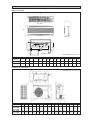 3
3
-
 4
4
-
 5
5
-
 6
6
-
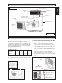 7
7
-
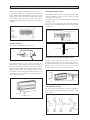 8
8
-
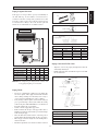 9
9
-
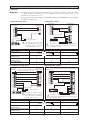 10
10
-
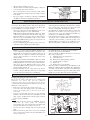 11
11
-
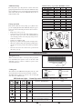 12
12
-
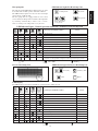 13
13
-
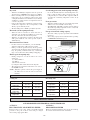 14
14
-
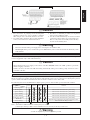 15
15
-
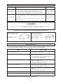 16
16
-
 17
17
-
 18
18
-
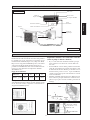 19
19
-
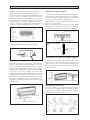 20
20
-
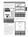 21
21
-
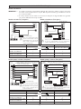 22
22
-
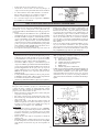 23
23
-
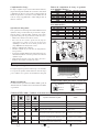 24
24
-
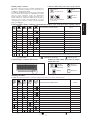 25
25
-
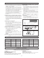 26
26
-
 27
27
-
 28
28
-
 29
29
-
 30
30
-
 31
31
-
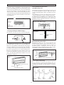 32
32
-
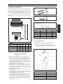 33
33
-
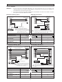 34
34
-
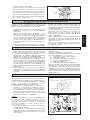 35
35
-
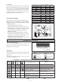 36
36
-
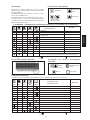 37
37
-
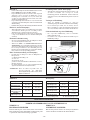 38
38
-
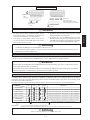 39
39
-
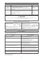 40
40
-
 41
41
-
 42
42
-
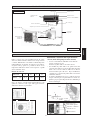 43
43
-
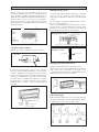 44
44
-
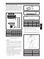 45
45
-
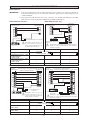 46
46
-
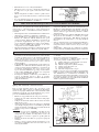 47
47
-
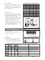 48
48
-
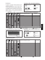 49
49
-
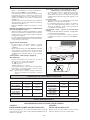 50
50
-
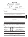 51
51
-
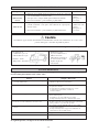 52
52
-
 53
53
-
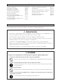 54
54
-
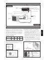 55
55
-
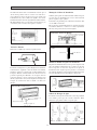 56
56
-
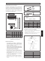 57
57
-
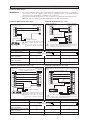 58
58
-
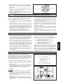 59
59
-
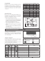 60
60
-
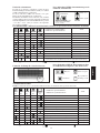 61
61
-
 62
62
-
 63
63
-
 64
64
-
 65
65
-
 66
66
-
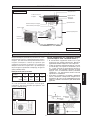 67
67
-
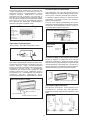 68
68
-
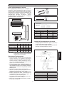 69
69
-
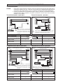 70
70
-
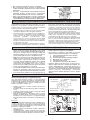 71
71
-
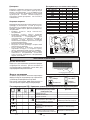 72
72
-
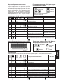 73
73
-
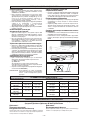 74
74
-
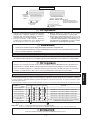 75
75
-
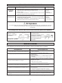 76
76
-
 77
77
-
 78
78
-
 79
79
-
 80
80
-
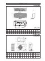 81
81
-
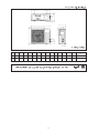 82
82
-
 83
83
-
 84
84
-
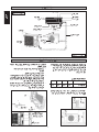 85
85
-
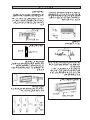 86
86
-
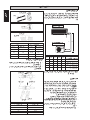 87
87
-
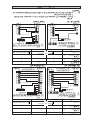 88
88
-
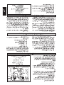 89
89
-
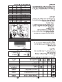 90
90
-
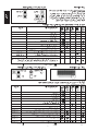 91
91
-
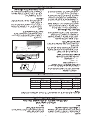 92
92
-
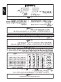 93
93
-
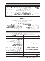 94
94
-
 95
95
-
 96
96


McQuay IM-WMF-0501 Guía de instalación
- Tipo
- Guía de instalación
en otros idiomas
- français: McQuay IM-WMF-0501 Guide d'installation
- italiano: McQuay IM-WMF-0501 Guida d'installazione
Artículos relacionados
-
McQuay WM15G Guía de instalación
-
McQuay A Series Guía de instalación
-
Acson MST101015A Guía de instalación
-
-
-
-
-
-
-
Otros documentos
-
Acson A5LC010CR Guía de instalación
-
Acson 5SL20CR Guía de instalación
-
-
Haier 2U14CS2ERA El manual del propietario
-
Haier 1U18FS2ERA Guía de instalación
-
Acson M-CCC-0501-ACSON Guía de instalación
-
-
-
Hitachi P-G23WA2 Guía de instalación
-