McQuay IM-WM1W-0704 Guía de instalación
- Tipo
- Guía de instalación

WALL MOUNTED
CHILLED WATER FAN COIL UNIT
INSTALLATION MANUAL
Group: CHILLED WATER
Part Number: A08019025518
Date: JULY 2004
IM-WM1W-0704-McQuay
© 2004 McQuay International


i
OUTLINE AND DIMENSIONS
All dimensions are in mm / (in)
Dimension A B C D E
WM 301 W 1120,0 (44,1) 360,0 (14,2) 200,0 (7,9) 730,0 (28,7) 347,0 (13,7)
Indoor Unit
D
INSTALLATION PLATE
E
FRONT VIEW
TOP VIEW
A
B
C
SIDE VIEW
WM 301 W (G11 / G12)
Part No: A08019022972 IM-WM1W-0704
MODEL: WM 301W
DISPLAY BOARD
HEAT VALVE
ROOM THERMISTOR
INDOOR COIL THERMISTOR
SWITCH BOARD
RED
BLUE
CAPACITOR
FAN MOTOR
ORANGE (LO)
BROWN (MED)
YELLOW (HI)
SOLENOID
VALVE
COMP N2 N1 L
TO CHILLER UNIT
L 240VAC
N 1PHASE
E50Hz
YELLOW/GREEN
BLUE
BLUE
BLUE
PURPLE
RED
LIVE VALVE
MAIN BOARD
CN-TS1
ROOM
ID
OO
CN WIRED
LIVE
MOOD
CN DISP
AS
FM
NOTICE

ii
NACHRICHT
Leitung Endpunkt zum Steuerpultbrett ist, wie in den Bauschaltplänen gezeigt.
Das Standardsteuerpultbrett (W1V3) kommt mit einem VALVE (JVLV) Überbrücker undeinem HEAT (JMODE) Überbrücker.
Das System muß als die Überbrückervorwähler zusammengebaut werden, die nachstehend aufgeführt wird:
HEAT Überbrücker VALVE Überbrücker
Abkühlende Modus U. Ventil-Anwendung × √
Abkühlender Modus U. Valveless Anwendung ××
Wärmepumpe Modus U. Ventil-Anwendung √ √
Wärmepumpe Modus U. Valveless Anwendung √
×
√ Bleiben Überbrücker! × Überbrücker Entfernt
Beispiel
: Wenn die Maßeinheit “Wärmepumpe Modus u. Valveless Anwendung” laufen läßt, bleiben der Überbrücker beim
Entfernen des Überbrückers.
VORSICHT!
Trennen Sie das Phasenspg.Versorgungsteil zur Maßeinheit, bevor Sie versuchen, die Verdrahtung anzuschließen.
NOTIFICATION
L’arrêt de fil au tableau de contrôle est comme montré dans les diagrammes de câblage.
Le tableau de contrôle standard (W1V3) vient avec un VALVE (JVLV) pullover et un HEAT (JMODE) pullover. Le système doit
être configuré comme choix de pullover énuméré ci-dessous:
HEAT Pullover VALVE Pullover
Mode De Refroidissement Et Application De Valve × √
Mode De Refroidissement Et Application Valveless ××
Mode De Heatpump Et Application De Valve √√
Mode De Heatpump Et Application Valveless √
×
√ Le Pullover Est resté × Le Pullover A enlevé
Exemple
: Si l’unité court le “Mode de Heatpump Et l’application Valveless”, restent le HEAT pullover tout en enlevant le VALVE
pullover.
ATTENTION !
Débranchez l’alimentation d’énergie de phase à l’unité avant d’essayer de relier le câblage.
NOTICE
Wire termination to the controller board is as shown in the wiring diagrams.
The standard controller board (W1V3) comes with a VALVE (JVLV) jumper and a HEAT (JMODE) jumper. The system must be
configured as the jumper selection listed below:
HEAT Jumper VALVE Jumper
Cooling Mode & Valve Application × √
Cooling Mode & Valveless Application ××
Heatpump Mode & Valve Application √ √
Heatpump Mode & Valveless Application √
×
√ Jumper Remained × Jumper Removed
Example:
If the unit is running “Heatpump Mode & Valveless Application”, remain the HEAT jumper while removing the VALVE
jumper.
CAUTION!
Disconnect the live power supply to the unit before attempting to connect the wiring.
ENGLISH
FRENCH
GERMAN

iii
ИНФОРМАЦИЯ
Электропроводка подсоединяется к панели управления, как показано на диаграмме соединений.
В набор стандартной панели управления (W1V3) входит соединительный провод VALVE (JVLV) и соединительный
провод HEAT (JMODE) .
Для настройки системы необходимо установить перемычки следующим образом:
Соединительный провод HEAT Соединительный провод VALVE
Режим Охлаждения & С использованием Клапана
× √
Режим Охлаждения & Без использования Клапана
××
Режим Теплового Насоса & С использованием Клапана
√√
Режим Теплового Насоса & Без использования Клапана
√ ×
√ Оставьте Соединительный провод! × Удалить перемычку
Например: Когда установка работает в режиме “Тепловой Насос & Без использования Клапана” оставьте
соединительный провод HEAT и снимите Соединительный провод VALVE.
ВНИМАНИЕ!
Прежде чем производить подсоединение проводников, отключите установку от источника питания.
AVISO
La terminación del alambre al tablero de regulador está úsegn lo demostrado en los digramas eléctricos.
El tablero de regulador estándar (W1V3) viene con un VALVE (JVLV) puente y un HEAT (JMODE) puente. El sistema se debe
configurar como la selección del puente enumerada abajo:
HEAT Puente VALVE Puente
Modo Que se refresca Y Uso De la Válvula × √
Modo Que se refresca Y Uso Sin Válvulas ××
Modo Del Heatpump Y Uso De la Válvula √ √
Modo Del Heatpump Y Uso Sin Válvulas √
×
√ El Puente Permanecía × El Puente Quitó
Ejemplo
: Si la unidad está funcionando “Modo Del Heatpump y el Uso Sin Válvulas”, permanece el HEAT puente mientras que
quita el VALVE puente.
PRECAUCIÓN!
Desconecte la fuente de alimentación viva a la unidad antes de procurar conectar el cableado.
AVVISO
Il termine del legare alla cartolina di regolatore è come indicato negli schemi elettrici.
La cartolina di regolatore standard (W1V3) viene con un VALVE (JVLV) ponticello e un HEAT (JMODE) ponticello. Il sistema
deve essere configurato come la selezione del ponticello elencata qui sotto:
HEAT Ponticello VALVE Ponticello
Modo Di Raffreddamento & Applicazione Della Valvola × √
Modo Di Raffreddamento & Applicazione Valveless ××
Modo Del Heatpump & Applicazione Della Valvola √√
Modo Del Heatpump & Applicazione Valveless √
×
√ Il Ponticello È rimasto × Il Ponticello Ha rimosso
Esempio
: Se l’unità sta facendo funzionare “Il Modo Del Heatpump & l’applicazione Valveless”, rimane il HEATponticello
mentre rimuove il VALVE ponticello.
ATTENZIONE!
Stacchi il gruppo di alimentazione in tensione all’unità prima di tentare di collegare i collegamenti.
RUSSIAN
SPANISH
ITALIAN

iv
Sharp edges and coil surfaces are potential locations which may cause injury
hazards. Avoid from being in contact with these places.
! Caution
Les bords coupants et les surfaces du refroidisseur tubulaire présentent
un risque de blessure. Mieux vaut éviter le contact avec ces endroits.
!
Avertissement
Scharfe Kanten und Wärmetauscherflächen stellen eine Gefahrenquelle dar. Jeglicher
Kontakt mit diesen Stellen ist zu vermeiden.
! Vorsicht
Los Bordes afilados y la superficie del serpentín pueden producir lesiones. Evite
tocarlos.
! Cuidado
Per preservarsi da eventuali ferite, evitare di toccare gli spigoli affilati e la superficie
dei serpentini.
! Cautela
Острые края и поверхности змеевиков являются потенциальными
местами нанесения травм. Остерегайтесь контакта с этими местами.
! Осторожно
This product is subjected to Waste of Electrical and Electronic Equipment Regulations (WEE
E
Regulations). The waste product shall be separately collected by specific collection and treatment centre
.
P
lease refer to local authorithy for these centres. This is only applicable to European Union countries
.
Ce produit est soumis
à
la r
à
é
r
r
é
é
é
lectriques e
t
é
é
é
ê
é
é
é
é
é
é
é
é
é
î
î
tre ces centres. Ceci
îî
est uniquement applicable aux pays de l'Union Euro
p
é
enne
.
Questo prodotto
è
soggetto alle disposizioni RAEE (Rifiuti di apparecchiature elettriche ed elettroniche)
.
à
à
locali. Questa disposizione
à
è
valida solamente i paes
i
d
el
l
’
U.
E
.
é
ctrico y Electr
ó
n
ico en materia d
e
ñ
ñ
á
í
fico
íí
de colecc
i
ó
solamente aplicable a los p
a
í
ses de la
U
n
i
ó
n
Europea
.
Dieses Produkt unterliegt den Bestimmungen zur Entsorgung von elektrischen und elektronische
n
G
er
ä
ä
ä
tes
ää
ü
ü
ll bei Ihrer
ö
ü
ö
ä
ndiges Abfall-Amt. Dieser
ää
Hinweis gilt nur f
ü
f
f
rL
ä
ischen Union
.
П
р
оцес
с
у
тилизаци
и
д
анног
о
прод
у
кт
а
рег
у
лир
у
етс
я
п
р
авилам
и
п
о
у
тилизаци
и
отхо
д
о
в
и
(WEEE Re
g
ulations).
и
,
.
Э
т
и
п
р
авил
а
Ев
р
опейског
о
.
NOTICE

1-1
English
IM-WM1W-0704 (1)-McQuay
Part No: A08019025518
This manual provides the procedures of installation to ensure a safe and good standard of operation for the air
conditioner unit.
Special adjustment may be necessary to suit local requirements.
Before using your air conditioner, please read this instruction manual carefully and keep it for future reference.
INSTALLATION MANUAL
WALL MOUNTED CHILLED WATER FAN COIL UNIT
MODEL
WM 301W / MWM 301W

1-2
CONTENTS
- Outline and Dimensions page i
- Notice page i-iv
- Safety Precautions page 2
- Installation Diagram page 3
- Installation of the Indoor Unit page 3
- Electrical Wiring Connection page 4
- Indicator Lights page 6
- Air Conditioner Unit Operation page 7
- Oparating Range page 7
- Optional : Electrostatic Filter page 8
- Service and Maintenance page 9
- Troubleshooting page 10
Before installing the air conditioner unit, please read the following safety precautions carefully.
SAFETY PRECAUTIONS
! Warning
• Installation and maintenance should be performed by qualified persons who are familiar with local code and
regulation, and experienced with this type of appliance.
• All field wiring must be installed in accordance with the national wiring regulation.
• Ensure that the rated voltage of the unit corresponds to that of the name plate before commencing wiring work
according to the wiring diagram.
• The unit must be GROUNDED to prevent possible hazard due to insulation failure.
• All electrical wiring must not touch the refrigerant piping, compressor or any moving parts of the fan motors.
• Confirm that the unit has been switched OFF before installing or servicing the unit.
! Caution
Please take note of the following important points when installing.
• Do not install the unit where leakage of flammable gas may occur.
If gas leaks and accumulates at the surrounding of the unit, it may cause fire ignition.
• Ensure that the drainage piping is connected properly.
If the drainage piping is not connected properly, it may cause water leakage which will dampen the
furniture.
• Do not overcharge the unit.
This unit is factory pre-charged. Overcharge will cause over-current or damage to the compressor.
• Ensure that the units panel is closed after service or installation.
Unsecured panels will cause the unit to operate noisily.
IMPORTANT
DO NOT INSTALL OR USE THE AIR CONDITIONER UNIT IN A LAUNDRY ROOM.

1-3
English
INSTALLATION DIAGRAM
Air Intake Grille
Air Discharge
Grille
Air Intake
Refrigerant Piping
Drain Hose
Front Frame
Back Housing
On/Off Switch
Air Filters
Indicator Lights
Signal Receiver
Air Discharge
Louvre
Outdoor Unit
Indoor Unit
Air Discharge
Nozzle
Air Intake
INSTALLATION OF THE INDOOR UNIT
Maintenance &
Servicing Space
Air Flow
Direction
Higher Than
Eye Level
The indoor unit must be installed in such a way so as to
prevent short circuit of the cool discharged air with the hot
return air. Please follow the installation clearance shown in
the figure. Do not place the indoor unit where there could be
direct sunlight shining on it. Also, this location must be
suitable for piping and drainage, and be away from doors or
windows.
Installation plate
Marking-offline
Thread
Right & rear side routing
The refrigerant piping can be routed to the unit in a
number of ways (left or right from the back of the unit), by
using the cut-out holes on the casing of the unit (see figure).
Bend the pipes carefully to the required position in order to
aligned it with the holes. For the right hand and rear side
out, hold the bottom of the piping and then position it to the
required direction (see figure). The condensation drain hose
can be taped to the pipes.
Mount the unit onto the installation plate
Hook the indoor unit onto the upper portion of the
installation plate (Engage the two hooks at the rear top of
the indoor unit with the upper edge of the installation plate).
Ensure that the hooks are properly seated on the
installation plate by moving it to the left and right.
50mm
50mm
50mm
50mm
50mm
50mm

1-4
Mounting installation plate
Ensure that the wall is strong enough to withstand the weight
of the unit. Otherwise, it is necessary to reinforce the wall
with plates, beams or pillars.
Use the level gauge for horizontal mounting, and fix it with
4 suitable screws.
In case the rear piping draws out, drill a hole 65mm in
diameter with a cone drill, slightly lower on the outside wall
(see figure).
Routing of piping
Remove the screw holding the front panel.
Piping routing
1
2
3
4
5
Inside
Outside
1/50 Inclination
End
Dipped
Into
Water
Water
Leaking
Water
Leaking
Water
Leaking
Water drainage piping
The indoor drain pipe must be in a downward gradient for
smooth drainage. Avoid situations that are likely to cause
water to leak.
Connecting cable
Drain hose
J
Wrong
J
Wrong
J
Wrong
j
Correct
✓
Water Drainage
ELECTRICAL WIRING CONNECTION
• All wires must be firmly connected.
• All wires must not touch the water piping, or any mov-
ing parts of the fan motor.
• The connecting wires between the indoor unit and the
outdoor unit must be clamped on the wire clamps
as shown in the figure.
• The power supply cord must be equivalent to H05RN-F
(245IEC57) which is the minimum requirement.
IMPORTANT : The figures shown in the table are for information purpose only. They should be checked and selected
to comply with the local/national codes of regulations. This is also subject to the type of installa-
tion and conductors used.
Model WM 301 W
Voltage range 220V – 240V
1Ph / 50Hz +
Power supply cable size mm
2
2.5
Number of wire 3
Interconnection cable size mm
2
2.5
Number of wire 3
Recommended fuse A 20

1-5
English
COMP
N L
WM 301 W
Water Piping Connection
The indoor unit is equipped with water outlet and inlet bare connection. There is an air-vent for air purging that is fitted at the
outlet water heater.
3 ways solenoid valve is required for cycling off or bypass the chilled water.
Black steel pipe, polyuthrene pipe, PVC pipe and copper tube are recommended in field installation.
All types of piping and connection must be insulated by polyurethane (ARMAFLEX type or equivalent) to avoid condensation.
Do not use contaminated or damaged pipe and fitting for installation.
Some main fitting components are needed in the system to enhance the capacity and ease of service, such as gate valve,
balancing valve, 2 ways or 3 ways solenoid valve, filter, strainer, etc.
Wire Clamp
Interconnection
Cable
Chiller
Gate Valve
Gate Valve
Three Way Valve
Good Controlling Bad Controlling
Gate Valve
Two Way Valve
Gate Valve
Gate Valve
FCUFCUFCU
Worst Controlling
Gate Valve

1-6
IR Signal Receiver
When an infrared remote control operating signal has
been transmitted, the signal receiver on the indoor unit
will make a <beep> sound to confirm acceptance of the
signal transmission.
Cooling Unit
The table shows the LED indicator lights for the air condi-
tioner unit under normal operation and fault conditions.
The LED indicator lights are located at the bottom right
side of the air conditioner unit.
Heat Pump Unit
The table shows the LED indicator lights for the air condi-
tioner unit under normal operation and fault conditions.
The LED indicator lights are located at the bottom right
side of the air conditioner unit.
INDICATOR LIGHTS
LED Indicator Lights
IR Receiver
LED Indicator Lights For Cooling Unit
Cool mode
Fan mode
Dry mode
Sleep mode
LED Indicator Lights For Heat Pump Unit
Cool mode
Dry mode
Sleep mode
Heat / Fan mode
(red / green)
LED Indicator Lights : Normal Operation And Fault Conditions
Operation / Fault Indication Action
Cool mode –
Heat mode –
Fan mode –
Dry mode –
Room sensor missing –
Pipe sensor missing –
ON or OFF
ON
Blinking
Cool Dry Sleep Heat Fan
* Dry mode = Cool mode at low fan
(green)
(red)

1-7
English
AIR CONDITIONER UNIT OPERATION
Dry mode
• When the air humidity is high, the unit can operate in dry
mode. Press <MODE> button and choose <DRY>.
• If the room temperature is 2°C/35.6°F higher than the set
temperature, the air conditioner will operate under cooling
mode until it reaches within the 2°C/35.6°F range of
difference compared to the set temperature before it
converts to dry mode.
• If the room temperature is within the 2°C/35.6°F range of
difference compared to the set temperature, it will
directly operate under dry mode.
• The unit will operate at LOW speed under dry mode.
Horizontal air flow control
• For more effective air circulation, you can manually adjust
the air discharge grille to the left or right.
• During cool mode operation and dry mode operation, do
not direct the air discharge louver downwards for too long.
If operating continues in this way, condensation may occur
on the louver, thus resulting in drippings.
Cooling
Dry
/ 77¡F
25¡C
Horizontal
25°C/77°F
Fan speed and rated cooling capacity
• The rated cooling capacity is provided at the maximum
fan speed.
• The cooling capacity is lower when the unit is operating at
MEDIUM and LOW fan speed.
! Warning
• Disconnect from the main power supply before servicing the air conditioner unit.
• DO NOT pull out the power cord when the power is ON. This may cause serious electrical shocks which may result
in fire hazards.
OPERATING RANGE
Heat Pump Unit
Temperature Ts °C/°F Th °C/°F
Minimum indoor
temperature
Maximum indoor
temperature
Minimum outdoor
temperature
Maximum outdoor
temperature
Ts: Dry bulb temperature. Th: Wet bulb temperature.
Cooling unit
Temperature Ts °C/°F Th °C/°F
Minimum indoor
19.0 / 66.2 14.0 / 57.2
temperature
Maximum indoor
32.0 / 89.6 23.0 / 73.4
temperature
Minimum outdoor
19.4 / 66.9
-
temperature
Maximum outdoor
46.0 / 114.8
-
temperature
16.0 / 60.8
30.0 / 86.0
-8.0 / 17.6
24.0 / 75.2
-
-
-9.0 / 15.8
18.0 / 64.4

1-8
HOW TO INSTALL
DUAL ACTION ELECTROSTATIC AIR PURIFYING
AND DEODORIZING FILTER MEDIA AND FILTER FRAME
ACTION 1-
ELECTROSTATIC AIR PURIFYING FILTER
Removes microscopic dust, smoke and small invisible
particles to keep the room air clean with pre-charged
electrostatic polypropylene filter.
OPTIONAL : ELECTROSTATIC FILTER
ACTION 2-
DEODORIZING FILTER
Removes unwanted smells and odors in the air and keeps
the room air fresh with activated carbon filter.
! Warning
• Disconnect from the main power supply before servicing the air conditioner unit.
• DO NOT pull out the power cord when the power is ON. This may cause serious electrical shocks which may
result in fire hazards.
! Caution
1. The electrostatic air purifying and deodorizing filter
should be replaced once every 6 months or when the
filter changes color to brownish, whichever is sooner.
2. Used dusty filters should be disposed and shouldn't be
reused, even if it has been cleaned and washed.
3. The filter is a consumable part which you can purchase
from your air conditioner dealer.
4. Use the new filter immediately once it has been taken
out from its sealed packing. Do not unpack the new
filter too early before it is actually used as this may
decrease its deodorizing effect.

1-9
English
SERVICE AND MAINTENANCE
Maintenance Procedures
1. Remove any dust adhering to the filter by using a vacuum cleaner or
wash in lukewarm water (below 40°C/104°F ) with a neutral cleaning
detergent.
2. Rinse the filter well and dry before placing it back onto the unit.
3. Do not use gasoline, volatile substances or chemicals to clean the filter.
1. Clean any dirt or dust on the grille or panel by wiping it off with a soft
cloth soaked in lukewarm water (below 40°C/104°F) and a neutral
detergent solution.
2. Do not use gasoline, volatile substances or chemicals to clean the
indoor unit.
Period
At least once every
2 weeks.
More frequently if
necessary.
At least once every
2 weeks.
More frequently if
necessary.
Service Parts
Indoor air filter
Indoor unit
WHEN THE UNIT IS NOT USED FOR AN EXTENDED PERIOD OF TIME
Operate the unit for 2 hours
with the following setting.
Operating mode : cool
Temperature : 30°C/86°F
Remove the power plug.
If you are using an independent
electric circuit for your unit,
cut off the circuit.
Remove the batteries in the
remote control.
! Caution
Do not operate any heating apparatus too close to the air conditioner unit. This may cause the plastic panel to melt
or deform as a result of the excessive heat.

1-10
If any malfunction of the air conditioner unit is noted, immediately switch off the power supply to the unit.
Check the following fault conditions and causes for some simple troubleshooting tips.
TROUBLESHOOTING
Causes / Action
- Power failure, or the fuse needs to be replaced.
- The power plug is disconnected.
- It is possible that your delay timer has been set incorrectly.
- If the fault persist after all these verifications, please
contact the air conditioner unit installer.
- The air filter is dirty.
- The doors or windows are open.
- The air suction and discharge are clogged.
- The regulated temperature is not high enough.
- Odours may be caused by cigarettes, smoke particles, perfume
etc. which might have adhered onto the coil.
- This is caused by air humidity after an extended period of
operation.
- The set temperature is too low, increase the temperature setting
and operate the unit at high fan speed.
- Switch off unit and call dealer.
Fault
1. The air conditioner unit does not operate.
2. The air flow is too low.
3. Discharge air flow has bad odour.
4. Condensation on the front air grille of the indoor unit.
5. Water flowing out from the air conditioner unit.
If the fault persists, please call your local dealer/serviceman.

2-1
Français
Ce manuel fournit les procédures d’installation pour assurer le bon fonctionnement et la sécurité de cet appareil.
Des ajustements peuvent être nécéssaires pour suivre les réglementations locales.
Avant d’installer et de faire fonctionner le climatiseur, lisez attentivement ce manuel et conservez le.
MANUEL D’INSTALLATION
VENTILO-CONVECTEUR MURAL À EAU GLACÉE
Modèle
WM 301W / MWM 301W
IM-WM1W-0704 (1)-McQuay
Part No: A08019025518

2-2
SOMMAIRE
- Contour et Dimensions page i
- Notification page i-iv
- Précautions de Sécurité page 2
- Diagramme D’installation page 3
- Installation de L’unité Intérieure page 3
- Raccordement Électrique page 4
- L’indicateur S’allume page 6
- Opération du Climatiseur page 7
- Plage D’exploitation page 7
- En Option : Filtre Électrostatique page 8
- Entretien et Maintenance page 9
- Analyse des Causes de Dysfonctionnement
du Climatiseur page 10
Avant de faire fonctionner l’appreil, veuillez bien lire les précautions de sécurité suivantes.
PRÉCAUTIONS DE SÉCURITÉ
! Attention
• L’installation et la maintenance doivent être exécutées par une personne qualifiée qui est familiarisée avec les lois
et réglementations en vigueur, et aussi expérimentée dans ce type d’équipements.
• Tous les câblages doivent répondre aux réglementations électriques nationales.
• Avant de commencer le raccordement suivant le schéma électrique, s’assurer que la tension nominale de l’appareil
corresponde bien à celle indiquée sur la plaque signalétique.
• L’ unité doit être raccordée à la TERRE pour prévenir tous les risques possibles dûes à un défaut d’isolation.
• Aucun câble électrique ne doit toucher la tuyauterie du réfrigérant, le compresseur ou les pièces mobiles des moteurs
de ventilation.
• Avant l’installation ou l’entretien du climatiseur, s’assurer que l’appareil est éteint (OFF).
! Avertissement
Vérifier les points suivants au cours de l’installation.
• Ne pas installer l’appareil où il peut se produire des fuites de gaz inflammable.
En cas de fuite et accumulation de gaz autour de l’appareil, il y a risque d’incendie.
• S’assurer que le tuyau d’évacuation du condensat est correctement branché.
Si le tuyau d’évacuation n’est pas correctement branché, les éventuelles fuites d’eau risquent de mouiller
le mobilier.
• Ne pas surcharger l’unité (en fluide frigorigène).
Cet appareil est préchargé en usine. Une charge trop importante risque de provoquer une surcharge
électrique ou d’endommager le compresseur.
• S’assurer que le panneau supérieur de l’appareil est remis en place après l’installation ou l’entretien.
Avec un panneau mal fixé l’appareil va fonctionner bruyamment.
IMPORTANT
NE PAS INSTALLER OU UTILISER LE CLIMATISEUR DANS UNE BUANDERIE.

2-3
Français
DIAGRAMME D’INSTALLATION
Unité Extérieure
Unité Intérieure
INSTALLATION DE L’UNITÉ INTÉRIEURE
Espace d’entretien et
de reparation
Direction de
la circulation
d’air
Plus haut que le
niveau des yeux
Installer l’unité intérieure de traitement d’air de façon à ce
qu’il n’y ait aucun obstacle sur la circulation de l’air
(risque de recyclage de l’air refroidi au refoulement de l’unité
et l’air à l’entrée). Veuillez respecter l’écartement
d’installation illustré sur le diagramme. Ne pas exposer
l’unité intérieure à l’influence directe de l’éclairage.
L’emplacement de l’unité, doit permettre une évacuation
aisée des condensats, et permettre une evacuation aisee des
condensats, et doit être suffisamment loin des portes.
Plaque d’Installation
Le Marquage-Hors ligne
Le fil
Acheminement de la tuyauterie
L’unité d’évacuations des condensats de l’unité interieure
devra être, dans la mesure du possible, dirigé vers la sortie
arrière des tuyauteries à travers le mur de support (voir
figure). Avant d’orienter le tubing, déclipser le support de
tube. Cintrer les tubes frigorifiques avec précaution et les
diriger vers la sorte choisie. Ne pas oublier de passer le câble
d’alimentation électrique dans l’unité intérieure à travers le
mur en même temps que les tuyauteries. Ne pas raccorder le
câble. Laisser une longueur de câble suffisante pour permettre
la connection ultérieure. Relier ensemble les tubes
frigorifiques, le flexible d’évacuation des condensats et le
câble électrique.
Mise en place de l’unite de la platine support
Positionner dans un premier temps l’unité intérieure sur la
languette d’accrochage supérieure de support. Pour vous
assurer que les crochets sont correctement installés sur la
plaque d’installation, essayez de les faire légèrement bouger
de gauche à droite.
50mm
50mm
50mm
50mm
50mm
50mm
Grilles de Reprise D’air
Grilles de Ventilation
Reprise Air
Tuyauteries Frigorifiques
Tuyau D’evacuation
Cadre Avant
Chassis Arriere
Interrupteur ON/OFF
Filtre À Air
Récepteur
de Signal
Led de Visualisation
Conduit de Ventilation
Refoulement d’air
Reprise Air

2-4
Montage de la platine support
S’assurrer que le mur de support soit suffisamment résistant,
pour supporter le poids de l’unité et éviter toutes vibrations.
Selon la composition du mur, utiliser des vis chevilles
appropriées pour la fixation de la platine support.
Utiliser la jauge à niveau pour le montage horizontal, puis la
fixer avec 4 vis appropriées.
Dans le cas de sortie arrière des tuyauteries, percer le trou Ø
65mm pour les canalisations à l’aide d’une scie cloche. Le
trou aura une légère pente vers l’unité extérieure (Voir figure).
Orientation des tuyauteries
Retirer les vis qui retiennent le panneau de devant.
Acheminement de la tuyauterie
1
2
3
4
5
À l’intèrieur
À l’extèrieur
Inclinaison de 1/50
Evacuation
d’eau de
Condensation
plongé
dans l’eau
Fuite
d’eau
Fuite
d’eau
Fuite
d’eau
Évacuation des condensats
Le tube d’évacuation des condensats de l’unité devra être,
dans la mesure du possible, dirigé vers la sortie arriere des
tuyauteries a travers le mur de support. Evitez les
situations susceptibles de causer une fuite d’eau.
Câble de liaison
Tuyau d’evacuation
J
Incorrect
J
Incorrect
J
Incorrect
j
Correct
✓
Drainage De L’eau
RACCORDEMENT ÉLECTRIQUE
• Tous les fils doivent être fermement connectés.
• Aucun fils ne doivent toucher les tubes frigorifiques, le
compresseur ou une autre partie mobile du moteur de
ventilateur.
• Le câble de liaison entre l’unité intérieure et extérieure
doit être fixé au boitier de raccordement à l’aide de
l’attache comme indiqué dans la figure ci-contre.
• Le cordon électrique doit être êquivalent à H05RN-F
(245IEC57) au minimum.
IMPORTANT : Ces valeurs sont données à titre indicatif seulement; elles doivent être vérifiées et ajustées en fonction des
normes et de la réglementations en vigueur. Elles dépendent aussi du type d’installation et du choix des
conducteurs utilisés.
Modèle WM 301 W
Tension d’alimentation 220V – 240V
1Ph / 50Hz +
Section du câble d’alim mm
2
2,5
Nombre de conducteurs 3
Section du câble de liaison mm
2
2,5
Nombre de conducteurs 3
Fusible aM A 20

2-5
Français
COMP
N L
WM 301 W
Raccordement des conduites d’eau
L’unité intérieure est munie de raccords nus aux prises d’entrée et de sortie d’eau. Il y a un évent pour la purge de l’air au
chauffe-eau de prise de sortie.
Il faut un électrorobinet à 3 voies pour mettre en circuit ou faire dériver l’eau refroidie.
On recommande les tuyaux d’acier noir, de polyuréthane, de PVC et de cuivre pour l’installation sur place.
Tous les types de tuyaux et de raccords doivent être isolés au polyuréthane (type ARMAFLEX ou équivalent) pour éviter la
condensation.
Ne pas installer avec des tuyaux et des raccords contaminés ou abîmés.
Certains éléments de raccord principaux sont nécessaires pour accroître la capacité du système et en faciliter l’entretien,
comme les robinets-vannes, les robinets d’équilibrage, les électrorobinets à 2 ou à 3 voies, les filtres, les épurateurs, etc.
Pince A Fil
Cable De
Connection
Refroidisseur
Refroidisseur
Robinet-
vanne
Robinet à trois voies
Bon contrôle Mauvais contrôle
Robinet à deux voies
FCUFCUFCU
Pire contrôle
Robinet-
vanne
Robinet-
vanne
Robinet-
vanne
Robinet-
vanne
Robinet-
vanne

2-6
IR Récepteur de signal
Lorsqu’un signal d’opération à infrarouge a été transmis, le
récepteur de signal de l’unité intérieure émet un <bip> pour
confirmer l’acceptation de transmission du signal.
Module refroidisseur
Le tableau montre que l’indicateur LED s’allume pour l’air
climatisé dans des conditions de fonctionnements normales
et par défaut. Les leds de visualisation apparaissent lorsque
le climatseur est sous tension, dans la fenêtre de couleur
bleu foncé située dans la partie inférieure droite du
climatiseur.
Module pompe à chaleur
Le tableau ci-dessous reprend en détail la visualisation par
led, des conditions normales de fonctionnement, et
conditions de défaut du climatiseur.
Les led de visualisation apparaissent lorsque le climatseur
est sous tension, dans la fenêtre de couleur bleu foncé située
dans la partie inférieure droite du climatiseur.
L’INDICATEUR S’ALLUME
L’indicateur LED s’allume pour l’unité de
refroidissement
L’indicateur LED s’allume pour l’unité de pompe
à chaleur
L’indicateur LED s’allume : Fonctionnement normal et défaillances
Fonctionnement normales/défaut Action
Mode refroidissement –
Mode chauffage –
Mode ventilation –
Mode déshumidification –
Thermostat d’ambiance absent –
Détecteur de canalisation absent –
LED Allumée ou ÉteinteLED Allumée LED Clignotante
Froid Déshumi- Sommeil
Chaleur
Ventilation
dification
* Mode déshumidification = Mode refroidissement avec ventilateur en basse vitesse
(vert)
Mode
refroidissement
Mode de
sommeil
Mode chaleur/
ventilateur
(rouge/vert)
Mode de
déshumidification
Mode ventilateur Mode de sommeil
Mode refroidissement
Mode de
déshumidification
(rouge)
LED De Visualisation
IR Récepteur De Signal

2-7
Français
OPÉRATION DU CLIMATISEUR
Déshumidification
• Lorsque le taux d’humidité de l’air est élevé, le climatiseur
peut fonctionner en mode de déshumidification. Appuyer
sur la touche <MODE> et sélectionner <DRY>.
• Au cas où la température de la pièce est de 2°C/35,6°F
supérieure à la température affichée, le climatiseur - avant
de passer en mode de déshumidification - fonctionnera en
mode de refroidissement jusqu’à ce que la température soit
retombée dans la limite des 2°C/35,6°F de différence par
rapport à la température affichée.
• Si la température de la pièce se trouve dans la limite des
2°C/35,6°F de différence par rapport à la température
affichée, l’appareil fonctionnera directement en mode de
déshumidification.
• En mode de déshumidification, l’appareil fonctionne à
faible vitesse de ventilation.
Contrôle du débit d’air horizontal
• Pour obtenir une meilleure circulation d’air, vous pouvez
ajuster la grille de refoulement d’air froid vers la gauche
ou vers la droite à la main.
• Pendant le fonctionnement en mode froid ou
déshumidification, il n’y a pas un refoulement d’air froid
pendant un long moment vers le bas. Car il pourrait se
produire de la condensation sur les volets d’air suivi d un
écoulement d’eau.
Refroidissement
Déshumidification
Vitesse de ventilation et capacité nominale de
refroidissement
• La capacité nominale de refroidissement peut être atteinte
en vitesse de ventilation maximum.
• La capacité de refroidissement est plus faible lorsque
l’appareil fonctionne en vitesse de ventilation moyenne
ou faible.
! Attention
• Couper l’alimentation du secteur avant d’effectuer l’entretien du climatiseur.
• NE PAS DÉBRANCHER le cordon électrique lorsqu’il y a du courant. Ceci pourrait provoquer des décharges
électriques avec pour résultat des risques d’incendie.
PLAGE D’EXPLOITATION
Module pompe à chaleur
Température Ts °C/°F Th °C/°F
Température
intérieure minimum
Température
intérieure maximum
Température
extérieure minimum
Température
extérieure maximum
Ts: Température au thermomètre sec.
Th: Température au thermomètre mouillé.
Module refroidisseur
Température Ts °C/°F Th °C/°F
Température
19,0 / 66,2 14,0 / 57,2
intérieure minimum
Température
32,0 / 89,6 23,0 / 73,4
intérieure maximum
Température
19,4 / 66,9 -
extérieure minimum
Température
46,0 / 114,8 -
extérieure maximum
16,0 / 60,8
30,0 / 86,0
-8,0 / 17,6
24,0 / 75,2
-
-
-9,0 / 15,8
18,0 / 64,4
/ 77¡F
25¡C
Horizontale
25°C/77°F

2-8
INSTALLATION
CADRE A FILTRE ET MATÉRIEL DE FILTRE ÉLECTROSTATIQUE DOUBLE ACTION
PURIFICATEUR D’AIR ET DÉSODORISANT
ACTION 1-
FILTRE PURIFICATEUR D’AIR
ELECTROSTATIQUE
Otez la poussière microscopique, la fumée et les petites
particules invisibles à l’aide d’un filtre polypropylène
électrostatique pour garder l’air de la pièce proper.
EN OPTION : FILTRE ÉLECTROSTATIQUE
ACTION 2-
FILTRE DESODORISANT
Débarrassez l’air des odeurs gênantes et conservez l’air de
la pièce frais à l’aide du filtre de carbone activé.
! Attention
• Couper l’alimentation du secteur avant d’effectuer l’entretien du climatiseur.
• NE PAS DÉBRANCHER le cordon électrique lorsqu’il y a du courant. Ceci pourrait provoquer des décharges
électriques avec pour résultat des risques d’incendie.
! Avertissement
1. Le filtre désodorisant et purificateur d’air électrostatique
doit être remplacé tous les 6 mois ou quand la couleur
du filtre devient marron, suivant ce qui se produit en
premier.
2. Les filtres usagés poussiéreux doivent être jetés et ne
peuvent être réutilisés, même si le filtre a été nettoyé et
lavé.
3. Le filtre est une pièce de rechange que vous trouverez
chez votre détaillant d’unités d’air climatisé.
4. Utilisez le nouveau filtre immédiatement une fois qu’il a
été sorti de son emballage hermétique. Ne sortez pas le
nouveau filtre trop tôt avant de l’utiliser, ceci peut
diminuer son effet désodorisant.
Ouverzle le
grillage du
cadre avant.
Inserez dans la fente
les filtres a double
action electrostatique
et desodorisant.
Replacez le filtre d’origine.
Sortez les filtres
d'origine en les
faisant glisser.

2-9
Français
Faites fonctionner l’unité
pendant 2 heures sur les
réglages suivants.
Mode de fonctionnement :
froid
Température : 30˚C/86˚F
Retirer la prise du secteur.
Si vous utilisez un circuit
électrique unique pour le
climatiseur, coupez le circuit.
Enlever les piles de la
télécommande.
ENTRETIEN ET MAINTENANCE
Procédure D’Entretien
1. Enlever la poussière du filtre à l’aide d’un aspirateur ou en
lavant le filtre à l’eau tiède (moins de 40°C/104°F) avec un
détergent neutre.
2. Bien rincer et sécher le filtre avant de le remettre en place.
3. Ne pas utiliser de gasoil, de substances volatiles ou autres
produits chimiques pour nettoyer le filtre.
1. Nettoyer la grille et le panneau en les essuyant avec un chif-
fon doux mouillé à l’eau tiède (moins de 40°C/104°F) et un
détergent neutre.
2. Ne pas utiliser de gasoil, de substances volatiles ou autres
produits chimiques pour nettoyer l’unité intérieure.
Périodicité
Au moins une fois
toutes les 2
semaines.
Plus souvent si
nécessaire.
Au moins une fois
toutes les 2
semaines.
Plus souvent si
nécessaire.
Pieces A Entretenir
Filtre à air intérieur
Unité intérieure
! Avertissement
Ne pas utiliser d’appareil de chauffage à proximité du climatiseur. La chaleur excessive pourrait faire fondre
ou déformer le panneau en plastique.
MISE A L’ARRÊT PROLONGUE DU CLIMATISEUR

2-10
ANALYSE DES CAUSES DE DYSFONCTIONNEMENT DU CLIMATISEUR
En cas de dysfonctionnement du climatiseur, couper aussitôt l’alimentation électrique. Vérifier ensuite les
points suivants pour détecter la nature et les causes de la panne.
Causes / Action
- Le circuit est peut être coupé ou un fusible est à changer.
- La prise de courant est peut être débranchée.
- La programmation de mise en marche/arrêt est peut-être mal
réglée.
- Si la panne persiste après ces vérifications, contacter
l’installateur.
- Le filtre à air est sale.
- Les portes ou les fenêtres sont ouvertes.
- Les entrées et sorties d’air sont bouchées.
- La température réglée n’est pas assez élevée.
- Les odeurs peuvent provenir de fumées de cigarettes, parfums ou
autres particules adhérants au refroidisseur.
- La condensation est due à l’humidité de l’air après une période
de fonctionnement prolongée.
- La température affichée est trop basse; augmenter la température
et faire tourner l’appareil à vitesse de ventilation élevée.
- Éteindre le climatisateur et appeler le concessionnaire.
Defauts
1. Le climatiseur ne fonctionne pas.
2. Le flux d’air est trop faible.
3. L’air dégagé a une mauvaise odeur.
4. Condensation sur la grille frontale de l’unité intérieure.
5. Ecoulement d’eau du climatiseur.
Si les pannes persistent, appeler votre revendeur ou le service après-vente.

3-1
Deutsch
Das vorliegende Handbuch enthält die Installationsanweisungen für einen sicheren und ordnungsgemäßen Betrieb
dieser Anlage.
Je nach den örtlichen Gegebenheiten können spezielle Anpassungen notwendig sein.
Vor der Inbetriebnahme des Klimagerätes dieses Handbuch bitte aufmerksam zur Kenntnis nehmen und für
künftigen Bedarf aufbewahren.
MONTAGEANLEITUNG
KALTWASSER-VENTILATOR-LUFTKÜHLER-WANDGERÄT
Modell
WM 301W / MWM 301W
IM-WM1W-0704 (1)-McQuay
Part No: A08019025518

3-2
INHALT
- Auslegung und Admessung seite i
- Nachricht seite i-iv
- Vorsichtmassnahmen seite 2
- Installationsdiagramm seite 3
- Installation des Innengerätes seite 3
- Kabelanschluß seite 4
- Betriebsleuchtanzeige seite 6
- Bedienung des Klimagerätes seite 7
- Betriebsbereich seite 7
- Optional : Elektrostatikfilter seite 8
- Instandhaltung und Wartung seite 9
- Störungs-Behebung seite 10
Vor der Installation sind nachfolgende Sicherheitsmaßnahmen aufmerksam zur Kenntnis zu nehmen.
VORSICHTMASSNAHMEN
! Achtung
• Die Installation und Wartung muß durch qualifizietes Personal erfolgen, Welches mit den örtlichen Bestimmungen
und diesem Ausrüstungstyp vertraut ist.
• Die gesamte E-Verkabelung hat in Übereinstimmung mit den landesspezifischen Anschlußvorschriften zu erfolgen.
• Vor dem Kabelanschluß gemäß Schaltbild ist sicherzustellen, daß die Betriebsspannung mit der auf dem Datenschild
des Gerätes angegebenen Spannung übereinstimmt.
• Das Gerät ist zum Schutz gegen fehlerhafte Isolierungen und entsprechende Risiken zu ERDEN.
• Die Kabel dürfen weder mit der Kühlmittelleitung, noch mit dem Kompressor oder den beweglichen Teilen der
Gebläsemotoren in Berührung kommen.
• Vor der Installation oder Wartung der Anlage ist sicherzustellen, daß das Gerät ausgeschaltet ist (OFF).
! Vorsicht
Vor der Installation sind folgende wichtige Punkte zu prüfen.
• Gerät nicht installieren, falls ein Leck entzündbaren Gases festgestellt wird.
Es besteht Feuergefahr, wenn Gas aus der Anlage entweicht und sich in der Umgebung ansammelt.
• Die Kondensat-Abflußleitung muß sachgemäß angeschlossen sein.
Ist die Abflußleitung nicht richtig angeschlossen, besteht Gefahr, daß durch auslaufendes Wasser
das Mobiliar feucht wird.
• Gerät nicht überlasten.
Das Gerät ist werkseitig vorgefüllt. Im Falle einer Überfüllung besteht die Gefahr einer Überbelastung
oder sonstigen Beschädigung des Kompressors.
• Nach Installation oder Wartung ist sicherzustellen, daß die Geräteabdeckung wieder montiert ist.
Eine mangelhafte Befestigung der Abdeckung führt zu Geräuschentwicklung während des Betriebs.
WICHTIG
DAS KLIMAGERÄT SOLLTE NICHT IN EINEM WÄSCHERAUM
INSTALLIERT ODER BENUTZT WERDEN.

3-3
Deutsch
INSTALLATIONSDIAGRAMM
Aussenanlage
Innen-Gerät
INSTALLATION DES INNENGERÄTES
Innengeräte sind so zu installieren, daß keine Interferenz
zwischen dem Kühlluftaustritt und der zurückgeführten Luft
besteht. Bei der Installation bitte die in der Zeichnung
angegebenen Abstände beachten. Ein Innenmontage-Gerät
darf nicht unter direkter Sonneneinstrahlung montiert
werden. Die Montageposition ist anhand der Rohrleitung und
der Drainage im gegebenen Abstand zu Türen oder Fenstern
zu gewährleisten.
Montageplatte
Markierung-offline
Gewinde
Verlegungsrichtung Rechts Und Hinten
Die Kühlmittel-Rohrleitung kann an die Einheit auf
verschiedene Weise angeschlossen werden (auf der Rückseite
links oder rechts der Einheit). Hierzu sind die Aussparungen
der Gërateverkleidung zu verwenden (siehe Abb.). Die Rohre
vorsichtig auf die entsprechenden Lochpositionen biegen.
Bei einem rechtseitigen bzw. bei einem Anschluß auf der
Rückseite das Rohrleitungsende festhalten und in die
entsprechende Richtung positionsgerecht biegen (siehe
Abb.). Der Kondensat-Drainageschlauch ist an die
Rohrleitungen anzupassen.
Gerätemontage auf der installationsplatte
Innenmontage-Gerät in den oberen Bereich der
Installationsplatte einhängen. (Die beiden hinteren oberen
Laschen der Innenmontage-Einheit in die obere Kante der
Installationsplatte einhängen). Bewegen Sie die
Montageplatte leicht nach links und rechts, um zu prüfen,
ob die Haken ordnungsgemäß eingegriffen haben.
50mm
50mm
50mm
50mm
50mm
Lufteinlassgitter
Abluftgitter
Lufteinlass
Kältemittelleitung
Ablaufschlauch
Vorderer Rahmen
Rückwärtiges Gehäuse
Ein-/Aus- Schalter
Luftfilter
Ir-Empfänger
Leuchtanzeige
Abluftaufsatz
Luftauslassdüse
Lufteinlass
Zwischenraum Für
Wartung Und Pelege
Richtung Des
Luftstroms
Oberhalb der
Augenhöhe
50mm

3-4
Montage der installations-halterungsplatte
Sicherstellen, daß die Trägerwand ausreichend fest ist, um
das Gewicht aufnehmen zu können. Falls nicht, müssen
geeignete Vertärkungsplatten, Träger oder Stützen verwendet
werden.
Beim Anbringen des Geräts eine Wasserwaage benutzen,
sodann das Gerät mit 4 geeigneten Schrauben befestigen.
Bei Rohrleitungs-herausführung auf der Rückseite: Eine
Bohrung 65 mm mit einem Konusbohrer setzen. Hierbei die
Bohrung auf der wandungsaußenseite etwas tiefer
positionieren (seihe Abb.).
Verlegungsrichtung Der Rohrleitungen
Die Schraube entfernen, die die Vorderabdeckung hält.
Verlegungsrichtung Der Rohrleitungen
1
2
3
4
5
Innen Außen
1/50 Neigung
In Wasser
Eintau-
Chendes
Rohrende
Wasser-
Leck
Wasser-
Leck
Wasser-
Leck
Wasser-entleerungsleitung
Zur problemlosen Kondensatabführung muß die
innenliegende Wasserentleerungsleitung Gefälle aufweisen.
Vermeiden Sie Umstände, die zum Austreten von Wasser
führen können.
Verbindungs-kabel
Ablaufschlauch
J
Falsch
J
Falsch
J
Falsch
j
Korrekt
✓
Wasserablauf
KABELANSCHLUß
• Alle Adern sind fest zu verdrahten.
• Jeglicher Kontakt einer Elektrokabelader mit der
Kältemittelleitung, dem Kompressor oder anderen
beweglichen Teilen des Gebläsemotors ist zu vermeiden.
• Die Anschlußadern zwischen Außen- und Innenmontage-
Gerät sind gem. Klemmbrücke gegen Abziehen zu
sichern.
• Das Anschlusskabel muss zumindest dem H05RN-F
(245 IEC57) entsprechen.
WICHTIG : Die angegeben Werte sind lediglich Richtwerte. Sie sind zu überprüfen und ggf. den örtlichen und/
oderlandesspezifischen Vorschriften und Bestimmungen anzugleichen. Des weiteren sind sie abhängig von der
Installationsart und dem Adernquerschnitt.
Modell WM 301 W
Spannungsbereich 220V – 240V
1Ph / 50Hz +
Zuleitungskabelquerschnitt mm
2
2,5
Adernanzahl 3
Zwischenkabelquerschnitt mm
2
2,5
Adernanzahl 3
Empfohlene Sicherung A 20

3-5
Deutsch
COMP
N L
WM 301 W
Verbindung der Wasserleitungen
Das Innengerät ist mit einem Wasserauslass und einer Glattrohr-Einlassverbindung ausgestattet. Angebracht am Auslauf des
Durchlauferhitzers gibt es eine Lüftungsöffnung zur Luftspülung.
Zur Umleitung des Kaltwassers ist ein 3-Weg-Magnetventil erforderlich.
Für die Installation vor Ort werden schwarze Stahlrohre, Polyurethanrohre, PVC-Rohre und Kupferrohre empfohlen.
Alle Rohrarten und Verbindungen müssen mit Polyurethan (ARMAFLEX oder äquivalent) abgedichtet werden, um
Kondensation zu vermeiden.
Benutzen Sie keine verunreinigten oder beschädigten Rohre oder Verbindungsstücke zur Installation.
Manche Hauptverbindungskomponenten werden im System benötigt, um das Leistungsvermögen zu erhöhen und einen
einfachen Service zu gewährleisten. Solche Komponenten sind Gatterventile, Entlastungsventile, 2-Weg- oder 3-Weg-
Magnetventile, Filter, Siebe, etc.
Drahtklemme
Verbin-
dungskabel
Kühler
Kühler
Gatterventil
Dreiwegventil
Gute Steuerung Schlechte Steuerung
Zweiwegventil
FCUFCUFCU
Schlechteste Steuerung
Gatterventil
Gatterventil
Gatterventil
Gatterventil
Gatterventil

3-6
Infrarot-Signalempfänger
Wenn von der Infrarot-Fernbedienung ein Signal an das
Gerät gesendet wird, bestätigt das Innen-gerät den Empfang
mit einem Signalton.
Kühleinheit
Die Tabelle erläutert die Bedeutung der Leuchtdioden für
den normalen Betrieb und eventuelle Störungen des
Klimageräts.
Die LED-Anzeigeleuchten befinden sich auf der rechten
unteren Seite des Klimagerätes.
Wärmepumpe
Nachstehende Tabelle enhält die einzelnen LED-
Funktionsanzeigen für Normalbetrieb und die verschiedenen
Störungsmeldungen.
Die LED-Anzeigeleuchten befinden sich auf der rechten
unteren Seite des Klimagerätes.
BETRIEBSLEUCHTANZEIGE
LED -Funktionsanzeige
Infrarot-Empfanger
Leuchtdiode für Kühlbetrieb
Leuchtdiode für Wärmepumpe
Leuchtdioden : Normale Betriebs- und Fehlerbedingungen
Normalbetrieb/Störungssituationen Maßnahme
Kühlmodus –
Heiz-Modus –
Gebläsemodus –
Entfeuchtungs-Modus –
Raumsensor fehlt –
Rohrsensor fehlt –
EIN oder AUS
EIN
Blinkend
Kühlen Trocknen
Schlafmodul
Heizen
Gebläse
* Entfeuchtungs-Modus = Kühlmodus bei niedriger Ventilatordrehzahl
(grün)
Kühlmodus
Schlafmodul
Wärme/
Gebläse Modul
(rot/grün)
Entfeuchtungs-
Modus
Gebläsemodus Schlafmodul
Kühlmodus
Entfeuchtungs-
Modus
(rot)

3-7
Deutsch
BEDIENUNG DES KLIMAGERÄTES
Entfeuchten
• Bei hoher Luftfeuchtigkeit ist das Gerät zum Entfeuchten
einsetzbar. Dazu die <MODE> Taste betätigen und
<DRY> anwählen.
• Liegt die Raumtemperatur um 2°C/35,6˚F höher als die
eingestellte Temperatur, arbeitet das Gerät im
Kühlbetrieb, bis die Raumtemperatur sich innerhalt von
2°C/35,6˚F Unterschied gegenüber der eingestellten
Temperatur befindet, und schaltet anschließend auf
Entfeuchten um.
• Liegt die Raumtemperatur innerhalb von 2°C/35,6˚F
Unterschied gegenüber der eingestellten Temperatur,
schaltet sich das Gerät direkt auf Entfeuchtung.
• Bei Entfeuchtung arbeitet das Gerät mit langsamer
Gebläsedrehzahl.
Horizontale Luftstromsteuerung
• Zur verbesserten Luftzirkulation kann das Abluftgitter
nach links oder rechts mit der Hand verstellt werden.
• Während der Kühl- oder Entfeuchtungs-funktion
(cooling/dry) solte das Strömungsrichtungsgitter nicht
über einen längeren Zeitraum hin direkt nach unten
gerichtet werden. Bei einer längeren Funktion in dieser
Einstellung kann sich Kondensat an den Lamellen bilden.
Bei einer Kondensatbildung kann es dadurch zu einer
Tropfenbildung kommen.
Kühlen
Entfeuchtle
Gebläsedrehzahl und vorgesehene Kühlleistung
• Die vorgesehene Kühlleistung wird bei maximaler
Gebläsedrehzahl erreicht.
• Bei mittlerer bzw. langsamer Gebläsedrehzahl liegt die
Kühlleistung niedriger.
! Achtung
• Vor Wartung des Klimagerätes das Stromkabel vom Netz trennen.
• Das Stromkabel nicht herausziehen, wenn das Gerät noch eingeschaltet ist. Ein elektrischer Schlag oder ein
Wohnungsbrand können die Folge sein.
BETRIEBSBEREICH
Wärmepumpe
Temperatur Ts °C/°F Th °C/°F
Mindest-
Innentemperatur
Maximale-
Innentemperatur
Mindest-
Außentemperatur
Maximale-
Außentemperatur
Ts: Trockenkugel-Temperatur. Th: Feuchtkugeltemperatur.
Kühleinheit
Temperatur Ts °C/°F Th °C/°F
Mindest-
19,0 / 66,2 14,0 / 57,2
Innentemperatur
Maximale-
32,0 / 89,6 23,0 / 73,4
Innentemperatur
Mindest-
19,4 / 66,9
-
Außentemperatur
Maximale-
46,0 / 114,8
-
Außentemperatur
16,0 / 60,8
30,0 / 86,0
-8,0 / 17,6
24,0 / 75,2
-
-
-9,0 / 15,8
18,0 / 64,4
/ 77¡F
25¡C
Waagerecht
25°C/77°F

3-8
INSTALLATIONSANLEITUNG
DOPPELT WIRKENDES FILTERMATERIAL UND FILTERRAHMEN FÜR
ELEKTROSTATIKBEHANDLUNG UND LUFTREINIGUNG
WIRKUNG 1-
ELEKTROSTATIKFILTER
Entfernt mikroskopisch feinen Staub, Rauch und unsichtbar
kleine Partikel und reinigt die Raumluft fortlaufend mit
positiv vorgeladenem elektrostatischem Polypropylenfilter.
OPTIONAL : ELEKTROSTATIKFILTER
WIRKUNG 2-
LUFTREINIGUNGSFILTER
Entfernt unangenehme Gerüche aus der Umgebungsluft und
erfrischt den Raum fortlaufend mit Aktivkohlefilter.
! Achtung
• Vor Wartung des Klimagerätes das Stromkabel vom Netz trennen.
• Das Stromkabel nicht herausziehen, wenn das Gerät noch eingeschaltet ist. Ein elektrischer Schlag oder ein
Wohnungsbrand können die Folge sein.
! Vorsicht
1. Der Filter für die Elektrostatikbehandlung und die
Luftreinigung sollte bei bräunlicher Verfärbung oder
spätestens nach 6 Monaten gewechselt werden.
2. Verbrauchte, staubige Filter sollten weggeworfen
werden. Sie können auch nach Reinigen und waschen
nicht wieder verwendet werden.
3. Der Filter ist ein Verbrauchsgegenstand, den Sie von
ihrem Kimagerätehändler beziehen können.
4. Verwenden Sie das neue Filtermaterial sofort nach
Entnahme aus der versiegelten Verpackung. Packen Sie
den neuen Filter nicht zu früh vor der tatsächlichen
Verwendung aus, da er sonst seine Luftreinigungswirkung
verliert.
Öffnen sie das
vordere
rahmengitter.
Schieben sie die
originalfilter
heraus.
Schieben sie den
originalfilter zuruck.
Setzen sie den
doppelwirkungsfilter
fur die
elektrostatikbehandlung
und die luftreinigung in
den schlitzen.

3-9
Deutsch
Betreiben Sie das Gerät 2
Stunden lang in folgender
Einstellung.
Betriebsmodus : Kühlen
Temperatur : 30˚C/86˚F
Netzstecker ziehen. Falls das
Klimagerät an einen eigenen
Stromkreis angeschlossen ist,
diesen Stromkreis unterbrechen.
(Sicherung herausdrehen oder
Sicherungsautomat abschalten).
Batterien aus der Fernbedienung
nehmen.
Wartungsverfahren
1. Luftfilter mit Staubsauger absaugen oder in lauwarmem Wasser (unter 40°C/
104˚F) mit neutraler Seife auswaschen.
Intervall
Mindestens alle 2
Wochen.
Ggf. häufiger.
Mindestens alle 2
Wochen.
Ggf. häufiger.
Wartungsteile
Luftfilter
Innen-Gerät
Innen-Gerät
1. Staub oder Schmutz an Gitter und Abdeckung mit einem weichen Tuch
abwischen. Das Tuch vorher in lauwarmem Wasser (unter 40°C/104˚F)
mit neutraler Seife anfeuchten.
2. Weder Benzin, noch Verdünner oder sonstige Chemikalien zum Reinigen
verwenden.
3. Weder Benzin, noch Verdünner oder sonstige Chemikalien zum Reinigen
verwenden.
2. Sorgfältig ausspülen und vor dem Wiedereinsetzen trocknen.
INSTANDHALTUNG UND WARTUNG
! Vorsicht
Keine Heizgeräte in der Nähe der Klimaanlage einschalten, sonst kann die Kunststoffabdeckung durch zu grosse
Wärme schmelzen oder beschädigt werden.
BEI LÄNGERER NICHTBENUTZUNG DES KLIMA-GERÄTES

3-10
STÖRUNGS-BEHEBUNG
Im Falle einer Funktionsstörung ist das Gerät sofort auszuschalten. Nachfolgend einige Hinweise zur
Behebung von einfachen Störungen.
Ursache / Maßnahme
- Stromversorgung fehlerhaft/ggf. Sicherung austaushen.
- Netzstecker nicht eingesteckt.
- Timer möglicherweise falsch programmiert.
- Falls die Störung nach diesen Kontrollen weiterhin besteht sollte
der Installateur benachrichtigt werden.
- Luftfilter verschmutzt.
- Türen order Fenster geöffnet.
- Lufteinlaß bzw. Luftauslaß verstopft.
- Regeltemperatur nicht hoch genug.
- Geruchsbildung möglicherweise durch Zigarettenrauch, Parfüm
usw. und entsprechenden Ablagerungen am Wärmetauscher.
- Bedingt durch Luftfeuchtigkeit nach längerem Betrieb des
Gerätes.
- Eingestellte Temperatur zu niedrig; Temperatureinstellung
erhöhen und das Gerät bei hoher Gebläsedrehzahl laufen lassen.
- Das Gerät ausschalten und den Reparaturservice
benachrichtigen.
Störung
1. Das Klimagerät funktioniert nicht.
2. Der Luftstrom ist zu schwach.
3. Die ausgeblasene Luft riecht unangenehm.
4. Kondensation am Vordergitter des Innengerätes.
5. Wasser fließt aus dem Klimagerät.
Kann die Störung nicht behoben werden, sollte der örtliche Kundendienst bzw. der Installateur
benachrichtigt werden.

4-1
Italiano
Il presente manuale descrive come procedere all’installazione del condizionatore per assicurarne il corretto
funzionamento in condizioni di sicurezza.
Degli adattamenti possono rivelarsi necessari per rispondere a particolari esigenze locali.
Prima di utilizzare il condizionatore, leggere attentamente le presenti istruzioni. Conservarle per ogni evenienza
futura.
MANUALE D’INSTALLAZIONE
UNITÀ FAN COIL ACQUA REFRIGERATA A PARETE
Modello
WM 301W / MWM 301W
IM-WM1W-0704 (1)-McQuay
Part No: A08019025518

4-2
SOMMARIO
- Disegni e Dimensioni pag. i
- Avviso pag. i-iv
- Norme di Sicurezza pag. 2
- Diagramma per L’installazione pag. 3
- Installazione Dell’unità Interna pag. 3
- Allacciamenti Elettrici pag. 4
- Spie di Controllo pag. 6
- Funzionamento del Condizionatore D’aria pag. 7
- Range di funzionamento pag. 7
- Opzionale : Filtro Elettrostatico pag. 8
- Pulizia e Manutenzione pag. 9
- Guasti e Riparazioni pag. 10
Leggere attentamente le norme di sicurezza che seguono, prima di procedere all’installazione.
NORME DI SICUREZZA
! Avvertenza
• L’installazione e la manutenzione devono essere eseguite da personale qualificato, competente in questo genere di
apparecchi e al corrente delle leggi e regolamenti in vigore.
• Tutti gli allacciamenti elettrici devono essere eseguiti conformemente alla regolamentazione elettrica in vigore.
• Prima di procedere agli allacciamenti secondo lo schema elettrico presentato più avanti, accertarsi che il voltaggio
dell’apparecchio corrisponda a quello della rete.
• Dotare il condizionatore di una presa di TERRA al fine di prevenire i rischi originati da eventuali deficienze del
sistema di isolamento.
• Evitare chi i fili elettrici tocchino condotti del refrigerante, il compressore o un qualsiasi organo rotante dei motori
della ventola.
• Prima di installare il condizionatore o di procedere ad interventi di manutenzione, accertarsi che sia spento (OFF).
! Cautela
Durante l’installazione, verificare accuratamente i punti seguenti.
• Non procedere all’installazione in luoghi dove possano verificarsi fughe di gas.
Pericolo d’incendio in caso di fughe o di concentrazioni di gas intorno al condizionatore.
• Verificare che i condotti di drenaggio siano stati correttamente installati.
Un’installazione incorretta può causare delle perdite d’acqua e danneggiare il mobilio.
• Non sovraccaricare il condizionatore.
L’apparecchio è precaricato in fabbrica. Qualsiasi sovraccarico provoca una sovracorrente e può
danneggiare il compressore.
• Dopo l’installazione o gli interventi di manutenzione accertarsi di rimettere a posto il pannello di
chiusura.
Una difettosa chiusura del pannello è causa di rumori durante il funzionamento.
IMPORTANTE
IL CONDIZIONATORE NON DEVE MAI ESSERE INSTALLATO O USATO
IN UNA LAVANDERIA.

4-3
Italiano
DIAGRAMMA PER L’INSTALLAZIONE
Unità Esterna
Unità Interna
INSTALLAZIONE DELL’UNITÀ INTERNA
Il blocco interno deve essere installato in modo che la
circolazione dell’aria fredda di scarico e dell’aria di ritorno
sia la più ampia possibile. Assicurarsi di mantenere le
distanze di sicurezza illustrate nella figura. Installare il blocco
interno in modo che non si trovi ad ess ere direttamente
esposto ai raggi del sole o in prossimità di porte e finestre.
Questa disposizione è la migliore anche per le tubazioni e il
sistema di drenaggio.
Piastra d’installazione
Marcatura off-line
Filo
Collegamento Posteriore Destro
I condotti del refrigerante possono essere collegati
all’apparecchiatura in differenti modi (lato posteriore destro
o sinistro) utilizzando i fori predisposti sul rivestimento
esterno (vedere figura). Piegare accuratamente i tubi nel verso
richiesto per condurli al foro appropriato. Poiché dal lato
posteriore destro la conduttura deve fuoriuscire, sostenerla
opportunamente e fissarne la direzione (vedere figura).
Utilizzado un nastro adesivo, attaccarvi quindi il tubo di
drenaggio.
Montaggio dell’unità sullo chassis
Agganciare l’unità alla parte superiore dello chassis (Inserire
i due ganci posteriori dell’unità negli appositi fori dello
chassis). Per controllare se gli agganci sono correttamente
inseriti nella piastra d’installazione, spostare l’unità
leggermente verso destra e sinistra.
50mm
50mm
50mm
50mm
50mm
50mm
Griglia Dell’entrata
Dell’aria
Griglia D’ingresso Dell’aria
Ingresso dell’aria
Condotti Del Refrigerante
Tubo di drenaggio
Pannello Anteriore
Pannello Posteriore
Interruttore Avvio/Arresto
Fitri Dell’aria
Rejilla de aire de
retorno
Spie Luminose
Feritoria di Ventilazione
Effusore Della Ventola
di Aerazione
Ingresso dell’aria
Mantenimento e
Servicing spazio
Aria Flusso
Direzione
Più alto del livello
degli occhi.

4-4
Modello WM 301 W
Voltaggi ammessi 220V – 240V
1Ph / 50Hz +
Dimensioni del cavetto di alimentazione
mm
2
2,5
Numero dei fili 3
Dimensioni del cavetto di interconnessione
mm
2
2,5
Numero dei fili 3
Fusibili consigliati A 20
Montaggio dello chassis
Accertarsi della capacità di tenuta della parete. Se il muro
non è in grado di sopportare il peso dell’apparecchio,
rinzorzarlo con delle piastre, delle travi o dei pilastrini di
sostegno.
Per il montaggio orizzontale, utilizzare il filo a piombo.
Fissare con 4 viti appropriate.
Nel caso in cui le tubazioni posteriori fuoriescano, praticare
sul muro un foro di 65mm di diametro servendosi di una
perforatrice a cono. Il foro deve presentare all’esterno una
leggera inclinatura verso il basso (veder figura).
Collegamento del condotti
Rimuovere la vite che assicura il pannello anteriore.
Collegamento Del Condotto
1
2
3
4
5
Dentro
Fuori
Inclinazione 1/50
Il tubo
pesca
nell’acqua
Perdite di
Liquido
Tubo di drenaggio
Il tubo di drenaggio interno deve essere posizionato in leggera
pendenza per garantirne un buon funzionamento. Evitare
condizioni che possono causare perdite d’acqua.
Cavetto Di
Collegamento
Tubo di drenaggio
J
Errato
J
Errato
J
Errato
j
Corretto
✓
Drenaggio dell’acqua
ALLACCIAMENTI ELETTRICI
• Tutti i fili devono essere collegati saldamente.
• I fili non devono toccare né i condotti del refrigerante,
ne il compressore né gli organi rotanti del motore della
ventola.
• I fili di collegamento tra il blocco interno e quello esterno
devoso essere fissati alla morsettiera come indicato nella
figura.
• La corda di alimentazione di corrente deve equivalere
ad un minimo di H05RN-F (245IEC57).
IMPORTANTE : I valori sopra indicati hanno solo un carattere indicativo. Devono quindi essere verificati e scelti in modo
da rispondere alle leggi vigenti e ai regolamenti locali. Inoltre, dipendono pure dal tipo di impianto e dai
conduttori utilizzati.
Perdite di
Liquido
Perdite
di Liquido

4-5
Italiano
COMP
N L
WM 301 W
Collegamento tubazioni acqua
L’unità è dotata di predisposizione per raccordi sulle uscite ed entrate dell’acqua. È presente una valvola di sfiato dell’aria
montata sull’uscita dello scaldacqua.
Per arrestare il ciclo o deviare il percorso dell’acqua refrigerata è richiesta un’elettrovalvola a 3 vie.
Per l’installazione sul posto si raccomanda l’utilizzo di tubi d’acciaio nero, in poliuretano, in PVC ed in rame.
Tutti i tipi di tubazioni e raccordi devono essere isolati con poliuretano (tipo ARMAFLEX o simile) per evitare condensa.
Non utilizzare tubi e raccordi contaminati o danneggiati per l’installazione.
Alcuni componenti di raccordo sono necessari nel circuito per aumentare la capacità e migliorare il funzionamento, come
saracinesche, valvole di bilanciamento, elettrovalvola a 2 o 3 vie, filtri, ecc.
Morsa Elettrica
Cavetto Di
Collegamento
Refrigeratore
Refrigeratore
Saracinesca
Valvola a tre vie
Controllo ottimale Controllo non ottimale
Valvola a due vie
FCUFCUFCU
Controllo peggiore
Saracinesca
Saracinesca
Saracinesca
Saracinesca
Saracinesca

4-6
Ricevitore a infrarossi
Il ricevitore segnali dell’unità interna emette un bip per
confermare il ricevimento di un segnale di trasmissione dal
telecomando.
Raffreddamento
La tabella mostra le spie luminose “LED” del condizionatore
d’aria durante il normale funzionamento e i guasti.
Le spie di controllo sono a diodi a emissione luminosa (LED)
e si trovano nella zona inferiore destra del condizionatore.
Riscaldamento
La tabella che segue indica la funzione della diverse spie di
controllo del condizionatore come pure gli interventi da
effettuare in caso di guasto.
Le spie di controllo sono a diodi a emissione luminosa (LED)
e si trovano nella zona inferiore destra del condizionatore.
SPIE DI CONTROLLO
Spie luminose “LED” dell’unità di
raffreddamento
Spie luminose “LED” dell’unità di riscaldamento
Spie luminose “LED”: Funzionamento normale e condizioni di guasto
Azione in corso/indicazione del guasto Intervento
Modalità Raffreddamento –
Modalità Riscaldamento –
Modalità Ventilazione –
Modalità Deumidificazione –
Sensore ambiente mancante –
Sensore tubo mancante –
ACCESO o SPENTOACCESO Lampeggiante
Freddo Secco Riposo Cald Ventola
* Modalità Riscaldamento = Modo raffreddamento con ventola al minimo
Modalità
Raffreddamento
Modalità Riposo
Modalità calore/
ventilatore
(Rosso/Verde)
Modalità
Deumidificazione
Modalità
Ventilatore
Modalità Riposo
Modalità
Raffreddamento
Modalità
Deumidificazione
(rosso)
Spie di Controllo Tipo LED
Ricevitore Infrarossi
(verde)

4-7
Italiano
FUNZIONAMENTO DEL CONDIZIONATORE D’ARIA
Modalità Secco
• Quando c’e molta umidità si può attivare la modalità secco.
Premere il pulsante <MODE> e scegliere <SECCO>.
• Se la temperatura ambiente è più di 2ºC/35,6ºF superiore
alla temperatura impostata, il condizionatore funzionerà
in modalità raffreddamento fino a che la differenza tra le
due temperature sarà minore di 2ºC/35,6ºF e poi funzionerà
in modalità secco.
• Se la differenza tra la temperastura ambiente e la
temperatura impostata è minore di 2˚C/35,6ºF, il
condizionatore funzionerà direttamente in modalità secco.
• In funzione secco il condizionatore funzionerà a velocità
BASSA.
Aggiustamento Orizzontale
• Per una più efficace circolazione dell’aria, è possibile
aggiustare a mano verso destra o sinistra la griglia di
ventilazione.
• Durante il funzionamento in modalità freddo e secco,
evitare di dirigere, per un lungo periodo di tempo, la feritoia
di ventilazione verso il basso. In caso contrario, è possibile
che sulla feritoia si formi della condensa che sgocciolerà
sul pavimento.
Raffreddamento
Secco
Velocità della ventola e capacità di raffreddamento
nominale
• La capacità di raffreddamento nominale è raggiungibile a
velocità massima del ventilatore.
• La capacità di raffreddamento è minore quando il
condizionatore funziona a velocità ventola MEDIA o
BASSA.
! Avvertenza
• Staccare la corrente prima di procedere a qualsiasi intervento di manutenzione sul condizionatore.
• Non rimuovere il cavo di alimentazione quando il condizionatore è acceso. Questo può causare seri
shock elettrici e pericolo d’incendio.
RANGE DI FUNZIONAMENTO
Unità di riscaldamento
Temperatura Ts °C/°F Th °C/°F
Temperatura
interna minima
Temperatura
interna massima
Temperatura
esterna minima
Temperatura
esterna massima
Ts: Temperatura a termometro asciutto.
Th: Temperatura a termometro bagnato.
Unità di raffreddamento
Temperatura Ts °C/°F Th °C/°F
Temperatura
19,0 / 66,2 14,0 / 57,2
interna minima
Temperatura
32,0 / 89,6 23,0 / 73,4
interna massima
Temperatura
19,4 / 66,9
-
esterna minima
Temperatura
46,0 / 114,8
-
esterna massima
16,0 / 60,8
30,0 / 86,0
-8,0 / 17,6
24,0 / 75,2
-
-
-9,0 / 15,8
18,0 / 64,4
/ 77¡F
25¡C
Orizzontale
25°C/77°F

4-8
INSTALLAZIONE
FILTRO DEODORIZZANTE E PURIFICATORE D’ARIA A DOPPIA AZIONE
ELETTROSTATICA E INTELAIATURA FILTRO
AZIONE 1-
FILTRO PURIFICATORE D’ARIA
ELETTROSTATICO
l filtro in polipropilene precaricato elettrostaticamente
rimuove particelle di polvere microscopiche, fumo ed altre
particelle invisibili in modo da mantenere l’aria pulita.
OPZIONALE : FILTRO ELETTROSTATICO
AZIONE 2-
FILTRO DEODORIZZANTE
Il filtro di carbone attivato rimuove odori sgradevoli nell’aria
e mantiene l’aria fresca nella stanza.
! Avvertenza
• Staccare la corrente prima di procedere a qualsiasi intervento di manutenzione sul condizionatore.
• Non rimuovere il cavo di alimentazione quando il condizionatore è acceso. Questo può causare seri shock elettrici
e pericolo d’incendio.
! Cautela
1. Il filtro deodorizzante e purificatore d’aria elettrostatico
deve essere cambiato ogni 6 mesi oppure quando diventa
di colore brunastro.
2. Il filtro sporco è da buttare, esso non può essere lavato e
riusato.
3. Il filtro è un componente che può essere acquistato dal
rivenditore di condizionatori d’aria autorizzato.
4. Una volta tolto il filtro dal suo sacchetto ermetico, usarlo
immediatamente. L’effetto deodorizzante del filtro
diminuisce se si apre il sacchetto molto prima di usarlo.
Aprirela
Griglia
Anteriore.
Inserire I Filtri A Doppia
Azione Elettrostatica
E Deodorizzante il
Posizione.
Inserire Nuovamente
I Filtri Originali.
Togliere I Filtri Original.

4-9
Italiano
Far funzionare il
condizionatore per 2 ore
nella modalità che segue.
Funzione : freddo
Temperatura : 30°C/86ºF
Disinserire la spina.
Se per il condizionatore si
utilizza un circuito
indipendente, interrompere
la corrente di tale circuito.
Togliere le pile dal
telecomando.
Periodo
Almeno due volte
al mese.
Più spesso se
necessario.
Almeno due volte
al mese.
Più spesso se
necessario.
QUANDO NON SI PREVEDE DI UTILIZZARE IL CONDIZIONATORE
PER UN LUNGO PERIODO DI TEMPO
PULIZIA E MANUTENZIONE
Procedure Di Manutenzione
1. Togliere la polvere dal filtro usando un’aspirapolvere o lavarlo in acqua tiepida
(sotto ai 40˚C/104˚F) con detersivo neutro.
2. Sciacquare bene e asciugare il filtro prima di rimetterlo nell'unità.
3. Non usare mai benzina o prodotti chimici per pulire il filtro.
1. Togliere la polvere e la sporcizia dalla griglia e dal pannello, strofinando
con un panno soffice imbevuto di acqua tiepida (sotto ai 40˚C/104˚F) e
detersivo neutro.
2. Non usare mai benzina o prodotti chimici per pulire l'unità interna.
Componenti
Filtro dell’aria
interno
Unità interna
! Cautela
Non utilizzare apparecchiature di riscaldamento nelle immediate vicinanze del condizionatore. L’eccessivo calore
potrebbe danneggiare o deformare il pannello in plastica.

4-10
GUASTI E RIPARAZIONI
Non appena si nota che il condizionatore funziona male, spegnerlolo immediatamente. Qui di seguito, sono
elencati alcuni guasti minori con le relative cause.
Guasto
1. Il condizionatore non funziona.
2. Il funsso d’aria è troppo debole.
3. L’aria che esce dal condizionatore ha cattivo odore.
4. Condensa sulla griglia anteriore di ventilazione dell’unita
interna.
5. Acqua sgocciola dal condizionatore.
Se il guasto persiste, rivolgersi al servizio di assistenza.
Origine / Intervento
- Interruzione della corrente o fusibile bruciato.
- La spina non è inserita.
- L’orario impostato sul timer di ritardo non è corretto.
- Se il guaste dopo tali verifiche, chiamare il servizio assistenza.
- Il filtro dell’aria è sporco.
- Porte e finestre aperte.
- L’aspirazione e lo scarico dell’aria sono ostruiti.
- La temperatura impostata non è sufficientemente bassa.
- Il cattivo odore può essere causato da sigarette, particelle di
fumo, profumi, ecc. depositati sul serpentino.
- La condensa è dovuta all’umidità dell' aria dopo un lungo
periodo di funzionamento.
- La temperatura impostata è troppo bassa. Aumentare la
temperatura e la velocità della ventola.
- Spegnere il condizionatore e chiamare il rivenditore.

5-1
Español
Este manual facilita instrucciones de instalación que garantizan un seguro y buen funcionamiento de la unidad
de aire acondicionado.
Es posible que sea necesario realizar un ajuste especial para adecuarse a los requisitos locales.
Por favor, antes de usar su equipo de aire acondicionado, lea cuidadosamente este manual de instrucciones, y
consérvelo para futuras consultas.
MANUAL DE INSTALACION
UNIDAD DE SERPENTÍN DE VENTILADOR DE AGUA
REFRIGERADA MONTADA EN PARED
Modelo
WM 301W / MWM 301W
IM-WM1W-0704 (1)-McQuay
Part No: A08019025518

5-2
ÍNDICE
- Esquema y Dimensiones página i
- Aviso página i-iv
- Precautiones de Seguridad página 2
- Diagramma de la Instalación página 3
- Instalación de la Unidad Interior página 3
- Conexión del Cableado Eléctrico página 4
- Luz Indicadora página 6
-
Operación de la Unidad de aire Acondicionado
página 7
- Condiciones de funcionamiento página 7
- Opcional : Filtro Electrostático página 8
- Reparaciones y Mantenimiento página 9
- Localización de Averias página 10
Antes de instalar su equipo, sírvase leer las siguientes precauciones de seguridad cuidadosamente.
PRECAUCIONES DE SEGURIDAD
! Advertencia
• La instalación y el mantenimiento deben ser realizador por personas calificadas que estén familiarizadas con el
código y los reglamentos locales y que tengan experiencia en este tipo de equipo.
• Todo el cableado de campo debe instalarse de acuerdo al reglamento de cableado nacional.
• Antes de comenzar la instalación eléctrica de acuerdo con el diagrama de cableado, asegúrese de que el voltaje
nominal de la unidad se corresponde con el de la place de identificación.
• La unidad debe estar PUESTA A TIERRA para evitar posibles peligros debidos a fallas del aislamiento.
• Ninguno delos cables de la instalación eléctrica dene estar en contacto con la tubería refrigerante, el compresor o
cualquier pieza móvil de los motores del ventilador.
• Antes de iniciar lainstalación o reparación de la unidad, asegúrese de que ha sido apagara (OFF).
! Cuidado
Asegúrese de seguir durante la instalación los siguientes puntos importantes.
• No instalar la unidad ahí donde pueda haber fuga de gas inflamable.
Siel gas procedente de una fuga de gas se acumula alrededor de la unidad puede producirse unincendio.
• Asegúrese de que la tubería de desagüe está conectada correctamente.
Si la tubería de desagüe no está conectada correctamenta se puede producir una fuga de agua que
mojaría los muebles.
• No sobrecargar la unidad.
Esta unidad está pre-cargada en fábrica. Su sobrecarga ocasionará sobre-corrinte o rotura del compresor.
• Asegúrese de que el panel de la unidad vuelve a cubrirla, bien colocado, después de la instalación
o de cualquier reparación.
Un panel mal sujetado hará que la unidad haga ruido al funcionar.
IMPORTANTE
NO INSTALE NI HAGA USO DE LA UNIDAD DE AIRE ACONDICIONADO EN UN CUARTO
DESTINADO A LAVAR ROPAS.

5-3
Español
DIAGRAMMA DE LA INSTALACIÓN
Unidad Exterior
Unidad Interior
INSTALACIÓN DE LA UNIDAD INTERIOR
La unidad de interior debe estar instalada de modo que el
aire de descarga frío no entre en contacto con el aire de
retorno caliente. Por favor, siga el espacio proporcionado
para la instalación tal y como se indica en el gráfico. No
colocar la unidad de interior donde le caiga la luz del sol
directamente. El emplazamiento debe ser adecuado para las
tuberías y la evacuación y debe estar lejos de la puerta o
ventana.
Plaque d’Installation
Vía lateral derecha y trasera
La tubería de refrigerante se puede dirigir hasta la unidad de
varias maneras (izquierda o derecha detrás de la unidad),
usando los agujeros recortados en la caja de la unidad (véase
la figura). Doblar cuidadosamente las tuberías hasta la
posición requerida para alinearlas con el agujero. Para la
extracción derecha y trasera, sujetar la parte inferior de la
tubería y fijar la dirección (véase la figure). La manguera de
desagüe de condensación debe ser fijada con cinta a las
tuberías.
Montar la unidad en la placa de instalación
Enganchar la unidad de interior en la porción superior de la
placa de instalación (Enganchar los 2 ganchos de la parte
trasera superior en el borde superior de la placa de
instalación). Para asegurar que los ganchos se encuentren
adecuamente instalados en la bandeja de instalación, intente
moverlos ligeramente hacia la izquierda o la derecha.
50mm
50mm
50mm
50mm
50mm
50mm
Rejilla de Entrada de Aire
Rejilla de Descarga de Aire
Entrada de Aire
Tubería de Refrigerante
Menguera de Desagüe
Cubierta Delantera
Chásis Trasero
Botón de Commutación
ON/OFF (Apagado/
Encendido)
Filtros Del Aire
Receptor de Señal
Luces Indicadoras
Persiana de Descarga de Aire
Tobera de Descarga de Aire
Entrada de Aire
Espacio de
mantenimiento y
servicio
Dirección del
flujo del aire
Más arriba que
el nivel de la
vista
Marca-fuera de línea
Rosca

5-4
Montaje de la placa de instalación
Verificar que la pared es lo suficientemente sólida como para
soportar el peso de la unidad. Si no es así, se debe reforzar la
pared con placas, vigas o pilares.
Usar la línea de plomada para el montaje horizontal y fijar
con 4 tornillos adecuados.
En caso de retracción de la tubería trasera, perforar un agujero
de 65mm de diámetro con una broca cónica, ligeramente
más bajo en la pared externa (véase la fig.).
Vía de la tubería
Retirar los tornillos que sujetan el panel frontal.
Vía de la Tubería
1
2
3
4
5
Interior Exterior
Inclinación 1/50
Extremo
sumejido
in agua
Fuga de
Agua
Fuga de
Agua
Fuga de
Agua
Tubería de desagüe de agua
La tubería de desagüe de interior debe tener una pendiente
descendente para lograr un vaciado uniforme. Evite
situaciones que puedan causar escapes de agua.
Cable De Interconexión
Menguera de Desagüe
J
Incorrecto
J
Incorrecto
J
Incorrecto
j
Correcto
✓
Desagüe del agua
CONEXIÓN DEL CABLEADO ELÉCTRICO
• Todos los alambres deben estar conectados firmemente.
• Ningún alambre debe tocar ninguna de las tuberías de
refrigerante, el compresor ni las piezas móviles del motor
del ventilador.
• Los alambres de conexión entre la unidad dee interior y
la unidad de exterior deben estar sujetados a la abrazadera
del alambre según la figura mostrada.
• El cable del enchufe para el toma corriente debe de ser
equivalente H05RN-F (245IEC57), tomando este como
un minimo requerimiento.
IMPORTANTE : Los valores mostrados arriba se dan a título informativo únicamente. Estos deben ser verificados y
seleccionados a fin de que cumplan con los códi gos y reglamentos locales y/o nacionales. También están
sujetos al tipo de instalación y al tamaño de los conductores.
Modelo WM 301 W
Margen de la tensión 220V – 240V
1Ph / 50Hz +
Tamaño del cable de alimentación mm
2
2,5
Número de alambre 3
Tamaño del cable de interconexión mm
2
2,5
Número de alambre 3
Fusible recomendado A 20

5-5
Español
Conexión de tubos de agua
La unidad interior está equipada con conexión al descubierto de salida y admisión. Hay un respiradero para purgar el aire,
situado en el calentador de agua de salida.
Se necesita una válvula solenoide de 3 vías para la expulsión o derivación del agua refrigerada.
Para la instalación, se recomiendan tubos de acero negro, de poliuretano, de PVC y de cobre.
Aísle todos los tubos y conexiones con poliuretano (tipo ARMAFLEX o equivalente) para evitar la condensación.
No utilice tubo o conexiones dañados o contaminados para la conexión.
Algunos componentes principales de conexión son necesarios en el sistema para mejorar la capacidad y facilitar el servicio,
del tipo de válvula de compuerta, válvula de equilibrado, válvula solenoide de 2 ó 3 vías, filtro, etc.
COMP
N L
WM 301 W
El Cable Utilizado
Para Juntar
Cable De
Interconexión
Refrigerador
Refrigerador
Válvula de
compuerta
Válvula de tres vías
Buen control Mal control
Válvula de dos vías
FCUFCUFCU
El peor control
Válvula de
compuerta
Válvula de
compuerta
Válvula de
compuerta
Válvula de
compuerta
Válvula de
compuerta

5-6
Receptor de señal IR (infrarroja)
Al transmitirse una señal de infrarrojos proveniente del
mando a distancia, el receptor de señales de la unidad
de interior producirá un sonido para confirmar la
aceptación de la señal transmitida.
Unidad de enfriamiento
La tabla que se muestra a continuación contiene las luces
indicadoras LED de funcionamiento normal y de condición
de falla de la unidad de aire acondicionado.
Las luces indicadoras LED están situadas en la parte inferior
derecha de la unidad de aire acondicionado.
Unidad de calentamiento
La tabla que se muestra a continuación contiene las luces
indicadoras LED para el funcionamiento normal y la
condición de falla de la unidad de aire acondicionado.
Las luces indicadoras LED están situadas en la parte
inferior derecha de la unidad de aire acondicionado.
LUZ INDICADORA
Luces indicadoras LED de funcionamiento para
la unidad de enfriamiento
Luces indicadoras LED de funcionamiento para la
unidad de calentamiento
Luces indicadoras LED : Funcionamiento normal y condiciones de avería
Condiciones de operación normales / Acción
condiciones de operación defectuosas
Modo de enfriamiento –
Modo de calentamiento –
Modo ventilador –
Modo seco –
Falta sensor de habitación –
Falta sensor de tubo –
ENCENDIDO o APAGADO
ENCENDIDO Parpadeante
Frio Seco Vigilia
Oscilación
Ventilador
* Modo seco = Modo de refrigeración con ventilador bajo
(verde)
Modo de
enfriamiento
Modo vigilia
Modo Programador
para Calentador /
Ventilador
(rojo / verde)
Modo seco
Modo ventilador
Modo vigilia
Modo de enfriamiento
Modo seco
(rojo)
Luces indicadoras LED
Receptor Infrarrojo

5-7
Español
OPERACIÓN DE LA UNIDAD DE AIRE ACONDICIONADO
Modo seco
• Cuando la humedad del aire es alta, la unidad puede operar
en modo seco. Pulse el botón de modo de funcionamiento
<MODE> y elija el seco <DRY>.
• Si la temperatura de la habitación está 2°C/35,6°F por
encima de la temperatura elegida en el ajuste, entonces la
unidad de aire acondicionado funcionará en modo de
enfriamiento hasta que se quede a 2°C/35,6°F de diferencia,
comparada con la temperatura elegida antes de pasar a
modo seco.
• Si la temperatura de la habitación está dentro de un margen
de 2°C/35,6°F de diferencia, comparada con la temperatura
elegida en el ajuste, funcionará directamente en modo seco.
• En el modo de funcionamiento seco, la unidad funcionará
a BAJA velocidad.
Control Del Flujo De Aire Horizontal
• Para lograr una circulación de aire más eficaz, se puede
ajustar la rejilla de descarga de aire hacia la izquierda o la
derecha manulmente.
• Durante el funcionamiento en modo enfriamiento y seco,
no dirigir la rejilla directriz de descarga de aire hacia abajo
mucho tiempo. Si el funcionamiento continúa de esta
manera, puede haber condensación en la rejilla directriz.
Puede haber goteo como resultado de la condensación.
Enfriamiento
Seco
Velocidad del ventilador y capacidad de
enfriamiento especificada
• La capacidad de enfriamiento especificada se provee con
el ventilador a máxima velocidad.
• La capacidad de enfriamiento es más baja cuando la
unidad funciona con el ventilador a velocidades media
y baja.
! Advertencia
• Desconecte la unidad de aire acondicionado de su fuente principal de electricidad antes de intentar repararla.
• NO tire del cordón de alimentación cuando la alimentación está conectada. Esto puede causar graves
sacudidas lo que puede producir un incendio.
CONDICIONES DE FUNCIONAMIENTO
Unidad de calentamiento
Temperatura Ts °C/°F Th °C/°F
Temperatura
interior mínima
Temperatura
interior máxima
Temperatura
exterior mínima
Temperatura
exterior máxima
Ts: Temperatura de ampolla seca Th: Temperatura de ampolla húmeda
Unidad de enfriamiento
Temperatura Ts °C/°F Th °C/°F
Temperatura
19,0 / 66,2 14,0 / 57,2
interior mínima
Temperatura
32,0 / 89,6 23,0 / 73,4
interior máxima
Temperatura
19,4 / 66,9
-
exterior mínima
Temperatura
46,0 / 114,8
-
exterior máxima
16,0 / 60,8
30,0 / 86,0
-8,0 / 17,6
24,0 / 75,2
-
-
-9,0 / 15,8
18,0 / 64,4
/ 77¡F
25¡C
Horizontal
25°C/77°F

5-8
MODO DE INSTALACIÓN
PURIFICADOR DE AIRE ELECTROSTÁTICO DE ACCIÓN DUAL Y
FILTRO DESODORIZADOR Y MARCO DE FILTRO
ACCIÓN 1-
PURIFICADOR DE AIRE ELECTROSTÁTICO
Elimine el polvo microscópico, humo y pequeñas partículas
invisibles para mantener el aire de la habitación limpio
mediante el filtro de polipropileno electrostático precargado.
OPCIONAL : FILTRO ELECTROSTÁTICO
ACCIÓN 2-
FILTRO DESODORIZADOR
Elimine odores desagradables y odores en el aire y mantenga
el aire en la habitación fresco mediante el filtro de carbón
activado.
! Advertencia
• Desconecte la unidad de aire acondicionado de su fuente principal de electricidad antes de intentar repararla.
• NO tire del cordón de alimentación cuando la alimentación está conectada. Esto puede causar graves
sacudidas lo que puede producir un incendio.
! Cuidado
1. Los filtros purificadores y desodorizadores de aire se
deben cambiar cada seis meses o cuando el color del
filtro cambie a amarronado, cualquiera de los casos que
se de con anterioridad.
2. Tire el filtro usado con polvo y no lo utilice de nuevo,
incluso después de haber sido lavado y limpiado.
3. El filtro es una artículo consumible, que Ud. puede
obtener en cualquier agente de acondicionadores de aire.
4. Utilice el nuevo filtro inmediatamente después de
desenvolverlo. No envuelva el filtro nuevo demasiado
pronto antes de ser usado, pues podría disminuir su efecto
desodorizante.
Abarala rejilia
del marco
frontal.
Deslice los filtro originales
en su antigua posición.
Deslice los filtro original
hacia el exterior.
Inserte los filtros de
acción dual
electrostaticos y
desodorizadores
en la ranura

5-9
Español
Opera la unidad durante
2 horas con el siguiente
programa.
Modo de funcionamiento :
cool (“frio”)
Temperatura : 30˚C/86˚F
Retirar al clavija de
alimentación. Si se usa un
circuito eléctrico
independiente para su unidad,
cortar el circuito.
Retirar las baterías del
control remoto.
CUANDO NO SE VA A USAR LA UNIDAD POR UN TIEMPO PROLONGADO
REPARACIONES Y MANTENIMIENTO
Procedimientos Para Su Maintenimento
1. Elimine el polvo adherido al filtro mediante una aspiradora o lavándolo en
agua templada (a menos de 40°C/104°F) con un jabón neutro.
2. Enjuague y seque bien el filtro antes de volverlo a colocar en la unidad.
3.
No use gasolina, sustancias volátiles ni productos químicos para limpiar el filtro.
1. Limpie cualquier suciedad o polvo de la rejilla o el panel con un trapo
suave empapado de agua tibia (a menos de 40°C/104°F) con una solución
detergente neutra.
2. No use gasolina, sustancias volátiles ni productos químicos para limpiar la
unidad de interior.
Precuencia
Al menos una vez
cada dos semanas.
Con mayor frecuencia
si es necesario.
Al menos una vez
cada dos semanas.
Con mayor frecuencia
si es necesario.
Componentes
Filtro de aire
(unidad de interior)
Unidad de interior
! Cuidado
No opere aparatos de calor cerca de la unidad de aire acondicionado. Esto puede fundir o deformar el panel de
plástico como resultado del excesivo calor.

5-10
LOCALIZACIÓN DE AVERIAS
Cuando detecte alguna anomalia en el funcionamiento de la unidad de aire acondicionado, desconéctela
inmediatamente de la fuente de alimentación eléctrica. Como unas simples pistas para el mantenimiento y
las reparaciones, compruebe los siguientes fallos y sus causas.
Causa / Acción
- Falla de alimentación o se debe remplazar el fusible.
- La clavija de alimentación está desconectada.
- Es posible que no haya ajustado correctamente el temporizador
de retardo.
- Si la falla persiste después de estas verificaciones,
póngase en contacto con el instalador de la unidad.
- El filtro de aire está sucio.
- Las puertas o ventanas están abiertas.
- La entrada y salida del aire están obstruidas.
- La temperatura elegida en el ajuste no es lo suficientemente alta.
- Estos olores se pueden deber a particularas de humo de
cigarrillo, perfume, sudor, etc. que se hayan adherido al
serpentin.
- Esto se debe a la humedad del aire, después de un tiempo de
funcionamiento prolongado.
- La temperatura elegida en el adjuste es demasiado baja. Aumente
la temperatura elegida y empieece la unidad con el ventilador a
alta velocidad.
- Desconecte la unidad y llame a su concesionario.
Falla
1. La unidad de aire acondicionado no funciona.
2. El flujo de aire es demasiado bajo.
3. El flujo de aire de descarge huele mal.
4. Condensación en la rejilla de aire frontal-unidad de interior.
5. Sale agua de la unidad de aire acondicionado.
Si la averia persiste, póngase en contacto con el técnico o vendedor local.

6-1
Русский
Это руководство рассматривает процедуру установки с целью обеспечения безопасности и
соответствующих стандартов для функционирования блока кондиционера.
Специальная регулировка по месту установки может быть необходима.
Перед использованием Вашего кондиционера, прочитайте, пожалуйста, внимательно данное
руководство по эксплуатации и сохраните его для обращения за справками в будущем.
РУКОВОДСТВО ПО УСТАНОВКЕ
ФАНКОЙЛ С ВОДЯНЫМ ОХЛАЖДЕНИЕМ ДЛЯ НАСТЕННОЙ
УСТАНОВКИ
Модель
WM 301W / MWM 301W
IM-WM1W-0704 (1)-McQuay
Part No: A08019025518

6-2
СОДЕРЖАНИЕ
- Схема и Размеры страница i
- Информация страница i-iv
- Меры Предосторожности страница 2
- Рисунок Установки страница 3
- Уcтановка Комнатного Блока страница 3
- Электрическая Схема Соединений страница 4
- Показания Индикаторов страница 6
- Операция Модуля Кондиционера страница 7
- Рабочий диапазон страница 7
- Дополнительно : Электростатический
Фильтр При Наличии страница 8
-
Сервис и Техническое Обслуживание
страница 9
- Меры по Устранению страница 10
Перед установкой блока кондиционера, прочитайте, пожалуйста, внимательно меры предосторожности.
МЕРЫ ПРЕДОСТОРОЖНОСТИ
! Внимание
• Установка и техническое обслуживание должны проводиться квалифицированным персоналом,
знающим местный код и положения и имеющим опыт работы с данным видом устройств.
•
Весь монтаж проводов должен проводиться в соответствии с национальными правилами электромонтажа.
• Перед началом электромонтажа удостоверьтесь, что напряжение блока соответствует указанному
на табличке, согласно электрической схеме.
•
Блок должен быть ЗАЗЕМЛЕН для предотвращения возможной опасности в результате неправильной
установки.
•
Вся электропроводка должна не приходить в соприкосновение с хладагентом насоса или лопастей двигателя.
• Удостоверьтесь, что блок ВЫКЛЮЧЕН перед установкой или обслуживанием.
! Осторожно
Пожалуйста, обратите внимание на нижеследующие важные моменты при
установке.
• Не устанавливайте блок в месте, где может произойти утечка взрывоопасного газа.
Если имеется утечка газа и его сбор рядом с блоком, то он может стать причиной
возгорания.
• Удостоверьтесь, что сливные трубы соединены надлежащим образом.
Если сливные трубы не соединены надлежащим образом, это может стать причиной
течи, которая намочит мебель.
• Не подвергайте перегрузке блок
Данный блок установлен на определенную нагрузку на заводе-изготовителе.
Перегрузка вызовет перегрузку тока или повредит компрессор.
• Удостоверьтесь, что панель блока закрыта после технического обслуживания или
установки.
Неплотно закрепленные панели вызовут шум при работе блока.
ВАЖНО
НЕ УСТАНАВЛИВАЙТЕ ИЛИ НЕ ИСПОЛЬЗУЙТЕ КОНДИЦИОНЕР В МОЕЧНОЙ.

6-3
Русский
РИСУНОК УСТАНОВКИ
Наружный Блок
Комнатный Блок
УСТАНОВКА КОМНАТНОГО БЛОКА
Внутренний модуль должен быть установлен так,
чтобы предотвратить столкновение выпуска
холодного воздуха с возвращающимся потоком
горячего воздуха. Пожалуйста, оставьте
пространство для установки, как показано на
рисунке. Не устанавливайте внутренний модуль
там, где модуль подвергается воздействию прямых
солнечных лучей. Также расположение должно
быть удобным для прокладки трубопроводов и
дренажа и удалено от дверей и окон.
Крепежная плита
Маркировка –
автономный режим
Резьба
Прокладка Справа и Сзади
Прокладка трубопровода хладагента может быть
осуществлена несколькими способами (слева или
справа модуля), через выламывающиеся
отверстия на корпусе модуля (смотрите рисунок).
Осторожно согните трубы в необходимое
положение для провода через отверстия. Для
провода справа или сзади, подведите трубы и
расположите их в необходимом направлении
(смотрите рисунок). Дренажный шланг
конденсации может быть зафиксирован к трубам.
Установите Модуль На Панель Крепления
Навесьте модуль на верхнюю часть панели
крепления (Подвесьте двумя крючками задней
верхней части внутреннего модуля на верхний край
панели крепления). Удостоверьтесь, что крючки на
панели крепления установлены должным образом
посредством раскачивания их влево и вправо.
50mm
50mm
50mm
50мм
50мм
50мм
Решетка Впуска
Воздуха
Решетка Выпуска
Воздуха
Впуск Воздуха
Трубопровод Хладогента
Дренажный Шланг
Передняя Панель
Задняя Панель
Включатель
Вкл/Выкл
Воздушный фильтр
Датчик
Сигналов
Показания
Индикаторов
Жалюзи Выпуска
Воздуха
Отверстие Выпуска
Воздуха
Впуск Воздуха
Пространство Для
Ремонта и Технического
Обслуживания
Направление
Потока
Воздуха
Выше уровня
глаз

6-4
Установка Панели Крепления
Удостоверьтесь, что стена достаточно крепкая и
может выдержать вес модуля. В противном случае,
усильте стену панелями, балками или стойками.
С помощью уровня добейтесь горизонтальное
положение, и закрепите панель при помощи 4
крепежными шурупами.
В случае, если задние трубопроводы выступают,
просверлите диаметром 65мм коническим сверлом
отверстие, расположенное более низко на
наружной стене (смотрите рисунок).
Прокладка Трубопроводов
Снимите винт, крепящий переднюю панель.
Прокладка трубопроводов
1
2
3
4
5
Наружный
комнатный
Наклон 1/50
Погруженный Конец
в Воду
Течь
Воды
Течь
Воды
Течь
Воды
Трубопровод Дренажа Воды
Внутренняя дренажная труба должна быть
установлена с уклоном вниз для дренажа.
Избегайте ситуаций, которые могут привести к течи
воды.
Кабель
Межсоединения
Дренажный шланг
Пренаж Воды
ЭЛЕКТРИЧЕСКАЯ СХЕМА СОЕДИНЕНИЙ
• Все провода должны быть хорошо соединены.
• Все электропроводка должна не приходить в
соприкосновение с хладагентом насоса или
лопастей двигателя.
• Провода, соединяющие внутренний модуль и
внешний модуль, должны быть закреплены
проводными зажимами как показано на рисунке.
• Cнур сети питания должен отвечать параметрам
шнура H05RN-F (245IEC57), который
представляет собой минимальные
предъявляемые требования.
ВАЖНО : Показатели, представленные в таблице, только для принятия во внимание. Они должны быть
сравнены и выбраны для того, чтобы они отвечали местным положениям/государственным
стандартам. Они также зависят от типа установки и сечения используемых проводников.
Модель WM 301 W
Диапазон напряжения 220V – 240V
1Ph / 50Hz +
Сечение шнура сети мм
2
2,5
Номер провода 3
Сечение проводов межсоединения
мм
2
2,5
Номер провода 3
Рекомендуемый предохранитель
A 20
J
НЕПРАВИЛЬНО
J
НЕПРАВИЛЬНО
J
НЕПРАВИЛЬНО
j
ПРАВИЛЬНО
✓

6-5
Русский
COMP
N L
WM 301 W
Подключение водяного контура
Внутренний блок оборудован патрубками подачи и отвода воды. На линии отвода нагретой воды
установлен воздушник для продувки воздухом.
3-ходовой электромагнитный вентиль необходим для переключения циркуляции охлажденной воды в
обводной контур (байпас).
Рекомендуется использовать стальные, полиуретановые, ПВХ и медные трубы.
Все трубопроводы и соединения необходимо изолировать полиуретановой теплоизоляцией (типа
ARMAFLEX или аналогичной) для предотвращения образования конденсата.
Не используйте загрязненные или поврежденные трубы и фитинги.
Для достижения максимальной производительности и простоты обслуживания системы необходимо
использовать в ней некоторые важные компоненты, такие как запорный вентиль, балансировочный
вентиль, 2-ходовой или 3-ходовой электромагнитный вентиль, фильтр, сетчатый фильтр и т.п.
Зажим
Проводов
Кабель
Межсоединения
Блок охлаждения
Блок охлаждения
Запорный
вентиль
Трехходовой вентиль
Хорошая управляемость Плохая управляемость
Двухходовой вентиль
FCUFCUFCU
Наихудшая управляемость
Запорный
вентиль
Запорный
вентиль
Запорный
вентиль
Запорный
вентиль
Запорный
вентиль

6-6
Датчик ИК сигналов
Когда пульт дистанционного управления передает
инфракрасные сигналы, датчик сигналов на
внутреннем модуле произведет сигнал <бип> для
подтверждения получения сигнала.
Модуль охлаждения
В таблице представлены показания индикаторов
СИД для модуля кондиционера при нормальных
условиях функционирования и при сбое.
Показания индикаторов СИД представлены на
нижней правой стороне модуля кондиционера.
Модуль обогревательного насоса
В таблице представлены показания индикаторов
СИД для модуля кондиционера при нормальных
условиях функционирования и при сбое.
Показания индикаторов СИД представлены на
правой нижней стороне модуля кондиционера.
ПОКАЗАНИЯ ИНДИКАТОРОВ
Показания индикаторов СИД модуля
охлаждения
Показания индикаторов СИД для модуля
обогревательного насоса
Показания индикаторов СИД : Нормальная работа и неисправности
Нормальное функционирование/ Действия
Неисправность
Режим охлаждения –
Режим Обогрев –
Режим вентиляции –
Режим осушения –
Отсутствует датчик температуры в помещении –
Отсутствует датчик трубопровода –
ВКЛ или ВЫКЛ
ВКЛ
Мигание
Осушение
Осуш Сна
Обогрев
Холод
* Режим осушения = Режим охлаждения при малых оборотах вентилятора
Режим
охлаждения
Режим
сна
Обогрев / Режим
вентиляции
(красный / зеленый)
Режим
осушения
Режим
вентиляции
Режим сна
Режим охлаждения
Режим
осушения
Показания
индикаторов СИД
ИК Датчик
(красный)
(зеленый)

6-7
Русский
ОПЕРАЦИЯ МОДУЛЯ КОНДИЦИОНЕРА
Режим осушения
• При повышенной влажности воздуха, модуль
может работать в режиме осушения. Нажмите
кнопку <РЕЖИМ> и <СУШКА>.
• При комнатной температуре на 2°C/35,6°F выше
установленной температуры, кондиционер будет
функционировать в режиме охлаждения до те
пор, пока он не достигнет разницу в 2°C/35,6°F
от установленной температуры прежде, чем он
переключится в режим осушения.
• Если комнатная температура в пределах разницы
в 2°C/35,6°F по сравнению с установленной
температурой, то модуль сразу же начнет
функционирование в режиме осушения.
• Модуль будет функционировать при скорости
НИЗК в режиме осушения.
Управление горизонтальным потоком
воздуха
• Для более эффективной циркуляции воздуха, Вы
можете вручную регулировать решетку выпуска
воздуха влево или вправо.
• В течение работы в режиме охлаждения или
режиме осушения, не направляйте жалюзи
выпуска воздуха вниз на слишком долгое время.
Если работа будет продолжаться в таких
условиях, то на жалюзи может появиться
конденсат, что вызовет к капанью.
Охлаждение
Осушение
Скорость вентилятора и номинальная
степень охлаждения
• Номинальная степень охлаждения
обеспечивается при максимальной скорости
вентилятора.
• Номинальная степень охлаждения ниже при
режиме модуля, работающего при скорости
вентилятора СРЕД и НИЗК.
! Внимание
• Отключите сетевое питание перед обслуживанием блока кондиционера.
• НЕ вытаскивайте сетевой шнур, когда сеть ВКЛЮЧЕНА. Это может стать причиной резкой нагрузки
тока, что может привести к возгоранию.
РАБОЧИЙ ДИАПАЗОН
Обогревательный насос
Температура Ts °C/°F Th °C/°F
Минимальная
комнатная температура
Максимальная
комнатная температура
Минимальная
наружная температура
Максимальная
наружная температура
Ts: Шарик сухого термометра.
Th: Шарик смоченного термометра.
Только охлаждение
Температура Ts °C/°F Th °C/°F
Минимальная
19,0 / 66,2 14,0 / 57,2
комнатная температура
Максимальная
32,0 / 89,6 23,0 / 73,4
комнатная температура
Минимальная
19,4 / 66,9
-
наружная температура
Максимальная
46,0 / 114,8
-
наружная температура
16,0 / 60,8
30,0 / 86,0
-8,0 / 17,6
24,0 / 75,2
-
-
-9,0 / 15,8
18,0 / 64,4
/ 77¡F
25¡C
Горизонтально
25°C/77°F

6-8
КАК УСТАНОВИ ТЬ
ЭЛЕКТРОСТАТИЧЕСКИЕ ВОЗДУХООЧИСТИТЕЛЬНЫЕ И ДЕЗОДОРИРУЮЩИЕ
ФИЛЬТРИРУЮОЩИЕ СРЕДСТВА ДВОЙНОГО ДЕЙСТВИЯ И ФИЛЬТРНАЯ РАМКА
ДЕЙСТВИЕ 1-
ЭЛЕКТРОСТАТИЧЕСКИЙ
ВОЗДУХООЧИСТИТЕЛЬНЫЙ ФИЛЬТР
Удаляет микроскопическую пыль, дым и мелкие
невидимые частицы для обеспечения чистоты
комнатного воздуха при помощи заправленного
электростатического полипропиленового фильтра.
ДОПОЛНИТЕЛЬНО : ЭЛЕКТРОСТАТИЧЕСКИЙ ФИЛЬТР ПРИ НАЛИЧИИ
ДЕЙСТВИЕ 2-
ДЕЗОДОРИРУЮЩИЙ ФИЛЬТР
Удаляет неприятные запахи в воздухе и сохраняет
комнатный воздух свежим С с помощью фильтра с
активированном углем.
! Внимание
• Отключите сетевое питание перед обслуживанием блока кондиционера.
• НЕ вытаскивайте сетевой шнур, когда сеть ВКЛЮЧЕНА. Это может стать причиной резкой нагрузки
тока, что может привести к возгоранию.
! Осторожно
1. Электростатический и дезодорирующий
фильтры должны быть заменены либо раз в
каждые 6 месяцев, либо при изменении цвета
фильтров в коричневатый, что наступит
первым.
2. Использованные загрязненные фильтры
должны быть выброшены и не применяться
вновь, даже после их очистки и мойки.
3. Фильтр имеется в продаже и его можно
приобрести у дилера Вашего кондиционера.
4. Используйте новый фильтр сразу же после того, как
он был извлечен из запечатанной упаковки. Не
открывайте преждевременно новый фильтр до его
непосредственного применения, поскольку это
может уменьшить его дезодорирующее действие.
Откройте
решетку
передней
рамки.
Вытащите основные
фильтры.
Вытащите основные фильтры.
Вставьте
электростатические
и дезодорирующие
фильтры двойного
действия в паз.

6-9
Русский
Функционирование
модуля в течение 2
часов со следующей
установкой.
Режим работы: холодно
Температура: 30
°
C/86
°F
Вытащите вилку.
Если используется
независимый подвод
питания для модуля,
выключите питание.
Выньте батареи из пульта
дистанционного
управления.
КОГДА ПРИБОР НЕ ИСПОЛЬЗУЕТСЯ В ТЕЧЕНИЕ ДЛИТЕЛЬНОГО ВРЕМЕНИ
СЕРВИС И ТЕХНИЧЕСКОЕ ОБСЛУЖИВАНИЕ
! Осторожно
Процедуры Технического Обслуживания
1. Очистите от пыли фильтр пылесосом или вымойте его в теплой
воде (ниже 40°С/104°F ) нейтральным моющим средством.
2. Хорошо прополоскайте и высушите фильтр перед установкой
его обратно в блок.
3. Не используйте бензиновые, легкоиспаряющиеся вещества
или химические средства для очистки фильтра.
1. Очистите от грязи или пыли решетку или панель, вытирая
при помощи мягкой ткани смоченной в теплой воде (ниже 40°С/
104
°F
) нейтральным моющим средством.
2. Не используйте бензиновые, легкоиспаряющиеся вещества
или химические средства для очистки комнатного блока.
Время
Не реже 2 раз в
неделю.
Чаще при
необходимости.
Не реже 2 раз в
неделю.
Чаще при
необходимости.
Узлы
Обслуживания
Комнатный
воздушный
фильтр
Комнатный
блок
Не устанавливайте обогревательные приборы в непосредственной близости от кондиционеру.
Это может привести к расплавлению пластиковой панели или ее деформации в результате
высокой температуры.

6-10
МЕРЫ ПО УСТРАНЕНИЮ
При обнаружении сбоев в работе кондиционера, немедленно выключите питание сети
блока. Проверьте нижеследующие признаки неисправностей, причины и советы
простейших мер по устранению.
Причины/действия
- Отсутствие сетевого питания или требуется замена
предохранителя.
- Вилка не вставлена.
- Существует вероятность того, что таймер задержки
установлен неправильно.
- Если неисправность не устранена после всех этих
проверок, пожалуйста, свяжитесь с персоналом,
установившего кондиционер.
- Воздушный фильтр загрязнен.
- Двери или окна открыты.
- Забился впуск и выпуск воздуха.
- Установленная температура недостаточно высока.
- Неприятный запах может быть вызван сигаретами,
частицами дыма, парфюмерии и т.п., которые могли
осесть на змеевике.
- Это вызвано влагой в воздухе после
продолжительного времени функционирования.
- Установленная температура слишком низка,
увеличьте установленную температуру и установите
скорость вентилятора на высокую.
- Выключите блок и обращайтесь к дилеру.
Неисправность
1. Кондиционер не работает.
2. Очень незначительный поток воздуха.
3. При выпуске воздуха имеется неприятный запах.
4. Конденсат на передней решетке комнатного
блока.
5. Вода выливается из кондиционера.
Если неисправность неустранима, пожалуйста, обращайтесь к Вашему местному
дилеру / специалисту.


• In the event that there is any conflict in the interpretation of this manual and any translation of the same in any language,
the English version of this manual shall prevail.
• The manufacturer reserves the right to revise any of the specification and design contain herein at any time without prior
notification.
• En cas de désaccord sur l’interprétation de ce manuel ou une de ses traductions, la version anglaise fera autorité.
• Le fabriquant se réserve le droit de modifier à tout moment et sans préavis la conception et les caractéristiques techniques
des appareils présentés dans ce manuel.
• Im Falle einer widersprüchlichen Auslegung der vorliegenden Anleitung bzw. einer ihrer Übersetzungen gilt die Ausführung
in Englisch.
• Änderungen von Design und technischen Merkmalen der in dieser Anleitung beschriebenen Geräte bleiben dem Hersteller
jederzeit vorbehalten.
• Nel caso ci fossero conflitti nell’interpretazione di questo manuale o delle sue stesse traduzioni in altre lingue, la versione
in lingua inglese prevale.
• Il fabbricante mantiene il diritto di cambiare qualsiasi specificazione e disegno contenuti qui senza precedente notifica.
• En caso de conflicto en la interpretación de este manual, y en su traducción a cualquier idioma, prevalecerá la versión
inglesa.
• El fabricante se reserva el derecho a modificar cualquiera de las especificaciones y diseños contenidos en el presente
manual en cualquier momento y sin notificación previa.
• В случае противоречия перевода данного руководства с другими переводами одного и того же текста,
английский вариант рассматривается как приоритетный.
• Завод-изготовитель оставляет за собой право изменять характеристики и конструкцию в любое время
без предварительного уведомления.

A08019025518
JULY 2004
IM-WM1W-0704-McQuay
© 2004 McQuay International


i
ABCDE
WM 301 W1120.0 (44.1)360.0 (14.2)200.0 (7.9)730.0 (28.7)347.0 (13.7)
D
E
A
B
C
WM 301 W (G11 / G12)
Part No: A08019022972IM-WM1W-0704
WM 301W
(LO)
(MED)
(HI)
COMP N2 N1 L
L
N
E
CN-TS1
ID
OO
CN
AS
FM
WU{ô« WEŠô WU{ô« WEŠô
WU{ô« WEŠô WU{ô« WEŠô
WU{ô« WEŠô
CN

ii
WU{ô« WEŠô WU{ô« WEŠô
WU{ô« WEŠô WU{ô« WEŠô
WU{ô« WEŠô
Æ„öÝô« qOuð UDD w W{ËdF w¼ U q¦ w¼ rJײ« WŠu l „öÝô« ·«dÞ« qOuð
WOÝUOI« rJײ« WŠu wðQð(W1V3) WKË l VALVE (JVLV) WKËË HEAT (JMODE) ¨
Ê« V−¹ Æp– VŠ …bŠu« VOdð vłd¹
∫qHÝôUÐ WKu« rIР×b u¼U q¦ ÂUEM« VOdð r²¹
WKË WKË
WKË WKË
WKËHEAT
WKË WKË
WKË WKË
WKËVALVE
ÂULB« ‰ULF²Ý«Ë b¹d³²« l{ËÂULB« ‰ULF²Ý«Ë b¹d³²« l{Ë
ÂULB« ‰ULF²Ý«Ë b¹d³²« l{ËÂULB« ‰ULF²Ý«Ë b¹d³²« l{Ë
ÂULB« ‰ULF²Ý«Ë b¹d³²« l{Ë
×√
ÂULB« ‰ULF²Ý« ÊËbÐË b¹d³²« l{ËÂULB« ‰ULF²Ý« ÊËbÐË b¹d³²« l{Ë
ÂULB« ‰ULF²Ý« ÊËbÐË b¹d³²« l{ËÂULB« ‰ULF²Ý« ÊËbÐË b¹d³²« l{Ë
ÂULB« ‰ULF²Ý« ÊËbÐË b¹d³²« l{Ë
××
ÂULB« ‰ULF²Ý«Ë W¹—«d(« WC*« l{ËÂULB« ‰ULF²Ý«Ë W¹—«d(« WC*« l{Ë
ÂULB« ‰ULF²Ý«Ë W¹—«d(« WC*« l{ËÂULB« ‰ULF²Ý«Ë W¹—«d(« WC*« l{Ë
ÂULB« ‰ULF²Ý«Ë W¹—«d(« WC*« l{Ë
√√
ÂULB« ‰ULF²Ý« ÊËbÐË W¹—«d(« WC*« l{ËÂULB« ‰ULF²Ý« ÊËbÐË W¹—«d(« WC*« l{Ë
ÂULB« ‰ULF²Ý« ÊËbÐË W¹—«d(« WC*« l{ËÂULB« ‰ULF²Ý« ÊËbÐË W¹—«d(« WC*« l{Ë
ÂULB« ‰ULF²Ý« ÊËbÐË W¹—«d(« WC*« l{Ë
√×
WOUÐ WKu«
√
WOUÐ WKu«
×
‰U¦
WKË wIЫ ¨¢ÂULB« ‰ULF²Ý« ÊËbÐË W¹—«d(« WC*« l{Ë¢ qG²Að …bŠu« X½U «–« ∫HEAT WKË Ÿe½« ULMOÐ VALVEÆ
tO³MðtO³Mð
tO³MðtO³Mð
tO³Mð
Æ„öÝô« qOuð WËU× q³ …bŠu« sŽ w(« WOzUÐdNJ« WUD« b¹Ëeð qB««
ARABIC
!

WOÐdF«WOÐdF«
WOÐdF«WOÐdF«
WOÐdF«
±
WM 301W / MWM 301W
Part No: A08019025518
IM-WM1W-0704 (1)-McQuay

≤
i
i-ii
!
•
•
•
•.
•
•OFF
!
•
•
•
•

WOÐdF«WOÐdF«
WOÐdF«WOÐdF«
WOÐdF«
≥
ON/OFF
50mm
50mm
50mm
50mm
50mm
50mm

¥
J
J
J
j
✓
•
•
•
•
H05RN-F(245IEC57)
∫ ÂU¼∫ ÂU¼
∫ ÂU¼∫ ÂU¼
∫ ÂU¼
1
2
3
4
5
WM 301 W
220V – 240V
1Ph / 50Hz +
2.5
3
2.5
3
A20

WOÐdF«WOÐdF«
WOÐdF«WOÐdF«
WOÐdF«
µ
COMP
N L
WM 301 W
PVC
ARMAFLEX
.
FCUFCUFCU

∂
LED
IR
LED
LED
IR
><
LED
LED
LED
LED
LED
*
–
–
–
–
–
–
( )
( )
ON OFF
ON

WOÐdF«WOÐdF«
WOÐdF«WOÐdF«
WOÐdF«
∑
/ 77¡F
25¡C
25°C/77°F
•
•MEDIUM
LOW
•
<MODE><DRY>
•°°
°°
•°°
•LOW
•
•
!
•
•ON
Ts
Th
Ts °C/°FTh °C/°F
16.0 / 60.8-
30.0 / 86.0-
-8.0 / 17.6-9.0 / 15.8
24.0 / 75.218.0 / 64.4
Ts °C/°FTh °C/°F
19.0 / 66.214.0 / 57.2
32.0 / 89.623.0 / 73.4
19.4 / 66.9-
46.0 / 114.8-

∏
!
•
•
ON
!

WOÐdF«WOÐdF«
WOÐdF«WOÐdF«
WOÐdF«
π
°°
°°
.
.
!
°°

±∞
-
-.
-
-
-
-
-
-
-
-
-
-


•
•
-
 1
1
-
 2
2
-
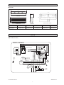 3
3
-
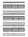 4
4
-
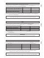 5
5
-
 6
6
-
 7
7
-
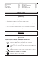 8
8
-
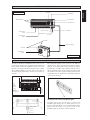 9
9
-
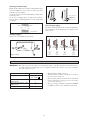 10
10
-
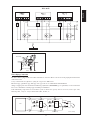 11
11
-
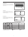 12
12
-
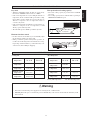 13
13
-
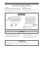 14
14
-
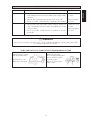 15
15
-
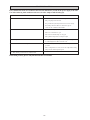 16
16
-
 17
17
-
 18
18
-
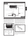 19
19
-
 20
20
-
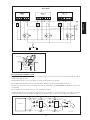 21
21
-
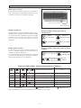 22
22
-
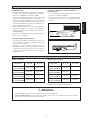 23
23
-
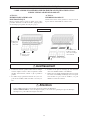 24
24
-
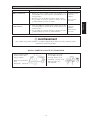 25
25
-
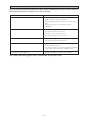 26
26
-
 27
27
-
 28
28
-
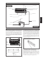 29
29
-
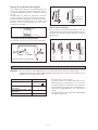 30
30
-
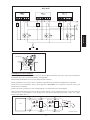 31
31
-
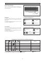 32
32
-
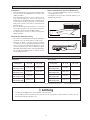 33
33
-
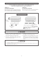 34
34
-
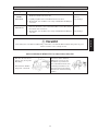 35
35
-
 36
36
-
 37
37
-
 38
38
-
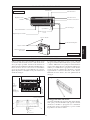 39
39
-
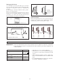 40
40
-
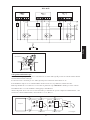 41
41
-
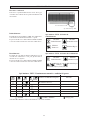 42
42
-
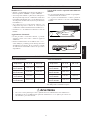 43
43
-
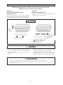 44
44
-
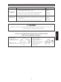 45
45
-
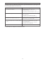 46
46
-
 47
47
-
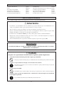 48
48
-
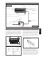 49
49
-
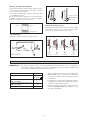 50
50
-
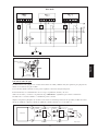 51
51
-
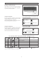 52
52
-
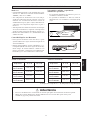 53
53
-
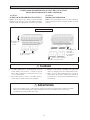 54
54
-
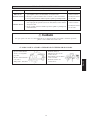 55
55
-
 56
56
-
 57
57
-
 58
58
-
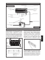 59
59
-
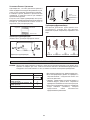 60
60
-
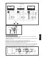 61
61
-
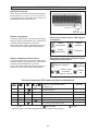 62
62
-
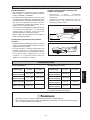 63
63
-
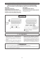 64
64
-
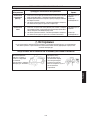 65
65
-
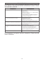 66
66
-
 67
67
-
 68
68
-
 69
69
-
 70
70
-
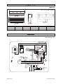 71
71
-
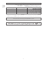 72
72
-
 73
73
-
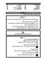 74
74
-
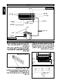 75
75
-
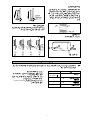 76
76
-
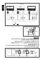 77
77
-
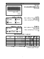 78
78
-
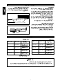 79
79
-
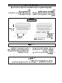 80
80
-
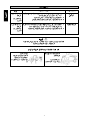 81
81
-
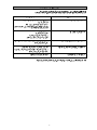 82
82
-
 83
83
-
 84
84


McQuay IM-WM1W-0704 Guía de instalación
- Tipo
- Guía de instalación
en otros idiomas
- français: McQuay IM-WM1W-0704 Guide d'installation
- italiano: McQuay IM-WM1W-0704 Guida d'installazione
Artículos relacionados
Otros documentos
-
Acson IM-WM1W-0704-ACSON Guía de instalación
-
-
Acson ACK030BW Installation Instructions Manual
-
Pioneer KEH-P2035 El manual del propietario
-
-
-
-
-
Acson MST101015A Guía de instalación