
Honeywell
730xxxxxx ©
Elster GmbH | All rights reserved. Subject to modification
1
English
Instruction Manual
Absolute ENCODER
Type S1 / S1D
Betriebsanleitung
Absolut ENCODER
Typ S1 / S1D
Mode d’emploi
ENCODEUR absolu
Type S1 / S1D
Manual de instrucciones
Absolut-ENCODER
Modelos S1 / S1D
Istruzioni d’uso
ENCODER assoluto
Tipo S1 / S1D
Gebruiksaanwijzing
Absoluut ENCODER
Type S1 / S1D

Honeywell
2
730xxxxxx © Elster GmbH | All rights reserved. Subject to modification

Honeywell
730xxxxxx ©
Elster GmbH | All rights reserved. Subject to modification
3
English
Français
Español
Italiano Nederlands Deutsch
Instruction Manual
Absolute ENCODER
Type S1 / S1D
Betriebsanleitung
Absolut ENCODER
Typ S1 / S1D
Mode d’emploi
ENCODEUR absolu
Type S1 / S1D
Manual de instrucciones
Absolut-ENCODER
Modelos S1 / S1D
Istruzioni d’uso
ENCODER assoluto
Tipo S1 / S1D
Gebruiksaanwijzing
Absoluut ENCODER
Type S1 / S1D

Honeywell
4
730xxxxxx © Elster GmbH | All rights reserved. Subject to modification

Honeywell
73024510a © Elster GmbH | All rights reserved. Subject to modification
5
English
ENCODER S1 / S1D
Instruction Manual
Absolute ENCODER
Type S1 S1D
E1


Honeywell
73024510a © Elster GmbH | All rights reserved. Subject to modification
7
English
Contents
1. Safety instructions ................................................................................................ 9
1.1 Intended use ................................................................................................... 10
1.2 Approvals and certifications ........................................................................... 10
1.3 Copyright and data protection ....................................................................... 11
1.4 Exemption from liability ................................................................................. 11
1.5 Product liability and guarantee ...................................................................... 12
1.6 Personnel ........................................................................................................ 12
1.7 Intended use and field of application ............................................................. 12
1.8 Legal declarations ........................................................................................... 12
1.9 Recycling and environmental protection ....................................................... 12
2. Structure and function ........................................................................................ 13
2.1 Device description .......................................................................................... 13
2.2 Working principle ........................................................................................... 13
2.3 Versions .......................................................................................................... 14
2.4 Connection configurations ............................................................................. 14
2.5 Top-mounted ENCODER ................................................................................. 16
3. Installation and commissioning ........................................................................... 16
4. Storage................................................................................................................ 17
5. Cleaning .............................................................................................................. 17
6. Repair ................................................................................................................. 17
7. Technical data ..................................................................................................... 17
8. Ambient conditions ............................................................................................. 18
9. Approvals ............................................................................................................ 18
10. Annex A – Standards and Norms ....................................................................... 19

Honeywell
8
73024510a © Elster GmbH | All rights reserved. Subject to modification
Information on the documentation
The latest version of the operating instructions is available to download from the
Honeywell website.
Please read the information in this document carefully in order to avoid injury to
the user or damage to the device. Moreover, currently valid national standards,
safety regulations and accident prevention regulations must be adhered to.
Should you have any problems understanding the contents of this document,
please contact your local Honeywell branch for support. Honeywell cannot
accept any responsibility for damage to property or personal injuries which are a
result of the information in this document not having been understood properly.
This document helps you to set up the operating conditions in such a way that
the safe and efficient use of the device is assured. In addition, this document also
specifies points and safety measures which must be particularly observed and
which are indicated using the following symbols:
WARNING or CAUTION
This symbol warns of dangerous situations. Failure to follow the
instructions could result in danger to people and the
environment or the meter could suffer damage.
INFORMATION or NOTE
Accurate measurement cannot be ensured if information or
notes with this symbol are ignored.

Honeywell
73024510a © Elster GmbH | All rights reserved. Subject to modification
9
English
1. Safety instructions
WARNING!
Danger of electrostatic discharge – only use a damp cloth to clean.
WARNING!
If there is danger that the device can be damaged from falling
(pointed, sharp-edged or heavy) objects, the operator must protect
the device.
WARNING!
Exposure to danger which can result from a chemical reaction
between parts of the meter and chemical substances in the vicinity
must be discussed with the manufacturer and the cause must be
eliminated.
WARNING!
The gas meter in which the encoder is installed must be integrated
into the equipotential bond, e.g. by connecting it to the grounded
pipeline.
INFORMATION!
Compliance with the specified operating and ambient conditions
as indicated on the type label and the gas meter type label is
absolutely essential for the safe operation of the encoder.

Honeywell
10
73024510a © Elster GmbH | All rights reserved. Subject to modification
1.1 Intended use
INFORMATION!
The manufacturer shall not be liable for damage caused by
improper or inappropriate use.
1.2 Approvals and certifications
CE marking / EU declaration of conformity
The manufacturer certifies conformity
with the EU
declaration of conformity and by attaching the CE marking.
The pulse generator meets the statutory requirements of
the relevant EU guidelines.
Comprehensive information on the applicable EU
Directives and Standards, as well as recognized
certifications, is contained in the EU declaration of
conformity.
The EU declaration of conformity is included in the delivery
and is also available to download at www.docuthek.com.
See Chapter 9 for more approvals and Directives.
Approvals and Annex A – Standards and Norms
ATEX
DANGER!
The encoder is suitable for use in Zone 1 or 2 hazardous
areas and is approved with the following certification:
Zone 1:
II 2G Ex ib IIB T4
(SCR+)
II 2G EEx ia IIB T4 (Namur)
TÜV 04 ATEX 2544
TÜV NORD CERT GmbH
Langemarckstr. 20
45747 Essen
Germany
Zone 2
:
II 3G Ex nA ic IIC T4 Gc
ATEX ELS 18.0001X
Elster GmbH
Steinern Straße 19-21
55252 Mainz-Kastel
Germany

Honeywell
73024510a © Elster GmbH | All rights reserved. Subject to modification
11
English
1.3 Copyright and data protection
This document has been created with the greatest possible care. No liability
is assumed for the accuracy, completeness or currency of the contents.
The contents and works produced in this document are subject to copyright.
Contributions by third parties are identified as such. The reproduction,
processing, distribution and any form of use beyond that which is permitted
by copyright require the written authorization of the respective author or the
manufacturer. The manufacturer strives to always respect the copyright of
others or to use his own or licence-free works.
We would like to point out that data transfer via the Internet (e.g. through e-
mail communication) can be subject to breaches in security. It is not
possible to provide complete protection against access by third parties.
1.4 Exemption from liability
The manufacturer shall not be liable for damage of any type caused by the
use of this product, including but not restricted to, direct, indirect or
incidental damage and its consequences.
This exemption from liability does not apply if the manufacturer has acted
intentionally or with gross negligence. In the event that any applicable law
does not allow such restrictions on implied warranties for defects, or the
exclusion or limitation of certain payments for damages, and should such
law apply to you, the above-mentioned exemption from liability, exclusions
or limitations may not apply to you in part or in whole.
For every product purchased, the warranty is valid in accordance with the
corresponding product documentation as well as the conditions of sale and
delivery of the manufacturer.
The manufacturer reserves the right to amend without prior notice the
contents of the documents, including this exemption from liability, in any
form and at any point in time, and for any reason, and shall in no way be liable
for any possible consequences of such amendments.

Honeywell
12
73024510a © Elster GmbH | All rights reserved. Subject to modification
1.5 Product liability and guarantee
The responsibility as to whether the device is suitable for the intended use is
that of the operator. The manufacturer cannot accept any liability for the
consequences of misuse by the operator. Improper installation or operation
of the devices (systems) render the warranty void. Furthermore, the relevant
“General Terms and Conditions” which form the basis of the purchase
contract also apply.
1.6 Personnel
This manual is aimed at staff who have adequate specialist and technical
knowledge (in Germany, for instance, in accordance with DVGW Codes of
Practice 492 and 495 or comparable technical regulations) on the basis of
their training and experience in the sector of energy and gas distribution.
1.7 Intended use and field of application
This product is intended to be used for the installation on/in gas meters from
Elster/Honeywell.
This product is not intended to be used for installation on/in (gas) meters
from other manufacturers.
1.8 Legal declarations
The metrological conformity assessment is based on the regulations of the
country concerned, where the device will be used.
1.9 Recycling and environmental protection
Honeywell has designed the transport packaging of the device to be
environmentally friendly. Packaging materials are always selected
consistently with a view to recycling. The cardboard items used constitute
secondary raw materials for the paperboard and paper industry. The
Instapak® foam packaging is recyclable and can be reused.
Plastic sheeting and strips/bands are also made of recyclable plastic. At
Honeywell, subsequent recycling and disposal are already elements of the
product development process. When selecting the materials, we allow for
reusability of the materials, suitability of materials and subassemblies for
dismantling and separation, and the risks of environmental pollution and
health risks when recycling and dumping on landfill sites.

Honeywell
73024510a © Elster GmbH | All rights reserved. Subject to modification
13
English
2. Structure and function
The ENCODER S1/S1D products are opto-electronic read-out units with
digital data transfer for turbine and rotary gas meters from Elster/Honeywell.
2.1 Device description
The encoder is integrated in an Elster/Honeywell meter index. The
technology is based on opto-electronic scanning which identifies the
position of the individual rollers on the mechanical index in a contact-free
process. The reading process for the Absolute ENCODER is therefore
identical to the manual reading of the mechanical index on site. Operation
of the Absolute ENCODER requires neither a battery nor an individual power
supply, as the power required for reading is supplied by the connected
device. The described technology can be flexibly adjusted to the application
by choosing one of the optional interface types.
2.2 Working principle
The digit rollers of the mechanical index are individually scanned by opto-
electronic means. Each roller has three asymmetrically arranged slots of
different lengths which are then scanned by five beams of light to determine
their position. The respective position of the roller and thus the digits on the
roller can be clearly identified thanks to the specific arrangement of the slots.
The light barriers consist of phototransistors, LEDs and optical waveguides
which are all scanned and evaluated one after the other using time-series
analysis. Control and evaluation of the light barriers is carried out by a
controller. This exactly defines the position of each individual digit roller and
transmits it to the connected add-on device (e.g. volume conversion device,
data logger or bus system) as part of a defined protocol. Depending on the
interface type, the protocol already includes various meter data such as the
factory number and meter size. The plug-and-play system means that no
subsequent parameterization is required.

Honeywell
14
73024510a © Elster GmbH | All rights reserved. Subject to modification
2.3 Versions
The ENCODER is available in two different mechanical versions, S1 and
S1D:
Fig. 1 | ENCODER S1 and ENCODER S1D
The ENCODER is available with the following communications protocols:
NAMUR (Ex Zone 1 or 2)
Unidirectional serial interface for direct connection to volume
conversion devices and data loggers (levels comply with EN 60947-5-5).
SCR+ (Ex Zone 1 or 2)
Low power interface, widely used for water meters, uses a protocol which
complies with IEC 62056-21 (formerly IEC 1107). The SCR interface can
be made compatible with the CL interface using a small separate,
external circuit.
M-Bus (without explosion protection)
For correcting multiple meters to an electronic evaluation system, e.g. in
industry or in a residential environment.
2.4 Connection configurations
Use only a screened cable to connect the encoder and ensure that the
pin assignment is correct (see Fig. 2 and sticker next to the cover of the
terminal box).
Only connect one conductor per terminal.
The maximum wire cross-section is 2.5 mm².
Wire end ferrules must be used for flexible cables.
TRZ with ENCODER S1 RABO with ENCODER S1D

Honeywell
73024510a © Elster GmbH | All rights reserved. Subject to modification
15
English
Tighten the screw terminals with a tightening torque of at least 0.8 Nm
to maximum 1 Nm.
Ensure the correct polarity of the two-wire connection on the Namur
interface. The M-Bus and SCR/SCR+ interfaces are independent of the
polarity.
It is possible to apply screening and to run a cable to the meter housing
or the pipe. It must be checked in advance that the grounding system
used allows grounding on both sides (ground loops and potential
difference in grounding).
Fig. 2 | Terminal assignment
On the version with a double index, the lower 2 terminals determine the
direction of the gas flow:
Bridge attached to lower terminals (as delivered): upper index is activated:
Fig. 3 | Flow direction right > left
Lower terminals unassigned: lower index is activated:
Fig. 4 | Flow direction left > right
An IN-Sxx pulse generator may be installed on the encoder index cover
as an option. The installation work and connection configuration are
shown in the relevant instruction manual.
For rotary gas meters: For top-mounted encoder S1D:
For rotary gas meters: For top-mounted encoder S1D:

Honeywell
16
73024510a © Elster GmbH | All rights reserved. Subject to modification
2.5 Top-mounted ENCODER
The top-mounted version of the
ENCODER S1/S1D is suitable for the
mechanical index drive of the MI2 index
cover and can be operated in addition to
the mechanical index installed in the gas
meter.
Connect the connector of the top-
mounted unit to the mechanical index
drive of the driving unit.
Use a locking screw to prevent it from
being pulled out.
Secure the locking screw with a seal for
use in custody transfer applications.
The electrical connection is made as
described in section 2.4 Connection
configurations.
3. Installation and commissioning
The encoder is supplied fully parameterized and ready for operation
together with the gas meters.
The electrical connection is made as described in section 2.4
Connection configurations.
For connecting the devices, use a screened cable pursuant to
IEC EN 60079-14.
WARNING!
If the encoder is used in hazardous areas, it must be connected to
an intrinsically safe circuit.
For installations in Zone 1, safety barriers or supply units must be
certified pursuant to ignition protection rating Ex ib IIC or Ex ia IIC.
Fig. 5 | Top-mounted ENCODER S1D

Honeywell
73024510a © Elster GmbH | All rights reserved. Subject to modification
17
English
4. Storage
Store the device in a dry and dust-free location.
Avoid constant direct sunlight.
Store the device in its original packaging.
Storage temperature: -40 to +70°C / -40 to +158°F.
5. Cleaning
WARNING!
Danger of electrostatic discharge – only use a damp cloth to clean.
DANGER!
There is a risk of explosion if the plastic cover of the index is
cleaned with a dry cloth.
It is forbidden to use aggressive chemical cleaning agents or
solvents for cleaning.
6. Repair
INFORMATION!
Repairs may be carried out only by authorized workshops.
7. Technical data
Namur
SCR+
M
-
Bus
Ui
≤ 13.5 V
≤ 38 V
Ii
≤ 20 mA
≤ 20 mA
Pi
≤ 0.27 W
≤ 0.76 W
Enclosure
IP67
Top
-
m
ounted encoder:
Torque
0.2 Nmm
Max. speed of the
index drive 1 Hz
Drive value
0.1 / 1 / 10
Decimal places
0.2 / 1 / 0
Table 2 | Technical data

Honeywell
18
73024510a © Elster GmbH | All rights reserved. Subject to modification
8. Ambient conditions
Ambient temperature
-
40°C to +60°C
Storage temperature
-
40°C to +60°C
Humidity
0 t
o 80% RH
Max. height above sea level
2000 m
Outdoor installation
Yes
Mechanical environments
M1
Table 3 | Ambient conditions
9. Approvals
Approval:
Approval number:
Approval body:
ATEX
Zone 1*:
II 2G Ex ib IIB T4 (SCR+)
II 2G EEx ia IIB T4 (Namur)
TÜV 04 ATEX 2544
TÜV NORD CERT GmbH
Langemarckstr. 20
45747 Essen | Germany
Zone 2*:
II 3G Ex nA ic IIC T4 Gc
ATEX ELS 18.0001X
Elster GmbH
Steinern Straße 19-21
55252 Mainz-Kastel | Germany
Table 4 | Approvals
WARNING!
* If the ENCODER S1 is connected to a Zone 2 supply unit which is
not approved to Ex ib IIC or Ex ia IIC, the ENCODER S1 will
irrevocably lose its approval for Zone 1.
ATEX/IECEx legend:
Marking of explosion protection
II
Equipment group: industrial (mining excluded)
2/3
Equipment category 2 (Zone 1) or equipment category 3 (Zone 2)
G
Potentially explosive gas atmospheres
ia/ib/ic
Type of ignition protection: intrinsically safe
nA
Non-sparking apparatus
IIC
Explosion group for gases
T4
Temperature class
Gb
Equipment protection level

Honeywell
73024510a © Elster GmbH | All rights reserved. Subject to modification
19
English
10. Annex A – Standards and Norms
The ENCODER meets the following norms and standards or the relevant
chapters within them*:
2014/30/EU
Electrom
agnetic compatibility
DIN EN 61326-1:2013
VDE 0843-20-1:2013-07
Electrical equipment for measurement, control and
laboratory use – EMC requirements – Part 1:
General requirements
DIN EN 60079
-
0:2012
+ A11:2013
IEC 60079-0:2011
Explosive atmospheres
–
Par
t 0: Equipment
–
General requirements
DIN EN 60079-11:2012
IEC 60079-11:2011
Explosive atmospheres
–
Part 11: Equipment
protection by intrinsic safety “i”
DIN EN 60079
-
15:2010
IEC 60079-15:2010
Explosive atmospheres
–
Part 15: Equipment
protection by type of protection “n”
* Standards valid at the time of the operating instructions going to press.

Honeywell
20
73024510a © Elster GmbH | All rights reserved. Subject to modification

Honeywell
73024510a © Elster GmbH | Alle Rechte und Änderungen vorbehalten
21
Deutsch
ENCODER S1 / S1D
Betriebsanleitung
Absolut ENCODER
Typ S1 / S1D

Honeywell
22
73024510a © Elster GmbH | Alle Rechte und Änderungen vorbehalten
Inhalt
1. Sicherheitshinweise ............................................................................................ 24
1.1 Bestimmungsgemäße Verwendung ............................................................... 25
1.2 Zulassungen und Zertifizierung ...................................................................... 25
1.3 Urheberrecht und Datenschutz ...................................................................... 26
1.4 Haftungsausschluss ........................................................................................ 26
1.5 Produkthaftung und Garantie ........................................................................ 27
1.6 Personal .......................................................................................................... 27
1.7 Verwendungszweck und Anwendungsbereich ............................................... 27
1.8 Rechtliche Erklärungen ................................................................................... 27
1.9 Recycling und Umweltschutz .......................................................................... 27
2. Aufbau und Funktion .......................................................................................... 28
2.1 Gerätebeschreibung ....................................................................................... 28
2.2 Funktionsprinzip ............................................................................................. 28
2.3 Ausführungen ................................................................................................. 29
2.4 Anschlusskonfigurationen .............................................................................. 29
2.5 Aufsatz-ENCODER ........................................................................................... 31
3. Installation und Inbetriebnahme ......................................................................... 31
4. Lagerung ............................................................................................................. 32
5. Reinigung ............................................................................................................ 32
6. Reparatur ............................................................................................................ 32
7. Technische Daten ................................................................................................ 32
8. Umgebungsbedingungen .................................................................................... 33
9. Zulassungen ........................................................................................................ 33
10. Anhang A – Standards und Normen .................................................................. 34

Honeywell
73024510a © Elster GmbH | Alle Rechte und Änderungen vorbehalten
23
Deutsch
Informationen
zur Dokumentation
Die neuste Version der Bedienungsanleitung steht auf der Honeywell-
Internetseite zum Download.
Um Verletzungen des Anwenders bzw. Schäden am Gerät zu vermeiden, ist es
erforderlich, dass Sie die Informationen in diesem Dokument aufmerksam lesen.
Darüber hinaus sind die geltenden nationalen Standards,
Sicherheitsbestimmungen sowie Unfallverhütungsvorschriften einzuhalten.
Falls Sie Probleme haben, den Inhalt dieses Dokuments zu verstehen, wenden
Sie sich für Unterstützung an die örtliche Honeywell-Niederlassung. Honeywell
kann keine Verantwortung für Sach- oder Personenschäden übernehmen, die
dadurch hervorgerufen wurden, dass Informationen in diesem Dokument nicht
richtig verstanden wurden.
Dieses Dokument hilft Ihnen, die Betriebsbedingungen so einzurichten, dass der
sichere und effiziente Einsatz des Geräts gewährleistet ist. Außerdem sind im
Dokument besonders zu berücksichtigende Punkte und
Sicherheitsvorkehrungen beschrieben, die jeweils in Verbindung mit den
nachfolgenden Symbolen erscheinen.
WARNUNG oder VORSICHT
Dieses Zeichen steht für gefährliche Situationen. Den
Anweisungen ist Folge zu leisten; sonst können Gefahren für
Menschen und Umwelt entstehen oder das Messgerät kann
einen Schaden erleiden.
INFORMATION oder HINWEIS
Wenn Informationen oder Hinweise mit diesem Zeichen
missachtet werden, kann eine genaue Messung nicht
gewährleistet werden.

Honeywell
24
73024510a © Elster GmbH | Alle Rechte und Änderungen vorbehalten
1. Sicherheitshinweise
WARNUNG!
Gefahr durch elektrostatische Entladung – benutzen Sie nur ein
feuchtes Tuch zum Reinigen.
WARNUNG!
Wenn die Gefahr besteht, dass das Gerät von herunterfallenden
(spitzen, scharfkantigen oder schweren) Gegenständen
beschädigt werden kann, ist der Betreiber verpflichtet, das Gerät zu
schützen.
WARNUNG!
Gefahren, die zu einer chemischen Reaktion zwischen den Teilen
des Messgerätes und chemischen Substanzen in der Umgebung
führen, müssen mit dem Hersteller abgesprochen und beseitigt
werden.
WARNUNG!
Der Gaszähler, in dem der Encoder installiert ist, muss in den
Potenzialausgleich eingebunden werden, z. B. über die geerdete
Rohrleitung.
INFORMATION!
Für die sichere Funktion des Encoders ist das Einhalten der auf
dem Typenschild und dem Gaszähler-Typenschild angegebenen
Betriebs- und Umgebungsbedingungen eine zwingende
Voraussetzung.

Honeywell
73024510a © Elster GmbH | Alle Rechte und Änderungen vorbehalten
25
Deutsch
1.1 Bestimmungsgemäße Verwendung
INFORMATION!
Der Hersteller haftet nicht für Schäden, die aus unsachgemäßem
oder nicht bestimmungsgemäßem Gebrauch entstehen.
1.2 Zulassungen und Zertifizierung
CE-Kennzeichnung / EU-Konformitätserklärung
Der Hersteller bescheinigt die Konformität in der
EU-Konformitätserklärung und durch das Anbringen des
CE-Kennzeichens.
Der Impulsgeber erfüllt die gesetzlichen Anforderungen
der entsprechenden EU-Richtlinien.
Umfassende Informationen über die angewendeten
EU-Richtlinien und -Normen sowie die anerkannten
Zertifizierungen sind in der EU-Konformitätserklärung.
Die EU-Konformitätserklärung ist im Lieferumfang
enthalten oder kann online unter www.docuthek.com
heruntergeladen werden.
Weitere Zulassungen und Richtlinien, siehe
Kapitel 9. Zulassungen und Anhang A – Standards
und Normen
ATEX
GEFAHR!
Der Encoder ist geeignet für den Einsatz in
explosionsgefährdeten Bereichen der Zone 1 oder 2 und ist
nach folgenden Bescheinigungen zugelassen:
Zone 1:
II
2G Ex ib IIB T4
(SCR+)
II 2G EEx ia IIB T4 (Namur)
TÜV 04 ATEX 2544
TÜV NORD CERT GmbH
Langemarckstr. 20
45747 Essen
Germany
Zone 2:
II 3G Ex nA ic IIC T4 Gc
ATEX ELS 18.0001X
Elster GmbH
Steinern Straße 19-21
55252 Mainz-Kastel

Honeywell
26
73024510a © Elster GmbH | Alle Rechte und Änderungen vorbehalten
1.3 Urheberrecht und Datenschutz
Dieses Dokument wurde mit größter Sorgfalt erstellt. Für die Richtigkeit,
Vollständigkeit und Aktualität der Inhalte wird jedoch keine Gewähr
übernommen.
Die erstellten Inhalte und Werke in diesem Dokument unterliegen dem
Urheberrecht. Beiträge Dritter sind als solche gekennzeichnet. Die
Vervielfältigung, Bearbeitung, Verbreitung und jede Art der Verwertung
außerhalb der Grenzen des Urheberrechtes bedürfen der schriftlichen
Zustimmung des jeweiligen Autors bzw. des Herstellers. Der Hersteller ist
bemüht, stets die Urheberrechte anderer zu beachten bzw. auf selbst
erstellte sowie lizenzfreie Werke zurückzugreifen.
Wir weisen darauf hin, dass die Datenübertragung im Internet (z. B. bei der
Kommunikation per E-Mail) Sicherheitslücken aufweisen kann. Ein
lückenloser Schutz der Daten vor dem Zugriff durch Dritte ist nicht möglich.
1.4 Haftungsausschluss
Der Hersteller ist nicht für Schäden jeder Art haftbar, die durch die
Verwendung dieses Produkts entstehen, einschließlich, aber nicht
beschränkt auf direkte, indirekte oder beiläufig entstandene Schäden und
Folgeschäden.
Dieser Haftungsausschluss gilt nicht, wenn der Hersteller vorsätzlich oder
grob fahrlässig gehandelt hat. Sollten aufgrund eines geltenden Gesetzes
derartige Einschränkungen der stillschweigenden Mängelhaftung oder der
Ausschluss bzw. die Begrenzung bestimmter Schadenersatzleistungen
nicht zulässig sein und derartiges Recht für Sie gelten, können der
Haftungsausschluss, die Ausschlüsse oder die Beschränkungen oben für
Sie teilweise oder vollständig ungültig sein.
Für jedes erworbene Produkt gilt die Gewährleistung gemäß der
entsprechenden Produktdokumentation sowie der Verkaufs- und Liefer-
bedingungen des Herstellers.
Der Hersteller behält sich das Recht vor, den Inhalt der Dokumente,
einschließlich dieses Haftungsausschlusses, in jeder Weise und zu jedem
Zeitpunkt, gleich aus welchem Grund, unangekündigt zu ändern, und ist in
keiner Weise für mögliche Folgen derartiger Änderungen haftbar.

Honeywell
73024510a © Elster GmbH | Alle Rechte und Änderungen vorbehalten
27
Deutsch
1.5 Produkthaftung und Garantie
Die Verantwortung, ob die Geräte für den jeweiligen Verwendungszweck
geeignet sind, liegt beim Betreiber. Der Hersteller übernimmt keine Haftung
für Folgen von Fehlgebrauch durch den Betreiber. Eine unsachgemäße
Installation oder Bedienung der Geräte (-systeme) führt zu Garantieverlust.
Darüber hinaus gelten die jeweiligen „Allgemeinen Geschäftsbedingungen“,
die die Grundlage des Kaufvertrags bilden.
1.6 Personal
Diese Anleitung richtet sich an Personal, das aufgrund seiner Ausbildung
und Erfahrung im Bereich der Energie- und Gasversorgung über
ausreichende Fach- und Sachkenntnisse verfügt (z. B. in Deutschland
DVGW-Arbeitsblätter 492 und 495 oder vergleichbare technische Regeln).
1.7 Verwendungszweck und Anwendungsbereich
Dieses Produkt ist vorgesehen zur Installation an/in Gasmessgeräten von
Elster/Honeywell.
Dieses Produkt ist nicht vorgesehen für die Installation an/in
(Gas-)Messgeräten von Fremdherstellern.
1.8 Rechtliche Erklärungen
Die messtechnische Konformitätsbewertung richtet sich nach den
Vorschriften des jeweiligen Landes, in dem das Gerät verwendet wird.
1.9 Recycling und Umweltschutz
Honeywell hat die Transportverpackungen der Geräte umweltgerecht
gestaltet. Bei der Auswahl wird konsequent auf die mögliche
Wiederverwertung geachtet. Die verwendeten Kartonagen sind
Sekundärrohstoffe der Pappe- und Papierindustrie. Die Instapak®-
Schaumverpackung ist recyclingfähig und wiederverwertbar.
Folien und Bänder sind ebenfalls aus recyclingfähigem Kunststoff. Bei
Honeywell ist das spätere Recycling und die Entsorgung bereits Bestandteil
der Produktentwicklung. Bei der Auswahl der Werkstoffe werden die
stoffliche Wiederverwertbarkeit, die Demontierbarkeit und Trennbarkeit von
Werkstoffen und Baugruppen ebenso berücksichtigt wie Umwelt- und
Gesundheitsgefahren bei Recycling und Deponierung.

Honeywell
28
73024510a © Elster GmbH | Alle Rechte und Änderungen vorbehalten
2. Aufbau und Funktion
Die Produkte ENCODER S1 / S1D sind optoelektronische Ausleseeinheiten
mit einer digitalen Datenübertragung für Turbinenrad- und
Drehkolbengaszähler von Elster/Honeywell.
2.1 Gerätebeschreibung
Der Encoder ist in einem Zählwerkskopf von Elster/Honeywell-Messgeräten
integriert. Grundlage der Technologie ist der optoelektronische
Abtastvorgang, in dem die Stellung der einzelnen Zahlenrollen des
mechanischen Zählwerkes berührungslos abgetastet wird. Der
Auslesevorgang des Absolut ENCODERs entspricht somit der manuellen
Ablesung des mechanischen Zählwerkes vor Ort. Eine Batterie oder eigene
Spannungsversorgung für den Betrieb des Absolut ENCODERs ist nicht
notwendig, da die erforderliche Energie für die Auslesung vom
angeschlossenen Gerät bereitgestellt wird. Mit Hilfe des optional wählbaren
Schnittstellentyps kann die beschriebene Technologie flexibel der
Applikation angepasst werden.
2.2 Funktionsprinzip
Die einzelnen Zahlenrollen des mechanischen Zählwerkes werden auf
optoelektronischem Wege abgetastet. Drei unterschiedlich lange und
asymmetrisch angeordnete Schlitze jeder Zahlenrolle werden dabei mit fünf
Lichtschranken auf ihre Stellung hin abgetastet. Die Schlitze sind so
angebracht, dass ihre jeweilige Stellung den Rollenstand und damit die
Ziffern der Rollen eindeutig beschreibt. Die Lichtschranken sind mit
Phototransistoren, LEDs und Lichtleitern realisiert, die alle nacheinander
zeitseriell gescannt und ausgewertet werden. Ansteuerung und Auswertung
der Lichtschranken werden durch einen Controller gesteuert. Dieser definiert
exakt die Position jeder einzelnen Zahlenrolle und gibt sie im Rahmen eines
definierten Protokolls an das angeschlossene Zusatzgerät (z. B.
Mengenumwerter, Datenspeicher oder Bus-System) weiter. Je nach
Schnittstellentyp beinhaltet das Protokoll bereits verschiedene Zählerdaten,
wie z. B. Fabriknummer und Zählergröße. Durch das „plug and play“-System
entfällt dann eine nachträgliche Parametrierung.

Honeywell
73024510a © Elster GmbH | Alle Rechte und Änderungen vorbehalten
29
Deutsch
2.3 Ausführungen
Den ENCODER gibt es in zwei verschiedenen mechanischen
Ausführungen, S1 und S1D:
Abb. 1 | ENCODER S1 und S1D
Den ENCODER gibt es mit folgenden verschiedenen
Kommunikationsprotokollen:
NAMUR (Ex-Zone 1 oder Zone 2)
Unidirektionale serielle Schnittstelle zum direkten Anschluss an
Mengenumwerter und Datenlogger (Pegel entsprechen EN 60947-5-5).
SCR+ (Ex-Zone 1 oder Zone 2)
Low-Power-Schnittstelle, bei Wasserzählern verbreitet, arbeitet mit
Protokoll nach IEC 62056-21 (ehemals IEC 1107). Mit Hilfe einer
kleinen, separaten, externen Beschaltung wird die SCR-Schnittstelle
kompatibel zur CL-Schnittstelle.
M-Bus (ohne Explosionsschutz)
Zum Anschluss mehrerer Zähler an eine Auswerteelektronik z. B. im
Industrie- oder auch im Haushaltsbereich
2.4 Anschlusskonfigurationen
Zum Anschluss ein abgeschirmtes Kabel verwenden und auf die richtige
Pin-Belegung achten (siehe Abb. 2 und Aufkleber neben dem Deckel der
Klemmbox).
Nur einen Leiter pro Klemme auflegen.
Der maximal zulässige Aderquerschnitt ist 2,5 mm².
Bei flexiblen Leitungen müssen Aderendhülsen verwendet werden.
TRZ mit ENCODER S1 RABO mit ENCODER S1D

Honeywell
30
73024510a © Elster GmbH | Alle Rechte und Änderungen vorbehalten
Die Schraubklemmen mit einem Anzugsmoment von minimal 0,8 Nm
bis maximal 1 Nm festziehen.
Auf die richtige Polung des 2-Drahtanschlusses ist bei der Namur-
Schnittstelle zu achten. Die M-Bus- und SCR/SCR+-Schnittstellen sind
polungsunabhängig.
Es besteht die Möglichkeit, die Schirmung aufzulegen und mit einem
Kabel an das Gehäuse des Zählers oder an die Rohrleitung zu führen. Es
ist vorher unbedingt zu prüfen, ob das angewendete Erdungssystem ein
beidseitiges Erden zulässt (Erdschleifen und Potenzialunterschiede der
Erdung).
Abb. 2 | Anschlussbelegung
Bei Ausführung mit Doppelzählwerk bestimmen die unteren 2 Klemmen
die Richtung des Gasdurchflusses:
Brücke an den unteren Klemmen ist aufgelegt (Auslieferzustand): Oberes
Zählwerk ist aktiviert:
Abb. 3 | Durchflussrichtung rechts > links
Untere Klemmen unbelegt: Unteres Zählwerk ist aktiviert:
Abb. 4 | Durchflussrichtung links > rechts
Optional kann an der Encoder-Zählwerkshaube ein IN-Sxx-Impulsgeber
installiert werden. Die Montage und die Anschlusskonfiguration können
Sie der zugehörigen Bedienungsanleitung entnehmen.
Bei Drehkolbengaszählern: Bei Encoder-Aufsatz S1D:
Bei Drehkolbengaszählern:
Bei
Encoder
-
Aufsatz S1D:

Honeywell
73024510a © Elster GmbH | Alle Rechte und Änderungen vorbehalten
31
Deutsch
2.5 Aufsatz-ENCODER
Die Aufsatzvariante des ENCODER
S1/S1D ist für den mechanischen Abtrieb
der MI2-Zählwerkshaube geeignet und
kann zusätzlich zum eingebauten
mechanischen Zählwerk des Gaszählers
betrieben werden.
Aufsatz mit Anschlussstutzen an den
mechanischen Abtrieb des
antreibenden Gerätes stecken.
Mit einer Sicherungsschraube vor dem
Herausziehen sichern.
Für den Einsatz im eichpflichtigen
Bereich Sicherungsschraube mit einer
Plombe sichern.
Der elektrische Anschluss erfolgt nach
Kapitel 2.4 Anschlusskonfigurationen.
3. Installation und Inbetriebnahme
Der Encoder wird parametriert und betriebsbereit mit den
Gasmessgeräten ausgeliefert.
Der elektrische Anschluss erfolgt nach Kapitel 2.4
Anschlusskonfigurationen.
Benutzen Sie ein geschirmtes Kabel nach IEC EN 60079-14, um die
Geräte anzuschließen.
WARNUNG!
Wird der Encoder im explosionsgefährdeten Bereich eingesetzt,
muss er an einen eigensicheren Stromkreis angeschlossen werden.
Für Installationen in der „Zone 1“ müssen Sicherheitsbarrieren oder
Speisegeräte nach der Zündschutzklasse Ex ib IIC oder Ex ia IIC
zertifiziert sein.
Abb. 5 | Aufsatz-ENCODER S1D

Honeywell
32
73024510a © Elster GmbH | Alle Rechte und Änderungen vorbehalten
4. Lagerung
Lagern Sie das Gerät an einem trockenen und staubfreien Ort.
Vermeiden Sie direkte, dauerhafte Sonneneinstrahlung.
Lagern Sie das Gerät in seiner Originalverpackung.
Lagertemperatur: -40...+70 °C / -40...+158 °F.
5. Reinigung
WARNUNG!
Gefahr durch elektrostatische Entladung – benutzen Sie nur ein
feuchtes Tuch zum Reinigen.
GEFAHR!
Es besteht Explosionsgefahr, wenn die Kunststoffhaube des
Zählwerkes mit einem trockenen Tuch gereinigt wird.
Das Verwenden von aggressiven chemischen Reinigungs-
mitteln oder Lösungsmitteln zur Reinigung ist verboten.
6. Reparatur
INFORMATION!
Reparaturen dürfen nur von autorisierten Werkstätten
durchgeführt werden.
7. Technische Daten
Namur
SCR+
M
-
Bus
Ui
≤
13,5 V
≤
38 V
Ii
≤
20 mA
≤
20 mA
Pi
≤
0,27 W
≤
0,76 W
Schutzart
IP67
Aufsatz
-
Encoder:
Drehmoment
0,2 Nmm
Max. Drehzahl des
Abtriebs 1 Hz
Abtriebswert
0,1 / 1 / 10
Nachkommastallen
0,2 / 1 / 0
Tabelle 2 | Technische Daten

Honeywell
73024510a © Elster GmbH | Alle Rechte und Änderungen vorbehalten
33
Deutsch
8. Umgebungsbedingungen
Umgebungstemperatur
-
40 °C bis +60 °C
Lagertemperatur
-
40
°
C bis +60
°
C
Feuchte
0 bis 80 % RH
Max. Höhe über NN
2000 m
Außeninstallation
Ja
Mechanische Umgebungsbedingungen
M1
Tabelle 3 | Umgebungsbedingungen
9. Zulassungen
Zulassung:
Zulass
ungsnummer:
Zulassungsstelle:
ATEX
Zone 1*:
II 2G Ex ib IIB T4 (SCR+)
II 2G EEx ia IIB T4 (Namur)
TÜV 04 ATEX 2544
TÜV NORD CERT GmbH | Langemarckstr. 20
45747 Essen | Germany
Zone 2*:
II 3G Ex nA ic IIC T4 Gc
ATEX ELS 18.0001X
Elster GmbH
Steinern Straße 19-21
55252 Mainz-Kastel
Tabelle 4 | Zulassungen
WARNUNG!
*Wird der S1 ENCODER an ein Speisegerät für die „Zone 2“
angeschlossen, dass nicht eine Zulassung nach Ex ib IIC oder
Ex ia IIC hat, so verliert der S1 ENCODER dauerhaft seine
Zulassung für die „Zone 1“.
ATEX / IECEx-Legende:
Kennzeichnung für Explosionsschutz
II Gerätegruppe: Industrie (Grubenbau ausgeschlossen)
2/3 Gerätekategorie 2 (Zone 1) oder Gerätekategorie 3 (Zone 2)
G Gasexplosionsgefährdete Bereiche
ia/ib/ic Zündschutzart: eigensicher
nA Nichtfunkendes Betriebsmittel
IIC Explosionsgruppe für Gase
T4 Temperaturklasse
Gb Geräteschutzniveau

Honeywell
34
73024510a © Elster GmbH | Alle Rechte und Änderungen vorbehalten
10. Anhang A – Standards und Normen
Der ENCODER erfüllt u. a. folgende Normen und Standards oder
entsprechend zutreffende Kapitel daraus*:
2014/30/EU
Elektromagnetische Verträglichkeit
DIN EN 61326-1:2013
VDE 0843-20-1:2013-07
Elektrische Mess
-
, Steuer
-
, Regel
-
und
Laborgeräte – EMV-Anforderungen – Teil 1:
Allgemeine Anforderungen
DIN EN 60079
-
0:2012
+ A11:2013
IEC 60079-0:2011
Explosionsgefährdete Bereiche
–
Teil 0:
Betriebsmittel – Allgemeine Anforderungen
DIN EN 60079
-
11:2012
IEC 60079-11:2011
Explosionsgefährdete Bereiche
–
Teil 11: Geräteschutz durch Eigensicherheit „i“
DIN EN 60079
-
15:2010
IEC 60079-15:2010
Explosion
sgefährdete Atmosphäre
-
Teil 15:
Geräteschutz durch Zündschutzart „n“
* Gültigkeit der Normen jeweils zur Drucklegung der Betriebsanleitung.

Honeywell
73024510a © Elster GmbH | Alle Rechte und Änderungen vorbehalten
35
Deutsch


Honeywell
73024510a
© Elster GmbH | Tous droits et modifications réservés
37
Français
ENCODER S1 / S1D
Mode d’emploi
ENCODEUR absolu
Type S1 / S1D
E1


Honeywell
73024510a
© Elster GmbH | Tous droits et modifications réservés
39
Français
Sommaire
1. Conseils de sécurité ............................................................................................. 41
1.1 Utilisation conformément à la destination .................................................... 42
1.2 Homologations et certifications ..................................................................... 42
1.3 Droit d’auteur et protection des données...................................................... 43
1.4 Clause de non-responsabilité ......................................................................... 43
1.5 Responsabilité produit et garantie ................................................................. 44
1.6 Personnel ........................................................................................................ 44
1.7 Utilisation prévue et domaine d’application .................................................. 44
1.8 Déclarations légales ........................................................................................ 44
1.9 Recyclage et protection de l’environnement ................................................. 44
2. Configuration et fonctionnement ........................................................................ 45
2.1 Description de l’appareil ................................................................................ 45
2.2 Principe de fonctionnement ........................................................................... 45
2.3 Versions .......................................................................................................... 46
2.4 Configurations de raccordement.................................................................... 46
2.5 Élément ENCODEUR ....................................................................................... 48
3. Installation et mise en service ............................................................................. 48
4. Entreposage ........................................................................................................ 49
5. Nettoyage ........................................................................................................... 49
6. Réparation .......................................................................................................... 49
7. Caractéristiques techniques ................................................................................ 49
8. Conditions ambiantes ......................................................................................... 50
9. Homologations .................................................................................................... 50
10. Annexe A – Documents normatifs ..................................................................... 51

Honeywell
40
73024510a © Elster GmbH | Tous droits et modifications réservés
Informations relatives à la documentation
La dernière version du mode d’emploi peut être téléchargée depuis le site
Internet Honeywell.
Afin que l’utilisateur ne se blesse pas ou que l’appareil ne soit pas endommagé,
il est indispensable de lire attentivement les informations contenues dans ce
document. De plus, les normes, dispositions de sécurité et prescriptions de
prévention des accidents nationales en vigueur doivent être respectées.
Si vous rencontrez des problèmes de compréhension du contenu de ce
document, demandez l’assistance de la succursale locale Honeywell. Honeywell
décline toute responsabilité eu égard aux dommages matériels et corporels
consécutifs à une mauvaise compréhension d’informations figurant dans ce
document.
Ce document vous aide à créer des conditions de fonctionnement qui
garantissent une utilisation sûre et efficace de l’appareil. Par ailleurs, des points
et des consignes de sécurité à respecter en particulier et qui comportent les
symboles ci-après sont mentionnés dans ce document.
AVERTISSEMENT ou ATTENTION
Ce symbole indique des situations dangereuses. Les
instructions doivent être respectées. Dans le cas contraire des
risques existent pour les utilisateurs et l’environnement ou
l’appareil de mesure peut être endommagé.
INFOR
MATION ou INDICATION
En cas de non-respect d’informations ou d’indications
comportant ce symbole, la précision de mesure ne peut être
garantie.

Honeywell
73024510a
© Elster GmbH | Tous droits et modifications réservés
41
Français
1. Conseils de sécurité
AVERTISSEMENT
!
Danger dû à des décharges électrostatiques – utiliser uniquement
un chiffon humide pour le nettoyage.
AVERTISSEMENT
!
Si l’appareil peut être endommagé par la chute d’objets (pointus,
tranchants ou lourds), l’exploitant est tenu de le protéger.
AVERTISSEMENT
!
Les dangers pouvant entraîner une réaction chimique entre les
composants de l’appareil de mesure et des substances chimiques
présentes dans l’environnement doivent être abordés avec le
fabricant et écartés.
AVERTISSEMENT
!
Le compteur de gaz dans lequel l’encodeur est installé doit être
intégré dans le système de compensation du potentiel en
procédant par exemple à un raccordement à une conduite mise à
la terre.
INFORMATION !
Pour garantir le fonctionnement fiable de l’encodeur, le respect
des conditions de service et des conditions ambiantes indiquées
sur la plaque signalétique de l’encodeur et celle du compteur de
gaz est une condition obligatoire.

Honeywell
42
73024510a © Elster GmbH | Tous droits et modifications réservés
1.1 Utilisation conformément à la destination
INFORMATION !
Le fabricant décline toute responsabilité en cas de dommages
consécutifs à une utilisation incorrecte ou non conforme.
1.2 Homologations et certifications
Marquage « CE » / Déclaration « UE » de conformité
Le fabricant atteste la conformité dans la déclaration
« UE » de conformité et par l’apposition du marquage
« CE ».
L’émetteur d’impulsions répond aux exigences légales
des directives UE correspondantes.
Des informations complètes relatives aux directives et
normes UE appliquées ainsi qu’aux certifications
reconnues figurent dans la déclaration « UE » de
conformité.
La déclaration « UE » de conformité est comprise dans la
livraison ou peut être téléchargée en ligne sur
www.docuthek.com.
Pour d’autres homologations et directives, se
reporter au Chapitre 9. Homologations et Annexe
A – Documents normatifs
ATEX
DANGER
!
L’encodeur convient à une utilisation dans une zone à risque
d’explosion 1 ou 2 et il est homologué suivant les
attestations ci-après.
Zone 1:
II 2G Ex ib IIB T4
(SCR+)
II 2G EEx ia IIB T4 (Namur)
TÜV 04 ATEX 2544
TÜV NORD CERT GmbH
Langemarckstr. 20
45747 Essen
Allemagne
Zone 2:
II 3G Ex nA ic IIC T4 Gc
ATEX ELS 18.0001X
Elster GmbH
Steinern Straße 19-21
55252 Mainz-Kastel
Allemagne

Honeywell
73024510a
© Elster GmbH | Tous droits et modifications réservés
43
Français
1.3 Droit d’auteur et protection des données
Ce document a été élaboré avec le plus grand soin. Honeywell décline
néanmoins toute responsabilité eu égard à l’exactitude, l’exhaustivité et la
mise à jour des contenus.
Les contenus et les œuvres créés dans ce document sont soumis au droit
d’auteur. Les contributions de tiers sont identifiées en tant que telles. La
duplication, le traitement, la diffusion et toute valorisation quelle qu’elle soit
en dehors des limites du droit d’auteur requièrent le consentement écrit des
différents auteurs ou du fabricant. Le fabricant s’efforce de prendre en
compte les droits d’auteur de tiers et de recourir aux œuvres qu’il aura lui-
même créées ou à celles sans licence.
Nous vous informons que la transmission de données sur Internet (par
exemple en cas de communication par e-mail) peut comporter des failles de
sécurité. Aucune protection parfaite des données contre un accès par des
tiers n’est possible.
1.4 Clause de non-responsabilité
Le fabricant décline toute responsabilité pour de quelconques dommages
lors de l’utilisation de ce produit, dont notamment des dommages directs,
indirects ou accessoires et des dommages induits.
Cette clause de non-responsabilité ne s’applique pas lorsque le fabricant a
agi délibérément ou par négligence grave. Lorsqu’en vertu d’une loi en
vigueur, de telles restrictions de la garantie implicite ou l’exclusion et la
restriction de certaines prestations en dommages-intérêts ne sont pas
autorisées, et lorsque cette loi s’applique à vous, la clause de non-
responsabilité, les exclusions ou les restrictions ci-dessus peuvent être
inapplicables en partie ou en totalité dans votre cas.
La garantie s’applique à tout produit acheté, conformément à la
documentation produit correspondante ainsi qu’aux conditions de vente et
de livraison du fabricant.
Le fabricant se réserve le droit de modifier sans préavis le contenu des
documents, dont cette clause de non-responsabilité, de quelle manière que
ce soit, à tout moment et pour quelque motif que ce soit, et il ne peut en
aucun cas être tenu responsable des conséquences éventuelles de telles
modifications.

Honeywell
44
73024510a © Elster GmbH | Tous droits et modifications réservés
1.5 Responsabilité produit et garantie
La responsabilité eu égard à l’adéquation des appareils aux différentes
utilisations prévues incombe à l’exploitant. Le fabricant n’assume aucune
responsabilité quant aux conséquences d’un mauvais usage par l’exploitant.
Une installation ou utilisation incorrectes des appareils (systèmes
d’appareils) entraîne une suppression de la garantie. De plus, les
« conditions générales » correspondantes qui constituent la base du contrat
d’achat s’appliquent.
1.6 Personnel
Ce mode d’emploi s’adresse aux personnes disposant de connaissances
techniques et de compétences suffisantes (par ex. selon les codes de
pratique DVGW 492 et 495 pour l’Allemagne ou selon les règles techniques
similaires) de par leur formation et leur expérience dans le domaine de
l’alimentation en énergie et en gaz.
1.7 Utilisation prévue et domaine d’application
Ce produit est prévu pour être installé sur/dans des appareils de mesure de
gaz d’Elster/Honeywell.
Ce produit n’est pas prévu pour être installé sur/dans des appareils de
mesure (de gaz) de fabricants tiers.
1.8 Déclarations légales
L’évaluation de conformité métrologique dépend des prescriptions du pays
concerné dans lequel l’appareil est utilisé.
1.9 Recyclage et protection de l’environnement
Honeywell a conçu les emballages destinés au transport dans le respect de
l’environnement. Les matériaux d’emballage sont choisis de façon à ce qu’un
recyclage soit possible. Les cartonnages utilisés sont des matières
secondaires de l’industrie du carton et du papier. L’emballage mousse
Instapak® est recyclable et récupérable.
Les feuilles et sangles sont également en plastique recyclable. Chez
Honeywell, le recyclage ultérieur et la mise au rebut font partie intégrante de
la conception du produit. Lors du choix des matériaux, la revalorisation des
matériaux, la facilité de désassemblage et le tri des matériaux et des modules
ont également été pris en compte, tout comme les problèmes liés à
l’environnement et à la santé lors du recyclage et de la mise au rebut.

Honeywell
73024510a
© Elster GmbH | Tous droits et modifications réservés
45
Français
2. Configuration et fonctionnement
Les produits ENCODEUR S1/S1D sont des unités de lecture opto-
électroniques avec une transmission numérique des données destinée à des
compteurs de gaz à turbine et des compteurs de gaz à pistons rotatifs
d’Elster/Honeywell.
2.1 Description de l’appareil
L’encodeur est intégré dans un totalisateur d’appareils de mesure
d’Elster/Honeywell. La technologie repose sur le processus de balayage
opto-électronique qui analyse de manière électrosensible la position des
différents rouleaux chiffrés du totalisateur mécanique. Le processus de
lecture de l’ENCODEUR absolu correspond ainsi à la lecture manuelle du
totalisateur mécanique sur place. Il n’est pas nécessaire de disposer d’une
batterie ou d’une alimentation électrique propre pour le fonctionnement de
l’ENCODEUR absolu car l’énergie requise pour la lecture est fournie par
l’appareil connecté. À l’aide du type d’interface sélectionnable en option, la
technologie décrite peut être adaptée de manière flexible à l’application.
2.2 Principe de fonctionnement
Les différents rouleaux chiffrés du totalisateur mécanique sont analysés par
voie opto-électronique. Les trois fentes de chaque rouleau chiffré, de
longueur différente et disposées de façon asymétrique, sont analysées par
cinq barrières photoélectriques sur leur position. Les fentes sont
positionnées de sorte que leur position respective décrit clairement la
position des rouleaux et donc leurs chiffres. Les barrières photoélectriques
sont réalisées avec des phototransistors, des LED et des fibres optiques qui
sont tous scannés et évalués tour à tour selon une série temporelle. Le
contrôle et l’évaluation des barrières photoélectriques sont effectués par un
contrôleur. Ce dernier définit précisément la position de chaque rouleau
chiffré individuel qu’il transmet à l’appareil supplémentaire connecté (par ex.
convertisseur de volume, concentrateur de données ou système bus) dans le
cadre d’un protocole défini. Selon le type d’interface, le protocole contient
déjà différentes données du compteur comme par exemple le numéro
d’usine et le calibre du compteur. Un paramétrage ultérieur est inutile avec
le système « plug and play ».

Honeywell
46
73024510a © Elster GmbH | Tous droits et modifications réservés
2.3 Versions
Il existe deux versions mécaniques différentes de l’ENCODEUR, S1 et S1D :
Fig. 1 | ENCODEUR S1 et S1D
L’ENCODEUR est disponible avec les différents protocoles de
communication suivants :
NAMUR (zone à risque d’explosion 1 ou 2).
Interface série unidirectionnelle pour une connexion directe au
convertisseur de volume et au concentrateur de données (niveaux
conformément à EN 60947-5-5).
SCR+ (zone à risque d’explosion 1 ou 2).
L’interface à faible puissance, répandue sur les compteurs d’eau,
fonctionne avec le protocole selon CEI 62056-21 (anciennement
CEI 1107). L’interface SCR devient compatible avec l’interface CL à
l’aide d’un petit circuit externe séparé.
M-Bus (sans protection contre les explosions)
Pour le raccordement de plusieurs compteurs à une unité électronique
d’analyse, par exemple dans le secteur industriel ou domestique
2.4 Configurations de raccordement
Pour le raccordement, utiliser un câble blindé et respecter l’affectation
correcte des broches (voir fig. 2 et autocollant apposé à côté du
couvercle de la boîte à bornes).
Placer seulement un conducteur par borne.
La section de conducteur maximale autorisée est de 2,5 mm².
Pour les câbles flexibles, il faut utiliser des câbles avec embouts.
TRZ avec ENCODEUR S1 RABO avec ENCODEUR S1D

Honeywell
73024510a
© Elster GmbH | Tous droits et modifications réservés
47
Français
Serrer les bornes à vis avec un couple de serrage de minimum 0,8 Nm à
maximum 1 Nm.
Respecter la polarité du raccordement à deux fils pour l’interface Namur.
Les interfaces M-Bus et SCR/SCR+ sont indépendantes de la polarité.
Il est possible de poser un blindage et de relier celui-ci au corps du
compteur ou à la conduite par l’intermédiaire d’un câble. Vérifier
auparavant impérativement si le dispositif de mise à la terre utilisé
permet une mise à la terre des deux côtés (circuits de retour par la terre
et différences de potentiel de la mise à la terre).
Fig. 2 | Affectation des raccords
Pour la version avec le totalisateur double, les 2 bornes inférieures
déterminent le sens d’écoulement du gaz :
Pontage des bornes inférieures (état à la livraison) : totalisateur supérieur
activé :
Fig. 3 | Sens d’écoulement droite > gauche
Bornes inférieures non assignées : totalisateur inférieur activé :
Fig. 4 | Sens d’écoulement gauche > droite
Un émetteur d’impulsions IN-Sxx peut être installé en option sur le
capot du totalisateur encodeur. Le montage et la configuration de
raccordement se trouvent dans le mode d’emploi correspondant.
Pour le compteur de gaz à
pistons rotatifs :
Pour l’élément en
codeur S1D
:
Pour le compteur de gaz à
pistons rotatifs : Pour l’élément encodeur S1D :

Honeywell
48
73024510a © Elster GmbH | Tous droits et modifications réservés
2.5 Élément ENCODEUR
La variante d’élément de l’ENCODEUR
S1/S1D convient à la sortie mécanique du
capot du totalisateur MI2 et peut être
utilisée en plus du totalisateur mécanique
monté sur le compteur de gaz.
Connecter l’élément avec son embout
de raccordement à la sortie mécanique
de l’appareil propulseur.
Protéger l’élément encodeur à l’aide
d’une vis d’arrêt, de sorte qu’il ne
puisse pas être retiré.
Protéger la vis d’arrêt avec un plomb en
cas d’utilisation pour les comptages
transactionnels.
Le raccordement électrique est réalisé
selon le chapitre 2.4. Configurations
de raccordement.
3. Installation et mise en service
L’encodeur est paramétré et livré prêt à fonctionner avec les appareils de
mesure de gaz.
Le raccordement électrique est réalisé selon le chapitre 2.4.
Configurations de raccordement.
Utiliser un câble blindé suivant CEI EN 60079-14 pour raccorder les
appareils.
AVERTISSEMENT
!
L’encodeur utilisé en atmosphères explosibles doit être raccordé à
un circuit électrique à sécurité intrinsèque.
Pour des installations en « zone 1 », les barrières de sécurité ou les
dispositifs d’alimentation doivent être certifiés conformément à la
classe de protection Ex ib IIC ou Ex ia IIC.
Fig. 5 | Élément ENCODEUR S1D

Honeywell
73024510a
© Elster GmbH | Tous droits et modifications réservés
49
Français
4. Entreposage
Entreposer l’appareil dans un endroit sec à l’abri de la poussière.
Éviter une exposition directe prolongée aux rayons du soleil.
Entreposer l’appareil dans son emballage d’origine.
Température d’entreposage : -40 à +70 °C / -40 à +158 °F.
5. Nettoyage
AVERTISSEMENT
!
Danger dû à des décharges électrostatiques – utiliser uniquement
un chiffon humide pour le nettoyage.
DANGER
!
Un risque d’explosion existe en cas de nettoyage du capot en
plastique du totalisateur à l’aide d’un chiffon sec.
L’utilisation de produits de nettoyage chimiques agressifs ou
de solvants pour le nettoyage est interdite.
6. Réparation
INFORMATION !
Les réparations ne peuvent être effectuées que par des ateliers
habilités.
7. Caractéristiques techniques
Namur
SCR+
M
-
Bus
Ui
≤
13,5 V
≤ 38 V
Ii
≤
20 mA
≤ 20 mA
Pi
≤
0,27 W
≤ 0,76 W
Type de protection
IP67
Élément encodeur
:
Couple
0,2 Nmm
Vitesse de rotation
maxi. de la sortie 1 Hz
Valeur de la sortie
0,1 / 1 / 10
Chiffres décimau
x
0,2 / 1 / 0
Tableau 2 | Caractéristiques techniques

Honeywell
50
73024510a © Elster GmbH | Tous droits et modifications réservés
8. Conditions ambiantes
Température ambiante
-
40 °C à +60 °C
Température d’entreposage
-
40 °C à +60 °C
Humidité
0 à 80
% d’humidité relative
Altitude maxi. NGF
2000 m
Installation extérieure
Oui
Environnements mécaniques
M1
Tableau 3 | Conditions ambiantes
9. Homologations
Homologation :
Numéro d’homologation :
Service d’homologation :
ATEX
Zone 1*:
II 2G Ex ib IIB T4 (SCR+)
II 2G EEx ia IIB T4 (Namur)
TÜV 04 ATEX 2544
TÜV NORD CERT GmbH
Langemarckstr. 20
45747 Essen | Allemagne
Zone 2*:
II 3G Ex nA ic IIC T4 Gc
ATEX ELS 18.0001X
Elster GmbH
Steinern Straße 19-21
55252 Mainz-Kastel | Allemagne
Tableau 4 | Homologations
AVERTISSEMENT
!
* Si l’ENCODEUR S1 est raccordé à un dispositif d’alimentation
destiné à la « zone 2 » non homologué Ex ib IIC ou Ex ia IIC,
l’ENCODEUR S1 perd définitivement son homologation pour la
« zone 1 ».
Légende ATEX/IECEx :
Marquage de protection contre les explosions
II
Groupe d’appareils : industrie (à l’exception de l’exploitation minière)
2/3 Catégorie d’appareils 2 (zone 1) ou catégorie d’appareils 3 (zone 2)
G Zones à risque d’explosion de gaz
ia/ib/ic Type de protection : à sécurité intrinsèque
nA Équipement anti-étincelles
IIC Groupe d’explosion pour les gaz
T4 Classe de température
Gb Niveau de protection du matériel

Honeywell
73024510a
© Elster GmbH | Tous droits et modifications réservés
51
Français
10. Annexe A – Documents normatifs
L’ENCODEUR répond notamment aux documents normatifs ci-après ou
aux chapitres pertinents qu’ils contiennent* :
2014/30/UE
Directive sur la compatibilité électromagnétique
DIN EN 61326-1:2013
VDE 0843-20-1:2013-07
Matériel électrique de mesure, de commande et
de laboratoire – Exigences relatives à la CEM –
Partie 1 : Exigences générales
DIN EN 60079
-
0:2012
+ A11:2013
CEI 60079-0:2011
Atmosphères explosives
–
Partie 0
: matériel
–
Exigences générales
DIN EN 60079-11:2012
CEI 60079-11:2011
Atmosphères explosiv
es
–
Partie
11
: protection de
l’équipement par sécurité intrinsèque « i »
DIN EN 60079-15:2010
IEC 60079-15:2010
Atmosphères explosives
–
Partie 15
: protection
du matériel par mode de protection « n »
* Validité des différentes normes au moment de la mise sous presse du mode d’emploi.

Honeywell
52
73024510a © Elster GmbH | Tous droits et modifications réservés

Honeywell
73024510a
© Elster GmbH | Tous droits et modifications réservés
53
Español
ENCODER S1 / S1D
Manual de instrucciones
Absolut-ENCODER
Modelos S1 / S1D


Honeywell
73024510a
© Elster GmbH | Reservados todos los derechos y el derecho a realizar modificaciones
55
Español
Índice
1. Indicaciones de seguridad ................................................................................... 57
1.1 Uso previsto.................................................................................................... 58
1.2 Aprobaciones y certificación .......................................................................... 58
1.3 Derechos de autor y protección de datos ...................................................... 59
1.4 Exoneración de la responsabilidad ................................................................. 59
1.5 Responsabilidad de producto y garantía ........................................................ 60
1.6 Personal .......................................................................................................... 60
1.7 Uso predeterminado y ámbito de aplicación ................................................. 60
1.8 Declaraciones legales ..................................................................................... 60
1.9 Reciclado y protección del medio ambiente .................................................. 60
2. Estructura y funcionamiento ............................................................................... 61
2.1 Descripción del equipo ................................................................................... 61
2.2 Principio de funcionamiento .......................................................................... 61
2.3 Versiones ........................................................................................................ 62
2.4 Configuraciones de conexión ......................................................................... 62
2.5 ENCODER sobrepuesto ................................................................................... 64
3. Instalación y puesta en funcionamiento .............................................................. 64
4. Almacenamiento ................................................................................................. 65
5. Limpieza .............................................................................................................. 65
6. Reparación .......................................................................................................... 65
7. Datos técnicos ..................................................................................................... 65
8. Condiciones ambientales .................................................................................... 66
9. Aprobaciones ...................................................................................................... 66
10. Anexo A – Estándares y normas ........................................................................ 67

Honeywell
56
73024510a © Elster GmbH | Reservados todos los derechos y el derecho a realizar modificaciones
Información sobre la documentación
La versión más reciente del manual de instrucciones está disponible en la página
de Internet de Honeywell para su descarga.
Para evitar lesiones del usuario o daños en el equipo es necesario que lea
detenidamente la información contenida en la presente documentación.
Además, se deben cumplir los estándares, disposiciones de seguridad y
normativas sobre prevención de accidentes laborales en vigor a nivel nacional.
En el caso de que tuviera problemas para comprender el contenido del presente
documento, diríjase para que le ayuden a la delegación local de Honeywell.
Honeywell no puede responder de daños personales o materiales derivados de
una mala comprensión de la información contenida en la presente
documentación.
Este documento le ayuda a crear las condiciones de servicio de modo que esté
garantizado el empleo eficiente y seguro del equipo. Por otra parte, en el
documento se describen los puntos y medidas de seguridad a tener
especialmente en cuenta y que aparecen en unión de los siguientes símbolos.
AVISO o PRECAUCIÓN
Este símbolo significa situaciones peligrosas. Hay que acatar
las instrucciones; de lo contrario pueden surgir peligros para las
personas y el medio ambiente, o el instrumento de medida
puede experimentar daños.
INFORMACIÓN o NOTA
Cuando se ignore información o notas señaladas con este
símbolo, no se podrá garantizar una medición exacta.

Honeywell
73024510a
© Elster GmbH | Reservados todos los derechos y el derecho a realizar modificaciones
57
Español
1. Indicaciones de seguridad
¡AVISO!
Peligro por descarga electrostática – utilizar solo un paño húmedo
para limpiar.
¡AVISO!
Cuando exista el riesgo de que la caída de objetos (puntiagudos,
afilados o pesados) pueda dañar el equipo, el operador está
obligado a proteger el equipo.
¡AVISO!
Los riesgos que puedan provocar reacciones químicas entre
elementos del instrumento de medida y las sustancias químicas
presentes en el entorno deben ser aclarados con el fabricante y
eliminados.
¡AVISO!
El contador de gas en el que se halle instalado el totalizador
ENCODER se tiene que integrar en la conexión equipotencial, p. ej.
a través de la tubería puesta a tierra.
¡INFORMACIÓN!
El mantenimiento de las condiciones de servicio y ambiente
especificadas en la placa de características y en la placa de
características del contador de gas es una condición previa
imprescindible para el funcionamiento seguro del totalizador
ENCODER.

Honeywell
58
73024510a © Elster GmbH | Reservados todos los derechos y el derecho a realizar modificaciones
1.1 Uso previsto
¡INFORMACIÓN!
El fabricante no responde de los daños derivados de un uso
inadecuado o no conforme a lo previsto.
1.2 Aprobaciones y certificación
Marcado CE / Declaración UE de conformidad
El fabricante identifica la conformidad en la declaración UE
de conformidad y colocando el marcado CE.
El emisor de impulsos cumple con los requisitos legales
de las directivas UE correspondientes.
La declaración UE de conformidad contiene información
completa sobre las directivas y normas UE aplicadas, así
como los certificados homologados.
La declaración UE de conformidad está incluida en el
suministro o se puede descargar en www.docuthek.com.
Para otras aprobaciones y directivas ver capítulo
9. Aprobaciones y Anexo A – Estándares y normas
ATEX
¡PELIGRO!
El totalizador ENCODER es adecuado para el empleo en
atmósferas potencialmente explosivas de la zona 1 o 2, y
está aprobado conforme a los siguientes certificados:
Zona 1:
II 2G Ex ib IIB T4
(SCR+)
II 2G EEx ia IIB T4 (Namur)
TÜV 04 ATEX 2544
TÜV NORD CERT GmbH
Langemarckstr. 20
45747 Essen
Alemania
Zona 2:
II 3G Ex nA ic IIC T4 Gc
ATEX ELS 18.0001X
Elster GmbH
Steinern Straße 19-21
55252 Mainz-Kastel
Alemania

Honeywell
73024510a
© Elster GmbH | Reservados todos los derechos y el derecho a realizar modificaciones
59
Español
1.3 Derechos de autor y protección de datos
Este documento ha sido elaborado con el máximo esmero. No obstante, no
se asume garantía alguna por la exactitud, integridad y actualidad de los
contenidos.
Los contenidos y obras en el presente documento están protegidos por los
derechos de autor. Las contribuciones de terceros están identificadas como
tales. La reproducción, adaptación, difusión y todo empleo fuera de los
límites de los derechos de autor, requerirán el consentimiento escrito del
autor respectivo o del fabricante. El fabricante se esfuerza por respetar
siempre los derechos de autor de terceros, o recurrir a obras elaboradas por
él mismo o exentas de licencia.
Advertimos sobre la posibilidad de que la transmisión de datos en Internet
(p. ej. en comunicaciones por correo electrónico) pueda presentar lagunas
de seguridad. No es posible una protección íntegra de los datos contra el
acceso de terceros.
1.4 Exoneración de la responsabilidad
El fabricante no responde de los daños de cualquier naturaleza ocasionados
por el uso del producto, incluidos, aunque no solo, los daños directos,
indirectos y que surjan de forma casual, así como daños secundarios.
Esta exoneración de la responsabilidad no se aplicará cuando el fabricante
hubiera actuado con premeditación o mediante una negligencia grave. En el
caso de que en virtud de una ley en vigor no se admitieran semejantes
limitaciones del saneamiento tácito o la exclusión, en su caso limitación, de
determinadas indemnizaciones de daños y perjuicios, y este derecho le fuera
aplicable, podrán ser total o parcialmente nulas para usted la exoneración
de responsabilidad y las exclusiones o limitaciones anteriores.
Para cada producto adquirido, la garantía será válida conforme a la
documentación del producto correspondiente, así como las condiciones de
venta y suministro del fabricante.
El fabricante se reserva el derecho a modificar sin previo aviso, no importa
cual fuere la causa, de cualquier modo y en todo momento, el contenido de
los documentos, incluida la presente exoneración de responsabilidad, y no
responderá en modo alguno de las posibles consecuencias de
modificaciones semejantes.

Honeywell
60
73024510a © Elster GmbH | Reservados todos los derechos y el derecho a realizar modificaciones
1.5 Responsabilidad de producto y garantía
La idoneidad de los equipos para el uso previsto respectivo es
responsabilidad del operador. El fabricante no asume ninguna
responsabilidad por las consecuencias de un uso inadecuado por parte del
operador. La instalación o el manejo inadecuados de los equipos (sistemas)
conlleva la pérdida de la garantía. Además, son aplicables las “Condiciones
generales de contrato” respectivas que constituyen el fundamento del
contrato de compraventa.
1.6 Personal
Estas instrucciones están dirigidas a un personal que, por su formación y
experiencia en el campo del suministro de gas y energía, dispone de
suficientes conocimientos técnicos y especiales (p. ej., en Alemania, según
las hojas de trabajo 492 y 495 de la DVGW (Asociación alemana de
profesionales del agua y el gas) u otras reglas técnicas equiparables).
1.7 Uso predeterminado y ámbito de aplicación
Este producto está previsto para la instalación en instrumentos de medida
de gas de Elster/Honeywell.
Este producto no está previsto para la instalación en instrumentos de
medida (de gas) de otros fabricantes.
1.8 Declaraciones legales
La evaluación de la conformidad metrológica se rige por las normas del país
en el que se utilice el equipo.
1.9 Reciclado y protección del medio ambiente
Honeywell ha diseñado los embalajes para el transporte del equipo de forma
respetuosa con el medio ambiente. En la selección se tiene en cuenta
consecuentemente su posible reciclaje. Los cartonajes utilizados son
materias primas secundarias de la industria del papel y el cartón. El embalaje
de espuma Instapak® es reciclable y reutilizable.
Las láminas y las cintas también son de plástico reciclable. En Honeywell el
posterior reciclaje y la eliminación ya forman parte del desarrollo del
producto. En la elección de los materiales de fabricación se tiene en cuenta
la posibilidad de reutilización de las sustancias, la posibilidad de desmontaje
y separación de los materiales y de los módulos de construcción, así como
los peligros para el medio ambiente y la salud en el proceso de reciclaje y
eliminación.

Honeywell
73024510a
© Elster GmbH | Reservados todos los derechos y el derecho a realizar modificaciones
61
Español
2. Estructura y funcionamiento
Los productos ENCODER S1 / S1D son unidades de lectura
optoelectrónicas con una transmisión de datos digital para contadores de
gas de turbina y de pistones rotativos de Elster/Honeywell.
2.1 Descripción del equipo
El totalizador ENCODER está integrado en un cabezal totalizador de
instrumentos de medida Elster/Honeywell. La base de la tecnología es la
exploración optoelectrónica, en la que la posición de los distintos tambores
de cifras del totalizador mecánico se explora sin contacto. Por lo tanto, el
proceso de lectura del totalizador Absolut ENCODER se corresponde con la
lectura manual del totalizador mecánico en el propio lugar. No se necesita
una batería ni una alimentación eléctrica propia para el funcionamiento del
totalizador Absolut ENCODER, porque la energía necesaria para la lectura la
proporciona el equipo conectado. La tecnología descrita se puede adaptar a
la aplicación de forma flexible con ayuda del tipo de interfaz seleccionable
opcionalmente.
2.2 Principio de funcionamiento
Los distintos tambores de cifras del totalizador mecánico se exploran de
forma optoelectrónica. En el proceso, tres ranuras de distinta longitud y
dispuestas asimétricamente en cada tambor de cifras se exploran en cuanto
a su posición con cinco barreras de luz. Las ranuras están situadas de
manera que su posición respectiva describe de forma unívoca el estado del
tambor y, por lo tanto, las cifras de los tambores. Las barreras de luz están
realizadas con fototransistores, LED y conductores de luz, todos los cuales
se exploran y se evalúan uno tras otro en series temporales. La activación y
la evaluación de las barreras de luz se controla por medio de un controlador,
que define exactamente la posición de cada tambor de cifras y la transmite,
dentro de un protocolo definido, al aparato adicional conectado (p. ej.
conversor de volumen, registrador de datos o sistema de bus). Según el tipo
de interfaz, el protocolo ya contiene diversos datos del contador, como p. ej.
número de serie y tamaño del contador. Gracias al sistema “plug and play”
en este caso no se requiere una parametrización posterior.

Honeywell
62
73024510a © Elster GmbH | Reservados todos los derechos y el derecho a realizar modificaciones
2.3 Versiones
El ENCODER está disponible en dos versiones mecánicas distintas, S1y
S1D:
Fig. 1 | ENCODER S1 y S1D
El ENCODER está disponible con los siguientes protocolos de
comunicación diferentes:
NAMUR (ambiente potencialmente explosivo Zona 1 o Zona 2)
Interfaz serie unidireccional para la conexión directa a conversor de
volumen y registrador de datos (niveles conforme EN 60947-5-5).
SCR+ (ambiente potencialmente explosivo Zona 1 o Zona 2)
Interfaz de baja potencia, muy empleada en contadores de agua,
funciona con protocolo según IEC 62056-21 (antiguamente IEC 1107).
Por medio de un circuito de conexión externo pequeño, aparte, la
interfaz SCR se hace compatible con la interfaz CL.
M-Bus (sin protección contra explosiones)
Para conectar varios contadores a un sistema electrónico de evaluación,
p. ej. en el sector industrial o incluso en el sector doméstico
2.4 Configuraciones de conexión
Utilizar para la conexión un cable blindado y prestar atención a la
correcta asignación de las clavijas (ver fig. 2 y etiqueta adhesiva junto a
la tapa de la caja de bornes).
Colocar solo un conductor por borne.
La sección máxima admisible del conductor es de 2,5 mm².
En el caso de cables flexibles se han de utilizar punteras.
TRZ con ENCODER S1 R.Abo con ENCODER S1D

Honeywell
73024510a
© Elster GmbH | Reservados todos los derechos y el derecho a realizar modificaciones
63
Español
Apretar los bornes roscados con un par de apriete de 0,8 Nm como
mínimo a 1 Nm como máximo.
En la interfaz Namur se ha de prestar atención a la polaridad correcta de
la conexión de 2 hilos. Las interfaces M-Bus y SCR/SCR+ son
independientes de la polaridad.
Existe la posibilidad de realizar un blindaje y conducir un cable al cuerpo
del contador o a la tubería. Es imprescindible comprobar antes si el
sistema de puesta a tierra permite poner a tierra a ambos lados (bucles
de tierra y diferencias de potencial de la puesta a tierra).
Fig. 2 | Asignación de conexiones
En la versión con totalizador doble, los 2 bornes inferiores determinan el
sentido del flujo de gas:
Está colocado el puente en los bornes inferiores (estado de suministro):
está activado el totalizador superior:
Fig. 3 | Sentido de flujo derecha > izquierda
Bornes inferiores no asignados: está activado el totalizador inferior:
Fig. 4 | Sentido de flujo izquierda > derecha
En el caso de contadores de gas
de pistones rotativos:
En el caso de totalizador
ENCODER sobrepuesto S1D:
En el caso de contadores de gas
de pistones rotativos:
En el caso de totalizador
ENCODER sobrepuesto S1D:

Honeywell
64
73024510a © Elster GmbH | Reservados todos los derechos y el derecho a realizar modificaciones
Opcionalmente se puede instalar en la tapa del totalizador ENCODER
un emisor de impulsos IN-Sxx. El montaje y la configuración de
conexión puede verlos en el manual de instrucciones correspondiente.
2.5 ENCODER sobrepuesto
La variante sobrepuesta del ENCODER
S1/S1D es apropiada para el arrastre
mecánico de la tapa del totalizador MI2 y
puede hacerse funcionar adicionalmente
al totalizador mecánico del contador de
gas.
Insertar el componente sobrepuesto
con su toma de conexión sobre el
arrastre mecánico del cabezal
contador.
Asegurar contra la extracción con un
tornillo de retención.
Para la utilización en mediciones con
calibrado obligatorio, asegurar el
tornillo de retención con un precinto.
La conexión eléctrica se establece de
acuerdo con el capítulo 2.4
Configuraciones de conexión.
3. Instalación y puesta en funcionamiento
El totalizador ENCODER se suministra parametrizado y listo para el
funcionamiento junto con los instrumentos de medida de gas.
La conexión eléctrica se establece de acuerdo con el capítulo 2.4
Configuraciones de conexión.
Utilizar un cable blindado conforme IEC EN 60079-14 para conectar los
equipos.
¡AVISO!
Si el totalizador ENCODER se emplea en atmósferas
potencialmente explosivas, tendrá que conectarse a un circuito de
seguridad intrínseca.
En las instalaciones de la “Zona 1”, las barreras de seguridad y las
fuentes de alimentación tienen que estar certificadas según el tipo
de protección Ex ib IIC o Ex ia IIC.
Fig. 5 | ENCODER sobrepuesto S1D

Honeywell
73024510a
© Elster GmbH | Reservados todos los derechos y el derecho a realizar modificaciones
65
Español
4. Almacenamiento
Almacenar el equipo en un lugar seco y sin polvo.
Evitar la exposición directa al sol permanente.
Almacenar el equipo en su embalaje original.
Temperatura de almacenamiento: -40 hasta +70 °C / -40 hasta
+158 °F.
5. Limpieza
¡AVISO!
Peligro por descarga electrostática – utilizar solo un paño húmedo
para limpiar.
¡PELIGRO!
Existe peligro de explosión cuando la tapa de plástico del
totalizador se limpie con un paño seco.
Está prohibido el uso de productos de limpieza o disolventes
químicos agresivos para la limpieza.
6. Reparación
¡INFORMACIÓN!
Las reparaciones únicamente pueden ser ejecutadas por talleres
autorizados.
7. Datos técnicos
Namur
SCR+
M
-
Bus
Ui
≤
13,5 V
≤ 38 V
Ii
≤
20
mA
≤ 20 mA
Pi
≤
0,27 W
≤ 0,76 W
Grado de protección
IP67
ENCODER sobrepuesto:
Par de giro
0,2 Nmm
Número de revoluciones
máx. del arrastre mecánico 1 Hz
Valor del arrastre mecánico
0,1 / 1 / 10
Decimales
0,2 / 1 / 0
Tabla 2 | Datos técnicos

Honeywell
66
73024510a © Elster GmbH | Reservados todos los derechos y el derecho a realizar modificaciones
8. Condiciones ambientales
Temperatura ambiente
-
40 °C hasta +60 °C
Temperatura de almacenamiento
-
40 °C hasta +60 °C
Humedad
0 a 80
%RH
Altitud máx. s. n. m.
2000 m
Instalación exterior
Sí
Entornos mecánicos
M1
Tabla 3 | Condiciones ambientales
9. Aprobaciones
Aprobación:
Número de aprobación:
Organismo de aprobación:
ATEX
Zona 1*:
II 2G Ex ib IIB T4 (SCR+)
II 2G EEx ia IIB T4 (Namur)
TÜV 04 ATEX 2544
TÜV NORD CERT GmbH
Langemarckstr. 20
45747 Essen | Alemania
Zona 2*:
II 3G Ex nA ic IIC T4 Gc
ATEX ELS 18.0001X
Elster GmbH
Steinern Straße 19-21
55252 Mainz-Kastel | Alemania
Tabla 4 | Aprobaciones
¡AVISO!
* En caso de que el ENCODER S1 esté conectado a una fuente de
alimentación para la “Zona 2” que no esté homologada según
Ex ib IIC o Ex ia IIC, este pierde de forma permanente su
aprobación para la “Zona 1”.
Leyenda ATEX/IECEx:
Marcado para protección contra explosiones
II
Grupo de aparatos: industria (con exclusión de explotaciones mineras)
2/3
Categoría de aparatos 2 (zona 1) o categoría de aparatos 3 (zona 2)
G
Zonas con riesgo de explosión de gas
ia/ib/ic
Tipo de protección: intrínsecamente seguro
nA
Equipo sin chispas
IIC
Grupo de explosión para gases
T4
Clase de temperatura
Gb
Nivel de protección de material

Honeywell
73024510a
© Elster GmbH | Reservados todos los derechos y el derecho a realizar modificaciones
67
Español
10. Anexo A – Estándares y normas
El totalizador ENCODER cumple, entre otras, con las siguientes normas y
estándares, o los capítulos respectivamente aplicables de los mismos*:
2014/30/UE
Compatibilidad electromagnética
DIN EN 61326-1:2013
VDE 0843-20-1:2013-07
Material eléctrico para medida, control y uso en
laboratorio. Requisitos de compatibilidad
electromagnética (CEM). Parte 1: Requisitos
generales.
DIN EN 60079
-
0:2012
+ A11:2013
IEC 60079-0:2011
Atmósferas explosivas. Parte 0: Equipo. Requisitos
generales.
DIN EN 60079
-
11:2012
IEC 60079-11:2011
Atmósfera
s explosivas. Parte 11: Protección del
equipo por seguridad intrínseca “i”.
DIN EN 60079
-
15:2010
IEC 60079-15:2010
Atmósferas explosivas. Parte 15: Protección del
equipo por tipo de protección “n”.
* Validez de las normas respectivamente en el momento de la impresión del manual de
instrucciones.


Honeywell
730xxxxxx ©
Elster GmbH | Reservados todos los derechos y el derecho a realizar modificaciones
69
Italiano
ENCODER S1 / S1D
Istruzioni d’uso
ENCODER assoluto
Tipo S1 / S1D


Honeywell
73024510a
© Elster GmbH | Tutti i diritti riservati e salvo modifiche tecniche
71
Italiano
Indice
1. Indicazioni di sicurezza ........................................................................................ 73
1.1 Uso previsto.................................................................................................... 74
1.2 Omologazioni e certificazioni ......................................................................... 74
1.3 Diritti d’autore e tutela dati ........................................................................... 75
1.4 Esclusione di responsabilità ........................................................................... 75
1.5 Responsabilità e garanzia sul prodotto .......................................................... 76
1.6 Personale ........................................................................................................ 76
1.7 Destinazione d’uso e campo applicativo ........................................................ 76
1.8 Dichiarazioni legali .......................................................................................... 76
1.9 Riciclaggio e tutela ambientale ...................................................................... 76
2. Assemblaggio e funzionamento .......................................................................... 77
2.1 Descrizione dell’apparecchio .......................................................................... 77
2.2 Principio di funzionamento ............................................................................ 77
2.3 Modelli ........................................................................................................... 78
2.4 Configurazioni di collegamento ...................................................................... 78
2.5 ENCODER a inserto ......................................................................................... 80
3. Installazione e messa in servizio .......................................................................... 80
4. Stoccaggio ........................................................................................................... 81
5. Pulizia ................................................................................................................. 81
6. Riparazione ......................................................................................................... 81
7. Dati tecnici .......................................................................................................... 81
8. Condizioni ambientali ......................................................................................... 82
9. Omologazioni ...................................................................................................... 82
10. Appendice A – Standard e norme ...................................................................... 83

Honeywell
72
73024510a © Elster GmbH | Tutti i diritti riservati e salvo modifiche tecniche
Informazioni sulla documentazione
La versione più aggiornata delle istruzioni d’uso si può scaricare dalla pagina
Internet di Honeywell.
Per evitare lesioni dell’utente o danni all’apparecchio, è necessario leggere
attentamente le informazioni di questo documento. Inoltre occorre attenersi agli
standard, alle disposizioni di sicurezza e alle norme antinfortunistiche in vigore a
livello nazionale.
Se si riscontrano problemi nell’interpretazione del presente documento,
rivolgersi alla filiale Honeywell locale per chiarimenti. Honeywell non si assume
alcuna responsabilità per danni a cose o persone che possano derivare da
un’interpretazione non corretta delle informazioni riportate in questo
documento.
Questo documento aiuta a fare in modo che le condizioni di esercizio
garantiscano un impiego sicuro ed efficiente dell’apparecchio. Nel documento,
inoltre, sono descritti punti e precauzioni di sicurezza, a cui attenersi in modo
specifico, che compaiono unitamente ai simboli riportati qui di seguito.
AVVERTENZA o ATTENZIONE
Questo simbolo si riferisce a situazioni pericolose. Seguire le
istruzioni, altrimenti possono scaturire pericoli per le persone e
per l’ambiente oppure l’apparecchio di misurazione può subire
danni.
INFORMAZIONE o INDICAZIONE
In caso di mancata osservanza delle informazioni o delle
indicazioni accompagnate da questo simbolo, non si
garantisce la precisione della misurazione.

Honeywell
73024510a
© Elster GmbH | Tutti i diritti riservati e salvo modifiche tecniche
73
Italiano
1. Indicazioni di sicurezza
AVVERTENZA!
Pericolo di scarica elettrostatica – utilizzare solo un panno umido
per pulire.
A
VVERTENZA!
Se sussiste il pericolo che l’apparecchio possa essere danneggiato
da oggetti in caduta (appuntiti, taglienti o pesanti), il gestore dello
stesso è tenuto a proteggerlo.
AVVERTENZA!
Pericoli che conducano a una reazione chimica tra le parti
dell’apparecchio di misurazione ed eventuali sostanze chimiche
presenti nelle vicinanze, vanno discussi con il costruttore ed
eliminati.
AVVERTENZA!
Il contatore del gas, in cui è installato l’encoder, deve essere
collegato al sistema di equipotenzialità, ad es. mediante
collegamento a una tubazione con neutro a terra.
INFORMAZIONE!
L’osservanza delle condizioni di esercizio e ambientali indicate
sulla targhetta dati nonché sulla targhetta dati del contatore è
condizione essenziale per il funzionamento affidabile dell’encoder.

Honeywell
74
73024510a © Elster GmbH | Tutti i diritti riservati e salvo modifiche tecniche
1.1 Uso previsto
INFORMAZIONE!
Il costruttore non risponde per danni derivati da un utilizzo non
appropriato e non conforme all’uso previsto.
1.2 Omologazioni e certificazioni
Marcatura CE / Dichiarazione UE di conformità
Il costruttore dichiara la conformità nell’apposita
dichiarazione UE e apponendo il marchio CE.
Il trasmettitore d’impulsi soddisfa le richieste di legge
delle rispettive direttive UE.
Nella dichiarazione UE di conformità sono riportate
informazioni riassuntive sulle direttive e norme UE
applicate, nonché le certificazioni riconosciute.
La dichiarazione UE di conformità è compresa nella
fornitura o si può scaricare online alla pagina
www.docuthek.com.
Per ulteriori omologazioni e direttive si veda il
Capitolo 9. Omologazioni e appendice A –
Standard e norme
ATEX
PERICOLO!
L’encoder è idoneo all’utilizzo in atmosfere potenzialmente
esplosive della zona 1 ed è omologato dalle seguenti
certificazioni:
Zon
a 1:
II 2G Ex ib IIB T4
(SCR+)
II 2G EEx ia IIB T4 (Namur)
TÜV 04 ATEX 2544
TÜV NORD CERT GmbH
Langemarckstr. 20
45747 Essen
Germania
Zona 2:
II 3G Ex nA ic IIC T4 Gc
ATEX ELS 18.0001X
Elster GmbH
Steinern Straße 19-21
55252 Mainz-Kastel
Germania

Honeywell
73024510a
© Elster GmbH | Tutti i diritti riservati e salvo modifiche tecniche
75
Italiano
1.3 Diritti d’autore e tutela dati
Il presente documento è stato redatto con estrema cura. Tuttavia non ci si
assume alcuna responsabilità circa la correttezza, la completezza e
l’attualità dei contenuti.
I contenuti e i lavori redatti in questo documento sono tutelati da diritti
d’autore. I contributi di terzi sono contrassegnati come tali. La riproduzione,
l’elaborazione, la diffusione e qualsiasi utilizzo, che esuli dai limiti del diritto
d’autore, richiedono l’approvazione scritta del rispettivo autore o del
costruttore. Il costruttore si impegna sempre a rispettare i diritti d’autore di
terzi ovvero a ricorrere a lavori realizzati in proprio o non soggetti a licenza.
Si avvisa che la trasmissione dati via Internet (ad es. nella comunicazione
per e-mail) può presentare lacune nella sicurezza. Una tutela dati priva di
lacune contro l’accesso di terzi non è possibile.
1.4 Esclusione di responsabilità
Il costruttore non è responsabile per danni di qualsiasi tipo derivati
dall’utilizzo del prodotto, inclusi, ma senza limitazione danni diretti, indiretti
o accidentali e danni consecutivi.
L’esclusione di responsabilità non vale, qualora il costruttore abbia agito con
premeditazione o per colpa grave. Se, in base a una legge vigente, le
limitazioni della responsabilità tacita per i difetti o dell’esonero ovvero della
limitazione del risarcimento danni determinato non sono riconosciute e tale
diritto risulta in vigore, l’esclusione di responsabilità, gli esoneri o le
limitazioni di cui sopra possono risultare parzialmente o completamente
inefficaci.
Su ogni prodotto acquistato vale la garanzia secondo la relativa
documentazione e secondo le condizioni di vendita e di consegna del
costruttore.
Il costruttore si riserva il diritto di modificare il contenuto dei documenti,
inclusa l’esclusione di responsabilità, in qualsiasi modo e in qualsiasi
momento, a prescindere dalla motivazione, e non è responsabile in alcun
modo delle eventuali conseguenze di tali modifiche.

Honeywell
76
73024510a © Elster GmbH | Tutti i diritti riservati e salvo modifiche tecniche
1.5 Responsabilità e garanzia sul prodotto
Il gestore è responsabile dell’idoneità degli apparecchi alla rispettiva finalità
d’uso. Il costruttore non si assume alcuna responsabilità per le conseguenze
dovute a un uso scorretto da parte del gestore. Un’installazione o un impiego
degli apparecchi (impianti di apparecchi) non appropriata/o comporta la
perdita della garanzia. Inoltre valgono le rispettive “Condizioni generali di
contratto” che rappresentano la base del contratto d’acquisto.
1.6 Personale
Queste istruzioni sono rivolte a personale che, in virtù della propria
formazione e della propria esperienza in materia di fornitura di energia e di
gas, dispone di sufficienti nozioni tecniche e competenze (ad es. in
Germania secondo le Schede di lavoro DVGW 492 e 495 o analoghi
regolamenti tecnici).
1.7 Destinazione d’uso e campo applicativo
Questo prodotto è studiato per l’installazione su/in apparecchi di
misurazione del gas di Elster/Honeywell.
Questo prodotto non è studiato per l’installazione su/in apparecchi di
misurazione (del gas) di altri costruttori.
1.8 Dichiarazioni legali
La valutazione della conformità dal punto di vista metrologico dipende dalle
disposizioni del Paese in cui si utilizza l’apparecchio.
1.9 Riciclaggio e tutela ambientale
Honeywell ha realizzato delle confezioni di trasporto degli apparecchi
compatibili con l’ambiente. Nella scelta si presta sempre una particolare
attenzione alle eventuali possibilità di riciclaggio. I cartoni utilizzati sono
materie prime secondarie dell’industria della carta. Gli imballi espansi
Instapak® sono riciclabili e riutilizzabili.
Anche le pellicole e i nastri sono in plastica riciclabile. Per la Honeywell il
riciclaggio e lo smaltimento rappresentano una tappa fondamentale dello
sviluppo del prodotto. Nella scelta dei materiali si tiene conto anche
dell’eventualità del loro riutilizzo, della possibilità di smontare e separare
materiali e componenti, nonché dei rischi ambientali e sanitari legati al
riciclaggio e al deposito.

Honeywell
73024510a
© Elster GmbH | Tutti i diritti riservati e salvo modifiche tecniche
77
Italiano
2. Assemblaggio e funzionamento
I prodotti ENCODER S1/S1D sono unità di lettura optoelettroniche con una
trasmissione dati digitale per contatori gas a turbina e a pistoni rotanti di
Elster/Honeywell.
2.1 Descrizione dell’apparecchio
L’Encoder è integrato in un totalizzatore di apparecchi di misurazione
Elster/Honeywell. Alla base della tecnologia c’è un processo di scansione
optoelettronica, con cui si scansiona la posizione delle singole tamburelle
del totalizzatore meccanico, senza alcun contatto. Il processo di lettura
dell’ENCODER assoluto corrisponde quindi alla lettura manuale del
totalizzatore meccanico in loco. Per il funzionamento dell’ENCODER
assoluto non è necessaria una batteria o un’alimentazione di tensione
propria, perché l’energia necessaria alla lettura è fornita dal dispositivo
collegato. Con l’ausilio del tipo d’interfaccia selezionabile in via opzionale si
può adattare la tecnologia descritta all’applicazione in modo flessibile.
2.2 Principio di funzionamento
Le singole tamburelle del totalizzatore meccanico vengono scansionate in
modo optoelettronico. In particolare, cinque fotocellule scansionano la
posizione di tre intagli di diversa lunghezza e in disposizione asimmetrica di
ogni tamburella. Gli intagli sono messi in modo che la loro posizione descriva
inequivocabilmente lo stato delle tamburelle e quindi le rispettive cifre. Le
fotocellule sono realizzate con fototransistor, LED e fibre ottiche che
vengono tutte scansionate e analizzate in sequenza temporale. Il comando
e l’analisi delle fotocellule è guidato da un controller che definisce
esattamente la posizione delle singole tamburelle e la trasmette
all’apparecchio supplementare collegato (ad es. convertitore di volume, data
logger o sistema bus) nell’ambito di un protocollo definito. A seconda del tipo
d’interfaccia, il protocollo contiene già diversi dati del contatore, quali ad es.
numero di serie e dimensione del contatore. Grazie al sistema “plug and
play”, inoltre, non si richiede una parametrizzazione successiva.

Honeywell
78
73024510a © Elster GmbH | Tutti i diritti riservati e salvo modifiche tecniche
2.3 Modelli
L’ENCODER è disponibile in due diversi modelli meccanici, S1 e S1D:
Fig. 1 | ENCODER S1 e S1D
L’ENCODER è disponibile con i vari protocolli di comunicazione riportati qui
di seguito:
NAMUR (zona potenzialmente esplosiva 1 o 2)
Interfaccia seriale unidirezionale per la connessione diretta al
convertitore di volume e al data logger (livelli conforme a EN 60947-5-
5).
SCR+ (zona potenzialmente esplosiva 1 o 2)
Interfaccia Low Power, molto impiegata per contatori dell’acqua, lavora
con protocollo conforme a IEC 62056-21 (ex-IEC 1107). Grazie a un
piccolo cablaggio esterno separato, l’interfaccia SCR diventa
compatibile con l’interfaccia CL.
M-Bus (senza protezione contro le esplosioni)
Per collegare più contatori a un sistema elettronico di analisi, ad es. nel
settore industriale, ma anche domestico.
2.4 Configurazioni di collegamento
Per effettuare il collegamento utilizzare solo cavi schermati e tenere
conto della corretta configurazione dei pin (vedi fig. 2 e targhetta
adesiva accanto al coperchio della morsettiera).
Posare un solo conduttore per ogni morsetto.
La sezione massima ammessa per il conduttore è di 2,5 mm².
Con conduttori flessibili si devono utilizzare capicorda.
TRZ con ENCODER S1 RABO con ENCODER S1D

Honeywell
73024510a
© Elster GmbH | Tutti i diritti riservati e salvo modifiche tecniche
79
Italiano
Chiudere i morsetti a vite con coppia di serraggio da minimo 0,8 Nm a
massimo 1 Nm.
Nell’interfaccia Namur rispettare la corretta polarità del collegamento a
2 fili. L’interfaccia M-Bus e l’interfaccia SCR/SCR+ sono indipendenti
per quanto riguarda la polarità.
C’è la possibilità di posare una schermatura e di arrivare con un cavo al
corpo del contatore o alla tubatura. Prima di procedere verificare
assolutamente se il sistema utilizzato ammette una messa a terra su
entrambi i lati (anelli di messa a terra e differenze di potenziale della
messa a terra).
Fig. 2 | Configurazione dei collegamenti
Nel modello con totalizzatore doppio sono i 2 morsetti inferiori a
determinare la direzione di flusso del gas:
Il cavallottaggio dei morsetti inferiori è posato (stato di fornitura): il
totalizzatore superiore è attivato:
Fig. 3 | Direzione di flusso destra > sinistra
Morsetti inferiori non collegati: il totalizzatore inferiore è attivato:
Fig. 4 | Direzione di flusso sinistra > destra
Sul coperchio del totalizzatore encoder si può installare in via opzionale
un trasmettitore d’impulsi IN-Sxx. Il montaggio e la configurazione di
collegamento sono riportati nelle rispettive istruzioni d’uso.
Con contatori gas a pistoni rotanti: Con inserto encoder S1D:
Con contatori gas a pistoni rotanti: Con inserto encoder S1D:

Honeywell
80
73024510a © Elster GmbH | Tutti i diritti riservati e salvo modifiche tecniche
2.5 ENCODER a inserto
La variante a inserto del ENCODER
S1/S1D è adeguata alla presa operativa
del coperchio del totalizzatore MI2 e può
essere utilizzata in aggiunta al
totalizzatore meccanico integrato del
contatore del gas.
Collegare l’inserto con il bocchettone
di raccordo alla presa operativa
dell’apparecchio trainante.
Fissare con una vite di sicurezza per
impedirne l’estrazione.
Per l’utilizzo per misurazioni fiscali
assicurare la vite di sicurezza con un
sigillo.
Il collegamento elettrico si effettua in
base al capitolo 2.4 Configurazioni di
collegamento.
3. Installazione e messa in servizio
L’encoder viene fornito con gli apparecchi di misurazione gas,
parametrizzato e pronto per l’uso.
Il collegamento elettrico si effettua in base al capitolo 2.4 Configurazioni
di collegamento.
Per collegare gli apparecchi utilizzare un cavo schermato secondo
IEC EN 60079-14.
AVVERTENZA!
Se l’encoder viene utilizzato in atmosfere potenzialmente
esplosive, deve essere collegato a un circuito elettrico a sicurezza
intrinseca.
Per installazioni nella “Zona 1”, le barriere di sicurezza o gli
alimentatori devono essere certificati in base alla protezione
antincendio Ex ib IIC o Ex ia IIC..
Fig. 5 | ENCODER S1D a inserto

Honeywell
73024510a
© Elster GmbH | Tutti i diritti riservati e salvo modifiche tecniche
81
Italiano
4. Stoccaggio
Stoccare l’apparecchio in luogo asciutto e privo di polvere.
Evitare l’esposizione permanente ai raggi diretti del sole.
Conservare l’apparecchio nella sua confezione originale.
Temperatura di stoccaggio: -40...+70 °C / -40...+158 °F.
5. Pulizia
AVVERTENZA!
Pericolo di scarica elettrostatica – utilizzare solo un panno umido
per pulire.
PERICOLO!
Sussiste pericolo di esplosione, qualora si pulisca il coperchio
in plastica del totalizzatore con un panno asciutto.
Per la pulizia è vietato l’uso di detergenti chimici aggressivi o di
solventi.
6. Riparazione
INFORMAZIONE!
Le riparazioni devono essere effettuate esclusivamente da officine
autorizzate.
7. Dati tecnici
Namur
SCR+
M
-
Bus
Ui
≤
13,5 V
≤ 38 V
Ii
≤
20 mA
≤ 20 mA
Pi
≤
0,27 W
≤ 0,76 W
Tipo di protezione
IP67
Encoder a inserto:
Coppia
0,2 Nmm
Numero di giri max della
presa operativa 1 Hz
Valore della presa
operativa
0,1 / 1 / 10
Posizioni dopo la virgola
0,2 / 1 / 0
Tabella 2 | Dati tecnici

Honeywell
82
73024510a © Elster GmbH | Tutti i diritti riservati e salvo modifiche tecniche
8. Condizioni ambientali
Temperatura ambiente
da
-
40
°C a
+60 °C
Temperatura di stoccaggio
da
-
40
°C a
+60 °C
Umidità
da 0 a 80
% RH
Altitudine max s.l.m.
2000 m
Installazione in esterni
Sì
Ambienti meccanici
M1
Tabella 3 | Condizioni ambientali
9. Omologazioni
Omologazione:
N° di omologazione:
Ente di omologazione:
ATEX
Zona 1*:
II 2G Ex ib IIB T4 (SCR+)
II 2G EEx ia IIB T4 (Namur)
TÜV 04 ATEX 2544
TÜV NORD CERT GmbH
Langemarckstr. 20
45747 Essen | Germania
Zona 2*:
II 3G Ex nA ic IIC T4 Gc
ATEX ELS 18.0001X
Elster GmbH
Steinern Straße 19-21
55252 Mainz-Kastel | Germania
Tabella 4 | Omologazioni
AVVERTENZA!
* Se l’ENCODER S1 viene collegato a un alimentatore per la
“Zona 2” senza omologazione ai sensi della Ex ib IIC o della Ex ia IIC,
l’ENCODER S1 perde in modo permanente la propria
omologazione per la “Zona 1”.
Legenda ATEX/IECEx:
marcatura di protezione dalle esplosioni
II
gruppo di apparecchi: industria (escluse miniere)
2/3 categoria di apparecchi 2 (zona 1) o categoria di apparecchi 3 (zona 2)
G ambienti a rischio di esplosione per gas
ia/ib/ic tipo di protezione antincendio: intrinseca
nA apparecchiatura non scintillante
IIC gruppo di esplosione per gas
T4 classe di temperatura
Gb livello di protezione apparecchiature

Honeywell
73024510a
© Elster GmbH | Tutti i diritti riservati e salvo modifiche tecniche
83
Italiano
10. Appendice A – Standard e norme
L’ENCODER soddisfa le norme e gli standard seguenti o quanto riportato
nei rispettivi capitoli in merito*:
2014/30/UE
Compatibilità elettromagnetica
DIN EN 61326-1:2013
VDE 0843-20-1:2013-07
Apparecchi elettrici di misura, controllo e
laboratorio – Prescrizioni di compatibilità
elettromagnetica – Parte 1: Prescrizioni generali
DIN EN 60079
-
0:2012
+ A11:2013
IEC 60079-0:2011
Atmosfere esplosive
–
Parte 0: Apparecchiature
–
Prescrizioni generali
DIN EN 60079
-
11:2012
IEC 60079-11:2011
Atmosfere esplosive
–
Parte 1
1: Apparecchiature
con modo di protezione a sicurezza intrinseca “i”
DIN EN 60079
-
15:2010
IEC 60079-15:2010
Atmosfere esplosive
–
Parte 15: Apparecchiature
con modo di protezione “n”
* Validità delle norme corrispondenti al momento della stampa delle istruzioni d’uso.


Honeywell
73024510a
© Elster GmbH | Alle rechten en wijzigingen voorbehouden
85
Nederlands
ENCODER S1 / S1D
Gebruiksaanwijzing
Absoluut ENCODER
Type S1 / S1D
E1

Honeywell
86
73024510a © Elster GmbH | Alle rechten en wijzigingen voorbehouden
Inhoud
1. Veiligheidsrichtlijnen .......................................................................................... 88
1.1 Bedoeld gebruik ............................................................................................. 89
1.2 Goedkeuringen en certificering ...................................................................... 89
1.3 Copyright en gegevensbescherming .............................................................. 90
1.4 Uitsluiting van aansprakelijkheid.................................................................... 90
1.5 Productaansprakelijkheid en garantie ............................................................ 91
1.6 Personeel ........................................................................................................ 91
1.7 Gebruiksdoel en toepassingsgebied ............................................................... 91
1.8 Rechtelijke verklaringen ................................................................................. 91
1.9 Recycling en milieubescherming .................................................................... 91
2. Opbouw en werking ............................................................................................ 92
2.1 Apparaatbeschrijving ...................................................................................... 92
2.2 Werkingsprincipe............................................................................................ 92
2.3 Uitvoeringen ................................................................................................... 93
2.4 Aansluitconfiguraties ...................................................................................... 93
2.5 Opzet-ENCODER ............................................................................................. 95
3. Installatie en inbedrijfstelling .............................................................................. 95
4. Opslag ................................................................................................................. 96
5. Reiniging ............................................................................................................. 96
6. Reparatie ............................................................................................................ 96
7. Technische gegevens ........................................................................................... 96
8. Omgevingsomstandigheden ................................................................................ 97
9. Goedkeuringen ................................................................................................... 97
10. Supplement A – Standaards en normen ............................................................ 98

Honeywell
73024510a
© Elster GmbH | Alle rechten en wijzigingen voorbehouden
87
Nederlands
Informatie over de documentatie
Op de internetpagina van Honeywell kan de nieuwste versie van de
gebruiksaanwijzing gedownload worden.
Om verwondingen van de gebruiker resp. schade aan het apparaat te voorkomen,
is het noodzakelijk, dat u de informatie in dit document aandachtig leest.
Bovendien moeten de geldende nationale standaards, veiligheidsbepalingen en
de voorschriften voor ongevallenpreventie nageleefd worden.
Neem voor ondersteuning contact op met de plaatselijke vestiging van
Honeywell, wanneer u problemen heeft om de inhoud van dit document te
begrijpen. Honeywell kan geen verantwoordelijkheid aanvaarden voor materiële
schade of letselschade, die ontstaat doordat de informatie in dit document niet
goed begrepen is.
Dit document helpt u om de bedrijfsomstandigheden zo in te richten, dat het
veilig en efficiënt gebruik van het apparaat gewaarborgd is. Bovendien worden in
dit document de in acht te nemen punten en veiligheidsvoorzieningen
beschreven, die telkens in combinatie met de volgende symbolen verschijnen.
WAARSCHUWING of OPGELET
Dit teken staat voor gevaarlijke situaties. De aanwijzingen
moeten worden opgevolgd, anders kan er gevaar voor mens en
milieu ontstaan of het meetapparaat kan beschadigd raken.
INFORMATIE of AANWIJZING
Wanneer informatie of aanwijzingen met dit teken genegeerd
worden, kan een nauwkeurige meting niet worden
gewaarborgd.

Honeywell
88
73024510a © Elster GmbH | Alle rechten en wijzigingen voorbehouden
1. Veiligheidsrichtlijnen
WAARSCHUWING!
Gevaar door elektrostatische ontlading – gebruik alleen een
vochtige doek om te reinigen.
WAARSCHUWING!
Wanneer het gevaar bestaat, dat het apparaat door vallende
voorwerpen met scherpe randen, scherpe of zware voorwerpen
beschadigd kan raken, is de exploitant verplicht het apparaat te
beschermen.
WAARSCHUWING!
Gevaren die tot een chemische reactie tussen de delen van het
meetapparaat en chemische substanties in de omgeving leiden,
moeten met de fabrikant afgesproken en verwijderd worden.
WAARSCHUWING!
De gasmeter waarin de encoder geïnstalleerd is, moet in de
potentiaalvereffening geïntegreerd worden, bijv. via de geaarde
buisleiding.
INFORMATIE!
Voor het betrouwbaar functioneren van de encoder moeten de op
het typeplaatje en op het typeplaatje van de gasmeter aangegeven
bedrijfs- en omgevingscondities onder alle omstandigheden
worden aangehouden.

Honeywell
73024510a
© Elster GmbH | Alle rechten en wijzigingen voorbehouden
89
Nederlands
1.1 Bedoeld gebruik
INFORMATIE!
De fabrikant is niet aansprakelijk voor schade die veroorzaakt is
door ondeskundig of oneigenlijk gebruik van het apparaat.
1.2 Goedkeuringen en certificering
CE-markering / EU-conformiteitsverklaring
De fabrikant certificeert de conform
iteit in de
EU-conformiteitsverklaring en door het aanbrengen van de
CE-markering.
De impulsgever voldoet aan de wettelijke eisen van de
betreffende EU-richtlijnen.
Uitvoerige informatie over de toegepaste EU-richtlijnen en
-normen evenals de erkende certificeringen staat in de EU-
conformiteitsverklaring.
De EU-conformiteitsverklaring is bij de levering inbegrepen
of kan online op www.docuthek.com worden gedownload.
Overige goedkeuringen en richtlijnen, zie
hoofdstuk 9. Goedkeuringen en Supplement A –
Standaards en normen
ATEX
GEVAAR!
De encoder is geschikt voor het gebruik in zone 1 of 2 op
plaatsen waar ontploffingsgevaar kan heersen en is volgens
de volgende certificeringen toegelaten:
Zone 1:
II 2G Ex ib IIB T4
(SCR+)
II 2G EEx ia IIB T4 (Namur)
TÜV 04 ATEX 2544
TÜV NORD CERT GmbH
Langemarckstr. 20
45747 Essen
Duitsland
Zone 2:
II 3G Ex nA ic IIC T4 Gc
ATEX ELS 18.0001X
Elster GmbH
Steinern Straße 19-21
55252 Mainz-Kastel
Duitsland

Honeywell
90
73024510a © Elster GmbH | Alle rechten en wijzigingen voorbehouden
1.3 Copyright en gegevensbescherming
Dit document werd met de grootste zorgvuldigheid opgesteld. Voor de
juistheid, volledigheid en actualiteit van de inhoud wordt echter geen
aansprakelijkheid aanvaard.
De opgestelde inhoud en werken in dit document vallen onder het
auteursrecht. Bijdragen van derden zijn als zodanig gekenmerkt. Voor de
verveelvoudiging, bewerking, verspreiding en elke vorm van gebruik buiten
de grenzen van het auteursrecht is de schriftelijke toestemming van de
betreffende auteur resp. de fabrikant vereist. De fabrikant spant zich in, om
steeds op de auteursrechten van anderen te letten resp. gebruik te maken
van zelf opgestelde en royalty-vrije werken.
Wij wijzen erop, dat de datatransmissie op internet (bijv. bij de communicatie
per e-mail) veiligheidshiaten kan vertonen. Een volledige bescherming van
de gegevens voor toegang door derden is niet mogelijk.
1.4 Uitsluiting van aansprakelijkheid
De fabrikant is niet aansprakelijk voor schade van welke aard dan ook, die
door het gebruik van dit product ontstaat, inclusief maar niet beperkt tot
directe, indirecte of incidentele schade en gevolgschade.
Deze uitsluiting van aansprakelijkheid geldt niet, wanneer de fabrikant
opzettelijk of grof nalatig gehandeld heeft. Mochten door een geldende wet
dergelijke beperkingen van de stilzwijgende aansprakelijkheid of van de
uitsluiting resp. beperking van bepaalde schadevergoedingen niet
toegestaan zijn en mocht een dergelijk recht voor u gelden, kunnen de
hierboven vermelde uitsluiting van aansprakelijkheid, de uitsluitingen of
beperkingen voor u deels of volledig ongeldig zijn.
Voor elk verworven product gelden de garantie volgens de betreffende
productdocumentatie evenals de verkoop- en leveringsvoorwaarden van de
fabrikant.
De fabrikant behoudt zich het recht voor, de inhoud van de documenten,
inclusief deze uitsluiting van aansprakelijkheid, op elke wijze en op elk
moment, om welke reden dan ook, onaangekondigd te veranderen en is op
geen enkele wijze voor mogelijke gevolgen van dergelijke wijzigingen
aansprakelijk.

Honeywell
73024510a
© Elster GmbH | Alle rechten en wijzigingen voorbehouden
91
Nederlands
1.5 Productaansprakelijkheid en garantie
De verantwoording of de apparaten voor het betreffende gebruiksdoel
geschikt zijn, ligt bij de exploitant. De fabrikant aanvaardt geen
aansprakelijkheid voor de gevolgen van verkeerd gebruik door de exploitant.
Het ondeskundig installeren of bedienen van de apparaten (systemen) leidt
tot verlies van garantie. Bovendien gelden de betreffende “Algemene
handelsvoorwaarden”, die de basis van de koopovereenkomst vormen.
1.6 Personeel
Deze handleiding is gericht op personeel dat op grond van zijn opleiding
en ervaring op het gebied van de energie- en gasvoorziening over voldoende
vak- en zaakkennis beschikt (bijv. in Duitsland overeenkomstig DVGW-
werkbladen 492 en 495 of vergelijkbare technische regels).
1.7 Gebruiksdoel en toepassingsgebied
Dit product is bestemd voor de installatie aan/in gasmeters van Elster /
Honeywell.
Dit product is niet bestemd voor de installatie aan/in (gas)meters van
andere fabrikanten.
1.8 Rechtelijke verklaringen
De meettechnische conformiteitsbeoordeling is afhankelijk van de
voorschriften die gelden in het land waarin het apparaat wordt gebruikt.
1.9 Recycling en milieubescherming
Honeywell heeft de transportverpakkingen van de apparaten op een
milieuvriendelijke manier ontworpen. Bij de keuze ervan wordt consequent
op mogelijk hergebruik gelet. De gebruikte kartonnages zijn secundaire
stoffen van de karton- en papierindustrie. De Instapak®-
schuimverpakkingen zijn recyclebaar en herbruikbaar.
Folies en banden zijn eveneens van voor recycling geschikt plastic. Bij
Honeywell is het laten recyclen en het afvoeren een onderdeel van de
productontwikkeling. Bij de keuze van de materialen wordt met de
herbruikbaarheid rekening gehouden en ook met de demonteerbaarheid en
sorteerbaarheid van materialen en componenten en met de risico’s voor
milieu en gezondheid bij recycling en afvoer.

Honeywell
92
73024510a © Elster GmbH | Alle rechten en wijzigingen voorbehouden
2. Opbouw en werking
De producten ENCODER S1 / S1D zijn opto-elektronische uitleesapparaten
met een digitale datatransmissie voor turbine- en rotorgasmeters van
Elster/Honeywell.
2.1 Apparaatbeschrijving
De encoder is geïntegreerd in een telwerkkop van Elster/Honeywell-
meetapparaten. Basis van de technologie is het opto-elektronische
aftastproces, waarin de stand van de afzonderlijke telwerkrollen van het
mechanische telwerk contactloos afgetast wordt. Het afleesproces van de
Absoluut ENCODER komt derhalve overeen met de handmatige aflezing van
het mechanische telwerk ter plaatse. Een batterij of eigen
spanningsvoorziening voor de werking van de Absoluut ENCODER is niet
nodig, omdat de vereiste energie voor de aflezing door het aangesloten
apparaat geleverd wordt. Met behulp van het optioneel kiesbare
interfacetype kan de beschreven technologie flexibel aan de applicatie
worden aangepast.
2.2 Werkingsprincipe
De afzonderlijke telwerkrollen van het mechanische telwerk worden opto-
elektronisch afgetast. Van drie asymmetrisch geplaatste sleuven met
verschillende lengte bij elke telwerkrol wordt daarbij met vijf fotocellen de
positie afgetast. De sleuven zijn zo geplaatst dat hun betreffende positie de
rolpositie en daarmee de cijfers van de rollen duidelijk beschrijft. De
fotocellen zijn met fototransistoren, LEDs en glasvezel uitgevoerd die alle
achter elkaar tijdgebonden gescand en geëvalueerd worden. Aansturing en
evaluatie van de fotocellen worden door een regelaar gestuurd. Deze
definieert exact de positie van elke afzonderlijke telwerkrol en geeft deze in
het kader van een gedefinieerd protocol aan het aangesloten hulpapparaat
(bijv. volumeherleidingsinstrument, datalogger of bussysteem) door. Al
naargelang het interfacetype bevat het protocol al verschillende
metergegevens, zoals bijv. het fabrieksnummer en de metergrootte. Door het
“plug and play”-systeem vervalt dan een parameterisatie achteraf.

Honeywell
73024510a
© Elster GmbH | Alle rechten en wijzigingen voorbehouden
93
Nederlands
2.3 Uitvoeringen
De ENCODER is er in twee verschillende mechanische uitvoeringen, S1 en
S1D:
Afb. 1 | ENCODER S1 en S1D
De ENCODER is er met de volgende verschillende
communicatieprotocollen:
NAMUR (Ex-zone 1 of 2)
Unidirectionele seriële interface voor de directe aansluiting aan een
volumeherleidingsinstrument en datalogger (niveaus voldoen aan
EN 60947-5-5).
SCR+ (Ex-zone 1 of 2)
Vermogensarme interface, gebruikelijk bij watermeters, werkt met een
protocol volgens IEC 62056-21 (voorheen IEC 1107). Met behulp van
een kleine, afzonderlijke, externe schakeling wordt de SCR interface
compatibel met de CL interface.
M-Bus (zonder explosiebeveiliging)
Voor de aansluiting van meerdere meters aan een evaluatie-elektronica,
bijv. in de industriële sector of in de sector huishoudens
2.4 Aansluitconfiguraties
Voor de aansluiting een afgeschermde kabel gebruiken en op de juiste
pin-aansluitingen letten (zie afb. 2 en sticker naast het deksel van het
aansluitkastje).
Slechts één kabel per klem aanbrengen.
De maximaal toegestane aderdoorsnede is 2,5 mm².
Bij flexibele leidingen moeten ader-eindhulzen gebruikt worden.
TRZ met ENCODER S1 RABO met ENCODER S1D

Honeywell
94
73024510a © Elster GmbH | Alle rechten en wijzigingen voorbehouden
De schroefklemmen met een aanhaalkoppel van minimaal 0,8 Nm tot
maximaal 1 Nm vastdraaien.
Let op de juiste polariteit van de 2-draads aansluiting bij de uitvoering
met Namur interface. De M-BUS en SCR/SCR+ interfaces zijn
onafhankelijk van de polariteit.
De mogelijkheid bestaat om de afscherming aan te brengen en met een
kabel op de behuizing van de meter of op de buisleiding aan te sluiten.
Vooraf moet absoluut gecontroleerd worden of het gebruikte
aardingssysteem wederzijds aarden toelaat (aardleidingen en
potentiaalverschillen van de aarding).
Afb. 2 | Aansluitingen
Bij uitvoeringen met dubbel telwerk bepalen de onderste 2 klemmen de
richting van de gasdoorstroming:
Brug aan de onderste klemmen is aangesloten (leveringstoestand): Het
bovenste telwerk is geactiveerd:
Afb. 3 | Doorstroomrichting rechts > links
Onderste klemmen vrij: Het onderste telwerk is geactiveerd:
Afb. 4 | Doorstroomrichting links > rechts
Optioneel kan aan de kap van het encoder-telwerk een impulsgever IN-
Sxx geïnstalleerd worden. De montage en de poortconfiguratie zijn te
vinden in de bijbehorende gebruiksaanwijzing.
Bij rotorgasmeters: Bij encoder-opzetstuk S1D:
Bij rotorgasmeters: Bij encoder-opzetstuk S1D:

Honeywell
73024510a
© Elster GmbH | Alle rechten en wijzigingen voorbehouden
95
Nederlands
2.5 Opzet-ENCODER
De opzetvariant van de ENCODER
S1/S1D is geschikt voor de mechanische
uitgang van de kap van het MI2-telwerk en
kan bovendien bij het ingebouwde
mechanische telwerk van de gasmeter
gebruikt worden.
Het opzetstuk met zijn aansluitstomp
op de mechanische uitgang van het
aandrijvende apparaat steken.
Met een borgbout tegen eruit trekken
borgen.
Voor aan de ijkwet onderworpen
gebruik de borgbout met een
verzegeling beveiligen.
De elektrische aansluiting wordt
uitgevoerd volgens hoofdstuk 2.4
Aansluitconfiguraties.
3. Installatie en inbedrijfstelling
De encoder wordt geparameteriseerd en bedrijfsklaar met de gasmeters
geleverd.
De elektrische aansluiting wordt uitgevoerd volgens hoofdstuk 2.4
Aansluitconfiguraties.
Gebruik een afgeschermde kabel conform IEC EN 60079-14 om de
apparaten aan te sluiten.
WAARSCHUWING!
Wordt de encoder op plaatsen gebruikt waar ontploffingsgevaar
kan heersen, dan moet deze op intrinsiek veilig stroomcircuit
aangesloten worden.
Voor installaties in “zone 1” moeten veiligheidsbarrières of
voedingsapparaten volgens brandbeveiligingsklasse Ex ib IIC of
Ex ia IIC gecertificeerd zijn.
Afb. 5 | Opzet-ENCODER S1D

Honeywell
96
73024510a © Elster GmbH | Alle rechten en wijzigingen voorbehouden
4. Opslag
Het apparaat op een droge en stofvrije plaats opslaan.
Direct permanent zonlicht vermijden.
Het apparaat in de originele verpakking opslaan.
Opslagtemperatuur: -40 tot +70°C / -40 tot +158°F.
5. Reiniging
WAARSCHUWING!
Gevaar door elektrostatische ontlading – gebruik alleen een
vochtige doek om te reinigen.
GEVAAR!
Er bestaat ontploffingsgevaar wanneer de kunststof kap van
het telwerk met een droge doek gereinigd wordt.
Het gebruik van agressieve chemische reinigingsmiddelen of
oplosmiddelen om te reinigen is verboden.
6. Reparatie
INFORMATIE!
Reparaties mogen alleen door bevoegde werkplaatsen worden
uitgevoerd.
7. Technische gegevens
Namur
SCR+
M
-
Bus
Ui
≤
13,
5 V
≤ 38 V
Ii
≤
20 mA
≤ 20 mA
Pi
≤
0,27 W
≤ 0,76 W
Beschermingsklasse
IP67
Opzet
-
encoder:
Draaimoment
0,2 Nmm
Max. toerental van
de uitgang 1 Hz
Uitvoerwaarde
0,1 / 1 / 10
Cijfers achter de
komma
0,2 / 1 / 0
Tabel 2 | Technische gegevens

Honeywell
73024510a
© Elster GmbH | Alle rechten en wijzigingen voorbehouden
97
Nederlands
8. Omgevingsomstandigheden
Omgevingstemperatuur
-
40°C tot +60°C
Opslagtemperatuur
-
40°C tot +60°C
Vocht
0 tot 80% RH
Max. hoogte boven zeeniveau
2000 m
Externe installatie
ja
Mechanische omgevingen
M1
Tabel 3 | Omgevingsomstandigheden
9. Goedkeuringen
G
oedkeuring:
Goedkeuringsnummer:
Goedkeuringskantoor:
ATEX
Zone 1*:
II 2G Ex ib IIB T4 (SCR+)
II 2G EEx ia IIB T4 (Namur)
TÜV 04 ATEX 2544
TÜV NORD CERT GmbH
Langemarckstr. 20
45747 Essen | Duitsland
Zone 2*:
II 3G Ex nA ic IIC T4 Gc
ATEX ELS 18.0001X
Elster GmbH
Steinern Straße 19-21
55252 Mainz-Kastel | Duitsland
Tabel 4 | Goedkeuringen
WAARSCHUWING!
* Wordt de ENCODER S1 op een voedingsapparaat voor “zone 2”
aangesloten, dat geen goedkeuring heeft volgens Ex ib IIC of
Ex ia IIC, dan verliest de ENCODER S1 permanent zijn goedkeuring
voor “zone 1”.
ATEX/IECEx-legenda:
Kenmerking voor de bescherming tegen ontploffing
II Apparatengroep: industrie (mijnbouw uitgesloten)
2/3 Apparatencategorie 2 (zone 1) of apparatencategorie 3 (zone 2)
G Gasexplosiegevaarlijke omgevingen
ia/ib/ic Ontstekingsbeschermingswijze: intrinsiek veilig
nA Niet vonkend materieel
IIC Explosiegroep voor gassen
T4 Temperatuurklasse
Gb Materieelbeschermingsniveau EPL

Honeywell
98
73024510a © Elster GmbH | Alle rechten en wijzigingen voorbehouden
10. Supplement A – Standaards en normen
De ENCODER voldoet o.a. aan de volgende normen en standaards of de
betreffende hoofdstukken daaruit*:
2014/30/EU
Elektromagnetische compatibiliteit
DIN EN 61326-1:2013
VDE 0843-20-1:2013-07
Elektrische uitrusting voor meting, besturing en
laboratoriumgebruik – EMC-eisen – Deel 1:
Algemene eisen
DIN EN 60079
-
0:2012
+ A11:2013
IEC 60079-0:2011
Explosieve atmosferen
–
Deel 0: Elektrisch
materieel – Algemene eisen
DIN EN 60079-11:2012
IEC 60079-11:2011
Explosieve atmosferen
–
Deel 11: Bescherming
van materieel door intrinsieke veiligheid “i”
DIN EN 60079
-
15:2010
IEC 60079-15:2010
Explosieve atmosferen
–
Deel 15: Bescherming
van materieel door beschermingswijze “n”
* Geldigheid van de normen telkens voor het drukken van de bedrijfshandleiding.

Honeywell
73024510a
© Elster GmbH | Alle rechten en wijzigingen voorbehouden
99
Nederlands

Honeywell
Elster GmbH
Steinern Straße 19-21 | 55252 Mainz-Kastel | Germany
Tel. +49 (0)6134/605-0 |Fax +49 (0)6134/605-390
E-mail: info-instromet-GE4N@honeywell.com
www.elster-instromet.com
73024510a_BA_Encoder S1_2018
-
03
-
de_en_fr_es_it_nl
-
 1
1
-
 2
2
-
 3
3
-
 4
4
-
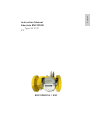 5
5
-
 6
6
-
 7
7
-
 8
8
-
 9
9
-
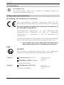 10
10
-
 11
11
-
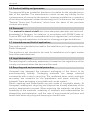 12
12
-
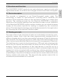 13
13
-
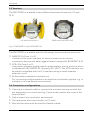 14
14
-
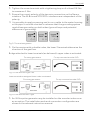 15
15
-
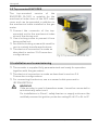 16
16
-
 17
17
-
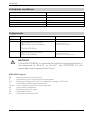 18
18
-
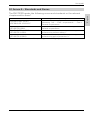 19
19
-
 20
20
-
 21
21
-
 22
22
-
 23
23
-
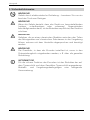 24
24
-
 25
25
-
 26
26
-
 27
27
-
 28
28
-
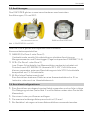 29
29
-
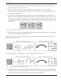 30
30
-
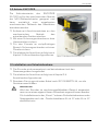 31
31
-
 32
32
-
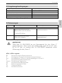 33
33
-
 34
34
-
 35
35
-
 36
36
-
 37
37
-
 38
38
-
 39
39
-
 40
40
-
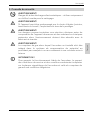 41
41
-
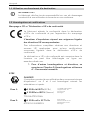 42
42
-
 43
43
-
 44
44
-
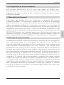 45
45
-
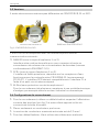 46
46
-
 47
47
-
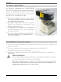 48
48
-
 49
49
-
 50
50
-
 51
51
-
 52
52
-
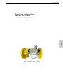 53
53
-
 54
54
-
 55
55
-
 56
56
-
 57
57
-
 58
58
-
 59
59
-
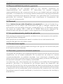 60
60
-
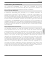 61
61
-
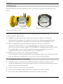 62
62
-
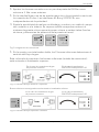 63
63
-
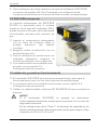 64
64
-
 65
65
-
 66
66
-
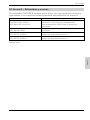 67
67
-
 68
68
-
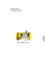 69
69
-
 70
70
-
 71
71
-
 72
72
-
 73
73
-
 74
74
-
 75
75
-
 76
76
-
 77
77
-
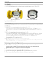 78
78
-
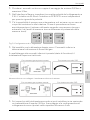 79
79
-
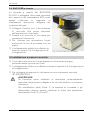 80
80
-
 81
81
-
 82
82
-
 83
83
-
 84
84
-
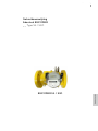 85
85
-
 86
86
-
 87
87
-
 88
88
-
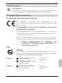 89
89
-
 90
90
-
 91
91
-
 92
92
-
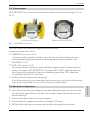 93
93
-
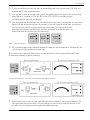 94
94
-
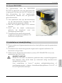 95
95
-
 96
96
-
 97
97
-
 98
98
-
 99
99
-
 100
100


Elster Absolute Manual de usuario
- Tipo
- Manual de usuario
En otros idiomas
- français: Elster Absolute Manuel utilisateur
- italiano: Elster Absolute Manuale utente
- Deutsch: Elster Absolute Benutzerhandbuch
- Nederlands: Elster Absolute Handleiding
Documentos relacionados
Otros documentos
-
Honeywell SM-RI-X, Q75 Instrucciones de operación
-
-
-
-
-
-
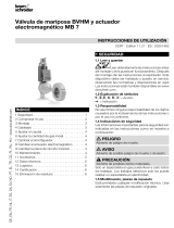 Kromschroder BVHM, MB 7 Instrucciones de operación
-
 Kromschroder DL..H, DL..N Instrucciones de operación

