Craftsman 706137510 El manual del propietario
- Tipo
- El manual del propietario

SEARS
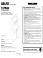
Operator's Manual
[RRFTSMRN ®
PREMIUM SERIES
THIS OPERATING INSTRUCTION MANUAL
COVER ALL PREMIUM SERIES TOOL CENTERS,
INTERMIDIATE CHESTS, AND RISER ASSEMBLYS.
Please indicate the following
information from the service
part drawing provided.
Model Number:
Model Description:
*Product you purchased may vary from picture shown*
CAUTION:
Read and follow all Safety Rules and Operating
Instructions before first use of this product. Retain this document
for future reference.
Sears, Roebuck and Co., Hoffman Estates, IL 60179 USA
Made in the U.S.A.
F890A5
4/97
SAFETY WARNINGS AND CAUTIONS:
• DO NOT stand on this product You may fail which may cause personal injury
• WEAR SAFETY GLASSES when removing or repositioning the slides The tool
could slip which may cause personal injury
• When moving this product, do not pull it Push the product to prevent personal injury
• Stacked products should be bolted together The products could become unstable
and tip, which may cause personal injury or product damage
• Handle and swivel casters must be attached on the same side of the product
• USE THE BRAKES when not moving this product This will prevent the product from
rolling, which may cause personal injury or product damage
• BE CAREFUL when opening more than one drawer The product may become
unstable and tip, which may cause personal injury or product damage
• DO NOT mount this product on a truck bed or any other moving object This may
cause personal injury or product damage
• DO NOT step in the drawers You may fall which may cause personal injury
• Appropriately secure this product before moving it with a forklift
• DO NOT tow with power equipment The product could tip, which may cause
personal injury or product damage
• DO NOT alter this product in any manner For example, do not weld external Iockbars
or attach electrical equipment This may cause product damage or personal injury
• Keep the product on level surfaces The product may become unstable and tip if
stored or moved on an un-IeveI surface, which may cause personal injury or product
damage
• When rearranging the drawers, be careful not to put too many heavy items in the top
drawers The product could become top heavy and tip, which may cause personal
injury or product damage
• BE CAREFUL when closing the cover Remove hands before the cover closes
completely to prevent personal injury
• Close the cover and lock the drawers and doors before moving this product The
drawers or doors could come open and make the product unstable and tip, which
may cause personal injury or product damage
• When locking this product, close the drawers before closing the cover for lock bars to
work properly
• The maximum weight for each drawer should be no more than 25 pounds
• The maximum product weight, including contents, should be no more than 400
pounds for tool centers
11
A
Call 1-800-366-7278 for Service Parts E; JlII] II
U
Refer to Service Parts Drawing for full listing of Service Parts

HARDWARE:
_ 1/4-20 Hex Nut
<(_ _:_1_# 1/4-20 x 7/16 Hex Screw
_ [_ 8-32 x 1/4 Pan Head Screw
_ 8-32 Hex Nut
<_ _/,_,_> 10-16 x 1/2 Sheet Metal Screw
Rivet
REMOVE CHEST FROM ROLL-
AWAY :
• The unit comes with the chest secured to
the inside of the roll-away by either two or
four 1/4-20 bolts.
• Lay the roll-away down on its back. Use
packaging material to protect the paint
finish.
• Remove the securing bolts from the
underside of the roll-away. Save the
screws for mounting the chest to the roll-
away.
• Remove the chest.
CASTER INSTALLATION:
NOTE: Use adequate manpower for this
operation.
• Lay the roll-away down on its back. Use
packaging material to protect the paint
finish.
• Mount both swivel casters on the same
side of the roll-away. The swivel caster
with the brake goes to the front of the
unit.
• Attach casters using 1/4-20 x 7/16 hex
screws and 1/4-20 hex nuts. Wrench
tighten.
• Return the roll-away to its upright
position.
MOUNTING INTERMEDIATE CHEST:
• Remove all drawers necessary in order to
attach units. Follow the drawer removal
and installation instructions in the
operation section.
• Position the intermediate chest on the
cabinet. Using the intermediate chest
bottom as a template, mark the mounting
hole locations onto the roll-away top. At
each mark drill a 5/16" diameter hole.
• Bolt the units together using two 1/4-20 x
7/16 hex screws and two 1/4-20 hex
nuts.
• Attach to the top chest with two 1/4-20 x
7/16 hex screws and two 1/4-20 hex
nuts.
• Reinstall all drawers. Follow the drawer
removal and installation instructions in the
operation section.
MOUNTING CHEST:
• Remove the drawer from the roll-away
(refer to the drawer removal instructions).
• Lift the chest onto the roll-away. Line up
the holes in the bottom of the chest with
the holes in the top of the roll-away.
• Attach the chest using two 1/4-20 screws
that were used to secure the chest to the
bottom of the roll-away.
• Wrench tighten all screws.
• Replace the drawer (refer to the drawer
installation instructions).
• To remove the chest, reverse the
procedure.
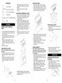
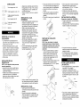
RISER ASSEMBLY:
NOTE: When assembled, the riser
should be the same size, left to right, as
the chest. Use adequate manpower for
this operation.
• Assemble the sides and the back (flange
side up) together using four 8-32 x 1/4
pan head screws and four 8-32 hex nuts.
Finger tighten.
• Position the riser assembly on the roll-
away. Secure using four 10-16 x 1/2
sheet metal screws. Wrench tighten.
• Position the chest on the riser. Secure
using four 10-16 x 1/2 sheet metal
screws. Wrench tighten.
• Wrench tighten the risers four 8-32 x 1/4
pan head screws and 8-32 hex nuts.
st
Back Side
i
%
Cart
SHELF INSTALLATION:
• Place the shelf in the roll-away and line
up the holes.
• Insert four plastic rivets through the sides
of the roll-away.
Shelf--.
Rivets.
\.\
Side_
• Press the rivet pin firmly into the rivet
body to secure the shelf.
• The shelf may be removed by prying the
rivet pins out using a screwdriver.
REMOVING AND INSTALLING
DRAWERS:
• Fully extend the drawer. Then push it
back a quarter of an inch.
• Insert a screwdriver into the slot in the
slide and depress the stop until it clears
the lance. Repeat this procedure for the
other slide. Remove the drawer.
f-- Stop
Lance
3 4

To reinstall the drawer, pry the stop far
enough out to engage the lance (3/16" to
1/4") and push the drawer onto the slides
until the stops pass over the lances.
TO LOCK CHEST:
• Insert the Iockbar (which stores in the top
tray), tabbed end up, into the slot in the
top tray and down into the slot in the
base. Close the cover and lock with the
key.
TO LOCK ROLL-AWAY &
INTERMEDIATE CHEST:
• Insert the Iockbar into the slot in the
base. Move the Iockbar toward the unit
until the bent end fits into the slot near
the lock. Lock with the key. The Iockbar
for the intermediate chest is stored in the
intermediate chests top drawer. The
Iockbar for the roll-away is stored in a slot
in the top front corner of the unit.
TO LOCK TOOL CENTER:
• Insert the slotted end of the Iockbar
through the slot in the top tray and down
into the slot on the panel and in the base.
• The slot in the locking bar fits over the
knob on the panel.
• Close the cover and lock with a padlock.
(Padlock not included).
TO UNLOCK UNITS:
• Reversethe locking procedure.
• For casters, use high quality bearing
grease, (yearly).
• Lubricate the slides, (twice yearly).
• Lubricate lock with graphite, (yearly).
• Periodically the drawer fronts, drawer
trim, and other surfaces should be
cleaned with a mild detergent and water.
• Auto wax will preserve the storage unit's
luster finish. Apply the wax as to a car.
The wax will also help protect the unit
against scratches.
• Grease and oil can be removed with most
standard cleaning fluids. For safety, use a
nonflammable cleaning fluid.
INTENTIONALLY LEFT BLANK

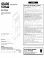
SEARS
CRRFTSMRN
SERIE PREMIUM
ESTE MANUAL DE INSTRUCCIONES DE
OPERACION CUBRE TODAS LAS SERIE
PREMIUM.
Manual del Operador
Sirvase indicar la siguiente informaci6n que
encontrara en el dibujo suministrado de la
pieza de servicio.
Nt_merode modelo:
Descripciondelmodelo:
El producto que ha comprado puede ser distinto deI que
se muestra en Ia ilustraci6n.
CUIDADO:
Antes de utilizar este producto por primera vez,
lea y observe todos los reglamentos de seguridad
y las instrucciones de operaci6n. Guarde este documento para referencia futura.
Fabricado en EE.UU.
Sears, Roebuck and Co., Hoffman Estates, IL 60179, EE.UU. F890A5
AbriI, 1997
ADVERTENCIAS Y PRECAUCIONES DE SEGURIDAD:
• NO se pare sobre este producto. Se puede caer y Iesionarse.
• USE GAFAS DE SEGURIDAD aI quitar o volvera situar Ias correderas. Se podria
resbalar Ia herramienta y causar Iesiones personales.
• Los productos apilados se deben atornilIar entre si. Podrian quedar inestabtes y
volcarse, Io cuaI podria causar Iesiones personales o dafios aI producto.
• At mover el producto, no tire deI mismo. Empt]jelo, de esta manera evitara Iesiones
personales.
• La manija y Ias ruedecilIas giratorias deben colocarse en el mismo lado deI producto.
• USE LOS FRENOS cuando no este moviendo este producto. Esto impedira que
ruede, Io cuaI podria causar Iesiones personales o dafios aI producto.
• TENGA MUCHO CUIDADO aI abrir varias gavetas. El producto podria quedar
inestabte y volcarse, Io cual podria causar Iesiones personales o dafios aI producto.
• NO instale este producto sobre Ia ptataforma de un cami6n ni sobre ningQn otro
objeto m6viI. Esto podria causar Iesiones personales o dafios al producto.
• NO se pare en Ias gavetas. Se puede caer y Iesionarse.
• Antes de mover este producto con un montacargas, asegQrelo de manera adecuada.
• NO remolque el producto con un equipo motorizado. Se puede volcar y causar
Iesiones personales o dafios aI producto.
• NO modifique este producto de ninguna forma. Por ejempto, no suelde barras de
btoqueo externas ni fije equipos electricos. Esto podria causar dafios al producto o
Iesiones personales.
• Mantenga el producto sobre superficies niveladas. Si se guarda sobre una superficie
desnivelada, o se mueve a ella, el producto podria quedar inestabte y volcarse, Io cual
podria causar Iesiones personales o dafios al producto.
• At reorganizar Ias gavetas, tenga cuidado de no poner demasiados elementos
pesados en Ias gavetas de arriba. Se podria acumular mucho peso en Ia parte
superior deI producto y volcarse, Io cual podria causar Iesiones personales o dafios al
producto.
• TENGA MUCHO CUIDADO aI cerrar Ia tapa. Retire Ias manos antes de que esta
cierre por compteto, para evitar Iesiones personales.
• Cierre Ia tapa y asegure Ias gavetas y puertas antes de mover este producto. Estas
se podrian abrir y hacer que el producto quede inestabte y se vuelque, Io cual podria
causar Iesiones personales o dafios aI producto.
• At asegurar este producto, cierre Ias gavetas antes de cerrar Ia tapa para que Ias
barras de btoqueo funcionen correctamente.
• El peso maximo en cada gaveta no debe ser mayor de 25 Iibras.
• El peso maximo deI producto, incluyendo su contenido, no debe ser mayor de 400
Iibras.
Para solicitar piezas de repuesto,
Ilame al 1-800-366-7278
Consulte el Dibujo de piezas de servicio para obtener
un listado completo de las piezas de servicio

D©
D©
QUINCALLERIA:
Tuercahexagonalde 1/4-20
Tornillohexagonalde 1/4-20x 7/16
Tornillode cabezatroncoc6nica
de 8-32x 1/4
Tuercahexagonalde 8-32
r_ _z_p_. Tornillo autorroscante de
_'-_J _'_Y 10-16 x 1/2
Remache
RETIRO DE LA CAJA DE LA
DESLIZADERA:
• La unidad trae Ia caja asegurada a Ia
parte interior de Ia deslizadera con dos o
cuatro pemos de 1/4-20.
• Acueste Ia deslizadera sobre su parte
posterior. Utilice el material de embalaje
para proteger el acabado de Ia pintura.
• Quite los pernos de fijaci6n de Ia parte
inferior de Ia deslizadera. Guarde los
tornillos para instalar Ia caja sobre esta.
• Quite Ia caja.
INSTALAClON DE LAS
RUEDEClLLAS:
NOTA: Use la ayuda de otras personas
para esta operacion.
• Acueste el carro sobre su parte trasera.
Proteja el acabado de Ia pintura con el
material de embalaje.
• Instale Ias dos ruedecilIas giratorias en el
mismo Iado deI carro. La ruedecilIa
giratoria con freno se debe colocar en Ia
parte delantera de Ia unidad.
• Asegure Ias ruedecillas usando tornilIos
hexagonaIes de 1/4-20 x 7/16 y tuercas
hexagonales de 1/4-20. Aprietelos con
una Ilave de tuercas.
• Vuelva a colocar el carro en su posici6n
vertical.
MONTAJE DE LA CAJA
INTERMEDIA:
• Quite todas Ias gavetas necesarias para
instalar Ias unidades. Siga Ias
instrucciones para retiro e instalaci6n de
Ias gavetas en Ia secci6n de Operaci6n.
• Sitee Ia caja intermedia sobre el
gabinete. Usando el fondo de Ia caja
intermedia como ptantilIa, marque Ias
ubicaciones de los agujeros de montaje
en el tabtero de trabajo de Ia caja
deslizabte. Haga un agujero de 5/16" de
diametro en cada marca.
• AtornilIe Ias unidades entre si usando
dos tornilIos hexagonales de 1/4-20 x
7/16 y dos tuercas hexagonales de
1/4-20.
• Fije a Ia caja superior con dos tornilIos
hexagonales de 1/4-20 x 7/16 y dos
tuercas hexagonales de 1/4-20.
1
• Vuelva a instalar todas Ias gavetas. Siga
Ias instrucciones para retiro e instaIaci6n
de Iasgavetas en Ia secci6n de Operaci6n.
MONTAJE DE LA CAJA:
• Quite Ia gaveta de Ia desIizadera
(consulte Ias instrucciones para retirar Ias
gavetas).
• Levante Ia caja sobre Ia deslizadera.
Atinee los agujeros en Ia parte inferior de
Ia caja con los de Ia superficie superior
de Ia deslizadera.
• Fije Ia caja usando dos de los tornilIos de
1/4-20 que se usaron para asegurar Ia
caja a la parte inferior de Ia deslizadera.
• Apriete los tornilIos con una Ilave de
tuercas.
• Vuelva a porter Ia gaveta (consulte Ias
instrucciones de instalaci6n de Ias
gavetas).
• Para retirar Ia caja, siga el procedimiento
inverso.
MONTAJE DEL CON JUNTO
ELEVADOR:
NOTA: Una vez armado, el conjunto
elevador debe tener el mismo tamafio,
de izquierda a derecha, que la caja. Use
la ayuda de otras personas para esta
operacion.
• Arme los paneIes IateraIes y posterior
(Iado de Ia aleta en posici6n vertical)
entre si usando cuatro tornilIos de
cabeza troncon6nica de 8-32 x 1/4 y
cuatro tuercas hexagonales de 8-32.
Apriete con los dedos.
• Sitee el conjunto elevador sobre el carro.
Asegerelo usando cuatro tomilIos
autorroscantes de 10-16 x 1/2. Apriete
con una Ilave de tuercas.
Caja
Panel trasero
Panel
lateral
Carro
• SitQe Ia caja sobre el conjunto elevador.
AsegOrela usando cuatro tornilIos
autorroscantes de 10-16 x 1/2. Apriere
con una Ilave de tuercas.
• Apriete con una Ilave de tuercas los
cuatro tornilIos de cabeza troncoc6nica
de 8-32 x 1/4 y Ias tuercas hexagonales
de 8-32.
INSTALAClON DE LA REPISA:
Solamente el modelo No. 706.657980.
• Ponga Ia repisa dentro de Ia deslizadera
y alinee los agujeros.
• Introduzca cuatro remaches de ptastico a
traves deI costado de Ia deslizadera.
Repisa
Remache =.
Lateral _
• Presione firmemente los pasadores
dentro deI cuerpo de los remaches para
asegurar Ia repisa.
• Si necesita quitar Ia repisa, palanquee
con un destornilIador los pasadores de
remache hasta sacartos.
RETIRO E INSTALAClON DE
LAS GAVETAS:
• Abra Ia gaveta deI todo. Luego empQjela
hacia atras 1/4 de pulgada.
• Introduzca un destornilIador en Ia
abertura en Ia corredera y hunda el tope
hasta que sobrepase Ia lancet& Repita
el procedimiento para el otro Iado. Quite
Ia gaveta.
f Tope
f
Lanceta
Lubricar
Para volver a instalar Ia gaveta, fuerce el
tope Io suficiente para enganchar Ia
Ianceta (3/16" a 1/4") y empuje Ia gaveta
sobre Ias correderas hasta que los topes
sobrepasen Ias Iancetas.
3 4

PARA ASEGURAR LA CAJA
PORTAHERRAMIENTAS:
• Introduzca Ia barra de btoqueo (que se
guarda en Ia bandeja superior), con el
extremo que tiene Ia IengQeta hacia
arriba, dentro de Iaabertura en Ia
bandeja superior y bajando hasta entrar
en Ia abertura en Ia base. Cierre Ia tapa y
asegQrela con Ilave.
PARA ASEGURAR LA CAJA
DESLIZABLE Y LA CAJA
INTERMEDIA:
• Introduzca Ia barra de btoqueo en Ia
abertura en Ia base. Mueva Ia barra de
btoqueo hacia Ia unidad hasta que el
extremo dobtado encaje dentro de Ia
abertura cerca deI seguro. Cierre con Ia
Ilave. La barra de btoqueo de la caja
intermedia se guarda en Ia gaveta
superior de Ia misma. La barra de
btoqueo de Ia caja deslizabte se guarda
en una ranura en Ia esquina superior
delantera de Ia unidad.
PARA ASEGURAR EL CENTRO
PAPA HERRAMIENTAS:
• Introduzca el extremo ranurado de Ia
barra de btoqueo por Ia abertura en Ia
bandeja superior, bajando por Ia ranura
en el panel hasta entrar en Ia base.
• La ranura en Ia barra de bloqueo encaja
en Ia perilla en el panel.
• Cierre Ia tapa y asegQreIa con un
candado. (No se incluye el candado).
PARA QUlTAR EL SEGURO A LAS
UNIDADES:
• Inviertael procedimientousadopara
asegurartas.
• La grasa y el aceite se pueden eliminar
con Ia mayoria de Iiquidos normales de
Iimpieza. Por seguridad, utiIice un Iiquido
de Iimpieza no inftamabte.
SE HA DEJADO EN
BLANCO
INTENCIONALMENTE
• Para Ias ruedecilIas, use grasa de alta
calidad para cojinetes, (una vez aI afio).
• Lubrique Ias correderas, (dos veces al
afio).
• Lubrique el seguro con grafito, (una vez
al afio).
• Periddicamente se deben Iimpiar los
frentes y Ias moIduras de Ias gavetas, y
otras superficies, con un detergente
suave y agua.
• La cera para autos preservara el
acabado Iustroso de Ias unidades de
almacenaje. Aptique cera como a un
auto. Esta tambien ayudara a proteger Ia
unidad contra arafiazos.
-
 1
1
-
 2
2
-
 3
3
-
 4
4
-
 5
5
-
 6
6


Craftsman 706137510 El manual del propietario
- Tipo
- El manual del propietario
en otros idiomas
- English: Craftsman 706137510 Owner's manual
Artículos relacionados
-
Craftsman 706654910 El manual del propietario
-
-
-
-
-
-
-
-
-
