
1
BATTERY OPERATED HYDRAULIC PULLER TYPE PUNCHING TOOL
OUTIL HYDRAULIQUE EMPORTE-PIECE SUR BATTERIE
HYDRAULISCHES AKKU-LOCHSTANZWERKZEUG
HERRAMIENTA HIDRÁULICA PERFORADORA A BATERíA
UTENSILE OLEODINAMICO FORALAMIERE A BATTERIA
B-FL750 B-FL750A B-FL750E B-FL750T
ENGLISH
FRANÇAIS
DEUTSCH
ESPAÑOL
ITALIANO
OPERATION AND MAINTENANCE MANUAL ................................... 6
NOTICE D’UTILISATION ET ENTRETIEN ........................................... 11
BEDIENUNGSANLEITUNG ................................................................... 16
MANUAL DE USO Y MANTENIMIENTO ........................................... 21
MANUALE D’USO E MANUTENZIONE ............................................. 26
14 M 079

2
2
3
3
4
4
4
3
B-FL750
Draw Stud - Tirant
Zugbolzen - Tirante
Draw Stud - Tirant
Zugbolzen - Tirante
Locking ring - Virole
- Kontermutter - Contera
- Ghiera
Die - Matrice - Matrize
Matriz - Matrice
Punch - Poinçon
- Stempel - Punzón - Punzone
Draw Stud - Tirant
Zugbolzen - Tirante
Die - Matrice - Matrize
Matriz - Matrice
Pilot hole
Avant-trou
Pilotbohrung
Agujero piloto
Preforo pilota
1
40
FIG. / BILD 1

3
1 + 3
LED WORKLIGHT / ECLAIRAGE PAR LED / LED ARBEITSLICHT / LUCES LED / ILLUMINAZIONE LED
2
HEAD / TETE / KOPF / CABEZA / TESTA
4
OPERATING BUTTON / GACHETTE DE COMMANDE / STARTKNOPF / BOTÓN DE ACCIONAMIENTO
/ PULSANTE DI AZIONAMENTO
5
PRESSURE RELEASE BUTTON / GACHETTE DE DECOMPRESSION / DRUCKABLASSKNOPF / BOTÓN
DESBLOQUEO PRESIÓN / PULSANTE DI RILASCIO
6
BATTERY / BATTERIE / AKKU / BATERÍA / BATTERIA
7
BATTERY CAPACITY INDICATOR / INDICATEUR DE CHARGE / AKKUANZEIGE / INDICADOR DE
CARGA BATERIA / INDICATORI AUTONOMIA BATTERIA
8
BATTERY CHECK BUTTON / BOUTON POUR CONTROL DE LA BATTERIE / TASTE FÜR AKKUÜBERPRÜ-
FUNG / BOTÓN DE CONTROL BATERÍA / PULSANTE DI VERIFICA BATTERIA
9
BATTERY RELEASE / DEBLOCAGE BATTERIE / AKKU ENTRIEGELUNG / DESBLOQUEO BATERÍA /
SBLOCCO BATTERIA
10
RING FOR SHOULDER STRAP / ANNEAU POUR BANDOULIERE / TRAGERIEMENRING / ANILLO PARA
CORREA / ANELLO AGGANCIO TRACOLLA
FIG. / BILD 2
3
10
4
5
6
2
1
9
8
7

4
FIG. / BILD 3
FIG. / BILD 4
NO
NON
NEIN
OK
Waste slug
Copeau de perçage
Stanzabfall
Virutas de perforación
Sfrido di tranciatura
4
Draw Stud - Tirant
Zugbolzen - Tirante
Punch - Poinçon
Stempel - Punzón
Punzone
Die - Matrice
Matrize - Matriz
Matrice
5

5
– When operating the tool, keep hands away from the danger zone.
– Au cours de l'utilisation, tenir les mains éloignées de la zone de danger.
– Während der Arbeit nicht mit den Händen in den Gefahrenbereich fassen.
– Durante su utilización, mantenga las manos fuera de la zona de peligro.
– Durante l'utilizzo, mantenere le mani fuori dalla zona di pericolo.
WARNING SYMBOLS - SYMBOLES D'AVERTISSEMENT - WARNSYMBOLE -
SÍMBOLOS DE ADVERTENCIA - SIMBOLI DI AVVERTENZA
Tool - Outil - Werkzeug - Herramienta - Utensile
– Before using the tool, carefully read the instructions in this manual.
– Avant d'utiliser cet outil, lire attentivement les instructions de cette notice.
– Vor Inbetriebnahme unbedingt die Bedienungsanleitung durchlesen.
– Antes de utilizar la herramienta, leer atentamente las instrucciones en este manual.
– Prima di utilizzare l'utensile, leggere attentamente le istruzioni riportate in questo manuale.
– Ensure appropriate Personal Protective Equipment (PPE) is used - including hand and eye protection.
– Assurez-vous d'utiliser équipements de protection individuelle (EPI) y compris la protection pour
les mains et les yeux.
– Achten Sie darauf geeignete persönliche Schutzausrüstung (PSA) zu verwen den, einschließlich
für Hände und Augen.
– Asegúrese de utilizar el equipo de protección personal (EPP) que incluye protección para las anos
y los ojos.
– Assicurarsi di utilizzare adeguati dispositivi di protezione personale (DPI) incluse protezioni per
mani e occhi.
– Never throw batteries into re or water.
– Jamais jeter les batteries dans le feu ou dans l'eau.
– Werfen Sie Akkus nicht ins Feuer oder Wasser.
– Nunca tire las baterías al fuego o al agua.
– Mai gettare le batterie nel fuoco o in acqua.
– Always recycle the batteries.
– Recycler toujours les batteries.
– Verbrauchte Akkus stets dem Recycling zuführen.
– Reutilizar siempre las baterías.
– Riciclare sempre le batterie.
– Do not discard batteries into domestic refuse or waste disposal.
– Ne pas jeter de batteries dans une poubelle ou autre lieu non prévu à cet e et.
– Verbrauchte Akkus nicht der allgemeinen Abfallentsorgung zuführen.
– No tirar las baterías al cubo de basura o lugar parecido.
– Non buttate le batterie fuori uso nei cestini della spazzatura o luoghi simili.
– User information (Directives 2011/65/EU and 2012/19/EU), see page 9.
– Information pour les utilisateurs (Directives 2011/65/EU et 2012/19/EU) voir page 14.
– Information für den Benutzer (Richtlinien 2011/65/EU und 2012/19/EU) siehe Seite 19.
– Informe para los usuarios (Directivas 2011/65/EU y 2012/19/EU) vease página 24.
– Informazione agli utenti (Direttive 2011/65/EU e 2012/19/EU) vedere pagina 29.
Battery - Batterie - Akku - Batería - Batteria

6
(1)
Directive 2006/42/EC, annexe 1, point 1.7.4.2 letter u
L
pA
= weighted continuous acoustic pressure level equivalent.
L
pCPeak
= maximum value of the weighted acoustic displacement pressure at the work place.
L
WA
= acoustic power level emitted by the machine.
(2)
Directive 2006/42/EC, annexe 1, point 2.2.1.1
Weighted root mean square in frequency of the acceleration the upper limbs are exposed to for each biodynamic
reference axis. Tests carried out in compliance with the indications contained in EN ISO 5349-1/2 Standard, and under
operating conditions much more severe than those normally found.
1. GENER AL CHARACTERISTICS
B-FL750 B-FL750E
B-FL750T
B-FL750A
Application range suitable for punching single layers of Stainless Steel,
Mild Steel, Fibreglass, Plastic material
Max. punching capacity
mm (inches)
ø 140 / 5.5
Developed force
kN (US sh. ton)
75 (9)
Minimum operating pressure
bar (psi)
700 (10,000)
Dimensions (ref. to Fig. 5)
mm (inches)
363 x 366 x 83 (14.3 x 14.4 x 3.3)
Weight with battery
kg (lbs)
5,1 (11.2)
Motor
V DC
18
Operating temperature
°C (°F)
-15 to +50 (+5 to +122)
Recommended oil
ENI ARNICA ISO 32 or equivalents
Operating speed
twin speed operation and automatic switching from a rapid
advancing speed of the ram to a slower, more powerful
speed
Safety
maximum pressure valve
Rechargeable battery
V / Ah / Wh
18 / 5.2 / 93.6
Type
CB1852 (Li-Ion)
Weight
kg (lbs)
0,66 (1.45)
Battery charger
ASC30-36
Input
type
EU
27044000
UK
27045000
AUS/NZ
27047000
USA/CAN
27046000
V / Hz
220 - 240 / 50 - 60 115 / 60
W
85
Acoustic noise
(1)
L
pA
dB (A)
73
L
pCPeak
dB (C) 94.5
L
WA
dB (A) 79
Vibration
(2)
m/s
2
0.575 max.
ENGLISH

7
ENGLISH
Do not use the tool for purposes other than those intended by Cembre.
The operator should concentrate on the work being performed and be careful to maintain bal
anced working position.
Before each use check the punches, dies and draw studs, and replace any that are worn or dam-
aged, particularly any punches that have damaged cutting surfaces.
Damaged or improperly assembled accessories can break and hit the operator with su cient
force to cause serious injuries.
Before each use, verify the integrity of the tool; replace any worn, possibly damaged or missing
parts with original Cembre spares.
Only for use in punching holes in single layers of material and thicknesses as shown in tables on pages
32 and 33. Any other use may cause components to break with potential risk of serious injury.
During operation do not allow anyone to pause in the work area, especially in front of the punch.
The use of Cembre punching accessories is recommended. Accessories from other suppliers may
not be designed to withstand the force generated by this tool and may be damaged or break with
potential risk of serious injury.
Protect the tool from rain and moisture. Water will damage the tool and battery.
Electro-hydraulic tools should not be operated in pouring rain.
2. INSTRUCTIONS FOR USE
The part reference includes the following:
Hydraulic tool.
Li-Ion rechargeable battery (2 pcs).
Battery charger (model depends on the tool version).
Shoulder strap.
Carrying case.
ø 11.5 mm Spiral bit (code 6134070).
TD-11 Draw stud with threaded 7/16"-3/4" (code 2685005).
TD-19 Draw stud with threaded 3/4"-3/4" (code 2685008).
USB cable (Ref. to § 5).
2.1) Preparation
The tool can be easily carried using either the handle or the
shoulder strap attached to ring (10) (Ref. to Fig. 2).
Before starting any work, check the battery charge
(Ref. to § 2.7) and recharge if necessary, following the
instructions in the battery charger user manual.
To replace the battery, remove it by pressing the release
button (9), then insert the new battery, sliding it into the
guides until it locks.
Battery
9
WARNING

8
2.2) Head rotation
Two independent joints enable the tool head to turn through 360° and rotate through 180°, allowing
the operator to work in the most comfortable position.
Do not attempt to turn the head when the hydraulic circuit is pressurised.
2.3) Assembling of the accessories (Ref. to Fig. 1)
Consult the tables on pages 32 and 33 and select the RD... Punching Kit suitable for the hole to be
made. For punching requirements other than those listed, please contact Cembre.
Round holes ø 15.5 to 30.5 mm
1 Drill a pilot hole in the plate at the desired point, using the ø 11.5 mm spiral bit supplied with the
tool.
2 Fully screw the TD-11 draw stud into the ram (40).
3 Thread the die onto the draw stud, pushing it to rest on the head.
4 Insert the draw stud into the pilot hole and screw the punch onto the draw stud until its cutting
edges are touching the back of the layer of material being punched.
Round holes ø 28.5 to 80.5 mm
1 Drill a pilot hole in the plate at the desired point, using a ø 20 mm spiral bit; alternatively, it is
possible to make the pilot hole with the ø 11.5 mm spiral bit supplied with the tool and widen it
with the KIT RD20.5SS.
2 Fully screw the TD-19 draw stud into the ram (40).
TD-19 draw stud is threaded 3/4" at both ends, screw the short thread into the ram.
3 Thread the die onto the draw stud, pushing it to rest on the head and continue as described in
point 4 above.
Round holes ø 100 to 120 mm
1 Drill a pilot hole in the plate at the desired point, using a ø 29 mm spiral bit; alternatively, it is
possible to make the pilot hole with the ø 11.5 mm spiral bit supplied with the tool and widen it
with the KIT RD30.5SS.
2 Thread the die onto the TD-28.5 draw stud (supplied with the Punching Kit) before screwing it
into the ram.
3 Fully screw the draw stud into the ram (40) and continue as described in point 4 above.
Square and rectangular holes
1 With a drill make the required pilot hole in the plate at the desired point.
2 Fully screw the draw stud (supplied with the Punching Kit) into ram (40) of the head.
3 Thread the die into the draw stud, pushing it to rest on the head.
4 Insert the draw stud into the pilot hole, thread the punch onto the draw stud until its cutting
edges are touching the back of the layer of material being punched then fully screw the locking
ring onto the draw stud to lock the punch in place.
2.4) Punching (Ref. to Fig. 3)
Before punching:
ENGLISH

9
ENGLISH
Check the correct match between die and punch.
Check that the draw stud is completely screwed into the ram head.
Check that the punch is completely screwed onto the stud, with its cutting edges touching
the back of the layer of material being punched.
Keep hands away from the punching zone to avoid serious risk of injury!
Firmly hold the tool and operate the push-button (4) to achieve the required hole: the ram will
gradually pull the punch forward until the hole is produced.
When the hole is performed, release the push-button (4), otherwise after the maximum pressure
relief valve has activated the motor, and will stop automatically.
2.5) LED Worklights
Whilst the tool is in operation, the work area is illuminated by two high luminosity LED Worklights
that switch o automatically at the end of the cycle.
2.6) Retracting the punch (Ref. to Fig. 4)
Press the pressure release button (5), the ram will back and the punch out of the hole.
Remove the punch from the draw stud then carefully and completely remove the scrap slug and
any residue from the die.
Check and remove scrap slug and any residue from the die.
2.7) Battery status
The battery is equipped with LED indicators that indicate the re-
maining battery life at any time by pressing the adjacent button (7):
4 LEDs illuminated: fully charged
2 LEDs illuminated: 50 % capacity
1 LED flashing: minimum charge, replace the battery.
Tool LEDs (1and 3) illuminated combined with an alarm
audible when the operating button (4) is pressed, indicate
that the battery voltage has dropped below a minimum
safety threshold; under these conditions the tool will not start,
and it is necessary to recharge or replace the battery.
The approximate time to fully recharge a battery is about 100
minutes.
After each working cycle, and after the extraction of the
battery from the tool, an integrated battery cut-o device
will operate after 70 s approx. Then the LED nearest to
button (P) will ash 5 times each 14 s approx. The battery will
be reactivated when it is reintroduced into the tool and the
operating button is pressed.
2.8) Using the battery charger
Carefully follow the instructions in the battery charger user manual.
7
3
1
4

10
3. MAINTENANCE
The tool is robust, completely sealed, and requires very little daily maintenance. Compliance with
the following points, should help to maintain its optimum performance:
3.1) Thorough cleaning
Dust, sand and dirt are a danger for any hydraulic device.
Every day, after use, the tool must be wiped with a clean cloth taking care to remove any residue,
especially close to pivots and moveable parts.
Do not use hydrocarbons to clean the rubber parts.
3.2) Storage case
When not in use, the tool should be stored and transported in the plastic case, to prevent damage.
The case is suitable for storing the tool and the accessories.
VAL-P56: Size 690x446x179 mm (27.1x17.5x7.0 inches) , weight 5,5 kg (12.1 lbs).
3.3) Routine maintenance
When the tool reaches the predetermined number of hours worked, it will signal that routine
maintenance is recommended.
The tool will continue to work however 15 sec. after use an alarm comprising 3 beeps com-
bined with illumination of the worklights will signal that its return to Cembre for service is
recommended (see § 6).
4. USE OF NON ORIGINAL Cembre PUNCHING ACCESSORIES
To obtain the best operating results, the use of original Cembre punching accessories is recom-
mended; as an alternative, it is possible to use punching accessories made by other manufacturers
by requesting separately the speci c adaptor (see page 34).
Check the compatibility of the accessories with the characteristics of the B-FL750 tool.
5. CONNECTION TO COMPUTER (Smartool thecnology)
The memory card integrated in the tool records operating data for transfer via the USB cable supplied.
To view and manage this data, go to www.cembre.com and register in the dedicated area, then
download the free Cembre software CEM_SWBT01.
Keeping the Firmware of the tool updated, via free of charge download from here, will optimise
the tool’s performance.
6. RETURN TO Cembre FOR OVERHAUL
In the case of a breakdown contact our Area Agent who will advise you on the problem and give
you the necessary instructions on how to dispatch the tool to our nearest service Centre; if possible,
attach a copy of the Test Certi cate supplied by Cembre together with the tool or ll in and attach
the form available in the “ASSISTANCE” section of the Cembre website.
ENGLISH

11
1. CARACTERISTIQUES GENER ALES
B-FL750 B-FL750E
B-FL750T
B-FL750A
Domaine d'application: conçu pour percer des tôles d’acier inoxydable, l’acier
doux, des parois en bre de verre et la matière plastique
Capacité de percage maxi. mm (inches) ø 140 / 5.5
Force développée
kN (US sh. ton)
75 (9)
Pression min. de travail
bar (psi) 700 (10,000)
Dimensions (voir Fig. 5) mm (inches) 363 x 366 x 83 (14.3 x 14.4 x 3.3)
Poids avec batterie
kg (lbs) 5,1 (11.2)
Moteur V DC 18
Température de fonction-
nement:
°C (°F) -15 à +50 (+5 à +122)
Huile recommandée: ENI ARNICA ISO 32 ou équivalents
Avance rapide:
l’outil passe automatiquement de la vitesse rapide
à la vitesse lente de perçage
Sécurité valve de surpression
Batterie rechargeable V / Ah / Wh 18 / 5.2 / 93.6
Type CB1852 (Li-Ion)
Poids kg (lbs) 0,66 (1.45)
Chargeur de batterie
ASC30-36
Alimentation
type
EU
27044000
UK
27045000
AUS/NZ
27047000
USA/CAN
27046000
V / Hz 220 - 240 / 50 - 60 115 / 60
W85
Bruit aérien sonore
(1)
L
pA
dB (A)
73
L
pCPeak
dB (C)
94.5
L
WA
dB (A) 79
Vibrations
(2)
m/s
2
0.575 maxi.
(1)
Directive 2006/42/CE, annexe 1, point 1.7.4.2, lettre u
L
pA
= niveau de pression sonore continue équivalente pondérée A sur le poste de travail.
L
pCPeak
= valeur de pression sonore instantanée pondérée C sur le poste de travail.
L
WA
= niveau de puissance acoustique dégagée par la machine.
(2)
Directive 2006/42/CE, annexe 1, point 2.2.1.1
Valeur quadratique moyenne pondérée en fréquence de l'accélération à laquelle sont exposés les membres supérieurs
pour chaque axe biodynamique de référence. Relevés réalisés suivant les indications de la Norme EN ISO 5349-1/2,
dans des conditions de service largement représentatives des conditions d'emploi normales.
FRANÇAIS

12
FRANÇAIS
Ne pas utiliser cet outil à des ns di érentes que celles prévues par le constructeur.
Restez bien attentif tout au long du travail, ne soyez pas distrait, ne perdez pas l’équilibre pendant
l'utilisation.
Avant chaque utilisation, contrôler les poinçons, les matrices et les tirants et les remplacer en cas
d'usure ou dommage, remplacer les poinçons qui présenteraient des surfaces de coupe endom-
magées.
Des accessoires endommagés ou mal montés peuvent se rompre et atteindre l’opérateur avec une
force su sante pour provoquer des lésions graves.
Avant chaque utilisation, véri er que la tête est en bon état; remplacer les pièces usagées et
éventuellement endommagées ou manquantes avec des pièces de rechange originales Cembre.
Ne pas faire de trous à travers deux couches ou plus de matériau ou avec des épaisseurs supérieure
à celles indiquées dans le tableau de la page 32 et 33; ceci pourrait provoquer la rupture du tirant
ou du poinçon et des conséquences également graves pour la sécurité des personnes.
Durant le perçage ne permettre à personne de rester dans la zone de travail, surtout devant le
poinçon.
Il est conseillé d’utiliser des accessoires de perçage Cembre. Les accessoires de perçage d’autres
fabricants pourraient s’abîmer ou ne pas résister à la force générée par cet outil ce qui aurait des
conséquences également graves pour la sécurité des personnes.
Protéger l’outil de la pluie et de l’humidité. L’eau pourrait endommager l’outil et la batterie, les
outils hydro-electriques ne devraient pas être utilisés sous la pluie.
2. INSTRUC TIONS D'UTILISATION
L' ensemble comprend:
Outil hydraulique pour percer.
Batterie rechargeable Li-Ion (2 pcs).
Chargeur de batterie (di érent en fonction de la version de l'outil).
Bandoulière.
Co ret de rangement.
Foret hélicoïdal ø11.5 mm (cod. 6134070).
Tirant “TD-11” leté 7/16"-3/4" (cod. 2685005).
Tirant “TD-19” leté 3/4"-3/4" (cod. 2685008).
Câble USB (Voir § 5).
2.1) Mise en service
L’outil peut être transporté facilement grâce à sa poignée
et à la bandoulière accrochée par l'anneau (10) (Voir Fig. 2).
Avant de commencer toute opération, contrôler l’état
de charge de la batterie (voir § 2.7) et si nécessaire, la
recharger en suivant les instructions contenues dans
le manuel d’utilisation du chargeur de batteries.
Pour remplacer la batterie, la retirer en appuyant sur le méca-
nisme de déblocage (9), puis introduire la nouvelle batterie en
la faisant coulisser sur les guides jusqu’au blocage complet.
Batterie
9
AVERTISSEMENT

13
FRANÇAIS
2.2) Rotation de la tête
La tête de l'outil, grâce à deux rotules indépendantes, peut tourner de 360° et pivoter de 180° par
rapport au corps, permettant à l'utilisateur de travailler dans la meilleure position.
Ne pas forcer la rotation de la tête, lorsque le circuit hydraulique est sous pression.
2.3) Montage des accessoires (Réf. a Fig. 1)
En consultant le tableau de la page 32 et 33, choisir le KIT de perforation RD... adapté au trou à
e ectuer. Pour des exigences de perçage di érentes de celles indiquées, contacter Cembre.
Trous ronds de ø 15,5 mm à 30,5 mm
1 A l’aide d’une perceuse, faire un avant-trou dans la tôle à l’endroit établi en utilisant le foret
hélicoïdal ø 11.5 mm fourni avec l'outil.
2 Visser complètement le tirant TD-11 dans le piston (40).
3 En ler correctement la matrice dans le tirant en la poussant pour qu’elle s’appuie sur la tête.
4 Insérer le tirant dans le trou déjà percé et visser le poinçon sur le tirant jusqu’à la tôle.
Trous ronds de ø 28,5 à 80,5 mm
1 A l’aide d’une perceuse, faire un avant-trou dans la tôle à l’endroit établi en utilisant un foret
hélicoïdal ø 20 mm; comme alternative il est possible de faire le avant-trou avec le foret hélicoïdal
ø 11.5 mm fourni avec l'outil et l’élargir avec le KIT RD20.5SS.
2 Visser complètement le tirant TD-19 dans le piston (40).
Le tirant TD-19 est leté 3/4” aux deux extrémités; visser dans le piston le côté avec le letage
le plus court.
3 En ler correctement la matrice dans le tirant en la poussant pour qu’elle s’appuie sur la tête et
continuer comme décrit dans le point 4 précédente.
Trous ronds de ø 100 à 120 mm
1 A l’aide d’une perceuse, faire un avant-trou dans la tôle à l’endroit établi en utilisant un foret
hélicoïdal ø 29 mm; comme alternative il est possible de faire le avant-trou avec le foret hélicoïdal
ø 11.5 mm fourni avec l'outil et l’élargir avec le KIT RD30.5SS.
2 En ler correctement la matrice dans le tirant TD-28.5 (fourni avec le kit de perçage) avant son
vissage dans le piston.
3 Visser complètement le tirant dans le piston (40) et continuer comme décrit dans le point 4
précédente.
Trous carrés et rectangulaires
– A l’aide d’une perceuse, faire un avant-trou dans la tôle à l’endroit établi.
– Visser complètement le tirant (fourni avec le kit de perçage) dans le piston (40).
– En ler la matrice dans le tirant en la poussant pour qu’elle s’appuie sur la tête.
– Insérer le tirant dans le trou puis insérer le poinçon sur le tirant jusqu’à ce qu’il bute contre la tôle.
– Visser complètement la vis de blocage sur le tirant pour bloquer l’ensemble.
2.4) Perçage (Réf. a Fig. 3)
Avant d’e ectuer le perçage:

14
FRANÇAIS
Véri er que le couplage entre la matrice et le poinçon correspondant est correct.
Véri er que le tirant est complètement vissé dans le piston de la tête.
Véri er que le poinçon est complètement vissé sur le tirant jusqu’à ce qu’il bute contre la tôle.
Tenir les mains éloignées de la zone de perçage. Risque de lésions!
Tenez l'outil fermement y appuyer sur la gâchette de commande (4) pour mettre en marche le
groupe moteur pompe, le mouvement du piston commencera entraînant ainsi le déplacement
en avant du poinçon et le perçage de la tôle.
Relâchez la gâchette de commande (4) lorsque la coupe est e ectuée.
Si l'on maintient le moteur actionné, l’outil s’arrêtera automatiquement avec l'intervention de la
valve de surpression.
2.5) Led
Lors de l’actionnement de l’outil, la zone de travail est éclairée au moyen de deux LED haute lumi-
nosité qui s’éteignent automatiquement à la n du cycle.
2.6) Réouverture del poinçon (Réf. a Fig. 4)
Pour rouvrir l'ensemble, en appuyant à fond sur la gâchette de déblocage (5) on provoque le
retour du piston et par conséquent le retour du poinçon.
Démonter le poinçon du tirant et expulser le copeau de perçage de la matrice.
Véri er qu’il ne reste aucun résidu de découpage à l’intérieure de la matrice.
2.7) Autonomie de la batterie
La batterie est équipée d’indicateurs à LED qui permettent de
contrôler, à tout moment, son autonomie résiduelle en appuyant
sur le bouton (7):
4 led allumées: autonomie maximale
2 led allumées: autonomie à 50 %
1 led clignotante: autonomie minimale, remplacer la batterie.
L'éclairage des deux Led (1 et 3) associé à l’avertisseur
sonore lorsque l’on appuie sur le bouton de déclenchement
(4 indique que la batterie est déchargée et que sa tension
est descendue au-dessous du seuil minimal de sécurité; dans cette
situation, l’outil ne démarre pas, il est donc nécessaire de rechar-
ger ou de remplacer la batterie.
À titre indicatif, le délai de recharge complète de la batterie cor-
respond à environ 100 min.
A la n de chaque cycle de travail comme à l’extraction de
la batterie de l’outil, un dispositif électronique arrête auto-
matiquement la batterie après environ 70 s.
Pour con rmer cette opération, la led la plus proche du bouton
(P) clignotera 5 fois en 14 s (approximativement). La batterie est
réactivée dès sa réintroduction dans l’outil, ou en appuyant sur
le bouton d’actionnement.
2.8) Utilisation du chargeur de batterie
Suivre attentivement les instructions indiquées sur le manuel.
7
3
1
4

15
FRANÇAIS
3. ENTRETIEN
L'outil est robuste, complètement scellé et ne nécessite aucune préoccupation ou attention particulier.
Les recommandations qui suivent sont néanmoins souhaitables pour assurer une longévité optimum:
3.1) Nettoyage élémentaire
Veiller à protéger l'outil de la poussière, du sable et de la boue qui sont un danger à tout système
hydraulique. Chaque jour après utilisation, l'outil doit être nettoyé à l'aide d'un chi on propre, tout
particulièrement aux endroits de pièces mobiles.
Ne jamais utiliser d’hydrocarbures pour le nettoyage des parties en caoutchouc.
3.2) Rangement
Au repos, pour protéger l'outil des coups accidentels et de la poussière, il convient de le ranger
dans le co ret. Ce co ret (type VAL-P56), adapté pour contenir l'outil et ses accessoires a comme
dimensions: 690x446x179 mm (27.1x17.5x7.0 inches) et un poids de 5,5 kg (12.1 lbs).
3.3) Entretien de routine
Lorsqu'on atteint le nombre prédéterminé d'heures de travail, l'outil va signaler la nécessité d'e ec-
tuer l'entretien de routine.
Après 15 secondes de l'exécution du dernier cycle, la nécessité de procéder à l'entretien de
routine est signalée par allumages intermittents répétés trois fois des LED associé à l’aver-
tisseur sonore. L'outil continue par ailleurs à travailler normalement; mais il est recommandé
de le renvoyer à Cembre pour une révision complète (voir § 6).
4. UTILISATION DES ACCESSOIRES DE PERÇAGE NON ORIGINAUX Cembre
Pour obtenir les meilleurs résultats opérationnels, il est conseillé d'utiliser des accessoires de perçage
originaux Cembre, sinon il est possible d'utiliser des accessoires de perçage d'autres fabricants
qui exigent leurs propres kits d’adaptation spéci ques (Voir page 34).
Véri er la compatibilité des accessoires avec les caractéristiques de l'outil B-FL750.
5. CONNEXION À L’ORDINATEUR (Smartool thecnology)
Le chier de mémoire intégrée dans l’outil permet d’enregistrer les paramètres de fonctionnement
et de pouvoir les transférer vers un ordinateur par l’intermédiaire du câble USB fourni. Pour visualiser
et gérer les données mémorisées, le logiciel Cembre CEM_SWBT01 est disponible gratuitement
après enregistrement dans le domaine réservé du site www.cembre.com. Dans ce domaine réservé,
il sera alors possible de trouver les mises à jour éventuelles des rmwares permettant à vos propres
outils une meilleure e cacité et d’améliorer leurs performances.
6. ENVOI EN REVISION A Cembre
En cas de dysfonctionnement de l’appareil, merci de vous adresser à notre Agent Régional qui vous
conseillera et le cas échéant vous donnera les instructions nécessaires pour envoyer l’appareil à
notre Centre de Service le plus proche. Dans ce cas, joindre une copie du Certi cat d’Essai livré par
Cembre avec l’appareil ou remplir et joindre le formulaire disponible dans la section “ASSISTANCE”
du site web Cembre.

16
1. ALLGEMEINE EIGENSCHAFTEN
(1)
Richtlinie 2006/42/EG, Anhang 1, Nummer 1.7.4.2, Buchstabe u
L
pA
= Stufe konstanter Emissionsschalldruckpegel entsprechend Gewichtung A am Arbeitsplatz.
L
pCPeak
= maximaler Emissionsschalldruckpegel entsprechend Gewichtung C am Arbeitsplatz.
L
WA
= Emissionsschalldruckpegel durch das Gerät
(2)
Richtlinie 2006/42/EG, Anhang 1, Nummer 2.2.1.1
Der durchschnittliche Schwingungsgesamtwert dem die oberen Körpergliedmaßen ausgesetzt sind, wurde technisch
vergleichbar nach EN ISO 5349-1/2 einer repräsentativen Maschine ermittelt und übersteigt nicht den vorgeschrie-
benen Wert.
B-FL750 B-FL750E
B-FL750T
B-FL750A
Anwendungsbereich geeignet zum Stanzen von rostfreiem Stahlblech, Weichstahl,
Material aus Glasfaser- und Kunststo material
Max. Stanzbereich: mm (inches) ø 140 / 5.5
Stanzkraft:
kN (US sh. ton)
75 (9)
Arbeitsdruck bar (psi) 700 (10,000)
Abmessungen (siehe Bild 5) mm (inches) 363 x 366 x 83 (14.3 x 14.4 x 3.3)
Gewicht inkl. Akku kg (lbs) 5,1 (11.2)
Motor V DC 18
Betriebstemperatur: °C (°F) -15 bis +50 (+5 bis +122)
Empfohlenes Öl: ENI ARNICA ISO 32 oder ähnliches
Kolbenvorschub:
Das Werkzeug ist mit einer Doppelkolbenhydraulikausgerü-
stet. Beim Beginn des Arbeitsvorganges wird automatisch
auf den langsameren Arbeitshub umgeschaltet
Sicherheit: Überdruckventil
Wiederau adbarer Akku V / Ah / Wh 18 / 5.2 / 93.6
Typ CB1852 (Li-Ion)
Gewicht kg (lbs) 0,66 (1.45)
Akkuladegerät
ASC30-36
Eingangspannung
Typ
EU
27044000
UK
27045000
AUS/NZ
27047000
USA/CAN
27046000
V / Hz 220 - 240 / 50 - 60 115 / 60
W85
Lärmschutzbestimmung
(1)
L
pA
dB (A)
73
L
pCPeak
dB (C) 94.5
L
WA
dB (A) 79
Vibrationen
(2)
m/s
2
0.575 max.
DEUTSCH

17
DEUTSCH
Verwenden Sie das Akkuwerkzeug ausschließlich für den vom Hersteller vorgesehenen Anwen-
dungszweck.
Arbeiten Sie konzentriert und lassen Sie sich während des Einsatzes nicht ablenken und nehmen
zur Arbeit eine sichere und standfeste Arbeitsposition ein!
Vor jeglicher Benutzung die Stempel, Matrizen, und Zugbolzen überprüfen und bei Verschleiß
oder Beschädigung ersetzen. Stempel mit beschädigten Schnittkanten ersetzen.
Beschädigte oder falsch montierte Werkzeuge können Brechen und Personen mit einer dermaßen
großen Kraft tre en, dass diese schwere Verletzungen davontragen können.
Vor jeder Benutzung die Unversehrtheit des Kopfes überprüfen. Verschlissene, beschädigte oder
fehlende Teile durch Originalersatzteile von Cembre ersetzen.
Es dürfen keine Stanzungen mit zwei oder mehreren Materialschichten und höheren Material-
stärken als in Tabellen auf den Seite 32 und 33 angegeben ist, durchgeführt werden.
Das könnte zur Beschädigung des Zugbolzens oder des Stempels führen und es besteht eine große
Gefahr für das Personal.
Während der Stanzung niemandem erlauben, im Arbeitsbereich zu verweilen, vor allem darf sich
niemand vor dem Stempel aufhalten.
Es wird die Verwendung des Stanzzubehörs von Cembre empfohlen. Stanzzubehör anderer Her-
steller könnte sich beschädigen oder der von diesem Werkzeug erzeugten Kraft nicht stand halten.
Daraus leitet sich eine große Gefahr für die Unversehrtheit des Personals ab.
Das Werkzeug vor Regen und Feuchtigkeit schützen. Wasser könnte das Werkzeug und den Akku
beschädigen. Elektrohydraulische Werkzeuge sollten nicht im Regen eingesetzt werden.
2. BEDIENUNGSHINWEISE
Zum Lieferumfang unter dieser Bezeichnung gehören folgende Teile:
Hydraulisches Akku-Lochstanzwerkzeug.
2 Stück wiederaufladbare Li-Ion Akkus.
Ladegerät (entsprechend der Länderkon guration).
Trageriemen.
Ko er.
Spiralbohrer ø11.5 mm (Art.Nr. 6134070).
Zugbolzen “TD-11” mit ein Gewinde 7/16"-3/4" (Art.Nr. 2685005).
Zugbolzen “TD-19” mit ein Gewinde 3/4"-3/4" (Art.Nr. 2685008).
USB-Kabel (siehe Punkt 5).
2.1) Vorbereitung
Das Werkzeug kann bequem am Gri oder mit dem Trage-
riemen, der am Ring (Bild 6 T.10) befestigt ist, transportiert
werden.
ÜberprüfenSie vor jedem Arbeitsvorgang den Ladezu-
stand der Akkus (siehe Pkt. 2.7) und laden Sie bei Bedarf
die Akkus entsprechend den Anweisungen in der Be-
dienungsanleitung des Akkuladegerätes auf.
Drücken Sie für den Akkuaustausch auf die Entriegelung
(9) und führen Sie den neuen Akku bis zum Einratsen ein.
Akku
9
HINWEISE

18
2.2) Drehbewegung des Kopfes
Der Kopf des Werkzeuges kann um 360° gedreht werden und der Stanzkopf kann noch um max.
180° abgewinkelt werden.
Der Kopf darf keinesfalls in eine andere Position gedreht werden, während das Werkzeug
unter Druck steht.
2.3) Montagezubehör (siehe Bild 1)
Aus den Tabellen auf den Seite 32 und 33 das entsprechende KIT RD... auswählen.
Bei hier nicht aufgeführten Anforderungen an die Stanzung bitte mit Cembre Kontakt aufnehmen.
Rundstanzungen von ø 15,5 bis 30,5 mm
1 Zur Führung mit einer Bohrmaschine am festgelegten Punkt eine Pilotbohrung in das Blech bohren.
Die Pilotbohrung mit dem Spiralbohrer der Größe ø11.5mm ausführen, der zum Lieferumfang
gehört.
2 Den Zugbolzen TD-11 vollständig in den Kolben (40) des Kopfes eindrehen.
3 Die Matrize auf den Zugbolzen aufsetzen und sie bis zum Anschlag an den Kopf schieben.
4 Den Zugbolzen in die Pilotbohrung einführen und den Stempel auf den Zugbolzen bis zum Blech
aufschrauben.
Rundstanzungen von ø 28,5 bis 80,5 mm
1 Zur Führung mit einer Bohrmaschine am festgelegten Punkt eine Pilotbohrung in das Blech
bohren. Dabei einen Spiralbohrer ø20 mm benutzen. Alternativ dazu kann die Pilotbohrung mit
dem Bohrer der Größe ø 11.5 mm ausgeführt werden. Anschließend die Bohrung mit dem
KIT RD20.5SS erweitern.
2 Den Zugbolzen TD-19 vollständig in den Kolben (40) des Kopfes eindrehen.
Der Zugbolzen TD-19 hat an beiden Enden ein 3/4"-Gewinde. In den Kolben des Werkzeuges
die Seite mit dem kürzeren Gewinde eindrehen.
3 Die Matrize auf den Zugbolzen aufsetzen und sie bis zum Anschlag an den Kopf schieben.
Entsprechend Punkt 4 fortfahren.
Rundstanzungen von ø 100 bis 120 mm
1 Zur Führung mit einer Bohrmaschine am festgelegten Punkt eine Pilotbohrung in das Blech
bohren. Dabei einen Spiralbohrer ø29 mm benutzen. Alternativ dazu kann die Pilotbohrung mit
dem Bohrer der Größe ø 11.5 mm durchgeführt werden Anschließend die Bohrung mit dem
KIT RD30.5SS erweitern.
2 Vor der Montage des Zugbolzen TD-28.5 (er ist im Lieferumfang des KIT RD.. enthalten) die Matrize
auf den Zugbolzen aufsetzen und dann in den Kolben des Werkzeuges schrauben.
3 Den Zugbolzen vollständig in den Kolben (40) eindrehen.
Entsprechend Punkt 4 fortfahren.
Quadratische und rechteckige Stanzungen
1 Zur Führung am festgelegten Punkt mit einer Bohrmaschine eine Pilotbohrung in das Blech bohren.
2 Den Zugbolzen vollständig in den Kolben (40) einschrauben (er ist im Lieferumfang des KIT RD..
enthalten).
3 Die Matrize auf den Zugbolzen aufsetzen und sie bis zum Anschlag an den Kopf schieben.
4 Den Zugbolzen in die Pilotbohrung einsetzen und den Stempel auf dem Zugbolzen bis zum Blech
schieben. Die Kontermutter vollständig auf den Zugbolzen aufschrauben, um alle Bauteile zu
xieren.
2.4) Stanzung (siehe Bild3)
Vor dem Stanzen folgendes beachten:
DEUTSCH

19
DEUTSCH
Die korrekte Montage der Matrize am entsprechenden Stempel kontrollieren.
Die vollständige Verschraubung des Zugbolzens im Kolben des Kopfes überprüfen.
Die vollständige Verschraubung des Stempels auf dem Zugbolzen (bis zum Blech) überprüfen.
Nicht in den Stanzbereich fassen. Verletzungsgefahr!
Halten Sie das Werkzeug fest und durch Drücken des Startknopfes (4) beginnen Motor und Pumpe
zu arbeiten und der Kolben beginnt sich zu bewegen, der Stempel bewegt sich und es erfolgt
das Stanzen des Bleches.
Wenn die Stanzung erfolgt ist, den Startknopf (4) loslassen. Ansonsten erfolgt automatisch die
Abschaltung bei Erreichen des Maximaldruckes durch das Überdruckventil.
2.5) LED
Während der Betätigung des Werkzeugs wird der Arbeitbereich von zwei LED-Anzeigen mit hoher
Helligkeit ausgeleuchtet, die sich am Zyklusende automatisch abschalten.
2.6) Zurückfahren des Stempels (siehe Bild4)
Um den Stempel zurückzufahren, drücken Sie kräftig des Druckablassknopf (5) bis sich der Kolben
vollständig zurückgezogen hat.
Den Stempel vom Zugbolzen abmontieren und den Stanzabfall aus der Matrize entfernen.
Überprüfen Sie, dass keine Stanzrückstände innerhalb der Matrize zurückbleiben.
2.7) Akkuladung
Die Akku ist mit LED-Anzeigen ausgestattet, die jederzeit über die verbleibende Akkulaufzeit Aus-
kunft gibt, indem man auf die Taste (7) drückt:
4 LED eingeschaltet: Maximale Ladung
2 LED eingeschaltet: Ladung zu 50 %
1 LED blinkend: Minimale Ladung, Akku austauschen bzw.
au aden.
Wenn der Akku nicht mehr ausreichende Ladung hat, wird
beim Betätigen des Startknopfes (4) über die LED Leuchten
(1 und 3) zusammen mit einem akustischen Signal das
Erreichen des Mindestsicherheitsniveau signalisiert. Unter diesen
Bedingungen kann das Werkzeug nicht in Betrieb genommen
werden. Laden Sie den Akku auf oder tauschen Sie ihn aus.
Ein vollständiger Ladevorgang eines leeren Akkus dauert etwa
100 Minuten.
Nach jedem Arbeitszyklus und wie auch nach der Entfer-
nung des Akkus schaltet es durch die eingebaute Elektronik
nach ca. 70s automatisch ab.
Als Bestätigung des Vorganges wird die LED bei der Taste (P) 5-mal
hintereinander innerhalb von ca. 14s blinken. Durch das Einführen
des Akkus in das Werkzeug wird der Akku wieder aktiviert oder
durch die Betätigung des Startknopfes.
2.8) Verwendung des Ladegerätes
Die in der Bedienungsanleitung gegebenen Hinweise sind zu beachten.
7
3
1
4

20
3. WARTUNG
Das Werkzeug ist robust und benötigt keine spezielle P ege.
Zur Erhaltung der Garantieansprüche beachten Sie folgende Hinweise:
3.1) P ege
Dieses hydraulische Werkzeug sollte vor starker Verschmutzung geschützt werden, da dies für ein
hydraulisches System gefährlich ist. Jeden Tag nach der Arbeit sollte das Werkzeug mit einem Tuch
von Schmutz und Staub gereinigt werden, besonders die beweglichen Teile. Verwenden Sie keine
Kohlenwassersto e (z.B. Teilereiniger, Bremsenreiniger) zum Reinigen der Gummiteile.
3.2) Lagerung
Wenn das Werkzeug nicht benötigt wird, sollte es in dem Kunststo ko er gelagert werden und ist
somit gegen Beschädigungen wie Stoß und Staub geschützt.
Der Metallko er Typ VAL-P56 hat folgende Abmessungen: 690x446x179 mm (27.1x17.5x7.0 inches)
und ein Gewicht von 5,5 kg (12.1 lbs.). Er ist geeignet zum Lagern vom Werkzeug und Zubehör.
3.3) Wartung
Sobald die vorgegebene Anzahl der maximalen Arbeitsstunden erreicht sind, signalisiert das Werk-
zeug die damit fällige Wartung.
15 Sekunden nach Ausführung des letzten Zyklus, wird eine bevorstehende Wartung,dreimal
hintereinander durch ein unterbrechendes Aufblinken der LED's, zusammen mit einem akus-
tischen Warnsignal angekündigt.
Das Werkzeug wird weiterhin normal arbeiten. Es wird das Einsenden des Werkzeuges an Cembre
empfohlen, für eine komplette Überholung (siehe Pkt. 6).
4. EINSATZ VON STANZWERKZEUGEN VON FREMDLIEFERANTEN
Um beste Ergebnisse zu erzielen, sollte das Originalstanzzubehör von Cembre benutzt werden.
Alternativ dazu kann Stanzzubehör anderer Hersteller mit einem speziellen separat zu bestellenden
Adapter verwendet werden (siehe Seite 34).
Die Kompatibilität von dem Stanzzubehörs anderer Hersteller mit den technischen Daten
vom B-FL750 kontrollieren.
5. ANSCHLUSS AN EINEN COMPUTER (Smartool thecnology)
Der im Werkzeug integrierte Speicher ermöglicht die Betriebsparameter zu speichern und mit dem
mitgelieferten USB-Kabel auf einen Computer zu übertragen.
Um die Daten vom Werkzeug zu übertragen und zu verwalten, müssen Sie unter www.cembre.com
die Cembre Software CEM_SWBT01 nach einer Registrieung downloaden.
Hier nden Sie auch mögliche Firmware Updates für die Platine des Werkzeuges, um eine bestmög-
liche Leistung und E zienz des Werkzeuges zu ermöglichen.
6. EINSENDUNG AN Cembre ZUR ÜBERPRÜFUNG
Sollten an dem Gerät Fehler auftreten, wenden Sie sich bitte an unsere Gebietsvertretung, die
Sie gerne beraten und Ihnen alle nötigen Informationen zum Einsenden des Gerätes an unseren
Hauptsitz geben wird. Wenn vorhanden, legen Sie dem Gerät bitte eine Kopie des von Cembre
mitgelieferten Zerti kates bei oder füllen das, unter dem Bereich “SUPPORT“ der Cembre Website,
verfügbare Formular aus und fügen es bei.
DEUTSCH

21
ESPAÑOL
1. CARACTERíSTICAS GENERALES
(1)
Directiva Europea 2006/42/CE, anexo 1, punto 1.7.4.2, letra u
L
pA
= nivel de presión acústica contínua equivalente ponderado A en el puesto de trabajo.
L
pCPeak
= valor máximo de la presión acústica instantánea ponderada C en el puesto de trabajo.
L
WA
= nivel de potencia acústica emitida por la máquina.
(2)
Directiva Europea 2006/42/CE, anexo 1, punto 2.2.1.1
Valor cuadrático medio ponderado en frecuencia, de la aceleración a la que están expuestos los miembros superiores
para cada eje biodinámico de referencia. Medidas realizadas según las indicaciones de la Norma EN ISO 5349-1/2, en
condiciones de utilización ampliamente representativas respecto a las que se encuentran normalmente.
B-FL750 B-FL750E
B-FL750T
B-FL750A
Campo de aplicación:
idónea para perforar chapa de acero inoxidable, acero
dulce, paredes de bra de vidrio y material plástico
Capacidad de perforado max.
mm (inches) ø 140 / 5.5
Fuerza desarrollada
kN (US sh. ton)
75 (9)
Presión de trabajo bar (psi) 700 (10,000)
Dimensiones (Ref. a Fig. 5) mm (inches) 363 x 366 x 83 (14.3 x 14.4 x 3.3)
Peso con batería kg (lbs) 5,1 (11.2)
Motor V DC 18
Temperatura de funciona-
miento
°C (°F) -15 a +50 (+5 a +122)
Aceite recomendado ENI ARNICA ISO 32 ó equivalentes
Velocidad de avance son dos: una rápida y otra más lenta de trabajo.
El paso de una a otra velocidad es automático
Seguridad válvula de sobrepresión
Batería recargable V / Ah / Wh 18 / 5.2 / 93.6
Tipo CB1852 (Li-Ion)
Peso kg (lbs) 0,66 (1.45)
Cargador de batería
ASC30-36
Alimentación
tipo
EU
27044000
UK
27045000
AUS/NZ
27047000
USA/CAN
27046000
V / Hz 220 - 240 / 50 - 60 115 / 60
W85
Ruido aéreo
(1)
L
pA
dB (A) 73
L
pCPeak
dB (C) 94.5
L
WA
dB (A) 79
Vibraciones
(2)
m/s
2
0.575 max.

22
ESPAÑOL
No utilice la herramienta para nes diferentes de los previstos por el fabricante.
Prestar atención en el trabajo, no distraerse y no perder el equilibrio durante la utilización.
Antes de cada uso, revisar los punzones, las matrices y los tirantes y sustituirlos en caso de desgast
o daños. Sustituir los punzones que presenten super cies de corte dañadas.
Los accesorios dañados o montados de forma inadecuada pueden romperse y golpear al operario
con una fuerza su ciente para causar lesiones graves.
Antes de cada uso, comprobar la integridad de la cabeza. Sustituir las partes desgastadas, da-
ñadas o ausentes con piezas de recambio originales Cembre.
No realizar ori cios a través de dos o más capas de material o con espesores superiores a los que
se muestran en las tablas pág. 32 y 33. Esto podría causar la rotura del tirante o del punzón y
causar lesiones graves.
Durante la perforación, no permitir a nadie permanecer en la zona de trabajo, sobre todo delante
del punzón.
Se recomienda el uso de accesorios de perforación Cembre. Los accesorios de perforación de otros
fabricantes podrían dañarse o no resistir a la fuerza generada por esta herramienta con conse-
cuencias que pueden ser incluso graves en la integridad personal.
Proteger la herramienta de la lluvia y la humedad. El agua podría dañar la herramienta y la
batería. Las herramientas electrohidráulicas no deberían funcionar bajo la lluvia.
2. INSTRUCCIONES DE USO
La referencia identi ca el conjunto formado por:
Herramienta hidráulica.
Batería recargable Li-Ion (2 uds).
Cargador de batería (diferente según el modelo de la herramienta).
Correa de transporte.
Caja.
Broca helicoidal ø11.5 mm (cod.6134070).
Tirante “TD-11” con rosca 7/16"-3/4" (cod. 2685005).
Tirante “TD-19” con rosca 3/4"-3/4" (cod. 2685008).
Cable USB (Ref. al § 5).
2.1) Preparación
La herramienta puede ser transportada fácilmente por
medio del asa o la correa de transporte jada al anillo (10)
(Ref. a Fig. 6).
Antes de iniciar cualquier trabajo, compruebe el
estado de carga de las baterías (Ref. al § 2.7).
Si es necesario, recárguelas siguiendo las instruccio-
nes del manual de uso del cargador.
Para sustituir la batería, retírela pulsando el desbloqueo (7)
y luego inserte la nueva batería deslizándola por las guías
hasta su tope.
Batería
7
ADVERTENCIAS

23
ESPAÑOL
2.2) Rotación de la cabeza
La cabeza de la herramienta, gracias a dos articulaciones independientes, puede ser girada 360° y
rotada 180° respecto al cuerpo, permitiendo al operario realizar el trabajo en la posición más adecuada.
No fuerce la cabeza, intentando rotarla, mientras el circuito hidráulico esté presurizado.
2.3) Montaje de los accesorios de perforación (Ref. en Fig 1)
Consultando las tablas pág. 32 y 33, elegir el kit de perforación RD... adecuado para el ori cio que se
debe realizar. En caso de necesidades de perforación diferentes, ponerse en contacto con Cembre.
Ori cios redondos de ø 15,5 a 30,5 mm
1 Con un taladro, realizar un pre-ori cio piloto en la chapa en el punto establecido utilizando la
broca helicoidal de ø 11.5 mm en dotación con la herramienta.
2 Enroscar completamente el tirante TD-11 en el pistón (40).
3 Introducir correctamente la matriz en el tirante empujándola en contra de la cabeza.
4 Introducir el tirante en el pre-ori cio y enroscar completamente el punzón en el tirante hasta la
chapa.
Ori cios redondos de ø 28,5 a 80,5 mm
1 Con un taladro, realizar un pre-ori cio piloto en la chapa en el punto establecido utilizando una
broca helicoidal de ø 20 mm. Como alternativa, se puede realizar el pre-ori cio con la broca de
ø 11.5 mm y ensancharlo con el KIT RD20.5SS.
2 Enroscar completamente el tirante TD-19 en el pistón (40).
El tirante TD-19 está roscado 3/4" en ambos extremos. Enroscar en el pistón por el lado con
la rosca más corta.
3 Introducir correctamente la matriz en el tirante empujándola en contra de la cabeza y continuar
como se describe en el punto 4 anterior.
Ori cios redondos de ø 100 a 120 mm
1 Con un taladro, realizar un pre-ori cio piloto en la chapa en el punto establecido utilizando una
broca helicoidal de ø 29 mm. Como alternativa, se puede realizar el pre-ori cio con la broca de
ø 11.5 mm y ensancharlo con el KIT RD30.5SS.
2 Introducir correctamente la matriz en el tirante TD-28.5 (suministrado con el kit de perforación)
antes de enroscarlo en el pistón.
3 Enroscar completamente el tirante en el pistón (40) y continuar como se describe en el punto 4
anterior.
Ori cios cuadrados y rectangulares
1 Con un taladro, realizar un pre-ori cio piloto en la chapa en el punto establecido.
2 Enroscar completamente el tirante (suministrado con el kit de perforación) en el pistón (40).
3 Introducir la matriz en el tirante empujándola en contra de la cabeza.
4 Introducir el tirante en el pre-ori cio y después introducir el punzón en el tirante hasta llegar a
la chapa. Enroscar completamente la contera de bloqueo en el tirante para bloquear todo.
2.4) Perforación (Ref. en Fig. 3)
Antes de proceder a la perforación:

24
ESPAÑOL
Comprobar el acoplamiento correcto entre la matriz y el punzón correspondiente.
Comprobar que se enrosque completamente el tirante en el pistón de la herramienta.
Comprobar que se enrosque completamente el punzón en el tirante hasta llegar a la chapa.
Mantener las manos lejos de la zona de perforación. ¡Peligro de lesiones!
Sostenga rmemente la herramienta y apriete el botón de accionamiento (4): empezará el mo-
vimiento del pistón con el consiguiente avance del punzón y la perforación de la chapa.
Cuando el ori cio esté realizado, soltar el pulsador (4), de lo contrario el motor se detendrá au-
tomáticamente después de la intervención de la válvula de sobrepresión.
2.5) Led
Durante el accionamiento de la herramienta, la zona de corte está iluminada por dos led de alta
luminosidad que se apagan automáticamente al nal del ciclo.
2.6) Reapertura del punzón (Ref. en Fig. 4)
Para volver a abrir el conjunto, actuar sobre el botón desbloqueo presión (5), se obtendrá el
retorno del pistón con la consiguiente apertura del punzón.
Desmontar el punzón por el tirante y expulsar las virutas de perforación de la matriz.
Comprobar que no queden residuos de perforación dentro de la matriz.
2.7) Autonomía de la batería
La batería está provista de indicadores de led que permiten saber la autonomía restante en cualquier
momento pulsando el botón (7):
4 led encendidos: autonomía máxima
2 led encendidos: autonomía al 50 %
1 led parpadeante: autonomía mínima, reemplazar la batería.
La iluminación de los Led (1 y 3) asociada a una señal acús-
tica cuando se presiona el botón de accio-namiento (4)
indica que la batería está descargada, y que su tensión está
por debajo de un punto mínimo de seguridad; en estas condiciones
la herramienta no se inicia, proceda a la recarga o a la sustitución
de la batería.
El tiempo aproximado para recargar completamente una batería
descargada es de 100 min.
Después de cada ciclo de trabajo, así como después de la
extracción de la batería de la herramienta, un dispositivo
electrónico permite el apagado automático de la batería
después de 70 s, aprox. y el LED más cercano del botón P parpa-
deará 5 veces consecutivas a intervalos de 14 s, aprox. La batería
se reactivará con su reinserción en la herramienta y pulsando el
botón de accionamiento.
2.8) Utilización del cargador de batería
Seguir atentamente las instrucciones detalladas en el manual correspondiente.
7
3
1
4

25
ESPAÑOL
3. MANTENIMIENTO
Esta herramienta es robusta, completamente precintada y no requiere cuidados especiales.
Para obtener un funcionamiento correcto, bastará tener algunas precauciones sencillas:
3.1) Limpieza adecuada
Tenga presente que el polvo, la arena y la suciedad en general, representan un peligro para toda
herramienta hidráulica. Tras cada día de uso, se debe limpiar la herramienta con un trapo limpio,
teniendo cuidado de eliminar la suciedad depositada, especialmente junto a las partes móviles.
No use hidrocarburos para la limpieza de las partes de caucho.
3.2) Almacenamiento
Para proteger la herramienta de golpes accidentales y del polvo cuando no se va a utilizar, es con-
veniente guardarla cerrada en su caja de cierre hermético.
Caja tipo VAL-P56, dimensiones 690x446x179 mm (27.1x17.5x7.0 inches) y peso 5,5 kg (12.1 lbs.).
es apropiada para almacenar la herramienta y los accesorios.
3.3) Mantenimiento ordinario
Alcanzado el número predeterminado de horas de trabajo, la herramienta señalará la necesidad
de realizar el mantenimiento ordinario.
Después de 15 seg. de la ejecución del último ciclo, la necesidad de hacer el mantenimient
ordinario se señaliza con la iluminación intermitente repetida tres veces de los LED y por un
aviso acústico al mismo tiempo.
La herramienta continuará trabajando normalmente, se recomienda enviar a Cembre para una
revisión completa (ver § 6).
4. USO DE ACCESORIOS DE PERFORACIÓN NO ORIGINALES Cembre
Para obtener los mejores resultados operativos, se recomienda el uso de accesorios de perforación
originales Cembre. Como alternativa, se pueden utilizar accesorios de perforación de otros fabri-
cantes pidiendo por separado los kits de adaptación especí cos (ver página 34).
Comprobar la compatibilidad de los accesorios con las características de la herramienta
B-FL750.
5. CONEXIÓN AL ORDENADOR (Smartool thecnology)
La tarjeta de memoria de la herramienta permite grabar los parámetros de funcionamiento y mediante
el cable USB suministrado, pasarlos a un ordenador. Para visualizar y gestionar los datos en la tarjeta
es necesario utilizar el software Cembre CEM_SWBT01, que se encuentra de forma gratuita en
la área reservada de la página web www.cembre.com. después la inscripción. En la misma área se
pueden encontrar también las actualizaciones del rmware de la tarjeta electrónica, para garantizar
el mejor rendimiento de la herramienta obteniendo la máxima e ciencia.
6. DEVOLUCION A Cembre PARA REVISIONES
En caso de fallo de la herramienta, contactar con nuestro Agente de Zona quien les aconsejará y
eventualmente les facilitará las instrucciones necesarias para remitir la herramienta a nuestro centro
de servicio más cercano. En tal caso, adjuntar a ser posible una copia del Certi cado de Ensayo en-
tregado en su día por Cembre con la herramienta o completar y adjuntar el formulario disponible
en la sección “ASISTENCIA” del sitio web Cembre.

26
1. CARATTERISTICHE GENERALI
(1)
Direttiva Europea 2006/42/CE, allegato 1, punto 1.7.4.2, lettera u)
L
pA
= livello di pressione acustica continuo equivalente ponderato A nel posto di lavoro.
L
pCPeak
= valore massimo della pressione acustica istantanea ponderata C nel posto di lavoro.
L
WA
= livello di potenza acustica emessa dalla macchina.
(2)
Direttiva Europea 2006/42/CE, allegato 1, punto 2.2.1.1
Valore quadratico medio ponderato, in frequenza, dell'accelerazione cui sono esposte le membra superiori, per ciascuno
degli assi biodinamici di riferimento derivante da rilievi condotti secondo le indicazioni della Norma EN ISO 5349-1/2,
in condizioni di utilizzo ampiamente rappresentative rispetto a quelle normalmente riscontrabili.
B-FL750 B-FL750E
B-FL750T
B-FL750A
Campo di applicazione adatto a forare lamiere in acciaio inossidabile, acciaio dolce
pareti in bra di vetro e materiale plastico
Capacità di foratura max.
mm (inches)
ø 140 / 5.5
Forza sviluppata
kN (US sh. ton)
75 (9)
Pressione di esercizio
bar (psi)
700 (10,000)
Dimensioni (Rif. a Fig. 5)
mm (inches)
363 x 366 x 83 (14.3 x 14.4 x 3.3)
Peso con batteria
kg (lbs)
5,1 (11.2)
Motore
V DC
18
Temperatura di utilizzo
°C (°F)
-15 a +50 (+5 a +122)
Olio consigliato ENI ARNICA ISO 32 o equivalenti
Velocità di avanzamento
sono due, una rapida ed una più lenta di lavoro
la commutazione da una all'altra é automatica
Sicurezza valvola di massima pressione
Batteria ricaricabile V / Ah / Wh 18 / 5.2 / 93.6
Tipo CB1852 (Li-Ion)
Peso
kg (lbs)
0,66 (1.45)
Caricabatteria ASC30-36
Alimentazione
tipo
EU
27044000
UK
27045000
AUS/NZ
27047000
USA/CAN
27046000
V / Hz
220 - 240 / 50 - 60 115 / 60
W
85
Rumore aereo
(1)
L
pA
dB (A)
73
L
pCPeak
dB (C)
94.5
L
WA
dB (A)
79
Vibrazioni
(2)
m/s
2
0.575 max.
ITALIANO

27
ITALIANO
Non impiegare l'utensile per scopi diversi da quelli previsti dal costruttore.
Prestare attenzione al lavoro, non distrarsi e non sbilanciarsi durante l'utilizzo.
Prima di ogni utilizzo controllare punzoni, matrici e tiranti e sostituirli in caso di usura o danne-
giamento, sostituire i punzoni che presentassero super ci di taglio danneggiate.
Accessori danneggiati o impropriamente assemblati possono rompersi e colpire l'operatore con
una forza su ciente a causare lesioni gravi.
Prima di ogni utilizzo veri care l'integrità della testa; sostituire le parti usurate, eventualmente
danneggiate o mancanti con parti di ricambio originali Cembre.
Non e ettuare fori attraverso due o più strati di materiale o su spessori superiori a quelli indicati
nelle tabelle a pag. 32 e 33; ciò potrebbe causare la rottura del tirante o del punzone con conse-
guenze anche gravi sull’incolumità personale.
Durante la foratura non permettere a nessuno di sostare nell'area di lavoro, soprattutto davanti
al punzone.
E consigliato l'utilizzo di accessori di foratura Cembre. Accessori di foratura di altri produttori
potrebbero danneggiarsi o non resistere alla forza generata da questo utensile con conseguenze
anche gravi sull'incolumità personale.
Proteggere l’utensile dalla pioggia e dall’umidità, l’acqua potrebbe danneggiare l’utensile e la
batteria. Gli utensili elettro-oleodinamici non dovrebbero essere usati sotto la pioggia.
2. ISTRUZIONI PER L’USO
La fornitura comprende:
Utensile oleodinamico foralamiere.
Batteria ricaricabile Li-Ion (2 pz).
Caricabatterie (di erente in base alla versione dell'utensile).
Tracolla.
Valigetta di contenimento.
Punta elicoidale ø 11.5 mm (cod. 6134070).
tirante “TD-11” lettatura 7/16"-3/4" (cod. 2685005).
tirante “TD-19” lettatura 3/4"-3/4" (cod. 2685008).
Cavo USB (Rif. al § 5).
2.1) Preparazione
L'utensile può essere trasportato agevolmente tramite
l'impugnatura o la tracolla ssata all’anello (10) (Rif. a Fig. 6).
Prima di iniziare qualsiasi lavoro, veri care lo stato di
carica delle batterie (Rif. al § 2.7) se necessario ricari-
carle seguendo le istruzioni riportate nel manuale
d’uso del caricabatterie.
Per sostituire la batteria s larla premendo lo sblocco (9) (Rif.
a Fig. 1), quindi inserire la nuova facendola scorrere nelle
guide, no al suo blocco.
Batteria
9
AVVERTENZE

28
2.2) Rotazione della testa (Rif. a Fig. 2)
La testa dell’utensile, grazie a due snodi indipendenti, può essere girata di 360° e ruotata di 180°
permettendo così all’operatore di eseguire il lavoro nella posizione più agevole.
Non ruotare la testa forzandola quando l’utensile è in pressione.
2.3) Montaggio degli accessori di foratura (Rif. a Fig. 1)
Consultando le tabelle a pag. 32 e 33, scegliere il kit di foratura RD... idoneo al foro da eseguire;
per esigenze di foratura diverse da quelle riportate contattare la Cembre.
Fori tondi da ø 15,5 a 30,5 mm
1 Con un trapano eseguire il preforo pilota nella lamiera nel punto stabilito utilizzando la punta
elicoidale ø 11.5 fornita in dotazione.
2 Avvitare completamente il tirante TD-11 nel pistone (40).
3 Infilare correttamente la matrice sul tirante, spingendola in appoggio sul pistone.
4 Inserire il tirante nel preforo quindi avvitare completamente il punzone sul tirante fin contro la
lamiera.
Fori tondi da ø 28,5 a 80,5 mm
1 Eseguire un preforo pilota ø 20 mm nella lamiera nel punto stabilito, in alternativa è possibile
eseguire il preforo con punta ø 11.5 mm fornita in dotazione e allargarlo con il KIT RD20.5SS.
2 Avvitare completamente il tirante TD-19 nel pistone (40).
Il tirante TD-19 è provvisto di lettatura da 3/4" su entrambe le estremità, avvitare nel pistone
il lato con lettatura più corta.
3 Infilare correttamente la matrice sul tirante, spingendola in appoggio sul pistone e continuare
come descritto al punto 4 precedente.
Fori tondi da ø 100 a 120 mm
1 Eseguire un preforo pilota ø 29 mm nella lamiera nel punto stabilito, in alternativa è possibile
eseguire il preforo con punta ø 11.5 mm fornita in dotazione e allargarlo con il KIT RD30.5SS.
2 Infilare correttamente la matrice sul tirante TD-28.5 (fornito in dotazione al kit di foratura) prima
di avvitarlo nel pistone.
3 Avvitare completamente il tirante nel pistone (40) e continuare come descritto al punto 4 prece-
dente.
Fori quadri e rettangolari
1 Eseguire nel punto stabilito il preforo pilota richiesto
2 Avvitare completamente il tirante (fornito in dotazione al kit di foratura) nel pistone (40).
3 Infilare la matrice nel tirante spingendola in appoggio sulla testa.
4 Inserire il tirante nel preforo, infilare il punzone sul tirante fin contro la lamiera quindi avvitare
completamente la ghiera di bloccaggio sul tirante per bloccare il tutto.
2.4) Foratura (Rif. a Fig. 3)
Prima di procedere alla foratura:
ITALIANO

29
ITALIANO
Veri care il corretto accoppiamento e posizionamento della matrice e del punzone.
Veri care il completo avvitamento del tirante nel pistone della testa.
Veri care il completo avvitamento del punzone sul tirante n contro la lamiera.
Mantenere le mani lontane dalla zona di foratura. Pericolo di lesioni!
Mantenere l'utensile ben saldo e premere il pulsante di azionamento (4): il punzone avanzerà
progressivamente sino alla completa tranciatura della lamiera.
A tranciatura avvenuta, rilasciare il pulsante di azionamento (4) ; mantenendo premuto il pulsante
di azionamento anche dopo la tranciatura della lamiera, si giungerà rapidamente all'intervento
della valvola di max. pressione e all'arresto automatico del motore.
2.5) Led
Durante l’azionamento dell’utensile, la zona di lavoro è illuminata da due led ad alta luminosità che
si spengono automaticamente a ne ciclo.
2.6) Arretramento del punzone (Rif. a Fig. 4)
Premendo a fondo il pulsante di rilascio (5) si otterrà il ritorno del pistone con conseguente ar-
retramento del punzone.
Smontare il punzone dal tirante ed espellere lo sfrido di tranciatura dalla matrice.
Veri care che non rimangano residui di tranciatura all'interno della matrice.
2.7) Autonomia della batteria
La batteria è provvista di indicatori a led che consentono di co-
noscerne l’autonomia residua in qualsiasi momento, premendo
il pulsante (7):
4 led accesi: massima autonomia
2 led accesi: autonomia al 50 %
1 led lampeggiante: minima autonomia, sostituire la batteria.
Alla pressione del pulsante di azionamento (4), l'accensione
dei led (1 e 3) unitamente ad un segnale acustico, indicano
che la batteria è scarica, la sua tensione è scesa sotto una
soglia minima di sicurezza; in queste condizioni l'utensile non si
avvìa, procedere alla ricarica della batteria o sostituirla con una
carica.
Indicativamente il tempo per ricaricare completamente una bat-
teria scarica è di circa 100 min.
Dopo ogni ciclo di lavoro, così come dopo l'estrazione della
batteria dal suo alloggiamento nell'utensile, un dispositivo
elettronico provvede all'autospegnimento della batteria
dopo 70 s (circa). A conferma di tale attività il LED più vicino al
pulsante (P) lampeggerà 5 volte e a distanza di 14 s (circa). La
batteria si riattiverà con il suo reinserimento nell'utensile e alla
pressione del pulsante di azionamento.
2.8) Utilizzo del caricabatterie
Seguire attentamente le istruzioni dettagliate sul relativo manuale d'uso.
7
3
1
4

30
3. MANUTENZIONE
L’utensile è robusto, completamente sigillato e non richiede attenzioni particolari per ottenere un
corretto funzionamento basterà osservare alcune semplici precauzioni:
3.1) Accurata pulizia
Tenere presente che la polvere, la sabbia e lo sporco rapresentano un pericolo per ogni apparec-
chiatura oleodinamica. Dopo ogni giorno d’uso si deve ripulire l’utensile con uno straccio pulito,
avendo cura di eliminare lo sporco depositatosi su di esso, specialmente vicino alle parti mobili.
Non usare idrocarburi per la pulizia delle parti in gomma.
3.2) Custodia
Per proteggere l’utensile da urti accidentali e dalla polvere, quando non viene utilizzato, è bene
custodirlo nell’apposita custodia accuratamente chiusa.
La custodia (tipo VAL-P56) è adatta al contenimento dell'utensile e degli accessori, ha dimensioni
690x446xh179 mm (27.1x17.5x7.0 inches) e pesa 5,5 kg (12.1 lbs.).
3.3) Manutenzione ordinaria
Raggiunto il numero di ore di lavoro prestabilite, l'utensile segnalerà la necessità di e ettuare la
manutenzione ordinaria.
Dopo 15 sec. dall'esecuzione dell'ultimo ciclo, la necessità di e ettuare la manutenzione
ordinaria viene segnalata dall'accensione intermittente ripetuta tre volte dei led e da un
contemporaneo avviso acustico. L'utensile continuerà a funzionare normalmente, se ne
consiglia l'invio a Cembre per una revisione completa (Rif. al § 6).
4. USO DI ACCESSORI DI FORATURA NON ORIGINALI Cembre
Per ottenere i migliori risultati operativi è consigliato l'uso degli accessori di foratura originali
Cembre, in alternativa è possibile utilizzare accessori di foratura di altri produttori richiedendo
separatamente i kit di adattamento speci ci (vedi pagina 34).
Veri care sempre la compatibilità degli accessori con le caratteristiche dell'utensile B-FL750.
5. COLLEGAMENTO AL COMPUTER (Smartool thecnology)
La scheda di memoria integrata nell’utensile permette di registrare i parametri relativi al funziona-
mento dell’utensile e di poterli trasferire successivamente ad un computer con il cavo USB fornito in
dotazione. Per visionare e gestire i dati della scheda, è necessario il software Cembre CEM_SWBT01
disponibile gratuitamente nell’area dedicata del sito www.cembre.com previa registrazione.
In detta area si possono trovare anche eventuali aggiornamenti rmware della scheda elettronica
per ottenere dal proprio utensile la massima e cienza, garantendone le migliori prestazioni.
6. RESA ALLA Cembre PER REVISIONE
In caso di guasto contattare il nostro Agente di Zona il quale vi consiglierà in merito e fornirà le
istruzioni necessarie per l’invio dell’utensile alla nostra Sede; se possibile, allegare copia del Certi-
cato di Collaudo a suo tempo fornito dalla Cembre con l’utensile oppure, compilare ed allegare
il modulo disponibile nella sezione “ASSISTENZA” del sito web Cembre.
ITALIANO

31
363 (14.3)
83 (3.3)
366 (14.4)
FIG. / BILD 5 mm (inch)

32
PUNCH, DIE & ACCESSORIES GUIDE - GUIDE POUR LA SELECTION DES ACCESSOIRES -
AUSWAHL DER STANZWERKZEUGE - GUIA PARA LA SELECCIÓN DE LOS ACCESORIOS -
GUIDA PER LA SCELTA DEGLI ACCESSORI
(*) Supplied with the KIT - Fournie avec le KIT - Im Lieferumfang des KIT - En dotación con el KIT - In dotazione al KIT
ROUND punch - Trous RONDS - Stanzwerkzeug RUND - Perforaciones REDONDAS - Forature TONDE
Hole dimension - Dimension trou -
Lochabmessungen - Dimensión agujero -
Dimensione Foro
Material - Matériel - Materiale
Max thickness - Max. epaisseur - Max.
Materialstärke - Espesor max. -
Spessore max. (mm)
Pilot hole -
Avant-trou -
Führung-
sbohrung -
Ori cio
piloto -
Preforo
Ø
Type
Typ
Tipo
Nominal
Abmessungen
Nominale
Pg ISO GAS
Stainless steel -
acier inox -
Edelstahl - acero
inox - Acciaio Inox
Mild steel -
acier doux -
Weichstahl -
acero dulce -
acciaio dolce
KIT
(Punch + Die)
(Poinçon + Matrice)
(Stempel + Matrize)
(Punzón + Matriz)
(Punzone + Matrice)
Draw Stud
Tirant
Zugbolzen
Tirante
Ø (mm) Ø (inch) (mm)
15,5 .610 Pg9 - -
2,5 mm (0.1 in.)
3,5 mm (0.14 in.)
11,5
RD15.5SS
TD-11
16,2 .638 - ISO-16 - RD16.2SS
17,0 .669 - - G3/8” RD17SS
17,5 .689 - - - RD17.5SS
18,8 .740 Pg11 - - RD18.8SS
19,1 .752 - - - RD19.1SS
20,5 .807 Pg 13,5 ISO-20 - RD20.5SS
21,5 .846 - - G1/2" RD21.5SS
22,6 .890 Pg16 - - RD22.6SS
23,8 .937 - - G5/8” RD23.8SS
25,4 1.000 - ISO-25 - RD25.4SS
27,0 1.063 - - G3/4” RD27SS
28,5 1.122 Pg21 - - RD28.5SS
30,5 1.201 - - G7/8”
RD30.5SS
28,5 1.122 Pg 21 - -
20,0
RD28.5SS-19
TD-19
30,5 1.201 - - G7/8” RD30.5SS-19
31,8 1.252 - - - RD31.8SS
32,5 1.279 - ISO-32 - RD32.5SS
34,0 1.338 - - G1" RD34SS
34,6 1.362 - - - RD34.6SS
37,2 1.464 Pg29 - - RD37.2SS
38,1 1.500 - - - RD38.1SS
38,5 1.515 - - G1"1/8" RD38.5SS
40,5 1.594 - ISO-40 - RD40.5SS
41,3 1.626 - - - RD41.3SS
42,5 1.673 - - G1”1/4” RD42.5SS
43,2 1.701 - - - RD43.2SS
44,5 1.752 - - - RD44.5SS
47,2 1.858 Pg36 - - RD47.2SS
48,5 1.909 - - G1”1/2” RD48.5SS
50,5 1.988 - ISO-50 - RD50.5SS
51,4 2.023 - - - RD51.4SS
52,4 2.063 - - - RD52.4SS
54,2 2.134 Pg42 - G1”3/4” RD54.2SS
60,0 2.362 Pg48 - G2” RD60SS
60,5 2.381 - - - RD60.5SS
64,0 2.520 - ISO-63 - RD64SS
65,0 2.559 - - - RD65SS
76,0 2.992 - - G2”1/2” 3 RD76SS
76,5 3.011 - - - 3,5 RD76.5SS
80,5 3.169 - - - 3 RD80.5SS
89,0 3.503 - - G3" 3,5 RD89SS
90,0 3.543 - - - 2 3 RD90SS
100,0 3.937 - - - 2 3
29,0
RD100SS
TD-28.5*
102,0 4.015 - - - 2 3 RD102SS
114,0 4.488 - - - 2 2,5 RD114SS
120,0 4.724 - - - 1,5 2 RD120SS
140,0 5.512 - - - 1,5 2 RD140SS
Rm= 700 N/mm
2
Rm= 510 N/mm
2

33
SQUARE punch - Trous CARRÉS - Stanzwerkzeug QUADRATISCH - Perforaciones CUADRADAS - Forature QUADRE
Hole dimension - Dimension trou -
Lochabmessungen - Dimensión agujero -
Dimensione Foro
Material - Matériel - Materiale
Max thickness - Max. epaisseur - Max.
Materialstärke - Espesor max. -
Spessore max. (mm)
Pilot hole -
Avant-trou -
Führung-
sbohrung -
Ori cio
piloto -
Preforo
Ø
Type
Typ
Tipo
Nominal -
Abmessungen - Nominale
Stainless steel -
acier inox -
Edelstahl -
acero inox -
Acciaio Inox
Mild steel -
acier doux -
Weichstahl -
acero dulce -
acciaio dolce
KIT (Punch + Die + Draw Stud)
KIT
(Poinçon + Matrice + Tirant)
KIT
(Stempel + Matrize + Zugbolzen)
KIT
(Punzón + Matriz + Tirante)
KIT
(Punzone + Matrice + Tirante)
(mm) (inch) (mm)
21,0 x 21,0 .827 x .827 2,5 3,5 12,0 RD21X21
46,0 x 46,0 1.811 x 1.811
1,5 2,0
26,5 RD46X46
68,0 x 68,0 2.677 x 2.677
22,5
RD68X68
92,0 x 92,0 3.622 x 3.622 RD92X92
126,0 x 126,0 4.960 x 4.960
28,5
RD126X126
138,0 x 138,0 5.433 x 5.433
1,0 1,5
RD138X138
220,0 x 220,0 8.661 x 8.661 RD220X220
Rm= 700 N/mm
2
Rm= 510 N/mm
2
"D" punch - Trous "D" - Stanzwerkzeug HALBRUND - Perforaciones MEDIA LUNA - Forature A MEZZALUNA
Hole dimension - Dimension trou -
Lochabmessungen - Dimensión agujero -
Dimensione Foro
Material - Matériel - Materiale
Max thickness - Max. epaisseur - Max.
Materialstärke - Espesor max. -
Spessore max. (mm)
Pilot hole -
Avant-trou -
Führung-
sbohrung -
Ori cio
piloto -
Preforo
Ø
Type
Typ
Tipo
Nominal -
Abmessungen - Nominale
Stainless steel -
acier inox -
Edelstahl -
acero inox -
Acciaio Inox
Mild steel -
acier doux -
Weichstahl -
acero dulce -
acciaio dolce
KIT (Punch + Die + Draw Stud)
KIT
(Poinçon + Matrice + Tirant)
KIT
(Stempel + Matrize + Zugbolzen)
KIT
(Punzón + Matriz + Tirante)
KIT
(Punzone + Matrice + Tirante)
(mm) (inch) (mm)
(a)38,3 x (b)36,6 (a)1.507 x (b)1.442
2,5 3,5 18,5
RD 18D
(a)43,1 x (b)41,5 (a)1.696 x (b)1.632 RD 24D
Rm= 700 N/mm
2
Rm= 510 N/mm
2
RECTANGULAR punch - Trous RECTANGULAIRES - Stanzwerkzueg RECHTECKIG - Perforaciones RECTANGULARES - Forature RETTANGOLARI
Hole dimension - Dimension trou -
Lochabmessungen - Dimensión agujero -
Dimensione Foro
Material - Matériel - Materiale
Max thickness - Max. epaisseur - Max.
Materialstärke - Espesor max. -
Spessore max. (mm)
Pilot hole -
Avant-trou -
Führung-
sbohrung -
Ori cio
piloto -
Preforo
Ø
Type
Typ
Tipo
Nominal -
Abmessungen - Nominale
Stainless steel -
acier inox -
Edelstahl -
acero inox -
Acciaio Inox
Mild steel -
acier doux -
Weichstahl -
acero dulce -
acciaio dolce
KIT (Punch + Die + Draw Stud)
KIT
(Poinçon + Matrice + Tirant)
KIT
(Stempel + Matrize + Zugbolzen)
KIT
(Punzón + Matriz + Tirante)
KIT
(Punzone + Matrice + Tirante)
(mm) (inch) (mm)
18,0 x 46,0 .709 x 1.811
2,0
2,0
16,5
RD18X46
22,0 x 30,0 .866 x 1.181 RD22X30
22,0 x 46,0 .866 x 1.811 RD22X46
35,0 x 86,0 1.377 x 3.385 RD35X86
35,0 x 112,0 1.377 x 4.409 RD35X112
36,0 x 46,0 1.417 x 1.811 23,8 RD36X46
37,0 x 54,0 1.456 x 2.125
1,5
16,5
RD37X54
37,0 x 67,0 1.456 x 2.637 RD37X67
37,0 x 88,0 1.456 x 3.464
26,5
RD37X88
37,0 x 104,0 1.456 x 4.094 RD37X104
37,0 x 115,0 1.456 x 4.527 RD37X115
46,0 x 54,0 1.811 x 2.126 RD46X54
46,0 x 72,0 1.811 x 2.835 RD46X72
46,0 x 107,0 1.811 x 4.212 RD46X107
50,0 x 98,0 1.968 x 3.858 RD50X98
67,0 x 126,0 2.637 x 4.960 28,5 RD67X126
Rm= 700 N/mm
2
Rm= 510 N/mm
2
a
b

34
USE OF NON-CEMBRE PUNCHING ACCESSORIES –
UTILISATION DES ACCESSOIRES DE PERÇAGE NON ORIGINAUX CEMBRE –
STANZWERKZEUG ANDERER HERSTELLER –
USO DE ACCESORIOS DE PERFORACIÓN NO ORIGINALES CEMBRE –
TIRANTI PER ACCESSORI DI FORATURA NON ORIGINALI CEMBRE
Type
Typ
Tipo
Punch and Die
Poinçon et Matrice
Stempel und Matrizen Typ
Punzón & Matriz
Punzone e Matrice
Pilot hole
Ø mm
Avant-trou
Ø mm
Führungsbohrung
Ø mm
Ori cio piloto
Ø mm
Preforo
Ø mm
TRD-9.4C (*) GREENLEE 3/8" - 24 UNF Ø 10.0
TRD-M11C (*) BM, COSMEC (M11x1.5) Ø 11.5
TD-M16C BM, COSMEC (M16x1.5) Ø 16.5
TD-27 BM, COSMEC (Ø105÷Ø140) Ø 27.5
TD-14X14-M14 BM, COSMEC 46x46 Ø 18.8
TD-120X20-M20 BM, COSMEC 92x92 Ø 27.5
TD-20X20-M20 (with plug - avec prise - mit Stift -
con pasador - con spina)
BM, COSMEC 42x95 Ø 27.5
TGD-13.5X13.5-M13 BM, COSMEC 40x40; 45x45; 46x46 (M13) Ø 18.8
TGD-10X10-M9 BM, COSMEC 006505 Ø 13.8
TD-9 IMB 9601 Ø 9.5
TD-16 IMB 9603 Ø 16.5
TD-10X10-M10 (with plug - avec prise - mit Stift -
con pasador - con spina)
IMB 9623 Ø 14.5
TD-14X14-M14/1" IMB 9625 Ø 19,5
TD-20 (without plug - sans prise - ohne Stift -
sin pasador - senza spina)
IMB 9626 Ø 27.5
TD-20X20-M20-C (with plug - avec prise - mit Stift -
con pasador - con spina)
IMB 9626 Ø 27.5
(*) The washer supplied with the KIT must be threaded onto the draw stud and positioned between the head and the die to allow the die to rest correctly.
(*) La rondelle fournie avec le KIT doit être en lée sur le tirant et placée entre la tête et la matrice pour permettre un appui correct de la matrice.
(*) Der im Lieferumfang mitgelieferte Ring muss auf den Zugbolzen geschoben und zwischen Kopf und Matrize positioniert werden. Damit wird ein
ordnungsgemäßes Anliegen der Matrize gewährleistet.
(*) La arandela en dotación con el KIT se debe introducir en el tirante y colocar entre la cabeza y la matriz para permitir un apoyo correcto de la matriz.
(*) La rondella in dotazione al KIT deve essere in lata sul tirante e posizionata fra la testa e la matrice per permettere un corretto appoggio della matrice stessa.

35
USER INFORMATION in accordance with Directives 2011/65/EU and 2012/19/EU.
The ‘Not in the bin’ symbol above when shown on equipment or packaging means that the equipment must,
at the end of its life, be disposed of separately from other waste.
The separate waste collection of such equipment is organised and managed by the manufacturer.
Users wishing to dispose of such equipment must contact the manufacturer and follow the prescribed guide-
lines for its separate collection. Appropriate waste separation, collection, environmentally compatible treat-
ment and disposal is intended to reduce harmful environmental e ects and promote the reuse and recycling
of materials contained in the equipment. Unlawful disposal of such equipment will be subject to the applica-
tion of administrative sanctions provided by current legislation.
INFORMATION POUR LES UTILISATEURS aux termes des Directives 2011/65/EU et 2012/19/EU.
Le symbole “poubelle barrée” apposé sur l’appareil ou sur son emballage indique que le produit, à la n de sa
vie utile, doit être recueilli séparément des autres déchets.
La collecte sélective du présent appareil en n de vie est organisée et gérée par le producteur. L’utilisateur
qui voudra se défaire du présent appareil devra par conséquent contacter le producteur et suivre le système
que celui-ci a adopté pour consentir la collecte séparée de l’appareil en n de vie. La collecte sélective adé-
quate pour l’envoi successif de l’appareil destiné au recyclage, au traitement et à l’élimination compatible avec
l’environnement contribue à éviter les e ets négatifs possibles sur l’environnement et sur la santé et favorise la
réutilisation ou le recyclage des matériaux dont l’appareil est composé. L’élimination abusive du produit par le
détenteur comporte l’application des sanctions administratives prévues par les lois en vigueur.
INFORMATION FÜR DEN BENUTZER gemäß der Richtlinien 2011/65/EU und 2012/19/EU.
Das durchkreuzte Zeichen des Mülleimers, das auf dem Gerät oder seiner Verpackung angebracht ist, zeigt an,
dass das Produkt am Ende seiner Lebenszeit von der allgemeinen Abfallentsorgung getrennt werden muss.
Die getrennte Sammlung des vorliegenden, zu entsorgenden Gerätes, wird vom Hersteller organisiert und
verwaltet. Der Eigentümer, der das Gerät zu entsorgen wünscht, muss sich daher mit dem Hersteller in Ver-
bindung setzen und die von ihm ausgewählte Methode, für die getrennte Sammlung des zu entsorgenden
Gerätes, befolgen.
Eine angemessene getrennte Sammlung zur Vorbereitung des Altgerätes für Recycling, Aufbereitung und für
eine umweltfreundliche Entsorgung, trägt dazu bei, mögliche negative Auswirkungen auf die Umwelt und
auf den Gesundheitszustand zu vermeiden, und begünstigt die Wiederverwertung und das Recycling der
Materialien des Gerätes. Bei widerrechtlicher Entsorgung des Produktes durch den Benutzer, werden die vom
Gesetz vorgesehene Verwaltungssanktionen angewandt.
INFORME PARA LOS USUARIOS en los términos de las Directivas 2011/65/EU y 2012/19/EU.
El símbolo del contenedor de basura cruzado por un aspa que aparece en el equipo o sobre su embalaje
indica que, al nal de su ciclo de vida útil, el producto debe ser eliminado independientemente de otros dese-
chos. La recogida selectiva del presente equipo, llegado al nal de su ciclo de vida, es organizada y manejada
por el fabricante. El usuario que desee deshacerse del presente equipo deberá, por lo tanto, contactar con el
fabricante y seguir el sistema adoptado por el mismo para permitir la recogida por separado del equipo que
ha concluido su ciclo de vida. La adecuada recogida selectiva, para el sucesivo envío del equipo dado de baja
al reciclaje, al tratamiento y al saneamiento ambiental compatible, contribuye a evitar posibles efectos nega-
tivos sobre el medio ambiente y sobre la salud favoreciendo el reempleo y el reciclaje de los materiales que
componen el equipo. La eliminación abusiva del equipo por parte del propietario implica la aplicación de las
sanciones administrativas prevista por la legislación vigente.
INFORMAZIONE AGLI UTENTI ai sensi delle Direttive Europee 2011/65/EU e 2012/19/EU.
Il simbolo del cassonetto barrato riportato sull’apparecchiatura o sulla sua confezione indica che il prodotto,
alla ne della sua vita utile, deve essere raccolto separatamente dagli altri ri uti.
La raccolta di erenziata della presente apparecchiatura giunta a ne vita è organizzata e gestita dal produt-
tore. L’utente che vorrà disfarsi della presente apparecchiatura dovrà quindi contattare il produttore e seguire
il sistema che questo ha adottato per consentire la raccolta separata dell’apparecchiatura giunta a ne vita.
L’adeguata raccolta di erenziata per l’avvio successivo dell’apparecchiatura dismessa al riciclaggio, al trat-
tamento ed allo smaltimento ambientalmente compatibile contribuisce ad evitare possibili e etti negativi
sull’ambiente e sulla salute e favorisce il reimpiego e/o il riciclo dei materiali di cui è composta l’apparec-
chiatura. Lo smaltimento abusivo del prodotto da parte del detentore comporta l’applicazione delle sanzioni
amministrative previste.
–
Following information applies in member states of the European Union:
– Les informations suivantes sont destinées aux pays membres del'Union Européenne:
– Die folgenden Hinweise gelten für Mitglieder der Europäischen Union:
– Las siguientes informaciones conciernen a los estados miembros de la Unión Europea:
– Le seguenti informazioni riguardano gli stati membri dell'Unione Europea:

36
3
6
This manual is the property of Cembre: any reproduction is forbidden without written permission.
Ce manuel est la proprieté de Cembre: toute reproduction est interdite sauf autorisation écrite.
Diese Bedienungsanleitung ist Eigentum der Firma Cembre.
Ohne vorherige schriftliche Genehmigung darf die Bedienungsanleitung weder vollständig noch teilweise vervielfältigt werden.
Este manual es propiedad de Cembre. Toda reproducción está prohibida sin autorización escrita.
Questo manuale è di proprietà della Cembre: ogni riproduzione é vietata se non autorizzata per scritto.
cod. 6261375
Cembre Ltd.
Dunton Park
Kingsbury Road, Curdworth - Sutton Coldfield
West Midlands B76 9EB (UK)
Tel.: +44 01675 470440 - Fax: +44 01675 470220
E-mail: [email protected]
www.cembre.co.uk
Cembre S.p.A.
Via Serenissima, 9
25135 Brescia (Italia)
Telefono: +39 030 36921
Telefax: +39 030 3365766
E-mail: [email protected]
www.cembre.com
Cembre S.a.r.l.
22 Avenue Ferdinand de Lesseps
91420 Morangis (France)
Tél.: +33 01 60 49 11 90 - Fax: +33 01 60 49 29 10
CS 92014 - 91423 Morangis Cédex
E-mail: [email protected]
www.cembre.fr
Cembre España S.L.U.
Calle Verano 6 y 8
28850 Torrejón de Ardoz
Madrid (España)
Tel.: +34 91 4852580 - Fax: +34 91 4852581
E-mail: [email protected]
www.cembre.es
Cembre GmbH
Heidemannstraße 166
80939 München (Deutschland)
Telefon: +49 89 3580676
E-mail: [email protected]
www.cembre.de
Cembre Inc.
Raritan Center Business Park
181 Fieldcrest Avenue
Edison, New Jersey 08837 (USA)
Tel.: +1 732 225-7415 - Fax: +1 732 225-7414
E-mail: [email protected]
www.cembreinc.com
www.cembre.com
IKUMA GmbH & Co. KG
Boschstraße 7
71384 Weinstadt (Deutschland)
Telefon: + 49 7151 20536-60
Telefax: +49 7151 20536-80
E-mail: [email protected]
www.ikuma.de
-
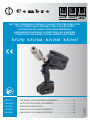 1
1
-
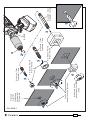 2
2
-
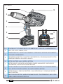 3
3
-
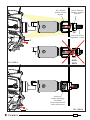 4
4
-
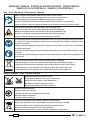 5
5
-
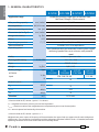 6
6
-
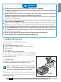 7
7
-
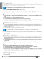 8
8
-
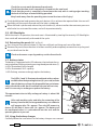 9
9
-
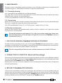 10
10
-
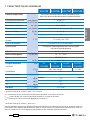 11
11
-
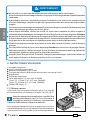 12
12
-
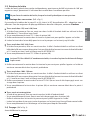 13
13
-
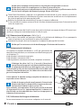 14
14
-
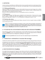 15
15
-
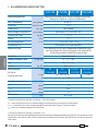 16
16
-
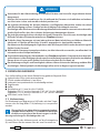 17
17
-
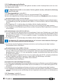 18
18
-
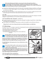 19
19
-
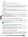 20
20
-
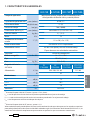 21
21
-
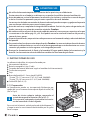 22
22
-
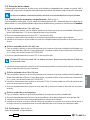 23
23
-
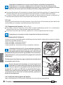 24
24
-
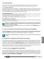 25
25
-
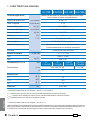 26
26
-
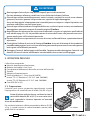 27
27
-
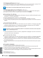 28
28
-
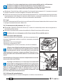 29
29
-
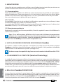 30
30
-
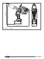 31
31
-
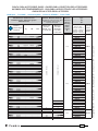 32
32
-
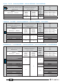 33
33
-
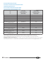 34
34
-
 35
35
-
 36
36


en otros idiomas
- français: Cembre B-FL750E Manuel utilisateur
- italiano: Cembre B-FL750E Manuale utente
- Deutsch: Cembre B-FL750E Benutzerhandbuch