Smartwares DIC-211 Manual de usuario
- Tipo
- Manual de usuario

Door entry
WIRED
INSTALLATION
52
DIC-211 intercom series
Instruction manual
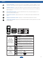
Melody
options
Door
release
Touch
buttons
2 - way
speech

DIC-211 Series
Name
1234
5678
Name
1234
5678
EN Instruction manual ..........................................................................................................4
DE Bedienungsanleitung ....................................................................................................12
FR Mode d’emploi .............................................................................................................20
NL Gebruiksaanwijzing ......................................................................................................28
ES Manual de usuario ........................................................................................................36
IT Manuele utente ............................................................................................................44
CS Návod na použití ..........................................................................................................52
SK Návod na obsluhu .........................................................................................................60


4EN
Name
1234
5678
WARNING
1. Please read these instructions carefully before installing and using the product.
2. Do not cut the power supply cable to extend it; the device (transformer) will not work with a longer
cable. Do not plug in the device until all the wiring has been nished.
INSTALLATION SAFETY
1. Keep children and bystanders away while installing the products. Distractions can cause you to lose
control.
2. Do not overreach when installing this product. Keep proper footing and balance at all times. This
enables better control in unexpected situations.
3. This product is not a toy. Mount it out of reach of children.
OPERATION SAFETY
1. Do not operate electrically powered products in explosive atmospheres, such as in the presence of
ammable liquids, gases, or dust. Electrically powered products create sparks which may ignite the dust
or fumes.
2. The warnings, precautions, and instructions discussed in this instruction manual cannot cover all
possible conditions and situations that may occur. It must be understood by the operator that common
sense and caution are factors which cannot be built into this product, but must be supplied by the
operator.
3. Do not expose the Power Adapter of this product to rain or wet conditions. Water entering the Power
Adapter will increase the risk of electric shock.
4. Do not abuse the Power Cord. Never use the cord for unplugging the plug from the outlet. Keep cord
away from heat, oil, sharp edges or moving parts. Damaged or entangled cords increase the risk of
electric shock.
5. The adapter must match the outlet. Never modify the plug in any way. Unmodied plugs and matching
outlets will reduce risk of electric shock.
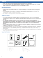
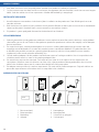
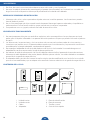
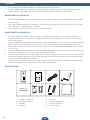
WHAT’S IN THE BOX
1. Indoor unit
2. Outdoor unit
3. Wiring
4. Adapter
5. Nameplate
6. Mounting plate
7. Screws and plugs
8. Quickstart guide

5
EN
10
7
1
2
4
5
6
8 9
3
ON
1
ON
4
1
3
2
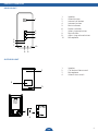
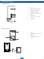
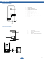
PRODUCT OVERVIEW
INDOOR UNIT
1. Speaker
2. Unlock button
3. Internal call button
4. Intercom button
5. Mute indicator
6. Power indicator
7. Select ringtone button
8. Mute Button
9. Adjust ring volume button
10. Microphone
WHAT’S IN THE BOX?
OUTDOOR UNIT
1. Speaker
2. Call button/ Name card
3. Microphone
4. Unlock time switch

6EN
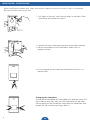
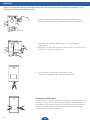
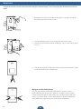
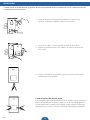
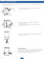
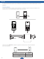
When installing the outdoor unit, make sure that the location you wish to install it is dry. It is important
that the electronics do not get wet.
1. Drill holes in the wall, insert the wall plugs in the holes. Place
the bracket and tighten the screws.
2. Connect the wires. Please pay attention to the color markings.
3. Mount the outdoor unit on the bracket. Make sure it is
properly secured.
4. Use the special security screw on the bottom of the unit, to
prevent theft.
Changing the nameplate
To change the nameplate on the outdoor unit, please push on the
call button on one side, then use a at screwdriver on the other
side to gently pull out the button. Now place the nameplate, and
replace the call button by pushing it back in.
INSTALLATION - OUTDOOR UNIT

7
EN
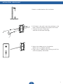
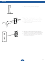
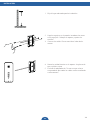
INSTALLATION - INDOOR UNIT
1.Select a suitable location for installation.
2. Drill holes in the wall, insert the wall plugs in the
holes. Place the bracket and tighten the screws.
3. Connect the wires. Please pay
attention to the color markings
4. Mount the indoor unit on the bracket.
Make sure it is properly secured.
5. Plug in the AC adapter after making sure all the
wires are properly connected.

8EN
Power
1
2
3
4
Indoor Unit
B, C or D
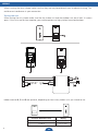
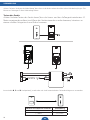
Indoor-monitor B, C and D are optional, depending on how many indoor units you intend to use.
Distance between units Wiring
1–50 m 2×0,75 mm2
1–100 m 2×1,5 mm2
When running the wires, please make sure that they are not placed directly next to electrical wiring, This
could cause interference in your connection.
Testing the unit
When testing the unit, please make sure that the indoor unit and the outdoor unit are at least 10 meters
apart. If the units are to close together, you could experience a high-pitched sound and echoes.
WIRING

9
EN
ON (1) OFF (0)
ON
ON
= =
1234
ON
Bit state Description
Bit 1&2
Link indoor unit
to outdoor push
button
12
ID = (00)
For rst button outdoor unit
12
ID = (10)
For second button outdoor unit
12
ID = (01)
For third button outdoor unit
12
ID = (11)
For fourth button outdoor unit
Bit 3
Set master/slave
3ID = (0) Master
3ID = (1) Slave
Bit 4
Set door/gate
4ID = (0) Door
4ID = (1) Gate
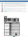
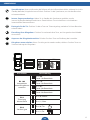
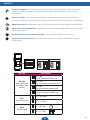
USE
Intercom function: When in standby, when a visitor presses the call button on the outdoor
unit, the indoor unit will chime. Press the intercom button to speak to the visitor.
Internal Intercom: When in standby, press and hold the intercom button to activate the
internal intercom function. Use this to communicate between your different indoor units.
Unlocking the door: After identifying your visitor, you can press this button to unlock the
door.
Setting your ringtone: Press this button multiple times to set the melody of your choice.
Adjusting the ringtone volume: Press this button to turn up the volume.
Muting the ringtone: Press this button to mute the ringtone, for when you don’t want to
be disturbed.

10 EN
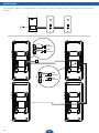
INSTALLATION
Extra indoor-monitors are optional, depending on how many indoor units you intend to use.
red
red
red
red
black
black
black
black
Outdoor
unit
Indoor
unit
Indoor
unit
Indoor
unit

TECHNICAL SPECIFICATION
INDOOR UNIT
Supply Voltage 15V 1A
Consumption current 150mA±10mA
Operation temperature -10˚C - +50˚C
Operation Humidity 85%(Max)
OUTDOOR UNIT
Consumption Current 60mA±10mA
Operating temperature -10˚C - +50˚C
Storage temperature -20˚C - +60˚C
Operating humidity ≤85%RH
SAFETY INFORMATION
Precaution
Do not cover the ventilation openings with objects such as newspaper, table cloths, curtains etc.
Do not allow this product to get directly into contact with heat sources or naked ames.
The normal operation of the product may be disturbed by strong electro-magnetic interference.
This equipment is built exclusively for domestic use.
The device must not be exposed to splashes and it must not be submerged.
No object containing liquids, such as a vase, may be placed on the device.
Maintain a minimum safety distance of 10cm all around the product in order to insure proper ventilation.
Insure the outdoor unit is not installed where it may be covered by water or rain.
Do not allow children to play with the device
Conforms to all relevant European Directives.
This symbol is known as the ‘Crossed-out Wheelie Bin Symbol’. When this symbol is
marked on a product or battery, it means that it should not be disposed of with your
general household waste. Some chemicals contained within electrical/electronic products
products or batteries can be harmful to health and the environment. Only dispose of
electrical/electronic/battery items in separate collection schemes, which cater for the
recovery and recycling of materials contained within. Your co-operation is vital to ensure
the success of these schemes and for the protection of the environment.

12 DE
Name
1234
5678
! WARNUNG
1. Bitte lesen Sie vor der Montage und Inbetriebnahme des Produkts die Bedienungsanweisungen aufmerksam
durch.
2. Zerschneiden Sie nicht das Stromversorgungskabel, um es zu verlängern. Das Gerät (Trafo) funktioniert nicht
mit einem längeren Kabel. Schließen Sie das Gerät erst dann an, wenn die Verkabelung abgeschlossen ist.
INSTALLATIONSSICHERHEIT
1. Halten Sie, während der Montage des Geräts, Kinder und Unbeteiligte fern. Ablenkungen können zum
Kontrollverlust führen.
2. Vermeiden Sie Überanstrengungen, während der Montage des Produkts. Sorgen Sie jederzeit für einen
angemessenen Halt und Gleichgewicht. In unerwarteten Lagen ermöglicht dies eine bessere Kontrolle.
3. Dieses Produkt ist kein Spielzeug. Bringen Sie es außerhalb der Reichweite von Kindern an.
BETRIEBSSICHERHEIT
1. Nehmen Sie keine elektronischen Geräte in explosiver Umgebung, wie zum Beispiel in Anwesenheit von
entzündlichen Flüssigkeiten, Gasen oder Staub in Betrieb. Elektronische Geräte erzeugen Funken, die Staub
oder Dämpfe entzünden können.
2. Nicht alle denkbaren Bedingungen und Situationen, die auftreten könnten, werden von den in dieser
Bedienungsanleitung erläuterten Warnhinweisen, Vorsichtsmaßnahmen und Vorschriften abgedeckt.
Grundsätzlich gilt, dass Faktoren, wie der gesunde Menschenverstand und Vorsicht nicht im Produkt integriert
sind, sondern vom Anwender mitgebracht werden müssen.
3. Setzen Sie den Netzstecker keinem Regen oder Nässe aus. In den Netzstecker eindringendes Wasser erhöht die
Gefahr eines elektrischen Schlags.
4. Überlasten Sie das Netzkabel nicht. Ziehen Sie niemals am Kabel, um den Netzstecker aus der Steckdose
herauszuziehen. Halten Sie das Kabel von Hitze, Öl, scharfen Kanten oder beweglichen Teilen fern. Beschädigte
oder verwickelte Kabel erhöhen das Risiko eines elektrischen Schlags.
5. Der Adapter muss zur Steckdose passen. Modifizieren Sie niemals den Netzstecker. Unveränderte Netzstecker
und passende Steckdosen verringern das Risiko eines elektrischen Schlags.
LIEFERUMFANGWHAT’S IN THE BOX?
1. Inneneinheit
2. Außeneinheit
3. Verkabelung
4. Netzstecker
5. Namensschild
6. Montageplatte
7. Schrauben und Dübel
8. Schnellstartanleitung

13
DE
10
7
1
2
4
5
6
8 9
3
ON
1
ON
4
1
3
2
PRODUKTÜBERBLICK
INNENEINHEIT
1. Lautsprecher
2. Entriegelungstaste
3. Interne Ruftaste
4. Sprechtaste
5. Anzeige für Stummschaltung
6. Betriebsanzeige
7. Auswahltaste für Klingelton
8. Stummschalttaste
9. Taste für Lautstärkeregulierung
10. Mikrofon
WHAT’S IN THE BOX?
AUßENEINHEIT
1. Lautsprecher
2. Ruftaste / Visitenkarte
3. Mikrofon
4. Zeitschaltuhr aktivieren

14 DE
MONTAGE
Sorgen Sie während der Montage der Außeneinheit dafür, dass der gewünschte Installationsort trocken ist. Es ist
wichtig, dass die Elektronik nicht nass wird.
1. Bohren Sie Löcher in die Wand und setzen Sie die Dübel ein.
Bringen Sie die Halterung an und ziehen Sie die Schrauben fest.
2. Verbinden Sie die Kabel. Bitte achten Sie auf die farbigen
Markierungen.
3. Befestigen Sie die Außeneinheit an der Halterung. Vergewissern Sie
sich, dass sie ordentlich befestigt ist.
4. Um Diebstahl vorzubeugen, verwenden Sie die
Sicherheitsschraube an der Unterseite der Einheit.
Das Namensschild ändern
Um das Namensschild am Außengerät zu ändern, bitte die Ruftaste auf
der einen Seite drücken und dann einen flachen Schraubenzieher auf
der anderen Seite einsetzen, um die Taste vorsichtig herauszuziehen.
Legen Sie nun das Namensschild eine und setzen Sie die Ruftaste
durch erneutes Drücken wieder ein.

15
DE
MONTAGE
1. Wählen Sie einen geeigneten Montageort.
2. Bohren Sie Löcher in die Wand und setzen Sie die
Dübel ein. Bringen Sie die Halterung an und ziehen
Sie die Schrauben fest.
3. Verbinden Sie die Kabel. Bitte achten Sie auf die
farbigen Markierungen.
4. Befestigen Sie die Inneneinheit an der Halterung.
Vergewissern Sie sich, dass sie ordentlich befestigt ist.
5. Nachdem Sie sichergestellt haben, dass alle Kabel
ordnungsgemäß verbunden wurden, schließen Sie
den Wechselstromadapter an.

16 DE
Achten Sie beim Verlegen der Kabel darauf, dass diese nicht direkt neben der elektrischen Verkabelung liegen. Dies
könnte zu Störungen in Ihrer Verbindung führen.
Testen des Geräts
Achten Sie beim Testen des Geräts darauf, dass das Innen- und das Außengerät mindestens 10
Meter voneinander entfernt sind. Wenn die Geräte einander zu nahe kommen, könnte es zu
einem schrillen Störgeräusch und Echos kommen.
VERKABELUNG
Power
1
2
3
4
Inneneinheit
B, C oder D
Inneneinheit B, C und D sind optional, je nach dem wie viele Inneneinheiten Sie beabsichtigen zu verwenden.
Abstand zwischen den Einheiten Verdrahtung
1–50 m 2×0,75 mm2
1–100 m 2×1,5 mm2

17
DE
VERWENDUNG
Sprechfunktion: Wenn ein Besucher die Ruftaste auf der Außeneinheit drückt, während sie sich in
Standby befindet, klingelt die innere Einheit. Drücken Sie die Sprechtaste, um mit dem Besucher
zu kommunizieren.
Interne Gegensprechanlage: Halten Sie in Standby die Sprechtaste gedrückt, um die
interne Gegensprechanlage zu aktivieren. Damit können Sie zwischen Ihren verschiedenen
Inneneinheiten kommunizieren.
Entriegeln Sie die Tür: Drücken Sie diese Taste zur Türentriegelung, nachdem Sie Ihren Besucher
erkannt haben.
Einstellung Ihres Klingeltons: Drücken Sie mehrmals diese Taste, um Ihre gewünschte Melodie
einzustellen.
Anpassen der Klingeltonlautstärke: Drücken Sie diese Taste zur Erhöhung der Lautstärke.
Klingelton stummschalten: Wenn Sie nicht gestört werden wollen, drücken Sie diese Taste zur
Stummschaltung des Klingeltons.
ON (1) OFF (0)
ON
ON
= =
1234
ON
Bit-schalter Beschreibung
Bit 1&2
Inneneinheit
einem Klingeltaster
zuweisen
12
ID = (00)
Taster 1 Außeneinheit
12
ID = (10)
Taster 2 Außeneinheit
12
ID = (01)
Taster 3 Außeneinheit
12
ID = (11)
Taster 4 Außeneinheit
Bit 3
Zuweisung
Master/Slave
3ID = (0) Master
3ID = (1) Slave
Bit 4
Set door/gate
4ID = (0) Tür
4ID = (1) Tor

18 DE
MONTAGE
Zusätzliche Innnenraum-Monitore sind optional erhältlich, je nachdem wie viele Innengeräte Sie verwenden
möchten.
Rot
Rot
Rot
Rot
Schwarz
Schwarz
Schwarz
Schwarz
Außen-
einheit
Innen-
einheit
Innen-
einheit
Innen-
einheit

TECHNISCHE DATEN
INNENEINHEIT
Netzspannung 15V 1A
Stromaufnahme 150mA±10mA
Betriebstemperatur -10˚C - +50˚C
Betriebsfeuchtigkeit 85%(Max)
AUSSENEINHEIT
Stromaufnahme 60mA±10mA
Betriebstemperatur -10˚C - +50˚C
Lagertemperatur -20˚C - +60˚C
Betriebsfeuchtigkeit ≤85%RH
SICHERHEITSHINWEISE
Vorsichtsmaßnahmen
Bedecken Sie die Lüftungsöffnungen nicht mit Objekten wie Zeitungen, Tischdecken, Vorhängen usw.
Lassen Sie dieses Produkt nicht in direkten Kontakt mit Wärmequellen oder offenen Flammen kommen.
Durch starke elektromagnetische Interferenzen kann der Normalbetrieb des Produkts gestört werden.
Dieses Gerät ist ausschließlich für den Heimgebrauch bestimmt.
Dieses Gerät darf keinen Wasserspritzern ausgesetzt sein oder in Wasser getaucht werden.
Es dürfen keine mit Flüssigkeit gefüllten Gefäße wie Vasen auf das Gerät gestellt werden.
Halten Sie einen Sicherheitsabstand von mindestens 10 cm um das Produkt ein, damit für eine ausreichende Belüftung
gesorgt ist.
Vergewissern Sie sich, dass die Außeneinheit nicht dort installiert ist, wo sie Wasser oder Regen ausgesetzt sein könnte.
Lassen Sie Kinder mit diesem Gerät nicht spielen.
Entspricht allen relevanten Europäischen Richtlinien.
Dieses Symbol ist bekannt als ‘Symbol der durchgestrichenen Mülltonne’. Wenn dieses Symbol
auf einem Produkt oder einer Batterie markiert ist, bedeutet das, dass es nicht mit Ihrem
allgemeinen Haushaltsmüll entsorgt werden sollte. Einige Chemikalien, die in elektrischen/
elektronischen Produkten oder Batterien enthalten sind können der Gesundheit und der Umwelt
schaden. Entsorgen Sie elektrische/elektronische/Batterie-Geräte in separaten Sammelmodellen,
die für die Rückgewinnung und das Recycling von darin enthaltenen Materialien sorgen. Ihre
Zusammenarbeit ist wichtig, um den Erfolg dieser Sammelmodelle zu sichern und für den
Schutz der Umwelt.

20 FR
Name
1234
5678
! AVERTISSEMENT
1. Veuillez lire ces instructions attentivement avant d’installer et d’utiliser le produit.
2. Ne coupez pas le câble d’alimentation pour le rallonger ; l’appareil (transformateur) ne fonctionne pas avec un
câble plus long. Ne branchez pas l’appareil tant que le câblage n’est pas terminé.
SECURITE D’INSTALLATION
1. Eloignez les enfants et les personnes autour pendant l’installation des produits. Les distractions peuvent vous
faire perdre le contrôle.
2. Ne pas vous étirez pendant l’installation de ce produit. Maintenez votre assise au sol et gardez l’équilibre à tout
moment. Cela permet un meilleur contrôle dans des situations inattendues.
3. Ce produit n’est pas un jouet. Montez-le hors de portée des enfants.
SECURITE DES OPERATIONS
1. N’utilisez pas de produits électriques en atmosphères explosives, comme en présence de liquides inflammables,
de gaz ou de poussières. Les produits électriques produisent des étincelles qui peuvent enflammer les
poussières ou les vapeurs.
2. Les avertissements, précautions et instructions présentés dans ce manuel ne peuvent pas couvrir toutes les
conditions et situations possibles qui peuvent se présenter. Il doit être entendu par l’opérateur que le bon
sens et la prudence sont des facteurs qui ne peuvent pas être intégrés dans ce produit, mais devront être de la
responsabilité de l’opérateur.
3. N’exposez pas l’adaptateur d’alimentation de ce produit à des conditions de pluie ou d’humidité. L’eau qui
pénètre dans l’adaptateur augmente le risque d’électrocution.
4. Ne maltraitez pas le cordon d’alimentation. Ne jamais utiliser le cordon pour débrancher la prise de
courant. Éloignez le cordon de la chaleur, de l’huile, de bords tranchants ou de pièces mobiles. Les cordons
endommagés ou enchevêtrés augmentent les risques d’électrocution.
5. L’adaptateur doit correspondre à la prise. Ne jamais modifier la prise d’aucune façon. Les prises non modifiées et
les prises correspondantes réduiront le risque d’électrocution.
LE CONTENUR DE LA BOITE
WHAT’S IN THE BOX?
1. Unité intérieure
2. Unité extérieure
3. Câblage
4. Adaptateur
5. Plaque signalétique
6. Plaque de montage
7. Vis et chevilles
8. Guide de démarrage rapide

21
FR
10
7
1
2
4
5
6
8 9
3
ON
1
ON
4
1
3
2
PRESENTATION DU PRODUIT
UNITE INTERIEURE
1. Haut-parleur
2. Bouton de déverrouillage
3. Bouton d’appel interne
4. Bouton de l’interphone
5. Indicateur de coupure du son
6. Indicateur de mise sous tension
7. Bouton de sélection de
sonnerie
8. Bouton de coupure du son
9. Bouton de réglage de volume
de sonnerie
10. Microphone
WHAT’S IN THE BOX?
UNITE EXTERIEURE
1. Haut-parleur
2. Bouton d’appel/carte de visite
3. Microphone
4. Commutateur de temps de
déverrouillage

22 FR
INSTALLATION
Lors de l’installation de l’unité extérieure, assurez-vous que l’emplacement que vous souhaitez pour l’installation est
sec. Il est important que les composants électroniques ne soient pas mouillés.
1. Percez les trous dans le mur, insérez les chevilles dans les trous.
Placez le support et serrez les vis.
2. Branchez les fils. Faites attention aux marquages de couleur.
3. Montez l’unité extérieure sur le support. Assurez-vous qu’elle est
bien fixée.
4. Utilisez la vis de sécurité spéciale au fond de l’appareil pour éviter
le vol.
Changer la plaque nominative
Pour changer la plaque nominative sur l’unité extérieure, appuyez sur
le bouton d’appel sur un de ses côtés, puis à l’aide d’un tournevis à
tête plate, sortez le bouton avec précaution en faisant levier depuis
le côté opposé. Placez ensuite la plaque nominative, puis remettez le
bouton en place en appuyant dessus.

23
FR
INSTALLATION
1. Sélectionnez un emplacement approprié pour
l’installation.
2. Percez des trous dans le mur, insérez les chevilles
dans les trous. Placez le support et serrez les vis.
3. Branchez les fils. Faites attention aux marquages de
couleur.
4. Montez l’unité intérieure sur le support. Assurez-vous
qu’elle est bien fixée.
5. Branchez l’adaptateur secteur après s’être assuré que
tous les câbles sont correctement connectés.

24 FR
Lorsque vous routez les câbles, assurez-vous qu’ils ne sont pas positionnés directement à côté d’un câblage
électrique, car cela pourrait causer des interférences sur votre connexion.
Tester l’unité
Pour tester l’unité, veillez à ce que les unités intérieures et extérieures se trouvent éloignées d’au moins 10 mètres.
Si les unités sont trop proches l’une de l’autre, vous pourriez créer un effet de boucle de son et d’échos très aigus.
CÂBLAGE
Power
1
2
3
4
Unité
intérieure
B, C et D
Les unités intérieures B, C et D sont en option, selon le nombre d’unités intérieures que vous avez l’intention
d’utiliser.
Distance entre les unités Câblage
1–50 m 2×0,75 mm2
1–100 m 2×1,5 mm2

25
FR
POUŽITÍ
Fonction interphone : En mode veille, lorsqu’un visiteur appuie sur le bouton d’appel sur l’unité
extérieure, l’unité intérieure sonne. Appuyez sur le bouton de l’interphone pour parler au visiteur.
Interphone interne : En mode veille, appuyez et maintenez le bouton de l’interphone enfoncé
pour activer la fonction d’interphone interne. Cela permet de communiquer entre vos différentes
unités intérieures.
Déverrouillage de la porte : Après avoir identifié votre visiteur, vous pouvez appuyer sur ce
bouton pour déverrouiller la porte.
Réglage de la sonnerie : Appuyez plusieurs fois sur ce bouton pour régler la mélodie de votre
choix.
Réglage du volume de sonnerie : Appuyez sur ce bouton pour augmenter le volume.
Coupure de la sonnerie : Appuyez sur ce bouton pour couper la sonnerie, quand vous ne voulez
pas être dérangé.
ON (1) OFF (0)
ON
ON
= =
1234
ON
Position du bit Descriptions
Bit 1&2
Raccordement
unité intérieure
vers bouton-
poussoir extérieur
12
ID = (00)
Pour première unité de bouton extérieur
12
ID = (10)
Pour deuxième unité de bouton extérieur
12
ID = (01)
Pour troisième unité de bouton extérieur
12
ID = (11)
Pour quatrième unité de bouton extérieur
Bit 3
Ensemble
maître/esclave
3ID = (0) Maître
3ID = (1) Esclave
Bit 4
Ensemble
porte/portail
4ID = (0) Porte
4ID = (1) Portail

26 FR
INSTALLATION
Les moniteurs intérieurs supplémentaires sont optionnels, selon le nombre d’unités intérieures que vous prévoyez
d’utiliser.
rouge
rouge
rouge
rouge
noir
noir
noir
noir
Unité
extérieure
Unité
intérieure
Unité
intérieure
Unité
intérieure

SPÉCIFICATION TECHNIQUE
UNITÉ INTÉRIEURE
Tension d’alimentation 15V 1A
Courant de consommation 150mA±10mA
Température de fonctionnement -10˚C - +50˚C
Humidité de fonctionnement 85%(Max)
UNITÉ EXTÉRIEURE
Courant de consommation 60mA±10mA
Température de fonctionnement -10˚C - +50˚C
Température de stockage -20˚C - +60˚C
Humidité de fonctionnement ≤85%RH
CONSIGNES DE SÉCURITÉ
Précaution
Ne couvrez pas les ouvertures de ventilation avec des objets tels que des journaux, des nappes, des rideaux, etc.
Ne laissez pas ce produit entrer directement en contact avec des sources de chaleur ou des ammes nues.
Le fonctionnement normal du produit peut être perturbé par une forte interférence électromagnétique.
Cet équipement est construit exclusivement pour usage domestique.
L’appareil ne doit pas être exposé aux éclaboussures et il ne doit pas être immergé.
Aucun objet contenant des liquides, tel qu’un vase, ne doit être placé sur l’appareil.
Maintenez une distance de sécurité minimale de 10 cm tout autour du produit an d’assurer une aération adéquate.
S’assurer que l’unité extérieure n’est pas installée là où elle peut être exposée à de l’eau ou de la pluie.
Ne laissez pas les enfants jouer avec l’appareil
Conforme aux directives européennes applicables.
Ce symbole est connu comme “La poubelle barrée”. Lorsque ce symbole est marqué sur un
produit ou sur une pile, cela signifie que qu’il ne doit pas être jeté avec les ordures ménagères.
Certains produits chimiques contenus dans les produits électriques/électroniques ou les piles
peuvent être nocifs pour la santé et l’environnement. Jeter uniquement les éléments électriques/
électroniques/piles dans des systèmes de collecte distincts, qui assurent la récupération et le
recyclage des matériaux contenus dans ces élements. Votre collaboration est essentielle pour
assurer le succès de ces programmes et pour la protection de l’environnement.

28 NL
Name
1234
5678
WAARSCHUWING
1. Lees deze instructies a.u.b. zorgvuldig door voordat u het product installeert en gebruikt.
2. Snij het stroomsnoer niet door om het te verlengen; het apparaat (de transformator) werkt niet met een langere
kabel. Steek de stekker niet in het stopcontact voordat alle bedrading is aangelegd.
INSTALLATIE VEILIGHEID
1. Houd kinderen en omstanders uit de buurt tijdens installatie van de producten. Door afleidingen kunt u de
controle verliezen.
2. Reik niet buiten uw macht bij het installeren van dit product. Bewaar te allen tijde uw evenwicht en houd beide
voeten op de grond. Hierdoor heeft u meer controle in overwachte situaties.
3. Dit product is geen speelgoed. Monteer het buiten bereik van kinderen.
VEILIGE BEDIENING
1. Gebruik geen elektrisch aangedreven producten in een explosieve atmosfeer, zoals in de buurt van brandbare
vloeistoffen, gassen of stof. Elektrisch aangedreven producten produceren vonken die mogelijk stof of dampen
kunnen ontsteken.
2. De waarschuwingen, voorzorgsmaatregelen en instructies in deze gebruiksaanwijzing kunnen nooit alle
mogelijke omstandigheden en situaties die zouden kunnen voorkomen afdekken. De gebruiker dient zich
te beseffen dat gezond verstand en voorzichtigheid factoren zijn die niet in het product kunnen worden
ingebouwd, maar van de gebruiker afhankelijk zijn.
3. Stel de voedingsadapter van dit product niet bloot aan regen of vochtige condities. Het risico op elektrische
schokken neemt toe als er water in de voedingsadapter komt.
4. Ga voorzichting om met het netsnoer. Trek nooit aan het snoer als u de stekker uit het stopcontact wilt
verwijderen. Houd het snoer uit de buurt van hitte, olie, scherpe randen of bewegende delen. Het risico op
elektrische schokken neemt toe als snoeren beschadigd of in de knoop raken.
5. De adapter moet geschikt zijn voor het stopcontact. Ga nooit zelf de stekker aanpassen. Originele stekkers en
passende stopcontacten verminderen het risico op elektrische schokken.
MEEGELEVERD IN DE DOOS
WHAT’S IN THE BOX?
1. Binneneenheid
2. Buiteneenheid
3. Bedrading
4. Adapter
5. Naamplaatje
6. Montageplaat
7. Schroeven en pluggen
8. Snelstartgids

29
NL
10
7
1
2
4
5
6
8 9
3
ON
1
ON
4
1
3
2
PRODUCTOVERZICHT
BINNENEENHEID
1. Luidspreker
2. Ontgrendeltoets
3. Intern gesprek-toets
4. Intercomtoets
5. Demp indicatie
6. Stroom indicatie
7. Kies beltoon toets
8. Dempen toets
9. Volumeknop beltoon
10. Microfoon
WHAT’S IN THE BOX?
BUITENEENHEID
1. Luidspreker
2. Beltoets/ Naamkaartje
3. Microfoon
4. Ontgrendel timerschakelaar

30 NL
INSTALLATIE
Zorg dat de locatie waar de buiteneenheid wordt geïnstalleerd droog is. Het is belangrijk dat de elektronica niet nat
wordt.
1. Boor gaten in de muur en doe de pluggen in de gaten. Plaats de
beugel en draai de schroeven aan.
2. Sluit de bedrading aan. Let a.u.b. op de kleurmarkeringen.
3. Monteer de buiteneenheid op de beugel. Zorg ervoor dat hij goed
vast zit.
4. Gebruik de speciale veiligheidsschroeven aan de onderzijde van de
eenheid, om diefstal te voorkomen.
Wijzigen van het naamplaatje
Om het naamplaatje op de buiteneenheid te wijzigen, drukt u
op de belknop aan de ene kant, gebruik vervolgens een gewone
schroevendraaier aan de andere kant om voorzichtig de knop naar
buiten te trekken. Plaats nu het naamplaatje en plaats de belknop
terug door deze voorzichtig weer naar binnen te drukken

31
NL
INSTALLATIE
1. Kies een geschikte locatie voor de installatie.
2. Boor gaten in de muur, doe de pluggen in de gaten.
Plaats de beugel en draai de schroeven aan.
3. Sluit de bedrading aan. Let a.u.b. op de
kleurmarkeringen
4. Monteer de binneneenheid op de beugel. Zorg
ervoor dat hij goed vast zit.
5. Controleer of de draden goed zijn aangesloten en
steek dan de netstroomadapter erin.

32 NL
Bij het leggen van de bedrading dient u te zorgen dat deze niet meteen naast de elektrische bedrading ligt. Dit kan
namelijk storing geven in uw aansluiting.
De eenheid testen
Zorg tijdens het testen van de eenheid dat de binnen- en buiteneenheid minimaal 10 meter uit elkaar staan. Als de
eenheden te dicht bij elkaar staan, kunnen een hoge toon en echo te horen zijn.
BEDRADING
Power
1
2
3
4
Binnen-
eenheid
B, C of D
Binneneenheden B, C en D zijn optioneel, afhankelijk van hoeveel binneneenheden u wilt gebruiken.
Afstand tussen eenheden Bedrading
1–50 m 2×0,75 mm2
1–100 m 2×1,5 mm2

33
NL
GEBRUIK
Intercomfunctie: Als een bezoeker de oproep-toets indrukt op de buiteneenheid terwijl die
standby staat, dan klinkt de bel via de binneneenheid. Druk op de intercomtoets om met de
bezoeker te praten.
Interne intercom: Druk op de intercomtoets om de interne intercom te activeren, als deze
standby staat. Gebruik dit om tussen de verschillende binneneenheden te communiceren.
Deur van het slot doen: Nadat u uw bezoeker geïdentificeerd heeft kunt u op deze toets drukken
om de deur te ontgrendelen.
Instellen van de beltoon: Druk meerdere keren op deze toets om uw melodie uit te kiezen.
Aanpassen van het beltoonvolume: Druk op deze toets om het volume te verhogen.
Dempen van de beltoon: Druk op deze toets om het volume van de beltoon te dempen, voor als
u niet gestoord wilt worden.
ON (1) OFF (0)
ON
ON
= =
1234
ON
Bit positie Omschrijving
Bit 1&2
Binneneenheid
koppelen aan
buiteneenheid
12
ID = (00)
Voor de eerste push knop
12
ID = (10)
Voor de tweede push knop
12
ID = (01)
Voor de derde push knop
12
ID = (11)
Voor de vierde push knop
Bit 3
Master/slave
instellen
3ID = (0) Master
3ID = (1) Slave
Bit 4
Deur/poort
instellen
4ID = (0) Deur
4ID = (1) Poort

34 NL
INSTALLATIE
Extra binnenmonitoren zijn optioneel, afhankelijk van hoeveel binneneenheden u wilt gebruiken.
rood
rood
rood
rood
zwart
zwart
zwart
zwart
Buiten
eenheid
Binnen
eenheid
Binnen
eenheid
Binnen
eenheid

TECHNISCHE SPECIFICATIES
BINNENEENHEID
Bedrijfsspanning 15V 1A
Stroomverbruik 150mA±10mA
Bedrijfstemperatuur -10˚C - +50˚C
Toelaatbare vochtigheid 85%(Max)
BUITENEENHEID
Stroomverbruik 60mA±10mA
Bedrijfstemperatuur -10˚C - +50˚C
Opslagtemperatuur -20˚C - +60˚C
Toelaatbare vochtigheid ≤85%RH
VEILIGHEIDSINFORMATIE
Voorzichtig
Blokkeer geen ventilatieopeningen met voorwerpen zoals kranten, tafelkleden, gordijnen, etc.
Laat dit product niet in direct contact komen met hittebronnen of open vuur.
Normaal functioneren van het prodcut kan verstoord worden door sterke elektromagnetische straling.
Deze apparatuur is alleen voor huishoudelijk gebruik gemaakt.
Het apparaat mag niet worden blootgesteld aan spatwater en mag niet worden ondergedompeld.
Voorwerpen die vloeistoffen bevatten, zoals een vaas, mogen niet op het apparaat gezet worden.
Bewaar een minimum afstand van 10cm rond het product zodat er voldoende ventilatie is.
Zorg dat de buiteneenheid niet wordt gemonteerd op een plaats die blootstaat aan water of regen.
Sta kinderen niet toe met het apparaat te spelen
Voldoet aan alle relevante Europese richtlijnen.
Dit symbool is bekend als het “doorgekruiste kliko-symbool”. Als dit symbool op een product of een
batterij is gemarkeerd, betekent dit dat het niet met uw normale huishoudelijk afval mag worden
afgevoerd. Sommige chemische stoffen in elektrische/elektronische producten of batterijen
kunnen voor de gezondheid en het milieu schadelijk zijn. Verwijder elektrische/elektronische/
batterij producten alleen met regelingen voor gescheiden afvalinzameling, die voorzien in de
terugwinning en recycling an materialen in de producten. Uw medewerking is van vitaal belang
voor het welslagen van deze regelingen en voor de bescherming van het milieu.

36 ES
Name
1234
5678
! ADVERTENCIA
1. Por favor, lea estas instrucciones detenidamente antes de instalar y usar el producto.
2. No corte el cable de alimentación para alargarlo; el aparato (transformador) no funcionará con un cable más
largo. No enchufe el dispositivo hasta que haya finalizado la instalación del cableado.
MEDIDAS DE SEGURIDAD DE INSTALACIÓN
1. Mantenga a los niños y a los espectadores alejados mientras instala los aparatos. Las distracciones pueden
hacerle perder el control.
2. No se estire para llegar más lejos cuando instale el aparato. Mantenga la postura adecuada y el equilibrio en
todo momento. De esta forma, tendrá un mayor control ante situaciones inesperadas.
3. Este producto no es un juguete, móntelo fuera del alcance de los niños.
SEGURIDAD DE FUNCIONAMIENTO
1. No maneje aparatos eléctricos en atmósferas explosivas, tales como aquellas en las que haya presencia de
polvo, gases o líquidos inflamables. Los aparatos eléctricos producen chispas que pueden encender el polvo o
los gases.
2. Las advertencias, las precauciones y las instrucciones de este manual no cubren todas las circunstancias y
situaciones que pueden ocurrir. El operario debe entender que el sentido común y la precaución son factores
que debe poner el propio trabajador, no depende del aparato.
3. No exponga el adaptador de corriente del producto a la lluvia ni a la humedad. La entrada de agua en el
adaptador de corriente aumentará el riesgo de descarga eléctrica.
4. No maltrate el cable de alimentación. No tire del cable para desenchufar el aparato de la toma de corriente.
Mantenga el cable alejado del calor, aceite, bordes afilados o piezas móviles. Los cables dañados o enredados
aumentan el riesgo de descarga eléctrica.
5. El adaptador debe coincidir con la toma. No realice ningún tipo de modificación en el enchufe. Los enchufes
que no se han modificado y que se adaptan a las tomas de corriente reducirán el riesgo de descarga eléctrica.
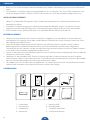
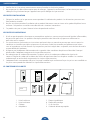
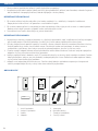
CONTENIDO DE LA CAJA
1. Unidad interior
2. Unidad exterior
3. Cables
4. Adaptador
5. Placa de identificación
6. Placa de montaje
7. Tornillos y tacos
8. Guía de inicio rápido

37
ES
10
7
1
2
4
5
6
8 9
3
ON
1
ON
4
1
3
2
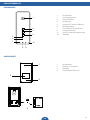
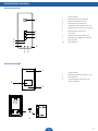
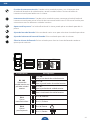
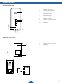
DESCRIPCIÓN DEL PRODUCTO
UNIDAD INTERIOR
1. Altavoz
2. Botón de apertura de puerta
3. Botón de llamada interna
4. Botón de intercomunicación
5. Indicador de silencio
6. Indicador de encendido
7. Botón de selección del tono de
llamada
8. Botón silencio
9. Botón de ajuste de volumen
del timbre
10. Micrófono
WHAT’S IN THE BOX?
UNIDAD EXTERIOR
1. Altavoz
2. Botón de llamada/ Etiqueta con
nombre
3. Micrófono
4. Interruptor de tiempo de
apertura

38 ES
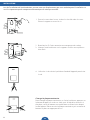
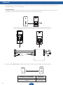
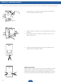
INSTALACIÓN
Cuando instale la unidad exterior, asegúrese de que el lugar donde desea instalarla esté seco. Es importante que no
se mojen las partes electrónicas.
1. Haga los agujeros en la pared e introduzca los tacos en los
agujeros. Coloque el soporte y apriete los tornillos.
2. Conecte los cables. Preste atención al color de las marcas.
3. Monte la unidad exterior en el soporte. Asegúrese de que esté
bien sujeta.
4. Utilice el tornillo de seguridad especial en la parte inferior de la
unidad, para evitar el robo.
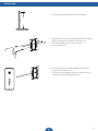
Cambiar la placa de identicación
Para cambiar la placa de identificación de la unidad exterior, empuje el
botón de llamada por un lado y luego use un destornillador plano en
el otro para extraer el botón con cuidado. Ahora coloque la placa de
identificación, y vuelva a colocar el botón de llamada presionándolo.

39
ES
INSTALACIÓN
1. Elija el lugar adecuado para la instalación.
2. Haga los agujeros en la pared e introduzca los tacos
en los agujeros. Coloque el soporte y apriete los
tornillos.
3. Conecte los cables. Preste atención al color de las
marcas.
4. Monte la unidad interior en el soporte. Asegúrese de
que esté bien sujeta.
5. Enchufe el adaptador de CA una vez que se haya
asegurado de que todos los cables están conectados
correctamente.

40 ES
Cuando instale los cables, asegúrese de que no estén colocados directamente junto a la instalación eléctrica. Esto
podría causar interferencias en la conexión.
Probar la unidad
Al probar la unidad, asegúrese de que la unidad interior y la unidad exterior estén alejadas una de la otra, al menos,
unos 10 metros. Si las unidades están demasiado cerca, podría producirse un sonido agudo y eco.
CABLES
Power
1
2
3
4
Unidad
interior
B, C y D
Las unidades interiores B, C y D son opcionales, depende de cuántas unidades interiores se vayan a utilizar.
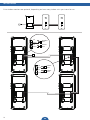
Distancia entre unidades Alambrado
1–50 m 2×0,75 mm2
1–100 m 2×1,5 mm2

41
ES
USO
Función de intercomunicación: Cuando está en modo de espera, si un visitante presiona
el botón de llamada en la unidad exterior, sonará la unidad interior. Presione el botón de
intercomunicación para hablar con el visitante.
Intercomunicación interna: Cuando está en modo de espera, mantenga pulsado el botón de
intercomunicación para activar la función de intercomunicación interna. Utilice esta función para
comunicarse entre las diferentes unidades interiores.
Apertura de la puerta: Tras la identificación del visitante, puede pulsar este botón para abrir la
puerta.
Ajuste del tono de llamada: Pulse este botón varias veces para seleccionar la melodía que desee.
Ajuste del volumen del tono de llamada: Pulse este botón para subir el volumen.
Silenciar el tono de llamada: Pulse este botón para silenciar el tono de llamada cuando no
quiera que lo molesten.
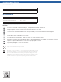
ON (1) OFF (0)
ON
ON
= =
1234
ON
Estado de bits Descripciones
Bit 1&2
Vinculación
unidad interior con
pulsador unidad
exterior
12
ID = (00)
Para primer botón de unidad exterior
12
ID = (10)
Para segundo botón de unidad exterior
12
ID = (01)
Para tercer botón de unidad exterior
12
ID = (11)
Para cuarto botón de unidad exterior
Bit 3
Ajuste
maestro/esclavo
3ID = (0) Maestro
3ID = (1) Esclavo
Bit 4
Ajuste
puerta/portón
4ID = (0) Puerta
4ID = (1) Portón

42 ES
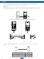
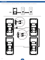
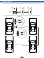
DIAGRAMA DE CONEXIÓN
Los monitores interiores adicionales son opcionales, depende de cuántas unidades interiores se vayan a utilizar.
rojo
rojo
rojo
rojo
negro
negro
negro
negro
Unidad
exterior
Unidad
interior
Unidad
interior
Unidad
interior

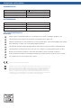
ESPECIFICACIONES TÉCNICAS
UNIDAD INTERIOR
Tensión de alimentación 15V 1A
Consumo eléctrico 150mA±10mA
Temperatura de funcionamiento -10˚C - +50˚C
Humedad de funcionamiento 85%(Max)
UNIDAD EXTERIOR
Consumo eléctrico 60mA±10mA
Temperatura de funcionamiento -10˚C - +50˚C
Temperatura de almacenamiento -20˚C - +60˚C
Humedad de funcionamiento ≤85%RH
INFORMACIÓN DE SEGURIDADŤ
Precaución
No cubra los oricios de ventilación con objetos, como periódicos, manteles, cortinas, etc.
Evite que el aparato entre en contacto directo con fuentes de calor o con llamas.
El funcionamiento normal del producto puede verse perturbado por una fuerte interferencia electromagnética.
Este aparato se ha fabricado exclusivamente para uso doméstico.
No exponga el aparato a salpicaduras ni lo sumerja.
No coloque objetos llenos de líquido, como por ejemplo un jarrón, encima del aparato.
Mantenga una distancia mínima de seguridad de 10 cm alrededor del aparato para asegurar una ventilación suciente.
Asegúrese de que la unidad exterior se instala en un lugar protegido de la lluvia.
No permita que jueguen los niños con este aparato
Cumple con todas las Normativas Europeas relevantes.
Este símbolo se conoce como “Símbolo de contenedor de basura con ruedas tachado con una X”
Cuando aparece este símbolo en un producto o una batería, significa que no puede desecharse
junto con los residuos domésticos normales. Algunos de los productos químicos que incluyen
los productos eléctricos/electrónicos o las baterías, pueden suponer un riesgo para la salud y el
medio ambiente. Deseche solamente los productos eléctricos/electrónicos y baterías en centros
de recogida independientes, diseñados para la correcta recuperación y reciclaje de los materiales
contenidos en su interior. Su cooperación es vital para asegurar el éxito de dichos centros/
lugares de recogida y para la protección del medio ambiente.

44 IT
Name
1234
5678
! AVVERTENZA
1. Leggere attentamente queste istruzioni prima di installare e utilizzare il prodotto.
2. Non tagliare il cavo di alimentazione per estenderlo; Il dispositivo (trasformatore) non funziona con un cavo più
lungo. Non collegare il dispositivo finché non sia stato completato il cablaggio.
SICUREZZA DELL’INSTALLAZIONE
1. Tenere i bambini e gli astanti lontani durante l’installazione dei prodotti. Le distrazioni possono farti perdere il
controllo.
2. Non sporgersi quando si installa questo prodotto. Tenere sempre il giusto equilibrio e una posizione ben salda.
Ciò consente un migliore controllo in situazioni inattese.
3. Questo prodotto non è un giocattolo. Montarlo fuori dalla portata dei bambini.
SICUREZZA DI FUNZIONAMENTO
1. Non utilizzare prodotti alimentati elettricamente in atmosfere esplosive, ad esempio in presenza di liquidi
infiammabili, gas o polveri. I prodotti alimentati elettricamente creano scintille che possono incendiare le
polveri o i fumi.
2. Le avvertenze, le precauzioni e le istruzioni fornite in questo manuale non possono coprire tutte le possibili
condizioni e situazioni che possono verificarsi. Occorre che l’operatore comprenda che il buon senso e la
cautela sono fattori che non possono essere inclusi in questo prodotto, ma debbano essere responsabilità
dell’operatore stesso.
3. Non esporre l’adattatore di alimentazione di questo prodotto a pioggia o a condizioni di umidità. L’acqua che
entra nell’adattatore di alimentazione aumenta il rischio di scosse elettriche.
4. Non trattare in modo inappropriato il cavo di alimentazione. Non utilizzare mai il cavo per scollegare la spina
dalla presa. Tenere il cavo lontano da calore, olio, bordi affilati o parti in movimento. I cavi danneggiati o
incastrati aumentano il rischio di scosse elettriche.
5. L’adattatore deve corrispondere alla presa. Non modificare mai la spina in alcun modo. Le spine non modificate
e le prese corrispondenti ridurranno il rischio di scosse elettriche.
CONTENUTO DELLA CONFEZIONE
1. Unità interna
2. Unità esterna
3. Cablaggio
4. Adattatore
5. Targhetta
6. Piastra di montaggio
7. Viti e tasselli
8. Guida rapida

45
IT
10
7
1
2
4
5
6
8 9
3
ON
1
ON
4
1
3
2
PANORAMICA DEL PRODOTTO
UNITÀ INTERNA
1. Altoparlante
2. Pulsante di sblocco
3. Pulsante di chiamata interna
4. Pulsante interfono
5. Spia di disattivazione audio
6. Spia di alimentazione
7. Pulsante di selezione suoneria
8. Pulsante di disattivazione
suoneria
9. Pulsante di regolazione
suoneria
10. Microfono
WHAT’S IN THE BOX?
UNITÀ ESTERNA
1. Altoparlante
2. Pulsante di chiamata/Targhetta
nome
3. Microfono
4. Sblocco interruttore orario

46 IT
INSTALLAZIONE
Quando si installa l’unità esterna, assicurarsi che la posizione in cui si desidera installarla sia all’asciutto. È
importante che l’elettronica non si bagni.
1. Praticare i fori nel muro, inserire i tasselli nei fori. Posizionare la
staffa e serrare le viti.
2. Collegare i cavi. Si prega di prestare attenzione ai codici colore.
3. Montare l’unità esterna sulla staffa. Assicurarsi che sia fissata
correttamente.
4. Utilizzare la vite speciale di sicurezza sul fondo dell’unità, per
evitare il furto.
Modicare la targhetta identicativa
Per modificare la targhetta identificativa dell’unità esterna, premere
il pulsante di chiamata da un lato, quindi utilizzare un cacciavite a
taglio dall’altro per estrarre delicatamente il pulsante. A questo punto
posizionare la targhetta identificativa e riposizionare il pulsante di
chiamata spingendolo nuovamente verso l’interno.

47
IT
INSTALLAZIONE
1. Selezionare una posizione adatta per l’installazione.
2. Praticare i fori nel muro, inserire le staffe a muro nei
fori. Posizionare la staffa e serrare le viti.
3. Collegare i cavi. Si prega di prestare attenzione ai
codici colore
4. Montare l’unità interna sulla staffa. Assicurarsi che sia
fissata correttamente.
5. Inserire l’adattatore CA dopo aver accertato che tutti i
cavi siano collegati correttamente.

48 IT
Quando si esegue il cablaggio, assicurarsi che i fili non siano posizionati direttamente accanto al cablaggio elettrico.
Questo potrebbe causare interferenze nella connessione.
Testare l’unità
Durante il test, assicurarsi che l’unità interna e l’unità esterna siano distanti almeno 10 metri l’una dall’altra. Se le unità
sono troppo vicine, è possibile che si verifichino suoni ed echi di grande intensità.
CABLAGGIO
Power
1
2
3
4
Unità interna
B, C e D
I monitor interni B, C e D sono opzionali, secondo quanti monitor interni si intenda utilizzare.
Distanza tra le unità Cablaggio
1–50 m 2×0,75 mm2
1–100 m 2×1,5 mm2

49
IT
UTILIZZO
Funzione di interfono: in modalità standby, quando un visitatore preme il pulsante di chiamata
sull’unità esterna, l‘unità interna emette un segnale acustico. Premere il pulsante dell’interfono per
parlare con il visitatore.
Interfono interno: in modalità standby, tenere premuto il pulsante dell’interfono per attivare la
funzione interfonica interna. Utilizzare questa funzione per comunicare tra le varie unità interne.
Sblocco della porta: dopo aver identificato il visitatore, è possibile premere questo pulsante per
sbloccare la porta.
Impostazione della suoneria: premere più volte questo pulsante per impostare la melodia
desiderata.
Regolazione del volume della suoneria: premere questo pulsante per aumentare il volume.
Disattivazione della suoneria: premere questo pulsante per disattivare la suoneria, quando non
si desidera essere disturbati.
ON (1) OFF (0)
ON
ON
= =
1234
ON
Impostazioni bit Descrições
Bit 1&2
Collegare l’unità
interna all’unità
esterna
12
ID = (00)
Per unità esterna primo pulsante
12
ID = (10)
Per unità esterna secondo pulsante
12
ID = (01)
Per unità esterna terzo pulsante
12
ID = (11)
Per unità esterna quarto pulsante
Bit 3
Conjunto
master/slave
3ID = (0) Master
3ID = (1) Slave
Bit 4
Conjunto
entrada/portal
4ID = (0) Entrada
4ID = (1) Portal

50 IT
DIAGRAMMA CONNESSIONE
I monitor interni extra sono opzionali, secondo quanti monitor interni si intenda utilizzare.
rosso
rosso
rosso
rosso
nero
nero
nero
nero
Unità
esterna
Unità
interna
Unità
interna
Unità
interna

SPECIFICHE TECNICHE
UNITÀ INTERNA
Tensione di alimentazione 15V 1A
Corrente di consumo 150mA±10mA
Temperatura di esercizio -10˚C - +50˚C
Umidità di esercizio 85%(Max)
UNITÀ ESTERNA
Corrente di consumo 60mA±10mA
Temperatura di esercizio -10˚C - +50˚C
Temperatura di conservazione -20˚C - +60˚C
Umidità di esercizio ≤85%RH
INFORMAZIONI SULLA SICUREZZA
Precauzioni
Non ostruire le aperture di aerazione con oggetti come ad esempio giornali, tovaglie, tende ecc.
Non lasciare che il prodotto entri a contatto diretto con fonti di calore o amme libere.
Il normale funzionamento del prodotto può essere disturbato da forti interferenze elettromagnetiche.
Questo apparecchio è destinato esclusivamente all’uso domestico.
L’apparecchio non deve essere esposto agli schizzi e non deve essere immerso.
Nessun oggetto contenente liquidi, come vasi, deve essere collocato sull’apparecchio.
Mantenere una distanza di sicurezza minima di 10 cm intorno al prodotto per garantire una sufciente ventilazione.
Assicurarsi che l’unità esterna non venga montata dove potrebbe essere bagnata dall’acqua o dalla pioggia.
Non lasciare che i bambini giochino con l’apparecchio
Conforme a tutte le direttive europee pertinenti.
Questo simbolo è noto come il ‘Simbolo del cassonetto barrato’ Quando questo simbolo è
segnato su un prodotto o una batteria, vuol dire che non deve essere smaltito insieme ai normali
rifiuti domestici. Alcune sostanze chimiche contenute in prodotti elettronici / elettrici o batterie
possono essere dannosi per la salute e l’ambiente. Smaltire oggetti elettronici/ elettrici/batterie
solo attraverso sistemi di raccolta differenziata, che si occupano del recupero e il riciclo dei
materiali contenuti all’interno La propria collaborazione è fondamentale per garantire il successo
di questi sistemi e per la tutela dell’ambiente.

52 CS
Name
1234
5678
VAROVÁNÍ
1. Před instalací a používáním zařízení si pečlivě přečtěte tyto pokyny.
2. Neodřezávejte přívodní napájecí kabel pro účely jeho prodloužení; zařízení (transformátor) nebude fungovat s
delším kabelem. Nezapojujte zařízení, dokud nepřipojíte všechny kabely.
BEZPEČNOST PŘI INSTALACI
1. Při instalaci zařízení zajistěte, aby děti a jiné osoby nacházející se v okolí byly v bezpečné vzdálenosti.
Rozptylování může ovlivnit vaši pozornost a soustředění na práci.
2. Při instalaci tohoto zařízení se nenaklánějte nebo nenatahujte. Vždy stůjte pevně na zemi ve stabilní poloze.
Budete tak mít lepší kontrolu v případě vzniku neočekávaných situací.
3. Toto zařízení není hračka. Nainstalujte jej mimo dosah dětí.
BEZPEČNOST PŘI PROVOZU
1. Nepoužívejte elektricky napájené produkty ve výbušných prostředích, např. za přítomnosti hořlavých kapalin,
plynů nebo prachu. Elektrické produkty vytvářejí jiskry, které mohou zapálit prach nebo výpary.
2. Výstrahy, bezpečnostní opatření a pokyny uvedené v tomto návodu k obsluze nemohou zahrnovat všechny
možné podmínky a situace, které mohou nastat. Obsluhující osoba musí pochopit, že zdravý rozum a
uvědomělost jsou faktory, které nelze vestavět do tohoto produktu, ale musí je mít ona sama.
3. Chraňte napájecí adaptér tohoto zařízení před deštěm nebo vlhkostí/mokrem. Vniknutí vody do napájecího
adaptéru zvyšuje riziko úrazu elektrickým proudem.
4. Udržujte napájecí kabel v dobrém stavu. Při vytahování zástrčky ze zásuvky nikdy netahejte za kabel. Chraňte
kabel před teplem, olejem, ostrými předměty nebo pohyblivými částmi. Poškozené nebo zapletené kabely
zvyšují riziko úrazu elektrickým proudem.
5. Adaptér musí odpovídat příslušné zásuvce. Zástrčku nikdy žádným způsobem neupravujte. Neupravené
zástrčky a odpovídající zásuvky snižují riziko úrazu elektrickým proudem.
OBSAH BALENÍ
1. Vnitřní jednotka
2. Venkovní jednotka
3. Vodiče
4. Adaptér
5. Jmenovka
6. Montážní deska
7. Šrouby a hmoždinky
8. Stručný návod

53
CS
10
7
1
2
4
5
6
8 9
3
ON
1
ON
4
1
3
2
PŘEHLED PRODUKTU
VNITŘNÍ JEDNOTKA
1. Reproduktor
2. Tlačítko odemknutí
3. Tlačítko interního volání
4. Tlačítko interkomu
5. Indikátor ztlumení
6. Indikátor napájení
7. Tlačítko výběru vyzvánění
8. Tlačítko ztlumení
9. Tlačítko nastavení hlasitosti
vyzvánění
10. Mikrofon
VENKOVNÍ JEDNOTKA
1. Reproduktor
2. Tlačítko volání / jmenovka
3. Mikrofon
4. Přepínač času odemknutí

54 CS
Před instalací venkovní jednotky se ujistěte, že místo zvolené pro instalaci je suché. Je důležité, aby elektronika nenavlhla.
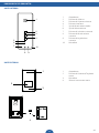
1. Vyvrtejte otvory ve stěně a zasuňte do otvorů hmoždinky.
Umístěte držák a utáhněte šrouby.
2. Připojte vodiče (viz „Vodiče“). Věnujte pozornost barevnému
označení.
3. Namontujte venkovní jednotku na držák. Ujistěte se, že je
správně upevněna.
4. Použijte speciální bezpečnostní šroub na spodní straně
jednotky, abyste zabránili krádeži.
Výměna jmenovky
Jestliže chcete vyměnit jmenovku na venkovní jednotce, stlačte
tlačítko volání na jedné straně a potom vsunutím plochého
šroubováku na druhé straně tlačítko jemně odejměte. Umístěte
jmenovku a zatlačením upevněte tlačítko volání zpět na místo.
INSTALACE – VENKOVNÍ JEDNOTKA

55
CS
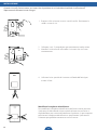
INSTALACE – VNITŘNÍ JEDNOTKA
1. Zvolte vhodné místo pro instalaci.
2. Vyvrtejte otvory ve stěně a zasuňte do otvorů
hmoždinky. Umístěte držák a utáhněte šrouby.
3. Připojte vodiče (viz „Vodiče“). Věnujte pozornost
barevnému označení.
4. Namontujte vnitřní jednotku na držák. Ujistěte
se, že je správně upevněna.
5. Ujistěte se, že jsou všechny vodiče správně
připojeny, a zapojte napájecí adaptér.

56 CS
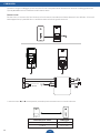
Vnitřní monitory B, C a D jsou volitelné v závislosti na počtu vnitřních jednotek, které chcete používat
Při instalaci vodičů se ujistěte, že nejsou umístěny přímo vedle elektrického vedení. Mohlo by to způsobit rušení
vašeho připojení.
Testování jednotky
Při testování jednotky se ujistěte, že vnitřní jednotka a venkovní jednotka jsou od sebe vzdáleny aspoň 10 metrů.
Pokud jsou jednotky příliš blízko u sebe, může docházet k výskytu pronikavého pisklavého zvuku a ozvěny.
VODIČE
Vzdálenost mezi jednotkami Vodiče
1–50 m 2×0,75 mm2
1–100 m 2×1,5 mm2
Power
1
2
3
4
Vnitřní
monitory
B, C or D

57
CS
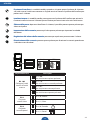
Funkce interkomu: Pokud v pohotovostním režimu stiskne návštěvník tlačítko volání na
venkovní jednotce, bude vnitřní jednotka zvonit. Po stisknutí tlačítka interkomu můžete hovořit s
návštěvníkem.
Interní interkom: Pokud v pohotovostním režimu stisknete a podržíte tlačítko interkomu, aktivuje
se funkce interního interkomu. Tato funkce slouží ke komunikaci mezi různými vnitřními jednotkami.
Odemknutí dveří: Po identifikaci návštěvníka můžete stisknutím tohoto tlačítka odemknout dveře.
Nastavení vyzvánění: Opakovaným stisknutím tohoto tlačítka nastavíte požadovanou melodii.
Nastavení hlasitosti vyzvánění: Stisknutím tohoto tlačítka zvýšíte hlasitost.
Ztlumení vyzvánění: Stisknutím tohoto tlačítka ztlumíte vyzvánění, jestliže nechcete být rušeni.
POUŽITÍ
ON (1) OFF (0)
ON
ON
= =
1234
ON
Bit state Description
Bit 1&2
Link indoor unit
to outdoor push
button
12
ID = (00)
For rst button outdoor unit
12
ID = (10)
For second button outdoor unit
12
ID = (01)
For third button outdoor unit
12
ID = (11)
For fourth button outdoor unit
Bit 3
Set master/slave
3ID = (0) Master
3ID = (1) Slave
Bit 4
Set door/gate
4ID = (0) Door
4ID = (1) Gate

58 CS
INSTALACE
Přídavné vnitřní monitory jsou volitelné v závislosti na počtu vnitřních jednotek, které chcete používat.
Červené
Červené
Červené
Červené
Černá
Černá
Černá
Černá
Venkovní
jednotka
Vnitřní
monitor
Vnitřní
monitor
Vnitřní
monitor

59
CS
TECHNICKÉ SPECIFIKACE
VNITŘNÍ JEDNOTKA
Napájecí napětí 15 V, 1 A
Spotřeba proudu 150 mA ± 10 mA
Provozní teplota -10 ˚C – +50 ˚C
Provozní vlhkost 85 % (max.)
VENKOVNÍ JEDNOTKA
Spotřeba proudu 60 mA ± 10 mA
Provozní teplota -10 ˚C – +50 ˚C
Skladovací teplota -20 ˚C – +60 ˚C
Provozní vlhkost ≤85 % RV
INFORMACE O BEZPEČNOSTI
Bezpečnostní opatření
Nezakrývejte větrací otvory předměty, jako jsou noviny, ubrusy, závěsy apod.
Nedovolte, aby toto zařízení přišlo do přímého kontaktu se zdroji tepla nebo otevřeného ohně.
Normální funkce zařízení může být negativně ovlivněna silným elektromagnetickým rušením.
Toto zařízení je určeno výhradně pro domácí použití.
Zařízení nesmí být vystaveno stříkající vodě ani nesmí být ponořeno do vody.
Na zařízení se nesmí pokládat žádné předměty naplněné tekutinou, jako například vázy.
Abyste zajistili správnou ventilaci, zachovejte minimální bezpečnostní vzdálenost 10 cm okolo všech stran zařízení.
Ujistěte se, že venkovní jednotka není nainstalována v místech, kde by mohla být vystavena působení vody nebo deště.
Nedovolte dětem, aby si se zařízením hrály.
Tento symbol je znám jako „symbol přeškrtnuté popelnice“. Pokud je tento symbol vyznačen na
produktu nebo baterii, znamená to, že je nelze likvidovat spolu s běžným komunálním odpadem.
Některé chemické látky obsažené v elektrických/elektronických produktech nebo bateriích
mohou být škodlivé pro zdraví lidí a životní prostředí. Likvidujte elektrické/elektronické/bateriové
produkty pouze ve sběrných dvorech, které obstarávají obnovu a recyklaci materiálů obsažených
v těchto produktech. Vaše spolupráce je nezbytná k zajištění úspěchu těchto způsobů likvidace a
k ochraně životního prostředí.
V souladu se všemi příslušnými evropskými směrnicemi.

60 SK
Name
1234
5678
VAROVANIE
1. Pred inštaláciou a použitím produktu si dôkladne prečítajte tieto pokyny.
2. Prívodný kábel neprerežte za účelom jeho predlžovania; zariadenie (transformátor) nebude pracovať s
dlhším káblom. Nepripájajte zariadenie, kým nebola dokončená inštalácia všetkých káblov.
BEZPEČNOSŤ PRI INŠTALÁCII
1. Pri inštalácii produktov držte deti a okolostojacich v bezpečnej vzdialenosti. Nepozornosť môže spôsobiť
stratu kontroly.
2. Pri inštalácii tohto produktu sa nenaťahujte. Nohy a rovnováhu udržujte vždy správne. Toto vám umožní
lepšiu kontrolu v nepredvídaných situáciách.
3. Tento produkt nie je hračka. Montujte ho mimo dosahu detí.
BEZPEČNOSŤ PRI PREVÁDZKE
1. Elektricky napájané produkty neprevádzkujte vo výbušných atmosférach, keď sú prítomné horľavé
kvapaliny, plyny alebo prach. Elektricky napájané produkty môžu produkovať iskry, ktoré môžu vznietiť
prach alebo výpary.
2. Varovania, bezpečnostné opatrenia a inštrukcie, ktoré sa nachádzajú v tomto návode na použitie nemôžu
pokryť všetky možné okolnosti a situácie, ktoré môžu nastať. Operátor ich musí pochopiť a používať
zdravý rozum a opatrnosť. Toto sú faktory, ktoré nie je možné obsiahnuť do tohto produktu, ale operátor
ich musí mať.
3. Elektrický adaptér tohto produktu nevystavujte dažďu alebo mokrým podmienkam. Voda sa dostane do
elektrického adaptéra a zvýši sa riziko úrazu elektrickým prúdom.
4. Prívodný kábel nepoškodzujte. Kábel nikdy nepoužívajte na odpojenie zástrčky zo zásuvky. Kábel udržujte
vždy mimo zdrojov tepla, oleja, ostrých hrán alebo pohyblivých častí. Poškodené alebo zamotané káble
zvyšujú riziko úrazu elektrickým prúdom.
5. Adaptér musí byť zhodný zo zásuvkou. Nikdy neupravujte zástrčku žiadnym spôsobom. Neupravované
zástrčky a zhodné zásuvky znižujú riziko úrazu elektrickým prúdom.
OBSAH BALENIA
1. Vnútorná jednotka
2. Vonkajšia jednotka
3. Kabeláž
4. Adaptér
5. Menovka
6. Montážna platnička
7. Skrutky a rozperky
8. Stručný návod

61
SK
10
7
1
2
4
5
6
8 9
3
ON
1
ON
4
1
3
2
OPIS PRODUKTU
VNÚTORNÁ JEDNOTKA
1. Reproduktor
2. Tlačidlo odomknutia
3. Tlačidlo interného volania
4. Tlačidlo interkomu
5. Indikátor vypnutia zvuku
6. Indikátor napájania
7. Tlačidlo voľby vyzváňacieho tónu
8. Tlačidlo vypnutia zvuku
9. Tlačidlo nastavenia hlasitosti zvonenia
10. Mikrofón
VONKAJŠIA JEDNOTKA
1. Reproduktor
2. Tlačidlo volania/Menovka
3. Mikrofón
4. Časový spínač na odomknutie

62 SK
Pri inštalácii vonkajšej jednotky dávajte pozor, aby bolo miesto na inštaláciu suché. Elektronické komponenty nesmú
dôjsť do kontaktu s vlhkosťou.
1. Do steny navŕtajte otvory a vložte do nich rozperky. Osaďte
konzolu a dotiahnite skrutky.
2. Pripojte vodiče (podľa časti „Kabeláž“). Venujte pozornosť
farebným označeniam.
3. Vonkajšiu jednotku namontujte na konzolu. Zabezpečte, aby
bola dôkladne pripevnená.
4. Na zabránenie krádeži použite špeciálnu bezpečnostnú skrutku
na spodnej strane jednotky.
Výmena menovky
Ak chcete zmeniť menovku na vonkajšej jednotke, stlačte tlačidlo
volania na jednej strane a potom pomocou plochého skrutkovača
na druhej strane tlačidlo opatrne vytiahnite. Vložte menovku a
tlačidlo volania zatlačte na pôvodné miesto.
INŠTALÁCIA – VONKAJŠIA JEDNOTKA

63
SK
INŠTALÁCIA – VNÚTORNÁ JEDNOTKA
1. Vyberte vhodné miesto na inštaláciu.
2. Do steny navŕtajte otvory a vložte do nich rozperky.
Osaďte konzolu a dotiahnite skrutky.
3. Pripojte vodiče (podľa časti „Kabeláž“). Venujte
pozornosť farebným označeniam.
4. Vnútornú jednotku namontujte na konzolu.
Zabezpečte, aby bola dôkladne pripevnená.
5. Skontrolujte, či sú všetky vodiče zapojené správne
a pripojte napájací adaptér.

64 SK
Vnútorné monitory B, C a D sú voliteľné. Ich počet závisí od množstva vnútorných jednotiek,
ktoré chcete používať.
Pri vedení kabeláže dávajte pozor, aby neviedla priamo vedľa elektrických rozvodov. Mohlo by dôjsť k rušeniu
pripojenia.
Testovanie jednotky
Pri testovaní jednotky by mala byť vnútorná jednotka vo vzdialenosti aspoň 10 metrov od vonkajšej. Ak sú
jednotky príliš pri sebe, mohlo by dôjsť k spätnej väzbe a ozvenám.
KABELÁŽ
Vzdálenost mezi jednotkami Vodiče
1–50 m 2×0,75 mm2
1–100 m 2×1,5 mm2
Power
1
2
3
4
Vnútorné
monitory
B, C e D

65
SK
Funkcia interkomu: Ak v pohotovostnom režime stlačí návštevník tlačidlo volania na vonkajšej
jednotke, vnútorná jednotka zazvoní. Po stlačení tlačidla interkomu môžete s návštevníkom
komunikovať.
Interný interkom: Stlačením tlačidla interkomu v pohotovostnom režime aktivujete funkciu
interného interkomu. Týmto postupom môžete komunikovať medzi rôznymi internými jednotkami.
Odomknutie dverí: Po identifikácii návštevníka môžete stlačením tohto tlačidla odomknúť dvere.
Nastavenie vyzváňacieho tónu: Opakovaným stláčaním tohto tlačidla môžete nastaviť melódiu
podľa svojho výberu.
Nastavenie hlasitosti vyzváňacieho tónu: Stlačením tohto tlačidla zvýšite hlasitosť.
Vypnutie vyzváňacieho tónu: Ak sa nechcete nechať rušiť, stlačením tohto tlačidla vypnete
vyzváňací tón.
POUŽITIE
ON (1) OFF (0)
ON
ON
= =
1234
ON
Bit state Description
Bit 1&2
Link indoor unit
to outdoor push
button
12
ID = (00)
For rst button outdoor unit
12
ID = (10)
For second button outdoor unit
12
ID = (01)
For third button outdoor unit
12
ID = (11)
For fourth button outdoor unit
Bit 3
Set master/slave
3ID = (0) Master
3ID = (1) Slave
Bit 4
Set door/gate
4ID = (0) Door
4ID = (1) Gate

66 SK
INŠTALÁCIA
Doplnkové vnútorné monitory sú voliteľné. Ich počet závisí od množstva vnútorných jednotiek, ktoré chcete
používať.
červená
červená
červená
červená
čierna
čierna
čierna
čierna
Vonkajšia
jednotka
Vnútorné
monitory
Vnitřní
monitor
Vnútorné
monitory

67
SK
TECHNICKÉ ÚDAJE
VNÚTORNÁ JEDNOTKA
Napájacie napätie 15 V, 1 A
Odber prúdu 150 mA ±10 mA
Prevádzková teplota −10 ˚C až +50 ˚C
Prevádzková vlhkosť 85 % (max.)
VONKAJŠIA JEDNOTKA
Odber prúdu 60 mA ±10 mA
Prevádzková teplota −10 ˚C až +50 ˚C
Teplota skladovania −20 ˚C až +60 ˚C
Prevádzková vlhkosť ≤85 % RV
BEZPEČNOSTNÉ INFORMÁCIE
Upozornenie
Vetracie otvory nezakrývajte predmetmi ako noviny, obrusy, závesy a pod.
Nedovoľte, aby sa tento produkt dostal do priameho kontaktu so zdrojmi tepla alebo s otvoreným plameňom.
Silné elektromagnetické rušenie môže negatívne ovplyvňovať normálnu prevádzku produktu.
Toto zariadenie je určené výhradne na domáce použitie.
Zariadenie nesmie byť vystavené špliechajúcej vode ani ponárané do vody.
Na zariadenie sa nesmú pokladať žiadne predmety naplnené kvapalinami, ako sú napríklad vázy.
Aby ste zaistili správne vetranie, zo všetkých strán produktu zabezpečte minimálnu bezpečnú vzdialenosť 10 cm.
Vonkajšiu jednotku neinštalujte na miesta, kde by mohla dôjsť do kontaktu s vodou alebo dažďom.
Nedovoľte deťom hrať sa so zariadením.
Tento symbol je známy ako symbol „prečiarknutého odpadkového koša“. Keď sa tento symbol
nachádza na zariadení alebo na batérii, znamená to, že by sa nemali likvidovať s bežným
komunálnym odpadom. Niektoré chemikálie, ktoré sa nachádzajú v elektrických/elektronických
produktoch alebo batériách, môžu byť škodlivé pre zdravie a životné prostredie. Elektrické/
elektronické produkty/batérie likvidujte iba v rámci schém separovaného zberu, ktorý
zabezpečuje zhodnocovanie a recykláciu použitých materiálov. Vaša spolupráca je nevyhnutná
na zabezpečenie úspechu týchto schém a na ochranu životného prostredia.
Vyhovuje všetkým príslušným smerniciam EÚ.
-
 1
1
-
 2
2
-
 3
3
-
 4
4
-
 5
5
-
 6
6
-
 7
7
-
 8
8
-
 9
9
-
 10
10
-
 11
11
-
 12
12
-
 13
13
-
 14
14
-
 15
15
-
 16
16
-
 17
17
-
 18
18
-
 19
19
-
 20
20
-
 21
21
-
 22
22
-
 23
23
-
 24
24
-
 25
25
-
 26
26
-
 27
27
-
 28
28
-
 29
29
-
 30
30
-
 31
31
-
 32
32
-
 33
33
-
 34
34
-
 35
35
-
 36
36
-
 37
37
-
 38
38
-
 39
39
-
 40
40
-
 41
41
-
 42
42
-
 43
43
-
 44
44
-
 45
45
-
 46
46
-
 47
47
-
 48
48
-
 49
49
-
 50
50
-
 51
51
-
 52
52
-
 53
53
-
 54
54
-
 55
55
-
 56
56
-
 57
57
-
 58
58
-
 59
59
-
 60
60
-
 61
61
-
 62
62
-
 63
63
-
 64
64
-
 65
65
-
 66
66
-
 67
67


Smartwares DIC-211 Manual de usuario
- Tipo
- Manual de usuario
en otros idiomas
- français: Smartwares DIC-211 Manuel utilisateur
- italiano: Smartwares DIC-211 Manuale utente
- English: Smartwares DIC-211 User manual
- Deutsch: Smartwares DIC-211 Benutzerhandbuch
- Nederlands: Smartwares DIC-211 Handleiding
- slovenčina: Smartwares DIC-211 Používateľská príručka
Otros documentos
-
mundoclima Series MUCOR-H8 “Column Super Inverter H8” Guía de instalación
-
-
-
Blyss Shelon Manual de usuario
-
-
-
-
-
-
Marmitek DoorPhone 124 Manual de usuario