Frigidaire GLCS376CBA Guía de instalación
- Categoría
- Hornos
- Tipo
- Guía de instalación
Este manual también es adecuado para

INSTALLATION AND SERVICE MUST BE PERFORMED BY
A QUALIFIED INSTALLER.
IMPORTANT: SAVE FOR LOCAL ELECTRICAL INSPECTOR'S USE.
READ AND SAVE THESE INSTRUCTIONS FOR FUTURE REFERENCE.
If the information in this manual is not followed exactly, a fire or explosion may
result causing property damage, personal injury or death.
FOR YOUR SAFETY:
-- Do not store or use gasoline or other flammable vapors and liquids in the vicinity of this or any other
appliance.
-- WHATTO DO IFYOU SMELLGAS:
• Do not try to light any appliance.
• Do not touch any electrical switch; do not use any phone in your building.
• Immediatelycallyourgassupplierfromaneighbor'sphone. Followthegassupplier'sinstructions.
• If you cannot reach your gas supplier, call the fire department.
-- Installation and service must be performed by a qualified installer, service agency or the gas supplier.
Do not pinch the power supply cord or the flexible gas
conduit between the range and the wall
Do not seal the range to the side cabinets
**NOTE: 30" (762 era) minimum clearance between the
cooktop and the bottom of the cabinet when the bottom
of wood or metal cabinet is protected by not less than ¼"
(0.64 cm) flame retardant millboard covered with not less
than No 28 MSG sheet metal, 0.015 '* (04 ram) stainless
steel, 0024" (0.6 mm) aluminum, or 0.020" (05 mm)
copper
36" (91 4 em) minimum clearance when the cabinet is
unprotected
• NOTE: Allow at least 19 ¼" (489 cm) clearance for door
depth when it is open
Shave Raised 30 _ Min 13_
Edge to Clear 30 _ 76.2 cm Min) (33 cm)
(762 cm) Wide
Cooktop Rim
3" Min
1 Y2_'Max (76 em Min
(3.8 cm Max) From Wall
This Side
Only 18" Min
(45.7 cm) Min
Locate Cabinet
Doors 1" (25
cm) Min
from Cutout
Opening
• Door Open
(see note)
Regulator
i!ifill;illiliilli!il!ii!;ii!!iii!ii;i¸iiii;i!!i!iil;!iiiiii!
35 3/8" (90 cm) -
36 3/8" (92 cm)
*Note: 29"
(737 era) Wide
Opening for
Overlapping
Cooktop and
Built-in Look
If installing Model With
Optional Side Panels,
Cutout Area Including
Countertop Must Be At
Least 30'* (76.2 cm) Wide
Grounded Jonction Box or Wall
Outlet Should Be Located 8"
to 17" (203 em to 432 em)
From Right Cabinet and 2" to
4" (51 cm to I02 cm) From
Floor
22 7/8"
30 "
(762 cm)
26 I/4" 29 _
(667 cm) (737 cm)
21 3/4" 36" (91.4 era) standard
(552 cm) 35 3/8" (90 cm) min.
FRONT
OF
CABINET
24" Min
(6I cm Min.)
_I I/8"
(45.7 cm)
G Ref
G. Minimum Cutout Depth is increased to 24" (61 cm) with backguard.
NOTE: Wiring diagram for these appliances are enclosed in this booklet.
_ Recycled paper
P/N 318201657 (0109) Rev. A
English - pages 1-1 I
Espa_ol - p_ginas 12-22
Wiring Diagrams - pages 23-25
Notes - 26-28

Important Notes to the Installer
1. Readall instructions contained in these installation
instructions before installing range.
2. Remove all packing material from the oven
compartments before connecting the gasand electrical
supply to the range.
3. Observe all governing codes and ordinances.
4. Besure to leavethese instructions with the consumer.
Important Note to the Consumer
Keep these instructions with your owner's guide for future
reference.
IMPORTANT SAFETY
INSTRUCTIONS
Installation of this range must conform with local codes
or, in the absence of local codes, with the National Fuel
Gas Code ANSI Z223.1--1atest edition, in United States
or with CAN/CGA-B149.1 and CAN/CGA-B149.2
standards in Canada.
Standard for Mobile Home Construction and Safety,
title 24, HUD (part 280)] or when such standard is not
applicable, the Standard for Manufactured Home
Installation 1982 (Manufactured Home Sites,
Communities and Setups), ANSI Z225.1/NFPA 501A-
latest edition, or with local codes in United States or
with CAN/CSA-Z240 MH, in Canada.
• Make sure the wall coverings around the range
can withstand the heat generated by the range.
• Before installing the range in an area covered
with linoleum or any other synthetic floor
covering, make sure the floor covering can
withstand heat at least 90°F (32.2°C) above room
temperature without shrinking, warping or
discoloring. Do not install the range over carpeting
unless you place an insulating pad or sheet of ¼" (0.6
cm) thick plywood between the range and carpeting.
• Do not obstruct the flow of combustion air at the
oven vent nor around the base or beneath the
lower front panel of the range. Avoid touching the
vent openings or nearby surfaces asthey may become
hot while the oven is in operation. This range requires
fresh air for proper burner combustion.
This range has been design certified by the American Gas
Association. As with any appliance using gas and
generating heat, there are certain safety precautions you
should follow. You will find them in the Use and Care
Guide, read it carefully.
• Be sure your range is installed and grounded
properly by a qualified installer or service
technician.
• This range must be electrically grounded in
accordance with local codes or, in their absence,
with the National Electrical Code ANSI/NFPA No.
70ilatest edition in United States (see Grounding
Instructions) or with CSA standard C22.1, Canadian
Electrical Code, Part 1 in Canada.
• The installation of appliances designed for
manufactured (mobile) home installation must conform
with Manufactured Home Construction and Safety
Standard, title 24CFR, part 3280 [Formerly the Federal
,, All ranges
can tip.
• Injury to
persons could
result.
• Install anti-tip
device
packed with
range.
Toreduce
the risk of tipping of the
range, the range must be
secured by properly
installed anti-tip bracket
)rovided with the range.
To check if the bracket is
installed properly, grasp
the top rear edgge of the
range and carefully tilt it
forward to make surethe
range isanchored.
Never leave children alone or
unattended in the area where an appliance is in use.
As children grow, teach them the proper, safe use of all
appliances. Never leave the oven door open when the
range is unattended.
Stepping, leaning or sitting on the
doors or drawers of this range can result in serious
injuries and can also cause damage to the range.
2
• Do not store items of interest to children in the
cabinets above the range. Children could be
seriously burned climbing on the range to reach items.
• To eliminate the need to reach over the surface
burners, cabinet storage space above the burners
should be avoided.
• Adjust surface burner flame size so it does not
extend beyond the edge of the cooking utensil.
Excessiveflame is hazardous.
• Do not use the oven as a storage space. This
creates a potentially hazardous situation.
• Never use your range for warming or heating the
room. Prolonged use of the range without adequate
ventilation can be dangerous.
• Do not store or use gasoline or other flammable
vapors and liquids near this or any other
appliance. Explosions or fires could result.
• In the event of an electrical power outage, the surface
burners can be lit manually. To light a surface burner,
hold a lit match to the burner head and slowly turn the
Surface Control Knob to LITE. Use caution when
lighting surface burners manually.
• Reset all controls to the "off" position after using
a programmable timing operation.

CANADAONLY:Thisapplianceis
equippedwith a4-pronggroundingplugfor your
protectionagainstshockhazard,andshouldbe
pluggeddirectlyintoaproperlygrounded
receptacle.Donotcutorremovethegroundprong
fromthis plug.
FORMODELSWITHSELF-CLEANFEATURE:
• Remove broiler pan, food and other utensils
before self-cleaning the oven. Wipe up excess
spillage. Follow the precleaning instructions in the Use
and Care Guide.
1. Power Supply Cord Kit (U.S.A.)
The user is responsible for connecting the power supply
cord to the connection block located behind the back
panel access cover.
This appliance may be connected by means of
permanent "hard wiring" (flexible armored or
nonmetallic shielded copper cable), or by means of a
power supply cord kit. Only a power supply cord kit
rated at 125/250 volts minimum, 40 amperes and
marked for use with ranges shall be used. Seechart
(below) for cord kit connection opening size rating
information. Cord must have either 3 or 4 conductors.
For mobile home installation, or areas where local codes
do not permit grounding through neutral, a 4 conductor
power supply cord kit rated at 125/250 volts minimum,
40 amperes and marked for use with ranges should be
used (see Figure 5).
Terminals on end of wires must be either closed loop or
open-end spade lugs with upturned ends. Cord must
have strain-relief clamp.
See below for 3 or 4 conductor wire connection.
Refer to chart below for range connection opening size and power
supply cord kit ampere rating information. See serial plate on range
for kilowatt rating data
See Serial Plate on Range for
Kw Rating
Cord Kit
Ampere
120/240 Volts I20/208 Volts Rating
0-I65Kw 0-125Kw 40 Amp
166-225Kw 12.6-185Kw 50 Amp.
Diameter (inches (cm)) of
Range Connection
Opening
Direct
Cord Kit Connection
I 3/8 (35) 1 1/8 (2.9)
I 3/8 (35) 1 3/8 (3.5)
NOTE: Dual fuel Slideqn Range isshipped from factory
with 1 1/8" (2.9 cm) dia. hole as shown on figure 4. If a
larger hole isrequired, punch out the knockout.
Risk of fire or electrical shock exists if
an incorrect size range cord kit is used, the
Installation Instructions are not followed, or the
strain relief bracket is discarded.
U.S.A.
Figure 1
Do not loosen the nuts which secure
the factory-installed range wiring to terminal block
while connecting range. Electrical failure or loss of
electrical connection may occur.
2. Factory Connected Power Supply
Cord (Canada only)
This range isequipped with a factory-connected power
cord (see Figure 2). Cord must be connected to a
grounded 120/240 volt or 120/208 volt range outlet. If
not outlet is available, have one installed by a qualified
electrician.
Canada Style
Figure 2
Electrical Shock Hazard
• Electrical ground is required on this appliance.
• Do not connect to the electrical supply until
appliance is permanently grounded.
• Disconnect power to the circuit breaker or fuse
box before making the electrical connection.
• This appliance must be connected to a
grounded, metallic, permanent wiring system,
or a grounding connector should be connected
to the grounding terminal or wire lead on the
appliance.
• Do not use the gas supply line for grounding
the appliance.
Failure to do any of the above could result in a
fire, personal injury or electrical shock.
3

3. Electrical Connection to the Range
(U.S.A.)
This appliance is manufactured with the neutral terminal
connected to the frame.
Three Conductor Wire Connection to Range
If local codes permit connection of the frame grounding
conductor to the neutral wire of the copper power supply
cord (see Figure 4).
1. Remove the 3 screws at the lower end of the rear
wire cover, then bend the lower end of the rear wire
cover (access cover) upward to expose range
terminal connection block (see Figure 3).
2. Remove the 3 loose nuts (after you removed the
rubber band) on the terminal block using a 3/8" nut
driver or socket.
3. Connect the neutral white wire of the copper power
supply cord to the center silver-colored terminal of
the terminal block, and connect the other wires to
the outer terminals. Match wires and terminals by
color (red wires connected to the right terminal,
black wires connected to the left terminal).
4. Replace the 3 nuts on the terminal block (see Figure
4).
5. Lower the terminal cover and replace the 3 screws.
Silver Colored Terminal
Red
.Wire
Terminal
Block
Black
Wire
BEND REARWIRE COVER HERE
FORACCESSTO ELECTRICHOOK-UP
Figure 3
A User Supplied Strain-
relief Must Be Installed
at This Location.
To 240 V
Receptacle
Figure 4
1 1/8" (2.9 cm) Dia.
Direct Connection
Hole. Punch Out
Knockout for 1 3/8"
(3.5 cm) Dia. Cord
Kit Hole.
4

Four Conductor Wire Connection to Range
(mobile homes)
1. Remove the 3 screws at the lower end of the rear
wire cover, then raise the lower end of the rear wire
cover (access cover) upward to expose range
terminal connection block (see Figure 3).
2. Remove the 3 loose nuts (after you remove the
rubber band) on the terminal block using a 3/8" nut
driver or socket.
3. Remove the grounding strap from the terminal block
and from the appliance frame.
4. Connect the ground wire (green) of the copper
power supply cord to the frame of the appliance
with the ground screw, using the hole in the frame
where the ground strap was removed (see Figure 5).
5. Connect the neutral of the copper power supply cord
to the center silver-colored terminal of the terminal
block, and connect the other wires to the outer
terminals. Match wires and terminals by color (red
wires connected to the right terminal, black wires
connected to the left terminal).
6. Replace the 3 nuts on the terminal block (see Figure
5).
7. Lower the terminal cover and replace the 3 screws.
Terminal Block Silver Colored Terminal
Red
,Wire
Black Wir_
1 1/8" (2.9 cm)
Dia. Direct
i
Connection
Hole. Punch
Out Knockout
for 1 3/8 (3.5
cm) Dia. Cord Kit
Hole.
A User Supplied
Strain-relief Must
Be Installed at
This Location
To 240 V Receptacle
NOTE: Be sure to remove the
supplied grounding strap.
Figure 5
Direct Electrical Connection to the Circuit
Breaker, Fuse Box or Junction Box
If the appliance isconnected directly to the circuit
breaker, fuse box or junction box, use flexible, armored
or nonmetallic sheathed copper cable (with grounding
wire). Supply a U.L listed strain-relief at each end of
the cable. At the appliance end, the cable goes through
the Direct Connection Hole (see Figure 5) on the Cord
Mounting Plate. Wire sizes (copper wire only) and
connections must conform to the rating of the appliance.
Where local codes permit connecting the appliance-
grounding conductor to the neutral (white) wire
(see Figure 6):
1. Disconnect the power supply.
2. In the circuit breaker, fuse box or junction box:
a) Connect the green (or bare copper) wire, thewhite
appliance cable wire, and the neutral (white) wire
together.
b) Connect the 2 black wires together.
c) Connect the 2 red wires together.
Neutral
(white) Wire
Cable from Residence
Wires 1
Box
Wire
Green Conduit
(or Bare Copper) Connector (or CSA
Wire Cable from listed)
Appliance
Figure 6
3-Wire (Grounded Neutral) Electrical System
(Example: Junction Box)
5

Where local codes DO NOT permit connecting the
appliance-grounding conductor to the neutral
(white) wire, or if connecting to 4-wire electrical
system (see Figure 7):
1. Disconnect the power supply.
2. Separate the green (or bare copper) and white
appliance cable wires.
3. In the circuit breaker, fuse box or junction box:
a) Connect the white appliance cable wire to the
neutral (white) wire.
b) Connect the 2 black wires together.
c) Connect the 2 red wires together.
d) Connect the green (or bare copper) grounding
wire to the grounding wire of the circuit breaker,
fuse box or junction box.
Green (or Bare
Copper) Wire
Red--_,
Wires
Cable from Residence
White Wire
Green (or Bare
Copper) Wire
te Wire
Junction U.Lqisted Conduit
Box Connector (or CSA
Cable from listed)
Appliance
Figure 7 - 4-Wire Electrical System
(Example: Junction Box)
4. Cabinet Construction
To eliminate the risk of burns or fire by
reaching over heated surface units, do not have cabinet
storage space above the range. If there is cabinet
storage space above range, reduce the risk by installing
a range hood that projects horizontally a minimum of 5"
(12.7 cm) beyond the bottom of the cabinet.
Countertop Preparation
The cooktop sides of the range fit over the cutout edge
of your countertop.
If you have a square finish (flat) countertop, no
countertop preparation is required.
Formed front-edged countertops must have molded
edge shaved flat 1/4" (0.64 cm) from each front corner
of opening.
Tile countertops may need trim cut back 1/4" (0.64
cm) from each front corner and/or rounded edge
flattened.
(0.64 cm)
30 _
/.(76.2 cm)
Formedor tiled countertop
trimmed ¼" (0.64 cm)
back at front corners of
countertop opening.
Figure 8
If the countertop opening width is greater than the
minimum cutout width, adjust the 1/4" (0.64 cm)
dimension.
Countertop must be level. Place a level on the
countertop, first side to side, then front to back. If the
countertop is not level, the range will not be level. The
oven must be level for satisfactory baking results.
Cooktop sides of range fit over edges of countertop
opening.
6

5. Gas Supply - Installation
When shipped from the factory, this unit is designed to
operate on 4" water column (1.0 kPa) Natural gas
manifold pressure. A convertible pressure regulator is
connected to the range manifold and MUST be
connected in series with the gas supply line. To access
the regulator, remove the drawer.
For proper operation, the maximum inlet pressure to
the regulator should be no more than 14" of water
column pressure (3.5 kPa).
The inlet pressure to the regulator must be at least 1"
(.25 kPa) greater than the regulator manifold pressure
setting. The regulator is set for 4" water column (1.0
kPa) Natural gas manifold pressure, the inlet pressure
must be at least 5" water column (1.25 kPa) Natural
gas. For LP/Propane gas, the regulator must be set for
10" water column (2.5 kPa) manifold pressure, the inlet
pressure must be at least 11 " water column (2.75 kPa).
The supply line should be equipped with an approved
shutoff valve (see Figure 9). This valve should be located
in the same room as the range and should be in a
location that allows ease of opening and closing. Do not
block access to the shutoff valve. The valve is for
turning on or shutting off gas to the appliance.
Open the shutoff valve in the gas supply line. Wait a
few minutes for gas to move through the gas line.
The gas supply between the shutoff valve and the
regulator may be connected by rigid piping or by A.G.A./
C.G.A.-approved flexible metallic union-connected
piping where local codes permit use.
The gas supply piping can be through the side wall of
the right cabinet. The right side cabinet is an ideal
location for the main shutoff valve.
Do not make the connection too tight.
The regulator is die cast. Overtightening may crack the
regulator resulting in a gas leak and possible fire or
explosion.
Assemble the flexible connector from the gas supply pipe
to the pressure regulator in order: 1- manual shutoff
valve, 2- flare union adapter, 3- flexible connector, 4-
flare union adapter, 5- pressure regulator.
The gas supply line to the shutoff valve should be 1/2" or
3/4" solid pipe.
The user must know the location of the main shutoff
valve and have easy access to it.
When using flexible gas conduit on the range, allow
sufficient slack to pull the range outside the cutout for
cleaning or servicing.
NOTE: Do not allow the flexible conduit to get pinched
between the wall and the range. To visually check,
remove the drawer.
Use pipe-joint compound made for use with Natural and
LF,/Propane gas to seal all gas connections. If flexible
connectors are used, be certain connectors are not
kinked.
Leak testing of the appliance shall be conducted
according to the manufacturer's instructions.
Check for leaks. After connecting the range to the gas
supply, check the system for leaks with a manometer. If
a manometer is not available, turn on the gas supply and
use a liquid leak detector at all joints and connections to
check for leaks.
[I_W/-'_t_II_[_I Do not use a flame to check for leaks
from gas connections. Checking for leaks with a flame
may result in a fire or explosion.
All openings in the wall or floor where the range isto be
installed must be sealed.
Tighten all connections if necessary to prevent gas
leakage in the cooktop or supply line.
Check alignment of valves after connecting the
cooktop to the gas supply to be sure the manifold pipe
has not been moved.
Disconnect this range and its individual shutoff
valve from the gas supply piping system during any
pressure testing of that system at test pressures greater
than 1/2 psig (3.5 kPa or 14" water column).
Isolate the range from the gas supply piping system
by closing its individual manual shutoff valve during any
pressure testing of the gas supply piping system at test
pressures equal to or less than 1/2 psig (3.5 kPa or 14"
water column).
6. LP/Propane Gas Conversion
This appliance can be used with Natural gas or LP/
Propane gas. It isshipped from the factory for use with
natural gas.
7
If you wish to convert your range for use with LF,/F,ropane
gas, use the supplied fixed orifices located in a bag
containing the literature marked "FOR LF,/PROPANEGAS
CONVERSION". Follow the instructions packaged with
the orifices.

ACCESS
COVER
Flexible Appliance Conduit Manual
Install sufficient length of flexible conduit Sutoff Valve
to allow the range to be pulled (supplied by
_ completely out of the cut-out area for user) Connect
proper servicing (supplied by user). Flare to Y2"or 3/4"
solid gas
Union supply pipe
Adaptor from the wall
or floor.
GAS
IPPLY
PRESSUREREGULATOR
LOCATION
RANGE
TO
APPLIANCE
Solid Piping Gas Supply
Sutoff
Valve
TO GAS SUPPLY
LINE
Figure 9
LP/Propane Gas Conversion (continued)
The conversion must be performed by a qualified service
technician in accordance with the manufacturer's
instructions and all local codes and requirements. Failure
to follow these instructions could result in serious injury
or property damage. The qualified agency performing
this work assumes responsibility for the conversion.
[!_W/-,I;t_11_[_1Failure to make the appropriate
conversion can result in personal injury and property
damage.
7. Moving the Appliance for
Servicing and Cleaning
Turn off the range line fuse or circuit breakers at the
main power source, and turn off the manual gas shut-off
valve. Make sure the range is cold. Remove the service
drawer (warmer drawer on some models) and open the
oven door. Lift the range at the front and slide it out of
the cut-out opening without creating undue strain on the
flexible gas conduit. Make sure not to pinch the flexible
gas conduit at the back of the range when replacing the
unit into the cut-out opening. Replace the drawer, close
the door and switch on the electrical power and gas to
the range.
The regulator must be disconnected before moving the
appliance, if the range regulator is connected to rigid
piping. If the range is equipped with a warmer drawer,
the regulator can be accessed through a lateral side
panel. Remove the 2 screws securing the panel, then
remove the panel. Disconnect the regulator from the
piping. Reassemble in reverse order (see Figure 10).
3teral
- side panel
warmer
(RH SIDE)
Drawer glide
(do not remove)
Figure 10
8

8. Range Installation
When unpacking the range, do not
discard the 4 shipping bolts. These are to be replaced
on the unit for use as leveling legs and height
adjustments.
1.
2.
Installation Without Side Panel(s)
A. The range cooktop overlaps the countertop at
the sides and the range rests on the floor. The
cooktop is 30" (76.2 cm) wide.
B. Install base cabinets 29" (73.7 cm) apart. Make
sure they are plumb and level before attaching
cooktop. Shave raised countertop edge to clear
30" (76.2 cm) wide range top rim.
C. Install cabinet doors 31 _'(78.7 cm) min. apart so
as not to interfere with range door opening.
D. Cutout countertop exactly as shown on page 1.
E. A backguard kit can be ordered through your
dealer.
F. Adjust leveling legs so that the underside of the
cooktop is sitting on the countertop.
G. Level the range. The floor where the range
is to be installed must be level (see
Figure 11).
Installation With Side Panel(s)
A. Install base cabinets 30 Vs" (76.5 cm) min.
apart. Make sure they are plumb and level.
B. Install cabinet doors 31 _'(78.7 cm) min. apart so
as not to interfere with range door opening.
c. A backguard kit can be ordered through your
dealer.
D An end panel kit can be ordered through your
dealer.
E. Level the range and adjust cooktop height.
Figure 9
10. Check Operation
Refer to the Owner's Guide packaged with the range for
operating instructions and for care and cleaning of your
range.
Do not touch the elements or burners.
They may be hot enough to cause burns.
Remove all packaging from the oven before testing.
1. Install Burner Bases and Burner Caps
This range is equipped with sealed burners as shown
(see Figure 12).
Burner
Cap
Burner
Base
Burner Gas
Pan ling
3. Installation With Backguard
The cutout depth of 21 s/8_'(55 cm) needs to be
increased to 24" (61 cm) when installing a backguard.
9. Leveling the Range
Level the range and set cooktop height before
installation in the cut-out opening.
1. Install an oven rack in the center of the oven.
2. Place a level on the rack. Take 2 readings with the
level placed diagonally in one direction and then the
other. Level the range, if necessary, by adjusting the
4 leg levelers with a wrench (see Figure15).
3. Taking care to not damage the countertop, slide
range into cut-out opening and double check for
levelness. If the range is not level, pull unit out and
readjust leveling legs, or make sure floor is level.
Electrode'
Figure 12
A. Unpack burner bases and burner caps.
B. Place burner bases over each gas opening.
C. Make sure the burner is properly aligned and
leveled. Place burner caps over appropriate
burner bases.
NOTE: There are no burner adjustments necessary on
this range.
2. Turn on Electrical Power and Open Main Shutoff
Gas Valve
9
.
Check the Igniters
Operation of electric igniters should be checked after
range and supply line connectors have been carefully
checked for leaks and range has been connected to
electric power.

Tocheckforproperlighting:
A. Pushinandturnasurfaceburnerknobtothe
LITEposition.Youwillheartheignitersparking.
B. Thesurfaceburnershouldlightwhengasis
availabletothetopburner.Eachburnershould
lightwithinfour(4)secondsinnormaloperation
afterairhasbeenpurgedfromsupplylines.
Visuallycheckthatburnerhaslit.
C. Oncetheburnerlights,thecontrolknobshould
berotatedoutoftheLITEposition.
Thereareseparateignitiondevicesforeachburner.
Tryeachknobseparatelyuntilallburnervalveshave
beenchecked.
4.
Adjust the "LOW" Setting of Surface Burner
Valves (see Figure 13)
A. Push in and turn each control to LITEuntil burner
ignites.
B. _turn knob to LOWEST POSITION.
C. If burner goes out, readjust valve as follows:
Reset control to OFF. Remove the surface burner
control knob, insert a thin-bladed screw driver
into the hollow valve stem and engage the
slotted screw inside. Flame size can be
increased or decreased with the turn of the
screw. Adjust flame until you can quickly turn
knob from LITEto LOWEST POSITIONwithout
extinguishing the flame. Flame should be as
small as possible without going out.
Broil-When the oven is set to BROIL,the upper element
in the oven should become red.
Clean-When the oven is set for a self-cleaning cycle, the
upper element should become red during the preheat
portion of the cycle. After reaching the self-cleaning
temperature, the lower element will become red.
Convection (some models)-When the oven is set to
CONV. BAKE/ROAST at 350°F (177°C), both elements
cycle on and off alternately and the convection fan will
turn. The convection fan will stop turning when the oven
door isopened during convection baking or roasting.
Warmer Drawer (some models)-Set the control knob
to HI and check to see the drawer is heating.
When All Hookups are Complete
Make sure all controls are left in the OFFposition.
Make sure the flow of combustion and ventilation air to
the range is unobstructed.
Model and Serial Number Location
The serial plate islocated on the oven front frame
behind the oven door (some models) or behind the
drawer (some models).
When ordering parts for or making inquiries about your
range, always be sure to include the model and serial
numbers and a lot number or letter from the serial plate
on your range.
Your serial plate also tells you the rating of the burners,
the type of fuel and the pressure the range was adjusted
for when it left the factory.
Figure 13
5. Operation of Oven Elements
The oven isequipped with an electronic oven control.
Eachof the functions hasbeen factory checked before
shipping. However, it is suggested that you verify the
operation of the electronic oven controls once more. Refer
to the Owner's Guide for operation. Follow the instructions
for the Clock, Timer, Bake, Broil, Convection (some
models) and Clean functions.
Bake-After setting the oven to 350°F (177°C) for baking,
the lower element in the oven should become red.
Before You Call for Service
Read the Avoid Service Checklist and operating
instructions in your Owner's Guide. It may save you time
and expense. The list includes common occurrences that
are not the result of defective workmanship or materials
in this appliance.
Refer to the warranty and service information in your
Owner's Guide for our phone number and address.
Please call or write if you have inquiries about your range
product and/or need to order parts.
10

11. Important Safety Warning
To reduce the risk of tipping of the range, the range
must be secured to the floor by properly installed anti-tip
brackets and screws packed with the range. Those parts
are located in a plastic bag in the oven. Failure to install
the anti-tip brackets will allow the range to tip over if
excessive weight is placed on an open door or if a child
climbs upon it. Serious injury might result from spilled
hot liquids or from the range itself.
Follow the instructions below to install the anti-tip
brackets.
If range is ever moved to a different location, the anti-tip
brackets must also be moved and installed with the
range. To check for proper installation, see step 5.
Tools Required:
5/16" Nutdriver or Flat Head Screwdriver
Adjustable Wrench
Electric Drill
3/16" Diameter Drill Bit
3/16" Diameter Masonry Drill Bit (if installing in
concrete)
Anti-Tip Brackets Installation Instructions
Brackets attach to the floor at the back of the range to
hold both rear leg levelers. When fastening to the floor,
be sure that screws do not penetrate electrical wiring or
plumbing. The screws provided will work in either wood
or concrete.
1. Unfold paper template and place it flat on the floor
with the back and side edges positioned exactly
where the back and sides of range will be located
when installed. (Use the diagram below to locate
brackets if template is not available.)
2. Mark on the floor the location of the 4 mounting
holes shown on the template. For easier installation,
3/16" (0.5 cm) diameter pilot holes 1/2" (1.3 cm)
deep can be drilled into the floor.
3. Remove template and place brackets on floor with
turned up flange to the front. Line up holes in
brackets with marks on floor and attach with 4
screws provided. Brackets must be secured to solid
floor. If attaching to concrete floor, first drill 3/16"
(0.5 cm) dia. pilot holes using a masonry drill bit.
4. Level range if necessary, by adjusting 4 leg levelers
with wrench (see Figure 15). A minimum clearance
of 1/8" (0.8 cm) is required between the bottom of
the range and the rear leg levelers to allow room for
the anti-tip brackets.
5. Slide range into place making sure rear legs are
trapped by ends of brackets. Range may need to be
shifted slightly to one side as it is being pushed back
to allow rear legs to align with brackets. Grasp the
top rear edge of the range and carefully attempt to
tilt it forward to make sure range is properly
anchored.
Anti-Tip
J
<?5
ideBack
Figure 14
Figure 15
11

LA INSTALACION Y EL SERVICIO DEBEN SER EFECTUADOS POR
UN INSTALADOR CALIFICADO.
IMPORTANTE: GUARDE ESTAS INSTRUCCIONES PARA USO DEL
INSPECTOR LOCAL DE ELECTRICIDAD.
LEA Y GUARDE ESTAS INSTRUCCIONES PARA REFERENCIA FUTURA.
T!_Si la informacibn contenida en este manual no es seguida exactamente, puede
ocurrir un incendio o explosibn causando dahos materiales, lesibn personal o la muerte.
PARASU SEGURIDAD:
-- No almacene ni utilice gasolina u otros vapores y liquidos inflamables en la proximidad de _ste o de
cualquier otro artefacto.
-- QUE DEBE HACER SI PERCIBEOLOR A GAS:
• Notratedeencender ning_n artefacto.
• No toque ning_n interruptor el_ctrico; no use ning_n telefono en su edificio.
• Llame a su proveedor de gas desde el telefono de un vecino. Siga las instrucciones del proveedor de gas.
• Si no Iogra comunicarse con su proveedor de gas, Ilame al departamento de bomberos.
-- La instalaci6n y el servicio de mantenimiento deben ser efectuados pot un instalador calificado, la agencia
de servicio o el proveedor de gas.
No pellizque et cord6n el_ctrico o ei conducto flexible de gas Aeepille et borde subido a que
entre la estufa y la pared deje espaeio para un borde
No seile la estufa a los armados de lado
**NOTA: Un espado mfnimo de 30" (76.2 cm) entre la
superficie de ia estufa y el fondo dei armario euando el
fondo del armario de madera o metal est& protegido por no
menos de I/4" (064 cm) de madera resistente al fuego
eubierta pot una ktmina met_liea de MSG, n0mero 28,
0.0t5'* (0.4 ram) de acero inoxidable, 0024" (06 ram) de
aluminio, 6 002" (0.5 ram) de cobre
30" (762 cm) de anchura de
estufa MIn 3_
(76 em) de
I 72" M&x la pared,
(38 cm M_x) sotamente
este lad
30" Min 13"
(762 cm MIn.) (33 cm)
I8" Mfn
(457 cm) Min
Un espado minimo de 36" cuando el armado no estct
protegido
• NOTA: Deje por los 19 V4" (489 cm) de espado Iibre
para la profundidad de la
)uerta cuando
esta abierta
35 3/8" (90 em) -
36 3/8" (92 cm)
Localise las puertas
del armario 1"
(25 era) rain
del hueco de
la abertura
171ii!!iii!¸ill¸i!!i¸iii!!ii!ii¸I!I!I
30" 26 1/4"
(762 cm) (66.7 cm)
lulador
29"
(737 cm)
*Nota: 29" (73.7
em) Anehura de la
abertura para
planeha
translapadala y
apariencia
eneerrada
Para la instalaei6n de modelos
con paneles taterales opci6nales,
et ,lrea dei hueco induyendo el
armario debe de estar 30" (762
cm) de anchura minimo
2t 314" 36" (914 em) standard
(552 cm) 35 318" (90 cm) rain
La caja de empalmes o el
enehufe de conexi6n con la
tierra deberfa situarse de 8" a
17" (20.3 em a 432 era) del
armado derecho y de 2" a 4"
(51 cm a I02 cm) dei suelo
PARTE
DELANTERA
DEL
ARMARIO
G La profundidad mfnima de recortado se aumenta a 24" (61 cm) con el uso de un protector trasero
24" Min
(61 cm Mfn)
ol 1/8"
(457 cm)
_ G Ref__
NOTA: Se adjunta el diagrama de cables de esta cocina al final de este libreta. P/N 318201657 (0109) Rev. A
_Papel redclado English - pages 1-1 I
Espa_ol- p_ginas 12-22
Diagrama de la instalaciOn al_mbrica - p_ginas 23-25
Notas - 26-28

Notas importantes para el Instalador
1. Leatodas lasinstrucciones contenidas en este manual
antes de instalar la estufa.
2. Saque todo el material usado en el embalaje del
compartimiento del homo antes de conectar el
suministro el_ctrico o de gas a la estufa.
3. Observe todos los c6digos y reglamentos pertinentes.
4. Deje estasinstrucciones con el comprador.
Nota Importante para el Consumidor
Conserve estas instrucciones y el Manual del Usuario para
referencia futura.
IMPORTANTES
INSTRUCCIONES DE
SEGURIDAD
Instalaci6n de esta estufa debe cumplir con todos los
c6digos locales, o en ausencia de c6digos locales con el
C6digo Nacional de Gas Combustible ANSIZ223.1--
01tima edici6nen los Estados Unidos, o el CAN/CGA-
B149.2 en Canad&
Eldise_o de esta estufa ha sido certificado por la
Asociaci6n de Gas Americana. En _ste como en
cualquier otro artefacto que use gas y genere calor, hay
ciertas precauciones de seguridad que usted debe seguir.
Estasser_n encontradas en el Manual del Usuario, I_alo
cuidadosamente.
• Asegdrese de que la estufa sea instalada y
conectada a tierra en forma apropiada pot un
instalador calificado o por un t_cnico.
• Esta estufa debe ser el_ctricamente puesta a tierra
de acuerdo con los codigos locales, o en su
ausencia, con el Cbdigo Electrico Nacional ANSI/
NFPA No. 70, dltima edicion en los Estados Unidos
(Vea las instrucciones para la puesta a tierra) o el
codigo Electrico Canadiense CSA Standard C22.1,
Part 1, en Canad&.
• La instalaci6n de aparatos dise_ados para instalaci6n
en casas prefabricadas (m6viles) debe conformar con el
Manufactured Home Construction and Safety Standard,
titulo 24CFR, parte 3280 [Anteriormente el Federal
@
• Todas las estufas
pueden
volcarse.
• EStOpodria
resultar en
lesiones
personales.
• Instale el
dispositivo
antivuelcos que
se ha empacado
junto con esta
estufa.
Papa reducir el rJesgo de que se
vuelque la estufa, hay que
asegurarla adecuadamente
colocandote los sopo_tes
antivuelco que se propordonan.
Para comprobar si estos estan
instalados y apretados en su
lugar como se debe, ase el borde
trasero superior de la estufa y
cuidadosamente inclinela hacia
adelante para asegurar que la
estufa se ancle.
Standard for Mobil Home Construction and Safety,
titulo 24, HUD (parte 280)] o cuando tal est_ndar no se
aplica, el Standard for Manufactured Home Installation
1982 (Manufactured Home sites, Communities and
Setups), ANSI Z225.1/NFPA 501A-edici6n m_s reciente,
o con los c6digos locales en los Estados Unidos o el
CAN/CSA-Z240 MH, en Canad&
• Asegdrese de que el material que recubre las
paredes alrededor de la estufa, pueda resistir el
calor generado por la estufa.
• Antes de instalar la estufa en un &rea cuyo piso
este recubierto con linbleo u otro tipo de piso
sintetico, asegurese de que _stos puedan resistir
una temperatura de pot Io menos 90°F (32.2 °)
sobre la temperatura ambiental sin provocar
encogimiento, deformaci6n o decoloracibn. No
instale la estufa sobre una alfombra al menos que
coloque una plancha de material aislante de por Io
menos ¼" (0.6 cm), entre la estufa y la alfombra.
• NO obstruya el flujo del aire de combustion en la
ventilaci6n del homo ni tampoco alrededor de la
base o debajo del panel inferior delantero de la
estufa. Evite tocar las aberturas o _reas cercanas de
la ventilaci6n, ya que pueden estar muy calientes
durante el funcionamiento del homo. La estufa
requiere aire fresco para la combusti6n apropiada de
los quemadores.
Nunca deje ni_os solos o
desatendidos en un area donde un artefacto esta
siendo usado. A medida que los ni_os crecen,
ens_eles el uso apropiado y de seguridad para todos los
artefactos. Nunca deje la puerta del homo abierta
cuando la estufa est_ desatendida.
No se pare, apoye o siente en la s
puertas o cajones de esta estufa pues puede resultar
en serias lesiones y puede tambien causar da_o a la
estufa.
• No almacene articulos que puedan interesar a los
ni_os en los gabinetes sobre la estufa. Los niEos
pueden quemarse seriamente tratando de trepar a la
estufa para alcanzar estos articulos.
• Los gabinetes de almacenamiento sobre la estufa
deben set evitados, para eliminar la necesidad de
tener que pasar sobre los quemadores superiores
de la estufa para Ilegar a ellos.
• Ajuste el tama_o de la llama de los quemadores
superiores de tal manera que esta no sobrepase el
borde de los utensilios de cocinar. La llama
excesiva es peligrosa.
• No use el horno como espacio de almacenaje. Esto
crear_ una situaci6n potencialmente peligrosa.
• Nunca use la estufa para calentar el cuarto. El uso
prolongado de la estufa sin la adecuada ventilaci6n
puede resultar peligroso.
13

• No almacene ni utilice gasolina u otros vapores y
liquidos inflamables en la proximidad de este o de
cualquier otro artefacto electrico. Puede provocar
incendio o explosion.
• En caso de una interruption del servicio el_ctrico, es
pasible de encender los quemadores de superficie a
mano. Para encender un quemador de suoerficie,
acerque un fOsforo encendido del cabezal del
quemador, y gire delicadamente el botOn de control de
superficie a LITE(encendido). Tener cuidado al
encender los quemadores a mano.
• Ajuste todos los controles a la posicion "OFF"
(apagada) despu_s de haber hecho una operacibn
con tiempo programado.
PARA MODELOS AUTOLIMPIANTES:
• Saque la asadera, alimentos o cualquier otro
utensilio antes de usar el ciclo de autolimpieza del
horno. Limpie todo exceso de derrame de alimentos.
Siga las instrucciones de prelimpiado en el Manual del
Usuario.
CANADA SOLAMENTE: Este aparato est.1
equipado con una enchufe de 4 patas puesta a tierra
para su protecciOn contra choque el_ctrico, y debe de
ser conectado directamente en una tomacorriente
correctamente puesta a tierra. No corte ni remueva esta
pata puesta a tierra del enchufe.
1. Juego de Cordon El ctrico (Estados
Unidos)
El consumidor tiene la responsabilidad de conectar el
cordon el_ctrico al bloque de conexi0n ubicado detr_s de
la cubierta de acceso del panel trasero.
Esteel_ctrodom_stico puede set conectado por medio de
una "conexiOn directa" de cables permanentes (cable
blindado flexible o no met_tlico recubierto de cobre), o por
medio de un ensamblaje de cordon de suministro el_ctrico.
Solamente un ensamblaje de cordon de suministro el_ctrico
con regimen de 125/250 voltios minimo, 40 amperios y
marcado para uso con cocinas debe ser utilizado. Vea la
tabla (m_s abajo) para informaciOn sobre el tama_o de
abertura de la conexiOn del ensamblaje de cordon. El
cordon debe de tener 3 o 4 conductores. En las
instalaciones para casas movibles, o en _reas donde los
c0digos locales no permitan la puesta a tierra al neutral, un
ensamblaje de cordon de suministro el_ctrico a 4
conductores con regimen de 125/250 voltios minimo, 40
amperios y marcado para uso con cocinas debe ser
utilizado (vet la figura 5).
Losbornes a la extremidad de los alambres deben ser a
curvas cerradas o con extremidades de lenguetas en forma
de U abiertas y curvadas. El cordon debe de tener una
abrazadera releva de anclaje.
Ver la tabla de arriba para conexiOn de alambres de 3 o 4
conductores.
Nota: La cocina corrediza fuel dual viene de fabrica con un
agujero d diametro 1 1/8" (2.9 cm) come muestra en la
figura 4. Si un agujero mas largo est,1necesario retire la
arandela pre-cortada.
Referirse a la tabla de arriba para el tama_o de abertura de conexiOn de
cocina adecuada, y la informaciOn sobre el regimen de amperios del
ensamblaje de cordon de suministro el_ctrico.
Vea la placa de serie de la
cocina para information sobre
el regimen de kilovatio
120/240 Volts 120/208 Volts
0-I6.5 Kw 0-I2.5 Kw 40 Amp
I6.6-22.5 Kw I2.6-I8.5 Kw 50 Amp
Regimen
de
ampedos
de
ensamblaje
del cordon
Diametro (pulgados
(cm)) de abierta de
conexiOn de cocina.
Ensemblaje ConexiOn
del cordon directa
13/8 (35) I I18 (29)
1 318(35) I 318(35)
TI_ Puede ocurrir riesgo de incendio o
choque el_ctrico sise usa un juego de cordon de
estufa de tama_o incorrecto, si las instrucciones de
instalacion no son seguidas o si no se usa el anclaje
del cable.
Riesgo de Choque El_ctrico
• Una puesta a tierra est_ requerido en este
aparato.
• No Io conecte a la corriente electrica hasta que
el aparato haya sido puesto a tierra
permanentemente.
• Desconecte la corriente el_ctrica a la caja de
empalmes antes de hacer la conexi6n el_ctrica.
• Este aparato debe estar conectado con un
sistema de alambres puesto en tierra, metElico
y permanente o un conector de puesta a tierra
debe conectarse al terminal de puesta a tierra
o el alambre conductor en el aparato.
• No utilice el suministro de gas para hacer la
puesta a tierra.
La falta de hacer cualquier de las cosas arriba
podria resultar en un incendio, choque electrico
o lesiones personales.
No desate las tuercas que sujetan el
alambraje de cocina que ha sido instalado en la
factoria al bloque terminal, cuando se hace la
conexion de la cocina. Se puede ocurrir el mal
funcionamiento o una interrupci6n del suministro
el_ctrico.
14

Estilo Estados Unidos
Figura I
2. Cord6n de fuente de energia conedado
de fabrica (Canad solamente)
Esta estufa viene de
fabrica equipada con un
cordon de fuente de
energia (vea a la figura
2). El cordon debe de
ser conectado a una
toma de corriente a tierra Estilo Canada1
de 120/240 voltios o de Figura 2
1201208 voltios. Si no
hay una toma de corriente a tierra en la habitaciOn,
debe de ser instalada por un t_cnico calificado
LEVANTE LA PARTE MAS BAJA DEL PANEL TRASERO
AQUI PARA TENER ACCESO AL BLOQUE DE
CONEXIONES DE LOS TERMINALES
Figura 3
Terminal plata
Alambre
rojo
3. Conexion Eldctrico de la Estufa
(Estados Unidos)
Este aparato se fabrica con el terminal neutro conectado
al marco.
Nota: Refiere a los diagramas de alambraje al final de
este manual.
Conexibn de tres alambres de conduccibn a
la estufa
si los c0digos locales permiten la conexi0n del conductor
de tierra del marco con el alambre neutro del cordon
el_ctrico de cobre (vea Figura 4).
1. Quite los tres tornillos en la parte m_tsbaja del panel
trasero, luego levante la parte m_tsbaja del panel
trasero (la cubierta de acceso) exponiendo el bloque
de conexiones de los terminales de la estufa (vea
Figura 3).
2. Quite las tres tuercas desatadas (despu_s de remover
la cinta de goma) sobre el bloque terminal usando
un destornillador o una Ilave de casquillo de 3/8".
3. Conecte el cable neutro del cordon el_ctrico de
cobre al terminal de color de plata en el centro del
bloque, y conecte los otros cabels a los terminales
laterales. Empareje los cables y los terminales seg0n
el color (cables rojos conectados con el terminal
derecho, cables negros conectados con el terminal
izquierdo.
4. Repone las tres tuercas desatadas sobre el bloque
terminal.
5. Baje la cubierta del terminal y reinstale los tres (3)
tornillos.
Bloque
terminal
Alambre
Negro
Una arazadera de
releva provista debe de
estar instalada a est.1
ubicadOn.
Hacia el 240 V
recept_iculo.
Figura 4
1 1/8" (2.9 cm)
Agujero de la
conexiOn direct&
Retira la arandela
pre-cortada para
1 3/8" (3.5 cm) Dia.
agujero.
Conexibn de 4 alambres de conduccibn a la
estufa (casas mbviles)
1. Quite los tres tornillos en la parte m_tsbaja del panel
trasero, luego levante la parte m_tsbaja del panel
trasero (la cubierta de acceso) exponiendo el bloque
de conexiones de los terminales de la estufa.
2. Quite las tres tuercas dasatadas (despu_s de remover
la cinta de goma) sobre el bloque termianl usando
un destornillador o una Ilave de casquillo de 3/8".
3. Quite la banda de puesta a tierra del bloque de los
terminales y del marco del artefacto. Retenga el
tornillo de puesta a tierra.
4. Conecte el alambre de puesta a tierra (verde) del
15

cord6n el_ctrico de cobre al marco del artefacto con
el tornillo de puesta a tierra, usando el agujero en el
marco donde sequit6 el tomillo de puesta a tierra
(yea figura 5).
5. Conecte el alambre neutro (blanco) del cord6n
el_ctrico de cobre al terminal de color de plata en
el centro del bloque y conecte los otros alambres al
los terminales laterales.
6. Repone las tres tuercas desatadas sobre el bloque
terminal.
7. Baje la cubierta de acceso y vuelva a poner los 3
tomillos.
Bloque terminal Terminal plata
Alambre
rojo
Alambre
negro
1 118"(2.9cm) B
Dia.agujero de
I
la conexiOn
directa. Retira la
arandela pre-
cortada para 1
3/8" (3.5 cm)
dia. agujero.
Una arazadera
releva provista
debe de estar
instalada a est_
ubicadOn.
Hada el 240 V receptSculo
NOTA: Asegurese de quitar la
banda de puesta a tierra
provista.
Figura 5
Conexibn el_ctrica directa al cortacircuito, a
la caja de fusibles o la caja de empalmes
Si el aparato eskt conectado directamente al cortacircuito,
a la caja de fusibles o a la caja de empalmes, use un cable
blindado flexible o no met_lico recubierto de cobre (con
alambre a tierra). Provee una abrazadera releva de anclaje
homologo ULa cada extremidad del cable. A la
extremidad del el_ctrodom_stico, el cable pase a trav_s del
agujero de la conexiOn directa (ver figura 5) en el cordon
de la placa de montaje. Eltama_3ode los alambres
(alambre de cobre solamente) y lasconexiones deben
estar conforme al regimen del el_ctrodom_stico.
Donde los codigos locales permitan conectar el
conductor de puesta a tierra del electrodomestico al
neutral (blanco) (vea figura 6):
1. Desconecteelsuministro el_ctrico.
2. Enel cortacircuito, la caja de fusibles o la caja de
empalmes
a) Conecte el alambre verde (o cobre desnudo), el
alambre blanco del cable del el_ctrodom_stico y el
alambre neutral (blanco) juntos.
b) Conecte los dos alambres negros juntos.
c) Conecte los dos alambres rojos juntos.
Cable de la fuente de
alimentaciOn
Alambre blanco es
(neutro) Negros
Alambres --..
Rojos
Caja de
empalmes
(neutro)
Alambre
desnudo o verde
Cable de la
estufa
Conductor de union
Iistado-UL (Nstado-CSA)
Figura 6
Sistema el_ctrico (ejemplo: caja de empalmes)
de 3 alambres (a tierra neutral)
16

Donde los codigos locales NO permitan conectar el
conductor de puesta a tierra del electrodomestico al
neutral (blanco), o siesta conectado con un sistema a
4 alambres (vea flgura 7):
1. Desconecte el suministro el_ctdco
2. Separe el alambre verde (o cobre desnudo) y el
alambre blanco del electrodom_stico.
3. En el cortacircuito, la caja de fusibles o la caja de
empalmes.
a. Conecte el alambre blanco del cable del
el_ctrodom_stico al alambre neutral (blanco).
b. Conecte los2 alambres negros juntos.
c. Conecte los2 alambres rojosjuntos.
d. Conecte el alambre verde (o de cobre desnudo) de
la puesta a tierra del alambre al alambre de
puesta a tierra del cortacircuito, de la caja de
fusibles o de la caja de empalmes.
Alambre desnudo
o verde
Alambres----
Rojos
L
Alambre
Cable de fuente de
alimentadOn
Alambre
blanco
negros
Alambre blanco
(neutro)
Caja de
empalmes Conductor de
Cable de la union listado-UL
estufa (o listado-CSA)
Figura 7 - Sistema electrico de 4 alambres
(ejemplo caja de empalme)
4. Construccion de los Armarios
!_ Para eliminar el riesgo de quemaduras
e incendios al tocar superficies sobre calentadas, sedebe
evitar colocar espacio para armarios de almacenamiento
sobre las estufas con elementos al descubierto. Si se
instalan armarios sobre la estufa, se pueden reducir tales
riesgos instalando una campana purificadora que se
proyecta horizontalemente un minimo de 5" (12.7 cm)
m_tsafuera de la parte inferior de los armarios.
Preparacibn del Mostrador
LOSlados de la superficie de la estufa se sobreponen a
los bordes recortados del mostrador.
Si el mostrador es cuadrado (piano), no requeri ninguna
preparaciOn.
Si usted tiene un mostrador de frente formado
(encorvado), hay que resurar cada esquina frontal hasta
que est_ piano hasta 1/4" (0.64 cm) de la abertura.
Los mostradores embaldosados pueden requerer un
recorte de 1/4" (0.64 cm) desde cada esquina delatera
y/o un aplanamiento de los bordes redondeados.
(0.64 cm)
J
30"
(76.2 cm)
_Mostradores embaldosados o
encorvadospueden requerer un
recorte de _A"(0.64 cm) desde
cadaesquina delatera.
Figura 8
Si la anchura de la abertura de superficie del
armario es mayor que la anchura minima del
recortado, ajuste la dimension de 1/4" (0.64 cm).
El mostrador debe estar nivelado. Ponga un nivel
sobre el mostrador, primero de un lado para otto y
despu_s de delante para atr_%. Si el mostrador no est_
nivelado, la estufa tampoco Io estar& El homo debe
estar nivelado para resultados satisfactorios de cocer.
Los lados de la superficie de la estufa se encajan pot
encima de los bordes de la abertura del mostrador.
17

5. Instalacion de la alimentacion de
gas
Esta unidad ha sido ajustada para operar con un m01tiple
de admisiOn para gas natural de 4" (1.0 kPa). Un
regulador de presi6n convertible esta conectado a la
v_lvula distribuidora y DEBEser conectado en serie con
la tuberia de suministro de gas.
Para la operacion apropiada, la m_xima presi6n de
entrada al regulador no debe exceder la presiOn de una
columna de agua de 14 pulgadas (3.5 kPa).
La presiOn de entrada al regulador debe ser por Io
menos 1 pulgada m_s grande que la v_lvula distribuidora
(.25 kPa). El regulador ha sido ajustado para gas natural
a 4 pulgadas de presiOn para la v_lvula distribuidora (1.0
kPa). La presiOn de entrada debe ser por Io menos de 5
pulgadas (1.25 kPa). Para propano llquido a 10
pulgadas de presiOn para la v_lvula distribuidora (2.5
kPa) la presiOn de entrada debe ser por Io menos de 11
pulgadas (2.75 kPa).
La tuberia deberia ser equipada con una v_lvula de
cierre aprobada (vea Figura 9). Esta v_lvula debe
ubicarse en la misma habitaci6n que la estufa en un
lugar que permita una una facilidad de abrir y cerrar.
No bloqu_e el acceso a la v_lvula de cierre. La v_lvula
es para abrir o cerrar el suministro de gas al aparato.
Abra la v_lvula de cierre en la linea de suministro de
gas. Espere unos minutos a que el gas se mueva por el
tubo.
El suministro de gas entre la v_lvula de cierre y el
regulador se puede conectar con tuberia rigida o con
tuberia flexible union met_lica conectada y aprobada por
la AGA/CGA donde los c6digos locales permiten.
La tuberia del suministro de gas puede pasar por la
pared lateral del armario derecho. El armario lateral
derecho es un lugar ideal para la wtlvula de cierre
pincipal.
[1_ No haga que la conexi0n est_
demadiado apretada. El regulador est,1fundido a
troquel. Apret_ndolo demasiado podria romper el
regulador resultando en escape de gas y posiblemente
un incendio o explosion.
Monte el conector flexible desde el tubo de suministro
de gas hasta el regulador de presiOn seg0n este orden:
1- v_lvula de cierre manual, 2- adaptor de gas, 3-
conector flexible, 4- adaptor de gas, 5- regulador de
presi6n.
La tuberia de suministro de gas debe set de 1/2" o 3/4"
D.k
Elconsumidor debe saber la posici6n de la v41vula
principal de cierre y tenet acceso f4cil a ello.
Cuando se usa un conducto flexible en la estufa, permita
sufidente flojedad como para sacar la estufa fuera del
recortado para la limpieza y el servicio.
NOTA: No permita que el conducto se pellizque entre la
pared y la estufa. Para verlo, saque el caj0n.
Use un compuesto para junturas de tuberia hecho para
uso con gas natural y de LP/Propano para sellar todas las
conexiones del gas. Si se usan los conectores flexibles
aseg0rese de que no est_n enroscados.
Para verificar si hay fugas en el electrodomestico
se debe de seguir las instrucciones del fabricante.
Asegt_rese de que no haya escapes de gas. Despu_s
de conectar la estufa al suministro de gas, compruebe el
sistema con un menOmetro. Si no tiene un manOmetro,
abre el gas y use un detector de fugas liquido en todas
lasjunturas y conexiones para averiguar si hay escapes
de gas.
No use llama para controlar que no
hayan p_rdidas de gas. La comprobaciOn de p_rdidas de
gas con una llama puede resultar en un incendio o
explosion.
Se debe sellar todas las aberturas en la pared o el piso
donde la estufa se instala.
Apriete todas las conexiones si hace falta para
prevenir fugas de gas en la superficie de la estufa o en
la linea de suministro.
Asegurese del alineamiento de las v_lvulas despu_s
de conectar la superficie de la estufa con el suministro
del gas para cerciorarse de que el tubo de escape no se
haya movido.
Desconecte esta estufa y su valvula individual de
cierre del sistema del siministro de gas durante
cualquier prueba de presi0n de ese sistema a presiones
mayores de 1/2 psig (3.5 kPa o 14" columna de agua).
Aisla la estufa del sistema del suministro de gas
cerrando su wtlvula manual de cierre individual durante
cualquier prueba de presi0n del suministro del gas a
presiones iguales a menos de 1/2 psig (3.5 kPa o 14"
columna de agua).
6. Conversi6n para uso de Propano Liquido
Este aparato puede ser usado con gas natural o propano
liquido. Ha sido ajustado en la fEbrica para operar con
gas natural solamente.
Si desea convertir su estufa para uso con propano
liquido, use los orificios provistos ubicados en el bolso
que contiene la literatura titulada "FOR LP/PROPANE
GAS CONVERSION". Siga las instrucciones que vienen
con los orificios.
18

UBICACION DEL
JBIERTA
DE ACCESO
TRASERA
V_lvula
Conector Flexiblepara Artefactos Manual
(Instaleun conducto Iosuficienremente Externa de
largo para poder sacarla estufa Cierre
_roralmente fuera da la arearecortadapara Conectea un
un servido satisfactorio), conducto
Adaptor s61idode
degas suministro de
gasde Y2"o
3/4 _t.
mSUMINISTRO
DE GAS
REGULADOR DE PRESION
PUERTA DE
HORNO
de la estufa,,, '
TO
APPLIANCE
Solid Piping Gas Supply
CAJON
Sutoff
Valve
TO GAS SUPPLY
LINE
Figura 9
Conversion para uso de Propano Liquido
(continuacion)
La conversion debe set efectuado pot un t_cnico de
servicio capacitado, de acuerdo con las instrucciones del
fabricante y con todos los c0digos y requisitos de las
autoridades correspondentes. El no seguir las
instrucciones podda dar como resultado lesiones graves o
da_os a la propiedad. El organismo autorizado para
Ilevar a cabo este trabajo asume la responsabilidad de la
conversi6n.
La falta de una conversion apropiada
puede resultar en lesiones graves y da_os a la
propiedad.
7. La mudanza del aparato para
reparaciones o limpieza
Apague la corriente el_ctrica a la estufa a la fuente de
poder principal, y apague la wilvula de cierre manual de
gas. Aseg0rese de que la estufa est_ fresca. Quite el cajOn
de servicio (el cajOncalentador en algunos modelos) y abre
la puerta del homo. Levante la frente de la estufa y
deslicela fuera de la abertura sin crear tension desmedida
sobre el conducto flexible de gas. Aseg0rese de no
pellizque el conducto flexible de gas detr_s de la estufa al
reemplazar la unidad en la abertura. Reemplace el caj0n,
cierre la puerta y enciende el gas y la corriente el_ctrica a
la estufa.
El regulador debe desconectarse antes de mover el
aparato, si el regulador de la estufa se conecta a una
ca_eria rigida. Si la estufa se equipa con un cajOn
calentador, el regulador puede accesarse mediante un
panel lateral de lado. Quite los dos tornillos que
aseguran el panel, entonces quite el panel. Desconecte
el regulador de la ca_eria. Reensamble en orden inverso
(consulte Figura 10).
Elpanel lateral de
lado- calentador
/" DERECHO)
t
Tornillo El desliz del
cajOn(nolo quite)
Figura 10
19

8. Instalacion de la estufa
Mientras se desembala la estufa, no
deseche los cuatro (4) pernos de embalaje
Reempl_celos como patas niveladoras y para ajustar la
altura de la unidad
aseg0rese que el suelo est_ nivelado.
1. Instalaci6n sin los paneles laterales
A Lasuperficie de la estufa se sobrepone al mostrador
por los lados y la estufa descansa sobre el piso. La
estufa esde 30" (76.2 cm) de anchura.
B Instale los gabinetes de base con una separaci6n de
29" (73.7 cm). Aseg0rese de que se aplomar y sean
nivelados antes de juntar la estufa. Acepille la parte
levantada del borde del mostrador dejando espacio
para la superficie de la estufa de 30" (76.2 cm).
C Instale las puertas de los gabinetes con una separaci6n
minima de 31" (78.7 cm) para que no obstruyan con
la puerta de la estufa al abrirse.
D Recorte el mostrador exactamente seg0n el dibujo en
la p_gina 1.
E Un protector trasero puede pedirse mediante su
negociante.
E Ajuste alas piernas de nivelaci6n de manera que la
parte de abajo de la plancha de cocinar est_ apoyada
contra el mostradon
G. Nivele la estufa. El piso donde la estufa se va a
instalar tiene que estar nivelado (Figura 11).
2. Instalacibn con los paneles laterales
A. Instale los gabinetes de base con una separaci6n
minima de 30 1/8" (76.5 cm) Aseg0rese de que se
aplomar y sean nivelados.
B Instale las puertas de los gabinetes con una separaci6n
minima de 31" (78.7 cm) para que no obstruyan con
la puerta de la estufa al abrirse.
C Un protector trasero puede pedirse mediante su
negociante.
DUn conjunto de paneles laterales puede pedirse
mediante su negociante.
E Nivele la estufa y ajuste la altura de la estufa
3. Instalaci6n con un protector trasero
Laprofundidad del recortado de 21 5/8" (55 cm) necesita
aumentarse a 24"(61 cm) al instalar un protector trasero
9. Nivelacion de la estufa
Nivele la estufa y ajuste la altura de la estufa antes
de instalarla en la abertura.
1. Coloque una parrilla del horno en el centro del horno.
2. Ponga un nivel sobre la parrilla. Tome dos lecturas con
el nivel puesto diagonalmente en una direcci6n y
despu_s en la otra. Nivele la estufa, si es necesario,
ajustando las 4 patas niveladoras con una Ilave de
tuercas (Figura 15).
3. Aseg0rese de no da_ar al mostrador, deslice la estufa
dentro de la abertura del hueco y vuelva a verificar a la
nivelaci6n Si la estufa no est_ nivelada, arranque el
electrodom_stico y vuelva a ajustar alas piernas o
Figura 11
10. Comprobacion del Funcionamiento
Consulte el Manual del Usuario incluido con la estufa
para instrucciones de operaci6n y instrucciones para el
cuidado y limpieza de su estufa.
I1_ No toque los elementos o quemadores.
Pueden estar bastante calientes para causar
quemaduras
Quite todo el embalaje de la unidad antes de
comprobarla
1. Instale las tapas de los quemadores y de las
tapas de los quemadores.
Esta estufa esta equipada con quemadores sellados
como se muestra m_s abajo (Figura 12).
A. Desembale las basas
de los quemadores y
las tapas de los
quemadores.
B. Coloque una basa de
quemador sobre cada
: Abertura abertura de gas.
gas C. Asegurese que el
quemador est_
correctamente
alineado y nivelado.
Coloque las tapas de
los quemadores sobre
las correctas basas
de quemadores
Electrodo Figura 12
NOTA: No hace falta ning0n ajuste de quemador en
esta estufa.
2. Enciende la corriente electrica y abre la v_lvula
principal de cierre.
3. Comprobacibn de los Encendedores
Elfuncionamiento de los encendedores el_ctricos
debe set comprobado despu_s de que la estufa y los
conectores a la tuberia de suministro de gas hayan
sido comprobados por escapes y la estufa haya sido
20 conectada el_ctricamente

Para comprobar que el encendido sea correcto:
A. Empuje y gire una perilla del quemador superior
hasta la posici6n LITE (encender). Se podria oir
el encendedor haciendo chispas.
B. El quemador se debera encender en cuatro (4)
segundos para un funcionamiento normal, luego
de que el aire haya sido purgado de la tuberia
de suministro de gas. Controle visualmente que
el quemador se hay encendido.
C. Luego que el quemador se haya encendido, la
perilla debe ser girada fuera de la posici6n LITE.
Cada quemador tiene su encendedor individual.
Controle las perillas separadamente hasta que todas
lasv_lvulas hayan sido controladas.
4.
Ajuste de la Posicibn LOW (BAJA) Para la V_lvula
del Quemador Superior (Figura 13)
A. Gire la perilla a la posici6n LITE(encender) hasta
que el quemador encienda.
B. R_pidamente gire la perilla a la POSICION MAS
BAJA.
C. Si el quemador se apaga, reajuste la valvula de
la siguiente forma: Mueva el control a la
posici6n OFF (apagada). Saque la perill ade
control del quemador superior, inserte un
destornillador piano pequefio en el hueco del
v_stago del a v_lvula hsta enganchar el tomillo
interior. Eltamafio de la llama puede ser
aumentado o disminuido girando el tornillo.
Ajuste el tama_o de la llama hasta que pueda
pasar r_pidamente de la posici6n LITEhasta la
posici6n MAS BAJA sin que se apague la llama.
La llama debe ser Io mas peque_a posible sin
que se apague.
Figura 13
5. Funcionamiento de los Elementos del Horno
Elhomo est_ equipado con un control electr6nico. Cada
funci6n ha sido probada en la f_brica antes del transporte.
Sin embargo, sugerimos que Ud. verifique el
funcionamiento de los controles del horno una vez m_s.
V6ase el Manual del Usuario para la operaci6n. Siga las
instrucciones par el Reloj Minutero, Cocer, Asar,
Covecci6n (algunos modelos) y lasfunciones de limpieza.
Cocer/Bake-Despu_s de poner el homo a 350°F (177°C)
para cocer, el element inferior debe ponerse rojo
Asar/BroiI-Cuando est_ puesto para BROIL,el elemento
superior sedebe poner rojo.
Limpieza/Clean-Cuando el homo est_ puesto para un
ciclo de auto-limpieza, el element superior se pondr_
rojo durante el periodo de precalentamiento del ciclo.
Despu_s de alcanzar la temperatura de auto-limpieza,
el elemento inferior se pondra rojo.
Convecci6n/Convection (algunos modelos)-Cuando
el horno se pone a CONV. BAKE/ROAST a 350°F
(177°C), los dos elementos se enciendan y se apagan
altemando en un ciclo y el ventilador se pone en
marcha. El ventilador de convecci6n se parara cuando
se abre la puerta del homo durante el cocido o el asado
por convecci6n.
Cajon calentador (algunos modelos)-Ponga la perilla
de control a HI y verifique que se est_ calentando el
caj6n.
Despu_s de Terminar la Instalacibn
AsegOrese de que todos los controles es%n en la posici6n
OFF (apagada).
AsegOrese de que el fluir del aire de combusti6n y de
ventilaci6n a la estufa no est_ obstruido.
Ubicacibn del N_mero de Modelo y de Serie
La placa con el nOmero de serie est_ ubicada en el
marco delantero del homo detras de la puerta del homo
(algunos modelos) o detras del caj6n (algunos modelos).
Cuando haga pedidos de repuestos o solicite informaci6n
con respecto a su estufa, est_ siempre seguro de induir
el nOmero de modelo y de serie y el nOmero o letra del
Iote de la placa de serie de su estufa.
La placa con el nOmero de serie tambi_n le da la
potencia nominal de los quemadores, el tipo de
combustible y la presi6n a la cual fu_ ajustada la estufa
en la fabric&
Antes de Llamar al Servicio
Lea la secci6n Evite Llamadas de Servicio en su Manual
del Usuario. Esto le podr_ ahorrar tiempo y gastos. Esta
lista incluye ocurrencias comunes que no son el resultado
de defectos de materiales o fabricaci6n de este
artefacto.
Lea la garantia y la informaci6n sobre el servicio en su
Manual del Usuario para obtener el nOmero de tel_fono
gratuito y la direcci6n del servicio. Por favor Ilame o
escriba si tiene preguntas acerca de su estufa o necesita
repuestos.
21

11.Importante Advertencia de Seguridad
Para reducir el riesgo de que la estufa se vuelque, es
necesario asegurarla al piso instalando los soportes
antivuelco y los tornillos suministrados con la estufa. Las
piezas se encuentran en un saco de pl_stico en el homo.
Si no se instalan los soportes antivuelco, laestufa se
puede volcar si se coloca exceso de peso en una puerta
abierta o si un ni_o sesube a ella. Se pueden ocasionar
lesiones graves causadas por los liquidos calientes
derramados o por la estufa misma.
Siga las instrucciones que m_tsabajo se indican para
instalar los soportes antivuelco.
Si la estufa es movida a otro lugar, los soportes
antivuelco deben tambi_n ser movidos e instalados en la
estufa. Para controlar la instalaci6n apropiada, vea el
paso nOmero 5.
Herramientas Necesarias:
Uave de tuerca de 5/16" o destomillador para tornillos
de cabeza plana
Llave inglesa
Taladro el_ctrico
Broca de 3/16" de di_metro
Broca para taladro de mamposteria de 3/16" de dia.
(si se est_ instalando en concreto)
Instrucciones de Instalacibn del Soporte
Antivuelco
Los soportes se fijan al suelo en la parte trasera de la
estufa para sujetar ambos niveladores de las patas
traseras. Cuando los est_ instalando al piso, asegOrese
de que los tornillos no penetren el alambrado el_ctrico o
_ Deslizar
Figura 14 haciaatras
plomeria. Lostornillos provistos pueden utilizarse en
madera o concreto.
1. Desdoble la plantilla de papel y col6quela plana en
el piso con los bordes laterales y el trasero colocados
exactamente donde la parte trasera y los lados de la
estufa ser_n colocados cuando sea instalada. (Use el
diagrama siguiente para ubicar los soportes si no se
dispone de la plantilla).
2. Marque en el piso la ubicaciOn de los 4 agujeros de
montaje como se muestra en la plantilla. Para
facilitar la instalaciOn, se pueden taladrar agujeros
piloto de 3/16" (0.5 cm) de dia. y 1/2" (1.3 cm) de
profundidad en el piso.
3. Saque la plantilla y coloque los soportes en el piso
con la brida hacia arriba dirigida hacia el frente.
Alinee los agujeros en los soportes con las marcas en
el piso y sujete con los 4 tornillos provistos. Los
soportes deben estar asegurados al piso firme. Si se
va a instalar en piso de concreto, primero debe
taladrar agujeros guia de 3/16" (0.5 cm) de di_metro
usando una broca para taladro de mamposteria.
4. Nivele la estufa si es necesario ajustando las cuatro
patas niveladoras con una Ilave (Ver la Figura 15
abajo). Se requiere un espacio libre minimo de 1/8"
(0.8 cm) entre la parte inferior de la estufa y los
niveladores de las patas traseras para dejar espacio
para los soportes antivuelco.
5. Deslice la estufa a su lugar asegur_ndose de que las
patas traseras est_n sujetas por los extremos de los
soportes. La estufa puede necesitar set movida
ligeramente a un lado cuando est_ siendo empujada
hacia atr_ts para permitir que las patas se alineen con
los soportes. Usted tambi_n puede asir el borde
trasero de la cima de la estufa y cuidadosamente
intentar voltearla para asegurarse de que la estufa
sea adecuadamente andada.
(
Figura 15
22

Wiring diagram for models equipped with that timer
Diagrama de la instaladbn alambrica para modelos equipado con este programador
0 • Oven
• Preheat
• DoorLocked
• * * Self-Cleaning Oven * * *
L2
R4
23

Wiring diagram for models equipped with that timer
Diagrama de la instalacibn alambrica para modelos equipado con este programador
0 • Oven
• Preheat
• Door Locked
• • • Self*Cleaning Oven • • •
L; COOKTOP CIRCUIT / PLANCHA DE COCINAR L2
_4
SURFACE ELEMENT SURFACE R
SW]TCH DUAL ELEMENT ELEHENT SURFACE UN]T SW[TCH
]NTERRUPTOR DE
]NTERRUPTOR ELEHENTO DOBLE DUAL ELEMENT _ L[N[TER UN]DAD DE SURPERF[C[E
ELEHENTO DOBLE _L M TADOR
P2 4A BKS ,'i_ I'__1,IF OlJ BRBR_ _"_Z2 m
BK 2 _/ a _
L
St $2 _ i
SURFACE IND]CATOR
JBR 8 [ND[C_OOR DE SUPERF]C[E
CENTER REAR SV[TCH CENTER REAR £_,]TCN
[NTERRUPTOR CENTRO m_$ERO CENTER REAR _ARH]NG ELEHENT [NTERRUPTOR CENTRO TRASERO
NOT SURFACE
SUPERF]C]E CAL [ENTE
SURFACE _ 5 _ RICI_/TR/_tS_ C_5_C_ SURFACE
UN]T S_[TCH SURFACE ELEHENT _ 5 _ _3R/Tg_SIJ_O [Z_[BcI_O UNIT SU[TCH
]NTERRUPTOR It £HO_N, 3 REOrD) o 5 us_ _c_rr/_E_rrL [Z_[_ ]NTERRUPTOR DE
ELEMENTO SURPERF[ClE ELEMENTO DE SUPERF[C[E UN]OA OE SURPERF]C]E
_3 __C_ MOSTRADO_ 3 REOU[R[O0) L2
_ I 01 B_ 8 _
BR B 0 5 LEFT FqO,V/FRENTE ]ZOU[ERDO , L M]TER HOT SURFACE
SURFACE ]ND]C_TOR *L[H]TADOR SUPERF[CIE CAL]ENTE
'L[_E_R_E_L]EH]T_30R ]ND[CADOR DE SUPERF[C[E
*Lm J_
EG._. / _K.O
COOKTOP C IRCUIT RIGHT/ PLANCHAFRoNTUN[TDE COCINAR
ELEHENTO OE FFIENTE DERECHO
LI r_ Ht Bq5 BR5 H2"_ N
RIGHT FRO_T S_[TCH
P]LOT L[SHT
R 3 LAHPARA P]LOTO
PR] @. _4_
LEFT FRONT UH]T
ELESENTO OE FRENTE ]ZOU]ERO0
N
L2
24

Wiring diagram for models equipped with that timer
Diagrama de la instaladbn alambrica para modelos equipado con este programador
• ,Even - Cook• .
Convection Oven
®0
O0
O0
©©©
Q©E)
E)E)E)
@®0
COOKTOP CIRCU[T
C]RCU]T TABLE CU[SSON
GAS AND ELECTRIC
GAZ ET ELECTRIOUE
OVEN CIRCUIT
C[RCUIT DU FOUR
RI
L2
Rs
R]OHT REAR
[_N[TERSV]TCH
[NTERRUPTEUR
ALLUH_GE ARR[ERE
DROET
LEFT REAR
LEFT FRONT
[BN[TER _]TCH
CONNECTOR
CONNECTEUR
CONVECTION ELEMEHT
ELENENT COHVEOT[ON
CAUTION:
LABEL ALL _[RE5 PR[OR TO O]SCONNECTION_HEN 5ERV]C]N_ CONTROL5
_]R]N6 ERRORO_N C_USE IMPROPERAND D_NGEROUSOPERAT]ON
VER]FY PRaPER BPER_T[BN AFTER _ERV[C]NB
AVERT]SSENENT:
ETIQUETER CHAQUEF[L _WMT LE BEBRANCHENENTBE CEUX C[ UNE ERREURBE
BR_NOHEHENTPEUT B_USER UNEOPERATIONBANGEREUSE.VER]F]ERLE BON
FONCT]ONNEHENTDE LAPPaRE]L APRES TOUTEREPaR_T]BN
REV:A
25

Notes
26

Notes
27

Notes
28
-
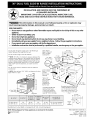 1
1
-
 2
2
-
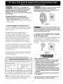 3
3
-
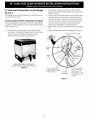 4
4
-
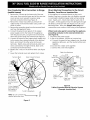 5
5
-
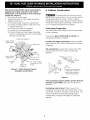 6
6
-
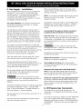 7
7
-
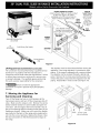 8
8
-
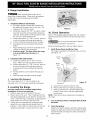 9
9
-
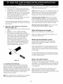 10
10
-
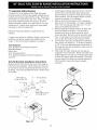 11
11
-
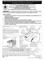 12
12
-
 13
13
-
 14
14
-
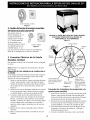 15
15
-
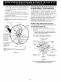 16
16
-
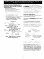 17
17
-
 18
18
-
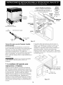 19
19
-
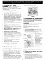 20
20
-
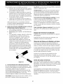 21
21
-
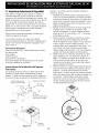 22
22
-
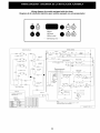 23
23
-
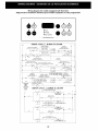 24
24
-
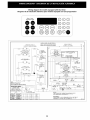 25
25
-
 26
26
-
 27
27
-
 28
28


Frigidaire GLCS376CBA Guía de instalación
- Categoría
- Hornos
- Tipo
- Guía de instalación
- Este manual también es adecuado para
en otros idiomas
Artículos relacionados
-
Frigidaire PLES389CCB Guía de instalación
-
-
Frigidaire FCS367CHSC Guía de instalación
-
-
-
Frigidaire CPDS3085KF El manual del propietario
-
-
Frigidaire FGDS3065PF Guía de instalación
-
Frigidaire FED355ABC Guía de instalación
-
Otros documentos
-
Kenmore 79075503206 Guía de instalación
-
Kenmore Pro 79079523605 Guía de instalación
-
-
Electrolux EI30DS55LBB Guía de instalación
-
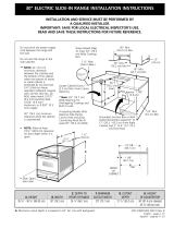 Kenmore Elite 79046822100 Guía de instalación
-
-
Electrolux EW30DS6CGW3 Guía de instalación
-
-
Kenmore 79046633602 Guía de instalación
-
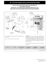 Kenmore Elite 79099513307 Guía de instalación

