
INSTALLATIONAND SERVICEMUSTBEPERFORMEDBY
A QUALIFIED INSTALLER.
IMPORTANT: SAVE FOR LOCAL ELECTRICAL INSPECTOR'S USE.
READ AND SAVE THESE INSTRUCTIONS FOR FUTURE REFERENCE.
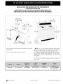
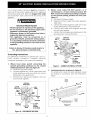
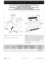
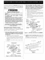
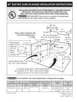
40 1/8" Min.
I01,9 cm Min.
30" Min.**
(76,2 cm Min,)
27¾"
. with handle
B _(70.5 c
18" Min, 13" Min,
(45.7 cm Min.) (33 cm Min.)
Grounded 24" Min.
Wall Outlet (61 cm Min.)
47 V4" Max.
(120 cm)
43¾"
(111,1 cm)
with larger__
door open _
feet extended
(91.4 cm)
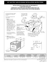
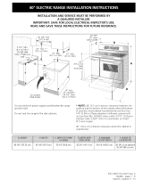
Do not pinch the power supply cord between the range
and the wall.
Do not seal the range to the side cabinets.
**NOTE: 24" (61 cm) minimum clearance between the
cooktop and the bottom of the cabinet when the bottom
of wood or metal cabinet is protected by not lessthan
1/4" (0.64 cm) flame retardant millboard covered with not
less than No, 28 MSG sheet metal, 0.015" (0,4 mm)
stainless steel, 0,024" (0,6 mm) aluminum, or 0.020" (0,5
mm) copper,
30" (76.2 cm) minimum clearance when the cabinet is
unprotected,
36°(91.4cm) 40t/8"(101.9cm) 25112"(64.8cm) 433/4"(111.1cm) 40W' (102.2cm) 36°(91.4cm)standard
353/8"(90cm)rain.
_ Recycled paper Printed in Canada P/N 318200870 (0006) Rev.D

Important Notes to the Installer
1, Read all instructions contained in these installation
instructions before installing range,
2, Remove all packing material from the oven
compartments before connecting the electrical supply to
the range.
3, Observe all governing codes and ordinances.
4, Be sure to leave these instructions with the consumer.
Important Note to the Consumer
Keep these instructions with your owner's guide for future
reference.
IMPORTANT SAFETY
INSTRUCTIONS
• Be sure your range is installed and grounded
properly by a qualified installer or service
technician.
• This range must be electrically grounded in
accordance with local codes or, in their absence,
with the National Electrical Code ANSI/NFPA No.
70--latest edition.
• The installation of appliances designed for
manufactured (mobile) home installation must conform
with Manufactured Home Construction and Safety
Standard, title 24CFR, part 3280 [Formerly the Federal
Standard for Mobile Home Construction and Safety,
title 24, HUD (part 280)] or when such standard is not
applicable, the Standard for Manufactured Home
Installation 1982 (Manufactured Home Sites,
Communities and Setups), ANSI Z225.1/NFPA 501A-
latest edition, or with local codes.
• Make sure the wall coverings around the range
can withstand the heat generated by the range.
@
Yl_v_,vl'-! ;i _IIL_[€
• ALL RANGES
CAN TIn
• INJURYTO
PERSONS
COULD
RESULT.
• INSTALL ANTI-
TIP DEVICE
PACKEDWITH
RANGE.
FIVAV-'111_II_[€IToREDUCE
THE RISKOF TIPPINGOF
THE RANGE, THE RANGE
MUST BE SECURED BY
PROPERLY INSTALLEDANTI-
TIPBRACKET(S)PROVIDED
WITH THE RANGE. TO
CHECK IFTHE BRACKETIS)
ISINSTALLEDPROPERLY,
REMOVE THE LOWER
PANEL OR STORAGE
DRAWERAND VERIFYTHAT
THE ANTI-TIP BRACKET(S)
ISENGAGED.
• Before installing the range in an area covered
with linoleum or any other synthetic floor
covering, make sure the floor covering can
withstand heat at least 90°F/32°C above room
temperature without shrinking, warping or
discoloring. Do not install the range over carpeting
unless you place an insulating pad or sheet of !/4" (6.4
mm) thick plywood between the range and carpeting.
FI,w'-_:t_ll_.[HNever leave children alone or
unattended in the area where an appliance is in use.
As children grow, teach them the proper, safe use of all
appliances, Never leave the oven door open when the
range is unattended,
FIV,'/'-l:t:ll:[dStepping, leaning or sitting on the
door(s) or drawer of this range can result in serious
injuries and can also cause damage to the range.
• Do not store items of interest to children in the
cabinets above the range. Children could be
seriously burned climbing on the range to reach items,
• To eliminate the need to reach over the surface
units, cabinet storage space above the units
should be avoided.
• Do not use the oven as a storage space. This
creates a potentially hazardous situation.
• Never use your range for warming or heating the
room. Prolonged use of the range without adequate
ventilation can be dangerous.
• Do not store or use gasoline or other flammable
vapors and liquids near this or any other
appliance. Explosions or fires could result.
• Reset all controls to the "off" position after using
a programmable timing operation.
• Save 4 shipping bolts from range packaging to
use as leveling legs for range.
Two anti-tip brackets MUST be removed from
lower back of range and MUST be installed. For
detailed instructions, see page 8.
FOR MODELS WITH SELF-CLEAN FEATURE:
• Remove broiler pan, food and other utensils
before self-cleaning the oven. Wipe up excess
spillage, Follow the precleaning instructions in the
Owner's Guide.
2

Power Supply Cord Kit
The user is responsible for connecting the power supply
cord to the connection block located behind the back
panel access cover.
This appliance may be connected by means of
permanent "hard wiring" (flexible armored or
nonmetallic shielded copper cable), or by means of a
power supply cord kit. Onlya power supply cord kit
rated at 125/250 volts minimum, 40 amperes and
marked for use with ranges shall be used. Cord must
have 3 conductors (see Figures 1 and 5).
Mobile home installation, or areas where local codes do
not permit grounding through neutral, a 4 conductor
power supply cord kit rated at 125/250 volts minimum,
40 amperes and marked for use with ranges should be
used (see Figures 2 and 6).
Terminals on ends of wires must either be closed loop or
open-end spade lugs with upturned ends. Cord must
have strain relief clamp.
_Risk of fire or electrical shock may be
incurred if an incorrect size range cord kit is used,
the Installation Instructions are not followed, or
the strain relief bracket is discarded,
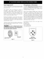
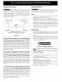
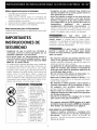
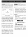
3-_ire Wall
3-Wire Power Receptacle
Supply Cord Kit
Figure 1
If Connecting to a 4-Wire System
This range is manufactured with the ground connected to
the cabinet. The ground must be revised so the green
ground wire of the 4-wire power supply cord is
connected to the cabinet. See "Four Conductor Wire
Connection to Range" on page 4.
When a 4-wire receptacle of NEMA Type 14-50R is used
(see Figure 1), a matching U.L.-listed, 4-wire, 250 volt,
40 ampere range power supply cord (pigtail) must be
used. This cord contains 4 copper conductors with ring
terminals at the appliance end, terminating in a NEMA
Type 14-50P plug on the supply end. The fourth (ground)
conductor must be identified by a green or green/yellow
cover and the neutral conductor by a white cover. Cord
should be Type SRD or SRDT with a U.L.-listed strain
relief and be at least 4 feet long.
The minimum conductor sizes for the copper 4-wire
power cord are:
40 ampere circuit
2 No. 8 conductors
1 No. 10 white neutral
1 No. 8 green ground
4-Wire Wall
Receptacle (14-50R)
Figure 2
3

Electrical Connection to the Range
This appliance is manufactured with the neutral terminal
connected to the frame.
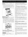
1. Three Conductor Wire Connection to Range
If local codes permit connection of the frame
grounding conductor to the neutral wire of the
copper power supply cord (see Figure 4).
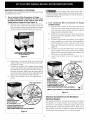
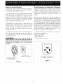
A, Remove the 3 screws at the lower end of the
rear wire cover, then raise the lower end of the
rear wire cover (access cover) upward to expose
range terminal connection block (see Figure 3),
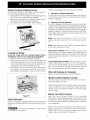
TO GAIN ACCESS TO LOWER TERMINAL BLOCK
BEND LOWER BACK COVER PLATE ALONG ROW
OF HOLES SHOWN HERE.
Figure 3
B, Remove the 3 loose nuts (after you removed the
rubber band) on the terminal block using 3/8"
nut driver or socket.
C, Connect the neutral of the copper power supply
cord to the center silver-colored terminal of the
terminal block, and connect the other wires to
the outer terminals. Math wires and terminals by
color (red wires connected to the right terminal,
black wires connected to the left terminal),
D, Lower the terminal cover and replace the 3
screws.
Silver Colored Terminal
A CONSUMER
SUPPLIEDSTRAIN-RELIEF
MUST BE INSTALLED
AT THIS LOCATION
TO FUSEDDISCONNECTBOX OR
APPROVEDWIRING DEVICEFOR
3-WIRE COPPERPOWERSUPPLYCORD (40 AMPERES)
Figure 4
Ilri_!_l_lDo not loosen nuts, wich secure the
factory-installed range wiring to terminal block while
connecting range, Electrical failure or lossof electrical
connection may occur.
2J
Four Conductor Wire Connection to Range
(mobile homes)
A, Remove the 3 screws at the lower end of the
rear wire cover, then raise the lower end of the
rear wire cover (access cover) upward to expose
range terminal connection block,
B, Remove the ground strap from the terminal
block and from the appliance frame, Retain the
ground screw,
C, Connect the ground wire (green) of the copper
power supply cord to the frame of the appliance
with the ground screw, using the hole in the
frame where the ground strap was removed (see
Figure 5),
D, Connect the neutral (white) wire of the copper
power supply cord to the center silver-colored
terminal of the terminal block, and connect the
other wires to the outer terminals.
E, Lower the terminal cover and replace the 3
screws,
SilverColored Terminal
A CONSUMER
SUPPLIEDSTRAIN-RELIEF
MUST BEINSTALLED
AT THIS LOCATION
TO FUSEDDISCONNECTBOX OR
APPROVEDWIRING DEVICEFOR "_
4-WIRE COPPERPOWERSUPPLYCORD (40 AMPERES)
NOTE: BESURETO REMOVE THE SUPPLIEDGROUNDING STRAP _
Figure 5
Electrical Connection to the Residence
Electrical System
The appliance may be connected directly to the fused
disconnect or circuit breaker box through flexible,
armored or nonmetallic sheathed copper cable (with
grounding wire), Locate the junction box to allow 2 to 3
feet of slack in the line so that the range can be moved
if servicing is ever necessary. Do not cut the conduit,

A U.L.-listedconduitconnectormust be provided at
each end of the power supply cable (at the appliance
and at the junction box). Wire sizes (copper wire only}
and connections must conform with the rating of the
appliance.
Electrical Shock Hazard
• Electrical ground is required on this appliance.
• Do not connect to the electrical supply until
appliance is permanently grounded.
• Disconnect power to the junction box before
making the electrical connection.
• This appliance must be connected to a
grounded, metallic, permanent wiring system,
or a grounding connector should be connected
to the grounding terminal or wire lead on the
appliance.
Failure to do any of the above could result in a
fire, personal injury or electrical shock.
Grounding Instructions
For appliances connected to a junction box, use U.L.-
listed conduit connectors. Complete electrical
connection according to local codes and ordinances,
1.
Where local codes permit connecting the
cabinet-grounding conductor to the neutral
(white)junction box wire (see Figure 6)
A. Disconnect the power supply.
B. Connect together the 3 wires: green (bare) and
white appliance cable wires and the neutral
(white) wire in the junction box.
C. Connect the 2 black wires together, then the
two red wires together.
Cablefrom
Power Supply
Ground
Rad_
_-==-Junction
Box
GreenWire Conduit
Cable from Connector
Range (or CSAlisted)
Figure 6 - GROUNDED NEUTRAL
2.
Where local codes DO NOT permit, or if
connecting to a 4-wire electrical system, DO
NOT connect the cabinet-grounding conductor
to the neutral (white)junction box wire (see
Figure 7)
A. Disconnect the power supply.
B. Separate the bare copper and white appliance
cable wires.
C. Connect the white appliance cable wire to the
neutral (white) wire in thejunction box.
D. Connect the 2 black wires together, then the
two red wires together.
E. Connect the bare copper grounding wire to the
grounding wire in the junction box.
Junction Cable from
Power Supply
Bare
Wire
Wire
White
re
e
_--U.L.-listed
Conduit
Cable from Connector
Range (or CSA listed)
Figure 7 - 4-WIRE ELECTRICAL SYSTEM
.
Locate junction box as shown in Figure 8.
If a service cord is used, the wall receptacle should
be located in accordance with the dimensions
below.
7" Max.
(17.8 cm
Center
Line of
Range
(s020,,crn)/ wALL
Center
Line of
Locate Electrical Hook*up Range
Inside Shaded Area
Figure 8
5

Cabinet Construction
[Ir_l!_T_To eliminate the risk of burns or fire by
reaching over heated surface units, cabinet storage
space located above the range should be avoided. If
cabinet storage space is to be provided, the risk can be
reduced by installing a range hood that projects
horizontally a minimum of 5" (12.7 cm) beyond the
bottom of the cabinet.
o
Center
Line of
Range
0
Follow instructions for
the type of installation you have
Figure 9
If range will be installed with a cabinet on both
sides, mark center of cabinet opening on floor. If back
of range will not be flush with the wall (the location
of the outlet may not allow the range to be positioned
against the wall), mark on the floor where the back
edge of the range will be. Place the template on the
floor aligning the template centerline with the centerline
marked in the cabinet opening. Place the back edge of
the template against the rear wall or the line marked for
the rear of the range.
If range will be installed with a cabinet on one side
only, move the range into final position, Mark on the
floor along the side of the range that is not against the
cabinet. If back of range will not be flush with the
wall (the location ofthe outlet may not allow the range
to be positioned against the wall), mark on the floor
where the back edge of the range will be. Place the
template on the floor and align side of template with the
line marked on the floor. Align the back of the template
with the rear wall or the line marked for the rear of the
range.
If range will not be installed against a cabinet,
move range into final position. Mark on the floor along
both sides of the range. If back of range will not be
flush with the wall (the location of the outlet may not
allow the range to be positioned against the wall), mark
on the floor where the back edge of the range will be.
Place the template on the floor and align sides of
template with the lines marked on the floor. Align the
back of the template with the rear wall or the line
marked for the rear of the range.
Range Installation
_'_rl'_l_lWhen unpacking the range, do not discard
the 4 shipping bolts. These are to be replaced on the
unit for use as leveling legs and height adjustments.
NOTE:
1. The back of the range may be installed directly
against the rear wall of the structure.
2. These ranges conform to U.L requirements for "0"
spacing from the range to adjacent vertical walls
above the countertop level. However, to reduce
possible scorching of vertical walls and to minimize
potential fire hazards under abnormal surface unit
use conditions such as high heat or no pans, a
minimum of 2" (5.1 cm) spacing should be provided
on both sides of the cooktop.
Preparation
1. Put on safety glasses and gloves. Remove oven racks
and parts package from inside the oven. Remove
shipping materials, tape and protective film from the
range.
2. Take 4 cardboard corners from the carton. Stack one
on top of another. Repeat with other 2 corners.
Place corners lengthwise on the floor in back of the
range to support range.
Excessive Weight Hazard
Use 2 or more people to move and install
range.
Failure to follow this instruction can result in
back or other injury.
3. Firmly grasp the range and gently lay it on its back
on the cardboard corners.
4. Remove and save the 4 shipping bolts from the skid.
Discard skid.
5. Install 4 shipping bolts as leveling legs.
6. Place cardboard in front of the range. Carefully
stand the range upright on cardboard.
7. Adjust the leveling legs to a point where the range
base does not touch the floor.
6

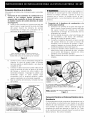
Remove Cooktop Shipping Screws
The liftable cooktop on this range is locked down to
prevent shipping damage (see Figure 10).
1. Open both doors and locate the two shipping screws
at the front end, underneath the cooktop.
2. Remove and discard the two shipping screws using a
#2 Robertson or Phillips head screwdriver.
3. The cooktop can now be lifted, when needed.
Figure 10
Leveling the Range
Level the range and set cooktop height before
installation in the cut-out opening (if applicable).
1. Install an oven rack in the center of the oven.
2. Place a level on the rack. Take 2 readings with the
level placed diagonally in one direction and then the
other. Level the range, if necessary, by adjusting the
4 leg levelers with a wrench (see Figure 13).
3. Slide range into cut-out opening and double check
for levelness. If the range is not level, pull unit out
and readjust leveling legs, or make sure floor is level.
Figure 11
Check Operation
Refer to the Owner's Guide packaged with the range for
operating instructions and for care and cleaning of your
range.
IIr_r_Do not touch the elements. They may be
hot enough to cause burns.
Remove all packaging from the oven before testing.
1. Operation of Surface Elements
Turn on each of the four surface elements and check to
see that they heat. Check the surface element indicator
light(s), if equipped.
2. Operation of Oven Elements
The oven is equipped with an electronic oven control. Each
of the functions has been factory checked before shipping.
However, it issuggested that you verify the operation of the
electronic oven controls once more. Refer to the Owner's
Guide for operation. Follow the instructions for the Clock,
Timer, Bake, Broil, Convection (some models) and Clean
(some models) functions.
Bake-After setting the oven to 350°F (177°C) for
baking, the lower element in the oven should become
red.
Broil-When the oven is set to BROIL, the upper element
in the oven should become red.
Clean (some models)-When the oven is set for a self-
cleaning cycle, the upper element should become red
during the preheat portion of the cycle. After reaching
the self-cleaning temperature, the lower element will
become red.
Convection (some models)-When the oven is set to
CONV. BAKE/ROAST at 350°F (177°C), both elements
cycle on and off alternately and the convection fan will
turn. The convection fan will stop turning when the oven
door is opened during convection baking or roasting.
When All Hookups are Complete
Make sure all controls are left in the OFFposition.
Model and Serial Number Location
The serial plate is located on the oven front frame
behind the large oven door.
When ordering parts for or making inquiries about your
range, always be sure to include the model and serial
numbers and a lot number or letter from the serial plate
on your range.
Before You Call for Service
Read the Avoid Service Checklist and operating
instructions in your Owner's Guide. It may save you time
and expense. The list includes common occurrences that
are not the result of defective workmanship or materials
in this appliance.
Refer to the warranty and service information in your
Owner's Guide for our phone number and address.
Please call or write if you have inquiries about your
range product and/or need to order parts.
7

Important Safety Warning
To reduce the risk of tipping of the range, the range
must be secured to the floor by properly installed anti-tip
brackets and screws packed with the range. Those parts
are located in a plastic bag in the oven. Failure to install
the anti-tip brackets will allow the range to tip over if
excessive weight is placed on an open door or if a child
climbs upon it. Serious injury might result from spilled
hot liquids or from the range itself.
Follow the instructions below to install the anti-tip
brackets,
If range is ever moved to a different location, the anti-tip
brackets must also be moved and installed with the
range, To check for proper installation, see step 5.
Tools Required:
5/16" (8 mm) Nutdriver or Flat Head Screwdriver
Adjustable Wrench
Electric Drill
3/16" (4.8 mm) Diameter Drill Bit
3/16" (4.8 mm) Diameter Masonry Drill Bit (if installing
in concrete)
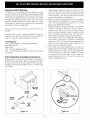
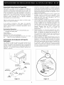
Anti-Tip Brackets Installation Instructions
Brackets attach to the floor at the back of the range to
hold both rear leg levelers. When fastening to the floor,
be sure that screws do not penetrate electrical wiring or
plumbing. The screws provided will work in either wood
or concrete.
1. Unfold paper template and place it flat on the floor
with the back and side edges positioned exactly
where the back and sides of range will be located
when installed. (Use the diagram below to locate
brackets if template is not available.)
2, Mark on the floor the location of the 4 mounting
holes shown on the template. For easier installation,
3/16" (4.8 mm) diameter pilot holes 1/2" (1.3 cm)
deep can be drilled into the floor,
3. Remove template and place brackets on floor with
turned up flanges to the front, Line up holes in
brackets with marks on floor and attach with 4
screws provided. Brackets must be secured to solid
floor, If attaching to concrete floor, first drill 3/1 6"
(4.8 mm) dia. pilot holes using a masonry drill bit.
4, Level range if necessary, by adjusting 4 leg levelers
with wrench, (See Figure 13 below.) A minimum
clearance of 1/8" (3,2 mm) is required between the
bottom of the range and the rear leg levelers to
allow room for the anti-tip brackets.
5. Slide range into place making sure rear legs are
trapped by ends of brackets. Range may need to be
shifted slightly to one side as it is being pushed back
to allow rear legs to align with brackets. You may
also grasp the top rear edge of the range and
carefully attempt to tilt it forward to make sure
range is properly anchored,
SLIDE
BACK
ANTI-TIp
BRACKET
\ i 3/4"
. ._?-,.. (1.9 cm)
BRACKET i_v f.-" "--.._'_:....
,. f*'(1.§ c SIDES
f
,. m) OF
,, ...... _RANGE
3/4 j,r -.....-..
(1.9 cm) ""-.?'_"
Figure 12 Figure 13
8

LA INSTALACION Y EL SERVICIO DEBEN SER EFECTUADOS POR
UN INSTALADOR CALIFICADO.
IMPORTANTE: GUARDE ESTAS INSTRUCCIONES PARA USO DEL
INSPECTOR LOCAL DE ELECTRICIDAD.
LEA Y GUARDE ESTAS INSTRUCCIONES PARA REFERENCIA FUTURA.
40 1/8" M/n,
I01,9 cm
30" MJn.**
(76,2 cm Min,)
13" Min,
(45.7 cm MIn.) (33 cm M/n.)
Tomacomiente 24" Min,
de pared (61 cm Min.)
puesto a tierra
273A ,,
_on la manija
B "_(70.5 cm)
_ 6
47 _/4" M_x. con las patas
(120 cm) extendidas
(91.4 cm)
43 3A'
(111.1 :m_
con la puerta
grande abierta
No pellizque el cordon electrico entre la estufa y la
pared,
No selle la estufa a los armarios de lado.
**NOTA: Un espacio minimo de 24" (61 cm) entre la
superficie de la estufa y el rondo del armario cuando el
rondo del armario de madera o metal eat8 protegido por
no menos de 1/4" (0.64 cm) de madera resistente al
fuego cubierta por una lamina metSlica de MSG, numero
28, 0,015" (0,4 mm) de acero inoxidable, 0.024" (0.6
mm) de aluminio, O 0,02" (0,5 mm) de cobre.
Un espacio minimo de 30" (76.2 cm) cuando el armario
no est8 protegido.
36°(91.4cm) 40t/_*(101.9cm) 25W'(64.8cm) 433/4"(111.1cm) 40W'(102.2 cm) 36"(91.4cm) normal
35318"(90cm) min.
_ Papel reciclado Imprese en Canada P/N 318200870 (0006) Rev.D

Notas importantes para el Instalador
1, Lea todas las instrucciones contenidas en este manual
antes de instalar la estufa,
2, Saque todo el material usado en el embalaje del
compartimiento del homo antes de conectar el
suministro electrico a la estufa,
3, Observe todos los c0digos y reglamentos pertinentes,
4, Deje estas instrucdones con el comprador,
Nora Importante para el Consumidor
Conserve estas instrucciones y el Manual del Usuario para
referencia futura,
IMPORTANTES
INSTRUCCIONES DE
SEGURIDAD
• Aseg_rese de que la estufa sea instalada y
conectada a tierra en forma apropiada por un
instalador calificado o por un t_cnico.
• Esta estufa debe set electricamente puesta a
tierra de acuerdo con los codigos locales, o en su
ausencia, con el Cbdigo Electrico Nacional ANSI/
NFPA No. 70, _ltima edicion.
• La instalacion de aparatos diser_ados para instalaci0n
en casas prefabricadas (moviles) debe conformar con
el Manufactured Home Construction and Safety
Standard, titulo 24CFR, parte 3280 [Anteriormente el
Federal Standard for Mobil Home Construction and
Safety, titulo 24, HUD (parte 280)] o cuando tal
estandar no se aplica, el Standard for Manufactured
Home Installation 1982 (Manufactured Home sites,
Communities and Setups), ANSI Z225,1/NFPA 501A-
edicion mas reciente, o con los codigos locales,
• TODAS LAS
ESTUFAS
PUEDEN
VOLCARSE
•ESTO
PODRIA
@ RESULTAR
EN LESIONE_<
PERSONALES.
• INSTALE EL
DISPOSITIVO
ANTIVUELCOS
QUE SE HA
E /IPACADO
JUNTO CON
ESTA
ESTUFA
_ARA REDUCIR EL
_IESGO DE QUE SE
VUELOUE LA :S#UFA
qAY OUE ASEGURARLA
ADECL ADAMENTE
COLOCANDOLE OS
SOPORTES
ANTIVUELCO QUE SE
_ROPORCIONAN. PARA
COMPROBAR S ESTOS
:STAN NSTALADOS Y
APRETADO_ EN SU
UGAR COMO SE
]EBE ASE EL BORDE
[RASERC SUPERIOR
DE _A :STUFA
CUIDADOSAMENTE
NC INELA HACIA
ADELANTE PARA
ASEGURAR OUE LA
:STUFA SE ANCLE
• Asegt_rese de que el material que recubre las
paredes alrededor de la estufa, pueda resistir el
calor generado pot la estufa.
• Antes de instalar la estufa en un _irea cuyo piso
este recubierto con linoleo u otro tipo de piso
sintetico, asegdrese de que estos puedan resistir
una temperatura de pot Io menos 90°F sobre la
temperatura ambiental sin provocar
encogimiento, deformacibn o decoloracibn. No
instale la estufa sobre una alfombra al menos que
coloque una plancha de material aislante de por Io
menos 1/4 pulgada, entre la estufa y la alfombra,
r_Nunca deje ni_os solos o
desatendidos en un _irea donde un artefacto esta
siendo usado. A medida que los niflos crecen,
enser_eles el uso apropiado y de seguridad para todos los
artefactos, Nunca deJe la puerta del horno abierta
cuando la estufa esta desatendida,
_No se pare, apoye o siente en las
puertas o cajones de esta estufa pues puede
resultar en serias lesiones y puede tambien causar
da_o a la estufa.
• No almacene articulos que puedan interesar a los
ni_os en los gabinetes sobre la estufa. Los niflos
pueden quemarse seriamente tratando de trepar a la
estufa para alcanzar estos articulos,
• Los gabinetes de almacenamiento sobre la estufa
deben ser evitados, para eliminar la necesidad de
tenet que pasar sobre los elementos superiores de
la estufa para Ilegar a ellos.
• No use el homo como espacio de almacenaje. Esto
creara una situacion potencialmente peligrosa,
• Nunca use la estufa para calentar el cuarto. El uso
prolongado de la estufa sin la adecuada ventilaci0n
puede resultar peligroso,
• No almacene ni utilice gasolina u otros vapores y
liquidos inflamables en la proximidad de _ste o
de cualquier otro artefacto el_ctrico. Puede
provocar incendio o explosion,
• Ajuste todos los controles a la posicibn "OFF"
(apagada) despues de haber hecho una operacion
con tiempo programado.
• Guarde los 4 pernos del empaque de la estufa
para usarlos como paras niveladoras.
Dos soportes antivuelco DEBEN quitarse de la parte
de inferior trasera de la estufa y DEBEN ser instalados.
Para detalles, vea instrucciones en la pagina 8.
PARA MODELOS AUTOLIMPIANTES:
• Saque la asadera, alimentos o cualquier otto
utensilio antes de usar el ciclo de autolimpieza
del horno. Limpie todo exceso de derrame de
alimentos, Siga lasinstruccionesde prelimpiadoenel
Manual del Usuario,
2

Juego de Cordbn El_ctrico
El consumidor tiene la responsabilidad de conectar el
cordon electrico al bloque de conexion ubicado detras de
la cubierta de acceso del panel trasero,
Este artefacto puede ser conectado mediante "cableado
rigido" permanente (un cable fexible escudido o un cable
de cobre escudido no metalico) o un "juego de cordon
electrico", Se usara solamente un juego de cordon
electrico para 125/250 voltios, 40 amperios y marcado
para uso con estufas, EIjuego de cordon electrico debe
tener 3 conductores (yea Figuras 1 y 5),
La instalaci0n en casas moviles, o areas donde los
codigos locales no permiten puesta a tierra a traves del
conductor neutro, se debe usar un juego de cordon
electrico de cuatro (4) conductores para 125/250 voltios
minimo, 40 amperios y marcado para uso con estufas
(yea Figuras 2 y 6),
Los terminales en las puntas de los alambres deben set
de circuito cerrado o de orejeta de pala punta abierta y
con las puntas vueltas hacia arriba, El cordon debe tener
kin anclaje del cable,
Puede ocurrir riesgo de incendio o
choque el_ctrico si se usa un juego de cordon de
estufa de tama_o incorrecto, si las instrucciones de
instalacion no son seguidas o si no se usa el anclaje
del cable,
Receptaculo de
Pared de 3 Alambres
Juego de Cordon de
Suministro Electrico de
3 Alambres
Figura 1
Si Hace Conexibn a un Sistema de 4 Alambres
Esta estufa esta fabricada con Ia puesta a tierra conectada
al gabinete, La puesta a tierra tiene que revisarse para que
el alambre verde de puesta a tierra de tin cordon de suministro
electrico de 4 alambres se conecte al gabinete, Vea
"Conexion de Conductor de 4 Alambres a la Estufa" en
pagina 4,
Cuando se usaun receptaculo de 4 alambres tipo NEMA 14-
50R (vea Figura 1), se debe usar un cordon electrico (tipo
trenza) para estufa de 4 alambres, de tipo U,L,de 250 voltios
y 40 amperios, Estecordon contiene 4 conductores de cobre
con anillos terminales al extremo del aparato que finalizan
en un enchufe NEMA tipo 14-50P en el extremo del suministro
de electricidad, El cuarto conductor (de puesta a tierra) debe
identificarse por una cubierta verde o verde/amarilla y el
conductor neutral por una cubierta blanca, Elcordon de ser
de Tipo SRDo SRDTcon un espacio de tirantez tipo Ui, que
debe ser de un minimo de 4 pies de largo,
Los calibres minimos de los conductores para un cordon se
suministro de 4 alambres son:
Circuito de 40 amperios
2 conductores No, 8
1 blanco neutral No, 10
1 verde de puesta a tierra No, 8
Receptaculo de Pared de 4
AIambres (14-50R)
Figura 2
3

Conexibn El_ctrica de la Estufa
Este aparato se fabrica con el terminal neutro conectado
al marco,
1, ConexiOn de tres alambres de conduccibn a la
estufa si los cbdigos locales permiten la
conexiOn del conductor de tierra del marco con
el alambre neutro del cordon electrico de cobre
(yea Figura 4),
A, Quite los tres tornillos en la parte rTras baja del
panel trasero, luego levante la parte mas baja
del panel trasero (la cubierta de acceso)
exponiendo el bloque de conexiones de los
terminales de la estufa (vea Figura 3),
PARA OBTENER ACCESO AL TAB/ERO iNFERIOR DE
BORNES, DOBLE HACiA ATRAS LA PLACA DE LA CUBIERfA
TRASERA POR LA FILA DE AGUJEROS QUE SE V£N AQU[
Figura 3
B, Quinte las tres tuercas desatadas (despues de
remover la cinta de goma) sobre el bloque
terminal usando un destornillador o una llave de
casquillo de 3/8",
C, Conecte el cable neutro del cordon electrico de
cobre al terminal de color de plata en el centro
del bloque, y conecte los otros cabels a los
terminales laterales, Empareje los cables ylos
terminales segun el color (cables rojos
conectados con el terminal derecho, cables
negros conectados con el terminal izquierdo),
D, Baje la cubierta del terminal y reinstale los tres
(3) tornillos,
Terminal de color plata
EN ESTE LUGAR SE DEBE
INSTALAR UN ANCLAJE DE
CABLE SUMtNISTRADO
POR EL CLIENTE
puesta a
A LA CAJA DE FUSIBLES O UN MECANISMO DE INSTALACION DE
ALAMBRES APROBADO PARA UN CORDON ELECTRICO DE COBRE
PARA TRES ALAMBRES (40 AMPERIOS),
Figura 4
FI_I_;I=["I:_I['_[°];INo desate las tuercas que sujetan el
alambraje de cocina que ha sido instalado en la
factoria al bloque terminal, cuando se hace la
conexion de la cocina, Se puede ocurrir el mal
funcionamiento o una interruption del suministro
electrico,
2, ConexiOn de 4 alambres de conducciOn a la
estufa (casas mOviles)
A, Quite Ios tres tornillos en la parte rTrasbaja del
panel trasero, luego levante la parte mas baja
del panel trasero (la cubierta de acceso)
exponiendo el bloque de conexiones de los
terminales de la estufa,
B, Quite la banda de puesta a tierra del bloque de
los terminales y del marco del artefacto,
Retenga el tornillo de puesta a tierra,
C, Conecte el alambre de puesta a tierra (verde)
del cordon electrico de cobre al marco del
artefacto con el tornillo de puesta a tierra,
usando el aguJero en el marco donde se quito el
tornillo de puesta a tierra (vea figura 5),
D, Conecte el alambre neutro (blanco) del cordon
electricode cobrealterminal de color de plata
en el centro del bloque y conecte los otros
alambres al los terminales laterales,
E, Baje la cubierta de acceso y vuelva a poner los 3
tornillos,
Terminal de color plata
EN ESTE LUGAR SE
DEBE INSTALAR UN
ANCLAJE DE CABLE
SUMINtSTRADO POR EL
',LIENTE
tierra (cable
A LA CAJA DE FUSIBLES O UN MECANISMO DE
INSTALACION DE ALAMBRES APROBADO PARA UN
L:l
CORDON ELECTRICO DE COBRE PARA 4 ALAMBRES (40
AMPERIOS).
NOTA: ASEGURESE DE QUITAR LA BANDA DE PUESTA A
TIERRA PROVISTA. Figura 5
ConexiOn El_ctrico al Sistema El_ctrico de la
Residencia
El electrodomestico debe conectarse directamente con la
caja de fusibles o cortacircuitos por medio de un cable
flexible de cobre blindado o con cubierta no-metalica
(con alambre de puesta a tierra), Ubique la caja de
empalmes de modo que permita un flojo de 2 o 3 pies
en la cuerda para que se pueda mover la estufa si hace
falta el servicio, No corte el conducto,

UnconectorlistadoporULtiene queponerseencada
extremodelcordonelectrico(enelelectrodomesticoy la
cajade fusibles),Lostamar_osde alambres(s61ode
cobre) y las conexiones deben conformarse con la
calificacion del electrodomestico,
Riesgo de Choque EI6ctrico
• Una puesta a tierra est_i requerido en este
aparato.
• No Io conecte a la corriente electrica hasta que
el aparato haya sido puesto a tierra
permanentemente,
• Desconecte la corriente el6ctrica a la caja de
empalmes antes de hacer la conexion electrica.
• Este aparato debe estar conectado con un
sistema de alambres puesto en tierra, metalico y
permanente o un conector de puesta a tierra
debe conectarse al terminal de puesta a tierra o
el alambre conductor en el aparato.
La falta de hacer cualquier de las cosas arriba
podrla resultar en un incendio, choque el6ctrico o
lesiones personales.
Instrucciones para la Puesta a Tierra
Para aparatos conectados a una caja de empalmes, use
conectores de conducto listados U,L, Complete la conexion
segun los codigos y ordenanzas locales,
1,
Donde los codigos locales permitan la conexibn
del conductor de gabinete - puesta a tierra con el
alambre neutro (blanco) de la caja de empalmes
(yea Figura 6)
A, Desconecte la fuente de alimentaci0n,
B, Junte y conecte los tres alambres, los alambres
de cables verde (pelados) y (neutral) blanco del
aparato y el alambre neutral blanco en la caJa de
empalmes,
C, Conecte los dos alambres negros, luego conecte
los rojos,
Cable de la fuente
de alimentaciOn
Alambres
j "t,. e a'mes
] ] \ Alambres
_JU blancos
_ Conductor de
union listado-UL
Cable de la estufa
Figura 6 - PUESTA A TIERRA NEUTRAL
2,
Donde los cbdigos locales NO Io permitan, o si se
esta conectando a un sistema electrico de 4
alambres - NO conectar el conductor de puesta a
tierra por el gabinete con el alambre neutro
(blanco) de la caja de empalmes (vea Figura 7)
A, Desconecte la fuente de alimentaci0n,
B, Separe los alambres de cobre desnudo y los
alambres blancos del aparato,
C, Conecte el alambre blanco del aparato con el
alambre neutro (blanco) en la caJa de empalmes,
D, Conecte los 2 alambres negros, luego los dos
alambres rojos,
E, Conecte el alambre desnudo de cobre de puesta
a tierra con el alambre de puesta a tierra en al
caja de empalmes,
Caja de Cable de la fuente de
empalmes _ _alimentaciOn
Alambres-. _
desnudo s
Plambres ,_ ,
Ala
desnudos
Alambres
Conducto de union
listado _U.L,
Cable de la estufa
Figura 7 - SISTEMA ELECTRIO DE 4 ALAMBRES
,
Localice la caja de empalmes como se ve en la
Figura 8, Si se usa Lm cordon de servicio, el
receptaculo de pared debe estar localizado segon
las medidas que se indican abajo,
DE LA ESTUFA
GO_:m)/ PARED
PISO
DE LA
ESTUFA
_BIOUE LO ELECTRICC
DENTRO D[L AREA
SOMBREADA
Figura 8
5

Construccibn de los Armarios
_Para eliminar el riesgo de quemaduras e
incendios al tocar superficies sobrecalentadas, se debe
evitar colocar espacio para armarios de almacenamiento
sobre las estufas con elementos al descubierto, Si se
instalan armarios sobre la estufa, se pueden reducir tales
riesgos instlando una campana purificadora que se
proyecta horizontalemente un mlnimo de 5" (12,7 cm)
mas afuera de la parte inferior de los armarios,
Center
Line of
Range
1
Siga las instrucciones para el tipo de
instalacion que usted tenga
Figura 9
Si la estufa se va a instalar con un armario a ambos lados,
marque el centro de la abertura del armario en el piso, Si la
parte trasera de la estufa no estara a ras con la pared (la
ubicacion del tomacorriente puede que no permita que la
estufa se pegue a ras con la pared), marque el piso donde
estara el border trasero de la estufa, Ponga el patron en el
piso, alineando la linea del centro del patron con la marca
en el centro de la abertura del armario, Ponga el borde
trasero del patron a ras contra la pared trasera o la linea
marcada para la parte de atras de la estufa,
Si la estufa se va a instalar con un armario a s61o un
lado, mueva la estufa a su posicion final, Marque el piso
por el lado de la estufa que no estara contra el armario, Si
la parte trasera de la estufa no estara a ras con la pared
(la ubicacion del tomacorriente puede que no permita que la
estufa se pegue a ras con la pared), marque el piso donde
el borde trasero de la estufa estar& Ponga el patron en el
piso y alinie el lado del patron con la llnea marcada en el
piso, Alinie la parte trasera del patron con la pared trasera o
la linea marcada para la parte de arras de la estufa,
Si la estufa no sera instalada junta contra un armario,
mueva la estufa a su posicion final. Marque el piso por los
dos lados de la estufa, Si la parte trasera de la estufa no
estara a ras con la pared (la ubicacion del tomacorriente
puede que no permita que la estufa se pegue a ras con la
pared), marque en el piso donde el borde trasero de la estufa
estara, Ponga el patron en el piso y alinie los lados del
patron con las llneas marcadas en el piso, Alinie la parte
trasera del patron con la pared trasera o la linea marcada
para la parte trasera de la estufa,
Instalacibn de la estufa
Mientras se desembala la estufa, ne
deseche los cuatro (4) pernos de embabalaje,
Reemplacelos como paras niveladoras y para ajustar la
altura de la unidad,
NOTA:
1, La parte trasera de la estufa puede set directamente
instalada a ras con la pared trasera de la estructura,
2, Estas estufas se conforman a los requerimientos U,L,
para espaciamiento "0" desde la estufa hasta las paredes
verticales adyacentes arriba del nivel del tablero, No
obstante, para reducir la posibilidad de quemar las
paredes verticalesy para disminuir el posible peligro de
incendio bajo condiciones anormales de uso de la tapa
con hornillas como alto calor o la ausencia de cazuelas,
se debe dejar un espacio de un minimo de 2" (5,1 cm)
en ambos lados de la tap&
Preparacibn
1, Pongase guantes y anteojos de seguridad, Quite las
parrillas del homo y paquete de piezas de adentro del
homo, Quite materiales de empaque, cinta y pelicula
protectiva de la estufa,
2, Tome las 4 esquinas de carton de la caja de empaque,
Coloquelas una encima de otra, Repita esta operacion
con las otras 2 esquinas, Coloque las esquinas
Iongitudinalmente en el piso detras de la estufa, para
apoyarla,
Peligro de Peso Excesivo
• Use 2 personas o mas para mover e instalar la
estufa.
• Si no cumple con esta instruccibn, puede resultar
en daho a la espalda u otra lesibn.
3, Sujete firmemente la estufa y suavamente recuestela en
su respaldo, en las esquinas de carton,
4, Quite y guarde los 4 pernos de empaque de la corredera,
Descarte la corredera,
5, Instale los 4 pernos de transporte como paras de
nivelacion,
6, Ponge el carton delante de la estufa, Cuidadosamente
pare la estufa en el carton,
7, Ajuste la paras de nivelacion al punto en que la base de
la estufa no toque el piso,
6

Quite Los Tornillos de Empaque de la
Superficie
La tapa levantable de esta estufa esta asegurada para abajo
para evitar dar_o durante el transporte (vea Figura 10),
1, Abra las dos puertas y Iocalice los dos tornillos de
transporte en el extremo delantero, debajo de la tap&
2, Quite y descarte los dos tornillos de transporte usando
un destornillador Phillips o Robertson #2,
3, Ahora se puede levantar la tapa, cuando sea necesario,
Figura 10
Nivelacibn de la estufa
Nivele la estufa y ajuste la altura de la estufa antes de
instalarla en la abertura,
1, Coloque una parrilla del homo en el centro del horno,
2, Ponga un nivel sobre la parrilla, Tome dos lecturas con el
nivel puesto diagonalmente en una direccion y despues
en la otra, Nivele Ia estufa, si es necesario, ajustando las
4 paras niveladoras con una Ilave de tuercas (Figura 12),
3, Deslice la estufa en la abertura y verifique la nivelacion
otra vez, Si la estufa no es nivelada, tire la unidad hacia
afuera y reajuste las paras niveladoras, o verifique que el
piso sea nivelado,
Figura 11
Comprobacibn del Funcionamiento
Consulte el Manual del Usuario incluido con la estufa
para instrucciones de operacion y instrucciones para el
cuidado y limpieza de su estufa,
r f_'j;l=t_:!_[e[']`'l No toque los elemento, Pueden estar
bastante calientes para causar quemaduras,
Quite todo el embalaje de la umidad antes de
comprobada,
1, Operaci6n de los elementos de superficie
Encienda cada uno de los cuatro elementos de superficie y
controle que se calienten, Verifique el funcionamiento de las
luces indicadoras de los elementos de superficie, si
equipadas,
2. Funcionamiento de los Elementos del Horno
El horno esta equipado con un control electronico, Cada
funcion ha sido probada en la fabrica antes del transporte,
Sin embargo, sugerimos que Ud, verifique el funcionamiento
de los controles del homo una vez mas, Vease el Manual
del Usuario para la operacion, Siga las instrucciones par el
Reloj, Minutero, Cocer, Asar, Coveccion (algunos modelos)
y las funciones de limpieza (algunos modelos),
Cocer/Bake-Despues de poner el horno a 350°F (177°C)
para cocer, el element inferior debe ponerse rojo
Asar/BroiI-Cuando esta puesto para BROIL, el elemento
superior se debe porter rojo,
Limpieza/Clean (algunos modelos)-Cuando el horno
esta puesto para un ciclo de auto-limpieza, el element
superior se pondra rojo durante el perlodo de
precalentamiento del ciclo, Despues de alcanzar la
temperatura de auto-limpieza, el elemento inferior se
pondra rojo,
Conveccion/Convection (algunos modelos)-Cuando el
horno se pone a CONV, BAKE/ROAST a 350°F (177°C),
los dos elementos se enciendan y se apagan alternando
en un ciclo y el ventilador se pone en marcha, El
ventilador de conveccion se parara cuando se abre la
puerta del horno durante el cocido o el asado por
conveccion,
Despues de Terminar la Instalacibn
Asegurese de que todos los controles esten en la posicion
OFF (apagada),
Ubicacibn del Nt_mero de Modelo y de Serie
La placa con el numero de serie esta ubicada en el
marco delantero del homo detras de la puerta del homo
grande,
Cuando haga pedidos de repuestos o solicite informacion
con respecto a su estufa, este siempre seguro de incluir
el numero de modelo y de serie y el numero o letra del
Iote de la placa de serie de su estufa,
Antes de Llamar al Servicio
Lea la seccion Lista de control de averias en su Manual
del Usuario, Esto le podra ahorrar tiempo y gastos, Esta
lista incluye ocurrencias comunes que no son el
resultado de defectos de materiales o fabricacion de este
artefacto,
Lea la garantla y la informacion sobre el servicio en su
Manual del Usuario para obtener el numero de telefono
gratuito y la direccion del servicio, Pot favor flame o
escriba si tiene pregumtas acerca de su estufa o necesita
repuestos,
7

Importante Advertencia de Seguridad
Para reducir el riesgo de que la estufa se vuelque, es
necesario asegurarla al piso instalando los soportes
antivuelco y los tornillos suministrados con la estufa, Las
piezas se encuentran en un saco de plastic0 en el homo,
Si no se instalan los soportes antivuelco, la estufa se
puede volcar si se coloca exceso de peso en una puerta
abierta o si un nino se sube a ella, Se pueden ocasionar
lesiones graves causadas por los liquidos calientes
derramados o por la estufa misma,
Siga las instrucciones que mas abajo se indican para
instalar los soportes antivuelco,
Si la estufa es movida a otro lugar, los soportes
antivuelco deben tambien ser movidos e instalados en la
estufa, Para controlar la instalacion apropiada, vea el
paso numero 5,
Herramientas Necesarias:
Llave de tuerca de 8/16" (8 mm) o destornillador para
tornillos de cabeza plana
Llave inglesa
Taladro electrico
Broca de 3/16" (4,8 mm) de diametro
Broca para taladro de mamposteria de 3/16" (4,8 mm)
de diam, (si se esta instalando en concreto)
Instrucciones de Instalacibn del Soporte
Antivuelco
Los soportes se fUan al suelo en la parte trasera de la
estufa para sujetar ambos niveladores de las paras
traseras, Cuando los este instalando al piso, asegurese de
que los tornillos no penetren el alambrado electrico o
plomeria, Los tornillos provistos pueden utilizarse en
madera o concreto,
SOPORTE
ANTIVUELCO
\ i 3/4"
9,_-_:-,,,. _,_(1.9 cm)
ANTIVUELCO [x_"" ....... :......
._ (1.3¢m) LADOS DE LA
"--.._'-.._._.,_ ESTUFA
3/4" J'_'--;; ...... _
(1.9 cm) ",,.?" J"
DESLICE
HACIA ATRAS
Figura 12
1, Desdoble la plantilla de papel y col0quela plana en
el piso con los bordes laterales y el trasero colocados
exactamente donde la parte trasera y los lados de la
estufa seran colocados cuando sea instalada, (Use el
diagrama siguiente para ubicar los soportes si no se
dispone de la plantilla),
2, Marque en el piso la ubicacion de los 4 agujeros de
montaje como se muestra en la plantilla, Para
facilitar la instalaci0n, se pueden taladrar aguJeros
piloto de 3/16" (4,8 mm) de diam, y 1/2" (1,3
cm)de profundidad en el piso,
3, Saque la plantilla y coloque los soportes en el piso
con la brida hacia arriba dirigida hacia el frente,
Alinee los agujeros en los soportes con las marcas en
el piso y sujete con los 4 tornillos provistos, Los
soportes deben estar asegurados al piso firme, Si se
va a instalar en piso de concreto, primero debe
taladrar agujeros guia de 3/16" (4,8 ram) de
diametro usando una broca para taladro de
mamposteria,
4, Nivele la estufa si es necesario ajustando las cuatro
paras niveladoras con una Ilave (Ver la Figura 12
abajo), Se requiere un espacio libre mlnimo de 1/8"
(3,2 mm) entre la parte inferior de la estufa y Ios
niveladores de las paras traseras para dejar espacio
para los soportes antivuelco,
5, Deslice la estufa a su lugar asegurandose de que las
patas traseras esten suJetas por los extremos de los
soportes, La estufa puede necesitar ser movida
ligeramente a un lado cuando esta siendo empujada
hacia atras para permitir que las patas se alineen con
los soportes, Usted tambien puede asir el borde
trasero de la cima de la estufa y cuidadosamente
intentar voltearla para asegurarse de que la estufa
sea adecuadamente anclada,
Pata
niveladora
Bajar
Figura 13
8
-
 1
1
-
 2
2
-
 3
3
-
 4
4
-
 5
5
-
 6
6
-
 7
7
-
 8
8
-
 9
9
-
 10
10
-
 11
11
-
 12
12
-
 13
13
-
 14
14
-
 15
15
-
 16
16


en otros idiomas
Artículos relacionados
Otros documentos
-
 Kenmore Elite 79046822100 Guía de instalación
-
 Kenmore Elite 79099513307 Guía de instalación
-
Kenmore 79046713602 Guía de instalación
-
 Kenmore Elite 79041059100 Guía de instalación
-
Kenmore Pro 79079623700 Guía de instalación
-
 Kenmore Elite 79045013101 Guía de instalación
-


