La página se está cargando...

iNSTALLATiON AND SERVICE MUST BE PERFORMED BY A QUALiFiED iNSTALLER.
iMPORTANT: SAVE FOR LOCAL ELECTRICAL iNSPECTOR'S USE.
READ AND SAVE THESE iNSTRUCTiONS FOR FUTURE REFERENCE.
OBSERVE ALL GOVERNING CODES AND ORDINANCES.
If the information in this manual is not followed exactly, a fire
or explosion may result causing property damage, personal injury or death.
FOR YOUR SAFETY:
-- Do not store or use gasoline or other flammable vapors and liquids in
the vicinity of this or any other appliance.
-- WHAT TO DO IF YOU SMELL GAS:
* Do not try to light any appliance.
* Do not touch any electrical switch; do not use any phone in your building.
* Immediately call your gas supplier from a neighbor's phone. Follow the gas
supplier's instructions.
* If you cannot reach your gas supplier, call the fire department.
-- Installation and service must be performed by a qualified installer, service
agency or the gas supplier.
Note: For
appliances
installed in
the state of
Massachusetts
seepage 3.
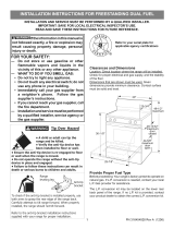
35 7/8" Min.
(91.1 cm Min.)
18" Min. 13" Max.
(33 cm Max.)
is a wall:
9" Min.
22.9 cm Min.)
Right side
Wall Outlet
junction box
location 24" Min.
(61 cm Min.)
24 1/2" Max.
(62.2 cm Max.)
Do not pinch the power supply cord between the range
and the wall.
Do not sealthe range to the side cabinets.
D
NOTE: 28" (71.1 cm) minimum clearance between the
cooktop and the bottom of the cabinet when the bottom
of wood or metal cabinet is protected by not lessthan
1/4" (0.64 cm) flame retardant millboard covered with
not lessthan No. 28 MSG sheet metal, 0.015" (0.4 mm)
stainless steel, 0.024" (0.6 mm) aluminum, or 0.020"
(0.5 mm) copper.
34" (86.4 cm) minimum clearance when the cabinet is
unprotected.
415/8"(105.7cm)Min. 357/8" 26 3/4" (67.9 cm) 35 3/4" (90.8 cm) Min.
42 5/8" (108.3cm)Max. (91.1 cm) 36 3/4" (93.3 cm) Max.
47 3/8" 36" (91.4 cm) Standard 36 1/16"
(120.3 cm) 35 3/4" (90.8 cm) Min. (91.6 cm)
Note: Wiring diagram for this model isenclosed in this booklet (seepage 24).
Printedin Canada
P/N318201782 (1302) Rev.B
English- pages 1-11; Espa_ol- p_Sginas12-23
Wiring Diagram - page 24

Important Notes to the Installer
1. Read all instructions contained in these installation
instructions before installing range.
2. Remove all packing material from the oven
compartments before connecting the electrical supply
to the range.
3. Observe all governing codes and ordinances.
4. Be sure to leave these instructions with the consumer.
5. Note: For operation at 2000 ft. elevations above see
level, appliance rating shall be reduced by 4 percent
for each additional 1000 ft.
Important Note to the Consumer
Keep these instructions with your owner's guide for future
reference.
Optional Items Available:
o A Cooktop Trim, if you want to remove the actual 6"
Stainless Steel Backsplash.
A 9" (22.9 cm) StainlessSteel Backsplash
A 12" (30.5 cm) Stainless Steel Backsplash
Those kits can be ordered for purchase through SearsParts
& Repair Center at 1-800-4-MY-HOME®.
IMPORTANT SAFETY
INSTRUCTIONS
Installation of this range must conform with local codes
or, in the absence of local codes, with the National Fuel
Gas Code ANSI Z223. l--latest edition.
When installing in a manufactured (mobile) home,
installation must conform with Manufactured Home
Construction and Safety Standard, title 24CFR, part
3280 [Formerly the Federal Standard for Mobile Home
Construction and Safety, title 24, HUD (part 280)] or,
when such standard is not applicable, the Standard for
Manufactured Home Installation, ANSI Z225.1/NFPA
501A-latest edition, or with local codes.
This range has been design certified by CSA international.
As with any appliance using gas and generating heat,
there are certain safety precautions you should follow. You
will find them in the Use and Care Guide, read it carefully.
* Be sure your range is installed and grounded
properly by a qualified installer or service
technician.
This range must be electrically grounded in
accordance with local codes or, in their absence,
with the National Electrical Code ANSI/NFPA No,
70--latest edition.
All rangescan
tip.
Injuryto
personscould
_ i result.
• Installanti-tip
devicepacked
with range.
To reduce the
risk of tipping of the range,
the range must be secured
by properly installed anti-tip
bracket(s) provided with the
range. To check if the bracket
is installed properly, grasp the
top rear edge of the range and
carefully tilt it forward to make
sure the range is anchored.
• Air curtain or other overhead hoods, which operate
by blowing a downward air flow on to a range, shall
not be used in conjunction with gas ranges other
than when the hood and range have been designed,
tested and listen by an independent test laboratory
for use in combination with each other.
• Make sure the wall coverings around the range
can withstand the heat generated by the range.
• Before installing the range in an area covered
with linoleum or any other synthetic floor
covering, make sure the floor covering can
withstand heat at least 90°F/32°C above room
temperature without shrinking, warping or
discoloring. Do not install the range over carpeting
unless you place an insulating pad or sheet of 1/4"
(6.4 mm) thick plywood between the range and
carpeting.
• Do not obstruct the flow of combustion air at the
oven vent nor around the base or beneath the
lower front panel of the range. Avoid touching the
vent openings or nearby surfaces as they may become
hot while the oven is in operation. This range requires
fresh air for proper burner combustion.
Never leave children alone or
unattended in the area where an appliance is in
use. As children grow, teach them the proper, safe use
of all appliances. Never leave the oven door open when
the range is unattended.
Stepping, leaning or sitting on the
door of this range can result in serious injuries and
can also cause damage to the range.
Do not store items of interest to children in
the cabinets above the range. Children could be
seriously burned climbing on the range to reach items.
To eliminate the need to reach over the surface
units, cabinet storage space above the units
should be avoided.
Adjust surface burner flame size so it does not
extend beyond the edge of the cooking utensil.
Excessiveflame is hazardous.
Do not use the oven as a storage space. This
creates a potentially hazardous situation.
Never use your range for warming or heating the
room. Prolonged use of the range without adequate
ventilation can be dangerous.
Do not store or use gasoline or other flammable
vapors and liquids near this or any other
appliance. Explosions or fires could result.
In the event of an electrical power outage, the surface
burners can be lit manually. To light a surface burner,
hold a lit match to the burner head and rapidly turn
the Surface Control knob to Med. Use caution when
lighting surface burners manually.
Remove broiler pan, food and other utensils
before self-cleaning the oven, Wipe up excess
spillage. Follow the cleaning instructions in the Use &
Care Guide.
Unlike the standard gas range, THiS COOKTOP
IS NOT REMOVABLE, Do not attempt to remove the
cooktop.

Special Instructions for appliances installed in the State
of Massachusetts: This appliance can only be installed
in the State of Massachusetts by a Massachusetts
licensed plumber or gas fitter. When using a flexible
gas connector, it must not exceed 3 feet (36 inches) in
length. A "T" handle type manual gas valve must be
installed in the gas supply line to this appliance.
Model and Serial Number Location
The serial plate is located at back of the appliance. Serial
Plate Location
A serial plate is located
on the lower trim and
visible when the oven
door is opened.
When ordering parts
for or making inquires
about your oven,
always be sure to
include the model and
serial numbers and a
lot number or letter
from the serial plate on
your oven.
Power Supply Cord Kit
The user is responsible for connecting the power supply
cord to the connection block located behind the back
panel access cover.
This appliance may be connected by means of
permanent "hard wiring" (flexible armored or
nonmetallic shielded copper cable), or by means of a
power supply cord kit. Use only a power supply cord kit
rated at 125/250 volts, 30 Amp and marked for use with
ranges. Cord must have either 3 or 4 conductors.
Terminals on end of wires must either be closed loop or
open-end spade lugs with upturned ends. Cord must
have strain relief clamp.
A 3-wire* or 4-wire single phase 120/240 or 120/208
Volt, 60 Hz AC only electrical supply is required on a
separate circuit fused on both sides of the line (time-
delay fuse or circuit breaker is recommended). DO NOT
fuse neutral. The fuse size must not exceed the circuit
rating of the appliance specified on the nameplate. Use a
circuit breaker and a power cord kit of 30 Amp.
*For mobile homes, new installations, recreational
vehicles, or areas where local codes do not permit
grounding through neutral, use a 4 conductor power
supply cord kit rated at 125/250 volts, 30 Amp and
marked for use with ranges (see Figure 4).
Junction Box or Wall ReceptacleLocation
Suggested location of the junction box or wall
receptacle is shown in Figure IA. It can also be
located in the lower left corner of the adjacent right
cabinet (see Figure IB). If a service cord is used, the
wall receptacle should be located in accordance with the
dimensions in figures 1A and lB.
Center
Line of
Range
10"
(25.4 cm)
Line of
Range
Figure IA
Figure IB /
Electrical Connection to the Range
This appliance is manufactured with the neutral terminal
connected to the range.
While connecting range, do not
loosen the nuts which secure the terminal block
to the range. Electrical failure or loss of electrical
connection may occur.
Note: Refer to the wiring diagram at the end of this
manual.
Electrical Shock Hazard
• Electrical ground is required on this appliance.
• Do not connect to the electrical supply until
appliance is permanently grounded.
• Disconnect power to the circuit breaker or fuse
box before making the electrical connection.
• This appliance must be connected to a
grounded, metallic, permanent wiring system,
or a grounding connector must be connected
to the grounding terminal or wire lead on the
appliance.
• Do not use the gas supply line for grounding
the appliance.
Failure to do any of the above could result in a
fire, personal injury or electrical shock.
3

Three Conductor Wire Connection to Range
(The 3-conductor cord or cable must be replaced with
a 4-conductor cord or cable where grounding through
the neutral conductor is prohibited in new installations,
mobile homes, recreational vehicles or in other areas
where local codes do not permit neutral grounding)
If local codes permit connection of the frame grounding
conductor to the neutral wire of the power supply cord
(Fig. 3):
1. Remove the
screws at the
lower end of the
rear wire access
panel, then lift
the lower part
of the access
panel to expose
range terminal
connection block
(Fig. 2).
Rear wire
access panel
Pressure regulator
location
Figure 2
Risk of fire or electrical shock exists
if an incorrect size range cord kit is used, if the
Installation Instructions are not followed, or if the
strain relief bracket is discarded,
Four Conductor Wire Connection to Range
(mobile homes)
1. Remove the screws at the lower end of the rear wire
access panel, then lift the lower part of the access
panel to expose range terminal connection block (Fig.
2).
2. Remove the three loose nuts on the terminal block
using a 3/8" nut driver or socket.
3. Remove the grounding strap from the terminal block
and from the appliance frame.
4. Connect the ground wire (green) of the power supply
cord to the frame of the appliance with the ground
screw, using the hole in the frame where the ground
strap was removed (see Figure 4).
5. Connect the neutral wire of the power supply cord to
the center silver-colored terminal of the terminal block,
and connect the other wires to the outer terminals.
Match terminal and power supply wires by color.
6. Replace the 3 nuts on the terminal block (see figure 4).
7. Replace the rear access panel using the screws
removed in step 1.
Direct Electrical Connection to the Circuit
Breaker, Fuse Box or Junction Box
Terminal
2. Remove the 3 loose nuts on the terminal block using
3/8" nut driver or socket.
3. Connect the neutral white wire of the power supply
cord to the center silver-colored terminal of the
terminal block, and connect the other wires to the
outer terminals. Match terminal and power supply
wires by color.
4. Replace the 3 nuts on the terminal block (see figure 3).
5. Replace the rear access panel using the screws
removed on step 1.
Colored
Terminal
1-1/8" Dia.
Direct
Connection
Hole. Punch
out knockout
for 1-3/8" Dia.
Cord Kit
A user supplied
Terminal
Block
be installed at this
location. To240 V receptacle
NOTE: Be sureto remove the f_
supplied grounding strap._
Figure 4
A strainrelief
supplied by
user must be
installed at this Iocatic
Figure 3
g
Strap
1-1/8" Dia. Direct
Connection Hole.
Punch out knockout
for 1-3/8" Dia.
Cord Kit Hole
4

if the appliance isconnected directly to the circuit breaker,
fuse box or junction box, use flexible, armored or non
metallic sheathed copper cable (with grounding wire).
Supply a U.L. listed strain-relief at each end of the cable.
At the appliance end, the cable goes through the Direct
Connection Hole (see Figure 4) on the Cord Mounting
Plate. Wire sizes(copper wire only) and connections
must conform to the rating of the appliance.
Where local codes permit connecting the appliance
cable ground wire to the power supply cable
neutral (white) wire (see Figure 5).
1. Disconnect the power supply.
2. In the circuit breaker, fuse box or junction box:
Connect appliance and power supply cable wires as
shown in figure 5.
Improper connection of aluminum
house wiring to copper leads can result in a short
circuit or fire. Use only connectors designed for
joining copper to aluminum, and follow the
manufacturer's recommended procedure closely.
Cable from Power Supply
White Wire
(Neutral)
RedWires q
Ground Wire
(Bare or Green Wire)
/_Black
_ires 1
141_--Junction
\\L BOX
I "-,,White Wire
j (Neutral)
U.L.-Listed
Conduit Connector
(or CSA listed)
Cable from appliance
Figure 5
3-WIRE GROUNDED JUNCTION BOX
You may not ground the oven through
the neutral (white) wire if oven is used in a new
branch circuit installation (1996 NEC), mobile home,
recreational vehicle, or where local codes do not
permit grounding through the neutral (white)
wire. When grounding through the neutral (white)
wire is prohibited, you must use a 4-wife power
supply cable. See Figure 6. Failure to heed this
warning may result in electrocution or other serious
personal injury.
If oven is used in a new branch circuit installation
(1996 NEC), mobile home, recreational vehicle, or
where local codes DO NOT permit connecting the
appliance cable ground wire to the power supply
cable neutral (white) wire you must use a 4 wire
power supply cable (see figure 6):
1. Disconnect the power supply.
2. In the circuit breaker, fuse box or junction box:
Connect appliance and power supply cable wires as
shown in figure 6.
DO NOT ground to a gas supply pipe. DO NOT connect
to electrical power supply until appliance is permanently
grounded. Connect the ground wire before turning on
the power (Figure 6).
Cable from Power Supply
Ground
Wire-- I
_::u_:::.:::. ! _,, _ ,_ White Wire
Red " " -::--: "
Wires ,_
Ground Wire ]_'_--_,(..i X
//
Wires-1
(Bare or _ S 5_ "'--_,,.-- /
Green Wire__ _ ,,,,,J "........
/ z'- vvn, evv,re
Junction Box _:-_'" _ U.L.-Listed
_:::::::_ Conduit Connector
(or CSA listed)
Cable from appliance
Figure 6
4-WIRE GROUNDED JUNCTION BOX
NOTE TO ELECTRICIAN: The armored cable leads
supplied with the appliance are UL-recognized for
connection to larger gauge household wiring. The
insulation of the leads is rated at temperatures much
higher than temperature rating of household wiring. The
current carrying capacity of the conductor is governed by
the temperature rating of the insulation around the wire,
rather than the wire gauge alone.

a Range Placement
To eliminate the risk of burns or fire from
reaching over heated surface units, cabinet storage space
located above the range should be avoided. If cabinet
storage space is to be provided, the risk can be reduced
by installing a range hood that projects horizontally a
minimum of 5" (12.7 cm) beyond the bottom of the
cabinet.
Center
Line of
Range
I
Follow instructions for
the type of installation you have
Figure 7
If range will be installed with a cabinet on both
sides, draw a center line on the floor between the
cabinets (see figure 8). If back of range will not be
flush with the wall (the location of the outlet may not
allow the range to be positioned against the wall), draw
a line on the floor where the back edge of the range will
be. Now install anti-tip bracket (see "Anti-Tip Bracket
Installation ", page 11).
If range will be installed with a cabinet on one
side only, move the range into final position. Draw a
line on the floor along the side of the range that is not
against the cabinet. If back of range will not be flush
with the wall (the location of the outlet may not allow
the range to be positioned against the wall), draw a
line on the floor where the back edge of the range will
be. Now install anti-tip bracket (see "Anti-Tip Bracket
Installation ", page 11).
If range will not be installed against a cabinet, move
range into final position. Draw a line on the floor along
both sides of the range. If back of range will not be
flush with the wall (the location of the outlet may not
allow the range to be positioned against the wall), draw
a line on the floor where the back edge of the range will
be. Now install anti-tip bracket (see "Anti-Tip Bracket
Installation ", page 11).
Gas Supply Installation
When shipped from the factory, this unit is designed
to operate on 4"(10,16 cm) water column (1.0 kPa)
Natural gas manifold pressure. A convertible pressure
regulator is connected to the range manifold and
MUST be connected in series with the gas supply line.
The regulator is located as shown in figure 2 and it is
accessible from front of the range.
For proper operation, the maximum inlet pressure to
the regulator should be no more than 14"(35,56 cm) of
water column pressure (3.5 kPa).
The inlet pressure to the regulator must be at least 1"
(.25 kPa) greater than the regulator manifold pressure
setting. The regulator is set for 4"(10,16 cm) water
column (1.0 kPa) Natural gas manifold pressure; the inlet
pressure must be at least 5"(12.60 cm) water column
(1.25 kPa) Natural gas. For LP/Propane gas, the regulator
must be set for 10"(25,4 cm) water column (2.5 kPa)
manifold pressure; the inlet pressure must be at least
11 "(27,9 cm) water column (2.75 kPa).
The supply line should be equipped with an approved
shutoff valve (see Figure 9). This valve should be located
in the same room as the range and should be in a
location that allows ease of opening and closing. Do not
block access to the shutoff valve. The valve is for turning
on or shutting off gas to the appliance. Open the shutoff
valve in the gas supply line. Wait a few minutes for gas
to move through the gas line.
The gas supply between the shutoff valve and the
regulator may be connected by rigid piping or by A.G.A./
C.G.A.-approved flexible metallic union-connected
piping where local codes permit use.
The gas supply piping can be through the side wall
of the right cabinet. The right side cabinet is an ideal
location for the main shutoff valve, if the range is
installed within cabinet storage space
Connection to Pressure Regulator
The regulator is already installed on the appliance.
Do not make the connection too tight.
The regulator is die cast. Overtightening may crack the
regulator resulting in a gas leak and possible fire or
explosion.
Manual GAS FLOW Pressure
Shutoff Flare _1_ Flare Regulator
Valve Union Union
Access
Off Connector
Cap
All connections must be wrench-tightened
Figure 8

Assembletheflexibleconnectorfromthegassupplypipe
tothepressureregulatorinthefollowingorder:
1. Manualshutoffvalve(notsupplied)
2. 1/2"nipple(notsupplied)
3. 1/2"flareunionadapter(notsupplied)
4. Flexibleconnector(notsupplied)
5. 1/2"flareunionadapter(notsupplied)
6. 1/2"nipple(notsupplied)
7. Pressureregulator(supplied)
Thegassupplylinetotheshutoffvalveshouldbe
1/2"(1,27cm)or3/4"(1.9cm)solidpipe.
Theusermustknowthelocationofthemainshutoff
valveandhaveeasyaccesstoit.
Whenusingflexiblegasconduitontherange,allow
sufficientslackto pulltherangeoutsidethecutoutfor
cleaningorservicing.
NOTE:Donotallowtheflexibleconduittogetpinched
betweenthewallandtherange.
Usepipe-jointcompoundmadeforusewithNaturaland
LP/Propanegastosealallgasconnections.Ifflexible
connectorsareused,becertainconnectorsarenot
kinked.
Donotuseaflameto checkforleaks
fromgasconnections.Checkingforleakswithaflame
mayresultinafireorexplosion.
Allopeningsinthewallorfloorwheretherangeisto be
installedmustbesealed.
Tightenallconnectionsif necessaryto preventgas
leakageinthecooktoporsupplyline.
Disconnectthisrangeandits individualshutoff
valvefromthegassupplypipingsystemduringany
pressuretestingofthesystemattestpressuresgreater
than1/2psig(3.5kPaor14"(35,56cm)watercolumn).
Isolatetherangefrom thegassupplypipingsystem
byclosingitsindividualmanualshutoffvalveduring
anypressuretestingofthegassupplypipingsystemat
testpressuresequaltoor lessthan1/2psig(3.5kPaor
14"(35,56cm)watercolumn).
g LP/Propane Gas Conversion
This appliance can be used with Natural gas or LP/
Propane gas. It is shipped from the factory for use with
natural gas.
If you wish to convert your range for use with LP/
Propane gas, use the supplied fixed orifices located in a
bag containing the literature marked "FOR LP/PROPANE
GAS CONVERSION." Follow the instructions packaged
with the orifices.
Shutoff Valve =
Open position
Figure 9
The supply line must be equipped with an approved
manual shutoff valve. This valve should be located in
the same room as the range and should be in a location
that allows ease of opening and closing. Do not block
access to the shutoff valve. The valve isfor turning on or
shutting off gas to the appliance.
Once regulator is in place, open the shutoff valve in the
gas supply line. Wait a few minutes for gas to move
through the gas line.
Check for leaks, After connecting the range to the gas
supply, check the system for leaks with a manometer.
If a manometer is not available, turn on the gas supply
and use a liquid leak detector (or soap and water) at all
joints and connections to check for leaks. Leaks will be
indicated by bubbles appearing at the connections or
joints.
The conversion must be performed by a qualified service
technician in accordance with the manufacturer's
instructions and all local codes and requirements. Failure
to follow these instructions could result in serious injury
or property damage. The qualified agency performing
this work assumes responsibility for the conversion.
Failure to make the appropriate
conversion can result in personal injury and property
damage.
Moving the Appliance for
Servicing and Cleaning
Turn off the range line fuse or circuit breakers at the
main power source, and turn off the manual gas shut-off
valve. Make sure the range is cold. Open the oven door.
Lift the range at the front and slide it out of the cut-out
opening without creating undue strain on the flexible
gas conduit. Make sure not to pinch the flexible gas
conduit at the back of the range when replacing the unit
into the cut-out opening. Close the door and switch on
the electrical power and gas to the range.
7

,
,
Range Installation
The back of the range may be installed directly
against the wall.
To reduce possible scorching of vertical walls and
to minimize potential fire hazards under abnormal
surface unit use conditions such as high heat or
no pans and to conform to Agency requirements,
a minimum of 9" (22.9 cm) spacing should be
provided on both sides of the cooktop.
Excessive Weight Hazard
• Use 2 or more people to move and install
range.
• Failure to follow this instruction can result in
back or other injury.
9.2 Check Operation
Refer to the Use and Care Guide packaged with the
cooktop for operating instructions and for care and
cleaning of your cooktop.
_Do not touch the burners. They may
be hot enough to cause burns.
1.Install Burner Caps
Standard Burners
This range is equipped with sealed burners as shown (see
Figure 11). All pieces are at their place. Take note where
they are. Remove all packaging material located
under the bridge burner head. Make sure the burner
is properly aligned and leveled. NOTE: There are no
burner adjustments necessary on this range.
NOTE: There are no burner adjustments necessary on
this cooktop.
Burner
Cap
9.1 Leveling the Range
1. Install an oven rack in the center of the oven.
2. Place a level on the rack (see Figure 10). Take 2
readings with the level placed diagonally in one
direction and then the other. Level the range, if
necessary, by adjusting the 4 leveling legs with a
wrench (see Figure 18).
3. Slide the range to its final position and double check
for levelness. If the range is not level, pull unit out
and readjust leveling legs, or make sure floor is level.
Burner
Head
\
Fig. 11
Figure 10
8

Bridge Style Burners (some models)
Install Burner Caps, these include one Bridge Burner
Center Cap (rectangular shaped) and the two Bridge
Burner End Caps (The Bridge Burner End Caps will fit
either the front or rear Bridge Burner Head locations).
Make sure that the lips located under the Bridge Burner
Caps fall into the slots located in the Bridge Burner Head
(See arrows in Figure 12) and that all the Bridge Burner
Caps lie flat and evenly on the Bridge Burner Head.
Bridge Burner Head
I
Burner
Caps
Fig.13
Bridge
Burner
End
Cap
Bridge
Burner
Center
Cap
Igniter
Hole
iiiili!_i!!i
Bridge
Burner Igniter
End Hole
Cap
Fig. 12
Double Ring Style Burners (some models)
The Double Ring burner only operates properly with
two burner caps in place. Be sure the burner cap lips are
positioned facing down towards the burner head (Figure
13) and into the recessedareas (Figure 14) on each side
of the burner head. Be sure both burner caps are seated
firmly and rest level on the burner head before operating.
Check the fit for each cap using the same method for the
round burner capsby gently sliding each cap from side to
side. Pleasenote that the burner cap lips should NOT move
out of recessed areasof the burner head.
Recessed
area
Burner
Head
Fig. 14
2. Turn on Electrical Power and Open Main Shutoff
Gas Valve
3. Check the Igniters
Operation of electric igniters should be checked after
range and supply line connectors have been carefully
checked for leaks and range has been connected to
electric power. Tocheck for proper lighting:
a. Push in and turn a surface burner knob to the LITE
position. All electronic surface ignitors will spark at the
same time. However, only the burner you are turning
on will ignite.
b.The surface burner should light once the flow of gas
reached the surface burner. Each burner should light
within four (4) seconds in normal operation after air
has been purged from supply lines. Visually check that
burner has lit.
c. Once the burner lights, the control knob should be
rotated out of the LITEposition.
There are separate ignition devices for each burner. Try
each knob separately until all burners have been checked.
9

4. Adjust the "LOW" Setting of Regular Burner
valve (see Figure 15):
a. Push in and turn control to LITEuntil burner ignites.
b. Quickly turn knob to LOWESTPOSITION.
c. If burner goes out, reset control to OFF.
d. Remove the surface burner control knob and
decorative ring.
e. Insert a thin-bladed screwdriver into the hollow valve
stem and engage the slotted screw inside. Flame
size can be increased or decreased by turning the
screw. Turn counterclockwise to increase flame size.
Turn clockwise to decrease flame size. Adjust flame
until you can quickly turn knob from LITEto LOWEST
POSITIONwithout extinguishing the flame. Flame
should be as small as possible without going out.
Note: Air mixture adjustment is not required on surface
burners.
Figure 15
5. Adjust the "LOW" Setting of the Dual Burner
(Bridge & Dual) Valve (Figure 16):
Note: On the dual valve the low setting of each portion
(rear portion of bridge burner and the center portion of
bridge burner) must be adjusted individually.
a. Push in and turn control to LITEuntil the rear portion
of the bridge burner ignites only.
b. Quickly turn knob to LOWESTPOSITION.
c. If burner goes out, reset control to OFF.
d. Remove the surface burner control knob.
e. The rear portion of the bridge burner flame size can
be increased or decreased by turning screw A (see
Figure 16). Use screw B to adjust the flame size of
the center portion of the bridge or dual burner. Turn
counterclockwise the screw to increase flame size.
Turn clockwise the screw to decrease flame size.
Adjust flame until you can quickly turn knob from
LITEto LOWEST POSITIONwithout extinguishing the
flame. Flame should be as small as possible without
going out.
Note: Air mixture adjustment is not required on surface
burners.
Figure 16
6. Operation of Oven Elements
The oven is equipped with an electronic oven control. Each
of the functions has been factory checked before shipping.
However, it is suggested that you verify the operation of
the electronic oven controls once more. Refer to the Use
and Care Guide for operation. Follow the instructions for
the Clock, Timer, Bake, Broil, Convection (some models)
and Clean (some models) functions.
When checking oven element operation,
do not touch the elements. They will be hot enough to
cause serious burns.
Bake-Verify that this function makes the oven hot. 20
seconds after turning oven on, open the door and you
should feel heat coming from the oven.
Broil-When the oven is set to BROIL,the upper element
in the oven should become red.
Convection- When the oven is set for convection
baking or roasting the convection fan will run. The
convection fan will stop running when the oven door is
opened.
When All Hookups are Complete
Make sure all controls are left in the OFFposition.
Before You Call for Service
Read the Before You Call for Service Checklist and
operating instructions in your Use and Care Guide.
It may save you time and expense. The list includes
common occurrences that are not the result of defective
workmanship or materials in this appliance.
Refer to your Use and Care Guide for Sears service
phone numbers, or call 1-800-4-MY-HOME ®
10

Important Safety Warning
To reduce the risk of tipping of the range, the range
must be secured to the floor by the properly installed
anti-tip bracket and screws packed with the range. These
parts are located in a plastic bag in the oven. Failure to
install the anti-tip bracket will allow the range to tip over
if excessive weight is placed on an open door or if a child
climbs upon it. Serious injury might result from spilled
hot liquids or from the range itself.
Follow the instructions below to install the anti-tip
bracket.
If range is ever moved to a different location, the anti-
tip bracket must also be moved and installed with the
range.
Tools Required:
5/16" (8 mm) Nut driver or Flat Head Screwdriver
Adjustable Wrench
Electric Drill
3/16" (4.8 mm) Diameter Drill Bit
3/16" (4.8 mm) Diameter Masonry Drill Bit (if installing in
concrete)
Anti-Tip Bracket Installation
1. An anti-tip bracket must be installed on the right and
left side at back of the range.
2. The anti-tip bracket supports are attached to the floor
at the back. When fastening to the floor, be sure that
screws do not penetrate electrical wiring or plumbing.
The screws provided will work in either wood or
concrete.
3. Unfold paper template and place it flat on the floor
with the back and side edges positioned exactly where
the back and sides of range will be located when
installed. (Use the diagram in figure 17 to locate
bracket if template is not available.)
/ 1-5/8" typ.
/
/
Installananti-tipbracke{: :- ; -
. - . .
on the right and left side
Figure 17
4. Mark on the floor the location of the mounting holes
shown on the template (right and left position). For
easier installation, 3/1 6" (4.8 mm) diameter pilot holes
1/2" (1.3 cm) deep can be drilled into the floor.
5. Remove template and place bracket on floor (see
figure 17). Line up holes in bracket with marks
on floor and attach the bracket using the screws
provided. Brackets must be secured to solid floor. If
attaching to concrete floor, first drill 3/1 6" (4.8 mm)
dia. pilot holes using a masonry drill bit.
6. Level range if necessary, by adjusting the 4 leveling
legs with an adjustable wrench. Loosen the screw
which fixes the decorative leg and lift it to reach the
leveling leg. Turn the leveling leg counterclockwise
to raise the range or clockwise to lower the range
(see Figure 18). Replace the decorative legs at your
convenience.
7. Before sliding the range to its final position; take note
of the serial and model numbers for future reference.
Slide range into place making sure each rear leg is
trapped by a the bracket. Range may need to be
shifted slightly to one side as it is being pushed back
to allow rear legs to align with brackets.
8. After installation, visually verify that the anti-tip
brackets are engaged.
Figure 18
11

LA INSTALAGON Y ELSEP,VICIODEBEN SEP,EFECTUADOS POP,UN INSTALADOP, CALIFICADO.
IMPOP,TANTE: GUAP,DE ESTAS INSTP,UCGONES PARA USO DEL INSPECTOR LOCAL DE ELECTP,ICIDAD.
LEA Y GUAP,DE ESTAS INSTP,UCCIONES PAP,A P,EFEP,ENCIA FUTUP,A.
OBSERVE CODIGOS GOBEP,NANTES Y OP,DENANZAS.
I!_ Si la informacion contenida en este manual no es seguida exactamente,
puede ocurrir un incendio o explosion causando da_os materiales, lesion personal o la
muerte.
PARA SU SEGURIDAD:
-- No almacene ni utilice gasolina u otros vapores y liquidos inflamables en la proximidad
de _ste o de cualquier otto electrodom_stico.
-- QUE DEBE HACER SI PERCIBEUN OLOR A GAS:
• No trate de encender ningun electrodom_stico.
• No toque ningun interruptor electrico; no use ningun tel@fono en su edificio.
• Llame a su proveedor de gas desde el telefono de un vecino. Siga las instrucciones del
proveedor de gas.
• Si no Iogra comunicarse con su proveedor de gas, Ilame al departamento de
bomberos.
-- La instalacion y el servicio de mantenimiento deben set efectuados pot un instalador
calificado, la agenda de servido o el proveedor de gas.
Nora: Para
electrodomes-
ticos instalados
en el estado de
Massachussets.
Veapagina 14.
V_a
Si hay una pared: Nota
9" M[n.
Si hay una pared:
9" M[n.
(22.9 cm Min.)
-lado derecho
Tomacorriente de
pared puesto a
tierra
No pellizque el cordon el_ctrico entre la estufa y la
pared.
No selle la estufa a los armarios laterales.
A
NOTA: Un espacio minimo de 28" (71.1 cm) entre la
superficie de la estufa y el fondo del armario cuando el
fonclo del armario de madera o metal est_qprotegido
pot no menos de 1/4" (0.64 cm) de madera resistente al
fuego cubierta pot una I_imina met_qlicade MSG, n0mero
28, 0.015" (0.4 ram) de acero inoxidable, 0.024" (0.6
ram) de aluminio, 6 0.02" (0.5 ram) de cobre.
Un espacio minimo de 34" (86.4 cm) cuando el armario
no est_qprotegiclo.
415/8"(105.7cm)Min. 357/8" 263/4"(67.9cm) 353/4"(90.8cm)Min.
425/8"(108.3cm)Max. (91.2cm) 363/4"(93.3cm)Max.
473/8"(120.3cm) 36"(91.4cm)Standard 361/16"(91.6cm)
353/4"(90.8cm)Min.
El diagrama del cableado de este modelo est_qincluido en esta manual (vea la pagina 24) P/N318201782 (1302) Rev.B
Impreso en Canada English - pages 1-11 Espa_ol - p_iginas 12-23
Diagrama de la instalaci6n al_imbrica - p_igina 24

Notas importantes para el Instalador
1. Leatodas las instrucciones contenidas en este manual
antes de instalar la estufa.
2. Saque todo el material usado en el empaque del
compartimiento del homo antes de conectar el
suministro el_ctrico a la estufa.
3. Observe todos los c6digos y reglamentos pertinentes.
4. Deje estas instrucciones con el comprador.
5. Nota: Para el correcto funcionamiento en lugares
superiores a los 2000 ft, el r_gimen del mecanismo debe
reducirse un 4% por cada 1000 ft sobre el nivel del mar.
Nota Importante para el Consumidor
Conserve estas instrucciones y el Manual del Usuario para
referencia futura.
Articuios Disponibles Opcionales:
• Un corte de Cooktop, si sedeseaquitar la Salpicadera
trasera de Acero Inoxidable que sobresale 6".
• Una Salpicaderatrasera deAcero Inoxidablede9" (22.9cm).
• Una Salpicaderatraserade Acero Inoxidable de 12" (30.5cm)
Estosjuegos se pueden ordenar para comprar mediante
SearsParts & Repair Center 1-800-4-MY-HOME®.
IMPORTANTES
INSTRUCCIONES DE
SEGURIDAD
InstalaciOn de esta estufa debe cumplir con todos los
c6digos locales, o en ausencia de c6digos locales con
el C6digo Nacional de Gas Combustible ANSIZ223.1--
01tima edici6n.
La instalaci6n de aparatos disehados para instalaci6n
en casas prefabricadas (m6viles) debe conformar con el
Manufactured Home Construction and Safety Standard,
titulo 24CFR, parte 3280 [Anteriormente el Federal
Standard for Mobil Home Construction and Safety, titulo
24, HUD (parte 280)] o cuando tal est_indar no se aplica,
el Standard for Manufactured Home Installation 1982
(Manufactured Home sites, Communities and Setups),
ANSI Z225.1/NFPA 501A-edici6n m_qsreciente, o con los
c0digos locales.
• Todas las estuffas pueden volcarse.
• Estopodriaresultarenlesionespersonales\\L/
• Instale el dispositivo antivuelco provisto
con esta estufa.
Para reducir el riesgo de que se vuelque la
estufa, hay que asegurarla adecuadamente
colocando Los soportes antivuelco que se
proporcionan. Para comprobar si estos estan
instalados y apretados correctamente, tome el horde
trasero superior de la estufa y cuidadosamente inclinela
hacia adelante para asegurarse que la estufa est_
anclada.
Esta estufa ha sido disehada y certificada por el organismo
CSA Internacional. Como en cualquier electrodom_stico
donde se use gas y se genere cierto calor, existen diversas
precauciones de seguridad que deben ser seguidas. Usted
encontrar_i esta lista de precauciones en el manual de Uso y
Cuidado, por favor I_alascuidadosamente.
No se deben usar cortinas de aire ni ninguna
otra campana de ventilaci6n superior que sople
aire hacia abajo sobre la estufa a gas a menos
que la campana de ventilacion y la estufa hayan
sido dise_adas, probadas y certificadas pot un
laboratorio de pruebas independiente para el uso
combinado de la una con la otra.
Asegurese de que la estufa sea instalada y
conectada a tierra en forma apropiada pot un
instalador calificado o pot un t6cnico.
Esta estufa debe set el6ctricamente puesta a
tierra de acuerdo con los codigos locales, o en su
ausencia, con el Codigo EI6ctrico Nacional ANSI/
NFPA No. 70, ultima edicion.
Asegurese de que el material que recubre las
paredes alrededor de la estufa, pueda resistir el
calor generado pot la estufa.
Antes de instalar la estufa en un area cuyo
piso este recubierto con linoleo u otto tipo de
piso sintetico, asegurese de que 6stos puedan
resistir una temperatura de pot Io menos 90°F
sobre la temperatura ambiental sin provocar
encogimiento, deformacion o decoloracion. No
instale la estufa sobre una alfombra al menos que
coloque una plancha de material aislante de por Io
menos 1/4 pulgada, entre la estufa y la alfombra.
• No obstruya el flujo del aire de combusti6n en la
ventilaciOn del horno ni tampoco alrededor de
la base o debajo del panel inferior delantero de
la estufa. Evite tocar las aberturas o _ireascercanas
de la ventilaci6n, ya que pueden estar muy calientes
durante el funcionamiento del homo. La estufa
requiere aire fresco para la combusti6n apropiada de
los quemadores.
Nunca deje ni_os solos
o desatendidos en un area donde un
electrodom6stico esta siendo usado. A medida que
los nihos crecen, ens_eles el uso apropiado y seguro
para todos los electrodom_sticos. Nunca deje la puerta
del homo abierta cuando la estufa est_qdesatendida.
No se pare, apoye o siente en
las puertas o cajones de esta estufa pues puede
resultar en serias lesiones y puede tambien causar
daffo a la estufa.
• No almacene articulos que puedan interesar a los
niffos en los gabinetes sobre la estufa. Los nihos
pueden quemarse seriamente tratando de trepar a la
estufa para alcanzar estos articulos
13

Los gabinetes de almacenamiento sobre la estufa
deben evitarse, para eliminar la necesidad de
tenet que pasar sobre los elementos superiores de
la estufa para Ilegar a ellos.
Ajuste el tamafio de la llama de los quemadores
superiores de tal manera que 6sta no sobrepase el
borde de los utensilios de cocinar. La llama excesiva
es peligrosa.
• No use el homo como espacio de almacenaie. Esto
crear_ una situaci0n potencialmente peligrosa.
• Nunca use la estufa para calentar el cuarto. El uso
prolongado de la estufa sin la adecuada ventilaci0n
puede resultar peligroso.
• No almacene ni utilice gasolina u otros vapores y
liquidos inflamables en la proximidad de 6ste o de
cualquier otto electrodomestico electrico. Puede
provocar incendio o explosion.
• En caso de una interrupci0n del servicio el_ctrico, es
posible de encender los quemadores de superficie
a mano. Para encender un quemador de superficie,
acerque un f0sforo encendido a la cabezal del
quemador, y gire r_pidamente el bot0n de control
de superficie a Med. Tenga cuidado al encender los
quemadores a mano.
• Retire el sartOn asador, alimentos o cualquier
otto utensilio antes de ajustar un ciclo de auto-
limpieza en el homo. Limpie el exceso de derrames.
Siga las instrucciones en manual de Uso y Cuidado.
A diferencia de otras cubiertas a gas, ESTA
CUBIERTA no es removible. No intente remover esta
cubierta.
Instrucciones eslaeciales para los electrodomesticos
instalados en el estado de Massachussets: Este
electrodomestico puede ser solamente instalado en el
estado de Massachussets laor un lalomero calificado
o instalador de gas con licencia en el estado de
Massachussets. Cuando se utilice un conector flexible
de gas, este no debe de exceder 3 pies (36 laulgadas)
de largo. Una v_lvula manual de tilaO "T" debe de
instalarse en la linea de alimentacion de gas hacia este
electrodomestico.
/ Ubicacion del
y de Serie
Una placa de serie
se encuentra sobre
el ribete decorativo y
es visible cuando la
puerta es abierta.
Cuando haga pedidos
de repuestos o solicite
informaciOn con
respecto a su estufa,
est_ siempre seguro
de incluir el n0mero
de modelo y de serie
y el n0mero o letra
del Iote de la placa de
serie de su estufa.
Numero de Modelo
Kit del Cable dei suministro
el6ctrico o alimentacion el6ctrica
El usuario es responsable de conectar el cable del
suministro el_ctrico al bloque de conexiOn Iocalizado
detr_is de la cubierta de acceso del panel trasero.
Este electrodom_stico puede conectarse por medio de un
"cableado duro permanente" (cable de cobre blindado
armado o no-met_qlicoflexible), o por meclio de un kit de
cable de alimentaciOn. Utilice solamente un kit de cable
de alimentaciOn clasificado en 125/250 voltios, 30 Amp. y
marcado para el uso de estufas. Elcable debe tener 3 o 4
conductores.
LasTerminales al final de los cables deben ser de del tipo
"anillo" o "espadas", _stas ultimas con la terminaciOn del
cable hacia dentro del barril de la Terminal. "El cable debe
tener un retenedor para eliminar esfuerzos sobre el cable."
Un cable con 3 alambres* o un cable con 4 alambres
monof_isico 120/240 o 120/208 voltio, 60 hertzios, AC
de alimentaciOn el_ctrica; se requiere en un circuito
separado en ambos lados de la linea (se recomienda un
fusible o un interruptor de retraso). Evite fundir al cable
neutro. Eltamaho del fusible no debe exceder el grado del
circuito del electrodom_stico especificado en la placa de
identificaciOn. Utilice un interruptor de 30 amperios.
* Para los hogares m0viles, nuevas instalaciones, los
vehiculos recreacionales, o las_ireasdonde los cOdigos
locales no permiten una conexi0n a tierra a trav_s de
un cable neutro, un kit de cable de alimentaciOn de 4
conductores clasificado en 125/250 voltios, 30 Amp.
y marcado para el uso en estufas debe ser empleado
(vea la figura 4).
14

Localizacion del receptaculo o la
caja de empalrnes
La localization sugerida se muestra en la figura numero
IA. Tambi_n puede set Iocalizado en la esquina inferior
izquierda del gabinete derecho adyacente. (vet Figura
IB). Si se utiliza un cable de alimentaciOn de servicio, el
recept_iculo de la pared debe de Iocalizarse de acuerdo a las
dimensiones.
Linea central
de la
estufa
10"
(25.4 cm!
1 .... "-<_-_ /_ 5" Max.
k < _: ! (12.7 cm Max.)
- Localizaci6n del receptSculo
._-_,_,_T::_ "_- . o la caja de empalmes
, L[nea central
.... de la
estufa
Figura IA
Riesgo de Choque Electrico
Se requiere una conexion a tierra en este
electrodomestico.
No Io conecte a la corriente el_ctrica hasta
que el aparato haya sido puesto a tierra
permanentemente.
Desconecte la corriente el_ctrica a la caja de
empalmes antes de hacer la conexion el_ctrica.
Este electrodom_stico se debe conectar a un
sistema aterrizado de cableado permanente y
met_lico, o bien un conector a tierra se deber_
conectar a la Terminal aterrizada.
El no seguir cualquiera de las adverancias aqui
mencionadas, podria resultar en un incendio,
choque electrico o lesiones.
Conexion de un cable de 3 alambres de
conduccion a ia estufa
(Un cordOn flexible o cable de 3 conductores debe de
set reemplazado con un cordOn flexible o cable de 4
conductores donde la conexiOn del conductor a tierra al
neutro esta prohibida en las nuevas instalaciones, las casas
sobre ruedas, los vehiculos de recreaciOn o otras _ireas
donde los cOdigos locales no permiten la conexiOn a tierra
al neutro).
Si los cOdigos locales permiten la conexiOn del conductor
de tierra del marco con el alambre neutro del cordOn
el@ctrico de cobre (vea Figura 3):
1. Quite los tornillos en el extremo inferior del panel de
acceso posterior, despu@slevante el panel de acceso
al bloque Terminal (vea figura 2).
Figure IB
Conexion Electrica de la Estufa
Esteaparato se fabrica con la terminal neutra conectada a
la estufa.
Mientras que conecte su estufa,
no afloje las tuercas que aseguran el bloque de
terminales a la estufa. Una averia electrica o bien la
p_rdida de la conexiOn el_ctrica puede ocurrir.
Nota: Re%rase al diagrama el_ctrico al final de este
manual.
Panel de acceso al
cable trasero
UbicaciOn del regulador
de presiOn
Figura 2
Si se usa un calibre incorrecto en el
kit del cable de alimentadOn, o las instrucciones de
instaladOn no se siguen debidamente, o bien si se
desecha el soporte del retenedor de cable el riesgo
de un choque electrico o fuego incrementar_.
15

2. Quite las tres tuercas sobre el bloque terminal usando un
destornillador o una Ilave de 3/8"(0,95 cm).
3. Conecte el cable neutro del color blanco de cobre al
terminal de color de plata en el centro del bloque,
y conecte los otros cables a los terminales laterales.
Empareje los alambres de la fuente de la terminal y de
alimentaci6n por color.
4. Instale las tres tuercas sobre el bloque terminal (vea
Figura 3).
5. Substituya el panel de acceso del alambre usando los
tornillos quitados en el paso 1.
Terminal
Terminal
Block
Conexion de 4 alambres de conduccion a ia
estufa (casas moviles)
1. Quite lostornillos en el extremo inferior del panel de acceso
posterior, despues levante el panel de acceso al bloque
Terminal (veafigura 2).
2. Retire las3 tuercas sobre el bloque terminal usando un
destornillador o Ilave de 3/8" pulgadas.
3. Quite la banda de conexion a tierra del bloque de
terminales y del marco del electrodomestico.
4. Conecte el alambre de tierra (verde) del cable de
alimentaci6n al marco del electrodom_stico con el
tornillo de tierra, usando el agujero en el marco de
donde el tornillo fue retirado (v_ase figura 4).
5. Conecte el alambre neutro (blanco) del cordon electrico
de cobre al terminal de color de plata en el centro del
bloque y conecte los otros alambres al losterminales
laterales. Empareje los alambres de la fuente del
terminal y de alimentaci6n por color.
6. Reponga las 3 tuercas sobre el bloque terminal (vea
figura 4).
7. Substituya el panel de acceso del alambre usando los
tornillos quitados en el paso 1.
Colored
Terminal
A strainrelief
supplied by the
user must be
installed at this
Figura 3
g
Strap
1-1/8" Dia. Direct
Connection Hole.
Punch out knockout
for 1-3/8" Dia.
Cord Kit Hole
1-1/8" Dia.
Direct
Connection
Hole. Punch
out knockout
for 1-3/8" Dia.
Cord Kit
A user supplied
strain-relief
be installed at this
location.
NOTE: Be sure to remove the
supplied grounding strap.-
To240 V receptacle
Figura 4
16

Conexi6n el_ctrica directa al cortadrcuito, a la caja
de fusibles o la caja de empalmes
Si el aparato est_i conectado directamente al cortacircuito,
a la caja de fusibles o a la caja de empalmes, use un cable
blindado flexible o no metalico recubierto de cobre (con
alambre a tierra). A la extremidad del electrodom6stico,
el cable paso a trav6s del agujero de la conexi6n directa
(vea figura 4) en el cable de la placa de montaje. El
tamaflo de los alambres (alambre de cobre solamente)
y las conexiones deben estar conforme al r6gimen del
electrodom6stico.
Donde los codigos locales permitan la conexion el cable
a tierra del electrodom_stico al cable de alimentacion
electrica neutro (blanco) Vea figura nemero 5,
1. Desconecte el suministro el_ctrico.
2. En el cortacircuito, la caja de fusibles o la caja de
empalmes:
Conecte el electrodom6stico y el cable de
alimentaciOn como se muestra en la figura numero 5.
Cable de la fuente de alimentaci6n
Alambre
blanco (Neutro) d (-_
Alamb[es _.. ""Jp
r,ojos -4, "d//t11\=
Alambres /_L_
desnudos _ _,_.:--¢J
o verdes _/ x:::T_
Cable de
la estufa
Alambres
-. _---C aja
\L. empalmes
I Alambre blanco
J (Neutro)
Conductor de
uni6n listado-U.L.
(listado-CSA)
Figura 5 - Sistema el_ctrico (ejemplo: caja de
empalmes) de 3 alambres (a tierra neutral)
Una conexi6n incorrecta del
alambrado de aluminio a los conductores de cobre
puede resultar en un corto circuito o incendio, Use
solamente los conectores disefiados para juntar
el cobre con el aluminio y siga exactamente el
procedimiento recomendado pot el fabricante,
No debe conectar a tierra el homo
a trav_s del cable neutral (blanco) si el homo es
usado en una instalacion de drcuito de ramal nuevo
(1996 NEC), en una casa rodante, en un vehlculo
para recreation o si los codigos locales no permiten
la conexion a tierra a trav_s del cable neutral
(blanco), Siesta prohibida la conexion a tierra a
trav_s del cable neutral (blanco), se debe usar un
cable de alimentacion de 4 hilos, Vet la Figura 6, Si
no se observa esta advertencia, esto puede resultar
en electrocud6n o en otra lesion personal grave,
Si el horno se usa en una instalacion de circuito de
ramal nuevo (1996 NEC), en una casa rodante, en
un vehiculo para recreacion o si los codigos locales
NO permiten la conexion a tierra a traves del cable
neutral (blanco) (vet figura 6):
1. Desconecte el suministro el_ctrico.
2. En el cortacircuito, la caja de fusibles o la caja de
empalmes:
Conecte el electrodom_stico y el cable de
alimentaciOn como se muestra en la figura numero 6.
Cable de
la estufa
Cable de la fuente de alimentaci6n
Alambre
neutro /- Alambre
Alambres I]\ _ _ lanco
desnudos .__1_._-'_
o verdes _ _ i s
Caja empal_nes _ Alambre
blanco
.S " -_--Conductor de
uni6n listado-U.L.
(listado-CSA)
Figura 6 - Sistema el_ctrico de 4 alambres
(ejemplo caja de empalme)
NO conecte el alambre puesto a tierra a una tuberfa
de suministro de gas. NO conecte el suministro de
energfa electrica hasta que el electrodomestico haya sido
permanentemente puesto a tierra. Conecte el alambre
de puesto a tierra antes de enchufar pot primera vez el
electrodomestico.
NOTA AL ELECTRICISTA: Los conductores de cable
blindados provistos con este electrodomestico son
aprobados pot UL para la conexion de alambrado domestico
de un calibre mayor. El aislamiento de los conductores
est_i calificado para temperaturas m_is altas que las del
alambrado domestico. La capacidad de corriente del
conductor est_i gobernada pot el tango de temperatura
del aislante alrededor del alambre en vez de solamente el
calibre del alambre.
17

Estufa - Colocadon
W.v_ Para eliminar el riesgo de quemaduras
o fuego pot el contacto de superficies sobrecalentadas,
cualquier espacio de almacenaje en los gabinetes situados
sobre la estufa debe set evitado. Si un espacio de
almacenaje debe de set proporcionado, el riesgo puede set
reducido instalando una campana de estufa que proyecte
horizontalmente e un mfnimo de el 5" (12.7 centfmetros).
,©
CL de la
estufa
I \\
Siga las instrucciones
para el tipo de instalaciOn que usted tenga
Figura 7
Si la estufa se va a insta[ar con armarios latera[es,
marque el centro de la abertura del armario en el piso (vet
la figura 7). Si la parte trasera de la estufa no estar_
a ras con la pared (la ubicacion del tomacorriente puede
que no permita que la estufa se pegue a ras con la pared),
marque el piso donde estate1 el border trasero de la estufa.
Ponga el patron en el piso, alineando la Ifnea del centro
del patron con la marca en el centro de la abertura del
armario. Ponga el borde trasero del patron a ras contra la
pared trasera o la Ifnea marcada para la parte de atr_is de la
estufa.
Si la estufa se va a insta[ar con un arrnario en un solo
un lado, mueva la estufa a su posicion final. Marque el piso
pot el lado de la estufa que no estate1contra el armario. Si
la parte trasera de la estufa no esta al ras con la pared
(la ubicacion del tomacorriente puede que no permita que la
estufa se pegue al ras con la pared), marque el piso donde el
borde trasero de la estufa estarZ Ponga el patron en el piso
y alinee el lado del patron con la I[nea marcada en el piso.
Alinee la parte trasera del patron con la pared trasera o la
I[nea marcada para la parte de atr_is de la estufa.
Si la estufa no ser_ instalada junto a un armario, mueva
la estufa a su posicion final. Marque el piso pot los dos lados
de la estufa. Si la parte trasera de la estufa no estar_ a
ras con la pared (la ubicacion del tomacorriente puede que
no permita que la estufa se pegue a ras con la pared), marque
en el piso donde el borde trasero de la estufa estarZ Ponga
el patron en el piso y alinie los lados del patron con las Ifneas
marcadas en el piso. Alinie la parte trasera del patron con la
pared trasera o la Ifnea marcada para la parte trasera de la
estufa.
Insta[acion de la alimentacion de
gas
Esta unidad ha sido ajustada de f_ibrica para operar con
una tuberfa para gas natural de 4" (1.0 kPa). Un regulador
de presion de conversion est,1 conectado a la wilvula
distribuidora y DEBEset conectado en serie con la tuberfa
de suministro de gas.
Para la operaci6n apropiada, la m_ixima presion de
entrada al regulador no debe exceder la presion de una
tuberfa de agua de 14 pulgadas (3.5 kPa).
La presion de entrada al regulador debe set pot Io menos 1
pulgada m_is grande que la wilvula distribuidora (.25 kPa).
El regulador ha sido ajustado para gas natural a 4 pulgadas
de presion para la wilvula distribuidora (1.0 kPa). La presion
de entrada debe ser pot Io menos de 5 pulgadas (1.25
kPa). Para propano Ifquido a 10 pulgadas de presion para la
wilvula distribuidora (2.5 kPa) la presion de entrada debe set
pot Io menos de 11 pulgadas (2.75 kPa).
La tuberfa deber_i set equipada con una wilvula de cierre
aprobada (vea Figura 9). Esta wilvula debe ubicarse en la
misma habitacion que la estufa en un lugar que permita
una una facilidad de abrir y cerrar. No bloquee el acceso
a la wilvula de cierre. La wilvula abre o cierra es para abrir
o cerrar el suministro de gas al aparato. Abra la wilvula de
cierre en la Ifnea de suministro de gas. Espere unos minutos
a que el gas pase pot el tubo.
El suministro de gas entre la wilvula de cierre y el regulador
se puede conectar con tuberfa rfgida o con tuberfa flexible
union met_ilica conectada y aprobada pot la AGA/CGA
donde los codigos locales permiten.
La tuberfa del suministro de gas puede pasar pot la pared
lateral del armario derecho. El armario lateral derecho es un
lugar ideal para la wilvula de cierre principal.
Valvula de FLUJO_DELGAS Regulador
cierre UniOn UniOn de presiOn
manual
Abier _ l _i_iI_'_i_ t _i
(on) _ Boquilla Conector Boquilla_
Apagado flexible Tapa de
(Off) entrada
Todaslasconexiones deben de ser apretadas con una Ilave.
Figura 8
18

Conexi6n dei regulador
El regulador esta instalado en el electrodomestico.
Asegurese de no apretar demasiado la
conexion. El sobre apretar la conexion puede romper el
regulador u generar una fuga de gas y posiblemente un
incendio o explosion.
Monte el conector flexible desde el tubo de suministro
de gas hasta el regulador de presiOn seg0n este orden:
1. V_ilvula de cierre manual (no incluido)
2. Boquilla de 1/2" (no incluido)
3. 1/2" Adaptador de union (no incluido)
4. Conector flexible (no incluido)
5. 1/2" Adaptador de union (no incluido)
6. Boquilla de 1/2" (no incluido)
7. regulador de presiOn (incluido)
La tuberia de suministro de gas debe ser de 1/2"(1,27
cm) o 3/4"(1.9 cm) D.I.
El consumidor debe saber la posiciOn de la wilvula
principal de cierre y tener acceso f_icil a esta.
NOTA: No permita que el conducto se pellizque entre la
pared y la estufa. Para verlo, saque el cajOn.
V=ilvula de derre -
Abierta
Figura 9
Use un compuesto para juntas de tuberia apropiado para
el uso con gas natural y de LP/Propano para sellar todas
las conexiones de gas. Si se usan conectores flexibles
aseg0rese de que no est_n enroscados.
La linea del suministro se debe equipar de una wilvula
de cierre manual aprobada. Esta wilvula se debe Iocalizar
en el mismo cuarto que la estufa y debe estar en una
IocalizaciOn que permita el flicil acceso para abrir y
cerrar. No obstruya el acceso a la wilvula. La wilvula abre
o cierra el suministro de gas a la estufa.
Una vez que regulador est_qen su lugar, abra la wilvula
en la linea del suministro de gas. Espere algunos minutos
para que el gas pase a trav_s de la linea de gas.
Asegurese de que no haya escapes de gas. Despues
de conectar la estufa al suministro de gas, compruebe el
sistema con un manometro. Si no tiene un manometro,
abra el gas y use un detector de fugas I[quido en todas las
juntas y conexiones para averiguar si hay escapesde gas.
No use flama para verificar que no
hayan p_rdidas de gas. La comprobaciOn de p_rdidas
de gas con una flama puede resultar en un incendio o
explosion.
Se debe sellar todas las aberturas en la pared o el piso
donde la estufa est_ instalada.
Apriete todas las conexiones si hace falta para
prevenir fugas de gas en la superficie de la estufa o en la
linea de suministro.
Desconecte esta estufa y su v_lvula individual
de derre del sistema del suministro de gas durante
cualquier prueba de presiOn de ese sistema a presiones
mayores de 1/2 psig (3.5 kPa o 14"(35,56 cm) columna
de agua).
Aisle la estufa del sistema del suministro de gas
cerrando su wilvula manual de cierre individual durante
cualquier prueba de presiOn del suministro del gas
a presiones iguales a menos de 1/2 psig (3.5 kPa o
14"(35,56 cm) columna de agua).
Conversi6n para uso de Propano
Liquido
Este aparato puede set usado con gas natural o propano
liquido. Ha sido ajustado en la f_ibrica para operar con
gas natural solamente.
Si desea convertir su estufa para uso con propano
liquido, use las espreas provistas ubicados en el bolso
que contiene la literatura titulada "FOR LP/PROPANEGAS
CONVERSION". Siga las instrucciones que vienen con las
espreas.
La conversion debe efectuarse pot un t_cnico de
servicio capacitado, de acuerdo con las instrucciones
del fabricante y con todos los cOdigos y requisitos
de las autoridades correspondientes. El no seguir las
instrucciones podria dar como resultado lesiones graves
o da_os a la propiedad. El organismo autorizado para
Ilevar a cabo este trabajo asume la responsabilidad de la
conversion.
La falta de una conversion apropiada
puede resultar en lesiones graves y dahos a la propiedad.
La rnudanza del aparato para
reparaciones o lirnpieza
Corte la corriente electrica a la estufa a la fuente de poder
principal, y cierre la wilvula manual de gas. Aseg0resede que
la estufa este frfa. Abra la puerta del homo. Levanteel frente
de la estufa y deslfcelafuera de laabertura sin crear tension
desmedida sobre el conducto flexible de gas. Aseg0resede
no pellizcar el conducto flexible de gasdetr_isde la estufa al
reinstalar la unidad en la abertura. Cierre la puerta y abra el
gasy lacorriente electrica a la estufa.
19

,
,
Instalad6n de la estufa
La parte trasera de la estufa puede set directamente
instalada a ras con la pared trasera de la estructura.
Para reducir posibles marcas o rayas de las paredes
verticales y minimizar los riesgos de choques
el_ctricos en caso de condiciones de uso anormales
como alto calor o no cazuelas, y para conformar a
los requisitos de A.G.A, un espacio minimo de 9"
(22.9 cm) debe de set provisto en ambos lados de la
plancha de cocinar.
Peligro de Peso Excesivo
o Use 2 personas o mas para mover e instalar la estufa.
Si no cumple con esta instruccion, usted podr,i
lesionarse la espalda u otra parte de su cuerpo.
9.2 Comprobad6n del Fundonamiento
Consulte el Manual del Usuario incluido con la estufa
para instrucciones de operaci6n y instrucciones para el
cuidado y limpieza de su estufa.
Quite todo el embarque de la unidad antes de
comprobarla.
1. Instalaci6n de las tapas de quemadores
Quemadores est,indar
Esta estufa esta equipada con quemadores sellados como
se muestra m_isabajo (Figura 11). Todas las piezas
est,in en su lugar. Tome nota en donde est_n. Quite
todo el material de protecci6n Iocalizado bajo la cabeza
del quemador de puente. NOTA: No hace falta ning0n
ajuste de quemador en esta estufa.
Tapa del
quemador
9.1 Nivelad6n de ia estufa
1. Coloque una parrilla del homo en el centro del
homo.
2. Ponga un nivel sobre la parrilla (figura 10). Ponga un
nivel sobre la parrilla. Tome dos lecturas con el nivel
puesto diagonalmente en una direcci6n y despu_s en
la otra. Nivele la estufa, si es necesario, ajustando las
4 patas niveladoras con una Ilave de tuercas (vea la
figura 18).
3. Deslice la estufa a su posici6n final y verifique dos
veces la nivelaci6n de la unidad. Si la estufa no
esta nivelada, jale la unidad y reajuste las patas
niveladoras, o aseg0rese que su piso este nivelado.
Cabeza del
quemador
Figura 10
2O

Ouemador de Puente (algunos modelos)
Vuelva a colocar lastapas del quemador de puente. Estas
incluyen una tapa del quemador de puente central (forma
rectangular) y dos tapas de los extremos del quemador
de puente (_stas calzan tanto en el extremo delantero
como en el trasero de la cabeza del quemador de puente).
AsegOrese de que las leng0etas ubicadas debajo de las
tapas del quemador de puente entrenen las ranuras que
se encuentran en la cabeza del quemador de puente
(vea las flechas en la Figura 12) y que todas las tapas del
quemador de puente queden planas y parejas sobre la
cabeza del quemador.
Cabeza del quemador
Tapas de los
quemadores
Figure 13
Tapa
del =
extremo
Tapa
central =
Tapa
del"
extremo
Figure 12
Ouemadores de anillo doble (algunos modelos)
El quemador de anillo doble s61ofunciona debidamente con
sus dostapas de quemador en su lugar. AsegOresede que
los rebordes de lastapas de los quemadores est_n orientados
hacia abajo hacia la cabeza del quemador (Figura 13) yen las
cavidades(Figura 14) a cada lado de la cabeza del quemador.
AsegOreseque lastapas de ambos quemadores est_n
firmemente asentadasy descansenen posici6n nivelada
sobre la cabeza del quemador antes de usarlo.
Verifique la colocaci6n de cada tapa usando el mismo
m_todo utilizado con lastapas de los quemadores redondos
deslizando cada tapa de lado a lado. Tengaen cuenta que
los rebordes de lastapas de los quemadores NO deben
moverse pot fuera de lascavidadesde la cabeza del
quemador.
Cabeza del
quemador
Figure 14
2. Encienda la corriente el6ctrica y abra la v_lvula
principal de alimentaci6n.
3. Comprobaci6n de los Encendedores
El funcionamiento de las bujias electr0nicas desde set
comprobado una vez que los conectores del suministro de
gas ban sido verificados y no exista ningOn tipo de fuga. Y
el suministro de electricidad se conecte a la estufa.
Para verificar un encendido correcto:
A. Presione y gire a una perilla a la posici6n de LITE.Todos
las bujias electr6nicas chispear_in al mismo tiempo. Sin
embargo, solamente el quemador que usted se est,1
girando encender&
B. El quemador se deber_i encender en cuatro (4)
segundos para un funcionamiento normal, luego
de que el aire haya sido purgado de la tuberia de
suministro de gas. Controle visualmente que el
quemador se hay encendido.
C. Luego que el quemador se haya encendido, la perilla
debe set girada fuera de la posici6n LITE.
Cada quemador tiene su encendedor individual. Controle
las perillas separadamente hasta que todas las wilvulas
hayan sido controladas.
21

4. Ajuste bajo ("LO") para la v,ilvula de los
quemadores de superficie (Figura 15)
a. Presioney gire el control hasta la posiciOn LITEpara
prender los quemadores.
b. Gire r_pidamente gire la perilla a la POSICIONMAS
BAJA.
c. Si el quemador seapaga, reajuste el control a OFF.
d. Retire la perilla y el anillo del quemador de superficie.
e. Inserte un destornillador fino-aplanado en el orifico del
w%tago de la wilvula e inserte en el tornillo ranurado.
El tamaho de la llama puede aumentarse o disminuirse
d_indole vuelta al tornillo. D_vuelta en sentido opuesto
a las manecillas del reloj para aumentar el tamaho de
la llama. D_ vuelta en sentido alas manecillas del reloj
para disminuir la llama. Ajuste la llama hasta que usted
puede dar vuelta r@idamente a la perilla de la posici6n
LITEa la POSICIONMAS BAJA sin extinguir la llama.
La llama debe set tan pequeha como sea posible sin
apagarse.
Nota: Elajuste de la mezcla del aire no se requiere en
los quemadores de superficie
Figura 16
Nota: Elajuste de la mezcla del aire no se requiere en los
quemadores de superficie.
6. Funcionamiento de los Elementos del Homo
El homo est_qequipado con un control electrOnico.
Cada funci6n ha sido probada en la f_ibrica antes del
transporte. Sin embargo, sugerimos que Ud. verifique
el funcionamiento de los controles del homo una vez
m_qs.V_ase el Manual del Usuario para la operaci6n.
Siga las instrucciones par el Reloj, Minutero, Cocer, Asar,
Convecci6n (algunos modelos) y las funciones de limpieza
(algunos modelos).
AI verificar el funcionamiento de
elemento de homo, no toque los elementos. EIIostendr_in
el calor bastante para causar lasquemaduras serias.
Figura 15
5. Ajuste bajo "LOW" para la v,ilvula de quemador
de superficie puente o doble (vea Figura 16)
(algunos modelos)
Nota: En la wilvula de quemador triple el ajuste "LOW"
de cada porci6n (porci6n posterior del quemador puente
y la porci6n de centro del quemador del puente) sedebe
ajustar individualmente.
a. Presioney gire el control a la posici6n LITEhasta que la
porci6n posterior del quemador puente se encienda.
b. Gire r_pidamente a la perilla a la POSICIONMAS BAJA.
c. Si el quemador se apaga, reajuste el control a OFE
d. Retire la perilla del quemador de superficie.
e. Eltamaho de la flama de la porci6n posterior del
quemador puente puede aumentarse o disminuirse
d_indole vuelta al tornillo A (vea Figura 16). Utilice
el tornillo B para ajustar el tamaho de la llama de la
porci6n central del quemador puente o del quemador
doble. D_ vuelta en sentido opuesto de las manecillas
del reloj para aumentar eltamaho de la llama. D_
vuelta en sentido a las manecillas del reloj para
disminuir la llama. Ajuste la llama hasta que usted
puede dar vuelta r@idamente a la perilla de la posici6n
LITEa la POSICIONMAS BAJA sin extinguir la llama.
La llama debe set tan pequeha como sea posible sin
apagarse.
Hornear-Verifique que esta funciOn caliente el homo. 20
segundos despu#s de encender el homo, abra la puerta y
usted debe sentir calor que sale del homo.
Asar-Cuando el homo se ajusta PARAASAR, el elemento
superior en el homo debe tomar un color rojo.
Convecci6n- Cuando el homo se ajusta para la convecci6n
(horneado o asado)el ventilador de la convecci6n funcionarS.
Elventilador de la convecci6n parar5 de funcionar cuando se
abra la puerta del homo.
Despues de Terrninar la Instalacion
Aseg0rese de que todos los controles est_n en la posiciOn
OFF(apagada).
Antes de Llarnar al Servicio
Lea la secciOn Lista de control de averias en su Manual
del Usuario. Esto le podr_i ahorrar tiempo y gastos. Esta
lista incluye ocurrencias comunes que no son el resultado
de defectos de materiales o fabricaci6n de este artefacto.
Re%rase a su manual de Usoy Cuidado para lalista telef6nica
del servicio SEARSo Ilame al 1-800-4-MY-HOME.
22

Importante Advertenda de Seguridad
Para reducir el riesgo de que la estufa se vuelque, es
necesario asegurarla al piso instalando los soportes
antivuelco y los tornillos suministrados con la estufa. Las
piezas se encuentran en un saco de pl_istico en el homo.
Si no se instalan los soportes antivuelco, la estufa se
puede volcar si se coloca exceso de peso en una puerta
abierta o si un niho se sube a ella. Se pueden ocasionar
lesiones graves causadas por los liquidos calientes
derramados o por la estufa misma.
Siga las instrucciones que m_qsabajo se indican para
instalar los soportes antivuelco.
Si la estufa es movida a otro lugar, los soportes antivuelco
deben tambi_n ser movidos e instalados en la estufa.
Herramientas Necesarias:
Llave de tuerca de 5/16" (8 mm) o destornillador para
tomillos de cabeza plana
Llave inglesa
Taladro el_ctrico
Broca de 3/16" (4.8 mm) de di_imetro
Broca para taladro de mamposteria de 3/16" (4.8 mm)
de di_i. (si se est,1instalando en concreto).
Instrucciones de Instalacion del
Soporte Antivuelco
1. El soporte antivuelco debe de ser instalado en el lado
derecho e izquierdo en la parte trasera de la unidad.
2. Elsoporte-base debe de fijarse al piso en la parte posterior.
Cuando los fije al piso, aseg0rese que los tornillos
no toquen ning0n cable el_ctrico o instalaciones de
plomeria. Lostomillos provistos funcionaran en madera
o concreto.
3. Desdoble la plantilla de papel y col6quela en el piso
con la parte posterior y los hordes laterales colocados
exactamente donde la parte posterior y los lados de la
estufa ser_in Iocalizados cuando este instalada (utilice
el diagrama en el cuadro 17 para situar el soporte si la
plantilla no est_qdisponible.).
4. Marque en el piso la Iocalizaci6n de los agujeros de
montaje demostrados en la plantilla (posici6n derecha
y izquierda). Para una instalaci6n m_qsflicil, los agujeros
1/2"(1.3 centimetros) de di_imetro y 3/16" (4.8 milimetros)
de profundidad pueden perforarse en el piso.
5. Quite la plantilla y coloque los soportes en piso (v_ase
figura 17). Alinee los agujeros en soporte con las
marcas en piso y una el soporte usando los tornillos
proporcionados. Elsoporte sedebe asegurar al piso s61ido.
Si seajusta a un piso concreto, primero taladre agujeros
con un di_imetro de 3/16"(4.8 milimetros) usando un
taladro de la albahileria.
6. Nivele la estufa si es necesario, ajustando las 4 patas
niveladoras con una Ilave ajustable. Afloje el tornillo que
fija la pata decorativa y lewintelo para alcanzar la pata de
nivelaci6n. D_vuelta a la pata de nivelaci6n a la izquierda
para levantar la estufa o a la derecha para bajar la estufa
(v_asela figura 18). Reemplacelaspatas decorativas seg0n
su conveniencia.
7. Antes de deslizar la estufa hacia su posici6n final; tome
la nota del n0mero de serie y de modelo para referencia
futura. Deslice la estufa a su lugar y aseg0rese que las
patas traseras est_n ancladas en los soportes. La estufa
podr_i necesitar ser inclinada levemente hacia un lado
mientras que se est_qempujando para permitir que las
patas posteriores se alineen con los soportes.
8. Despu_s de la instalaci6n, verifique visualmente que los
soportes antivuelco est_n correctamente enganchados
(anclados). F.........................::::::::::::::::_
Figura 18

L2
R-7
COOKTOP CIRCUIT // CIRCUITO DE PLANCHA DE COCINAR //
CIRCUIT TABLE CUISSON
_ W-40 BK*14
_ W-40
TOP BtRNER IGNITER -_ _f\ FJ\ f \
QUEMADORDE E_CENBIDO
-" W 401 / _ W-14
BODGZE D'ALLUMAGE _ '\ S N ,\ y
BRULEUR SURFACE CUISSON
W 40 IGNITER MODULE BOARD
CUARDODE MODULO DE ENCENDIDO
/ W-40 BLOC CONNECTION ALLUMEUR
_ DISPLAY
POT. POT, J2 Jl
TEMP SEL, i _1
N
W-5
i R-7 R/W-7 [_. 0_40 R-7
[MERMAL CIRCMH BREAKER/IN[ERRUPtOR
DE OIRCUITOTERMIOO/DISJONOTEUR _ .
TMERMIQUE _ I .................... _1 .....BK-14
BK-7
SEE LEGEND/ ,
VER LEYENDA/
VOIR LEGENDE J
,
DOMT:: ....................................................
°° li
,_" -_THERMOMETER DOOR SWITOH/ZNTERRUPTOB DE
_" ',THERMOMETER PUERIA/IN{ERRUPIEUN DE PORIE
\
'\ / _"THERMOMETRE 4_> ...._ BK- 20
W-14
V-20! V-20 BK_14 S
TEMPERATURE PROBE/
j SONDA DRT_MPERATURA/
BK-20
CARNE TERMOMETRO RECEP./ _
RECEP. THERMOMETRE A VIANDE m _ _I _ | _ I
H SP_ED/AL A V_L_I_AD dAUF V{_'_SSE
COOLING FAN/VENTILADOR DE ENFRZA_IENTO/
VENTILATEUR REFROZDISSEMENT
BK_7
)
LAMP /LAMPARA/LAMPE
BK-14
W_14
4_
LATCH MOTOR/MOTOR BE
CERROJO/MOTEUB VERROU
CONVECTION ELEMENT/ ............ _ i j L_ _} ......... _
ELEMENTO DE CONVECOION/ _ ./_
ELEMENT CONVECTION W_14
0"6 ............._ 0_6 I_
BROIL ELEMENT/ BRIM} R-22 CONVECTION FAN/VENTI[ADOR DE CONVEOCtON/
ELEMENTO DE ABADO/ i CONVECTION VENTILATEUR
ELEMENT GBIL
BL-8 _ ]_ _ BL-7 i BR/W 14 MR/W-14
\ S W-14
BAKE ELEMENTI
ELEMENTO BE HORNO/
ELEMENT CUISSON
Y_6 _ ...................... Y-6 I
L1
BK-7
GMLMB CODE/GODZGDS DE GULOR/GDDE
DE COULEUR
G.-GREEN/VERDE/VERT
W,-WHITE/BLANCO/BLANC
B,-RED/ROJO/ROUGE
O.-OBANGE/NARANJA/ORANGE
Y.-YELLOW/AMARZLLO/JAUNE
BR,-BROWM/MORENO/BRUN
BL,-BLUE/AZUL/BLEU
BK.-BLACK/NEGRO/NOIR
BR/W.-BROWN/WMETE // BRUN/BLANC
R/W.-BED/WM_T_// _OU_E/BLAMC
CODE_AU_ .........UL
CODIGO MEDIDA
CODE CALIBRE
5 18 t50 EXL-150 3321
6 16 150 EXL-150 3321
7 14 150 EXL-150 3321
8 12 lbO EXL-150 3321
10 18 200 SEW-1 3122
14 20 150 EXL-t50 3321
20 20 200 SEW-1 3122
22 22 150 10109
40 18 200 10202
SW.A
LATCH MOTOR
MOTOR DE CERROJO
MOTEUR VERROU
I] E] F]
LEGEND/LEYENDA/LEGENDE
J3 1
[]
[]
[]
[]
[] J7
iiI
i • i J5
CAUTION: DISCONNECT POWER BEFORE SERVICING UNIT.
ATENCION:CORTAR EL CORIENTE ANTES DE REALIZAR ELMANTENIMIENTO DEL ELECTRODOMESTICO.
ATTENTION:COUPEZ L'ALIMENTATION AVANT D'EFFECTUER LA REPARATION.
24
/