CAME SLUNA, SSIRELED Guía de instalación
- Categoría
- Iluminación exterior
- Tipo
- Guía de instalación

LUNA
119RV46
MANUALE
D’INSTALLAZIONE
SIRENA A LED PER CENTRALI ANTIFURTO
It
a
li
a
n
o
IT
Русски
й
R
U
Fran
ç
ais
FR
English
E
N
Italian
o
IT

I dati e le informazioni indicate in questo manuale sono da ritenersi suscettibili di modifica in qualsiasi momento e senza obbligo di preavviso.
Pag.
2
2 - Codice manuale:
119RV46
119 R V4 6 ver.
2.0
2.0 11/2012 © CAME cancelli automatici S.p.A.
IT
“ISTRUZIONI IMPORTANTI PER LA SICUREZZA DURANTE L’INSTALLAZIONE”
ATTENZIONE: L’INSTALLAZIONE NON CORRETTA PUÒ CAUSARE GRAVI DANNI SEGUIRE TUTTE LE ISTRUZIONI DI INSTALLAZIONE
IL PRESENTE MANUALE È DESTINATO SOLAMENTE A INSTALLATORI PROFESSIONALI O A PERSONE COMPETENTI.
Legenda simboli
Destinazione d’uso
Descrizione sirena
Questo simbolo indica parti da leggere con attenzione.
Questo simbolo indica parti riguardanti la sicurezza.
Questo simbolo indica cosa comunicare all’utente.
La sirena LUNA è stata progettata per centrali antifurto e viene installata esternamente.
Ogni installazione e uso difformi da quanto indicato in questo manuale sono da considerarsi vietate.
La sirena per centrali antifurto LUNA è progettata e costruita interamente da CAME Cancelli Automatici S.p.A. in
conformità alle seguenti normative: EN 50130-4 e EN 50131-4.
Sirena da esterno autoalimentata, autoprotetta, con contenitore in ABS. Lampeggiatore in policarbonato a segnala-
zione a LED. All’interno del contenitore sono presenti:
una scheda elettronica, una sirena acustica e due interruttori tamper per la rilevazione dei tentativi di apertura del
coperchio, la rimozione della sirena dalla parete e la neutralizzazione con schiuma.

Pag.
3
3 - Codice manuale:
119RV46
119 R V4 6 ver.
2.0
2.0 11/2012 © CAME cancelli automatici S.p.A.
I dati e le informazioni indicate in questo manuale sono da ritenersi suscettibili di modifica in qualsiasi momento e senza obbligo di preavviso.
IT
Dati tecnici
Alimentazione 12 V-15 V DC
Assorbimento 1,5 A
Assorbimento a riposo 30 mA
Cono 8 Ω magnetodinamico
Livello pressione sonora 108 dB (A) ad 1 m
Batteria 12V 2,2 Ah
Peso (batteria esclusa) 2,5 kg
Temperatura di esercizio -25°C ÷ 55°C
Umidità relativa 25% ÷ 75%
senza condensa
Grado di protezione IP44
Classe ambientale III
Grado di sicurezza 2

280
140
135
7
4
1
6
89
5
2
10
3
6
11
I dati e le informazioni indicate in questo manuale sono da ritenersi suscettibili di modifica in qualsiasi momento e senza obbligo di preavviso.
Pag.
4
4 - Codice manuale:
119RV46
119 R V4 6 ver.
2.0
2.0 11/2012 © CAME cancelli automatici S.p.A.
IT
Dimensioni
(mm)
Componenti principali
1 -Base sirena
2 -Tamper antistrappo
3 -Scheda elettronica
4 -Supporto per alloggiamento batteria
5 -Cono
6 -Sostegno coperchio
7 -Griglia di protezione
8 -Coperchio
9 -Finestra lampeggiatore
10 -Sensore antischiuma
11 -Passacavo

Pag.
5
5 - Codice manuale:
119RV46
119 R V4 6 ver.
2.0
2.0 11/2012 © CAME cancelli automatici S.p.A.
I dati e le informazioni indicate in questo manuale sono da ritenersi suscettibili di modifica in qualsiasi momento e senza obbligo di preavviso.
IT
Prima di procedere all’installazione è necessario:
• Verificare che il punto di fissaggio della sirena sia in una zona protetta dagli urti, che le superfici di ancoraggio siano
solide, e che il fissaggio venga fatto con elementi adatti (viti, tasselli, ecc) alla superficie.
• Verificare che le eventuali connessioni interne al contenitore (eseguite per la continuità del circuito di protezione)
siano provviste di isolamento supplementare rispetto ad altre parti conduttrici interne.
• Predisporre tubazioni e canaline adeguate per il passaggio dei cavi elettrici garantendone la protezione contro il
danneggiamento meccanico.
L’installazione deve essere effettuata da personale qualificato ed esperto e nel pieno rispetto delle
normative vigenti.
Installazione
Verifi che preliminari
Assicurarsi di avere tutti gli strumenti ed il materiale necessario, per effettuare l’installazione nella massima
sicurezza, secondo le normative vigenti. Ecco alcuni esempi.
Attrezzi e materiali

UP
DOWN
Controllare che in questa area la superficie sia
solida e piana, tale da offrire appoggio al perno di
contatto della rinena
Controllare che in questa area la superficie sia
solida e piana, tale da offrire appoggio al perno di
contatto della rinena
Controllare che in questa area la superficie sia
solida e piana, tale da offrire appoggio al perno di
contatto della rinena
Controllare che in questa area la superficie sia
solida e piana, tale da offrire appoggio al perno di
contatto della rinena
Controllare che in questa area la superficie sia
solida e piana, tale da offrire appoggio al perno di
contatto della rinena
Controllare che in questa area la superficie sia
solida e piana, tale da offrire appoggio al perno di
contatto della rinena
I dati e le informazioni indicate in questo manuale sono da ritenersi suscettibili di modifica in qualsiasi momento e senza obbligo di preavviso.
Pag.
6
6 - Codice manuale:
119RV46
119 R V4 6 ver.
2.0
2.0 11/2012 © CAME cancelli automatici S.p.A.
IT
Prevedere una canalina
sul punto previsto di
fissaggio della sirena per
il passaggio dei cavi dalla
centrale.
Procedura di montaggio
Per una corretta installazione, seguire la procedura di seguito riportata.
Servirsi della dima
in dotazione per
segnare i punti
di fissaggio della
sirena.
Forare i punti
contrassegnati.

2
31
Pag.
7
7 - Codice manuale:
119RV46
119 R V4 6 ver.
2.0
2.0 11/2012 © CAME cancelli automatici S.p.A.
I dati e le informazioni indicate in questo manuale sono da ritenersi suscettibili di modifica in qualsiasi momento e senza obbligo di preavviso.
IT
Togliere il coperchio della sirena svitando la
vite posizionata frontalmente
Togliere la griglia di protezione dal fondo della sirena svitando le 4 viti.
Nota: per praticità, mettere la griglia all’interno del coperchio.

I dati e le informazioni indicate in questo manuale sono da ritenersi suscettibili di modifica in qualsiasi momento e senza obbligo di preavviso.
Pag.
8
8 - Codice manuale:
119RV46
119 R V4 6 ver.
2.0
2.0 11/2012 © CAME cancelli automatici S.p.A.
IT
Forare sulla parte superiore della base in uno o più punti (a seconda del
numero di cavi da passare) contrassegnati.
Infilare il passacavo (i passacavi) in dotazione nel foro
(nei fori).
Passacavo

Pag.
9
9 - Codice manuale:
119RV46
119 R V4 6 ver.
2.0
2.0 11/2012 © CAME cancelli automatici S.p.A.
I dati e le informazioni indicate in questo manuale sono da ritenersi suscettibili di modifica in qualsiasi momento e senza obbligo di preavviso.
IT
Controllare che la superficie di appoggio del fondo
della sirena sia piana in modo da non compromettere il
corretto funzionamento del Tamper antistrappo.
Tamper antistrappo
Posizionare la base in orizzontale servendosi della
livella incorporata e fissarla con elementi adatti al
tipo di superficie.
Livella

12V / 2,2Ah
I dati e le informazioni indicate in questo manuale sono da ritenersi suscettibili di modifica in qualsiasi momento e senza obbligo di preavviso.
Pag.
10
10 - Codice manuale:
119RV46
119 R V4 6 ver.
2.0
2.0 11/2012 © CAME cancelli automatici S.p.A.
IT
Inserire la batteria (non inclusa)
nel fondo della sirena, eseguire i
collegamenti elettrici (vedi capitolo
cablaggi) e i settaggi (vedi par. selezione
funzioni).
Attenzione: lasciare il dip 1 (LOCK) in
posizione ON.
Dopo aver eseguito i collegamenti elettrici anche dalla
centrale, posizionare il dip 1 (LOCK) in OFF.

1
2
3
Pag.
11
11 - Codice manuale:
119RV46
119 R V4 6 ver.
2.0
2.0 11/2012 © CAME cancelli automatici S.p.A.
I dati e le informazioni indicate in questo manuale sono da ritenersi suscettibili di modifica in qualsiasi momento e senza obbligo di preavviso.
IT
Inserire e fissare la griglia di protezione con
le 4 viti.
Infine, inserire e fissare il coperchio
esterno.

7
8
6
5
1
2
4
3
9
I dati e le informazioni indicate in questo manuale sono da ritenersi suscettibili di modifica in qualsiasi momento e senza obbligo di preavviso.
Pag.
12
12 - Codice manuale:
119RV46
119 R V4 6 ver.
2.0
2.0 11/2012 © CAME cancelli automatici S.p.A.
IT
Descrizione scheda
1 - Connettore per cavi batteria e cono
2 - Interruttore antistrappo e antischiuma
3 - Interruttore antiapertura
4 - Connettore per cavi LED di segnalazione
5 - Dip-switch
6 - Morsettiera di alimentazione e accessori
7 - Fusibile di protezione scheda F 3,15A
8 - Fusibile di protezione inversione polarità batteria F 3,15A
9 - LED di segnalazione
Componenti principali

Pag.
13
13 - Codice manuale:
119RV46
119 R V4 6 ver.
2.0
2.0 11/2012 © CAME cancelli automatici S.p.A.
I dati e le informazioni indicate in questo manuale sono da ritenersi suscettibili di modifica in qualsiasi momento e senza obbligo di preavviso.
IT
(1) Default (ON) blocco sirena; (OFF) dopo 30 secondi, la sirena è pronta per essere attivata dalla centrale.
(2) Default (ON) i LED lampeggiano fino al tempo di allarme impostato; (OFF) i led lampeggiano fino al
ripristino del comando sul morsetto “C” (contatto N.C.).
(3-4) Impostazione del tempo di allarme della sirena (vedi tabella SOPRA).
(5-6) Default (5 OFF)-(6 ON) ingresso LED 1, funziona con comando negativo (-).
(7-8) Default (7 OFF)-(8 ON) ingresso LED 2, funziona con comando negativo (-).
Posizione dip 3 e 4 Tempo allarme sec.
3 OFF 4 OFF 600
3 ON 4 OFF 420
3 OFF 4 ON 180 (default)
3 ON 4 ON 120
Selezioni funzioni (Dip-switch)

I dati e le informazioni indicate in questo manuale sono da ritenersi suscettibili di modifica in qualsiasi momento e senza obbligo di preavviso.
Pag.
14
14 - Codice manuale:
119RV46
119 R V4 6 ver.
2.0
2.0 11/2012 © CAME cancelli automatici S.p.A.
IT
N.B. Qualora i cavi abbiano lunghezza diversa rispetto a quanto previsto in tabella, si determini la sezione dei cavi
sulla base dell’effettivo assorbimento dei dispositivi collegati e secondo le prescrizioni indicate dalla normativa CEI
EN 60204-1.
Per i collegamenti che prevedano più carichi sulla stessa linea (sequenziali), il dimensionamento a tabella deve essere
riconsiderato sulla base degli assorbimenti e delle distanze effettivi. Per i collegamenti di prodotti non contemplati in
questo manuale fa fede la documentazione allegata ai prodotti stessi.
Collegamento Tipo cavo Lunghezza cavo
1 < 10 m
Lunghezza cavo
10 < 20 m
Lunghezza cavo
20 < 30 m
Alimentazione dalla centrale
FROR CEI
20-22
CEI EN
50267-2-1
2 x 0,5 mm22 x 0,75 mm22 x 1,0 mm2
Circuito tamper 2 x 0,22 mm22 x 0,5 mm22 x 0,5 mm2
Ingresso comando sirena 1 x 0,22 mm21 x 0,5 mm21 x 0,5 mm2
Ingressi LED sirena (opzionali) 2 x 0,22 mm22 x 0,22 mm22 x 0,5 mm2
Blocco sirena con chiave esterna
(opzionali) 2 x 0,22 mm22 x 0,5 mm22 x 0,5 mm2
Tipo e sezione cavi
Cablaggi

-+
Pag.
15
15 - Codice manuale:
119RV46
119 R V4 6 ver.
2.0
2.0 11/2012 © CAME cancelli automatici S.p.A.
I dati e le informazioni indicate in questo manuale sono da ritenersi suscettibili di modifica in qualsiasi momento e senza obbligo di preavviso.
IT
Alimentazione scheda e accessori (necessari)
Batteria
12V DC - 2.2Ah
TAMPER : Collegamento agli interruttori tamper
C : Ingresso di comando sirena. Un positivo (+) collegato al C, blocca la sirena.
Un negativo (-) collegato al C, attiva la sirena.
-, + : Alimentazione 12V - DC.
Nero Rosso
CENTRALE

I dati e le informazioni indicate in questo manuale sono da ritenersi suscettibili di modifica in qualsiasi momento e senza obbligo di preavviso.
Pag.
16
16 - Codice manuale:
119RV46
119 R V4 6 ver.
2.0
2.0 11/2012 © CAME cancelli automatici S.p.A.
IT
Dispositivi e segnalazioni (opzionali)
LED1 : Ingresso per comando LED posizionati frontalmente.
Un negativo (-) collegato all’ingresso, i LED si accendono.
LED2 : Ingresso per comando LED posizionati in basso.
Un negativo (-) collegato all’ingresso, i LED si accendono.
- : Negativo scheda da usare per l’ingresso LED.
LOCK : Ingresso di blocco. Un positivo (+) collegato all’ingresso LOCK, blocca la sirena.
Tolto il collegamento, la sirena si ripristina dopo 30 secondi.
+ : Positivo scheda da usare per l’ingresso LOCK.

CENTRAL
Pag.
17
17 - Codice manuale:
119RV46
119 R V4 6 ver.
2.0
2.0 11/2012 © CAME cancelli automatici S.p.A.
I dati e le informazioni indicate in questo manuale sono da ritenersi suscettibili di modifica in qualsiasi momento e senza obbligo di preavviso.
IT
Blocco sirena da esterno con
chiave personalizzata

LED1
LED2
I dati e le informazioni indicate in questo manuale sono da ritenersi suscettibili di modifica in qualsiasi momento e senza obbligo di preavviso.
Pag.
18
18 - Codice manuale:
119RV46
119 R V4 6 ver.
2.0
2.0 11/2012 © CAME cancelli automatici S.p.A.
IT
N.B.: se si desidera che i LED1 e/o LED2 si
accendono dopo un comando di attivazione
del sistema di allarme, dopo un rilevamen-
to di presenza in un determinato luogo, per
rilevamento di gas etc., collegare l’ingresso
LED1 o LED2 con il negativo (-) della scheda
mediante un relè.

Pag.
19
19 - Codice manuale:
119RV46
119 R V4 6 ver.
2.0
2.0 11/2012 © CAME cancelli automatici S.p.A.
I dati e le informazioni indicate in questo manuale sono da ritenersi suscettibili di modifica in qualsiasi momento e senza obbligo di preavviso.
IT
CAME CANCELLI AUTOMATICI S.p.A. implementa all’interno dei propri stabilimenti un Sistema di Gestione
Ambientale certificato e conforme alla norma UNI EN ISO 14001 a garanzia del rispetto e della tutela dell’ambiente.
Vi chiediamo di continuare l’opera di tutela dell’ambiente, che CAME considera uno dei fondamenti di sviluppo delle
proprie strategie operative e di mercato, semplicemente osservando brevi indicazioni in materia di smaltimento:
SMALTIMENTO DELL’IMBALLO
I componenti dell’imballo (cartone, plastiche etc.) sono assimilabili ai rifiuti solidi urbani e possono essere smaltiti sen-
za alcuna difficoltà, semplicemente effettuando la raccolta differenziata per il riciclaggio. Prima di procedere è sempre
opportuno verificare le normative specifiche vigenti nel luogo d’installazione.
NON DISPERDERE NELL’AMBIENTE!
SMALTIMENTO DEL PRODOTTO
I nostri prodotti sono realizzati con materiali diversi. La maggior parte di essi (alluminio, plastica, ferro, cavi elettrici)
è assimilabile ai rifiuti solidi e urbani. Possono essere riciclati attraverso la raccolta e lo smaltimento differenziato
nei centri autorizzati. Altri componenti (schede elettroniche, batterie dei trasmettitori etc.) possono invece contenere
sostanze inquinanti. Vanno quindi rimossi e consegnati a ditte autorizzate al recupero e allo smaltimento degli stessi.
Prima di procedere è sempre opportuno verificare le normative specifiche vigenti nel luogo di smaltimento.
NON DISPERDERE NELL’AMBIENTE!
Dismissione e smaltimento

CAME
CAME
France
France
S.a.
S.a. FRANCE
Nanterre Cedex
Nanterre Cedex
(+33) 0 825 825 874 - (+33) 1 46 13 05 00
GERMANY
CAME Gmbh Seefeld
CAME Gmbh Seefeld
Seefeld
Seefeld
(+49) 33 3988390 - (+49) 33 39883985
CAME Automatismes S.a.
CAME Automatismes S.a. FRANCE
Marseille
Marseille
(+33) 0 825 825 874 - (+33) 4 91 60 69 05
U.A.E.
CAME Gulf Fze
CAME Gulf Fze
Dubai
Dubai
(+971) 4 8860046 - (+971) 4 8860048
CAME Automatismos S.a.
CAME Automatismos S.a. SPAIN
Madrid
Madrid
(+34) 91 52 85 009 - (+34) 91 46 85 442
RUSSIA
CAME Rus - Umc Rus Llc
CAME Rus - Umc Rus Llc
Moscow
Moscow
(+7) 495 739 00 69
-
(+7) 495 739 00 69 (ext. 226)
CAME United Kingdom Ltd.
CAME United Kingdom Ltd. GREAT BRITAIN
Nottingham
Nottingham
(+44) 115 9210430 - (+44) 115 9210431
PORTUGAL
CAME Portugal - Ucj Portugal Unipessoal Lda
CAME Portugal - Ucj Portugal Unipessoal Lda
Barreiro
Barreiro
(+351) 21 207 39 67 - (+351) 21 207 39 65
CAME Group Benelux S.a.
CAME Group Benelux S.a. BELGIUM
Lessines
Lessines
(+32) 68 333014 - (+32) 68 338019
INDIA
CAME India - Automation Solutions Pvt. Ltd
CAME India - Automation Solutions Pvt. Ltd
New Delhi
New Delhi
(+91) 11 64640255/256 - (+91) 2678 3510
CAME Americas Automation Llc
CAME Americas Automation Llc U.S.A
Medley
Medley, FL
(+1) 305 433 3307 - (+1) 305 396 3331
ASIA
CAME Asia Pacific
CAME Asia Pacific
Singapore
Singapore
(+65) 6275 0249 - (+65) 6274 8426
CAME Gmbh
CAME Gmbh GERMANY
Korntal
Korntal
(+49) 71 5037830 - (+49) 71 50378383
CAME
CAME
Cancelli Automatici S.p.a.
Cancelli Automatici S.p.a. ITALY
Dosson Di Casier
Dosson Di Casier (Tv)
(+39) 0422 4940 - (+39) 0422 4941
Informazioni Commerciali 800 848095
ITALY
CAME Sud s.r.l.
CAME Sud s.r.l.
Napoli
Napoli
(+39) 081 7524455 - (+39) 081 7529190
CAME Service Italia S.r.l.
CAME Service Italia S.r.l. ITALY
Dosson Di Casier
Dosson Di Casier (Tv)
(+39) 0422 383532 - (+39) 0422 490044
Assistenza Tecnica 800 295830
ITALY
CAME Global Utilities s.r.l.
CAME Global Utilities s.r.l.
Gessate
Gessate (Mi)
(+39) 02 95380366 - (+39) 02 95380224
www.came.com www.came.it
09_2011
Italiano
Italiano - Codice manuale:
119RV46
119RV4 6 ver.
2.0
2.0 11/2012 © CAME
cancelli automatici s.p.a.
I dati e le informazioni indicate in questo manuale sono da ritenersi
suscettibili di modifica in qualsiasi momento e senza obbligo di
preavviso da parte di CAME Cancelli Automatici S.p.a.

LUNA
INSTALLATION
MANUAL
LED SIREN FOR BURGLARPROOF CONTROL UNITS
Englis
h
EN
119RV46EN

The data and information in this manual may be changed at any time and without prior notice.
p.
2
2 - Manual code:
119PV89
119 P V8 9 ver.
3.0
3.006/2012 © CAME Cancelli Automatici S.p.A.
EN
"IMPORTANT SAFETY INSTRUCTIONS DURING INSTALLATION"
WARNING: IMPROPER INSTALLATION MAY RESULT IN SERIOUS HARM. PLEASE FOLLOW ALL INSTALLATION INSTRUCTIONS.
THIS MANUAL IS INTENDED ONLY FOR PROFESSIONAL INSTALLERS OR OTHER COMPETENT INDIVIDUALS.
Legend of symbols
Intended use
Siren description
This symbol means parts must be read carefully.
This symbol means the parts describe safety issues.
This symbol tells you what to tell the user.
The LUNA siren is designed for burglarproof control units and is installed externally.
Every installation and use other than that specified in this manual is forbidden.
The LUNA burglarproof control unit siren is designed and built entirely by CAME Cancelli Automatici S.p.A. in com-
pliance with the following regulations:EN 50130-4 and EN 50131-4.
Self-powered external, self-protected siren with ABS shell.Polycarbonate LED warning flashing light.Inside the con-
tainer there are:
an electronic card, an sound siren and two tamper switches for detecting any attempts to remove the cover, or to
remove the siren from the wall or neutralise it using foam.

p.
3
3 - Manual code:
119RV46
119 R V4 6 ver.
2.0
2.0 11/2012 © CAME Cancelli Automatici S.p.A.
The data and information in this manual may be changed at any time and without prior notice.
EN
Technical data
Power supply 12 V-15 V DC
Power draw 1.5 A
Power draw when idle 30 mA
Cone 8 Ωdynamic magnet
Level of sound pressure 108 dB (A) ad 1 m
Battery 12V 2.2 Ah
Weight (battery not included) 2.5 kg
Working temperature -25°C ÷ 55°C
Relative humidity 25% ÷ 75%
without condensation
Protection rating IP44
Environmental Class III
Safety rating 2

280
140
135
7
4
1
6
89
5
2
10
3
6
11
The data and information in this manual may be changed at any time and without prior notice.
p.
4
4 - Manual code:
119PV89
119 P V8 9 ver.
3.0
3.006/2012 © CAME Cancelli Automatici S.p.A.
EN
Dimensions
(mm)
Main component parts
1 - Siren base
2 - Rip-proof tamper switch
3 - Electronic card
4 - Support for battery housing
5 - Cone
6 - Cover support
7 - Protective grille
8 - Cover
9 - Flasher window
10 - Foam-proof sensor
11 - Cable ring

p.
5
5 - Manual code:
119RV46
119 R V4 6 ver.
2.0
2.0 11/2012 © CAME Cancelli Automatici S.p.A.
The data and information in this manual may be changed at any time and without prior notice.
EN
Before beginning to install, the following is necessary:
Make sure that the point where the siren is anchored is free from any impacts, and that the surface is solid and that
proper tools and materials are used (i.e. screws, wall plugs, etc.).
• Check that any connections inside the container (made for continuity purposes of the protective circuit) be fitted
with extra insulation compared to other internal conductive parts.
• Set up proper conduits and electric cable raceways, making sure these are protected from any mechanical damage.
Installation must be carried by skilled, qualified technicians in accordance with current regulations.
Installation
Preliminary checks
Make sure you have all the tools and materials needed to carry out the installation in total safety and in accordance
with current regulations. Here are some examples.
Tools and materials

UP
DOWN
Controllare che in questa area la superficie sia
solida e piana, tale da offrire appoggio al perno di
contatto della rinena
Controllare che in questa area la superficie sia
solida e piana, tale da offrire appoggio al perno di
contatto della rinena
Controllare che in questa area la superficie sia
solida e piana, tale da offrire appoggio al perno di
contatto della rinena
Controllare che in questa area la superficie sia
solida e piana, tale da offrire appoggio al perno di
contatto della rinena
Controllare che in questa area la superficie sia
solida e piana, tale da offrire appoggio al perno di
contatto della rinena
Controllare che in questa area la superficie sia
solida e piana, tale da offrire appoggio al perno di
contatto della rinena
The data and information in this manual may be changed at any time and without prior notice.
p.
6
6 - Manual code:
119PV89
119 P V8 9 ver.
3.0
3.006/2012 © CAME Cancelli Automatici S.p.A.
EN
Set up a conduit at the
siren's anchoring point for
cables to the control unit
to pass through.
Mounting procedure
For proper installation, follow the procedure described below.
Use the stencil
to mark the siren
anchoring points.
Perforate the marked
points.

2
31
p.
7
7 - Manual code:
119RV46
119 R V4 6 ver.
2.0
2.0 11/2012 © CAME Cancelli Automatici S.p.A.
The data and information in this manual may be changed at any time and without prior notice.
EN
Remove the siren cover by unscrewing the
front screw.
Remove the protective grille from the back of the siren by unscrewing
the 4 screws.
Note: for practical reasons, place the grille inside the cover.

The data and information in this manual may be changed at any time and without prior notice.
p.
8
8 - Manual code:
119PV89
119 P V8 9 ver.
3.0
3.006/2012 © CAME Cancelli Automatici S.p.A.
EN
Perforate the top part of the base (depending on the number of cables you have
to pass through) where marked.
Insert the supplied cable ring (rings) into the hole
(holes).
Cable ring

p.
9
9 - Manual code:
119RV46
119 R V4 6 ver.
2.0
2.0 11/2012 © CAME Cancelli Automatici S.p.A.
The data and information in this manual may be changed at any time and without prior notice.
EN
Check that the resting surface at the bottom of the siren
is flat so as not to compromise the proper functioning of
the Rip-proof tamper.
Rip-proof tamper
Place the base horizontally using the built-in level
and secure it properly depending on the type of
surface.
Level

12V / 2,2Ah
The data and information in this manual may be changed at any time and without prior notice.
p.
10
10 - Manual code:
119PV89
119 P V8 9 ver.
3.0
3.006/2012 © CAME Cancelli Automatici S.p.A.
EN
Insert battery (not included) into the
bottom of the siren, make any electrical
connections (see wiring chapter)
and necessary settings (see function
selection paragraph).
Warning: leave DIP-switch 1 (LOCK) in
the ON position.
After completing the electrical connections also from
the control unit, position Dip-switch 1 (LOCK) to OFF.

1
2
3
p.
11
11 - Manual code:
119RV46
119 R V4 6 ver.
2.0
2.0 11/2012 © CAME Cancelli Automatici S.p.A.
The data and information in this manual may be changed at any time and without prior notice.
EN
Insert and secure the protective grill using the
4 screws.
Finally, insert and secure the outer
cover.

7
8
6
5
1
2
4
3
9
The data and information in this manual may be changed at any time and without prior notice.
p.
12
12 - Manual code:
119PV89
119 P V8 9 ver.
3.0
3.006/2012 © CAME Cancelli Automatici S.p.A.
EN
Card description
1 - Connector for battery cables and cone
2 - Rip-proof and foam-proof switch
3 - Open-proof switch
4 - LED warning lights cable connector
5 - Dip-switches
6 - Power supply and accessories terminals
7 - Protective fuse for the F 3.15A card
8 - Protective fuse for inverting F 3.15A battery polarity
9 - LED warning lights
Main component parts

p.
13
13 - Manual code:
119RV46
119 R V4 6 ver.
2.0
2.0 11/2012 © CAME Cancelli Automatici S.p.A.
The data and information in this manual may be changed at any time and without prior notice.
EN
(1) Default (ON) siren block; (OFF) after 30 seconds, the siren is ready for activation by the control unit.
(2) Default (ON) the LEDs flash until the set alarm time;(OFF) the LEDs flash until the N.C. contact command
on terminal "C" is restored.
(3-4) Setting the siren alarm time (see table ABOVE).
(5-6) Defaults (5 OFF)-(6 ON) LED 1 input, works with negative (-) command.
(7-8) Default (7 OFF)-(8 ON) LED 2 input, works with negative command (-).
Position Dip-switches
3 and 4
Alarm time in seconds
3 OFF 4 OFF 600
3 ON 4 OFF 420
3 OFF 4 ON 180 (default)
3 ON 4 ON 120
Functions selection (Dip-switches)

The data and information in this manual may be changed at any time and without prior notice.
p.
14
14 - Manual code:
119PV89
119 P V8 9 ver.
3.0
3.006/2012 © CAME Cancelli Automatici S.p.A.
EN
N.B. If cables are of a different length than that shown in the table, determine the cable section based on the actual
draw and the number of connected devices and according the what is set forth in the CEI EN 60204-1 code of regu-
lations.
For connections featuring several loads on the same line (i.e. sequential ones), the dimensions shown on the table
must be reconsidered according to the total draw and actual distances. When connecting products not featured in this
manual, only refer to the literature accompanying such products.
Connection Cable type Cable length
1 < 10 m
Cable length
10 < 20 m
Cable length
20 < 30 m
Power supply to control unit
FROR CEI
20-22
CEI EN
50267-2-1
2 x 0.5 mm22 x 0.75 mm22 x 1.0 mm2
Tamper circuit 2 x 0.22 mm22 x 0.5 mm22 x 0.5 mm2
Siren command input 1 x 0.22 mm21 x 0.5 mm21 x 0.5 mm2
Siren LED inputs (optional) 2 x 0.22 mm22 x 0.22 mm22 x 0.5 mm2
Siren block with external key
(optional) 2 x 0.22 mm22 x 0.5 mm22 x 0.5 mm2
Cable type and section
Wiring

-+
p.
15
15 - Manual code:
119RV46
119 R V4 6 ver.
2.0
2.0 11/2012 © CAME Cancelli Automatici S.p.A.
The data and information in this manual may be changed at any time and without prior notice.
EN
Power supply to card and accessories (required)
Battery
12V DC - 2.2Ah
TAMPER: Connection to tamper switches
C : Siren command input.A positive (+) connected to C, blocks the siren.
A negative (-) connected to C, activates the siren.
-, + : Power supply 12V -DC.
Black Red
CONTROL UNIT

The data and information in this manual may be changed at any time and without prior notice.
p.
16
16 - Manual code:
119PV89
119 P V8 9 ver.
3.0
3.006/2012 © CAME Cancelli Automatici S.p.A.
EN
Warning devices (optional)
LED 1 : Command input for LE Ds positionedfrontally.
With a negative (-) connected to the input, the LEDs turn on.
LED 2 : Command input for LEDs positioned below.
With a negative (-) connected to the input, the LEDs turn on.
- : Card negative to be used for LED input.
LOCK : Blocking input.A positive (+) connected to the LOCK input, blocks the siren.
When connection is removed, the siren restores itself after 30 seconds.
+ : Card positive to be used for LOCK input.

CENTRAL
p.
17
17 - Manual code:
119RV46
119 R V4 6 ver.
2.0
2.0 11/2012 © CAME Cancelli Automatici S.p.A.
The data and information in this manual may be changed at any time and without prior notice.
EN
External siren block with
customised key

LED1
LED2
The data and information in this manual may be changed at any time and without prior notice.
p.
18
18 - Manual code:
119PV89
119 P V8 9 ver.
3.0
3.006/2012 © CAME Cancelli Automatici S.p.A.
EN
N.B.: if you wish LED 1 and/or LED 2 to turn
on after each alarm system activation com-
mand, or motion detection in a certain spot,
for gas detection, etc., connect the LED 1 or
LED 2 inputs with the card negative (-) via
a relay.

p.
19
19 - Manual code:
119RV46
119 R V4 6 ver.
2.0
2.0 11/2012 © CAME Cancelli Automatici S.p.A.
The data and information in this manual may be changed at any time and without prior notice.
EN
In its premises, CAME Cancelli Automatici S.p.A. implements an Environmental Management System certified
in compliance with the UNI EN ISO 14001 standard to ensure environmental protection. Please help us to safeguard
the environment. At CAME we believe this to be one of the fundamentals in its market operations and development
strategies. Just follow these short disposal instructions:
DISPOSING OF THE PACKAGING
The components of the packaging (i.e. cardboard, plastic, etc.) are solid urban waste and may be disposed of without
much trouble, simply by separating them for recycling. Before proceeding it is always a good idea to check your local
legislation on the matter.
DO NOT DISPOSE OF IN THE NATURE!
PRODUCT DISPOSAL
Our products are made up of various materials. Most of these (aluminium, plastic, iron, electric cables) are solid urban
waste. These can be disposed of at local solid waste management dumps or recycling plants. Other components
(electronic cards, transmitter batteries, etc. ) may contain polluting substances. These must therefore be handed over
the specially authorised disposal firms. Before proceeding it is always a good idea to check your local legislation on
the matter.
DO NOT DISPOSE OF IN THE NATURE!
Dismantling and disposal

CAME
CAME
France
France
S.a.
S.a. FRANCE
Nanterre Cedex
Nanterre Cedex
(+33) 0 825 825 874 - (+33) 1 46 13 05 00
GERMANY
CAME Gmbh Seefeld
CAME Gmbh Seefeld
Seefeld
Seefeld
(+49) 33 3988390 - (+49) 33 39883985
CAME Automatismes S.a.
CAME Automatismes S.a. FRANCE
Marseille
Marseille
(+33) 0 825 825 874 - (+33) 4 91 60 69 05
U.A.E.
CAME Gulf Fze
CAME Gulf Fze
Dubai
Dubai
(+971) 4 8860046 - (+971) 4 8860048
CAME Automatismos S.a.
CAME Automatismos S.a. SPAIN
Madrid
Madrid
(+34) 91 52 85 009 - (+34) 91 46 85 442
RUSSIA
CAME Rus - Umc Rus Llc
CAME Rus - Umc Rus Llc
Moscow
Moscow
(+7) 495 739 00 69
-
(+7) 495 739 00 69 (ext. 226)
CAME United Kingdom Ltd.
CAME United Kingdom Ltd. GREAT BRITAIN
Nottingham
Nottingham
(+44) 115 9210430 - (+44) 115 9210431
PORTUGAL
CAME Portugal - Ucj Portugal Unipessoal Lda
CAME Portugal - Ucj Portugal Unipessoal Lda
Barreiro
Barreiro
(+351) 21 207 39 67 - (+351) 21 207 39 65
CAME Group Benelux S.a.
CAME Group Benelux S.a. BELGIUM
Lessines
Lessines
(+32) 68 333014 - (+32) 68 338019
INDIA
CAME India - Automation Solutions Pvt. Ltd
CAME India - Automation Solutions Pvt. Ltd
New Delhi
New Delhi
(+91) 11 64640255/256 - (+91) 2678 3510
CAME Americas Automation Llc
CAME Americas Automation Llc U.S.A
Medley
Medley, FL
(+1) 305 433 3307 - (+1) 305 396 3331
ASIA
CAME Asia Pacific
CAME Asia Pacific
Singapore
Singapore
(+65) 6275 0249 - (+65) 6274 8426
CAME Gmbh
CAME Gmbh GERMANY
Korntal
Korntal
(+49) 71 5037830 - (+49) 71 50378383
CAME
CAME
Cancelli Automatici S.p.a.
Cancelli Automatici S.p.a. ITALY
Dosson Di Casier
Dosson Di Casier (Tv)
(+39) 0422 4940 - (+39) 0422 4941
Informazioni Commerciali 800 848095
ITALY
CAME Sud s.r.l.
CAME Sud s.r.l.
Napoli
Napoli
(+39) 081 7524455 - (+39) 081 7529190
CAME Service Italia S.r.l.
CAME Service Italia S.r.l. ITALY
Dosson Di Casier
Dosson Di Casier (Tv)
(+39) 0422 383532 - (+39) 0422 490044
Assistenza Tecnica 800 295830
ITALY
CAME Global Utilities s.r.l.
CAME Global Utilities s.r.l.
Gessate
Gessate (Mi)
(+39) 02 95380366 - (+39) 02 95380224
www.came.com www.came.it
09_2011
English
English - Manual code
119RV46
119RV4 6 ver.
2.0
2.0 11/2012 © CAME
cancelli Automatici S.p.a.
The data and information in this manual may be changed at any time
and without obligation on the part of Came Cancelli Automatici S.p.a.
to notify said changes.

LUNA
MANUEL
D’INSTALLATION
SIRÈNE A LED POUR CENTRALES ANTIVOL
Françai
s
FR
119RV46FR

Les données et les informations contenues dans ce manuel sont susceptibles de subir des modifications à tout moment et sans aucun préavis.
Page
2
2 - Code manuel :
119RV46
119 R V4 6 ver. 2
.0
.0 11/2012 © CAME cancelli automatici S.p.A.
FR
«INSTRUCTIONS IMPORTANTES POUR LA SÉCURITÉ PENDANT L’INSTALLATION»
ATTENTION: UNE INSTALLATION INCORRECTE PEUT PROVOQUER DE GRAVES DOMMAGES, SUIVRE TOUTES LES INSTRUCTIONS D’INSTAL-
LATION
LE PRÉSENT MANUEL EST EXCLUSIVEMENT DESTINÉ À DES INSTALLATEURS PROFESSIONNELS OU À DES PERSONNES
COMPÉTENTES.
Légende symboles
Destination d’utilisation
Description sirène
Ce symbole indique les parties à lire avec attention.
Ce symbole indique les parties concernant la sécurité.
Ce symbole indique ce qu’il faut communiquer à l’utilisateur
La sirène LUNA a été conçue pour des centrales antivol et est installée en externe.
Toute installation et utilisation non conformes à ce qui est indiqué dans ce manuel sont interdites.
La sirène pour centrales antivol LUNA est conçue et fabriquée entièrement par CAME Cancelli Automatici S.p.A. en
conformité avec les normes suivantes: EN 50130-4 et EN 50131-4.
Sirène pour extérieur autoalimentée, auto-protégée, avec conteneur en ABS. Clignotant en polycarbone à signalisa-
tion à LED. Sont présents à l’intérieur du conteneur:
une carte électronique, une sirène sonore et deux interrupteurs de sécurité pour la détection des tentatives d’ouver-
ture du couvercle, de suppression de la sirène du mur et neutralisation avec mousse.

Page
3
3 - Code manuel :
119RV46
119 R V4 6 ver. 2
.0
.0 11/2012 © CAME cancelli automatici S.p.A.
Les données et les informations contenues dans ce manuel sont susceptibles de subir des modifications à tout moment et sans aucun préavis.
FR
Données techniques
Alimentation 12 V-15 V DC
Absorption 1,5 A
Absorption au repos 30 mA
Cône 8 Ω magnétodynamique
Niveau de pression sonore 108 dB (A) à 1 m
Batterie 12 V 2,2 Ah
Poids (batterie exclue) 2,5 kg
Température de fonctionnement -25°C ÷ 55°C
Humidité relative 25% ÷ 75%
sans condensation
Degré de protection IP44
Classe environnementale III
Degré de sécurité 2

280
140
135
7
4
1
6
89
5
2
10
3
6
11
Les données et les informations contenues dans ce manuel sont susceptibles de subir des modifications à tout moment et sans aucun préavis.
Page
4
4 - Code manuel :
119RV46
119 R V4 6 ver. 2
.0
.0 11/2012 © CAME cancelli automatici S.p.A.
FR
Dimensions
(mm)
Principaux composants
1 – Base sirène
2 – Dispositif anti-arrachement
3 – Carte électronique
4 – Support pour logement batterie
5 - Cône
6 – Soutien couvercle
7 – Grille de protection
8 - Couvercle
9 – Fenêtre clignotant
10 – Capteur anti mousse
11 – Passe-câble

Page
5
5 - Code manuel :
119RV46
119 R V4 6 ver. 2
.0
.0 11/2012 © CAME cancelli automatici S.p.A.
Les données et les informations contenues dans ce manuel sont susceptibles de subir des modifications à tout moment et sans aucun préavis.
FR
Avant de réaliser l’installation, il est nécessaire de:
* Vérifier que le point de fixation de la sirène est bien situé dans une zone protégée des chocs, que les surfaces
d’ancrage sont solides et que la fixation est faite avec des éléments adaptés (vis, tasseaux, etc.) à la surface.
• Vérifier que les éventuelles connexions internes au conteneur (effectuées pour assurer la continuité du circuit
de protection) sont bien équipées d’une isolation supplémentaire par rapport aux autres parties conductrices internes.
• Préparer les tubes et conduites nécessaires au passage des câbles électriques en en assurant la protection contre
les dommages mécaniques.
L’installation doit être effectuée par du personnel qualifié et expert et conformément aux normes en
vigueur.
Installation
Vérifi cations préliminaires
Vérifier d’avoir tous les instruments et le matériel nécessaire pour effectuer l’installation dans des conditions de
sécurité maximales et conformément aux normes en vigueur. En voilà quelques exemples:
Équipements et matériels

UP
DOWN
Controllare che in questa area la superficie sia
solida e piana, tale da offrire appoggio al perno di
contatto della rinena
Controllare che in questa area la superficie sia
solida e piana, tale da offrire appoggio al perno di
contatto della rinena
Controllare che in questa area la superficie sia
solida e piana, tale da offrire appoggio al perno di
contatto della rinena
Controllare che in questa area la superficie sia
solida e piana, tale da offrire appoggio al perno di
contatto della rinena
Controllare che in questa area la superficie sia
solida e piana, tale da offrire appoggio al perno di
contatto della rinena
Controllare che in questa area la superficie sia
solida e piana, tale da offrire appoggio al perno di
contatto della rinena
Les données et les informations contenues dans ce manuel sont susceptibles de subir des modifications à tout moment et sans aucun préavis.
Page
6
6 - Code manuel :
119RV46
119 R V4 6 ver. 2
.0
.0 11/2012 © CAME cancelli automatici S.p.A.
FR
Prévoir une goulotte sur le
point prévu pour la fixation
de la sirène, pour le
passage des câbles depuis
la centrale.
Procédure de montage
Pour avoir une installation correcte, suivre la procédure reportée ci-dessous.
Utiliser le gabarit
fourni pour marquer
les points de fixation
de la sirène.
Forer les points
signalés.

2
31
Page
7
7 - Code manuel :
119RV46
119 R V4 6 ver. 2
.0
.0 11/2012 © CAME cancelli automatici S.p.A.
Les données et les informations contenues dans ce manuel sont susceptibles de subir des modifications à tout moment et sans aucun préavis.
FR
Retirer le couvercle de la sirène en dévissant
la vis positionnée frontalement
Retirer la grille e protection du fond de la sirène en dévissant les 4 vis.
Note: pour plus de commodité, mettre la grille à l’intérieur du
couvercle.

Les données et les informations contenues dans ce manuel sont susceptibles de subir des modifications à tout moment et sans aucun préavis.
Page
8
8 - Code manuel :
119RV46
119 R V4 6 ver. 2
.0
.0 11/2012 © CAME cancelli automatici S.p.A.
FR
Forer sur la partie supérieure de la base sur un ou plusieurs des points (en
fonction du nombre de câbles à faire passer) signalés.
Enfiler le passe-câble (les passe-câbles) fournis dans
l’orifice (dans les orifices).
Passe-câble

Page
9
9 - Code manuel :
119RV46
119 R V4 6 ver. 2
.0
.0 11/2012 © CAME cancelli automatici S.p.A.
Les données et les informations contenues dans ce manuel sont susceptibles de subir des modifications à tout moment et sans aucun préavis.
FR
Contrôler que la surface d’appui du fond de la sirène est
bien plane de manière à ne pas risquer de compromettre
le bon fonctionnement du dispositif anti-arrachement.
Dispositif anti-arrache-
ment
Positionner la base à l’horizontale en utilisant le
niveau incorporé et la fixer avec des éléments
adaptés au type de surface.
Niveau

12V / 2,2Ah
Les données et les informations contenues dans ce manuel sont susceptibles de subir des modifications à tout moment et sans aucun préavis.
Page
10
10 - Code manuel :
119RV46
119 R V4 6 ver. 2
.0
.0 11/2012 © CAME cancelli automatici S.p.A.
FR
Mettre la batterie (non fournie)
dans le fond de la sirène, effectuer
les branchements électriques (voir
chapitre câblages) et les réglages (voir
paragraphe sélection fonctions).
Attention: laisser le dip 1 (LOCK) sur la
position ON.
Après avoir effectué les branchements électriques
également depuis la centrale, positionner le dip 1
(LOCK) sur OFF.

1
2
3
Page
11
11 - Code manuel :
119RV46
119 R V4 6 ver. 2
.0
.0 11/2012 © CAME cancelli automatici S.p.A.
Les données et les informations contenues dans ce manuel sont susceptibles de subir des modifications à tout moment et sans aucun préavis.
FR
Installer et fixer la grille de protection avec
les 4 vis.
Enfin, installer et fixer le couvercle
externe.

7
8
6
5
1
2
4
3
9
Les données et les informations contenues dans ce manuel sont susceptibles de subir des modifications à tout moment et sans aucun préavis.
Page
12
12 - Code manuel :
119RV46
119 R V4 6 ver. 2
.0
.0 11/2012 © CAME cancelli automatici S.p.A.
FR
Description carte
1 – Connecteur pour câbles batterie et cône
2 – Interrupteur anti-arrachement et anti-mousse
3 – Interrupteur anti-ouverture
4 – Connecteur pour câbles LED de signalisation
5 – Interrupteur Dip
6 – Bornier d’alimentation et accessoires
7 – Fusible de protection carte F 3,15 A
8 – Fusible de protection inversion polarité batterie F 3,15 A
9 - LED de signalisation
Principaux composants

Page
13
13 - Code manuel :
119RV46
119 R V4 6 ver. 2
.0
.0 11/2012 © CAME cancelli automatici S.p.A.
Les données et les informations contenues dans ce manuel sont susceptibles de subir des modifications à tout moment et sans aucun préavis.
FR
(1) Défaut (ON) blocage sirène; (OFF) au bout de 30 secondes, la sirène est prête à être activée depuis la
centrale.
(2) Défaut (ON) les LED clignotent jusqu’à l’écoulement de la durée d’alarme configurée; (OFF) les leds
clignotent jusqu’à la reprise de la commande sur le bornier «C» (contact N.C.).
(3-4) Configuration de la durée d’alarme de la sirène (voir tableau CI-DESSUS).
(5-6) Défaut (5 OFF) - (6 ON) entrée LED 1, fonctionne avec une commande négative (-).
(7-8) Défaut (7 OFF) - (8 ON) entrée LED 2, fonctionne avec une commande négative (-).
Position dip 3 et 4 Délai alarmes sec.
3 OFF 4 OFF 600
3 ON 4 OFF 420
3 OFF 4 ON 180 (défaut)
3 ON 4 ON 120
Sélections fonctions (interrupteur dip)

Les données et les informations contenues dans ce manuel sont susceptibles de subir des modifications à tout moment et sans aucun préavis.
Page
14
14 - Code manuel :
119RV46
119 R V4 6 ver. 2
.0
.0 11/2012 © CAME cancelli automatici S.p.A.
FR
N.B. Si les câbles ont des longueurs différentes de ce qui est prévu dans le tableau, déterminer la section des câbles
sur la base de l’absorption effective des dispositifs branchés et selon les prescriptions indiquées dans la norme CEI
EN 60204-1.
Pour les branchements prévoyant plusieurs charges sur la même ligne (séquentiels), la dimension mentionnée dans le
tableau doit être revue sur la base des absorptions et des distances effectives. Pour brancher des produits non prévus
dans ce manuel, se référer à la documentation jointe aux produits en question.
Branchement Type câble Longueur câble
1 < 10 m
Longueur câble
10 < 20 m
Longueur câble
20 < 30 m
Alimentation depuis la centrale
FROR CEI
20-22
CEI EN
50267-2-1
2 x 0,5 mm22 x 0,75 mm22 x 1,0 mm2
Circuit intégrité 2 x 0,22 mm22 x 0,5 mm22 x 0,5 mm2
Entrée de commande sirène. 1 x 0,5 0,22 mm21 x 0,5 mm21 x 0,5 mm2
Entrées LED sirène (en option) 2 x 0,22 mm22 x 0,22 mm22 x 0,5 mm2
Blocage sirène avec clé externe (en
option) 2 x 0,22 mm22 x 0,5 mm22 x 0,5 mm2
Type et section câbles
Câblages

-+
Page
15
15 - Code manuel :
119RV46
119 R V4 6 ver. 2
.0
.0 11/2012 © CAME cancelli automatici S.p.A.
Les données et les informations contenues dans ce manuel sont susceptibles de subir des modifications à tout moment et sans aucun préavis.
FR
Alimentation carte et accessoires (nécessaires)
Batterie
12 V CC – 2,2 Ah
SÉCURITÉ : Branchement sur les interrupteurs de sécurité
C : Entrée de commande sirène. Un positif (+) branché sur C, bloque la sirène.
Un négatif (-) branché sur C, active la sirène.
-, + : Alimentation en 12V (CC).
Noir Rouge
CENTRALE

Les données et les informations contenues dans ce manuel sont susceptibles de subir des modifications à tout moment et sans aucun préavis.
Page
16
16 - Code manuel :
119RV46
119 R V4 6 ver. 2
.0
.0 11/2012 © CAME cancelli automatici S.p.A.
FR
Dispositifs et signalisations (en option)
LED1: Entrée pour commande LEDS positionnés frontalement.
Un négatif (-) branché sur l’entrée, les LED s’allument.
LED2: Entrée pour commande LED positionnés en bas.
Un négatif (-) branché sur l’entrée, les LED s’allument.
- : Négatif, carte à utiliser pour l’entrée LED.
LOCK: Entrée de blocage. Un positif (+) branché sur l’entrée LOCK, bloque la sirène.
Une fois le branchement supprimé, la sirène est restaurée au bout de 30 secondes
+ : Positif carte à utiliser pour l’entrée LOCK.

CENTRAL
Page
17
17 - Code manuel :
119RV46
119 R V4 6 ver. 2
.0
.0 11/2012 © CAME cancelli automatici S.p.A.
Les données et les informations contenues dans ce manuel sont susceptibles de subir des modifications à tout moment et sans aucun préavis.
FR
Bloc sirène d’extérieur avec
clé personnalisée

LED1
LED2
Les données et les informations contenues dans ce manuel sont susceptibles de subir des modifications à tout moment et sans aucun préavis.
Page
18
18 - Code manuel :
119RV46
119 R V4 6 ver. 2
.0
.0 11/2012 © CAME cancelli automatici S.p.A.
FR
N.B. si on désire que les LED1 et/ou LED2
s’allument sur une commande d’activation
du système d’alarme, après la détection
d’une présence dans un endroit déterminé,
pour la détection de gaz, etc., brancher l’en-
trée LED1 ou LED2 avec le négatif (-) de la
carte au moyen d’un relais.

Page
19
19 - Code manuel :
119RV46
119 R V4 6 ver. 2
.0
.0 11/2012 © CAME cancelli automatici S.p.A.
Les données et les informations contenues dans ce manuel sont susceptibles de subir des modifications à tout moment et sans aucun préavis.
FR
CAME CANCELLI AUTOMATICI S.p.A. met en place au sein de ses établissements un Système de Gestion
Environnementale certifié et conforme aux normes UNI EN ISO 14001, en garantie du respect et de la protection de
l’environnement. Nous vous demandons de poursuivre l’action de protection de l’environnement qui est considérée par
CAME comme l’un des fondements du développement de ses stratégies opérationnelles et de marché, en respectant
simplement de brèves indications en matière d’élimination:
ÉLIMINATION DE L’EMBALLAGE
Les composants de l’emballage (carton, plastiques, etc.) sont assimilables aux déchets urbains solides et peuvent être
éliminés sans aucune difficulté, simplement en procédant au recueil différencié pour le recyclage. Avant d’effectuer ces
opérations il est toujours recommandé de vérifier les normes spécifiques en vigueur sur le lieu d’installation.
NE PAS ÉLIMINER DANS L’ENVIRONNEMENT!
ÉLIMINATION DU PRODUIT
Nos produits sont fabriqués avec différents matériaux. La grande partie de ceux-ci (aluminium, plastique, fer, câ-
bles électriques) est assimilable aux déchets urbains solides. Ils peuvent être recyclés par la collecte et l’élimination
différenciées dans les centres autorisés. Autres composants (cartes électroniques, batteries des émetteurs, etc.) peu-
vent par contre contenir des substances polluantes. Il faut donc les désinstaller et les remettre aux entreprises ayant
les autorisations nécessaires pour la récupération et l’élimination de ceux-ci. Avant d’effectuer ces opérations il est
toujours recommandé de vérifier les normes spécifiques en vigueur sur le lieu d’élimination.
NE PAS ÉLIMINER DANS L’ENVIRONNEMENT!
Élimination et mise au rebut

CAME
CAME
France
France
S.a.
S.a. FRANCE
Nanterre Cedex
Nanterre Cedex
(+33) 0 825 825 874 - (+33) 1 46 13 05 00
GERMANY
CAME Gmbh Seefeld
CAME Gmbh Seefeld
Seefeld
Seefeld
(+49) 33 3988390 - (+49) 33 39883985
CAME Automatismes S.a.
CAME Automatismes S.a. FRANCE
Marseille
Marseille
(+33) 0 825 825 874 - (+33) 4 91 60 69 05
U.A.E.
CAME Gulf Fze
CAME Gulf Fze
Dubai
Dubai
(+971) 4 8860046 - (+971) 4 8860048
CAME Automatismos S.a.
CAME Automatismos S.a. SPAIN
Madrid
Madrid
(+34) 91 52 85 009 - (+34) 91 46 85 442
RUSSIA
CAME Rus - Umc Rus Llc
CAME Rus - Umc Rus Llc
Moscow
Moscow
(+7) 495 739 00 69
-
(+7) 495 739 00 69 (ext. 226)
CAME United Kingdom Ltd.
CAME United Kingdom Ltd. GREAT BRITAIN
Nottingham
Nottingham
(+44) 115 9210430 - (+44) 115 9210431
PORTUGAL
CAME Portugal - Ucj Portugal Unipessoal Lda
CAME Portugal - Ucj Portugal Unipessoal Lda
Barreiro
Barreiro
(+351) 21 207 39 67 - (+351) 21 207 39 65
CAME Group Benelux S.a.
CAME Group Benelux S.a. BELGIUM
Lessines
Lessines
(+32) 68 333014 - (+32) 68 338019
INDIA
CAME India - Automation Solutions Pvt. Ltd
CAME India - Automation Solutions Pvt. Ltd
New Delhi
New Delhi
(+91) 11 64640255/256 - (+91) 2678 3510
CAME Americas Automation Llc
CAME Americas Automation Llc U.S.A
Medley
Medley, FL
(+1) 305 433 3307 - (+1) 305 396 3331
ASIA
CAME Asia Pacific
CAME Asia Pacific
Singapore
Singapore
(+65) 6275 0249 - (+65) 6274 8426
CAME Gmbh
CAME Gmbh GERMANY
Korntal
Korntal
(+49) 71 5037830 - (+49) 71 50378383
CAME
CAME
Cancelli Automatici S.p.a.
Cancelli Automatici S.p.a. ITALY
Dosson Di Casier
Dosson Di Casier (Tv)
(+39) 0422 4940 - (+39) 0422 4941
Informazioni Commerciali 800 848095
ITALY
CAME Sud s.r.l.
CAME Sud s.r.l.
Napoli
Napoli
(+39) 081 7524455 - (+39) 081 7529190
CAME Service Italia S.r.l.
CAME Service Italia S.r.l. ITALY
Dosson Di Casier
Dosson Di Casier (Tv)
(+39) 0422 383532 - (+39) 0422 490044
Assistenza Tecnica 800 295830
ITALY
CAME Global Utilities s.r.l.
CAME Global Utilities s.r.l.
Gessate
Gessate (Mi)
(+39) 02 95380366 - (+39) 02 95380224
www.came.com www.came.it
09_2011
Français
Français - Code manuel:
119RV46
119RV4 6 Version
2.0
2.0 11/2012 ©
CAME cancelli automatici s.p.a.
Les données et les informations contenues dans ce manuel sont
susceptibles de modifications à n’importe quel moment et sans
aucune obligation de préavis de la part de Came Cancelli Automatici
S.p.A.

LUNA
ИНСТРУКЦИЯ ПО
УСТАНОВКЕ
СИРЕНА СО СВЕТОДИОДНОЙ ЛАМПОЙ ДЛЯ СИСТЕМ ОХРАННОЙ
СИГНАЛИЗАЦИИ
Русски
й
RU
119RV46RU

Все данные и информация, содержащиеся в этой инструкции, могут быть изменены в любое время и без предварительного уведомления.
Стр.
2
2 - Код руководства:
119RV46
119 R V4 6 ver.
2.0
2.0 11/2012 © CAME cancelli automatici S.p.A.
RU
ВАЖНЫЕ ИНСТРУКЦИИ ПО ТЕХНИКЕ БЕЗОПАСНОСТИ ВО ВРЕМЯ МОНТАЖНЫХ РАБОТ
ВНИМАНИЕ: НЕПРАВИЛЬНАЯ УСТАНОВКА МОЖЕТ ПРИВЕСТИ К СЕРЬЕЗНОМУ УЩЕРБУ. ВНИМАТЕЛЬНО СЛЕДУЙТЕ ИНСТРУКЦИЯМ ПО
МОНТАЖУ.
НАСТОЯЩЕЕ РУКОВОДСТВО ПРЕДНАЗНАЧЕНО ИСКЛЮЧИТЕЛЬНО ДЛЯ ПРОФЕССИОНАЛЬНЫХ МОНТАЖНИКОВ ИЛИ
КВАЛИФИЦИРОВАННЫХ СПЕЦИАЛИСТОВ.
Условные обозначения
Назначение
Описание сирены
Этот символ обозначает раздел, требующий внимательного прочтения.
Этот символ обозначает раздел, связанный с вопросами безопасности.
Этот символ обозначает раздел, предназначенный для ознакомления конечного пользователя.
Сирена LUNA была разработана для систем охранной сигнализации и предназначена для наружной установки.
Запрещается использовать устройство не по назначению и устанавливать его вразрез с указаниями,
содержащимися в настоящем руководстве.
Сирена для систем охранной сигнализации LUNA разработана и изготовлена компанией CAME Cancelli
Automatici S.p.A. в полном соответствии с нормативами: EN 50130-4 и EN 50131-4.
Автономная сирена для наружной установки с системой защиты и корпусом из АБС-пластика. Сигнальная
светодиодная лампа из поликарбоната. Внутри корпуса расположены:
электронная плата, звуковая сирена и два выключателя ТАМПЕР для выявления несанкционированных
попыток взлома крышки, снятия сирены со стены или ее нейтрализации посредством монтажной пены.

Стр.
3
3 - Код руководства:
119RV46
119 R V4 6 ver.
2.0
2.0 11/2012 © CAME cancelli automatici S.p.A.
Все данные и информация, содержащиеся в этой инструкции, могут быть изменены в любое время и без предварительного уведомления.
RU
Электропитание =12-15 В
Потребляемый ток 1,5 A
Потребление в режиме ожидания 30 мА
Конус 8 Ω магнитодинамический
Уровень звукового давления 108 дБ (A) / 1 м
Батарейка 12 В, 2,2 Ач
Масса (без батарейки) 2,5 кг
Рабочая температура -25°C ÷ 55°C
Относительная влажность 25% ÷ 75%
без образования конденсата
Класс защиты IP44
Класс опасности III
Уровень безопасности 2
Технические характеристики

280
140
135
7
4
1
6
89
5
2
10
3
6
11
Все данные и информация, содержащиеся в этой инструкции, могут быть изменены в любое время и без предварительного уведомления.
Стр.
4
4 - Код руководства:
119RV46
119 R V4 6 ver.
2.0
2.0 11/2012 © CAME cancelli automatici S.p.A.
RU
Габаритные размеры
(мм)
Основные компоненты
1. Монтажное основание сирены
2. Выключатель ТАМПЕР для защиты от
взлома
3. Электронная плата
4. Держатель для батарейки
5. Конус
6. Кронштейн крышки
7. Защитная сетка
8. Крышка
9. Сигнальный экран
10. Датчик обнаружения пены
11. Гермоввод

Стр.
5
5 - Код руководства:
119RV46
119 R V4 6 ver.
2.0
2.0 11/2012 © CAME cancelli automatici S.p.A.
Все данные и информация, содержащиеся в этой инструкции, могут быть изменены в любое время и без предварительного уведомления.
RU
Перед тем как приступить к монтажным работам, выполните следующее:
• Убедитесь, что сирена будет установлена в месте, защищенном от внешних воздействий, и закреплена
на твердой, ровной поверхности. Проверьте также, чтобы были подготовлены подходящие крепежные
элементы.
• Обеспечьте дополнительную изоляцию электрической цепи от других токопроводящих частей
механизма.
• Приготовьте лотки и каналы для проводки кабеля, гарантирующие надежную защиту от механических
повреждений.
Установка должна производиться квалифицированным персоналом в полном соответствии с
требованиями действующих норм безопасности.
Монтаж
Предварительные проверки
Перед началом монтажных работ убедитесь в наличии всех необходимых инструментов и материалов,
которые позволят произвести установку системы в полном соответствии с действующими нормами
безопасности. Вот несколько примеров.
Инструменты и материалы

UP
DOWN
Controllare che in questa area la superficie sia
solida e piana, tale da offrire appoggio al perno di
contatto della rinena
Controllare che in questa area la superficie sia
solida e piana, tale da offrire appoggio al perno di
contatto della rinena
Controllare che in questa area la superficie sia
solida e piana, tale da offrire appoggio al perno di
contatto della rinena
Controllare che in questa area la superficie sia
solida e piana, tale da offrire appoggio al perno di
contatto della rinena
Controllare che in questa area la superficie sia
solida e piana, tale da offrire appoggio al perno di
contatto della rinena
Controllare che in questa area la superficie sia
solida e piana, tale da offrire appoggio al perno di
contatto della rinena
Все данные и информация, содержащиеся в этой инструкции, могут быть изменены в любое время и без предварительного уведомления.
Стр.
6
6 - Код руководства:
119RV46
119 R V4 6 ver.
2.0
2.0 11/2012 © CAME cancelli automatici S.p.A.
RU
Предусмотрите в месте
крепления сирены к
стене кабелепровод для
проводов, идущих от
блока управления.
Порядок выполнения монтажных работ
Для правильной установки устройства следуйте приведенным ниже инструкциям.
Воспользуйтесь
прилагающимся
шаблоном, чтобы
точно отметить
места крепления
сирены к стене.
Просверлите отверстия в
обозначенных местах.

2
31
Стр.
7
7 - Код руководства:
119RV46
119 R V4 6 ver.
2.0
2.0 11/2012 © CAME cancelli automatici S.p.A.
Все данные и информация, содержащиеся в этой инструкции, могут быть изменены в любое время и без предварительного уведомления.
RU
Снимите крышку сирены, отвинтив
расположенный спереди шуруп.
Отсоедините защитную сетку от основания сирены, отвинтив 4
шурупа.
Примечание: для удобства положите сетку внутрь крышки.

Все данные и информация, содержащиеся в этой инструкции, могут быть изменены в любое время и без предварительного уведомления.
Стр.
8
8 - Код руководства:
119RV46
119 R V4 6 ver.
2.0
2.0 11/2012 © CAME cancelli automatici S.p.A.
RU
Просверлите одно или два отверстия (в зависимости от количества
проводимых кабелей) в обозначенных местах верхней части основания.
Вставьте прилагающийся гермоввод
(гермовводы) в отверстие (отверстия).
Гермоввод

Стр.
9
9 - Код руководства:
119RV46
119 R V4 6 ver.
2.0
2.0 11/2012 © CAME cancelli automatici S.p.A.
Все данные и информация, содержащиеся в этой инструкции, могут быть изменены в любое время и без предварительного уведомления.
RU
Проверьте, чтобы монтажная поверхность, на
которую устанавливается основание сирены, была
ровной и не препятствовала работе выключателя
ТАМПЕР.
Выключатель ТАМПЕР
для защиты от взлома
С помощью встроенного нивелира выровняйте
основание относительно горизонтальной оси
и зафиксируйте его, используя подходящие
крепежные детали.
Нивелир

12V / 2,2Ah
Все данные и информация, содержащиеся в этой инструкции, могут быть изменены в любое время и без предварительного уведомления.
Стр.
10
10 - Код руководства:
119RV46
119 R V4 6 ver.
2.0
2.0 11/2012 © CAME cancelli automatici S.p.A.
RU
Установите батарейку (не входит в
комплект поставки) на основание
сирены, выполните электрические
подключения (см. соответствующий
раздел) и настройки (см. раздел
"Выбор функций").
Внимание: оставьте dip-
переключатель 1 (LOCK) в
положении ON.
После того как были выполнены электрические
подключения к блоку управления, установите dip-
переключатель 1 (LOCK) в положение OFF.

1
2
3
Стр.
11
11 - Код руководства:
119RV46
119 R V4 6 ver.
2.0
2.0 11/2012 © CAME cancelli automatici S.p.A.
Все данные и информация, содержащиеся в этой инструкции, могут быть изменены в любое время и без предварительного уведомления.
RU
Вставьте и зафиксируйте защитную сетку
с помощью 4 шурупов.
Наконец, вставьте и
зафиксируйте внешнюю крышку.

7
8
6
5
1
2
4
3
9
Все данные и информация, содержащиеся в этой инструкции, могут быть изменены в любое время и без предварительного уведомления.
Стр.
12
12 - Код руководства:
119RV46
119 R V4 6 ver.
2.0
2.0 11/2012 © CAME cancelli automatici S.p.A.
RU
Описание платы
1 - Разъем для кабелей батарейки и конуса
2 - Выключатель ТАМПЕР для защиты сирены от пены и
от снятия со стены
3 - Выключатель ТАМПЕР для защиты от взлома
4 - Разъем для кабелей светодиодных индикаторов
5 - Dip-переключатель
6 - Клеммная колодка для подключения
электропитания и аксессуаров
7 - Плавкий предохранитель платы F 3,15 A
8 - Предохранитель для защиты от инверсии
полярности батарейки F 3,15 A
9 - Светодиодные индикаторы
Основные компоненты

Стр.
13
13 - Код руководства:
119RV46
119 R V4 6 ver.
2.0
2.0 11/2012 © CAME cancelli automatici S.p.A.
Все данные и информация, содержащиеся в этой инструкции, могут быть изменены в любое время и без предварительного уведомления.
RU
(1) По умолчанию (ON) отключение сирены; (OFF) через 30 секунд сирена может быть активирована
с помощью блока управления.
(2) По умолчанию (ON) светодиодные индикаторы мигают в течение заданного промежутка
времени; (OFF) светодиодные индикаторы мигают до тех пор, пока не будет замкнут контакт на
клеммной колодке “C” (НЗ контакт).
(3-4) Установка времени работы звуковой сигнализации сирены (см. таблицу СВЕРХУ).
(5-6) По умолчанию (5 OFF)-(6 ON) вход LED 1, работает только с отрицательным контактом (-)
(7-8) По умолчанию (7 OFF)-(8 ON) вход LED 2, работает только с отрицательным контактом (-)
Положение dip-
переключателей 3 и 4
Время работы
сигнализации сек.
3 OFF 4 OFF 600
3 ON 4 OFF 420
3 OFF 4 ON 180 (по умолчанию)
3 ON 4 ON 120
Выбор функций (dip-переключатели)

Все данные и информация, содержащиеся в этой инструкции, могут быть изменены в любое время и без предварительного уведомления.
Стр.
14
14 - Код руководства:
119RV46
119 R V4 6 ver.
2.0
2.0 11/2012 © CAME cancelli automatici S.p.A.
RU
Важное примечание: если длина кабеля отличается от приведенной в таблице, то необходимо определить
надлежащее сечение кабеля исходя из фактической потребляемой мощности устройства в соответствии с
указаниями стандарта CEI EN 60204-1.
Для последовательных подключений, предусматривающих большую нагрузку на тот же участок
цепи, значения в таблице должны быть пересмотрены с учетом реальных показателей потребления и
фактических расстояний. При подключении устройств, не рассматриваемых в данной инструкции, следует
руководствоваться технической документацией соответствующего изделия.
Подключение Тип
кабеля Длина кабеля
1 < 10 м Длина кабеля
10 < 20 м Длина кабеля
20 < 30 м
Электропитание блока управления
FROR CEI
20-22
CEI EN
50267-
2-1
2 x 0,5 мм2 2 x 0,75 мм2 2 x 1,0 мм2
Цепь тампера 2 x 0,22 мм2 2 x 0,5 мм2 2 x 0,5 мм2
Контактный вход сирены 1 x 0,22 мм2 1 x 0,5 мм2 1 x 0,5 мм2
Контактные входы светодиодных
индикаторов сирены (опция) 2 x 0,22 мм2 2 x 0,22 мм2 2 x 0,5 мм2
Отключение сирены с помощью ключа
(опция) 2 x 0,22 мм2 2 x 0,5 мм2 2 x 0,5 мм2
Тип и сечение кабелей
Кабели

-+
Стр.
15
15 - Код руководства:
119RV46
119 R V4 6 ver.
2.0
2.0 11/2012 © CAME cancelli automatici S.p.A.
Все данные и информация, содержащиеся в этой инструкции, могут быть изменены в любое время и без предварительного уведомления.
RU
Электропитание платы и аксессуаров (необходимы)
Батарейка
=12 В - 2,2 Ач
TAMPER : подключение к выключателям ТАМПЕР
C : контактный вход сирены. Положительный контакт (+), подключенный к C, отключает сирену.
Отрицательный контакт (+), подключенный к C, активирует сирену.
-, + : Электропитание =12 В.
Черный Красный
БЛОК УПРАВЛЕНИЯ

Все данные и информация, содержащиеся в этой инструкции, могут быть изменены в любое время и без предварительного уведомления.
Стр.
16
16 - Код руководства:
119RV46
119 R V4 6 ver.
2.0
2.0 11/2012 © CAME cancelli automatici S.p.A.
RU
Устройства и сигнализация (опция)
LED1 : контактный вход для светодиодных индикаторов, расположенных спереди.
Отрицательный контакт (-) подключен ко входу, светодиодные индикаторы загораются.
LED2 : контактный вход для светодиодных индикаторов, расположенных внизу.
Отрицательный контакт (-) подключен ко входу, светодиодные индикаторы загораются.
- : Отрицательный контакт платы используется для входа светодиодных индикаторов.
LOCK : контактный вход для отключения сирены. Положительный контакт (+), подключенный ко входу
LOCK, отключает сирену.
После размыкания контактов сирена возобновляет работу спустя 30 секунд.
+ : Положительный контакт платы используется для входа LOCK.

CENTRAL
Стр.
17
17 - Код руководства:
119RV46
119 R V4 6 ver.
2.0
2.0 11/2012 © CAME cancelli automatici S.p.A.
Все данные и информация, содержащиеся в этой инструкции, могут быть изменены в любое время и без предварительного уведомления.
RU
Внешнее отключение
сирены с помощью
индивидуального ключа

LED1
LED2
Все данные и информация, содержащиеся в этой инструкции, могут быть изменены в любое время и без предварительного уведомления.
Стр.
18
18 - Код руководства:
119RV46
119 R V4 6 ver.
2.0
2.0 11/2012 © CAME cancelli automatici S.p.A.
RU
Важное примечание: если требуется,
чтобы светоиндикаторы LED1 и/
или LED2 загорались после команды
включения сигнализационной системы,
после обнаружения присутствия в
определенном месте, обнаружения газа
и т.д., подключите вход светодиода
LED1 или LED2 к отрицательному
контакту (-) платы посредством реле.

Стр.
19
19 - Код руководства:
119RV46
119 R V4 6 ver.
2.0
2.0 11/2012 © CAME cancelli automatici S.p.A.
Все данные и информация, содержащиеся в этой инструкции, могут быть изменены в любое время и без предварительного уведомления.
RU
В качестве гарантии защиты и охраны окружающей среды компания CAME CANCELLI AUTOMATICI S.p.A
внедряет на территории своих учреждений систему управления окружающей средой, сертифицированную
и полностью соответствующую международному стандарту UNI EN ISO 14001. Мы убедительно просим вас
продолжить начатую работу по защите окружающей среды, лежащую в основе оперативных и рыночных
стратегий компании, следуя этим простым инструкциям по утилизации использованных материалов.
УТИЛИЗАЦИЯ УПАКОВКИ
Элементы упаковки (картон, пластмасса и т.д.) ассимилируются как твердые отходы и могут быть
утилизированы без каких-либо проблем посредством дифференцированного сбора и последующей
переработки. Прежде чем приступить к работе, всегда целесообразно проверить особые нормативы,
действующие на территории установки изделия.
НЕ ЗАГРЯЗНЯЙТЕ ОКРУЖАЮЩУЮ СРЕДУ!
УТИЛИЗАЦИЯ ИЗДЕЛИЯ
Наши изделия изготовлены из разных материалов. Бóльшая их часть (алюминий, пластмасса, сталь,
электрические кабели) ассимилируется как городские твердые отходы. Они могут быть переработаны
в авторизованных центрах после сбора и дифференцированной утилизации. Другие компоненты
(электронные платы, батарейки брелоков-передатчиков и т.д.), напротив, могут содержать загрязняющие
вещества. Поэтому их необходимо извлечь и передать авторизованным фирмам, специализирующимся
на их утилизации. Прежде чем приступить к работе, всегда целесообразно проверить особые нормативы,
действующие на территории утилизации изделия.
НЕ ЗАГРЯЗНЯЙТЕ ОКРУЖАЮЩУЮ СРЕДУ!
Утилизация отходов

CAME
CAME
France
France
S.a.
S.a. FRANCE
Nanterre Cedex
Nanterre Cedex
(+33) 0 825 825 874 - (+33) 1 46 13 05 00
GERMANY
CAME Gmbh Seefeld
CAME Gmbh Seefeld
Seefeld
Seefeld
(+49) 33 3988390 - (+49) 33 39883985
CAME Automatismes S.a.
CAME Automatismes S.a. FRANCE
Marseille
Marseille
(+33) 0 825 825 874 - (+33) 4 91 60 69 05
U.A.E.
CAME Gulf Fze
CAME Gulf Fze
Dubai
Dubai
(+971) 4 8860046 - (+971) 4 8860048
CAME Automatismos S.a.
CAME Automatismos S.a. SPAIN
Madrid
Madrid
(+34) 91 52 85 009 - (+34) 91 46 85 442
RUSSIA
CAME Rus - Umc Rus Llc
CAME Rus - Umc Rus Llc
Moscow
Moscow
(+7) 495 739 00 69
-
(+7) 495 739 00 69 (ext. 226)
CAME United Kingdom Ltd.
CAME United Kingdom Ltd. GREAT BRITAIN
Nottingham
Nottingham
(+44) 115 9210430 - (+44) 115 9210431
PORTUGAL
CAME Portugal - Ucj Portugal Unipessoal Lda
CAME Portugal - Ucj Portugal Unipessoal Lda
Barreiro
Barreiro
(+351) 21 207 39 67 - (+351) 21 207 39 65
CAME Group Benelux S.a.
CAME Group Benelux S.a. BELGIUM
Lessines
Lessines
(+32) 68 333014 - (+32) 68 338019
INDIA
CAME India - Automation Solutions Pvt. Ltd
CAME India - Automation Solutions Pvt. Ltd
New Delhi
New Delhi
(+91) 11 64640255/256 - (+91) 2678 3510
CAME Americas Automation Llc
CAME Americas Automation Llc U.S.A
Medley
Medley, FL
(+1) 305 433 3307 - (+1) 305 396 3331
ASIA
CAME Asia Pacific
CAME Asia Pacific
Singapore
Singapore
(+65) 6275 0249 - (+65) 6274 8426
CAME Gmbh
CAME Gmbh GERMANY
Korntal
Korntal
(+49) 71 5037830 - (+49) 71 50378383
CAME
CAME
Cancelli Automatici S.p.a.
Cancelli Automatici S.p.a. ITALY
Dosson Di Casier
Dosson Di Casier (Tv)
(+39) 0422 4940 - (+39) 0422 4941
Informazioni Commerciali 800 848095
ITALY
CAME Sud s.r.l.
CAME Sud s.r.l.
Napoli
Napoli
(+39) 081 7524455 - (+39) 081 7529190
CAME Service Italia S.r.l.
CAME Service Italia S.r.l. ITALY
Dosson Di Casier
Dosson Di Casier (Tv)
(+39) 0422 383532 - (+39) 0422 490044
Assistenza Tecnica 800 295830
ITALY
CAME Global Utilities s.r.l.
CAME Global Utilities s.r.l.
Gessate
Gessate (Mi)
(+39) 02 95380366 - (+39) 02 95380224
www.came.com www.came.it
09_2011
Русский
Русский - Код руководства:
119RV46
119RV4 6 версия
2.0
2.0 11/2012
© CAME cancelli automatici s.p.a. - Компания CAME cancelli
automatici S.p.A. сохраняет за собой право на изменение
содержащейся в этой инструкции информации в любое время
и без предварительного уведомления.
-
 1
1
-
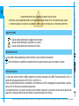 2
2
-
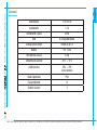 3
3
-
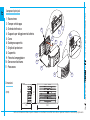 4
4
-
 5
5
-
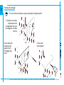 6
6
-
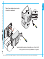 7
7
-
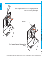 8
8
-
 9
9
-
 10
10
-
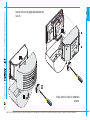 11
11
-
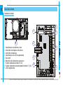 12
12
-
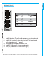 13
13
-
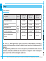 14
14
-
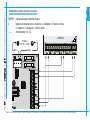 15
15
-
 16
16
-
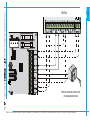 17
17
-
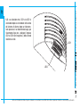 18
18
-
 19
19
-
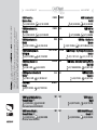 20
20
-
 21
21
-
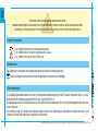 22
22
-
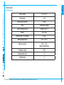 23
23
-
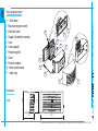 24
24
-
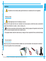 25
25
-
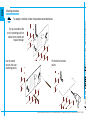 26
26
-
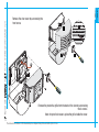 27
27
-
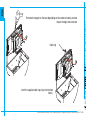 28
28
-
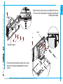 29
29
-
 30
30
-
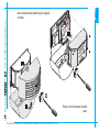 31
31
-
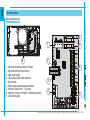 32
32
-
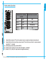 33
33
-
 34
34
-
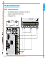 35
35
-
 36
36
-
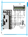 37
37
-
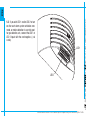 38
38
-
 39
39
-
 40
40
-
 41
41
-
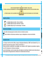 42
42
-
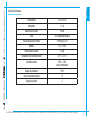 43
43
-
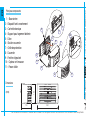 44
44
-
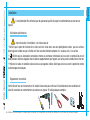 45
45
-
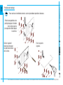 46
46
-
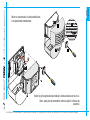 47
47
-
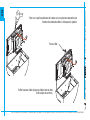 48
48
-
 49
49
-
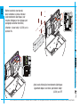 50
50
-
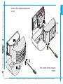 51
51
-
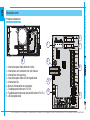 52
52
-
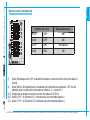 53
53
-
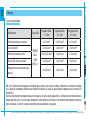 54
54
-
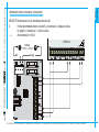 55
55
-
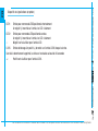 56
56
-
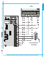 57
57
-
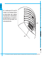 58
58
-
 59
59
-
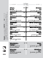 60
60
-
 61
61
-
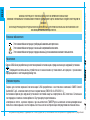 62
62
-
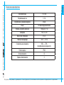 63
63
-
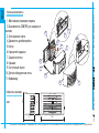 64
64
-
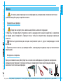 65
65
-
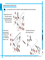 66
66
-
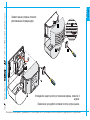 67
67
-
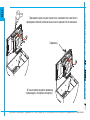 68
68
-
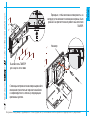 69
69
-
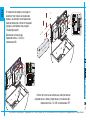 70
70
-
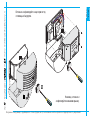 71
71
-
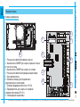 72
72
-
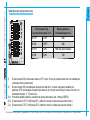 73
73
-
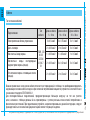 74
74
-
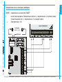 75
75
-
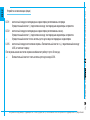 76
76
-
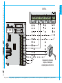 77
77
-
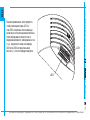 78
78
-
 79
79
-
 80
80


CAME SLUNA, SSIRELED Guía de instalación
- Categoría
- Iluminación exterior
- Tipo
- Guía de instalación
en otros idiomas
- français: CAME SLUNA, SSIRELED Guide d'installation
- italiano: CAME SLUNA, SSIRELED Guida d'installazione
Artículos relacionados
-
CAME HEI, SLUNA/O680 Guía de instalación
-
-
-
-
-
-
-
-
-
