
Documentazione
Tecnica
U34
rev. 0.2
03/2007
©
CAME
CANCELLI
AUTOMATICI
319U34
QUADRO COMANDO
CONTROL
PANEL
ARMOIRE
DE COMMANDE
SCHALTTAFEL
CUADRO
DE MANDO
SERIE Z | Z SERIES | SÉRIE Z | BAUREIHE Z | SERIE Z
ZL170N
CARATTERISTICHE GENERALI
ITALIA-
274
204
133
184
254
DESCRIZIONE QUADRO COMANDO
Quadro elettrico per motoriduttori a 24V d.c.
con alimentazione 230V a.c. monofase con
frequenza 50÷60 Hz.
Progettato e costruito interamente dalla CAME
Cancelli Automatici S.p.A. per il comando di
singoli motoriduttori delle serie FERNI,
EMEGA e FROG, risponde alle vigenti norme
di sicurezza con grado di protezione IP54.
Scatola in ABS.
Garantito 24 mesi salvo manomissioni.
Il quadro comando va alimentato con la tensio-
ne di 230V sui morsetti L1-L2 ed è protetto in
ingresso con fusibile di linea da 3.15A-F.
I dispositivi di comando sono
a bassa tensione e protetti
con fusibile da 630mA-F. La
potenza complessiva degli
accessori a 24V, protetti da
fusibile a 3.15A-F, non deve
superare i 40W.
La schedina ADT (che trovate all’interno della
scatola del quadro), gestisce tutti i rallenta-
menti e/o il finecorsa di apertura, riducendo
la quantità di cavi da collegare (vedi pagine
20 e 21).

-2-
SICUREZZA
Le fotocellule possono essere collegate e
predisposte per:
- Riapertura in fase di chiusura (2-C1), le foto-
cellule rilevando un ostacolo durante la fase di
chiusura del cancello, provocano l’inversione
di marcia fino alla completa apertura;
- Stop parziale (2-C3), arresto del cancello se in
movimento con conseguente predisposi zione
alla chiusura automatica;
- Stop totale (1-2), arresto del cancello con
l’esclusione del ciclo di chiusura automatica;
per riprendere il movimento bisogna agire sulla
pulsantiera o sul radiocomando.
- Il quadro elettrico include un sensore ampe-
rometrico del motore che interviene quando
un ostacolo blocca il movimento in apertura
o in chiusura.
Normalmente ne inverte la direzione di mo-
vimento, ma se interviene quando il cancello
si trova a 5 cm dalla battuta di chiusura o di
apertura, ne arresta il movimento (vedi anche
regolazione del trimmer OP TIME pag. 22).
La sensibilità del dispositivo è regolabile me-
diante trimmers (pag. 27).
Attenzione! Nel caso venga rilevato per
due volte consecutive un ostacolo in fase di
chiusura (e con funzione Chiusura Automati-
ca attivata), l’automazione si comporterà nel
seguente modo:
1) inverte il moto, aprendo completamente
il cancello;
2) disattiva la Chiusura Automatica;
3) blocca qualsiasi funzione del quadro
comando.
Per riattivare l’automazione è necessario dare
un comando di chiusura con i pulsanti collegati
su 2-3, 2-3P e 2-7 (solo pulsante).
- Il trasformatore è dotato di una protezione
che in caso di sovraccarico termico mantiene
l’anta aperta. La richiusura avviene solo dopo
che la temperatura è scesa sotto la soglia di
sovraccarico.
ACCESSORI COLLEGABILI
- Lampada spia per segnalazione “cancello
aperto” (10-5);
- Lampada ciclo per illuminare la zona di
manovra: rimane accesa dal momento in cui
le ante iniziano l’apertura fino alla completa
chiusura (compreso il tempo di chiusura
automatica). Nel caso non venga inserita
la chiusura automatica, rimane accesa solo
durante il movimento.
- Lampeggiatore di movimento, con possibilità
di selezionare il prelampeggio dello stesso (dip
4 selettore funzioni);
- Elettroserratura;
- Scheda LB18 per alimentazione mediante
batterie che, in caso di mancanza di energia
elettrica, interviene automaticamente. Al ri-
pristino della tensione di linea, provvede alla
ricarica delle batterie stesse;
- Scheda radiofrequenza AF, (vedi tabella
pag. 28);
Inoltre è previsto un contatto ausiliario, sui
morsetti A1-A2, per qualsiasi dispositivo da
attivare contemporaneamente al comando
di apertura.
ALTRE FUNZIONI SELEZIONABILI
- Chiusura automatica. Il temporizzatore di
chiusura automatica si autoalimenta a fine-
tempo corsa in apertura. Il tempo prefissato

-3-
Attenzione! Prima di interve nire
all’interno dell’apparecchiatura, togliere la
tensione di linea e scollegare le batterie (se
inserite).
regolabile, è comunque subordinato dall’in-
tervento di eventuali accessori di sicurezza
e si esclude dopo un intervento di “stop” o in
mancanza di energia elettrica;
- Rilevazione ostacolo. A motore fermo (can-
cello chiuso, aperto o dopo un comando di
stop totale), impedisce qualsiasi movimento
se i dispositivi di sicurezza (es. fotocellule)
rilevano un ostacolo;
- Colpo d’ariete. Funzione che facilita lo sgan-
ciamento della serratura; a ogni comando di
apertura, le ante premono in battuta di chiusura
per un secondo, facilitando l’operazione di
sgancio dell’elettroserratura;
- Funzione a “uomo presente”. Funzionamento
del cancello mantenendo premuto il pulsante
(esclude la funzione del radiocomando);
- Selezione tipo di comando:
- «apre-stop-chiude-stop» per pulsante
e/o trasmettitore;
- «apre-chiude-inversione» per pulsante
e/o trasmettitore;
- «solo apre» per trasmettitore.
REGOLAZIONI
- Trimmer SENS/VEL = Regolazione sensibilità
amperometrica durante la marcia: min/max;
- Trimmer SENS/RALL = Regolazione sensi-
bilità amperometrica durante il rallentamento:
min/max;
- Trimmer TCA = Regolazione tempo chiusura
automatica: da 1” a 120”;
- Trimmer TL (OP TIME) = Regolazione della
zona di arresto in battuta (vedi pag. 22);
- Regolazione velocità di marcia e di rallenta-
mento mediante connettori faston sul trasfor-
matore (vedi pag. 27).

-4-
DESCRIPTION OF CONTROL PANEL
Control panel for 24V d.c. gear motors,
powered by 230V a.c. at 50-60 Hz (single-
phase).
Designed to control single FERNI, EMEGA,
and FROG gear motors.
Designed and built entirely by CAME CAN-
CELLI AUTOMATICI S.p.A. to meet safety
standards at an IP 54 protection level.
Housing in ABS.
Guaranteed 24 months, unless tampered
with.
This control panel is powered by 230V a.c.
across terminals L1 and L2, and is protected
by a 3.15A-F fuse on the main power line.
Control systems are powered by low voltage
and protected by a 630mA-F fuse.
The total power consumption of 24V acces-
sories (which are protected by a 3.15A-F fuse)
must not exceed 40 W.
The ADT card (that you find in the control
panel package) manages all the slow-down
and/or end points in the opening phase, thus
reducing the number of connectable cables
(see pages 20 and 21).
SAFETY
Photocells can be connected to obtain:
- Re-opening during the closing cycle (2-C1),
if the photocells identify an obstacle while the
gate is closing, they will reverse the direction
of movement until the gate is completely
open;
- Partial stop, shutdown of moving gate,
with activation of an automatic closing cycle
(2-C3);
- Total stop (1-2), shutdown of gate move-
ment without automatic closing; a pushbutton
or radio remote control must be actuated to
resume movement).
- The electrical panel includes an ampero-
metric sensor for the motor which is triggered
whenever an obstacle blocks movement dur-
ing opening or closing.ù
It normally inverts the direction of movement,
but if it activates when the gate is 5 cm from
being fully close or open, it completely halts
the movement (also see adjusting the OP
TIME trimmer page 23).
The sensor’s sensitivity can be adjusted using
the trimmers (see page 27).
Warning! If an obstacle is detected two times
in a row during the closing phase (and when
the Automatic Closing function is on), the
operator will:
1) it inverts the motion, completely opening
the gate;
2) it deactivates the Automatic Closing;
3) Block all functions of the control panel.
To reactivate the operator, send a “close
command” by pushing the buttons connected
on 2-3, 2-3P and 2-7 (only the button).
- The transformers are equipped with a guard
that will keep the doors open in case of ther-
mal overload.
They are closed again only after the temper-
ature falls below the overload threshold.
GENERAL CHARACTERISTICS
EN-

-5-
ACCESSORIES WHICH CAN BE
CONNECTED TO THIS UNIT
- “Gate open” signal light (10-5);
- Cycle lamp to light the passage area: it re-
mains on from the moment the doors begin to
open until they are fully closed (including the
automatic closing time). If automatic closing
is not activated, the lamp remains on only
during movement.
- Movement flashing lamp with pre-flashing
option (dip 4 function selector);
- Electric lock;
- LB18 circuit card for battery operation, which
is automatically connected in case of power
failure. Battery is recharged when line voltage
is restored.
- Radiofrequency AF board (see table
page 28).
An auxiliary contact is also provided on ter-
minals A1-A2 for any device that should be
activated at the same time as the opening
command.
OTHER FUNCTIONS AVAILABLE
- Automatic closing. The automatic closing
timer is automatically activated at the end of
the opening cycle. The preset, adjustable
automatic closing time is automatically inter-
rupted by the activation of any safety system,
and is deactivated after a STOP command or
in case of power failure;
- Obstacle detection. When the motor is
stopped (gate is closed, open or half-open
after an emergency stop command), the
transmitter and the control pushbutton will
be deactivated if an obstacle is detected by
one of the safety devices (for example, the
photocells);
- Hammer movement. This feature makes it
easy for the lock to release (the door wings
momentarily press against the closure stops
when the open command is given, which fa-
cilitates release of the electric lock);
- “Operator present” function. Gate operates
only when the pushbutton is held down (the
radio remote control system is deactivated);
- Type of command:
- «open-stop-close-stop» for pushbutton
and radio transmitter;
- «open-close-reverse» for pushbutton
and radio transmitter;
- «open only» for radio transmitter.
ADJUSTMENTS
- Trimmer SENS/VEL = Adjustment of
amperometric sensitivity during operating:
min/max;
- Trimmer SENS/RALL = Adjustment of
amperometric sensitivity during slowdown:
min/max;
- Trimmer TCA = Adjustment of automatic
closing time: 1” to 120”;
- Trimmer TL (OP TIME) = Adjusting of the
stop zone (open/closed position, see page
23);
- Faston connectors on the transformer are
used to select normal operating and slowdown
speeds;
Caution! Shut off the mains power
and disconnect the batteries before servi-
cing the inside of the unit.

-6-
DESCRIPTION ARMOIRE DE COMMANDE
Armoire électrique pour motoréducteurs à
24V c.c. avec alimentation 230V monopha-
sée; fréquence 50÷60 Hz.
Entièrement conçue et fabriquée par CAME
Cancelli Automatici S.p.A. pour commander
les différents motoréducteurs de la série
FERNI, EMEGA et FROG, l’armoire est
conforme aux normes de sécurité en vigueur
avec un degré de protection IP 54. Boîtier
en ABS.
Garantie 24 mois sauf en cas d’endomma-
gement.
L’armoire de commande doit être alimentée
avec une tension de 230V sur les bornes L1
et L2 et elle est protégée en entrée par un
fusible de ligne de 3.15A-F. Les dispositifs de
commande sont à basse tension et protégés
avec un fusible de 630mA-F. La puissance
totale des accessoires en 24V, protégés par
un fusible de 3.15A-F, ne doit pas dépasser
40W.
La fiche ADT (que vous trouvez à l’intérieur
du boitier de l’armoire), gère tous les ralen-
tissements et/ou les butées d’ouverture, en
réduisant la quantité de câbles à brancher
(voir pages 20 et 21).
SÉCURITÉ
Il est possible de brancher des photocellules
et de les programmer pour:
- Réouverture en phase de fermeture (2-C1),
les cellules photoélectriques provoquent
l’inversion de marche jusqu’à l’ouverture
complète si elles relèvent un obstacle durant
la phase de fermeture du portail;
- Stop partiel (2-C3), arrêt du portail et ferme-
ture automatique;
- Stop total (1-2), arrêt du portail et désactiva-
tion d’un éventuel cycle de fermeture automa-
tique; pour activer de nouveau le mouvement,
il faut agir sur les boutons-poussoirs ou sur la
radiocommande);
- Le tableau électrique contient un capteur am-
pèremétrique du moteur qui intervient quand
un obstacle bloque le mouvement durant la
phase d’ouverture ou de fermeture.
Normalement il sert pour invertir la direc-
tion du mouvement, mais s’il intervient lors-
que le portail se trouve à 5 cm. de la butée
de fermeture ou d’ouverture, il en arrête le
mouvement (voir aussi réglage du trimmer
OP TIME page 24).
Des compensateurs permettent de régler la
sensibilité du dispositif (page 27).
Attention ! Au cas où un obstacle serait
détecté deux fois de suite au cours de la
fermeture (et avec la fonction Fermeture
Automatique en activité), l’automatisme pro-
cèdera de la façon suivante :
1) il invertit le mouvement en ouvrant com-
plètement le portail ;
2 ) il arrête la Fermeture Automatique ;
3) il bloque absolument toutes les fonc-
tions de l’armoire de commande.
Pour remettre en marche l’automatisme il
faut donner une commande de fermeture
avec les boutons connectés sur 2-3, 2-3P et
2-7 (bouton-poussoir seulement).
- Le transformateur est équipé d’une protec-
tion qui permet au vantail de rester ouvert en
cas de surcharge thermique.
Le renouvellement de la fermeture s’effectue
seulement lorsque la température est descen-
due au-dessous du seuil de surcharge.
CARACTÉRISTIQUES GÉNÉRALES

-7-
ACCESSOIRES POUVANT ÊTRE BRANCHÉS
- Lampe pour signalisation de “portail ouvert”
(10-5);
- Lampe cycle pour éclairer la zone de manœu-
vre: elle reste allumée à partir du moment où
les vantaux commencent à s’ouvrir jusqu’à la
fermeture complète (y compris le temps de
fermeture automatique). Elle ne reste allumée
que durant le mouvement si la fermeture
automatique n’est pas activée.
- Clignotant indiquant le mouvement, avec pos-
sibilité d’en sélectionner le pré-clignotement
(interrupteur 4 sélecteur de fonctions);
- Serrure électrique;
- Carte LB18 pour l’alimentation par batteries
qui intervient automatiquement en cas de cou-
pure de courant. Elle recharge les batteries
quand le courant est rétabli;
- Carte radiofréquence AF (voir tableau
pag. 28);
Un contact auxiliaire est également prévu, sur
les bornes A1-A2, pour n’importe quel dispositif
à activer en même temps que la commande
d’ouverture.
AUTRES FONCTIONS POUVANT ÊTRE
SÉLECTIONNÉES
- Fermeture automatique. Le temporisateur
de fermeture automatique est autoalimenté à
la fin du temps de la course en ouverture. Le
temps réglable est programmé, cependant, il
est subordonné à l’intervention d’éventuels
accessoires de sécurité et il est exclu après
une intervention de “stop” ou en cas de cou-
pure de courant;
- Détection obstacle. Quand le moteur est
arrêté (portail fermé, ouvert ou semi-ouvert,
cette position est obtenue avec une com-
mande de stop total), annule toute fonction
de l’émetteur ou du bouton-poussoir en cas
d’obstacle détecté par les dispositifs de sécu-
rité (ex. Photocellules) ;
- Coup de bélier. Fonction qui facilite le dé-
blocage de la serrure (à chaque commande
d’ouverture, les vantaux se portent en butée
de fermeture pendant une seconde, facilitant
ainsi l’opération de déblocage de la serrure
électrique);
- Fonction “homme mort”. Fonctionnement
du portail en maintenant appuyé le bouton-
poussoir (exclut la fonction de la radiocom-
mande);
- Type de commande:
- «ouverte-stop-fermée-stop» pour bou-
ton-poussoir et émetteur radio;
- «ouverture - fermeture - inversion» pour
bouton-poussoir et émetteur radio;
- «seulement ouverture» pour émetteur
radio.
RÉGLAGES
- Trimmer SENS/VEL = Réglage sensibilité
ampèrométrique pendant le mouvement :
min./max;
- Trimmer SENS/RALL = Réglage sensibilité
ampèrométrique pendant le ralentissement :
min./max;
- Trimmer TCA = Temps de fermeture auto-
matique: de 1 à 120”;
- Trimmer TL (OP TIME) = Réglage de l’em-
placement d’arrêt en butée (voir page 24).
- Réglage vitesse de mouvement et de ra-
lentissement à l’aide de connecteurs rapides
placés sur le transformateur (voir page 27).
Attention! Avant d’intervenir à l’in-
térieur de l’appareillage, couper la tension
de ligne et débrancher les batteries (si
branchées).

-8-
BESCHREIBUNG DES STEUERGERÄTS
Schalttafel für 24-V-Gleichstrom-Getrie-
bemotoren mit 230-V-Einphasen strom-
versorgung; Frequenz: 50-60 Hz.
Vollkommen von der CAME Cancelli Auto-
matici S.p.A. zur Steuerung von einzelnen
Getriebemotoren der Serie FERNI, EMEGA
und FROG entsprechend den geltenden
Sicherheitsnormen mit Schutzgrad IP54 ent-
wickelt und hergestellt. ABS-Gehäuse.
24 Monate Garantie, vorbehaltlich unsachge-
mäßer Handhabung und Montage.
Die Schalttafel wird mit einer Spannung von
230V über die Klemmen L1 und L2 gespeist
und ist am Eingang mit einer 3.15-A-F-
Hauptsicherung. Die Steuerungen erfolgen
mit Niederspannung und geschützen enie
630mA-F-Sicherung. Die Gesamtleistung des
durch eine 3.15-A-F-Sicherung geschützten
24-V-Zubehörs darf 40W nicht überschrei-
ten.
Die ADT-Steuerung (im innern des Schalt-
schrankes) steuert sämtliche Soft-Stops bzw.
Endläufe im Auflauf, auf diese Weise müssen
weniger Kabel angeschlossen werden (siehe
Seite 20 und 21).
SICHERHEITSVORRICHTUNGEN
Die Lichtschranken können für folgende
Funktionen angeschlossen bzw. vorbereitet
werden:
- Wiederöffnen beim Schließen (2-C1), die
Lichtschranken ermitteln ein Hindernis wäh-
rend des schließens vom Tor und lösen die
Umkehr der Laufrichtung vom Tor aus, bis
dieses wieder vollständig geöffnet ist;
- Teilstop (2-C3), Stillstand des Tores während
des Torlaufs, mit darauffolgender automati-
scher Torschließung;
- Totalstop (1-2), sofortiger Stillstand des Tores
mit Ausschluß eventueller Schließautomatik:
Fortsetzung des Torlaufs über Drucktaster-
bzw. Funksendersteuerung;
- Auf der Schalttafel befindet sich ebenfalls ein
Motor-Stromsensor, welcher eingreift, wenn
die Bewegung beim Öffnen und Schließen
durch ein Hindernis blockiert wird.
Normalerweise wird der Torlauf reversiert,
doch wenn der Torflügel nur 5 cm von den
Toranschlägen entfernt ist, wird der Torlauf
unterbrochen (siehe auch Einstellung des
Trimmers OP TIME auf Seite 25).
Die Empfindlichkeit der Vorrichtung ist durch
Trimmer einstellbar (seite. 27).
Achtung! Sollte während des Zulaufs zweimal
hintereinander ein Hindernis erfasst werden
(bei aktiviertem Autozulauf), bewirkt der au-
tomatische Antrieb folgendes:
1) Reversierung bis zur völligen Toröff-
nung;
2) Deaktivierung des Autozulaufs;
3) Jede Funktion der Steuerung wird blo-
ckiert.
Um den Antrieb wieder zu reaktivieren muss
mit den auf 2-3, 2-3P und 2-7 (nur Schalter)
angeschlossenen Tastern ein Zu-Befehl ge-
geben werden.
- Der Transformator Ist mit einer Sicherung
ausgestattet, die bei Wärmestau dafür sorgt,
daß der Türflügel offen bleibt.
Das Tor schließt erst wieder, wenn die Tem-
peratur unter das Niveau der Überladung
abgesunken ist.
ALLGEMEINE MERKMALE
DEUT-

-9-
ANSCHLIESSBARES ZUBEHÖR
- Anzeigeleuchte für “Tor offen” (10-5);
- Betriebszyklus-Anzeigeleuchte. Das Licht,
das den Torbereich beleuchtet, bleibt vom
Beginn des Öffnens bis zum vollständigen
Schließen der Torflügel eingeschaltet (ein-
schließlich Wartezeit für automatisches
Schließen). Wenn das automatische
Schließen nicht zugeschaltet ist, bleibt das
Licht nur während der Torbewegung einge-
schaltet (10-E3).
- Bewegungsblinker mit der Wahlmöglichkeit
von vorherigem Blinken (dip 4 Funktionswähl-
schalter);
- Elektroschloß;
- Karte LB18 für Stromversorgung über
Notbatterien, die sich bei Stromausfall
automatisch zuschalten. Bei erneuter Netz-
stromversorgung lädt dieselbe die Batterien
erneut aut.
- Funkfrequenz-Platine AF (siehe Tabelle
Seite 28);
Es ist ferner ein Zusatzkontakt auf den Klem-
men A1-A2 für jede beliebige Vorrichtung,
die gleichzeitig mit der Öffnungssteuerung zu
aktivieren ist, vorgesehen.
ANDERE WAHLFUNKTIONEN
- Schließautomatik. Der Schließautomatik-Zei-
schalter speist sich beim Öffnen am Ende der
Torlaufzeit selbst . Die voreingestellte Zeit ist
auf jeden Fall immer dem Eingriff eventueller
Sicherheitsvorrichtungen untergeordnet und
schließt sich nach einem “Stop”-Eingriff bzw.
bei Stromausfall selbst aus;
- Hinderniserfassung. Bei stillstehendem
Motor (Tor geschlossen, geöffnet oder durch
eine Totalstop-Steuerung halb geöffnet) wird
bei durch die Sicherheitsvorrichtungen (z.B.:
Lichtschranken) erfaßtem Hindernis jede Sen-
der- oder Drucktasterfunktion annulliert;
- Widderstoß. Funktion, die das Auslösen
des Elektroschlosses erleichtert; (bei jeder
Öffnungssteuerung üben die Torflügel eine
Sekunde lang einen leichten Druck auf den
Schließungsendanschlag aus und erleichtern
dadurch die Entriegelung des Elektroschlos-
ses);
- Funktion “Bedienung vom Steuerpult”. Tor-
betrieb durch Druck tasterbetätigung (Funk-
fernsteuerung ausgeschlossen);
- Steuerart:
- «Öffnen-Stop-Schließen-Stop» für
Drucktaster- und Funksendersteuerart;
- «Öffnen-Schließen-Torlaufumsteue-
rung» für Drucktaster und Funksender-
steuerart;
- «nur Öffnen» für Funksendersteuerart.
EINSTELLUNGEN
- Trimmer SENS/VEL = Einstellung der am-
peremetrischen Empfindlichk eit während
Laufgeschwindigkeit: min/max;
- Trimmer SENS/RALL = Einstellung der
amperemetrischen Empfindlichk während
Laufverlangsamung: min/max;
- Trimmer TCA = Zeiteinstellung Schließauto-
matik: von 1” bis 120”,
- Trimmer TL (OP TIME) = Einstellung des
Toranschlages (siehe Seite 25);
- Einstellung der Laufgeschwindigkeit und der
Laufverlangsamung über Faston-Verbinder
am Transformator (siehe Seite 27).
Achtung! Das Gerät vor Eingriffen
im inneren spannungsfrei schalten und
die Stromzufuhr mittels Batterien (falls
zugeschaltet) unterbrechen.

-10-
DESCRIPCIÓN CUADRO DE MANDO
Cuadro eléctrico para motorreductores a
24V d.c. con alimentación 230V monofase:
frecuencia 50÷60 Hz.
Diseñado y fabricado enteramente por CAME
CANCELLI AUTOMATICI S.p.A. para el accio-
namiento de motorreductores independientes
serie FERNI, EMEGA y FROG, cumple con
las normas de seguridad vigentes, con grado
de protección IP 54 e caja de ABS. Garantiza-
do 24 meses salvo manipulaciones.
El cuadro de mando se alimenta con una
tensión de 230V en los bornes L1 y L2 y está
protegido en entrada con fusible de línea de
3.15A-F. Los dispositivos de mando son a
baja tensión y està protegidos por fusible a
630mA-F. La potencia total de los accesorios
a 24V, protegidos por fusible a 3.15A-F, no
debe superar los 40W.
La tarjeta ADT (que está dentro de la caja del
cuadro), controla todas las desaceleraciones
y/o el final de carrera de apertura, reducien-
do la cantidad de cables a conectar (véase
páginas 20 y 21).
SEGURIDAD
Las fotocélulas pueden estar conectadas y
predispuestas para:
- Reapertura en la fase de cierre (2-C1), las
fotocélulas detectan un obstàculo durante el
cierre de la puerta, provocando la inversión de
marcha hasta la apertura completa;
- Parada parcial (2-C3), parada de la puerta
si se encuentra en movimiento con la consi-
guiente predisposición al cierre automático;
- Parada total (1-2), parada de la puerta ex-
cluyendo el posible ciclo de cierre automático;
para reactivar el movimiento es preciso actuar
en el teclado o en el mando a distancia);
- El cuadro eléctrico incluye un sensor ampe-
rimétrico del motor que se activa cuando un
obstáculo bloquea el movimiento durante la
apertura o cierre.
Normalmente invierte la dirección de movi-
miento, pero si interviene cuando la cancela
está a 5 cm del tope de cierre o de apertura,
detiene el movimiento (véase también regu-
lación del trimmer OP TIME pág. 26).
La sensibilidad del dispositivo se ajusta con
los trimmers (pág.27).
¡Atención! Si se detectase dos veces con-
secutivas un obstáculo en fase de cierre (y
con función Cierre Automático activada), la
automatización se comportará de la siguien-
te manera:
1) invierte el movimiento, abriendo com-
pletamente la cancela;
2) desactiva el Cierre Automático;
3) bloquea cualquier función del cuadro de
mando.
Para reactivar la automatización es nece-
sario dar un mando de cierre con los pulsa-
dores conectados en 2-3, 2-3P y 2-7 (sólo
pulsador).
- El transformador está equipado con una
protección que ante una sobrecarga térmica
mantiene abiertas las hojas.
El recierre se verifica recién después que la
temperatura ha descendido por debajo del
nivel de sobrecarga.
CARACTERISTICAS GENERALES
ESPA-

-11-
ACCESORIOS CONECTABLES
- Lámpara por señal de “puerta abierta”
(10-5);
- Lámpara ciclo para iluminar la zona de
maniobra: queda encendida desde cuando
las hojas comienzan a abrirse hasta que se
cierran por completo (incluido el tiempo de
cierre automático). Si no se conectara el cierre
automático, queda encendida sólo durante el
movimiento.
-Luz intermitente de movimiento con posibili-
dad de seleccionar la intermitencia previa (dip
4 selector funciones);
- Cerradura eléctrica;
- Tarjeta LB18 para la alimentación mediante
baterías que, en caso de falta de energía
eléctrica, interviene automáticamente. Una
vez conectada de nuevo la tensión de línea,
se ocupa de cargar las baterías;
- Tarjeta radiofrecuencia AF (ver tabla
pág.28);
También se ha previsto un contacto auxiliar, en
los bornes A1-A2, para cualquier dispositivo
que se haya de activar simultáneamente al
mando de apertura.
OTRAS FUNCIONES SELECCIONABLES
- Cierre automático. El temporizador de cierre
automático se autoalimenta en fin-de-tiempo
carrera en fase de apertura. El tiempo prefija-
do regulable, sin embargo, está subordinado
a la intervención de posibles accesorios
de seguridad y se excluye después de una
intervención de parada o en caso de falta de
energía eléctrica;
- Detección obstáculo. Con el motor parado
(puerta cerrada, abierta o en posición semi-
abierta obtenida a través de un comando
de stop total), anula cualquier función del
transmisor o del botón en caso de obstáculo
detectado por los dispositivos de seguridad
(por ejemplo: fotocélulas);
- Golpe de ariete. Función que facilita el des-
enganche de la cerradura (en cada comando
de apertura las puertas presionan el tope
del cierre durante un segundo, facilitando la
operación de desenganche de la electroce-
rradura);
- Función a “hombre presente”. Funciona-
miento de la puerta manteniendo pulsada la
tecla (excluye la función del mando a distan-
cia);
- Tipo de mando;
- «apertura-parada-cierre-parada» para
tecla y transmisor de radio;
- «apertura-cierre-inversión» para tecla y
transmisor de radio;
- «sólo apertura» para transmisor de
radio.
REGULACIONES
- Trimer SENS/VEL = Regulación sensibilidad
amperimétrica durante la marcha: mín/máx;
- Trimer SENS/RALL = Regulación sensibili-
dad amperimétrica durante el ralentamiento:
mín/máx;
- Trimer TCA = Tiempo cierre automático: de
1” a 120”;
-> Trimmer TL (OP TIME) = Regulación de la
zona de parada en el tope (véase pág. 26);
- Regulación velocidad de marcha y de dece-
leración por medio de conectores faston en el
transformador (véase pág. 27).
¡Atención! Antes de actuar dentro
del aparato, quitar la tensión de línea y
desecnectar las baterías (si estuvieran
conectadas).

-12-
SCHEDA BASE -
MOTHERBOARD
-
CARTE BASE -
GRUNDPLATINE - TARJETA BASE
1) Trasformatore
2) Trimmer di regolazione sensibilità amperome-
trica durante la marcia
3) Trimmer di regolazione sensibilità amperome-
trica durante il rallentamento
4) Trimmer di regolazione della zona di arresto
in battuta
5) Trimmer di regolazione chiusura automatica
6) Pulsante memorizzazione codice
7) Morsettiera per il collegamento al caricabatte-
rie LB18 (vedi pag. 17)
8) Fusibile centralina 630mA-F
9) Fusibile accessori 3.15A-F
10) LED di segnalazione codice radio
11) Selettore funzioni
12) Jumper selezione uscita
B1-B2/lampada ciclo
13) Fusibile di linea 3.15A-F
14) Innesto scheda radiofrequenza
15) Morsettiera di collegamento
16) Schedina ADT per gestione rallentamenti
(vedi pagg. 20/21)
17) Morsettiera per ADT (da usare solo con Frog
24V, vedi pag. 21)
COMPONENTI PRINCIPALI
ITALIANO
230V
230V
0
12
24
RALL.MIN
RALL.MAX
VEL.MIN
VEL.MAX
AF
ZL170
QUADRO COMANDO
PROG
SEN S VEL T LSENS RALL T C A
A BCDEF I
MORSETTIERA CARICA BATTERIE
R1
FUSIBILE
CENTRALINA
630mA
FUSIBILE
ACCESSORI
3.15A
230V
FUSIBILE
CENTRALINA
3.15A
2
1 345678910
ON
21
0 RALL VEL 24V 12V
J2
L1 L2 M NR 10 11 E E3 5 S 1 237C1C3
A1
T
B1 B2
A2
T
1
2
RA R RC FA F M N
MNR
ADT x ZL170
7
8
9
32 4 5
10
14
11
13
15
16
1
NERO - BLACK - NOIR - SCHWARZ - NEGRO
BLU - BLUE - BLEU - BLAU - AZUL
MARRONE - BROWN - MARRON - BRAUN - CASTÁÑO
ROSSO - RED - ROUGE - ROT - ROJO
BIANCO - WHITE - BLANC - WEISS - BLANCO
BLU - BLUE - BLEU - BLAU - AZUL
VIOLA - PURPLE - VIOLET - VIOLETT - PÚRPURA
17
6
12

-13-
MAIN COMPONENTES
1) Transformer
2) Trimmer for adjustment of amperometric
sensitivity during operation
3) Trimmer for adjustment of amperometric
sensitivity during slowdown
4) Trimmer to adjust the stop zone
(open/closed position)
5) Trimmer for adjustment of automatic closing
6) Button for memorizing code
7) Terminal board for connectiong battery
charger LB18 (see pag. 17)
8) Fuse on central control unit, 630 mA
9) Fuse on accessory power line, 3.15A
10) Radio code signal LED
11) Functions switch
12) Jumper which selects output B1-B2/operating
cycle indicador light
13) Line fuse, 3.15A
14) Radiofrequency board socket
15) Terminal block for external connections
16) ADT card for slowdown control (see pages
21/21)
17) ADT terminal board (to be used only with Frog
ENGLISH
PRINCIPAUX COMPOSANTS
1) Transformateur
2) Trimmer de réglage sensibilité
ampèremétrique pendant le mouvement
3) Trimmer de réglage sensibilité
ampèremétrique pendant le ralentissement
4) Trimmer de réglage de l’emplacement d’arrêt
en butée
5) Trimmer de réglage fermeture automatique
6) Bouton-poussoir mémorisation code
7) Plaque à bornes pour le branchement au
chargeur de batteries LB18 (voir page 17)
8) Fusible boîtier 630mA
9) Fusible accessoires 3.15A
10) LED de signalisation code radio
11) Selecteur de fonctions
12) Pontet sélection sortie B1-B2/lampe cycle
13) Fusible de ligne 3.15A
14) Branchement carte radiofréquence
15) Plaque à bornes de connexion
16) Carte ADT pour gérer les ralentissements
(voir pages 20/21)
17) Plaque à bornes pour ADT (à n’utiliser
qu’avec Frog 24V, voir page 21)
FRANÇAIS
HAUPTKOMPONENTEN
1) Transformatoren
2) Trimmer zur Einstellung amperemetrischen
Empfindlichkeit während Laufgeschwindigkeit
3) Trimmer zur Einstellung amperemetrischen
Empfindlichkeit während Laufverlangsamung
4) Trimmer zur Einstellung des Toranschlages
5) Trimmer zur Einstellung der Schließautomatik
6) Code-Speichertasten
7) Klemmleiste für den Anschluß an das
Batterieladegerät LB18 (siehe Seite 17)
8) Schaltkastensicherung 630mA
9) Zubehör-Sicherung 3.15A
10) Anzeige LED-Funkcode
11) Wählschalter für Funktionen
12) Jumper zur Wahl des Ausgangs B1-B2/
Betriebszyklus Anzeigeleuchte
13) Hauptsicherung 3.15A
14) Steckanschluß Funkfrequenz-Platine
15) AnschlußKlemmenleiste
16) Karte ADT zur Verwaltung der
Verlangsamungen (siehe Seiten 20/21)
17) Klemmenbrett ADT (nur mit Frog 24V zu
benutzen, siehe Seite 21).
DEUTSCH
PRINCIPALES COMPONENTES
1) Transformadores
2) Trimer de regulación sensibilidad
amperimétrica durante la marcha
3) Trimer de regulación sensibilidad
amperimétrica durante el ralentamiento
4) Trimmer de regulación de la zona de parada
en el tope
5) Trimer de regulación tiempo cierre automático
6) Teclas memorización códigos
7) Caja de bornes para la conexión del cargador
de batería LB18 (véase pág. 17)
8) Fusible para central 630mA
9) Fusible accesorios 3.15A
10) LED de señal código radio
11) Selector de funciones
12) Jumper selección salida B1-B2/lámpara ciclo
13) Fusible de línea 3.15A
14) Conexión tarjeta radiofrecuencia
15) Caja de bornes para las conexiónes
16) Tarjeta ADT para gestión de deceleraciones
(véanse págs. 20/21)
17) Caja de conexiones para ADT (se usa sólo
con Frog 24V, véase pág. 21)
ESPANOL

-14-
Alimentazione quadro comando - 230V (a.c.)
Power supply for control unit - 230V (a.c.)
Alimentation armoire de commande - 230V (c.a.)
Stromversorgung Steuergerät - 230V (Wechselstrom)
Alimentación cuadro de mando - 230V (a.c.)
Alimentazione accessori (max 40W):
- 24V (a.c.) con alimentazione a 230V(a.c.)
- 24V (d.c.) con alimentazione a 24V (d.c.)
Power supply to accessories (max. 40W):
24V (a.c.) with power supply at 230V (a.c.)
24V (d.c.) with power supply at 24V (d.c.)
Alimentation accessoires (max 40W):
- 24V (c.a.) avec alimentation à 230V(c.a.)
- 24V (c.c.) avec alimentation à 24V (c.c.)
Stromversorgung Zubehör (max 40W):
- 24V (Wechselstrom) bei Stromversorgung 230V(Wechselstrom)
- 24V (Wechselstrom) bei Stromversorgung 24V (Gleichstrom)
Alimentación accesorios (max 40W):
- 24V (a.c.) con alimentación a 230V(a.c.)
- 24V (d.c.) con alimentación a 24V (d.c.)
Uscita 24V-25W max.in movimento (es. lampeggiatore)
24V-25W max. output in motion (e.g. flashing light)
Sortie 24V-25W max. en mouvement (ex. clignotant)
Ausgang 24V-25W max. “in Bewegung” (z.B. Blinkleuchte)
Salida 24V-25W max. en movimiento (por ej. lámpara intermi-
tente)
Collegamento elettroserratura (12V-15W max.)
con EMEGA, vedi anche pag. 17
Connection for electrically-actuated lock: 12V-15W max.
With EMEGA please also see pg. 17
Connexion serrure électrique (12V-15W max.)
avec EMEGA, voir également page 17
Anschluß Elektroschloß (12V-15W max.)
Mit EMEGA, siehe auch Seite 17
Conexión electrocerradura (12V-15W max.)
con EMEGA, véase también pág. 17
Lampada spia 24V-3W max. “cancello aperto”
24V-3W max. gate-open signal lamp
Lampe-témoin 24V-3W max. “vantail ouvert”
Kontrollampe 24 V-3W max. “Tor geöffnet”
Lámpara indicadora 24V-3W max. “puerta abierta”
11
S
L1
L2
10
11
10
E
10
5

-15-
2
7
2
3
2
C1
2
C3
Collegamento antenna
Antenna connection
Connexion antenne
Antennenanschluß
Conexión antena
Pulsante di stop (N.C.)
Stop button (N.C.)
Bouton-poussoir de stop (N.F.)
Stop-Taste (Ruhekontakt)
Tecla de parada (N.C.)
Pulsante apre (N.O.)
Open button (N.O.)
Bouton-poussoir d’ouverture (N.O.)
Taste Öffnen (Arbeitskontakt)
Tecla de apertura (N.O.)
Collegamento radio e/o pulsante (N.O.)
Connector (N.O.) radio and/or pushbutton
Connection radio et/ou bouton-poussoir (N.O.)
Anschluß Funkfernsteuerung und/oder Drucktaster (N.O.)
Conexión radio y/o pulsador (N.O.)
Contatto (N.C.) di riapertura in fase di chiusura
(da cortocircuitare se non viene utilizzato)
Contact (N.C.) for re-opening during closure
(should be short circuited if not used)
Contact (N.F.) de réouverture pendant la fermeture
(à court-circuiter s’il n’est pas utilisé)
Ruhekontakt Wiederöffnen beim Schließen
(bei Nichtbenutzung kurzzuschließen)
Contacto (N.C.) para la apertura en la fase de cierre
(se cortocircuita si no se utiliza)
Contatto (N.C.) di Stop parziale
Partial stop contact (N.C.)
Contact (N.F.) d’arrêt partiel
Ruhekontakt Partial-Stop
Contacto (N.C.) de parada parcial
1
2

-16-
Uscita contatto (N.O.): si chiude per 3” a ogni coman-
do di apertura. Portata contatto: 5A (250V a.c.)
Contact outlet (N.O.): it is closed for 3” upon opening
command. Contact capacity: 5A (250V AC)
Sortie contact (N.O.): il se ferme pendant 3’’ à chaque
commande d’ouverture. Débit contact: 5A (250V a.c.)
Kontaktausgang (N.O.): schließt sich bei jeder Öffnungs-
steuerung für 3”. Leistung: 5A (250V WS)
Salida contacto (N.A.): se cierra durante 3” cada vez que se
acciona la apertura Capacidad contacto: 5A (250V a.c.)
-
JUMPER IN POS. A (DEFAULT)
Lampada ciclo a 24V - 25W max
-
JUMPER IN POSITION A (DEFAULT)
24V - 25W max cycle indicador light
-
PONTET EN POS. A (DEFAULT)
Lampe cycle 24V - 25W max
-
JUMPER AUF POS. A GESCHALTET (DEFAULT)
Betriebszyklus-Anzeigeleuchte 24V - 25W max
-
JUMPER IN POS. A (DEFAULT)
Lampara ciclo 24V - 25W max
-
JUMPER IN POS. B
Uscita contatto (N.O.) 2° canale radio
Portata contatto: 1A a 24V d.c.
-
JUMPER IN POSITION B
Contact output (N.O.) 2
nd
radio channel
Contact capacity: 1A to 24V d.c.
-
PONTET EN POS. B
Sortie contact (N.O.) 2
eme
canal radio
Porté du contact: 1A à 24V c.c.
-
JUMPER AUF POS. B GESCHALTET
Ausgang Arbeitskontakt Stromfestigkeit gemäß Radiokanal
Stromfestigkeit Kontakt: 1A bei 24V Gleichstrom
-
JUMPER IN POS. B
Salida contacto (N.O.) 2° canal radio
Capacidad contacto: 1A a 24V d.c.
Jumper 12 pag. 12
COLLEGAMENTI ALTERNATIVI
ALTERNATIVE CONNECTIONS
BRANCHEMENTS ALTERNATIFS
ALTERNATIVE ANSCHLÜSSE
CONEXIONES ALTERNATIVAS
A1
A2
10
E3
B1
B2
B
A

-17-
CONFIGURAZIONE MORSETTIERA PER LB18 - TERMINAL BOARD CONFIGURATION FOR LB18 - CONFIGURATION DE LA PLAQUE À BORNES POUR
LB18 - KLEMMENBRETTKONFIGURATION FÜR LB 18 - CONFIGURACIÓN CAJA DE CONEXIONES PARA LB18
Nel caso di utilizzo della scheda caricabatterie LB18, togliere tutti i
ponticelli e collegare la scheda come indicato nella relativa documen-
tazione.
In case the LB18 battery charger card is used, remove all jumpers
and connect the card as indicated in the card’s relevant documenta-
tion.
En cas d’utilisation de la carte LB18 pour charger les batteries, enlever
tous les fi ls de liaison et brancher la carte comme indiqué dans la
documentation correspondante.
Bei Benutzung der Batterielade-Karte LB18 alle Überbrückungen
entfernen und die Karte nach den Angaben in der entsprechenden
Anleitung anschließen.
Si se utiliza la tarjeta cargador de baterías LB18, elimine todas las
conexiones puente y conecte la tarjeta tal como indicado en la docu-
mentación respectiva.
Confi gurazione di fabbrica
Standard factory confi guration
Confi guration effectuée en usine
Werkkonfi guration
Confi guración de fábrica
Particolarità dell’abbinamento ZL170N/EMEGA con serratura elettrica E881
Details of the ZL170N/EMEGA with E881 electric lock
Branchement spécial ZL 170N/EMEGA avec serrure électrique E881
Besonderheiten bei der Koppelung ZL170N/EMEGA mit elektrischem Schloß E881
Peculiaridad de la combinación ZL170N/Emega/cerradura E881
Per alimentare a 24V la serratura E881 sui morsetti 11-S (normalmen-
te a 12V) agire sui ponticelli come segue:
Fig. A - CON scheda LB18, lasciare un solo ponticello su B-D e collega-
re la scheda come indicato nella relativa documentazione.
Fig. B - SENZA scheda LB18, modifi care il ponticello C-D in B-D
To power the E881 lock at 24V on terminals 11-S (normally at 12V)
adjust the jumpers as follows:
Fig. A - WITH LB18 board, leave just one jumper on B-D and connect
the board as shown in the relative documentation.
Fig. B - WITHOUT LB18 board, change jumper C-D into B-D.
Pour alimenter la serrure E881 sur les bornes 11-S en 24 V (normale-
ment en 12 V), agir sur les fi ls de liaison comme suit:
Fig. A - AVEC la carte LB18, ne laisser qu’un fi l de liaison sur B-D et
brancher la carte comme indiqué dans la documentation correspon-
dante.
Fig. B - SANS carte LB18, modifi er le fi l de liaison C-D en B-D.
Zur Speisung des Schlosses E881 an den Klemmen 11-S bei 24V
(gewöhnlich bei 12V), wie folgt auf die Überbrückungen einwirken:
Abb. A - MIT Karte LB18, nur eine Überbrückung an B-D lassen und
die Karte nach den Anleitungen in der entsprechenden Dokumentation
anschließen.
Abb. B - OHNE Karte LB18, die Überbrückung C-D in B-D ändern.
Para alimentar a 24V la cerradura E881 en los bornes 11-S (normalmente a 12V) actúe sobre los conectortes
puentes de la siguiente manera:
Fig. A - CON tarjeta LB18, deje un solo conector puente en B-D y conecte la tarjeta como indicado en la
documentación respectiva.
Fig. B - SIN tarjeta LB18, modifi que el puente C-D en B-D
Fig. /Abb. A
ZL170N + EMEGA + LB18 + E881
Fig. /Abb. B
ZL170N + EMEGA + E881

-18-
1 ON Chiusura automatica attivata;
2 ON Funzionamento pulsante o comando
radio “apre/chiude/inversione”
attivato;
2 OFF Funzionamento pulsante o comando
radio “apre/stop/chiude/stop”
attivato;
3 ON Funzionamento comando radio “solo
apertura” attivato;
4 ON Prelampeggio in apertura e in
chiusura attivato;
5 ON Rilevazione dell’ostacolo attivato;
6 ON Funzionamento a “uomo presente”
attivato; (esclude la funzione del
radiocomando)
7 ON Funzione colpo d’ariete attivato; (per
facilitare lo sgancio della serratura)
8 OFF Stop parziale attivato; con dispositivo
di sicurezza collegato ai morsetti
2-C3, (se non viene utilizzato il
dispositivo, selezionare il dip in ON)
9 OFF Pulsante “stop” attivato; con
dispositivo di sicurezza collegato ai
morsetti 1-2, (se non viene utilizzato il
dispositivo, selezionare il dip in ON)
10 Deve rimanere in OFF
ITALIANO
1 ON Automatic closure enabled;
2 ON “Open/close/reverse” radio control or
pushbutton function enabled;
2 OFF “Open/stop/close/stop” radio control
or pushbutton function enabled;
3 ON “Only open” radio control function
enabled;
4 ON Pre-flashing (opening and closing)
enabled;
5 ON Obstacle detection device enabled;
6 ON “Operator present” operation
enabled; (radio remote control is
deactivated when function is se-
lected)
7 ON Hammer movement operation ena-
bled; (this function helps unlock the
electric lock)
8 OFF “Partial-stop” enabled; insert the
safety device on terminal 2-C3 (if not
used, set the dip-switch to ON)
9 OFF “Stop” button enabled; insert the
safety device on terminal 1-2 (if not
used, set the dip-switch to ON)
10 Must stay OFF
ENGLISH
SELETTORE FUNZIONI - FUNCTIUONS SWITCH - SELECTEUR DE FONCTIONS
WÄHLSCHALTER FÜR FUNKTIONEN - SELECTOR DE FUNCIONES
DIP-SWITCH 10 VIE
10-WAY DIP-SWITCH
DIP-SWITCH 10 VOIES
ZEHNWEG-DIP-SWITCH
DIP-SWITCH 10 VÍAS

-19-
1 ON Cierre automático activado;
2 ON Funcionamiento tecla o radiomando
“apertura/cierre/inversión” activado;
2 OFF Funcionamiento tecla o radiomando
“apertura/parada/cierre/parada”
activado;
3 ON Funcionamiento radiomando “sola
apertura” activado;
4 ON Pre-intermitencia en la fase de
apertura y cierre activado;
5 ON Detección del obstáculo activado;
6 ON Funcionamiento a “hombre presente”
activado; (escluye la función del
mando de radio)
7 ON Funcionamiento golpe de ariete
activado; (esta función sirve
para agilizar desenganche de la
electrocerradura)
8 OFF “Parada parcial” activada; introducir
el dispositivo de seguridad en los
bornes 2-C3, (si no se utiliza, poner el
dip en ON)
9 OFF “Pulsador parada” activada;
introducir el dispositivo de seguridad
en los bornes 1-2, (si no se utiliza,
poner el dip en ON)
10
Debe quedar en OFF
ESPANOL
1 ON Fermeture automatique activé;
2 ON Fonctionnement bouton-possoir ou
commande radio “ouverte/fermeé/
inversion” activé;
2 OFF Fonctionnement bouton-possoir ou
commande radio “ouverture/stop/
fermeture/stop” activé;
3 ON Fonctionnement commande radio
“ouverture seulement” activé;
4 ON Preclignotement pandant la phase
d’ouverture et de fermeture activé;
5 ON Dispositif de détection d’obstacle
activé;
6 ON Fonctionnement avec “homme
mort” activé; (exclut la fonction
radiocommande)
7 ON Fonctionnement coup de bélier
activé; (pour faciliter le déblocage de
la serrure)
8 OFF “Arrêt partiel” activé; monter le
dispositif de sécurité sur les bornes
2-C3, (s’il n’est pas utilisé, positionner
l’interrupteur à positions multiples sur
ON)
9 OFF Poussoir “stop” activé; monter le
dispositif de sécurité sur les bornes
1-2, (s’il n’est pas utilisé, positionner
l’interrupteur à positions multiples sur
ON)
10 Il doit rester sur OFF
FRANÇAIS
1 ON Schließautomatik zugeschaltet;
2 ON Betrieb Funkfernsteuerung und
Drucktaster “Umschalten/Öffnen/
Schließen” zugeschaltet
2 OFF Betrieb Funkfernsteuerung und
Drucktaster “Öffnen/Stop/Schließen/
Stop” zugeschaltet;
3 ON Betrieb Funkfernsteuerung “nur
Öffnen” zugeschaltet;
4 ON Vorblinken beim Öffnen und
Schließen zugeschaltet;
5 ON Hindemisaufnahme zugeschaltet;
6 ON Bedienung vom “Steuerpult”
zugeschaltet; (bei Wahl
dieser Betriebsart wird die
Funkfernsteuerung ausgeschlossen)
7 ON Funktion Widderstoß zugeschaltet;
(durch diese Funktion wird das
Auslösen des Elektroschlosses
erleichtert)
8 OFF “Teilweiser-Stop” zugeschaltet;
stecken Sie die Sicherung in die
Klemmen 2-C3 (falls nicht verwendet,
schalten Sie den Dip auf ON)
9 OFF “Stop-Taste” zugeschaltet; stecken
Sie die Sicherung in die Klemmen 1-2
(falls nicht verwendet, schalten Sie
den Dip auf ON)
10 Muss auf OFF eingestellt bleiben
DEUTSCH

-20-
La schedina ADT va fi ssata alla morsettiera del motoriduttore come illustrato,
e collegata al quadro solamente con i morsetti M, N e R (il morsetto RA non
è attivo su FERNI ed EMEGA).
N.B. A fi ne installazione, è necessario memorizzare il tempo di lavoro
dell’automazione, nel seguente modo:
1 - mettere il dip 6 in ON;
2 - premere CH1 fi no all’apertura completa del cancello;
3 - premere CH2 e rilasciarlo quando il cancello è completamente chiuso;
4 - riportare il dip 6 in OFF.
The ADT card is fastened to the gear motor terminal board as illustrated,
and connected to the control panel only with terminals M, N and R (RA
terminal is not active with FERNI and EMEGA).
N.B.: once the installation is completed, you need to memorize the
operating time in the following way:
1 - select the dip 6 in ON;
2 - keep CH1 pressed until the gate is completely open;
3 - keep CH2 pressed until the gate is completely closed;
4 - select the dip 6 in OFF.
La carte ADT doit être fi xée à la plaque à bornes du motoréducteur, comme indiqué. Elle ne doit être
branchée à l’armoire qu’avec les bornes M, N et R (la borne n’est pas active sur FERNI et EMEGA).
N.B. Au terme de l’installation, il est nécessaire de mettre en mémoire la durée du temps de travail
de l’automatisme, en procédant de la façon suivante :
1 - placez le dip 6 sur ON ;
2 - appuyez sur le bouton CH1 jusqu’à l’ouverture complète du
portail ;
3 - appuyez sur le bouton CH2 et relâchez-le quand le portail est
complètement fermé ;
4 - replacez le dip 6 sur OFF.
Die ADT-Karte ist am Klemmenbrett des Getriebemotors wie
abgebildet zu befestigen und ausschließlich mit den Klemmen
M, N und R an die Schalttafel anzuschließen (die Klemme RA
ist bei FERNI und EMEGA nicht aktiviert).
N.B. Nach dem Aufbau der Anlage muss die Betriebszeit der
Toranlage in folgender Weise gespeichert werden:
1 - Dip 6 auf ON stellen;
2 - CH1 bis zum vollständigen Toraufl auf drücken;
3 - CH2 drücken bis das Tor geschlossen ist;
4 - Dip 6 wieder auf OFF stellen.
La tarjeta ADT se fi ja en la caja de conexiones del
motorreductor como ilustrado, y se conecta al cuadro
solamente con los bornes M, N y R (el borne RA no está
activo en Ferni y Emega).
Nota: Concluida la instalación es necesario memorizar
el tiempo de trabajo de la automatización de la siguiente
manera:
1 - poner el dip 6 en ON;
2 - apretar CH1 hasta la apertura completa de la
cancela;
3 - apretar CH2 y soltarlo cuando la cancela está
completamente cerrada;
4 - volver a llevar el dip 6 a OFF.
M NR 10 11 E E3
ZL170N
COLLEGAMENTI QUADRO/MOTORIDUTTORE - CONTROL PANEL/GEAR MOTOR CONNECTIONS
BRANCHEMENTS ARMOIRE/ MOTORÉDUCTEUR
ANSCHLÜSSE SCHALTTAFEL/GETRIEBEMOTOR - CONEXIONES CUADRO/MOTORREDUCTOR
EMEGA
24V
FERNI
24V
1
2
RA R RC FA F M N
MNR
ADT x ZL170
RA R RC FA F M N

-21-
1
2
RA R RC FA F M N
MNR
ADT x ZL170
RA R RC FA F M N
FROG
24V
marrone - brown - marron
braun - marrón
blu - blue - bleu
Blau - azul
marrone - brown - marron
braun - marrón
Con il Frog invece, schedina ADT e morsettiera, dopo
il collegamento ai cavi in uscita dal motoriduttore,
possono essere lasciati all’interno del quadro o in
analoga scatola a tenuta.
But after connection to the gear motor’s outlet
cables, the ADT card and terminal board can be left
inside the control panel or in a similar sealed box
with FROG gear motors.
Avec FROG, la carte ADT et la plaque à bornes
peuvent au contraire être laissées à l’intérieur de
l’armoire ou dans un boîtier étanche analogue après
les avoir branchées aux câbles à la sortie du mo-
toréducteur.
Bei FROG dagegen können ADT-Karte
und Klemmenbrett nach Anschluß an
die Ausgangskabel des Getriebemo-
tors im Schalttafelinneren oder in
einem ähnlichen dichten Kasten
gelassen werden.
En cambio, con Frog, la tarjeta ADT
y caja de conexiones, después de la
conexión a los cables que salen del
motorreductor, se pueden dejar dentro
del cuadro o en otra caja similar.
COLLEGAMENTI QUADRO/MOTORIDUTTORE - CONTROL PANEL/GEAR MOTOR CONNECTIONS
BRANCHEMENTS ARMOIRE/ MOTORÉDUCTEUR
ANSCHLÜSSE SCHALTTAFEL/GETRIEBEMOTOR - CONEXIONES CUADRO/MOTORREDUCTOR
ZL170N
M NR 10 11 E E3

-22-
fig. 3
fig. 1
OP TIME
fig. 2
OP TIME
Dopo aver impostato gli spazi di rallentamento (rif. C fig. 3) con la procedura “regolazione microinter-
ruttori” illustrata nel manuale del motoriduttore ...
... prendere la dima - che viene fornita assieme al quadro - e tenerla appoggiata a una delle due battu-
te come da fig. 1 (la regolazione va fatta indifferentemente sulla battuta di apertura o di chiusura).
Azionare il cancello - con un pulsante di comando o con il trasmettitore - e ruotare il trimmer
OP TIME (TL) in senso orario fino a che l’anta inverte la direzione appena tocca l’ostacolo/dima.
Girare quindi la dima dal lato corto (fig. 2) e ruotare il trimmer OP TIME (TL) in senso antiorario fino
a che l’anta si arresta toccando l’ostacolo/dima.
A = Zona di intervento del sensore amperometri-
co con inversione del movimento
B = Zona di marcia a velocità normale
C = Zona di marcia a velocità rallentata
D = Zona di intervento del sensore amperometri-
co con arresto del movimento
E = Battute di arresto in chiusura e in apertura
REGOLAZIONE DELLA ZONA DI ARRESTO IN BATTUTA
ITALIANO

-23-
After setting the slow down spacing (ref. C fig. 3) with the “adjust microswitches” procedures shown in
the gearmotor’s manual…
…take the template - which is supplied with the control panel - and hold it up against one of the two
mechanical stops as shown in fig. 1 (adjustment is to be made either on the closing endstop or opening
endstop).
Activate the gate - either using a command button or the remote control - and turn the OP TIME (TL)
trimmer clockwise until the gate leaf inverts its direction just as it touches the obstacle/template.
Then turn the template from its short side (fig. 2) and turn the OP TIME (TL) trimmer counterclockwise
until the gate leaf stops against the obstable/template.
ADJUSTING THE STOP ZONE
ENGLISH
fig. 3
A = Amperometric sensor’s operating area with
inverted movement
B = Normal speed operating area
C = Slowdown speed operating area
D = Amperometric sensor’s operating area with
stopped movement
E = Closing and opening endstops
fig. 1
OP TIME
fig. 2
OP TIME

-24-
fig. 3
fig. 1
OP TIME
fig. 2
OP TIME
Après avoir configuré les espaces de ralentissement (réf. C fig. 3) avec la procédure “ réglage micro-
interrupteurs “ comme il est indiqué sur le manuel du motoréducteur…
… prenez le gabarit - fourni avec l’armoire - et tenez-le en l’appuyant sur une des deux butées comme
sur le dessin 1 (le réglage peut se faire aussi bien sur la butée d’ouverture que de fermeture).
Mettez le portail en service - avec un bouton de commande ou avec l’émetteur - et tournez le trimmer
OP TIME (TL) dans le sens des aiguilles d’une montre jusqu’à ce que la porte invertisse la direction
dès qu’elle est en contact avec l’obstacle/gabarit.
Tournez ensuite le gabarit du côté court (fig. 2) et faites tourner le trimmer OP TIME (TL) dans le sens
inverse aux aiguilles d’une montre jusqu’à ce que la porte s’arrête au contact avec l’obstacle/ga-
barit.
RÉGLAGE DE L’EMPLACEMENT D’ARRÊT EN BUTÉE
FRANÇAIS
A = Zone où le capteur ampérométrique intervient
avec inversion du mouvement.
B = Zone de marche à vitesse normale.
C = Zone de marche à vitesse ralentie.
D = Zone où le capteur ampérométrique intervient
avec arrêt du mouvement.
E = Butée d’arrêt en fermeture et en ouverture.

-25-
fig. 3
fig. 1
OP TIME
fig. 2
OP TIME
A = Wirkungsbereich des amperometrischen
Fühlers mit darauf folgender Reversierung
des Torlaufs
B = normale Torlaufgeschwindigkeit
C = verlangsamte Torlaufgeschwindigkeit
D = Wirkungsbereich des amperometrischen
Fühlers mit darauf folgendem Stopp
E = Toranschläge im Auf- und Zulauf
EINSTELLUNG DES TORANSCHLAGES
DEUTSCH
Nach Einstellung der Softstopps (Bez. C Fig. 3) mittels der in der Betriebsanleitung des Getriebemotors
beschriebenen “Einstellung der Mikroschalter” ...
… die der Steuerung beigefügte Schablone wie in Fig. 1 beschrieben an einen der beiden Toranschläge
anhalten (die Einstellung kann auf beiden Toranschlägen, im Auf- oder Zulauf, erfolgen).
Das Tor mittels Befehlstaster oder per Funk bewegen und den Trimmer OP TIME (TL) Uhrzeigersinn
drehen, bis der Torflügel reversiert, sobald er das Hindernis bzw. die Schablone berührt.
Die Schablone auf die kurze Seite drehen (Fig. 2) und den Trimmer OP TIME (TL) gegen den Uhrzei-
gersinn drehen, bis der Torflügel stoppt, sobald er das Hindernis bzw. die Schablone berührt.

-26-
fig. 3
fig. 1
OP TIME
fig. 2
OP TIME
Después de haber programado los espacios de desaceleración (ref. C fig. 3) con el procedimiento “re-
gulación microinterruptores” ilustrado en el manual del motorreductor...
... tomar la plantilla - que se suministra con el cuadro y tenerla apoyada a uno de los dos topes como
se indica en la fig. 1 (la regulación se efectúa indistintamente tanto en el tope de apertura como en el
de cierre).
Accionar la cancela, con un pulsador de mando o con el emisor y girar el trimmer OP TIME (TL) en
sentido horario hasta que la hoja invierte la dirección apenas toca el obstáculo /plantilla.
Girar por lo tanto la plantilla del lado corto (fig. 2) y girar el trimmer OP TIME (TL) en sentido antihorario
hasta que la hoja se para tocando el obstáculo/plantilla.
A = Zona de intervención del sensor
amperométrico con inversión del
movimiento
B = Zona de marcha a velocidad normal
C = Zona de marcha velocidad desacelerada
D = Zona de intervención del sensor
amperométrico con detención del
movimiento
E = Topes de parada en fase de cierre y de
apertura
REGULACIÓN DE LA ZONA DE PARADA EN EL TOPE
ESPAÑOL

-27-
ITALIANO
Per la regolazione delle velocità
di marcia e dei rallentamenti,
spostare i faston sui relativi
connettori indicati.
ENGLISH
To adjust the operating and
slowdown speeds, move
the faston con nectors to the
indicated connectors.
FRANÇAIS
Pour le réglage de la vitesse de
fonction nement et des ralentis-
sements, déplacer les fastons
sur les conne cteurs.
DEUTCH
Zur Einstellung der
Laufgeschwindigkeit und der
Laufverlang samungsphasen die
Faston-Verbinder der Abbildung
entsprech end positionieren.
ESPAÑOL
Para la regulación de las
velocidades de marcha y ralenta-
mientos, desplazar los fastons a
los corres pon dientes conectores
indicados.
REGOLAZIONE VELOCITÀ DI APERTURA/CHIUSURA E DI RALLENTAMENTO
SELECTION OF OPENING/CLOSING AND SLOWDOWN SPEED
RÉGLAGE VITESSE D’OUVERTURE/FERMETURE ET DE RALENTISSEMENT
EINSTELLUNG DER ÖFFNUNGS/SCHLIESSGESCHWINDIGKEIT UND DER LAUFVERLANGSAMUNG REGU-
LACIÓN VELOCIDAD DE APERTURA/CIERRE Y DE RALENTAMIENTO
230V
230V
0
12
24
RALL.MIN
RALL.MAX
VEL.MIN
VEL.MAX
faston rallentamento
slowdown speed faston
faston ralentissement
Faston Laufverlangsamung
faston ralentamiento
faston marcia
operating speed faston
faston mouvement
Faston Laufgeschwindigkeit
faston marcha
REGOLAZIONE TRIMMERS - TRIMMERS REGOLATION - RÉGLAGE TRIMMERS
TRIMMERS EINSTELLUNG - REGULACIÓN TRIMMERS
MAX MIN
MAX MIN
1”120”
SENS/VEL SENS/RALL TCA

-28-
PROGRAMMAZIONE DEL RADIOCOMANDO / PROGRAMMING THE REMOTE CONTROL
PROGRAMMATION DE LA COMMANDE RADIO
PROGRAMMIERUNG DER FUNKFERNSTEUERUNG / PROGRAMACION DEL MANDO A DISTANCIA
ENGLISH
PROCEDURE
A. insert an AF
card **.
B. encode tran-
smitter/s.
C. store code
in the mother-
board.
FRANCAIS
PROCEDURE
A. placer une
carte AF **.
B. codifier le/s
émetteur/s.
C. mémoriser
DEUTSCH
PROZEDUR
A. Stecken Sie
eine Karte
AF **.
B. Codieren Sie
den/die Sender.
C. Speichern Sie
die Codierung
auf der Grund-
platine.
ITALIANO
PROCEDURA
A. inserire una
scheda AF**.
B. codificare il/i
trasmettitore/i.
C. memorizzare
la codifica
sulla scheda
base.
ESPANOL
PROCEDIMIENTO
A. introducir una
tarjeta AF **.
B. codifi-
car el/los
transmisor/es.
C. memorizar la
codificación
en la tarjeta
base.
(**) Per trasmettitori con frequenza 433.92 AM (serie TOP e
serie TAM), sulla relativa scheda AF43S bisogna posizionare
il jumper come illustrato.
(**) On AM transmitters operating at 433.92 MHz (TOP and TAM
series), position the jumper connection on circuit card AF43S
as shown on the sheet.
(**) Pour les émetteurs de fréquence 433.92 AM (série TOP
et série TAM) il faut positionner le pontet sur la carte AF43S
correspondante de la façon indiquée.
(**) Bei Sendern mit einer Frequenz von 433.92 AM (Reihe
TOP und Reihe TAM) ist der auf der entsprechenden Platine
AF43S befi ndliche Jumper der Abbildung entsprechend zu
positionieren.
(**) Para transmisores con frecuencia 433.92 AM (serie TOP
y serie TAM), en la tarjeta corespondiente AF43S es necesario
colocar el jumper como se indica
TOP
TAM
SCHEDA BASE
MOTHERBOARD
CARTE DE BASE
BASISKARTE
TARJETA BASE
SCHEDA “AF”
“AF” BOARD
CARTE “AF”
KARTE «AF»
TARJETA «AF»
La schedina AF deve essere inserita OBBLIGATORIAMENTE in assenza di tensione, perché la scheda madre la riconosce
solo quando viene alimentata
The AF board should ALWAYS be inserted when the power is off because the motherboard only recognises it when it is powered.
La carte AF doit OBLIGATOIREMENT être branchée en l’absence de tension car la carte mère ne la reconnaît que quand elle
est alimentée.
Vor Einschieben der Karte die Stromzufuhr UNBEDINGT abschalten, da die Erkennung durch die Hauptkarte nur über eine Neueinschaltung
( nur durch Versorgung) erfolgt.
La tarjeta AF se debe montar OBLIGATORIAMENTE en caso de falta de corriente, porque la tarjeta madre la reconoce sólo cuando
está alimentada
INSERIMENTO SCHEDA AF - AF BOARD INSERTION - INSTALLATION DE LA CARTE AF
EINSTECKEN DER KARTE AF- MONTAJE DE LA TARJETA AF
A
AF
ZL170
QUADRO CO
M
Frequen-
za / MHz
Frequen-
cy / MHz
Frequen-
ce / MHz
Frequenz
/ MHz
Frecuen-
cia /
MHz
Scheda ra-
diofrequenza
Rdiofrequen-
cy board
Caret radio-
fréquence
Funkfre-
quenz-Platine
Tarjeta
radiofre-
cuencia
Tra-
smet-
titore
Tran-
smitter
Emet-
teur
Funk-
sender
Tran-
smisor

-29-
CODIFICA TRASMETTITORI - TRANSMITTER ENCODING - CODIFICATION DES EMETTEURS
CODIERUNG DER SENDER - CODIFICACIÓN TRANSMISORES
B
vedi istruzioni su confezione
see instructions on pack
voir instructions sur l’embal-
lage
Siehe Anleitungen auf der
Packung.
ver instrucciones en el
embalaje
vedi foglio istruzioni inserito nella confezione
della scheda AF43SR
see instruction sheet inside the pack of
AF43SR circuit card
voir les instructions qui se trouve dans l’emballa-
ge de la carte AF43SR
Siehe Anleitungen, die der Packung beiliegen
der Platine AF43SR
ver hoja de instrucciones adjunta en el embalaje
de la tarjeta AF43SR
ATOMO
AT01 • AT02
AT04
TOUCH
TCH 4024 • TCH 4048
TOP
TOP-432NA • TOP-434NA
TOP-432S
TOP
TOP-302A • TOP-304A
TOP
TOP-432A • TOP-434A
TAM
T432 • T434 • T438
TAM-432SA
TFM
T132 • T134 • T138
T152 • T154 • T158

-30-
ITALIANO
Tenere premuto il tasto “CH1” sulla scheda base
(il led di segnalazione lampeggia), con un tasto
del trasmettitore si invia il codice, il led rimarrà
acceso a segnalare l’avvenuta memorizzazione
(vedi fig. 1 pag. 31).
Eseguire la stessa procedura con il tasto “CH2”
associandolo con un altro tasto del trasmettitore
(vedi fig. 2 pag. 31).
CH1 = Canale per comandi diretti ad una funzione
della centralina del motoriduttore (per il tipo di
comando vedi selettore funzioni).
CH2 = Canale per comandi diretti ad un dispositivo
accessorio collegato su B1-B2 (utilizzabile solo
se abilitato, vedi pag. 16).
N.B.: Se in seguito si vuol cambiare codice,
basta ripetere la sequenza descritta.
DEUTSCH
Die Taste “CH1” gedrückt halten und nach
Aufleuchten der Anzeige-Leuchtdiode über den
Sender-Taster einen Steuerimpuls ausführen:
ein kurzes Blinken der Led zeigt die erfolgte
Speicherung an (siehe Abb. 1 Seite 31).
Gehen Sie ebenso mit Taste “CH2” vor und
ordnen sie ihr eine andere Taste des Senders
zu (siehe Abb. 2 Seite 31).
CH1 = Kanal für die Direktsteuerung einer
Funktion des Getriebemotor-Schaltkastens (für die
Steuerungsart siehe Funktionswählschalter).
CH2 = Kanal für Direktsteuerung eines über
B1-B2 angeschlossenen Zubehörs (nur bei
Aktivierung benutzbar, siehe Seite 16).
HINWEIS: bei eventuell erwünschter Sender
codeänderung ist der beschriebene Vorgang
zu wiederholen.
ENGLISH
Keep the CH1 key pressed on the base card
(the signal LED will flash), and with a key on
the transmitter the code is sent, the LED will
remain lit to signal the successful saving of the
code (see figure 1 pag. 31).
Perform the same procedure with the “CH2” key,
associating it with another transmitter key (see
figure 2 pag. 31).
CH1 = Channel for direct control of one function
performed by the control unit on the gear motor
(for the type of command, see the function
selector)
CH2 = Channel for direct control of an accessory
connected across B1-B2 (it may be used only if
enabled. See page 16).
N.B. If you wish to change the code on your
transmitters in the future, simply repeat the
procedure described above.
FRANCAIS
Appuyer sur la touche “CH1” sur la carte de base
(le led de signalisation clignote), avec une touche
du emetteur on envoie le code, le led restera
allumé pour signaler que la mémorisation s’est
effectuèe (voir fig. 1 pag. 31).
Suivre la même procédure avec la touche “CH2”
en l’associant avec une autre touche du emetteur
(voir fig. 2 pag. 31).
CH1 = Canal pour obtenir la commande directe
d’une fonction du boîtier du motoréducteur
(voir le sélecteur des fonctions pour le type de
commande)
CH2 = Canal pour obtenir la commande directe
d’un dispositif accessoire branché sur B1-B2
(n’est utilisable que s’il est activé, voir page
16).
N.B.: Si, successivement, on veut changer le
code des émetteur, il suffit de répéter la séquence
MEMORIZZAZIONE CODICE - CODE STORAGE - MEMORISATION DU CODE
SPEICHERN VOM CODE - MEMORIZACIÓN CÓDIGO
C
ESPANOL
Mantener oprimida la tecla “CH1” en la tarjeta base (el led de señalización parpadea), con una tecla
del transmisor se envía el código, el led permanece encendido para indicar que el almacenamendo
se ha efectuado (ver fig. 2 pag. 31).
Efectuar el mismo procedimiento con la tecla “CH2” asociándola a otra tecla del transmisor (ver
fig. 2 pag. 31).
CH1 = Canal para mando directo a una función de la central del motorreductor (para el tipo de
mando véase selector funciones)
CH2 = Canal para un mando directo a un dispositivo accesorio conectado en B1-B2 (utilizable
sólo si está activo, véase pág. 16).
Nota: Si posteriormente se quisiera cambiar el código de los propios transmisores, sólo hay que
repetir la secuencia descrita.

-31-
MEMORIZZAZIONE CODICE - CODE STORAGE - MEMORISATION DU CODE
SPEICHERN VOM CODE - MEMORIZACIÓN CÓDIGO
C
AF
ZL170
QUADRO COMANDO
PROG
T
L T C A
21
J2
CH2
AF
ZL170
QUADRO COMANDO
PROG
T
L
T C A
21
J2
CH1
Scheda radiofrequenza AF
AF radiofrequency board
Carte radiofrèquence AF
Funkfrequenz-Platine AF
Tarjeta radiofrecuencia AF
LED di segnalazione
signal LED
LED de signalisation
Anzeigeleuchtdiode
LED de señal
Fig./Abb. 1
Fig./Abb. 2

DECLARATION DU FABRICANT
Aux termes de la disposition de l’Annexe II B de la Directive
Machines 98/37/CE
Déclare sous sa responsabilité, que les produits suivants pour
l’automation de portails et portes de garage, ainsi dénommés:
ZL170N
... sont conformes aux conditions nécessaires et aux
dispositions appropriées, fi xées par les Directives suivantes
et aux articles applicables des Règlementations de référence
indiqués ci-après.
--- DIRECTIVES ---
-> 98/37/CE - 98/79/CE DIRECTIVE MACHINES
-> 98/336/CEE - 92/31/CEE DIRECTIVE COMPATIBILITÉ
ELECTROMAGNÉTIQUE
-> 73/23/CEE - 93/68/CE DIRECTIVE BASSE TENSION
-> 89/106/CEE DIRECTIVE MATÉRIAUX DE CONSTRUCTION
--- RÈGLEMENTATIONS ---
EN 13241-1 • EN 12635 • EN 6100-6-2 • EN 12453 • EN 12978
EN 61000-6-3 • EN 12445 • EN 60335-1
AVIS IMPORTANT !
Il est interdit de mettre en service le/les produit/s, objet de
cette déclaration, avant de les incorporer à l’installation et/ou
de terminer le montage de cette dernière, conformément aux
dispositions de la Directive Machines 98/37/CE.
L’administrateur délégué
Monsieur Andrea Menuzzo
ERKLÄRUNG DES HERSTELLERS
Gemäß Anlage II B der Maschinenrichtlinie 98/37/EU
Bestätigt unter eigener Verantwortung, dass folgende automa-
tische Antriebe für Tore und Garagentore:
ZL170N
… den grundlegenden Anforderungen und entsprechenden
Bestimmungen
der folgenden Richtlinien und der anzuwendenden Teilbestim-
mungen
der im folgenden aufgeführten Gesetzesvorschriften entspre-
chen.
--- RICHTLINIEN ---
-> 98/37/CE - 98/79/CE MASCHINENRICHTLINIE
-> 98/336/CEE - 92/31/CEE RICHTLINIE ÜBER ELEKTROMA-
GNETISCHE VERTRÄGLICHKEIT
->73/23/CEE - 93/68/CE NIEDERSPANNUNGSRICHTLINIE
-> 89/106/CEE RICHTLINIE FÜR BAUMATERIALIEN
--- NORMEN ---
EN 13241-1 • EN 12635 • EN 6100-6-2 • EN 12453 • EN 12978
EN 61000-6-3 • EN 12445 • EN 60335-1
WICHTIGE HINWEISE!
Es ist untersagt, das/die diese Erklärung betreende/n
Produkt/e vor Fertigstellung und/oder Einbau gemäß den
Bestimmungen der
Richtlinie 98/37/EU zu verwenden.
Der Geshaftfürer
Herr Andrea Menuzzo
DE FR
CAME cancelli automatici s.p.a. • Via Martiri della Libertà, 15 • 31030 Dosson di Casier • TREVISO - ITALY
IT
DICHIARAZIONE DI CONFORMITÀ
Ai sensi dell’allegato II B della
Direttiva Macchine 98/37/CE
Dichiara sotto la propria responsabilità,
che i seguenti prodotti per l’automazione
di cancelli e porte da garage, così
denominati:
ZL170N
sono conformi ai requisiti essenziali ed
alle disposizioni pertinenti, stabilite dalle
seguenti Direttive e alle parti applicabili
delle Normative di riferimento in seguito
elencate:
--- DIRETTIVE ---
-> 98/37/CE - 98/79/CE DIRETTIVA
MACCHINE
-> 98/336/CEE - 92/31/CEE DIRETTIVA
COMPATIBILITÀ ELETTROMAGNETICA
-> 73/23/CEE - 93/68/CE DIRETTIVA
BASSA TENSIONE
-> 89/106/CEE DIRETTIVA MATERIALI
DA COSTRUZIONE
--- NORMATIVE ---
EN 13241-1 • EN 12635 • EN 6100-6-2 •
EN 12453 EN 12978 • EN 61000-6-3 • EN
12445 • EN 60335-1
AVVERTENZA IMPORTANTE!
È vietato mettere in servizio il/i prodotto/i
oggetto della presente dichiarazione,
prima del completamento e/o incor-
poramento, in totale conformità alle
disposizioni della
Direttiva Macchine 98/37/CE
L’amministratore delegato
Andrea Menuzzo
DECLARATION OF CONFORMITY
Pursuant to annex II B of the
Machinery Directive 98/37/EC
Is fully liable in declaring that the
products for automatic garage doors and
gates listed below:
ZL170N
comply with the National Law related to
the following European Directives and
to the applicable parts of the following
Standards:
— DIRECTIVES —
-> 98/37/CE - 98/79/CE MACHINERY
DIRECTIVE
-> 98/336/CEE - 92/31/CEE
ELECTROMAGNETIC COMPATIBILITY
DIRECTIVE
-> 73/23/CEE - 93/68/CE LOW VOLTAGE
DIRECTIVE
-> 89/106/CEE CONSTRUCTION
PRODUCTS DIRECTIVE
--- STANDARDS ---
EN 13241-1 • EN 12635 • EN 6100-6-2 •
EN 12453 EN 12978 • EN 61000-6-3 • EN
12445 • EN 60335-1
IMPORTANT WARNING!
Do not use the equipment specifi ed
here above, before completing the full
installation In full compliance with the
Machinery Directive 98/37/EC
The Managing Director
Mr. Andrea Menuzzo
DECLARACIÓN DE CONFORMIDAD
De conformidad con el anexo II B de la
Directiva de Máquinas 98/37/CE
Declara bajo su exclusiva
responsabilidad, que los siguientes
productos para la automatización
de cancelas y puertas para garajes,
denominados:
ZL170N
son de conformidad con los requisitos
esenciales y las disposiciones
pertinentes, establecidos por las
siguientes Directivas y con las partes
aplicables de las Normativas de
referencia que se indican a continuación:
--- DIRECTIVAS ---
-> 98/37/CE - 98/79/CE DIRECTIVA DE
MÁQUINAS
-> 98/336/CEE - 92/31/CEE DIRECTIVA
COMPATIBILIDAD ELECTROMAGNÉTICA
-> 73/23/CEE - 93/68/CE DIRECTIVA
BAJA TENSIÓN
-> 89/106/CEE DIRECTIVA MATERIALES
PARA LA FABRICACIÓN
--- NORMATIVAS ---
EN 13241-1 • EN 12635 • EN 6100-6-2 •
EN 12453 EN 12978 • EN 61000-6-3 • EN
12445 • EN 60335-1
ADVERTENCIA IMPORTANTE!
Está prohibido hacer funcionar
el/los producto/s, objeto de la presente
declaración, antes del completamiento
y/o incorporación de los mismos (en la
instalación fi nal), de conformidad con la
Directiva de Máquinas 98/37/CE
El administrador delegado:
CAME cancelli automatici s.p.a. • Via Martiri della Libertà, 15 • 31030 Dosson di Casier • TREVISO - ITALY
EN ES
Wartecker GmbH
Vestenthal 137, 4431 Haidershofen
07434/ 424 21-0, 07434/ 424 21-19
oce@wartecker.at
wartecker.at
Transcripción de documentos
SERIE Z | Z SERIES | QUADRO COMANDO CONTROL PANEL ARMOIRE DE COMMANDE SCHALTTAFEL CUADRO DE MANDO SÉRIE Z | BAUREIHE Z | SERIE Z Documentazione Tecnica U34 rev. 0.2 03/2007 ZL170N © CAME CANCELLI AUTOMATICI 319U34 254 274 204 184 133 CARATTERISTICHE GENERALI DESCRIZIONE QUADRO COMANDO Quadro elettrico per motoriduttori a 24V d.c. con alimentazione 230V a.c. monofase con frequenza 50÷60 Hz. Progettato e costruito interamente dalla CAME Cancelli Automatici S.p.A. per il comando di singoli motoriduttori delle serie FERNI, EMEGA e FROG, risponde alle vigenti norme di sicurezza con grado di protezione IP54. Scatola in ABS. Garantito 24 mesi salvo manomissioni. Il quadro comando va alimentato con la tensione di 230V sui morsetti L1-L2 ed è protetto in ingresso con fusibile di linea da 3.15A-F. I dispositivi di comando sono a bassa tensione e protetti con fusibile da 630mA-F. La potenza complessiva degli accessori a 24V, protetti da fusibile a 3.15A-F, non deve superare i 40W. ITALIA- La schedina ADT (che trovate all’interno della scatola del quadro), gestisce tutti i rallentamenti e/o il finecorsa di apertura, riducendo la quantità di cavi da collegare (vedi pagine 20 e 21). - Il trasformatore è dotato di una protezione che in caso di sovraccarico termico mantiene Le fotocellule possono essere collegate e l’anta aperta. La richiusura avviene solo dopo predisposte per: che la temperatura è scesa sotto la soglia di - Riapertura in fase di chiusura (2-C1), le fotosovraccarico. cellule rilevando un ostacolo durante la fase di chiusura del cancello, provocano l’inversione ACCESSORI COLLEGABILI di marcia fino alla completa apertura; - Stop parziale (2-C3), arresto del cancello se in - Lampada spia per segnalazione “cancello movimento con conseguente predisposizione aperto” (10-5); - Lampada ciclo per illuminare la zona di alla chiusura automatica; - Stop totale (1-2), arresto del cancello con manovra: rimane accesa dal momento in cui l’esclusione del ciclo di chiusura automatica; le ante iniziano l’apertura fino alla completa per riprendere il movimento bisogna agire sulla chiusura (compreso il tempo di chiusura automatica). Nel caso non venga inserita pulsantiera o sul radiocomando. la chiusura automatica, rimane accesa solo - Il quadro elettrico include un sensore ampe- durante il movimento. rometrico del motore che interviene quando - Lampeggiatore di movimento, con possibilità un ostacolo blocca il movimento in apertura di selezionare il prelampeggio dello stesso (dip 4 selettore funzioni); o in chiusura. Normalmente ne inverte la direzione di mo- - Elettroserratura; vimento, ma se interviene quando il cancello - Scheda LB18 per alimentazione mediante si trova a 5 cm dalla battuta di chiusura o di batterie che, in caso di mancanza di energia apertura, ne arresta il movimento (vedi anche elettrica, interviene automaticamente. Al ripristino della tensione di linea, provvede alla regolazione del trimmer OP TIME pag. 22). La sensibilità del dispositivo è regolabile me- ricarica delle batterie stesse; - Scheda radiofrequenza AF, (vedi tabella diante trimmers (pag. 27). Attenzione! Nel caso venga rilevato per pag. 28); SICUREZZA due volte consecutive un ostacolo in fase di chiusura (e con funzione Chiusura Automatica attivata), l’automazione si comporterà nel seguente modo: 1) inverte il moto, aprendo completamente il cancello; 2) disattiva la Chiusura Automatica; 3) blocca qualsiasi funzione del quadro comando. Per riattivare l’automazione è necessario dare un comando di chiusura con i pulsanti collegati su 2-3, 2-3P e 2-7 (solo pulsante). -2- Inoltre è previsto un contatto ausiliario, sui morsetti A1-A2, per qualsiasi dispositivo da attivare contemporaneamente al comando di apertura. ALTRE FUNZIONI SELEZIONABILI - Chiusura automatica. Il temporizzatore di chiusura automatica si autoalimenta a finetempo corsa in apertura. Il tempo prefissato regolabile, è comunque subordinato dall’intervento di eventuali accessori di sicurezza e si esclude dopo un intervento di “stop” o in mancanza di energia elettrica; - Rilevazione ostacolo. A motore fermo (cancello chiuso, aperto o dopo un comando di stop totale), impedisce qualsiasi movimento se i dispositivi di sicurezza (es. fotocellule) rilevano un ostacolo; - Colpo d’ariete. Funzione che facilita lo sganciamento della serratura; a ogni comando di apertura, le ante premono in battuta di chiusura per un secondo, facilitando l’operazione di sgancio dell’elettroserratura; - Funzione a “uomo presente”. Funzionamento del cancello mantenendo premuto il pulsante (esclude la funzione del radiocomando); - Selezione tipo di comando: - «apre-stop-chiude-stop» per pulsante e/o trasmettitore; - «apre-chiude-inversione» per pulsante e/o trasmettitore; - «solo apre» per trasmettitore. REGOLAZIONI - Trimmer SENS/VEL = Regolazione sensibilità amperometrica durante la marcia: min/max; - Trimmer SENS/RALL = Regolazione sensibilità amperometrica durante il rallentamento: min/max; - Trimmer TCA = Regolazione tempo chiusura automatica: da 1” a 120”; - Trimmer TL (OP TIME) = Regolazione della zona di arresto in battuta (vedi pag. 22); - Regolazione velocità di marcia e di rallentamento mediante connettori faston sul trasformatore (vedi pag. 27). Attenzione! Prima di interve nire all’interno dell’apparecchiatura, togliere la tensione di linea e scollegare le batterie (se inserite). -3- GENERAL CHARACTERISTICS EN- - Total stop (1-2), shutdown of gate movement without automatic closing; a pushbutton Control panel for 24V d.c. gear motors, or radio remote control must be actuated to powered by 230V a.c. at 50-60 Hz (singleresume movement). phase). Designed to control single FERNI, EMEGA, - The electrical panel includes an amperoand FROG gear motors. metric sensor for the motor which is triggered Designed and built entirely by CAME CANwhenever an obstacle blocks movement durCELLI AUTOMATICI S.p.A. to meet safety ing opening or closing.ù standards at an IP 54 protection level. It normally inverts the direction of movement, Housing in ABS. but if it activates when the gate is 5 cm from Guaranteed 24 months, unless tampered being fully close or open, it completely halts with. the movement (also see adjusting the OP This control panel is powered by 230V a.c. TIME trimmer page 23). across terminals L1 and L2, and is protected The sensor’s sensitivity can be adjusted using by a 3.15A-F fuse on the main power line. the trimmers (see page 27). Control systems are powered by low voltage Warning! If an obstacle is detected two times and protected by a 630mA-F fuse. in a row during the closing phase (and when The total power consumption of 24V accesthe Automatic Closing function is on), the sories (which are protected by a 3.15A-F fuse) operator will: must not exceed 40 W. 1) it inverts the motion, completely opening The ADT card (that you find in the control the gate; panel package) manages all the slow-down 2) it deactivates the Automatic Closing; and/or end points in the opening phase, thus 3) Block all functions of the control panel. reducing the number of connectable cables To reactivate the operator, send a “close (see pages 20 and 21). command” by pushing the buttons connected on 2-3, 2-3P and 2-7 (only the button). DESCRIPTION OF CONTROL PANEL SAFETY Photocells can be connected to obtain: - Re-opening during the closing cycle (2-C1), if the photocells identify an obstacle while the gate is closing, they will reverse the direction of movement until the gate is completely open; - Partial stop, shutdown of moving gate, with activation of an automatic closing cycle (2-C3); -4- - The transformers are equipped with a guard that will keep the doors open in case of thermal overload. They are closed again only after the temperature falls below the overload threshold. ACCESSORIES WHICH CAN BE CONNECTED TO THIS UNIT - Hammer movement. This feature makes it easy for the lock to release (the door wings momentarily press against the closure stops when the open command is given, which facilitates release of the electric lock); - “Operator present” function. Gate operates only when the pushbutton is held down (the radio remote control system is deactivated); - Type of command: - «open-stop-close-stop» for pushbutton and radio transmitter; - «open-close-reverse» for pushbutton and radio transmitter; - «open only» for radio transmitter. - “Gate open” signal light (10-5); - Cycle lamp to light the passage area: it remains on from the moment the doors begin to open until they are fully closed (including the automatic closing time). If automatic closing is not activated, the lamp remains on only during movement. - Movement flashing lamp with pre-flashing option (dip 4 function selector); - Electric lock; - LB18 circuit card for battery operation, which is automatically connected in case of power failure. Battery is recharged when line voltage ADJUSTMENTS is restored. - Trimmer SENS/VEL = Adjustment of - Radiofrequency AF board (see table amperometric sensitivity during operating: page 28). min/max; - Trimmer SENS/RALL = Adjustment of An auxiliary contact is also provided on teramperometric sensitivity during slowdown: minals A1-A2 for any device that should be min/max; activated at the same time as the opening - Trimmer TCA = Adjustment of automatic command. closing time: 1” to 120”; - Trimmer TL (OP TIME) = Adjusting of the OTHER FUNCTIONS AVAILABLE stop zone (open/closed position, see page - Automatic closing. The automatic closing 23); timer is automatically activated at the end of the opening cycle. The preset, adjustable - Faston connectors on the transformer are automatic closing time is automatically inter- used to select normal operating and slowdown rupted by the activation of any safety system, speeds; and is deactivated after a STOP command or in case of power failure; - Obstacle detection. When the motor is stopped (gate is closed, open or half-open after an emergency stop command), the transmitter and the control pushbutton will be deactivated if an obstacle is detected by Caution! Shut off the mains power one of the safety devices (for example, the and disconnect the batteries before serviphotocells); cing the inside of the unit. -5- CARACTÉRISTIQUES GÉNÉRALES - Stop total (1-2), arrêt du portail et désactivation d’un éventuel cycle de fermeture automaArmoire électrique pour motoréducteurs à tique; pour activer de nouveau le mouvement, 24V c.c. avec alimentation 230V monopha- il faut agir sur les boutons-poussoirs ou sur la sée; fréquence 50÷60 Hz. radiocommande); Entièrement conçue et fabriquée par CAME Cancelli Automatici S.p.A. pour commander - Le tableau électrique contient un capteur amles différents motoréducteurs de la série pèremétrique du moteur qui intervient quand FERNI, EMEGA et FROG, l’armoire est un obstacle bloque le mouvement durant la conforme aux normes de sécurité en vigueur phase d’ouverture ou de fermeture. avec un degré de protection IP 54. Boîtier Normalement il sert pour invertir la direcen ABS. tion du mouvement, mais s’il intervient lorsGarantie 24 mois sauf en cas d’endomma- que le portail se trouve à 5 cm. de la butée gement. de fermeture ou d’ouverture, il en arrête le L’armoire de commande doit être alimentée mouvement (voir aussi réglage du trimmer avec une tension de 230V sur les bornes L1 OP TIME page 24). et L2 et elle est protégée en entrée par un Des compensateurs permettent de régler la fusible de ligne de 3.15A-F. Les dispositifs de sensibilité du dispositif (page 27). commande sont à basse tension et protégés Attention ! Au cas où un obstacle serait avec un fusible de 630mA-F. La puissance détecté deux fois de suite au cours de la totale des accessoires en 24V, protégés par fermeture (et avec la fonction Fermeture un fusible de 3.15A-F, ne doit pas dépasser Automatique en activité), l’automatisme pro40W. cèdera de la façon suivante : La fiche ADT (que vous trouvez à l’intérieur 1) il invertit le mouvement en ouvrant comdu boitier de l’armoire), gère tous les ralenplètement le portail ; tissements et/ou les butées d’ouverture, en 2 ) il arrête la Fermeture Automatique ; réduisant la quantité de câbles à brancher 3) il bloque absolument toutes les fonc(voir pages 20 et 21). tions de l’armoire de commande. Pour remettre en marche l’automatisme il SÉCURITÉ faut donner une commande de fermeture Il est possible de brancher des photocellules avec les boutons connectés sur 2-3, 2-3P et 2-7 (bouton-poussoir seulement). et de les programmer pour: - Réouverture en phase de fermeture (2-C1), les cellules photoélectriques provoquent - Le transformateur est équipé d’une protecl’inversion de marche jusqu’à l’ouverture tion qui permet au vantail de rester ouvert en complète si elles relèvent un obstacle durant cas de surcharge thermique. Le renouvellement de la fermeture s’effectue la phase de fermeture du portail; - Stop partiel (2-C3), arrêt du portail et ferme- seulement lorsque la température est descendue au-dessous du seuil de surcharge. ture automatique; DESCRIPTION ARMOIRE DE COMMANDE -6- ACCESSOIRES POUVANT ÊTRE BRANCHÉS - Coup de bélier. Fonction qui facilite le déblocage de la serrure (à chaque commande d’ouverture, les vantaux se portent en butée de fermeture pendant une seconde, facilitant ainsi l’opération de déblocage de la serrure électrique); - Fonction “homme mort”. Fonctionnement du portail en maintenant appuyé le boutonpoussoir (exclut la fonction de la radiocommande); - Type de commande: - «ouverte-stop-fermée-stop» pour bouton-poussoir et émetteur radio; - «ouverture - fermeture - inversion» pour bouton-poussoir et émetteur radio; - «seulement ouverture» pour émetteur radio. - Lampe pour signalisation de “portail ouvert” (10-5); - Lampe cycle pour éclairer la zone de manœuvre: elle reste allumée à partir du moment où les vantaux commencent à s’ouvrir jusqu’à la fermeture complète (y compris le temps de fermeture automatique). Elle ne reste allumée que durant le mouvement si la fermeture automatique n’est pas activée. - Clignotant indiquant le mouvement, avec possibilité d’en sélectionner le pré-clignotement (interrupteur 4 sélecteur de fonctions); - Serrure électrique; - Carte LB18 pour l’alimentation par batteries qui intervient automatiquement en cas de coupure de courant. Elle recharge les batteries quand le courant est rétabli; RÉGLAGES - Carte radiofréquence AF (voir tableau - Trimmer SENS/VEL = Réglage sensibilité pag. 28); ampèrométrique pendant le mouvement : min./max; Un contact auxiliaire est également prévu, sur - Trimmer SENS/RALL = Réglage sensibilité les bornes A1-A2, pour n’importe quel dispositif ampèrométrique pendant le ralentissement : à activer en même temps que la commande min./max; d’ouverture. - Trimmer TCA = Temps de fermeture automatique: de 1 à 120”; AUTRES FONCTIONS POUVANT ÊTRE - Trimmer TL (OP TIME) = Réglage de l’emSÉLECTIONNÉES placement d’arrêt en butée (voir page 24). - Fermeture automatique. Le temporisateur de fermeture automatique est autoalimenté à - Réglage vitesse de mouvement et de rala fin du temps de la course en ouverture. Le lentissement à l’aide de connecteurs rapides temps réglable est programmé, cependant, il placés sur le transformateur (voir page 27). est subordonné à l’intervention d’éventuels accessoires de sécurité et il est exclu après une intervention de “stop” ou en cas de coupure de courant; - Détection obstacle. Quand le moteur est arrêté (portail fermé, ouvert ou semi-ouvert, cette position est obtenue avec une comAttention! Avant d’intervenir à l’inmande de stop total), annule toute fonction térieur de l’appareillage, couper la tension de l’émetteur ou du bouton-poussoir en cas de ligne et débrancher les batteries (si d’obstacle détecté par les dispositifs de sécurité (ex. Photocellules) ; branchées). -7- ALLGEMEINE MERKMALE DEUT- - Totalstop (1-2), sofortiger Stillstand des Tores mit Ausschluß eventueller Schließautomatik: Schalttafel für 24-V-Gleichstrom-GetrieFortsetzung des Torlaufs über Drucktasterbemotoren mit 230-V-Einphasen strombzw. Funksendersteuerung; versorgung; Frequenz: 50-60 Hz. Vollkommen von der CAME Cancelli Auto- Auf der Schalttafel befindet sich ebenfalls ein matici S.p.A. zur Steuerung von einzelnen Motor-Stromsensor, welcher eingreift, wenn Getriebemotoren der Serie FERNI, EMEGA die Bewegung beim Öffnen und Schließen und FROG entsprechend den geltenden durch ein Hindernis blockiert wird. Sicherheitsnormen mit Schutzgrad IP54 entNormalerweise wird der Torlauf reversiert, wickelt und hergestellt. ABS-Gehäuse. doch wenn der Torflügel nur 5 cm von den 24 Monate Garantie, vorbehaltlich unsachgeToranschlägen entfernt ist, wird der Torlauf mäßer Handhabung und Montage. unterbrochen (siehe auch Einstellung des Die Schalttafel wird mit einer Spannung von Trimmers OP TIME auf Seite 25). 230V über die Klemmen L1 und L2 gespeist Die Empfindlichkeit der Vorrichtung ist durch und ist am Eingang mit einer 3.15-A-FTrimmer einstellbar (seite. 27). Hauptsicherung. Die Steuerungen erfolgen Achtung! Sollte während des Zulaufs zweimal mit Niederspannung und geschützen enie hintereinander ein Hindernis erfasst werden 630mA-F-Sicherung. Die Gesamtleistung des (bei aktiviertem Autozulauf), bewirkt der audurch eine 3.15-A-F-Sicherung geschützten tomatische Antrieb folgendes: 24-V-Zubehörs darf 40W nicht überschrei1) Reversierung bis zur völligen Toröfften. nung; Die ADT-Steuerung (im innern des Schalt2) Deaktivierung des Autozulaufs; schrankes) steuert sämtliche Soft-Stops bzw. 3) Jede Funktion der Steuerung wird bloEndläufe im Auflauf, auf diese Weise müssen ckiert. weniger Kabel angeschlossen werden (siehe Um den Antrieb wieder zu reaktivieren muss Seite 20 und 21). mit den auf 2-3, 2-3P und 2-7 (nur Schalter) angeschlossenen Tastern ein Zu-Befehl geSICHERHEITSVORRICHTUNGEN geben werden. Die Lichtschranken können für folgende Funktionen angeschlossen bzw. vorbereitet - Der Transformator Ist mit einer Sicherung ausgestattet, die bei Wärmestau dafür sorgt, werden: - Wiederöffnen beim Schließen (2-C1), die daß der Türflügel offen bleibt. Lichtschranken ermitteln ein Hindernis wäh- Das Tor schließt erst wieder, wenn die Temrend des schließens vom Tor und lösen die peratur unter das Niveau der Überladung Umkehr der Laufrichtung vom Tor aus, bis abgesunken ist. dieses wieder vollständig geöffnet ist; - Teilstop (2-C3), Stillstand des Tores während des Torlaufs, mit darauffolgender automatischer Torschließung; BESCHREIBUNG DES STEUERGERÄTS -8- ANSCHLIESSBARES ZUBEHÖR - Widderstoß. Funktion, die das Auslösen des Elektroschlosses erleichtert; (bei jeder Öffnungssteuerung üben die Torflügel eine Sekunde lang einen leichten Druck auf den Schließungsendanschlag aus und erleichtern dadurch die Entriegelung des Elektroschlosses); - Funktion “Bedienung vom Steuerpult”. Torbetrieb durch Drucktasterbetätigung (Funkfernsteuerung ausgeschlossen); - Steuerart: - «Öffnen-Stop-Schließen-Stop» für Drucktaster- und Funksendersteuerart; - «Öffnen-Schließen-Torlaufumsteuerung» für Drucktaster und Funksendersteuerart; - «nur Öffnen» für Funksendersteuerart. - Anzeigeleuchte für “Tor offen” (10-5); - Betriebszyklus-Anzeigeleuchte. Das Licht, das den Torbereich beleuchtet, bleibt vom Beginn des Öffnens bis zum vollständigen Schließen der Torflügel eingeschaltet (einschließlich Wartezeit für automatisches Schließen). Wenn das automatische Schließen nicht zugeschaltet ist, bleibt das Licht nur während der Torbewegung eingeschaltet (10-E3). - Bewegungsblinker mit der Wahlmöglichkeit von vorherigem Blinken (dip 4 Funktionswählschalter); - Elektroschloß; - Karte LB18 für Stromversorgung über Notbatterien, die sich bei Stromausfall EINSTELLUNGEN automatisch zuschalten. Bei erneuter Netzstromversorgung lädt dieselbe die Batterien - Trimmer SENS/VEL = Einstellung der amerneut aut. peremetrischen Empfindlichk eit während - Funkfrequenz-Platine AF (siehe Tabelle Laufgeschwindigkeit: min/max; Seite 28); - Trimmer SENS/RALL = Einstellung der amperemetrischen Empfindlichk während Es ist ferner ein Zusatzkontakt auf den KlemLaufverlangsamung: min/max; men A1-A2 für jede beliebige Vorrichtung, - Trimmer TCA = Zeiteinstellung Schließautodie gleichzeitig mit der Öffnungssteuerung zu matik: von 1” bis 120”, aktivieren ist, vorgesehen. - Trimmer TL (OP TIME) = Einstellung des Toranschlages (siehe Seite 25); ANDERE WAHLFUNKTIONEN - Schließautomatik. Der Schließautomatik-Zei- - Einstellung der Laufgeschwindigkeit und der schalter speist sich beim Öffnen am Ende der Laufverlangsamung über Faston-Verbinder Torlaufzeit selbst . Die voreingestellte Zeit ist am Transformator (siehe Seite 27). auf jeden Fall immer dem Eingriff eventueller Sicherheitsvorrichtungen untergeordnet und schließt sich nach einem “Stop”-Eingriff bzw. bei Stromausfall selbst aus; - Hinderniserfassung. Bei stillstehendem Motor (Tor geschlossen, geöffnet oder durch Achtung! Das Gerät vor Eingriffen eine Totalstop-Steuerung halb geöffnet) wird im inneren spannungsfrei schalten und bei durch die Sicherheitsvorrichtungen (z.B.: die Stromzufuhr mittels Batterien (falls Lichtschranken) erfaßtem Hindernis jede Senzugeschaltet) unterbrechen. der- oder Drucktasterfunktion annulliert; -9- CARACTERISTICAS GENERALES ESPA- - Parada total (1-2), parada de la puerta excluyendo el posible ciclo de cierre automático; Cuadro eléctrico para motorreductores a para reactivar el movimiento es preciso actuar 24V d.c. con alimentación 230V monofase: en el teclado o en el mando a distancia); frecuencia 50÷60 Hz. Diseñado y fabricado enteramente por CAME - El cuadro eléctrico incluye un sensor ampeCANCELLI AUTOMATICI S.p.A. para el acciorimétrico del motor que se activa cuando un namiento de motorreductores independientes obstáculo bloquea el movimiento durante la serie FERNI, EMEGA y FROG, cumple con apertura o cierre. las normas de seguridad vigentes, con grado Normalmente invierte la dirección de movide protección IP 54 e caja de ABS. Garantizamiento, pero si interviene cuando la cancela do 24 meses salvo manipulaciones. está a 5 cm del tope de cierre o de apertura, El cuadro de mando se alimenta con una detiene el movimiento (véase también regutensión de 230V en los bornes L1 y L2 y está lación del trimmer OP TIME pág. 26). protegido en entrada con fusible de línea de La sensibilidad del dispositivo se ajusta con 3.15A-F. Los dispositivos de mando son a los trimmers (pág.27). baja tensión y està protegidos por fusible a ¡Atención! Si se detectase dos veces con630mA-F. La potencia total de los accesorios secutivas un obstáculo en fase de cierre (y a 24V, protegidos por fusible a 3.15A-F, no con función Cierre Automático activada), la debe superar los 40W. automatización se comportará de la siguienLa tarjeta ADT (que está dentro de la caja del te manera: cuadro), controla todas las desaceleraciones 1) invierte el movimiento, abriendo comy/o el final de carrera de apertura, reducienpletamente la cancela; do la cantidad de cables a conectar (véase 2) desactiva el Cierre Automático; páginas 20 y 21). 3) bloquea cualquier función del cuadro de mando. SEGURIDAD Para reactivar la automatización es neceLas fotocélulas pueden estar conectadas y sario dar un mando de cierre con los pulsadores conectados en 2-3, 2-3P y 2-7 (sólo predispuestas para: - Reapertura en la fase de cierre (2-C1), las pulsador). fotocélulas detectan un obstàculo durante el cierre de la puerta, provocando la inversión de - El transformador está equipado con una protección que ante una sobrecarga térmica marcha hasta la apertura completa; - Parada parcial (2-C3), parada de la puerta mantiene abiertas las hojas. si se encuentra en movimiento con la consi- El recierre se verifica recién después que la guiente predisposición al cierre automático; temperatura ha descendido por debajo del nivel de sobrecarga. DESCRIPCIÓN CUADRO DE MANDO -10- ACCESORIOS CONECTABLES - Lámpara por señal de “puerta abierta” (10-5); - Lámpara ciclo para iluminar la zona de maniobra: queda encendida desde cuando las hojas comienzan a abrirse hasta que se cierran por completo (incluido el tiempo de cierre automático). Si no se conectara el cierre automático, queda encendida sólo durante el movimiento. -Luz intermitente de movimiento con posibilidad de seleccionar la intermitencia previa (dip 4 selector funciones); - Cerradura eléctrica; - Tarjeta LB18 para la alimentación mediante baterías que, en caso de falta de energía eléctrica, interviene automáticamente. Una vez conectada de nuevo la tensión de línea, se ocupa de cargar las baterías; - Tarjeta radiofrecuencia AF (ver tabla pág.28); También se ha previsto un contacto auxiliar, en los bornes A1-A2, para cualquier dispositivo que se haya de activar simultáneamente al mando de apertura. OTRAS FUNCIONES SELECCIONABLES detectado por los dispositivos de seguridad (por ejemplo: fotocélulas); - Golpe de ariete. Función que facilita el desenganche de la cerradura (en cada comando de apertura las puertas presionan el tope del cierre durante un segundo, facilitando la operación de desenganche de la electrocerradura); - Función a “hombre presente”. Funcionamiento de la puerta manteniendo pulsada la tecla (excluye la función del mando a distancia); - Tipo de mando; - «apertura-parada-cierre-parada» para tecla y transmisor de radio; - «apertura-cierre-inversión» para tecla y transmisor de radio; - «sólo apertura» para transmisor de radio. REGULACIONES - Trimer SENS/VEL = Regulación sensibilidad amperimétrica durante la marcha: mín/máx; - Trimer SENS/RALL = Regulación sensibilidad amperimétrica durante el ralentamiento: mín/máx; - Trimer TCA = Tiempo cierre automático: de 1” a 120”; -> Trimmer TL (OP TIME) = Regulación de la zona de parada en el tope (véase pág. 26); - Cierre automático. El temporizador de cierre automático se autoalimenta en fin-de-tiempo carrera en fase de apertura. El tiempo prefija- - Regulación velocidad de marcha y de decedo regulable, sin embargo, está subordinado leración por medio de conectores faston en el a la intervención de posibles accesorios transformador (véase pág. 27). de seguridad y se excluye después de una intervención de parada o en caso de falta de energía eléctrica; - Detección obstáculo. Con el motor parado (puerta cerrada, abierta o en posición semi¡Atención! Antes de actuar dentro abierta obtenida a través de un comando del aparato, quitar la tensión de línea y de stop total), anula cualquier función del desecnectar las baterías (si estuvieran transmisor o del botón en caso de obstáculo conectadas). -11- SCHEDA BASE - MOTHERBOARD - CARTE BASE - GRUNDPLATINE - TARJETA BASE 17 0 230V 12 24 230V RALL.MIN RALL.MAX RA R RC FA F M N 1 2 M N R ADT x ZL170 VEL.MAX - BLUE - BLEU - BLAU - AZUL 1 16 - WHITE - BLANC - WEISS - BLANCO C D E F I R1 FUSIBILE CENTRALINA FUSIBILE ACCESSORI 630mA 3.15A SENS VEL SENS RALL 4 TL 5 T CA 1 24V MORSETTIERA CARICA BATTERIE 8 9 ON 2 3 RALL 6 1 7 2 4 10 5 ZL170 B 12V A 3 BLU 2 - BLUE - BLEU - BLAU - AZUL - BLACK - NOIR - SCHWARZ - NEGRO BLU NERO PROG ROSSO - RED - ROUGE - ROT - ROJO MARRONE - BROWN - MARRON - BRAUN - CASTÁÑO QUADRO COMANDO BIANCO VEL VIOLA - PURPLE - VIOLET - VIOLETT - PÚRPURA VEL.MIN 6 0 7 8 9 10 11 J2 12 230V 14 3.15A L1 L2 AF FUSIBILE CENTRALINA 13 M N R 10 11 E E3 5 S 1 2 3 7 C1 C3 A1 A2 T T B1 B2 15 ITALIANO COMPONENTI PRINCIPALI 1) Trasformatore 2) Trimmer di regolazione sensibilità amperometrica durante la marcia 3) Trimmer di regolazione sensibilità amperometrica durante il rallentamento 4) Trimmer di regolazione della zona di arresto in battuta 5) Trimmer di regolazione chiusura automatica 6) Pulsante memorizzazione codice 7) Morsettiera per il collegamento al caricabatterie LB18 (vedi pag. 17) 8) Fusibile centralina 630mA-F -12- 9) 10) 11) 12) 13) 14) 15) 16) 17) Fusibile accessori 3.15A-F LED di segnalazione codice radio Selettore funzioni Jumper selezione uscita B1-B2/lampada ciclo Fusibile di linea 3.15A-F Innesto scheda radiofrequenza Morsettiera di collegamento Schedina ADT per gestione rallentamenti (vedi pagg. 20/21) Morsettiera per ADT (da usare solo con Frog 24V, vedi pag. 21) ENGLISH MAIN COMPONENTES 1) Transformer 2) Trimmer for adjustment of amperometric sensitivity during operation 3) Trimmer for adjustment of amperometric sensitivity during slowdown 4) Trimmer to adjust the stop zone (open/closed position) 5) Trimmer for adjustment of automatic closing 6) Button for memorizing code 7) Terminal board for connectiong battery charger LB18 (see pag. 17) 8) Fuse on central control unit, 630 mA 9) Fuse on accessory power line, 3.15A 10) Radio code signal LED 11) Functions switch 12) Jumper which selects output B1-B2/operating cycle indicador light 13) Line fuse, 3.15A 14) Radiofrequency board socket 15) Terminal block for external connections 16) ADT card for slowdown control (see pages 21/21) 17) ADT terminal board (to be used only with Frog DEUTSCH HAUPTKOMPONENTEN 1) Transformatoren 2) Trimmer zur Einstellung amperemetrischen Empfindlichkeit während Laufgeschwindigkeit 3) Trimmer zur Einstellung amperemetrischen Empfindlichkeit während Laufverlangsamung 4) Trimmer zur Einstellung des Toranschlages 5) Trimmer zur Einstellung der Schließautomatik 6) Code-Speichertasten 7) Klemmleiste für den Anschluß an das Batterieladegerät LB18 (siehe Seite 17) 8) Schaltkastensicherung 630mA 9) Zubehör-Sicherung 3.15A 10) Anzeige LED-Funkcode 11) Wählschalter für Funktionen 12) Jumper zur Wahl des Ausgangs B1-B2/ Betriebszyklus Anzeigeleuchte 13) Hauptsicherung 3.15A 14) Steckanschluß Funkfrequenz-Platine 15) AnschlußKlemmenleiste 16) Karte ADT zur Verwaltung der Verlangsamungen (siehe Seiten 20/21) 17) Klemmenbrett ADT (nur mit Frog 24V zu benutzen, siehe Seite 21). FRANÇAIS PRINCIPAUX COMPOSANTS 1) Transformateur 2) Trimmer de réglage sensibilité ampèremétrique pendant le mouvement 3) Trimmer de réglage sensibilité ampèremétrique pendant le ralentissement 4) Trimmer de réglage de l’emplacement d’arrêt en butée 5) Trimmer de réglage fermeture automatique 6) Bouton-poussoir mémorisation code 7) Plaque à bornes pour le branchement au chargeur de batteries LB18 (voir page 17) 8) Fusible boîtier 630mA 9) Fusible accessoires 3.15A 10) LED de signalisation code radio 11) Selecteur de fonctions 12) Pontet sélection sortie B1-B2/lampe cycle 13) Fusible de ligne 3.15A 14) Branchement carte radiofréquence 15) Plaque à bornes de connexion 16) Carte ADT pour gérer les ralentissements (voir pages 20/21) 17) Plaque à bornes pour ADT (à n’utiliser qu’avec Frog 24V, voir page 21) ESPANOL PRINCIPALES COMPONENTES 1) Transformadores 2) Trimer de regulación sensibilidad amperimétrica durante la marcha 3) Trimer de regulación sensibilidad amperimétrica durante el ralentamiento 4) Trimmer de regulación de la zona de parada en el tope 5) Trimer de regulación tiempo cierre automático 6) Teclas memorización códigos 7) Caja de bornes para la conexión del cargador de batería LB18 (véase pág. 17) 8) Fusible para central 630mA 9) Fusible accesorios 3.15A 10) LED de señal código radio 11) Selector de funciones 12) Jumper selección salida B1-B2/lámpara ciclo 13) Fusible de línea 3.15A 14) Conexión tarjeta radiofrecuencia 15) Caja de bornes para las conexiónes 16) Tarjeta ADT para gestión de deceleraciones (véanse págs. 20/21) 17) Caja de conexiones para ADT (se usa sólo con Frog 24V, véase pág. 21) -13- L1 L2 10 11 10 E 11 S 10 5 -14- Alimentazione quadro comando - 230V (a.c.) Power supply for control unit - 230V (a.c.) Alimentation armoire de commande - 230V (c.a.) Stromversorgung Steuergerät - 230V (Wechselstrom) Alimentación cuadro de mando - 230V (a.c.) Alimentazione accessori (max 40W): - 24V (a.c.) con alimentazione a 230V(a.c.) - 24V (d.c.) con alimentazione a 24V (d.c.) Power supply to accessories (max. 40W): 24V (a.c.) with power supply at 230V (a.c.) 24V (d.c.) with power supply at 24V (d.c.) Alimentation accessoires (max 40W): - 24V (c.a.) avec alimentation à 230V(c.a.) - 24V (c.c.) avec alimentation à 24V (c.c.) Stromversorgung Zubehör (max 40W): - 24V (Wechselstrom) bei Stromversorgung 230V(Wechselstrom) - 24V (Wechselstrom) bei Stromversorgung 24V (Gleichstrom) Alimentación accesorios (max 40W): - 24V (a.c.) con alimentación a 230V(a.c.) - 24V (d.c.) con alimentación a 24V (d.c.) Uscita 24V-25W max.in movimento (es. lampeggiatore) 24V-25W max. output in motion (e.g. flashing light) Sortie 24V-25W max. en mouvement (ex. clignotant) Ausgang 24V-25W max. “in Bewegung” (z.B. Blinkleuchte) Salida 24V-25W max. en movimiento (por ej. lámpara intermitente) Collegamento elettroserratura (12V-15W max.) con EMEGA, vedi anche pag. 17 Connection for electrically-actuated lock: 12V-15W max. With EMEGA please also see pg. 17 Connexion serrure électrique (12V-15W max.) avec EMEGA, voir également page 17 Anschluß Elektroschloß (12V-15W max.) Mit EMEGA, siehe auch Seite 17 Conexión electrocerradura (12V-15W max.) con EMEGA, véase también pág. 17 Lampada spia 24V-3W max. “cancello aperto” 24V-3W max. gate-open signal lamp Lampe-témoin 24V-3W max. “vantail ouvert” Kontrollampe 24 V-3W max. “Tor geöffnet” Lámpara indicadora 24V-3W max. “puerta abierta” Collegamento antenna Antenna connection Connexion antenne Antennenanschluß Conexión antena 1 2 2 3 2 7 2 C1 2 C3 Pulsante di stop (N.C.) Stop button (N.C.) Bouton-poussoir de stop (N.F.) Stop-Taste (Ruhekontakt) Tecla de parada (N.C.) Pulsante apre (N.O.) Open button (N.O.) Bouton-poussoir d’ouverture (N.O.) Taste Öffnen (Arbeitskontakt) Tecla de apertura (N.O.) Collegamento radio e/o pulsante (N.O.) Connector (N.O.) radio and/or pushbutton Connection radio et/ou bouton-poussoir (N.O.) Anschluß Funkfernsteuerung und/oder Drucktaster (N.O.) Conexión radio y/o pulsador (N.O.) Contatto (N.C.) di riapertura in fase di chiusura (da cortocircuitare se non viene utilizzato) Contact (N.C.) for re-opening during closure (should be short circuited if not used) Contact (N.F.) de réouverture pendant la fermeture (à court-circuiter s’il n’est pas utilisé) Ruhekontakt Wiederöffnen beim Schließen (bei Nichtbenutzung kurzzuschließen) Contacto (N.C.) para la apertura en la fase de cierre (se cortocircuita si no se utiliza) Contatto (N.C.) di Stop parziale Partial stop contact (N.C.) Contact (N.F.) d’arrêt partiel Ruhekontakt Partial-Stop Contacto (N.C.) de parada parcial -15- Uscita contatto (N.O.): si chiude per 3” a ogni comando di apertura. Portata contatto: 5A (250V a.c.) Contact outlet (N.O.): it is closed for 3” upon opening command. Contact capacity: 5A (250V AC) Sortie contact (N.O.): il se ferme pendant 3’’ à chaque commande d’ouverture. Débit contact: 5A (250V a.c.) Kontaktausgang (N.O.): schließt sich bei jeder Öffnungssteuerung für 3”. Leistung: 5A (250V WS) Salida contacto (N.A.): se cierra durante 3” cada vez que se acciona la apertura Capacidad contacto: 5A (250V a.c.) A1 A2 - JUMPER IN POS. A (DEFAULT) Lampada ciclo a 24V - 25W max - JUMPER IN POSITION A (DEFAULT) 24V - 25W max cycle indicador light - PONTET EN POS. A (DEFAULT) Lampe cycle 24V - 25W max - JUMPER AUF POS. A GESCHALTET (DEFAULT) Betriebszyklus-Anzeigeleuchte 24V - 25W max - JUMPER IN POS. A (DEFAULT) Lampara ciclo 24V - 25W max 10 E3 Jumper 12 pag. 12 A B1 B2 -16- COLLEGAMENTI ALTERNATIVI ALTERNATIVE CONNECTIONS BRANCHEMENTS ALTERNATIFS ALTERNATIVE ANSCHLÜSSE CONEXIONES ALTERNATIVAS B - JUMPER IN POS. B Uscita contatto (N.O.) 2° canale radio Portata contatto: 1A a 24V d.c. - JUMPER IN POSITION B Contact output (N.O.) 2nd radio channel Contact capacity: 1A to 24V d.c. - PONTET EN POS. B Sortie contact (N.O.) 2eme canal radio Porté du contact: 1A à 24V c.c. - JUMPER AUF POS. B GESCHALTET Ausgang Arbeitskontakt Stromfestigkeit gemäß Radiokanal Stromfestigkeit Kontakt: 1A bei 24V Gleichstrom - JUMPER IN POS. B Salida contacto (N.O.) 2° canal radio Capacidad contacto: 1A a 24V d.c. CONFIGURAZIONE MORSETTIERA PER LB18 - TERMINAL BOARD CONFIGURATION FOR LB18 - CONFIGURATION DE LA PLAQUE À BORNES POUR LB18 - KLEMMENBRETTKONFIGURATION FÜR LB 18 - CONFIGURACIÓN CAJA DE CONEXIONES PARA LB18 Configurazione di fabbrica Standard factory configuration Configuration effectuée en usine Werkkonfiguration Configuración de fábrica Nel caso di utilizzo della scheda caricabatterie LB18, togliere tutti i ponticelli e collegare la scheda come indicato nella relativa documentazione. In case the LB18 battery charger card is used, remove all jumpers and connect the card as indicated in the card’s relevant documentation. En cas d’utilisation de la carte LB18 pour charger les batteries, enlever tous les fils de liaison et brancher la carte comme indiqué dans la documentation correspondante. Bei Benutzung der Batterielade-Karte LB18 alle Überbrückungen entfernen und die Karte nach den Angaben in der entsprechenden Anleitung anschließen. Si se utiliza la tarjeta cargador de baterías LB18, elimine todas las conexiones puente y conecte la tarjeta tal como indicado en la documentación respectiva. Particolarità dell’abbinamento ZL170N/EMEGA con serratura elettrica E881 Details of the ZL170N/EMEGA with E881 electric lock Branchement spécial ZL 170N/EMEGA avec serrure électrique E881 Besonderheiten bei der Koppelung ZL170N/EMEGA mit elektrischem Schloß E881 Peculiaridad de la combinación ZL170N/Emega/cerradura E881 Per alimentare a 24V la serratura E881 sui morsetti 11-S (normalmenFig. /Abb. A te a 12V) agire sui ponticelli come segue: Fig. A - CON scheda LB18, lasciare un solo ponticello su B-D e collegare la scheda come indicato nella relativa documentazione. Fig. B - SENZA scheda LB18, modificare il ponticello C-D in B-D To power the E881 lock at 24V on terminals 11-S (normally at 12V) adjust the jumpers as follows: Fig. A - WITH LB18 board, leave just one jumper on B-D and connect the board as shown in the relative documentation. ZL170N + EMEGA + LB18 + E881 Fig. B - WITHOUT LB18 board, change jumper C-D into B-D. Pour alimenter la serrure E881 sur les bornes 11-S en 24 V (normaleFig. /Abb. B ment en 12 V), agir sur les fils de liaison comme suit: Fig. A - AVEC la carte LB18, ne laisser qu’un fil de liaison sur B-D et brancher la carte comme indiqué dans la documentation correspondante. Fig. B - SANS carte LB18, modifier le fil de liaison C-D en B-D. Zur Speisung des Schlosses E881 an den Klemmen 11-S bei 24V (gewöhnlich bei 12V), wie folgt auf die Überbrückungen einwirken: ZL170N + EMEGA + E881 Abb. A - MIT Karte LB18, nur eine Überbrückung an B-D lassen und die Karte nach den Anleitungen in der entsprechenden Dokumentation anschließen. Abb. B - OHNE Karte LB18, die Überbrückung C-D in B-D ändern. Para alimentar a 24V la cerradura E881 en los bornes 11-S (normalmente a 12V) actúe sobre los conectortes puentes de la siguiente manera: Fig. A - CON tarjeta LB18, deje un solo conector puente en B-D y conecte la tarjeta como indicado en la documentación respectiva. Fig. B - SIN tarjeta LB18, modifique el puente C-D en B-D -17- SELETTORE FUNZIONI - FUNCTIUONS SWITCH - SELECTEUR DE FONCTIONS WÄHLSCHALTER FÜR FUNKTIONEN - SELECTOR DE FUNCIONES DIP-SWITCH 10 VIE 10-WAY DIP-SWITCH DIP-SWITCH 10 VOIES ZEHNWEG-DIP-SWITCH DIP-SWITCH 10 VÍAS ITALIANO 1 ON 2 ON 2 OFF 3 ON 4 ON 5 ON 6 ON 7 ON 8 OFF 9 OFF 10 -18- Chiusura automatica attivata; Funzionamento pulsante o comando radio “apre/chiude/inversione” attivato; Funzionamento pulsante o comando radio “apre/stop/chiude/stop” attivato; Funzionamento comando radio “solo apertura” attivato; Prelampeggio in apertura e in chiusura attivato; Rilevazione dell’ostacolo attivato; Funzionamento a “uomo presente” attivato; (esclude la funzione del radiocomando) Funzione colpo d’ariete attivato; (per facilitare lo sgancio della serratura) Stop parziale attivato; con dispositivo di sicurezza collegato ai morsetti 2-C3, (se non viene utilizzato il dispositivo, selezionare il dip in ON) Pulsante “stop” attivato; con dispositivo di sicurezza collegato ai morsetti 1-2, (se non viene utilizzato il dispositivo, selezionare il dip in ON) Deve rimanere in OFF ENGLISH 1 ON 2 ON Automatic closure enabled; “Open/close/reverse” radio control or pushbutton function enabled; 2 OFF “Open/stop/close/stop” radio control or pushbutton function enabled; 3 ON “Only open” radio control function enabled; 4 ON Pre-flashing (opening and closing) enabled; 5 ON Obstacle detection device enabled; 6 ON “Operator present” operation enabled; (radio remote control is deactivated when function is selected) 7 ON Hammer movement operation enabled; (this function helps unlock the electric lock) 8 OFF “Partial-stop” enabled; insert the safety device on terminal 2-C3 (if not used, set the dip-switch to ON) 9 OFF “Stop” button enabled; insert the safety device on terminal 1-2 (if not used, set the dip-switch to ON) 10 Must stay OFF FRANÇAIS 1 ON 2 ON 2 OFF 3 ON 4 ON 5 ON 6 ON 7 ON 8 OFF 9 OFF 10 Fermeture automatique activé; Fonctionnement bouton-possoir ou commande radio “ouverte/fermeé/ inversion” activé; Fonctionnement bouton-possoir ou commande radio “ouverture/stop/ fermeture/stop” activé; Fonctionnement commande radio “ouverture seulement” activé; Preclignotement pandant la phase d’ouverture et de fermeture activé; Dispositif de détection d’obstacle activé; Fonctionnement avec “homme mort” activé; (exclut la fonction radiocommande) Fonctionnement coup de bélier activé; (pour faciliter le déblocage de la serrure) “Arrêt partiel” activé; monter le dispositif de sécurité sur les bornes 2-C3, (s’il n’est pas utilisé, positionner l’interrupteur à positions multiples sur ON) Poussoir “stop” activé; monter le dispositif de sécurité sur les bornes 1-2, (s’il n’est pas utilisé, positionner l’interrupteur à positions multiples sur ON) DEUTSCH 1 ON 2 ON 2 OFF 3 ON 4 ON 5 ON 6 ON 7 ON 8 OFF 9 OFF Schließautomatik zugeschaltet; Betrieb Funkfernsteuerung und Drucktaster “Umschalten/Öffnen/ Schließen” zugeschaltet Betrieb Funkfernsteuerung und Drucktaster “Öffnen/Stop/Schließen/ Stop” zugeschaltet; Betrieb Funkfernsteuerung “nur Öffnen” zugeschaltet; Vorblinken beim Öffnen und Schließen zugeschaltet; Hindemisaufnahme zugeschaltet; Bedienung vom “Steuerpult” zugeschaltet; (bei Wahl dieser Betriebsart wird die Funkfernsteuerung ausgeschlossen) Funktion Widderstoß zugeschaltet; (durch diese Funktion wird das Auslösen des Elektroschlosses erleichtert) “Teilweiser-Stop” zugeschaltet; stecken Sie die Sicherung in die Klemmen 2-C3 (falls nicht verwendet, schalten Sie den Dip auf ON) “Stop-Taste” zugeschaltet; stecken Sie die Sicherung in die Klemmen 1-2 (falls nicht verwendet, schalten Sie den Dip auf ON) 10 Muss auf OFF eingestellt bleiben 7 ON Funcionamiento golpe de ariete activado; (esta función sirve para agilizar desenganche de la electrocerradura) “Parada parcial” activada; introducir el dispositivo de seguridad en los bornes 2-C3, (si no se utiliza, poner el dip en ON) “Pulsador parada” activada; introducir el dispositivo de seguridad en los bornes 1-2, (si no se utiliza, poner el dip en ON) Il doit rester sur OFF ESPANOL 1 ON 2 ON 2 OFF 3 ON 4 ON 5 ON 6 ON Cierre automático activado; Funcionamiento tecla o radiomando “apertura/cierre/inversión” activado; Funcionamiento tecla o radiomando “apertura/parada/cierre/parada” activado; Funcionamiento radiomando “sola apertura” activado; Pre-intermitencia en la fase de apertura y cierre activado; Detección del obstáculo activado; Funcionamiento a “hombre presente” activado; (escluye la función del mando de radio) 8 OFF 9 OFF 10 Debe quedar en OFF -19- COLLEGAMENTI QUADRO/MOTORIDUTTORE - CONTROL PANEL/GEAR MOTOR CONNECTIONS BRANCHEMENTS ARMOIRE/ MOTORÉDUCTEUR ANSCHLÜSSE SCHALTTAFEL/GETRIEBEMOTOR - CONEXIONES CUADRO/MOTORREDUCTOR La schedina ADT va fissata alla morsettiera del motoriduttore come illustrato, e collegata al quadro solamente con i morsetti M, N e R (il morsetto RA non è attivo su FERNI ed EMEGA). N.B. A fine installazione, è necessario memorizzare il tempo di lavoro dell’automazione, nel seguente modo: 1 - mettere il dip 6 in ON; 2 - premere CH1 fino all’apertura completa del cancello; 3 - premere CH2 e rilasciarlo quando il cancello è completamente chiuso; 4 - riportare il dip 6 in OFF. ZL170N M N R 10 11 E E3 The ADT card is fastened to the gear motor terminal board as illustrated, and connected to the control panel only with terminals M, N and R (RA terminal is not active with FERNI and EMEGA). N.B.: once the installation is completed, you need to memorize the operating time in the following way: 1 - select the dip 6 in ON; 2 - keep CH1 pressed until the gate is completely open; 3 - keep CH2 pressed until the gate is completely closed; 4 - select the dip 6 in OFF. La carte ADT doit être fixée à la plaque à bornes du motoréducteur, comme indiqué. Elle ne doit être branchée à l’armoire qu’avec les bornes M, N et R (la borne n’est pas active sur FERNI et EMEGA). N.B. Au terme de l’installation, il est nécessaire de mettre en mémoire la durée du temps de travail de l’automatisme, en procédant de la façon suivante : 1 - placez le dip 6 sur ON ; 2 - appuyez sur le bouton CH1 jusqu’à l’ouverture complète du portail ; FERNI 3 - appuyez sur le bouton CH2 et relâchez-le quand le portail est 24V complètement fermé ; 4 - replacez le dip 6 sur OFF. Die ADT-Karte ist am Klemmenbrett des Getriebemotors wie abgebildet zu befestigen und ausschließlich mit den Klemmen M, N und R an die Schalttafel anzuschließen (die Klemme RA ist bei FERNI und EMEGA nicht aktiviert). N.B. Nach dem Aufbau der Anlage muss die Betriebszeit der Toranlage in folgender Weise gespeichert werden: 1 - Dip 6 auf ON stellen; 2 - CH1 bis zum vollständigen Torauflauf drücken; 3 - CH2 drücken bis das Tor geschlossen ist; 4 - Dip 6 wieder auf OFF stellen. La tarjeta ADT se fija en la caja de conexiones del motorreductor como ilustrado, y se conecta al cuadro solamente con los bornes M, N y R (el borne RA no está activo en Ferni y Emega). Nota: Concluida la instalación es necesario memorizar el tiempo de trabajo de la automatización de la siguiente manera: 1 - poner el dip 6 en ON; 2 - apretar CH1 hasta la apertura completa de la cancela; 3 - apretar CH2 y soltarlo cuando la cancela está completamente cerrada; 4 - volver a llevar el dip 6 a OFF. -20- EMEGA 24V RA R RA R RC FA RC 1 2 FA F F M M N N M N R ADT x ZL170 COLLEGAMENTI QUADRO/MOTORIDUTTORE - CONTROL PANEL/GEAR MOTOR CONNECTIONS BRANCHEMENTS ARMOIRE/ MOTORÉDUCTEUR ANSCHLÜSSE SCHALTTAFEL/GETRIEBEMOTOR - CONEXIONES CUADRO/MOTORREDUCTOR Con il Frog invece, schedina ADT e morsettiera, dopo il collegamento ai cavi in uscita dal motoriduttore, possono essere lasciati all’interno del quadro o in analoga scatola a tenuta. ZL170N But after connection to the gear motor’s outlet cables, the ADT card and terminal board can be left inside the control panel or in a similar sealed box with FROG gear motors. M N R 10 11 M N E E3 Avec FROG, la carte ADT et la plaque à bornes peuvent au contraire être laissées à l’intérieur de l’armoire ou dans un boîtier étanche analogue après les avoir branchées aux câbles à la sortie du motoréducteur. Bei FROG dagegen können ADT-Karte und Klemmenbrett nach Anschluß an die Ausgangskabel des Getriebemotors im Schalttafelinneren oder in einem ähnlichen dichten Kasten gelassen werden. En cambio, con Frog, la tarjeta ADT y caja de conexiones, después de la conexión a los cables que salen del motorreductor, se pueden dejar dentro del cuadro o en otra caja similar. RA RA R RC FA R RC 1 2 FA F F M N M N R ADT x ZL170 FROG 24V marrone - brown - marron braun - marrón blu - blue - bleu Blau - azul marrone - brown - marron braun - marrón -21- ITALIANO REGOLAZIONE DELLA ZONA DI ARRESTO IN BATTUTA Dopo aver impostato gli spazi di rallentamento (rif. C fig. 3) con la procedura “regolazione microinterruttori” illustrata nel manuale del motoriduttore ... ... prendere la dima - che viene fornita assieme al quadro - e tenerla appoggiata a una delle due battute come da fig. 1 (la regolazione va fatta indifferentemente sulla battuta di apertura o di chiusura). Azionare il cancello - con un pulsante di comando o con il trasmettitore - e ruotare il trimmer OP TIME (TL) in senso orario fino a che l’anta inverte la direzione appena tocca l’ostacolo/dima. Girare quindi la dima dal lato corto (fig. 2) e ruotare il trimmer OP TIME (TL) in senso antiorario fino a che l’anta si arresta toccando l’ostacolo/dima. fig. 1 OP TIME fig. 2 OP TIME fig. 3 A = Zona di intervento del sensore amperometrico con inversione del movimento B = Zona di marcia a velocità normale C = Zona di marcia a velocità rallentata D = Zona di intervento del sensore amperometrico con arresto del movimento E = Battute di arresto in chiusura e in apertura -22- ENGLISH ADJUSTING THE STOP ZONE After setting the slow down spacing (ref. C fig. 3) with the “adjust microswitches” procedures shown in the gearmotor’s manual… …take the template - which is supplied with the control panel - and hold it up against one of the two mechanical stops as shown in fig. 1 (adjustment is to be made either on the closing endstop or opening endstop). Activate the gate - either using a command button or the remote control - and turn the OP TIME (TL) trimmer clockwise until the gate leaf inverts its direction just as it touches the obstacle/template. Then turn the template from its short side (fig. 2) and turn the OP TIME (TL) trimmer counterclockwise until the gate leaf stops against the obstable/template. fig. 1 OP TIME fig. 2 OP TIME fig. 3 A = Amperometric sensor’s operating area with inverted movement B = Normal speed operating area C = Slowdown speed operating area D = Amperometric sensor’s operating area with stopped movement E = Closing and opening endstops -23- FRANÇAIS RÉGLAGE DE L’EMPLACEMENT D’ARRÊT EN BUTÉE Après avoir configuré les espaces de ralentissement (réf. C fig. 3) avec la procédure “ réglage microinterrupteurs “ comme il est indiqué sur le manuel du motoréducteur… … prenez le gabarit - fourni avec l’armoire - et tenez-le en l’appuyant sur une des deux butées comme sur le dessin 1 (le réglage peut se faire aussi bien sur la butée d’ouverture que de fermeture). Mettez le portail en service - avec un bouton de commande ou avec l’émetteur - et tournez le trimmer OP TIME (TL) dans le sens des aiguilles d’une montre jusqu’à ce que la porte invertisse la direction dès qu’elle est en contact avec l’obstacle/gabarit. Tournez ensuite le gabarit du côté court (fig. 2) et faites tourner le trimmer OP TIME (TL) dans le sens inverse aux aiguilles d’une montre jusqu’à ce que la porte s’arrête au contact avec l’obstacle/gabarit. fig. 1 OP TIME fig. 2 OP TIME fig. 3 A = Zone où le capteur ampérométrique intervient avec inversion du mouvement. B = Zone de marche à vitesse normale. C = Zone de marche à vitesse ralentie. D = Zone où le capteur ampérométrique intervient avec arrêt du mouvement. E = Butée d’arrêt en fermeture et en ouverture. -24- DEUTSCH EINSTELLUNG DES TORANSCHLAGES Nach Einstellung der Softstopps (Bez. C Fig. 3) mittels der in der Betriebsanleitung des Getriebemotors beschriebenen “Einstellung der Mikroschalter” ... … die der Steuerung beigefügte Schablone wie in Fig. 1 beschrieben an einen der beiden Toranschläge anhalten (die Einstellung kann auf beiden Toranschlägen, im Auf- oder Zulauf, erfolgen). Das Tor mittels Befehlstaster oder per Funk bewegen und den Trimmer OP TIME (TL) Uhrzeigersinn drehen, bis der Torflügel reversiert, sobald er das Hindernis bzw. die Schablone berührt. Die Schablone auf die kurze Seite drehen (Fig. 2) und den Trimmer OP TIME (TL) gegen den Uhrzeigersinn drehen, bis der Torflügel stoppt, sobald er das Hindernis bzw. die Schablone berührt. fig. 1 OP TIME fig. 2 OP TIME fig. 3 A = Wirkungsbereich des amperometrischen Fühlers mit darauf folgender Reversierung des Torlaufs B = normale Torlaufgeschwindigkeit C = verlangsamte Torlaufgeschwindigkeit D = Wirkungsbereich des amperometrischen Fühlers mit darauf folgendem Stopp E = Toranschläge im Auf- und Zulauf -25- ESPAÑOL REGULACIÓN DE LA ZONA DE PARADA EN EL TOPE Después de haber programado los espacios de desaceleración (ref. C fig. 3) con el procedimiento “regulación microinterruptores” ilustrado en el manual del motorreductor... ... tomar la plantilla - que se suministra con el cuadro y tenerla apoyada a uno de los dos topes como se indica en la fig. 1 (la regulación se efectúa indistintamente tanto en el tope de apertura como en el de cierre). Accionar la cancela, con un pulsador de mando o con el emisor y girar el trimmer OP TIME (TL) en sentido horario hasta que la hoja invierte la dirección apenas toca el obstáculo /plantilla. Girar por lo tanto la plantilla del lado corto (fig. 2) y girar el trimmer OP TIME (TL) en sentido antihorario hasta que la hoja se para tocando el obstáculo/plantilla. fig. 1 OP TIME fig. 2 OP TIME fig. 3 A = Zona de intervención del sensor amperométrico con inversión del movimiento B = Zona de marcha a velocidad normal C = Zona de marcha velocidad desacelerada D = Zona de intervención del sensor amperométrico con detención del movimiento E = Topes de parada en fase de cierre y de apertura -26- REGOLAZIONE TRIMMERS - TRIMMERS REGOLATION - RÉGLAGE TRIMMERS TRIMMERS EINSTELLUNG - REGULACIÓN TRIMMERS SENS/VEL MAX SENS/RALL MIN MAX TCA MIN 120” 1” REGOLAZIONE VELOCITÀ DI APERTURA/CHIUSURA E DI RALLENTAMENTO SELECTION OF OPENING/CLOSING AND SLOWDOWN SPEED RÉGLAGE VITESSE D’OUVERTURE/FERMETURE ET DE RALENTISSEMENT EINSTELLUNG DER ÖFFNUNGS/SCHLIESSGESCHWINDIGKEIT UND DER LAUFVERLANGSAMUNG REGULACIÓN VELOCIDAD DE APERTURA/CIERRE Y DE RALENTAMIENTO ITALIANO Per la regolazione delle velocità di marcia e dei rallentamenti, spostare i faston sui relativi connettori indicati. 0 230V 12 24 faston rallentamento slowdown speed faston faston ralentissement Faston Laufverlangsamung faston ralentamiento 230V RALL.MIN ENGLISH To adjust the operating and slowdown speeds, move the faston connectors to the indicated connectors. RALL.MAX VEL.MIN VEL.MAX faston marcia operating speed faston faston mouvement Faston Laufgeschwindigkeit faston marcha FRANÇAIS Pour le réglage de la vitesse de fonctionnement et des ralentissements, déplacer les fastons sur les connecteurs. DEUTCH Zur Einstellung der Laufgeschwindigkeit und der Laufverlangsamungsphasen die Faston-Verbinder der Abbildung entsprechend positionieren. ESPAÑOL Para la regulación de las velocidades de marcha y ralentamientos, desplazar los fastons a los correspondientes conectores indicados. -27- PROGRAMMAZIONE DEL RADIOCOMANDO / PROGRAMMING THE REMOTE CONTROL PROGRAMMATION DE LA COMMANDE RADIO PROGRAMMIERUNG DER FUNKFERNSTEUERUNG / PROGRAMACION DEL MANDO A DISTANCIA ITALIANO ENGLISH FRANCAIS DEUTSCH ESPANOL PROCEDURA PROCEDURE PROCEDURE PROZEDUR PROCEDIMIENTO A. A. inserire una scheda AF**. B. B. codificare il/i trasmettitore/i. C. C. memorizzare la codifica sulla scheda base. A. insert an AF card **. encode tran- B. smitter/s. C. store code in the motherboard. placer une carte AF **. codifier le/s émetteur/s. mémoriser A. Stecken Sie A. introducir una eine Karte tarjeta AF **. AF **. B. codifiB. Codieren Sie car el/los den/die Sender. transmisor/es. C. Speichern Sie C. memorizar la die Codierung codificación auf der Grunden la tarjeta platine. base. INSERIMENTO SCHEDA AF - AF BOARD INSERTION - INSTALLATION DE LA CARTE AF EINSTECKEN DER KARTE AF- MONTAJE DE LA TARJETA AF A Frequenza / MHz Frequency / MHz Frequence / MHz Frequenz / MHz Frecuencia / MHz Scheda radiofrequenza Rdiofrequency board Caret radiofréquence Funkfrequenz-Platine Tarjeta radiofrecuencia Trasmettitore Transmitter Emetteur Funksender Transmisor TOP TAM (**) Per trasmettitori con frequenza 433.92 AM (serie TOP e serie TAM), sulla relativa scheda AF43S bisogna posizionare il jumper come illustrato. ZL170 QUADRO COM (**) On AM transmitters operating at 433.92 MHz (TOP and TAM series), position the jumper connection on circuit card AF43S as shown on the sheet. AF SCHEDA BASE MOTHERBOARD CARTE DE BASE BASISKARTE TARJETA BASE SCHEDA “AF” “AF” BOARD CARTE “AF” KARTE «AF» TARJETA «AF» (**) Pour les émetteurs de fréquence 433.92 AM (série TOP et série TAM) il faut positionner le pontet sur la carte AF43S correspondante de la façon indiquée. (**) Bei Sendern mit einer Frequenz von 433.92 AM (Reihe TOP und Reihe TAM) ist der auf der entsprechenden Platine AF43S befindliche Jumper der Abbildung entsprechend zu positionieren. (**) Para transmisores con frecuencia 433.92 AM (serie TOP y serie TAM), en la tarjeta corespondiente AF43S es necesario colocar el jumper como se indica La schedina AF deve essere inserita OBBLIGATORIAMENTE in assenza di tensione, perché la scheda madre la riconosce solo quando viene alimentata The AF board should ALWAYS be inserted when the power is off because the motherboard only recognises it when it is powered. La carte AF doit OBLIGATOIREMENT être branchée en l’absence de tension car la carte mère ne la reconnaît que quand elle est alimentée. Vor Einschieben der Karte die Stromzufuhr UNBEDINGT abschalten, da die Erkennung durch die Hauptkarte nur über eine Neueinschaltung ( nur durch Versorgung) erfolgt. La tarjeta AF se debe montar OBLIGATORIAMENTE en caso de falta de corriente, porque la tarjeta madre la reconoce sólo cuando está alimentada -28- B CODIFICA TRASMETTITORI - TRANSMITTER ENCODING - CODIFICATION DES EMETTEURS CODIERUNG DER SENDER - CODIFICACIÓN TRANSMISORES ATOMO AT01 • AT02 AT04 TOUCH TCH 4024 • TCH 4048 vedi foglio istruzioni inserito nella confezione della scheda AF43SR see instruction sheet inside the pack of AF43SR circuit card voir les instructions qui se trouve dans l’emballage de la carte AF43SR Siehe Anleitungen, die der Packung beiliegen der Platine AF43SR ver hoja de instrucciones adjunta en el embalaje de la tarjeta AF43SR vedi istruzioni su confezione see instructions on pack voir instructions sur l’emballage Siehe Anleitungen auf der Packung. ver instrucciones en el embalaje TOP TOP-432NA • TOP-434NA TOP-432S TOP TOP TOP-432A • TOP-434A TOP-302A • TOP-304A TAM TFM T432 • T434 • T438 TAM-432SA T132 • T134 • T138 T152 • T154 • T158 -29- C MEMORIZZAZIONE CODICE - CODE STORAGE - MEMORISATION DU CODE SPEICHERN VOM CODE - MEMORIZACIÓN CÓDIGO ITALIANO ENGLISH Tenere premuto il tasto “CH1” sulla scheda base (il led di segnalazione lampeggia), con un tasto del trasmettitore si invia il codice, il led rimarrà acceso a segnalare l’avvenuta memorizzazione (vedi fig. 1 pag. 31). Eseguire la stessa procedura con il tasto “CH2” associandolo con un altro tasto del trasmettitore (vedi fig. 2 pag. 31). CH1 = Canale per comandi diretti ad una funzione della centralina del motoriduttore (per il tipo di comando vedi selettore funzioni). CH2 = Canale per comandi diretti ad un dispositivo accessorio collegato su B1-B2 (utilizzabile solo se abilitato, vedi pag. 16). N.B.: Se in seguito si vuol cambiare codice, basta ripetere la sequenza descritta. Keep the CH1 key pressed on the base card (the signal LED will flash), and with a key on the transmitter the code is sent, the LED will remain lit to signal the successful saving of the code (see figure 1 pag. 31). Perform the same procedure with the “CH2” key, associating it with another transmitter key (see figure 2 pag. 31). CH1 = Channel for direct control of one function performed by the control unit on the gear motor (for the type of command, see the function selector) CH2 = Channel for direct control of an accessory connected across B1-B2 (it may be used only if enabled. See page 16). N.B. If you wish to change the code on your transmitters in the future, simply repeat the procedure described above. FRANCAIS DEUTSCH Appuyer sur la touche “CH1” sur la carte de base (le led de signalisation clignote), avec une touche du emetteur on envoie le code, le led restera allumé pour signaler que la mémorisation s’est effectuèe (voir fig. 1 pag. 31). Suivre la même procédure avec la touche “CH2” en l’associant avec une autre touche du emetteur (voir fig. 2 pag. 31). CH1 = Canal pour obtenir la commande directe d’une fonction du boîtier du motoréducteur (voir le sélecteur des fonctions pour le type de commande) CH2 = Canal pour obtenir la commande directe d’un dispositif accessoire branché sur B1-B2 (n’est utilisable que s’il est activé, voir page 16). N.B.: Si, successivement, on veut changer le code des émetteur, il suffit de répéter la séquence Die Taste “CH1” gedrückt halten und nach Aufleuchten der Anzeige-Leuchtdiode über den Sender-Taster einen Steuerimpuls ausführen: ein kurzes Blinken der Led zeigt die erfolgte Speicherung an (siehe Abb. 1 Seite 31). Gehen Sie ebenso mit Taste “CH2” vor und ordnen sie ihr eine andere Taste des Senders zu (siehe Abb. 2 Seite 31). CH1 = Kanal für die Direktsteuerung einer Funktion des Getriebemotor-Schaltkastens (für die Steuerungsart siehe Funktionswählschalter). CH2 = Kanal für Direktsteuerung eines über B1-B2 angeschlossenen Zubehörs (nur bei Aktivierung benutzbar, siehe Seite 16). HINWEIS: bei eventuell erwünschter Sender codeänderung ist der beschriebene Vorgang zu wiederholen. ESPANOL Mantener oprimida la tecla “CH1” en la tarjeta base (el led de señalización parpadea), con una tecla del transmisor se envía el código, el led permanece encendido para indicar que el almacenamendo se ha efectuado (ver fig. 2 pag. 31). Efectuar el mismo procedimiento con la tecla “CH2” asociándola a otra tecla del transmisor (ver fig. 2 pag. 31). CH1 = Canal para mando directo a una función de la central del motorreductor (para el tipo de mando véase selector funciones) CH2 = Canal para un mando directo a un dispositivo accesorio conectado en B1-B2 (utilizable sólo si está activo, véase pág. 16). Nota: Si posteriormente se quisiera cambiar el código de los propios transmisores, sólo hay que repetir la secuencia descrita. -30- MEMORIZZAZIONE CODICE - CODE STORAGE - MEMORISATION DU CODE SPEICHERN VOM CODE - MEMORIZACIÓN CÓDIGO 2 QUADRO COMANDO 1 CH1 ZL170 T CA TL PROG Fig./Abb. 1 LED di segnalazione signal LED LED de signalisation Anzeigeleuchtdiode LED de señal J2 Scheda radiofrequenza AF AF radiofrequency board Carte radiofrèquence AF Funkfrequenz-Platine AF Tarjeta radiofrecuencia AF AF T CA 1 2 CH2 ZL170 TL PROG Fig./Abb. 2 QUADRO COMANDO C J2 AF -31- IT DICHIARAZIONE DI CONFORMITÀ Ai sensi dell’allegato II B della Direttiva Macchine 98/37/CE CAME cancelli automatici s.p.a. Dichiara sotto la propria responsabilità, che i seguenti prodotti per l’automazione di cancelli e porte da garage, così denominati: ZL170N sono conformi ai requisiti essenziali ed alle disposizioni pertinenti, stabilite dalle seguenti Direttive e alle parti applicabili delle Normative di riferimento in seguito elencate: --- DIRETTIVE ---> 98/37/CE - 98/79/CE DIRETTIVA MACCHINE -> 98/336/CEE - 92/31/CEE DIRETTIVA COMPATIBILITÀ ELETTROMAGNETICA -> 73/23/CEE - 93/68/CE DIRETTIVA BASSA TENSIONE -> 89/106/CEE DIRETTIVA MATERIALI DA COSTRUZIONE --- NORMATIVE --EN 13241-1 • EN 12635 • EN 6100-6-2 • EN 12453 EN 12978 • EN 61000-6-3 • EN 12445 • EN 60335-1 AVVERTENZA IMPORTANTE! È vietato mettere in servizio il/i prodotto/i oggetto della presente dichiarazione, prima del completamento e/o incorporamento, in totale conformità alle disposizioni della Direttiva Macchine 98/37/CE EN DECLARATION OF CONFORMITY ESDECLARACIÓN DE CONFORMIDAD Pursuant to annex II B of the De conformidad con el anexo II B de la Machinery Directive 98/37/EC Directiva de Máquinas 98/37/CE • Via Martiri della Libertà, 15 • 31030 Dosson di Casier • TREVISO - ITALY Is fully liable in declaring that the products for automatic garage doors and gates listed below: ZL170N comply with the National Law related to the following European Directives and to the applicable parts of the following Standards: — DIRECTIVES — -> 98/37/CE - 98/79/CE MACHINERY DIRECTIVE -> 98/336/CEE - 92/31/CEE ELECTROMAGNETIC COMPATIBILITY DIRECTIVE -> 73/23/CEE - 93/68/CE LOW VOLTAGE DIRECTIVE -> 89/106/CEE CONSTRUCTION PRODUCTS DIRECTIVE --- STANDARDS --EN 13241-1 • EN 12635 • EN 6100-6-2 • EN 12453 EN 12978 • EN 61000-6-3 • EN 12445 • EN 60335-1 IMPORTANT WARNING! Do not use the equipment specifi ed here above, before completing the full installation In full compliance with the Machinery Directive 98/37/EC L’amministratore delegato Andrea Menuzzo DE The Managing Director Mr. Andrea Menuzzo Declara bajo su exclusiva responsabilidad, que los siguientes productos para la automatización de cancelas y puertas para garajes, denominados: ZL170N son de conformidad con los requisitos esenciales y las disposiciones pertinentes, establecidos por las siguientes Directivas y con las partes aplicables de las Normativas de referencia que se indican a continuación: --- DIRECTIVAS ---> 98/37/CE - 98/79/CE DIRECTIVA DE MÁQUINAS -> 98/336/CEE - 92/31/CEE DIRECTIVA COMPATIBILIDAD ELECTROMAGNÉTICA -> 73/23/CEE - 93/68/CE DIRECTIVA BAJA TENSIÓN -> 89/106/CEE DIRECTIVA MATERIALES PARA LA FABRICACIÓN --- NORMATIVAS --EN 13241-1 • EN 12635 • EN 6100-6-2 • EN 12453 EN 12978 • EN 61000-6-3 • EN 12445 • EN 60335-1 ADVERTENCIA IMPORTANTE! Está prohibido hacer funcionar el/los producto/s, objeto de la presente declaración, antes del completamiento y/o incorporación de los mismos (en la instalación fi nal), de conformidad con la Directiva de Máquinas 98/37/CE El administrador delegado: FR DECLARATION DU FABRICANT Aux termes de la disposition de l’Annexe II B de la Directive Machines 98/37/CE • Via Martiri della Libertà, 15 • 31030 Dosson di Casier • TREVISO - ITALY ERKLÄRUNG DES HERSTELLERS Gemäß Anlage II B der Maschinenrichtlinie 98/37/EU CAME cancelli automatici s.p.a. Bestätigt unter eigener Verantwortung, dass folgende automatische Antriebe für Tore und Garagentore: ZL170N … den grundlegenden Anforderungen und entsprechenden Bestimmungen der folgenden Richtlinien und der anzuwendenden Teilbestimmungen der im folgenden aufgeführten Gesetzesvorschriften entsprechen. --- RICHTLINIEN ---> 98/37/CE - 98/79/CE MASCHINENRICHTLINIE -> 98/336/CEE - 92/31/CEE RICHTLINIE ÜBER ELEKTROMAGNETISCHE VERTRÄGLICHKEIT ->73/23/CEE - 93/68/CE NIEDERSPANNUNGSRICHTLINIE -> 89/106/CEE RICHTLINIE FÜR BAUMATERIALIEN --- NORMEN --EN 13241-1 • EN 12635 • EN 6100-6-2 • EN 12453 • EN 12978 EN 61000-6-3 • EN 12445 • EN 60335-1 WICHTIGE HINWEISE! Es ist untersagt, das/die diese Erklärung betreffende/n Produkt/e vor Fertigstellung und/oder Einbau gemäß den Bestimmungen der Richtlinie 98/37/EU zu verwenden. Der Geshaftfürer Herr Andrea Menuzzo Déclare sous sa responsabilité, que les produits suivants pour l’automation de portails et portes de garage, ainsi dénommés: ZL170N ... sont conformes aux conditions nécessaires et aux dispositions appropriées, fi xées par les Directives suivantes et aux articles applicables des Règlementations de référence indiqués ci-après. --- DIRECTIVES ---> 98/37/CE - 98/79/CE DIRECTIVE MACHINES -> 98/336/CEE - 92/31/CEE DIRECTIVE COMPATIBILITÉ ELECTROMAGNÉTIQUE -> 73/23/CEE - 93/68/CE DIRECTIVE BASSE TENSION -> 89/106/CEE DIRECTIVE MATÉRIAUX DE CONSTRUCTION --- RÈGLEMENTATIONS --EN 13241-1 • EN 12635 • EN 6100-6-2 • EN 12453 • EN 12978 EN 61000-6-3 • EN 12445 • EN 60335-1 AVIS IMPORTANT ! Il est interdit de mettre en service le/les produit/s, objet de cette déclaration, avant de les incorporer à l’installation et/ou de terminer le montage de cette dernière, conformément aux dispositions de la Directive Machines 98/37/CE. L’administrateur délégué Monsieur Andrea Menuzzo Wartecker GmbH Vestenthal 137, 4431 Haidershofen 07434/ 424 21-0, 07434/ 424 21-19 [email protected] wartecker.at-
 1
1
-
 2
2
-
 3
3
-
 4
4
-
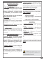 5
5
-
 6
6
-
 7
7
-
 8
8
-
 9
9
-
 10
10
-
 11
11
-
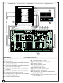 12
12
-
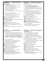 13
13
-
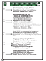 14
14
-
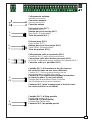 15
15
-
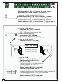 16
16
-
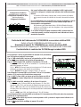 17
17
-
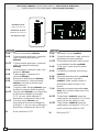 18
18
-
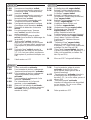 19
19
-
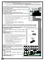 20
20
-
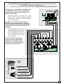 21
21
-
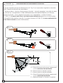 22
22
-
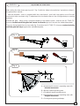 23
23
-
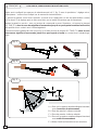 24
24
-
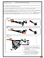 25
25
-
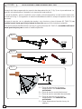 26
26
-
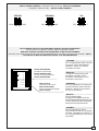 27
27
-
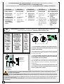 28
28
-
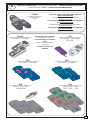 29
29
-
 30
30
-
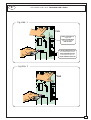 31
31
-
 32
32


CAME ZL170N Manual de usuario
- Tipo
- Manual de usuario
- Este manual también es adecuado para
En otros idiomas
- français: CAME ZL170N Manuel utilisateur
- italiano: CAME ZL170N Manuale utente
- English: CAME ZL170N User manual
- Deutsch: CAME ZL170N Benutzerhandbuch
Documentos relacionados
-
CAME ZL170N El manual del propietario
-
CAME ZL170N Manual de usuario
-
-
-
-
-
-
-
CAME ZL19A El manual del propietario
-