
Documentazione
Tecnica
M43
rev. 3.1
08/2006
©
CAME
CANCELLI
AUTOMATICI
319M43
QUADRO COMANDO
CONTROL
PANEL
ARMOIRE
DE COMMANDE
SCHALTTAFEL
CUADRO
DE MANDO
SERIE Z | Z SERIES | SÉRIE Z | BAUREIHE Z | SERIE Z
ZL19
CARATTERISTICHE GENERALI
ITALIANO
Descrizione quadro comando
Quadro elettrico per motoriduttori a 24V con
alimentazione 230V monofase; frequenza
50÷60 Hz.
Adatto al comando di motoriduttori serie
ATI, FERNI,FROG e FAST.
Progettato e costruito interamente dalla
CAME CANCELLI AUTOMATICI S.p.A.,
risponde alle vigenti norme di sicurezza, con
grado di protezione IP 54. Scatola in ABS,
dotata di presa per il riciclo d'aria. Garantito
24 mesi salvo manomissioni.
Il quadro comando va alimentato con la
tensione di 230V sui morsetti L1 ed L2 ed è
protetto in ingresso con fusibile di linea da
3.15A.
I dispositivi di comando sono a bassa
tensione e protetti con fusibile da 315mA.
La potenza complessiva degli accessori a
24V, protetti da fusibile a 3.15A, non deve
superare i 40W.
Sicurezza
Le fotocellule possono essere collegate e
predisposte per:
- Riapertura
in fase di chiusura (2-C1), le
fotocellule rilevando un ostacolo durante
la fase di chiusura del cancello, provocano
l’inversione di marcia no alla completa
apertura;

-2-
-3-
- Stop parziale, arresto del cancello se in
movimento con conseguente predisposizio-
ne alla chiusura automatica (2-C3);
- Stop totale
(1-2), arresto del cancello con
l'esclusione del ciclo di chiusura automatica;
per riprendere il movimento bisogna agire
sulla pulsantiera o sul radiocomando;
- F
unzione del test di sicurezza. Ad ogni co-
mando di apertura e chiusura delle ante, la
centralina verica l'efcenza delle fotocellule
(vedi pag. 26).
Il quadro elettrico include un sensore ampe-
rometrico dei motori che interviene quando
un ostacolo blocca il movimento in apertura
o in chiusura. Se in marcia, esso inverte il
movimento. Se in rallentamento, il motore
interessato si blocca mentre l'altro completa
il suo movimento. La sensibilità del dispo-
sitivo è regolabile mediante trimmers (vedi
pag.12).
I trasformatori sono dotati di una protezione
che in caso di sovraccarico termico mantie-
ne le ante aperte.
La richiusura avviene solo dopo che la
temperatura è scesa sotto la soglia di emer-
genza.
Accessori collegabili
- Lampada di segnalazione di "cancello
aperto";
- Lampeggiatore di movimento;
- Lampada ciclo;
- Elettroserratura;
- Scheda LB18 per alimentazione mediante
batteria che, in caso di mancanza di energia
elettrica, interviene automaticamente. Al
ripristino della tensione di linea, provvede
alla ricarica della batteria stessa;
- Scheda radiofrequenza AF (vedi tabella
pag.29).
Altre funzioni selezionabili
- Chiusura automatica
. Il temporizzatore di
chiusura automatica si autoalimenta a ne-
tempo corsa in apertura. Il tempo pressato
regolabile, è comunque subordinato dall'in-
tervento di eventuali accessori di sicurezza
e si esclude dopo un intervento di "stop" o in
mancanza di energia elettrica;
- Rilevazione ostacolo
. A motore fermo
(cancello chiuso, aperto o dopo un co-
mando di stop totale), impedisce qualsiasi
movimento se i dispositivi di sicurezza (es.
fotocellule) rilevano un ostacolo;
- Colpo d'ariete
. Funzione che facilita lo
sganciamento della serratura; (ad ogni co-
mando di apertura, le ante premono in bat-
tuta di chiusura per un secondo, facilitando
l'operazione di sgancio dell'elettroserratura);
- Lampada ciclo
. Lampada che illumina la
zona di manovra: rimane accesa dal mo-
mento in cui le ante iniziano l'apertura no
alla completa chiusura (compreso il tempo
di chiusura automatica). Nel caso non viene
inserita la chiusura automatica rimane
accesa solo durante il movimento (10-E3).
Selezionarla tramite jumper (vedi pag.20);
- Abilitazione
comando motoriduttori: ATI,
FERNI o FROG selezionabili tramite dip-
switch a 4 vie (vedi pag.23);
- Funzione a "uomo presente
". Funziona-
mento del cancello mantenendo premuto il
pulsante (esclude la funzione del radioco-
mando);
- Prelampeggio
in apertura e chiusura;
- Tipo di comando
:
- «apre-stop-chiude-stop» per pulsante e/o
trasmettitore;
- «apre-chiude-inversione» per pulsante e/o

-2-
-3-
trasmettitore;
- «solo apre» per trasmettitore.
Regolazioni
- Trimmer REG/FINE = Regolazione ne del
sensore amperometrico durante la marcia:
min/max;
- Trimmer SENS/VEL = Regolazione sen-
sibilità amperometrica durante la marcia:
min/max;
- Trimmer SENS/RALL = Regolazione
sensibilità amperometrica durante il rallenta-
mento: min/max;
- Trimmer TCA = Regolazione tempo chiu-
sura automatica: da 2" a 120";
- Trimmer TR2M = Ritardo chiusura del
motore M2: da 1" a 15";
- Trimmer TL = Regolazione tempo di lavo-
ro: da 13" a 120";
- Regolazione velocità di marcia e di rallen-
tamento mediante connettori faston sulla
scheda;
Attenzione! Prima di intervenire
all’interno dell’apparecchiatura, togliere la
tensione di linea e scollegare le batterie
(se inserite).

-4-
-5-
GENERAL CHARACTERISTICS
ENGLISH
Description of control panel
Control panel for 24V d.c. gear motors,
powered by 230V a.c. at 50-60 Hz (single-
phase).
Designed to control ATI, FERNI and FROG
gear motors.
Designed and built entirely by CAME
CANCELLI AUTOMATICI S.p.A., it meets
regulations in force and with IP 54 level of
protection.
Housing in ABS is equipped with vents to
provide internal air circulation. Guaranteed
24 months, unless tampered with.
This control panel is powered by 230V a.c.
across terminals L1 and L2, and is protected
by a 3.15A fuse on the main power line.
Control systems are powered by low voltage
and protected by a 315 mA fuse.
The total power consumption of 24V acces-
sories (which are protected by a 3.15A fuse)
must not exceed 40 W.
Safety
Photocells can be connected to obtain:
- Re-opening
during the closing cycle (2-
C1), if the photocells identify an obstacle
while the gate is closing, they will reverse
the direction of movement until the gate is
completely open;
- Partial stop,
shutdown of moving gate,
with activation of an automatic closing cycle
(2-C3);
- Total stop
(1-2), shutdown of gate move-
ment without automatic closing; a pushbut-
ton or radio remote control must be actuated
to resume movement).
- Safety test function.
The control unit will
now check the safety system every time an
opening or closing command is given (see
p. 26).
The electrical panel includes an amperome-
tric sensor for the motors which is triggered
whenever an obstacle blocks movement du-
ring opening or closing. If operating speed,
the sensor inverts the movement direction.
If it is slowing down, one motor stops while
the other completes its movement. The sen-
sor's sensitivity can be adjusted using the
trimmers (see p.12).
The transformers are equipped with a
guard, which in case of thermal overload will
keep the doors open.
They are closed again only after the tem-
perature falls below the emergency thresh-
old.
Accessories which can be connected to
this unit
- “Gate open” signal light;
- Flashing signal light when gate is in motion
- Electric lock;
- LB18 circuit card for emergency battery,
which is automatically connected in case of
power failure; battery is recharged when line
power is restored
- Radiofrequency AF board (see table
pag.29).
Other functions available
- Automatic closing.
The automatic closing
timer is automatically activated at the end
of the opening cycle. The preset, adjusta-
ble automatic closing time is automatically
interrupted by the activation of any safety
system, and is deactivated after a STOP
command or in case of power failure;

-4-
-5-
- Obstacle detection: When the motor is
stopped (gate is closed, open or half-open
after an emergency stop command), the
transmitter and the control pushbutton will
be deactivated if an obstacle is detected by
one of the safety devices (for example, the
photocells);
- Hammer movement:
This feature makes it
easy for the lock to release (the door wings
momentarily press against the closure stops
when the open command is given, which
facilitates release of the electric lock);
- Cycle lamp
. The lamp which lights the
manoeuvring zone: it remains lit from the
moment the doors begin to open until they
are completely closed (including the time
required for the automatic closure). In case
automatic closure is not enabled, the lamp
remains lit only during movement (10-E3).
Select it using the jumpers (see p. 20);
- The panel is enabled
at the command
for ATI gearmotors or at the command for
FERNI and FROG gearmotors, which can
be selected with the 4-way dip-switch (see
p. 23).
-
"Operator present" function: Gate operates
only when the pushbutton is held down (the
radio remote control system is deactivated);
- Flashing light
activated before opening and
closing cycle begins;
- Type of command
:
- «open-stop-close-stop» for pushbutton
and radio transmitter;
- «open-close-reverse» for pushbutton and
radio transmitter;
- «open only» for radio transmitter.
Adjustments
- REG/FINE trimmer = Fine adjustment
of amperometric sensitivity during motor
operation
- Trimmer SENS/VEL = Adjustment of
amperometric sensitivity during operating:
min/max;
- Trimmer SENS/RALL = Adjustment of
amperometric sensitivity during slowdown:
min/max;
- Trimmer TCA = Adjustment of automatic
closing time: 2" to 120";
- Trimmer TR2M = Delay on closing cycle
- motor 2: 1" to 15";
- Trimmer TL = Adjustment of operating
time: 13" to 120";
- Faston connectors on the circuit card
are used to select normal operating and
slowdown speeds;
Caution! Shut off the mains power
and disconnect the batteries before
servicing the inside of the unit.

-6-
-7-
Description armoire de commande
Armoire électrique pour motoréducteurs
à 24V c.c. avec alimentation 230V mo-
nophasée; fréquence 50÷60 Hz.
Adaptée à commander les motoréducteurs
de la série ATI, FERNI ou FROG.
L’armoire est entièrement conçue et fabri-
quée par CAME CANCELLI AUTOMATICI
S.p.A. conformément aux normes de sécuri-
té en vigueur avec un degré de protection IP
54. Boîtier en ABS muni de prise de circu-
lation d’air. Garantie 24 mois sauf en cas
d’endommagement.
L’armoire de commande doit être alimentée
avec une tension de 230V sur les bornes L1
et L2 et elle est protégée en entrée par un
fusible de ligne de 3.15A. Les dispositifs de
commande sont à basse tension et protégés
avec un fusible de 630mA. La puissance
totale des accessoires en 24V, protégés par
un fusible de 3.15A, ne doit pas dépasser
40W.
Sécurité
Il est possible de brancher des photocellules
et de les programmer pour:
- Réouverture
en phase de fermeture
(2-C1), les cellules photoélectriques provo-
quent l’inversion de marche jusqu’à l’ouver-
ture complète si elles relèvent un obstacle
durant la phase de fermeture du portail;
- Stop partiel,
arrêt du portail et fermeture
automatique (2-C3);
- Stop total
(1-2), arrêt du portail et désac-
tivation d’un éventuel cycle de fermeture
automatique; pour activer de nouveau le
mouvement, il faut agir sur les boutons-
poussoirs ou sur la radiocommande);
- Fonction du test de securité. Cela permet
au boîtier de vérier le bon fonctionnement
des despositifs de securité aprés chaque
commande d'ouverture ou de fermeture
(voir pag. 26÷27);
Le tableau électrique comprend un capteur
ampèremétrique pour les moteurs, qui se
déclenche quand un obstacle bloque le
mouvement d'ouverture ou de fermeture.
S'ils sont en marche, il inverse le mouve-
ment. Si un des moteurs ralentit, le moteur
concerné se bloque et l'autre termine son
mouvement. La sensibilité de ce dispositif
est réglable au moyen trimmers (voir p. 12).
Les transformateurs sont dotés d’une pro-
tection qui en cas de surcharge thermique
garde les portes ouvertes.
Le réenclenchement se fait seulement après
que la température soit descendue sous le
seuil d’émergence.
Accessoires pouvant être branchés
- Lampe de signalisation de “portail ouvert”;
- Clignotant de mouvement;
- Serrure électrique;
- Carte LB18 pour l’alimentation par batterie
intervenant automatiquement en cas d’ab-
sence d’énergie électrique, au rétablisse-
ment de la tension de ligne, la carte procède
au rechargement de la batterie;
- Carte radiofréquence AF (voir tableau
pag.29).
Autres fonctions pouvant
être sélectionnées
- Fermeture automatique
. Le temporisateur
de fermeture automatique est autoalimenté
à la n du temps de la course en ouver-
CARACTÉRISTIQUES GÉNÉRALES
FRANÇAIS

-6-
-7-
ture. Le temps réglable est programmé,
cependant, il est subordonné à l’intervention
d’éventuels accessoires de sécurité et il est
exclu après une intervention de “stop” ou en
cas de coupure de courant;
- Détection obstacle
. Quand le moteur est
arrêté (portail fermé, ouvert ou semi-ouvert,
cette position est obtenue avec une com-
mande de stop total), annule toute fonction
de l’émetteur ou du bouton-poussoir en cas
d’obstacle détecté par les dispositifs de sé-
curité (ex. Photocellules) ;
- Coup de bélier
. Fonction qui facilite le dé-
blocage de la serrure (à chaque commande
d’ouverture, les vantaux se portent en butée
de fermeture pendant une seconde, faci-
litant ainsi l’opération de déblocage de la
serrure électrique);
- Lampe cycle
. Ampoule qui illumine la zone
de manoeuvre: elle reste allumée à partir du
moment ou les portes commencent l’ouver-
ture jusqu’à la fermeture complète (y com-
pris le temps de fermeture automatique).
Si elle n’est pas insérée la fermeture auto-
matique reste allumée seulement durant le
mouvement (10-E3). La sélectionner à l’aide
du jumper (voir p. 20);
- Tableau prévu
pour la commande par
motoréducteurs ATI ou la commande par
motoréducteurs FERNI et FROG, à sélec-
tionner par interrupteur à positions multiples
à 4 voies (voir p.23);
- Fonction “homme mort”
. Fonctionnement
du portail en maintenant appuyé le bouton-
poussoir (exclut la fonction de la radiocom-
mande) ;
- Préclignotement
en ouverture et en ferme-
ture;
- Type de commande:
- «ouverte-stop-fermée-stop» pour bouton-
poussoir et émetteur radio;
- «ouverture - fermeture - inversion» pour
bouton-poussoir et émetteur radio;
- «seulement ouverture» pour émetteur
radio;.
Réglages
- Trimmer REG/FINE = Réglage n du cap-
teur ampèremétrique pendant le fonctionne-
ment: min./max.;
- Trimmer SENS/VEL = Réglage sensibilité
ampèrométrique pendant le mouvement :
min./max;
- Trimmer SENS/RALL = Réglage sensibilité
ampèrométrique pendant le ralentissement
: min./max;
- Trimmer T.C.A. = Temps de fermeture
automatique: de 2 à 120";
- Trimmer T.R. 2M = Retard fermeture mo-
teur 2: de 1" à 15";
- Trimmer T.L. = Réglage temps de fonction-
nement: de 13" à 120";
- Réglage vitesse de mouvement et de ra-
lentissement à l'aide de connecteurs rapides
placés sur carte.
Attention! Avant d’intervenir à
l’intérieur de l’appareillage, couper la
tension de ligne et débrancher les batte-
ries (si branchées).

-8-
-9-
ALLGEMEINE MERKMALE
DEUTSCH
Beschreibung des Steuergeräts
Schalttafel für 24-V-Gleichstrom-Getrie-
bemotoren mit 230-V-Einphasenstrom-
versorgung; Frequenz: 50-60 Hz.
Zur Steuerung von Getriebemotoren der
Baureihen ATI, FERNI und FROG.
Vollkommen von der CAME CANCELLI
AUTOMATICI S.p.A. den geltenden Siche-
rheitsnormen entsprechend entwickelt und
hergestellt. Schutzgrad: IP 54. ABS-Gehäu-
se mit Luftklappe. 24 Monate Garantie,
vorbehaltlich unsachgemäßer Handhabung
und Montage.
Die Schalttafel wird mit einer Spannung von
230V über die Klemmen L1 und L2 gespeist
und ist am Eingang mit einer 3.15-A-Haup-
tsicherung. Die Steuerungen erfolgen mit
Niederspannung und geschützen enie
630mA-Sicherung. Die Gesamtleistung des
durch eine 3.15-A-Sicherung geschützten
24-V-Zubehörs darf 40W nicht überschrei-
ten.
Sicherheitsvorrichtungen
Die Lichtschranken können für folgende
Funktionen angeschlossen bzw. vorbereitet
werden:
- Wiederöffnen
beim Schließen (2-C1),
die Lichtschranken ermitteln ein Hindernis
während des schließens vom Tor und lösen
die Umkehr der Laufrichtung vom Tor aus,
bis dieses wieder vollständig geöffnet ist;
- Teilstop,
Stillstand des Tores während des
Torlaufs, mit darauffolgender automatischer
Torschließung (2-C3);
- Totalstop
(1-2), sofortiger Stillstand des
Tores mit Ausschluß eventueller Schließau-
tomatik: Fortsetzung des Torlaufs über
Drucktaster- bzw. Funksendersteuerung;
- Sicherheitstest-Funktion. Dadurch besteht
die Möglichkeit, die Leistungsfähigkeit der
Sicherheitsvorrichtungen nach jeder Öff-
nungs-und Schließsteuerung zu überprüfen
(siehe Seite 26 und 27).
Auf der Schalttafel bendet sich auch den
amperemetrischen Sensor
für die Motoren,
der zugeschaltet wird, wenn die Bewegung
beim Öffnen oder Schließen durch ein
Hindernis blockiert wird. Beim Öffnen oder
Schließen des Tors wird die Laufrichtung
umgekehrt. Beim Bremsen wird der betroffe-
ne Motor blockiert, während der andere sei-
ne Bewegung beendet. Die Empndlichkeit
der Vorrichtung kann mithilfe eines Trim-
mers eingestellt werden (siehe Seite 12).
Die Transformatoren sind mit einer Siche-
rung ausgestattet, die bei Wärmestau dafür
sorgt, daß die Torügel offen bleiben.
Das erneute Schließen erfolgt erst dann,
wenn die Temperatur unter den Wert geffa-
len ist, der die Notsituation auslöst.
Anschließbares Zubehör
- Anzeigeleuchte für “Tor offen”;
- Blinkleuchte “Tor in Bewegung”;
- Elektroschloß;
- Steckplatine LB18 für Stromversorgung
über Notbatterie, die sich bei Stromausfall
automatisch zuschaltet und die Batterie
bei erneuter Netz-Stromversorgung wieder
auädt.
- Funkfrequenz-Platine AF (siehe Tabelle
Seite 29)
Andere Wahlfunktionen
- Schließautomatik
. Der Schließautoma-
tik-Zeischalter speist sich beim Öffnen am
Ende der Torlaufzeit selbst . Die vorein-

-8-
-9-
gestellte Zeit ist auf jeden Fall immer dem
Eingriff eventueller Sicherheitsvorrichtungen
untergeordnet und schließt sich nach einem
“Stop”-Eingriff bzw. bei Stromausfall selbst
aus;
-
Hinderniserfassung. Bei stillstehendem
Motor (Tor geschlossen, geöffnet oder durch
eine Totalstop-Steuerung halb geöffnet) wird
bei durch die Sicherheitsvorrichtungen (z.B.:
Lichtschranken) erfaßtem Hindernis jede
Sender- oder Drucktasterfunktion annulliert;
- Widderstoß
. Funktion, die das Auslösen
des Elektroschlosses erleichtert; (bei jeder
Öffnungssteuerung üben die Torügel eine
Sekunde lang einen leichten Druck auf den
Schließungsendanschlag aus und erlei-
chtern dadurch die Entriegelung des Elek-
troschlosses);
- Betriebszyklus-Anzeigeleuchte
. Das Licht,
das den Torbereich beleuchtet, bleibt vom
Beginn des Öffnens bis zum vollständigen
Schließen der Torügel eingeschaltet (ein-
schließlich Wartezeit für automatisches
Schließen). Wenn das automatische
Schließen nicht zugeschaltet ist, bleibt das
Licht nur während der Torbewegung einge-
schaltet (10-E3). Das Licht bitte mithilfe vom
Jumper wählen (siehe Seite 20).
- Schalttafel geeignet
zur Steuerung von ATI
Getriebemotoren oder FERNI und FROG
Getriebemotoren, die mithilfe eines Vie-
rweg-Dip-Switch gewählt werden können
(siehe Seite 23).
- Funktion “Bedienung vom Steuerpult”
.
Torbetrieb durch Drucktasterbetätigung
(Funkfernsteuerung ausgeschlossen);
- Vorblinken
beim Öffnen und Schließen;
- Steuerart
:
- «Öffnen-Stop-Schließen-Stop» für Druck-
taster- und Funksendersteuerart;
- «Öffnen-Schließen-Torlaufumsteuerung»
für Drucktaster und Funksendersteuerart;
- «nur Öffnen» für Funksendersteuerart.
Einstellungen
- Trimmer REG/FINE = Feineinstellung des
amperemetrischen Sensors während des
Torlaufs: min/max;
- Trimmer SENS/VEL = Einstellung der
amperemetrischen Empndlichk eit während
Laufgeschwindigkeit: min/max;
- Trimmer SENE/RALL = Einstellung der
amperemetrischen Empndlichk während
Laufverlangsamung: min/max;
- Trimmer TCA = Zeiteinstellung Schließau-
tomatik: von 2" bis 120",
- Trimmer TR2M = Schließverzögerung
Motor 2: von 1" bis 15";
- Trimmer TL = Einstellung Laufzeit: von 13"
bis 120";
- Einstellung der Laufgeschwindigkeit und
Einstellung der Laufverlangsamung über
Faston-Verbinder auf Platine.
Achtung! Das Gerät vor Eingriffen
im inneren spannungsfrei schalten und
die Stromzufuhr mittels Batterien (falls
zugeschaltet) unterbrechen.

-10-
-11-
CARACTERISTICAS GENERALES
ESPANOL
Descripción cuadro de mando
Cuadro eléctrico para motorreductores a
24V d.c. con alimentación 230V monofase:
frecuencia 50÷60 Hz.
Adecuado para el mando de motorreducto-
res serie ATI, FERNI y FROG.
Diseñado y fabricado enteramente por
CAME CANCELLI AUTOMATICI S.p.A.,
cumple con las normas de seguridad vigen-
tes, con grado de protección IP 54. Caja de
ABS, dotada de toma para la recirculación
de aire. Garantizado 24 meses salvo mani-
pulaciones.
El cuadro de mando se alimenta con una
tensión de 230V en los bornes L1 y L2 y
está protegido en entrada con fusible de
línea de 3.15A. Los dispositivos de mando
son a baja tensión y està protegidos por
fusible a 630mA. La potencia total de los
accesorios a 24V, protegidos por fusible a
3.15A, no debe superar los 40W.
Seguridad
Las fotocélulas pueden estar conectadas y
predispuestas para:
- Reapertura
en la fase de cierre (2-C1), las
fotocélulas detectan un obstàculo durante el
cierre de la puerta, provocando la inversión
de marcha hasta la apertura completa;
- Parada parcial,
parada de la puerta si
se encuentra en movimiento con la consi-
guiente predisposición al cierre automático
(2-C3);
- Parada total
(1-2), parada de la puer-
ta excluyendo el posible ciclo de cierre
automático; para reactivar el movimiento es
preciso actuar en el teclado o en el mando
a distancia);
-
Función de las pruebas de seguridad.
Permite a la central comprobar la eciencia
en los dispositivos de seguridad después de
cada comando de apertura y cierre (véase
pág. 26÷27).
El cuadro eléctrico incluye un sensor am-
perimétrico de los motores que se activa
cuando el obstáculo bloquea el movimiento
en las fases de apertura o cierre. Durante
la marcha, invierte el movimiento. Durante
la fase de desaceleración, el motor afecta-
do se para mientras el otro lleva a cabo el
movimiento respectivo. La sensibilidad del
dispositivo puede regularse mediante unos
trimmer (ver pág. 12).
Los transformadores están provistos de una
protección que ante una sobrecarga térmica
mantiene abiertas las hojas.
El cierre se produce sólo después de que la
temperatura ha llegado por debajo del um-
bral de emergencia.
Accesorios conectables
- Lámpara de señal de “puerta abierta”;
- Lámpara intermitente de movimiento;
- Cerradura eléctrica;
- Tarjeta LB18 para la alimentación me-
diante batería que, en caso de falta de ener-
gía eléctrica, interviene automáticamente;
una vez conectada de nuevo la tensión de
línea, se ocupa de cargar la batería misma;
- Tarjeta radiofrecuencia AF (ver tabla
pág.29).
Otras funciones seleccionables
- Cierre automático
. El temporizador de
cierre automático se autoalimenta en n-
de-tiempo carrera en fase de apertura. El
tiempo prejado regulable, sin embargo,

-10-
-11-
está subordinado a la intervención de posi-
bles accesorios de seguridad y se excluye
después de una intervención de parada o
en caso de falta de energía eléctrica;
-
Detección obstáculo. Con el motor parado
(puerta cerrada, abierta o en posición semi-
abierta obtenida a través de un comando
de stop total), anula cualquier función del
transmisor o del botón en caso de obstáculo
detectado por los dispositivos de seguridad
(por ejemplo: fotocélulas);
- Golpe de ariete
. Función que facilita el
desenganche de la cerradura (en cada co-
mando de apertura las puertas presionan
el tope del cierre durante un segundo, faci-
litando la operación de desenganche de la
electrocerradura);
- Lámpara ciclo.
Lámpara que alumbra la
zona de maniobra: se queda encendida a
partir del momento en que las hojas em-
piezan la apertura hasta el cierre completo
(incluyendo el tiempo de cierre automático).
Si no se habilita el cierre automático, el
cierre permanece encendido sólo durante
el movimiento (10-E3). Se selecciona me-
diante el jumper (ver pág.20);
- Cuadro habilitado
para el mando para
motorreductores ATI o bien para el mando
para motorreductores FERNI y FROG que
pueden seleccionarse mediante el -switch
de 4 vías (ver pág.23);
- Función a "hombre presente"
. Funciona-
miento de la puerta manteniendo pulsada
la tecla (excluye la función del mando a
distancia);
- Preintermitencia
en fase de apertura y
cierre;
- Tipo de mando;
- «apertura-parada-cierre-parada» para te-
cla y transmisor de radio;
- «apertura-cierre-inversión» para tecla y
transmisor de radio;
- «sólo apertura» para transmisor de radio.
Regulaciones
- Trimer REG/FINE = Regulación n del
sensor amperimétrico durante la marcha:
mín./máx.;
- Trimer SENS/VEL = Regulación sensi-
bilidad amperimétrica durante la marcha:
mín/máx;
- Trimer SENS/RALL = Regulación sensibili-
dad amperimétrica durante el ralentamiento:
mín/máx;
- Trimer TCA = Tiempo cierre automático:
de 2" a 120”;
- Trimer TR2M = Retraso cierre motor 2: de
1" a 15”;
- Trimer TL = Regulación tiempo trabajo: de
13" a 120";
- Regulación velocidad de marcha y de
ralentamiento mediante conectores faston
en tarjeta.
¡Atención! Antes de actuar dentro
del aparato, quitar la tensión de línea y
desecnectar las baterías (si estuvieran
conectadas)
.

-12-
-13-
SCHEDA BASE - MOTHERBOARD - CARTE BASE - GRUNDPLATINE - TARJETA BASE
RSE
P
R
OG
RA
M
MIN
G F
U
NC
TI
ON
R7
00
LI
NE
FUSE
1,
6 A
M
O
T
O
R
F
U
S
E
1
0
A
A
C
CE
S
S
O
R
I
E
S
F
U
S
E
1
,
6
A
C
O
N
T
R
O
L
B
O
A
R
D
F
U
S
E
6
3
0
m
A
+ A
.C
. -
W
A
RNING
!
L
I
N
E
3
,
1
5
A
C
O
N
T
R
O
L
B
O
A
R
D
+
-
+
-
+
-
A
M
P
.
S
E
N
S
.
S
L
O
W
D
O
W
N
F
I
N
E
A
D
J
.
A
M
P
.
S
E
N
S
.
S
L
O
W
D
O
W
N
1
S
P
E
E
D
1
C
O
M
M
O
N
2
S
L
O
W
D
O
W
N
2
S
P
E
E
D
2
1
2
V
2
4
V
C
O
N
T
R
O
L
B
O
A
R
D
Z
L
1
9
1 2
3
4
5 6
7
8
9 1
0
11
1
2
0
4
05
06
07
0
8
V4
V5
V
6 V
7
V
8
Z
L
1
9
A
F
U
S
E
M
O
T
O
R
1
F
U
S
E
1
0
A
M
O
T
O
R
2
F
U
S
E
1
0
A
A
M
P
.
S
E
N
S
.
L
O
C
K
F
U
S
E
2
A
A
C
C
E
S
S
O
R
I
E
S
F
U
S
E
2
A
E
L
E
C
T
R
I
C
F
U
S
E
3
1
5
m
A
Z
L
1
9
B
A
F
W
A
R
N
I
N
G
!
T
E
R
M
I
C
O
1
2
3
3
P
7
C
3
C
1
C
H
1
C
H
2
T
.
L
.
T
R
2
M
.
T
.
C
.
A
.
+
-
+
-
+
-
1
2
3
4
5
6
7
8
9
1
0
1
1
1
2
0
4
0
5
0
6
0
7
0
8
V
1
V
2
V
3
R
A
1
R
C
1
C
R
A
2
R
C
2
F
A
1
C
F
C
1
C
F
C
2
F
A
2
C
E
3
B
1
/
B
2
17
12
4
2
5
3
6
7
8
11
13
14
15
16
18
19
10
9
20
1
21
22
23

-12-
-13-
MAIN COMPONENTES
1) Transformer
2) Connectors for speed selection
3) Terminal board for connectiong battery
charger LB18 (connect a bridge across
terminala A-B; C-D; E-F; G-H if battery
charger is not used)
4) Fuse on accessory power line, 2A
5) Fuse on central control unit, 315 mA
6) Fine adjustment of amperometric
sensitivity during motor operation
7) Trimmer for adjustment of
amperometric sensitivity during
operation
8) Trimmer for adjustment of
amperometric sensitivity during
slowdown
9) Trimmer for adjustment of operating
time
10) Trimmer for adjustment of automatic
closing
11) Trimmer for adjustment of delay on
closing cycle motor n.2
12) 10-dip function switch (see pag.24)
13) Radio code/automatic closing signal
LED
14) Button for memorizing code numbers
15) Jumper which selects output B1-B2/
operating cycle indicador light
16) Radiofrequency board socket
17) Line fuse, 3.15A
18) Terminal block for external conections
19) 4-dip function switch (see pag.23)
20) Jumper for selection of type of control
for button in 2-7
21) Electric lock fuse 2A
22) fuse motor n°1 10 A.
23) fuse motor n°2 10 A.
PRINCIPALI COMPONENTI
1) Trasformatori
2) Connettori regolazione velocità
3) Morsettiera per il collegamento al
caricabatterie LB18 (se non utilizzata,
assicurarsi che i ponticelli siano
collegati tra A-B; C-D; E-F; G-H)
4) Fusibile accessori 2A
5) Fusibile centralina 315mA
6) Trimmer di regolazione ne della
sensibilità amperometrica durante la
marcia
7) Trimmer di regolazione sensibilità
amperometrica durante la marcia
8) Trimmer di regolazione sensibilità
amperometrica durante il rallentamento
9) Trimmer di regolazione tempo lavoro
10) Trimmer di regolazione chiusura
automatica
11) Trimmer di regolazione ritardo chiusura
2° motore
12) Selettore funzioni a 10 dip (vedi pagina
24)
13) LED di segnalazione codice radio/
conteggio tempo TCA
14) Pulsanti memorizzazione codice
15) Jumper selezione uscita B1-B2 /
lampada ciclo
16) Innesto scheda radiofrequenza
17) Fusibile di linea 3.15A
18) Morsettiera di collegamento
19) Selettore funzioni a 4 dip (vedi pagina
23)
20) Jumper selezione tipo di comando per
pulsante 2-7
21) Fusibile elettroblocco 2A
22) Fusibile motore n°1 10 A
23) Fusibile motore n°2 10 A
ITALIANO
ENGLISH

-14-
-15-
PRINCIPAUX COMPOSANTS
1) Transformateur
2) Connecteurs réglage vitesse
3) Plaque à bornes pour le branchement
au chargeur de batteries LB18 (si elle
n'est pas utilisée, s'assurer que les
pontets sont branchés entre A-B; C-D;
E-F; G-H)
4) Fusible accessoires 2A
5) Fusible boîtier 315mA
6) Trimmer de réglage n de la sensibilité
ampèremétrique pendant le fonctionne-
ment
7) Trimmer de réglage sensibilité am-
pèremétrique pendant le mouvement
8) Trimmer de réglage sensibilité am-
pèremétrique pendant le ralentisse-
ment
9) Trimmer de réglage temps de fonction-
nement
10) Trimmer de réglage fermeture automa-
tique
11) Trimmer de réglage retard fermeture
moteur 2
12) Selecteur de fonctions à 10 interrup-
teurs à positions multiples (voir
pag.25)
13) LED de signalisation code radio/
comptage temps TCA
14) Bouton-poussoir mémorisation code
15) Pontet sélection sortie B1-B2/lampe
cycle
16) Branchement carte radiofréquence
17) Fusible de ligne 3.15A
18) Plaque à bornes de connexion
19) Selecteur de fonctions à 4 interrupteurs
à positions multiples (voir pag.23)
20) Pontet de sélection type de commande
pour bouton-poussoir en 2-7
21) fusible du serrure electronique 2A
22) moteur fusible n°1 10 A
23) moteur fusible n°2 10 A
FRANÇAIS
HAUPTKOMPONENTEN
1) Transformatoren
2) Verbinder für Geschwin digkeits ein-
stellung
3) Klemmleiste für den Anschluß an das
Batterieladegerät LB18 (bei Nichtve-
rwendung überprüfen, ob A-B, C-D,
E-F, G-H gebrückt sind)
4) Zubehör-Sicherung 2A
5) Schaltkastensicherung 315mA
6) Trimmer zur Feineinstellung des am-
peremetrischen Sensors während des
Torlaufs: min/max;
7) Trimmer zur Einstellung amperemetri-
schen Empndlichkeit während Laufge-
schwindigkeit
8) Trimmer zur Einstellung ampereme-
trischen Empndlichkeit während
Laufverlangsamung
9) Trimmer zur Einstellung Laufzeit
10) Trimmer zur Einstellung der Schließau-
tomatik
11) Trimmer zur Einstellung Schließverzö-
gerung Motor 2
12) Wählschalter für Funktionen mit 10 Dip.
(Siehe Seite 25)
13) Schließautomatik/Anzeige LED-
Funkcode
14) Code-Speichertasten
15) Jumper zur Wahl des Ausgangs B1-B2/
Betriebszyklus Anzeigeleuchte
16) Steckanschluß Funkfrequenz-Platine
17) Hauptsicherung 3.15A
18) AnschlußKlemmenleiste
19) Wählschalter für Funktionen mit 4 Dip.
(Siehe Seite 23)
20) Steuerart-Wahljumper für Taste auf 2-7
21) Schmelz elektronische schloss 2A
22) Schmelz Motor n°1 10 A.
23) Schmelz Motor n°2 10 A
DEUTSCH

-14-
-15-
PRINCIPALES COMPONENTES
1) Transformadores
2) Conectores regulación velocidad
3) Caja de bornes para la conexión del
cargador de batería LB18 (si no se
usa, asegurarse de que los puentes
están conectados entr A-B, C-D, E-F,
G-H)
4) Fusible accesorios 2A
5) Fusible para central 315 mA
6) Trimer de regulación n de sensibilidad
amperimétrica durante la marcha
7) Trimer de regulación sensibilidad am-
perimétrica durante la marcha
8) Trimer de regulación sensibilidad
amperimétrica durante el ralenta-
miento
9) Trimer de regulación tiempo trabajo
10) Trimer de regulación tiempo cierre
automático
11) Trimer de regulación retraso cierre 2°
motor
12) Selector de funciones con 10 dip (ver
pag.25)
13) LED de señal código radio / cierre
automático
14) Teclas memorización códigos
15) Jumper selección salida B1-B2/
lámpara ciclo
16) Conexión tarjeta radiofrecuencia
17) Fusible de línea 3.15A
18) Caja de bornes para las conexiónes
19) Selector de funciones con 4 dip (ver
pag.23)
20) Jumper selección tipo de mando para
tecla en 2-7
21) fusible de la cerradura electronica 2A
22) fusible motor n°1 10 A.
23) fusible motor n°2 10 A.
ESPANOL

-16-
-17-
COLLEGAMENTI ELETTRICI - ELECTRICAL CONNECTIONS - BRANCHEMENTS ÉLECTRIQUES
ELEKRISCHE ANSCHLÜSSE - CONEXIONES ELÉCTRICAS
1
Collegamento motore
Connection to motor
Branchement moteur
Motoranschluß
Conexión motor
2
Microinterruttore di necorsa in
apertura
Microswitch-limit switch on aperture
Micro-interrupteur n de course en
ouverture
Microschalter Endschalter beim Öffnen
Microinterruptor nal de recorrido en
la apertura
COLLEGAMENTO 2 MOTORI
CONNECTION 2 MOTORS
BRANCHEMENT 2 MOTEURS
ANSCHLUß 2 MOTOREN
CONEXIÓN 2 MOTORES
ATI
24V
M1 N1 M2 N2
1
2
3
4
RA R RC FA F M N
RA R RC FA F M N
M1 N1 M2 N2
COLLEGAMENTO 1 MOTORE - CONNECTION 1 MOTOR - BRANCHEMENT 1 MOTEUR
ANSCHLUß 1 MOTOR - CONEXIÓN 1 MOTOR

-16-
-17-
Microinterruttore di rallentamento
Microswitch-deceleration
Micro-interrupteur ralentissement
Microschalter Laufverlangsamung
Microinterruptor de deceleraciön
3 4
in chiusura in apertura
on closure on aperture
en fermeture en ouverture
beim Schließen beim Öffnen
en el cierre en la apertura
Cortocircuitare
Short-circuit
Court-circuiter
kurzgeschlossen werden
cortocircuitar
M1 N1 M2 N2
marrone-brown marron-braun-marrón
FROG
24V
4
3
1
marrone-brown marron-braun-marrón
blu-blue-bleu-Blau-azul
M1 N1 M2 N2
COLLEGAMENTO 1 MOTORE - CONNECTION 1 MOTOR - BRANCHEMENT 1 MOTEUR
ANSCHLUß 1 MOTOR - CONEXIÓN 1 MOTOR

-18-
-19-
1
Collegamento motore
Connection to motor
Branchement moteur
Motoranschluß
Conexión motor
2
Microinterruttore di
necorsa in apertura
Microswitch-limit
switch on aperture
Micro-interrupteur
n de course en
ouverture
Microschalter End-
schalter beim Öffnen
Microinterruptor nal
de recorrido en la
apertura
3
Microinterruttore di rallenta-
mento in chiusura
Microswitch-deceleration on
closure
Micro-interrupteur ralentisse-
ment en fermeture
Microschalter Laufverlangsamung
beim Schließen
Microinterruptor de decelera-
ciön en el cierre
Cortocircuitare
Short-circuit
Court-circuiter
kurzgeschlossen werden
cortocircuitar
M1 N1 M2 N2
COLLEGAMENTO 1 MOTORE - CONNECTION 1 MOTOR - BRANCHEMENT 1 MOTEUR
ANSCHLUß 1 MOTOR - CONEXIÓN 1 MOTOR
COLLEGAMENTO 2 MOTORI
CONNECTION 2 MOTORS
BRANCHEMENT 2 MOTEURS
ANSCHLUß 2 MOTOREN
CONEXIÓN 2 MOTORES
RA1
M1 N1 M2 N2
FERNI
24V
1
2
3
R RC FA F M N
R RC FA F M N

-18-
-19-
M1 N1 M2 N2
COLLEGAMENTO 1 MOTORE - CONNECTION 1 MOTOR - BRANCHEMENT 1 MOTEUR
ANSCHLUß 1 MOTOR - CONEXIÓN 1 MOTOR
COLLEGAMENTO 2 MOTORI
CONNECTION 2 MOTORS
BRANCHEMENT 2 MOTEURS
ANSCHLUß 2 MOTOREN
CONEXIÓN 2 MOTORES
M1 N1 M2 N2
FAST
24V
R RC FA F M N
1
Collegamento motore
Connection to motor
Branchement moteur
Motoranschluß
Conexión motor
2
Microinterruttore di
necorsa in apertura
Microswitch-limit
switch on aperture
Micro-interrupteur
n de course en
ouverture
Microschalter End-
schalter beim Öffnen
Microinterruptor nal
de recorrido en la
apertura
3
Microinterruttore di rallenta-
mento in chiusura
Microswitch-deceleration on
closure
Micro-interrupteur ralentisse-
ment en fermeture
Microschalter Laufverlangsamung
beim Schließen
Microinterruptor de decelera-
ciön en el cierre
Cortocircuitare
Short-circuit
Court-circuiter
kurzgeschlossen werden
cortocircuitar
3
2
1
R RC FA F M N

-20-
-21-
L1
L2
10
11
10
E
11
S
10
5
Alimentazione quadro comando - 230V (a.c.)
Power supply for control unit - 230V (a.c.)
Alimentation armoire de commande - 230V (c.a.)
Stromversorgung Steuergerät - 230V (Wechselstrom)
Alimentación cuadro de mando - 230V (a.c.)
Alimentazione accessori (max 40W):
- 24V (a.c.) con alimentazione a 230V(a.c.)
- 24V (d.c.) con alimentazione a 24V (d.c.)
Power supply to accessories (max. 40W):
24V (a.c.) with power supply at 230V (a.c.)
24V (d.c.) with power supply at 24V (d.c.)
Alimentation accessoires (max 40W):
- 24V (c.a.) avec alimentation à 230V(c.a.)
- 24V (c.c.) avec alimentation à 24V (c.c.)
Stromversorgung Zubehör (max 40W):
- 24V (Wechselstrom) bei Stromversorgung 230V(Wechselstrom)
- 24V (Wechselstrom) bei Stromversorgung 24V (Gleichstrom)
Alimentación accesorios (max 40W):
- 24V (a.c.) con alimentación a 230V(a.c.)
- 24V (d.c.) con alimentación a 24V (d.c.)
Uscita 24V-25W max.in movimento (es. lampeggiatore)
24V-25W max. output in motion (e.g. ashing light)
Sortie 24V-25W max. en mouvement (ex. clignotant)
Ausgang 24V-25W max. "in Bewegung" (z.B. Blinkleuchte)
Salida 24V-25W max. en movimiento (por ej. lámpara intermi-
tente)
Collegamento elettroserratura (12V-15W max.)
Connection for electrically-actuated lock: 12V-15W max.
Connexion serrure électrique (12V-15W max.)
Anschluß Elektroschloß (12V-15W max.)
Conexión electrocerradura (12V-15W max.)
Lampada spia 24V-3W max. “cancello aperto”
24V-3W max. gate-open signal lamp
Lampe-témoin 24V-3W max. "vantail ouvert"
Kontrollampe 24 V-3W max. “Tor geöffnet”
Lámpara indicadora 24V-3W max. “puerta abierta”

-20-
-21-
Collegamento antenna
Antenna connection
Connexion antenne
Antennenanschluß
Conexión antena
B1
B2
10
E3
POS. A POS. B
JUMPER n°15
Uscita contatto (N.O.) 2° canale radio
Portata contatto: 1A a 24V d.c.
- Jumper in pos. B
Contact output (N.O.) 2
nd
radio channel
Contact capacity: 1A to 24V d.c.
- Jumper in position B
Sortie contact (N.O.) 2
eme
canal radio
Porté du contact: 1A à 24V c.c.
- Pontet en pos. B
Ausgang Arbeitskontakt Stromfestigkeit gemäß Radiokanal
Stromfestigkeit Kontakt: 1A bei 24V Gleichstrom
- Jumper auf Pos. B geschaltet.
Salida contacto (N.O.) 2° canal radio
Capacidad contacto: 1A a 24V d.c.
- Jumper in pos. B
Lampada ciclo a 24V - 25W max.
- Jumper in pos. A (default)
24V - 25W max. cycle indicador light
- Jumper in position A (default)
Lampe cycle 24V - 25W max.
- Pontet en pos. A (default)
Betriebszyklus-Anzeigeleuchte 24V - 25W max.
- Jumper auf Pos. A geschaltet (default)
Lampara ciclo 24V - 25W max.
- Jumper in pos. A (default)

-22-
-23-
1
2
Pulsante di stop (N.C.)
Stop button (N.C.)
Bouton-poussoir de stop (N.F.)
Stop-Taste (Ruhekontakt)
Tecla de parada (N.C.)
Pulsante apre (N.O.)
Open button (N.O.)
Bouton-poussoir d'ouverture (N.O.)
Taste Öffnen (Arbeitskontakt)
Tecla de apertura (N.O.)
Collegamento radio e/o pulsante (N.O.), Jumper disinserito.
Per funzionamento vedi dip 2-3
Connector (N.O.) radio and/or pushbutton (Jumper desabled).
See DIP 2-3 for command type
Connection radio et/ou bouton-poussoir (N.O.), Jumper de-
branché.
Pour commande voir 2-3
Anschluß Funkfernsteuerung und/oder Drucktaster (N.O.), Jumper
Ausgeschalt.
Steuerart siehe DIP 2-3
Conexión radio y/o pulsador (N.O.), Jumper desactivado.
Para mando mirar dip 2-3
Funzionamento pulsante: solo chiusura (Jumper inserito)
Button operation: closure only (Jumper enabled)
Fonction bouton-poussoir: seulement fermeture (Jumper
branché )
Taster-Funktion: nur Schließen (Jumper Eingeschalt)
Funcionamiento tecla: sólo cierre (Jumper activado)
2
7
2
3
JUMPER n°20
JUMPER n°20

-22-
-23-
Pulsante (N.O.) per apertura pedonale (apertura del 2°
motore)
Pushbutton (normally open) which opens the gate to per-
mit pedestrian passage (opens to motor no. 2)
Bouton-poussoir (N.O.) pour ouverture passage
piétons (ouverture du 2° moteur)
Drucktaster (Arbeitskontakt) für Fußgänger-Durchgang
(Öffnung eines einzigen Torügels über Motor 2)
Tecla (N.O.) para apertura peatonal (apertura del 2°
motor)
Contatto (N.C.) di riapertura in fase di chiusura
Contact (N.C.) for re-opening during closure
Contact (N.F.) de réouverture pendant la fermeture
Ruhekontakt Wiederöffnen beim Schließen
Contacto (N.C.) para la apertura en la fase de cierre
Contatto (N.C.) di Stop parziale
Partial stop contact (N.C.)
Contact (N.F.) d'arrêt partiel
Ruhekontakt Partial-Stop
Contacto (N.C.) de parada parcial
N.B. Tutti i con-
tatti e pulsanti
N.C. non usati
devono essere
cortocircuitati.
N.B. A bridge
connection must
be applied across
all N.C. contacts
and pushbutton
not used.
N.B. Tous les
contacts et les
poussoirs N.C.
doivent être
courtcircuités
s'ils ne sont
utiliseé.
HINWEIS.
Alle
Kontakte und
Tasten N.C. nicht
angeschlossen
sind, müssen
kurzgeschlossen
werden.
NOTA.
Todos
los contactos y
pulsadores N.C.
no conexiona-
dos deben ser
cortocircuita-
dos.
2
3P
2
C1
2
C3

-24-
-25-
TEST FUNZIONAMENTO FOTOCELLULE / PHOTOCELL FUNCTION TEST
TEST FONCTIONNEMENT PHOTOCELLULES
TEST FÜR DAS FUNKTIONIEREN DER LICHTSCHRANKEN / TEST FUNCIONAMIENTO FOTOCELULAS
ITALIANO
ENGLISH
FIG. 2
ABB. 2
DIR
FIG. 1
ABB. 1
Consente alla centralina di vericare
l'efcienza dei dispositivi di sicurez-
za (fotocellule) dopo ogni comando
di apertura o di chiusura. Un'even-
tuale anomalia delle fotocellule è
identicata con un lampeggio del
led sul quadro comando, di conse-
guenza annulla qualsiasi funzione
del radiocomando e dei pulsanti.
Collegamento elettrico per il funzio-
namento del test di sicurezza.
I trasmettitori e i ricevitori delle
fotocellule devono essere collegati
come illustrati nelle g.1 e g.2.
IMPORTANTE: Quando si esegue
la funzione test di sicurezza, VERI-
FICARE che NON CI SIANO PONTI
tra i contatti 2-C3, 2-C1 e, se non uti-
lizzati, escluderli tramite dip 8 e 10.
It allows the gearcase to check the
efciency of the safety devices (pho-
toelectric cells) after each command
to open or close. Any anomaly of the
photoelectric cells is identied with a
ash of the LED on the control panel;
therefore all functions of the remote
control and buttons are cancelled.
Electrical connection for safety-test
functioning.
The transmitters and the receivers of
the photoelectric cells must be con-
nected as illustrated in gs.1 and 2.
IMPORTANT: When the safety test
function is performed, check that there
are no jumpers between contacts 2-C3,
2-C1 and, if not being used, exclude
them using dip switches 8 and 10.
DOC

-24-
-25-
FRANÇAIS
ESPANOL
DEUTSCH
Il permet à la centrale de vérier
l'efcacité des dispositifs de sécurité
(photocellules) après chaque com-
mande d'ouverture ou de fermeture.
Un led qui clignote sur le tableau de
commande indique une anomalie
éventuelle des photocellules, ce qui
annule toute fonction de la radio-
commande et des boutons.
Branchement électrique pour le fonc-
tionnement du test de sécurité.
Les émetteurs et les récepteurs des
photocellules doivent être branchés
comme indiqué sur les g. 1 et 2.
IMPORTANT: En effectuant la fonc-
tion test de sécurité, VERIFIER s'il
Y A DES PONTS entre les contacts
2-C3, 2-C1 et les exclure à l'aide des
microinterrupteurs 8 et 10, s'ils ne
sont pas utilisés.
Erlaubt der Steuerung, die Funktion-
stüchtigkeit der Sicherheitsvorrichtun-
gen (Lichtschranken) nach jedem
Befehl zum Öffnen oder Schließen
zu kontrollieren. Eine Störung an den
Lichtschranken wird durch Blinken vom
LED an der Steuertafel angezeigt und
setzt Fernbedienung und Tasten vorü-
bergehend außer Betrieb.
Stromanschluß für den Sicherheitstest.
Die Sender und Empfänger der Licht-
schranken müssen wie auf Abb. 1 und
2 dargestellt angeschlossen werden.
BITTE BEACHTEN: Wenn der Si-
cherheitstest durchgeführt wird, muß
SICHERGESTELLT werden, daß die
Kontakte 2-C3 und 2-C1 nicht.
ÜBERBRÜCKT sind. Wenn die Kon-
takte nicht benützt werden, müssen sie
mit den Dip-Schaltern 8 und 10 ausge-
schlossen werden.
Permite que la central verique la eciencia de los dispositivos de segu-
ridad (fotocélulas) después de cada mando de apertura o de cierre. Una
posible irregularidad de las fotocélulas es identicada con un parpadeo del
indicador luminoso en el cuadro de mandos, anulando toda función de los
radiomandos y de los botones.
Conexión eléctrica para el funcionamiento del ensayo de seguridad.
Los transmisores y receptores de las fotocélulas se deben conectar tal
como muestran las guras 1 y 2.
IMPORTANTE: cuando se ejecuta la función de ensayo de seguridad, CON-
TROLE que NO HAYA PUENTES DE CONEXIÓN entre los contactos 2-C3, 2-C1
y, si no se los utiliza, desconéctelos con los dips 8 y 10.

-26-
-27-
R
S
E
P
R
O
G
R
A
M
M
I
N
G
F
U
N
C
T
I
O
N
R
7
0
0
L
I
N
E
F
U
S
E
1
,
6
A
M
O
T
O
R
F
U
S
E
1
0
A
A
C
C
E
S
S
O
R
I
E
S
F
U
S
E
1
,
6
A
C
O
N
T
R
O
L
B
O
A
R
D
F
U
S
E
6
3
0
m
A
+
A
.
C
. -
WA
RN
ING
!
L
I
N
E
3
,
1
5
A
C
O
N
T
R
O
L
B
O
A
R
D
+
-
+
-
+
-
A
M
P
.
S
E
N
S
.
S
L
O
W
D
O
W
N
F
I
N
E
A
D
J
.
A
M
P
.
S
E
N
S
.
SLOWD
O
WN1
SPEED
1
C
OMMON2
S
LO
WDOWN
2
SPEED2
1
2V
24V
C
O
N
T
R
O
L
B
O
A
R
D
ZL
1
9
1
2 3 4 5 6 7
8
9 10 11
1
2
0
4 05
06 07 0
8
V4 V5 V6 V
7 V
8
ZL1
9
A
F
U
S
E
M
O
T
O
R
1
F
U
S
E
1
0
A
M
O
T
O
R
2
F
U
S
E
1
0
A
A
M
P
.
S
E
N
S
.
L
O
C
K
F
U
S
E
2
A
A
C
C
E
S
S
O
R
I
E
S
F
U
S
E
2
A
E
L
E
C
T
R
I
C
F
U
S
E
3
1
5
m
A
Z
L1
9B
A
F
W
A
R
N
I
N
G
!
T
E
R
M
I
C
O
1
2
3
3
P
7
C
3
C
1
C
H
1
C
H
2
T
.
L
.
T
R
2
M
.
T
.
C
.
A
.
+
-
+
-
+
-
1
2
3
4
5
6
7
8
9
1
0
1
1
1
2
0
4
0
5
0
6
0
7
0
8
V
1
V
2
V
3
R
A
1
R
C
1
C
R
A
2
R
C
2
F
A
1
C
F
C
1
C
F
C
2
F
A
2
C
E
3
B
1
/
B
2
DIP-SWITCH 10 VIE
10-WAY DIP-SWITCH
DIP-SWITCH 10 VOIES
ZEHNWEG-DIP-SWITCH
DIP-SWITCH 10 VÍAS
1 ON Chiusura automatica attivata;
2 ON Funzionamento pulsante o
comando radio "apre/chiude/
inversione" attivato;
2 OFF Funzionamento pulsante o
comando radio "apre/stop/chiude/
stop" attivato;
3 ON Funzionamento comando radio
"solo apertura" attivato;
4 ON Prelampeggio in apertura e in
chiusura attivato;
5 ON Rilevazione dell'ostacolo attivato;
6 ON Funzionamento a "uomo presente"
attivato; (esclude la funzione del
radiocomando)
7 ON Funzione colpo d'ariete attivato;
(per facilitare lo sgancio della ser-
ratura)
8 OFF Stop parziale attivato; con
dispositivo di sicurezza collegato
ai morsetti 2-C3, (se non viene
utilizzato il dispositivo, selezionare
il dip in ON)
9 OFF Pulsante "stop" attivato; con
dispositivo di sicurezza collegato
ai morsetti 1-2, (se non viene utiliz-
zato il dispositivo, selezionare il dip
in ON)
10 OFF Riapertura in fase di chiusura
attivato; con dispositivo di sicurez-
za collegato ai morsetti 2-C1, (se
non viene utilizzato il dispositivo,
selezionare il dip in ON)
1 ON Automatic closure enabled;
2 ON "Open/close/reverse" radio control
or pushbutton function enabled;
2 OFF "Open/stop/close/stop" radio
control or pushbutton function
enabled;
3 ON "Only open" radio control function
enabled;
4 ON Pre-ashing (opening and closing)
enabled;
5 ON Obstacle detection device ena-
bled;
6 ON "Operator present" operation
enabled; (radio remote control
is deactivated when function is
selected)
7 ON Hammer movement operation ena-
bled; (this function helps unlock
the electric lock)
8 OFF "Partial-stop" enabled; insert the
safety device on terminal 2-C3 (if
not used, set the dip-switch to ON)
9 OFF "Stop" button enabled; insert the
safety device on terminal 1-2 (if not
used, set the dip-switch to ON)
10OFF Re-opening in closing phase ena-
bled; insert the safety device on
terminal 2-C1 (if not used, set the
dip-switch to ON)
ITALIANO ENGLISH
ON
OFF

-26-
-27-
1 ON Fermeture automatique activé;
2 ON Fonctionnement bouton-possoir ou
commande radio
"ouverte/fermeé/inversion" activé;
2 OFF Fonctionnement bouton-possoir ou
commande radio
"ouverture/stop/fermeture/stop"
activé;
3 ON Fonctionnement commande radio
"ouverture seulement" activé;
4 ON Preclignotement pandant la phase
d'ouverture et de
fermeture activé;
5 ON Dispositif de détection d'obstacle
activé;
6 ON Fonctionnement avec "homme
mort" activé; (exclut la
fonction radiocommande)
7 ON Fonctionnement coup de bélier
activé; (pour faciliter le
déblocage de la serrure)
8 OFF "Arrêt partiel" activé; monter le di-
spositif de sécurité sur les bornes
2-C3, (s'il n'est pas utilisé, posi-
tionner l'interrupteur à positions
multiples sur ON)
9 OFF Poussoir "stop" activé; monter
le dispositif de sécurité sur les
bornes 1-2, (s'il n'est pas utilisé,
positionner l'inter rupteur à posi-
tions multiples sur ON)
10 OFF Réouverture en phase de ferme-
ture activé;monter le dispositif
de sécurité sur les bornes 2-C1,
(s'il n'est pas utilisé, positionner
l'interrupteur à positions multiples
sur ON)
1 ON Schließautomatik zugeschaltet;
2 ON Betrieb Funkfernsteuerung und
Drucktaster "Umschalten/Öffnen/
Schließen" zugeschaltet
2 OFF Betrieb Funkfernsteuerung
und Drucktaster "Öffnen/Stop/
Schließen/Stop" zugeschaltet;
3 ON Betrieb Funkfernsteuerung "nur
Öffnen" zugeschaltet;
4 ON Vorblinken beim Öffnen und
Schließen zugeschaltet;
5 ON Hindemisaufnahme zugeschaltet;
6 ON Bedienung vom "Steuerpult"
zugeschaltet; (bei Wahl dieser
Betriebsart wird die Funkfernsteue-
rung ausgeschlossen)
7 ON Funktion Widderstoß zugeschal-
tet; (durch diese Funktion wird das
Auslösen des Elektroschlosses
erleichtert)
8 OFF "Teilweiser-Stop" zugeschaltet;
stecken Sie die Sicherung in die
Klemmen 2-C3 (falls nicht verwen-
det, schalten Sie den Dip auf ON)
9 OFF "Stop-Taste" zugeschaltet;
stecken Sie die Sicherung in die
Klemmen 1-2 (falls nicht verwen-
det, schalten Sie den Dip auf ON)
10 OFF Wiederöffnen beim Schließen
zugeschaltet; stecken Sie die
Sicherung in die Klemmen 2-C1
(falls nicht verwendet, schalten Sie
den Dip auf ON)
1 ON Cierre automático activado;
2 ON Funcionamiento tecla o radioman-
do "apertura/cierre/
inversión" activado;
2 OFF Funcionamiento tecla o radioman-
do "apertura/parada/cierre/parada"
activado;
3 ON Funcionamiento radiomando "sola
apertura" activado;
4 ON Pre-intermitencia en la fase de
apertura y cierre activado;
5 ON Detección del obstáculo activado;
6 ON Funcionamiento a "hombre
presente" activado; (escluye la
función del mando de radio)
7 ON Funcionamiento golpe de ariete
activado; (esta función sirve para
agilizar desenganche de la electro-
cerradura)
8 OFF "Parada parcial" activada; introdu-
cir el dispositivo de seguridad en
los bornes 2-C3, ( si no se utiliza,
poner el dip en ON)
9 OFF "Pulsador parada" activada; in-
troducir el dispositivo de seguridad
en los bornes 1-2, ( si no se utiliza,
poner el dip en ON)
10 OFF Reapertura en la fase de cierre
activado; introducir el dispositivo
de seguridad en los bornes 2-C1, (
si no se utiliza, poner el dip en ON)
FRANÇAIS
ESPANOL
DEUTSCH

-28-
-29-
DIP-SWITCH 4 VIE / 4-WAY DIP-SWITCH
DIP-SWITCH 4 VOIES
VIERWEG-DIP-SWITCH / DIP-SWITCH 4 VÍAS
M1 M2
1 2
ON
1 2
ON
ON
3
ON
4
1OFF-2OFF1ON-2ON
3 ON
4
M1 M2
SELEZIONI FUNZIONI - SELECTION FUNCTIONS - SÉLECTION FONCTIONES
FUNKTIONSWAHL - SELECCIÓN DE LAS FUNCIONES
1 ON-2ON Pour association aux mo-
toréducteurs série ATI;
1 OFF-2OFF Pour association aux
motoréducteurs série
FROG/FERNI;
3 ON Activation du test de sé-
curité pour le contrôle du
bon fonctionnement des
photocellules (voir p.27)
4 Non utilisé
1 ON-2 ON Zur Kopplung mit Getriebe-
motoren der Baureihe ATI;
1 OFF-2 OFF Zur Kopplung mit Getrie-
bemotoren der Baureihe
FROG/FERNI;
3 ON Aktivierung der Siche-
rheitstest-Funktion zur
Überprüfung der Licht-
schranken-Leistungkeit
(siehe S. 27)
4 Nicht in Verwendung
1 ON-2 ON Para combinación con los
motorreductores serie ATI;
1 OFF-2 OFF Para combinación con
los motorreductores serie
FROG/FERNI;
3 ON Activación del puebra de
seguridad para comprobar
la eciencia de las fotocélu-
las (ver pág.27)
4 Non utilizado
1 ON-2 ON Selects operation with ATI
gearmotors;
1 OFF-2 OFF Selects operation with
FROG/FERNI gearmotors;
3 ON Activates safety test that
checks the photocells pro-
per operation (see p.26)
4 Not used
1 ON-2 ON Per abbinamento ai motori-
duttori serie ATI;
1 OFF-2 OFF Per abbinamento ai motori-
duttori serie FROG/FERNI;
3 ON Attivazione del test di sicu-
rezza per la verica
dell'efcenza delle fotocel-
lule (vedi pag.26)
4 Non utilizzato
DEUTSCH
ESPANOL
ENGLISH FRANÇAIS
ITALIANO

-28-
-29-
PROGRAMMAZIONE DEL RADIOCOMANDO / PROGRAMMING THE REMOTE CONTROL
PROGRAMMATION DE LA COMMANDE RADIO
PROGRAMMIERUNG DER FUNKFERNSTEUERUNG / PROGRAMACION DEL MANDO A DISTANCIA
ENGLISH
PROCEDURE
A. insert an
AF card **.
B. encode
transmitter/s.
C. store code in the
motherboard.
FRANCAIS
PROCEDURE
A. placer une
carte AF **.
B. codier le/s
émetteur/s.
C. mémoriser la
codication sur
la carte base.
DEUTSCH
PROZEDUR
A. Stecken Sie eine
Karte AF **.
B
. Codieren Sie
den/die Sender.
C. Speichern Sie
die Codierung
auf der Grund-
platine.
ITALIANO
PROCEDURA
A. inserire una
scheda AF**.
B. codicare il/i
trasmettitore/i.
C. memorizzare la
codica sulla
scheda base.
ESPANOL
PROCEDIMIENTO
A. introducir una
tarjeta AF **.
B.
codicar el/los
transmisor/es.
C. memorizar la
codicación en
la tarjeta base.
(**) Per trasmettitori con frequenza 433.92 AM (serie TOP e
serie TAM) bisogna, sulla relativa scheda AF43S, posizionare il
jumper come illustrato.
(**) On AM transmitters operating at 433.92 MHz (TOP and TAM
series), position the jumper connection on circuit card AF43S as
shown on the sheet.
(**) Pour les émetteurs de fréquence 433.92 AM (série TOP
et série TAM) il faut positionner le pontet sur la carte AF43S
correspondante de la façon indiquée.
(**) Bei Sendern mit einer Frequenz von 433.92 AM (Reihe TOP
und Reihe TAM) ist der auf der entsprechenden Platine AF43S
bendliche Jumper der Abbildung entsprechend zu positionieren.
(**) Para transmisores con frecuencia 433.92 AM (serie TOP y
serie TAM) es necesario, en la tarjeta corespondiente AF43S,
colocar el jumper como se indica
TOP
TAM
SCHEDA BASE
MOTHERBOARD
CARTE DE BASE
BASISKARTE
TARJETA BASE
SCHEDA "AF"
"AF" BOARD
CARTE "AF"
KARTE «AF»
TARJETA «AF»
La schedina AF deve essere inserita OBBLIGATORIAMENTE in assenza di tensione, perché la scheda madre la riconosce solo quando viene alimentata
The AF board should ALWAYS be inserted when the power is off because the motherboard only recognises it when it is powered.
La carte AF doit OBLIGATOIREMENT être branchée en l’absence de tension car la carte mère ne la reconnaît que quand elle est alimentée.
Vor Einschieben der Karte die Stromzufuhr UNBEDINGT abschalten, da die Erkennung durch die Hauptkarte nur über eine Neueinschaltung ( nur durch Versorgung) erfolgt.
La tarjeta AF se debe montar OBLIGATORIAMENTE en caso de falta de corriente, porque la tarjeta madre la reconoce sólo cuando está alimentada
INSERIMENTO SCHEDA AF - AF BOARD INSERTION - INSTALLATION DE LA CARTE AF
EINSTECKEN DER KARTE AF- MONTAJE DE LA TARJETA AF
A

-30-
-31-
CODIFICA TRASMETTITORI - TRANSMITTER ENCODING - CODIFICATION DES EMETTEURS
CODIERUNG DER SENDER - CODIFICACIÓN TRANSMISORES
B
PROCEDURA COMUNE DI
CODIFICA
1.segnare un codice (anche
per archivio)
2.inserire jumper codica J
3.memorizzarlo
4.disinserire jumper J
STANDARD ENCODING PRO-
CEDURE
1.assign a code (also on le)
2.connect encoding jumper J
3.register code
4.disconnect jumper J
PROCEDURE COMMUNE DE
CODIFICATION
1.taper un code (également
pour les archives)
2.placer un cavalier de codi-
cation J
3.mémoriser le code
4.enlever le cavalier J
ANLEITUNGEN ZUR CODIERUNG
1.Ordnen Sie einen Code zu
(auch für das Archiv).
2.Schalten Sie den Codierungs-
Jumper J ein.
3.Speichern Sie den Code.
4.Schalten Sie den Jumper J
wieder aus.
PROCEDIMIENTO COMŠN DE
CODIFICACIÓN
1.marcar un código (también
para el archivo)
2.conectar un jumper codi-
cación J
3.registrar el código
4.desconectar jumper J
premere in sequenza P1 o P2 per registrare il codice;
al decimo impulso un doppio suono confermerà
l'avvenuta registrazione
Press P1 or P2 in sequence in order to register the
code; at the tenth pulse, a double beep will conrm
that registration has occurred
appuyer en séquence sur P1 ou P2 pour mémoriser
le code; à la dixième impulsion, une double sonnerie
conrme que le code a été mémorisé
Drücken Sie nacheinander P1 oder P2, um den
Code zu speichern. Nach dem zehnten Impuls signa-
lisiert ein doppelter Piepton, daß der Code gespei-
chert worden ist.
oprimir repetidamente P1 ó P2 para registrar el códi-
go; con el décimo impulso un doble sonido señalará
que el registro se ha efectuado.
2.
J
3.
codice/codice/codice/codice/codice
1.
4.
J
P1=OFF
P2=ON
TOP QUARZATI - QUARTZ - AU QUARTZ - QUARTZGENAUE - CUARZO

-30-
-31-
La prima codica deve essere effettuata mantenendo i jumper posi-
zionati per i canali 1 e 2 come da g. A; per eventuali e successive
impostazioni su canali diversi vedi g. B
The rst encoding operation must be carried out whilst keeping the
jumpers positioned for channels 1 and 2 as per g. A; see g. B for any
subsequent settings on different channels.
La première codication doit être effectuée en maintenant les cava-
liers en position pour les canaux 1 et 2, comme d'après la g. A; pour
des saisies successives éventuelles sur des canaux différents, voir
g. B
Für die erste Codierung muß der Jumper auf den Kanälen 1 und 2
positioniert bleiben (siehe Abb. A). Für eventuelle weitere oder spätere
Einstellungen auf anderen Kanälen halten Sie sich bitte an Abb. B.
La primera codicación tiene que efectuarse manteniendo los jumper
conectados para los canales 1 y 2 como se ilustra en la g. A; para
planteamientos posteriores en canales distintos ver la g. B
T262M - T302M
J
T2622M - T3022M
P1=CH1 - P2=CH2
P3=CH3 - P4=CH4
J
T264M - T304M
P1=CH1
P2=CH2
g.
2° codice/codice/codice/codice/codice
P3=CH1
P4=CH2
J
1° codice/codice codice/
codice/codice
P1=CH1
P2=CH2
J
g. B
P1=CH1 - P2=CH4
P1=CH1 - P2=CH3
P1=CH3 - P2=CH2
P1=CH3 - P2=CH4

-32-
-33-
AT01 - AT02 - AT04
vedi foglio istruzioni inserito nella confezione della scheda AF43SR
see instruction sheet inside the pack of AF43SR circuit card
voir les instructions qui se trouve dans l'emballage de la carte AF43SR
Siehe Anleitungen, die der Packung beiliegen der Platine AF43SR
ver hoja de instrucciones adjunta en el embalaje de la tarjeta AF43SR
ATOMO
vedi istruzioni su confezione
see instructions on pack
voir instructions sur l'emballage
Siehe Anleitungen auf der Packung.
ver instrucciones en el embalaje
TOP-432S / TOP-432NA / TOP-434NA
T434M - T314M
impostare solo il codice
set code only
ne saisir que le code
Stellen Sie nur den Code ein.
plantear sólo el código
P1=CH1
P2=CH2
P3=CH3
P4=CH4
C
TOP
impostare il codice sul dip-switch C e il canale su D (P1=CH1 e P2=CH2,
impostazione di default)
set the code to dip-switch C and channel to D (P1=CH1 and P2=CH2,
default setting)
saisir le code sur le commutateur dip C et le canal sur D (P1=CH1 et
P2=CH2, saisie de défaut)
Stellen Sie den Code auf den Dip-Switch C und den Kanal auf D
(P1=CH1 und P2=CH2; Grundeinstellung).
plantear el código en el dip-switch C y el canal en D (P1=CH1 y P2=CH2,
planteamiento por defecto)
T432M - T312M
vedi foglio istruzioni inserito nella confezione
see instruction sheet inside the pack
voir la notice d'instructions qui se trouve dans
l'emballage
Siehe Anleitungen, die der Packung beiliegen.
ver hoja de instrucciones adjunta en el
embalaje
TAM
T132
T134
T138
T432
T434
T438
TFM
C
D
P2
CH1 CH2 CH3
CH4
P1
CH1 CH2 CH3
CH4
CAME
CAME
CAME
CAME
CAME
CAME
CAME
T152
T154
T158
TAM-432SA

-32-
-33-
ITALIANO
Tenere premuto il tasto "CH1" sulla scheda base (il led di segnalazione lampeggia), con un tasto del
trasmettitore si invia il codice, il led rimarrà acceso a segnalare l'avvenuta memorizzazione (vedi
g.1). Eseguire la stessa procedura con il tasto "CH2" associandolo con un altro tasto del trasmettitore
(g.2).
CH1 = Canale per comandi diretti ad una funzione della centralina del motoriduttore (comando "solo
apre" / "apre-chiude-inversione" oppure "apre-stop-chiude-stop", a seconda della selezione effetuata
sui dip-switch 2 e 3).
CH2 = Canale per comandi diretti ad un dispositivo accessorio collegato su B1-B2.
DEUTSCH
Die Taste "CH1" gedrückt halten und nach Aueuchten der Anzeige-Leuchtdiode über den Sender-Taster
einen Steuerimpuls ausführen: ein kurzes Blinken der Led zeigt die erfolgte Speicherung an (Abb.1).
Gehen Sie ebenso mit Taste "CH2" vor und ordnen sie ihr eine andere Taste des Senders zu (Abb.2).
CH1 = Kanal für die Direktsteuerung einer Funktion des Getriebemotor-Schaltkastens (Steuerung "nur
Öffnen" / "Öffnen-Schließen-Sicherheitsrücklauf" bzw. "Öffnen-Stp-Schließen-Stop", je nach über Dip-
Switch 2 und 3 ausgeführter Wahl).
CH2 = Kanal für Direktsteuerung eines über B1-B2 angeschlossenen Zubehörs.
HINWEIS: bei eventuell erwünschter Sender codeänderung ist der beschriebene Vorgang zu wiede-
ENGLISH
Keep the CH1 key pressed on the base card (the signal LED will ash), and with a key on the transmitter
the code is sent, the LED will remain lit to signal the successful saving of the code (gure 1).
Perform the same procedure with the "CH2" key, associating it with another transmitter key (gure 2).
CH1 = Channel for direct control of one function performed by the control unit on the gear motor ("open only"
/ "open-close-reverse" or "open-stop-close-stop", depending on the position of dip switches 2 and 3).
CH2 = Channel for direct control of an accessory connected across B1-B2.
N.B. If you wish to change the code on your transmitters in the future, simply repeat the procedure
described above.
FRANCAIS
Appuyer sur la touche "CH1" sur la carte de base (le led de signalisation clignote), avec une touche
du emetteur on envoie le code, le led restera allumé pour signaler que la mémorisation s'est effectuèe
(g.1).
Suivre la même procédure avec la touche "CH2" en l'associant avec une autre touche du emetteur
(g.2).
CH1 = Canal pour obtenir la commande directe d'une fonction du boîtier du motoréducteur ( commande
"uniquement ouverture" / "ouverture-fermeture-inversion" ou "ouverte-stop-ferme-stop" en fonction de
la sélection effectuée sur les dip-switchs 2 et 3).
CH2 = Canal pour obtenir la commande directe d'un dispositif accessoire branché sur B1-B2.
MEMORIZZAZIONE CODICE - CODE STORAGE - MEMORISATION DU CODE
SPEICHERN VOM CODE - MEMORIZACIÓN CÓDIGO
C
ESPANOL
Mantener oprimida la tecla "CH1" en la tarjeta base (el led de señalización parpadea), con una tecla
del transmisor se envía el código, el led permanece encendido para indicar que el almacenamendo se
ha efectuado (g.1).
Efectuar el mismo procedimiento con la tecla "CH2" asociándola a otra tecla del transmisor (g.2).
CH1 = Canal para mando directo a una función de la central del motorreductor (mando "solo abre" /
"abre-cierra-inversión" o "abre-stop-cierra-stop", según la selección efectuada en los dip-switch 2 y 3).
CH2 = Canal para un mando directo a un dispositivo accesorio conectado en B1-B2.
Nota: Si posteriormente se quisiera cambiar el código de los propios transmisores, sólo hay que repetir
la secuencia descrita.

-34-
-35-
FIG. 1
ABB. 1
LED di segnalazione
signal LED
LED de signalisation
Anzeigeleuchtdiode
LED de señal
Scheda radiofrequenza AF
AF radiofrequency board
Carte radiofrèquence AF
Funkfrequenz-Platine AF
Tarjeta radiofrecuencia AF
FIG. 2
ABB. 2
CH2
CH1

-34-
-35-
Assemblare le cerniere a pressione
Assemble the hinges by pressure
Assembler les charnières à pression
Setzen Sie die Druckscharniere zusammen.
Ensamblar las bisagras a presión
Inserire le cerniere nella scatola (sul lato
destro o sinistro a scelta) e fermarle con le viti
e le rondelle in dotazione
Insert the hinges (on the right or left side,
according to choice) and secure using the
screws and washers supplied
Placer les charnières (du côté droit ou gauche
au choix) et les xer avec les vis et les
rondelles fournies de série
Setzen Sie die Scharniere ein (je nach
Wunsch auf der rechten oder linken Seite)
und befestigen Sie sie mit den mitgelieferten
Schrauben und Unterlegscheiben
Introducir las bisagras (en el lado izquierdo o
derecho, a placer) y jarlas con los tornillos y
las arandelas suministradas a tal efecto
2
scorrono per ruotare
they must slide in order to turn
elles glissent pour tourner
laufen zum Drehen
deslizan para girar
15 mm~
1
!!
Posizionare e ssare la scatola del
quadro
Position and secure the control
panel housing
Placer et xer la boîte de l'armoire
Plazieren Sie das Gehäuse der
Schalttafel und befestigen Sie es.
Colocar y sujetar la caja del cuadro
3
Inserire a scatto il coperchio sulle cerniere,
chiuderlo e ssarlo con le viti in dotazione
Snap the cover onto the hinges and secure
using the screws supplied.
Assembler par encliquetage le couvercle sur
les charnières et xer le couvercle avec les vis
fournies de série
Lassen Sie den Deckel in den Scharnieren
einrasten und befestigen Sie ihn mit den mitge-
lieferten Schrauben.
Introducir la tapa en las bisagras hasta oír un
chasquido y jar la tapa con los tornillos sumi-
nistrados a tal efecto.
4
ISTRUZIONI MONTAGGIO - ASSEMBLY INSTRUCTIONS - INSTRUCTIONS MONTAGE
MONTAGEANWEISUNGEN - INSTRUCCIONES MONTAJE

CAME NORD S.R.L.________COLOGNO M. (MI)
(+39) 02 26708293 (+39) 02 25490288
CAME SUD S.R.L. __________________NAPOLI
(+39) 081 7524455 (+39) 081 7529109
CAME (AMERICA) L.L.C.__________MIAMI (FL)
(+1) 305 5930227 (+1) 305 5939823
CAME AUTOMATISMOS S.A_________MADRID
(+34) 091 5285009 (+34) 091 4685442
CAME BELGIUM_____________LESSINES
(+32) 068 333014 (+32) 068 338019
CAME CANCELLI AUTOMATICI S.P.A.
D
OSSON DI CASIER (TREVISO)
(+39) 0422 (+39) 0422 490944
CAME FRANCE S.A.___NANTERRE CEDEX (PARIS)
(+33) 01 46130505 (+33) 01 46130500
CAME GMBH______K
ORNTAL BEI (STUTTGART)
(+49) 07 11839590 (+49) 07 118395925
CAME GMBH___________S
EEFELD BEI (BERLIN)
(+49) 03 33988390 (+49) 03 339885508
CAME PL SP.ZO.O____________WARSZAWA
(+48) 022 8365076 (+48) 022 8369920
CAME UNITED KINGDOM LTD___NOTTINGHAM
(+44) 01159 387200 (+44) 01159 382694
A
SSISTENZA TECNICA
NUMERO VERDE
800 295830
W
EB
www.came.it
E-
MAIL
SISTEMA QUALITÅ
CERTIFICATO
Documentazione
Tecnica
M43
rev. 3.1
08/2006
©
CAME
CANCELLI
AUTOMATICI
319M43
QUADRO COMANDO
CONTROL
PANEL
ARMOIRE
DE COMMANDE
SCHALTTAFEL
CUADRO
DE MANDO
SERIE Z | Z SERIES | SÉRIE Z | BAUREIHE Z | SERIE Z
ZL19
Per la regolazione delle velocità di marcia e dei rallenta-
menti, spostare i faston sui relativi connettori indicati.
To adjust the operating and slowdown speeds, move the
faston connectors to the indicated connectors.
Pour le réglage de la vitesse de fonctionnement et des
ralentissements, déplacer les fastons sur les conne-
cteurs.
Zur Einstellung der Laufgeschwindigkeit und der
Laufverlangsamungsphasen die Faston-Verbinder der Abbil-
dung entsprechend positionieren.
Para la regulación de las velocidades de marcha y
ralentamientos, desplazar los fastons a los correspon-
dientes conectores indicados.
faston rallentamento M1
M1 slowdown speed faston
faston ralentissement M1
Faston Laufverlangsamung M1
faston ralentamiento M1
faston rallentamento M2
M2 slowdown speed faston
faston ralentissement M2
Faston Laufverlangsamung M2
faston ralentamiento M2
REGOLAZIONE VELOCITÀ DI APERTURA/CHIUSURA E DI RALLENTAMENTO - SELECTION O
F OPENING/CLOSING AND SLOWDOWN SPEED - RÉGLAGE VITESSE D'OUVERTURE/FERMETURE ET DE
RALENTISSEMENT - EINSTELLUNG DER ÖFFNUNGS/SCHLIESSGESCHWINDIGKEIT UND DER LAUFVER-
LANGSAMUNG - REGULACIÓN VELOCIDAD DE APERTURA/CIERRE Y DE RALENTAMIENTO
faston marcia M1
M1 operating speed faston
faston mouvement M1
Faston Laufgeschwindigkeit M1
faston marcha M1
faston marcia M2
M2 operating speed faston
faston mouvement M2
Faston Laufgeschwindigkeit M2
faston marcha M2
Transcripción de documentos
SERIE Z | Z SERIES | SÉRIE Z | BAUREIHE SERIE Z Documentazione Tecnica M43 QUADRO COMANDO CONTROL PANEL ARMOIRE DE COMMANDE SCHALTTAFEL CUADRO DE MANDO ITALIANO Z | rev. ZL19 3.1 08/2006 © CAME CANCELLI AUTOMATICI 319M43 CARATTERISTICHE GENERALI Descrizione quadro comando Quadro elettrico per motoriduttori a 24V con alimentazione 230V monofase; frequenza 50÷60 Hz. Adatto al comando di motoriduttori serie ATI, FERNI,FROG e FAST. Progettato e costruito interamente dalla CAME CANCELLI AUTOMATICI S.p.A., risponde alle vigenti norme di sicurezza, con grado di protezione IP 54. Scatola in ABS, dotata di presa per il riciclo d'aria. Garantito 24 mesi salvo manomissioni. Il quadro comando va alimentato con la tensione di 230V sui morsetti L1 ed L2 ed è protetto in ingresso con fusibile di linea da 3.15A. I dispositivi di comando sono a bassa tensione e protetti con fusibile da 315mA. La potenza complessiva degli accessori a 24V, protetti da fusibile a 3.15A, non deve superare i 40W. Sicurezza Le fotocellule possono essere collegate e predisposte per: - Riapertura in fase di chiusura (2-C1), le fotocellule rilevando un ostacolo durante la fase di chiusura del cancello, provocano l’inversione di marcia fino alla completa apertura; - Stop parziale, arresto del cancello se in movimento con conseguente predisposizione alla chiusura automatica (2-C3); - Stop totale (1-2), arresto del cancello con l'esclusione del ciclo di chiusura automatica; per riprendere il movimento bisogna agire sulla pulsantiera o sul radiocomando; - Funzione del test di sicurezza. Ad ogni comando di apertura e chiusura delle ante, la centralina verifica l'efficenza delle fotocellule (vedi pag. 26). Il quadro elettrico include un sensore amperometrico dei motori che interviene quando un ostacolo blocca il movimento in apertura o in chiusura. Se in marcia, esso inverte il movimento. Se in rallentamento, il motore interessato si blocca mentre l'altro completa il suo movimento. La sensibilità del dispositivo è regolabile mediante trimmers (vedi pag.12). I trasformatori sono dotati di una protezione che in caso di sovraccarico termico mantiene le ante aperte. La richiusura avviene solo dopo che la temperatura è scesa sotto la soglia di emergenza. Accessori collegabili - Lampada di segnalazione di "cancello aperto"; - Lampeggiatore di movimento; - Lampada ciclo; - Elettroserratura; - Scheda LB18 per alimentazione mediante batteria che, in caso di mancanza di energia elettrica, interviene automaticamente. Al ripristino della tensione di linea, provvede alla ricarica della batteria stessa; - Scheda radiofrequenza AF (vedi tabella pag.29). -2- Altre funzioni selezionabili - Chiusura automatica. Il temporizzatore di chiusura automatica si autoalimenta a finetempo corsa in apertura. Il tempo prefissato regolabile, è comunque subordinato dall'intervento di eventuali accessori di sicurezza e si esclude dopo un intervento di "stop" o in mancanza di energia elettrica; - Rilevazione ostacolo. A motore fermo (cancello chiuso, aperto o dopo un comando di stop totale), impedisce qualsiasi movimento se i dispositivi di sicurezza (es. fotocellule) rilevano un ostacolo; - Colpo d'ariete. Funzione che facilita lo sganciamento della serratura; (ad ogni comando di apertura, le ante premono in battuta di chiusura per un secondo, facilitando l'operazione di sgancio dell'elettroserratura); - Lampada ciclo. Lampada che illumina la zona di manovra: rimane accesa dal momento in cui le ante iniziano l'apertura fino alla completa chiusura (compreso il tempo di chiusura automatica). Nel caso non viene inserita la chiusura automatica rimane accesa solo durante il movimento (10-E3). Selezionarla tramite jumper (vedi pag.20); - Abilitazione comando motoriduttori: ATI, FERNI o FROG selezionabili tramite dipswitch a 4 vie (vedi pag.23); - Funzione a "uomo presente". Funzionamento del cancello mantenendo premuto il pulsante (esclude la funzione del radiocomando); - Prelampeggio in apertura e chiusura; - Tipo di comando: - «apre-stop-chiude-stop» per pulsante e/o trasmettitore; - «apre-chiude-inversione» per pulsante e/o trasmettitore; - «solo apre» per trasmettitore. Regolazioni - Trimmer REG/FINE = Regolazione fine del sensore amperometrico durante la marcia: min/max; - Trimmer SENS/VEL = Regolazione sensibilità amperometrica durante la marcia: min/max; - Trimmer SENS/RALL = Regolazione sensibilità amperometrica durante il rallentamento: min/max; - Trimmer TCA = Regolazione tempo chiusura automatica: da 2" a 120"; - Trimmer TR2M = Ritardo chiusura del motore M2: da 1" a 15"; - Trimmer TL = Regolazione tempo di lavoro: da 13" a 120"; - Regolazione velocità di marcia e di rallentamento mediante connettori faston sulla scheda; Attenzione! Prima di intervenire all’interno dell’apparecchiatura, togliere la tensione di linea e scollegare le batterie (se inserite). -3- GENERAL CHARACTERISTICS ENGLISH Description of control panel opening or closing command is given (see p. 26). Control panel for 24V d.c. gear motors, The electrical panel includes an amperomepowered by 230V a.c. at 50-60 Hz (singletric sensor for the motors which is triggered phase). whenever an obstacle blocks movement duDesigned to control ATI, FERNI and FROG ring opening or closing. If operating speed, gear motors. the sensor inverts the movement direction. Designed and built entirely by CAME If it is slowing down, one motor stops while CANCELLI AUTOMATICI S.p.A., it meets the other completes its movement. The senregulations in force and with IP 54 level of sor's sensitivity can be adjusted using the protection. trimmers (see p.12). Housing in ABS is equipped with vents to The transformers are equipped with a provide internal air circulation. Guaranteed guard, which in case of thermal overload will 24 months, unless tampered with. keep the doors open. This control panel is powered by 230V a.c. across terminals L1 and L2, and is protected They are closed again only after the temperature falls below the emergency threshby a 3.15A fuse on the main power line. Control systems are powered by low voltage old. and protected by a 315 mA fuse. The total power consumption of 24V acces- Accessories which can be connected to sories (which are protected by a 3.15A fuse) this unit must not exceed 40 W. Safety Photocells can be connected to obtain: - Re-opening during the closing cycle (2C1), if the photocells identify an obstacle while the gate is closing, they will reverse the direction of movement until the gate is completely open; - Partial stop, shutdown of moving gate, with activation of an automatic closing cycle (2-C3); - Total stop (1-2), shutdown of gate movement without automatic closing; a pushbutton or radio remote control must be actuated to resume movement). - Safety test function. The control unit will now check the safety system every time an -4- - “Gate open” signal light; - Flashing signal light when gate is in motion - Electric lock; - LB18 circuit card for emergency battery, which is automatically connected in case of power failure; battery is recharged when line power is restored - Radiofrequency AF board (see table pag.29). Other functions available - Automatic closing. The automatic closing timer is automatically activated at the end of the opening cycle. The preset, adjustable automatic closing time is automatically interrupted by the activation of any safety system, and is deactivated after a STOP command or in case of power failure; - Obstacle detection: When the motor is stopped (gate is closed, open or half-open after an emergency stop command), the transmitter and the control pushbutton will be deactivated if an obstacle is detected by one of the safety devices (for example, the photocells); - Hammer movement: This feature makes it easy for the lock to release (the door wings momentarily press against the closure stops when the open command is given, which facilitates release of the electric lock); - Cycle lamp. The lamp which lights the manoeuvring zone: it remains lit from the moment the doors begin to open until they are completely closed (including the time required for the automatic closure). In case automatic closure is not enabled, the lamp remains lit only during movement (10-E3). Select it using the jumpers (see p. 20); - The panel is enabled at the command for ATI gearmotors or at the command for FERNI and FROG gearmotors, which can be selected with the 4-way dip-switch (see p. 23). - "Operator present" function: Gate operates only when the pushbutton is held down (the radio remote control system is deactivated); - Flashing light activated before opening and closing cycle begins; - Type of command: - «open-stop-close-stop» for pushbutton and radio transmitter; - «open-close-reverse» for pushbutton and radio transmitter; - «open only» for radio transmitter. operation - Trimmer SENS/VEL = Adjustment of amperometric sensitivity during operating: min/max; - Trimmer SENS/RALL = Adjustment of amperometric sensitivity during slowdown: min/max; - Trimmer TCA = Adjustment of automatic closing time: 2" to 120"; - Trimmer TR2M = Delay on closing cycle - motor 2: 1" to 15"; - Trimmer TL = Adjustment of operating time: 13" to 120"; - Faston connectors on the circuit card are used to select normal operating and slowdown speeds; Caution! Shut off the mains power and disconnect the batteries before servicing the inside of the unit. Adjustments - REG/FINE trimmer = Fine adjustment of amperometric sensitivity during motor -5- CARACTÉRISTIQUES GÉNÉRALES FRANÇAIS Description armoire de commande - Fonction du test de securité. Cela permet au boîtier de vérifier le bon fonctionnement Armoire électrique pour motoréducteurs des despositifs de securité aprés chaque à 24V c.c. avec alimentation 230V mocommande d'ouverture ou de fermeture nophasée; fréquence 50÷60 Hz. (voir pag. 26÷27); Adaptée à commander les motoréducteurs Le tableau électrique comprend un capteur de la série ATI, FERNI ou FROG. ampèremétrique pour les moteurs, qui se L’armoire est entièrement conçue et fabridéclenche quand un obstacle bloque le quée par CAME CANCELLI AUTOMATICI mouvement d'ouverture ou de fermeture. S.p.A. conformément aux normes de sécurité en vigueur avec un degré de protection IP S'ils sont en marche, il inverse le mouvement. Si un des moteurs ralentit, le moteur 54. Boîtier en ABS muni de prise de circuconcerné se bloque et l'autre termine son lation d’air. Garantie 24 mois sauf en cas mouvement. La sensibilité de ce dispositif d’endommagement. L’armoire de commande doit être alimentée est réglable au moyen trimmers (voir p. 12). avec une tension de 230V sur les bornes L1 Les transformateurs sont dotés d’une protection qui en cas de surcharge thermique et L2 et elle est protégée en entrée par un garde les portes ouvertes. fusible de ligne de 3.15A. Les dispositifs de commande sont à basse tension et protégés Le réenclenchement se fait seulement après que la température soit descendue sous le avec un fusible de 630mA. La puissance totale des accessoires en 24V, protégés par seuil d’émergence. un fusible de 3.15A, ne doit pas dépasser Accessoires pouvant être branchés 40W. - Lampe de signalisation de “portail ouvert”; Sécurité - Clignotant de mouvement; Il est possible de brancher des photocellules - Serrure électrique; - Carte LB18 pour l’alimentation par batterie et de les programmer pour: intervenant automatiquement en cas d’ab- Réouverture en phase de fermeture sence d’énergie électrique, au rétablisse(2-C1), les cellules photoélectriques provoquent l’inversion de marche jusqu’à l’ouver- ment de la tension de ligne, la carte procède au rechargement de la batterie; ture complète si elles relèvent un obstacle - Carte radiofréquence AF (voir tableau durant la phase de fermeture du portail; pag.29). - Stop partiel, arrêt du portail et fermeture automatique (2-C3); - Stop total (1-2), arrêt du portail et désactivation d’un éventuel cycle de fermeture automatique; pour activer de nouveau le mouvement, il faut agir sur les boutonspoussoirs ou sur la radiocommande); -6- Autres fonctions pouvant être sélectionnées - Fermeture automatique. Le temporisateur de fermeture automatique est autoalimenté à la fin du temps de la course en ouver- ture. Le temps réglable est programmé, cependant, il est subordonné à l’intervention d’éventuels accessoires de sécurité et il est exclu après une intervention de “stop” ou en cas de coupure de courant; - Détection obstacle. Quand le moteur est arrêté (portail fermé, ouvert ou semi-ouvert, cette position est obtenue avec une commande de stop total), annule toute fonction de l’émetteur ou du bouton-poussoir en cas d’obstacle détecté par les dispositifs de sécurité (ex. Photocellules) ; - Coup de bélier. Fonction qui facilite le déblocage de la serrure (à chaque commande d’ouverture, les vantaux se portent en butée de fermeture pendant une seconde, facilitant ainsi l’opération de déblocage de la serrure électrique); - Lampe cycle. Ampoule qui illumine la zone de manoeuvre: elle reste allumée à partir du moment ou les portes commencent l’ouverture jusqu’à la fermeture complète (y compris le temps de fermeture automatique). Si elle n’est pas insérée la fermeture automatique reste allumée seulement durant le mouvement (10-E3). La sélectionner à l’aide du jumper (voir p. 20); - Tableau prévu pour la commande par motoréducteurs ATI ou la commande par motoréducteurs FERNI et FROG, à sélectionner par interrupteur à positions multiples à 4 voies (voir p.23); - Fonction “homme mort”. Fonctionnement du portail en maintenant appuyé le boutonpoussoir (exclut la fonction de la radiocommande) ; - Préclignotement en ouverture et en fermeture; - Type de commande: - «ouverte-stop-fermée-stop» pour bouton- poussoir et émetteur radio; - «ouverture - fermeture - inversion» pour bouton-poussoir et émetteur radio; - «seulement ouverture» pour émetteur radio;. Réglages - Trimmer REG/FINE = Réglage fin du capteur ampèremétrique pendant le fonctionnement: min./max.; - Trimmer SENS/VEL = Réglage sensibilité ampèrométrique pendant le mouvement : min./max; - Trimmer SENS/RALL = Réglage sensibilité ampèrométrique pendant le ralentissement : min./max; - Trimmer T.C.A. = Temps de fermeture automatique: de 2 à 120"; - Trimmer T.R. 2M = Retard fermeture moteur 2: de 1" à 15"; - Trimmer T.L. = Réglage temps de fonctionnement: de 13" à 120"; - Réglage vitesse de mouvement et de ralentissement à l'aide de connecteurs rapides placés sur carte. Attention! Avant d’intervenir à l’intérieur de l’appareillage, couper la tension de ligne et débrancher les batteries (si branchées). -7- ALLGEMEINE MERKMALE Beschreibung des Steuergeräts DEUTSCH Schalttafel für 24-V-Gleichstrom-Getriebemotoren mit 230-V-Einphasenstromversorgung; Frequenz: 50-60 Hz. Zur Steuerung von Getriebemotoren der Baureihen ATI, FERNI und FROG. Vollkommen von der CAME CANCELLI AUTOMATICI S.p.A. den geltenden Sicherheitsnormen entsprechend entwickelt und hergestellt. Schutzgrad: IP 54. ABS-Gehäuse mit Luftklappe. 24 Monate Garantie, vorbehaltlich unsachgemäßer Handhabung und Montage. Die Schalttafel wird mit einer Spannung von 230V über die Klemmen L1 und L2 gespeist und ist am Eingang mit einer 3.15-A-Hauptsicherung. Die Steuerungen erfolgen mit Niederspannung und geschützen enie 630mA-Sicherung. Die Gesamtleistung des durch eine 3.15-A-Sicherung geschützten 24-V-Zubehörs darf 40W nicht überschreiten. - Sicherheitstest-Funktion. Dadurch besteht die Möglichkeit, die Leistungsfähigkeit der Sicherheitsvorrichtungen nach jeder Öffnungs-und Schließsteuerung zu überprüfen (siehe Seite 26 und 27). Auf der Schalttafel befindet sich auch den amperemetrischen Sensor für die Motoren, der zugeschaltet wird, wenn die Bewegung beim Öffnen oder Schließen durch ein Hindernis blockiert wird. Beim Öffnen oder Schließen des Tors wird die Laufrichtung umgekehrt. Beim Bremsen wird der betroffene Motor blockiert, während der andere seine Bewegung beendet. Die Empfindlichkeit der Vorrichtung kann mithilfe eines Trimmers eingestellt werden (siehe Seite 12). Die Transformatoren sind mit einer Sicherung ausgestattet, die bei Wärmestau dafür sorgt, daß die Torflügel offen bleiben. Das erneute Schließen erfolgt erst dann, wenn die Temperatur unter den Wert geffalen ist, der die Notsituation auslöst. Sicherheitsvorrichtungen Anschließbares Zubehör Die Lichtschranken können für folgende Funktionen angeschlossen bzw. vorbereitet werden: - Wiederöffnen beim Schließen (2-C1), die Lichtschranken ermitteln ein Hindernis während des schließens vom Tor und lösen die Umkehr der Laufrichtung vom Tor aus, bis dieses wieder vollständig geöffnet ist; - Teilstop, Stillstand des Tores während des Torlaufs, mit darauffolgender automatischer Torschließung (2-C3); - Totalstop (1-2), sofortiger Stillstand des Tores mit Ausschluß eventueller Schließautomatik: Fortsetzung des Torlaufs über Drucktaster- bzw. Funksendersteuerung; - Anzeigeleuchte für “Tor offen”; - Blinkleuchte “Tor in Bewegung”; - Elektroschloß; - Steckplatine LB18 für Stromversorgung über Notbatterie, die sich bei Stromausfall automatisch zuschaltet und die Batterie bei erneuter Netz-Stromversorgung wieder auflädt. - Funkfrequenz-Platine AF (siehe Tabelle Seite 29) -8- Andere Wahlfunktionen - Schließautomatik. Der Schließautomatik-Zeischalter speist sich beim Öffnen am Ende der Torlaufzeit selbst . Die vorein- gestellte Zeit ist auf jeden Fall immer dem Eingriff eventueller Sicherheitsvorrichtungen untergeordnet und schließt sich nach einem “Stop”-Eingriff bzw. bei Stromausfall selbst aus; - Hinderniserfassung. Bei stillstehendem Motor (Tor geschlossen, geöffnet oder durch eine Totalstop-Steuerung halb geöffnet) wird bei durch die Sicherheitsvorrichtungen (z.B.: Lichtschranken) erfaßtem Hindernis jede Sender- oder Drucktasterfunktion annulliert; - Widderstoß. Funktion, die das Auslösen des Elektroschlosses erleichtert; (bei jeder Öffnungssteuerung üben die Torflügel eine Sekunde lang einen leichten Druck auf den Schließungsendanschlag aus und erleichtern dadurch die Entriegelung des Elektroschlosses); - Betriebszyklus-Anzeigeleuchte. Das Licht, das den Torbereich beleuchtet, bleibt vom Beginn des Öffnens bis zum vollständigen Schließen der Torflügel eingeschaltet (einschließlich Wartezeit für automatisches Schließen). Wenn das automatische Schließen nicht zugeschaltet ist, bleibt das Licht nur während der Torbewegung eingeschaltet (10-E3). Das Licht bitte mithilfe vom Jumper wählen (siehe Seite 20). - Schalttafel geeignet zur Steuerung von ATI Getriebemotoren oder FERNI und FROG Getriebemotoren, die mithilfe eines Vierweg-Dip-Switch gewählt werden können (siehe Seite 23). - Funktion “Bedienung vom Steuerpult”. Torbetrieb durch Drucktasterbetätigung (Funkfernsteuerung ausgeschlossen); - Vorblinken beim Öffnen und Schließen; - Steuerart: - «Öffnen-Stop-Schließen-Stop» für Drucktaster- und Funksendersteuerart; - «Öffnen-Schließen-Torlaufumsteuerung» für Drucktaster und Funksendersteuerart; - «nur Öffnen» für Funksendersteuerart. Einstellungen - Trimmer REG/FINE = Feineinstellung des amperemetrischen Sensors während des Torlaufs: min/max; - Trimmer SENS/VEL = Einstellung der amperemetrischen Empfindlichk eit während Laufgeschwindigkeit: min/max; - Trimmer SENE/RALL = Einstellung der amperemetrischen Empfindlichk während Laufverlangsamung: min/max; - Trimmer TCA = Zeiteinstellung Schließautomatik: von 2" bis 120", - Trimmer TR2M = Schließverzögerung Motor 2: von 1" bis 15"; - Trimmer TL = Einstellung Laufzeit: von 13" bis 120"; - Einstellung der Laufgeschwindigkeit und Einstellung der Laufverlangsamung über Faston-Verbinder auf Platine. Achtung! Das Gerät vor Eingriffen im inneren spannungsfrei schalten und die Stromzufuhr mittels Batterien (falls zugeschaltet) unterbrechen. -9- CARACTERISTICAS GENERALES Descripción cuadro de mando Cuadro eléctrico para motorreductores a 24V d.c. con alimentación 230V monofase: frecuencia 50÷60 Hz. Adecuado para el mando de motorreductores serie ATI, FERNI y FROG. Diseñado y fabricado enteramente por CAME CANCELLI AUTOMATICI S.p.A., cumple con las normas de seguridad vigentes, con grado de protección IP 54. Caja de ABS, dotada de toma para la recirculación de aire. Garantizado 24 meses salvo manipulaciones. El cuadro de mando se alimenta con una tensión de 230V en los bornes L1 y L2 y está protegido en entrada con fusible de línea de 3.15A. Los dispositivos de mando son a baja tensión y està protegidos por fusible a 630mA. La potencia total de los accesorios a 24V, protegidos por fusible a 3.15A, no debe superar los 40W. Seguridad Las fotocélulas pueden estar conectadas y predispuestas para: - Reapertura en la fase de cierre (2-C1), las fotocélulas detectan un obstàculo durante el cierre de la puerta, provocando la inversión de marcha hasta la apertura completa; - Parada parcial, parada de la puerta si se encuentra en movimiento con la consiguiente predisposición al cierre automático (2-C3); - Parada total (1-2), parada de la puerta excluyendo el posible ciclo de cierre automático; para reactivar el movimiento es preciso actuar en el teclado o en el mando a distancia); - Función de las pruebas de seguridad. -10- ESPANOL Permite a la central comprobar la eficiencia en los dispositivos de seguridad después de cada comando de apertura y cierre (véase pág. 26÷27). El cuadro eléctrico incluye un sensor amperimétrico de los motores que se activa cuando el obstáculo bloquea el movimiento en las fases de apertura o cierre. Durante la marcha, invierte el movimiento. Durante la fase de desaceleración, el motor afectado se para mientras el otro lleva a cabo el movimiento respectivo. La sensibilidad del dispositivo puede regularse mediante unos trimmer (ver pág. 12). Los transformadores están provistos de una protección que ante una sobrecarga térmica mantiene abiertas las hojas. El cierre se produce sólo después de que la temperatura ha llegado por debajo del umbral de emergencia. Accesorios conectables - Lámpara de señal de “puerta abierta”; - Lámpara intermitente de movimiento; - Cerradura eléctrica; - Tarjeta LB18 para la alimentación mediante batería que, en caso de falta de energía eléctrica, interviene automáticamente; una vez conectada de nuevo la tensión de línea, se ocupa de cargar la batería misma; - Tarjeta radiofrecuencia AF (ver tabla pág.29). Otras funciones seleccionables - Cierre automático. El temporizador de cierre automático se autoalimenta en finde-tiempo carrera en fase de apertura. El tiempo prefijado regulable, sin embargo, está subordinado a la intervención de posibles accesorios de seguridad y se excluye después de una intervención de parada o en caso de falta de energía eléctrica; - Detección obstáculo. Con el motor parado (puerta cerrada, abierta o en posición semiabierta obtenida a través de un comando de stop total), anula cualquier función del transmisor o del botón en caso de obstáculo detectado por los dispositivos de seguridad (por ejemplo: fotocélulas); - Golpe de ariete. Función que facilita el desenganche de la cerradura (en cada comando de apertura las puertas presionan el tope del cierre durante un segundo, facilitando la operación de desenganche de la electrocerradura); - Lámpara ciclo. Lámpara que alumbra la zona de maniobra: se queda encendida a partir del momento en que las hojas empiezan la apertura hasta el cierre completo (incluyendo el tiempo de cierre automático). Si no se habilita el cierre automático, el cierre permanece encendido sólo durante el movimiento (10-E3). Se selecciona mediante el jumper (ver pág.20); - Cuadro habilitado para el mando para motorreductores ATI o bien para el mando para motorreductores FERNI y FROG que pueden seleccionarse mediante el -switch de 4 vías (ver pág.23); - Función a "hombre presente". Funcionamiento de la puerta manteniendo pulsada la tecla (excluye la función del mando a distancia); - Preintermitencia en fase de apertura y cierre; - Tipo de mando; - «apertura-parada-cierre-parada» para tecla y transmisor de radio; - «apertura-cierre-inversión» para tecla y transmisor de radio; - «sólo apertura» para transmisor de radio. Regulaciones - Trimer REG/FINE = Regulación fin del sensor amperimétrico durante la marcha: mín./máx.; - Trimer SENS/VEL = Regulación sensibilidad amperimétrica durante la marcha: mín/máx; - Trimer SENS/RALL = Regulación sensibilidad amperimétrica durante el ralentamiento: mín/máx; - Trimer TCA = Tiempo cierre automático: de 2" a 120”; - Trimer TR2M = Retraso cierre motor 2: de 1" a 15”; - Trimer TL = Regulación tiempo trabajo: de 13" a 120"; - Regulación velocidad de marcha y de ralentamiento mediante conectores faston en tarjeta. ¡Atención! Antes de actuar dentro del aparato, quitar la tensión de línea y desecnectar las baterías (si estuvieran conectadas) . -11- SCHEDA BASE - MOTHERBOARD - CARTE BASE - GRUNDPLATINE - TARJETA BASE 2 � ��� � ��� �� �� �� �� �������� ��� �������� ��� �������� �������� ������� ������� ������� ������� 1 4 21 12V 24V � � � � � � � � � � �� �� CONTROL BOARD FUSE 315mA ELECTRIC LOCK FUSE 2A MOTOR 2 FUSE 10A FINE ADJ. AMP.SENS. + - � � � � CH1 � � � � � �� LINE FUSE 3,15A �� WARNING! 7 14 CH2 + T.L. 9 11 10 16 E3 15 1 2 3 4 5 6 7 8 9 10 11 12 04 05 06 07 08 V1 V2 V3 ������� TERMICO �1 2� 3� �� 3P 7� �� �� � 18 8 19 B1/B2 - + T.C.A. - + TR2M. - 13 ��� C� � F��� ��� ��� ��� ��� FC ��� ��� C RA2 RA1 RC 1 � 1 C RC2 C� FA1 A2 FC2 -12- SLOWDOWN AMP. SENS. + - 6 20 12 AMP.SENS. + - � � � � 1 2 3 4 5 6 7 8 9 10 11 12 04 05 06 07 08 V4 V5 V6 V7 V8 ZL19 ZL19A ZL19B 23 22 17 CONTROL BOARD �� MOTOR 1 FUSE 10A 5 ACCESSORIES FUSE 2A SPEED2 SLOWDOWN2 SPEED1 COMMON2 SLOWDOWN1 3 �� C3 �� C1 �� � � �� �� �� AF ITALIANO 1) 2) 3) 4) 5) 6) 7) 8) 9) 10) 11) 12) 13) 14) 15) 16) 17) 18) 19) 20) 21) 22) 23) PRINCIPALI COMPONENTI Trasformatori Connettori regolazione velocità Morsettiera per il collegamento al caricabatterie LB18 (se non utilizzata, assicurarsi che i ponticelli siano collegati tra A-B; C-D; E-F; G-H) Fusibile accessori 2A Fusibile centralina 315mA Trimmer di regolazione fine della sensibilità amperometrica durante la marcia Trimmer di regolazione sensibilità amperometrica durante la marcia Trimmer di regolazione sensibilità amperometrica durante il rallentamento Trimmer di regolazione tempo lavoro Trimmer di regolazione chiusura automatica Trimmer di regolazione ritardo chiusura 2° motore Selettore funzioni a 10 dip (vedi pagina 24) LED di segnalazione codice radio/ conteggio tempo TCA Pulsanti memorizzazione codice Jumper selezione uscita B1-B2 / lampada ciclo Innesto scheda radiofrequenza Fusibile di linea 3.15A Morsettiera di collegamento Selettore funzioni a 4 dip (vedi pagina 23) Jumper selezione tipo di comando per pulsante 2-7 Fusibile elettroblocco 2A Fusibile motore n°1 10 A Fusibile motore n°2 10 A ENGLISH MAIN COMPONENTES 1) 2) 3) Transformer Connectors for speed selection Terminal board for connectiong battery charger LB18 (connect a bridge across terminala A-B; C-D; E-F; G-H if battery charger is not used) 4) Fuse on accessory power line, 2A 5) Fuse on central control unit, 315 mA 6) Fine adjustment of amperometric sensitivity during motor operation 7) Trimmer for adjustment of amperometric sensitivity during operation 8) Trimmer for adjustment of amperometric sensitivity during slowdown 9) Trimmer for adjustment of operating time 10) Trimmer for adjustment of automatic closing 11) Trimmer for adjustment of delay on closing cycle motor n.2 12) 10-dip function switch (see pag.24) 13) Radio code/automatic closing signal LED 14) Button for memorizing code numbers 15) Jumper which selects output B1-B2/ operating cycle indicador light 16) Radiofrequency board socket 17) Line fuse, 3.15A 18) Terminal block for external conections 19) 4-dip function switch (see pag.23) 20) Jumper for selection of type of control for button in 2-7 21) Electric lock fuse 2A 22) fuse motor n°1 10 A. 23) fuse motor n°2 10 A. -13- FRANÇAIS 1) 2) 3) PRINCIPAUX COMPOSANTS Transformateur Connecteurs réglage vitesse Plaque à bornes pour le branchement au chargeur de batteries LB18 (si elle n'est pas utilisée, s'assurer que les pontets sont branchés entre A-B; C-D; E-F; G-H) 4) Fusible accessoires 2A 5) Fusible boîtier 315mA 6) Trimmer de réglage fin de la sensibilité ampèremétrique pendant le fonctionnement 7) Trimmer de réglage sensibilité ampèremétrique pendant le mouvement 8) Trimmer de réglage sensibilité ampèremétrique pendant le ralentissement 9) Trimmer de réglage temps de fonctionnement 10) Trimmer de réglage fermeture automatique 11) Trimmer de réglage retard fermeture moteur 2 12) Selecteur de fonctions à 10 interrupteurs à positions multiples (voir pag.25) 13) LED de signalisation code radio/ comptage temps TCA 14) Bouton-poussoir mémorisation code 15) Pontet sélection sortie B1-B2/lampe cycle 16) Branchement carte radiofréquence 17) Fusible de ligne 3.15A 18) Plaque à bornes de connexion 19) Selecteur de fonctions à 4 interrupteurs à positions multiples (voir pag.23) 20) Pontet de sélection type de commande pour bouton-poussoir en 2-7 21) fusible du serrure electronique 2A 22) moteur fusible n°1 10 A 23) moteur fusible n°2 10 A -14- DEUTSCH 1) 2) HAUPTKOMPONENTEN Transformatoren Verbinder für Geschwin digkeits einstellung 3) Klemmleiste für den Anschluß an das Batterieladegerät LB18 (bei Nichtverwendung überprüfen, ob A-B, C-D, E-F, G-H gebrückt sind) 4) Zubehör-Sicherung 2A 5) Schaltkastensicherung 315mA 6) Trimmer zur Feineinstellung des amperemetrischen Sensors während des Torlaufs: min/max; 7) Trimmer zur Einstellung amperemetrischen Empfindlichkeit während Laufgeschwindigkeit 8) Trimmer zur Einstellung amperemetrischen Empfindlichkeit während Laufverlangsamung 9) Trimmer zur Einstellung Laufzeit 10) Trimmer zur Einstellung der Schließautomatik 11) Trimmer zur Einstellung Schließverzögerung Motor 2 12) Wählschalter für Funktionen mit 10 Dip. (Siehe Seite 25) 13) Schließautomatik/Anzeige LEDFunkcode 14) Code-Speichertasten 15) Jumper zur Wahl des Ausgangs B1-B2/ Betriebszyklus Anzeigeleuchte 16) Steckanschluß Funkfrequenz-Platine 17) Hauptsicherung 3.15A 18) AnschlußKlemmenleiste 19) Wählschalter für Funktionen mit 4 Dip. (Siehe Seite 23) 20) Steuerart-Wahljumper für Taste auf 2-7 21) Schmelz elektronische schloss 2A 22) Schmelz Motor n°1 10 A. 23) Schmelz Motor n°2 10 A ESPANOL PRINCIPALES COMPONENTES 1) 2) 3) Transformadores Conectores regulación velocidad Caja de bornes para la conexión del cargador de batería LB18 (si no se usa, asegurarse de que los puentes están conectados entr A-B, C-D, E-F, G-H) 4) Fusible accesorios 2A 5) Fusible para central 315 mA 6) Trimer de regulación fin de sensibilidad amperimétrica durante la marcha 7) Trimer de regulación sensibilidad amperimétrica durante la marcha 8) Trimer de regulación sensibilidad amperimétrica durante el ralentamiento 9) Trimer de regulación tiempo trabajo 10) Trimer de regulación tiempo cierre automático 11) Trimer de regulación retraso cierre 2° motor 12) Selector de funciones con 10 dip (ver pag.25) 13) LED de señal código radio / cierre automático 14) Teclas memorización códigos 15) Jumper selección salida B1-B2/ lámpara ciclo 16) Conexión tarjeta radiofrecuencia 17) Fusible de línea 3.15A 18) Caja de bornes para las conexiónes 19) Selector de funciones con 4 dip (ver pag.23) 20) Jumper selección tipo de mando para tecla en 2-7 21) fusible de la cerradura electronica 2A 22) fusible motor n°1 10 A. 23) fusible motor n°2 10 A. -15- COLLEGAMENTI ELETTRICI - ELECTRICAL CONNECTIONS - BRANCHEMENTS ÉLECTRIQUES ELEKRISCHE ANSCHLÜSSE - CONEXIONES ELÉCTRICAS COLLEGAMENTO 2 MOTORI CONNECTION 2 MOTORS BRANCHEMENT 2 MOTEURS ANSCHLUß 2 MOTOREN CONEXIÓN 2 MOTORES ATI 24V ��� ��� � ��� ��� � ��� ��� � M1 N1 M2 N2 N N ��� ��� � M F RC FA 2 RC FA F M 1 R 4 RA RA R 3 COLLEGAMENTO 1 MOTORE - CONNECTION 1 MOTOR - BRANCHEMENT 1 MOTEUR ANSCHLUß 1 MOTOR - CONEXIÓN 1 MOTOR ��� ��� � 1 ��� ��� � Collegamento motore Connection to motor Branchement moteur Motoranschluß Conexión motor -16- ��� ��� � ��� ��� � 2 M1 N1 M2 N2 Microinterruttore di finecorsa in apertura Microswitch-limit switch on aperture Micro-interrupteur fin de course en ouverture Microschalter Endschalter beim Öffnen Microinterruptor final de recorrido en la apertura Microinterruttore di rallentamento Microswitch-deceleration Micro-interrupteur ralentissement Microschalter Laufverlangsamung Microinterruptor de deceleraciön 3 Cortocircuitare Short-circuit Court-circuiter kurzgeschlossen werden cortocircuitar 4 in chiusura on closure en fermeture beim Schließen en el cierre in apertura on aperture en ouverture beim Öffnen en la apertura FROG 24V ��� ��� � ��� ��� � ��� ��� � ��� ��� � M1 N1 M2 N2 1 marrone-brown marron-braun-marrón 4 blu-blue-bleu-Blau-azul 3 marrone-brown marron-braun-marrón COLLEGAMENTO 1 MOTORE - CONNECTION 1 MOTOR - BRANCHEMENT 1 MOTEUR ANSCHLUß 1 MOTOR - CONEXIÓN 1 MOTOR ��� ��� � ��� ��� � ��� ��� � ��� ��� � M1 N1 M2 N2 -17- COLLEGAMENTO 2 MOTORI CONNECTION 2 MOTORS BRANCHEMENT 2 MOTEURS ANSCHLUß 2 MOTOREN CONEXIÓN 2 MOTORES FERNI 24V ��� ��� � ��� ��� � ��� ��� � M1 N1 M2 N2 N N RA1 ��� � ��� F F M M 1 RC FA RC FA 2 R R 3 COLLEGAMENTO 1 MOTORE - CONNECTION 1 MOTOR - BRANCHEMENT 1 MOTEUR ANSCHLUß 1 MOTOR - CONEXIÓN 1 MOTOR ��� ��� � ��� ��� � 1 Collegamento motore Connection to motor Branchement moteur Motoranschluß Conexión motor Cortocircuitare Short-circuit Court-circuiter kurzgeschlossen werden cortocircuitar -18- ��� ��� � ��� ��� � 2 M1 N1 M2 N2 Microinterruttore di finecorsa in apertura Microswitch-limit switch on aperture Micro-interrupteur fin de course en ouverture Microschalter Endschalter beim Öffnen Microinterruptor final de recorrido en la apertura 3 Microinterruttore di rallentamento in chiusura Microswitch-deceleration on closure Micro-interrupteur ralentissement en fermeture Microschalter Laufverlangsamung beim Schließen Microinterruptor de deceleraciön en el cierre COLLEGAMENTO 2 MOTORI CONNECTION 2 MOTORS BRANCHEMENT 2 MOTEURS ANSCHLUß 2 MOTOREN CONEXIÓN 2 MOTORES FAST 24V ��� ��� � ��� ��� � ��� ��� � M1 N1 M2 N2 N N ��� ��� � F F M M 1 RC FA RC FA 2 R R 3 COLLEGAMENTO 1 MOTORE - CONNECTION 1 MOTOR - BRANCHEMENT 1 MOTEUR ANSCHLUß 1 MOTOR - CONEXIÓN 1 MOTOR ��� ��� � ��� ��� � 1 Collegamento motore Connection to motor Branchement moteur Motoranschluß Conexión motor Cortocircuitare Short-circuit Court-circuiter kurzgeschlossen werden cortocircuitar ��� ��� 2 � ��� ��� � M1 N1 M2 N2 Microinterruttore di finecorsa in apertura Microswitch-limit switch on aperture Micro-interrupteur fin de course en ouverture Microschalter Endschalter beim Öffnen Microinterruptor final de recorrido en la apertura 3 Microinterruttore di rallentamento in chiusura Microswitch-deceleration on closure Micro-interrupteur ralentissement en fermeture Microschalter Laufverlangsamung beim Schließen Microinterruptor de deceleraciön en el cierre -19- �� �� L1 L2 10 11 10 E 11 S 10 5 -20- �� �� �� �� �� �� � �� � � �� �� �� Alimentazione quadro comando - 230V (a.c.) Power supply for control unit - 230V (a.c.) Alimentation armoire de commande - 230V (c.a.) Stromversorgung Steuergerät - 230V (Wechselstrom) Alimentación cuadro de mando - 230V (a.c.) Alimentazione accessori (max 40W): - 24V (a.c.) con alimentazione a 230V(a.c.) - 24V (d.c.) con alimentazione a 24V (d.c.) Power supply to accessories (max. 40W): 24V (a.c.) with power supply at 230V (a.c.) 24V (d.c.) with power supply at 24V (d.c.) Alimentation accessoires (max 40W): - 24V (c.a.) avec alimentation à 230V(c.a.) - 24V (c.c.) avec alimentation à 24V (c.c.) Stromversorgung Zubehör (max 40W): - 24V (Wechselstrom) bei Stromversorgung 230V(Wechselstrom) - 24V (Wechselstrom) bei Stromversorgung 24V (Gleichstrom) Alimentación accesorios (max 40W): - 24V (a.c.) con alimentación a 230V(a.c.) - 24V (d.c.) con alimentación a 24V (d.c.) Uscita 24V-25W max.in movimento (es. lampeggiatore) 24V-25W max. output in motion (e.g. flashing light) Sortie 24V-25W max. en mouvement (ex. clignotant) Ausgang 24V-25W max. "in Bewegung" (z.B. Blinkleuchte) Salida 24V-25W max. en movimiento (por ej. lámpara intermitente) Collegamento elettroserratura (12V-15W max.) Connection for electrically-actuated lock: 12V-15W max. Connexion serrure électrique (12V-15W max.) Anschluß Elektroschloß (12V-15W max.) Conexión electrocerradura (12V-15W max.) Lampada spia 24V-3W max. “cancello aperto” 24V-3W max. gate-open signal lamp Lampe-témoin 24V-3W max. "vantail ouvert" Kontrollampe 24 V-3W max. “Tor geöffnet” Lámpara indicadora 24V-3W max. “puerta abierta” Collegamento antenna Antenna connection Connexion antenne Antennenanschluß Conexión antena JUMPER n°15 POS. A POS. B � � � �� � �� �� 10 E3 B1 B2 Lampada ciclo a 24V - 25W max. - Jumper in pos. A (default) 24V - 25W max. cycle indicador light - Jumper in position A (default) Lampe cycle 24V - 25W max. - Pontet en pos. A (default) Betriebszyklus-Anzeigeleuchte 24V - 25W max. - Jumper auf Pos. A geschaltet (default) Lampara ciclo 24V - 25W max. - Jumper in pos. A (default) Uscita contatto (N.O.) 2° canale radio Portata contatto: 1A a 24V d.c. - Jumper in pos. B Contact output (N.O.) 2nd radio channel Contact capacity: 1A to 24V d.c. - Jumper in position B Sortie contact (N.O.) 2eme canal radio Porté du contact: 1A à 24V c.c. - Pontet en pos. B Ausgang Arbeitskontakt Stromfestigkeit gemäß Radiokanal Stromfestigkeit Kontakt: 1A bei 24V Gleichstrom - Jumper auf Pos. B geschaltet. Salida contacto (N.O.) 2° canal radio Capacidad contacto: 1A a 24V d.c. - Jumper in pos. B -21- � 1 2 2 3 � � �� � �� �� Pulsante di stop (N.C.) Stop button (N.C.) Bouton-poussoir de stop (N.F.) Stop-Taste (Ruhekontakt) Tecla de parada (N.C.) Pulsante apre (N.O.) Open button (N.O.) Bouton-poussoir d'ouverture (N.O.) Taste Öffnen (Arbeitskontakt) Tecla de apertura (N.O.) Collegamento radio e/o pulsante (N.O.), Jumper disinserito. Per funzionamento vedi dip 2-3 Connector (N.O.) radio and/or pushbutton (Jumper desabled). See DIP 2-3 for command type Connection radio et/ou bouton-poussoir (N.O.), Jumper debranché. Pour commande voir 2-3 Anschluß Funkfernsteuerung und/oder Drucktaster (N.O.), Jumper Ausgeschalt. Steuerart siehe DIP 2-3 Conexión radio y/o pulsador (N.O.), Jumper desactivado. Para mando mirar dip 2-3 2 JUMPER n°20 7 Funzionamento pulsante: solo chiusura (Jumper inserito) Button operation: closure only (Jumper enabled) Fonction bouton-poussoir: seulement fermeture (Jumper branché ) Taster-Funktion: nur Schließen (Jumper Eingeschalt) Funcionamiento tecla: sólo cierre (Jumper activado) JUMPER n°20 -22- 2 3P 2 C1 2 C3 N.B. Tutti i contatti e pulsanti N.C. non usati devono essere cortocircuitati. Pulsante (N.O.) per apertura pedonale (apertura del 2° motore) Pushbutton (normally open) which opens the gate to permit pedestrian passage (opens to motor no. 2) Bouton-poussoir (N.O.) pour ouverture passage piétons (ouverture du 2° moteur) Drucktaster (Arbeitskontakt) für Fußgänger-Durchgang (Öffnung eines einzigen Torflügels über Motor 2) Tecla (N.O.) para apertura peatonal (apertura del 2° motor) Contatto (N.C.) di riapertura in fase di chiusura Contact (N.C.) for re-opening during closure Contact (N.F.) de réouverture pendant la fermeture Ruhekontakt Wiederöffnen beim Schließen Contacto (N.C.) para la apertura en la fase de cierre Contatto (N.C.) di Stop parziale Partial stop contact (N.C.) Contact (N.F.) d'arrêt partiel Ruhekontakt Partial-Stop Contacto (N.C.) de parada parcial N.B. A bridge connection must be applied across all N.C. contacts and pushbutton not used. N.B. Tous les contacts et les poussoirs N.C. doivent être courtcircuités s'ils ne sont utiliseé. HINWEIS. Alle Kontakte und Tasten N.C. nicht angeschlossen sind, müssen kurzgeschlossen werden. NOTA. Todos los contactos y pulsadores N.C. no conexionados deben ser cortocircuitados. -23- TEST FUNZIONAMENTO FOTOCELLULE / PHOTOCELL FUNCTION TEST TEST FONCTIONNEMENT PHOTOCELLULES TEST FÜR DAS FUNKTIONIEREN DER LICHTSCHRANKEN / TEST FUNCIONAMIENTO FOTOCELULAS FIG. 1 ABB. 1 DOC DIR � � �� �������� ����� ���� ���� � � �� �� � �� � � �� ���� ITALIANO Consente alla centralina di verificare l'efficienza dei dispositivi di sicurezza (fotocellule) dopo ogni comando di apertura o di chiusura. Un'eventuale anomalia delle fotocellule è identificata con un lampeggio del led sul quadro comando, di conseguenza annulla qualsiasi funzione del radiocomando e dei pulsanti. Collegamento elettrico per il funzionamento del test di sicurezza. I trasmettitori e i ricevitori delle fotocellule devono essere collegati come illustrati nelle fig.1 e fig.2. IMPORTANTE: Quando si esegue la funzione test di sicurezza, VERIFICARE che NON CI SIANO PONTI tra i contatti 2-C3, 2-C1 e, se non utilizzati, escluderli tramite dip 8 e 10. -24- FIG. 2 ABB. 2 �� � � � �� � �� �� �� � � �� �� � �� � � �� ���� � � � �� � ���� ENGLISH It allows the gearcase to check the efficiency of the safety devices (photoelectric cells) after each command to open or close. Any anomaly of the photoelectric cells is identified with a flash of the LED on the control panel; therefore all functions of the remote control and buttons are cancelled. Electrical connection for safety-test functioning. The transmitters and the receivers of the photoelectric cells must be connected as illustrated in figs.1 and 2. IMPORTANT: When the safety test function is performed, check that there are no jumpers between contacts 2-C3, 2-C1 and, if not being used, exclude them using dip switches 8 and 10. FRANÇAIS Il permet à la centrale de vérifier l'efficacité des dispositifs de sécurité (photocellules) après chaque commande d'ouverture ou de fermeture. Un led qui clignote sur le tableau de commande indique une anomalie éventuelle des photocellules, ce qui annule toute fonction de la radiocommande et des boutons. Branchement électrique pour le fonctionnement du test de sécurité. Les émetteurs et les récepteurs des photocellules doivent être branchés comme indiqué sur les fig. 1 et 2. IMPORTANT: En effectuant la fonction test de sécurité, VERIFIER s'il Y A DES PONTS entre les contacts 2-C3, 2-C1 et les exclure à l'aide des microinterrupteurs 8 et 10, s'ils ne sont pas utilisés. DEUTSCH Erlaubt der Steuerung, die Funktionstüchtigkeit der Sicherheitsvorrichtungen (Lichtschranken) nach jedem Befehl zum Öffnen oder Schließen zu kontrollieren. Eine Störung an den Lichtschranken wird durch Blinken vom LED an der Steuertafel angezeigt und setzt Fernbedienung und Tasten vorübergehend außer Betrieb. Stromanschluß für den Sicherheitstest. Die Sender und Empfänger der Lichtschranken müssen wie auf Abb. 1 und 2 dargestellt angeschlossen werden. BITTE BEACHTEN: Wenn der Sicherheitstest durchgeführt wird, muß SICHERGESTELLT werden, daß die Kontakte 2-C3 und 2-C1 nicht. ÜBERBRÜCKT sind. Wenn die Kontakte nicht benützt werden, müssen sie mit den Dip-Schaltern 8 und 10 ausgeschlossen werden. ESPANOL Permite que la central verifique la eficiencia de los dispositivos de seguridad (fotocélulas) después de cada mando de apertura o de cierre. Una posible irregularidad de las fotocélulas es identificada con un parpadeo del indicador luminoso en el cuadro de mandos, anulando toda función de los radiomandos y de los botones. Conexión eléctrica para el funcionamiento del ensayo de seguridad. Los transmisores y receptores de las fotocélulas se deben conectar tal como muestran las figuras 1 y 2. IMPORTANTE: cuando se ejecuta la función de ensayo de seguridad, CONTROLE que NO HAYA PUENTES DE CONEXIÓN entre los contactos 2-C3, 2-C1 y, si no se los utiliza, desconéctelos con los dips 8 y 10. -25- DIP-SWITCH 10 VÍAS 24V 12V SPEED2 COMMON2 SPEED1 SLOWDOWN2 � � � � � � � � �� �� ZL19 ZL19A ZL19B � � � � �� FINE ADJ. AMP.SENS. + T.L. - + T.C.A. - + TR2M. - E3 LINE 1 2 3 4 5 6 7 8 9 10 11 12 04 05 06 07 08 V1 V2 V3 ��� FC2 ��� C� � FA2 ��� ��� ��� ��� F��� ��� C1 C C RA2 RC2 C� FA1 1 � RA1 RC ������� TERMICO 1� 2� 3� �� 3P 7� �� �� � 2 OFF 3 ON 4 ON 5 ON 6 ON 7 ON 8 OFF 9 OFF 10 OFF -26- Chiusura automatica attivata; Funzionamento pulsante o comando radio "apre/chiude/ inversione" attivato; Funzionamento pulsante o comando radio "apre/stop/chiude/ stop" attivato; Funzionamento comando radio "solo apertura" attivato; Prelampeggio in apertura e in chiusura attivato; Rilevazione dell'ostacolo attivato; Funzionamento a "uomo presente" attivato; (esclude la funzione del radiocomando) Funzione colpo d'ariete attivato; (per facilitare lo sgancio della serratura) Stop parziale attivato; con dispositivo di sicurezza collegato ai morsetti 2-C3, (se non viene utilizzato il dispositivo, selezionare il dip in ON) Pulsante "stop" attivato; con dispositivo di sicurezza collegato ai morsetti 1-2, (se non viene utilizzato il dispositivo, selezionare il dip in ON) Riapertura in fase di chiusura attivato; con dispositivo di sicurezza collegato ai morsetti 2-C1, (se non viene utilizzato il dispositivo, selezionare il dip in ON) �� C3 �� C1 �� � � �� �� �� ENGLISH 1 ON 2 ON 2 OFF 3 ON 4 ON 5 ON 6 ON 7 ON 8 OFF 9 OFF 10OFF SLOWDOWN AMP. SENS. + B1/B2 + FUSE 3,15A ITALIANO AMP.SENS. + CH2 CH1 � � � � � �� WARNING! 1 ON 2 ON CONTROL BOARD FUSE 315mA CONTROL BOARD � � � � ZEHNWEG-DIP-SWITCH � ELECTRIC LOCK FUSE 2A MOTOR 2 FUSE 10A MOTOR 1 FUSE 10A 1 2 3 4 5 6 7 8 9 10 11 12 V4 V5 V6 V7 V8 04 05 06 07 08 DIP-SWITCH 10 VOIES ACCESSORIES FUSE 2A � �� 10-WAY DIP-SWITCH SLOWDOWN1 ON OFF DIP-SWITCH 10 VIE Automatic closure enabled; "Open/close/reverse" radio control or pushbutton function enabled; "Open/stop/close/stop" radio control or pushbutton function enabled; "Only open" radio control function enabled; Pre-flashing (opening and closing) enabled; Obstacle detection device enabled; "Operator present" operation enabled; (radio remote control is deactivated when function is selected) Hammer movement operation enabled; (this function helps unlock the electric lock) "Partial-stop" enabled; insert the safety device on terminal 2-C3 (if not used, set the dip-switch to ON) "Stop" button enabled; insert the safety device on terminal 1-2 (if not used, set the dip-switch to ON) Re-opening in closing phase enabled; insert the safety device on terminal 2-C1 (if not used, set the dip-switch to ON) AF FRANÇAIS 1 ON 2 ON 2 OFF 3 ON 4 ON 5 ON 6 ON 7 ON 8 OFF 9 OFF 10 OFF Fermeture automatique activé; Fonctionnement bouton-possoir ou commande radio "ouverte/fermeé/inversion" activé; Fonctionnement bouton-possoir ou commande radio "ouverture/stop/fermeture/stop" activé; Fonctionnement commande radio "ouverture seulement" activé; Preclignotement pandant la phase d'ouverture et de fermeture activé; Dispositif de détection d'obstacle activé; Fonctionnement avec "homme mort" activé; (exclut la fonction radiocommande) Fonctionnement coup de bélier activé; (pour faciliter le déblocage de la serrure) "Arrêt partiel" activé; monter le dispositif de sécurité sur les bornes 2-C3, (s'il n'est pas utilisé, positionner l'interrupteur à positions multiples sur ON) Poussoir "stop" activé; monter le dispositif de sécurité sur les bornes 1-2, (s'il n'est pas utilisé, positionner l'inter rupteur à positions multiples sur ON) Réouverture en phase de fermeture activé;monter le dispositif de sécurité sur les bornes 2-C1, (s'il n'est pas utilisé, positionner l'interrupteur à positions multiples sur ON) DEUTSCH 1 ON 2 ON 2 OFF 3 ON 4 ON 5 ON 6 ON 7 ON 8 OFF 9 OFF 10 OFF Schließautomatik zugeschaltet; Betrieb Funkfernsteuerung und Drucktaster "Umschalten/Öffnen/ Schließen" zugeschaltet Betrieb Funkfernsteuerung und Drucktaster "Öffnen/Stop/ Schließen/Stop" zugeschaltet; Betrieb Funkfernsteuerung "nur Öffnen" zugeschaltet; Vorblinken beim Öffnen und Schließen zugeschaltet; Hindemisaufnahme zugeschaltet; Bedienung vom "Steuerpult" zugeschaltet; (bei Wahl dieser Betriebsart wird die Funkfernsteuerung ausgeschlossen) Funktion Widderstoß zugeschaltet; (durch diese Funktion wird das Auslösen des Elektroschlosses erleichtert) "Teilweiser-Stop" zugeschaltet; stecken Sie die Sicherung in die Klemmen 2-C3 (falls nicht verwendet, schalten Sie den Dip auf ON) "Stop-Taste" zugeschaltet; stecken Sie die Sicherung in die Klemmen 1-2 (falls nicht verwendet, schalten Sie den Dip auf ON) Wiederöffnen beim Schließen zugeschaltet; stecken Sie die Sicherung in die Klemmen 2-C1 (falls nicht verwendet, schalten Sie den Dip auf ON) ESPANOL 1 ON 2 ON Cierre automático activado; Funcionamiento tecla o radiomando "apertura/cierre/ inversión" activado; 2 OFF Funcionamiento tecla o radiomando "apertura/parada/cierre/parada" activado; 3 ON Funcionamiento radiomando "sola apertura" activado; 4 ON Pre-intermitencia en la fase de apertura y cierre activado; 5 ON Detección del obstáculo activado; 6 ON Funcionamiento a "hombre presente" activado; (escluye la función del mando de radio) 7 ON Funcionamiento golpe de ariete activado; (esta función sirve para agilizar desenganche de la electrocerradura) 8 OFF "Parada parcial" activada; introducir el dispositivo de seguridad en los bornes 2-C3, ( si no se utiliza, poner el dip en ON) 9 OFF "Pulsador parada" activada; introducir el dispositivo de seguridad en los bornes 1-2, ( si no se utiliza, poner el dip en ON) 10 OFF Reapertura en la fase de cierre activado; introducir el dispositivo de seguridad en los bornes 2-C1, ( si no se utiliza, poner el dip en ON) -27- SELEZIONI FUNZIONI - SELECTION FUNCTIONS - SÉLECTION FONCTIONES FUNKTIONSWAHL - SELECCIÓN DE LAS FUNCIONES DIP-SWITCH 4 VIE / 4-WAY DIP-SWITCH DIP-SWITCH 4 VOIES VIERWEG-DIP-SWITCH / DIP-SWITCH 4 VÍAS M1 ON M2 M1 3 ON Attivazione del test di sicurezza per la verifica dell'efficenza delle fotocellule (vedi pag.26) 4 Non utilizzato 1 2 1ON-2ON ON 3 1OFF-2OFF ON 4 3 ON 4 ENGLISH 1 ON-2 ON FRANÇAIS Selects operation with ATI gearmotors; 1 OFF-2 OFF Selects operation with FROG/FERNI gearmotors; 3 ON 4 Activates safety test that checks the photocells proper operation (see p.26) 1 ON-2ON Pour association aux motoréducteurs série ATI; 1 OFF-2OFF Pour association aux motoréducteurs série FROG/FERNI; 3 ON Activation du test de sécurité pour le contrôle du bon fonctionnement des photocellules (voir p.27) 4 Non utilisé Not used ESPANOL DEUTSCH 1 ON-2 ON Per abbinamento ai motoriduttori serie ATI; 1 OFF-2 OFF Per abbinamento ai motoriduttori serie FROG/FERNI; M2 ON 1 2 ITALIANO 1 ON-2 ON Zur Kopplung mit Getriebemotoren der Baureihe ATI; 1 ON-2 ON Para combinación con los motorreductores serie ATI; 1 OFF-2 OFF Zur Kopplung mit Getriebemotoren der Baureihe FROG/FERNI; 1 OFF-2 OFF Para combinación con los motorreductores serie FROG/FERNI; 3 ON Aktivierung der Sicherheitstest-Funktion zur Überprüfung der Lichtschranken-Leistungkeit (siehe S. 27) 3 ON Activación del puebra de seguridad para comprobar la eficiencia de las fotocélulas (ver pág.27) 4 Non utilizado 4 Nicht in Verwendung -28- PROGRAMMAZIONE DEL RADIOCOMANDO / PROGRAMMING THE REMOTE CONTROL PROGRAMMATION DE LA COMMANDE RADIO PROGRAMMIERUNG DER FUNKFERNSTEUERUNG / PROGRAMACION DEL MANDO A DISTANCIA ITALIANO ENGLISH FRANCAIS DEUTSCH ESPANOL PROCEDURA PROCEDURE PROCEDURE PROZEDUR PROCEDIMIENTO A. inserire una scheda AF**. A. insert an AF card **. A. placer une carte AF **. A. Stecken Sie eine A. introducir una tarjeta AF **. Karte AF **. B. codifier le/s B. codificare il/i B. encode B. codificar el/los B. Codieren Sie den/die Sender. émetteur/s. trasmettitore/i. transmisor/es. transmitter/s. C. Speichern Sie C. memorizar la C. memorizzare la C. store code in the C. mémoriser la die Codierung codification sur codificación en codifica sulla motherboard. auf der Grundla carte base. la tarjeta base. scheda base. platine. A INSERIMENTO SCHEDA AF - AF BOARD INSERTION - INSTALLATION DE LA CARTE AF EINSTECKEN DER KARTE AF- MONTAJE DE LA TARJETA AF TOP SCHEDA "AF" "AF" BOARD CARTE "AF" KARTE «AF» TARJETA «AF» TAM (**) Per trasmettitori con frequenza 433.92 AM (serie TOP e serie TAM) bisogna, sulla relativa scheda AF43S, posizionare il jumper come illustrato. (**) On AM transmitters operating at 433.92 MHz (TOP and TAM series), position the jumper connection on circuit card AF43S as shown on the sheet. (**) Pour les émetteurs de fréquence 433.92 AM (série TOP et série TAM) il faut positionner le pontet sur la carte AF43S correspondante de la façon indiquée. SCHEDA BASE MOTHERBOARD CARTE DE BASE BASISKARTE TARJETA BASE (**) Bei Sendern mit einer Frequenz von 433.92 AM (Reihe TOP und Reihe TAM) ist der auf der entsprechenden Platine AF43S befindliche Jumper der Abbildung entsprechend zu positionieren. (**) Para transmisores con frecuencia 433.92 AM (serie TOP y serie TAM) es necesario, en la tarjeta corespondiente AF43S, colocar el jumper como se indica La schedina AF deve essere inserita OBBLIGATORIAMENTE in assenza di tensione, perché la scheda madre la riconosce solo quando viene alimentata The AF board should ALWAYS be inserted when the power is off because the motherboard only recognises it when it is powered. La carte AF doit OBLIGATOIREMENT être branchée en l’absence de tension car la carte mère ne la reconnaît que quand elle est alimentée. Vor Einschieben der Karte die Stromzufuhr UNBEDINGT abschalten, da die Erkennung durch die Hauptkarte nur über eine Neueinschaltung ( nur durch Versorgung) erfolgt. La tarjeta AF se debe montar OBLIGATORIAMENTE en caso de falta de corriente, porque la tarjeta madre la reconoce sólo cuando está alimentada -29- B CODIFICA TRASMETTITORI - TRANSMITTER ENCODING - CODIFICATION DES EMETTEURS CODIERUNG DER SENDER - CODIFICACIÓN TRANSMISORES TOP QUARZATI - QUARTZ - AU QUARTZ - QUARTZGENAUE - CUARZO PROCEDURA COMUNE DI CODIFICA 1.segnare un codice (anche per archivio) 2.inserire jumper codifica J 3.memorizzarlo 4.disinserire jumper J ANLEITUNGEN ZUR CODIERUNG 1.Ordnen Sie einen Code zu (auch für das Archiv). 2.Schalten Sie den CodierungsJumper J ein. 3.Speichern Sie den Code. 4.Schalten Sie den Jumper J wieder aus. 1. STANDARD ENCODING PROCEDURE 1.assign a code (also on file) 2.connect encoding jumper J 3.register code 4.disconnect jumper J PROCEDURE COMMUNE DE CODIFICATION 1.taper un code (également pour les archives) 2.placer un cavalier de codification J 3.mémoriser le code 4.enlever le cavalier J PROCEDIMIENTO COMŠN DE CODIFICACIÓN 1.marcar un código (también para el archivo) 2.conectar un jumper codificación J 3.registrar el código 4.desconectar jumper J codice/codice/codice/codice/codice 2. J 3. -30- premere in sequenza P1 o P2 per registrare il codice; al decimo impulso un doppio suono confermerà l'avvenuta registrazione Press P1 or P2 in sequence in order to register the code; at the tenth pulse, a double beep will confirm that registration has occurred appuyer en séquence sur P1 ou P2 pour mémoriser le code; à la dixième impulsion, une double sonnerie confirme que le code a été mémorisé Drücken Sie nacheinander P1 oder P2, um den Code zu speichern. Nach dem zehnten Impuls signalisiert ein doppelter Piepton, daß der Code gespeichert worden ist. oprimir repetidamente P1 ó P2 para registrar el código; con el décimo impulso un doble sonido señalará que el registro se ha efectuado. P1=OFF P2=ON 4. J J T262M - T302M La prima codifica deve essere effettuata mantenendo i jumper posizionati per i canali 1 e 2 come da fig. A; per eventuali e successive impostazioni su canali diversi vedi fig. B The first encoding operation must be carried out whilst keeping the jumpers positioned for channels 1 and 2 as per fig. A; see fig. B for any subsequent settings on different channels. La première codification doit être effectuée en maintenant les cavaliers en position pour les canaux 1 et 2, comme d'après la fig. A; pour des saisies successives éventuelles sur des canaux différents, voir fig. B Für die erste Codierung muß der Jumper auf den Kanälen 1 und 2 positioniert bleiben (siehe Abb. A). Für eventuelle weitere oder spätere Einstellungen auf anderen Kanälen halten Sie sich bitte an Abb. B. La primera codificación tiene que efectuarse manteniendo los jumper conectados para los canales 1 y 2 como se ilustra en la fig. A; para planteamientos posteriores en canales distintos ver la fig. B fig. B fig. P1=CH1 - P2=CH3 P1=CH3 - P2=CH2 P1=CH1 - P2=CH4 P1=CH3 - P2=CH4 P1=CH1 P2=CH2 T2622M - T3022M 1° codice/codice codice/ codice/codice J T264M - T304M P1=CH1 P2=CH2 P1=CH1 - P2=CH2 P3=CH3 - P4=CH4 J 2° codice/codice/codice/codice/codice J P3=CH1 P4=CH2 -31- ATOMO AT01 - AT02 - AT04 E CAM vedi foglio istruzioni inserito nella confezione della scheda AF43SR see instruction sheet inside the pack of AF43SR circuit card voir les instructions qui se trouve dans l'emballage de la carte AF43SR Siehe Anleitungen, die der Packung beiliegen der Platine AF43SR ver hoja de instrucciones adjunta en el embalaje de la tarjeta AF43SR E CAM E CAM TOP T432M - T312M impostare il codice sul dip-switch C e il canale su D (P1=CH1 e P2=CH2, impostazione di default) set the code to dip-switch C and channel to D (P1=CH1 and P2=CH2, default setting) saisir le code sur le commutateur dip C et le canal sur D (P1=CH1 et P2=CH2, saisie de défaut) Stellen Sie den Code auf den Dip-Switch C und den Kanal auf D (P1=CH1 und P2=CH2; Grundeinstellung). plantear el código en el dip-switch C y el canal en D (P1=CH1 y P2=CH2, planteamiento por defecto) D P1 CH1 CH2 CH3 CH4 CH1 CH2 CH3 CH4 P2 C T434M - T314M P1=CH1 P2=CH2 P3=CH3 P4=CH4 impostare solo il codice set code only ne saisir que le code Stellen Sie nur den Code ein. plantear sólo el código TOP-432S / TOP-432NA / TOP-434NA vedi istruzioni su confezione see instructions on pack voir instructions sur l'emballage Siehe Anleitungen auf der Packung. ver instrucciones en el embalaje C TAM TFM T432 T434 T438 CAM vedi foglio istruzioni inserito nella confezione see instruction sheet inside the pack voir la notice d'instructions qui se trouve dans l'emballage Siehe Anleitungen, die der Packung beiliegen. ver hoja de instrucciones adjunta en el embalaje T132 T134 T138 T152 T154 T158 E TAM-432SA E CAM E CAM -32- E CAM C MEMORIZZAZIONE CODICE - CODE STORAGE - MEMORISATION DU CODE SPEICHERN VOM CODE - MEMORIZACIÓN CÓDIGO ITALIANO Tenere premuto il tasto "CH1" sulla scheda base (il led di segnalazione lampeggia), con un tasto del trasmettitore si invia il codice, il led rimarrà acceso a segnalare l'avvenuta memorizzazione (vedi fig.1). Eseguire la stessa procedura con il tasto "CH2" associandolo con un altro tasto del trasmettitore (fig.2). CH1 = Canale per comandi diretti ad una funzione della centralina del motoriduttore (comando "solo apre" / "apre-chiude-inversione" oppure "apre-stop-chiude-stop", a seconda della selezione effetuata sui dip-switch 2 e 3). CH2 = Canale per comandi diretti ad un dispositivo accessorio collegato su B1-B2. ENGLISH Keep the CH1 key pressed on the base card (the signal LED will flash), and with a key on the transmitter the code is sent, the LED will remain lit to signal the successful saving of the code (figure 1). Perform the same procedure with the "CH2" key, associating it with another transmitter key (figure 2). CH1 = Channel for direct control of one function performed by the control unit on the gear motor ("open only" / "open-close-reverse" or "open-stop-close-stop", depending on the position of dip switches 2 and 3). CH2 = Channel for direct control of an accessory connected across B1-B2. N.B. If you wish to change the code on your transmitters in the future, simply repeat the procedure described above. FRANCAIS Appuyer sur la touche "CH1" sur la carte de base (le led de signalisation clignote), avec une touche du emetteur on envoie le code, le led restera allumé pour signaler que la mémorisation s'est effectuèe (fig.1). Suivre la même procédure avec la touche "CH2" en l'associant avec une autre touche du emetteur (fig.2). CH1 = Canal pour obtenir la commande directe d'une fonction du boîtier du motoréducteur ( commande "uniquement ouverture" / "ouverture-fermeture-inversion" ou "ouverte-stop-ferme-stop" en fonction de la sélection effectuée sur les dip-switchs 2 et 3). CH2 = Canal pour obtenir la commande directe d'un dispositif accessoire branché sur B1-B2. DEUTSCH Die Taste "CH1" gedrückt halten und nach Aufleuchten der Anzeige-Leuchtdiode über den Sender-Taster einen Steuerimpuls ausführen: ein kurzes Blinken der Led zeigt die erfolgte Speicherung an (Abb.1). Gehen Sie ebenso mit Taste "CH2" vor und ordnen sie ihr eine andere Taste des Senders zu (Abb.2). CH1 = Kanal für die Direktsteuerung einer Funktion des Getriebemotor-Schaltkastens (Steuerung "nur Öffnen" / "Öffnen-Schließen-Sicherheitsrücklauf" bzw. "Öffnen-Stp-Schließen-Stop", je nach über DipSwitch 2 und 3 ausgeführter Wahl). CH2 = Kanal für Direktsteuerung eines über B1-B2 angeschlossenen Zubehörs. HINWEIS: bei eventuell erwünschter Sender codeänderung ist der beschriebene Vorgang zu wiedeESPANOL Mantener oprimida la tecla "CH1" en la tarjeta base (el led de señalización parpadea), con una tecla del transmisor se envía el código, el led permanece encendido para indicar que el almacenamendo se ha efectuado (fig.1). Efectuar el mismo procedimiento con la tecla "CH2" asociándola a otra tecla del transmisor (fig.2). CH1 = Canal para mando directo a una función de la central del motorreductor (mando "solo abre" / "abre-cierra-inversión" o "abre-stop-cierra-stop", según la selección efectuada en los dip-switch 2 y 3). CH2 = Canal para un mando directo a un dispositivo accesorio conectado en B1-B2. Nota: Si posteriormente se quisiera cambiar el código de los propios transmisores, sólo hay que repetir la secuencia descrita. -33- FIG. 1 ABB. 1 CH1 LED di segnalazione signal LED LED de signalisation Anzeigeleuchtdiode LED de señal Scheda radiofrequenza AF AF radiofrequency board Carte radiofrèquence AF Funkfrequenz-Platine AF Tarjeta radiofrecuencia AF CH2 FIG. 2 ABB. 2 -34- ISTRUZIONI MONTAGGIO - ASSEMBLY INSTRUCTIONS - INSTRUCTIONS MONTAGE MONTAGEANWEISUNGEN - INSTRUCCIONES MONTAJE !! 1 Assemblare le cerniere a pressione Assemble the hinges by pressure Assembler les charnières à pression Setzen Sie die Druckscharniere zusammen. Ensamblar las bisagras a presión 15 mm~ scorrono per ruotare they must slide in order to turn elles glissent pour tourner laufen zum Drehen deslizan para girar 3 Posizionare e fissare la scatola del quadro Position and secure the control panel housing Placer et fixer la boîte de l'armoire Plazieren Sie das Gehäuse der Schalttafel und befestigen Sie es. Colocar y sujetar la caja del cuadro 4 2 Inserire le cerniere nella scatola (sul lato destro o sinistro a scelta) e fermarle con le viti e le rondelle in dotazione Insert the hinges (on the right or left side, according to choice) and secure using the screws and washers supplied Placer les charnières (du côté droit ou gauche au choix) et les fixer avec les vis et les rondelles fournies de série Setzen Sie die Scharniere ein (je nach Wunsch auf der rechten oder linken Seite) und befestigen Sie sie mit den mitgelieferten Schrauben und Unterlegscheiben Introducir las bisagras (en el lado izquierdo o derecho, a placer) y fijarlas con los tornillos y las arandelas suministradas a tal efecto Inserire a scatto il coperchio sulle cerniere, chiuderlo e fissarlo con le viti in dotazione Snap the cover onto the hinges and secure using the screws supplied. Assembler par encliquetage le couvercle sur les charnières et fixer le couvercle avec les vis fournies de série Lassen Sie den Deckel in den Scharnieren einrasten und befestigen Sie ihn mit den mitgelieferten Schrauben. Introducir la tapa en las bisagras hasta oír un chasquido y fijar la tapa con los tornillos suministrados a tal efecto. -35- REGOLAZIONE VELOCITÀ DI APERTURA/CHIUSURA E DI RALLENTAMENTO - SELECTION O F OPENING/CLOSING AND SLOWDOWN SPEED - RÉGLAGE VITESSE D'OUVERTURE/FERMETURE ET DE RALENTISSEMENT - EINSTELLUNG DER ÖFFNUNGS/SCHLIESSGESCHWINDIGKEIT UND DER LAUFVERLANGSAMUNG - REGULACIÓN VELOCIDAD DE APERTURA/CIERRE Y DE RALENTAMIENTO Per la regolazione delle velocità di marcia e dei rallentamenti, spostare i faston sui relativi connettori indicati. To adjust the operating and slowdown speeds, move the faston connectors to the indicated connectors. Pour le réglage de la vitesse de fonctionnement et des ralentissements, déplacer les fastons sur les connecteurs. Zur Einstellung der Laufgeschwindigkeit und der Laufverlangsamungsphasen die Faston-Verbinder der Abbildung entsprechend positionieren. Para la regulación de las velocidades de marcha y ralentamientos, desplazar los fastons a los correspondientes conectores indicados. faston rallentamento M1 M1 slowdown speed faston faston ralentissement M1 Faston Laufverlangsamung M1 faston ralentamiento M1 faston rallentamento M2 M2 slowdown speed faston faston ralentissement M2 Faston Laufverlangsamung M2 faston ralentamiento M2 faston marcia M2 M2 operating speed faston faston mouvement M2 Faston Laufgeschwindigkeit M2 faston marcha M2 faston marcia M1 M1 operating speed faston faston mouvement M1 Faston Laufgeschwindigkeit M1 faston marcha M1 ASSISTENZA TECNICA NUMERO VERDE 800 295830 WEB www.came.it E-MAIL [email protected] SISTEMA QUALITÅ CERTIFICATO CAME CANCELLI AUTOMATICI S.P.A. DOSSON DI CASIER (TREVISO) (+39) 0422 (+39) 0422 490944 CAME NORD S.R.L.________COLOGNO M. (MI) (+39) 02 26708293 (+39) 02 25490288 CAME SUD S.R.L. __________________NAPOLI (+39) 081 7524455 (+39) 081 7529109 CAME (AMERICA) L.L.C.__________MIAMI (FL) (+1) 305 5930227 (+1) 305 5939823 CAME AUTOMATISMOS S.A_________MADRID (+34) 091 5285009 (+34) 091 4685442 CAME BELGIUM_____________LESSINES (+32) 068 333014 (+32) 068 338019 CAME FRANCE S.A.___NANTERRE CEDEX (PARIS) (+33) 01 46130505 (+33) 01 46130500 CAME GMBH______KORNTAL BEI (STUTTGART) (+49) 07 11839590 (+49) 07 118395925 CAME GMBH___________SEEFELD BEI (BERLIN) (+49) 03 33988390 (+49) 03 339885508 CAME PL SP.ZO.O____________WARSZAWA (+48) 022 8365076 (+48) 022 8369920 CAME UNITED KINGDOM LTD___NOTTINGHAM (+44) 01159 387200 (+44) 01159 382694-
 1
1
-
 2
2
-
 3
3
-
 4
4
-
 5
5
-
 6
6
-
 7
7
-
 8
8
-
 9
9
-
 10
10
-
 11
11
-
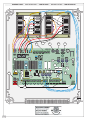 12
12
-
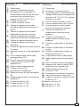 13
13
-
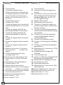 14
14
-
 15
15
-
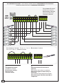 16
16
-
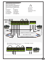 17
17
-
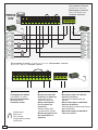 18
18
-
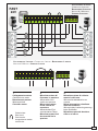 19
19
-
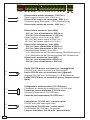 20
20
-
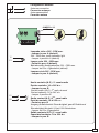 21
21
-
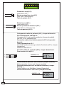 22
22
-
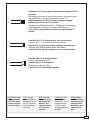 23
23
-
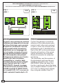 24
24
-
 25
25
-
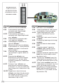 26
26
-
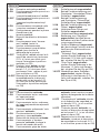 27
27
-
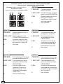 28
28
-
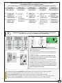 29
29
-
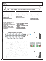 30
30
-
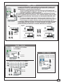 31
31
-
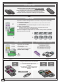 32
32
-
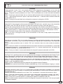 33
33
-
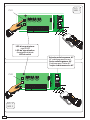 34
34
-
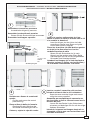 35
35
-
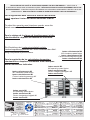 36
36


CAME ZL19 El manual del propietario
- Tipo
- El manual del propietario
- Este manual también es adecuado para
en otros idiomas
- français: CAME ZL19 Le manuel du propriétaire
- italiano: CAME ZL19 Manuale del proprietario
- English: CAME ZL19 Owner's manual
- Deutsch: CAME ZL19 Bedienungsanleitung
Artículos relacionados
-
CAME ZL19 El manual del propietario
-
-
-
-
-
-
CAME ZL170N Manual de usuario
-
-
-