
Documentazione
Tecnica
S77
rev. 0.2
09/2001
©
CAME
CANCELLI
AUTOMATICI
319S77
QUADRO COMANDO
CONTROL PANEL
ARMOIRE DE COMMANDE
SCHALTTAFEL
CUADRO DE MANDO
SERIE Z |
Z SERIES
| SÉRIE Z |
BAUREIHE Z |
SERIE Z
ZL170
CANCELLI AUTOMATICI
CARATTERISTICHE GENERALI
ITALIANOITALIANO
ITALIANOITALIANO
ITALIANO
Descrizione quadro comando
Quadro elettrico per
motoriduttori a 24V d.c.
con alimentazione 230V a.c. monofase con
frequenza 50÷60 Hz.
Progettato e costruito interamente dalla
CAME Cancelli Automatici S.p.A. per il
comando di
singoli motoriduttori
delle serie
FAST,FERNI, EMEGA,FROG e ATI, risponde
alle vigenti norme di sicurezza UNI 8612 con
grado di protezione IP54.
Scatola in ABS, dotata di presa per il riciclo
d'aria.
Garantito 12 mesi salvo manomissioni.
Il quadro comando va alimentato con la
tensione di 230V sui
morsetti L1-L2 ed è protetto
in ingresso con fusibile di
linea da 3.15A.
I dispositivi di comando sono a bassa tensione
e protetti con fusibile da 630mA. La potenza
complessiva degli accessori a 24V, protetti
da fusibile a 3.15A, non deve superare i 40W.
Il quadro, oltre al normale rallentamento di
finecorsa in apertura e chiusura, prevede
anche la
partenza rallentata dell’apertura e
della chiusura
. La schedina ADT (fornita
all’interno della scatola quadro), gestisce
tutti questi rallentamenti, riducendo anche la
quantità di cavi da collegare (
vedi pagg. 20/21
).
197
110
290
174
*
264
*
13
13
19
6
Posizione fori di fissaggio
Position of holes for fastening
Position trous de fixation
Position der Befestigungslöcher
Posición orificios de fijación
*

-2-
Sicurezza
Le fotocellule possono essere collegate e
predisposte per:
-
Riapertura in fase di chiusura
(2-C1), le
fotocellule rilevando un ostacolo durante la
fase di chiusura del cancello, provocano
l’inversione di marcia fino alla completa
apertura;
-
Stop parziale
(2-C3), arresto del cancello se
in movimento con conseguente
predisposizione alla chiusura automatica;
-
Stop totale
(1-2), arresto del cancello con
l'esclusione del ciclo di chiusura automatica;
per riprendere il movimento bisogna agire
sulla pulsantiera o sul radiocomando.
- Il quadro elettrico include un
sensore
amperometrico
del motore che interviene
quando un ostacolo blocca il movimento in
apertura o in chiusura. Se in marcia, esso
inverte il movimento. Se in rallentamento, il
motore si blocca. La sensibilità del dispositivo
è regolabile mediante trimmers (pag. 19).
- Il trasformatore è dotato di una
protezione
che in caso di
sovraccarico termico
mantiene
l’anta aperta. La richiusura avviene solo dopo
che la temperatura è scesa sotto la soglia di
emergenza.
Accessori collegabili
-
Lampada spia
per segnalazione "cancello
aperto" (10-5);
-
Lampada ciclo
per illuminare la zona di
manovra: rimane accesa dal momento in cui
le ante iniziano l'apertura fino alla completa
chiusura (compreso il tempo di chiusura
automatica). Nel caso non venga inserita la
chiusura automatica, rimane accesa solo
durante il movimento.
Collegarla sui morsetti 10-E3 e selezionarla
tramite jumper. E’ alternativa al 2° canale
radio (vedi pag. 16);
-
Lampeggiatore
di movimento, con
possibilità di selezionare il
prelampeggio
dello stesso (dip 4 selettore funzioni);
-
Elettroserratura
;
-
Scheda LB18
per alimentazione mediante
batterie che, in caso di mancanza di energia
elettrica, interviene automaticamente. Al
ripristino della tensione di linea, provvede
alla ricarica delle batterie stesse;
-
Scheda radiofrequenza AF
, (vedi tabella
pag. 23);
Inoltre è previsto un
contatto ausiliario,
sui
morsetti A1-A2, per qualsiasi dispositivo da
attivare contemporaneamente al comando
di apertura.
Altre funzioni selezionabili
-
Chiusura automatica.
Il temporizzatore di
chiusura automatica si autoalimenta a fine-
tempo corsa in apertura. Il tempo prefissato
regolabile, è comunque subordinato
dall'intervento di eventuali accessori di
sicurezza e si esclude dopo un intervento di
"stop" o in mancanza di energia elettrica;
-
Rilevazione ostacolo
. A motore fermo
(cancello chiuso, aperto o dopo un comando
di stop totale), impedisce qualsiasi
movimento se i dispositivi di sicurezza (es.
fotocellule) rilevano un ostacolo;
-
Colpo d'ariete.
Funzione che facilita lo
sganciamento della serratura; a ogni
comando di apertura, le ante premono in
battuta di chiusura per un secondo, facilitando
l'operazione di sgancio dell'elettroserratura;
-
Funzione a "uomo presente"
.
Funzionamento del cancello mantenendo

-3-
Attenzione! Prima di intervenire
all’interno dell’apparecchiatura, togliere
la tensione di linea e scollegare le
batterie (se inserite).
premuto il pulsante (esclude la funzione del
radiocomando);
-
Selezione motoriduttore
da comandare,
tramite selettore funzioni;
-
Selezione tipo di comando
:
- «apre-stop-chiude-stop» per pulsante
e/o trasmettitore;
- «apre-chiude-inversione» per pulsante
e/o trasmettitore;
- «solo apre» per trasmettitore.
Regolazioni
-
Trimmer SENS/VEL
= Regolazione
sensibilità amperometrica durante la marcia:
min/max;
-
Trimmer SENS/RALL
= Regolazione
sensibilità amperometrica durante il
rallentamento: min/max;
-
Trimmer TCA
= Regolazione tempo chiusura
automatica: da 1" a 120";
-
Trimmer TL
= Regolazione tempo di lavoro:
da 13" a 120";
-
Regolazione velocità di marcia e di
rallentamento
mediante connettori faston sul
trasformatore.

-4-
GENERAL CHARACTERISTICS
ENGLISHENGLISH
ENGLISHENGLISH
ENGLISH
Description of control panel
Control panel for 24V d.c. gear motors,
powered by 230V a.c. at 50-60 Hz (single-
phase).
Designed to control
single
FAST, FERNI,
EMEGA, FROG and ATI
gear motors
.
Designed and built entirely by CAME
CANCELLI AUTOMATICI S.p.A. to meet UNI
8612 safety standards at an IP 54 protection
level.
Housing in ABS is equipped with vents to
provide internal air circulation.
Guaranteed 12 months, unless tampered
with.
This control panel is powered by 230V a.c.
across terminals L1 and L2, and is protected
by a 3.15A fuse on the main power line.
Control systems are powered by low voltage
and protected by a 630mA fuse.
The total power consumption of 24V
accessories (which are protected by a 3.15A
fuse) must not exceed 40 W.
In addition to normal endstop slowing when
closing and opening, the control panel also
allows slowed-down initial opening and
closing movements. The ADT card (supplied
in the control panel box) manages these
slower movements, also decreasing the
amount of connection cables (see pages 20/
21).
Safety
Photocells can be connected to obtain:
-
Re-opening
during the closing cycle (2-
C1), if the photocells identify an obstacle
while the gate is closing, they will reverse
the direction of movement until the gate is
completely open;
-
Partial stop,
shutdown of moving gate, with
activation of an automatic closing cycle (2-
C3);
-
Total stop
(1-2), shutdown of gate movement
without automatic closing; a pushbutton or
radio remote control must be actuated to
resume movement).
- The electrical panel includes an
amperometric sensor
for the motor which is
triggered whenever an obstacle blocks
movement during opening or closing. If
operating speed, the sensor inverts the
movement direction. If it is slowing down, the
motor stops. The sensor's sensitivity can be
adjusted using the trimmers.
- The transformers are equipped with a
guard
that will keep the doors open in case of
thermal overload
. They are closed again only
after the temperature falls below the
emergency threshold.
Accessories which can be connected to
this unit
- “Gate open”
signal light
(10-5);
-
Cycle lamp
to light the passage area: it
remains on from the moment the doors begin
to open until they are fully closed (including
the automatic closing time). If automatic
closing is not activated, the lamp remains on
only during movement.
Connect it to terminals 10-E3 and select it
with a jumper. It is an alternative to the
second radio channel (see page 16);
- Movement
flashing lamp
with
pre-flashing
option (dip 4 function selector);
-
Electric lock
;

-5-
-
LB18 circuit card
for battery operation,
which is automatically connected in case of
power failure. Battery is recharged when line
voltage is restored.
-
Radiofrequency AF board
(see table pag.
23).
An
auxiliary contact
is also provided on
terminals A1-A2 for any device that should be
activated at the same time as the opening
command.
Other functions available
-
Automatic closing.
The automatic closing
timer is automatically activated at the end of
the opening cycle. The preset, adjustable
automatic closing time is automatically
interrupted by the activation of any safety
system, and is deactivated after a STOP
command or in case of power failure;
-
Obstacle detection.
When the motor is
stopped (gate is closed, open or half-open
after an emergency stop command), the
transmitter and the control pushbutton will
be deactivated if an obstacle is detected by
one of the safety devices (for example, the
photocells);
-
Hammer movement.
This feature makes it
easy for the lock to release (the door wings
momentarily press against the closure stops
when the open command is given, which
facilitates release of the electric lock);
-
"Operator present" function.
Gate operates
only when the pushbutton is held down (the
radio remote control system is deactivated);
-
Gear motor selection
to be operated via a
function selector;
-
Type of command
:
- «open-stop-close-stop» for pushbutton
and radio transmitter;
-
«open-close-reverse» for pushbutton
and radio transmitter;
- «open only» for radio transmitter.
Adjustments
-
Trimmer SENS/VEL
= Adjustment of
amperometric sensitivity during operating:
min/max;
-
Trimmer SENS/RALL
= Adjustment of
amperometric sensitivity during slowdown:
min/max;
-
Trimmer TCA
= Adjustment of automatic
closing time: 1" to 120";
-
Trimmer TL
= Adjustment of operating time:
13" to 120";
- Faston connectors on the transformer are
used to
select normal operating and
slowdown speeds
;
Caution! Shut off the mains power
and disconnect the batteries before
servicing the inside of the unit.

-6-
Description armoire de commande
Armoire électrique pour
motoréducteurs à
24V c.c.
avec alimentation 230V
monophasée; fréquence 50÷60 Hz.
Entièrement conçue et fabriquée par CAME
Cancelli Automatici S.p.A. pour commander
les
différents motoréducteurs
de la série
FAST, FERNI, EMEGA, FROG et ATI, l'armoire
est conforme aux normes de sécurité en
vigueur UNI 8612 avec un degré de
protection IP 54.
Boîtier en ABS muni de prise de circulation
d’air. Garantie 12 mois sauf en cas
d’endommagement.
L’armoire de commande doit être alimentée
avec une tension de 230V sur les bornes L1
et L2 et elle est protégée en entrée par un
fusible de ligne de 3.15A. Les dispositifs de
commande sont à basse tension et protégés
avec un fusible de 630mA. La puissance
totale des accessoires en 24V, protégés par
un fusible de 3.15A, ne doit pas dépasser
40W.
Mis à part le ralentissement normal de fin de
course en ouverture et en fermeture,
l'armoire prévoit également le
départ ralenti
de l'ouverture et de la fermeture
. La carte
ADT (fournie à l'intérieur de l'armoire) gère
tous ces ralentissements, en réduisant
également la quantité de câbles à brancher
(voir pages 20/21).
Sécurité
Il est possible de brancher des photocellules
et de les programmer pour:
-
Réouverture en phase de fermeture
(2-C1),
les cellules photoélectriques provoquent
l’inversion de marche jusqu’à l’ouverture
complète si elles relèvent un obstacle durant
la phase de fermeture du portail;
-
Stop partiel
(2-C3), arrêt du portail et
fermeture automatique;
-
Stop total
(1-2), arrêt du portail et
désactivation d’un éventuel cycle de
fermeture automatique; pour activer de
nouveau le mouvement, il faut agir sur les
boutons-poussoirs ou sur la
radiocommande);
- Le tableau électrique contient un capteur
ampèremétrique du moteur qui
intervient quand un obstacle bloque le
mouvement durant la phase d’ouverture
ou de fermeture.
Le capteur inverse le mouvement lorsque
cela se produit. S’il s’agit de la
phase de ralentissement, le moteur
concerné se bloque alors que l’autre
complète le mouvement.
Des compensateurs permettent de régler la
sensibilité
du dispositif (page 19).
- Le transformateur est équipé d'une
protection
qui permet au vantail de rester
ouvert en cas de
surcharge thermique
.
Celui-ci ne peut se refermer que quand la
température est descendue en dessous du
seuil d'urgence.
Accessoires pouvant être branchés
-
Lampe pour signalisation
de “portail ouvert”
(10-5);
- Lampe cycle
pour éclairer la zone de
manœuvre: elle reste allumée à partir du
moment où les vantaux commencent à
s'ouvrir jusqu'à la fermeture complète (y
compris le temps de fermeture automatique).
Elle ne reste allumée que durant le
CARACTÉRISTIQUES GÉNÉRALES
FRANÇAISFRANÇAIS
FRANÇAISFRANÇAIS
FRANÇAIS

-7-
mouvement si la fermeture automatique n'est
pas activée.
La brancher aux bornes 10-E3 et la
sélectionner à l'aide du cavalier. Elle peut
être utilisée à la place du 2
ème
canal radio
(voir page 16);
-
Clignotant
indiquant le mouvement, avec
possibilité d'en sélectionner le
pré-
clignotement
(interrupteur 4 sélecteur de
fonctions);
-
Serrure électrique
;
-
Carte LB18
pour l'alimentation par batteries
qui intervient automatiquement en cas de
coupure de courant. Elle recharge les
batteries quand le courant est rétabli;
-
Carte radiofréquence AF
(voir tableau pag.
23);
Un
contact auxiliaire
est également prévu,
sur les bornes A1-A2, pour n'importe quel
dispositif à activer en même temps que la
commande d'ouverture.
Autres fonctions pouvant
être sélectionnées
-
Fermeture automatique.
Le temporisateur
de fermeture automatique est autoalimenté
à la fin du temps de la course en ouverture.
Le temps réglable est programmé,
cependant, il est subordonné à l’intervention
d’éventuels accessoires de sécurité et il est
exclu après une intervention de “stop” ou en
cas de coupure de courant;
-
Détection obstacle.
Quand le moteur est
arrêté (portail fermé, ouvert ou semi-ouvert,
cette position est obtenue avec une
commande de stop total), annule toute
fonction de l’émetteur ou du bouton-poussoir
en cas d’obstacle détecté par les dispositifs
de sécurité (ex. Photocellules) ;
-
Coup de bélier.
Fonction qui facilite le
déblocage de la serrure (à chaque
commande d’ouverture, les vantaux se
portent en butée de fermeture pendant une
seconde, facilitant ainsi l’opération de
déblocage de la serrure électrique);
-
Fonction “homme mort”
. Fonctionnement
du portail en maintenant appuyé le bouton-
poussoir (exclut la fonction de la
radiocommande);
-
Sélection du motoréducteur
à commander
à l'aide du sélecteur de fonctions;
-
Type de commande:
- «ouverte-stop-fermée-stop» pour
bouton-poussoir et émetteur radio;
- «ouverture - fermeture - inversion» pour
bouton-poussoir et émetteur radio;
- «seulement ouverture» pour émetteur
radio.
Réglages
-
Trimmer SENS/VEL
= Réglage sensibilité
ampèrométrique pendant le mouvement :
min./max;
-
Trimmer SENS/RALL
= Réglage sensibilité
ampèrométrique pendant le ralentissement
: min./max;
-
Trimmer T.C.A.
= Temps de fermeture
automatique: de 1 à 120";
-
Trimmer T.L.
= Réglage temps de
fonctionnement: de 13" à 120";
-
Réglage vitesse de mouvement et de
ralentissement
à l'aide de connecteurs
rapides placés sur le transformateur.
Attention! Avant d’intervenir à
l’intérieur de l’appareillage, couper la
tension de ligne et débrancher les
batteries (si branchées).

-8-
ALLGEMEINE MERKMALE
DEUTSCHDEUTSCH
DEUTSCHDEUTSCH
DEUTSCH
Beschreibung des Steuergeräts
Schalttafel für
24-V-Gleichstrom-
Getriebemotoren
mit 230-V-
Einphasenstromversorgung; Frequenz:
50-60 Hz.
Vollkommen von der CAME Cancelli
Automatici S.p.A. zur Steuerung von
einzelnen Getriebemotoren
der Serie
FAST, FERNI, EMEGA, FROG und ATI
entsprechend den geltenden
Sicherheitsnormen UNI 8612 mit Schutzgrad
IP54 entwickelt und hergestellt.
ABS-Gehäuse mit Luftklappe. 12 Monate
Garantie, vorbehaltlich unsachgemäßer
Handhabung und Montage.
Die Schalttafel wird mit einer Spannung
von 230V über die Klemmen L1 und L2
gespeist und ist am Eingang mit einer
3.15-A-Hauptsicherung. Die Steuerungen
erfolgen mit Niederspannung und
geschützen enie 630mA-Sicherung. Die
Gesamtleistung des durch eine 3.15-A-
Sicherung geschützten 24-V-Zubehörs
darf 40W nicht überschreiten.
Auf der Schalttafel ist außer dem normalen
Bremsvermögen des Anschlags auch
der
verlangsamte Öffnungs- und
Schließungsbeginn
vorgesehen. Die ADT-
Karte (im Inneren des Schalttafelgehäuses)
verwaltet alle diese Verlangsamungen , bei
gleichzeitiger Verminderung der Anzahl
anzuschließender Kabel. (siehe Seiten 20/
21)
Sicherheitsvorrichtungen
Die Lichtschranken können für folgende
Funktionen angeschlossen bzw. vorbereitet
werden:
-
Wiederöffnen beim Schließen
(2-C1), die
Lichtschranken ermitteln ein Hindernis
während des schließens vom Tor und lösen
die Umkehr der Laufrichtung vom Tor aus,
bis dieses wieder vollständig geöffnet ist;
-
Teilstop
(2-C3), Stillstand des Tores
während des Torlaufs, mit darauffolgender
automatischer Torschließung;
-
Totalstop
(1-2), sofortiger Stillstand des
Tores mit Ausschluß eventueller
Schließautomatik: Fortsetzung des Torlaufs
über Drucktaster- bzw.
Funksendersteuerung;
- Auf der Schalttafel befindet sich ebenfalls
ein Motor-Stromsensor, welcher eingreift,
wenn die Bewegung beim Öffnen und
Schließen durch ein Hindernis blockiert wird.
Bei Normallauf wird die Bewegung somit
umgesteuert. Beim Bremsen wird ein Motor
blockiert, während der andere seine
Bewegung vollendet.
Die Empfindlichkeit der Vorrichtung ist durch
Trimmer einstellbar (seite. 19).
- Der Transformator Ist mit einer
Sicherung
ausgestattet, die bei
Wärmestau
dafür sorgt,
daß der Türflügel offen bleibt.
Das erneute Schließen erfolgt erst dann,
wenn die Temperatur unter den Wert, der
die Notsituation auslöst hat, gefallen ist..
Anschließbares Zubehör
-
Anzeigeleuchte
für “Tor offen” (10-5);
-
Lampe
zur Beleuchtung der
Steuerungszone: bleibt vom Beginn der
Öffnung der Türflügel bis zum vollständigen
Schließen (einschließlich die Zeit für das
automatische Schließen) eingeschaltet.
Ohne Aktivierung der automatischen
Schließung, bleibt sie nur während der

-9-
Bewegung eingeschaltet.
An den Klemmen 10-E3 anschließen und
mittels Funktionswählschalter wählen.
Alternativ zum 2° Radiokanal (siehe Seite
16)
-
Bewegungsblinker
mit der Wahlmöglichkeit
von
vorherigem Blinken
(dip 4
Funktionswählschalter);
-
Elektroschloß
;
-
Karte LB18
für Stromversorgung über
Notbatterien, die sich bei Stromausfall
automatisch zuschalten. Bei erneuter
Netzstromversorgung lädt dieselbe die
Batterien erneut aut.
-
Funkfrequenz-Platine AF
(siehe Tabelle
Seite 23);
Es ist ferner ein
Zusatzkontakt
auf den
Klemmen A1-A2 für jede beliebige
Vorrichtung, die gleichzeitig mit der
Öffnungssteuerung zu aktivieren ist,
vorgesehen.
Andere Wahlfunktionen
-
Schließautomatik
. Der Schließautomatik-
Zeischalter speist sich beim Öffnen am Ende
der Torlaufzeit selbst . Die voreingestellte Zeit
ist auf jeden Fall immer dem Eingriff
eventueller Sicherheitsvorrichtungen
untergeordnet und schließt sich nach einem
“Stop”-Eingriff bzw. bei Stromausfall selbst
aus;
-
Hinderniserfassung
. Bei stillstehendem
Motor (Tor geschlossen, geöffnet oder durch
eine Totalstop-Steuerung halb geöffnet) wird
bei durch die Sicherheitsvorrichtungen (z.B.:
Lichtschranken) erfaßtem Hindernis jede
Sender- oder Drucktasterfunktion annulliert;
-
Widderstoß
. Funktion, die das Auslösen des
Elektroschlosses erleichtert; (bei jeder
Öffnungssteuerung üben die Torflügel eine
Sekunde lang einen leichten Druck auf den
Schließungsendanschlag aus und
erleichtern dadurch die Entriegelung des
Elektroschlosses);
-
Funktion “Bedienung vom Steuerpult”
.
Torbetrieb durch Drucktasterbetätigung
(Funkfernsteuerung ausgeschlossen);
-
Wahl Getriebemotor
durch
Funktionswählschalter;
-
Steuerart
:
- «Öffnen-Stop-Schließen-Stop» für
Drucktaster- und Funksendersteuerart;
- «Öffnen-Schließen-
Torlaufumsteuerung» für Drucktaster
und Funksendersteuerart;
- «nur Öffnen» für Funksendersteuerart.
Einstellungen
-
Trimmer SENS/VEL
= Einstellung der
amperemetrischen Empfindlichk eit
während Laufgeschwindigkeit: min/max;
-
Trimmer SENS/RALL
= Einstellung der
amperemetrischen Empfindlichk während
Laufverlangsamung: min/max;
-
Trimmer TCA
= Zeiteinstellung
Schließautomatik: von 1" bis 120",
-
Trimmer TL
= Einstellung Laufzeit: von 13"
bis 120";
-
Einstellung der Laufgeschwindigkeit und
der Laufverlangsamung
über Faston-
Verbinder am Transformator.
Achtung! Das Gerät vor Eingriffen
im inneren spannungsfrei schalten und
die Stromzufuhr mittels Batterien (falls
zugeschaltet) unterbrechen.

-10-
CARACTERISTICAS GENERALES
ESPANOLESPANOL
ESPANOLESPANOL
ESPANOL
Descripción cuadro de mando
Cuadro eléctrico para
motorreductores a
24V d.c.
con alimentación 230V monofase:
frecuencia 50÷60 Hz.
Diseñado y fabricado enteramente por
CAME CANCELLI AUTOMATICI S.p.A. para
el accionamiento de motorreductores
independientes serie FAST, FERNI, EMEGA,
FROG y ATI, cumple con las normas de
seguridad vigentes UNI 8612, con grado de
protección IP 54.
Caja de ABS, dotada de toma para la
recirculación de aire. Garantizado 12 meses
salvo manipulaciones.
El cuadro de mando se alimenta con una
tensión de 230V en los bornes L1 y L2 y
está protegido en entrada con fusible de
línea de 3.15A. Los dispositivos de mando
son a baja tensión y està protegidos por
fusible a 630mA. La potencia total de los
accesorios a 24V, protegidos por fusible a
3.15A, no debe superar los 40W.
Además de la deceleración normal en fin
de carrera en apertura y cierre, el cuadro
también prevé el
arranque lento de la
apertura y del cierre
. La tarjeta ADT
(suministrada dentro de la caja del cuadro),
gestiona todas las deceleraciones,
reduciendo la cantidad de cables que se
han de conectar (véanse págs. 20/21).
Seguridad
Las fotocélulas pueden estar conectadas y
predispuestas para:
-
Reapertura en la fase de cierre
(2-C1), las
fotocélulas detectan un obstàculo durante
el cierre de la puerta, provocando la
inversión de marcha hasta la apertura
completa;
-
Parada parcial
(2-C3)
,
parada de la puerta
si se encuentra en movimiento con la
consiguiente predisposición al cierre
automático;
-
Parada total
(1-2), parada de la puerta
excluyendo el posible ciclo de cierre
automático; para reactivar el movimiento es
preciso actuar en el teclado o en el mando a
distancia);
- El cuadro eléctrico incluye un sensor
amperimétrico del motor que se activa
cuando un obstáculo bloquea el
movimiento durante la apertura o cierre. Si
el motor está funcionando, el sensor
invierte el movimiento. Si un motor está
desacelerando, éste se detiene, mientras
que el otro motor completa su movimiento.
La sensibilidad del dispositivo se ajusta
con los trimmers (pág.19).
- El transformador está equipado con una
protección
que ante una
sobrecarga térmica
mantiene abiertas las hojas.
El cierre se produce sólo después de que la
temperatura ha descendido por debajo del
umbral de emergencia.
Accesorios conectables
-
Lámpara
por señal de “puerta abierta” (10-
5);
-
Lámpara ciclo
para iluminar la zona de
maniobra: queda encendida desde cuando
las hojas comienzan a abrirse hasta que se
cierran por completo (incluido el tiempo de
cierre automático). Si no se conectara el
cierre automático, queda encendida sólo
durante el movimiento.

-11-
Conéctela a los bornes 10-E3 y selecciónela
con el jumper. Es alternativa al 2° canal radio
(véase pág. 16);
-Luz intermitente
de movimiento con
posibilidad de seleccionar la
intermitencia
previa
(dip 4 selector funciones);
-
Cerradura eléctrica
;
-
Tarjeta LB18
para la alimentación
mediante baterías que, en caso de falta de
energía eléctrica, interviene
automáticamente. Una vez conectada de
nuevo la tensión de línea, se ocupa de
cargar las baterías;
-
Tarjeta radiofrecuencia AF
(ver tabla
pág.23);
También se ha previsto un
contacto auxiliar,
en los bornes A1-A2, para cualquier
dispositivo que se haya de activar
simultáneamente al mando de apertura.
Otras funciones seleccionables
-
Cierre automático
. El temporizador de
cierre automático se autoalimenta en fin-de-
tiempo carrera en fase de apertura. El tiempo
prefijado regulable, sin embargo, está
subordinado a la intervención de posibles
accesorios de seguridad y se excluye
después de una intervención de parada o
en caso de falta de energía eléctrica;
-
Detección obstáculo.
Con el motor parado
(puerta cerrada, abierta o en posición semi-
abierta obtenida a través de un comando
de stop total), anula cualquier función del
transmisor o del botón en caso de obstáculo
detectado por los dispositivos de seguridad
(por ejemplo: fotocélulas);
-
Golpe de ariete.
Función que facilita el
desenganche de la cerradura (en cada
comando de apertura las puertas presionan
el tope del cierre durante un segundo,
facilitando la operación de desenganche de
la electrocerradura);
-
Función a "hombre presente"
.
Funcionamiento de la puerta manteniendo
pulsada la tecla (excluye la función del
mando a distancia);
-
Selección
del
motorreductor que se ha de
accionar con el selector de funciones
;
-
Tipo de mando;
- «apertura-parada-cierre-parada» para
tecla y transmisor de radio;
- «apertura-cierre-inversión» para tecla
y transmisor de radio;
- «sólo apertura» para transmisor de
radio.
Regulaciones
-
Trimer SENS/VEL
= Regulación
sensibilidad amperimétrica durante la
marcha: mín/máx;
-
Trimer SENS/RALL
= Regulación
sensibilidad amperimétrica durante el
ralentamiento: mín/máx;
-
Trimer TCA
= Tiempo cierre automático: de
1" a 120”;
-
Trimer TL
= Regulación tiempo trabajo: de
13" a 120";
-
Regulación velocidad de marcha y de
deceleración
por medio de conectores faston
en el transformador
¡Atención! Antes de actuar dentro
del aparato, quitar la tensión de línea y
desecnectar las baterías (si estuvieran
conectadas).

-12-
SCHEDA BASE -
MOTHERBOARD
- CARTE BASE -
GRUNDPLATINE
- TARJETA BASE
1) Trasformatore
2) Trimmer di regolazione sensibilità
amperometrica durante la marcia
3) Trimmer di regolazione sensibilità
amperometrica durante il rallentamento
4) Trimmer di regolazione tempo lavoro
5) Trimmer di regolazione chiusura automatica
6) Pulsante memorizzazione codice
7) Morsettiera per il collegamento al
caricabatterie LB18 (vedi pag. 17)
8) Fusibile centralina 630mA
9) Fusibile accessori 3.15A
10) LED di segnalazione codice radio
11) Selettore funzioni
12) Jumper selezione uscita B1-B2/lampada
ciclo
13) Fusibile di linea 3.15A
14) Innesto scheda radiofrequenza
15) Morsettiera di collegamento
16) Schedina ADT per gestione rallentamenti
(vedi pagg. 20/21)
17) Morsettiera per ADT (da usare solo con
Frog 24V, vedi pag. 21)
COMPONENTI PRINCIPALI
ITALIANO
230V
230V
0
12
24
RALL.MIN
RALL.MAX
VEL.MIN
VEL.MAX
AF
ZL170
QUADRO COMANDO
PROG
SENS VEL T LSENS RALL T C A
A BCDEF I
MORSETTIERA CARICA BATTERIE
R1
FUSIBILE
CENTRALINA
630mA
FUSIBILE
ACCESSORI
3 . 1 5 A
230V
FUSIBILE
CENTRALINA
3 . 1 5 A
21 345678910
ON
21
0 RALL VEL 24V 12V
J2
L1 L2 M NR 10 11 E E3 5 S 1 237C1C3A1
T
B1 B2A2
T
1
2
RA R RC FA F M N
MNR
ADT x ZL170
7
8
9
32 4 5
10
14
11
13
15
16
1
NERO -
BLACK
- NOIR -
SCHWARZ
- NEGRO
BLU -
BLUE
- BLEU -
BLAU
- AZUL
MARRONE -
BROWN
- MARRON -
BRAUN
- CASTÁÑO
ROSSO -
RED
- ROUGE -
ROT
- ROJO
BIANCO -
WHITE
- BLANC -
WEI
ß
- BLANCO
BLU -
BLUE
- BLEU -
BLAU
- AZUL
VIOLA -
PURPLE
- VIOLET -
VIOLETT
- PÚRPURA
17
6
12

-13-
MAIN COMPONENTES
1) Transformer
2) Trimmer for adjustment of amperometric
sensitivity during operation
3) Trimmer for adjustment of amperometric
sensitivity during slowdown
4) Trimmer for adjustment of operating time
5) Trimmer for adjustment of automatic closing
6) Button for memorizing code
7) Terminal board for connectiong battery
charger LB18 (vedi pag. 16))
8) Fuse on central control unit, 630 mA
9) Fuse on accessory power line, 3.15A
10) Radio code signal LED
11) Functions switch
12) Jumper which selects output B1-B2/
operating cycle indicador light
13) Line fuse, 3.15A
14) Radiofrequency board socket
15) Terminal block for external connections
16) ADT card for slowdown control (see pages
21/21)
17) ADT terminal board (to be used only with
Frog 24V. See page 21).
ENGLISH
PRINCIPAUX COMPOSANTS
1) Transformateur
2) Trimmer de réglage sensibilité
ampèremétrique pendant le mouvement
3) Trimmer de réglage sensibilité
ampèremétrique pendant le ralentissement
4) Trimmer de réglage temps de
fonctionnement
5) Trimmer de réglage fermeture automatique
6) Bouton-poussoir mémorisation code
7) Plaque à bornes pour le branchement au
chargeur de batteries LB18 (vedi pag. 16)
8) Fusible boîtier 630mA
9) Fusible accessoires 3.15A
10) LED de signalisation code radio
11) Selecteur de fonctions
12) Pontet sélection sortie B1-B2/lampe cycle
13) Fusible de ligne 3.15A
14) Branchement carte radiofréquence
15) Plaque à bornes de connexion
16) Carte ADT pour gérer les ralentissements
(voir pages 20/21)
17) Plaque à bornes pour ADT (à n'utiliser
qu'avec Frog 24V, voir page 21)
FRANÇAIS
HAUPTKOMPONENTEN
1) Transformatoren
2) Trimmer zur Einstellung amperemetrischen
Empfindlichkeit während
Laufgeschwindigkeit
3) Trimmer zur Einstellung amperemetrischen
Empfindlichkeit während
Laufverlangsamung
4) Trimmer zur Einstellung Laufzeit
5) Trimmer zur Einstellung der
Schließautomatik
6) Code-Speichertasten
7) Klemmleiste für den Anschluß an das
Batterieladegerät LB18 (vedi pag. 16)
8) Schaltkastensicherung 630mA
9) Zubehör-Sicherung 3.15A
10) Anzeige LED-Funkcode
11) Wählschalter für Funktionen
12) Jumper zur Wahl des Ausgangs B1-B2/
Betriebszyklus Anzeigeleuchte
13) Hauptsicherung 3.15A
14) Steckanschluß Funkfrequenz-Platine
15) AnschlußKlemmenleiste
16) Karte ADT zur Verwaltung der
Verlangsamungen (siehe Seiten 20/21)
17) Klemmenbrett ADT (nur mit Frog 24V zu
benutzen, siehe Seite 21).
DEUTSCH
PRINCIPALES COMPONENTES
1) Transformadores
2) Trimer de regulación sensibilidad
amperimétrica durante la marcha
3) Trimer de regulación sensibilidad
amperimétrica durante el ralentamiento
4) Trimer de regulación tiempo trabajo
5) Trimer de regulación tiempo cierre
automático
6) Teclas memorización códigos
7) Caja de bornes para la conexión del
cargador de batería LB18 (vedi pag. 16)
8) Fusible para central 630mA
9) Fusible accesorios 3.15A
10) LED de señal código radio
11) Selector de funciones
12) Jumper selección salida B1-B2/lámpara
ciclo
13) Fusible de línea 3.15A
14) Conexión tarjeta radiofrecuencia
15) Caja de bornes para las conexiónes
16)Tarjeta ADT para gestión de deceleraciones
(véanse págs. 20/21)
17)Caja de conexiones para ADT (se usa sólo
con Frog 24V, véase pág. 21)
ESPANOL

-14-
L1L1
L1L1
L1
L2L2
L2L2
L2
1010
1010
10
1111
1111
11
1010
1010
10
E E
E E
E
11 11
11 11
11
S S
S S
S
1010
1010
10
5 5
5 5
5
Alimentazione quadro comando - 230V (a.c.)
Power supply for control unit - 230V (a.c.)
Alimentation armoire de commande - 230V (c.a.)
Stromversorgung Steuergerät - 230V (Wechselstrom)
Alimentación cuadro de mando - 230V (a.c.)
Alimentazione accessori (max 40W):
- 24V (a.c.) con alimentazione a 230V(a.c.)
- 24V (d.c.) con alimentazione a 24V (d.c.)
Power supply to accessories (max. 40W):
24V (a.c.) with power supply at 230V (a.c.)
24V (d.c.) with power supply at 24V (d.c.)
Alimentation accessoires (max 40W):
- 24V (c.a.) avec alimentation à 230V(c.a.)
- 24V (c.c.) avec alimentation à 24V (c.c.)
Stromversorgung Zubehör (max 40W):
- 24V (Wechselstrom) bei Stromversorgung
230V(Wechselstrom)
- 24V (Wechselstrom) bei Stromversorgung 24V (Gleichstrom)
Alimentación accesorios (max 40W):
- 24V (a.c.) con alimentación a 230V(a.c.)
- 24V (d.c.) con alimentación a 24V (d.c.)
Uscita 24V-25W max.in movimento (es. lampeggiatore)
24V-25W max. output in motion (e.g. flashing light)
Sortie 24V-25W max. en mouvement (ex. clignotant)
Ausgang 24V-25W max. "in Bewegung" (z.B. Blinkleuchte)
Salida 24V-25W max. en movimiento (por ej. lámpara
intermitente)
Collegamento elettroserratura (12V-15W max.)
con EMEGA, vedi anche pag. 17
Connection for electrically-actuated lock: 12V-15W max.
With EMEGA please also see pg. 17
Connexion serrure électrique (12V-15W max.)
avec EMEGA, voir également page 17
Anschluß Elektroschloß (12V-15W max.)
Mit EMEGA, siehe auch Seite 17
Conexión electrocerradura (12V-15W max.)
con EMEGA, véase también pág. 17
Lampada spia 24V-3W max. “cancello aperto”
24V-3W max. gate-open signal lamp
Lampe-témoin 24V-3W max. "vantail ouvert"
Kontrollampe 24 V-3W max. “Tor geöffnet”
Lámpara indicadora 24V-3W max. “puerta abierta”
L1 L2 M NR 10 11 E E3 5 S 1 237C1C3
A1
T
B1 B2
A2
T

-15-
1
2
2
7
2
3
2
C1
2
C3
L1 L2 M NR 10 11 E E3 5 S 1 237C1C3
A1
T
B1 B2
A2
T
Collegamento antenna
Antenna connection
Connexion antenne
Antennenanschluß
Conexión antena
Pulsante di stop (N.C.)
Stop button (N.C.)
Bouton-poussoir de stop (N.F.)
Stop-Taste (Ruhekontakt)
Tecla de parada (N.C.)
Pulsante apre (N.O.)
Open button (N.O.)
Bouton-poussoir d'ouverture (N.O.)
Taste Öffnen (Arbeitskontakt)
Tecla de apertura (N.O.)
Collegamento radio e/o pulsante (N.O.)
Connector (N.O.) radio and/or pushbutton
Connection radio et/ou bouton-poussoir (N.O.)
Anschluß Funkfernsteuerung und/oder Drucktaster (N.O.)
Conexión radio y/o pulsador (N.O.)
Contatto (N.C.) di riapertura in fase di chiusura
(da cortocircuitare se non viene utilizzato)
Contact (N.C.) for re-opening during closure
(should be short circuited if not used)
Contact (N.F.) de réouverture pendant la fermeture
(à court-circuiter s'il n'est pas utilisé)
Ruhekontakt Wiederöffnen beim Schließen
(bei Nichtbenutzung kurzzuschließen)
Contacto (N.C.) para la apertura en la fase de cierre
(se cortocircuita si no se utiliza)
Contatto (N.C.) di Stop parziale
Partial stop contact (N.C.)
Contact (N.F.) d'arrêt partiel
Ruhekontakt Partial-Stop
Contacto (N.C.) de parada parcial

-16-
Uscita contatto (N.O.): si chiude per 3” a ogni coman-
do di apertura. Portata contatto: 5A (250V a.c.)
Contact outlet (N.O.): it is closed for 3" upon opening
command. Contact capacity: 5A (250V AC)
Sortie contact (N.O.): il se ferme pendant 3'' à chaque
commande d'ouverture. Débit contact: 5A (250V a.c.)
Kontaktausgang (N.O.): schließt sich bei jeder
Öffnungssteuerung für 3". Leistung: 5A (250V WS)
Salida contacto (N.A.): se cierra durante 3” cada vez que se
acciona la apertura Capacidad contacto: 5A (250V a.c.)
Uscita contatto (N.O.) secondo canale radio
Portata contatto: 1A a 24V (d.c.)
Contact output (N.O.) second radio channel
Contact capacity: 1A to 24V (d.c.)
Sortie contact (N.O. selon le canal radio
Porté du contact: 1A à 24V (c.c.)
Ausgang Arbeitskontakt Stromfestigkeit gemäß
Radiokanal
Stromfestigkeit Kontakt: 1A bei 24V (Gleichstrom)
Salida contacto (N.O.)según canal radio
Capacidad contacto: 1A a 24V (d.c.)
Lampada ciclo a 24V - 25W max.
24V - 25W max. cycle indicador light
Lampe cycle 24V - 25W max.
Betriebszyklus-Anzeigeleuchte 24V - 25W max.
Lampara ciclo 24V - 25W max.
B1
B2
10
E3
L1 L2 M NR 10 11 E E3 5 S 1 237C1C3
A1
T
B1 B2
A2
T
A1
A2
Jumper 12 pag. 12
COLLEGAMENTI ALTERNATIVI
ALTERNATIVE CONNECTIONS
BRANCHEMENTS ALTERNATIFS
ALTERNATIVE ANSCHLÜSSE
CONEXIONES ALTERNATIVAS

-17-
CONFIGURAZIONE MORSETTIERA PER LB18 -
TERMINAL BOARD CONFIGURATION FOR LB18 -
CONFIGURATION DE LA PLAQUE À BORNES POUR
LB18
- KLEMMENBRETTKONFIGURATION FÜR LB 18 -
CONFIGURACIÓN CAJA DE CONEXIONES PARA LB18
Nel caso di utilizzo della scheda caricabatterie LB18, togliere
tutti i ponticelli e collegare la scheda come indicato nella
relativa documentazione.
In case the LB18 battery charger card is used, remove all
jumpers and connect the card as indicated in the card's
relevant documentation.
En cas d'utilisation de la carte LB18 pour charger les batteries,
enlever tous les fils de liaison et brancher la carte comme
indiqué dans la documentation correspondante.
Bei Benutzung der Batterielade-Karte LB18 alle
Überbrückungen entfernen und die Karte nach den Angaben
in der entsprechenden Anleitung anschließen.
Si se utiliza la tarjeta cargador de baterías LB18, elimine todas
las conexiones puente y conecte la tarjeta tal como indicado en
la documentación respectiva.
Configurazione di fabbrica
Standard factory configuration
Configuration effectuée en usine
Werkkonfiguration
Configuración de fábrica
A BCDEF I
MORSETTIERA CARICA BATTERIE
R1
FUSIBIL
E
CENTRALI
6 3 0 mA
Particolarità dell’abbinamento ZL170/EMEGA con serratura elettrica E881
Details of the ZL170/EMEGA with E881 electric lock
Branchement spécial ZL 170/EMEGA avec serrure électrique E881
Besonderheiten bei der Koppelung ZL170/EMEGA mit elektrischem Schloß E881
Peculiaridad de la combinación ZL170/Emega/cerradura E881
Per alimentare a 24V la serratura E881 sui morsetti 11-S
(normalmente a 12V) agire sui ponticelli come segue:
Fig. A -
CON scheda LB18, lasciare un solo ponticello su B-D e
collegare la scheda come indicato nella relativa documentazio-
ne.
Fig. B -
SENZA scheda LB18, modificare il ponticello C-D in B-D
To power the E881 lock at 24V on terminals 11-S (normally at
12V) adjust the jumpers as follows:
Fig. A - WITH LB18 board, leave just one jumper on B-D and
connect the board as shown in the relative documentation.
Fig. B - WITHOUT LB18 board, change jumper C-D into B-D.
Pour alimenter la serrure E881 sur les bornes 11-S en 24 V
(normalement en 12 V), agir sur les fils de liaison comme suit:
Fig. A -
AVEC la carte LB18, ne laisser qu'un fil de liaison sur
B-D et brancher la carte comme indiqué dans la documentation
correspondante.
Fig. B -
SANS carte LB18, modifier le fil de liaison C-D en B-D.
Zur Speisung des Schlosses E881 an den Klemmen 11-S bei
24V (gewöhnlich bei 12V), wie folgt auf die Überbrückungen
einwirken:
Abb. A - MIT Karte LB18, nur eine Überbrückung an B-D lassen und die Karte nach den
Anleitungen in der entsprechenden Dokumentation anschließen.
Abb. B - OHNE Karte LB18, die Überbrückung C-D in B-D ändern.
Para alimentar a 24V la cerradura E881 en los bornes 11-S (normalmente a 12V) actúe sobre los
conectortes puentes de la siguiente manera:
Fig. A -
CON tarjeta LB18, deje un solo conector puente en B-D y conecte la tarjeta como indicado
en la documentación respectiva.
A BCDEF I
MORSETTIERA CARICA BATTERIE
R1
FUSIBIL
E
CENTRALI
6 3 0 mA
Fig. /Abb. A
ZL170 + EMEGA + LB18 + E881
A BCDEF I
MORSETTIERA CARICA BATTERIE
R1
FUSIBIL
E
CENTRALI
6 3 0 mA
Fig. /Abb. B
ZL170 + EMEGA + E881

-18-
1 ON Chiusura automatica attivata;
2 ON Funzionamento pulsante o comando
radio "apre/chiude/inversione"
attivato;
2 OFF Funzionamento pulsante o comando
radio "apre/stop/chiude/stop"
attivato;
3 ON Funzionamento comando radio "solo
apertura" attivato;
4 ON Prelampeggio in apertura e in chiusura
attivato;
5 ON Rilevazione dell'ostacolo attivato;
6 ON Funzionamento a "uomo presente"
attivato; (esclude la funzione del
radiocomando)
7 ON Funzione colpo d'ariete attivato; (per
facilitare lo sgancio della serratura)
8 OFF Stop parziale attivato; con dispositivo
di sicurezza collegato ai morsetti 2-
C3, (se non viene utilizzato il
dispositivo, selezionare il dip in ON)
9 OFF Pulsante "stop" attivato; con
dispositivo di sicurezza collegato ai
morsetti 1-2, (se non viene utilizzato il
dispositivo, selezionare il dip in ON)
10 ON con motoriduttori ATI - FAST
10 OFF con motoriduttori FERNI/FROG/
EMEGA
ITALIANO
1 ON Automatic closure enabled;
2 ON "Open/close/reverse" radio control or
pushbutton function enabled;
2 OFF "Open/stop/close/stop" radio control
or pushbutton function enabled;
3 ON "Only open" radio control function
enabled;
4 ON Pre-flashing (opening and closing)
enabled;
5 ON Obstacle detection device enabled;
6 ON "Operator present" operation
enabled; (radio remote control is
deactivated when function is
selected)
7 ON Hammer movement operation
enabled; (this function helps unlock
the electric lock)
8 OFF "Partial-stop" enabled; insert the
safety device on terminal 2-C3 (if not
used, set the dip-switch to ON)
9 OFF "Stop" button enabled; insert the
safety device on terminal 1-2 (if not
used, set the dip-switch to ON)
10 ON With ATI - FAST gear motor
10 OFF With FERNI/FROG/EMEGA gear
motors
ENGLISH
21 345678910
ON
DIP-SWITCH 10 VIE
10-WAY DIP-SWITCH
DIP-SWITCH 10 VOIES
ZEHNWEG-DIP-SWITCH
DIP-SWITCH 10 VÍAS
2
1
3
45
6
78910
O
N
ON
OFF
SELETTORE FUNZIONI -
FUNCTIUONS SWITCH -
SELECTEUR DE FONCTIONS
WÄHLSCHALTER FÜR FUNKTIONEN -
SELECTOR DE FUNCIONES

-19-
1 ON Cierre automático activado;
2 ON Funcionamiento tecla o radiomando
"apertura/cierre/inversión" activado;
2 OFF Funcionamiento tecla o radiomando
"apertura/parada/cierre/parada"
activado;
3 ON Funcionamiento radiomando "sola
apertura" activado;
4 ON Pre-intermitencia en la fase de
apertura y cierre activado;
5 ON Detección del obstáculo activado;
6 ON Funcionamiento a "hombre presente"
activado; (escluye la función del
mando de radio)
7 ON Funcionamiento golpe de ariete
activado; (esta función sirve para
agilizar desenganche de la
electrocerradura)
8 OFF "Parada parcial" activada; introducir
el dispositivo de seguridad en los
bornes 2-C3, (si no se utiliza, poner el
dip en ON)
9 OFF "Pulsador parada" activada;
introducir el dispositivo de seguridad
en los bornes 1-2, (si no se utiliza,
poner el dip en ON)
10 ON con motorreductores ATI - FAST
10 OFF con motorreductores FERNI/FROG/
EMEGA
ESPANOL
1 ON Fermeture automatique activé;
2 ON Fonctionnement bouton-possoir ou
commande radio "ouverte/fermeé/
inversion" activé;
2 OFF Fonctionnement bouton-possoir ou
commande radio "ouverture/stop/
fermeture/stop" activé;
3 ON Fonctionnement commande radio
"ouverture seulement" activé;
4 ON Preclignotement pandant la phase
d'ouverture et de fermeture activé;
5 ON Dispositif de détection d'obstacle
activé;
6 ON Fonctionnement avec "homme mort"
activé; (exclut la fonction
radiocommande)
7 ON Fonctionnement coup de bélier
activé; (pour faciliter le déblocage de
la serrure)
8 OFF "Arrêt partiel" activé; monter le
dispositif de sécurité sur les bornes 2-
C3, (s'il n'est pas utilisé, positionner
l'interrupteur à positions multiples sur
ON)
9 OFF Poussoir "stop" activé; monter le
dispositif de sécurité sur les bornes 1-
2, (s'il n'est pas utilisé, positionner
l'interrupteur à positions multiples sur
ON)
10 ON avec les motoréducteurs ATI - FAST
10 OFF avec les motoréducteurs FERNI/
FROG/EMEGA
FRANÇAIS
1 ON Schließautomatik zugeschaltet;
2 ON Betrieb Funkfernsteuerung und
Drucktaster "Umschalten/Öffnen/
Schließen" zugeschaltet
2 OFF Betrieb Funkfernsteuerung und
Drucktaster "Öffnen/Stop/Schließen/
Stop" zugeschaltet;
3 ON Betrieb Funkfernsteuerung "nur
Öffnen" zugeschaltet;
4 ON Vorblinken beim Öffnen und Schließen
zugeschaltet;
5 ON Hindemisaufnahme zugeschaltet;
6 ON Bedienung vom "Steuerpult"
zugeschaltet; (bei Wahl dieser
Betriebsart wird die
Funkfernsteuerung ausgeschlossen)
7 ON Funktion Widderstoß zugeschaltet;
(durch diese Funktion wird das
Auslösen des Elektroschlosses
erleichtert)
8 OFF "Teilweiser-Stop" zugeschaltet;
stecken Sie die Sicherung in die
Klemmen 2-C3 (falls nicht verwendet,
schalten Sie den Dip auf ON)
9 OFF "Stop-Taste" zugeschaltet; stecken
Sie die Sicherung in die Klemmen 1-2
(falls nicht verwendet, schalten Sie
den Dip auf ON)
10 ON Mit Getriebemotoren ATI - FAST
10 OFF Mit Getriebemotoren FERNI/FROG/
EMEGA
DEUTSCH
REGOLAZIONE TRIMMERS
- TRIMMERS REGOLATION
- RÉGLAGE TRIMMERS
TRIMMERS EINSTELLUNG -
REGULACIÓN TRIMMERS
MAX MIN
SENS RALL
MAX MIN
1”120”
T L
13”120”
SEN S VEL
T C A

-20-
M NR 10 11 E E3
ZL170
COLLEGAMENTI QUADRO/MOTORIDUTTORE -
CONTROL PANEL/GEAR MOTOR CONNECTIONS
BRANCHEMENTS ARMOIRE/ MOTORÉDUCTEUR
ANSCHLÜSSE SCHALTTAFEL/GETRIEBEMOTOR -
CONEXIONES CUADRO/MOTORREDUCTOR
La schedina ADT va fissata alla morsettiera
del motoriduttore come illustrato, e
collegata al quadro solamente con i
morsetti M, N e R.
The ADT card is fastened to the gear
motor terminal board as illustrated, and
connected to the control panel only with
terminals M, N and R.
La carte ADT doit être fixée à la plaque à
bornes du motoréducteur, comme indiqué.
Elle ne doit être branchée à l'armoire qu'avec
les bornes M, N et R.
Die ADT-Karte ist am Klemmenbrett des
Getriebemotors wie abgebildet zu
befestigen und ausschließlich mit den
Klemmen M, N und R an die Schalttafel
anzuschließen.
La tarjeta ADT se fija en la caja de conexiones
del motorreductor como ilustrado, y se
conecta al cuadro solamente con los bornes
M, N y R.
N.B.: il morsetto RA non è attivo su
FAST, FERNI ed EMEGA.
NOTE: RA terminal is not active
with FAST, FERNI and EMEGA.
N.B.: la borne n'est pas active sur
FAST, FERNI et EMEGA.
N.B.: die Klemme RA ist bei
FAST, FERNI und EMEGA nicht
aktiviert.
N.B.: el borne RA no está activo en
FAST, FERNI y EMEGA,
ATI 24V
1
2
RA R RC FA F M N
MNR
ADT x ZL170
EMEGA
24V
RA R RC FA F M N
FAST
24V
FERNI
24V

-21-
M NR 10 11 E E3 5
ZL170
FROG
24V
marrone -
brown
- marron
braun
- marrón
blu -
blue
- bleu
Blau
- azul
marrone -
brown
- marron
braun
- marrón
Con il FROG invece, schedina ADT e
morsettiera, dopo il collegamento ai cavi in
uscita dal motoriduttore, possono essere
lasciati all’interno del quadro o in analoga
scatola a tenuta.
But after connection to the gear motor's
outlet cables, the ADT card and terminal
board can be left inside the control panel
or in a similar sealed box with FROG gear
motors.
Avec FROG, la carte ADT et la plaque à
bornes peuvent au contraire être laissées à
l'intérieur de l'armoire ou dans
un boîtier étanche analogue
après les avoir branchées aux
câbles à la sortie du
motoréducteur.
Bei FROG dagegen können
ADT-Karte und
Klemmenbrett nach Anschluß
an die Ausgangskabel des
Getriebemotors im
Schalttafelinneren oder in
einem ähnlichen dichten
Kasten gelassen werden.
En cambio, con FROG, la tarjeta
ADT y caja de conexiones,
después de la conexión a los
cables que salen del
motorreductor, se pueden dejar
dentro del cuadro o en otra caja
similar.
RA R RC FA F M N
1
2
RA R RC FA F M N
MNR
ADT x ZL170
COLLEGAMENTI QUADRO/MOTORIDUTTORE -
CONTROL PANEL/GEAR MOTOR CONNECTIONS
BRANCHEMENTS ARMOIRE/ MOTORÉDUCTEUR
ANSCHLÜSSE SCHALTTAFEL/GETRIEBEMOTOR -
CONEXIONES CUADRO/MOTORREDUCTOR

-22-
ITALIANO
Per la regolazione delle
velocità di marcia e dei
rallentamenti, spostare i faston
sui relativi connettori indicati.
REGOLAZIONE VELOCITÀ DI APERTURA/CHIUSURA E DI RALLENTAMENTO
SELECTION OF OPENING/CLOSING AND SLOWDOWN SPEED
RÉGLAGE VITESSE D'OUVERTURE/FERMETURE ET DE RALENTISSEMENT
EINSTELLUNG DER ÖFFNUNGS/SCHLIESSGESCHWINDIGKEIT UND DER LAUFVERLANGSAMUNG
REGULACIÓN VELOCIDAD DE APERTURA/CIERRE Y DE RALENTAMIENTO
ENGLISH
To adjust the operating and
slowdown speeds, move the
faston connectors to the
indicated connectors.
FRANÇAIS
Pour le réglage de la vitesse
de fonctionnement et des
ralentissements, déplacer les
fastons sur les connecteurs.
DEUTCH
Zur Einstellung der
Laufgeschwindigkeit und der
Laufverlangsamungsphasen
die Faston-Verbinder der
Abbildung entsprechend
positionieren.
230V
230V
0
12
24
RALL.MIN
RALL.MAX
VEL.MIN
VEL.MAX
faston rallentamento
slowdown speed faston
faston ralentissement
Faston Laufverlangsamung
faston ralentamiento
faston marcia
operating speed faston
faston mouvement
Faston Laufgeschwindigkeit
faston marcha
+
)
ITALIANO
A = • Partenza rallentata in
apertura
• Rallentamento in
chiusura
B = Marcia normale in
apertura e chiusura
C = • Rallentamento in
apertura
• Partenza rallentata in
chiusura
ATTENZIONE!
- Tagliando nel punto 1, si
elimina la partenza rallentata in
apertura.
- Tagliando nel punto 1 e 2, si
elimina la partenza rallentata in
apertura e chiusura.
ENGLISH
A = • Initial slowed-down
opening
• Closing slowdown
B = Normal opening and
closing speed
C = • Slowed-down opening
• Initial slowed-down
closing
WARNING!
- Cutting at point 1 eliminates
initial slowed-down opening.
- Cutting at point 1 and 2
eliminates initial slowed-down
closing and opening.
FRANÇAIS
A = • Démarrage ralenti durant
l'ouverture
• Ralentissement durant la
fermeture
B = Marche normale durant
l'ouverture et la fermeture
C = • Ralentissement durant
l'ouverture
• Démarrage ralenti durant
la fermeture
ATTENTION!
- En coupant au point 1, on
élimine le démarrage ralenti
durant l'ouverture.
- En coupant au point 1 et 2,
on élimine le démarrage ralenti
durant l'ouverture et la
fermeture.
DEUTCH
A = • Verlangsamter Start bei
Öffnung
• Verlangsamung bei
Schließung
B = • Normallauf bei Öffnung
und Schließung
C = • Verlangsamung bei
Öffnung
• Verlangsamter Start bei
Schließung
ACHTUNG!
- bei Schneiden in Punkt 1,
wird der verlangsamte Start bei
Öffnung beseitigt.
- Bei Schneiden in Punkt 1 und
2, wird der verlangsamte Start
bei Öffnung und bei Schlie-
ßung beseitigt.
ESPAÑOL
A = • Arranque lento en
apertura
• Arranque lento en cierre
B = Funcionamiento normal en
apertura y cierre
C = • Deceleración en
apertura
• Arranque lento en cierre
ATENCIÓN!
- Cortando en el punto 1, se
elimina el arranque lento en
apertura.
- Cortando en el punto1 e 2, se
elimina el arranque lento e
apertura y cierre
ESPAÑOL
Para la regulación de las
velocidades de marcha y
ralentamientos, desplazar los
fastons a los correspondientes
conectores indicados.
1
2
RA R R
C

-23-
PROGRAMMAZIONE DEL RADIOCOMANDO /
PROGRAMMING THE REMOTE CONTROL
PROGRAMMATION DE LA COMMANDE RADIO
PROGRAMMIERUNG DER FUNKFERNSTEUERUNG
/ PROGRAMACION DEL MANDO A DISTANCIA
ENGLISH
PROCEDURE
A. insert an
AF card **.
B. encode
transmitter/s.
C. store code in
the
motherboard.
FRANCAIS
PROCEDURE
A. placer une
carte AF **.
B. codifier le/s
émetteur/s.
C. mémoriser la
codification
sur la carte
base.
DEUTSCH
PROZEDUR
A. Stecken Sie
eine Karte
AF **.
B. Codieren Sie
den/die
Sender.
C. Speichern Sie
die Codierung
auf der
Grundplatine.
ITALIANO
PROCEDURA
A. inserire una
scheda AF**.
B. codificare il/i
trasmettito-
re/i.
C. memorizzare
la codifica
sulla scheda
base.
ESPANOL
PROCEDIMIENTO
A. introducir
una tarjeta
AF **.
B. codificar el/
los
transmisor/
es.
C. memorizar la
codificación
en la tarjeta
base.
(**) Per trasmettitori con frequenza 433.92 AM (serie TOP e serie
TAM), sulla relativa scheda AF43S bisogna posizionare il jumper
come illustrato.
(**) On AM transmitters operating at 433.92 MHz (TOP and TAM
series), position the jumper connection on circuit card AF43S as
shown on the sheet.
(**) Pour les émetteurs de fréquence 433.92 AM (série TOP et
série TAM) il faut positionner le pontet sur la carte AF43S
correspondante de la façon indiquée.
(**) Bei Sendern mit einer Frequenz von 433.92 AM (Reihe TOP und
Reihe TAM) ist der auf der entsprechenden Platine AF43S befindliche
Jumper der Abbildung entsprechend zu positionieren.
(**) Para transmisores con frecuencia 433.92 AM (serie TOP y
serie TAM), en la tarjeta corespondiente AF43S es necesario
colocar el jumper como se indica
TOP
TAM
SCHEDA BASE
MOTHERBOARD
CARTE DE BASE
BASISKARTE
TARJETA BASE
SCHEDA "AF"
"AF" BOARD
CARTE "AF"
KARTE «AF»
TARJETA «AF»
La schedina AF deve essere inserita OBBLIGATORIAMENTE in assenza di tensione, perché la scheda madre la riconosce
solo quando viene alimentata
The AF board should ALWAYS be inserted when the power is off because the motherboard only recognises it when it is
powered.
La carte AF doit OBLIGATOIREMENT être branchée en l’absence de tension car la carte mère ne la reconnaît que quand elle est
alimentée.
Vor Einschieben der Karte die Stromzufuhr UNBEDINGT abschalten, da die Erkennung durch die Hauptkarte nur über eine
Neueinschaltung ( nur durch Versorgung) erfolgt.
La tarjeta AF se debe montar OBLIGATORIAMENTE en caso de falta de corriente, porque la tarjeta madre la reconoce sólo
cuando está alimentada
INSERIMENTO SCHEDA AF -
AF BOARD INSERTION
- INSTALLATION DE LA CARTE AF
EINSTECKEN DER KARTE AF-
MONTAJE DE LA TARJETA AF
A
Frequenza / MHz
Frequency / MHz
Frequence / MHz
Frequenz / MHz
Frecuencia / MHz
Scheda radiofrequenza
Rdiofrequency board
Caret radiofréquence
Funkfrequenz-Platine
Tarjeta radiofrecuencia
Trasmettitore
Transmitter
Emetteur
Funksender
Transmisor
FM 26.995 AF130 TFM
FM 30.9 AF150 TFM
AM 26.995 AF26 TOP
AM 30.9 AF30 TOP
AM 433.92 AF43S / AF43SM TAM / TOP
AM 433.92 AF43SR ATOMO
AF
ZL170
QUADRO COM
A

-24-
CODIFICA TRASMETTITORI -
TRANSMITTER ENCODING
- CODIFICATION DES EMETTEURS
CODIERUNG DER SENDER -
CODIFICACIÓN TRANSMISORES
B
PROCEDURA COMUNE DI
CODIFICA
1.segnare un codice (anche
per archivio)
2.inserire jumper codifica J
3.memorizzarlo
4.disinserire jumper J
STANDARD ENCODING
PROCEDURE
1.assign a code (also on file)
2.connect encoding jumper J
3.register code
4.disconnect jumper J
PROCEDURE COMMUNE DE
CODIFICATION
1.taper un code (également
pour les archives)
2.placer un cavalier de
codification J
3.mémoriser le code
4.enlever le cavalier J
ANLEITUNGEN ZUR
CODIERUNG
1.Ordnen Sie einen Code zu
(auch für das Archiv).
2.Schalten Sie den
Codierungs-Jumper J ein.
3.Speichern Sie den Code.
4.Schalten Sie den Jumper J
wieder aus.
PROCEDIMIENTO COMÚN DE
CODIFICACIÓN
1.marcar un código (también
para el archivo)
2.conectar un jumper
codificación J
3.registrar el código
4.desconectar jumper J
premere in sequenza P1 o P2 per registrare il
codice; al decimo impulso un doppio suono
confermerà l'avvenuta registrazione
Press P1 or P2 in sequence in order to register the
code; at the tenth pulse, a double beep will confirm
that registration has occurred
appuyer en séquence sur P1 ou P2 pour mémoriser
le code; à la dixième impulsion, une double
sonnerie confirme que le code a été mémorisé
Drücken Sie nacheinander P1 oder P2, um den
Code zu speichern. Nach dem zehnten Impuls
signalisiert ein doppelter Piepton, daß der Code
gespeichert worden ist.
oprimir repetidamente P1 ó P2 para registrar el
código; con el décimo impulso un doble sonido
señalará que el registro se ha efectuado.
2.
J
3.
ON
OFF
P1
P2
codice/
codice
/codice/
codice
/codice
1.
4.
J
P1=OFF
P2=ON
TOP
QUARZATI
- QUARTZ
- AU QUARTZ
- QUARTZGENAUE
- CUARZO

-25-
La prima codifica deve essere effettuata mantenendo i jumper
posizionati per i canali 1 e 2 come da fig. A; per eventuali e succes-
sive impostazioni su canali diversi vedi fig. B
The first encoding operation must be carried out whilst keeping the
jumpers positioned for channels 1 and 2 as per fig. A; see fig. B for
any subsequent settings on different channels.
La première codification doit être effectuée en maintenant les
cavaliers en position pour les canaux 1 et 2, comme d'après la fig.
A; pour des saisies successives éventuelles sur des canaux
différents, voir fig. B
Für die erste Codierung muß der Jumper auf den Kanälen 1 und 2
positioniert bleiben (siehe Abb. A). Für eventuelle weitere oder
spätere Einstellungen auf anderen Kanälen halten Sie sich bitte an
Abb. B.
La primera codificación tiene que efectuarse manteniendo los
jumper conectados para los canales 1 y 2 como se ilustra en la fig.
A; para planteamientos posteriores en canales distintos ver la fig. B
T262M - T302M
P1 P2
J
T2622M - T3022M
P1 P2
P3 P4
P1=CH1 - P2=CH2
P3=CH3 - P4=CH4
J
T264M - T304M
P1=CH1
P2=CH2
fig. A
2° codice/
codice
/codice/
codice
/codice
ON
OFF
P1
P2
P3=CH1
P4=CH2
J
1° codice/
codice
codice/
codice
/codice
P1 P2
P3 P4
P1=CH1
P2=CH2
J
fig. B
P1=CH1 - P2=CH4
P1=CH1 - P2=CH3
P1=CH3 - P2=CH2
P1=CH3 - P2=CH4

-26-
AT01 - AT02
vedi foglio istruzioni inserito nella confezione della scheda AF43SR
see instruction sheet inside the pack of AF43SR circuit card
voir les instructions qui se trouve dans l'emballage de la carte AF43SR
Siehe Anleitungen, die der Packung beiliegen der Platine AF43SR
ver hoja de instrucciones adjunta en el embalaje de la tarjeta AF43SR
ATOMO
vedi istruzioni su confezione
see instructions on pack
voir instructions sur l'emballage
Siehe Anleitungen auf der Packung.
ver instrucciones en el embalaje
T432S - T432SA
T434M - T314M
impostare solo il codice
set code only
ne saisir que le code
Stellen Sie nur den Code ein.
plantear sólo el código
P1=CH1
P2=CH2
P3=CH3
P4=CH4
1 2 3 4 5 6 7 8 9 10
C
P1 P2
P3 P4
TOP
impostare il codice sul dip-switch C e il canale su D (P1=CH1 e
P2=CH2, impostazione di default)
set the code to dip-switch C and channel to D (P1=CH1 and P2=CH2,
default setting)
saisir le code sur le commutateur dip C et le canal sur D (P1=CH1 et
P2=CH2, saisie de défaut)
Stellen Sie den Code auf den Dip-Switch C und den Kanal auf D
(P1=CH1 und P2=CH2; Grundeinstellung).
plantear el código en el dip-switch C y el canal en D (P1=CH1 y
P2=CH2, planteamiento por defecto)
T432M - T312M
vedi foglio istruzioni inserito nella
confezione
see instruction sheet inside the pack
voir la notice d'instructions qui se
trouve dans l'emballage
Siehe Anleitungen, die der Packung
beiliegen.
ver hoja de instrucciones adjunta en el
embalaje
TAM
T132
T134
T138
T152
T154
T158
T432
T434
T438
TFM
1 2 3 4 5 6 7 8 9 10
1 2 3 4
C
D
P1 P2
P2
CH1 CH2 CH3
CH4
P1
CH1 CH2 CH3
CH4
1 2 3 4 1 2 3 4 1 2 3 41 2 3 4
1 2 3 4 1 2 3 4 1 2 3 4 1 2 3 4
-27-
ITALIANO
Tenere premuto il tasto "CH1" sulla scheda base
(il led di segnalazione lampeggia), con un tasto del
trasmettitore si invia il codice, il led rimarrà acceso
a segnalare l'avvenuta memorizzazione (vedi fig.
1 pag. 28).
Eseguire la stessa procedura con il tasto "CH2"
associandolo con un altro tasto del trasmettitore
(vedi fig. 2 pag. 28).
CH1 = Canale per comandi diretti ad una funzione
della centralina del motoriduttore (per il tipo di
comando vedi selettore funzioni).
CH2 = Canale per comandi diretti ad un dispositivo
accessorio collegato su B1-B2 (utilizzabile solo
se abilitato, vedi pag. 16).
N.B.: Se in seguito si vuol cambiare codice, basta
ripetere la sequenza descritta.
DEUTSCH
Die Taste "CH1" gedrückt halten und nach
Aufleuchten der Anzeige-Leuchtdiode über den
Sender-Taster einen Steuerimpuls ausführen: ein
kurzes Blinken der Led zeigt die erfolgte
Speicherung an (siehe Abb. 1 Seite 28).
Gehen Sie ebenso mit Taste "CH2" vor und
ordnen sie ihr eine andere Taste des Senders zu
(siehe Abb. 2 Seite 28).
CH1 = Kanal für die Direktsteuerung einer Funktion
des Getriebemotor-Schaltkastens (für die
Steuerungsart siehe Funktionswählschalter).
CH2 = Kanal für Direktsteuerung eines über B1-
B2 angeschlossenen Zubehörs (nur bei
Aktivierung benutzbar, siehe Seite 16).
HINWEIS: bei eventuell erwünschter Sender
codeänderung ist der beschriebene Vorgang zu
wiederholen.
ENGLISH
Keep the CH1 key pressed on the base card (the
signal LED will flash), and with a key on the
transmitter the code is sent, the LED will remain
lit to signal the successful saving of the code (see
figure 1 pag. 28).
Perform the same procedure with the "CH2" key,
associating it with another transmitter key (see
figure 2 pag. 28).
CH1 = Channel for direct control of one function
performed by the control unit on the gear motor
(for the type of command, see the function selector)
CH2 = Channel for direct control of an accessory
connected across B1-B2 (it may be used only if
enabled. See page 16).
N.B. If you wish to change the code on your
transmitters in the future, simply repeat the
procedure described above.
FRANCAIS
Appuyer sur la touche "CH1" sur la carte de base
(le led de signalisation clignote), avec une touche
du emetteur on envoie le code, le led restera
allumé pour signaler que la mémorisation s'est
effectuèe (voir fig. 1 pag. 28).
Suivre la même procédure avec la touche "CH2"
en l'associant avec une autre touche du emetteur
(voir fig. 2 pag. 28).
CH1 = Canal pour obtenir la commande directe
d'une fonction du boîtier du motoréducteur (voir le
sélecteur des fonctions pour le type de
commande)
CH2 = Canal pour obtenir la commande directe
d'un dispositif accessoire branché sur B1-B2
(n'est utilisable que s'il est activé, voir page 16).
N.B.: Si, successivement, on veut changer le
code des émetteur, il suffit de répéter la séquence
décrite ci-dessus.
MEMORIZZAZIONE CODICE -
CODE STORAGE
- MEMORISATION DU CODE
SPEICHERN VOM CODE -
MEMORIZACIÓN CÓDIGO
C
ESPANOL
Mantener oprimida la tecla "CH1" en la tarjeta base (el led de señalización parpadea), con una tecla
del transmisor se envía el código, el led permanece encendido para indicar que el almacenamendo
se ha efectuado (ver fig. 2 pag. 28).
Efectuar el mismo procedimiento con la tecla "CH2" asociándola a otra tecla del transmisor (ver fig.
2 pag. 28).
CH1 = Canal para mando directo a una función de la central del motorreductor (para el tipo de mando
véase selector funciones)
CH2 = Canal para un mando directo a un dispositivo accesorio conectado en B1-B2 (utilizable sólo
si está activo, véase pág. 16).
Nota: Si posteriormente se quisiera cambiar el código de los propios transmisores, sólo hay que repetir
la secuencia descrita.

CAME LOMBARDIA S.R.L.___COLOGNO M. (MI)
(+39) 02 26708293 (+39) 02 25490288
CAME SUD S.R.L. _________________NAPOLI
(+39) 081 7524455 (+39) 081 7529109
CAME (AMERICA) L.L.C._________MIAMI (FL)
(+1) 305 5930227 (+1) 305 5939823
CAME AUTOMATISMOS S.A_________MADRID
(+34) 091 5285009 (+34) 091 4685442
CAME BELGIUM____________LESSINES
(+32) 068 333014 (+32) 068 338019
CAME CANCELLI AUTOMATICI S.P.A.
DOSSON DI CASIER (TREVISO)
(+39) 0422 (+39) 0422 490944
CAME FRANCE S.A.___NANTERRE CEDEX (PARIS)
(+33) 01 46130505 (+33) 01 46130500
CAME GMBH____KORNTAL BEI (STUTTGART)
(+49) 07 11839590 (+49) 07 118395925
CAME GMBH________SEEFELD BEI (BERLIN)
(+49) 03 33988390 (+49) 03 339885508
CAME PL SP.ZO.O_________WARSZAWA
(+48) 022 8365076 (+48) 022 8369920
CAME UNITED KINGDOM LTD___NOTTINGHAM
(+44) 01159 387200 (+44) 01159 382694
A
SSISTENZA TECNICA
NUMERO VERDE
800 295830
W
EB
www.came.it
E-
MAIL
SISTEMA QUALITÀ
CERTIFICATO
CANCELLI AUTOMATICI
MEMORIZZAZIONE CODICE -
CODE STORAGE
- MEMORISATION DU CODE
SPEICHERN VOM CODE -
MEMORIZACIÓN CÓDIGO
C
AF
ZL170
QUADRO COMANDO
PROG
T
L T C A
21
J2
CH2
Scheda radiofrequenza AF
AF radiofrequency board
Carte radiofrèquence AF
Funkfrequenz-Platine AF
Tarjeta radiofrecuencia AF
AF
ZL170
QUADRO COMANDO
PROG
T
L T C A
21
J2
CH1
Scheda radiofrequenza AF
AF radiofrequency board
Carte radiofrèquence AF
Funkfrequenz-Platine AF
Tarjeta radiofrecuencia AF
LED di segnalazione
signal LED
LED de signalisation
Anzeigeleuchtdiode
LED de señal
Fig./Abb. 1
Fig./Abb. 2
Transcripción de documentos
SERIE Z | Z SERIES | SÉRIE Z | * SERIE Z Documentazione Tecnica rev. 0.2 09/2001 ZL170 CANCELLI AUTOMATICI © CAME CANCELLI AUTOMATICI 319S77 13 264 290 * 19 174 Z | S77 QUADRO COMANDO CONTROL PANEL ARMOIRE DE COMMANDE SCHALTTAFEL CUADRO DE MANDO 13 BAUREIHE 6 * 110 197 CARATTERISTICHE GENERALI Descrizione quadro comando Quadro elettrico per motoriduttori a 24V d.c. con alimentazione 230V a.c. monofase con frequenza 50÷60 Hz. Progettato e costruito interamente dalla CAME Cancelli Automatici S.p.A. per il comando di singoli motoriduttori delle serie FAST,FERNI, EMEGA,FROG e ATI, risponde alle vigenti norme di sicurezza UNI 8612 con grado di protezione IP54. Scatola in ABS, dotata di presa per il riciclo d'aria. Garantito 12 mesi salvo manomissioni. Il quadro comando va alimentato con la tensione di 230V sui morsetti L1-L2 ed è protetto in ingresso con fusibile di linea da 3.15A. Posizione fori di fissaggio Position of holes for fastening Position trous de fixation Position der Befestigungslöcher Posición orificios de fijación ITALIANO I dispositivi di comando sono a bassa tensione e protetti con fusibile da 630mA. La potenza complessiva degli accessori a 24V, protetti da fusibile a 3.15A, non deve superare i 40W. Il quadro, oltre al normale rallentamento di finecorsa in apertura e chiusura, prevede anche la partenza rallentata dell’apertura e della chiusura. La schedina ADT (fornita all’interno della scatola quadro), gestisce tutti questi rallentamenti, riducendo anche la quantità di cavi da collegare (vedi pagg. 20/21). Sicurezza Collegarla sui morsetti 10-E3 e selezionarla tramite jumper. E’ alternativa al 2° canale radio (vedi pag. 16); - Lampeggiatore di movimento, con possibilità di selezionare il prelampeggio dello stesso (dip 4 selettore funzioni); - Elettroserratura; - Scheda LB18 per alimentazione mediante batterie che, in caso di mancanza di energia elettrica, interviene automaticamente. Al ripristino della tensione di linea, provvede alla ricarica delle batterie stesse; - Scheda radiofrequenza AF, (vedi tabella pag. 23); Le fotocellule possono essere collegate e predisposte per: - Riapertura in fase di chiusura (2-C1), le fotocellule rilevando un ostacolo durante la fase di chiusura del cancello, provocano l’inversione di marcia fino alla completa apertura; - Stop parziale (2-C3), arresto del cancello se in movimento con conseguente predisposizione alla chiusura automatica; - Stop totale (1-2), arresto del cancello con l'esclusione del ciclo di chiusura automatica; per riprendere il movimento bisogna agire sulla pulsantiera o sul radiocomando. Inoltre è previsto un contatto ausiliario, sui morsetti A1-A2, per qualsiasi dispositivo da - Il quadro elettrico include un sensore attivare contemporaneamente al comando amperometrico del motore che interviene di apertura. quando un ostacolo blocca il movimento in apertura o in chiusura. Se in marcia, esso Altre funzioni selezionabili inverte il movimento. Se in rallentamento, il motore si blocca. La sensibilità del dispositivo - Chiusura automatica. Il temporizzatore di chiusura automatica si autoalimenta a fineè regolabile mediante trimmers (pag. 19). tempo corsa in apertura. Il tempo prefissato - Il trasformatore è dotato di una protezione regolabile, è comunque subordinato che in caso di sovraccarico termico mantiene dall'intervento di eventuali accessori di l’anta aperta. La richiusura avviene solo dopo sicurezza e si esclude dopo un intervento di che la temperatura è scesa sotto la soglia di "stop" o in mancanza di energia elettrica; - Rilevazione ostacolo . A motore fermo emergenza. (cancello chiuso, aperto o dopo un comando di stop totale), impedisce qualsiasi Accessori collegabili movimento se i dispositivi di sicurezza (es. - Lampada spia per segnalazione "cancello fotocellule) rilevano un ostacolo; aperto" (10-5); - Colpo d'ariete. Funzione che facilita lo - Lampada ciclo per illuminare la zona di sganciamento della serratura; a ogni manovra: rimane accesa dal momento in cui comando di apertura, le ante premono in le ante iniziano l'apertura fino alla completa battuta di chiusura per un secondo, facilitando chiusura (compreso il tempo di chiusura l'operazione di sgancio dell'elettroserratura; automatica). Nel caso non venga inserita la - Funzione a "uomo presente" . chiusura automatica, rimane accesa solo Funzionamento del cancello mantenendo durante il movimento. -2- premuto il pulsante (esclude la funzione del radiocomando); - Selezione motoriduttore da comandare, tramite selettore funzioni; - Selezione tipo di comando: - «apre-stop-chiude-stop» per pulsante e/o trasmettitore; - «apre-chiude-inversione» per pulsante e/o trasmettitore; - «solo apre» per trasmettitore. Regolazioni - Trimmer SENS/VEL = Regolazione sensibilità amperometrica durante la marcia: min/max; - Trimmer SENS/RALL = Regolazione sensibilità amperometrica durante il rallentamento: min/max; - Trimmer TCA = Regolazione tempo chiusura automatica: da 1" a 120"; - Trimmer TL = Regolazione tempo di lavoro: da 13" a 120"; - Regolazione velocità di marcia e di rallentamento mediante connettori faston sul trasformatore. Attenzione! Prima di intervenire all’interno dell’apparecchiatura, togliere la tensione di linea e scollegare le batterie (se inserite). -3- GENERAL CHARACTERISTICS Description of control panel Control panel for 24V d.c. gear motors, powered by 230V a.c. at 50-60 Hz (singlephase). Designed to control single FAST, FERNI, EMEGA, FROG and ATI gear motors. Designed and built entirely by CAME CANCELLI AUTOMATICI S.p.A. to meet UNI 8612 safety standards at an IP 54 protection level. Housing in ABS is equipped with vents to provide internal air circulation. Guaranteed 12 months, unless tampered with. This control panel is powered by 230V a.c. across terminals L1 and L2, and is protected by a 3.15A fuse on the main power line. Control systems are powered by low voltage and protected by a 630mA fuse. The total power consumption of 24V accessories (which are protected by a 3.15A fuse) must not exceed 40 W. In addition to normal endstop slowing when closing and opening, the control panel also allows slowed-down initial opening and closing movements. The ADT card (supplied in the control panel box) manages these slower movements, also decreasing the amount of connection cables (see pages 20/ 21). Safety Photocells can be connected to obtain: - Re-opening during the closing cycle (2C1), if the photocells identify an obstacle while the gate is closing, they will reverse the direction of movement until the gate is completely open; -4- ENGLISH - Partial stop, shutdown of moving gate, with activation of an automatic closing cycle (2C3); - Total stop (1-2), shutdown of gate movement without automatic closing; a pushbutton or radio remote control must be actuated to resume movement). - The electrical panel includes an amperometric sensor for the motor which is triggered whenever an obstacle blocks movement during opening or closing. If operating speed, the sensor inverts the movement direction. If it is slowing down, the motor stops. The sensor's sensitivity can be adjusted using the trimmers. - The transformers are equipped with a guard that will keep the doors open in case of thermal overload. They are closed again only after the temperature falls below the emergency threshold. Accessories which can be connected to this unit - “Gate open” signal light (10-5); - Cycle lamp to light the passage area: it remains on from the moment the doors begin to open until they are fully closed (including the automatic closing time). If automatic closing is not activated, the lamp remains on only during movement. Connect it to terminals 10-E3 and select it with a jumper. It is an alternative to the second radio channel (see page 16); - Movement flashing lamp with pre-flashing option (dip 4 function selector); - Electric lock; - LB18 circuit card for battery operation, which is automatically connected in case of power failure. Battery is recharged when line voltage is restored. - Radiofrequency AF board (see table pag. 23). and radio transmitter; - «open-close-reverse» for pushbutton and radio transmitter; - «open only» for radio transmitter. Adjustments - Trimmer SENS/VEL = Adjustment of An auxiliary contact is also provided on amperometric sensitivity during operating: terminals A1-A2 for any device that should be min/max; activated at the same time as the opening - Trimmer SENS/RALL = Adjustment of command. amperometric sensitivity during slowdown: min/max; Other functions available - Trimmer TCA = Adjustment of automatic - Automatic closing. The automatic closing closing time: 1" to 120"; timer is automatically activated at the end of - Trimmer TL = Adjustment of operating time: the opening cycle. The preset, adjustable 13" to 120"; automatic closing time is automatically - Faston connectors on the transformer are interrupted by the activation of any safety used to select normal operating and system, and is deactivated after a STOP slowdown speeds; command or in case of power failure; - Obstacle detection. When the motor is stopped (gate is closed, open or half-open after an emergency stop command), the transmitter and the control pushbutton will be deactivated if an obstacle is detected by one of the safety devices (for example, the photocells); - Hammer movement. This feature makes it easy for the lock to release (the door wings momentarily press against the closure stops when the open command is given, which facilitates release of the electric lock); - "Operator present" function. Gate operates only when the pushbutton is held down (the radio remote control system is deactivated); - Gear motor selection to be operated via a function selector; - Type of command: Caution! Shut off the mains power - «open-stop-close-stop» for pushbutton and disconnect the batteries before servicing the inside of the unit. -5- CARACTÉRISTIQUES GÉNÉRALES Description armoire de commande Armoire électrique pour motoréducteurs à 24V c.c. avec alimentation 230V monophasée; fréquence 50÷60 Hz. Entièrement conçue et fabriquée par CAME Cancelli Automatici S.p.A. pour commander les différents motoréducteurs de la série FAST, FERNI, EMEGA, FROG et ATI, l'armoire est conforme aux normes de sécurité en vigueur UNI 8612 avec un degré de protection IP 54. Boîtier en ABS muni de prise de circulation d’air. Garantie 12 mois sauf en cas d’endommagement. L’armoire de commande doit être alimentée avec une tension de 230V sur les bornes L1 et L2 et elle est protégée en entrée par un fusible de ligne de 3.15A. Les dispositifs de commande sont à basse tension et protégés avec un fusible de 630mA. La puissance totale des accessoires en 24V, protégés par un fusible de 3.15A, ne doit pas dépasser 40W. Mis à part le ralentissement normal de fin de course en ouverture et en fermeture, l'armoire prévoit également le départ ralenti de l'ouverture et de la fermeture. La carte ADT (fournie à l'intérieur de l'armoire) gère tous ces ralentissements, en réduisant également la quantité de câbles à brancher (voir pages 20/21). Sécurité Il est possible de brancher des photocellules et de les programmer pour: - Réouverture en phase de fermeture (2-C1), les cellules photoélectriques provoquent l’inversion de marche jusqu’à l’ouverture complète si elles relèvent un obstacle durant -6- FRANÇAIS la phase de fermeture du portail; - Stop partiel (2-C3), arrêt du portail et fermeture automatique; - Stop total (1-2), arrêt du portail et désactivation d’un éventuel cycle de fermeture automatique; pour activer de nouveau le mouvement, il faut agir sur les boutons-poussoirs ou sur la radiocommande); - Le tableau électrique contient un capteur ampèremétrique du moteur qui intervient quand un obstacle bloque le mouvement durant la phase d’ouverture ou de fermeture. Le capteur inverse le mouvement lorsque cela se produit. S’il s’agit de la phase de ralentissement, le moteur concerné se bloque alors que l’autre complète le mouvement. Des compensateurs permettent de régler la sensibilité du dispositif (page 19). - Le transformateur est équipé d'une protection qui permet au vantail de rester ouvert en cas de surcharge thermique . Celui-ci ne peut se refermer que quand la température est descendue en dessous du seuil d'urgence. Accessoires pouvant être branchés - Lampe pour signalisation de “portail ouvert” (10-5); - Lampe cycle pour éclairer la zone de manœuvre: elle reste allumée à partir du moment où les vantaux commencent à s'ouvrir jusqu'à la fermeture complète (y compris le temps de fermeture automatique). Elle ne reste allumée que durant le mouvement si la fermeture automatique n'est pas activée. La brancher aux bornes 10-E3 et la sélectionner à l'aide du cavalier. Elle peut être utilisée à la place du 2ème canal radio (voir page 16); - Clignotant indiquant le mouvement, avec possibilité d'en sélectionner le préclignotement (interrupteur 4 sélecteur de fonctions); - Serrure électrique; - Carte LB18 pour l'alimentation par batteries qui intervient automatiquement en cas de coupure de courant. Elle recharge les batteries quand le courant est rétabli; - Carte radiofréquence AF (voir tableau pag. 23); déblocage de la serrure (à chaque commande d’ouverture, les vantaux se portent en butée de fermeture pendant une seconde, facilitant ainsi l’opération de déblocage de la serrure électrique); - Fonction “homme mort”. Fonctionnement du portail en maintenant appuyé le boutonpoussoir (exclut la fonction de la radiocommande); - Sélection du motoréducteur à commander à l'aide du sélecteur de fonctions; - Type de commande: - «ouverte-stop-fermée-stop» pour bouton-poussoir et émetteur radio; - «ouverture - fermeture - inversion» pour bouton-poussoir et émetteur radio; - «seulement ouverture» pour émetteur radio. Un contact auxiliaire est également prévu, Réglages sur les bornes A1-A2, pour n'importe quel - Trimmer SENS/VEL = Réglage sensibilité dispositif à activer en même temps que la ampèrométrique pendant le mouvement : commande d'ouverture. min./max; Autres fonctions pouvant - Trimmer SENS/RALL = Réglage sensibilité être sélectionnées ampèrométrique pendant le ralentissement - Fermeture automatique. Le temporisateur : min./max; de fermeture automatique est autoalimenté - Trimmer T.C.A. = Temps de fermeture à la fin du temps de la course en ouverture. automatique: de 1 à 120"; Le temps réglable est programmé, - Trimmer T.L. = Réglage temps de cependant, il est subordonné à l’intervention fonctionnement: de 13" à 120"; d’éventuels accessoires de sécurité et il est - Réglage vitesse de mouvement et de exclu après une intervention de “stop” ou en ralentissement à l'aide de connecteurs cas de coupure de courant; rapides placés sur le transformateur. - Détection obstacle. Quand le moteur est arrêté (portail fermé, ouvert ou semi-ouvert, cette position est obtenue avec une commande de stop total), annule toute fonction de l’émetteur ou du bouton-poussoir en cas d’obstacle détecté par les dispositifs Attention! Avant d’intervenir à de sécurité (ex. Photocellules) ; l’intérieur de l’appareillage, couper la - Coup de bélier. Fonction qui facilite le tension de ligne et débrancher les batteries (si branchées). -7- ALLGEMEINE MERKMALE Beschreibung des Steuergeräts Schalttafel für 24-V-GleichstromGetriebemotoren mit 230-VEinphasenstromversorgung; Frequenz: 50-60 Hz. Vollkommen von der CAME Cancelli Automatici S.p.A. zur Steuerung von einzelnen Getriebemotoren der Serie FAST, FERNI, EMEGA, FROG und ATI entsprechend den geltenden Sicherheitsnormen UNI 8612 mit Schutzgrad IP54 entwickelt und hergestellt. ABS-Gehäuse mit Luftklappe. 12 Monate Garantie, vorbehaltlich unsachgemäßer Handhabung und Montage. Die Schalttafel wird mit einer Spannung von 230V über die Klemmen L1 und L2 gespeist und ist am Eingang mit einer 3.15-A-Hauptsicherung. Die Steuerungen erfolgen mit Niederspannung und geschützen enie 630mA-Sicherung. Die Gesamtleistung des durch eine 3.15-ASicherung geschützten 24-V-Zubehörs darf 40W nicht überschreiten. Auf der Schalttafel ist außer dem normalen Bremsvermögen des Anschlags auch der verlangsamte Öffnungsund Schließungsbeginn vorgesehen. Die ADTKarte (im Inneren des Schalttafelgehäuses) verwaltet alle diese Verlangsamungen , bei gleichzeitiger Verminderung der Anzahl anzuschließender Kabel. (siehe Seiten 20/ 21) DEUTSCH Lichtschranken ermitteln ein Hindernis während des schließens vom Tor und lösen die Umkehr der Laufrichtung vom Tor aus, bis dieses wieder vollständig geöffnet ist; - Teilstop (2-C3), Stillstand des Tores während des Torlaufs, mit darauffolgender automatischer Torschließung; - Totalstop (1-2), sofortiger Stillstand des Tores mit Ausschluß eventueller Schließautomatik: Fortsetzung des Torlaufs über Drucktaster- bzw. Funksendersteuerung; - Auf der Schalttafel befindet sich ebenfalls ein Motor-Stromsensor, welcher eingreift, wenn die Bewegung beim Öffnen und Schließen durch ein Hindernis blockiert wird. Bei Normallauf wird die Bewegung somit umgesteuert. Beim Bremsen wird ein Motor blockiert, während der andere seine Bewegung vollendet. Die Empfindlichkeit der Vorrichtung ist durch Trimmer einstellbar (seite. 19). - Der Transformator Ist mit einer Sicherung ausgestattet, die bei Wärmestau dafür sorgt, daß der Türflügel offen bleibt. Das erneute Schließen erfolgt erst dann, wenn die Temperatur unter den Wert, der die Notsituation auslöst hat, gefallen ist.. Anschließbares Zubehör - Anzeigeleuchte für “Tor offen” (10-5); Lampe zur Beleuchtung der Steuerungszone: bleibt vom Beginn der Öffnung der Türflügel bis zum vollständigen Sicherheitsvorrichtungen Die Lichtschranken können für folgende Schließen (einschließlich die Zeit für das Funktionen angeschlossen bzw. vorbereitet automatische Schließen) eingeschaltet. Ohne Aktivierung der automatischen werden: - Wiederöffnen beim Schließen (2-C1), die Schließung, bleibt sie nur während der -8- Bewegung eingeschaltet. An den Klemmen 10-E3 anschließen und mittels Funktionswählschalter wählen. Alternativ zum 2° Radiokanal (siehe Seite 16) - Bewegungsblinker mit der Wahlmöglichkeit von vorherigem Blinken (dip 4 Funktionswählschalter); - Elektroschloß; - Karte LB18 für Stromversorgung über Notbatterien, die sich bei Stromausfall automatisch zuschalten. Bei erneuter Netzstromversorgung lädt dieselbe die Batterien erneut aut. - Funkfrequenz-Platine AF (siehe Tabelle Seite 23); Elektroschlosses erleichtert; (bei jeder Öffnungssteuerung üben die Torflügel eine Sekunde lang einen leichten Druck auf den Schließungsendanschlag aus und erleichtern dadurch die Entriegelung des Elektroschlosses); - Funktion “Bedienung vom Steuerpult” . Torbetrieb durch Drucktasterbetätigung (Funkfernsteuerung ausgeschlossen); - Wahl Getriebemotor durch Funktionswählschalter; - Steuerart: - «Öffnen-Stop-Schließen-Stop» für Drucktaster- und Funksendersteuerart; - «Öffnen-SchließenTorlaufumsteuerung» für Drucktaster und Funksendersteuerart; - «nur Öffnen» für Funksendersteuerart. Es ist ferner ein Zusatzkontakt auf den Klemmen A1-A2 für jede beliebige Einstellungen Vorrichtung, die gleichzeitig mit der - Trimmer SENS/VEL = Einstellung der Öffnungssteuerung zu aktivieren ist, amperemetrischen Empfindlichk eit vorgesehen. während Laufgeschwindigkeit: min/max; - Trimmer SENS/RALL = Einstellung der Andere Wahlfunktionen amperemetrischen Empfindlichk während - Schließautomatik. Der Schließautomatik- Laufverlangsamung: min/max; Zeischalter speist sich beim Öffnen am Ende - Trimmer TCA = Zeiteinstellung der Torlaufzeit selbst . Die voreingestellte Zeit Schließautomatik: von 1" bis 120", ist auf jeden Fall immer dem Eingriff - Trimmer TL = Einstellung Laufzeit: von 13" eventueller Sicherheitsvorrichtungen bis 120"; untergeordnet und schließt sich nach einem - Einstellung der Laufgeschwindigkeit und “Stop”-Eingriff bzw. bei Stromausfall selbst der Laufverlangsamung über Fastonaus; Verbinder am Transformator. - Hinderniserfassung. Bei stillstehendem Motor (Tor geschlossen, geöffnet oder durch eine Totalstop-Steuerung halb geöffnet) wird bei durch die Sicherheitsvorrichtungen (z.B.: Achtung! Das Gerät vor Eingriffen Lichtschranken) erfaßtem Hindernis jede im inneren spannungsfrei schalten und Sender- oder Drucktasterfunktion annulliert; die Stromzufuhr mittels Batterien (falls - Widderstoß. Funktion, die das Auslösen des zugeschaltet) unterbrechen. -9- CARACTERISTICAS GENERALES Descripción cuadro de mando Cuadro eléctrico para motorreductores a 24V d.c. con alimentación 230V monofase: frecuencia 50÷60 Hz. Diseñado y fabricado enteramente por CAME CANCELLI AUTOMATICI S.p.A. para el accionamiento de motorreductores independientes serie FAST, FERNI, EMEGA, FROG y ATI, cumple con las normas de seguridad vigentes UNI 8612, con grado de protección IP 54. Caja de ABS, dotada de toma para la recirculación de aire. Garantizado 12 meses salvo manipulaciones. El cuadro de mando se alimenta con una tensión de 230V en los bornes L1 y L2 y está protegido en entrada con fusible de línea de 3.15A. Los dispositivos de mando son a baja tensión y està protegidos por fusible a 630mA. La potencia total de los accesorios a 24V, protegidos por fusible a 3.15A, no debe superar los 40W. Además de la deceleración normal en fin de carrera en apertura y cierre, el cuadro también prevé el arranque lento de la apertura y del cierre . La tarjeta ADT (suministrada dentro de la caja del cuadro), gestiona todas las deceleraciones, reduciendo la cantidad de cables que se han de conectar (véanse págs. 20/21). Seguridad Las fotocélulas pueden estar conectadas y predispuestas para: - Reapertura en la fase de cierre (2-C1), las fotocélulas detectan un obstàculo durante el cierre de la puerta, provocando la inversión de marcha hasta la apertura -10- ESPANOL completa; - Parada parcial (2-C3), parada de la puerta si se encuentra en movimiento con la consiguiente predisposición al cierre automático; - Parada total (1-2), parada de la puerta excluyendo el posible ciclo de cierre automático; para reactivar el movimiento es preciso actuar en el teclado o en el mando a distancia); - El cuadro eléctrico incluye un sensor amperimétrico del motor que se activa cuando un obstáculo bloquea el movimiento durante la apertura o cierre. Si el motor está funcionando, el sensor invierte el movimiento. Si un motor está desacelerando, éste se detiene, mientras que el otro motor completa su movimiento. La sensibilidad del dispositivo se ajusta con los trimmers (pág.19). - El transformador está equipado con una protección que ante una sobrecarga térmica mantiene abiertas las hojas. El cierre se produce sólo después de que la temperatura ha descendido por debajo del umbral de emergencia. Accesorios conectables - Lámpara por señal de “puerta abierta” (105); - Lámpara ciclo para iluminar la zona de maniobra: queda encendida desde cuando las hojas comienzan a abrirse hasta que se cierran por completo (incluido el tiempo de cierre automático). Si no se conectara el cierre automático, queda encendida sólo durante el movimiento. - Golpe de ariete. Función que facilita el desenganche de la cerradura (en cada comando de apertura las puertas presionan el tope del cierre durante un segundo, facilitando la operación de desenganche de la electrocerradura); - Función a "hombre presente" . Funcionamiento de la puerta manteniendo pulsada la tecla (excluye la función del - Cerradura eléctrica; mando a distancia); - Tarjeta LB18 para la alimentación mediante baterías que, en caso de falta de -Selección del motorreductor que se ha de accionar con el selector de funciones; energía eléctrica, interviene - Tipo de mando; automáticamente. Una vez conectada de - «apertura-parada-cierre-parada» para nuevo la tensión de línea, se ocupa de tecla y transmisor de radio; cargar las baterías; - «apertura-cierre-inversión» para tecla y transmisor de radio; - Tarjeta radiofrecuencia AF (ver tabla - «sólo apertura» para transmisor de pág.23); radio. Conéctela a los bornes 10-E3 y selecciónela con el jumper. Es alternativa al 2° canal radio (véase pág. 16); -Luz intermitente de movimiento con posibilidad de seleccionar la intermitencia previa (dip 4 selector funciones); También se ha previsto un contacto auxiliar, en los bornes A1-A2, para cualquier Regulaciones dispositivo que se haya de activar - Trimer SENS/VEL = Regulación simultáneamente al mando de apertura. sensibilidad amperimétrica durante la marcha: mín/máx; - Trimer SENS/RALL = Regulación Otras funciones seleccionables sensibilidad amperimétrica durante el - Cierre automático . El temporizador de ralentamiento: mín/máx; cierre automático se autoalimenta en fin-de- - Trimer TCA = Tiempo cierre automático: de tiempo carrera en fase de apertura. El tiempo 1" a 120”; prefijado regulable, sin embargo, está - Trimer TL = Regulación tiempo trabajo: de subordinado a la intervención de posibles 13" a 120"; accesorios de seguridad y se excluye - Regulación velocidad de marcha y de después de una intervención de parada o deceleración por medio de conectores faston en el transformador en caso de falta de energía eléctrica; - Detección obstáculo. Con el motor parado (puerta cerrada, abierta o en posición semiabierta obtenida a través de un comando de stop total), anula cualquier función del transmisor o del botón en caso de obstáculo detectado por los dispositivos de seguridad (por ejemplo: fotocélulas); ¡Atención! Antes de actuar dentro del aparato, quitar la tensión de línea y desecnectar las baterías (si estuvieran conectadas). -11- SCHEDA BASE - MOTHERBOARD - CARTE BASE - GRUNDPLATINE - TARJETA BASE 0 230V 17 12 24 230V RALL.MIN RALL.MAX VEL.MIN RA R RC FA F M N 1 2 AZUL 1 WEIß - NERO 12V A B C D E - - BLACK F - BLUE - BLEU NOIR FUSIBILE CENTRALINA 2 FUSIBILE ACCESSORI 630mA 3 4 5 SENS VEL SENS RALL TL T CA 1 8 QUADRO COMANDO 24V VEL 6 9 ON 1 2 3 RALL 2 3.15A MORSETTIERA CARICA BATTERIE 7 - BLANCO - BLAU - AZUL - SCHWARZ - NEGRO I R1 BLAU - - BLEU BLANC - - BLUE WHITE - VIOLET BLU PURPLE - ROSSO - RED - ROUGE - ROT - ROJO MARRONE - BROWN - MARRON - BRAUN - CASTÁÑO PROG BIANCO 4 10 5 ZL170 VIOLETT - 16 BLU PÚRPURA VEL.MAX VIOLA M N R ADT x ZL170 6 0 7 8 9 10 11 J2 12 230V 14 3.15A L1 L2 AF FUSIBILE CENTRALINA 13 M N R 10 11 E E3 5 S 1 2 3 7 C1 C3 A1 A2 T T B1 B2 15 ITALIANO COMPONENTI PRINCIPALI 1) Trasformatore 2) Trimmer di regolazione sensibilità amperometrica durante la marcia 3) Trimmer di regolazione sensibilità amperometrica durante il rallentamento 4) Trimmer di regolazione tempo lavoro 5) Trimmer di regolazione chiusura automatica 6) Pulsante memorizzazione codice 7) Morsettiera per il collegamento al caricabatterie LB18 (vedi pag. 17) 8) Fusibile centralina 630mA 9) Fusibile accessori 3.15A -12- 10) LED di segnalazione codice radio 11) Selettore funzioni 12) Jumper selezione uscita B1-B2/lampada ciclo 13) Fusibile di linea 3.15A 14) Innesto scheda radiofrequenza 15) Morsettiera di collegamento 16) Schedina ADT per gestione rallentamenti (vedi pagg. 20/21) 17) Morsettiera per ADT (da usare solo con Frog 24V, vedi pag. 21) ENGLISH MAIN COMPONENTES 1) Transformer 2) Trimmer for adjustment of amperometric sensitivity during operation 3) Trimmer for adjustment of amperometric sensitivity during slowdown 4) Trimmer for adjustment of operating time 5) Trimmer for adjustment of automatic closing 6) Button for memorizing code 7) Terminal board for connectiong battery charger LB18 (vedi pag. 16)) 8) Fuse on central control unit, 630 mA 9) Fuse on accessory power line, 3.15A 10) Radio code signal LED 11) Functions switch 12) Jumper which selects output B1-B2/ operating cycle indicador light 13) Line fuse, 3.15A 14) Radiofrequency board socket 15) Terminal block for external connections 16) ADT card for slowdown control (see pages 21/21) 17) ADT terminal board (to be used only with Frog 24V. See page 21). DEUTSCH HAUPTKOMPONENTEN 1) Transformatoren 2) Trimmer zur Einstellung amperemetrischen Empfindlichkeit während Laufgeschwindigkeit 3) Trimmer zur Einstellung amperemetrischen Empfindlichkeit während Laufverlangsamung 4) Trimmer zur Einstellung Laufzeit 5) Trimmer zur Einstellung der Schließautomatik 6) Code-Speichertasten 7) Klemmleiste für den Anschluß an das Batterieladegerät LB18 (vedi pag. 16) 8) Schaltkastensicherung 630mA 9) Zubehör-Sicherung 3.15A 10) Anzeige LED-Funkcode 11) Wählschalter für Funktionen 12) Jumper zur Wahl des Ausgangs B1-B2/ Betriebszyklus Anzeigeleuchte 13) Hauptsicherung 3.15A 14) Steckanschluß Funkfrequenz-Platine 15) AnschlußKlemmenleiste 16) Karte ADT zur Verwaltung der Verlangsamungen (siehe Seiten 20/21) 17) Klemmenbrett ADT (nur mit Frog 24V zu benutzen, siehe Seite 21). FRANÇAIS PRINCIPAUX COMPOSANTS 1) Transformateur 2) Trimmer de réglage sensibilité ampèremétrique pendant le mouvement 3) Trimmer de réglage sensibilité ampèremétrique pendant le ralentissement 4) Trimmer de réglage temps de fonctionnement 5) Trimmer de réglage fermeture automatique 6) Bouton-poussoir mémorisation code 7) Plaque à bornes pour le branchement au chargeur de batteries LB18 (vedi pag. 16) 8) Fusible boîtier 630mA 9) Fusible accessoires 3.15A 10) LED de signalisation code radio 11) Selecteur de fonctions 12) Pontet sélection sortie B1-B2/lampe cycle 13) Fusible de ligne 3.15A 14) Branchement carte radiofréquence 15) Plaque à bornes de connexion 16) Carte ADT pour gérer les ralentissements (voir pages 20/21) 17) Plaque à bornes pour ADT (à n'utiliser qu'avec Frog 24V, voir page 21) ESPANOL PRINCIPALES COMPONENTES 1) Transformadores 2) Trimer de regulación sensibilidad amperimétrica durante la marcha 3) Trimer de regulación sensibilidad amperimétrica durante el ralentamiento 4) Trimer de regulación tiempo trabajo 5) Trimer de regulación tiempo cierre automático 6) Teclas memorización códigos 7) Caja de bornes para la conexión del cargador de batería LB18 (vedi pag. 16) 8) Fusible para central 630mA 9) Fusible accesorios 3.15A 10) LED de señal código radio 11) Selector de funciones 12) Jumper selección salida B1-B2/lámpara ciclo 13) Fusible de línea 3.15A 14) Conexión tarjeta radiofrecuencia 15) Caja de bornes para las conexiónes 16)Tarjeta ADT para gestión de deceleraciones (véanse págs. 20/21) 17)Caja de conexiones para ADT (se usa sólo con Frog 24V, véase pág. 21) -13- L1 L2 L1 L2 10 11 10 E 11 S 10 5 -14- M N R 10 11 E E3 5 S 1 2 3 7 C1 C3 A1 A2 T T B1 B2 Alimentazione quadro comando - 230V (a.c.) Power supply for control unit - 230V (a.c.) Alimentation armoire de commande - 230V (c.a.) Stromversorgung Steuergerät - 230V (Wechselstrom) Alimentación cuadro de mando - 230V (a.c.) Alimentazione accessori (max 40W): - 24V (a.c.) con alimentazione a 230V(a.c.) - 24V (d.c.) con alimentazione a 24V (d.c.) Power supply to accessories (max. 40W): 24V (a.c.) with power supply at 230V (a.c.) 24V (d.c.) with power supply at 24V (d.c.) Alimentation accessoires (max 40W): - 24V (c.a.) avec alimentation à 230V(c.a.) - 24V (c.c.) avec alimentation à 24V (c.c.) Stromversorgung Zubehör (max 40W): - 24V (Wechselstrom) bei Stromversorgung 230V(Wechselstrom) - 24V (Wechselstrom) bei Stromversorgung 24V (Gleichstrom) Alimentación accesorios (max 40W): - 24V (a.c.) con alimentación a 230V(a.c.) - 24V (d.c.) con alimentación a 24V (d.c.) Uscita 24V-25W max.in movimento (es. lampeggiatore) 24V-25W max. output in motion (e.g. flashing light) Sortie 24V-25W max. en mouvement (ex. clignotant) Ausgang 24V-25W max. "in Bewegung" (z.B. Blinkleuchte) Salida 24V-25W max. en movimiento (por ej. lámpara intermitente) Collegamento elettroserratura (12V-15W max.) con EMEGA, vedi anche pag. 17 Connection for electrically-actuated lock: 12V-15W max. With EMEGA please also see pg. 17 Connexion serrure électrique (12V-15W max.) avec EMEGA, voir également page 17 Anschluß Elektroschloß (12V-15W max.) Mit EMEGA, siehe auch Seite 17 Conexión electrocerradura (12V-15W max.) con EMEGA, véase también pág. 17 Lampada spia 24V-3W max. “cancello aperto” 24V-3W max. gate-open signal lamp Lampe-témoin 24V-3W max. "vantail ouvert" Kontrollampe 24 V-3W max. “Tor geöffnet” Lámpara indicadora 24V-3W max. “puerta abierta” L1 L2 M N R 10 11 E E3 5 S 1 2 3 7 C1 C3 A1 A2 T T B1 B2 Collegamento antenna Antenna connection Connexion antenne Antennenanschluß Conexión antena 1 2 2 3 2 7 2 C1 2 C3 Pulsante di stop (N.C.) Stop button (N.C.) Bouton-poussoir de stop (N.F.) Stop-Taste (Ruhekontakt) Tecla de parada (N.C.) Pulsante apre (N.O.) Open button (N.O.) Bouton-poussoir d'ouverture (N.O.) Taste Öffnen (Arbeitskontakt) Tecla de apertura (N.O.) Collegamento radio e/o pulsante (N.O.) Connector (N.O.) radio and/or pushbutton Connection radio et/ou bouton-poussoir (N.O.) Anschluß Funkfernsteuerung und/oder Drucktaster (N.O.) Conexión radio y/o pulsador (N.O.) Contatto (N.C.) di riapertura in fase di chiusura (da cortocircuitare se non viene utilizzato) Contact (N.C.) for re-opening during closure (should be short circuited if not used) Contact (N.F.) de réouverture pendant la fermeture (à court-circuiter s'il n'est pas utilisé) Ruhekontakt Wiederöffnen beim Schließen (bei Nichtbenutzung kurzzuschließen) Contacto (N.C.) para la apertura en la fase de cierre (se cortocircuita si no se utiliza) Contatto (N.C.) di Stop parziale Partial stop contact (N.C.) Contact (N.F.) d'arrêt partiel Ruhekontakt Partial-Stop Contacto (N.C.) de parada parcial -15- L1 L2 A1 A2 B1 B2 M N R 10 11 E E3 5 S 1 2 3 7 C1 C3 A1 A2 T Uscita contatto (N.O.) secondo canale radio Portata contatto: 1A a 24V (d.c.) Contact output (N.O.) second radio channel Contact capacity: 1A to 24V (d.c.) Sortie contact (N.O. selon le canal radio Porté du contact: 1A à 24V (c.c.) Ausgang Arbeitskontakt Stromfestigkeit gemäß Radiokanal Stromfestigkeit Kontakt: 1A bei 24V (Gleichstrom) Salida contacto (N.O.)según canal radio Capacidad contacto: 1A a 24V (d.c.) COLLEGAMENTI ALTERNATIVI ALTERNATIVE CONNECTIONS BRANCHEMENTS ALTERNATIFS ALTERNATIVE ANSCHLÜSSE CONEXIONES ALTERNATIVAS E3 -16- B1 B2 Uscita contatto (N.O.): si chiude per 3” a ogni comando di apertura. Portata contatto: 5A (250V a.c.) Contact outlet (N.O.): it is closed for 3" upon opening command. Contact capacity: 5A (250V AC) Sortie contact (N.O.): il se ferme pendant 3'' à chaque commande d'ouverture. Débit contact: 5A (250V a.c.) Kontaktausgang (N.O.): schließt sich bei jeder Öffnungssteuerung für 3". Leistung: 5A (250V WS) Salida contacto (N.A.): se cierra durante 3” cada vez que se acciona la apertura Capacidad contacto: 5A (250V a.c.) Jumper 12 pag. 12 10 T Lampada ciclo a 24V - 25W max. 24V - 25W max. cycle indicador light Lampe cycle 24V - 25W max. Betriebszyklus-Anzeigeleuchte 24V - 25W max. Lampara ciclo 24V - 25W max. CONFIGURAZIONE MORSETTIERA PER LB18 - TERMINAL BOARD CONFIGURATION FOR LB18 - CONFIGURATION DE LA PLAQUE À BORNES POUR LB18 - KLEMMENBRETTKONFIGURATION FÜR LB 18 - CONFIGURACIÓN CAJA DE CONEXIONES PARA LB18 Configurazione di fabbrica Standard factory configuration Configuration effectuée en usine Werkkonfiguration Configuración de fábrica A B C D E F I R1 FUSIBILE CENTRALI 630mA MORSETTIERA CARICA BATTERIE Nel caso di utilizzo della scheda caricabatterie LB18, togliere tutti i ponticelli e collegare la scheda come indicato nella relativa documentazione. In case the LB18 battery charger card is used, remove all jumpers and connect the card as indicated in the card's relevant documentation. En cas d'utilisation de la carte LB18 pour charger les batteries, enlever tous les fils de liaison et brancher la carte comme indiqué dans la documentation correspondante. Bei Benutzung der Batterielade-Karte LB18 alle Überbrückungen entfernen und die Karte nach den Angaben in der entsprechenden Anleitung anschließen. Si se utiliza la tarjeta cargador de baterías LB18, elimine todas las conexiones puente y conecte la tarjeta tal como indicado en la documentación respectiva. Particolarità dell’abbinamento ZL170/EMEGA con serratura elettrica E881 Details of the ZL170/EMEGA with E881 electric lock Branchement spécial ZL 170/EMEGA avec serrure électrique E881 Besonderheiten bei der Koppelung ZL170/EMEGA mit elektrischem Schloß E881 Peculiaridad de la combinación ZL170/Emega/cerradura E881 Per alimentare a 24V la serratura E881 sui morsetti 11-S Fig. /Abb. A (normalmente a 12V) agire sui ponticelli come segue: Fig. A - CON scheda LB18, lasciare un solo ponticello su B-D e collegare la scheda come indicato nella relativa documentazioFUSIBILE A B C D E F I R1 ne. CENTRALI 630mA Fig. B - SENZA scheda LB18, modificare il ponticello C-D in B-D MORSETTIERA CARICA BATTERIE To power the E881 lock at 24V on terminals 11-S (normally at 12V) adjust the jumpers as follows: ZL170 + EMEGA + LB18 + E881 Fig. A - WITH LB18 board, leave just one jumper on B-D and connect the board as shown in the relative documentation. Fig. B - WITHOUT LB18 board, change jumper C-D into B-D. Fig. /Abb. B Pour alimenter la serrure E881 sur les bornes 11-S en 24 V (normalement en 12 V), agir sur les fils de liaison comme suit: Fig. A - AVEC la carte LB18, ne laisser qu'un fil de liaison sur FUSIBILE A B C D E F I R1 B-D et brancher la carte comme indiqué dans la documentation CENTRALI 630mA correspondante. MORSETTIERA CARICA BATTERIE Fig. B - SANS carte LB18, modifier le fil de liaison C-D en B-D. Zur Speisung des Schlosses E881 an den Klemmen 11-S bei ZL170 + EMEGA + E881 24V (gewöhnlich bei 12V), wie folgt auf die Überbrückungen einwirken: Abb. A - MIT Karte LB18, nur eine Überbrückung an B-D lassen und die Karte nach den Anleitungen in der entsprechenden Dokumentation anschließen. Abb. B - OHNE Karte LB18, die Überbrückung C-D in B-D ändern. Para alimentar a 24V la cerradura E881 en los bornes 11-S (normalmente a 12V) actúe sobre los conectortes puentes de la siguiente manera: Fig. A - CON tarjeta LB18, deje un solo conector puente en B-D y conecte la tarjeta como indicado en la documentación respectiva. -17- SELETTORE FUNZIONI - FUNCTIUONS SWITCH - SELECTEUR DE FONCTIONS WÄHLSCHALTER FÜR FUNKTIONEN - SELECTOR DE FUNCIONES ON OFF O N DIP-SWITCH 10 VIE 1 ON 1 2 2 10-WAY DIP-SWITCH 3 4 3 5 6 4 DIP-SWITCH 10 VOIES 7 8 5 6 9 10 ZEHNWEG-DIP-SWITCH 7 DIP-SWITCH 10 VÍAS 8 9 10 ITALIANO 1 ON Chiusura automatica attivata; 2 ON Funzionamento pulsante o comando radio "apre/chiude/inversione" attivato; 2 OFF Funzionamento pulsante o comando radio "apre/stop/chiude/stop" attivato; 3 ON Funzionamento comando radio "solo apertura" attivato; 4 ON Prelampeggio in apertura e in chiusura attivato; 5 ON Rilevazione dell'ostacolo attivato; 6 ON Funzionamento a "uomo presente" attivato; (esclude la funzione del radiocomando) 7 ON Funzione colpo d'ariete attivato; (per facilitare lo sgancio della serratura) 8 OFF Stop parziale attivato; con dispositivo di sicurezza collegato ai morsetti 2C3, (se non viene utilizzato il dispositivo, selezionare il dip in ON) 9 OFF Pulsante "stop" attivato; con dispositivo di sicurezza collegato ai morsetti 1-2, (se non viene utilizzato il dispositivo, selezionare il dip in ON) 10 ON con motoriduttori ATI - FAST 10 OFF con motoriduttori FERNI/FROG/ EMEGA -18- ENGLISH 1 ON 2 ON 2 OFF 3 ON 4 ON 5 ON 6 ON 7 ON 8 OFF 9 OFF 10 ON 10 OFF Automatic closure enabled; "Open/close/reverse" radio control or pushbutton function enabled; "Open/stop/close/stop" radio control or pushbutton function enabled; "Only open" radio control function enabled; Pre-flashing (opening and closing) enabled; Obstacle detection device enabled; "Operator present" operation enabled; (radio remote control is deactivated when function is selected) Hammer movement operation enabled; (this function helps unlock the electric lock) "Partial-stop" enabled; insert the safety device on terminal 2-C3 (if not used, set the dip-switch to ON) "Stop" button enabled; insert the safety device on terminal 1-2 (if not used, set the dip-switch to ON) With ATI - FAST gear motor With FERNI/FROG/EMEGA gear motors DEUTSCH FRANÇAIS 1 ON 2 ON Fermeture automatique activé; Fonctionnement bouton-possoir ou commande radio "ouverte/fermeé/ inversion" activé; 2 OFF Fonctionnement bouton-possoir ou commande radio "ouverture/stop/ fermeture/stop" activé; 3 ON Fonctionnement commande radio "ouverture seulement" activé; 4 ON Preclignotement pandant la phase d'ouverture et de fermeture activé; 5 ON Dispositif de détection d'obstacle activé; 6 ON Fonctionnement avec "homme mort" activé; (exclut la fonction radiocommande) 7 ON Fonctionnement coup de bélier activé; (pour faciliter le déblocage de la serrure) 8 OFF "Arrêt partiel" activé; monter le dispositif de sécurité sur les bornes 2C3, (s'il n'est pas utilisé, positionner l'interrupteur à positions multiples sur ON) 9 OFF Poussoir "stop" activé; monter le dispositif de sécurité sur les bornes 12, (s'il n'est pas utilisé, positionner l'interrupteur à positions multiples sur ON) 10 ON avec les motoréducteurs ATI - FAST 10 OFF avec les motoréducteurs FERNI/ FROG/EMEGA ESPANOL 1 ON Cierre automático activado; 2 ON Funcionamiento tecla o radiomando "apertura/cierre/inversión" activado; 2 OFF Funcionamiento tecla o radiomando "apertura/parada/cierre/parada" activado; 3 ON Funcionamiento radiomando "sola apertura" activado; 4 ON Pre-intermitencia en la fase de apertura y cierre activado; 5 ON Detección del obstáculo activado; 6 ON Funcionamiento a "hombre presente" activado; (escluye la función del mando de radio) 1 ON 2 ON Schließautomatik zugeschaltet; Betrieb Funkfernsteuerung und Drucktaster "Umschalten/Öffnen/ Schließen" zugeschaltet 2 OFF Betrieb Funkfernsteuerung und Drucktaster "Öffnen/Stop/Schließen/ Stop" zugeschaltet; 3 ON Betrieb Funkfernsteuerung "nur Öffnen" zugeschaltet; 4 ON Vorblinken beim Öffnen und Schließen zugeschaltet; 5 ON Hindemisaufnahme zugeschaltet; 6 ON Bedienung vom "Steuerpult" zugeschaltet; (bei Wahl dieser Betriebsart wird die Funkfernsteuerung ausgeschlossen) 7 ON Funktion Widderstoß zugeschaltet; (durch diese Funktion wird das Auslösen des Elektroschlosses erleichtert) 8 OFF "Teilweiser-Stop" zugeschaltet; stecken Sie die Sicherung in die Klemmen 2-C3 (falls nicht verwendet, schalten Sie den Dip auf ON) 9 OFF "Stop-Taste" zugeschaltet; stecken Sie die Sicherung in die Klemmen 1-2 (falls nicht verwendet, schalten Sie den Dip auf ON) 10 ON Mit Getriebemotoren ATI - FAST 10 OFF Mit Getriebemotoren FERNI/FROG/ EMEGA 7 ON Funcionamiento golpe de ariete activado; (esta función sirve para agilizar desenganche de la electrocerradura) 8 OFF "Parada parcial" activada; introducir el dispositivo de seguridad en los bornes 2-C3, (si no se utiliza, poner el dip en ON) 9 OFF "Pulsador parada" activada; introducir el dispositivo de seguridad en los bornes 1-2, (si no se utiliza, poner el dip en ON) 10 ON con motorreductores ATI - FAST 10 OFF con motorreductores FERNI/FROG/ EMEGA REGOLAZIONE TRIMMERS - TRIMMERS REGOLATION - RÉGLAGE TRIMMERS TRIMMERS EINSTELLUNG - REGULACIÓN TRIMMERS SENS RALL SENS VEL MAX MIN MAX T CA TL MIN 120” 13” 120” 1” -19- COLLEGAMENTI QUADRO/MOTORIDUTTORE - CONTROL PANEL/GEAR MOTOR CONNECTIONS BRANCHEMENTS ARMOIRE/ MOTORÉDUCTEUR ANSCHLÜSSE SCHALTTAFEL/GETRIEBEMOTOR - CONEXIONES CUADRO/MOTORREDUCTOR La schedina ADT va fissata alla morsettiera del motoriduttore come illustrato, e collegata al quadro solamente con i morsetti M, N e R. ZL170 The ADT card is fastened to the gear motor terminal board as illustrated, and connected to the control panel only with terminals M, N and R. M N R 10 11 E E3 La carte ADT doit être fixée à la plaque à bornes du motoréducteur, comme indiqué. Elle ne doit être branchée à l'armoire qu'avec les bornes M, N et R. Die ADT-Karte ist am Klemmenbrett des Getriebemotors wie abgebildet zu befestigen und ausschließlich mit den Klemmen M, N und R an die Schalttafel anzuschließen. La tarjeta ADT se fija en la caja de conexiones del motorreductor como ilustrado, y se conecta al cuadro solamente con los bornes M, N y R. FAST 24V EMEGA 24V FERNI 24V N.B.: il morsetto RA non è attivo su FAST, FERNI ed EMEGA. NOTE: RA terminal is not active with FAST, FERNI and EMEGA. ATI 24V RA R N.B.: la borne n'est pas active sur FAST, FERNI et EMEGA. RC FA F M N.B.: die Klemme RA ist bei FAST, FERNI und EMEGA nicht aktiviert. N N.B.: el borne RA no está activo en FAST, FERNI y EMEGA, RA R RC 1 2 -20- FA F M N M N R ADT x ZL170 COLLEGAMENTI QUADRO/MOTORIDUTTORE - CONTROL PANEL/GEAR MOTOR CONNECTIONS BRANCHEMENTS ARMOIRE/ MOTORÉDUCTEUR ANSCHLÜSSE SCHALTTAFEL/GETRIEBEMOTOR - CONEXIONES CUADRO/MOTORREDUCTOR Con il FROG invece, schedina ADT e morsettiera, dopo il collegamento ai cavi in uscita dal motoriduttore, possono essere lasciati all’interno del quadro o in analoga scatola a tenuta. ZL170 But after connection to the gear motor's outlet cables, the ADT card and terminal board can be left inside the control panel or in a similar sealed box with FROG gear motors. M N R 10 11 E E3 5 Avec FROG, la carte ADT et la plaque à bornes peuvent au contraire être laissées à l'intérieur de l'armoire ou dans un boîtier étanche analogue après les avoir branchées aux câbles à la sortie du motoréducteur. Bei FROG dagegen können ADT-Karte und Klemmenbrett nach Anschluß an die Ausgangskabel des Getriebemotors im Schalttafelinneren oder in einem ähnlichen dichten Kasten gelassen werden. En cambio, con FROG, la tarjeta ADT y caja de conexiones, después de la conexión a los cables que salen del motorreductor, se pueden dejar dentro del cuadro o en otra caja similar. RA RA R RC FA R RC 1 2 FA F F M M N N M N R ADT x ZL170 FROG 24V marrone - brown - marron braun - marrón blu - blue - bleu Blau - azul marrone - brown - marron braun - marrón -21- REGOLAZIONE VELOCITÀ DI APERTURA/CHIUSURA E DI RALLENTAMENTO SELECTION OF OPENING/CLOSING AND SLOWDOWN SPEED RÉGLAGE VITESSE D'OUVERTURE/FERMETURE ET DE RALENTISSEMENT EINSTELLUNG DER ÖFFNUNGS/SCHLIESSGESCHWINDIGKEIT UND DER LAUFVERLANGSAMUNG REGULACIÓN VELOCIDAD DE APERTURA/CIERRE Y DE RALENTAMIENTO ITALIANO ENGLISH Per la regolazione delle velocità di marcia e dei rallentamenti, spostare i faston sui relativi connettori indicati. 0 230V 12 24 FRANÇAIS To adjust the operating and slowdown speeds, move the faston connectors to the indicated connectors. DEUTCH faston rallentamento slowdown speed faston faston ralentissement Faston Laufverlangsamung faston ralentamiento Zur Einstellung der Laufgeschwindigkeit und der Laufverlangsamungsphasen die Faston-Verbinder der Abbildung entsprechend positionieren. 230V RALL.MIN RALL.MAX VEL.MIN VEL.MAX faston marcia operating speed faston faston mouvement Faston Laufgeschwindigkeit faston marcha ITALIANO A = • Partenza rallentata in apertura • Rallentamento in chiusura B = Marcia normale in apertura e chiusura C = • Rallentamento in apertura • Partenza rallentata in chiusura ATTENZIONE! - Tagliando nel punto 1, si elimina la partenza rallentata in apertura. - Tagliando nel punto 1 e 2, si elimina la partenza rallentata in apertura e chiusura. FRANÇAIS A = • Démarrage ralenti durant l'ouverture • Ralentissement durant la fermeture B = Marche normale durant l'ouverture et la fermeture C = • Ralentissement durant l'ouverture • Démarrage ralenti durant la fermeture ATTENTION! - En coupant au point 1, on élimine le démarrage ralenti durant l'ouverture. - En coupant au point 1 et 2, on élimine le démarrage ralenti durant l'ouverture et la fermeture. -22- Pour le réglage de la vitesse de fonctionnement et des ralentissements, déplacer les fastons sur les connecteurs. ESPAÑOL Para la regulación de las velocidades de marcha y ralentamientos, desplazar los fastons a los correspondientes conectores indicados. ENGLISH ) + RA R RC A = • Initial slowed-down opening • Closing slowdown B = Normal opening and closing speed C = • Slowed-down opening • Initial slowed-down closing WARNING! - Cutting at point 1 eliminates initial slowed-down opening. - Cutting at point 1 and 2 eliminates initial slowed-down closing and opening. 1 2 DEUTCH A = • Verlangsamter Start bei Öffnung • Verlangsamung bei Schließung B = • Normallauf bei Öffnung und Schließung C = • Verlangsamung bei Öffnung • Verlangsamter Start bei Schließung ACHTUNG! - bei Schneiden in Punkt 1, wird der verlangsamte Start bei Öffnung beseitigt. - Bei Schneiden in Punkt 1 und 2, wird der verlangsamte Start bei Öffnung und bei Schließung beseitigt. ESPAÑOL A = • Arranque lento en apertura • Arranque lento en cierre B = Funcionamiento normal en apertura y cierre C = • Deceleración en apertura • Arranque lento en cierre ATENCIÓN! - Cortando en el punto 1, se elimina el arranque lento en apertura. - Cortando en el punto1 e 2, se elimina el arranque lento e apertura y cierre PROGRAMMAZIONE DEL RADIOCOMANDO / PROGRAMMING THE REMOTE CONTROL PROGRAMMATION DE LA COMMANDE RADIO PROGRAMMIERUNG DER FUNKFERNSTEUERUNG / PROGRAMACION DEL MANDO A DISTANCIA ITALIANO ENGLISH FRANCAIS DEUTSCH ESPANOL PROCEDURA PROCEDURE PROCEDURE PROZEDUR PROCEDIMIENTO A. placer une carte AF **. encode transmitter/s. B. codifier le/s émetteur/s. store code in the motherboard. C. A. inserire una A. scheda AF**. insert an B. codificare il/i B. trasmettitore/i. C. memorizzare la codifica sulla scheda base. C. AF card **. A. Stecken Sie eine Karte A. introducir una tarjeta AF **. B. codificar el/ los transmisor/ es. AF **. B. mémoriser la codification sur la carte C. base. Codieren Sie den/die Sender. Speichern Sie die Codierung C. auf der Grundplatine. memorizar la codificación en la tarjeta base. INSERIMENTO SCHEDA AF - AF BOARD INSERTION - INSTALLATION DE LA CARTE AF EINSTECKEN DER KARTE AF- MONTAJE DE LA TARJETA AF A Frequenza / MHz Frequency / MHz Frequence / MHz Frequenz / MHz Frecuencia / MHz Scheda radiofrequenza Rdiofrequency board Caret radiofréquence Funkfrequenz-Platine Tarjeta radiofrecuencia Trasmettitore Transmitter Emetteur Funksender Transmisor FM 26.995 AF130 TFM FM 30.9 AF150 TFM AM 26.995 AF26 TOP AM 30.9 AF30 TOP AM 433.92 AF43S / AF43SM TAM / TOP ZL170 AF43SR QUADROCOMA AM 433.92 AF SCHEDA BASE MOTHERBOARD CARTE DE BASE BASISKARTE TARJETA BASE ATOMO SCHEDA "AF" "AF" BOARD CARTE "AF" KARTE «AF» TARJETA «AF» TOP TAM (**) Per trasmettitori con frequenza 433.92 AM (serie TOP e serie TAM), sulla relativa scheda AF43S bisogna posizionare il jumper come illustrato. (**) On AM transmitters operating at 433.92 MHz (TOP and TAM series), position the jumper connection on circuit card AF43S as shown on the sheet. (**) Pour les émetteurs de fréquence 433.92 AM (série TOP et série TAM) il faut positionner le pontet sur la carte AF43S correspondante de la façon indiquée. (**) Bei Sendern mit einer Frequenz von 433.92 AM (Reihe TOP und Reihe TAM) ist der auf der entsprechenden Platine AF43S befindliche Jumper der Abbildung entsprechend zu positionieren. (**) Para transmisores con frecuencia 433.92 AM (serie TOP y serie TAM), en la tarjeta corespondiente AF43S es necesario colocar el jumper como se indica La schedina AF deve essere inserita OBBLIGATORIAMENTE in assenza di tensione, perché la scheda madre la riconosce solo quando viene alimentata The AF board should ALWAYS be inserted when the power is off because the motherboard only recognises it when it is powered. La carte AF doit OBLIGATOIREMENT être branchée en l’absence de tension car la carte mère ne la reconnaît que quand elle est alimentée. Vor Einschieben der Karte die Stromzufuhr UNBEDINGT abschalten, da die Erkennung durch die Hauptkarte nur über eine Neueinschaltung ( nur durch Versorgung) erfolgt. La tarjeta AF se debe montar OBLIGATORIAMENTE en caso de falta de corriente, porque la tarjeta madre la reconoce sólo cuando está alimentada -23- B CODIFICA TRASMETTITORI - TRANSMITTER ENCODING - CODIFICATION DES EMETTEURS CODIERUNG DER SENDER - CODIFICACIÓN TRANSMISORES TOP QUARZATI - QUARTZ - AU QUARTZ - QUARTZGENAUE - CUARZO PROCEDURA COMUNE DI CODIFICA 1.segnare un codice (anche per archivio) 2.inserire jumper codifica J 3.memorizzarlo 4.disinserire jumper J ANLEITUNGEN ZUR CODIERUNG 1.Ordnen Sie einen Code zu (auch für das Archiv). 2.Schalten Sie den Codierungs-Jumper J ein. 3.Speichern Sie den Code. 4.Schalten Sie den Jumper J wieder aus. 1. -24- 1.assign a code (also on file) 2.connect encoding jumper J 3.register code 4.disconnect jumper J PROCEDURE COMMUNE DE CODIFICATION 1.taper un code (également pour les archives) 2.placer un cavalier de codification J 3.mémoriser le code 4.enlever le cavalier J PROCEDIMIENTO COMÚN DE CODIFICACIÓN 1.marcar un código (también para el archivo) 2.conectar un jumper codificación J 3.registrar el código 4.desconectar jumper J codice/codice/codice/codice/codice P1 P2 3. STANDARD ENCODING PROCEDURE 2. OFF ON premere in sequenza P1 o P2 per registrare il codice; al decimo impulso un doppio suono confermerà l'avvenuta registrazione Press P1 or P2 in sequence in order to register the code; at the tenth pulse, a double beep will confirm that registration has occurred appuyer en séquence sur P1 ou P2 pour mémoriser le code; à la dixième impulsion, une double sonnerie confirme que le code a été mémorisé Drücken Sie nacheinander P1 oder P2, um den Code zu speichern. Nach dem zehnten Impuls signalisiert ein doppelter Piepton, daß der Code gespeichert worden ist. oprimir repetidamente P1 ó P2 para registrar el código; con el décimo impulso un doble sonido señalará que el registro se ha efectuado. J P1=OFF P2=ON 4. J T262M - T302M P1 P2 La prima codifica deve essere effettuata mantenendo i jumper posizionati per i canali 1 e 2 come da fig. A; per eventuali e successive impostazioni su canali diversi vedi fig. B The first encoding operation must be carried out whilst keeping the J jumpers positioned for channels 1 and 2 as per fig. A; see fig. B for any subsequent settings on different channels. La première codification doit être effectuée en maintenant les cavaliers en position pour les canaux 1 et 2, comme d'après la fig. A; pour des saisies successives éventuelles sur des canaux différents, voir fig. B Für die erste Codierung muß der Jumper auf den Kanälen 1 und 2 positioniert bleiben (siehe Abb. A). Für eventuelle weitere oder spätere Einstellungen auf anderen Kanälen halten Sie sich bitte an Abb. B. La primera codificación tiene que efectuarse manteniendo los jumper conectados para los canales 1 y 2 como se ilustra en la fig. A; para planteamientos posteriores en canales distintos ver la fig. B fig. B fig. A P1=CH1 - P2=CH3 P1=CH3 - P2=CH2 P1=CH1 - P2=CH4 P1=CH3 - P2=CH4 P1=CH1 P2=CH2 T2622M - T3022M 1° codice/codice codice/codice/codice P1 P2 P3 P4 T264M - T304M J P1=CH1 P2=CH2 P1=CH1 - P2=CH2 P3=CH3 - P4=CH4 P1 P2 P3 P4 J 2° codice/codice/codice/codice/codice P1 P2 OFF ON J P3=CH1 P4=CH2 -25- ATOMO AT01 - AT02 vedi foglio istruzioni inserito nella confezione della scheda AF43SR see instruction sheet inside the pack of AF43SR circuit card voir les instructions qui se trouve dans l'emballage de la carte AF43SR Siehe Anleitungen, die der Packung beiliegen der Platine AF43SR ver hoja de instrucciones adjunta en el embalaje de la tarjeta AF43SR TOP T432M - T312M impostare il codice sul dip-switch C e il canale su D (P1=CH1 e P2=CH2, impostazione di default) set the code to dip-switch C and channel to D (P1=CH1 and P2=CH2, default setting) saisir le code sur le commutateur dip C et le canal sur D (P1=CH1 et P2=CH2, saisie de défaut) Stellen Sie den Code auf den Dip-Switch C und den Kanal auf D (P1=CH1 und P2=CH2; Grundeinstellung). plantear el código en el dip-switch C y el canal en D (P1=CH1 y P2=CH2, planteamiento por defecto) D P1 P2 1 1 2 3 4 5 6 2 7 3 8 4 9 10 P1 1 2 3 4 CH1 C 2 3 4 CH1 T434M - T314M P2 P3 P4 P1=CH1 P2=CH2 P3=CH3 P4=CH4 1 2 3 4 5 6 7 8 2 3 4 1 2 3 4 9 impostare solo il codice set code only ne saisir que le code Stellen Sie nur den Code ein. plantear sólo el código 1 2 3 4 CH2 1 2 3 4 CH3 2 3 4 2 3 4 CH4 vedi istruzioni su confezione see instructions on pack voir instructions sur l'emballage Siehe Anleitungen auf der Packung. ver instrucciones en el embalaje 10 TAM TFM T432 T434 T438 1 T432S - T432SA C vedi foglio istruzioni inserito nella confezione see instruction sheet inside the pack voir la notice d'instructions qui se trouve dans l'emballage Siehe Anleitungen, die der Packung beiliegen. ver hoja de instrucciones adjunta en el embalaje -26- 1 CH4 CH3 P2 1 P1 1 CH2 T132 T134 T138 T152 T154 T158 C MEMORIZZAZIONE CODICE - CODE STORAGE - MEMORISATION DU CODE SPEICHERN VOM CODE - MEMORIZACIÓN CÓDIGO ITALIANO ENGLISH Tenere premuto il tasto "CH1" sulla scheda base (il led di segnalazione lampeggia), con un tasto del trasmettitore si invia il codice, il led rimarrà acceso a segnalare l'avvenuta memorizzazione (vedi fig. 1 pag. 28). Eseguire la stessa procedura con il tasto "CH2" associandolo con un altro tasto del trasmettitore (vedi fig. 2 pag. 28). CH1 = Canale per comandi diretti ad una funzione della centralina del motoriduttore (per il tipo di comando vedi selettore funzioni). CH2 = Canale per comandi diretti ad un dispositivo accessorio collegato su B1-B2 (utilizzabile solo se abilitato, vedi pag. 16). Keep the CH1 key pressed on the base card (the signal LED will flash), and with a key on the transmitter the code is sent, the LED will remain lit to signal the successful saving of the code (see figure 1 pag. 28). Perform the same procedure with the "CH2" key, associating it with another transmitter key (see figure 2 pag. 28). CH1 = Channel for direct control of one function performed by the control unit on the gear motor (for the type of command, see the function selector) CH2 = Channel for direct control of an accessory connected across B1-B2 (it may be used only if enabled. See page 16). N.B. If you wish to change the code on your transmitters in the future, simply repeat the procedure described above. N.B.: Se in seguito si vuol cambiare codice, basta ripetere la sequenza descritta. FRANCAIS DEUTSCH Appuyer sur la touche "CH1" sur la carte de base (le led de signalisation clignote), avec une touche du emetteur on envoie le code, le led restera allumé pour signaler que la mémorisation s'est effectuèe (voir fig. 1 pag. 28). Suivre la même procédure avec la touche "CH2" en l'associant avec une autre touche du emetteur (voir fig. 2 pag. 28). CH1 = Canal pour obtenir la commande directe d'une fonction du boîtier du motoréducteur (voir le sélecteur des fonctions pour le type de commande) CH2 = Canal pour obtenir la commande directe d'un dispositif accessoire branché sur B1-B2 (n'est utilisable que s'il est activé, voir page 16). N.B.: Si, successivement, on veut changer le code des émetteur, il suffit de répéter la séquence décrite ci-dessus. Die Taste "CH1" gedrückt halten und nach Aufleuchten der Anzeige-Leuchtdiode über den Sender-Taster einen Steuerimpuls ausführen: ein kurzes Blinken der Led zeigt die erfolgte Speicherung an (siehe Abb. 1 Seite 28). Gehen Sie ebenso mit Taste "CH2" vor und ordnen sie ihr eine andere Taste des Senders zu (siehe Abb. 2 Seite 28). CH1 = Kanal für die Direktsteuerung einer Funktion des Getriebemotor-Schaltkastens (für die Steuerungsart siehe Funktionswählschalter). CH2 = Kanal für Direktsteuerung eines über B1B2 angeschlossenen Zubehörs (nur bei Aktivierung benutzbar, siehe Seite 16). HINWEIS: bei eventuell erwünschter Sender codeänderung ist der beschriebene Vorgang zu wiederholen. ESPANOL Mantener oprimida la tecla "CH1" en la tarjeta base (el led de señalización parpadea), con una tecla del transmisor se envía el código, el led permanece encendido para indicar que el almacenamendo se ha efectuado (ver fig. 2 pag. 28). Efectuar el mismo procedimiento con la tecla "CH2" asociándola a otra tecla del transmisor (ver fig. 2 pag. 28). CH1 = Canal para mando directo a una función de la central del motorreductor (para el tipo de mando véase selector funciones) CH2 = Canal para un mando directo a un dispositivo accesorio conectado en B1-B2 (utilizable sólo si está activo, véase pág. 16). Nota: Si posteriormente se quisiera cambiar el código de los propios transmisores, sólo hay que repetir la secuencia descrita. -27- C MEMORIZZAZIONE CODICE - CODE STORAGE - MEMORISATION DU CODE SPEICHERN VOM CODE - MEMORIZACIÓN CÓDIGO TL T CA PROG Fig./Abb. 1 1 2 LED di segnalazione signal LED LED de signalisation Anzeigeleuchtdiode LED de señal ZL170 QUADROCOMANDO CH1 J2 Scheda radiofrequenza AF AF radiofrequency board Carte radiofrèquence AF Funkfrequenz-Platine AF Tarjeta radiofrecuencia AF AF TL T CA PROG Fig./Abb. 2 1 2 ZL170 QUADROCOMANDO CH2 J2 Scheda radiofrequenza AF AF radiofrequency board Carte radiofrèquence AF Funkfrequenz-Platine AF Tarjeta radiofrecuencia AF ASSISTENZA TECNICA NUMERO VERDE 800 295830 CANCELLI AUTOMATICI SISTEMA QUALITÀ CERTIFICATO WEB www.came.it E-MAIL [email protected] CAME CANCELLI AUTOMATICI S.P.A. DOSSON DI CASIER (TREVISO) (+39) 0422 (+39) 0422 490944 AF CAME LOMBARDIA S.R.L.___COLOGNO M. (MI) (+39) 02 26708293 (+39) 02 25490288 CAME SUD S.R.L. _________________NAPOLI (+39) 081 7524455 (+39) 081 7529109 CAME (AMERICA) L.L.C._________MIAMI (FL) (+1) 305 5930227 (+1) 305 5939823 CAME AUTOMATISMOS S.A_________MADRID (+34) 091 5285009 (+34) 091 4685442 CAME BELGIUM____________LESSINES (+32) 068 333014 (+32) 068 338019 CAME FRANCE S.A.___NANTERRE CEDEX (PARIS) (+33) 01 46130505 (+33) 01 46130500 CAME GMBH____K ORNTAL BEI (STUTTGART) (+49) 07 11839590 (+49) 07 118395925 CAME GMBH________S EEFELD BEI (BERLIN) (+49) 03 33988390 (+49) 03 339885508 CAME PL SP.ZO.O_________WARSZAWA (+48) 022 8365076 (+48) 022 8369920 CAME UNITED KINGDOM LTD___NOTTINGHAM (+44) 01159 387200 (+44) 01159 382694-
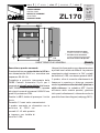 1
1
-
 2
2
-
 3
3
-
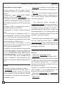 4
4
-
 5
5
-
 6
6
-
 7
7
-
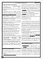 8
8
-
 9
9
-
 10
10
-
 11
11
-
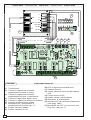 12
12
-
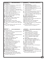 13
13
-
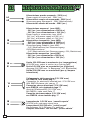 14
14
-
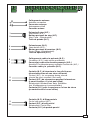 15
15
-
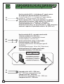 16
16
-
 17
17
-
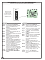 18
18
-
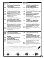 19
19
-
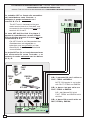 20
20
-
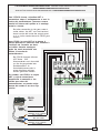 21
21
-
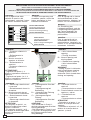 22
22
-
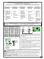 23
23
-
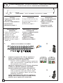 24
24
-
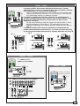 25
25
-
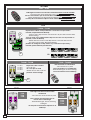 26
26
-
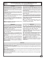 27
27
-
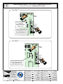 28
28


CAME ZL170 El manual del propietario
- Tipo
- El manual del propietario
- Este manual también es adecuado para
en otros idiomas
- français: CAME ZL170 Le manuel du propriétaire
- italiano: CAME ZL170 Manuale del proprietario
- English: CAME ZL170 Owner's manual
- Deutsch: CAME ZL170 Bedienungsanleitung
Artículos relacionados
-
CAME ZL170N Manual de usuario
-
CAME ZL170N El manual del propietario
-
-
-
-
-
-
-
-