Poulan Pro PP445 El manual del propietario
- Categoría
- Mini cultivadores
- Tipo
- El manual del propietario

PoulanPilO
Instruction Manual
Manual de Instrucciones
Manuel d'lnstructions
PP445
For Occasional Use Only
&
WARNING:
Read and follow all Safety Rules and Operating InstnJctionsbefore
using this product. Failure to do so can result in serious injury.
ADVERTENCIA:
Lea el manual de instrucciones y siga todas tas advertencias e
instrucciones de seguddad. El no hacedo puede resultar en le-
siones graves.
AVERTISSEMENT:
Life le manuel d'instructions et bien respecter tousles avertisse-
merits et toutes les instructions de s6curit6. Tout d6faut de le
faire pourrait entrafner des blessures graves.
Electrolux Home Products, Inc.
250 Bobby Jones Expressway
Augusta, GA 30907
[] From the EtectroluxGroup. The world's No.l choice,
I_ITCIJF_,CI_,_N/NGAN_OUTDOOR,{ppI_4NCESCOMBINEIJ
Copyright (02002 Electrolux Home Products, Inc. 530163735 11/11/02

DANGER! Thisprunercan
be dangerous! Careless or im-
proper use can cause
sedous or even fatal injury.
Read and understand the
instruction manual before
using the pruner.
_ Always wear appropriate ear protection, eye protection and head protection.
-] DANGER! Falling objects can cause severe head injury. Wear head
protection when operating this unit. Do not stand beneath branch being
cut.
_ WARNING: Always disconnect spark
plug wire and place wire where it cannot contact
spark plug to prevent accidental starting when
setting up, transporting, adjusting or making re-
pairs except carburetor adjustments.
Because a pruner is a high-speed wood-cL_ting
tool, special safety precautions must be ob-
served to reduce the risk ofaccidents. Careless
or improper use of this tool can cause serious or
even fatal injury.
PLAN AHEAD
• Read this manual carefully until you
completely understand and can follow all
safety rules, precautions, and operating
instructions before attempting to use the unit.
• Restdct the use of your pruner to adult users
who understand and can follow safety rules,
preca_ions, and operating instructions found
on the unit and in this manual.
INSTRUCTION SAFETY INFORMATION
MANUAL ON THE UNIT
• Wear protective gear. Always use
steel-toed safety footwear with non-slip
soles; snug-fitting clothing; heavy, long
pants, and long sleeves; heavy-duty,
non-slip gloves; eye protection such as
non-fogging, vented goggles or face
screen; an approved safety hard hat; and
sound barriers (ear plugs or mufflers) to
protect your hearing. Regular users should
have hearing checked regularly as engine
noise can damage hearing. Secure hair
above shoulder length. Secure or remove
loose clothing and jewelry or clothing with
loosely hanging ties, straps, tassels, etc.
2
Hearing Safety Hat
Protection _'SEy e
"""'_ Qo,w _ "_" Protection
Snug
Heavy Duty
Clothing Gloves
Safety Safety Chaps
Shoes
• Keep all parts of your body away from the
chain when the engine is running.
• Keep children, bystanders, and animals a
minimum of 50 feet (15 meters) away from
the work area. Do not allow other people or
animals to be near when starting or
operating the pruner.
HAZARDZONE
50 feet
_ (15 meters)
A
DANGER: Donot
use near electrical
wires or power lines.
Keep pruner at least
30 feet (10 meters)
away from all power
lines.

• Do not handle or operate a pruner when you
are fatigued, ill, or upset, or if you have taken
alcohol, drugs, or medication You must be in
good physical condition and mentally alerL If
you have any condition that might be
aggravated by strenuous work, check with
doctor before operating a pruner.
• Carefully plan your pruning operation in
advance. Do not start cutting until you have
a clear work area, secure footing, and a
planned retreat path.
If situations occur which are not covered in
this manual, use care and good judgment. If
you need assistance, contact your authorized
service dealer or call 1-800-554-6723.
OPERATE YOUR PRUNER SAFELY
• Do not operate a pruner with one hand.
Serious injury to the operator, helpers,
bystanders or any combination of these
persons may result from one-handed
operation. A pruner is intended for
two-handed use.
• Operate the pruner only in a well-ventilated
outdoor area.
• Do not operate pruner from a ladder or in a
tree.
• Do not use a pruner tocut down trees or any
portion of the tree trunk
• Only use for pruning limbs or branches not
greater than 4 inches in diameter.
• Never stand under the limb you are pruning.
Always position yourself out of the path of
falling debris
• Do not cut small brush and saplings with the
pruner Slender matter may catch in the
chain and be whipped toward you, pulling
you off balance
• Make sure the chain will not make contact
with any object while starting the engine.
Never try to start the unit when the guide
bar is in a cut.
• Do not put pressure on the pruner at the end
of the cut. Applying pressure can cause you
to lose control when the cut is completed
• Do not run the unit at high speed when not
pruning
• If you strike or become entangled with a
foreign object, stop the engine immediately
and check for damage. Have any damage
repaired by an authorized service dealer
before attempting further operations.
• Do not operate a pruner that is damaged,
improperly adjusted, or not completely and
securely assembled. Always replace bar
and chain immediately if it becomes
damaged, broken or is otherwise removed.
• Always stop the unit when work is delayed
or when walking from one cutting location to
another. Stop the engine before setting the
unit down.
• Use only in daylight or good artificial light.
• Use only for jobs explained in this manual
(or manuals for optional attachments).
MAINTAIN YOUR PRUNER IN GOOD
WORKING ORDER
• Have all service performed by a qualified
service dealer with the exception of the
items listed in the maintenance section of
this manual
• Make certain the chain stops moving when
the throttle trigger is released For
correction, rerer to CARBURETOR
ADJUSTMENTS.
• Never modify your unit in any way
• Keep the handles dry, clean, and free ofoil
or fuel mixture
• Keep fuel and oil caps, screws, and
fasteners securely tightened.
• Make carburetor adjustments with lower
end supported to prevent chain from
contacting any object.
• Keep others away when making carburetor
adjustments
• Use only Poulan PRO® accessories and
replacement parts as recommended.
HANDLE FUEL WITH CAUTION
• Do not smoke while handling fuel or while
operating the pruner.
• Eliminate all sources of sparks or flame in
the areas where fuel is mixed or poured.
There should be no smoking, open flames,
or work that could cause sparks. Allow
engine to cool before refueling.
• Mix aed pour fuel in an outdoor area on bare
ground; store fuel in a cool, dry, well
ventilated place; and use an approved,
marked container for all fuel purposes.
Wipe up all fuel spills before starting engine.
• Move at least 10 feet (3 meters) from fueling
site before starting engine.
• Turn the engine off and let unit cool in a
non-combustible area, not on dry leaves,
straw, paper, etc. Slowly remove fuel cap
and refuel unit.
• Store the unit and fuel in an area where fuel
vapors can not reach sparks or open flames
from water heaters, electric motors or
switches, furnaces, etc.
KICKBACK
_WARNING: Avoid kickback which
can result in serious injury. Kickback is the
backward, upward or sudden forward motion
of the guide bar occurring when the chain
near the upper tip of the guide bar contacts
any object such as a log or branch, or when
the wood closes in and pinches the chain in
the cut. Contacting a foreign object in the
wood can also result in loss of control
• Rotational Kickback can occur when the
moving chain contacts an object at the upper
tip of the guide bar. This contact can cause
the chain to dig into the object, which stops
the chain for an instant The result is a
lightning fast, reverse reaction which kicks the
guide bar up and back toward the operator.
• Pinch-Kickback can occur when the wood
closes in and pinches the moving chain in
the cut along the top ofthe guide bar and the
chain is suddenly stopped. This sudden
stopping of the chain results in a reversal of
the chain force used to cut wood and
causes the pruner to move in the opposite
direction of the chain rotation The pruner is
driven straight back toward the operator
• Pull-In can occur when the moving chain
contacts a foreign object inthe wood in the CL_
along the bottom of the guide bar and the
3

chain is suddenly stopped. This sudden
stopping pulis the pruner forward and away
from the operator and could easily cause the
operator to lose control of the pruner.
REDUCE THE CHANCE OF
KICKBACK
• Recognize that kickback can happen. With
a basic understanding of kickback, you can
reduce the element of surprise which
contributes to accidents.
• Never let the moving chain contact any
object at the tip of the guide bar.
• Keep the working area free from
obstructions such asother trees, branches,
rocks, stumps, etc. Eliminate or avoid any
obstruction that your chain could hit while
you are cutting. When cutting a branch, do
not let the guide bar contact branch or other
objects around it.
• Keep your chain sharp end properly
tensioned. A loose or dull chain can
increase the chance of kickback occurring.
Follow manufacturer's chain sharpening
and maintenance instructions. Check
tension at regular intervals with the engine
stopped, never with the engine running.
Make sure the bar clamp nut is securely
tightened after tensioning the chain.
• Begin and continue cutting at full speed. If
the chain is moving at aslower speed, there
is greater chance of kickback occurring.
• Cut one branch at a time.
• Use extreme caution when re-entering a
previous cut.
• Do not attempt cuts starting with the tip of
the bar (plunge cuts).
• Watch for shifting of wood or other forces that
could close a cut and pinch or fall into chain.
• Use the Reduced-Kickback Guide Bar and
Low-Kickback Chain specified for your unit.
MAINTAIN CONTROL
• Stand with your weight evenly balanced on
both feet.
• Stand slightly to the left side of the pruner to
keep your body from being in a direct line
with the cutting chain.
KICKBACK SAFETY FEATURES
The following features are included on your
pruner to help reduce the hazard of kickback;
however, such features will not totally elimi-
nate this danger. As a pruner user, do not rely
only on safety devices. You must follow all
safety precautions, instructions, and mainte-
nance in this manual to help avoid kickback
and other forces which can result in serious
injury.
• Reduced-Kickback Guide Bar, designed
with a small radius tip which reduces the
size of the kickback danger zone on the bar
tip.
Reduced Kickback Symmetrical Guide Bar
NI RadiusTip
Symmetrical Guide Bar _.
I
Large Radius Tip
• Low-Kickback Chain, designed with a
contoured depth gauge and guard link
which deflect kickback force and allow
wood to gradually ride into the cutter.
Contoured Depth Gauge
_k Elongated Guard UnkDe_ects
ickback force
Low-Kickback _ and allows wood
Chain to gradually ride
into elx_tet
• Keep e good, firm grip on the pruner with
both hands when the engine is running and
don't let go. A firm grip will help you reduce
kickback end maintain control. Keep the
fingers of your left hand encircling and your
left thumb under the assist handle. Keep
your right hand completely around the
throttle handle whether your are right
handed or left handed.
_J_Can Obstruct Material
Not a Low-Kickback Chain
SAFETY NOTICE: Exposure to vibrations
through prolonged use of gasoline powered
hand tools could cause blood vessel or nerve
damage in the fingers, hands, and joints of
people prone to circulation disorders or ab-
normal swellings. Prolonged use in cold
weather has been linked to blood vessel dam-
age inotherwise healthy people. If symptoms
occur such as numbness, pain, loss of
strength, change in skin color or texture, or
loss of feeling in the fingers, hands, or joints,
discontinue the use of this tool and seek med-
ical attention. An anti-vibration system does
not guarantee the avoidance of these prob-
lems. Users who operate power tools on a
continual and regular basis must monitor
closely their physical condition and the condi-
tion of this tool.
4

SPECIAL NOTICE: This unit is equipped
with a temperature limiting muffler and spark
arresting screen which meets the require-
ments of California Codes 4442 and 4443. All
U.S. forest land and the states of California,
Idaho, Maine, Minnesota, New Jersey, Ore-
gon, and Washington require by law that
many internal combustion engines be
equipped with asparkarresting screen. If you
operate in a locale where such regulations ex-
ist, you are legally responsible for maintaining
the operating condition of these parts. Failure
to do so is a violation of the law. For normal
homeowner use, the muffler and spark arrest-
ing screen will not require any service. After
50 hours of use, we recommend that your
muffler be serviced or replaced by an autho-
rized service dealer.
ADDITIONAL SAFETY RULES
FOR OPTIONAL ATTACHMENTS
DWARNING: For each optional at-
tachment used, read entire instruction manu-
al before use and follow all warnings and in-
structions in manual and on attachment.
II.WARNINIs: Ensure handlebar is
installed when using edger or brushcutter at-
tachments. Attach handlebar above arrowoe
safety label on the upper tube (engine end of
unit), if your edger or brushcutter attachment
does not include a handlebar, a handlebar ac-
cessory kit (#530071451) is available from
your authorized service dealer.
Handlebar
Eye Protection
U Boots
Keep children, bystanders, and animals 50 feet
(15 meters) away. Stop unit immediately if ap-
proached.
_WARNING: inspect the area to be
trimmed before each use. Remove objects
(rocks, broken glass, nails, wire, etc.) which
can be thrown by or become entangled in line.
Hard objects can damage the trimmer head
and be thrown causing serious injury.
• Use only for trimming, scalping, mowing and
sweeping. Do not use for edging, pruning or
hedge trimming.
• Cut from your right to your left. Cutting on
left side of the shield will throw debris away
from the operator.
EDGER SAFETY
_WARNING: inspect the area to be
edged before each use. Remove objects
(rocks, broken glass, nails, wire, etc.) which
can be thrown by the blade or can wrap
around the shaft.
• Blade rotates momentarily after the trigger
is released. The blade can seriously cut
you or others.
• Allow blade to stop before removing it from
the cut.
Blade rotates
after the
LINE TRIMMER SAFETY
_ DANGER: Neverusebladeswith line
trimmer attachment. Never use flailing de-
vices with any attachment. Use of any other
accessories with line trimmer attachment will
increase the risk of injury.
@CO
="k
WARNING: Trimmer line throws ob-
jects violently. You and others can be blinded/in-
jured. Wear eye and leg protection. Keep body
parts clear of rotating line.
• Throw away blades that are bent, warped,
cracked, broken or damaged in any other
way. Replace parts that are cracked,
chipped, or damaged before using the unit.
• Do not attempt to remove cut material nor
hold material to be cut when the engine is
running or when cutting blade is moving.
• Always keep the wheel and depth adjusting
skid in contact with the ground.
• Always push the unit slowly over the
ground. Stay alert for uneven sidewalks,
holes in the terrain, large roots, etc.
• Always use the handlebar when using edg-
er attachment.
5

BLOWER/VACUUM SAFETY
_WARNING: Inspect area before
starting unit. Remove all debris and hard ob-
jects such as rocks, glass, wire, etc. that can
ricochet, be thrown, or otherwise cause injury
or damage during operation.
• Do not set unit on any surface except a
clean, hard area while engine is running.
Debris such as gravel, sand, dust, grass,
etc., could be picked up by the air intake
and thrown out through discharge opening,
damaging unit, property, or causing serious
injury to bystanders or operator.
• Never place objects inside the blower
tubes, vacuum tubes or blower outlet. Al-
ways direct the blowing debris away from
people, animals, glass, and solid objects
such as trees, automobiles, walls, etc. The
force of air can cause rocks, dirt, or sticks to
be thrown or to ricochet which can hurt
people or animals, break glass, or cause
other damage.
• Never run unit without the proper equip-
ment attached. When using your unit as a
blower, always install blower tubes.
• Check air intake opening, blower tubes or
vacuum tubes frequently, always with en-
gine stopped and spark plugdisconnected.
Keep vents and discharge tubes free of de-
bris which can accumulate and restrict
proper air flow.
• Never place any object in air intake opening
as this could restrict proper air flow and
cause damage to the unit.
• Never use forspreading chemicals, fertiliz-
ers, or other substances which may contain
toxic materials.
• To avoid spreading fire, do not use near leaf
or brush fires, fireplaces, barbecue pits,
ashtrays, etc.
BRUSHCUTTER SAFETY
_, DANGER: Blade can thrust violently
away from material it does not cut. Blade
thrust can cause amputation of arms or legs.
_ WARNING: Donot usetrimmer head
as a fastening device for the blade.
jects or seriously cut you if accidentally
touched. Stop the blade by contacting the
right hand side of the coasting blade with ma-
terial already cut.
Stop coasting _
blade by contact _. _
with cut material.
,t=
DWARNING: Inspect the area to be
cut before each use. Remove objects (rocks,
broken glass, nails, wire, etc.) which can be
thrown or become entangled in the blade or
trimmer line.
• Throw away and replace blades that are
bent, warped, cracked, broken or damaged
in any other way.
• Install required shield properly before using
the unit. Use the metal shield for all metal
blade use.
_ WARNING: Onlyusebrushcutterat-
tachmentsthat provide a metal shield with
proboscis nose.
se
• Use only specified blade and make sure itis
properly installed and securely fastened.
• Cut from your left to your right. Cutting on
the right side of the shield will throw debris
away from the operator.
• Always use the handlebar and a properly
adjusted shoulder strap with blade (see AS-
SEMBLY instructions in brushcutter attach-
ment instruction manual).
CULTIVATOR SAFETY
i_ WARNING: Rotating tines can cause
sedous injury. Keep away from rotating tines.
Stop the engine and disconnect the spark plug
before unclogging tines or making repairs.
,t=
DWARNING: Inspect the area to be
_WARNING: The blade continues to cultivated before starting theunit. Removeall
spin after the throttle is released or engine is debris and hard and sharp objects such as
turned off. The coasting blade can throw ob- rocks, vines, branch- es, rope, string, etc.
6

• Avoid heavy contact with solid objects that
might stop the tines. If heavy contact oc-
curs, stop the engine and inspect the unit
for damage.
• Never operate the cultivator without the tine
cover in place and properly secured.
• Keep the tines and guard clear of debris.
• After striking a foreign object, stop the engine,
disconnect the spark plug and inspect the cul-
tivator for damage. Repair before restarting.
• Disconnect attachment from the drive en-
gine before cleaning the tines with a hose
and water to remove any build-og. Oil the
tines to prevent rust.
• Always wear gloves when servicing or
cleaning the tines. The tines become very
sharp from use.
• Do not run unit at high speed unless culti-
vating.
HEDGE TRIMMER SAFETY
£1, _
a DANL_ER: RISK OF CUT; KEEP
HANDS AWAY FROM BLADE - Blade
moves momentarily after the trigger is re-
leased. Do not attempt to clear away cut ma-
terial when the blade is in motion. Make sure
the switch is in the OFF position, the spark
plug wire is disconnected, and the blade has
stopped moving before removing jammed
material fremthecuttiog blade. Donot grabor
hold the unit by the cutting blade.
Blades move
momentarily
after the
trigger s
d.
Allow blades to stop
before removing
them from the cut.
41=.WARNINg: Inspect the area before
starting the unit. Remove all debris and hard
objects such as rocks, glass, wire, etc. that
can ricochet, be thrown, or otherwise cause
injury or damage during operation.
• Do not use a cutting blade that is bent,
warped, cracked, broken or damaged in any
other way. Have worn or damaged parts re-
placed by your aL_hodzed service dealer.
• Always keep unit in front of your body.
Keep all parts of your body away from the
cutting blade.
• Keep the cutting blade and air vents clear of
debris.
SNOW THROWER SAFETY
_,WARNING: Keep hands and feet
away from the rotor when starting or running
the engine. Never attempt to clear the rotor
with the engine/motor running. Stop engine
and disconnect spark plug before unclogging
snow or debris from discharge chute or when
adjusting vanes.
,t=
_WARNING: Never lean over dis-
charge chute. Rocks or debris could be
thrown into the eyes and face and cause seri-
ous injury or blindness.
,t=
_WARNING: Inspect the area where
the unit is to be used. Remove objects that
could be thrown or damage the unit. Some
objects may be hidden by fallen snow - be
alert for the possibility.
• Direct material discharge away from glass
enclosures, automobiles, etc.
• Do not run engine at high speed while not
removing snow.
• Be attentive when using the snowthrewer,
and stay alert for holes in the terrain and
other hidden hazards.
• Make sure the rotor will spin freely before
attaching the snowthrower to the power-
head.
• If the rotor will not rotate freely due to frezen
ice, thaw the unit before thoroughly before
attempting to operate under power.
• Keep the rotor clear of debris.
• Do not throw snow near other people. The
snow thrower could propel small objects at
high speed causing injury.
• After striking a foreign object, stop the en-
gine, disconnect spark plug and inspect the
snowthrewer for damage and repair if nec-
essary before restarting unit.
• Never operate the snowthrewer near glass
enclosures, automobiles and trucks.
• Never attempt to use the snowthrower on a
roof.
• Never operate the snowthrower near win-
dow wells, dropoffs, etc.
• Never discharge snow onto public roads or
near moving traffic.
• Clear snow from slopes by going up and
down; never across. Use caution when
changing directions. Never clear snow
from steep slopes.
• Let snowthrewer run for afew minutes after
clearing snow so moving parts do not
freeze.
• Look behind and use care when backing
up. Exercise caution to avoid slipping or fal-
ling, especially when operating in reverse.
• Know how to stop quickly.
7

4D.WARNING: If received assembled,
repeat all steps to ensure your unit is properly
assembled and all fasteners are secure.
Examine parts for damage. Do not use dam-
aged parts.
NOTE: If you need assistance or find parts
missing or damaged, call 1-800-554-6723.
It is normal for the fuel filter to rattle in the
empty fuel tank.
Finding fuel or oil residue on muffler is normal
due to carburetor adjustments and testing
done by the manufacturer.
TOOLS REQUIRED
• Hex wrench (provided)
INSTALLING PRUNER ATTACH-
MENT
CAUTION: When removing or installing at-
tachments, place the unit on aflat surface for
stability.
1. Loosen the coupler by turning the knob
counterclockwise.
LOOSEN
Shipping
protector
Knob
TIGHTEN
2. Remove shipping protector from coupler.
3. Remove the tube cap from the pruner at-
tachment (if present).
4. Posifion locking/release button of attach-
ment into guide recess of coupler.
5. Push the attachment into the coupler until
the locking/release button snaps into the
primary hole.
6. Before using the unit, tighten the knob se-
curely by turning clockwise.
Coupler Primary Hole
\ /r_Uide Recess
UTPuPberL°,¢k'ans£/ ALOc_emrent
Button
liWARNINL_: Make sure the locking/
release button is locked in the primary hole
and the knob is securely tightened before op-
erating the unit. All attachments are designed
to be used in the primary hole.
For optional attachments, see the AS-
SEMBLY section of the applicable attach-
ment instruction manual.
SHOULDER STRAP ASSEMBLY
_WARNING: Proper shoulder strap
adjustments must be made with the engine
completely stopped before using unit.
1. Try on shoulder strap and adjust for fit
and balance before starting the engine or
beginning a cutting operation.
2. Insert your right arm and head through
the shoulder strap and allow it to rest on
your left shoulder. Make sure the danger
sign is centered on your back and the
hook is to the right side of your waist.
NOTE: A one-half twist is built in the shoul-
der strap to allow the strap to rest flat on the
shoulder.
3. Adjust the strap, allowing the hook to be
about 3 - 6 inches below the waist.
4. Fasten the strap hook to the clamp lo-
cated between the throttle handle and the
assist handle and lift the tool to the oper-
ating position.
NOTE: It may be necessary to relocate the
shoulder strap clamp on the shaft for proper
balancing of unit.
TO RELOCATE SHOULDER STRAP
CLAMP:
1. Loosen and remove both clamp screws.
2. Place the upper shoulder strap clamp
over the upper tube.
3. Position the lower shoulder strap clamp
under the upper tube and align the upper
and lower clamp screw holes.
Upper Shoulder
Clamp
POWERHEAD
END
7
Lower Shoulder | ATTACHMENT
Strap Clamp O END
Screws
4. insert two screws into the screw holes.
5. Secure shoulder strap clamp by tighten-
ing screws with a hex wrench.
ADJUSTING THE ASSIST HANDLE
_WARNING: When adjusting the as-
sist handle, be sure it remains between the
coupler and the _I lower arrow (closest to
coupler) on the safety label to ensure proper
balancing of unit. When adjusting the assist
handle or handlebar during use of optional at-
tachments, it must be repositioned between
the throttle trigger and the _' upper arrow
(closest to engine) on the safety label.
1. Loosen wing nut on handle.
2. Rotate the handle on the tube to an up-
right position; retighten wing nut.
8

KNOW YOUR PRUNER
READ THIS INSTRUCTION MANUAL AND SAFETY RULES BEFORE OPERATING YOUR UNIT.
Compare the illustrations with your unit to familiarize yourself with the location of the various controls
and adjustments. Save this manual for future reference.
Pruner
,-- !
Tube
I Attachment Hanger
Bar oil fill cap
Chain
Assist Han(_,._ ON/OFF Switch __
Coupler _ _ "_ .,_ll__._
S o e S pC P Fuelmix l-
Starter Handle.. fill cap
/
Throttle Trigger
Choke
Bar Bar nut
Primer
Bulb
Muffler
ONIOFF SWITCH
The OH/OFF switch is located on the trigger
handle and is used to stop the engine. Move the
switch to the OFF position to stop the engine.
PRIMER BULB
The PRIMER BULB removes air from the car-
buretor and fuel lines and fills them with fuel.
This allows you to start the engine with fewer
pulls on the starter rope. Activate the primer
bulb by pressing it and allowing it to return to
its original form.
CHOKE
The CHOKE helps to supply fuel to the engine
to aid in cold starting. Activate the choke by
moving the choke lever to the FULL CHOKE
position. After the engine attempts to start, move
the choke lever to the HALF CHOKE position.
Once engine has started, move the choke lever
to the OFF CHOKE position.
COUPLER
The COUPLER enables optional attach-
ments to be installed on the unit.
CHAIN TENSION
It is normal for a new chain to stretch during
first 15 minutes of operation. You should
check your chain tension frequently. See
CHAIN TENSION in the SERVICE AND AD-
JUSTMENTS section.
BEFORE STARTING ENGINE
WARNING: Be sure to read the fuel
information in the safety rules before you be-
gin. If you do not understand the safety rules,
do not attempt to fuel your unit. Call
1-800-554-6723.
FUELING ENGINE
_,WARNING: Remove fuel cap slowly
when refueling.
This engine is certified to operate on
unleaded gasoline. Before operation,
gasoline must be mixed with a good quality
synthetic 2-cycle air-cooled engine oil
designed to be mixed at a ratio of 40:1.
Poulan/Weed Eater brand synthetic oil is
recommended. Mix gasoline and oil at a ratio
of 40:1. A 40:1 ratio is obtained by mixing 3.2
ounces (95 ml) of oil with 1 gallon (4 liters) of
unleaded gasoline. DO NOT USE automotive
oil or boat oil. These oils will cause engine
damage. When mixing fuel, follow
instructions printed on container.
Once oil is added to gasoline, shake container
momentarily to assure that the fuel is thoroughly
mixed. Always read and follow the safety rules
relating to fuel before fueling your unit.
BAR AND CHAIN LUBRICATION
The bar and chain require lubrication. The chain
oiler provides continuous lubrication to the chain
and guide bar. Be sure to fill the bar oil tank
when you fill the fuel tank (Capacity =4.6 fi. oz.).
Lack of oil will quickly ruin the bar and chain.
Too little oil will cause overheating shown by
smoke coming from the chain and/or discolor-
ation of the bar. The oil output is aL_omatically
metered during operation. Always fill the bar oil
tank when you fill the fuel tank.
Genuine Poulan® or Poulan PRO® bar and
chain oil is recommended to protect your unit
against excessive wear from heat and fric-
tion. Poulan® or Poulan PRO® oil resists
high temperature thinning. If Poulan@ or
Poulan PRO@ bar and chain oil is not avaiP
able, use a good grade SAE 30 oil.
9

• Never use waste oil for bar and chain
lubdcation.
• Always stop the engine before removing
the oil cap.
IMPORTANT
Experience indicates that alcohol blended
fuels (called gasohol or using ethanol or
methanol) can attract moisture which leads to
separation and formation of acids during stor-
age. Acidic gas can damage the fuel system
of an engine while in storage. To avoid engine
problems, empty the fuel system before stor-
age for 30 days or longer. Drain the gas tank,
start the engine and let it run until the fuel lines
and carburetor are empty. Use fresh fuel next
season. Never use engine or carburetor
cleaner products in the fuel tank or permanent
damage may occur.
See the STORAGE section for additional in-
formation.
HOW TO STOP YOUR UNIT
• To stop the engine, move the ON/OFF
switch to the OFF position.
• If engine does not stop, move choke lever
to the FULL CHOKE position.
F Switch
HOW TO START YOUR UNIT
_, WARNING: Make sure the chain will
not make contact with any object while start-
ing the engine. Never try to start the unit when
the guide bar is in a cut. Avoid any contact
with the muffler. A hot muffler can cause seri-
ous burns.
STARTING A COLD ENGINE (or a
warm engine after running out of
fuel)
Choke
.Lever
Muffler
1. Set unit on a flat surface.
2. Move ON/OFF switch to the ON position.
3. Slowly press the primer bulb 6 times.
4. Move choke lever to FULL CHOKE by
aligning lever with position shown on de-
cal (see illustration below).
Choke
position
decal
5. Squeeze the throttle trigger fully and hold
through all remainin 9 steps.
6. Pull starter rope handle sharply until en-
gine sounds as if itis trying to start, but do
not pull rope more than 6 times.
7. As soon as engine sounds as if it is trying
to start, move choke lever to HALF
CHOKE by aligning lever with position
shown on decal (see illustration below).
Choke
position
10
8. Pull starter rope sharply until engine runs,
b_ no more than 6 pulls. If the engine
doesn't start after 6 pulls (at the HALF
CHOKE position), move the choke lever to
the FULL CHOKE position and press the
primer bulb 6 times. Squeeze and hold the
throttle trigger and pull the starter rope 2
more times. Move the choke lever to the
HALF CHOKE position and pull the starter
rope until the engine runs, but no more than
6 pulls. If the engine doesn't start, repeat
procedure 2 additional times.
NOTE: if engine still doesn't start, it is
probably flooded. Proceed to STARTING A
FLOODED ENGINE.
9. Once the engine starts, allow it to run 10se-
conds, then move the choke lever to OFF
CHOKE by aligning lever with position
shown on decal (see illustration below). Al-
low the unit to run for 30 more seconds at
OFF CHOKE before releasing the throttle
trigger. NOTE: If engine dies with the
choke lever in the OFF CHOKE position,
move the choke lever to the HALF CHOKE
position and pull the rope until engine runs,
bL_no more than 6 pulis.

STARTING A WARM ENGINE
1. Move ON/OFF switch to the ON position.
2. Move the choke lever to the HALF
CHOKE position.
3. Squeeze and hold the throttle trigger.
Keep throttle trigger fully squeezed until
the engine runs smoothly.
4. Pull starter rope sharply until engine runs,
but no more than 5 pulls.
5. Allow engine to run 15 seconds, then
move the choke lever to the OFF CHOKE
position.
NOTE: If engine has not started, pullstarter
rope 5 more pulls. If engine still does not run, it
is probably flooded.
STARTING A FLOODED ENGINE
Flooded engines can be started by placing
the choke lever in the OFF CHOKE position;
then, pull the rope to clear the engine of ex-
cess fuel. This could require pulling the starter
handle many times depending on how badly
the unit is flooded.
If the unit still doesn't start, refer to
TROUBLESHOOTING TABLE or call
1-800-554-6723.
OPERATING THE COUPLER
This model is equipped with a coupler which
enables optional attachments to be installed.
The optional attachments are:
MODEL:
Edger ....................... PP1000E
Cultivator ................... PP2000T
Blower ...................... PP3000B
Brushcutter ................. PP4000C
WARNING: Always stop unit and dis-
connect spark plug before removing or instal-
ling attachments.
REMOVING PRUNER ATTACHMENT
_3R OTHER OPTIONAL ATTACH-
ENTS)
CAUTION: When removing orinstalling at-
tachments, place the unit on aflat surface for
stability.
1. Loosen the coupler by turning the knob
counterclockwise.
Upper Tube
Coupler
Lower
Attachment
TIGHTEN Knob
2. Press and hold the locking/release bL_ton.
Locking/Release
Button
/
Lower Attachment
UpperTube
3. While securely holding the engine and
upper tube, pull the attachment straight
out of the coupler.
INSTALLING OPTIONAL ATTACH-
MENTS
1. Remove the tube cap from the attach-
ment (if present).
2. Position locking/release button of attach-
ment into guide recess of coupler.
3. Push the attachment into the coupler until
the locking/release button snaps into the
primary hole.
4. Before using the unit, tighten the knob se-
curely by turning clockwise.
Coupler Primary Hole
\ / Guide Recess
Upper Locking/ Attachment
Tube Release
Button
I=,WARNING: Make sere the locking/
release button is locked in the primary hole
and the knob is securely tightened before op-
erating the unit.
INSTALLING ATTACHMENT
HANGER
An attachment hanger is provided for storage
when attachment is not in use.
To install hanger on attachment:
1. Remove the tube cap from the attach-
ment (if present) and discard.
2. Press and hold the locking/release button.
3. Push hanger onto the attachment until the
locking/release button snaps into the hole.
OPERATING POSITION
HAeLaV_AYS_._,_ '_'_'_
Prot ionEye
I ant
[ _L/ Heavy Shoes ,,
Y
A
dll DANGER: Do not extend arms above
shoulders while pruning, Do not stand be-
neath branch being cut.
_WARNING: Always wear head, eye,
hearing, foot and body protection to reduce
the risk of injury when operating this unit.
11

When operating unit, clip shoulder strap onto
clamp, stand as shown and check for the fol-
lowing:
• Extend your left arm and hold assist handle
with your left hand.
• Hold throttle grip with your right hand with
finger on throttle trigger.
• Keep engine end below waist level.
• Keep shoulder strap pad centered on your
left shoulder and danger sign centered on
your back.
• Maintain full weight of tool on your left
shoulder.
Always release the throttle trigger and allow
the engine to return to idle speed when not
pruning.
To stop engine:
• Release the throttle trigger.
• Move the QN/OFF switch to the QFF posi-
tion.
PRUNING
_WARNING: Be alert for and guard
against kickback. Do not allow the moving
chain to contact any other branches or ob-
jects at the nose of the guide bar when prun-
ing. Allowing such contact can result in seri-
ous injury.
IMPORTANT POINTS
• Work slowly, keeping both hands firmly
gripped on the pruner. Maintain secure
footing and balance.
• Plan cut carefully. Check direction branch
will fall.
• Watch OL_for springpoles. Springpoles ere
small size limbs which can catch the chain
and whip toward you or pull you off balance.
Use extreme caution when cutting small size
limbs or slender material.
• Watch out for branches immediately behind
the branch being pruned. If the chain hits
the rear branch, damage to the unit may
occur.
• Be alert for springback. Watch out for
branches that ere bent or under pressure.
Avoid being struck by the branch or the
pruner when the tension in the wood fibers
is released.
• Keep a clear work area. Frequently clear
branches out of the way to avoid tripping
over them.
• Long branches should be removed in
several pieces.
PRUNING TECHNIQUE
When ready to cut, accelerate to full throttle
end apply a light cutting pressure. DO NOT
use back and forth sawing action.
Second cut
Third cut
First cut
}f Pruning technique
1. Make the first cut 6 inches from the tree
trunk on the bottom of the limb. Use top of
guide bar to make this cut. Cut 1/3
through the diameter of the limb.
NOTE: When making the second and third
cuts, rest the foot of the pruner against the
tree limb that is being cut to prevent whipping
of the branch.
Foot
2. Next, move 2- 4 inches farther out on the
limb end make a second cut all the way
through the limb.
3. Then, make a final cut leaving a I - 2inch
collar from the trunk of the tree to avoid
damage to the tree.
DWARNING: Disconnect the spark
plug before performing maintenance except
for carburetor adjustments.
CHECK FOR LOOSE
FASTENERS AND PARTS
• Spark Plug Boot
• Air Filter
• Housing Screws
• Assist Handle Screw
CHECK FOR DAMAGED OR
WORN PARTS
Contact an authorized service dealer for re-
placement of damaged or worn parts.
• ON/OFF Switch - Ensure ON/OFF switch
functions properly by moving the switch to
the OFF position. Make sure engine stops;
then restart engine and continue.
• Fuel tank - Discontinue use of unit if fuel
tank shows signs of damage or leaks.
12

• Oiltank- Discontinueuseofunitifoiltank
showssignsofdamageorleaks.
INSPECTANDCLEANUNITANDLA-
BELS
• Aftereachuse.inspectcompleteunitfor
looseordamagedparts.Cleantheunitand
labelsusingadampclothwithamilddeter-
gent.
• Wipeoffunitwithacleandrycloth.
CHECKCHAINTENSION
i_ WARNING: Wear protective gloves
when handling chain. The chain is sharp and
can cut you even when it is not moving. Make
chain adjustments with lower end supported.
Chain tension is very important. Chains
stretch during use. This is especially true dur-
ing the first few times you use your pruner, Al-
ways check chain tension each time you use
and refuel your unit.
1. Use the screwdriver end of the chain ad-
justment tool (bar tool) to move chain
around guide bar to ensure kinks do not
exist. The chain should rotate freely.
Chain Adjustment Tool
Bar
2. Loosen bar clamp nut until it is finger tight
against the bar clamp.
Adjusting Screw Bar clamp nut
3. Turn adjusting screw clockwise until
chain solidly contacts bottom of guide bar
rail. Then, turn adjusting screw an addi-
tional 1/4 turn.
Adjusting Screw - 1/4 Turn
4. Using bar tool, roll chain around guide bar
to ensure all links are in bar groove.
5. Lift up tip of guide bar to check for sag.
Release tip of guide bar. then turn adjust-
ing screw 1/4 turn clockwise. Repeat until
sag does not exist.
6. While lifting tip of guide bar. tighten bar
clamp nut securely with the bar tool.
7. Use the screwdriver end of the bar tool to
move chain around guide bar.
8. If chain does not rotate, it is too tight.
Slightly loosen bar clamp nut and loosen
chain by turning the adjusting screw 1/4
turn counterclockwise. Retighten bar
clamp nut.
9. If chain is too loose, it will sag below the
guide bar and needs to be tightened fol-
lowing above procedure.
_,WARNING: DO NOT operate the
pruner if the chain is loose. Ifthe pruner is oper-
ated with a loose chain, the chain could jump oft
the guide bar and result in sedous injury.
CHECK CHAIN SHARPNESS
A sharp chain makes wood chips. A dull chain
makes a sawdust powder and cuts slowly.
See CHAIN SHARPENING in the SERVICE
AND ADJUSTMENTS section.
CLEAN AIR FILTER
A dirty air filter decreases engine perform-
ance and increases fuel consumption and
harmful emissions. Always clean after every
5 hours of operation.
1. Clean the cover and the area around it to
keep dirt from falling into the carburetor
chamber when the cover is removed.
2. Remove parts by pressing button to re-
lease air filter cover.
NOTE: To avoid creating a fire hazard or
producing harmful evaporative emissions, do
not clean filter in gasoline or other flammable
solvent.
3. Wash the filter in soap and water.
4. Allow filter to dry.
5. Add a few drops of oil to the filter;
squeeze the filter to distribute oil.
6. Replace parts.
Button _T_ir_ilt___
Air Filter
Cover
BAR MAINTENANCE
If your pruner cuts to one side, has to be
forced through the cut, or been run with an im-
proper amount of bar lubrication it may be
necessary to service your bar. A worn barwill
damage your chain and make cutting difficult.
After each use, ensure ON/OFF switch is in
the OFF position, then clean all sawdust from
the guide bar and sprocket hole.
To maintain qluide bar:
• Move ON/(_FF switch to the OFF position
and disconnect spark plug.
• Loosen and remove bar clamp nut and
chain brake. Remove bar and chain from
pruner.
• Clean the oil holes and bar groove after
each 5 hours of operation.
13

Remove Sawdust From _J(_
• Burring of guide bar rails is a normal
process of rail wear. Remove these burrs
with a flat file.
• When rail top is uneven, use a flat file to
restore square edges and sides.
1_ File Rail Edges'_ N _1
and Sides I U I
Square I I
Worn Groove Correct Groove
Replace guide bar when the groove is worn,
the guide bar is bent or cracked, or when
excess heating or burring of the rails occurs. If
replacement is necessary, use only the guide
bar specified for your pruner in the repair
parts list.
LUBRICATION
FillCap
• See GUIDE BAR AND CHAIN OIL under
the OPERATION section.
REPLACE SPARK PLUG
Replace the spark plug each year to ensure
the engine starts easier and runs better. Set
spark plug gap at 0.025 inch. Ignition timing is
fixed and nonadjustable.
1. Twist, then pull off spark plug boot.
2. Remove spark plug from cylinder and
discard.
3. Replace with Champion RCJ-6Y spark
plug and tighten securely with a 3/4 inch
socket wrench.
4. Reinstall the spark plug boot.
_,WARNING: Disconnect the spark
plug before performing maintenance, service, or
adjustments except for carburetor adjustments.
CHAIN SHARPENING
Chain sharpening is a complicated task that
requires special tools. We recommended you
refer chain sharpening to a professional chain
sharpener.
CHAIN REPLACEMENT
_,WARNING: Wear protective gloves
when handling chain. The chain is sharp and
can cut you even when it is not moving.
It is normal for a new chain to stretch during the
first 15 minutes of operation. You should re-
check your chain tension frequently and adjust
the chain tension as required. See CHAIN TEN-
SION section.
Replace the old chain when it becomes worn or
damaged. Use only the Low-Kickback replace-
ment chain specified in the repair parts list.
TO REPLACE CHAIN:
1. Move ON/OFF switch to the OFF position
and disconnect spark plug.
2. Remove bar clamp nut.
3. Remove bar clamp.
4. Turn adjusting screw by hand coenter-
clockwise until adjusting pin jest touches
the stop.
5. Slide guide bar behind sprocket until
guide bar stops against sprocket.
6. Remove the old chain.
7. Carefully remove new chain from pack-
age. Hold chain with the drive links as
shown.
Tip of
Bar
Cutters Depth Gauge
8. Place chain over sprocket, fitting the
drive links in the sprocket.
9. Fit bottom of drive links between the teeth
in the sprocket in the nose of the guide
bar.
10. Fit chain drive links into bar groove.
14

11. Pull guide bar forward until chain is snug
in guide bar groove. Ensure aft drive links
are in the bar groove.
12. Now, install bar clamp making sure the
adjusting pin is positioned in the lower
hole in the guide bar.
Lower Hole
Adjus_g Pi
/Guide Bar
13, Install bar clamp nut and finger tighten
only, Do not tighten any further at this
point. Proceed to the CHAIN ADJUST-
MENT section.
CHAIN ADJUSTMENT
See CHECK CHAIN TENSION in MAINTE-
NANCE section.
CARBURETOR ADJUSTMENT
WARNING: Keep others away when
making idle speed adjustments. The chain
will be moving during most of this procedure.
Wear your protective equipment and observe
all safety precautions. After making adjust-
ments, the chain must not move at idle speed.
The carburetor has been carefully set at the
factory. Adjustment to the idle speed may be
necessary if you notice any of the following
conditions:
• Engine will not idle when the throttle is re-
leased.
• The chain moves at idle.
Make adjustments with the unit supported so
the pruner is offthe ground and the chain will
not make contact with any object. Hold the
unit by hand while running and making adjust-
ments. Keep all parts of your body away from
the chain and muffler.
Idle Spe_
IDLE SPEED ADJUSTMENT
Allow engine to idle. Adjust idle speed until en-
gine runs without chain moving (idle too fast)
or stalling (idle speed too slow).
• Turn idle speed screw clockwise to in-
crease engine speed if engine stalls or dies.
• Turn idle speed screw counterclockwise to
decrease engine speed if chain moves at
idle.
_WARNING: Recheck the idle speed
after each adjustment. The chain must not
move at idle speed to avoid serious injury to
the operator or others.
if you require further assistance or are unsure
aboL_ performing this procedure, contact your
aL_horized service dealer or call
1-800-554-6723.
DWARNING: Perform the following
steps after each use:
• Allow engine to cool before storing or trans-
porting.
• Store unit and fuel in a well ventilated area
where fuel vapors cannot reach sparks or
open flames from water heaters, electric
motors or switches, furnaces, etc.
• Store unit with all guards in place. Position
unit so that any sharp object cannot acci-
dentally cause injury.
• Store unit and fuel well out of the reach of
children.
SEASONAL STORAGE
Prepare unit for storage at end of season or if
it will not be used for 30 days or more.
If your unit is to be stored for a period of time:
• Clean the entire unit before lengthy
storage.
• Store in a clean dry area.
• Lightly oil external metal surfaces.
FUEL SYSTEM
Under FUELING ENGINE in the OPERA-
TION section of this manual, see message la-
beled IMPORTANT regarding the use of ga-
sohol in your engine.
Fuel stabilizer is an acceptable alternative in
minimizing the formation of fuel gum deposits
during storage. Add stabilizer to the gasoline
in the fuel tank or fuel storage container. Fol-
low the mix instructions found on stabilizer
container. Run engine at least 5 minutes after
adding stabilizer.
ENGINE
• Remove spark plug and pour 1teaspoon of
40:1, 2-cycle engine oil (air cooled) through
the spark plug opening. Slowly pull the
starter rope 8 to 10 times to distribute oil.
• Replace spark plug with new one of recom-
mended type and heat range.
• Clean air filter.
• Check entire unit for loose screws, nuts,
and bolts. Replace any damaged, broken,
or worn parts.
• At the beginning of the next season, use
only fresh fuel having the proper gasoline to
oil ratio.
OTHER
• Do not store gasoline from one season to
another.
• Replace your gasoline can if it starts to rust.
15

TROUBLESHOOTING TABLE
WARNING: Always stop unit and disconnect spark plug before performing all of the
recommended remedies below except remedies that require operation of the unit.
TROUBLE
Engine will not
start.
CAUSE REMEDY
1. MoveON/OFF switch to ON.
1. ON/OFF switch in
OFF position.
2. Engine flooded.
3. Fuel tank empty.
4. Spark plug not firing.
5. Fuel not reaching
carburetor,
6. Carburetor requires
adjustment.
Engine will 1. Idle speed set too high
not idle or too low.
properly. 2. Crankshaft seals worn.
3. Compression low.
1. Air filter dirty.
2. Spark plug fouled.
Engine will not
accelerate,
lacks power,
or dies under
a load.
3. Carburetor requires
adjustment.
4. Carbon build-up on
muffler outlet screen.
5. Compression low.
1. Choke partially on.
2. Fuel mixture incorrect.
2. See "Starting a Flooded Engine" in
Operation Section.
3. Fill tank with correct fuel mixture.
4. install new spark plug.
5. Check for dirty fuel filter; replace.
Check for kinked or split fuel line;
repair or replace.
6. Contact an authorized service dealer.
1. See "Carburetor Adjustment" in
Service and Adjustments Section.
2. Contact an authorized service dealer.
3. Contact an authorized service dealer.
1. Clean or replace air filter.
2. Clean or replace plug
and regap.
3. Contact an authorized service dealer.
4. Contact an authorized service dealer.
5. Contact an authorized service dealer.
Engine 1. Adjust choke.
smokes 2. Empty fuel tank and refill with
_=xcessively. correct fuel mixture.
3. Air filter dirty. 3. Clean or replace air filter.
4. Carburetor requires 4. Contact an authorized service dealer.
adjustment.
Engine runs 1. Fuel mixture incorrect. 1. See "Fueling Engine" in Operation
hot. section.
2. Spark plug incorrect. 2. Replace with correct spark plug.
3. Carburetor requires 3. Contact an authorized service dealer.
adjustment.
4. Carbon build-up on 4. Contact an authorized service dealer.
muffler outlet screen.
Chain moves at 1. Idle speed requires 1. See "Carburetor Adjustment" in
idle speed, adjustment. Service and Adjustments Section.
2. Clutch requires repair. 2. Contact an authorized service dealer.
16

ELECTROLUX HOME PRODUCTS, INC.,
warrants to the original purchaser that each
new Poulan PRO ® brand gasoline tool orat-
tachment is free from defects in material and
workmanship and agrees to repair or replace
under this warranty any defective gasoline
product or attachment as follows from the
original date of purchase.
2 YEARS- Parts and Labor, when used for
household purposes.
90 DAYS - Parts and Labor, when used for
commercial, professional, or income produc-
ing purposes.
30 DAYS - Parts and Labor, if used for rental
purposes.
This warranty is not transferable and does not
cover damage or liability caused by improper
handling, improper maintenance, or the use
of accessories and/or attachments not spe-
cifically recommended by ELECTROLUX
HOME PRODUCTS, INC., for this tool. Addi-
tionally, this warranty does not cover tune-
ups, spark plugs, filters, cutting line, or rotat-
ing head parts that will wear and require
replacement with reasonable use dudng the
warranty period. This warranty does not cov-
er predelivery setup or normal adjustments
explained in the instruction manual.
THIS WARRANTY GIVES YOU SPECIFIC
LEGAL RIGHTS, AND YOU MAY HAVE
OTHER RIGHTS WHICH VARY FROM
STATE TO STATE,
NO CLAIMS FOR CONSEQUENTIAL OR
OTHER DAMAGES WILL BE ALLOWED,
AND THERE ARE NO OTHER EXPRESS
WARRANTIES EXCEPT THOSE EX-
PRESSLY STIPULATED HEREIN.
SOME STATES DO NOT ALLOW LIMITA-
TIONS ON HOW LONG AN IMPLIED WAR-
RANTY LASTS OR THE EXCLUSION OR
LIMITATIONS OF INCIDENTAL OR CON-
SEQUENTIAL DAMAGES, SO THE ABOVE
LIMITATIONS OR EXCLUSION MAY NOT
APPLY TO YOU.
The policy of ELECTROLUX HOME PROD-
UCTS, INC., is to continuously improve its
products. Therefore, ELECTROLUX HOME
PRODUCTS, INC., reserves the right to
change, modify, or discontinue models, de-
signs, specifications, and accessories of all
products at any time without notice or obliga-
tion to any purchaser.
YOUR WARRANTY RIGHTS AND OB-
LIGATIONS: The U. S. Environmental
Protection Agency and ELECTROLUX
HOME PRODUCTS, INC., are pleased to ex-
plain the emissions control system warranty
on your year 2002-2004 small off-road en-
gine. ELECTROLUX HOME PRODUCTS,
INC., must warrant the emission control sys-
tem on your small off-road engine for the peri-
ods of time listed below provided there has
been no abuse, neglect, or improper mainte-
nance of your small off-road engine. Your
emission control system includes parts such
as the carburetor and the ignition system.
Where a warrantable condition exists, ELEC-
TROLUX HOME PRODUCTS, INC., will re-
pair your small off-rood engine at no cost to
you. Expenses covered under warranty in-
clude diagnosis, parts and labor. MANUFAC-
TURER'S WARRANTY COVERAGE: If any
emissions related part on your engine (as
listed under Emissions Control Warranty
Parts List) is defective or adefect in the mate-
rials or workmanship of the engine causes the
failure of such an emission related part, the
part will be repaired or replaced by ELEC-
TROLUX HOME PRODUCTS, INC. OWN-
ER'S WARRANTY RESPONSIBILITIES:
As the small off-road engine owner, you are
responsible for the performance of the re-
quired maintenance listed in your instruction
manual. ELECTROLUX HOME PROD-
UCTS, INC., recommends that you retain all
receipts covering maintenance on your small
off-road engine, but ELECTROLUX HOME
PRODUCTS, INC., cannot deny warranty
solely for the lack of receipts or for your failure
to ensure the performance of all scheduled
maintenance. As the small off-road engine
owner, you should be aware that ELECTRO-
LUX HOME PRODUCTS, INC., may deny
you warranty coverage if your small off-road
engine or a part of it has failed due to abuse,
neglect, improper maintenance, unapproved
modifications, or the use of parts not made or
approved by the original equipment manufac-
turer. You are responsible for presenting your
small off-road engine to a ELECTROLUX
HOME PRODUCTS, INC., authorized repair
center as soon as a problem exists. Warranty
repairs should be completed in a reasonable
amount of time, not to exceed 30 days. Ifyou
have any questions regarding your warranty
rights and responsibilities, you should contact
your nearest authorized service center or call
ELECTROLUX HOME PRODUCTS, INC., at
1-800-554-6723. WARRANTY COM-
MENCEMENT DATE: The warranty period
begins on the date the small off-road engine
is purchased. LENGTH OF COVERAGE:
This warranty shall be for a period of two
ears from the initial date of urchase. WHAT
[/S COVERED: REPAIR _R REPLACE-
MENT OF PARTS. Repair or replacement of
any warranted part will be performed at no
charge to the owner at an approved ELEC-
TROLUX HOME PRODUCTS, INC., servic-
ing center. If you have any questions regard-
17

ing your warranty dghts and responsibilities,
you should contact your nearest authorized
service center or call ELECTROLUX HOME
PRODUCTS, INC., at 1-800-554-6723.
WARRANTY PERIOD: Any warranted part
which is not scheduled for replacement as re-
quired maintenance, or which is scheduled
only for regular inspection to the effect of "re-
pair or replace as necessary" shall be war-
ranted for 2 years. Any warranted part which
is scheduled for replacement as required
maintenance shall bewarrantad for the pedod
of time up to the first scheduled replacement
point for that part. DIAGNOSIS: The owner
shall not be charged for diagnostic labor
which leads to the determination that a war-
ranted part is defective if the diagnostic work
isperformed at an approved ELECTROLUX
HOME PRODUCTS, INC., servicing center.
CONSEQUENTIAL DAMAGES: ELEC-
TROLUX HOME PRODUCTS, INC., may be
liable for damages to other engine compo-
nents caused by the failure of a warranted
part still under warranty. WHAT IS NOT
COVERED: All failures caused by abuse, ne-
glect, or improper maintenance are not cov-
ered. ADD-ON OR MODIFIED PARTS: The
use of add-on or modified parts can be
grounds for disallowing a warranty claim.
ELECTROLUX HOME PRODUCTS, INC., is
not liable to cover failures of warranted parts
caused by the use of add-on or modified
parts. HOW TO FILE A CLAIM: If you have
any questions regarding your warranty rights
and responsibilities, you should contact your
nearest authorized service center or call
ELECTROLUX HOME PRODUCTS, INC., at
1-800-554-6723. WHERE TO GET WAR-
RANTY SERVICE: Warranty services or re-
pairs shall be provided at all ELECTROLUX
HOME PRODUCTS, INC., service canters.
Call 1-800-554-6723. MAINTENANCE,
REPLACEMENT AND REPAIR OF EMIS-
SION RELATED PARTS: Any ELECTRO-
LUX HOME PRODUCTS, INC., approved re-
placement part used in the performance of
any warranty maintenance or repair on emis-
sion related parts will be provided without
charge to the owner if the part is under war-
ranty. EMISSION CONTROL WARRANTY
PARTS LIST: Carburetor, Ignition System:
Spark Plug covered up to maintenance
schedule), Ignition Module. MAINTENANCE
STATEMENT: The owner is responsible for
the performance of all required maintenance
as defined in the instruction manual.
This engine is certified to be emissions compliant for the following use:
[] Moderate (50 hours)
[] Intermediate (125 hours)
[] Extended (300 hours)
18

PELIGRO: iEstacortadora _ Lea y comprenda el
de ramas puede ser peligrosat manual de instruc-
El uso descuidedo o indebido _ clones antes de user la
de esta herremiente puede cortadora de ramas.
causar graves o a_n heridas
[_ fatales!
Use siempre le protecoion de oidos apropiada, la pretecci6n de
ojos y la protecci6n de la cabeza,
PEMGRO: Los objetos el caer pueden causar lesionea en au cabeza.
Use proteccion en su cabeza mientraa opere este aparate, Nunca ae pare
bajo la rama que eat& podando.
_ ADVERTENCIA: Desconecte
siempre el cable de la bujfa y coloquelo donde
no puede entrar en contacto con el bujia, para
evitar cuelquier arranque accidental al prepa-
tar, transportar, ajustar o reperar el eparato,
excepto en el caso de ajustes el carburador.
Debido aque las codadora de ramas son instru-
mentos para coder madera a alta velocidad, de-
ben observarse precauciones de seguridad es-
pecieles pera reducir el riesgo de accidentes. El
uso descoidado o indebido de esta herramienta
puede causar graves o at_n heridas fateles.
P|ENSE ANTES DE PROCEDER
• Antes de utilizar la cortadore de ramas, lea at-
tentamente este manuel hasta estar seguro o
comprenderlo completamente y poder seguir
todas las reglas de seguridad, precaucions e
instrucciones de uso que se den en 61.
• Limite el uso de la cortedora de ramas a
aquellos usuarios edultos que comprendad
y pueden implementar todas les precau-
clones, regles de segurided e instrucoiones
de uso que se encuentran en este manual.
MANUAL DE tNFORMAClON DE
INSTRUCClONES SEGURIDAD DEL
APARATO
• Use eguipo protector. Siempre use calzedo
de aeguridad con puntaa de acero y auelas
anti-deslizantes; ropa ajustade el cuerpo;
pentalonea pesedos y largos y mangaa lar-
gas; guantes gruesos de uso industrial anti-
dealizantea; protecci6n de ojoa tales como
gafas de seguridad que no se empeSan y
con abertures de ventilleci6n o mascara
protectora pare le cara; casco duro aproba-
do; y barrere de sonido (tepones de oido u
orejeras anti-sonido) para proteger la audi-
cion. LOSque usan cortadora de ramas de
fuerza deber_n hacerse revisar la audici6n
frecuentemente ya que el ruido de las corta-
dora de ramas puede deSar los oidos. Men-
tenge el cabello por encime de los hombros.
No use ropa suelta y joyas ni ropa con cor-
betas, tiras, borlas, etc. que cuelgan libre-
mente.
Protecci6n Casco Duro
de Oidos _L A_"
"'"_1_" Proteccidn de
Ojos
Rope Ajustade
Guantes de
Uso Industrial
Zapetos de Pantorrilleres
Segurided uridad
"NN
• Mantenga todas las partes del cuerpo aleja-
das de la cadena siempre que el motor est_
en funcionamiento.
• Mantenga a los ni_os, espectadorea y ani-
males a una distancia minima de 15 metros
(50 pies) del &reade trabajo o cuando est_ ha-
cienco arrancar el motor.
ZONA DEPELIG )"_
).+ ! 5metros
50pies
19

A
41_PELIGRO: Nola
use cerca de los
alambras el_ctricos o
de las I{neas de en-
ergia. Mantenga la
cortadora de ramas
por Io menos 30 pies
10 leters leos de to-
das las I neas de en-
ergia.
• No levante ni opera la codadora de ramas
cuando est_ faigado, enfermo, ansicoo o si ha
tornado alcohol, drogas o remedios. Es im-
prescindible que ed. est_ en buenas condi-
ciones f{sicas y alerta mentalmente. Si ud.
sufre de cualquier condici6n que pueda em-
peorar con el trabajo arduo, asesorese con su
m_dico.
• No ponga en marcha la cortadora de ramas
sin tenet un _rea de trabajo despejada, super-
ficie estable para paraPse y un camino prede-
terminado de retroceso.
Se acontece alguna situaci6n no prevista en
este manual, tenga cuidado y use buen criter-
io. Si necesita ayuda, entre en contacto con
su distribuidor autorizado del servicio o Ilame
al 1-800-554-6723.
USE LA CORTADORA DE RAMAS
OBSERVANDO TODOS LOS PRO-
CEDIMIENTOS DE SEOURIDAD
• Mantenga las dos manos en las manijas
siempra que el aparato est_ en marcha. El
uso del aparato con una sola mano puede
causar graves heridas al usuario, a los asis-
tentes, o a los espectadoras. Las cortadora
de ramas estan diseSadas para que se las
use con las dos manos en todo momento.
• Haga uso de la cortadora de ramas 6nica-
mente en lugares exteriores bien ventillados.
• No haga uso de la codadora de ramas desde
las escaleras portatiles ni de los &rboles.
• No use la codadora de ramas para talar
_rboles o cualquier pade del tronco de[ _rboL
• Usela solamente para podar los tallos y ra-
mas no m_s grandes de 4 pulgadas de
di&metro.
• Nunca se pare bajo la rama que esta podan-
do. Ubiquese siempre fuera del sitio donde
caeran los residuos.
• No code maleza ni ramas tiemas con la coda-
dora de ramas. Los matedales finos pueden
atascarse en la cadena y azotar contra su
cuerpo o provocar que pierda el equilibrio.
• Aseg_rase de que la cadena no vaya a hacer
contacto con ningl3n objeto antes de poner en
marcha el motor. Nunca intente hacer arran-
car el aparato con la barra gufa en un corte.
• No aplique presion a la codadora al final de los
codes. Aplicar presi6n puede hacer que pier-
da el control al completarse el code.
• No haga funcionar la unidad a alta velocidad
mientras no esta podando.
• Si golpea o se enreda con alg6n objeto ex-
traSo, apague el motor de inmediato e in-
speccione si existen daSos. Lleve la corta-
dora de ramas a un distribuidor autodzado
del servicio para reparar los daSos antes de
intentar confinuar [a operaci6n.
• No ponga en funcionamiento la cortadora de
ramas si est& daSada, incorrectamente ajus-
tada, o si no estQ armada completa y segura-
mente. Siempre cambie el barra y el cadena
immediatamente si daSado, roto, o se sale por
cualquier motivo.
• Apague siempra la unidad cuando se demore
el trabajo y mientras camina entre zonas de
code. Pare el motor antes de colocar el apa-
rato en la tierra.
• Opere Onicamente bajo la luz del dia o bajo
una buena luz artificial.
• Use 6nicamente para trabajos detallados
en este manual.
MANTENOA LA CORTADORA DE
RAMAS EN BUENAS CONDICIONES
DE FUNCTIONAMIENTO
• Lleve la cortadora de ramas a un distribuidor
autodzado del servicio para que haga todo
servicio menos aquellos procedimientos lista-
dos en la secci6n de mantenimiento de este
manual.
• Asegl3rase de que la cadena se detenga por
completo cuando se suelta el gatillo. Para
hacer correcciones, yea los AJUSTES AL
CARBURADOR.
• Nunca haga modificaciones de ninguna indole
a su codadora de ramas.
• Mantenga las manijas secas, limpias y libras
de aceite o de mezcia de combustible.
• Mantenga las tapas y los fijadores blen fijos.
• Ajuste el carburador con la part inferior
apoyada para impedir que el cadena entre
en contacto con alg_n objeto.
• Cuando realice ajustes en el carburador, no
permita que nadie se acerque.
• Use exclusivamente los accesonos y repues-
tos Poulan PRO® recomendados.
MANEJE EL COMBUSTIBLE CON
EXTREMO CUIDADO
• NO fume mientras trabaja con el combustible
ni cuando est& haciendo uso de la cortadora
de ramas.
• Elimine todas las posibles fuentes de chispas
o llamas en las _reas donde se mezcla o
viede el combustible. No debe haber el fumar,
llamas abiedas, o trabajo que podria causar
chispas. Permita que el motor esfrio antes de
reaprovisionar de combustible.
• Mezcle yvierta el combustible afuera y use ra-
cipiente aprobado para combustibles y mar-
cado como tal. Limpie todos los derrames de
combustible.
• AI6jese a por Io mendos 3 metros (10 pies)del
lugar de abastecimiento antes de poner el mo-
tor en marcha.
• Apague el motor y deje que la cortadora de
ramas se enfrie en un lugar libre de sub-
stancias combustibles y no sobra hojas se-
cas, paja, papel, etc. Retire la tapa lenta-
mente y reabastezca el aparato.
• Guarde el aparato en un espacico fresco,
seco y bien ventilado donde los vapores del
combustible no pueden entrar en contacto
con chispas ni llamas ablertas provenientes
de termotangues, motores o interruptores
el6ctricos, calefactores centrales, etc.
20

RECULADA
_ADVERTENClA: Evite reculada le
pueden causar graves heridas. Reculada es
el movimiento hacia el frente, hacia atr&s o
r&pidamente hacia adelante, esto puede ocur-
fir cuando la punta de la barra gula de la corta-
dora de ramas entra en contacto con cualqui-
er objeto como puede ser otra rama o tronco, o
cuando la madera se cierra y atasca mientras
se hace el corte. El entrar en contacto con
alg6n objeto extrafio a la madera le puede
causar al usuario la p6rdida del control de la
cortadora de ramas.
• La Reculada Rotacional puede acontecer
cuando la cadena en movimiento entra en
contacto con algt3n objeto en la parte superior
de la punta de la barra guia puede causar que
la cadena entre al material y se detenga 13or
un instante. El resultado es una reacc_on =n-
versa, a velocidad de rel&mpago, que hace
recular la barra gula hacia arriba y hacia atr&s
hacia el usuario.
• La Reculada pot Atasco acontecen cuando
la madera se cierra y atasca la cadena en mo-
vimiento en el corte a Io largo de la parte supe-
rior de la barra guia yla cadena se detiene re-
pentinamente. Esta detenci6n repentina de la
cadena tiene como resultado una inversi6nde
la fuerza de lacadena usada para cortar mad-
era y causa que la cortadora de ramas se
mueva en sentido opuesto al de la rotaci6n de
la cadena. La cortadora de ramas directa-
mente hacia atr&s en direcoi6n al usuario.
• La Reculada pot Impulsi6n puede acontec-
er coando la cadena en movimiento entra en
contacto con algt_nobjeto extraSo a la madera
en el code a Io largo de la parte inferior de la
barra gula y la cadena se detiene repentina-
mente. Esta detenci6n repentina de la cadena
tira de la cortadora de ramas adelante y lejos
del usuario y podria hacer f_cilmente al usua-
rio perder el control de la codadora de ramas.
REDUZCA LAS PROBABILIDADES
DE RECULADA
• Reconozca que la codadora de ramas puede
recular. Con una comprensi6n b_sica del
fend,meno de la reculada de la cortadora de
ramas, ud. puede reducir el elemento de sor-
presa que contribuye a los acoidentes.
• Nunca permita que la cadena en movimiento
toque ningun objeto en la punta de la barra
gu=a.
• Mantenga el &rea de trabajo libre de obstruc-
ciones come por ejemplo otros &rboles, ra-
mas, piedras, tocones, etc. Elimine o evite
todo obst_culo que la codadora de ramas
pueda enfrentar al cortar. AI codar una rama,
no deje la barra gula entrar en contacto con
otra rama o otros objetos alrededor.
• Mantenga la cadena afilada y con la tensi6n
correct& Las cadenas con poco filo o flojas
incrementan la probabilidad de reculada. Siga
las instrucoiones del fabricante para afilar y
efectuar mantenimiento de la cadena. Verifi-
que la tensi6n a intervalos regulares con el
motor parado, nunca en marcha. Aseg6rese
de que las tuerca del abrazadera de la barra
est6n ajustadas firmemente.
• Empiece y efectt3e la totalidad de cada code
con el acelerador a fondo. Si la cadena se
esta moviendo a una velocidad menor que la
m_xima, hay mas probabilidad de que la cor-
tadora de ramas recule.
• Code Qnicamente un rama a la vez.
• Use cuidado extremo al entrar de nuevo en un
code ya empezado.
• No intente hacer cortes empexando con la
punta de la barra (cortes de taladro).
• Tenga cuidado con troncos que se desplazan
y con las demos fuerzas que poddan cerrar
un corte y apretar la cadena o caer sobre ella.
• Use la Barra Guia Reducidora de Reculadas
y la Cadena Minimizadora de Reculadas.
MANTENGA EL CONTROL
• Sostenga fuertemente la cortadora con las
dos manos mientras est_ en marcha el motor
y no afloje. Sostener firmemente puede
neutralizar las reculadas y ayudarle a manten-
erel control de lacortadora. Sostenga la man-
ija auxiliar con la mano izquierda, colocando el
pulgar debajo de la manija y rodeando laman-
ija con los dedos. Mantenga la mano derecha
envolviendo totalmente la manija de gatillo
acelerador, sea ud. derecho o zurdo.
• P_rese con el peso distribuido igualmente
entre los dos pies.
• Parese levemente hacia la izquierda de la cor*
tadora de ramas para evitar que el cuerpo
est6 en linea directa con la cadena.
DISPOSITIVOS DE SEGURIDAD
CONTRA LAS REGULADAS
Los siguientes dispositivos han sido incluidos
en la cortadora para ayudar a reducir el riesgo
de reculadas; sin embargo, tales implementos
no pueden eliminar totalmente esta peligro.
Como usuario de cortadora de ramas, ud. no
debe confiarse solamente en los dispositivos
de seguridad. Ud. debe seguir todas las pre-
cauciones de seguridad, instrucoiones y man-
tenimiento que se encuentran en este manual
para ayudar a evitar las reculadas yotras fuer-
zas que pueden causar graves heridas.
• Barra Guia Reducidora de Reculadas, dis-
efiada con punta de redio pequefio que re-
duce el tamafio de la zona de peligro en la
punta de la barra.
21

Barra Guia SimOtdca Reducidora de Reculadas
Zona De Pelig_o
}_L_ntade Radio
_equeSo
Z_na De
B_ra Guia Sim6trica Pelig_o
Punta de Radio Grande
• Las Cadenas Minimizadoras de Reculadas
han satisfecho los requisitos de rendimiento
en pruebas con una muestra representativa
de cortadora de rames de cadene con despla-
zamiento de menos de 3,8 pulgadas, como se
especifica en ANSI B175.1.
Marcador de Profundidad Perfllado
J Estab6n Protector Alargado
dereaceidny
permiteque la
CadenaMini- _ maderaentre
mizadora de gradualmente a
Reculadas la cuchilta
dueSo de la casa, el silenciador y la rejille
antichispa no requerir_n ningQn servicio.
Despu6s de 50 horas de uso, recomendamos
que al silenciador se le de servicio o sea
substituido por un distribuidor autorizado del
servicio.
REGLAS ADICIONALES DE SE-
GURIDAD PARA ACCESORIOS
OPClONAL
_,ADVERTENClA: Para cade acce-
sorio opcional usada, lea a manual de instrec-
clones enteros antes de uso y siga todas las
advertencias e instrucciones en manual yen
la accesorio.
_,ADVERTENClA: AsegQrese el
manije est& instalado al usar ]as acoesorios al
cotter hordes o al cortadora de malezas.
Instale el manija sobre la flecha de la etiqueta
de seguridad del tubo superior (extremo con
el motor del aparato). Si su accesorios del cot-
tar bordes o del cortadora de malezas no in-
cluye un manija, un kit de accesorio del manija
(#530071451) esta disponible de su distribui-
dot autorizado del servicio.
Puede Obstruir MateriaJ
No un Cadena Minimizadora de Reculadas
AVlSO SPECIAL: El ester expuesto alas
vibraciones a trav6s del uso prolongado de
herremientas de fuerza e gesolina puede cua-
ser daSos a los vasos sangumeos ca los ner-
vios de los dedos, las manos y las coyunturas
en aquellas personas que tienen propensidad
a los trastornos de la circuleci6n o alas hin-
chazones anormales. El uso prolongado en
tiempo frio ha sido asociado con daSos a los
vasos snaguineos de personas que per otra
parte se encuentran en perfecto estado de sa-
lud. Si ocurren sintomas tales como el entu-
mecimiento, el dolor, la falta de fuerza, los
cambios en el color o la textura de la piel o faita
de sentido en los dedos, las manos o las coy-
unturas, deje de usar esta maquina inmedia-
tamente y procure atencion m_dica. Los siste-
mas de anti-vibracion no garantizan que se
eviten tales problemes. Los asuerios que ha-
cen uso continuo y prolongando de las herra-
mientas de fuerza deben fiscelizar atenta-
mente su estado fisico y el estado del aparato.
AVISO ESPECIAL: Su aparato viene equi-
pada con silenciador limitador de temperatura
y con rejilla antichispa que cumpla los requisi-
tos de los COdigos de California 4442 y 4443.
Todas las tierras forestadas federales, m_s
los estados de California, Idaho, Maine, Min-
nesota, Nueva Jersey, Washington y Oreg6n,
requieren por ley que touches motores de
combusti6n interna esten equipados con rejil-
la antichispa. Si usted el aparato en un estado
y otra Iocalidad donde existen tales reglamen-
tos, usted tiene la responsabilidad juridice de
mantener estas piezas en correcto estado de
,_ Manija
SEGURIDAD AL RECORTAR
_, PELIGRO: Nanaa use cuahillas con
accesorio del cortadora de linea. Nunca use
dispositivos desgranadores con accesorios.
El aparato fue fiseSado pare ser usado excla-
sivamente como cortodora de line& El usode
cualquier otro accesorios con accesorio del
cortadora de linea incrementar_ el peligro de
heridas.
0(90
4m.ADVERTENL;IA: La linea de corte
arroje objetos violentamente. Usted, al igual
que otras personas, puede quedar ciego o
herido. Use anteojos de seguridad y protec-
cion en les piernas. Mantenga todas las
partes del cuerpo alejadas de la linea girante.
Use anteojos de seguridad
Botas
Mantenga e los ni_os, los espectadores y ani-
males a una distancia minima de 15 metros
funcionamiento. De Io contrario, estara en in- (50 pies). Pare el motor inmediatamente ai al-
fracciOn de la ley. Para el uao normal del guien se le acerca.
22

A
411ADVERTENCIA: Inspeccione el area
antes de cada uso. Retire los objetos (piedras,
vidrio roto, davos, alambre, etc.) que se puedan
enredar en [allnea o que 6sta pueda arrojar. Los
objetos daros pueden daSar el cabezal y _ste
los puede arrojar, caasando graves heridas.
• Use el aparato exdusivamente para recortar,
para cotter c_sped y para barter. No Io use
para cortar bordes, pare podar nipara recortar
seto.
• Corte de su derecha a izquierda. Si corta
con la linen del lado izquierdo del protector,
los escombros volar_n en sentido opuesto
al usuario.
SEGURIDAD AL CORTAR BORDES
ADVERTENCIA: Inspeccione el &tea
a ser cortada antes de cada uso. Retire losobje-
tos (piedras, vicrio roto, clavos, alambre, hilo,
etc.) qee puedan ser arrojados por la cuchil[a o
que puedan enroscarse en el eje.
• La cuchilla continua girando por un instante
despu6s de que se suelte el gatillo. La cu-
chilla puede herir gravemente al ususario o
a terceras.
• Deje que [a cuchilla se detenga antes de sa-
carla del corte.
La cuchilla gira Deje que la cuchilla
por un instante I se detenga antes _
despu6s de I I de sacarla del /
que se haya / I cote, I
• Deseche toda cuchilla doblada, torcida,
reaquebrajada, quebrada odafiada de cual-
quier otro modo. Gamble todas [as piezas
reaquebrajadas, deacantilladaa o da_adas
antes de uaar el aparato.
• No intente remover el material y osrlado o
sostenga e[ material a ser corlado mientraa el
motor se encuentre en marcha o cuando el
diapositivo que corta se encuentre en movi-
miento.
• Mantenga siempre [as rueda y el ca[zo en
contacto con e[ suelo.
• Siempre empuje el aparato lentamente
sobre el terreno. Cuidese constantemente
contra Ins aceras desniveladas, hoyos en el
terreno, raices grandes, etc.
• Siempre use el manija al usando accesorio
al cortar bordes.
SEGURIDAD AL PROPULSOR DE
AIREIASPIRADORA
ADVERTENCIA: Inspeccione el &tea
antes de poner en matodos los escombros yob-
jetos s6[idos tales como piedras, vidrio, a[ambre,
etc., qee el aparato pueda arrojar al aire o hacer
rebotar causando heridas de este o cualquier
otro modo durante el use del misrno.
• No apoye el aparato con el motor en marcha
en ninguna superficie qee no est6 limpia o que
no sea s6[ida. El aparato podda aspirar es-
c6sped, etc. per ]aentrada de aspiracion y ar-
rojarlos por la salida de propulsion, daSando el
aparato y/u otros objetos, o caosando graves
betides a espectadores o al usuario.
• Nunca coloque objetos dentro de los tubos
de propulsion, tubos de aspiraci6n o salida
de aire; siempre dirija los escombros ee di-
reccion contraria a donde personas, ani-
males, vidrierasu otros objetos solidos tales
como arboles, automoviles, paredes, etc.
se encuentran. La fuerza del aire puede ar-
rojar o hacer rebotar piedras, tierra o ramas,
hiriendo a personas o animales, rompiendo
vidrieras o causando otros dafios.
• Nunca ponga el aparato en marcha sin toner
todo el equipo correspondiente inatalado. AI
usar el aparato como propulsor de aire,
sirmpre instale los tubos de propulsi6n.
• Inspeccione frecuentemente la abertura de
entrada de aire, los tubos de propulsion, y
los tubos de aspiraci6n siempre con el mo-
tor detenido y la bujia desconectada. Man-
tenga laa aberturas de ventilaci6n y los tu-
bos de descarga libres de escombros que
se pueden acumular y limitar la circulaci6n
debida de aire.
• Nunca coloque objeto alguno dentro de la en-
trada de aire ya que de hacerlo podria limitar la
circulad6n d'aire y daSar el aparato.
• Nanca use el aparato pare esparcir substan-
cias qaimicas, fertilizantes u otras substan-
cias que puedan contener materiales t6xicos.
•Para evitar la propagaci6n de incendios, no
use el aparato cerca de hogueras de hogas-
secas o de matorrales, de hogares de leSa,
de parrillas, barbacoas, ceniceros, etc.
SEGURIDAD AL CORTADORA DE
MALEZAS
="t
ill PELIGRO: La cachilla puede rebotar
violentamente en materiales que no puede cot-
tar. Los rebotes de la cuchilla pueden causar la
amputacion de brazos o piernas.
,t=
_ADVERTENCIA: No utilice el cabe-
zal podador como dispositivo de sujeci6n de
la cuchilla.
_ADVERTENCIA: La cuchilla sigue
girando incluso despues de soltar el acelera-
dor o de apagar el motor. Incluso cuando esta
girando libremente, la cuchilla puede despedir
combros tales como gavilla, arena, polvo, objetos o causar cortes profundos si se toca
23

accidentelmente. Detenga la cuchilla ponien-
do en contacto el lado derecho de la misma
con material ya cortado.
Pare detener la _J_
cuchilla cuando gire _. ._
libremente, pongela ._'
en contecto con ma-
terial previamente _
cortado.
liADVERTENL;IA: Antes de cada
uso, inspeccione la zona de trabajo. Retire to-
dos los objetos (rocas, cristeles rotos, clavos,
cables, hilos, etc.) que puedan set despedi-
dos o queder enredados en la cuchilla o en el
cabezal podador.
• Deseche y sestituya la cuchillas dobladas,
dentedas, pertidas, rotas o deteriorades de
algSn modo.
• Antes de utilizer el eparato, instale el protector
apropieda. Utilice el protector metalica siem-
pro que trabaje con una cuchilla met_lica.
_ ADVERTENCIA: Utilice sola-
mente Ins accesorios el cortadore de malezas
que proveen de un protector met_lica con la
nariz ecentueda.
Nariz
Acentaada
• Utilice exclusivamente la cuchilla especifi-
cedo y asegQrese de que est6 correcta-
mente instelado y firmemente sujeto.
• Corte siempre de izquierda a derecha. Si se
corte con le linee del lado derecho del protec-
tor, los escombros volar&n en sentido opuesto
al usuado.
• Siempre que trabaje con cuchilla, utilice el
manije y une corree al hombro correcte-
mente ajustada (yea las instrecciones de
MONTAJE en el manual de instrucciones
de la accesorio del podadora).
SEGURIDAD AL CULTIVADOR
_,ADVERTENClA: Las p_as girato-
des pueden causer graves heridas. Mant_n-
gase alejado de las p5as giratorias. Apague el
motor antes de desatascar las pt3as o hacer
reparaciones.
_ADVERTENCIA: Inspeccione el
_rea a cultivar antes de arrancar el aperato.
Retire todos los residuos y los objetos duros y
cortentes como rocas, enredaderas, ramas,
soga, cuerda, etc.
• Evite el contacto con objetos s61idos que
peuden detener las pQas. Si ocurre un con-
tecto fuerte, pare el motor e inspeccione el
apareto pare ver si hay da_os.
• No opere nance el eparato sin la protector
de le pQas en su lugar y bien asegureda.
• Mantenga les pQas y la protector libre de re-
siduos.
• Luego de golpeer un objeto extrafio, pare el
motor, inspeccione el cultivedor para ver si
hey daSos y rep_relos antes de volver a ar-
rancar el apareto.
• Desconecte el cultivador del ensemble del
motor antes de limpiar le p5as con una man-
guera y agua para retirar todo Io que se
heya acumulado. Luego lubrique las pt3as
con aceite pera evitar le oxideci6n.
• Use siempre guantes cuando haga repara-
ciones o limpie las pt3as ya que se afilan ma-
cho con el aso.
• No funcione el eparato en revoluciones al-
tas a menos que cultive.
SEGURIDAD AL PODADORA DE SE-
TO8
PELIGRO: RIESGO DE CORTADU-
RAS; MANTENGA LAS MANOS ALEJADAS
DE LA CUCHILLA - La cuchilla continuar& gi-
rando momentaneamente al solter el getiUo acel-
erador. No intente limpiar material ya cortado
mientres le cuchilla se encuentre girando.
Asegt3rose de que el interruptor se encuentre en
la posici6n OFF, el cable de la bujia desconecta-
do, y la cuchilla detenide antes de remover el
material que se haya atascado en la cuchilla. No
sostenge o agarre el aparato por la cuchilla.
La cuchilla conti-
nuar'a girando mo-
ment&neamente al
Oltar el gatillo
dor
Permita que las
cuchillas se de-
tengan antes de
remover las del
A
II ADVERTENCIA: Inspeccione el &tea
de trabajo antes de comenzer. Retire todos los
desechos y matedel s61ido como rocas, viddo
roto, alambre, etc. que puedan rebotar, ser
arrojados al eire o de otra manera causer
accidentes o daSos darante el uso del aparato.
• No use el eperato si la cachilla se encuentra
doblada, torcida, astilleda, rota o deSede de
cualquier manere. Entre en contacto con el
distribuidor autorizado del servicio para el
reemplazo de piezas daSadas o
desgastadas.
• Siempre mantenga el aparato en frente suyo.
Mantenga todas las partes del cuerpo
alejadas de la cachilla.
• Mantenga la cuchilla y los respira- deros de
aire libres de desechos.
24

SEGURIDAD AL PODADOR DE AR-
BOLES
_,ADVERTENClA: Ls coshilla osci-
lante pueden caosar graves lesiones. Inspec-
cione el aparato antes de usarla. No opere el
aparato con una cuchilla doblada, qaebrada ni
desafilada. Mant6ngase alejado de la cuchilla.
41_ADVERTENCIA: La cuchilla osci-
lante ast& afilada. No la toque. Para evitar
graves lesiones, siempre apague el aparato y
asegt_rese de que la cuchilla se haya detenido
completamente, desconacte la bujia y use
guantes cuando cambie o maneje la cuchilla.
_ADMERTENCIA: La cuchilla en des-
censo puede causar lesiones al continuar su
movimiento luego de apagar el aparato. Man-
tenga un cointrol adecuado de la aparato hasta
que la cuchilla haya dejado de moverse pot
completo. Mantenga las manos, la cara y los
pies lejos de todas las partes moviles. No {n-
tente tocar nidetener la cuchiUa mientras est6 en
movimieeto.
specciona si existen dafios. Haga cualquier
dafio reparar por un distribuidor autorizado
del servicio antes de procurar otras opera-
ciones. Descarte las cuchillas qua est_n
dobladas, combadas, rajadas o rotas.
• Apague el aparato de inmediato si siente
una vibracion excesiva. La vibracion indica
que hay problamas. Inspeccione en detalle
si existen tuercas o pemos flojos o dafio
antes de continuar. Entre en contacto con el
distribuidor autodzado del servicio para el
remplazo de piezas dafiadas e] necesario.
SEGURIDAD AL SOPLADOR DE
NIEVE
_ ADVERTENClA: Mantenga las
manos y pies alejadas del rotor al arrancar or
funcionar el motor. Nunca trate de limpiar el
rotor cuando el motor est6 en marcha nueva-
mente. Apague el motor y desconecte la bujia
antes de limpiar la nieve o escombros del dis-
positivo de descarga o cuando ajuste los de-
flectores.
£= _
4D.ADVERTENL;IA: Los objetos que
caen pueden causar graves lesionas en su
cabeza. Use proteccion en su cabeza mien-
tras opere esta aparato con una accesorio al
podador de _rboles.
DADVERTENCIA: Para evitar graves
lesiones, no use mas de un brazo de extensi6n
con el accesono podador de _rboles.
ADMERTENCIA: Mantenga el poda-
dor lejos de Ifneas de fuerza el6ctrica y cables
de alectricidad.
• Solamente uso para podar las ramas hasta
4 pulgadas de di_metro.
• No opere el aparato a una velocidad mayor
que la nacesaria para podar. No haga fun-
cionar el aparato a alta velocidad mientras
no est& podando.
• Apague siempre el aparato cuando se de-
more el trabajo y mientras camina entre zo-
has de corte,
• Si golpea o sa enreda con alg5n abjeto ex-
traSo, apague el motor de inmediato e in-
I=.ADVERTENCIA: Nunca este cerca
de la apertura de la descarga. Rocas o escom-
bros sa puedan lanzar an los ojos y la cara, el
resultado le causarua kesu6n o ceguera ser_a.
_ADVERTENCIA: Inspeccione el
_rea donde se utilizara el aparato. Retire to-
dos los objectos que puedan ser despedidos
o puede haber daSos en la aparato. Algunos
objetos se pueden ocultar por la nieve caida
-- est6 alerta para la posibilidad.
• Nunca haga funcionar el soplador de nieve
cerca de recintos de vidrio, autornSviles, etc.
• No funcione el aparato an revoluciones al-
tas a menos .que remueva nieve.
• Ponga atenclon cuando este usando el so-
plador de nieve y este alerta si hay hoyos en
el terreno u otros riesgos escondidos.
• AsagQresa de que el rotor gira librement
antes de instalar el soplador de nieve en el
aparato motriz.
• Si el motor no gira libramente debido a hielo
congelado, dascongele la herramienta
antes de intentar usarla bajo corriente.
• Mantenga el rotor limpio de basuras.
• No sople nieve cerca de otras personas. El
soplador de nieve puede lanzar objetos pa-
queSos a alta velocidad, caosando lesiones.
• Despu6s de golpear un objeto axtraSo, pare
el motor, desconecte la bujfa e inspeccione
si el soplador de nieve ha sufrido daSo y
rap_relo antes de volver a usarlo.
• Nuna haga funcionar el soplador de nieve cer-
ca de recintos de vidrio, aL_om6viles y ca-
miones.
25

• Nunca utilice el soplador de nieve sobre un • Deje que el soplador de nieve funcione du-
techo, rante unos minutos antes de comenzar a
• Nunca haga funcionar el sopledor de nieve Iimpiar la nieve para que las piezas m6viles
cerca de ventanas, bajadas, etc. no se congelen.
• Nunca lance la nieve hacia caminos p_bli- • Mire detr&s suyo y tenga cuidedo cuando
cos o cerca del trafico, retroceda. Tenga cuicado para evitar res-
• Limpie la nieve de las pendientes yeedo ha- balarse o caerse.
cia arriba y hacia abajo; nunca de manera • Aprenda a detener la herramienta en forma
horizontal Tenga cuidedo cuaedo cambie r&pida.
de direcci6n. Nunca limpie la nieve de pen-
dientes demasiedo empinadas.
ADVERTENCIA: si recibi6 el apara-
to ya armado, repita todos los pasos para ase-
gurar que el mismo se encuentre correcta-
mente armedo y que todos los fijadores se
encuentren bien ajustados.
Examine las piezas para verificar que no haya
daSos. No use piezas daSadas.
AVI80: Si necesita ayuda, si faltan piezas o
si hay piezas da_adas, Name a{ n_mero
1-800-554-6723.
Es normal escochar que el flitro de combustible
goipetee en eltanque vacfo.
Es normal encontrar residuos de aceite o de ga-
solina en el silenciador, debido a los ajustes al
carburador y a las pruebas efectuadas por el
fabdcante.
HERRAMIENTA8 NECESARIA8
• Un Ilave hexagonal (provista) se requiere para
el montaje.
INSTALAClON DE LA ACCESORIO
DEL CORTADORA DE RAMAS
PRECAUClON: A{ instalar {as acoesorio
del cortadora, ponga el aparato en una super-
ficie plana para estabilidad.
1. Afloje el acopledor dando vuelta a la peril-
la a la izquierda.
Acoplador
AFLOJE
Protector d_
embarque
Perilla
APRIETAN
Primer
Acopledor\ hgt J_ i#g_erio de
Tubo Bot6n de Accesorio
Superior Conexi6n/ inferior
Deseonexi6n
a_ADVERTENClA: Antes de operar
esta aparato, aseg_rese de que el bot6n de
conexiSn/desconexidn est6 asegurado en el
primer agujero y la perilla est6 bien ajustada.
Tedos los accesorios han sido diseSedos
para ser utilizados en el primer agujero.
Para las accesorios opcional, vea la secci6n
MONTAGE de la aplicables manual de
instrucciones de la accesorio.
MONTAJE DE LA CORREA AL
HOMBRO
_,ADVERTENCIA: Antes de hacer
algun ajuste de la correa para el hombro, es
impresciedible que el motor este
completamente detenido.
1. Antes de poner en marcha el motor o iniciar
cualquier tarea de corte, p6ngase la correa
en el hombro yajt3stela a su medida de too-
do que le permita mantener el equilibrio.
2. Intreduzca el brazo derecho y la cabeza
por el arco de la correa y apoye 6sta en el
hombro izquierdo. Aseg6rese de que el
signo de peligro se encuentre en su es-
palda y de que el enganche se encuentre
en el ledo derecho de su cintura.
AVISO: La correa puede girarse media vuelta
2. Remueva el protector de embarque del para garantizar que quede apoyeda en toda su
acoplador, anchura sobre el hombro.
3. Retire la tapa de tubo del acoesorio del 3. Ajuste la correa para permitir que el engan-
cortedora de ramas (si presente), che quede a unos 8 - 15 cm per debajo de
4. Coloque el bot6n de conexi6n/desconex- la cintura.
i6n del acoesorio en el agujero de la guia 4. Fije el enganche de la correa a la abraza-
del acoplador, dera situeda entre la empuSadura de es-
5. Empuje el accesorio en el acoplador has- puma y el bloque de montaje y levante ]a
ta que el bot6n de conexi6n/desconexi6n herramienta hasta la posici6n de trabajo.
se encaje en el primer agujero. AMISO: Puede ser necesario mover la
6. Antes de usar el aparato, apriete la perilla abrazedera de lacorrea para el hombro en el eje
firmemente dando vuelta a la derecha, para un equilibrio apropiedo del aparato.
26

PARA MOVER LA ABRAZADERA
DE LA CORREA AL HOMBRO:
1. Afloje y remueva ambos tomillos de la
abrazadera.
2. Coloque la abrazadera superior de la cor-
tea pare hombro en la parte superior del
tubo.
3. Coloque la abrazadera inferior de la correa
para hombro debajo del tubo superior y ali-
nee los huecos del tomillo de laabrazadera
superior y la abrazadera inferior.
EXTREMO CON
EL CABEZA DE
MOTOR
Abrazadera Superior
de la Correa para
Hombro
Abrazadera
Inferior de la
Correa para Hombro
EXTREMO CON
EL ACCESORIO
CONOZCA SU APARATO
4. Inserte dos tornillos en los huecos para
tomillos.
5. Apriete la abrazadera de la correa para el
hombro apretando los tornillos con la
Ilave hexagonal.
AJUSTE DEL MANIJA AUXlLIAR
ADVERTENClA: AI ajustar la manija
auxiliar, este seguro que permanezca entre el
acoplador y la _= flecha inferior (Io mas cer-
ca al acoplador) en la etiqueta de seguridad
para asegurar el equilibrio apropiado. AI ajus-
tar la manija auxiliar o manija en forma de bar-
rera durante el uso de accesorios opcionales,
debe set colocada de nuevo entre el gatillo
acelerador y la _' flecha superior (Io m&s
cerca al motor) en la etiqueta de seguridad.
1. Afloje la tuerca mariposa en el manija.
2. Gire el manija en posici6n vertical. Vuelva
a apretar la tuerca madposa firmemente.
LEA ESTE MANUAL DE INSTRUCCIONES Y LAS REGLAS DE SEGURIDAD ANTES DE
PONER EL APARATO EN MARCHA. Compare las ilustraciones con su aparato para familiari-
zarse con la ubicaci6n de los diversos controles y ajustes. Guarde este manual para uso futuro.
Cortadora de tames Tubo
I uspensor pare
accesorio
Cadena
Manija de la cuerda de arranque
Tapa del tanque de
lubricante de barra
Manija Auxiliar
| Interruptor ON/OFF
Acop,e0or \ _,,
Abrazadera de la ./# - \_
Correa al Hombro Tape del
tanque de
combustible
/,
Gatillo acelerador
Palanca
Barra Tuerca de [a barra del cebador
Bombeador
Silenciador
INTERRUPTOR ON/OFF CEBADOR
Se usa el interrupter ON/OFF pare detener el El CEBADOR ayuda a suministrar combus-
motor. Coloque el interruptor ON/OFF en la posi- tible al motor para facilitar el arranque coando
cion OFF para detener el motor, el motor esta frio. Acione el cebador colocan-
BOMBEADOR do la palanca en la posicion FULL CHOKE.
El BOMBEADOR retira el aire de el carbura- Despu6s que el motor intente arrancar, mue-
dor y de las lineas de combustible y las Ilena vala palanca del cebador ala posici6n HALF
demezcladecombustible, permitiendole pon- CHOKE. Despu6s que el motor se haya
er el motor en marcha con menos tirones de la puesto en marcha, ponga la palanca del ceba-
cuerda de arranque. Accione el bombeador doren la posicion OFF CHOKE.
oprimi6ndolo y luego dejando que este re-
cobre su forma original.
27

ACOPLADOR
El ACOPLADOR permite la instalacion de ac-
cesodos opcionales.
TENSION DE LA CADENA
Es normal que las cadenas nuevas se estiren
durante los primeros 15 minutos de uso. Deb-
era verificarse la tensi6n de la cadena fie-
cuentemente. VeaVERIFIQUE LATENSION
DE LA CADENA en la secci6n de MANTEN-
IMIENTO.
ANTES DE PONER EN MARCHA EL
MOTOR
_,ADVERTENClA: Lea atenta-
mente la informaci6n sobre el combustible en
laas reglas de seguddad antes de comenzar.
Si no comprende las reglas de seguddad, no
intente abastecer el aparato de combustible.
Llame al nt3mero 1-800-554-6723.
ABASTECIMIENTO DEL MOTOR
I_ADVERTENClA: Remueva la tapa
del tanque de combustible lentamente al rea-
bastecer combustible.
Este motor est& habilitado para funcionar con
gasolina sin plomo. Antes de comenzar con el
uso, se deber_ mezclar la gasolina con un aceite
de sint6tico de buena calidad para motores de 2
tiempos enfriados a aire. Recomendamos el
aceite de sint6tico de la marca Poulan/Weed
Eater. Mezcle la gasolina con el aceite en la
proporci6n 40:1. Se obtiene una propord6n de
40:1 mezclando 3.2 onzas (95 ml) de aceite con
cada gal6n (4 Iitros) de gasolina sin plomo. NO
USE aceite para autom6viles ni para barcas.
Estos aceites daSaran el motor. AI mezclar el
combustible, siga las instrucciones impresas en
el recipiente. Una vez haya afiadido el aceite a la
gasolina, agite al recipiente brevemente para
asegurar que el combustible est_
completamente mezclado. Siempre lea y siga
las instrucciones de seguridad que tienen que
ver con el combustible antes de abastecer el
aparato.
LUBRICAClON DE LA BARRA Y DE
LA CADENA
La barra y la cadena requieren lubricaci6n. El li-
bricador de la cadena provee lubricaci6n contin-
ua a la cadena y ala barra guia. No se olvide de
Ilenar el tanque de aceite para barra siempre
que Ilene el tanque de combustible (Capacidad
= 4,6 ft. oz.). La falta de aceite arruinar& la barra y
la cadena rapidamente. El uso de demasiado
poco aceite causar& exceso de calentamiento
que sera detectable por el humo proveniente de
la cadena y/o pot la descoloracion de la barra.
La cantidad de lubricaci6n es medida autom&ti-
camente durante el funcionamiento de la corta-
dora de ramas. Siempre Ilene el tanque de
aceite de la barra cuando Uene el tanque de
combustible.
Se recomienda el aceite Poalan o Poulan
PRO_> genuino para barra y cadena para pro-
teger el aparato contra el desgaste excesivo
provocado por el calory la fricci6n. El aceite
Poulan o Poulan PRO@ resiste la p6rdida de
espesura a altas temperaturas. Si no nay dispo-
nibilidad de aceite para barra ycadena Poulan o
Poulan PRO_) use un aceite de buena calidad
tipo SAE 30.
28
• Nunca utilice aceite usado para ]a lubricaddn
de la barra y de la cadena.
• Pare siempre el motor antes de abrir la tapa
del tanque de aceite.
IMPORTANTE
La experiencia indica que los combustible mez-
clados con alcohol (los Ilamados gasohol o los
que contienen etanol o metanol) pueden atraer
la humedad, Ioque puede causar la separaci6n
y la forrnaci6n de &cidos durante el almacenaje.
La gasolina acida puede dafiar el sistema de
combustible del motor durante el almacenaje.
Para evitar problemas con el motor, debera va-
ciarse elsistema de combustible antes de alma-
cenar el aparato por 30 dias o mas. Vacie el tan-
que de combustible, ponga el motor en marcha y
dejelo en marcha hasta que las lineas de com-
bustible y el carburador queden vacios. Use
combustible fresco para la pr6xima temporada.
Nunca use productos de limpieza de motor o
carburador en el tanque de combustible ya que
de hacefla puede provocar dafios permanentes.
Vea la seccion de ALMACENAJE para informa-
cion adicionaL
PARA DETENER EL MOTOR
• Para detener el motor, mueva el interruptor
ON/OFF a ]a posicion OFF.
• Si el motor no se detiene, mueva la palanca
del cebador a la posici6n FULL CHOKE.
_F tor
PARA PONER EN MARCHA
EL MOTOR
_ ADVERTENCIA: Aseg6rese de que
la cadena no vaya a hacer contacto con ning6n
objeto antes de poner en marcha el motor. Nun-
ca intente hacer arrancar el aparato con la barra
guia en un code. Evite el hacer ning6n tipo de
contacto con el silenciador. Un silenciador
caliente podria provocar quemaduras de gra-
vedad si se toca.
PAPA ARRANCAR CON MOTOR
FRIO (O motor caliente despu_s de
quedar sin combustible)

Manija de la Cuerda
de Arranque
I Palanca
del
Cebador
Bombeador
;ilenciador
1. Ponga el aparato en una supedicie plan&
2. Mueva el interruptor ON/OFF a la posi-
c/on ON.
3. Optima lentamente el bombeador 6 veces.
4. Mueva la palanca del cebador a FULL
CHOKE alineando la palanca en la posici6n
mostrada en la etiqueta (vea la ilustracion
abajo).
cuerda de arranque hasta que el motor se
ponga en march& pero no m&s de 6
veces. Si el motor no arranca, repita el
procedimiento de arranque otras 2 veces
adicionales.
AVlSO: Si el motor no arranca, proba-
blemente se encuentre ahogado. Proce-
da con la seccion ARRANQUE DE MO-
TOR AHOGADO.
9. Una vez que el motor arranca, permita
que el motor marche por 10 segundos,
luego mueva la palanca del cebador a
OFF CHOKE alineando la palanca en la
posici6n mostrada en la etiqueta (vea la
ilustraci6n abajo). Permita que el motor
marcha pot 30 segundos con la palanca
del cebador en la posici6n OFF CHOKE
antes de soltar el gatillo acelerador.
AVlSO: Si el motor se apaga con la pa-
lanca del cebador en la posicion OFF
CHOKE, mueva la palanca a la posici6n
HALF CHOKE y tire de la ceerda de ar-
ranque hasta que el motor se ponga en
Etiqueta marcha, pero no m&s de 6 t/tones.
lamuestra_ / _u_i L_
posici6n
del i
cebado
5. Apriete ysujete el gatillo durante todos los cebador i_-_
pasos siguientes.
6. Tire firmemente del manija de la cuerda
de arranque hasta que el motor suene
comosi est6 intentando arrancar, pero no
tire de la cuerda m&s de 6 veces.
7. Tan pronto como el motor suene como si
fuera a arrancar, mueva la palanca del ce-
bador a HALF CHOKE alineando la palan-
ca en la posici6n mostrada en la etiqueta
(vea la ilustraci6n abajo).
Etiqueta
8. Tire firmemente del manija de la cuerda
de arranque hasta que el motor arranque,
pero no m_s de 6 t/tones. Si el motor no
arranca despu6s del sexto tir6n de la
cuerda de arranque (con la palanca del
cebador en la posici6n HALF CHOKE),
mueva la palanca del cebador a la posi-
c/on FULL CHOKE y oprima el bombea-
dor 6 veces. Apriete y sostenga el gatillo
acelerador y tire de la cuerda de arranque
otras 2 veces. Mueva la palanca del ceba-
dot a la posici6n HALF CHOKE y tire de la
PARA ARRANCAR CON EL MOTOR
CALIENTE
1. Mueva el interruptor ON/OFF a Is posi-
ci6n ON.
2. Mueva la palanca del cebador a ]a posi-
ci6n HALF CHOKE.
3. Oprima y sostenga el gatille acelerador,
Mantenga el gatil]o totalmente oprimide
hasta que el motor marche sin problemas.
4. Tire firmemente del manija de la cuerda
de arranque hasta que el motor se ponga
en marcha, pero no mas de 5 t/tones.
5. Permita que el motor marche pot 15 segun-
dos, entonces mueva la palanca del ceba-
dot a la posici6n OFF CHOKE.
AV|SO: Si el motor no arranca, tire de lacuer-
da otras 5 veces. Si el motor no arranca, pro-
bablemente est_ ahogado.
ARRANQUE DE MOTOR AHOGADO
Lors motores ahogados pueden ponerse en
marcha moviendo la palanca del cebador a la
posicion OFF CHOKE; luego, tire de la cuerda
para aclarar el exceso de combustible. Esto
podr& requerir que se tire del manija de la
cuerda muchas veces dependiendo cuan
ahogado se encuentre el motor.
Si el aparato sigue sinponerse en march&
vea la TABLA DIAGNOSTICA o Ilame al
nt3mero 1-800-554-6723.
29

OPERACION DEL ACOPLADOR
Este modelo esta equipado con un acoplador,
el eual permite la instalaci6n de accesorios
opeionales, Los accesorios opcionales son:
MODELO:
Cortadora de Bordes .......... PP1000E
Cultivador ................... PP2000T
Propulsor de Aire ............. PP3000B
Cortadora de Malezas ......... PP4000C
_,ADVERTENCIA: Siempre apague
el aparato y desconecte la bujia antes de reti-
tar o instalar los accesorios.
COMO REMOVER EL ACCESORIO
DEL CORTADORA DE RAMAS (U
OTRAS ACCESORIOS OPCIONAL)
PRECAUClON: AI retirar o instalar las ac-
cesorios, ponga el aparato en una superficie
plana para estabilidad.
1. Afloje el acoplador dando vuelta a la peril-
laa la izquierda.
Tubo
Acoplador
AFLOJE
Accesorio
Inferior
DADVERTENCIA: Antes de operar
esta aparato, asegt3rese de que el bot6n de
conexi6n/desconexi6n est6 asegurado en el
primer agujero y la perilla est6 bien ajustada.
INSTACALI(_N DEL SUSPENSOR
Una sespensor de la accesorio se proporcio-
na pare el almacenaje cuando la accesorio no
se est_ utilizando.
Para instalar la suspensi6n en la accesorio:
1. Retire la tapa de tubo del accesorio (si
presente) y deseche.
2. Presione y sostenga el bot6n de conex-
i6n/desconexi6n.
3. Empuje la suspensor sobre la accesorio
haste que el bot6n de conexi6n/
desconexi6n se encaja en el hueco.
POSICION DE USO
SIEMPRE USE:
Protecci6n
para la Protecci6n
cabeza para los
Perilla
2. Oprima y sostenga el bot6n de conexi6n/
desconexi6n.
Bot6n de Conexi6n/
Desconexi6n
Tubo Superior
Accesorio Inferior
3. Mientras sostiene el motor y el tubo supe-
rior con firmeza, quite el accesorio inferior
del acoplador en forma recta.
INSTALACI_N DEL ACCESORIOS
OPClONAL
1. Retire le tapa de tubo del accesorio (si
presente).
2. Coloque el bot6n de conexi6n/desconex-
i6n del accesorio inferior en el agujero de
la guia del acoplador.
3. Empuje el accesorio inferior en el acopla-
dor hasta que el bot6n de conexi6n/des-
conexi6n se encaje en el primer agujero,
4. Antes de usar el aparato, apriete la perilla
firmemente dando vuelta ala derecha.
Primer
Acoplador\ PgLje}_t_ iAaglero de
Tubo Bot6n de Accesorio
Superior Conexi6n/ Inferior
Desconexi6n
_, PELIGRO: No extienda los brazos por
encima de los hombros cuando use la corta-
dora de ramas. Nunca se pare directamente
bajo la rama que est_ podando,
,t= _
4D.ADVERTENL;IA: Use siempre pro-
tecci6n en sus ojos, su audici6n, sus pies y su
cuerpo pare reducir el riesgo de lesiones
cuando opere esta aparato.
Ceando aparato de funcionamiento, en-
ganche la correa para hombro en el abrazad-
era, par6se como se yea en la figure y verifi-
que Io siguiente:
• Amplie su brazo izquierdo y sostenga la
empufiadura del manija con su mano
izquierda.
• Sostenga el empufiadura del acelerador
con su mano derecha con un dedo en el ga-
tillo.
• Mantenga el extremo con el motor del
aparato debajo de la cintura.
• Mantenga el almohadilla de la correa al
hombro centrada en el hombro izquierda y
el seSal de peligro centrada en su espalda.
• Mantenga todo el peso de la herramienta en
el hombro izquierdo.
Siempre que no se halle cortando, suelte el
gatillo acelerador y permita que el motor vuel-
va a marcha lenta.
30

Para detener el motor:
• Suelte el gatiHo acelerador.
• Presione y sostenga el interruptor ON/OFF
hasta que el motor se haya detenido por
completo.
PARA PODAR
ADMERTENCIA: Est_ alerta y tenga
cuidado con los reculada. Cuando cortar ra-
mas y podar, nunca permita que la cadena en
movimiento toque ning0n objeto en la penta
de la barra guia. Permitir tal contacto puede
causar graves heridas.
PUNTOS IMPORTANTES
• Trabaje lentamente, con las dos manos suje-
tando firmemente la cortadora de ramas.
Mantenga el eqeilibno, con los pies en una su-
pefficie estable.
• Planifique cuidadosamente el corte. Verifi-
que la direccion donde caer_ el ramo.
• Tome cuidado con las ramas chicas. El ma-
terial de poco di_metro puede entredarse
en la cadena, dando un latigazo al usuario o
haciendo que pierda el equilibrio. Use extre-
mo cuidado al cortar ramas pequeSas.
• Tome cuidado con las ramas justo detr&s de
la rama que se corta. Si la cadena golpea
las ramas de atr_s, podria caosarle daSos.
• Est6 alerta contra los rebotes. Tenga cuidado
al cortar ramas dobladas o bajo presion para
evitar ser golpeado per la rama o lacortadora
de ramas cuando se suelte la tensi6n en las
fibras de madera.
• Despeje frecuentemente las rams acumula-
das para no le hagan tropezar.
• Remueva los ramos largas despu_s de cor-
tarlos en varios trozos.
TECNICA PAPA PODAR
AI estar preparado para cortar, acelere el mo-
tor hasta la velocidad maxima y aplique una
presion ligera de corte. NO USE el aparato a
la manera de aserradura que vay viene.
1. Haga el primer corte a 15 centimetros del
tronco del _rbol, del lado inferior de ]a
rama. Utilice el lado superior de la barra
guia para realizar este corte. Atraviese la
rama hasta Ilegar a 1/3 de su diametro.
AV|SO: AI hacer los cortes segundo y ter-
cero, apoye el pie de la cortadora contra la
rama que usted esta cortando.
Pie
2. Luego, mueva 5 a 10 diez centimetros ha-
cia el extremo de la rama y despu6s haga
un segundo corte atravesando completa-
mente la rama.
3. Finalmente haga un tercer corte, descen-
diente, dejando un toco de 2,5 a 5
centimetros sobresaliendo del tronco del
_rbol.
Segundo
corte
Tereer corte
TOC(
Primer corte
T_cnica para podar
31

_ ADVERTENCIA: Desconecte la
bujla antes de hacer cualqeier mantenimiento,
con la excepcion de los ajustes al carburador.
VERIFIQUE QUE NO HAYA FIJA-
DORES NI PIEZAS SUELTAS
• Cebierta de la Bujla
• Filtro de Aire
• Tornillos de la Caja
• Tomillo del Manija Auxiliar
VERIFIQUE QUE NO HAYA PIEZAS
DA_IADAS 0 GASTADAS
Entre en contacto con el distribuidor autoriza-
do del servicio para el reemplazo de piezas
dafiadas o desgestadas.
• Interreptor ON/OFF - Asegt)rese de que el
interruptor ON/OFF est6 funcionando cor-
rectamente colocandolo en la posici6n OFF.
Asegt)rese de que el motor se haya deteni-
do por completo, luego, ponga el motor en
marcha nuevamente y contin5e.
• Tenque de combustible - Deje de usar el
aparato si hay sefiales de defios o p_rididas
en el tanque de combustible.
• Tanque de aceite - Deje de usar el aparato
si el tanque de aceite da sefiales de dafio o
fugas.
INSPECCIONE Y LIMPIE EL APARA-
TO Y SUS PLACAS
• Despu6s de que cada uso, inspeccione la
aparato completa para saber si hay piezas
flojas o dafiadas. Limpie el aparato y las
placas usando un trapo ht]medo con un de-
tergente suave.
• Seque el aparato usando un trapo seco y
Iimpio.
VERIFIQUE LA TENSION DE LA CA-
DENA
_,ADVERTENCIA: Useguantespro-
tectores al manejar la cadena. La cadena tiene
fllo y podda causarle graves cortaderas, aun
cuando esta no se encuentre en movimiento.
Ajuste la cadena con la parte inferior apoyada
para impedir que el cadena entre en contacto
con algt_n objeto.
La tensi6n de lacadena es muy importante. Es-
tiramientos de la cadena durante eso. Esto es
especialmente verdad durante los tiempos pnm-
eros que usted L_iliza la cortadora de ramas.
Controle siempre la tensi6n de la cadena cada
vezqee usted utiliza y reaprovisiona su cortado-
ra de ramas de combustible.
1. Use la punta en forma del destornillador de
la herramienta de ajeste de la cadena (her-
ramienta de la barra) para mover la cadena
alrededor de la barra guia para asegerarse
de que la cadena no se haya enroscado. La
cadena deber_ moverse libremente.
Herramienta de
Barra
guia
2. Afloje las tuerca del abrazadera de la bar-
re hasta que est6n tan ajestadas contra la
abrazadera con los dedos 5nicamente.
TornUlo de ajuste Tuerca del abra-
zadera de la barra
3. Gire el tornillo de ajuste a [aderecha (en el
sentido del reloj) hasta entra en contacto
con s61idamente el fondo del riel de la bar-
ra ge{a. Luego, gire el tornillo de ajuste de
la vuelta una 1/4 vuelta adicionaL
Tornillo de Ajuste - 1/4 de Vuelta
4. Usando la herramienta de la barra, haga _i-
tar la codene elrededor de la berra guJa
para asegurarse de que todos los esla-
bones se encuentren dentro de las ranura
de la barra.
5. Suelte la barra y gire el tornillo de ajuste
1/4 de vuelte a la derecha (en el sentido
del reloj). Repita este paso hasta que no
haya m_s separac_on.
6. Manteniendo la punta dela barra levanta-
da, ajuste firmemente las tuerca del abra-
zedera de la barra con la herramienta de
la barra.
7. Use la punta en forma de destomillador de
la herramienta de la barra para hacer rotar
la cadena por la barra.
8. Si no puede hacer rotar la cadena, est_
demasiado ajusteda. Afloje levemente
las tuercas de le abrazadera y afloje ca-
dena dar vuelta el tomillo de ajeste 1/4 de
vuelte hacia la izquierda (en contra del
sentido del reloj). Vuelva a ajustar las
tuerca del abrazadera de la barra.
9. Si le cedena se encuentra demasiado flo-
ja, colgar_ por debajo de la barra guia, es
necesario tensionar la cadene usando el
procedimiento antes mencionado.
32

,&
4m.ADVERTENClA: NOUSEia corta-
dora de ramas si la cadena se encuentra floja.
Si la cortadora de ramas se funciona con un
cadena flojo, la cadena podria saltar de la bar-
ra y resultado en accidentes muy graves.
VERIFIQUE SI LA CADENA ESTA
AFILADA
Las cadenas afiladas producen trocitos de
madera. Las cadenas desafiladas producen
polvo de aserrin y cortan lentamente. Vea
AFILACION DE LA CADENA en la seccion
SERVICIO Y AJUSTES.
LIMPIE EL FILTRO DEL AIRE
Los filtros de aire sucios disminuyen la vida
_til y el rendimiento del motor e incrementan el
consumo de combustible y de emiciones noci-
vas. Limpie siempre el filtro de aire despu6s
de cada 5 bores de uso.
1. Limpie la tape y el &rea alrededor de la
tapa para evitar que caiga suciedad o de-
sechos en el carburador cuando se sa-
que la tap&
2. Retire las piezas presionando el bot6n
para aflojar la tapa del filtro de aim.
AVISO: Para evitar peligro de incendio y de
emiciones evaporativas nocivas, no limpie el
filtro de aire con gasolina ni cualquier otro sol-
vente inflamable.
3. Limpie el filtro con agua y jab6n.
4. Permita que el filtro se seque.
5. Aplique varias gotas de aceite al filtro; expd-
ma el filtro pare distribuir el aceite.
6. Reponga las piezas.
_(e._ _j_ Tape del
Filtro de Aire
MANTENIMIENTO DE LA BARRA
Si la cortadora de ramas corta pare un lado, si
hay que forzarla para que atraviese el corte, o
si se la ha hecho funcionar con una cantidad
inadecuada de lubricante de barra, tal vez sea
necesario un mantenimiento de la barra. Las
barras gastadas daSan la cadena y tornan
dificil el trabajo de cortar.
Despu_s de usar, aseg_rese el interruptor ON/
OFF esta en posici6n OFF, luego Iimpie todo el
aserrin y cualquier otto escombro de la ranura
de la barra y del orificio del engranaje.
Para mantener la barra gu=a:.
• Mueva el interruptor ON/OFF en posici6n
OFF y desconecte la bujia.
• Afloje y retire las tuercas del freno de cede-
nay el freno de cadena. Retire la barray la
cadena del aparato.
• Limpie los orificios del aceite y el ranura de la
barra despu6s de cada 5 horas de la opera-
ci6n.
Retire el Aserrin de la
Ranura de la Barra
• Los rieles de la barra desarrollan protuberan-
cias algastarse. S&quelas con una lima plana.
• Si la superficie superior del riel est_ desni-
velada, use una lima plana para restaurar la
forma cuadrada.
"_- Encuadre los ----_ [_
Bordes del Riels
con una Lima
Ranura Ranura
gastada correcta
Cambie la barra si la ranura esta gastada, si la
barra est_ torcida o resquebrajada o si hay ca-
lentamiento excesivo o formaci6n de protub-
erancias en los rieles. Si es necesario cam-
biar la barra, use exclusivamente la barra guia
especificada para su cortadora de ramas en la
lista de repuestos, especificada tambi_n en la
calcomania de repuesto de barra y cadena
que se encuentra en la cortadora de tames.
LUBRICACION
Je de
iubricante de barra
• Vea ACEITE PAPA BARRA Y LA CADENA
en la secci6n USO.
CAMBIE LA BUJIA
Deber& cambiarse la bujia anualmente para
asegurar que el motor arranque facilmente y
tenga un mejor rendimiento. Ajuste la separa-
cion de los electrodos a 0,025 de pulgada. El
encendido es fijo e inalterable.
1. Gire y saquela cubierta de la bu ia.
2. Retire la bujia del cilindro y des6chela.
3. C&mbiela por una bujia Champion RCJ-6Y
y ajuste firmemente la bujia nueva con una
Ilave de cubo de 3/4 de pulgada.
4. Instale nuevamente la cubierta de la
bujia.
33

_ADVERTENCIA: Desconecte la
bujia antes de realizar mantenimiente, servi-
cio, o ajustes, excepto de ajustes del carbura-
dor.
AFILAClON DE LA CADENA
La afilaci6n de la cadena requiere herramientas
especiales. Se puede comprar las herramientas
en Sears e Ilevar la cadena a un especialista de
afilaci6n,
REEMPLAZAR LA CADENA
_ADVERTENClA: Use9uantespro-
tectores al manejar la cadena. La cadena tiene
file y podria causarle graves cortaduras, aun
cuando 6sta no se encuentre en movimiento.
Es normal que una cadena nueva se estire du-
rante los primeros 15 minutes de use. Usted
debera verificar la tensi6n de la cadena con fre-
cuencia y ajustada cuando sea necesario. Vea
la secci6n de TENSION DE LA CADENA.
Cambie la cadena usada coando est6 gastada o
daSada.Use exclusivamente la cadena de re-
puesto Minimizadora de Reculadas que se es-
pecifica en la lista de repuestos para repara-
ciones.
PARA REEMPLAZAR LA CADENA:
1. Mueva el interruptor ON/OFF a la posi-
cion OFF y desconecte la bujia,
2. Retire las tuercas del abrazadera de la
barra.
3. Retire las abrazadera de la barra.
4. Gire el tornillo de ajuste a mane hacia la
izquierda (en contra del sentido del reloj)
haste que la clavija de ajuste toque el re-
tenter.
5. Haga deslizar la barra per detras del cilin-
dro del embrague hasta que la barra se
detenga al tocar el engranaje del cilindro
del embrague.
6. Retire la cadena usada.
7. Retire muy cuidadosamente la nueva ca-
dena del paquete. Sostenga la cadena
con Ion eslabones de impulsi6n orienta-
dos come se ve en la ilustracion.
Punta de
la Barra
/
LAS CUCHILLAS DEBERAN
APUNTAR EN DIRECCION A LA
ROTACION
Cuchillas Marcador de Profundidad
Eslabones de Funcionamiento
8. Coloque la cadena per encima y detr_s
del embrague, poner las eslabones de
funcionamiento en el cilindro del embra-
gue.
9. Coloque los eslabones de propulsidn
entre los dientes de la engranaje en la
punta de la barra.
10. Coloque los eslabones de propulsi6n en
la ranura de la barra.
11. Tire la barra hacia adelante hasta que la
cadena quede tirante en la ranura de la
barra. Asegure todas las eslabones de
propulsi6n estan en el ranura de la barra.
12, Ahora instale la abrazadera de la barra
asegur_ndose que la clavija de ajuste
est_ posicionada en el orificio inferior en
la barra gufa.
_erior
' _d_ _' Clavija de
Gu_a
13. Instale las tuercas del abrazadera de la
barra y ajQstelas a mano t3nicamente. No
los ajuste m_s per ahora. Vaya a la sec-
cion AJUSTE DE LA CADENA.
AJUSTE DE LA CADENA
Vea TENSION DE LA CADENA en la seccid, n
de MANTENIMIENTO.
34

AJUSTE AL CARBURADOR
_ADVERTENClA: La cadena estara
en movimiento durante la mayor parte de este
procedimiento. Use el equipo protector y ob-
serve todad las precauciones de seguridad. La
cadena no debe moverse con el motor en mar-
cha lenta.
El carburador ha sido ajustado cuidadosa-
mente en la f_brica. Posiblemente se hagan
necesarios ajustes de la marcha lenta si se
nota cualquiera de las siguientes condi-
clones:
• La cadena se mueve con el motor en mar-
cha [enta.
• La sierra no anda a marcha lenta.
Haga los ajustes con el aparato apoyandol6
asJque la cortadora de ramas no este tocando
la tierra y la cadena no haga contacto con
ningQn objeto. Mantenga e[ unidad con la
mano mientras que funciona y hace ajustes.
Mantenga a todas las partes de su cuerpo ale-
jadas de la cadena y el silenciador.
Tornillo de [a Marcha Lenta
AJUSTE DE LA MARCHA LENTA
Deje que el motor trabaje en marcha lenta.
Ajuste las revoluciones hasta que el motor se
mantenga en maroha sin que la cadena se
mueva (la maroha lenta es demasiado) o que
el motor se ahogue (la marcha lenta es dema-
siado lenta).
• Gire el torni[[o de la marcha lenta a la dere-
cha (en el sentido del reloj) para aumentar
las revoluciones del motor.
• Gire e[ tornillo de [a marcha lenta a [a iz-
quierda (en contra del sentido de] re{oj) para
bajar [as revoluciones.
41_ADVERTENClA: Despu_s de com-
pletar estos ajustes, verifique la marcha lenta.
La cadena no debe moverse con el motor en
maroha lenta para evitar graves heridas al op-
erador o a otros.
Si necesita mas ayuda o no est_ seguro de
como hacer el procedimiento, entre en con-
tacto con su distribuidor autorizado del servi-
cio o Ilame al 1-800-554-6723.
_ ADVERTENClA: Realice los
siguientes pasos despu6s de cada uso:
• Permita que el motor se enfrie antes de
guardarlo o transportarlo.
• Guarde e[ aparato y el combustible en un lu-
gar bien ventilado donde los vapores del
combustible no puedan entrar en contacto
con chispas ni llamas abiertas provenientes
de clentadores de agua, motores o interrpu-
tores el_ctricos, calefactores centrales, etc.
• Guarde el aparato con todos los protectores
en su [ugar y co[oquelo de modo que [as pie-
zas cortantes no puedan causar heridas por
accidente.
• Guarde e[ aparato y el combustible en un lu-
gar completamente fuera del alcance de los
ni_os.
ESTACIONAL ALMACENAJE
Prepare el aparato para a[macenarlo a[ final
de [atemporada o si no Io va a usar por m_s de
30 dias.
Si va a a[macenar e[ aparato durante un perio-
do largo de tiempo:
• Limpie el aparato por comp[eto antes del al-
macenaje.
• Almacene en un _rea limpia y seca.
• Aplique una pequefia cantidad de aceite a
las superficies extemas meta[icas.
SISTEMA DE COMBUSTIBLE
Vea el mensaje marcado como IMPOR-
TANTE, que se refiere al uso de combustibles
con mezcla de alcohol en su aparato, en la
secci6n de USO, bajo ABASTECIMIENTO
DEL MOTOR. Los estabilizadores de com-
bustible son una alternativa aceptable para
minimizar [a formaci6n de dep6sitos de goma
durante el almacenaje. Afiada estabilizador a
la gasolina en el tanque de combustible o en el
recipiente para almacenar el mismo. Siga las
instrucciones de mezcla que se encuentran
impresas en el envase. Ponga el motor en
maroha y d_je[o en marcha por unos 5 minu-
tos despu6s de haberie puesto estabilizador.
MOTOR
• Retire ]a bujia y vierta una cucharadita de
aceite 40:1 para motores a 2 tiempos en-
fdados a aire) por la abertura para la bujia.
Lentamente, tire de la cuerda de arranque
de 8 a 10 veces para distribuir el aceite.
• Cambie la buj{a por una nueva del tipo y de
la gama de ca[or recomendados.
• Limpie el fi[tro de aire.
• Examine todo el aparato para verificar que
no haya tornillos, tuercas ni pernos sueltos.
Cambie todas la piezas daSadas, quebra-
das o gastadas.
• AI principio de la pr6xima temporada, use
exclusivamente combustible fresco con la
proporci6n correcta de gasolina a aceite.
35

OTROS
• No guarde la gasolina de una temporada a
la pr6xima.
• Cambie el recipiente de gasolina si se em-
pieza a oxidar.
TABLA DIAGNOSTICA
_, ADVERTENCIA: Siempre apague el aparato y desconecte la bujia antes de hac-
er cualquiera de las reparaciones recomendadas a continuaci6n que no requieran que
SINTOMA
El motor no
arranca.
El motor no
anda en
marcha lenta
como debe.
El motor no
acelera, le
falta
potencia o
se para bajo
carga.
El motor
humea ex-
cealva-
mente
El motor
marcha con
temperatura
elevada.
La cadena se
mueve en
marcha lent&
la unidad est6 en operaci6n.
CAUSA
1. El interruptor ON/OFF est&
en posici6n OFF.
2. El motor est_ ahogado.
3. El tanque de combustible
est& vacio.
4. La bujfa no est_ haciendo
chispa.
5. El combustible no est&
Ilegando al carburador.
6. El carburador requier
aiuste.
1. Las revoluciones de la
marcha lenta estan muy
altos o muy bajas.
2. Las lunas del cigueSal
est&n gastadas.
3. La compresion est_ baja.
1. El filtro de aire est_ sucio.
2. La bujia est& carbonizada.
3. El carburador requiere
ajuste.
4. Acumulacion de carbon.
5. La compresi6n est_ baja.
1. El cebador esta parcial-
mente accionado.
2. La mezcla de combustible
se ha hecho incorrecta-
mente.
3. El filtro de aire est_ sucio.
4. El carburador requiere
ajuste.
1. La mezcla de combustible
esta se he hecho
incorrectamente.
2. Se ha instalado la bujla
incorrect&
3. El carburador requiere
ajuste.
4. Acumulaci6n de carb6n.
1. La marcha lenta reqeiere
ajuste.
2. El embrague requiere
reparaciones.
SOLUCION
1. Coloque el interruptor ON/OFF a la
posici6n ON.
2. Vea "Arranque de Motor Ahogado"
en la secci6n Uso.
3. Llene el tanque con la mezcla
correcta de combustible.
4. Instale una bujia nueva.
5. Venfique si el filtro de combustible no
est6 sucio; c_mbielo. Vedfique si hay
dobleces en la linea de combustible
o si est_ partida; reparela o c_mbiela.
6. Entre en contacto con el distribuidor
autorizado del servicio.
1. Vea "Ajuste al Carburador" en la
secci6n Servicio y Ajustes.
2. Entre en contacto con el distribuidor
autorizado del servicio.
3. Entre en contacto con el distribuidor
autorizado del servicio.
1. Limpie o cambie el filtro de aire.
2. Limpie o cambie la bujfa y calibre
la separaci6n.
3. Entre en contacto con el distribuidor
autorizado del servicio.
4. Entre en contacto con el distribuidor
autorizado del servicio.
5. Entre en contacto con el distribuidor
autorizado del servicio.
1. Ajuste el cebador.
2. Vaci6 el tanque de combustible y
Ilenelo de combustible con la mezcla
correcta.
3. Limpie o cambie el filtro de aire.
4. Entre en contacto con el distdbuidor
autonzado del servicio.
1. Vea "Abastecimiento del Motor" en la
secci6n Uso.
2. Cambie por la bujia correcta.
3. Entre en contacto con el distribuidor
autorizado del servicio.
4. Entre en contacto con el distribuidor
autorizado del servicio.
1. Vea "Ajuste al Carburador" en la
secci6n Servicio y Ajustes.
2. Entre en contacto con el distribuidor
autorizado del servicio.
36

ELECTROLUX HOME PRODUCTS, INC.,
garantiza al comprador original que cada her- plicados en el manual de instrucciones.
ramienta nueva a gasolina y accesorio nuevo
marca Poulan PRO ®sera libre de defectos
de materiales y de mano de obra y que se
compromete a reparar o reemplazar, bajo las
condiciones de esta garantia, todo producto y
accesorio a gasolina fefectuoso como se de-
talla a continuacion, a partir de la fecha de
com pra original:
2 ANOS -Piezas y Mano de Obra, cuando
usado para fines dom6sticos.
90 DIAS -Piezas y Mano de Obra, si usado
para fines comerciales o profesionales o para
fines lucrativos.
30 DIAS -Piezas y Mano de Obra, si usado
para prop6sifios de alquiler.
Esta garantfa snoes transferible y no cubre
da5os ni responsabilidad civil debidos a man-
ejo indebido, mantenimiento incorrecto no al
uso de accesorios y/ojuejos de piezas adicio-
nales no recomendados especificzmente por
ELECTROLUX HOME PRODUCTS, INC.,
para esta herramienta. Asimismo, esta ga-
rantfa no cubre afinaciones, bujias, filtros, so-
gas de arrangue, resortes de arrangue, Ifnea
de corte, ni las piezas del cabezal rotativo que
se desgastan y requieren reemplazo por el
uso razonable durante el perfodo de vigencia
de la garantla. Esta garantla no cubre prepa-
SUS DERECHOS Y OBLIGACIONES DE
GARANTIA: La Agencia de Protecci6n Am-
raci6n de pre-entrega ni ajustes normales ex-
ESTA GARANTIA CONFIERE DERECHOS
JURIDICOS ESPEClFICOS AL COMPRA-
DOR, QUE PUEDE TENER OTROS DERE-
CHOS QUE VARIAN ENTRE ESTADOS.
NO SE ADMITIRAN RECLAMOS POR DA-
NOS CONSECUENTES NI POR OTROS
DANOS NI SE APLICARA NINGUNA OTRA
GARANTIA EXPRESA ADEMAS DE
AQUELLAS EXPRESAMENTE ESPIPULA-
DAS EN LA PRESENTE.
ALGUNOS ESTADOS NO PERMITEN LIMI-
TACIONES DEL PERIODO DE VIEGENClA
DE GARANTIAS IMPLICITAS, NO LA EX-
CLUSION DE DANOS CONSECUENTES O
INCIDENTALES, NI SU LIMITACION, DE
MODO QUE LA EXCLUSION Y LAS LIMITA-
CLONES ANTERIORES PUEDEN NO TEN-
ER VALIDEZ EN SU CASO.
ES norma de ELECTROLUX HOME PRO-
DUCTS, INC., mejorar sos productos conti-
nuamente. Por Io tanto, ELECTROLUX
HOME PRODUCTS, INC., se reserva el tier-
echo de cambiar, modificar o descontinuar
modelos, diseSos, especificaciones y acce-
sorios de todos los productos en cualquier
momento sin previo aviso no responsabilidad
para con ningQn comprador.
biental de los Estados Unidos y ELECTRO-
LUX HOME PRODUCTS, INC., se compla-
cen en explicar la garantia con la que cuenta
el sistema de control de emision en su motor
pequeSo, modelo 2002-2004, para uso fuera
de carretera. ELECTROLUX HOME PROD-
UCTS, INC., debera garanfizar el sistema de
control de emision en su maquina de motor
peque5o para uso fuera de carretera por los
periodos de fiempo que explicamos a confi-
nuacion y con la condici6n de que su m_quina
de motor pequefio para uso fuera de carretera
no haya sufrido ningSn tipo de abuso, negli-
gencia o mantenimiento inapropiado. Su sis-
tema de control de emision incluye piezas
tales como el carburador y el sistema de igni-
cion. Donde exista una condicion que re-
quiera reparaci6n bajo garantia, ELECTRO-
LUX HOME PRODUCTS, INC., reparara
gratis su motor peque5o para uso fuera de
carretera. Los gatos cubiertos bajo la ga-
rantfa incluyen el diagnostico, las piezas y la-
bor. CUBIERTA DE GARANTIA DEL FAB-
RICANTE: Si cualquier pieza relacionada con
el sistema de emisi6n de su motor (eomo he-
mos enumerado en la lista de piezas de COn-
tro{ de emision baJo garantia) se encontrara
defectuosa o defectos en el material o en lala-
bor del motor causaran que tal pieza comen-
zada por ELECTROLUX HOME
PRODUCTS, INC. GARANTIA DE RE-
SPONSABILIDAD DE DEL DUEllO: Como
duefio de una m&quina de motor pequefio
para uso fuera de earretera, usted ser_ re-
sponsable por el mantenimiento adeeuado en
los periodos previamente programados y an*
umerados en su manual de instrucolones.
ELECTROLUX HOME PRODUCTS, INC,,
reeomienda qua guarde todos los reeibos que
{ndiquen qua se ha desempefiado mantenimi-
ento en su maquina de motor peque_o para
uso fuera de earretera, pero ELECTROLUX
HOME PRODUCTS. INC,, no podra negar el
servio{obajo garant{a [']nioamente a causa de
la falta de recibos o por el incumplimiento de
su parte en asegurarse que el mantenimiento
programado haya sidodesempeSado. Como
duefio de una m&quina de motor pequeSo
para uso fuera de carretera, usted deber&
contar con el conocimiento de que ELEC-
TROLUX HOME PRODUCTS, INC. puede
negar la cubierta bajo garantia si su maquina
de motor pequeSo para uso fuera de carretera
o alguna pieza de la misma ha dejado de fun-
cionar debido al abuso, negligencia, manten-
imiento inapropiado, modificaciones no apro-
badas o el uso de piezas que no hayan sido
fabricadas o aprobadas por el fabricante origi-
nal del equipo. Es responsabilidad suya el Ile-
var su m_quina de motor pequeSo para uso
zaraa fallar, [apieza ser_reparada oreempla- fuera de carretera a un centro de reparaci6n
37

autorizado ELECTROLUX HOME PROD-
UCTS, INC., tan pronto como se presente el
problem& Las reparaciones bao garantfa
deberan ser completadas en un periodo de
tiempo razonable, que no exceda los 30 dins.
Si cuenta usted con alguna pregunta en rela-
cion a sus derechos y responsabilidades de
garantia, usted deber_ comunicarse con su
distribuidor autorizado del servicio m&s cer-
cano o Ilamar a ELECTROLUX HOME
PRODUCTS, INC., al 1-800-554-6723. FE-
CHA DEL COMIENZA DE LA GARANTIA:
El perfodo de garantfa comienza en la fecha
de compra de la m&quina de motor pequeSo
para uso fuera de carretera. DURACION DE
LA GARANTIA: Esta garantfa cuenta con un
periodo de duracion de dos aSos comenzan-
do en la fecha inicial de compra. QUE
CUBRE LA GARANTIA: REPARAOION O
REEMPLAZO DE PIEZAS. La reparaci6n o
el reemplazo de cualquier pieza garantizada
ser_n desempeSados y ofrecidos al dueSo sin
costo alguno en un distribuidor aetorizado del
servicio ELECTROLUX HOME PRODUCTS,
INC. Si coenta usted con alguna pregunta en
relacion a sus derechos y responsabilidades
de garantfa, usted debera comunicarse con
su distribuidor autorizado del servicio m_s
cercano o Ilamar a ELECTROLUX HOME
PRODUCTS, ]NC., al 1-800-564-6723.
PERIODO DE GARANTIA: Cualquier pieza
garantizada que no est6 programada para ser
reemplazada como parte del mantenimiento
requerido, o que est6 programada 6nica-
mente para inspecci6n regular para efectos
de "reparaci6n o reemplazo si fuera necesa-
rio" deber& garantizarse por un periodo de
dos aSos. Cualquier pieza garantizada que
este programada para ser reemplazada como
parte del mantenimiento requerido debera es-
tar garantizada por el perfodo de tiempo que
comienza en la fecha de compra inicial hasta
la fecha del primer reemplazo programado
para dicha pieza. DIAGNOSTICO: No se
debera cobrar al dueSo ning6n tipo de cargos
por la labor de diagn6stico la cual determine
que una pieza garantizada se encuentra de-
fectuosa si el trabajo de diagn6stico ha sido
desempe_ado por un distribuidor autorizado
del servicio ELECTROLUX HOME PROD-
UCTS, INC.,. DANOS POR CONSECUE-
ClA: ELECTROLUX HOME PRODUCTS,
INC., podra ser responsable de daSos ocerri-
dos a otras piezas del motor causados por la
falla de una pieza garantizada que se en-
cuentre bajo el perfodo de garantfa. QUE NO
CUBRE LA GARANTIA: Todas las fallas
causadas porel abuso, negligencia o manten-
imiento~inapropiado no est_n cubiertas. PIE-
ZAS ANADIDAS O MODIFICADAS: El uso
de piezas aSadidas o la modificaci6n de pie-
zas podran servir como base para que se
anule la reclamaci6n de garantia. La garantfa
de ELECTROLUX HOME PRODUCTS,
INC., no se responsabiliza por el mal funcio-
namiento debido al uso depiezas aSadidas o
de piezas modificadas. COMO ENTABLAR
UNA RECLAMAClON: Si cuenta usted con
alguna pregunta relacionada con sus dare-
chos y responsabilidades de garantia, usted
debera entrar en contacto con su distribuidor
autorizado del servicio ELECTROLUX
HOME PRODUCTS, INC., m_s cercano o Ila-
mar a ELECTROLUX HOME PRODUCTS,
INC., al 1-800-554-6723. DONDE OB-
TENER SERVIClO DE GARANTIA: Servicio
o reparaciones bajo garantfa deber_n ser pro-
vistas en todos los distdbuidors autorizado
del servicio ELECTROLUX HOME PROD-
UCTS, INC. Pot favor comunlquese al
1-800-554-6723. MANTENIMIENTO, RE-
EMPLAZO Y REPARAClON DE PIEZAS
RELAClONADAS CON LA EMISION: Cual-
quiet pieza de repuesto ELECTROLUX
HOME PRODUCTS, INC., aprobada y utiliza-
da en el desempeSo de cualquier servicio de
mantenimiento o servicio de reparaci6n bajo
garantia de piezas relacionadas con la emi-
sion ser_ provisto sin costo alguno al dueSo si
la pieza se encuentra bajo garantfa. LISTA
SE PIEZAS DE CONTROL DE EMISION
GARANTIZADAS: Carburador, Sistema de
Ignicion: Bujia (cubierta hasta la fecha de
mantenimiento programada), Modulo de Igni-
cion. DEGLARAClON DE MANTENIMIEN-
TO: El dueSo es responsable de adquidr todo
el mantenimiento requerido como Io define en
el manual de instrucciones.
Se certifica este motor para satisfacer los requisitos de emisi6n para los uso siguientes:
[] Moderado (50 horas)
[] Intermedio (125 horns)
[] Extendido (300 horns)
38
-
 1
1
-
 2
2
-
 3
3
-
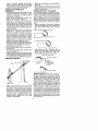 4
4
-
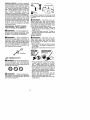 5
5
-
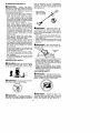 6
6
-
 7
7
-
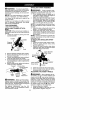 8
8
-
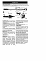 9
9
-
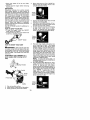 10
10
-
 11
11
-
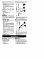 12
12
-
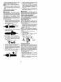 13
13
-
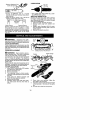 14
14
-
 15
15
-
 16
16
-
 17
17
-
 18
18
-
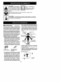 19
19
-
 20
20
-
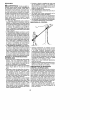 21
21
-
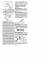 22
22
-
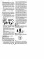 23
23
-
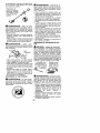 24
24
-
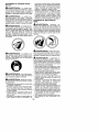 25
25
-
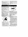 26
26
-
 27
27
-
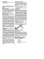 28
28
-
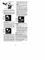 29
29
-
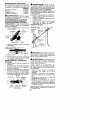 30
30
-
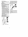 31
31
-
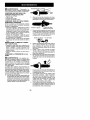 32
32
-
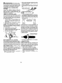 33
33
-
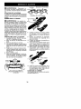 34
34
-
 35
35
-
 36
36
-
 37
37
-
 38
38


Poulan Pro PP445 El manual del propietario
- Categoría
- Mini cultivadores
- Tipo
- El manual del propietario
en otros idiomas
- English: Poulan Pro PP445 Owner's manual
Artículos relacionados
-
 Poulan Pro PP258TP Manual de usuario
-
 Poulan Pro PPB200 El manual del propietario
-
 Poulan Pro PPB150E El manual del propietario
-
 Poulan Pro PP5000P Manual de usuario
-
 Poulan Pro PP446T Manual de usuario
-
 Poulan Pro PP446T El manual del propietario
-
 Poulan Pro PP2822 Manual de usuario
-
 Poulan Pro PP446T El manual del propietario
-
 Poulan Pro SM446E El manual del propietario
-
 Poulan Pro SM446E El manual del propietario


Otros documentos
-
Poulan PP136 El manual del propietario
-
-
Weed Eater 530164008 El manual del propietario
-
-
WEEDEATER GHT 220 LE El manual del propietario
-
-
-
Craftsman 358792450 El manual del propietario
-
Ryobi RYPRN33 Guía del usuario
-