CAME FLY, PB2100, PB2110 Guía de instalación
- Tipo
- Guía de instalación

Documentazione
Tecnica
M82
rev. 2.1
04/2005
©
CAME
CANCELLI
AUTOMATICI
119PM82
SERIE FLY |
FLY SERIES |
SÉRIE FLY |
BAUREIHE FLY |
SERIE FLY
PB2100
CANCELLI AUTOMATICI
AUTOMAZIONE PER PORTE A BATTENTE DOPPIA
AUTOMATION FOR DOUBLE SWING GATES
AUTOMATION POUR PORTE A BATTANT DOUBLE
AUTOMATIK FÜR DOPPELTE FLÜGELTÜREN
AUTOMATIZACIÓN PARA PUERTAS DE BATIENTE DOBLE

ATTENZIONE!
importanti istruzioni per la sicurezza delle persone:
LEGGETE ATTENTAMENTE!
Premessa
• Il prodotto dovrà essere destinato solo all’uso per il quale è
stato espressamente concepito. Ogni altro uso è da conside-
rarsi quindi pericoloso. La CAME cancelli automatici s.p.a. non
è responsabile per eventuali danni causati da usi impropri, er-
ronei ed irragionevoli • Conservate queste avvertenze assieme
ai manuali di installazione e d’uso dei componenti l’impianto di
automazione.
Prima dell’installazione
(verifi ca dell’esistente: nel caso di valutazione
negativa, non procedete prima di aver ottemperato
agli obblighi di messa in sicurezza)
• Controllate che la parte da automatizzare sia in buono stato
meccanico, che sia bilanciata e in asse, e che si apra e si chiu-
da correttamente. Verifi cate inoltre che siano presenti adeguati
fermi meccanici di arresto • Se l’automazione deve essere in-
stallata a un’altezza inferiore ai 2,5 m dal pavimento o da altro
livello di accesso, verifi cate la necessità di eventuali protezioni
e/o avvertimenti • Qualora vi siano aperture pedonali ricavate
nelle ante da automatizzare, ci deve essere un sistema di
blocco della loro apertura durante il movimento • Assicuratevi
che l’apertura dell’anta automatizzata non causi situazioni di
intrappolamento con le parti fi sse circostanti • Non montate
l’automazione rovesciata o su elementi che potrebbero piegarsi.
Se necessario, aggiungete adeguati rinforzi ai punti di fi ssaggio
• Non installate su ante poste in salita o discesa (non in piano)
• Controllate che eventuali dispositivi di irrigazione non possa-
no bagnare il motoriduttore dal basso verso l’alto.
Installazione
• Segnalate e delimitate adeguatamente tutto il cantiere
per evitare incauti accessi all’area di lavoro ai non addetti,
specialmente minori e bambini • Fate attenzione nel maneg-
giare automazioni con peso superiore ai 20 kg (vedi manuale
d’installazione). Nel caso, premunitevi di strumenti per la movi-
mentazione in sicurezza • Tutti i comandi di apertura (pulsanti,
selettori a chiave, lettori magnetici etc.) devono essere installati
ad almeno 1,85 m dal perimetro dell’area di manovra del can-
cello, oppure dove non possano essere raggiunti dall’esterno
attraverso il cancello. Inoltre i comandi diretti (a pulsante, a
sfi oramento etc) devono essere installati a un’altezza minima
di 1,5 m e non devono essere accessibili al pubblico • Tutti i
comandi in modalità “azione mantenuta”, devono essere posti
in luoghi dai quali siano completamente visibili le ante in movi-
mento e le relative aree di transito o manovra • Applicate, ove
mancasse, una etichetta permanente che indichi la posizione
del dispositivo di sblocco • Prima della consegna all’utente, ve-
rifi cate la conformità dell’impianto alla norma EN 12453 (prove
d’impatto), assicuratevi che l’automazione sia stata regolata
adeguatamente e che i dispositivi di sicurezza e protezione
e lo sblocco manuale funzionino correttamente • Applicate
ove necessario e in posizione chiaramente visibile i Simboli di
Avvertimento (es. targa cancello).
Istruzioni e raccomandazioni
particolari per gli utenti
• Tenete libere da ingombri e pulite le aree di manovra del can-
cello. Mantenete sgombro dalla vegetazione il raggio d’azione
delle fotocellule • Non permettete ai bambini di giocare con
i dispositivi di comando fi ssi, oppure nell’area di manovra del
cancello. Tenete fuori dalla loro portata i dispositivi di coman-
do a distanza (trasmettitori) • Controllate frequentemente
l’impianto, allo scopo di verifi care eventuali anomalie e segni
di usura o danni alle strutture mobili, ai componenti dell’auto-
mazione, a tutti i punti e dispositivi di fi ssaggio, ai cavi e alle
connessioni accessibili. Mantenete lubrifi cati e puliti i punti di
snodo (cerniere) e di attrito (guide di scorrimento) • Eseguite
controlli funzionali a fotocellule e bordi sensibili ogni sei mesi.
Assicurate una costante pulizia dei vetrini delle fotocellule
(utilizzate un panno leggermente inumidito con acqua; non
utilizzate solventi o altri prodotti chimici) • Nel caso si rendano
necessarie riparazioni o modifi che alle regolazioni dell’impianto,
sbloccate l’automazione e non utilizzatela fi no al ripristino delle
condizioni di sicurezza • Togliete l’alimentazione elettrica prima
di sbloccare l’automazione per aperture manuali. Consultate le
istruzioni • È fatto DIVIETO all’utente di eseguire OPERAZIONI
NON ESPRESSAMENTE A LUI RICHIESTE E INDICATE nei
manuali. Per le riparazioni, le modifi che alle regolazioni e per
le manutenzioni straordinarie, RIVOLGETEVI ALL’ASSISTENZA
TECNICA • Annotate l’esecuzione delle verifi che sul registro
delle manutenzioni periodiche.
Istruzioni e raccomandazioni
particolari per tutti
• Evitate di operare in prossimità delle cerniere o degli organi
meccanici in movimento • Non entrate nel raggio di azione
dell’automazione mentre è in movimento • Non opponetevi
al moto dell’automazione poiché può causare situazioni di
pericolo • Fate sempre e comunque particolare attenzione
ai punti pericolosi che dovranno essere segnalati da appositi
pittogrammi e/o strisce giallo-nere • Durante l’utilizzo di un
selettore o di un comando in modalità “azione mantenuta”,
controllate continuamente che non ci siano persone nel raggio
d’azione delle parti in movimento, fi no al rilascio del comando
• Il cancello può muoversi in ogni momento senza preavviso •
Togliete sempre l’alimentazione elettrica durante le operazioni
di pulizia o di manutenzione.


WARNING!
Important instructions for the safety of people:
READ CAREFULLY!
Foreword
• Use of the products must be restricted to its intended use
(i.e. that for which it was expressly built for). Any other use is
to be considered dangerous. Came Cancelli Automatici S.p.A.
is not liable for any damage resulting from improper, wrongful
or unreasonable use • Keep these warnings with the installa-
tion and use manuals issued with the automated system.
Before installing
(preliminary check: in case of a negative
outcome, do not proceed before having
complied with the safety obligations)
• Make sure that the parts you intend to automate are in
good working order, and that they are properly balanced
and aligned. Also, make sure that proper mechanical stops
are already in place • If the operator will be installed at a
height of less than 2.5 m from the ground or other access
level, check whether you will need any protections and/or
warnings • Any gate leaves, fi tted with pedestrian entrances,
onto which you will install an operator, must have a blocking
mechanism when the gate is in motion • Make sure that the
opening of the automated gate is not an entrapment hazard
as regards any surrounding fi xed parts • Do not mount the
operator upside down or onto any elements that may fold
under its weight. If needed, add suitable reinforcements at
the points where it is secured • Do not install onto gates on
either an upward or downward slope (i.e. that are not on fl at,
level ground) • Check that any lawn watering devices will not
wet the gearmotor from the bottom up.
Installation
• Carefully section off the entire site to prevent unauthorised
access, especially by minors and children • Be careful when
handling operators that weigh more than 20 Kg (see installa-
tion manual). In such cases, employ proper weight handling
safety equipment • All opening commands (e.g. buttons, key
selectors, magnetic detectors, etc.) must be installed at least
1.85 m from the gate’s area of operation perimeter - or where
they cannot be reached from the outside of the gate. Also,
the direct commands (e.g. push button, or proximity devices,
etc.) must be installed at a height of at least 1.5 m and must
not be accessible to the public • All ‘maintained action’ com-
mands, must be placed where the moving gate leaves, transit
areas and driveways are completely visible • If missing, ap-
ply a permanent label that shows the position of the release
mechanism • Before delivering to the client, verify that the
system is EN 12453 (impact test) standard compliant. Make
sure that the operator has been properly adjusted and that the
safety and protection devices, as well as the manual release
are working properly • Where necessary and in plain sight,
apply the Warning Sings (e.g. gate plate).
Special instructions and
advice for users
• Keep the gate’s area of operation clean and clear of any
obstacles. Trim any vegetation that may interfere with the
photocells • Do not allow children to play with the fi xed com-
mand devices, or in the gate’s area of operation. Keep any
remote control devices (i.e. transmitters) away from the chil-
dren as well • Frequently check the system, to see whether
any anomalies or signs of wear and tear appear on the moving
parts, on the component parts, on the securing points, on the
cables and any accessible connections. Keep any joints (i.e.
hinges) lubricated and clean, and do the same where fric-
tion may occur (i.e. slide rails) • Perform functional tests on
photocells and sensitive edges, every six months. Keep glass
panels constantly clean (use a slightly water-moistened cloth;
do not use solvents or any other chemical products) • If the
system requires repairs or modifi cations, release the operator
and do not use it until safety conditions have been restored
• Cut off the power supply before releasing the operator for
manual openings. See instructions • Users are FORBIDDEN
to carry out ANY ACTIONS THAT THEY HAVE NOT BEEN
EXPRESSLY ASKED TO DO OR SO INDICATED in the manu-
als. Any repairs, modifi cations to the settings and extraor-
dinary maintenance MUST BE DONE BY THE TECHNICAL
ASSISTANCE STAFF • On the periodic maintenance log, note
down the checks you have done.
Special instructions and
advice for all
• Avoid working near the hinges or moving mechanical parts
• Stay clear of the gate’s area of operation when in motion •
Do not resist the direction of movement of the gate; this may
present a safety hazard • At all times be extremely careful
about dangerous points that must be indicated by proper
pictograms and/or black and yellow stripes • When using
a selector or command in ‘maintained action’ mode, keep
checking that there are no people in the area of operation of
the moving parts. Do this until you release the command •
The gate may move at any time without warning • Always cut
the power when cleaning performing maintenance.


ATTENTION !
Instructions importantes pour la sécurité des personnes :
À LIRE ATTENTIVEMENT !
Introduction
• Le produit devra être uniquement destiné à l’usage pour
lequel il a été spécifi quement conçu. Tout autre usage sera
donc considéré comme dangereux. La société CAME Cancelli
Automatici S.p.A. ne peut être considérée comme responsable
des éventuels dommages provoqués par des usages impropres,
erronés et déraisonnables • Conservez ces avertissements
avec les manuels d’instruction et d’utilisation des composants
de l’installation d’automatisme.
Avant l’installation
(vérifi cation de l’installation existante : en cas
d’évaluation négative, ne continuez pas avant d’avoir
respecté les obligations de mise en sécurité)
• Contrôlez que la partie à automatiser est en bon état mécani-
que, qu’elle est équilibrée et dans l’axe et qu’elle s’ouvre et se
ferme correctement. Vérifi ez également que les butées mécani-
ques d’arrêt nécessaires sont présentes • Si l’automatisme doit
être installé à une hauteur inférieure à 2,5 m du sol ou d’un autre
niveau d’accès, vérifi ez le besoin d’éventuelles protections et / ou
éventuels avertissements • Au cas où des ouvertures pour les
piétons seraient réalisées dans les portes, il faut que soit installé
un système de blocage de leur ouverture pendant le mouvement
• Vérifi ez que l’ouverture de la porte automatisée n’entraîne pas
de situations de blocage avec les pièces fi xes environnantes •
Ne montez pas l’automatisme retourné ou sur des éléments qui
pourraient plier. Si nécessaire, ajoutez les renforts nécessaires
sur les points de fi xation • N’installez pas le système sur des
portes en montée ou en descente (qui ne seraient pas planes) •
Contrôlez que les éventuels dispositifs d’irrigation ne risquent pas
de mouiller le motoréducteur du bas vers le haut.
Installation
• Signalez et délimitez soigneusement tout le chantier afi n d’évi-
ter des accès imprudents dans la zone de travail de la part de
personnes étrangères au chantier et spécialement de mineurs et
d’enfants • Faites attention en manœuvrant les automatismes
pesant plus de 20 kg (voir manuel d’installation). Si nécessaire,
équipez-vous des moyens nécessaires au déplacement en sécu-
rité • Toutes les commandes d’ouverture (boutons poussoirs, sé-
lecteurs à clé, lecteurs magnétiques, etc.) doivent être installés à
au moins 1,85 m du périmètre de la zone de manœuvre du portail,
ou bien là où elles ne peuvent être attrapées depuis l’extérieur à
travers le portail. En outre, les commandes directes (à touche, à
effl eurement, etc.) doivent être installées à une hauteur minimale
de 1,5 m et ne doivent pas être accessibles au public • Toutes les
commandes en modalité « action maintenue » doivent être instal-
lées dans des endroits d’où les portes en mouvement et les zones
de transit ou de manœuvre correspondantes sont entièrement vi-
sibles • Mettez, s’il n’y en avait pas, une étiquette permanente qui
indique la position du dispositif de déblocage • Avant la remise
à l’utilisateur, vérifi ez la conformité de l’installation avec la norme
EN 12453 (essai d’impact), assurez-vous que l’automatisme a
correctement été réglé et que les dispositifs de sécurité et de
protection et le déblocage manuel fonctionnent correctement •
Mettez, là où c’est nécessaire et dans une position bien visible,
les Symboles d’Avertissement (Ex. plaque du portail).
Instructions et recommandations
particulières pour les utilisateurs
• Conservez la zone de manœuvre du portail propre et sans rien
qui risque de l’encombrer. Retirez la végétation se trouvant dans
le rayon d’action des photocellules • Ne laissez pas les enfants
jouer avec les dispositifs de commande fi xes ou dans la zone de
manœuvre du portail. Conservez hors de leur portée les disposi-
tifs de commande à distance (émetteurs) • Contrôlez fréquem-
ment l’installation afi n de vérifi er les éventuelles anomalies et
les signes d’usure ou d’endommagements des parties mobiles
de l’automatisme, et de tous les points et dispositifs de fi xation,
des câbles et des branchements accessibles. Maintenez correc-
tement graissés et propres les points d’articulation (charnières) et
de frottement (guides de coulissement) • Effectuez des contrôles
fonctionnels des photocellules et des bords sensibles tous les six
mois. Gardez constamment propres les lames des photocellules
(utilisez un chiffon légèrement humidifi é avec de l’eau ; n’utili-
sez pas de solvants ou autres produits chimiques) • Au cas où
il serait nécessaire d’effectuer des réparations ou des modifi ca-
tions sur les réglages de l’installation, débloquez l’automatisme
et ne l’utilisez plus jusqu’à ce que les conditions de sécurité aient
été rétablies • Coupez l’alimentation électrique avant de déblo-
quer l’automatisme pour permettre les ouvertures manuelles.
Consultez les instructions • Il est INTERDIT à l’utilisateur de réa-
liser DES OPERATIONS QUI NE LUI SONT PAS EXPRESSEMENT
DEMANDEES ET INDIQUEES dans les manuels. Pour les répa-
rations, les modifi cations des réglages et pour les opérations
d’entretien extraordinaires, ADRESSEZ-VOUS A L’ASSISTANCE
TECHNIQUE • Notez la réalisation des vérifi cations dans le regis-
tre des entretiens réguliers.
Instructions et recommandations
particulières pour tous
• Evitez de travailler à proximité des charnières ou des organes
mécaniques en mouvement • Ne pénétrez pas dans le rayon
d’action de l’automatisme pendant que celui-ci est en mouve-
ment • Ne vous opposez pas au mouvement de l’automatisme car
cela pourrait entraîner des situations de danger • Faites toujours
particulièrement attention aux points dangereux signalés par les
pictogrammes appropriés et/ou les bandes jaunes et noires •
Pendant l’utilisation d’un sélecteur ou d’une commande en moda-
lité « action maintenue », contrôlez continuellement que personne
ne se trouve dans le rayon d’action des parties en mouvement,
jusqu’au relâchement de la commande • Le portail peut bouger
à n’importe quel moment sans avertissement • Coupez toujours
l’alimentation électrique pendant les opérations de nettoyage ou
d’entretien.


ACHTUNG!
Wichtige Sicherheitshinweise:
BITTE SORGFÄLTIG DURCHLESEN!
Vorwort
• Das Gerät ist ausschließlich für den vorgegebenen Zweck zu
verwenden. Anderweitige Verwendung des Geräts ist demzu-
folge gefährlich. Die CAME Cancelli Automatici S.p.A. haftet
nicht für durch ungeeignete, unsachgemäße und fehlerhaf-
te Verwendung verursachte Schäden • Bewahren Sie diese
Sicherheitshinweise zusammen mit der Montage- und Ge-
brauchsanweisung der Anlage auf.
Vor der Montage
(Überprüfung der vorhandenen Anlage, bei negativer
Bewertung vor der Montage zunächst dafür sorgen,
dass die Anlage sicher ist)
• Überprüfen, dass die zu automatisierenden Teile in guter
mechanischer Verfassung sind, dass sie ausbalanciert und
auf einer Achse sind und dass sie sich problemlos öffnen und
schließen. Zudem kontrollieren, dass geeignete mechanische
Toranschläge vorhanden sind • Sollte der Antrieb in weniger als
2,5 m Höhe vom Boden oder von einer anderen Zugangsebene
montiert werden, überprüfen, ob etwaige Schutzanlagen bzw.
Warnschilder anzubringen sind • Sollten die zu automatisieren-
den Torfl ügel über Fußgängertore verfügen, muss ein System,
das deren Öffnen während der Torbewegung verhindert, vor-
handen sein • Überprüfen, dass die Torfl ügelbewegung keine
Quetschgefahr mit den umliegenden Mauerwerken bewirkt •
Den Antrieb nicht verkehrt herum oder auf Teile montieren, die
sich biegen könnten. Wenn nötig die Befestigungspunkte in
geeigneter Weise verstärken • Nicht auf bergauf bzw. bergab
liegenden Torfl ügeln (nicht eben liegenden) montieren • Über-
prüfen, dass etwaige Bewässerungsanlagen den Getriebemotor
nicht von unten befeuchten können.
Montage
• Die Baustelle in geeigneter Weise begrenzen und sichern, da-
mit sich Unbefugte, vor allem Minderjährige, nicht der Baustel-
le nähern können • Bei Antrieben, die mehr als 20 kg wiegen
(siehe Montageanleitung) ist besondere Vorsicht gegeben. In
diesem Fall, benötigt man geeignete Geräte, um den Antrieb
sicher bewegen zu können • Sämtliche Auf-Befehlsgeräte
(Taster, Schlüsseltaster, Magnetkartenleser usw.) müssen
mindestens 1,85 m vom Torbereich bzw. so installiert werden,
dass man sie nicht von außen erreichen kann. Zudem müssen
sämtliche Befehsgeräte (Taster, Annäherungsschalter usw.) in
mindestens 1,5 m Höhe und so installiert werden, dass sie nicht
von Unbefugten betätigt werden können • Sämtliche Befehls-
geräte in “Totmannbedienung” müssen so installiert werden,
dass die sich bewegenden Torfl ügel und der Zufahrtsbereich
gut überblickbar sind • Wenn nicht vorhanden, einen die Ent-
riegelungsanheit anzeigenden Aufkleber anbringen • Vor Über-
gabe an den Verwender überprüfen, dass die Anlage der Norm
EN 12453 (Tornorm) entspricht und sicher stellen, dass die Au-
tomation in geeigneter Weise eingestellt wurde sowie, dass die
Sicherheits- und Schutzeinrichtungen bzw. die manuelle Entrie-
gelungseinheit in korrekter Weise funktionieren • Wenn nötig
Warnhinweise (z. B. Torwarnschild) gut sichtbar anbringen.
Anweisungen und Empfehlungen
für den Verwender
• Dafür sorgen, dass der Torbereich sauber und Hindernisfrei
ist. Den Funktionsbereich der Lichtschranken von Pfl anzen-
wuchs frei halten • Kindern das Spielen mit den festen Befehls-
geräten bzw. im Torbereich untersagen. Funkbefehlsgeräte
(Handsender) nicht in Reichweite von Kindern aufbewahren •
Die Anlage regelmäßig überprüfen, um etwaige Fehlfunktionen,
Verschleißerscheinungen bzw. Schäden an den beweglichen
Teilen, an den Antriebskomponenten sowie an allen Befesti-
gungspunkten, Kabeln und zugänglichen Kabelverbindungen
festzustellen. Sämtliche Gelenke (Scharniere) und Reibungs-
stellen (Laufschienen) schmieren und sauber halten • Alle
sechs Monate die Funktionstüchtigkeit von Lichtschranken und
Sicherheitsleisten überprüfen. Die Lichtschranken regelmäßig
säubern (verwenden Sie dafür ein mit Wasser befeuchtetes
Tuch und vermeiden Sie Lösungsmittel sowie andere Chemi-
kalienl) • Sollten Reparaturen oder Einstellungsänderungen
erforderlich sein, den Antrieb entriegeln und bis zur erneuten
Sicherung nicht verwenden • Vor der Entriegelung der Anlage
zur manuellen Toröffnung die Stromversorgung unterbrechen.
Anleitungen befolgen. NICHT AUSDRÜCKLICH IN den Anwei-
sungen AUFGEFÜHRTE TÄTIGKEITEN sind dem Verwender
UNTERSAGT. Für Reparaturen, Einstellungsänderungen und
außerplanmäßige Wartungsmaßnahmen WENDEN SIE SICH
BITTE AN DEN WARTUNGSDIENST • Das Ergebnis der Über-
prüfung der Anlage im Wartungsbuch aufführen.
Anweisungen und Empfehlungen
für alle
• Tätigkeiten in Nähe der Scharniere bzw. der sich bewegenden
mechanischen Teile vermeiden • Den Funktionsbereich des sich
bewegenden Tores vermeiden • Nicht gegen die Antriebskraft
einwirken, da dadurch Gefahrsituationen entstehen können • In
den Gefahrzonen, die durch entsprechende Warnhinweise bzw.
schwarz-gelbe Färbung zu kennzeichnen sind, besonders vor-
sichtig sein • Während der Betätigung eines Tasters bzw. eines
Befehlsgerätes im „Totmannbetrieb” ständig kontrollieren, dass
sich bis zum Schluss keine Personen im Bereich der sich bewe-
genden Torfl ügel befi nden • Das Tor kann sich jederzeit ohne
Vorwarnung in Bewegung setzen. • Während der Säuberung
und Wartung immer die Stromversorgung unterbrechen.


¡ATENCIÓN!
Importantes instrucciones de seguridad:
¡LEER ATENTAMENTE!
Condiciones preliminares
• Este producto deberá destinarse sólo para el uso para el
cual ha sido expresamente fabricado. Cualquier uso diferente,
se debe considerar impropio y por lo tanto peligroso. CAME
cancelli automatici s.p.a. no se hace responsable por eventuales
daños causados debido a una utilización inadecuada, errónea o
desmedida • Conservar estas advertencias junto a los manuales
de instalación y utilización de los componentes de la instalación
de automatización.
Antes de la instalación
(verifi cación preliminar de la instalación: en caso de
resultado negativo, no proceder sin haber cumplido
previamente las condiciones de puesta en seguridad)
• Controlar que la parte a automatizar esté en buen estado
mecánico, balanceada y alineada y que se abra y cierre co-
rrectamente. Verifi car además que existan adecuados bloqueos
mecánicos de parada • Si la automatización debe instalarse a
una altura inferior de 2,5 m desde el pavimento o desde otro
nivel de acceso, verifi car si se necesitan eventuales protecciones
y/o advertencias • En caso que existan aperturas peatonales en
las hojas a automatizar, debe existir un sistema de bloqueo de
la apertura durante el movimiento • Cerciorarse que la apertura
de la hoja automatizada no provoque situaciones de entrampado
con las partes fi jas circunstantes • No montar la automatización
al revés o en elementos que pudieran plegarse. Si es necesario,
agregar adecuados refuerzos en los puntos de fi jación • No ins-
talar en hojas colocadas en subidas o en bajada (que no estén
sobre un plano) • Controlar que los eventuales dispositivos de
riego no mojen el motorreductor de abajo hacia arriba.
Instalación
• Señalar y delimitar adecuadamente toda la obra para evitar
accesos imprudentes por parte de personas no pertinentes a
los trabajos, especialmente niños • Prestar mucha atención a
la manipulación de automatizaciones con un peso superior de
20 kg (véase manual de instalación). En dicho caso, utilizar ins-
trumentos idóneos para su movimiento en condiciones seguras
• Todos los mandos de apertura (botones, selectores de llave,
lectores magnéticos, etc.) deben instalarse a una distancia de
1,85 m como mínimo desde el perímetro del área de maniobra
de la cancela, o bien donde no puedan alcanzarse desde afuera
de la cancela. Además los mandos directos (de botón, de mem-
brana, etc.) deben instalarse a una altura mínima de 1,5 m y
no deben ser accesibles al público • Todos los mandos en la
modalidad “acción mantenida”, deben ponerse en sitios desde
los cuales sean completamente visibles las hojas en movimiento
y las relativas áreas de tránsito o maniobra • Aplicar donde falte,
una etiqueta permanente que indique la posición del dispositivo
de desbloqueo • Antes de la entrega al usuario, verifi car la con-
formidad de la instalación a la norma EN 12453 (pruebas de
impacto), cerciorarse que la automatización haya sido regulada
adecuadamente y que los dispositivos de seguridad y protección
y el desbloqueo manual funcionen correctamente • Aplicar don-
de sea necesario y en forma visible los Símbolos de Advertencias
(ej. placa cancela).
Instrucciones y recomendaciones particulares
para los usuarios
• Mantener limpia y sin obstrucciones las zonas de maniobra de
la cancela. Mantener limpio de vegetación el radio de acción de
las fotocélulas • No permitir a los niños jugar con los dispositivos
de mando fi jos o en las zonas de maniobra de la cancela. Tener
fuera del alcance de los mismos los dispositivos de mando a
distancia (emisores) • Controlar frecuentemente la instalación
para verifi car eventuales anomalías y desgastes o daños a las
estructuras móviles, a los componentes de la automatización,
a todos los puntos y dispositivos de fi jación, a los cables y a las
conexiones accesibles. Mantener lubricados y limpios los puntos
de articulación (goznes) y de rozamiento (guías de deslizamiento)
• Efectuar controles funcionales a fotocélulas y bordes sensibles
cada seis meses. Cerciorarse que los cristales de las fotocélulas
estén limpios (utilizar un paño ligeramente húmedo; no utilizar
solventes u otros productos químicos) • Si fuese necesario
efectuar reparaciones o modifi caciones a las regulaciones de la
instalación, desbloquear la automatización y no utilizarla hasta
que no se restablezcan las condiciones de seguridad • Quitar la
alimentación eléctrica antes de desbloquear la automatización
para aperturas manuales. Consultar las instrucciones • SE
PROHIBE al usuario efectuar OPERACIONES NO REQUERIDAS
EXPRESAMENTE AL MISMO E INDICADAS en los manuales.
Por reparaciones, modifi caciones a las regulaciones o para
operaciones de mantenimiento extraordinario, DIRIGIRSE A LA
ASISTENCIA TÉCNICA • Anotar la ejecución de las verifi cacio-
nes en el registro de mantenimiento periódico.
Instrucciones y recomendaciones particulares
para todos en general
• Evitar operar cerca de goznes u órganos mecánicos en mo-
vimiento • No entrar en el radio de acción de la automatización
mientras está en movimiento • No oponerse al movimiento de
la automatización porqué se podrían crear situaciones de pe-
ligro • Prestar mucha atención a los puntos peligrosos. Estos
deberán estar señalados por los relativos pictogramas y/o
bandas amarillos-.negras • Durante la utilización de un selector
o de un mando en la modalidad “acción mantenida”, controlar
continuamente que no haya personas en el radio de acción de
la partes en movimiento hasta que no se suelte el mando • ¡La
cancela puede moverse en cualquier momento! • Quitar siempre
la alimentación eléctrica durante las operaciones de limpieza o
de mantenimiento.


PAGINA LASCIATA INTENZIONALMENTE BIANCA
THIS PAGE LEFT INTENTIONALLY BLANK
NOUS AVONS LAISSÉ EXPRÈS CETTE PAGE BLANCHE
DIE SEITE WURDE ABSICHLICH LEER GELASSEN
PÁGINA DEJADA EN BLANCO INTENCIONALMENTE

PAGINA LASCIATA INTENZIONALMENTE BIANCA
THIS PAGE LEFT INTENTIONALLY BLANK
NOUS AVONS LAISSÉ EXPRÈS CETTE PAGE BLANCHE
DIE SEITE WURDE ABSICHLICH LEER GELASSEN
PÁGINA DEJADA EN BLANCO INTENCIONALMENTE

22
22
2
Controllare che le apparecchiature di comando, di sicurezza e gli accessori siano originali CAME; ciò garantisce e rende l'impianto di facile esecuzione e
manutenzione.
For easy installation and maintenance, be sure to use CAME original control equipment, safety systems and accessories.
Descrizione:
Sistema per l'apertura automatica di una
porta a battente doppia con ante fino a
1,20 m.
Progettato e costruito interamente dalla
CAME S.p.A., con grado di protezione
IP40. Garantito 24 mesi salvo
manomissioni.
Modelli:
-PB2100 Due motoriduttori reversibili a
24V con quadri elettrici incorporati.
-PF2100 Profili e coperchio dell'
automazione.
Bracci di azionamento:
-PB1001 Braccio a slitta per apertura a
tirare
-PB1002 Braccio snodato per aperture a
spingere.
Accessori a richiesta:
-MA7034 Sistema antipanico a batteria.
-MA7041 Selettore funzioni;
-MS9502 Sensore a sfioramento;
-MF9011/9111 Fotocellule di comando e
sicurezza;
-MR8001/8002 Radar a infrarosso;
- MR8102/8103 Radar a microonde;
-MR8334-70-90 Sensore di sicurezza a
infrarossi attivi;
-MP8030/8060 Pedane sensibili;
Comprobar que los equipos de mando, de seguridad y los acesorios sean originales CAME; lo cual garantiza y facilita el uso y el mantenimiento del aparato.
Wir empfehlen original CAME-Schalt-und-Sicherheitsvorrichtungen mit entsprechendem Zubehör zu montieren, um die einwandfreie Montage und die problemlose
Wartung der Anlage zu gewährleisten.
Vérifiez que l'appareillage de commande, de sécurité et les accessoires sont des produits originaux CAME afin de garantir l'installation et d'en faciliter le montage
et l'entretien.
CARATTERISTICHE GENERALI
GENERAL CHARACTERISTICS
CARACTERISTIQUES GENERALES
ALLGEMEINE MERKMALE
CARACTERISTICAS GENERALES
Description:
Automatic opening system of double
swing gates with doors up to 1.20 m.
Entirely designed and manufactured by
CAME S.p.A. with IP40 protection level.
Guaranteed for 24 months if not
tampered with.
Models:
-PB2100 Two reversible 24V gear motor
with built-in control boards.
-PF2100 Sections and automation cover.
Actuated with mechanical arms:
-PB1001 Sliding arm for opening by
pulling.
-PB1002 Articulated arm for opening by
pushing.
Optional accessories:
-MA7034 Battery-powered anti-panic
system;
-MA7041 Function selector;
-MS9502 Touch-activated switch;
-MF9011/9111 Command and safety
photocells;
-MR8001/8002 Infrared radar;
- MR8102/8103 Microwave radar;
-MR8334-70-90 Activ infrared safety
sensor;
-MP8030/8060 Sensitive boards;
Description:
Système pour l'ouverture automatique
d'une porte à battant double avec
battants jusqu'à 1,20 m.
Conçu et construit entièrement par
CAME S.p.A., avec degré de protection
IP40. Garantie 2 ans sauf en cas
d'altération.
Modèles:
-PB2100 Deux motoréducteurs réversibles
à 24V avec tableaux électriques
incorporés;
-PF2100 Profils et couvercle de
l'automation.
Bras d'actionnement:
-PB1001 Bras à glissière pour ouvrir en
tirant;
-PB1002 Bras articulé pour ouvrir en
poussant.
Accessoires sur demande:
-MA7034 Système anti-panique à
batterie;
-MA7041 Sélecteur des fonctions;
-MS9502 Interrupteur a effleurement;
-MF9011/9111 Photocellules de
commande et de sécurité;
-MR8001/8002 Radar à infrarouge;
- MR8102/8103 Radar à micro-ondes;
-MR8334-70-90 Capteur de securité a
infrarouges actifs;
-MP8030/8060 Supports sensibles.
Beschreibung:
System für das automatische Öffnen
einer doppelten Flügeltür mit Türen bis
zu 1.20 m.
Entworfen und komplett gefertigt von
CAME S.p.A. mit Schutzklasse IP40. 24
Monate Garantie. Veränderungen am
System führen zu einem sofortigen
Verfall des Garantieanspruchs.
Modelle:
-PB2100 Zwei umkehrbare 24V
Getriebemotoren mit eingebauter
Schalttafel;
-PF2100 Profile und Abdeckung vom
Automatikantrieb.
Antriebsarme:
-PB1001 Schlittenarm für das Öffnen
durch Ziehen;
-PB1002 Gelenkarm für das Öffnen durch
Schieben.
Auf Anfrage erhältliches Zubehör:
-MA7034 Panikschutzsystem mit
Batterie;
-MA7041 Wählschalter für Torfunktionen;
-MS9502 Touch-Schalter;
-MF9011/9111 Steuerung- und
Sicherheitsphotozellen;
-MR8001/8002 Infrarot-Radar;
- MR8102/8103 Mikrowellen-Radar;
-MR8334-70-90 Sicherheitssensoren mit
aktiven infrarotstrahlen;
-MP8030/8060 Empfindliche
Trittbereiche.
Descripción:
Sistema para la apertura automática de
una puerta de batiente doble con hojas
de hasta 1,20 m.
Diseñado y fabricado completamente por
CAME S.p.A., con grado de protección
IP40. Garantizado por 24 meses, salvo
alteración del producto.
Modelos:
-PB2100 Dos motorreductores reversibles
de 24V con cuadros eléctricos
incorporados;
-PF2100 Perfiles y tapa de la
automatización.
Brazos de accionamiento:
-PB1001 Brazo de deslizante para abrir
tirando;
-PB1002 Brazo articulado para abrir
empujando.
Accesorios a encargo:
-MA7034 Sistema antipánico de batería;
-MA7041 Selector de las funciones;
-MS9502 Interruptor por rozamiento;
-MF9011/9111 Fotocélulas de mando y
de seguridad;
-MR8001/8002 Radar de rayos
infrarrojos;
- MR8102/8103 Radar de microondas;
-MR8334-70-90 Sensor de seguridad de
infrarrojos activos
-MP8030/8060 Plataformas sensibles.

33
33
3
CARATTERISTICHE TECNICHE /
TECHNICAL CHARACTERISTICS
/ CARACTERISTIQUES TECHNIQUES
TECHNISCHE DATEN
/ CARACTERISTICAS TECNICAS
DESCRIZIONE DELLE PARTI /
DESCRIPTION OF COMPONENTS
/ DESCRIPTION DES PIECES
BESCHREIBUNG DER BAUTEILE
/ DESCRIPCION DE LAS PARTES
(1) Possibilità di alimentare l'automazione con tensione diverse su richiesta -
Upon request, there is the possibility of
powering up the automation with a different voltage
- Possibilité d'alimenter l'automation avec une tension différente
sur demande -
Auf Wunsch besteht die Möglichkeit, den Antrieb auch mit einer anderen Spannung zu versoren -
A pedido,
posibilidad de alimentar la automatización con otra tensión.
(2) Servizio intensivo -
Heavy-duty service
- Service intensif -
Intensivbetrieb
- Service intensif.
(3) 90° compreso rallentamento -
to 90° including slowdown
- à 90°, y compris ralentissement -
bei 90° Öffnengswinkel,
einschließlich Laufverlangsamung
- a 90°, incluído el ralentamiento.
(4) Compresa elettroserratura -
Electric locking system included
- Y compris serrure électrique -
Einschließlich Elektroschloß
- Incluida electrocerradura.
Motoriduttore
Gearmotor
Motorreductor
Getriebemotor
Motoréducteur
Trasformatore
Transformer
Transformateur
Transforma
Motoréducteur
Scheda comando
Control panel
Armoire de commande
Schalttafel
Tarjeta de mando
Involucro
Enclosure
Boîtier
Gehäuse
Envoltura
Base di fissaggio
Anchoring base
Base de fixation
Basis zur Antringung
Base de sujeción
1
2
3
.REV .TNEMILA XAMETNERROC EROTOM ETNERROC ELANIMON XAMAZNETOP ATIBROSSA AZNETTIMRETNI OROVAL AIPPOC XAM IDOTROPPAR ENOIZUDIR OPMET ARUTREPA XAMAZNETOP IROSSECCA IDARUTAREPMET OIZICRESE
.REV REWOP YLPPUS XAMROTOM TNERRUC LANIMON TNERRUC REWOPXAM NOITPMUSNOC ELCYCYTUD XAM EUQROT OITARNOITCUDER GNINEPO EMIT
SEIROSSECCA MUMIXAMROF REWOP
GNITAREPO ERUTAREPMET
.REV .TNEMILA NOITPOSBA ELAMIXAM RUETOM
NOITPOSBA ELANIMON
ECNASSIUP ELAMIXAM EEBROSBA
ECNETTIMRETNI LIAVARTED ELPUOC LAMIXAM EDTROPPAR NOITCUDER SPMET ERUTREVUO'D
ECNASSIUP MUMIXAM SERIOSSECCA
EDERUTARÉPMET TNEMENNOITCNOF
.REV -ßULHCSNA GNUNNAPS -LAMIXAM ROTOMMORTS -LANIMON MORTS XAMAZNETOP ATIBROSSA -UADTLAHCSNIE RE
-TSHCÖH -MOMHERD TNE
-SGNUZTESRETNU SINTLÄHREV TIEZSGNUNFFÖ ELAMIXAM GNUTSIEL RÖHEBUZ
-SBEIRTEB RUTAREPMET
.REV .TNEMILA ETNEIRROC ROTOMAMIXAM ETNEIRROC ELANIMON XAMAICNETOP ADIVROSBA AICNETIMRETNI OJABART ROTOM OMIXAM EDNOICALER NOICCUDER OPMEIT ARUTREPA
AICNETOP AMIXÁM SOIROSECCA
EDARUTAREPMET OICIVRES
0.1 c.aV032 .c.aV42 zH06/05
A21 )6+6(
)V032( A2,1 )6,0+6,0(
W672 )831+831( mN04801/1"5a"2adW03°07+<°02-
4
Batterie
Battery
Batteries
Batterien
Baterías

44
44
4
8080
8080
80
DIMENSIONI E MISURE DI FISSAGGIO /
ANCHORING DIMENSIONS AND MEASUREMENTS
/ DIMENSIONS ET MESURES
DE FIXATION /
GRÖSSE UND ABMESSUNGEN FÜR DIE ANBRINGUNG
/ DIMENSIONES Y MEDIDAS DE SUJECIÓN
LUNGHEZZA MINIMA INVOLUCRO = 1,160 m
LUNGHEZZA MASSIMA INVOLUCRO = 5,000 m
MINIMUM LENGTH OF ENCLOSURE = 1,160m
MAXIMUM LENGTH OF ENCLOSURE = 5,000m
LONGUEUR MINIMUM BOÎTIER = 1,160m
LONGUEUR MAXIMUM BOÎTIER = 5,000m
MINDESTLÄNGE GEHÄUSE = 1,160m
HÖCHSTLÄNGE GEHÄUSE = 5,000m
LONGITUD MÍNIMA ENVOLTURA = 1,160m
LONGITUD MÁXIMA ENVOLTURA = 5,000m
La misura C (interasse cerniere) deve essere rilevata e comunicata per definire l'esecuzione
dell'automazione stessa (Rif. PF2100), inoltre è di riferimento per il fissaggio delle basi di
ancoraggio.
Nelle esecuzioni Standard, le misure A (tra interasse cerniera e interasse brac-
cio) sono pari a 100 mm e la misura T (lunghezza trave PF2100) corrispon-
de alla C.
Nei casi di involucro con lunghezza maggiore, deve essere comu-
nicata la misura T in quanto è diversa dalla C e le misure (A
sx) e (A dx) di disassamento se non sono simmetriche.
Measurement of C (hinge axle base) must be
taken and notified to define the execution of the
automation itself (Ref. PF2100); it is also useful as
reference for securing the anchoring bases.
In the Standard execution, the A measurements
(between hinge axle base and arm axle base)
equal 100 mm and the measurement for T (PF2100
beam length) corresponds to C.
If the enclosure is longer, the T measurement
must be taken as it varies from the C measure-
ment and the misalignment (A left and A right)
measurements if they are not symmetrical.
Relever et communiquer la mesure C (distance
charnières) pour définir la version de l’automation
(Réf. PF2100), celle-ci sert également de référence
pour fixer les bases d’ancrage.
Dans les versions standard, les mesures A (entre
distance charnières et distance bras) sont égales
à 100 mm et la mesure T (longueur poutre PF2100)
correspond à la mesure C.
Si le boîtier a une longueur supérieure,
communiquer la mesure T car elle est différente
de la mesure C ainsi que les mesures (A gauche)
et (A droite) de désaxement si elles ne sont pas
symétriques
Der Wert C (Abstand Scharniere) muß gemessen und mitgeteilt werden, da er für die Ausführung vom Automatikantrieb
benötigt wird (Rif. PF2100). Außerdem dient er als Bezug für die Anbringung der Verankerungsbasis.
Bei den Standardausführungen entsprechen die Werte A (Abstand Scharnier und Abstand Arm) 100 mm und der Wert
T (Länge vom Querträger PF2100) dem Wert C.
Bei längeren Gehäusen muß der Wert T mitgeteilt werden, da er vom Wert C abweicht, sowie die Werte (A links) und
(A rechts) der Fluchtabweichung, falls sie nicht symmetrisch sind.
Hay que medir y comunicar la medida
C (distancia entre ejes de las
bisagras), que sirve para definir la
ejecución de la misma automatización
(Ref. PF2100), y como referencia para
la fijación de las bases de anclaje.
En las ejecuciones Estándares, las
medidas A (distancia entre el eje de la
bisagra y el eje del brazo) son iguales
a 100 mm y la medida T (longitud
perfil PF2100) corresponde a la C.
En los casos de envoltura más larga,
hay que comunicar la medida T puesto
que es diferente de la C y las medidas
(A izq) y (A der.) de desalineación si
no son simétricas
ITALIANO
ENGLISH
FRANÇAIS
DEUTSCH
ESPANOL
T = C
100 114
100
96
49.5
49.5 237 237
573
200 8787 99.5 99.5
45
30
11
37
71
155
65
C = T Standar

55
55
5
DEFINIZIONI DI POSIZIONAMENTO /
POSITIONING
/ DEFINITIONS DU POSITIONNEMENT
HINWEISE ZUR POSITIONIERUNG /
DEFINICIONES DE POSICIONAMIENTO
1) L'automazione è già programmata in funzionamento
MASTER-SLAVE. Le schede comando sono contrasse-
gnate con etichette visibili.
2) Posizionare il lato MASTER sull'anta che deve chiu-
dere per 2a.
3) L'automazione ha uscite simmetriche per l'attacco dei
bracci (PB1001-1002). Nel caso si necessiti, invertire la
posizione MASTER-SLAVE, rovesciare la trave PB2100
come da figura.
1) Automation is already programmed in the MASTER-
SLAVE mode. The control boards are marked with distinct
labels.
2) Place the MASTER side on the door that must close
last.
3) The automation has symmetrical outlets for mounting
the arms (PB1001-1002). If necessary, invert the position
of the MASTER-SLAVE and turn over the PB2100 beam
as illustrated in the figure.
21345678910O
N
SLAVE
21 3 4 5 67 8910O
N
MASTER
MASTERSLAVE
MASTER
MASTER
SLAVEMASTER
((
((
(chiusura anticipata)
(closure brought forward)
(fermeture anticipée)
(Vorgezogenes Schließen)
(cierre anticipado)
(chiusura ritardata)
(closure-delayed)
(fermeture retardée)
(Verzögertes Schließen)
(cierre retardado)
11
11
1
22
22
2
33
33
3
SLAVE MASTER
ITALIANO
ENGLISH
FRANÇAIS
DEUTSCH
ESPANOL
1)L’automation est déjà programmée pour le
fonctionnement MASTER-SLAVE (maître/ auxiliaire). Les
cartes de commande sont indiquées par des étiquettes
visibles.
2) Placer le côté MASTER sur le battant qui doit fermer en
second.
3) L’automation a des sorties symétriques pour le raccord
des bras (PB1001-1002). En cas de besoin, inverser la
position MASTER-SLAVE, renverser la poutre PB2100
comme indiqué sur la figure.
1) Die Automatik ist bereits in der MASTER-SLAVE
Funktionsweise programmiert. Die Steuerkarten sind mit
sichtbaren Aufklebern gekennzeichnet.
2) Die MASTER-Seite an dem Türflügel positionieren, der
als zweiter geschlossen wird.
3)Die Automatik hat symmetrische Ausgänge zur
Anbringung der Arme (PB1001-1002). Falls nötig, die
MASTER-SLAVE Position vertauschen und den
Querträger PB2100 so umdrehen, wie auf der Abbildung
zu sehen ist.
1) La automatización ya está programada en funcio-
namiento MASTER-SLAVE. Las tarjetas de mando están
marcadas con etiquetas visibles.
2) Coloque el lado MASTER en la puerta que se ha de
cerrar en segundo lugar.
3) La automatización tiene salidas simétricas para la
conexión de los brazos (PB1001-1002). Si se requiere la
inversión de la posición MASTER-SLAVE, invierta el perfil
PB2100 como muestra la figura.

66
66
6
1) Enlever le couvercle du boîtier à l’aide d’un tournevis plat.
2) Desserrer les vis des bases de fixation des transformateurs
(tournevis cruciforme) et ne déplacer les transformateurs
afin de libérer les écrous M8 (clé à tube de 13) que si c’est
nécessaire.
Enlever les bases de fixation du boîtier moteur.
3) Aligner les bases aux battants en suivant les références
horizontales indiquées dans le dessin (pour les références
1) Togliere il coperchio dall'involucro con l'aiuto di un cac-
ciavite a taglio.
2) Allentare le viti delle basi fissaggio dei trasformatori (cac-
ciavite a croce) e solo se necessario spostare i trasforma-
tori in modo da liberare i dadi M8 (chiave a tubo da 13).
Togliere le basi di fissaggio dall'involucro motore.
3) Allineare le basi alle ante, seguendo i riferimenti oriz-
zontali indicati nel disegno (per quelli verticali seguire le
misure applicative specifiche al braccio di azionamento da
utilizzare, PB1001 pag.8÷9, PB1002 pag.10÷12).
Fissare adeguatamente le basi su più punti facendo fuoriu-
scire le viti M8 come indicato nel disegno. Attenzione: pre-
disporre i cavi cablaggio (vedi ingresso cavi).
4) Dopo il fissaggio delle basi, allineare i fori dell'involucro
motore alle viti M8 delle basi, far passare i cavi cablaggio e
fissare le due parti con gli scontri e i dadi in dotazione (chiave
a tubo da 13)
5) Riposizionare, bloccare e ricollegare i trasformatori (cac-
ciavite a croce).
Eseguire i collegamenti elettrici nei due quadri, seguendo
le istruzioni del paragrafo relativo (pag.16÷17).
ISTRUZIONI DI MONTAGGIO /
ASSEMBLY INSTRUCTIONS
/ INSTRUCTIONS POUR LE MONTAGE
MONTAGEANLEITUNG
/ INSTRUCCIONES DE MONTAJE
11
11
1
22
22
2
33
33
3
UNI 5739 M8x20
1) Remove the cover from the enclosure with a screwdriver.
2) Loosen the screws from the transformer anchoring base
(Phillips screwdriver) and move the transformers to loosen
the M8 nuts (13-socket spanner) only if necessary.
Remove the anchoring bases from the motor’s enclosure.
3) Align the bases to the doors according to the horizontal
reference marks indicated in the drawing (for the vertical
ones, follow the application measurements specific to the
operating arm to be used, PB1001 pg.8-9, PB1002 pg.10-
12).
Adequately secure the bases at various points, making the
M8 screws emerge as indicated in the drawing. Warning:
prepare the cables beforehand (see cable inlet).
4) After fixing the bases, align the motor enclosure’s screw
holes to the bases’ M8 screws, feeding the cables through
and fixing the two parts with the pawls and the nuts provided
(13-socket spanner)
5) Replace, secure and reconnect the transformers (Philips
screwdriver).
Follow instructions found in the appropriate paragraph (pg.16-
17) to make the necessary electrical connections in the two
boards.
ITALIANO
ENGLISH
FRANÇAIS
INGRESSO CAVI
CABLE INLET
ENTRÉE DES CÂBLES
KABELEINGANG
ENTRADA CABLES

77
77
7
44
44
4
55
55
5
DEUTSCH
1) Mithilfe eines Schraubenziehers den Deckel vom Gehäuse
entfernen.
2) Die Schrauben der Basis, an der die Trafos befestigt sind,
lösen (Kreuzschlitzschraubenzieher). Die Trafos nur dann
verschieben, wenn dies nötig ist, um Zugriff auf die M8-
Muttern zu haben (13-er Steckschlüssel).
Die Befestigungsbasen vom Motorgehäuse abmachen.
3) Die Basen mit den Türflügeln ausrichten und dabei die
horizontalen Bezüge beachten, die in der Zeichnung
angegeben sind (für die vertikalen Bezüge siehe
entsprechende Werte vom jeweils verwendeten Antriebsarm:
PB1001 S. 8-9 und PB1002 S. 10-12).
Die Basen an den entsprechenden Punkten befestigen.
Dabei müssen die M8 Schrauben herauskommen, wie auf
der Abbildung zu sehen ist. Achtung: Die Kabel bereitstellen
(siehe Kabeleingang)!
4) Nachdem die Basen befestigt worden sind, die Löcher
vom Motorgehäuse mit den M8-Schrauben der Basen
ausrichten, das Kabel durchziehen und die beiden Teile mit
den beiliegenden Gegenstücken und Muttern befestigen
(13-er Steckschlüssel).
5) Die Trafos wieder in ihre ursprüngliche Position bringen,
blockieren und anschließen (Kreuzschlitzschraubenzieher).
Die Stromanschlüsse an den beiden Schalttafeln nach den
Anweisungen im entsprechenden Abschnitt (S. 16÷17)
durchführen.
1) Quite la tapa de la envoltura ayudándose con un destornillador.
2) Afloje los tornillos de las bases de fijación de los transformadores (destornillador cruciforme) y, sólo si fuera
necesario, corra los transformadores para poder quitar las tuercas M8 (llave de tubo de 13).
Quite las base de fijación de la envoltura del motor.
3) Alinee las bases a las hojas, siguiendo las referencias horizontales indicadas en el dibujo (para las verticales siga
las medidas específicas de aplicación del brazo de accionamiento que se ha de usar, PB1001 págs.8˜9, PB1002
págs.10˜12).
Fije de manera adecuada las bases sobre varios puntos haciendo salir los tornillos M8 como indicado en el dibujo.
Atención: prepare los cables para el cableado (véase entrada cables).
4) Tras fijar las bases, alinee los agujeros de la envoltura del motor con los tornillos M8 de las bases, haga pasar los
cables y fije las dos piezas con los casquillos roscados y tuercas suministrados (llave de tubo de 13)
5) Vuelva a posicionar, bloquee y conecte de nuevo los transformadores (destornillador cruciforme).
Haga las conexiones eléctricas en los dos cuadros, siguiendo las instrucciones del párrafo respectivo
(págs.16÷17).
ESPANOL
verticales, suivre les mesures spécifiques d’application au
bras d’actionnement à utiliser, PB1001 pages 8÷9, PB1002
pages 10÷12).
Fixer correctement les bases en plusieurs endroits en faisant
sortir les vis M8 comme indiqué sur le dessin. Attention:
prévoir les câbles de branchement (voir entrée câbles).
4) Après avoir fixé les bases, aligner les trous du boîtier
moteur aux vis M8 des bases, faire passer les câbles de
branchement et fixer les deux parties avec les vis et les
écrous fournis de série (clé à tube de 13)
5) Replacer, bloquer et brancher à nouveau les
transformateurs (tournevis cruciforme).
Effectuer les branchements électriques dans les deux tableaux
en suivant les instructions du paragraphe correspondant
(pages 16÷17).
INGRESSO CAVI
CABLE INLET
ENTRÉE DES CÂBLES
KABELEINGANG
ENTRADA CABLES

88
88
8
The standard
opening angle can
be adjusted up to
100°÷120° (see
table).
Warning: at
maximum aperture,
ground anchors are
necessary to keep
the overstop from
damaging the arms
and motors.
L'angolo di apertu-
ra standar è
regolabile fino a
100°÷120° (vedi
tabella).
Attenzione: nella
massima apertura
sono indispensabili
i fermi a pavimento
per ovviare che
l'oltrecorsa dan-
neggi bracci e
motori.
D
A
B
ß
ß
Assi & ingombri /
Centre lines and external dimensions
/ Axes et encombrements /
Achsen & Abmessungen
/ Ejes y dimensiones máximas
PB1001 - BRACCIO A SLITTA /
PB1001 - SLIDING ARM
/ PB1001 - BRAS À GLISSIÈRE
PB1001 - GLEITARM
/ PB1001 - BRAZO DESLIZANTE
dimensione / peso
dimensions / weights
dimensions / poids
Abmessungen / Gewicht
dimensiones / pesos
0.80 m - 250 kg
1.00 m - 200 kg
1.20 m - 150 kg
L'angle d'ouverture
standard est
réglable jusqu'à
100÷120° (voir
tableau).
Attention: les arrêts
au sol sont
indispensables en
ouverture maximum
pour éviter que le
mouvement hors-
course n'abîme les
bras et les moteurs.
Der Standard-
öffnungswinkel kann
bis zu 100° bis 120°
eingestellt werden
(siehe Tabelle).
Achtung: Bei
maximaler Öffnung
sind Türstopper auf
dem Boden nötig,
damit die Arme und
Motoren nicht durch
zu weites Öffnen
beschädigt werden.
El ángulo de aper-
tura estándar se
regula hasta
100°÷120° (véase
tabla).
Atención: es
indispensable
colocar topes en el
piso para la apertu-
ra máxima y así
evitar que la
superación de la
carrera máxima
averíe los brazos y
motores.
ß
°001 °021
A001 001
B56 56
D083 533

99
99
9
114
112
75
155
5
400 71
D
280
A
B
max. 30 mm a filo superiore anta
30 mm max. distance from the upper edge of the door
max 30 mm, à fil du côté supérieur du vantail
max. 30 mm von der oberen Türkante entfernt
máx. 30 mm a filo superior puerta
139
102
5
15±0,2
18
6,5
B
Applicazione standard
Standar application
Application standard
Standardanbringung
Aplicación estándar
Con spessoramento abbassato vite M6x35
M6x35 screws for lowered shimming
Avec cale abaissée vis M6x35
Mit verkürztem Distanzstück Schraube M6x35
Con arandela distanciadora baja tornillo M6x35
Applicazione disassata
Misaligned application
Application désaxée
Anbringung mit Fluchtabweichung
Aplicación desalineada
Con spessoramento lungo vite M6x60
M6x60 screws for long shimming
Avec cale longue vis M6x60
Mit langem Distanzstück Schraube M6x60
Con arandela distanciadora alta tornillo M6x60
Il punto di fissaggio del motoriduttore, deve rispet-
tare gli allineamenti definiti.
The gear motor's anchorage point must match
the established alignments.
Le point de fixation du motoréducteur doit
respecter les alignements définis.
Der Punkt, an dem der Getriebemotor
angebracht wird, muß mit den vorgegebenen
Ausrichtungen übereinstimmen.
El punto de sujeción del motorreductor tiene que
respetar las alineaciones definidas.
Vite M6x16
M6x16 screw
Vis M6x16
Schraube M6x16
Tornillo M6x16
Scontro acciaio
Steel pawl
Butée acier
Stahlgegenstück
Casquillo roscado de acero
Boccola ottone
Brass bush
Douille laiton
Messingbuchse
Casquillo de
latón
Nei casi necessiti maggiore
disassamento tra slitta e
bracci, usufruire apposita
boccola e vite M6x35 di serie
(B).
In case more misalignment is
necessary between runner and
arms, use appropriate bush and
M6x35 (B) series screws.
S'il faut davantage de
désaxement entre la glissiére
et les bras, utiliser une douille
prévue à cet effet et les vis
M6x35 de série (B).
Wenn eine größere
Fluchtabweichung zwischen
Schlitten und Armen nötig ist,
die entsprechende Buchse und
die serienmäßigen Schrauben
M6x35 (B) verwenden.
Cuando se requiera una mayor
desalineación entre corredera
y brazos, aproveche el
casquillo y tornillos M6x35
suministrado de serie (B).
SNODO -
ARTICULATION
ARTICULATION
GELENK
- ARTICULACIÓN
Foro di riferimento asse braccio
Reference hole for arm axle
Trou de référence axe bras
Bezugsbohrung Achse Arm
Agujero de referencia eje del brazo
Scontro di fissaggio
Fixing ward
Butee de fixation
Gegenstück
Controplaca de fijación
**
*
*
*
*
*
*
*
*

1010
1010
10
A=100
D=250
B<120
71 50
ß
180
ß
D=250
180
B<120
A=100
71 50
ß
ß
Assi & ingombri / Assi & ingombri /
Assi & ingombri / Assi & ingombri /
Assi & ingombri / Centre lines and external dimensions / Axes et encombrements / / Axes et encombrements /
/ Axes et encombrements / / Axes et encombrements /
/ Axes et encombrements / Achsen & Abmessungen/ Ejes y dimensiones máximas/ Ejes y dimensiones máximas
/ Ejes y dimensiones máximas/ Ejes y dimensiones máximas
/ Ejes y dimensiones máximas
PB1002 - BRACCIO SNODATO /
ARTICULATED ARM - PB1002
/ PB1002 - BRAS ARTICULÉ
PB1002 - GELENKARM
/ PB1002 - BRAZO ARTICULADO
dimensione / peso
dimensions / weights
dimensions / poids
Abmessungen / Gewicht
dimensiones / pesos
0.80 m - 250 kg
1.00 m - 200 kg
1.20 m - 150 kg
ß ß
ß ß
ß = min 15° - max 120°
D=250
A=100
71 C=350 max
B=420 max
ß
ß
120
A=100
C=350 max
B=420 max
71
ß
ß
D=250
120
°021<ß
001=A
024<B
053<C
052=D
°081<ß
001=A
021<B
05<C
052=D

1111
1111
11
A=100
D=250
100
60
80
71
B
C
ß min
R
This system is
designed to open
swinging door wings to
a 120° angle. However,
a 180° opening angle
is possible as long as
distance "B" is not
excessive. Distances
"A" and "D" cannot be
changed. To compen-
sate for differences in
distance "B", change
the length of the idle
arm as shown on the
figure. However, be
sure that the angle
between the
transmission arm and
idle arm "ß" does not
exceed 120° when the
door wing is opened all
the way, and 15° when
the door wing is
closed.
Note: The maximum
load capacity of the
system is reduced by
30% when the idle arm
is fully extended.
A maximum aperture,
ground anchors are
necessary to keep the
overstop from
damaging the arms
and motors.
Il sistema garantisce
sempre una apertu-
ra dell'anta a 120°,
tuttavia può anche
arrivare a 180°, a
condizione che "B"
sia limitata.
Le misure "A" e "D"
sono fisse. Compen-
sare le differenti
misure di "B"
variando la lunghez-
za della leva di
rinvio come da fig.a.
Fare attenzione che
alla massima aper-
tura anta, l'angolo
tra braccio e leva di
rinvio "ß" non
superi i 120° e in
chiusura non sia
inferiore a 15°.
Nota: Nelle applica-
zioni con massima
estensione della
leva di rinvio limita-
re la portata massi-
ma del 30%.
Nel punto di massi-
ma apertura sono
indispensabili i
fermi a pavimento
per ovviare che
l'oltrecorsa danneg-
gi bracci e motori.
Le systéme garantit
toujours une ouver-
ture du vantail à 120°,
cependant l'ouvertu-
re peut arriver
jusqu'à 180° à
condition que la
dimension"B" soit
limitée. Les
dimensions "A" et
"D" sont fixes.
Compenser les
différentes dimen-
sions "B" en
modifiant la longueur
du levier de renvoi
comme en fig.a.
Veiller à ce que,
quand l'ouverture du
vantail est à son
maximum, l'angle "ß"
entre le bras et le
levier de renvoi ne
dépasse pas 120° et à
ce que cet angle ne
soit pas inférieur à
15° en fermeture.
Remarque: Dans les
applications avec
extension maximale
du levier de renvoi,
limiter de 30% la
portée maximale.
Les arrêts au sol
sont indispensables
en ouverture
maximum pour éviter
que le mouvement
hors-course n'abîme
les bras et les
moteurs.
El sistema garantiza
siempre una apertu-
ra de la puerta a
120°, sivembargo
puede llegar incluso
a 180°, con la
condición de que
"B" sea limitada.
Las medidas "A" y
"D" son fijas. Com-
pensar las
diferentes medidas
de "B" variando la
longitud de la
palanca de reenvio
como indica la fig.a.
Prestar atención a
que, con la puerta
en apertura máxima,
el ángulo entre el
brazo y la planca de
reenvio "ß" no
supere los 120° y en
fase de cierre no
sea inferior a 15°.
Nota: En las aplica-
ciones con máxima
extensión de la
palanca de reenvio
limitar el alcance
máximo del 30%.
Es indispensable
colocar topes en el
piso para la apertura
máxima y así evitar
que la superación
de la carrera
máxima averíe los
brazos y motores.
Das Antriebssystem
gewährleistet einen
Türöffnungswinkel von
120°, der bei
Reduzierung des
Maßes "B" können
durch Längenänderung
des Vorgelegehebels
ausgeglichen werden
(siehe Abb.a).
Achtung: der zwischen
Arm und
Vorgelegehebel
liegende Winkel "ß"
darf bei maximaler
Türflügeloffnung 120°
nicht überschreiten
und muß bei
geschlossener Tür
mindestens 15°
betragen.
Hinweis: bei maximaler
Extension des Vorgel-
egehebels ist die
Höchstbela-
stungsfähigkeit um
30% zu reduzieren.
An der Stelle der
maximalen Türöffnung
müssen Türstopper am
Boden angebracht
werden, damit Arme
und Motoren nicht
durch zu weites Öffnen
beschädigt werden.
fig.a
Vite M6x16
M6x16 screw
Vis M6x16
Schraube M6x16
Tornillo M6x16
Scontro acciaio
Steel pawl
Butée acier
Stahlgegenstück
Casquillo roscado
de acero
Boccola ottone
Brass bush
Douille laiton
Messingbuchse
Casquillo de latón
SNODO -
ARTICULATION
- ARTICULATION
GELENK
- ARTICULACIÓN
329 min.
534 max.
Foro di riferimento asse braccio
Reference hole for arm axle
Trou de référence axe bras
Bezugsbohrung Achse Arm
Agujero de referencia eje del brazo

1212
1212
12
Applicazione su porte inferiori a 2.5 m.
Installation on doors with height less than 2.5 m.
Application sur portes de moins de 2.5 m.
Anbringung bei unter 2.5 m hohen Türen.
Aplicación en puertas inferiores a 2.5 m.
Applicazione su porte superiori a 2.5 m.
Installation on doors with height exceeding 2.5 m.
Application sur portes de plus de 2.5 m.
Anbringung bei über 2.5 m hohen Türen.
Aplicación en puertas superiores a 2.5 m.
The mounting point
for the gear motor is
determined in
reference to top edge
of the passageway
(Lp). During
operation, the
transmission levers
must pass below the
top edge of the
passageway. Be sure
to respect the
minimum distances
indicated on the
examples. Also, pay
special attention to
the height of the
door: if the door is
less than 2.5 metres
tall, the gap (Lp)
between upper edge
of the door and the
arm must be at least
30 mm (see figure).
In this case, use the
bushing and
oversized screw (M6
x 60, UNI5933)
supplied with the unit.
Il punto di fissag-
gio del
motoriduttore, fa
riferimento al
bordo inferiore
della luce di pas-
saggio (Lp). Le leve
di trasmissione,
nell'azionamento
dell'anta, devono
passare sotto tale
ingombro. Rispet-
tare le distanze
minime riportate
negli esempi
facendo attenzione
alle altezze del
vano. Nel caso di
altezze inferiori ai
2,5 metri, la luce
(Lp) non deve
essere inferiore ai
30 mm, vanno
perciò utilizzate la
boccola e la vite
maggiorate in
dotazione (M6x60
UNI 5933).
Le point de fixation
du motoréducteur
se réfère au board
inférieur de l'espace
de passage (Lp).
Quand le vantail est
actionné, les leviers
de transmission
doivent passer sous
cet encombrement.
Respecter les
distances
minimales
reportées dans les
exemples en faisant
attention aux
hauteurs de
l'espace. En cas
d'hauteurs
inférieures à 2,5 m,
le passage (Lp) ne
doit pas être
inférieur à 30 mm, il
faut donc utiliser la
bague et la vis
majorées fournies
avec le matériel (M6
x 60 UNI5933).
El punto de fijación
del motorreductor
toma como
referencia el borde
inferior de la luz de
paso (Lp). Las
palancas de
transmisión, en el
accionamiento de
la puerta, deben
pasar por debajo
de dicha zona.
Respetar las
distancias mínimas
indicadas en los
ejemplos prestan-
do atención a las
alturas del vano.
En el caso de
alturas inferiores a
2,5 m, la luz (Lp)
no debe ser
inferior a 30 mm,
por lo tanto es
preciso utilizar el
casquillo y el
tornillo
sobredimensionados
(M6x60 UNI5933).
Als Bezugspunkt für
die Montage des
Getriebemotors dient
der untere Rand der
lichten
Durchgangshöhe
(Lp). Die
Antriebshebel
müssen während der
Türbewegung bzw.
des Türantriebs
ungehindert darunter
passieren können.
Die in den
Montagebeispielen
angegebenen
Mindestabstände und
die Höhe der
Türöffnung sind
unbedingt
einzuhalten bzw. zu
beachten. Bei unter
2,5 m liegender
Türhöhe muß der
lichte (Lp) Abstand
Mindestens 30 mm
betragen und es sind
daher die zum
Lieferumfang
gehörende
überdimensionierte
Buchse und die
überdimensionierte
Schraube (M6 x 60
UNI5933) zu
L p
80
min. 30
133
min. 110
114
Con spessoramento abbassato vite M6x35
M6x35 screws for lowered shimming
Avec cale abaissée vis M6x35
Mit verkürztem Distanzstück Schraube M6x35
Con arandela distanciadora baja tornillo M6x35
Con spessoramento lungo vite M6x60
M6x60 screws for long shimming
Avec cale longue vis M6x60
Mit langem Distanzstück Schraube M6x60
Con arandela distanciadora alta tornillo M6x60
L p
80
min. 10
min. 90
147
71
155
Scontro di fissaggio
Fixing ward
Butee de fixation
Gegenstück
Controplaca de fijación

1313
1313
13
MAIN COMPONENTS
1Terminal boards for connection battery
2 Terminal boards for performing connections
3 Socket connecting card MA7034
4 Fuse on accessory power line, 2A
5 Socket connecting card MF9011/9111
6 Fuse on electronic control unit 630mA
7 Programming buttons
8 LED for coding/displaying the automatic closing time
9 RESET button
10 "Function selection" dip switch
11 Trimmer VEL adjustment of operating speed
12 Trimmer RALL adjustment of slowdown speed
13 Trimmer TCA regolazione automatic closing
14 Trimmer adjustment motor torque limiter
15 Terminal board for motor
16 Terminal board for connecting the two paired motors
17 Terminal board for function selector
18 "Function selection" dip switch
19 Fuse on motor, 5A
20 Fuse line 5A
PRINCIPALI COMPONENTI
1 Morsettiera per collegamento batterie
2 Morsettiere per collegamenti
3 Innesto per scheda MA7034
4 Fusibile accessori 2A
5 Innesto per scheda MF9011/9111
6 Fusibile centralina 630mA
7 Pulsanti di programmazione
8 LED di codifica/conteggio TCA
9Pulsante RESET
10 Dip-switch "selezione funzioni" a 10 vie
11 Trimmer VEL regolazione velocità di marcia
12 Trimmer RALL regolazione velocità di rallentamento
13 Trimmer TCA regolazione chiusura automatica
14 Trimmer regolazione forza motore
15 Morsettiera per collegamento al motore
16 Morsettiera per collegamento tra 2 motori abbinati
17 Morsettiera per selettore funzioni
18 Dip-switch "selezione funzioni" a 2 vie
19 Fusibile motore 5A
20 Fusibile linea 5A
HAUPTKOMPONENTEN
1 Anschlußklemmenbrett für Batterien
2 Anschlußklemmenbrett
3 Steckanschluß für Steckmodul MA7034
4 Zubehörsicherung 2A
5 Steckanschluß für Steckmodul MF9011/9111
6 Schaltkasten-Sicherung 630mA
7 Programmiertasten
8 LED Codierung/TCA-Zählung
9 RESET-Taste
10 Dip-switch "Funktionswahl"
11 Trimmer VEL einstellung Laufgeschwindigkeit
12 Trimmer RALL einstellung Laufverlangsamung
13 Trimmer TCA einstellung Schließautomatik
14 Trimmer einstellung Drehmomentbegrenzer des motors
15 Anschlußklemmenbrett für Motor
16 Klemmleiste für den Anschluß von 2 gekoppelten Motoren
17 Anschlußklemmenbrett für Functionswahlschalter
18 Dip-switch "Funktionswahl"
19 Motor-Sicherung 5A
20 Hauptsicherungen 5A
COMPONENTES PRINCIPALES
1Cajas de bornes para conexión baterias
2 Cajas de bornes para conexiones
3 Conexión para tarjeta MA7034
4 Fusible accesorios 2A
5 Conexión para tarjeta MF9011/9111
6 Fusible central 630mA
7 Teclas de programación
8 LED de codificación - cuenta TCA
9 Tecla RESET
10 Dip-switch "selección funciones"
11 Trimmer VELL regulación velocidad de marcha
12 Trimmer RALL regulación durante el ralentamiento
13 Trimmer TCA regulación cierre automático
14 Trimmer regulación limitador de par motor
15 Cajas de borne para conexión motor
16 Caja de bornes para conexión de 2 motores conjuntos
17 Cajas de bornes para selector funciones
18 Dip-switch "selección funciones"
19 Fusible motor 5A
20 Fusible línea 5A
PRINCIPAUX COMPOSANTS
1Plaque à bornes pour branchement batteries
2 Plaque à bornes pour les branchements
3 Branchement pour carte MA7034
4 Fusible accessoires 2A
5 Branchement pour carte MF9011/9111
6 Fusible boîtier 630mA
7 Boutons-poussoirs de programmation
8 LED de codage/comptage TCA
9 Bouton-poussoir RESET
10 Dip-switch "sélection fonctions"
11 Trimmer VEL réglage vitesse de mouvement
12 Trimmer RALL réglage pendant le ralentissement
13 Trimmer TCA réglage fermeture automatique
14 Trimmer réglage limiteur de couple moteur
15 Plaque à borne pour moteur
16 Plaque à bornes pour bran. entre 2 moteurs accouplés
17 Plaque à bornes pour sélecteur de function
18 Dip-switch "sélection fonctions"
19 Fusible moteur 5A
20 Fusible de ligne 5A
QUADRO COMANDO ZP10 /
CONTROL PANEL ZP10
/ ARMOIRE DE COMMANDE ZP10
SCHALTAFFEL ZP10
/ CUADRO DE MANDO ZP10
230V
230V
24V
24V
20
12345678910
MF9011 - MF9111
MA7034
+
-
+-+-+-
12
ZP10
CAME
2
5
46
7
10 11 12 13
17
3
14 15
1
24V + E1 E2 -
16
8
9
19
18
MF9011/9111 = scheda micro-fotocellula di sicurezza
MF9011/9111 = card security micro-photocell
MF9011/9111 = carte micro-photocellule de securite
MF9011/9111 = Brücken-Steckmodul Sicherheitsfotozellen-
mikroschalter
MF9011/9111 = tarjeta micro-fotocelula de seguridad
MA7034 = scheda sistema antipanico
MA7034 = card anti-panic system
MA7034 = carte sisteme antipanique
MA7034 = Brücken-Steckmodul antipanik-system
MA7034 = tarjeta sistema antipánico
Connettori ad innesto /
Plug-in connectors /
Connecteurs
Steckverbinder /
Conectores a encastre
FF
FF
F
EE
EE
E
II
II
I
DD
DD
D
GBGB
GBGB
GB

1414
1414
14
L'automazione va alimentata con la
tensione di (230V a.c.) sui morsetti
dei trasformatori, (protetta in
ingresso con fusibili da 2A).
I comandi sono a bassa tensione e
sono protetti con fusibile accessori
da 2A. Le schede sono protette
con fusibili da 630 mA. La potenza
complessiva degli accessori a 24V
non deve superare i 30W (compre-
sa elettroserratura).
Sicurezza
É sempre attivo un sistema di
verifica di ostacolo, che entra in
funzione instantaneamente quando
viene bloccato il moto dell'anta.
In apertura esegue la richiusura.
In chiusura esegue la riapertura.
Se l'ostacolo permane, esegue tre
tentate chiusure, fermandosi con
l'anta in appoggio all'ostacolo.
Dopo aver liberato l'anta, un
comando di apertura ne ripristina il
normale funzionamento.
DESCRIZIONE TECNICA SCHEDA BASE ZP10
ITALIANO
Accessori di complemento
Dispositivi di sicurezza e di coman-
do che possono essere inseriti
direttamente sulla scheda:
- MA7041 (selettore funzioni);
- MA7034 (sistema antipanico,
funzione solo tampone);
- MF9011/MF9111 (scheda micro-
fotocellula di sicurezza).
Altre funzioni
Selezionabili tramite "dip-switch"
vedere a pag.17÷19).
- "Push & Go";
- "Wind Stop" di sicurezza;
- Rilevazione di presenza ostacolo;
- Comando "bistabile";
- Stop momentaneo;
- "Sistema antipanico".
Regolazioni
- Trimmer TCA = Il temporizzatore
di chiusura automatica si
autoalimenta a fine-tempo corsa in
apertura. Il tempo è comunque
subordinato dall'intervento di
eventuali accessori di sicurezza.
N.B: quando si alimenta il quadro,
la funzione di chiusura automatica
è subito attivata, indipendentemen-
te dalla posizione dell'anta;
- Trimmer RALL = Velocità di
rallentamento;
- Trimmer VEL = Velocità di marcia
o tempo di apertura (vedi tabella
delle carat. tec. pag.3)
- Trimmer di regolazione coppia
motore.
The automation is powered with
(230V a/c.) voltage on the trans-
formers’ terminals, protected in in-
put by a 2A fuse. The commands
are low voltage and are protected
by a 2A accessory fuse. 630 MA
fuses protect the boards. The 24V
accessories’ total voltage must not
go beyond 30W (including electric
locking device).
Safety
An obstacle check system is al-
ways turned on and is automati-
cally activated when the door’s mo-
tion is blocked.
It reverses the door’s motion and
begins closing during the opening
phase.
It reverses the door’s motion and
begins opening during the closing
phase if the obstacle is not re-
moved. It attempts closing three
times, after which the door stops at
the point where the obstacle is
present. After removing the obsta-
cle, a command to open resumes
normal operation.
TECHNICAL DESCRIPTION ZP10 MOTHERBOARD
ENGLISH
Accessories
Safety and command devices that
may be added directly to the boards:
- MA7041 (function selector);
- MA7034 (anti-panic system, only a
damper function);
- MF9011/MF9111 (card safety mi-
cro-photoelectric cell).
Other functions
These functions are selected on the
dip switches (see p.17÷19).
- “Push & Go”;
- “Wind Stop” safety feature;
- Detection of obstacle;
- "Step" command;
- Temporary stop;
- "Antipanic System";
Adjustments
- Trimmer TCA = The automatic
closing timer is automatically started
at the beginning of the slowdown
cycle during opening.This timer is
automatically interrupted when any
safety accessory is tripped,
regardless of the position of the
door wing;
- Trimmer RALL = Slowdown
speed: min/max;
- Trimmer VEL = Operating speed
or time required for opening the
gate (see table of the technical
characteristics pag.3);
- Trimmer adjustment motor torque
limiter.
Attenzione! Prima di interve-
nire all’interno dell’apparecchia-
tura, togliere la tensione di linea e
scollegare le batterie (se inserite).
Caution! Shut off the mains
power and disconnect the batteries
before servicing the inside of the
unit.

1515
1515
15
Der Automatikantrieb wird mit einer
Spannung von 230 V WS gespeist,
die an den Klemmen der Trafos
angelegt wird und im Eingang mit
einer 2A Sicherung geschützt ist. Die
Steuerungen funktionieren mit
Niedrigspannung und sind durch 2A
Zusatzsicherungen geschützt. Die
Platinen sind durch 630 MA
Sicherungen geschützt. Die
Gesamtleistung der 24V Zubehörteile
darf 30W nicht übersteigen
(einschließlich Elektroschloß).
Sicherheit
Ein System zur Ermittlung eventueller
Hindernisse ist immer aktiviert und
schaltet sich sofort zu, wenn der
Motor vom Türflügel blockiert wird.
Beim Öffnen wird der Türflügel
wieder geschlossen.
Beim Schließen wird der Türflügel
wieder geöffnet. Wenn das Hindernis
weiterhin ermittelt wird, werden drei
Schließversuche durchgeführt.
Anschließend hält der Türflügel am
Hindernis an. Nachdem das Hindernis
aus dem Weg geräumt wurde, kann
die normale Funktion durch einen
Befehl zum Öffnen wieder
aufgenommen werden.
Zusatzausstattung
Sicherheits- und Steuervorrichtungen,
die direkt auf die Karten gesteckt
werden können:
- MA7041 (Wählschalter für
Funktionen);
- MA7034 (Panikschutzsystem, nur als
Reserve bei Stromausfall gedacht);
- MF9011/MF9111 (Brücken-
Steckmodul Mikro-
Sicherheitsphotozelle).
Andere Wahlfunktionen
Diese Funktionene sind über "Dip-
Switch" wáhlbar (siehe Seite 17÷19).
- "Push & Go";
- "Wind Stop" - Sicherung;
- Hindernisaufnahme;
- Bistabiler Befehl"
- Momentaner Stop;
- "Panikschutzsystem".
TECHNISCHE BESCHREIBUNG GRUNDPLATINE ZP10
DEUTSCH
DESCRIPTION TECHNIQUE CARTE BASE ZP10
FRANÇAIS
L’automation doit être alimentée avec
une tension de (230V c.a.) sur les
bornes des transformateurs et être
protégée à l’entrée par un fusible de
2A. Les commandes sont à basse
tension et sont protégées par un
fusible accessoires de 2A. Les cartes
sont protégées par des fusibles de
630 MA. La puissance totale des
accessoires à 24V ne doit pas
dépasser les 30W (y compris la
serrure électrique).
Sécurité
Un système de contrôle des
obstacles, qui se met à fonctionner
instantanément quand le mouvement
du battant est bloqué, est toujours
activé.
Il referme en ouverture.
Il rouvre en fermeture; si l’obstacle
subsiste, il effectue trois tentatives de
fermeture et le battant s’arrête
ensuite contre l’obstacle. Après avoir
libéré les battants, une commande
d’ouverture en rétablit le
fonctionnement normal.
Accessoires complémentaires
Dispositifs de sécurité et de
commande qui peuvent être branchés
directement sur les cartes:
- MA7041 (sélecteur fonctions);
- MA7034 (système anti-panique,
fonction uniquement tampon);
- MF9011/MF9111 (carte micro-
photocellule de sécurité).
Autres fonctions
Ces fonctions peuvent être
sélectionnées sur les dip (p.17÷19).
- "Push & Go";
- "Wind Stop" de sécurité;
- Détection de présence;
- Commande "bistable"
- Stop temporaire;
- "Système anti-panique".
Réglages
- Trimmer TCA = Temps de fermeture
automatique: da 1 a 16". Le tempo-
risateur de fermeture automatique
s’autoalimente au début du temps de
ralentissement en ouverture. Le
temps est cependant subordonné à
l’intervention d’éventuels accessoires
de sécurité. N.B. : quand on alimente
l’armoire, la fonction de fermeture
automatique est immédiatement
activée, indépendamment de la
position du vantail;
- Trimmer RALL = Vitesse de ralen-
tissement: min/max;
- Trimmer VEL = Vitesse de
mouvement ou temps d'ouverture
(voir tableau caracteristiques
techniques, pag.3);
- Trimmer réglage limiteur de couple
moteur min/max.
Attention! Avant d'intervenir à
l'intérieur de l'appareillage, couper
la tension de ligne et débrancher les
batteries (si branchées).
Einstellungen
- Trimmer TCA = Der
Schließautomatik-Zeitschalter speist
sich beim Öffnen am Beginn der
Laufverlangsamung selbst. Die vor-
eingestellte Zeit ist auf jeden Fall
immer dem Eingriff eventuellen
Sicherheitszubehörs untergeordnet.
HINWEIS: wenn die Schalttafel mit
Strom versorgt wird, dann ist,
unabhängig von der Türflügelposition,
sofort auch die Schließ- automatik-
Funktion zugeschaltet;
- Trimmer RALL =
Laufverlangsamung: min/max;
- Trimmer VEL = Laufgeschwindigkeit
bzw. oder Öffnungszeit (sehen Tablle
Technische daten S.3);
- Trimmer einstellung Drehmomentb-
egrenzer des motors min/max.
Achtung! Das Gerät vor
Eingriffen im inneren spannungsfrei
schalten und die Stromzufuhr mittels
Batterien (falls zugeschaltet)
unterbrechen.
La automatización se alimenta con
tensión (230V c.a.) a los bornes de
los transformadores, protegida en
entrada con fusible de 2A. Los
mandos son de baja tensión y están
protegidos con fusibles auxiliares de
2A. Las tarjetas están protegidas con
fusibles de 630 mA. La potencia total
de los accesorios a 24V no tiene que
superar 30 W (incluida la
electrocerradura).
Seguridad
Un sistema de verificación de
obstáculo que se pone en
funcionamiento instantáneamente
cuando se bloquea el movimiento de
la hoja está siempre activo.
Durante la apertura se cierra.
Durante el cierre se abre, si el
obstáculo permanece, hace tres
tentativas, luego la hoja se detiene
apoyada contra el obstáculo. Tras
haber liberado las hojas, un mando
de apertura reactiva el
DESCRIPCIÓN TÉCNICA TARJETA BASE ZP10
ESPAÑOL funcionamiento normal.
Accesorios complementarios
Dispositivos de seguridad y de
accionamiento que se pueden instalar
directamente en las tarjetas:
- MA7041 (selector funciones);
- MA7034 (sistema antipánico, función
sólo tampón);
- MF9011/MF9111 (Tarjeta micro-
fotocélula de seguridad).
Regulaciones
Estas funciones se pueden seleccinar
por medio del "dip-switch" (ver
p.17÷19).
"Push & Go";
- "Wind Stop" de seguridad;
- Detección del obstáculo;
- Mando "biestable"
- Parada momentánea;
- "Sistema antipánico".
Regulaciones
- Trimmer TCA = El temporizador de
Atención! Antes de actuar
dentro del aparado, quitar la
tensión de línea y desecnectar las
baterías (si estuvieran
conectadas).
cierre automático se autoalimenta al
inicio del tiempo de ralentamiento en
apertura. En cualquier caso, el
tiempo está subordinado a la
intervención de los posibles
accesorios de seguridad. N.B:
cuando se alimenta el cuadro, la
función de cierre automático se
activa inmediatamente,
independientemente de la posición
de la puerta;
- Trimer RALL = Velocidad de
ralentamiento: min/max;
- Trimer VEL = Velocidad de marcha
o tiempo de apertura (mirar tabla
caracteristicas tecnicas pág.3);
- Trimer regulación limitador de para
motor.

1616
1616
16
DOC P
LBC
230V
230V
24V
24V
DOC P
LBC
230V
230V
24V
24V
Motore - 24V (d.c.)
24V (d.c.) Motor
Moteur - 24V (c.c.)
Motor - 24V (Gleichstrom)
Motor - (d.c.)24V
Alimentazioni accessori 24V (a.c.) max. 15W
24V (a.c.)Powering accessories (max 15W)
Alimentation accessoires 24V (c.a.) max.15W
Zubehörspeisung 24V (Wechselstrom) max. 15W
Alimentación accesoios (a.c.) 24V max. 15W
Collegamento radar 1 di apertura (N.O.), viene escluso dal MA7041 in «EXIT»
Opening radar 1 (N.O.) connection; it is disabled from the MA7041 when in the «EXIT» position
Branchement radar 1 d'ouverture (N.O.), il est exclu par le sélecteur MA7041 en «EXIT»
Anschluß Radar 1 beim Öffnen (N.O.), wird vom MA7041 in «EXIT» ausgeschlossen
Conexión rádar 1 de apertura (N.O.), es desconectado por MA7041 en «EXIT»
Collegamento radar 2 di apertura (N.O.) o radar "stop momentaneo" (vedi dip 9, p.22÷24)
Opening radar 1 (N.O.) connection or "momentary stop" radar (see dip 9, pg. 22÷24)
Branchement radar 2 de ouverture (N.O.) ou radar "arrêt momentané" (voir dip 9, p.22÷24)
Anschluß Radar 2 beim Öffnen (N.O.) oder Radar "Vorübergehender Stop" (siehe dip 9, S.22÷24)
Conexión rádar 2 de apertura (N.O.) o radar "paro momentáneo" (véase dip 9, págs. 22÷24)
Il pulsante non interviene durante il movimento dell'anta. Se durante il conteggio della chiusura
automatica si preme il pulsante collegato su 2-R3, si ottiene la chiusura immediata della porta.
The button is not activated during the movement of the gate door. If the button connected to 2-R3 is pressed
during the automatic closure count, the door will close immediately.
Le bouton n'intervient pas durant le mouvement du battant. On obtient la fermeture immédiate de la
porte en appuyant sur le bouton branché sur 2-R3 durant le comptage de la fermeture automatique.
Der Druckknopf greift während des Türflügelbetriebs nicht ein. Wenn man den auf 2-R3 angeschlossenen
Druckknopf während der automatischen Schließung betätigt, wird die Tür sofort geschlossen.
El botón no interviene durante el movimiento de la hoja. Si durante la cuenta del cierre automático
se oprime el botón conectado a 2-R3, se obtiene el cierre inmediato de la puerta.
Collegamento elettroserratura 12V (a.c.) - ( 15W max.)
Connection for electrically-actuated 12V (a.c.) - (15W max.)
Connexion serrure èlectrique 12V (c.a.) - (15W max.)
Anschluß Elektroverriegelung 12V (Wechselstrom) -
(15W max.)
Conexión electrocerradura 12V (a.c.)- (15W max.)
M
1 2 3 4 5 6 7
ENTRY EXIT
CLOSED EMERGENCY
SELECTION
1 2 3 4 5 6 7
La funzione di apertura parziale non
è abilitata anche se si selezioni dal
selettore MA7041.
The function for partial opening is not
enabled, even if it is selected on the
MA7041 selector.
La fonction d'ouverture partielle n'est
pas habilitée même si la sélection se
fait à partir du sélecteur MA7041.
Die Funktion für das teilweise Öffnen ist
nicht zugeschaltet, auch wenn sie vom
Wählschalter MA7041 aus angewählt
wird.
La función de apertura parcial no
está habilitada aunque se seleccione
mediante el selector MA7041.
Nel caso non sia collegato il selettore MA7041 e si voglia comunque
ottenere la funzione antipanico, ponticellare i contatti 1-3 come
indicato in figura.
In case the MA7041 selector is not connected and you wish to activate the
antipanic function, bond contacts 1-3 as shown in the figure.
Si le sélecteur MA7041 n'est pas connecté et que l'on veuille quand
même obtenir la fonction anti-panique, mettre en pontet les contacts
1-3 comme il est indiqué sur la figure.
Falls der Wählschalter MA7041 nicht angeschlossen sein sollte und trotz-
dem die Panikschutzfunktion aktiviert werden soll, bitte die Kontakte 1 und
3 wie auf der Abbildung dargestellt über-
brücken.
Si no está conectado el selector
MA7041 pero se quiere obtener la fun-
ción antipánico, conectar en deriva-
ción los contactos 1-3 como se indica
en la figura.
Alimentazione dei quadri elettrici a 230V - 50/60 Hz
Terminal board for connecting motor power supply
Collegamento per alimentazione dei quadri elettrici
Anschlußklemmenleiste für Motorstromversorgung
Collegamento per alimentazione dei quadri elettrici
+BATT- +_
E1 E2 10 11 S 1 2 R1 R2 R3 M C1 M N
1 2 3 4 5 6 7
24V TX RX GND
M
N
+10
-11
2
R1
2
R2
2
R3
11
S
COLLEGAMENTI ELETTRICI /
ELECTRICAL CONNECTIONS
/ BRANCHEMENTS ELECTRIQUE
ELEKTRISCHE ANSCHLUSSE
/ CONEXIONS ELECTRICAS
Eseguire solo sulla mor-
settiera MASTER i colle-
gamenti elettrici e le
selezioni predisposte
normalmente (es.: selet-
tore MA7041, fotocellule
MF9011/9111, elet-
troserratura, attivazione
«comando bistabile»,
ecc.). Sulla SLAVE, assi-
curarsi che ci sia il pon-
te tra i morsetti 1-2.
Make electrical connections
only on the MASTER termi-
nal board and the normally
preset selections (e.g.: the
MA7041 selector, MF9011/
9111 photoelectric cell, the
electric locking device, acti-
vating the “bistable com-
mand”, etc.). Make sure
there is a jumper between
1-2 terminals on the SLAVE
board.
N’effectuer les branche-
ments électriques et les
sélections prévues
normalement (ex.:
sélecteur MA7041,
photocellule MF9011/9111,
serrure électrique,
activation “commande
bistable”, etc.) que sur la
plaque à bornes MASTER.
Contrôler s’il y a un
pontet entre les bornes 1-
2 sur la plaque à bornes
SLAVE.
Die elektrischen Anschlüsse
und die normalerweise
vorgegebene Auswahl (z.B.
Wählschalter MA7041,
Sicherheitsphotozelle
MF9011/9111,
Elektroschloß, Aktivierung
vom “bistabilen Befehl”
usw.) dürfen nur am
Klemmbrett vom MASTER
ausgeführt werden. Am
Klemmbrett vom SLAVE
müssen die Klemmen 1 und
2 überbrückt werden.
Haga sólo en el tablero
de bornes MASTER las
conexiones eléctricas y
las selecciones
preajustadas normal-
mente (ej.: selector
MA7041, fotocélula
MF9011/9111,
electrocerradura,
activación “mando
biestable”, etc.). En la
SLAVE, asegúrese de
que esté hecha la
conexión puente entre
los bornes 1-2.

1717
1717
17
- Il contatto 2-M è normalmente aperto (N.O.) e ha una doppia funzionalità:
1) Nella situazione di normale funzionamento è abilitato all'apertura della sola automazione MASTER, anche se il
selettore funzioni MA7041 è selezionato in "porte chiuse". Questa funzione può essere utilizzata per passaggio
preferenziale, (es. chiusura serale, comando di apertura su selettori a chiave o magnetici).
2) Selezionando il dip 5 in ON si ha la funzione di apertura "bistabile" (premendo il pulsante l'anta apre, ripremendo
chiude). Attenzione, utilizzando questa funzione i contatti 2-R1 e 2-R2 vengono esclusi.
Nota: nel collegamento abbinato, il contatto è abilitato all'apertura della sola automazione MASTER.
- The 2-M contact is normally open (N.O.), and has a double function:
1) In an ordinary operating situation, it is activated only upon the opening of the MASTER automation, even if the MA7041
function selector is set to "closed doors". This function can be used for preferential passage, (e.g., evening closure, opening
command on key or magnetic switches).
2) By setting dip switch 5 to ON (10-way module), the “bistable” opening function is enabled (by pressing the button
the door opens; pressing it again closes the door). Attention, by using this function contacts 2-R1 and 2-R2 are excluded.
Note: in the combined connection the contact is set for the opening of the MASTER automation only.
- Le contact 2-M est normalement ouvert (N.O) est à une double fonctionnalité:
1) Durant le fonctionnement normal, il ne peut effectuer que l'ouverture de l'automation MASTER, même si le sélec-
teur des fonctions MA7041 est mis sur "portes fermée". Cette fonction peut être utilisée par passage préférentiel, (ex.
fermeture sérielle, commande d’ouverture sur des sélecteurs à clés ou magnétiques).
2) En sélectionnant le dip 5 sur ON (modules à 10 voies) on a la fonction d’ouverture “bistable” (en appuyant sur le
bouton la porte ouvre, en appuyant de nouveau elle ferme). Attention, en utilisant cette fonction les contacts 2-R1 et
2-R2 sont exclus.
Remarque: en cas de branchements accouplé, le contact n'est activé qu'à l'ouverture de l'automatisme principal
(MASTER).
Der Kontakt 2-M ist ein Normally-Open-Kontakt (NO) und hat eine doppelte Funktion:
1)Bei normalem Betrieb ist hiermit das Öffnen nur der MASTER-Automatik möglich, auch wenn der Wählschalter für Funktio
nen MA7041 auf "Türen geschlossen" steht. Diese Funktion kann für Durchfahrten mit Präferenz verwendet werden (z.B.
Schließen am Abend, Öffnungsbefehl mit Schlüssel oder Magnetschalter).
2)Wenn der Dip-Schalter 5 auf ON gestellt wird (10-Weg-Modul), wird die Funktion "bistabiler Befehl" aktiviert (bei
Drücken des Knopfes öffnet sich das Tor, bei erneutem Drücken schließt es sich wieder. Achtung! Wenn dieseFunktion ak-
tiviert ist, werden die Kontakte 2-R1 und 2-R2 ausgeschlossen.
Anmerkung: beim kombinierten Anschluß, wird nur der Kontakt der MASTER-Automatik zum Öffnen befähigt.
- El contacto 2-M es del tipo normalmente abierto (N.O.) y desempeña dos funciones:
1) En situación de funcionamiento normal, está habilitada la apertura sólo de la automatización MASTER, si bien el
selector funciones MA7041 està colocado en "puertas cerradas". Esta función puede utilizarse para un pasaje de
preferencia (p. ej. cierre nocturno, mando de apertura en selectores de llave o magnéticos).
2) Situando el dip 5 en ON (módulo de 10 vías) se obtiene la función de apertura «paso a paso» (oprimiendo el pulsa-
dor la hoja se abre, al oprimirlo de nuevo se cierra). Atención, utilizando esta función los contactos 2-R1 y 2-R2 se
inhabilitan.
Nota: en la conexión combinada, el contacto está habilitato para la apertura de la automatización MASTER sola.
2
M
Il contatto 1-2 è di tipo N.C. e ponticellato all'origine. Per l'utilizzo di questa funzione, sostituire il ponte con l'apposito
dispositivo.
Contact 1-2 is normaly close and bridge together at the factory. To use these function, replace the bridge
connection with the relative device.
Le contact 1-2 et de type N.F. et court-circuit à l'origine. Pour l'utilisation de ces fonction, remplacer le pontet par le
dispositif prévu à cet effet.
Der kontakt 1-2 sind normalerweise geschlossene und ursprünglich gebrückt kontakt. Für den Einsatz dieser
Funktionen die Brücken durch die entsprechenden Vorrichtungen ersetzen.
El contacto 1-2 se de tipo N.C. y puenteado al origen. Para la utilización de esta funcion, sustituir el puente con el
dispositivo correspondiente.
Il contatto 2-C1 viene utilizzato in caso si desideri inserire un sistema di sicurezza (es. fotocellule o altro dispositivo di
controllo), che non sia possibile accogliere nell'apposita sede ad innesto.
Contact 2-C1 is used for connecting safety systems (for example, photocells or other control device) which cannot
be installed in the seat provided.
Si on désire brancher un système de sécurité (par ex.: photocellules ou un autre dispositif de contrôle) qui ne peut pas
être placé dans le connecteur prévu à cet effet, il est possible d'utilisser le contact 2-C1.
Der kontakt 2-C1 dient für den Anschluß eines Sicherheitssystems (z.B. Lichtschranken oder eine andere kontroll-
bzw. Uberwachungsvorrichtung), das nicht in den entsprechenden Steckanschluß eingefügt werden kann.
El contacto 2-C1 se utiliza cuando se quiere introducir un sistema de seguridad (ej. fotocélulas u otro dispositivo de
control), que no sea posible introducir en el correspondiente alojamiento a encastre.
Pulsante manuale (N.O.)
Manual button (N.O.)
Bouton-poussoir manuel (N.O.)
Taster Handbetrieb (N.O.)
Pulsador manual (N.O. )
Pulsante stop totale (N.C.)
Total stop button (N.C.)
Bouton-poussoir arrêt total (N.F.)
Stop-Total Taste (Ruhekontakt)
Pulsador de parada total (N.C.)
1
2
2
C1
Contatto (N.C.) di «riapertura in fase di chiusura», vedi dip 8, p.22÷24
Contact (N.C.) for «re-aperture during closure», see dip 8, pg.22÷24
Contact (N.F.) de «réouverture pendant la fermeture», voir dip 8, p.22÷24
Kontakt (Ruhekontakt) «Wiederöffnen beim Schliessen», s. dip 8, S.22÷24
Contacdo (N.C.) para «la apertura en la fase de cierre», véase dip 8, p.22÷24

1818
1818
18
APERTURA
CHIUSURA
AA
AA
A
LED di segnalazione
Signal LED
LED de signalisation
Anzeige-LED
LED de señal
33
33
3
PROGRAMMAZIONE FINECORSA /
LIMIT SWITCH PROGRAMMING
/ PROGRAMMATION FIN DE COURSE
ENDAUSSCHALTER-PROGRAMMIER
/ PROGRAMACION FINAL DE CARRERA
1)Dopo aver eseguito i collegamenti elettrici e selezionato
le funzioni desiderate (pag 22÷24), alimentare i motori
con tensione a 230V sui relativi morsetti dei trasformatori.
Le ante procederanno a velocità rallentata in chiusura (in
caso contrario togliere la tensione e invertire i fili del
motore).
N.B.: l'automazione PB2100 è predisposta dalla CAME
per l'utilizzo dei bracci richiesti sull'ordine specifico, nel
caso di modifica in fase di installazione, invertire i fili del
motore.
Attenzione: Nel caso di programmazione con fasi
invertite, le ante possono muoversi pericolosamente.
Dopo tale verifica procedere con la programmazione.
2)Inserire i dip-switch 10 in ON sia su MASTER che sulla
SLAVE, portare entrambe le ante in battuta di chiusura;
premere i tasti "C" e rilasciarli all'accensione dei relativi
led.
3)Procedere portando la MASTER nella posizione di
apertura desiderata, premere il tasto "A" e rilasciarlo
all'accensione del led.
Eseguire la stessa procedura sulla SLAVE.
4)Dopo tali operazioni, selezionare i dip-switch 10 in OFF
e azionare un comando di apertura, che attiverà il ciclo di
manovra, eseguendo la chiusura automatica prima del-
l'anta SLAVE e poi della MASTER, in funzione del tempo
di richiusura automatica selezionata.
Fare attenzione che il dispositivo 7041 sia correttamente
selezionato.
N.B. Le ante necessitano di fermi meccanici in posizione
di chiusura (battuta).
5)Procedere con le regolazioni di velocità (tempo di
apertura), rallentamento, chiusura automatica e forza
motore in base alle caratteristiche dimensionali dell'anta
e alle necessità dell'utente (vedere regolazioni pag.24).
APERTURA
CHIUSURA CC
CC
C
LED di segnalazione
Signal LED
LED de signalisation
Anzeige-LED
LED de señal
11
11
1
22
22
2
"Slave" "Master"
APERTURA
CHIUSURA
CC
CC
C
"Slave" "Master"
Alimentazione a 230V - 50/60 Hz
Alimentazione a 230V - 50/60 Hz
Alimentazione a 230V - 50/60
Alimentazione a 230V - 50/60 Hz
Alimentazione a 230V - 50/60 Hz
230V
230V
24V
24V
230V
230V
24V
24V
230V
230V
ITALIANO
ENGLISH
21 345678910
O
N
21 345678910
O
N
1) After making the electric connections and selecting the
desired functions (pg. 22-24), power up the motors with
230V on the transformers’ appropriate terminals. The
doors will proceed at a reduced speed when closing
(otherwise shut down power and invert the motors’ wires).
N.B.: PB2100 automation is designed by CAME for use
with the arms requested in the specific order. If a modifi-
cation takes place while installing the automation, invert
the motor’s wires.
Note: In case of programming with inverted phases,
the doors could move unexpectedly and dangerously.
After doing a check, proceed with programming.
2) Insert the 10 dip switches into ON both on the MASTER
door and the SLAVE door, and then move both doors to a
closed position; press down on the “C” keys until the LED
indicators light up.
3) Proceed by setting the MASTER door in the desired
opening position, press down on the “A” key until the LED
indicators light up.
Follow the same procedure for the SLAVE door.
4) After these operations, set the no. 10 dip switches to
OFF and activate a command to open, which will in turn
activate the manoeuvring cycle, performing the automatic
closure of the SLAVE door first and then of the MASTER
door, according to the automatic reclosing time set.
Make sure the 7041 device is correctly selected.
N.B. The doors require mechanical end-stops in the fully
closed position.
5) Proceed with speed adjustment, slowing down, auto-
matic closure and motive power based on the door’s
dimensional characteristics and the user’s requirements
(see adjustments on pg.24).

1919
1919
19
ENTRY EXIT
CLOSED EMERGENCY
SELECTION
MA7041
44
44
4
2
1 345678910O
N
55
55
5
Scheda base del motore «SLAVE»
«SLAVE» Motor main board
Carte de base du moteur «SLAVE»
Basiskarte vom Motor «SLAVE»
Tarjeta base del motor «SLAVE»
Scheda base del motore «MASTER»
«MASTER» Motor main board
Carte de base du moteur
«MASTER»
Basiskarte vom Motor «MASTER»
Tarjeta base del motor «MASTER»
FRANÇAIS
DEUTSCH ESPANOL
1)Après avoir effectué les branchements électriques et
sélectionné les fonctions voulues (pages 22÷24), alimenter
les moteurs avec une tension de 230V sur les bornes
correspondantes des transformateurs. Les battants auront
une vitesse réduite en fermeture (dans le cas contraire,
couper le courant et inverser les fils des moteurs).
N.B.: l’automation PB2100 est prévue par CAME pour
utiliser les bras demandés sur la commande spécifique.
Inverser les fils du moteur en cas de modification en cours
d’installation.
Attention: Les battants peuvent se déplacer
dangereusement en cas de programmation avec les phases
inversées.
Continuer la programmation après avoir effectué ce contrôle.
2)Mettre les commutateurs à bascule (dip) 10 sur ON aussi
bien sur la plaque à bornes MASTER que sur la plaque
SLAVE, mettre les deux battants en butée de fermeture;
appuyer sur les touches «C» et les relâcher quand les
voyants correspondants s’allument.
3)Continuer en mettant le battant MASTER en position
d’ouverture voulue, appuyer sur la touche «A» et la relâcher
quand le voyant s’allume.
Faire la même chose pour le battant SLAVE.
4)Après avoir effectué ces opérations, mettre les
commutateurs à bascule 10 sur OFF et actionner une
commande d’ouverture, qui activera le cycle de manœuvre,
en effectuant la fermeture automatique d’abord du battant
SLAVE et ensuite du battant MASTER, en fonction du
temps de fermeture automatique sélectionné.
Veiller à ce que le dispositif 7041 soit sélectionné
correctement.
N.B. Les battants ont besoin d’arrêts mécaniques en
position de fermeture (butée).
5)Continuer en réglant la vitesse, le ralentissement, la
fermeture automatique et la force moteur selon les
dimensions du battant et les besoins de l’utilisateur (voir
réglages page 24).
1)Nachdem die Stromanschlüsse durchgeführt und die
gewünschten Funktionen ausgewählt worden sind (S. 22-
24), an die Motoren über die entsprechenden Klemmen der
Trafos eine Spannung von 230 V anlegen. Die Türen laufen
beim Schließen langsamer (ansonsten die Stromversorgung
abnehmen und die Drähte vom Motor vertauschen).
Hinweis: Der Automatikantrieb PB2100 wurde von CAME
auf die Verwendung von speziell bestellten Armen ausgelegt.
Bei Veränderungen in der Installationsphase die Drähte am
Motor vertauschen.
Achtung: Bei Programmierung mit vertauschten Phasen
kann die Türbewegung gefährlich sein!
Nach dieser Kontrolle kann die Programmierung erfolgen.
2)Die Dip-Schalter 10 sowohl am MASTER als auch am
SLAVE auf ON schalten. Beide Türflügel bis zum Anschlag
schließen. Die Tasten „C“ drücken und loslassen, sobald die
entsprechenden LEDs angehen.
3) Jetzt den MASTER in die gewünschte Öffnungsposition
bringen, die Taste „A“ drücken und loslassen, sobald das
LED angeht.
Ebenso am SLAVE vorgehen.
4)Anschließend die Dip-Schalter 10 wieder auf OFF schalten
und einen Öffnungsbefehl geben, mit dem ein komplettes
Tormanöver ausgelöst wird. Dabei wird zunächst der
Türflügel vom SLAVE und dann der vom MASTER
geschlossen, und zwar anhand der Zeit, die für das
automatische Schließen eingestellt worden ist.
Bitte darauf achten, daß der Wählschalter 7041 richtig
geschaltet ist!
Hinweis: Für die Türflügel sind mechanische Anschläge in
der geschlossenen Stellung notwendig.
5)Jetzt können Geschwindigkeit, Verlangsamung,
automatisches Schließen und Motorstärke anhand der
Türgröße und der Ansprüche des Benutzers eingestellt
werden (siehe Einstellungen auf S. 24).
1)Tras hacer las conexiones eléctricas y haber
seleccionado las funciones deseadas (págs. 22˜24),
alimente los motores con tensión a 230V en los bornes
respectivos de los transformadores. Las hojas se cerrarán
a velocidad lenta (en caso contrario, corte la tensión e
invierta los hilos de los motores).
N.B.: la automatización PB2100 está preajustada por
CAME para el empleo de los brazos solicitados en el
pedido específico; si se hiciera una modificación durante
la instalación invierta los hilos del motor.
Atención: en caso de programación con fases
invertidas, las hojas se pueden mover de modo peligroso.
Después de dicha verificación proceda con la
programación.
2) Coloque los dip-switches 10 en ON tanto en MASTER
como en SLAVE, coloque ambas hojas en el tope de
cierre; pulse las teclas “C” y suéltelas al encenderse los
leds respectivos.
3) Coloque la MASTER en la posición de apertura deseada,
pulse la tecla «A» y suéltela cuando se encienda el led.
Efectúe el mismo procedimiento para la SLAVE.
4)Después de dichas operaciones, coloque los dip-switches
10 en OFF y accione una apertura, que activará el ciclo de
maniobra cerrando automáticamente la puerta SLAVE y
luego la MASTER, en función del tiempo de cierre
automático seleccionado.
Ponga atención en que el dispositivo 7041 esté
seleccionado correctamente.
N.B. Las hojas requieren topes mecánicos en la posición
de cierre.
5)Luego regule la velocidad, desaceleración, cierre
automático y fuerza del motor sobre la base de las
características dimensionales de la hoja y de las
necesidades del usuario (véase regulaciones pág.24).
10
+
-
+-+-+-
10
+
-
+-+-+-

2020
2020
20
COLLEGAMENTO ABBINATO (nei casi di eventuali scollegamenti per manutenzioni) /
MATCHING CONNECTIONS (in
case of possible down times for maintenance
/ BRANCHEMENT ACCOUPLE (en cas de débranchement éventuel pour
maintenance) /
KOMBIANSCHLUSS (wenn wegen Wartungsarbeiten Verbindungen unterbroche werden müssen /
CONEXIÓN
COMBINADA (en los casos de posibles desconexiones por mantenimiento)
MASTER: chiusura anta ritardata;
SLAVE: chiusura anta anticipata (Rif. pagina 5).
1)Collegare i due quadri attraverso i morsetti come da
figura.
2)Sul quadro elettrico relativo all'anta in chiusura antici-
pata selezionare:
- il dip 1 in ON per renderlo motore SLAVE
- il dip 8 in ON
e cortocircuitare i contatti 1-2 (se non presente di serie)
3)Nell'anta in chiusura ritardata:
- il dip 2 in ON per renderlo motore MASTER
Eseguire solo sulla MASTER i collegamenti elettrici e le
selezioni predisposte normalmente (es.: selettore
MA7041, elettroserratura, attivazione comando "bista-
bile", fotocellule MF9011/9111).
4)Le funzioni "Wind Stop" e "Push & Go" vanno invece
selezionate sui due quadri (dip 6 e 7), cosi come la
programmazione dei finecorsa (pag.18). Anche l'even-
tuale kit antipanico a batterie MA7034 va inserito su
entrambi i motori. In quest'ultimo caso se non viene
inserito il selettore funzioni MA7041, sul quadro MASTER
ponticellare i morsetti 1-3 (pag.16).
Le selezioni SLAVE e MASTER (punti 2 e 3) devono
essere fatte in assenza di tensione. Quando si ripristina
la tensione o dopo un reset, attendere la chiusura auto-
matica delle ante o, se chiuse, almeno 15 secondi prima
di comandare l'apertura.
MORSETTIERAMORSETTIERA
MORSETTIERAMORSETTIERA
MORSETTIERA
MOTOREMOTORE
MOTOREMOTORE
MOTORE 1 1
1 1
1
MOTOR
1
TERMINAL
BLOCK
PLAQUEPLAQUE
PLAQUEPLAQUE
PLAQUE
ÀÀ
ÀÀ
À
BORNESBORNES
BORNESBORNES
BORNES
MOTEURMOTEUR
MOTEURMOTEUR
MOTEUR 1 1
1 1
1
KLEMMBRETT
MOTOR
1
CUADROCUADRO
CUADROCUADRO
CUADRO
DEDE
DEDE
DE
BORNESBORNES
BORNESBORNES
BORNES
MOTORMOTOR
MOTORMOTOR
MOTOR 1 1
1 1
1
MORSETTIERAMORSETTIERA
MORSETTIERAMORSETTIERA
MORSETTIERA
MOTOREMOTORE
MOTOREMOTORE
MOTORE 2 2
2 2
2
MOTOR
2
TERMINAL
BLOCK
PLAQUEPLAQUE
PLAQUEPLAQUE
PLAQUE
ÀÀ
ÀÀ
À
BORNESBORNES
BORNESBORNES
BORNES
MOTEURMOTEUR
MOTEURMOTEUR
MOTEUR 2 2
2 2
2
KLEMMBRETT
MOTOR
2
CUADROCUADRO
CUADROCUADRO
CUADRO
DEDE
DEDE
DE
BORNESBORNES
BORNESBORNES
BORNES
MOTORMOTOR
MOTORMOTOR
MOTOR 2 2
2 2
2
"Slave"
"Master"
11
11
1
22
22
2
33
33
3
GND RX TX
GND RX TX
ITALIANO
ENGLISH
MASTER: delayed door closure;
SLAVE: door closure brought forward (Ref. page 5).
1) Connect the two boards via the terminals, as shown in
the figure.
2) Set the following on the brought-forward closure door’s
electric board:
- dip switch 1 to ON to turn it into the SLAVE motor
- dip switch 8 to ON
and short-circuit contacts 1-2 (if not supplied as standard)
3) On the delayed closure door:
- dip switch 2 to ON to turn it into the MASTER motor
Make electrical connections only on the MASTER terminal
board and the normally pre-set selections (i. e.: the
MA7041 selector, the electric locking device, activating
the “bistable command”, the MF9011/9111 photoelectric
cells, etc.).
4) On the other hand, the “Wind Stop” and “Push & Go”
functions are selected on two boards (dip switches 6 and
7), as well as the programming of the end-stop (pg.18).
The MA7034 battery-powered anti-panic kit, if installed, is
also inserted in both motors. In this last case, if the
MA7041 function selector is not inserted, make jumper
connections with terminals 1-3 (pg. 16) on the MASTER
board.
The SLAVE and MASTER (points 2 and 3) selections must
be made with the power turned off. When power is
restored or after resetting, wait for the automatic closing of
the doors or, if already closed, wait at least 15 seconds
before activating the aperture.
2
1 345678910
O
N
ZP10
CAME
1011 S 1 2 R1R2 R3M C1
2
1 345678910
O
N
ZP10
CAME
1011 S 1 2 R1R2 R3MC1

2121
2121
21
LBC
ZP10
LBC
44
44
4
MA7034
ESPANOL
FRANÇAIS
DEUTSCH
MASTER: cierre de hoja retardado;
SLAVE: cierre de hoja anticipado (Ref. página 5).
1)Conecte los dos cuadros a través de los bornes como
muestra la figura.
2)En el cuadro eléctrico respectivo de la hoja de cierre
anticipado coloque:
- el dip 1 en ON para que funcione como motor SLAVE
- el dip 8 en ON
y ponga en cortocircuito los contactos 1-2 (si no están
presentes de serie)
3)En la hoja de cierre retardado, coloque:
- el dip 2 en ON para que funcione como motor
MASTER
Haga sólo sobre el tablero de bornes MASTER las
conexiones eléctricas y la selecciones preajustadas nor-
malmente (ej.: selector MA7041, electrocerradura,
activación mando “biestable», fotocélulas MF9011/9111).
4)Las funciones «Wind Stop» y «Push & Go» se
seleccionan en los dos cuadros (dip 6 y 7), así como
también la programación de los finales de carrera
(pág.18).También el posible kit antipánico de baterías
MA7034 se conecta a ambos motores. En este último
caso, si no se conecta el selector funciones MA7041, en
el cuadro MASTER haga una conexión puente de los
bornes 1-3 (pág.16).
Las selecciones SLAVE y MASTER (puntos 2 y 3) se
deben hacer sin tensión. Cuando se reactiva la tensión o
tras un reset, espere a que las hojas se cierren por
completo o, si estuvieran cerradas, espere por lo menos
15 segundos antes de accionar la apertura.
MASTER: Verzögertes Schließen vom Türflügel;
SLAVE: Vorgezogenes Schließen von Türflügel.
1)Die beiden Schalttafeln mit den Klemmen so anschließen,
wie auf der Abbildung dargestellt ist.
2)Auf der Schalttafel vom Türflügel mit vorgezogenem
Schließen folgende Einstellungen durchführen:
-Dip-Schalter 1 auf ON, um dem Motor den SLAVE
Status zu verleihen;
-Dip-Schalter 8 auf ON;
-die Kontakte 1 und 2 kurzschließen (falls nicht
serienmäßig überbrückt).
3)Auf der Schalttafel vom Türflügel mit verzögertem
Schließen:
- Dip-Schalter 2 auf ON, um dem Motor den MASTER
Status zu verleihen.
Die elektrischen Anschlüsse und die normalerweise
vorgegebene Auswahl (z.B. Wählschalter MA7041,
Elektroschloß, Aktivierung vom „bistabilen Befehl“,
Photozellen MF 9011/9111) dürfen nur am Klemmbrett
vom MASTER ausgeführt werden.
4)Die Funktionen „Wind Stop“ und „Push & Go“ dagegen
müssen auf beiden Schalttafeln eingestellt werden (Dip-
Schalter 6 und 7), eben so wie die Programmierung der
Endanschläge (S. 18). Auch das als Optional erhältliche
Panikschutz-Set mit Batterie muß in beide Motoren
eingesetzt werden. Sollte bei eingebautem Panikschutz-
Set kein Wählschalter für Funktionen vorhanden sein,
müssen auf der MASTER-Schalttafel die Klemmen 1 und
3 überbrückt werden (S. 16).
Die Zuordnung von MASTER und SLAVE (Punkt 2 und 3)
muß bei abgeschaltetem Strom erfolgen. Wenn der Strom
wieder eingeschaltet wird oder nach einem Reset das
automatische Schließen der Türflügel abwarten, oder falls
die Tür geschlossen ist, mindestens 15 Sekunden lang
warten, bevor der Befehl zum Öffnen gegeben wird.
MASTER: fermeture retardée du battant;
SLAVE: fermeture anticipée du battant (Réf. page 5).
1) Brancher les deux tableaux à l’aide des bornes comme
indiqué sur la figure.
2) Mettre:
-le commutateur à bascule 1 sur ON pour qu’il devienne
moteur SLAVE
-le commutateur à bascule 8 sur ON
sur le tableau électrique relatif au battant en fermeture
anticipée et court-circuiter les contacts 1-2 (si ce n’est
pas fait de série)
3) Mettre:
-le commutateur à bascule 2 sur ON pour qu’il devienne
moteur MASTER
sur le tableau relatif au battant en fermeture retardée
N’effectuer les branchements électriques et les sélections
prévues normalement (ex.: sélecteur MA7041, serrure
électrique, activation commande «bistable», photocellule
MF9011/9111) que sur la plaque à bornes MASTER.
4) Les fonctions «Wind Stop» et «Push & Go» doivent au
contraire être sélectionnées sur les deux tableaux
(commutateurs à bascule 6 et 7), même chose pour la
programmation des interrupteurs de fin de course (page
18). Le kit anti-panique à batteries MA7034 éventuel doit
également être branché aux deux moteurs. Dans ce cas,
effectuer un pontet entre les bornes 1-3 (page 16) si le
sélecteur des fonctions MA7041 n’est pas branché sur le
tableau MASTER.
Les sélections SLAVE et MASTER (points 2 et 3) doivent
être faites en l’absence de courant. Attendre la fermeture
automatique des battants ou au moins 15 secondes, s’ils
sont fermés, avant de commander l’ouverture quand on
rétablit le courant ou après une remise à zéro.
2
1 345678910
O
N

2222
2222
22
10 Dip MASTER SLAVE FUNZIONE ABILITATA
1OFF ON Attiva motore ritardato in apertura.
2ON OFF Attiva motore ritardato in chiusura.
3 - - Non utilizzato, tenere il dip in posizione «OFF».
4ON OFF
Rilevazione di presenza ostacolo dalle fotocellule o altro sistema collegato su 2-C1 con ante a
finecorsa (se ostacolo è presente nella zona di sicurezza, impedisce la manovra di apertura su
2-M, 2-R1 e 2-R2).
5ON OFF Attiva passo-passo, un comando su 2-M apre, un sucessivo comando su 2-M chiude,
«comando bistabile» (esclude TCA e contatti R1e R2).
6ON ON "Wind stop", impedisce l'apertura indesiderata delle ante in presenza di correnti d'aria. La
funzione si esclude automaticamente con l'intervento del sistema antipanico a batteria.
7ON ON "Push & Go", apertura delle ante mediante spinta manuale, tale funzione si esclude se si
seleziona "porte chiuse" dal selettore funzioni MA7041.
8OFF ON
Riapertura in fase di chiusura, inserire un dispositivo di sicurezza su 2-C1, le fotocellule
rilevando un'ostacolo durante la fase di chiusura delle ante, provocano l'inversione di marcia
fino alla completa apertura.
9ON OFF
Stop momentaneo in apertura (con questa selezione cambia il normale funzionamento del
radar collegato su 2-R2), arresto dell'anta durante la fase di apertura o di chiusura in presenza
di ostacolo rilevato dal radar. A ostacolo rimosso, l'anta riprenderà il movimento di apertura dal
punto in cui è stato interrotto.
10 ON ON Programmazione finecorsa (vedere pagina 18).
2 Dip MASTER SLAVE FUNZIONE ABILITATA
1ON ON Esclude la scheda micro-fotocellule di sicurezza MF9011-9111
2- - Non utilizzato, tenere il dip in posizione di "OFF"
10 Dip MASTER SLAVE ENABLED FUNCTION
1OFF ON Activates the delayed motor in the opening mode.
2ON OFF Activates the delayed motor in the closing mode.
3 - - Not used, keep the dip switch in the OFF position.
4ON OFF Detection of obstacle with doors at end-stop (if the obstacle is present in the safety zone, it
hinders the opening manoeuvre on 2-M, 2-R1 and 2-R2)
5ON OFF Activates the step-by-step selector, a 2-M command opens, a subsequent command closes
on 2-M, "bistable command" (disables TCA and the R1e and R2 contacts)
6ON ON
"Wind stop" prevents the undesired opening of the doors when there are strong air currents.
The function is automatically disabled with the activation of the battery-powered anti-panic
system.
7ON ON "Push & Go", a function that allows the opening of the doors simply by pushing them
manually, is disabled if the "closed doors" function in the MA7041 function selector is enabled.
8OFF ON
Reopening during the closing phase. Insert a security device on 2-C1. When the
photoelectric cells detect an obstacle during the doors' closing phase, the doors invert their
direction until they are fully open.
9ON OFF
A momentary stop during opening (the normal operation of the radar connected to 2-R2
changes with this selection), the door stops during the opening or closing phase when an
obstacle is detected by the radar. Once the obstacle is removed, the door will resume
opening from where it had stopped.
10 ON ON Limit switch programming (see page 18).
2 Dip MASTER SLAVE ENABLED FUNCTION
1ON ON Disabled security micro-photocell MF9011-9111
2- - Not used, keep the dip switch in the OFF position
SELEZIONI FUNZIONI /
SELECTION OF FUNCTIONS
/ SÈLECTION FONCTIONS
FUNKTIONSWAHL
/ SELECCIÓN DE LAS FUNCIONES
I
GB
ONON
ONON
ON
OFFOFF
OFFOFF
OFF
Settaggio di default
Default setting
Réglage par défault
Default-Einstellung
Regulación por defecto
2
1345678910
O
N
2
1345678910
O
NONON
ONON
ON
OFFOFF
OFFOFF
OFF
«MASTER» «SLAVE»

2323
2323
23
10 Dip MASTER SLAVE FONCTION PREVUE
1OFF ON Aktiviert verzögerten Motor beim Öffnen
2ON OFF Active le moteur retardé en ouverture
3 - - Active le moteur retardé en fermeture
4ON OFF Relève la présence d'un obstacle avec battants en fin de course (si l'obstacle se trouve
dans la zone de sécurité, il empêche la manœuvre d'ouverture sur 2-M, 2-R1 et 2-R2).
5ON OFF Active, pas à pas, une commande sur 2-M ouverture, une autre commande sur 2-M
fermeture, "commande bistable" (sauf TCA et contacts R1 et R2).
6ON ON "Wind stop" empêche l'ouverture non souhaitée des battants en présence de courants d'air.
La fonction s'exclut automatiquement avec l'intervention du système anti-panique à batterie.
7ON ON "Push & Go", ouverture des battants à l'aide d'une poussée manuelle, cette fonction
s'exclut si on sélectionne "portes fermées" sur le sélecteur des fonctions MA7041.
8OFF ON Réouverture en phase de fermeture, mettre un dispositif de sécurité sur 2-C1. En relevant
un obstacle durant la phase de fermeture des battants, les photocellules provoquent
l'inversion de marche jusqu'à l'ouverture complète.
9ON OFF
Arrêt momentané en ouverture (le fonctionnement normal du radar branché sur 2-R2
change avec cette sélection), arrêt du battant durant la phase d'ouverture ou de fermeture
en présence d'un obstacle relevé par le radar. Le battant reprend le mouvement d'ouverture
à l'endroit où il a été interrompu quand l'obstacle a été enlevé.
10 ON ON Programmation fin de course (voir page 18).
2 Dip MASTER SLAVE FONCTION PREVUE
1ON ON Sauf micro-photocellule de securite MF9011-9111
2- - N'est pas utilisé, laisser le commutateur à bascule sur "OFF"
10 Dip MASTER SLAVE AKTIVIERTE FUNKTION
1OFF ON Aktiviert verzögerten Motor beim Öffnen
2ON OFF Aktiviert verzögerten Motor beim Schließen
3 - - Nicht in Gebrauch, den Dip auf OFF stehen lassen
4ON OFF Ermittlung von Hindernissen bei Türflügel am Endanschlag. Wenn sich das Hindernis im
Sicherheitsbereich befindet, wird das Öffnungsmanöver auf 2-M, 2-R1 und 2-R2 verhindert.
5ON OFF Aktiviert die Schrittfunktion: ein Befehl auf 2-M öffnet, ein weiterer Befehl auf 2-M schließt -
"bistabiler Befehl" (schließt ASZ (autom. Schließzeit) und die Kontakte R1 und R2 aus).
6ON ON "Wind Stop": Verhindert das ungewollte Öffnen der Türflügel durch Luftzüge. Das System
wird automatisch ausgeschaltet, wenn das Panikschutzsystem mit Batterie zugeschaltet
wird.
7ON ON "Push & Go": Öffnen der Türflügel von Hand durch Dagegendrücken. Diese Funktion ist
ausgeschlossen, wenn am Wählschalter für Funktionen MA7041 "Türen geschlossen"
gewählt wird.
8OFF ON Erneutes Öffnen beim Schließen: Wenn eine Sicherheitsvorrichtung auf 2-C1 gesteckt wird
und die Photozellen beim Schließen der Türflügel ein Hindernis ermitteln, wird die
Umkehrung der Laufrichtung ausgelöst, bis die Tür ganz offen ist.
9ON OFF
Vorübergehender Stop beim Öffnen: Damit ändert sich die normale Funktionsweise des
Radars, der an 2-R2 angeschlossen ist. Beim Öffnen oder beim Schließen wird die Tür
angehalten, wenn vom Radar ein Hindernis ermittelt wird. Nach Beseitigung des
Hindernisses nimmt die Tür ihre Bewegung an der Stelle wieder auf, an der sie
unterbrochen wurde.
10 ON ON Programmierung vom Endanschlag (siehe S. 18).
2 Dip MASTER SLAVE AKTIVIERTE FUNKTION
1ON ON Schließt Sicherheitsfotozellenmikroschalter MF9011-9111
2- - Nicht in Gebrauch, den Dip auf OFF stehen lassen
D
F

Tutti i dati sono stati controllati con la
massima cura. Non ci assumiamo co-
munque alcuna responsabilità per
eventuali errori od omissioni.
All data checked with the maximum care.
However, no liability is accepted for any
error or omission.
Toutes les données ont été contrôlées
très soigneusement. Nous n’assumons
de toute façon aucune responsabilité pour
les erreurs ou omissions éventuelles.
Die Daten wurden mit höchster Sorgfalt
geprüft. Für eventuelle Fehler oder
Auslassungen übernehmen wir keine
Haftung.
CANCELLI AUTOMATICI
CAME CANCELLI AUTOMATICI S.P.A.
DOSSON DI CASIER (TREVISO)
(+39) 0422 4940 (+39) 0422 4941
SISTEMA QUALITÀ
CERTIFICATO
ASSISTENZA TECNICA
NUMERO VERDE
800 295830
WEB
www.came.it
E-MAIL
Todos los datos se han controlado con
la máxima atención. No obstante no
nos responsabilizamos de los posibles
errores u omisiones.
10 Dip MASTER SLAVE FUNCIÓN HABILITADA
1OFF ON Activa motor retardado durante apertura.
2ON OFF Activa motor retardado durante cierre.
3 - - No utilizado, deje el dip en posición "OFF".
4ON OFF Detección de presencia de obstáculo con hojas en final de carrera (si hay un obstáculo en zona
seguridad impide la maniobra de apertura en 2-M, 2-R1 y 2-R2).).
5ON OFF Activación paso a paso, un mando en 2-M abre, otro mando sucesivo en 2-M cierra, "mando
biestable" (desconecta TCA y contactos R1y R2).
6ON ON "Wind stop", impide la apertura indeseable de las hojas si hay corriente de aire. La función se
desconecta automáticamente con el accionamiento del sistema antipánico de batería.
7ON ON "Push & Go", apertura de las hojas mediante empuje manual, dicha función se desconecta si
se selecciona "puertas cerradas" desde selector funciones MA7041.
8OFF ON Apertura durante el cierre, monte un dispositivo de seguridad en 2-C1 , las fotocélulas
detectado un obstáculo durante el cierre de las hojas hacen la inversión de marcha hasta que
se abren completamente.
9ON OFF
Paro momentáneo durante la apertura (con esta selección cambia el funcionamiento normal del
radar conectado en 2-R2), paro de la hoja durante la apertura o cierre ante presencia de
obstáculo detectado por el radar. Una vez quitado el obstáculo, la hoja reanudará el movimiento
de apertura desde el punto en que fue interrumpido.
10 ON ON Programación final de carrera (véase página 18).
2 Dip MASTER SLAVE FUNCIÓN HABILITADA
1ON ON Desconecta micro-fotocelula de seguridad MF9011-9111
2- - No utilizzado, deje el dip en posición "OFF"
12345678910
MF9011 - MF9111
MA 70 34
+
-
+- +-+-
12
ZP10
CAME
REGULACIÓN TRIMMERS
EINTELLUNG TRIMMERS
RÉGLAGE TRIMMERS
TRIMMERS ADJUSTMENT
REGOLAZIONE TRIMMERS
ITALIANO
FRANÇAIS
ENGLISH
DEUTSCH ESPANOL
REGOLAZIONI -
ADJUSTMENTS
- RÉGLAGES -
EINSTELLUNGEN
- REGULACIONES
VEL.
RALL. TCA
FORZA
MOTORE
Trimmer VEL.
= Adjustment of the door’s speed or opening time
from a minimum of 2" to a max. of 5", with a 90° opening angle
including the slowing down (MASTER-SLAVE).
Trimmer RALL.
= Min/max adjustment of slowing down speed
(MASTER-SLAVE).
Trimmer T.C.A.
= Adjustment of the door’s speed or closing time
from a minimum of 1" to a max. of 16" (MASTER).
Trimmer FORZA MOTORE
= Min/max adjustment (MAS.-SL.).
Trimmer VEL.
= Réglage de la vitesse de marche ou du temps
d’ouverture d’un min. de 2" à un max. de 5", avec angle d’ouver-
ture de 90° y compris le ralentissement (MASTER-SLAVE).
Trimmer RALL.
= Réglage de la vitesse de ralentissement min./
max. (MASTER-SLAVE).
Trimmer T.C.A.
= Réglage du temps de fermeture automatique
d’un min. de 1" à un max. de 16" (MASTER).
Trimmer FORZA MOTORE
= Réglage min./max. (MAS.-SL.).
Trimmer VEL.
= Eistellung der Laufgeschwindigkeit oder der
Öffnungsdauer mit einem Minimum von 2 Minuten und einem
Maximum von 5 Minuten bei einem Öffnungswinkel von 90° und
einschließlich Verlangsamung (MASTER-SLAVE).
Trimmer RALL.
= Einstellung der min./max. Geschwindigkeit bei
Verlangsamung (MASTER-SLAVE);
Trimmer T.C.A.
= Einstellung der Schließautomatik mit einem
min. von 1" und einem max. von 16" (MASTER);
Trimmer FORZA MOTORE
= Einstellung min./max. ((MAS.-SL).
Trimmer VEL.
= Regulación de la velocidad de marcha o tiempo
de apertura desde un mín. de 2" hasta un máx. de 5", con ángulo
de apertura de 90° incluida la desaceleración (MAS.-SLAVE);
Trimmer RALL.
=Regulación de la velocidad de desaceleración
mím./máx. (MASTER-SLAVE);
Trimmer T.C.A.
= Regulación del tiempo de cierre automático
desde un mín. de 1" hasta un máx. de 16" (MASTER);
Trimmer FORZA MOTORE
= Regulación mín/mäx (MAS.-SL).
Trimmer VEL.
= Regolazione velocità di marcia o tempo di
apertura da un min. di 2" a un max. di 5", con angolo di apertura
di 90° compreso rallentamento (MASTER-SLAVE).
Trimmer RALL.
= Regolazione velocità di rallentamento min/
max (MASTER-SLAVE).
Trimmer T.C.A.
= Regolazione tempo chiusura automatica da
un min. di 1" a un max. di 16" (MASTER).
Trimmer FORZA MOTORE
= Regolazione min/max (MASTER-
SLAVE).
E
-
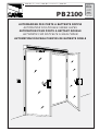 1
1
-
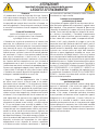 2
2
-
 3
3
-
 4
4
-
 5
5
-
 6
6
-
 7
7
-
 8
8
-
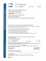 9
9
-
 10
10
-
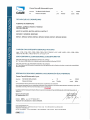 11
11
-
 12
12
-
 13
13
-
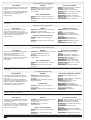 14
14
-
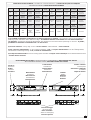 15
15
-
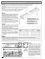 16
16
-
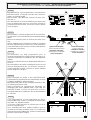 17
17
-
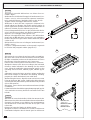 18
18
-
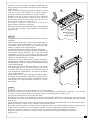 19
19
-
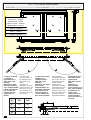 20
20
-
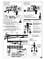 21
21
-
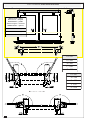 22
22
-
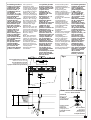 23
23
-
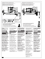 24
24
-
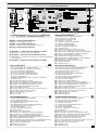 25
25
-
 26
26
-
 27
27
-
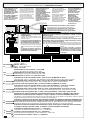 28
28
-
 29
29
-
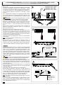 30
30
-
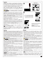 31
31
-
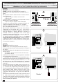 32
32
-
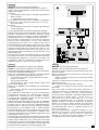 33
33
-
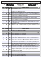 34
34
-
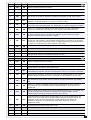 35
35
-
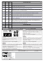 36
36


CAME FLY, PB2100, PB2110 Guía de instalación
- Tipo
- Guía de instalación
en otros idiomas
Artículos relacionados
-
CAME UNIPARK ARK1 Manual de usuario
-
-
CAME BXE 241 Manual de usuario
-
-
-
-
-
CAME ZL19N El manual del propietario
-
-