
Documentazione
Tecnica
S20
rev. 2.1
08/2001
©
CAME
CANCELLI
AUTOMATICI
119BS20
SERIE BX |
BX SERIES
|
SÉRIE BX |
BAUREIHE BX
|
SERIE BX
BXE
CANCELLI AUTOMATICI
Automazioni per cancelli scorrevoli
Automation systems for sliding gates
Automatisations pour portails coulissant
Antriebe für den Schiebetore
Automatización para puertas correderas
3 x 1.5 / 230V
2 x 1 - TX
2 x 1
2 x 1.5
RG58
6
5
9
3
1
2
8
10
4 x 1 - RX
11
3 x 1.5 / 230V
2 x 1 - TX
3 x 1
2 x 1.5
RG58
6
5
4
8
3
1
2
9
9
2 x 1 - TX
4 x 1 - RX
10
4 x 1 - RX
7
1 - Gruppo BXE
2 - Quadro comando
incorporato
3 - Ricevitore radio
4 - Cremagliera
5 - Selettore a chiave
6 - Lampeggiatore di
movimento
7 - Antenna
8 - Fotocellule di
sicurezza
9 - Colonnina per
fotocellula
10 - Fermo anta
1 - BXE Antriebsmotor
2 - Schalttafel im Antrieb
3 - Funkempfänger
4 - Zahnstange
5 - Außenantenne
6 - Blinkleuchte “Tor in
Bewegung”
7 - Schlüsselschalter
8 - IR Lichtschranke
9 - Lichtschrankeensäule
10 -Toranschlag
1 - BXE unit
2 - Control panel
(incorporated)
3 - Radio receiver
4 - Rack
5 - Electric lock
6 - Flashing light indica-
ting door movement
7 - Antenna
8 - Safety photocells
9 - Photocell column
10 - Closure stop
Impianto tipo Installation type
Standard montage
Instalación tipo
1 - Conjunto BXE
2 - Cuadro de mando
incorporado
3 - Radiorreceptor
4 - Cremallera
5 - Selector mediante
llave
6 - Lámpara intermiten-
te de movimiento
7 - Antena receptora
8 - Fotocélulas de
seguridad
9 - Columna para
fotocélula
10 - Tope puerta
1 - Groupe BXE
2 - Armoire de
commande
incorporé
3 - Récepteur radio
4 - Crémaillère
5 - Sélecteur a clé
6 - Clignotant de
mouvement
7 - Antenne de
réception
8 - Photocellules de
sécurité
9 - Colonne pour
photocellule
10 - Butée d'arrêt
Standard installation

ITALIANO
CAME cancelli automatici s.p.a.
Via Martiri della Libertà, 15
31030 Dosson di Casier
TREVISO - ITALY
www.came.it - [email protected]
ITALIANO
ATTENZIONE!
importanti istruzioni per la sicurezza delle persone:
LEGGETE ATTENTAMENTE!
Premessa
• Il prodotto dovrà essere destinato solo all’uso per il quale è
stato espressamente concepito. Ogni altro uso è da conside-
rarsi quindi pericoloso. La CAME cancelli automatici s.p.a. non
è responsabile per eventuali danni causati da usi impropri, er-
ronei ed irragionevoli • Conservate queste avvertenze assieme
ai manuali di installazione e d’uso dei componenti l’impianto di
automazione.
Prima dell’installazione
(verifi ca dell’esistente: nel caso di valutazione
negativa, non procedete prima di aver ottemperato
agli obblighi di messa in sicurezza)
• Controllate che la parte da automatizzare sia in buono stato
meccanico, che sia bilanciata e in asse, e che si apra e si chiu-
da correttamente. Verifi cate inoltre che siano presenti adeguati
fermi meccanici di arresto • Se l’automazione deve essere in-
stallata a un’altezza inferiore ai 2,5 m dal pavimento o da altro
livello di accesso, verifi cate la necessità di eventuali protezioni
e/o avvertimenti • Qualora vi siano aperture pedonali ricavate
nelle ante da automatizzare, ci deve essere un sistema di
blocco della loro apertura durante il movimento • Assicuratevi
che l’apertura dell’anta automatizzata non causi situazioni di
intrappolamento con le parti fi sse circostanti • Non montate
l’automazione rovesciata o su elementi che potrebbero piegarsi.
Se necessario, aggiungete adeguati rinforzi ai punti di fi ssaggio
• Non installate su ante poste in salita o discesa (non in piano)
• Controllate che eventuali dispositivi di irrigazione non possa-
no bagnare il motoriduttore dal basso verso l’alto.
Installazione
• Segnalate e delimitate adeguatamente tutto il cantiere
per evitare incauti accessi all’area di lavoro ai non addetti,
specialmente minori e bambini • Fate attenzione nel maneg-
giare automazioni con peso superiore ai 20 kg (vedi manuale
d’installazione). Nel caso, premunitevi di strumenti per la movi-
mentazione in sicurezza • Tutti i comandi di apertura (pulsanti,
selettori a chiave, lettori magnetici etc.) devono essere installati
ad almeno 1,85 m dal perimetro dell’area di manovra del can-
cello, oppure dove non possano essere raggiunti dall’esterno
attraverso il cancello. Inoltre i comandi diretti (a pulsante, a
sfi oramento etc) devono essere installati a un’altezza minima
di 1,5 m e non devono essere accessibili al pubblico • Tutti i
comandi in modalità “azione mantenuta”, devono essere posti
in luoghi dai quali siano completamente visibili le ante in movi-
mento e le relative aree di transito o manovra • Applicate, ove
mancasse, una etichetta permanente che indichi la posizione
del dispositivo di sblocco • Prima della consegna all’utente, ve-
rifi cate la conformità dell’impianto alla norma EN 12453 (prove
d’impatto), assicuratevi che l’automazione sia stata regolata
adeguatamente e che i dispositivi di sicurezza e protezione
e lo sblocco manuale funzionino correttamente • Applicate
ove necessario e in posizione chiaramente visibile i Simboli di
Avvertimento (es. targa cancello).
Istruzioni e raccomandazioni
particolari per gli utenti
• Tenete libere da ingombri e pulite le aree di manovra del can-
cello. Mantenete sgombro dalla vegetazione il raggio d’azione
delle fotocellule • Non permettete ai bambini di giocare con
i dispositivi di comando fi ssi, oppure nell’area di manovra del
cancello. Tenete fuori dalla loro portata i dispositivi di coman-
do a distanza (trasmettitori) • Controllate frequentemente
l’impianto, allo scopo di verifi care eventuali anomalie e segni
di usura o danni alle strutture mobili, ai componenti dell’auto-
mazione, a tutti i punti e dispositivi di fi ssaggio, ai cavi e alle
connessioni accessibili. Mantenete lubrifi cati e puliti i punti di
snodo (cerniere) e di attrito (guide di scorrimento) • Eseguite
controlli funzionali a fotocellule e bordi sensibili ogni sei mesi.
Assicurate una costante pulizia dei vetrini delle fotocellule
(utilizzate un panno leggermente inumidito con acqua; non
utilizzate solventi o altri prodotti chimici) • Nel caso si rendano
necessarie riparazioni o modifi che alle regolazioni dell’impianto,
sbloccate l’automazione e non utilizzatela fi no al ripristino delle
condizioni di sicurezza • Togliete l’alimentazione elettrica prima
di sbloccare l’automazione per aperture manuali. Consultate le
istruzioni • È fatto DIVIETO all’utente di eseguire OPERAZIONI
NON ESPRESSAMENTE A LUI RICHIESTE E INDICATE nei
manuali. Per le riparazioni, le modifi che alle regolazioni e per
le manutenzioni straordinarie, RIVOLGETEVI ALL’ASSISTENZA
TECNICA • Annotate l’esecuzione delle verifi che sul registro
delle manutenzioni periodiche.
Istruzioni e raccomandazioni
particolari per tutti
• Evitate di operare in prossimità delle cerniere o degli organi
meccanici in movimento • Non entrate nel raggio di azione
dell’automazione mentre è in movimento • Non opponetevi
al moto dell’automazione poiché può causare situazioni di
pericolo • Fate sempre e comunque particolare attenzione
ai punti pericolosi che dovranno essere segnalati da appositi
pittogrammi e/o strisce giallo-nere • Durante l’utilizzo di un
selettore o di un comando in modalità “azione mantenuta”,
controllate continuamente che non ci siano persone nel raggio
d’azione delle parti in movimento, fi no al rilascio del comando
• Il cancello può muoversi in ogni momento senza preavviso •
Togliete sempre l’alimentazione elettrica durante le operazioni
di pulizia o di manutenzione.
IT


ENGLISH
ENGLISH
CAME cancelli automatici s.p.a.
Via Martiri della Libertà, 15
31030 Dosson di Casier
TREVISO - ITALY
www.came.it - [email protected]
WARNING!
Important instructions for the safety of people:
READ CAREFULLY!
Foreword
• Use of the products must be restricted to its intended use
(i.e. that for which it was expressly built for). Any other use is
to be considered dangerous. Came Cancelli Automatici S.p.A.
is not liable for any damage resulting from improper, wrongful
or unreasonable use • Keep these warnings with the installa-
tion and use manuals issued with the automated system.
Before installing
(preliminary check: in case of a negative
outcome, do not proceed before having
complied with the safety obligations)
• Make sure that the parts you intend to automate are in
good working order, and that they are properly balanced
and aligned. Also, make sure that proper mechanical stops
are already in place • If the operator will be installed at a
height of less than 2.5 m from the ground or other access
level, check whether you will need any protections and/or
warnings • Any gate leaves, fi tted with pedestrian entrances,
onto which you will install an operator, must have a blocking
mechanism when the gate is in motion • Make sure that the
opening of the automated gate is not an entrapment hazard
as regards any surrounding fi xed parts • Do not mount the
operator upside down or onto any elements that may fold
under its weight. If needed, add suitable reinforcements at
the points where it is secured • Do not install onto gates on
either an upward or downward slope (i.e. that are not on fl at,
level ground) • Check that any lawn watering devices will not
wet the gearmotor from the bottom up.
Installation
• Carefully section off the entire site to prevent unauthorised
access, especially by minors and children • Be careful when
handling operators that weigh more than 20 Kg (see installa-
tion manual). In such cases, employ proper weight handling
safety equipment • All opening commands (e.g. buttons, key
selectors, magnetic detectors, etc.) must be installed at least
1.85 m from the gate’s area of operation perimeter - or where
they cannot be reached from the outside of the gate. Also,
the direct commands (e.g. push button, or proximity devices,
etc.) must be installed at a height of at least 1.5 m and must
not be accessible to the public • All ‘maintained action’ com-
mands, must be placed where the moving gate leaves, transit
areas and driveways are completely visible • If missing, ap-
ply a permanent label that shows the position of the release
mechanism • Before delivering to the client, verify that the
system is EN 12453 (impact test) standard compliant. Make
sure that the operator has been properly adjusted and that the
safety and protection devices, as well as the manual release
are working properly • Where necessary and in plain sight,
apply the Warning Sings (e.g. gate plate).
Special instructions and
advice for users
• Keep the gate’s area of operation clean and clear of any
obstacles. Trim any vegetation that may interfere with the
photocells • Do not allow children to play with the fi xed com-
mand devices, or in the gate’s area of operation. Keep any
remote control devices (i.e. transmitters) away from the chil-
dren as well • Frequently check the system, to see whether
any anomalies or signs of wear and tear appear on the moving
parts, on the component parts, on the securing points, on the
cables and any accessible connections. Keep any joints (i.e.
hinges) lubricated and clean, and do the same where fric-
tion may occur (i.e. slide rails) • Perform functional tests on
photocells and sensitive edges, every six months. Keep glass
panels constantly clean (use a slightly water-moistened cloth;
do not use solvents or any other chemical products) • If the
system requires repairs or modifi cations, release the operator
and do not use it until safety conditions have been restored
• Cut off the power supply before releasing the operator for
manual openings. See instructions • Users are FORBIDDEN
to carry out ANY ACTIONS THAT THEY HAVE NOT BEEN
EXPRESSLY ASKED TO DO OR SO INDICATED in the manu-
als. Any repairs, modifi cations to the settings and extraor-
dinary maintenance MUST BE DONE BY THE TECHNICAL
ASSISTANCE STAFF • On the periodic maintenance log, note
down the checks you have done.
Special instructions and
advice for all
• Avoid working near the hinges or moving mechanical parts
• Stay clear of the gate’s area of operation when in motion •
Do not resist the direction of movement of the gate; this may
present a safety hazard • At all times be extremely careful
about dangerous points that must be indicated by proper
pictograms and/or black and yellow stripes • When using
a selector or command in ‘maintained action’ mode, keep
checking that there are no people in the area of operation of
the moving parts. Do this until you release the command •
The gate may move at any time without warning • Always cut
the power when cleaning performing maintenance.
EN


FRANÇAIS
CAME cancelli automatici s.p.a.
Via Martiri della Libertà, 15
31030 Dosson di Casier
TREVISO - ITALY
www.came.it - [email protected]
FRANÇAIS
ATTENTION !
Instructions importantes pour la sécurité des personnes :
À LIRE ATTENTIVEMENT !
Introduction
• Le produit devra être uniquement destiné à l’usage pour
lequel il a été spécifi quement conçu. Tout autre usage sera
donc considéré comme dangereux. La société CAME Cancelli
Automatici S.p.A. ne peut être considérée comme responsable
des éventuels dommages provoqués par des usages impropres,
erronés et déraisonnables • Conservez ces avertissements
avec les manuels d’instruction et d’utilisation des composants
de l’installation d’automatisme.
Avant l’installation
(vérifi cation de l’installation existante : en cas
d’évaluation négative, ne continuez pas avant d’avoir
respecté les obligations de mise en sécurité)
• Contrôlez que la partie à automatiser est en bon état mécani-
que, qu’elle est équilibrée et dans l’axe et qu’elle s’ouvre et se
ferme correctement. Vérifi ez également que les butées mécani-
ques d’arrêt nécessaires sont présentes • Si l’automatisme doit
être installé à une hauteur inférieure à 2,5 m du sol ou d’un autre
niveau d’accès, vérifi ez le besoin d’éventuelles protections et / ou
éventuels avertissements • Au cas où des ouvertures pour les
piétons seraient réalisées dans les portes, il faut que soit installé
un système de blocage de leur ouverture pendant le mouvement
• Vérifi ez que l’ouverture de la porte automatisée n’entraîne pas
de situations de blocage avec les pièces fi xes environnantes •
Ne montez pas l’automatisme retourné ou sur des éléments qui
pourraient plier. Si nécessaire, ajoutez les renforts nécessaires
sur les points de fi xation • N’installez pas le système sur des
portes en montée ou en descente (qui ne seraient pas planes) •
Contrôlez que les éventuels dispositifs d’irrigation ne risquent pas
de mouiller le motoréducteur du bas vers le haut.
Installation
• Signalez et délimitez soigneusement tout le chantier afi n d’évi-
ter des accès imprudents dans la zone de travail de la part de
personnes étrangères au chantier et spécialement de mineurs et
d’enfants • Faites attention en manœuvrant les automatismes
pesant plus de 20 kg (voir manuel d’installation). Si nécessaire,
équipez-vous des moyens nécessaires au déplacement en sécu-
rité • Toutes les commandes d’ouverture (boutons poussoirs, sé-
lecteurs à clé, lecteurs magnétiques, etc.) doivent être installés à
au moins 1,85 m du périmètre de la zone de manœuvre du portail,
ou bien là où elles ne peuvent être attrapées depuis l’extérieur à
travers le portail. En outre, les commandes directes (à touche, à
effl eurement, etc.) doivent être installées à une hauteur minimale
de 1,5 m et ne doivent pas être accessibles au public • Toutes les
commandes en modalité « action maintenue » doivent être instal-
lées dans des endroits d’où les portes en mouvement et les zones
de transit ou de manœuvre correspondantes sont entièrement vi-
sibles • Mettez, s’il n’y en avait pas, une étiquette permanente qui
indique la position du dispositif de déblocage • Avant la remise à
l’utilisateur, vérifi ez la conformité de l’installation avec la norme
EN 12453 (essai d’impact), assurez-vous que l’automatisme a
correctement été réglé et que les dispositifs de sécurité et de
protection et le déblocage manuel fonctionnent correctement •
Mettez, là où c’est nécessaire et dans une position bien visible,
les Symboles d’Avertissement (Ex. plaque du portail).
Instructions et recommandations
particulières pour les utilisateurs
• Conservez la zone de manœuvre du portail propre et sans
rien qui risque de l’encombrer. Retirez la végétation se trouvant
dans le rayon d’action des photocellules • Ne laissez pas les
enfants jouer avec les dispositifs de commande fi xes ou dans
la zone de manœuvre du portail. Conservez hors de leur portée
les dispositifs de commande à distance (émetteurs) • Contrôlez
fréquemment l’installation afi n de vérifi er les éventuelles anoma-
lies et les signes d’usure ou d’endommagements des parties
mobiles de l’automatisme, et de tous les points et dispositifs de
fi xation, des câbles et des branchements accessibles. Maintenez
correctement graissés et propres les points d’articulation (char-
nières) et de frottement (guides de coulissement) • Effectuez des
contrôles fonctionnels des photocellules et des bords sensibles
tous les six mois. Gardez constamment propres les lames des
photocellules (utilisez un chiffon légèrement humidifi é avec de
l’eau ; n’utilisez pas de solvants ou autres produits chimiques)
• Au cas où il serait nécessaire d’effectuer des réparations ou
des modifi cations sur les réglages de l’installation, débloquez
l’automatisme et ne l’utilisez plus jusqu’à ce que les conditions
de sécurité aient été rétablies • Coupez l’alimentation électrique
avant de débloquer l’automatisme pour permettre les ouver-
tures manuelles. Consultez les instructions • Il est INTERDIT
à l’utilisateur de réaliser DES OPERATIONS QUI NE LUI SONT
PAS EXPRESSEMENT DEMANDEES ET INDIQUEES dans les
manuels. Pour les réparations, les modifi cations des réglages et
pour les opérations d’entretien extraordinaires, ADRESSEZ-VOUS
A L’ASSISTANCE TECHNIQUE • Notez la réalisation des vérifi ca-
tions dans le registre des entretiens réguliers.
Instructions et recommandations
particulières pour tous
• Evitez de travailler à proximité des charnières ou des organes
mécaniques en mouvement • Ne pénétrez pas dans le rayon
d’action de l’automatisme pendant que celui-ci est en mouve-
ment • Ne vous opposez pas au mouvement de l’automatisme car
cela pourrait entraîner des situations de danger • Faites toujours
particulièrement attention aux points dangereux signalés par les
pictogrammes appropriés et/ou les bandes jaunes et noires •
Pendant l’utilisation d’un sélecteur ou d’une commande en moda-
lité « action maintenue », contrôlez continuellement que personne
ne se trouve dans le rayon d’action des parties en mouvement,
jusqu’au relâchement de la commande • Le portail peut bouger
à n’importe quel moment sans avertissement • Coupez toujours
l’alimentation électrique pendant les opérations de nettoyage ou
d’entretien.
FR


DEUTSCH
DEUTSCH
CAME cancelli automatici s.p.a.
Via Martiri della Libertà, 15
31030 Dosson di Casier
TREVISO - ITALY
www.came.it - [email protected]
ACHTUNG!
Wichtige Sicherheitshinweise:
BITTE SORGFÄLTIG DURCHLESEN!
Vorwort
• Das Gerät ist ausschließlich für den vorgegebenen Zweck zu
verwenden. Anderweitige Verwendung des Geräts ist demzu-
folge gefährlich. Die CAME Cancelli Automatici S.p.A. haftet
nicht für durch ungeeignete, unsachgemäße und fehlerhaf-
te Verwendung verursachte Schäden • Bewahren Sie diese
Sicherheitshinweise zusammen mit der Montage- und Ge-
brauchsanweisung der Anlage auf.
Vor der Montage
(Überprüfung der vorhandenen Anlage, bei negativer
Bewertung vor der Montage zunächst dafür sorgen,
dass die Anlage sicher ist)
• Überprüfen, dass die zu automatisierenden Teile in guter
mechanischer Verfassung sind, dass sie ausbalanciert und
auf einer Achse sind und dass sie sich problemlos öffnen und
schließen. Zudem kontrollieren, dass geeignete mechanische
Toranschläge vorhanden sind • Sollte der Antrieb in weniger als
2,5 m Höhe vom Boden oder von einer anderen Zugangsebene
montiert werden, überprüfen, ob etwaige Schutzanlagen bzw.
Warnschilder anzubringen sind • Sollten die zu automatisieren-
den Torfl ügel über Fußgängertore verfügen, muss ein System,
das deren Öffnen während der Torbewegung verhindert, vor-
handen sein • Überprüfen, dass die Torfl ügelbewegung keine
Quetschgefahr mit den umliegenden Mauerwerken bewirkt •
Den Antrieb nicht verkehrt herum oder auf Teile montieren, die
sich biegen könnten. Wenn nötig die Befestigungspunkte in
geeigneter Weise verstärken • Nicht auf bergauf bzw. bergab
liegenden Torfl ügeln (nicht eben liegenden) montieren • Über-
prüfen, dass etwaige Bewässerungsanlagen den Getriebemotor
nicht von unten befeuchten können.
Montage
• Die Baustelle in geeigneter Weise begrenzen und sichern, da-
mit sich Unbefugte, vor allem Minderjährige, nicht der Baustel-
le nähern können • Bei Antrieben, die mehr als 20 kg wiegen
(siehe Montageanleitung) ist besondere Vorsicht gegeben. In
diesem Fall, benötigt man geeignete Geräte, um den Antrieb
sicher bewegen zu können • Sämtliche Auf-Befehlsgeräte
(Taster, Schlüsseltaster, Magnetkartenleser usw.) müssen
mindestens 1,85 m vom Torbereich bzw. so installiert werden,
dass man sie nicht von außen erreichen kann. Zudem müssen
sämtliche Befehsgeräte (Taster, Annäherungsschalter usw.) in
mindestens 1,5 m Höhe und so installiert werden, dass sie nicht
von Unbefugten betätigt werden können • Sämtliche Befehls-
geräte in “Totmannbedienung” müssen so installiert werden,
dass die sich bewegenden Torfl ügel und der Zufahrtsbereich
gut überblickbar sind • Wenn nicht vorhanden, einen die Ent-
riegelungsanheit anzeigenden Aufkleber anbringen • Vor Über-
gabe an den Verwender überprüfen, dass die Anlage der Norm
EN 12453 (Tornorm) entspricht und sicher stellen, dass die Au-
tomation in geeigneter Weise eingestellt wurde sowie, dass die
Sicherheits- und Schutzeinrichtungen bzw. die manuelle Entrie-
gelungseinheit in korrekter Weise funktionieren • Wenn nötig
Warnhinweise (z. B. Torwarnschild) gut sichtbar anbringen.
Anweisungen und Empfehlungen
für den Verwender
• Dafür sorgen, dass der Torbereich sauber und Hindernisfrei
ist. Den Funktionsbereich der Lichtschranken von Pfl anzen-
wuchs frei halten • Kindern das Spielen mit den festen Befehls-
geräten bzw. im Torbereich untersagen. Funkbefehlsgeräte
(Handsender) nicht in Reichweite von Kindern aufbewahren •
Die Anlage regelmäßig überprüfen, um etwaige Fehlfunktionen,
Verschleißerscheinungen bzw. Schäden an den beweglichen
Teilen, an den Antriebskomponenten sowie an allen Befesti-
gungspunkten, Kabeln und zugänglichen Kabelverbindungen
festzustellen. Sämtliche Gelenke (Scharniere) und Reibungs-
stellen (Laufschienen) schmieren und sauber halten • Alle
sechs Monate die Funktionstüchtigkeit von Lichtschranken und
Sicherheitsleisten überprüfen. Die Lichtschranken regelmäßig
säubern (verwenden Sie dafür ein mit Wasser befeuchtetes
Tuch und vermeiden Sie Lösungsmittel sowie andere Chemi-
kalienl) • Sollten Reparaturen oder Einstellungsänderungen
erforderlich sein, den Antrieb entriegeln und bis zur erneuten
Sicherung nicht verwenden • Vor der Entriegelung der Anlage
zur manuellen Toröffnung die Stromversorgung unterbrechen.
Anleitungen befolgen. NICHT AUSDRÜCKLICH IN den Anwei-
sungen AUFGEFÜHRTE TÄTIGKEITEN sind dem Verwender
UNTERSAGT. Für Reparaturen, Einstellungsänderungen und
außerplanmäßige Wartungsmaßnahmen WENDEN SIE SICH
BITTE AN DEN WARTUNGSDIENST • Das Ergebnis der Über-
prüfung der Anlage im Wartungsbuch aufführen.
Anweisungen und Empfehlungen
für alle
• Tätigkeiten in Nähe der Scharniere bzw. der sich bewegenden
mechanischen Teile vermeiden • Den Funktionsbereich des sich
bewegenden Tores vermeiden • Nicht gegen die Antriebskraft
einwirken, da dadurch Gefahrsituationen entstehen können • In
den Gefahrzonen, die durch entsprechende Warnhinweise bzw.
schwarz-gelbe Färbung zu kennzeichnen sind, besonders vor-
sichtig sein • Während der Betätigung eines Tasters bzw. eines
Befehlsgerätes im „Totmannbetrieb” ständig kontrollieren, dass
sich bis zum Schluss keine Personen im Bereich der sich bewe-
genden Torfl ügel befi nden • Das Tor kann sich jederzeit ohne
Vorwarnung in Bewegung setzen. • Während der Säuberung
und Wartung immer die Stromversorgung unterbrechen.
DE


ESPAÑOL
CAME cancelli automatici s.p.a.
Via Martiri della Libertà, 15
31030 Dosson di Casier
TREVISO - ITALY
www.came.it - [email protected]
ESPAÑOL
¡ATENCIÓN!
Importantes instrucciones de seguridad:
¡LEER ATENTAMENTE!
Condiciones preliminares
• Este producto deberá destinarse sólo para el uso para el
cual ha sido expresamente fabricado. Cualquier uso diferente,
se debe considerar impropio y por lo tanto peligroso. CAME
cancelli automatici s.p.a. no se hace responsable por eventuales
daños causados debido a una utilización inadecuada, errónea o
desmedida • Conservar estas advertencias junto a los manuales
de instalación y utilización de los componentes de la instalación
de automatización.
Antes de la instalación
(verifi cación preliminar de la instalación: en caso de
resultado negativo, no proceder sin haber cumplido
previamente las condiciones de puesta en seguridad)
• Controlar que la parte a automatizar esté en buen estado
mecánico, balanceada y alineada y que se abra y cierre co-
rrectamente. Verifi car además que existan adecuados bloqueos
mecánicos de parada • Si la automatización debe instalarse a
una altura inferior de 2,5 m desde el pavimento o desde otro
nivel de acceso, verifi car si se necesitan eventuales protecciones
y/o advertencias • En caso que existan aperturas peatonales en
las hojas a automatizar, debe existir un sistema de bloqueo de
la apertura durante el movimiento • Cerciorarse que la apertura
de la hoja automatizada no provoque situaciones de entrampado
con las partes fi jas circunstantes • No montar la automatización
al revés o en elementos que pudieran plegarse. Si es necesario,
agregar adecuados refuerzos en los puntos de fi jación • No ins-
talar en hojas colocadas en subidas o en bajada (que no estén
sobre un plano) • Controlar que los eventuales dispositivos de
riego no mojen el motorreductor de abajo hacia arriba.
Instalación
• Señalar y delimitar adecuadamente toda la obra para evitar
accesos imprudentes por parte de personas no pertinentes a
los trabajos, especialmente niños • Prestar mucha atención a
la manipulación de automatizaciones con un peso superior de
20 kg (véase manual de instalación). En dicho caso, utilizar ins-
trumentos idóneos para su movimiento en condiciones seguras
• Todos los mandos de apertura (botones, selectores de llave,
lectores magnéticos, etc.) deben instalarse a una distancia de
1,85 m como mínimo desde el perímetro del área de maniobra
de la cancela, o bien donde no puedan alcanzarse desde afuera
de la cancela. Además los mandos directos (de botón, de mem-
brana, etc.) deben instalarse a una altura mínima de 1,5 m y
no deben ser accesibles al público • Todos los mandos en la
modalidad “acción mantenida”, deben ponerse en sitios desde
los cuales sean completamente visibles las hojas en movimiento
y las relativas áreas de tránsito o maniobra • Aplicar donde falte,
una etiqueta permanente que indique la posición del dispositivo
de desbloqueo • Antes de la entrega al usuario, verifi car la con-
formidad de la instalación a la norma EN 12453 (pruebas de
impacto), cerciorarse que la automatización haya sido regulada
adecuadamente y que los dispositivos de seguridad y protección
y el desbloqueo manual funcionen correctamente • Aplicar don-
de sea necesario y en forma visible los Símbolos de Advertencias
(ej. placa cancela).
Instrucciones y recomendaciones particulares
para los usuarios
• Mantener limpia y sin obstrucciones las zonas de maniobra de
la cancela. Mantener limpio de vegetación el radio de acción de
las fotocélulas • No permitir a los niños jugar con los dispositivos
de mando fi jos o en las zonas de maniobra de la cancela. Tener
fuera del alcance de los mismos los dispositivos de mando a
distancia (emisores) • Controlar frecuentemente la instalación
para verifi car eventuales anomalías y desgastes o daños a las
estructuras móviles, a los componentes de la automatización,
a todos los puntos y dispositivos de fi jación, a los cables y a las
conexiones accesibles. Mantener lubricados y limpios los puntos
de articulación (goznes) y de rozamiento (guías de deslizamiento)
• Efectuar controles funcionales a fotocélulas y bordes sensibles
cada seis meses. Cerciorarse que los cristales de las fotocélulas
estén limpios (utilizar un paño ligeramente húmedo; no utilizar
solventes u otros productos químicos) • Si fuese necesario
efectuar reparaciones o modifi caciones a las regulaciones de la
instalación, desbloquear la automatización y no utilizarla hasta
que no se restablezcan las condiciones de seguridad • Quitar la
alimentación eléctrica antes de desbloquear la automatización
para aperturas manuales. Consultar las instrucciones • SE
PROHIBE al usuario efectuar OPERACIONES NO REQUERIDAS
EXPRESAMENTE AL MISMO E INDICADAS en los manuales.
Por reparaciones, modifi caciones a las regulaciones o para
operaciones de mantenimiento extraordinario, DIRIGIRSE A LA
ASISTENCIA TÉCNICA • Anotar la ejecución de las verifi cacio-
nes en el registro de mantenimiento periódico.
Instrucciones y recomendaciones particulares
para todos en general
• Evitar operar cerca de goznes u órganos mecánicos en mo-
vimiento • No entrar en el radio de acción de la automatización
mientras está en movimiento • No oponerse al movimiento de
la automatización porqué se podrían crear situaciones de pe-
ligro • Prestar mucha atención a los puntos peligrosos. Estos
deberán estar señalados por los relativos pictogramas y/o
bandas amarillos-.negras • Durante la utilización de un selector
o de un mando en la modalidad “acción mantenida”, controlar
continuamente que no haya personas en el radio de acción de
la partes en movimiento hasta que no se suelte el mando • ¡La
cancela puede moverse en cualquier momento! • Quitar siempre
la alimentación eléctrica durante las operaciones de limpieza o
de mantenimiento.
ES


2
CARATTERISTICHE GENERALI -
GENERAL SPECIFICATIONS
- CARACTÉRISTIQUES GÉNÉRALES
ALLGEMEINES MERKMALE
- CARACTERÍSTICAS GENERALES
MISURE D'INGOMBRO -
OVERALL DIMENSIONS
- MESURES D'ENCOMBREMENT -
ABMESSUNGEN
- MEDIDAS
Progettato e costruito
interamente dalla
CAME, risponde alle
vigenti norme di
sicurezza (UNI 8612),
con grado di protezio-
ne IP54.
Garantito 12 mesi
salvo manomissioni.
Il a été entièrement
conçu et realisé par
les Ets CAME, confor-
mément aux normes
de sécurité en vigueur
(NFP 25362) avec
degré de protection
IP54.
Il est garanti 12 mois
sauf en cas d'endom-
magement.
Designed and construc-
ted entirely by CAME;
conforms to (UNI 8612)
safety standards with IP
54 protection rating.
12 mounth guarantee;
guarantee void if unit is
tampered with.
Vollständig von der
CAME geplant und her-
gestellt, entsprechend
den geltenden
Sicherheits-bedigungen
(UNI 8612) mit Schutz-
grad IP54.
12 Monate Garantie,
Bedienungs und
Montagefehler ausge-
schlossen.
Diseñado y construi-
do totalmente por
CAME, con arreglo a
las vigentes normas
de seguridad (UNI
8612) con grado de
protección IP54.
Garantia de 12 meses
salvo manipulacio-
nes.
CARATTERISTICHE TECNICHE -
TECHNICAL CHARACTERISTICS -
CARACTERISTIQUES TECHNIQUES
TECNISCHE DATEN -
CARACTERISTICAS TECNICAS
240
105
150
290
125165
105
310
22 max.
-amissamatatroP
-stimilesU
xameétroP
-thciwegroT
atreuposeP
elaiznediserosu
laitnediseR
leitnediseregasu
ztasnienetavirp
laicnediserosu
008gK
MOTORIDUTTORE
GRADO DI
PROTEZIONE
PESO ALI MENTA ZIONE ASSORBIMENTO POTENZA
INTERMITTENZA
LAVORO
COPPIA RAPPORTO DI RI DU ZI ONE SPI NTA VELOCITA ' MA X. CONDENSATORE
GEARMOTOR
PROTECTION
RATING
WEIGHT POWER SUPPLY CUR RENT POWER DUTY CICLE MAX TOR QUE
RED UCTION
RATIO
PUSH MAX. SPEED CAPACITOR
MOTOR ÉDUCTEUR
DEGRÉ DE
PROTECTION
POIDS ALI MENTATI ON ABSORPTI ON PUISSANCE
INTERMIT TENCE
DE TRAVAIL
COUPLE RAPPOR T DE REDUC TION POUSSÉE VITESSE MAX. CONDENSATEUR
GET RI EBEMOTOR SC HUTZGRAD GEWI CH T
STROM_
VERSORGU NG
STROMAUF NAHME LEI STU NG EINSC HALTDAUER DREHM OMENT
UNTERSET ZUNGS_
VERHÄLTN IS
REGELBARER
MAX.
ÜBERTRAGU NGS
KONDENSATOR
MOTORREDUCTOR
GRADO DE
PROTECCION
PESO ALIM ENTACI ON ABSORBENCIA POTENCIA
INTERMITENCIA
TRA BAJO
PAR E JA
(MOTOR)
RELACION DE
RED UCCION
EMPUJE
VELOCIDAD
MAX.
CONDEN SADOR
BXE IP 54 15 Kg 230V a.c. 2,4A 300W 30 % * 32 Nm 1/33 800 N 10 m/min. 20 µF
* Ottenuta mediante quadro comando CAME
* Obtained with CAME control panel
* Obtenue au moyen armoire de commande CAME
* Erreicht mit Hilte der "CAME" Schalttafel
* Se obtiene mediante el cuadro de mando CAME

3
PRIMA DELL'INSTALLAZIONE ... -
BEFORE INSTALLING .....
- AVANT D'INSTALLER L'AUTOMATISME .....
VOR DEN INSTALLATION ÜBERPRÜFEN
... - ANTES DE INSTALAR EL AUTOMATISMO...
FISSAGGIO BASE MOTORE -
MOTOR TO BASE ANCHORAGE
- FIXATION DE LA PLAQUE DU MOTEUR
BEFESTIGUNGS DER MOTORBASIS
- FIJACIÓN BASE MOTOR
- La hoja de la puerta debe
estar suficientemente rigida
y compacta
- Las ruedas de desliza-
miento deben estar perfecta
y engrasadas adecuada-
mente.
- La guia de deslizamiento
debe estar bien fijada en el
suelo, sobresaliendo a lo
largo de su entera longitud,
sin huecos ni irregularida-
des (que podrian
obstaculizar el movimiento
de la puerta).
- La guia superior debe
tener el justo juego con la
puerta metálica (para ga-
rantizar un movimiento
regular y silencioso).
- Disponer un tope para
apertura y el cierre.
- Disponer un conducto
para los cables eléctricos
que cumpla con las disposi-
ciones de mando y
seguridad.
- Die Leistungfähigkeit der
feststehenden und bewegli-
chen Teile des Tores
überprüfen.
- Das Tor sollte ausreichend
stabil sein. Die Gleitrollen
sollten in guten Zustand und
angemessen geschmiert sein.
- Die Gleitführung auf dem
Boden sollte sich in optimaler
Position befinden: gut auf
dem Boden befestigt, in sei-
ner Gesamtlänge vollständig
über dem Boden, ohne Ver-
tiefungen und/oder
Unebenheiten, die die Tor-
bewegung behindern können.
- Die oberen Führungsschie-
nen sollten das richtige Spiel
zum Tor haben, um ein präzi-
ses und regelmäßiges Gleiten
zu garantieren.
- Einen Anschlag für Tor Auf
und Tor Tu sollte vorhanden
sein.
- Den Lauf der elektrischen
Kabel nach den Steuerungs
und Sicherheitsbestim-
mungen vorsehen.
- Le panneau mobile du
portail devra être suf-
fisamment rigide et solide.
- Les roues de coulis-
sement devront être en très
bon état. En outre, elles
devront être conve-
nablement graissées.
- Le rail de guidage devra
être bien fixé au sol. De
plus, il devra se présenter
entièrement en surface sans
affaissement ou irrégularité
(qui pourraient empêcher le
mouvement du portail).
- Le guide supérieur devra
avoir un jeu convenable
avec le portail (pour per-
mettre un mouvement
régulier et silencieux).
- Prévoir une butée d’arrêt à
l’ouverture et à la ferme-
ture.
- Prévoir le passage des
câbles électriques selon les
dispositifs de commande et
de sécurité.
- The gate must be suffi-
ciently rigid and solid.
- The wheels on which the
gate slide must be in perfect
condition and adequately
lubricated.
- The wheel guide must be
firmly attached to the
ground, completely expo-
sed, and without any dips or
irregular sections which
might hinder the movement
of the gate.
- The upper guide must allow
for the correct amount of
play in order to guarantee
smooth and silent movement
of the gate.
- Opening and closure stops
must be installed.
- The wiring must be routed
as specified by the control
and safety requirements.
- Controllare che l'anta sia
rigida e compatta e che le
ruote di scorrimento siano
in buono stato e adeguata-
mente ingrassate.
- La guida a terra dovrà es-
sere ben fissata al suolo,
completamente in superficie
in tutta la sua lunghezza e
priva di irregolarità che
possano ostacolare il movi-
mento del cancello.
- I pattini-guida superiori
non devono creare attriti.
- Prevedere un fermo anta
in apertura e uno in chiusu-
ra ed il percorso dei cavi
elettrici come da impianto
tipo.
- Inserire le viti nella pia-
stra di ancoraggio
bloccandole con i dadi in
dotazione, ed estrarre le
zanche preformate verso il
basso.
- Predisporre, dimensio-
nandola in base alle misure
del motoriduttore, una piaz-
zola in cemento (si
consiglia di farla sporgere
dal terreno di circa 50 mm.)
con annegata la piastra di
ancoraggio e relative
zanche sulla quale sara'
fissato il gruppo.
- La base di fissaggio dovra'
risultare perfettamente in
bolla, pulita in tutte le sue
estremita', con il filetto
delle viti completamente in
superfice.
N.B.: Dalla stessa dovranno
emergere i tubi flessibili
per il passaggio dei cavi di
collegamento elettrico.
- Install the screws in the
anchor plate and fasten them
with a nut, then bend the pre-
formed clamps downwards.
- Construct a cement founda-
tion that is large enough to
accomodate the gear motor
(it is a good idea to protrude
50 mm. from the ground).
When pouring the founda-
tion, embed the gear motor
anchor plate and the relative
clamps in the cement.
- The anchor bolts should be
embedded in the concrete in
the positions indicated;
the drive unit is then attached
to this bots. The anchor plate
must be perfectly level and
absolu-tly clean; the bolts
threads must be completly
exposed.
N.B.: The flexible tubes for
the electrical wiring must be
embedded in the base and
protude in the correct posi-
tion.
- Introduire les vis dans la
plaque d'ancrage en les
bloquant avec un écrou, et
replier les agrafes préfor-
mées ver le bas.
- Préparer une base en
ciment d'une dimension
adéquate aux mesures du
motoréducteur (il est con-
seillé de la faire dépasser
du terrain d'environ 50
mm.), et noyer dedans la
plaque d'ancrage et les
agrafes correspondantes
afin de permettre le fixage
du groupe.
- La base de fixation devrà
être parfaitement de niveau
et propre sur toute sa
surface et le filet des vis
devra être complètement en
surface.
N.B. Les câbles pour le
branchement électrique
devront sortir de cette base.
- Die Schrauben in die Anker-
platte einfügen und mit einer
Schraubenmutter blockieren,
die vorgeformten Fundament-
anker nach unten umbiegen.
- Eine den Abmessungen des
Getriebemotors entsprechen-
de Betonfundamentplatte (Es
empfiehlt sich, diese ca. 50
mm. vom Boden herausragen
zu las-sen) zum Einbetten der
Ankerplatte und der entspre-
chenden Fundamentanker,
die zur Befestigung des An-
triebsaggregats dienen,
vorbereiten.
- Die Befestigungs-unterlage
muß in seiner gesamten Län-
ge vollkommen eben und
sauber sein. Das Gewinde der
Schrauben müssen gänzlich.
hervorstehen.
Wichtig: die Kabel für den
Elektroanschluß müssen
herausrgen.
- Introducir los tornillos en
la placa de anclaje, blo-
queándolos con una tuerca,
y doblar las palancas
preformadas hacia abajo.
- Preparar, dándole las di-
mensiones adecuadas en
función de las medidas del
motorreductor, una platafor-
ma de cemento (se
aconseja dejarla sobresalir
del suelo aprox. 50 mm.)
con la placa de enclaje
embedida y con las corres-
pondientes varillas, que
permitrá la fijación del gru-
po.
- La base de fijación debe
estar perfectamente nivela-
da, limpia en todos sus
extremos, con la rosca de
los tornillos totalmente in
superficie.
N.B.: De ésta deben
sobresilar los tubos flexi-
bles para el paso de los
cables para las conexiones
eléctricas.
50 mm.
75 mm.
105 mm.
Struttura fissa
Wall
Structrure fixe
Feste Struktur
Estructura fija
Anta cancello
Gate wing
Panneau mobile du portail
Gleitachse
Puerta
Piazzola in cemento
Concrete base
Plate-forme en ciment
Plattenachse
Plataforma de cemento
Cavi
Cable
Câbles
Kabel
Cables
Cremagliera
Rack-limit
Cremaillére
Zahnstange
Cremallera
Piastra di ancoraggio / Zanche
Fixing plate / Anchor stays
Plaque de fixation / Agrafes
Gleitachse / Verankerung
Placa de fijación / Barras de fijción

4
INSTALLAZIONE DEL GRUPPO -
UNIT INSTALLATION -
INSTALATION DU GROUPE
AUFSTELLUNG DES AGGREGATS
- COLOCACIÓN DEL GRUPO
Nella fase preliminare di
installazione, i piedini
dovranno sporgere di 5-
10 mm. per permettere
allineamenti, fissaggio
della cremagliera e
regolazioni successive.
L'accoppiamento esatto
con la linea di scor-
rimento del cancello è
ottenibile dal sistema di
regolazione integrale
(brevettato) composto da:
- le asole che permet-
tono la regolazione
orizzontale;
- i piedini filettati in
acciaio che permettono
la regolazione verticale e
la messa in bolla;
- le piastrine e i dadi di
fissaggio che rendono
solidale l'aggancio del
gruppo alla base.
During the initial phase of
installation, the feet
should protrude by 5-10
mm. in order to allow for
alignment, anchorage of
the rack and further
adjustments.
Perfect alignment with the
guide rail is made possible
by the (patented) built-in
regulation system, which
consists of:
- slots for horizontal
adjustment;
- threaded steel feet for
vertical adjustment and
levelling;
- plates and bolts for
anchorage to the base.
Dans la phase de
instalation préliminaire,
les broches devront
dépasser de 5 à 10 mm
afin de permettre les
alignements et les
réglages nécessaires
après la pose.
L’accouplement exact
avec la ligne de
coulissement du portail
s’effectue par le système
de réglage hauteur
(breveté) dont le groupe
est pourvu, et qui
comprend plus
précisément:
- les trous oblong
permettant le réglage
horizontal;
- les broches filetées en
acier qui donnent le
réglage vertical et la
mise à niveau;
- les plaques et les
écrous de fixation qui
assemblent solidement le
groupe à la plaque de
fixation scellée.
Nun die Montage des
Antriebsmotors vorneh-
men. Die genaue Kop-
plung mit der Gleitlinie des
Tors wird von dem
integrierten Einstel-
lungssystem (patentiert)
garantiert, mit dem das
Aggregat ausgestattet ist
und zwar:
- die Osen für die
horizontale Einstellung,
- die Gewindefüße aus
Stahl für die vertikale
Einstellung und die
Nivellierung,
- die Befestigungsplät-
tchen und muttern zur
soliden Befestigung des
Aggregats an die
Bodenplatte.
Während der Vorberei-
tungsarbeiten der Montage
sollten die Füße 5-10 mm
herausragen, um
Ausfluchtungen und
Einstellung auch nach der
Fertigstellung zu
ermöglich.
En la fase previa de la
colocación, los pies
deben sobresalir 5-10
mm para consentir la
alineación, la fijación de
la cremallera y las regu-
laciones sucesivas.
El acoplamiento exacto
con la linea de desli-
zamiento de la puerta
metálica se obtiene
mediante el sistema de
regulación integral
(patentado) que consta
de:
- los agujeros ovalados
que consienten la
regulación horizontal;
- las tuercas de acero
que permiten la
regulación vertical y la
nivelación;
- las placas y las tuercas
de fijación que hacen
solidario el enganche del
conjunto con la base.
5÷10 mm.
Ingresso cavi
Cable entrances
Passage des câbles
Kabeleinführungen
Accoppiamento pignone-cremagliera
con gioco 1÷2 mm.
Rack-to-pinion coupling with 1÷2 mm. clearance
Assemblage pignon-crémailère avec jeu
de 1 à 2 mm.
Zwischen Zahnstange und dem Antriebsritzel
1÷2 mm. Spiel einstellen
Acoplamiento piñon-cremaliera
1÷2 mm. de juego
Regolazione orizzontale e fissaggio
Horizontal adjustment unit and achorage
Réglage horizontal et fixation
Horizontale Einstellung
Regulación horizontal y fijación
Regolazione verticale - messa in bolla
Vertical adjustment and unit leveling
Réglage vertical - mise à niveau
Vertikale Einstellung
Regulación vertical y nivelación
Entrada cables
1÷2 mm.

5
FISSAGGIO CREMAGLIERA-
ATTACHING THE RACK/LIMIT
- FIXATION CREMAILLÉRE
MONTAGE DE ZAHNSTANGE -
FIJACIÓN DE LA CREMALLERA
Con el fin de permitir al
ENCODER medir la
carrera de la puerta, fijar
la cremallera con el
mismo a mitad de
carrera:
- coloque la hoja en la
mitad de la carrera,
apoye la cremallera
sobre el piñon del
motorreductor y deslice
manualmente la puerta,
fijando la cremallera a
todo lo largo;
- La carrera máxima de
la puerta es de 14 m;
- Finalizadas las ope-
raciones para la fijacion
de la cremallera, regular
los pies (por medio de un
destornillador) de modo
que se obtenga el justo
juego entre el piñón y la
cremallera (1-2 mm).
N.B. Esto hace que el
peso de la puerta
metálica no cargue sobre
el conjunto.
- Si la cremallera ya ha
sido fijada, hay que
regular el acoplamiento
piñón/cremallera.
- Una vez realizados los
ajuste, fijar el conjunto
cerrando las dos tuercas
de fijación.
Ist der ENCODER zur
Erfassung bzw. Überwa-
chung des Torlaufs auf
halber Laufhöhe auf der
Zahnstange zu befestigen:
- den Torflügel halb öffnen
und die Zahnstange auf
dem Ritzel vom Getriebe-
motor auflegen. Dann das
Tor von Hand verschieben
und dabei die Zahnstange
auf ganzer Länge
befestigen;
- Der maximale Lauf vom
Tor beträgt 14 m;
- Die verstellbaren Füße
des Antriebsmotors (mit
einem Schraubenzieher)
so einstellen, daß
zwischen Ritzel und
Zahnstange ein Spiel (1-2
mm) besteht.
Wichtig: Dadurch wird
vermieden, daß das
Gewicht des Tores auf
dem Aggregat lastet.
- Nach diesen Einstel-
lungsarbeiten das
Aggregat durch Anziehen
der beiden Muttem
befestigen.
Afin de permettre à
l'ENCODEUR de relever la
course du portail, fixer la
crémaillère avec le
portail à micourse:
- mettre la porte à la
moitié de sa course,
poser la crémaillère sur
le pignon du
motoréducteur et faire
coulisser manuellement
le portail en fixant la
crémaillère sur toute sa
longueur;
- La course maximum du
portail est de 14 m;
- Lorsque la fixation de la
crémaillère est terminée
régler les broches (en
utilisant un tournevis) de
façon à obtenir un jeu
convenable (1-2 mm)
dans l’assemblage du
pignon et de la
crémaillère.
N.B. Ceci pour éviter que
le poids du portail ne
repose sur le groupe.
- Si la crémaillère est
déjà fixée, utiliser le
système de réglage
hauteur pour assembler
correctement de facon
exacte le pignon et la
crémaillère.
- Exécuter tous les
réglages, fixer le groupe
en serrant les deux
écrous de fixation.
Install the rack with the
gate at the half-way point.
This will enable the
ENCODER to detect gate
travel properly:
- allow the door to reach
mid-run, set the rack on
the rationmotor's pinion
and slide the gate
manually, fixing the rack's
entire lenght;
- The gate's maximum run
is 14 m;
- when the rack is attached
to the gate, adjust the feet
using a screwdriver until
the play between the
pinion and the rack is
correct (1-2 mm.).
N.B.: This position
ensures that the weight of
the gate does not rest on
the gearmotor.
- If the rack is already
attached, proceed directly
to the adjustment of the
rack/pinion coupling.
- When the necessary
adjustment have been
completed, fasten the unit
in position by tightening
the two anchor bolts.
Al fine di permettere
all'ENCODER di rilevare
la corsa del cancello,
fissare la cremagliera
con il cancello a meta'
corsa:
- portare l'anta a meta'
corsa, appoggiare la
cremagliera sul pignone
del motoriduttore e far
scorrere manualmente il
cancello fissando la
cremagliera in tutta la
sua lunghezza;
- La corsa massima del
cancello é di 14 m;
- ultimata l'operazione di
fissaggio della crema-
gliera, regolare i piedini
(servendosi di un
cacciavite) in modo da
ottenere il giusto giuoco
tra pignone e cremaglie-
ra (1-2 mm).
N.B. : Questo evitera' che
il peso del cancello vada
a gravare sul gruppo.
- Se la cremagliera é gia'
fissata, procedere
direttamente alla
regolazione dell'accop-
piamento pignone/
cremagliera.
- Eseguite tutte le
regolazioni, fissare il
gruppo stringendo i dadi
di fissaggio.

6
SBLOCCO MOTORIDUTTORE -
GEAR RELEASE
- OPÉRATION DE DÉBLOCAGE
- ANTRIEBSENTRIEGELUNG
DESBLOQUEO MOTORREDUCTOR
Per aprire lo
sportellino inserire la
chiave, spingerla e
ruotala in senso
orario; sbloccare
quindi il
motoriduttore
ruotando la manopola
nella direzione
indicata.
Pour ouvrir la trappe,
introduire la clé, la
pousser et la tourner
dans le sens des
aiguilles d'une
montre. Débloquer
ensuite le
motoréducteur en
tournant la poignée
dans la direction
indiquée.
Para abrir la
portezuela introducir
la llave, empujarla y
girarla en sentido
horario; desbloqear el
motorreductor
girando la manilla en
la dirección indicada.
To open the access
door, insert the key,
push down and rotate
clockwise. Now, release
the gear motor by
rotating the knob in the
direction shown.
Zum Öffnen der klappe
den Schlüssel
einfügen,
hineindrücken und im
Uhrzeigersinn drehen.
Dann den
Getriebemotor durch
Drehen des Knopfs in
die angegebene
Richtung entsperren.
ATTENZIONE:
l'apertura dello spor-
tellino di sblocco im-
pedisce il funziona-
mento del motore.
ATTENTION:
the opening of the
unblock panel arrests
the motor.
ATTENTION:
l’ouverture de la por-
te de déblocage
empêche le fonction-
nement du moteur.
ACHTUNG:
Wenn das Freigabetür-
chen geöffnet wird,
funktioniert der Motor
nicht.
ATENCIÓN:
la apertura de la tapa
de desbloqueo,
impide el funciona-
miento del motor.
Release
Sblocco
Blocco
Engage
Blockierend
Entriegelt
Blocage
Déblocage
Desbloqueo
Bloqueo
CAME

7
Important:
- the opening of the unblock panel arrests
the motor.
- Shut off the mains power and disconnect
the batteries before servicing the inside
of the unit.
La scheda comando va alimentata a (230V
a.c.) sui morsetti L1 e L2 ed è protetto in
ingresso con fusibili da 5A.
I dispositivi di comando sono a bassa ten-
sione (24V), e sono protetti con fusibile da
1A. La potenza complessiva degli acces-
sori a 24V, non deve superare i 20W.
Il tempo lavoro è fisso a 90 secondi.
SICUREZZA
Le fotocellule possono essere collegate e
predisposte per:
-
Riapertura
in fase di chiusura (2-C1);
-
Stop parziale,
arresto del cancello se in
movimento con conseguente pre-
disposizione alla chiusura automatica
(2-C3);
-
Stop totale,
(1-2) arresta il cancello esclu-
dendo l'eventuale ciclo di chiusura
automatica; per riprendere il movimento
bisogna agire sulla pulsantiera o sul
radiocomando;
Nota: Se un contatto di sicurezza normal-
mente chiuso (2-C1, 2-C3, 1-2) si apre,
viene segnalato dal lampeggio del LED di
segnalazione (n°5)
-
Rilevazione di presenza ostacolo.
A mo-
tore fermo (cancello chiuso, aperto o dopo
un comando di stop totale), impedisce
qualsiasi movimento se i dispositivi di si-
curezza (es.fotocellule) rilevano un
ostacolo.
- La scheda, inoltre, integra e gestisce
automaticamente una funzione di sicurez-
za che, in caso di rilevazione di ostacoli,
funziona nel seguente modo:
in apertura
il cancello si ferma e attiva la chiusura
automatica;
in chiusura
il cancello inverte il senso di marcia fino
alla completa apertura con conseguente
intervento della chiusura automatica.
Attenzione! dopo tre inversioni consecuti-
ve, il cancello resta aperto escludendo la
chiusura automatica: per chiudere, usare
il radiocomando o il pulsante di chiusura.
ACCESSORI COLLEGABILI
-
Lampada ciclo.
Lampada che illumina la
zona di manovra, rimane accesa dal mo-
mento in cui l'anta inizia l'apertura fino alla
completa chiusura (compreso il tempo di
chiusura automatica). La funzione della
lampada ciclo si ottiene in uscita W-E solo
se i dip n°1 «chiusura automatica» e n°10
«lampada ciclo» sono posizionati in ON,
vedi pagina 17;
-
Lampada spia cancello aperto.
Lampada
che segnala la posizione di apertura del
cancello e che si spegne quando il cancel-
lo attiva il finecorsa chiude; collegarla ai
morsetti 10-5.
Nota: gli accessori a 24V non necessitano
di collegamento a terra.
ALTRE FUNZIONI
-
Chiusura automatica.
Il temporizzatore di
chiusura automatica si autoalimenta a
finecorsa in apertura. Il tempo prefissato
regolabile, é comunque subordinato dal-
l'intervento di eventuali accessori di
sicurezza e si esclude dopo un intervento
Attenzione:
- l'apertura dello sportellino di sblocco
impedisce il funzionamento del motore.
- prima di intervenire all'interno dell'appa-
recchiatura, togliere la tensione di linea e
scollegare le batterie (se inserite).
DESCRIZIONE TECNICA SCHEDA BASE ZBXE
ITALIANO
di «stop» totale o in mancanza di energia
elettrica;
-
Apertura parziale.
Apertura del cancello
per passaggio pedonale, viene attivata
collegandosi ai morsetti 2-3P ed è
regolabile mediante trimmer AP.PARZ.;
-
Funzionamento a uomo presente.
Fun-
zionamento del cancello mantenendo
premuto il pulsante (selezionandolo si
esclude la funzione del radiocomando);
-
Programmazione
taratura dei finecorsa
elettronici di apertura e di chiusura;
-
Funzione master,
il quadro assume tutte
le funzioni di comando nel caso di due
motori abbinati (vedi pagina 15);
-
Funzione slave
; il quadro viene esclusi-
vamente pilotato dal "master" (vedi pagina
15);
-
Prelampeggio
in apertura e chiusura;
-
Tipo di comando:
- apre-chiude-inversione;
- apre-stop-chiude-stop;
- solo apertura.
REGOLAZIONI
- Trimmer AP.PARZ. = Apertura parziale:
da 1"a 14";
- Trimmer TCA = Tempo chiusura automa-
tica: da 1" a 150";
This control board is powered by 230V
AC across terminals L1 and L2, and is
protected by a 5A fuse on the main power
line. Control systems are powered by low
voltage and protected with by a 1A fuse.
The total power consumption of 24 V ac-
cessories must not exceed 20 W.
Fixed operating time of 90 seconds.
SAFETY
Photocells can be connected to obtain:
-
Re-opening
during the closing cycle (2-
C1);
-
Partial stop,
shutdown of moving gate,
with activation of an automatic closing
cycle (2-C3);
-
Total stop,
(1-2) shutdown of gate move-
ment without automatic closing; a
pushbutton or radio remote control must
be actuated to resume movement;
Note: If a safety contact which is normally
closed (2-C1, 2-C3, 1-2) is opened, the
LED (n°11) will flash to indicate this fact;
-
Obstacle presence detection.
When the
motor is stopped (gate is closed, open or
half-open after an emercency stop com-
mand), the transmitter and the control
pushbutton will be deactivated if an ob-
stacle is detected by one of the safety
devices (for example, the photocells).
- In addition, the board automatically inte-
grates and runs a safety function that
works in the following manner in case
obstacles are detected;
during opening
the gate stops and the automatic closure is
activated;
during closure
the gate inverts its direction until it is com-
pletely open, after which it closes
automatically.
Warning! after three consecutive inver-
sions, the gate will remain open and
automatic closure will be discontinued.
Toclose the gate, use the radio remote
control or the push-button.
ACCESSORIES WHICH CAN BE CON-
NECTED
-
Cycle lamp.
The lamp which lights the
manoeuvring zone: it remains lit from the
moment the gate begin to open until it is
completely closed (including the time re-
quired for the automatic closure). The
function of the cycle lamp is obtained in
output W-E1 only if dip switch No.1 «auto-
matic closing» and No. 10 «Cycle lamp»
are set to ON (see page 17).
-
Open gate pilot lamp.
It is a light that indi-
cates the sliding gate's open position and
turns off when the gate activates the clos-
ing end-stop, connect it to terminal blocks
10-5.
N.B.: the 24V accessories do not need a
earth connection.
OTHER FUNCTIONS
-
Automatic closing
. The automatic clos-
ing timer is automatically activated at the
end of the opening cycle. The preset, ad-
justable automatic closing time is
automatically interrupted by the activation
of any safety system, and is deactivated
after a STOP command or in case of power
failure;
-
Partial opening.
Gate opening for pas-
sage on foot is activated by connecting to
the 2-3P terminal blocks and it can be
adjusted by the AP.PARZ. trimmer;
-
"Operator present"
function: Gate oper-
ates only when the pushbutton is held
down (radio remote control is deactivated
when function is selected);
-
Programming
the calibration of the elec-
tronic opening and closing limit switches;
-
Master function;
the panel assumes all
the command functions when two paired
motors are used (see pag. 15);
-
Slave function;
this panel is exclusively
controlled by the “MASTER” (see page
15);
-
Flashing light
activated before opening
and closing cycle begins;
-
Selection of command sequence:
-open-close-reverse;
-open-stop-close-stop;
-open only
ADJUSTMENTS
-Trimmer AP.PARZ. = Partial opening: 1" to
14";
-Trimmer TCA = Automatic closing time:
1" to 150";
TECHNICAL DESCRIPTION ZBXE MOTHERBOARD
ENGLISH

8
Attention:
- l’ouverture de la porte de déblocage
empêche le fonctionnement du moteur.
- avant d'intervenir à l'intérieur de
l'appareillage, couper la tension de ligne
et débrancher les batteries (si
branchées).
La carte de commande doit être alimen-
tée avec une tension de 230V sur les bor-
nes L1 et L2 et elle est protégée en entrée
par un fusible de ligne de 5A. Les disposi-
tifs de commande sont à basse tension et
protégés avec fusible de 1A. La puissance
totale des accessoires à 24V, ne doit pas
dépasser 20W.
Temps de fonctionnement fixe de 90 sec.
SÉCURITÉ
Il est possible de brancher des
photocellules et de les programmer pour:
-
Réouverture
en phase de fermeture (2-
C1);
-
Stop partiel
, arrêt du portail, si en mou-
vement, et conséquente programmation
pour la fermeture automatique (2-C3);
-
Stop total
, (1-2) arrêt du portail et désac-
tivation d’un éventuel cycle de fermeture
automatique; pour activer de nouveau le
mouvement, il faut agir sur les boutons-
poussoirs ou sur la radiocommande;
Remarque: Le voyant (LED - n°11) de si-
gnalisation qui clignote indique qu'un con-
tact de sécurité normalment fermé (2-C1,
2-CX, 1-2) s'ouvre.
-
Détection de présence obstacle
.
Quand le moteur est arrête (portail fermé,
ouvert ou semi-ouvert, cette position est
obtenue avec une commande de stop to-
tal), annule toute fonction de l'émetteur ou
du bouton-poussoir en cas d'obstacle dé-
tecté par les dispositifs de sécurité (ex.
Photocellules).
- Par ailleurs, la carte contient et gère
automatiquement une fonction de sécu-
rité qui fonctionne de la façon suivante en
cas de détection d'obstacles:
en ouverture
le portail s'arrête et active la fermeture
automatique;
en fermeture
le portail inverse le sens de marche jus-
qu'à l'ouverture complète avec par consé-
quent intervention de la fermeture
automatique. Attention! le portail reste
ouvert en excluant la fermeture automati-
que après trois inversions consécutives:
utiliser la radiocommande ou le bouton de
fermeture pour refermer le portail.
ACCESSOIRES POUVANT ÊTRE
BRANCHÉS
-
Lampe cycle.
Ampoule qui illumine la
zone de manoeuvre; elle reste allumée à
partir du moment ou les portes commen-
cent l'ouverture jusqu'à la fermeture com-
plète (y compris le temps de fermeture
automatique). On n'obtient la fonction de
la lampe cycle à la sortie W-E1 que si les
commutateurs à bascule n°1 «fermeture
automatique» et n°10 «Lampe cycle» sont
positionnés sur ON, voir pag.17;
-
Lampe porte ouverte
, Lampe qui signale
la position d'ouverture de la porte coulis-
sante, elle s'éteint quand la porte active
l'interrupteur de fin de course fermeture,
la brancher aux bornes 10-5.
Note: les accessoires à 24V non't pas
besoin d'être branchés à la terre.
AUTRES FONCTIONS
-
Fermeture automatique.
Le temporisateur
de fermeture automatique est auto-
alimenté à la fin du temps de la course en
ouverture. Le temps réglable est pro-
grammé, cependant, il est subordonné à
l’intervention d’éventuels accessoires de
sécurité et il est exclu après une interven-
tion de “stop” ou en cas de coupure de
courant;
-
Ouverture partielle
. Ouverture de la grille
pour le passage pour piétons, elle est en-
clenchée en se reliant aux bornes 2-3P et
est réglable par un trimmer AP.PARZ..
-
Fonction "homme mort".
Fonctionnement
du portail en maintenant appuyé le bou-
ton-poussoir (en le sélectionnant, on ex-
clut la fonction radiocommande);
-
Programmation
calibrage des butées de
fin de course électroniques d'ouverture
et de fermeture;
-
Fonction master
, le pupitre prend toutes
les fonctions de commande si les deux
moteurs sont mis ensemble (voir p.15);
-
Fonction slave,
le pupitre est exclusive-
ment piloté par le “ MASTER ” (voir page
15);
-
Préclignotement
en ouverture et en fer-
meture;
-
Types de commande:
-ouverte-fermé- inversion;
-ouverte-stop-fermée-stop;
-seulement ouverture.
RÉGLAGES
-Trimmer AP.PARZ.= Ouverture partielle:
de 1" à 14"
-Trimmer T.C.A. = Temps de fermeture
automatique : de 1" à 150";
Die grundplatine wird mit einer Spannung
von 230V über die Klemmen L1 und L2
gespeist und ist am Eingang mit einer 5A-
Hauptsicherung. Die Steuerungen erfol-
gen mit Niederspannung und geschützen
enie 1A-Sicherung. Die Gesamtleistung
des 24-V-Zubehörs darf 20W nicht über-
schreiten.
Feste Laufzeit von 90 Sekunden.
SICHERHEITSVORRICHTUNGEN
Die Lichtschranken können für folgende
Funktionen angeschlossen bzw. vorberei-
tet werden:
- Wiederöffnen
beim Schließen (2-C1);
- Teilstop
, Stillstand des Tores während
des Torlaufs, mit darauffolgender
automatischer Torschließung (2-C3);
- Totalstop
(1-2), sofortiger Stillstand des
Tores mit Ausschluß eventueller Schließ-
automatik: Fortsetzung des Torlaufs über
Drucktaster- bzw. Funksteuerung;
Hinweis: Wenn sich ein normalerweise
geschlossener (NC) Sicherheitskontakt (2-
C1, 2-C3, 1-2) öffnet, wird dies durch Blin-
ken der Kontrolleuchte (n°11) angezeigt.
- Ermittlung eventuell vorhandener Hinder-
nisse
. Bei stillstehendem Motor (Tor ge-
schlossen, geöffnet oder durch eine
Totalstop Steuerung halb geöffnet) wird
bei durch die Sicherheitsvorrichtungen
(z.B.: Lichtschranken) erfaßtem Hindernis
jede Sensor-oder Drucktasterfunktion an-
nulliert.
- Die Karte enthält und verwaltet außer-
dem automatisch eine Sicherheitsfunktion,
die die Torbewegung bei Ermittlung von
Hindernissen folgendermaßen regelt:
Beim Öffnen
hält das Tor an und das automatische
Schließen wird ausgelöst;
DESCRIPTION TECHNIQUE CARTE BASE ZBXE
Beim Schließen
wird die Laufrichtung vom Tor umgekehrt,
bis das Tor vollständig geöffnet ist. An-
schließend wird das automatische Schlie-
ßen ausgelöst.
Achtung! Wenn dreimal hintereinander die
Laufrichtung vom Tor umgekehrt wurde,
bleibt das Tor offen und das automatische
Schließen wird deaktiviert. Das Tor kann
in diesem Fall mit der Fernsteuerung oder
dem Schließ-Knopf wieder zugemacht
werden.
ANSCHLIEßBARES ZUBEHÖR
- Beleuchtung Zyklus
. Das Licht, das den
Torbereich beleuchtet, bleibt vom Beginn
des Öffnens bis zum vollständigen Schlie-
ßen der Torflügel eingeschaltet (ein-
schließlich Wartezeit für automatisches
Schließen). Die Funktion der Lampe für
den Zyklus erhält man nur dann auf dem
Ausgang W-E1, wenn die Dip-Switches
Nr.1 "Automatisches Schließen" und Nr.10
"Beleuchtung Zyklus " auf ON stehen (sie-
he S.17).
-
Kontrollampe bei geöffnetem Tor
. Die
Kontrollampe zeigt an, daß das Tor geöff-
net ist; sie erlischt wenn das Tor den
Endanschlag des Schließvorganges er-
reicht hat, mit den Klemmen 10-5 verbin-
den.
Hinweis: Die 24V Zubehörteile müssen
nicht geertet werden.
ANDERE FUNKTIONEN
- Schließautomatik
. Der Schließautomatik-
Zeischalter speist sich beim Öffnen am
Ende der Torlaufzeit selbst . Die voreinge-
stellte Zeit ist auf jeden Fall immer dem
Eingriff eventueller Sicherheitsvor-
richtungen untergeordnet und schließt
sich nach einem “Stop”-Eingriff bzw. bei
Stromausfall selbst aus;
- TeilÖffnung
Das Öffnen des Tores für das
Durchlassen von Fußgängern wird durch
Anschluß an die Klemmen 2-3P arktiviert
und kann über den Timer AP.PARZ. ein-
gestellt werden;
- Funktion "Bedienung vom Steuerpult".
Torbetrieb durch Drucktasterbetätigung
(bei Wahl dieser Betriebsart wird die Funk-
fernsteuerung ausg-eschlossen);
- Programmierung
der Eichung der elek-
tronischen Endanschläge Öffnen und
Schließen;
- Master-Funktion
(übergeordnet).Wenn
zwei Motoren kombiniert Steuerungs-
funktionen (siehe S.15);
-
Slave-Funktion
(untergeordnet). Die
Schalttafel unterliegt komplett der Steue-
rung durch die MASTER-Schalttafel (sie-
he S. 15);
- Vorblinken
beim Öffnen und Schließen;
- Steuerart
:
- Öffnen-Schließen- Torlaufumsteuer.;
- Öffnen-Stop-Schließen-Stop;
- nur Öffnen.
EINSTELLUNGEN
- Trimmer AP.PARZ.= Teilöffnung: von 1" bis
14";
- Trimmer TCA = Zeiteinstellung Schließ-
automatik: von 1" bis 150";
Achtung:
- Wenn das Freigabetür-chen geöffnet wird,
funktioniert der Motor nicht.
- Das Gerät vor Eingriffen im inneren span-
nungsfrei schalten und die Stromzufuhr
mittels Batterien (falls zugeschaltet)
unterbrechen.
FRANÇAIS
TECHNISCHE BESCHREIBUNG GRUNDPLATINE ZBXE
DEUTSCH

9
La tarjeta de mando se alimenta con una
tensión de 230V en los bornes L1 y L2 y
está protegido en entrada con fusible de
línea de 5A. Los dispositivos de mando
son a baja tensión y està protegidos por
fusible a 1A. La potencia total de los ac-
cesorios a 24V, no debe superar los 20W.
Tiempo de trabajo fijo a 90 segundos.
SEGURIDAD
Las fotocélulas pueden estar conectadas
y predispuestas para:
-
Reapertura
en la fase de cierre (2-C1);
-
Stop parcial
parada de la puerta si se
encuentra en movimiento con la con-
siguiente predisposición al cierre automá-
tico (2-C3);
-
Stop total
(1-2), parada de la puerta ex-
cluyendo el posible ciclo de cierre auto-
mático; para reactivar el movimiento es
preciso actuar en el teclado o en el man-
do a distancia);
Nota: La apertura de un contacto de se-
guridad normalmente cerrado (2-C1, 2-
C3, 1-2) es señalada por medio del destello
del LED de señalización (n°11).
-
Detección de presencia obstáculo
. Con
el motorparado (puerta cerrada, abierta o
en posición semi-abierta obtenida a tra-
vés de un comando de stop total), anula
cualquier función del transmisor o del bo-
tón en caso de obstáculo detectado por
los dispositivos de seguridad (por ejem-
plo: fotocélulas);
- Además la tarjeta integra y maneja
automáticamente una función de seguri-
dad, que si se detectaran obstáculos fun-
ciona de la siguiente manera:
durante la apertura
la puerta se detiene y se activa el cierre
automático;
durante el cierre
la puerta invierte la dirección de marcha
hasta la apertura completa con el consi-
guiente accionamiento del cierre automá-
tico.
¡Atención! tras tres inversiones consecu-
tivas, la puerta queda abierta desconec-
tando el cierre automático: para cerrar use
el radiocontrol o el botón de cierre.
ACCESORIOS CONECTABLES
-
Lámpara ciclo.
Lámpara que alumbra la
zona de maniobra; se queda encendida a
partir del momento en que las hojas em-
piezan la apertura hasta el cierre comple-
to (incluyendo el tiempo de cierre
automático). El funcionamiento de la lám-
para ciclo se obtiene en la salida W-E1
sólo si los dips n°1 «cierre automático» y
n°10 «Lámpara ciclo» están colocados en
ON, véase página 17;
-
Indicador luminoso de puerta abierta.
Lámpara que indica que la puerta de co-
rredera está, se apaga cuando la puerta
activa el final de carrera de cierre, conéc-
tela a los bornes 10-5.
Nota: los accesorios 24V no requieren la
conexión a tierra.
OTRAS FUNCIONES
-
Cierre automático.
El temporizador de
cierre automático se autoalimenta en fin-
de-tiempo carrera en fase de apertura. El
tiempo prefijado regulable, sin embargo,
está subordinado a la intervención de
posibles accesorios de seguridad y se
excluye después de una intervención de
parada o en caso de falta de energía eléc-
trica;
-
Apertura parcial.
La apertura de la puer-
ta para paso peatonal se activa con la
conexión a los bornes 2-3P y se regula
mediante el trimmer AP.PARZ.;
-
Función a " hombre presente"
. Fun-
cionamiento de la puerta manteniendo
pulsada la tecla (seleccionándolo se
escluye la función del mando de radio);
-
Programación
regulación de los
microinterruptores de tope electrónicos de
apertura y cierre;
-
Función master
, el cuadro asume todas
las funciones de mando en el caso de dos
motores combinados (véase p.15);
-
Función slave
; el cuadro es accionado
exclusivamente por el “MASTER” (véase
página 15);
-
Preintermitencia
en fase de apertura y
cierre;
-
Tipo de mando:
-apertura-cierre-inversión;
-apertura-stop-cierre-stop;
-sólo apertura.
REGULACIONES
-Trimmer AP.PARZ.= Apertura parcial: de 1"
a 14";
-Trimmer TCA = Tiempo cierre automáti-
co: de 1" a 150”;
Atención:
- la apertura de la tapa de desbloqueo,
impide el funcionamiento del motor.
- antes de actuar dentro del aparato,
quitar la tensión de línea y desecnetar
las baterías (si estuvieran conectadas).
DESCRIPCIÓN TÉCNICA TARJETA BASE ZBXE
ESPAÑOL

10
SCHEDA BASE ZBXE -
ZBXE MOTHERBOARD
- CARTE BASE ZBXE -
GRUNDPLATINE ZBXE
- TARJETA BASE ZBXE
MAIN COMPONENTS
1 Terminal block for external connections
2 5A line fuses
3 1A accessories fuse
4 Socket radiofrequency board
5 Radio code and program encoder signal LED
6 Buttons for storing radio code and limit switch
programming
7 "Function selection" dip-switch
8 Trimmer AP.PARZ.: Partial opening adjustment
9 Trimmer TCA: automatic closing time adjustment
10 24V voltage signal LED
11 Fixed Encoder mother board
COMPOSANTS PRINCIPAUX
1 Plaque à bornes pour les branchements
2 Fusibles de ligne 5A
3 Fusible accessoires 1A
4 Branchement carte radiofréquence
5 LED de signalisation code radio et prog. encoder
6 Boutons-poussoirs mémorisation codes code radio et
programmation fin de course
7 Dip-switch "sélection fonction"
8 Trimmer AP.PARZ.: Réglage Ouverture partielle
9 Trimmer TCA: Réglage Temps de fermeture automatique
10 LED de signalisation tension 24V
11 Carte fixe Encodeur
COMPONENTES PRINCIPALES
1 Caja de bornes para las conexiónes
2 Fusibles de linea 5A
3 Fusible accesorios 1A
4 Conexión tarjeta radiofrecuencia
5 LED de señal código radio y programación encoder
6 Teclas memorización código radio y programación final
de carrera
7 Dip-switch "seleción función"
8 Trimmer AP.PARZ.: Regulación Apertura parcial
9 Trimmer TCA: Regulación cierre automático
10 LED de señal de tensión 24V
11 Tarjeta fija Encoder
HAUPTKOMPONENTEN
1 Anschluss-Klemmenleiste
2 5A-Sicherung Leitungs
3 1A-Sicherung Zubehörs
4 Steckanschluß Funkfrequenze-Platine
5 Anzeige-LED Funkcode und Programmier encoder
6 Funkcode-Speichertasten und Endausschalter-
Programmiertaste
7 "Funktionswahl" dip-switch
8 Trimmer AP.PARZ.: Einstellung Teilöffnung
9 Trimmer TCA: Einstellung Zeiteinstellung
Schließautomatik
10 Anzeige-LED der 24V-Spannung
11 feste Encoder-Platine
D
GB
COMPONENTI PRINCIPALI
1 Morsettiere di collegamento
2 Fusibili di linea 5A
3 Fusibile accessori 1A
4 Innesto scheda radiofrequenza
5 LED di segnalazione codice radio e prog. encoder
6 Pulsanti memorizzazione codice radio e prog. finecorsa
F
E
I
7 Dip-switch "selezione funzioni"
8 Trimmer AP.PARZ.: regolazione apertura parziale
9 Trimmer TCA: regolazione tempo di chiusura automatica
10 LED di segnalazione di tensione 24V
11 Scheda fissa Encoder
CHIUDE / CH1
APRE / CH2
AF
ENCODER
AP.PARZ.
T.C.A.
21 345678910O
N
1
2
3
4
10
6
7
8 9 5
11
Dis. 26221

11
COLLEGAMENTI ELETTRICI -
ELECTRICAL CONNECTIONS -
BRANCHEMENTS ÉLECTRIQUES
ELEKRISCHE ANSCHLÜSSE -
CONEXIONES ELÉCTRICAS
L1
L2
UVWE
10 11 1 2 3 3P 4 5 7
2MOT
E
_
_
_
2C1C3B1B2
10
11
1
2
2
3
2
3P
N.B. Rispettare la polarità nel
collegamento delle fotocellule (TX e
RX).
N.B. When connecting the photocells
(TX and RX), observe the correct
polarities.
N.B. Respecter la polarité lors de la
connexion des photocellules (TX et
RX).
Anmerkung: beim Anschließen der
Photozellen (TX und RX) auf die
Polung achten.
N.B. Respetar la polaridad en la
conexión de las fotocélulas (TX y
RX).
10 11
4:
NO C NC
6:
W
E
U
W
V
L1
L2
UVWE
UVWE
Alimentazione 230V (a.c.)
230V (a.c.) power input
Alimentation 230V (c.a.)
Stromversorgung 230V (Wechselstrom)
Alimentación 230V (a.c.)
Motore monofase 230V(a.c.)
230V (a.c.) single-phase motor
Moteur monophasé 230V (c.a.)
Einphasenmotor 230V (Wechselstrom)
Motor monofásico 230V (a.c.)
Uscita 230V (a.c.) in movimento (es. lampeggiatore - max. 25W)
230V (a.c.) output in motion (e.g. flashing light - MAX. 25W)
Sortie 230V (c.a.) en mouvement (ex. clignotant - max. 25)
Ausgang 230V (Wechselstrom) in Bewegung (z.B. Blinker - max.25W)
Salida de 230V (a.c.) en movimento (p.ej. lámpara intermitente - max. 25W)
Uscita 230V a.c. lampada ciclo (vedi descrizione pag. 7)
230V a.c. cycle lamp (see description pg. 7)
Sortie 230V c.a. lampe cycle (voir description pag. 8)
Betriebszyklus-Anzeigeleuchte - 230V Wechselstrom (sehen S. 8)
Salida de 230V a.c. lámpara ciclo (mirar descripción pág. 9)
Alimentazione accessori 24V (a.c.) max. 20W
24V (a.c.) Powering accessories (max 20W)
Alimentation accessoires 24V (a.c.) max.20W
Zubehörspeisung 24V (Wechselstrom) max. 20W
Alimentación accesorios 24V (a.c.) max. 20W
Pulsante stop (N.C.)
Pushbutton stop (N.C.)
Bouton-poussoir arrêt (N.F.)
Stop-Taste (N.C.)
Pulsador de stop (N.C.)
Pulsante apre (N.O.)
Pushbutton open (N.O.)
Bouton-possoir ouverture (N.O.)
Taste Öffnen (N.O.)
Pulsador de apertura (N.O.)
Pulsante apre (N.O.) per apertura parziale
Open button (N.O.) for partial opening
Bouton-poussoir d'ouverture (N.O.) pour ouverture partial
Taste Öffnen (Arbeitskontakt) für Partial-Stop
Pulsador de apertura (N.O.) para apertura parcial
2
1
34
5
67
8910
ON
1 ON
10 ON

12
Pulsante chiude (N.O.)
Close button (N.O.)
Poussoir de fermeture (N.O.)
Taste Schließen (Arbeitskontakt)
Pulsador de cierre (N.O.)
Contatto radio e/o pulsante per comando (vedi dip-switch 2-3-4 sel.funzioni)
Contact radio and/or button for control (see dip-switch 2-3-4function selection)
Contact radio et/ou poussoir pour commande (dip-switch 2-3-4 sel.fonction)
Funkkontakt und/oder Taste Steuerart (dip-switch 2-3-4
Funktionswahl)
Contacto radio y/o pulsador para mando (dip-switch 2-3-4 sel.fonción)
Contatto (N.C.) di «riapertura durante la chiusura»
Contact (N.C.) for «re-aperture during closure»
Contact (N.F.) de «réouverture pendant la fermeture»
Kontakt (Ruhekontakt) Wiederöffnen beim Schliessen
Contacto (N.C.) para la apertura en la fase de cierre
Contatto (N.C.) stop parziale
Partial stop contact (N.C.)
Contact (N.F.) d'arrêt partial
Teil-Stop (Ruhekontakt) Kontakt
Contacto (N.C.) de stop parcial
Lampada spia (24V-3W) cancello aperto
24V-3W gate-opened signal lamp
Lampe-témoin (24V-3W) portail ouverture
Signallampe (24V-3W), Öffnen
Lampara indicadora (24V-3W) puerta abierta
Collegamento antenna
Antenna connection
Connexion antenne
Antennenanschluß
Conexión antena
Uscita contatto (N.O.) Portata contatto: 5A a 24V(d.c.)
Contact output (N.O.) Resistive load: 5A 24V (d.c.)
Sortie contact (N.O.) Portée contact: 5A a 24V(c.c.)
Ausgang Arbeitskontakt Stromfestigkeit: 5A bei 24V (Gleichstrom)
Salida contacto (N.O.) Carga resistiva: 5A a 24V (d.c.)
Uscita per comando simultaneo di n.2 motori abbinati
Connection for simultaneous control of 2 combined motors
Sortie pour commande simultanée de 2 moteurs accouples
Ausgang zur gleichzeitigen Steuerung von 2 parallelgeschalteten Motoren
Salida para el mando simultáneo de n.2 motores acoplados
2 2
2 2
2
7 7
7 7
7
2 2
2 2
2
C1C1
C1C1
C1
2 2
2 2
2
C3C3
C3C3
C3
1010
1010
10
5 5
5 5
5
B1B1
B1B1
B1
B2B2
B2B2
B2
2MOT 2MOT
2MOT 2MOT
2MOT
2 2
2 2
2
4 4
4 4
4
L1
L2
UVWE
10 11 1 2 3 3P 4 5 7
2MOT
E
_
_
_
2C1C3B1B2

13
1
234
L2T
L1T
0
24
12
LIMITATORE DI COPPIA MOTORE /
MOTOR TORQUE LIMITER
/ LIMITEUR DE COUPLE MOTEUR
DREHMOMENTBEGRENZER DES MOTORS
/ LIMITADOR DE PAR MOTOR
COLLEGAMENTO A TERRA /
EARTH CONNECTION
/ BRANCHEMENT Á LA TERRE
ERDUNG
/ CONEXIÓN A TIERRA
(A)
Conecte el hilo de
tierra usando el
tornillo
autoterrajante (A) de
serie.
Das Massekabel
anschließen und
dazu die
selbsteinschneidenden
Schrauben verwen-
den (A), die der
Packung beiliegen.
Para variar el par
motor, desplazar el
faston indicado
hasta una de las 4
posiciones; 1 mín. -
4 máx.
Zur Änderung des
Motor-Drehmoments
den angegebenen
Faston auf eine der 4
Stellungen
positionieren: 1 min. -
4 max.
Pour varier le couple
du moteur, déplacer
le connecteur
indiqué sur l'une des
4 positions; 1 min. -
4 max.
To vary the motor
torque, move the
indicated faston to
one of the four
positions: 1=min,
4=max.
Per variare la coppia
motore, spostare il
faston indicato su
una delle 4 posizio-
ni; 1 min - 4 max.
Collegare il filo di
terra usando la vite
automaschiante (A)
in dotazione.
Connect the earth wire
by using the provided
self-tapping screw (A).
Brancher le fil de
terre en utilisant la
vis autoforeuse (A)
fournie de série.

14
AF
ENCODER
21 345678910O
N
APRE / CH2
AF
ENCODER
21 345678910O
N
CHIUDE / CH1
APRE / C H2
AP.PARZ. T.C.A.
Chiudere lo sportello dello sblocco e inserire il dip-switch 8 in ON, il led di
segnalazione inizia a lampeggiare (1). Portare il cancello in finecorsa chiude,
premere il tasto "CHIUDE", il led rimane acceso finchè si mantiene premuto
il tasto (2).
Procedere portando il cancello a finecorsa apre e premere il tasto "APRE" (3).
Riposizionare il Dip-switch 8 in OFF (4), aprire lo sportello e inserire la
manopola di sblocco.
N.B. In fase di programmazione finecorsa apre, se premendo il tasto "APRE"
il led rimane spento, invertire le fasi del motore ed Encoder come illustrato (5).
Close the door panel of the outlet and set dip-switch 8 to ON. The LED will
begin flashing (1). Bring the gate to the close limit-switch, press button
“CHIUDE”; the LED will remain lit as long as the button is released (2).
Now, move the gate to the end-of-travel position when open, and press the
"APRE" key (3).
Move Dip-switch 8 to OFF (4), open the access door and turn the release
Knob.
N.B. If the LED does not light up when the "APRE" key is pressed to program
the end-of-travel position when opened, reverse the motor and encoder
connections as shown on the diagram (5).
Fermer le volet de déblocage et insérer le dip-switch 8 sur ON, le del de
signalisation commence à clignoter (1). Mettre le grille sur la butée de fin de
course ferme, appuyer sur la touche “CHIUDE“, le led reste allumé tant que
l’on appuie sur la touche (2).
Procéder en amenantle portail en position de fin de course ouverture puis
appuyer sur la touche "APRE" (3). Déconnecter le Dip-switch 8 sur OFF (4),
ouvrir la porte et insérer la poignée de déblocage.
N.B. Pendant la phase de programmation de la fin de course ouverture, si, en
appuyant sur la touche "APRE", le led reste éteint, inverser les phases du
moteur et de l'encodeur de la façon indiquée (5).
Schließen Sie das Freigabetürchen und schalten Sie den Dip-Switch 8 auf ON.
Jetzt beginnt die Kontrolleuchte zu blinken (1). Das Tor bis zum Endanschlag
Schließen bringen. Dazu die Taste "CHIUDE" drücken. Das LED bleibt so
lange an, wie die Taste gedrückt gehalten wird (2).
Das Tor ganz Öffnen (Öffnungsendstellung) und die Taste "APRE" drücken
(3).
Dip-Switch 8 ausschalten (4), Abdeckung öffnen und Entriegelungsgriff
einfügen.
HINWEIS: wenn die Anzeige-LED wõhrend des Drückens der Taste "APRE"
in der Öffnungsendschalter-Programmierphase erloschenbleibt, dann sind
die Anschlüsse der Motorphasendrõhte und des Encoders der Abbildung
entsprechend zu wechseln (5).
Cierre la tapa del dispositivo de desbloqueo y conecte el dip-switch 8 en ON;
el indicador luminoso inicia a parpadear (1). Lleve la verja hasta el final de
carrera de cierre, pulsar la tecla “CHIUDE”; el indicador luminoso permanece
encendido mientras se mantenga apretado la tecla (2).
Proceder llevando la puerta a la posición final de carrera abre, pulsar la tecla
"APRE" (3).
Desconetar el Dip-switch 8 en OFF (4), abrir la portezuela e introducir la
manópola de desbloqueo.
NOTA. En la fase de programación final de carrera abre, si pulsando la tecla
"APRE" el LED está apagado, invertir las fases del motor y Encoder como
indicado en la figura (5).
LED intermittente
Signal LED
LED de signalisation
Anzeige-LED
LED de señal
PROGRAMMAZIONE FINECORSA -
LIMIT SWITCH PROGRAMMING -
PROGRAMMATION FIN DE COURSE
ENDAUSSCHALTER-PROGRAMMIER -
PROGRAMMACION FINAL DE CARRERA
ITALIANO
ENGLISH
FRANÇAIS
ESPANOL
DEUTSCH
2
1 34567
8910
ON
CHIUDE / CH1
APRE / C H2
AP.PARZ. T.C.A.
CHIUDE
2
LED acceso
Signal LED
LED de
signalisation
Anzeige-LED
LED de señal
1
3
LED acceso
Signal LED
LED de signalisation
Anzeige-LED
LED de señal
4
APRE
montaggio a sinistra vista interna
mounting on the left-hand side
of the gate
montage à gauche vue de l'intérieur
die Montage auf der linken Seite
angeschlossen, interne Ansicht
montaje a la izquierda vista interior
E1
UVW
M
E
2
1
3
45
6
78910
ON
eventuale montaggio a destra
if right-hand installation is desired
éventuel montage à droite
eventuelle Montage auf der rechten
Seite
eventual montaje a la derecha
U
VWE1
M
E
5

15
COLLEGAMENTO PER 2 MOTORI ABBINATI -
CONNECTIONS FOR 2 COMBINED MOTORS
CONNEXIONS POUR 2 MOTEURS ACCOUPLÉS
ANSCHLUSSE FÜR 2 PARALLELGESCHALTETEN MOTOREN
- CONEXIÓN PARA 2 MOTORES ACOPLADOS
AB
1
AF
ENCODER
2
SCHEDA RADIOFREQUENZA "AF"
"AF" RADIO FREQUENCY BOARD
CARTE FREQUENCE RADIO "AF"
RADIOFREQUENZKARTE «AF»
TARJETA RADIOFRECUENCIA AF
E
/ CH1
/
CH2
AP.PARZ. T.C.A.
21 345678910O
N
FUNZIONI
FUNCTIONS
FONCTIONS
FUNKTIONEN
FUNCIONES
3
REGOLAZIONI
SETTING
RÉGLAGES
EINSTELLUNGEN
REGULACIONES
UVWE
10 11 1 2 3 3P 4 5 7
2M O T
2C1C3B1B2
COLLEGAMENTI ELETTRICI
ELECTRICAL CONNECTIONS
BRANCHEMENTS ÉLECTRIQUES
ELEKRISCHE ANSCHLÜSSE
CONEXIONES ELÉCTRICAS
ENGLISH
In case two combined motors are installed, proceed in the following man-
ner:
- Match the directions
(
1) in which gear motors A and B rotate by chang-
ing the direction in which motor B rotates, see page 14 “limit switch
programming” point 5;
- Decide between A and B which is to be the Master motor (or pilot, i.e. the
motor that controls both the gates) and which is to be the Slave (i.e. that
piloted by the Master), then
on the Master control board:
- check that the (AF) radio frequency board is fitted (2);
- make the normal electrical connections and select the functions
desired (3);
- set the dip-switch 7 to ON and dip-switch 9 to OFF on the func-
tion selector (4);
on the Slave control board:
- set the dip-switch 7 to OFF and dip-switch 9 to ON on the func-
tion selector (5);
- Wire the electrical connections between the terminal boards, as shown
(6)
NB: If the two coupled gates are of different sizes, the master function
must be fitted to the motor control board installed on the longer door.
FRANÇAIS
Procéder comme suit en cas d'installation de deux moteurs accouplés:
- Coordonner le sens de marche (1) des motoréducteurs "A" et "B" en modi-
fiant le sens de rotation du moteur "B", voir page 14 "programmation interrup-
teur de fin de course" point 5;
- Entre les deux moteurs A et B, choisir quel est celui qui doit être Master (ou
pilote, c'est-à-dire le moteur qui commande les deux grilles) et Slave (c'est-
à-dire celui piloté par le moteur master) et puis
sur la carte de commande du moteur Master:
- contrôler si carte AF de radiofréquence (2) a été insérée;
- effectuer les branchements électriques normaux et sélectionner les
fonctions voulues (3);
- mettre les microinterrupteurs 7 in ON et 9 in OFF sur le sélecteur
des fonctions (4);
sur la carte de commande du moteur Slave:
- mettre les microinterrupteurs 7 in OFF et 9 in ON sur le sélecteur
des fonctions (5);
- Effectuer les branchements comme indiqué sur la figure (6) entre les pla-
ques à bornes
NOTE: Si les deux grilles accouplées n'ont pas la même dimension, la fonc-
tion master doit être insérée dans le tableau du moteur installé sur la porte la
plus longue.
ITALIANO
Nel caso di installazione di due motori abbinati, procedere nel seguente modo:
- Coordinare il senso di marcia (1) dei motoriduttori "A" e "B", modificando la
rotazione del motore "B", vedi pag. 14 "programmazione finecorsa" punto 5;
- Stabilire tra A e B quale deve essere il motore Master (o pilota, cioè il motore
che comanda ambedue i cancelli) e quale Slave (e cioè quello pilotato dal
master); quindi
sulla scheda comando del Master:
- assicurarsi che sia inserita la scheda AF di radiofrequenza (2);
- eseguire i normali collegamenti elettrici e selezionare le funzioni
desiderate (3);
- posizionare il dip 7 in ON e il 9 in OFF sul selettore funzioni (4);
sulla scheda comando dello Slave:
- posizionare il dip 7 in OFF e il 9 in ON sul selettore funzioni (5);
- Eseguire tra le morsettiere i collegamenti come da figura (6)
NOTA: Se i due cancelli abbinati sono di dimensioni diverse, la funzione
master deve essere inserita nel quadro del motore installato sull'anta più
lunga.

16
5
CHIUDE / CH1
APRE / CH2
AF
ENCODER
AP.PARZ. T.C.A.
21 3456 78910O
N
2
1
34
5
67
8910
ON
SCHEDA BASE DEL MOTORE "SLAVE"
"SLAVE" MOTOR MAIN BOARD
CARTE DE BASE DU MOTEUR "SLAVE"
BASISKARTE VOM MOTOR "SLAVE"
TARJETA BASE DEL MOTOR «SLAVE»
7 OFF - 9 ON
4
CHIUDE / CH1
APRE / CH2
AF
ENCODER
AP.PARZ. T.C.A.
21 3456 78910O
N
2
1
34
5
67
8910
ON
SCHEDA BASE DEL MOTORE "MASTER"
"MASTER" MOTOR MAIN BOARD
CARTE DE BASE DU MOTEUR "MASTER"
BASISKARTE VOM MOTOR "MASTER"
TARJETA BASE DEL MOTOR «MASTER»
7 ON - 9 OFF
ESPANIOL
En el caso de instalación de dos motores combinados, proceda de la si-
guiente manera:
- Coordine el sentido de funcionamiento (1) de los motorreductores A y B,
modificando la rotación del motor "B" , véase pág. 14 "programación fin de
carrera" punto 5;
- Establezca entre A y B cuál debe ser el motor Master (o piloto, es decir el
motor que acciona ambas hojas) y cuál debe ser el Slave (es decir aquel
conducido por el Master), entonces,
en la tarjeta de mando del Master:
- asegúrese de que esté conectada la tarjeta de radiofrecuencia AF
(2);
- realice las conexiones eléctricas normales y seleccione las funcio-
nes deseadas (3);
- coloque el dip 7 en ON y el 9 en OFF en el selector de funciones (4);
en la tarjeta de mando del Slave:
- coloque el dip 7 en OFF y el 9 en ON en el selector de funciones (5);
- Ejecute las conexiones entre los tableros de bornes, como indicado en la
Figura (6);
NOTA: Si las dos hojas asociadas tienen distinto tamaño, la función master
se tiene que conectar al cuadro del motor instalado en la hoja más larga.
Zur Installation von zwei parallel geschalteten Motoren bitte wie folgt vorge-
hen:
- Die Laufrichtung (1) der Getriebemotoren A und B aufeinander abstimmen
und dazu gegebenenfalls die Drehrichtung von Motor B ändern (siehe S. 14
Abschnitt 5 „Programmierung vom Endanschlag“).
- Festlegen, welcher der beiden Motoren A und B der Master-Motor sein soll,
also der übergeordnete Motor, der beide Tore steuert, und welcher der Slave-
Motor sein soll, also der untergeordnete, der vom Master gesteuert wird.
Dann die Steuerkarte vom Master-Motor zur Hand nehmen:
- Sicherstellen, daß die Radiofrequenz-Karte AF (2) eingesteckt ist.
- Die normalen elektrischen Anschlüsse durchführen und die gewünsch-
ten Funktionen auswählen (3).
- Am Funktionsschalter (4) den Dip-Switch 7 auf ON und den Dip-
Switch 9 auf OFF stellen.
Dann die Steuerkarte vom Slave-Motor zur Hand nehmen:
- Am Funktionsschalter (5) den Dip-Switch 7 auf OFF und den Dip-
Switch 9 auf ON stellen.
- Die Anschlüsse an den Klemmleisten wie auf Abbildung (6) dargestellt durch-
führen.
BITTE BEACHTEN: Falls die beiden parallel geschalteten Tore nicht gleich
groß sein sollten, muß der Motor, der am längeren Torflügel installiert ist, die
Master-Funktion übernehmen.
DEUTSCH
Morsettiera del quadro motore «MASTER»
Terminal board of the "MASTER" motor control panel
Plaque à bornes du tableau du moteur «MASTER»
Klemmbrett der Schalttafel vom Motor «MASTER»
Tablero de bornes del cuadro motor «MASTER»
Morsettiera del quadro motore «SLAVE»
Terminal board of the "SLAVE" motor control panel
Plaque à bornes du tableau du moteur «SLAVE»
Klemmbrett der Schalttafel vom Motor «SLAVE»
Tablero de bornes del cuadro motor «SLAVE»
10 11 1 2 3 3P 4 5 7
2M O T
2C1C3B1B2
10 11 1 2 3 3P 4 5 7
2M O T
2C1C3B1B2
6

17
CHIUDE / CH1
APRE / CH2
AF
ENCODER
AP.PARZ. T.C.A.
2
1 34567
8910
O
N
SELEZIONI FUNZIONI -
SELECTION OF FUNCTIONS
- SÉLECTION FONCTIONS
FUNKTIONSWAHL
- SELECCIÓN DE LAS FUNCIONES
ON
OFF
DIP-SWITCH 10 VIE
/ 10-WAY DIP-SWITCH
/ DIP-SWITCH 10 VOIES
ZEHNWEG-DIP-SWITCH /
DIP-SWITCH 10 VÍAS
FRANÇAIS
1 ON Fonction fermeture automatique sélectionnée;
2 ON Fonction "ouverture-stop-fermeture-stop" avec bouton
(2-7) et commande-radio sélectionnée;
2 OFF Fonction "ouverture-fermeture" avec bouton (2-7) et
commande-radio sélectionnée;
3 ON Fonction "seulement ouverture" avec commande-radio
sélectionnée;
4 ON Fonction "contact mantenu" sélectionnée (exclut la
fonction radiocommande)
5 ON Fonction preclignotement sélectionnée (Temps fix
5sec.);
6 ON Dispositif de détection de présence, à moteur arrête,
sélectionnée;
7 ON - 9 OFF Fonction "Master" sélectionnée (seulement
pour le branchement accouplé, voir p. 15);
8 ON Fonction "Spare" (programmation fin de course) sé-
lectionnée;
9 ON - 7 OFF Fonction "Slave" sélectionnée (seulement pour
le branchement accouplé, voir p. 15);
10 ON - 1 ON Fonction lampe cycle sélectionnée;
ESPANIOL
1 ON Función cierre automático activada;
2 ON Función "apertura-stop-cierre-stop" con botón (2-7) y
radiomando activada;
2 OFF Función "apertura-cierre" con botón (2-7) y radiomando
activada;
3 ON Función "sólo apertura" con radiomando activada;
4 ON Función "hombre presente" activada (escluye la fun-
ción del radiomando)
5 ON Función preintermitencia activada; (tiempo fijo 5 sec.)
6 ON Función detección del obstàculo, a motor parado, acti-
vada;
7 ON - 9 OFF Función "Master" activada (sólo para la co-
nexión combinada, véase p.15)
8 ON Función "Spare" (programación final de carrera) activa-
da;
9 ON - 7 OFF Función "Slave" activada (sólo para la co-
nexión combinada, véase p.15)
10 ON - 1 ON Función lámpara ciclo activada;
ITALIANO
1 ON Chiusura automatica attivata;
2 ON Funzione "apre-stop-chiude-stop" con pulsante (2-7) e
radiocomando attivata;
2 OFF Funzione "apre-chiude" con pulsante (2-7) e
radiocomando attivata;
3 ON Funzione "solo apertura" con radiocomando attivata;
4 ON "uomo presente" attivato (esclude la funzione del
radiocomando);
5 ON Prelampeggio attivato (tempo fisso 5 sec.);
6 ON Rilevazione ostacolo, a motore fermo, attivato;
7 ON - 9 OFF Funzione "Master" attivata; (solo per collega-
mento abbinato, pag. 15);
8 ON Funzione "Spare" attivata (programmazione
finecorsa);
9 ON - 7 OFF Funzione "Slave" attivata; (solo per collega-
mento abbinato, pag. 15);
10 ON - 1 ON Funzione lampada ciclo attivata;
ENGLISH
1 ON Automatic closure function enabled;
2 ON "Open-stop-close-stop" function with button (2-7) and
radio control enabled;
2 OFF "Open-close" function with button (2-7) and radio
control enabled,
3 ON "Only open" function with radio control enabled;
4 ON "Present man" operation enabled (and radio remote
control deactivated)
5 ON Pre-flashing function enabled (5 sec. fixed time);
6 ON Obstacle detection device, with motor stopped,
enabled;
7 ON - 9 OFF "Master" function enabled (only for coupled
connection, see pag. 15);
8 ON "Spare" function (limit switch programming) enabled;
9 ON - 7 OFF "Slave" function enabled (only for coupled
connection, see pag. 15);
10 ON - 1 ON Courtesy light function enabled;
2
1 34567
8910
O
N
DEUTSCH
1 ON Funktion Schließautomatik zugeschaltet;
2 ON Funktion "Öffnen-stop-Schließen-stop" mit Druckknopf
(2-7) und Fernsteuerung zugeschaltet;
2 OFF Funktion "Öffnen-Schließen" mit Druckknopf (2-7) und
Fernsteuerung zugeschaltet;
3 ON Funktion "nur Öffnen" mit Fernsteuerung zugeschaltet;
4 ON Bedienung vom "Steuerpult" zugeschaltet (bei Wahl
dieser Betriebsart wird die Funkfernsteuerung ausge-
schlossen)
5 ON Funktion Vorblinker zugeschaltet (Zeiteinstellung feste
5 sek.);
6 ON Funktion Hindernisaufnahme, bei stillstehendem Motor,
zugeschaltet;
7 ON - 9 OFF Master-Funktion zugeschaltet (nur für kombi-
nierte Anschlüsse, siehe S. 15);
8 ON Funktion "Spare" (Programmierendausschalter) zu-
geschaltet;
9 ON - 7 OFF Slave-Funktion zugeschaltet (nur für kombi-
nierte Anschlüsse, siehe S. 15);
10 ON - 1 ON Funktion Beleuchtung Zyklus zugeschaltet;

18
ENGLISH
PROCEDURE
A. insert an
AF card **.
B. encode
transmitter/s.
C. store code in the
motherboard.
FRANÇAIS
PROCEDURE
A. placer une carte
AF **.
B. codifier le/s
émetteur/s.
C. mémoriser la
codification sur
la carte base.
DEUTSCH
PROZEDUR
A. Stecken Sie eine
Karte AF **.
B. Codieren Sie den/
die Sender.
C. Speichern Sie die
Codierung auf der
Grundplatine.
ZBXE
INSTALLAZIONE DEL RADIOCOMANDO -
RADIO CONTROL INSTALLATION -
INSTALLATION DE LA RADIOCOMMANDE
INSTALLATION DER RADIOSTEUERUNG -
INSTALACIÓN DEL RADIOMANDO
ITALIANO
PROCEDURA
A. inserire una
scheda AF **.
B. codificare il/i
trasmettitore/i.
C. memorizzare la
codifica sulla
scheda base.
ESPANOL
PROCEDIMIENTO
A. introducir una
tarjeta AF **.
B. codificar el/los
transmisor/es.
C. memorizar la
codificación en
la tarjeta base.
La schedina AF deve essere inserita OBBLIGATORIAMENTE in assenza di tensione, perché la scheda madre la riconosce
solo quando viene alimentata
The AF board should ALWAYS be inserted when the power is off because the motherboard only recognises it when it is
powered.
La carte AF doit OBLIGATOIREMENT être branchée en l’absence de tension car la carte mère ne la reconnaît que quand
elle est alimentée.
Vor Einschieben der Karte die Stromzufuhr UNBEDINGT abschalten, da die Erkennung durch die Hauptkarte nur über eine
Neueinschaltung ( nur durch Versorgung) erfolgt.
La tarjeta AF se debe montar OBLIGATORIAMENTE en caso de falta de corriente, porque la tarjeta madre la reconoce sólo
cuando está alimentada
(**) Per trasmettitori con frequenza 433.92 AM (serie
TOP e serie TAM) bisogna, sulla relativa scheda AF43S,
posizionare il jumper come illustrato.
(**) On AM transmitters operating at 433.92 MHz
(TOP and TAM series), position the jumper
connection on circuit card AF43S as shown on the
sheet.
(**) Pour les émetteurs de fréquence 433.92 AM (série
TOP et série TAM) il faut positionner le pontet sur la
carte AF43S correspondante de la façon indiquée.
(**) Bei Sendern mit einer Frequenz von 433.92 AM
(Reihe TOP und Reihe TAM) ist der auf der
entsprechenden Platine AF43S befindliche Jumper
der Abbildung entsprechend zu positionieren.
(**) Para transmisores con frecuencia 433.92 AM (serie
TOP y serie TAM) es necesario, en la tarjeta
corespondiente AF43S, colocar el jumper como se
indica
TOP TAM
AF43S/SM
SCHEDA BASE
MOTHERBOARD
CARTE DE BASE
BASISKARTE
TARJETA BASE
SCHEDA "AF"
"AF" BOARD
CARTE "AF"
KARTE «AF»
TARJETA «AF»
zHM/azneuqerF
zHM/ycneuqerF
zHM/ecneuqerF
zHM/zneuqerF
zHM/aicneucerF
azneuqerfoidaradehcS
draobycneuqerfoidaR
ecneuqérfoidaretraC
enitalP-zneuqerfknuF
aicneucerfoidaratejraT
erotittemsarT
rettimsnarT
ruettemE
rednesknuF
rosimsnarT
599.62MF 031FA MFT
009.03MF 051FA MFT
599.62MA 62FA POT
009.03MA 03FA POT
29.334MA
MS34FA/S34FA POT/MAT
RS34FA OMOTA
INSERIMENTO SCHEDA AF -
AF BOARD INSERTION
- NSTALLATION DE LA CARTE AF
EINSTECKEN DER KARTE AF -
MONTAJE DE LA TARJETA AF
A

19
CODIFICA TRASMETTITORI -
TRANSMITTER ENCODING
- CODIFICATION DES EMETTEURS
CODIERUNG DER SENDER
- CODIFICACIÓN TRANSMISORES
B
TOP
QUARZATI
- QUARTZ
- AU QUARTZ
- QUARTZGENAUE
- CUARZO
PROCEDURA COMUNE DI CODIFICA
T262M-T264M-T2622M
T302M-T304M-T3022M
1.segnare un codice (anche per archivio)
2.inserire jumper codifica J
3.memorizzarlo
4.disinserire jumper J
STANDARD ENCODING PROCEDURE
T262M-T264M-T2622M
T302M-T304M-T3022M
1.assign a code (also on file)
2.connect encoding jumper J
3.register code
4.disconnect jumper J
PROCEDURE COMMUNE DE CODIFICATION
T262M-T264M-T2622M
T302M-T304M-T3022M
1.taper un code (également pour les
archives)
2.placer un cavalier de codification J
3.mémoriser le code
4.enlever le cavalier J
ANLEITUNGEN ZUR CODIERUNG
T262M-T264M-T2622M
T302M-T304M-T3022M
1.Ordnen Sie einen Code zu (auch für das
Archiv).
2.Schalten Sie den Codierungs-Jumper J ein.
3.Speichern Sie den Code.
4.Schalten Sie den Jumper J wieder aus.
PROCEDIMIENTO COMÚN DE CODIFICACIÓN
T262M-T264M-T2622M
T302M-T304M-T3022M
1.marcar un código (también para el
archivo)
2.conectar un jumper codificación J
3.registrar el código
4.desconectar jumper J
2.
J
ON
OFF
P1
P2
codice/
codice
/codice/
codice
/codice
1.
4.
J
premere in sequenza P1 o P2 per registrare il
codice; al decimo impulso un doppio suono
confermerà l'avvenuta registrazione
Press P1 or P2 in sequence in order to register
the code; at the tenth pulse, a double beep will
confirm that registration has occurred
appuyer en séquence sur P1 ou P2 pour
mémoriser le code; à la dixième impulsion, une
double sonnerie confirme que le code a été
mémorisé
Drücken Sie nacheinander P1 oder P2, um den
Code zu speichern. Nach dem zehnten Impuls
signalisiert ein doppelter Piepton, daß der Code
gespeichert worden ist.
oprimir repetidamente P1 ó P2 para registrar el
código; con el décimo impulso un doble sonido
señalará que el registro se ha efectuado.
P1=OFF
P2=ON
3.
P1 P2
T2622M - T3022M
2° codice/
codice
/codice/
codice
/codice
ON
OFF
P1
P2
P3=CH1
P4=CH2
J
1° codice/
codice
codice/
codice
/codice
P1=CH1
P2=CH2
J
P1 P2
P3 P4
P1=CH1 - P2=CH2
P3=CH3 - P4=CH4
J
T264M - T304M
La prima codifica deve essere effettuata mantenendo i jumper
posizionati per i canali 1 e 2 come da fig. A; per eventuali e succes-
sive impostazioni su canali diversi vedi fig. B
The first encoding operation must be carried out whilst keeping the
jumpers positioned for channels 1 and 2 as per fig. A; see fig. B for
any subsequent settings on different channels.
La première codification doit être effectuée en maintenant les
cavaliers en position pour les canaux 1 et 2, comme d'après la fig.
A; pour des saisies successives éventuelles sur des canaux
différents, voir fig. B
Für die erste Codierung muß der Jumper auf den Kanälen 1 und 2
positioniert bleiben (siehe Abb. A). Für eventuelle weitere oder
spätere Einstellungen auf anderen Kanälen halten Sie sich bitte an
Abb. B.
La primera codificación tiene que efectuarse manteniendo los
jumper conectados para los canales 1 y 2 como se ilustra en la fig.
A; para planteamientos posteriores en canales distintos ver la fig. B
T262M - T302M
P1 P2
J
P1=CH1
P2=CH2
fig. A
fig. B
P1=CH1 - P2=CH4
P1=CH1 - P2=CH3
P1=CH3 - P2=CH2
P1=CH3 - P2=CH4

20
vedi foglio istruzioni inserito
nella confezione
see instruction sheet inside
the pack
voir la notice d'instructions
qui se trouve dans
l'emballage
Siehe Anleitungen, die der
Packung beiliegen.
ver hoja de instrucciones
adjunta en el embalaje
TAM
T132
T134
T138
T152
T154
T158
T432
T434
T438
TFM
impostare il codice sul dip-switch C e il canale su D (P1=CH1 e
P2=CH2, impostazione di default)
set the code to dip-switch C and channel to D (P1=CH1 and P2=CH2,
default setting)
saisir le code sur le commutateur dip C et le canal sur D (P1=CH1 et
P2=CH2, saisie de défaut)
Stellen Sie den Code auf den Dip-Switch C und den Kanal auf D
(P1=CH1 und P2=CH2; Grundeinstellung).
plantear el código en el dip-switch C y el canal en D (P1=CH1 y
P2=CH2, planteamiento por defecto)
T432M - T312M
1 2 3 4 5 6 7 8 9 10
1 2 3 4
C
D
P1 P2
P2
CH1 CH2 CH3
CH4
P1
CH1 CH2 CH3
CH4
1 2 3 4 1 2 3 4 1 2 3 41 2 3 4
1 2 3 4 1 2 3 4 1 2 3 4 1 2 3 4
vedi istruzioni su confezione
see instructions on pack
voir instructions sur l'emballage
Siehe Anleitungen auf der Packung.
ver instrucciones en el embalaje
T432S / T432SAT434M - T314M
impostare solo il
codice
set code only
ne saisir que le code
Stellen Sie nur den
Code ein.
plantear sólo el código
P1=CH1
P2=CH2
P3=CH3
P4=CH4
1 2 3 4 5 6 7 8 9 10
C
P1 P2
P3 P4
CODIFICA TRASMETTITORI -
TRANSMITTER ENCODING
- CODIFICATION DES EMETTEURS
CODIERUNG DER SENDER
- CODIFICACIÓN TRANSMISORES
B
CODIFICA TRASMETTITORI -
TRANSMITTER ENCODING
- CODIFICATION DES EMETTEURS
CODIERUNG DER SENDER
- CODIFICACIÓN TRANSMISORES
B
TOP
CODIFICA TRASMETTITORI -
TRANSMITTER ENCODING
- CODIFICATION DES EMETTEURS
CODIERUNG DER SENDER
- CODIFICACIÓN TRANSMISORES
B
ATOMO
vedi foglio istruzioni inserito nella confezione
della scheda AF43SR
see instruction sheet inside the pack of
AF43SR circuit card
voir les instructions qui se trouve dans
l'emballage de la carte AF43SR
Siehe Anleitungen, die der Packung beiliegen
der Platine AF43SR
ver hoja de instrucciones adjunta en el
embalaje de la tarjeta AF43SR
AT01 - AT02

21
ITALIANO
-Assicurarsi che il dip 8 sia in
OFF (programmazione
finecorsa disattivata);
-Tenere premuto il tasto "CH1"
sulla scheda base (il led di
segnalazione lampeggia), con
un tasto del trasmettitore
s'invia il codice, il led rimarrà
acceso a segnalare l'avvenuta
memorizzazione (vedi fig.1).
Eseguire la stessa procedura
con il tasto "CH2" associandolo
con un altro tasto del trasmetti-
tore (fig.2).
CH1 = Canale per comandi
diretti ad una funzione della
centralina del motoriduttore
(comando "solo apre" / "apre-
chiude-inversione" oppure
"apre-stop-chiude-stop", a
seconda della selezione
effetuata sui dip-switch 2 e 3).
CH2 = Canale per comandi
diretti ad un dispositivo
accessorio collegato su B1-B2.
N.B.: Se in seguito si vuol
cambiare codice, basta
ripetere la sequenza descritta.
DEUTSCH
-Stellen Sie den Dip-Switch 8 auf
OFF (Programmierung
Endanschlag ausgeschlossen).
-Halten Sie die Taste CH1 an der
Basiskarte gedrückt (die
Kontrolleuchte blinkt). Senden
Sie den Code mit einer Taste
vom Sender. Der Kontrolleuchte
bleibt jetzt an und zeigt dadurch
das erfolgte Speichern an
(Abb.1).
Gehen Sie ebenso mit Taste CH2
vor und ordnen sie ihr eine an-
dere Taste des Senders zu
(Abb.2)
CH1 = Kanal für die Direkt-
steuerung einer Funktion des
Getriebemotor-Schaltkastens
(Steuerung "nur Öffnen" / "Öff-
nen-Schließen-Sicherheits-
rücklauf" bzw. "Öffnen-Stp-
Schließen-Stop", je nach über
Dip-Switch 2 und 3 ausgeführter
Wahl).
CH2 = Kanal für Direktsteuerung
eines über B1-B2 angeschlosse-
nen Zubehörs.
HINWEIS: bei eventuell er-
wünschter Sender
codeänderung ist der beschrie-
bene Vorgang zu wiederholen.
ESPANOL
-Coloque el dip 8 en OFF (programación final de carrera desactivada);
-Mantener oprimida la tecla "CH1" en la tarjeta base (el led de señalización parpadea), con una tecla del transmisor se envía el
código, el led permanece encendido para indicar que el almacenamendo se ha efectuado (fig.1).
Efectuar el mismo procedimiento con la tecla "CH2" asociándola a otra tecla del transmisor (fig.2).
CH1 = Canal para mando directo a una función de la central del motorreductor (mando "solo abre" / "abre-cierra-inversión" o "abre-
stop-cierra-stop", según la selección efectuada en los dip-switch 2 y 3).
CH2 = Canal para un mando directo a un dispositivo accesorio conectado en B1-B2.
NOTA: Si posteriormente se quisiera cambiar el código de los propios transmisores, sólo hay que repetir la secuencia descrita.
ENGLISH
-Position Dip 8 to OFF ( limit
switch programming deacti-
vated);
-Keep the CH1 key pressed on
the base card (the signal LED
will flash), and with a key on the
transmitter the code is sent, the
LED will remain lit to signal the
successful saving of the code
(figure 1).
Perform the same procedure
with the CH2 key, associating it
with another transmitter key
(figure 2).
CH1 = Channel for direct control
of one function performed by
the control unit on the gear
motor ("open only" / "open-
close-reverse" or "open-stop-
close-stop", depending on the
position of dip switches 2 and
3).
CH2 = Channel for direct control
of an accessory connected
across B1-B2.
N.B. If you wish to change the
code on your transmitters in the
future, simply repeat the proce-
dure described above.
FRANÇAIS
-Positionner le dip 8 sur OFF
(programmation des butées de
fin de course désenclenchée);
-Appuyer sur la touche "CH1"
sur la carte de base (le led de
signalisation clignote), avec
une touche du emetteur on en-
voie le code, le led restera al-
lumé pour signaler que la mé-
morisation s'est effectuèe
(fig.1).
Suivre la même procédure avec
la touche "CH2" en l'associant
avec une autre touche du
emetteur (fig.2).
CH1 = Canal pour obtenir la
commande directe d'une fonc-
tion du boîtier du
motoréducteur ( commande
"uniquement ouverture" /
"ouverture-fermeture-inversion"
ou "ouverte-stop-ferme-stop"
en fonction de la sélection ef-
fectuée sur les dip-switchs 2 et
3).
CH2 = Canal pour obtenir la
commande directe d'un dispo-
sitif accessoire branché sur B1-
B2.
N.B.: Si, successivement, on
veut changer le code des émet-
teur, il suffit de répéter la sé-
quence décrite ci-dessus.
MEMORIZZAZIONE CODICE -
CODE STORAGE
- MEMORISATION DU CODE
SPEICHERN VOM CODE
- MEMORIZACIÓN CÓDIGO
C
CHIUDE / CH1
APRE / CH2
AP.PARZ.
T.C.A.
Fig. 1 / Abb. 1
LED di segnalazione codice radio
Radio code signal LED
LED de signalisation code radio
Funkcode-Anzeigeleuchtdiode
LED de señal código radio
CHIUDE / CH1
APRE / CH2
AP.PARZ.
T.C.A.
Fig. 2 / Abb. 2
LED di segnalazione codice radio
Radio code signal LED
LED de signalisation code radio
Funkcode-Anzeigeleuchtdiode
LED de señal código radio

Tutti i dati sono stati controllati con la
massima cura. Non ci assumiamo co-
munque alcuna responsabilità per
eventuali errori od omissioni.
All data checked with the maximum care.
However, no liability is accepted for any error
or omission.
Toutes les données ont été contrôlées
très soigneusement. Nous n’assumons
de toute façon aucune responsabilité pour
les erreurs ou omissions éventuelles.
Die Daten wurden mit höchster Sorgfalt
geprüft. Für eventuelle Fehler oder
Auslassungen übernehmen wir keine
Haftung.
Todos los datos se han controlado con
la máxima atención. No obstante no nos
responsabilizamos de los posibles
errores u omisiones.
CANCELLI AUTOMATICI
CAME CANCELLI AUTOMATICI S.P.A.
DOSSON DI CASIER (TREVISO)
(+39) 0422 490960 (+39) 0422 490944
SISTEMA QUALITÀ
CERTIFICATO
ASSISTENZA TECNICA
NUMERO VERDE
800 295830
W
EB
www.came.it
E-MAIL
PAGINA LASCIATA INTENZIONALMENTE BIANCA
THIS PAGE LEFT INTENTIONALLY BLANK
DIE SEITE WURDE ABSICHLICH LEER GELASSEN
NOUS AVONS LAISSÉ EXPRÈS CETTE PAGE BLANCHE
PÁGINA DEJADA EN BLANCO INTENCIONALMENTE
Transcripción de documentos
SERIE BX | BX SERIES | SÉRIE BX | BAUREIHE BX | SERIE BX Documentazione Tecnica S20 rev. 2.1 08/2001 BXE CANCELLI AUTOMATICI © CAME CANCELLI AUTOMATICI 119BS20 Automazioni per cancelli scorrevoli Automation systems for sliding gates Automatisations pour portails coulissant Antriebe für den Schiebetore Automatización para puertas correderas 9 11 10 1 2 3 8 5 4 10 9 9 8 6 5 6 7 2 x 1 - TX 2 x 1.5 2x1 3 3 x 1.5 / 230V 4 x 1 - RX RG58 2 x 1 - TX 4 x 1 - RX Impianto tipo 1 - Gruppo BXE 2 - Quadro comando incorporato 3 - Ricevitore radio 4 - Cremagliera 5 - Selettore a chiave 6 - Lampeggiatore di movimento 7 - Antenna 8 - Fotocellule di sicurezza 9 - Colonnina per fotocellula 10 - Fermo anta Standard installation 1 - BXE unit 2 - Control panel (incorporated) 3 - Radio receiver 4 - Rack 5 - Electric lock 6 - Flashing light indicating door movement 7 - Antenna 8 - Safety photocells 9 - Photocell column 10 - Closure stop Installation type 1 - Groupe BXE 2 - Armoire de commande incorporé 3 - Récepteur radio 4 - Crémaillère 5 - Sélecteur a clé 6 - Clignotant de mouvement 7 - Antenne de réception 8 - Photocellules de sécurité 9 - Colonne pour photocellule 10 - Butée d'arrêt Standard montage 123456- BXE Antriebsmotor Schalttafel im Antrieb Funkempfänger Zahnstange Außenantenne Blinkleuchte “Tor in Bewegung” 7 - Schlüsselschalter 8 - IR Lichtschranke 9 - Lichtschrankeensäule 10 -Toranschlag Instalación tipo 1 - Conjunto BXE 2 - Cuadro de mando incorporado 3 - Radiorreceptor 4 - Cremallera 5 - Selector mediante llave 6 - Lámpara intermitente de movimiento 7 - Antena receptora 8 - Fotocélulas de seguridad 9 - Columna para fotocélula 10 - Tope puerta ITALIANO IT I TA L I A N O ATTENZIONE! importanti istruzioni per la sicurezza delle persone: LEGGETE ATTENTAMENTE! Premessa • Il prodotto dovrà essere destinato solo all’uso per il quale è stato espressamente concepito. Ogni altro uso è da considerarsi quindi pericoloso. La CAME cancelli automatici s.p.a. non è responsabile per eventuali danni causati da usi impropri, erronei ed irragionevoli • Conservate queste avvertenze assieme ai manuali di installazione e d’uso dei componenti l’impianto di automazione. ove necessario e in posizione chiaramente visibile i Simboli di Avvertimento (es. targa cancello). Istruzioni e raccomandazioni particolari per gli utenti • Tenete libere da ingombri e pulite le aree di manovra del cancello. Mantenete sgombro dalla vegetazione il raggio d’azione delle fotocellule • Non permettete ai bambini di giocare con i dispositivi di comando fissi, oppure nell’area di manovra del cancello. Tenete fuori dalla loro portata i dispositivi di comanPrima dell’installazione do a distanza (trasmettitori) • Controllate frequentemente (verifica dell’esistente: nel caso di valutazione l’impianto, allo scopo di verificare eventuali anomalie e segni negativa, non procedete prima di aver ottemperato di usura o danni alle strutture mobili, ai componenti dell’autoagli obblighi di messa in sicurezza) • Controllate che la parte da automatizzare sia in buono stato mazione, a tutti i punti e dispositivi di fissaggio, ai cavi e alle meccanico, che sia bilanciata e in asse, e che si apra e si chiu- connessioni accessibili. Mantenete lubrificati e puliti i punti di da correttamente. Verificate inoltre che siano presenti adeguati snodo (cerniere) e di attrito (guide di scorrimento) • Eseguite fermi meccanici di arresto • Se l’automazione deve essere in- controlli funzionali a fotocellule e bordi sensibili ogni sei mesi. stallata a un’altezza inferiore ai 2,5 m dal pavimento o da altro Assicurate una costante pulizia dei vetrini delle fotocellule livello di accesso, verificate la necessità di eventuali protezioni (utilizzate un panno leggermente inumidito con acqua; non e/o avvertimenti • Qualora vi siano aperture pedonali ricavate utilizzate solventi o altri prodotti chimici) • Nel caso si rendano nelle ante da automatizzare, ci deve essere un sistema di necessarie riparazioni o modifiche alle regolazioni dell’impianto, blocco della loro apertura durante il movimento • Assicuratevi sbloccate l’automazione e non utilizzatela fino al ripristino delle che l’apertura dell’anta automatizzata non causi situazioni di condizioni di sicurezza • Togliete l’alimentazione elettrica prima intrappolamento con le parti fisse circostanti • Non montate di sbloccare l’automazione per aperture manuali. Consultate le l’automazione rovesciata o su elementi che potrebbero piegarsi. istruzioni • È fatto DIVIETO all’utente di eseguire OPERAZIONI Se necessario, aggiungete adeguati rinforzi ai punti di fissaggio NON ESPRESSAMENTE A LUI RICHIESTE E INDICATE nei • Non installate su ante poste in salita o discesa (non in piano) manuali. Per le riparazioni, le modifiche alle regolazioni e per • Controllate che eventuali dispositivi di irrigazione non possa- le manutenzioni straordinarie, RIVOLGETEVI ALL’ASSISTENZA TECNICA • Annotate l’esecuzione delle verifiche sul registro no bagnare il motoriduttore dal basso verso l’alto. delle manutenzioni periodiche. Installazione Istruzioni e raccomandazioni • Segnalate e delimitate adeguatamente tutto il cantiere particolari per tutti per evitare incauti accessi all’area di lavoro ai non addetti, specialmente minori e bambini • Fate attenzione nel maneg- • Evitate di operare in prossimità delle cerniere o degli organi giare automazioni con peso superiore ai 20 kg (vedi manuale meccanici in movimento • Non entrate nel raggio di azione d’installazione). Nel caso, premunitevi di strumenti per la movi- dell’automazione mentre è in movimento • Non opponetevi mentazione in sicurezza • Tutti i comandi di apertura (pulsanti, al moto dell’automazione poiché può causare situazioni di selettori a chiave, lettori magnetici etc.) devono essere installati pericolo • Fate sempre e comunque particolare attenzione ad almeno 1,85 m dal perimetro dell’area di manovra del can- ai punti pericolosi che dovranno essere segnalati da appositi cello, oppure dove non possano essere raggiunti dall’esterno pittogrammi e/o strisce giallo-nere • Durante l’utilizzo di un attraverso il cancello. Inoltre i comandi diretti (a pulsante, a selettore o di un comando in modalità “azione mantenuta”, sfioramento etc) devono essere installati a un’altezza minima controllate continuamente che non ci siano persone nel raggio di 1,5 m e non devono essere accessibili al pubblico • Tutti i d’azione delle parti in movimento, fino al rilascio del comando comandi in modalità “azione mantenuta”, devono essere posti • Il cancello può muoversi in ogni momento senza preavviso • in luoghi dai quali siano completamente visibili le ante in movi- Togliete sempre l’alimentazione elettrica durante le operazioni mento e le relative aree di transito o manovra • Applicate, ove di pulizia o di manutenzione. mancasse, una etichetta permanente che indichi la posizione del dispositivo di sblocco • Prima della consegna all’utente, verificate la conformità dell’impianto alla norma EN 12453 (prove CAME cancelli automatici s.p.a. Via Martiri della Libertà, 15 d’impatto), assicuratevi che l’automazione sia stata regolata 31030 Dosson di Casier adeguatamente e che i dispositivi di sicurezza e protezione TREVISO - ITALY e lo sblocco manuale funzionino correttamente • Applicate www.came.it - [email protected] EN ENGLISH ENGLISH WARNING! Important instructions for the safety of people: READ CAREFULLY! Foreword • Use of the products must be restricted to its intended use (i.e. that for which it was expressly built for). Any other use is to be considered dangerous. Came Cancelli Automatici S.p.A. is not liable for any damage resulting from improper, wrongful or unreasonable use • Keep these warnings with the installation and use manuals issued with the automated system. are working properly • Where necessary and in plain sight, apply the Warning Sings (e.g. gate plate). Installation • Carefully section off the entire site to prevent unauthorised access, especially by minors and children • Be careful when handling operators that weigh more than 20 Kg (see installation manual). In such cases, employ proper weight handling safety equipment • All opening commands (e.g. buttons, key selectors, magnetic detectors, etc.) must be installed at least 1.85 m from the gate’s area of operation perimeter - or where they cannot be reached from the outside of the gate. Also, the direct commands (e.g. push button, or proximity devices, etc.) must be installed at a height of at least 1.5 m and must not be accessible to the public • All ‘maintained action’ commands, must be placed where the moving gate leaves, transit areas and driveways are completely visible • If missing, apply a permanent label that shows the position of the release mechanism • Before delivering to the client, verify that the system is EN 12453 (impact test) standard compliant. Make sure that the operator has been properly adjusted and that the safety and protection devices, as well as the manual release Special instructions and advice for all • Avoid working near the hinges or moving mechanical parts • Stay clear of the gate’s area of operation when in motion • Do not resist the direction of movement of the gate; this may present a safety hazard • At all times be extremely careful about dangerous points that must be indicated by proper pictograms and/or black and yellow stripes • When using a selector or command in ‘maintained action’ mode, keep checking that there are no people in the area of operation of the moving parts. Do this until you release the command • The gate may move at any time without warning • Always cut the power when cleaning performing maintenance. Special instructions and advice for users • Keep the gate’s area of operation clean and clear of any obstacles. Trim any vegetation that may interfere with the photocells • Do not allow children to play with the fixed comBefore installing mand devices, or in the gate’s area of operation. Keep any (preliminary check: in case of a negative remote control devices (i.e. transmitters) away from the chiloutcome, do not proceed before having dren as well • Frequently check the system, to see whether complied with the safety obligations) any anomalies or signs of wear and tear appear on the moving • Make sure that the parts you intend to automate are in parts, on the component parts, on the securing points, on the good working order, and that they are properly balanced cables and any accessible connections. Keep any joints (i.e. and aligned. Also, make sure that proper mechanical stops hinges) lubricated and clean, and do the same where fricare already in place • If the operator will be installed at a tion may occur (i.e. slide rails) • Perform functional tests on height of less than 2.5 m from the ground or other access photocells and sensitive edges, every six months. Keep glass level, check whether you will need any protections and/or panels constantly clean (use a slightly water-moistened cloth; warnings • Any gate leaves, fitted with pedestrian entrances, do not use solvents or any other chemical products) • If the onto which you will install an operator, must have a blocking system requires repairs or modifications, release the operator mechanism when the gate is in motion • Make sure that the and do not use it until safety conditions have been restored opening of the automated gate is not an entrapment hazard • Cut off the power supply before releasing the operator for as regards any surrounding fixed parts • Do not mount the manual openings. See instructions • Users are FORBIDDEN operator upside down or onto any elements that may fold to carry out ANY ACTIONS THAT THEY HAVE NOT BEEN under its weight. If needed, add suitable reinforcements at EXPRESSLY ASKED TO DO OR SO INDICATED in the manuthe points where it is secured • Do not install onto gates on als. Any repairs, modifications to the settings and extraoreither an upward or downward slope (i.e. that are not on flat, dinary maintenance MUST BE DONE BY THE TECHNICAL level ground) • Check that any lawn watering devices will not ASSISTANCE STAFF • On the periodic maintenance log, note down the checks you have done. wet the gearmotor from the bottom up. CAME cancelli automatici s.p.a. Via Martiri della Libertà, 15 31030 Dosson di Casier TREVISO - ITALY www.came.it - [email protected] FR FRANÇAIS ATTENTION ! Instructions importantes pour la sécurité des personnes : À LIRE ATTENTIVEMENT ! FRANÇAIS Introduction • Le produit devra être uniquement destiné à l’usage pour lequel il a été spécifiquement conçu. Tout autre usage sera donc considéré comme dangereux. La société CAME Cancelli Automatici S.p.A. ne peut être considérée comme responsable des éventuels dommages provoqués par des usages impropres, erronés et déraisonnables • Conservez ces avertissements avec les manuels d’instruction et d’utilisation des composants de l’installation d’automatisme. Avant l’installation (vérification de l’installation existante : en cas d’évaluation négative, ne continuez pas avant d’avoir respecté les obligations de mise en sécurité) • Contrôlez que la partie à automatiser est en bon état mécanique, qu’elle est équilibrée et dans l’axe et qu’elle s’ouvre et se ferme correctement. Vérifiez également que les butées mécaniques d’arrêt nécessaires sont présentes • Si l’automatisme doit être installé à une hauteur inférieure à 2,5 m du sol ou d’un autre niveau d’accès, vérifiez le besoin d’éventuelles protections et / ou éventuels avertissements • Au cas où des ouvertures pour les piétons seraient réalisées dans les portes, il faut que soit installé un système de blocage de leur ouverture pendant le mouvement • Vérifiez que l’ouverture de la porte automatisée n’entraîne pas de situations de blocage avec les pièces fixes environnantes • Ne montez pas l’automatisme retourné ou sur des éléments qui pourraient plier. Si nécessaire, ajoutez les renforts nécessaires sur les points de fixation • N’installez pas le système sur des portes en montée ou en descente (qui ne seraient pas planes) • Contrôlez que les éventuels dispositifs d’irrigation ne risquent pas de mouiller le motoréducteur du bas vers le haut. Installation • Signalez et délimitez soigneusement tout le chantier afin d’éviter des accès imprudents dans la zone de travail de la part de personnes étrangères au chantier et spécialement de mineurs et d’enfants • Faites attention en manœuvrant les automatismes pesant plus de 20 kg (voir manuel d’installation). Si nécessaire, équipez-vous des moyens nécessaires au déplacement en sécurité • Toutes les commandes d’ouverture (boutons poussoirs, sélecteurs à clé, lecteurs magnétiques, etc.) doivent être installés à au moins 1,85 m du périmètre de la zone de manœuvre du portail, ou bien là où elles ne peuvent être attrapées depuis l’extérieur à travers le portail. En outre, les commandes directes (à touche, à effleurement, etc.) doivent être installées à une hauteur minimale de 1,5 m et ne doivent pas être accessibles au public • Toutes les commandes en modalité « action maintenue » doivent être installées dans des endroits d’où les portes en mouvement et les zones de transit ou de manœuvre correspondantes sont entièrement visibles • Mettez, s’il n’y en avait pas, une étiquette permanente qui indique la position du dispositif de déblocage • Avant la remise à l’utilisateur, vérifiez la conformité de l’installation avec la norme EN 12453 (essai d’impact), assurez-vous que l’automatisme a correctement été réglé et que les dispositifs de sécurité et de protection et le déblocage manuel fonctionnent correctement • Mettez, là où c’est nécessaire et dans une position bien visible, les Symboles d’Avertissement (Ex. plaque du portail). Instructions et recommandations particulières pour les utilisateurs • Conservez la zone de manœuvre du portail propre et sans rien qui risque de l’encombrer. Retirez la végétation se trouvant dans le rayon d’action des photocellules • Ne laissez pas les enfants jouer avec les dispositifs de commande fixes ou dans la zone de manœuvre du portail. Conservez hors de leur portée les dispositifs de commande à distance (émetteurs) • Contrôlez fréquemment l’installation afin de vérifier les éventuelles anomalies et les signes d’usure ou d’endommagements des parties mobiles de l’automatisme, et de tous les points et dispositifs de fixation, des câbles et des branchements accessibles. Maintenez correctement graissés et propres les points d’articulation (charnières) et de frottement (guides de coulissement) • Effectuez des contrôles fonctionnels des photocellules et des bords sensibles tous les six mois. Gardez constamment propres les lames des photocellules (utilisez un chiffon légèrement humidifié avec de l’eau ; n’utilisez pas de solvants ou autres produits chimiques) • Au cas où il serait nécessaire d’effectuer des réparations ou des modifications sur les réglages de l’installation, débloquez l’automatisme et ne l’utilisez plus jusqu’à ce que les conditions de sécurité aient été rétablies • Coupez l’alimentation électrique avant de débloquer l’automatisme pour permettre les ouvertures manuelles. Consultez les instructions • Il est INTERDIT à l’utilisateur de réaliser DES OPERATIONS QUI NE LUI SONT PAS EXPRESSEMENT DEMANDEES ET INDIQUEES dans les manuels. Pour les réparations, les modifications des réglages et pour les opérations d’entretien extraordinaires, ADRESSEZ-VOUS A L’ASSISTANCE TECHNIQUE • Notez la réalisation des vérifications dans le registre des entretiens réguliers. Instructions et recommandations particulières pour tous • Evitez de travailler à proximité des charnières ou des organes mécaniques en mouvement • Ne pénétrez pas dans le rayon d’action de l’automatisme pendant que celui-ci est en mouvement • Ne vous opposez pas au mouvement de l’automatisme car cela pourrait entraîner des situations de danger • Faites toujours particulièrement attention aux points dangereux signalés par les pictogrammes appropriés et/ou les bandes jaunes et noires • Pendant l’utilisation d’un sélecteur ou d’une commande en modalité « action maintenue », contrôlez continuellement que personne ne se trouve dans le rayon d’action des parties en mouvement, jusqu’au relâchement de la commande • Le portail peut bouger à n’importe quel moment sans avertissement • Coupez toujours l’alimentation électrique pendant les opérations de nettoyage ou d’entretien. CAME cancelli automatici s.p.a. Via Martiri della Libertà, 15 31030 Dosson di Casier TREVISO - ITALY www.came.it - [email protected] DE DEUTSCH DEUTSCH ACHTUNG! Wichtige Sicherheitshinweise: BITTE SORGFÄLTIG DURCHLESEN! Vorwort • Das Gerät ist ausschließlich für den vorgegebenen Zweck zu verwenden. Anderweitige Verwendung des Geräts ist demzufolge gefährlich. Die CAME Cancelli Automatici S.p.A. haftet nicht für durch ungeeignete, unsachgemäße und fehlerhafte Verwendung verursachte Schäden • Bewahren Sie diese Sicherheitshinweise zusammen mit der Montage- und Gebrauchsanweisung der Anlage auf. Sicherheits- und Schutzeinrichtungen bzw. die manuelle Entriegelungseinheit in korrekter Weise funktionieren • Wenn nötig Warnhinweise (z. B. Torwarnschild) gut sichtbar anbringen. Montage • Die Baustelle in geeigneter Weise begrenzen und sichern, damit sich Unbefugte, vor allem Minderjährige, nicht der Baustelle nähern können • Bei Antrieben, die mehr als 20 kg wiegen (siehe Montageanleitung) ist besondere Vorsicht gegeben. In diesem Fall, benötigt man geeignete Geräte, um den Antrieb sicher bewegen zu können • Sämtliche Auf-Befehlsgeräte (Taster, Schlüsseltaster, Magnetkartenleser usw.) müssen mindestens 1,85 m vom Torbereich bzw. so installiert werden, dass man sie nicht von außen erreichen kann. Zudem müssen sämtliche Befehsgeräte (Taster, Annäherungsschalter usw.) in mindestens 1,5 m Höhe und so installiert werden, dass sie nicht von Unbefugten betätigt werden können • Sämtliche Befehlsgeräte in “Totmannbedienung” müssen so installiert werden, dass die sich bewegenden Torflügel und der Zufahrtsbereich gut überblickbar sind • Wenn nicht vorhanden, einen die Entriegelungsanheit anzeigenden Aufkleber anbringen • Vor Übergabe an den Verwender überprüfen, dass die Anlage der Norm EN 12453 (Tornorm) entspricht und sicher stellen, dass die Automation in geeigneter Weise eingestellt wurde sowie, dass die Anweisungen und Empfehlungen für alle • Tätigkeiten in Nähe der Scharniere bzw. der sich bewegenden mechanischen Teile vermeiden • Den Funktionsbereich des sich bewegenden Tores vermeiden • Nicht gegen die Antriebskraft einwirken, da dadurch Gefahrsituationen entstehen können • In den Gefahrzonen, die durch entsprechende Warnhinweise bzw. schwarz-gelbe Färbung zu kennzeichnen sind, besonders vorsichtig sein • Während der Betätigung eines Tasters bzw. eines Befehlsgerätes im „Totmannbetrieb” ständig kontrollieren, dass sich bis zum Schluss keine Personen im Bereich der sich bewegenden Torflügel befinden • Das Tor kann sich jederzeit ohne Vorwarnung in Bewegung setzen. • Während der Säuberung und Wartung immer die Stromversorgung unterbrechen. Anweisungen und Empfehlungen für den Verwender • Dafür sorgen, dass der Torbereich sauber und Hindernisfrei ist. Den Funktionsbereich der Lichtschranken von Pflanzenwuchs frei halten • Kindern das Spielen mit den festen Befehlsgeräten bzw. im Torbereich untersagen. Funkbefehlsgeräte Vor der Montage (Handsender) nicht in Reichweite von Kindern aufbewahren • (Überprüfung der vorhandenen Anlage, bei negativer Die Anlage regelmäßig überprüfen, um etwaige Fehlfunktionen, Bewertung vor der Montage zunächst dafür sorgen, Verschleißerscheinungen bzw. Schäden an den beweglichen dass die Anlage sicher ist) • Überprüfen, dass die zu automatisierenden Teile in guter Teilen, an den Antriebskomponenten sowie an allen Befestimechanischer Verfassung sind, dass sie ausbalanciert und gungspunkten, Kabeln und zugänglichen Kabelverbindungen auf einer Achse sind und dass sie sich problemlos öffnen und festzustellen. Sämtliche Gelenke (Scharniere) und Reibungsschließen. Zudem kontrollieren, dass geeignete mechanische stellen (Laufschienen) schmieren und sauber halten • Alle Toranschläge vorhanden sind • Sollte der Antrieb in weniger als sechs Monate die Funktionstüchtigkeit von Lichtschranken und 2,5 m Höhe vom Boden oder von einer anderen Zugangsebene Sicherheitsleisten überprüfen. Die Lichtschranken regelmäßig montiert werden, überprüfen, ob etwaige Schutzanlagen bzw. säubern (verwenden Sie dafür ein mit Wasser befeuchtetes Warnschilder anzubringen sind • Sollten die zu automatisieren- Tuch und vermeiden Sie Lösungsmittel sowie andere Chemiden Torflügel über Fußgängertore verfügen, muss ein System, kalienl) • Sollten Reparaturen oder Einstellungsänderungen das deren Öffnen während der Torbewegung verhindert, vor- erforderlich sein, den Antrieb entriegeln und bis zur erneuten handen sein • Überprüfen, dass die Torflügelbewegung keine Sicherung nicht verwenden • Vor der Entriegelung der Anlage Quetschgefahr mit den umliegenden Mauerwerken bewirkt • zur manuellen Toröffnung die Stromversorgung unterbrechen. Den Antrieb nicht verkehrt herum oder auf Teile montieren, die Anleitungen befolgen. NICHT AUSDRÜCKLICH IN den Anweisich biegen könnten. Wenn nötig die Befestigungspunkte in sungen AUFGEFÜHRTE TÄTIGKEITEN sind dem Verwender geeigneter Weise verstärken • Nicht auf bergauf bzw. bergab UNTERSAGT. Für Reparaturen, Einstellungsänderungen und liegenden Torflügeln (nicht eben liegenden) montieren • Über- außerplanmäßige Wartungsmaßnahmen WENDEN SIE SICH prüfen, dass etwaige Bewässerungsanlagen den Getriebemotor BITTE AN DEN WARTUNGSDIENST • Das Ergebnis der Überprüfung der Anlage im Wartungsbuch aufführen. nicht von unten befeuchten können. CAME cancelli automatici s.p.a. Via Martiri della Libertà, 15 31030 Dosson di Casier TREVISO - ITALY www.came.it - [email protected] ES E S PA Ñ O L ¡ATENCIÓN! Importantes instrucciones de seguridad: ¡LEER ATENTAMENTE! ESPAÑOL Condiciones preliminares • Este producto deberá destinarse sólo para el uso para el cual ha sido expresamente fabricado. Cualquier uso diferente, se debe considerar impropio y por lo tanto peligroso. CAME cancelli automatici s.p.a. no se hace responsable por eventuales daños causados debido a una utilización inadecuada, errónea o desmedida • Conservar estas advertencias junto a los manuales de instalación y utilización de los componentes de la instalación de automatización. Antes de la instalación (verificación preliminar de la instalación: en caso de resultado negativo, no proceder sin haber cumplido previamente las condiciones de puesta en seguridad) • Controlar que la parte a automatizar esté en buen estado mecánico, balanceada y alineada y que se abra y cierre correctamente. Verificar además que existan adecuados bloqueos mecánicos de parada • Si la automatización debe instalarse a una altura inferior de 2,5 m desde el pavimento o desde otro nivel de acceso, verificar si se necesitan eventuales protecciones y/o advertencias • En caso que existan aperturas peatonales en las hojas a automatizar, debe existir un sistema de bloqueo de la apertura durante el movimiento • Cerciorarse que la apertura de la hoja automatizada no provoque situaciones de entrampado con las partes fijas circunstantes • No montar la automatización al revés o en elementos que pudieran plegarse. Si es necesario, agregar adecuados refuerzos en los puntos de fijación • No instalar en hojas colocadas en subidas o en bajada (que no estén sobre un plano) • Controlar que los eventuales dispositivos de riego no mojen el motorreductor de abajo hacia arriba. Instalación • Señalar y delimitar adecuadamente toda la obra para evitar accesos imprudentes por parte de personas no pertinentes a los trabajos, especialmente niños • Prestar mucha atención a la manipulación de automatizaciones con un peso superior de 20 kg (véase manual de instalación). En dicho caso, utilizar instrumentos idóneos para su movimiento en condiciones seguras • Todos los mandos de apertura (botones, selectores de llave, lectores magnéticos, etc.) deben instalarse a una distancia de 1,85 m como mínimo desde el perímetro del área de maniobra de la cancela, o bien donde no puedan alcanzarse desde afuera de la cancela. Además los mandos directos (de botón, de membrana, etc.) deben instalarse a una altura mínima de 1,5 m y no deben ser accesibles al público • Todos los mandos en la modalidad “acción mantenida”, deben ponerse en sitios desde los cuales sean completamente visibles las hojas en movimiento y las relativas áreas de tránsito o maniobra • Aplicar donde falte, una etiqueta permanente que indique la posición del dispositivo de desbloqueo • Antes de la entrega al usuario, verificar la conformidad de la instalación a la norma EN 12453 (pruebas de impacto), cerciorarse que la automatización haya sido regulada adecuadamente y que los dispositivos de seguridad y protección y el desbloqueo manual funcionen correctamente • Aplicar donde sea necesario y en forma visible los Símbolos de Advertencias (ej. placa cancela). Instrucciones y recomendaciones particulares para los usuarios • Mantener limpia y sin obstrucciones las zonas de maniobra de la cancela. Mantener limpio de vegetación el radio de acción de las fotocélulas • No permitir a los niños jugar con los dispositivos de mando fijos o en las zonas de maniobra de la cancela. Tener fuera del alcance de los mismos los dispositivos de mando a distancia (emisores) • Controlar frecuentemente la instalación para verificar eventuales anomalías y desgastes o daños a las estructuras móviles, a los componentes de la automatización, a todos los puntos y dispositivos de fijación, a los cables y a las conexiones accesibles. Mantener lubricados y limpios los puntos de articulación (goznes) y de rozamiento (guías de deslizamiento) • Efectuar controles funcionales a fotocélulas y bordes sensibles cada seis meses. Cerciorarse que los cristales de las fotocélulas estén limpios (utilizar un paño ligeramente húmedo; no utilizar solventes u otros productos químicos) • Si fuese necesario efectuar reparaciones o modificaciones a las regulaciones de la instalación, desbloquear la automatización y no utilizarla hasta que no se restablezcan las condiciones de seguridad • Quitar la alimentación eléctrica antes de desbloquear la automatización para aperturas manuales. Consultar las instrucciones • SE PROHIBE al usuario efectuar OPERACIONES NO REQUERIDAS EXPRESAMENTE AL MISMO E INDICADAS en los manuales. Por reparaciones, modificaciones a las regulaciones o para operaciones de mantenimiento extraordinario, DIRIGIRSE A LA ASISTENCIA TÉCNICA • Anotar la ejecución de las verificaciones en el registro de mantenimiento periódico. Instrucciones y recomendaciones particulares para todos en general • Evitar operar cerca de goznes u órganos mecánicos en movimiento • No entrar en el radio de acción de la automatización mientras está en movimiento • No oponerse al movimiento de la automatización porqué se podrían crear situaciones de peligro • Prestar mucha atención a los puntos peligrosos. Estos deberán estar señalados por los relativos pictogramas y/o bandas amarillos-.negras • Durante la utilización de un selector o de un mando en la modalidad “acción mantenida”, controlar continuamente que no haya personas en el radio de acción de la partes en movimiento hasta que no se suelte el mando • ¡La cancela puede moverse en cualquier momento! • Quitar siempre la alimentación eléctrica durante las operaciones de limpieza o de mantenimiento. CAME cancelli automatici s.p.a. Via Martiri della Libertà, 15 31030 Dosson di Casier TREVISO - ITALY www.came.it - [email protected] CARATTERISTICHE GENERALI - GENERAL SPECIFICATIONS - CARACTÉRISTIQUES GÉNÉRALES ALLGEMEINES MERKMALE - CARACTERÍSTICAS GENERALES Progettato e costruito interamente dalla CAME, risponde alle vigenti norme di sicurezza (UNI 8612), con grado di protezione IP54. Garantito 12 mesi salvo manomissioni. Designed and constructed entirely by CAME; conforms to (UNI 8612) safety standards with IP 54 protection rating. 12 mounth guarantee; guarantee void if unit is tampered with. Il a été entièrement conçu et realisé par les Ets CAME, conformément aux normes de sécurité en vigueur (NFP 25362) avec degré de protection IP54. Il est garanti 12 mois sauf en cas d'endommagement. Vollständig von der CAME geplant und hergestellt, entsprechend den geltenden Sicherheits-bedigungen (UNI 8612) mit Schutzgrad IP54. 12 Monate Garantie, Bedienungs und Montagefehler ausgeschlossen. Diseñado y construido totalmente por CAME, con arreglo a las vigentes normas de seguridad (UNI 8612) con grado de protección IP54. Garantia de 12 meses salvo manipulaciones. Portata massima - Use limits - Portée max Torgewicht - Peso puerta uso residenziale Residential usage residentiel privaten einsatz uso residencial Kg 800 CARATTERISTICHE TECNICHE - TECHNICAL CHARACTERISTICS - CARACTERISTIQUES TECHNIQUES TECNISCHE DATEN - CARACTERISTICAS TECNICAS MOTORIDUTTORE GRADO DI PROTEZIONE GEARMOTOR PROTECTION RATING WEIGHT POWER SUPPLY CURRENT POWER MOTORÉDUCTEUR DEGRÉ DE PROTECTION POIDS ALIMENTATION ABSORPTION PUISSANCE GETRIEBEMOTOR SCHUTZGRAD GEWICHT STROM_ VERSORGUNG STROMAUFNAHME LEISTUNG MOTORREDUCTOR GRADO DE PROTECCION PESO ALIMENTACION ABSORBENCIA BXE IP 54 15 Kg 230V a.c. 2,4A PESO ALIMENTAZIONE ASSORBIMENTO POTENZA INTERMITTENZA LAVORO COPPIA RAPPORTO DI RIDUZIONE DUTY CICLE MAX TORQUE REDUCTION RATIO SPINTA VELOCITA' MAX. CONDENSATORE PUSH MAX. SPEED CAPACITOR INTERMITTENCE DE TRAVAIL COUPLE RAPPORT DE REDUCTION POUSSÉE VITESSE MAX. CONDENSATEUR EINSCHALTDAUER DREHMOMENT UNTERSETZUNGS_ VERHÄLTNIS REGELBARER MAX. ÜBERTRAGUNGS KONDENSATOR POTENCIA INTERMITENCIA TRABAJO PAREJA (MOTOR) RELACION DE REDUCCION EMPUJE VELOCIDAD MAX. CONDENSADOR 300W 30 % * 32 Nm 1/33 800 N 10 m/min. 20 µF * Ottenuta mediante quadro comando CAME * Obtained with CAME control panel * Obtenue au moyen armoire de commande CAME * Erreicht mit Hilte der "CAME" Schalttafel * Se obtiene mediante el cuadro de mando CAME MISURE D'INGOMBRO - OVERALL DIMENSIONS - MESURES D'ENCOMBREMENT - ABMESSUNGEN - MEDIDAS 240 165 105 22 max. 310 105 125 150 290 2 PRIMA DELL'INSTALLAZIONE ... - BEFORE INSTALLING ..... - AVANT D'INSTALLER L'AUTOMATISME ..... VOR DEN INSTALLATION ÜBERPRÜFEN ... - ANTES DE INSTALAR EL AUTOMATISMO... - Controllare che l'anta sia rigida e compatta e che le ruote di scorrimento siano in buono stato e adeguatamente ingrassate. - La guida a terra dovrà essere ben fissata al suolo, completamente in superficie in tutta la sua lunghezza e priva di irregolarità che possano ostacolare il movimento del cancello. - I pattini-guida superiori non devono creare attriti. - Prevedere un fermo anta in apertura e uno in chiusura ed il percorso dei cavi elettrici come da impianto tipo. - The gate must be sufficiently rigid and solid. - The wheels on which the gate slide must be in perfect condition and adequately lubricated. - The wheel guide must be firmly attached to the ground, completely exposed, and without any dips or irregular sections which might hinder the movement of the gate. - The upper guide must allow for the correct amount of play in order to guarantee smooth and silent movement of the gate. - Opening and closure stops must be installed. - The wiring must be routed as specified by the control and safety requirements. - Le panneau mobile du portail devra être suffisamment rigide et solide. - Les roues de coulissement devront être en très bon état. En outre, elles devront être convenablement graissées. - Le rail de guidage devra être bien fixé au sol. De plus, il devra se présenter entièrement en surface sans affaissement ou irrégularité (qui pourraient empêcher le mouvement du portail). - Le guide supérieur devra avoir un jeu convenable avec le portail (pour permettre un mouvement régulier et silencieux). - Prévoir une butée d’arrêt à l’ouverture et à la fermeture. - Prévoir le passage des câbles électriques selon les dispositifs de commande et de sécurité. - Die Leistungfähigkeit der feststehenden und beweglichen Teile des Tores überprüfen. - Das Tor sollte ausreichend stabil sein. Die Gleitrollen sollten in guten Zustand und angemessen geschmiert sein. - Die Gleitführung auf dem Boden sollte sich in optimaler Position befinden: gut auf dem Boden befestigt, in seiner Gesamtlänge vollständig über dem Boden, ohne Vertiefungen und/oder Unebenheiten, die die Torbewegung behindern können. - Die oberen Führungsschienen sollten das richtige Spiel zum Tor haben, um ein präzises und regelmäßiges Gleiten zu garantieren. - Einen Anschlag für Tor Auf und Tor Tu sollte vorhanden sein. - Den Lauf der elektrischen Kabel nach den Steuerungs und Sicherheitsbestimmungen vorsehen. - La hoja de la puerta debe estar suficientemente rigida y compacta - Las ruedas de deslizamiento deben estar perfecta y engrasadas adecuadamente. - La guia de deslizamiento debe estar bien fijada en el suelo, sobresaliendo a lo largo de su entera longitud, sin huecos ni irregularidades (que podrian obstaculizar el movimiento de la puerta). - La guia superior debe tener el justo juego con la puerta metálica (para garantizar un movimiento regular y silencioso). - Disponer un tope para apertura y el cierre. - Disponer un conducto para los cables eléctricos que cumpla con las disposiciones de mando y seguridad. FISSAGGIO BASE MOTORE - MOTOR TO BASE ANCHORAGE - FIXATION DE LA PLAQUE DU MOTEUR BEFESTIGUNGS DER MOTORBASIS - FIJACIÓN BASE MOTOR Anta cancello Gate wing Panneau mobile du portail Gleitachse Puerta 75 mm. 105 mm. 50 mm. Piastra di ancoraggio / Zanche Fixing plate / Anchor stays Plaque de fixation / Agrafes Gleitachse / Verankerung Placa de fijación / Barras de fijción Cremagliera Rack-limit Cremaillére Zahnstange Cremallera Struttura fissa Wall Structrure fixe Feste Struktur Estructura fija Piazzola in cemento Concrete base Plate-forme en ciment Plattenachse Plataforma de cemento Cavi Cable Câbles Kabel Cables - Inserire le viti nella piastra di ancoraggio bloccandole con i dadi in dotazione, ed estrarre le zanche preformate verso il basso. - Predisporre, dimensionandola in base alle misure del motoriduttore, una piazzola in cemento (si consiglia di farla sporgere dal terreno di circa 50 mm.) con annegata la piastra di ancoraggio e relative zanche sulla quale sara' fissato il gruppo. - La base di fissaggio dovra' risultare perfettamente in bolla, pulita in tutte le sue estremita', con il filetto delle viti completamente in superfice. N.B.: Dalla stessa dovranno emergere i tubi flessibili per il passaggio dei cavi di collegamento elettrico. - Install the screws in the anchor plate and fasten them with a nut, then bend the preformed clamps downwards. - Construct a cement foundation that is large enough to accomodate the gear motor (it is a good idea to protrude 50 mm. from the ground). When pouring the foundation, embed the gear motor anchor plate and the relative clamps in the cement. - The anchor bolts should be embedded in the concrete in the positions indicated; the drive unit is then attached to this bots. The anchor plate must be perfectly level and absolu-tly clean; the bolts threads must be completly exposed. N.B.: The flexible tubes for the electrical wiring must be embedded in the base and protude in the correct position. - Introduire les vis dans la plaque d'ancrage en les bloquant avec un écrou, et replier les agrafes préformées ver le bas. - Die Schrauben in die Ankerplatte einfügen und mit einer Schraubenmutter blockieren, die vorgeformten Fundamentanker nach unten umbiegen. - Introducir los tornillos en la placa de anclaje, bloqueándolos con una tuerca, y doblar las palancas preformadas hacia abajo. - Préparer une base en ciment d'une dimension adéquate aux mesures du motoréducteur (il est conseillé de la faire dépasser du terrain d'environ 50 mm.), et noyer dedans la plaque d'ancrage et les agrafes correspondantes afin de permettre le fixage du groupe. - Eine den Abmessungen des Getriebemotors entsprechende Betonfundamentplatte (Es empfiehlt sich, diese ca. 50 mm. vom Boden herausragen zu las-sen) zum Einbetten der Ankerplatte und der entsprechenden Fundamentanker, die zur Befestigung des Antriebsaggregats dienen, vorbereiten. - La base de fixation devrà être parfaitement de niveau et propre sur toute sa surface et le filet des vis devra être complètement en surface. - Die Befestigungs-unterlage muß in seiner gesamten Länge vollkommen eben und sauber sein. Das Gewinde der Schrauben müssen gänzlich. hervorstehen. - Preparar, dándole las dimensiones adecuadas en función de las medidas del motorreductor, una plataforma de cemento (se aconseja dejarla sobresalir del suelo aprox. 50 mm.) con la placa de enclaje embedida y con las correspondientes varillas, que permitrá la fijación del grupo. N.B. Les câbles pour le branchement électrique devront sortir de cette base. Wichtig: die Kabel für den Elektroanschluß müssen herausrgen. 3 - La base de fijación debe estar perfectamente nivelada, limpia en todos sus extremos, con la rosca de los tornillos totalmente in superficie. N.B.: De ésta deben sobresilar los tubos flexibles para el paso de los cables para las conexiones eléctricas. Accoppiamento pignone-cremagliera con gioco 1÷2 mm. Rack-to-pinion coupling with 1÷2 mm. clearance Assemblage pignon-crémailère avec jeu de 1 à 2 mm. Regolazione orizzontale e fissaggio Horizontal adjustment unit and achorage Réglage horizontal et fixation Horizontale Einstellung Regulación horizontal y fijación 1÷2 mm. INSTALLAZIONE DEL GRUPPO - UNIT INSTALLATION - INSTALATION DU GROUPE AUFSTELLUNG DES AGGREGATS - COLOCACIÓN DEL GRUPO Zwischen Zahnstange und dem Antriebsritzel 1÷2 mm. Spiel einstellen Acoplamiento piñon-cremaliera 1÷2 mm. de juego 5÷10 mm. Regolazione verticale - messa in bolla Vertical adjustment and unit leveling Réglage vertical - mise à niveau Vertikale Einstellung Regulación vertical y nivelación Ingresso cavi Cable entrances Passage des câbles Kabeleinführungen Entrada cables Nella fase preliminare di installazione, i piedini dovranno sporgere di 510 mm. per permettere allineamenti, fissaggio della cremagliera e regolazioni successive. L'accoppiamento esatto con la linea di scorrimento del cancello è ottenibile dal sistema di regolazione integrale (brevettato) composto da: - le asole che permettono la regolazione orizzontale; - i piedini filettati in acciaio che permettono la regolazione verticale e la messa in bolla; - le piastrine e i dadi di fissaggio che rendono solidale l'aggancio del gruppo alla base. During the initial phase of installation, the feet should protrude by 5-10 mm. in order to allow for alignment, anchorage of the rack and further adjustments. Perfect alignment with the guide rail is made possible by the (patented) built-in regulation system, which consists of: - slots for horizontal adjustment; - threaded steel feet for vertical adjustment and levelling; - plates and bolts for anchorage to the base. Dans la phase de instalation préliminaire, les broches devront dépasser de 5 à 10 mm afin de permettre les alignements et les réglages nécessaires après la pose. L’accouplement exact avec la ligne de coulissement du portail s’effectue par le système de réglage hauteur (breveté) dont le groupe est pourvu, et qui comprend plus précisément: - les trous oblong permettant le réglage horizontal; - les broches filetées en acier qui donnent le réglage vertical et la mise à niveau; - les plaques et les écrous de fixation qui assemblent solidement le groupe à la plaque de fixation scellée. 4 Nun die Montage des Antriebsmotors vornehmen. Die genaue Kopplung mit der Gleitlinie des Tors wird von dem integrierten Einstellungssystem (patentiert) garantiert, mit dem das Aggregat ausgestattet ist und zwar: - die Osen für die horizontale Einstellung, - die Gewindefüße aus Stahl für die vertikale Einstellung und die Nivellierung, - die Befestigungsplättchen und muttern zur soliden Befestigung des Aggregats an die Bodenplatte. Während der Vorbereitungsarbeiten der Montage sollten die Füße 5-10 mm herausragen, um Ausfluchtungen und Einstellung auch nach der Fertigstellung zu ermöglich. En la fase previa de la colocación, los pies deben sobresalir 5-10 mm para consentir la alineación, la fijación de la cremallera y las regulaciones sucesivas. El acoplamiento exacto con la linea de deslizamiento de la puerta metálica se obtiene mediante el sistema de regulación integral (patentado) que consta de: - los agujeros ovalados que consienten la regulación horizontal; - las tuercas de acero que permiten la regulación vertical y la nivelación; - las placas y las tuercas de fijación que hacen solidario el enganche del conjunto con la base. FISSAGGIO CREMAGLIERA- ATTACHING THE RACK/LIMIT - FIXATION CREMAILLÉRE MONTAGE DE ZAHNSTANGE - FIJACIÓN DE LA CREMALLERA Al fine di permettere all'ENCODER di rilevare la corsa del cancello, fissare la cremagliera con il cancello a meta' corsa: Install the rack with the gate at the half-way point. This will enable the ENCODER to detect gate travel properly: Afin de permettre à l'ENCODEUR de relever la course du portail, fixer la crémaillère avec le portail à micourse: Ist der ENCODER zur Erfassung bzw. Überwachung des Torlaufs auf halber Laufhöhe auf der Zahnstange zu befestigen: Con el fin de permitir al ENCODER medir la carrera de la puerta, fijar la cremallera con el mismo a mitad de carrera: - portare l'anta a meta' corsa, appoggiare la cremagliera sul pignone del motoriduttore e far scorrere manualmente il cancello fissando la cremagliera in tutta la sua lunghezza; - allow the door to reach mid-run, set the rack on the rationmotor's pinion and slide the gate manually, fixing the rack's entire lenght; - The gate's maximum run is 14 m; - when the rack is attached to the gate, adjust the feet using a screwdriver until the play between the pinion and the rack is correct (1-2 mm.). - mettre la porte à la moitié de sa course, poser la crémaillère sur le pignon du motoréducteur et faire coulisser manuellement le portail en fixant la crémaillère sur toute sa longueur; - den Torflügel halb öffnen und die Zahnstange auf dem Ritzel vom Getriebemotor auflegen. Dann das Tor von Hand verschieben und dabei die Zahnstange auf ganzer Länge befestigen; - coloque la hoja en la mitad de la carrera, apoye la cremallera sobre el piñon del motorreductor y deslice manualmente la puerta, fijando la cremallera a todo lo largo; - Der maximale Lauf vom Tor beträgt 14 m; - La carrera máxima de la puerta es de 14 m; - La corsa massima del cancello é di 14 m; - ultimata l'operazione di fissaggio della cremagliera, regolare i piedini (servendosi di un cacciavite) in modo da ottenere il giusto giuoco tra pignone e cremagliera (1-2 mm). N.B. : Questo evitera' che il peso del cancello vada a gravare sul gruppo. - Se la cremagliera é gia' fissata, procedere direttamente alla regolazione dell'accoppiamento pignone/ cremagliera. - Eseguite tutte le regolazioni, fissare il gruppo stringendo i dadi di fissaggio. N.B.: This position ensures that the weight of the gate does not rest on the gearmotor. - If the rack is already attached, proceed directly to the adjustment of the rack/pinion coupling. - When the necessary adjustment have been completed, fasten the unit in position by tightening the two anchor bolts. - La course maximum du portail est de 14 m; - Die verstellbaren Füße - Lorsque la fixation de la des Antriebsmotors (mit crémaillère est terminée einem Schraubenzieher) régler les broches (en so einstellen, daß utilisant un tournevis) de zwischen Ritzel und façon à obtenir un jeu Zahnstange ein Spiel (1-2 convenable (1-2 mm) mm) besteht. dans l’assemblage du Wichtig: Dadurch wird pignon et de la vermieden, daß das crémaillère. Gewicht des Tores auf N.B. Ceci pour éviter que dem Aggregat lastet. le poids du portail ne - Nach diesen Einstelrepose sur le groupe. lungsarbeiten das - Si la crémaillère est Aggregat durch Anziehen déjà fixée, utiliser le der beiden Muttem système de réglage befestigen. hauteur pour assembler correctement de facon exacte le pignon et la crémaillère. - Exécuter tous les réglages, fixer le groupe en serrant les deux écrous de fixation. 5 - Finalizadas las operaciones para la fijacion de la cremallera, regular los pies (por medio de un destornillador) de modo que se obtenga el justo juego entre el piñón y la cremallera (1-2 mm). N.B. Esto hace que el peso de la puerta metálica no cargue sobre el conjunto. - Si la cremallera ya ha sido fijada, hay que regular el acoplamiento piñón/cremallera. - Una vez realizados los ajuste, fijar el conjunto cerrando las dos tuercas de fijación. SBLOCCO MOTORIDUTTORE - GEAR RELEASE - OPÉRATION DE DÉBLOCAGE - ANTRIEBSENTRIEGELUNG DESBLOQUEO MOTORREDUCTOR Per aprire lo sportellino inserire la chiave, spingerla e ruotala in senso orario; sbloccare quindi il motoriduttore ruotando la manopola nella direzione indicata. To open the access door, insert the key, push down and rotate clockwise. Now, release the gear motor by rotating the knob in the direction shown. Pour ouvrir la trappe, introduire la clé, la pousser et la tourner dans le sens des aiguilles d'une montre. Débloquer ensuite le motoréducteur en tournant la poignée dans la direction indiquée. ATTENZIONE: ATTENTION: l'apertura dello spor- the opening of the tellino di sblocco im- unblock panel arrests pedisce il funziona- the motor. mento del motore. ATTENTION: l’ouverture de la porte de déblocage empêche le fonctionnement du moteur. Para abrir la portezuela introducir la llave, empujarla y girarla en sentido horario; desbloqear el motorreductor girando la manilla en la dirección indicada. Zum Öffnen der klappe den Schlüssel einfügen, hineindrücken und im Uhrzeigersinn drehen. Dann den Getriebemotor durch Drehen des Knopfs in die angegebene Richtung entsperren. ACHTUNG: Wenn das Freigabetürchen geöffnet wird, funktioniert der Motor nicht. ATENCIÓN: la apertura de la tapa de desbloqueo, impide el funcionamiento del motor. Blocco Engage Blocage Blockierend Bloqueo CAME Sblocco Release Déblocage Entriegelt Desbloqueo 6 ITALIANO DESCRIZIONE TECNICA SCHEDA BASE ZBXE La scheda comando va alimentata a (230V a.c.) sui morsetti L1 e L2 ed è protetto in ingresso con fusibili da 5A. I dispositivi di comando sono a bassa tensione (24V), e sono protetti con fusibile da 1A. La potenza complessiva degli accessori a 24V, non deve superare i 20W. Il tempo lavoro è fisso a 90 secondi. SICUREZZA Le fotocellule possono essere collegate e predisposte per: -Riapertura in fase di chiusura (2-C1); -Stop parziale, arresto del cancello se in movimento con conseguente predisposizione alla chiusura automatica (2-C3); -Stop totale, (1-2) arresta il cancello escludendo l'eventuale ciclo di chiusura automatica; per riprendere il movimento bisogna agire sulla pulsantiera o sul radiocomando; Nota: Se un contatto di sicurezza normalmente chiuso (2-C1, 2-C3, 1-2) si apre, viene segnalato dal lampeggio del LED di segnalazione (n°5) - Rilevazione di presenza ostacolo. A motore fermo (cancello chiuso, aperto o dopo un comando di stop totale), impedisce qualsiasi movimento se i dispositivi di sicurezza (es.fotocellule) rilevano un ostacolo. - La scheda, inoltre, integra e gestisce automaticamente una funzione di sicurezza che, in caso di rilevazione di ostacoli, funziona nel seguente modo: ENGLISH in apertura il cancello si ferma e attiva la chiusura automatica; in chiusura il cancello inverte il senso di marcia fino alla completa apertura con conseguente intervento della chiusura automatica. Attenzione! dopo tre inversioni consecutive, il cancello resta aperto escludendo la chiusura automatica: per chiudere, usare il radiocomando o il pulsante di chiusura. ACCESSORI COLLEGABILI -Lampada ciclo. Lampada che illumina la zona di manovra, rimane accesa dal momento in cui l'anta inizia l'apertura fino alla completa chiusura (compreso il tempo di chiusura automatica). La funzione della lampada ciclo si ottiene in uscita W-E solo se i dip n°1 «chiusura automatica» e n°10 «lampada ciclo» sono posizionati in ON, vedi pagina 17; -Lampada spia cancello aperto. Lampada che segnala la posizione di apertura del cancello e che si spegne quando il cancello attiva il finecorsa chiude; collegarla ai morsetti 10-5. Nota: gli accessori a 24V non necessitano di collegamento a terra. ALTRE FUNZIONI -Chiusura automatica. Il temporizzatore di chiusura automatica si autoalimenta a finecorsa in apertura. Il tempo prefissato regolabile, é comunque subordinato dall'intervento di eventuali accessori di sicurezza e si esclude dopo un intervento di «stop» totale o in mancanza di energia elettrica; -Apertura parziale. Apertura del cancello per passaggio pedonale, viene attivata collegandosi ai morsetti 2-3P ed è regolabile mediante trimmer AP.PARZ.; -Funzionamento a uomo presente. Funzionamento del cancello mantenendo premuto il pulsante (selezionandolo si esclude la funzione del radiocomando); -Programmazione taratura dei finecorsa elettronici di apertura e di chiusura; - Funzione master, il quadro assume tutte le funzioni di comando nel caso di due motori abbinati (vedi pagina 15); - Funzione slave; il quadro viene esclusivamente pilotato dal "master" (vedi pagina 15); - Prelampeggio in apertura e chiusura; -Tipo di comando: - apre-chiude-inversione; - apre-stop-chiude-stop; - solo apertura. REGOLAZIONI - Trimmer AP.PARZ. = Apertura parziale: da 1"a 14"; - Trimmer TCA = Tempo chiusura automatica: da 1" a 150"; Attenzione: - l'apertura dello sportellino di sblocco impedisce il funzionamento del motore. - prima di intervenire all'interno dell'apparecchiatura, togliere la tensione di linea e scollegare le batterie (se inserite). TECHNICAL DESCRIPTION ZBXE MOTHERBOARD This control board is powered by 230V AC across terminals L1 and L2, and is protected by a 5A fuse on the main power line. Control systems are powered by low voltage and protected with by a 1A fuse. The total power consumption of 24 V accessories must not exceed 20 W. Fixed operating time of 90 seconds. SAFETY Photocells can be connected to obtain: - Re-opening during the closing cycle (2C1); - Partial stop, shutdown of moving gate, with activation of an automatic closing cycle (2-C3); - Total stop, (1-2) shutdown of gate movement without automatic closing; a pushbutton or radio remote control must be actuated to resume movement; Note: If a safety contact which is normally closed (2-C1, 2-C3, 1-2) is opened, the LED (n°11) will flash to indicate this fact; - Obstacle presence detection. When the motor is stopped (gate is closed, open or half-open after an emercency stop command), the transmitter and the control pushbutton will be deactivated if an obstacle is detected by one of the safety devices (for example, the photocells). - In addition, the board automatically integrates and runs a safety function that works in the following manner in case obstacles are detected; during opening the gate stops and the automatic closure is activated; during closure the gate inverts its direction until it is completely open, after which it closes automatically. Warning! after three consecutive inversions, the gate will remain open and automatic closure will be discontinued. Toclose the gate, use the radio remote control or the push-button. ACCESSORIES WHICH CAN BE CONNECTED - Cycle lamp. The lamp which lights the manoeuvring zone: it remains lit from the moment the gate begin to open until it is completely closed (including the time required for the automatic closure). The function of the cycle lamp is obtained in output W-E1 only if dip switch No.1 «automatic closing» and No. 10 «Cycle lamp» are set to ON (see page 17). - Open gate pilot lamp. It is a light that indicates the sliding gate's open position and turns off when the gate activates the closing end-stop, connect it to terminal blocks 10-5. N.B.: the 24V accessories do not need a earth connection. OTHER FUNCTIONS - Automatic closing. The automatic closing timer is automatically activated at the end of the opening cycle. The preset, adjustable automatic closing time is automatically interrupted by the activation of any safety system, and is deactivated after a STOP command or in case of power 7 failure; - Partial opening. Gate opening for passage on foot is activated by connecting to the 2-3P terminal blocks and it can be adjusted by the AP.PARZ. trimmer; - "Operator present" function: Gate operates only when the pushbutton is held down (radio remote control is deactivated when function is selected); - Programming the calibration of the electronic opening and closing limit switches; - Master function; the panel assumes all the command functions when two paired motors are used (see pag. 15); - Slave function; this panel is exclusively controlled by the “MASTER” (see page 15); - Flashing light activated before opening and closing cycle begins; - Selection of command sequence: -open-close-reverse; -open-stop-close-stop; -open only ADJUSTMENTS -Trimmer AP.PARZ. = Partial opening: 1" to 14"; -Trimmer TCA = Automatic closing time: 1" to 150"; Important: - the opening of the unblock panel arrests the motor. - Shut off the mains power and disconnect the batteries before servicing the inside of the unit. FRANÇAIS DESCRIPTION TECHNIQUE CARTE BASE ZBXE La carte de commande doit être alimentée avec une tension de 230V sur les bornes L1 et L2 et elle est protégée en entrée par un fusible de ligne de 5A. Les dispositifs de commande sont à basse tension et protégés avec fusible de 1A. La puissance totale des accessoires à 24V, ne doit pas dépasser 20W. Temps de fonctionnement fixe de 90 sec. SÉCURITÉ Il est possible de brancher des photocellules et de les programmer pour: -Réouverture en phase de fermeture (2C1); -Stop partiel, arrêt du portail, si en mouvement, et conséquente programmation pour la fermeture automatique (2-C3); -Stop total, (1-2) arrêt du portail et désactivation d’un éventuel cycle de fermeture automatique; pour activer de nouveau le mouvement, il faut agir sur les boutonspoussoirs ou sur la radiocommande; Remarque: Le voyant (LED - n°11) de signalisation qui clignote indique qu'un contact de sécurité normalment fermé (2-C1, 2-CX, 1-2) s'ouvre. -Détection de présence obstacle. Quand le moteur est arrête (portail fermé, ouvert ou semi-ouvert, cette position est obtenue avec une commande de stop total), annule toute fonction de l'émetteur ou du bouton-poussoir en cas d'obstacle détecté par les dispositifs de sécurité (ex. Photocellules). - Par ailleurs, la carte contient et gère automatiquement une fonction de sécurité qui fonctionne de la façon suivante en DEUTSCH cas de détection d'obstacles: en ouverture le portail s'arrête et active la fermeture automatique; en fermeture le portail inverse le sens de marche jusqu'à l'ouverture complète avec par conséquent intervention de la fermeture automatique. Attention! le portail reste ouvert en excluant la fermeture automatique après trois inversions consécutives: utiliser la radiocommande ou le bouton de fermeture pour refermer le portail. ACCESSOIRES POUVANT ÊTRE BRANCHÉS -Lampe cycle. Ampoule qui illumine la zone de manoeuvre; elle reste allumée à partir du moment ou les portes commencent l'ouverture jusqu'à la fermeture complète (y compris le temps de fermeture automatique). On n'obtient la fonction de la lampe cycle à la sortie W-E1 que si les commutateurs à bascule n°1 «fermeture automatique» et n°10 «Lampe cycle» sont positionnés sur ON, voir pag.17; -Lampe porte ouverte, Lampe qui signale la position d'ouverture de la porte coulissante, elle s'éteint quand la porte active l'interrupteur de fin de course fermeture, la brancher aux bornes 10-5. Note: les accessoires à 24V non't pas besoin d'être branchés à la terre. AUTRES FONCTIONS -Fermeture automatique. Le temporisateur de fermeture automatique est autoalimenté à la fin du temps de la course en ouverture. Le temps réglable est programmé, cependant, il est subordonné à l’intervention d’éventuels accessoires de sécurité et il est exclu après une intervention de “stop” ou en cas de coupure de courant; -Ouverture partielle. Ouverture de la grille pour le passage pour piétons, elle est enclenchée en se reliant aux bornes 2-3P et est réglable par un trimmer AP.PARZ.. -Fonction "homme mort". Fonctionnement du portail en maintenant appuyé le bouton-poussoir (en le sélectionnant, on exclut la fonction radiocommande); -Programmation calibrage des butées de fin de course électroniques d'ouverture et de fermeture; -Fonction master, le pupitre prend toutes les fonctions de commande si les deux moteurs sont mis ensemble (voir p.15); - Fonction slave, le pupitre est exclusivement piloté par le “ MASTER ” (voir page 15); -Préclignotement en ouverture et en fermeture; -Types de commande: -ouverte-fermé- inversion; -ouverte-stop-fermée-stop; -seulement ouverture. RÉGLAGES -Trimmer AP.PARZ.= Ouverture partielle: de 1" à 14" -Trimmer T.C.A. = Temps de fermeture automatique : de 1" à 150"; Attention: - l’ouverture de la porte de déblocage empêche le fonctionnement du moteur. - avant d'intervenir à l'intérieur de l'appareillage, couper la tension de ligne et débrancher les batteries (si branchées). TECHNISCHE BESCHREIBUNG GRUNDPLATINE ZBXE Die grundplatine wird mit einer Spannung von 230V über die Klemmen L1 und L2 gespeist und ist am Eingang mit einer 5AHauptsicherung. Die Steuerungen erfolgen mit Niederspannung und geschützen enie 1A-Sicherung. Die Gesamtleistung des 24-V-Zubehörs darf 20W nicht überschreiten. Feste Laufzeit von 90 Sekunden. SICHERHEITSVORRICHTUNGEN Die Lichtschranken können für folgende Funktionen angeschlossen bzw. vorbereitet werden: - Wiederöffnen beim Schließen (2-C1); - Teilstop, Stillstand des Tores während des Tor laufs, mit darauffolgender automatischer Torschließung (2-C3); - Totalstop (1-2), sofortiger Stillstand des Tores mit Ausschluß eventueller Schließautomatik: Fortsetzung des Torlaufs über Drucktaster- bzw. Funksteuerung; Hinweis: Wenn sich ein normalerweise geschlossener (NC) Sicherheitskontakt (2C1, 2-C3, 1-2) öffnet, wird dies durch Blinken der Kontrolleuchte (n°11) angezeigt. - Ermittlung eventuell vorhandener Hindernisse. Bei stillstehendem Motor (Tor geschlossen, geöffnet oder durch eine Totalstop Steuerung halb geöffnet) wird bei durch die Sicherheitsvorrichtungen (z.B.: Lichtschranken) erfaßtem Hindernis jede Sensor-oder Drucktasterfunktion annulliert. - Die Karte enthält und verwaltet außerdem automatisch eine Sicherheitsfunktion, die die Torbewegung bei Ermittlung von Hindernissen folgendermaßen regelt: Beim Öffnen hält das Tor an und das automatische Schließen wird ausgelöst; Beim Schließen wird die Laufrichtung vom Tor umgekehrt, bis das Tor vollständig geöffnet ist. Anschließend wird das automatische Schließen ausgelöst. Achtung! Wenn dreimal hintereinander die Laufrichtung vom Tor umgekehrt wurde, bleibt das Tor offen und das automatische Schließen wird deaktiviert. Das Tor kann in diesem Fall mit der Fernsteuerung oder dem Schließ-Knopf wieder zugemacht werden. ANSCHLIEßBARES ZUBEHÖR - Beleuchtung Zyklus. Das Licht, das den Torbereich beleuchtet, bleibt vom Beginn des Öffnens bis zum vollständigen Schließen der Torflügel eingeschaltet (einschließlich Wartezeit für automatisches Schließen). Die Funktion der Lampe für den Zyklus erhält man nur dann auf dem Ausgang W-E1, wenn die Dip-Switches Nr.1 "Automatisches Schließen" und Nr.10 "Beleuchtung Zyklus " auf ON stehen (siehe S.17). - Kontrollampe bei geöffnetem Tor. Die Kontrollampe zeigt an, daß das Tor geöffnet ist; sie erlischt wenn das Tor den Endanschlag des Schließvorganges erreicht hat, mit den Klemmen 10-5 verbinden. Hinweis: Die 24V Zubehörteile müssen nicht geertet werden. ANDERE FUNKTIONEN - Schließautomatik. Der SchließautomatikZeischalter speist sich beim Öffnen am Ende der Torlaufzeit selbst . Die voreingestellte Zeit ist auf jeden Fall immer dem Eingriff eventueller Sicherheitsvorrichtungen untergeordnet und schließt 8 sich nach einem “Stop”-Eingriff bzw. bei Stromausfall selbst aus; - TeilÖffnung Das Öffnen des Tores für das Durchlassen von Fußgängern wird durch Anschluß an die Klemmen 2-3P arktiviert und kann über den Timer AP.PARZ. eingestellt werden; - Funktion "Bedienung vom Steuerpult". Torbetrieb durch Drucktasterbetätigung (bei Wahl dieser Betriebsart wird die Funkfernsteuerung ausg-eschlossen); - Programmierung der Eichung der elektronischen Endanschläge Öffnen und Schließen; - Master-Funktion (übergeordnet).Wenn zwei Motoren kombiniert Steuerungsfunktionen (siehe S.15); - Slave-Funktion (untergeordnet). Die Schalttafel unterliegt komplett der Steuerung durch die MASTER-Schalttafel (siehe S. 15); - Vorblinken beim Öffnen und Schließen; - Steuerart: - Öffnen-Schließen- Torlaufumsteuer.; - Öffnen-Stop-Schließen-Stop; - nur Öffnen. EINSTELLUNGEN - Trimmer AP.PARZ.= Teilöffnung: von 1" bis 14"; - Trimmer TCA = Zeiteinstellung Schließautomatik: von 1" bis 150"; Achtung: - Wenn das Freigabetür-chen geöffnet wird, funktioniert der Motor nicht. - Das Gerät vor Eingriffen im inneren spannungsfrei schalten und die Stromzufuhr mittels Batterien (falls zugeschaltet) unterbrechen. ESPAÑOL DESCRIPCIÓN TÉCNICA TARJETA BASE ZBXE La tarjeta de mando se alimenta con una tensión de 230V en los bornes L1 y L2 y está protegido en entrada con fusible de línea de 5A. Los dispositivos de mando son a baja tensión y està protegidos por fusible a 1A. La potencia total de los accesorios a 24V, no debe superar los 20W. Tiempo de trabajo fijo a 90 segundos. SEGURIDAD Las fotocélulas pueden estar conectadas y predispuestas para: -Reapertura en la fase de cierre (2-C1); -Stop parcial parada de la puerta si se encuentra en movimiento con la consiguiente predisposición al cierre automático (2-C3); -Stop total (1-2), parada de la puerta excluyendo el posible ciclo de cierre automático; para reactivar el movimiento es preciso actuar en el teclado o en el mando a distancia); Nota: La apertura de un contacto de seguridad normalmente cerrado (2-C1, 2C3, 1-2) es señalada por medio del destello del LED de señalización (n°11). -Detección de presencia obstáculo. Con el motorparado (puerta cerrada, abierta o en posición semi-abierta obtenida a través de un comando de stop total), anula cualquier función del transmisor o del botón en caso de obstáculo detectado por los dispositivos de seguridad (por ejemplo: fotocélulas); - Además la tarjeta integra y maneja automáticamente una función de seguridad, que si se detectaran obstáculos funciona de la siguiente manera: durante la apertura la puerta se detiene y se activa el cierre automático; durante el cierre la puerta invierte la dirección de marcha hasta la apertura completa con el consiguiente accionamiento del cierre automático. ¡Atención! tras tres inversiones consecutivas, la puerta queda abierta desconectando el cierre automático: para cerrar use el radiocontrol o el botón de cierre. ACCESORIOS CONECTABLES -Lámpara ciclo. Lámpara que alumbra la zona de maniobra; se queda encendida a partir del momento en que las hojas empiezan la apertura hasta el cierre completo (incluyendo el tiempo de cierre automático). El funcionamiento de la lámpara ciclo se obtiene en la salida W-E1 sólo si los dips n°1 «cierre automático» y n°10 «Lámpara ciclo» están colocados en ON, véase página 17; -Indicador luminoso de puerta abierta. Lámpara que indica que la puerta de corredera está, se apaga cuando la puerta activa el final de carrera de cierre, conéctela a los bornes 10-5. Nota: los accesorios 24V no requieren la conexión a tierra. OTRAS FUNCIONES -Cierre automático. El temporizador de cierre automático se autoalimenta en finde-tiempo carrera en fase de apertura. El tiempo prefijado regulable, sin embargo, está subordinado a la intervención de posibles accesorios de seguridad y se excluye después de una intervención de parada o en caso de falta de energía eléctrica; -Apertura parcial. La apertura de la puerta para paso peatonal se activa con la conexión a los bornes 2-3P y se regula mediante el trimmer AP.PARZ.; - Función a " hombre presente" . Funcionamiento de la puerta manteniendo pulsada la tecla (seleccionándolo se 9 escluye la función del mando de radio); - Programación regulación de los microinterruptores de tope electrónicos de apertura y cierre; -Función master, el cuadro asume todas las funciones de mando en el caso de dos motores combinados (véase p.15); -Función slave; el cuadro es accionado exclusivamente por el “MASTER” (véase página 15); -Preintermitencia en fase de apertura y cierre; -Tipo de mando: -apertura-cierre-inversión; -apertura-stop-cierre-stop; -sólo apertura. REGULACIONES -Trimmer AP.PARZ.= Apertura parcial: de 1" a 14"; -Trimmer TCA = Tiempo cierre automático: de 1" a 150”; Atención: - la apertura de la tapa de desbloqueo, impide el funcionamiento del motor. - antes de actuar dentro del aparato, quitar la tensión de línea y desecnetar las baterías (si estuvieran conectadas). SCHEDA BASE ZBXE - ZBXE MOTHERBOARD - CARTE BASE ZBXE - GRUNDPLATINE ZBXE - TARJETA BASE ZBXE 1 3 2 10 AF ENCODER 4 11 APRE / CH2 Dis. 26221 6 O 1 N CHIUDE / CH1 AP.PARZ. 8 2 3 4 5 6 7 8 9 10 T.C.A. 9 5 I COMPONENTI PRINCIPALI 1 2 3 4 5 6 Morsettiere di collegamento Fusibili di linea 5A Fusibile accessori 1A Innesto scheda radiofrequenza LED di segnalazione codice radio e prog. encoder Pulsanti memorizzazione codice radio e prog. finecorsa MAIN COMPONENTS 1 2 3 4 5 6 7 8 9 10 11 7 8 9 10 11 7 8 9 10 11 GB Terminal block for external connections 5A line fuses 1A accessories fuse Socket radiofrequency board Radio code and program encoder signal LED Buttons for storing radio code and limit switch programming "Function selection" dip-switch Trimmer AP.PARZ.: Partial opening adjustment Trimmer TCA: automatic closing time adjustment 24V voltage signal LED Fixed Encoder mother board HAUPTKOMPONENTEN 1 2 3 4 5 6 7 COMPOSANTS PRINCIPAUX Plaque à bornes pour les branchements Fusibles de ligne 5A Fusible accessoires 1A Branchement carte radiofréquence LED de signalisation code radio et prog. encoder Boutons-poussoirs mémorisation codes code radio et programmation fin de course 7 Dip-switch "sélection fonction" 8 Trimmer AP.PARZ.: Réglage Ouverture partielle 9 Trimmer TCA: Réglage Temps de fermeture automatique 10 LED de signalisation tension 24V 11 Carte fixe Encodeur COMPONENTES PRINCIPALES 1 2 3 4 5 6 7 8 9 10 11 10 F 1 2 3 4 5 6 D Anschluss-Klemmenleiste 5A-Sicherung Leitungs 1A-Sicherung Zubehörs Steckanschluß Funkfrequenze-Platine Anzeige-LED Funkcode und Programmier encoder Funkcode-Speichertasten und EndausschalterProgrammiertaste "Funktionswahl" dip-switch Trimmer AP.PARZ.: Einstellung Teilöffnung Trimmer TCA: Einstellung Zeiteinstellung Schließautomatik Anzeige-LED der 24V-Spannung feste Encoder-Platine Dip-switch "selezione funzioni" Trimmer AP.PARZ.: regolazione apertura parziale Trimmer TCA: regolazione tempo di chiusura automatica LED di segnalazione di tensione 24V Scheda fissa Encoder E Caja de bornes para las conexiónes Fusibles de linea 5A Fusible accesorios 1A Conexión tarjeta radiofrecuencia LED de señal código radio y programación encoder Teclas memorización código radio y programación final de carrera Dip-switch "seleción función" Trimmer AP.PARZ.: Regulación Apertura parcial Trimmer TCA: Regulación cierre automático LED de señal de tensión 24V Tarjeta fija Encoder COLLEGAMENTI ELETTRICI - ELECTRICAL CONNECTIONS - BRANCHEMENTS ÉLECTRIQUES ELEKRISCHE ANSCHLÜSSE - CONEXIONES ELÉCTRICAS 2MOT L1 L2 Alimentazione 230V (a.c.) 230V (a.c.) power input Alimentation 230V (c.a.) Stromversorgung 230V (Wechselstrom) Alimentación 230V (a.c.) U W V Motore monofase 230V(a.c.) 230V (a.c.) single-phase motor Moteur monophasé 230V (c.a.) Einphasenmotor 230V (Wechselstrom) Motor monofásico 230V (a.c.) _ 10 11 1 2 3 3P 4 5 7 _ U V W E E 2 C1 C3 B1 B2 _ L1 L2 Uscita 230V (a.c.) in movimento (es. lampeggiatore - max. 25W) 230V (a.c.) output in motion (e.g. flashing light - MAX. 25W) Sortie 230V (c.a.) en mouvement (ex. clignotant - max. 25) Ausgang 230V (Wechselstrom) in Bewegung (z.B. Blinker - max.25W) Salida de 230V (a.c.) en movimento (p.ej. lámpara intermitente - max. 25W) W E U V W E Uscita 230V a.c. lampada ciclo (vedi descrizione pag. 7) 230V a.c. cycle lamp (see description pg. 7) Sortie 230V c.a. lampe cycle (voir description pag. 8) Betriebszyklus-Anzeigeleuchte - 230V Wechselstrom (sehen S. 8) Salida de 230V a.c. lámpara ciclo (mirar descripción pág. 9) 10 ON 1 ON ON 1 10 11 2 3 4 5 Alimentazione accessori 24V (a.c.) max. 20W 24V (a.c.) Powering accessories (max 20W) Alimentation accessoires 24V (a.c.) max.20W Zubehörspeisung 24V (Wechselstrom) max. 20W Alimentación accesorios 24V (a.c.) max. 20W 1 2 Pulsante stop (N.C.) Pushbutton stop (N.C.) Bouton-poussoir arrêt (N.F.) Stop-Taste (N.C.) Pulsador de stop (N.C.) 2 3 Pulsante apre (N.O.) Pushbutton open (N.O.) Bouton-possoir ouverture (N.O.) Taste Öffnen (N.O.) Pulsador de apertura (N.O.) 6 7 8 9 10 U V W E N.B. Rispettare la polarità nel collegamento delle fotocellule (TX e RX). N.B. When connecting the photocells (TX and RX), observe the correct polarities. N.B. Respecter la polarité lors de la connexion des photocellules (TX et RX). Anmerkung: beim Anschließen der Photozellen (TX und RX) auf die Polung achten. N.B. Respetar la polaridad en la conexión de las fotocélulas (TX y RX). 6: 4: NO C NC 10 11 2 3P Pulsante apre (N.O.) per apertura parziale Open button (N.O.) for partial opening Bouton-poussoir d'ouverture (N.O.) pour ouverture partial Taste Öffnen (Arbeitskontakt) für Partial-Stop Pulsador de apertura (N.O.) para apertura parcial 11 2MOT _ 10 11 1 2 3 3P 4 5 7 _ U V W E E _ L1 L2 2 C1 C3 B1 B2 2 4 Pulsante chiude (N.O.) Close button (N.O.) Poussoir de fermeture (N.O.) Taste Schließen (Arbeitskontakt) Pulsador de cierre (N.O.) 2 7 Contatto radio e/o pulsante per comando (vedi dip-switch 2-3-4 sel.funzioni) Contact radio and/or button for control (see dip-switch 2-3-4function selection) Contact radio et/ou poussoir pour commande (dip-switch 2-3-4 sel.fonction) Funkkontakt und/oder Taste Steuerart (dip-switch 2-3-4 Funktionswahl) Contacto radio y/o pulsador para mando (dip-switch 2-3-4 sel.fonción) 2 C1 Contatto (N.C.) di «riapertura durante la chiusura» Contact (N.C.) for «re-aperture during closure» Contact (N.F.) de «réouverture pendant la fermeture» Kontakt (Ruhekontakt) Wiederöffnen beim Schliessen Contacto (N.C.) para la apertura en la fase de cierre 2 C3 Contatto (N.C.) stop parziale Partial stop contact (N.C.) Contact (N.F.) d'arrêt partial Teil-Stop (Ruhekontakt) Kontakt Contacto (N.C.) de stop parcial 10 5 Lampada spia (24V-3W) cancello aperto 24V-3W gate-opened signal lamp Lampe-témoin (24V-3W) portail ouverture Signallampe (24V-3W), Öffnen Lampara indicadora (24V-3W) puerta abierta Collegamento antenna Antenna connection Connexion antenne Antennenanschluß Conexión antena B1 B2 2MOT Uscita contatto (N.O.) Portata contatto: 5A a 24V(d.c.) Contact output (N.O.) Resistive load: 5A 24V (d.c.) Sortie contact (N.O.) Portée contact: 5A a 24V(c.c.) Ausgang Arbeitskontakt Stromfestigkeit: 5A bei 24V (Gleichstrom) Salida contacto (N.O.) Carga resistiva: 5A a 24V (d.c.) Uscita per comando simultaneo di n.2 motori abbinati Connection for simultaneous control of 2 combined motors Sortie pour commande simultanée de 2 moteurs accouples Ausgang zur gleichzeitigen Steuerung von 2 parallelgeschalteten Motoren Salida para el mando simultáneo de n.2 motores acoplados 12 COLLEGAMENTO A TERRA / EARTH CONNECTION / BRANCHEMENT Á LA TERRE ERDUNG / CONEXIÓN A TIERRA Collegare il filo di terra usando la vite automaschiante (A) in dotazione. Connect the earth wire by using the provided self-tapping screw (A). Brancher le fil de terre en utilisant la vis autoforeuse (A) fournie de série. Das Massekabel anschließen und dazu die selbsteinschneidenden Schrauben verwenden (A), die der Packung beiliegen. Conecte el hilo de tierra usando el tornillo autoterrajante (A) de serie. (A) LIMITATORE DI COPPIA MOTORE / MOTOR TORQUE LIMITER / LIMITEUR DE COUPLE MOTEUR DREHMOMENTBEGRENZER DES MOTORS / LIMITADOR DE PAR MOTOR Per variare la coppia motore, spostare il faston indicato su una delle 4 posizioni; 1 min - 4 max. To vary the motor torque, move the indicated faston to one of the four positions: 1=min, 4=max. Pour varier le couple du moteur, déplacer le connecteur indiqué sur l'une des 4 positions; 1 min. 4 max. L2T 1 2 3 4 L1T 012 24 13 Zur Änderung des Motor-Drehmoments den angegebenen Faston auf eine der 4 Stellungen positionieren: 1 min. 4 max. Para variar el par motor, desplazar el faston indicado hasta una de las 4 posiciones; 1 mín. 4 máx. PROGRAMMAZIONE FINECORSA - LIMIT SWITCH PROGRAMMING - PROGRAMMATION FIN DE COURSE ENDAUSSCHALTER-PROGRAMMIER - PROGRAMMACION FINAL DE CARRERA 1 ON 1 2 3 4 5 6 8 9 10 7 APRE / CH2 O 1 2 3 4 5 6 7 8 9 10 N LED intermittente Signal LED LED de signalisation Anzeige-LED LED de señal ENGLISH Close the door panel of the outlet and set dip-switch 8 to ON. The LED will begin flashing (1). Bring the gate to the close limit-switch, press button “CHIUDE”; the LED will remain lit as long as the button is released (2). Now, move the gate to the end-of-travel position when open, and press the "APRE" key (3). Move Dip-switch 8 to OFF (4), open the access door and turn the release Knob. N.B. If the LED does not light up when the "APRE" key is pressed to program the end-of-travel position when opened, reverse the motor and encoder connections as shown on the diagram (5). 2 APRE / CH2 CHIUDE / C H1 AP.PARZ. T.C.A. LED acceso Signal LED LED de signalisation Anzeige-LED LED de señal CHIUDE FRANÇAIS Fermer le volet de déblocage et insérer le dip-switch 8 sur ON, le del de signalisation commence à clignoter (1). Mettre le grille sur la butée de fin de course ferme, appuyer sur la touche “CHIUDE“, le led reste allumé tant que l’on appuie sur la touche (2). Procéder en amenantle portail en position de fin de course ouverture puis appuyer sur la touche "APRE" (3). Déconnecter le Dip-switch 8 sur OFF (4), ouvrir la porte et insérer la poignée de déblocage. N.B. Pendant la phase de programmation de la fin de course ouverture, si, en appuyant sur la touche "APRE", le led reste éteint, inverser les phases du moteur et de l'encodeur de la façon indiquée (5). 3 APRE / C H2 CHIUDE / C H1 DEUTSCH AP.PARZ. APRE Schließen Sie das Freigabetürchen und schalten Sie den Dip-Switch 8 auf ON. Jetzt beginnt die Kontrolleuchte zu blinken (1). Das Tor bis zum Endanschlag Schließen bringen. Dazu die Taste "CHIUDE" drücken. Das LED bleibt so lange an, wie die Taste gedrückt gehalten wird (2). Das Tor ganz Öffnen (Öffnungsendstellung) und die Taste "APRE" drücken (3). Dip-Switch 8 ausschalten (4), Abdeckung öffnen und Entriegelungsgriff einfügen. HINWEIS: wenn die Anzeige-LED wõhrend des Drückens der Taste "APRE" in der Öffnungsendschalter-Programmierphase erloschenbleibt, dann sind die Anschlüsse der Motorphasendrõhte und des Encoders der Abbildung entsprechend zu wechseln (5). T.C.A. LED acceso Signal LED LED de signalisation Anzeige-LED LED de señal 14 AF ENCODER 4 ON 1 2 3 4 5 6 7 8 9 10 O 1 2 3 4 5 6 7 8 9 10 N ESPANOL Cierre la tapa del dispositivo de desbloqueo y conecte el dip-switch 8 en ON; el indicador luminoso inicia a parpadear (1). Lleve la verja hasta el final de carrera de cierre, pulsar la tecla “CHIUDE”; el indicador luminoso permanece encendido mientras se mantenga apretado la tecla (2). Proceder llevando la puerta a la posición final de carrera abre, pulsar la tecla "APRE" (3). Desconetar el Dip-switch 8 en OFF (4), abrir la portezuela e introducir la manópola de desbloqueo. NOTA. En la fase de programación final de carrera abre, si pulsando la tecla "APRE" el LED está apagado, invertir las fases del motor y Encoder como indicado en la figura (5). AF ENCODE R ITALIANO Chiudere lo sportello dello sblocco e inserire il dip-switch 8 in ON, il led di segnalazione inizia a lampeggiare (1). Portare il cancello in finecorsa chiude, premere il tasto "CHIUDE", il led rimane acceso finchè si mantiene premuto il tasto (2). Procedere portando il cancello a finecorsa apre e premere il tasto "APRE" (3). Riposizionare il Dip-switch 8 in OFF (4), aprire lo sportello e inserire la manopola di sblocco. N.B. In fase di programmazione finecorsa apre, se premendo il tasto "APRE" il led rimane spento, invertire le fasi del motore ed Encoder come illustrato (5). 5 U V W E1 E M U V W E1 M E montaggio a sinistra vista interna mounting on the left-hand side of the gate montage à gauche vue de l'intérieur die Montage auf der linken Seite angeschlossen, interne Ansicht montaje a la izquierda vista interior eventuale montaggio a destra if right-hand installation is desired éventuel montage à droite eventuelle Montage auf der rechten Seite eventual montaje a la derecha COLLEGAMENTO PER 2 MOTORI ABBINATI - CONNECTIONS FOR 2 COMBINED MOTORS CONNEXIONS POUR 2 MOTEURS ACCOUPLÉS ANSCHLUSSE FÜR 2 PARALLELGESCHALTETEN MOTOREN - CONEXIÓN PARA 2 MOTORES ACOPLADOS ITALIANO Nel caso di installazione di due motori abbinati, procedere nel seguente modo: 1 - Coordinare il senso di marcia (1) dei motoriduttori "A" e "B", modificando la rotazione del motore "B", vedi pag. 14 "programmazione finecorsa" punto 5; - Stabilire tra A e B quale deve essere il motore Master (o pilota, cioè il motore che comanda ambedue i cancelli) e quale Slave (e cioè quello pilotato dal master); quindi sulla scheda comando del Master: - assicurarsi che sia inserita la scheda AF di radiofrequenza (2); - eseguire i normali collegamenti elettrici e selezionare le funzioni desiderate (3); - posizionare il dip 7 in ON e il 9 in OFF sul selettore funzioni (4); A B sulla scheda comando dello Slave: - posizionare il dip 7 in OFF e il 9 in ON sul selettore funzioni (5); - Eseguire tra le morsettiere i collegamenti come da figura (6) NOTA: Se i due cancelli abbinati sono di dimensioni diverse, la funzione master deve essere inserita nel quadro del motore installato sull'anta più lunga. 2 SCHEDA RADIOFREQUENZA "AF" "AF" RADIO FREQUENCY BOARD CARTE FREQUENCE RADIO "AF" RADIOFREQUENZKARTE «AF» TARJETA RADIOFRECUENCIA AF ENGLISH In case two combined motors are installed, proceed in the following manner: - Match the directions (1) in which gear motors A and B rotate by changing the direction in which motor B rotates, see page 14 “limit switch programming” point 5; on the Master control board: - check that the (AF) radio frequency board is fitted (2); - make the normal electrical connections and select the functions desired (3); - set the dip-switch 7 to ON and dip-switch 9 to OFF on the function selector (4); AF ENCODER - Decide between A and B which is to be the Master motor (or pilot, i.e. the motor that controls both the gates) and which is to be the Slave (i.e. that piloted by the Master), then on the Slave control board: - set the dip-switch 7 to OFF and dip-switch 9 to ON on the function selector (5); - Wire the electrical connections between the terminal boards, as shown (6) NB: If the two coupled gates are of different sizes, the master function must be fitted to the motor control board installed on the longer door. FRANÇAIS 3 Procéder comme suit en cas d'installation de deux moteurs accouplés: - Coordonner le sens de marche (1) des motoréducteurs "A" et "B" en modifiant le sens de rotation du moteur "B", voir page 14 "programmation interrupteur de fin de course" point 5; U V W E 2MOT 2 C1 C3 B1 B2 COLLEGAMENTI ELETTRICI ELECTRICAL CONNECTIONS BRANCHEMENTS ÉLECTRIQUES ELEKRISCHE ANSCHLÜSSE CONEXIONES ELÉCTRICAS - Entre les deux moteurs A et B, choisir quel est celui qui doit être Master (ou pilote, c'est-à-dire le moteur qui commande les deux grilles) et Slave (c'està-dire celui piloté par le moteur master) et puis sur la carte de commande du moteur Master: - contrôler si carte AF de radiofréquence (2) a été insérée; - effectuer les branchements électriques normaux et sélectionner les fonctions voulues (3); - mettre les microinterrupteurs 7 in ON et 9 in OFF sur le sélecteur des fonctions (4); 10 11 1 2 3 3P 4 5 7 / CH2 O 1 2 3 4 5 6 7 8 9 10 N sur la carte de commande du moteur Slave: - mettre les microinterrupteurs 7 in OFF et 9 in ON sur le sélecteur des fonctions (5); - Effectuer les branchements comme indiqué sur la figure (6) entre les plaques à bornes NOTE: Si les deux grilles accouplées n'ont pas la même dimension, la fonction master doit être insérée dans le tableau du moteur installé sur la porte la plus longue. 15 E / CH1 AP.PARZ. T.C.A. REGOLAZIONI SETTING RÉGLAGES EINSTELLUNGEN REGULACIONES FUNZIONI FUNCTIONS FONCTIONS FUNKTIONEN FUNCIONES DEUTSCH Zur Installation von zwei parallel geschalteten Motoren bitte wie folgt vorgehen: - Die Laufrichtung (1) der Getriebemotoren A und B aufeinander abstimmen und dazu gegebenenfalls die Drehrichtung von Motor B ändern (siehe S. 14 Abschnitt 5 „Programmierung vom Endanschlag“). ON 1 2 3 Dann die Steuerkarte vom Master-Motor zur Hand nehmen: - Sicherstellen, daß die Radiofrequenz-Karte AF (2) eingesteckt ist. - Die normalen elektrischen Anschlüsse durchführen und die gewünschten Funktionen auswählen (3). - Am Funktionsschalter (4) den Dip-Switch 7 auf ON und den DipSwitch 9 auf OFF stellen. 4 5 6 7 AF ENCODER - Festlegen, welcher der beiden Motoren A und B der Master-Motor sein soll, also der übergeordnete Motor, der beide Tore steuert, und welcher der SlaveMotor sein soll, also der untergeordnete, der vom Master gesteuert wird. 4 7 ON - 9 OFF 8 9 10 APRE / CH2 O 1 2 3 4 5 6 N CHIUDE / CH1 AP.PARZ. 7 8 9 10 T.C.A. SCHEDA BASE DEL MOTORE "MASTER" "MASTER" MOTOR MAIN BOARD CARTE DE BASE DU MOTEUR "MASTER" BASISKARTE VOM MOTOR "MASTER" TARJETA BASE DEL MOTOR «MASTER» Dann die Steuerkarte vom Slave-Motor zur Hand nehmen: - Am Funktionsschalter (5) den Dip-Switch 7 auf OFF und den DipSwitch 9 auf ON stellen. - Die Anschlüsse an den Klemmleisten wie auf Abbildung (6) dargestellt durchführen. BITTE BEACHTEN: Falls die beiden parallel geschalteten Tore nicht gleich groß sein sollten, muß der Motor, der am längeren Torflügel installiert ist, die Master-Funktion übernehmen. 5 ESPANIOL 7 OFF - 9 ON En el caso de instalación de dos motores combinados, proceda de la siguiente manera: - Establezca entre A y B cuál debe ser el motor Master (o piloto, es decir el motor que acciona ambas hojas) y cuál debe ser el Slave (es decir aquel conducido por el Master), entonces, en la tarjeta de mando del Master: - asegúrese de que esté conectada la tarjeta de radiofrecuencia AF (2); - realice las conexiones eléctricas normales y seleccione las funciones deseadas (3); - coloque el dip 7 en ON y el 9 en OFF en el selector de funciones (4); ON 1 2 3 4 5 6 7 AF ENCODER - Coordine el sentido de funcionamiento (1) de los motorreductores A y B, modificando la rotación del motor "B" , véase pág. 14 "programación fin de carrera" punto 5; 8 9 10 APRE / CH2 O 1 2 3 4 5 6 N CHIUDE / CH1 AP.PARZ. 7 8 9 10 T.C.A. SCHEDA BASE DEL MOTORE "SLAVE" "SLAVE" MOTOR MAIN BOARD CARTE DE BASE DU MOTEUR "SLAVE" BASISKARTE VOM MOTOR "SLAVE" TARJETA BASE DEL MOTOR «SLAVE» en la tarjeta de mando del Slave: - coloque el dip 7 en OFF y el 9 en ON en el selector de funciones (5); - Ejecute las conexiones entre los tableros de bornes, como indicado en la Figura (6); NOTA: Si las dos hojas asociadas tienen distinto tamaño, la función master se tiene que conectar al cuadro del motor instalado en la hoja más larga. 6 Morsettiera del quadro motore «MASTER» Terminal board of the "MASTER" motor control panel Plaque à bornes du tableau du moteur «MASTER» Klemmbrett der Schalttafel vom Motor «MASTER» Tablero de bornes del cuadro motor «MASTER» 10 11 1 2 3 3P 4 5 7 2MOT Morsettiera del quadro motore «SLAVE» Terminal board of the "SLAVE" motor control panel Plaque à bornes du tableau du moteur «SLAVE» Klemmbrett der Schalttafel vom Motor «SLAVE» Tablero de bornes del cuadro motor «SLAVE» 10 11 1 2 3 3P 4 5 7 2 C1 C3 B1 B2 16 2MOT 2 C1 C3 B1 B2 SELEZIONI FUNZIONI - SELECTION OF FUNCTIONS - SÉLECTION FONCTIONS FUNKTIONSWAHL- SELECCIÓN DE LAS FUNCIONES ITALIANO 1 ON Chiusura automatica attivata; 2 ON Funzione "apre-stop-chiude-stop" con pulsante (2-7) e radiocomando attivata; 2 OFF Funzione "apre-chiude" con pulsante (2-7) e radiocomando attivata; AF ENCODER DIP-SWITCH 10 VIE / 10-WAY DIP-SWITCH / DIP-SWITCH 10 VOIES ZEHNWEG-DIP-SWITCH / DIP-SWITCH 10 VÍAS 3 ON Funzione "solo apertura" con radiocomando attivata; 4 ON "uomo presente" attivato (esclude la funzione del APRE / CH2 O 1 2 3 4 N CHIUDE / CH1 AP.PARZ. 5 6 7 8 9 10 T.C.A. radiocomando); ON OFF O 1 N 2 3 4 5 6 7 8 9 10 5 ON Prelampeggio attivato (tempo fisso 5 sec.); 6 ON Rilevazione ostacolo, a motore fermo, attivato; 7 ON - 9 OFF 8 ON Funzione "Master" attivata; (solo per collegamento abbinato, pag. 15); Funzione "Spare" attivata (programmazione finecorsa); 9 ON - 7 OFF Funzione "Slave" attivata; (solo per collegamento abbinato, pag. 15); 10 ON - 1 ON Funzione lampada ciclo attivata; FRANÇAIS ENGLISH 1 ON Automatic closure function enabled; 2 ON "Open-stop-close-stop" function with button (2-7) and radio control enabled; 1 ON 2 ON Fonction fermeture automatique sélectionnée; Fonction "ouverture-stop-fermeture-stop" avec bouton (2-7) et commande-radio sélectionnée; 2 OFF Fonction "ouverture-fermeture" avec bouton (2-7) et commande-radio sélectionnée; 3 ON Fonction "seulement ouverture" avec commande-radio sélectionnée; 4 ON Fonction "contact mantenu" sélectionnée (exclut la fonction radiocommande) 5 ON Fonction preclignotement sélectionnée (Temps fix 5sec.); 6 ON Dispositif de détection de présence, à moteur arrête, sélectionnée; 7 ON - 9 OFF Fonction "Master" sélectionnée (seulement pour le branchement accouplé, voir p. 15); 8 ON Fonction "Spare" (programmation fin de course) sélectionnée; 9 ON - 7 OFF Fonction "Slave" sélectionnée (seulement pour le branchement accouplé, voir p. 15); 10 ON - 1 ON Fonction lampe cycle sélectionnée; 2 OFF "Open-close" function with button (2-7) and radio control enabled, 3 ON "Only open" function with radio control enabled; 4 ON "Present man" operation enabled (and radio remote control deactivated) 5 ON Pre-flashing function enabled (5 sec. fixed time); 6 ON Obstacle detection device, with motor stopped, enabled; 7 ON - 9 OFF 8 ON "Master" function enabled (only for coupled connection, see pag. 15); "Spare" function (limit switch programming) enabled; 9 ON - 7 OFF "Slave" function enabled (only for coupled connection, see pag. 15); 10 ON - 1 ON Courtesy light function enabled; ESPANIOL DEUTSCH 1 ON 2 ON Función cierre automático activada; Función "apertura-stop-cierre-stop" con botón (2-7) y radiomando activada; 2 OFF Función "apertura-cierre" con botón (2-7) y radiomando activada; 3 ON Función "sólo apertura" con radiomando activada; 4 ON Función "hombre presente" activada (escluye la función del radiomando) 5 ON Función preintermitencia activada; (tiempo fijo 5 sec.) 6 ON Función detección del obstàculo, a motor parado, activada; 7 ON - 9 OFF Función "Master" activada (sólo para la conexión combinada, véase p.15) 8 ON Función "Spare" (programación final de carrera) activada; 9 ON - 7 OFF Función "Slave" activada (sólo para la conexión combinada, véase p.15) 10 ON - 1 ON Función lámpara ciclo activada; 1 ON 2 ON Funktion Schließautomatik zugeschaltet; Funktion "Öffnen-stop-Schließen-stop" mit Druckknopf (2-7) und Fernsteuerung zugeschaltet; 2 OFF Funktion "Öffnen-Schließen" mit Druckknopf (2-7) und Fernsteuerung zugeschaltet; 3 ON Funktion "nur Öffnen" mit Fernsteuerung zugeschaltet; 4 ON Bedienung vom "Steuerpult" zugeschaltet (bei Wahl dieser Betriebsart wird die Funkfernsteuerung ausgeschlossen) 5 ON Funktion Vorblinker zugeschaltet (Zeiteinstellung feste 5 sek.); 6 ON Funktion Hindernisaufnahme, bei stillstehendem Motor, zugeschaltet; 7 ON - 9 OFF Master-Funktion zugeschaltet (nur für kombinierte Anschlüsse, siehe S. 15); 8 ON Funktion "Spare" (Programmierendausschalter) zugeschaltet; 9 ON - 7 OFF Slave-Funktion zugeschaltet (nur für kombinierte Anschlüsse, siehe S. 15); 10 ON - 1 ON Funktion Beleuchtung Zyklus zugeschaltet; 17 ZBXE INSTALLAZIONE DEL RADIOCOMANDO - RADIO CONTROL INSTALLATION - INSTALLATION DE LA RADIOCOMMANDE INSTALLATION DER RADIOSTEUERUNG - INSTALACIÓN DEL RADIOMANDO ITALIANO ENGLISH FRANÇAIS DEUTSCH ESPANOL PROCEDURA PROCEDURE PROCEDURE PROZEDUR PROCEDIMIENTO A. inserire una scheda AF **. B. codificare il/i trasmettitore/i. C. memorizzare la codifica sulla scheda base. A. insert an AF card **. B. encode transmitter/s. C. store code in the motherboard. A. Stecken Sie eine A. introducir una Karte AF **. tarjeta AF **. B. Codieren Sie den/ B. codificar el/los die Sender. transmisor/es. C. Speichern Sie die C. memorizar la Codierung auf der codificación en la tarjeta base. Grundplatine. A. placer une carte AF **. B. codifier le/s émetteur/s. C. mémoriser la codification sur la carte base. INSERIMENTO SCHEDA AF - AF BOARD INSERTION - NSTALLATION DE LA CARTE AF EINSTECKEN DER KARTE AF - MONTAJE DE LA TARJETA AF A Frequenz a / MH z Scheda radiofrequenz a Frequency / M H z R adi ofrequency board Frequence / MH z C arte radiofréquence Frequenz / M H z Funkfrequenz-Pl ati ne Frecuencia / MH z Tarjeta radiofrecuencia Trasmettitore Transm i tter Emetteur Funksender Transmisor FM 26.995 AF130 FM 30.900 AF150 TFM AM 26.995 AF26 TOP AM 30.900 TOP TAM TFM AF30 TOP AF43S / AF43SM TAM / TOP AF43SR ATOMO AM 433.92 (**) Per trasmettitori con frequenza 433.92 AM (serie TOP e serie TAM) bisogna, sulla relativa scheda AF43S, posizionare il jumper come illustrato. (**) On AM transmitters operating at 433.92 MHz (TOP and TAM series), position the jumper connection on circuit card AF43S as shown on the sheet. SCHEDA BASE MOTHERBOARD CARTE DE BASE BASISKARTE TARJETA BASE AF43S/SM (**) Pour les émetteurs de fréquence 433.92 AM (série TOP et série TAM) il faut positionner le pontet sur la carte AF43S correspondante de la façon indiquée. (**) Bei Sendern mit einer Frequenz von 433.92 AM (Reihe TOP und Reihe TAM) ist der auf der entsprechenden Platine AF43S befindliche Jumper der Abbildung entsprechend zu positionieren. SCHEDA "AF" "AF" BOARD CARTE "AF" KARTE «AF» TARJETA «AF» (**) Para transmisores con frecuencia 433.92 AM (serie TOP y serie TAM) es necesario, en la tarjeta corespondiente AF43S, colocar el jumper como se indica La schedina AF deve essere inserita OBBLIGATORIAMENTE in assenza di tensione, perché la scheda madre la riconosce solo quando viene alimentata The AF board should ALWAYS be inserted when the power is off because the motherboard only recognises it when it is powered. La carte AF doit OBLIGATOIREMENT être branchée en l’absence de tension car la carte mère ne la reconnaît que quand elle est alimentée. Vor Einschieben der Karte die Stromzufuhr UNBEDINGT abschalten, da die Erkennung durch die Hauptkarte nur über eine Neueinschaltung ( nur durch Versorgung) erfolgt. La tarjeta AF se debe montar OBLIGATORIAMENTE en caso de falta de corriente, porque la tarjeta madre la reconoce sólo cuando está alimentada 18 CODIFICA TRASMETTITORI - TRANSMITTER ENCODING - CODIFICATION DES EMETTEURS B CODIERUNG DER SENDER - CODIFICACIÓN TRANSMISORES TOP QUARZATI - QUARTZ - AU QUARTZ - QUARTZGENAUE - CUARZO PROCEDURA COMUNE DI CODIFICA STANDARD ENCODING PROCEDURE PROCEDURE COMMUNE DE CODIFICATION T262M-T264M-T2622M T302M-T304M-T3022M T262M-T264M-T2622M T302M-T304M-T3022M T262M-T264M-T2622M T302M-T304M-T3022M 1.segnare un codice (anche per archivio) 2.inserire jumper codifica J 3.memorizzarlo 4.disinserire jumper J 1.assign a code (also on file) 2.connect encoding jumper J 3.register code 4.disconnect jumper J 1.taper un code (également pour les archives) 2.placer un cavalier de codification J 3.mémoriser le code 4.enlever le cavalier J ANLEITUNGEN ZUR CODIERUNG T262M-T264M-T2622M T302M-T304M-T3022M 1.Ordnen Sie einen Code zu (auch für das Archiv). 2.Schalten Sie den Codierungs-Jumper J ein. 3.Speichern Sie den Code. 4.Schalten Sie den Jumper J wieder aus. 1. codice/codice/codice/codice/codice P1 P2 2. OFF ON J PROCEDIMIENTO COMÚN DE CODIFICACIÓN T262M-T264M-T2622M T302M-T304M-T3022M 3. 1.marcar un código (también para el archivo) 2.conectar un jumper codificación J 3.registrar el código 4.desconectar jumper J T2622M - T3022M 1° codice/codice codice/codice/codice P1 P2 J premere in sequenza P1 o P2 per registrare il codice; al decimo impulso un doppio suono confermerà l'avvenuta registrazione Press P1 or P2 in sequence in order to register the code; at the tenth pulse, a double beep will confirm that registration has occurred appuyer en séquence sur P1 ou P2 pour mémoriser le code; à la dixième impulsion, une double sonnerie confirme que le code a été mémorisé Drücken Sie nacheinander P1 oder P2, um den Code zu speichern. Nach dem zehnten Impuls signalisiert ein doppelter Piepton, daß der Code gespeichert worden ist. oprimir repetidamente P1 ó P2 para registrar el código; con el décimo impulso un doble sonido señalará que el registro se ha efectuado. P1=OFF P2=ON 4. J P1=CH1 P2=CH2 2° codice/codice/codice/codice/codice P1 P2 T262M - T302M OFF ON J P1 P2 P3=CH1 P4=CH2 T264M - T304M P1=CH1 - P2=CH2 P3=CH3 - P4=CH4 P1 P2 P3 P4 La prima codifica deve essere effettuata mantenendo i jumper posizionati per i canali 1 e 2 come da fig. A; per eventuali e successive impostazioni su canali diversi vedi fig. B The first encoding operation must be carried out whilst keeping the J jumpers positioned for channels 1 and 2 as per fig. A; see fig. B for any subsequent settings on different channels. La première codification doit être effectuée en maintenant les cavaliers en position pour les canaux 1 et 2, comme d'après la fig. A; pour des saisies successives éventuelles sur des canaux différents, voir fig. B Für die erste Codierung muß der Jumper auf den Kanälen 1 und 2 positioniert bleiben (siehe Abb. A). Für eventuelle weitere oder spätere Einstellungen auf anderen Kanälen halten Sie sich bitte an Abb. B. La primera codificación tiene que efectuarse manteniendo los jumper conectados para los canales 1 y 2 como se ilustra en la fig. A; para planteamientos posteriores en canales distintos ver la fig. B fig. B fig. A J P1=CH1 - P2=CH3 P1=CH3 - P2=CH2 P1=CH1 - P2=CH4 P1=CH3 - P2=CH4 P1=CH1 P2=CH2 19 CODIFICA TRASMETTITORI - TRANSMITTER ENCODING - CODIFICATION DES EMETTEURS CODIERUNG DER SENDER - CODIFICACIÓN TRANSMISORES B ATOMO AT01 - AT02 vedi foglio istruzioni inserito nella confezione della scheda AF43SR see instruction sheet inside the pack of AF43SR circuit card voir les instructions qui se trouve dans l'emballage de la carte AF43SR Siehe Anleitungen, die der Packung beiliegen der Platine AF43SR ver hoja de instrucciones adjunta en el embalaje de la tarjeta AF43SR CODIFICA TRASMETTITORI - TRANSMITTER ENCODING - CODIFICATION DES EMETTEURS CODIERUNG DER SENDER - CODIFICACIÓN TRANSMISORES B TOP T432M - T312M impostare il codice sul dip-switch C e il canale su D (P1=CH1 e P2=CH2, impostazione di default) set the code to dip-switch C and channel to D (P1=CH1 and P2=CH2, default setting) saisir le code sur le commutateur dip C et le canal sur D (P1=CH1 et P2=CH2, saisie de défaut) Stellen Sie den Code auf den Dip-Switch C und den Kanal auf D (P1=CH1 und P2=CH2; Grundeinstellung). plantear el código en el dip-switch C y el canal en D (P1=CH1 y P2=CH2, planteamiento por defecto) D P1 P2 1 1 2 3 4 5 6 2 7 3 8 4 9 10 P1 1 2 3 4 CH1 C 1 2 3 4 1 CH2 2 3 4 1 2 3 4 3 4 CH4 CH3 P2 1 2 CH1 T434M - T314M P1 P2 P3 P4 2 3 4 5 6 7 8 9 1 2 3 4 CH2 1 2 3 4 CH3 10 2 CH4 vedi istruzioni su confezione see instructions on pack voir instructions sur l'emballage Siehe Anleitungen auf der Packung. ver instrucciones en el embalaje CODIFICA TRASMETTITORI - TRANSMITTER ENCODING - CODIFICATION DES EMETTEURS CODIERUNG DER SENDER - CODIFICACIÓN TRANSMISORES TAM T432 T434 T438 1 T432S / T432SA C B 4 impostare solo il codice set code only ne saisir que le code Stellen Sie nur den Code ein. plantear sólo el código P1=CH1 P2=CH2 P3=CH3 P4=CH4 1 3 TFM vedi foglio istruzioni inserito nella confezione see instruction sheet inside the pack voir la notice d'instructions qui se trouve dans l'emballage Siehe Anleitungen, die der Packung beiliegen. ver hoja de instrucciones adjunta en el embalaje 20 T132 T134 T138 T152 T154 T158 MEMORIZZAZIONE CODICE - CODE STORAGE - MEMORISATION DU CODE C SPEICHERN VOM CODE - MEMORIZACIÓN CÓDIGO ENGLISH FRANÇAIS DEUTSCH -Position Dip 8 to OFF ( limit switch programming deactivated); -Keep the CH1 key pressed on the base card (the signal LED will flash), and with a key on the transmitter the code is sent, the LED will remain lit to signal the successful saving of the code (figure 1). Perform the same procedure with the CH2 key, associating it with another transmitter key (figure 2). CH1 = Channel for direct control of one function performed by the control unit on the gear motor ("open only" / "openclose-reverse" or "open-stopclose-stop", depending on the position of dip switches 2 and 3). CH2 = Channel for direct control of an accessory connected across B1-B2. N.B. If you wish to change the code on your transmitters in the future, simply repeat the procedure described above. -Positionner le dip 8 sur OFF (programmation des butées de fin de course désenclenchée); -Appuyer sur la touche "CH1" sur la carte de base (le led de signalisation clignote), avec une touche du emetteur on envoie le code, le led restera allumé pour signaler que la mémorisation s'est effectuèe (fig.1). Suivre la même procédure avec la touche "CH2" en l'associant avec une autre touche du emetteur (fig.2). CH1 = Canal pour obtenir la commande directe d'une fonction du boîtier du motoréducteur ( commande "uniquement ouverture" / "ouverture-fermeture-inversion" ou "ouverte-stop-ferme-stop" en fonction de la sélection effectuée sur les dip-switchs 2 et 3). CH2 = Canal pour obtenir la commande directe d'un dispositif accessoire branché sur B1B2. N.B.: Si, successivement, on veut changer le code des émetteur, il suffit de répéter la séquence décrite ci-dessus. -Stellen Sie den Dip-Switch 8 auf OFF (Programmierung Endanschlag ausgeschlossen). -Halten Sie die Taste CH1 an der Basiskarte gedrückt (die Kontrolleuchte blinkt). Senden Sie den Code mit einer Taste vom Sender. Der Kontrolleuchte bleibt jetzt an und zeigt dadurch das erfolgte Speichern an (Abb.1). Gehen Sie ebenso mit Taste CH2 vor und ordnen sie ihr eine andere Taste des Senders zu (Abb.2) CH1 = Kanal für die Direktsteuerung einer Funktion des Getriebemotor-Schaltkastens (Steuerung "nur Öffnen" / "Öffnen-Schließen-Sicherheitsrücklauf" bzw. "Öffnen-StpSchließen-Stop", je nach über Dip-Switch 2 und 3 ausgeführter Wahl). CH2 = Kanal für Direktsteuerung eines über B1-B2 angeschlossenen Zubehörs. HINWEIS: bei eventuell erwünschter Sender codeänderung ist der beschriebene Vorgang zu wiederholen. ITALIANO -Assicurarsi che il dip 8 sia in OFF (programmazione finecorsa disattivata); -Tenere premuto il tasto "CH1" sulla scheda base (il led di segnalazione lampeggia), con un tasto del trasmettitore s'invia il codice, il led rimarrà acceso a segnalare l'avvenuta memorizzazione (vedi fig.1). Eseguire la stessa procedura con il tasto "CH2" associandolo con un altro tasto del trasmettitore (fig.2). CH1 = Canale per comandi diretti ad una funzione della centralina del motoriduttore (comando "solo apre" / "aprechiude-inversione" oppure "apre-stop-chiude-stop", a seconda della selezione effetuata sui dip-switch 2 e 3). CH2 = Canale per comandi diretti ad un dispositivo accessorio collegato su B1-B2. N.B.: Se in seguito si vuol cambiare codice, basta ripetere la sequenza descritta. ESPANOL -Coloque el dip 8 en OFF (programación final de carrera desactivada); -Mantener oprimida la tecla "CH1" en la tarjeta base (el led de señalización parpadea), con una tecla del transmisor se envía el código, el led permanece encendido para indicar que el almacenamendo se ha efectuado (fig.1). Efectuar el mismo procedimiento con la tecla "CH2" asociándola a otra tecla del transmisor (fig.2). CH1 = Canal para mando directo a una función de la central del motorreductor (mando "solo abre" / "abre-cierra-inversión" o "abrestop-cierra-stop", según la selección efectuada en los dip-switch 2 y 3). CH2 = Canal para un mando directo a un dispositivo accesorio conectado en B1-B2. NOTA: Si posteriormente se quisiera cambiar el código de los propios transmisores, sólo hay que repetir la secuencia descrita. Fig. 1 / Abb. 1 LED di segnalazione codice radio Radio code signal LED LED de signalisation code radio Funkcode-Anzeigeleuchtdiode LED de señal código radio Fig. 2 / Abb. 2 APRE / CH2 APRE / CH2 CHIUDE / CH1 LED di segnalazione codice radio Radio code signal LED LED de signalisation code radio Funkcode-Anzeigeleuchtdiode LED de señal código radio AP.PARZ. T.C.A. CHIUDE / CH1 21 AP.PARZ. T.C.A. PAGINA LASCIATA INTENZIONALMENTE BIANCA THIS PAGE LEFT INTENTIONALLY BLANK DIE SEITE WURDE ABSICHLICH LEER GELASSEN NOUS AVONS LAISSÉ EXPRÈS CETTE PAGE BLANCHE PÁGINA DEJADA EN BLANCO INTENCIONALMENTE Tutti i dati sono stati controllati con la massima cura. Non ci assumiamo comunque alcuna responsabilità per eventuali errori od omissioni. All data checked with the maximum care. However, no liability is accepted for any error or omission. ASSISTENZA TECNICA NUMERO VERDE 800 295830 CANCELLI AUTOMATICI SISTEMA QUALITÀ CERTIFICATO WEB www.came.it E-MAIL [email protected] CAME CANCELLI AUTOMATICI S.P.A. DOSSON DI CASIER (TREVISO) (+39) 0422 490960 (+39) 0422 490944 Toutes les données ont été contrôlées très soigneusement. Nous n’assumons de toute façon aucune responsabilité pour les erreurs ou omissions éventuelles. Die Daten wurden mit höchster Sorgfalt geprüft. Für eventuelle Fehler oder Auslassungen übernehmen wir keine Haftung. Todos los datos se han controlado con la máxima atención. No obstante no nos responsabilizamos de los posibles errores u omisiones.-
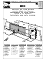 1
1
-
 2
2
-
 3
3
-
 4
4
-
 5
5
-
 6
6
-
 7
7
-
 8
8
-
 9
9
-
 10
10
-
 11
11
-
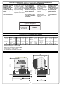 12
12
-
 13
13
-
 14
14
-
 15
15
-
 16
16
-
 17
17
-
 18
18
-
 19
19
-
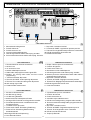 20
20
-
 21
21
-
 22
22
-
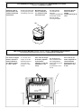 23
23
-
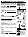 24
24
-
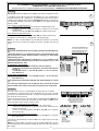 25
25
-
 26
26
-
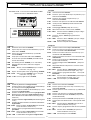 27
27
-
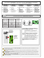 28
28
-
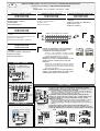 29
29
-
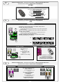 30
30
-
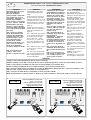 31
31
-
 32
32


CAME BXE 241 Manual de usuario
- Tipo
- Manual de usuario
- Este manual también es adecuado para
En otros idiomas
- français: CAME BXE 241 Manuel utilisateur
- italiano: CAME BXE 241 Manuale utente
- English: CAME BXE 241 User manual
- Deutsch: CAME BXE 241 Benutzerhandbuch
Documentos relacionados
-
CAME UNIPARK ARK1 Manual de usuario
-
CAME BXE Manual de usuario
-
-
-
-
-
CAME ZBKS Manual de usuario
-
-
-

