CAME BXE 241 El manual del propietario
- Categoría
- Abridor de puerta
- Tipo
- El manual del propietario
Este manual también es adecuado para

Documentazione
Tecnica
M19
rev. 2.9
07/2001
©
CAME
CANCELLI
AUTOMATICI
119BM19
SERIE BX |
BX SERIES
|
SÉRIE BX |
BAUREIHE BX
|
SERIE BX
BXE 241
CANCELLI AUTOMATICI
Automazioni per cancelli scorrevoli
Automation systems for sliding gates
Automatisations pour pourtails coulissant
Antriebe für den Schiebetore
Automatización para puertas correderas
1 - Gruppo BXE 241
2 - Quadro comando
incorporato
3 - Ricevitore radio
4 - Cremagliera
5 - Selettore a chiave
6 - Lampeggiatore di
movimento
7 - Antenna
8 - Fotocellule di
sicurezza
9 - Colonnina per
fotocellula
10 - Fermo anta
1 - BXE 241
Antriebsmotor
2 - Schalttafel im Antrieb
3 - Funkempfänger
4 - Zahnstange
5 - Außenantenne
6 - Blinkleuchte “Tor in
Bewegung”
7 - Schlüsselschalter
8 - IR Lichtschranke
9 - Lichtschrankeen-
säule
10- Toranschlag
1 - BXE 241 unit
2 - Control panel
(incorporated)
3 - Radio receiver
4 - Rack
5 - Electric lock
6 - Flashing light
indicating door
movement
7 - Antenna
8 - Safety photocells
9 - Photocell column
10- Closure stop
Impianto tipo Installation type
Standard montage
Instalación tipo
1 - Conjunto BXE 241
2 - Cuadro de mando
incorporado
3 - Radiorreceptor
4 - Cremallera
5 - Selector mediante
llave
6 - Lámpara
intermitente de
movimiento
7 - Antena receptora
8 - Fotocélulas de
seguridad
9 - Columna para
fotocélula
10 - Tope puerta
1 - Groupe BXE 241
2 - Armoire de
commande
incorporé
3 - Récepteur radio
4 - Crémaillère
5 - Sélecteur a clé
6 - Clignotant de
mouvement
7 - Antenne de
réception
8 - Photocellules de
sécurité
9 - Colonne pour
photocellule
10 - Butée d'arrêt
Standard installation
3 x 1.5 / 230V
2 x 1 - TX
2 x 1
2 x 1.5
RG58
$
#
'
!
&
4 x 1 - RX
3 x 1.5 / 230V
2 x 1 - TX
3 x 1
2 x 1.5
RG58
$
#
"
&
!
'
'
2 x 1 - TX
4 x 1 - RX
4 x 1 - RX
%

2
CARATTERISTICHE GENERALI -
GENERAL SPECIFICATIONS
- CARACTÉRISTIQUES GÉNÉRALES -
ALLGEMEINES
CARACTERÍSTICAS GENERALES
* Ottenuta mediante quadro comando CAME
* Obtained with CAME control panel
* Obtenue au moyen armoire de commande CAME
* Regulierbarer schub erreicht mit Hilfe der CAME Motorsteuerrung
* Empuje regulable obtenido mediante tablero de control CAME
MISURE D'INGOMBRO -
OVERALL DIMENSIONS
- MEASURES D'ENCOMBRENT -
ABMESSUNGEN
- MEDIDAS
Progettato e costruito
interamente dalla
CAME, risponde alle
vigenti norme di
sicurezza (UNI 8612),
con grado di protezio-
ne IP54.
Garantito 12 mesi
salvo manomissioni.
Il a été entièrement
conçu et costruit par
les Ets CAME,
conforméement aux
normes de sécurité en
viguer (UNI 8612) avec
degré de protection
IP54.
Il est garanti 12 mois
sauf en cas
d'altértions.
Designed and
constructed entirely by
CAME; conforms to
(UNI 8612) safety
standards with IP54
protection rating.
12 mounth guarantee;
guarantee void if unit is
tampered with.
Vollständig von der
CAME geplant und
hergestellt,
entsprechend den
geltenden Sicherheits-
bedigungen (UNI 8612)
mit Schutzgrad IP54.
12 Monate Garantie,
Bedienungs - und
Montagefehler
ausgeschlossen.
Diseñado y
construido totalmente
por CAME, con
arreglo a las vigentes
normas de seguridad
(UNI 8612) con grado
de protección IP54.
Garantia de 12 meses
salvo manipulaciones.
CARATTERISTICHE TECNICHE -
TECNICHAL CARACTERISTICS -
CARACTERISTIQUES TECNIQUES
TECNISCHE DATEN -
CARACTERISTICAS TECNICAS
240
105
150
290
125165
105
31
0
22 max.
-amissamatatroP
-stimilesU
-xameétroP
-thciwegroT
atreuposeP
elaiznediserosu
laitnediseR
leitnediseregasu
ztasnienetavirp
laicnediserosu
008gK
ovisnetniosu
ytud-yvaeH
fisnetniegasu
beirtebvisnetnI
ovisnetniosu
006gK
EROTTUDIROTOM OSEP ENOIZATNEMILA
OTNEMIBROSSA
.XAM
AZNETOP
.XAM
AZNETTIMRETNI
OROVAL
AIPPOC
OTROPPAR
ENOIZUDIRID
ATNIPS
'ATICOLEV
XAM
ROTOMRAEG THGIEW YLPPUSREWOP TNERRUCXAM REWOPXAM ELCICYTUD
XAM
EUQROT
NOITCUDER
OITAR
HSUP DEEPSXAM
RUETCUDÉROTOM SDIOP NOITATNEMILA
NOITPROSBA
XAM
ECNASSIUP
XAM
ECNETTIMRETNI
LIAVARTED
ELPUOC
TROPPAR
NOITCUDERED
EÉSSUOP
ESSETIV
XAM
ROTOMEBEIRTEG THCIWEG
_MORTS
GNUGROSREV
_FUAMORTS
EMHAN
GNUTSIEL
_TLAHCSNIE
REUAD
_HERD
TNEMOM
_SGNUZTESRETNU
SINTLÄHREV
_LEGER
RERAB
XAM
SGNUGARTREBÜ
ROTCUDERROTOM OSEP NOICATNEMILA
AICNEBROSBA
XAM
AICNETOP
XAM
AICNETIMRETNI
OJABART
AJERAP
)ROTOM(
EDNOICALER
NOICCUDER
EJUPME XAMDADICOLEV
142EXB gK51 .c.dV42 A71 W004 %05 mN72* 33/1 N007 .nim/m01

3
PRECAUZIONI -
BEFORE INSTALLING ...
- AVANT D'INSTALLER L'AUTOMATISME ... -
VOR DEN INSTALLATION
ÜBERPRÜFEN ...
- ANTES DE INSTALAR EL AUTOMATISMO ...
FISSAGGIO BASE MOTORE -
MOTOR TO BASE ANCHORAGE
- FIXATION DE LA PLAQUE DU MOTEUR
BEFESTIGUNGS DER MOTORBASIS
- FIJACIÓN BASE MOTOR
- La hoja de la puerta
debe estar
suficientemiente rigida y
compacta
- Las ruedas de
deslizamiento deben
estar perfecta y
engrasadas
adecuadamente.
- La guia de
deslizamiento debe estar
bien fijada en el suelo,
sobresaliendo a lo largo
de su entera longitud,
sin huecos ni
irregularidades (que
podrian obstaculizar el
movimiento de la
puerta).
- La guia superior debe
tener el justo juego con
la puerta metálica (para
garantizar un
movimiento regular y
silencioso).
- Disponer un tope para
apertura y el cierre.
- Disponer un conducto
para los cables
eléctricos que cumpla
con las disposiciones de
mando y seguridad.
- Die Leistungfähigkeit der
feststehenden und
beweglichen Teile des
Tores überprüfen.
- Das Tor sollte
ausreichend stabil sein.
Die Gleitrollen sollten in
guten Zustand und
angemessen geschmiert
sein.
- Die Gleitführung auf dem
Boden sollte sich in
optimaler Position
befinden: gut auf dem
Boden befestigt, in seiner
Gesamtlänge vollständig
über dem Boden, ohne
Vertiefungen und/oder
Unebenheiten, die
Torbewegung behindern
können.
- Die oberen
Führungsschienen sollten
das richtige Spiel zum Tor
haben, um ein präzises
und regelmäßiges Gleiten
zu garantieren.
- Einen Anschlag für Tor
Auf und Tor Tu sollte
vorhanden sein.
- Den Lauf der
elektrischen Kabel nach
den Steuerungs und
Sicherheitsbestimmungen
vorsehen.
- Le panneau mobile du
portail devra être
suffisamment rigide et
solide.
- Les roues de
coulissement devront
être en très bon état. En
outre, elles devront être
convenablement
raissées.
- Le rail de guidage
devra être bien fixée au
sol. De plus, il devra se
présenter entièrement en
surface sans
affaissements ou
irrégularités (qui
pourraient empêcher le
mouvement du portail).
- Le guide supérieur
devra avoir un jeu
convenable avec le
portail (pour permettre
un mouvement régulier
et silencieux).
- Prévoir une butée
d’arrêt à l’ouverture et à
la fermeture.
- Prévoir le passage des
câbles électriques selon
les dispositions de
commande et de
sécurité.
- The gate must be
sufficiently rigid and solid.
- The wheels on which the
gate slide must be in
perfect condition and
adequately lubricated.
- The wheel guide must be
firmly attached to the
ground, completely
exposed, and without any
dips or irregular sections
which might hinder the
movement of the gate.
- The upper guide must
allow for the correct
amount of play in order to
guarantee smooth and
silent movement of the
gate.
- Aperture and closure
stops must be installed.
- The wiring must be
routed as specified by the
control and safety
requirements.
- Controllare che l'anta
sia rigida e compatta e
che le ruote di
scorrimento siano in
buono stato e
adeguatamente
ingrassate.
- La guida a terra dovrà
essere ben fissata al
suolo, completamente in
superficie in tutta la sua
lunghezza, priva di
affossamenti e/o
irregolarità che possano
ostacolare il movimento
del cancello.
- I pattini-guida superiori
non devono creare attriti.
- Prevedere un fermo
anta in apertura e uno in
chiusura ed il percorso
dei cavi elettrici come da
impianto tipo.
50 mm.
75 mm.
105 mm.
Struttura fissa
Wall
Structrure fixe
Feste Struktur
Estructura fija
Anta cancello
Gate wing
Panneau mobile du portail
Gleitachse
Puerta
Piazzola in cemento
Concrete base
Plate-forme en ciment
Plattenachse
Plataforma de cemento
Cavi
Cable
Câbles
Kabel
Cables
Cremagliera
Rack-limit
Cremaillére
Zahnstange
Cremallera
Piastra di ancoraggio / Zanche
Fixing plate / Anchor stays
Plaque de fixation / Agrafes
Gleitachse / Verankerung
Placa de fijación / Barras de fijción
- Inserire le viti nella
piastra di ancoraggio
bloccandole con un
dado, ed estrarre le
zanche preformate verso
il basso.
- Predisporre, dimen
sionandola in base alle
misure del motori
duttore, una piazzola in
cemento (si consiglia di
farla sporgere dal terreno
di circa 50 mm.) con
annegata la piastra di
ancoraggio e relative
zanche sulla quale sara'
fissato il gruppo.
- La base di fissaggio
dovra' risultare perfet
tamente in bolla, pulita in
tutte le sue estremita',
con il filetto delle viti
completamente in
superfice.
N.B.: Dalla stessa
dovranno emergere i tubi
flessibili per il passaggio
dei cavi di collegamento
elettrico.
- Install the screws in the
anchor plate and fasten
them with a nut, then
bend the preformed
clamps downwards.
- Construct a cement
foundation that is large
enough to accomodate
the gear motor (it is a
good idea to protrude 50
mm. from the ground).
When pouring the
foundation, embed the
gear motor anchor plate
and the relative clamps in
the cement.
- The anchor bolts should
be embedded in the
concrete in the positions
indicated; the drive
unit is then attached to
this bots. The anchor
plate must be perfectly
level and absolutly clean;
the bolts threads must be
completly exposed.
N.B.: The flexible tubes for
the electrical wiring must
be embedded in the base
and protude in the correct
position.
- Introduire les vis dans
la plaque d'ancrage en
les bloquant avec un
écrou, et replier les
agrafes préformées ver
le bas.
- Préparer une base en
ciment d'une dimension
adéquate aux mesures
du motoréducteur (il est
conseillé de la faire
dépasser du terrain
d'environ 50 mm.), et
noyer dedans la plaque
d'ancrage et les agrafes
corre-spondantes afin
de permettre le fixage
du groupe.
- La base de fixation
devrà être parfaitement
de niveau et propre sur
toute sa surface et le
filet des vis devra être
complètement en
surface.
N.B. Les câbles pour le
branchement électrique
devront sortir de cette
base.
- Die Schrauben in die
Ankerplatte einfügen und
mit einer
Schraubenmutter
blockieren, die vorgefor-
mten Fundamentanker
nach unten umbiegen.
- Eine den Abmessungen
des Getriebemotors ents-
prechende Betonfunda-
mentplatte (Es empfiehlt
sich, diese ca. 50 mm.
vom Boden herausragen
zu las-sen) zum
Einbetten der Ankerplatte
und der entsprechenden
Funda-mentanker, die
zur Befestigung des
Antriebs-aggregats
dienen, vorbe-reiten.
- Die Befestigungs-unter-
lage muß in seiner
gesam-ten Länge
vollkommen eben und
sauber sein. Das
Gewinde der Schrau-ben
müssen gänzlich.
hervorstehen.
Wichtig: die Kabel für den
Elektroanschluß müssen
herausrgen.
- Introducir los tornillos
en la placa de anclaje,
bloqueándolos con una
tuerca, y doblar las
palancas preformadas
hacia abajo.
- Preparar, dándole las
dimensiones adecua-
das en función de las
medidas del motor-
reductor, una
plataforma de cemento
(se aconseja dejarla
sobresalir del suelo
aprox. 50 mm.) con la
placa de enclaje
embedida y con las
cor-respondientes
varillas, que permitrá la
fijación del grupo.
- La base de fijación
debe estar
perfectamente nivelada,
limpia en todos sus
extremos, con la ro-sca
de los tornillos total-
mente in superficie.
N.B.: De ésta deben
sobresilar los tubos
flexibles para el paso de
los cables para las
conexiones eléctricas.

4
POSA DEL GRUPPO -
UNIT INSTALLATION -
INSTALALTION DU GROUPE -
AUFSTELLUNG DES AGGREGATS
COLOCACIÓN DEL GRUPO
Nella fase preliminare
di posa, i piedini
dovranno sporgere di
5-10 mm. per
permettere
allineamenti, fissaggio
della crema-gliera e
regolazioni successive.
L'accoppiamento
esatto con la linea di
scorrimento del
cancello è ottenibile
dal sistema di
regolazione integrale
(brevettato) composto
da:
- le asole che
permettono la
regolazione
orizzontale;
- i piedini filettati in
acciaio che permettono
la regolazione verticale
e la messa in bolla;
- le piastrine e i dadi di
fissaggio che rendono
solidale l'aggancio del
gruppo alla base.
During the initial phase
of installation, the feet
should protude by 5-10
mm. in order to allow for
alignment, anchorage of
the rack and further
adjustments.
Perfect alignment with
the guide rail is made
possible by the
(patented) built-in
regulation system, wich
consists of:
- slots for horizontal
adjustment;
- threaded steel feet for
vertical adjustment and
levelling;
- plates and bolts for
anchorage to the base.
Procéder maintenant à
la pose du groupe.
Dans la phase de pose
préliminaire, les
broches devront
dépasser de 5 à 10 mm
afin de permettre les
alignements et les
réglages nécessaires
après la pose.
L’accouplement exact
avec la ligne de
coulissement du
portail s’effectue par le
système de réglage
hauteur (breveté) dont
le groupe est pourvu,
et qui comprend plus
précisément:
- les trous oblong
permettant le réglage
horizontal;
- les broches filetees
en acier qui donnent le
réglage vertical et la
mise à niveau;
- les plaques et les
écrous de fixation qui
assemblent solidement
le groupe à la plaque
de fixation scellée.
Nun die Montage des
Antriebsmotors
vornehmen. Die genaue
Kopplung mit der
Gleitlinie des Tors wird
von dem integrierten
Einstellungssystem
(patentiert) garantiert,
mit dem das Aggregat
ausgestattet ist und
zwar:
- die Osen für die
horizontale Einstellung,
- die Gewindefüße aus
Stahl für die vertikale
Einstellung und die
Nivellierung,
- die
Befestigungsplättchen
und-muttern zur soliden
Befestigung des
Aggregats an die
Bodenplatte.
Während der
Vorbereitungsarbeiten
der Montage sollten die
Füße 5-10 mm
herausragen, um
Ausfluchtungen und
Einstellung auch nach
der Fertigstellung zu
ermöglich.
En la fase previa del
emplazamiento, los
pies deben sobresalir
5-10 mm para consen-
tir la alineación, la
fijación de la
cremallera y las
regulaciones
sucesivas.
El acoplamiento
exacto con la linea de
deslizamiento de la
puerta metálica se
obtiene mediante el
sistema de regulación
integral (patentado)
que consta de:
- los agujeros
ovalados que
consienten la
regulación horizontal;
- los pies roscados de
acero que permiten la
regulación vertical y la
nivelación;
- las placas y las
tuercas de fijación que
hacen solidario el
enganche del conjunto
con la base.
5÷
10
m
m
.
Ingresso cavi
Cable entrances
Passage des câbles
Kabeleinführungen
Accoppiamento pignone-cremagliera
con gioco 1÷2 mm.
Rack-to-pinion coupling with 1÷2 mm. clearance
Assemblage pignon-crémailère avec jeu
de 1 à 2 mm.
Zwischen Zahnstange und dem Antriebsritzel
1÷2 mm. Spiel einstellen
Acoplamiento piñon-cremaliera
1÷2 mm. de juego
Regolazione orizzontale e fissaggio
Horizontal adjustment unit and achorage
Réglage horizontal et fixation
Horizontale Einstellung
Regulación horizontal y fijación
Regolazione verticale - messa in bolla
Vertical adjustment and unit leveling
Réglage vertical - mise à niveau
Vertikale Einstellung
Regulación vertical y nivelación
Entrada cables
1÷2 mm.

5
FISSAGGIO CREMAGLIERA -
ATTACHING THE RACK/LIMIT
- FIXATION CREMAILLÉRE -
MONTAGE DE ZAHNSTANGE -
FIJACIÓN DE LA
CREMALLERA
Mod. CGZ / CGZS
Con el fin de permitir al
ENCODER medir la
carrera de la puerta,
fijar la cremallera con
el mismo a mitad de
carrera:
- coloque la hoja en la
mitad de la carrera,
apoye la cremallera
sobre el piñon del
motorreductor y
deslice manualmente
la puerta, fijando la
cremallera a todo lo
largo;
- La carrera máxima de
la puerta es de 14 m;
- Finalizadas las ope-
raciones para la
fijacion de la cremal-
lera, regular los pies
(por medio de un
destornillador) de
modo que se obtenga
el justo juego entre el
piñón y la cremallera
(1-2 mm).
N.B. Esto hace que el
peso de la puerta
metálica no cargue
sobre el conjunto.
- Si la cremallera ya ha
sido fijada, hay que
regular el acopla-
miento piñón-cremal-
lera.
- Una vez realizados
los ajuste, fijar el
conjun-to cerrando
las dos tuercas de
fijación.
Ist der ENCODER zur
Erfassung bzw. Überwa-
chung des Torlaufs auf
halber Laufhöhe auf der
Zahnstange zu befesti-
gen:
- den Torflügel halb
öffnen und die
Zahnstange auf dem
Ritzel vom
Getriebemotor aufle-
gen. Dann das Tor von
Hand verschieben und
dabei die Zahnstange
auf ganzer Länge
befestigen;
- Der maximale Lauf vom
Tor beträgt 14 m;
- Die verstellbaren Füße
des Antriebsmotors
(mit einem Schrauben-
zieher) so einstellen,
daß zwischen Ritzel
und Zahnstange ein
Spiel (1-2 mm) besteht.
Wichtig: Dadurch wird
vermieden, daß das
Gewicht des Tores auf
dem Aggregat lastet.
- Nach diesen Einstel-
lungsarbeiten das
Aggregat durch Anzie-
hen der beiden Muttem
befestigen.
Afin de permettre à
l'ENCODEUR de rele-
ver la course du
portail, fixer la
crémaillère avec le
portail à mi-course:
- mettre la porte à la
moitié de sa course,
poser la crémaillère
sur le pignon du
motoréducteur et faire
coulisser manuel-
lement le portail en
fixant la crémaillère
sur toute sa longueur;
- La course maximum
du portail est de 14 m;
- Lorsque la fixation de
la crémaillère est
terminée régler les
broches (en utilisant
un tournevis) de
façon à obtenir un jeu
convenable (1-2 mm)
dans l’assemblage du
pignon et de la
crémail-lère.
N.B. Ceci pour éviter
que le poids du portail
ne repose sur le
groupe.
- Si la crémaillère est
déjà fixée, utiliser le
système de réglage
hauteur pour assem-
bler correctement de
facon exacte le pi-
gnon et la
crémaillère.
- Exécuter tous les
réglages, fixer le
groupe en serrant les
deux écrous de
fixation.
Install the rack with the
gate at the half-way
point. This will enable the
ENCODER to detect
gate travel properly:
- allow the door to reach
mid-run, set the rack on
the rationmotor's pinion
and slide the gate
manually, fixing the
rack's entire lenght;
- The gate's maximum run
is 14 m;
- when the rack is
attached to the gate,
adjust the feet using a
screwdriver until the
play between the pinion
and the rack is correct
(1-2 mm.).
N.B.: This position
ensures that the weight
of the gate does not rest
on the gearmotor.
- If the rack is already
attached, proceed
directly to the adjust-
ment of the rack/pinion
coupling.
- When the necessary
adjustment have been
completed, fasten the
unit in position by
tightening the two
anchor bolts.
Al fine di permettere
all'ENCODER di rileva-
re la corsa del cancel-
lo, fissare la crema-
gliera con il cancello a
meta' corsa:
- portare l'anta a meta'
corsa, appoggiare la
cremagliera sul
pignone del moto-
riduttore e far scorrere
manualmente il can-
cello fissando la
cremagliera in tutta la
sua lunghezza;
- La corsa massima del
cancello é di 14 m;
- ultimata l'operazione
di fissaggio della
cremagliera, regolare
i piedini (servendosi
di un cacciavite) in
modo da ottenere il
giusto giuoco tra
pignone e
cremagliera (1-2 mm).
N.B. : Questo evitera'
che il peso del cancello
vada a gravare sul
gruppo.
- Se la cremagliera é
gia' fissata, procedere
direttamente alla re-
golazione dell'ac-
coppiamento pigno-
ne-cremagliera.
- Eseguite tutte le
regolazioni, fissare il
gruppo stringendo i
dadi di fissaggio.

6
SBLOCCO MOTORIDUTTORE -
GEAR RELEASE
- OPÉRATION DE DÉBLOCAGE -
ANTRIEBSENTRIEGELUNG
DESBLOQUEO MOTORREDUCTOR
Release
Sblocco
Blocco
Engage
Blockierend
Entriegelt
Blocage
Déblocage
Desbloqueo
Bloqueo
CAME
- Per aprire lo
sportellino inserire
la chiave, spingerla
e ruotala in senso
orario; sbloccare
quindi il
motoriduttore
ruotando la
manopola nella
direzione indicata.
ATTENZIONE:
l'apertura dello
sportellino di
sblocco impedisce il
funzionamento del
motore.
- Pour ouvrir la
trappe, introduire la
clé, la pousser et la
tourner dans le sens
des aiguilles d'une
montre. Débloquer
ensuite le
motoréducteur en
tournant la poignée
dans la direction
indiquée.
ATTENTION:
l'ouverture de la
porte de déblocage
empêche le
fonctionemment du
moteur.
- Para abrir la
portezuela
introducir la llave,
empujarla y girarla
en sentido horario;
desbloqear el
motorreductor
girando la manilla
en la dirección
indicada.
ATENCIÓN:
la apertura de la
tapa de desbloqueo,
impide el
funcionamiento del
motor.
- To open the access
door, insert the key,
push down and rotate
clockwise. Now,
release the gear
motor by rotating the
knob in the direction
shown.
ATTENTION:
the opening of the
unblockpanel arrests
the motor.
- Zum Öffnen der
klappe den Schlüssel
einfügen,
hineindrücken und im
Uhrzeigersinn
drehen. Dann den
Getriebemotor durch
Drehen des Knopfs in
die angegebene
Richtung entsperren.
ACHTUNG:
Wenn das
Freigabetürchen
geöffnet wird,
funktioniert der
Motornicht.
La página se está cargando...
La página se está cargando...

9
La tarjeta de mando se alimenta con
una tensión de 230V en los bornes L1
y L2 y está protegido en entrada con
fusible de línea de 5A. Los dispositivos
de mando son a baja tensión y està
protegidos por fusible a 2A. La
potencia total de los accesorios a 24V,
no debe superar los 40W.
Tiempo de trabajo fijo a 90 segundos.
Seguridad
Las fotocélulas pueden estar
conectadas y predispuestas para:
-
Reapertura
en la fase de cierre (2-
C1);
-
Stop parcial
parada de la puerta si se
encuentra en movimiento con la
consiguiente predisposición al cierre
automático (2-C3);
-
Stop total
(1-2), parada de la puerta
excluyendo el posible ciclo de cierre
automático; para reactivar el
movimiento es preciso actuar en el
teclado o en el mando a distancia);
Nota: La apertura de un contacto de
seguridad normalmente cerrado (2-
C1, 2-C3, 1-2) es señalada por medio
del destello del LED de señalización
(n°14).
-
Detección obstáculo
. Con el motor
parado (puerta cerrada, abierta o en
posición semi-abierta obtenida a
través de un comando de stop total),
anula cualquier función del transmisor
o del botón en caso de obstáculo
detectado por los dispositivos de
seguridad (por ejemplo: fotocélulas);
Además la tarjeta integra y maneja
automáticamente una función de
seguridad, que si se detectaran
obstáculos funciona de la siguiente
manera:
- durante la apertura la puerta invierte
la dirección de marcha hasta cerrarse
completamente;
- durante el cierre la puerta invierte la
dirección de marcha hasta abrirse
completamente, con consiguiente
accionamiento del cierre automático.
ATENCIÓN: después de tres
inversiones consecutivas, la puerta
queda abierta excluyendo el cierre
automático; para volver a cerrar, use
el radiocontrol o el botón de cierre.
DESCRIPCIÓN TÉCNICA TARJETA BASE ZBXE24
Otras funciones
-
Lámpara ciclo.
Lámpara que alumbra
la zona de maniobra; se queda
encendida a partir del momento en
que las hojas empiezan la apertura
hasta el cierre completo (incluyendo
el tiempo de cierre automático). El
funcionamiento de la lámpara ciclo se
obtiene en la salida 10-E1 sólo si los
dips n°2 «cierre automático» y n°3
«detección presencia obstáculo»
están colocados en ON, véase página
12;
-
Indicador luminoso de puerta abierta.
Lámpara que indica que la puerta de
corredera está, se apaga cuando la
puerta activa el final de carrera de
cierre, conéctela a los bornes 10-5.
Otras funciones
-
Cierre automático.
El temporizador de
cierre automático se autoalimenta en
fin-de-tiempo carrera en fase de
apertura. El tiempo prefijado regulable,
sin embargo, está subordinado a la
intervención de posibles accesorios
de seguridad y se excluye después de
una intervención de parada o en caso
de falta de energía eléctrica;
-
Apertura parcial.
La apertura de la
puerta para paso peatonal se activa
con la conexión a los bornes 2-3P y
se regula mediante el trimmer
AP.PARZ.;
-
Función a " hombre presente"
.
Funcionamiento de la puerta
manteniendo pulsada la tecla;
-
Función master
, el cuadro asume
todas las funciones de mando en el
caso de dos motores combinados
(véase p.18);
-
Programación
regulación de los
microinterruptores de tope
electrónicos de apertura y cierre
(véase p. 15);
-
Preintermitencia
en fase de apertura
y cierre;
-
Tipo de mando:
-apertura-cierre-inversión;
-apertura-stop-cierre-stop;
-sólo apertura.
Regulaciones
-Trimmer AP.PARZ.= Apertura parcial:
de 4" a 15";
-Trimmer TCA = Tiempo cierre
automático: de 1" a 150”;
-Trimmer RALL = Regulación
velocidad de ralentamiento min/max;
-Trimmer VEL = Regulación velocidad
de marcha;
-Trimmer SENS = Regulación
sensibilidad amperométrica min/max.
ESPAÑOL
Atención:
- la apertura de la tapa de desbloqueo,
impide el funcionamiento del motor.
- antes de actuar dentro del aparato, quitar
la tensión de línea y desecnetar las
baterías (siestuvieran conec-tadas).

10
2
1 345678910
ON
AF
PROGRAMMAZIONE
F U S . L I N E A 5 A
FUS. ACCESSORI 2A
SENS.
VEL. RALL.
T.C.A. APER.PARZ.
CH1 CH2 F.APRE F.CHIUDE
BXE24
QUADRO COMANDO
ENCODER
ZBXE24
SCHEDA BASE -
MOTHERBOARD
- CARTE BASE -
GRUNDPLATINE
- TARJETA BASE
22
22
2
1616
1616
16
33
33
3
99
99
9
88
88
8
1010
1010
10
1111
1111
11
1212
1212
12
44
44
4
77
77
7
55
55
5
1313
1313
13
1515
1515
15
66
66
6
1414
1414
14
11
11
1
COMPOSANTS PRINCIPAUX
1 Plaque à bornes pour les branchements
2 Fusibles de ligne 5A
3 Fusible accessoires 2A
4 Branchement carte radiofréquence (voir tableau)
5 LED de signalisation code radio
6 Boutons-poussoirs mémorisation code radio
7 Dip-switch "sélection fonction"
8 Trimmer AP.PARZ.: Réglage Ouverture partielle
9 Trimmer TCA: Réglage Temps de fermeture automatique
10 Trimmer RALL.: Réglage vitesse de ralentissement
11 Trimmer VEL.: Réglage vitesse de mouvement
12 Trimmer SENS: Réglage sensibilité ampèremétrique
13 LED de signalisation fermeture automatique et prog.encoder
14 Boutons-poussoir programmation fin de course
15 Carte fixe Encodeur
16 LED de signalisation pour dispositif ampèremétrique
F
COMPONENTES PRINCIPALES
1 Caja de bornes para las conexiónes
2 Fusible de linea 5A
3 Fusible accesorios 2A
4 Conexión tarjeta radiofrecuencia (vedas tabla)
5 LED de señal código radio
6 Teclas memorización código radio
7 Dip-switch "seleción función"
8 Trimmer AP.PARZ.: Regulación Apertura parcial
9 Trimmer TCA: Regulación cierre automático
10 Trimmer RALL.: Regulación velocidad de ralentamiento
11 Trimmer VEL.: Regulación velocidad de marcha
12 Trimmer SENS: Regulación sensibilidad amperométrica
13 LED de señal cierre automático y programmación encoder
14 Teclas programación final de carrera
15 Tarjeta fija Encoder
16 LED de señal para dispositivo amperimétrico
E
HAUPTKOMPONENTEN
1 Anschluss-Klemmenleiste
2 5A-Sicherung Leitungs
3 2A-Sicherung Zubehörs
4 Steckanschluß Funkfrequenze-Platine (sehen Tabelle)
5 Anzeige-LED Funkcode
6 Funkcode-Speichertasten
7 "Funktionswahl" dip-switch
8 Trimmer AP.PARZ.: Einstellung Teilöffnung
9 Trimmer TCA: Einstellung Zeiteinstellung Schließautomatik
10 Trimmer RALL.: Einstellung Laufverlangsamung
11 Trimmer VEL.: Einstellung Laufgeschwindigkeit
12 Trimmer SENS: amperemetrische Ansprechempfindlichkeit
13 Anzeige-LED Schließautomatik und Programmier encoder
14 Endausschalter Programmiertasten
15 Feste Encoder-Platine
16 Anzeige-LED für Amperemetergerät
D
MAIN COMPONENTS
1 Terminal block for external connections
2 5A line fuse
3 2A accessories fuse
4 Socket radiofrequency board (see table)
5 Radio code signal LED
6 Buttons for storing radio code numbers
7 "Function selection" dip-switch
8 Trimmer AP.PARZ.: Partial opening adjustment
9 Trimmer TCA: automatic closing time adjustment
10 Trimmer RALL.: slowdown speed adjustment
11 Trimmer VEL.: operating speed adjustment
12 Trimmer SENS: sensitivity of amperometric safety system
13 Automatic closing and program encoder signal LED
14 Limit switch programming buttons
15 Encoder mother board
16 Signal LED for amperometric detector
GB
COMPONENTI PRINCIPALI
1 Morsettiere di collegamento
2 Fusibile di linea 5A
3 Fusibile accessori 2A
4 Innesto scheda radiofrequenza (vedi tabella)
5 LED di segnalazione codice radio
6 Pulsanti memorizzazione codice radio
7 Dip-switch "selezione funzioni"
8 Trimmer AP.PARZ.: regolazione apertura parziale
9 Trimmer TCA: regolazione tempo di chiusura automatica
10 Trimmer RALL.: regolazione velocità di rallentamento
11 Trimmer VEL.: regolazione velocità di marcia
12 Trimmer SENS: regolazione sensibilità amperometrica
13 LED di segnalazione chiusura automatica e prog.encoder
14 Pulsanti programmazione finecorsa
15 Scheda fissa Encoder
16 LED di segnalazione per dispositivo amperometrico
I

11
SELEZIONI FUNZIONI -
SELECTION OF FUNCTIONS
- SÉLECTION FONCTIONS -
FUNKTIONSWAHL
- SELECCIÓN DE LAS FUNCIONES
ZBXE24
ON
OFF
21 3456 78910
ON
AF
PRO G RAM M AZ IO NE
FU S. LINEA 5A
FU S. ACCESSORI 2A
SEN S.
VEL. RALL.
T.C.A. T.L. APER.PARZ.
CH1 CH2 F.APRE F.CHIUDE
BXE24
QUADR O COMANDO
ENCODER
1 ON Funzionamento "uomo presente" attivato
2 ON Funzionamento chiusura automatica attivata
3 ON Funzionamento rilevazione ostacolo attivato
4 ON Funzionamento prelampeggio attivato
5 ON Funzionamento "spare" (programmazione finecorsa)
attivato
6 OFF Funzione "master" disattivata (da attivare solo per il
collegamento abbinato, vedi pag. 18)
7 ON Funzione "apre-chiude" con pulsante 2-7 attivato
8 ON Funzione "apre-stop-chiude-stop" con 2-7 attivato
7 ON - 9 ON Funzione "apre-chiude" con radiocomando
(scheda AF inserita) attivata
8 ON - 9 ON Funzione "apre-stop-chiude-stop" con
radiocomando (scheda AF inserita) attivata
7 ON - 10 ON Funzione "solo apertura" con radiocomando
(scheda AF inserita) attivato
ITALIANO
1 ON Fonctionnement "contact mantenu" sélectionée
2 ON Fonctionnement fermeture automatique sélectionnée
3 ON Dispositif de détection de présence (moteur en fin
de course) sélectionnée
4 ON Fonctionnement preclignotement sélectionnée
5 ON Fonctionnement "spare" (programmation fin de course)
sélectionnée
6 OFF Fonctionnement "master" désactivée (à n'activer
que pour le branchement accouplé, voir pag. 18)
7 ON Fonction "ouverture-fermeture" avec bouton (2-7)
sélectionnée
8 ON Fonction "ouverture-stop-fermeture-stop" avec bouton
(2-7) sélectionnée
7 ON - 9 ON Fonction "ouverture-fermeture" avec
commande radio (carte AF insérée)
sélectionnée
8 ON - 9 ON Fonction "ouverture-stop-fermeture-stop" avec
commande radio (carte AF insérée)
sélectionnée
7 ON - 10 ON Fonction "seulement ouverture" avec com-
mande radio (carte AF insérée) sélectionnée
FRANÇAIS
1 ON "Present man" operation enabled.
2 ON Automatic closure function enabled;
3 ON Obstacle detection device (motor of limit position)
enabled;
4 ON "Pre-flashing" function enabled;
5 ON "Spare" (limit switch programming) enabled;
6 OFF "Master" function desabled (to enabled only for
coupled connection, see pag. 18);
7 ON "Open-close" function with button 2-7 enabled,
8 ON "Open-stop-close-stop" function with button 2-7
enabled;
7 ON - 9 ON "Open-close" function with radio control
(AF board inserted) enabled;
8 ON - 9 ON "Open-stop-close-stop" function control (AF
board inserted) enabled;
7 ON - 10 ON "Only open" function control (AF board
inserted) enabled;
ENGLISH
1 ON Funktionierung "Steuerpult" zugeschaltet
2 ON Funktionierung Schließautomatik zugeschaltet
3 ON Funktionierung Hindernisaufnahme zugeschaltet
4 ON Funktionierung Vorblinker zugeschaltet
5 ON Funktionierung"spare" (Programmier-
endausschalter) zugeschaltet
6 OFF Funk. "master" ausgeschlossen (wird nur für
kombinierte Anschlüsse zugeschaltet - siehe S. 18)
7 ON Funktionierung "Öffnen-Schließen" mit Druckknopf (2-7)
zugeschaltet
8 ON Funktionierung "Öffnen-stop-Schließen-stop" mit
Druckknopf (2-7) zugeschaltet
7 ON - 9 ON Funktionierung "Öffnen-Schließen" mit Fern-
steuerung (Karte AF eingesteckt) zugeschaltet
8 ON - 9 ON Funktionierung "Öffnen-stop-Schließen-stop"
mit Fernsteuerung (Karte AF eingesteckt)
zugeschaltet
7 ON - 10 ON Funktionierung "nur Öffnen" mit FerNsteuerung
(Karte AF eingesteckt) zugeschaltet
DEUTSCH
1 ON Funciónamiento "hombre presente" activado
2 ON Funciónamiento cierre automático activado
3 ON Funciónamiento detección del obstàculo activado
4 ON Funciónamiento preintermitencia activado
5 ON Funciónamiento "spare" (programación final de carrera)
activado
6 OFF Función "master" desactivada (se activa sólo para la
conexión combinada, véase pág.18)
7 ON Función "apertura-cierre" con botón (2-7) activado
8 ON Función "apertura-stop-cierre-stop" con botón (2-7)
activado
7 ON - 9 ON Función "apertura-cierre" con radiocontrol
(tarjeta AF conectada) activado
8 ON - 9 ON Función "apertura-stop-cierre-stop" con
radiocontrol (tarjeta AF conectada) activado
7 ON - 10 ON Función "sólo apertura" con radiocontrol (tarjeta
AF conectada) activado
ESPANOL
2
1 34567
8910
ON

12
Alimentazione 230V (a.c.)
230V (a.c.) power input
Alimentation 230V (c.a.)
Stromversorgung 230V (Wechselstrom)
Alimentación 230V (a.c.)
Motore 24V(d.c.)
24V (d.c.) motor
Moteur 24V (c.c.)
Motor 24V (Gleichstrom)
Motor 24V (d.c.)
Uscita 24V (a.c.) in movimento (es.lampeggiatore - 25W)
24V (a.c.) output in motion (e.g. 25W - flashing light)
Sortie 24V (c.a.) en mouvement (ex. branchement clignotant - 25W)
Ausgang 24V (Wechselstrom) in Bewegung (z.B. Blinker-Anschluß - 25W)
Salida de 24V (a.c.) en movimento (p.ej. conexión lámpara intermitente
25W)
Uscita 24V (a.c.) lampada ciclo - max. 60W (vedi descrizione pag. 7)
24V (a.c.) max. 60W -cycle lamp (see description pg. 7)
Sortie 24V (c.a.) lampe cycle - max. 60W (voir description pag. 7)
Betriebszyklus-Anzeigeleuchte - 24V (Wechselstrom) - max.60W (sehen S. 7)
Salida de 24V (a.c.) lámpara ciclo - max. 60W (mirar descripción pág. 7)
Alimentazione accessori 24V (a.c.) max. 40W
24V (a.c.)Powering accessories (max 40W)
Alimentation accessoires 24V (c.a.) max.40W
Zubehörspeisung 24V (Wechselstrom) max. 40W
Alimentación accesoios 24V (a.c.) max. 40W
Pulsante stop (N.C.)
Pushbutton stop (N.C.)
Bouton-poussoir arrêt (N.F.)
Stop-Taste (N.C.)
Pulsador de stop (N.C.)
Pulsante apre (N.O.)
Pushbutton opens (N.O.)
Bouton-possoir ouverture (N.O.)
Taste Öffnen (N.O.)
Pulsador de apertura (N.O.)
Pulsante apre (N.O.) per apertura parziale
Open button (N.O.) for partial aperture
Bouton-poussoir d'ouverture (N.O.) pour ouverture partial
Taste Öffnen (Arbeitskontakt) für TeilÖffnung
Pulsador de apertura (N.O.) para aperture parcial
10
E1
+10
-11
1
2
2
3
2
3P
L1
L2
M
N
N.B. Rispettare la polarità nel
collegamento delle fotocellule
(TX e RX).
N.B. When connecting the
photocells (TX and RX), observe
the correct polarities.
N.B. Respecter la polarité lors de
la connexion des photocellules
(TX et RX).
Anmerkung: beim Anschließen der
Photozellen (TX und RX) auf die
Polung achten.
N.B. Respetar la polaridad en la
conexión de las fotocélulas (TX y
RX).
10 11
4:
NO C NC
6:
10 11
E1 1
72534
3P
2C1
C3
2
MOT
B1 B2
M NL1 L2
ENCODER
ZBXE24
COLLEGAMENTI ELETTRICI -
ELECTRICAL CONNECTIONS -
BRANCHEMENTS ÉLECTRIQUES
- ELEKRISCHE ANSCHLÜSSE -
CONEXIONES ELÉCTRICAS
2
1 34567
8910
ON
10 11 E1 1
10 11 E1 1

13
2
C1
2
C3
B1
B2
2MOT
10
5
Contatto radio e/o pulsante per comando (vedi dip-switch 7-8-9-10 sel.funzioni)
Contact radio and/or button for control (see dip-switch 7-8-9-10 function selection)
Contact radio et/ou poussoir pour commande (dip-switch 7-8-9-10 sel.fonction)
Funkkontakt und/oder Taste Steuerart (dip-switch 7-8-9-10
Funktionswahl)
Contacto radio y/o pulsador para mando (dip-switch 7-8-9-10 seleción
fonción)
Pulsante chiude (N.O.)
Close button (N.O.)
Poussoir de fermeture (N.O.)
Taste Schließen (Arbeitskontakt)
Pulsador de cierre (N.O.)
Contatto (N.C.) di «riapertura durante la chiusura»
Contact (N.C.) for «re-aperture during closure»
Contact (N.F.) de «réouverture pendant la fermeture»
Kontakt (Ruhekontakt) Wiederöffnen beim Schliessen
Contacto (N.C.) para la apertura en la fase de cierre
Contatto (N.C.) stop parziale
Partial stop contact (N.C.)
Contact (N.F.) d'arrêt partial
Teil-Stop (Ruhekontakt) Kontakt
Contacto (N.C.) de stop parcia
Lampada spia (24V-3W) cancello aperto
(24V-3W) gate-opened signal lamp
Lampe-témoin 24V-3W) portail ouverture
Signallampe (24V-3W) Öffnen
Lampara indicadora (24V-3W) puerta abierta
Collegamento antenna
Antenna connection
Connexion antenne
Antennenanschluß
Conexión antena
Uscita contatto (N.O.) Portata contatto: 5A a 24V(d.c.)
Contact output (N.O.) Resistive load: 5A 24V (d.c.)
Sortie contact (N.O.) Portée contact: 5A a 24V(c.c.)
Ausgang Arbeitskontakt Stromfestigkeit: 5A bei 24V (Gleichstrom)
Salida contacto (N.O.) Carga resistiva: 5A a 24V(d.c.)
Uscita per comando simultaneo di n.2 motori abbinati
Connection for simultaneous control of 2 combined motors
Sortie pour commande simultanée de 2 moteurs accouples
Ausgang zur gleichzeitigen Steuerung von 2 parallelgeschalteten Motoren
Salida para el mando simultáneo de n.2 motores acoplados
2
4
ZBXE24
COLLEGAMENTI ELETTRICI -
ELECTRICAL CONNECTIONS -
BRANCHEMENTS ÉLECTRIQUES
- ELEKRISCHE ANSCHLÜSSE -
CONEXIONES ELÉCTRICAS
2
7

14
Chiudere lo sportello dello sblocco e inserire il dip-switch 5 in ON, il led di
segnalazione inizia a lampeggiare (1). Portare il cancello in finecorsa di
chiusura, premere il tasto "CHIUDE", il led rimane acceso finchè si mantiene
premuto il tasto (2).
Procedere portando il cancello a finecorsa in apertura e premere il tasto
"APRE" (3).
Riposizionare il Dip-switch 5 in OFF (4), aprire lo sportello e inserire la
manopola di sblocco.
N.B. In fase di programmazione finecorsa apre, se premendo il tasto
"APRE" il led rimane spento, invertire le fasi del motore ed Encoder come
illustrato (5).
Close the door panel pf the outlet and set dip-switch 5to ON. The LED will
begin flashing (1). Bring the gate to the close limit-switch, press button
"CHIUDE"; the LED will remain lit as the button is released (2).
Now, move the gate to the end-of-travel position when open, and press the
"APRE" key (3).
Move Dip-switch 5 to OFF (4), open the access door and turn the release
Knob.
N.B. If the LED does not light up when the "APRE" key is pressed to program
the end-of-travel position when opened, reverse the motor and encoder
connections as shown on the diagram (5).
Fermer le volet de déblocage et insérer le dip-switch 5 sur ON, le del de
signalisation commence à clignoter (1). Mettre le grille sur la butée de fin de
course ferme, appuyer sur la touche “CHIUDE“, le led reste allumé tant que
l’on appuie sur la touche (2).
Procéder en amenantle portail en position de fin de course ouverture puis
appuyer sur la touche "APRE" (3). Déconnecter le Dip-switch 5 sur OFF (4),
ouvrir la porte et insérer la poignée de déblocage.
N.B. Pendant la phase de programmation de la fin de course ouverture, si,
en appuyant sur la touche "APRE", le led reste éteint, inverser les phases
du moteur et de l'encodeur de la façon indiquée (5).
Schließen Sie das Freigabetürchen und schalten Sie den Dip-Switch 5 auf
ON. Jetzt beginnt die Kontrolleuchte zu blinken (1). Das Tor bis zum
Endanschlag Schließen bringen. Dazu die Taste "CHIUDE" drücken. Das
LED bleibt so lange an, wie die Taste gedrückt gehalten wird (2).
Das Tor ganz Öffnen (Öffnungsendstellung) und die Taste "APRE" drücken
(3).
Dip-Switch 5 ausschalten (4), Abdeckung öffnen und Entriegelungsgriff
einfügen.
HINWEIS: wenn die Anzeige-LED wõhrend des Drückens der Taste
"APRE" in der Öffnungsendschalter-Programmierphase erloschenbleibt,
dann sind die Anschlüsse der Motorphasendrõhte und des Encoders der
Abbildung entsprechend zu wechseln (5).
Cierre la tapa del dispositivo de desbloqueo y conecte el dip-switch 5 en ON;
el indicador luminoso inicia a parpadear (1). Lleve la verja hasta el final de
carrera de cierre, pulsar la tecla “CHIUDE”; el indicador luminoso permanece
encendido mientras se mantenga apretado la tecla (2).
Proceder llevando la puerta a la posición final de carrera abre, pulsar la tecla
"APRE" (3).
Desconetar el Dip-switch 5 en OFF (4), abrir la portezuela e introducir la
manópola de desbloqueo.
NOTA. En la fase de programación final de carrera abre, si pulsando la tecla
"APRE" el LED está apagado, invertir las fases del motor y Encoder como
indicado en la figura (5).
CH1 CH2 F.APRE F.CHIUDE
PROGRA MMAZ IO NE
ZBXE24
CH1 CH2 F.APRE F.CHIUDE
PROGRA MMAZ IO NE
CH1 CH2 F.APRE F.CHIUDE
PROGRA MMAZ IO NE
CHIUDE
LED di segnalazione
Signal LED
LED de signalisation
Anzeige-LED
LED de señal
APRE
LED di segnalazione
Signal LED
LED de signalisation
Anzeige-LED
LED de señal
LED di segnalazione
Signal LED
LED de signalisation
Anzeige-LED
LED de señal
montaggio a sinistra vista interna
mounting on the left-hand side of the gate
montage à gauche - vue de l'intérieur
die Montage auf der linken Seite
angeschlossen, interne Ansicht
montaje a la izquierda vista interior
eventuale montaggio a destra
if right-hand installation is desired
éventuel montage à droite
eventuelle Montage auf der rechten Seite
eventual montaje a la derecha
4
3
2
1
PROGRAMMAZIONE FINECORSA -
LIMIT SWITCH PROGRAMMING -
PROGRAMMATION FIN DE COURSE
ENDAUSSCHALTER-PROGRAMMIER -
PROGRAMMACION FINAL DE CARRERA
ITALIANO
ENGLISH
FRANÇAIS
DEUTSCH
ESPANIOL
5
2
1
3
45
6
78910
ON
2
1
34
5
67
8910
ON
MN
M
ENCODER
FINECORSA
MN
M
ENCODER
FINECORSA
La página se está cargando...

16
FRANÇAIS
En cas de coupure de courant, la carte BN1 permet d'alimenter
l'automation à l'aide de batteries. Elle recharge ces derniéres quand
la tension de la ligne a été rétablie.
- Placer les batteries dans la bride prévue à cet effet et les brancher
(en utilisant les fils fournis de série) à la borne (+,-) de la carte
ZBXE24 (Fig.1).
DEUTSCH
Die Karte BN1 ermöglicht die Speisung des Automatikbetriebes
durch Batterie, wenn der Strom ausfallen sollte. Sobald die
Stromversorgung wieder hergestellt ist, wird auch die Batterie wieder
aufgeladen.
- Die Batterien in die Halterung einlegen und (mit den beiliegen den
Kabeln) an die Klemme (+/-) der ZBXE24-Karte anschließen
(Abb.1).
ESPANIOL
La tarjeta BN1 permite la alimentación de la automatización por
medio de baterías, en el caso de que falte la energía eléctrica. Al
restablecerse la tensión de la línea, también efectúa la recarga.
- Introducir las baterías en la patilla presente a tal efecto y
conectarlas (utilizando los hilos suministrados) al borne (+,-) de la
tarjeta ZBXE24 (Fig.1).
BATTERIA
-
- -
ABC
D
AB
C
D
SCHEDA BASE BN1
BN1 MOTHERBOARD
CARTE DE BASE BN1
BASISKARTE BN1
TARJETA BASE BN1
SCHEDA BASE ZBXE241
ZBXE241 MOTHERBOARD
CARTE DE BASE ZBXE241
BASISKARTE ZBXE241
TARJETA BASE ZBXE241
BATTERIE DI EMERGENZA (12V-1,2Ah) ESCLUSE
STANDBY BATTERY (12V-1,2Ah, NOT INCLUDED)
BATTERIES D'URGENCE (12V-1,2Ah) EXCLUES
NOTBATTERIEN (12V-1,2Ah) AUSGESCHLOSSEN
BATERIAS DE EMERGENCIA (12V-1,2Ah) EXCLUIDAS
1
LED VERDE:
Segnalazione ali-
mentazione di linea
presente.
LED ROSSO:
Segnalazione ali-
mentazione batterie
di emergenza.
GREEN LED:
Signals presence of
line voltage.
RED LED:
Signals that system is
running on
emergency batteries.
LED VERT:
Signalisation
présence tension de
ligne.
LED ROUGE:
Signalisation
alimentation par
batteries d'urgence
GRÜNE LED:
Anzeige
Netzstromversorgung.
ROTE LED:
Anzeige
Notbatterieversorgung.
LED VERDE:
Señal tensión de
línea presente.
LED ROJO:
Señal alimentación
baterías de emer-
gencia.
La página se está cargando...

18
ESPANIOL
DEUTSCH
SETTAGGIO OBBLIGATORIO
OBLIGATORY SETTING
INSTALLATION OBLIGATOIRE
DAS SETUP IST OBLIGATORISCH
REGULACION OBLIGATORIA
Wenn zwei kombinierte Motoren installiert werden sollen, gehen Sie dazu
bitte folgendermaßen vor:
- Die Gangrichtung der Getriebemotoren A und B durch Drehrichtungsõnderung
des Motores B (siehe Endschalter) koordinieren;
-Legen Sie fest, welcher der Motoren A und B der Master-Motor (übergeordnet)
sein soll. Stellen Sie dazu den Dip-Switch 6 auf der Steuerungskarte auf ON (1).
Unter Master-Motor wird der Motor verstanden, der beide Tore steuert.
- Versichern Sie sich, daß der Radioempfänger (AF) nur auf der MASTER
Schalttafel angebracht ist (2);
-Führen Sie nur am MASTER Klemmbrett die elektrischen Anschlüsse und die
normalerweise durchgeführten Voreinstellungen aus (3);
- Die Verbindungen zwischen den beiden Klemmleisten der Abbildung ent-
sprechend ausführen;
- Kontrollieren Sie, daß alle Dip-Switch auf der Schalttafel des untergeordneten Motor auf OFF stehen (4).
HINWEIS: Wenn die beiden gekoppelten Tore unterschiedlich graß sind, muß die Master-Funktion in die Schalttafel der Motors
eingesetzt werden, der am längeren Tor installiert ist.
En el caso de instalación de dos motores combinados, actúe de la siguiente manera:
- Coordinar el sentido de marcha de los motorreductores A y B, modificando la rotación del motor B (ver final de carrera);
- Establezca el motor master (o piloto) entre los motores A y B, colocando el dip-switch 6 en ON en la tarjeta de mando (1). "Master"
significa que el motor acciona ambas puertas.
- Asegúrese de que el radiorreceptor (AF) estè conectado sólo en el cuadro MASTER (2);
- Realice las conexiones eléctricas y las selecciones normalmente reguladas, sólo en el tablero de bornes MASTER (3);
- Efectuar entre las cajas de bornes las conexions como indicado en la "Figura A";
- Asegúrese de que todos los dip del cuadro del 2° motor estén desactivados OFF (4).
NOTA: Si las dos verjas asociadas tienen distintos tamaño, la función master se tiene que conectar en el cuadro del motor instalado
en la hoja más larga.
3
«SLAVE»
2
1 345678910
ON
«Fig. A»
«Abb.A»
Morsettiera del quadro motore «MASTER»
Terminal board of the "MASTER" motor control panel
Plaque à bornes du tableau du moteur «MASTER»
Klemmbrett der Schalttafel vom Motor «MASTER»
Tablero de bornes del cuadro motor «MASTER»
Morsettiera del quadro motore «2»
Terminal board of the "2" motor control panel
Plaque à bornes du tableau du moteur «2»
Klemmbrett der Schalttafel vom Motor «2»
Tablero de bornes del cuadro motor «2»
10 11
E1
1
725343P
2C1
C3
10 11
E1
1
725343P
2C1
C3
2MOT
2MOT
COLLEGAMENTO PER 2 MOTORI ABBINATI -
CONNECTIONS FOR 2 COMBINED MOTORS
- CONNEXIONS POUR 2 MOTEURS ACCOUPLÉS
ANSCHLUSSE FÜR 2 PARALLELGESCHALTETEN MOTOREN
- CONEXIÓN PARA 2 MOTORES ACOPLADOS
ZBXE24

19
ENGLISH
PROCEDURE
A. insert an
AF card **.
B. encode
transmitter/s.
C. store code in the
motherboard.
FRANÇAIS
PROCEDURE
A. placer une carte
AF **.
B. codifier le/s
émetteur/s.
C. mémoriser la
codification sur
la carte base.
DEUTSCH
PROZEDUR
A. Stecken Sie eine
Karte AF **.
B. Codieren Sie den/
die Sender.
C. Speichern Sie die
Codierung auf der
Grundplatine.
ZBXE24
INSTALLAZIONE DEL RADIOCOMANDO -
RADIO CONTROL INSTALLATION -
INSTALLATION DE LA RADIOCOMMANDE
INSTALLATION DER RADIOSTEUERUNG -
INSTALACIÓN DEL RADIOMANDO
ITALIANO
PROCEDURA
A. inserire una
scheda AF **.
B. codificare il/i
trasmettitore/i.
C. memorizzare la
codifica sulla
scheda base.
ESPANOL
PROCEDIMIENTO
A. introducir una
tarjeta AF **.
B. codificar el/los
transmisor/es.
C. memorizar la
codificación en
la tarjeta base.
La schedina AF deve essere inserita OBBLIGATORIAMENTE in assenza di tensione, perché la scheda madre la
riconosce solo quando viene alimentata
The AF board should ALWAYS be inserted when the power is off because the motherboard only recognises it when it is
powered.
La carte AF doit OBLIGATOIREMENT être branchée en l’absence de tension car la carte mère ne la reconnaît que quand
elle est alimentée.
Vor Einschieben der Karte die Stromzufuhr UNBEDINGT abschalten, da die Erkennung durch die Hauptkarte nur über eine
Neueinschaltung ( nur durch Versorgung) erfolgt.
La tarjeta AF se debe montar OBLIGATORIAMENTE en caso de falta de corriente, porque la tarjeta madre la reconoce
sólo cuando está alimentada
SCHEDA BASE
MOTHERBOARD
CARTE DE BASE
BASISKARTE
TARJETA BASE
(**) Per trasmettitori con frequenza 433.92 AM (serie
TOP e serie TAM) bisogna, sulla relativa scheda AF43S,
posizionare il jumper come illustrato.
(**) On AM transmitters operating at 433.92 MHz
(TOP and TAM series), position the jumper
connection on circuit card AF43S as shown on the
sheet.
(**) Pour les émetteurs de fréquence 433.92 AM (série
TOP et série TAM) il faut positionner le pontet sur la
carte AF43S correspondante de la façon indiquée.
(**) Bei Sendern mit einer Frequenz von 433.92 AM
(Reihe TOP und Reihe TAM) ist der auf der
entsprechenden Platine AF43S befindliche Jumper
der Abbildung entsprechend zu positionieren.
(**) Para transmisores con frecuencia 433.92 AM (serie
TOP y serie TAM) es necesario, en la tarjeta
corespondiente AF43S, colocar el jumper como se
indica
TOP TAM
zHM/azneuqerF
zHM/ycneuqerF
zHM/ecneuqerF
zHM/zneuqerF
zHM/aicneucerF
azneuqerfoidaradehcS
draobycneuqerfoidaR
ecneuqérfoidaretraC
enitalP-zneuqerfknuF
aicneucerfoidaratejraT
erotittemsarT
rettimsnarT
ruettemE
rednesknuF
rosimsnarT
599.62MF 031FA MFT
009.03MF 051FA MFT
599.62MA 62FA POT
009.03MA 03FA POT
29.334MA
MS34FA/S34FA POT/MAT
RS34FA OMOTA
AF
G AMMA ON
BXE24
QUA DRO C O MANDO
ENCODER
SCHEDA "AF"
"AF" BOARD
CARTE "AF"
KARTE «AF»
TARJETA «AF»
INSERIMENTO SCHEDA AF -
AF BOARD INSERTION
- NSTALLATION DE LA CARTE AF
EINSTECKEN DER KARTE AF -
MONTAJE DE LA TARJETA AF
A

20
CODIFICA TRASMETTITORI -
TRANSMITTER ENCODING
- CODIFICATION DES EMETTEURS
CODIERUNG DER SENDER
- CODIFICACIÓN TRANSMISORES
B
TOP
QUARZATI
-
- AU QUARTZ
- QUARTZGENAUE
- CUARZO
PROCEDURA COMUNE DI CODIFICA
T262M-T264M-T2622M
T302M-T304M-T3022M
1.segnare un codice (anche per archivio)
2.inserire jumper codifica J
3.memorizzarlo
4.disinserire jumper J
STANDARD ENCODING PROCEDURE
T262M-T264M-T2622M
T302M-T304M-T3022M
1.assign a code (also on file)
2.connect encoding jumper J
3.register code
4.disconnect jumper J
PROCEDURE COMMUNE DE CODIFICATION
T262M-T264M-T2622M
T302M-T304M-T3022M
1.taper un code (également pour les
archives)
2.placer un cavalier de codification J
3.mémoriser le code
4.enlever le cavalier J
ANLEITUNGEN ZUR CODIERUNG
T262M-T264M-T2622M
T302M-T304M-T3022M
1.Ordnen Sie einen Code zu (auch für das
Archiv).
2.Schalten Sie den Codierungs-Jumper J ein.
3.Speichern Sie den Code.
4.Schalten Sie den Jumper J wieder aus.
PROCEDIMIENTO COMÚN DE CODIFICACIÓN
T262M-T264M-T2622M
T302M-T304M-T3022M
1.marcar un código (también para el
archivo)
2.conectar un jumper codificación J
3.registrar el código
4.desconectar jumper J
2.
J
ON
OFF
P1
P2
codice/
codice
/codice/
codice
/codice
1.
4.
J
premere in sequenza P1 o P2 per registrare il
codice; al decimo impulso un doppio suono
confermerà l'avvenuta registrazione
Press P1 or P2 in sequence in order to register
the code; at the tenth pulse, a double beep will
confirm that registration has occurred
appuyer en séquence sur P1 ou P2 pour
mémoriser le code; à la dixième impulsion, une
double sonnerie confirme que le code a été
mémorisé
Drücken Sie nacheinander P1 oder P2, um den
Code zu speichern. Nach dem zehnten Impuls
signalisiert ein doppelter Piepton, daß der Code
gespeichert worden ist.
oprimir repetidamente P1 ó P2 para registrar el
código; con el décimo impulso un doble sonido
señalará que el registro se ha efectuado.
P1=OFF
P2=ON
3.
P1 P2
T2622M - T3022M
2° codice/
codice
/codice/
codice
/codice
ON
OFF
P1
P2
P3=CH1
P4=CH2
J
1° codice/
codice
codice/
codice
/codice
P1=CH1
P2=CH2
J
P1 P2
P3 P4
P1=CH1 - P2=CH2
P3=CH3 - P4=CH4
J
T264M - T304M
La prima codifica deve essere effettuata mantenendo i jumper
posizionati per i canali 1 e 2 come da fig. A; per eventuali e succes-
sive impostazioni su canali diversi vedi fig. B
The first encoding operation must be carried out whilst keeping the
jumpers positioned for channels 1 and 2 as per fig. A; see fig. B for
any subsequent settings on different channels.
La première codification doit être effectuée en maintenant les
cavaliers en position pour les canaux 1 et 2, comme d'après la fig.
A; pour des saisies successives éventuelles sur des canaux
différents, voir fig. B
Für die erste Codierung muß der Jumper auf den Kanälen 1 und 2
positioniert bleiben (siehe Abb. A). Für eventuelle weitere oder
spätere Einstellungen auf anderen Kanälen halten Sie sich bitte an
Abb. B.
La primera codificación tiene que efectuarse manteniendo los
jumper conectados para los canales 1 y 2 como se ilustra en la fig.
A; para planteamientos posteriores en canales distintos ver la fig. B
T262M - T302M
P1 P2
J
P1=CH1
P2=CH2
fig. A
fig. B
P1=CH1 - P2=CH4
P1=CH1 - P2=CH3
P1=CH3 - P2=CH2
P1=CH3 - P2=CH4
La página se está cargando...

22
ITALIANO
- Tenendo premuto
il tasto "CH1" e
dopo l'accensione
del led di segnala-
zione, inviare un
comando con il
tasto del trasmetti-
tore: un breve
lampeggio del led
segnalerà l'avvenu-
ta memorizzazione
(vedi fig.1).
Eseguire la stessa
procedura con il
tasto "CH2" asso-
ciandolo con un'al-
tro tasto del tra-
smettitore (fig.2).
CH1 = Canale per
comandi diretti ad
una funzione della
centralina del
motoriduttore
(comando "solo
apre" / "apre-
chiude-inversione"
oppure "apre-stop-
chiude-stop", a
seconda della
selezione effetuata
sui dip-switch 7,8,9
e 10).
CH2 = Canale per
comandi diretti ad
un dispositivo
accessorio collega-
to su B1-B2.
N.B.: Se in seguito
si vuol cambiare
codice, basta
ripetere la sequenza
descritta.
DEUTSCH
- Die Taste "CH1"
gedrückt halten und
nach Aufleuchten der
Anzeige-Leuchtdiode
über den Sender-
Taster einen
Steuerimpuls
ausführen: ein kurzes
Blinken der Led zeigt
die erfolgte
Speicherung an
(Abb.1).
Gehen Sie ebenso
mit Taste "CH2" vor
und ordnen sie ihr
eine andere Taste
des Senders zu
(Abb.2)
CH1 = Kanal für die
Direktsteuerung einer
Funktion des
Getriebemotor-
Schaltkastens
(Steuerung "nur
Öffnen" / "Öffnen-
Schließen-
Sicherheitsrücklauf"
bzw. "Öffnen-Stp-
Schließen-Stop", je
nach über Dip-Switch
7,8,9 und 10
ausgeführter Wahl).
CH2 = Kanal für
Direktsteuerung
eines über B1-B2
angeschlossenen
Zubehörs.
HINWEIS: bei
eventuell
erwünschter Sender
codeänderung ist der
beschriebene
Vorgang zu
wiederholen.
ESPANOL
- Manteniendo
pulsada la tecla
"CH1" y después
del encendido del
LED de señal con la
tecla del
transmisor: una
breve luz
parpadeante del
LED señalará que la
memorización ha
sido efectuada
(fig.1).
Efectuar el mismo
procedimiento con
la tecla "CH2"
asociándola a otra
tecla del transmisor
(fig.2).
CH1 = Canal para
mando directo a
una función de la
central del
motorreductor
(mando "solo abre"
/ "abre-cierra-
inversión" o "abre-
stop-cierra-stop",
según la selección
efectuada en los
dip-switch 7,8,9 y
10).
CH2 = Canal para
un mando directo a
un dispositivo
accesorio
conectado en B1-
B2.
NOTA: Si posterior-
mente se quisiera
cambiar el código
de los propios
transmisores, sólo
hay que repetir la
secuencia descrita.
ENGLISH
-While holding down
key "CH1", press the
control key on the
transmitter after the
signal LED lights up.
When the key is
pressed, the LED will
flash briefly to signal
that the command
has been stored
(figure 1).
Perform the same
procedure with the
"CH2" key,
associating it with
another transmitter
key (figure 2).
CH1 = Channel for
direct control of one
function performed by
the control unit on the
gear motor ("open
only" / "open-close-
reverse" or "open-
stop-close-stop",
depending on the
position of dip
switches 7,8,9 and
10).
CH2 = Channel for
direct control of an
accessory connected
across B1-B2.
N.B. If you wish to
change the code on
your transmitters in
the future, simply
repeat the procedure
described above.
FRANÇAIS
- En maintenant
appuyée la touche
"CH1" et aprés que
le led de
signalisation s'est
allumé, envoyer une
commande avec la
touche de
l'émetteur: un bref
clignotement du led
signalera que la
mémorisation a été
exécutée. (fig.1).
Suivre la même
procédure avec la
touche "CH2" en
l'associant avec une
autre touche du
emetteur (fig.2).
CH1 = Canal pour
obtenir la
commande directe
d'une fonction du
boîtier du
motoréducteur (
commande
"uniquement ouver-
ture" / "ouverture-
fermeture-
inversion" ou
"ouverte-stop-
ferme-stop" en
fonction de la
sélection effectuée
sur les dip-switchs
7,8,9 et 10).
CH2 = Canal pour
obtenir la
commande directe
d'un dispositif
accessoire branché
sur B1-B2.
N.B.: Si,
successivement, on
veut changer le
code des émetteur,
il suffit de répéter la
séquence décrite ci-
dessus.
MEMORIZZAZIONE CODICE -
CODE STORAGE
- MEMORISATION DU CODE
SPEICHERN VOM CODE
- MEMORIZACIÓN CÓDIGO
C

23
CH1
AF
CH2 F. apre F. chiude
LED di segnalazione codice radio
Radio code signal LED
LED de signalisation code radio
Funkcode-Anzeigeleuchtdiode
LED de señal código radio
CH1
AF
CH2 F. apre F. chiude
Scheda radiofrequenza AF
AF Radiofrequency board
Carte radiofrèquence AF
Funkfrequenze-Platine AF
Tarjeta radiofrecuencia AF
LED di segnalazione codice radio
Radio code signal LED
LED de signalisation code radio
Funkcode-Anzeigeleuchtdiode
LED de señal código radio
Scheda radiofrequenza AF
AF Radiofrequency board
Carte radiofrèquence AF
Funkfrequenze-Platine AF
Tarjeta radiofrecuencia AF
Fig. 1 / Abb. 1
Fig. 2 / Abb. 2

Tutti i dati sono stati controllati con la
massima cura. Non ci assumiamo co-
munque alcuna responsabilità per
eventuali errori od omissioni.
All data checked with the maximum care.
However, no liability is accepted for any error
or omission.
Toutes les données ont été contrôlées
très soigneusement. Nous n’assumons
de toute façon aucune responsabilité pour
les erreurs ou omissions éventuelles.
Die Daten wurden mit höchster Sorgfalt
geprüft. Für eventuelle Fehler oder
Auslassungen übernehmen wir keine
Haftung.
Todos los datos se han controlado con
la máxima atención. No obstante no nos
responsabilizamos de los posibles
errores u omisiones.
CANCELLI AUTOMATICI
CAME LOMBARDIA S.R.L.______COLOGNO M. (MI)
(+39) 02 26708293 (+39) 02 25490288
CAME SUD S.R.L. ___________________NAPOLI
(+39) 081 752445 (+39) 081 7529109
CAME (AMERICA) L.L.C.____________MIAMI ( FL)
(+1) 305 5930227 (+1) 305 5939823
CAME AUTOMATISMOS S.A__________MADRID
(+34) 091 5285009 (+34) 091 4685442
CAME BELGIUM__________________LESSINES
(+32) 068 333014 (+32) 068 338019
CAME FRANCE S.A.____NANTERRE CEDEX (PARIS)
(+33) 01 46130505 (+33) 01 46130500
CAME GMBH________KORNTAL BEI (STUTTGART)
(+49) 07 11839590 (+49) 07 118395925
CAME GMBH____________SEEFELD BEI (BERLIN)
(+49) 03 33988390 (+49) 03 339885508
CAME PL SP.ZO.O______________WARSZAWA
(+48) 022 8699933 (+48) 022 6399933
CAME UNITED KINGDOM LTD___NOTTINGHAM
(+44) 01159 387200 (+44) 01159 382694
CAME CANCELLI AUTOMATICI S.P.A.
DOSSON DI CASIER (TREVISO)
(+39) 0422 490960 (+39) 0422 490944
SISTEMA QUALITÀ
CERTIFICATO
ASSISTENZA TECNICA
NUMERO VERDE
800 295830
W
EB
www.came.it
E-MAIL
Tutti i dati riportati nel presente libretto
sono indicativi. La CAME s.p.a. si riserva
di apportare eventuali modifiche inerenti
all'evoluzione tecnologica dei prodotti.
All data mentioned in the present booklet are
for information only. CAME SPA reserves the
right to introduce changes relating to
technological improvements of the products.
Toutes les données mentionnées dans le
livret sont indicatives. CAME se réserve le
droit d'apporter des modifications
éventuelles par rapport à l'évolution
téchnologique des produits.
Todos los datos de este libreto son
indicativos. CAME s.p.a. se reserva el
derecho de aportar las modificaciones
producidas por la evolución tecnológica
de los productos.
Alle in der vorliegenden Beschreibung
angegebenen Daten dienen nur der
information. CAME S.P.A. behält sich
technische Andernungen vor.
NOTE -
NOTE
- NOTE -
HINWEIS
- NOTA
Transcripción de documentos
SERIE BX | BX SERIES | SÉRIE BX | BAUREIHE BX | SERIE BX Documentazione Tecnica M19 rev. 2.9 07/2001 BXE 241 © CAME CANCELLI AUTOMATICI 119BM19 CANCELLI AUTOMATICI Automazioni per cancelli scorrevoli Automation systems for sliding gates Automatisations pour pourtails coulissant Antriebe für den Schiebetore Automatización para puertas correderas ' ! & # " ' ' & $ # $ % 2 x 1.5 2 x 1 - TX 32 x 1 3 x 1.5 / 230V 4 x 1 - RX RG58 2 x 1 - TX 4 x 1 - RX Impianto tipo 1 - Gruppo BXE 241 2 - Quadro comando incorporato 3 - Ricevitore radio 4 - Cremagliera 5 - Selettore a chiave 6 - Lampeggiatore di movimento 7 - Antenna 8 - Fotocellule di sicurezza 9 - Colonnina per fotocellula 10 - Fermo anta Standard installation 1 - BXE 241 unit 2 - Control panel (incorporated) 3 - Radio receiver 4 - Rack 5 - Electric lock 6 - Flashing light indicating door movement 7 - Antenna 8 - Safety photocells 9 - Photocell column 10- Closure stop Installation type 1 - Groupe BXE 241 2 - Armoire de commande incorporé 3 - Récepteur radio 4 - Crémaillère 5 - Sélecteur a clé 6 - Clignotant de mouvement 7 - Antenne de réception 8 - Photocellules de sécurité 9 - Colonne pour photocellule 10 - Butée d'arrêt Standard montage 1 - BXE 241 Antriebsmotor 2 - Schalttafel im Antrieb 3 - Funkempfänger 4 - Zahnstange 5 - Außenantenne 6 - Blinkleuchte “Tor in Bewegung” 7 - Schlüsselschalter 8 - IR Lichtschranke 9 - Lichtschrankeensäule 10- Toranschlag Instalación tipo 1 - Conjunto BXE 241 2 - Cuadro de mando incorporado 3 - Radiorreceptor 4 - Cremallera 5 - Selector mediante llave 6 - Lámpara intermitente de movimiento 7 - Antena receptora 8 - Fotocélulas de seguridad 9 - Columna para fotocélula 10 - Tope puerta CARATTERISTICHE GENERALI - GENERAL SPECIFICATIONS - CARACTÉRISTIQUES GÉNÉRALES - ALLGEMEINES CARACTERÍSTICAS GENERALES Progettato e costruito interamente dalla CAME, risponde alle vigenti norme di sicurezza (UNI 8612), con grado di protezione IP54. Garantito 12 mesi salvo manomissioni. Il a été entièrement conçu et costruit par les Ets CAME, conforméement aux normes de sécurité en viguer (UNI 8612) avec degré de protection IP54. Il est garanti 12 mois sauf en cas d'altértions. Designed and constructed entirely by CAME; conforms to (UNI 8612) safety standards with IP54 protection rating. 12 mounth guarantee; guarantee void if unit is tampered with. Vollständig von der CAME geplant und hergestellt, entsprechend den geltenden Sicherheitsbedigungen (UNI 8612) mit Schutzgrad IP54. 12 Monate Garantie, Bedienungs - und Montagefehler ausgeschlossen. Diseñado y construido totalmente por CAME, con arreglo a las vigentes normas de seguridad (UNI 8612) con grado de protección IP54. Garantia de 12 meses salvo manipulaciones. Portata massima - Use limits - Portée max - Torgewicht - Peso puerta uso residenziale Residential usage residentiel privaten einsatz uso residencial Kg 800 uso intensivo Heavy-duty usage intensif Intensivbetrieb uso intensivo Kg 600 CARATTERISTICHE TECNICHE - TECNICHAL CARACTERISTICS - CARACTERISTIQUES TECNIQUES TECNISCHE DATEN - CARACTERISTICAS TECNICAS MOTORIDUTTORE PESO ALIMENTAZIONE GEARMOTOR WEIGHT POWER SUPPLY ASSORBIMENTO MAX. POTENZA MAX. MAX CURRENT MAX POWER INTERMITTENZA LAVORO COPPIA RAPPORTO DI RIDUZIONE SPINTA VELOCITA' MAX DUTY CICLE MAX TORQUE REDUCTION RATIO PUSH MAX SPEED COUPLE RAPPORT DE REDUCTION POUSSÉE VITESSE MAX ALIMENTATION ABSORPTION MAX GETRIEBEMOTOR GEWICHT STROM_ VERSORGUNG STROMAUF_ NAHME LEISTUNG EINSCHALT_ DAUER DREH_ MOMENT UNTERSETZUNGS_ VERHÄLTNIS REGEL_ BARER MAX ÜBERTRAGUNGS MOTORREDUCTOR PESO ALIMENTACION ABSORBENCIA MAX POTENCIA MAX INTERMITENCIA TRABAJO PAREJA (MOTOR) RELACION DE REDUCCION EMPUJE VELOCIDAD MAX BXE 241 15 Kg 24V d.c. 17A 400W 50 % * 27 Nm 1/33 700 N 10 m/min. MOTORÉDUCTEUR POIDS PUISSANCE INTERMITTENCE MAX DE TRAVAIL * Ottenuta mediante quadro comando CAME * Obtained with CAME control panel * Obtenue au moyen armoire de commande CAME * Regulierbarer schub erreicht mit Hilfe der CAME Motorsteuerrung * Empuje regulable obtenido mediante tablero de control CAME MISURE D'INGOMBRO - OVERALL DIMENSIONS - MEASURES D'ENCOMBRENT - ABMESSUNGEN - MEDIDAS 240 165 105 22 max. 310 105 125 150 290 2 PRECAUZIONI - BEFORE INSTALLING ... - AVANT D'INSTALLER L'AUTOMATISME ... - VOR DEN INSTALLATION ÜBERPRÜFEN ... - ANTES DE INSTALAR EL AUTOMATISMO ... - Controllare che l'anta sia rigida e compatta e che le ruote di scorrimento siano in buono stato e adeguatamente ingrassate. - La guida a terra dovrà essere ben fissata al suolo, completamente in superficie in tutta la sua lunghezza, priva di affossamenti e/o irregolarità che possano ostacolare il movimento del cancello. - I pattini-guida superiori non devono creare attriti. - Prevedere un fermo anta in apertura e uno in chiusura ed il percorso dei cavi elettrici come da impianto tipo. - The gate must be sufficiently rigid and solid. - The wheels on which the gate slide must be in perfect condition and adequately lubricated. - The wheel guide must be firmly attached to the ground, completely exposed, and without any dips or irregular sections which might hinder the movement of the gate. - The upper guide must allow for the correct amount of play in order to guarantee smooth and silent movement of the gate. - Aperture and closure stops must be installed. - The wiring must be routed as specified by the control and safety requirements. - Le panneau mobile du portail devra être suffisamment rigide et solide. - Les roues de coulissement devront être en très bon état. En outre, elles devront être convenablement raissées. - Le rail de guidage devra être bien fixée au sol. De plus, il devra se présenter entièrement en surface sans affaissements ou irrégularités (qui pourraient empêcher le mouvement du portail). - Le guide supérieur devra avoir un jeu convenable avec le portail (pour permettre un mouvement régulier et silencieux). - Prévoir une butée d’arrêt à l’ouverture et à la fermeture. - Prévoir le passage des câbles électriques selon les dispositions de commande et de sécurité. - Die Leistungfähigkeit der feststehenden und beweglichen Teile des Tores überprüfen. - Das Tor sollte ausreichend stabil sein. Die Gleitrollen sollten in guten Zustand und angemessen geschmiert sein. - Die Gleitführung auf dem Boden sollte sich in optimaler Position befinden: gut auf dem Boden befestigt, in seiner Gesamtlänge vollständig über dem Boden, ohne Vertiefungen und/oder Unebenheiten, die Torbewegung behindern können. - Die oberen Führungsschienen sollten das richtige Spiel zum Tor haben, um ein präzises und regelmäßiges Gleiten zu garantieren. - Einen Anschlag für Tor Auf und Tor Tu sollte vorhanden sein. - Den Lauf der elektrischen Kabel nach den Steuerungs und Sicherheitsbestimmungen vorsehen. - La hoja de la puerta debe estar suficientemiente rigida y compacta - Las ruedas de deslizamiento deben estar perfecta y engrasadas adecuadamente. - La guia de deslizamiento debe estar bien fijada en el suelo, sobresaliendo a lo largo de su entera longitud, sin huecos ni irregularidades (que podrian obstaculizar el movimiento de la puerta). - La guia superior debe tener el justo juego con la puerta metálica (para garantizar un movimiento regular y silencioso). - Disponer un tope para apertura y el cierre. - Disponer un conducto para los cables eléctricos que cumpla con las disposiciones de mando y seguridad. FISSAGGIO BASE MOTORE - MOTOR TO BASE ANCHORAGE - FIXATION DE LA PLAQUE DU MOTEUR BEFESTIGUNGS DER MOTORBASIS - FIJACIÓN BASE MOTOR 50 mm. Piastra di ancoraggio / Zanche Fixing plate / Anchor stays Plaque de fixation / Agrafes Gleitachse / Verankerung Placa de fijación / Barras de fijción Cremagliera Rack-limit Cremaillére Zahnstange Cremallera 75 mm. 105 mm. Anta cancello Gate wing Panneau mobile du portail Gleitachse Puerta Struttura fissa Wall Structrure fixe Feste Struktur Estructura fija Piazzola in cemento Concrete base Plate-forme en ciment Plattenachse Plataforma de cemento Cavi Cable Câbles Kabel Cables - Inserire le viti nella piastra di ancoraggio bloccandole con un dado, ed estrarre le zanche preformate verso il basso. - Predisporre, dimen sionandola in base alle misure del motori duttore, una piazzola in cemento (si consiglia di farla sporgere dal terreno di circa 50 mm.) con annegata la piastra di ancoraggio e relative zanche sulla quale sara' fissato il gruppo. - La base di fissaggio dovra' risultare perfet tamente in bolla, pulita in tutte le sue estremita', con il filetto delle viti completamente in superfice. N.B.: Dalla stessa dovranno emergere i tubi flessibili per il passaggio dei cavi di collegamento elettrico. - Install the screws in the anchor plate and fasten them with a nut, then bend the preformed clamps downwards. - Construct a cement foundation that is large enough to accomodate the gear motor (it is a good idea to protrude 50 mm. from the ground). When pouring the foundation, embed the gear motor anchor plate and the relative clamps in the cement. - The anchor bolts should be embedded in the concrete in the positions indicated; the drive unit is then attached to this bots. The anchor plate must be perfectly level and absolutly clean; the bolts threads must be completly exposed. N.B.: The flexible tubes for the electrical wiring must be embedded in the base and protude in the correct position. - Introduire les vis dans la plaque d'ancrage en les bloquant avec un écrou, et replier les agrafes préformées ver le bas. - Préparer une base en ciment d'une dimension adéquate aux mesures du motoréducteur (il est conseillé de la faire dépasser du terrain d'environ 50 mm.), et noyer dedans la plaque d'ancrage et les agrafes corre-spondantes afin de permettre le fixage du groupe. - La base de fixation devrà être parfaitement de niveau et propre sur toute sa surface et le filet des vis devra être complètement en surface. N.B. Les câbles pour le branchement électrique devront sortir de cette base. 3 - Die Schrauben in die Ankerplatte einfügen und mit einer Schraubenmutter blockieren, die vorgeformten Fundamentanker nach unten umbiegen. - Eine den Abmessungen des Getriebemotors entsprechende Betonfundamentplatte (Es empfiehlt sich, diese ca. 50 mm. vom Boden herausragen zu las-sen) zum Einbetten der Ankerplatte und der entsprechenden Funda-mentanker, die zur Befestigung des Antriebs-aggregats dienen, vorbe-reiten. - Die Befestigungs-unterlage muß in seiner gesam-ten Länge vollkommen eben und sauber sein. Das Gewinde der Schrau-ben müssen gänzlich. hervorstehen. Wichtig: die Kabel für den Elektroanschluß müssen herausrgen. - Introducir los tornillos en la placa de anclaje, bloqueándolos con una tuerca, y doblar las palancas preformadas hacia abajo. - Preparar, dándole las dimensiones adecuadas en función de las medidas del motorreductor, una plataforma de cemento (se aconseja dejarla sobresalir del suelo aprox. 50 mm.) con la placa de enclaje embedida y con las cor-respondientes varillas, que permitrá la fijación del grupo. - La base de fijación debe estar perfectamente nivelada, limpia en todos sus extremos, con la ro-sca de los tornillos totalmente in superficie. N.B.: De ésta deben sobresilar los tubos flexibles para el paso de los cables para las conexiones eléctricas. Accoppiamento pignone-cremagliera con gioco 1÷2 mm. Rack-to-pinion coupling with 1÷2 mm. clearance Assemblage pignon-crémailère avec jeu de 1 à 2 mm. Regolazione orizzontale e fissaggio Horizontal adjustment unit and achorage Réglage horizontal et fixation Horizontale Einstellung Regulación horizontal y fijación Zwischen Zahnstange und dem Antriebsritzel 1÷2 mm. Spiel einstellen Acoplamiento piñon-cremaliera 1÷2 mm. de juego 1÷2 mm. POSA DEL GRUPPO - UNIT INSTALLATION - INSTALALTION DU GROUPE - AUFSTELLUNG DES AGGREGATS COLOCACIÓN DEL GRUPO 5÷10 mm. Regolazione verticale - messa in bolla Vertical adjustment and unit leveling Réglage vertical - mise à niveau Vertikale Einstellung Regulación vertical y nivelación Ingresso cavi Cable entrances Passage des câbles Kabeleinführungen Entrada cables Nella fase preliminare di posa, i piedini dovranno sporgere di 5-10 mm. per permettere allineamenti, fissaggio della crema-gliera e regolazioni successive. L'accoppiamento esatto con la linea di scorrimento del cancello è ottenibile dal sistema di regolazione integrale (brevettato) composto da: - le asole che permettono la regolazione orizzontale; - i piedini filettati in acciaio che permettono la regolazione verticale e la messa in bolla; - le piastrine e i dadi di fissaggio che rendono solidale l'aggancio del gruppo alla base. During the initial phase of installation, the feet should protude by 5-10 mm. in order to allow for alignment, anchorage of the rack and further adjustments. Perfect alignment with the guide rail is made possible by the (patented) built-in regulation system, wich consists of: - slots for horizontal adjustment; - threaded steel feet for vertical adjustment and levelling; - plates and bolts for anchorage to the base. Procéder maintenant à la pose du groupe. Dans la phase de pose préliminaire, les broches devront dépasser de 5 à 10 mm afin de permettre les alignements et les réglages nécessaires après la pose. L’accouplement exact avec la ligne de coulissement du portail s’effectue par le système de réglage hauteur (breveté) dont le groupe est pourvu, et qui comprend plus précisément: - les trous oblong permettant le réglage horizontal; - les broches filetees en acier qui donnent le réglage vertical et la mise à niveau; - les plaques et les écrous de fixation qui assemblent solidement le groupe à la plaque de fixation scellée. 4 Nun die Montage des Antriebsmotors vornehmen. Die genaue Kopplung mit der Gleitlinie des Tors wird von dem integrierten Einstellungssystem (patentiert) garantiert, mit dem das Aggregat ausgestattet ist und zwar: - die Osen für die horizontale Einstellung, - die Gewindefüße aus Stahl für die vertikale Einstellung und die Nivellierung, - die Befestigungsplättchen und-muttern zur soliden Befestigung des Aggregats an die Bodenplatte. Während der Vorbereitungsarbeiten der Montage sollten die Füße 5-10 mm herausragen, um Ausfluchtungen und Einstellung auch nach der Fertigstellung zu ermöglich. En la fase previa del emplazamiento, los pies deben sobresalir 5-10 mm para consentir la alineación, la fijación de la cremallera y las regulaciones sucesivas. El acoplamiento exacto con la linea de deslizamiento de la puerta metálica se obtiene mediante el sistema de regulación integral (patentado) que consta de: - los agujeros ovalados que consienten la regulación horizontal; - los pies roscados de acero que permiten la regulación vertical y la nivelación; - las placas y las tuercas de fijación que hacen solidario el enganche del conjunto con la base. FISSAGGIO CREMAGLIERA - ATTACHING THE RACK/LIMIT - FIXATION CREMAILLÉRE - MONTAGE DE ZAHNSTANGE - FIJACIÓN DE LA CREMALLERA Mod. CGZ / CGZS Al fine di permettere all'ENCODER di rilevare la corsa del cancello, fissare la cremagliera con il cancello a meta' corsa: Install the rack with the gate at the half-way point. This will enable the ENCODER to detect gate travel properly: - portare l'anta a meta' corsa, appoggiare la cremagliera sul pignone del motoriduttore e far scorrere manualmente il cancello fissando la cremagliera in tutta la sua lunghezza; - La corsa massima del cancello é di 14 m; - ultimata l'operazione di fissaggio della cremagliera, regolare i piedini (servendosi di un cacciavite) in modo da ottenere il giusto giuoco tra pignone e cremagliera (1-2 mm). N.B. : Questo evitera' che il peso del cancello vada a gravare sul gruppo. - Se la cremagliera é gia' fissata, procedere direttamente alla regolazione dell'accoppiamento pignone-cremagliera. - Eseguite tutte le regolazioni, fissare il gruppo stringendo i dadi di fissaggio. - allow the door to reach mid-run, set the rack on the rationmotor's pinion and slide the gate manually, fixing the rack's entire lenght; - The gate's maximum run is 14 m; - when the rack is attached to the gate, adjust the feet using a screwdriver until the play between the pinion and the rack is correct (1-2 mm.). N.B.: This position ensures that the weight of the gate does not rest on the gearmotor. - If the rack is already attached, proceed directly to the adjustment of the rack/pinion coupling. - When the necessary adjustment have been completed, fasten the unit in position by tightening the two anchor bolts. Afin de permettre à l'ENCODEUR de relever la course du por tail, fixer la crémaillère avec le portail à mi-course: - mettre la porte à la moitié de sa course, poser la crémaillère sur le pignon du motoréducteur et faire coulisser manuellement le portail en fixant la crémaillère sur toute sa longueur; - La course maximum du portail est de 14 m; - Lorsque la fixation de la crémaillère est terminée régler les broches (en utilisant un tournevis) de façon à obtenir un jeu convenable (1-2 mm) dans l’assemblage du pignon et de la crémail-lère. N.B. Ceci pour éviter que le poids du portail ne repose sur le groupe. - Si la crémaillère est déjà fixée, utiliser le système de réglage hauteur pour assembler correctement de facon exacte le pignon et la crémaillère. - Exécuter tous les réglages, fixer le groupe en serrant les deux écrous de fixation. 5 Ist der ENCODER zur Erfassung bzw. Überwachung des Torlaufs auf halber Laufhöhe auf der Zahnstange zu befestigen: Con el fin de permitir al ENCODER medir la carrera de la puerta, fijar la cremallera con el mismo a mitad de carrera: - den Torflügel halb öffnen und die Zahnstange auf dem Ritzel vom Getriebemotor auflegen. Dann das Tor von Hand verschieben und dabei die Zahnstange auf ganzer Länge befestigen; - Der maximale Lauf vom Tor beträgt 14 m; - Die verstellbaren Füße des Antriebsmotors (mit einem Schraubenzieher) so einstellen, daß zwischen Ritzel und Zahnstange ein Spiel (1-2 mm) besteht. Wichtig: Dadurch wird ver mieden, daß das Gewicht des Tores auf dem Aggregat lastet. - Nach diesen Einstellungsarbeiten das Aggregat durch Anziehen der beiden Muttem befestigen. - coloque la hoja en la mitad de la carrera, apoye la cremallera sobre el piñon del motorreductor y deslice manualmente la puerta, fijando la cremallera a todo lo largo; - La carrera máxima de la puerta es de 14 m; - Finalizadas las operaciones para la fijacion de la cremallera, regular los pies (por medio de un destornillador) de modo que se obtenga el justo juego entre el piñón y la cremallera (1-2 mm). N.B. Esto hace que el peso de la puer ta metálica no cargue sobre el conjunto. - Si la cremallera ya ha sido fijada, hay que regular el acoplamiento piñón-cremallera. - Una vez realizados los ajuste, fijar el conjun-to cerrando las dos tuercas de fijación. SBLOCCO MOTORIDUTTORE - GEAR RELEASE - OPÉRATION DE DÉBLOCAGE - ANTRIEBSENTRIEGELUNG DESBLOQUEO MOTORREDUCTOR - Per aprire lo sportellino inserire la chiave, spingerla e ruotala in senso orario; sbloccare quindi il motoriduttore ruotando la manopola nella direzione indicata. - To open the access door, insert the key, push down and rotate clockwise. Now, release the gear motor by rotating the knob in the direction shown. - Pour ouvrir la trappe, introduire la clé, la pousser et la tourner dans le sens des aiguilles d'une montre. Débloquer ensuite le motoréducteur en tournant la poignée dans la direction indiquée. - Zum Öffnen der klappe den Schlüssel einfügen, hineindrücken und im Uhrzeigersinn drehen. Dann den Getriebemotor durch Drehen des Knopfs in die angegebene Richtung entsperren. - Para abrir la portezuela introducir la llave, empujarla y girarla en sentido horario; desbloqear el motorreductor girando la manilla en la dirección indicada. ATTENZIONE: l'apertura dello sportellino di sblocco impedisce il funzionamento del motore. ATTENTION: the opening of the unblockpanel arrests the motor. ATTENTION: l'ouverture de la porte de déblocage empêche le fonctionemment du moteur. ACHTUNG: Wenn das Freigabetürchen geöffnet wird, funktioniert der Motornicht. ATENCIÓN: la apertura de la tapa de desbloqueo, impide el funcionamiento del motor. Blocco Engage Blocage Blockierend Bloqueo CAME Sblocco Release Déblocage Entriegelt Desbloqueo 6 ESPAÑOL DESCRIPCIÓN TÉCNICA TARJETA BASE ZBXE24 La tarjeta de mando se alimenta con una tensión de 230V en los bornes L1 y L2 y está protegido en entrada con fusible de línea de 5A. Los dispositivos de mando son a baja tensión y està protegidos por fusible a 2A. La potencia total de los accesorios a 24V, no debe superar los 40W. Tiempo de trabajo fijo a 90 segundos. Seguridad Las fotocélulas pueden estar conectadas y predispuestas para: -Reapertura en la fase de cierre (2C1); -Stop parcial parada de la puerta si se encuentra en movimiento con la consiguiente predisposición al cierre automático (2-C3); -Stop total (1-2), parada de la puerta excluyendo el posible ciclo de cierre automático; para reactivar el movimiento es preciso actuar en el teclado o en el mando a distancia); Nota: La apertura de un contacto de seguridad normalmente cerrado (2C1, 2-C3, 1-2) es señalada por medio del destello del LED de señalización (n°14). -Detección obstáculo. Con el motor parado (puerta cerrada, abierta o en posición semi-abierta obtenida a través de un comando de stop total), anula cualquier función del transmisor o del botón en caso de obstáculo detectado por los dispositivos de seguridad (por ejemplo: fotocélulas); Además la tarjeta integra y maneja automáticamente una función de seguridad, que si se detectaran obstáculos funciona de la siguiente manera: - durante la apertura la puerta invierte la dirección de marcha hasta cerrarse completamente; - durante el cierre la puerta invierte la dirección de marcha hasta abrirse completamente, con consiguiente accionamiento del cierre automático. ATENCIÓN: después de tres inversiones consecutivas, la puerta queda abierta excluyendo el cierre automático; para volver a cerrar, use el radiocontrol o el botón de cierre. Otras funciones -Lámpara ciclo. Lámpara que alumbra la zona de maniobra; se queda encendida a partir del momento en que las hojas empiezan la apertura hasta el cierre completo (incluyendo el tiempo de cierre automático). El funcionamiento de la lámpara ciclo se obtiene en la salida 10-E1 sólo si los dips n°2 «cierre automático» y n°3 «detección presencia obstáculo» están colocados en ON, véase página 12; -Indicador luminoso de puerta abierta. Lámpara que indica que la puerta de corredera está, se apaga cuando la puerta activa el final de carrera de cierre, conéctela a los bornes 10-5. Regulaciones -Trimmer AP.PARZ.= Apertura parcial: de 4" a 15"; -Trimmer TCA = Tiempo cierre automático: de 1" a 150”; -Trimmer RALL = Regulación velocidad de ralentamiento min/max; -Trimmer VEL = Regulación velocidad de marcha; -Trimmer SENS = Regulación sensibilidad amperométrica min/max. Otras funciones -Cierre automático. El temporizador de cierre automático se autoalimenta en fin-de-tiempo carrera en fase de apertura. El tiempo prefijado regulable, sin embargo, está subordinado a la intervención de posibles accesorios de seguridad y se excluye después de una intervención de parada o en caso de falta de energía eléctrica; -Apertura parcial. La apertura de la puerta para paso peatonal se activa con la conexión a los bornes 2-3P y se regula mediante el trimmer AP.PARZ.; -Función a " hombre presente". Funcionamiento de la puerta manteniendo pulsada la tecla; -Función master, el cuadro asume todas las funciones de mando en el caso de dos motores combinados (véase p.18); -Programación regulación de los microinterruptores de tope electrónicos de apertura y cierre (véase p. 15); -Preintermitencia en fase de apertura y cierre; -Tipo de mando: -apertura-cierre-inversión; -apertura-stop-cierre-stop; -sólo apertura. Atención: - la apertura de la tapa de desbloqueo, impide el funcionamiento del motor. - antes de actuar dentro del aparato, quitar la tensión de línea y desecnetar las baterías (siestuvieran conec-tadas). 9 ZBXE24 SCHEDA BASE 15 9 10 1 FUS.LINEA5A 5 6 AF 7 8 2 - MOTHERBOARD - CARTE BASE - GRUNDPLATINE - TARJETA BASE 4 2 3 ENCODER 4 3 1 ON FUS.ACCESSORI2A QUADROCOMANDO BXE24 7 13 16 5 14 PROGRAMMAZIONE 6 SENS. VEL. 12 11 RALL. 10 COMPONENTI PRINCIPALI 1 2 3 4 5 6 7 8 9 10 11 12 13 14 15 16 GB T.C.A. F.APRE F.CHIUDE APER.PARZ. 9 8 I COMPOSANTS PRINCIPAUX Terminal block for external connections 5A line fuse 2A accessories fuse Socket radiofrequency board (see table) Radio code signal LED Buttons for storing radio code numbers "Function selection" dip-switch Trimmer AP.PARZ.: Partial opening adjustment Trimmer TCA: automatic closing time adjustment Trimmer RALL.: slowdown speed adjustment Trimmer VEL.: operating speed adjustment Trimmer SENS: sensitivity of amperometric safety system Automatic closing and program encoder signal LED Limit switch programming buttons Encoder mother board Signal LED for amperometric detector HAUPTKOMPONENTEN 1 2 3 4 5 6 7 8 9 10 11 12 13 14 15 16 CH2 Morsettiere di collegamento Fusibile di linea 5A Fusibile accessori 2A Innesto scheda radiofrequenza (vedi tabella) LED di segnalazione codice radio Pulsanti memorizzazione codice radio Dip-switch "selezione funzioni" Trimmer AP.PARZ.: regolazione apertura parziale Trimmer TCA: regolazione tempo di chiusura automatica Trimmer RALL.: regolazione velocità di rallentamento Trimmer VEL.: regolazione velocità di marcia Trimmer SENS: regolazione sensibilità amperometrica LED di segnalazione chiusura automatica e prog.encoder Pulsanti programmazione finecorsa Scheda fissa Encoder LED di segnalazione per dispositivo amperometrico MAIN COMPONENTS 1 2 3 4 5 6 7 8 9 10 11 12 13 14 15 16 CH1 Plaque à bornes pour les branchements Fusibles de ligne 5A Fusible accessoires 2A Branchement carte radiofréquence (voir tableau) LED de signalisation code radio Boutons-poussoirs mémorisation code radio Dip-switch "sélection fonction" Trimmer AP.PARZ.: Réglage Ouverture partielle Trimmer TCA: Réglage Temps de fermeture automatique Trimmer RALL.: Réglage vitesse de ralentissement Trimmer VEL.: Réglage vitesse de mouvement Trimmer SENS: Réglage sensibilité ampèremétrique LED de signalisation fermeture automatique et prog.encoder Boutons-poussoir programmation fin de course Carte fixe Encodeur LED de signalisation pour dispositif ampèremétrique 1 2 3 4 5 6 7 8 9 10 11 12 13 14 15 16 Caja de bornes para las conexiónes Fusible de linea 5A Fusible accesorios 2A Conexión tarjeta radiofrecuencia (vedas tabla) LED de señal código radio Teclas memorización código radio Dip-switch "seleción función" Trimmer AP.PARZ.: Regulación Apertura parcial Trimmer TCA: Regulación cierre automático Trimmer RALL.: Regulación velocidad de ralentamiento Trimmer VEL.: Regulación velocidad de marcha Trimmer SENS: Regulación sensibilidad amperométrica LED de señal cierre automático y programmación encoder Teclas programación final de carrera Tarjeta fija Encoder LED de señal para dispositivo amperimétrico D COMPONENTES PRINCIPALES Anschluss-Klemmenleiste 5A-Sicherung Leitungs 2A-Sicherung Zubehörs Steckanschluß Funkfrequenze-Platine (sehen Tabelle) Anzeige-LED Funkcode Funkcode-Speichertasten "Funktionswahl" dip-switch Trimmer AP.PARZ.: Einstellung Teilöffnung Trimmer TCA: Einstellung Zeiteinstellung Schließautomatik Trimmer RALL.: Einstellung Laufverlangsamung Trimmer VEL.: Einstellung Laufgeschwindigkeit Trimmer SENS: amperemetrische Ansprechempfindlichkeit Anzeige-LED Schließautomatik und Programmier encoder Endausschalter Programmiertasten Feste Encoder-Platine Anzeige-LED für Amperemetergerät 10 F 1 2 3 4 5 6 7 8 9 10 11 12 13 14 15 16 E ZBXE24 - SELECTION OF FUNCTIONS - SÉLECTION FONCTIONS - FUNKTIONSWAHL- SELECCIÓN DE LAS FUNCIONES SELEZIONI FUNZIONI ITALIANO Funzionamento "uomo presente" attivato Funzionamento chiusura automatica attivata Funzionamento rilevazione ostacolo attivato Funzionamento prelampeggio attivato Funzionamento "spare" (programmazione finecorsa) attivato 6 OFF Funzione "master" disattivata (da attivare solo per il collegamento abbinato, vedi pag. 18) 7 ON Funzione "apre-chiude" con pulsante 2-7 attivato 8 ON Funzione "apre-stop-chiude-stop" con 2-7 attivato 7 ON - 9 ON Funzione "apre-chiude" con radiocomando (scheda AF inserita) attivata 8 ON - 9 ON Funzione "apre-stop-chiude-stop" con radiocomando (scheda AF inserita) attivata 7 ON - 10 ON Funzione "solo apertura" con radiocomando (scheda AF inserita) attivato 7 8 9 10 1 ON 2 ON 3 ON 4 ON 5 ON AF 5 ENCODER 4 5 6 1 2 3 ON FU S. ACCESS ORI2A 6 7 8 9 10 FU S. LINEA5A Q UA DR OCO MA NDO 4 BXE24 PRO GRAM MAZIONE T. C. A. CH2 T. L. F.APRE F.C HIUDE 2 3 RALL. APER.PARZ. ON 1 ON VEL. OFF CH1 SENS. FRANÇAIS ENGLISH 1 ON 2 ON 3 ON Fonctionnement "contact mantenu" sélectionée Fonctionnement fermeture automatique sélectionnée Dispositif de détection de présence (moteur en fin de course) sélectionnée 4 ON Fonctionnement preclignotement sélectionnée 5 ON Fonctionnement "spare" (programmation fin de course) sélectionnée 6 OFF Fonctionnement "master" désactivée (à n'activer que pour le branchement accouplé, voir pag. 18) 7 ON Fonction "ouverture-fermeture" avec bouton (2-7) sélectionnée 8 ON Fonction "ouverture-stop-fermeture-stop" avec bouton (2-7) sélectionnée 7 ON - 9 ON Fonction "ouverture-fermeture" avec commande radio (carte AF insérée) sélectionnée 8 ON - 9 ON Fonction "ouverture-stop-fermeture-stop" avec commande radio (carte AF insérée) sélectionnée 7 ON - 10 ON Fonction "seulement ouverture" avec commande radio (carte AF insérée) sélectionnée 1 ON 2 ON 3 ON "Present man" operation enabled. Automatic closure function enabled; Obstacle detection device (motor of limit position) enabled; 4 ON "Pre-flashing" function enabled; 5 ON "Spare" (limit switch programming) enabled; 6 OFF "Master" function desabled (to enabled only for coupled connection, see pag. 18); 7 ON "Open-close" function with button 2-7 enabled, 8 ON "Open-stop-close-stop" function with button 2-7 enabled; 7 ON - 9 ON "Open-close" function with radio control (AF board inserted) enabled; 8 ON - 9 ON "Open-stop-close-stop" function control (AF board inserted) enabled; 7 ON - 10 ON "Only open" function control (AF board inserted) enabled; DEUTSCH ESPANOL 1 ON 2 ON 3 ON 4 ON 5 ON Funktionierung "Steuerpult" zugeschaltet Funktionierung Schließautomatik zugeschaltet Funktionierung Hindernisaufnahme zugeschaltet Funktionierung Vorblinker zugeschaltet Funktionierung"spare" (Programmierendausschalter) zugeschaltet 6 OFF Funk. "master" ausgeschlossen (wird nur für kombinierte Anschlüsse zugeschaltet - siehe S. 18) 7 ON Funktionierung "Öffnen-Schließen" mit Druckknopf (2-7) zugeschaltet 8 ON Funktionierung "Öffnen-stop-Schließen-stop" mit Druckknopf (2-7) zugeschaltet 7 ON - 9 ON Funktionierung "Öffnen-Schließen" mit Fernsteuerung (Karte AF eingesteckt) zugeschaltet 8 ON - 9 ON Funktionierung "Öffnen-stop-Schließen-stop" mit Fernsteuerung (Karte AF eingesteckt) zugeschaltet 7 ON - 10 ON Funktionierung "nur Öffnen" mit FerNsteuerung (Karte AF eingesteckt) zugeschaltet 1 ON 2 ON 3 ON 4 ON 5 ON Funciónamiento "hombre presente" activado Funciónamiento cierre automático activado Funciónamiento detección del obstàculo activado Funciónamiento preintermitencia activado Funciónamiento "spare" (programación final de carrera) activado 6 OFF Función "master" desactivada (se activa sólo para la conexión combinada, véase pág.18) 7 ON Función "apertura-cierre" con botón (2-7) activado 8 ON Función "apertura-stop-cierre-stop" con botón (2-7) activado 7 ON - 9 ON Función "apertura-cierre" con radiocontrol (tarjeta AF conectada) activado 8 ON - 9 ON Función "apertura-stop-cierre-stop" con radiocontrol (tarjeta AF conectada) activado 7 ON - 10 ON Función "sólo apertura" con radiocontrol (tarjeta AF conectada) activado 11 ZBXE24 COLLEGAMENTI ELETTRICI - ELECTRICAL CONNECTIONS - BRANCHEMENTS ÉLECTRIQUES - ELEKRISCHE ANSCHLÜSSE - CONEXIONES ELÉCTRICAS L1 L2 L1 L2 M N M N 10 11 E1 1 2 3 3P 4 5 7 2 MOT 2 C1 C3 B1 B2 ENCODER Alimentazione 230V (a.c.) 230V (a.c.) power input Alimentation 230V (c.a.) Stromversorgung 230V (Wechselstrom) Alimentación 230V (a.c.) Motore 24V(d.c.) 24V (d.c.) motor Moteur 24V (c.c.) Motor 24V (Gleichstrom) Motor 24V (d.c.) Uscita 24V (a.c.) in movimento (es.lampeggiatore - 25W) 24V (a.c.) output in motion (e.g. 25W - flashing light) Sortie 24V (c.a.) en mouvement (ex. branchement clignotant - 25W) Ausgang 24V (Wechselstrom) in Bewegung (z.B. Blinker-Anschluß - 25W) Salida de 24V (a.c.) en movimento (p.ej. conexión lámpara intermitente 25W) 10 E1 10 11 E1 1 Uscita 24V (a.c.) lampada ciclo - max. 60W (vedi descrizione pag. 7) 24V (a.c.) max. 60W -cycle lamp (see description pg. 7) Sortie 24V (c.a.) lampe cycle - max. 60W (voir description pag. 7) Betriebszyklus-Anzeigeleuchte - 24V (Wechselstrom) - max.60W (sehen S. 7) Salida de 24V (a.c.) lámpara ciclo - max. 60W (mirar descripción pág. 7) ON 1 +10 -11 1 2 2 3 4 5 6 7 Alimentazione accessori 24V (a.c.) max. 40W 24V (a.c.)Powering accessories (max 40W) Alimentation accessoires 24V (c.a.) max.40W Zubehörspeisung 24V (Wechselstrom) max. 40W Alimentación accesoios 24V (a.c.) max. 40W Pulsante stop (N.C.) Pushbutton stop (N.C.) Bouton-poussoir arrêt (N.F.) Stop-Taste (N.C.) Pulsador de stop (N.C.) 10 11 E1 1 8 9 10 N.B. Rispettare la polarità nel collegamento delle fotocellule (TX e RX). N.B. When connecting the photocells (TX and RX), observe the correct polarities. N.B. Respecter la polarité lors de la connexion des photocellules (TX et RX). Anmerkung: beim Anschließen der Photozellen (TX und RX) auf die Polung achten. N.B. Respetar la polaridad en la conexión de las fotocélulas (TX y RX). 6: 4: NO C NC 2 3 Pulsante apre (N.O.) Pushbutton opens (N.O.) Bouton-possoir ouverture (N.O.) Taste Öffnen (N.O.) Pulsador de apertura (N.O.) 2 3P Pulsante apre (N.O.) per apertura parziale Open button (N.O.) for partial aperture Bouton-poussoir d'ouverture (N.O.) pour ouverture partial Taste Öffnen (Arbeitskontakt) für TeilÖffnung Pulsador de apertura (N.O.) para aperture parcial 12 10 11 ZBXE24 COLLEGAMENTI ELETTRICI - ELECTRICAL CONNECTIONS - BRANCHEMENTS ÉLECTRIQUES - ELEKRISCHE ANSCHLÜSSE - CONEXIONES ELÉCTRICAS 2 7 Contatto radio e/o pulsante per comando (vedi dip-switch 7-8-9-10 sel.funzioni) Contact radio and/or button for control (see dip-switch 7-8-9-10 function selection) Contact radio et/ou poussoir pour commande (dip-switch 7-8-9-10 sel.fonction) Funkkontakt und/oder Taste Steuerart (dip-switch 7-8-9-10 Funktionswahl) Contacto radio y/o pulsador para mando (dip-switch 7-8-9-10 seleción fonción) 2 4 Pulsante chiude (N.O.) Close button (N.O.) Poussoir de fermeture (N.O.) Taste Schließen (Arbeitskontakt) Pulsador de cierre (N.O.) 2 C1 Contatto (N.C.) di «riapertura durante la chiusura» Contact (N.C.) for «re-aperture during closure» Contact (N.F.) de «réouverture pendant la fermeture» Kontakt (Ruhekontakt) Wiederöffnen beim Schliessen Contacto (N.C.) para la apertura en la fase de cierre 2 C3 Contatto (N.C.) stop parziale Partial stop contact (N.C.) Contact (N.F.) d'arrêt partial Teil-Stop (Ruhekontakt) Kontakt Contacto (N.C.) de stop parcia 10 5 Lampada spia (24V-3W) cancello aperto (24V-3W) gate-opened signal lamp Lampe-témoin 24V-3W) portail ouverture Signallampe (24V-3W) Öffnen Lampara indicadora (24V-3W) puerta abierta Collegamento antenna Antenna connection Connexion antenne Antennenanschluß Conexión antena B1 B2 2MOT Uscita contatto (N.O.) Portata contatto: 5A a 24V(d.c.) Contact output (N.O.) Resistive load: 5A 24V (d.c.) Sortie contact (N.O.) Portée contact: 5A a 24V(c.c.) Ausgang Arbeitskontakt Stromfestigkeit: 5A bei 24V (Gleichstrom) Salida contacto (N.O.) Carga resistiva: 5A a 24V(d.c.) Uscita per comando simultaneo di n.2 motori abbinati Connection for simultaneous control of 2 combined motors Sortie pour commande simultanée de 2 moteurs accouples Ausgang zur gleichzeitigen Steuerung von 2 parallelgeschalteten Motoren Salida para el mando simultáneo de n.2 motores acoplados 13 ZBXE24 1 2 3 4 5 6 7 8 LED di segnalazione Signal LED LED de signalisation Anzeige-LED LED de señal 1 Chiudere lo sportello dello sblocco e inserire il dip-switch 5 in ON, il led di segnalazione inizia a lampeggiare (1). Portare il cancello in finecorsa di chiusura, premere il tasto "CHIUDE", il led rimane acceso finchè si mantiene premuto il tasto (2). Procedere portando il cancello a finecorsa in apertura e premere il tasto "APRE" (3). Riposizionare il Dip-switch 5 in OFF (4), aprire lo sportello e inserire la manopola di sblocco. N.B. In fase di programmazione finecorsa apre, se premendo il tasto "APRE" il led rimane spento, invertire le fasi del motore ed Encoder come illustrato (5). ON ITALIANO 9 10 PROGRAMMAZIONE FINECORSA - LIMIT SWITCH PROGRAMMING - PROGRAMMATION FIN DE COURSE ENDAUSSCHALTER-PROGRAMMIER - PROGRAMMACION FINAL DE CARRERA PROGRAMMAZIONE CH1 CH2 F.APRE F.CHIUDE ENGLISH Close the door panel pf the outlet and set dip-switch 5to ON. The LED will begin flashing (1). Bring the gate to the close limit-switch, press button "CHIUDE"; the LED will remain lit as the button is released (2). Now, move the gate to the end-of-travel position when open, and press the "APRE" key (3). Move Dip-switch 5 to OFF (4), open the access door and turn the release Knob. N.B. If the LED does not light up when the "APRE" key is pressed to program the end-of-travel position when opened, reverse the motor and encoder connections as shown on the diagram (5). 2 PROGRAMMAZIONE CH1 CH2 LED di segnalazione Signal LED LED de signalisation Anzeige-LED LED de señal F.APRE F.CHIUDE CHIUDE FRANÇAIS Fermer le volet de déblocage et insérer le dip-switch 5 sur ON, le del de signalisation commence à clignoter (1). Mettre le grille sur la butée de fin de course ferme, appuyer sur la touche “CHIUDE“, le led reste allumé tant que l’on appuie sur la touche (2). Procéder en amenantle portail en position de fin de course ouverture puis appuyer sur la touche "APRE" (3). Déconnecter le Dip-switch 5 sur OFF (4), ouvrir la porte et insérer la poignée de déblocage. N.B. Pendant la phase de programmation de la fin de course ouverture, si, en appuyant sur la touche "APRE", le led reste éteint, inverser les phases du moteur et de l'encodeur de la façon indiquée (5). CH1 LED di segnalazione Signal LED LED de signalisation Anzeige-LED LED de señal 9 10 8 7 6 5 4 2 3 M N 14 F.APRE F.CHIUDE APRE 4 ESPANIOL Cierre la tapa del dispositivo de desbloqueo y conecte el dip-switch 5 en ON; el indicador luminoso inicia a parpadear (1). Lleve la verja hasta el final de carrera de cierre, pulsar la tecla “CHIUDE”; el indicador luminoso permanece encendido mientras se mantenga apretado la tecla (2). Proceder llevando la puerta a la posición final de carrera abre, pulsar la tecla "APRE" (3). Desconetar el Dip-switch 5 en OFF (4), abrir la portezuela e introducir la manópola de desbloqueo. NOTA. En la fase de programación final de carrera abre, si pulsando la tecla "APRE" el LED está apagado, invertir las fases del motor y Encoder como indicado en la figura (5). CH2 ENCODER FINECORSA 1 Schließen Sie das Freigabetürchen und schalten Sie den Dip-Switch 5 auf ON. Jetzt beginnt die Kontrolleuchte zu blinken (1). Das Tor bis zum Endanschlag Schließen bringen. Dazu die Taste "CHIUDE" drücken. Das LED bleibt so lange an, wie die Taste gedrückt gehalten wird (2). Das Tor ganz Öffnen (Öffnungsendstellung) und die Taste "APRE" drücken (3). Dip-Switch 5 ausschalten (4), Abdeckung öffnen und Entriegelungsgriff einfügen. HINWEIS: wenn die Anzeige-LED wõhrend des Drückens der Taste "APRE" in der Öffnungsendschalter-Programmierphase erloschenbleibt, dann sind die Anschlüsse der Motorphasendrõhte und des Encoders der Abbildung entsprechend zu wechseln (5). PROGRAMMAZIONE ON DEUTSCH 3 montaggio a sinistra vista interna mounting on the left-hand side of the gate montage à gauche - vue de l'intérieur die Montage auf der linken Seite angeschlossen, interne Ansicht montaje a la izquierda vista interior M 5 eventuale montaggio a destra if right-hand installation is desired éventuel montage à droite eventuelle Montage auf der rechten Seite eventual montaje a la derecha M N M ENCODER FINECORSA FRANÇAIS En cas de coupure de courant, la carte BN1 permet d'alimenter l'automation à l'aide de batteries. Elle recharge ces derniéres quand la tension de la ligne a été rétablie. - Placer les batteries dans la bride prévue à cet effet et les brancher (en utilisant les fils fournis de série) à la borne (+,-) de la carte ZBXE24 (Fig.1). DEUTSCH Die Karte BN1 ermöglicht die Speisung des Automatikbetriebes durch Batterie, wenn der Strom ausfallen sollte. Sobald die Stromversorgung wieder hergestellt ist, wird auch die Batterie wieder aufgeladen. BATTERIE DI EMERGENZA (12V-1,2Ah) ESCLUSE STANDBY BATTERY (12V-1,2Ah, NOT INCLUDED) BATTERIES D'URGENCE (12V-1,2Ah) EXCLUES NOTBATTERIEN (12V-1,2Ah) AUSGESCHLOSSEN BATERIAS DE EMERGENCIA (12V-1,2Ah) EXCLUIDAS - Die Batterien in die Halterung einlegen und (mit den beiliegen den Kabeln) an die Klemme (+/-) der ZBXE24-Karte anschließen (Abb.1). - - BATTERIA ESPANIOL A B C D La tarjeta BN1 permite la alimentación de la automatización por medio de baterías, en el caso de que falte la energía eléctrica. Al restablecerse la tensión de la línea, también efectúa la recarga. - Introducir las baterías en la patilla presente a tal efecto y conectarlas (utilizando los hilos suministrados) al borne (+,-) de la tarjeta ZBXE24 (Fig.1). SCHEDA BASE ZBXE241 ZBXE241 MOTHERBOARD CARTE DE BASE ZBXE241 BASISKARTE ZBXE241 TARJETA BASE ZBXE241 1 D C B A SCHEDA BASE BN1 BN1 MOTHERBOARD CARTE DE BASE BN1 BASISKARTE BN1 TARJETA BASE BN1 LED VERDE: Segnalazione alimentazione di linea presente. GREEN LED: Signals presence of line voltage. LED VERT: Signalisation présence tension de ligne. GRÜNE LED: Anzeige Netzstromversorgung. LED VERDE: Señal tensión de línea presente. LED ROSSO: Segnalazione alimentazione batterie di emergenza. RED LED: Signals that system is running on emergency batteries. LED ROUGE: Signalisation alimentation par batteries d'urgence ROTE LED: Anzeige Notbatterieversorgung. LED ROJO: Señal alimentación baterías de emergencia. 16 ZBXE24 COLLEGAMENTO PER 2 MOTORI ABBINATI - CONNECTIONS FOR 2 COMBINED MOTORS - CONNEXIONS POUR 2 MOTEURS ACCOUPLÉS ANSCHLUSSE FÜR 2 PARALLELGESCHALTETEN MOTOREN - CONEXIÓN PARA 2 MOTORES ACOPLADOS DEUTSCH Wenn zwei kombinierte Motoren installiert werden sollen, gehen Sie dazu bitte folgendermaßen vor: SETTAGGIO OBBLIGATORIO - Die Gangrichtung der Getriebemotoren A und B durch Drehrichtungsõnderung OBLIGATORY SETTING des Motores B (siehe Endschalter) koordinieren; INSTALLATION OBLIGATOIRE «SLAVE» DAS SETUP IST OBLIGATORISCH -Legen Sie fest, welcher der Motoren A und B der Master-Motor (übergeordnet) REGULACION OBLIGATORIA sein soll. Stellen Sie dazu den Dip-Switch 6 auf der Steuerungskarte auf ON (1). Unter Master-Motor wird der Motor verstanden, der beide Tore steuert. ON - Versichern Sie sich, daß der Radioempfänger (AF) nur auf der MASTER 3 Schalttafel angebracht ist (2); 1 2 3 4 5 6 7 8 9 10 - Führen Sie nur am MASTER Klemmbrett die elektrischen Anschlüsse und die normalerweise durchgeführten Voreinstellungen aus (3); - Die Verbindungen zwischen den beiden Klemmleisten der Abbildung entsprechend ausführen; - Kontrollieren Sie, daß alle Dip-Switch auf der Schalttafel des untergeordneten Motor auf OFF stehen (4). HINWEIS: Wenn die beiden gekoppelten Tore unterschiedlich graß sind, muß die Master-Funktion in die Schalttafel der Motors eingesetzt werden, der am längeren Tor installiert ist. ESPANIOL En el caso de instalación de dos motores combinados, actúe de la siguiente manera: - Coordinar el sentido de marcha de los motorreductores A y B, modificando la rotación del motor B (ver final de carrera); - Establezca el motor master (o piloto) entre los motores A y B, colocando el dip-switch 6 en ON en la tarjeta de mando (1). "Master" significa que el motor acciona ambas puertas. - Asegúrese de que el radiorreceptor (AF) estè conectado sólo en el cuadro MASTER (2); - Realice las conexiones eléctricas y las selecciones normalmente reguladas, sólo en el tablero de bornes MASTER (3); - Efectuar entre las cajas de bornes las conexions como indicado en la "Figura A"; - Asegúrese de que todos los dip del cuadro del 2° motor estén desactivados OFF (4). NOTA: Si las dos verjas asociadas tienen distintos tamaño, la función master se tiene que conectar en el cuadro del motor instalado en la hoja más larga. «Fig. A» «Abb.A» Morsettiera del quadro motore «MASTER» Terminal board of the "MASTER" motor control panel Plaque à bornes du tableau du moteur «MASTER» Klemmbrett der Schalttafel vom Motor «MASTER» Tablero de bornes del cuadro motor «MASTER» 10 11 E1 1 2 3 3P 4 5 7 2MOT Morsettiera del quadro motore «2» Terminal board of the "2" motor control panel Plaque à bornes du tableau du moteur «2» Klemmbrett der Schalttafel vom Motor «2» Tablero de bornes del cuadro motor «2» 10 11 E1 1 2 3 3P 4 5 7 2 C1C3 18 2MOT 2 C1C3 ZBXE24 INSTALLAZIONE DEL RADIOCOMANDO - RADIO CONTROL INSTALLATION - INSTALLATION DE LA RADIOCOMMANDE INSTALLATION DER RADIOSTEUERUNG - INSTALACIÓN DEL RADIOMANDO ITALIANO ENGLISH FRANÇAIS DEUTSCH ESPANOL PROCEDURA PROCEDURE PROCEDURE PROZEDUR PROCEDIMIENTO A. inserire una scheda AF **. B. codificare il/i trasmettitore/i. C. memorizzare la codifica sulla scheda base. A. insert an AF card **. B. encode transmitter/s. C. store code in the motherboard. A. Stecken Sie eine Karte AF **. B. Codieren Sie den/ die Sender. C. Speichern Sie die Codierung auf der Grundplatine. A. placer une carte AF **. B. codifier le/s émetteur/s. C. mémoriser la codification sur la carte base. A. introducir una tarjeta AF **. B. codificar el/los transmisor/es. C. memorizar la codificación en la tarjeta base. INSERIMENTO SCHEDA AF - AF BOARD INSERTION - NSTALLATION DE LA CARTE AF EINSTECKEN DER KARTE AF - MONTAJE DE LA TARJETA AF A Frequenz a / MH z Scheda radiofrequenz a Frequency / M H z R adi ofrequency board Frequence / MH z C arte radiofréquence Frequenz / M H z Funkfrequenz-Pl ati ne Frecuencia / MH z Tarjeta radiofrecuencia Trasmettitore Transm i tter Emetteur Funksender Transmisor FM 26.995 AF130 TFM FM 30.900 AF150 TFM AM 26.995 AF26 TOP AM 30.900 AF30 TOP AF43S / AF43SM TAM / TOP AF43SR ATOMO TOP (**) Per trasmettitori con frequenza 433.92 AM (serie TOP e serie TAM) bisogna, sulla relativa scheda AF43S, posizionare il jumper come illustrato. AM 433.92 (**) On AM transmitters operating at 433.92 MHz (TOP and TAM series), position the jumper connection on circuit card AF43S as shown on the sheet. AF SCHEDA BASE MOTHERBOARD CARTE DE BASE BASISKARTE TARJETA BASE ENCODER TAM (**) Pour les émetteurs de fréquence 433.92 AM (série TOP et série TAM) il faut positionner le pontet sur la carte AF43S correspondante de la façon indiquée. SCHEDA "AF" "AF" BOARD CARTE "AF" KARTE «AF» TARJETA «AF» (**) Bei Sendern mit einer Frequenz von 433.92 AM (Reihe TOP und Reihe TAM) ist der auf der entsprechenden Platine AF43S befindliche Jumper der Abbildung entsprechend zu positionieren. (**) Para transmisores con frecuencia 433.92 AM (serie TOP y serie TAM) es necesario, en la tarjeta corespondiente AF43S, colocar el jumper como se indica QUADRO COMANDO BXE24 G AMMA ON La schedina AF deve essere inserita OBBLIGATORIAMENTE in assenza di tensione, perché la scheda madre la riconosce solo quando viene alimentata The AF board should ALWAYS be inserted when the power is off because the motherboard only recognises it when it is powered. La carte AF doit OBLIGATOIREMENT être branchée en l’absence de tension car la carte mère ne la reconnaît que quand elle est alimentée. Vor Einschieben der Karte die Stromzufuhr UNBEDINGT abschalten, da die Erkennung durch die Hauptkarte nur über eine Neueinschaltung ( nur durch Versorgung) erfolgt. La tarjeta AF se debe montar OBLIGATORIAMENTE en caso de falta de corriente, porque la tarjeta madre la reconoce sólo cuando está alimentada 19 CODIFICA TRASMETTITORI - TRANSMITTER ENCODING - CODIFICATION DES EMETTEURS B CODIERUNG DER SENDER - CODIFICACIÓN TRANSMISORES TOP QUARZATI - - AU QUARTZ - QUARTZGENAUE - CUARZO PROCEDURA COMUNE DI CODIFICA STANDARD ENCODING PROCEDURE PROCEDURE COMMUNE DE CODIFICATION T262M-T264M-T2622M T302M-T304M-T3022M T262M-T264M-T2622M T302M-T304M-T3022M T262M-T264M-T2622M T302M-T304M-T3022M 1.segnare un codice (anche per archivio) 2.inserire jumper codifica J 3.memorizzarlo 4.disinserire jumper J 1.assign a code (also on file) 2.connect encoding jumper J 3.register code 4.disconnect jumper J 1.taper un code (également pour les archives) 2.placer un cavalier de codification J 3.mémoriser le code 4.enlever le cavalier J ANLEITUNGEN ZUR CODIERUNG T262M-T264M-T2622M T302M-T304M-T3022M 1.Ordnen Sie einen Code zu (auch für das Archiv). 2.Schalten Sie den Codierungs-Jumper J ein. 3.Speichern Sie den Code. 4.Schalten Sie den Jumper J wieder aus. 1. codice/codice/codice/codice/codice P1 P2 2. OFF ON J PROCEDIMIENTO COMÚN DE CODIFICACIÓN T262M-T264M-T2622M T302M-T304M-T3022M 3. premere in sequenza P1 o P2 per registrare il codice; al decimo impulso un doppio suono confermerà l'avvenuta registrazione Press P1 or P2 in sequence in order to register the code; at the tenth pulse, a double beep will confirm that registration has occurred appuyer en séquence sur P1 ou P2 pour mémoriser le code; à la dixième impulsion, une double sonnerie confirme que le code a été mémorisé Drücken Sie nacheinander P1 oder P2, um den Code zu speichern. Nach dem zehnten Impuls signalisiert ein doppelter Piepton, daß der Code gespeichert worden ist. oprimir repetidamente P1 ó P2 para registrar el código; con el décimo impulso un doble sonido señalará que el registro se ha efectuado. 1.marcar un código (también para el archivo) 2.conectar un jumper codificación J 3.registrar el código 4.desconectar jumper J T2622M - T3022M 1° codice/codice codice/codice/codice P1 P2 J P1=CH1 P2=CH2 4. J La prima codifica deve essere effettuata mantenendo i jumper posizionati per i canali 1 e 2 come da fig. A; per eventuali e successive impostazioni su canali diversi vedi fig. B OFF The first encoding operation must be carried out whilst keeping the jumpers positioned for channels 1 and 2 as per fig. A; see fig. B for any subsequent settings on different channels. ON J P2=ON T262M - T302M 2° codice/codice/codice/codice/codice P1 P2 P1=OFF P1 P2 P3=CH1 P4=CH2 La première codification doit être effectuée en maintenant les J cavaliers en position pour les canaux 1 et 2, comme d'après la fig. A; pour des saisies successives éventuelles sur des canaux différents, voir fig. B Für die erste Codierung muß der Jumper auf den Kanälen 1 und 2 positioniert bleiben (siehe Abb. A). Für eventuelle weitere oder spätere Einstellungen auf anderen Kanälen halten Sie sich bitte an Abb. B. La primera codificación tiene que efectuarse manteniendo los jumper conectados para los canales 1 y 2 como se ilustra en la fig. A; para planteamientos posteriores en canales distintos ver la fig. B T264M - T304M P1=CH1 - P2=CH2 P3=CH3 - P4=CH4 P1 P2 P3 P4 fig. B fig. A J P1=CH1 - P2=CH3 P1=CH3 - P2=CH2 P1=CH1 - P2=CH4 P1=CH3 - P2=CH4 P1=CH1 P2=CH2 20 MEMORIZZAZIONE CODICE - CODE STORAGE - MEMORISATION DU CODE C SPEICHERN VOM CODE - MEMORIZACIÓN CÓDIGO ITALIANO ENGLISH FRANÇAIS DEUTSCH ESPANOL - Tenendo premuto il tasto "CH1" e dopo l'accensione del led di segnalazione, inviare un comando con il tasto del trasmettitore: un breve lampeggio del led segnalerà l'avvenuta memorizzazione (vedi fig.1). Eseguire la stessa procedura con il tasto "CH2" associandolo con un'altro tasto del trasmettitore (fig.2). CH1 = Canale per comandi diretti ad una funzione della centralina del motoriduttore (comando "solo apre" / "aprechiude-inversione" oppure "apre-stopchiude-stop", a seconda della selezione effetuata sui dip-switch 7,8,9 e 10). CH2 = Canale per comandi diretti ad un dispositivo accessorio collegato su B1-B2. N.B.: Se in seguito si vuol cambiare codice, basta ripetere la sequenza descritta. -While holding down key "CH1", press the control key on the transmitter after the signal LED lights up. When the key is pressed, the LED will flash briefly to signal that the command has been stored (figure 1). Perform the same procedure with the "CH2" key, associating it with another transmitter key (figure 2). CH1 = Channel for direct control of one function performed by the control unit on the gear motor ("open only" / "open-closereverse" or "openstop-close-stop", depending on the position of dip switches 7,8,9 and 10). CH2 = Channel for direct control of an accessory connected across B1-B2. N.B. If you wish to change the code on your transmitters in the future, simply repeat the procedure described above. - En maintenant appuyée la touche "CH1" et aprés que le led de signalisation s'est allumé, envoyer une commande avec la touche de l'émetteur: un bref clignotement du led signalera que la mémorisation a été exécutée. (fig.1). Suivre la même procédure avec la touche "CH2" en l'associant avec une autre touche du emetteur (fig.2). CH1 = Canal pour obtenir la commande directe d'une fonction du boîtier du motoréducteur ( commande "uniquement ouverture" / "ouverturefermetureinversion" ou "ouverte-stopferme-stop" en fonction de la sélection effectuée sur les dip-switchs 7,8,9 et 10). CH2 = Canal pour obtenir la commande directe d'un dispositif accessoire branché sur B1-B2. N.B.: Si, successivement, on veut changer le code des émetteur, il suffit de répéter la séquence décrite cidessus. - Die Taste "CH1" gedrückt halten und nach Aufleuchten der Anzeige-Leuchtdiode über den SenderTaster einen Steuerimpuls ausführen: ein kurzes Blinken der Led zeigt die erfolgte Speicherung an (Abb.1). Gehen Sie ebenso mit Taste "CH2" vor und ordnen sie ihr eine andere Taste des Senders zu (Abb.2) CH1 = Kanal für die Direktsteuerung einer Funktion des GetriebemotorSchaltkastens (Steuerung "nur Öffnen" / "ÖffnenSchließenSicherheitsrücklauf" bzw. "Öffnen-StpSchließen-Stop", je nach über Dip-Switch 7,8,9 und 10 ausgeführter Wahl). CH2 = Kanal für Direktsteuerung eines über B1-B2 angeschlossenen Zubehörs. HINWEIS: bei eventuell erwünschter Sender codeänderung ist der beschriebene Vorgang zu wiederholen. - Manteniendo pulsada la tecla "CH1" y después del encendido del LED de señal con la tecla del transmisor: una breve luz parpadeante del LED señalará que la memorización ha sido efectuada (fig.1). Efectuar el mismo procedimiento con la tecla "CH2" asociándola a otra tecla del transmisor (fig.2). CH1 = Canal para mando directo a una función de la central del motorreductor (mando "solo abre" / "abre-cierrainversión" o "abrestop-cierra-stop", según la selección efectuada en los dip-switch 7,8,9 y 10). CH2 = Canal para un mando directo a un dispositivo accesorio conectado en B1B2. NOTA: Si posteriormente se quisiera cambiar el código de los propios transmisores, sólo hay que repetir la secuencia descrita. 22 Scheda radiofrequenza AF AF Radiofrequency board Carte radiofrèquence AF Funkfrequenze-Platine AF Tarjeta radiofrecuencia AF AF Fig. 1 / Abb. 1 LED di segnalazione codice radio Radio code signal LED LED de signalisation code radio Funkcode-Anzeigeleuchtdiode LED de señal código radio CH1 CH2 F. apre F. chiude Scheda radiofrequenza AF AF Radiofrequency board Carte radiofrèquence AF Funkfrequenze-Platine AF Tarjeta radiofrecuencia AF AF Fig. 2 / Abb. 2 LED di segnalazione codice radio Radio code signal LED LED de signalisation code radio Funkcode-Anzeigeleuchtdiode LED de señal código radio CH1 CH2 23 F. apre F. chiude NOTE - NOTE - NOTE - HINWEIS - NOTA Tutti i dati riportati nel presente libretto sono indicativi. La CAME s.p.a. si riserva di apportare eventuali modifiche inerenti all'evoluzione tecnologica dei prodotti. Tutti i dati sono stati controllati con la massima cura. Non ci assumiamo comunque alcuna responsabilità per eventuali errori od omissioni. All data mentioned in the present booklet are for information only. CAME SPA reserves the right to introduce changes relating to technological improvements of the products. All data checked with the maximum care. However, no liability is accepted for any error or omission. ASSISTENZA TECNICA NUMERO VERDE 800 295830 CANCELLI AUTOMATICI SISTEMA QUALITÀ CERTIFICATO WEB www.came.it E-MAIL [email protected] CAME CANCELLI AUTOMATICI S.P.A. DOSSON DI CASIER (TREVISO) (+39) 0422 490960 (+39) 0422 490944 Toutes les données mentionnées dans le livret sont indicatives. CAME se réserve le droit d'apporter des modifications éventuelles par rapport à l'évolution Toutes les données ont été contrôlées téchnologique des produits. très soigneusement. Nous n’assumons de toute façon aucune responsabilité pour les erreurs ou omissions éventuelles. Alle in der vorliegenden Beschreibung angegebenen Daten dienen nur der information. CAME S.P.A. behält sich technische Andernungen vor. Die Daten wurden mit höchster Sorgfalt geprüft. Für eventuelle Fehler oder Auslassungen übernehmen wir keine Haftung. CAME LOMBARDIA S.R.L.______COLOGNO M. (MI) (+39) 02 26708293 (+39) 02 25490288 CAME SUD S.R.L. ___________________NAPOLI (+39) 081 752445 (+39) 081 7529109 CAME (AMERICA) L.L.C.____________MIAMI (FL) (+1) 305 5930227 (+1) 305 5939823 CAME AUTOMATISMOS S.A__________MADRID (+34) 091 5285009 (+34) 091 4685442 CAME BELGIUM__________________LESSINES (+32) 068 333014 (+32) 068 338019 Todos los datos de este libreto son indicativos. CAME s.p.a. se reserva el derecho de aportar las modificaciones producidas por la evolución tecnológica Todos datos se han controlado con de loslos productos. la máxima atención. No obstante no nos responsabilizamos de los posibles errores u omisiones. CAME FRANCE S.A.____NANTERRE CEDEX (PARIS) (+33) 01 46130505 (+33) 01 46130500 CAME GMBH________KORNTAL BEI (STUTTGART) (+49) 07 11839590 (+49) 07 118395925 CAME GMBH____________SEEFELD BEI (BERLIN) (+49) 03 33988390 (+49) 03 339885508 CAME PL SP.ZO.O______________WARSZAWA (+48) 022 8699933 (+48) 022 6399933 CAME UNITED KINGDOM LTD___NOTTINGHAM (+44) 01159 387200 (+44) 01159 382694-
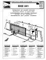 1
1
-
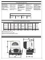 2
2
-
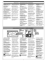 3
3
-
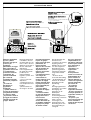 4
4
-
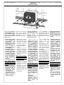 5
5
-
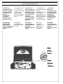 6
6
-
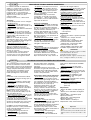 7
7
-
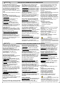 8
8
-
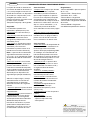 9
9
-
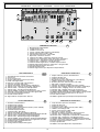 10
10
-
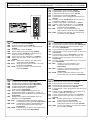 11
11
-
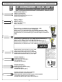 12
12
-
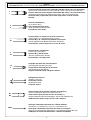 13
13
-
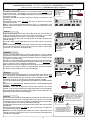 14
14
-
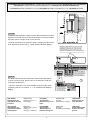 15
15
-
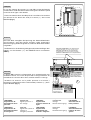 16
16
-
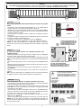 17
17
-
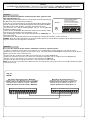 18
18
-
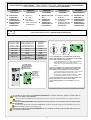 19
19
-
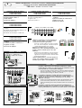 20
20
-
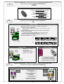 21
21
-
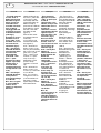 22
22
-
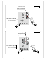 23
23
-
 24
24


CAME BXE 241 El manual del propietario
- Categoría
- Abridor de puerta
- Tipo
- El manual del propietario
- Este manual también es adecuado para
en otros idiomas
- français: CAME BXE 241 Le manuel du propriétaire
- italiano: CAME BXE 241 Manuale del proprietario
- English: CAME BXE 241 Owner's manual
- Deutsch: CAME BXE 241 Bedienungsanleitung
Artículos relacionados
-
CAME BXE El manual del propietario
-
CAME BXE 241 Manual de usuario
-
CAME BX241 Manual de usuario
-
-
-
-
-
-
-
