CAME BXE El manual del propietario
- Categoría
- Abridor de puerta
- Tipo
- El manual del propietario

Documentazione
Tecnica
S20
rev. 2.1
08/2001
©
CAME
CANCELLI
AUTOMATICI
119BS20
SERIE BX |
BX SERIES
|
SÉRIE BX |
BAUREIHE BX
|
SERIE BX
BXE
CANCELLI AUTOMATICI
Automazioni per cancelli scorrevoli
Automation systems for sliding gates
Automatisations pour portails coulissant
Antriebe für den Schiebetore
Automatización para puertas correderas
3 x 1.5 / 230V
2 x 1 - TX
2 x 1
2 x 1.5
RG58
6
5
9
3
1
2
8
10
4 x 1 - RX
11
3 x 1.5 / 230V
2 x 1 - TX
3 x 1
2 x 1.5
RG58
6
5
4
8
3
1
2
9
9
2 x 1 - TX
4 x 1 - RX
10
4 x 1 - RX
7
1 - Gruppo BXE
2 - Quadro comando
incorporato
3 - Ricevitore radio
4 - Cremagliera
5 - Selettore a chiave
6 - Lampeggiatore di
movimento
7 - Antenna
8 - Fotocellule di
sicurezza
9 - Colonnina per
fotocellula
10 - Fermo anta
1 - BXE Antriebsmotor
2 - Schalttafel im Antrieb
3 - Funkempfänger
4 - Zahnstange
5 - Außenantenne
6 - Blinkleuchte “Tor in
Bewegung”
7 - Schlüsselschalter
8 - IR Lichtschranke
9 - Lichtschrankeensäule
10 -Toranschlag
1 - BXE unit
2 - Control panel
(incorporated)
3 - Radio receiver
4 - Rack
5 - Electric lock
6 - Flashing light indica-
ting door movement
7 - Antenna
8 - Safety photocells
9 - Photocell column
10 - Closure stop
Impianto tipo Installation type
Standard montage
Instalación tipo
1 - Conjunto BXE
2 - Cuadro de mando
incorporado
3 - Radiorreceptor
4 - Cremallera
5 - Selector mediante
llave
6 - Lámpara intermiten-
te de movimiento
7 - Antena receptora
8 - Fotocélulas de
seguridad
9 - Columna para
fotocélula
10 - Tope puerta
1 - Groupe BXE
2 - Armoire de
commande
incorporé
3 - Récepteur radio
4 - Crémaillère
5 - Sélecteur a clé
6 - Clignotant de
mouvement
7 - Antenne de
réception
8 - Photocellules de
sécurité
9 - Colonne pour
photocellule
10 - Butée d'arrêt
Standard installation

2
CARATTERISTICHE GENERALI -
GENERAL SPECIFICATIONS
- CARACTÉRISTIQUES GÉNÉRALES
ALLGEMEINES MERKMALE
- CARACTERÍSTICAS GENERALES
MISURE D'INGOMBRO -
OVERALL DIMENSIONS
- MESURES D'ENCOMBREMENT -
ABMESSUNGEN
- MEDIDAS
Progettato e costruito
interamente dalla
CAME, risponde alle
vigenti norme di
sicurezza (UNI 8612),
con grado di protezio-
ne IP54.
Garantito 12 mesi
salvo manomissioni.
Il a été entièrement
conçu et realisé par
les Ets CAME, confor-
mément aux normes
de sécurité en vigueur
(NFP 25362) avec
degré de protection
IP54.
Il est garanti 12 mois
sauf en cas d'endom-
magement.
Designed and construc-
ted entirely by CAME;
conforms to (UNI 8612)
safety standards with IP
54 protection rating.
12 mounth guarantee;
guarantee void if unit is
tampered with.
Vollständig von der
CAME geplant und her-
gestellt, entsprechend
den geltenden
Sicherheits-bedigungen
(UNI 8612) mit Schutz-
grad IP54.
12 Monate Garantie,
Bedienungs und
Montagefehler ausge-
schlossen.
Diseñado y construi-
do totalmente por
CAME, con arreglo a
las vigentes normas
de seguridad (UNI
8612) con grado de
protección IP54.
Garantia de 12 meses
salvo manipulacio-
nes.
CARATTERISTICHE TECNICHE -
TECHNICAL CHARACTERISTICS -
CARACTERISTIQUES TECHNIQUES
TECNISCHE DATEN -
CARACTERISTICAS TECNICAS
240
105
150
290
125165
105
310
22 max.
-amissamatatroP
-stimilesU
xameétroP
-thciwegroT
atreuposeP
elaiznediserosu
laitnediseR
leitnediseregasu
ztasnienetavirp
laicnediserosu
008gK
MOTORIDUTTORE
GRADO DI
PROTEZIONE
PESO ALI MENTA ZIONE ASSORBIMENTO POTENZA
INTERMITTENZA
LAVORO
COPPIA RAPPORTO DI RI DU ZIONE SPI NTA VELOCITA ' MA X. CONDENSATORE
GEARMOTOR
PROTECTION
RATING
WEIGHT POWER SUPPLY CUR RENT POWER DUTY CICLE MAX TOR QUE
RED UCTION
RATIO
PUSH MAX. SPEED CAPACITOR
MOTOR ÉDUCTEUR
DEGRÉ DE
PROTECTION
POIDS ALI MENTATI ON ABSORPTI ON PUISSANCE
INTERMIT TENCE
DE TRAVAIL
COUPLE RAPPOR T DE REDUC TION POUSSÉE VITESSE MAX. CONDENSATEUR
GET RI EBEMOTOR SCHUTZGRAD GEWI CH T
STROM_
VERSORGU NG
STROMAUF NAHME LEI STUNG EINSCHALTDAUER DREHMOMEN T
UNTERSET ZUNGS_
VERHÄLTN IS
REGELBARER
MAX.
ÜBERTRAGU NGS
KONDENSATOR
MOTORREDUCTOR
GRADO DE
PROTECCION
PESO ALIM ENTACI ON ABSORBENCIA POTENCIA
INTERMITENCIA
TRA BAJO
PAR E JA
(MOTOR)
RELACION DE
RED UCCION
EMPUJE
VELOCIDAD
MAX.
CONDEN SADOR
BXE IP 54 15 Kg 230V a.c. 2,4A 300W 30 % * 32 Nm 1/33 800 N 10 m/min. 20 µF
* Ottenuta mediante quadro comando CAME
* Obtained with CAME control panel
* Obtenue au moyen armoire de commande CAME
* Erreicht mit Hilte der "CAME" Schalttafel
* Se obtiene mediante el cuadro de mando CAME

3
PRIMA DELL'INSTALLAZIONE ... -
BEFORE INSTALLING .....
- AVANT D'INSTALLER L'AUTOMATISME .....
VOR DEN INSTALLATION ÜBERPRÜFEN
... - ANTES DE INSTALAR EL AUTOMATISMO...
FISSAGGIO BASE MOTORE -
MOTOR TO BASE ANCHORAGE
- FIXATION DE LA PLAQUE DU MOTEUR
BEFESTIGUNGS DER MOTORBASIS
- FIJACIÓN BASE MOTOR
- La hoja de la puerta debe
estar suficientemente rigida
y compacta
- Las ruedas de desliza-
miento deben estar perfecta
y engrasadas adecuada-
mente.
- La guia de deslizamiento
debe estar bien fijada en el
suelo, sobresaliendo a lo
largo de su entera longitud,
sin huecos ni irregularida-
des (que podrian
obstaculizar el movimiento
de la puerta).
- La guia superior debe
tener el justo juego con la
puerta metálica (para ga-
rantizar un movimiento
regular y silencioso).
- Disponer un tope para
apertura y el cierre.
- Disponer un conducto
para los cables eléctricos
que cumpla con las disposi-
ciones de mando y
seguridad.
- Die Leistungfähigkeit der
feststehenden und bewegli-
chen Teile des Tores
überprüfen.
- Das Tor sollte ausreichend
stabil sein. Die Gleitrollen
sollten in guten Zustand und
angemessen geschmiert sein.
- Die Gleitführung auf dem
Boden sollte sich in optimaler
Position befinden: gut auf
dem Boden befestigt, in sei-
ner Gesamtlänge vollständig
über dem Boden, ohne Ver-
tiefungen und/oder
Unebenheiten, die die Tor-
bewegung behindern können.
- Die oberen Führungsschie-
nen sollten das richtige Spiel
zum Tor haben, um ein präzi-
ses und regelmäßiges Gleiten
zu garantieren.
- Einen Anschlag für Tor Auf
und Tor Tu sollte vorhanden
sein.
- Den Lauf der elektrischen
Kabel nach den Steuerungs
und Sicherheitsbestim-
mungen vorsehen.
- Le panneau mobile du
portail devra être suf-
fisamment rigide et solide.
- Les roues de coulis-
sement devront être en très
bon état. En outre, elles
devront être conve-
nablement graissées.
- Le rail de guidage devra
être bien fixé au sol. De
plus, il devra se présenter
entièrement en surface sans
affaissement ou irrégularité
(qui pourraient empêcher le
mouvement du portail).
- Le guide supérieur devra
avoir un jeu convenable
avec le portail (pour per-
mettre un mouvement
régulier et silencieux).
- Prévoir une butée d’arrêt à
l’ouverture et à la ferme-
ture.
- Prévoir le passage des
câbles électriques selon les
dispositifs de commande et
de sécurité.
- The gate must be suffi-
ciently rigid and solid.
- The wheels on which the
gate slide must be in perfect
condition and adequately
lubricated.
- The wheel guide must be
firmly attached to the
ground, completely expo-
sed, and without any dips or
irregular sections which
might hinder the movement
of the gate.
- The upper guide must allow
for the correct amount of
play in order to guarantee
smooth and silent movement
of the gate.
- Opening and closure stops
must be installed.
- The wiring must be routed
as specified by the control
and safety requirements.
- Controllare che l'anta sia
rigida e compatta e che le
ruote di scorrimento siano
in buono stato e adeguata-
mente ingrassate.
- La guida a terra dovrà es-
sere ben fissata al suolo,
completamente in superficie
in tutta la sua lunghezza e
priva di irregolarità che
possano ostacolare il movi-
mento del cancello.
- I pattini-guida superiori
non devono creare attriti.
- Prevedere un fermo anta
in apertura e uno in chiusu-
ra ed il percorso dei cavi
elettrici come da impianto
tipo.
- Inserire le viti nella pia-
stra di ancoraggio
bloccandole con i dadi in
dotazione, ed estrarre le
zanche preformate verso il
basso.
- Predisporre, dimensio-
nandola in base alle misure
del motoriduttore, una piaz-
zola in cemento (si
consiglia di farla sporgere
dal terreno di circa 50 mm.)
con annegata la piastra di
ancoraggio e relative
zanche sulla quale sara'
fissato il gruppo.
- La base di fissaggio dovra'
risultare perfettamente in
bolla, pulita in tutte le sue
estremita', con il filetto
delle viti completamente in
superfice.
N.B.: Dalla stessa dovranno
emergere i tubi flessibili
per il passaggio dei cavi di
collegamento elettrico.
- Install the screws in the
anchor plate and fasten them
with a nut, then bend the pre-
formed clamps downwards.
- Construct a cement founda-
tion that is large enough to
accomodate the gear motor
(it is a good idea to protrude
50 mm. from the ground).
When pouring the founda-
tion, embed the gear motor
anchor plate and the relative
clamps in the cement.
- The anchor bolts should be
embedded in the concrete in
the positions indicated;
the drive unit is then attached
to this bots. The anchor plate
must be perfectly level and
absolu-tly clean; the bolts
threads must be completly
exposed.
N.B.: The flexible tubes for
the electrical wiring must be
embedded in the base and
protude in the correct posi-
tion.
- Introduire les vis dans la
plaque d'ancrage en les
bloquant avec un écrou, et
replier les agrafes préfor-
mées ver le bas.
- Préparer une base en
ciment d'une dimension
adéquate aux mesures du
motoréducteur (il est con-
seillé de la faire dépasser
du terrain d'environ 50
mm.), et noyer dedans la
plaque d'ancrage et les
agrafes correspondantes
afin de permettre le fixage
du groupe.
- La base de fixation devrà
être parfaitement de niveau
et propre sur toute sa
surface et le filet des vis
devra être complètement en
surface.
N.B. Les câbles pour le
branchement électrique
devront sortir de cette base.
- Die Schrauben in die Anker-
platte einfügen und mit einer
Schraubenmutter blockieren,
die vorgeformten Fundament-
anker nach unten umbiegen.
- Eine den Abmessungen des
Getriebemotors entsprechen-
de Betonfundamentplatte (Es
empfiehlt sich, diese ca. 50
mm. vom Boden herausragen
zu las-sen) zum Einbetten der
Ankerplatte und der entspre-
chenden Fundamentanker,
die zur Befestigung des An-
triebsaggregats dienen,
vorbereiten.
- Die Befestigungs-unterlage
muß in seiner gesamten Län-
ge vollkommen eben und
sauber sein. Das Gewinde der
Schrauben müssen gänzlich.
hervorstehen.
Wichtig: die Kabel für den
Elektroanschluß müssen
herausrgen.
- Introducir los tornillos en
la placa de anclaje, blo-
queándolos con una tuerca,
y doblar las palancas
preformadas hacia abajo.
- Preparar, dándole las di-
mensiones adecuadas en
función de las medidas del
motorreductor, una platafor-
ma de cemento (se
aconseja dejarla sobresalir
del suelo aprox. 50 mm.)
con la placa de enclaje
embedida y con las corres-
pondientes varillas, que
permitrá la fijación del gru-
po.
- La base de fijación debe
estar perfectamente nivela-
da, limpia en todos sus
extremos, con la rosca de
los tornillos totalmente in
superficie.
N.B.: De ésta deben
sobresilar los tubos flexi-
bles para el paso de los
cables para las conexiones
eléctricas.
50 mm.
75 mm.
105 mm.
Struttura fissa
Wall
Structrure fixe
Feste Struktur
Estructura fija
Anta cancello
Gate wing
Panneau mobile du portail
Gleitachse
Puerta
Piazzola in cemento
Concrete base
Plate-forme en ciment
Plattenachse
Plataforma de cemento
Cavi
Cable
Câbles
Kabel
Cables
Cremagliera
Rack-limit
Cremaillére
Zahnstange
Cremallera
Piastra di ancoraggio / Zanche
Fixing plate / Anchor stays
Plaque de fixation / Agrafes
Gleitachse / Verankerung
Placa de fijación / Barras de fijción

4
INSTALLAZIONE DEL GRUPPO -
UNIT INSTALLATION -
INSTALATION DU GROUPE
AUFSTELLUNG DES AGGREGATS
- COLOCACIÓN DEL GRUPO
Nella fase preliminare di
installazione, i piedini
dovranno sporgere di 5-
10 mm. per permettere
allineamenti, fissaggio
della cremagliera e
regolazioni successive.
L'accoppiamento esatto
con la linea di scor-
rimento del cancello è
ottenibile dal sistema di
regolazione integrale
(brevettato) composto da:
- le asole che permet-
tono la regolazione
orizzontale;
- i piedini filettati in
acciaio che permettono
la regolazione verticale e
la messa in bolla;
- le piastrine e i dadi di
fissaggio che rendono
solidale l'aggancio del
gruppo alla base.
During the initial phase of
installation, the feet
should protrude by 5-10
mm. in order to allow for
alignment, anchorage of
the rack and further
adjustments.
Perfect alignment with the
guide rail is made possible
by the (patented) built-in
regulation system, which
consists of:
- slots for horizontal
adjustment;
- threaded steel feet for
vertical adjustment and
levelling;
- plates and bolts for
anchorage to the base.
Dans la phase de
instalation préliminaire,
les broches devront
dépasser de 5 à 10 mm
afin de permettre les
alignements et les
réglages nécessaires
après la pose.
L’accouplement exact
avec la ligne de
coulissement du portail
s’effectue par le système
de réglage hauteur
(breveté) dont le groupe
est pourvu, et qui
comprend plus
précisément:
- les trous oblong
permettant le réglage
horizontal;
- les broches filetées en
acier qui donnent le
réglage vertical et la
mise à niveau;
- les plaques et les
écrous de fixation qui
assemblent solidement le
groupe à la plaque de
fixation scellée.
Nun die Montage des
Antriebsmotors vorneh-
men. Die genaue Kop-
plung mit der Gleitlinie des
Tors wird von dem
integrierten Einstel-
lungssystem (patentiert)
garantiert, mit dem das
Aggregat ausgestattet ist
und zwar:
- die Osen für die
horizontale Einstellung,
- die Gewindefüße aus
Stahl für die vertikale
Einstellung und die
Nivellierung,
- die Befestigungsplät-
tchen und muttern zur
soliden Befestigung des
Aggregats an die
Bodenplatte.
Während der Vorberei-
tungsarbeiten der Montage
sollten die Füße 5-10 mm
herausragen, um
Ausfluchtungen und
Einstellung auch nach der
Fertigstellung zu
ermöglich.
En la fase previa de la
colocación, los pies
deben sobresalir 5-10
mm para consentir la
alineación, la fijación de
la cremallera y las regu-
laciones sucesivas.
El acoplamiento exacto
con la linea de desli-
zamiento de la puerta
metálica se obtiene
mediante el sistema de
regulación integral
(patentado) que consta
de:
- los agujeros ovalados
que consienten la
regulación horizontal;
- las tuercas de acero
que permiten la
regulación vertical y la
nivelación;
- las placas y las tuercas
de fijación que hacen
solidario el enganche del
conjunto con la base.
5÷10 mm.
Ingresso cavi
Cable entrances
Passage des câbles
Kabeleinführungen
Accoppiamento pignone-cremagliera
con gioco 1÷2 mm.
Rack-to-pinion coupling with 1÷2 mm. clearance
Assemblage pignon-crémailère avec jeu
de 1 à 2 mm.
Zwischen Zahnstange und dem Antriebsritzel
1÷2 mm. Spiel einstellen
Acoplamiento piñon-cremaliera
1÷2 mm. de juego
Regolazione orizzontale e fissaggio
Horizontal adjustment unit and achorage
Réglage horizontal et fixation
Horizontale Einstellung
Regulación horizontal y fijación
Regolazione verticale - messa in bolla
Vertical adjustment and unit leveling
Réglage vertical - mise à niveau
Vertikale Einstellung
Regulación vertical y nivelación
Entrada cables
1÷2 mm.

5
FISSAGGIO CREMAGLIERA-
ATTACHING THE RACK/LIMIT
- FIXATION CREMAILLÉRE
MONTAGE DE ZAHNSTANGE -
FIJACIÓN DE LA CREMALLERA
Con el fin de permitir al
ENCODER medir la
carrera de la puerta, fijar
la cremallera con el
mismo a mitad de
carrera:
- coloque la hoja en la
mitad de la carrera,
apoye la cremallera
sobre el piñon del
motorreductor y deslice
manualmente la puerta,
fijando la cremallera a
todo lo largo;
- La carrera máxima de
la puerta es de 14 m;
- Finalizadas las ope-
raciones para la fijacion
de la cremallera, regular
los pies (por medio de un
destornillador) de modo
que se obtenga el justo
juego entre el piñón y la
cremallera (1-2 mm).
N.B. Esto hace que el
peso de la puerta
metálica no cargue sobre
el conjunto.
- Si la cremallera ya ha
sido fijada, hay que
regular el acoplamiento
piñón/cremallera.
- Una vez realizados los
ajuste, fijar el conjunto
cerrando las dos tuercas
de fijación.
Ist der ENCODER zur
Erfassung bzw. Überwa-
chung des Torlaufs auf
halber Laufhöhe auf der
Zahnstange zu befestigen:
- den Torflügel halb öffnen
und die Zahnstange auf
dem Ritzel vom Getriebe-
motor auflegen. Dann das
Tor von Hand verschieben
und dabei die Zahnstange
auf ganzer Länge
befestigen;
- Der maximale Lauf vom
Tor beträgt 14 m;
- Die verstellbaren Füße
des Antriebsmotors (mit
einem Schraubenzieher)
so einstellen, daß
zwischen Ritzel und
Zahnstange ein Spiel (1-2
mm) besteht.
Wichtig: Dadurch wird
vermieden, daß das
Gewicht des Tores auf
dem Aggregat lastet.
- Nach diesen Einstel-
lungsarbeiten das
Aggregat durch Anziehen
der beiden Muttem
befestigen.
Afin de permettre à
l'ENCODEUR de relever la
course du portail, fixer la
crémaillère avec le
portail à micourse:
- mettre la porte à la
moitié de sa course,
poser la crémaillère sur
le pignon du
motoréducteur et faire
coulisser manuellement
le portail en fixant la
crémaillère sur toute sa
longueur;
- La course maximum du
portail est de 14 m;
- Lorsque la fixation de la
crémaillère est terminée
régler les broches (en
utilisant un tournevis) de
façon à obtenir un jeu
convenable (1-2 mm)
dans l’assemblage du
pignon et de la
crémaillère.
N.B. Ceci pour éviter que
le poids du portail ne
repose sur le groupe.
- Si la crémaillère est
déjà fixée, utiliser le
système de réglage
hauteur pour assembler
correctement de facon
exacte le pignon et la
crémaillère.
- Exécuter tous les
réglages, fixer le groupe
en serrant les deux
écrous de fixation.
Install the rack with the
gate at the half-way point.
This will enable the
ENCODER to detect gate
travel properly:
- allow the door to reach
mid-run, set the rack on
the rationmotor's pinion
and slide the gate
manually, fixing the rack's
entire lenght;
- The gate's maximum run
is 14 m;
- when the rack is attached
to the gate, adjust the feet
using a screwdriver until
the play between the
pinion and the rack is
correct (1-2 mm.).
N.B.: This position
ensures that the weight of
the gate does not rest on
the gearmotor.
- If the rack is already
attached, proceed directly
to the adjustment of the
rack/pinion coupling.
- When the necessary
adjustment have been
completed, fasten the unit
in position by tightening
the two anchor bolts.
Al fine di permettere
all'ENCODER di rilevare
la corsa del cancello,
fissare la cremagliera
con il cancello a meta'
corsa:
- portare l'anta a meta'
corsa, appoggiare la
cremagliera sul pignone
del motoriduttore e far
scorrere manualmente il
cancello fissando la
cremagliera in tutta la
sua lunghezza;
- La corsa massima del
cancello é di 14 m;
- ultimata l'operazione di
fissaggio della crema-
gliera, regolare i piedini
(servendosi di un
cacciavite) in modo da
ottenere il giusto giuoco
tra pignone e cremaglie-
ra (1-2 mm).
N.B. : Questo evitera' che
il peso del cancello vada
a gravare sul gruppo.
- Se la cremagliera é gia'
fissata, procedere
direttamente alla
regolazione dell'accop-
piamento pignone/
cremagliera.
- Eseguite tutte le
regolazioni, fissare il
gruppo stringendo i dadi
di fissaggio.

6
SBLOCCO MOTORIDUTTORE -
GEAR RELEASE
- OPÉRATION DE DÉBLOCAGE
- ANTRIEBSENTRIEGELUNG
DESBLOQUEO MOTORREDUCTOR
Per aprire lo
sportellino inserire la
chiave, spingerla e
ruotala in senso
orario; sbloccare
quindi il
motoriduttore
ruotando la manopola
nella direzione
indicata.
Pour ouvrir la trappe,
introduire la clé, la
pousser et la tourner
dans le sens des
aiguilles d'une
montre. Débloquer
ensuite le
motoréducteur en
tournant la poignée
dans la direction
indiquée.
Para abrir la
portezuela introducir
la llave, empujarla y
girarla en sentido
horario; desbloqear el
motorreductor
girando la manilla en
la dirección indicada.
To open the access
door, insert the key,
push down and rotate
clockwise. Now, release
the gear motor by
rotating the knob in the
direction shown.
Zum Öffnen der klappe
den Schlüssel
einfügen,
hineindrücken und im
Uhrzeigersinn drehen.
Dann den
Getriebemotor durch
Drehen des Knopfs in
die angegebene
Richtung entsperren.
ATTENZIONE:
l'apertura dello spor-
tellino di sblocco im-
pedisce il funziona-
mento del motore.
ATTENTION:
the opening of the
unblock panel arrests
the motor.
ATTENTION:
l’ouverture de la por-
te de déblocage
empêche le fonction-
nement du moteur.
ACHTUNG:
Wenn das Freigabetür-
chen geöffnet wird,
funktioniert der Motor
nicht.
ATENCIÓN:
la apertura de la tapa
de desbloqueo,
impide el funciona-
miento del motor.
Release
Sblocco
Blocco
Engage
Blockierend
Entriegelt
Blocage
Déblocage
Desbloqueo
Bloqueo
CAME
La página se está cargando...
La página se está cargando...

9
La tarjeta de mando se alimenta con una
tensión de 230V en los bornes L1 y L2 y
está protegido en entrada con fusible de
línea de 5A. Los dispositivos de mando
son a baja tensión y està protegidos por
fusible a 1A. La potencia total de los ac-
cesorios a 24V, no debe superar los 20W.
Tiempo de trabajo fijo a 90 segundos.
SEGURIDAD
Las fotocélulas pueden estar conectadas
y predispuestas para:
-
Reapertura
en la fase de cierre (2-C1);
-
Stop parcial
parada de la puerta si se
encuentra en movimiento con la con-
siguiente predisposición al cierre automá-
tico (2-C3);
-
Stop total
(1-2), parada de la puerta ex-
cluyendo el posible ciclo de cierre auto-
mático; para reactivar el movimiento es
preciso actuar en el teclado o en el man-
do a distancia);
Nota: La apertura de un contacto de se-
guridad normalmente cerrado (2-C1, 2-
C3, 1-2) es señalada por medio del destello
del LED de señalización (n°11).
-
Detección de presencia obstáculo
. Con
el motorparado (puerta cerrada, abierta o
en posición semi-abierta obtenida a tra-
vés de un comando de stop total), anula
cualquier función del transmisor o del bo-
tón en caso de obstáculo detectado por
los dispositivos de seguridad (por ejem-
plo: fotocélulas);
- Además la tarjeta integra y maneja
automáticamente una función de seguri-
dad, que si se detectaran obstáculos fun-
ciona de la siguiente manera:
durante la apertura
la puerta se detiene y se activa el cierre
automático;
durante el cierre
la puerta invierte la dirección de marcha
hasta la apertura completa con el consi-
guiente accionamiento del cierre automá-
tico.
¡Atención! tras tres inversiones consecu-
tivas, la puerta queda abierta desconec-
tando el cierre automático: para cerrar use
el radiocontrol o el botón de cierre.
ACCESORIOS CONECTABLES
-
Lámpara ciclo.
Lámpara que alumbra la
zona de maniobra; se queda encendida a
partir del momento en que las hojas em-
piezan la apertura hasta el cierre comple-
to (incluyendo el tiempo de cierre
automático). El funcionamiento de la lám-
para ciclo se obtiene en la salida W-E1
sólo si los dips n°1 «cierre automático» y
n°10 «Lámpara ciclo» están colocados en
ON, véase página 17;
-
Indicador luminoso de puerta abierta.
Lámpara que indica que la puerta de co-
rredera está, se apaga cuando la puerta
activa el final de carrera de cierre, conéc-
tela a los bornes 10-5.
Nota: los accesorios 24V no requieren la
conexión a tierra.
OTRAS FUNCIONES
-
Cierre automático.
El temporizador de
cierre automático se autoalimenta en fin-
de-tiempo carrera en fase de apertura. El
tiempo prefijado regulable, sin embargo,
está subordinado a la intervención de
posibles accesorios de seguridad y se
excluye después de una intervención de
parada o en caso de falta de energía eléc-
trica;
-
Apertura parcial.
La apertura de la puer-
ta para paso peatonal se activa con la
conexión a los bornes 2-3P y se regula
mediante el trimmer AP.PARZ.;
-
Función a " hombre presente"
. Fun-
cionamiento de la puerta manteniendo
pulsada la tecla (seleccionándolo se
escluye la función del mando de radio);
-
Programación
regulación de los
microinterruptores de tope electrónicos de
apertura y cierre;
-
Función master
, el cuadro asume todas
las funciones de mando en el caso de dos
motores combinados (véase p.15);
-
Función slave
; el cuadro es accionado
exclusivamente por el “MASTER” (véase
página 15);
-
Preintermitencia
en fase de apertura y
cierre;
-
Tipo de mando:
-apertura-cierre-inversión;
-apertura-stop-cierre-stop;
-sólo apertura.
REGULACIONES
-Trimmer AP.PARZ.= Apertura parcial: de 1"
a 14";
-Trimmer TCA = Tiempo cierre automáti-
co: de 1" a 150”;
Atención:
- la apertura de la tapa de desbloqueo,
impide el funcionamiento del motor.
- antes de actuar dentro del aparato,
quitar la tensión de línea y desecnetar
las baterías (si estuvieran conectadas).
DESCRIPCIÓN TÉCNICA TARJETA BASE ZBXE
ESPAÑOL

10
SCHEDA BASE ZBXE -
ZBXE MOTHERBOARD
- CARTE BASE ZBXE -
GRUNDPLATINE ZBXE
- TARJETA BASE ZBXE
MAIN COMPONENTS
1 Terminal block for external connections
2 5A line fuses
3 1A accessories fuse
4 Socket radiofrequency board
5 Radio code and program encoder signal LED
6 Buttons for storing radio code and limit switch
programming
7 "Function selection" dip-switch
8 Trimmer AP.PARZ.: Partial opening adjustment
9 Trimmer TCA: automatic closing time adjustment
10 24V voltage signal LED
11 Fixed Encoder mother board
COMPOSANTS PRINCIPAUX
1 Plaque à bornes pour les branchements
2 Fusibles de ligne 5A
3 Fusible accessoires 1A
4 Branchement carte radiofréquence
5 LED de signalisation code radio et prog. encoder
6 Boutons-poussoirs mémorisation codes code radio et
programmation fin de course
7 Dip-switch "sélection fonction"
8 Trimmer AP.PARZ.: Réglage Ouverture partielle
9 Trimmer TCA: Réglage Temps de fermeture automatique
10 LED de signalisation tension 24V
11 Carte fixe Encodeur
COMPONENTES PRINCIPALES
1 Caja de bornes para las conexiónes
2 Fusibles de linea 5A
3 Fusible accesorios 1A
4 Conexión tarjeta radiofrecuencia
5 LED de señal código radio y programación encoder
6 Teclas memorización código radio y programación final
de carrera
7 Dip-switch "seleción función"
8 Trimmer AP.PARZ.: Regulación Apertura parcial
9 Trimmer TCA: Regulación cierre automático
10 LED de señal de tensión 24V
11 Tarjeta fija Encoder
HAUPTKOMPONENTEN
1 Anschluss-Klemmenleiste
2 5A-Sicherung Leitungs
3 1A-Sicherung Zubehörs
4 Steckanschluß Funkfrequenze-Platine
5 Anzeige-LED Funkcode und Programmier encoder
6 Funkcode-Speichertasten und Endausschalter-
Programmiertaste
7 "Funktionswahl" dip-switch
8 Trimmer AP.PARZ.: Einstellung Teilöffnung
9 Trimmer TCA: Einstellung Zeiteinstellung
Schließautomatik
10 Anzeige-LED der 24V-Spannung
11 feste Encoder-Platine
D
GB
COMPONENTI PRINCIPALI
1 Morsettiere di collegamento
2 Fusibili di linea 5A
3 Fusibile accessori 1A
4 Innesto scheda radiofrequenza
5 LED di segnalazione codice radio e prog. encoder
6 Pulsanti memorizzazione codice radio e prog. finecorsa
F
E
I
7 Dip-switch "selezione funzioni"
8 Trimmer AP.PARZ.: regolazione apertura parziale
9 Trimmer TCA: regolazione tempo di chiusura automatica
10 LED di segnalazione di tensione 24V
11 Scheda fissa Encoder
CHIUDE / CH1
APRE / CH2
AF
ENCODER
AP.PARZ.
T.C.A.
21 345678910O
N
1
2
3
4
10
6
7
8 9 5
11
Dis. 26221

11
COLLEGAMENTI ELETTRICI -
ELECTRICAL CONNECTIONS -
BRANCHEMENTS ÉLECTRIQUES
ELEKRISCHE ANSCHLÜSSE -
CONEXIONES ELÉCTRICAS
L1
L2
UVWE
10 11 1 2 3 3P 4 5 7
2MOT
E
_
_
_
2C1C3B1B2
10
11
1
2
2
3
2
3P
N.B. Rispettare la polarità nel
collegamento delle fotocellule (TX e
RX).
N.B. When connecting the photocells
(TX and RX), observe the correct
polarities.
N.B. Respecter la polarité lors de la
connexion des photocellules (TX et
RX).
Anmerkung: beim Anschließen der
Photozellen (TX und RX) auf die
Polung achten.
N.B. Respetar la polaridad en la
conexión de las fotocélulas (TX y
RX).
10 11
4:
NO C NC
6:
W
E
U
W
V
L1
L2
UVWE
UVWE
Alimentazione 230V (a.c.)
230V (a.c.) power input
Alimentation 230V (c.a.)
Stromversorgung 230V (Wechselstrom)
Alimentación 230V (a.c.)
Motore monofase 230V(a.c.)
230V (a.c.) single-phase motor
Moteur monophasé 230V (c.a.)
Einphasenmotor 230V (Wechselstrom)
Motor monofásico 230V (a.c.)
Uscita 230V (a.c.) in movimento (es. lampeggiatore - max. 25W)
230V (a.c.) output in motion (e.g. flashing light - MAX. 25W)
Sortie 230V (c.a.) en mouvement (ex. clignotant - max. 25)
Ausgang 230V (Wechselstrom) in Bewegung (z.B. Blinker - max.25W)
Salida de 230V (a.c.) en movimento (p.ej. lámpara intermitente - max. 25W)
Uscita 230V a.c. lampada ciclo (vedi descrizione pag. 7)
230V a.c. cycle lamp (see description pg. 7)
Sortie 230V c.a. lampe cycle (voir description pag. 8)
Betriebszyklus-Anzeigeleuchte - 230V Wechselstrom (sehen S. 8)
Salida de 230V a.c. lámpara ciclo (mirar descripción pág. 9)
Alimentazione accessori 24V (a.c.) max. 20W
24V (a.c.) Powering accessories (max 20W)
Alimentation accessoires 24V (a.c.) max.20W
Zubehörspeisung 24V (Wechselstrom) max. 20W
Alimentación accesorios 24V (a.c.) max. 20W
Pulsante stop (N.C.)
Pushbutton stop (N.C.)
Bouton-poussoir arrêt (N.F.)
Stop-Taste (N.C.)
Pulsador de stop (N.C.)
Pulsante apre (N.O.)
Pushbutton open (N.O.)
Bouton-possoir ouverture (N.O.)
Taste Öffnen (N.O.)
Pulsador de apertura (N.O.)
Pulsante apre (N.O.) per apertura parziale
Open button (N.O.) for partial opening
Bouton-poussoir d'ouverture (N.O.) pour ouverture partial
Taste Öffnen (Arbeitskontakt) für Partial-Stop
Pulsador de apertura (N.O.) para apertura parcial
2
1
34
5
67
8910
ON
1 ON
10 ON
La página se está cargando...

13
1
234
L2T
L1T
0
24
12
LIMITATORE DI COPPIA MOTORE /
MOTOR TORQUE LIMITER
/ LIMITEUR DE COUPLE MOTEUR
DREHMOMENTBEGRENZER DES MOTORS
/ LIMITADOR DE PAR MOTOR
COLLEGAMENTO A TERRA /
EARTH CONNECTION
/ BRANCHEMENT Á LA TERRE
ERDUNG
/ CONEXIÓN A TIERRA
(A)
Conecte el hilo de
tierra usando el
tornillo
autoterrajante (A) de
serie.
Das Massekabel
anschließen und
dazu die
selbsteinschneidenden
Schrauben verwen-
den (A), die der
Packung beiliegen.
Para variar el par
motor, desplazar el
faston indicado
hasta una de las 4
posiciones; 1 mín. -
4 máx.
Zur Änderung des
Motor-Drehmoments
den angegebenen
Faston auf eine der 4
Stellungen
positionieren: 1 min. -
4 max.
Pour varier le couple
du moteur, déplacer
le connecteur
indiqué sur l'une des
4 positions; 1 min. -
4 max.
To vary the motor
torque, move the
indicated faston to
one of the four
positions: 1=min,
4=max.
Per variare la coppia
motore, spostare il
faston indicato su
una delle 4 posizio-
ni; 1 min - 4 max.
Collegare il filo di
terra usando la vite
automaschiante (A)
in dotazione.
Connect the earth wire
by using the provided
self-tapping screw (A).
Brancher le fil de
terre en utilisant la
vis autoforeuse (A)
fournie de série.

14
AF
ENCODER
21 345678910O
N
APRE / CH2
AF
ENCODER
21 345678910O
N
CHIUDE / CH1
APRE / C H2
AP.PARZ. T.C.A.
Chiudere lo sportello dello sblocco e inserire il dip-switch 8 in ON, il led di
segnalazione inizia a lampeggiare (1). Portare il cancello in finecorsa chiude,
premere il tasto "CHIUDE", il led rimane acceso finchè si mantiene premuto
il tasto (2).
Procedere portando il cancello a finecorsa apre e premere il tasto "APRE" (3).
Riposizionare il Dip-switch 8 in OFF (4), aprire lo sportello e inserire la
manopola di sblocco.
N.B. In fase di programmazione finecorsa apre, se premendo il tasto "APRE"
il led rimane spento, invertire le fasi del motore ed Encoder come illustrato (5).
Close the door panel of the outlet and set dip-switch 8 to ON. The LED will
begin flashing (1). Bring the gate to the close limit-switch, press button
“CHIUDE”; the LED will remain lit as long as the button is released (2).
Now, move the gate to the end-of-travel position when open, and press the
"APRE" key (3).
Move Dip-switch 8 to OFF (4), open the access door and turn the release
Knob.
N.B. If the LED does not light up when the "APRE" key is pressed to program
the end-of-travel position when opened, reverse the motor and encoder
connections as shown on the diagram (5).
Fermer le volet de déblocage et insérer le dip-switch 8 sur ON, le del de
signalisation commence à clignoter (1). Mettre le grille sur la butée de fin de
course ferme, appuyer sur la touche “CHIUDE“, le led reste allumé tant que
l’on appuie sur la touche (2).
Procéder en amenantle portail en position de fin de course ouverture puis
appuyer sur la touche "APRE" (3). Déconnecter le Dip-switch 8 sur OFF (4),
ouvrir la porte et insérer la poignée de déblocage.
N.B. Pendant la phase de programmation de la fin de course ouverture, si, en
appuyant sur la touche "APRE", le led reste éteint, inverser les phases du
moteur et de l'encodeur de la façon indiquée (5).
Schließen Sie das Freigabetürchen und schalten Sie den Dip-Switch 8 auf ON.
Jetzt beginnt die Kontrolleuchte zu blinken (1). Das Tor bis zum Endanschlag
Schließen bringen. Dazu die Taste "CHIUDE" drücken. Das LED bleibt so
lange an, wie die Taste gedrückt gehalten wird (2).
Das Tor ganz Öffnen (Öffnungsendstellung) und die Taste "APRE" drücken
(3).
Dip-Switch 8 ausschalten (4), Abdeckung öffnen und Entriegelungsgriff
einfügen.
HINWEIS: wenn die Anzeige-LED wõhrend des Drückens der Taste "APRE"
in der Öffnungsendschalter-Programmierphase erloschenbleibt, dann sind
die Anschlüsse der Motorphasendrõhte und des Encoders der Abbildung
entsprechend zu wechseln (5).
Cierre la tapa del dispositivo de desbloqueo y conecte el dip-switch 8 en ON;
el indicador luminoso inicia a parpadear (1). Lleve la verja hasta el final de
carrera de cierre, pulsar la tecla “CHIUDE”; el indicador luminoso permanece
encendido mientras se mantenga apretado la tecla (2).
Proceder llevando la puerta a la posición final de carrera abre, pulsar la tecla
"APRE" (3).
Desconetar el Dip-switch 8 en OFF (4), abrir la portezuela e introducir la
manópola de desbloqueo.
NOTA. En la fase de programación final de carrera abre, si pulsando la tecla
"APRE" el LED está apagado, invertir las fases del motor y Encoder como
indicado en la figura (5).
LED intermittente
Signal LED
LED de signalisation
Anzeige-LED
LED de señal
PROGRAMMAZIONE FINECORSA -
LIMIT SWITCH PROGRAMMING -
PROGRAMMATION FIN DE COURSE
ENDAUSSCHALTER-PROGRAMMIER -
PROGRAMMACION FINAL DE CARRERA
ITALIANO
ENGLISH
FRANÇAIS
ESPANOL
DEUTSCH
2
1 34567
8910
ON
CHIUDE / CH1
APRE / C H2
AP.PARZ. T.C.A.
CHIUDE
2
LED acceso
Signal LED
LED de
signalisation
Anzeige-LED
LED de señal
1
3
LED acceso
Signal LED
LED de signalisation
Anzeige-LED
LED de señal
4
APRE
montaggio a sinistra vista interna
mounting on the left-hand side
of the gate
montage à gauche vue de l'intérieur
die Montage auf der linken Seite
angeschlossen, interne Ansicht
montaje a la izquierda vista interior
E1
UVW
M
E
2
1
3
45
6
78910
ON
eventuale montaggio a destra
if right-hand installation is desired
éventuel montage à droite
eventuelle Montage auf der rechten
Seite
eventual montaje a la derecha
U
VWE1
M
E
5
La página se está cargando...

16
5
CHIUDE / CH1
APRE / CH2
AF
ENCODER
AP.PARZ. T.C.A.
21 345678910O
N
2
1
34
5
67
8910
ON
SCHEDA BASE DEL MOTORE "SLAVE"
"SLAVE" MOTOR MAIN BOARD
CARTE DE BASE DU MOTEUR "SLAVE"
BASISKARTE VOM MOTOR "SLAVE"
TARJETA BASE DEL MOTOR «SLAVE»
7 OFF - 9 ON
4
CHIUDE / CH1
APRE / CH2
AF
ENCODER
AP.PARZ. T.C.A.
21 345678910O
N
2
1
34
5
67
8910
ON
SCHEDA BASE DEL MOTORE "MASTER"
"MASTER" MOTOR MAIN BOARD
CARTE DE BASE DU MOTEUR "MASTER"
BASISKARTE VOM MOTOR "MASTER"
TARJETA BASE DEL MOTOR «MASTER»
7 ON - 9 OFF
ESPANIOL
En el caso de instalación de dos motores combinados, proceda de la si-
guiente manera:
- Coordine el sentido de funcionamiento (1) de los motorreductores A y B,
modificando la rotación del motor "B" , véase pág. 14 "programación fin de
carrera" punto 5;
- Establezca entre A y B cuál debe ser el motor Master (o piloto, es decir el
motor que acciona ambas hojas) y cuál debe ser el Slave (es decir aquel
conducido por el Master), entonces,
en la tarjeta de mando del Master:
- asegúrese de que esté conectada la tarjeta de radiofrecuencia AF
(2);
- realice las conexiones eléctricas normales y seleccione las funcio-
nes deseadas (3);
- coloque el dip 7 en ON y el 9 en OFF en el selector de funciones (4);
en la tarjeta de mando del Slave:
- coloque el dip 7 en OFF y el 9 en ON en el selector de funciones (5);
- Ejecute las conexiones entre los tableros de bornes, como indicado en la
Figura (6);
NOTA: Si las dos hojas asociadas tienen distinto tamaño, la función master
se tiene que conectar al cuadro del motor instalado en la hoja más larga.
Zur Installation von zwei parallel geschalteten Motoren bitte wie folgt vorge-
hen:
- Die Laufrichtung (1) der Getriebemotoren A und B aufeinander abstimmen
und dazu gegebenenfalls die Drehrichtung von Motor B ändern (siehe S. 14
Abschnitt 5 „Programmierung vom Endanschlag“).
- Festlegen, welcher der beiden Motoren A und B der Master-Motor sein soll,
also der übergeordnete Motor, der beide Tore steuert, und welcher der Slave-
Motor sein soll, also der untergeordnete, der vom Master gesteuert wird.
Dann die Steuerkarte vom Master-Motor zur Hand nehmen:
- Sicherstellen, daß die Radiofrequenz-Karte AF (2) eingesteckt ist.
- Die normalen elektrischen Anschlüsse durchführen und die gewünsch-
ten Funktionen auswählen (3).
- Am Funktionsschalter (4) den Dip-Switch 7 auf ON und den Dip-
Switch 9 auf OFF stellen.
Dann die Steuerkarte vom Slave-Motor zur Hand nehmen:
- Am Funktionsschalter (5) den Dip-Switch 7 auf OFF und den Dip-
Switch 9 auf ON stellen.
- Die Anschlüsse an den Klemmleisten wie auf Abbildung (6) dargestellt durch-
führen.
BITTE BEACHTEN: Falls die beiden parallel geschalteten Tore nicht gleich
groß sein sollten, muß der Motor, der am längeren Torflügel installiert ist, die
Master-Funktion übernehmen.
DEUTSCH
Morsettiera del quadro motore «MASTER»
Terminal board of the "MASTER" motor control panel
Plaque à bornes du tableau du moteur «MASTER»
Klemmbrett der Schalttafel vom Motor «MASTER»
Tablero de bornes del cuadro motor «MASTER»
Morsettiera del quadro motore «SLAVE»
Terminal board of the "SLAVE" motor control panel
Plaque à bornes du tableau du moteur «SLAVE»
Klemmbrett der Schalttafel vom Motor «SLAVE»
Tablero de bornes del cuadro motor «SLAVE»
10 11 1 2 3 3P 4 5 7
2M O T
2C1C3B1B2
10 11 1 2 3 3P 4 5 7
2M O T
2C1C3B1B2
6

17
CHIUDE / CH1
APRE / CH2
AF
ENCODER
AP.PARZ. T.C.A.
2
1 34567
8910
O
N
SELEZIONI FUNZIONI -
SELECTION OF FUNCTIONS
- SÉLECTION FONCTIONS
FUNKTIONSWAHL
- SELECCIÓN DE LAS FUNCIONES
ON
OFF
DIP-SWITCH 10 VIE
/ 10-WAY DIP-SWITCH
/ DIP-SWITCH 10 VOIES
ZEHNWEG-DIP-SWITCH /
DIP-SWITCH 10 VÍAS
FRANÇAIS
1 ON Fonction fermeture automatique sélectionnée;
2 ON Fonction "ouverture-stop-fermeture-stop" avec bouton
(2-7) et commande-radio sélectionnée;
2 OFF Fonction "ouverture-fermeture" avec bouton (2-7) et
commande-radio sélectionnée;
3 ON Fonction "seulement ouverture" avec commande-radio
sélectionnée;
4 ON Fonction "contact mantenu" sélectionnée (exclut la
fonction radiocommande)
5 ON Fonction preclignotement sélectionnée (Temps fix
5sec.);
6 ON Dispositif de détection de présence, à moteur arrête,
sélectionnée;
7 ON - 9 OFF Fonction "Master" sélectionnée (seulement
pour le branchement accouplé, voir p. 15);
8 ON Fonction "Spare" (programmation fin de course) sé-
lectionnée;
9 ON - 7 OFF Fonction "Slave" sélectionnée (seulement pour
le branchement accouplé, voir p. 15);
10 ON - 1 ON Fonction lampe cycle sélectionnée;
ESPANIOL
1 ON Función cierre automático activada;
2 ON Función "apertura-stop-cierre-stop" con botón (2-7) y
radiomando activada;
2 OFF Función "apertura-cierre" con botón (2-7) y radiomando
activada;
3 ON Función "sólo apertura" con radiomando activada;
4 ON Función "hombre presente" activada (escluye la fun-
ción del radiomando)
5 ON Función preintermitencia activada; (tiempo fijo 5 sec.)
6 ON Función detección del obstàculo, a motor parado, acti-
vada;
7 ON - 9 OFF Función "Master" activada (sólo para la co-
nexión combinada, véase p.15)
8 ON Función "Spare" (programación final de carrera) activa-
da;
9 ON - 7 OFF Función "Slave" activada (sólo para la co-
nexión combinada, véase p.15)
10 ON - 1 ON Función lámpara ciclo activada;
ITALIANO
1 ON Chiusura automatica attivata;
2 ON Funzione "apre-stop-chiude-stop" con pulsante (2-7) e
radiocomando attivata;
2 OFF Funzione "apre-chiude" con pulsante (2-7) e
radiocomando attivata;
3 ON Funzione "solo apertura" con radiocomando attivata;
4 ON "uomo presente" attivato (esclude la funzione del
radiocomando);
5 ON Prelampeggio attivato (tempo fisso 5 sec.);
6 ON Rilevazione ostacolo, a motore fermo, attivato;
7 ON - 9 OFF Funzione "Master" attivata; (solo per collega-
mento abbinato, pag. 15);
8 ON Funzione "Spare" attivata (programmazione
finecorsa);
9 ON - 7 OFF Funzione "Slave" attivata; (solo per collega-
mento abbinato, pag. 15);
10 ON - 1 ON Funzione lampada ciclo attivata;
ENGLISH
1 ON Automatic closure function enabled;
2 ON "Open-stop-close-stop" function with button (2-7) and
radio control enabled;
2 OFF "Open-close" function with button (2-7) and radio
control enabled,
3 ON "Only open" function with radio control enabled;
4 ON "Present man" operation enabled (and radio remote
control deactivated)
5 ON Pre-flashing function enabled (5 sec. fixed time);
6 ON Obstacle detection device, with motor stopped,
enabled;
7 ON - 9 OFF "Master" function enabled (only for coupled
connection, see pag. 15);
8 ON "Spare" function (limit switch programming) enabled;
9 ON - 7 OFF "Slave" function enabled (only for coupled
connection, see pag. 15);
10 ON - 1 ON Courtesy light function enabled;
2
1 34567
8910
O
N
DEUTSCH
1 ON Funktion Schließautomatik zugeschaltet;
2 ON Funktion "Öffnen-stop-Schließen-stop" mit Druckknopf
(2-7) und Fernsteuerung zugeschaltet;
2 OFF Funktion "Öffnen-Schließen" mit Druckknopf (2-7) und
Fernsteuerung zugeschaltet;
3 ON Funktion "nur Öffnen" mit Fernsteuerung zugeschaltet;
4 ON Bedienung vom "Steuerpult" zugeschaltet (bei Wahl
dieser Betriebsart wird die Funkfernsteuerung ausge-
schlossen)
5 ON Funktion Vorblinker zugeschaltet (Zeiteinstellung feste
5 sek.);
6 ON Funktion Hindernisaufnahme, bei stillstehendem Motor,
zugeschaltet;
7 ON - 9 OFF Master-Funktion zugeschaltet (nur für kombi-
nierte Anschlüsse, siehe S. 15);
8 ON Funktion "Spare" (Programmierendausschalter) zu-
geschaltet;
9 ON - 7 OFF Slave-Funktion zugeschaltet (nur für kombi-
nierte Anschlüsse, siehe S. 15);
10 ON - 1 ON Funktion Beleuchtung Zyklus zugeschaltet;

18
ENGLISH
PROCEDURE
A. insert an
AF card **.
B. encode
transmitter/s.
C. store code in the
motherboard.
FRANÇAIS
PROCEDURE
A. placer une carte
AF **.
B. codifier le/s
émetteur/s.
C. mémoriser la
codification sur
la carte base.
DEUTSCH
PROZEDUR
A. Stecken Sie eine
Karte AF **.
B. Codieren Sie den/
die Sender.
C. Speichern Sie die
Codierung auf der
Grundplatine.
ZBXE
INSTALLAZIONE DEL RADIOCOMANDO -
RADIO CONTROL INSTALLATION -
INSTALLATION DE LA RADIOCOMMANDE
INSTALLATION DER RADIOSTEUERUNG -
INSTALACIÓN DEL RADIOMANDO
ITALIANO
PROCEDURA
A. inserire una
scheda AF **.
B. codificare il/i
trasmettitore/i.
C. memorizzare la
codifica sulla
scheda base.
ESPANOL
PROCEDIMIENTO
A. introducir una
tarjeta AF **.
B. codificar el/los
transmisor/es.
C. memorizar la
codificación en
la tarjeta base.
La schedina AF deve essere inserita OBBLIGATORIAMENTE in assenza di tensione, perché la scheda madre la riconosce
solo quando viene alimentata
The AF board should ALWAYS be inserted when the power is off because the motherboard only recognises it when it is
powered.
La carte AF doit OBLIGATOIREMENT être branchée en l’absence de tension car la carte mère ne la reconnaît que quand
elle est alimentée.
Vor Einschieben der Karte die Stromzufuhr UNBEDINGT abschalten, da die Erkennung durch die Hauptkarte nur über eine
Neueinschaltung ( nur durch Versorgung) erfolgt.
La tarjeta AF se debe montar OBLIGATORIAMENTE en caso de falta de corriente, porque la tarjeta madre la reconoce sólo
cuando está alimentada
(**) Per trasmettitori con frequenza 433.92 AM (serie
TOP e serie TAM) bisogna, sulla relativa scheda AF43S,
posizionare il jumper come illustrato.
(**) On AM transmitters operating at 433.92 MHz
(TOP and TAM series), position the jumper
connection on circuit card AF43S as shown on the
sheet.
(**) Pour les émetteurs de fréquence 433.92 AM (série
TOP et série TAM) il faut positionner le pontet sur la
carte AF43S correspondante de la façon indiquée.
(**) Bei Sendern mit einer Frequenz von 433.92 AM
(Reihe TOP und Reihe TAM) ist der auf der
entsprechenden Platine AF43S befindliche Jumper
der Abbildung entsprechend zu positionieren.
(**) Para transmisores con frecuencia 433.92 AM (serie
TOP y serie TAM) es necesario, en la tarjeta
corespondiente AF43S, colocar el jumper como se
indica
TOP TAM
AF43S/SM
SCHEDA BASE
MOTHERBOARD
CARTE DE BASE
BASISKARTE
TARJETA BASE
SCHEDA "AF"
"AF" BOARD
CARTE "AF"
KARTE «AF»
TARJETA «AF»
zHM/azneuqerF
zHM/ycneuqerF
zHM/ecneuqerF
zHM/zneuqerF
zHM/aicneucerF
azneuqerfoidaradehcS
draobycneuqerfoidaR
ecneuqérfoidaretraC
enitalP-zneuqerfknuF
aicneucerfoidaratejraT
erotittemsarT
rettimsnarT
ruettemE
rednesknuF
rosimsnarT
599.62MF 031FA MFT
009.03MF 051FA MFT
599.62MA 62FA POT
009.03MA 03FA POT
29.334MA
MS34FA/S34FA POT/MAT
RS34FA OMOTA
INSERIMENTO SCHEDA AF -
AF BOARD INSERTION
- NSTALLATION DE LA CARTE AF
EINSTECKEN DER KARTE AF -
MONTAJE DE LA TARJETA AF
A
La página se está cargando...
La página se está cargando...

21
ITALIANO
-Assicurarsi che il dip 8 sia in
OFF (programmazione
finecorsa disattivata);
-Tenere premuto il tasto "CH1"
sulla scheda base (il led di
segnalazione lampeggia), con
un tasto del trasmettitore
s'invia il codice, il led rimarrà
acceso a segnalare l'avvenuta
memorizzazione (vedi fig.1).
Eseguire la stessa procedura
con il tasto "CH2" associandolo
con un altro tasto del trasmetti-
tore (fig.2).
CH1 = Canale per comandi
diretti ad una funzione della
centralina del motoriduttore
(comando "solo apre" / "apre-
chiude-inversione" oppure
"apre-stop-chiude-stop", a
seconda della selezione
effetuata sui dip-switch 2 e 3).
CH2 = Canale per comandi
diretti ad un dispositivo
accessorio collegato su B1-B2.
N.B.: Se in seguito si vuol
cambiare codice, basta
ripetere la sequenza descritta.
DEUTSCH
-Stellen Sie den Dip-Switch 8 auf
OFF (Programmierung
Endanschlag ausgeschlossen).
-Halten Sie die Taste CH1 an der
Basiskarte gedrückt (die
Kontrolleuchte blinkt). Senden
Sie den Code mit einer Taste
vom Sender. Der Kontrolleuchte
bleibt jetzt an und zeigt dadurch
das erfolgte Speichern an
(Abb.1).
Gehen Sie ebenso mit Taste CH2
vor und ordnen sie ihr eine an-
dere Taste des Senders zu
(Abb.2)
CH1 = Kanal für die Direkt-
steuerung einer Funktion des
Getriebemotor-Schaltkastens
(Steuerung "nur Öffnen" / "Öff-
nen-Schließen-Sicherheits-
rücklauf" bzw. "Öffnen-Stp-
Schließen-Stop", je nach über
Dip-Switch 2 und 3 ausgeführter
Wahl).
CH2 = Kanal für Direktsteuerung
eines über B1-B2 angeschlosse-
nen Zubehörs.
HINWEIS: bei eventuell er-
wünschter Sender
codeänderung ist der beschrie-
bene Vorgang zu wiederholen.
ESPANOL
-Coloque el dip 8 en OFF (programación final de carrera desactivada);
-Mantener oprimida la tecla "CH1" en la tarjeta base (el led de señalización parpadea), con una tecla del transmisor se envía el
código, el led permanece encendido para indicar que el almacenamendo se ha efectuado (fig.1).
Efectuar el mismo procedimiento con la tecla "CH2" asociándola a otra tecla del transmisor (fig.2).
CH1 = Canal para mando directo a una función de la central del motorreductor (mando "solo abre" / "abre-cierra-inversión" o "abre-
stop-cierra-stop", según la selección efectuada en los dip-switch 2 y 3).
CH2 = Canal para un mando directo a un dispositivo accesorio conectado en B1-B2.
NOTA: Si posteriormente se quisiera cambiar el código de los propios transmisores, sólo hay que repetir la secuencia descrita.
ENGLISH
-Position Dip 8 to OFF ( limit
switch programming deacti-
vated);
-Keep the CH1 key pressed on
the base card (the signal LED
will flash), and with a key on the
transmitter the code is sent, the
LED will remain lit to signal the
successful saving of the code
(figure 1).
Perform the same procedure
with the CH2 key, associating it
with another transmitter key
(figure 2).
CH1 = Channel for direct control
of one function performed by
the control unit on the gear
motor ("open only" / "open-
close-reverse" or "open-stop-
close-stop", depending on the
position of dip switches 2 and
3).
CH2 = Channel for direct control
of an accessory connected
across B1-B2.
N.B. If you wish to change the
code on your transmitters in the
future, simply repeat the proce-
dure described above.
FRANÇAIS
-Positionner le dip 8 sur OFF
(programmation des butées de
fin de course désenclenchée);
-Appuyer sur la touche "CH1"
sur la carte de base (le led de
signalisation clignote), avec
une touche du emetteur on en-
voie le code, le led restera al-
lumé pour signaler que la mé-
morisation s'est effectuèe
(fig.1).
Suivre la même procédure avec
la touche "CH2" en l'associant
avec une autre touche du
emetteur (fig.2).
CH1 = Canal pour obtenir la
commande directe d'une fonc-
tion du boîtier du
motoréducteur ( commande
"uniquement ouverture" /
"ouverture-fermeture-inversion"
ou "ouverte-stop-ferme-stop"
en fonction de la sélection ef-
fectuée sur les dip-switchs 2 et
3).
CH2 = Canal pour obtenir la
commande directe d'un dispo-
sitif accessoire branché sur B1-
B2.
N.B.: Si, successivement, on
veut changer le code des émet-
teur, il suffit de répéter la sé-
quence décrite ci-dessus.
MEMORIZZAZIONE CODICE -
CODE STORAGE
- MEMORISATION DU CODE
SPEICHERN VOM CODE
- MEMORIZACIÓN CÓDIGO
C
CHIUDE / CH1
APRE / CH2
AP.PARZ.
T.C.A.
Fig. 1 / Abb. 1
LED di segnalazione codice radio
Radio code signal LED
LED de signalisation code radio
Funkcode-Anzeigeleuchtdiode
LED de señal código radio
CHIUDE / CH1
APRE / CH2
AP.PARZ.
T.C.A.
Fig. 2 / Abb. 2
LED di segnalazione codice radio
Radio code signal LED
LED de signalisation code radio
Funkcode-Anzeigeleuchtdiode
LED de señal código radio
La página se está cargando...
La página se está cargando...
La página se está cargando...
Transcripción de documentos
SERIE BX | BX SERIES | SÉRIE BX | BAUREIHE BX | SERIE BX Documentazione Tecnica S20 rev. 2.1 08/2001 BXE CANCELLI AUTOMATICI © CAME CANCELLI AUTOMATICI 119BS20 Automazioni per cancelli scorrevoli Automation systems for sliding gates Automatisations pour portails coulissant Antriebe für den Schiebetore Automatización para puertas correderas 9 11 10 1 2 3 8 5 4 10 9 9 8 6 5 6 7 2 x 1 - TX 2 x 1.5 2x1 3 3 x 1.5 / 230V 4 x 1 - RX RG58 2 x 1 - TX 4 x 1 - RX Impianto tipo 1 - Gruppo BXE 2 - Quadro comando incorporato 3 - Ricevitore radio 4 - Cremagliera 5 - Selettore a chiave 6 - Lampeggiatore di movimento 7 - Antenna 8 - Fotocellule di sicurezza 9 - Colonnina per fotocellula 10 - Fermo anta Standard installation 1 - BXE unit 2 - Control panel (incorporated) 3 - Radio receiver 4 - Rack 5 - Electric lock 6 - Flashing light indicating door movement 7 - Antenna 8 - Safety photocells 9 - Photocell column 10 - Closure stop Installation type 1 - Groupe BXE 2 - Armoire de commande incorporé 3 - Récepteur radio 4 - Crémaillère 5 - Sélecteur a clé 6 - Clignotant de mouvement 7 - Antenne de réception 8 - Photocellules de sécurité 9 - Colonne pour photocellule 10 - Butée d'arrêt Standard montage 123456- BXE Antriebsmotor Schalttafel im Antrieb Funkempfänger Zahnstange Außenantenne Blinkleuchte “Tor in Bewegung” 7 - Schlüsselschalter 8 - IR Lichtschranke 9 - Lichtschrankeensäule 10 -Toranschlag Instalación tipo 1 - Conjunto BXE 2 - Cuadro de mando incorporado 3 - Radiorreceptor 4 - Cremallera 5 - Selector mediante llave 6 - Lámpara intermitente de movimiento 7 - Antena receptora 8 - Fotocélulas de seguridad 9 - Columna para fotocélula 10 - Tope puerta CARATTERISTICHE GENERALI - GENERAL SPECIFICATIONS - CARACTÉRISTIQUES GÉNÉRALES ALLGEMEINES MERKMALE - CARACTERÍSTICAS GENERALES Progettato e costruito interamente dalla CAME, risponde alle vigenti norme di sicurezza (UNI 8612), con grado di protezione IP54. Garantito 12 mesi salvo manomissioni. Designed and constructed entirely by CAME; conforms to (UNI 8612) safety standards with IP 54 protection rating. 12 mounth guarantee; guarantee void if unit is tampered with. Il a été entièrement conçu et realisé par les Ets CAME, conformément aux normes de sécurité en vigueur (NFP 25362) avec degré de protection IP54. Il est garanti 12 mois sauf en cas d'endommagement. Vollständig von der CAME geplant und hergestellt, entsprechend den geltenden Sicherheits-bedigungen (UNI 8612) mit Schutzgrad IP54. 12 Monate Garantie, Bedienungs und Montagefehler ausgeschlossen. Diseñado y construido totalmente por CAME, con arreglo a las vigentes normas de seguridad (UNI 8612) con grado de protección IP54. Garantia de 12 meses salvo manipulaciones. Portata massima - Use limits - Portée max Torgewicht - Peso puerta uso residenziale Residential usage residentiel privaten einsatz uso residencial Kg 800 CARATTERISTICHE TECNICHE - TECHNICAL CHARACTERISTICS - CARACTERISTIQUES TECHNIQUES TECNISCHE DATEN - CARACTERISTICAS TECNICAS MOTORIDUTTORE GRADO DI PROTEZIONE GEARMOTOR PROTECTION RATING WEIGHT POWER SUPPLY CURRENT POWER MOTORÉDUCTEUR DEGRÉ DE PROTECTION POIDS ALIMENTATION ABSORPTION PUISSANCE GETRIEBEMOTOR SCHUTZGRAD GEWICHT STROM_ VERSORGUNG STROMAUFNAHME LEISTUNG MOTORREDUCTOR GRADO DE PROTECCION PESO ALIMENTACION ABSORBENCIA BXE IP 54 15 Kg 230V a.c. 2,4A PESO ALIMENTAZIONE ASSORBIMENTO POTENZA INTERMITTENZA LAVORO COPPIA RAPPORTO DI RIDUZIONE DUTY CICLE MAX TORQUE REDUCTION RATIO SPINTA VELOCITA' MAX. CONDENSATORE PUSH MAX. SPEED CAPACITOR INTERMITTENCE DE TRAVAIL COUPLE RAPPORT DE REDUCTION POUSSÉE VITESSE MAX. CONDENSATEUR EINSCHALTDAUER DREHMOMENT UNTERSETZUNGS_ VERHÄLTNIS REGELBARER MAX. ÜBERTRAGUNGS KONDENSATOR POTENCIA INTERMITENCIA TRABAJO PAREJA (MOTOR) RELACION DE REDUCCION EMPUJE VELOCIDAD MAX. CONDENSADOR 300W 30 % * 32 Nm 1/33 800 N 10 m/min. 20 µF * Ottenuta mediante quadro comando CAME * Obtained with CAME control panel * Obtenue au moyen armoire de commande CAME * Erreicht mit Hilte der "CAME" Schalttafel * Se obtiene mediante el cuadro de mando CAME MISURE D'INGOMBRO - OVERALL DIMENSIONS - MESURES D'ENCOMBREMENT - ABMESSUNGEN - MEDIDAS 240 165 105 22 max. 310 105 125 150 290 2 PRIMA DELL'INSTALLAZIONE ... - BEFORE INSTALLING ..... - AVANT D'INSTALLER L'AUTOMATISME ..... VOR DEN INSTALLATION ÜBERPRÜFEN ... - ANTES DE INSTALAR EL AUTOMATISMO... - Controllare che l'anta sia rigida e compatta e che le ruote di scorrimento siano in buono stato e adeguatamente ingrassate. - La guida a terra dovrà essere ben fissata al suolo, completamente in superficie in tutta la sua lunghezza e priva di irregolarità che possano ostacolare il movimento del cancello. - I pattini-guida superiori non devono creare attriti. - Prevedere un fermo anta in apertura e uno in chiusura ed il percorso dei cavi elettrici come da impianto tipo. - The gate must be sufficiently rigid and solid. - The wheels on which the gate slide must be in perfect condition and adequately lubricated. - The wheel guide must be firmly attached to the ground, completely exposed, and without any dips or irregular sections which might hinder the movement of the gate. - The upper guide must allow for the correct amount of play in order to guarantee smooth and silent movement of the gate. - Opening and closure stops must be installed. - The wiring must be routed as specified by the control and safety requirements. - Le panneau mobile du portail devra être suffisamment rigide et solide. - Les roues de coulissement devront être en très bon état. En outre, elles devront être convenablement graissées. - Le rail de guidage devra être bien fixé au sol. De plus, il devra se présenter entièrement en surface sans affaissement ou irrégularité (qui pourraient empêcher le mouvement du portail). - Le guide supérieur devra avoir un jeu convenable avec le portail (pour permettre un mouvement régulier et silencieux). - Prévoir une butée d’arrêt à l’ouverture et à la fermeture. - Prévoir le passage des câbles électriques selon les dispositifs de commande et de sécurité. - Die Leistungfähigkeit der feststehenden und beweglichen Teile des Tores überprüfen. - Das Tor sollte ausreichend stabil sein. Die Gleitrollen sollten in guten Zustand und angemessen geschmiert sein. - Die Gleitführung auf dem Boden sollte sich in optimaler Position befinden: gut auf dem Boden befestigt, in seiner Gesamtlänge vollständig über dem Boden, ohne Vertiefungen und/oder Unebenheiten, die die Torbewegung behindern können. - Die oberen Führungsschienen sollten das richtige Spiel zum Tor haben, um ein präzises und regelmäßiges Gleiten zu garantieren. - Einen Anschlag für Tor Auf und Tor Tu sollte vorhanden sein. - Den Lauf der elektrischen Kabel nach den Steuerungs und Sicherheitsbestimmungen vorsehen. - La hoja de la puerta debe estar suficientemente rigida y compacta - Las ruedas de deslizamiento deben estar perfecta y engrasadas adecuadamente. - La guia de deslizamiento debe estar bien fijada en el suelo, sobresaliendo a lo largo de su entera longitud, sin huecos ni irregularidades (que podrian obstaculizar el movimiento de la puerta). - La guia superior debe tener el justo juego con la puerta metálica (para garantizar un movimiento regular y silencioso). - Disponer un tope para apertura y el cierre. - Disponer un conducto para los cables eléctricos que cumpla con las disposiciones de mando y seguridad. FISSAGGIO BASE MOTORE - MOTOR TO BASE ANCHORAGE - FIXATION DE LA PLAQUE DU MOTEUR BEFESTIGUNGS DER MOTORBASIS - FIJACIÓN BASE MOTOR Anta cancello Gate wing Panneau mobile du portail Gleitachse Puerta 75 mm. 105 mm. 50 mm. Piastra di ancoraggio / Zanche Fixing plate / Anchor stays Plaque de fixation / Agrafes Gleitachse / Verankerung Placa de fijación / Barras de fijción Cremagliera Rack-limit Cremaillére Zahnstange Cremallera Struttura fissa Wall Structrure fixe Feste Struktur Estructura fija Piazzola in cemento Concrete base Plate-forme en ciment Plattenachse Plataforma de cemento Cavi Cable Câbles Kabel Cables - Inserire le viti nella piastra di ancoraggio bloccandole con i dadi in dotazione, ed estrarre le zanche preformate verso il basso. - Predisporre, dimensionandola in base alle misure del motoriduttore, una piazzola in cemento (si consiglia di farla sporgere dal terreno di circa 50 mm.) con annegata la piastra di ancoraggio e relative zanche sulla quale sara' fissato il gruppo. - La base di fissaggio dovra' risultare perfettamente in bolla, pulita in tutte le sue estremita', con il filetto delle viti completamente in superfice. N.B.: Dalla stessa dovranno emergere i tubi flessibili per il passaggio dei cavi di collegamento elettrico. - Install the screws in the anchor plate and fasten them with a nut, then bend the preformed clamps downwards. - Construct a cement foundation that is large enough to accomodate the gear motor (it is a good idea to protrude 50 mm. from the ground). When pouring the foundation, embed the gear motor anchor plate and the relative clamps in the cement. - The anchor bolts should be embedded in the concrete in the positions indicated; the drive unit is then attached to this bots. The anchor plate must be perfectly level and absolu-tly clean; the bolts threads must be completly exposed. N.B.: The flexible tubes for the electrical wiring must be embedded in the base and protude in the correct position. - Introduire les vis dans la plaque d'ancrage en les bloquant avec un écrou, et replier les agrafes préformées ver le bas. - Die Schrauben in die Ankerplatte einfügen und mit einer Schraubenmutter blockieren, die vorgeformten Fundamentanker nach unten umbiegen. - Introducir los tornillos en la placa de anclaje, bloqueándolos con una tuerca, y doblar las palancas preformadas hacia abajo. - Préparer une base en ciment d'une dimension adéquate aux mesures du motoréducteur (il est conseillé de la faire dépasser du terrain d'environ 50 mm.), et noyer dedans la plaque d'ancrage et les agrafes correspondantes afin de permettre le fixage du groupe. - Eine den Abmessungen des Getriebemotors entsprechende Betonfundamentplatte (Es empfiehlt sich, diese ca. 50 mm. vom Boden herausragen zu las-sen) zum Einbetten der Ankerplatte und der entsprechenden Fundamentanker, die zur Befestigung des Antriebsaggregats dienen, vorbereiten. - La base de fixation devrà être parfaitement de niveau et propre sur toute sa surface et le filet des vis devra être complètement en surface. - Die Befestigungs-unterlage muß in seiner gesamten Länge vollkommen eben und sauber sein. Das Gewinde der Schrauben müssen gänzlich. hervorstehen. - Preparar, dándole las dimensiones adecuadas en función de las medidas del motorreductor, una plataforma de cemento (se aconseja dejarla sobresalir del suelo aprox. 50 mm.) con la placa de enclaje embedida y con las correspondientes varillas, que permitrá la fijación del grupo. N.B. Les câbles pour le branchement électrique devront sortir de cette base. Wichtig: die Kabel für den Elektroanschluß müssen herausrgen. 3 - La base de fijación debe estar perfectamente nivelada, limpia en todos sus extremos, con la rosca de los tornillos totalmente in superficie. N.B.: De ésta deben sobresilar los tubos flexibles para el paso de los cables para las conexiones eléctricas. Accoppiamento pignone-cremagliera con gioco 1÷2 mm. Rack-to-pinion coupling with 1÷2 mm. clearance Assemblage pignon-crémailère avec jeu de 1 à 2 mm. Regolazione orizzontale e fissaggio Horizontal adjustment unit and achorage Réglage horizontal et fixation Horizontale Einstellung Regulación horizontal y fijación 1÷2 mm. INSTALLAZIONE DEL GRUPPO - UNIT INSTALLATION - INSTALATION DU GROUPE AUFSTELLUNG DES AGGREGATS - COLOCACIÓN DEL GRUPO Zwischen Zahnstange und dem Antriebsritzel 1÷2 mm. Spiel einstellen Acoplamiento piñon-cremaliera 1÷2 mm. de juego 5÷10 mm. Regolazione verticale - messa in bolla Vertical adjustment and unit leveling Réglage vertical - mise à niveau Vertikale Einstellung Regulación vertical y nivelación Ingresso cavi Cable entrances Passage des câbles Kabeleinführungen Entrada cables Nella fase preliminare di installazione, i piedini dovranno sporgere di 510 mm. per permettere allineamenti, fissaggio della cremagliera e regolazioni successive. L'accoppiamento esatto con la linea di scorrimento del cancello è ottenibile dal sistema di regolazione integrale (brevettato) composto da: - le asole che permettono la regolazione orizzontale; - i piedini filettati in acciaio che permettono la regolazione verticale e la messa in bolla; - le piastrine e i dadi di fissaggio che rendono solidale l'aggancio del gruppo alla base. During the initial phase of installation, the feet should protrude by 5-10 mm. in order to allow for alignment, anchorage of the rack and further adjustments. Perfect alignment with the guide rail is made possible by the (patented) built-in regulation system, which consists of: - slots for horizontal adjustment; - threaded steel feet for vertical adjustment and levelling; - plates and bolts for anchorage to the base. Dans la phase de instalation préliminaire, les broches devront dépasser de 5 à 10 mm afin de permettre les alignements et les réglages nécessaires après la pose. L’accouplement exact avec la ligne de coulissement du portail s’effectue par le système de réglage hauteur (breveté) dont le groupe est pourvu, et qui comprend plus précisément: - les trous oblong permettant le réglage horizontal; - les broches filetées en acier qui donnent le réglage vertical et la mise à niveau; - les plaques et les écrous de fixation qui assemblent solidement le groupe à la plaque de fixation scellée. 4 Nun die Montage des Antriebsmotors vornehmen. Die genaue Kopplung mit der Gleitlinie des Tors wird von dem integrierten Einstellungssystem (patentiert) garantiert, mit dem das Aggregat ausgestattet ist und zwar: - die Osen für die horizontale Einstellung, - die Gewindefüße aus Stahl für die vertikale Einstellung und die Nivellierung, - die Befestigungsplättchen und muttern zur soliden Befestigung des Aggregats an die Bodenplatte. Während der Vorbereitungsarbeiten der Montage sollten die Füße 5-10 mm herausragen, um Ausfluchtungen und Einstellung auch nach der Fertigstellung zu ermöglich. En la fase previa de la colocación, los pies deben sobresalir 5-10 mm para consentir la alineación, la fijación de la cremallera y las regulaciones sucesivas. El acoplamiento exacto con la linea de deslizamiento de la puerta metálica se obtiene mediante el sistema de regulación integral (patentado) que consta de: - los agujeros ovalados que consienten la regulación horizontal; - las tuercas de acero que permiten la regulación vertical y la nivelación; - las placas y las tuercas de fijación que hacen solidario el enganche del conjunto con la base. FISSAGGIO CREMAGLIERA- ATTACHING THE RACK/LIMIT - FIXATION CREMAILLÉRE MONTAGE DE ZAHNSTANGE - FIJACIÓN DE LA CREMALLERA Al fine di permettere all'ENCODER di rilevare la corsa del cancello, fissare la cremagliera con il cancello a meta' corsa: Install the rack with the gate at the half-way point. This will enable the ENCODER to detect gate travel properly: Afin de permettre à l'ENCODEUR de relever la course du portail, fixer la crémaillère avec le portail à micourse: Ist der ENCODER zur Erfassung bzw. Überwachung des Torlaufs auf halber Laufhöhe auf der Zahnstange zu befestigen: Con el fin de permitir al ENCODER medir la carrera de la puerta, fijar la cremallera con el mismo a mitad de carrera: - portare l'anta a meta' corsa, appoggiare la cremagliera sul pignone del motoriduttore e far scorrere manualmente il cancello fissando la cremagliera in tutta la sua lunghezza; - allow the door to reach mid-run, set the rack on the rationmotor's pinion and slide the gate manually, fixing the rack's entire lenght; - The gate's maximum run is 14 m; - when the rack is attached to the gate, adjust the feet using a screwdriver until the play between the pinion and the rack is correct (1-2 mm.). - mettre la porte à la moitié de sa course, poser la crémaillère sur le pignon du motoréducteur et faire coulisser manuellement le portail en fixant la crémaillère sur toute sa longueur; - den Torflügel halb öffnen und die Zahnstange auf dem Ritzel vom Getriebemotor auflegen. Dann das Tor von Hand verschieben und dabei die Zahnstange auf ganzer Länge befestigen; - coloque la hoja en la mitad de la carrera, apoye la cremallera sobre el piñon del motorreductor y deslice manualmente la puerta, fijando la cremallera a todo lo largo; - Der maximale Lauf vom Tor beträgt 14 m; - La carrera máxima de la puerta es de 14 m; - La corsa massima del cancello é di 14 m; - ultimata l'operazione di fissaggio della cremagliera, regolare i piedini (servendosi di un cacciavite) in modo da ottenere il giusto giuoco tra pignone e cremagliera (1-2 mm). N.B. : Questo evitera' che il peso del cancello vada a gravare sul gruppo. - Se la cremagliera é gia' fissata, procedere direttamente alla regolazione dell'accoppiamento pignone/ cremagliera. - Eseguite tutte le regolazioni, fissare il gruppo stringendo i dadi di fissaggio. N.B.: This position ensures that the weight of the gate does not rest on the gearmotor. - If the rack is already attached, proceed directly to the adjustment of the rack/pinion coupling. - When the necessary adjustment have been completed, fasten the unit in position by tightening the two anchor bolts. - La course maximum du portail est de 14 m; - Die verstellbaren Füße - Lorsque la fixation de la des Antriebsmotors (mit crémaillère est terminée einem Schraubenzieher) régler les broches (en so einstellen, daß utilisant un tournevis) de zwischen Ritzel und façon à obtenir un jeu Zahnstange ein Spiel (1-2 convenable (1-2 mm) mm) besteht. dans l’assemblage du Wichtig: Dadurch wird pignon et de la vermieden, daß das crémaillère. Gewicht des Tores auf N.B. Ceci pour éviter que dem Aggregat lastet. le poids du portail ne - Nach diesen Einstelrepose sur le groupe. lungsarbeiten das - Si la crémaillère est Aggregat durch Anziehen déjà fixée, utiliser le der beiden Muttem système de réglage befestigen. hauteur pour assembler correctement de facon exacte le pignon et la crémaillère. - Exécuter tous les réglages, fixer le groupe en serrant les deux écrous de fixation. 5 - Finalizadas las operaciones para la fijacion de la cremallera, regular los pies (por medio de un destornillador) de modo que se obtenga el justo juego entre el piñón y la cremallera (1-2 mm). N.B. Esto hace que el peso de la puerta metálica no cargue sobre el conjunto. - Si la cremallera ya ha sido fijada, hay que regular el acoplamiento piñón/cremallera. - Una vez realizados los ajuste, fijar el conjunto cerrando las dos tuercas de fijación. SBLOCCO MOTORIDUTTORE - GEAR RELEASE - OPÉRATION DE DÉBLOCAGE - ANTRIEBSENTRIEGELUNG DESBLOQUEO MOTORREDUCTOR Per aprire lo sportellino inserire la chiave, spingerla e ruotala in senso orario; sbloccare quindi il motoriduttore ruotando la manopola nella direzione indicata. To open the access door, insert the key, push down and rotate clockwise. Now, release the gear motor by rotating the knob in the direction shown. Pour ouvrir la trappe, introduire la clé, la pousser et la tourner dans le sens des aiguilles d'une montre. Débloquer ensuite le motoréducteur en tournant la poignée dans la direction indiquée. ATTENZIONE: ATTENTION: l'apertura dello spor- the opening of the tellino di sblocco im- unblock panel arrests pedisce il funziona- the motor. mento del motore. ATTENTION: l’ouverture de la porte de déblocage empêche le fonctionnement du moteur. Para abrir la portezuela introducir la llave, empujarla y girarla en sentido horario; desbloqear el motorreductor girando la manilla en la dirección indicada. Zum Öffnen der klappe den Schlüssel einfügen, hineindrücken und im Uhrzeigersinn drehen. Dann den Getriebemotor durch Drehen des Knopfs in die angegebene Richtung entsperren. ACHTUNG: Wenn das Freigabetürchen geöffnet wird, funktioniert der Motor nicht. ATENCIÓN: la apertura de la tapa de desbloqueo, impide el funcionamiento del motor. Blocco Engage Blocage Blockierend Bloqueo CAME Sblocco Release Déblocage Entriegelt Desbloqueo 6 ESPAÑOL DESCRIPCIÓN TÉCNICA TARJETA BASE ZBXE La tarjeta de mando se alimenta con una tensión de 230V en los bornes L1 y L2 y está protegido en entrada con fusible de línea de 5A. Los dispositivos de mando son a baja tensión y està protegidos por fusible a 1A. La potencia total de los accesorios a 24V, no debe superar los 20W. Tiempo de trabajo fijo a 90 segundos. SEGURIDAD Las fotocélulas pueden estar conectadas y predispuestas para: -Reapertura en la fase de cierre (2-C1); -Stop parcial parada de la puerta si se encuentra en movimiento con la consiguiente predisposición al cierre automático (2-C3); -Stop total (1-2), parada de la puerta excluyendo el posible ciclo de cierre automático; para reactivar el movimiento es preciso actuar en el teclado o en el mando a distancia); Nota: La apertura de un contacto de seguridad normalmente cerrado (2-C1, 2C3, 1-2) es señalada por medio del destello del LED de señalización (n°11). -Detección de presencia obstáculo. Con el motorparado (puerta cerrada, abierta o en posición semi-abierta obtenida a través de un comando de stop total), anula cualquier función del transmisor o del botón en caso de obstáculo detectado por los dispositivos de seguridad (por ejemplo: fotocélulas); - Además la tarjeta integra y maneja automáticamente una función de seguridad, que si se detectaran obstáculos funciona de la siguiente manera: durante la apertura la puerta se detiene y se activa el cierre automático; durante el cierre la puerta invierte la dirección de marcha hasta la apertura completa con el consiguiente accionamiento del cierre automático. ¡Atención! tras tres inversiones consecutivas, la puerta queda abierta desconectando el cierre automático: para cerrar use el radiocontrol o el botón de cierre. ACCESORIOS CONECTABLES -Lámpara ciclo. Lámpara que alumbra la zona de maniobra; se queda encendida a partir del momento en que las hojas empiezan la apertura hasta el cierre completo (incluyendo el tiempo de cierre automático). El funcionamiento de la lámpara ciclo se obtiene en la salida W-E1 sólo si los dips n°1 «cierre automático» y n°10 «Lámpara ciclo» están colocados en ON, véase página 17; -Indicador luminoso de puerta abierta. Lámpara que indica que la puerta de corredera está, se apaga cuando la puerta activa el final de carrera de cierre, conéctela a los bornes 10-5. Nota: los accesorios 24V no requieren la conexión a tierra. OTRAS FUNCIONES -Cierre automático. El temporizador de cierre automático se autoalimenta en finde-tiempo carrera en fase de apertura. El tiempo prefijado regulable, sin embargo, está subordinado a la intervención de posibles accesorios de seguridad y se excluye después de una intervención de parada o en caso de falta de energía eléctrica; -Apertura parcial. La apertura de la puerta para paso peatonal se activa con la conexión a los bornes 2-3P y se regula mediante el trimmer AP.PARZ.; - Función a " hombre presente" . Funcionamiento de la puerta manteniendo pulsada la tecla (seleccionándolo se 9 escluye la función del mando de radio); - Programación regulación de los microinterruptores de tope electrónicos de apertura y cierre; -Función master, el cuadro asume todas las funciones de mando en el caso de dos motores combinados (véase p.15); -Función slave; el cuadro es accionado exclusivamente por el “MASTER” (véase página 15); -Preintermitencia en fase de apertura y cierre; -Tipo de mando: -apertura-cierre-inversión; -apertura-stop-cierre-stop; -sólo apertura. REGULACIONES -Trimmer AP.PARZ.= Apertura parcial: de 1" a 14"; -Trimmer TCA = Tiempo cierre automático: de 1" a 150”; Atención: - la apertura de la tapa de desbloqueo, impide el funcionamiento del motor. - antes de actuar dentro del aparato, quitar la tensión de línea y desecnetar las baterías (si estuvieran conectadas). SCHEDA BASE ZBXE - ZBXE MOTHERBOARD - CARTE BASE ZBXE - GRUNDPLATINE ZBXE - TARJETA BASE ZBXE 1 3 2 10 AF ENCODER 4 11 APRE / CH2 Dis. 26221 6 O 1 N CHIUDE / CH1 AP.PARZ. 8 2 3 4 5 6 7 8 9 10 T.C.A. 9 5 I COMPONENTI PRINCIPALI 1 2 3 4 5 6 Morsettiere di collegamento Fusibili di linea 5A Fusibile accessori 1A Innesto scheda radiofrequenza LED di segnalazione codice radio e prog. encoder Pulsanti memorizzazione codice radio e prog. finecorsa MAIN COMPONENTS 1 2 3 4 5 6 7 8 9 10 11 7 8 9 10 11 7 8 9 10 11 GB Terminal block for external connections 5A line fuses 1A accessories fuse Socket radiofrequency board Radio code and program encoder signal LED Buttons for storing radio code and limit switch programming "Function selection" dip-switch Trimmer AP.PARZ.: Partial opening adjustment Trimmer TCA: automatic closing time adjustment 24V voltage signal LED Fixed Encoder mother board HAUPTKOMPONENTEN 1 2 3 4 5 6 7 COMPOSANTS PRINCIPAUX Plaque à bornes pour les branchements Fusibles de ligne 5A Fusible accessoires 1A Branchement carte radiofréquence LED de signalisation code radio et prog. encoder Boutons-poussoirs mémorisation codes code radio et programmation fin de course 7 Dip-switch "sélection fonction" 8 Trimmer AP.PARZ.: Réglage Ouverture partielle 9 Trimmer TCA: Réglage Temps de fermeture automatique 10 LED de signalisation tension 24V 11 Carte fixe Encodeur COMPONENTES PRINCIPALES 1 2 3 4 5 6 7 8 9 10 11 10 F 1 2 3 4 5 6 D Anschluss-Klemmenleiste 5A-Sicherung Leitungs 1A-Sicherung Zubehörs Steckanschluß Funkfrequenze-Platine Anzeige-LED Funkcode und Programmier encoder Funkcode-Speichertasten und EndausschalterProgrammiertaste "Funktionswahl" dip-switch Trimmer AP.PARZ.: Einstellung Teilöffnung Trimmer TCA: Einstellung Zeiteinstellung Schließautomatik Anzeige-LED der 24V-Spannung feste Encoder-Platine Dip-switch "selezione funzioni" Trimmer AP.PARZ.: regolazione apertura parziale Trimmer TCA: regolazione tempo di chiusura automatica LED di segnalazione di tensione 24V Scheda fissa Encoder E Caja de bornes para las conexiónes Fusibles de linea 5A Fusible accesorios 1A Conexión tarjeta radiofrecuencia LED de señal código radio y programación encoder Teclas memorización código radio y programación final de carrera Dip-switch "seleción función" Trimmer AP.PARZ.: Regulación Apertura parcial Trimmer TCA: Regulación cierre automático LED de señal de tensión 24V Tarjeta fija Encoder COLLEGAMENTI ELETTRICI - ELECTRICAL CONNECTIONS - BRANCHEMENTS ÉLECTRIQUES ELEKRISCHE ANSCHLÜSSE - CONEXIONES ELÉCTRICAS 2MOT L1 L2 Alimentazione 230V (a.c.) 230V (a.c.) power input Alimentation 230V (c.a.) Stromversorgung 230V (Wechselstrom) Alimentación 230V (a.c.) U W V Motore monofase 230V(a.c.) 230V (a.c.) single-phase motor Moteur monophasé 230V (c.a.) Einphasenmotor 230V (Wechselstrom) Motor monofásico 230V (a.c.) _ 10 11 1 2 3 3P 4 5 7 _ U V W E E 2 C1 C3 B1 B2 _ L1 L2 Uscita 230V (a.c.) in movimento (es. lampeggiatore - max. 25W) 230V (a.c.) output in motion (e.g. flashing light - MAX. 25W) Sortie 230V (c.a.) en mouvement (ex. clignotant - max. 25) Ausgang 230V (Wechselstrom) in Bewegung (z.B. Blinker - max.25W) Salida de 230V (a.c.) en movimento (p.ej. lámpara intermitente - max. 25W) W E U V W E Uscita 230V a.c. lampada ciclo (vedi descrizione pag. 7) 230V a.c. cycle lamp (see description pg. 7) Sortie 230V c.a. lampe cycle (voir description pag. 8) Betriebszyklus-Anzeigeleuchte - 230V Wechselstrom (sehen S. 8) Salida de 230V a.c. lámpara ciclo (mirar descripción pág. 9) 10 ON 1 ON ON 1 10 11 2 3 4 5 Alimentazione accessori 24V (a.c.) max. 20W 24V (a.c.) Powering accessories (max 20W) Alimentation accessoires 24V (a.c.) max.20W Zubehörspeisung 24V (Wechselstrom) max. 20W Alimentación accesorios 24V (a.c.) max. 20W 1 2 Pulsante stop (N.C.) Pushbutton stop (N.C.) Bouton-poussoir arrêt (N.F.) Stop-Taste (N.C.) Pulsador de stop (N.C.) 2 3 Pulsante apre (N.O.) Pushbutton open (N.O.) Bouton-possoir ouverture (N.O.) Taste Öffnen (N.O.) Pulsador de apertura (N.O.) 6 7 8 9 10 U V W E N.B. Rispettare la polarità nel collegamento delle fotocellule (TX e RX). N.B. When connecting the photocells (TX and RX), observe the correct polarities. N.B. Respecter la polarité lors de la connexion des photocellules (TX et RX). Anmerkung: beim Anschließen der Photozellen (TX und RX) auf die Polung achten. N.B. Respetar la polaridad en la conexión de las fotocélulas (TX y RX). 6: 4: NO C NC 10 11 2 3P Pulsante apre (N.O.) per apertura parziale Open button (N.O.) for partial opening Bouton-poussoir d'ouverture (N.O.) pour ouverture partial Taste Öffnen (Arbeitskontakt) für Partial-Stop Pulsador de apertura (N.O.) para apertura parcial 11 COLLEGAMENTO A TERRA / EARTH CONNECTION / BRANCHEMENT Á LA TERRE ERDUNG / CONEXIÓN A TIERRA Collegare il filo di terra usando la vite automaschiante (A) in dotazione. Connect the earth wire by using the provided self-tapping screw (A). Brancher le fil de terre en utilisant la vis autoforeuse (A) fournie de série. Das Massekabel anschließen und dazu die selbsteinschneidenden Schrauben verwenden (A), die der Packung beiliegen. Conecte el hilo de tierra usando el tornillo autoterrajante (A) de serie. (A) LIMITATORE DI COPPIA MOTORE / MOTOR TORQUE LIMITER / LIMITEUR DE COUPLE MOTEUR DREHMOMENTBEGRENZER DES MOTORS / LIMITADOR DE PAR MOTOR Per variare la coppia motore, spostare il faston indicato su una delle 4 posizioni; 1 min - 4 max. To vary the motor torque, move the indicated faston to one of the four positions: 1=min, 4=max. Pour varier le couple du moteur, déplacer le connecteur indiqué sur l'une des 4 positions; 1 min. 4 max. L2T 1 2 3 4 L1T 012 24 13 Zur Änderung des Motor-Drehmoments den angegebenen Faston auf eine der 4 Stellungen positionieren: 1 min. 4 max. Para variar el par motor, desplazar el faston indicado hasta una de las 4 posiciones; 1 mín. 4 máx. PROGRAMMAZIONE FINECORSA - LIMIT SWITCH PROGRAMMING - PROGRAMMATION FIN DE COURSE ENDAUSSCHALTER-PROGRAMMIER - PROGRAMMACION FINAL DE CARRERA 1 ON 1 2 3 4 5 6 8 9 10 7 APRE / CH2 O 1 2 3 4 5 6 7 8 9 10 N LED intermittente Signal LED LED de signalisation Anzeige-LED LED de señal ENGLISH Close the door panel of the outlet and set dip-switch 8 to ON. The LED will begin flashing (1). Bring the gate to the close limit-switch, press button “CHIUDE”; the LED will remain lit as long as the button is released (2). Now, move the gate to the end-of-travel position when open, and press the "APRE" key (3). Move Dip-switch 8 to OFF (4), open the access door and turn the release Knob. N.B. If the LED does not light up when the "APRE" key is pressed to program the end-of-travel position when opened, reverse the motor and encoder connections as shown on the diagram (5). 2 APRE / CH2 CHIUDE / C H1 AP.PARZ. T.C.A. LED acceso Signal LED LED de signalisation Anzeige-LED LED de señal CHIUDE FRANÇAIS Fermer le volet de déblocage et insérer le dip-switch 8 sur ON, le del de signalisation commence à clignoter (1). Mettre le grille sur la butée de fin de course ferme, appuyer sur la touche “CHIUDE“, le led reste allumé tant que l’on appuie sur la touche (2). Procéder en amenantle portail en position de fin de course ouverture puis appuyer sur la touche "APRE" (3). Déconnecter le Dip-switch 8 sur OFF (4), ouvrir la porte et insérer la poignée de déblocage. N.B. Pendant la phase de programmation de la fin de course ouverture, si, en appuyant sur la touche "APRE", le led reste éteint, inverser les phases du moteur et de l'encodeur de la façon indiquée (5). 3 APRE / C H2 CHIUDE / C H1 DEUTSCH AP.PARZ. APRE Schließen Sie das Freigabetürchen und schalten Sie den Dip-Switch 8 auf ON. Jetzt beginnt die Kontrolleuchte zu blinken (1). Das Tor bis zum Endanschlag Schließen bringen. Dazu die Taste "CHIUDE" drücken. Das LED bleibt so lange an, wie die Taste gedrückt gehalten wird (2). Das Tor ganz Öffnen (Öffnungsendstellung) und die Taste "APRE" drücken (3). Dip-Switch 8 ausschalten (4), Abdeckung öffnen und Entriegelungsgriff einfügen. HINWEIS: wenn die Anzeige-LED wõhrend des Drückens der Taste "APRE" in der Öffnungsendschalter-Programmierphase erloschenbleibt, dann sind die Anschlüsse der Motorphasendrõhte und des Encoders der Abbildung entsprechend zu wechseln (5). T.C.A. LED acceso Signal LED LED de signalisation Anzeige-LED LED de señal 14 AF ENCODER 4 ON 1 2 3 4 5 6 7 8 9 10 O 1 2 3 4 5 6 7 8 9 10 N ESPANOL Cierre la tapa del dispositivo de desbloqueo y conecte el dip-switch 8 en ON; el indicador luminoso inicia a parpadear (1). Lleve la verja hasta el final de carrera de cierre, pulsar la tecla “CHIUDE”; el indicador luminoso permanece encendido mientras se mantenga apretado la tecla (2). Proceder llevando la puerta a la posición final de carrera abre, pulsar la tecla "APRE" (3). Desconetar el Dip-switch 8 en OFF (4), abrir la portezuela e introducir la manópola de desbloqueo. NOTA. En la fase de programación final de carrera abre, si pulsando la tecla "APRE" el LED está apagado, invertir las fases del motor y Encoder como indicado en la figura (5). AF ENCODE R ITALIANO Chiudere lo sportello dello sblocco e inserire il dip-switch 8 in ON, il led di segnalazione inizia a lampeggiare (1). Portare il cancello in finecorsa chiude, premere il tasto "CHIUDE", il led rimane acceso finchè si mantiene premuto il tasto (2). Procedere portando il cancello a finecorsa apre e premere il tasto "APRE" (3). Riposizionare il Dip-switch 8 in OFF (4), aprire lo sportello e inserire la manopola di sblocco. N.B. In fase di programmazione finecorsa apre, se premendo il tasto "APRE" il led rimane spento, invertire le fasi del motore ed Encoder come illustrato (5). 5 U V W E1 E M U V W E1 M E montaggio a sinistra vista interna mounting on the left-hand side of the gate montage à gauche vue de l'intérieur die Montage auf der linken Seite angeschlossen, interne Ansicht montaje a la izquierda vista interior eventuale montaggio a destra if right-hand installation is desired éventuel montage à droite eventuelle Montage auf der rechten Seite eventual montaje a la derecha DEUTSCH Zur Installation von zwei parallel geschalteten Motoren bitte wie folgt vorgehen: - Die Laufrichtung (1) der Getriebemotoren A und B aufeinander abstimmen und dazu gegebenenfalls die Drehrichtung von Motor B ändern (siehe S. 14 Abschnitt 5 „Programmierung vom Endanschlag“). ON 1 2 3 Dann die Steuerkarte vom Master-Motor zur Hand nehmen: - Sicherstellen, daß die Radiofrequenz-Karte AF (2) eingesteckt ist. - Die normalen elektrischen Anschlüsse durchführen und die gewünschten Funktionen auswählen (3). - Am Funktionsschalter (4) den Dip-Switch 7 auf ON und den DipSwitch 9 auf OFF stellen. 4 5 6 7 AF ENCODER - Festlegen, welcher der beiden Motoren A und B der Master-Motor sein soll, also der übergeordnete Motor, der beide Tore steuert, und welcher der SlaveMotor sein soll, also der untergeordnete, der vom Master gesteuert wird. 4 7 ON - 9 OFF 8 9 10 APRE / CH2 O 1 2 3 4 5 6 N CHIUDE / CH1 AP.PARZ. 7 8 9 10 T.C.A. SCHEDA BASE DEL MOTORE "MASTER" "MASTER" MOTOR MAIN BOARD CARTE DE BASE DU MOTEUR "MASTER" BASISKARTE VOM MOTOR "MASTER" TARJETA BASE DEL MOTOR «MASTER» Dann die Steuerkarte vom Slave-Motor zur Hand nehmen: - Am Funktionsschalter (5) den Dip-Switch 7 auf OFF und den DipSwitch 9 auf ON stellen. - Die Anschlüsse an den Klemmleisten wie auf Abbildung (6) dargestellt durchführen. BITTE BEACHTEN: Falls die beiden parallel geschalteten Tore nicht gleich groß sein sollten, muß der Motor, der am längeren Torflügel installiert ist, die Master-Funktion übernehmen. 5 ESPANIOL 7 OFF - 9 ON En el caso de instalación de dos motores combinados, proceda de la siguiente manera: - Establezca entre A y B cuál debe ser el motor Master (o piloto, es decir el motor que acciona ambas hojas) y cuál debe ser el Slave (es decir aquel conducido por el Master), entonces, en la tarjeta de mando del Master: - asegúrese de que esté conectada la tarjeta de radiofrecuencia AF (2); - realice las conexiones eléctricas normales y seleccione las funciones deseadas (3); - coloque el dip 7 en ON y el 9 en OFF en el selector de funciones (4); ON 1 2 3 4 5 6 7 AF ENCODER - Coordine el sentido de funcionamiento (1) de los motorreductores A y B, modificando la rotación del motor "B" , véase pág. 14 "programación fin de carrera" punto 5; 8 9 10 APRE / CH2 O 1 2 3 4 5 6 N CHIUDE / CH1 AP.PARZ. 7 8 9 10 T.C.A. SCHEDA BASE DEL MOTORE "SLAVE" "SLAVE" MOTOR MAIN BOARD CARTE DE BASE DU MOTEUR "SLAVE" BASISKARTE VOM MOTOR "SLAVE" TARJETA BASE DEL MOTOR «SLAVE» en la tarjeta de mando del Slave: - coloque el dip 7 en OFF y el 9 en ON en el selector de funciones (5); - Ejecute las conexiones entre los tableros de bornes, como indicado en la Figura (6); NOTA: Si las dos hojas asociadas tienen distinto tamaño, la función master se tiene que conectar al cuadro del motor instalado en la hoja más larga. 6 Morsettiera del quadro motore «MASTER» Terminal board of the "MASTER" motor control panel Plaque à bornes du tableau du moteur «MASTER» Klemmbrett der Schalttafel vom Motor «MASTER» Tablero de bornes del cuadro motor «MASTER» 10 11 1 2 3 3P 4 5 7 2MOT Morsettiera del quadro motore «SLAVE» Terminal board of the "SLAVE" motor control panel Plaque à bornes du tableau du moteur «SLAVE» Klemmbrett der Schalttafel vom Motor «SLAVE» Tablero de bornes del cuadro motor «SLAVE» 10 11 1 2 3 3P 4 5 7 2 C1 C3 B1 B2 16 2MOT 2 C1 C3 B1 B2 SELEZIONI FUNZIONI - SELECTION OF FUNCTIONS - SÉLECTION FONCTIONS FUNKTIONSWAHL- SELECCIÓN DE LAS FUNCIONES ITALIANO 1 ON Chiusura automatica attivata; 2 ON Funzione "apre-stop-chiude-stop" con pulsante (2-7) e radiocomando attivata; 2 OFF Funzione "apre-chiude" con pulsante (2-7) e radiocomando attivata; AF ENCODER DIP-SWITCH 10 VIE / 10-WAY DIP-SWITCH / DIP-SWITCH 10 VOIES ZEHNWEG-DIP-SWITCH / DIP-SWITCH 10 VÍAS 3 ON Funzione "solo apertura" con radiocomando attivata; 4 ON "uomo presente" attivato (esclude la funzione del APRE / CH2 O 1 2 3 4 N CHIUDE / CH1 AP.PARZ. 5 6 7 8 9 10 T.C.A. radiocomando); ON OFF O 1 N 2 3 4 5 6 7 8 9 10 5 ON Prelampeggio attivato (tempo fisso 5 sec.); 6 ON Rilevazione ostacolo, a motore fermo, attivato; 7 ON - 9 OFF 8 ON Funzione "Master" attivata; (solo per collegamento abbinato, pag. 15); Funzione "Spare" attivata (programmazione finecorsa); 9 ON - 7 OFF Funzione "Slave" attivata; (solo per collegamento abbinato, pag. 15); 10 ON - 1 ON Funzione lampada ciclo attivata; FRANÇAIS ENGLISH 1 ON Automatic closure function enabled; 2 ON "Open-stop-close-stop" function with button (2-7) and radio control enabled; 1 ON 2 ON Fonction fermeture automatique sélectionnée; Fonction "ouverture-stop-fermeture-stop" avec bouton (2-7) et commande-radio sélectionnée; 2 OFF Fonction "ouverture-fermeture" avec bouton (2-7) et commande-radio sélectionnée; 3 ON Fonction "seulement ouverture" avec commande-radio sélectionnée; 4 ON Fonction "contact mantenu" sélectionnée (exclut la fonction radiocommande) 5 ON Fonction preclignotement sélectionnée (Temps fix 5sec.); 6 ON Dispositif de détection de présence, à moteur arrête, sélectionnée; 7 ON - 9 OFF Fonction "Master" sélectionnée (seulement pour le branchement accouplé, voir p. 15); 8 ON Fonction "Spare" (programmation fin de course) sélectionnée; 9 ON - 7 OFF Fonction "Slave" sélectionnée (seulement pour le branchement accouplé, voir p. 15); 10 ON - 1 ON Fonction lampe cycle sélectionnée; 2 OFF "Open-close" function with button (2-7) and radio control enabled, 3 ON "Only open" function with radio control enabled; 4 ON "Present man" operation enabled (and radio remote control deactivated) 5 ON Pre-flashing function enabled (5 sec. fixed time); 6 ON Obstacle detection device, with motor stopped, enabled; 7 ON - 9 OFF 8 ON "Master" function enabled (only for coupled connection, see pag. 15); "Spare" function (limit switch programming) enabled; 9 ON - 7 OFF "Slave" function enabled (only for coupled connection, see pag. 15); 10 ON - 1 ON Courtesy light function enabled; ESPANIOL DEUTSCH 1 ON 2 ON Función cierre automático activada; Función "apertura-stop-cierre-stop" con botón (2-7) y radiomando activada; 2 OFF Función "apertura-cierre" con botón (2-7) y radiomando activada; 3 ON Función "sólo apertura" con radiomando activada; 4 ON Función "hombre presente" activada (escluye la función del radiomando) 5 ON Función preintermitencia activada; (tiempo fijo 5 sec.) 6 ON Función detección del obstàculo, a motor parado, activada; 7 ON - 9 OFF Función "Master" activada (sólo para la conexión combinada, véase p.15) 8 ON Función "Spare" (programación final de carrera) activada; 9 ON - 7 OFF Función "Slave" activada (sólo para la conexión combinada, véase p.15) 10 ON - 1 ON Función lámpara ciclo activada; 1 ON 2 ON Funktion Schließautomatik zugeschaltet; Funktion "Öffnen-stop-Schließen-stop" mit Druckknopf (2-7) und Fernsteuerung zugeschaltet; 2 OFF Funktion "Öffnen-Schließen" mit Druckknopf (2-7) und Fernsteuerung zugeschaltet; 3 ON Funktion "nur Öffnen" mit Fernsteuerung zugeschaltet; 4 ON Bedienung vom "Steuerpult" zugeschaltet (bei Wahl dieser Betriebsart wird die Funkfernsteuerung ausgeschlossen) 5 ON Funktion Vorblinker zugeschaltet (Zeiteinstellung feste 5 sek.); 6 ON Funktion Hindernisaufnahme, bei stillstehendem Motor, zugeschaltet; 7 ON - 9 OFF Master-Funktion zugeschaltet (nur für kombinierte Anschlüsse, siehe S. 15); 8 ON Funktion "Spare" (Programmierendausschalter) zugeschaltet; 9 ON - 7 OFF Slave-Funktion zugeschaltet (nur für kombinierte Anschlüsse, siehe S. 15); 10 ON - 1 ON Funktion Beleuchtung Zyklus zugeschaltet; 17 ZBXE INSTALLAZIONE DEL RADIOCOMANDO - RADIO CONTROL INSTALLATION - INSTALLATION DE LA RADIOCOMMANDE INSTALLATION DER RADIOSTEUERUNG - INSTALACIÓN DEL RADIOMANDO ITALIANO ENGLISH FRANÇAIS DEUTSCH ESPANOL PROCEDURA PROCEDURE PROCEDURE PROZEDUR PROCEDIMIENTO A. inserire una scheda AF **. B. codificare il/i trasmettitore/i. C. memorizzare la codifica sulla scheda base. A. insert an AF card **. B. encode transmitter/s. C. store code in the motherboard. A. Stecken Sie eine A. introducir una Karte AF **. tarjeta AF **. B. Codieren Sie den/ B. codificar el/los die Sender. transmisor/es. C. Speichern Sie die C. memorizar la Codierung auf der codificación en la tarjeta base. Grundplatine. A. placer une carte AF **. B. codifier le/s émetteur/s. C. mémoriser la codification sur la carte base. INSERIMENTO SCHEDA AF - AF BOARD INSERTION - NSTALLATION DE LA CARTE AF EINSTECKEN DER KARTE AF - MONTAJE DE LA TARJETA AF A Frequenz a / MH z Scheda radiofrequenz a Frequency / M H z R adi ofrequency board Frequence / MH z C arte radiofréquence Frequenz / M H z Funkfrequenz-Pl ati ne Frecuencia / MH z Tarjeta radiofrecuencia Trasmettitore Transm i tter Emetteur Funksender Transmisor FM 26.995 AF130 FM 30.900 AF150 TFM AM 26.995 AF26 TOP AM 30.900 TOP TAM TFM AF30 TOP AF43S / AF43SM TAM / TOP AF43SR ATOMO AM 433.92 (**) Per trasmettitori con frequenza 433.92 AM (serie TOP e serie TAM) bisogna, sulla relativa scheda AF43S, posizionare il jumper come illustrato. (**) On AM transmitters operating at 433.92 MHz (TOP and TAM series), position the jumper connection on circuit card AF43S as shown on the sheet. SCHEDA BASE MOTHERBOARD CARTE DE BASE BASISKARTE TARJETA BASE AF43S/SM (**) Pour les émetteurs de fréquence 433.92 AM (série TOP et série TAM) il faut positionner le pontet sur la carte AF43S correspondante de la façon indiquée. (**) Bei Sendern mit einer Frequenz von 433.92 AM (Reihe TOP und Reihe TAM) ist der auf der entsprechenden Platine AF43S befindliche Jumper der Abbildung entsprechend zu positionieren. SCHEDA "AF" "AF" BOARD CARTE "AF" KARTE «AF» TARJETA «AF» (**) Para transmisores con frecuencia 433.92 AM (serie TOP y serie TAM) es necesario, en la tarjeta corespondiente AF43S, colocar el jumper como se indica La schedina AF deve essere inserita OBBLIGATORIAMENTE in assenza di tensione, perché la scheda madre la riconosce solo quando viene alimentata The AF board should ALWAYS be inserted when the power is off because the motherboard only recognises it when it is powered. La carte AF doit OBLIGATOIREMENT être branchée en l’absence de tension car la carte mère ne la reconnaît que quand elle est alimentée. Vor Einschieben der Karte die Stromzufuhr UNBEDINGT abschalten, da die Erkennung durch die Hauptkarte nur über eine Neueinschaltung ( nur durch Versorgung) erfolgt. La tarjeta AF se debe montar OBLIGATORIAMENTE en caso de falta de corriente, porque la tarjeta madre la reconoce sólo cuando está alimentada 18 MEMORIZZAZIONE CODICE - CODE STORAGE - MEMORISATION DU CODE C SPEICHERN VOM CODE - MEMORIZACIÓN CÓDIGO ENGLISH FRANÇAIS DEUTSCH -Position Dip 8 to OFF ( limit switch programming deactivated); -Keep the CH1 key pressed on the base card (the signal LED will flash), and with a key on the transmitter the code is sent, the LED will remain lit to signal the successful saving of the code (figure 1). Perform the same procedure with the CH2 key, associating it with another transmitter key (figure 2). CH1 = Channel for direct control of one function performed by the control unit on the gear motor ("open only" / "openclose-reverse" or "open-stopclose-stop", depending on the position of dip switches 2 and 3). CH2 = Channel for direct control of an accessory connected across B1-B2. N.B. If you wish to change the code on your transmitters in the future, simply repeat the procedure described above. -Positionner le dip 8 sur OFF (programmation des butées de fin de course désenclenchée); -Appuyer sur la touche "CH1" sur la carte de base (le led de signalisation clignote), avec une touche du emetteur on envoie le code, le led restera allumé pour signaler que la mémorisation s'est effectuèe (fig.1). Suivre la même procédure avec la touche "CH2" en l'associant avec une autre touche du emetteur (fig.2). CH1 = Canal pour obtenir la commande directe d'une fonction du boîtier du motoréducteur ( commande "uniquement ouverture" / "ouverture-fermeture-inversion" ou "ouverte-stop-ferme-stop" en fonction de la sélection effectuée sur les dip-switchs 2 et 3). CH2 = Canal pour obtenir la commande directe d'un dispositif accessoire branché sur B1B2. N.B.: Si, successivement, on veut changer le code des émetteur, il suffit de répéter la séquence décrite ci-dessus. -Stellen Sie den Dip-Switch 8 auf OFF (Programmierung Endanschlag ausgeschlossen). -Halten Sie die Taste CH1 an der Basiskarte gedrückt (die Kontrolleuchte blinkt). Senden Sie den Code mit einer Taste vom Sender. Der Kontrolleuchte bleibt jetzt an und zeigt dadurch das erfolgte Speichern an (Abb.1). Gehen Sie ebenso mit Taste CH2 vor und ordnen sie ihr eine andere Taste des Senders zu (Abb.2) CH1 = Kanal für die Direktsteuerung einer Funktion des Getriebemotor-Schaltkastens (Steuerung "nur Öffnen" / "Öffnen-Schließen-Sicherheitsrücklauf" bzw. "Öffnen-StpSchließen-Stop", je nach über Dip-Switch 2 und 3 ausgeführter Wahl). CH2 = Kanal für Direktsteuerung eines über B1-B2 angeschlossenen Zubehörs. HINWEIS: bei eventuell erwünschter Sender codeänderung ist der beschriebene Vorgang zu wiederholen. ITALIANO -Assicurarsi che il dip 8 sia in OFF (programmazione finecorsa disattivata); -Tenere premuto il tasto "CH1" sulla scheda base (il led di segnalazione lampeggia), con un tasto del trasmettitore s'invia il codice, il led rimarrà acceso a segnalare l'avvenuta memorizzazione (vedi fig.1). Eseguire la stessa procedura con il tasto "CH2" associandolo con un altro tasto del trasmettitore (fig.2). CH1 = Canale per comandi diretti ad una funzione della centralina del motoriduttore (comando "solo apre" / "aprechiude-inversione" oppure "apre-stop-chiude-stop", a seconda della selezione effetuata sui dip-switch 2 e 3). CH2 = Canale per comandi diretti ad un dispositivo accessorio collegato su B1-B2. N.B.: Se in seguito si vuol cambiare codice, basta ripetere la sequenza descritta. ESPANOL -Coloque el dip 8 en OFF (programación final de carrera desactivada); -Mantener oprimida la tecla "CH1" en la tarjeta base (el led de señalización parpadea), con una tecla del transmisor se envía el código, el led permanece encendido para indicar que el almacenamendo se ha efectuado (fig.1). Efectuar el mismo procedimiento con la tecla "CH2" asociándola a otra tecla del transmisor (fig.2). CH1 = Canal para mando directo a una función de la central del motorreductor (mando "solo abre" / "abre-cierra-inversión" o "abrestop-cierra-stop", según la selección efectuada en los dip-switch 2 y 3). CH2 = Canal para un mando directo a un dispositivo accesorio conectado en B1-B2. NOTA: Si posteriormente se quisiera cambiar el código de los propios transmisores, sólo hay que repetir la secuencia descrita. Fig. 1 / Abb. 1 LED di segnalazione codice radio Radio code signal LED LED de signalisation code radio Funkcode-Anzeigeleuchtdiode LED de señal código radio Fig. 2 / Abb. 2 APRE / CH2 APRE / CH2 CHIUDE / CH1 LED di segnalazione codice radio Radio code signal LED LED de signalisation code radio Funkcode-Anzeigeleuchtdiode LED de señal código radio AP.PARZ. T.C.A. CHIUDE / CH1 21 AP.PARZ. T.C.A.-
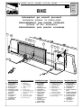 1
1
-
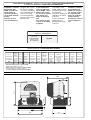 2
2
-
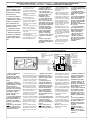 3
3
-
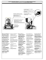 4
4
-
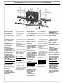 5
5
-
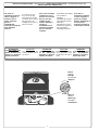 6
6
-
 7
7
-
 8
8
-
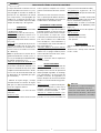 9
9
-
 10
10
-
 11
11
-
 12
12
-
 13
13
-
 14
14
-
 15
15
-
 16
16
-
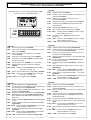 17
17
-
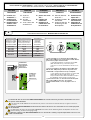 18
18
-
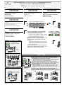 19
19
-
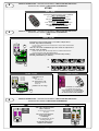 20
20
-
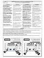 21
21
-
 22
22
-
 23
23
-
 24
24


CAME BXE El manual del propietario
- Categoría
- Abridor de puerta
- Tipo
- El manual del propietario
en otros idiomas
- français: CAME BXE Le manuel du propriétaire
- italiano: CAME BXE Manuale del proprietario
- English: CAME BXE Owner's manual
- Deutsch: CAME BXE Bedienungsanleitung
Artículos relacionados
-
CAME BXE 241 El manual del propietario
-
-
CAME BXE 241 Manual de usuario
-
-
-
CAME ZBKS Manual de usuario
-
CAME ZT4C El manual del propietario
-
-
-


