
sauder.com
File Cabinet
Model 420406
NOTE: THIS INSTRUCTION
BOOKLET CONTAINS IMPORTANT
SAFETY INFORMATION.
PLEASE READ AND KEEP FOR
FUTURE REFERENCE.
English pg 1-18
Français pg 19-21
Español pg 22-24
Lot # 531682 07/17/19
Purchased: __________________
sauder.com
CONTACT US FIRST
BEFORE MAKING ANY RETURNS TO THE STORE.
Share your journey!
sauder.com
CONTACT US FIRST
BEFORE MAKING ANY RETURNS TO THE STORE.
Visit sauder.com/service to order replacement parts, view video assembly tips, or chat with a live rep.
Prefer the phone? Give us a ring at
1-800-445-1527.
Customer Service is available Monday-Friday - 9 a.m. to 5:30 p.m. EST (except holidays)
Get all organized
and stu .

Table of Contents Assembly Tools Required
Part Identifi cation
Hardware Identifi cation
Assembly Steps
Français
Español
Safety
Warranty
No. 2 Phillips Screwdriver
Tip Shown Actual Size
Skip the power trip.
This time.
3
4
5-18
19-21
22-24
25-26
27
Page 2 www.sauder.com 420406

Part Identifi cation
å While not all parts are labeled, some of the parts will have a label or an inked letter on the edge
to help distinguish similar parts from each other. Use this part identifi cation to help identify similar parts.
Now you know
our ABCs.
A RIGHT END (1)
B LEFT END (1)
C RIGHT LEG FRAME (1)
D LEFT LEG FRAME (1)
E TOP (1)
F BACK (1)
G EXTENSION BLOCK (4)
H UPPER BRACE (1)
I BRACE (2)
J SMALL DRAWER FRONT (1)
K LARGE DRAWER FRONT (1)
L SMALL DRAWER BACK (1)
M LARGE DRAWER BACK (1)
N SMALL RIGHT DRAWER SIDE (1)
O SMALL LEFT DRAWER SIDE (1)
P LARGE RIGHT DRAWER SIDE (1)
Q LARGE LEFT DRAWER SIDE (1)
R DRAWER BOTTOM (2)
A
B
C
D
E
F
H
I
I
G
G
G
G
J
K
L
M
R
R
P
Q
N
O
Page 3www.sauder.com420406

Hardware Identifi cation
å Screws are shown actual size. You may receive extra hardware with your unit.
3
RIGHT CABINET RAIL - 1
4
LEFT CABINET RAIL - 1
6
LEFT DRAWER SLIDE - 1
5
RIGHT DRAWER SLIDE - 1
1
EXTENSION RAIL - 2
2
EXTENSION SLIDE - 2
BLACK 1-3/4" PAN HEAD SCREW - 6
19
BLACK 1" PAN HEAD SCREW - 8
22
BLACK 1" FLAT HEAD SCREW - 8
21
BLACK 1/2" FLAT HEAD SCREW - 16
24
BLACK 1/2" PAN HEAD SCREW - 12
25
BLACK 1/2" MACHINE SCREW - 6
23
WOOD DOWEL - 3
11
METAL BRACKET - 6
15
PULL - 2
14
TOOL - 1
17
HIDDEN CAM - 14
9
CAM SCREW - 14
10
NUT - 4
12
WHEEL BOLT - 4
18
Page 4 www.sauder.com 420406
BLACK 1-9/16" FLAT HEAD SCREW - 2
20
WHEEL - 4
13
SMALL BLACK 1/2" MACHINE SCREW - 4
26
RIGHT FILE GLIDE - 1
7
LEFT FILE GLIDE - 1
8

Step 1
Look for this icon. It means a
video assembly tip is available at
www.sauder.com/services/tips
å
Assemble your unit on a carpeted fl oor or on the empty
carton to avoid scratching your unit or the fl oor.
å
Fasten the EXTENSION BLOCKS (G) to the ENDS (A and B).
Use eight BLACK 1" PAN HEAD SCREWS (22).
å
NOTE: Do not overtighten the screws.
Page 5www.sauder.com420406
These large holes must be here.
BLACK 1" PAN HEAD SCREW
(8 used in this step)
22
These edges must be even.
These large holes must be here.
These edges must be even.
A
B

Step 2
Page 6 www.sauder.com 420406
å
Separate the EXTENSION SLIDES (2) from the EXTENSION RAILS (1) as shown in the upper diagram below. Be
prepared, the parts are greasy.
å
Fasten the EXTENSION RAILS (1) to the EXTENSION BLOCKS on each END (A and B) as shown. Use four
BLACK 1/2" FLAT HEAD SCREWS (24).
å
NOTE: For each EXTENSION RAIL, turn a SCREW into the holes shown in the upper diagram below.
å
NOTE: The EXTENSION SLIDES will be used later for the DRAWERS.
å
Fasten the RIGHT CABINET RAIL (3) to the EXTENSION BLOCK on the RIGHT END (A) and the LEFT
CABINET RAIL (4) to the EXTENSION BLOCK on the LEFT END (B). Use four BLACK 1/2" FLAT HEAD
SCREWS (24) through the 1st and 9th holes in the RAIL.
å
Fasten six METAL BRACKETS (15) to the edges of the ENDS (A and B) as shown. Use six BLACK 1/2" PAN
HEAD SCREWS (25).
å
NOTE: Be sure the BRACKETS are even with the edges of the ENDS.
Open end
Push down on the release lever and
pull the SLIDE (2) from the RAIL (1).
1
1
2
3
4
1
1
2
15
25
15
25
24
Open end
A
B
Use these holes.
Extension Rail and
Slide separated
Roller end
BLACK 1/2" PAN HEAD SCREW
(6 used for the METAL BRACKETS)
25
BLACK 1/2" FLAT HEAD SCREW
(8 used for the RAILS)
24
24
Roller end

å
Place the LEFT END (B) inside the LEFT LEG FRAME (D) as
shown in the upper diagram below.
å
Fasten the LEFT END (B) to the LEFT LEG FRAME (D). Use
three BLACK 1/2" PAN HEAD SCREWS (25) through the
METAL BRACKETS and three BLACK 1-3/4" PAN HEAD
SCREWS (19) through the LEFT LEG FRAME as shown.
Step 3
Page 7www.sauder.com420406
19
25
B
B
D
D
These holes must be here.
Flange
25
BLACK 1-3/4" PAN HEAD SCREW
(3 used for the LEFT LEG FRAME)
19
BLACK 1/2" PAN HEAD SCREW
(3 used for the METAL BRACKETS)
25
Remember:
Righty tighty.
Lefty loosey.

Step 4
Page 8 www.sauder.com 420406
å
Place the RIGHT END (A) inside the RIGHT LEG FRAME (C)
as shown in the upper diagram below.
å
Fasten the RIGHT END (A) to the RIGHT LEG FRAME (C).
Use three BLACK 1/2" PAN HEAD SCREWS (25) through
the METAL BRACKETS and three BLACK 1-3/4"
PAN HEAD SCREWS (19) through the
RIGHT LEG FRAME as shown.
19
A
A
C
C
These holes must be here.
Flange
25
BLACK 1/2" PAN HEAD SCREW
(3 used for the METAL BRACKETS)
25
BLACK 1-3/4" PAN HEAD SCREW
(3 used for the RIGHT LEG FRAME)
19
25

å
Turn two CAM SCREWS (10) into the LEFT END (B) as shown.
å
Push two HIDDEN CAMS (9) into the BACK (F) with the arrow
in the CAM pointing toward the edge of the BACK.
å
Insert a WOOD DOWEL (11) into the LEFT END (B). Fasten the
BACK (F) to the LEFT END (B). Tighten two HIDDEN CAMS.
å
NOTE: Be sure the WOOD DOWEL inserts into the BACK.
å
Fasten the BRACES (H and I) to the LEFT LEG FRAME (D).
Use three BLACK 1/2" MACHINE SCREWS (23).
Step 5
Page 9www.sauder.com420406
3
21
9
The arrow must
point toward the
edge of the board.
The hole should be o set to the
right side for all three braces.
10
10
9
9
H
I
I
BLACK 1/2" MACHINE SCREW
(3 used for the BRACES)
23
B
D
F
11
Short edge with holes

å
Turn two CAM SCREWS (10) into the RIGHT END (A) as shown.
å
Push two HIDDEN CAMS (9) into the BACK (F) with the arrow
in the CAM pointing toward the edge of the BACK.
å
Insert a WOOD DOWEL (11) into the RIGHT END (A). Fasten the
BACK (F) to the LEFT END (B). Tighten two HIDDEN CAMS.
å
NOTE: Be sure the WOOD DOWEL inserts into the BACK.
å
Fasten the BRACES (H and I) to the RIGHT LEG FRAME (C).
Use three BLACK 1/2" MACHINE SCREWS (23).
Step 6
Page 10 www.sauder.com 420406
3
21
9
The arrow must
point toward the
edge of the board.
10
10
11
H
I
I
A
C
BLACK 1/2" MACHINE SCREW
(3 used for the BRACES)
23
9
9
F

å
Fasten the WHEELS (13) to the LEG FRAMES (C and D).
With the TOOL (17), tighten four WHEEL BOLTS (18) and
four NUTS (12).
Step 7
Page 11www.sauder.com420406
17
18
18
12
12
13
13
13
13
C
D
Side Step: Make
nachos. (Optional, but
recommended.)

Step 8
Page 12 www.sauder.com 420406
3
21
9
The arrow must
point toward the
edge of the board.
å
Carefully stand your unit upright.
å
Turn two CAM SCREWS (10) into the TOP (E) as shown.
å
Push two HIDDEN CAMS (9) into the BACK (F) with the
arrow in the CAM pointing toward the edge of the BACK.
å
Insert a WOOD DOWEL (11) into the TOP (E). Fasten the
TOP (E) to the BACK (F). Tighten two HIDDEN CAMS.
å
NOTE: Be sure the WOOD DOWEL inserts into the BACK.
å
Fasten the TOP (E) to the UPPER BRACE (H). Use two
BLACK 1-9/16" FLAT HEAD SCREWS (20).
9
9
11
10
10
E
F
H
BLACK 1-9/16" FLAT HEAD SCREW
(2 used in this step)
20

å
Fasten the EXTENSION SLIDES (2) to the LARGE
DRAWER SIDES (P and Q). Use four BLACK 1/2" FLAT
HEAD SCREWS (24).
å
Fasten the LARGE DRAWER SIDES (P and Q) to the
LARGE DRAWER BACK (M). Use four BLACK 1" FLAT
HEAD SCREWS (21).
å
Slide the DRAWER BOTTOM (R) into the grooves in the
LARGE DRAWER SIDES (P and Q) and LARGE
DRAWER BACK (M).
Step 9
Page 13www.sauder.com420406
BLACK 1" FLAT HEAD SCREW
(4 used for the DRAWER BACK)
21
BLACK 1/2" FLAT HEAD SCREW
(4 used for the SLIDES)
24
2
Use these holes.
P
P
Q
2
2
Q
Open end
Open end
Open end
M
R
Groove
Groove

å
Turn four CAM SCREWS (10) into the LARGE
DRAWER FRONT (K).
å
Insert four HIDDEN CAMS (9) into the LARGE
DRAWER SIDES (P and Q).
å
Fasten the LARGE DRAWER FRONT (K) to the LARGE
DRAWER SIDES (P and Q). Tighten four HIDDEN CAMS.
å
Fasten a PULL (14) to the LARGE DRAWER FRONT (K). Use
two SMALL BLACK 1/2" MACHINE SCREWS (26).
å
Push the RIGHT FILE GLIDE (7) onto the top edge of the
LARGE DRAWER RIGHT SIDE (P) and the LEFT FILE GLIDE (8)
onto the top edge of the LARGE DRAWER LEFT SIDE (Q).
Step 10
Page 14 www.sauder.com 420406
3
21
9
The arrow must
point toward the
edge of the board.
SMALL BLACK 1/2" MACHINE SCREW
(2 used for the PULL)
26
9
9
10
10
10
14
P
P
Q
Q
K
7
8
Be sure the DRAWER
BOTTOM (R) inserts into
the groove in the LARGE
DRAWER FRONT (K).
R
Notch

å
Fasten the SMALL DRAWER SIDES (N and O) to the
SMALL DRAWER BACK (L). Use four BLACK 1" FLAT
HEAD SCREWS (21).
å
Slide the DRAWER BOTTOM (R) into the grooves in
the SMALL DRAWER SIDES (N and O) and SMALL
DRAWER BACK (L).
Step 11
Page 15www.sauder.com420406
BLACK 1" FLAT HEAD SCREW
(4 used for the DRAWER BACK)
21
Groove
Groove
L
N
O
R

Step 12
å
Turn four CAM SCREWS (10) into the SMALL
DRAWER FRONT (J).
å
Insert four HIDDEN CAMS (9) into the SMALL
DRAWER SIDES (N and O).
å
Fasten the SMALL DRAWER FRONT (J) to the SMALL
DRAWER SIDES (N and O). Tighten four HIDDEN CAMS.
å
Fasten a PULL (14) to the SMALL DRAWER FRONT (J).
Use two SMALL BLACK 1/2" MACHINE SCREWS (26).
Page 16 www.sauder.com 420406
3
21
9
The arrow must
point toward the
edge of the board.
14
9
10
10
Be sure the DRAWER
BOTTOM (R) inserts into
the groove in the SMALL
DRAWER FRONT (J).
J
R
SMALL BLACK 1/2" MACHINE SCREW
(2 used for the PULL)
26
N
O

å
Carefully fl ip the SMALL drawer over.
å
Fasten the RIGHT DRAWER SLIDE (5) to the SMALL DRAWER
RIGHT SIDE (N) and the LEFT DRAWER SLIDE (6) to the
SMALL DRAWER LEFT SIDE (O). Use four BLACK 1/2" FLAT
HEAD SCREWS (24) through the 3rd and 8th holes from the
front of the RAILS.
Step 13
Page 17www.sauder.com420406
BLACK 1/2" FLAT HEAD SCREW
(4 used for the RAILS)
24
5
6
24
Use this hole.
N
O
Almost time to
celebrate! With a nap.

Step 14
Page 18 www.sauder.com 420406
å
To insert the SMALL drawer into your unit, tip the front of the drawer down and drop the rollers on the drawer behind
the rollers on the unit. Lift the front of the drawer up and slide it into the unit.
å
To insert the LARGE drawer into your unit, line up the EXTENSION SLIDES on the drawer with the EXTENSION RAILS
on the unit and push the drawer into the unit until the drawer is fully inserted. The drawer will push in hard until it is all
the way in, then it will slide in and out easier.
å
NOTE: Please read the back pages of the instruction booklet for important safety information.
å
This completes assembly. Clean with a damp cloth. Wipe dry.
Place the roller on the SLIDE
behing the roller on the RAIL.
15 lbs.
30 lbs.
50 lbs.
And to celebrate, why not share your success story at Walmart.com or

Noter la date d’achat
de cet élément et
conserver le livret pour
future référence. Pour
contacter Sauder en
ce qui concerne cet
élément, faire référence
au numéro de lot et
numéro de modèle en
appelant notre numéro
sans frais.
Lot nº : ____________
Date de
l'achet : ____________
LISTE DE PIÈCES
REFERENCE DESCRIPTION QUANTITÉ
LISTE DE PIÈCES
REFERENCE DESCRIPTION QUANTITÉ
NOUS SOMMES LA POUR VOUS AIDER!
Nous faisons de notre mieux pour nous assurer que votre meuble
arrive dans d’excellentes conditions. Nos représentants du service
Clientèle sont aimables et prêts à vous aider au cas où une pièce
aurait été endommagée ou manquerait (ou si vous aviez besoin
d’aide pour l’assemblage). NE RAMENEZ PAS LE MEUBLE AU
MAGASIN. Au Canada, composez ce numéro d’appel gratuit:
1-800-445-1527
Du lundi au vendredi, de 9 heures du matin à
5:30 heures du soir (horaire Côte Est)
(sauf jours fériés)
Si une pièce a besoin d’être remplacée, la pièce de remplacement
sera envoyée dans les 48 heures. (Sauf week-ends et jours fériés)
Utilisez les instructions d’assemblage en français avec les
schémas étape par étape du manuel d’instruction en anglais.
Chaque étape en français correspond à la même étape
en anglais. La pièce devant être attachée à l’élément est
représentée en gris sur les schémas de chaque étape pour plus
de précision. Comparer la “Liste de pièces” ci-dessous avec
la “PART IDENTIFICATION” du manuel en anglais pour vous
familiariser avec les pièces avant l’assemblage.
REMARQUE : CE MANUEL D’INSTRUCTIONS CONTIENT
D’IMPORTANTES INFORMATIONS RELATIVES À LA SÉCURITÉ.
À LIRE ET CONSERVER POUR TOUTE RÉFÉRENCE FUTURE.
ClasseurModèle 420406
1 GLISSIÈRE D'EXTENSION ....................................2
2 COULISSE D'EXTENSION ....................................2
3 GLISSIÈRE DROITE D'ÉLÉMENT .....................1
4 GLISSIÈRE GAUCHE D'ÉLÉMENT ..................1
5 COULISSE DROITE DE TIROIR .........................1
6 COULISSE GAUCHE DE TIROIR ......................1
7 COULISSE DROITE DE CLASSEUR ..............1
8 COULISSE GAUCHE DE CLASSEUR ...........1
9 EXCENTRIQUE ESCAMOTABLE ...................14
10 VIS D'EXCENTRIQUE .............................................14
11 CHEVILLE EN BOIS ...................................................3
12 ÉCROU ................................................................................4
13 ROULETTE .......................................................................4
14 POIGNÉE ............................................................................2
15 CONSOLE EN MÉTAL .............................................6
17 OUTIL ....................................................................................1
18 BOULON DE ROULETTE .......................................4
19 VIS TÊTE GOUTTE DE
SUIF 44,5 mm NOIRE .............................................6
20 VIS TÊTE PLATE 40 mm NOIRE ....................2
21 VIS TÊTE PLATE 25 mm NOIRE .....................8
22 VIS TÊTE GOUTTE DE
SUIF 25 mm NOIRE ..................................................8
23 VIS À MÉTAUX 13 mm NOIRE ..........................6
24 VIS TÊTE PLATE 13 mm NOIRE ................... 16
25 VIS TÊTE GOUTTE DE
SUIF 13 mm NOIRE .................................................12
26 PETITE VIS À MÉTAUX 13 mm NOIRE .......4
A EXTRÉMITÉ DROITE ..................................................1
B EXTRÉMITÉ GAUCHE ...............................................1
C CADRE DE PIED DROIT ..........................................1
D CADRE DE PIED GAUCHE ....................................1
E DESSUS ...............................................................................1
F ARRIÈRE ..............................................................................1
G BLOC D'EXTENSION ................................................4
H ENTRETOISE SUPÉRIEURE .................................1
I ENTRETOISE...................................................................2
J DEVANT DE PETIT TIROIR ...................................1
K DEVANT DE GRAND TIROIR ...............................1
L ARRIÈRE DE PETIT TIROIR ...................................1
M ARRIÈRE DE GRAND TIROIR ..............................1
N CÔTÉ DROIT DE PETIT TIROIR ........................1
O CÔTÉ GAUCHE DE PETIT TIROIR..................1
P CÔTÉ DROIT DE GRAND TIROIR ....................1
Q CÔTÉ GAUCHE DE GRAND TIROIR .............1
R FOND DE TIROIR .........................................................2
Page 19www.sauder.com420406

ÉTAPE 1
Assembler l'élément sur un sol à moquette ou sur le carton vide
pour éviter d'endommager l'élément ou le sol.
Fixer les BLOCS D'EXTENSION (G) aux EXTRÉMITÉS (A et B).
Utiliser huit VIS TÊTE GOUTTE DE SUIF 25 mm NOIRES (22).
REMARQUE : Ne pas trop serrer les vis.
ÉTAPE 2
Séparer les COULISSES D'EXTENSION (2) des GLISSIÈRES
D'EXTENSION (1) comme l'indique le schéma ci-dessous
supérieure. Faire attention car les pièces sont graissées.
Fixer les GLISSIÈRES D'EXTENSION (1) aux BLOCS D'EXTENSION
sur chaque EXTRÉMITÉ (A et B) comme l'indique le schéma.
Utiliser quatre VIS TÊTE PLATE 13 mm NOIRES (24).
REMARQUE : Pour chaque GLISSIÈRE D'EXTENSION, faire tourner une
VIS dans les trous indiqués dans le schéma ci-dessous supérieure.
REMARQUE : Les COULISSES D'EXTENSION seront utilisées
ultérieurement pour les TIROIRS.
Fixer la GLISSIÈRE DROITE D'ÉLÉMENT (3) au BLOC
D'EXTENSION sur l’EXTRÉMITÉ DROITE (A) et la GLISSIÈRE
GAUCHE D'ÉLÉMENT (4) au BLOC D'EXTENSION sur
l’EXTRÉMITÉ GAUCHE (B). Utiliser quatre VIS TÊTE PLATE 13 mm
NOIRES (24) dans les 1er et 9è trous dans la GLISSIÈRE.
Fixer six CONSOLES EN MÉTAL (15) aux chants des
EXTRÉMITÉS (A et B) comme l'indique le schéma. Utiliser six VIS
TÊTE GOUTTE DE SUIF 13 mm NOIRES (25).
REMARQUE : S'assurer que les CONSOLES sont à fl eur des
chants des EXTRÉMITÉS.
ÉTAPE 5
Faire tourner deux VIS D'EXCENTRIQUE (10) dans l'EXTRÉMITÉ
GAUCHE (B) comme l'indique le schéma.
Enfoncer deux EXCENTRIQUES ESCAMOTABLES (9) dans
l'ARRIÈRE (F) avec la fl èche dans l’EXCENTRIQUE dirigée vers le
chant de l'ARRIÈRE.
Insérer une CHEVILLE EN BOIS (11) dans l'EXTRÉMITÉ
GAUCHE (B). Fixer l'ARRIÈRE (F) à l'EXTRÉMITÉ GAUCHE (B).
Serrer deux EXCENTRIQUES ESCAMOTABLES.
REMARQUE : S’assurer d’insérer la CHEVILLE EN BOIS
dans l'ARRIÈRE.
Fixer les ENTRETOISES (H et I) au CADRE DE PIED GAUCHE (D).
Utiliser trois VIS À MÉTAUX 13 mm NOIRES (23).
ÉTAPE 6
Enfoncer deux VIS D'EXCENTRIQUE (10) dans l'EXTRÉMITÉ
DROITE (A) comme l'indique le schéma.
Enfoncer deux EXCENTRIQUES ESCAMOTABLES (9) dans
l'ARRIÈRE (F) avec la fl èche dans l’EXCENTRIQUE dirigée vers le
chant de l'ARRIÈRE.
Insérer une CHEVILLE EN BOIS (11) dans l'EXTRÉMITÉ
DROITE (A). Fixer l'ARRIÈRE (F) à l'EXTRÉMITÉ GAUCHE (B).
Serrer deux EXCENTRIQUES ESCAMOTABLES.
REMARQUE : S’assurer d’insérer la CHEVILLE EN BOIS
dans l'ARRIÈRE.
Fixer les ENTRETOISES (H et I) au CADRE DE PIED DROIT (C).
Utiliser trois VIS À MÉTAUX 13 mm NOIRES (23).
ÉTAPE 3
PLacer l'EXTRÉMITÉ GAUCHE (B) à l’intérieur du CADRE DE PIED
GAUCHE (D) comme l'indique le schéma ci-dessous supérieure.
Fixer l'EXTRÉMITÉ GAUCHE (B) au CADRE DE PIED GAUCHE (D).
Utiliser trois VIS TÊTE GOUTTE DE SUIF 13 mm NOIRES (25)
à travers les CONSOLES EN MÉTAL et trois VIS TÊTE GOUTTE
DE SUIF 44,5 mm NOIRES (19) à travers le CADRE DE PIED
GAUCHE comme l'indique le schéma.
ÉTAPE 7
Fixer les ROULETTES (13) aux CADRES DE PIED (C et D). Avec
l'OUTIL (17), serrer quatre BOULONS DE ROULETTE (18) et
quatre ÉCROUS (12).
ÉTAPE 8
Relever, avec précaution, l'élément dans sa position verticale.
Enfoncer deux VIS D'EXCENTRIQUE (10) dans le DESSUS (E)
comme l'indique le schéma.
Enfoncer deux EXCENTRIQUES ESCAMOTABLES (9) dans
l'ARRIÈRE (F) avec la fl èche dans l’EXCENTRIQUE dirigée vers le
chant de l'ARRIÈRE.
Insérer une CHEVILLE EN BOIS (11) dans le DESSUS (E). Fixer
le DESSUS (E) à l’ARRIÈRE (F). Serrer deux EXCENTRIQUES
ESCAMOTABLES.
REMARQUE : S’assurer d’insérer la CHEVILLE EN BOIS
dans l'ARRIÈRE.
Fixer le DESSUS (E) à l'ENTRETOISE SUPÉRIEURE (H). Utiliser
deux VIS TÊTE PLATE 40 mm NOIRES (20).
Page 20 www.sauder.com 420406
ÉTAPE 4
Placer l'EXTRÉMITÉ DROITE (A) à l’intérieur du CADRE DE PIED
DROIT (C) comme l'indique le schéma ci-dessous supérieure.
Fixer l'EXTRÉMITÉ DROITE (A) au CADRE DE PIED DROIT (C).
Utiliser trois VIS TÊTE GOUTTE DE SUIF 13 mm NOIRES (25) à
travers les CONSOLES EN MÉTAL et trois VIS TÊTE GOUTTE DE
SUIF 44,5 mm NOIRES (19) à travers le CADRE DE PIED DROIT
comme l'indique le schéma.

ÉTAPE 9
Fixer les COULISSES D’EXTENSION (2) aux CÔTÉS DE
GRAND TIROIR (P et Q). Utiliser quatre VIS TÊTE
PLATE 13 mm NOIRES (24).
Fixer les CÔTÉS DE GRAND TIROIR (P et Q) à l'ARRIÈRE
DE GRAND TIROIR (M). Utiliser quatre VIS TÊTE
PLATE 25 mm NOIRES (21).
Enfi ler le FOND DE TIROIR (R) dans les rainures des CÔTÉS DE
GRAND TIROIR (P et Q) et de l'ARRIÈRE DE GRAND TIROIR (M).
ÉTAPE 10
Serrer quatre CHEVILLES D’EXCENTRIQUE (10) dans le DEVANT
DE GRAND TIROIR (K).
Insérer quatre EXCENTRIQUES ESCAMOTABLES (9) dans les
CÔTÉS DE GRAND TIROIR (P et Q).
Fixer le DEVANT DE GRAND TIROIR (K) aux CÔTÉS DE GRAND
TIROIR (P et Q). Serrer quatre EXCENTRIQUES ESCAMOTABLES.
Fixer une POIGNÉE (14) au DEVANT DE GRAND TIROIR (K).
Utiliser deux PETITES VIS À MÉTAUX 13 mm NOIRES (26).
Enfoncer l'ARMATURE DROITE POUR DOSSIERS (7) sur le chant
supérieur du CÔTÉ DROIT DE GRAND TIROIR (P) et l'ARMATURE
GAUCHE POUR DOSSIERS (8) sur le chant supérieur du
CÔTÉ GAUCHE DE GRAND TIROIR (Q).
ÉTAPE 12
Serrer quatre CHEVILLES D’EXCENTRIQUE (10) dans le DEVANT
DE PETIT TIROIR (J).
Insérer quatre EXCENTRIQUES ESCAMOTABLES (9) dans les
CÔTÉS DE PETIT TIROIR (N et O).
Fixer le DEVANT DE PETIT TIROIR (J) aux CÔTÉS DE PETIT
TIROIR (N et O). Serrer quatre EXCENTRIQUES ESCAMOTABLES.
Fixer une POIGNÉE (14) sur le DEVANT DE PETIT TIROIR (J).
Utiliser deux PETITES VIS À MÉTAUX 13 mm NOIRES (26).
ÉTAPE 13
Retourner soigneusement le PETIT tiroir.
Fixer la COULISSE DE TIROIR DROITE (5) sur le CÔTÉ DROIT DE
PETIT TIROIR (N) et la COULISSE DE TIROIR GAUCHE (6) sur le
CÔTÉ GAUCHE DE PETIT TIROIR (O). Utiliser quatre VIS TÊTE
PLATE 13 mm NOIRES (24) à travers les 3è et 8è trous à partir du
devant des GLISSIÈRES.
ÉTAPE 11
Fixer les CÔTÉS DE PETIT TIROIR (N et O) à l'ARRIÈRE DE PETIT
TIROIR (L). Utiliser quatre VIS TÊTE PLATE 25 mm NOIRES (21).
Enfi ler le FOND DE TIROIR (R) dans les rainures des CÔTÉS DE
PETIT TIROIR (N et O) et de l'ARRIÈRE DE PETIT TIROIR (L).
ÉTAPE 14
Pour insérer le PETIT tiroir dans l'élément, abaisser le devant
du tiroir et faire passer les roulettes situées sur le tiroir derrière
les roulettes situées sur l'élément. Relever le devant du tiroir et
l'enfi ler dans l'élément.
Pour insérer le GRAND tiroir dans l'élément, aligner les
COULISSES D'EXTENSION du tiroir sur les GLISSIÈRES
D'EXTENSION de l'élément et enfoncer le tiroir dans l'élément
jusqu'à ce que le tiroir soit complètement inséré. Le tiroir o rira
une certaine résistance jusqu'à ce qu'il soit complètement inséré
dans l'élément, il glissera ensuite sans di culté.
REMARQUE : Prière de lire les informations importantes sur la
sécurité fi gurant sur les pages arrière du manuel d’instructions.
Ceci complète l'assemblage.
Nettoyer avec un tissu humide. Essuyer.
Page 21www.sauder.com420406

Anote la fecha de
comprar esta unidad y
guarde el folleto para
su referencia futura. Si
necesita ponerse en
contacto con Sauder en
cuanto a esta unidad,
refi érase al número
de lote y al número de
modelo cuando llame a
nuestro número gratis.
No. lote: ____________
Fecha de
compra: ____________
LISTA DE PARTES
ITEM DESCRIPCIÓN CANTIDAD
ESTAMOS AQUI PARA AYUDAR!
Tratamos de asegurar que su mueble llega en condición excelente.
Nuestros representantes de Servicio al Cliente son amables y
listos para ayudarle con servicio rápido y efi ciente si una parte
está defectuosa o ausente (o si necesita ayuda con el ensamblaje).
NO DEVUELVA LA UNIDAD A LA TIENDA. Llame este número sin
cargo:
1-800-445-1527
Lunes a viernes, 9:00 a.m. - 5:30 p.m.
Hora ofi cial del Este
(excepto días festivos)
Si requiere un repuesto de una parte, será enviado dentro de
48 horas (excepto los fi nes de semana y días festivos)
Use estas instrucciones de ensamblaje en español junto con las
fi guras paso-a-paso provistas en el folleto inglés. Cada paso
en español corresponde al mismo paso en inglés. Se destacan
las fi guras de cada paso con una tonalidad oscura para mostrar
precisamente cual parte se debe montar a la unidad. Compare
la “Lista de Part” abajo con la “Part Identifi cation” en el folleto en
inglés para familiarizarse con Las partes de ensamblaje.
NOTA: ESTE FOLLETO DE INSTRUCCIONES CONTIENE
INFORMACIÓN IMPORTANTE SOBRE LA SEGURIDAD. POR
FAVOR LEA Y GUÁRDELO PARA REFERENCIA EN EL FUTURO.
1 RIEL DE EXTENSIÓN ................................................2
2 CORREDERA DE EXTENSIÓN ...........................2
3 RIEL DERECHO DE GABINETE .........................1
4 RIEL IZQUIERDO DE GABINETE ......................1
5 CORREDERA DERECHA DE CAJÓN ............1
6 CORREDERA IZQUIERDA DE CAJÓN .........1
7 CORRIMIENTO DERECHO DEL
ARCHIVADOR .................................................................1
8 CORRIMIENTO IZQUIERDO DEL
ARCHIVADOR .................................................................1
9 EXCÉNTRICO ESCONDIDO .............................14
10 BIELA DE EXCÉNTRICO ......................................14
11 PASADOR DE MADERA .........................................3
12 TUERCA ..............................................................................4
13 RUEDA .................................................................................4
14 TIRADOR ............................................................................2
15 SOPORTE DE METAL ..............................................6
17 HERRAMIENTA ...............................................................1
18 PERNO DE RUEDA .....................................................4
19 TORNILLO NEGRO DE CABEZA
REDONDA de 44,5 mm..........................................6
20 TORNILLO NEGRO DE CABEZA
PERDIDA de 40 mm .................................................2
21 TORNILLO NEGRO DE CABEZA
PERDIDA de 25 mm .................................................8
22 TORNILLO NEGRO DE CABEZA
REDONDA de 25 mm ..............................................8
23 TORNILLO NEGRO PARA METAL
de 13 mm ...........................................................................6
24 TORNILLO NEGRO DE CABEZA
PERDIDA de 13 mm ...............................................16
25 TORNILLO NEGRO DE CABEZA
REDONDA de 13 mm .............................................12
26 TORNILLO PEQUEÑO NEGRO
PARA METAL de 13 mm ........................................4
A EXTREMO DERECHO ...............................................1
B EXTREMO IZQUIERDO ............................................1
C MARCO DE LA PATA DERECHA ......................1
D MARCO DE LA PATA IZQUIERDA ...................1
E PANEL SUPERIOR .......................................................1
F DORSO .................................................................................1
G BLOQUE DE EXTENSIÓN .....................................4
H RIOSTRA SUPERIOR .................................................1
I RIOSTRA ............................................................................2
J CARA DE CAJÓN PEQUEÑO .............................1
K CARA DE CAJÓN GRANDE .................................1
L DORSO DE CAJÓN PEQUEÑO ........................1
M DORSO DE CAJÓN GRANDE ............................1
N
LADO DERECHO DE CAJÓN PEQUEÑO
....1
O
LADO IZQUIERDO DE CAJÓN PEQUEÑO
...1
P LADO DERECHO DE CAJÓN GRANDE .....1
Q
LADO IZQUIERDO DE CAJÓN GRANDE
.....1
R FONDO DE CAJÓN ...................................................2
LISTA DE PARTES
ITEM DESCRIPCIÓN CANTIDAD
ArchiveroModelo 420406
Page 22 www.sauder.com 420406

PASO 1
Ensamble la unidad sobre un piso alfombrado o sobre el cartón
vacío para evitar rayar la unidad o el piso.
Fije los BLOQUES DE EXTENSIÓN (G) a los EXTREMOS (A y B).
Utilice ocho TORNILLOS NEGROS DE CABEZA REDONDA
de 25 mm (22).
NOTA: No apriete los TORNILLOS en exceso.
PASO 2
Separe las CORREDERAS DE EXTENSIÓN (2) de los RIELES DE
EXTENSIÓN (1) como se muestra en el diagrama superior mas
abajo. Prepárese, las piezas son grasientas.
Fije los RIELES DE EXTENSIÓN (1) a los BLOQUES DE EXTENSIÓN
en cada EXTREMO (A y B) como se muestra. Use cuatro
TORNILLOS NEGROS DE CABEZA PERDIDA de 13 mm (24).
NOTA: Para cada RIEL DE EXTENSIÓN, atornille un TORNILLO
dentro de los agujeros indicados en el diagrama superior mas abajo.
NOTA: Las CORREDERAS DE EXTENSIÓN se utilizarán más tarde
para los CAJONES.
Fije el RIEL DERECHO DE GABINETE (3) al BLOQUE DE
EXTENSIÓN del EXTREMO DERECHO (A) y el RIEL IZQUIERDO
DE GABINETE (4) al BLOQUE DE EXTENSIÓN del EXTREMO
IZQUIERDO (B). Utilice cuatro TORNILLOS DE CABEZA PERDIDA
de 13 mm (24) a través del 1a y del 9a agujeros en el RIEL.
Fije seis SOPORTES DE METAL (15) a los bordes de los
EXTREMOS (A y B) como se muestra. Utilice seis TORNILLOS
NEGROS DE CABEZA REDONDA de 13 mm (25).
NOTA: Asegúrese que los SOPORTES estén nivelados con los
bordes de los EXTREMOS.
PASO 5
Gire dos BIELAS DE EXCÉNTRICO (10) en el EXTREMO
IZQUIERDO (B) como se muestra.
Empuje dos EXCÉNTRICOS ESCONDIDOS (9) en el DORSO (F)
con la fl echa del EXCÉNTRICO apunte hacia el borde del DORSO.
Inserte un PASADOR DE MADERA (11) dentro del EXTREMO
IZQUIERDO (B). Fije el DORSO (F) al EXTREMO IZQUIERDO (B).
Apriete dos EXCÉNTRICOS ESCONDIDOS.
NOTA: Asegúrese de que el PASADOR DE MADERA se inserten
en el DORSO.
Fije las RIOSTRAS (H e I) al MARCO DE LA PATA IZQUIERDA (D).
Utilice tres TORNILLOS NEGROS PARA METAL de 13 mm (23).
PASO 6
Gire dos BIELAS DE EXCÉNTRICO (10) en el EXTREMO
DERECHO (A) como se muestra.
Empuje dos EXCÉNTRICOS ESCONDIDOS (9) en el DORSO (F)
con la fl echa del EXCÉNTRICO apunte hacia el borde del DORSO.
Inserte un PASADOR DE MADERA (11) dentro del EXTREMO
DERECHO (A). Fije el DORSO (F) al EXTREMO IZQUIERDO (B).
Apriete dos EXCÉNTRICOS ESCONDIDOS.
NOTA: Asegúrese de que el PASADOR DE MADERA se inserten
en el DORSO.
Fije las RIOSTRAS (H e I) al MARCO DE LA PATA DERECHA (C).
Utilice tres TORNILLOS NEGROS PARA METAL de 13 mm (23).
PASO 3
Coloque el EXTREMO IZQUIERDO (B) al interior del MARCO
DE LA PATA IZQUIERDA (D) como se muestra en el diagrama
superior mas abajo.
Fije el EXTREMO IZQUIERDO (B) al MARCO DE LA PATA
IZQUIERDA (D). Utilice tres TORNILLOS NEGROS DE CABEZA
REDONDA de 13 mm (25) a través de los SOPORTES DE METAL y
tres TORNILLOS NEGROS DE CABEZA REDONDA de 44,5 mm (19)
a través del MARCO DE LA PATA IZQUIERDA como se muestra.
PASO 7
Fije las RUEDAS (13) a los MARCOS DE PATA (C y D). Con la
HERRAMIENTA (17), apriete cuatro PERNOS DE RUEDA (18) y
cuatro TUERCAS (12).
PASO 4
Coloque el EXTREMO DERECHO (A) al interior del MARCO DE
LA PATA DERECHA (C) como se muestra en el diagrama superior
mas abajo.
Fije el EXTREMO DERECHO (A) al MARCO DE LA PATA
DERECHA (C). Utilice tres TORNILLOS NEGROS DE CABEZA
REDONDA de 13 mm (25) a través de los SOPORTES DE
METAL y tres TORNILLOS NEGROS DE CABEZA REDONDA
de 44,5 mm (19) a través del MARCO DE LA PATA DERECHA
como se muestra.
PASO 8
Cuidadosamente ponga la unidad en posición vertical.
Gire dos BIELAS DE EXCÉNTRICO (10) en el PANEL
SUPERIOR (E) como se muestra.
Empuje dos EXCÉNTRICOS ESCONDIDOS (9) en el DORSO (F)
con la fl echa del EXCÉNTRICO apunte hacia el borde del DORSO.
Inserte un PASADOR DE MADERA (11) dentro del PANEL
SUPERIOR (E). Fije el PANEL SUPERIOR (E) al DORSO (F). Apriete
dos EXCÉNTRICOS ESCONDIDOS.
NOTA: Asegúrese de que el PASADOR DE MADERA se inserten
en el DORSO.
Fije el PANEL SUPERIOR (E) a la RIOSTRA SUPERIOR (H). Utilice
dos TORNILLOS NEGROS DE CABEZA PERDIDA de 40 mm (20).
Page 23www.sauder.com420406

PASO 9
Fije las CORREDERAS DE EXTENSIÓN (2) a los LADOS DE
CAJÓN GRANDE (P y Q). Use cuatro TORNILLOS NEGROS DE
CABEZA PERDIDA de 13 mm (24).
Fije los LADOS DE CAJÓN GRANDE (P y Q) al DORSO DE
CAJÓN GRANDE (M). Use cuatro TORNILLOS NEGROS DE
CABEZA PERDIDA de 25 mm (21).
Deslice el FONDO DE CAJÓN (R) dentro de las ranuras de los
LADOS DE CAJÓN GRANDE (P y Q) y del DORSO DE
CAJÓN GRANDE (M).
PASO 10
Atornille cuatro BIELAS DE EXCÉNTRICO (10) dentro de la CARA
DE CAJÓN GRANDE (K).
Inserte cuatro EXCÉNTRICOS ESCONDIDOS (9) dentro de los
LADOS DE CAJÓN GRANDE (P y Q).
Fije la CARA DE CAJÓN GRANDE (K) a los LADOS DE CAJÓN
GRANDE (P y Q). Apriete cuatro EXCÉNTRICOS ESCONDIDOS.
Fije un TIRADOR (14) a la CARA DE CAJÓN GRANDE (K). Utilice dos
TORNILLOS PEQUEÑOS NEGROS PARA METAL de 13 mm (26).
Empuje el CORRIMIENTO DERECHO DE ARCHIVADOR (7) sobre
el borde superior del LADO DERECHO DE CAJÓN GRANDE (P)
y el CORRIMIENTO IZQUIERDO DE ARCHIVADOR (8) sobre el
borde superior del LADO IZQUIERDO DE CAJÓN GRANDE (Q).
PASO 12
Atornille cuatro BIELAS DE EXCÉNTRICO (10) dentro de la CARA
DE CAJÓN PEQUEÑO (J).
Inserte cuatro EXCÉNTRICOS ESCONDIDOS (9) en los LADOS
DE CAJÓN PEQUEÑO (N y O).
Fije la CARA DE CAJÓN PEQUEÑO (J) a los LADOS DE CAJÓN
PEQUEÑO (N y O). Apriete cuatro EXCÉNTRICOS ESCONDIDOS.
Fije un TIRADOR (14) a la CARA DE CAJÓN PEQUEÑO (J). Utilice
dos TORNILLOS PEQUEÑOS NEGROS PARA METAL de 13 mm (26).
PASO 13
De vuelta con cuidado el cajón PEQUEÑO.
Fije la CORREDERA DERECHA DE CAJÓN (5) al LADO
DERECHO DE CAJÓN PEQUEÑO (N) y la CORREDERA
IZQUIERDA DE CAJÓN (6) al LADO IZQUIERDO DE CAJÓN
PEQUEÑO (O). Utilice cuatro TORNILLOS DE CABEZA PERDIDA
de 13 mm (24) a través del 3a y del 8a agujeros desde el
frente de los RIELES.
PASO 11
Fije los LADOS DE CAJÓN PEQUEÑO (N y O) al DORSO DE
CAJÓN PEQUEÑO (L). Use cuatro TORNILLOS NEGROS DE
CABEZA PERDIDA de 25 mm (21).
Deslice el FONDO DE CAJÓN (R) dentro de las ranuras de los
LADOS DE CAJÓN PEQUEÑO (N y O) y del DORSO DE
CAJÓN PEQUEÑO (L).
PASO 14
Para insertar el cajón PEQUEÑO dentro de la unidad, incline la
parte delantera del cajón y deje que los rodillos del cajón caigan
detrás de los rodillos de la unidad. Levante la parte delantera del
cajón y deslícelo dentro de la unidad.
Para insertar el cajón GRANDE dentro de la unidad, alinee las
CORREDERAS DE EXTENSIÓN sujetadas al cajón con los RIELES
DE EXTENSIÓN sujetados a la unidad y empuje el cajón dentro
de la unidad hasta que el cajón está completamente insertado. El
cajón mueve con difi cultad hasta que se inserte completamente
dentro de la unidad, después deslizará fácilmente hacia dentro y
hacia fuera.
NOTA: Por favor, lea las páginas de atrás del folleto de
instrucciones en cuanto a importante información de seguridad.
Esto completa el ensamblaje. Limpiar con un trapo húmedo.
Seque con un paño.
Page 24 www.sauder.com 420406

Page 25www.sauder.com420406
CAUTION
Please use your furniture correctly and safely. Improper use can cause safety hazards,
or damage to your furniture or household items. Carefully read the following chart.
Look out for: What can happen: How to avoid the problem:
• Overloaded fi le cabinet drawers. • Risk of injury.
• Top-heavy furniture can tip over.
• Overloaded drawers can break.
• Never exceed the weight limits shown in
the instructions.
• Work from bottom to top when loading
drawers. Place the heavier items on lower
drawers.
• Improperly moving the fi le cabinet. • Risk of injury or equipment damage.
• The fi le cabinet can tip if not moved
carefully over obstacles or across a
changing fl oor surface (for example, from a
wood fl oor to a carpeted fl oor).
• Lift the fi le cabinet so the casters clear
any obstacles or abrupt changes in the fl oor
surface.
• Placing TVs on furniture items that are not
designed to support a television is
hazardous.
• Risk of injury or death. TVs can be very
heavy. Plus the weight and location of the
picture tube tends to make TVs unbalanced
and prone to tipping forward.
• This product is not designed to support a
television.
ATTENTION
Prière d’utiliser le mobilier à bon escient et avec prudence. Une mauvaise utilisation peut être à l’origine de risques
d’accident ou peut endommager le mobilier et les articles ménagers. Lire attentivement le tableau suivant.
À surveiller : Danger éventuel : Solution :
• Tiroirs pour dossiers surchargés. • Risque de blessure.
• Un meuble mal équilibré risque de
basculer.
• Des tiroirs surchargés risquerait de
casser.
• Ne jamais excéder les limites de poids
indiquées dans les instructions.
• Pour charger les tiroirs, commencer par
remplir celui du bas pour fi nir par celui du
haut. Placer les objets les plus lourds dans
les tiroirs inférieurs.
• Déplacement inadequate le classeur. • Risque de blessure ou de dommage
matériel.
• Le classeur risque de se renverser si on
ne fait pas preuve de prudence pour le
déplacer par-dessus les obstacles ou d’une
surface de sol à une autre (par exemple,
d’un plancher à moquette).
• Relever le classeur de manière à dégager
les roulettes de tour obstacles ou tout
changement abrupt dans la surface du
sol.
• Il est dangereux utiliser un meuble
que n’est pas conçu pour supporter un
téléviseur.
• Risque de blessures graves, voire
mortelles. Les téléviseurs peuvent être très
lourds. De plus, le poids et l’emplacement
du tube image ont tendance à rendre les
téléviseurs instables et enclins à tomber
vers l’avant.
• Ce produit n’est pas destiné à supporter
un téléviseur.

Page 26 www.sauder.com 420406
PRECAUCIÓN
Por favor use el mobiliario correcta y seguramente. El mal uso puede causar riesgos de seguridad
o daño a las unidades o artículos domésticos. Cuidadosamente lea la tabla a continuación.
Esté alerto de: Puede ocurrir: Evitar el problema:
• Cajones del gabinete de archivo
sobrecargados.
• Riesgo de lesiones.
• El mobiliario inestable puede volcarse.
• Los cajones sobrecargados pueden
romperse.
• Nunca exceder los límites de peso
indicados en las instrucciones.
• Comience a cargar los cajones desde la base
y trabaje hacia arriba. Coloque los artículos más
pesados en los cajones inferiores.
• Mover el archivero incorrectamente. • Riesgo de lesiones o daño al equipo.
• El carrito puede inclinar si no se mueve
con cuidado sobre los obstáculos o sobre
una superfi cie de piso que cambie (por
ejemplo, sobre un piso en madera junto a
un piso alfombrado).
• Levante el archivero de manera que las
ruedecitas no encuentren un obstáculo u
otro cambio repentino en la superfi cie del
piso.
• Es peligroso colocar los televisores sobre
unidades de mobiliario que no están
diseñadas para soportar un televisor.
• Un riesgo de lesiones o la muerte. Los
televisores pueden ser muy pesados. Además,
el peso y la ubicación del tubo de imagen
tienden a causar la inestabilidad de televisores
y son propensos a inclinarse hacia adelante.
• Este producto no está diseñado para
soportar un televisor.

Page 27www.sauder.com420406
1. Sauder Woodworking Co. (Sauder®) provee cobertura de garantía limitada al
comprador original de este producto por un período de un año, a partir de la fecha de
compra, contra defectos en los materiales o de mano de obra en los componentes de
muebles Sauder. Como es utilizado en esta Garantía, “defecto” signifi ca imperfecciones
en los componentes que de manera fundamental afecta la utilidad del producto. Esta
Garantía le permite a usted ciertos derechos legales, y usted también podría poseer
otros derechos adicionales, los cuales varían de estado a estado.
2. No hay cobertura de garantía para defectos o estados que resulten del
incumplimiento en seguir las instrucciones, la información o las advertencias sobre el
ensamblaje del producto; del uso incorrecto o maltrato, del daño intencional, incendio,
inundación, cambio o modifi cación del producto; o de la utilización del producto de
manera contradictoria con el uso para el cual fue fabricado, ni por ningún estado que
resulte del mantenimiento, limpieza o cuidado incorrecto o inadecuado. Tampoco no
hay cobertura de garantía para los productos rentados o para cualesquiera productos
comprados “de uso” o “como está”, en una venta de bienes embargados o en una
venta por salirse del negocio, o comprados a un liquidador.
3. Como un recurso exclusivo bajo esta Garantía, Sauder (sólo a su opción) reparará,
reemplazará o reembolsará el valor de cualquier componente defectuoso de mueble.
Sauder puede requerir una confi rmación independiente de un defecto reclamado y una
prueba de compra. Las piezas de repuesto serán garantizadas solamente por el período
de tiempo que queda de la Garantía original. SAUDER NO TENDRÁ RESPONSABILIDAD
por NINGÚN DAÑO INCIDENTAL O CONSECUENTE DE NINGÚN TIPO y todos dichos
daños SE EXCLUYEN DE ESTA GARANTÍA, tales como pérdida de uso, desensamblaje,
transportación, trabajo o daño a la propiedad en o cerca del producto. Algunos estados
no permiten la exclusión o limitación de daños incidentales o consecuentes, en tales
instancias la limitación o exclusión antes mencionada podría no ser aplicable a usted.
4. Esta Garantía sólo es aplicable a defectos garantizados que primeramente surjan
y se informen a Sauder dentro del período de cobertura de garantía. La Garantía
no puede ser transferida a propietarios o usuarios subsiguientes del producto, y
ésta será inmediatamente invalidada en el caso que el producto sea revendido,
transferido, arrendado o rentado a cualquier tercero u otra persona que no sea el
comprador original.
5. NO HAY OTRA GARANTÍA APLICABLE A ESTE PRODUCTO. Bajo las leyes
de ciertos estados, pueden no haber garantías implícitas de Sauder y se hace
renuncia de responsabilidad de todas las garantías implícitas donde lo permita la
ley, INCLUYENDO CUALQUIER GARANTÍA IMPLÍCITA DE MERCANTIBILIDAD O
DE APTITUD PARA UN PROPÓSITO EN PARTICULAR. EN LA MEDIDA CUALQUIER
GARANTÍA IMPLÍCITA ES APLICABLE, CUALESQUIERA GARANTÍAS IMPLÍCITAS,
INCLUYENDO AQUELLA DE MERCANTIBILIDAD O DE APTITUD PARA UN
PROPÓSITO EN PARTICULAR, SE LIMITAN EN DURACIÓN HASTA LA DURACIÓN
DE ESTA GARANTÍA IMPLÍCITA o hasta el periodo mínimo permitido por la ley,
la que sea más corta. Algunos estados no permiten limitaciones en cuanto a la
duración de una garantía implícita, por eso la limitación arriba citada pueda no ser
aplicable a usted.
6. Para solicitud de información o reclamación de Garantía, por favor, visite nuestro
sitio Web www.sauder.com. Usted también puede contactar a Sauder llamando al
1.800.445.1527. Sauder puede solicitar que las reclamaciones sean presentadas por
escrito a: Sauder Woodworking Co., 502 Middle Street, Archbold, OH 43502 USA.
Por favor incluya su recibo de venta u otra prueba de compra y una descripción
detallada del defecto del producto.
GARANTÍA LIMITADA DE 1 AÑO
1. Sauder Woodworking Co. (Sauder®) o re une couverture de garantie limitée à l'acheteur
initial du présent produit pendant une période de un an à compter de la date d'achat
contre tout défaut de matériaux ou de fabrication des composantes de mobilier Sauder.
Le mot « défaut », tel qu’il est utilisé sous les termes de la présente garantie, comprend
les imperfections des pièces qui empêchent substantiellement l’utilisation du produit. La
présente garantie vous donne des droits légaux spécifi ques et il est possible que vous
ayez des droits supplémentaires variant d’État en État ou de province en province.
2. La présente garantie ne saurait couvrir les défauts ou conditions qui surviendraient
à la suite du non respect des instructions, informations ou mises en garde de
montage, d’une mauvaise utilisation ou d’un abus, d’un dommage intentionnel, d’un
incendie, d’une inondation, d’une altération ou modifi cation du produit, d’une utilisation
du produit allant à l’encontre de son usage prévu, ni aucune condition résultant d'une
maintenance, d'un nettoyage ou d'un entretien inappropriés ou inadéquats. De plus,
il n'existe aucune garantie pour les produits loués ou tous les produits achetés «
d'occasion » ou « en l'état », dans le cadre d'une vente aux enchères ou de solde
pour cessation de commerce, ou auprès d'un liquidateur.
3. En tant que recours exclusif en vertu de la présente garantie, Sauder réparera,
remplacera ou rembourser (sur sa seule décision) la valeur de toute composante de
mobilier défectueuse. Sauder peut exiger une confi rmation indépendante du défaut
revendiqué ainsi qu'une preuve d'achat. Les pièces de rechange seront garanties
uniquement pendant la période restante de la garantie originale. SAUDER NE SERA EN
AUCUN CAS RESPONSABLE de TOUT DOMMAGE ACCESSOIRE OU CONSÉCUTIF
DE TOUTE SORTE et lesdits dommages sont EXCLUS DE LA PRÉSENTE GARANTIE,
à savoir perte d'utilisation, démontage, transport, main d'œuvre ou dommages
matériels sur ou à proximité du produit. Certains États ou provinces ne permettant pas
l’exclusion ou la limite aux responsabilités pour dommages accidentels ou consécutifs,
la limite ou l’exclusion ci -dessus peut ne pas être applicable.
4. La présente garantie ne s'applique qu'aux défauts garantis qui se produisent pour
la première fois et qui sont signalés à Sauder dans les limites de couverture de la
garantie. La garantie ne peut pas être transférée à des propriétaires ou utilisateurs
subséquents du produit, et sera immédiatement invalidée dans le cas où le produit
est revendu, transféré, loué sous bail ou loué à une tierce partie ou personne autre
que l’acheteur original.
5. IL N'EXISTE AUCUNE AUTRE GARANTIE EN VIGUEUR POUR LE PRÉSENT
PRODUIT. En vertu des lois de certains États ou provinces, il ne peut y avoir
de garanties implicites de la part de Sauder et toutes les garanties implicites,
Y COMPRIS TOUTE GARANTIE IMPLICITE DE COMMERCIABILITÉ OU
D'ADAPTATION À UN USAGE PARTICULIER sont déclinées partout où la
loi l'autorise. DANS LA MESURE OÙ TOUTE GARANTIE IMPLICITE EST
APPLICABLE, TOUTE GARANTIE IMPLICITE, Y COMPRIS TOUTE GARANTIE
DE COMMERCIABILITÉ OU D'ADAPTATION À UN USAGE PARTICULIER, EST
LIMITÉE À LA DURÉE DE LA PRÉSENTE GARANTIE EXPRESSE ou à la période
minimum autorisée par la loi, la période la plus courte étant retenue. Certains États
ne permettant pas que des limites soient imposées quant à la durée d’une garantie
implicite, la limite ci-dessus peut donc ne pas être applicable.
6. Pour toute question concernant la garantie ou toute demande de réclamation,
consulter le site Web www.sauder.com. Il est également possible de contacter Sauder
en composant le 1.800.445.1527. Sauder peut exiger de soumettre les demandes de
réclamation sous garantie par écrit à : Sauder Woodworking Co., 502 Middle Street,
Archbold, OH 43502 USA. Veuillez joindre votre ticket de caisse ou toute autre
preuve d’achat ainsi qu’une description spécifi que du défaut de produit.
GARANTIE LIMITÉE DE 1 AN
1. Sauder Woodworking Co. (Sauder®) provides limited warranty coverage to the
original purchaser of this product for a period of one year from the date of purchase
against defects in materials or workmanship of Sauder furniture components.
As used in this Warranty, “defect” means imperfections in components which
substantially impair the utility of the product. This Warranty gives you specifi c legal
rights, and you may also have other rights which vary from state to state.
2. There is no warranty coverage for defects or conditions that result from the failure
to follow product assembly instructions, information or warnings, misuse or abuse,
intentional damage, fi re, fl ood, alteration or modifi cation of the product, or use of the
product in a manner inconsistent with its intended use, nor any condition resulting
from incorrect or inadequate maintenance, cleaning, or care. There is also no
warranty coverage for rented products or any products purchased “used” or “as is”, at
a distress or going-out-of business sale, or from a liquidator.
3. As the exclusive remedy under this Warranty, Sauder will (at its sole option) repair,
replace or refund the value of any defective furniture component. Sauder may require
independent confi rmation of the claimed defect and proof of purchase. Replacement
parts will be warranted for only the remaining period of the original Warranty. SAUDER
SHALL HAVE NO LIABILITY for ANY INCIDENTAL OR CONSEQUENTIAL DAMAGES
OF ANY KIND and all such damages are EXCLUDED FROM THIS WARRANTY, such
as loss of use, disassembly, transportation, labor or damage to property on or near
the product. Some states do not allow the exclusion or limitation of incidental or
consequential damages, so the above limitation or exclusion may not apply to you.
4. This Warranty applies only to warranted defects that fi rst arise and are reported to
Sauder within the warranty coverage period. The Warranty cannot be transferred to
subsequent owners or users of the product, and it shall be immediately void in the
event the product is resold, transferred, leased or rented to any third party or person
other than the original purchaser.
5. THERE ARE NO OTHER WARRANTIES APPLICABLE TO THIS PRODUCT. Under
the laws of certain states, there may be no implied warranties from Sauder and all
implied warranties, INCLUDING ANY IMPLIED WARRANTY OF MERCHANTABILITY
OR FITNESS FOR A PARTICULAR PURPOSE are disclaimed where allowed by law.
TO THE EXTENT ANY IMPLIED WARRANTIES ARE APPLICABLE, ANY IMPLIED
WARRANTIES, INCLUDING ANY IMPLIED WARRANTY OF MERCHANTABILITY OR
FITNESS FOR A PARTICULAR PURPOSE, ARE LIMITED IN DURATION TO THE
DURATION OF THIS EXPRESS WARRANTY or the minimum period allowed by law,
whichever is shorter. Some states do not allow limitations on how long an implied
Warranty lasts, so the above limitation may not apply to you.
6. For Warranty inquiries or claims, please visit our website www.sauder.com. You
can also contact Sauder at 1.800.445.1527. Sauder may require Warranty claims to
be submitted in writing to: Sauder Woodworking Co., 502 Middle Street, Archbold,
OH 43502 USA. Please include your sales receipt or other proof of purchase and a
specifi c description of the product defect.
1-YEAR LIMITED WARRANTY

General Conformity Certifi cate
1. This certifi cate applies to the Sauder Global Sourcing
Product identifi ed by this Instruction Book.
2. This certifi cate applies to compliance of this
product with the CPSC Ban on Lead-Containing
Paint (16 CFR 1303).
3. This product is manufactured for:
Sauder Woodworking Company
502 Middle St.
Archbold, OH 43502
419-446-2711
4. Date of Manufacture: __________________________
So, how did it go?
Set a world record for speed?
Feeling good about yourself?
Nice. Get social with it on any of these
quality share sites.
And don’t forget to rate
and review your piece at Walmart.com
in the product detail page.
If you need assistance please contact customer service at 800-445-1527 Monday-Friday - 9 a.m. to
5:30 p.m. EST (except holidays) or at
sauder.com/service.
Register your new
product online
For immediate service, 24 hours per day, 7 days per
week, to order replacement parts, access assembly tips
and register your product, visit www.sauder.com/service
July 2019
Transcripción de documentos
CONTACT CONTACTUS USFIRST FIRST sauder.com BEFORE BEFOREMAKING MAKINGANY ANYRETURNS RETURNSTO TOTHE THESTORE. STORE. Visit sauder.com/service to order replacement parts, view video assembly tips, or chat with a live rep. Prefer the phone? Give us a ring at 1-800-445-1527. Customer Service is available Monday-Friday - 9 a.m. to 5:30 p.m. EST (except holidays) Get all organized and stuff. File Cabinet Model 420406 NOTE: THIS INSTRUCTION BOOKLET CONTAINS IMPORTANT SAFETY INFORMATION. PLEASE READ AND KEEP FOR FUTURE REFERENCE. English pg 1-18 Français pg 19-21 Español pg 22-24 Share your journey! Lot # 531682 07/17/19 Purchased: __________________ Table of Contents Part Identification Hardware Identification Assembly Steps Assembly Tools Required 3 4 5-18 Français 19-21 Español 22-24 Safety 25-26 Warranty Page 2 No. 2 Phillips Screwdriver Tip Shown Actual Size Skip the power trip. This time. 27 www.sauder.com 420406 Now you know our ABCs. Part Identification å While not all parts are labeled, some of the parts will have a label or an inked letter on the edge to help distinguish similar parts from each other. Use this part identification to help identify similar parts. A RIGHT END (1) G EXTENSION BLOCK (4) M LARGE DRAWER BACK (1) B LEFT END (1) H UPPER BRACE (1) N SMALL RIGHT DRAWER SIDE (1) C RIGHT LEG FRAME (1) I BRACE (2) O SMALL LEFT DRAWER SIDE (1) D LEFT LEG FRAME (1) J SMALL DRAWER FRONT (1) P LARGE RIGHT DRAWER SIDE (1) E TOP (1) K LARGE DRAWER FRONT (1) Q LARGE LEFT DRAWER SIDE (1) F BACK (1) L SMALL DRAWER BACK (1) R DRAWER BOTTOM (2) C E A L F H M G N G R J P O I G R B Q G K D 420406 I www.sauder.com Page 3 Hardware Identification å Screws are shown actual size. You may receive extra hardware with your unit. 1 EXTENSION RAIL - 2 2 5 RIGHT DRAWER SLIDE - 1 3 EXTENSION SLIDE - 2 6 LEFT DRAWER SLIDE - 1 RIGHT CABINET RAIL - 1 7 RIGHT FILE GLIDE - 1 4 LEFT CABINET RAIL - 1 8 LEFT FILE GLIDE - 1 9 HIDDEN CAM - 14 14 PULL - 2 19 BLACK 1-3/4" PAN HEAD SCREW - 6 20 BLACK 1-9/16" FLAT HEAD SCREW - 2 21 BLACK 1" FLAT HEAD SCREW - 8 22 BLACK 1" PAN HEAD SCREW - 8 23 BLACK 1/2" MACHINE SCREW - 6 24 BLACK 1/2" FLAT HEAD SCREW - 16 25 BLACK 1/2" PAN HEAD SCREW - 12 26 SMALL BLACK 1/2" MACHINE SCREW - 4 Page 4 10 CAM SCREW - 14 15 METAL BRACKET - 6 11 WOOD DOWEL - 3 17 TOOL - 1 www.sauder.com 12 NUT - 4 18 WHEEL BOLT - 4 13 WHEEL - 4 420406 Look for this icon. It means a video assembly tip is available at www.sauder.com/services/tips Step 1 å Assemble your unit on a carpeted floor or on the empty carton to avoid scratching your unit or the floor. å Fasten the EXTENSION BLOCKS (G) to the ENDS (A and B). Use eight BLACK 1" PAN HEAD SCREWS (22). å NOTE: Do not overtighten the screws. These large holes must be here. 22 BLACK 1" PAN HEAD SCREW (8 used in this step) B These edges must be even. These large holes must be here. A These edges must be even. 420406 www.sauder.com Page 5 Step 2 å Separate the EXTENSION SLIDES (2) from the EXTENSION RAILS (1) as shown in the upper diagram below. Be prepared, the parts are greasy. å Fasten the EXTENSION RAILS (1) to the EXTENSION BLOCKS on each END (A and B) as shown. Use four BLACK 1/2" FLAT HEAD SCREWS (24). å å å NOTE: For each EXTENSION RAIL, turn a SCREW into the holes shown in the upper diagram below. å Fasten six METAL BRACKETS (15) to the edges of the ENDS (A and B) as shown. Use six BLACK 1/2" PAN HEAD SCREWS (25). å NOTE: Be sure the BRACKETS are even with the edges of the ENDS. NOTE: The EXTENSION SLIDES will be used later for the DRAWERS. Fasten the RIGHT CABINET RAIL (3) to the EXTENSION BLOCK on the RIGHT END (A) and the LEFT CABINET RAIL (4) to the EXTENSION BLOCK on the LEFT END (B). Use four BLACK 1/2" FLAT HEAD SCREWS (24) through the 1st and 9th holes in the RAIL. Push down on the release lever and pull the SLIDE (2) from the RAIL (1). 1 2 Extension Rail and Slide separated 1 2 Use these holes. 24 BLACK 1/2" FLAT HEAD SCREW (8 used for the RAILS) 24 25 Roller end 1 15 4 Open end B 3 1 A 24 Roller end 25 Open end 25 15 BLACK 1/2" PAN HEAD SCREW (6 used for the METAL BRACKETS) Page 6 www.sauder.com 420406 Step 3 å Place the LEFT END (B) inside the LEFT LEG FRAME (D) as shown in the upper diagram below. å Fasten the LEFT END (B) to the LEFT LEG FRAME (D). Use three BLACK 1/2" PAN HEAD SCREWS (25) through the METAL BRACKETS and three BLACK 1-3/4" PAN HEAD SCREWS (19) through the LEFT LEG FRAME as shown. Remember: Righty tighty. Lefty loosey. Flange B D These holes must be here. 25 BLACK 1/2" PAN HEAD SCREW (3 used for the METAL BRACKETS) 25 25 B D 19 BLACK 1-3/4" PAN HEAD SCREW (3 used for the LEFT LEG FRAME) 420406 19 www.sauder.com Page 7 Step 4 å Place the RIGHT END (A) inside the RIGHT LEG FRAME (C) as shown in the upper diagram below. å Fasten the RIGHT END (A) to the RIGHT LEG FRAME (C). Use three BLACK 1/2" PAN HEAD SCREWS (25) through the METAL BRACKETS and three BLACK 1-3/4" PAN HEAD SCREWS (19) through the RIGHT LEG FRAME as shown. Flange A C These holes must be here. 25 BLACK 1/2" PAN HEAD SCREW (3 used for the METAL BRACKETS) 25 25 A C 19 19 BLACK 1-3/4" PAN HEAD SCREW (3 used for the RIGHT LEG FRAME) Page 8 www.sauder.com 420406 Step 5 å å Turn two CAM SCREWS (10) into the LEFT END (B) as shown. å Insert a WOOD DOWEL (11) into the LEFT END (B). Fasten the BACK (F) to the LEFT END (B). Tighten two HIDDEN CAMS. å å NOTE: Be sure the WOOD DOWEL inserts into the BACK. 1 2 Push two HIDDEN CAMS (9) into the BACK (F) with the arrow in the CAM pointing toward the edge of the BACK. 9 Fasten the BRACES (H and I) to the LEFT LEG FRAME (D). Use three BLACK 1/2" MACHINE SCREWS (23). The arrow must point toward the edge of the board. 3 F 9 I 10 9 Short edge with holes I 11 10 H B D 23 BLACK 1/2" MACHINE SCREW (3 used for the BRACES) 420406 www.sauder.com The hole should be offset to the right side for all three braces. Page 9 Step 6 å å Turn two CAM SCREWS (10) into the RIGHT END (A) as shown. å Insert a WOOD DOWEL (11) into the RIGHT END (A). Fasten the BACK (F) to the LEFT END (B). Tighten two HIDDEN CAMS. å å NOTE: Be sure the WOOD DOWEL inserts into the BACK. 1 2 Push two HIDDEN CAMS (9) into the BACK (F) with the arrow in the CAM pointing toward the edge of the BACK. 9 Fasten the BRACES (H and I) to the RIGHT LEG FRAME (C). Use three BLACK 1/2" MACHINE SCREWS (23). 3 The arrow must point toward the edge of the board. 23 10 11 9 BLACK 1/2" MACHINE SCREW (3 used for the BRACES) A C 10 9 F I I H Page 10 www.sauder.com 420406 Step 7 å Fasten the WHEELS (13) to the LEG FRAMES (C and D). With the TOOL (17), tighten four WHEEL BOLTS (18) and four NUTS (12). Side Step: Make nachos. (Optional, but recommended.) 13 18 12 17 13 13 13 12 18 D C 420406 www.sauder.com Page 11 Step 8 å å å Carefully stand your unit upright. å Insert a WOOD DOWEL (11) into the TOP (E). Fasten the TOP (E) to the BACK (F). Tighten two HIDDEN CAMS. å å NOTE: Be sure the WOOD DOWEL inserts into the BACK. 1 2 Turn two CAM SCREWS (10) into the TOP (E) as shown. Push two HIDDEN CAMS (9) into the BACK (F) with the arrow in the CAM pointing toward the edge of the BACK. Fasten the TOP (E) to the UPPER BRACE (H). Use two BLACK 1-9/16" FLAT HEAD SCREWS (20). 9 The arrow must point toward the edge of the board. 3 10 9 11 E 10 9 F H 20 BLACK 1-9/16" FLAT HEAD SCREW (2 used in this step) Page 12 www.sauder.com 420406 Step 9 å Fasten the EXTENSION SLIDES (2) to the LARGE DRAWER SIDES (P and Q). Use four BLACK 1/2" FLAT HEAD SCREWS (24). å Fasten the LARGE DRAWER SIDES (P and Q) to the LARGE DRAWER BACK (M). Use four BLACK 1" FLAT HEAD SCREWS (21). å Slide the DRAWER BOTTOM (R) into the grooves in the LARGE DRAWER SIDES (P and Q) and LARGE DRAWER BACK (M). Use these holes. 24 Open end 2 Open end BLACK 1/2" FLAT HEAD SCREW (4 used for the SLIDES) Open end 2 2 Q P 21 Groove BLACK 1" FLAT HEAD SCREW (4 used for the DRAWER BACK) P M Groove R Q 420406 www.sauder.com Page 13 Step 10 å Turn four CAM SCREWS (10) into the LARGE DRAWER FRONT (K). å Insert four HIDDEN CAMS (9) into the LARGE DRAWER SIDES (P and Q). å Fasten the LARGE DRAWER FRONT (K) to the LARGE DRAWER SIDES (P and Q). Tighten four HIDDEN CAMS. å Fasten a PULL (14) to the LARGE DRAWER FRONT (K). Use two SMALL BLACK 1/2" MACHINE SCREWS (26). å Push the RIGHT FILE GLIDE (7) onto the top edge of the LARGE DRAWER RIGHT SIDE (P) and the LEFT FILE GLIDE (8) onto the top edge of the LARGE DRAWER LEFT SIDE (Q). 1 2 9 3 The arrow must point toward the edge of the board. P 10 9 Q 10 R 9 Notch K 14 10 7 8 P Be sure the DRAWER BOTTOM (R) inserts into the groove in the LARGE DRAWER FRONT (K). 26 Q SMALL BLACK 1/2" MACHINE SCREW (2 used for the PULL) Page 14 www.sauder.com 420406 Step 11 å Fasten the SMALL DRAWER SIDES (N and O) to the SMALL DRAWER BACK (L). Use four BLACK 1" FLAT HEAD SCREWS (21). å Slide the DRAWER BOTTOM (R) into the grooves in the SMALL DRAWER SIDES (N and O) and SMALL DRAWER BACK (L). 21 BLACK 1" FLAT HEAD SCREW (4 used for the DRAWER BACK) Groove N L R O Groove 420406 www.sauder.com Page 15 Step 12 å Turn four CAM SCREWS (10) into the SMALL DRAWER FRONT (J). å Insert four HIDDEN CAMS (9) into the SMALL DRAWER SIDES (N and O). å Fasten the SMALL DRAWER FRONT (J) to the SMALL DRAWER SIDES (N and O). Tighten four HIDDEN CAMS. å Fasten a PULL (14) to the SMALL DRAWER FRONT (J). Use two SMALL BLACK 1/2" MACHINE SCREWS (26). 1 2 9 3 The arrow must point toward the edge of the board. N 10 R 9 O J 10 14 Be sure the DRAWER BOTTOM (R) inserts into the groove in the SMALL DRAWER FRONT (J). Page 16 www.sauder.com 26 SMALL BLACK 1/2" MACHINE SCREW (2 used for the PULL) 420406 Step 13 å å Carefully flip the SMALL drawer over. Fasten the RIGHT DRAWER SLIDE (5) to the SMALL DRAWER RIGHT SIDE (N) and the LEFT DRAWER SLIDE (6) to the SMALL DRAWER LEFT SIDE (O). Use four BLACK 1/2" FLAT HEAD SCREWS (24) through the 3rd and 8th holes from the front of the RAILS. Almost time to celebrate! With a nap. 24 24 BLACK 1/2" FLAT HEAD SCREW (4 used for the RAILS) Use this hole. O 6 5 N 420406 www.sauder.com Page 17 Step 14 å To insert the SMALL drawer into your unit, tip the front of the drawer down and drop the rollers on the drawer behind the rollers on the unit. Lift the front of the drawer up and slide it into the unit. å To insert the LARGE drawer into your unit, line up the EXTENSION SLIDES on the drawer with the EXTENSION RAILS on the unit and push the drawer into the unit until the drawer is fully inserted. The drawer will push in hard until it is all the way in, then it will slide in and out easier. å å NOTE: Please read the back pages of the instruction booklet for important safety information. This completes assembly. Clean with a damp cloth. Wipe dry. And to celebrate, why not share your success story at Walmart.com or 50 lbs. 15 lbs. 30 lbs. Place the roller on the SLIDE behing the roller on the RAIL. Page 18 www.sauder.com 420406 Modèle 420406 Classeur Utilisez les instructions d’assemblage en français avec les schémas étape par étape du manuel d’instruction en anglais. Chaque étape en français correspond à la même étape en anglais. La pièce devant être attachée à l’élément est représentée en gris sur les schémas de chaque étape pour plus de précision. Comparer la “Liste de pièces” ci-dessous avec la “PART IDENTIFICATION” du manuel en anglais pour vous familiariser avec les pièces avant l’assemblage. REMARQUE : CE MANUEL D’INSTRUCTIONS CONTIENT D’IMPORTANTES INFORMATIONS RELATIVES À LA SÉCURITÉ. À LIRE ET CONSERVER POUR TOUTE RÉFÉRENCE FUTURE. Noter la date d’achat de cet élément et conserver le livret pour future référence. Pour contacter Sauder en ce qui concerne cet élément, faire référence au numéro de lot et numéro de modèle en appelant notre numéro sans frais. Lot nº : ____________ Date de l'achet : ____________ 420406 NOUS SOMMES LA POUR VOUS AIDER! Nous faisons de notre mieux pour nous assurer que votre meuble arrive dans d’excellentes conditions. Nos représentants du service Clientèle sont aimables et prêts à vous aider au cas où une pièce aurait été endommagée ou manquerait (ou si vous aviez besoin d’aide pour l’assemblage). NE RAMENEZ PAS LE MEUBLE AU MAGASIN. Au Canada, composez ce numéro d’appel gratuit: 1-800-445-1527 Du lundi au vendredi, de 9 heures du matin à 5:30 heures du soir (horaire Côte Est) (sauf jours fériés) Si une pièce a besoin d’être remplacée, la pièce de remplacement sera envoyée dans les 48 heures. (Sauf week-ends et jours fériés) LISTE DE PIÈCES REFERENCE DESCRIPTION QUANTITÉ LISTE DE PIÈCES REFERENCE DESCRIPTION QUANTITÉ A EXTRÉMITÉ DROITE ..................................................1 1 GLISSIÈRE D'EXTENSION ....................................2 B EXTRÉMITÉ GAUCHE ...............................................1 2 COULISSE D'EXTENSION ....................................2 C CADRE DE PIED DROIT ..........................................1 3 GLISSIÈRE DROITE D'ÉLÉMENT .....................1 D CADRE DE PIED GAUCHE ....................................1 4 GLISSIÈRE GAUCHE D'ÉLÉMENT ..................1 E DESSUS ...............................................................................1 5 COULISSE DROITE DE TIROIR .........................1 F ARRIÈRE ..............................................................................1 6 COULISSE GAUCHE DE TIROIR......................1 G BLOC D'EXTENSION ................................................4 7 COULISSE DROITE DE CLASSEUR ..............1 H ENTRETOISE SUPÉRIEURE .................................1 8 COULISSE GAUCHE DE CLASSEUR ...........1 I ENTRETOISE...................................................................2 9 EXCENTRIQUE ESCAMOTABLE ...................14 J DEVANT DE PETIT TIROIR ...................................1 10 VIS D'EXCENTRIQUE .............................................14 K DEVANT DE GRAND TIROIR ...............................1 11 CHEVILLE EN BOIS ...................................................3 L ARRIÈRE DE PETIT TIROIR...................................1 12 ÉCROU ................................................................................4 M ARRIÈRE DE GRAND TIROIR ..............................1 13 ROULETTE .......................................................................4 N CÔTÉ DROIT DE PETIT TIROIR ........................1 14 POIGNÉE............................................................................2 O CÔTÉ GAUCHE DE PETIT TIROIR..................1 15 CONSOLE EN MÉTAL .............................................6 P CÔTÉ DROIT DE GRAND TIROIR....................1 17 OUTIL ....................................................................................1 Q CÔTÉ GAUCHE DE GRAND TIROIR .............1 18 BOULON DE ROULETTE.......................................4 R FOND DE TIROIR.........................................................2 19 VIS TÊTE GOUTTE DE SUIF 44,5 mm NOIRE .............................................6 20 VIS TÊTE PLATE 40 mm NOIRE ....................2 21 VIS TÊTE PLATE 25 mm NOIRE .....................8 22 VIS TÊTE GOUTTE DE SUIF 25 mm NOIRE..................................................8 23 VIS À MÉTAUX 13 mm NOIRE ..........................6 24 VIS TÊTE PLATE 13 mm NOIRE ................... 16 25 VIS TÊTE GOUTTE DE SUIF 13 mm NOIRE .................................................12 26 PETITE VIS À MÉTAUX 13 mm NOIRE.......4 www.sauder.com Page 19 ÉTAPE 1 ÉTAPE 5 Assembler l'élément sur un sol à moquette ou sur le carton vide pour éviter d'endommager l'élément ou le sol. Faire tourner deux VIS D'EXCENTRIQUE (10) dans l'EXTRÉMITÉ GAUCHE (B) comme l'indique le schéma. Fixer les BLOCS D'EXTENSION (G) aux EXTRÉMITÉS (A et B). Utiliser huit VIS TÊTE GOUTTE DE SUIF 25 mm NOIRES (22). Enfoncer deux EXCENTRIQUES ESCAMOTABLES (9) dans l'ARRIÈRE (F) avec la flèche dans l’EXCENTRIQUE dirigée vers le chant de l'ARRIÈRE. REMARQUE : Ne pas trop serrer les vis. Insérer une CHEVILLE EN BOIS (11) dans l'EXTRÉMITÉ GAUCHE (B). Fixer l'ARRIÈRE (F) à l'EXTRÉMITÉ GAUCHE (B). Serrer deux EXCENTRIQUES ESCAMOTABLES. ÉTAPE 2 Séparer les COULISSES D'EXTENSION (2) des GLISSIÈRES D'EXTENSION (1) comme l'indique le schéma ci-dessous supérieure. Faire attention car les pièces sont graissées. REMARQUE : S’assurer d’insérer la CHEVILLE EN BOIS dans l'ARRIÈRE. Fixer les ENTRETOISES (H et I) au CADRE DE PIED GAUCHE (D). Utiliser trois VIS À MÉTAUX 13 mm NOIRES (23). Fixer les GLISSIÈRES D'EXTENSION (1) aux BLOCS D'EXTENSION sur chaque EXTRÉMITÉ (A et B) comme l'indique le schéma. Utiliser quatre VIS TÊTE PLATE 13 mm NOIRES (24). ÉTAPE 6 REMARQUE : Pour chaque GLISSIÈRE D'EXTENSION, faire tourner une VIS dans les trous indiqués dans le schéma ci-dessous supérieure. Enfoncer deux VIS D'EXCENTRIQUE (10) dans l'EXTRÉMITÉ DROITE (A) comme l'indique le schéma. REMARQUE : Les COULISSES D'EXTENSION seront utilisées ultérieurement pour les TIROIRS. Enfoncer deux EXCENTRIQUES ESCAMOTABLES (9) dans l'ARRIÈRE (F) avec la flèche dans l’EXCENTRIQUE dirigée vers le chant de l'ARRIÈRE. Fixer la GLISSIÈRE DROITE D'ÉLÉMENT (3) au BLOC D'EXTENSION sur l’EXTRÉMITÉ DROITE (A) et la GLISSIÈRE GAUCHE D'ÉLÉMENT (4) au BLOC D'EXTENSION sur l’EXTRÉMITÉ GAUCHE (B). Utiliser quatre VIS TÊTE PLATE 13 mm NOIRES (24) dans les 1er et 9è trous dans la GLISSIÈRE. Fixer six CONSOLES EN MÉTAL (15) aux chants des EXTRÉMITÉS (A et B) comme l'indique le schéma. Utiliser six VIS TÊTE GOUTTE DE SUIF 13 mm NOIRES (25). Insérer une CHEVILLE EN BOIS (11) dans l'EXTRÉMITÉ DROITE (A). Fixer l'ARRIÈRE (F) à l'EXTRÉMITÉ GAUCHE (B). Serrer deux EXCENTRIQUES ESCAMOTABLES. REMARQUE : S’assurer d’insérer la CHEVILLE EN BOIS dans l'ARRIÈRE. Fixer les ENTRETOISES (H et I) au CADRE DE PIED DROIT (C). Utiliser trois VIS À MÉTAUX 13 mm NOIRES (23). REMARQUE : S'assurer que les CONSOLES sont à fleur des chants des EXTRÉMITÉS. ÉTAPE 7 ÉTAPE 3 Fixer les ROULETTES (13) aux CADRES DE PIED (C et D). Avec l'OUTIL (17), serrer quatre BOULONS DE ROULETTE (18) et quatre ÉCROUS (12). PLacer l'EXTRÉMITÉ GAUCHE (B) à l’intérieur du CADRE DE PIED GAUCHE (D) comme l'indique le schéma ci-dessous supérieure. Fixer l'EXTRÉMITÉ GAUCHE (B) au CADRE DE PIED GAUCHE (D). Utiliser trois VIS TÊTE GOUTTE DE SUIF 13 mm NOIRES (25) à travers les CONSOLES EN MÉTAL et trois VIS TÊTE GOUTTE DE SUIF 44,5 mm NOIRES (19) à travers le CADRE DE PIED GAUCHE comme l'indique le schéma. ÉTAPE 4 Placer l'EXTRÉMITÉ DROITE (A) à l’intérieur du CADRE DE PIED DROIT (C) comme l'indique le schéma ci-dessous supérieure. Fixer l'EXTRÉMITÉ DROITE (A) au CADRE DE PIED DROIT (C). Utiliser trois VIS TÊTE GOUTTE DE SUIF 13 mm NOIRES (25) à travers les CONSOLES EN MÉTAL et trois VIS TÊTE GOUTTE DE SUIF 44,5 mm NOIRES (19) à travers le CADRE DE PIED DROIT comme l'indique le schéma. Page 20 ÉTAPE 8 Relever, avec précaution, l'élément dans sa position verticale. Enfoncer deux VIS D'EXCENTRIQUE (10) dans le DESSUS (E) comme l'indique le schéma. Enfoncer deux EXCENTRIQUES ESCAMOTABLES (9) dans l'ARRIÈRE (F) avec la flèche dans l’EXCENTRIQUE dirigée vers le chant de l'ARRIÈRE. Insérer une CHEVILLE EN BOIS (11) dans le DESSUS (E). Fixer le DESSUS (E) à l’ARRIÈRE (F). Serrer deux EXCENTRIQUES ESCAMOTABLES. REMARQUE : S’assurer d’insérer la CHEVILLE EN BOIS dans l'ARRIÈRE. Fixer le DESSUS (E) à l'ENTRETOISE SUPÉRIEURE (H). Utiliser deux VIS TÊTE PLATE 40 mm NOIRES (20). www.sauder.com 420406 ÉTAPE 9 ÉTAPE 12 Fixer les COULISSES D’EXTENSION (2) aux CÔTÉS DE GRAND TIROIR (P et Q). Utiliser quatre VIS TÊTE PLATE 13 mm NOIRES (24). Serrer quatre CHEVILLES D’EXCENTRIQUE (10) dans le DEVANT DE PETIT TIROIR (J). Fixer les CÔTÉS DE GRAND TIROIR (P et Q) à l'ARRIÈRE DE GRAND TIROIR (M). Utiliser quatre VIS TÊTE PLATE 25 mm NOIRES (21). Insérer quatre EXCENTRIQUES ESCAMOTABLES (9) dans les CÔTÉS DE PETIT TIROIR (N et O). Fixer le DEVANT DE PETIT TIROIR (J) aux CÔTÉS DE PETIT TIROIR (N et O). Serrer quatre EXCENTRIQUES ESCAMOTABLES. Enfiler le FOND DE TIROIR (R) dans les rainures des CÔTÉS DE GRAND TIROIR (P et Q) et de l'ARRIÈRE DE GRAND TIROIR (M). Fixer une POIGNÉE (14) sur le DEVANT DE PETIT TIROIR (J). Utiliser deux PETITES VIS À MÉTAUX 13 mm NOIRES (26). ÉTAPE 10 ÉTAPE 13 Serrer quatre CHEVILLES D’EXCENTRIQUE (10) dans le DEVANT DE GRAND TIROIR (K). Insérer quatre EXCENTRIQUES ESCAMOTABLES (9) dans les CÔTÉS DE GRAND TIROIR (P et Q). Fixer le DEVANT DE GRAND TIROIR (K) aux CÔTÉS DE GRAND TIROIR (P et Q). Serrer quatre EXCENTRIQUES ESCAMOTABLES. Fixer une POIGNÉE (14) au DEVANT DE GRAND TIROIR (K). Utiliser deux PETITES VIS À MÉTAUX 13 mm NOIRES (26). Enfoncer l'ARMATURE DROITE POUR DOSSIERS (7) sur le chant supérieur du CÔTÉ DROIT DE GRAND TIROIR (P) et l'ARMATURE GAUCHE POUR DOSSIERS (8) sur le chant supérieur du CÔTÉ GAUCHE DE GRAND TIROIR (Q). ÉTAPE 11 Fixer les CÔTÉS DE PETIT TIROIR (N et O) à l'ARRIÈRE DE PETIT TIROIR (L). Utiliser quatre VIS TÊTE PLATE 25 mm NOIRES (21). Enfiler le FOND DE TIROIR (R) dans les rainures des CÔTÉS DE PETIT TIROIR (N et O) et de l'ARRIÈRE DE PETIT TIROIR (L). Retourner soigneusement le PETIT tiroir. Fixer la COULISSE DE TIROIR DROITE (5) sur le CÔTÉ DROIT DE PETIT TIROIR (N) et la COULISSE DE TIROIR GAUCHE (6) sur le CÔTÉ GAUCHE DE PETIT TIROIR (O). Utiliser quatre VIS TÊTE PLATE 13 mm NOIRES (24) à travers les 3è et 8è trous à partir du devant des GLISSIÈRES. ÉTAPE 14 Pour insérer le PETIT tiroir dans l'élément, abaisser le devant du tiroir et faire passer les roulettes situées sur le tiroir derrière les roulettes situées sur l'élément. Relever le devant du tiroir et l'enfiler dans l'élément. Pour insérer le GRAND tiroir dans l'élément, aligner les COULISSES D'EXTENSION du tiroir sur les GLISSIÈRES D'EXTENSION de l'élément et enfoncer le tiroir dans l'élément jusqu'à ce que le tiroir soit complètement inséré. Le tiroir offrira une certaine résistance jusqu'à ce qu'il soit complètement inséré dans l'élément, il glissera ensuite sans difficulté. REMARQUE : Prière de lire les informations importantes sur la sécurité figurant sur les pages arrière du manuel d’instructions. Ceci complète l'assemblage. Nettoyer avec un tissu humide. Essuyer. 420406 www.sauder.com Page 21 Modelo 420406 Archivero Use estas instrucciones de ensamblaje en español junto con las figuras paso-a-paso provistas en el folleto inglés. Cada paso en español corresponde al mismo paso en inglés. Se destacan las figuras de cada paso con una tonalidad oscura para mostrar precisamente cual parte se debe montar a la unidad. Compare la “Lista de Part” abajo con la “Part Identification” en el folleto en inglés para familiarizarse con Las partes de ensamblaje. ESTAMOS AQUI PARA AYUDAR! Tratamos de asegurar que su mueble llega en condición excelente. Nuestros representantes de Servicio al Cliente son amables y listos para ayudarle con servicio rápido y eficiente si una parte está defectuosa o ausente (o si necesita ayuda con el ensamblaje). NO DEVUELVA LA UNIDAD A LA TIENDA. Llame este número sin cargo: 1-800-445-1527 NOTA: ESTE FOLLETO DE INSTRUCCIONES CONTIENE INFORMACIÓN IMPORTANTE SOBRE LA SEGURIDAD. POR FAVOR LEA Y GUÁRDELO PARA REFERENCIA EN EL FUTURO. Lunes a viernes, 9:00 a.m. - 5:30 p.m. Hora oficial del Este (excepto días festivos) Si requiere un repuesto de una parte, será enviado dentro de 48 horas (excepto los fines de semana y días festivos) Anote la fecha de comprar esta unidad y guarde el folleto para su referencia futura. Si necesita ponerse en contacto con Sauder en cuanto a esta unidad, refiérase al número de lote y al número de modelo cuando llame a nuestro número gratis. No. lote: ____________ Fecha de compra: ____________ ITEM LISTA DE PARTES DESCRIPCIÓN CANTIDAD ITEM A EXTREMO DERECHO ...............................................1 B EXTREMO IZQUIERDO ............................................1 C MARCO DE LA PATA DERECHA ......................1 D MARCO DE LA PATA IZQUIERDA ...................1 E PANEL SUPERIOR .......................................................1 F DORSO .................................................................................1 1 2 3 4 5 6 7 G BLOQUE DE EXTENSIÓN .....................................4 8 H RIOSTRA SUPERIOR .................................................1 I RIOSTRA ............................................................................2 J CARA DE CAJÓN PEQUEÑO .............................1 K CARA DE CAJÓN GRANDE .................................1 L DORSO DE CAJÓN PEQUEÑO ........................1 M DORSO DE CAJÓN GRANDE ............................1 N LADO DERECHO DE CAJÓN PEQUEÑO ....1 O LADO IZQUIERDO DE CAJÓN PEQUEÑO ...1 P LADO DERECHO DE CAJÓN GRANDE .....1 Q LADO IZQUIERDO DE CAJÓN GRANDE .....1 R FONDO DE CAJÓN ...................................................2 9 10 11 12 13 14 15 17 18 19 20 21 22 23 24 25 26 Page 22 www.sauder.com LISTA DE PARTES DESCRIPCIÓN CANTIDAD RIEL DE EXTENSIÓN ................................................2 CORREDERA DE EXTENSIÓN...........................2 RIEL DERECHO DE GABINETE .........................1 RIEL IZQUIERDO DE GABINETE ......................1 CORREDERA DERECHA DE CAJÓN ............1 CORREDERA IZQUIERDA DE CAJÓN .........1 CORRIMIENTO DERECHO DEL ARCHIVADOR .................................................................1 CORRIMIENTO IZQUIERDO DEL ARCHIVADOR .................................................................1 EXCÉNTRICO ESCONDIDO .............................14 BIELA DE EXCÉNTRICO ......................................14 PASADOR DE MADERA .........................................3 TUERCA ..............................................................................4 RUEDA .................................................................................4 TIRADOR............................................................................2 SOPORTE DE METAL ..............................................6 HERRAMIENTA...............................................................1 PERNO DE RUEDA .....................................................4 TORNILLO NEGRO DE CABEZA REDONDA de 44,5 mm..........................................6 TORNILLO NEGRO DE CABEZA PERDIDA de 40 mm .................................................2 TORNILLO NEGRO DE CABEZA PERDIDA de 25 mm .................................................8 TORNILLO NEGRO DE CABEZA REDONDA de 25 mm ..............................................8 TORNILLO NEGRO PARA METAL de 13 mm...........................................................................6 TORNILLO NEGRO DE CABEZA PERDIDA de 13 mm ............................................... 16 TORNILLO NEGRO DE CABEZA REDONDA de 13 mm .............................................12 TORNILLO PEQUEÑO NEGRO PARA METAL de 13 mm ........................................4 420406 PASO 1 PASO 5 Ensamble la unidad sobre un piso alfombrado o sobre el cartón vacío para evitar rayar la unidad o el piso. Gire dos BIELAS DE EXCÉNTRICO (10) en el EXTREMO IZQUIERDO (B) como se muestra. Fije los BLOQUES DE EXTENSIÓN (G) a los EXTREMOS (A y B). Utilice ocho TORNILLOS NEGROS DE CABEZA REDONDA de 25 mm (22). Empuje dos EXCÉNTRICOS ESCONDIDOS (9) en el DORSO (F) con la flecha del EXCÉNTRICO apunte hacia el borde del DORSO. NOTA: No apriete los TORNILLOS en exceso. Inserte un PASADOR DE MADERA (11) dentro del EXTREMO IZQUIERDO (B). Fije el DORSO (F) al EXTREMO IZQUIERDO (B). Apriete dos EXCÉNTRICOS ESCONDIDOS. PASO 2 NOTA: Asegúrese de que el PASADOR DE MADERA se inserten en el DORSO. Separe las CORREDERAS DE EXTENSIÓN (2) de los RIELES DE EXTENSIÓN (1) como se muestra en el diagrama superior mas abajo. Prepárese, las piezas son grasientas. Fije los RIELES DE EXTENSIÓN (1) a los BLOQUES DE EXTENSIÓN en cada EXTREMO (A y B) como se muestra. Use cuatro TORNILLOS NEGROS DE CABEZA PERDIDA de 13 mm (24). NOTA: Para cada RIEL DE EXTENSIÓN, atornille un TORNILLO dentro de los agujeros indicados en el diagrama superior mas abajo. NOTA: Las CORREDERAS DE EXTENSIÓN se utilizarán más tarde para los CAJONES. Fije el RIEL DERECHO DE GABINETE (3) al BLOQUE DE EXTENSIÓN del EXTREMO DERECHO (A) y el RIEL IZQUIERDO DE GABINETE (4) al BLOQUE DE EXTENSIÓN del EXTREMO IZQUIERDO (B). Utilice cuatro TORNILLOS DE CABEZA PERDIDA de 13 mm (24) a través del 1a y del 9a agujeros en el RIEL. Fije las RIOSTRAS (H e I) al MARCO DE LA PATA IZQUIERDA (D). Utilice tres TORNILLOS NEGROS PARA METAL de 13 mm (23). PASO 6 Gire dos BIELAS DE EXCÉNTRICO (10) en el EXTREMO DERECHO (A) como se muestra. Empuje dos EXCÉNTRICOS ESCONDIDOS (9) en el DORSO (F) con la flecha del EXCÉNTRICO apunte hacia el borde del DORSO. Inserte un PASADOR DE MADERA (11) dentro del EXTREMO DERECHO (A). Fije el DORSO (F) al EXTREMO IZQUIERDO (B). Apriete dos EXCÉNTRICOS ESCONDIDOS. NOTA: Asegúrese de que el PASADOR DE MADERA se inserten en el DORSO. Fije seis SOPORTES DE METAL (15) a los bordes de los EXTREMOS (A y B) como se muestra. Utilice seis TORNILLOS NEGROS DE CABEZA REDONDA de 13 mm (25). Fije las RIOSTRAS (H e I) al MARCO DE LA PATA DERECHA (C). Utilice tres TORNILLOS NEGROS PARA METAL de 13 mm (23). NOTA: Asegúrese que los SOPORTES estén nivelados con los bordes de los EXTREMOS. PASO 7 PASO 3 Fije las RUEDAS (13) a los MARCOS DE PATA (C y D). Con la HERRAMIENTA (17), apriete cuatro PERNOS DE RUEDA (18) y cuatro TUERCAS (12). Coloque el EXTREMO IZQUIERDO (B) al interior del MARCO DE LA PATA IZQUIERDA (D) como se muestra en el diagrama superior mas abajo. PASO 8 Fije el EXTREMO IZQUIERDO (B) al MARCO DE LA PATA IZQUIERDA (D). Utilice tres TORNILLOS NEGROS DE CABEZA REDONDA de 13 mm (25) a través de los SOPORTES DE METAL y tres TORNILLOS NEGROS DE CABEZA REDONDA de 44,5 mm (19) a través del MARCO DE LA PATA IZQUIERDA como se muestra. Cuidadosamente ponga la unidad en posición vertical. PASO 4 Inserte un PASADOR DE MADERA (11) dentro del PANEL SUPERIOR (E). Fije el PANEL SUPERIOR (E) al DORSO (F). Apriete dos EXCÉNTRICOS ESCONDIDOS. Coloque el EXTREMO DERECHO (A) al interior del MARCO DE LA PATA DERECHA (C) como se muestra en el diagrama superior mas abajo. Fije el EXTREMO DERECHO (A) al MARCO DE LA PATA DERECHA (C). Utilice tres TORNILLOS NEGROS DE CABEZA REDONDA de 13 mm (25) a través de los SOPORTES DE METAL y tres TORNILLOS NEGROS DE CABEZA REDONDA de 44,5 mm (19) a través del MARCO DE LA PATA DERECHA como se muestra. 420406 Gire dos BIELAS DE EXCÉNTRICO (10) en el PANEL SUPERIOR (E) como se muestra. Empuje dos EXCÉNTRICOS ESCONDIDOS (9) en el DORSO (F) con la flecha del EXCÉNTRICO apunte hacia el borde del DORSO. NOTA: Asegúrese de que el PASADOR DE MADERA se inserten en el DORSO. Fije el PANEL SUPERIOR (E) a la RIOSTRA SUPERIOR (H). Utilice dos TORNILLOS NEGROS DE CABEZA PERDIDA de 40 mm (20). www.sauder.com Page 23 PASO 9 PASO 12 Fije las CORREDERAS DE EXTENSIÓN (2) a los LADOS DE CAJÓN GRANDE (P y Q). Use cuatro TORNILLOS NEGROS DE CABEZA PERDIDA de 13 mm (24). Atornille cuatro BIELAS DE EXCÉNTRICO (10) dentro de la CARA DE CAJÓN PEQUEÑO (J). Fije los LADOS DE CAJÓN GRANDE (P y Q) al DORSO DE CAJÓN GRANDE (M). Use cuatro TORNILLOS NEGROS DE CABEZA PERDIDA de 25 mm (21). Inserte cuatro EXCÉNTRICOS ESCONDIDOS (9) en los LADOS DE CAJÓN PEQUEÑO (N y O). Fije la CARA DE CAJÓN PEQUEÑO (J) a los LADOS DE CAJÓN PEQUEÑO (N y O). Apriete cuatro EXCÉNTRICOS ESCONDIDOS. Deslice el FONDO DE CAJÓN (R) dentro de las ranuras de los LADOS DE CAJÓN GRANDE (P y Q) y del DORSO DE CAJÓN GRANDE (M). Fije un TIRADOR (14) a la CARA DE CAJÓN PEQUEÑO (J). Utilice dos TORNILLOS PEQUEÑOS NEGROS PARA METAL de 13 mm (26). PASO 13 PASO 10 Atornille cuatro BIELAS DE EXCÉNTRICO (10) dentro de la CARA DE CAJÓN GRANDE (K). Inserte cuatro EXCÉNTRICOS ESCONDIDOS (9) dentro de los LADOS DE CAJÓN GRANDE (P y Q). Fije la CARA DE CAJÓN GRANDE (K) a los LADOS DE CAJÓN GRANDE (P y Q). Apriete cuatro EXCÉNTRICOS ESCONDIDOS. Fije un TIRADOR (14) a la CARA DE CAJÓN GRANDE (K). Utilice dos TORNILLOS PEQUEÑOS NEGROS PARA METAL de 13 mm (26). Empuje el CORRIMIENTO DERECHO DE ARCHIVADOR (7) sobre el borde superior del LADO DERECHO DE CAJÓN GRANDE (P) y el CORRIMIENTO IZQUIERDO DE ARCHIVADOR (8) sobre el borde superior del LADO IZQUIERDO DE CAJÓN GRANDE (Q). PASO 11 Fije los LADOS DE CAJÓN PEQUEÑO (N y O) al DORSO DE CAJÓN PEQUEÑO (L). Use cuatro TORNILLOS NEGROS DE CABEZA PERDIDA de 25 mm (21). Deslice el FONDO DE CAJÓN (R) dentro de las ranuras de los LADOS DE CAJÓN PEQUEÑO (N y O) y del DORSO DE CAJÓN PEQUEÑO (L). De vuelta con cuidado el cajón PEQUEÑO. Fije la CORREDERA DERECHA DE CAJÓN (5) al LADO DERECHO DE CAJÓN PEQUEÑO (N) y la CORREDERA IZQUIERDA DE CAJÓN (6) al LADO IZQUIERDO DE CAJÓN PEQUEÑO (O). Utilice cuatro TORNILLOS DE CABEZA PERDIDA de 13 mm (24) a través del 3a y del 8a agujeros desde el frente de los RIELES. PASO 14 Para insertar el cajón PEQUEÑO dentro de la unidad, incline la parte delantera del cajón y deje que los rodillos del cajón caigan detrás de los rodillos de la unidad. Levante la parte delantera del cajón y deslícelo dentro de la unidad. Para insertar el cajón GRANDE dentro de la unidad, alinee las CORREDERAS DE EXTENSIÓN sujetadas al cajón con los RIELES DE EXTENSIÓN sujetados a la unidad y empuje el cajón dentro de la unidad hasta que el cajón está completamente insertado. El cajón mueve con dificultad hasta que se inserte completamente dentro de la unidad, después deslizará fácilmente hacia dentro y hacia fuera. NOTA: Por favor, lea las páginas de atrás del folleto de instrucciones en cuanto a importante información de seguridad. Esto completa el ensamblaje. Limpiar con un trapo húmedo. Seque con un paño. Page 24 www.sauder.com 420406 CAUTION Please use your furniture correctly and safely. Improper use can cause safety hazards, or damage to your furniture or household items. Carefully read the following chart. Look out for: What can happen: How to avoid the problem: • Overloaded file cabinet drawers. • Risk of injury. • Top-heavy furniture can tip over. • Overloaded drawers can break. • Never exceed the weight limits shown in the instructions. • Work from bottom to top when loading drawers. Place the heavier items on lower drawers. • Improperly moving the file cabinet. • Risk of injury or equipment damage. • The file cabinet can tip if not moved carefully over obstacles or across a changing floor surface (for example, from a wood floor to a carpeted floor). • Lift the file cabinet so the casters clear any obstacles or abrupt changes in the floor surface. • Placing TVs on furniture items that are not • Risk of injury or death. TVs can be very • This product is not designed to support a designed to support a television is heavy. Plus the weight and location of the television. hazardous. picture tube tends to make TVs unbalanced and prone to tipping forward. ATTENTION Prière d’utiliser le mobilier à bon escient et avec prudence. Une mauvaise utilisation peut être à l’origine de risques d’accident ou peut endommager le mobilier et les articles ménagers. Lire attentivement le tableau suivant. À surveiller : Danger éventuel : Solution : • Tiroirs pour dossiers surchargés. • Risque de blessure. • Un meuble mal équilibré risque de basculer. • Des tiroirs surchargés risquerait de casser. • Ne jamais excéder les limites de poids indiquées dans les instructions. • Pour charger les tiroirs, commencer par remplir celui du bas pour finir par celui du haut. Placer les objets les plus lourds dans les tiroirs inférieurs. • Déplacement inadequate le classeur. • Risque de blessure ou de dommage matériel. • Le classeur risque de se renverser si on ne fait pas preuve de prudence pour le déplacer par-dessus les obstacles ou d’une surface de sol à une autre (par exemple, d’un plancher à moquette). • Relever le classeur de manière à dégager les roulettes de tour obstacles ou tout changement abrupt dans la surface du sol. • Il est dangereux utiliser un meuble que n’est pas conçu pour supporter un téléviseur. • Risque de blessures graves, voire mortelles. Les téléviseurs peuvent être très lourds. De plus, le poids et l’emplacement du tube image ont tendance à rendre les téléviseurs instables et enclins à tomber vers l’avant. • Ce produit n’est pas destiné à supporter un téléviseur. 420406 www.sauder.com Page 25 PRECAUCIÓN Por favor use el mobiliario correcta y seguramente. El mal uso puede causar riesgos de seguridad o daño a las unidades o artículos domésticos. Cuidadosamente lea la tabla a continuación. Esté alerto de: Puede ocurrir: Evitar el problema: • Cajones del gabinete de archivo sobrecargados. • Riesgo de lesiones. • El mobiliario inestable puede volcarse. • Los cajones sobrecargados pueden romperse. • Nunca exceder los límites de peso indicados en las instrucciones. • Comience a cargar los cajones desde la base y trabaje hacia arriba. Coloque los artículos más pesados en los cajones inferiores. • Mover el archivero incorrectamente. • Riesgo de lesiones o daño al equipo. • El carrito puede inclinar si no se mueve con cuidado sobre los obstáculos o sobre una superficie de piso que cambie (por ejemplo, sobre un piso en madera junto a un piso alfombrado). • Levante el archivero de manera que las ruedecitas no encuentren un obstáculo u otro cambio repentino en la superficie del piso. • Es peligroso colocar los televisores sobre unidades de mobiliario que no están diseñadas para soportar un televisor. • Un riesgo de lesiones o la muerte. Los televisores pueden ser muy pesados. Además, el peso y la ubicación del tubo de imagen tienden a causar la inestabilidad de televisores y son propensos a inclinarse hacia adelante. • Este producto no está diseñado para soportar un televisor. Page 26 www.sauder.com 420406 1-YEAR LIMITED WARRANTY 1. Sauder Woodworking Co. (Sauder®) provides limited warranty coverage to the original purchaser of this product for a period of one year from the date of purchase against defects in materials or workmanship of Sauder furniture components. As used in this Warranty, “defect” means imperfections in components which substantially impair the utility of the product. This Warranty gives you specific legal rights, and you may also have other rights which vary from state to state. 2. There is no warranty coverage for defects or conditions that result from the failure to follow product assembly instructions, information or warnings, misuse or abuse, intentional damage, fire, flood, alteration or modification of the product, or use of the product in a manner inconsistent with its intended use, nor any condition resulting from incorrect or inadequate maintenance, cleaning, or care. There is also no warranty coverage for rented products or any products purchased “used” or “as is”, at a distress or going-out-of business sale, or from a liquidator. 3. As the exclusive remedy under this Warranty, Sauder will (at its sole option) repair, replace or refund the value of any defective furniture component. Sauder may require independent confirmation of the claimed defect and proof of purchase. Replacement parts will be warranted for only the remaining period of the original Warranty. SAUDER SHALL HAVE NO LIABILITY for ANY INCIDENTAL OR CONSEQUENTIAL DAMAGES OF ANY KIND and all such damages are EXCLUDED FROM THIS WARRANTY, such as loss of use, disassembly, transportation, labor or damage to property on or near the product. Some states do not allow the exclusion or limitation of incidental or consequential damages, so the above limitation or exclusion may not apply to you. GARANTIE LIMITÉE DE 1 AN 1. Sauder Woodworking Co. (Sauder®) offre une couverture de garantie limitée à l'acheteur initial du présent produit pendant une période de un an à compter de la date d'achat contre tout défaut de matériaux ou de fabrication des composantes de mobilier Sauder. Le mot « défaut », tel qu’il est utilisé sous les termes de la présente garantie, comprend les imperfections des pièces qui empêchent substantiellement l’utilisation du produit. La présente garantie vous donne des droits légaux spécifiques et il est possible que vous ayez des droits supplémentaires variant d’État en État ou de province en province. 2. La présente garantie ne saurait couvrir les défauts ou conditions qui surviendraient à la suite du non respect des instructions, informations ou mises en garde de montage, d’une mauvaise utilisation ou d’un abus, d’un dommage intentionnel, d’un incendie, d’une inondation, d’une altération ou modification du produit, d’une utilisation du produit allant à l’encontre de son usage prévu, ni aucune condition résultant d'une maintenance, d'un nettoyage ou d'un entretien inappropriés ou inadéquats. De plus, il n'existe aucune garantie pour les produits loués ou tous les produits achetés « d'occasion » ou « en l'état », dans le cadre d'une vente aux enchères ou de solde pour cessation de commerce, ou auprès d'un liquidateur. 3. En tant que recours exclusif en vertu de la présente garantie, Sauder réparera, remplacera ou rembourser (sur sa seule décision) la valeur de toute composante de mobilier défectueuse. Sauder peut exiger une confirmation indépendante du défaut revendiqué ainsi qu'une preuve d'achat. Les pièces de rechange seront garanties uniquement pendant la période restante de la garantie originale. SAUDER NE SERA EN AUCUN CAS RESPONSABLE de TOUT DOMMAGE ACCESSOIRE OU CONSÉCUTIF DE TOUTE SORTE et lesdits dommages sont EXCLUS DE LA PRÉSENTE GARANTIE, à savoir perte d'utilisation, démontage, transport, main d'œuvre ou dommages matériels sur ou à proximité du produit. Certains États ou provinces ne permettant pas l’exclusion ou la limite aux responsabilités pour dommages accidentels ou consécutifs, la limite ou l’exclusion ci -dessus peut ne pas être applicable. GARANTÍA LIMITADA DE 1 AÑO 1. Sauder Woodworking Co. (Sauder®) provee cobertura de garantía limitada al comprador original de este producto por un período de un año, a partir de la fecha de compra, contra defectos en los materiales o de mano de obra en los componentes de muebles Sauder. Como es utilizado en esta Garantía, “defecto” significa imperfecciones en los componentes que de manera fundamental afecta la utilidad del producto. Esta Garantía le permite a usted ciertos derechos legales, y usted también podría poseer otros derechos adicionales, los cuales varían de estado a estado. 2. No hay cobertura de garantía para defectos o estados que resulten del incumplimiento en seguir las instrucciones, la información o las advertencias sobre el ensamblaje del producto; del uso incorrecto o maltrato, del daño intencional, incendio, inundación, cambio o modificación del producto; o de la utilización del producto de manera contradictoria con el uso para el cual fue fabricado, ni por ningún estado que resulte del mantenimiento, limpieza o cuidado incorrecto o inadecuado. Tampoco no hay cobertura de garantía para los productos rentados o para cualesquiera productos comprados “de uso” o “como está”, en una venta de bienes embargados o en una venta por salirse del negocio, o comprados a un liquidador. 3. Como un recurso exclusivo bajo esta Garantía, Sauder (sólo a su opción) reparará, reemplazará o reembolsará el valor de cualquier componente defectuoso de mueble. Sauder puede requerir una confirmación independiente de un defecto reclamado y una prueba de compra. Las piezas de repuesto serán garantizadas solamente por el período de tiempo que queda de la Garantía original. SAUDER NO TENDRÁ RESPONSABILIDAD por NINGÚN DAÑO INCIDENTAL O CONSECUENTE DE NINGÚN TIPO y todos dichos daños SE EXCLUYEN DE ESTA GARANTÍA, tales como pérdida de uso, desensamblaje, transportación, trabajo o daño a la propiedad en o cerca del producto. Algunos estados no permiten la exclusión o limitación de daños incidentales o consecuentes, en tales instancias la limitación o exclusión antes mencionada podría no ser aplicable a usted. 420406 4. This Warranty applies only to warranted defects that first arise and are reported to Sauder within the warranty coverage period. The Warranty cannot be transferred to subsequent owners or users of the product, and it shall be immediately void in the event the product is resold, transferred, leased or rented to any third party or person other than the original purchaser. 5. THERE ARE NO OTHER WARRANTIES APPLICABLE TO THIS PRODUCT. Under the laws of certain states, there may be no implied warranties from Sauder and all implied warranties, INCLUDING ANY IMPLIED WARRANTY OF MERCHANTABILITY OR FITNESS FOR A PARTICULAR PURPOSE are disclaimed where allowed by law. TO THE EXTENT ANY IMPLIED WARRANTIES ARE APPLICABLE, ANY IMPLIED WARRANTIES, INCLUDING ANY IMPLIED WARRANTY OF MERCHANTABILITY OR FITNESS FOR A PARTICULAR PURPOSE, ARE LIMITED IN DURATION TO THE DURATION OF THIS EXPRESS WARRANTY or the minimum period allowed by law, whichever is shorter. Some states do not allow limitations on how long an implied Warranty lasts, so the above limitation may not apply to you. 6. For Warranty inquiries or claims, please visit our website www.sauder.com. You can also contact Sauder at 1.800.445.1527. Sauder may require Warranty claims to be submitted in writing to: Sauder Woodworking Co., 502 Middle Street, Archbold, OH 43502 USA. Please include your sales receipt or other proof of purchase and a specific description of the product defect. 4. La présente garantie ne s'applique qu'aux défauts garantis qui se produisent pour la première fois et qui sont signalés à Sauder dans les limites de couverture de la garantie. La garantie ne peut pas être transférée à des propriétaires ou utilisateurs subséquents du produit, et sera immédiatement invalidée dans le cas où le produit est revendu, transféré, loué sous bail ou loué à une tierce partie ou personne autre que l’acheteur original. 5. IL N'EXISTE AUCUNE AUTRE GARANTIE EN VIGUEUR POUR LE PRÉSENT PRODUIT. En vertu des lois de certains États ou provinces, il ne peut y avoir de garanties implicites de la part de Sauder et toutes les garanties implicites, Y COMPRIS TOUTE GARANTIE IMPLICITE DE COMMERCIABILITÉ OU D'ADAPTATION À UN USAGE PARTICULIER sont déclinées partout où la loi l'autorise. DANS LA MESURE OÙ TOUTE GARANTIE IMPLICITE EST APPLICABLE, TOUTE GARANTIE IMPLICITE, Y COMPRIS TOUTE GARANTIE DE COMMERCIABILITÉ OU D'ADAPTATION À UN USAGE PARTICULIER, EST LIMITÉE À LA DURÉE DE LA PRÉSENTE GARANTIE EXPRESSE ou à la période minimum autorisée par la loi, la période la plus courte étant retenue. Certains États ne permettant pas que des limites soient imposées quant à la durée d’une garantie implicite, la limite ci-dessus peut donc ne pas être applicable. 6. Pour toute question concernant la garantie ou toute demande de réclamation, consulter le site Web www.sauder.com. Il est également possible de contacter Sauder en composant le 1.800.445.1527. Sauder peut exiger de soumettre les demandes de réclamation sous garantie par écrit à : Sauder Woodworking Co., 502 Middle Street, Archbold, OH 43502 USA. Veuillez joindre votre ticket de caisse ou toute autre preuve d’achat ainsi qu’une description spécifique du défaut de produit. 4. Esta Garantía sólo es aplicable a defectos garantizados que primeramente surjan y se informen a Sauder dentro del período de cobertura de garantía. La Garantía no puede ser transferida a propietarios o usuarios subsiguientes del producto, y ésta será inmediatamente invalidada en el caso que el producto sea revendido, transferido, arrendado o rentado a cualquier tercero u otra persona que no sea el comprador original. 5. NO HAY OTRA GARANTÍA APLICABLE A ESTE PRODUCTO. Bajo las leyes de ciertos estados, pueden no haber garantías implícitas de Sauder y se hace renuncia de responsabilidad de todas las garantías implícitas donde lo permita la ley, INCLUYENDO CUALQUIER GARANTÍA IMPLÍCITA DE MERCANTIBILIDAD O DE APTITUD PARA UN PROPÓSITO EN PARTICULAR. EN LA MEDIDA CUALQUIER GARANTÍA IMPLÍCITA ES APLICABLE, CUALESQUIERA GARANTÍAS IMPLÍCITAS, INCLUYENDO AQUELLA DE MERCANTIBILIDAD O DE APTITUD PARA UN PROPÓSITO EN PARTICULAR, SE LIMITAN EN DURACIÓN HASTA LA DURACIÓN DE ESTA GARANTÍA IMPLÍCITA o hasta el periodo mínimo permitido por la ley, la que sea más corta. Algunos estados no permiten limitaciones en cuanto a la duración de una garantía implícita, por eso la limitación arriba citada pueda no ser aplicable a usted. 6. Para solicitud de información o reclamación de Garantía, por favor, visite nuestro sitio Web www.sauder.com. Usted también puede contactar a Sauder llamando al 1.800.445.1527. Sauder puede solicitar que las reclamaciones sean presentadas por escrito a: Sauder Woodworking Co., 502 Middle Street, Archbold, OH 43502 USA. Por favor incluya su recibo de venta u otra prueba de compra y una descripción detallada del defecto del producto. www.sauder.com Page 27 If you need assistance please contact customer service at 800-445-1527 Monday-Friday - 9 a.m. to 5:30 p.m. EST (except holidays) or at sauder.com/service. Register your new product online For immediate service, 24 hours per day, 7 days per week, to order replacement parts, access assembly tips and register your product, visit www.sauder.com/service So, how did it go? Set a world record for speed? Feeling good about yourself? Nice. Get social with it on any of these quality share sites. And don’t forget to rate and review your piece at Walmart.com in the product detail page. General Conformity Certificate 1. This certificate applies to the Sauder Global Sourcing Product identified by this Instruction Book. 2. This certificate applies to compliance of this product with the CPSC Ban on Lead-Containing Paint (16 CFR 1303). 3. This product is manufactured for: Sauder Woodworking Company 502 Middle St. Archbold, OH 43502 419-446-2711 July 2019 4. Date of Manufacture: __________________________-
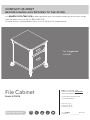 1
1
-
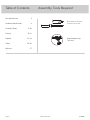 2
2
-
 3
3
-
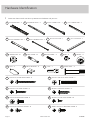 4
4
-
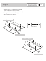 5
5
-
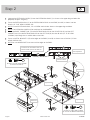 6
6
-
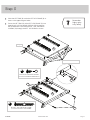 7
7
-
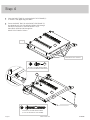 8
8
-
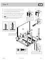 9
9
-
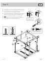 10
10
-
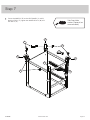 11
11
-
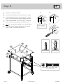 12
12
-
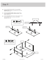 13
13
-
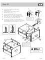 14
14
-
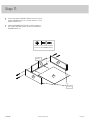 15
15
-
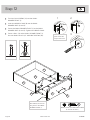 16
16
-
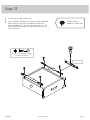 17
17
-
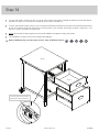 18
18
-
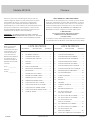 19
19
-
 20
20
-
 21
21
-
 22
22
-
 23
23
-
 24
24
-
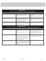 25
25
-
 26
26
-
 27
27
-
 28
28


En otros idiomas
- français: Sauder 420406 Mode d'emploi
- English: Sauder 420406 Operating instructions
Documentos relacionados
-
Sauder Boulevard Cafe 420650 Manual de usuario
-
-
-
-
-
-
-
-
-