


Described product
W16
WLG16
Manufacturer
SICK AG
Erwin-Sick-Str. 1
79183 Waldkirch
Germany
Legal information
This work is protected by copyright. Any rights derived from the copyright shall be
reserved for SICK AG. Reproduction of this document or parts of this document is
only permissible within the limits of the legal determination of Copyright Law. Any modi‐
fication, abridgment or translation of this document is prohibited without the express
written permission of SICK AG.
The trademarks stated in this document are the property of their respective owner.
© SICK AG. All rights reserved.
Original document
This document is an original document of SICK AG.
2006/42/EC
NO
SAFETY
2
8020349.19RH / 22.12.2020 | SICK
Subject to change without notice

Contents
1 Safety information............................................................................ 4
1.1 General safety notes................................................................................ 4
1.2 Notes on UL approval............................................................................... 4
2 Intended use...................................................................................... 4
3 Operating and status indicators...................................................... 4
4 Mounting............................................................................................. 5
5 Electrical installation........................................................................ 5
6 Additional functions.......................................................................... 7
7 Commissioning.................................................................................. 8
7.1 Alignment.................................................................................................. 8
7.2 Check the application conditions............................................................ 9
7.3 Sensing range setting............................................................................... 9
7.4 Time function setting................................................................................ 12
7.5 Setting light/dark switching..................................................................... 13
8 Process data structure..................................................................... 13
9 Troubleshooting................................................................................. 14
10 Disassembly and disposal............................................................... 14
11 Maintenance...................................................................................... 14
12 Technical data.................................................................................... 14
12.1 Dimensional drawings.............................................................................. 15
CONTENTS
8020349.19RH / 22.12.2020 | SICK
Subject to change without notice
3

1 Safety information
1.1 General safety notes
■
Read the operating instructions before commissioning.
■
Connection, mounting, and configuration may only be performed by trained
specialists.
■
2006/42/EC
NO
SAFETY
Not a safety component in accordance with the EU Machinery Directive.
■
Do not install the sensor at locations that are exposed to direct sunlight
or other weather influences, unless this is expressly permitted in the operating
instructions.
■
These operating instructions contain information required during the life cycle of
the sensor.
1.2 Notes on UL approval
The device shall be supplied from an isolating transformer having a secondary overcur‐
rent protective device that complies with UL 248 to be installed in the field rated either:
a) max 5 amps for voltages 0 ~ 20 V (0 ~ 28.3 V peak), or
b) 100 / Vp for voltages of 20 ~ 30 V (28.3 ~ 42.4 V peak).
Alternatively, they can be supplied from a Class 2 power supply.
UL Environmental Rating: Enclosure type 1
2 Intended use
The WLG16 is an opto-electronic photoelectric retro-reflective sensor (referred to as
“sensor” in the following) for the optical, non-contact detection of objects, animals, and
persons. A reflector is required for it to function. If the product is used for any other
purpose or modified in any way, any warranty claim against SICK AG shall become void.
WLG16 is a photoelectric retro-reflective sensor with optional add-on for detecting
transparent objects.
3 Operating and status indicators
WLG16x-xxxxxx20 WLG16-xxxxxxx21 WLG16-xxxxxxx22
1
2
34
1
2
34
6
1
2
34
5
1
BluePilot blue: mode selection
1 SAFETY INFORMATION
4
8020349.19RH / 22.12.2020 | SICK
Subject to change without notice

2
Press-turn element: adjustment of mode and sensitivity
3
LED indicator yellow: status of received light beam
4
LED indicator green: supply voltage active
5
Press-turn element: time function adjustment
6
Teach pushbutton: adjustment of light/dark switching
4 Mounting
Mount the sensor and the reflector using suitable mounting brackets (see the SICK
range of accessories). Align the sensor and reflector with each other.
Note the sensor’s maximum permissible tightening torque of < 1,3 Nm.
5 Electrical installation
The sensors must be connected in a voltage-free state. The following information must
be observed, depending on the connection type:
– Male connector connection: Note pin assignment.
– Cable: wire color
Only supply/switch on the voltage once all electrical connections have been estab‐
lished.
Explanations on connection diagram:
Alarm = alarm output
Health = alarm output
MF (pin 2 configuration) = external input, teach-in, switching signal
Q
L1
/C = switching output, IO-Link communication
Test = test input
U
B
: 10 ... 30 V DC
Table 1: Connections
Wxx16x- x4 xH x5 xI
1 = BN
2 = WH
3 = BU
4 = BK
5= GY
1
2
4 3
0.14 mm
2
AWG26
1
2
4 3
5
0.14 mm
2
AWG26
Wxx16x- x9 xB
1 = BN
2 = BU
3 = not connected
4 = BK
5= WH
6 = GY
7 = not connected
3 4
1
2 5
6
I
N
= 4 A
3
7
2
1
6
5
4
I
N
= 6 A
MOUNTING 4
8020349.19RH / 22.12.2020 | SICK
Subject to change without notice
5

Table 2: DC
WLG16
x-
xxX6XxxxA00 xxX6Xx
xxA01-
A99
Push-
pull
xx161 xx162 xx163 xx165 xx168 xx16A xx16L xx16N xx16x
PNP xx861 xx862 xx863 xx865 xx868 xx86A xx86L xx86N xx86x
1 = BN + (L+)
2 = WH MF
3 = BU - (M)
4 = BK Q
L1
/C
Default:
MF
Q
Q
Alarm Alarm Test →
L+
no func‐
tion
Test →
L+
no func‐
tion
www.sic
k.com
80227
09
Default:
Q
L1
/C
Q
Q
Q
Q
Q Q
Q Q www.sic
k.com
80227
09
Table 3: DC
WLG16x- xxXXXxxxZZZ
Push-pull xx111 xx112 xx114 xx116 xx421 xx422 xx721 xx722
PNP xx811 xx812 xx814 xx816 xxB21 xxB22 - -
BN + (L+)
WH Q
Q
Health Health Q
Q
Q
Q
BU - (M)
BK
Q
Q
Q
Q
Q
Q
Q
Q
GR - - - - Test →
L+
Test →
L+
Test →
M
Test →
M
5 ELECTRICAL INSTALLATION
6
8020349.19RH / 22.12.2020 | SICK
Subject to change without notice

Table 4: Push-pull, PNP, NPN
Push-pull
PNP
NPN
+ (L+)
Q ≤ 100 mA
‒ (M)
Push-pull
PNP
NPN
+ (L+)
Q ≤ 100 mA
‒ (M)
Push-pull
PNP
NPN
+ (L+)
Q ≤ 100 mA
‒ (M)
Push-pull
PNP
NPN
+ (L+)
Q ≤ 100 mA
‒ (M)
6 Additional functions
Alarm
Alarm output: The sensor (WLG16) features a pre-failure notification output (“Alarm” in
connection diagram [see table 2]), which issues a notification if the sensor is only ready
for operation to a limited extent. The LED flashes in this case. Possible causes: Sensor
is contaminated, sensor is out of alignment. In the good state: LOW (0), if excessively
contaminated HIGH (1).
Health output: The sensor (WLG16) features a pre-failure notification output (“Health”
in connection diagram [see table 2]), which issues a notification if the sensor is only
ready for operation to a limited extent or the cable has been interrupted. Possible
causes: Sensor or reflector is contaminated, sensor is out of alignment, cable is dam‐
aged. In the good state: HIGH (1), if excessively contaminated or in the event of cable
interruption LOW (0). The yellow LED indicator flashes in this case.
ADDITIONAL FUNCTIONS 6
8020349.19RH / 22.12.2020 | SICK
Subject to change without notice
7

Table 5: Alarm / Health
Alarm (≤ 100 mA) Health (≤100 mA)
+ (L+)
Alarm
‒ (M)
+ (L+)
Health
‒ (M)
+ (L+)
Alarm
‒ (M)
+ (L+)
Health
‒ (M)
Test input
Test input: The WLG16 sensors feature a test input (“TI” or “Test” on the connection
diagram [table 2], which can be used to switch the sender off and, therefore, check that
the sensor is functioning correctly: If female cable connectors with LED indicators are
used, you have to ensure that the TI is assigned accordingly.
It is important that there is no object between the sensor and reflector; activate the
test input (see the connection diagram). The send LED is shut down or the detection
of an object is simulated. Refer to table 6 to check the function. If the switching output
fails to behave in accordance with the graphic, check the application conditions. see
„Troubleshooting“, page 14
Table 6: Test
Test → M Test → L+
+ (L+)
Test
– (M)
+ (L+)
Test
– (M)
+ (L+)
Test
– (M)
+ (L+)
Test
– (M)
7 Commissioning
7.1 Alignment
Align the sensor with a suitable reflector. Select the position so that the red emitted
light beam hits the center of the reflector. The sensor must have a clear view of the
reflector, with no object in the path of the beam [see figure 1]. You must ensure that the
optical openings of the sensor and reflector are completely clear.
6 ADDITIONAL FUNCTIONS
8
8020349.19RH / 22.12.2020 | SICK
Subject to change without notice

Figure 1: Alignment
7.2 Check the application conditions
Adjust the distance between the sensor and the reflector according to the correspond‐
ing diagram [see figure 2] (x = sensing range, y = operating reserve).
Distance in m (feet)
Sensing range
1
2
3
4
5
6
0 1
(3.28)
2
(6.56)
3
(9.84)
4
(13.12)
5
(16.4)
6
(19.69)
4
2.8
0
2.5
0
3.5
0
5
0
1.20
0
Figure 2: Maximum distance between the sensor and the respective reflector type
1
Reflector PL10F CHEM
2
Reflective tape REF-AC1000 (50 x 50 mm)
3
Reflector PL10FH-1
4
Reflector PL10F
5
Reflector PL20F
6
Reflector P250F
7.3 Sensing range setting
The Teach-Turn adjustment is used to set the object mode and switching threshold, see
figure 3, see figure 4.
The WLG16 is equipped with AutoAdapt technology. The switching threshold is automat‐
ically adjusted in the event of contamination or after cleaning.
COMMISSIONING 7
8020349.19RH / 22.12.2020 | SICK
Subject to change without notice
9

•
Turn the Teach-Turn adjustment (without pressing) to set the desired object mode.
A blue LED lights up according to the set object mode.
•
Press the Teach-Turn adjustment for about 1 to 3 seconds to set the switching
threshold.
If mode 1 to 4 is selected, the yellow LED lights up when the reflector is in view of
the sensor.
•
Lead the object into the path of the beam. The yellow LED goes out, meaning the
object is detected and the setting is correct.
•
With object selection 5, the film must be in the path of the beam when the
potentiometer is pressed. The yellow LED does not light up until the film is no
longer in the beam path. When this has been checked, the setting is correct.
•
The blue LED of mode M lights up when a setting has been selected via IO-Link
which deviates from the predefined parameter sets of modes 1-5. This mode
cannot be selected directly on the device.
1 M
2
3 4 5
1
Highly-transparent objects
2
Semi-transparent objects
3
Opaque objects
4
Bottles/trays
5
Check of foil tear
M Manual (specific setting via IO-Link)
7 COMMISSIONING
10
8020349.19RH / 22.12.2020 | SICK
Subject to change without notice

1 2 3 4
1 M
2
3 4 5
1 M
2
3 4 5
1 M
2
3 4 5
1 M
2
3 4 5
1 M
2
3 4 5
1 M
2
3 4 5
1 M
2
3 4 5
1...3 sec.
1
2
3
Figure 3: Object mode 1 - 4
COMMISSIONING
7
8020349.19RH / 22.12.2020 | SICK
Subject to change without notice
11

5
1 M
2
3 4 5
1 M
2
3 4 5
1 M
2
3 4 5
1 M
2
3 4 5
1 M
2
3 4 5
1...3 sec.
1
2
3
Figure 4: Object mode 5
7.4
Time function setting
1
0
T1
T2
M
T4
T3
t
t
t t t
t
t t t t
t t t
t
t
t t
Input signal
0
T1
T2
T3
T4
M = Manual (specific setting via IO-Link)
7 COMMISSIONING
12
8020349.19RH / 22.12.2020 | SICK
Subject to change without notice

1 ms 30.000 ms
2
7.5 Setting light/dark switching
1
L
D
M
L light switching
D Dark switching
M manual (specific setting via IO-Link)
8 Process data structure
WLG16x-xxxxxxxxAxx:
A00 A70 A71 A72 A73 A75
IO-Link V1.1
Process
data
2 bytes 4 bytes
Byte 0: bits 15... 8
Byte 1: bits 7... 0
Byte 0: bits 31...
24
Byte 1: bits 13...
16
Byte 2: bits 15...
8
Byte 3: bits 7... 0
Bit 0 / Data
type
Q
L1
/ Boolean
Bit 1 / Data
type
Q
L2
/ Boolean Qint.1 /
Boolean
Q
L2
/
Boolean
Qint.1 / Boolean
Bit... /
Descrip‐
tion / Data
type
2 ...15 /
[empty]
2 ...15 /
[time mea‐
surement
value] /
UInt 14
2 … 15 /
[counter
value] /
UInt 14
2 … 15 /
[length /
speed
measure‐
ment] /
SInt14
2 /
Qint.1 /
Boolean
2 … 7 / [empty]
Bit... /
Descrip‐
tion / Data
type
3 … 15 /
[time mea‐
surement
value] /
UInt13
8 … 31 / [carrier
load] / UInt 24
COMMISSIONING 7
8020349.19RH / 22.12.2020 | SICK
Subject to change without notice
13

9 Troubleshooting
The Troubleshooting table indicates measures to be taken if the sensor stops working.
LED indicator/fault pattern Cause Measures
Green LED flashes IO-Link communication None
Switching outputs do not
behave in accordance with
table 4
1. Change of the configuration
2. Short-circuit
1. Adjustment of the configura‐
tion
2. Check electrical connections
10 Disassembly and disposal
The sensor must be disposed of according to the applicable country-specific regula‐
tions. Efforts should be made during the disposal process to recycle the constituent
materials (particularly precious metals).
NOTE
Disposal of batteries, electric and electronic devices
•
According to international directives, batteries, accumulators and electrical or
electronic devices must not be disposed of in general waste.
•
The owner is obliged by law to return this devices at the end of their life to the
respective public collection points.
•
WEEE: This symbol on the product, its package or in this document,
indicates that a product is subject to these regulations.
11 Maintenance
SICK sensors are maintenance-free.
We recommend doing the following regularly:
•
Clean the external lens surfaces
•
Check the screw connections and plug-in connections
No modifications may be made to devices.
Subject to change without notice. Specified product properties and technical data are
not written guarantees.
12 Technical data
WLG16P
Sensing range (with reflector P250F) 0 m ... 5 m
1)
Light spot diameter/distance Ø 80 mm (5 m)
Supply voltage U
B
DC 10 ... 30 V
Ripple ≤ 5 V
SS
Current consumption ≤ 30 mA
2)
< 50 mA
3)
9 TROUBLESHOOTING
14
8020349.19RH / 22.12.2020 | SICK
Subject to change without notice

WLG16P
Output current I
max.
≤ 100 mA
Max. response time ≤ 500 μs
4)
Switching frequency 1,000 Hz
5)
Enclosure rating
6)
see table 1:
x4, xH, x5, xI: IP66, IP67, IP69
7)
x9, xB: IP65
Protection class III
Circuit protection A, B, C, D
8)
Ambient operating temperature –40 °C ... +60 °C
9)
1)
We recommend using compound triangular reflectors or reflective tape to ensure reliable operation. Suitable reflectors and foils can be
found in the SICK accessories range. Use of reflectors with large-scale triple structures can negatively influence functionality.
2)
16 VDC to 30 VDC, without load
3)
10 VDC to 16 VDC, without load
4)
Signal transit time with resistive load in switching mode. Deviating values possible in COM2 mode.
5)
With a light/dark ratio of 1:1 in switching mode. Deviating values possible in IO-Link mode.
6)
Pursuant to EN 60529
7)
Replaces IP69 K pursuant to ISO 20653: 2013-03
8)
A = U
B
-connections reverse polarity protected
B = inputs and output reverse-polarity protected
C = Interference suppression
D = outputs overcurrent and short-circuit protected
9)
Do not bend cables below 0°C.
12.1 Dimensional drawings
3
2
20 (0.79)
Ø 12.9
(0.51)
Ø 4.1 (0.16)
39.9 (1.57)
55.4 (2.18)
45.5 (1.79)
5 (0.2)
42 (1.65)
29.9 (0.18)
6
(0.24)
3 (0.12)
6.5 (0.26)
15 (0.59)
27.8 (1.09)
7.7
(0.3)
7.8
(0.31)
7.2 (0.28)
35.5 (1.4)
4.1 (0.16)
8.3
(0.33)
55.7 (2.19)
34.5 (1.36)
1
4
Figure 5: Dimensional drawing 1, cable
1
Center of optical axis
2
Fixing hole, Ø 4.1 mm
3
Connection
4
Display and setting elements
M12
17.5
(0.24)
3
2
1
20 (0.79)
18
(0.71)
34.5 (1.36)
Ø 4.1 (0.16)
7 (0.28)
39.9 (1.57)
55.4 (2.18)
55.7 (2.19)
45.5 (1.79)
5 (0.2)
29.9 (0.18)
52.9 (2.08)
6
(0.24)
3 (0.12)
6.5 (0.26)
15 (0.59)
28 (1.1)
7.5
(0.3)
35.5 (1.4)
4.1 (0.16)
42 (1.65)
4
Figure 6: Dimensional drawing 2, male con‐
nector
TECHNICAL DATA 12
8020349.19RH / 22.12.2020 | SICK
Subject to change without notice
15


Beschriebenes Produkt
W16
WLG16
Hersteller
SICK AG
Erwin-Sick-Str. 1
79183 Waldkirch
Deutschland
Rechtliche Hinweise
Dieses Werk ist urheberrechtlich geschützt. Die dadurch begründeten Rechte bleiben
bei der Firma SICK AG. Die Vervielfältigung des Werks oder von Teilen dieses Werks
ist nur in den Grenzen der gesetzlichen Bestimmungen des Urheberrechtsgesetzes
zulässig. Jede Änderung, Kürzung oder Übersetzung des Werks ohne ausdrückliche
schriftliche Zustimmung der Firma SICK AG ist untersagt.
Die in diesem Dokument genannten Marken sind Eigentum ihrer jeweiligen Inhaber.
© SICK AG. Alle Rechte vorbehalten.
Originaldokument
Dieses Dokument ist ein Originaldokument der SICK AG.
2006/42/EC
NO
SAFETY
8020349.19RH / 22.12.2020 | SICK
Subject to change without notice
17

Inhalt
13 Zu Ihrer Sicherheit............................................................................. 19
13.1 Allgemeine Sicherheitshinweise.............................................................. 19
13.2 Hinweise zur UL Zulassung...................................................................... 19
14 Bestimmungsgemäße Verwendung............................................... 19
15 Bedien- und Anzeigeelemente........................................................ 19
16 Montage.............................................................................................. 20
17 Elektrische Installation..................................................................... 20
18 Zusatzfunktionen.............................................................................. 22
19 Inbetriebnahme................................................................................. 23
19.1 Ausrichtung............................................................................................... 23
19.2 Einsatzbedingungen prüfen..................................................................... 24
19.3 Einstellung Schaltabstand....................................................................... 24
19.4 Einstellung Zeitfunktionen....................................................................... 27
19.5 Einstellung Hell-/Dunkelschaltend.......................................................... 28
20 Prozessdatenstruktur........................................................................ 28
21 Störungsbehebung............................................................................ 29
22 Demontage und Entsorgung............................................................ 29
23 Wartung.............................................................................................. 29
24 Technische Daten.............................................................................. 29
24.1 Maßzeichnungen...................................................................................... 30
INHALT
18
8020349.19RH / 22.12.2020 | SICK
Subject to change without notice

13 Zu Ihrer Sicherheit
13.1 Allgemeine Sicherheitshinweise
■
Lesen Sie vor der Inbetriebnahme des Geräts die Betriebsanleitung.
■
Der Anschluss, die Montage und die Konfiguration des Geräts dürfen nur
von geschultem Fachpersonal vorgenommen werden.
■
2006/42/EC
NO
SAFETY
Bei diesem Gerät handelt es sich um kein sicherheitsgerichtetes Bauteil im
Sinne der EU-Maschinenrichtlinie.
■
Installieren Sie den Sensor nicht an Orten, die direkter Sonneneinstrahlung
oder sonstigen Wettereinflüssen ausgesetzt sind, ausser dies ist in der Betriebs‐
anleitung ausdrücklich erlaubt.
■
Die vorliegende Betriebsanleitung enthält Informationen, die während des Lebens‐
zyklus der Lichtschranke benötigt werden.
13.2 Hinweise zur UL Zulassung
The device shall be supplied from an isolating transformer having a secondary overcur‐
rent protective device that complies with UL 248 to be installed in the field rated either:
a) max 5 amps for voltages 0 ~ 20 V (0 ~ 28.3 V peak), or
b) 100 / Vp for voltages of 20 ~ 30 V (28.3 ~ 42.4 V peak).
Alternatively, they can be supplied from a Class 2 power supply.
UL Environmental Rating: Enclosure type 1
14 Bestimmungsgemäße Verwendung
Die WLG16 ist eine optoelektronische Reflexions-Lichtschranke (im Folgenden Sensor
genannt) und wird zum optischen, berührungslosen Erfassen von Sachen, Tieren und
Personen eingesetzt. Zur Funktion wird ein Reflektor benötigt. Bei jeder anderen
Verwendung und bei Veränderungen am Produkt verfällt jeglicher Gewährleistungsan‐
spruch gegenüber der SICK AG.
WLG16 ist eine Reflexions-Lichtschranke mit Zusatzoption zur Detektion transparenter
Objekte.
15 Bedien- und Anzeigeelemente
WLG16x-xxxxxx20 WLG16-xxxxxxx21 WLG16-xxxxxxx22
1
2
34
1
2
34
6
1
2
34
5
ZU IHRER SICHERHEIT 13
8020349.19RH / 22.12.2020 | SICK
Subject to change without notice
19

1
BluePilot blau: Moduswahl
2
Drück-Dreh-Element: Einstellung von Modus und Empfindlichkeit
3
Anzeige-LED gelb: Status Lichtempfang
4
Anzeige-LED grün: Betriebsspannung aktiv
5
Drück-Dreh-Element: Einstellung der Zeitfunktionen
6
Teach-Taste: Einstellung hell-/dunkelschaltend
16 Montage
Sensor und Reflektor an geeignete Befestigungswinkel montieren (siehe SICK-Zube‐
hör-Programm). Sensor und Reflektor zueinander ausrichten.
Maximal zulässiges Anzugsdrehmoment des Sensors von < 1,3 Nm beachten.
17 Elektrische Installation
Anschluss der Sensoren muss spannungsfrei erfolgen. Je nach Anschlussart sind die
folgenden Informationen zu beachten:
– Steckeranschluss: Pinbelegung beachten.
– Leitung: Adernfarbe
Erst nach Anschluss aller elektrischen Verbindungen die Spannungsversorgung anlegen
bzw. einschalten.
Erläuterungen zum Anschlussschema:
Alarm = Alarmausgang
Health = Alarmausgang
MF (Pin-2-Konfiguration) = Externer Eingang, Teach-in, Schaltsignal
Q
L1
/C = Schaltausgang, IO-Link Kommunikation
Test = Testeingang
U
B
: 10 ... 30 V DC
Tabelle 7: Anschlüsse
Wxx16x- x4 xH x5 xI
1 = BN
2 = WH
3 = BU
4 = BK
5= GY
1
2
4 3
0.14 mm
2
AWG26
1
2
4 3
5
0.14 mm
2
AWG26
Wxx16x- x9 xB
1 = BN
2 = BU
3 = not connected
4 = BK
5= WH
6 = GY
7 = not connected
3 4
1
2 5
6
I
N
= 4 A
3
7
2
1
6
5
4
I
N
= 6 A
16 MONTAGE
20
8020349.19RH / 22.12.2020 | SICK
Subject to change without notice

Tabelle 8: DC
WLG16
x-
xxX6XxxxA00 xxX6Xx
xxA01-
A99
Push-
pull
xx161 xx162 xx163 xx165 xx168 xx16A xx16L xx16N xx16x
PNP xx861 xx862 xx863 xx865 xx868 xx86A xx86L xx86N xx86x
1 = BN + (L+)
2 = WH MF
3 = BU - (M)
4 = BK Q
L1
/C
Default:
MF
Q
Q
Alarm Alarm Test →
L+
no func‐
tion
Test →
L+
no func‐
tion
www.sic
k.com
80227
09
Default:
Q
L1
/C
Q
Q
Q
Q
Q Q
Q Q www.sic
k.com
80227
09
Tabelle 9: DC
WLG16x- xxXXXxxxZZZ
Push-pull xx111 xx112 xx114 xx116 xx421 xx422 xx721 xx722
PNP xx811 xx812 xx814 xx816 xxB21 xxB22 - -
BN + (L+)
WH Q
Q
Health Health Q
Q
Q
Q
BU - (M)
BK
Q
Q
Q
Q
Q
Q
Q
Q
GR - - - - Test →
L+
Test →
L+
Test →
M
Test →
M
ELEKTRISCHE INSTALLATION 17
8020349.19RH / 22.12.2020 | SICK
Subject to change without notice
21

Tabelle 10: Push-pull, PNP, NPN
Push-pull
PNP
NPN
+ (L+)
Q ≤ 100 mA
‒ (M)
Push-pull
PNP
NPN
+ (L+)
Q ≤ 100 mA
‒ (M)
Push-pull
PNP
NPN
+ (L+)
Q ≤ 100 mA
‒ (M)
Push-pull
PNP
NPN
+ (L+)
Q ≤ 100 mA
‒ (M)
18 Zusatzfunktionen
Alarm
Alarmausgang: Der Sensor (WLG16) verfügt über einen Vorausfallmeldeausgang
("Alarm" im Anschlussschema [siehe Tabelle 2]) der meldet, wenn der Sensor nur noch
eingeschränkt betriebsbereit ist. Dabei blinkt die Anzeige-LED. Mögliche Ursachen: Ver‐
schmutzung des Sensors, Sensor ist dejustiert. Im Gutzustand: LOW (0), bei zu starker
Verschmutzung HIGH (1).
Health-Ausgang: Der Sensor (WLG16) verfügt über einen Vorausfallmeldeausgang
("Health" im Anschlussschema [siehe Tabelle 2]), der meldet, wenn der Sensor nur
noch eingeschränkt betriebsbereit ist oder die Leitung unterbrochen ist. Mögliche
Ursachen: Verschmutzung von Sensor oder Reflektor, Sensor ist dejustiert, Leitung ist
beschädigt. Im Gutzustand: HIGH (1), bei zu starker Verschmutzung oder Leitungsunter‐
brechung LOW (0). Dabei blinkt die gelbe Anzeige-LED.
18 ZUSATZFUNKTIONEN
22
8020349.19RH / 22.12.2020 | SICK
Subject to change without notice

Tabelle 11: Alarm / Health
Alarm (≤ 100 mA) Health (≤100 mA)
+ (L+)
Alarm
‒ (M)
+ (L+)
Health
‒ (M)
+ (L+)
Alarm
‒ (M)
+ (L+)
Health
‒ (M)
Testeingang
Testeingang: Die Sensoren WLG16 verfügen über einen Testeingang („TE“ oder „Test“
im Anschlussschema [Tabelle 2], mit dem der Sender ausgeschaltet und somit die
ordnungsgemäße Funktion des Sensors überprüft werden kann: Bei Verwendung von
Leitungsdosen mit LED-Anzeigen ist darauf zu achten, dass der TE entsprechend belegt
ist.
Es darf sich kein Objekt zwischen Sensor und Reflektor befinden, Testeingang aktivie‐
ren (siehe Anschlussschema). Sende-LED wird abgeschaltet, bzw. es wird simuliert,
dass ein Objekt erkannt wird. Zur Überprüfung der Funktion die Tabelle 6 heranziehen.
Verhält sich der Schaltausgang nicht gemäß der Grafik, Einsatzbedingungen prüfen.
siehe „Störungsbehebung“, Seite 29
Tabelle 12: Test
Test → M Test → L+
+ (L+)
Test
– (M)
+ (L+)
Test
– (M)
+ (L+)
Test
– (M)
+ (L+)
Test
– (M)
19 Inbetriebnahme
19.1 Ausrichtung
Sensor auf geeigneten Reflektor ausrichten. Positionierung so wählen, dass der rote
Sendelichtstrahl in der Mitte des Reflektors auftrifft. Der Sensor muss freie Sicht
auf den Reflektor haben, es darf sich kein Objekt im Strahlengang befinden [siehe
Abbildung 7]. Es ist darauf zu achten, dass die optischen Öffnungen von Sensor und
Reflektor vollständig frei sind.
ZUSATZFUNKTIONEN 18
8020349.19RH / 22.12.2020 | SICK
Subject to change without notice
23

Abbildung 7: Ausrichtung
19.2 Einsatzbedingungen prüfen
Distanz zwischen Sensor und Reflektor mit dem zugehörigen Diagramm [siehe
Abbildung 8] abgleichen (x = Schaltabstand, y = Funktionsreserve).
Abstand in m
Schaltabstand
1
2
3
4
5
6
0 1 2 3 4 5 6
4
2,8
0
2,5
0
3,5
0
5
0
1,20
0
Abbildung 8: Maximaler Abstand zwischen Sensor und dem jeweiligen Reflektortyp
1
Reflektor PL10F CHEM
2
Reflexionsfolie REF-AC1000 (50 x 50 mm)
3
Reflektor PL10FH-1
4
Reflektor PL10F
5
Reflektor PL20F
6
Reflektor P250F
19.3 Einstellung Schaltabstand
Mit dem Drück-Dreh-Element werden Objektmodus und Schaltschwelle eingestellt,
siehe Abbildung 9, siehe Abbildung 10.
Die WLG16 ist mit der AutoAdapt-Technologie ausgestattet. Im Falle einer Verschmut‐
zung oder nach einer Reinigung wird die Schaltschwelle automatisch angepasst.
19 INBETRIEBNAHME
24
8020349.19RH / 22.12.2020 | SICK
Subject to change without notice

•
Drehen Sie das Drück-Dreh-Element (ohne zu drücken), um den gewünschten
Objektmodus einstellen. Eine blaue Anzeige-LED leuchtet entsprechend dem ein‐
gestellten Objektmodus .
•
Drücken Sie das Drück-Dreh-Element für ca. 1…3 sec., um die Schaltschwelle
einzustellen.
Im Falle der Moduswahl 1 bis 4 leuchtet die gelbe Anzeige-LED bei Sicht des
Sensors auf den Reflektor.
•
Führen Sie das Objekt in den Strahlengang, die gelbe Anzeige-LED erlischt, d.h.
das Objekt wird erkannt und die Einstellung ist korrekt.
•
Bei der Objektauswahl 5 muss sich die Folie im Strahlengang befinden, während
dem Drücken des Potentiometers. Die gelbe Anzeige-LED leuchtet erst, wenn sich
die Folie nicht mehr im Strahlengang befindet. Wenn dies überprüft wurde, dann
ist die Einstellung korrekt.
•
Die blaue Anzeige-LED des Modus M leuchtet, wenn via IO-Link eine Einstellung
gewählt wurde, welche von den vordefinierten Parameter-Sets der Modi 1-5
abweicht. Dieser Modus kann nicht direkt am Gerät angewählt werden.
1 M
2
3 4 5
1
Hoch-transparente Objekte
2
Semi-transparente Objekte
3
Nicht-transparente Objekte
4
Flaschen/Trays
5
Folienriss-Kontrolle
M Manuell (spezifische Einstellung via IO-Link)
INBETRIEBNAHME 19
8020349.19RH / 22.12.2020 | SICK
Subject to change without notice
25

1 2 3 4
1 M
2
3 4 5
1 M
2
3 4 5
1 M
2
3 4 5
1 M
2
3 4 5
1 M
2
3 4 5
1 M
2
3 4 5
1 M
2
3 4 5
1...3 sec.
1
2
3
Abbildung 9: Objektmodus 1 - 4
19
INBETRIEBNAHME
26
8020349.19RH / 22.12.2020 | SICK
Subject to change without notice

5
1 M
2
3 4 5
1 M
2
3 4 5
1 M
2
3 4 5
1 M
2
3 4 5
1 M
2
3 4 5
1...3 sec.
1
2
3
Abbildung 10: Objektmodus 5
19.4
Einstellung Zeitfunktionen
1
0
T1
T2
M
T4
T3
t
t
t t t
t
t t t t
t t t
t
t
t t
Input signal
0
T1
T2
T3
T4
M = Manuell (spezifische Einstellung via IO-Link)
INBETRIEBNAHME 19
8020349.19RH / 22.12.2020 | SICK
Subject to change without notice
27

1 ms 30.000 ms
2
19.5 Einstellung Hell-/Dunkelschaltend
1
L
D
M
L hellschaltend
D dunkelschaltend
M manuell (spezifische Einstellung via IO-Link)
20 Prozessdatenstruktur
WLG16x-xxxxxxxxAxx:
A00 A70 A71 A72 A73 A75
IO-Link V1.1
Process
data
2 Byte 4 Byte
Byte 0 : Bit 15... 8
Byte 1: Bit 7... 0
Byte 0 : Bit 31...
24
Byte 1: Bit 13... 16
Byte 2: Bit 15... 8
Byte 3: Bit 7... 0
Bit 0/ Data
type
Q
L1
/ Boolean
Bit 1/ Data
type
Q
L2
/ Boolean Qint.1 /
Boolean
Q
L2
/ Boo‐
lean
Qint.1 / Boolean
Bit... /
Descrip‐
tion / Data
type
2...15 /
[empty]
2...15 /
[Time
measure‐
ment
value] /
UInt 14
2 … 15 /
[Counter
value] /
UInt 14
2 … 15 /
[Length /
speed
measure‐
ment] /
SInt14
2 /
Qint.1 /
Boolean
2…7 / [empty]
Bit... /
Descrip‐
tion / Data
type
3 … 15 /
[Time
measure‐
ment
value] /
UInt13
8 … 31 / [Carrier
load] / UInt 24
19 INBETRIEBNAHME
28
8020349.19RH / 22.12.2020 | SICK
Subject to change without notice

21 Störungsbehebung
Tabelle Störungsbehebung zeigt, welche Maßnahmen durchzuführen sind, wenn die
Funktion des Sensors nicht mehr gegeben ist.
Anzeige-LED / Fehlerbild Ursache Maßnahme
grüne LED blinkt IO-Link Kommunikation keine
Schaltausgänge verhalten sich
nicht gemäß
Tabelle 4
1. Änderung der Konfiguration
2. Kurzschluss
1. Anpassung der Konfigura‐
tion
2. Elektrische Anschlüsse prü‐
fen
22 Demontage und Entsorgung
Die Lichtschranke muss entsprechend den geltenden länderspezifischen Vorschriften
entsorgt werden. Bei der Entsorgung sollte eine werkstoffliche Verwertung (insbeson‐
dere der Edelmetalle) angestrebt werden.
HINWEIS
Entsorgung von Batterien, Elektro- und Elektronikgeräten
•
Gemäß den internationalen Vorschriften dürfen Batterien, Akkus sowie Elektro-
und Elektronikgeräte nicht mit dem Hausmüll entsorgt werden.
•
Der Besitzer ist gesetzlich verpflichtet, diese Geräte am Ende ihrer Lebensdauer
bei den entsprechenden öffentlichen Sammelstellen abzugeben.
•
WEEE: Dieses Symbol auf dem Produkt, dessen Verpackung oder im
vorliegenden Dokument gibt an, dass ein Produkt den genannten Vorschriften
unterliegt.
23 Wartung
SICK-Sensoren sind wartungsfrei.
Wir empfehlen, in regelmäßigen Abständen
•
die optischen Grenzflächen zu reinigen
•
Verschraubungen und Steckverbindungen zu überprüfen
Veränderungen an Geräten dürfen nicht vorgenommen werden.
Irrtümer und Änderungen vorbehalten. Angegebene Produkteigenschaften und techni‐
sche Daten stellen keine Garantieerklärung dar.
24 Technische Daten
WLG16P
Schaltabstand (mit Reflektor P250F) 0 m ... 5 m
1)
Lichtfleckdurchmesser/Entfernung Ø 80 mm (5 m)
Versorgungsspannung U
B
DC 10 ... 30 V
Restwelligkeit ≤ 5 V
SS
STÖRUNGSBEHEBUNG 21
8020349.19RH / 22.12.2020 | SICK
Subject to change without notice
29

WLG16P
Stromaufnahme ≤ 30 mA
2)
< 50 mA
3)
Ausgangsstrom I
max.
≤ 100 mA
Ansprechzeit max. ≤ 500 μs
4)
Schaltfrequenz 1000 Hz
5)
Schutzart
6)
siehe Tabelle 7:
x4, xH, x5, xI: IP66, IP67, IP69
7)
x9, xB: IP65
Schutzklasse III
Schutzschaltungen A, B, C, D
8)
Betriebsumgebungstemperatur –40 °C ... +60 °C
9)
1)
Für einen zuverlässigen Betrieb empfehlen wir die Verwendung von Feintripel-Reflektoren oder Reflexionsfolie. Geeignete Reflektoren und
Folien finden Sie im Zubehör-Programm von Sick. Die Verwendung von Reflektoren mit großer Tripelstruktur kann die Funktionsfähigkeit
beeinträchtigen.
2)
16VDC...30VDC, ohne Last
3)
10VDC...16VDC, ohne Last
4)
Signallaufzeit bei ohmscher Last im Schaltmodus. Abweichende Werte im COM2-Modus möglich.
5)
Bei Hell-Dunkel-Verhältnis 1:1 im Schaltmodus. Abweichende Werte im IO-Link-Modus möglich.
6)
Nach EN 60529
7)
Ersetzt IP69K nach ISO 20653: 2013-03
8)
A = U
B
-Anschlüsse verpolsicher
B = Ein- und Ausgänge verpolsicher
C = Störimpulsunterdrückung
D = Ausgänge überstrom- und kurzschlussfest
9)
Leitungen unter 0 °C nicht verformen
24.1 Maßzeichnungen
20
Ø 12,9
Ø 4,1
39,9
55,4
45,5
5
42
29,9
6
3
6,5
15
27,8
7,7
7,8
7,2
35,5
4,1
8,3
55,7
3
2
34,5
1
4
Abbildung 11: Maßzeichnung 1, Leitung
1
Mitte Optikachse
2
Befestigungsbohrung, Ø 4,1 mm
3
Anschluss
4
Anzeige- und Einstellelemente
20
M12
18
Ø 4,1
39,9
55,4
55,7
45,5
5
7
42
29,9
52,9
6
17,5
3
6,5
15
28
7,5
35,5
4,1
3
2
34,5
1
4
Abbildung 12: Maßzeichnung 2, Stecker
24 TECHNISCHE DATEN
30
8020349.19RH / 22.12.2020 | SICK
Subject to change without notice


Produit décrit
W16
WLG16
Fabricant
SICK AG
Erwin-Sick-Straße 1
79183 Waldkirch
Allemagne
Remarques juridiques
Cet ouvrage est protégé par les droits d'auteur. Les droits établis restent dévolus à
la société SICK AG. La reproduction de l'ouvrage, même partielle, n'est autorisée que
dans le cadre légal prévu par la loi sur les droits d'auteur. Toute modification, tout
abrègement ou toute traduction de l'ouvrage est interdit sans l'accord écrit exprès de la
société SICK AG.
Les marques citées dans ce document sont la propriété de leurs détenteurs respectifs.
© SICK AG. Tous droits réservés.
Document original
Ce document est un document original de SICK AG.
2006/42/EC
NO
SAFETY
32
8020349.19RH / 22.12.2020 | SICK
Subject to change without notice

Contenu
25 Pour votre sécurité............................................................................ 34
25.1 Consignes générales de sécurité............................................................. 34
25.2 Remarques sur l’homologation UL.......................................................... 34
26 Utilisation conforme.......................................................................... 34
27 Éléments de commande et d’affichage........................................ 34
28 Montage.............................................................................................. 35
29 Installation électrique....................................................................... 35
30 Fonctions supplémentaires............................................................. 37
31 Mise en service.................................................................................. 38
31.1 Alignement................................................................................................ 38
31.2 Vérification des conditions d’utilisation.................................................. 39
31.3 Réglage distance de commutation.......................................................... 39
31.4 Réglage des fonctions temporelles......................................................... 42
31.5 Réglage commutation claire/sombre...................................................... 43
32 Structure de données de process................................................... 43
33 Élimination des défauts................................................................... 44
34 Démontage et mise au rebut.......................................................... 44
35 Maintenance...................................................................................... 44
36 Caractéristiques techniques............................................................ 44
36.1 Plans cotés................................................................................................ 45
CONTENU
8020349.19RH / 22.12.2020 | SICK
Subject to change without notice
33

25 Pour votre sécurité
25.1 Consignes générales de sécurité
■
Lire la notice d’instruction avant la mise en service.
■
Le raccordement, le montage et la configuration ne doivent être réalisés
que par un personnel qualifié.
■
2006/42/EC
NO
SAFETY
N’est pas un composant de sécurité selon la Directive machines de l’UE.
■
N’installez pas le capteur à des endroits directement exposées aux rayons
du soleil ou à d’autres conditions météorologiques, sauf si cela est explicitement
autorisé dans la notice d'instruction.
■
Cette notice d’instruction contient des informations nécessaires durant le cycle de
vie du capteur.
25.2 Remarques sur l’homologation UL
The device shall be supplied from an isolating transformer having a secondary overcur‐
rent protective device that complies with UL 248 to be installed in the field rated either:
a) max 5 amps for voltages 0 ~ 20 V (0 ~ 28.3 V peak), or
b) 100 / Vp for voltages of 20 ~ 30 V (28.3 ~ 42.4 V peak).
Alternatively, they can be supplied from a Class 2 power supply.
UL Environmental Rating: Enclosure type 1
26 Utilisation conforme
WLG16 est une barrière réflex optoélectronique (appelée capteur dans ce document)
qui permet la détection optique sans contact d’objets, d’animaux et de personnes. Un
réflecteur est nécessaire à son fonctionnement. Toute autre utilisation ou modification
du produit annule la garantie de SICK AG.
WLG16 est une barrière réflex avec option supplémentaire pour la détection d’objets
transparents.
27 Éléments de commande et d’affichage
WLG16x-xxxxxx20 WLG16-xxxxxxx21 WLG16-xxxxxxx22
1
2
34
1
2
34
6
1
2
34
5
1
BluePilot bleu : choix du mode
25 POUR VOTRE SÉCURITÉ
34
8020349.19RH / 22.12.2020 | SICK
Subject to change without notice

2
Bouton poussoir rotatif : réglage du mode et de la sensibilité
3
LED d’état jaune : état réception de lumière
4
LED d’état verte : tension d’alimentation active
5
Bouton poussoir rotatif: réglage des fonctions temporelles
6
Touche d’apprentissage : réglage commutation claire/sombre
28 Montage
Monter le capteur et le réflecteur sur une équerre de fixation (voir la gamme d’acces‐
soires SICK). Aligner le capteur sur le réflecteur.
Respecter le couple de serrage maximum autorisé du capteur de < 1,3 Nm.
29 Installation électrique
Le raccordement des capteurs doit s’effectuer hors tension. Selon le mode de raccor‐
dement, respecter les informations suivantes :
– Raccordement du connecteur : respecter l’affectation des broches.
– Câble : couleur des fils
Activer l’alimentation électrique seulement après avoir effectué les branchements élec‐
triques.
Explications relatives au schéma de raccordement :
Alarme = sortie alarme
Health = sortie alarme
MF (configuration broche 2) = entrée externe, apprentissage, signal de commutation
Q
L1
/C = sortie de commutation, communication IO-Link
Test = entrée de test
U
B
: 10 ... 30 V DC
Tableau 13: Connexions
Wxx16x- x4 xH x5 xI
1 = BN
2 = WH
3 = BU
4 = BK
5= GY
1
2
4 3
0,14 mm
2
AWG26
1
2
4 3
5
0,14 mm
2
AWG26
Wxx16x- x9 xB
1 = BN
2 = BU
3 = not connected
4 = BK
5= WH
6 = GY
7 = not connected
3 4
1
2 5
6
I
N
= 4 A
3
7
2
1
6
5
4
I
N
= 6 A
MONTAGE 28
8020349.19RH / 22.12.2020 | SICK
Subject to change without notice
35

Tableau 14: CC
WLG16
x-
xxX6XxxxA00 xxX6Xx
xxA01-
A99
Push-
pull
xx161 xx162 xx163 xx165 xx168 xx16A xx16L xx16N xx16x
PNP xx861 xx862 xx863 xx865 xx868 xx86A xx86L xx86N xx86x
1 = BN + (L+)
2 = WH MF
3 = BU - (M)
4 = BK Q
L1
/C
Par
défaut :
MF
Q
Q
Alarme Alarme Test →
L+
no func‐
tion
Test →
L+
no func‐
tion
www.sic
k.com
80227
09
Par
défaut :
Q
L1
/C
Q
Sortie Q
Q
Q
Q Q
Q Q www.sic
k.com
80227
09
Tableau 15: DC
WLG16x- xxXXXxxxZZZ
Push-pull xx111 xx112 xx114 xx116 xx421 xx422 xx721 xx722
PNP xx811 xx812 xx814 xx816 xxB21 xxB22 - -
BN + (L+)
WH Q
Q
Health Health Q
Q
Q
Q
BU - (M)
BK
Q
Q
Q
Q
Q
Q
Q
Q
GR - - - - Test →
L+
Test →
L+
Test →
M
Test →
M
29 INSTALLATION ÉLECTRIQUE
36
8020349.19RH / 22.12.2020 | SICK
Subject to change without notice

Tableau 16: Push-pull, PNP, NPN
Push-pull
PNP
NPN
+ (L+)
Q ≤ 100 mA
‒ (M)
Push-pull
PNP
NPN
+ (L+)
Q ≤ 100 mA
‒ (M)
Push-pull
PNP
NPN
+ (L+)
Q ≤ 100 mA
‒ (M)
Push-pull
PNP
NPN
+ (L+)
Q ≤ 100 mA
‒ (M)
30 Fonctions supplémentaires
Alarme
Sortie alarme : le capteur (WLG16) est équipé d’une sortie de signalisation avant
panne (« Alarme » dans le schéma de raccordement [voir tableau 2]) qui indique si
le fonctionnement du capteur est limité. La LED clignote. Causes possibles : encrasse‐
ment du capteur, capteur déréglé. Si l’état est correct : LOW (0), en cas d’encrassement
important HIGH (1).
Sortie Health : le capteur (WLG16) est équipé d’une sortie de signalisation avant
panne (« Health » dans le schéma de raccordement [voir tableau 2]), qui indique si
le fonctionnement du capteur est limité ou si le câble est coupé. Causes possibles :
encrassement du capteur ou du réflecteur, le capteur est déréglé, le câble est endom‐
magé. Si l’état est correct : HIGH (1), en cas d’encrassement important ou de coupure
de câble LOW (0). La LED jaune clignote.
FONCTIONS SUPPLÉMENTAIRES 30
8020349.19RH / 22.12.2020 | SICK
Subject to change without notice
37

Tableau 17: Alarme / Health
Alarme (≤ 100 mA) Health (≤100 mA)
+ (L+)
Alarm
‒ (M)
+ (L+)
Health
‒ (M)
+ (L+)
Alarm
‒ (M)
+ (L+)
Health
‒ (M)
Entrée test
Entrée test : les capteurs WLG16 disposent d’une entrée test (« TE » ou « Test » dans
le schéma de raccordement [tableau 2] qui permet de désactiver l’émetteur et ainsi
de contrôler le bon fonctionnement du capteur : lorsque des câbles avec connecteur
femelle équipés de LED sont utilisés, s’assurer que la TE est correctement affectée.
Aucun objet ne doit se trouver entre le capteur et le réflecteur, activer l’entrée test (voir
le schéma de raccordement). La LED d’émission s’éteint ou une détection d’objet est
simulée. Pour vérifier le fonctionnement, utiliser tableau 6. Si la sortie de commutation
ne se comporte pas comme indiqué dans le graphique, vérifier les conditions d’utilisa‐
tion.voir „Élimination des défauts“, page 44
Tableau 18: Test
Test → M Test → L+
+ (L+)
Test
– (M)
+ (L+)
Test
– (M)
+ (L+)
Test
– (M)
+ (L+)
Test
– (M)
31 Mise en service
31.1 Alignement
Aligner le capteur sur un réflecteur adapté. Choisir la position de sorte que le faisceau
lumineux émis rouge touche le réflecteur en plein centre. Le capteur doit disposer d’un
champ de vision dégagé sur le réflecteur, il ne doit donc y avoir aucun objet dans la
trajectoire du faisceau [voir illustration 13]. S’assurer que les ouvertures optiques du
capteur et du réflecteur sont parfaitement dégagées.
30 FONCTIONS SUPPLÉMENTAIRES
38
8020349.19RH / 22.12.2020 | SICK
Subject to change without notice

Illustration 13: Alignement
31.2 Vérification des conditions d’utilisation
Comparer la distance entre le capteur et le réflecteur avec le diagramme correspon‐
dant [voir illustration 14] (x = distance de commutation, y = réserve de fonctionne‐
ment).
Distance in m (feet)
Sensing range
1
2
3
4
5
6
0 1
(3.28)
2
(6.56)
3
(9.84)
4
(13.12)
5
(16.4)
6
(19.69)
4
2.8
0
2.5
0
3.5
0
5
0
1.20
0
Illustration 14: Distance maximale entre le capteur et le type de réflecteur respectif
1
Réflecteur PL10F, CHEM
2
Bande réflecteur REF-AC1000 (50 x 50 mm)
3
Réflecteur PL10FH-1
4
Réflecteur PL10F
5
Réflecteur PL20F
6
Réflecteur P250F
31.3 Réglage distance de commutation
Le bouton combiné pousser ou tourner permet de régler le mode de l’objet et le seuil
de commutation, voir illustration 15, voir illustration 16.
Le WLG16 est équipé de la technologie AutoAdapt. En présence d’un encrassement ou
après un nettoyage, le seuil de commutation est automatiquement adapté.
MISE EN SERVICE 31
8020349.19RH / 22.12.2020 | SICK
Subject to change without notice
39

•
Tournez le poussoir rotatif (sans appuyer) pour régler le mode de l’objet souhaité.
Un affichage LED bleu s’allume selon le mode de l’objet réglé.
•
Appuyez sur le poussoir rotatif pendant environ 1 à 3 secondes pour régler le seuil
de commutation.
Dans le cas de la sélection du mode 1 à 4, l’affichage LED jaune s’allume au
niveau de la vue du capteur sur le réflecteur.
•
Amenez l’objet directement dans la trajectoire du faisceau, l’affichage LED jaune
s’éteint, c.à.d. que l’objet est détecté et le réglage est correct.
•
Lors de la sélection du mode 5, le film doit se situer dans la trajectoire du fais‐
ceau pendant la pression sur le potentiomètre. L’affichage LED jaune ne s’allume
que lorsqu’il n’y a plus de film dans la trajectoire du faisceau. Si cela a été vérifié,
le réglage est correct.
•
L’affichage LED bleu du mode M s’allume lorsqu’un réglage différent des jeux de
paramètres prédéfinis des modes 1 à 5 a été sélectionné via IO-Link. Ce mode ne
peut pas être sélectionné directement sur l’appareil.
1 M
2
3 4 5
1
Objets ultra transparents
2
Objets semi-transparents
3
Objets opaques
4
Bouteilles/trays
5
Cotrôle fissure du film
M Manuel (réglage spécifique via IO-Link)
31 MISE EN SERVICE
40
8020349.19RH / 22.12.2020 | SICK
Subject to change without notice

1 2 3 4
1 M
2
3 4 5
1 M
2
3 4 5
1 M
2
3 4 5
1 M
2
3 4 5
1 M
2
3 4 5
1 M
2
3 4 5
1 M
2
3 4 5
1...3 sec.
1
2
3
Illustration 15: Mode de l’objet 1 à 4
MISE EN SERVICE
31
8020349.19RH / 22.12.2020 | SICK
Subject to change without notice
41

5
1 M
2
3 4 5
1 M
2
3 4 5
1 M
2
3 4 5
1 M
2
3 4 5
1 M
2
3 4 5
1...3 sec.
1
2
3
Illustration 16: Mode de l’objet 5
31.4
Réglage des fonctions temporelles
1
0
T1
T2
M
T4
T3
t
t
t t t
t
t t t t
t t t
t
t
t t
Input signal
0
T1
T2
T3
T4
M = Manuel (réglage spécifique via IO-Link)
31 MISE EN SERVICE
42
8020349.19RH / 22.12.2020 | SICK
Subject to change without notice

1 ms 30.000 ms
2
31.5 Réglage commutation claire/sombre
1
L
D
M
L commutation claire
D commutation sombre
M Manuel (réglage spécifique via IO-Link)
32 Structure de données de process
WLG16x-xxxxxxxxAxx :
A00 A70 A71 A72 A73 A75
IO-Link V1.1
Données de
processus
2 octets 4 octets
Octet 0 : bit 15 ... 8
Octet 1 : bit 7 ... 0
Octet 0 : bit 31 ...
24
Octet 1 : bit 13 ...
16
Octet 2 : bit 15 ...
8
Octet 3 : bit 7 ... 0
Bit 0 / type
de données
Q
L1
/ booléen
Bit 1 / type
de données
Q
L2
/ booléen Qint.1 /
booléen
Q
L2
/
booléen
Qint.1 / booléen
Bit... / des‐
crip‐
tion / type
de données
2 ...
15 / [vide]
2 ...
15 / [vale
ur de
mesure du
temps] / U
lnt 14
2 ...
15 / [contr
e-
valeur] / U
lnt 14
2 ...
15 / [lon‐
gueur / m
esure de
la
vitesse] /
Slnt14
2 /
Qint.1 /
booléen
2 ... 7 / [vide]
Bit... / des‐
crip‐
tion / type
de données
3 ...
15 / [vale
ur de
mesure du
temps] / U
lnt13
8 ... 31 / [charge
support] / Ulnt 24
MISE EN SERVICE 31
8020349.19RH / 22.12.2020 | SICK
Subject to change without notice
43

33 Élimination des défauts
Le tableau Élimination des défauts présente les mesures à appliquer si le capteur ne
fonctionne plus.
LED d'état / image du défaut Cause Mesure
La LED verte clignote Communication IO-Link Aucune
Les sorties de commutation
ne se comportent pas selon
tableau 4
1. Modification de la configu‐
ration
2. Court-circuit
1. Adaptation de la configura‐
tion
2. Vérifier les raccordements
électriques
34 Démontage et mise au rebut
Le capteur doit être mis au rebut selon les régulations spécifiques au pays respectif.
Dans la limite du possible, les matériaux du capteur doivent être recyclés (notamment
les métaux précieux).
REMARQUE
Mise au rebut des batteries, des appareils électriques et électroniques
•
Selon les directives internationales, les batteries, accumulateurs et appareils
électriques et électroniques ne doivent pas être mis au rebut avec les ordures
ménagères.
•
Le propriétaire est obligé par la loi de retourner ces appareils à la fin de leur cycle
de vie au point de collecte respectif.
•
WEEE: Ce symbole sur le produit, son emballage ou dans ce document
indique qu’un produit est soumis à ces régulations.
35 Maintenance
Les capteurs SICK ne nécessitent aucune maintenance.
Nous vous recommandons de procéder régulièrement
•
au nettoyage des surfaces optiques
•
au contrôle des vissages et des connexions enfichables
Ne procéder à aucune modification sur les appareils.
Sujet à modification sans préavis. Les caractéristiques du produit et techniques four‐
nies ne sont pas une déclaration de garantie.
36 Caractéristiques techniques
WLG16P
Portée (avec réflecteur P250F) 0 m ... 5 m
1)
Diamètre spot / distance Ø 80 mm (5 m)
Tension d'alimentation U
B
DC 10 ... 30 V
Ondulation résiduelle ≤ 5 V
SS
33 ÉLIMINATION DES DÉFAUTS
44
8020349.19RH / 22.12.2020 | SICK
Subject to change without notice

WLG16P
Consommation électrique ≤ 30 mA
2)
< 50 mA
3)
Courant de sortie I
max.
≤ 100 mA
Temps de réponse max. ≤ 500 μs
4)
Fréquence de commutation 1.000 Hz
5)
Indice de protection
6)
voir tableau 13 :
x4, xH, x5, xI : IP66, IP67, IP69
7)
x9, xB : IP65
Classe de protection III
Protections électriques A, B, C, D
8)
Température de service –40 °C ... +60 °C
9)
1)
Il est conseillé d'utiliser des réflecteurs à petits prismes ou une bande de réfecteur prismatique pour un fonctionnement fiable. Vous
trouverez des réflecteurs et des films appropriés dans la gamme d'accessoires Sick. L'utilisation de réflecteurs composés de gros prismes
peut diminuer les capacités de l'appareil.
2)
16 V CC ... 30 V CC, sans charge
3)
10 V CC ... 16 V CC, sans charge
4)
Durée du signal sur charge ohmique en mode commutation. Valeurs différentes possibles en mode COM2.
5)
Pour un rapport clair/sombre de 1:1 en mode de commutation. Valeurs différentes possibles en mode IO-Link.
6)
Selon EN 60529
7)
Remplace IP69K selon ISO 20653: 2013-03
8)
A = raccordements U
B
protégés contre les inversions de polarité
B = entrées et sorties protégées contre les inversions de polarité
C = Suppression des impulsions parasites
D = sorties protégées contre les courts-circuits et les surcharges
9)
Ne pas déformer les câbles sous 0 °C
36.1 Plans cotés
3
2
20 (0.79)
Ø 12.9
(0.51)
Ø 4.1 (0.16)
39.9 (1.57)
55.4 (2.18)
45.5 (1.79)
5 (0.2)
42 (1.65)
29.9 (0.18)
6
(0.24)
3 (0.12)
6.5 (0.26)
15 (0.59)
27.8 (1.09)
7.7
(0.3)
7.8
(0.31)
7.2 (0.28)
35.5 (1.4)
4.1 (0.16)
8.3
(0.33)
55.7 (2.19)
34.5 (1.36)
1
4
Illustration 17: Plan coté 1, câble
1
Centre de l’axe optique
2
Trou de fixation, Ø 4,1 mm
3
Connexion
4
Éléments d’affichage et de réglage
M12
17.5
(0.24)
3
2
1
20 (0.79)
18
(0.71)
34.5 (1.36)
Ø 4.1 (0.16)
7 (0.28)
39.9 (1.57)
55.4 (2.18)
55.7 (2.19)
45.5 (1.79)
5 (0.2)
29.9 (0.18)
52.9 (2.08)
6
(0.24)
3 (0.12)
6.5 (0.26)
15 (0.59)
28 (1.1)
7.5
(0.3)
35.5 (1.4)
4.1 (0.16)
42 (1.65)
4
Illustration 18: Plan coté 2, connecteur
mâle
CARACTÉRISTIQUES TECHNIQUES 36
8020349.19RH / 22.12.2020 | SICK
Subject to change without notice
45


Produto descrito
W16
WLG16
Fabricante
SICK AG
Erwin-Sick-Str. 1
79183 Waldkirch
Alemanha
Notas legais
Reservados os direitos autorais do presente documento. Todos os direitos permane‐
cem em propriedade da empresa SICK AG. A reprodução total ou parcial desta obra só
é permitida dentro dos limites regulamentados pela Lei de Direitos Autorais. É proibido
alterar, resumir ou traduzir esta obra sem a autorização expressa e por escrito da SICK
AG.
As marcas citadas neste documento são de propriedade de seus respectivos pro‐
prietários.
© SICK AG. Todos os direitos reservados
Documento original
Este é um documento original da SICK AG.
2006/42/EC
NO
SAFETY
8020349.19RH / 22.12.2020 | SICK
Subject to change without notice
47

Índice
37 Para a sua segurança....................................................................... 49
37.1 Instruções gerais de segurança.............................................................. 49
37.2 Indicações sobre a homologação UL...................................................... 49
38 Uso pretendido................................................................................... 49
39 Elementos de comando e indicação.............................................. 49
40 Montagem.......................................................................................... 50
41 Instalação elétrica............................................................................. 50
42 Funções adicionais............................................................................ 52
43 Colocação em operação.................................................................. 53
43.1 Alinhamento.............................................................................................. 53
43.2 Verificar as condições de uso.................................................................. 54
43.3 Ajuste da distância de comutação.......................................................... 54
43.4 Configuração funções de tempo.............................................................. 57
43.5 Ajuste comutação por sombra/luz.......................................................... 58
44 Estrutura de dados de processos.................................................... 58
45 Eliminação de falhas........................................................................ 59
46 Desmontagem e descarte............................................................... 59
47 Manutenção....................................................................................... 59
48 Dados técnicos.................................................................................. 59
48.1 Desenhos dimensionais........................................................................... 60
ÍNDICE
48
8020349.19RH / 22.12.2020 | SICK
Subject to change without notice

37 Para a sua segurança
37.1 Instruções gerais de segurança
■
Leia o manual de instruções antes de colocar em operação.
■
Conexão, montagem e configuração só podem ser realizadas por especia‐
listas treinados.
■
2006/42/EC
NO
SAFETY
Não é um componente de segurança em conformidade com a Diretriz de
Máquinas da UE.
■
Não instalar o sensor em locais expostos à luz solar direta ou outras
influências atmosféricas, a menos que isto seja expressamente permitido no
manual de operação.
■
Esse manual de instruções contém informações necessárias durante o ciclo de
vida do sensor.
37.2 Indicações sobre a homologação UL
The device shall be supplied from an isolating transformer having a secondary overcur‐
rent protective device that complies with UL 248 to be installed in the field rated either:
a) max 5 amps for voltages 0 ~ 20 V (0 ~ 28.3 V peak), or
b) 100 / Vp for voltages of 20 ~ 30 V (28.3 ~ 42.4 V peak).
Alternatively, they can be supplied from a Class 2 power supply.
UL Environmental Rating: Enclosure type 1
38 Uso pretendido
A WLG16 é uma barreira de luz de reflexão optoeletrônica (doravante denominada
“sensor”) utilizada para a detecção óptica, sem contato, de objetos, animais e pes‐
soas. É necessário um refletor para o funcionamento. Qualquer utilização diferente ou
alterações do produto ocasionam a perda da garantia da SICK AG.
WLG16 é uma barreira de luz de reflexão com opção adicional para a detecção de
objetos transparentes.
39 Elementos de comando e indicação
WLG16x-xxxxxx20 WLG16-xxxxxxx21 WLG16-xxxxxxx22
1
2
34
1
2
34
6
1
2
34
5
PARA A SUA SEGURANÇA 37
8020349.19RH / 22.12.2020 | SICK
Subject to change without notice
49

1
BluePilot azul: seleção de modo
2
Elemento Push-Turn: modo de ajuste e sensibilidade
3
Indicador LED amarelo: status recepção luminosa
4
LED indicador verde: tensão de alimentação ativa
5
Elemento de pressão e giro: ajuste das funções de tempo
6
Tecla teach: ajuste de comutação por sombra/luz
40 Montagem
Montar o sensor e o refletor em cantoneiras de fixação adequadas (ver a linha de
acessórios SICK). Alinhar o sensor e o refletor entre si.
Observar o torque de aperto máximo permitido de < 1,3 Nm para o sensor.
41 Instalação elétrica
A conexão dos sensores deve ser realizada em estado desenergizado. Conforme o tipo
de conexão, devem ser observadas as seguintes informações:
– Conector: observar a disposição dos pinos.
– Cabo: Cor dos fios
Instalar ou ligar a alimentação de tensão somente após a conexão de todas as
conexões elétricas.
Explicações relativas ao esquema de conexões:
Alarm = saída de alarme
Health = saída de alarme
MF (configuração do pino 2) = entrada externa, Teach-in, sinal de comutação
Q
L1
/C = saída de comutação, comunicação IO-Link
Test = Entrada de teste
U
B
: 10 ... 30 V CC
Tabela 19: Conexões
Wxx16x- x4 xH x5 xI
1 = BN
2 = WH
3 = BU
4 = BK
5= GY
1
2
4 3
0,14 mm
2
AWG26
1
2
4 3
5
0,14 mm
2
AWG26
Wxx16x- x9 xB
1 = BN
2 = BU
3 = not connected
4 = BK
5= WH
6 = GY
7 = not connected
3 4
1
2 5
6
I
N
= 4 A
3
7
2
1
6
5
4
I
N
= 6 A
40 MONTAGEM
50
8020349.19RH / 22.12.2020 | SICK
Subject to change without notice

Tabela 20: CC
WLG16
x-
xxX6XxxxA00 xxX6Xx
xxA01-
-A99
Push-
-pull
xx161 xx162 xx163 xx165 xx168 xx16A xx16L xx16N xx16x
PNP xx861 xx862 xx863 xx865 xx868 xx86A xx86L xx86N xx86x
1 = BN
(mar‐
rom)
+ (L+)
2 = WH
(branco
)
MF
3 = BU
(azul)
- (M)
4 = BK
(preto)
Q
L1
/C
Default:
MF
Q
Q
Alarme Alarme Teste
→ L+
no func‐
tion
Teste
→ L+
no func‐
tion
www.sic
k.com
80227
09
Default:
Q
L1
/C
Q
Q
Q
Q
Q Q
Q Q www.sic
k.com
80227
09
Tabela 21: CC
WLG16x- xxXXXxxxZZZ
Push-pull xx111 xx112 xx114 xx116 xx421 xx422 xx721 xx722
PNP xx811 xx812 xx814 xx816 xxB21 xxB22 - -
BN + (L+)
WH Q
Q
Health Health Q
Q
Q
Q
BU - (M)
BK
Q
Q
Q
Q
Q
Q
Q
Q
GR - - - - Teste →
L+
Teste →
L+
Teste →
M
Teste →
M
INSTALAÇÃO ELÉTRICA 41
8020349.19RH / 22.12.2020 | SICK
Subject to change without notice
51

Tabela 22: Push-pull, PNP, NPN
Push-pull
PNP
NPN
+ (L+)
Q ≤ 100 mA
‒ (M)
Push-pull
PNP
NPN
+ (L+)
Q ≤ 100 mA
‒ (M)
Push-pull
PNP
NPN
+ (L+)
Q ≤ 100 mA
‒ (M)
Push-pull
PNP
NPN
+ (L+)
Q ≤ 100 mA
‒ (M)
42 Funções adicionais
Alarme
Saída de alarme: O Sensor (WLG16) dispõe de uma saída de pré-aviso de falha
(“Alarme” no esquema de conexões [ver tabela 2]) que avisa quando o sensor está
com operacionalidade restrita. O indicador LED está intermitente, neste caso. Causas
possíveis: contaminação do sensor, sensor desajustado. No estado OK: LOW (0), em
caso de forte contaminação HIGH (1).
Saída Health: O sensor (WLG16) dispõe de uma saída de aviso de pré-falha (“Health”
no esquema de conexões [ver tabela 2]), que avisa quando o sensor está com opera‐
cionalidade restrita ou se o cabo estiver interrompido. Causas possíveis: sujeira do
sensor ou do refletor, sensor está desajustado, cabo está danificado. No estado OK:
HIGH (1), em caso de forte ensujamento ou interrupção do cabo LOW (0). O indicador
LED amarelo está intermitente.
42 FUNÇÕES ADICIONAIS
52
8020349.19RH / 22.12.2020 | SICK
Subject to change without notice

Tabela 23: Alarm / Health
Alarme (≤ 100 mA) Health (≤100 mA)
+ (L+)
Alarm
‒ (M)
+ (L+)
Health
‒ (M)
+ (L+)
Alarm
‒ (M)
+ (L+)
Health
‒ (M)
Entrada de teste
Entrada de teste: Os sensores WLG16 dispõem de uma entrada de teste (“ET” ou
“Teste” no esquema de conexões [tabela 2], através da qual o emissor é desligado,
permitindo assim o seu funcionamento correto: ao utilizar conectores fêmea do cabo
com indicadores LED, certificar-se de que a ET tenha o pin-out adequado.
Não deve haver nenhum objeto entre o sensor e o refletor, ativar a entrada de teste
(ver o esquema de conexões). O LED de emissão é desligado ou há a simulação, de
que um objeto foi detectado. Utilizar os tabela 6 para verificar a função. Se a saída de
comutação não se comportar de acordo com o gráfico, verificar as condições de uso.
ver „Eliminação de falhas“, página 59.
Tabela 24: Teste
Teste → M Teste → L+
+ (L+)
Test
– (M)
+ (L+)
Test
– (M)
+ (L+)
Test
– (M)
+ (L+)
Test
– (M)
43 Colocação em operação
43.1 Alinhamento
Alinhar o sensor ao refletor adequado. Selecionar o posicionamento de forma que o
feixe da luz de emissão vermelho incida sobre o centro do refletor. O sensor precisa ter
visão livre para o refletor; não deve haver nenhum objeto posicionado na trajetória do
raio luminoso [ver figura 19]. Certificar-se de que as aberturas óticas do sensor e do
refletor estejam completamente livres.
FUNÇÕES ADICIONAIS 42
8020349.19RH / 22.12.2020 | SICK
Subject to change without notice
53

Figura 19: Alinhamento
43.2 Verificar as condições de uso
Equiparar a distância entre o sensor e o refletor com o respectivo diagrama [ver
figura 20] (x = distância de comutação, y = reserva operacional).
Distance in m (feet)
Sensing range
1
2
3
4
5
6
0 1
(3.28)
2
(6.56)
3
(9.84)
4
(13.12)
5
(16.4)
6
(19.69)
4
2.8
0
2.5
0
3.5
0
5
0
1.20
0
Figura 20: Distância máxima entre sensor e respectivo tipo de refletor
1
Refletor PL10F CHEM
2
Fita refletiva REF-AC1000 (50 x 50 mm)
3
Refletor PL10FH-1
4
Refletor PL10F
5
Refletor PL20F
6
Refletor P250F
43.3 Ajuste da distância de comutação
Com o elemento de pressão e giro, são ajustados o modo de objeto e o limite de
comutação, ver figura 21, ver figura 22.
O WLG16 é equipado com a tecnologia AutoAdapt. No caso de condições de sujeira ou
após uma limpeza, o limite de comutação é adaptado automaticamente.
43 COLOCAÇÃO EM OPERAÇÃO
54
8020349.19RH / 22.12.2020 | SICK
Subject to change without notice

•
Girar o elemento de pressão e giro (sem apertar) para ajustar o modo de objeto
desejado. Um indicador LED azul acende de acordo com o modo de objeto ajus‐
tado.
•
Aperte o elemento de pressão e giro por aprox. 1 a 3 seg. para ajustar o eixo de
comutação.
No caso da seleção do modo 1 a 4, o indicador LED amarelo acende na vista do
sensor sobre o refletor.
•
Passe o objeto no caminho óptico, o indicador LED amarelo apaga, ou seja, o
objeto é detectado e o ajuste é correto.
•
Na seleção de objeto 5, a folha deve estar no caminho ótico enquanto o
potenciômetro é apertado. O indicador LED amarelo só acende quando a folha
não estiver mais no caminho ótico. Quando isto é verificado, estão o ajuste está
correto.
•
O indicador LED azul do modo M acende se através de iO-Link tiver sido selecio‐
nado um ajuste que é diferente do conjunto de parâmetros dos modos 1-5. Este
modo não pode ser selecionado diretamente no dispositivo.
1 M
2
3 4 5
1
Objetos altamente transparentes
2
Objetos semitransparentes
3
Objetos opacos
4
Garrafas/bandejas
5
Controle de ruptura de filme
M Manual (configuração específica via IO-Link)
COLOCAÇÃO EM OPERAÇÃO 43
8020349.19RH / 22.12.2020 | SICK
Subject to change without notice
55

1 2 3 4
1 M
2
3 4 5
1 M
2
3 4 5
1 M
2
3 4 5
1 M
2
3 4 5
1 M
2
3 4 5
1 M
2
3 4 5
1 M
2
3 4 5
1...3 sec.
1
2
3
Figura 21: Modo de objeto 1 - 4
43
COLOCAÇÃO EM OPERAÇÃO
56
8020349.19RH / 22.12.2020 | SICK
Subject to change without notice

5
1 M
2
3 4 5
1 M
2
3 4 5
1 M
2
3 4 5
1 M
2
3 4 5
1 M
2
3 4 5
1...3 sec.
1
2
3
Figura 22: Modo de objeto 5
43.4
Configuração funções de tempo
1
0
T1
T2
M
T4
T3
t
t
t t t
t
t t t t
t t t
t
t
t t
Input signal
0
T1
T2
T3
T4
M = Manual (configuração específica via IO-Link)
COLOCAÇÃO EM OPERAÇÃO 43
8020349.19RH / 22.12.2020 | SICK
Subject to change without notice
57

1 ms 30.000 ms
2
43.5 Ajuste comutação por sombra/luz
1
L
D
M
L Comutação por luz
D Comutação por sombra
M manualmente (configuração específica via IO-Link)
44 Estrutura de dados de processos
WLG16x-xxxxxxxxAxx:
A00 A70 A71 A72 A73 A75
IO-Link V1.1
Process
data
2 Byte 4 Byte
Byte 0 : Bit 15... 8
Byte 1: Bit 7... 0
Byte 0 : Bit 31...
24
Byte 1: Bit 13... 16
Byte 2: Bit 15... 8
Byte 3: Bit 7... 0
Bit 0/ Data
type
Q
L1
/ Boolean
Bit 1/ Data
type
Q
L2
/ Boolean Qint.1 /
Boolean
Q
L2
/ Boo‐
lean
Qint.1 / Boolean
Bit... / Des‐
cription /
Data type
2...15 /
[empty]
2...15 /
[Time
measure‐
ment
value] /
UInt 14
2 … 15 /
[Counter
value] /
UInt 14
2 … 15 /
[Length /
speed
measure‐
ment] /
SInt14
2 /
Qint.1 /
Boolean
2…7 / [empty]
Bit... / Des‐
cription /
Data type
3 … 15 /
[Time
measure‐
ment
value] /
UInt13
8 … 31 / [Carrier
load] / UInt 24
43 COLOCAÇÃO EM OPERAÇÃO
58
8020349.19RH / 22.12.2020 | SICK
Subject to change without notice

45 Eliminação de falhas
A tabela Eliminação de falhas mostra as medidas a serem executadas, quando o
sensor não estiver funcionando.
Indicador LED / padrão de
erro
Causa Medida
LED verde intermitente Comunicação IO-Link Nenhuma
As saídas de comutação não
se comportam de acordo com
a
tabela 4
1. Alteração da configuração
2. Curto-circuito
1. Adaptação da configuração
2. Verificar as conexões elétri‐
cas
46 Desmontagem e descarte
O sensor deve ser descartado de acordo com os regulamentos específicos por país
aplicáveis. Deve-se realizar um esforço durante o processo de descarte para reciclar os
materiais constituintes (particularmente metais preciosos).
NOTA
Descarte de pilhas e dispositivos elétricos e eletrônicos
•
De acordo com diretrizes internacionais, pilhas, acumuladores e dispositivos
elétricos ou eletrônicos não devem ser descartados junto do lixo comum.
•
O proprietário é obrigado por lei a retornar esses dispositivos ao fim de sua vida
útil para os pontos de coleta públicos respectivos.
•
WEEE: Este símbolo sobre o produto, seu pacote o neste documento,
indica que um produto está sujeito a esses regulamentos.
47 Manutenção
Os sensores SICK não requerem manutenção.
Recomendamos que se efetue em intervalos regulares
•
uma limpeza das superfícies ópticas
•
uma verificação das conexões roscadas e dos conectores
Não são permitidas modificações no aparelho.
Sujeito a alterações sem aviso prévio. As propriedades do produto e os dados técnicos
especificados não constituem nenhum certificado de garantia.
48 Dados técnicos
WLG16P
Distância de comutação (com refletor P250F) 0 m ... 5 m
1)
Diâmetro do ponto de luz/distância Ø 80 mm (5 m)
Tensão de alimentação U
B
DC 10 ... 30 V
Ondulação residual ≤ 5 V
SS
ELIMINAÇÃO DE FALHAS 45
8020349.19RH / 22.12.2020 | SICK
Subject to change without notice
59

WLG16P
Consumo de corrente ≤ 30 mA
2)
< 50 mA
3)
Corrente de saída I
max.
≤ 100 mA
Tempo máx. de resposta ≤ 500 μs
4)
Frequência de comutação 1.000 Hz
5)
Tipo de proteção
6)
ver tabela 19:
x4, xH, x5, xI: IP66, IP67, IP69
7)
x9, xB: IP65
Classe de proteção III
Circuitos de proteção A, B, C, D
8)
Temperatura ambiente de funcionamento –40 °C ... +60 °C
9)
1)
Para um funcionamento seguro, recomendamos o uso de refletores com espelhos prismáticos finos ou de folhas de reflexão. No programa
de acessórios da SICK, encontram-se folhas e refletores adequados. A utilização de refletores com estrutura prismática grande pode
prejudicar sua funcionalidade.
2)
16VCC...30VCC, sem carga
3)
10VCC...16VCC, sem carga
4)
Tempo de duração do sinal em carga ôhmica no modo de comutação. Valores diferentes possíveis no modo COM2.
5)
Na proporção claro-escuro 1:1 no modo de comutação. Valores diferentes possíveis no modo IO-Link.
6)
Conforme EN 60529
7)
Substitui IP69K conforme ISO 20653: 2013-03
8)
A = conexões protegidas contra inversão de pólos U
B
B = Entradas e saídas protegidas contra polaridade inversa
C = Supressão de impulsos parasitas
D = Saídas protegidas contra sobrecorrente e curto-circuito
9)
Não deformar cabos abaixo de 0 °C
48.1 Desenhos dimensionais
3
2
20 (0.79)
Ø 12.9
(0.51)
Ø 4.1 (0.16)
39.9 (1.57)
55.4 (2.18)
45.5 (1.79)
5 (0.2)
42 (1.65)
29.9 (0.18)
6
(0.24)
3 (0.12)
6.5 (0.26)
15 (0.59)
27.8 (1.09)
7.7
(0.3)
7.8
(0.31)
7.2 (0.28)
35.5 (1.4)
4.1 (0.16)
8.3
(0.33)
55.7 (2.19)
34.5 (1.36)
1
4
Figura 23: Desenho dimensional 1, cabo
1
Centro do eixo do sistema óptico
2
Furo de fixação, Ø 4,1 mm
3
Conexão
4
Elementos de indicação e ajuste
M12
17.5
(0.24)
3
2
1
20 (0.79)
18
(0.71)
34.5 (1.36)
Ø 4.1 (0.16)
7 (0.28)
39.9 (1.57)
55.4 (2.18)
55.7 (2.19)
45.5 (1.79)
5 (0.2)
29.9 (0.18)
52.9 (2.08)
6
(0.24)
3 (0.12)
6.5 (0.26)
15 (0.59)
28 (1.1)
7.5
(0.3)
35.5 (1.4)
4.1 (0.16)
42 (1.65)
4
Figura 24: Desenho dimensional 2, conec‐
tor macho
48 DADOS TÉCNICOS
60
8020349.19RH / 22.12.2020 | SICK
Subject to change without notice


Descrizione prodotto
W16
WLG16
Produttore
SICK AG
Erwin-Sick-Str. 1
79183 Waldkirch
Germania
Note legali
Questo manuale è protetto dai diritti d'autore. I diritti che ne conseguono rimangono
alla ditta SICK. Il manuale o parti di esso possono essere fotocopiati esclusivamente
entro i limiti previsti dalle disposizioni di legge in materia di diritti d’autore. Non è
consentito modificare, abbreviare o tradurre il presente manuale senza previa autoriz‐
zazione scritta della ditta SICK AG.
I marchi riportati nel presente manuale sono di proprietà del rispettivo proprietario.
© SICK AG. Tutti i diritti riservati.
Documento originale
Questo documento è un originale della ditta SICK AG.
2006/42/EC
NO
SAFETY
62
8020349.19RH / 22.12.2020 | SICK
Subject to change without notice

Indice
49 Norme di sicurezza............................................................................ 64
49.1 Avvertenze di sicurezza generali.............................................................. 64
49.2 Indicazioni sull’omologazione UL............................................................. 64
50 Uso conforme..................................................................................... 64
51 Elementi di comando e di visualizzazione..................................... 64
52 Montaggio.......................................................................................... 65
53 Installazione elettrica....................................................................... 65
54 Funzioni supplementari.................................................................... 67
55 Messa in funzione............................................................................. 68
55.1 Orientamento............................................................................................ 68
55.2 Controllare le condizioni d’impiego......................................................... 69
55.3 Regolazione distanza di lavoro................................................................ 69
55.4 Regolazione funzioni temporali................................................................ 72
55.5 Impostazione funzionamento light on/dark on....................................... 73
56 Struttura dati di processo................................................................. 73
57 Eliminazione difetti........................................................................... 74
58 Smontaggio e smaltimento............................................................. 74
59 Manutenzione.................................................................................... 74
60 Dati tecnici.......................................................................................... 74
60.1 Disegni quotati.......................................................................................... 75
INDICE
8020349.19RH / 22.12.2020 | SICK
Subject to change without notice
63

49 Norme di sicurezza
49.1 Avvertenze di sicurezza generali
■
Prima di eseguire la messa in servizio, leggere le istruzioni per l’uso.
■
Il collegamento, il montaggio e la configurazione devono essere eseguiti
esclusivamente da personale tecnico qualificato.
■
2006/42/EC
NO
SAFETY
Non è un componente di sicurezza ai sensi della Direttiva Macchine UE.
■
Non installare il sensore in luoghi esposti all'irraggiamento solare diretto
o ad altri influssi meteorologici, se non espressamente consentito nelle istruzioni
per l'uso.
■
Le presenti Istruzioni per l’uso contengono informazioni necessarie durante il ciclo
di vita del sensore.
49.2 Indicazioni sull’omologazione UL
The device shall be supplied from an isolating transformer having a secondary overcur‐
rent protective device that complies with UL 248 to be installed in the field rated either:
a) max 5 amps for voltages 0 ~ 20 V (0 ~ 28.3 V peak), or
b) 100 / Vp for voltages of 20 ~ 30 V (28.3 ~ 42.4 V peak).
Alternatively, they can be supplied from a Class 2 power supply.
UL Environmental Rating: Enclosure type 1
50 Uso conforme
WLG16 è un sensore fotoelettrico a riflettore (di seguito detto sensore) utilizzato per il
rilevamento ottico senza contatto di oggetti, animali e persone. Per il funzionamento
è necessario un riflettore. Se viene utilizzato diversamente e in caso di modifiche del
prodotto, decade qualsiasi diritto alla garanzia nei confronti di SICK.
WLG16 è un sensore fotoelettrico a riflettore con opzione supplementare per il rileva‐
mento di oggetti trasparenti.
51 Elementi di comando e di visualizzazione
WLG16x-xxxxxx20 WLG16-xxxxxxx21 WLG16-xxxxxxx22
1
2
34
1
2
34
6
1
2
34
5
1
BluePilot blu: selezione modalità
49 NORME DI SICUREZZA
64
8020349.19RH / 22.12.2020 | SICK
Subject to change without notice

2
Elemento a pressione-rotazione: impostazione di modalità e sensibilità
3
Indicatore LED giallo: stato ricezione luce
4
Indicatore LED verde: tensione di alimentazione attiva
5
Elemento a pressione-rotazione: impostazione delle funzioni temporali
6
Pulsante teach: Impostazione funzionamento light on/dark on
52 Montaggio
Montare il sensore e il riflettore su staffe di fissaggio adatte (vedi il catalogo degli
accessori SICK). Orientare reciprocamente il sensore e il rispettivo riflettore.
Rispettare la coppia di serraggio massima consentita del sensore di < 1,3 Nm.
53 Installazione elettrica
Il collegamento dei sensori deve avvenire in assenza di tensione. In base al tipo di
collegamento si devono rispettare le seguenti informazioni:
– Collegamento a spina: osservare la configurazione dei pin.
– Cavo: colore filo
Solamente in seguito alla conclusione di tutti i collegamenti elettrici, ripristinare o
accendere l’alimentazione di tensione.
Spiegazioni dello schema di collegamento:
Allarme = uscita allarme
Health = uscita allarme
MF (configurazione pin 2) = ingresso esterno, teach-in, segnale di commutazione
Q
L1
/ C = uscita di commutazione, comunicazione IO-Link
Test = entrata di prova
U
B
: 10 ... 30 V DC
Tabella 25: Collegamenti
Wxx16x- x4 xH x5 xI
1 = BN
2 = WH
3 = BU
4 = BK
5= GY
1
2
4 3
0.14 mm
2
AWG26
1
2
4 3
5
0.14 mm
2
AWG26
Wxx16x- x9 xB
1 = BN
2 = BU
3 = not connected
4 = BK
5= WH
6 = GY
7 = not connected
3 4
1
2 5
6
I
N
= 4 A
3
7
2
1
6
5
4
I
N
= 6 A
MONTAGGIO 52
8020349.19RH / 22.12.2020 | SICK
Subject to change without notice
65

Tabella 26: DC
WLG16
x-
xxX6XxxxA00 xxX6Xx‐
xxA01-
A99
Push-
pull
xx161 xx162 xx163 xx165 xx168 xx16A xx16L xx16N xx16x
PNP xx861 xx862 xx863 xx865 xx868 xx86A xx86L xx86N xx86x
1 = BN + (L+)
2 = WH MF
3 = BU - (M)
4 = BK Q
L1
/C
Default:
MF
Q
Q
Allarme Allarme Test →
L+
no func‐
tion
Test →
L+
no func‐
tion
www.sic
k.com
80227
09
Default:
Q
L1
/C
Q
Q
Q
Q
Q Q
Q Q www.sic
k.com
80227
09
Tabella 27: DC
WLG16x- xxXXXxxxZZZ
Push-pull xx111 xx112 xx114 xx116 xx421 xx422 xx721 xx722
PNP xx811 xx812 xx814 xx816 xxB21 xxB22 - -
BN + (L+)
WH Q
Q
Health Health Q
Q
Q
Q
BU - (M)
BK
Q
Q
Q
Q
Q
Q
Q
Q
GR - - - - Test →
L+
Test →
L+
Test →
M
Test →
M
53 INSTALLAZIONE ELETTRICA
66
8020349.19RH / 22.12.2020 | SICK
Subject to change without notice

Tabella 28: Push-pull, PNP, NPN
Push-pull
PNP
NPN
+ (L+)
Q ≤ 100 mA
‒ (M)
Push-pull
PNP
NPN
+ (L+)
Q ≤ 100 mA
‒ (M)
Push-pull
PNP
NPN
+ (L+)
Q ≤ 100 mA
‒ (M)
Push-pull
PNP
NPN
+ (L+)
Q ≤ 100 mA
‒ (M)
54 Funzioni supplementari
Allarme
Emissione di allarme: Il sensore (WLG16) dispone di un’uscita per messaggio di previ‐
sta avaria (“Allarme” nello schema di collegamento [v. tabella 2]) che segnala se il
sensore è ancora solo limitatamente operativo. In questo caso l’indicatore LED lampeg‐
gia. Possibili cause: sensore sporco, sensore disallineato. In buono stato: LOW (0), in
caso di molto sporco HIGH (1).
Uscita Health: Il sensore (WLG16) dispone di un’uscita per messaggio di prevista avaria
("Health" nello schema di collegamento [v. tabella 2]) che segnala se il sensore è
ancora solo limitatamente operativo o la linea interrotta. Possibili cause: sensore o
riflettore sporchi, sensore disallineato, linea danneggiata. In buono stato: HIGH (1), in
caso di sporco elevato o interruzione della linea LOW (0). In questo caso l’indicatore a
LED giallo lampeggia.
FUNZIONI SUPPLEMENTARI 54
8020349.19RH / 22.12.2020 | SICK
Subject to change without notice
67

Tabella 29: Allarme/Health
Allarme (≤ 100 mA) Health (≤ 100 mA)
+ (L+)
Alarm
‒ (M)
+ (L+)
Health
‒ (M)
+ (L+)
Alarm
‒ (M)
+ (L+)
Health
‒ (M)
Ingresso test
Ingresso di prova: I sensori WLG16 dispongono di un’entrata di test (“TE” o “Test” nello
schema di collegamento [tabella 2], con cui è possibile disattivare l’emettitore e quindi
controllare il funzionamento regolare del sensore: utilizzando connettori femmina pre‐
cablati con LED, occorre assicurarsi che TE sia occupato in modo corrispondente.
Tra sensore e riflettore non deve essere presente nessun oggetto, attivare ingresso
di prova (vedi schema di collegamento). Il LED di emissione si spegne, ovvero viene
simulato il rilevamento di un oggetto. Per verificare il funzionamento, fare riferimento a
tabella 6. Se l’uscita di commutazione non si comporta conformemente a quanto ripor‐
tato nel grafico, controllare le condizioni d’impiego.v. „Eliminazione difetti“, pagina 74
Tabella 30: Test
Test → M Test → L+
+ (L+)
Test
– (M)
+ (L+)
Test
– (M)
+ (L+)
Test
– (M)
+ (L+)
Test
– (M)
55 Messa in funzione
55.1 Orientamento
Orientare il sensore su un riflettore idoneo. Scegliere la posizione in modo tale che il
raggio di luce rosso emesso colpisca il centro del riflettore. Il sensore deve avere la
visuale libera sul riflettore, nel percorso ottico non deve trovarsi nessun oggetto [v.
figura 25]. Prestare attenzione affinché le aperture ottiche del sensore e del riflettore
siano completamente libere.
54 FUNZIONI SUPPLEMENTARI
68
8020349.19RH / 22.12.2020 | SICK
Subject to change without notice

Figura 25: Allineamento
55.2 Controllare le condizioni d’impiego
Bilanciare la distanza tra sensore e riflettore con il diagramma corrispondente [vedi
figura 26] (x = distanza di lavoro, y = riserva operativa).
Distance in m (feet)
Sensing range
1
2
3
4
5
6
0 1
(3.28)
2
(6.56)
3
(9.84)
4
(13.12)
5
(16.4)
6
(19.69)
4
2.8
0
2.5
0
3.5
0
5
0
1.20
0
Figura 26: Distanza massima tra sensore e relativo tipo di riflettore
1
Riflettore PL10F CHEM
2
Riflettore adesivo REF-AC1000 (50 x 50 mm)
3
Riflettore PL10FH-1
4
Riflettore PL10F
5
Riflettore PL20F
6
Riflettore P250F
55.3 Regolazione distanza di lavoro
L’elemento a pressione-rotazione consente di impostare la modalità oggetto e la soglia
di commutazione, v. figura 27, v. figura 28.
WLG16 è dotato della tecnologia AutoAdapt. In presenza di sporco o dopo una pulizia,
la soglia di commutazione viene adattata automaticamente.
MESSA IN FUNZIONE 55
8020349.19RH / 22.12.2020 | SICK
Subject to change without notice
69

•
Ruotare l’elemento a pressione-rotazione (senza premere) per impostare la moda‐
lità oggetto desiderata. Si accenderà il LED blu corrispondente alla modalità
oggetto impostata.
•
Tenere premuto l’elemento a pressione-rotazione per circa 1-3 secondi per impo‐
stare la soglia di commutazione.
Selezionando le modalità da 1 a 4, se il sensore ha la visuale libera sul riflettore il
LED giallo si accende.
•
Condurre l’oggetto nella traiettoria del raggio; il LED giallo si spegne, ovvero
l’oggetto viene rilevato e l’impostazione è corretta.
•
Se si seleziona l’oggetto 5 è necessario che il riflettore si trovi nella traiettoria
del raggio mentre si preme il potenziometro. Il LED giallo si accende soltanto se
il riflettore non si trova più nella traiettoria del raggio. Una volta verificato questo
aspetto, l’impostazione sarà corretta.
•
Il LED blu della modalità M si accende se è stata selezionata tramite IO-Link
un’impostazione diversa dai set di parametri predefiniti delle modalità 1-5. Questa
modalità non può essere selezionata direttamente sul dispositivo.
1 M
2
3 4 5
1
Oggetti trasparenti
2
Oggetti semitrasparenti
3
Oggetti non trasparenti
4
Bottiglie/vassoi
5
Controllo rottura pellicola
M Manuale (impostazione specifica tramite IO-Link)
55 MESSA IN FUNZIONE
70
8020349.19RH / 22.12.2020 | SICK
Subject to change without notice

1 2 3 4
1 M
2
3 4 5
1 M
2
3 4 5
1 M
2
3 4 5
1 M
2
3 4 5
1 M
2
3 4 5
1 M
2
3 4 5
1 M
2
3 4 5
1...3 sec.
1
2
3
Figura 27: Modalità oggetto 1-4
MESSA IN FUNZIONE
55
8020349.19RH / 22.12.2020 | SICK
Subject to change without notice
71

5
1 M
2
3 4 5
1 M
2
3 4 5
1 M
2
3 4 5
1 M
2
3 4 5
1 M
2
3 4 5
1...3 sec.
1
2
3
Figura 28: Modalità oggetto 5
55.4
Regolazione funzioni temporali
1
0
T1
T2
M
T4
T3
t
t
t t t
t
t t t t
t t t
t
t
t t
Input signal
0
T1
T2
T3
T4
M = Manuale (impostazione specifica tramite IO-Link)
55 MESSA IN FUNZIONE
72
8020349.19RH / 22.12.2020 | SICK
Subject to change without notice

1 ms 30.000 ms
2
55.5 Impostazione funzionamento light on/dark on
1
L
D
M
L funzionamento light on
D funzionamento dark on
M manuale (impostazione specifica tramite IO-Link)
56 Struttura dati di processo
WLG16x-xxxxxxxxAxx:
A00 A70 A71 A72 A73 A75
IO-Link V1.1
Process
data
2 byte 4 byte
Byte 0 : bit 15... 8
Byte 1: bit 7... 0
Byte 0: bit 31... 24
Byte 1: bit 13... 16
Byte 2: bit 15... 8
Byte 3: bit 7... 0
Bit 0/ Data
type
Q
L1
/ Boolean
Bit 1/ Data
type
Q
L2
/ Boolean Qint.1 /
Boolean
Q
L2
/ Boo‐
lean
Qint.1 / Boolean
Bit... /
Descrip‐
tion / Data
type
2...15 /
[empty]
2...15 /
[Time
measure‐
ment
value] /
UInt 14
2 … 15 /
[Counter
value] /
UInt 14
2 … 15 /
[Length /
speed
measure‐
ment] /
SInt14
2 /
Qint.1 /
Boolean
2…7 / [empty]
Bit... /
Descrip‐
tion / Data
type
3 … 15 /
[Time
measure‐
ment
value] /
UInt13
8 … 31 / [Carrier
load] / UInt 24
MESSA IN FUNZIONE 55
8020349.19RH / 22.12.2020 | SICK
Subject to change without notice
73

57 Eliminazione difetti
La tabella di rimozione dei disturbi mostra quali provvedimenti si devono adottare
quando il sensore non funziona più.
Indicatore LED / figura di
errore
Causa Provvedimento
il LED verde lampeggia Comunicazione IO-Link Nessuno
Le uscite di commutazione
non si comportano conforme‐
mente alle
tabella 4
1. Modifica della configura‐
zione
2. Corto circuito
1. Adattamento della configu‐
razione
2. Controllare i collegamenti
elettrici
58 Smontaggio e smaltimento
Il sensore deve essere smaltito in conformità con le leggi nazionali vigenti in materia.
Durante il processo di smaltimento, riciclare se possibile i materiali che compongono il
sensore (in particolare i metalli nobili).
INDICAZIONE
Smaltimento di batterie, dispositivi elettrici ed elettronici
•
In base a direttive internazionali, le batterie, gli accumulatori e i dispositivi elettrici
ed elettronici non devono essere smaltiti tra i rifiuti generici.
•
Il titolare è tenuto per legge a riconsegnare questi dispositivi alla fine del loro ciclo
di vita presso i rispettivi punti di raccolta pubblici.
•
WEEE: Questo simbolo presente sul prodotto, nella sua confezione o nel
presente documento, indica che un prodotto è soggetto a tali regolamentazioni.
59 Manutenzione
I sensori SICK sono esenti da manutenzione.
A intervalli regolari si consiglia di
•
pulire le superfici limite ottiche
•
Verificare i collegamenti a vite e gli innesti a spina
Non è consentito effettuare modifiche agli apparecchi.
Contenuti soggetti a modifiche senza preavviso. Le proprietà del prodotto e le schede
tecniche indicate non costituiscono una dichiarazione di garanzia.
60 Dati tecnici
WLG16P
Distanza di commutazione (con riflettore P250F) 0 m ... 5 m
1)
Diametro punto luminoso/distanza Ø 80 mm (5 m)
Tensione di alimentazione U
B
DC 10 ... 30 V
Ripple residuo ≤ 5 V
SS
57 ELIMINAZIONE DIFETTI
74
8020349.19RH / 22.12.2020 | SICK
Subject to change without notice

WLG16P
Consumo di corrente ≤ 30 mA
2)
< 50 mA
3)
Corrente di uscita I
max.
≤ 100 mA
Tempo di reazione max. ≤ 500 μs
4)
Frequenza di commutazione 1.000 Hz
5)
Tipo di protezione
6)
v. tabella 25:
x4, xH, x5, xI: IP66, IP67, IP69
7)
x9, xB: IP65
Classe di protezione III
Commutazioni di protezione A, B, C, D
8)
Temperatura ambientale di funzionamento –40 °C ... +60 °C
9)
1)
Per un funzionamento affidabile consigliamo l'uso di riflettori a microprismi o pellicola riflettente. Potete trovare riflettori e pellicole adatti
nel catalogo accessori SICK. L'uso di riflettori con grande struttura prismatica può ridurre la funzionalità.
2)
16 V DC ... 30 V DC, senza carico
3)
10 V DC ... 16 V DC, senza carico
4)
Durata segnale con carico ohmico in modalità di commutazione. Possibilità di valori diversi in modalità COM2.
5)
Con rapporto chiaro/scuro 1:1 in modalità di commutazione. Possibilità di valori diversi in modalità IO-Link
6)
A norma EN 60529
7)
sostituisce IP69K secondo ISO 20653: 2013-03
8)
A = U
V
-Allacciamenti protetti dall'inversione di polarità
B = entrate e uscite protette da polarità inversa
C = Soppressione impulsi di disturbo
D = uscite protette da sovracorrente e da cortocircuito.
9)
Non deformare i conduttori sotto i 0 °C
60.1 Disegni quotati
3
2
20 (0.79)
Ø 12.9
(0.51)
Ø 4.1 (0.16)
39.9 (1.57)
55.4 (2.18)
45.5 (1.79)
5 (0.2)
42 (1.65)
29.9 (0.18)
6
(0.24)
3 (0.12)
6.5 (0.26)
15 (0.59)
27.8 (1.09)
7.7
(0.3)
7.8
(0.31)
7.2 (0.28)
35.5 (1.4)
4.1 (0.16)
8.3
(0.33)
55.7 (2.19)
34.5 (1.36)
1
4
Figura 29: Disegni dimensionali 1, cavo
1
Centro asse ottico
2
Foro di fissaggio, Ø 4,1 mm
3
Collegamento
4
Elementi di comando e imposta‐
zione
M12
17.5
(0.24)
3
2
1
20 (0.79)
18
(0.71)
34.5 (1.36)
Ø 4.1 (0.16)
7 (0.28)
39.9 (1.57)
55.4 (2.18)
55.7 (2.19)
45.5 (1.79)
5 (0.2)
29.9 (0.18)
52.9 (2.08)
6
(0.24)
3 (0.12)
6.5 (0.26)
15 (0.59)
28 (1.1)
7.5
(0.3)
35.5 (1.4)
4.1 (0.16)
42 (1.65)
4
Figura 30: Disegni dimensionali 2, connet‐
tore maschio
DATI TECNICI 60
8020349.19RH / 22.12.2020 | SICK
Subject to change without notice
75


Producto descrito
W16
WLG16
Fabricante
SICK AG
Erwin-Sick-Str. 1
79183 Waldkirch
Alemania
Información legal
Este documento está protegido por la legislación sobre la propiedad intelectual. Los
derechos derivados de ello son propiedad de SICK AG. Únicamente se permite la
reproducción total o parcial de este documento dentro de los límites establecidos por
las disposiciones legales sobre propiedad intelectual. Está prohibida la modificación,
abreviación o traducción del documento sin la autorización expresa y por escrito de
SICK AG.
Las marcas mencionadas en este documento pertenecen a sus respectivos propieta‐
rios.
© SICK AG. Reservados todos los derechos.
Documento original
Este es un documento original de SICK AG.
2006/42/EC
NO
SAFETY
8020349.19RH / 22.12.2020 | SICK
Subject to change without notice
77

Índice
61 Para su seguridad............................................................................. 79
61.1 Indicaciones generales de seguridad..................................................... 79
61.2 Indicaciones sobre la homologación UL................................................. 79
62 Uso conforme a lo previsto.............................................................. 79
63 Elementos de mando y visualización............................................. 80
64 Montaje............................................................................................... 80
65 Instalación eléctrica.......................................................................... 80
66 Funciones adicionales...................................................................... 82
67 Puesta en marcha............................................................................. 83
67.1 Alineación.................................................................................................. 83
67.2 Comprobar las condiciones de uso......................................................... 84
67.3 Ajuste de la distancia de conmutación................................................... 84
67.4 Ajuste de las funciones de temporización.............................................. 87
67.5 Ajuste de conmutación en claro/oscuro................................................. 88
68 Estructura de los datos de proceso................................................ 88
69 Resolución de problemas................................................................ 89
70 Desmontaje y eliminación............................................................... 89
71 Mantenimiento.................................................................................. 89
72 Datos técnicos................................................................................... 89
72.1 Dibujos acotados...................................................................................... 90
ÍNDICE
78
8020349.19RH / 22.12.2020 | SICK
Subject to change without notice

61 Para su seguridad
61.1 Indicaciones generales de seguridad
■
Lea las instrucciones de uso antes de realizar la puesta en servicio.
■
Únicamente personal especializado y debidamente cualificado debe llevar
a cabo las tareas de conexión, montaje y configuración.
■
2006/42/EC
NO
SAFETY
No se trata de un componente de seguridad según las definiciones de la
directiva de máquinas de la UE.
■
No instale el sensor en lugares directamente expuestos a la radiación solar
o a otras influencias climatológicas, salvo si las instrucciones de uso lo permiten
expresamente.
■
Las presentes instrucciones de uso contienen la información necesaria para toda
la vida útil del sensor.
61.2 Indicaciones sobre la homologación UL
The device shall be supplied from an isolating transformer having a secondary overcu‐
rrent protective device that complies with UL 248 to be installed in the field rated
either:
a) max 5 amps for voltages 0 ~ 20 V (0 ~ 28.3 V peak), or
b) 100 / Vp for voltages of 20 ~ 30 V (28.3 ~ 42.4 V peak).
Alternatively, they can be supplied from a Class 2 power supply.
UL Environmental Rating: Enclosure type 1
62 Uso conforme a lo previsto
La WLG16 es una barrera fotoeléctrica optoelectrónica de detección sobre objeto
(denominada en lo sucesivo sensor) empleada para la detección óptica y sin contacto
de objetos, animales y personas. Para que funcione es necesario un reflector. Cual‐
quier uso diferente al previsto o modificaciones en el producto invalidarán la garantía
por parte de SICK AG.
WLG16 es una barrera fotoeléctrica de reflexión sobre objeto con una opción adicional
para la detección de objetos transparentes.
PARA SU SEGURIDAD 61
8020349.19RH / 22.12.2020 | SICK
Subject to change without notice
79

63 Elementos de mando y visualización
WLG16x-xxxxxx20 WLG16-xxxxxxx21 WLG16-xxxxxxx22
1
2
34
1
2
34
6
1
2
34
5
1
BluePilot azul: selección de modo
2
Pulsador giratorio: ajuste del modo y la sensibilidad
3
LED indicador amarillo: estado de recepción de luz
4
LED indicador verde: tensión de alimentación activa
5
Pulsador giratorio: ajuste de las funciones de temporización
6
Tecla teach: ajuste de conmutación en claro/oscuro
64 Montaje
Montar el sensor y el reflector en escuadras de fijación adecuadas (véase el programa
de accesorios SICK). Alinear el sensor y el reflector entre sí.
Respetar el par de apriete máximo admisible del sensor de < 1,3 Nm.
65 Instalación eléctrica
La conexión de los sensores debe ser sin tensión. Debe tenerse en cuenta la siguiente
información en función del tipo de conexión:
– Conexión de enchufes: observar la asignación de terminales.
– Cable: color del hilo
No aplicar o conectar la fuente de alimentación hasta que no se hayan finalizado todas
las conexiones eléctricas.
Explicaciones relativas al diagrama de conexiones:
Alarm = salida de alarma
Health = salida de alarma
MF (configuración 2 de terminales) = entrada externa, teach-in, señal de conmutación
Q
L1
/ C = salida conmutada, comunicación con sistema IO-Link
Test = entrada de prueba
U
B
= 10 ... 30 V DC
63 ELEMENTOS DE MANDO Y VISUALIZACIÓN
80
8020349.19RH / 22.12.2020 | SICK
Subject to change without notice

Tabla 31: Conexiones
Wxx16x- x4 xH x5 xI
1 = BN
2 = WH
3 = BU
4 = BK
5= GY
1
2
4 3
0,14 mm
2
AWG26
1
2
4 3
5
0,14 mm
2
AWG26
Wxx16x- x9 xB
1 = BN
2 = BU
3 = not connected
4 = BK
5= WH
6 = GY
7 = not connected
3 4
1
2 5
6
I
N
= 4 A
3
7
2
1
6
5
4
I
N
= 6 A
Tabla 32: CC
WLG16
x-
xxX6XxxxA00 xxX6Xx
xxA01-
A99
Push-
pull
xx161 xx162 xx163 xx165 xx168 xx16A xx16L xx16N xx16x
PNP xx861 xx862 xx863 xx865 xx868 xx86A xx86L xx86N xx86x
1 = BN
(marrón
)
+ (L+)
2 = WH
(blanco
)
MF
3 = BU
(azul)
- (M)
4 = BK
(negro)
Q
L1
/C
Por
defecto
: MF
Q
Q
Alarm Alarm Test →
L+
no fun‐
ction
Test →
L+
no fun‐
ction
www.sic
k.com
80227
09
Por
defecto
: Q
L1
/C
Q
Q
Q
Q
Q Q
Q Q www.sic
k.com
80227
09
Tabla 33: CC
WLG16x-
xxXXXxxxZZZ
Push-pull xx111 xx112 xx114 xx116 xx421 xx422 xx721 xx722
PNP xx811 xx812 xx814 xx816 xxB21 xxB22 - -
BN + (L+)
WH Q
Q
Health Health Q
Q
Q
Q
BU - (M)
BK
Q
Q
Q
Q
Q
Q
Q
Q
GR - - - - Test →
L+
Test →
L+
Test →
M
Test →
M
INSTALACIÓN ELÉCTRICA 65
8020349.19RH / 22.12.2020 | SICK
Subject to change without notice
81

Tabla 34: Push-pull, PNP, NPN
Push-pull
PNP
NPN
+ (L+)
Q ≤ 100 mA
‒ (M)
Push-pull
PNP
NPN
+ (L+)
Q ≤ 100 mA
‒ (M)
Push-pull
PNP
NPN
+ (L+)
Q ≤ 100 mA
‒ (M)
Push-pull
PNP
NPN
+ (L+)
Q ≤ 100 mA
‒ (M)
66 Funciones adicionales
Alarm
Salida de alarma: el sensor (WLG16) dispone de una salida de aviso de fallo previo
(“Alarm” en el diagrama de conexiones [véase tabla 2]) que avisa cuando el sensor solo
está operativo de forma limitada. En este caso, el LED parpadea. Causas posibles: el
sensor está sucio o desajustado. En buen estado: LOW (0), si está muy sucio: HIGH (1).
Salida Health: el sensor (WLG16) dispone de una salida de aviso de fallo previo
(“Health” en el diagrama de conexiones [véase tabla 2]) que avisa cuando el sensor
solo está operativo de forma limitada, o cuando el cable está interrumpido. Causas
posibles: el sensor o el reflector están sucios, el sensor está desajustado, o el cable
está dañado. En buen estado: HIGH (1), si está muy sucio, o si el cable está interrum‐
pido: LOW (0). En este caso, el LED amarillo parpadea.
66 FUNCIONES ADICIONALES
82
8020349.19RH / 22.12.2020 | SICK
Subject to change without notice

Tabla 35: Alarm / Health
Alarm (≤ 100 mA) Health (≤100 mA)
+ (L+)
Alarm
‒ (M)
+ (L+)
Health
‒ (M)
+ (L+)
Alarm
‒ (M)
+ (L+)
Health
‒ (M)
Entrada de prueba
Entrada de prueba: los sensores WLG16 disponen de una entrada de prueba (“TE” o
“Test” en el diagrama de conexiones [tabla 2]) con la que se puede desconectar el
emisor y, de este modo, comprobar el funcionamiento correcto del sensor: en caso de
utilizar tomas de red con indicaciones LED ha de verificarse que TE esté asignada de
forma correspondiente.
Comprobar que no haya ningún objeto entre el sensor y el reflector y activar la entrada
de prueba (véase el diagrama de conexiones). El LED emisor se desconecta o se
simula que se ha detectado un objeto. Para comprobar el funcionamiento, consultar
la tabla 6. Si la salida conmutada no se comporta según el gráfico, comprobar las
condiciones de uso. véase „Resolución de problemas“, página 89
Tabla 36: Test
Test → M Test → L+
+ (L+)
Test
– (M)
+ (L+)
Test
– (M)
+ (L+)
Test
– (M)
+ (L+)
Test
– (M)
67 Puesta en marcha
67.1 Alineación
Alinear el sensor con un reflector adecuado. Seleccionar una posición que permita que
el haz de luz emitida rojo incida en el centro del reflector. El sensor debe tener una
vista despejada del reflector; no puede haber ningún objeto en la trayectoria del haz
[véase figura 31]. Comprobar que las aberturas ópticas del sensor y del reflector estén
completamente libres.
FUNCIONES ADICIONALES 66
8020349.19RH / 22.12.2020 | SICK
Subject to change without notice
83

Figura 31: Alineación
67.2 Comprobar las condiciones de uso
Cotejar la distancia entre el sensor y el reflector con el diagrama correspondiente
[véase figura 32] (x = distancia de conmutación, y = reserva de funcionamiento).
Distance in m (feet)
Sensing range
1
2
3
4
5
6
0 1
(3.28)
2
(6.56)
3
(9.84)
4
(13.12)
5
(16.4)
6
(19.69)
4
2.8
0
2.5
0
3.5
0
5
0
1.20
0
Figura 32: Distancia máxima entre sensor y el tipo de reflector correspondiente
1
Reflector PL10F CHEM
2
Lámina de reflexión REF-AC1000 (50 x 50 mm)
3
Reflector PL10FH-1
4
Reflector PL10F
5
Reflector PL20F
6
Reflector P250F
67.3 Ajuste de la distancia de conmutación
Con el elemento de presión y rotación se ajustan el modo del objeto y el umbral de
conmutación, véase figura 33, véase figura 34.
El WLG16 está equipado con la tecnología AutoAdapt. En caso de suciedad o tras
efectuar una limpieza, el umbral de conmutación se adapta automáticamente.
67 PUESTA EN MARCHA
84
8020349.19RH / 22.12.2020 | SICK
Subject to change without notice

•
Girar el elemento de presión y rotación (sin pulsarlo) para ajustar el modo de
objeto deseado. Se ilumina un LED azul conforme al modo de objeto ajustado.
•
Pulsar el elemento de presión y rotación durante aprox. 1 a 3 s para ajustar el
umbral de conmutación deseado.
En caso de seleccionar los modos de 1 a 4, el LED amarillo se ilumina cuando el
sensor puede ver el reflector.
•
Si se sitúa el objeto en la trayectoria del haz, el LED amarillo se apaga, esto es, se
detecta el objeto, y el ajuste es correcto.
•
En caso de seleccionar el modo de objeto 5, la lámina debe encontrarse en la
trayectoria del haz mientras se pulsa el potenciómetro. El LED amarillo no se
ilumina hasta que la lámina ya no se encuentre en la trayectoria del haz. Cuando
se haya comprobado que es así, el ajuste es correcto.
•
El LED azul del modo M se ilumina cuando se ha seleccionado un ajuste a través
de IO-Link que difiere del conjunto de parámetros predefinidos de los modos 1-5.
Este modo no puede seleccionarse directamente en el dispositivo.
1 M
2
3 4 5
1
Objetos muy transparentes
2
Objetos semitransparentes
3
Objetos no transparentes
4
Botellas/bandejas
5
Control de rotura de lámina
M Manual (ajuste específico vía IO-Link)
PUESTA EN MARCHA 67
8020349.19RH / 22.12.2020 | SICK
Subject to change without notice
85

1 2 3 4
1 M
2
3 4 5
1 M
2
3 4 5
1 M
2
3 4 5
1 M
2
3 4 5
1 M
2
3 4 5
1 M
2
3 4 5
1 M
2
3 4 5
1...3 sec.
1
2
3
Figura 33: Modo de objeto 1 - 4
67
PUESTA EN MARCHA
86
8020349.19RH / 22.12.2020 | SICK
Subject to change without notice

5
1 M
2
3 4 5
1 M
2
3 4 5
1 M
2
3 4 5
1 M
2
3 4 5
1 M
2
3 4 5
1...3 sec.
1
2
3
Figura 34: Modo de objeto 5
67.4
Ajuste de las funciones de temporización
1
0
T1
T2
M
T4
T3
t
t
t t t
t
t t t t
t t t
t
t
t t
Input signal
0
T1
T2
T3
T4
M = Manual (ajuste específico vía IO-Link)
PUESTA EN MARCHA 67
8020349.19RH / 22.12.2020 | SICK
Subject to change without notice
87

1 ms 30.000 ms
2
67.5 Ajuste de conmutación en claro/oscuro
1
L
D
M
L conmutación en claro
D conmutación en oscuro
M Manual (ajuste específico vía IO-Link)
68 Estructura de los datos de proceso
WLG16x-xxxxxxxxAxx:
A00 A70 A71 A72 A73 A75
IO-Link V1.1
Datos de
proceso
2 bytes 4 bytes
Byte 0: bit 15 ... 8
Byte 1: bit 7 ... 0
Byte 0: bit 31 ...
24
Byte 1: bit 13 ...
16
Byte 2: bit 15 ... 8
Byte 3: bit 7 ... 0
Bit 0 / tipo
de datos
Q
L1
/ booleano
Bit 1 / tipo
de datos
Q
L2
/ booleano Qint.1 /
booleano
Q
L2
/ boo‐
leano
Qint.1 / booleano
Bit... / des‐
cripción /
tipo de
datos
2 ... 15 /
[vacío]
2 ... 15 /
[valor de
medición
de
tiempo] /
UInt 14
2 … 15 /
[valor de
conta‐
dor] / UInt
14
2 … 15 /
[longitud /
medición
de veloci‐
dad] / SIn‐
t14
2 /
Qint.1 /
booleano
2 … 7 / [vacío]
Bit... / des‐
cripción /
tipo de
datos
3 … 15 /
[valor de
medición
de
tiempo] /
UInt13
8 … 31 / [carga de
portador] / UInt
24
67 PUESTA EN MARCHA
88
8020349.19RH / 22.12.2020 | SICK
Subject to change without notice

69 Resolución de problemas
La tabla “Resolución de problemas” muestra las medidas que hay que tomar cuando
ya no está indicado el funcionamiento del sensor.
LED indicador / imagen de
error
Causa Acción
El LED verde parpadea Comunicación con sistema IO-
Link
ninguna
Las salidas conmutadas no se
comportan según la
tabla 4
1. Cambio de la configuración
2. Cortocircuito
1. Adaptación de la configu‐
ración
2. Comprobar las conexiones
eléctricas
70 Desmontaje y eliminación
El sensor debe eliminarse de conformidad con las reglamentaciones nacionales aplica‐
bles. Como parte del proceso de eliminación, se debe intentar reciclar los materiales al
máximo posible (especialmente los metales preciosos).
INDICACIÓN
Eliminación de las baterías y los dispositivos eléctricos y electrónicos
•
De acuerdo con las directivas internacionales, las pilas, las baterías y los dispositi‐
vos eléctricos y electrónicos no se deben eliminar junto con la basura doméstica.
•
La legislación obliga a que estos dispositivos se entreguen en los puntos de
recogida públicos al final de su vida útil.
•
WEEE: La presencia de este símbolo en el producto, el material de emba‐
laje o este documento indica que el producto está sujeto a esta reglamentación.
71 Mantenimiento
Los sensores SICK no precisan mantenimiento.
A intervalos regulares, recomendamos:
•
Limpiar las superficies ópticas externas
•
Comprobar las uniones roscadas y las conexiones.
No se permite realizar modificaciones en los aparatos.
Sujeto a cambio sin previo aviso. Las propiedades y los datos técnicos del producto no
suponen ninguna declaración de garantía.
72 Datos técnicos
WLG16P
Distancia de conmutación (con reflector P250F) 0 m ... 5 m
1)
Diámetro del punto luminoso/distancia Ø 80 mm (5 m)
Tensión de alimentación U
B
DC 10 ... 30 V
RESOLUCIÓN DE PROBLEMAS 69
8020349.19RH / 22.12.2020 | SICK
Subject to change without notice
89

WLG16P
Ondulación residual ≤ 5 V
SS
Consumo de corriente ≤ 30 mA
2)
< 50 mA
3)
Intensidad de salida I
max.
≤ 100 mA
Tiempo de respuesta máx. ≤ 500 μs
4)
Frecuencia de conmutación 1.000 Hz
5)
Tipo de protección
6)
véase tabla 31:
x4, xH, x5, xI: IP66, IP67, IP69
7)
x9, xB: IP65
Clase de protección III
Circuitos de protección A, B, C, D
8)
Temperatura ambiente de servicio –40 °C ... +60 °C
9)
1)
Para un funcionamiento fiable recomendamos el uso de reflectores finetriple o bien lámina de reflexión. En el programa de accesorios de
Sick encontrará láminas y reflectores apropiados. El uso de reflectores con una estructura triple grande puede influenciar negativamente
la capacidad de funcionamiento.
2)
16 VCC...30 VCC, sin carga
3)
10 VCC...16 VCC, sin carga
4)
Duración de la señal con carga óhmica en modo de conmutación. Posibilidad de valores diferentes en el modo COM2.
5)
Con una relación claro/oscuro de 1:1 en modo de conmutación. Posibilidad de valores diferentes en el modo IO-Link.
6)
según EN 60529
7)
Sustituye IP69K: conforme a ISO 20653:2013-03
8)
A = U
B
protegidas contra polarización inversa
B = Entradas y salidas protegidas contra polarización incorrecta
C = Supresión de impulsos parásitosD=Salidas a prueba de sobrecorriente y cortocircuitos.
9)
No deformar los cables por debajo de los 0 °C
72.1 Dibujos acotados
3
2
20 (0.79)
Ø 12.9
(0.51)
Ø 4.1 (0.16)
39.9 (1.57)
55.4 (2.18)
45.5 (1.79)
5 (0.2)
42 (1.65)
29.9 (0.18)
6
(0.24)
3 (0.12)
6.5 (0.26)
15 (0.59)
27.8 (1.09)
7.7
(0.3)
7.8
(0.31)
7.2 (0.28)
35.5 (1.4)
4.1 (0.16)
8.3
(0.33)
55.7 (2.19)
34.5 (1.36)
1
4
Figura 35: Dibujo acotado 1, cable
1
Centro del eje óptico
2
Orificio de fijación, Ø 4,1 mm
3
Conexión
4
Elementos de control y de ajuste
M12
17.5
(0.24)
3
2
1
20 (0.79)
18
(0.71)
34.5 (1.36)
Ø 4.1 (0.16)
7 (0.28)
39.9 (1.57)
55.4 (2.18)
55.7 (2.19)
45.5 (1.79)
5 (0.2)
29.9 (0.18)
52.9 (2.08)
6
(0.24)
3 (0.12)
6.5 (0.26)
15 (0.59)
28 (1.1)
7.5
(0.3)
35.5 (1.4)
4.1 (0.16)
42 (1.65)
4
Figura 36: Dibujo acotado 2, conector
macho
72 DATOS TÉCNICOS
90
8020349.19RH / 22.12.2020 | SICK
Subject to change without notice


所说明的产品
W16
WLG16
制造商
SICK AG
Erwin-Sick-Str.1
79183 Waldkirch, Germany
德国
法律信息
本文档受版权保护。其中涉及到的一切权利归西克公司所有。只允许在版权法的范
围内复制本文档的全部或部分内容。未经西克公司的明确书面许可,不允许对文档
进行修改、删减或翻译。
本文档所提及的商标为其各自所有者的资产。
© 西克公司版权所有。
原始文档
本文档为西克股份公司的原始文档。
2006/42/EC
NO
SAFETY
92
8020349.19RH / 22.12.2020 | SICK
Subject to change without notice

内容
73 安全信息................................................................................ 94
73.1 一般安全提示.......................................................................................... 94
73.2 关于 UL 认证的提示.............................................................................. 94
74 设计用途................................................................................ 94
75 操作及显示元件...................................................................... 94
76 安装........................................................................................ 95
77 电气安装................................................................................ 95
78 附加功能................................................................................ 97
79 调试........................................................................................ 98
79.1 校准.......................................................................................................... 98
79.2 检查使用条件.......................................................................................... 99
79.3 触发感应距离设置.................................................................................. 99
79.4 时间功能设置.......................................................................................... 101
79.5 明通/暗通开关设置................................................................................ 102
80 过程数据结构......................................................................... 102
81 故障排除................................................................................ 103
82 拆卸和废弃处置...................................................................... 103
83 保养........................................................................................ 103
84 技术数据................................................................................ 103
84.1 尺寸图...................................................................................................... 104
内容
8020349.19RH / 22.12.2020 | SICK
Subject to change without notice
93

73 安全信息
73.1 一般安全提示
■
调试之前阅读本操作指南。
■
只有经过培训的专业人员才能执行连接、安装和配置工作。
■
2006/42/EC
NO
SAFETY
非符合欧盟机械指令的安全组件。
■
请勿将传感器安装在阳光直射或受其它气候影响的位置,除非操作指南
中明确允许这一行为。
■
这些操作指南包含传感器寿命周期内所必需的信息。
73.2 关于 UL 认证的提示
The device shall be supplied from an isolating transformer having a secondary
overcurrent protective device that complies with UL 248 to be installed in the
field rated either:
a) max 5 amps for voltages 0 ~ 20 V (0 ~ 28.3 V peak), or
b) 100 / Vp for voltages of 20 ~ 30 V (28.3 ~ 42.4 V peak).
Alternatively, they can be supplied from a Class 2 power supply.
UL Environmental Rating: Enclosure type 1
74
设计用途
WLG16 是一种镜反射式光电传感器(下文简称为“传感器”),用于物体、动物和人
体的非接触式光学检测。执行功能需要反射镜。如滥用本产品或擅自对其改装,则
SICK 股份公司的所有质保承诺均将失效。
WLG16 是一种镜反射式光电传感器,带有用于检测透明物体的附加选项。
75
操作及显示元件
WLG16x-xxxxxx20 WLG16-xxxxxxx21 WLG16-xxxxxxx22
1
2
34
1
2
34
6
1
2
34
5
1
BluePilot 蓝色:模式选择
2
按转元件:设定模式及灵敏度
3
黄色 LED 指示灯:光接收状态
4
绿色 LED 指示灯:工作电压激活
5
按转元件:用于调节时间功能
73 安全信息
94
8020349.19RH / 22.12.2020 | SICK
Subject to change without notice

6
示教键:明通/暗通开关设置
76 安装
将传感器和反射镜安装在合适的安装支架上(参见 SICK 配件说明书)。相互对准
传感器和反射镜。
注意传感器的最大允许拧紧力矩为 < 1,3 Nm。
77
电气安装
必须在断电状态连接传感器。依据不同连接类型,注意下列信息:
– 插头连接:注意引脚分配。
– 电缆:芯线颜色
一旦完成所有电气连接,则应加上或接通电源。
接线图说明:
Alarm = 警报输出端
Health = 警报输出端
MF(针脚 2 配置) = 外部输入端,示教功能,开关信号
Q
L1
/C = 开关量输出,IO-Link 通信
Test = 测试输入端
U
B
: 10 ... 30 V DC
表格 37: 接口
Wxx16x- x4 xH x5 xI
1 = BN
2 = WH
3 = BU
4 = BK
5= GY
1
2
4 3
0.14 mm
2
AWG26
1
2
4 3
5
0.14 mm
2
AWG26
Wxx16x- x9 xB
1 = BN
2 = BU
3 = not connected
4 = BK
5= WH
6 = GY
7 = not connected
3 4
1
2 5
6
I
N
= 4 A
3
7
2
1
6
5
4
I
N
= 6 A
安装 76
8020349.19RH / 22.12.2020 | SICK
Subject to change without notice
95

表格 38: DC
WLG16
x-
xxX6XxxxA00 xxX6X
xxxA01
-A99
推挽式 xx161 xx162 xx163 xx165 xx168 xx16A xx16L xx16N xx16x
PNP xx861 xx862 xx863 xx865 xx868 xx86A xx86L xx86N xx86x
1 = BN
(棕)
+ (L+)
2 = WH
(白)
MF
3 = BU
(蓝)
- (M)
4 = BK
(黑)
Q
L1
/C
默认:
MF
Q
Q
Alarm Alarm
Test →
L+
无功能
Test →
L+
无功能 www.si
ck.com
80227
09
默认:
Q
L1
/C
Q
Q
Q
Q
Q Q
Q Q www.si
ck.com
80227
09
表格 39: DC
WLG16x
-
xxXXXxxxZZZ
推挽式 xx111 xx112 xx114 xx116 xx421 xx422 xx721 xx722
PNP xx811 xx812 xx814 xx816 xxB21 xxB22 - -
BN
+ (L+)
WH
Q
Q
Health Health Q
Q
Q
Q
BU
- (M)
BK
Q
Q
Q
Q
Q
Q
Q
Q
GR
- - - -
Test →
L+
Test →
L+
Test →
M
Test →
M
77 电气安装
96
8020349.19RH / 22.12.2020 | SICK
Subject to change without notice

表格 40: 推挽式,PNP,NPN
Push-pull
PNP
NPN
+ (L+)
Q ≤ 100 mA
‒ (M)
Push-pull
PNP
NPN
+ (L+)
Q ≤ 100 mA
‒ (M)
Push-pull
PNP
NPN
+ (L+)
Q ≤ 100 mA
‒ (M)
Push-pull
PNP
NPN
+ (L+)
Q ≤ 100 mA
‒ (M)
78 附加功能
Alarm
报警输出端:传感器 (WLG16) 具有一个预先停机输出端(接线图[参见 表格 2]中的
“Alarm”),该输出仅在传感器运行受限时发送消息。此时,LED 指示灯闪烁。潜在
原因:传感器脏污,未调节传感器。状态良好:LOW (0),脏污严重时则为 HIGH
(1)。
Health 输出:传感器 (WLG16) 具有一个预先停机输出(接线图[参见 表格 2]中的
“Health”),该输出仅在传感器运行受限或电缆断裂时发送消息。潜在原因:传感器
或反射镜脏污,未调节传感器,电缆受损。状态良好:HIGH (1),脏污严重或电缆
断裂时则为 LOW (0)。此时,黄色 LED 指示灯闪烁。
附加功能 78
8020349.19RH / 22.12.2020 | SICK
Subject to change without notice
97

表格 41: Alarm / Health
Alarm (≤ 100 mA) Health (≤100 mA)
+ (L+)
Alarm
‒ (M)
+ (L+)
Health
‒ (M)
+ (L+)
Alarm
‒ (M)
+ (L+)
Health
‒ (M)
测试输入端
测试输入端:传感器 WLG16 具有一个测试输入端(接线图 [表格 2] 中的“TE”或者
“Test”),使用该输入端可关闭发射器,从而检查传感器功能是否正确:使用配备
LED 指示灯的电缆插口时应注意相应分配 TE。
传感器和反射镜之间不得有任何物体,激活测试输入端(参见接线图。发送 LED 关
闭或者模拟检测到物体。参照 表格 6 检查功能。如果开关量输出的表现不符合图中
要求,则须检查使用条件。参见 „故障排除“, 第 103 页
表格 42: 测试
Test → M Test → L+
+ (L+)
Test
– (M)
+ (L+)
Test
– (M)
+ (L+)
Test
– (M)
+ (L+)
Test
– (M)
79 调试
79.1 校准
将传感器对准合适的反射镜。选择定位,确保红色发射光束射中反射镜的中间。传
感器应无遮挡地观察到反射镜,光路中不得有任何物体 [参见 插图 37]。此时应注
意传感器和反射镜的光学开口处应无任何遮挡。
78 附加功能
98
8020349.19RH / 22.12.2020 | SICK
Subject to change without notice

插图 37: 对准
79.2 检查使用条件
根据相关图表 [参见 插图 38] 调整传感器和反射镜之间的距离(x = 触发感应距
离,y = 运行备用)。
Distance in m (feet)
Sensing range
1
2
3
4
5
6
0 1
(3.28)
2
(6.56)
3
(9.84)
4
(13.12)
5
(16.4)
6
(19.69)
4
2.8
0
2.5
0
3.5
0
5
0
1.20
0
插图 38: 传感器和相应反射镜之间的最大间距
1
反射器 PL10F CHEM
2
反光膜 REF-AC1000 (50 x 50 mm)
3
反射器 PL10FH-1
4
反射器 PL10F
5
反射器 PL20F
6
反射器 P250F
79.3 触发感应距离设置
通过按转元件设置物体模式与开关阈值,参见 插图 39,参见 插图 40。
WLG16 配备 AutoAdapt 技术。存在脏污或经过清洁后,将自动调整开关阈值。
•
转动按转元件(不要按压)设置所需物体模式。蓝色 LED 指示灯根据所设物体
模式亮起。
•
按住按转元件 1 到 3 秒左右,设置开关阈值。
在模式选项 1 到 4 的情况下,黄色 LED 指示灯会在传感器观察到反射镜时亮
起。
调试 79
8020349.19RH / 22.12.2020 | SICK
Subject to change without notice
99

•
如果将物体移动至光路中,则黄色 LED 指示灯将熄灭,即识别到物体且设置正
确。
•
在模式选项 5 中,按住电位计的同时薄膜应处于光路之中。直到薄膜不再处于
光路之中,黄色 LED 指示灯才会亮起。检查过此项后,方为设置正确。
•
如果已通过 IO-Link 选好设置(与模式 1-5 的预定义参数集存在差异),则 M
模式的蓝色 LED 指示灯亮起。该模式无法直接在设备上选择。
1 M
2
3 4 5
1
高透明物件
2
Semi 透明物件
3
不透明物件
4
瓶體 / 托盤
5
薄膜破裂檢 查
M
手动(通过 IO-Link 进行特定设置)
1 2 3 4
1 M
2
3 4 5
1 M
2
3 4 5
1 M
2
3 4 5
1 M
2
3 4 5
1 M
2
3 4 5
1 M
2
3 4 5
1 M
2
3 4 5
1...3 sec.
1
2
3
插图 39: 物体模式 1 - 4
79
调试
100
8020349.19RH / 22.12.2020 | SICK
Subject to change without notice

5
1 M
2
3 4 5
1 M
2
3 4 5
1 M
2
3 4 5
1 M
2
3 4 5
1 M
2
3 4 5
1...3 sec.
1
2
3
插图 40: 物体模式 5
79.4
时间功能设置
1
0
T1
T2
M
T4
T3
t
t
t t t
t
t t t t
t t t
t
t
t t
Input signal
0
T1
T2
T3
T4
M = 手动(通过 IO-Link 进行特定设置)
调试 79
8020349.19RH / 22.12.2020 | SICK
Subject to change without notice
101

1 ms 30.000 ms
2
79.5 明通/暗通开关设置
1
L
D
M
L
亮通
D
暗通
M
手动(通过 IO-Link 进行特定设置)
80 过程数据结构
WLG16x-xxxxxxxxAxx:
A00 A70 A71 A72 A73 A75
IO-Link V1.1
流程数据 2 Byte 4 Byte
Byte 0:Bit 15... 8
Byte 1:Bit 7... 0
Byte 0:Bit 31...
24
Byte 1:Bit 13...
16
Byte 2:Bit 15...
8
Byte 3:Bit 7... 0
Bit 0/ 数据
类型
Q
L1
/ Boolean
Bit 1/ 数据
类型
Q
L2
/ Boolean Qint.1 /
Boolean
Q
L2
/
Boolean
Qint.1 / Boolean
Bit... / 描
述/ 数据类
型
2...15 /
[empty]
2...15 /
[Time
measure
ment
value] /
UInt 14
2 … 15 /
[Counter
value] /
UInt 14
2 … 15 /
[Length /
speed
measure
ment] /
SInt14
2 /
Qint.1 /
Boolean
2…7 / [empty]
Bit... / 描
述/ 数据类
型
3 … 15 /
[Time
measure
ment
value] /
UInt13
8 … 31 / [Carrier
load] / UInt 24
79 调试
102
8020349.19RH / 22.12.2020 | SICK
Subject to change without notice

81 故障排除
故障排除表格中罗列了传感器无法执行某项功能时应采取的各项措施。
LED 指示灯 / 故障界面 原因 措施
绿色 LED 闪烁 IO-Link 通信 无
开关量输出的表现不符合表
表格 4
1. 配置变化
2. 短路
1. 配置调整
2. 检查电气连接
82 拆卸和废弃处置
必须根据适用的国家/地区特定法规处理传感器。在废弃处置过程中应努力回收构成
材料(特别是贵金属)。
提示
电池、电气和电子设备的废弃处置
•
根据国际指令,电池、蓄电池和电气或电子设备不得作为一般废物处理。
•
根据法律,所有者有义务在使用寿命结束时将这些设备返还给相应的公共收集
点。
•
WEEE: 产品、其包装或本文档中的此符号表示产品受这些法规约束。
83
保养
SICK 传感器无需保养。
我们建议,定期:
•
清洁镜头检测面
•
检查螺栓连接和插头连接
不得对设备进行任何改装。
如有更改,不另行通知。所给出的产品特性和技术参数并非质保声明。
84
技术数据
WLG16P
开关距离(带反射器 P250F) 0 m ... 5 m
1)
光斑直径/距离 Ø 80 mm (5 m)
供电电压 U
B
DC 10 ... 30 V
残余纹波
≤ 5 V
SS
消耗电流 ≤ 30 mA
2)
< 50 mA
3)
输出电流 I
max.
≤ 100 mA
最长响应时间 ≤ 500 μs
4)
开关频率 1,000 Hz
5)
防护类型
6)
参见 表格 37:
x4, xH, x5, xI: IP66, IP67, IP69
7)
故障排除 81
8020349.19RH / 22.12.2020 | SICK
Subject to change without notice
103

WLG16P
x9, xB: IP65
防护等级 III
保护电路 A, B, C, D
8)
工作环境温度 –40 °C ... +60 °C
9)
1)
为确保可靠运行,我们建议使用三棱镜反射器或反射箔。合适的反射器和反射箔请参见 SICK 配件产品系列。使用带三棱镜结构的反
射器可能妨碍其功能运行。
2)
16VDC...30VDC,无负荷
3)
10VDC...16VDC,无负荷
4)
信号传输时间(开启模式中的电阻性负荷时)。在 COM2-模式下允许偏差值。
5)
明暗比 1:1,在开启模式时。在 IO-Link 模式下允许偏差值。
6)
符合 EN 60529
7)
代替 IP69K,根据 ISO 20653: 2013-03
8)
A = U
B
接口(已采取反极性保护措施)
B = 具有反极性保护的输入端和输出端
C = 抑制干扰脉冲
D = 抗过载电流和抗短路输出端
9)
在 0 °C 以下不要弯曲线缆
84.1 尺寸图
3
2
20 (0.79)
Ø 12.9
(0.51)
Ø 4.1 (0.16)
39.9 (1.57)
55.4 (2.18)
45.5 (1.79)
5 (0.2)
42 (1.65)
29.9 (0.18)
6
(0.24)
3 (0.12)
6.5 (0.26)
15 (0.59)
27.8 (1.09)
7.7
(0.3)
7.8
(0.31)
7.2 (0.28)
35.5 (1.4)
4.1 (0.16)
8.3
(0.33)
55.7 (2.19)
34.5 (1.36)
1
4
插图 41: 尺寸图 1,电缆
1
光轴中心
2
固定孔,直径 4.1 mm
3
接口
4
显示与设置元件
M12
17.5
(0.24)
3
2
1
20 (0.79)
18
(0.71)
34.5 (1.36)
Ø 4.1 (0.16)
7 (0.28)
39.9 (1.57)
55.4 (2.18)
55.7 (2.19)
45.5 (1.79)
5 (0.2)
29.9 (0.18)
52.9 (2.08)
6
(0.24)
3 (0.12)
6.5 (0.26)
15 (0.59)
28 (1.1)
7.5
(0.3)
35.5 (1.4)
4.1 (0.16)
42 (1.65)
4
插图 42: 尺寸图 2,插头
84 技术数据
104
8020349.19RH / 22.12.2020 | SICK
Subject to change without notice


説明されている製品
W16
WLG16
メーカー
SICK AG
Erwin-Sick-Str.1
79183 Waldkirch
Germany
法律情報
本書は著作権によって保護されています。著作権に由来するいかなる権利も SICK
AG が保有しています。本書および本書の一部の複製は、著作権法の法的規定の範
囲内でのみ許可されます。本書の内容を変更、削除または翻訳することは、SICK
AG の書面による明確な同意がない限り禁じられています。
本書に記載されている商標は、それぞれの所有者の所有です。
© SICK AG. 無断複写・複製・転載を禁ず。
オリジナルドキュメント
このドキュメントは SICK AG のオリジナルドキュメントです。
2006/42/EC
NO
SAFETY
106
8020349.19RH / 22.12.2020 | SICK
Subject to change without notice

目次
85 安全情報................................................................................ 108
85.1 一般的な安全上の注意事項.................................................................. 108
85.2 UL 認証に関する注意事項.................................................................... 108
86 用途........................................................................................ 108
87 操作/表示要素........................................................................ 108
88 取り付け................................................................................ 109
89 電気的設置............................................................................. 109
90 追加機能................................................................................ 111
91 コミッショニング.................................................................. 112
91.1 光軸調整.................................................................................................. 112
91.2 使用条件の確認...................................................................................... 113
91.3 検出距離の設定...................................................................................... 113
91.4 タイマー機能設定.................................................................................. 116
91.5 ライト/ダークオンの設定.................................................................... 117
92 プロセスデータ構造.............................................................. 117
93 トラブルシューティング....................................................... 118
94 分解および廃棄...................................................................... 118
95 メンテナンス......................................................................... 118
96 テクニカルデータ.................................................................. 118
96.1 寸法図...................................................................................................... 119
目次
8020349.19RH / 22.12.2020 | SICK
Subject to change without notice
107

85 安全情報
85.1 一般的な安全上の注意事項
■
コミッショニング前に取扱説明書をよくお読みください。
■
本製品の接続・取付・コンフィグレーションは、訓練を受けた技術者が
行ってください。
■
2006/42/EC
NO
SAFETY
本製品は、EU の機械指令を満たす人体保護用の安全コンポーネントで
はありません。
■
取扱説明書で明示的に許可されている場合を除き、直射日光やその他の
天候の影響を受ける場所には設置しないでください。
■
本取扱説明書には、センサのライフサイクル中に必要となる情報が記載されて
います。
85.2 UL 認証に関する注意事項
The device shall be supplied from an isolating transformer having a secondary
overcurrent protective device that complies with UL 248 to be installed in the
field rated either:
a) max 5 amps for voltages 0 ~ 20 V (0 ~ 28.3 V peak), or
b) 100 / Vp for voltages of 20 ~ 30 V (28.3 ~ 42.4 V peak).
Alternatively, they can be supplied from a Class 2 power supply.
UL Environmental Rating: Enclosure type 1
86
用途
WLG16 とはリフレクタ形光電センサ (以下センサと呼ぶ) で、物体、動物または人
物などを光学技術により非接触で検知するための装置です。機能させるにはリフ
レクタが必要です。製品を用途以外の目的で使用したり改造したりした場合は、
SICK AG に対する一切の保証請求権が無効になります。
WLG16 は透明体検出オプション付きリフレクタ形光電センサです。
87
操作/表示要素
WLG16x-xxxxxx20 WLG16-xxxxxxx21 WLG16-xxxxxxx22
1
2
34
1
2
34
6
1
2
34
5
1
BluePilot 青:モード選択
85 安全情報
108
8020349.19RH / 22.12.2020 | SICK
Subject to change without notice

2
プッシュターン要素:設定モードと感度
3
黄色の LED 表示: 受光状態
4
緑色の LED 表示: 動作電圧有効
5
プッシュターン操作部: タイマー機能の設定
6
ティーチボタン: ライト/ダークオンの設定
88 取り付け
センサとリフレクタを適切な取付ブラケットに取り付けます (SICK アクセサリプ
ログラムを参照)。センサとリフレクタの位置を互いに合わせます。
センサの締付トルクの最大許容値< 1,3 Nm を遵守してください。
89
電気的設置
センサの接続は無電圧状態で行う必要があります。接続タイプに応じて以下の情
報を遵守してください:
– コネクタ接続: ピン割り当てに注意。
– ケーブル: 芯線色
すべての電気的接続部を接続してから供給電圧を印加、あるいは電源を入れてくだ
さい。
配線図に関する説明:
アラーム = アラーム出力
ヘルス = アラーム出力
MF (ピン 2 設定) = 外部入力、ティーチイン、スイッチング信号
Q
L1
/ C = スイッチング出力、IO-Link 通信
テスト = テスト入力
U
B
: 10 ... 30 V DC
表 43: 接続
Wxx16x- x4 xH x5 xI
1 = BN
2 = WH
3 = BU
4 = BK
5= GY
1
2
4 3
0.14 mm
2
AWG26
1
2
5
4 3
0.14 mm
2
AWG26
Wxx16x- x9 xB
1 = BN
2 = BU
3 = not connected
4 = BK
5= WH
6 = GY
7 = not connected
3 4
1
2 5
6
I
N
= 4 A
3
7
2
1
6
5
4
I
N
= 6 A
取り付け 88
8020349.19RH / 22.12.2020 | SICK
Subject to change without notice
109

表 44: DC
WLG16
x-
xxX6XxxxA00 xxX6X
xxxA01
-A99
プッシ
ュプル
xx161 xx162 xx163 xx165 xx168 xx16A xx16L xx16N xx16x
PNP xx861 xx862 xx863 xx865 xx868 xx86A xx86L xx86N xx86x
1 = 茶
+ (L+)
2 = 白
MF
3 = 青
- (M)
4 = 黒
Q
L1
/C
デフォ
ルト:
MF
Q
Q
Alarm Alarm
Test →
L+
no
functio
n
Test →
L+
no
functio
n
www.si
ck.com
80227
09
デフォ
ルト:
Q
L1
/C
Q
Q
Q
Q
Q Q
Q Q www.si
ck.com
80227
09
表 45: DC
WLG16x
-
xxXXXxxxZZZ
プッシュ
プル
xx111 xx112 xx114 xx116 xx421 xx422 xx721 xx722
PNP xx811 xx812 xx814 xx816 xxB21 xxB22 - -
茶
+ (L+)
白
Q
Q
ヘルス ヘルス Q
Q
Q
Q
青
- (M)
黒
Q
Q
Q
Q
Q
Q
Q
Q
GR
- - - -
Test →
L+
Test →
L+
Test →
M
Test →
M
89 電気的設置
110
8020349.19RH / 22.12.2020 | SICK
Subject to change without notice

表 46: プッシュプル、PNP、NPN
Push-pull
PNP
NPN
+ (L+)
Q ≤ 100 mA
‒ (M)
Push-pull
PNP
NPN
+ (L+)
Q ≤ 100 mA
‒ (M)
Push-pull
PNP
NPN
+ (L+)
Q ≤ 100 mA
‒ (M)
Push-pull
PNP
NPN
+ (L+)
Q ≤ 100 mA
‒ (M)
90 追加機能
Alarm
アラーム出力: センサ (WLG16) には、センサ能力が低下している場合に通知する、
故障前通知出力 (配線図 [参照 表 2] の「アラーム」) が備わっています。その際
LED 表示灯が点滅します。想定される原因: センサの汚れ、センサ調整不良。良好
状態: LOW (0)、汚れがひどい場合: HIGH (1)。
ヘルス出力: センサ (WLG16) には故障前通知出力 (配線図 [参照 表 2] の「ヘル
ス」) が搭載されており、センサ能力低下時またはケーブル断線時にこの出力から通
知が発せられます。考えられる原因: センサまたはリフレクタの汚れ、センサの調
整不良、ケーブルの損傷。良好状態: HIGH (1)、汚れがひどい場合、またはケーブ
ル断線時: LOW (0)。その際黄色の LED 表示灯が点滅します。
追加機能 90
8020349.19RH / 22.12.2020 | SICK
Subject to change without notice
111

表 47: アラーム / ヘルス
アラーム (≤ 100 mA) ヘルス (≤ 100 mA)
+ (L+)
Alarm
‒ (M)
+ (L+)
Health
‒ (M)
+ (L+)
Alarm
‒ (M)
+ (L+)
Health
‒ (M)
テスト入力
テスト入力: センサ WLG16 にはテスト入力 (配線図 [表 2] の「TE」または「Test」)
が搭載されており、これを使用して投光器をオフにして、センサが正しく機能して
いるかどうかを点検することができます。LED 表示灯付きのメスケーブルコネク
タを使用する場合は、TE が適切に割り当てられていることに注意してください。
センサとリフレクタの間に対象物があってはなりません。テスト入力をアクティ
ブにします (配線図を参照)。投光 LED がオフになるか、または対象物の検出がシ
ミュレーションされます。機能を点検するには、表 6 を参照します。スイッチング
出力が図に従った動作を示さない場合は、使用条件を確認してください。参照 „ト
ラブルシューティング“, ページ 118
表 48: テスト
Test → M Test → L+
+ (L+)
Test
– (M)
+ (L+)
Test
– (M)
+ (L+)
Test
– (M)
+ (L+)
Test
– (M)
91 コミッショニング
91.1 光軸調整
センサを適切なリフレクタに合わせて光軸調整します。赤色の投光軸がリフレク
タの中央に照射されるように位置決めします。センサからリフレクタへの視界が
遮られたり、光路に対象物があってはなりません [参照 図 43]。センサおよびリフ
レクタの光学的開口の視界を遮るものが一切ないことを確認してください。
90 追加機能
112
8020349.19RH / 22.12.2020 | SICK
Subject to change without notice

図 43: 方向調整
91.2 使用条件の確認
センサとリフレクタの間隔を対応する図 [図 44 を参照] と照合します (x = 検出距
離、y = 予備能)。
Distance in m (feet)
Sensing range
1
2
3
4
5
6
0 1
(3.28)
2
(6.56)
3
(9.84)
4
(13.12)
5
(16.4)
6
(19.69)
4
2.8
0
2.5
0
3.5
0
5
0
1.20
0
図 44: センサと各リフレクタタイプの最大間隔
1
リフレクタ PL10F CHEM
2
反射テープ REF-AC1000 (50 x 50 mm)
3
リフレクタ PL10FH-1
4
リフレクタ PL10F
5
リフレクタ PL20F
6
リフレクタ P250F
91.3 検出距離の設定
プッシュターン要素で対象物モードとスイッチング閾値を設定します: 参照
図 45、参照 図 46。
WLG16 は AutoAdapt 技術を搭載しています。汚れが生じた場合や清掃後は、スイ
ッチング閾値が自動的に調整されます。
コミッショニング 91
8020349.19RH / 22.12.2020 | SICK
Subject to change without notice
113

•
プッシュターン要素を (プッシュせずに) 回して、任意の対象物モードに設定
します。青色の LED 表示灯が設定された対象物モードに従って点灯します。
•
プッシュターン要素を約 1~3 秒押して、スイッチング閾値を設定します。
モード選択 1~4 では、センサがリフレクタを向いている場合、黄色い LED 表
示灯が点灯します。
•
対象物を光路に移動させ、黄色い LED 表示灯が消えて対象物が検出されたら、
正しく設定されたことを意味します。
•
対象物選択モード 5 では、ポテンショメータを押している間に、光路内にフィ
ルムが存在していなければなりません。黄色い LED 表示灯は、光路内にフィ
ルムがなくなってから点灯します。これが確認できれば、設定が正しいことを
意味します。
•
モード M の青色の LED 表示灯は、事前定義された 1~5 モードのパラメータ
セットとは異なる設定を IO-Link 経由で選択した場合に点灯します。このモー
ドは直接機器で選択することはできません。
1 M
2
3 4 5
1
透明性の高い対象物
2
半透明性の対象物
3
非透明性の対象物
4
瓶/トレイ
5
フィルム亀裂点検
M
手動 (IO-Link を介した特定の設定)
91 コミッショニング
114
8020349.19RH / 22.12.2020 | SICK
Subject to change without notice

1 2 3 4
1 M
2
3 4 5
1 M
2
3 4 5
1 M
2
3 4 5
1 M
2
3 4 5
1 M
2
3 4 5
1 M
2
3 4 5
1 M
2
3 4 5
1...3 sec.
1
2
3
図 45: 対象物モード 1~4
コミッショニング
91
8020349.19RH / 22.12.2020 | SICK
Subject to change without notice
115

5
1 M
2
3 4 5
1 M
2
3 4 5
1 M
2
3 4 5
1 M
2
3 4 5
1 M
2
3 4 5
1...3 sec.
1
2
3
図 46: 対象物モード 5
91.4
タイマー機能設定
1
0
T1
T2
M
T4
T3
t
t
t t t
t
t t t t
t t t
t
t
t t
Input signal
0
T1
T2
T3
T4
M = 手動 (IO-Link を介した特定の設定)
91 コミッショニング
116
8020349.19RH / 22.12.2020 | SICK
Subject to change without notice

1 ms 30.000 ms
2
91.5 ライト/ダークオンの設定
1
L
D
M
L
ライトオン
D
ダークオン
M
手動 (IO-Link を介した特定の設定)
92 プロセスデータ構造
WLG16x-xxxxxxxxAxx:
A00 A70 A71 A72 A73 A75
IO-Link V1.1
プロセスデ
ータ
2 バイト 4 バイト
バイト 0 : ビット 15... 8
バイト 1: ビット 7... 0
バイト 0: ビット
31... 24
バイト 1: ビット
13... 16
バイト 2 : ビッ
ト 15... 8
バイト 3: ビット
7... 0
ビット 0/
データタイ
プ
Q
L1
/ ブール型
ビット 1/
データタイ
プ
Q
L2
/ ブール型 Qint.1 /
ブール型
Q
L2
/ ブ
ール型
Qint.1 / ブール型
ビット... /
説明 / デ
ータタイプ
2...15 /
[空]
2...15 /
[時間測定
値] / UInt
14
2 … 15 /
[カウンタ
値] / UInt
14
2 … 15 /
[長さ / 速
度測定] /
SInt14
2 /
Qint.1 /
ブール型
2…7 / [空]
ビット... /
説明 / デ
ータタイプ
3 ...15 /
[時間測定
値] /
UInt13
8 … 31 / [キャリ
アロード] / UInt
24
コミッショニング 91
8020349.19RH / 22.12.2020 | SICK
Subject to change without notice
117

93 トラブルシューティング
トラブルシューティングの表は、センサが機能しなくなった場合に、どのような対
策を講じるべきかを示しています。
LED 表示灯/故障パターン 原因 対策
緑色の LED が点滅 IO リンク通信 なし
スイッチング出力がに従っ
た動作を示さない。
表 4
1. 設定の変更
2. 短絡
1. 設定の調整
2. 電気的接続を点検する
94 分解および廃棄
センサは必ず該当国の規制にしたがって処分してください。廃棄処理の際には、で
きるだけ構成材料をリサイクルするよう努めてください(特に貴金属類)。
メモ
バッテリー、電気および電子デバイスの廃棄
•
国際的指令に従い、バッテリー、アキュムレータ、および電気または電子デバ
イスは、一般廃棄物として廃棄することはできません。
•
法律により、所有者は、本デバイスの耐用年数の終了時に本デバイスをそれぞ
れの公的な回収場所まで返却することが義務付けられています。
•
WEEE: 製品、梱包または本文書に記載されているこの記号は、製品が
これらの規制の対象であることを示します。
95
メンテナンス
SICK センサはメンテナンスフリーです。
定期的に以下を行うことをお勧めしています:
•
レンズ境界面の清掃
•
ネジ締結と差込み締結の点検
機器を改造することは禁止されています。
記載内容につきましては予告なしに変更する場合がございますのであらかじめご
了承ください。指定された製品特性および技術データは保証書ではありません。
96
テクニカルデータ
WLG16P
検出範囲(リフレクタを用いた場合 P250F) 0 m ... 5 m
1)
光点のスポット径/距離 Ø 80 mm (5 m)
供給電圧 U
B
DC 10 ... 30 V
残留リップル
≤ 5 V
SS
消費電流 ≤ 30 mA
2)
< 50 mA
3)
93 トラブルシューティング
118
8020349.19RH / 22.12.2020 | SICK
Subject to change without notice

WLG16P
出力電流 I
max.
≤ 100 mA
最大応答時間 ≤ 500 μs
4)
スイッチング周波数 1,000 Hz
5)
保護等級
6)
参照 表 43:
x4、xH、x5、xI: IP66、IP67、IP69
7)
x9、xB: IP65
保護クラス III
回路保護 A, B, C, D
8)
周辺温度 (作動中) –40 °C ... +60 °C
9)
1)
動作の信頼性を高めるため、トリプルリフレクタまたはリフレクタシートの使用をお勧めします。適切なリフレクタやリフレクタ
シートは、SICK 製品カタログに記載されています。大きなトリプル構造をもつリフレクタの使用は、センサの検出機能に悪影響を
与える場合があります。
2)
16VDC...30VDC、負荷なし
3)
10VDC...16VDC、負荷なし
4)
切替モードでの抵抗負荷における信号遷移時間。COM2 モードでは値が異なる場合があります。
5)
切替モードで明暗比率 1:1 の場合 IO-Link モードでは値が異なる場合があります。
6)
EN 60529 準拠
7)
ISO 20653: 2013-03 準拠の IP69K の代わり
8)
A = U
B
電源電圧逆接保護
B = 出入力 逆接保護
C = 干渉パルス抑制
D = 出力の過電流保護および短絡保護
9)
0°C を下回る場合はケーブルを曲げないでください。
96.1 寸法図
3
2
20 (0.79)
Ø 12.9
(0.51)
Ø 4.1 (0.16)
39.9 (1.57)
55.4 (2.18)
45.5 (1.79)
5 (0.2)
42 (1.65)
29.9 (0.18)
6
(0.24)
3 (0.12)
6.5 (0.26)
15 (0.59)
27.8 (1.09)
7.7
(0.3)
7.8
(0.31)
7.2 (0.28)
35.5 (1.4)
4.1 (0.16)
8.3
(0.33)
55.7 (2.19)
34.5 (1.36)
1
4
図 47: 寸法図 1、ケーブル
1
光軸中心
2
取付穴、Ø 4.1 mm
3
接続
4
表示/設定要素
M12
17.5
(0.24)
3
2
1
20 (0.79)
18
(0.71)
34.5 (1.36)
Ø 4.1 (0.16)
7 (0.28)
39.9 (1.57)
55.4 (2.18)
55.7 (2.19)
45.5 (1.79)
5 (0.2)
29.9 (0.18)
52.9 (2.08)
6
(0.24)
3 (0.12)
6.5 (0.26)
15 (0.59)
28 (1.1)
7.5
(0.3)
35.5 (1.4)
4.1 (0.16)
42 (1.65)
4
図 48: 寸法図 2、オスコネクタ
テクニカルデータ 96
8020349.19RH / 22.12.2020 | SICK
Subject to change without notice
119


Описание продукта
W16
WLG16
Изготовитель
SICK AG
Erwin-Sick-Str. 1
79183 Waldkirch
Deutschland (Германия)
Правовые примечания
Данная документация защищена авторским правом. Обоснованные таким образом
права сохраняются за фирмой SICK AG. Тиражирование документации или ее
части допускается только в рамках положений закона об авторских правах.
Внесение в документацию изменений, сокращение или перевод ее содержимого
без однозначного письменного согласия фирмы SICK AG запрещено.
Товарные знаки, упомянутые в данном документе, являются собственностью
соответствующего владельца.
© SICK AG Все права защищены.
Оригинальный документ
Настоящий документ является оригинальным документом SICK AG.
2006/42/EC
NO
SAFETY
8020349.19RH / 22.12.2020 | SICK
Subject to change without notice
121

Содержание
97 Безопасность.................................................................................... 123
97.1 Общие указания по технике безопасности.......................................... 123
97.2 Указания по допуску к эксплуатации UL................................................ 123
98 Использование по назначению.................................................... 123
99 Элементы управления и индикаторы.......................................... 124
100 Монтаж............................................................................................... 124
101 Электрическое подключение.........................................................124
102 Дополнительные функции.............................................................. 126
103 Ввод в эксплуатацию.......................................................................128
103.1 Выравнивание......................................................................................... 128
103.2 Проверка условий эксплуатации............................................................ 128
103.3 Настройка расстояния срабатывания.................................................. 129
103.4 Настройка функций времени................................................................. 131
103.5 Настройка срабатывания при наличии/отсутствии света.................. 132
104 Структура технологических данных............................................. 132
105 Устранение неисправностей......................................................... 133
106 Демонтаж и утилизация.................................................................. 133
107 Техобслуживание............................................................................. 133
108 Технические характеристики........................................................ 133
108.1 Габаритные чертежи................................................................................ 134
СОДЕРЖАНИЕ
122
8020349.19RH / 22.12.2020 | SICK
Subject to change without notice

97 Безопасность
97.1 Общие указания по технике безопасности
■
Перед вводом в эксплуатацию прочитайте инструкции по эксплуатации.
■
Подключение, монтаж и настройку могут выполнять только
квалифицированные специалисты.
■
2006/42/EC
NO
SAFETY
Не является компонентом безопасности в соответствии с Директивой ЕС
по работе с машинным оборудованием.
■
Не устанавливайте датчик в местах, подверженных воздействию прямых
солнечных лучей или других атмосферных воздействий, за исключением
случаев, когда это явным образом разрешено в руководстве по эксплуатации.
■
Настоящие инструкции по эксплуатации содержат информацию, необходимую в
течение срока эксплуатации датчика.
97.2 Указания по допуску к эксплуатации UL
The device shall be supplied from an isolating transformer having a secondary
overcurrent protective device that complies with UL 248 to be installed in the field
rated either:
a) max 5 amps for voltages 0 ~ 20 V (0 ~ 28.3 V peak), or
b) 100 / Vp for voltages of 20 ~ 30 V (28.3 ~ 42.4 V peak).
Alternatively, they can be supplied from a Class 2 power supply.
UL Environmental Rating: Enclosure type 1
98 Использование по назначению
WLG16 является отражательным фотоэлектрическим датчиком (в дальнейшем
называемым «датчик») и используется для оптической бесконтактной регистрации
предметов, животных и людей. Для функционирования необходим отражатель. В
случае использования устройства для иных целей, а также в случае внесения в
изделие изменений, любые претензии к компании SICK AG на предоставление
гарантии исключаются.
WLG16 – это отражательный фотоэлектрический датчик с дополнительной опцией для
детекции прозрачных объектов.
БЕЗОПАСНОСТЬ 97
8020349.19RH / 22.12.2020 | SICK
Subject to change without notice
123

99 Элементы управления и индикаторы
WLG16x-xxxxxx20 WLG16-xxxxxxx21 WLG16-xxxxxxx22
1
2
34
1
2
34
6
1
2
34
5
1
BluePilot синий: выбор режима
2
Элемент Push-Turn: режим настройки и чувствительность
3
СД-индикатор желтый: состояние приема света
4
Светодиодный индикатор, зелёный: напряжение питания включено
5
Кнопка настройки в сочетании с потенциометром в одном элементе обучения:
настройка функций времени
6
Кнопка обучения: настройка срабатывания при наличии/отсутствии света
100 Монтаж
Установите датчик и отражатель на подходящем крепёжном уголке (см. программу
принадлежностей от SICK). Выровняйте датчик и отражатель относительно друг друга.
Выдерживайте максимально допустимый момент затяжки датчика в < 1,3 Нм.
101 Электрическое подключение
Подключайте сенсоры при отключенном напряжении питания В зависимости от типа
подключения следует принять во внимание следующую информацию:
– Штекерное соединение: соблюдать расположение выводов.
– Кабель: цвет жилы
Подавайте и включайте напряжение питания только после подключения всех
электрических соединений.
Пояснения к схеме подключения:
Alarm = выход сигнала тревоги
Health = выход сигнала тревоги
MF = (конфигурация контакта 2) внешний вход, обучение, коммутационный сигнал
Q
L1
/ C = переключающий выход, коммуникация IO-Link
Test = тестовый вход
U
B
: 10 ... 30 В пост. тока
99 ЭЛЕМЕНТЫ УПРАВЛЕНИЯ И ИНДИКАТОРЫ
124
8020349.19RH / 22.12.2020 | SICK
Subject to change without notice

Таблица 49: Соединения
Wxx16x- x4 xH x5 xI
1 = BN
2 = WH
3 = BU
4 = BK
5= GY
1
2
4 3
0,14 мм
2
AWG26
1
2
4 3
5
0,14 мм
2
AWG26
Wxx16x- x9 xB
1 = BN
2 = BU
3 = not connected
4 = BK
5= WH
6 = GY
7 = not connected
3 4
1
2 5
6
I
N
= 4 A
3
7
2
1
6
5
4
I
N
= 6 A
Таблица 50: пост. ток
WLG16
x-
xxX6XxxxA00 xxX6Xx
xxA01-
A99
Двухтак
тный
xx161 xx162 xx163 xx165 xx168 xx16A xx16L xx16N xx16x
PNP xx861 xx862 xx863 xx865 xx868 xx86A xx86L xx86N xx86x
1 = BN
(
коричн
евый)
+ (L+)
2 = WH
(белый)
MF
3 = BU
(синий)
- (M)
4 = BK
(
черный
)
Q
L1
/C
По
умолча
нию:
MF
Q
Q
Alarm/
Сигнал
тревоги
Alarm/
Сигнал
тревоги
Провер
ка →
L+
no
functio
n
Провер
ка →
L+
no
functio
n
www.sic
k.com
80227
09
По
умолча
нию:
Q
L1
/C
Q
Q
Q
Q
Q Q
Q Q www.sic
k.com
80227
09
ЭЛЕКТРИЧЕСКОЕ ПОДКЛЮЧЕНИЕ 101
8020349.19RH / 22.12.2020 | SICK
Subject to change without notice
125

Таблица 51: пост. ток
WLG16x- xxXXXxxxZZZ
Двухтакт
ный
xx111 xx112 xx114 xx116 xx421 xx422 xx721 xx722
PNP xx811 xx812 xx814 xx816 xxB21 xxB22 - -
BN + (L+)
WH Q
Q
Health Health Q
Q
Q
Q
BU - (M)
BK
Q
Q
Q
Q
Q
Q
Q
Q
GR - - - - Проверк
а → L+
Проверк
а → L+
Проверк
а → M
Проверк
а → M
Таблица 52: Двухктактный/ PNP + NPN
Push-pull
PNP
NPN
+ (L+)
Q ≤ 100 mA
‒ (M)
Push-pull
PNP
NPN
+ (L+)
Q ≤ 100 mA
‒ (M)
Push-pull
PNP
NPN
+ (L+)
Q ≤ 100 mA
‒ (M)
Push-pull
PNP
NPN
+ (L+)
Q ≤ 100 mA
‒ (M)
102 Дополнительные функции
Alarm/Сигнал тревоги
Выход аварийного сигнала: датчик (WLG16) оснащен выходом сигнала сообщения
о предварительном сбое («Alarm» на схеме подключения [см. таблица 2]) который
извещает об ограниченной эксплуатационной готовности датчика. При этом
мигает светодиодный индикатор. Возможные причины: загрязнение датчика, датчик
разрегулирован. В исправном состоянии: НИЗКИЙ (0), при слишком сильном
загрязнении ВЫСОКИЙ (1).
Выход Health: датчик (WLG16) оснащен выходом сигнала предварительного
сообщения об отказе («Health» на схеме подключения [см. таблица 2]), который
извещает об ограниченной эксплуатационной готовности датчика или обрыве
102 ДОПОЛНИТЕЛЬНЫЕ ФУНКЦИИ
126
8020349.19RH / 22.12.2020 | SICK
Subject to change without notice

кабеля. Возможные причины: загрязнение датчика или отражателя, датчик
разрегулирован, повреждение проводов. В хорошем состоянии: ВЫСОКИЙ (1), при
сильном загрязнении или при обрыве кабеля НИЗКИЙ (0). При этом мигает жёлтый
светодиодный индикатор.
Таблица 53: Alarm / Health
Alarm (≤ 100 мА) Health (≤100 мА)
+ (L+)
Alarm
‒ (M)
+ (L+)
Health
‒ (M)
+ (L+)
Alarm
‒ (M)
+ (L+)
Health
‒ (M)
Тестовый вход
Тестовый вход: датчики WLG16 имеют тестовый вход («TE» или «Test» на схеме
подключения [таблица 2]), с помощью которого можно выключить датчик и
тем самым проверить исправность его функционирования: при использовании
линейных розеток со светодиодными индикаторами следите за правильным
подключением TE.
Между датчиком и отражателем не должно быть объектов, активировать тестовый
вход (см. схему подключения). Светодиод излучателя отключается, либо создается
имитация распознавания объекта. Для проверки функционирования использовать
таблица 6. Если характер поведения переключающего выхода не соответствует
изображению, проверить условия эксплуатации. см. „Устранение неисправностей“,
страница 133
Таблица 54: Проверка
Проверка → M Проверка → L+
+ (L+)
Test
– (M)
+ (L+)
Test
– (M)
+ (L+)
Test
– (M)
+ (L+)
Test
– (M)
ДОПОЛНИТЕЛЬНЫЕ ФУНКЦИИ 102
8020349.19RH / 22.12.2020 | SICK
Subject to change without notice
127

103 Ввод в эксплуатацию
103.1 Выравнивание
Направьте датчик на соответствующий отражатель. Выберите такую позицию, чтобы
красный луч излучателя попадал в центр отражателя. Луч датчика должен свободно
доходить до отражателя, нахождение каких-либо объектов на пути луча не допускается
[см. рисунок 49]. Необходимо следить за тем, чтобы оптические отверстия на
датчике и отражателе были совершенно свободными.
Рисунок 49: Выравнивание
103.2 Проверка условий эксплуатации
Скорректировать дистанцию между датчиком и отражателем с помощью
соответствующей диаграммы [см. рисунок 50] (x = расстояние срабатывания, y =
функциональный резерв).
Distance in m (feet)
Sensing range
1
2
3
4
5
6
0 1
(3.28)
2
(6.56)
3
(9.84)
4
(13.12)
5
(16.4)
6
(19.69)
4
2.8
0
2.5
0
3.5
0
5
0
1.20
0
Рисунок 50: Максимальное расстояние между датчиком и соответствующим типом
отражателя
1
Отражатель PL10F CHEM
2
Отражающая пленка REF-AC1000 (50 x 50 мм)
3
Отражатель PL10FH-1
4
Отражатель PL10F
5
Отражатель PL20F
103 ВВОД В ЭКСПЛУАТАЦИЮ
128
8020349.19RH / 22.12.2020 | SICK
Subject to change without notice

6
Отражатель P250F
103.3 Настройка расстояния срабатывания
С помощью поворотно-нажимного элемента настраивается режим объекта и порог
срабатывания, см. рисунок 51, см. рисунок 52.
WLG16 поддерживает технологию AutoAdapt. В случае загрязнения или после
проведения очистки, порог срабатывания регулируется автоматически.
•
Поверните поворотно-нажимной элемент (без нажима) для настройки
желаемого режима объекта. Синий светодиодный индикатор загорается
согласно настроенному режиму объекта.
•
Нажмите поворотно-нажимной элемент примерно на 1...3 секунды для
настройки порога переключения.
В случае выбора режима с 1 по 4, загорается жёлтый светодиодный индикатор
при направлении датчика на отражатель.
•
Поместите объект на траекторию луча, жёлтый светодиод гаснет, т. е. объект
распознаётся — настройка правильная.
•
При выборе объекта 5 плёнка должна находиться на траектории луча во время
нажатия на потенциометр. Жёлтый светодиодный индикатор загорается только
тогда, когда плёнка больше не находится на траектории луча. Если это было
проверено, значит настройка правильная.
•
Синий светодиодный индикатор режима M загорается, если была выбрана
настройка через IO-Link, которая отличается от предопределённых наборов
параметров режимов 1-5. Этот режим не может быть выбран непосредственно
на устройстве.
1 M
2
3 4 5
1
Высокопрозрачные объекты
2
Полупрозрачные объекты
3
Непрозрачные объекты
4
Бутылки/лотки
5
Контроль разрыва пленки
M Вручную (специфические настройки через IO-Link)
ВВОД В ЭКСПЛУАТАЦИЮ 103
8020349.19RH / 22.12.2020 | SICK
Subject to change without notice
129

1 2 3 4
1 M
2
3 4 5
1 M
2
3 4 5
1 M
2
3 4 5
1 M
2
3 4 5
1 M
2
3 4 5
1 M
2
3 4 5
1 M
2
3 4 5
1...3 sec.
1
2
3
Рисунок 51: Режима объекта 1 - 4
103
ВВОД В ЭКСПЛУАТАЦИЮ
130
8020349.19RH / 22.12.2020 | SICK
Subject to change without notice

5
1 M
2
3 4 5
1 M
2
3 4 5
1 M
2
3 4 5
1 M
2
3 4 5
1 M
2
3 4 5
1...3 sec.
1
2
3
Рисунок 52: Режима объекта 5
103.4
Настройка функций времени
1
0
T1
T2
M
T4
T3
t
t
t t t
t
t t t t
t t t
t
t
t t
Input signal
0
T1
T2
T3
T4
M = Вручную (специфические настройки через IO-Link)
ВВОД В ЭКСПЛУАТАЦИЮ 103
8020349.19RH / 22.12.2020 | SICK
Subject to change without notice
131

1 ms 30.000 ms
2
103.5 Настройка срабатывания при наличии/отсутствии света
1
L
D
M
L активация при наличии отраженного света
D активация при отсутствии отраженного света
M вручную (специфические настройки через IO-Link)
104 Структура технологических данных
WLG16x-xxxxxxxxAxx:
A00 A70 A71 A72 A73 A75
IO-Link V1.1
Данные
процесса
2 байта 4 байта
0 байт: бит 15... 8
1 байт: бит 7... 0
0 байт : бит 31...
24
1 байт: бит 13...
16
2 байта: бит 15...
8
3 байта: бит 7... 0
0 бит / тип
данных
Q
L1
/ Boolean
1 бит / тип
данных
Q
L2
/ Boolean Qint.1 /
Boolean
Q
L2
/
Boolean
Qint.1 / Boolean
Бит... /
описание /
тип данных
2... 15 /
[пусто]
2... 15 /
[значение
измерени
я
времени]
/ UInt 14
2... 15 /
[значение
счётчика]
/ UInt 14
2... 15 /
[измерени
е длины /
скорости]
/ SInt14
2 /
Qint.1 /
Boolean
2... 7 / [пусто]
Бит... /
описание /
тип данных
3... 15 /
[значение
измерени
я
времени]
/ UInt13
8 … 31 /
[пропускная
способность] /
UInt 24
103 ВВОД В ЭКСПЛУАТАЦИЮ
132
8020349.19RH / 22.12.2020 | SICK
Subject to change without notice

105 Устранение неисправностей
В таблице Устранение неисправностей показано, какие меры необходимо
предпринять, если датчики не работают.
Cветодиодный индикатор /
картина неисправности
Причина Меры по устранению
зеленый светодиод мигает Коммуникация IO-Link Нет
Коммутационные выходы
ведут себя не согласно
таблица 4
1. Изменение конфигурации
2. Короткое замыкание
1. Адаптация конфигурации
2. Проверка электрических
подключений
106 Демонтаж и утилизация
Датчик должен быть утилизирован в соответствии с действующим законодательством
конкретной страны. В процессе утилизации следует прилагать усилия для
переработки составляющих материалов (особенно драгоценных металлов).
УКАЗАНИЕ
Утилизация батарей, электрических и электронных устройств
•
В соответствии с международными директивами батареи, аккумуляторы и
электрические или электронные устройства не должны выбрасываться в общий
мусор.
•
По закону владелец обязан вернуть эти устройства в конце срока их службы в
соответствующие пункты общественного сбора.
•
WEEE: Этот символ на изделии, его упаковке или в данном документе
указывает на то, что изделие подпадает под действие настоящих правил.
107 Техобслуживание
Датчики SICK не нуждаются в техобслуживании.
Рекомендуется регулярно
•
очищать оптические ограничивающие поверхности
•
проверять прочность резьбовых и штекерных соединений
Запрещается вносить изменения в устройства.
Право на ошибки и внесение изменений сохранено. Указанные свойства изделия и
технические характеристики не являются гарантией.
108 Технические характеристики
WLG16P
Расстояние срабатывания (с отражателем P250F) 0 m ... 5 m
1)
Диаметр светового пятна/расстояние Ø 80 мм (5 м)
Напряжение питания U
B
DC 10 ... 30 V
Остаточная пульсация ≤ 5 В
SS
УСТРАНЕНИЕ НЕИСПРАВНОСТЕЙ 105
8020349.19RH / 22.12.2020 | SICK
Subject to change without notice
133

WLG16P
Потребляемый ток ≤ 30 мA
2)
< 50 мА
3)
Выходной ток I
макс.
≤ 100 mA
Время отклика макс. ≤ 500 μs
4)
Частота переключения 1000 Гц
5)
Класс защиты
6)
см. таблица 49:
x4, xH, x5, xI: IP66, IP67, IP69
7)
x9, xB: IP65
Класс защиты III
Схемы защиты A, B, C, D
8)
Диапазон рабочих температур –40 °C ... +60 °C
9)
1)
Для обеспечения надежности и безопасности эксплуатации мы рекомендуем использовать только чувствительные тройные отражатели
или отражающую пленку. Соответствующие отражатели и пленки вы найдете с ассортименте принадлежностей Sick. Использование
отражателей с большой тройной структурой может послужить причиной снижения работоспособности.
2)
16 … 30 В пост. тока, без нагрузки
3)
10 … 16 В пост. тока, без нагрузки
4)
Продолжительность сигнала при омической нагрузке в режиме переключения. Возможны другие значения в режиме COM2.
5)
При соотношении «светло/темно» 1:1, в режиме переключения. Возможны другие значения в режиме IO-Link.
6)
по EN 60529
7)
Заменяет IP69K согласно ISO 20653: 2013-03
8)
A = U
B
-подключения с защитой от перепутывания полюсов
B = входы и выходы с защитой от перепутывания полюсов
C = подавление импульсных помех
D = выходы защищены от перенапряжения и короткого замыкания
9)
Не деформировать кабели при температуре ниже 0 °C
108.1 Габаритные чертежи
3
2
20 (0.79)
Ø 12.9
(0.51)
Ø 4.1 (0.16)
39.9 (1.57)
55.4 (2.18)
45.5 (1.79)
5 (0.2)
42 (1.65)
29.9 (0.18)
6
(0.24)
3 (0.12)
6.5 (0.26)
15 (0.59)
27.8 (1.09)
7.7
(0.3)
7.8
(0.31)
7.2 (0.28)
35.5 (1.4)
4.1 (0.16)
8.3
(0.33)
55.7 (2.19)
34.5 (1.36)
1
4
Рисунок 53: Масштабный чертёж 1,
кабель
1
середина оптической оси
2
крепежное отверстие, Ø 4,1 мм
3
Соединение
4
Элементы индикации и управления
M12
17.5
(0.24)
3
2
1
20 (0.79)
18
(0.71)
34.5 (1.36)
Ø 4.1 (0.16)
7 (0.28)
39.9 (1.57)
55.4 (2.18)
55.7 (2.19)
45.5 (1.79)
5 (0.2)
29.9 (0.18)
52.9 (2.08)
6
(0.24)
3 (0.12)
6.5 (0.26)
15 (0.59)
28 (1.1)
7.5
(0.3)
35.5 (1.4)
4.1 (0.16)
42 (1.65)
4
Рисунок 54: Масштабный чертёж 2,
штекер
108 ТЕХНИЧЕСКИЕ ХАРАКТЕРИСТИКИ
134
8020349.19RH / 22.12.2020 | SICK
Subject to change without notice

Detailed addresses and further locations at www.sick.com
Australia
Phone +61 (3) 9457 0600
1800 33 48 02 – tollfree
E-Mail [email protected]
Austria
Phone +43 (0) 2236 62288-0
E-Mail of[email protected]
Belgium/Luxembourg
Phone +32 (0) 2 466 55 66
E-Mail [email protected]
Brazil
Phone +55 11 3215-4900
E-Mail [email protected]
Canada
Phone +1 905.771.1444
E-Mail [email protected]
Czech Republic
Phone +420 234 719 500
E-Mail [email protected]
Chile
Phone +56 (2) 2274 7430
E-Mail c[email protected]
China
Phone +86 20 2882 3600
E-Mail inf[email protected]
Denmark
Phone +45 45 82 64 00
E-Mail [email protected]
Finland
Phone +358-9-25 15 800
E-Mail [email protected]
France
Phone +33 1 64 62 35 00
E-Mail [email protected]
Germany
Phone +49 (0) 2 11 53 010
E-Mail [email protected]
Greece
Phone +30 210 6825100
E-Mail [email protected]
Hong Kong
Phone +852 2153 6300
E-Mail [email protected]
Hungary
Phone +36 1 371 2680
E-Mail ertek[email protected]
India
Phone +91-22-6119 8900
E-Mail info@sick-india.com
Israel
Phone +972 97110 11
E-Mail [email protected]
Italy
Phone +39 02 27 43 41
E-Mail [email protected]
Japan
Phone +81 3 5309 2112
E-Mail suppor[email protected]
Malaysia
Phone +603-8080 7425
E-Mail enquiry[email protected]
Mexico
Phone +52 (472) 748 9451
E-Mail [email protected]
Netherlands
Phone +31 (0) 30 229 25 44
E-Mail [email protected]
New Zealand
Phone +64 9 415 0459
0800 222 278 – tollfree
E-Mail [email protected].nz
Norway
Phone +47 67 81 50 00
E-Mail [email protected]
Poland
Phone +48 22 539 41 00
E-Mail [email protected]
Romania
Phone +40 356-17 11 20
E-Mail [email protected]
Russia
Phone +7 495 283 09 90
E-Mail [email protected]
Singapore
Phone +65 6744 3732
E-Mail sale[email protected]
Slovakia
Phone +421 482 901 201
E-Mail [email protected]
Slovenia
Phone +386 591 78849
E-Mail of[email protected]
South Africa
Phone +27 10 060 0550
E-Mail info@sickautomation.co.za
South Korea
Phone +82 2 786 6321/4
E-Mail infokorea@sick.com
Spain
Phone +34 93 480 31 00
E-Mail [email protected]
Sweden
Phone +46 10 110 10 00
E-Mail [email protected]
Switzerland
Phone +41 41 619 29 39
E-Mail [email protected]
Taiwan
Phone +886-2-2375-6288
E-Mail sale[email protected]
Thailand
Phone +66 2 645 0009
E-Mail [email protected]
Turkey
Phone +90 (216) 528 50 00
E-Mail [email protected]
United Arab Emirates
Phone +971 (0) 4 88 65 878
E-Mail [email protected]
United Kingdom
Phone +44 (0)17278 31121
E-Mail [email protected]
USA
Phone +1 800.325.7425
E-Mail [email protected]
Vietnam
Phone +65 6744 3732
E-Mail sales
SICK
8020349.19RH / 22.12.2020 | SICK
Subject to change without notice
135
Transcripción de documentos
OPERATING INSTRUCTIONS WLG16 OPERATING INSTRUCTIONS WLG16 de en es fr it ja pt ru zh Described product W16 WLG16 Manufacturer SICK AG Erwin-Sick-Str. 1 79183 Waldkirch Germany Legal information This work is protected by copyright. Any rights derived from the copyright shall be reserved for SICK AG. Reproduction of this document or parts of this document is only permissible within the limits of the legal determination of Copyright Law. Any modi‐ fication, abridgment or translation of this document is prohibited without the express written permission of SICK AG. The trademarks stated in this document are the property of their respective owner. © SICK AG. All rights reserved. Original document This document is an original document of SICK AG. NO 2006/42/EC SAFETY 2 8020349.19RH / 22.12.2020 | SICK Subject to change without notice CONTENTS Contents 1 Safety information............................................................................ 4 1.1 1.2 General safety notes................................................................................ Notes on UL approval............................................................................... 4 4 2 Intended use...................................................................................... 4 3 Operating and status indicators...................................................... 4 4 Mounting............................................................................................. 5 5 Electrical installation........................................................................ 5 6 Additional functions.......................................................................... 7 7 Commissioning.................................................................................. 8 7.1 7.2 7.3 7.4 7.5 Alignment.................................................................................................. Check the application conditions............................................................ Sensing range setting............................................................................... Time function setting................................................................................ Setting light/dark switching..................................................................... 8 Process data structure..................................................................... 13 9 Troubleshooting................................................................................. 14 10 Disassembly and disposal............................................................... 14 11 Maintenance...................................................................................... 14 12 Technical data.................................................................................... 14 12.1 Dimensional drawings.............................................................................. 8020349.19RH / 22.12.2020 | SICK Subject to change without notice 8 9 9 12 13 15 3 1 SAFETY INFORMATION 1 Safety information 1.1 General safety notes ■ Read the operating instructions before commissioning. ■ Connection, mounting, and configuration may only be performed by trained specialists. ■ NO 2006/42/EC SAFETY Not a safety component in accordance with the EU Machinery Directive. ■ ■ 1.2 Do not install the sensor at locations that are exposed to direct sunlight or other weather influences, unless this is expressly permitted in the operating instructions. These operating instructions contain information required during the life cycle of the sensor. Notes on UL approval The device shall be supplied from an isolating transformer having a secondary overcur‐ rent protective device that complies with UL 248 to be installed in the field rated either: a) b) max 5 amps for voltages 0 ~ 20 V (0 ~ 28.3 V peak), or 100 / Vp for voltages of 20 ~ 30 V (28.3 ~ 42.4 V peak). Alternatively, they can be supplied from a Class 2 power supply. UL Environmental Rating: Enclosure type 1 2 Intended use The WLG16 is an opto-electronic photoelectric retro-reflective sensor (referred to as “sensor” in the following) for the optical, non-contact detection of objects, animals, and persons. A reflector is required for it to function. If the product is used for any other purpose or modified in any way, any warranty claim against SICK AG shall become void. WLG16 is a photoelectric retro-reflective sensor with optional add-on for detecting transparent objects. 3 Operating and status indicators WLG16x-xxxxxx20 WLG16-xxxxxxx21 WLG16-xxxxxxx22 6 4 1 4 1 2 3 1 2 4 5 3 1 2 4 3 BluePilot blue: mode selection 8020349.19RH / 22.12.2020 | SICK Subject to change without notice MOUNTING 4 2 3 4 5 6 4 Press-turn element: adjustment of mode and sensitivity LED indicator yellow: status of received light beam LED indicator green: supply voltage active Press-turn element: time function adjustment Teach pushbutton: adjustment of light/dark switching Mounting Mount the sensor and the reflector using suitable mounting brackets (see the SICK range of accessories). Align the sensor and reflector with each other. Note the sensor’s maximum permissible tightening torque of < 1,3 Nm. 5 Electrical installation The sensors must be connected in a voltage-free state. The following information must be observed, depending on the connection type: – – Male connector connection: Note pin assignment. Cable: wire color Only supply/switch on the voltage once all electrical connections have been estab‐ lished. Explanations on connection diagram: Alarm = alarm output Health = alarm output MF (pin 2 configuration) = external input, teach-in, switching signal QL1/C = switching output, IO-Link communication Test = test input UB: 10 ... 30 V DC Table 1: Connections Wxx16x1 = BN 2 = WH 3 = BU 4 = BK 5= GY x4 4 xH x5 3 5 4 1 2 Wxx16x- 8020349.19RH / 22.12.2020 | SICK Subject to change without notice 3 0.14 mm2 AWG26 1 1 = BN 2 = BU 3 = not connected 4 = BK 5= WH 6 = GY 7 = not connected xI 2 x9 1 xB 7 6 2 5 3 0.14 mm2 AWG26 1 6 2 5 3 4 4 IN = 4 A IN = 6 A 5 5 ELECTRICAL INSTALLATION Table 2: DC WLG16 x- xxX6XxxxA00 xxX6Xx xxA01A99 Pushpull xx161 xx162 xx163 xx165 xx168 xx16A xx16L xx16N xx16x PNP xx861 xx862 xx863 xx865 xx868 xx86A xx86L xx86N xx86x 1 = BN + (L+) 2 = WH MF 3 = BU - (M) 4 = BK QL1/C Default: MF Q Q Alarm Alarm Default: QL1/C Q Q Q Q Test → no func‐ Test → no func‐ www.sic L+ tion L+ tion k.com 80227 09 Q Q Q Q www.sic k.com 80227 09 Table 3: DC WLG16x- xxXXXxxxZZZ Push-pull xx111 xx112 xx114 xx116 xx421 xx422 xx721 xx722 PNP xx811 xx812 xx814 xx816 xxB21 xxB22 - - Q Q Q Q BN WH + (L+) Q Q Health Health BU 6 - (M) BK Q Q Q Q Q Q Q Q GR - - - - Test → L+ Test → L+ Test → M Test → M 8020349.19RH / 22.12.2020 | SICK Subject to change without notice ADDITIONAL FUNCTIONS 6 Table 4: Push-pull, PNP, NPN + (L+) + (L+) PNP PNP Q ≤ 100 mA Push-pull NPN NPN ‒ (M) ‒ (M) + (L+) + (L+) PNP PNP Q ≤ 100 mA Push-pull NPN Q ≤ 100 mA Push-pull NPN ‒ (M) 6 Q ≤ 100 mA Push-pull ‒ (M) Additional functions Alarm Alarm output: The sensor (WLG16) features a pre-failure notification output (“Alarm” in connection diagram [see table 2]), which issues a notification if the sensor is only ready for operation to a limited extent. The LED flashes in this case. Possible causes: Sensor is contaminated, sensor is out of alignment. In the good state: LOW (0), if excessively contaminated HIGH (1). Health output: The sensor (WLG16) features a pre-failure notification output (“Health” in connection diagram [see table 2]), which issues a notification if the sensor is only ready for operation to a limited extent or the cable has been interrupted. Possible causes: Sensor or reflector is contaminated, sensor is out of alignment, cable is dam‐ aged. In the good state: HIGH (1), if excessively contaminated or in the event of cable interruption LOW (0). The yellow LED indicator flashes in this case. 8020349.19RH / 22.12.2020 | SICK Subject to change without notice 7 6 ADDITIONAL FUNCTIONS Table 5: Alarm / Health Alarm (≤ 100 mA) Health (≤100 mA) + (L+) + (L+) Alarm Health ‒ (M) ‒ (M) + (L+) + (L+) Alarm Health ‒ (M) ‒ (M) Test input Test input: The WLG16 sensors feature a test input (“TI” or “Test” on the connection diagram [table 2], which can be used to switch the sender off and, therefore, check that the sensor is functioning correctly: If female cable connectors with LED indicators are used, you have to ensure that the TI is assigned accordingly. It is important that there is no object between the sensor and reflector; activate the test input (see the connection diagram). The send LED is shut down or the detection of an object is simulated. Refer to table 6 to check the function. If the switching output fails to behave in accordance with the graphic, check the application conditions. see „Troubleshooting“, page 14 Table 6: Test Test → M 7 Commissioning 7.1 Alignment Test → L+ + (L+) + (L+) Test Test – (M) – (M) + (L+) + (L+) Test Test – (M) – (M) Align the sensor with a suitable reflector. Select the position so that the red emitted light beam hits the center of the reflector. The sensor must have a clear view of the reflector, with no object in the path of the beam [see figure 1]. You must ensure that the optical openings of the sensor and reflector are completely clear. 8 8020349.19RH / 22.12.2020 | SICK Subject to change without notice COMMISSIONING 7 Figure 1: Alignment 7.2 Check the application conditions Adjust the distance between the sensor and the reflector according to the correspond‐ ing diagram [see figure 2] (x = sensing range, y = operating reserve). 1 2 3 4 5 6 0 1.2 0 4 0 2.8 0 2.5 0 3.5 0 0 5 1 2 3 4 5 6 (3.28) (6.56) (9.84) (13.12) (16.4) (19.69) Distance in m (feet) Sensing range Figure 2: Maximum distance between the sensor and the respective reflector type 7.3 1 Reflector PL10F CHEM 2 Reflective tape REF-AC1000 (50 x 50 mm) 3 Reflector PL10FH-1 4 Reflector PL10F 5 Reflector PL20F 6 Reflector P250F Sensing range setting The Teach-Turn adjustment is used to set the object mode and switching threshold, see figure 3, see figure 4. The WLG16 is equipped with AutoAdapt technology. The switching threshold is automat‐ ically adjusted in the event of contamination or after cleaning. 8020349.19RH / 22.12.2020 | SICK Subject to change without notice 9 7 COMMISSIONING • Turn the Teach-Turn adjustment (without pressing) to set the desired object mode. A blue LED lights up according to the set object mode. Press the Teach-Turn adjustment for about 1 to 3 seconds to set the switching threshold. If mode 1 to 4 is selected, the yellow LED lights up when the reflector is in view of the sensor. Lead the object into the path of the beam. The yellow LED goes out, meaning the object is detected and the setting is correct. With object selection 5, the film must be in the path of the beam when the potentiometer is pressed. The yellow LED does not light up until the film is no longer in the beam path. When this has been checked, the setting is correct. The blue LED of mode M lights up when a setting has been selected via IO-Link which deviates from the predefined parameter sets of modes 1-5. This mode cannot be selected directly on the device. • • • • 3 4 5 2 10 1 M 1 2 3 4 5 M Highly-transparent objects Semi-transparent objects Opaque objects Bottles/trays Check of foil tear Manual (specific setting via IO-Link) 8020349.19RH / 22.12.2020 | SICK Subject to change without notice COMMISSIONING 7 1234 1 3 4 5 2 1 M 3 4 5 2 1 M 3 2 4 5 2 1 M 3 4 5 2 1 M 1...3 sec. 3 4 5 2 1 M 3 4 5 2 1 3 M 3 4 5 2 1 M Figure 3: Object mode 1 - 4 8020349.19RH / 22.12.2020 | SICK Subject to change without notice 11 7 COMMISSIONING 5 1 3 4 5 2 1 2 M 3 4 5 2 1 M 3 4 5 2 1...3 sec. 1 M 3 4 5 2 1 M 3 3 4 5 2 1 M Figure 4: Object mode 5 7.4 Time function setting 1 M T4 T3 0 T1 T2 Input signal 0 T1 t t t T2 t t t t t t t t t T3 t t t t t T4 M = Manual (specific setting via IO-Link) 12 8020349.19RH / 22.12.2020 | SICK Subject to change without notice COMMISSIONING 7 2 1 ms 7.5 30.000 ms Setting light/dark switching 1 M L D L D M 8 light switching Dark switching manual (specific setting via IO-Link) Process data structure WLG16x-xxxxxxxxAxx: A00 A70 A71 A72 IO-Link 2 bytes 4 bytes Byte 0: bits 15... 8 Byte 1: bits 7... 0 Byte 0: bits 31... 24 Byte 1: bits 13... 16 Byte 2: bits 15... 8 Byte 3: bits 7... 0 Bit 0 / Data type QL1 / Boolean Bit 1 / Data type Bit... / Descrip‐ tion / Data type 8020349.19RH / 22.12.2020 | SICK Subject to change without notice A75 V1.1 Process data Bit... / Descrip‐ tion / Data type A73 QL2 / Boolean 2 ...15 / [empty] 2 ...15 / [time mea‐ surement value] / UInt 14 2 … 15 / [counter value] / UInt 14 Qint.1 / Boolean QL2 / Boolean Qint.1 / Boolean 2 … 15 / [length / speed measure‐ ment] / SInt14 2/ Qint.1 / Boolean 2 … 7 / [empty] 3 … 15 / [time mea‐ surement value] / UInt13 8 … 31 / [carrier load] / UInt 24 13 9 TROUBLESHOOTING 9 Troubleshooting The Troubleshooting table indicates measures to be taken if the sensor stops working. 10 LED indicator/fault pattern Cause Measures Green LED flashes IO-Link communication None Switching outputs do not behave in accordance with table 4 1. Change of the configuration 1. Adjustment of the configura‐ tion 2. Short-circuit 2. Check electrical connections Disassembly and disposal The sensor must be disposed of according to the applicable country-specific regula‐ tions. Efforts should be made during the disposal process to recycle the constituent materials (particularly precious metals). NOTE Disposal of batteries, electric and electronic devices • According to international directives, batteries, accumulators and electrical or electronic devices must not be disposed of in general waste. • The owner is obliged by law to return this devices at the end of their life to the respective public collection points. • This symbol on the product, its package or in this document, WEEE: indicates that a product is subject to these regulations. 11 Maintenance SICK sensors are maintenance-free. We recommend doing the following regularly: • • Clean the external lens surfaces Check the screw connections and plug-in connections No modifications may be made to devices. Subject to change without notice. Specified product properties and technical data are not written guarantees. 12 Technical data WLG16P Sensing range (with reflector P250F) 0 m ... 5 m1) Light spot diameter/distance Ø 80 mm (5 m) Supply voltage UB DC 10 ... 30 V Ripple ≤ 5 VSS Current consumption ≤ 30 mA2) < 50 mA3) 14 8020349.19RH / 22.12.2020 | SICK Subject to change without notice TECHNICAL DATA 12 WLG16P Output current Imax. ≤ 100 mA Max. response time ≤ 500 μs4) Switching frequency 1,000 Hz5) Enclosure rating6) see table 1: x4, xH, x5, xI: IP66, IP67, IP697) x9, xB: IP65 Protection class III Circuit protection A, B, C, D8) Ambient operating temperature –40 °C ... +60 °C9) 12.1 Dimensional drawings 42 (1.65) 4.1 (0.16) 20 (0.79) 8.3 7.8 (0.31) 4 29.9 (0.18) 35.5 (1.4) 6 2 7.2 (0.28) 55.7 (2.19) 45.5 (1.79) 5 (0.2) (0.33) 34.5 (1.36) 1 3 Ø 12.9 7.7 (0.51) (0.3) (0.24) 1 6.5 (0.26) 3 (0.12) 15 (0.59) 27.8 (1.09) Figure 5: Dimensional drawing 1, cable 8020349.19RH / 22.12.2020 | SICK Subject to change without notice 42 (1.65) 4.1 (0.16) 20 (0.79) 4 1 Center of optical axis 2 Fixing hole, Ø 4.1 mm 3 Connection 4 Display and setting elements 17.5 (0.24) 29.9 (0.18) 52.9 (2.08) 6 2 (0.24) 6.5 (0.26) 3 (0.12) 15 (0.59) 3 7.5 M12 (0.3) Ø 4.1 (0.16) 39.9 (1.57) 55.4 (2.18) 9) 55.7 (2.19) 45.5 (1.79) 5 (0.2) 7 (0.28) 7) 8) 34.5 (1.36) 5) 6) 18 4) (0.71) 2) 3) We recommend using compound triangular reflectors or reflective tape to ensure reliable operation. Suitable reflectors and foils can be found in the SICK accessories range. Use of reflectors with large-scale triple structures can negatively influence functionality. 16 VDC to 30 VDC, without load 10 VDC to 16 VDC, without load Signal transit time with resistive load in switching mode. Deviating values possible in COM2 mode. With a light/dark ratio of 1:1 in switching mode. Deviating values possible in IO-Link mode. Pursuant to EN 60529 Replaces IP69 K pursuant to ISO 20653: 2013-03 A = UB-connections reverse polarity protected B = inputs and output reverse-polarity protected C = Interference suppression D = outputs overcurrent and short-circuit protected Do not bend cables below 0°C. Ø 4.1 (0.16) 39.9 (1.57) 55.4 (2.18) 1) 28 (1.1) 35.5 (1.4) Figure 6: Dimensional drawing 2, male con‐ nector 15 BETRIEBSANLEITUNG WLG16 de en es fr it ja pt ru zh Beschriebenes Produkt W16 WLG16 Hersteller SICK AG Erwin-Sick-Str. 1 79183 Waldkirch Deutschland Rechtliche Hinweise Dieses Werk ist urheberrechtlich geschützt. Die dadurch begründeten Rechte bleiben bei der Firma SICK AG. Die Vervielfältigung des Werks oder von Teilen dieses Werks ist nur in den Grenzen der gesetzlichen Bestimmungen des Urheberrechtsgesetzes zulässig. Jede Änderung, Kürzung oder Übersetzung des Werks ohne ausdrückliche schriftliche Zustimmung der Firma SICK AG ist untersagt. Die in diesem Dokument genannten Marken sind Eigentum ihrer jeweiligen Inhaber. © SICK AG. Alle Rechte vorbehalten. Originaldokument Dieses Dokument ist ein Originaldokument der SICK AG. NO 2006/42/EC SAFETY 8020349.19RH / 22.12.2020 | SICK Subject to change without notice 17 INHALT Inhalt 13 Zu Ihrer Sicherheit............................................................................. 19 13.1 Allgemeine Sicherheitshinweise.............................................................. 13.2 Hinweise zur UL Zulassung...................................................................... 14 Bestimmungsgemäße Verwendung............................................... 19 15 Bedien- und Anzeigeelemente........................................................ 19 16 Montage.............................................................................................. 20 17 Elektrische Installation..................................................................... 20 18 Zusatzfunktionen.............................................................................. 22 19 Inbetriebnahme................................................................................. 23 19.1 19.2 19.3 19.4 19.5 Ausrichtung............................................................................................... Einsatzbedingungen prüfen..................................................................... Einstellung Schaltabstand....................................................................... Einstellung Zeitfunktionen....................................................................... Einstellung Hell-/Dunkelschaltend.......................................................... 23 24 24 27 28 20 Prozessdatenstruktur........................................................................ 28 21 Störungsbehebung............................................................................ 29 22 Demontage und Entsorgung............................................................ 29 23 Wartung.............................................................................................. 29 24 Technische Daten.............................................................................. 29 24.1 Maßzeichnungen...................................................................................... 18 19 19 30 8020349.19RH / 22.12.2020 | SICK Subject to change without notice ZU IHRER SICHERHEIT 13 13 Zu Ihrer Sicherheit 13.1 Allgemeine Sicherheitshinweise ■ Lesen Sie vor der Inbetriebnahme des Geräts die Betriebsanleitung. ■ Der Anschluss, die Montage und die Konfiguration des Geräts dürfen nur von geschultem Fachpersonal vorgenommen werden. ■ NO 2006/42/EC Bei diesem Gerät handelt es sich um kein sicherheitsgerichtetes Bauteil im Sinne der EU-Maschinenrichtlinie. SAFETY ■ ■ 13.2 Installieren Sie den Sensor nicht an Orten, die direkter Sonneneinstrahlung oder sonstigen Wettereinflüssen ausgesetzt sind, ausser dies ist in der Betriebs‐ anleitung ausdrücklich erlaubt. Die vorliegende Betriebsanleitung enthält Informationen, die während des Lebens‐ zyklus der Lichtschranke benötigt werden. Hinweise zur UL Zulassung The device shall be supplied from an isolating transformer having a secondary overcur‐ rent protective device that complies with UL 248 to be installed in the field rated either: a) b) max 5 amps for voltages 0 ~ 20 V (0 ~ 28.3 V peak), or 100 / Vp for voltages of 20 ~ 30 V (28.3 ~ 42.4 V peak). Alternatively, they can be supplied from a Class 2 power supply. UL Environmental Rating: Enclosure type 1 14 Bestimmungsgemäße Verwendung Die WLG16 ist eine optoelektronische Reflexions-Lichtschranke (im Folgenden Sensor genannt) und wird zum optischen, berührungslosen Erfassen von Sachen, Tieren und Personen eingesetzt. Zur Funktion wird ein Reflektor benötigt. Bei jeder anderen Verwendung und bei Veränderungen am Produkt verfällt jeglicher Gewährleistungsan‐ spruch gegenüber der SICK AG. WLG16 ist eine Reflexions-Lichtschranke mit Zusatzoption zur Detektion transparenter Objekte. 15 Bedien- und Anzeigeelemente WLG16x-xxxxxx20 WLG16-xxxxxxx21 WLG16-xxxxxxx22 6 4 8020349.19RH / 22.12.2020 | SICK Subject to change without notice 1 2 3 1 2 4 5 3 1 2 4 3 19 16 MONTAGE 1 2 3 4 5 6 16 BluePilot blau: Moduswahl Drück-Dreh-Element: Einstellung von Modus und Empfindlichkeit Anzeige-LED gelb: Status Lichtempfang Anzeige-LED grün: Betriebsspannung aktiv Drück-Dreh-Element: Einstellung der Zeitfunktionen Teach-Taste: Einstellung hell-/dunkelschaltend Montage Sensor und Reflektor an geeignete Befestigungswinkel montieren (siehe SICK-Zube‐ hör-Programm). Sensor und Reflektor zueinander ausrichten. Maximal zulässiges Anzugsdrehmoment des Sensors von < 1,3 Nm beachten. 17 Elektrische Installation Anschluss der Sensoren muss spannungsfrei erfolgen. Je nach Anschlussart sind die folgenden Informationen zu beachten: – – Steckeranschluss: Pinbelegung beachten. Leitung: Adernfarbe Erst nach Anschluss aller elektrischen Verbindungen die Spannungsversorgung anlegen bzw. einschalten. Erläuterungen zum Anschlussschema: Alarm = Alarmausgang Health = Alarmausgang MF (Pin-2-Konfiguration) = Externer Eingang, Teach-in, Schaltsignal QL1/C = Schaltausgang, IO-Link Kommunikation Test = Testeingang UB: 10 ... 30 V DC Tabelle 7: Anschlüsse Wxx16x1 = BN 2 = WH 3 = BU 4 = BK 5= GY x4 4 xH x5 3 5 4 1 2 Wxx16x- 20 3 0.14 mm2 AWG26 1 1 = BN 2 = BU 3 = not connected 4 = BK 5= WH 6 = GY 7 = not connected xI 2 x9 1 xB 7 6 2 5 3 4 IN = 4 A 0.14 mm2 AWG26 1 6 2 5 3 4 IN = 6 A 8020349.19RH / 22.12.2020 | SICK Subject to change without notice ELEKTRISCHE INSTALLATION 17 Tabelle 8: DC WLG16 x- xxX6XxxxA00 xxX6Xx xxA01A99 Pushpull xx161 xx162 xx163 xx165 xx168 xx16A xx16L xx16N xx16x PNP xx861 xx862 xx863 xx865 xx868 xx86A xx86L xx86N xx86x 1 = BN + (L+) 2 = WH MF 3 = BU - (M) 4 = BK QL1/C Default: MF Q Q Alarm Alarm Default: QL1/C Q Q Q Q Test → no func‐ Test → no func‐ www.sic L+ tion L+ tion k.com 80227 09 Q Q Q Q www.sic k.com 80227 09 Tabelle 9: DC WLG16x- xxXXXxxxZZZ Push-pull xx111 xx112 xx114 xx116 xx421 xx422 xx721 xx722 PNP xx811 xx812 xx814 xx816 xxB21 xxB22 - - Q Q Q Q BN WH + (L+) Q Q Health Health BU 8020349.19RH / 22.12.2020 | SICK Subject to change without notice - (M) BK Q Q Q Q Q Q Q Q GR - - - - Test → L+ Test → L+ Test → M Test → M 21 18 ZUSATZFUNKTIONEN Tabelle 10: Push-pull, PNP, NPN + (L+) + (L+) PNP PNP Q ≤ 100 mA Push-pull NPN NPN ‒ (M) ‒ (M) + (L+) + (L+) PNP PNP Q ≤ 100 mA Push-pull NPN Q ≤ 100 mA Push-pull NPN ‒ (M) 18 Q ≤ 100 mA Push-pull ‒ (M) Zusatzfunktionen Alarm Alarmausgang: Der Sensor (WLG16) verfügt über einen Vorausfallmeldeausgang ("Alarm" im Anschlussschema [siehe Tabelle 2]) der meldet, wenn der Sensor nur noch eingeschränkt betriebsbereit ist. Dabei blinkt die Anzeige-LED. Mögliche Ursachen: Ver‐ schmutzung des Sensors, Sensor ist dejustiert. Im Gutzustand: LOW (0), bei zu starker Verschmutzung HIGH (1). Health-Ausgang: Der Sensor (WLG16) verfügt über einen Vorausfallmeldeausgang ("Health" im Anschlussschema [siehe Tabelle 2]), der meldet, wenn der Sensor nur noch eingeschränkt betriebsbereit ist oder die Leitung unterbrochen ist. Mögliche Ursachen: Verschmutzung von Sensor oder Reflektor, Sensor ist dejustiert, Leitung ist beschädigt. Im Gutzustand: HIGH (1), bei zu starker Verschmutzung oder Leitungsunter‐ brechung LOW (0). Dabei blinkt die gelbe Anzeige-LED. 22 8020349.19RH / 22.12.2020 | SICK Subject to change without notice ZUSATZFUNKTIONEN 18 Tabelle 11: Alarm / Health Alarm (≤ 100 mA) Health (≤100 mA) + (L+) + (L+) Alarm Health ‒ (M) ‒ (M) + (L+) + (L+) Alarm Health ‒ (M) ‒ (M) Testeingang Testeingang: Die Sensoren WLG16 verfügen über einen Testeingang („TE“ oder „Test“ im Anschlussschema [Tabelle 2], mit dem der Sender ausgeschaltet und somit die ordnungsgemäße Funktion des Sensors überprüft werden kann: Bei Verwendung von Leitungsdosen mit LED-Anzeigen ist darauf zu achten, dass der TE entsprechend belegt ist. Es darf sich kein Objekt zwischen Sensor und Reflektor befinden, Testeingang aktivie‐ ren (siehe Anschlussschema). Sende-LED wird abgeschaltet, bzw. es wird simuliert, dass ein Objekt erkannt wird. Zur Überprüfung der Funktion die Tabelle 6 heranziehen. Verhält sich der Schaltausgang nicht gemäß der Grafik, Einsatzbedingungen prüfen. siehe „Störungsbehebung“, Seite 29 Tabelle 12: Test Test → M 19 Inbetriebnahme 19.1 Ausrichtung Test → L+ + (L+) + (L+) Test Test – (M) – (M) + (L+) + (L+) Test Test – (M) – (M) Sensor auf geeigneten Reflektor ausrichten. Positionierung so wählen, dass der rote Sendelichtstrahl in der Mitte des Reflektors auftrifft. Der Sensor muss freie Sicht auf den Reflektor haben, es darf sich kein Objekt im Strahlengang befinden [siehe Abbildung 7]. Es ist darauf zu achten, dass die optischen Öffnungen von Sensor und Reflektor vollständig frei sind. 8020349.19RH / 22.12.2020 | SICK Subject to change without notice 23 19 INBETRIEBNAHME Abbildung 7: Ausrichtung 19.2 Einsatzbedingungen prüfen Distanz zwischen Sensor und Reflektor mit dem zugehörigen Diagramm [siehe Abbildung 8] abgleichen (x = Schaltabstand, y = Funktionsreserve). 1 2 3 4 5 6 0 1,2 0 4 0 2,8 0 2,5 0 3,5 0 0 5 1 2 3 4 5 6 Abstand in m Schaltabstand Abbildung 8: Maximaler Abstand zwischen Sensor und dem jeweiligen Reflektortyp 19.3 1 Reflektor PL10F CHEM 2 Reflexionsfolie REF-AC1000 (50 x 50 mm) 3 Reflektor PL10FH-1 4 Reflektor PL10F 5 Reflektor PL20F 6 Reflektor P250F Einstellung Schaltabstand Mit dem Drück-Dreh-Element werden Objektmodus und Schaltschwelle eingestellt, siehe Abbildung 9, siehe Abbildung 10. Die WLG16 ist mit der AutoAdapt-Technologie ausgestattet. Im Falle einer Verschmut‐ zung oder nach einer Reinigung wird die Schaltschwelle automatisch angepasst. 24 8020349.19RH / 22.12.2020 | SICK Subject to change without notice INBETRIEBNAHME 19 • Drehen Sie das Drück-Dreh-Element (ohne zu drücken), um den gewünschten Objektmodus einstellen. Eine blaue Anzeige-LED leuchtet entsprechend dem ein‐ gestellten Objektmodus . Drücken Sie das Drück-Dreh-Element für ca. 1…3 sec., um die Schaltschwelle einzustellen. Im Falle der Moduswahl 1 bis 4 leuchtet die gelbe Anzeige-LED bei Sicht des Sensors auf den Reflektor. Führen Sie das Objekt in den Strahlengang, die gelbe Anzeige-LED erlischt, d.h. das Objekt wird erkannt und die Einstellung ist korrekt. Bei der Objektauswahl 5 muss sich die Folie im Strahlengang befinden, während dem Drücken des Potentiometers. Die gelbe Anzeige-LED leuchtet erst, wenn sich die Folie nicht mehr im Strahlengang befindet. Wenn dies überprüft wurde, dann ist die Einstellung korrekt. Die blaue Anzeige-LED des Modus M leuchtet, wenn via IO-Link eine Einstellung gewählt wurde, welche von den vordefinierten Parameter-Sets der Modi 1-5 abweicht. Dieser Modus kann nicht direkt am Gerät angewählt werden. • • • • 3 4 5 2 8020349.19RH / 22.12.2020 | SICK Subject to change without notice 1 M 1 2 3 4 5 M Hoch-transparente Objekte Semi-transparente Objekte Nicht-transparente Objekte Flaschen/Trays Folienriss-Kontrolle Manuell (spezifische Einstellung via IO-Link) 25 19 INBETRIEBNAHME 1234 1 3 4 5 2 1 M 3 4 5 2 1 M 3 2 4 5 2 1 M 3 4 5 2 1 M 1...3 sec. 3 4 5 2 1 M 3 4 5 2 1 3 M 3 4 5 2 1 M Abbildung 9: Objektmodus 1 - 4 26 8020349.19RH / 22.12.2020 | SICK Subject to change without notice INBETRIEBNAHME 19 5 1 3 4 5 2 1 2 M 3 4 5 2 1 M 3 4 5 2 1...3 sec. 1 M 3 4 5 2 1 M 3 3 4 5 2 1 M Abbildung 10: Objektmodus 5 19.4 Einstellung Zeitfunktionen 1 M T4 T3 0 T1 T2 Input signal 0 T1 t t t T2 t t t t t t t t t t T3 t t t t T4 M = Manuell (spezifische Einstellung via IO-Link) 8020349.19RH / 22.12.2020 | SICK Subject to change without notice 27 19 INBETRIEBNAHME 2 1 ms 19.5 30.000 ms Einstellung Hell-/Dunkelschaltend 1 M L D L D M 20 hellschaltend dunkelschaltend manuell (spezifische Einstellung via IO-Link) Prozessdatenstruktur WLG16x-xxxxxxxxAxx: A00 A70 A71 A72 IO-Link 2 Byte 4 Byte Byte 0 : Bit 15... 8 Byte 1: Bit 7... 0 Byte 0 : Bit 31... 24 Byte 1: Bit 13... 16 Byte 2: Bit 15... 8 Byte 3: Bit 7... 0 Bit 0/ Data type QL1 / Boolean Bit 1/ Data type Bit... / Descrip‐ tion / Data type 28 A75 V1.1 Process data Bit... / Descrip‐ tion / Data type A73 QL2 / Boolean 2...15 / [empty] 2...15 / [Time measure‐ ment value] / UInt 14 2 … 15 / [Counter value] / UInt 14 Qint.1 / Boolean QL2 / Boo‐ lean Qint.1 / Boolean 2 … 15 / [Length / speed measure‐ ment] / SInt14 2/ Qint.1 / Boolean 2…7 / [empty] 3 … 15 / [Time measure‐ ment value] / UInt13 8 … 31 / [Carrier load] / UInt 24 8020349.19RH / 22.12.2020 | SICK Subject to change without notice STÖRUNGSBEHEBUNG 21 21 Störungsbehebung Tabelle Störungsbehebung zeigt, welche Maßnahmen durchzuführen sind, wenn die Funktion des Sensors nicht mehr gegeben ist. Anzeige-LED / Fehlerbild Ursache Maßnahme grüne LED blinkt IO-Link Kommunikation keine Schaltausgänge verhalten sich 1. Änderung der Konfiguration 1. Anpassung der Konfigura‐ nicht gemäß tion 2. Kurzschluss Tabelle 4 2. Elektrische Anschlüsse prü‐ fen 22 Demontage und Entsorgung Die Lichtschranke muss entsprechend den geltenden länderspezifischen Vorschriften entsorgt werden. Bei der Entsorgung sollte eine werkstoffliche Verwertung (insbeson‐ dere der Edelmetalle) angestrebt werden. HINWEIS Entsorgung von Batterien, Elektro- und Elektronikgeräten • Gemäß den internationalen Vorschriften dürfen Batterien, Akkus sowie Elektround Elektronikgeräte nicht mit dem Hausmüll entsorgt werden. • Der Besitzer ist gesetzlich verpflichtet, diese Geräte am Ende ihrer Lebensdauer bei den entsprechenden öffentlichen Sammelstellen abzugeben. • Dieses Symbol auf dem Produkt, dessen Verpackung oder im WEEE: vorliegenden Dokument gibt an, dass ein Produkt den genannten Vorschriften unterliegt. 23 Wartung SICK-Sensoren sind wartungsfrei. Wir empfehlen, in regelmäßigen Abständen • • die optischen Grenzflächen zu reinigen Verschraubungen und Steckverbindungen zu überprüfen Veränderungen an Geräten dürfen nicht vorgenommen werden. Irrtümer und Änderungen vorbehalten. Angegebene Produkteigenschaften und techni‐ sche Daten stellen keine Garantieerklärung dar. 24 Technische Daten WLG16P Schaltabstand (mit Reflektor P250F) 0 m ... 5 m1) Lichtfleckdurchmesser/Entfernung Ø 80 mm (5 m) Versorgungsspannung UB DC 10 ... 30 V Restwelligkeit ≤ 5 VSS 8020349.19RH / 22.12.2020 | SICK Subject to change without notice 29 24 TECHNISCHE DATEN WLG16P Stromaufnahme ≤ 30 mA2) < 50 mA3) Ausgangsstrom Imax. ≤ 100 mA Ansprechzeit max. ≤ 500 μs4) Schaltfrequenz 1000 Hz5) Schutzart6) siehe Tabelle 7: x4, xH, x5, xI: IP66, IP67, IP697) x9, xB: IP65 Schutzklasse III Schutzschaltungen A, B, C, D8) Betriebsumgebungstemperatur –40 °C ... +60 °C9) 2) 3) 4) 5) 6) 7) 8) 9) Für einen zuverlässigen Betrieb empfehlen wir die Verwendung von Feintripel-Reflektoren oder Reflexionsfolie. Geeignete Reflektoren und Folien finden Sie im Zubehör-Programm von Sick. Die Verwendung von Reflektoren mit großer Tripelstruktur kann die Funktionsfähigkeit beeinträchtigen. 16VDC...30VDC, ohne Last 10VDC...16VDC, ohne Last Signallaufzeit bei ohmscher Last im Schaltmodus. Abweichende Werte im COM2-Modus möglich. Bei Hell-Dunkel-Verhältnis 1:1 im Schaltmodus. Abweichende Werte im IO-Link-Modus möglich. Nach EN 60529 Ersetzt IP69K nach ISO 20653: 2013-03 A = UB-Anschlüsse verpolsicher B = Ein- und Ausgänge verpolsicher C = Störimpulsunterdrückung D = Ausgänge überstrom- und kurzschlussfest Leitungen unter 0 °C nicht verformen 24.1 Maßzeichnungen 42 42 4,1 4,1 20 4 5 1 6 17,5 2 6 7 6,5 18 8,3 3 3 7,7 15 27,8 Abbildung 11: Maßzeichnung 1, Leitung 30 29,9 52,9 55,7 45,5 2 34,5 29,9 35,5 Ø 4,1 39,9 55,4 55,7 45,5 7,8 7,2 34,5 1 Ø 12,9 4 5 20 Ø 4,1 39,9 55,4 1) 1 Mitte Optikachse 2 Befestigungsbohrung, Ø 4,1 mm 3 Anschluss 4 Anzeige- und Einstellelemente M12 6,5 3 7,5 3 15 28 35,5 Abbildung 12: Maßzeichnung 2, Stecker 8020349.19RH / 22.12.2020 | SICK Subject to change without notice NOTICE D’INSTRUCTION WLG16 de en es fr it ja pt ru zh Produit décrit W16 WLG16 Fabricant SICK AG Erwin-Sick-Straße 1 79183 Waldkirch Allemagne Remarques juridiques Cet ouvrage est protégé par les droits d'auteur. Les droits établis restent dévolus à la société SICK AG. La reproduction de l'ouvrage, même partielle, n'est autorisée que dans le cadre légal prévu par la loi sur les droits d'auteur. Toute modification, tout abrègement ou toute traduction de l'ouvrage est interdit sans l'accord écrit exprès de la société SICK AG. Les marques citées dans ce document sont la propriété de leurs détenteurs respectifs. © SICK AG. Tous droits réservés. Document original Ce document est un document original de SICK AG. NO 2006/42/EC SAFETY 32 8020349.19RH / 22.12.2020 | SICK Subject to change without notice CONTENU Contenu 25 Pour votre sécurité............................................................................ 34 25.1 Consignes générales de sécurité............................................................. 25.2 Remarques sur l’homologation UL.......................................................... 26 Utilisation conforme.......................................................................... 34 27 Éléments de commande et d’affichage........................................ 34 28 Montage.............................................................................................. 35 29 Installation électrique....................................................................... 35 30 Fonctions supplémentaires............................................................. 37 31 Mise en service.................................................................................. 38 31.1 31.2 31.3 31.4 31.5 Alignement................................................................................................ Vérification des conditions d’utilisation.................................................. Réglage distance de commutation.......................................................... Réglage des fonctions temporelles......................................................... Réglage commutation claire/sombre...................................................... 38 39 39 42 43 32 Structure de données de process................................................... 43 33 Élimination des défauts................................................................... 44 34 Démontage et mise au rebut.......................................................... 44 35 Maintenance...................................................................................... 44 36 Caractéristiques techniques............................................................ 44 36.1 Plans cotés................................................................................................ 8020349.19RH / 22.12.2020 | SICK Subject to change without notice 34 34 45 33 25 POUR VOTRE SÉCURITÉ 25 Pour votre sécurité 25.1 Consignes générales de sécurité ■ Lire la notice d’instruction avant la mise en service. ■ Le raccordement, le montage et la configuration ne doivent être réalisés que par un personnel qualifié. ■ NO 2006/42/EC SAFETY N’est pas un composant de sécurité selon la Directive machines de l’UE. ■ ■ 25.2 N’installez pas le capteur à des endroits directement exposées aux rayons du soleil ou à d’autres conditions météorologiques, sauf si cela est explicitement autorisé dans la notice d'instruction. Cette notice d’instruction contient des informations nécessaires durant le cycle de vie du capteur. Remarques sur l’homologation UL The device shall be supplied from an isolating transformer having a secondary overcur‐ rent protective device that complies with UL 248 to be installed in the field rated either: a) b) max 5 amps for voltages 0 ~ 20 V (0 ~ 28.3 V peak), or 100 / Vp for voltages of 20 ~ 30 V (28.3 ~ 42.4 V peak). Alternatively, they can be supplied from a Class 2 power supply. UL Environmental Rating: Enclosure type 1 26 Utilisation conforme WLG16 est une barrière réflex optoélectronique (appelée capteur dans ce document) qui permet la détection optique sans contact d’objets, d’animaux et de personnes. Un réflecteur est nécessaire à son fonctionnement. Toute autre utilisation ou modification du produit annule la garantie de SICK AG. WLG16 est une barrière réflex avec option supplémentaire pour la détection d’objets transparents. 27 Éléments de commande et d’affichage WLG16x-xxxxxx20 WLG16-xxxxxxx21 WLG16-xxxxxxx22 6 4 1 34 1 2 3 1 2 4 5 3 1 2 4 3 BluePilot bleu : choix du mode 8020349.19RH / 22.12.2020 | SICK Subject to change without notice MONTAGE 28 2 3 4 5 6 28 Bouton poussoir rotatif : réglage du mode et de la sensibilité LED d’état jaune : état réception de lumière LED d’état verte : tension d’alimentation active Bouton poussoir rotatif: réglage des fonctions temporelles Touche d’apprentissage : réglage commutation claire/sombre Montage Monter le capteur et le réflecteur sur une équerre de fixation (voir la gamme d’acces‐ soires SICK). Aligner le capteur sur le réflecteur. Respecter le couple de serrage maximum autorisé du capteur de < 1,3 Nm. 29 Installation électrique Le raccordement des capteurs doit s’effectuer hors tension. Selon le mode de raccor‐ dement, respecter les informations suivantes : – – Raccordement du connecteur : respecter l’affectation des broches. Câble : couleur des fils Activer l’alimentation électrique seulement après avoir effectué les branchements élec‐ triques. Explications relatives au schéma de raccordement : Alarme = sortie alarme Health = sortie alarme MF (configuration broche 2) = entrée externe, apprentissage, signal de commutation QL1/C = sortie de commutation, communication IO-Link Test = entrée de test UB : 10 ... 30 V DC Tableau 13: Connexions Wxx16x1 = BN 2 = WH 3 = BU 4 = BK 5= GY x4 4 xH x5 3 5 4 1 2 Wxx16x- 8020349.19RH / 22.12.2020 | SICK Subject to change without notice 3 0,14 mm2 AWG26 1 1 = BN 2 = BU 3 = not connected 4 = BK 5= WH 6 = GY 7 = not connected xI 2 x9 1 xB 7 6 2 5 3 0,14 mm2 AWG26 1 6 2 5 3 4 4 IN = 4 A IN = 6 A 35 29 INSTALLATION ÉLECTRIQUE Tableau 14: CC WLG16 x- xxX6XxxxA00 xxX6Xx xxA01A99 Pushpull xx161 xx162 xx163 xx165 xx168 xx16A xx16L xx16N xx16x PNP xx861 xx862 xx863 xx865 xx868 xx86A xx86L xx86N xx86x 1 = BN + (L+) 2 = WH MF 3 = BU - (M) 4 = BK QL1/C Par défaut : MF Q Q Alarme Alarme Par défaut : QL1/C Q Sortie Q Q Q Test → no func‐ Test → no func‐ www.sic L+ tion L+ tion k.com 80227 09 Q Q Q Q www.sic k.com 80227 09 Tableau 15: DC WLG16x- xxXXXxxxZZZ Push-pull xx111 xx112 xx114 xx116 xx421 xx422 xx721 xx722 PNP xx811 xx812 xx814 xx816 xxB21 xxB22 - - Q Q Q Q BN WH + (L+) Q Q Health Health BU 36 - (M) BK Q Q Q Q Q Q Q Q GR - - - - Test → L+ Test → L+ Test → M Test → M 8020349.19RH / 22.12.2020 | SICK Subject to change without notice FONCTIONS SUPPLÉMENTAIRES 30 Tableau 16: Push-pull, PNP, NPN + (L+) + (L+) PNP PNP Q ≤ 100 mA Push-pull NPN NPN ‒ (M) ‒ (M) + (L+) + (L+) PNP PNP Q ≤ 100 mA Push-pull NPN Q ≤ 100 mA Push-pull NPN ‒ (M) 30 Q ≤ 100 mA Push-pull ‒ (M) Fonctions supplémentaires Alarme Sortie alarme : le capteur (WLG16) est équipé d’une sortie de signalisation avant panne (« Alarme » dans le schéma de raccordement [voir tableau 2]) qui indique si le fonctionnement du capteur est limité. La LED clignote. Causes possibles : encrasse‐ ment du capteur, capteur déréglé. Si l’état est correct : LOW (0), en cas d’encrassement important HIGH (1). Sortie Health : le capteur (WLG16) est équipé d’une sortie de signalisation avant panne (« Health » dans le schéma de raccordement [voir tableau 2]), qui indique si le fonctionnement du capteur est limité ou si le câble est coupé. Causes possibles : encrassement du capteur ou du réflecteur, le capteur est déréglé, le câble est endom‐ magé. Si l’état est correct : HIGH (1), en cas d’encrassement important ou de coupure de câble LOW (0). La LED jaune clignote. 8020349.19RH / 22.12.2020 | SICK Subject to change without notice 37 30 FONCTIONS SUPPLÉMENTAIRES Tableau 17: Alarme / Health Alarme (≤ 100 mA) Health (≤100 mA) + (L+) + (L+) Alarm Health ‒ (M) ‒ (M) + (L+) + (L+) Alarm Health ‒ (M) ‒ (M) Entrée test Entrée test : les capteurs WLG16 disposent d’une entrée test (« TE » ou « Test » dans le schéma de raccordement [tableau 2] qui permet de désactiver l’émetteur et ainsi de contrôler le bon fonctionnement du capteur : lorsque des câbles avec connecteur femelle équipés de LED sont utilisés, s’assurer que la TE est correctement affectée. Aucun objet ne doit se trouver entre le capteur et le réflecteur, activer l’entrée test (voir le schéma de raccordement). La LED d’émission s’éteint ou une détection d’objet est simulée. Pour vérifier le fonctionnement, utiliser tableau 6. Si la sortie de commutation ne se comporte pas comme indiqué dans le graphique, vérifier les conditions d’utilisa‐ tion.voir „Élimination des défauts“, page 44 Tableau 18: Test Test → M 31 Mise en service 31.1 Alignement Test → L+ + (L+) + (L+) Test Test – (M) – (M) + (L+) + (L+) Test Test – (M) – (M) Aligner le capteur sur un réflecteur adapté. Choisir la position de sorte que le faisceau lumineux émis rouge touche le réflecteur en plein centre. Le capteur doit disposer d’un champ de vision dégagé sur le réflecteur, il ne doit donc y avoir aucun objet dans la trajectoire du faisceau [voir illustration 13]. S’assurer que les ouvertures optiques du capteur et du réflecteur sont parfaitement dégagées. 38 8020349.19RH / 22.12.2020 | SICK Subject to change without notice MISE EN SERVICE 31 Illustration 13: Alignement 31.2 Vérification des conditions d’utilisation Comparer la distance entre le capteur et le réflecteur avec le diagramme correspon‐ dant [voir illustration 14] (x = distance de commutation, y = réserve de fonctionne‐ ment). 1 2 3 4 5 6 0 1.2 0 4 0 2.8 0 2.5 0 3.5 0 0 5 1 2 3 4 5 6 (3.28) (6.56) (9.84) (13.12) (16.4) (19.69) Distance in m (feet) Sensing range Illustration 14: Distance maximale entre le capteur et le type de réflecteur respectif 31.3 1 Réflecteur PL10F, CHEM 2 Bande réflecteur REF-AC1000 (50 x 50 mm) 3 Réflecteur PL10FH-1 4 Réflecteur PL10F 5 Réflecteur PL20F 6 Réflecteur P250F Réglage distance de commutation Le bouton combiné pousser ou tourner permet de régler le mode de l’objet et le seuil de commutation, voir illustration 15, voir illustration 16. Le WLG16 est équipé de la technologie AutoAdapt. En présence d’un encrassement ou après un nettoyage, le seuil de commutation est automatiquement adapté. 8020349.19RH / 22.12.2020 | SICK Subject to change without notice 39 31 MISE EN SERVICE • Tournez le poussoir rotatif (sans appuyer) pour régler le mode de l’objet souhaité. Un affichage LED bleu s’allume selon le mode de l’objet réglé. Appuyez sur le poussoir rotatif pendant environ 1 à 3 secondes pour régler le seuil de commutation. Dans le cas de la sélection du mode 1 à 4, l’affichage LED jaune s’allume au niveau de la vue du capteur sur le réflecteur. Amenez l’objet directement dans la trajectoire du faisceau, l’affichage LED jaune s’éteint, c.à.d. que l’objet est détecté et le réglage est correct. Lors de la sélection du mode 5, le film doit se situer dans la trajectoire du fais‐ ceau pendant la pression sur le potentiomètre. L’affichage LED jaune ne s’allume que lorsqu’il n’y a plus de film dans la trajectoire du faisceau. Si cela a été vérifié, le réglage est correct. L’affichage LED bleu du mode M s’allume lorsqu’un réglage différent des jeux de paramètres prédéfinis des modes 1 à 5 a été sélectionné via IO-Link. Ce mode ne peut pas être sélectionné directement sur l’appareil. • • • • 3 4 5 2 40 1 M 1 2 3 4 5 M Objets ultra transparents Objets semi-transparents Objets opaques Bouteilles/trays Cotrôle fissure du film Manuel (réglage spécifique via IO-Link) 8020349.19RH / 22.12.2020 | SICK Subject to change without notice MISE EN SERVICE 31 1234 1 3 4 5 2 1 M 3 4 5 2 1 M 3 2 4 5 2 1 M 3 4 5 2 1 M 1...3 sec. 3 4 5 2 1 M 3 4 5 2 1 3 M 3 4 5 2 1 M Illustration 15: Mode de l’objet 1 à 4 8020349.19RH / 22.12.2020 | SICK Subject to change without notice 41 31 MISE EN SERVICE 5 1 3 4 5 2 1 2 M 3 4 5 2 1 M 3 4 5 2 1...3 sec. 1 M 3 4 5 2 1 M 3 3 4 5 2 1 M Illustration 16: Mode de l’objet 5 31.4 Réglage des fonctions temporelles 1 M T4 T3 0 T1 T2 Input signal 0 T1 t t t T2 t t t t t t t t t T3 t t t t t T4 M = Manuel (réglage spécifique via IO-Link) 42 8020349.19RH / 22.12.2020 | SICK Subject to change without notice MISE EN SERVICE 31 2 1 ms 31.5 30.000 ms Réglage commutation claire/sombre 1 M L D L D M 32 commutation claire commutation sombre Manuel (réglage spécifique via IO-Link) Structure de données de process WLG16x-xxxxxxxxAxx : A00 A70 A71 A72 IO-Link 2 octets 4 octets Octet 0 : bit 15 ... 8 Octet 1 : bit 7 ... 0 Octet 0 : bit 31 ... 24 Octet 1 : bit 13 ... 16 Octet 2 : bit 15 ... 8 Octet 3 : bit 7 ... 0 Bit 0 / type de données QL1 / booléen QL2 / booléen Qint.1 / booléen Bit... / des‐ 2 ... 2 ... 2 ... 2 ... crip‐ 15 / [vide] 15 / [vale 15 / [contr 15 / [lon‐ tion / type ur de egueur / m de données mesure du valeur] / U esure de temps] / U lnt 14 la lnt 14 vitesse] / Slnt14 Bit... / des‐ crip‐ tion / type de données 8020349.19RH / 22.12.2020 | SICK Subject to change without notice A75 V1.1 Données de processus Bit 1 / type de données A73 QL2 / booléen Qint.1 / booléen 2/ Qint.1 / booléen 2 ... 7 / [vide] 3 ... 8 ... 31 / [charge 15 / [vale support] / Ulnt 24 ur de mesure du temps] / U lnt13 43 33 ÉLIMINATION DES DÉFAUTS 33 Élimination des défauts Le tableau Élimination des défauts présente les mesures à appliquer si le capteur ne fonctionne plus. 34 LED d'état / image du défaut Cause Mesure La LED verte clignote Communication IO-Link Aucune Les sorties de commutation ne se comportent pas selon tableau 4 1. Modification de la configu‐ ration 2. Court-circuit 1. Adaptation de la configura‐ tion 2. Vérifier les raccordements électriques Démontage et mise au rebut Le capteur doit être mis au rebut selon les régulations spécifiques au pays respectif. Dans la limite du possible, les matériaux du capteur doivent être recyclés (notamment les métaux précieux). REMARQUE Mise au rebut des batteries, des appareils électriques et électroniques • Selon les directives internationales, les batteries, accumulateurs et appareils électriques et électroniques ne doivent pas être mis au rebut avec les ordures ménagères. • Le propriétaire est obligé par la loi de retourner ces appareils à la fin de leur cycle de vie au point de collecte respectif. • WEEE: Ce symbole sur le produit, son emballage ou dans ce document indique qu’un produit est soumis à ces régulations. 35 Maintenance Les capteurs SICK ne nécessitent aucune maintenance. Nous vous recommandons de procéder régulièrement • • au nettoyage des surfaces optiques au contrôle des vissages et des connexions enfichables Ne procéder à aucune modification sur les appareils. Sujet à modification sans préavis. Les caractéristiques du produit et techniques four‐ nies ne sont pas une déclaration de garantie. 36 Caractéristiques techniques WLG16P Portée (avec réflecteur P250F) 0 m ... 5 m1) Diamètre spot / distance Ø 80 mm (5 m) Tension d'alimentation UB DC 10 ... 30 V Ondulation résiduelle ≤ 5 VSS 44 8020349.19RH / 22.12.2020 | SICK Subject to change without notice CARACTÉRISTIQUES TECHNIQUES 36 WLG16P Consommation électrique ≤ 30 mA2) < 50 mA3) Courant de sortie Imax. ≤ 100 mA Temps de réponse max. ≤ 500 μs4) Fréquence de commutation 1.000 Hz5) Indice de protection6) voir tableau 13 : x4, xH, x5, xI : IP66, IP67, IP697) x9, xB : IP65 Classe de protection III Protections électriques A, B, C, D8) Température de service –40 °C ... +60 °C9) 36.1 Plans cotés 42 (1.65) 4.1 (0.16) 20 (0.79) 8.3 7.8 (0.31) 4 29.9 (0.18) 35.5 (1.4) 6 2 7.2 (0.28) 55.7 (2.19) 45.5 (1.79) 5 (0.2) (0.33) 34.5 (1.36) 1 (0.24) 3 Ø 12.9 7.7 (0.51) (0.3) 1 6.5 (0.26) 3 (0.12) 15 (0.59) 27.8 (1.09) Illustration 17: Plan coté 1, câble 8020349.19RH / 22.12.2020 | SICK Subject to change without notice 42 (1.65) 4.1 (0.16) 20 (0.79) 4 1 Centre de l’axe optique 2 Trou de fixation, Ø 4,1 mm 3 Connexion 4 Éléments d’affichage et de réglage 17.5 (0.24) 29.9 (0.18) 52.9 (2.08) 6 2 (0.24) 6.5 (0.26) 3 (0.12) 15 (0.59) 3 7.5 M12 (0.3) Ø 4.1 (0.16) 39.9 (1.57) 55.4 (2.18) 9) 55.7 (2.19) 45.5 (1.79) 5 (0.2) 7 (0.28) 8) 34.5 (1.36) 6) 7) 18 4) 5) (0.71) 2) 3) Il est conseillé d'utiliser des réflecteurs à petits prismes ou une bande de réfecteur prismatique pour un fonctionnement fiable. Vous trouverez des réflecteurs et des films appropriés dans la gamme d'accessoires Sick. L'utilisation de réflecteurs composés de gros prismes peut diminuer les capacités de l'appareil. 16 V CC ... 30 V CC, sans charge 10 V CC ... 16 V CC, sans charge Durée du signal sur charge ohmique en mode commutation. Valeurs différentes possibles en mode COM2. Pour un rapport clair/sombre de 1:1 en mode de commutation. Valeurs différentes possibles en mode IO-Link. Selon EN 60529 Remplace IP69K selon ISO 20653: 2013-03 A = raccordements UB protégés contre les inversions de polarité B = entrées et sorties protégées contre les inversions de polarité C = Suppression des impulsions parasites D = sorties protégées contre les courts-circuits et les surcharges Ne pas déformer les câbles sous 0 °C Ø 4.1 (0.16) 39.9 (1.57) 55.4 (2.18) 1) 28 (1.1) 35.5 (1.4) Illustration 18: Plan coté 2, connecteur mâle 45 MANUAL DE INSTRUÇÕES WLG16 de en es fr it ja pt ru zh Produto descrito W16 WLG16 Fabricante SICK AG Erwin-Sick-Str. 1 79183 Waldkirch Alemanha Notas legais Reservados os direitos autorais do presente documento. Todos os direitos permane‐ cem em propriedade da empresa SICK AG. A reprodução total ou parcial desta obra só é permitida dentro dos limites regulamentados pela Lei de Direitos Autorais. É proibido alterar, resumir ou traduzir esta obra sem a autorização expressa e por escrito da SICK AG. As marcas citadas neste documento são de propriedade de seus respectivos pro‐ prietários. © SICK AG. Todos os direitos reservados Documento original Este é um documento original da SICK AG. NO 2006/42/EC SAFETY 8020349.19RH / 22.12.2020 | SICK Subject to change without notice 47 ÍNDICE Índice 37 Para a sua segurança....................................................................... 49 37.1 Instruções gerais de segurança.............................................................. 37.2 Indicações sobre a homologação UL...................................................... 38 Uso pretendido................................................................................... 49 39 Elementos de comando e indicação.............................................. 49 40 Montagem.......................................................................................... 50 41 Instalação elétrica............................................................................. 50 42 Funções adicionais............................................................................ 52 43 Colocação em operação.................................................................. 53 43.1 43.2 43.3 43.4 43.5 Alinhamento.............................................................................................. Verificar as condições de uso.................................................................. Ajuste da distância de comutação.......................................................... Configuração funções de tempo.............................................................. Ajuste comutação por sombra/luz.......................................................... 53 54 54 57 58 44 Estrutura de dados de processos.................................................... 58 45 Eliminação de falhas........................................................................ 59 46 Desmontagem e descarte............................................................... 59 47 Manutenção....................................................................................... 59 48 Dados técnicos.................................................................................. 59 48.1 Desenhos dimensionais........................................................................... 48 49 49 60 8020349.19RH / 22.12.2020 | SICK Subject to change without notice PARA A SUA SEGURANÇA 37 37 Para a sua segurança 37.1 Instruções gerais de segurança ■ Leia o manual de instruções antes de colocar em operação. ■ Conexão, montagem e configuração só podem ser realizadas por especia‐ listas treinados. ■ NO 2006/42/EC Não é um componente de segurança em conformidade com a Diretriz de Máquinas da UE. SAFETY ■ ■ 37.2 Não instalar o sensor em locais expostos à luz solar direta ou outras influências atmosféricas, a menos que isto seja expressamente permitido no manual de operação. Esse manual de instruções contém informações necessárias durante o ciclo de vida do sensor. Indicações sobre a homologação UL The device shall be supplied from an isolating transformer having a secondary overcur‐ rent protective device that complies with UL 248 to be installed in the field rated either: a) b) max 5 amps for voltages 0 ~ 20 V (0 ~ 28.3 V peak), or 100 / Vp for voltages of 20 ~ 30 V (28.3 ~ 42.4 V peak). Alternatively, they can be supplied from a Class 2 power supply. UL Environmental Rating: Enclosure type 1 38 Uso pretendido A WLG16 é uma barreira de luz de reflexão optoeletrônica (doravante denominada “sensor”) utilizada para a detecção óptica, sem contato, de objetos, animais e pes‐ soas. É necessário um refletor para o funcionamento. Qualquer utilização diferente ou alterações do produto ocasionam a perda da garantia da SICK AG. WLG16 é uma barreira de luz de reflexão com opção adicional para a detecção de objetos transparentes. 39 Elementos de comando e indicação WLG16x-xxxxxx20 WLG16-xxxxxxx21 WLG16-xxxxxxx22 6 4 8020349.19RH / 22.12.2020 | SICK Subject to change without notice 1 2 3 1 2 4 5 3 1 2 4 3 49 40 MONTAGEM 1 2 3 4 5 6 40 BluePilot azul: seleção de modo Elemento Push-Turn: modo de ajuste e sensibilidade Indicador LED amarelo: status recepção luminosa LED indicador verde: tensão de alimentação ativa Elemento de pressão e giro: ajuste das funções de tempo Tecla teach: ajuste de comutação por sombra/luz Montagem Montar o sensor e o refletor em cantoneiras de fixação adequadas (ver a linha de acessórios SICK). Alinhar o sensor e o refletor entre si. Observar o torque de aperto máximo permitido de < 1,3 Nm para o sensor. 41 Instalação elétrica A conexão dos sensores deve ser realizada em estado desenergizado. Conforme o tipo de conexão, devem ser observadas as seguintes informações: – – Conector: observar a disposição dos pinos. Cabo: Cor dos fios Instalar ou ligar a alimentação de tensão somente após a conexão de todas as conexões elétricas. Explicações relativas ao esquema de conexões: Alarm = saída de alarme Health = saída de alarme MF (configuração do pino 2) = entrada externa, Teach-in, sinal de comutação QL1/C = saída de comutação, comunicação IO-Link Test = Entrada de teste UB: 10 ... 30 V CC Tabela 19: Conexões Wxx16x1 = BN 2 = WH 3 = BU 4 = BK 5= GY x4 4 xH x5 3 5 4 1 2 Wxx16x- 50 3 0,14 mm2 AWG26 1 1 = BN 2 = BU 3 = not connected 4 = BK 5= WH 6 = GY 7 = not connected xI 2 x9 1 xB 7 6 2 5 3 4 IN = 4 A 0,14 mm2 AWG26 1 6 2 5 3 4 IN = 6 A 8020349.19RH / 22.12.2020 | SICK Subject to change without notice INSTALAÇÃO ELÉTRICA 41 Tabela 20: CC WLG16 x- xxX6XxxxA00 xxX6Xx xxA01-A99 Push-pull xx161 xx162 xx163 xx165 xx168 xx16A xx16L xx16N xx16x PNP xx861 xx862 xx863 xx865 xx868 xx86A xx86L xx86N xx86x 1 = BN (mar‐ rom) + (L+) 2 = WH (branco ) MF 3 = BU (azul) - (M) 4 = BK (preto) QL1/C Default: MF Q Q Alarme Alarme Teste → L+ no func‐ tion Teste → L+ Default: QL1/C Q Q Q Q Q Q Q no func‐ www.sic tion k.com 80227 09 Q www.sic k.com 80227 09 Tabela 21: CC WLG16x- xxXXXxxxZZZ Push-pull xx111 xx112 xx114 xx116 xx421 xx422 xx721 xx722 PNP xx811 xx812 xx814 xx816 xxB21 xxB22 - - Q Q Q Q BN WH + (L+) Q Q Health Health BU 8020349.19RH / 22.12.2020 | SICK Subject to change without notice - (M) BK Q Q Q Q Q Q Q Q GR - - - - Teste → L+ Teste → L+ Teste → M Teste → M 51 42 FUNÇÕES ADICIONAIS Tabela 22: Push-pull, PNP, NPN + (L+) + (L+) PNP PNP Q ≤ 100 mA Push-pull NPN NPN ‒ (M) ‒ (M) + (L+) + (L+) PNP PNP Q ≤ 100 mA Push-pull NPN Q ≤ 100 mA Push-pull NPN ‒ (M) 42 Q ≤ 100 mA Push-pull ‒ (M) Funções adicionais Alarme Saída de alarme: O Sensor (WLG16) dispõe de uma saída de pré-aviso de falha (“Alarme” no esquema de conexões [ver tabela 2]) que avisa quando o sensor está com operacionalidade restrita. O indicador LED está intermitente, neste caso. Causas possíveis: contaminação do sensor, sensor desajustado. No estado OK: LOW (0), em caso de forte contaminação HIGH (1). Saída Health: O sensor (WLG16) dispõe de uma saída de aviso de pré-falha (“Health” no esquema de conexões [ver tabela 2]), que avisa quando o sensor está com opera‐ cionalidade restrita ou se o cabo estiver interrompido. Causas possíveis: sujeira do sensor ou do refletor, sensor está desajustado, cabo está danificado. No estado OK: HIGH (1), em caso de forte ensujamento ou interrupção do cabo LOW (0). O indicador LED amarelo está intermitente. 52 8020349.19RH / 22.12.2020 | SICK Subject to change without notice FUNÇÕES ADICIONAIS 42 Tabela 23: Alarm / Health Alarme (≤ 100 mA) Health (≤100 mA) + (L+) + (L+) Alarm Health ‒ (M) ‒ (M) + (L+) + (L+) Alarm Health ‒ (M) ‒ (M) Entrada de teste Entrada de teste: Os sensores WLG16 dispõem de uma entrada de teste (“ET” ou “Teste” no esquema de conexões [tabela 2], através da qual o emissor é desligado, permitindo assim o seu funcionamento correto: ao utilizar conectores fêmea do cabo com indicadores LED, certificar-se de que a ET tenha o pin-out adequado. Não deve haver nenhum objeto entre o sensor e o refletor, ativar a entrada de teste (ver o esquema de conexões). O LED de emissão é desligado ou há a simulação, de que um objeto foi detectado. Utilizar os tabela 6 para verificar a função. Se a saída de comutação não se comportar de acordo com o gráfico, verificar as condições de uso. ver „Eliminação de falhas“, página 59. Tabela 24: Teste Teste → M 43 Colocação em operação 43.1 Alinhamento Teste → L+ + (L+) + (L+) Test Test – (M) – (M) + (L+) + (L+) Test Test – (M) – (M) Alinhar o sensor ao refletor adequado. Selecionar o posicionamento de forma que o feixe da luz de emissão vermelho incida sobre o centro do refletor. O sensor precisa ter visão livre para o refletor; não deve haver nenhum objeto posicionado na trajetória do raio luminoso [ver figura 19]. Certificar-se de que as aberturas óticas do sensor e do refletor estejam completamente livres. 8020349.19RH / 22.12.2020 | SICK Subject to change without notice 53 43 COLOCAÇÃO EM OPERAÇÃO Figura 19: Alinhamento 43.2 Verificar as condições de uso Equiparar a distância entre o sensor e o refletor com o respectivo diagrama [ver figura 20] (x = distância de comutação, y = reserva operacional). 1 2 3 4 5 6 0 1.2 0 4 0 2.8 0 2.5 0 3.5 0 0 5 1 2 3 4 5 6 (3.28) (6.56) (9.84) (13.12) (16.4) (19.69) Distance in m (feet) Sensing range Figura 20: Distância máxima entre sensor e respectivo tipo de refletor 43.3 1 Refletor PL10F CHEM 2 Fita refletiva REF-AC1000 (50 x 50 mm) 3 Refletor PL10FH-1 4 Refletor PL10F 5 Refletor PL20F 6 Refletor P250F Ajuste da distância de comutação Com o elemento de pressão e giro, são ajustados o modo de objeto e o limite de comutação, ver figura 21, ver figura 22. O WLG16 é equipado com a tecnologia AutoAdapt. No caso de condições de sujeira ou após uma limpeza, o limite de comutação é adaptado automaticamente. 54 8020349.19RH / 22.12.2020 | SICK Subject to change without notice COLOCAÇÃO EM OPERAÇÃO 43 • Girar o elemento de pressão e giro (sem apertar) para ajustar o modo de objeto desejado. Um indicador LED azul acende de acordo com o modo de objeto ajus‐ tado. Aperte o elemento de pressão e giro por aprox. 1 a 3 seg. para ajustar o eixo de comutação. No caso da seleção do modo 1 a 4, o indicador LED amarelo acende na vista do sensor sobre o refletor. Passe o objeto no caminho óptico, o indicador LED amarelo apaga, ou seja, o objeto é detectado e o ajuste é correto. Na seleção de objeto 5, a folha deve estar no caminho ótico enquanto o potenciômetro é apertado. O indicador LED amarelo só acende quando a folha não estiver mais no caminho ótico. Quando isto é verificado, estão o ajuste está correto. O indicador LED azul do modo M acende se através de iO-Link tiver sido selecio‐ nado um ajuste que é diferente do conjunto de parâmetros dos modos 1-5. Este modo não pode ser selecionado diretamente no dispositivo. • • • • 3 4 5 2 8020349.19RH / 22.12.2020 | SICK Subject to change without notice 1 M 1 2 3 4 5 M Objetos altamente transparentes Objetos semitransparentes Objetos opacos Garrafas/bandejas Controle de ruptura de filme Manual (configuração específica via IO-Link) 55 43 COLOCAÇÃO EM OPERAÇÃO 1234 1 3 4 5 2 1 M 3 4 5 2 1 M 3 2 4 5 2 1 M 3 4 5 2 1 M 1...3 sec. 3 4 5 2 1 M 3 4 5 2 1 3 M 3 4 5 2 1 M Figura 21: Modo de objeto 1 - 4 56 8020349.19RH / 22.12.2020 | SICK Subject to change without notice COLOCAÇÃO EM OPERAÇÃO 43 5 1 3 4 5 2 1 2 M 3 4 5 2 1 M 3 4 5 2 1...3 sec. 1 M 3 4 5 2 1 M 3 3 4 5 2 1 M Figura 22: Modo de objeto 5 43.4 Configuração funções de tempo 1 M T4 T3 0 T1 T2 Input signal 0 T1 t t t T2 t t t t t t t t t t T3 t t t t T4 M = Manual (configuração específica via IO-Link) 8020349.19RH / 22.12.2020 | SICK Subject to change without notice 57 43 COLOCAÇÃO EM OPERAÇÃO 2 1 ms 43.5 30.000 ms Ajuste comutação por sombra/luz 1 M L D L D M 44 Comutação por luz Comutação por sombra manualmente (configuração específica via IO-Link) Estrutura de dados de processos WLG16x-xxxxxxxxAxx: A00 A70 A71 A72 IO-Link 2 Byte 4 Byte Byte 0 : Bit 15... 8 Byte 1: Bit 7... 0 Byte 0 : Bit 31... 24 Byte 1: Bit 13... 16 Byte 2: Bit 15... 8 Byte 3: Bit 7... 0 Bit 0/ Data type QL1 / Boolean Bit 1/ Data type Bit... / Des‐ cription / Data type 58 A75 V1.1 Process data Bit... / Des‐ cription / Data type A73 QL2 / Boolean 2...15 / [empty] 2...15 / [Time measure‐ ment value] / UInt 14 2 … 15 / [Counter value] / UInt 14 Qint.1 / Boolean QL2 / Boo‐ lean Qint.1 / Boolean 2 … 15 / [Length / speed measure‐ ment] / SInt14 2/ Qint.1 / Boolean 2…7 / [empty] 3 … 15 / [Time measure‐ ment value] / UInt13 8 … 31 / [Carrier load] / UInt 24 8020349.19RH / 22.12.2020 | SICK Subject to change without notice ELIMINAÇÃO DE FALHAS 45 45 Eliminação de falhas A tabela Eliminação de falhas mostra as medidas a serem executadas, quando o sensor não estiver funcionando. Indicador LED / padrão de erro Causa Medida LED verde intermitente Comunicação IO-Link Nenhuma As saídas de comutação não 1. Alteração da configuração se comportam de acordo com 2. Curto-circuito a tabela 4 46 1. Adaptação da configuração 2. Verificar as conexões elétri‐ cas Desmontagem e descarte O sensor deve ser descartado de acordo com os regulamentos específicos por país aplicáveis. Deve-se realizar um esforço durante o processo de descarte para reciclar os materiais constituintes (particularmente metais preciosos). NOTA Descarte de pilhas e dispositivos elétricos e eletrônicos • De acordo com diretrizes internacionais, pilhas, acumuladores e dispositivos elétricos ou eletrônicos não devem ser descartados junto do lixo comum. O proprietário é obrigado por lei a retornar esses dispositivos ao fim de sua vida • útil para os pontos de coleta públicos respectivos. • WEEE: Este símbolo sobre o produto, seu pacote o neste documento, indica que um produto está sujeito a esses regulamentos. 47 Manutenção Os sensores SICK não requerem manutenção. Recomendamos que se efetue em intervalos regulares • • uma limpeza das superfícies ópticas uma verificação das conexões roscadas e dos conectores Não são permitidas modificações no aparelho. Sujeito a alterações sem aviso prévio. As propriedades do produto e os dados técnicos especificados não constituem nenhum certificado de garantia. 48 Dados técnicos WLG16P Distância de comutação (com refletor P250F) 0 m ... 5 m1) Diâmetro do ponto de luz/distância Ø 80 mm (5 m) Tensão de alimentação UB DC 10 ... 30 V Ondulação residual ≤ 5 VSS 8020349.19RH / 22.12.2020 | SICK Subject to change without notice 59 48 DADOS TÉCNICOS WLG16P Consumo de corrente ≤ 30 mA2) < 50 mA3) Corrente de saída Imax. ≤ 100 mA Tempo máx. de resposta ≤ 500 μs4) Frequência de comutação 1.000 Hz5) Tipo de proteção6) ver tabela 19: x4, xH, x5, xI: IP66, IP67, IP697) x9, xB: IP65 Classe de proteção III Circuitos de proteção A, B, C, D8) Temperatura ambiente de funcionamento –40 °C ... +60 °C9) 8) 9) 48.1 Desenhos dimensionais 42 (1.65) 4.1 (0.16) 20 (0.79) 8.3 7.8 (0.31) 4 29.9 (0.18) 35.5 (1.4) 6 2 7.2 (0.28) 55.7 (2.19) 45.5 (1.79) 5 (0.2) (0.33) 34.5 (1.36) 1 (0.24) 3 Ø 12.9 7.7 (0.51) (0.3) 1 6.5 (0.26) 3 (0.12) 15 (0.59) 27.8 (1.09) Figura 23: Desenho dimensional 1, cabo 60 42 (1.65) 4.1 (0.16) 20 (0.79) 4 1 Centro do eixo do sistema óptico 2 Furo de fixação, Ø 4,1 mm 3 Conexão 4 Elementos de indicação e ajuste 17.5 (0.24) 29.9 (0.18) 52.9 (2.08) 6 2 (0.24) 6.5 (0.26) 3 (0.12) 15 (0.59) 3 7.5 M12 (0.3) Ø 4.1 (0.16) 39.9 (1.57) 55.4 (2.18) 7) 55.7 (2.19) 45.5 (1.79) 5 (0.2) 7 (0.28) 5) 6) 34.5 (1.36) 4) 18 3) (0.71) 2) Para um funcionamento seguro, recomendamos o uso de refletores com espelhos prismáticos finos ou de folhas de reflexão. No programa de acessórios da SICK, encontram-se folhas e refletores adequados. A utilização de refletores com estrutura prismática grande pode prejudicar sua funcionalidade. 16VCC...30VCC, sem carga 10VCC...16VCC, sem carga Tempo de duração do sinal em carga ôhmica no modo de comutação. Valores diferentes possíveis no modo COM2. Na proporção claro-escuro 1:1 no modo de comutação. Valores diferentes possíveis no modo IO-Link. Conforme EN 60529 Substitui IP69K conforme ISO 20653: 2013-03 A = conexões protegidas contra inversão de pólos UB B = Entradas e saídas protegidas contra polaridade inversa C = Supressão de impulsos parasitas D = Saídas protegidas contra sobrecorrente e curto-circuito Não deformar cabos abaixo de 0 °C Ø 4.1 (0.16) 39.9 (1.57) 55.4 (2.18) 1) 28 (1.1) 35.5 (1.4) Figura 24: Desenho dimensional 2, conec‐ tor macho 8020349.19RH / 22.12.2020 | SICK Subject to change without notice ISTRUZIONI PER L’USO WLG16 de en es fr it ja pt ru zh Descrizione prodotto W16 WLG16 Produttore SICK AG Erwin-Sick-Str. 1 79183 Waldkirch Germania Note legali Questo manuale è protetto dai diritti d'autore. I diritti che ne conseguono rimangono alla ditta SICK. Il manuale o parti di esso possono essere fotocopiati esclusivamente entro i limiti previsti dalle disposizioni di legge in materia di diritti d’autore. Non è consentito modificare, abbreviare o tradurre il presente manuale senza previa autoriz‐ zazione scritta della ditta SICK AG. I marchi riportati nel presente manuale sono di proprietà del rispettivo proprietario. © SICK AG. Tutti i diritti riservati. Documento originale Questo documento è un originale della ditta SICK AG. NO 2006/42/EC SAFETY 62 8020349.19RH / 22.12.2020 | SICK Subject to change without notice INDICE Indice 49 Norme di sicurezza............................................................................ 64 49.1 Avvertenze di sicurezza generali.............................................................. 49.2 Indicazioni sull’omologazione UL............................................................. 50 Uso conforme..................................................................................... 64 51 Elementi di comando e di visualizzazione..................................... 64 52 Montaggio.......................................................................................... 65 53 Installazione elettrica....................................................................... 65 54 Funzioni supplementari.................................................................... 67 55 Messa in funzione............................................................................. 68 55.1 55.2 55.3 55.4 55.5 Orientamento............................................................................................ Controllare le condizioni d’impiego......................................................... Regolazione distanza di lavoro................................................................ Regolazione funzioni temporali................................................................ Impostazione funzionamento light on/dark on....................................... 68 69 69 72 73 56 Struttura dati di processo................................................................. 73 57 Eliminazione difetti........................................................................... 74 58 Smontaggio e smaltimento............................................................. 74 59 Manutenzione.................................................................................... 74 60 Dati tecnici.......................................................................................... 74 60.1 Disegni quotati.......................................................................................... 8020349.19RH / 22.12.2020 | SICK Subject to change without notice 64 64 75 63 49 NORME DI SICUREZZA 49 Norme di sicurezza 49.1 Avvertenze di sicurezza generali ■ Prima di eseguire la messa in servizio, leggere le istruzioni per l’uso. ■ Il collegamento, il montaggio e la configurazione devono essere eseguiti esclusivamente da personale tecnico qualificato. ■ NO 2006/42/EC SAFETY Non è un componente di sicurezza ai sensi della Direttiva Macchine UE. ■ ■ 49.2 Non installare il sensore in luoghi esposti all'irraggiamento solare diretto o ad altri influssi meteorologici, se non espressamente consentito nelle istruzioni per l'uso. Le presenti Istruzioni per l’uso contengono informazioni necessarie durante il ciclo di vita del sensore. Indicazioni sull’omologazione UL The device shall be supplied from an isolating transformer having a secondary overcur‐ rent protective device that complies with UL 248 to be installed in the field rated either: a) b) max 5 amps for voltages 0 ~ 20 V (0 ~ 28.3 V peak), or 100 / Vp for voltages of 20 ~ 30 V (28.3 ~ 42.4 V peak). Alternatively, they can be supplied from a Class 2 power supply. UL Environmental Rating: Enclosure type 1 50 Uso conforme WLG16 è un sensore fotoelettrico a riflettore (di seguito detto sensore) utilizzato per il rilevamento ottico senza contatto di oggetti, animali e persone. Per il funzionamento è necessario un riflettore. Se viene utilizzato diversamente e in caso di modifiche del prodotto, decade qualsiasi diritto alla garanzia nei confronti di SICK. WLG16 è un sensore fotoelettrico a riflettore con opzione supplementare per il rileva‐ mento di oggetti trasparenti. 51 Elementi di comando e di visualizzazione WLG16x-xxxxxx20 WLG16-xxxxxxx21 WLG16-xxxxxxx22 6 4 1 64 1 2 3 1 2 4 5 3 1 2 4 3 BluePilot blu: selezione modalità 8020349.19RH / 22.12.2020 | SICK Subject to change without notice MONTAGGIO 52 2 3 4 5 6 52 Elemento a pressione-rotazione: impostazione di modalità e sensibilità Indicatore LED giallo: stato ricezione luce Indicatore LED verde: tensione di alimentazione attiva Elemento a pressione-rotazione: impostazione delle funzioni temporali Pulsante teach: Impostazione funzionamento light on/dark on Montaggio Montare il sensore e il riflettore su staffe di fissaggio adatte (vedi il catalogo degli accessori SICK). Orientare reciprocamente il sensore e il rispettivo riflettore. Rispettare la coppia di serraggio massima consentita del sensore di < 1,3 Nm. 53 Installazione elettrica Il collegamento dei sensori deve avvenire in assenza di tensione. In base al tipo di collegamento si devono rispettare le seguenti informazioni: – – Collegamento a spina: osservare la configurazione dei pin. Cavo: colore filo Solamente in seguito alla conclusione di tutti i collegamenti elettrici, ripristinare o accendere l’alimentazione di tensione. Spiegazioni dello schema di collegamento: Allarme = uscita allarme Health = uscita allarme MF (configurazione pin 2) = ingresso esterno, teach-in, segnale di commutazione QL1 / C = uscita di commutazione, comunicazione IO-Link Test = entrata di prova UB: 10 ... 30 V DC Tabella 25: Collegamenti Wxx16x1 = BN 2 = WH 3 = BU 4 = BK 5= GY x4 4 xH x5 3 5 4 1 2 Wxx16x- 8020349.19RH / 22.12.2020 | SICK Subject to change without notice 3 0.14 mm2 AWG26 1 1 = BN 2 = BU 3 = not connected 4 = BK 5= WH 6 = GY 7 = not connected xI 2 x9 1 xB 7 6 2 5 3 0.14 mm2 AWG26 1 6 2 5 3 4 4 IN = 4 A IN = 6 A 65 53 INSTALLAZIONE ELETTRICA Tabella 26: DC WLG16 x- xxX6XxxxA00 xxX6Xx‐ xxA01A99 Pushpull xx161 xx162 xx163 xx165 xx168 xx16A xx16L xx16N xx16x PNP xx861 xx862 xx863 xx865 xx868 xx86A xx86L xx86N xx86x 1 = BN + (L+) 2 = WH MF 3 = BU - (M) 4 = BK QL1/C Default: MF Q Q Default: QL1/C Q Q Allarme Allarme Test → no func‐ Test → no func‐ www.sic L+ tion L+ tion k.com 80227 09 Q Q Q Q Q Q www.sic k.com 80227 09 Tabella 27: DC WLG16x- xxXXXxxxZZZ Push-pull xx111 xx112 xx114 xx116 xx421 xx422 xx721 xx722 PNP xx811 xx812 xx814 xx816 xxB21 xxB22 - - Q Q Q Q BN WH + (L+) Q Q Health Health BU 66 - (M) BK Q Q Q Q Q Q Q Q GR - - - - Test → L+ Test → L+ Test → M Test → M 8020349.19RH / 22.12.2020 | SICK Subject to change without notice FUNZIONI SUPPLEMENTARI 54 Tabella 28: Push-pull, PNP, NPN + (L+) + (L+) PNP PNP Q ≤ 100 mA Push-pull NPN NPN ‒ (M) ‒ (M) + (L+) + (L+) PNP PNP Q ≤ 100 mA Push-pull NPN Q ≤ 100 mA Push-pull NPN ‒ (M) 54 Q ≤ 100 mA Push-pull ‒ (M) Funzioni supplementari Allarme Emissione di allarme: Il sensore (WLG16) dispone di un’uscita per messaggio di previ‐ sta avaria (“Allarme” nello schema di collegamento [v. tabella 2]) che segnala se il sensore è ancora solo limitatamente operativo. In questo caso l’indicatore LED lampeg‐ gia. Possibili cause: sensore sporco, sensore disallineato. In buono stato: LOW (0), in caso di molto sporco HIGH (1). Uscita Health: Il sensore (WLG16) dispone di un’uscita per messaggio di prevista avaria ("Health" nello schema di collegamento [v. tabella 2]) che segnala se il sensore è ancora solo limitatamente operativo o la linea interrotta. Possibili cause: sensore o riflettore sporchi, sensore disallineato, linea danneggiata. In buono stato: HIGH (1), in caso di sporco elevato o interruzione della linea LOW (0). In questo caso l’indicatore a LED giallo lampeggia. 8020349.19RH / 22.12.2020 | SICK Subject to change without notice 67 54 FUNZIONI SUPPLEMENTARI Tabella 29: Allarme/Health Allarme (≤ 100 mA) Health (≤ 100 mA) + (L+) + (L+) Alarm Health ‒ (M) ‒ (M) + (L+) + (L+) Alarm Health ‒ (M) ‒ (M) Ingresso test Ingresso di prova: I sensori WLG16 dispongono di un’entrata di test (“TE” o “Test” nello schema di collegamento [tabella 2], con cui è possibile disattivare l’emettitore e quindi controllare il funzionamento regolare del sensore: utilizzando connettori femmina pre‐ cablati con LED, occorre assicurarsi che TE sia occupato in modo corrispondente. Tra sensore e riflettore non deve essere presente nessun oggetto, attivare ingresso di prova (vedi schema di collegamento). Il LED di emissione si spegne, ovvero viene simulato il rilevamento di un oggetto. Per verificare il funzionamento, fare riferimento a tabella 6. Se l’uscita di commutazione non si comporta conformemente a quanto ripor‐ tato nel grafico, controllare le condizioni d’impiego.v. „Eliminazione difetti“, pagina 74 Tabella 30: Test Test → M 55 Messa in funzione 55.1 Orientamento Test → L+ + (L+) + (L+) Test Test – (M) – (M) + (L+) + (L+) Test Test – (M) – (M) Orientare il sensore su un riflettore idoneo. Scegliere la posizione in modo tale che il raggio di luce rosso emesso colpisca il centro del riflettore. Il sensore deve avere la visuale libera sul riflettore, nel percorso ottico non deve trovarsi nessun oggetto [v. figura 25]. Prestare attenzione affinché le aperture ottiche del sensore e del riflettore siano completamente libere. 68 8020349.19RH / 22.12.2020 | SICK Subject to change without notice MESSA IN FUNZIONE 55 Figura 25: Allineamento 55.2 Controllare le condizioni d’impiego Bilanciare la distanza tra sensore e riflettore con il diagramma corrispondente [vedi figura 26] (x = distanza di lavoro, y = riserva operativa). 1 2 3 4 5 6 0 1.2 0 4 0 2.8 0 2.5 0 3.5 0 0 5 1 2 3 4 5 6 (3.28) (6.56) (9.84) (13.12) (16.4) (19.69) Distance in m (feet) Sensing range Figura 26: Distanza massima tra sensore e relativo tipo di riflettore 55.3 1 Riflettore PL10F CHEM 2 Riflettore adesivo REF-AC1000 (50 x 50 mm) 3 Riflettore PL10FH-1 4 Riflettore PL10F 5 Riflettore PL20F 6 Riflettore P250F Regolazione distanza di lavoro L’elemento a pressione-rotazione consente di impostare la modalità oggetto e la soglia di commutazione, v. figura 27, v. figura 28. WLG16 è dotato della tecnologia AutoAdapt. In presenza di sporco o dopo una pulizia, la soglia di commutazione viene adattata automaticamente. 8020349.19RH / 22.12.2020 | SICK Subject to change without notice 69 55 MESSA IN FUNZIONE • Ruotare l’elemento a pressione-rotazione (senza premere) per impostare la moda‐ lità oggetto desiderata. Si accenderà il LED blu corrispondente alla modalità oggetto impostata. Tenere premuto l’elemento a pressione-rotazione per circa 1-3 secondi per impo‐ stare la soglia di commutazione. Selezionando le modalità da 1 a 4, se il sensore ha la visuale libera sul riflettore il LED giallo si accende. Condurre l’oggetto nella traiettoria del raggio; il LED giallo si spegne, ovvero l’oggetto viene rilevato e l’impostazione è corretta. Se si seleziona l’oggetto 5 è necessario che il riflettore si trovi nella traiettoria del raggio mentre si preme il potenziometro. Il LED giallo si accende soltanto se il riflettore non si trova più nella traiettoria del raggio. Una volta verificato questo aspetto, l’impostazione sarà corretta. Il LED blu della modalità M si accende se è stata selezionata tramite IO-Link un’impostazione diversa dai set di parametri predefiniti delle modalità 1-5. Questa modalità non può essere selezionata direttamente sul dispositivo. • • • • 3 4 5 2 70 1 M 1 2 3 4 5 M Oggetti trasparenti Oggetti semitrasparenti Oggetti non trasparenti Bottiglie/vassoi Controllo rottura pellicola Manuale (impostazione specifica tramite IO-Link) 8020349.19RH / 22.12.2020 | SICK Subject to change without notice MESSA IN FUNZIONE 55 1234 1 3 4 5 2 1 M 3 4 5 2 1 M 3 2 4 5 2 1 M 3 4 5 2 1 M 1...3 sec. 3 4 5 2 1 M 3 4 5 2 1 3 M 3 4 5 2 1 M Figura 27: Modalità oggetto 1-4 8020349.19RH / 22.12.2020 | SICK Subject to change without notice 71 55 MESSA IN FUNZIONE 5 1 3 4 5 2 1 2 M 3 4 5 2 1 M 3 4 5 2 1...3 sec. 1 M 3 4 5 2 1 M 3 3 4 5 2 1 M Figura 28: Modalità oggetto 5 55.4 Regolazione funzioni temporali 1 M T4 T3 0 T1 T2 Input signal 0 T1 t t t T2 t t t t t t t t t T3 t t t t t T4 M = Manuale (impostazione specifica tramite IO-Link) 72 8020349.19RH / 22.12.2020 | SICK Subject to change without notice MESSA IN FUNZIONE 55 2 1 ms 55.5 30.000 ms Impostazione funzionamento light on/dark on 1 M L D L D M 56 funzionamento light on funzionamento dark on manuale (impostazione specifica tramite IO-Link) Struttura dati di processo WLG16x-xxxxxxxxAxx: A00 A70 A71 A72 IO-Link 2 byte 4 byte Byte 0 : bit 15... 8 Byte 1: bit 7... 0 Byte 0: bit 31... 24 Byte 1: bit 13... 16 Byte 2: bit 15... 8 Byte 3: bit 7... 0 Bit 0/ Data type QL1 / Boolean Bit 1/ Data type Bit... / Descrip‐ tion / Data type 8020349.19RH / 22.12.2020 | SICK Subject to change without notice A75 V1.1 Process data Bit... / Descrip‐ tion / Data type A73 QL2 / Boolean 2...15 / [empty] 2...15 / [Time measure‐ ment value] / UInt 14 2 … 15 / [Counter value] / UInt 14 Qint.1 / Boolean QL2 / Boo‐ lean Qint.1 / Boolean 2 … 15 / [Length / speed measure‐ ment] / SInt14 2/ Qint.1 / Boolean 2…7 / [empty] 3 … 15 / [Time measure‐ ment value] / UInt13 8 … 31 / [Carrier load] / UInt 24 73 57 ELIMINAZIONE DIFETTI 57 Eliminazione difetti La tabella di rimozione dei disturbi mostra quali provvedimenti si devono adottare quando il sensore non funziona più. 58 Indicatore LED / figura di errore Causa Provvedimento il LED verde lampeggia Comunicazione IO-Link Nessuno Le uscite di commutazione non si comportano conforme‐ mente alle tabella 4 1. Modifica della configura‐ zione 2. Corto circuito 1. Adattamento della configu‐ razione 2. Controllare i collegamenti elettrici Smontaggio e smaltimento Il sensore deve essere smaltito in conformità con le leggi nazionali vigenti in materia. Durante il processo di smaltimento, riciclare se possibile i materiali che compongono il sensore (in particolare i metalli nobili). INDICAZIONE Smaltimento di batterie, dispositivi elettrici ed elettronici • In base a direttive internazionali, le batterie, gli accumulatori e i dispositivi elettrici ed elettronici non devono essere smaltiti tra i rifiuti generici. • Il titolare è tenuto per legge a riconsegnare questi dispositivi alla fine del loro ciclo di vita presso i rispettivi punti di raccolta pubblici. • WEEE: Questo simbolo presente sul prodotto, nella sua confezione o nel presente documento, indica che un prodotto è soggetto a tali regolamentazioni. 59 Manutenzione I sensori SICK sono esenti da manutenzione. A intervalli regolari si consiglia di • • pulire le superfici limite ottiche Verificare i collegamenti a vite e gli innesti a spina Non è consentito effettuare modifiche agli apparecchi. Contenuti soggetti a modifiche senza preavviso. Le proprietà del prodotto e le schede tecniche indicate non costituiscono una dichiarazione di garanzia. 60 Dati tecnici WLG16P Distanza di commutazione (con riflettore P250F) 0 m ... 5 m1) Diametro punto luminoso/distanza Ø 80 mm (5 m) Tensione di alimentazione UB DC 10 ... 30 V Ripple residuo ≤ 5 VSS 74 8020349.19RH / 22.12.2020 | SICK Subject to change without notice DATI TECNICI 60 WLG16P Consumo di corrente ≤ 30 mA2) < 50 mA3) Corrente di uscita Imax. ≤ 100 mA Tempo di reazione max. ≤ 500 μs4) Frequenza di commutazione 1.000 Hz5) Tipo di protezione6) v. tabella 25: x4, xH, x5, xI: IP66, IP67, IP697) x9, xB: IP65 Classe di protezione III Commutazioni di protezione A, B, C, D8) Temperatura ambientale di funzionamento –40 °C ... +60 °C9) 7) 8) 9) 60.1 Disegni quotati 42 (1.65) 4.1 (0.16) 20 (0.79) 4 34.5 (1.36) 8.3 (0.33) 7.8 (0.31) 29.9 (0.18) 35.5 (1.4) 6 2 7.2 (0.28) 55.7 (2.19) 45.5 (1.79) 5 (0.2) 4 1 3 Ø 12.9 7.7 (0.51) (0.3) (0.24) 1 6.5 (0.26) 3 (0.12) 15 (0.59) 27.8 (1.09) Figura 29: Disegni dimensionali 1, cavo 8020349.19RH / 22.12.2020 | SICK Subject to change without notice 42 (1.65) 4.1 (0.16) 20 (0.79) 1 Centro asse ottico 2 Foro di fissaggio, Ø 4,1 mm 3 Collegamento 4 Elementi di comando e imposta‐ zione 17.5 (0.24) 29.9 (0.18) 52.9 (2.08) 6 2 (0.24) 6.5 (0.26) 3 (0.12) 15 (0.59) 3 7.5 M12 (0.3) Ø 4.1 (0.16) 39.9 (1.57) 55.4 (2.18) 6) 55.7 (2.19) 45.5 (1.79) 5 (0.2) 7 (0.28) 5) 34.5 (1.36) 4) 18 3) (0.71) 2) Per un funzionamento affidabile consigliamo l'uso di riflettori a microprismi o pellicola riflettente. Potete trovare riflettori e pellicole adatti nel catalogo accessori SICK. L'uso di riflettori con grande struttura prismatica può ridurre la funzionalità. 16 V DC ... 30 V DC, senza carico 10 V DC ... 16 V DC, senza carico Durata segnale con carico ohmico in modalità di commutazione. Possibilità di valori diversi in modalità COM2. Con rapporto chiaro/scuro 1:1 in modalità di commutazione. Possibilità di valori diversi in modalità IO-Link A norma EN 60529 sostituisce IP69K secondo ISO 20653: 2013-03 A = UV-Allacciamenti protetti dall'inversione di polarità B = entrate e uscite protette da polarità inversa C = Soppressione impulsi di disturbo D = uscite protette da sovracorrente e da cortocircuito. Non deformare i conduttori sotto i 0 °C Ø 4.1 (0.16) 39.9 (1.57) 55.4 (2.18) 1) 28 (1.1) 35.5 (1.4) Figura 30: Disegni dimensionali 2, connet‐ tore maschio 75 INSTRUCCIONES DE USO WLG16 de en es fr it ja pt ru zh Producto descrito W16 WLG16 Fabricante SICK AG Erwin-Sick-Str. 1 79183 Waldkirch Alemania Información legal Este documento está protegido por la legislación sobre la propiedad intelectual. Los derechos derivados de ello son propiedad de SICK AG. Únicamente se permite la reproducción total o parcial de este documento dentro de los límites establecidos por las disposiciones legales sobre propiedad intelectual. Está prohibida la modificación, abreviación o traducción del documento sin la autorización expresa y por escrito de SICK AG. Las marcas mencionadas en este documento pertenecen a sus respectivos propieta‐ rios. © SICK AG. Reservados todos los derechos. Documento original Este es un documento original de SICK AG. NO 2006/42/EC SAFETY 8020349.19RH / 22.12.2020 | SICK Subject to change without notice 77 ÍNDICE Índice 61 Para su seguridad............................................................................. 79 61.1 Indicaciones generales de seguridad..................................................... 61.2 Indicaciones sobre la homologación UL................................................. 62 Uso conforme a lo previsto.............................................................. 79 63 Elementos de mando y visualización............................................. 80 64 Montaje............................................................................................... 80 65 Instalación eléctrica.......................................................................... 80 66 Funciones adicionales...................................................................... 82 67 Puesta en marcha............................................................................. 83 67.1 67.2 67.3 67.4 67.5 Alineación.................................................................................................. Comprobar las condiciones de uso......................................................... Ajuste de la distancia de conmutación................................................... Ajuste de las funciones de temporización.............................................. Ajuste de conmutación en claro/oscuro................................................. 83 84 84 87 88 68 Estructura de los datos de proceso................................................ 88 69 Resolución de problemas................................................................ 89 70 Desmontaje y eliminación............................................................... 89 71 Mantenimiento.................................................................................. 89 72 Datos técnicos................................................................................... 89 72.1 Dibujos acotados...................................................................................... 78 79 79 90 8020349.19RH / 22.12.2020 | SICK Subject to change without notice PARA SU SEGURIDAD 61 61 Para su seguridad 61.1 Indicaciones generales de seguridad ■ Lea las instrucciones de uso antes de realizar la puesta en servicio. ■ Únicamente personal especializado y debidamente cualificado debe llevar a cabo las tareas de conexión, montaje y configuración. ■ NO 2006/42/EC No se trata de un componente de seguridad según las definiciones de la directiva de máquinas de la UE. SAFETY ■ ■ 61.2 No instale el sensor en lugares directamente expuestos a la radiación solar o a otras influencias climatológicas, salvo si las instrucciones de uso lo permiten expresamente. Las presentes instrucciones de uso contienen la información necesaria para toda la vida útil del sensor. Indicaciones sobre la homologación UL The device shall be supplied from an isolating transformer having a secondary overcu‐ rrent protective device that complies with UL 248 to be installed in the field rated either: a) b) max 5 amps for voltages 0 ~ 20 V (0 ~ 28.3 V peak), or 100 / Vp for voltages of 20 ~ 30 V (28.3 ~ 42.4 V peak). Alternatively, they can be supplied from a Class 2 power supply. UL Environmental Rating: Enclosure type 1 62 Uso conforme a lo previsto La WLG16 es una barrera fotoeléctrica optoelectrónica de detección sobre objeto (denominada en lo sucesivo sensor) empleada para la detección óptica y sin contacto de objetos, animales y personas. Para que funcione es necesario un reflector. Cual‐ quier uso diferente al previsto o modificaciones en el producto invalidarán la garantía por parte de SICK AG. WLG16 es una barrera fotoeléctrica de reflexión sobre objeto con una opción adicional para la detección de objetos transparentes. 8020349.19RH / 22.12.2020 | SICK Subject to change without notice 79 63 ELEMENTOS DE MANDO Y VISUALIZACIÓN 63 Elementos de mando y visualización WLG16x-xxxxxx20 WLG16-xxxxxxx21 WLG16-xxxxxxx22 6 1 2 3 4 1 2 3 4 5 6 64 1 2 4 5 3 1 2 4 3 BluePilot azul: selección de modo Pulsador giratorio: ajuste del modo y la sensibilidad LED indicador amarillo: estado de recepción de luz LED indicador verde: tensión de alimentación activa Pulsador giratorio: ajuste de las funciones de temporización Tecla teach: ajuste de conmutación en claro/oscuro Montaje Montar el sensor y el reflector en escuadras de fijación adecuadas (véase el programa de accesorios SICK). Alinear el sensor y el reflector entre sí. Respetar el par de apriete máximo admisible del sensor de < 1,3 Nm. 65 Instalación eléctrica La conexión de los sensores debe ser sin tensión. Debe tenerse en cuenta la siguiente información en función del tipo de conexión: – – Conexión de enchufes: observar la asignación de terminales. Cable: color del hilo No aplicar o conectar la fuente de alimentación hasta que no se hayan finalizado todas las conexiones eléctricas. Explicaciones relativas al diagrama de conexiones: Alarm = salida de alarma Health = salida de alarma MF (configuración 2 de terminales) = entrada externa, teach-in, señal de conmutación QL1 / C = salida conmutada, comunicación con sistema IO-Link Test = entrada de prueba UB = 10 ... 30 V DC 80 8020349.19RH / 22.12.2020 | SICK Subject to change without notice INSTALACIÓN ELÉCTRICA 65 Tabla 31: Conexiones Wxx16x- x4 1 = BN 2 = WH 3 = BU 4 = BK 5= GY xH 4 x5 3 xI 5 4 1 3 0,14 mm2 AWG26 2 1 Wxx16x- 0,14 mm2 AWG26 2 x9 1 = BN 2 = BU 3 = not connected 4 = BK 5= WH 6 = GY 7 = not connected xB 1 7 6 2 5 3 4 1 6 2 5 3 4 IN = 6 A IN = 4 A Tabla 32: CC WLG16 x- xxX6XxxxA00 xxX6Xx xxA01A99 Pushpull xx161 xx162 xx163 xx165 xx168 xx16A xx16L xx16N xx16x PNP xx861 xx862 xx863 xx865 xx868 xx86A xx86L xx86N xx86x no fun‐ www.sic ction k.com 80227 09 1 = BN (marrón ) + (L+) 2 = WH (blanco ) MF 3 = BU (azul) - (M) 4 = BK (negro) QL1/C Por defecto : MF Q Q Alarm Alarm Test → L+ no fun‐ ction Test → L+ Por defecto : QL1/C Q Q Q Q Q Q Q Q www.sic k.com 80227 09 Tabla 33: CC xxXXXxxxZZZ WLG16xPush-pull xx111 xx112 xx114 xx116 xx421 xx422 xx721 xx722 PNP xx811 xx812 xx814 xx816 xxB21 xxB22 - - Q Q Health Health Q Q Q Q BN WH + (L+) BU 8020349.19RH / 22.12.2020 | SICK Subject to change without notice - (M) BK Q Q Q Q Q Q Q Q GR - - - - Test → L+ Test → L+ Test → M Test → M 81 66 FUNCIONES ADICIONALES Tabla 34: Push-pull, PNP, NPN + (L+) + (L+) PNP PNP Q ≤ 100 mA Push-pull NPN NPN ‒ (M) ‒ (M) + (L+) + (L+) PNP PNP Q ≤ 100 mA Push-pull NPN Q ≤ 100 mA Push-pull NPN ‒ (M) 66 Q ≤ 100 mA Push-pull ‒ (M) Funciones adicionales Alarm Salida de alarma: el sensor (WLG16) dispone de una salida de aviso de fallo previo (“Alarm” en el diagrama de conexiones [véase tabla 2]) que avisa cuando el sensor solo está operativo de forma limitada. En este caso, el LED parpadea. Causas posibles: el sensor está sucio o desajustado. En buen estado: LOW (0), si está muy sucio: HIGH (1). Salida Health: el sensor (WLG16) dispone de una salida de aviso de fallo previo (“Health” en el diagrama de conexiones [véase tabla 2]) que avisa cuando el sensor solo está operativo de forma limitada, o cuando el cable está interrumpido. Causas posibles: el sensor o el reflector están sucios, el sensor está desajustado, o el cable está dañado. En buen estado: HIGH (1), si está muy sucio, o si el cable está interrum‐ pido: LOW (0). En este caso, el LED amarillo parpadea. 82 8020349.19RH / 22.12.2020 | SICK Subject to change without notice FUNCIONES ADICIONALES 66 Tabla 35: Alarm / Health Alarm (≤ 100 mA) Health (≤100 mA) + (L+) + (L+) Alarm Health ‒ (M) ‒ (M) + (L+) + (L+) Alarm Health ‒ (M) ‒ (M) Entrada de prueba Entrada de prueba: los sensores WLG16 disponen de una entrada de prueba (“TE” o “Test” en el diagrama de conexiones [tabla 2]) con la que se puede desconectar el emisor y, de este modo, comprobar el funcionamiento correcto del sensor: en caso de utilizar tomas de red con indicaciones LED ha de verificarse que TE esté asignada de forma correspondiente. Comprobar que no haya ningún objeto entre el sensor y el reflector y activar la entrada de prueba (véase el diagrama de conexiones). El LED emisor se desconecta o se simula que se ha detectado un objeto. Para comprobar el funcionamiento, consultar la tabla 6. Si la salida conmutada no se comporta según el gráfico, comprobar las condiciones de uso. véase „Resolución de problemas“, página 89 Tabla 36: Test Test → M 67 Puesta en marcha 67.1 Alineación Test → L+ + (L+) + (L+) Test Test – (M) – (M) + (L+) + (L+) Test Test – (M) – (M) Alinear el sensor con un reflector adecuado. Seleccionar una posición que permita que el haz de luz emitida rojo incida en el centro del reflector. El sensor debe tener una vista despejada del reflector; no puede haber ningún objeto en la trayectoria del haz [véase figura 31]. Comprobar que las aberturas ópticas del sensor y del reflector estén completamente libres. 8020349.19RH / 22.12.2020 | SICK Subject to change without notice 83 67 PUESTA EN MARCHA Figura 31: Alineación 67.2 Comprobar las condiciones de uso Cotejar la distancia entre el sensor y el reflector con el diagrama correspondiente [véase figura 32] (x = distancia de conmutación, y = reserva de funcionamiento). 1 2 3 4 5 6 0 1.2 0 4 0 2.8 0 2.5 0 3.5 0 0 5 1 2 3 4 5 6 (3.28) (6.56) (9.84) (13.12) (16.4) (19.69) Distance in m (feet) Sensing range Figura 32: Distancia máxima entre sensor y el tipo de reflector correspondiente 67.3 1 Reflector PL10F CHEM 2 Lámina de reflexión REF-AC1000 (50 x 50 mm) 3 Reflector PL10FH-1 4 Reflector PL10F 5 Reflector PL20F 6 Reflector P250F Ajuste de la distancia de conmutación Con el elemento de presión y rotación se ajustan el modo del objeto y el umbral de conmutación, véase figura 33, véase figura 34. El WLG16 está equipado con la tecnología AutoAdapt. En caso de suciedad o tras efectuar una limpieza, el umbral de conmutación se adapta automáticamente. 84 8020349.19RH / 22.12.2020 | SICK Subject to change without notice PUESTA EN MARCHA 67 • Girar el elemento de presión y rotación (sin pulsarlo) para ajustar el modo de objeto deseado. Se ilumina un LED azul conforme al modo de objeto ajustado. Pulsar el elemento de presión y rotación durante aprox. 1 a 3 s para ajustar el umbral de conmutación deseado. En caso de seleccionar los modos de 1 a 4, el LED amarillo se ilumina cuando el sensor puede ver el reflector. Si se sitúa el objeto en la trayectoria del haz, el LED amarillo se apaga, esto es, se detecta el objeto, y el ajuste es correcto. En caso de seleccionar el modo de objeto 5, la lámina debe encontrarse en la trayectoria del haz mientras se pulsa el potenciómetro. El LED amarillo no se ilumina hasta que la lámina ya no se encuentre en la trayectoria del haz. Cuando se haya comprobado que es así, el ajuste es correcto. El LED azul del modo M se ilumina cuando se ha seleccionado un ajuste a través de IO-Link que difiere del conjunto de parámetros predefinidos de los modos 1-5. Este modo no puede seleccionarse directamente en el dispositivo. • • • • 3 4 5 2 8020349.19RH / 22.12.2020 | SICK Subject to change without notice 1 M 1 2 3 4 5 M Objetos muy transparentes Objetos semitransparentes Objetos no transparentes Botellas/bandejas Control de rotura de lámina Manual (ajuste específico vía IO-Link) 85 67 PUESTA EN MARCHA 1234 1 3 4 5 2 1 M 3 4 5 2 1 M 3 2 4 5 2 1 M 3 4 5 2 1 M 1...3 sec. 3 4 5 2 1 M 3 4 5 2 1 3 M 3 4 5 2 1 M Figura 33: Modo de objeto 1 - 4 86 8020349.19RH / 22.12.2020 | SICK Subject to change without notice PUESTA EN MARCHA 67 5 1 3 4 5 2 1 2 M 3 4 5 2 1 M 3 4 5 2 1...3 sec. 1 M 3 4 5 2 1 M 3 3 4 5 2 1 M Figura 34: Modo de objeto 5 67.4 Ajuste de las funciones de temporización 1 M T4 T3 0 T1 T2 Input signal 0 T1 t t t T2 t t t t t t t t t T3 t t t t t T4 M = Manual (ajuste específico vía IO-Link) 8020349.19RH / 22.12.2020 | SICK Subject to change without notice 87 67 PUESTA EN MARCHA 2 1 ms 67.5 30.000 ms Ajuste de conmutación en claro/oscuro 1 M L D L D M 68 conmutación en claro conmutación en oscuro Manual (ajuste específico vía IO-Link) Estructura de los datos de proceso WLG16x-xxxxxxxxAxx: A00 A70 A71 A72 IO-Link 2 bytes 4 bytes Byte 0: bit 15 ... 8 Byte 1: bit 7 ... 0 Byte 0: bit 31 ... 24 Byte 1: bit 13 ... 16 Byte 2: bit 15 ... 8 Byte 3: bit 7 ... 0 Bit 0 / tipo de datos QL1 / booleano Bit 1 / tipo de datos Bit... / des‐ cripción / tipo de datos 88 A75 V1.1 Datos de proceso Bit... / des‐ cripción / tipo de datos A73 QL2 / booleano 2 ... 15 / [vacío] 2 ... 15 / [valor de medición de tiempo] / UInt 14 Qint.1 / booleano QL2 / boo‐ leano Qint.1 / booleano 2 … 15 / 2 … 15 / [valor de [longitud / conta‐ medición dor] / UInt de veloci‐ 14 dad] / SIn‐ t14 2/ Qint.1 / booleano 2 … 7 / [vacío] 3 … 15 / [valor de medición de tiempo] / UInt13 8 … 31 / [carga de portador] / UInt 24 8020349.19RH / 22.12.2020 | SICK Subject to change without notice RESOLUCIÓN DE PROBLEMAS 69 69 Resolución de problemas La tabla “Resolución de problemas” muestra las medidas que hay que tomar cuando ya no está indicado el funcionamiento del sensor. LED indicador / imagen de error Causa Acción El LED verde parpadea Comunicación con sistema IO- ninguna Link Las salidas conmutadas no se 1. Cambio de la configuración 1. Adaptación de la configu‐ comportan según la ración 2. Cortocircuito tabla 4 2. Comprobar las conexiones eléctricas 70 Desmontaje y eliminación El sensor debe eliminarse de conformidad con las reglamentaciones nacionales aplica‐ bles. Como parte del proceso de eliminación, se debe intentar reciclar los materiales al máximo posible (especialmente los metales preciosos). INDICACIÓN Eliminación de las baterías y los dispositivos eléctricos y electrónicos • De acuerdo con las directivas internacionales, las pilas, las baterías y los dispositi‐ vos eléctricos y electrónicos no se deben eliminar junto con la basura doméstica. • La legislación obliga a que estos dispositivos se entreguen en los puntos de recogida públicos al final de su vida útil. • La presencia de este símbolo en el producto, el material de emba‐ WEEE: laje o este documento indica que el producto está sujeto a esta reglamentación. 71 Mantenimiento Los sensores SICK no precisan mantenimiento. A intervalos regulares, recomendamos: • • Limpiar las superficies ópticas externas Comprobar las uniones roscadas y las conexiones. No se permite realizar modificaciones en los aparatos. Sujeto a cambio sin previo aviso. Las propiedades y los datos técnicos del producto no suponen ninguna declaración de garantía. 72 Datos técnicos WLG16P Distancia de conmutación (con reflector P250F) 0 m ... 5 m1) Diámetro del punto luminoso/distancia Ø 80 mm (5 m) Tensión de alimentación UB DC 10 ... 30 V 8020349.19RH / 22.12.2020 | SICK Subject to change without notice 89 72 DATOS TÉCNICOS WLG16P Ondulación residual ≤ 5 VSS Consumo de corriente ≤ 30 mA2) < 50 mA3) Intensidad de salida Imax. ≤ 100 mA Tiempo de respuesta máx. ≤ 500 μs4) Frecuencia de conmutación 1.000 Hz5) Tipo de protección6) véase tabla 31: x4, xH, x5, xI: IP66, IP67, IP697) x9, xB: IP65 Clase de protección III Circuitos de protección A, B, C, D8) Temperatura ambiente de servicio –40 °C ... +60 °C9) 9) 72.1 Dibujos acotados 42 (1.65) 4.1 (0.16) 20 (0.79) 4 34.5 (1.36) 8.3 (0.33) 7.8 (0.31) 29.9 (0.18) 35.5 (1.4) 6 2 7.2 (0.28) 55.7 (2.19) 45.5 (1.79) 5 (0.2) 4 1 3 Ø 12.9 7.7 (0.51) (0.3) (0.24) 1 6.5 (0.26) 3 (0.12) 15 (0.59) 27.8 (1.09) Figura 35: Dibujo acotado 1, cable 90 42 (1.65) 4.1 (0.16) 20 (0.79) 1 Centro del eje óptico 2 Orificio de fijación, Ø 4,1 mm 3 Conexión 4 Elementos de control y de ajuste 17.5 (0.24) 29.9 (0.18) 52.9 (2.08) 6 2 (0.24) 6.5 (0.26) 3 (0.12) 15 (0.59) 3 7.5 M12 (0.3) Ø 4.1 (0.16) 39.9 (1.57) 55.4 (2.18) 8) 55.7 (2.19) 45.5 (1.79) 5 (0.2) 7 (0.28) 7) 34.5 (1.36) 5) 6) 18 4) (0.71) 2) 3) Para un funcionamiento fiable recomendamos el uso de reflectores finetriple o bien lámina de reflexión. En el programa de accesorios de Sick encontrará láminas y reflectores apropiados. El uso de reflectores con una estructura triple grande puede influenciar negativamente la capacidad de funcionamiento. 16 VCC...30 VCC, sin carga 10 VCC...16 VCC, sin carga Duración de la señal con carga óhmica en modo de conmutación. Posibilidad de valores diferentes en el modo COM2. Con una relación claro/oscuro de 1:1 en modo de conmutación. Posibilidad de valores diferentes en el modo IO-Link. según EN 60529 Sustituye IP69K: conforme a ISO 20653:2013-03 A = UB protegidas contra polarización inversa B = Entradas y salidas protegidas contra polarización incorrecta C = Supresión de impulsos parásitosD=Salidas a prueba de sobrecorriente y cortocircuitos. No deformar los cables por debajo de los 0 °C Ø 4.1 (0.16) 39.9 (1.57) 55.4 (2.18) 1) 28 (1.1) 35.5 (1.4) Figura 36: Dibujo acotado 2, conector macho 8020349.19RH / 22.12.2020 | SICK Subject to change without notice 操作指南 WLG16 de en es fr it ja pt ru zh 所说明的产品 W16 WLG16 制造商 SICK AG Erwin-Sick-Str.1 79183 Waldkirch, Germany 德国 法律信息 本文档受版权保护。其中涉及到的一切权利归西克公司所有。只允许在版权法的范 围内复制本文档的全部或部分内容。未经西克公司的明确书面许可,不允许对文档 进行修改、删减或翻译。 本文档所提及的商标为其各自所有者的资产。 © 西克公司版权所有。 原始文档 本文档为西克股份公司的原始文档。 NO 2006/42/EC SAFETY 92 8020349.19RH / 22.12.2020 | SICK Subject to change without notice 内容 内容 73 安全信息................................................................................ 94 73.1 一般安全提示.......................................................................................... 73.2 关于 UL 认证的提示.............................................................................. 94 94 74 设计用途................................................................................ 94 75 操作及显示元件...................................................................... 94 76 安装........................................................................................ 95 77 电气安装................................................................................ 95 78 附加功能................................................................................ 97 79 调试........................................................................................ 98 79.1 79.2 79.3 79.4 79.5 校准.......................................................................................................... 98 检查使用条件.......................................................................................... 99 触发感应距离设置.................................................................................. 99 时间功能设置.......................................................................................... 101 明通/暗通开关设置................................................................................ 102 80 过程数据结构......................................................................... 102 81 故障排除................................................................................ 103 82 拆卸和废弃处置...................................................................... 103 83 保养........................................................................................ 103 84 技术数据................................................................................ 103 84.1 尺寸图...................................................................................................... 104 8020349.19RH / 22.12.2020 | SICK Subject to change without notice 93 73 安全信息 73 安全信息 73.1 一般安全提示 ■ 调试之前阅读本操作指南。 ■ 只有经过培训的专业人员才能执行连接、安装和配置工作。 ■ NO 2006/42/EC SAFETY 非符合欧盟机械指令的安全组件。 ■ ■ 73.2 请勿将传感器安装在阳光直射或受其它气候影响的位置,除非操作指南 中明确允许这一行为。 这些操作指南包含传感器寿命周期内所必需的信息。 关于 UL 认证的提示 The device shall be supplied from an isolating transformer having a secondary overcurrent protective device that complies with UL 248 to be installed in the field rated either: a) b) max 5 amps for voltages 0 ~ 20 V (0 ~ 28.3 V peak), or 100 / Vp for voltages of 20 ~ 30 V (28.3 ~ 42.4 V peak). Alternatively, they can be supplied from a Class 2 power supply. UL Environmental Rating: Enclosure type 1 74 设计用途 WLG16 是一种镜反射式光电传感器(下文简称为“传感器”),用于物体、动物和人 体的非接触式光学检测。执行功能需要反射镜。如滥用本产品或擅自对其改装,则 SICK 股份公司的所有质保承诺均将失效。 WLG16 是一种镜反射式光电传感器,带有用于检测透明物体的附加选项。 75 操作及显示元件 WLG16x-xxxxxx20 WLG16-xxxxxxx21 WLG16-xxxxxxx22 6 4 1 2 3 4 5 94 1 2 3 1 2 4 5 3 1 2 4 3 BluePilot 蓝色:模式选择 按转元件:设定模式及灵敏度 黄色 LED 指示灯:光接收状态 绿色 LED 指示灯:工作电压激活 按转元件:用于调节时间功能 8020349.19RH / 22.12.2020 | SICK Subject to change without notice 安装 76 6 76 示教键:明通/暗通开关设置 安装 将传感器和反射镜安装在合适的安装支架上(参见 SICK 配件说明书)。相互对准 传感器和反射镜。 注意传感器的最大允许拧紧力矩为 < 1,3 Nm。 77 电气安装 必须在断电状态连接传感器。依据不同连接类型,注意下列信息: – – 插头连接:注意引脚分配。 电缆:芯线颜色 一旦完成所有电气连接,则应加上或接通电源。 接线图说明: Alarm = 警报输出端 Health = 警报输出端 MF(针脚 2 配置) = 外部输入端,示教功能,开关信号 QL1/C = 开关量输出,IO-Link 通信 Test = 测试输入端 UB: 10 ... 30 V DC 表格 37: 接口 Wxx16x1 = BN 2 = WH 3 = BU 4 = BK 5= GY x4 4 xH x5 3 5 4 1 2 Wxx16x- 8020349.19RH / 22.12.2020 | SICK Subject to change without notice 3 0.14 mm2 AWG26 1 1 = BN 2 = BU 3 = not connected 4 = BK 5= WH 6 = GY 7 = not connected xI 2 x9 1 xB 7 6 2 5 3 4 IN = 4 A 0.14 mm2 AWG26 1 6 2 5 3 4 IN = 6 A 95 77 电气安装 表格 38: DC WLG16 x- xxX6XxxxA00 xxX6X xxxA01 -A99 推挽式 xx161 xx162 xx163 xx165 xx168 xx16A xx16L xx16N xx16x PNP xx861 xx862 xx863 xx865 xx868 xx86A xx86L xx86N xx86x 1 = BN (棕) + (L+) 2 = WH (白) MF 3 = BU (蓝) - (M) 4 = BK (黑) QL1/C 默认: MF Q Q Alarm Alarm 默认: QL1/C Q Q Q Q Test → 无功能 Test → 无功能 www.si ck.com L+ L+ 80227 09 Q Q Q Q www.si ck.com 80227 09 表格 39: DC WLG16x - xxXXXxxxZZZ 推挽式 xx111 xx112 xx114 xx116 xx421 xx422 xx721 xx722 PNP xx811 xx812 xx814 xx816 xxB21 xxB22 - - Q Q Q Q BN WH + (L+) Q Q Health Health BK Q Q Q Q Q Q Q Q GR - - - - Test → L+ Test → L+ Test → M Test → M BU 96 - (M) 8020349.19RH / 22.12.2020 | SICK Subject to change without notice 附加功能 78 表格 40: 推挽式,PNP,NPN + (L+) + (L+) PNP PNP Q ≤ 100 mA Push-pull NPN NPN ‒ (M) ‒ (M) + (L+) + (L+) PNP PNP Q ≤ 100 mA Push-pull NPN Q ≤ 100 mA Push-pull NPN ‒ (M) 78 Q ≤ 100 mA Push-pull ‒ (M) 附加功能 Alarm 报警输出端:传感器 (WLG16) 具有一个预先停机输出端(接线图[参见 表格 2]中的 “Alarm”),该输出仅在传感器运行受限时发送消息。此时,LED 指示灯闪烁。潜在 原因:传感器脏污,未调节传感器。状态良好:LOW (0),脏污严重时则为 HIGH (1)。 Health 输出:传感器 (WLG16) 具有一个预先停机输出(接线图[参见 表格 2]中的 “Health”),该输出仅在传感器运行受限或电缆断裂时发送消息。潜在原因:传感器 或反射镜脏污,未调节传感器,电缆受损。状态良好:HIGH (1),脏污严重或电缆 断裂时则为 LOW (0)。此时,黄色 LED 指示灯闪烁。 8020349.19RH / 22.12.2020 | SICK Subject to change without notice 97 78 附加功能 表格 41: Alarm / Health Alarm (≤ 100 mA) Health (≤100 mA) + (L+) + (L+) Alarm Health ‒ (M) ‒ (M) + (L+) + (L+) Alarm Health ‒ (M) ‒ (M) 测试输入端 测试输入端:传感器 WLG16 具有一个测试输入端(接线图 [表格 2] 中的“TE”或者 “Test”),使用该输入端可关闭发射器,从而检查传感器功能是否正确:使用配备 LED 指示灯的电缆插口时应注意相应分配 TE。 传感器和反射镜之间不得有任何物体,激活测试输入端(参见接线图。发送 LED 关 闭或者模拟检测到物体。参照 表格 6 检查功能。如果开关量输出的表现不符合图中 要求,则须检查使用条件。参见 „故障排除“, 第 103 页 表格 42: 测试 Test → M 79 调试 79.1 校准 Test → L+ + (L+) + (L+) Test Test – (M) – (M) + (L+) + (L+) Test Test – (M) – (M) 将传感器对准合适的反射镜。选择定位,确保红色发射光束射中反射镜的中间。传 感器应无遮挡地观察到反射镜,光路中不得有任何物体 [参见 插图 37]。此时应注 意传感器和反射镜的光学开口处应无任何遮挡。 98 8020349.19RH / 22.12.2020 | SICK Subject to change without notice 调试 79 插图 37: 对准 79.2 检查使用条件 根据相关图表 [参见 插图 38] 调整传感器和反射镜之间的距离(x = 触发感应距 离,y = 运行备用)。 1 2 3 4 5 6 0 1.2 0 4 0 2.8 0 2.5 0 3.5 0 5 0 1 2 3 4 5 6 (3.28) (6.56) (9.84) (13.12) (16.4) (19.69) Distance in m (feet) Sensing range 插图 38: 传感器和相应反射镜之间的最大间距 79.3 1 反射器 PL10F CHEM 2 反光膜 REF-AC1000 (50 x 50 mm) 3 反射器 PL10FH-1 4 反射器 PL10F 5 反射器 PL20F 6 反射器 P250F 触发感应距离设置 通过按转元件设置物体模式与开关阈值,参见 插图 39,参见 插图 40。 WLG16 配备 AutoAdapt 技术。存在脏污或经过清洁后,将自动调整开关阈值。 • • 8020349.19RH / 22.12.2020 | SICK Subject to change without notice 转动按转元件(不要按压)设置所需物体模式。蓝色 LED 指示灯根据所设物体 模式亮起。 按住按转元件 1 到 3 秒左右,设置开关阈值。 在模式选项 1 到 4 的情况下,黄色 LED 指示灯会在传感器观察到反射镜时亮 起。 99 79 调试 如果将物体移动至光路中,则黄色 LED 指示灯将熄灭,即识别到物体且设置正 确。 在模式选项 5 中,按住电位计的同时薄膜应处于光路之中。直到薄膜不再处于 光路之中,黄色 LED 指示灯才会亮起。检查过此项后,方为设置正确。 如果已通过 IO-Link 选好设置(与模式 1-5 的预定义参数集存在差异),则 M 模式的蓝色 LED 指示灯亮起。该模式无法直接在设备上选择。 • • • 3 4 5 2 1 M 1 2 3 4 5 M 高透明物件 Semi 透明物件 不透明物件 瓶體 / 托盤 薄膜破裂檢 查 手动(通过 IO-Link 进行特定设置) 1234 1 3 4 5 2 1 M 3 4 5 2 1 M 3 2 4 5 2 1 M 3 4 5 2 1 M 1...3 sec. 3 4 5 2 1 M 3 4 5 2 1 3 M 3 4 5 2 1 M 插图 39: 物体模式 1 - 4 100 8020349.19RH / 22.12.2020 | SICK Subject to change without notice 调试 79 5 1 3 4 5 2 1 2 M 3 4 5 2 1 M 3 4 5 2 1...3 sec. 1 M 3 4 5 2 1 M 3 3 4 5 2 1 M 插图 40: 物体模式 5 79.4 时间功能设置 1 M T4 T3 0 T1 T2 Input signal 0 T1 t t t T2 t t t t t t t t t T3 t t t t t T4 M = 手动(通过 IO-Link 进行特定设置) 8020349.19RH / 22.12.2020 | SICK Subject to change without notice 101 79 调试 2 1 ms 79.5 30.000 ms 明通/暗通开关设置 1 M L D L D M 80 亮通 暗通 手动(通过 IO-Link 进行特定设置) 过程数据结构 WLG16x-xxxxxxxxAxx: A00 A70 A71 A72 IO-Link 2 Byte 4 Byte Byte 0:Bit 15... 8 Byte 1:Bit 7... 0 Byte 0:Bit 31... 24 Byte 1:Bit 13... 16 Byte 2:Bit 15... 8 Byte 3:Bit 7... 0 Bit 0/ 数据 类型 QL1 / Boolean Bit 1/ 数据 类型 Bit... / 描 述/ 数据类 型 102 A75 V1.1 流程数据 Bit... / 描 述/ 数据类 型 A73 QL2 / Boolean 2...15 / [empty] 2...15 / [Time measure ment value] / UInt 14 2 … 15 / [Counter value] / UInt 14 Qint.1 / Boolean QL2 / Boolean Qint.1 / Boolean 2 … 15 / [Length / speed measure ment] / SInt14 2/ Qint.1 / Boolean 2…7 / [empty] 3 … 15 / [Time measure ment value] / UInt13 8 … 31 / [Carrier load] / UInt 24 8020349.19RH / 22.12.2020 | SICK Subject to change without notice 故障排除 81 81 故障排除 故障排除表格中罗列了传感器无法执行某项功能时应采取的各项措施。 82 LED 指示灯 / 故障界面 原因 措施 绿色 LED 闪烁 IO-Link 通信 无 开关量输出的表现不符合表 表格 4 1. 配置变化 2. 短路 1. 配置调整 2. 检查电气连接 拆卸和废弃处置 必须根据适用的国家/地区特定法规处理传感器。在废弃处置过程中应努力回收构成 材料(特别是贵金属)。 提示 电池、电气和电子设备的废弃处置 • 根据国际指令,电池、蓄电池和电气或电子设备不得作为一般废物处理。 • 根据法律,所有者有义务在使用寿命结束时将这些设备返还给相应的公共收集 点。 • WEEE: 83 产品、其包装或本文档中的此符号表示产品受这些法规约束。 保养 SICK 传感器无需保养。 我们建议,定期: • • 清洁镜头检测面 检查螺栓连接和插头连接 不得对设备进行任何改装。 如有更改,不另行通知。所给出的产品特性和技术参数并非质保声明。 84 技术数据 WLG16P 开关距离(带反射器 P250F) 0 m ... 5 m1) 光斑直径/距离 Ø 80 mm (5 m) 供电电压 UB DC 10 ... 30 V 残余纹波 ≤ 5 VSS 消耗电流 ≤ 30 mA2) < 50 mA3) 输出电流 Imax. ≤ 100 mA 最长响应时间 ≤ 500 μs4) 开关频率 1,000 Hz5) 防护类型 6) 参见 表格 37: x4, xH, x5, xI: IP66, IP67, IP697) 8020349.19RH / 22.12.2020 | SICK Subject to change without notice 103 84 技术数据 WLG16P x9, xB: IP65 防护等级 III 保护电路 A, B, C, D8) 工作环境温度 –40 °C ... +60 °C9) 9) 84.1 尺寸图 42 (1.65) 4.1 (0.16) 20 (0.79) 8.3 7.8 (0.31) 4 29.9 (0.18) 35.5 (1.4) 6 2 7.2 (0.28) 55.7 (2.19) 45.5 (1.79) 5 (0.2) (0.33) 34.5 (1.36) 1 3 Ø 12.9 7.7 (0.51) (0.3) (0.24) 1 6.5 (0.26) 3 (0.12) 15 (0.59) 27.8 (1.09) 插图 41: 尺寸图 1,电缆 104 42 (1.65) 4.1 (0.16) 20 (0.79) 4 1 光轴中心 2 固定孔,直径 4.1 mm 3 接口 4 显示与设置元件 17.5 (0.24) 29.9 (0.18) 52.9 (2.08) 6 2 (0.24) 6.5 (0.26) 3 (0.12) 15 (0.59) 3 7.5 M12 (0.3) Ø 4.1 (0.16) 39.9 (1.57) 55.4 (2.18) 8) 55.7 (2.19) 45.5 (1.79) 5 (0.2) 7 (0.28) 6) 7) 34.5 (1.36) 4) 5) 18 3) (0.71) 2) 为确保可靠运行,我们建议使用三棱镜反射器或反射箔。合适的反射器和反射箔请参见 SICK 配件产品系列。使用带三棱镜结构的反 射器可能妨碍其功能运行。 16VDC...30VDC,无负荷 10VDC...16VDC,无负荷 信号传输时间(开启模式中的电阻性负荷时)。在 COM2-模式下允许偏差值。 明暗比 1:1,在开启模式时。在 IO-Link 模式下允许偏差值。 符合 EN 60529 代替 IP69K,根据 ISO 20653: 2013-03 A = UB 接口(已采取反极性保护措施) B = 具有反极性保护的输入端和输出端 C = 抑制干扰脉冲 D = 抗过载电流和抗短路输出端 在 0 °C 以下不要弯曲线缆 Ø 4.1 (0.16) 39.9 (1.57) 55.4 (2.18) 1) 28 (1.1) 35.5 (1.4) 插图 42: 尺寸图 2,插头 8020349.19RH / 22.12.2020 | SICK Subject to change without notice 取扱説明書 WLG16 de en es fr it ja pt ru zh 説明されている製品 W16 WLG16 メーカー SICK AG Erwin-Sick-Str.1 79183 Waldkirch Germany 法律情報 本書は著作権によって保護されています。著作権に由来するいかなる権利も SICK AG が保有しています。本書および本書の一部の複製は、著作権法の法的規定の範 囲内でのみ許可されます。本書の内容を変更、削除または翻訳することは、SICK AG の書面による明確な同意がない限り禁じられています。 本書に記載されている商標は、それぞれの所有者の所有です。 © SICK AG. 無断複写・複製・転載を禁ず。 オリジナルドキュメント このドキュメントは SICK AG のオリジナルドキュメントです。 NO 2006/42/EC SAFETY 106 8020349.19RH / 22.12.2020 | SICK Subject to change without notice 目次 目次 85 安全情報................................................................................ 108 85.1 一般的な安全上の注意事項.................................................................. 108 85.2 UL 認証に関する注意事項.................................................................... 108 86 用途........................................................................................ 108 87 操作/表示要素........................................................................ 108 88 取り付け................................................................................ 109 89 電気的設置............................................................................. 109 90 追加機能................................................................................ 111 91 コミッショニング.................................................................. 112 91.1 91.2 91.3 91.4 91.5 光軸調整.................................................................................................. 使用条件の確認...................................................................................... 検出距離の設定...................................................................................... タイマー機能設定.................................................................................. ライト/ダークオンの設定.................................................................... 112 113 113 116 117 92 プロセスデータ構造.............................................................. 117 93 トラブルシューティング....................................................... 118 94 分解および廃棄...................................................................... 118 95 メンテナンス......................................................................... 118 96 テクニカルデータ.................................................................. 118 96.1 寸法図...................................................................................................... 119 8020349.19RH / 22.12.2020 | SICK Subject to change without notice 107 85 安全情報 85 安全情報 85.1 一般的な安全上の注意事項 ■ コミッショニング前に取扱説明書をよくお読みください。 ■ 本製品の接続・取付・コンフィグレーションは、訓練を受けた技術者が 行ってください。 ■ NO 2006/42/EC 本製品は、EU の機械指令を満たす人体保護用の安全コンポーネントで はありません。 SAFETY ■ ■ 85.2 取扱説明書で明示的に許可されている場合を除き、直射日光やその他の 天候の影響を受ける場所には設置しないでください。 本取扱説明書には、センサのライフサイクル中に必要となる情報が記載されて います。 UL 認証に関する注意事項 The device shall be supplied from an isolating transformer having a secondary overcurrent protective device that complies with UL 248 to be installed in the field rated either: a) b) max 5 amps for voltages 0 ~ 20 V (0 ~ 28.3 V peak), or 100 / Vp for voltages of 20 ~ 30 V (28.3 ~ 42.4 V peak). Alternatively, they can be supplied from a Class 2 power supply. UL Environmental Rating: Enclosure type 1 86 用途 WLG16 とはリフレクタ形光電センサ (以下センサと呼ぶ) で、物体、動物または人 物などを光学技術により非接触で検知するための装置です。機能させるにはリフ レクタが必要です。製品を用途以外の目的で使用したり改造したりした場合は、 SICK AG に対する一切の保証請求権が無効になります。 WLG16 は透明体検出オプション付きリフレクタ形光電センサです。 87 操作/表示要素 WLG16x-xxxxxx20 WLG16-xxxxxxx21 WLG16-xxxxxxx22 6 4 1 108 1 2 3 1 2 4 5 3 1 2 4 3 BluePilot 青:モード選択 8020349.19RH / 22.12.2020 | SICK Subject to change without notice 取り付け 88 プッシュターン要素:設定モードと感度 黄色の LED 表示: 受光状態 緑色の LED 表示: 動作電圧有効 プッシュターン操作部: タイマー機能の設定 ティーチボタン: ライト/ダークオンの設定 2 3 4 5 6 88 取り付け センサとリフレクタを適切な取付ブラケットに取り付けます (SICK アクセサリプ ログラムを参照)。センサとリフレクタの位置を互いに合わせます。 センサの締付トルクの最大許容値< 1,3 Nm を遵守してください。 89 電気的設置 センサの接続は無電圧状態で行う必要があります。接続タイプに応じて以下の情 報を遵守してください: – – コネクタ接続: ピン割り当てに注意。 ケーブル: 芯線色 すべての電気的接続部を接続してから供給電圧を印加、あるいは電源を入れてくだ さい。 配線図に関する説明: アラーム = アラーム出力 ヘルス = アラーム出力 MF (ピン 2 設定) = 外部入力、ティーチイン、スイッチング信号 QL1 / C = スイッチング出力、IO-Link 通信 テスト = テスト入力 UB: 10 ... 30 V DC 表 43: 接続 Wxx16x1 = BN 2 = WH 3 = BU 4 = BK 5= GY x4 4 1 xH 8020349.19RH / 22.12.2020 | SICK Subject to change without notice xI 5 3 4 3 1 2 0.14 mm2 AWG26 2 Wxx16x1 = BN 2 = BU 3 = not connected 4 = BK 5= WH 6 = GY 7 = not connected x5 x9 1 xB 7 6 2 5 3 0.14 mm2 AWG26 1 6 2 5 3 4 4 IN = 4 A IN = 6 A 109 89 電気的設置 表 44: DC WLG16 x- xxX6XxxxA00 xxX6X xxxA01 -A99 プッシ ュプル xx161 xx162 xx163 xx165 xx168 xx16A xx16L xx16N xx16x PNP xx861 xx862 xx863 xx865 xx868 xx86A xx86L xx86N xx86x 1=茶 + (L+) 2=白 MF 3=青 - (M) 4=黒 QL1/C デフォ ルト: MF Q Q Alarm Alarm デフォ ルト: QL1/C Q Q Q Q no no www.si Test → Test → functio functio ck.com L+ L+ n n 80227 09 Q Q Q Q www.si ck.com 80227 09 表 45: DC WLG16x - xxXXXxxxZZZ プッシュ プル xx111 xx112 xx114 xx116 xx421 xx422 xx721 xx722 PNP xx811 xx812 xx814 xx816 xxB21 xxB22 - - Q Q Q Q 茶 白 + (L+) Q Q ヘルス ヘルス 黒 Q Q Q Q Q Q Q Q GR - - - - Test → L+ Test → L+ Test → M Test → M 青 110 - (M) 8020349.19RH / 22.12.2020 | SICK Subject to change without notice 追加機能 90 表 46: プッシュプル、PNP、NPN + (L+) + (L+) PNP PNP Q ≤ 100 mA Push-pull NPN NPN ‒ (M) ‒ (M) + (L+) + (L+) PNP PNP Q ≤ 100 mA Push-pull NPN Q ≤ 100 mA Push-pull NPN ‒ (M) 90 Q ≤ 100 mA Push-pull ‒ (M) 追加機能 Alarm アラーム出力: センサ (WLG16) には、センサ能力が低下している場合に通知する、 故障前通知出力 (配線図 [参照 表 2] の「アラーム」) が備わっています。その際 LED 表示灯が点滅します。想定される原因: センサの汚れ、センサ調整不良。良好 状態: LOW (0)、汚れがひどい場合: HIGH (1)。 ヘルス出力: センサ (WLG16) には故障前通知出力 (配線図 [参照 表 2] の「ヘル ス」) が搭載されており、センサ能力低下時またはケーブル断線時にこの出力から通 知が発せられます。考えられる原因: センサまたはリフレクタの汚れ、センサの調 整不良、ケーブルの損傷。良好状態: HIGH (1)、汚れがひどい場合、またはケーブ ル断線時: LOW (0)。その際黄色の LED 表示灯が点滅します。 8020349.19RH / 22.12.2020 | SICK Subject to change without notice 111 90 追加機能 表 47: アラーム / ヘルス アラーム (≤ 100 mA) ヘルス (≤ 100 mA) + (L+) + (L+) Alarm Health ‒ (M) ‒ (M) + (L+) + (L+) Alarm Health ‒ (M) ‒ (M) テスト入力 テスト入力: センサ WLG16 にはテスト入力 (配線図 [表 2] の「TE」または「Test」) が搭載されており、これを使用して投光器をオフにして、センサが正しく機能して いるかどうかを点検することができます。LED 表示灯付きのメスケーブルコネク タを使用する場合は、TE が適切に割り当てられていることに注意してください。 センサとリフレクタの間に対象物があってはなりません。テスト入力をアクティ ブにします (配線図を参照)。投光 LED がオフになるか、または対象物の検出がシ ミュレーションされます。機能を点検するには、表 6 を参照します。スイッチング 出力が図に従った動作を示さない場合は、使用条件を確認してください。参照 „ト ラブルシューティング“, ページ 118 表 48: テスト Test → M 91 コミッショニング 91.1 光軸調整 Test → L+ + (L+) + (L+) Test Test – (M) – (M) + (L+) + (L+) Test Test – (M) – (M) センサを適切なリフレクタに合わせて光軸調整します。赤色の投光軸がリフレク タの中央に照射されるように位置決めします。センサからリフレクタへの視界が 遮られたり、光路に対象物があってはなりません [参照 図 43]。センサおよびリフ レクタの光学的開口の視界を遮るものが一切ないことを確認してください。 112 8020349.19RH / 22.12.2020 | SICK Subject to change without notice コミッショニング 91 図 43: 方向調整 91.2 使用条件の確認 センサとリフレクタの間隔を対応する図 [図 44 を参照] と照合します (x = 検出距 離、y = 予備能)。 1 2 3 4 5 6 0 1.2 0 4 0 2.8 0 2.5 0 3.5 0 0 5 1 2 3 4 5 6 (3.28) (6.56) (9.84) (13.12) (16.4) (19.69) Distance in m (feet) Sensing range 図 44: センサと各リフレクタタイプの最大間隔 91.3 1 リフレクタ PL10F CHEM 2 反射テープ REF-AC1000 (50 x 50 mm) 3 リフレクタ PL10FH-1 4 リフレクタ PL10F 5 リフレクタ PL20F 6 リフレクタ P250F 検出距離の設定 プッシュターン要素で対象物モードとスイッチング閾値を設定します: 参照 図 45、参照 図 46。 WLG16 は AutoAdapt 技術を搭載しています。汚れが生じた場合や清掃後は、スイ ッチング閾値が自動的に調整されます。 8020349.19RH / 22.12.2020 | SICK Subject to change without notice 113 91 コミッショニング プッシュターン要素を (プッシュせずに) 回して、任意の対象物モードに設定 します。青色の LED 表示灯が設定された対象物モードに従って点灯します。 プッシュターン要素を約 1~3 秒押して、スイッチング閾値を設定します。 モード選択 1~4 では、センサがリフレクタを向いている場合、黄色い LED 表 示灯が点灯します。 対象物を光路に移動させ、黄色い LED 表示灯が消えて対象物が検出されたら、 正しく設定されたことを意味します。 対象物選択モード 5 では、ポテンショメータを押している間に、光路内にフィ ルムが存在していなければなりません。黄色い LED 表示灯は、光路内にフィ ルムがなくなってから点灯します。これが確認できれば、設定が正しいことを 意味します。 モード M の青色の LED 表示灯は、事前定義された 1~5 モードのパラメータ セットとは異なる設定を IO-Link 経由で選択した場合に点灯します。このモー ドは直接機器で選択することはできません。 • • • • • 3 4 5 2 114 1 M 1 2 3 4 5 M 透明性の高い対象物 半透明性の対象物 非透明性の対象物 瓶/トレイ フィルム亀裂点検 手動 (IO-Link を介した特定の設定) 8020349.19RH / 22.12.2020 | SICK Subject to change without notice コミッショニング 91 1234 1 3 4 5 2 1 M 3 4 5 2 1 M 3 2 4 5 2 1 M 3 4 5 2 1 M 1...3 sec. 3 4 5 2 1 M 3 4 5 2 1 3 M 3 4 5 2 1 M 図 45: 対象物モード 1~4 8020349.19RH / 22.12.2020 | SICK Subject to change without notice 115 91 コミッショニング 5 1 3 4 5 2 1 2 M 3 4 5 2 1 M 3 4 5 2 1...3 sec. 1 M 3 4 5 2 1 M 3 3 4 5 2 1 M 図 46: 対象物モード 5 91.4 タイマー機能設定 1 M T4 T3 0 T1 T2 Input signal 0 T1 t t t T2 t t t t t t t t t T3 t t t t t T4 M = 手動 (IO-Link を介した特定の設定) 116 8020349.19RH / 22.12.2020 | SICK Subject to change without notice コミッショニング 91 2 1 ms 91.5 30.000 ms ライト/ダークオンの設定 1 M L D L D M 92 ライトオン ダークオン 手動 (IO-Link を介した特定の設定) プロセスデータ構造 WLG16x-xxxxxxxxAxx: A00 A70 A71 A72 IO-Link 2 バイト 4 バイト バイト 0 : ビット 15... 8 バイト 1: ビット 7... 0 バイト 0: ビット 31... 24 バイト 1: ビット 13... 16 バイト 2 : ビッ ト 15... 8 バイト 3: ビット 7... 0 ビット 0/ データタイ プ QL1 / ブール型 ビット 1/ データタイ プ ビット... / 説明 / デ ータタイプ 8020349.19RH / 22.12.2020 | SICK Subject to change without notice A75 V1.1 プロセスデ ータ ビット... / 説明 / デ ータタイプ A73 QL2 / ブール型 2...15 / [空] Qint.1 / ブール型 QL2 / ブ ール型 Qint.1 / ブール型 2...15 / 2 … 15 / 2 … 15 / [時間測定 [カウンタ [長さ / 速 値] / UInt 値] / UInt 度測定] / 14 14 SInt14 2/ Qint.1 / ブール型 2…7 / [空] 3 ...15 / 8 … 31 / [キャリ [時間測定 アロード] / UInt 値] / 24 UInt13 117 93 トラブルシューティング 93 トラブルシューティング トラブルシューティングの表は、センサが機能しなくなった場合に、どのような対 策を講じるべきかを示しています。 94 LED 表示灯/故障パターン 原因 対策 緑色の LED が点滅 IO リンク通信 なし スイッチング出力がに従っ た動作を示さない。 表4 1. 設定の変更 2. 短絡 1. 設定の調整 2. 電気的接続を点検する 分解および廃棄 センサは必ず該当国の規制にしたがって処分してください。廃棄処理の際には、で きるだけ構成材料をリサイクルするよう努めてください(特に貴金属類)。 メモ バッテリー、電気および電子デバイスの廃棄 • 国際的指令に従い、バッテリー、アキュムレータ、および電気または電子デバ イスは、一般廃棄物として廃棄することはできません。 • 法律により、所有者は、本デバイスの耐用年数の終了時に本デバイスをそれぞ れの公的な回収場所まで返却することが義務付けられています。 • WEEE: 製品、梱包または本文書に記載されているこの記号は、製品が これらの規制の対象であることを示します。 95 メンテナンス SICK センサはメンテナンスフリーです。 定期的に以下を行うことをお勧めしています: • • レンズ境界面の清掃 ネジ締結と差込み締結の点検 機器を改造することは禁止されています。 記載内容につきましては予告なしに変更する場合がございますのであらかじめご 了承ください。指定された製品特性および技術データは保証書ではありません。 96 テクニカルデータ WLG16P 検出範囲(リフレクタを用いた場合 P250F) 0 m ... 5 m1) 光点のスポット径/距離 Ø 80 mm (5 m) 供給電圧 UB DC 10 ... 30 V 残留リップル ≤ 5 VSS 消費電流 ≤ 30 mA2) < 50 mA3) 118 8020349.19RH / 22.12.2020 | SICK Subject to change without notice テクニカルデータ 96 WLG16P 出力電流 Imax. ≤ 100 mA 最大応答時間 ≤ 500 μs4) スイッチング周波数 1,000 Hz5) 保護等級 6) 参照 表 43: x4、xH、x5、xI: IP66、IP67、IP697) x9、xB: IP65 保護クラス III 回路保護 A, B, C, D8) 周辺温度 (作動中) –40 °C ... +60 °C9) 9) 96.1 寸法図 42 (1.65) 4.1 (0.16) 20 (0.79) 4 34.5 (1.36) 8.3 (0.33) 7.8 (0.31) 29.9 (0.18) 35.5 (1.4) 6 2 7.2 (0.28) 55.7 (2.19) 45.5 (1.79) 5 (0.2) 4 1 3 Ø 12.9 7.7 (0.51) (0.3) (0.24) 1 6.5 (0.26) 3 (0.12) 15 (0.59) 27.8 (1.09) 図 47: 寸法図 1、ケーブル 8020349.19RH / 22.12.2020 | SICK Subject to change without notice 42 (1.65) 4.1 (0.16) 20 (0.79) 1 光軸中心 2 取付穴、Ø 4.1 mm 3 接続 4 表示/設定要素 17.5 (0.24) 29.9 (0.18) 52.9 (2.08) 6 2 (0.24) 6.5 (0.26) 3 (0.12) 15 (0.59) 3 7.5 M12 (0.3) Ø 4.1 (0.16) 39.9 (1.57) 55.4 (2.18) 8) 55.7 (2.19) 45.5 (1.79) 5 (0.2) 7 (0.28) 7) 34.5 (1.36) 5) 6) 18 3) 4) (0.71) 2) 動作の信頼性を高めるため、トリプルリフレクタまたはリフレクタシートの使用をお勧めします。適切なリフレクタやリフレクタ シートは、SICK 製品カタログに記載されています。大きなトリプル構造をもつリフレクタの使用は、センサの検出機能に悪影響を 与える場合があります。 16VDC...30VDC、負荷なし 10VDC...16VDC、負荷なし 切替モードでの抵抗負荷における信号遷移時間。COM2 モードでは値が異なる場合があります。 切替モードで明暗比率 1:1 の場合 IO-Link モードでは値が異なる場合があります。 EN 60529 準拠 ISO 20653: 2013-03 準拠の IP69K の代わり A = UB 電源電圧逆接保護 B = 出入力 逆接保護 C = 干渉パルス抑制 D = 出力の過電流保護および短絡保護 0°C を下回る場合はケーブルを曲げないでください。 Ø 4.1 (0.16) 39.9 (1.57) 55.4 (2.18) 1) 28 (1.1) 35.5 (1.4) 図 48: 寸法図 2、オスコネクタ 119 РУКОВОДСТВО ПО ЭКСПЛУАТАЦИИ WLG16 de en es fr it ja pt ru zh Описание продукта W16 WLG16 Изготовитель SICK AG Erwin-Sick-Str. 1 79183 Waldkirch Deutschland (Германия) Правовые примечания Данная документация защищена авторским правом. Обоснованные таким образом права сохраняются за фирмой SICK AG. Тиражирование документации или ее части допускается только в рамках положений закона об авторских правах. Внесение в документацию изменений, сокращение или перевод ее содержимого без однозначного письменного согласия фирмы SICK AG запрещено. Товарные знаки, упомянутые в данном документе, являются собственностью соответствующего владельца. © SICK AG Все права защищены. Оригинальный документ Настоящий документ является оригинальным документом SICK AG. NO 2006/42/EC SAFETY 8020349.19RH / 22.12.2020 | SICK Subject to change without notice 121 СОДЕРЖАНИЕ Содержание 97 Безопасность.................................................................................... 123 97.1 Общие указания по технике безопасности.......................................... 123 97.2 Указания по допуску к эксплуатации UL................................................ 123 98 Использование по назначению.................................................... 123 99 Элементы управления и индикаторы.......................................... 124 100 Монтаж............................................................................................... 124 101 Электрическое подключение......................................................... 124 102 Дополнительные функции.............................................................. 126 103 Ввод в эксплуатацию....................................................................... 128 103.1 Выравнивание......................................................................................... 103.2 Проверка условий эксплуатации............................................................ 103.3 Настройка расстояния срабатывания.................................................. 103.4 Настройка функций времени................................................................. 103.5 Настройка срабатывания при наличии/отсутствии света.................. 128 128 129 131 132 104 Структура технологических данных............................................. 132 105 Устранение неисправностей......................................................... 133 106 Демонтаж и утилизация.................................................................. 133 107 Техобслуживание............................................................................. 133 108 Технические характеристики........................................................ 133 108.1 Габаритные чертежи................................................................................ 134 122 8020349.19RH / 22.12.2020 | SICK Subject to change without notice БЕЗОПАСНОСТЬ 97 97 Безопасность 97.1 Общие указания по технике безопасности ■ Перед вводом в эксплуатацию прочитайте инструкции по эксплуатации. ■ Подключение, монтаж и настройку могут выполнять только квалифицированные специалисты. ■ NO 2006/42/EC Не является компонентом безопасности в соответствии с Директивой ЕС по работе с машинным оборудованием. SAFETY ■ ■ 97.2 Не устанавливайте датчик в местах, подверженных воздействию прямых солнечных лучей или других атмосферных воздействий, за исключением случаев, когда это явным образом разрешено в руководстве по эксплуатации. Настоящие инструкции по эксплуатации содержат информацию, необходимую в течение срока эксплуатации датчика. Указания по допуску к эксплуатации UL The device shall be supplied from an isolating transformer having a secondary overcurrent protective device that complies with UL 248 to be installed in the field rated either: a) b) max 5 amps for voltages 0 ~ 20 V (0 ~ 28.3 V peak), or 100 / Vp for voltages of 20 ~ 30 V (28.3 ~ 42.4 V peak). Alternatively, they can be supplied from a Class 2 power supply. UL Environmental Rating: Enclosure type 1 98 Использование по назначению WLG16 является отражательным фотоэлектрическим датчиком (в дальнейшем называемым «датчик») и используется для оптической бесконтактной регистрации предметов, животных и людей. Для функционирования необходим отражатель. В случае использования устройства для иных целей, а также в случае внесения в изделие изменений, любые претензии к компании SICK AG на предоставление гарантии исключаются. WLG16 – это отражательный фотоэлектрический датчик с дополнительной опцией для детекции прозрачных объектов. 8020349.19RH / 22.12.2020 | SICK Subject to change without notice 123 99 ЭЛЕМЕНТЫ УПРАВЛЕНИЯ И ИНДИКАТОРЫ 99 Элементы управления и индикаторы WLG16x-xxxxxx20 WLG16-xxxxxxx21 WLG16-xxxxxxx22 6 4 1 2 3 4 5 6 100 1 2 3 1 2 4 5 3 1 2 4 3 BluePilot синий: выбор режима Элемент Push-Turn: режим настройки и чувствительность СД-индикатор желтый: состояние приема света Светодиодный индикатор, зелёный: напряжение питания включено Кнопка настройки в сочетании с потенциометром в одном элементе обучения: настройка функций времени Кнопка обучения: настройка срабатывания при наличии/отсутствии света Монтаж Установите датчик и отражатель на подходящем крепёжном уголке (см. программу принадлежностей от SICK). Выровняйте датчик и отражатель относительно друг друга. Выдерживайте максимально допустимый момент затяжки датчика в < 1,3 Нм. 101 Электрическое подключение Подключайте сенсоры при отключенном напряжении питания В зависимости от типа подключения следует принять во внимание следующую информацию: – – Штекерное соединение: соблюдать расположение выводов. Кабель: цвет жилы Подавайте и включайте напряжение питания только после подключения всех электрических соединений. Пояснения к схеме подключения: Alarm = выход сигнала тревоги Health = выход сигнала тревоги MF = (конфигурация контакта 2) внешний вход, обучение, коммутационный сигнал QL1 / C = переключающий выход, коммуникация IO-Link Test = тестовый вход UB: 10 ... 30 В пост. тока 124 8020349.19RH / 22.12.2020 | SICK Subject to change without notice ЭЛЕКТРИЧЕСКОЕ ПОДКЛЮЧЕНИЕ 101 Таблица 49: Соединения Wxx16x- x4 1 = BN 2 = WH 3 = BU 4 = BK 5= GY 4 xH x5 3 5 4 1 xI 3 0,14 мм2 AWG26 2 1 Wxx16x- 0,14 мм2 AWG26 2 x9 1 = BN 2 = BU 3 = not connected 4 = BK 5= WH 6 = GY 7 = not connected 1 xB 7 6 2 5 3 4 1 6 2 5 3 4 IN = 6 A IN = 4 A Таблица 50: пост. ток WLG16 x- 8020349.19RH / 22.12.2020 | SICK Subject to change without notice xxX6XxxxA00 xxX6Xx xxA01A99 Двухтак тный xx161 xx162 xx163 xx165 xx168 xx16A xx16L xx16N xx16x PNP xx861 xx862 xx863 xx865 xx868 xx86A xx86L xx86N xx86x Alarm/ Alarm/ Провер Сигнал Сигнал ка → тревоги тревоги L+ no functio n Провер ка → L+ Q Q Q 1 = BN ( коричн евый) + (L+) 2 = WH (белый) MF 3 = BU (синий) - (M) 4 = BK ( черный ) QL1/C По умолча нию: MF Q Q По умолча нию: QL1/C Q Q Q Q no www.sic functio k.com n 80227 09 Q www.sic k.com 80227 09 125 102 ДОПОЛНИТЕЛЬНЫЕ ФУНКЦИИ Таблица 51: пост. ток WLG16x- xxXXXxxxZZZ Двухтакт ный xx111 xx112 xx114 xx116 xx421 xx422 xx721 xx722 PNP xx811 xx812 xx814 xx816 xxB21 xxB22 - - Q Q Health Health Q Q Q Q Q Q Q Q BN WH + (L+) BU - (M) BK Q Q Q Q GR - - - - Проверк Проверк Проверк Проверк а → L+ а → L+ а→M а→M Таблица 52: Двухктактный/ PNP + NPN + (L+) + (L+) PNP PNP Q ≤ 100 mA Push-pull NPN ‒ (M) ‒ (M) + (L+) + (L+) PNP PNP Q ≤ 100 mA Push-pull NPN Q ≤ 100 mA Push-pull NPN ‒ (M) 102 Q ≤ 100 mA Push-pull NPN ‒ (M) Дополнительные функции Alarm/Сигнал тревоги Выход аварийного сигнала: датчик (WLG16) оснащен выходом сигнала сообщения о предварительном сбое («Alarm» на схеме подключения [см. таблица 2]) который извещает об ограниченной эксплуатационной готовности датчика. При этом мигает светодиодный индикатор. Возможные причины: загрязнение датчика, датчик разрегулирован. В исправном состоянии: НИЗКИЙ (0), при слишком сильном загрязнении ВЫСОКИЙ (1). Выход Health: датчик (WLG16) оснащен выходом сигнала предварительного сообщения об отказе («Health» на схеме подключения [см. таблица 2]), который извещает об ограниченной эксплуатационной готовности датчика или обрыве 126 8020349.19RH / 22.12.2020 | SICK Subject to change without notice ДОПОЛНИТЕЛЬНЫЕ ФУНКЦИИ 102 кабеля. Возможные причины: загрязнение датчика или отражателя, датчик разрегулирован, повреждение проводов. В хорошем состоянии: ВЫСОКИЙ (1), при сильном загрязнении или при обрыве кабеля НИЗКИЙ (0). При этом мигает жёлтый светодиодный индикатор. Таблица 53: Alarm / Health Alarm (≤ 100 мА) Health (≤100 мА) + (L+) + (L+) Alarm Health ‒ (M) ‒ (M) + (L+) + (L+) Alarm Health ‒ (M) ‒ (M) Тестовый вход Тестовый вход: датчики WLG16 имеют тестовый вход («TE» или «Test» на схеме подключения [таблица 2]), с помощью которого можно выключить датчик и тем самым проверить исправность его функционирования: при использовании линейных розеток со светодиодными индикаторами следите за правильным подключением TE. Между датчиком и отражателем не должно быть объектов, активировать тестовый вход (см. схему подключения). Светодиод излучателя отключается, либо создается имитация распознавания объекта. Для проверки функционирования использовать таблица 6. Если характер поведения переключающего выхода не соответствует изображению, проверить условия эксплуатации. см. „Устранение неисправностей“, страница 133 Таблица 54: Проверка Проверка → M 8020349.19RH / 22.12.2020 | SICK Subject to change without notice Проверка → L+ + (L+) + (L+) Test Test – (M) – (M) + (L+) + (L+) Test Test – (M) – (M) 127 103 ВВОД В ЭКСПЛУАТАЦИЮ 103 Ввод в эксплуатацию 103.1 Выравнивание Направьте датчик на соответствующий отражатель. Выберите такую позицию, чтобы красный луч излучателя попадал в центр отражателя. Луч датчика должен свободно доходить до отражателя, нахождение каких-либо объектов на пути луча не допускается [см. рисунок 49]. Необходимо следить за тем, чтобы оптические отверстия на датчике и отражателе были совершенно свободными. Рисунок 49: Выравнивание 103.2 Проверка условий эксплуатации Скорректировать дистанцию между датчиком и отражателем с помощью соответствующей диаграммы [см. рисунок 50] (x = расстояние срабатывания, y = функциональный резерв). 1 2 3 4 5 6 0 1.2 0 4 0 2.8 0 2.5 0 3.5 0 0 5 1 2 3 4 5 6 (3.28) (6.56) (9.84) (13.12) (16.4) (19.69) Distance in m (feet) Sensing range Рисунок 50: Максимальное расстояние между датчиком и соответствующим типом отражателя 128 1 Отражатель PL10F CHEM 2 Отражающая пленка REF-AC1000 (50 x 50 мм) 3 Отражатель PL10FH-1 4 Отражатель PL10F 5 Отражатель PL20F 8020349.19RH / 22.12.2020 | SICK Subject to change without notice ВВОД В ЭКСПЛУАТАЦИЮ 103 Отражатель P250F 6 103.3 Настройка расстояния срабатывания С помощью поворотно-нажимного элемента настраивается режим объекта и порог срабатывания, см. рисунок 51, см. рисунок 52. WLG16 поддерживает технологию AutoAdapt. В случае загрязнения или после проведения очистки, порог срабатывания регулируется автоматически. • Поверните поворотно-нажимной элемент (без нажима) для настройки желаемого режима объекта. Синий светодиодный индикатор загорается согласно настроенному режиму объекта. Нажмите поворотно-нажимной элемент примерно на 1...3 секунды для настройки порога переключения. В случае выбора режима с 1 по 4, загорается жёлтый светодиодный индикатор при направлении датчика на отражатель. Поместите объект на траекторию луча, жёлтый светодиод гаснет, т. е. объект распознаётся — настройка правильная. При выборе объекта 5 плёнка должна находиться на траектории луча во время нажатия на потенциометр. Жёлтый светодиодный индикатор загорается только тогда, когда плёнка больше не находится на траектории луча. Если это было проверено, значит настройка правильная. Синий светодиодный индикатор режима M загорается, если была выбрана настройка через IO-Link, которая отличается от предопределённых наборов параметров режимов 1-5. Этот режим не может быть выбран непосредственно на устройстве. • • • • 3 4 5 2 8020349.19RH / 22.12.2020 | SICK Subject to change without notice 1 M 1 2 3 4 5 M Высокопрозрачные объекты Полупрозрачные объекты Непрозрачные объекты Бутылки/лотки Контроль разрыва пленки Вручную (специфические настройки через IO-Link) 129 103 ВВОД В ЭКСПЛУАТАЦИЮ 1234 1 3 4 5 2 1 M 3 4 5 2 1 M 3 2 4 5 2 1 M 3 4 5 2 1 M 1...3 sec. 3 4 5 2 1 M 3 4 5 2 1 3 M 3 4 5 2 1 M Рисунок 51: Режима объекта 1 - 4 130 8020349.19RH / 22.12.2020 | SICK Subject to change without notice ВВОД В ЭКСПЛУАТАЦИЮ 103 5 1 3 4 5 2 1 2 M 3 4 5 2 1 M 3 4 5 2 1...3 sec. 1 M 3 4 5 2 1 M 3 3 4 5 2 1 M Рисунок 52: Режима объекта 5 103.4 Настройка функций времени 1 M T4 T3 0 T1 T2 Input signal 0 T1 t t t T2 t t t t t t t t t T3 t t t t t T4 M = Вручную (специфические настройки через IO-Link) 8020349.19RH / 22.12.2020 | SICK Subject to change without notice 131 103 ВВОД В ЭКСПЛУАТАЦИЮ 2 1 ms 103.5 30.000 ms Настройка срабатывания при наличии/отсутствии света 1 M L D L D M 104 активация при наличии отраженного света активация при отсутствии отраженного света вручную (специфические настройки через IO-Link) Структура технологических данных WLG16x-xxxxxxxxAxx: A00 A70 A71 A72 IO-Link 2 байта 4 байта 0 байт: бит 15... 8 1 байт: бит 7... 0 0 байт : бит 31... 24 1 байт: бит 13... 16 2 байта: бит 15... 8 3 байта: бит 7... 0 0 бит / тип данных QL1 / Boolean 1 бит / тип данных Бит... / описание / тип данных 132 A75 V1.1 Данные процесса Бит... / описание / тип данных A73 QL2 / Boolean 2... 15 / [пусто] Qint.1 / Boolean 2... 15 / 2... 15 / 2... 15 / [значение [значение [измерени измерени счётчика] е длины / я / UInt 14 скорости] времени] / SInt14 / UInt 14 QL2 / Boolean Qint.1 / Boolean 2/ Qint.1 / Boolean 2... 7 / [пусто] 3... 15 / [значение измерени я времени] / UInt13 8 … 31 / [пропускная способность] / UInt 24 8020349.19RH / 22.12.2020 | SICK Subject to change without notice УСТРАНЕНИЕ НЕИСПРАВНОСТЕЙ 105 105 Устранение неисправностей В таблице Устранение неисправностей показано, какие меры необходимо предпринять, если датчики не работают. 106 Cветодиодный индикатор / картина неисправности Причина Меры по устранению зеленый светодиод мигает Коммуникация IO-Link Нет Коммутационные выходы ведут себя не согласно таблица 4 1. Изменение конфигурации 2. Короткое замыкание 1. Адаптация конфигурации 2. Проверка электрических подключений Демонтаж и утилизация Датчик должен быть утилизирован в соответствии с действующим законодательством конкретной страны. В процессе утилизации следует прилагать усилия для переработки составляющих материалов (особенно драгоценных металлов). УКАЗАНИЕ Утилизация батарей, электрических и электронных устройств • В соответствии с международными директивами батареи, аккумуляторы и электрические или электронные устройства не должны выбрасываться в общий мусор. • По закону владелец обязан вернуть эти устройства в конце срока их службы в соответствующие пункты общественного сбора. • WEEE: Этот символ на изделии, его упаковке или в данном документе указывает на то, что изделие подпадает под действие настоящих правил. 107 Техобслуживание Датчики SICK не нуждаются в техобслуживании. Рекомендуется регулярно • • очищать оптические ограничивающие поверхности проверять прочность резьбовых и штекерных соединений Запрещается вносить изменения в устройства. Право на ошибки и внесение изменений сохранено. Указанные свойства изделия и технические характеристики не являются гарантией. 108 Технические характеристики WLG16P Расстояние срабатывания (с отражателем P250F) 0 m ... 5 m1) Диаметр светового пятна/расстояние Ø 80 мм (5 м) Напряжение питания UB DC 10 ... 30 V Остаточная пульсация ≤ 5 ВSS 8020349.19RH / 22.12.2020 | SICK Subject to change without notice 133 108 ТЕХНИЧЕСКИЕ ХАРАКТЕРИСТИКИ WLG16P Потребляемый ток ≤ 30 мA2) < 50 мА3) Выходной ток Iмакс. ≤ 100 mA Время отклика макс. ≤ 500 μs4) Частота переключения 1000 Гц5) Класс защиты6) см. таблица 49: x4, xH, x5, xI: IP66, IP67, IP697) x9, xB: IP65 Класс защиты III Схемы защиты A, B, C, D8) Диапазон рабочих температур –40 °C ... +60 °C9) 8) 9) 108.1 Габаритные чертежи 42 (1.65) 4.1 (0.16) 20 (0.79) 8.3 7.8 (0.31) 4 29.9 (0.18) 35.5 (1.4) 6 2 7.2 (0.28) 55.7 (2.19) 45.5 (1.79) 5 (0.2) (0.33) 34.5 (1.36) 1 (0.24) 3 Ø 12.9 7.7 (0.51) (0.3) 1 6.5 (0.26) 3 (0.12) 15 (0.59) 27.8 (1.09) Рисунок 53: Масштабный чертёж 1, кабель 134 42 (1.65) 4.1 (0.16) 20 (0.79) 4 1 середина оптической оси 2 крепежное отверстие, Ø 4,1 мм 3 Соединение 4 Элементы индикации и управления 17.5 (0.24) 29.9 (0.18) 52.9 (2.08) 6 2 (0.24) 6.5 (0.26) 3 (0.12) 15 (0.59) 3 7.5 M12 (0.3) Ø 4.1 (0.16) 39.9 (1.57) 55.4 (2.18) 7) 55.7 (2.19) 45.5 (1.79) 5 (0.2) 7 (0.28) 6) 34.5 (1.36) 4) 5) 18 3) (0.71) 2) Для обеспечения надежности и безопасности эксплуатации мы рекомендуем использовать только чувствительные тройные отражатели или отражающую пленку. Соответствующие отражатели и пленки вы найдете с ассортименте принадлежностей Sick. Использование отражателей с большой тройной структурой может послужить причиной снижения работоспособности. 16 … 30 В пост. тока, без нагрузки 10 … 16 В пост. тока, без нагрузки Продолжительность сигнала при омической нагрузке в режиме переключения. Возможны другие значения в режиме COM2. При соотношении «светло/темно» 1:1, в режиме переключения. Возможны другие значения в режиме IO-Link. по EN 60529 Заменяет IP69K согласно ISO 20653: 2013-03 A = UB-подключения с защитой от перепутывания полюсов B = входы и выходы с защитой от перепутывания полюсов C = подавление импульсных помех D = выходы защищены от перенапряжения и короткого замыкания Не деформировать кабели при температуре ниже 0 °C Ø 4.1 (0.16) 39.9 (1.57) 55.4 (2.18) 1) 28 (1.1) 35.5 (1.4) Рисунок 54: Масштабный чертёж 2, штекер 8020349.19RH / 22.12.2020 | SICK Subject to change without notice SICK Australia Phone +61 (3) 9457 0600 1800 33 48 02 – tollfree E-Mail [email protected] Hungary Phone +36 1 371 2680 E-Mail [email protected] Slovakia Phone +421 482 901 201 E-Mail [email protected] India Phone +91-22-6119 8900 E-Mail [email protected] Slovenia Phone +386 591 78849 E-Mail [email protected] Israel Phone +972 97110 11 E-Mail [email protected] South Africa Phone +27 10 060 0550 E-Mail [email protected] Italy Phone +39 02 27 43 41 E-Mail [email protected] South Korea Phone +82 2 786 6321/4 E-Mail [email protected] Japan Phone +81 3 5309 2112 E-Mail [email protected] Spain Phone +34 93 480 31 00 E-Mail [email protected] Malaysia Phone +603-8080 7425 E-Mail [email protected] Sweden Phone +46 10 110 10 00 E-Mail [email protected] Mexico Phone +52 (472) 748 9451 E-Mail [email protected] Switzerland Phone +41 41 619 29 39 E-Mail [email protected] Netherlands Phone +31 (0) 30 229 25 44 E-Mail [email protected] Taiwan Phone +886-2-2375-6288 E-Mail [email protected] Denmark Phone +45 45 82 64 00 E-Mail [email protected] New Zealand Phone +64 9 415 0459 0800 222 278 – tollfree E-Mail [email protected] Thailand Phone +66 2 645 0009 E-Mail [email protected] Finland Phone +358-9-25 15 800 E-Mail [email protected] Norway Phone +47 67 81 50 00 E-Mail [email protected] France Phone +33 1 64 62 35 00 E-Mail [email protected] Poland Phone +48 22 539 41 00 E-Mail [email protected] Germany Phone +49 (0) 2 11 53 010 E-Mail [email protected] Romania Phone +40 356-17 11 20 E-Mail [email protected] Greece Phone +30 210 6825100 E-Mail [email protected] Russia Phone +7 495 283 09 90 E-Mail [email protected] Hong Kong Phone +852 2153 6300 E-Mail [email protected] Singapore Phone +65 6744 3732 E-Mail [email protected] Austria Phone +43 (0) 2236 62288-0 E-Mail [email protected] Belgium/Luxembourg Phone +32 (0) 2 466 55 66 E-Mail [email protected] Brazil Phone +55 11 3215-4900 E-Mail [email protected] Canada Phone +1 905.771.1444 E-Mail [email protected] Czech Republic Phone +420 234 719 500 E-Mail [email protected] Chile Phone +56 (2) 2274 7430 E-Mail [email protected] China Phone +86 20 2882 3600 E-Mail [email protected] Turkey Phone +90 (216) 528 50 00 E-Mail [email protected] United Arab Emirates Phone +971 (0) 4 88 65 878 E-Mail [email protected] United Kingdom Phone +44 (0)17278 31121 E-Mail [email protected] USA Phone +1 800.325.7425 E-Mail [email protected] Vietnam Phone +65 6744 3732 E-Mail [email protected] Detailed addresses and further locations at www.sick.com 8020349.19RH / 22.12.2020 | SICK Subject to change without notice 135-
 1
1
-
 2
2
-
 3
3
-
 4
4
-
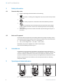 5
5
-
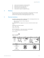 6
6
-
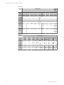 7
7
-
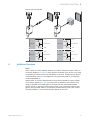 8
8
-
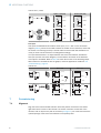 9
9
-
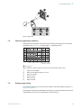 10
10
-
 11
11
-
 12
12
-
 13
13
-
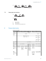 14
14
-
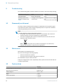 15
15
-
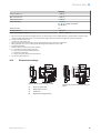 16
16
-
 17
17
-
 18
18
-
 19
19
-
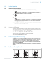 20
20
-
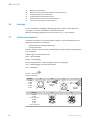 21
21
-
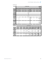 22
22
-
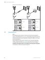 23
23
-
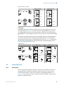 24
24
-
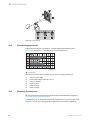 25
25
-
 26
26
-
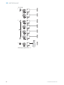 27
27
-
 28
28
-
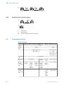 29
29
-
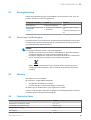 30
30
-
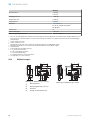 31
31
-
 32
32
-
 33
33
-
 34
34
-
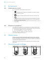 35
35
-
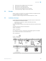 36
36
-
 37
37
-
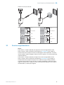 38
38
-
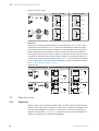 39
39
-
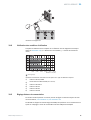 40
40
-
 41
41
-
 42
42
-
 43
43
-
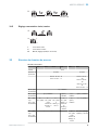 44
44
-
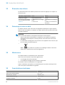 45
45
-
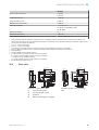 46
46
-
 47
47
-
 48
48
-
 49
49
-
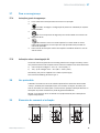 50
50
-
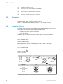 51
51
-
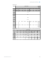 52
52
-
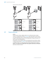 53
53
-
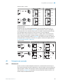 54
54
-
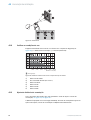 55
55
-
 56
56
-
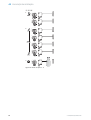 57
57
-
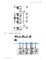 58
58
-
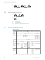 59
59
-
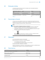 60
60
-
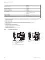 61
61
-
 62
62
-
 63
63
-
 64
64
-
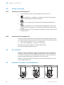 65
65
-
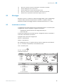 66
66
-
 67
67
-
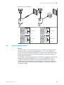 68
68
-
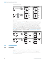 69
69
-
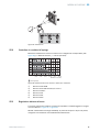 70
70
-
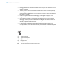 71
71
-
 72
72
-
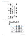 73
73
-
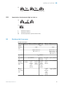 74
74
-
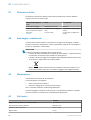 75
75
-
 76
76
-
 77
77
-
 78
78
-
 79
79
-
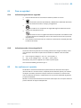 80
80
-
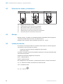 81
81
-
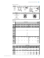 82
82
-
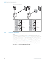 83
83
-
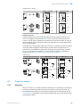 84
84
-
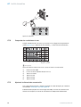 85
85
-
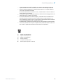 86
86
-
 87
87
-
 88
88
-
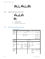 89
89
-
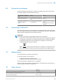 90
90
-
 91
91
-
 92
92
-
 93
93
-
 94
94
-
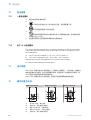 95
95
-
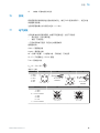 96
96
-
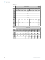 97
97
-
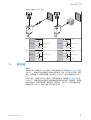 98
98
-
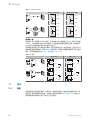 99
99
-
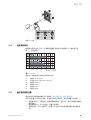 100
100
-
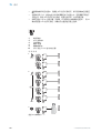 101
101
-
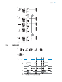 102
102
-
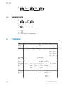 103
103
-
 104
104
-
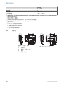 105
105
-
 106
106
-
 107
107
-
 108
108
-
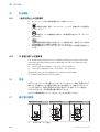 109
109
-
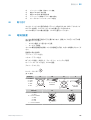 110
110
-
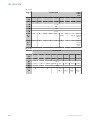 111
111
-
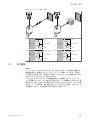 112
112
-
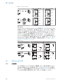 113
113
-
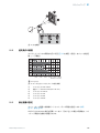 114
114
-
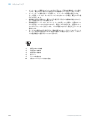 115
115
-
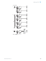 116
116
-
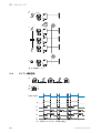 117
117
-
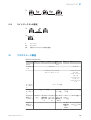 118
118
-
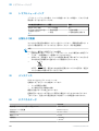 119
119
-
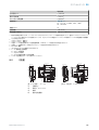 120
120
-
 121
121
-
 122
122
-
 123
123
-
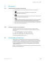 124
124
-
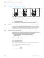 125
125
-
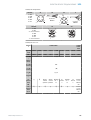 126
126
-
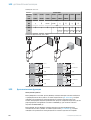 127
127
-
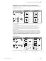 128
128
-
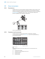 129
129
-
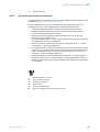 130
130
-
 131
131
-
 132
132
-
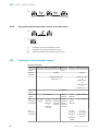 133
133
-
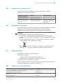 134
134
-
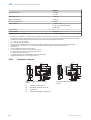 135
135
-
 136
136


En otros idiomas
- français: SICK WLG16 Mode d'emploi
- italiano: SICK WLG16 Istruzioni per l'uso
- English: SICK WLG16 Operating instructions
- Deutsch: SICK WLG16 Bedienungsanleitung
- русский: SICK WLG16 Инструкция по эксплуатации
- português: SICK WLG16 Instruções de operação
- 日本語: SICK WLG16 取扱説明書
Documentos relacionados
-
SICK WLA16 Instrucciones de operación
-
-
-
-
-
-
-
-
-