


Described product
W26
WSE26
Manufacturer
SICK AG
Erwin-Sick-Str. 1
79183 Waldkirch
Germany
Legal information
This work is protected by copyright. Any rights derived from the copyright shall be
reserved for SICK AG. Reproduction of this document or parts of this document is
only permissible within the limits of the legal determination of Copyright Law. Any modi‐
fication, abridgment or translation of this document is prohibited without the express
written permission of SICK AG.
The trademarks stated in this document are the property of their respective owner.
© SICK AG. All rights reserved.
Original document
This document is an original document of SICK AG.
2006/42/EC
NO
SAFETY
2
8020358.19RH / 15.01.2021 | SICK
Subject to change without notice

Contents
1 Safety information............................................................................ 4
1.1 General safety notes................................................................................ 4
1.2 Notes on UL approval............................................................................... 4
2 Intended use...................................................................................... 4
3 Operating and status indicators...................................................... 4
4 Mounting............................................................................................. 5
5 Electrical installation........................................................................ 5
6 Additional functions.......................................................................... 8
7 Commissioning.................................................................................. 9
7.1 Alignment.................................................................................................. 9
7.2 Check the application conditions............................................................ 10
7.3 Time function setting................................................................................ 11
7.4 Setting light/dark switching..................................................................... 12
8 Process data structure..................................................................... 12
9 Troubleshooting................................................................................. 12
10 Disassembly and disposal............................................................... 13
11 Maintenance...................................................................................... 13
12 Technical data.................................................................................... 14
12.1 Dimensional drawings.............................................................................. 14
CONTENTS
8020358.19RH / 15.01.2021 | SICK
Subject to change without notice
3

1 Safety information
1.1 General safety notes
■
Read the operating instructions before commissioning.
■
Connection, mounting, and configuration may only be performed by trained
specialists.
■
2006/42/EC
NO
SAFETY
Not a safety component in accordance with the EU Machinery Directive.
■
Do not install the sensor at locations that are exposed to direct sunlight
or other weather influences, unless this is expressly permitted in the operating
instructions.
■
These operating instructions contain information required during the life cycle of
the sensor.
1.2 Notes on UL approval
The device shall be supplied from an isolating transformer having a secondary overcur‐
rent protective device that complies with UL 248 to be installed in the field rated either:
a) max 5 amps for voltages 0 ~ 20 V (0 ~ 28.3 V peak), or
b) 100 / Vp for voltages of 20 ~ 30 V (28.3 ~ 42.4 V peak).
Alternatively, they can be supplied from a Class 2 power supply.
UL Environmental Rating: Enclosure type 1
2 Intended use
The WSE26 is an opto-electronic through-beam photoelectric sensor (referred to as
“sensor” in the following) for the optical, non-contact detection of objects, animals, and
persons. A sender (WS) and a receiver (WE) are required for operation. If the product is
used for any other purpose or modified in any way, any warranty claim against SICK AG
shall become void.
3 Operating and status indicators
WSO26 x-xxxxxxA0 WEO26 x-xxxxxx00 WEO26 x-xxxxxx01 WEO26 x-xxxxxx02
3 2
1
3 2
1
23
5
1
3 2
4
1 SAFETY INFORMATION
4
8020358.19RH / 15.01.2021 | SICK
Subject to change without notice

WEO26x-xxxxxx30 WEO26x-xxxxxx31 WEO26x-xxxxxx32
3 2
6
1
1
23
5
6
1
3 2
4
6
1
BluePilot blue: alignment aid
2
LED indicator yellow: status of received light beam
3
LED indicator green: supply voltage active
4
Press-turn element: time function adjustment
5
Teach pushbutton: adjustment of light/dark switching
6
Teach-Button: adjusting the sensitivity
4 Mounting
Mount sensors (sender and receiver) using suitable mounting brackets (see the SICK
range of accessories). Align the sender and receiver with each other.
NOTE
When mounting multiple through-beam photoelectric sensors next each other, swap
the arrangement of the sender (WS26) and receiver (WE26) for every second pair.
Also maintain a sufficiently large distance between the pairs based on the light spot
diameter of the sender (WS26), see figure 1.
Receiver (WE)
Receiver (WE)
Sender (WS)
Sender (WS)
Sender (WS)
Receiver (WE)
Figure 1: Arrangement of multiple through-beam photoelectric sensors
Note the sensor’s maximum permissible tightening torque of < 1,3 Nm.
5 Electrical installation
The sensors must be connected in a voltage-free state. The following information must
be observed, depending on the connection type:
– Male connector connection: Note pin assignment
– Cable: wire color
Only supply/switch on the voltage once all electrical connections have been estab‐
lished.
MOUNTING 4
8020358.19RH / 15.01.2021 | SICK
Subject to change without notice
5

Explanations of the connection diagram (following tables):
Alarm = alarm output
Health = alarm output
MF (pin 2 configuration) = external input, teach-in, switching signal
Q
L1
/C = switching output, IO-Link communication
Test = test input
U
B
: 10 ... 30 V DC
Table 1: Connections
Wxx26x- x4 xH x5 xI
1 = BN
2 = WH
3 = BU
4 = BK
5= GY
1
2
4 3
0.14 mm
2
AWG26
1
2
4 3
5
0.14 mm
2
AWG26
Wxx26x- x9 xB
1 = BN
2 = BU
3 = not connected
4 = BK
5= WH
6 = GY
7 = not connected
3 4
1
2 5
6
I
N
= 4 A
3
7
2
1
6
5
4
I
N
= 6 A
Table 2: DC, sender
WSO26x- xxXZZxZZZ
xx1ZZ xx2ZZ xx3ZZ xx6ZZ xx7ZZ
BN + (L+)
WH -
BU - (M)
BK - Test → L+ Test → M - -
GY - - - Test → L+ Test → M
5 ELECTRICAL INSTALLATION
6
8020358.19RH / 15.01.2021 | SICK
Subject to change without notice

Table 3: DC, receiver
WEO26x- xxX6XxxxA00 xxX6XxxxA
01-A99
Push-pull xx162 xx161 xx163 xx165 xx16A xx16N xx16x
PNP xx862 xx861 xx863 xx865 xx86A xx86N xx86x
1 = BN + (L+)
2 = WH MF
3 = BU - (M)
4 = BK Q
L1
/C
Default: MF
Q
Q Alarm Alarm no func‐
tion
no func‐
tion
www.sick.c
om/
8022709
Default:
Q
L1
/C
Q
Q Q
Q
Q
Q www.sick.c
om/
8022709
Table 4: DC, receiver
WEO26x- xxXXXxxZZZ
Push-pull xx111 xx112 xx114 xx116
PNP xx811 xx812 xx814 xx816
BN + (L+)
WH Q
Q
Health Health
BU - (M)
BK
Q
Q
Q
Q
GY - - - -
ELECTRICAL INSTALLATION 5
8020358.19RH / 15.01.2021 | SICK
Subject to change without notice
7

Table 5: Push-pull, PNP, NPN
Push-pull
PNP
NPN
+ (L+)
Q ≤ 100 mA
‒ (M)
Push-pull
PNP
NPN
+ (L+)
Q ≤ 100 mA
‒ (M)
Push-pull
PNP
NPN
+ (L+)
Q ≤ 100 mA
‒ (M)
Push-pull
PNP
NPN
+ (L+)
Q ≤ 100 mA
‒ (M)
6 Additional functions
Alarm
Alarm output: The sensor (WSE26) features a pre-failure notification output (“Alarm”
in the connection diagram [see table 3]), which issues a notification if the sensor is
only ready for operation to a limited extent. The LED flashes in this case. Possible
causes: sensor is contaminated, sensor is out of alignment. In the good state: LOW (0),
if excessively contaminated HIGH (1).
Health
Health output: The sensor (WSE26) features a pre-failure notification output (“Health”
in the connection diagram [see table 3]), which issues a notification if the sensor is
only ready for operation to a limited extent or the cable has been interrupted. Possible
causes: Sensor is contaminated, sensor is out of alignment, cable is damaged. In the
good state: HIGH (1), if excessively contaminated or in the event of cable interruption
LOW (0). The yellow LED indicator flashes in this case.
6 ADDITIONAL FUNCTIONS
8
8020358.19RH / 15.01.2021 | SICK
Subject to change without notice

Table 6: Alarm
Alarm (≤ 100 mA) Health (≤100 mA)
+ (L+)
Alarm
‒ (M)
+ (L+)
Health
‒ (M)
+ (L+)
Alarm
‒ (M)
+ (L+)
Health
‒ (M)
Test input
Test input: The sensors (WSO26P, WSO26I) feature a test input (“TI” or “Test” on the
connection diagram [see table 2]), which can be used to switch the sender off and,
therefore, check that the sensor is functioning correctly: If female cable connectors with
LED indicators are used, you have to ensure that the TI is assigned accordingly.
It is important that there is no object between the sender and receiver, activate the test
input (see the connection diagram [see table 2]).
The send LED is shut down or the detection of an object is simulated. Refer to table 7
to check the function. If the switching output fails to behave in accordance with the
graphic, check the application conditions, see "Troubleshooting", page 12.
Table 7: Test
Test → M Test → L+
+ (L+)
Test
‒ (M)
+ (L+)
Test
– (M)
+ (L+)
Test
‒ (M)
+ (L+)
Test
– (M)
7 Commissioning
7.1 Alignment
WSO26P: Align the sender with the receiver. Select the position so that the red emitted
light beam hits the receiver. Tip: Use white paper or a reflector as an alignment aid. The
sender must have a clear view of the receiver, with no object in the path of the beam
[see table]. You must ensure that the optical openings (front screen) of the sensors are
completely clear.
ADDITIONAL FUNCTIONS 6
8020358.19RH / 15.01.2021 | SICK
Subject to change without notice
9

WSO26I: Align the sender with the receiver. Select the position so that the infrared light
(not visible) hits the receiver. The correct alignment can only be detected via the LEDs.
See table and table 5. The sender must have a clear view of the receiver, with no object
in the path of the beam. You must ensure that the optical openings (front screen) of the
sensors are completely clear.
Table: Alignment
Figure 2: Alignment 1
WEO
WEO
WSO
Figure 3: Alignment 2
7.2 Check the application conditions
WSE26 are through-beam photoelectric sensors that can be used at shorter distances,
in particular due to the large sensing range or the very high operating reserve.
Note application conditions: Adjust distance between sender and receiver with the
associated diagram [see table 8] (x = sensing range, y = operating reserve).
If several through-beam photoelectric sensors which are installed next to one another
are to be used, we recommend swapping the sender/receiver arrangement at every
second through-beam photoelectric sensor and ensuring that there is sufficient dis‐
tance between the through-beam photoelectric sensors. By doing this, mutual interfer‐
ence can be prevented [see figure 1].
NOTE TIP:
For some applications (e.g., when switching errors arise due to reflections), we recom‐
mend slightly misaligning the sender and receiver or significantly reducing the oper‐
ating reserve. The WSE26 can suppress switching errors under these conditions by
means of a teach-in (via IO-Link or using the Teach-in button on the housing). This
reduces the operating reserve at the same time.
7 COMMISSIONING
10
8020358.19RH / 15.01.2021 | SICK
Subject to change without notice

Table 8: Application conditions
0
10,000
1,000
100
10
1
10
(0.39)
20
(0.79)
30
(1.18)
40
(1.57)
50
(1.97)
60
(2.36)
Function reserve
Distance in m (feet)
WSE26P-xxxxx1xx, WSE26I-xxxxx1xx
Figure 4: Characteristic line 1
Sensing range
0 40
(131.23)
60
(196.85)
20
(65.62)
50 600
Sensing range typ. max.
1
Distance in m (feet)
Figure 5: Bar graph 1
7.3 Time function setting
1
0
T1
T2
M
T4
T3
t
t
t t t
t
t t t t
t t t
t
t
t t
Input signal
0
T1
T2
T3
T4
M = Manual (specific setting via IO-Link)
1 ms 30.000 ms
2
COMMISSIONING 7
8020358.19RH / 15.01.2021 | SICK
Subject to change without notice
11

7.4 Setting light/dark switching
1
L
D
M
L light switching
D Dark switching
M manual (specific setting via IO-Link)
8 Process data structure
WSE26x-xxxxxxxxAxx:
A00 A70 A71 A72 A73 A75
IO-Link V1.1
Process
data
2 bytes 4 bytes
Byte 0: bits 15... 8
Byte 1: bits 7... 0
Byte 0: bits 31...
24
Byte 1: bits 13...
16
Byte 2: bits 15...
8
Byte 3: bits 7... 0
Bit 0 / Data
type
Q
L1
/ Boolean
Bit 1 / Data
type
Q
L2
/ Boolean Qint.1 /
Boolean
Q
L2
/
Boolean
Qint.1 / Boolean
Bit... /
Descrip‐
tion / Data
type
2 ...15 /
[empty]
2 ...15 /
[time mea‐
surement
value] /
UInt 14
2 … 15 /
[counter
value] /
UInt 14
2 … 15 /
[length /
speed
measure‐
ment] /
SInt14
2 /
Qint.1 /
Boolean
2 … 7 / [empty]
Bit... /
Descrip‐
tion / Data
type
3 … 15 /
[time mea‐
surement
value] /
UInt13
8 … 31 / [carrier
load] / UInt 24
9 Troubleshooting
The Troubleshooting table indicates measures to be taken if the sensor stops working.
LED indicator/fault pattern Cause Measures
WEO:Green LED flashes IO-Link communication None
7 COMMISSIONING
12
8020358.19RH / 15.01.2021 | SICK
Subject to change without notice

LED indicator/fault pattern Cause Measures
Switching outputs do not
behave in accordance with
table 5
1. Change of the configuration
2. Short-circuit
1. Adjustment of the configura‐
tion
2. Check electrical connections
Not all blue LEDs light up. a) Insufficient alignment
b) Contamination of the opti‐
cal surfaces
c) Particles in the light beam
d) Distance between sender
(WS) and receiver (WE) is
too large
a) Check alignment
b) Cleaning of the optical sur‐
faces.
c) Avoid contamination in the
air as far as possible
d) Check sensing range
No object in beam path, no
output signal
Test input (Test) is not con‐
nected properly
Check connection of the test
input. When using female cable
connectors with LED indicators,
make sure the test input is
assigned correspondingly.
Yellow LED flashes Distance between sender
(WS) and receiver (WE) is too
large / Beam of WS is not
completely on WE or WE is not
aligned to WS
Check sensing range, see
figure 5
Check alignment
Yellow LED lights up, although
an object is in the path of the
beam.
The beam of light of a pho‐
toelectric through-beam sen‐
sor hits the receiver of
another (neighboring) photo‐
electric through-beam sensor
Swap the sender and receiver
arrangement at every sec‐
ond through-beam photoelec‐
tric sensor and ensure that
there is sufficient distance
between the through-beam
photoelectric sensors
10 Disassembly and disposal
The sensor must be disposed of according to the applicable country-specific regula‐
tions. Efforts should be made during the disposal process to recycle the constituent
materials (particularly precious metals).
NOTE
Disposal of batteries, electric and electronic devices
•
According to international directives, batteries, accumulators and electrical or
electronic devices must not be disposed of in general waste.
•
The owner is obliged by law to return this devices at the end of their life to the
respective public collection points.
•
WEEE: This symbol on the product, its package or in this document,
indicates that a product is subject to these regulations.
11 Maintenance
SICK sensors are maintenance-free.
We recommend doing the following regularly:
•
Clean the external lens surfaces
•
Check the screw connections and plug-in connections
No modifications may be made to devices.
DISASSEMBLY AND DISPOSAL 10
8020358.19RH / 15.01.2021 | SICK
Subject to change without notice
13

Subject to change without notice. Specified product properties and technical data are
not written guarantees.
12 Technical data
WSE26P WSE26I
Sensing range max. 0 m ... 60 m 0 m ... 60 m
Light spot diameter/distance Ø 90 mm / 8 m Ø 110 mm / 8 m
Supply voltage U
B
DC 10 ... 30 V DC 10 ... 30 V
Ripple ≤ 5 V
SS
≤ 5 V
SS
Current consumption ≤ 30 mA
1)
< 50 mA
2)
≤ 30 mA
1)
< 50 mA
2)
Output current I
max.
≤ 100 mA ≤ 100 mA
Max. response time ≤ 500 μs
3)
≤ 500 μs
3)
Switching frequency 1,000 Hz
4)
1,000 Hz
4)
Enclosure rating
5)
see table 1:
x4, xH, x5, xI: IP66, IP67,
IP69
6)
x9, xB: IP65
see table 1:
x4, xH, x5, xI: IP66, IP67,
IP69
6)
x9, xB: IP65
Protection class III III
Circuit protection A, B, C, D
7)
A, B, C, D
7)
Ambient operating temperature –40 °C ... +60 °C
8)
–40 °C ... +60 °C
8)
1)
16 VDC to 30 VDC, without load
2)
10 VDC to 16 VDC, without load
3)
Signal transit time with resistive load in switching mode. Deviating values possible in COM2 mode.
4)
With a light/dark ratio of 1:1 in switching mode. Deviating values possible in IO-Link mode.
5)
Pursuant to EN 60529
6)
Replaces IP69 K pursuant to ISO 20653: 2013-03
7)
A = U
B
-connections reverse polarity protected
B = inputs and output reverse-polarity protected
C = Interference suppression
D = outputs overcurrent and short-circuit protected
8)
Do not bend cables below 0°C.
12.1 Dimensional drawings
4
3
3
2
7.1 (0.28)
8.1 (0.32)
10.8 (0.43)
25 (0.98)
38.8 (1.53)
6.4
(0.25)
12.9
(0.51)
48.1 (1.89)
40 (1.57)
44.2 (1.74)
10
(0.39)
Ø 5.2 (0.2)
24.6 (0.97)
82.2 (3.24)
70 (2.76)
Ø 5.2 (0.2)
7.3
(0.29)
8.1 (0.32)
76.5 (3.01)
82.5 (3.25)
32.4
(1.28)
53.3 (2.1)
1
12.9
(0.51)
24.6 (0.97)
7.3
(0.29)
57.4 (2.26)
5
Figure 6: Dimensional drawing 1, cable
1
Center of optical axis, sender
2
Center of optical axis, receiver
3
Fixing hole Ø 5.2 mm
4
connection
5
Display and setting elements
7.1 (0.28)
8.1 (0.32)
10.8 (0.43)
25 (0.98)
39 (1.54)
6.3 (0.25)
M12
48.1 (1.89)
40 (1.57)
44.2 (1.74)
19.7
(0.78)
Ø 5.2 (0.2)
24.6 (0.97)
82.2 (3.24)
70 (2.76)
Ø 5.2 (0.2)
17
(0.67)
7.9 (0.31)
76.5 (3.01)
82.5 (3.25)
32.4
(1.28)
2
53.3 (2.1)
63.9 (2.52)
4
3
3
M12
1
24.6 (0.97)
17
(0.67)
57.4 (2.26)
5
Figure 7: Dimensional drawing 2, male con‐
nector
12 TECHNICAL DATA
14
8020358.19RH / 15.01.2021 | SICK
Subject to change without notice


Beschriebenes Produkt
W26
WSE26
Hersteller
SICK AG
Erwin-Sick-Str. 1
79183 Waldkirch
Deutschland
Rechtliche Hinweise
Dieses Werk ist urheberrechtlich geschützt. Die dadurch begründeten Rechte bleiben
bei der Firma SICK AG. Die Vervielfältigung des Werks oder von Teilen dieses Werks
ist nur in den Grenzen der gesetzlichen Bestimmungen des Urheberrechtsgesetzes
zulässig. Jede Änderung, Kürzung oder Übersetzung des Werks ohne ausdrückliche
schriftliche Zustimmung der Firma SICK AG ist untersagt.
Die in diesem Dokument genannten Marken sind Eigentum ihrer jeweiligen Inhaber.
© SICK AG. Alle Rechte vorbehalten.
Originaldokument
Dieses Dokument ist ein Originaldokument der SICK AG.
2006/42/EC
NO
SAFETY
16
8020358.19RH / 15.01.2021 | SICK
Subject to change without notice

Inhalt
13 Zu Ihrer Sicherheit............................................................................. 18
13.1 Allgemeine Sicherheitshinweise.............................................................. 18
13.2 Hinweise zur UL Zulassung...................................................................... 18
14 Bestimmungsgemäße Verwendung............................................... 18
15 Bedien- und Anzeigeelemente........................................................ 18
16 Montage.............................................................................................. 19
17 Elektrische Installation..................................................................... 19
18 Zusatzfunktionen.............................................................................. 22
19 Inbetriebnahme................................................................................. 23
19.1 Ausrichtung............................................................................................... 23
19.2 Einsatzbedingungen prüfen..................................................................... 24
19.3 Einstellung Zeitfunktionen....................................................................... 25
19.4 Einstellung Hell-/Dunkelschaltend.......................................................... 26
20 Prozessdatenstruktur........................................................................ 26
21 Störungsbehebung............................................................................ 26
22 Demontage und Entsorgung............................................................ 27
23 Wartung.............................................................................................. 27
24 Technische Daten.............................................................................. 28
24.1 Maßzeichnungen...................................................................................... 28
INHALT
8020358.19RH / 15.01.2021 | SICK
Subject to change without notice
17

13 Zu Ihrer Sicherheit
13.1 Allgemeine Sicherheitshinweise
■
Lesen Sie vor der Inbetriebnahme des Geräts die Betriebsanleitung.
■
Der Anschluss, die Montage und die Konfiguration des Geräts dürfen nur
von geschultem Fachpersonal vorgenommen werden.
■
2006/42/EC
NO
SAFETY
Bei diesem Gerät handelt es sich um kein sicherheitsgerichtetes Bauteil im
Sinne der EU-Maschinenrichtlinie.
■
Installieren Sie den Sensor nicht an Orten, die direkter Sonneneinstrahlung
oder sonstigen Wettereinflüssen ausgesetzt sind, ausser dies ist in der Betriebs‐
anleitung ausdrücklich erlaubt.
■
Die vorliegende Betriebsanleitung enthält Informationen, die während des Lebens‐
zyklus der Lichtschranke benötigt werden.
13.2 Hinweise zur UL Zulassung
The device shall be supplied from an isolating transformer having a secondary overcur‐
rent protective device that complies with UL 248 to be installed in the field rated either:
a) max 5 amps for voltages 0 ~ 20 V (0 ~ 28.3 V peak), or
b) 100 / Vp for voltages of 20 ~ 30 V (28.3 ~ 42.4 V peak).
Alternatively, they can be supplied from a Class 2 power supply.
UL Environmental Rating: Enclosure type 1
14 Bestimmungsgemäße Verwendung
Die WSE26 ist eine opto-elektronische Einweg-Lichtschranke (im Folgenden Sensor
genannt) und wird zum optischen, berührungslosen Erfassen von Sachen, Tieren und
Personen eingesetzt. Zum Betrieb ist ein Sender (WS) und ein Empfänger (WE) erfor‐
derlich. Bei jeder anderen Verwendung und bei Veränderungen am Produkt verfällt
jeglicher Gewährleistungsanspruch gegenüber der SICK AG.
15 Bedien- und Anzeigeelemente
WSO26x-xxxxxxA0 WEO26x-xxxxxx00 WEO26x-xxxxxx01 WEO26x-xxxxxx02
3 2
1
3 2
1
23
5
1
3 2
4
13 ZU IHRER SICHERHEIT
18
8020358.19RH / 15.01.2021 | SICK
Subject to change without notice

WEO26x-xxxxxx30 WEO26x-xxxxxx31 WEO26x-xxxxxx32
3 2
6
1
1
23
5
6
1
3 2
4
6
1
BluePilot blau: Ausrichthilfe
2
Anzeige-LED gelb: Status Lichtempfang
3
Anzeige-LED grün: Betriebsspannung aktiv
4
Drück-Dreh-Element: Einstellung der Zeitfunktionen
5
Teach-Taste: Einstellung hell-/dunkelschaltend
6
Teach-Taste: Einstellung der Empfindlichkeit
16 Montage
Sensoren (Sender und Empfänger) an geeignete Befestigungswinkel montieren (siehe
SICK-Zubehör-Programm). Sender und Empfänger zueinander ausrichten.
HINWEIS
Bei Montage mehrerer Einweg-Lichtschranken nebeneinander die Anordnung des Sen‐
ders (WS26) und Empfängers (WE26) bei jedem zweiten Paar tauschen. Außerdem
basierend auf dem Lichtfleckdurchmesser des Senders (WS26) einen ausreichend
großen Abstand zwischen den Paaren einhalten, siehe Abbildung 8.
Receiver (WE)
Receiver (WE)
Sender (WS)
Sender (WS)
Sender (WS)
Receiver (WE)
Abbildung 8: Anordnung mehrerer Einweg-Lichtschranken
Maximal zulässiges Anzugsdrehmoment des Sensors von < 1,3 Nm beachten.
17 Elektrische Installation
Anschluss der Sensoren muss spannungsfrei erfolgen. Je nach Anschlussart sind die
folgenden Informationen zu beachten:
– Steckeranschluss: Pinbelegung beachten
– Leitung: Adernfarbe
Erst nach Anschluss aller elektrischen Verbindungen die Spannungsversorgung anlegen
bzw. einschalten.
MONTAGE 16
8020358.19RH / 15.01.2021 | SICK
Subject to change without notice
19

Erläuterungen zum Anschlussschema (folgende Tabellen):
Alarm = Alarmausgang
Health = Alarmausgang
MF (Pin-2-Konfiguration) = Externer Eingang, Teach-in, Schaltsignal
Q
L1
/C = Schaltausgang, IO-Link Kommunikation
Test = Testeingang
U
B
: 10 ... 30 V DC
Tabelle 9: Anschlüsse
Wxx26x- x4 xH x5 xI
1 = BN
2 = WH
3 = BU
4 = BK
5= GY
1
2
4 3
0.14 mm
2
AWG26
1
2
4 3
5
0.14 mm
2
AWG26
Wxx26x- x9 xB
1 = BN
2 = BU
3 = not connected
4 = BK
5= WH
6 = GY
7 = not connected
3 4
1
2 5
6
I
N
= 4 A
3
7
2
1
6
5
4
I
N
= 6 A
Tabelle 10: DC, Sender
WSO26x- xxXZZxZZZ
xx1ZZ xx2ZZ xx3ZZ xx6ZZ xx7ZZ
BN + (L+)
WH -
BU - (M)
BK - Test → L+ Test → M - -
GY - - - Test → L+ Test → M
17 ELEKTRISCHE INSTALLATION
20
8020358.19RH / 15.01.2021 | SICK
Subject to change without notice

Tabelle 11: DC, Empfänger
WEO26x- xxX6XxxxA00 xxX6Xxxx‐
A01-A99
Push-pull xx162 xx161 xx163 xx165 xx16A xx16N xx16x
PNP xx862 xx861 xx863 xx865 xx86A xx86N xx86x
1 = BN + (L+)
2 = WH MF
3 = BU - (M)
4 = BK Q
L1
/C
Default: MF
Q
Q Alarm Alarm no func‐
tion
no func‐
tion
www.sick.c
om/
8022709
Default:
Q
L1
/C
Q
Q Q
Q
Q
Q www.sick.c
om/
8022709
Tabelle 12: DC, Empfänger
WEO26x- xxXXXxxZZZ
Push-pull xx111 xx112 xx114 xx116
PNP xx811 xx812 xx814 xx816
BN + (L+)
WH Q
Q
Health Health
BU - (M)
BK
Q
Q
Q
Q
GY - - - -
ELEKTRISCHE INSTALLATION 17
8020358.19RH / 15.01.2021 | SICK
Subject to change without notice
21

Tabelle 13: Push-pull, PNP, NPN
Push-pull
PNP
NPN
+ (L+)
Q ≤ 100 mA
‒ (M)
Push-pull
PNP
NPN
+ (L+)
Q ≤ 100 mA
‒ (M)
Push-pull
PNP
NPN
+ (L+)
Q ≤ 100 mA
‒ (M)
Push-pull
PNP
NPN
+ (L+)
Q ≤ 100 mA
‒ (M)
18 Zusatzfunktionen
Alarm
Alarmausgang: Der Sensor (WSE26) verfügt über einen Vorausfallmeldeausgang
("Alarm" im Anschlussschema [siehe Tabelle 3]), der meldet, wenn der Sensor nur noch
eingeschränkt betriebsbereit ist. Dabei blinkt die Anzeige-LED. Mögliche Ursachen: Ver‐
schmutzung von Sensor, Sensor ist dejustiert. Im Gutzustand: LOW (0), bei zu starker
Verschmutzung HIGH (1).
Health
Health-Ausgang: Der Sensor (WSE26) verfügt über einen Vorausfallmeldeausgang
("Health" im Anschlussschema [siehe Tabelle 3]), der meldet, wenn der Sensor nur
noch eingeschränkt betriebsbereit ist oder die Leitung unterbrochen ist. Mögliche Ursa‐
chen: Verschmutzung von Sensor, Sensor ist dejustiert, Leitung ist beschädigt. Im
Gutzustand: HIGH (1), bei zu starker Verschmutzung oder Leitungsunterbrechung LOW
(0). Dabei blinkt die gelbe Anzeige-LED.
18 ZUSATZFUNKTIONEN
22
8020358.19RH / 15.01.2021 | SICK
Subject to change without notice

Tabelle 14: Alarm
Alarm (≤ 100 mA) Health (≤100 mA)
+ (L+)
Alarm
‒ (M)
+ (L+)
Health
‒ (M)
+ (L+)
Alarm
‒ (M)
+ (L+)
Health
‒ (M)
Testeingang
Testeingang: Die Sensoren (WSO26P, WSO26I) verfügen über einen Testeingang („TE“
oder „Test“ im Anschlussschema [siehe Tabelle 2]), mit dem der Sender ausgeschaltet
und somit die ordnungsgemäße Funktion des Sensors überprüft werden kann: Bei
Verwendung von Leitungsdosen mit LED-Anzeigen ist darauf zu achten, dass der TE
entsprechend belegt ist.
Es darf sich kein Objekt zwischen Sensor und Empfänger befinden, Testeingang aktivie‐
ren (siehe Anschlussschema [siehe Tabelle 2]).
Sende-LED wird abgeschaltet, bzw. es wird simuliert, dass ein Objekt erkannt wird.
Zur Überprüfung der Funktion die Tabelle 7 heranziehen. Verhält sich der Schaltaus‐
gang nicht gemäß der Grafik, Einsatzbedingungen prüfen, siehe "Störungsbehebung",
Seite 26.
Tabelle 15: Test
Test → M Test → L+
+ (L+)
Test
‒ (M)
+ (L+)
Test
– (M)
+ (L+)
Test
‒ (M)
+ (L+)
Test
– (M)
19 Inbetriebnahme
19.1 Ausrichtung
WSO26P: Den Sender auf den Empfänger ausrichten. Positionierung so wählen, dass
der rote Sendelichtstrahl auf den Empfänger auftrifft. Tipp: Weißes Papier oder Reflek‐
tor als Ausrichthilfe verwenden. Der Sender muss freie Sicht auf den Empfänger haben,
es darf sich kein Objekt im Strahlengang befinden [siehe Tabelle]. Es ist darauf zu
achten, dass die optischen Öffnungen (Frontscheiben) der Sensoren vollständig frei
sind.
ZUSATZFUNKTIONEN 18
8020358.19RH / 15.01.2021 | SICK
Subject to change without notice
23

WSO26I: Den Sender auf den Empfänger ausrichten. Positionierung so wählen, dass
das Infrarotlicht (nicht sichtbar) auf den Empfänger auftrifft. Die korrekte Ausrichtung
kann nur über die Anzeige-LEDs erkannt werden. Siehe dazu Tabelle und Tabelle 5.
Der Sender muss freie Sicht auf den Empfänger haben, es darf sich kein Objekt im
Strahlengang befinden. Es ist darauf zu achten, dass die optischen Öffnungen (Front‐
scheiben) der Sensoren vollständig frei sind.
Tabelle: Ausrichtung
Abbildung 9: Ausrichtung 1
WEO
WEO
WSO
Abbildung 10: Ausrichtung 2
19.2 Einsatzbedingungen prüfen
WSE26 sind Einweg-Lichtschranken, die besonders wegen dem großen Schaltabstand
oder der sehr hohen Funktionsreserve auf kürzerer Distanz eingesetzt werden.
Einsatzbedingungen beachten: Distanz zwischen Sender und Empfänger mit dem zuge‐
hörigen Diagramm [siehe Tabelle 16] abgleichen (x = Schaltabstand, y = Funktionsre‐
serve).
Beim Einsatz von mehreren Einweg-Lichtschranken, die nebeneinander installiert wer‐
den, empfehlen wir, bei jeder zweiten Einweg-Lichtschranke die Anordnung von Sender
und Empfänger zu tauschen, bzw. genügend Abstand zwischen den Einweg-Lichtschran‐
ken einzuhalten. Damit können gegenseitige Beeinflussungen vermieden werden [siehe
Abbildung 8].
HINWEIS TIPP:
Für manche Applikationen (z. B. Fehlschaltungen treten durch Umspiegelungen auf)
empfiehlt es sich die Ausrichtung von Sender und Empfänger etwas zu dejustieren
oder die Funktionsreserve signifikant zu reduzieren. Durch einen Teach (via IO-Link
oder mittels Teach-Taste am Gehäuse) kann die WSE26 unter diesen Bedingungen
Fehlschaltungen unterdrücken. Gleichzeitig reduziert sich die Funktionsreserve.
19 INBETRIEBNAHME
24
8020358.19RH / 15.01.2021 | SICK
Subject to change without notice

Tabelle 16: Einsatzbedingungen
0 10 20 30 40 6050
10.000
1.000
100
10
1
Funktionsreserve
Abstand in m
WSE26P-xxxxx1xx, WSE26I-xxxxx1xx
Abbildung 11: Kennlinie 1
Abstand in m
Schaltabstand
0 40 6010 30 5020 70
50 600
typ. max. Schaltabstand
1
Abbildung 12: Balkendiagramm 1
19.3
Einstellung Zeitfunktionen
1
0
T1
T2
M
T4
T3
t
t
t t t
t
t t t t
t t t
t
t
t t
Input signal
0
T1
T2
T3
T4
M = Manuell (spezifische Einstellung via IO-Link)
1 ms 30.000 ms
2
INBETRIEBNAHME 19
8020358.19RH / 15.01.2021 | SICK
Subject to change without notice
25

19.4 Einstellung Hell-/Dunkelschaltend
1
L
D
M
L hellschaltend
D dunkelschaltend
M manuell (spezifische Einstellung via IO-Link)
20 Prozessdatenstruktur
WSE26x-xxxxxxxxAxx:
A00 A70 A71 A72 A73 A75
IO-Link V1.1
Process
data
2 Byte 4 Byte
Byte 0 : Bit 15... 8
Byte 1: Bit 7... 0
Byte 0 : Bit 31...
24
Byte 1: Bit 13... 16
Byte 2: Bit 15... 8
Byte 3: Bit 7... 0
Bit 0/ Data
type
Q
L1
/ Boolean
Bit 1/ Data
type
Q
L2
/ Boolean Qint.1 /
Boolean
Q
L2
/ Boo‐
lean
Qint.1 / Boolean
Bit... /
Descrip‐
tion / Data
type
2...15 /
[empty]
2...15 /
[Time
measure‐
ment
value] /
UInt 14
2 … 15 /
[Counter
value] /
UInt 14
2 … 15 /
[Length /
speed
measure‐
ment] /
SInt14
2 /
Qint.1 /
Boolean
2…7 / [empty]
Bit... /
Descrip‐
tion / Data
type
3 … 15 /
[Time
measure‐
ment
value] /
UInt13
8 … 31 / [Carrier
load] / UInt 24
21 Störungsbehebung
Tabelle Störungsbehebung zeigt, welche Maßnahmen durchzuführen sind, wenn die
Funktion des Sensors nicht mehr gegeben ist.
Anzeige-LED / Fehlerbild Ursache Maßnahme
WEO:grüne LED blinkt IO-Link Kommunikation keine
19 INBETRIEBNAHME
26
8020358.19RH / 15.01.2021 | SICK
Subject to change without notice

Anzeige-LED / Fehlerbild Ursache Maßnahme
Schaltausgänge verhalten sich
nicht gemäß
Tabelle 5
1. Änderung der Konfiguration
2. Kurzschluss
1. Anpassung der Konfigura‐
tion
2. Elektrische Anschlüsse prü‐
fen
Nicht alle blauen LEDs leuch‐
ten.
a) ungenügende Ausrichtung
b) Verschmutzung der opti‐
schen Flächen
c) Partikel im Lichtstrahl
d) Abstand zwischen Sender
(WS) und Empfänger (WE)
ist zu groß
a) Ausrichtung prüfen
b) Reinigung der optischen
Flächen.
c) sofern möglich, Verschmut‐
zung in der Luft vermeiden
d) Schaltabstand prüfen
Kein Objekt im Strahlengang,
kein Ausgangssignal
Testeingang (Test) ist nicht
korrekt angeschlossen
Anschluss des Testeingangs
prüfen. Bei Verwendung von
Leitungsdosen mit LED-Anzei‐
gen ist darauf zu achten, dass
der Testeingang entsprechend
belegt wird.
gelbe LED blinkt Abstand zwischen Sender
(WS) und Empfänger (WE) ist
zu groß / Lichtstrahl von WS
ist nicht vollständig auf WE
bzw. WE ist nicht auf WS aus‐
gerichtet
Schaltabstand prüfen, siehe
Abbildung 12
Ausrichtung prüfen
Gelbe LED leuchtet, obwohl
ein Objekt im Strahlengang
ist.
Der Lichtstrahl einer Ein‐
weg-Lichtschranke trifft auf
den Empfänger einer anderen
(benachbarten) Einweg-Licht‐
schranke
Bei jeder zweiten Einweg-Licht‐
schranke die Anordnung von
Sender und Empfänger tau‐
schen, bzw. genügend Abstand
zwischen den Einweg-Licht‐
schranken einhalten
22 Demontage und Entsorgung
Die Lichtschranke muss entsprechend den geltenden länderspezifischen Vorschriften
entsorgt werden. Bei der Entsorgung sollte eine werkstoffliche Verwertung (insbeson‐
dere der Edelmetalle) angestrebt werden.
HINWEIS
Entsorgung von Batterien, Elektro- und Elektronikgeräten
•
Gemäß den internationalen Vorschriften dürfen Batterien, Akkus sowie Elektro-
und Elektronikgeräte nicht mit dem Hausmüll entsorgt werden.
•
Der Besitzer ist gesetzlich verpflichtet, diese Geräte am Ende ihrer Lebensdauer
bei den entsprechenden öffentlichen Sammelstellen abzugeben.
•
WEEE: Dieses Symbol auf dem Produkt, dessen Verpackung oder im
vorliegenden Dokument gibt an, dass ein Produkt den genannten Vorschriften
unterliegt.
23 Wartung
SICK-Sensoren sind wartungsfrei.
Wir empfehlen, in regelmäßigen Abständen
DEMONTAGE UND ENTSORGUNG 22
8020358.19RH / 15.01.2021 | SICK
Subject to change without notice
27

•
die optischen Grenzflächen zu reinigen
•
Verschraubungen und Steckverbindungen zu überprüfen
Veränderungen an Geräten dürfen nicht vorgenommen werden.
Irrtümer und Änderungen vorbehalten. Angegebene Produkteigenschaften und techni‐
sche Daten stellen keine Garantieerklärung dar.
24 Technische Daten
WSE26P WSE26I
Schaltabstand max. 0 m ... 60 m 0 m ... 60 m
Lichtfleckdurchmesser/Entfernung Ø 90 mm / 8 m Ø 110 mm / 8 m
Versorgungsspannung U
B
DC 10 ... 30 V DC 10 ... 30 V
Restwelligkeit ≤ 5 V
SS
≤ 5 V
SS
Stromaufnahme ≤ 30 mA
1)
< 50 mA
2)
≤ 30 mA
1)
< 50 mA
2)
Ausgangsstrom I
max.
≤ 100 mA ≤ 100 mA
Ansprechzeit max. ≤ 500 μs
3)
≤ 500 μs
3)
Schaltfrequenz 1000 Hz
4)
1000 Hz
4)
Schutzart
5)
siehe Tabelle 9:
x4, xH, x5, xI: IP66, IP67,
IP69
6)
x9, xB: IP65
siehe Tabelle 9:
x4, xH, x5, xI: IP66, IP67,
IP69
6)
x9, xB: IP65
Schutzklasse III III
Schutzschaltungen A, B, C, D
7)
A, B, C, D
7)
Betriebsumgebungstemperatur –40 °C ... +60 °C
8)
–40 °C ... +60 °C
8)
1)
16VDC...30VDC, ohne Last
2)
10VDC...16VDC, ohne Last
3)
Signallaufzeit bei ohmscher Last im Schaltmodus. Abweichende Werte im COM2-Modus möglich.
4)
Bei Hell-Dunkel-Verhältnis 1:1 im Schaltmodus. Abweichende Werte im IO-Link-Modus möglich.
5)
Nach EN 60529
6)
Ersetzt IP69K nach ISO 20653: 2013-03
7)
A = U
B
-Anschlüsse verpolsicher
B = Ein- und Ausgänge verpolsicher
C = Störimpulsunterdrückung
D = Ausgänge überstrom- und kurzschlussfest
8)
Leitungen unter 0 °C nicht verformen
24.1 Maßzeichnungen
7,1
8,1
10,8
25
38,86,4
12,9
48,1
40
10
44,2
Ø 5,2
24,6
82,2
70
Ø 5,2
76,5
8,1
82,5
53,3
7,3
4
3
3
32,4
2
12,9
24,6
7,3
57,4
1
5
Abbildung 13: Maßzeichnung 1, Leitung
1
Mitte Optikachse Sender
2
Mitte Optikachse Empfänger
3
Befestigungsbohrung Ø 5,2 mm
7,1
8,1
10,8
25
396,3
M12
48,1
40
44,219,7
Ø 5,2
24,6
82,2
70
Ø 5,2
17
7,9
76,5
82,5
32,4
2
53,3
63,9
4
3
3
M12
24,6
17
57,4
1
5
Abbildung 14: Maßzeichnung 2, Stecker
24 TECHNISCHE DATEN
28
8020358.19RH / 15.01.2021 | SICK
Subject to change without notice

4
Anschluss
5
Anzeige- und Einstellelemente
TECHNISCHE DATEN 24
8020358.19RH / 15.01.2021 | SICK
Subject to change without notice
29


Produit décrit
W26
WSE26
Fabricant
SICK AG
Erwin-Sick-Straße 1
79183 Waldkirch
Allemagne
Remarques juridiques
Cet ouvrage est protégé par les droits d'auteur. Les droits établis restent dévolus à
la société SICK AG. La reproduction de l'ouvrage, même partielle, n'est autorisée que
dans le cadre légal prévu par la loi sur les droits d'auteur. Toute modification, tout
abrègement ou toute traduction de l'ouvrage est interdit sans l'accord écrit exprès de la
société SICK AG.
Les marques citées dans ce document sont la propriété de leurs détenteurs respectifs.
© SICK AG. Tous droits réservés.
Document original
Ce document est un document original de SICK AG.
2006/42/EC
NO
SAFETY
8020358.19RH / 15.01.2021 | SICK
Subject to change without notice
31

Contenu
25 Pour votre sécurité............................................................................ 33
25.1 Consignes générales de sécurité............................................................. 33
25.2 Remarques sur l’homologation UL.......................................................... 33
26 Utilisation conforme.......................................................................... 33
27 Éléments de commande et d’affichage........................................ 33
28 Montage.............................................................................................. 34
29 Installation électrique....................................................................... 34
30 Fonctions supplémentaires............................................................. 37
31 Mise en service.................................................................................. 38
31.1 Alignement................................................................................................ 38
31.2 Vérification des conditions d’utilisation.................................................. 39
31.3 Réglage des fonctions temporelles......................................................... 40
31.4 Réglage commutation claire/sombre...................................................... 41
32 Structure de données de process................................................... 41
33 Élimination des défauts................................................................... 41
34 Démontage et mise au rebut.......................................................... 42
35 Maintenance...................................................................................... 43
36 Caractéristiques techniques............................................................ 43
36.1 Plans cotés................................................................................................ 44
CONTENU
32
8020358.19RH / 15.01.2021 | SICK
Subject to change without notice

25 Pour votre sécurité
25.1 Consignes générales de sécurité
■
Lire la notice d’instruction avant la mise en service.
■
Le raccordement, le montage et la configuration ne doivent être réalisés
que par un personnel qualifié.
■
2006/42/EC
NO
SAFETY
N’est pas un composant de sécurité selon la Directive machines de l’UE.
■
N’installez pas le capteur à des endroits directement exposées aux rayons
du soleil ou à d’autres conditions météorologiques, sauf si cela est explicitement
autorisé dans la notice d'instruction.
■
Cette notice d’instruction contient des informations nécessaires durant le cycle de
vie du capteur.
25.2 Remarques sur l’homologation UL
The device shall be supplied from an isolating transformer having a secondary overcur‐
rent protective device that complies with UL 248 to be installed in the field rated either:
a) max 5 amps for voltages 0 ~ 20 V (0 ~ 28.3 V peak), or
b) 100 / Vp for voltages of 20 ~ 30 V (28.3 ~ 42.4 V peak).
Alternatively, they can be supplied from a Class 2 power supply.
UL Environmental Rating: Enclosure type 1
26 Utilisation conforme
WSE26 est une barrière émetteur-récepteur optoélectronique (appelée capteur dans
ce document) qui permet la détection optique sans contact d’objets, d’animaux et de
personnes. Un émetteur (WS) et un récepteur (WE) sont nécessaires à son fonctionne‐
ment. Toute autre utilisation ou modification du produit annule la garantie de SICK AG.
27 Éléments de commande et d’affichage
WSO26x-xxxxxxA0 WEO26x-xxxxxx00 WEO26x-xxxxxx01 WEO26x-xxxxxx02
3 2
1
3 2
1
23
5
1
3 2
4
POUR VOTRE SÉCURITÉ 25
8020358.19RH / 15.01.2021 | SICK
Subject to change without notice
33

WEO26x-xxxxxx30 WEO26x-xxxxxx31 WEO26x-xxxxxx32
3 2
6
1
1
23
5
6
1
3 2
4
6
1
BluePilot bleu: outil d’alignement
2
LED d’état jaune : état réception de lumière
3
LED d’état verte : tension d’alimentation active
4
Bouton poussoir rotatif: réglage des fonctions temporelles
5
Touche d’apprentissage : réglage commutation claire/sombre
6
Bouton de Teach: réglage de la sensibilité
28 Montage
Monter les capteurs (émetteur et récepteur) sur une équerre de fixation (voir la gamme
d’accessoires SICK). Aligner l’émetteur et sur le récepteur.
REMARQUE
Lors du montage des barrières émetteurs-récepteurs les unes à côté des autres, alter‐
ner le couple émetteur (WS26) et récepteur (WE26) à chaque paire. Maintenir en outre
une distance suffisamment grande entre les paires en se basant sur le diamètre du
spot lumineux du capteur (WS26), voir illustration 15.
Receiver (WE)
Receiver (WE)
Sender (WS)
Sender (WS)
Sender (WS)
Receiver (WE)
Illustration 15: Disposition de plusieurs barrières émetteur-récepteur
Respecter le couple de serrage maximum autorisé du capteur de < 1,3 Nm.
29 Installation électrique
Le raccordement des capteurs doit s’effectuer hors tension. Selon le mode de raccor‐
dement, respecter les informations suivantes :
– Raccordement du connecteur : respecter l’affectation des broches
– Câble : couleur des fils
Activer l’alimentation électrique seulement après avoir effectué les branchements élec‐
triques.
28 MONTAGE
34
8020358.19RH / 15.01.2021 | SICK
Subject to change without notice

Explications relatives au schéma de raccordement (tableaux suivants) :
Alarme = sortie alarme
Health = sortie alarme
MF (configuration broche 2) = entrée externe, apprentissage, signal de commutation
Q
L1
/C = sortie de commutation, communication IO-Link
Test = entrée de test
U
B
: 10 ... 30 V DC
Tableau 17: Connexions
Wxx26x- x4 xH x5 xI
1 = BN
2 = WH
3 = BU
4 = BK
5= GY
1
2
4 3
0,14 mm
2
AWG26
1
2
4 3
5
0,14 mm
2
AWG26
Wxx26x- x9 xB
1 = BN
2 = BU
3 = not connected
4 = BK
5= WH
6 = GY
7 = not connected
3 4
1
2 5
6
I
N
= 4 A
3
7
2
1
6
5
4
I
N
= 6 A
Tableau 18: CC, émetteur
WSO26x- xxXZZxZZZ
xx1ZZ xx2ZZ xx3ZZ xx6ZZ xx7ZZ
BN + (L+)
WH -
BU - (M)
BK - Test → L+ Test → M - -
GY - - - Test → L+ Test → M
INSTALLATION ÉLECTRIQUE 29
8020358.19RH / 15.01.2021 | SICK
Subject to change without notice
35

Tableau 19: DC, récepteur
WEO26x- xxX6XxxxA00 xxX6XxxxA
01-A99
Push-pull xx162 xx161 xx163 xx165 xx16A xx16N xx16x
PNP xx862 xx861 xx863 xx865 xx86A xx86N xx86x
1 = BN + (L+)
2 = WH MF
3 = BU - (M)
4 = BK Q
L1
/ C
Par défaut :
MF
Q
Q Alarme Alarme no func‐
tion
no func‐
tion
www.sick.c
om/
8022709
Par défaut :
Q
L1
/ C
Q
Q Q
Q
Q
Q www.sick.c
om/
8022709
Tableau 20: CC, récepteur
WEO26x- xxXXXxxZZZ
Push-pull xx111 xx112 xx114 xx116
PNP xx811 xx812 xx814 xx816
BN + (L+)
WH Q
Q
Health Health
BU - (M)
BK
Q
Q
Q
Q
GY - - - -
29 INSTALLATION ÉLECTRIQUE
36
8020358.19RH / 15.01.2021 | SICK
Subject to change without notice

Tableau 21: Push-pull, PNP, NPN
Push-pull
PNP
NPN
+ (L+)
Q ≤ 100 mA
‒ (M)
Push-pull
PNP
NPN
+ (L+)
Q ≤ 100 mA
‒ (M)
Push-pull
PNP
NPN
+ (L+)
Q ≤ 100 mA
‒ (M)
Push-pull
PNP
NPN
+ (L+)
Q ≤ 100 mA
‒ (M)
30 Fonctions supplémentaires
Alarme
Sortie d’alarme : le capteur (WSE26) dispose d’une sortie de signal de pré-défaillance
(« Alarm » dans le schéma de raccordement [voir tableau 3]), qui signale lorsque le
capteur n’est opérationnel que de manière limitée. La LED clignote. Causes possibles :
encrassement du capteur, le capteur est mal aligné. Si l’état est correct : LOW (0), en
cas d’encrassement important HIGH (1).
Health
Sortie Health : le capteur (WSE26) dispose d’une sortie de signal de pré-défaillance
(« Health » dans le schéma de raccordement [voir tableau 3]), qui signale lorsque le
capteur n’est opérationnel que de manière limitée ou lorsque la ligne est interrompue.
Causes possibles : encrassement du capteur, le capteur est mal aligné, câble défec‐
tueux. Si l’état est correct : HIGH (1), en cas d’encrassement important ou de coupure
de câble LOW (0). La LED jaune clignote.
FONCTIONS SUPPLÉMENTAIRES 30
8020358.19RH / 15.01.2021 | SICK
Subject to change without notice
37

Tableau 22: Alarme
Alarme (≤ 100 mA) Health (≤100 mA)
+ (L+)
Alarm
‒ (M)
+ (L+)
Health
‒ (M)
+ (L+)
Alarm
‒ (M)
+ (L+)
Health
‒ (M)
Entrée test
Entrée test : les capteurs (WSO26P, WSO26I) disposent d’une entrée test (« TE » ou
« Test » dans le schéma de raccordement [voir tableau 2]), qui peut être utilisée pour
éteindre l’émetteur et ainsi vérifier que le capteur fonctionne correctement : lorsque
vous utilisez des boîtes de câblage avec des indicateurs LED, assurez-vous que l’entrée
TE est affectée en conséquence.
Aucun objet ne doit se trouver entre le capteur et le récepteur ; activer l’entrée test (voir
schéma de raccordement [voir tableau 2]).
La LED d’émission s’éteint ou une détection d’objet est simulée. Utiliser tableau 7 pour
vérifier la fonction. Si la sortie de commutation ne se comporte pas selon le schéma,
vérifiez les conditions de fonctionnement voir "Élimination des défauts", page 41.
Tableau 23: Test
Test → M Test → L+
+ (L+)
Test
‒ (M)
+ (L+)
Test
– (M)
+ (L+)
Test
‒ (M)
+ (L+)
Test
– (M)
31 Mise en service
31.1 Alignement
WSO26P : aligner l’émetteur sur le récepteur. Choisir la position de sorte que le fais‐
ceau lumineux émis rouge touche le récepteur. Conseil : utiliser un morceau de papier
blanc ou le réflecteur comme outil d’alignement. L’émetteur doit disposer d’un champ
de vision dégagé sur le récepteur, il ne doit donc y avoir aucun objet dans la trajectoire
du faisceau [voir tableau]. S’assurer que les ouvertures optiques (vitres frontales) des
capteurs sont parfaitement dégagées.
30 FONCTIONS SUPPLÉMENTAIRES
38
8020358.19RH / 15.01.2021 | SICK
Subject to change without notice

WSO26I : aligner l’émetteur sur le récepteur. Choisir la position de sorte que le faisceau
infrarouge (invisible) touche le récepteur. Seules les LED permettent de savoir si l’ali‐
gnement est correct. Voir tableau et tableau 5. L’émetteur doit disposer d’un champ
de vue dégagé sur le récepteur, il ne doit donc y avoir aucun objet dans la trajectoire
du faisceau. S’assurer que les ouvertures optiques (vitres frontales) des capteurs sont
parfaitement dégagées.
Tableau: Alignement
Illustration 16: Alignement 1
WEO
WEO
WSO
Illustration 17: Alignement 2
31.2 Vérification des conditions d’utilisation
WSE26 sont des barrières émetteur-récepteur qui sont avant tout utilisées sur des
distances plus courtes en raison de leur grande distance de commutation ou des
réserves de fonctionnement très élevées.
Respecter les conditions d’utilisation : comparer la distance entre l’émetteur et le
récepteur avec le diagramme correspondant [voir tableau 24] (x = distance de commu‐
tation, y = réserve de fonctionnement).
Si plusieurs barrières émetteur-récepteur sont installées les unes à côté des autres,
nous recommandons d’intervertir la place de l’émetteur et du récepteur une fois sur
deux ou de laisser suffisamment d’espace entre les barrières émetteur-récepteur. Ceci
permet d’éviter les interférences mutuelles [voir illustration 15].
REMARQUE CONSEIL :
Pour certaines applications (par ex. des commutations incorrectes surviennent à cause
de réflexions), il est conseillé de désajuster l’alignement de l’émetteur et du récepteur
ou de réduire considérablement la réserve de fonctionnement. Avec un apprentissage
(via IO-Link ou la touche d’apprentissage sur le boîtier), la WSE26 peut supprimer
des commutations incorrectes dans ces conditions. En même temps, la réserve de
fonctionnement est réduite.
MISE EN SERVICE 31
8020358.19RH / 15.01.2021 | SICK
Subject to change without notice
39

Tableau 24: Conditions d'utilisation
0
10,000
1,000
100
10
1
10
(0.39)
20
(0.79)
30
(1.18)
40
(1.57)
50
(1.97)
60
(2.36)
Function reserve
Distance in m (feet)
WSE26P-xxxxx1xx, WSE26I-xxxxx1xx
Illustration 18: Caractéristique 1
Sensing range
0 40
(131.23)
60
(196.85)
20
(65.62)
50 600
Sensing range typ. max.
1
Distance in m (feet)
Illustration 19: Diagramme à barres 1
31.3 Réglage des fonctions temporelles
1
0
T1
T2
M
T4
T3
t
t
t t t
t
t t t t
t t t
t
t
t t
Input signal
0
T1
T2
T3
T4
M = Manuel (réglage spécifique via IO-Link)
1 ms 30.000 ms
2
31 MISE EN SERVICE
40
8020358.19RH / 15.01.2021 | SICK
Subject to change without notice

31.4 Réglage commutation claire/sombre
1
L
D
M
L commutation claire
D commutation sombre
M Manuel (réglage spécifique via IO-Link)
32 Structure de données de process
WSE26x-xxxxxxxxAxx :
A00 A70 A71 A72 A73 A75
IO-Link V1.1
Données de
processus
2 octets 4 octets
Octet 0 : bit 15 ... 8
Octet 1 : bit 7 ... 0
Octet 0 : bit 31 ...
24
Octet 1 : bit 13 ...
16
Octet 2 : bit 15 ...
8
Octet 3 : bit 7 ... 0
Bit 0 / type
de données
Q
L1
/ booléen
Bit 1 / type
de données
Q
L2
/ booléen Qint.1 /
booléen
Q
L2
/
booléen
Qint.1 / booléen
Bit... / des‐
crip‐
tion / type
de données
2 ...
15 / [vide]
2 ...
15 / [vale
ur de
mesure du
temps] / U
lnt 14
2 ...
15 / [contr
e-
valeur] / U
lnt 14
2 ...
15 / [lon‐
gueur / m
esure de
la
vitesse] /
Slnt14
2 /
Qint.1 /
booléen
2 ... 7 / [vide]
Bit... / des‐
crip‐
tion / type
de données
3 ...
15 / [vale
ur de
mesure du
temps] / U
lnt13
8 ... 31 / [charge
support] / Ulnt 24
33 Élimination des défauts
Le tableau Élimination des défauts présente les mesures à appliquer si le capteur ne
fonctionne plus.
MISE EN SERVICE 31
8020358.19RH / 15.01.2021 | SICK
Subject to change without notice
41

LED d'état / image du défaut Cause Mesure
WEO :La LED verte clignote Communication IO-Link Aucune
Les sorties de commutation
ne se comportent pas selon
tableau 5
1. Modification de la configu‐
ration
2. Court-circuit
1. Adaptation de la configura‐
tion
2. Vérifier les raccordements
électriques
Toutes les LED bleues ne cli‐
gnotent pas.
a) alignement insuffisant
b) Encrassement des sur‐
faces optiques
c) Particules dans le faisceau
lumineux
d) Distance entre l'émetteur
(WS) et le récepteur (WE)
est trop grande
a) Vérifier l’alignement
b) Nettoyage des surfaces
optiques.
c) Si possible, éviter l’encras‐
sement dans l’air
d) Vérifier la distance de com‐
mutation
Pas d’objet dans la trajectoire
du faisceau, pas de signal de
sortie
L'entrée test (Test) n'est pas
correctement raccordée
Contrôler le raccordement de
l'entrée test. Si des connec‐
teurs femelles avec affichages
LED sont utilisés, s'assurer que
l'entrée test est correctement
affectée.
La LED jaune clignote Distance entre l'émetteur
(WS) et le récepteur (WE)
est trop grande / Le faisceau
lumineux de WS n’est pas
entièrement aligné sur WE
respectivement WE n’est pas
aligné sur WS
Vérifier la distance de commu‐
tation, voir illustration 19
Vérifier l’alignement
La LED jaune s'allume, alors
qu’il n’y a pas d'objet dans la
trajectoire du faisceau.
Le faisceau lumineux d'une
barrière émetteur-récepteur
atteint le récepteur d'une
autre barrière émetteur-récep‐
teur (voisine)
Pour une barrière émet‐
teur-récepteur sur deux, inter‐
vertir la place de l’émetteur
et du récepteur ou laisser suf‐
fisamment d’espace entre les
barrières émetteur-récepteur
34 Démontage et mise au rebut
Le capteur doit être mis au rebut selon les régulations spécifiques au pays respectif.
Dans la limite du possible, les matériaux du capteur doivent être recyclés (notamment
les métaux précieux).
REMARQUE
Mise au rebut des batteries, des appareils électriques et électroniques
•
Selon les directives internationales, les batteries, accumulateurs et appareils
électriques et électroniques ne doivent pas être mis au rebut avec les ordures
ménagères.
•
Le propriétaire est obligé par la loi de retourner ces appareils à la fin de leur cycle
de vie au point de collecte respectif.
•
WEEE: Ce symbole sur le produit, son emballage ou dans ce document
indique qu’un produit est soumis à ces régulations.
33 ÉLIMINATION DES DÉFAUTS
42
8020358.19RH / 15.01.2021 | SICK
Subject to change without notice

35 Maintenance
Les capteurs SICK ne nécessitent aucune maintenance.
Nous vous recommandons de procéder régulièrement
•
au nettoyage des surfaces optiques
•
au contrôle des vissages et des connexions enfichables
Ne procéder à aucune modification sur les appareils.
Sujet à modification sans préavis. Les caractéristiques du produit et techniques four‐
nies ne sont pas une déclaration de garantie.
36 Caractéristiques techniques
WSE26P WSE26I
Portée max. 0 m ... 60 m 0 m ... 60 m
Diamètre spot / distance Ø 90 mm / 8 m Ø 110 mm / 8 m
Tension d'alimentation U
B
DC 10 ... 30 V DC 10 ... 30 V
Ondulation résiduelle ≤ 5 V
SS
≤ 5 V
SS
Consommation électrique ≤ 30 mA
1)
< 50 mA
2)
≤ 30 mA
1)
< 50 mA
2)
Courant de sortie I
max.
≤ 100 mA ≤ 100 mA
Temps de réponse max. ≤ 500 μs
3)
≤ 500 μs
3)
Fréquence de commutation 1.000 Hz
4)
1.000 Hz
4)
Indice de protection
5)
voir tableau 17 :
x4, xH, x5, xI : IP66, IP67,
IP69
6)
x9, xB : IP65
voir tableau 17 :
x4, xH, x5, xI : IP66, IP67,
IP69
6)
x9, xB : IP65
Classe de protection III III
Protections électriques A, B, C, D
7)
A, B, C, D
7)
Température de service –40 °C ... +60 °C
8)
–40 °C ... +60 °C
8)
1)
16 V CC ... 30 V CC, sans charge
2)
10 V CC ... 16 V CC, sans charge
3)
Durée du signal sur charge ohmique en mode commutation. Valeurs différentes possibles en mode COM2.
4)
Pour un rapport clair/sombre de 1:1 en mode de commutation. Valeurs différentes possibles en mode IO-Link.
5)
Selon EN 60529
6)
Remplace IP69K selon ISO 20653: 2013-03
7)
A = raccordements U
B
protégés contre les inversions de polarité
B = entrées et sorties protégées contre les inversions de polarité
C = Suppression des impulsions parasites
D = sorties protégées contre les courts-circuits et les surcharges
8)
Ne pas déformer les câbles sous 0 °C
MAINTENANCE 35
8020358.19RH / 15.01.2021 | SICK
Subject to change without notice
43

36.1 Plans cotés
4
3
3
2
7.1 (0.28)
8.1 (0.32)
10.8 (0.43)
25 (0.98)
38.8 (1.53)
6.4
(0.25)
12.9
(0.51)
48.1 (1.89)
40 (1.57)
44.2 (1.74)
10
(0.39)
Ø 5.2 (0.2)
24.6 (0.97)
82.2 (3.24)
70 (2.76)
Ø 5.2 (0.2)
7.3
(0.29)
8.1 (0.32)
76.5 (3.01)
82.5 (3.25)
32.4
(1.28)
53.3 (2.1)
1
12.9
(0.51)
24.6 (0.97)
7.3
(0.29)
57.4 (2.26)
5
Illustration 20: Plan coté 1, câble
1
Centre de l’axe optique émetteur
2
Centre de l’axe optique récepteur
3
Trou de fixation Ø 5,2 mm
4
Connexion
5
Éléments d’affichage et de réglage
7.1 (0.28)
8.1 (0.32)
10.8 (0.43)
25 (0.98)
39 (1.54)
6.3 (0.25)
M12
48.1 (1.89)
40 (1.57)
44.2 (1.74)
19.7
(0.78)
Ø 5.2 (0.2)
24.6 (0.97)
82.2 (3.24)
70 (2.76)
Ø 5.2 (0.2)
17
(0.67)
7.9 (0.31)
76.5 (3.01)
82.5 (3.25)
32.4
(1.28)
2
53.3 (2.1)
63.9 (2.52)
4
3
3
M12
1
24.6 (0.97)
17
(0.67)
57.4 (2.26)
5
Illustration 21: Plan coté 2, connecteur
mâle
36 CARACTÉRISTIQUES TECHNIQUES
44
8020358.19RH / 15.01.2021 | SICK
Subject to change without notice


Produto descrito
W26
WSE26
Fabricante
SICK AG
Erwin-Sick-Str. 1
79183 Waldkirch
Alemanha
Notas legais
Reservados os direitos autorais do presente documento. Todos os direitos permane‐
cem em propriedade da empresa SICK AG. A reprodução total ou parcial desta obra só
é permitida dentro dos limites regulamentados pela Lei de Direitos Autorais. É proibido
alterar, resumir ou traduzir esta obra sem a autorização expressa e por escrito da SICK
AG.
As marcas citadas neste documento são de propriedade de seus respectivos pro‐
prietários.
© SICK AG. Todos os direitos reservados
Documento original
Este é um documento original da SICK AG.
2006/42/EC
NO
SAFETY
46
8020358.19RH / 15.01.2021 | SICK
Subject to change without notice

Índice
37 Para a sua segurança....................................................................... 48
37.1 Instruções gerais de segurança.............................................................. 48
37.2 Indicações sobre a homologação UL...................................................... 48
38 Uso pretendido................................................................................... 48
39 Elementos de comando e indicação.............................................. 48
40 Montagem.......................................................................................... 49
41 Instalação elétrica............................................................................. 49
42 Funções adicionais............................................................................ 52
43 Colocação em operação.................................................................. 53
43.1 Alinhamento.............................................................................................. 53
43.2 Verificar as condições de uso.................................................................. 54
43.3 Configuração funções de tempo.............................................................. 55
43.4 Ajuste comutação por sombra/luz.......................................................... 56
44 Estrutura de dados de processos.................................................... 56
45 Eliminação de falhas........................................................................ 56
46 Desmontagem e descarte............................................................... 57
47 Manutenção....................................................................................... 57
48 Dados técnicos.................................................................................. 58
48.1 Desenhos dimensionais........................................................................... 58
ÍNDICE
8020358.19RH / 15.01.2021 | SICK
Subject to change without notice
47

37 Para a sua segurança
37.1 Instruções gerais de segurança
■
Leia o manual de instruções antes de colocar em operação.
■
Conexão, montagem e configuração só podem ser realizadas por especia‐
listas treinados.
■
2006/42/EC
NO
SAFETY
Não é um componente de segurança em conformidade com a Diretriz de
Máquinas da UE.
■
Não instalar o sensor em locais expostos à luz solar direta ou outras
influências atmosféricas, a menos que isto seja expressamente permitido no
manual de operação.
■
Esse manual de instruções contém informações necessárias durante o ciclo de
vida do sensor.
37.2 Indicações sobre a homologação UL
The device shall be supplied from an isolating transformer having a secondary overcur‐
rent protective device that complies with UL 248 to be installed in the field rated either:
a) max 5 amps for voltages 0 ~ 20 V (0 ~ 28.3 V peak), or
b) 100 / Vp for voltages of 20 ~ 30 V (28.3 ~ 42.4 V peak).
Alternatively, they can be supplied from a Class 2 power supply.
UL Environmental Rating: Enclosure type 1
38 Uso pretendido
A WSE26 é uma barreira de luz unidirecional optoeletrônica (doravante denominada
“sensor”) utilizada para a detecção óptica, sem contato, de objetos, animais e pessoas.
Para a operação, são necessários um emissor (WS) e um receptor (WE). Qualquer
utilização diferente ou alterações do produto ocasionam a perda da garantia da SICK
AG.
39 Elementos de comando e indicação
WSO26x-xxxxxxA0 WEO26x-xxxxxx00 WEO26x-xxxxxx01 WEO26x-xxxxxx02
3 2
1
3 2
1
23
5
1
3 2
4
37 PARA A SUA SEGURANÇA
48
8020358.19RH / 15.01.2021 | SICK
Subject to change without notice

WEO26x-xxxxxx30 WEO26x-xxxxxx31 WEO26x-xxxxxx32
3 2
6
1
1
23
5
6
1
3 2
4
6
1
BluePilot azul: ajuda de alinhamento
2
Indicador LED amarelo: status recepção luminosa
3
LED indicador verde: tensão de alimentação ativa
4
Elemento de pressão e giro: ajuste das funções de tempo
5
Tecla teach: ajuste de comutação por sombra/luz
6
Tecla teach: configuração da sensibilidade
40 Montagem
Montar os sensores (emissor e receptor) em cantoneiras de fixação adequadas (ver a
linha de acessórios SICK). Alinhar o emissor e o receptor entre si.
NOTA
Na montagem de barreiras de luz unidirecionais adjacentes entre si, alterne o arranjo
emissor (WS26) e o receptor (WE26) a cada par. Certifique-se também de que seja
mantida uma distância suficiente entre os pares baseado no diâmetro do ponto de luz
do emissor (WS26), ver figura 22.
Receiver (WE)
Receiver (WE)
Sender (WS)
Sender (WS)
Sender (WS)
Receiver (WE)
Figura 22: Disposição de várias barreiras de luz unidirecionais
Observar o torque de aperto máximo permitido de < 1,3 Nm para o sensor.
41 Instalação elétrica
A conexão dos sensores deve ser realizada em estado desenergizado. Conforme o tipo
de conexão, devem ser observadas as seguintes informações:
– Conector: observar a disposição dos pinos
– Cabo: Cor dos fios
Instalar ou ligar a alimentação de tensão somente após a conexão de todas as
conexões elétricas.
MONTAGEM 40
8020358.19RH / 15.01.2021 | SICK
Subject to change without notice
49

Explicações relativas ao esquema de conexões (tabelas seguintes):
Alarm = saída de alarme
Health = saída de alarme
MF (configuração do pino 2) = entrada externa, Teach-in, sinal de comutação
Q
L1
/C = saída de comutação, comunicação IO-Link
Test = Entrada de teste
U
B
: 10 ... 30 V CC
Tabela 25: Conexões
Wxx26x- x4 xH x5 xI
1 = BN
2 = WH
3 = BU
4 = BK
5= GY
1
2
4 3
0,14 mm
2
AWG26
1
2
4 3
5
0,14 mm
2
AWG26
Wxx26x- x9 xB
1 = BN
2 = BU
3 = not connected
4 = BK
5= WH
6 = GY
7 = not connected
3 4
1
2 5
6
I
N
= 4 A
3
7
2
1
6
5
4
I
N
= 6 A
Tabela 26: CC, emissor
WSO26x- xxXZZxZZZ
xx1ZZ xx2ZZ xx3ZZ xx6ZZ xx7ZZ
BN + (L+)
WH -
BU - (M)
BK - Teste → L+ Teste → M - -
GY - - - Teste → L+ Teste → M
41 INSTALAÇÃO ELÉTRICA
50
8020358.19RH / 15.01.2021 | SICK
Subject to change without notice

Tabela 27: CC, receptor
WEO26x- xxX6XxxxA00 xxX6Xxx‐
xA01-A99
Push-pull xx162 xx161 xx163 xx165 xx16A xx16N xx16x
PNP xx862 xx861 xx863 xx865 xx86A xx86N xx86x
1 = BN
(marrom)
+ (L+)
2 = WH
(branco)
MF
3 = BU
(azul)
- (M)
4 = BK
(preto)
Q
L1
/ C
Default: MF
Q
Q Alarme Alarme no func‐
tion
no func‐
tion
www.sick.c
om/
8022709
Default:
Q
L1
/ C
Q
Q Q
Q
Q
Q www.sick.c
om/
8022709
Tabela 28: CC, receptor
WEO26x- xxXXXxxZZZ
Push-pull xx111 xx112 xx114 xx116
PNP xx811 xx812 xx814 xx816
BN + (L+)
WH Q
Q
Health Health
BU - (M)
BK
Q
Q
Q
Q
GY - - - -
INSTALAÇÃO ELÉTRICA 41
8020358.19RH / 15.01.2021 | SICK
Subject to change without notice
51

Tabela 29: Push-pull, PNP, NPN
Push-pull
PNP
NPN
+ (L+)
Q ≤ 100 mA
‒ (M)
Push-pull
PNP
NPN
+ (L+)
Q ≤ 100 mA
‒ (M)
Push-pull
PNP
NPN
+ (L+)
Q ≤ 100 mA
‒ (M)
Push-pull
PNP
NPN
+ (L+)
Q ≤ 100 mA
‒ (M)
42 Funções adicionais
Alarme
Saída de alarme: o sensor (WSE26) dispõe de uma saída de pré-aviso de falha
(“Alarme” no esquema de conexões [ver tabela 3]) que avisa quando o sensor está
com operacionalidade restrita. O indicador LED está intermitente, neste caso. Causas
possíveis: contaminação do sensor , sensor desajustado. No estado OK: LOW (0), em
caso de forte contaminação HIGH (1).
Health
Saída de alarme: o sensor (WSE26) dispõe de uma saída de pré-aviso de falha
(“Health” no esquema de conexões [ver tabela 3]), que avisa quando o sensor está
com operacionalidade restrita ou se o cabo está interrompido. Causas possíveis:
sujeira do sensor , sensor está desajustado, cabo está danificado. No estado OK: HIGH
(1), em caso de forte ensujamento ou interrupção do cabo LOW (0). O indicador LED
amarelo está intermitente.
42 FUNÇÕES ADICIONAIS
52
8020358.19RH / 15.01.2021 | SICK
Subject to change without notice

Tabela 30: Alarme
Alarme (≤ 100 mA) Health (≤100 mA)
+ (L+)
Alarm
‒ (M)
+ (L+)
Health
‒ (M)
+ (L+)
Alarm
‒ (M)
+ (L+)
Health
‒ (M)
Entrada de teste
Entrada de teste: Os sensores (WSO26P,WSO26I) dispõem de uma entrada de teste
(“ET” ou “Teste” no esquema de conexões [ver tabela 2]), através da qual o emissor
é desligado, permitindo assim a verificação do funcionamento correto do sensor: ao
utilizar conectores fêmea do cabo com indicadores LED, certificar-se de que a ET tenha
o pin-out adequado.
Não deve haver nenhum objeto entre o sensor e o receptor, ativar a entrada de teste
(ver o esquema de conexões [ver tabela 2]).
O LED emissor é desligado ou há a simulação, de que um objeto foi detectado. Para
verificar a função, recorrer aos tabela 7. Se a saída digital não se comportar de acordo
com o gráfico, verificar as condições de uso, ver "Eliminação de falhas", página 56.
Tabela 31: Testar
Teste → M Teste → L+
+ (L+)
Test
‒ (M)
+ (L+)
Test
– (M)
+ (L+)
Test
‒ (M)
+ (L+)
Test
– (M)
43 Colocação em operação
43.1 Alinhamento
WSO26P: alinhar o emissor ao receptor. Selecionar o posicionamento de forma que
o feixe da luz de emissão vermelho incida sobre o receptor. Dica: utilizar uma folha
branca ou refletor como auxílio do alinhamento. O emissor deve ter visão livre sobre o
receptor; não deve haver objetos no caminho ótico [ver tabela]. Certificar-se de que as
aberturas óticas (vidros frontais) dos sensores estejam completamente livres.
FUNÇÕES ADICIONAIS 42
8020358.19RH / 15.01.2021 | SICK
Subject to change without notice
53

WSO26I: alinhar o emissor ao receptor. Selecionar o posicionamento de forma que a
luz infravermelha (invisível) incida sobre o receptor. O alinhamento correto só pode ser
verificado através dos indicadores LED. Ver tabela e tabela 5. O emissor deve ter visão
livre sobre o receptor; não deve haver objetos no caminho do feixe. Certificar-se de que
as aberturas óticas (vidros frontais) dos sensores estejam completamente livres.
Tabela: Alinhamento
Figura 23: Alinhamento 1
WEO
WEO
WSO
Figura 24: Alinhamento 2
43.2 Verificar as condições de uso
WSE26 são barreiras de luz unidirecionais, utilizadas em distâncias menores, devido
à grande distância de comutação ou à sua alta reserva operacional em curtas
distâncias.
Observar as condições de uso: equiparar a distância entre emissor e receptor e gráfico
correspondente [ver tabela 32] (x = distância de comutação, y = reserva operacional).
Se forem utilizadas várias barreiras de luz unidirecionais instaladas lado a lado, reco‐
mendamos inverter a disposição do emissor e do receptor a cada segunda barreira de
luz unidirecional, ou seja, manter uma distância satisfatória entre as barreiras de luz
unidirecionais. Isto permite evitar interferências recíprocas [ver figura 22].
NOTA DICA:
Para muitas aplicações, (por exemplo, comutações erradas se formam devido a
inversões na reflexão), é recomendado desajustar levemente o alinhamento entre o
emissor e o receptor ou reduzir significativamente a reserva operacional. Por meio
de um teach-in (via IO-Link ou por meio da tecla Teach na carcaça), a WSE26 pode
suprimir comutações erradas sob estas condições. Simultaneamente é reduzida a
reserva operacional.
43 COLOCAÇÃO EM OPERAÇÃO
54
8020358.19RH / 15.01.2021 | SICK
Subject to change without notice

Tabela 32: Condições de utilização
0
10,000
1,000
100
10
1
10
(0.39)
20
(0.79)
30
(1.18)
40
(1.57)
50
(1.97)
60
(2.36)
Function reserve
Distance in m (feet)
WSE26P-xxxxx1xx, WSE26I-xxxxx1xx
Figura 25: Curva característica 1
Sensing range
0 40
(131.23)
60
(196.85)
20
(65.62)
50 600
Sensing range typ. max.
1
Distance in m (feet)
Figura 26: Diagrama de barras 1
43.3 Configuração funções de tempo
1
0
T1
T2
M
T4
T3
t
t
t t t
t
t t t t
t t t
t
t
t t
Input signal
0
T1
T2
T3
T4
M = Manual (configuração específica via IO-Link)
1 ms 30.000 ms
2
COLOCAÇÃO EM OPERAÇÃO 43
8020358.19RH / 15.01.2021 | SICK
Subject to change without notice
55

43.4 Ajuste comutação por sombra/luz
1
L
D
M
L Comutação por luz
D Comutação por sombra
M manualmente (configuração específica via IO-Link)
44 Estrutura de dados de processos
WSE26x-xxxxxxxxAxx:
A00 A70 A71 A72 A73 A75
IO-Link V1.1
Process
data
2 Byte 4 Byte
Byte 0 : Bit 15... 8
Byte 1: Bit 7... 0
Byte 0 : Bit 31...
24
Byte 1: Bit 13... 16
Byte 2: Bit 15... 8
Byte 3: Bit 7... 0
Bit 0/ Data
type
Q
L1
/ Boolean
Bit 1/ Data
type
Q
L2
/ Boolean Qint.1 /
Boolean
Q
L2
/ Boo‐
lean
Qint.1 / Boolean
Bit... / Des‐
cription /
Data type
2...15 /
[empty]
2...15 /
[Time
measure‐
ment
value] /
UInt 14
2 … 15 /
[Counter
value] /
UInt 14
2 … 15 /
[Length /
speed
measure‐
ment] /
SInt14
2 /
Qint.1 /
Boolean
2…7 / [empty]
Bit... / Des‐
cription /
Data type
3 … 15 /
[Time
measure‐
ment
value] /
UInt13
8 … 31 / [Carrier
load] / UInt 24
45 Eliminação de falhas
A tabela Eliminação de falhas mostra as medidas a serem executadas, quando o
sensor não estiver funcionando.
Indicador LED / padrão de
erro
Causa Medida
WEO:LED verde intermitente Comunicação IO-Link Nenhuma
43 COLOCAÇÃO EM OPERAÇÃO
56
8020358.19RH / 15.01.2021 | SICK
Subject to change without notice

Indicador LED / padrão de
erro
Causa Medida
As saídas de comutação não
se comportam de acordo com
a
tabela 5
1. Alteração da configuração
2. Curto-circuito
1. Adaptação da configuração
2. Verificar as conexões elétri‐
cas
Nem todos os LEDs azuis
acendem.
a) Alinhamento insuficiente
b) Sujeira nas áreas ópticas
c) Partícula no feixe de luz
d) Distância entre o emissor
(WS) e o receptor (WE)
grande demais
a) Verificar o alinhamento
b) Limpeza das áreas ópticas.
c) se possível, evitar a sujeira
no ar
d) Verificar a distância de
comutação
Nenhum objeto na entrada do
feixe, nenhum sinal de saída
Entrada de teste (Test) não
está conectada corretamente
Verificar a conexão da entrada
de teste. Se forem usados
conectores fêmea do cabo
com indicações de LED, deve-
-se observar que a entrada
de teste seja respectivamente
ocupada.
LED amarelo intermitente Distância entre o emissor
(WS) e o receptor (WE) grande
demais / O feixe de luz de WS
não está totalmente alinhado
ao WE ou WE não está total‐
mente alinhado ao WS
Verificar a distância de
comutação, ver figura 26
Verificar o alinhamento
LED amarelo acende, embora
haja um objeto no caminho
óptico.
O feixe de luz de uma bar‐
reira de luz unidirecional está
incidindo sobre o receptor de
uma outra barreira de luz uni‐
direcional (vizinha)
Trocar a disposição do sensor
e do receptor a cada duas
barreiras de luz unidirecionais
ou manter distância suficiente
entre as barreira de luz unidire‐
cionais
46 Desmontagem e descarte
O sensor deve ser descartado de acordo com os regulamentos específicos por país
aplicáveis. Deve-se realizar um esforço durante o processo de descarte para reciclar os
materiais constituintes (particularmente metais preciosos).
NOTA
Descarte de pilhas e dispositivos elétricos e eletrônicos
•
De acordo com diretrizes internacionais, pilhas, acumuladores e dispositivos
elétricos ou eletrônicos não devem ser descartados junto do lixo comum.
•
O proprietário é obrigado por lei a retornar esses dispositivos ao fim de sua vida
útil para os pontos de coleta públicos respectivos.
•
WEEE: Este símbolo sobre o produto, seu pacote o neste documento,
indica que um produto está sujeito a esses regulamentos.
47 Manutenção
Os sensores SICK não requerem manutenção.
Recomendamos que se efetue em intervalos regulares
DESMONTAGEM E DESCARTE 46
8020358.19RH / 15.01.2021 | SICK
Subject to change without notice
57

•
uma limpeza das superfícies ópticas
•
uma verificação das conexões roscadas e dos conectores
Não são permitidas modificações no aparelho.
Sujeito a alterações sem aviso prévio. As propriedades do produto e os dados técnicos
especificados não constituem nenhum certificado de garantia.
48 Dados técnicos
WSE26P WSE26I
Distância de comutação máx. 0 m ... 60 m 0 m ... 60 m
Diâmetro do ponto de luz/distância Ø 90 mm / 8 m Ø 110 mm / 8 m
Tensão de alimentação U
B
DC 10 ... 30 V DC 10 ... 30 V
Ondulação residual ≤ 5 V
SS
≤ 5 V
SS
Consumo de corrente ≤ 30 mA
1)
< 50 mA
2)
≤ 30 mA
1)
< 50 mA
2)
Corrente de saída I
max.
≤ 100 mA ≤ 100 mA
Tempo máx. de resposta ≤ 500 μs
3)
≤ 500 μs
3)
Frequência de comutação 1.000 Hz
4)
1.000 Hz
4)
Tipo de proteção
5)
ver tabela 25:
x4, xH, x5, xI: IP66, IP67,
IP69
6)
x9, xB: IP65
ver tabela 25:
x4, xH, x5, xI: IP66, IP67,
IP69
6)
x9, xB: IP65
Classe de proteção III III
Circuitos de proteção A, B, C, D
7)
A, B, C, D
7)
Temperatura ambiente de funcionamento –40 °C ... +60 °C
8)
–40 °C ... +60 °C
8)
1)
16VCC...30VCC, sem carga
2)
10VCC...16VCC, sem carga
3)
Tempo de duração do sinal em carga ôhmica no modo de comutação. Valores diferentes possíveis no modo COM2.
4)
Na proporção claro-escuro 1:1 no modo de comutação. Valores diferentes possíveis no modo IO-Link.
5)
Conforme EN 60529
6)
Substitui IP69K conforme ISO 20653: 2013-03
7)
A = conexões protegidas contra inversão de pólos U
B
B = Entradas e saídas protegidas contra polaridade inversa
C = Supressão de impulsos parasitas
D = Saídas protegidas contra sobrecorrente e curto-circuito
8)
Não deformar cabos abaixo de 0 °C
48.1 Desenhos dimensionais
4
3
3
2
7.1 (0.28)
8.1 (0.32)
10.8 (0.43)
25 (0.98)
38.8 (1.53)
6.4
(0.25)
12.9
(0.51)
48.1 (1.89)
40 (1.57)
44.2 (1.74)
10
(0.39)
Ø 5.2 (0.2)
24.6 (0.97)
82.2 (3.24)
70 (2.76)
Ø 5.2 (0.2)
7.3
(0.29)
8.1 (0.32)
76.5 (3.01)
82.5 (3.25)
32.4
(1.28)
53.3 (2.1)
1
12.9
(0.51)
24.6 (0.97)
7.3
(0.29)
57.4 (2.26)
5
Figura 27: Desenho dimensional 1, cabo
1
Centro do eixo do sistema óptico,
emissor
7.1 (0.28)
8.1 (0.32)
10.8 (0.43)
25 (0.98)
39 (1.54)
6.3 (0.25)
M12
48.1 (1.89)
40 (1.57)
44.2 (1.74)
19.7
(0.78)
Ø 5.2 (0.2)
24.6 (0.97)
82.2 (3.24)
70 (2.76)
Ø 5.2 (0.2)
17
(0.67)
7.9 (0.31)
76.5 (3.01)
82.5 (3.25)
32.4
(1.28)
2
53.3 (2.1)
63.9 (2.52)
4
3
3
M12
1
24.6 (0.97)
17
(0.67)
57.4 (2.26)
5
Figura 28: Desenho dimensional 2, conec‐
tor macho
48 DADOS TÉCNICOS
58
8020358.19RH / 15.01.2021 | SICK
Subject to change without notice

2
Centro do eixo do sistema óptico
receptor
3
Orifício de montagem Ø 5.2 mm
4
Conexão
5
Elementos de indicação e ajuste
DADOS TÉCNICOS 48
8020358.19RH / 15.01.2021 | SICK
Subject to change without notice
59


Descrizione prodotto
W26
WSE26
Produttore
SICK AG
Erwin-Sick-Str. 1
79183 Waldkirch
Germania
Note legali
Questo manuale è protetto dai diritti d'autore. I diritti che ne conseguono rimangono
alla ditta SICK. Il manuale o parti di esso possono essere fotocopiati esclusivamente
entro i limiti previsti dalle disposizioni di legge in materia di diritti d’autore. Non è
consentito modificare, abbreviare o tradurre il presente manuale senza previa autoriz‐
zazione scritta della ditta SICK AG.
I marchi riportati nel presente manuale sono di proprietà del rispettivo proprietario.
© SICK AG. Tutti i diritti riservati.
Documento originale
Questo documento è un originale della ditta SICK AG.
2006/42/EC
NO
SAFETY
8020358.19RH / 15.01.2021 | SICK
Subject to change without notice
61

Indice
49 Norme di sicurezza............................................................................ 63
49.1 Avvertenze di sicurezza generali.............................................................. 63
49.2 Indicazioni sull’omologazione UL............................................................. 63
50 Uso conforme..................................................................................... 63
51 Elementi di comando e di visualizzazione..................................... 63
52 Montaggio.......................................................................................... 64
53 Installazione elettrica....................................................................... 64
54 Funzioni supplementari.................................................................... 67
55 Messa in funzione............................................................................. 68
55.1 Orientamento............................................................................................ 68
55.2 Controllare le condizioni d’impiego......................................................... 69
55.3 Regolazione funzioni temporali................................................................ 70
55.4 Impostazione funzionamento light on/dark on....................................... 71
56 Struttura dati di processo................................................................. 71
57 Eliminazione difetti........................................................................... 71
58 Smontaggio e smaltimento............................................................. 72
59 Manutenzione.................................................................................... 72
60 Dati tecnici.......................................................................................... 73
60.1 Disegni quotati.......................................................................................... 73
INDICE
62
8020358.19RH / 15.01.2021 | SICK
Subject to change without notice

49 Norme di sicurezza
49.1 Avvertenze di sicurezza generali
■
Prima di eseguire la messa in servizio, leggere le istruzioni per l’uso.
■
Il collegamento, il montaggio e la configurazione devono essere eseguiti
esclusivamente da personale tecnico qualificato.
■
2006/42/EC
NO
SAFETY
Non è un componente di sicurezza ai sensi della Direttiva Macchine UE.
■
Non installare il sensore in luoghi esposti all'irraggiamento solare diretto
o ad altri influssi meteorologici, se non espressamente consentito nelle istruzioni
per l'uso.
■
Le presenti Istruzioni per l’uso contengono informazioni necessarie durante il ciclo
di vita del sensore.
49.2 Indicazioni sull’omologazione UL
The device shall be supplied from an isolating transformer having a secondary overcur‐
rent protective device that complies with UL 248 to be installed in the field rated either:
a) max 5 amps for voltages 0 ~ 20 V (0 ~ 28.3 V peak), or
b) 100 / Vp for voltages of 20 ~ 30 V (28.3 ~ 42.4 V peak).
Alternatively, they can be supplied from a Class 2 power supply.
UL Environmental Rating: Enclosure type 1
50 Uso conforme
WSE26 è un sensore fotoelettrico a sbarramento (di seguito detto sensore) utilizzato
per il rilevamento ottico senza contatto di oggetti, animali e persone. Per l’esercizio
sono necessari un emettitore (WS) e un ricevitore (WE). Se viene utilizzato diversa‐
mente e in caso di modifiche del prodotto, decade qualsiasi diritto alla garanzia nei
confronti di SICK.
51 Elementi di comando e di visualizzazione
WSO26x-xxxxxxA0 WEO26x-xxxxxx00 WEO26x-xxxxxx01 WEO26x-xxxxxx02
3 2
1
3 2
1
23
5
1
3 2
4
NORME DI SICUREZZA 49
8020358.19RH / 15.01.2021 | SICK
Subject to change without notice
63

WEO26x-xxxxxx30 WEO26x-xxxxxx31 WEO26x-xxxxxx32
3 2
6
1
1
23
5
6
1
3 2
4
6
1
BluePilot blu: ausilio di allineamento
2
Indicatore LED giallo: stato ricezione luce
3
Indicatore LED verde: tensione di alimentazione attiva
4
Elemento a pressione-rotazione: impostazione delle funzioni temporali
5
Pulsante teach: Impostazione funzionamento light on/dark on
6
Tasto Teach: impostazione della sensibilità
52 Montaggio
Montare i sensori (emettitore e ricevitore) su staffe di fissaggio adatte (vedi il catalogo
degli accessori SICK). Orientare reciprocamente l’emettitore e il rispettivo ricevitore.
INDICAZIONE
Se i sensori fotoelettrici a sbarramento vengono montati l’uno accanto all’altro, alter‐
nare la disposizione di emettitore (WS26) e ricevitore (WE26) ad ogni coppia. Inoltre,
in base al diametro del punto luminoso dell’emettitore (WS26) rispettare una distanza
sufficientemente ampia tra le coppie, vedi figura 29.
Receiver (WE)
Receiver (WE)
Sender (WS)
Sender (WS)
Sender (WS)
Receiver (WE)
Figura 29: Disposizione di diversi sensori fotoelettrici a sbarramento
Rispettare la coppia di serraggio massima consentita del sensore di < 1,3 Nm.
53 Installazione elettrica
Il collegamento dei sensori deve avvenire in assenza di tensione. In base al tipo di
collegamento si devono rispettare le seguenti informazioni:
– Collegamento a spina: osservare la configurazione dei pin
– Cavo: colore filo
Solamente in seguito alla conclusione di tutti i collegamenti elettrici, ripristinare o
accendere l’alimentazione di tensione.
52 MONTAGGIO
64
8020358.19RH / 15.01.2021 | SICK
Subject to change without notice

Spiegazioni dello schema di collegamento (tabelle seguenti):
Allarme = uscita allarme
Health = uscita allarme
MF (configurazione pin 2) = ingresso esterno, teach-in, segnale di commutazione
Q
L1
/ C = uscita di commutazione, comunicazione IO-Link
Test = entrata di prova
U
B
: 10 ... 30 V DC
Tabella 33: Collegamenti
Wxx26x- x4 xH x5 xI
1 = BN
2 = WH
3 = BU
4 = BK
5= GY
1
2
4 3
0.14 mm
2
AWG26
1
2
4 3
5
0.14 mm
2
AWG26
Wxx26x- x9 xB
1 = BN
2 = BU
3 = not connected
4 = BK
5= WH
6 = GY
7 = not connected
3 4
1
2 5
6
I
N
= 4 A
3
7
2
1
6
5
4
I
N
= 6 A
Tabella 34: DC, emettitore
WSO26x- xxXZZxZZZ
xx1ZZ xx2ZZ xx3ZZ xx6ZZ xx7ZZ
BN + (L+)
WH -
BU - (M)
BK - Test → L+ Test → M - -
GY - - - Test → L+ Test → M
INSTALLAZIONE ELETTRICA 53
8020358.19RH / 15.01.2021 | SICK
Subject to change without notice
65

Tabella 35: DC, ricevitore
WEO26x- xxX6XxxxA00 xxX6Xxx‐
xA01-A99
Push-pull xx162 xx161 xx163 xx165 xx16A xx16N xx16x
PNP xx862 xx861 xx863 xx865 xx86A xx86N xx86x
1 = BN + (L+)
2 = WH MF
3 = BU - (M)
4 = BK Q
L1
/ C
Default: MF
Q
Q Allarme Allarme no func‐
tion
no func‐
tion
www.sick.c
om/
8022709
Default:
Q
L1
/ C
Q
Q Q
Q
Q
Q www.sick.c
om/
8022709
Tabella 36: DC, ricevitore
WEO26x- xxXXXxxZZZ
Push-pull xx111 xx112 xx114 xx116
PNP xx811 xx812 xx814 xx816
BN + (L+)
WH Q
Q
Health Health
BU - (M)
BK
Q
Q
Q
Q
GY - - - -
53 INSTALLAZIONE ELETTRICA
66
8020358.19RH / 15.01.2021 | SICK
Subject to change without notice

Tabella 37: Push-pull, PNP, NPN
Push-pull
PNP
NPN
+ (L+)
Q ≤ 100 mA
‒ (M)
Push-pull
PNP
NPN
+ (L+)
Q ≤ 100 mA
‒ (M)
Push-pull
PNP
NPN
+ (L+)
Q ≤ 100 mA
‒ (M)
Push-pull
PNP
NPN
+ (L+)
Q ≤ 100 mA
‒ (M)
54 Funzioni supplementari
Allarme
Uscita allarme: il sensore (WSE26) dispone di un’uscita di segnalazione preventiva
(“Allarme” nello schema di collegamento [v. tabella 3]), che segnala una prontezza al
funzionamento del sensore limitata. In questo caso l’indicatore LED lampeggia. Cause
possibili: imbrattamento del sensore, il sensore è deregolato. In buono stato: LOW (0),
in caso di molto sporco HIGH (1).
Health
Uscita Health: il sensore (WSE26) dispone di un’uscita di segnalazione preventiva
(“Health” nello schema di collegamento [v. tabella 3]), che segnala una prontezza al
funzionamento del sensore limitata o che il cavo è interrotto. Cause possibili: imbratta‐
mento del sensore, il sensore non è regolato correttamente, il cavo è danneggiato. In
buono stato: HIGH (1), in caso di sporco elevato o interruzione della linea LOW (0). In
questo caso l’indicatore a LED giallo lampeggia.
FUNZIONI SUPPLEMENTARI 54
8020358.19RH / 15.01.2021 | SICK
Subject to change without notice
67

Tabella 38: Allarme
Allarme (≤ 100 mA) Health (≤ 100 mA)
+ (L+)
Alarm
‒ (M)
+ (L+)
Health
‒ (M)
+ (L+)
Alarm
‒ (M)
+ (L+)
Health
‒ (M)
Ingresso test
Ingresso di prova: I sensori (WSO26P, WSO26I) dispongono di un ingresso di prova
(“TE” o “Test“ nello schema di collegamento [v. tabella 2]), con cui è possibile disatti‐
vare l’emettitore e controllare così il funzionamento regolare del sensore: Nel caso in
cui si utilizzino connettori femmina precablati con indicatori LED, assicurarsi che TE sia
occupato in modo corrispondente.
Tra sensore e ricevitore non deve trovarsi nessun oggetto, attivare ingresso di prova
(vedi schema di collegamento [v. tabella 2]).
Il LED di emissione si spegne, ovvero viene simulato il rilevamento di un oggetto. Per
controllare il funzionamento, considerare tabella 7 . Se l’uscita di commutazione non si
comporta come indicato nel grafico, controllare le condizioni d’impiego, v. "Eliminazione
difetti", pagina 71.
Tabella 39: Test
Test → M Test → L+
+ (L+)
Test
‒ (M)
+ (L+)
Test
– (M)
+ (L+)
Test
‒ (M)
+ (L+)
Test
– (M)
55 Messa in funzione
55.1 Orientamento
WSO26P: Orientare l’emettitore sul ricevitore. Scegliere la posizione in modo tale che il
raggio di luce rosso emesso colpisca il ricevitore. Suggerimento: usare carta bianca o
il riflettore come ausilio di allineamento. L’emettitore deve avere una visuale libera sul
ricevitore, non ci deve essere nessun oggetto nella traiettoria del raggio [vedi tabella].
Fare attenzione che le aperture ottiche dei sensori (frontalini) siano completamente
libere.
54 FUNZIONI SUPPLEMENTARI
68
8020358.19RH / 15.01.2021 | SICK
Subject to change without notice

WSO26I: Orientare l’emettitore sul ricevitore. Scegliere la posizione in modo tale che
la luce infrarossa (non visibile) colpisca il ricevitore. L’allineamento corretto può essere
rilevato solo tramite l’indicatore LED. A tale proposito vedi tabella e tabella 5. L’emetti‐
tore deve avere una visuale libera sul ricevitore, non ci deve essere nessun oggetto
nella traiettoria del raggio. Fare attenzione che le aperture ottiche dei sensori (fronta‐
lini) siano completamente libere.
Tabella: Allineamento
Figura 30: Allineamento 1
WEO
WEO
WSO
Figura 31: Allineamento 2
55.2 Controllare le condizioni d’impiego
WSE26 Sono sensori fotoelettrici .a sbarramento che, grazie alla grande distanza di
lavoro o alla riserva operativa molto elevata, possono essere impostati su una distanza
breve.
Osservare le condizioni d’impiego: bilanciare la distanza tra emettitore e ricevitore con
il relativo diagramma [v. tabella 40] (x = distanza di lavoro, y = riserva operativa).
Se si utilizzano diversi sensori fotoelettrici a sbarramento installati uno accanto
all’altro, ogni due sensori fotoelettrici a sbarramento, si raccomanda di sostituire la
disposizione tra emettitore e ricevitore ovvero di mantenere una distanza sufficiente
tra i sensori fotoelettrici a sbarramento. In tal modo si possono evitare interferenza
reciproche [v. figura 29].
INDICAZIONE SUGGERIMENTO:
per alcune applicazioni (ad es. se si verificano malfunzionamenti per via dei riflessi) si
suggerisce di modificare l’allineamento di emettitore e ricevitore oppure di ridurre in
modo significativo la riserva operativa. Mediante un teach-in (tramite IO-Link o tramite
il pulsante teach sulla custodia), in queste condizioni, WSE26 è in grado di sopprimere
attivazioni errate. Contemporaneamente, si riduce la riserva operativa.
MESSA IN FUNZIONE 55
8020358.19RH / 15.01.2021 | SICK
Subject to change without notice
69

Tabella 40: Condizioni d'impiego
0
10,000
1,000
100
10
1
10
(0.39)
20
(0.79)
30
(1.18)
40
(1.57)
50
(1.97)
60
(2.36)
Function reserve
Distance in m (feet)
WSE26P-xxxxx1xx, WSE26I-xxxxx1xx
Figura 32: Linea caratteristica 1
Sensing range
0 40
(131.23)
60
(196.85)
20
(65.62)
50 600
Sensing range typ. max.
1
Distance in m (feet)
Figura 33: Diagramma a barre 1
55.3 Regolazione funzioni temporali
1
0
T1
T2
M
T4
T3
t
t
t t t
t
t t t t
t t t
t
t
t t
Input signal
0
T1
T2
T3
T4
M = Manuale (impostazione specifica tramite IO-Link)
1 ms 30.000 ms
2
55 MESSA IN FUNZIONE
70
8020358.19RH / 15.01.2021 | SICK
Subject to change without notice

55.4 Impostazione funzionamento light on/dark on
1
L
D
M
L funzionamento light on
D funzionamento dark on
M manuale (impostazione specifica tramite IO-Link)
56 Struttura dati di processo
WSE26x-xxxxxxxxAxx:
A00 A70 A71 A72 A73 A75
IO-Link V1.1
Process
data
2 byte 4 byte
Byte 0 : bit 15... 8
Byte 1: bit 7... 0
Byte 0: bit 31... 24
Byte 1: bit 13... 16
Byte 2: bit 15... 8
Byte 3: bit 7... 0
Bit 0/ Data
type
Q
L1
/ Boolean
Bit 1/ Data
type
Q
L2
/ Boolean Qint.1 /
Boolean
Q
L2
/ Boo‐
lean
Qint.1 / Boolean
Bit... /
Descrip‐
tion / Data
type
2...15 /
[empty]
2...15 /
[Time
measure‐
ment
value] /
UInt 14
2 … 15 /
[Counter
value] /
UInt 14
2 … 15 /
[Length /
speed
measure‐
ment] /
SInt14
2 /
Qint.1 /
Boolean
2…7 / [empty]
Bit... /
Descrip‐
tion / Data
type
3 … 15 /
[Time
measure‐
ment
value] /
UInt13
8 … 31 / [Carrier
load] / UInt 24
57 Eliminazione difetti
La tabella di rimozione dei disturbi mostra quali provvedimenti si devono adottare
quando il sensore non funziona più.
Indicatore LED / figura di
errore
Causa Provvedimento
WEO:il LED verde lampeggia Comunicazione IO-Link Nessuno
MESSA IN FUNZIONE 55
8020358.19RH / 15.01.2021 | SICK
Subject to change without notice
71

Indicatore LED / figura di
errore
Causa Provvedimento
Le uscite di commutazione
non si comportano conforme‐
mente alle
tabella 5
1. Modifica della configura‐
zione
2. Corto circuito
1. Adattamento della configu‐
razione
2. Controllare i collegamenti
elettrici
Non tutti i LED blu si accen‐
dono.
a) Allineamento insufficiente
b) Impurità sulle superfici
ottiche
c) Particelle nel fascio lumi‐
noso
d) Distanza eccessiva tra
emettitore (WS) e ricevi‐
tore (WE)
a) Controllare l’allineamento
b) Pulizia delle superfici otti‐
che.
c) Evitare il più possibile even‐
tuali impurità nell’aria
d) Controllare la distanza di
lavoro
Nessun oggetto nella traietto‐
ria del raggio, nessun segnale
in uscita
L'entrata di prova (Test) non è
collegata correttamente
Controllare il collegamento
dell'entrata di test. Per l'uti‐
lizzo di connettori femmina pre‐
cablati con indicatori LED si
deve prestare attenzione che
l'entrata di test sia adeguata‐
mente occupata.
il LED giallo lampeggia Distanza eccessiva tra emetti‐
tore (WS) e ricevitore (WE) /
Il raggio luminoso dell'emet‐
titore (WS) non è completa‐
mente allineato al ricevitore
(WE) o viceversa
Controllare la distanza di
lavoro, v. figura 33
Controllare l’allineamento
Il LED giallo si accende nono‐
stante vi sia un oggetto nella
traiettoria del raggio.
Il fascio di luce dell'emetti‐
tore colpisce il ricevitore di un
altro relè fotoelettrico unidire‐
zionale (vicino)
In ogni sensore fotoelettrico
a sbarramento scambiare la
disposizione di emettitore e
ricevitore, oppure rispettare
una distanza sufficiente fra i
sensori fotoelettrici a sbarra‐
mento.
58 Smontaggio e smaltimento
Il sensore deve essere smaltito in conformità con le leggi nazionali vigenti in materia.
Durante il processo di smaltimento, riciclare se possibile i materiali che compongono il
sensore (in particolare i metalli nobili).
INDICAZIONE
Smaltimento di batterie, dispositivi elettrici ed elettronici
•
In base a direttive internazionali, le batterie, gli accumulatori e i dispositivi elettrici
ed elettronici non devono essere smaltiti tra i rifiuti generici.
•
Il titolare è tenuto per legge a riconsegnare questi dispositivi alla fine del loro ciclo
di vita presso i rispettivi punti di raccolta pubblici.
•
WEEE: Questo simbolo presente sul prodotto, nella sua confezione o nel
presente documento, indica che un prodotto è soggetto a tali regolamentazioni.
59 Manutenzione
I sensori SICK sono esenti da manutenzione.
58 SMONTAGGIO E SMALTIMENTO
72
8020358.19RH / 15.01.2021 | SICK
Subject to change without notice

A intervalli regolari si consiglia di
•
pulire le superfici limite ottiche
•
Verificare i collegamenti a vite e gli innesti a spina
Non è consentito effettuare modifiche agli apparecchi.
Contenuti soggetti a modifiche senza preavviso. Le proprietà del prodotto e le schede
tecniche indicate non costituiscono una dichiarazione di garanzia.
60 Dati tecnici
WSE26P WSE26I
Distanza max. di commutazione 0 m ... 60 m 0 m ... 60 m
Diametro punto luminoso/distanza Ø 90 mm / 8 m Ø 110 mm / 8 m
Tensione di alimentazione U
B
DC 10 ... 30 V DC 10 ... 30 V
Ripple residuo ≤ 5 V
SS
≤ 5 V
SS
Consumo di corrente ≤ 30 mA
1)
< 50 mA
2)
≤ 30 mA
1)
< 50 mA
2)
Corrente di uscita I
max.
≤ 100 mA ≤ 100 mA
Tempo di reazione max. ≤ 500 μs
3)
≤ 500 μs
3)
Frequenza di commutazione 1.000 Hz
4)
1.000 Hz
4)
Tipo di protezione
5)
v. tabella 33:
x4, xH, x5, xI: IP66, IP67,
IP69
6)
x9, xB: IP65
v. tabella 33:
x4, xH, x5, xI: IP66, IP67,
IP69
6)
x9, xB: IP65
Classe di protezione III III
Commutazioni di protezione A, B, C, D
7)
A, B, C, D
7)
Temperatura ambientale di funzionamento –40 °C ... +60 °C
8)
–40 °C ... +60 °C
8)
1)
16 V DC ... 30 V DC, senza carico
2)
10 V DC ... 16 V DC, senza carico
3)
Durata segnale con carico ohmico in modalità di commutazione. Possibilità di valori diversi in modalità COM2.
4)
Con rapporto chiaro/scuro 1:1 in modalità di commutazione. Possibilità di valori diversi in modalità IO-Link
5)
A norma EN 60529
6)
sostituisce IP69K secondo ISO 20653: 2013-03
7)
A = U
V
-Allacciamenti protetti dall'inversione di polarità
B = entrate e uscite protette da polarità inversa
C = Soppressione impulsi di disturbo
D = uscite protette da sovracorrente e da cortocircuito.
8)
Non deformare i conduttori sotto i 0 °C
60.1 Disegni quotati
4
3
3
2
7.1 (0.28)
8.1 (0.32)
10.8 (0.43)
25 (0.98)
38.8 (1.53)
6.4
(0.25)
12.9
(0.51)
48.1 (1.89)
40 (1.57)
44.2 (1.74)
10
(0.39)
Ø 5.2 (0.2)
24.6 (0.97)
82.2 (3.24)
70 (2.76)
Ø 5.2 (0.2)
7.3
(0.29)
8.1 (0.32)
76.5 (3.01)
82.5 (3.25)
32.4
(1.28)
53.3 (2.1)
1
12.9
(0.51)
24.6 (0.97)
7.3
(0.29)
57.4 (2.26)
5
Figura 34: Disegni dimensionali 1, cavo
1
Centro asse ottico trasmettitore
2
Centro asse ottico ricevitore
7.1 (0.28)
8.1 (0.32)
10.8 (0.43)
25 (0.98)
39 (1.54)
6.3 (0.25)
M12
48.1 (1.89)
40 (1.57)
44.2 (1.74)
19.7
(0.78)
Ø 5.2 (0.2)
24.6 (0.97)
82.2 (3.24)
70 (2.76)
Ø 5.2 (0.2)
17
(0.67)
7.9 (0.31)
76.5 (3.01)
82.5 (3.25)
32.4
(1.28)
2
53.3 (2.1)
63.9 (2.52)
4
3
3
M12
1
24.6 (0.97)
17
(0.67)
57.4 (2.26)
5
Figura 35: Disegni dimensionali 2, connet‐
tore maschio
DATI TECNICI 60
8020358.19RH / 15.01.2021 | SICK
Subject to change without notice
73

3
Foro di fissaggio Ø 5,2 mm
4
collegamento
5
Elementi di comando e imposta‐
zione
60 DATI TECNICI
74
8020358.19RH / 15.01.2021 | SICK
Subject to change without notice


Producto descrito
W26
WSE26
Fabricante
SICK AG
Erwin-Sick-Str. 1
79183 Waldkirch
Alemania
Información legal
Este documento está protegido por la legislación sobre la propiedad intelectual. Los
derechos derivados de ello son propiedad de SICK AG. Únicamente se permite la
reproducción total o parcial de este documento dentro de los límites establecidos por
las disposiciones legales sobre propiedad intelectual. Está prohibida la modificación,
abreviación o traducción del documento sin la autorización expresa y por escrito de
SICK AG.
Las marcas mencionadas en este documento pertenecen a sus respectivos propieta‐
rios.
© SICK AG. Reservados todos los derechos.
Documento original
Este es un documento original de SICK AG.
2006/42/EC
NO
SAFETY
76
8020358.19RH / 15.01.2021 | SICK
Subject to change without notice

Índice
61 Para su seguridad............................................................................. 78
61.1 Indicaciones generales de seguridad..................................................... 78
61.2 Indicaciones sobre la homologación UL................................................. 78
62 Uso conforme a lo previsto.............................................................. 78
63 Elementos de mando y visualización............................................. 78
64 Montaje............................................................................................... 79
65 Instalación eléctrica.......................................................................... 79
66 Funciones adicionales...................................................................... 82
67 Puesta en marcha............................................................................. 83
67.1 Alineación.................................................................................................. 83
67.2 Comprobar las condiciones de uso......................................................... 84
67.3 Ajuste de las funciones de temporización.............................................. 85
67.4 Ajuste de conmutación en claro/oscuro................................................. 86
68 Estructura de los datos de proceso................................................ 86
69 Resolución de problemas................................................................ 86
70 Desmontaje y eliminación............................................................... 87
71 Mantenimiento.................................................................................. 87
72 Datos técnicos................................................................................... 88
72.1 Dibujos acotados...................................................................................... 88
ÍNDICE
8020358.19RH / 15.01.2021 | SICK
Subject to change without notice
77

61 Para su seguridad
61.1 Indicaciones generales de seguridad
■
Lea las instrucciones de uso antes de realizar la puesta en servicio.
■
Únicamente personal especializado y debidamente cualificado debe llevar
a cabo las tareas de conexión, montaje y configuración.
■
2006/42/EC
NO
SAFETY
No se trata de un componente de seguridad según las definiciones de la
directiva de máquinas de la UE.
■
No instale el sensor en lugares directamente expuestos a la radiación solar
o a otras influencias climatológicas, salvo si las instrucciones de uso lo permiten
expresamente.
■
Las presentes instrucciones de uso contienen la información necesaria para toda
la vida útil del sensor.
61.2 Indicaciones sobre la homologación UL
The device shall be supplied from an isolating transformer having a secondary overcu‐
rrent protective device that complies with UL 248 to be installed in the field rated
either:
a) max 5 amps for voltages 0 ~ 20 V (0 ~ 28.3 V peak), or
b) 100 / Vp for voltages of 20 ~ 30 V (28.3 ~ 42.4 V peak).
Alternatively, they can be supplied from a Class 2 power supply.
UL Environmental Rating: Enclosure type 1
62 Uso conforme a lo previsto
La WSE26 es una barrera emisor-receptor optoelectrónica (en lo sucesivo llamada
sensor) empleada para la detección óptica y sin contacto de objetos, animales y
personas. Para que funcione se precisa un emisor (WS) y un receptor (WE). Cualquier
uso diferente al previsto o modificación en el producto invalidará la garantía por parte
de SICK AG.
63 Elementos de mando y visualización
WSO26x-xxxxxxA0 WEO26x-xxxxxx00 WEO26x-xxxxxx01 WEO26x-xxxxxx02
3 2
1
3 2
1
23
5
1
3 2
4
61 PARA SU SEGURIDAD
78
8020358.19RH / 15.01.2021 | SICK
Subject to change without notice

WEO26x-xxxxxx30 WEO26x-xxxxxx31 WEO26x-xxxxxx32
3 2
6
1
1
23
5
6
1
3 2
4
6
1
BluePilot azul: piloto de alineación
2
LED indicador amarillo: estado de recepción de luz
3
LED indicador verde: tensión de alimentación activa
4
Pulsador giratorio: ajuste de las funciones de temporización
5
Tecla teach: ajuste de conmutación en claro/oscuro
6
Boton Teach: ajuste de la sensibilidad
64 Montaje
Montar los sensores (emisor y receptor) en escuadras de fijación adecuadas (véase el
programa de accesorios SICK). Alinear el emisor y el receptor entre sí.
INDICACIÓN
Al montaje barreras emisor-receptor adyacentes entre sí, se debe alternar la dispo‐
sición del emisor (WS26) y el receptor (WE26) de cada pareja. También debe asegu‐
rarse una distancia suficiente entre las parejas de acuerdo con el diámetro del spot del
emisor (WS26), véase figura 36.
Receiver (WE)
Receiver (WE)
Sender (WS)
Sender (WS)
Sender (WS)
Receiver (WE)
Figura 36: Disposición de varias barreras emisor-receptor
Respetar el par de apriete máximo admisible del sensor de < 1,3 Nm.
65 Instalación eléctrica
La conexión de los sensores debe ser sin tensión. Debe tenerse en cuenta la siguiente
información en función del tipo de conexión:
– Conexión de enchufes: observar la asignación de terminales
– Cable: color del hilo
No aplicar o conectar la fuente de alimentación hasta que no se hayan finalizado todas
las conexiones eléctricas.
MONTAJE 64
8020358.19RH / 15.01.2021 | SICK
Subject to change without notice
79

Explicaciones relativas al diagrama de conexiones (en las tablas siguientes):
Alarm = salida de alarma
Health = salida de alarma
MF (configuración 2 de terminales) = entrada externa, teach-in, señal de conmutación
Q
L1
/ C = salida conmutada, comunicación con sistema IO-Link
Test = entrada de prueba
U
B
= 10 ... 30 V DC
Tabla 41: Conexiones
Wxx26x- x4 xH x5 xI
1 = BN
2 = WH
3 = BU
4 = BK
5= GY
1
2
4 3
0,14 mm
2
AWG26
1
2
4 3
5
0,14 mm
2
AWG26
Wxx26x- x9 xB
1 = BN
2 = BU
3 = not connected
4 = BK
5= WH
6 = GY
7 = not connected
3 4
1
2 5
6
I
N
= 4 A
3
7
2
1
6
5
4
I
N
= 6 A
Tabla 42: CC, emisor
WSO26x- xxXZZxZZZ
xx1ZZ xx2ZZ xx3ZZ xx6ZZ xx7ZZ
BN + (L+)
WH -
BU - (M)
BK - Test → L+ Test → M - -
GY - - - Test → L+ Test → M
65 INSTALACIÓN ELÉCTRICA
80
8020358.19RH / 15.01.2021 | SICK
Subject to change without notice

Tabla 43: CC, receptor
WEO26x- xxX6XxxxA00 xxX6Xxx‐
xA01-A99
Push-pull xx162 xx161 xx163 xx165 xx16A xx16N xx16x
PNP xx862 xx861 xx863 xx865 xx86A xx86N xx86x
1 = BN
(marrón)
+ (L+)
2 = WH
(blanco)
MF
3 = BU
(azul)
- (M)
4 = BK
(negro)
Q
L1
/ C
Por
defecto: MF
Q
Q Alarm Alarm no fun‐
ction
no fun‐
ction
www.sick.c
om/
8022709
Por
defecto:
Q
L1
/ C
Q
Q Q
Q
Q
Q www.sick.c
om/
8022709
Tabla 44: CC, receptor
WEO26x- xxXXXxxZZZ
Push-pull xx111 xx112 xx114 xx116
PNP xx811 xx812 xx814 xx816
BN + (L+)
WH Q
Q
Health Health
BU - (M)
BK
Q
Q
Q
Q
GY - - - -
INSTALACIÓN ELÉCTRICA 65
8020358.19RH / 15.01.2021 | SICK
Subject to change without notice
81

Tabla 45: Push-pull, PNP, NPN
Push-pull
PNP
NPN
+ (L+)
Q ≤ 100 mA
‒ (M)
Push-pull
PNP
NPN
+ (L+)
Q ≤ 100 mA
‒ (M)
Push-pull
PNP
NPN
+ (L+)
Q ≤ 100 mA
‒ (M)
Push-pull
PNP
NPN
+ (L+)
Q ≤ 100 mA
‒ (M)
66 Funciones adicionales
Alarm
Salida de alarma: el sensor (WSE26) dispone de una salida de aviso de fallo previo
(“Alarm” en el diagrama de conexiones [véase tabla 3]), que avisa cuando el sensor
solo está operativo de forma limitada. En este caso, el LED parpadea. Causas posibles:
el sensor están sucios, o el sensor está desajustado. En buen estado: LOW (0), si está
muy sucio: HIGH (1).
Health
Salida Health: el sensor (WSE26) dispone de una salida de aviso de fallo previo
("Health" en el diagrama de conexiones [véase tabla 3]), que avisa cuando el sensor
solo está operativo de forma limitada, o cuando el cable está interrumpido. Causas
posibles: el sensor o están sucios, el sensor está desajustado, o el cable está dañado.
En buen estado: HIGH (1), si está muy sucio, o si el cable está interrumpido: LOW (0).
En este caso, el LED amarillo parpadea.
66 FUNCIONES ADICIONALES
82
8020358.19RH / 15.01.2021 | SICK
Subject to change without notice

Tabla 46: Alarm
Alarm (≤ 100 mA) Health (≤100 mA)
+ (L+)
Alarm
‒ (M)
+ (L+)
Health
‒ (M)
+ (L+)
Alarm
‒ (M)
+ (L+)
Health
‒ (M)
Entrada de prueba
Entrada de prueba: los sensores (WSO26P, WSO26I) disponen de una entrada de
prueba ("TE" o “Test” en el diagrama de conexiones) [véase tabla 2], con la que se
puede desconectar el emisor y, de este modo, comprobar el funcionamiento correcto
del sensor: en caso de utilizar tomas de red con indicaciones LED ha de verificarse que
la TE está correctamente asignada.
No debe haber ningún objeto entre el sensor y el receptor, activar la entrada de prueba
(véase el diagrama de conexiones [véase tabla 2]).
El LED emisor se desconecta o se simula que se ha detectado un objeto. Para com‐
probar el funcionamiento, consultar tabla 7. Si la salida conmutada no se comporta
según el gráfico, comprobar las condiciones de uso, véase "Resolución de problemas",
página 86.
Tabla 47: Test
Test → M Test → L+
+ (L+)
Test
‒ (M)
+ (L+)
Test
– (M)
+ (L+)
Test
‒ (M)
+ (L+)
Test
– (M)
67 Puesta en marcha
67.1 Alineación
WSO26P: alinear el emisor con el receptor. Seleccionar una posición que permita que
el haz de luz emitida rojo incida en el receptor. Recomendación: utilizar un papel blanco
o un reflector como útil de alineación. El emisor debe tener una visión despejada
del receptor, no puede haber ningún objeto en la trayectoria del haz [véase tabla].
Comprobar que las aberturas ópticas (pantallas frontales) de los sensores estén com‐
pletamente libres.
FUNCIONES ADICIONALES 66
8020358.19RH / 15.01.2021 | SICK
Subject to change without notice
83

WSO26I: alinear el emisor con el receptor. Seleccionar una posición que permita que
la luz infrarroja (no visible) incida en el receptor. La alineación correcta solo se puede
reconocer mediante los LED. Véase a este respecto tabla y tabla 5. El emisor debe
tener una visión despejada del receptor; no puede haber ningún objeto en la trayectoria
del haz. Comprobar que las aberturas ópticas (pantallas frontales) de los sensores
estén completamente libres.
Tabla: Alineación
Figura 37: Alineación 1
WEO
WEO
WSO
Figura 38: Alineación 2
67.2 Comprobar las condiciones de uso
WSE26 son barreras emisor-receptor que se utilizan especialmente en distancias
menores debido a la gran distancia de conmutación o a la reserva de funcionamiento
muy elevada.
Observar las condiciones de uso: cotejar la distancia entre el emisor y el receptor
con el diagrama correspondiente [véase tabla 48] (x = distancia de conmutación, y =
reserva de funcionamiento).
En caso de utilizar varias barreras emisor-receptor instaladas de forma contigua, reco‐
mendamos cambiar cada dos barreras emisor-receptor la disposición de los emisores y
de los receptores o mantener una distancia suficiente entre las barreras emisor-recep‐
tor. De este modo se evitarán las interferencias mutuas [véase figura 36].
INDICACIÓN CONSEJO:
Para algunas aplicaciones (p. ej., si se producen conmutaciones erróneas debido a
reflexiones), se recomienda desajustar levemente la alineación del emisor y del recep‐
tor o reducir significativamente la reserva de funcionamiento. Por medio de una progra‐
mación (a través de IO-Link o con la tecla de programación de la carcasa) la WSE26
puede suprimir conmutaciones erróneas en estas condiciones. Al mismo tiempo se
reduce la reserva de funcionamiento.
67 PUESTA EN MARCHA
84
8020358.19RH / 15.01.2021 | SICK
Subject to change without notice

Tabla 48: Condiciones de uso
0
10,000
1,000
100
10
1
10
(0.39)
20
(0.79)
30
(1.18)
40
(1.57)
50
(1.97)
60
(2.36)
Function reserve
Distance in m (feet)
WSE26P-xxxxx1xx, WSE26I-xxxxx1xx
Figura 39: Curva característica 1
Sensing range
0 40
(131.23)
60
(196.85)
20
(65.62)
50 600
Sensing range typ. max.
1
Distance in m (feet)
Figura 40: Gráfico de barras 1
67.3 Ajuste de las funciones de temporización
1
0
T1
T2
M
T4
T3
t
t
t t t
t
t t t t
t t t
t
t
t t
Input signal
0
T1
T2
T3
T4
M = Manual (ajuste específico vía IO-Link)
1 ms 30.000 ms
2
PUESTA EN MARCHA 67
8020358.19RH / 15.01.2021 | SICK
Subject to change without notice
85

67.4 Ajuste de conmutación en claro/oscuro
1
L
D
M
L conmutación en claro
D conmutación en oscuro
M Manual (ajuste específico vía IO-Link)
68 Estructura de los datos de proceso
WSE26x-xxxxxxxxAxx:
A00 A70 A71 A72 A73 A75
IO-Link V1.1
Datos de
proceso
2 bytes 4 bytes
Byte 0: bit 15 ... 8
Byte 1: bit 7 ... 0
Byte 0: bit 31 ...
24
Byte 1: bit 13 ...
16
Byte 2: bit 15 ... 8
Byte 3: bit 7 ... 0
Bit 0 / tipo
de datos
Q
L1
/ booleano
Bit 1 / tipo
de datos
Q
L2
/ booleano Qint.1 /
booleano
Q
L2
/ boo‐
leano
Qint.1 / booleano
Bit... / des‐
cripción /
tipo de
datos
2 ... 15 /
[vacío]
2 ... 15 /
[valor de
medición
de
tiempo] /
UInt 14
2 … 15 /
[valor de
conta‐
dor] / UInt
14
2 … 15 /
[longitud /
medición
de veloci‐
dad] / SIn‐
t14
2 /
Qint.1 /
booleano
2 … 7 / [vacío]
Bit... / des‐
cripción /
tipo de
datos
3 … 15 /
[valor de
medición
de
tiempo] /
UInt13
8 … 31 / [carga de
portador] / UInt
24
69 Resolución de problemas
La tabla “Resolución de problemas” muestra las medidas que hay que tomar cuando
ya no está indicado el funcionamiento del sensor.
67 PUESTA EN MARCHA
86
8020358.19RH / 15.01.2021 | SICK
Subject to change without notice

LED indicador / imagen de
error
Causa Acción
WEO:El LED verde parpadea Comunicación con sistema IO-
Link
ninguna
Las salidas conmutadas no se
comportan según la
tabla 5
1. Cambio de la configuración
2. Cortocircuito
1. Adaptación de la configu‐
ración
2. Comprobar las conexiones
eléctricas
No se iluminan todos los LED
azules.
a) Alineación insuficiente
b) Suciedad en las superfi‐
cies ópticas
c) Partículas en el haz de luz
d) La distancia entre el emi‐
sor (WS) y el receptor (WE)
es excesiva
a) Comprobar la alineación
b) Limpieza de las superficies
ópticas.
c) Siempre que sea posible,
evitar la suciedad en el aire
d) Comprobar la distancia de
conmutación
Ningún objeto en la trayectoria
del haz, sin señal de salida
La entrada de prueba (Test)
no está correctamente conec‐
tada
Verificar la conexión de la
entrada de prueba. Si se usan
tomas de red con indicadores
LED, se debe prestar atención
a que la entrada de prueba
esté ocupada de forma corres‐
pondiente.
El LED amarillo parpadea La distancia entre el emisor
(WS) y el receptor (WE) es
excesiva / El haz de luz de
WS no está completamente
alineado con WE o WE no está
alineado con WS
Comprobar la distancia de con‐
mutación, véase figura 40
Comprobar la alineación
El LED amarillo se ilumina
pese a que hay un objeto en
la trayectoria del haz..
El haz de luz de una barrera
fotoeléctrica monohaz incide
sobre el receptor de otra
barrera fotoeléctrica monohaz
(vecina)
Cada dos barreras emi‐
sor-receptor, cambiar la dispo‐
sición de emisores y receptores
o mantener una distancia sufi‐
ciente entre ellas
70 Desmontaje y eliminación
El sensor debe eliminarse de conformidad con las reglamentaciones nacionales aplica‐
bles. Como parte del proceso de eliminación, se debe intentar reciclar los materiales al
máximo posible (especialmente los metales preciosos).
INDICACIÓN
Eliminación de las baterías y los dispositivos eléctricos y electrónicos
•
De acuerdo con las directivas internacionales, las pilas, las baterías y los dispositi‐
vos eléctricos y electrónicos no se deben eliminar junto con la basura doméstica.
•
La legislación obliga a que estos dispositivos se entreguen en los puntos de
recogida públicos al final de su vida útil.
•
WEEE: La presencia de este símbolo en el producto, el material de emba‐
laje o este documento indica que el producto está sujeto a esta reglamentación.
71 Mantenimiento
Los sensores SICK no precisan mantenimiento.
RESOLUCIÓN DE PROBLEMAS 69
8020358.19RH / 15.01.2021 | SICK
Subject to change without notice
87

A intervalos regulares, recomendamos:
•
Limpiar las superficies ópticas externas
•
Comprobar las uniones roscadas y las conexiones.
No se permite realizar modificaciones en los aparatos.
Sujeto a cambio sin previo aviso. Las propiedades y los datos técnicos del producto no
suponen ninguna declaración de garantía.
72 Datos técnicos
WSE26P WSE26I
Distancia de conmutación máx. 0 m ... 60 m 0 m ... 60 m
Diámetro del punto luminoso/distancia Ø 90 mm / 8 m Ø 110 mm / 8 m
Tensión de alimentación U
B
DC 10 ... 30 V DC 10 ... 30 V
Ondulación residual ≤ 5 V
SS
≤ 5 V
SS
Consumo de corriente ≤ 30 mA
1)
< 50 mA
2)
≤ 30 mA
1)
< 50 mA
2)
Intensidad de salida I
max.
≤ 100 mA ≤ 100 mA
Tiempo de respuesta máx. ≤ 500 μs
3)
≤ 500 μs
3)
Frecuencia de conmutación 1.000 Hz
4)
1.000 Hz
4)
Tipo de protección
5)
véase tabla 41:
x4, xH, x5, xI: IP66, IP67,
IP69
6)
x9, xB: IP65
véase tabla 41:
x4, xH, x5, xI: IP66, IP67,
IP69
6)
x9, xB: IP65
Clase de protección III III
Circuitos de protección A, B, C, D
7)
A, B, C, D
7)
Temperatura ambiente de servicio –40 °C ... +60 °C
8)
–40 °C ... +60 °C
8)
1)
16 VCC...30 VCC, sin carga
2)
10 VCC...16 VCC, sin carga
3)
Duración de la señal con carga óhmica en modo de conmutación. Posibilidad de valores diferentes en el modo COM2.
4)
Con una relación claro/oscuro de 1:1 en modo de conmutación. Posibilidad de valores diferentes en el modo IO-Link.
5)
según EN 60529
6)
Sustituye IP69K: conforme a ISO 20653:2013-03
7)
A = U
B
protegidas contra polarización inversa
B = Entradas y salidas protegidas contra polarización incorrecta
C = Supresión de impulsos parásitos
D=Salidas a prueba de sobrecorriente y cortocircuitos.
8)
No deformar los cables por debajo de los 0 °C
72.1 Dibujos acotados
4
3
3
2
7.1 (0.28)
8.1 (0.32)
10.8 (0.43)
25 (0.98)
38.8 (1.53)
6.4
(0.25)
12.9
(0.51)
48.1 (1.89)
40 (1.57)
44.2 (1.74)
10
(0.39)
Ø 5.2 (0.2)
24.6 (0.97)
82.2 (3.24)
70 (2.76)
Ø 5.2 (0.2)
7.3
(0.29)
8.1 (0.32)
76.5 (3.01)
82.5 (3.25)
32.4
(1.28)
53.3 (2.1)
1
12.9
(0.51)
24.6 (0.97)
7.3
(0.29)
57.4 (2.26)
5
Figura 41: Dibujo acotado 1, cable
1
Centro del eje óptico del emisor
2
Centro del eje óptico del receptor
7.1 (0.28)
8.1 (0.32)
10.8 (0.43)
25 (0.98)
39 (1.54)
6.3 (0.25)
M12
48.1 (1.89)
40 (1.57)
44.2 (1.74)
19.7
(0.78)
Ø 5.2 (0.2)
24.6 (0.97)
82.2 (3.24)
70 (2.76)
Ø 5.2 (0.2)
17
(0.67)
7.9 (0.31)
76.5 (3.01)
82.5 (3.25)
32.4
(1.28)
2
53.3 (2.1)
63.9 (2.52)
4
3
3
M12
1
24.6 (0.97)
17
(0.67)
57.4 (2.26)
5
Figura 42: Dibujo acotado 2, conector
macho
72 DATOS TÉCNICOS
88
8020358.19RH / 15.01.2021 | SICK
Subject to change without notice

3
Orificio de fijación Ø 5,2 mm
4
Conexión
5
Elementos de control y de ajuste
DATOS TÉCNICOS 72
8020358.19RH / 15.01.2021 | SICK
Subject to change without notice
89


所说明的产品
W26
WSE26
制造商
SICK AG
Erwin-Sick-Str.1
79183 Waldkirch, Germany
德国
法律信息
本文档受版权保护。其中涉及到的一切权利归西克公司所有。只允许在版权法的范
围内复制本文档的全部或部分内容。未经西克公司的明确书面许可,不允许对文档
进行修改、删减或翻译。
本文档所提及的商标为其各自所有者的资产。
© 西克公司版权所有。
原始文档
本文档为西克股份公司的原始文档。
2006/42/EC
NO
SAFETY
8020358.19RH / 15.01.2021 | SICK
Subject to change without notice
91

内容
73 安全信息................................................................................ 93
73.1 一般安全提示.......................................................................................... 93
73.2 关于 UL 认证的提示.............................................................................. 93
74 设计用途................................................................................ 93
75 操作及显示元件...................................................................... 93
76 安装........................................................................................ 94
77 电气安装................................................................................ 94
78 附加功能................................................................................ 97
79 调试........................................................................................ 98
79.1 方位.......................................................................................................... 98
79.2 检查使用条件.......................................................................................... 99
79.3 时间功能设置.......................................................................................... 100
79.4 明通/暗通开关设置................................................................................ 100
80 过程数据结构......................................................................... 100
81 故障排除................................................................................ 101
82 拆卸和废弃处置...................................................................... 102
83 保养........................................................................................ 102
84 技术数据................................................................................ 102
84.1 尺寸图...................................................................................................... 103
内容
92
8020358.19RH / 15.01.2021 | SICK
Subject to change without notice

73 安全信息
73.1 一般安全提示
■
调试之前阅读本操作指南。
■
只有经过培训的专业人员才能执行连接、安装和配置工作。
■
2006/42/EC
NO
SAFETY
非符合欧盟机械指令的安全组件。
■
请勿将传感器安装在阳光直射或受其它气候影响的位置,除非操作指南
中明确允许这一行为。
■
这些操作指南包含传感器寿命周期内所必需的信息。
73.2 关于 UL 认证的提示
The device shall be supplied from an isolating transformer having a secondary
overcurrent protective device that complies with UL 248 to be installed in the
field rated either:
a) max 5 amps for voltages 0 ~ 20 V (0 ~ 28.3 V peak), or
b) 100 / Vp for voltages of 20 ~ 30 V (28.3 ~ 42.4 V peak).
Alternatively, they can be supplied from a Class 2 power supply.
UL Environmental Rating: Enclosure type 1
74
设计用途
WSE26 是一种对射式光电传感器(下文简称为“传感器”),用于物体、动物和人体
的非接触式光学检测。须配有一个发射器 (WS) 和一个接收器 (WE) 才可正常运行。
如滥用本产品或擅自对其改装,则 SICK 公司的所有质保承诺均将失效。
75
操作及显示元件
WSO26x-xxxxxxA0 WEO26x-xxxxxx00 WEO26x-xxxxxx01 WEO26x-xxxxxx02
3 2
1
3 2
1
23
5
1
3 2
4
安全信息 73
8020358.19RH / 15.01.2021 | SICK
Subject to change without notice
93

WEO26x-xxxxxx30 WEO26x-xxxxxx31 WEO26x-xxxxxx32
3 2
6
1
1
23
5
6
1
3 2
4
6
1
BluePilot 蓝色: 校准辅助
2
黄色 LED 指示灯:光接收状态
3
绿色 LED 指示灯:工作电压激活
4
按转元件:用于调节时间功能
5
示教键:明通/暗通开关设置
6
钮 Teach:设定灵敏度
76 安装
将传感器(发射器和接收器)安装在合适的安装支架上(参见 SICK 配件目录)。
相互对准发射器和接收器。
提示
当彼此相邻地安装多个对射式光电传感器时,每隔一对交替布置发射器 (WS26) 和
接收器 (WE26)。此外,根据发射器 (WS26) 光点直径,确保各对之间有足够的距
离,参见 插图 43。
Receiver (WE)
Receiver (WE)
Sender (WS)
Sender (WS)
Sender (WS)
Receiver (WE)
插图 43: 多个对射式光电传感器的布置
注意传感器的最大允许拧紧力矩为 < 1,3 Nm。
77 电气安装
必须在断电状态连接传感器。依据不同连接类型,注意下列信息:
– 插头连接:注意引脚分配
– 电缆:芯线颜色
一旦完成所有电气连接,则应加上或接通电源。
接线图(下表)说明:
Alarm = 警报输出端
76 安装
94
8020358.19RH / 15.01.2021 | SICK
Subject to change without notice

Health = 警报输出端
MF(针脚 2 配置) = 外部输入端,示教功能,开关信号
Q
L1
/C = 开关量输出,IO-Link 通信
Test = 测试输入端
U
B
: 10 ... 30 V DC
表格 49: 接口
Wxx26x- x4 xH x5 xI
1 = BN
2 = WH
3 = BU
4 = BK
5= GY
1
2
4 3
0.14 mm
2
AWG26
1
2
4 3
5
0.14 mm
2
AWG26
Wxx26x- x9 xB
1 = BN
2 = BU
3 = not connected
4 = BK
5= WH
6 = GY
7 = not connected
3 4
1
2 5
6
I
N
= 4 A
3
7
2
1
6
5
4
I
N
= 6 A
表格 50: DC,发射器
WSO26x-
xxXZZxZZZ
xx1ZZ xx2ZZ xx3ZZ xx6ZZ xx7ZZ
BN
+ (L+)
WH
-
BU
- (M)
BK
-
Test → L+ Test → M
- -
GY
- - -
Test → L+ Test → M
电气安装 77
8020358.19RH / 15.01.2021 | SICK
Subject to change without notice
95

表格 51: DC,接收器
WEO26x- xxX6XxxxA00 xxX6Xxxx
A01-A99
推挽式 xx162 xx161 xx163 xx165 xx16A xx16N xx16x
PNP xx862 xx861 xx863 xx865 xx86A xx86N xx86x
1 = BN
(棕)
+ (L+)
2 = WH
(白)
MF
3 = BU
(蓝)
- (M)
4 = BK
(黑)
Q
L1
/ C
默认:MF
Q
Q Alarm Alarm 无功能 无功能 www.sick.c
om/
8022709
默认:
Q
L1
/ C
Q
Q Q
Q
Q
Q www.sick.c
om/
8022709
表格 52: DC,接收器
WEO26x-
xxXXXxxZZZ
推挽式 xx111 xx112 xx114 xx116
PNP xx811 xx812 xx814 xx816
BN
+ (L+)
WH
Q
Q
Health Health
BU
- (M)
BK
Q
Q
Q
Q
GY
- - - -
77 电气安装
96
8020358.19RH / 15.01.2021 | SICK
Subject to change without notice

表格 53: 推挽式,PNP,NPN
Push-pull
PNP
NPN
+ (L+)
Q ≤ 100 mA
‒ (M)
Push-pull
PNP
NPN
+ (L+)
Q ≤ 100 mA
‒ (M)
Push-pull
PNP
NPN
+ (L+)
Q ≤ 100 mA
‒ (M)
Push-pull
PNP
NPN
+ (L+)
Q ≤ 100 mA
‒ (M)
78 附加功能
Alarm
报警输出:传感器 (WSE26) 具有一个预先停机报告输出(接线图[参见 表格 3]中的
“Alarm”),该输出仅在传感器运行受限时发送消息。此时,LED 指示灯闪烁。潜在
原因:传感器脏污,未调节传感器。状态良好:LOW (0),脏污严重时则为 HIGH
(1)。
Health
Health 输出:传感器 (WSE26) 具有一个预先停机报告输出(接线图 [参见
表格 3]),该输出仅在传感器运行受限或电缆断裂时发送消息。潜在原因:传感器脏
污,未调节传感器,电缆受损。状态良好:HIGH (1),脏污严重或电缆断裂时则为
LOW (0)。此时,黄色 LED 指示灯闪烁。
附加功能 78
8020358.19RH / 15.01.2021 | SICK
Subject to change without notice
97

表格 54: Alarm
Alarm (≤ 100 mA) Health (≤100 mA)
+ (L+)
Alarm
‒ (M)
+ (L+)
Health
‒ (M)
+ (L+)
Alarm
‒ (M)
+ (L+)
Health
‒ (M)
测试输入端
测试输入端:传感器 (WSO26P, WSO26I) 具有一个测试输入端(接线图 [参见
表格 2] 中的“TE”或者“Test”),使用该输入端可关闭发射器,从而检查传感器功能
是否正确:使用配备 LED 指示灯的电缆插口时应注意相应分配 TE。
传感器和接收器之间不得出现任何物体,激活测试输入端(参见接线图 [参见
表格 2])。
发送 LED 关闭或者模拟检测到物体。参照 表格 7 检查功能。如果开关量输出的表
现不符合图中要求,则须检查使用条件,参见 "故障排除", 第 101 页 。
表格 55: 测试
Test → M Test → L+
+ (L+)
Test
‒ (M)
+ (L+)
Test
– (M)
+ (L+)
Test
‒ (M)
+ (L+)
Test
– (M)
79 调试
79.1 方位
WSO26P:将发射器对准接收器。选择定位,确保红色发射光束射中接收器。提
示:可使用白纸或反射镜作为对准辅助设备。发射器应无遮挡地观察到接收器,光
路中不得有任何物体 [参见 表格]。此时,应注意传感器的光学开口(透明保护盖)
处应无任何遮挡。
WSO26I:将发射器对准接收器。选择定位,确保红外光(不可见光)射中接收器。
仅可通过 LED 指示灯辨别是否正确对准。为此,请参见 表格 和 表格 5。发射器应
无遮挡地观察到接收器,光路中不得有任何物体。此时,应注意传感器的光学开口
(透明保护盖)处应无任何遮挡。
78 附加功能
98
8020358.19RH / 15.01.2021 | SICK
Subject to change without notice

表格: 对准
插图 44: 对准 1
WEO
WEO
WSO
插图 45: 对准 2
79.2 检查使用条件
WSE26 是对射式光电传感器,由于触发感应距离长或运行备用很高,因此可在较短
的距离上使用。
注意使用条件:使用随附的图表 [参见 表格 56] 调整发射器和接收器之间的距离(x
= 触发感应距离,y = 运行备用)。
使用多个采用相邻方式安装的对射式光电传感器时,我们建议每隔一个光电传感器
即交换发射器和接收器的顺序或按规定在各个对射式光电传感器之间保留足够间
距。由此可避免相互干扰 [参见 插图 43]。
提示 建议:
对于某些应用(例如因反射导致错误开关),建议稍微偏离发射器与接收器的对准
或显著降低运行备用。通过示教(通过 IO-Link 或借助外壳上的示教按钮),
WSE26 可以在这些条件下抑制错误开关。同时,运行备用降低。
表格 56: 使用条件
0
10,000
1,000
100
10
1
10
(0.39)
20
(0.79)
30
(1.18)
40
(1.57)
50
(1.97)
60
(2.36)
Function reserve
Distance in m (feet)
WSE26P-xxxxx1xx, WSE26I-xxxxx1xx
插图 46: 特征曲线 1
Sensing range
0 40
(131.23)
60
(196.85)
20
(65.62)
50 600
Sensing range typ. max.
1
Distance in m (feet)
插图 47: 条形图 1
调试 79
8020358.19RH / 15.01.2021 | SICK
Subject to change without notice
99

79.3 时间功能设置
1
0
T1
T2
M
T4
T3
t
t
t t t
t
t t t t
t t t
t
t
t t
Input signal
0
T1
T2
T3
T4
M = 手动(通过 IO-Link 进行特定设置)
1 ms 30.000 ms
2
79.4 明通/暗通开关设置
1
L
D
M
L
亮通
D
暗通
M
手动(通过 IO-Link 进行特定设置)
80 过程数据结构
WSE26x-xxxxxxxxAxx:
79 调试
100
8020358.19RH / 15.01.2021 | SICK
Subject to change without notice

A00 A70 A71 A72 A73 A75
IO-Link V1.1
流程数据 2 Byte 4 Byte
Byte 0:Bit 15... 8
Byte 1:Bit 7... 0
Byte 0:Bit 31...
24
Byte 1:Bit 13...
16
Byte 2:Bit 15...
8
Byte 3:Bit 7... 0
Bit 0/ 数据
类型
Q
L1
/ Boolean
Bit 1/ 数据
类型
Q
L2
/ Boolean Qint.1 /
Boolean
Q
L2
/
Boolean
Qint.1 / Boolean
Bit... / 描
述/ 数据类
型
2...15 /
[empty]
2...15 /
[Time
measure
ment
value] /
UInt 14
2 … 15 /
[Counter
value] /
UInt 14
2 … 15 /
[Length /
speed
measure
ment] /
SInt14
2 /
Qint.1 /
Boolean
2…7 / [empty]
Bit... / 描
述/ 数据类
型
3 … 15 /
[Time
measure
ment
value] /
UInt13
8 … 31 / [Carrier
load] / UInt 24
81 故障排除
故障排除表格中罗列了传感器无法执行某项功能时应采取的各项措施。
LED 指示灯 / 故障界面 原因 措施
WEO:绿色 LED 闪烁 IO-Link 通信 无
开关量输出的表现不符合表
表格 5
1. 配置变化
2. 短路
1. 配置调整
2. 检查电气连接
并非所有蓝色 LED 灯都亮
起。
a) 校准不足
b) 光学表面脏污
c) 光束中有颗粒物
d) 发射器 (WS) 和接收器
(WE) 之间的距离过大
a) 检查对准状态
b) 清洁光学表面。
c) 如可能,防止空气污染
d) 检查触发感应距离
光路中无物体,无输出信号 未正确连接测试输入端
(Test)
检查测试输入端接口。在使用
带 LED 指示灯的电缆插口时
须注意,测试输入端应进行相
应的分配。
黄色 LED 闪烁 发射器 (WS) 和接收器 (WE)
之间的距离过大 / WS 光束
未完全对准 WE 或 WE 未对
准 WS
检查触发感应距离, 参见
插图 47
检查对准状态
儘管光路中有物件,黃色的
LED 仍亮起。
某个单向光栅的光束照射到
另一个(相邻)单向光栅的
接收器上
每隔一个对射式光电传感器即
交换发射器和接收器的顺序或
在各个对射式光电传感器之间
保留足够间距
故障排除 81
8020358.19RH / 15.01.2021 | SICK
Subject to change without notice
101

82 拆卸和废弃处置
必须根据适用的国家/地区特定法规处理传感器。在废弃处置过程中应努力回收构成
材料(特别是贵金属)。
提示
电池、电气和电子设备的废弃处置
•
根据国际指令,电池、蓄电池和电气或电子设备不得作为一般废物处理。
•
根据法律,所有者有义务在使用寿命结束时将这些设备返还给相应的公共收集
点。
•
WEEE: 产品、其包装或本文档中的此符号表示产品受这些法规约束。
83
保养
SICK 传感器无需保养。
我们建议,定期:
•
清洁镜头检测面
•
检查螺栓连接和插头连接
不得对设备进行任何改装。
如有更改,不另行通知。所给出的产品特性和技术参数并非质保声明。
84
技术数据
WSE26P WSE26I
最大开关距离 0 m ... 60 m 0 m ... 60 m
光斑直径/距离 Ø 90 mm / 8 m Ø 110 mm / 8 m
供电电压 U
B
DC 10 ... 30 V DC 10 ... 30 V
残余纹波
≤ 5 V
SS
≤ 5 V
SS
消耗电流 ≤ 30 mA
1)
< 50 mA
2)
≤ 30 mA
1)
< 50 mA
2)
输出电流 I
max.
≤ 100 mA ≤ 100 mA
最长响应时间 ≤ 500 μs
3)
≤ 500 μs
3)
开关频率 1,000 Hz
4)
1,000 Hz
4)
防护类型
5)
参见 表格 49:
x4, xH, x5, xI: IP66, IP67,
IP69
6)
x9, xB: IP65
参见 表格 49:
x4, xH, x5, xI: IP66, IP67,
IP69
6)
x9, xB: IP65
防护等级 III III
保护电路 A, B, C, D
7)
A, B, C, D
7)
82 拆卸和废弃处置
102
8020358.19RH / 15.01.2021 | SICK
Subject to change without notice

WSE26P WSE26I
工作环境温度 –40 °C ... +60 °C
8)
–40 °C ... +60 °C
8)
1)
16VDC...30VDC,无负荷
2)
10VDC...16VDC,无负荷
3)
信号传输时间(开启模式中的电阻性负荷时)。在 COM2-模式下允许偏差值。
4)
明暗比 1:1,在开启模式时。在 IO-Link 模式下允许偏差值。
5)
符合 EN 60529
6)
代替 IP69K,根据 ISO 20653: 2013-03
7)
A = U
B
接口(已采取反极性保护措施)
B = 具有反极性保护的输入端和输出端
C = 抑制干扰脉冲
D = 抗过载电流和抗短路输出端
8)
在 0 °C 以下不要弯曲线缆
84.1 尺寸图
4
3
3
2
7.1 (0.28)
8.1 (0.32)
10.8 (0.43)
25 (0.98)
38.8 (1.53)
6.4
(0.25)
12.9
(0.51)
48.1 (1.89)
40 (1.57)
44.2 (1.74)
10
(0.39)
Ø 5.2 (0.2)
24.6 (0.97)
82.2 (3.24)
70 (2.76)
Ø 5.2 (0.2)
7.3
(0.29)
8.1 (0.32)
76.5 (3.01)
82.5 (3.25)
32.4
(1.28)
53.3 (2.1)
1
12.9
(0.51)
24.6 (0.97)
7.3
(0.29)
57.4 (2.26)
5
插图 48: 尺寸图 1,电缆
1
发射器光轴中心
2
接收器光轴中心
3
安装孔 Ø 5,2 mm
4
接口
5
显示与设置元件
7.1 (0.28)
8.1 (0.32)
10.8 (0.43)
25 (0.98)
39 (1.54)
6.3 (0.25)
M12
48.1 (1.89)
40 (1.57)
44.2 (1.74)
19.7
(0.78)
Ø 5.2 (0.2)
24.6 (0.97)
82.2 (3.24)
70 (2.76)
Ø 5.2 (0.2)
17
(0.67)
7.9 (0.31)
76.5 (3.01)
82.5 (3.25)
32.4
(1.28)
2
53.3 (2.1)
63.9 (2.52)
4
3
3
M12
1
24.6 (0.97)
17
(0.67)
57.4 (2.26)
5
插图 49: 尺寸图 2,插头
技术数据 84
8020358.19RH / 15.01.2021 | SICK
Subject to change without notice
103


説明されている製品
W26
WSE26
メーカー
SICK AG
Erwin-Sick-Str.1
79183 Waldkirch
Germany
法律情報
本書は著作権によって保護されています。著作権に由来するいかなる権利も SICK
AG が保有しています。本書および本書の一部の複製は、著作権法の法的規定の範
囲内でのみ許可されます。本書の内容を変更、削除または翻訳することは、SICK
AG の書面による明確な同意がない限り禁じられています。
本書に記載されている商標は、それぞれの所有者の所有です。
© SICK AG. 無断複写・複製・転載を禁ず。
オリジナルドキュメント
このドキュメントは SICK AG のオリジナルドキュメントです。
2006/42/EC
NO
SAFETY
8020358.19RH / 15.01.2021 | SICK
Subject to change without notice
105

目次
85 安全情報................................................................................ 107
85.1 一般的な安全上の注意事項.................................................................. 107
85.2 UL 認証に関する注意事項.................................................................... 107
86 用途........................................................................................ 107
87 操作/表示要素........................................................................ 107
88 取付け.................................................................................... 108
89 電気的設置............................................................................. 108
90 追加機能................................................................................ 111
91 コミッショニング.................................................................. 112
91.1 方向調整.................................................................................................. 112
91.2 使用条件の確認...................................................................................... 113
91.3 タイマー機能設定.................................................................................. 114
91.4 ライト/ダークオンの設定.................................................................... 115
92 プロセスデータ構造.............................................................. 115
93 トラブルシューティング....................................................... 115
94 分解および廃棄...................................................................... 116
95 メンテナンス......................................................................... 116
96 技術仕様................................................................................ 117
96.1 寸法図...................................................................................................... 117
目次
106
8020358.19RH / 15.01.2021 | SICK
Subject to change without notice

85 安全情報
85.1 一般的な安全上の注意事項
■
コミッショニング前に取扱説明書をよくお読みください。
■
本製品の接続・取付・コンフィグレーションは、訓練を受けた技術者が
行ってください。
■
2006/42/EC
NO
SAFETY
本製品は、EU の機械指令を満たす人体保護用の安全コンポーネントで
はありません。
■
取扱説明書で明示的に許可されている場合を除き、直射日光やその他の
天候の影響を受ける場所には設置しないでください。
■
本取扱説明書には、センサのライフサイクル中に必要となる情報が記載されて
います。
85.2 UL 認証に関する注意事項
The device shall be supplied from an isolating transformer having a secondary
overcurrent protective device that complies with UL 248 to be installed in the
field rated either:
a) max 5 amps for voltages 0 ~ 20 V (0 ~ 28.3 V peak), or
b) 100 / Vp for voltages of 20 ~ 30 V (28.3 ~ 42.4 V peak).
Alternatively, they can be supplied from a Class 2 power supply.
UL Environmental Rating: Enclosure type 1
86
用途
WSE26 とは透過形光電スイッチ (以下センサと呼ぶ) で、物体、動物または人物な
どを光学技術により非接触で検知するための装置です。動作には投光器 (WS) お
よび受光器 (WE) が必要です。製品を用途以外の目的で使用したり改造したりし
た場合は、SICK AG に対する一切の保証請求権が無効になります。
87
操作/表示要素
WSO26x-xxxxxxA0 WEO26x-xxxxxx00 WEO26x-xxxxxx01 WEO26x-xxxxxx02
3 2
1
3 2
1
23
5
1
3 2
4
安全情報 85
8020358.19RH / 15.01.2021 | SICK
Subject to change without notice
107

WEO26x-xxxxxx30 WEO26x-xxxxxx31 WEO26x-xxxxxx32
3 2
6
1
1
23
5
6
1
3 2
4
6
1
BluePilot 青:整列補助
2
黄色の LED 表示: 受光状態
3
緑色の LED 表示: 動作電圧有効
4
プッシュターン操作部: タイマー機能の設定
5
ティーチボタン: ライト/ダークオンの設定
6
ティーチボタン: 感度の設定
88 取付け
センサ (投光器と受光器) を適切な取付ブラケットに取り付けます (SICK アクセサ
リプログラムを参照)。投光器と受光器を互いに方向調整します。
メモ
透過形光電センサを互いに隣接させて取り付ける場合は、投光器 (WS26) と受光器
(WE26) をひとつおきに交互になるよう配置します。また、投光器 (WS26) の投光
スポット径に基づき、ペアの間に十分な間隔を設けるようにしてください: 図 50
を参照。
Receiver (WE)
Receiver (WE)
Sender (WS)
Sender (WS)
Sender (WS)
Receiver (WE)
図 50: 複数の透過形光電センサの配置
センサの締付トルクの最大許容値< 1,3 Nm を遵守してください。
89 電気的設置
センサの接続は無電圧状態で行う必要があります。接続タイプに応じて以下の情
報を遵守してください:
– コネクタ接続: ピン割り当てに注意
– ケーブル: 芯線色
すべての電気的接続部を接続してから供給電圧を印加、あるいは電源を入れてくだ
さい。
88 取付け
108
8020358.19RH / 15.01.2021 | SICK
Subject to change without notice

配線図の説明 (以下の表):
アラーム = アラーム出力
ヘルス = アラーム出力
MF (ピン 2 設定) = 外部入力、ティーチイン、スイッチング信号
Q
L1
/ C = スイッチング出力、IO-Link 通信
テスト = テスト入力
U
B
: 10 ... 30 V DC
表 57: 接続
Wxx26x- x4 xH x5 xI
1 = BN
2 = WH
3 = BU
4 = BK
5= GY
1
2
4 3
0.14 mm
2
AWG26
1
2
4 3
5
0.14 mm
2
AWG26
Wxx26x- x9 xB
1 = BN
2 = BU
3 = not connected
4 = BK
5= WH
6 = GY
7 = not connected
3 4
1
2 5
6
I
N
= 4 A
3
7
2
1
6
5
4
I
N
= 6 A
表 58: DC、投光器
WSO26x-
xxXZZxZZZ
xx1ZZ xx2ZZ xx3ZZ xx6ZZ xx7ZZ
茶
+ (L+)
白
-
青
- (M)
黒
-
Test → L+ Test → M
- -
GY
- - -
Test → L+ Test → M
電気的設置 89
8020358.19RH / 15.01.2021 | SICK
Subject to change without notice
109

表 59: DC、受光器
WEO26x- xxX6XxxxA00 xxX6Xxxx
A01-A99
プッシュプ
ル
xx162 xx161 xx163 xx165 xx16A xx16N xx16x
PNP xx862 xx861 xx863 xx865 xx86A xx86N xx86x
1 = 茶
+ (L+)
2 = 白
MF
3 = 青
- (M)
4 = 黒
Q
L1
/ C
デフォル
ト: MF
Q
Q Alarm Alarm no
function
no
function
www.sick.c
om/
8022709
デフォル
ト: Q
L1
/ C
Q
Q Q
Q
Q
Q www.sick.c
om/
8022709
表 60: DC、受光器
WEO26x-
xxXXXxxZZZ
プッシュプル xx111 xx112 xx114 xx116
PNP xx811 xx812 xx814 xx816
茶
+ (L+)
白
Q
Q
ヘルス ヘルス
青
- (M)
黒
Q
Q
Q
Q
GY
- - - -
89 電気的設置
110
8020358.19RH / 15.01.2021 | SICK
Subject to change without notice

表 61: プッシュプル、PNP、NPN
Push-pull
PNP
NPN
+ (L+)
Q ≤ 100 mA
‒ (M)
Push-pull
PNP
NPN
+ (L+)
Q ≤ 100 mA
‒ (M)
Push-pull
PNP
NPN
+ (L+)
Q ≤ 100 mA
‒ (M)
Push-pull
PNP
NPN
+ (L+)
Q ≤ 100 mA
‒ (M)
90 追加機能
アラーム
アラーム出力: センサ (WSE26) には、センサ能力が低下している場合に通知する、
事前障害通知出力 (配線図 [参照 表 3] の「アラーム」) が備わっています。その際
LED 表示灯が点滅します。考えられる原因: センサの汚れ、センサ位置のずれ。良
好状態: LOW (0)、汚れがひどい場合: HIGH (1)。
ヘルス
ヘルス出力: センサ (WSE26) には事前障害通知出力 (配線図 [参照 表 3] の「ヘル
ス」) が搭載されており、センサ能力低下時またはケーブル断線時にこの出力から通
知が発せられます。考えられる原因: センサの汚れ、センサの調整不良、ケーブル
の損傷。良好状態: HIGH (1)、汚れがひどい場合、またはケーブル断線時: LOW
(0)。その際黄色の LED 表示灯が点滅します。
追加機能 90
8020358.19RH / 15.01.2021 | SICK
Subject to change without notice
111

表 62: アラーム
アラーム (≤ 100 mA) ヘルス (≤ 100 mA)
+ (L+)
Alarm
‒ (M)
+ (L+)
Health
‒ (M)
+ (L+)
Alarm
‒ (M)
+ (L+)
Health
‒ (M)
テスト入力
テスト入力: センサ (WSO26P, WSO26I) にはテスト入力 (配線図 [参照 表 2] の
「TE」または「Test」) が搭載されており、これを使用して投光器をオフにして、セ
ンサが正しく機能しているかどうかを点検することができます。LED 表示灯付き
のメスケーブルコネクタを使用する場合は、TE が適切に割り当てられていること
に注意してください。
センサと受光器の間に対象物があってはなりません。テスト入力をアクティブに
します (配線図 [参照 表 2] を参照)。
投光 LED がオフになるか、対象物が検出されたというシミュレーションが行われ
ます。機能を点検するには、表 7 を参照してください。スイッチング出力が図に
従った動作を示さない場合は、使用条件を確認してください: 参照 "トラブルシュー
ティング", ページ 115。
表 63: Test
Test → M Test → L+
+ (L+)
Test
‒ (M)
+ (L+)
Test
– (M)
+ (L+)
Test
‒ (M)
+ (L+)
Test
– (M)
91 コミッショニング
91.1 方向調整
WSO26P: 投光器を受光器に合わせて方向調整します。赤色の投光軸が受光器に照
射されるように、位置決めします。ヒント: 白紙またはリフレクタを光軸調整補助
装置として使用してください。投光器から受光器への視界が遮られたり、光路に対
象物があってはなりません [表を参照]。センサの光開口部 (フロントカバー) が全
く遮られないよう注意してください。
90 追加機能
112
8020358.19RH / 15.01.2021 | SICK
Subject to change without notice

WSO26I: 投光器を受光器に合わせて方向調整します。赤外光 (不可視) が受光器に
照射されるように位置決めします。方向調整が正しいかどうかは、LED 表示灯によ
ってのみ確認できます。これについては、表と表 5 を参照。投光器から受光器への
視界が遮られたり、光路に対象物があってはなりません。センサの光開口部 (フロ
ントカバー) が全く遮られないよう注意してください。
表: 方向調整
図 51: 方向調整 1
WEO
WEO
WSO
図 52: 方向調整 2
91.2 使用条件の確認
WSE26 はその大きな検出距離、あるいは非常に高い予備能により、短い間隔で使
用される過形光電センサです。
使用条件を遵守してください: 投光器と受光器の間隔を対応する図 [参照 表 64] と
照合します (x = 検出距離、y = 予備能)。
複数の透過形光電センサを隣り合わせに取り付けて使用する場合、透過形光電セン
サひとつおきに投光器と受光器の配置を入れ替え、透過形光電センサの間に十分な
間隔を保つことをお勧めします。それにより相互干渉を回避することができます
[参照 図 50]。
メモ ヒント:
一部のアプリケーション (例えば反射により誤動作が発生するなど) では、投光器と
受光器の方向調整をわずかにずらすか、または予備能を大幅に減らすことをお勧め
します。ティーチ (IO-Link 経由または筐体のティーチボタンを使用) を通じて、
WSE26 はこういった条件下での誤動作を抑制することができます。それと同時に
予備能が減少します。
コミッショニング 91
8020358.19RH / 15.01.2021 | SICK
Subject to change without notice
113

表 64: 使用条件
0
10,000
1,000
100
10
1
10
(0.39)
20
(0.79)
30
(1.18)
40
(1.57)
50
(1.97)
60
(2.36)
Function reserve
Distance in m (feet)
WSE26P-xxxxx1xx, WSE26I-xxxxx1xx
図 53: 特性曲線 1
Sensing range
0 40
(131.23)
60
(196.85)
20
(65.62)
50 600
Sensing range typ. max.
1
Distance in m (feet)
図 54: 棒グラフ 1
91.3 タイマー機能設定
1
0
T1
T2
M
T4
T3
t
t
t t t
t
t t t t
t t t
t
t
t t
Input signal
0
T1
T2
T3
T4
M = 手動 (IO-Link を介した特定の設定)
1 ms 30.000 ms
2
91 コミッショニング
114
8020358.19RH / 15.01.2021 | SICK
Subject to change without notice

91.4 ライト/ダークオンの設定
1
L
D
M
L
ライトオン
D
ダークオン
M
手動 (IO-Link を介した特定の設定)
92 プロセスデータ構造
WSE26x-xxxxxxxxAxx:
A00 A70 A71 A72 A73 A75
IO-Link V1.1
プロセスデ
ータ
2 バイト 4 バイト
バイト 0 : ビット 15... 8
バイト 1: ビット 7... 0
バイト 0: ビット
31... 24
バイト 1: ビット
13... 16
バイト 2 : ビッ
ト 15... 8
バイト 3: ビット
7... 0
ビット 0/
データタイ
プ
Q
L1
/ ブール型
ビット 1/
データタイ
プ
Q
L2
/ ブール型 Qint.1 /
ブール型
Q
L2
/ ブ
ール型
Qint.1 / ブール型
ビット... /
説明 / デ
ータタイプ
2...15 /
[空]
2...15 /
[時間測定
値] / UInt
14
2 … 15 /
[カウンタ
値] / UInt
14
2 … 15 /
[長さ / 速
度測定] /
SInt14
2 /
Qint.1 /
ブール型
2…7 / [空]
ビット... /
説明 / デ
ータタイプ
3 ...15 /
[時間測定
値] /
UInt13
8 … 31 / [キャリ
アロード] / UInt
24
93 トラブルシューティング
トラブルシューティングの表は、センサが機能しなくなった場合に、どのような対
策を講じるべきかを示しています。
LED 表示灯/故障パターン 原因 対策
WEO:緑色の LED が点滅 IO リンク通信 なし
コミッショニング 91
8020358.19RH / 15.01.2021 | SICK
Subject to change without notice
115

LED 表示灯/故障パターン 原因 対策
スイッチング出力がに従っ
た動作を示さない。
表 5
1. 設定の変更
2. 短絡
1. 設定の調整
2. 電気的接続を点検する
青色 LED の一部が点灯しな
い。
a) 光軸調整が不十分
b) 光学面の汚れ
c) 光軸内の粒子
d) 投光器 (WS) と受光器
(WE) の間隔が大きすぎ
る
a) 光軸調整を点検する
b) 光学面の清掃
c) 可能、空気中の汚れを防ぐ
d) 検出距離を点検する
光路内に対象物なし、出力信
号がない
テスト入力(Test)が正しく
接続されていない
テスト入力の接続を点検しま
す。LED 表示灯付きのメスケ
ーブルコネクタを使用する場
合、テスト入力が適切に割り
当てられていることに注意し
てください。
黄色の LED が点滅 投光器 (WS) と受光器 (WE)
の間隔が大きすぎる / WS
から WE への光線が完全で
はない、または WE が WS に
合わせて光軸調整されてい
ない
検出距離を点検する, 参照
図 54
光軸調整を点検する
光路に対象物が存在してい
るのに黄色の LED が点灯す
る。
透過形光電センサの投光光
軸が、別の(隣接する)透過
形光電センサの受光器にあ
たる
透過形光電スイッチひとつお
きに、投光器と受光器の配置
を入れ替え、透過形光電スイ
ッチ同士の間に十分な間隔を
保ちます。
94
分解および廃棄
センサは必ず該当国の規制にしたがって処分してください。廃棄処理の際には、で
きるだけ構成材料をリサイクルするよう努めてください(特に貴金属類)。
メモ
バッテリー、電気および電子デバイスの廃棄
•
国際的指令に従い、バッテリー、アキュムレータ、および電気または電子デバ
イスは、一般廃棄物として廃棄することはできません。
•
法律により、所有者は、本デバイスの耐用年数の終了時に本デバイスをそれぞ
れの公的な回収場所まで返却することが義務付けられています。
•
WEEE: 製品、梱包または本文書に記載されているこの記号は、製品が
これらの規制の対象であることを示します。
95
メンテナンス
SICK センサはメンテナンスフリーです。
定期的に以下を行うことをお勧めしています:
•
レンズ境界面の清掃
•
ネジ締結と差込み締結の点検
機器を改造することは禁止されています。
94 分解および廃棄
116
8020358.19RH / 15.01.2021 | SICK
Subject to change without notice

記載内容につきましては予告なしに変更する場合がございますのであらかじめご
了承ください。指定された製品特性および技術データは保証書ではありません。
96 技術仕様
WSE26P WSE26I
最大検出範囲 0 m ... 60 m 0 m ... 60 m
光点のスポット径/距離 Ø 90 mm / 8 m Ø 110 mm / 8 m
供給電圧 U
B
DC 10 ... 30 V DC 10 ... 30 V
残留リップル
≤ 5 V
SS
≤ 5 V
SS
消費電流 ≤ 30 mA
1)
< 50 mA
2)
≤ 30 mA
1)
< 50 mA
2)
出力電流 I
max.
≤ 100 mA ≤ 100 mA
最大応答時間 ≤ 500 μs
3)
≤ 500 μs
3)
スイッチング周波数 1,000 Hz
4)
1,000 Hz
4)
保護等級
5)
参照 表 57:
x4、xH、x5、xI: IP66、
IP67、IP69
6)
x9、xB: IP65
参照 表 57:
x4、xH、x5、xI: IP66、
IP67、IP69
6)
x9、xB: IP65
保護クラス III III
回路保護 A, B, C, D
7)
A, B, C, D
7)
周辺温度 (作動中) –40 °C ... +60 °C
8)
–40 °C ... +60 °C
8)
1)
16VDC...30VDC、負荷なし
2)
10VDC...16VDC、負荷なし
3)
切替モードでの抵抗負荷における信号遷移時間。COM2 モードでは値が異なる場合があります。
4)
切替モードで明暗比率 1:1 の場合 IO-Link モードでは値が異なる場合があります。
5)
EN 60529 準拠
6)
ISO 20653: 2013-03 準拠の IP69K の代わり
7)
A = U
B
電源電圧逆接保護
B = 出入力 逆接保護
C = 干渉パルス抑制
D = 出力の過電流保護および短絡保護
8)
0°C を下回る場合はケーブルを曲げないでください。
96.1 寸法図
4
3
3
2
7.1 (0.28)
8.1 (0.32)
10.8 (0.43)
25 (0.98)
38.8 (1.53)
6.4
(0.25)
12.9
(0.51)
48.1 (1.89)
40 (1.57)
44.2 (1.74)
10
(0.39)
Ø 5.2 (0.2)
24.6 (0.97)
82.2 (3.24)
70 (2.76)
Ø 5.2 (0.2)
7.3
(0.29)
8.1 (0.32)
76.5 (3.01)
82.5 (3.25)
32.4
(1.28)
53.3 (2.1)
1
12.9
(0.51)
24.6 (0.97)
7.3
(0.29)
57.4 (2.26)
5
図 55: 寸法図 1、ケーブル
1
投光器光軸の中心
2
受光器光軸の中心
3
取り付け穴 Ø5.2 mm
4
接続
5
表示/設定要素
7.1 (0.28)
8.1 (0.32)
10.8 (0.43)
25 (0.98)
39 (1.54)
6.3 (0.25)
M12
48.1 (1.89)
40 (1.57)
44.2 (1.74)
19.7
(0.78)
Ø 5.2 (0.2)
24.6 (0.97)
82.2 (3.24)
70 (2.76)
Ø 5.2 (0.2)
17
(0.67)
7.9 (0.31)
76.5 (3.01)
82.5 (3.25)
32.4
(1.28)
2
53.3 (2.1)
63.9 (2.52)
4
3
3
M12
1
24.6 (0.97)
17
(0.67)
57.4 (2.26)
5
図 56: 寸法図 2、オスコネクタ
技術仕様 96
8020358.19RH / 15.01.2021 | SICK
Subject to change without notice
117


Описание продукта
W26
WSE26
Изготовитель
SICK AG
Erwin-Sick-Str. 1
79183 Waldkirch
Deutschland (Германия)
Правовые примечания
Данная документация защищена авторским правом. Обоснованные таким образом
права сохраняются за фирмой SICK AG. Тиражирование документации или ее
части допускается только в рамках положений закона об авторских правах.
Внесение в документацию изменений, сокращение или перевод ее содержимого
без однозначного письменного согласия фирмы SICK AG запрещено.
Товарные знаки, упомянутые в данном документе, являются собственностью
соответствующего владельца.
© SICK AG Все права защищены.
Оригинальный документ
Настоящий документ является оригинальным документом SICK AG.
2006/42/EC
NO
SAFETY
8020358.19RH / 15.01.2021 | SICK
Subject to change without notice
119

Содержание
97 Безопасность.................................................................................... 121
97.1 Общие указания по технике безопасности.......................................... 121
97.2 Указания по допуску к эксплуатации UL................................................ 121
98 Использование по назначению.................................................... 121
99 Элементы управления и индикаторы.......................................... 121
100 Монтаж............................................................................................... 122
101 Электрическое подключение.........................................................122
102 Дополнительные функции.............................................................. 125
103 Ввод в эксплуатацию.......................................................................126
103.1 Выравнивание......................................................................................... 126
103.2 Проверка условий эксплуатации............................................................ 127
103.3 Настройка функций времени................................................................. 128
103.4 Настройка срабатывания при наличии/отсутствии света.................. 129
104 Структура технологических данных............................................. 129
105 Устранение неисправностей......................................................... 129
106 Демонтаж и утилизация.................................................................. 130
107 Техобслуживание............................................................................. 131
108 Технические характеристики........................................................ 131
108.1 Габаритные чертежи................................................................................ 132
СОДЕРЖАНИЕ
120
8020358.19RH / 15.01.2021 | SICK
Subject to change without notice

97 Безопасность
97.1 Общие указания по технике безопасности
■
Перед вводом в эксплуатацию прочитайте инструкции по эксплуатации.
■
Подключение, монтаж и настройку могут выполнять только
квалифицированные специалисты.
■
2006/42/EC
NO
SAFETY
Не является компонентом безопасности в соответствии с Директивой ЕС
по работе с машинным оборудованием.
■
Не устанавливайте датчик в местах, подверженных воздействию прямых
солнечных лучей или других атмосферных воздействий, за исключением
случаев, когда это явным образом разрешено в руководстве по эксплуатации.
■
Настоящие инструкции по эксплуатации содержат информацию, необходимую в
течение срока эксплуатации датчика.
97.2 Указания по допуску к эксплуатации UL
The device shall be supplied from an isolating transformer having a secondary
overcurrent protective device that complies with UL 248 to be installed in the field
rated either:
a) max 5 amps for voltages 0 ~ 20 V (0 ~ 28.3 V peak), or
b) 100 / Vp for voltages of 20 ~ 30 V (28.3 ~ 42.4 V peak).
Alternatively, they can be supplied from a Class 2 power supply.
UL Environmental Rating: Enclosure type 1
98 Использование по назначению
WSE26 является однолучевым фотоэлектрическим датчиком (в дальнейшем
именуемым «датчик») и используется для оптической бесконтактной регистрации
предметов, животных и людей. Для работы необходимы излучатель (WS) и приёмник
(WE). В случае использования устройства для иных целей, а также в случае внесения
в изделие изменений, любые претензии к компании SICK AG на предоставление
гарантии исключаются.
99 Элементы управления и индикаторы
WSO26x-xxxxxxA0 WEO26x-xxxxxx00 WEO26x-xxxxxx01 WEO26x-xxxxxx02
3 2
1
3 2
1
23
5
1
3 2
4
БЕЗОПАСНОСТЬ 97
8020358.19RH / 15.01.2021 | SICK
Subject to change without notice
121

WEO26x-xxxxxx30 WEO26x-xxxxxx31 WEO26x-xxxxxx32
3 2
6
1
1
23
5
6
1
3 2
4
6
1
BluePilot синий: выравнивание
2
СД-индикатор желтый: состояние приема света
3
Светодиодный индикатор, зелёный: напряжение питания включено
4
Кнопка настройки в сочетании с потенциометром в одном элементе обучения:
настройка функций времени
5
Кнопка обучения: настройка срабатывания при наличии/отсутствии света
6
Кнопка обучения: настройка чувствительности
100 Монтаж
Установите датчики (излучатель и приёмник) на подходящем крепёжном уголке
(см. программу принадлежностей от SICK). Выровняйте излучатель и приёмник
относительно друг друга.
УКАЗАНИЕ
При монтаже нескольких однолучевых фотоэлектрических датчиков рядом друг с
другом чередуйте расположение излучателя (WS26) и приёмника (WE26) в каждой
второй паре. Также убедитесь в наличии достаточного расстояния между парами в
зависимости от диаметра светового пятна излучателя (WS26), см. рисунок 57.
Receiver (WE)
Receiver (WE)
Sender (WS)
Sender (WS)
Sender (WS)
Receiver (WE)
Рисунок 57: Расположение нескольких однолучевых фотоэлектрических датчиков
Соблюдать максимально допустимый момент затяжки датчика < 1,3 Нм.
101 Электрическое подключение
Подключайте сенсоры при отключенном напряжении питания В зависимости от типа
подключения следует принять во внимание следующую информацию:
– Штекерное соединение: соблюдать расположение выводов
– Кабель: цвет жилы
100 МОНТАЖ
122
8020358.19RH / 15.01.2021 | SICK
Subject to change without notice

Подавайте и включайте напряжение питания только после подключения всех
электрических соединений.
Пояснения к схеме подключений (следующие таблицы):
Alarm = выход сигнала тревоги
Health = выход сигнала тревоги
MF = (конфигурация контакта 2) внешний вход, обучение, коммутационный сигнал
Q
L1
/ C = переключающий выход, коммуникация IO-Link
Test = тестовый вход
U
B
: 10 ... 30 В пост. тока
Таблица 65: Соединения
Wxx26x- x4 xH x5 xI
1 = BN
2 = WH
3 = BU
4 = BK
5= GY
1
2
4 3
0,14 мм
2
AWG26
1
2
4 3
5
0,14 мм
2
AWG26
Wxx26x- x9 xB
1 = BN
2 = BU
3 = not connected
4 = BK
5= WH
6 = GY
7 = not connected
3 4
1
2 5
6
I
N
= 4 A
3
7
2
1
6
5
4
I
N
= 6 A
Таблица 66: Постоянный ток, передатчик
WSO26x- xxXZZxZZZ
xx1ZZ xx2ZZ xx3ZZ xx6ZZ xx7ZZ
BN + (L+)
WH -
BU - (M)
BK - Проверка →
L+
Проверка →
M
- -
GY - - - Проверка →
L+
Проверка →
M
ЭЛЕКТРИЧЕСКОЕ ПОДКЛЮЧЕНИЕ 101
8020358.19RH / 15.01.2021 | SICK
Subject to change without notice
123

Таблица 67: Постоянный ток, приёмник
WEO26x- xxX6XxxxA00 xxX6XxxxA
01-A99
Двухтактны
й
xx162 xx161 xx163 xx165 xx16A xx16N xx16x
PNP xx862 xx861 xx863 xx865 xx86A xx86N xx86x
1 = BN
(
коричневы
й)
+ (L+)
2 = WH
(белый)
MF
3 = BU
(синий)
- (M)
4 = BK
(черный)
Q
L1
/ C
По
умолчанию
: MF
Q
Q Alarm/
Сигнал
тревоги
Alarm/
Сигнал
тревоги
no
function
no
function
www.sick.c
om/
8022709
По
умолчанию
: Q
L1
/ C
Q
Q Q
Q
Q
Q www.sick.c
om/
8022709
Таблица 68: Постоянный ток, приёмник
WEO26x- xxXXXxxZZZ
Двухтактный xx111 xx112 xx114 xx116
PNP xx811 xx812 xx814 xx816
BN + (L+)
WH Q
Q
Health Health
BU - (M)
BK
Q
Q
Q
Q
GY - - - -
101 ЭЛЕКТРИЧЕСКОЕ ПОДКЛЮЧЕНИЕ
124
8020358.19RH / 15.01.2021 | SICK
Subject to change without notice

Таблица 69: Двухтактный/ PNP + NPN
Push-pull
PNP
NPN
+ (L+)
Q ≤ 100 mA
‒ (M)
Push-pull
PNP
NPN
+ (L+)
Q ≤ 100 mA
‒ (M)
Push-pull
PNP
NPN
+ (L+)
Q ≤ 100 mA
‒ (M)
Push-pull
PNP
NPN
+ (L+)
Q ≤ 100 mA
‒ (M)
102 Дополнительные функции
Alarm
Выход аварийного сигнала: датчик (WSE26) оснащён выходом сигнала
предварительного сообщения об отказе («Alarm» на схеме подключения [см.
таблица 3]), который извещает об ограниченной эксплуатационной готовности
датчика. При этом мигает светодиодный индикатор. Возможные причины:
загрязнение датчика, датчик разрегулирован. В исправном состоянии: НИЗКИЙ (0),
при слишком сильном загрязнении ВЫСОКИЙ (1).
Health
Выход Health: датчик (WSE26) оснащён выходом сигнала предварительного
сообщения об отказе («Health» на схеме подключения [см. таблица 3]), который
извещает об ограниченной эксплуатационной готовности датчика или обрыве
кабеля. Возможные причины: загрязнение датчика, датчик разрегулирован,
повреждение кабеля. В хорошем состоянии: ВЫСОКИЙ (1), при сильном
загрязнении или при обрыве кабеля НИЗКИЙ (0). При этом мигает жёлтый
светодиодный индикатор.
ДОПОЛНИТЕЛЬНЫЕ ФУНКЦИИ 102
8020358.19RH / 15.01.2021 | SICK
Subject to change without notice
125

Таблица 70: Alarm
Alarm (≤ 100 мА) Health (≤100 мА)
+ (L+)
Alarm
‒ (M)
+ (L+)
Health
‒ (M)
+ (L+)
Alarm
‒ (M)
+ (L+)
Health
‒ (M)
Тестовый вход
Тестовый вход: датчики (WSO26P, WSO26I) имеют тестовый вход («TE» или «Test»
на схеме подключения [см. таблица 2]), с помощью которого можно выключить
излучатель и тем самым проверить исправность функционирования датчика: при
использовании линейных розеток со светодиодными индикаторами следите за
правильным подключением тестового входа TE.
Между датчиком и приёмником не должно быть объектов, активировать тестовый
вход (см. схему подключения [см. таблица 2]).
Светодиод излучателя отключается / моделируется распознавание объекта. Для
проверки функционирования использовать таблица 7. Если характер поведения
переключающего выхода не соответствует изображению, проверить условия
эксплуатации, см. "Устранение неисправностей", страница 129.
Таблица 71: Проверка
Проверка → M Проверка → L+
+ (L+)
Test
‒ (M)
+ (L+)
Test
– (M)
+ (L+)
Test
‒ (M)
+ (L+)
Test
– (M)
103 Ввод в эксплуатацию
103.1 Выравнивание
WSO26P: направьте излучатель на приёмник. Выберите такую позицию, чтобы
красный луч излучателя попадал на приёмник. Совет: в качестве вспомогательного
устройства для юстировки используйте лист белой бумаги или отражатель. Луч
излучателя должен свободно доходить до приёмника, нахождение каких-либо
объектов на пути луча не допускается [см. таблица]. Необходимо следить за
тем, чтобы оптические отверстия (лицевые панели) датчиков были совершенно
свободными.
102 ДОПОЛНИТЕЛЬНЫЕ ФУНКЦИИ
126
8020358.19RH / 15.01.2021 | SICK
Subject to change without notice

WSO26I: направьте излучатель на приёмник. Выберите такую позицию,
чтобы инфракрасный луч (он не виден) попадал на приёмник. Правильность
выравнивания можно определить с помощью светодиодных индикаторов. См.
таблица и таблица 5. Луч излучателя должен свободно доходить до приёмника,
нахождение объектов на пути луча не допускается. Необходимо следить за тем, чтобы
оптические отверстия (лицевые панели) датчиков были совершенно свободными.
Таблица: Выравнивание
Рисунок 58: Выравнивание 1
WEO
WEO
WSO
Рисунок 59: Выравнивание 2
103.2 Проверка условий эксплуатации
WSE26 – это однолучевые фотоэлектрические датчики, которые из-за большого
расстояния срабатывания или очень высокого функционального резерва
используются на более коротких дистанциях.
Соблюдать условия эксплуатации: сравнить дистанцию между излучателем и
приёмником с соответствующей диаграммой [см. таблица 72] (x = расстояние
срабатывания, y = функциональный резерв).
При применении нескольких однолучевых фотоэлектрических датчиков, которые
устанавливаются рядом друг с другом, рекомендуется поменять местами излучатель
и приёмник каждого второго датчика или же выдержать достаточное расстояние
между датчиками. Таким образом можно избежать взаимного влияния [см.
рисунок 57].
УКАЗАНИЕ СОВЕТ:
В некоторых случаях применения (например, когда из-за отражения происходят
ложные срабатывания) рекомендуется немного нарушить выравнивание излучателя
и приёмника либо значительно уменьшить функциональный резерв. В результате
обучения (через IO-Link или с помощью кнопки обучения на корпусе) WSE26 может
подавлять ложные срабатывания в этих условиях. Одновременно уменьшается
функциональный резерв.
ВВОД В ЭКСПЛУАТАЦИЮ 103
8020358.19RH / 15.01.2021 | SICK
Subject to change without notice
127

Таблица 72: Условия эксплуатации
0
10,000
1,000
100
10
1
10
(0.39)
20
(0.79)
30
(1.18)
40
(1.57)
50
(1.97)
60
(2.36)
Function reserve
Distance in m (feet)
WSE26P-xxxxx1xx, WSE26I-xxxxx1xx
Рисунок 60: Характеристика 1
Sensing range
0 40
(131.23)
60
(196.85)
20
(65.62)
50 600
Sensing range typ. max.
1
Distance in m (feet)
Рисунок 61: Столбиковая диаграмма 1
103.3 Настройка функций времени
1
0
T1
T2
M
T4
T3
t
t
t t t
t
t t t t
t t t
t
t
t t
Input signal
0
T1
T2
T3
T4
M = Вручную (специфические настройки через IO-Link)
1 ms 30.000 ms
2
103 ВВОД В ЭКСПЛУАТАЦИЮ
128
8020358.19RH / 15.01.2021 | SICK
Subject to change without notice

103.4 Настройка срабатывания при наличии/отсутствии света
1
L
D
M
L активация при наличии отраженного света
D активация при отсутствии отраженного света
M вручную (специфические настройки через IO-Link)
104 Структура технологических данных
WSE26x-xxxxxxxxAxx:
A00 A70 A71 A72 A73 A75
IO-Link V1.1
Данные
процесса
2 байта 4 байта
0 байт: бит 15... 8
1 байт: бит 7... 0
0 байт : бит 31...
24
1 байт: бит 13...
16
2 байта: бит 15...
8
3 байта: бит 7... 0
0 бит / тип
данных
Q
L1
/ Boolean
1 бит / тип
данных
Q
L2
/ Boolean Qint.1 /
Boolean
Q
L2
/
Boolean
Qint.1 / Boolean
Бит... /
описание /
тип данных
2... 15 /
[пусто]
2... 15 /
[значение
измерени
я
времени]
/ UInt 14
2... 15 /
[значение
счётчика]
/ UInt 14
2... 15 /
[измерени
е длины /
скорости]
/ SInt14
2 /
Qint.1 /
Boolean
2... 7 / [пусто]
Бит... /
описание /
тип данных
3... 15 /
[значение
измерени
я
времени]
/ UInt13
8 … 31 /
[пропускная
способность] /
UInt 24
105 Устранение неисправностей
В таблице Устранение неисправностей показано, какие меры необходимо
предпринять, если датчики не работают.
ВВОД В ЭКСПЛУАТАЦИЮ 103
8020358.19RH / 15.01.2021 | SICK
Subject to change without notice
129

Cветодиодный индикатор /
картина неисправности
Причина Меры по устранению
WEO:зеленый светодиод
мигает
Коммуникация IO-Link Нет
Коммутационные выходы
ведут себя не согласно
таблица 5
1. Изменение конфигурации
2. Короткое замыкание
1. Адаптация конфигурации
2. Проверка электрических
подключений
Не все синие светодиоды
горят.
a) Неудовлетворительная
юстировка
b) Загрязнение оптических
поверхностей
c) Частицы в световом луче
d) Слишком большое
расстояние между
передатчиком (WS) и
приёмником (WE)
a) Проверить юстировку
b) Очистка оптических
поверхностей.
c) Если возможно, избегать
загрязнений в воздухе
d) Проверить расстояние
срабатывания
Объект отсутствует в
траектории луча, отсутствует
выходной сигнал
Тестовый вход (Тest) неверно
подключен
Проверить подключение
тестового входа. При
использовании розеток со
светодиодными индикаторами
следите за правильным
подключением тестового
входа.
желтый светодиод мигает Слишком большое
расстояние между
передатчиком (WS) и
приёмником (WE) / Световой
луч WS не полностью
направлен на WE или WE не
направлен на WS
Проверить расстояние
срабатывания, см.
рисунок 61
Проверить юстировку
Жёлтый светодиод горит,
несмотря на то, что объект
находится на траектории луча
Световой луч однолучевого
фоторелейного барьера
попадает на приемник
другого (соседнего)
однолучевого фоторелейного
барьера
На каждом
втором однолучевом
фотоэлектрическом датчике
поменять расположение
передатчика и
приёмника или соблюдать
достаточное расстояние
между однолучевыми
фотоэлектрическими
датчиками.
106 Демонтаж и утилизация
Датчик должен быть утилизирован в соответствии с действующим законодательством
конкретной страны. В процессе утилизации следует прилагать усилия для
переработки составляющих материалов (особенно драгоценных металлов).
105 УСТРАНЕНИЕ НЕИСПРАВНОСТЕЙ
130
8020358.19RH / 15.01.2021 | SICK
Subject to change without notice

УКАЗАНИЕ
Утилизация батарей, электрических и электронных устройств
•
В соответствии с международными директивами батареи, аккумуляторы и
электрические или электронные устройства не должны выбрасываться в общий
мусор.
•
По закону владелец обязан вернуть эти устройства в конце срока их службы в
соответствующие пункты общественного сбора.
•
WEEE: Этот символ на изделии, его упаковке или в данном документе
указывает на то, что изделие подпадает под действие настоящих правил.
107 Техобслуживание
Датчики SICK не нуждаются в техобслуживании.
Рекомендуется регулярно
•
очищать оптические ограничивающие поверхности
•
проверять прочность резьбовых и штекерных соединений
Запрещается вносить изменения в устройства.
Право на ошибки и внесение изменений сохранено. Указанные свойства изделия и
технические характеристики не являются гарантией.
108 Технические характеристики
WSE26P WSE26I
Расстояние срабатывания, макс. 0 m ... 60 m 0 m ... 60 m
Диаметр светового пятна/расстояние Ø 90 mm / 8 m Ø 110 mm / 8 m
Напряжение питания U
B
DC 10 ... 30 V DC 10 ... 30 V
Остаточная пульсация ≤ 5 В
SS
≤ 5 В
SS
Потребляемый ток ≤ 30 мA
1)
< 50 мА
2)
≤ 30 мA
1)
< 50 мА
2)
Выходной ток I
макс.
≤ 100 mA ≤ 100 mA
Время отклика макс. ≤ 500 μs
3)
≤ 500 μs
3)
Частота переключения 1000 Гц
4)
1000 Гц
4)
Класс защиты
5)
см. таблица 65:
x4, xH, x5, xI: IP66, IP67,
IP69
6)
x9, xB: IP65
см. таблица 65:
x4, xH, x5, xI: IP66, IP67,
IP69
6)
x9, xB: IP65
Класс защиты III III
Схемы защиты A, B, C, D
7)
A, B, C, D
7)
ТЕХОБСЛУЖИВАНИЕ 107
8020358.19RH / 15.01.2021 | SICK
Subject to change without notice
131

WSE26P WSE26I
Диапазон рабочих температур –40 °C ... +60 °C
8)
–40 °C ... +60 °C
8)
1)
16 … 30 В пост. тока, без нагрузки
2)
10 … 16 В пост. тока, без нагрузки
3)
Продолжительность сигнала при омической нагрузке в режиме переключения. Возможны другие значения в режиме COM2.
4)
При соотношении «светло/темно» 1:1, в режиме переключения. Возможны другие значения в режиме IO-Link.
5)
по EN 60529
6)
Заменяет IP69K согласно ISO 20653: 2013-03
7)
A = U
B
-подключения с защитой от перепутывания полюсов
B = входы и выходы с защитой от перепутывания полюсов
C = подавление импульсных помех
D = выходы защищены от перенапряжения и короткого замыкания
8)
Не деформировать кабели при температуре ниже 0 °C
108.1 Габаритные чертежи
4
3
3
2
7.1 (0.28)
8.1 (0.32)
10.8 (0.43)
25 (0.98)
38.8 (1.53)
6.4
(0.25)
12.9
(0.51)
48.1 (1.89)
40 (1.57)
44.2 (1.74)
10
(0.39)
Ø 5.2 (0.2)
24.6 (0.97)
82.2 (3.24)
70 (2.76)
Ø 5.2 (0.2)
7.3
(0.29)
8.1 (0.32)
76.5 (3.01)
82.5 (3.25)
32.4
(1.28)
53.3 (2.1)
1
12.9
(0.51)
24.6 (0.97)
7.3
(0.29)
57.4 (2.26)
5
Рисунок 62: Масштабный чертёж 1,
кабель
1
Середина оптической оси
излучателя
2
Середина оптической оси
приёмника
3
Монтажное отверстие Ø 5,2 мм
4
соединение
5
Элементы индикации и управления
7.1 (0.28)
8.1 (0.32)
10.8 (0.43)
25 (0.98)
39 (1.54)
6.3 (0.25)
M12
48.1 (1.89)
40 (1.57)
44.2 (1.74)
19.7
(0.78)
Ø 5.2 (0.2)
24.6 (0.97)
82.2 (3.24)
70 (2.76)
Ø 5.2 (0.2)
17
(0.67)
7.9 (0.31)
76.5 (3.01)
82.5 (3.25)
32.4
(1.28)
2
53.3 (2.1)
63.9 (2.52)
4
3
3
M12
1
24.6 (0.97)
17
(0.67)
57.4 (2.26)
5
Рисунок 63: Масштабный чертёж 2,
штекер
108 ТЕХНИЧЕСКИЕ ХАРАКТЕРИСТИКИ
132
8020358.19RH / 15.01.2021 | SICK
Subject to change without notice

Detailed addresses and further locations at www.sick.com
Australia
Phone +61 (3) 9457 0600
1800 33 48 02 – tollfree
E-Mail [email protected]
Austria
Phone +43 (0) 2236 62288-0
E-Mail of[email protected]
Belgium/Luxembourg
Phone +32 (0) 2 466 55 66
E-Mail [email protected]
Brazil
Phone +55 11 3215-4900
E-Mail [email protected]
Canada
Phone +1 905.771.1444
E-Mail [email protected]
Czech Republic
Phone +420 234 719 500
E-Mail [email protected]
Chile
Phone +56 (2) 2274 7430
E-Mail c[email protected]
China
Phone +86 20 2882 3600
E-Mail inf[email protected]
Denmark
Phone +45 45 82 64 00
E-Mail [email protected]
Finland
Phone +358-9-25 15 800
E-Mail [email protected]
France
Phone +33 1 64 62 35 00
E-Mail [email protected]
Germany
Phone +49 (0) 2 11 53 010
E-Mail [email protected]
Greece
Phone +30 210 6825100
E-Mail [email protected]
Hong Kong
Phone +852 2153 6300
E-Mail [email protected]
Hungary
Phone +36 1 371 2680
E-Mail ertek[email protected]
India
Phone +91-22-6119 8900
E-Mail info@sick-india.com
Israel
Phone +972 97110 11
E-Mail [email protected]
Italy
Phone +39 02 27 43 41
E-Mail [email protected]
Japan
Phone +81 3 5309 2112
E-Mail suppor[email protected]
Malaysia
Phone +603-8080 7425
E-Mail enquiry.my@sick.com
Mexico
Phone +52 (472) 748 9451
E-Mail [email protected]
Netherlands
Phone +31 (0) 30 229 25 44
E-Mail [email protected]
New Zealand
Phone +64 9 415 0459
0800 222 278 – tollfree
E-Mail [email protected].nz
Norway
Phone +47 67 81 50 00
E-Mail [email protected]
Poland
Phone +48 22 539 41 00
E-Mail [email protected]
Romania
Phone +40 356-17 11 20
E-Mail [email protected]
Russia
Phone +7 495 283 09 90
E-Mail [email protected]
Singapore
Phone +65 6744 3732
E-Mail s[email protected]
Slovakia
Phone +421 482 901 201
E-Mail [email protected]
Slovenia
Phone +386 591 78849
E-Mail of[email protected]
South Africa
Phone +27 10 060 0550
E-Mail info@sickautomation.co.za
South Korea
Phone +82 2 786 6321/4
E-Mail [email protected]
Spain
Phone +34 93 480 31 00
E-Mail [email protected]
Sweden
Phone +46 10 110 10 00
E-Mail [email protected]
Switzerland
Phone +41 41 619 29 39
E-Mail contac[email protected]
Taiwan
Phone +886-2-2375-6288
E-Mail s[email protected]
Thailand
Phone +66 2 645 0009
E-Mail [email protected]
Turkey
Phone +90 (216) 528 50 00
E-Mail [email protected]
United Arab Emirates
Phone +971 (0) 4 88 65 878
E-Mail contac[email protected]
United Kingdom
Phone +44 (0)17278 31121
E-Mail [email protected]
USA
Phone +1 800.325.7425
E-Mail [email protected]
Vietnam
Phone +65 6744 3732
E-Mail sales
SICK
8020358.19RH / 15.01.2021 | SICK
Subject to change without notice
133
Transcripción de documentos
OPERATING INSTRUCTIONS WSE26 OPERATING INSTRUCTIONS WSE26 de en es fr it ja pt ru zh Described product W26 WSE26 Manufacturer SICK AG Erwin-Sick-Str. 1 79183 Waldkirch Germany Legal information This work is protected by copyright. Any rights derived from the copyright shall be reserved for SICK AG. Reproduction of this document or parts of this document is only permissible within the limits of the legal determination of Copyright Law. Any modi‐ fication, abridgment or translation of this document is prohibited without the express written permission of SICK AG. The trademarks stated in this document are the property of their respective owner. © SICK AG. All rights reserved. Original document This document is an original document of SICK AG. NO 2006/42/EC SAFETY 2 8020358.19RH / 15.01.2021 | SICK Subject to change without notice CONTENTS Contents 1 Safety information............................................................................ 4 1.1 1.2 General safety notes................................................................................ Notes on UL approval............................................................................... 4 4 2 Intended use...................................................................................... 4 3 Operating and status indicators...................................................... 4 4 Mounting............................................................................................. 5 5 Electrical installation........................................................................ 5 6 Additional functions.......................................................................... 8 7 Commissioning.................................................................................. 9 7.1 7.2 7.3 7.4 Alignment.................................................................................................. Check the application conditions............................................................ Time function setting................................................................................ Setting light/dark switching..................................................................... 8 Process data structure..................................................................... 12 9 Troubleshooting................................................................................. 12 10 Disassembly and disposal............................................................... 13 11 Maintenance...................................................................................... 13 12 Technical data.................................................................................... 14 12.1 Dimensional drawings.............................................................................. 8020358.19RH / 15.01.2021 | SICK Subject to change without notice 9 10 11 12 14 3 1 SAFETY INFORMATION 1 Safety information 1.1 General safety notes ■ Read the operating instructions before commissioning. ■ Connection, mounting, and configuration may only be performed by trained specialists. ■ NO 2006/42/EC SAFETY Not a safety component in accordance with the EU Machinery Directive. ■ ■ 1.2 Do not install the sensor at locations that are exposed to direct sunlight or other weather influences, unless this is expressly permitted in the operating instructions. These operating instructions contain information required during the life cycle of the sensor. Notes on UL approval The device shall be supplied from an isolating transformer having a secondary overcur‐ rent protective device that complies with UL 248 to be installed in the field rated either: a) b) max 5 amps for voltages 0 ~ 20 V (0 ~ 28.3 V peak), or 100 / Vp for voltages of 20 ~ 30 V (28.3 ~ 42.4 V peak). Alternatively, they can be supplied from a Class 2 power supply. UL Environmental Rating: Enclosure type 1 2 Intended use The WSE26 is an opto-electronic through-beam photoelectric sensor (referred to as “sensor” in the following) for the optical, non-contact detection of objects, animals, and persons. A sender (WS) and a receiver (WE) are required for operation. If the product is used for any other purpose or modified in any way, any warranty claim against SICK AG shall become void. 3 Operating and status indicators WSO26 x-xxxxxxA0 WEO26 x-xxxxxx00 WEO26 x-xxxxxx01 WEO26 x-xxxxxx02 5 3 4 2 3 4 1 1 1 2 3 2 3 2 8020358.19RH / 15.01.2021 | SICK Subject to change without notice MOUNTING 4 WEO26x-xxxxxx30 WEO26x-xxxxxx31 WEO26x-xxxxxx32 5 1 6 3 1 2 3 4 5 6 4 2 1 6 3 4 2 1 6 3 2 BluePilot blue: alignment aid LED indicator yellow: status of received light beam LED indicator green: supply voltage active Press-turn element: time function adjustment Teach pushbutton: adjustment of light/dark switching Teach-Button: adjusting the sensitivity Mounting Mount sensors (sender and receiver) using suitable mounting brackets (see the SICK range of accessories). Align the sender and receiver with each other. NOTE When mounting multiple through-beam photoelectric sensors next each other, swap the arrangement of the sender (WS26) and receiver (WE26) for every second pair. Also maintain a sufficiently large distance between the pairs based on the light spot diameter of the sender (WS26), see figure 1. Sender (WS) Receiver (WE) Receiver (WE) Sender (WS) Sender (WS) Receiver (WE) Figure 1: Arrangement of multiple through-beam photoelectric sensors Note the sensor’s maximum permissible tightening torque of < 1,3 Nm. 5 Electrical installation The sensors must be connected in a voltage-free state. The following information must be observed, depending on the connection type: – – Male connector connection: Note pin assignment Cable: wire color Only supply/switch on the voltage once all electrical connections have been estab‐ lished. 8020358.19RH / 15.01.2021 | SICK Subject to change without notice 5 5 ELECTRICAL INSTALLATION Explanations of the connection diagram (following tables): Alarm = alarm output Health = alarm output MF (pin 2 configuration) = external input, teach-in, switching signal QL1/C = switching output, IO-Link communication Test = test input UB: 10 ... 30 V DC Table 1: Connections Wxx26x1 = BN 2 = WH 3 = BU 4 = BK 5= GY x4 4 xH x5 3 1 xI 5 4 3 1 2 0.14 mm2 AWG26 2 Wxx26x- 0.14 mm2 AWG26 x9 1 = BN 2 = BU 3 = not connected 4 = BK 5= WH 6 = GY 7 = not connected 1 xB 7 6 2 5 3 4 1 6 2 5 3 4 IN = 6 A IN = 4 A Table 2: DC, sender WSO26x- xxXZZxZZZ xx1ZZ xx2ZZ BN 6 xx3ZZ xx6ZZ xx7ZZ + (L+) WH - BU - (M) BK - Test → L+ Test → M - - GY - - - Test → L+ Test → M 8020358.19RH / 15.01.2021 | SICK Subject to change without notice ELECTRICAL INSTALLATION 5 Table 3: DC, receiver WEO26x- xxX6XxxxA00 xxX6XxxxA 01-A99 Push-pull xx162 xx161 xx163 xx165 xx16A xx16N xx16x PNP xx862 xx861 xx863 xx865 xx86A xx86N xx86x 1 = BN + (L+) 2 = WH MF 3 = BU - (M) 4 = BK QL1/C Default: MF Q Q Alarm Alarm no func‐ tion no func‐ tion www.sick.c om/ 8022709 Default: QL1/C Q Q Q Q Q Q www.sick.c om/ 8022709 Table 4: DC, receiver WEO26x- xxXXXxxZZZ Push-pull xx111 xx112 xx114 xx116 PNP xx811 xx812 xx814 xx816 Health Health BN WH + (L+) Q Q BU 8020358.19RH / 15.01.2021 | SICK Subject to change without notice - (M) BK Q Q Q Q GY - - - - 7 6 ADDITIONAL FUNCTIONS Table 5: Push-pull, PNP, NPN + (L+) + (L+) PNP PNP Q ≤ 100 mA Push-pull Q ≤ 100 mA Push-pull NPN NPN ‒ (M) ‒ (M) + (L+) + (L+) PNP PNP Q ≤ 100 mA Push-pull NPN NPN ‒ (M) 6 Q ≤ 100 mA Push-pull ‒ (M) Additional functions Alarm Alarm output: The sensor (WSE26) features a pre-failure notification output (“Alarm” in the connection diagram [see table 3]), which issues a notification if the sensor is only ready for operation to a limited extent. The LED flashes in this case. Possible causes: sensor is contaminated, sensor is out of alignment. In the good state: LOW (0), if excessively contaminated HIGH (1). Health Health output: The sensor (WSE26) features a pre-failure notification output (“Health” in the connection diagram [see table 3]), which issues a notification if the sensor is only ready for operation to a limited extent or the cable has been interrupted. Possible causes: Sensor is contaminated, sensor is out of alignment, cable is damaged. In the good state: HIGH (1), if excessively contaminated or in the event of cable interruption LOW (0). The yellow LED indicator flashes in this case. 8 8020358.19RH / 15.01.2021 | SICK Subject to change without notice ADDITIONAL FUNCTIONS 6 Table 6: Alarm Alarm (≤ 100 mA) Health (≤100 mA) + (L+) + (L+) Alarm Health ‒ (M) ‒ (M) + (L+) + (L+) Alarm Health ‒ (M) ‒ (M) Test input Test input: The sensors (WSO26P, WSO26I) feature a test input (“TI” or “Test” on the connection diagram [see table 2]), which can be used to switch the sender off and, therefore, check that the sensor is functioning correctly: If female cable connectors with LED indicators are used, you have to ensure that the TI is assigned accordingly. It is important that there is no object between the sender and receiver, activate the test input (see the connection diagram [see table 2]). The send LED is shut down or the detection of an object is simulated. Refer to table 7 to check the function. If the switching output fails to behave in accordance with the graphic, check the application conditions, see "Troubleshooting", page 12. Table 7: Test Test → M 7 Commissioning 7.1 Alignment Test → L+ + (L+) + (L+) Test Test ‒ (M) – (M) + (L+) + (L+) Test Test ‒ (M) – (M) WSO26P: Align the sender with the receiver. Select the position so that the red emitted light beam hits the receiver. Tip: Use white paper or a reflector as an alignment aid. The sender must have a clear view of the receiver, with no object in the path of the beam [see table]. You must ensure that the optical openings (front screen) of the sensors are completely clear. 8020358.19RH / 15.01.2021 | SICK Subject to change without notice 9 7 COMMISSIONING WSO26I: Align the sender with the receiver. Select the position so that the infrared light (not visible) hits the receiver. The correct alignment can only be detected via the LEDs. See table and table 5. The sender must have a clear view of the receiver, with no object in the path of the beam. You must ensure that the optical openings (front screen) of the sensors are completely clear. Table: Alignment WEO WSO WEO Figure 2: Alignment 1 7.2 Figure 3: Alignment 2 Check the application conditions WSE26 are through-beam photoelectric sensors that can be used at shorter distances, in particular due to the large sensing range or the very high operating reserve. Note application conditions: Adjust distance between sender and receiver with the associated diagram [see table 8] (x = sensing range, y = operating reserve). If several through-beam photoelectric sensors which are installed next to one another are to be used, we recommend swapping the sender/receiver arrangement at every second through-beam photoelectric sensor and ensuring that there is sufficient dis‐ tance between the through-beam photoelectric sensors. By doing this, mutual interfer‐ ence can be prevented [see figure 1]. NOTE TIP: For some applications (e.g., when switching errors arise due to reflections), we recom‐ mend slightly misaligning the sender and receiver or significantly reducing the oper‐ ating reserve. The WSE26 can suppress switching errors under these conditions by means of a teach-in (via IO-Link or using the Teach-in button on the housing). This reduces the operating reserve at the same time. 10 8020358.19RH / 15.01.2021 | SICK Subject to change without notice COMMISSIONING 7 Table 8: Application conditions Function reserve 10,000 WSE26P-xxxxx1xx, WSE26I-xxxxx1xx 1 0 50 0 60 20 40 60 (65.62) (131.23) (196.85) Distance in m (feet) 1,000 Sensing range Sensing range typ. max. Figure 5: Bar graph 1 100 10 1 0 10 20 30 40 50 60 (0.39) (0.79) (1.18) (1.57) (1.97) (2.36) Distance in m (feet) Figure 4: Characteristic line 1 7.3 Time function setting 1 M T4 T3 0 T1 T2 Input signal 0 T1 t t t T2 t t t t t t t t t t T3 t t t t T4 M = Manual (specific setting via IO-Link) 2 1 ms 8020358.19RH / 15.01.2021 | SICK Subject to change without notice 30.000 ms 11 7 COMMISSIONING 7.4 Setting light/dark switching 1 M L D L D M 8 light switching Dark switching manual (specific setting via IO-Link) Process data structure WSE26x-xxxxxxxxAxx: A00 A70 A71 A72 IO-Link 2 bytes 4 bytes Byte 0: bits 15... 8 Byte 1: bits 7... 0 Byte 0: bits 31... 24 Byte 1: bits 13... 16 Byte 2: bits 15... 8 Byte 3: bits 7... 0 Bit 0 / Data type QL1 / Boolean Bit 1 / Data type QL2 / Boolean 2 ...15 / [empty] 2 ...15 / [time mea‐ surement value] / UInt 14 2 … 15 / [counter value] / UInt 14 Qint.1 / Boolean QL2 / Boolean Qint.1 / Boolean 2 … 15 / [length / speed measure‐ ment] / SInt14 2/ Qint.1 / Boolean 2 … 7 / [empty] 3 … 15 / [time mea‐ surement value] / UInt13 8 … 31 / [carrier load] / UInt 24 Bit... / Descrip‐ tion / Data type 9 A75 V1.1 Process data Bit... / Descrip‐ tion / Data type A73 Troubleshooting The Troubleshooting table indicates measures to be taken if the sensor stops working. 12 LED indicator/fault pattern Cause Measures WEO:Green LED flashes IO-Link communication None 8020358.19RH / 15.01.2021 | SICK Subject to change without notice DISASSEMBLY AND DISPOSAL 10 LED indicator/fault pattern Cause Switching outputs do not behave in accordance with table 5 1. Change of the configuration 1. Adjustment of the configura‐ tion 2. Short-circuit 2. Check electrical connections Not all blue LEDs light up. a) Insufficient alignment b) Contamination of the opti‐ cal surfaces c) Particles in the light beam d) Distance between sender (WS) and receiver (WE) is too large a) Check alignment b) Cleaning of the optical sur‐ faces. c) Avoid contamination in the air as far as possible d) Check sensing range No object in beam path, no output signal Test input (Test) is not con‐ nected properly Check connection of the test input. When using female cable connectors with LED indicators, make sure the test input is assigned correspondingly. Yellow LED flashes Distance between sender Check sensing range, see (WS) and receiver (WE) is too figure 5 large / Beam of WS is not Check alignment completely on WE or WE is not aligned to WS Yellow LED lights up, although The beam of light of a pho‐ an object is in the path of the toelectric through-beam sen‐ beam. sor hits the receiver of another (neighboring) photo‐ electric through-beam sensor 10 Measures Swap the sender and receiver arrangement at every sec‐ ond through-beam photoelec‐ tric sensor and ensure that there is sufficient distance between the through-beam photoelectric sensors Disassembly and disposal The sensor must be disposed of according to the applicable country-specific regula‐ tions. Efforts should be made during the disposal process to recycle the constituent materials (particularly precious metals). NOTE Disposal of batteries, electric and electronic devices • According to international directives, batteries, accumulators and electrical or electronic devices must not be disposed of in general waste. • The owner is obliged by law to return this devices at the end of their life to the respective public collection points. • WEEE: This symbol on the product, its package or in this document, indicates that a product is subject to these regulations. 11 Maintenance SICK sensors are maintenance-free. We recommend doing the following regularly: • • Clean the external lens surfaces Check the screw connections and plug-in connections No modifications may be made to devices. 8020358.19RH / 15.01.2021 | SICK Subject to change without notice 13 12 TECHNICAL DATA Subject to change without notice. Specified product properties and technical data are not written guarantees. 12 Technical data WSE26P WSE26I Sensing range max. 0 m ... 60 m 0 m ... 60 m Light spot diameter/distance Ø 90 mm / 8 m Ø 110 mm / 8 m Supply voltage UB DC 10 ... 30 V DC 10 ... 30 V Ripple ≤ 5 VSS ≤ 5 VSS Current consumption ≤ 30 mA1) < 50 mA2) ≤ 30 mA1) < 50 mA2) Output current Imax. ≤ 100 mA ≤ 100 mA Max. response time ≤ 500 μs 3) ≤ 500 μs3) Switching frequency 1,000 Hz4) 1,000 Hz4) Enclosure rating5) see table 1: x4, xH, x5, xI: IP66, IP67, IP696) x9, xB: IP65 see table 1: x4, xH, x5, xI: IP66, IP67, IP696) x9, xB: IP65 Protection class III III Circuit protection A, B, C, D A, B, C, D7) Ambient operating temperature –40 °C ... +60 °C8) –40 °C ... +60 °C8) 3) 4) 5) 6) 7) 8) 16 VDC to 30 VDC, without load 10 VDC to 16 VDC, without load Signal transit time with resistive load in switching mode. Deviating values possible in COM2 mode. With a light/dark ratio of 1:1 in switching mode. Deviating values possible in IO-Link mode. Pursuant to EN 60529 Replaces IP69 K pursuant to ISO 20653: 2013-03 A = UB-connections reverse polarity protected B = inputs and output reverse-polarity protected C = Interference suppression D = outputs overcurrent and short-circuit protected Do not bend cables below 0°C. 12.1 Dimensional drawings 48.1 (1.89) Ø 5.2 (0.2) 48.1 (1.89) 24.6 (0.97) 5 7.3 12.9 (0.51) 6.4 (0.25) Figure 6: Dimensional drawing 1, cable 14 1 Center of optical axis, sender 2 Center of optical axis, receiver 3 Fixing hole Ø 5.2 mm 4 connection 5 Display and setting elements M12 82.5 (3.25) 76.5 (3.01) 7.9 (0.31) 32.4 (1.28) 17 2 (0.67) 17 7.1 (0.28) 10.8 (0.43) 25 (0.98) 8.1 (0.32) 38.8 (1.53) 53.3 (2.1) 4 57.4 (2.26) Ø 5.2 (0.2) 70 (2.76) 82.2 (3.24) 40 (1.57) 44.2 (1.74) 3 (0.29) (1.28) 32.4 7.3 (0.29) (0.51) 82.5 (3.25) 76.5 (3.01) 8.1 (0.32) 57.4 (2.26) 12.9 10 (0.39) Ø 5.2 (0.2) 5 1 1 2 24.6 (0.97) 3 3 (0.67) 24.6 (0.97) 24.6 (0.97) 19.7 (0.78) 63.9 (2.52) 40 (1.57) 44.2 (1.74) 3 4 M12 6.3 (0.25) Ø 5.2 (0.2) 70 (2.76) 82.2 (3.24) 1) 2) 7) 7.1 (0.28) 10.8 (0.43) 25 (0.98) 8.1 (0.32) 39 (1.54) 53.3 (2.1) Figure 7: Dimensional drawing 2, male con‐ nector 8020358.19RH / 15.01.2021 | SICK Subject to change without notice BETRIEBSANLEITUNG WSE26 de en es fr it ja pt ru zh Beschriebenes Produkt W26 WSE26 Hersteller SICK AG Erwin-Sick-Str. 1 79183 Waldkirch Deutschland Rechtliche Hinweise Dieses Werk ist urheberrechtlich geschützt. Die dadurch begründeten Rechte bleiben bei der Firma SICK AG. Die Vervielfältigung des Werks oder von Teilen dieses Werks ist nur in den Grenzen der gesetzlichen Bestimmungen des Urheberrechtsgesetzes zulässig. Jede Änderung, Kürzung oder Übersetzung des Werks ohne ausdrückliche schriftliche Zustimmung der Firma SICK AG ist untersagt. Die in diesem Dokument genannten Marken sind Eigentum ihrer jeweiligen Inhaber. © SICK AG. Alle Rechte vorbehalten. Originaldokument Dieses Dokument ist ein Originaldokument der SICK AG. NO 2006/42/EC SAFETY 16 8020358.19RH / 15.01.2021 | SICK Subject to change without notice INHALT Inhalt 13 Zu Ihrer Sicherheit............................................................................. 18 13.1 Allgemeine Sicherheitshinweise.............................................................. 13.2 Hinweise zur UL Zulassung...................................................................... 14 Bestimmungsgemäße Verwendung............................................... 18 15 Bedien- und Anzeigeelemente........................................................ 18 16 Montage.............................................................................................. 19 17 Elektrische Installation..................................................................... 19 18 Zusatzfunktionen.............................................................................. 22 19 Inbetriebnahme................................................................................. 23 19.1 19.2 19.3 19.4 Ausrichtung............................................................................................... Einsatzbedingungen prüfen..................................................................... Einstellung Zeitfunktionen....................................................................... Einstellung Hell-/Dunkelschaltend.......................................................... 23 24 25 26 20 Prozessdatenstruktur........................................................................ 26 21 Störungsbehebung............................................................................ 26 22 Demontage und Entsorgung............................................................ 27 23 Wartung.............................................................................................. 27 24 Technische Daten.............................................................................. 28 24.1 Maßzeichnungen...................................................................................... 8020358.19RH / 15.01.2021 | SICK Subject to change without notice 18 18 28 17 13 ZU IHRER SICHERHEIT 13 Zu Ihrer Sicherheit 13.1 Allgemeine Sicherheitshinweise ■ Lesen Sie vor der Inbetriebnahme des Geräts die Betriebsanleitung. ■ Der Anschluss, die Montage und die Konfiguration des Geräts dürfen nur von geschultem Fachpersonal vorgenommen werden. ■ NO 2006/42/EC Bei diesem Gerät handelt es sich um kein sicherheitsgerichtetes Bauteil im Sinne der EU-Maschinenrichtlinie. SAFETY ■ ■ 13.2 Installieren Sie den Sensor nicht an Orten, die direkter Sonneneinstrahlung oder sonstigen Wettereinflüssen ausgesetzt sind, ausser dies ist in der Betriebs‐ anleitung ausdrücklich erlaubt. Die vorliegende Betriebsanleitung enthält Informationen, die während des Lebens‐ zyklus der Lichtschranke benötigt werden. Hinweise zur UL Zulassung The device shall be supplied from an isolating transformer having a secondary overcur‐ rent protective device that complies with UL 248 to be installed in the field rated either: a) b) max 5 amps for voltages 0 ~ 20 V (0 ~ 28.3 V peak), or 100 / Vp for voltages of 20 ~ 30 V (28.3 ~ 42.4 V peak). Alternatively, they can be supplied from a Class 2 power supply. UL Environmental Rating: Enclosure type 1 14 Bestimmungsgemäße Verwendung Die WSE26 ist eine opto-elektronische Einweg-Lichtschranke (im Folgenden Sensor genannt) und wird zum optischen, berührungslosen Erfassen von Sachen, Tieren und Personen eingesetzt. Zum Betrieb ist ein Sender (WS) und ein Empfänger (WE) erfor‐ derlich. Bei jeder anderen Verwendung und bei Veränderungen am Produkt verfällt jeglicher Gewährleistungsanspruch gegenüber der SICK AG. 15 Bedien- und Anzeigeelemente WSO26x-xxxxxxA0 WEO26x-xxxxxx00 WEO26x-xxxxxx01 WEO26x-xxxxxx02 5 3 18 2 3 4 1 1 1 2 3 2 3 2 8020358.19RH / 15.01.2021 | SICK Subject to change without notice MONTAGE 16 WEO26x-xxxxxx30 WEO26x-xxxxxx31 WEO26x-xxxxxx32 5 1 6 3 1 2 3 4 5 6 16 2 1 6 3 4 2 1 6 3 2 BluePilot blau: Ausrichthilfe Anzeige-LED gelb: Status Lichtempfang Anzeige-LED grün: Betriebsspannung aktiv Drück-Dreh-Element: Einstellung der Zeitfunktionen Teach-Taste: Einstellung hell-/dunkelschaltend Teach-Taste: Einstellung der Empfindlichkeit Montage Sensoren (Sender und Empfänger) an geeignete Befestigungswinkel montieren (siehe SICK-Zubehör-Programm). Sender und Empfänger zueinander ausrichten. HINWEIS Bei Montage mehrerer Einweg-Lichtschranken nebeneinander die Anordnung des Sen‐ ders (WS26) und Empfängers (WE26) bei jedem zweiten Paar tauschen. Außerdem basierend auf dem Lichtfleckdurchmesser des Senders (WS26) einen ausreichend großen Abstand zwischen den Paaren einhalten, siehe Abbildung 8. Sender (WS) Receiver (WE) Receiver (WE) Sender (WS) Sender (WS) Receiver (WE) Abbildung 8: Anordnung mehrerer Einweg-Lichtschranken Maximal zulässiges Anzugsdrehmoment des Sensors von < 1,3 Nm beachten. 17 Elektrische Installation Anschluss der Sensoren muss spannungsfrei erfolgen. Je nach Anschlussart sind die folgenden Informationen zu beachten: – – Steckeranschluss: Pinbelegung beachten Leitung: Adernfarbe Erst nach Anschluss aller elektrischen Verbindungen die Spannungsversorgung anlegen bzw. einschalten. 8020358.19RH / 15.01.2021 | SICK Subject to change without notice 19 17 ELEKTRISCHE INSTALLATION Erläuterungen zum Anschlussschema (folgende Tabellen): Alarm = Alarmausgang Health = Alarmausgang MF (Pin-2-Konfiguration) = Externer Eingang, Teach-in, Schaltsignal QL1/C = Schaltausgang, IO-Link Kommunikation Test = Testeingang UB: 10 ... 30 V DC Tabelle 9: Anschlüsse Wxx26x1 = BN 2 = WH 3 = BU 4 = BK 5= GY x4 4 xH x5 3 1 xI 5 4 3 1 2 0.14 mm2 AWG26 2 Wxx26x- 0.14 mm2 AWG26 x9 1 = BN 2 = BU 3 = not connected 4 = BK 5= WH 6 = GY 7 = not connected 1 xB 7 6 2 5 3 4 1 6 2 5 3 4 IN = 6 A IN = 4 A Tabelle 10: DC, Sender WSO26x- xxXZZxZZZ xx1ZZ xx2ZZ BN 20 xx3ZZ xx6ZZ xx7ZZ + (L+) WH - BU - (M) BK - Test → L+ Test → M - - GY - - - Test → L+ Test → M 8020358.19RH / 15.01.2021 | SICK Subject to change without notice ELEKTRISCHE INSTALLATION 17 Tabelle 11: DC, Empfänger WEO26x- xxX6XxxxA00 xxX6Xxxx‐ A01-A99 Push-pull xx162 xx161 xx163 xx165 xx16A xx16N xx16x PNP xx862 xx861 xx863 xx865 xx86A xx86N xx86x 1 = BN + (L+) 2 = WH MF 3 = BU - (M) 4 = BK QL1/C Default: MF Q Q Alarm Alarm no func‐ tion no func‐ tion www.sick.c om/ 8022709 Default: QL1/C Q Q Q Q Q Q www.sick.c om/ 8022709 Tabelle 12: DC, Empfänger WEO26x- xxXXXxxZZZ Push-pull xx111 xx112 xx114 xx116 PNP xx811 xx812 xx814 xx816 Health Health BN WH + (L+) Q Q BU 8020358.19RH / 15.01.2021 | SICK Subject to change without notice - (M) BK Q Q Q Q GY - - - - 21 18 ZUSATZFUNKTIONEN Tabelle 13: Push-pull, PNP, NPN + (L+) + (L+) PNP PNP Q ≤ 100 mA Push-pull Q ≤ 100 mA Push-pull NPN NPN ‒ (M) ‒ (M) + (L+) + (L+) PNP PNP Q ≤ 100 mA Push-pull NPN NPN ‒ (M) 18 Q ≤ 100 mA Push-pull ‒ (M) Zusatzfunktionen Alarm Alarmausgang: Der Sensor (WSE26) verfügt über einen Vorausfallmeldeausgang ("Alarm" im Anschlussschema [siehe Tabelle 3]), der meldet, wenn der Sensor nur noch eingeschränkt betriebsbereit ist. Dabei blinkt die Anzeige-LED. Mögliche Ursachen: Ver‐ schmutzung von Sensor, Sensor ist dejustiert. Im Gutzustand: LOW (0), bei zu starker Verschmutzung HIGH (1). Health Health-Ausgang: Der Sensor (WSE26) verfügt über einen Vorausfallmeldeausgang ("Health" im Anschlussschema [siehe Tabelle 3]), der meldet, wenn der Sensor nur noch eingeschränkt betriebsbereit ist oder die Leitung unterbrochen ist. Mögliche Ursa‐ chen: Verschmutzung von Sensor, Sensor ist dejustiert, Leitung ist beschädigt. Im Gutzustand: HIGH (1), bei zu starker Verschmutzung oder Leitungsunterbrechung LOW (0). Dabei blinkt die gelbe Anzeige-LED. 22 8020358.19RH / 15.01.2021 | SICK Subject to change without notice ZUSATZFUNKTIONEN 18 Tabelle 14: Alarm Alarm (≤ 100 mA) Health (≤100 mA) + (L+) + (L+) Alarm Health ‒ (M) ‒ (M) + (L+) + (L+) Alarm Health ‒ (M) ‒ (M) Testeingang Testeingang: Die Sensoren (WSO26P, WSO26I) verfügen über einen Testeingang („TE“ oder „Test“ im Anschlussschema [siehe Tabelle 2]), mit dem der Sender ausgeschaltet und somit die ordnungsgemäße Funktion des Sensors überprüft werden kann: Bei Verwendung von Leitungsdosen mit LED-Anzeigen ist darauf zu achten, dass der TE entsprechend belegt ist. Es darf sich kein Objekt zwischen Sensor und Empfänger befinden, Testeingang aktivie‐ ren (siehe Anschlussschema [siehe Tabelle 2]). Sende-LED wird abgeschaltet, bzw. es wird simuliert, dass ein Objekt erkannt wird. Zur Überprüfung der Funktion die Tabelle 7 heranziehen. Verhält sich der Schaltaus‐ gang nicht gemäß der Grafik, Einsatzbedingungen prüfen, siehe "Störungsbehebung", Seite 26. Tabelle 15: Test Test → M 19 Inbetriebnahme 19.1 Ausrichtung Test → L+ + (L+) + (L+) Test Test ‒ (M) – (M) + (L+) + (L+) Test Test ‒ (M) – (M) WSO26P: Den Sender auf den Empfänger ausrichten. Positionierung so wählen, dass der rote Sendelichtstrahl auf den Empfänger auftrifft. Tipp: Weißes Papier oder Reflek‐ tor als Ausrichthilfe verwenden. Der Sender muss freie Sicht auf den Empfänger haben, es darf sich kein Objekt im Strahlengang befinden [siehe Tabelle]. Es ist darauf zu achten, dass die optischen Öffnungen (Frontscheiben) der Sensoren vollständig frei sind. 8020358.19RH / 15.01.2021 | SICK Subject to change without notice 23 19 INBETRIEBNAHME WSO26I: Den Sender auf den Empfänger ausrichten. Positionierung so wählen, dass das Infrarotlicht (nicht sichtbar) auf den Empfänger auftrifft. Die korrekte Ausrichtung kann nur über die Anzeige-LEDs erkannt werden. Siehe dazu Tabelle und Tabelle 5. Der Sender muss freie Sicht auf den Empfänger haben, es darf sich kein Objekt im Strahlengang befinden. Es ist darauf zu achten, dass die optischen Öffnungen (Front‐ scheiben) der Sensoren vollständig frei sind. Tabelle: Ausrichtung WEO WSO WEO Abbildung 9: Ausrichtung 1 19.2 Abbildung 10: Ausrichtung 2 Einsatzbedingungen prüfen WSE26 sind Einweg-Lichtschranken, die besonders wegen dem großen Schaltabstand oder der sehr hohen Funktionsreserve auf kürzerer Distanz eingesetzt werden. Einsatzbedingungen beachten: Distanz zwischen Sender und Empfänger mit dem zuge‐ hörigen Diagramm [siehe Tabelle 16] abgleichen (x = Schaltabstand, y = Funktionsre‐ serve). Beim Einsatz von mehreren Einweg-Lichtschranken, die nebeneinander installiert wer‐ den, empfehlen wir, bei jeder zweiten Einweg-Lichtschranke die Anordnung von Sender und Empfänger zu tauschen, bzw. genügend Abstand zwischen den Einweg-Lichtschran‐ ken einzuhalten. Damit können gegenseitige Beeinflussungen vermieden werden [siehe Abbildung 8]. HINWEIS TIPP: Für manche Applikationen (z. B. Fehlschaltungen treten durch Umspiegelungen auf) empfiehlt es sich die Ausrichtung von Sender und Empfänger etwas zu dejustieren oder die Funktionsreserve signifikant zu reduzieren. Durch einen Teach (via IO-Link oder mittels Teach-Taste am Gehäuse) kann die WSE26 unter diesen Bedingungen Fehlschaltungen unterdrücken. Gleichzeitig reduziert sich die Funktionsreserve. 24 8020358.19RH / 15.01.2021 | SICK Subject to change without notice INBETRIEBNAHME 19 Tabelle 16: Einsatzbedingungen Funktionsreserve 10.000 WSE26P-xxxxx1xx, WSE26I-xxxxx1xx 1 0 0 50 10 20 30 40 50 1.000 Schaltabstand 60 60 70 Abstand in m typ. max. Schaltabstand Abbildung 12: Balkendiagramm 1 100 10 1 0 10 20 30 40 50 60 Abstand in m Abbildung 11: Kennlinie 1 19.3 Einstellung Zeitfunktionen 1 M T4 T3 0 T1 T2 Input signal 0 T1 t t t T2 t t t t t t t t t t T3 t t t t T4 M = Manuell (spezifische Einstellung via IO-Link) 2 1 ms 8020358.19RH / 15.01.2021 | SICK Subject to change without notice 30.000 ms 25 19 INBETRIEBNAHME 19.4 Einstellung Hell-/Dunkelschaltend 1 M L D L D M 20 hellschaltend dunkelschaltend manuell (spezifische Einstellung via IO-Link) Prozessdatenstruktur WSE26x-xxxxxxxxAxx: A00 A70 A71 A72 IO-Link 2 Byte 4 Byte Byte 0 : Bit 15... 8 Byte 1: Bit 7... 0 Byte 0 : Bit 31... 24 Byte 1: Bit 13... 16 Byte 2: Bit 15... 8 Byte 3: Bit 7... 0 Bit 0/ Data type QL1 / Boolean Bit 1/ Data type QL2 / Boolean 2...15 / [empty] 2...15 / [Time measure‐ ment value] / UInt 14 2 … 15 / [Counter value] / UInt 14 Qint.1 / Boolean QL2 / Boo‐ lean Qint.1 / Boolean 2 … 15 / [Length / speed measure‐ ment] / SInt14 2/ Qint.1 / Boolean 2…7 / [empty] 3 … 15 / [Time measure‐ ment value] / UInt13 8 … 31 / [Carrier load] / UInt 24 Bit... / Descrip‐ tion / Data type 21 A75 V1.1 Process data Bit... / Descrip‐ tion / Data type A73 Störungsbehebung Tabelle Störungsbehebung zeigt, welche Maßnahmen durchzuführen sind, wenn die Funktion des Sensors nicht mehr gegeben ist. 26 Anzeige-LED / Fehlerbild Ursache Maßnahme WEO:grüne LED blinkt IO-Link Kommunikation keine 8020358.19RH / 15.01.2021 | SICK Subject to change without notice DEMONTAGE UND ENTSORGUNG 22 Anzeige-LED / Fehlerbild Ursache Maßnahme Schaltausgänge verhalten sich 1. Änderung der Konfiguration 1. Anpassung der Konfigura‐ nicht gemäß tion 2. Kurzschluss Tabelle 5 2. Elektrische Anschlüsse prü‐ fen 22 Nicht alle blauen LEDs leuch‐ ten. a) ungenügende Ausrichtung b) Verschmutzung der opti‐ schen Flächen c) Partikel im Lichtstrahl d) Abstand zwischen Sender (WS) und Empfänger (WE) ist zu groß a) Ausrichtung prüfen b) Reinigung der optischen Flächen. c) sofern möglich, Verschmut‐ zung in der Luft vermeiden d) Schaltabstand prüfen Kein Objekt im Strahlengang, kein Ausgangssignal Testeingang (Test) ist nicht korrekt angeschlossen Anschluss des Testeingangs prüfen. Bei Verwendung von Leitungsdosen mit LED-Anzei‐ gen ist darauf zu achten, dass der Testeingang entsprechend belegt wird. gelbe LED blinkt Abstand zwischen Sender (WS) und Empfänger (WE) ist zu groß / Lichtstrahl von WS ist nicht vollständig auf WE bzw. WE ist nicht auf WS aus‐ gerichtet Schaltabstand prüfen, siehe Abbildung 12 Ausrichtung prüfen Gelbe LED leuchtet, obwohl ein Objekt im Strahlengang ist. Der Lichtstrahl einer Ein‐ weg-Lichtschranke trifft auf den Empfänger einer anderen (benachbarten) Einweg-Licht‐ schranke Bei jeder zweiten Einweg-Licht‐ schranke die Anordnung von Sender und Empfänger tau‐ schen, bzw. genügend Abstand zwischen den Einweg-Licht‐ schranken einhalten Demontage und Entsorgung Die Lichtschranke muss entsprechend den geltenden länderspezifischen Vorschriften entsorgt werden. Bei der Entsorgung sollte eine werkstoffliche Verwertung (insbeson‐ dere der Edelmetalle) angestrebt werden. HINWEIS Entsorgung von Batterien, Elektro- und Elektronikgeräten • Gemäß den internationalen Vorschriften dürfen Batterien, Akkus sowie Elektround Elektronikgeräte nicht mit dem Hausmüll entsorgt werden. • Der Besitzer ist gesetzlich verpflichtet, diese Geräte am Ende ihrer Lebensdauer bei den entsprechenden öffentlichen Sammelstellen abzugeben. • WEEE: Dieses Symbol auf dem Produkt, dessen Verpackung oder im vorliegenden Dokument gibt an, dass ein Produkt den genannten Vorschriften unterliegt. 23 Wartung SICK-Sensoren sind wartungsfrei. Wir empfehlen, in regelmäßigen Abständen 8020358.19RH / 15.01.2021 | SICK Subject to change without notice 27 24 TECHNISCHE DATEN • • die optischen Grenzflächen zu reinigen Verschraubungen und Steckverbindungen zu überprüfen Veränderungen an Geräten dürfen nicht vorgenommen werden. Irrtümer und Änderungen vorbehalten. Angegebene Produkteigenschaften und techni‐ sche Daten stellen keine Garantieerklärung dar. 24 Technische Daten WSE26P WSE26I Schaltabstand max. 0 m ... 60 m 0 m ... 60 m Lichtfleckdurchmesser/Entfernung Ø 90 mm / 8 m Ø 110 mm / 8 m Versorgungsspannung UB DC 10 ... 30 V DC 10 ... 30 V Restwelligkeit ≤ 5 VSS ≤ 5 VSS Stromaufnahme 1) ≤ 30 mA < 50 mA2) ≤ 30 mA1) < 50 mA2) Ausgangsstrom Imax. ≤ 100 mA ≤ 100 mA Ansprechzeit max. ≤ 500 μs ≤ 500 μs3) Schaltfrequenz 1000 Hz4) 1000 Hz4) Schutzart5) siehe Tabelle 9: x4, xH, x5, xI: IP66, IP67, IP696) x9, xB: IP65 siehe Tabelle 9: x4, xH, x5, xI: IP66, IP67, IP696) x9, xB: IP65 Schutzklasse III III Schutzschaltungen A, B, C, D A, B, C, D7) Betriebsumgebungstemperatur –40 °C ... +60 °C8) –40 °C ... +60 °C8) 3) 4) 5) 6) 7) 8) 16VDC...30VDC, ohne Last 10VDC...16VDC, ohne Last Signallaufzeit bei ohmscher Last im Schaltmodus. Abweichende Werte im COM2-Modus möglich. Bei Hell-Dunkel-Verhältnis 1:1 im Schaltmodus. Abweichende Werte im IO-Link-Modus möglich. Nach EN 60529 Ersetzt IP69K nach ISO 20653: 2013-03 A = UB-Anschlüsse verpolsicher B = Ein- und Ausgänge verpolsicher C = Störimpulsunterdrückung D = Ausgänge überstrom- und kurzschlussfest Leitungen unter 0 °C nicht verformen 24.1 Maßzeichnungen 48,1 24,6 24,6 Ø 5,2 48,1 24,6 24,6 5 Ø 5,2 3 12,9 6,4 7,1 10,8 25 38,8 53,3 Abbildung 13: Maßzeichnung 1, Leitung 1 Mitte Optikachse Sender 2 Mitte Optikachse Empfänger 3 Befestigungsbohrung Ø 5,2 mm 8,1 M12 M12 82,5 76,5 63,9 19,7 40 44,2 3 7,9 32,4 17 4 2 17 82,5 76,5 70 82,2 Ø 5,2 3 7,3 7,3 12,9 40 44,2 10 8,1 32,4 57,4 2 57,4 1 1 28 5 3 4 6,3 70 82,2 2) 7) 25 39 53,3 Ø 5,2 1) 3) 7,1 10,8 8,1 Abbildung 14: Maßzeichnung 2, Stecker 8020358.19RH / 15.01.2021 | SICK Subject to change without notice TECHNISCHE DATEN 24 8020358.19RH / 15.01.2021 | SICK Subject to change without notice 4 Anschluss 5 Anzeige- und Einstellelemente 29 NOTICE D’INSTRUCTION WSE26 de en es fr it ja pt ru zh Produit décrit W26 WSE26 Fabricant SICK AG Erwin-Sick-Straße 1 79183 Waldkirch Allemagne Remarques juridiques Cet ouvrage est protégé par les droits d'auteur. Les droits établis restent dévolus à la société SICK AG. La reproduction de l'ouvrage, même partielle, n'est autorisée que dans le cadre légal prévu par la loi sur les droits d'auteur. Toute modification, tout abrègement ou toute traduction de l'ouvrage est interdit sans l'accord écrit exprès de la société SICK AG. Les marques citées dans ce document sont la propriété de leurs détenteurs respectifs. © SICK AG. Tous droits réservés. Document original Ce document est un document original de SICK AG. NO 2006/42/EC SAFETY 8020358.19RH / 15.01.2021 | SICK Subject to change without notice 31 CONTENU Contenu 25 Pour votre sécurité............................................................................ 33 25.1 Consignes générales de sécurité............................................................. 25.2 Remarques sur l’homologation UL.......................................................... 26 Utilisation conforme.......................................................................... 33 27 Éléments de commande et d’affichage........................................ 33 28 Montage.............................................................................................. 34 29 Installation électrique....................................................................... 34 30 Fonctions supplémentaires............................................................. 37 31 Mise en service.................................................................................. 38 31.1 31.2 31.3 31.4 Alignement................................................................................................ Vérification des conditions d’utilisation.................................................. Réglage des fonctions temporelles......................................................... Réglage commutation claire/sombre...................................................... 38 39 40 41 32 Structure de données de process................................................... 41 33 Élimination des défauts................................................................... 41 34 Démontage et mise au rebut.......................................................... 42 35 Maintenance...................................................................................... 43 36 Caractéristiques techniques............................................................ 43 36.1 Plans cotés................................................................................................ 32 33 33 44 8020358.19RH / 15.01.2021 | SICK Subject to change without notice POUR VOTRE SÉCURITÉ 25 25 Pour votre sécurité 25.1 Consignes générales de sécurité ■ Lire la notice d’instruction avant la mise en service. ■ Le raccordement, le montage et la configuration ne doivent être réalisés que par un personnel qualifié. ■ NO 2006/42/EC SAFETY N’est pas un composant de sécurité selon la Directive machines de l’UE. ■ ■ 25.2 N’installez pas le capteur à des endroits directement exposées aux rayons du soleil ou à d’autres conditions météorologiques, sauf si cela est explicitement autorisé dans la notice d'instruction. Cette notice d’instruction contient des informations nécessaires durant le cycle de vie du capteur. Remarques sur l’homologation UL The device shall be supplied from an isolating transformer having a secondary overcur‐ rent protective device that complies with UL 248 to be installed in the field rated either: a) b) max 5 amps for voltages 0 ~ 20 V (0 ~ 28.3 V peak), or 100 / Vp for voltages of 20 ~ 30 V (28.3 ~ 42.4 V peak). Alternatively, they can be supplied from a Class 2 power supply. UL Environmental Rating: Enclosure type 1 26 Utilisation conforme WSE26 est une barrière émetteur-récepteur optoélectronique (appelée capteur dans ce document) qui permet la détection optique sans contact d’objets, d’animaux et de personnes. Un émetteur (WS) et un récepteur (WE) sont nécessaires à son fonctionne‐ ment. Toute autre utilisation ou modification du produit annule la garantie de SICK AG. 27 Éléments de commande et d’affichage WSO26x-xxxxxxA0 WEO26x-xxxxxx00 WEO26x-xxxxxx01 WEO26x-xxxxxx02 5 3 8020358.19RH / 15.01.2021 | SICK Subject to change without notice 2 3 4 1 1 1 2 3 2 3 2 33 28 MONTAGE WEO26x-xxxxxx30 WEO26x-xxxxxx31 WEO26x-xxxxxx32 5 1 6 3 1 2 3 4 5 6 28 2 1 6 3 4 2 1 6 3 2 BluePilot bleu: outil d’alignement LED d’état jaune : état réception de lumière LED d’état verte : tension d’alimentation active Bouton poussoir rotatif: réglage des fonctions temporelles Touche d’apprentissage : réglage commutation claire/sombre Bouton de Teach: réglage de la sensibilité Montage Monter les capteurs (émetteur et récepteur) sur une équerre de fixation (voir la gamme d’accessoires SICK). Aligner l’émetteur et sur le récepteur. REMARQUE Lors du montage des barrières émetteurs-récepteurs les unes à côté des autres, alter‐ ner le couple émetteur (WS26) et récepteur (WE26) à chaque paire. Maintenir en outre une distance suffisamment grande entre les paires en se basant sur le diamètre du spot lumineux du capteur (WS26), voir illustration 15. Sender (WS) Receiver (WE) Receiver (WE) Sender (WS) Sender (WS) Receiver (WE) Illustration 15: Disposition de plusieurs barrières émetteur-récepteur Respecter le couple de serrage maximum autorisé du capteur de < 1,3 Nm. 29 Installation électrique Le raccordement des capteurs doit s’effectuer hors tension. Selon le mode de raccor‐ dement, respecter les informations suivantes : – – Raccordement du connecteur : respecter l’affectation des broches Câble : couleur des fils Activer l’alimentation électrique seulement après avoir effectué les branchements élec‐ triques. 34 8020358.19RH / 15.01.2021 | SICK Subject to change without notice INSTALLATION ÉLECTRIQUE 29 Explications relatives au schéma de raccordement (tableaux suivants) : Alarme = sortie alarme Health = sortie alarme MF (configuration broche 2) = entrée externe, apprentissage, signal de commutation QL1/C = sortie de commutation, communication IO-Link Test = entrée de test UB : 10 ... 30 V DC Tableau 17: Connexions Wxx26x1 = BN 2 = WH 3 = BU 4 = BK 5= GY x4 4 xH x5 3 1 xI 5 4 3 1 2 0,14 mm2 AWG26 2 Wxx26x- 0,14 mm2 AWG26 x9 1 = BN 2 = BU 3 = not connected 4 = BK 5= WH 6 = GY 7 = not connected 1 xB 7 6 2 5 3 4 1 6 2 5 3 4 IN = 6 A IN = 4 A Tableau 18: CC, émetteur WSO26x- xxXZZxZZZ xx1ZZ xx2ZZ BN 8020358.19RH / 15.01.2021 | SICK Subject to change without notice xx3ZZ xx6ZZ xx7ZZ + (L+) WH - BU - (M) BK - Test → L+ Test → M - - GY - - - Test → L+ Test → M 35 29 INSTALLATION ÉLECTRIQUE Tableau 19: DC, récepteur WEO26x- xxX6XxxxA00 xxX6XxxxA 01-A99 Push-pull xx162 xx161 xx163 xx165 xx16A xx16N xx16x PNP xx862 xx861 xx863 xx865 xx86A xx86N xx86x 1 = BN + (L+) 2 = WH MF 3 = BU - (M) 4 = BK QL1 / C Par défaut : MF Q Q Alarme Alarme no func‐ tion no func‐ tion www.sick.c om/ 8022709 Par défaut : QL1 / C Q Q Q Q Q Q www.sick.c om/ 8022709 Tableau 20: CC, récepteur WEO26x- xxXXXxxZZZ Push-pull xx111 xx112 xx114 xx116 PNP xx811 xx812 xx814 xx816 Health Health BN WH + (L+) Q Q BU 36 - (M) BK Q Q Q Q GY - - - - 8020358.19RH / 15.01.2021 | SICK Subject to change without notice FONCTIONS SUPPLÉMENTAIRES 30 Tableau 21: Push-pull, PNP, NPN + (L+) + (L+) PNP PNP Q ≤ 100 mA Push-pull Q ≤ 100 mA Push-pull NPN NPN ‒ (M) ‒ (M) + (L+) + (L+) PNP PNP Q ≤ 100 mA Push-pull NPN NPN ‒ (M) 30 Q ≤ 100 mA Push-pull ‒ (M) Fonctions supplémentaires Alarme Sortie d’alarme : le capteur (WSE26) dispose d’une sortie de signal de pré-défaillance (« Alarm » dans le schéma de raccordement [voir tableau 3]), qui signale lorsque le capteur n’est opérationnel que de manière limitée. La LED clignote. Causes possibles : encrassement du capteur, le capteur est mal aligné. Si l’état est correct : LOW (0), en cas d’encrassement important HIGH (1). Health Sortie Health : le capteur (WSE26) dispose d’une sortie de signal de pré-défaillance (« Health » dans le schéma de raccordement [voir tableau 3]), qui signale lorsque le capteur n’est opérationnel que de manière limitée ou lorsque la ligne est interrompue. Causes possibles : encrassement du capteur, le capteur est mal aligné, câble défec‐ tueux. Si l’état est correct : HIGH (1), en cas d’encrassement important ou de coupure de câble LOW (0). La LED jaune clignote. 8020358.19RH / 15.01.2021 | SICK Subject to change without notice 37 30 FONCTIONS SUPPLÉMENTAIRES Tableau 22: Alarme Alarme (≤ 100 mA) Health (≤100 mA) + (L+) + (L+) Alarm Health ‒ (M) ‒ (M) + (L+) + (L+) Alarm Health ‒ (M) ‒ (M) Entrée test Entrée test : les capteurs (WSO26P, WSO26I) disposent d’une entrée test (« TE » ou « Test » dans le schéma de raccordement [voir tableau 2]), qui peut être utilisée pour éteindre l’émetteur et ainsi vérifier que le capteur fonctionne correctement : lorsque vous utilisez des boîtes de câblage avec des indicateurs LED, assurez-vous que l’entrée TE est affectée en conséquence. Aucun objet ne doit se trouver entre le capteur et le récepteur ; activer l’entrée test (voir schéma de raccordement [voir tableau 2]). La LED d’émission s’éteint ou une détection d’objet est simulée. Utiliser tableau 7 pour vérifier la fonction. Si la sortie de commutation ne se comporte pas selon le schéma, vérifiez les conditions de fonctionnement voir "Élimination des défauts", page 41. Tableau 23: Test Test → M 31 Mise en service 31.1 Alignement Test → L+ + (L+) + (L+) Test Test ‒ (M) – (M) + (L+) + (L+) Test Test ‒ (M) – (M) WSO26P : aligner l’émetteur sur le récepteur. Choisir la position de sorte que le fais‐ ceau lumineux émis rouge touche le récepteur. Conseil : utiliser un morceau de papier blanc ou le réflecteur comme outil d’alignement. L’émetteur doit disposer d’un champ de vision dégagé sur le récepteur, il ne doit donc y avoir aucun objet dans la trajectoire du faisceau [voir tableau]. S’assurer que les ouvertures optiques (vitres frontales) des capteurs sont parfaitement dégagées. 38 8020358.19RH / 15.01.2021 | SICK Subject to change without notice MISE EN SERVICE 31 WSO26I : aligner l’émetteur sur le récepteur. Choisir la position de sorte que le faisceau infrarouge (invisible) touche le récepteur. Seules les LED permettent de savoir si l’ali‐ gnement est correct. Voir tableau et tableau 5. L’émetteur doit disposer d’un champ de vue dégagé sur le récepteur, il ne doit donc y avoir aucun objet dans la trajectoire du faisceau. S’assurer que les ouvertures optiques (vitres frontales) des capteurs sont parfaitement dégagées. Tableau: Alignement WEO WSO WEO Illustration 16: Alignement 1 31.2 Illustration 17: Alignement 2 Vérification des conditions d’utilisation WSE26 sont des barrières émetteur-récepteur qui sont avant tout utilisées sur des distances plus courtes en raison de leur grande distance de commutation ou des réserves de fonctionnement très élevées. Respecter les conditions d’utilisation : comparer la distance entre l’émetteur et le récepteur avec le diagramme correspondant [voir tableau 24] (x = distance de commu‐ tation, y = réserve de fonctionnement). Si plusieurs barrières émetteur-récepteur sont installées les unes à côté des autres, nous recommandons d’intervertir la place de l’émetteur et du récepteur une fois sur deux ou de laisser suffisamment d’espace entre les barrières émetteur-récepteur. Ceci permet d’éviter les interférences mutuelles [voir illustration 15]. REMARQUE CONSEIL : Pour certaines applications (par ex. des commutations incorrectes surviennent à cause de réflexions), il est conseillé de désajuster l’alignement de l’émetteur et du récepteur ou de réduire considérablement la réserve de fonctionnement. Avec un apprentissage (via IO-Link ou la touche d’apprentissage sur le boîtier), la WSE26 peut supprimer des commutations incorrectes dans ces conditions. En même temps, la réserve de fonctionnement est réduite. 8020358.19RH / 15.01.2021 | SICK Subject to change without notice 39 31 MISE EN SERVICE Tableau 24: Conditions d'utilisation Function reserve 10,000 WSE26P-xxxxx1xx, WSE26I-xxxxx1xx 1 0 50 0 60 20 40 60 (65.62) (131.23) (196.85) Distance in m (feet) 1,000 Sensing range Sensing range typ. max. Illustration 19: Diagramme à barres 1 100 10 1 0 10 20 30 40 50 60 (0.39) (0.79) (1.18) (1.57) (1.97) (2.36) Distance in m (feet) Illustration 18: Caractéristique 1 31.3 Réglage des fonctions temporelles 1 M T4 T3 0 T1 T2 Input signal 0 T1 t t t T2 t t t t t t t t t t T3 t t t t T4 M = Manuel (réglage spécifique via IO-Link) 2 1 ms 40 30.000 ms 8020358.19RH / 15.01.2021 | SICK Subject to change without notice MISE EN SERVICE 31 31.4 Réglage commutation claire/sombre 1 M L D L D M 32 commutation claire commutation sombre Manuel (réglage spécifique via IO-Link) Structure de données de process WSE26x-xxxxxxxxAxx : A00 A70 A71 A72 IO-Link 2 octets 4 octets Octet 0 : bit 15 ... 8 Octet 1 : bit 7 ... 0 Octet 0 : bit 31 ... 24 Octet 1 : bit 13 ... 16 Octet 2 : bit 15 ... 8 Octet 3 : bit 7 ... 0 Bit 0 / type de données QL1 / booléen QL2 / booléen Qint.1 / booléen Bit... / des‐ 2 ... 2 ... 2 ... 2 ... crip‐ 15 / [vide] 15 / [vale 15 / [contr 15 / [lon‐ tion / type ur de egueur / m de données mesure du valeur] / U esure de temps] / U lnt 14 la lnt 14 vitesse] / Slnt14 Bit... / des‐ crip‐ tion / type de données 33 A75 V1.1 Données de processus Bit 1 / type de données A73 QL2 / booléen Qint.1 / booléen 2/ Qint.1 / booléen 2 ... 7 / [vide] 3 ... 8 ... 31 / [charge 15 / [vale support] / Ulnt 24 ur de mesure du temps] / U lnt13 Élimination des défauts Le tableau Élimination des défauts présente les mesures à appliquer si le capteur ne fonctionne plus. 8020358.19RH / 15.01.2021 | SICK Subject to change without notice 41 33 ÉLIMINATION DES DÉFAUTS 34 LED d'état / image du défaut Cause Mesure WEO :La LED verte clignote Communication IO-Link Aucune Les sorties de commutation ne se comportent pas selon tableau 5 1. Modification de la configu‐ ration 2. Court-circuit 1. Adaptation de la configura‐ tion 2. Vérifier les raccordements électriques Toutes les LED bleues ne cli‐ gnotent pas. a) alignement insuffisant b) Encrassement des sur‐ faces optiques c) Particules dans le faisceau lumineux d) Distance entre l'émetteur (WS) et le récepteur (WE) est trop grande a) Vérifier l’alignement b) Nettoyage des surfaces optiques. c) Si possible, éviter l’encras‐ sement dans l’air d) Vérifier la distance de com‐ mutation Pas d’objet dans la trajectoire du faisceau, pas de signal de sortie L'entrée test (Test) n'est pas correctement raccordée Contrôler le raccordement de l'entrée test. Si des connec‐ teurs femelles avec affichages LED sont utilisés, s'assurer que l'entrée test est correctement affectée. La LED jaune clignote Distance entre l'émetteur (WS) et le récepteur (WE) est trop grande / Le faisceau lumineux de WS n’est pas entièrement aligné sur WE respectivement WE n’est pas aligné sur WS Vérifier la distance de commu‐ tation, voir illustration 19 Vérifier l’alignement La LED jaune s'allume, alors qu’il n’y a pas d'objet dans la trajectoire du faisceau. Le faisceau lumineux d'une barrière émetteur-récepteur atteint le récepteur d'une autre barrière émetteur-récep‐ teur (voisine) Pour une barrière émet‐ teur-récepteur sur deux, inter‐ vertir la place de l’émetteur et du récepteur ou laisser suf‐ fisamment d’espace entre les barrières émetteur-récepteur Démontage et mise au rebut Le capteur doit être mis au rebut selon les régulations spécifiques au pays respectif. Dans la limite du possible, les matériaux du capteur doivent être recyclés (notamment les métaux précieux). REMARQUE Mise au rebut des batteries, des appareils électriques et électroniques • Selon les directives internationales, les batteries, accumulateurs et appareils électriques et électroniques ne doivent pas être mis au rebut avec les ordures ménagères. • Le propriétaire est obligé par la loi de retourner ces appareils à la fin de leur cycle de vie au point de collecte respectif. • WEEE: Ce symbole sur le produit, son emballage ou dans ce document indique qu’un produit est soumis à ces régulations. 42 8020358.19RH / 15.01.2021 | SICK Subject to change without notice MAINTENANCE 35 35 Maintenance Les capteurs SICK ne nécessitent aucune maintenance. Nous vous recommandons de procéder régulièrement • • au nettoyage des surfaces optiques au contrôle des vissages et des connexions enfichables Ne procéder à aucune modification sur les appareils. Sujet à modification sans préavis. Les caractéristiques du produit et techniques four‐ nies ne sont pas une déclaration de garantie. 36 Caractéristiques techniques WSE26P WSE26I Portée max. 0 m ... 60 m 0 m ... 60 m Diamètre spot / distance Ø 90 mm / 8 m Ø 110 mm / 8 m Tension d'alimentation UB DC 10 ... 30 V DC 10 ... 30 V Ondulation résiduelle ≤ 5 VSS ≤ 5 VSS Consommation électrique 1) ≤ 30 mA < 50 mA2) ≤ 30 mA1) < 50 mA2) Courant de sortie Imax. ≤ 100 mA ≤ 100 mA Temps de réponse max. 3) ≤ 500 μs ≤ 500 μs3) Fréquence de commutation 1.000 Hz4) 1.000 Hz4) Indice de protection5) voir tableau 17 : x4, xH, x5, xI : IP66, IP67, IP696) x9, xB : IP65 voir tableau 17 : x4, xH, x5, xI : IP66, IP67, IP696) x9, xB : IP65 Classe de protection III III Protections électriques A, B, C, D7) Température de service –40 °C ... +60 °C 1) 2) 3) 4) 5) 6) 7) 8) A, B, C, D7) 8) –40 °C ... +60 °C8) 16 V CC ... 30 V CC, sans charge 10 V CC ... 16 V CC, sans charge Durée du signal sur charge ohmique en mode commutation. Valeurs différentes possibles en mode COM2. Pour un rapport clair/sombre de 1:1 en mode de commutation. Valeurs différentes possibles en mode IO-Link. Selon EN 60529 Remplace IP69K selon ISO 20653: 2013-03 A = raccordements UB protégés contre les inversions de polarité B = entrées et sorties protégées contre les inversions de polarité C = Suppression des impulsions parasites D = sorties protégées contre les courts-circuits et les surcharges Ne pas déformer les câbles sous 0 °C 8020358.19RH / 15.01.2021 | SICK Subject to change without notice 43 36 CARACTÉRISTIQUES TECHNIQUES Plans cotés 48.1 (1.89) Ø 5.2 (0.2) 48.1 (1.89) 24.6 (0.97) 5 3 7.3 12.9 (0.51) 6.4 (0.25) Illustration 20: Plan coté 1, câble 44 1 Centre de l’axe optique émetteur 2 Centre de l’axe optique récepteur 3 Trou de fixation Ø 5,2 mm 4 Connexion 5 Éléments d’affichage et de réglage M12 82.5 (3.25) 76.5 (3.01) 7.9 (0.31) 32.4 (1.28) 17 2 (0.67) 17 7.1 (0.28) 10.8 (0.43) 25 (0.98) 8.1 (0.32) 38.8 (1.53) 53.3 (2.1) 4 57.4 (2.26) Ø 5.2 (0.2) 70 (2.76) 82.2 (3.24) 40 (1.57) 44.2 (1.74) 3 (0.29) (1.28) 32.4 7.3 (0.29) (0.51) 82.5 (3.25) 76.5 (3.01) 8.1 (0.32) 57.4 (2.26) 12.9 10 (0.39) Ø 5.2 (0.2) 5 1 1 2 24.6 (0.97) 3 (0.67) 24.6 (0.97) 24.6 (0.97) 19.7 (0.78) 63.9 (2.52) 40 (1.57) 44.2 (1.74) 3 4 M12 6.3 (0.25) Ø 5.2 (0.2) 70 (2.76) 82.2 (3.24) 36.1 7.1 (0.28) 10.8 (0.43) 25 (0.98) 8.1 (0.32) 39 (1.54) 53.3 (2.1) Illustration 21: Plan coté 2, connecteur mâle 8020358.19RH / 15.01.2021 | SICK Subject to change without notice MANUAL DE INSTRUÇÕES WSE26 de en es fr it ja pt ru zh Produto descrito W26 WSE26 Fabricante SICK AG Erwin-Sick-Str. 1 79183 Waldkirch Alemanha Notas legais Reservados os direitos autorais do presente documento. Todos os direitos permane‐ cem em propriedade da empresa SICK AG. A reprodução total ou parcial desta obra só é permitida dentro dos limites regulamentados pela Lei de Direitos Autorais. É proibido alterar, resumir ou traduzir esta obra sem a autorização expressa e por escrito da SICK AG. As marcas citadas neste documento são de propriedade de seus respectivos pro‐ prietários. © SICK AG. Todos os direitos reservados Documento original Este é um documento original da SICK AG. NO 2006/42/EC SAFETY 46 8020358.19RH / 15.01.2021 | SICK Subject to change without notice ÍNDICE Índice 37 Para a sua segurança....................................................................... 48 37.1 Instruções gerais de segurança.............................................................. 37.2 Indicações sobre a homologação UL...................................................... 38 Uso pretendido................................................................................... 48 39 Elementos de comando e indicação.............................................. 48 40 Montagem.......................................................................................... 49 41 Instalação elétrica............................................................................. 49 42 Funções adicionais............................................................................ 52 43 Colocação em operação.................................................................. 53 43.1 43.2 43.3 43.4 Alinhamento.............................................................................................. Verificar as condições de uso.................................................................. Configuração funções de tempo.............................................................. Ajuste comutação por sombra/luz.......................................................... 53 54 55 56 44 Estrutura de dados de processos.................................................... 56 45 Eliminação de falhas........................................................................ 56 46 Desmontagem e descarte............................................................... 57 47 Manutenção....................................................................................... 57 48 Dados técnicos.................................................................................. 58 48.1 Desenhos dimensionais........................................................................... 8020358.19RH / 15.01.2021 | SICK Subject to change without notice 48 48 58 47 37 PARA A SUA SEGURANÇA 37 Para a sua segurança 37.1 Instruções gerais de segurança ■ Leia o manual de instruções antes de colocar em operação. ■ Conexão, montagem e configuração só podem ser realizadas por especia‐ listas treinados. ■ NO 2006/42/EC Não é um componente de segurança em conformidade com a Diretriz de Máquinas da UE. SAFETY ■ ■ 37.2 Não instalar o sensor em locais expostos à luz solar direta ou outras influências atmosféricas, a menos que isto seja expressamente permitido no manual de operação. Esse manual de instruções contém informações necessárias durante o ciclo de vida do sensor. Indicações sobre a homologação UL The device shall be supplied from an isolating transformer having a secondary overcur‐ rent protective device that complies with UL 248 to be installed in the field rated either: a) b) max 5 amps for voltages 0 ~ 20 V (0 ~ 28.3 V peak), or 100 / Vp for voltages of 20 ~ 30 V (28.3 ~ 42.4 V peak). Alternatively, they can be supplied from a Class 2 power supply. UL Environmental Rating: Enclosure type 1 38 Uso pretendido A WSE26 é uma barreira de luz unidirecional optoeletrônica (doravante denominada “sensor”) utilizada para a detecção óptica, sem contato, de objetos, animais e pessoas. Para a operação, são necessários um emissor (WS) e um receptor (WE). Qualquer utilização diferente ou alterações do produto ocasionam a perda da garantia da SICK AG. 39 Elementos de comando e indicação WSO26x-xxxxxxA0 WEO26x-xxxxxx00 WEO26x-xxxxxx01 WEO26x-xxxxxx02 5 3 48 2 3 4 1 1 1 2 3 2 3 2 8020358.19RH / 15.01.2021 | SICK Subject to change without notice MONTAGEM 40 WEO26x-xxxxxx30 WEO26x-xxxxxx31 WEO26x-xxxxxx32 5 1 6 3 1 2 3 4 5 6 40 2 1 6 3 4 2 1 6 3 2 BluePilot azul: ajuda de alinhamento Indicador LED amarelo: status recepção luminosa LED indicador verde: tensão de alimentação ativa Elemento de pressão e giro: ajuste das funções de tempo Tecla teach: ajuste de comutação por sombra/luz Tecla teach: configuração da sensibilidade Montagem Montar os sensores (emissor e receptor) em cantoneiras de fixação adequadas (ver a linha de acessórios SICK). Alinhar o emissor e o receptor entre si. NOTA Na montagem de barreiras de luz unidirecionais adjacentes entre si, alterne o arranjo emissor (WS26) e o receptor (WE26) a cada par. Certifique-se também de que seja mantida uma distância suficiente entre os pares baseado no diâmetro do ponto de luz do emissor (WS26), ver figura 22. Sender (WS) Receiver (WE) Receiver (WE) Sender (WS) Sender (WS) Receiver (WE) Figura 22: Disposição de várias barreiras de luz unidirecionais Observar o torque de aperto máximo permitido de < 1,3 Nm para o sensor. 41 Instalação elétrica A conexão dos sensores deve ser realizada em estado desenergizado. Conforme o tipo de conexão, devem ser observadas as seguintes informações: – – Conector: observar a disposição dos pinos Cabo: Cor dos fios Instalar ou ligar a alimentação de tensão somente após a conexão de todas as conexões elétricas. 8020358.19RH / 15.01.2021 | SICK Subject to change without notice 49 41 INSTALAÇÃO ELÉTRICA Explicações relativas ao esquema de conexões (tabelas seguintes): Alarm = saída de alarme Health = saída de alarme MF (configuração do pino 2) = entrada externa, Teach-in, sinal de comutação QL1/C = saída de comutação, comunicação IO-Link Test = Entrada de teste UB: 10 ... 30 V CC Tabela 25: Conexões Wxx26x1 = BN 2 = WH 3 = BU 4 = BK 5= GY x4 4 xH x5 3 1 xI 5 4 3 1 2 0,14 mm2 AWG26 2 Wxx26x- 0,14 mm2 AWG26 x9 1 = BN 2 = BU 3 = not connected 4 = BK 5= WH 6 = GY 7 = not connected 1 xB 7 6 2 5 3 4 1 6 2 5 3 4 IN = 6 A IN = 4 A Tabela 26: CC, emissor WSO26x- xxXZZxZZZ xx1ZZ xx2ZZ BN 50 xx3ZZ xx6ZZ xx7ZZ + (L+) WH - BU - (M) BK - Teste → L+ Teste → M - - GY - - - Teste → L+ Teste → M 8020358.19RH / 15.01.2021 | SICK Subject to change without notice INSTALAÇÃO ELÉTRICA 41 Tabela 27: CC, receptor WEO26x- xxX6XxxxA00 xxX6Xxx‐ xA01-A99 Push-pull xx162 xx161 xx163 xx165 xx16A xx16N xx16x PNP xx862 xx861 xx863 xx865 xx86A xx86N xx86x 1 = BN (marrom) + (L+) 2 = WH (branco) MF 3 = BU (azul) - (M) 4 = BK (preto) QL1 / C Default: MF Q Q Alarme Alarme no func‐ tion no func‐ tion www.sick.c om/ 8022709 Default: QL1 / C Q Q Q Q Q Q www.sick.c om/ 8022709 Tabela 28: CC, receptor WEO26x- xxXXXxxZZZ Push-pull xx111 xx112 xx114 xx116 PNP xx811 xx812 xx814 xx816 Health Health BN WH + (L+) Q Q BU 8020358.19RH / 15.01.2021 | SICK Subject to change without notice - (M) BK Q Q Q Q GY - - - - 51 42 FUNÇÕES ADICIONAIS Tabela 29: Push-pull, PNP, NPN + (L+) + (L+) PNP PNP Q ≤ 100 mA Push-pull Q ≤ 100 mA Push-pull NPN NPN ‒ (M) ‒ (M) + (L+) + (L+) PNP PNP Q ≤ 100 mA Push-pull NPN NPN ‒ (M) 42 Q ≤ 100 mA Push-pull ‒ (M) Funções adicionais Alarme Saída de alarme: o sensor (WSE26) dispõe de uma saída de pré-aviso de falha (“Alarme” no esquema de conexões [ver tabela 3]) que avisa quando o sensor está com operacionalidade restrita. O indicador LED está intermitente, neste caso. Causas possíveis: contaminação do sensor , sensor desajustado. No estado OK: LOW (0), em caso de forte contaminação HIGH (1). Health Saída de alarme: o sensor (WSE26) dispõe de uma saída de pré-aviso de falha (“Health” no esquema de conexões [ver tabela 3]), que avisa quando o sensor está com operacionalidade restrita ou se o cabo está interrompido. Causas possíveis: sujeira do sensor , sensor está desajustado, cabo está danificado. No estado OK: HIGH (1), em caso de forte ensujamento ou interrupção do cabo LOW (0). O indicador LED amarelo está intermitente. 52 8020358.19RH / 15.01.2021 | SICK Subject to change without notice FUNÇÕES ADICIONAIS 42 Tabela 30: Alarme Alarme (≤ 100 mA) Health (≤100 mA) + (L+) + (L+) Alarm Health ‒ (M) ‒ (M) + (L+) + (L+) Alarm Health ‒ (M) ‒ (M) Entrada de teste Entrada de teste: Os sensores (WSO26P,WSO26I) dispõem de uma entrada de teste (“ET” ou “Teste” no esquema de conexões [ver tabela 2]), através da qual o emissor é desligado, permitindo assim a verificação do funcionamento correto do sensor: ao utilizar conectores fêmea do cabo com indicadores LED, certificar-se de que a ET tenha o pin-out adequado. Não deve haver nenhum objeto entre o sensor e o receptor, ativar a entrada de teste (ver o esquema de conexões [ver tabela 2]). O LED emissor é desligado ou há a simulação, de que um objeto foi detectado. Para verificar a função, recorrer aos tabela 7. Se a saída digital não se comportar de acordo com o gráfico, verificar as condições de uso, ver "Eliminação de falhas", página 56. Tabela 31: Testar Teste → M 43 Colocação em operação 43.1 Alinhamento Teste → L+ + (L+) + (L+) Test Test ‒ (M) – (M) + (L+) + (L+) Test Test ‒ (M) – (M) WSO26P: alinhar o emissor ao receptor. Selecionar o posicionamento de forma que o feixe da luz de emissão vermelho incida sobre o receptor. Dica: utilizar uma folha branca ou refletor como auxílio do alinhamento. O emissor deve ter visão livre sobre o receptor; não deve haver objetos no caminho ótico [ver tabela]. Certificar-se de que as aberturas óticas (vidros frontais) dos sensores estejam completamente livres. 8020358.19RH / 15.01.2021 | SICK Subject to change without notice 53 43 COLOCAÇÃO EM OPERAÇÃO WSO26I: alinhar o emissor ao receptor. Selecionar o posicionamento de forma que a luz infravermelha (invisível) incida sobre o receptor. O alinhamento correto só pode ser verificado através dos indicadores LED. Ver tabela e tabela 5. O emissor deve ter visão livre sobre o receptor; não deve haver objetos no caminho do feixe. Certificar-se de que as aberturas óticas (vidros frontais) dos sensores estejam completamente livres. Tabela: Alinhamento WEO WSO WEO Figura 23: Alinhamento 1 43.2 Figura 24: Alinhamento 2 Verificar as condições de uso WSE26 são barreiras de luz unidirecionais, utilizadas em distâncias menores, devido à grande distância de comutação ou à sua alta reserva operacional em curtas distâncias. Observar as condições de uso: equiparar a distância entre emissor e receptor e gráfico correspondente [ver tabela 32] (x = distância de comutação, y = reserva operacional). Se forem utilizadas várias barreiras de luz unidirecionais instaladas lado a lado, reco‐ mendamos inverter a disposição do emissor e do receptor a cada segunda barreira de luz unidirecional, ou seja, manter uma distância satisfatória entre as barreiras de luz unidirecionais. Isto permite evitar interferências recíprocas [ver figura 22]. NOTA DICA: Para muitas aplicações, (por exemplo, comutações erradas se formam devido a inversões na reflexão), é recomendado desajustar levemente o alinhamento entre o emissor e o receptor ou reduzir significativamente a reserva operacional. Por meio de um teach-in (via IO-Link ou por meio da tecla Teach na carcaça), a WSE26 pode suprimir comutações erradas sob estas condições. Simultaneamente é reduzida a reserva operacional. 54 8020358.19RH / 15.01.2021 | SICK Subject to change without notice COLOCAÇÃO EM OPERAÇÃO 43 Tabela 32: Condições de utilização Function reserve 10,000 WSE26P-xxxxx1xx, WSE26I-xxxxx1xx 1 0 50 0 60 20 40 60 (65.62) (131.23) (196.85) Distance in m (feet) 1,000 Sensing range Sensing range typ. max. Figura 26: Diagrama de barras 1 100 10 1 0 10 20 30 40 50 60 (0.39) (0.79) (1.18) (1.57) (1.97) (2.36) Distance in m (feet) Figura 25: Curva característica 1 43.3 Configuração funções de tempo 1 M T4 T3 0 T1 T2 Input signal 0 T1 t t t T2 t t t t t t t t t t T3 t t t t T4 M = Manual (configuração específica via IO-Link) 2 1 ms 8020358.19RH / 15.01.2021 | SICK Subject to change without notice 30.000 ms 55 43 COLOCAÇÃO EM OPERAÇÃO 43.4 Ajuste comutação por sombra/luz 1 M L D L D M 44 Comutação por luz Comutação por sombra manualmente (configuração específica via IO-Link) Estrutura de dados de processos WSE26x-xxxxxxxxAxx: A00 A70 A71 A72 IO-Link 2 Byte 4 Byte Byte 0 : Bit 15... 8 Byte 1: Bit 7... 0 Byte 0 : Bit 31... 24 Byte 1: Bit 13... 16 Byte 2: Bit 15... 8 Byte 3: Bit 7... 0 Bit 0/ Data type QL1 / Boolean Bit 1/ Data type QL2 / Boolean 2...15 / [empty] 2...15 / [Time measure‐ ment value] / UInt 14 2 … 15 / [Counter value] / UInt 14 Qint.1 / Boolean QL2 / Boo‐ lean Qint.1 / Boolean 2 … 15 / [Length / speed measure‐ ment] / SInt14 2/ Qint.1 / Boolean 2…7 / [empty] 3 … 15 / [Time measure‐ ment value] / UInt13 8 … 31 / [Carrier load] / UInt 24 Bit... / Des‐ cription / Data type 45 A75 V1.1 Process data Bit... / Des‐ cription / Data type A73 Eliminação de falhas A tabela Eliminação de falhas mostra as medidas a serem executadas, quando o sensor não estiver funcionando. 56 Indicador LED / padrão de erro Causa Medida WEO:LED verde intermitente Comunicação IO-Link Nenhuma 8020358.19RH / 15.01.2021 | SICK Subject to change without notice DESMONTAGEM E DESCARTE 46 Indicador LED / padrão de erro 46 Causa Medida As saídas de comutação não 1. Alteração da configuração se comportam de acordo com 2. Curto-circuito a tabela 5 1. Adaptação da configuração 2. Verificar as conexões elétri‐ cas Nem todos os LEDs azuis acendem. Alinhamento insuficiente Sujeira nas áreas ópticas Partícula no feixe de luz Distância entre o emissor (WS) e o receptor (WE) grande demais a) Verificar o alinhamento b) Limpeza das áreas ópticas. c) se possível, evitar a sujeira no ar d) Verificar a distância de comutação Nenhum objeto na entrada do Entrada de teste (Test) não feixe, nenhum sinal de saída está conectada corretamente Verificar a conexão da entrada de teste. Se forem usados conectores fêmea do cabo com indicações de LED, deve-se observar que a entrada de teste seja respectivamente ocupada. a) b) c) d) LED amarelo intermitente Distância entre o emissor Verificar a distância de (WS) e o receptor (WE) grande comutação, ver figura 26 demais / O feixe de luz de WS Verificar o alinhamento não está totalmente alinhado ao WE ou WE não está total‐ mente alinhado ao WS LED amarelo acende, embora haja um objeto no caminho óptico. O feixe de luz de uma bar‐ reira de luz unidirecional está incidindo sobre o receptor de uma outra barreira de luz uni‐ direcional (vizinha) Trocar a disposição do sensor e do receptor a cada duas barreiras de luz unidirecionais ou manter distância suficiente entre as barreira de luz unidire‐ cionais Desmontagem e descarte O sensor deve ser descartado de acordo com os regulamentos específicos por país aplicáveis. Deve-se realizar um esforço durante o processo de descarte para reciclar os materiais constituintes (particularmente metais preciosos). NOTA Descarte de pilhas e dispositivos elétricos e eletrônicos • De acordo com diretrizes internacionais, pilhas, acumuladores e dispositivos elétricos ou eletrônicos não devem ser descartados junto do lixo comum. • O proprietário é obrigado por lei a retornar esses dispositivos ao fim de sua vida útil para os pontos de coleta públicos respectivos. • WEEE: Este símbolo sobre o produto, seu pacote o neste documento, indica que um produto está sujeito a esses regulamentos. 47 Manutenção Os sensores SICK não requerem manutenção. Recomendamos que se efetue em intervalos regulares 8020358.19RH / 15.01.2021 | SICK Subject to change without notice 57 48 DADOS TÉCNICOS • • uma limpeza das superfícies ópticas uma verificação das conexões roscadas e dos conectores Não são permitidas modificações no aparelho. Sujeito a alterações sem aviso prévio. As propriedades do produto e os dados técnicos especificados não constituem nenhum certificado de garantia. 48 Dados técnicos WSE26P WSE26I Distância de comutação máx. 0 m ... 60 m 0 m ... 60 m Diâmetro do ponto de luz/distância Ø 90 mm / 8 m Ø 110 mm / 8 m Tensão de alimentação UB DC 10 ... 30 V DC 10 ... 30 V Ondulação residual ≤ 5 VSS ≤ 5 VSS Consumo de corrente 1) ≤ 30 mA < 50 mA2) ≤ 30 mA1) < 50 mA2) Corrente de saída Imax. ≤ 100 mA ≤ 100 mA Tempo máx. de resposta ≤ 500 μs 3) ≤ 500 μs3) Frequência de comutação 1.000 Hz4) 1.000 Hz4) Tipo de proteção5) ver tabela 25: x4, xH, x5, xI: IP66, IP67, IP696) x9, xB: IP65 ver tabela 25: x4, xH, x5, xI: IP66, IP67, IP696) x9, xB: IP65 Classe de proteção III III Circuitos de proteção A, B, C, D A, B, C, D7) Temperatura ambiente de funcionamento –40 °C ... +60 °C8) –40 °C ... +60 °C8) 2) 3) 4) 5) 6) 7) 8) 16VCC...30VCC, sem carga 10VCC...16VCC, sem carga Tempo de duração do sinal em carga ôhmica no modo de comutação. Valores diferentes possíveis no modo COM2. Na proporção claro-escuro 1:1 no modo de comutação. Valores diferentes possíveis no modo IO-Link. Conforme EN 60529 Substitui IP69K conforme ISO 20653: 2013-03 A = conexões protegidas contra inversão de pólos UB B = Entradas e saídas protegidas contra polaridade inversa C = Supressão de impulsos parasitas D = Saídas protegidas contra sobrecorrente e curto-circuito Não deformar cabos abaixo de 0 °C 48.1 Desenhos dimensionais 48.1 (1.89) Ø 5.2 (0.2) 48.1 (1.89) 24.6 (0.97) 5 7.3 6.4 (0.25) Figura 27: Desenho dimensional 1, cabo 1 58 Centro do eixo do sistema óptico, emissor 82.5 (3.25) 76.5 (3.01) 7.9 (0.31) 32.4 (1.28) 17 57.4 (2.26) M12 2 (0.67) 7.1 (0.28) 10.8 (0.43) 25 (0.98) 8.1 (0.32) 38.8 (1.53) 53.3 (2.1) 4 17 3 (0.29) (1.28) 32.4 7.3 (0.29) 12.9 (0.51) 40 (1.57) 44.2 (1.74) Ø 5.2 (0.2) 70 (2.76) 82.2 (3.24) 82.5 (3.25) 76.5 (3.01) 8.1 (0.32) 57.4 (2.26) 12.9 (0.51) 10 (0.39) Ø 5.2 (0.2) 5 1 1 2 24.6 (0.97) 3 3 (0.67) 24.6 (0.97) 24.6 (0.97) 19.7 (0.78) 63.9 (2.52) 40 (1.57) 44.2 (1.74) 3 4 M12 6.3 (0.25) Ø 5.2 (0.2) 70 (2.76) 82.2 (3.24) 1) 7) 7.1 (0.28) 10.8 (0.43) 25 (0.98) 8.1 (0.32) 39 (1.54) 53.3 (2.1) Figura 28: Desenho dimensional 2, conec‐ tor macho 8020358.19RH / 15.01.2021 | SICK Subject to change without notice DADOS TÉCNICOS 48 8020358.19RH / 15.01.2021 | SICK Subject to change without notice 2 Centro do eixo do sistema óptico receptor 3 Orifício de montagem Ø 5.2 mm 4 Conexão 5 Elementos de indicação e ajuste 59 ISTRUZIONI PER L’USO WSE26 de en es fr it ja pt ru zh Descrizione prodotto W26 WSE26 Produttore SICK AG Erwin-Sick-Str. 1 79183 Waldkirch Germania Note legali Questo manuale è protetto dai diritti d'autore. I diritti che ne conseguono rimangono alla ditta SICK. Il manuale o parti di esso possono essere fotocopiati esclusivamente entro i limiti previsti dalle disposizioni di legge in materia di diritti d’autore. Non è consentito modificare, abbreviare o tradurre il presente manuale senza previa autoriz‐ zazione scritta della ditta SICK AG. I marchi riportati nel presente manuale sono di proprietà del rispettivo proprietario. © SICK AG. Tutti i diritti riservati. Documento originale Questo documento è un originale della ditta SICK AG. NO 2006/42/EC SAFETY 8020358.19RH / 15.01.2021 | SICK Subject to change without notice 61 INDICE Indice 49 Norme di sicurezza............................................................................ 63 49.1 Avvertenze di sicurezza generali.............................................................. 49.2 Indicazioni sull’omologazione UL............................................................. 50 Uso conforme..................................................................................... 63 51 Elementi di comando e di visualizzazione..................................... 63 52 Montaggio.......................................................................................... 64 53 Installazione elettrica....................................................................... 64 54 Funzioni supplementari.................................................................... 67 55 Messa in funzione............................................................................. 68 55.1 55.2 55.3 55.4 Orientamento............................................................................................ Controllare le condizioni d’impiego......................................................... Regolazione funzioni temporali................................................................ Impostazione funzionamento light on/dark on....................................... 68 69 70 71 56 Struttura dati di processo................................................................. 71 57 Eliminazione difetti........................................................................... 71 58 Smontaggio e smaltimento............................................................. 72 59 Manutenzione.................................................................................... 72 60 Dati tecnici.......................................................................................... 73 60.1 Disegni quotati.......................................................................................... 62 63 63 73 8020358.19RH / 15.01.2021 | SICK Subject to change without notice NORME DI SICUREZZA 49 49 Norme di sicurezza 49.1 Avvertenze di sicurezza generali ■ Prima di eseguire la messa in servizio, leggere le istruzioni per l’uso. ■ Il collegamento, il montaggio e la configurazione devono essere eseguiti esclusivamente da personale tecnico qualificato. ■ NO 2006/42/EC SAFETY Non è un componente di sicurezza ai sensi della Direttiva Macchine UE. ■ ■ 49.2 Non installare il sensore in luoghi esposti all'irraggiamento solare diretto o ad altri influssi meteorologici, se non espressamente consentito nelle istruzioni per l'uso. Le presenti Istruzioni per l’uso contengono informazioni necessarie durante il ciclo di vita del sensore. Indicazioni sull’omologazione UL The device shall be supplied from an isolating transformer having a secondary overcur‐ rent protective device that complies with UL 248 to be installed in the field rated either: a) b) max 5 amps for voltages 0 ~ 20 V (0 ~ 28.3 V peak), or 100 / Vp for voltages of 20 ~ 30 V (28.3 ~ 42.4 V peak). Alternatively, they can be supplied from a Class 2 power supply. UL Environmental Rating: Enclosure type 1 50 Uso conforme WSE26 è un sensore fotoelettrico a sbarramento (di seguito detto sensore) utilizzato per il rilevamento ottico senza contatto di oggetti, animali e persone. Per l’esercizio sono necessari un emettitore (WS) e un ricevitore (WE). Se viene utilizzato diversa‐ mente e in caso di modifiche del prodotto, decade qualsiasi diritto alla garanzia nei confronti di SICK. 51 Elementi di comando e di visualizzazione WSO26x-xxxxxxA0 WEO26x-xxxxxx00 WEO26x-xxxxxx01 WEO26x-xxxxxx02 5 3 8020358.19RH / 15.01.2021 | SICK Subject to change without notice 2 3 4 1 1 1 2 3 2 3 2 63 52 MONTAGGIO WEO26x-xxxxxx30 WEO26x-xxxxxx31 WEO26x-xxxxxx32 5 1 6 3 1 2 3 4 5 6 52 2 1 6 3 4 2 1 6 3 2 BluePilot blu: ausilio di allineamento Indicatore LED giallo: stato ricezione luce Indicatore LED verde: tensione di alimentazione attiva Elemento a pressione-rotazione: impostazione delle funzioni temporali Pulsante teach: Impostazione funzionamento light on/dark on Tasto Teach: impostazione della sensibilità Montaggio Montare i sensori (emettitore e ricevitore) su staffe di fissaggio adatte (vedi il catalogo degli accessori SICK). Orientare reciprocamente l’emettitore e il rispettivo ricevitore. INDICAZIONE Se i sensori fotoelettrici a sbarramento vengono montati l’uno accanto all’altro, alter‐ nare la disposizione di emettitore (WS26) e ricevitore (WE26) ad ogni coppia. Inoltre, in base al diametro del punto luminoso dell’emettitore (WS26) rispettare una distanza sufficientemente ampia tra le coppie, vedi figura 29. Sender (WS) Receiver (WE) Receiver (WE) Sender (WS) Sender (WS) Receiver (WE) Figura 29: Disposizione di diversi sensori fotoelettrici a sbarramento Rispettare la coppia di serraggio massima consentita del sensore di < 1,3 Nm. 53 Installazione elettrica Il collegamento dei sensori deve avvenire in assenza di tensione. In base al tipo di collegamento si devono rispettare le seguenti informazioni: – – Collegamento a spina: osservare la configurazione dei pin Cavo: colore filo Solamente in seguito alla conclusione di tutti i collegamenti elettrici, ripristinare o accendere l’alimentazione di tensione. 64 8020358.19RH / 15.01.2021 | SICK Subject to change without notice INSTALLAZIONE ELETTRICA 53 Spiegazioni dello schema di collegamento (tabelle seguenti): Allarme = uscita allarme Health = uscita allarme MF (configurazione pin 2) = ingresso esterno, teach-in, segnale di commutazione QL1 / C = uscita di commutazione, comunicazione IO-Link Test = entrata di prova UB: 10 ... 30 V DC Tabella 33: Collegamenti Wxx26x1 = BN 2 = WH 3 = BU 4 = BK 5= GY x4 4 xH x5 3 1 xI 5 4 3 1 2 0.14 mm2 AWG26 2 Wxx26x- 0.14 mm2 AWG26 x9 1 = BN 2 = BU 3 = not connected 4 = BK 5= WH 6 = GY 7 = not connected 1 xB 7 6 2 5 3 4 1 6 2 5 3 4 IN = 6 A IN = 4 A Tabella 34: DC, emettitore WSO26x- xxXZZxZZZ xx1ZZ xx2ZZ BN 8020358.19RH / 15.01.2021 | SICK Subject to change without notice xx3ZZ xx6ZZ xx7ZZ + (L+) WH - BU - (M) BK - Test → L+ Test → M - - GY - - - Test → L+ Test → M 65 53 INSTALLAZIONE ELETTRICA Tabella 35: DC, ricevitore WEO26x- xxX6XxxxA00 xxX6Xxx‐ xA01-A99 Push-pull xx162 xx161 xx163 xx165 xx16A xx16N xx16x PNP xx862 xx861 xx863 xx865 xx86A xx86N xx86x 1 = BN + (L+) 2 = WH MF 3 = BU - (M) 4 = BK QL1 / C Default: MF Q Q Allarme Allarme no func‐ tion no func‐ tion www.sick.c om/ 8022709 Default: QL1 / C Q Q Q Q Q Q www.sick.c om/ 8022709 Tabella 36: DC, ricevitore WEO26x- xxXXXxxZZZ Push-pull xx111 xx112 xx114 xx116 PNP xx811 xx812 xx814 xx816 Health Health BN WH + (L+) Q Q BU 66 - (M) BK Q Q Q Q GY - - - - 8020358.19RH / 15.01.2021 | SICK Subject to change without notice FUNZIONI SUPPLEMENTARI 54 Tabella 37: Push-pull, PNP, NPN + (L+) + (L+) PNP PNP Q ≤ 100 mA Push-pull Q ≤ 100 mA Push-pull NPN NPN ‒ (M) ‒ (M) + (L+) + (L+) PNP PNP Q ≤ 100 mA Push-pull NPN NPN ‒ (M) 54 Q ≤ 100 mA Push-pull ‒ (M) Funzioni supplementari Allarme Uscita allarme: il sensore (WSE26) dispone di un’uscita di segnalazione preventiva (“Allarme” nello schema di collegamento [v. tabella 3]), che segnala una prontezza al funzionamento del sensore limitata. In questo caso l’indicatore LED lampeggia. Cause possibili: imbrattamento del sensore, il sensore è deregolato. In buono stato: LOW (0), in caso di molto sporco HIGH (1). Health Uscita Health: il sensore (WSE26) dispone di un’uscita di segnalazione preventiva (“Health” nello schema di collegamento [v. tabella 3]), che segnala una prontezza al funzionamento del sensore limitata o che il cavo è interrotto. Cause possibili: imbratta‐ mento del sensore, il sensore non è regolato correttamente, il cavo è danneggiato. In buono stato: HIGH (1), in caso di sporco elevato o interruzione della linea LOW (0). In questo caso l’indicatore a LED giallo lampeggia. 8020358.19RH / 15.01.2021 | SICK Subject to change without notice 67 54 FUNZIONI SUPPLEMENTARI Tabella 38: Allarme Allarme (≤ 100 mA) Health (≤ 100 mA) + (L+) + (L+) Alarm Health ‒ (M) ‒ (M) + (L+) + (L+) Alarm Health ‒ (M) ‒ (M) Ingresso test Ingresso di prova: I sensori (WSO26P, WSO26I) dispongono di un ingresso di prova (“TE” o “Test“ nello schema di collegamento [v. tabella 2]), con cui è possibile disatti‐ vare l’emettitore e controllare così il funzionamento regolare del sensore: Nel caso in cui si utilizzino connettori femmina precablati con indicatori LED, assicurarsi che TE sia occupato in modo corrispondente. Tra sensore e ricevitore non deve trovarsi nessun oggetto, attivare ingresso di prova (vedi schema di collegamento [v. tabella 2]). Il LED di emissione si spegne, ovvero viene simulato il rilevamento di un oggetto. Per controllare il funzionamento, considerare tabella 7 . Se l’uscita di commutazione non si comporta come indicato nel grafico, controllare le condizioni d’impiego, v. "Eliminazione difetti", pagina 71. Tabella 39: Test Test → M 55 Messa in funzione 55.1 Orientamento Test → L+ + (L+) + (L+) Test Test ‒ (M) – (M) + (L+) + (L+) Test Test ‒ (M) – (M) WSO26P: Orientare l’emettitore sul ricevitore. Scegliere la posizione in modo tale che il raggio di luce rosso emesso colpisca il ricevitore. Suggerimento: usare carta bianca o il riflettore come ausilio di allineamento. L’emettitore deve avere una visuale libera sul ricevitore, non ci deve essere nessun oggetto nella traiettoria del raggio [vedi tabella]. Fare attenzione che le aperture ottiche dei sensori (frontalini) siano completamente libere. 68 8020358.19RH / 15.01.2021 | SICK Subject to change without notice MESSA IN FUNZIONE 55 WSO26I: Orientare l’emettitore sul ricevitore. Scegliere la posizione in modo tale che la luce infrarossa (non visibile) colpisca il ricevitore. L’allineamento corretto può essere rilevato solo tramite l’indicatore LED. A tale proposito vedi tabella e tabella 5. L’emetti‐ tore deve avere una visuale libera sul ricevitore, non ci deve essere nessun oggetto nella traiettoria del raggio. Fare attenzione che le aperture ottiche dei sensori (fronta‐ lini) siano completamente libere. Tabella: Allineamento WEO WSO WEO Figura 30: Allineamento 1 55.2 Figura 31: Allineamento 2 Controllare le condizioni d’impiego WSE26 Sono sensori fotoelettrici .a sbarramento che, grazie alla grande distanza di lavoro o alla riserva operativa molto elevata, possono essere impostati su una distanza breve. Osservare le condizioni d’impiego: bilanciare la distanza tra emettitore e ricevitore con il relativo diagramma [v. tabella 40] (x = distanza di lavoro, y = riserva operativa). Se si utilizzano diversi sensori fotoelettrici a sbarramento installati uno accanto all’altro, ogni due sensori fotoelettrici a sbarramento, si raccomanda di sostituire la disposizione tra emettitore e ricevitore ovvero di mantenere una distanza sufficiente tra i sensori fotoelettrici a sbarramento. In tal modo si possono evitare interferenza reciproche [v. figura 29]. INDICAZIONE SUGGERIMENTO: per alcune applicazioni (ad es. se si verificano malfunzionamenti per via dei riflessi) si suggerisce di modificare l’allineamento di emettitore e ricevitore oppure di ridurre in modo significativo la riserva operativa. Mediante un teach-in (tramite IO-Link o tramite il pulsante teach sulla custodia), in queste condizioni, WSE26 è in grado di sopprimere attivazioni errate. Contemporaneamente, si riduce la riserva operativa. 8020358.19RH / 15.01.2021 | SICK Subject to change without notice 69 55 MESSA IN FUNZIONE Tabella 40: Condizioni d'impiego Function reserve 10,000 WSE26P-xxxxx1xx, WSE26I-xxxxx1xx 1 0 50 0 60 20 40 60 (65.62) (131.23) (196.85) Distance in m (feet) 1,000 Sensing range Sensing range typ. max. Figura 33: Diagramma a barre 1 100 10 1 0 10 20 30 40 50 60 (0.39) (0.79) (1.18) (1.57) (1.97) (2.36) Distance in m (feet) Figura 32: Linea caratteristica 1 55.3 Regolazione funzioni temporali 1 M T4 T3 0 T1 T2 Input signal 0 T1 t t t T2 t t t t t t t t t t T3 t t t t T4 M = Manuale (impostazione specifica tramite IO-Link) 2 1 ms 70 30.000 ms 8020358.19RH / 15.01.2021 | SICK Subject to change without notice MESSA IN FUNZIONE 55 55.4 Impostazione funzionamento light on/dark on 1 M L D L D M 56 funzionamento light on funzionamento dark on manuale (impostazione specifica tramite IO-Link) Struttura dati di processo WSE26x-xxxxxxxxAxx: A00 A70 A71 A72 IO-Link 2 byte 4 byte Byte 0 : bit 15... 8 Byte 1: bit 7... 0 Byte 0: bit 31... 24 Byte 1: bit 13... 16 Byte 2: bit 15... 8 Byte 3: bit 7... 0 Bit 0/ Data type QL1 / Boolean Bit 1/ Data type QL2 / Boolean 2...15 / [empty] 2...15 / [Time measure‐ ment value] / UInt 14 2 … 15 / [Counter value] / UInt 14 Qint.1 / Boolean QL2 / Boo‐ lean Qint.1 / Boolean 2 … 15 / [Length / speed measure‐ ment] / SInt14 2/ Qint.1 / Boolean 2…7 / [empty] 3 … 15 / [Time measure‐ ment value] / UInt13 8 … 31 / [Carrier load] / UInt 24 Bit... / Descrip‐ tion / Data type 57 A75 V1.1 Process data Bit... / Descrip‐ tion / Data type A73 Eliminazione difetti La tabella di rimozione dei disturbi mostra quali provvedimenti si devono adottare quando il sensore non funziona più. 8020358.19RH / 15.01.2021 | SICK Subject to change without notice Indicatore LED / figura di errore Causa Provvedimento WEO:il LED verde lampeggia Comunicazione IO-Link Nessuno 71 58 SMONTAGGIO E SMALTIMENTO 58 Indicatore LED / figura di errore Causa Provvedimento Le uscite di commutazione non si comportano conforme‐ mente alle tabella 5 1. Modifica della configura‐ zione 2. Corto circuito 1. Adattamento della configu‐ razione 2. Controllare i collegamenti elettrici Non tutti i LED blu si accen‐ dono. a) Allineamento insufficiente b) Impurità sulle superfici ottiche c) Particelle nel fascio lumi‐ noso d) Distanza eccessiva tra emettitore (WS) e ricevi‐ tore (WE) a) Controllare l’allineamento b) Pulizia delle superfici otti‐ che. c) Evitare il più possibile even‐ tuali impurità nell’aria d) Controllare la distanza di lavoro Nessun oggetto nella traietto‐ L'entrata di prova (Test) non è ria del raggio, nessun segnale collegata correttamente in uscita Controllare il collegamento dell'entrata di test. Per l'uti‐ lizzo di connettori femmina pre‐ cablati con indicatori LED si deve prestare attenzione che l'entrata di test sia adeguata‐ mente occupata. il LED giallo lampeggia Distanza eccessiva tra emetti‐ Controllare la distanza di tore (WS) e ricevitore (WE) / lavoro, v. figura 33 Il raggio luminoso dell'emet‐ Controllare l’allineamento titore (WS) non è completa‐ mente allineato al ricevitore (WE) o viceversa Il LED giallo si accende nono‐ stante vi sia un oggetto nella traiettoria del raggio. Il fascio di luce dell'emetti‐ tore colpisce il ricevitore di un altro relè fotoelettrico unidire‐ zionale (vicino) In ogni sensore fotoelettrico a sbarramento scambiare la disposizione di emettitore e ricevitore, oppure rispettare una distanza sufficiente fra i sensori fotoelettrici a sbarra‐ mento. Smontaggio e smaltimento Il sensore deve essere smaltito in conformità con le leggi nazionali vigenti in materia. Durante il processo di smaltimento, riciclare se possibile i materiali che compongono il sensore (in particolare i metalli nobili). INDICAZIONE Smaltimento di batterie, dispositivi elettrici ed elettronici • In base a direttive internazionali, le batterie, gli accumulatori e i dispositivi elettrici ed elettronici non devono essere smaltiti tra i rifiuti generici. • Il titolare è tenuto per legge a riconsegnare questi dispositivi alla fine del loro ciclo di vita presso i rispettivi punti di raccolta pubblici. • WEEE: Questo simbolo presente sul prodotto, nella sua confezione o nel presente documento, indica che un prodotto è soggetto a tali regolamentazioni. 59 Manutenzione I sensori SICK sono esenti da manutenzione. 72 8020358.19RH / 15.01.2021 | SICK Subject to change without notice DATI TECNICI 60 A intervalli regolari si consiglia di • • pulire le superfici limite ottiche Verificare i collegamenti a vite e gli innesti a spina Non è consentito effettuare modifiche agli apparecchi. Contenuti soggetti a modifiche senza preavviso. Le proprietà del prodotto e le schede tecniche indicate non costituiscono una dichiarazione di garanzia. 60 Dati tecnici WSE26P WSE26I Distanza max. di commutazione 0 m ... 60 m 0 m ... 60 m Diametro punto luminoso/distanza Ø 90 mm / 8 m Ø 110 mm / 8 m Tensione di alimentazione UB DC 10 ... 30 V DC 10 ... 30 V Ripple residuo ≤ 5 VSS ≤ 5 VSS Consumo di corrente 1) ≤ 30 mA < 50 mA2) ≤ 30 mA1) < 50 mA2) Corrente di uscita Imax. ≤ 100 mA ≤ 100 mA Tempo di reazione max. 3) ≤ 500 μs ≤ 500 μs3) Frequenza di commutazione 1.000 Hz4) 1.000 Hz4) Tipo di protezione5) v. tabella 33: x4, xH, x5, xI: IP66, IP67, IP696) x9, xB: IP65 v. tabella 33: x4, xH, x5, xI: IP66, IP67, IP696) x9, xB: IP65 Classe di protezione III III Commutazioni di protezione A, B, C, D7) A, B, C, D7) Temperatura ambientale di funzionamento –40 °C ... +60 °C8) –40 °C ... +60 °C8) 3) 4) 5) 6) 7) 8) 16 V DC ... 30 V DC, senza carico 10 V DC ... 16 V DC, senza carico Durata segnale con carico ohmico in modalità di commutazione. Possibilità di valori diversi in modalità COM2. Con rapporto chiaro/scuro 1:1 in modalità di commutazione. Possibilità di valori diversi in modalità IO-Link A norma EN 60529 sostituisce IP69K secondo ISO 20653: 2013-03 A = UV-Allacciamenti protetti dall'inversione di polarità B = entrate e uscite protette da polarità inversa C = Soppressione impulsi di disturbo D = uscite protette da sovracorrente e da cortocircuito. Non deformare i conduttori sotto i 0 °C 60.1 Disegni quotati 48.1 (1.89) Ø 5.2 (0.2) 48.1 (1.89) 24.6 (0.97) 5 (0.51) 7.3 12.9 6.4 (0.25) Figura 34: Disegni dimensionali 1, cavo 8020358.19RH / 15.01.2021 | SICK Subject to change without notice 1 Centro asse ottico trasmettitore 2 Centro asse ottico ricevitore M12 82.5 (3.25) 76.5 (3.01) 7.9 (0.31) 32.4 (1.28) 17 2 (0.67) 17 7.1 (0.28) 10.8 (0.43) 25 (0.98) 8.1 (0.32) 38.8 (1.53) 53.3 (2.1) 4 57.4 (2.26) Ø 5.2 (0.2) 70 (2.76) 82.2 (3.24) 40 (1.57) 44.2 (1.74) 3 (0.29) (1.28) 32.4 7.3 (0.29) (0.51) 82.5 (3.25) 76.5 (3.01) 8.1 (0.32) 57.4 (2.26) 12.9 10 (0.39) Ø 5.2 (0.2) 5 1 1 2 24.6 (0.97) 3 3 (0.67) 24.6 (0.97) 24.6 (0.97) 19.7 (0.78) 63.9 (2.52) 40 (1.57) 44.2 (1.74) 3 4 M12 6.3 (0.25) Ø 5.2 (0.2) 70 (2.76) 82.2 (3.24) 1) 2) 7.1 (0.28) 10.8 (0.43) 25 (0.98) 8.1 (0.32) 39 (1.54) 53.3 (2.1) Figura 35: Disegni dimensionali 2, connet‐ tore maschio 73 60 DATI TECNICI 74 3 Foro di fissaggio Ø 5,2 mm 4 collegamento 5 Elementi di comando e imposta‐ zione 8020358.19RH / 15.01.2021 | SICK Subject to change without notice INSTRUCCIONES DE USO WSE26 de en es fr it ja pt ru zh Producto descrito W26 WSE26 Fabricante SICK AG Erwin-Sick-Str. 1 79183 Waldkirch Alemania Información legal Este documento está protegido por la legislación sobre la propiedad intelectual. Los derechos derivados de ello son propiedad de SICK AG. Únicamente se permite la reproducción total o parcial de este documento dentro de los límites establecidos por las disposiciones legales sobre propiedad intelectual. Está prohibida la modificación, abreviación o traducción del documento sin la autorización expresa y por escrito de SICK AG. Las marcas mencionadas en este documento pertenecen a sus respectivos propieta‐ rios. © SICK AG. Reservados todos los derechos. Documento original Este es un documento original de SICK AG. NO 2006/42/EC SAFETY 76 8020358.19RH / 15.01.2021 | SICK Subject to change without notice ÍNDICE Índice 61 Para su seguridad............................................................................. 78 61.1 Indicaciones generales de seguridad..................................................... 61.2 Indicaciones sobre la homologación UL................................................. 62 Uso conforme a lo previsto.............................................................. 78 63 Elementos de mando y visualización............................................. 78 64 Montaje............................................................................................... 79 65 Instalación eléctrica.......................................................................... 79 66 Funciones adicionales...................................................................... 82 67 Puesta en marcha............................................................................. 83 67.1 67.2 67.3 67.4 Alineación.................................................................................................. Comprobar las condiciones de uso......................................................... Ajuste de las funciones de temporización.............................................. Ajuste de conmutación en claro/oscuro................................................. 83 84 85 86 68 Estructura de los datos de proceso................................................ 86 69 Resolución de problemas................................................................ 86 70 Desmontaje y eliminación............................................................... 87 71 Mantenimiento.................................................................................. 87 72 Datos técnicos................................................................................... 88 72.1 Dibujos acotados...................................................................................... 8020358.19RH / 15.01.2021 | SICK Subject to change without notice 78 78 88 77 61 PARA SU SEGURIDAD 61 Para su seguridad 61.1 Indicaciones generales de seguridad ■ Lea las instrucciones de uso antes de realizar la puesta en servicio. ■ Únicamente personal especializado y debidamente cualificado debe llevar a cabo las tareas de conexión, montaje y configuración. ■ NO 2006/42/EC No se trata de un componente de seguridad según las definiciones de la directiva de máquinas de la UE. SAFETY ■ ■ 61.2 No instale el sensor en lugares directamente expuestos a la radiación solar o a otras influencias climatológicas, salvo si las instrucciones de uso lo permiten expresamente. Las presentes instrucciones de uso contienen la información necesaria para toda la vida útil del sensor. Indicaciones sobre la homologación UL The device shall be supplied from an isolating transformer having a secondary overcu‐ rrent protective device that complies with UL 248 to be installed in the field rated either: a) b) max 5 amps for voltages 0 ~ 20 V (0 ~ 28.3 V peak), or 100 / Vp for voltages of 20 ~ 30 V (28.3 ~ 42.4 V peak). Alternatively, they can be supplied from a Class 2 power supply. UL Environmental Rating: Enclosure type 1 62 Uso conforme a lo previsto La WSE26 es una barrera emisor-receptor optoelectrónica (en lo sucesivo llamada sensor) empleada para la detección óptica y sin contacto de objetos, animales y personas. Para que funcione se precisa un emisor (WS) y un receptor (WE). Cualquier uso diferente al previsto o modificación en el producto invalidará la garantía por parte de SICK AG. 63 Elementos de mando y visualización WSO26x-xxxxxxA0 WEO26x-xxxxxx00 WEO26x-xxxxxx01 WEO26x-xxxxxx02 5 3 78 2 3 4 1 1 1 2 3 2 3 2 8020358.19RH / 15.01.2021 | SICK Subject to change without notice MONTAJE 64 WEO26x-xxxxxx30 WEO26x-xxxxxx31 WEO26x-xxxxxx32 5 1 6 3 1 2 3 4 5 6 64 2 1 6 3 4 2 1 6 3 2 BluePilot azul: piloto de alineación LED indicador amarillo: estado de recepción de luz LED indicador verde: tensión de alimentación activa Pulsador giratorio: ajuste de las funciones de temporización Tecla teach: ajuste de conmutación en claro/oscuro Boton Teach: ajuste de la sensibilidad Montaje Montar los sensores (emisor y receptor) en escuadras de fijación adecuadas (véase el programa de accesorios SICK). Alinear el emisor y el receptor entre sí. INDICACIÓN Al montaje barreras emisor-receptor adyacentes entre sí, se debe alternar la dispo‐ sición del emisor (WS26) y el receptor (WE26) de cada pareja. También debe asegu‐ rarse una distancia suficiente entre las parejas de acuerdo con el diámetro del spot del emisor (WS26), véase figura 36. Sender (WS) Receiver (WE) Receiver (WE) Sender (WS) Sender (WS) Receiver (WE) Figura 36: Disposición de varias barreras emisor-receptor Respetar el par de apriete máximo admisible del sensor de < 1,3 Nm. 65 Instalación eléctrica La conexión de los sensores debe ser sin tensión. Debe tenerse en cuenta la siguiente información en función del tipo de conexión: – – Conexión de enchufes: observar la asignación de terminales Cable: color del hilo No aplicar o conectar la fuente de alimentación hasta que no se hayan finalizado todas las conexiones eléctricas. 8020358.19RH / 15.01.2021 | SICK Subject to change without notice 79 65 INSTALACIÓN ELÉCTRICA Explicaciones relativas al diagrama de conexiones (en las tablas siguientes): Alarm = salida de alarma Health = salida de alarma MF (configuración 2 de terminales) = entrada externa, teach-in, señal de conmutación QL1 / C = salida conmutada, comunicación con sistema IO-Link Test = entrada de prueba UB = 10 ... 30 V DC Tabla 41: Conexiones Wxx26x1 = BN 2 = WH 3 = BU 4 = BK 5= GY x4 4 xH x5 3 1 xI 5 4 3 1 2 0,14 mm2 AWG26 2 Wxx26x- 0,14 mm2 AWG26 x9 1 = BN 2 = BU 3 = not connected 4 = BK 5= WH 6 = GY 7 = not connected 1 xB 7 6 2 5 3 4 1 6 2 5 3 4 IN = 6 A IN = 4 A Tabla 42: CC, emisor WSO26x- xxXZZxZZZ xx1ZZ xx2ZZ BN 80 xx3ZZ xx6ZZ xx7ZZ + (L+) WH - BU - (M) BK - Test → L+ Test → M - - GY - - - Test → L+ Test → M 8020358.19RH / 15.01.2021 | SICK Subject to change without notice INSTALACIÓN ELÉCTRICA 65 Tabla 43: CC, receptor WEO26x- xxX6XxxxA00 xxX6Xxx‐ xA01-A99 Push-pull xx162 xx161 xx163 xx165 xx16A xx16N xx16x PNP xx862 xx861 xx863 xx865 xx86A xx86N xx86x 1 = BN (marrón) + (L+) 2 = WH (blanco) MF 3 = BU (azul) - (M) 4 = BK (negro) QL1 / C Por defecto: MF Q Q Alarm Alarm no fun‐ ction no fun‐ ction www.sick.c om/ 8022709 Por defecto: QL1 / C Q Q Q Q Q Q www.sick.c om/ 8022709 Tabla 44: CC, receptor WEO26x- xxXXXxxZZZ Push-pull xx111 xx112 PNP xx811 xx812 BN WH xx116 xx814 xx816 Health Health + (L+) Q Q BU 8020358.19RH / 15.01.2021 | SICK Subject to change without notice xx114 - (M) BK Q Q Q Q GY - - - - 81 66 FUNCIONES ADICIONALES Tabla 45: Push-pull, PNP, NPN + (L+) + (L+) PNP PNP Q ≤ 100 mA Push-pull Q ≤ 100 mA Push-pull NPN NPN ‒ (M) ‒ (M) + (L+) + (L+) PNP PNP Q ≤ 100 mA Push-pull NPN NPN ‒ (M) 66 Q ≤ 100 mA Push-pull ‒ (M) Funciones adicionales Alarm Salida de alarma: el sensor (WSE26) dispone de una salida de aviso de fallo previo (“Alarm” en el diagrama de conexiones [véase tabla 3]), que avisa cuando el sensor solo está operativo de forma limitada. En este caso, el LED parpadea. Causas posibles: el sensor están sucios, o el sensor está desajustado. En buen estado: LOW (0), si está muy sucio: HIGH (1). Health Salida Health: el sensor (WSE26) dispone de una salida de aviso de fallo previo ("Health" en el diagrama de conexiones [véase tabla 3]), que avisa cuando el sensor solo está operativo de forma limitada, o cuando el cable está interrumpido. Causas posibles: el sensor o están sucios, el sensor está desajustado, o el cable está dañado. En buen estado: HIGH (1), si está muy sucio, o si el cable está interrumpido: LOW (0). En este caso, el LED amarillo parpadea. 82 8020358.19RH / 15.01.2021 | SICK Subject to change without notice FUNCIONES ADICIONALES 66 Tabla 46: Alarm Alarm (≤ 100 mA) Health (≤100 mA) + (L+) + (L+) Alarm Health ‒ (M) ‒ (M) + (L+) + (L+) Alarm Health ‒ (M) ‒ (M) Entrada de prueba Entrada de prueba: los sensores (WSO26P, WSO26I) disponen de una entrada de prueba ("TE" o “Test” en el diagrama de conexiones) [véase tabla 2], con la que se puede desconectar el emisor y, de este modo, comprobar el funcionamiento correcto del sensor: en caso de utilizar tomas de red con indicaciones LED ha de verificarse que la TE está correctamente asignada. No debe haber ningún objeto entre el sensor y el receptor, activar la entrada de prueba (véase el diagrama de conexiones [véase tabla 2]). El LED emisor se desconecta o se simula que se ha detectado un objeto. Para com‐ probar el funcionamiento, consultar tabla 7. Si la salida conmutada no se comporta según el gráfico, comprobar las condiciones de uso, véase "Resolución de problemas", página 86. Tabla 47: Test Test → M 67 Puesta en marcha 67.1 Alineación Test → L+ + (L+) + (L+) Test Test ‒ (M) – (M) + (L+) + (L+) Test Test ‒ (M) – (M) WSO26P: alinear el emisor con el receptor. Seleccionar una posición que permita que el haz de luz emitida rojo incida en el receptor. Recomendación: utilizar un papel blanco o un reflector como útil de alineación. El emisor debe tener una visión despejada del receptor, no puede haber ningún objeto en la trayectoria del haz [véase tabla]. Comprobar que las aberturas ópticas (pantallas frontales) de los sensores estén com‐ pletamente libres. 8020358.19RH / 15.01.2021 | SICK Subject to change without notice 83 67 PUESTA EN MARCHA WSO26I: alinear el emisor con el receptor. Seleccionar una posición que permita que la luz infrarroja (no visible) incida en el receptor. La alineación correcta solo se puede reconocer mediante los LED. Véase a este respecto tabla y tabla 5. El emisor debe tener una visión despejada del receptor; no puede haber ningún objeto en la trayectoria del haz. Comprobar que las aberturas ópticas (pantallas frontales) de los sensores estén completamente libres. Tabla: Alineación WEO WSO WEO Figura 37: Alineación 1 67.2 Figura 38: Alineación 2 Comprobar las condiciones de uso WSE26 son barreras emisor-receptor que se utilizan especialmente en distancias menores debido a la gran distancia de conmutación o a la reserva de funcionamiento muy elevada. Observar las condiciones de uso: cotejar la distancia entre el emisor y el receptor con el diagrama correspondiente [véase tabla 48] (x = distancia de conmutación, y = reserva de funcionamiento). En caso de utilizar varias barreras emisor-receptor instaladas de forma contigua, reco‐ mendamos cambiar cada dos barreras emisor-receptor la disposición de los emisores y de los receptores o mantener una distancia suficiente entre las barreras emisor-recep‐ tor. De este modo se evitarán las interferencias mutuas [véase figura 36]. INDICACIÓN CONSEJO: Para algunas aplicaciones (p. ej., si se producen conmutaciones erróneas debido a reflexiones), se recomienda desajustar levemente la alineación del emisor y del recep‐ tor o reducir significativamente la reserva de funcionamiento. Por medio de una progra‐ mación (a través de IO-Link o con la tecla de programación de la carcasa) la WSE26 puede suprimir conmutaciones erróneas en estas condiciones. Al mismo tiempo se reduce la reserva de funcionamiento. 84 8020358.19RH / 15.01.2021 | SICK Subject to change without notice PUESTA EN MARCHA 67 Tabla 48: Condiciones de uso Function reserve 10,000 WSE26P-xxxxx1xx, WSE26I-xxxxx1xx 1 0 50 0 60 20 40 60 (65.62) (131.23) (196.85) Distance in m (feet) 1,000 Sensing range Sensing range typ. max. Figura 40: Gráfico de barras 1 100 10 1 0 10 20 30 40 50 60 (0.39) (0.79) (1.18) (1.57) (1.97) (2.36) Distance in m (feet) Figura 39: Curva característica 1 67.3 Ajuste de las funciones de temporización 1 M T4 T3 0 T1 T2 Input signal 0 T1 t t t T2 t t t t t t t t t t T3 t t t t T4 M = Manual (ajuste específico vía IO-Link) 2 1 ms 8020358.19RH / 15.01.2021 | SICK Subject to change without notice 30.000 ms 85 67 PUESTA EN MARCHA 67.4 Ajuste de conmutación en claro/oscuro 1 M L D L D M 68 conmutación en claro conmutación en oscuro Manual (ajuste específico vía IO-Link) Estructura de los datos de proceso WSE26x-xxxxxxxxAxx: A00 A70 A71 A72 IO-Link 2 bytes 4 bytes Byte 0: bit 15 ... 8 Byte 1: bit 7 ... 0 Byte 0: bit 31 ... 24 Byte 1: bit 13 ... 16 Byte 2: bit 15 ... 8 Byte 3: bit 7 ... 0 Bit 0 / tipo de datos QL1 / booleano Bit 1 / tipo de datos QL2 / booleano 2 ... 15 / [vacío] Bit... / des‐ cripción / tipo de datos 69 A75 V1.1 Datos de proceso Bit... / des‐ cripción / tipo de datos A73 2 ... 15 / [valor de medición de tiempo] / UInt 14 Qint.1 / booleano QL2 / boo‐ leano Qint.1 / booleano 2 … 15 / 2 … 15 / [valor de [longitud / conta‐ medición dor] / UInt de veloci‐ 14 dad] / SIn‐ t14 2/ Qint.1 / booleano 2 … 7 / [vacío] 3 … 15 / [valor de medición de tiempo] / UInt13 8 … 31 / [carga de portador] / UInt 24 Resolución de problemas La tabla “Resolución de problemas” muestra las medidas que hay que tomar cuando ya no está indicado el funcionamiento del sensor. 86 8020358.19RH / 15.01.2021 | SICK Subject to change without notice RESOLUCIÓN DE PROBLEMAS 69 LED indicador / imagen de error Causa Acción WEO:El LED verde parpadea Comunicación con sistema IO- ninguna Link Las salidas conmutadas no se 1. Cambio de la configuración 1. Adaptación de la configu‐ comportan según la ración 2. Cortocircuito tabla 5 2. Comprobar las conexiones eléctricas No se iluminan todos los LED azules. a) Alineación insuficiente b) Suciedad en las superfi‐ cies ópticas c) Partículas en el haz de luz d) La distancia entre el emi‐ sor (WS) y el receptor (WE) es excesiva a) Comprobar la alineación b) Limpieza de las superficies ópticas. c) Siempre que sea posible, evitar la suciedad en el aire d) Comprobar la distancia de conmutación Ningún objeto en la trayectoria La entrada de prueba (Test) Verificar la conexión de la del haz, sin señal de salida no está correctamente conec‐ entrada de prueba. Si se usan tada tomas de red con indicadores LED, se debe prestar atención a que la entrada de prueba esté ocupada de forma corres‐ pondiente. 70 El LED amarillo parpadea La distancia entre el emisor Comprobar la distancia de con‐ (WS) y el receptor (WE) es mutación, véase figura 40 excesiva / El haz de luz de Comprobar la alineación WS no está completamente alineado con WE o WE no está alineado con WS El LED amarillo se ilumina pese a que hay un objeto en la trayectoria del haz.. El haz de luz de una barrera fotoeléctrica monohaz incide sobre el receptor de otra barrera fotoeléctrica monohaz (vecina) Cada dos barreras emi‐ sor-receptor, cambiar la dispo‐ sición de emisores y receptores o mantener una distancia sufi‐ ciente entre ellas Desmontaje y eliminación El sensor debe eliminarse de conformidad con las reglamentaciones nacionales aplica‐ bles. Como parte del proceso de eliminación, se debe intentar reciclar los materiales al máximo posible (especialmente los metales preciosos). INDICACIÓN Eliminación de las baterías y los dispositivos eléctricos y electrónicos • De acuerdo con las directivas internacionales, las pilas, las baterías y los dispositi‐ vos eléctricos y electrónicos no se deben eliminar junto con la basura doméstica. La legislación obliga a que estos dispositivos se entreguen en los puntos de • recogida públicos al final de su vida útil. • WEEE: La presencia de este símbolo en el producto, el material de emba‐ laje o este documento indica que el producto está sujeto a esta reglamentación. 71 Mantenimiento Los sensores SICK no precisan mantenimiento. 8020358.19RH / 15.01.2021 | SICK Subject to change without notice 87 72 DATOS TÉCNICOS A intervalos regulares, recomendamos: • • Limpiar las superficies ópticas externas Comprobar las uniones roscadas y las conexiones. No se permite realizar modificaciones en los aparatos. Sujeto a cambio sin previo aviso. Las propiedades y los datos técnicos del producto no suponen ninguna declaración de garantía. 72 Datos técnicos WSE26P WSE26I Distancia de conmutación máx. 0 m ... 60 m 0 m ... 60 m Diámetro del punto luminoso/distancia Ø 90 mm / 8 m Ø 110 mm / 8 m Tensión de alimentación UB DC 10 ... 30 V DC 10 ... 30 V Ondulación residual ≤ 5 VSS ≤ 5 VSS Consumo de corriente 1) ≤ 30 mA < 50 mA2) ≤ 30 mA1) < 50 mA2) Intensidad de salida Imax. ≤ 100 mA ≤ 100 mA Tiempo de respuesta máx. ≤ 500 μs 3) ≤ 500 μs3) Frecuencia de conmutación 1.000 Hz4) 1.000 Hz4) Tipo de protección5) véase tabla 41: x4, xH, x5, xI: IP66, IP67, IP696) x9, xB: IP65 véase tabla 41: x4, xH, x5, xI: IP66, IP67, IP696) x9, xB: IP65 Clase de protección III III Circuitos de protección A, B, C, D7) A, B, C, D7) Temperatura ambiente de servicio –40 °C ... +60 °C8) –40 °C ... +60 °C8) 3) 4) 5) 6) 7) 8) 16 VCC...30 VCC, sin carga 10 VCC...16 VCC, sin carga Duración de la señal con carga óhmica en modo de conmutación. Posibilidad de valores diferentes en el modo COM2. Con una relación claro/oscuro de 1:1 en modo de conmutación. Posibilidad de valores diferentes en el modo IO-Link. según EN 60529 Sustituye IP69K: conforme a ISO 20653:2013-03 A = UB protegidas contra polarización inversa B = Entradas y salidas protegidas contra polarización incorrecta C = Supresión de impulsos parásitos D=Salidas a prueba de sobrecorriente y cortocircuitos. No deformar los cables por debajo de los 0 °C 72.1 Dibujos acotados 48.1 (1.89) Ø 5.2 (0.2) 48.1 (1.89) 24.6 (0.97) 5 (0.51) 7.3 12.9 6.4 (0.25) Figura 41: Dibujo acotado 1, cable 88 1 Centro del eje óptico del emisor 2 Centro del eje óptico del receptor M12 82.5 (3.25) 76.5 (3.01) 7.9 (0.31) 32.4 (1.28) 17 2 (0.67) 17 7.1 (0.28) 10.8 (0.43) 25 (0.98) 8.1 (0.32) 38.8 (1.53) 53.3 (2.1) 4 57.4 (2.26) Ø 5.2 (0.2) 70 (2.76) 82.2 (3.24) 40 (1.57) 44.2 (1.74) 3 (0.29) (1.28) 32.4 7.3 (0.29) (0.51) 82.5 (3.25) 76.5 (3.01) 8.1 (0.32) 57.4 (2.26) 12.9 10 (0.39) Ø 5.2 (0.2) 5 1 1 2 24.6 (0.97) 3 3 (0.67) 24.6 (0.97) 24.6 (0.97) 19.7 (0.78) 63.9 (2.52) 40 (1.57) 44.2 (1.74) 3 4 M12 6.3 (0.25) Ø 5.2 (0.2) 70 (2.76) 82.2 (3.24) 1) 2) 7.1 (0.28) 10.8 (0.43) 25 (0.98) 8.1 (0.32) 39 (1.54) 53.3 (2.1) Figura 42: Dibujo acotado 2, conector macho 8020358.19RH / 15.01.2021 | SICK Subject to change without notice DATOS TÉCNICOS 72 8020358.19RH / 15.01.2021 | SICK Subject to change without notice 3 Orificio de fijación Ø 5,2 mm 4 Conexión 5 Elementos de control y de ajuste 89 操作指南 WSE26 de en es fr it ja pt ru zh 所说明的产品 W26 WSE26 制造商 SICK AG Erwin-Sick-Str.1 79183 Waldkirch, Germany 德国 法律信息 本文档受版权保护。其中涉及到的一切权利归西克公司所有。只允许在版权法的范 围内复制本文档的全部或部分内容。未经西克公司的明确书面许可,不允许对文档 进行修改、删减或翻译。 本文档所提及的商标为其各自所有者的资产。 © 西克公司版权所有。 原始文档 本文档为西克股份公司的原始文档。 NO 2006/42/EC SAFETY 8020358.19RH / 15.01.2021 | SICK Subject to change without notice 91 内容 内容 73 安全信息................................................................................ 93 73.1 一般安全提示.......................................................................................... 73.2 关于 UL 认证的提示.............................................................................. 93 93 74 设计用途................................................................................ 93 75 操作及显示元件...................................................................... 93 76 安装........................................................................................ 94 77 电气安装................................................................................ 94 78 附加功能................................................................................ 97 79 调试........................................................................................ 98 79.1 79.2 79.3 79.4 方位.......................................................................................................... 98 检查使用条件.......................................................................................... 99 时间功能设置.......................................................................................... 100 明通/暗通开关设置................................................................................ 100 80 过程数据结构......................................................................... 100 81 故障排除................................................................................ 101 82 拆卸和废弃处置...................................................................... 102 83 保养........................................................................................ 102 84 技术数据................................................................................ 102 84.1 尺寸图...................................................................................................... 103 92 8020358.19RH / 15.01.2021 | SICK Subject to change without notice 安全信息 73 73 安全信息 73.1 一般安全提示 ■ 调试之前阅读本操作指南。 ■ 只有经过培训的专业人员才能执行连接、安装和配置工作。 ■ NO 2006/42/EC SAFETY 非符合欧盟机械指令的安全组件。 ■ ■ 73.2 请勿将传感器安装在阳光直射或受其它气候影响的位置,除非操作指南 中明确允许这一行为。 这些操作指南包含传感器寿命周期内所必需的信息。 关于 UL 认证的提示 The device shall be supplied from an isolating transformer having a secondary overcurrent protective device that complies with UL 248 to be installed in the field rated either: a) b) max 5 amps for voltages 0 ~ 20 V (0 ~ 28.3 V peak), or 100 / Vp for voltages of 20 ~ 30 V (28.3 ~ 42.4 V peak). Alternatively, they can be supplied from a Class 2 power supply. UL Environmental Rating: Enclosure type 1 74 设计用途 WSE26 是一种对射式光电传感器(下文简称为“传感器”),用于物体、动物和人体 的非接触式光学检测。须配有一个发射器 (WS) 和一个接收器 (WE) 才可正常运行。 如滥用本产品或擅自对其改装,则 SICK 公司的所有质保承诺均将失效。 75 操作及显示元件 WSO26x-xxxxxxA0 WEO26x-xxxxxx00 WEO26x-xxxxxx01 WEO26x-xxxxxx02 5 3 8020358.19RH / 15.01.2021 | SICK Subject to change without notice 2 3 4 1 1 1 2 3 2 3 2 93 76 安装 WEO26x-xxxxxx30 WEO26x-xxxxxx31 WEO26x-xxxxxx32 5 1 6 3 1 2 3 4 5 6 76 2 1 6 3 4 2 1 6 3 2 BluePilot 蓝色: 校准辅助 黄色 LED 指示灯:光接收状态 绿色 LED 指示灯:工作电压激活 按转元件:用于调节时间功能 示教键:明通/暗通开关设置 钮 Teach:设定灵敏度 安装 将传感器(发射器和接收器)安装在合适的安装支架上(参见 SICK 配件目录)。 相互对准发射器和接收器。 提示 当彼此相邻地安装多个对射式光电传感器时,每隔一对交替布置发射器 (WS26) 和 接收器 (WE26)。此外,根据发射器 (WS26) 光点直径,确保各对之间有足够的距 离,参见 插图 43。 Sender (WS) Receiver (WE) Receiver (WE) Sender (WS) Sender (WS) Receiver (WE) 插图 43: 多个对射式光电传感器的布置 注意传感器的最大允许拧紧力矩为 < 1,3 Nm。 77 电气安装 必须在断电状态连接传感器。依据不同连接类型,注意下列信息: – – 插头连接:注意引脚分配 电缆:芯线颜色 一旦完成所有电气连接,则应加上或接通电源。 接线图(下表)说明: Alarm = 警报输出端 94 8020358.19RH / 15.01.2021 | SICK Subject to change without notice 电气安装 77 Health = 警报输出端 MF(针脚 2 配置) = 外部输入端,示教功能,开关信号 QL1/C = 开关量输出,IO-Link 通信 Test = 测试输入端 UB: 10 ... 30 V DC 表格 49: 接口 Wxx26x1 = BN 2 = WH 3 = BU 4 = BK 5= GY x4 4 xH x5 3 1 xI 5 4 3 1 2 0.14 mm2 AWG26 2 Wxx26x- 0.14 mm2 AWG26 x9 1 = BN 2 = BU 3 = not connected 4 = BK 5= WH 6 = GY 7 = not connected xB 1 7 6 2 5 3 1 6 2 5 3 4 4 IN = 6 A IN = 4 A 表格 50: DC,发射器 WSO26x- xxXZZxZZZ xx1ZZ 8020358.19RH / 15.01.2021 | SICK Subject to change without notice xx2ZZ xx3ZZ BN + (L+) WH - BU - (M) xx6ZZ xx7ZZ BK - Test → L+ Test → M - - GY - - - Test → L+ Test → M 95 77 电气安装 表格 51: DC,接收器 WEO26x- xxX6XxxxA00 xxX6Xxxx A01-A99 推挽式 xx162 xx161 xx163 xx165 xx16A xx16N xx16x PNP xx862 xx861 xx863 xx865 xx86A xx86N xx86x 1 = BN (棕) + (L+) 2 = WH (白) MF 3 = BU (蓝) - (M) 4 = BK (黑) QL1 / C 默认:MF Q Q Alarm Alarm 无功能 无功能 www.sick.c om/ 8022709 默认: QL1 / C Q Q Q Q Q Q www.sick.c om/ 8022709 表格 52: DC,接收器 WEO26x- xxXXXxxZZZ 推挽式 xx111 xx112 xx114 xx116 PNP xx811 xx812 xx814 xx816 Health Health BN WH + (L+) Q Q BU 96 - (M) BK Q Q Q Q GY - - - - 8020358.19RH / 15.01.2021 | SICK Subject to change without notice 附加功能 78 表格 53: 推挽式,PNP,NPN + (L+) + (L+) PNP PNP Q ≤ 100 mA Push-pull Q ≤ 100 mA Push-pull NPN NPN ‒ (M) ‒ (M) + (L+) + (L+) PNP PNP Q ≤ 100 mA Push-pull NPN NPN ‒ (M) 78 Q ≤ 100 mA Push-pull ‒ (M) 附加功能 Alarm 报警输出:传感器 (WSE26) 具有一个预先停机报告输出(接线图[参见 表格 3]中的 “Alarm”),该输出仅在传感器运行受限时发送消息。此时,LED 指示灯闪烁。潜在 原因:传感器脏污,未调节传感器。状态良好:LOW (0),脏污严重时则为 HIGH (1)。 Health Health 输出:传感器 (WSE26) 具有一个预先停机报告输出(接线图 [参见 表格 3]),该输出仅在传感器运行受限或电缆断裂时发送消息。潜在原因:传感器脏 污,未调节传感器,电缆受损。状态良好:HIGH (1),脏污严重或电缆断裂时则为 LOW (0)。此时,黄色 LED 指示灯闪烁。 8020358.19RH / 15.01.2021 | SICK Subject to change without notice 97 78 附加功能 表格 54: Alarm Alarm (≤ 100 mA) Health (≤100 mA) + (L+) + (L+) Alarm Health ‒ (M) ‒ (M) + (L+) + (L+) Alarm Health ‒ (M) ‒ (M) 测试输入端 测试输入端:传感器 (WSO26P, WSO26I) 具有一个测试输入端(接线图 [参见 表格 2] 中的“TE”或者“Test”),使用该输入端可关闭发射器,从而检查传感器功能 是否正确:使用配备 LED 指示灯的电缆插口时应注意相应分配 TE。 传感器和接收器之间不得出现任何物体,激活测试输入端(参见接线图 [参见 表格 2])。 发送 LED 关闭或者模拟检测到物体。参照 表格 7 检查功能。如果开关量输出的表 现不符合图中要求,则须检查使用条件,参见 "故障排除", 第 101 页 。 表格 55: 测试 Test → M 79 调试 79.1 方位 Test → L+ + (L+) + (L+) Test Test ‒ (M) – (M) + (L+) + (L+) Test Test ‒ (M) – (M) WSO26P:将发射器对准接收器。选择定位,确保红色发射光束射中接收器。提 示:可使用白纸或反射镜作为对准辅助设备。发射器应无遮挡地观察到接收器,光 路中不得有任何物体 [参见 表格]。此时,应注意传感器的光学开口(透明保护盖) 处应无任何遮挡。 WSO26I:将发射器对准接收器。选择定位,确保红外光(不可见光)射中接收器。 仅可通过 LED 指示灯辨别是否正确对准。为此,请参见 表格 和 表格 5。发射器应 无遮挡地观察到接收器,光路中不得有任何物体。此时,应注意传感器的光学开口 (透明保护盖)处应无任何遮挡。 98 8020358.19RH / 15.01.2021 | SICK Subject to change without notice 调试 79 表格: 对准 WEO WSO WEO 插图 44: 对准 1 79.2 插图 45: 对准 2 检查使用条件 WSE26 是对射式光电传感器,由于触发感应距离长或运行备用很高,因此可在较短 的距离上使用。 注意使用条件:使用随附的图表 [参见 表格 56] 调整发射器和接收器之间的距离(x = 触发感应距离,y = 运行备用)。 使用多个采用相邻方式安装的对射式光电传感器时,我们建议每隔一个光电传感器 即交换发射器和接收器的顺序或按规定在各个对射式光电传感器之间保留足够间 距。由此可避免相互干扰 [参见 插图 43]。 提示 建议: 对于某些应用(例如因反射导致错误开关),建议稍微偏离发射器与接收器的对准 或显著降低运行备用。通过示教(通过 IO-Link 或借助外壳上的示教按钮), WSE26 可以在这些条件下抑制错误开关。同时,运行备用降低。 表格 56: 使用条件 Function reserve 10,000 WSE26P-xxxxx1xx, WSE26I-xxxxx1xx 1 0 50 0 60 20 40 60 (65.62) (131.23) (196.85) Distance in m (feet) 1,000 Sensing range Sensing range typ. max. 插图 47: 条形图 1 100 10 1 0 10 20 30 40 50 60 (0.39) (0.79) (1.18) (1.57) (1.97) (2.36) Distance in m (feet) 插图 46: 特征曲线 1 8020358.19RH / 15.01.2021 | SICK Subject to change without notice 99 79 调试 79.3 时间功能设置 1 M T4 T3 0 T1 T2 Input signal 0 T1 t t t T2 t t t t t t t t t t T3 t t t t T4 M = 手动(通过 IO-Link 进行特定设置) 2 1 ms 79.4 30.000 ms 明通/暗通开关设置 1 M L D L D M 80 亮通 暗通 手动(通过 IO-Link 进行特定设置) 过程数据结构 WSE26x-xxxxxxxxAxx: 100 8020358.19RH / 15.01.2021 | SICK Subject to change without notice 故障排除 81 A00 A70 A71 A72 IO-Link 2 Byte 4 Byte Byte 0:Bit 15... 8 Byte 1:Bit 7... 0 Byte 0:Bit 31... 24 Byte 1:Bit 13... 16 Byte 2:Bit 15... 8 Byte 3:Bit 7... 0 Bit 0/ 数据 类型 QL1 / Boolean Bit 1/ 数据 类型 QL2 / Boolean 2...15 / [empty] 2...15 / [Time measure ment value] / UInt 14 2 … 15 / [Counter value] / UInt 14 Qint.1 / Boolean QL2 / Boolean Qint.1 / Boolean 2 … 15 / [Length / speed measure ment] / SInt14 2/ Qint.1 / Boolean 2…7 / [empty] 3 … 15 / [Time measure ment value] / UInt13 8 … 31 / [Carrier load] / UInt 24 Bit... / 描 述/ 数据类 型 81 A75 V1.1 流程数据 Bit... / 描 述/ 数据类 型 A73 故障排除 故障排除表格中罗列了传感器无法执行某项功能时应采取的各项措施。 8020358.19RH / 15.01.2021 | SICK Subject to change without notice LED 指示灯 / 故障界面 原因 措施 WEO:绿色 LED 闪烁 IO-Link 通信 无 开关量输出的表现不符合表 表格 5 1. 配置变化 2. 短路 1. 配置调整 2. 检查电气连接 并非所有蓝色 LED 灯都亮 起。 a) b) c) d) a) b) c) d) 光路中无物体,无输出信号 未正确连接测试输入端 (Test) 检查测试输入端接口。在使用 带 LED 指示灯的电缆插口时 须注意,测试输入端应进行相 应的分配。 黄色 LED 闪烁 发射器 (WS) 和接收器 (WE) 之间的距离过大 / WS 光束 未完全对准 WE 或 WE 未对 准 WS 检查触发感应距离, 参见 插图 47 检查对准状态 儘管光路中有物件,黃色的 LED 仍亮起。 某个单向光栅的光束照射到 另一个(相邻)单向光栅的 接收器上 每隔一个对射式光电传感器即 交换发射器和接收器的顺序或 在各个对射式光电传感器之间 保留足够间距 校准不足 光学表面脏污 光束中有颗粒物 发射器 (WS) 和接收器 (WE) 之间的距离过大 检查对准状态 清洁光学表面。 如可能,防止空气污染 检查触发感应距离 101 82 拆卸和废弃处置 82 拆卸和废弃处置 必须根据适用的国家/地区特定法规处理传感器。在废弃处置过程中应努力回收构成 材料(特别是贵金属)。 提示 电池、电气和电子设备的废弃处置 • 根据国际指令,电池、蓄电池和电气或电子设备不得作为一般废物处理。 • 根据法律,所有者有义务在使用寿命结束时将这些设备返还给相应的公共收集 点。 • WEEE: 83 产品、其包装或本文档中的此符号表示产品受这些法规约束。 保养 SICK 传感器无需保养。 我们建议,定期: • • 清洁镜头检测面 检查螺栓连接和插头连接 不得对设备进行任何改装。 如有更改,不另行通知。所给出的产品特性和技术参数并非质保声明。 84 技术数据 WSE26P WSE26I 最大开关距离 0 m ... 60 m 0 m ... 60 m 光斑直径/距离 Ø 90 mm / 8 m Ø 110 mm / 8 m 供电电压 UB DC 10 ... 30 V DC 10 ... 30 V 残余纹波 ≤ 5 VSS ≤ 5 VSS 消耗电流 1) ≤ 30 mA < 50 mA2) ≤ 30 mA1) < 50 mA2) 输出电流 Imax. ≤ 100 mA ≤ 100 mA 最长响应时间 ≤ 500 μs 3) ≤ 500 μs3) 开关频率 1,000 Hz4) 1,000 Hz4) 防护类型 5) 参见 表格 49: x4, xH, x5, xI: IP66, IP67, IP696) x9, xB: IP65 参见 表格 49: x4, xH, x5, xI: IP66, IP67, IP696) x9, xB: IP65 防护等级 III III 保护电路 A, B, C, D 102 7) A, B, C, D7) 8020358.19RH / 15.01.2021 | SICK Subject to change without notice 技术数据 84 WSE26P 工作环境温度 2) 3) 4) 5) 6) 7) 8) –40 °C ... +60 °C –40 °C ... +60 °C8) 16VDC...30VDC,无负荷 10VDC...16VDC,无负荷 信号传输时间(开启模式中的电阻性负荷时)。在 COM2-模式下允许偏差值。 明暗比 1:1,在开启模式时。在 IO-Link 模式下允许偏差值。 符合 EN 60529 代替 IP69K,根据 ISO 20653: 2013-03 A = UB 接口(已采取反极性保护措施) B = 具有反极性保护的输入端和输出端 C = 抑制干扰脉冲 D = 抗过载电流和抗短路输出端 在 0 °C 以下不要弯曲线缆 84.1 尺寸图 48.1 (1.89) Ø 5.2 (0.2) 48.1 (1.89) 24.6 (0.97) 5 7.3 6.4 (0.25) 插图 48: 尺寸图 1,电缆 8020358.19RH / 15.01.2021 | SICK Subject to change without notice 1 发射器光轴中心 2 接收器光轴中心 3 安装孔 Ø 5,2 mm 4 接口 5 显示与设置元件 82.5 (3.25) 76.5 (3.01) 7.9 (0.31) 32.4 (1.28) 17 57.4 (2.26) M12 2 (0.67) 7.1 (0.28) 10.8 (0.43) 25 (0.98) 8.1 (0.32) 38.8 (1.53) 53.3 (2.1) 4 17 3 (0.29) (1.28) 32.4 7.3 (0.29) 12.9 (0.51) 40 (1.57) 44.2 (1.74) Ø 5.2 (0.2) 70 (2.76) 82.2 (3.24) 82.5 (3.25) 76.5 (3.01) 8.1 (0.32) 57.4 (2.26) 12.9 (0.51) 10 (0.39) Ø 5.2 (0.2) 5 1 1 2 24.6 (0.97) 3 3 (0.67) 24.6 (0.97) 24.6 (0.97) 19.7 (0.78) 63.9 (2.52) 40 (1.57) 44.2 (1.74) 3 4 M12 6.3 (0.25) Ø 5.2 (0.2) 70 (2.76) 82.2 (3.24) 1) WSE26I 8) 7.1 (0.28) 10.8 (0.43) 25 (0.98) 8.1 (0.32) 39 (1.54) 53.3 (2.1) 插图 49: 尺寸图 2,插头 103 取扱説明書 WSE26 de en es fr it ja pt ru zh 説明されている製品 W26 WSE26 メーカー SICK AG Erwin-Sick-Str.1 79183 Waldkirch Germany 法律情報 本書は著作権によって保護されています。著作権に由来するいかなる権利も SICK AG が保有しています。本書および本書の一部の複製は、著作権法の法的規定の範 囲内でのみ許可されます。本書の内容を変更、削除または翻訳することは、SICK AG の書面による明確な同意がない限り禁じられています。 本書に記載されている商標は、それぞれの所有者の所有です。 © SICK AG. 無断複写・複製・転載を禁ず。 オリジナルドキュメント このドキュメントは SICK AG のオリジナルドキュメントです。 NO 2006/42/EC SAFETY 8020358.19RH / 15.01.2021 | SICK Subject to change without notice 105 目次 目次 85 安全情報................................................................................ 107 85.1 一般的な安全上の注意事項.................................................................. 107 85.2 UL 認証に関する注意事項.................................................................... 107 86 用途........................................................................................ 107 87 操作/表示要素........................................................................ 107 88 取付け.................................................................................... 108 89 電気的設置............................................................................. 108 90 追加機能................................................................................ 111 91 コミッショニング.................................................................. 112 91.1 91.2 91.3 91.4 方向調整.................................................................................................. 使用条件の確認...................................................................................... タイマー機能設定.................................................................................. ライト/ダークオンの設定.................................................................... 112 113 114 115 92 プロセスデータ構造.............................................................. 115 93 トラブルシューティング....................................................... 115 94 分解および廃棄...................................................................... 116 95 メンテナンス......................................................................... 116 96 技術仕様................................................................................ 117 96.1 寸法図...................................................................................................... 117 106 8020358.19RH / 15.01.2021 | SICK Subject to change without notice 安全情報 85 85 安全情報 85.1 一般的な安全上の注意事項 ■ コミッショニング前に取扱説明書をよくお読みください。 ■ 本製品の接続・取付・コンフィグレーションは、訓練を受けた技術者が 行ってください。 ■ NO 2006/42/EC 本製品は、EU の機械指令を満たす人体保護用の安全コンポーネントで はありません。 SAFETY ■ ■ 85.2 取扱説明書で明示的に許可されている場合を除き、直射日光やその他の 天候の影響を受ける場所には設置しないでください。 本取扱説明書には、センサのライフサイクル中に必要となる情報が記載されて います。 UL 認証に関する注意事項 The device shall be supplied from an isolating transformer having a secondary overcurrent protective device that complies with UL 248 to be installed in the field rated either: a) b) max 5 amps for voltages 0 ~ 20 V (0 ~ 28.3 V peak), or 100 / Vp for voltages of 20 ~ 30 V (28.3 ~ 42.4 V peak). Alternatively, they can be supplied from a Class 2 power supply. UL Environmental Rating: Enclosure type 1 86 用途 WSE26 とは透過形光電スイッチ (以下センサと呼ぶ) で、物体、動物または人物な どを光学技術により非接触で検知するための装置です。動作には投光器 (WS) お よび受光器 (WE) が必要です。製品を用途以外の目的で使用したり改造したりし た場合は、SICK AG に対する一切の保証請求権が無効になります。 87 操作/表示要素 WSO26x-xxxxxxA0 WEO26x-xxxxxx00 WEO26x-xxxxxx01 WEO26x-xxxxxx02 5 3 8020358.19RH / 15.01.2021 | SICK Subject to change without notice 2 3 4 1 1 1 2 3 2 3 2 107 88 取付け WEO26x-xxxxxx30 WEO26x-xxxxxx31 WEO26x-xxxxxx32 5 1 6 3 1 2 3 4 5 6 88 2 1 6 3 4 2 1 6 3 2 BluePilot 青:整列補助 黄色の LED 表示: 受光状態 緑色の LED 表示: 動作電圧有効 プッシュターン操作部: タイマー機能の設定 ティーチボタン: ライト/ダークオンの設定 ティーチボタン: 感度の設定 取付け センサ (投光器と受光器) を適切な取付ブラケットに取り付けます (SICK アクセサ リプログラムを参照)。投光器と受光器を互いに方向調整します。 メモ 透過形光電センサを互いに隣接させて取り付ける場合は、投光器 (WS26) と受光器 (WE26) をひとつおきに交互になるよう配置します。また、投光器 (WS26) の投光 スポット径に基づき、ペアの間に十分な間隔を設けるようにしてください: 図 50 を参照。 Sender (WS) Receiver (WE) Receiver (WE) Sender (WS) Sender (WS) Receiver (WE) 図 50: 複数の透過形光電センサの配置 センサの締付トルクの最大許容値< 1,3 Nm を遵守してください。 89 電気的設置 センサの接続は無電圧状態で行う必要があります。接続タイプに応じて以下の情 報を遵守してください: – – コネクタ接続: ピン割り当てに注意 ケーブル: 芯線色 すべての電気的接続部を接続してから供給電圧を印加、あるいは電源を入れてくだ さい。 108 8020358.19RH / 15.01.2021 | SICK Subject to change without notice 電気的設置 89 配線図の説明 (以下の表): アラーム = アラーム出力 ヘルス = アラーム出力 MF (ピン 2 設定) = 外部入力、ティーチイン、スイッチング信号 QL1 / C = スイッチング出力、IO-Link 通信 テスト = テスト入力 UB: 10 ... 30 V DC 表 57: 接続 Wxx26x1 = BN 2 = WH 3 = BU 4 = BK 5= GY x4 4 xH x5 3 1 xI 5 4 3 1 2 0.14 mm2 AWG26 2 Wxx26x- 0.14 mm2 AWG26 x9 1 = BN 2 = BU 3 = not connected 4 = BK 5= WH 6 = GY 7 = not connected xB 1 7 6 2 5 3 4 1 6 2 5 3 4 IN = 6 A IN = 4 A 表 58: DC、投光器 WSO26x- xxXZZxZZZ xx1ZZ xx2ZZ 茶 8020358.19RH / 15.01.2021 | SICK Subject to change without notice xx3ZZ xx6ZZ xx7ZZ + (L+) 白 - 青 - (M) 黒 - Test → L+ Test → M - - GY - - - Test → L+ Test → M 109 89 電気的設置 表 59: DC、受光器 WEO26x- xxX6XxxxA00 xxX6Xxxx A01-A99 プッシュプ ル xx162 xx161 xx163 xx165 xx16A xx16N xx16x PNP xx862 xx861 xx863 xx865 xx86A xx86N xx86x 1=茶 + (L+) 2=白 MF 3=青 - (M) 4=黒 QL1 / C デフォル ト: MF Q Q Alarm Alarm no function no function www.sick.c om/ 8022709 デフォル ト: QL1 / C Q Q Q Q Q Q www.sick.c om/ 8022709 表 60: DC、受光器 WEO26x- xxXXXxxZZZ プッシュプル xx111 xx112 PNP xx811 xx812 茶 白 xx116 xx814 xx816 ヘルス ヘルス + (L+) Q Q 青 110 xx114 - (M) 黒 Q Q Q Q GY - - - - 8020358.19RH / 15.01.2021 | SICK Subject to change without notice 追加機能 90 表 61: プッシュプル、PNP、NPN + (L+) + (L+) PNP PNP Q ≤ 100 mA Push-pull Q ≤ 100 mA Push-pull NPN NPN ‒ (M) ‒ (M) + (L+) + (L+) PNP PNP Q ≤ 100 mA Push-pull NPN NPN ‒ (M) 90 Q ≤ 100 mA Push-pull ‒ (M) 追加機能 アラーム アラーム出力: センサ (WSE26) には、センサ能力が低下している場合に通知する、 事前障害通知出力 (配線図 [参照 表 3] の「アラーム」) が備わっています。その際 LED 表示灯が点滅します。考えられる原因: センサの汚れ、センサ位置のずれ。良 好状態: LOW (0)、汚れがひどい場合: HIGH (1)。 ヘルス ヘルス出力: センサ (WSE26) には事前障害通知出力 (配線図 [参照 表 3] の「ヘル ス」) が搭載されており、センサ能力低下時またはケーブル断線時にこの出力から通 知が発せられます。考えられる原因: センサの汚れ、センサの調整不良、ケーブル の損傷。良好状態: HIGH (1)、汚れがひどい場合、またはケーブル断線時: LOW (0)。その際黄色の LED 表示灯が点滅します。 8020358.19RH / 15.01.2021 | SICK Subject to change without notice 111 90 追加機能 表 62: アラーム アラーム (≤ 100 mA) ヘルス (≤ 100 mA) + (L+) + (L+) Alarm Health ‒ (M) ‒ (M) + (L+) + (L+) Alarm Health ‒ (M) ‒ (M) テスト入力 テスト入力: センサ (WSO26P, WSO26I) にはテスト入力 (配線図 [参照 表 2] の 「TE」または「Test」) が搭載されており、これを使用して投光器をオフにして、セ ンサが正しく機能しているかどうかを点検することができます。LED 表示灯付き のメスケーブルコネクタを使用する場合は、TE が適切に割り当てられていること に注意してください。 センサと受光器の間に対象物があってはなりません。テスト入力をアクティブに します (配線図 [参照 表 2] を参照)。 投光 LED がオフになるか、対象物が検出されたというシミュレーションが行われ ます。機能を点検するには、表 7 を参照してください。スイッチング出力が図に 従った動作を示さない場合は、使用条件を確認してください: 参照 "トラブルシュー ティング", ページ 115。 表 63: Test Test → M 91 コミッショニング 91.1 方向調整 Test → L+ + (L+) + (L+) Test Test ‒ (M) – (M) + (L+) + (L+) Test Test ‒ (M) – (M) WSO26P: 投光器を受光器に合わせて方向調整します。赤色の投光軸が受光器に照 射されるように、位置決めします。ヒント: 白紙またはリフレクタを光軸調整補助 装置として使用してください。投光器から受光器への視界が遮られたり、光路に対 象物があってはなりません [表を参照]。センサの光開口部 (フロントカバー) が全 く遮られないよう注意してください。 112 8020358.19RH / 15.01.2021 | SICK Subject to change without notice コミッショニング 91 WSO26I: 投光器を受光器に合わせて方向調整します。赤外光 (不可視) が受光器に 照射されるように位置決めします。方向調整が正しいかどうかは、LED 表示灯によ ってのみ確認できます。これについては、表と表 5 を参照。投光器から受光器への 視界が遮られたり、光路に対象物があってはなりません。センサの光開口部 (フロ ントカバー) が全く遮られないよう注意してください。 表: 方向調整 WEO WSO WEO 図 51: 方向調整 1 91.2 図 52: 方向調整 2 使用条件の確認 WSE26 はその大きな検出距離、あるいは非常に高い予備能により、短い間隔で使 用される過形光電センサです。 使用条件を遵守してください: 投光器と受光器の間隔を対応する図 [参照 表 64] と 照合します (x = 検出距離、y = 予備能)。 複数の透過形光電センサを隣り合わせに取り付けて使用する場合、透過形光電セン サひとつおきに投光器と受光器の配置を入れ替え、透過形光電センサの間に十分な 間隔を保つことをお勧めします。それにより相互干渉を回避することができます [参照 図 50]。 メモ ヒント: 一部のアプリケーション (例えば反射により誤動作が発生するなど) では、投光器と 受光器の方向調整をわずかにずらすか、または予備能を大幅に減らすことをお勧め します。ティーチ (IO-Link 経由または筐体のティーチボタンを使用) を通じて、 WSE26 はこういった条件下での誤動作を抑制することができます。それと同時に 予備能が減少します。 8020358.19RH / 15.01.2021 | SICK Subject to change without notice 113 91 コミッショニング 表 64: 使用条件 Function reserve 10,000 WSE26P-xxxxx1xx, WSE26I-xxxxx1xx 1 0 50 0 60 20 40 60 (65.62) (131.23) (196.85) Distance in m (feet) 1,000 Sensing range Sensing range typ. max. 図 54: 棒グラフ 1 100 10 1 0 10 20 30 40 50 60 (0.39) (0.79) (1.18) (1.57) (1.97) (2.36) Distance in m (feet) 図 53: 特性曲線 1 91.3 タイマー機能設定 1 M T4 T3 0 T1 T2 Input signal 0 T1 t t t T2 t t t t t t t t t t T3 t t t t T4 M = 手動 (IO-Link を介した特定の設定) 2 1 ms 114 30.000 ms 8020358.19RH / 15.01.2021 | SICK Subject to change without notice コミッショニング 91 91.4 ライト/ダークオンの設定 1 M L D L D M 92 ライトオン ダークオン 手動 (IO-Link を介した特定の設定) プロセスデータ構造 WSE26x-xxxxxxxxAxx: A00 A70 A71 A72 IO-Link 2 バイト 4 バイト バイト 0 : ビット 15... 8 バイト 1: ビット 7... 0 バイト 0: ビット 31... 24 バイト 1: ビット 13... 16 バイト 2 : ビッ ト 15... 8 バイト 3: ビット 7... 0 ビット 0/ データタイ プ QL1 / ブール型 ビット 1/ データタイ プ QL2 / ブール型 2...15 / [空] Qint.1 / ブール型 QL2 / ブ ール型 Qint.1 / ブール型 2...15 / 2 … 15 / 2 … 15 / [時間測定 [カウンタ [長さ / 速 値] / UInt 値] / UInt 度測定] / 14 14 SInt14 2/ Qint.1 / ブール型 2…7 / [空] ビット... / 説明 / デ ータタイプ 93 A75 V1.1 プロセスデ ータ ビット... / 説明 / デ ータタイプ A73 3 ...15 / 8 … 31 / [キャリ [時間測定 アロード] / UInt 値] / 24 UInt13 トラブルシューティング トラブルシューティングの表は、センサが機能しなくなった場合に、どのような対 策を講じるべきかを示しています。 8020358.19RH / 15.01.2021 | SICK Subject to change without notice LED 表示灯/故障パターン 原因 対策 WEO:緑色の LED が点滅 IO リンク通信 なし 115 94 分解および廃棄 LED 表示灯/故障パターン 原因 対策 スイッチング出力がに従っ た動作を示さない。 表5 1. 設定の変更 2. 短絡 1. 設定の調整 2. 電気的接続を点検する 青色 LED の一部が点灯しな い。 a) b) c) d) a) b) c) d) 光軸調整が不十分 光学面の汚れ 光軸内の粒子 投光器 (WS) と受光器 (WE) の間隔が大きすぎ る 光軸調整を点検する 光学面の清掃 可能、空気中の汚れを防ぐ 検出距離を点検する 光路内に対象物なし、出力信 テスト入力(Test)が正しく テスト入力の接続を点検しま 号がない 接続されていない す。LED 表示灯付きのメスケ ーブルコネクタを使用する場 合、テスト入力が適切に割り 当てられていることに注意し てください。 94 黄色の LED が点滅 投光器 (WS) と受光器 (WE) 検出距離を点検する, 参照 の間隔が大きすぎる / WS 図 54 から WE への光線が完全で 光軸調整を点検する はない、または WE が WS に 合わせて光軸調整されてい ない 光路に対象物が存在してい るのに黄色の LED が点灯す る。 透過形光電センサの投光光 軸が、別の(隣接する)透過 形光電センサの受光器にあ たる 透過形光電スイッチひとつお きに、投光器と受光器の配置 を入れ替え、透過形光電スイ ッチ同士の間に十分な間隔を 保ちます。 分解および廃棄 センサは必ず該当国の規制にしたがって処分してください。廃棄処理の際には、で きるだけ構成材料をリサイクルするよう努めてください(特に貴金属類)。 メモ バッテリー、電気および電子デバイスの廃棄 • 国際的指令に従い、バッテリー、アキュムレータ、および電気または電子デバ イスは、一般廃棄物として廃棄することはできません。 • 法律により、所有者は、本デバイスの耐用年数の終了時に本デバイスをそれぞ れの公的な回収場所まで返却することが義務付けられています。 • WEEE: 製品、梱包または本文書に記載されているこの記号は、製品が これらの規制の対象であることを示します。 95 メンテナンス SICK センサはメンテナンスフリーです。 定期的に以下を行うことをお勧めしています: • • レンズ境界面の清掃 ネジ締結と差込み締結の点検 機器を改造することは禁止されています。 116 8020358.19RH / 15.01.2021 | SICK Subject to change without notice 技術仕様 96 記載内容につきましては予告なしに変更する場合がございますのであらかじめご 了承ください。指定された製品特性および技術データは保証書ではありません。 96 技術仕様 WSE26P WSE26I 最大検出範囲 0 m ... 60 m 0 m ... 60 m 光点のスポット径/距離 Ø 90 mm / 8 m Ø 110 mm / 8 m 供給電圧 UB DC 10 ... 30 V DC 10 ... 30 V 残留リップル ≤ 5 VSS ≤ 5 VSS 消費電流 ≤ 30 mA1) < 50 mA2) ≤ 30 mA1) < 50 mA2) 出力電流 Imax. ≤ 100 mA ≤ 100 mA 最大応答時間 ≤ 500 μs 3) ≤ 500 μs3) スイッチング周波数 1,000 Hz4) 1,000 Hz4) 保護等級 5) 参照 表 57: x4、xH、x5、xI: IP66、 IP67、IP696) x9、xB: IP65 参照 表 57: x4、xH、x5、xI: IP66、 IP67、IP696) x9、xB: IP65 保護クラス III III 回路保護 A, B, C, D 周辺温度 (作動中) –40 °C ... +60 °C8) 2) 3) 4) 5) 6) 7) 8) –40 °C ... +60 °C8) 16VDC...30VDC、負荷なし 10VDC...16VDC、負荷なし 切替モードでの抵抗負荷における信号遷移時間。COM2 モードでは値が異なる場合があります。 切替モードで明暗比率 1:1 の場合 IO-Link モードでは値が異なる場合があります。 EN 60529 準拠 ISO 20653: 2013-03 準拠の IP69K の代わり A = UB 電源電圧逆接保護 B = 出入力 逆接保護 C = 干渉パルス抑制 D = 出力の過電流保護および短絡保護 0°C を下回る場合はケーブルを曲げないでください。 96.1 寸法図 48.1 (1.89) Ø 5.2 (0.2) 48.1 (1.89) 24.6 (0.97) 5 (0.51) 7.3 12.9 6.4 図 55: 寸法図 1、ケーブル 8020358.19RH / 15.01.2021 | SICK Subject to change without notice 1 投光器光軸の中心 2 受光器光軸の中心 3 取り付け穴 Ø5.2 mm 4 接続 5 表示/設定要素 M12 82.5 (3.25) 76.5 (3.01) 7.9 (0.31) 32.4 (1.28) 17 2 (0.67) 57.4 (2.26) 17 7.1 (0.28) 10.8 (0.43) 25 (0.98) 8.1 (0.32) 38.8 (1.53) 53.3 (2.1) 4 (0.25) Ø 5.2 (0.2) 70 (2.76) 82.2 (3.24) 40 (1.57) 44.2 (1.74) 3 (0.29) (1.28) 32.4 7.3 (0.29) (0.51) 82.5 (3.25) 76.5 (3.01) 8.1 (0.32) 57.4 (2.26) 12.9 10 (0.39) Ø 5.2 (0.2) 5 1 1 2 24.6 (0.97) 3 3 (0.67) 24.6 (0.97) 24.6 (0.97) 19.7 (0.78) 63.9 (2.52) 40 (1.57) 44.2 (1.74) 3 4 M12 6.3 (0.25) Ø 5.2 (0.2) 70 (2.76) 82.2 (3.24) 1) A, B, C, D7) 7) 7.1 (0.28) 10.8 (0.43) 25 (0.98) 8.1 (0.32) 39 (1.54) 53.3 (2.1) 図 56: 寸法図 2、オスコネクタ 117 РУКОВОДСТВО ПО ЭКСПЛУАТАЦИИ WSE26 de en es fr it ja pt ru zh Описание продукта W26 WSE26 Изготовитель SICK AG Erwin-Sick-Str. 1 79183 Waldkirch Deutschland (Германия) Правовые примечания Данная документация защищена авторским правом. Обоснованные таким образом права сохраняются за фирмой SICK AG. Тиражирование документации или ее части допускается только в рамках положений закона об авторских правах. Внесение в документацию изменений, сокращение или перевод ее содержимого без однозначного письменного согласия фирмы SICK AG запрещено. Товарные знаки, упомянутые в данном документе, являются собственностью соответствующего владельца. © SICK AG Все права защищены. Оригинальный документ Настоящий документ является оригинальным документом SICK AG. NO 2006/42/EC SAFETY 8020358.19RH / 15.01.2021 | SICK Subject to change without notice 119 СОДЕРЖАНИЕ Содержание 97 Безопасность.................................................................................... 121 97.1 Общие указания по технике безопасности.......................................... 121 97.2 Указания по допуску к эксплуатации UL................................................ 121 98 Использование по назначению.................................................... 121 99 Элементы управления и индикаторы.......................................... 121 100 Монтаж............................................................................................... 122 101 Электрическое подключение......................................................... 122 102 Дополнительные функции.............................................................. 125 103 Ввод в эксплуатацию....................................................................... 126 103.1 Выравнивание......................................................................................... 103.2 Проверка условий эксплуатации............................................................ 103.3 Настройка функций времени................................................................. 103.4 Настройка срабатывания при наличии/отсутствии света.................. 126 127 128 129 104 Структура технологических данных............................................. 129 105 Устранение неисправностей......................................................... 129 106 Демонтаж и утилизация.................................................................. 130 107 Техобслуживание............................................................................. 131 108 Технические характеристики........................................................ 131 108.1 Габаритные чертежи................................................................................ 132 120 8020358.19RH / 15.01.2021 | SICK Subject to change without notice БЕЗОПАСНОСТЬ 97 97 Безопасность 97.1 Общие указания по технике безопасности ■ Перед вводом в эксплуатацию прочитайте инструкции по эксплуатации. ■ Подключение, монтаж и настройку могут выполнять только квалифицированные специалисты. ■ NO 2006/42/EC Не является компонентом безопасности в соответствии с Директивой ЕС по работе с машинным оборудованием. SAFETY ■ ■ 97.2 Не устанавливайте датчик в местах, подверженных воздействию прямых солнечных лучей или других атмосферных воздействий, за исключением случаев, когда это явным образом разрешено в руководстве по эксплуатации. Настоящие инструкции по эксплуатации содержат информацию, необходимую в течение срока эксплуатации датчика. Указания по допуску к эксплуатации UL The device shall be supplied from an isolating transformer having a secondary overcurrent protective device that complies with UL 248 to be installed in the field rated either: a) b) max 5 amps for voltages 0 ~ 20 V (0 ~ 28.3 V peak), or 100 / Vp for voltages of 20 ~ 30 V (28.3 ~ 42.4 V peak). Alternatively, they can be supplied from a Class 2 power supply. UL Environmental Rating: Enclosure type 1 98 Использование по назначению WSE26 является однолучевым фотоэлектрическим датчиком (в дальнейшем именуемым «датчик») и используется для оптической бесконтактной регистрации предметов, животных и людей. Для работы необходимы излучатель (WS) и приёмник (WE). В случае использования устройства для иных целей, а также в случае внесения в изделие изменений, любые претензии к компании SICK AG на предоставление гарантии исключаются. 99 Элементы управления и индикаторы WSO26x-xxxxxxA0 WEO26x-xxxxxx00 WEO26x-xxxxxx01 WEO26x-xxxxxx02 5 3 8020358.19RH / 15.01.2021 | SICK Subject to change without notice 2 3 4 1 1 1 2 3 2 3 2 121 100 МОНТАЖ WEO26x-xxxxxx30 WEO26x-xxxxxx31 WEO26x-xxxxxx32 5 1 6 3 1 2 3 4 5 6 100 2 1 6 3 4 2 1 6 3 2 BluePilot синий: выравнивание СД-индикатор желтый: состояние приема света Светодиодный индикатор, зелёный: напряжение питания включено Кнопка настройки в сочетании с потенциометром в одном элементе обучения: настройка функций времени Кнопка обучения: настройка срабатывания при наличии/отсутствии света Кнопка обучения: настройка чувствительности Монтаж Установите датчики (излучатель и приёмник) на подходящем крепёжном уголке (см. программу принадлежностей от SICK). Выровняйте излучатель и приёмник относительно друг друга. УКАЗАНИЕ При монтаже нескольких однолучевых фотоэлектрических датчиков рядом друг с другом чередуйте расположение излучателя (WS26) и приёмника (WE26) в каждой второй паре. Также убедитесь в наличии достаточного расстояния между парами в зависимости от диаметра светового пятна излучателя (WS26), см. рисунок 57. Sender (WS) Receiver (WE) Receiver (WE) Sender (WS) Sender (WS) Receiver (WE) Рисунок 57: Расположение нескольких однолучевых фотоэлектрических датчиков Соблюдать максимально допустимый момент затяжки датчика < 1,3 Нм. 101 Электрическое подключение Подключайте сенсоры при отключенном напряжении питания В зависимости от типа подключения следует принять во внимание следующую информацию: – – 122 Штекерное соединение: соблюдать расположение выводов Кабель: цвет жилы 8020358.19RH / 15.01.2021 | SICK Subject to change without notice ЭЛЕКТРИЧЕСКОЕ ПОДКЛЮЧЕНИЕ 101 Подавайте и включайте напряжение питания только после подключения всех электрических соединений. Пояснения к схеме подключений (следующие таблицы): Alarm = выход сигнала тревоги Health = выход сигнала тревоги MF = (конфигурация контакта 2) внешний вход, обучение, коммутационный сигнал QL1 / C = переключающий выход, коммуникация IO-Link Test = тестовый вход UB: 10 ... 30 В пост. тока Таблица 65: Соединения Wxx26x1 = BN 2 = WH 3 = BU 4 = BK 5= GY x4 4 xH x5 3 1 xI 5 4 3 1 2 0,14 мм2 AWG26 2 Wxx26x- x9 1 = BN 2 = BU 3 = not connected 4 = BK 5= WH 6 = GY 7 = not connected 0,14 мм2 AWG26 xB 1 7 6 2 5 3 1 6 2 5 3 4 4 IN = 6 A IN = 4 A Таблица 66: Постоянный ток, передатчик WSO26x- xxXZZxZZZ xx1ZZ 8020358.19RH / 15.01.2021 | SICK Subject to change without notice xx2ZZ xx3ZZ BN + (L+) WH - BU - (M) xx6ZZ xx7ZZ BK - Проверка → L+ Проверка → M - - GY - - - Проверка → L+ Проверка → M 123 101 ЭЛЕКТРИЧЕСКОЕ ПОДКЛЮЧЕНИЕ Таблица 67: Постоянный ток, приёмник WEO26x- xxX6XxxxA00 xxX6XxxxA 01-A99 Двухтактны й xx162 xx161 xx163 xx165 xx16A xx16N xx16x PNP xx862 xx861 xx863 xx865 xx86A xx86N xx86x 1 = BN ( коричневы й) + (L+) 2 = WH (белый) MF 3 = BU (синий) - (M) 4 = BK (черный) QL1 / C По умолчанию : MF Q Q Alarm/ Сигнал тревоги Alarm/ Сигнал тревоги no function no function www.sick.c om/ 8022709 По умолчанию : QL1 / C Q Q Q Q Q Q www.sick.c om/ 8022709 Таблица 68: Постоянный ток, приёмник WEO26x- xxXXXxxZZZ Двухтактный xx111 xx112 xx114 xx116 PNP xx811 xx812 xx814 xx816 Health Health BN WH + (L+) Q Q BU 124 - (M) BK Q Q Q Q GY - - - - 8020358.19RH / 15.01.2021 | SICK Subject to change without notice ДОПОЛНИТЕЛЬНЫЕ ФУНКЦИИ 102 Таблица 69: Двухтактный/ PNP + NPN + (L+) + (L+) PNP PNP Q ≤ 100 mA Push-pull Q ≤ 100 mA Push-pull NPN NPN ‒ (M) ‒ (M) + (L+) + (L+) PNP PNP Q ≤ 100 mA Push-pull NPN NPN ‒ (M) 102 Q ≤ 100 mA Push-pull ‒ (M) Дополнительные функции Alarm Выход аварийного сигнала: датчик (WSE26) оснащён выходом сигнала предварительного сообщения об отказе («Alarm» на схеме подключения [см. таблица 3]), который извещает об ограниченной эксплуатационной готовности датчика. При этом мигает светодиодный индикатор. Возможные причины: загрязнение датчика, датчик разрегулирован. В исправном состоянии: НИЗКИЙ (0), при слишком сильном загрязнении ВЫСОКИЙ (1). Health Выход Health: датчик (WSE26) оснащён выходом сигнала предварительного сообщения об отказе («Health» на схеме подключения [см. таблица 3]), который извещает об ограниченной эксплуатационной готовности датчика или обрыве кабеля. Возможные причины: загрязнение датчика, датчик разрегулирован, повреждение кабеля. В хорошем состоянии: ВЫСОКИЙ (1), при сильном загрязнении или при обрыве кабеля НИЗКИЙ (0). При этом мигает жёлтый светодиодный индикатор. 8020358.19RH / 15.01.2021 | SICK Subject to change without notice 125 102 ДОПОЛНИТЕЛЬНЫЕ ФУНКЦИИ Таблица 70: Alarm Alarm (≤ 100 мА) Health (≤100 мА) + (L+) + (L+) Alarm Health ‒ (M) ‒ (M) + (L+) + (L+) Alarm Health ‒ (M) ‒ (M) Тестовый вход Тестовый вход: датчики (WSO26P, WSO26I) имеют тестовый вход («TE» или «Test» на схеме подключения [см. таблица 2]), с помощью которого можно выключить излучатель и тем самым проверить исправность функционирования датчика: при использовании линейных розеток со светодиодными индикаторами следите за правильным подключением тестового входа TE. Между датчиком и приёмником не должно быть объектов, активировать тестовый вход (см. схему подключения [см. таблица 2]). Светодиод излучателя отключается / моделируется распознавание объекта. Для проверки функционирования использовать таблица 7. Если характер поведения переключающего выхода не соответствует изображению, проверить условия эксплуатации, см. "Устранение неисправностей", страница 129. Таблица 71: Проверка Проверка → M 103 Ввод в эксплуатацию 103.1 Выравнивание Проверка → L+ + (L+) + (L+) Test Test ‒ (M) – (M) + (L+) + (L+) Test Test ‒ (M) – (M) WSO26P: направьте излучатель на приёмник. Выберите такую позицию, чтобы красный луч излучателя попадал на приёмник. Совет: в качестве вспомогательного устройства для юстировки используйте лист белой бумаги или отражатель. Луч излучателя должен свободно доходить до приёмника, нахождение каких-либо объектов на пути луча не допускается [см. таблица]. Необходимо следить за тем, чтобы оптические отверстия (лицевые панели) датчиков были совершенно свободными. 126 8020358.19RH / 15.01.2021 | SICK Subject to change without notice ВВОД В ЭКСПЛУАТАЦИЮ 103 WSO26I: направьте излучатель на приёмник. Выберите такую позицию, чтобы инфракрасный луч (он не виден) попадал на приёмник. Правильность выравнивания можно определить с помощью светодиодных индикаторов. См. таблица и таблица 5. Луч излучателя должен свободно доходить до приёмника, нахождение объектов на пути луча не допускается. Необходимо следить за тем, чтобы оптические отверстия (лицевые панели) датчиков были совершенно свободными. Таблица: Выравнивание WEO WSO WEO Рисунок 58: Выравнивание 1 103.2 Рисунок 59: Выравнивание 2 Проверка условий эксплуатации WSE26 – это однолучевые фотоэлектрические датчики, которые из-за большого расстояния срабатывания или очень высокого функционального резерва используются на более коротких дистанциях. Соблюдать условия эксплуатации: сравнить дистанцию между излучателем и приёмником с соответствующей диаграммой [см. таблица 72] (x = расстояние срабатывания, y = функциональный резерв). При применении нескольких однолучевых фотоэлектрических датчиков, которые устанавливаются рядом друг с другом, рекомендуется поменять местами излучатель и приёмник каждого второго датчика или же выдержать достаточное расстояние между датчиками. Таким образом можно избежать взаимного влияния [см. рисунок 57]. УКАЗАНИЕ СОВЕТ: В некоторых случаях применения (например, когда из-за отражения происходят ложные срабатывания) рекомендуется немного нарушить выравнивание излучателя и приёмника либо значительно уменьшить функциональный резерв. В результате обучения (через IO-Link или с помощью кнопки обучения на корпусе) WSE26 может подавлять ложные срабатывания в этих условиях. Одновременно уменьшается функциональный резерв. 8020358.19RH / 15.01.2021 | SICK Subject to change without notice 127 103 ВВОД В ЭКСПЛУАТАЦИЮ Таблица 72: Условия эксплуатации Function reserve 10,000 WSE26P-xxxxx1xx, WSE26I-xxxxx1xx 1 0 50 0 60 20 40 60 (65.62) (131.23) (196.85) Distance in m (feet) 1,000 Sensing range Sensing range typ. max. Рисунок 61: Столбиковая диаграмма 1 100 10 1 0 10 20 30 40 50 60 (0.39) (0.79) (1.18) (1.57) (1.97) (2.36) Distance in m (feet) Рисунок 60: Характеристика 1 103.3 Настройка функций времени 1 M T4 T3 0 T1 T2 Input signal 0 T1 t t t T2 t t t t t t t t t t T3 t t t t T4 M = Вручную (специфические настройки через IO-Link) 2 1 ms 128 30.000 ms 8020358.19RH / 15.01.2021 | SICK Subject to change without notice ВВОД В ЭКСПЛУАТАЦИЮ 103 103.4 Настройка срабатывания при наличии/отсутствии света 1 M L D L D M 104 активация при наличии отраженного света активация при отсутствии отраженного света вручную (специфические настройки через IO-Link) Структура технологических данных WSE26x-xxxxxxxxAxx: A00 A70 A71 A72 IO-Link 2 байта 4 байта 0 байт: бит 15... 8 1 байт: бит 7... 0 0 байт : бит 31... 24 1 байт: бит 13... 16 2 байта: бит 15... 8 3 байта: бит 7... 0 0 бит / тип данных QL1 / Boolean 1 бит / тип данных QL2 / Boolean 2... 15 / [пусто] Qint.1 / Boolean 2... 15 / 2... 15 / 2... 15 / [значение [значение [измерени измерени счётчика] е длины / я / UInt 14 скорости] времени] / SInt14 / UInt 14 Бит... / описание / тип данных 105 A75 V1.1 Данные процесса Бит... / описание / тип данных A73 QL2 / Boolean Qint.1 / Boolean 2/ Qint.1 / Boolean 2... 7 / [пусто] 3... 15 / [значение измерени я времени] / UInt13 8 … 31 / [пропускная способность] / UInt 24 Устранение неисправностей В таблице Устранение неисправностей показано, какие меры необходимо предпринять, если датчики не работают. 8020358.19RH / 15.01.2021 | SICK Subject to change without notice 129 105 УСТРАНЕНИЕ НЕИСПРАВНОСТЕЙ Cветодиодный индикатор / картина неисправности Причина Меры по устранению WEO:зеленый светодиод мигает Коммуникация IO-Link Нет Коммутационные выходы ведут себя не согласно таблица 5 1. Изменение конфигурации 2. Короткое замыкание 1. Адаптация конфигурации 2. Проверка электрических подключений Не все синие светодиоды горят. a) Неудовлетворительная юстировка b) Загрязнение оптических поверхностей c) Частицы в световом луче d) Слишком большое расстояние между передатчиком (WS) и приёмником (WE) a) Проверить юстировку b) Очистка оптических поверхностей. c) Если возможно, избегать загрязнений в воздухе d) Проверить расстояние срабатывания Объект отсутствует в траектории луча, отсутствует выходной сигнал Тестовый вход (Тest) неверно Проверить подключение подключен тестового входа. При использовании розеток со светодиодными индикаторами следите за правильным подключением тестового входа. желтый светодиод мигает Слишком большое расстояние между передатчиком (WS) и приёмником (WE) / Световой луч WS не полностью направлен на WE или WE не направлен на WS Жёлтый светодиод горит, Световой луч однолучевого несмотря на то, что объект фоторелейного барьера находится на траектории луча попадает на приемник другого (соседнего) однолучевого фоторелейного барьера 106 Проверить расстояние срабатывания, см. рисунок 61 Проверить юстировку На каждом втором однолучевом фотоэлектрическом датчике поменять расположение передатчика и приёмника или соблюдать достаточное расстояние между однолучевыми фотоэлектрическими датчиками. Демонтаж и утилизация Датчик должен быть утилизирован в соответствии с действующим законодательством конкретной страны. В процессе утилизации следует прилагать усилия для переработки составляющих материалов (особенно драгоценных металлов). 130 8020358.19RH / 15.01.2021 | SICK Subject to change without notice ТЕХОБСЛУЖИВАНИЕ 107 УКАЗАНИЕ Утилизация батарей, электрических и электронных устройств • В соответствии с международными директивами батареи, аккумуляторы и электрические или электронные устройства не должны выбрасываться в общий мусор. • По закону владелец обязан вернуть эти устройства в конце срока их службы в соответствующие пункты общественного сбора. • WEEE: Этот символ на изделии, его упаковке или в данном документе указывает на то, что изделие подпадает под действие настоящих правил. 107 Техобслуживание Датчики SICK не нуждаются в техобслуживании. Рекомендуется регулярно • • очищать оптические ограничивающие поверхности проверять прочность резьбовых и штекерных соединений Запрещается вносить изменения в устройства. Право на ошибки и внесение изменений сохранено. Указанные свойства изделия и технические характеристики не являются гарантией. 108 Технические характеристики WSE26P WSE26I Расстояние срабатывания, макс. 0 m ... 60 m 0 m ... 60 m Диаметр светового пятна/расстояние Ø 90 mm / 8 m Ø 110 mm / 8 m Напряжение питания UB DC 10 ... 30 V DC 10 ... 30 V Остаточная пульсация ≤ 5 ВSS ≤ 5 ВSS Потребляемый ток ≤ 30 мA < 50 мА2) ≤ 30 мA1) < 50 мА2) Выходной ток Iмакс. ≤ 100 mA ≤ 100 mA Время отклика макс. ≤ 500 μs ≤ 500 μs3) Частота переключения 1000 Гц4) 1000 Гц4) Класс защиты5) см. таблица 65: x4, xH, x5, xI: IP66, IP67, IP696) x9, xB: IP65 см. таблица 65: x4, xH, x5, xI: IP66, IP67, IP696) x9, xB: IP65 Класс защиты III III Схемы защиты A, B, C, D7) A, B, C, D7) 8020358.19RH / 15.01.2021 | SICK Subject to change without notice 1) 3) 131 108 ТЕХНИЧЕСКИЕ ХАРАКТЕРИСТИКИ WSE26P Диапазон рабочих температур 2) 3) 4) 5) 6) 7) 8) –40 °C ... +60 °C8) 16 … 30 В пост. тока, без нагрузки 10 … 16 В пост. тока, без нагрузки Продолжительность сигнала при омической нагрузке в режиме переключения. Возможны другие значения в режиме COM2. При соотношении «светло/темно» 1:1, в режиме переключения. Возможны другие значения в режиме IO-Link. по EN 60529 Заменяет IP69K согласно ISO 20653: 2013-03 A = UB-подключения с защитой от перепутывания полюсов B = входы и выходы с защитой от перепутывания полюсов C = подавление импульсных помех D = выходы защищены от перенапряжения и короткого замыкания Не деформировать кабели при температуре ниже 0 °C 108.1 Габаритные чертежи 48.1 (1.89) Ø 5.2 (0.2) 48.1 (1.89) 24.6 (0.97) 5 7.3 6.4 (0.25) Рисунок 62: Масштабный чертёж 1, кабель 132 1 Середина оптической оси излучателя 2 Середина оптической оси приёмника 3 Монтажное отверстие Ø 5,2 мм 4 соединение 5 Элементы индикации и управления 82.5 (3.25) 76.5 (3.01) 7.9 (0.31) 32.4 (1.28) 17 57.4 (2.26) M12 2 (0.67) 7.1 (0.28) 10.8 (0.43) 25 (0.98) 8.1 (0.32) 38.8 (1.53) 53.3 (2.1) 4 17 3 (0.29) (1.28) 32.4 7.3 (0.29) 12.9 (0.51) 40 (1.57) 44.2 (1.74) Ø 5.2 (0.2) 70 (2.76) 82.2 (3.24) 82.5 (3.25) 76.5 (3.01) 8.1 (0.32) 57.4 (2.26) 12.9 (0.51) 10 (0.39) Ø 5.2 (0.2) 5 1 1 2 24.6 (0.97) 3 3 (0.67) 24.6 (0.97) 24.6 (0.97) 19.7 (0.78) 63.9 (2.52) 40 (1.57) 44.2 (1.74) 3 4 M12 6.3 (0.25) Ø 5.2 (0.2) 70 (2.76) 82.2 (3.24) 1) –40 °C ... +60 °C WSE26I 8) 7.1 (0.28) 10.8 (0.43) 25 (0.98) 8.1 (0.32) 39 (1.54) 53.3 (2.1) Рисунок 63: Масштабный чертёж 2, штекер 8020358.19RH / 15.01.2021 | SICK Subject to change without notice SICK Australia Phone +61 (3) 9457 0600 1800 33 48 02 – tollfree E-Mail [email protected] Hungary Phone +36 1 371 2680 E-Mail [email protected] Slovakia Phone +421 482 901 201 E-Mail [email protected] India Phone +91-22-6119 8900 E-Mail [email protected] Slovenia Phone +386 591 78849 E-Mail [email protected] Israel Phone +972 97110 11 E-Mail [email protected] South Africa Phone +27 10 060 0550 E-Mail [email protected] Italy Phone +39 02 27 43 41 E-Mail [email protected] South Korea Phone +82 2 786 6321/4 E-Mail [email protected] Japan Phone +81 3 5309 2112 E-Mail [email protected] Spain Phone +34 93 480 31 00 E-Mail [email protected] Malaysia Phone +603-8080 7425 E-Mail [email protected] Sweden Phone +46 10 110 10 00 E-Mail [email protected] Mexico Phone +52 (472) 748 9451 E-Mail [email protected] Switzerland Phone +41 41 619 29 39 E-Mail [email protected] Netherlands Phone +31 (0) 30 229 25 44 E-Mail [email protected] Taiwan Phone +886-2-2375-6288 E-Mail [email protected] Denmark Phone +45 45 82 64 00 E-Mail [email protected] New Zealand Phone +64 9 415 0459 0800 222 278 – tollfree E-Mail [email protected] Thailand Phone +66 2 645 0009 E-Mail [email protected] Finland Phone +358-9-25 15 800 E-Mail [email protected] Norway Phone +47 67 81 50 00 E-Mail [email protected] France Phone +33 1 64 62 35 00 E-Mail [email protected] Poland Phone +48 22 539 41 00 E-Mail [email protected] Germany Phone +49 (0) 2 11 53 010 E-Mail [email protected] Romania Phone +40 356-17 11 20 E-Mail [email protected] Greece Phone +30 210 6825100 E-Mail [email protected] Russia Phone +7 495 283 09 90 E-Mail [email protected] Hong Kong Phone +852 2153 6300 E-Mail [email protected] Singapore Phone +65 6744 3732 E-Mail [email protected] Austria Phone +43 (0) 2236 62288-0 E-Mail [email protected] Belgium/Luxembourg Phone +32 (0) 2 466 55 66 E-Mail [email protected] Brazil Phone +55 11 3215-4900 E-Mail [email protected] Canada Phone +1 905.771.1444 E-Mail [email protected] Czech Republic Phone +420 234 719 500 E-Mail [email protected] Chile Phone +56 (2) 2274 7430 E-Mail [email protected] China Phone +86 20 2882 3600 E-Mail [email protected] Turkey Phone +90 (216) 528 50 00 E-Mail [email protected] United Arab Emirates Phone +971 (0) 4 88 65 878 E-Mail [email protected] United Kingdom Phone +44 (0)17278 31121 E-Mail [email protected] USA Phone +1 800.325.7425 E-Mail [email protected] Vietnam Phone +65 6744 3732 E-Mail [email protected] Detailed addresses and further locations at www.sick.com 8020358.19RH / 15.01.2021 | SICK Subject to change without notice 133-
 1
1
-
 2
2
-
 3
3
-
 4
4
-
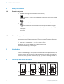 5
5
-
 6
6
-
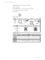 7
7
-
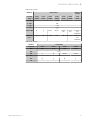 8
8
-
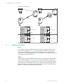 9
9
-
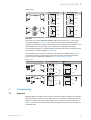 10
10
-
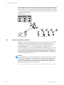 11
11
-
 12
12
-
 13
13
-
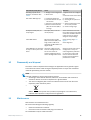 14
14
-
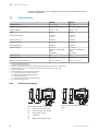 15
15
-
 16
16
-
 17
17
-
 18
18
-
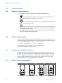 19
19
-
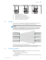 20
20
-
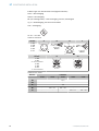 21
21
-
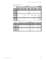 22
22
-
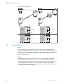 23
23
-
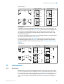 24
24
-
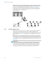 25
25
-
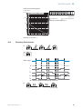 26
26
-
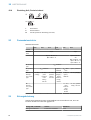 27
27
-
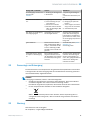 28
28
-
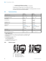 29
29
-
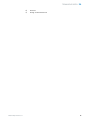 30
30
-
 31
31
-
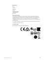 32
32
-
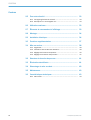 33
33
-
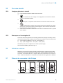 34
34
-
 35
35
-
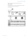 36
36
-
 37
37
-
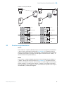 38
38
-
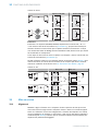 39
39
-
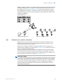 40
40
-
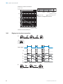 41
41
-
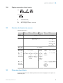 42
42
-
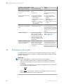 43
43
-
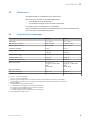 44
44
-
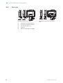 45
45
-
 46
46
-
 47
47
-
 48
48
-
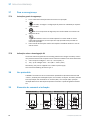 49
49
-
 50
50
-
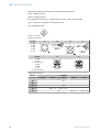 51
51
-
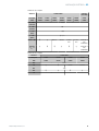 52
52
-
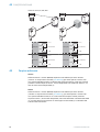 53
53
-
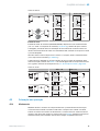 54
54
-
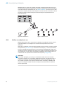 55
55
-
 56
56
-
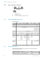 57
57
-
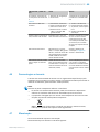 58
58
-
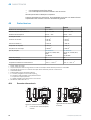 59
59
-
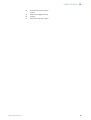 60
60
-
 61
61
-
 62
62
-
 63
63
-
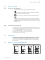 64
64
-
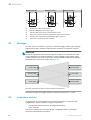 65
65
-
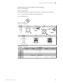 66
66
-
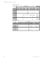 67
67
-
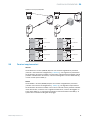 68
68
-
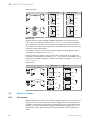 69
69
-
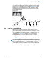 70
70
-
 71
71
-
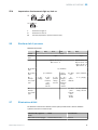 72
72
-
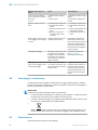 73
73
-
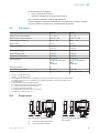 74
74
-
 75
75
-
 76
76
-
 77
77
-
 78
78
-
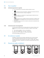 79
79
-
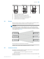 80
80
-
 81
81
-
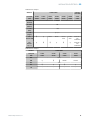 82
82
-
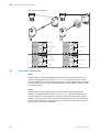 83
83
-
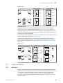 84
84
-
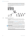 85
85
-
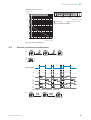 86
86
-
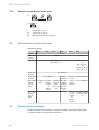 87
87
-
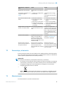 88
88
-
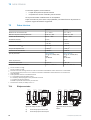 89
89
-
 90
90
-
 91
91
-
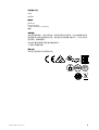 92
92
-
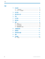 93
93
-
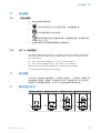 94
94
-
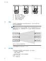 95
95
-
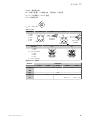 96
96
-
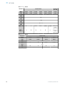 97
97
-
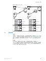 98
98
-
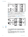 99
99
-
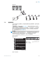 100
100
-
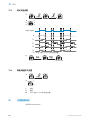 101
101
-
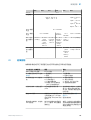 102
102
-
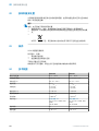 103
103
-
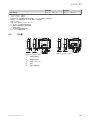 104
104
-
 105
105
-
 106
106
-
 107
107
-
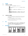 108
108
-
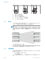 109
109
-
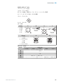 110
110
-
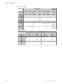 111
111
-
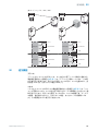 112
112
-
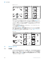 113
113
-
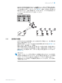 114
114
-
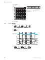 115
115
-
 116
116
-
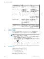 117
117
-
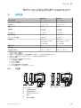 118
118
-
 119
119
-
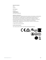 120
120
-
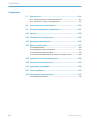 121
121
-
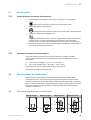 122
122
-
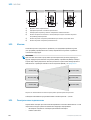 123
123
-
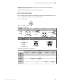 124
124
-
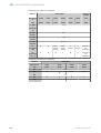 125
125
-
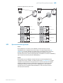 126
126
-
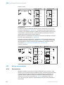 127
127
-
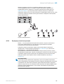 128
128
-
 129
129
-
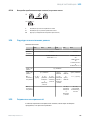 130
130
-
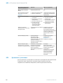 131
131
-
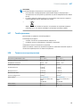 132
132
-
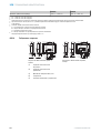 133
133
-
 134
134


en otros idiomas
- français: SICK WSE26 Mode d'emploi
- italiano: SICK WSE26 Istruzioni per l'uso
- English: SICK WSE26 Operating instructions
- Deutsch: SICK WSE26 Bedienungsanleitung
- русский: SICK WSE26 Инструкция по эксплуатации
- português: SICK WSE26 Instruções de operação
- 日本語: SICK WSE26 取扱説明書
Artículos relacionados
-
SICK WTB26 Instrucciones de operación
-
-
-
-
-
-
-
-
-