Dometic SMP301-01, SMP301-02, SMP301-03, SMP301-04, SMP301-05, SMP301-07, SMP301-10 Instrucciones de operación
- Tipo
- Instrucciones de operación

SMP301-01, SMP301-02, SMP301-03,
SMP301-04, SMP301-05, SMP301-07,
SMP301-10
Switch-mode power supply
Installation and Operating Manual. . . . . . . . 9
Schaltnetzteil
Montage- und Bedienungsanleitung . . . . .28
Bloc d'alimentation
Instructions de montage
et de service . . . . . . . . . . . . . . . . . . . . . . . . .49
Fuente conmutada
Instrucciones de montaje y de uso . . . . . . .69
Alimentatore a commutazione
Istruzioni di montaggio e d’uso . . . . . . . . .89
Voeding
Montagehandleiding en
gebruiksaanwijzing . . . . . . . . . . . . . . . . . .109
Koplingsstrømforsyning
Monterings- og bruksanvisning . . . . . . . .129
EN
DE
FR
ES
IT
NL
NO
ENERGY & LIGHTING
ACCESSORIES
SMP301-01-02-03-04-05-10--IO-7s.book Seite 1 Mittwoch, 23. Oktober 2019 11:56 11

SMP301-01-02-03-04-05-10--IO-7s.book Seite 2 Mittwoch, 23. Oktober 2019 11:56 11

SMP301
3
1
1 2 3 4 5
67
89
10
11
12
SMP 301-01
2
1
SMP 301-02
2345
11
67
89
10
SMP301-01-02-03-04-05-10--IO-7s.book Seite 3 Mittwoch, 23. Oktober 2019 11:56 11

SMP301
4
3
1 2 3 4 5
67
89
10
1112
SMP 301-03
4
1 2 3 4 5
67
89
10
11
12
SMP 301-04
SMP301-01-02-03-04-05-10--IO-7s.book Seite 4 Mittwoch, 23. Oktober 2019 11:56 11

SMP301
5
5
1 2 3 4 5
67
89
10
11
12
SMP 301-05
1 2 3 4 5 6 7 8 9 10
17 16 15 14 13 12 11
SMP 301-07
6
SMP301-01-02-03-04-05-10--IO-7s.book Seite 5 Mittwoch, 23. Oktober 2019 11:56 11

SMP301
6
7
113 2 3 4 5
67
89
10
11
12
SMP 301-10
SMP301-01-02-03-04-05-10--IO-7s.book Seite 6 Mittwoch, 23. Oktober 2019 11:56 11

SMP301
7
≥ 200 mm
≥ 50 mm
≥ 200 mm
≥ 200 mm
≥ 100 mm
≥ 200 mm
A
B
8
SMP301-01-02-03-04-05-10--IO-7s.book Seite 7 Mittwoch, 23. Oktober 2019 11:56 11

SMP301
8
3
2
1
1.
1.
2.
9
1
0
SMP301-01-02-03-04-05-10--IO-7s.book Seite 8 Mittwoch, 23. Oktober 2019 11:56 11

EN
SMP301 Explanation of symbols
9
Please read this instruction manual carefully before installation and first
use, and store it in a safe place. If you pass on the product to another
person, hand over this instruction manual along with it.
Table of contents
1 Explanation of symbols. . . . . . . . . . . . . . . . . . . . . . . . . . . . . . . . . . . . . . . . . . .9
2 Safety instructions . . . . . . . . . . . . . . . . . . . . . . . . . . . . . . . . . . . . . . . . . . . . . .10
3 Scope of delivery . . . . . . . . . . . . . . . . . . . . . . . . . . . . . . . . . . . . . . . . . . . . . .13
4 Accessories . . . . . . . . . . . . . . . . . . . . . . . . . . . . . . . . . . . . . . . . . . . . . . . . . . .13
5 Intended use . . . . . . . . . . . . . . . . . . . . . . . . . . . . . . . . . . . . . . . . . . . . . . . . . .13
6 Technical description . . . . . . . . . . . . . . . . . . . . . . . . . . . . . . . . . . . . . . . . . . .13
7 Installing the switching power supply . . . . . . . . . . . . . . . . . . . . . . . . . . . . . .18
8 Using the switching power supply. . . . . . . . . . . . . . . . . . . . . . . . . . . . . . . . .21
9 Maintaining and cleaning the switching power supply . . . . . . . . . . . . . . . 22
10 Troubleshooting . . . . . . . . . . . . . . . . . . . . . . . . . . . . . . . . . . . . . . . . . . . . . . 23
11 Warranty . . . . . . . . . . . . . . . . . . . . . . . . . . . . . . . . . . . . . . . . . . . . . . . . . . . . 23
12 Disposal . . . . . . . . . . . . . . . . . . . . . . . . . . . . . . . . . . . . . . . . . . . . . . . . . . . . . 24
13 Technical data . . . . . . . . . . . . . . . . . . . . . . . . . . . . . . . . . . . . . . . . . . . . . . . . 24
1 Explanation of symbols
D
!
DANGER!
Safety instruction: Indicates a hazardous situation that, if not avoided,
will result in death or serious injury.
WARNING!
Safety instruction: Indicates a hazardous situation that, if not avoided,
could result in death or serious injury.
SMP301-01-02-03-04-05-10--IO-7s.book Seite 9 Mittwoch, 23. Oktober 2019 11:56 11

EN
Safety instructions SMP301
10
!
A
I
2 Safety instructions
The manufacturer accepts no liability for damage in the following cases:
• Faulty assembly or connection
• Damage to the product resulting from mechanical influences and incorrect
connection voltage
• Alterations to the product without express permission from the manufacturer
• Use for purposes other than those described in the operating manual
2.1 General safety
!
WARNING!
• This product can be used by children aged eight years or over, as well
as by persons with diminished physical, sensory or mental capacities
or a lack of experience and knowledge, provided they are supervised,
or have been taught how to use the device safely and are aware of the
resulting risks.
• Cleaning and user maintenance may not be carried out by unsuper-
vised children.
• Only use the product as intended.
•Do not use the product in wet or damp environments or in areas
where there is a risk of gas or dust explosions.
• Maintenance and repair work may only be carried out by qualified per-
sonnel who are familiar with the risks involved and the relevant regula-
tions.
CAUTION!
Safety instruction: Indicates a hazardous situation that, if not avoided,
could result in minor or moderate injury.
NOTICE!
Indicates a situation that, if not avoided, can result in property damage.
NOTE
Supplementary information for operating the product.
SMP301-01-02-03-04-05-10--IO-7s.book Seite 10 Mittwoch, 23. Oktober 2019 11:56 11

EN
SMP301 Safety instructions
11
2.2 Safety when installing the product
!
WARNING!
• The electrical installation may only be connected by qualified person-
nel and only in accordance with the national regulations. Incorrect
connection may cause severe hazards.
• Take the precautions necessary to ensure that children cannot inter-
fere with the product.
Dangerous situations may occur which cannot be recognized by chil-
dren!
A
NOTICE!
• Do not expose the product to any heat source (such as direct sunlight
or heating). Avoid additional heating of the device in this way.
Electrical cables
!
CAUTION!
• Lay the cables so that they cannot be tripped over or damaged.
• Have damaged power cables replaced by a specialist in accordance
with national regulations.
A
NOTICE!
• If cables have to be fed through metal walls or other walls with sharp
edges, use ducts or bushings to prevent damage.
• Do not lay cables that are loose or sharply bent next to electrically con-
ductive material (metal).
• Do not pull on the cables.
• Do not lay the AC cable and the DC cable in the same duct.
• Firmly secure the cables.
2.3 Operating the product safely
!
WARNING!
• Operate the product only if you are certain that the casing and the
cables are undamaged.
• Always disconnect the power supply when working on the product.
SMP301-01-02-03-04-05-10--IO-7s.book Seite 11 Mittwoch, 23. Oktober 2019 11:56 11

EN
Safety instructions SMP301
12
A
NOTICE!
• Make sure the ventilation grills in the product are not covered.
• Ensure good ventilation.
2.4 Operating the battery charger safely
(only SMP301-07)
D
DANGER!
• The battery may emit explosive gases during the charging process.
Ensure that there are no sparks or flames in the vicinity of the battery.
Ensure that the product is sufficiently ventilated.
!
WARNING!
• Wear safety glasses when handling the battery and especially when
connecting and disconnecting the battery.
• In the event of the skin or eyes coming into contact with battery acid,
rinse out the affected areas immediately with lots of water and call a
doctor.
• Only charge rechargeable batteries.
• Only charge the battery if it is not frozen.
• Do not put the battery charger on the battery.
• Do not cover the battery charger.
• Only use the battery charger if the casing, connections and cable are
undamaged.
A
NOTICE!
• A charging voltage of up to 15 V is possible during the charging pro-
cess. Ensure that there are no consumer units connected to the battery
during the charging process. This is to prevent the consumer units
connected from being damaged.
• The battery charger switches to preservation mode following the
charging process. If the battery charger does not switch out of charge
mode, disconnect the battery charger from the battery. Have the bat-
tery charger checked by a specialist electrician.
• Regularly check the battery for damage and for defects when it is in
use. A defective battery is detected by the battery charger during the
charging process.
SMP301-01-02-03-04-05-10--IO-7s.book Seite 12 Mittwoch, 23. Oktober 2019 11:56 11

EN
SMP301 Scope of delivery
13
3Scope of delivery
• Switching power supply
• Battery charger (only SMP301-07)
• Installation and operating manual
4Accessories
Available as accessories (not included in the scope of delivery):
5 Intended use
The type SMP301-01/-02/-03/-04/-05/-07/-10 switching power supply is suitable
for installation in habitable recreational vehicles (e.g. mobile homes, camper vans,
boats etc.). The switching power supply is used as the voltage supply for the DC con-
sumer units and can be supplied with AC or DC.
The battery charger of the SMP301-07 switching power supply is suitable for charg-
ing 6-cell lead batteries (lead-acid, gel, AGM) with a capacity of 50 Ah to 300 Ah. Do
not use the battery charger for any other purpose and do not use it to charge other
types of batteries.
The switching power supply is approved for permanent operation.
6 Technical description
The switching power supply converts an unstabilized input voltage to a stabilized
output voltage. It provides a constant DC voltage of 12.7 V for DC consumer units.
For power supply, a battery can be connected to the switching power supply via the
battery input (chapter “Connecting the switching power supply” on page 19).
The integrated priority circuit automatically switches over from battery operation to
mains operation when an external power supply is available. The battery is automat-
ically disconnected from the consumer unit.
Battery operation is activated automatically if mains operation is deactivated. The
consumer units connected are supplied with energy via the battery.
Description Ref. number
Overvoltage protection 9106505815
SMP301-01-02-03-04-05-10--IO-7s.book Seite 13 Mittwoch, 23. Oktober 2019 11:56 11

EN
Technical description SMP301
14
Only SMP301-07
In mains operation, the battery charger supplies the battery with a constant charging
voltage. The battery charger can supply a charging current of up to 20 A until a bat-
tery voltage of 12.7 V is reached. The battery charger can supply a charging current
of up to 5 A at a battery voltage in excess of 12.7 V. The charging process for the bat-
tery is shorter if as many consumer units as possible are switched off. Once the bat-
tery is fully charged, the battery charger supplies it with a float charge.
The battery charger has the following safety functions:
• Overheating protection:
The charging current is reduced if the ambient temperature is too high.
• Deep discharge protection:
Battery operation is deactivated if the battery voltage drops below 10.8 V.
6.1 Connections and displays
SMP301-01
Item in
fig. 1, page 3
Element
1 Plug-in fuse F1 for output group 1 (maximum 15 A)
2 Plug-in fuse F2 for output group 2 (maximum 10 A)
3 Plug-in fuse F3 for output group 3 (maximum 7.5 A)
4 Plug-in fuse F4 for output group 4 (maximum 15 A)
5 Plug-in fuse F5 for output group 5 (maximum 15 A)
6 3x flat plug P5 6.3 mm for group 5
7 3x flat plug P4 6.3 mm for group 4
8 Flat plug P3 6.3 mm for group 3
9 Flat plug P2 6.3 mm for group 2
10 Flat plug P1 6.3 mm for group 1
11 10x flat plug P7 6.3 mm battery terminal / common earth connection
12 2x flat plug P6 for positive terminal battery
SMP301-01-02-03-04-05-10--IO-7s.book Seite 14 Mittwoch, 23. Oktober 2019 11:56 11

EN
SMP301 Technical description
15
SMP301-02
SMP301-03
Item in
fig. 2, page 3
Element
1 Plug-in fuse F1 for output group 1 (maximum 15 A)
2 Plug-in fuse F2 for output group 2 (maximum 15 A)
3 Plug-in fuse F3 for output group 3 (maximum 15 A)
4 Plug-in fuse F4 for output group 4 (maximum 15 A)
5 Plug-in fuse F5 for output group 5 (maximum 15 A)
6 Flat plug P5 6.3 mm for group 5
7 Flat plug P4 6.3 mm for group 4
8 Flat plug P3 6.3 mm for group 3
9 Flat plug P2 6.3 mm for group 2
10 Flat plug P1 6.3 mm for group 1
11 4x flat plug P7 6.3 mm common earth connection
Item in
fig. 3, page 4
Element
1 Plug-in fuse F1 for output group 1 (maximum 10 A)
2 Plug-in fuse F2 for output group 2 (maximum 10 A)
3 Plug-in fuse F3 for output group 3 (maximum 5 A)
4 Plug-in fuse F4 for output group 4 (maximum 5 A)
5 Plug-in fuse F5 for output group 5 (maximum 10 A)
6 3x flat plug P5 6.3 mm for group 5
7 3x flat plug P4 6.3 mm for group 4
8 Flat plug P3 6.3 mm for group 3
9 Flat plug P2 6.3 mm for group 2
10 Flat plug P1 6.3 mm for group 1
11 10x flat plug P7 6.3 mm battery terminal / common earth connection
12 2x flat plug P6 for positive terminal battery
SMP301-01-02-03-04-05-10--IO-7s.book Seite 15 Mittwoch, 23. Oktober 2019 11:56 11

EN
Technical description SMP301
16
SMP301-04
SMP301-05
Item in
fig. 4, page 4
Element
1 Plug-in fuse F1 for output group 1 (maximum 15 A)
2 Plug-in fuse F2 for output group 2 (maximum 10 A)
3 Plug-in fuse F3 for output group 3 (maximum 7.5 A)
4 Plug-in fuse F4 for output group 4 (maximum 15 A)
5 Plug-in fuse F5 for output group 5 (maximum 15 A)
6 3x flat plug P5 6.3 mm for group 5
7 3x flat plug P4 6.3 mm for group 4
8 Flat plug P3 6.3 mm for group 3
9 Flat plug P2 6.3 mm for group 2
10 Flat plug P1 6.3 mm for group 1
11 10x flat plug P7 6.3 mm battery terminal / common earth connection
12 2x flat plug P6 for positive terminal battery
Item in
fig. 5, page 5
Element
1 Plug-in fuse F1 for output group 1 (maximum 15 A)
2 Plug-in fuse F2 for output group 2 (maximum 10 A)
3 Plug-in fuse F3 for output group 3 (maximum 7.5 A)
4 Plug-in fuse F4 for output group 4 (maximum 15 A)
5 Plug-in fuse F5 for output group 5 (maximum 15 A)
6 3x flat plug P5 6.3 mm for group 5
7 3x flat plug P4 6.3 mm for group 4
8 Flat plug P3 6.3 mm for group 3
9 Flat plug P2 6.3 mm for group 2
10 Flat plug P1 6.3 mm for group 1
SMP301-01-02-03-04-05-10--IO-7s.book Seite 16 Mittwoch, 23. Oktober 2019 11:56 11

EN
SMP301 Technical description
17
SMP301-07
The LED LD6B indicates the battery charging status as follows:
• Main charge (12.7 V):
flashes yellow slowly (1 second on, 1 second off)
• Equalizing charge (approx. 14.4 V):
flashes yellow quickly (0.5 seconds on, 0.5 seconds off)
11 10x flat plug P7 6.3 mm battery terminal / common earth connection
12 2x flat plug P6 for positive terminal battery
Item in
fig. 6, page 5
Element
1 AC plug
2 LED LD6B “battery charging status”
3 LED LD6 “battery fuse defective”
4 2x flat plug P6 for positive terminal battery
5 Battery fuse F6 (20 A type ATO)
6 Plug-in fuse F1 for output group 1 (maximum 15 A)
7 Plug-in fuse F2 for output group 2 (maximum 15 A)
8 Plug-in fuse F3 for output group 3 (maximum 15 A)
9 Plug-in fuse F4 for output group 4 (maximum 15 A)
10 Plug-in fuse F5 for output group 5 (maximum 15 A)
11 3x flat plug P5 6.3 mm for group 5
12 3x flat plug P4 6.3 mm for group 4
13 Flat plug P3 6.3 mm for group 3
14 Flat plug P2 6.3 mm for group 2
15 Flat plug P1 6.3 mm for group 1
16 5x LED “plug-in fuse F1–F5 defective” (LD1–LD5)
17 10x flat plug P7 6.3 mm battery connection / common earth connec-
tion
Item in
fig. 5, page 5
Element
SMP301-01-02-03-04-05-10--IO-7s.book Seite 17 Mittwoch, 23. Oktober 2019 11:56 11

EN
Installing the switching power supply SMP301
18
• Charging process complete:
lights up yellow
•Fault:
flashes yellow very quickly
SMP301-10
7 Installing the switching power supply
7.1 Fastening the switching power supply
When selecting the installation location, pay attention to the following instructions:
• The switching power supply must be installed vertically on a wall (maximum
ambient temperature 50 °C) or horizontally on the ground or on a pedestal (max-
imum ambient temperature 40 °C and maximum load 75%).
• The optimum installation position is vertically on a wall.
Item in
fig. 7, page 6
Element
1 Plug-in fuse F1 for output group 1 (maximum 15 A)
2 Plug-in fuse F2 for output group 2 (maximum 10 A)
3 Plug-in fuse F3 for output group 3 (maximum 7.5 A)
4 Plug-in fuse F4 for output group 4 (maximum 15 A)
5 Plug-in fuse F5 for output group 5 (maximum 15 A)
6 3x flat plug P5 6.3 mm for group 5
7 3x flat plug P4 6.3 mm for group 4
8 Flat plug P3 6.3 mm for group 3
9 Flat plug P2 6.3 mm for group 2
10 Flat plug P1 6.3 mm for group 1
11 10x flat plug P7 6.3 mm battery terminal / common earth connection
12 2x flat plug P6 for positive terminal battery
13 CI bus connection
SMP301-01-02-03-04-05-10--IO-7s.book Seite 18 Mittwoch, 23. Oktober 2019 11:56 11

EN
SMP301 Installing the switching power supply
19
• The switching power supply must be installed in a location that is protected from
moisture.
• The switching power supply must not be installed in areas with easily flammable
materials (e.g. gas cylinder lockers).
• The switching power supply must not be installed in a dusty environment.
• The place of installation must be well ventilated. A ventilation system must be
available when the device is installed in small, enclosed spaces. Please observe
the minimum clearance around the switching power supply (fig. 8, page 7).
• There must be free space in front of the ventilation grills.
• When ambient temperatures are higher than those stated above (such as in
engine or heating compartments, or when exposed to direct sunlight), the heat
produced by the switching power supply when under load can lead to automatic
shutdown.
• The device must be installed on a level and sufficiently sturdy surface.
A
Fasten the switching power supply as follows:
➤ Screw one screw through each of the four bore holes in the four fastening tabs
(fig. 9 1, page 8).
7.2 Connecting the switching power supply
SMP301-02
Please note that flat plugs P1–P5 are individually fused via plug-in fuses F1–F5 in the
following manner:
NOTICE!
Before drilling any holes, make sure that no electrical cables or other
parts of the vehicle can be damaged by drilling, sawing and filing.
Flat plug Fuse Fuse assignment
Maximum permissible
current
P1 F1 15 A 15 A
P2 F2 15 A 15 A
P3 F3 15 A 15 A
P4 F4 15 A 15 A
P5 F5 15 A 15 A
SMP301-01-02-03-04-05-10--IO-7s.book Seite 19 Mittwoch, 23. Oktober 2019 11:56 11

EN
Installing the switching power supply SMP301
20
➤ Press the two tabs (fig. 9 3, page 8) in the direction indicated by the arrows and
lift the cover off (fig. 9 2, page 8).
➤ Connect the positive terminal of the consumer units to the flat plugs P1–P5
(fig. 2 6–10, page3).
➤ Connect the negative terminal of the consumer units to one of the flat plugs P7
(any pin) (fig. 2 11, page 3).
➤ Connect the AC connection cable to the AC plug.
➤ Secure all cables with strain relief clamps.
SMP301-01/ -03/ -04/ -05/ -07/ -10
Please note that flat plugs P1–P6 are individually fused via plug-in fuses F1–F6 in the
following manner:
➤ Press the two tabs (fig. 9 3, page 8) in the direction indicated by the arrows and
lift the cover off (fig. 9 2, page 8).
➤ Connect the positive terminal of the consumer units to the flat plugs P1–P6
(fig. 3 6–10, page4).
➤ Connect the negative terminal of the consumer units to one of the flat plugs P7
(any pin) (fig. 3 11, page 4).
➤ Connect the positive terminal of the battery to one of the flat plugs P6.
– SMP301-01/ -03/ -04/ -05/ -10: z. B. fig. 1 12,page 3
– SMP301-07: fig. 6 4, page 5
➤ Connect the negative terminal of the battery to one of the flat plugs P7 (any pin).
– SMP301-01/ -03/ -04/ -05/ -10: z. B. fig. 1 11,page 3
– SMP301-07: fig. 6 17, page 5
Flat plug Fuse Fuse assignment
Maximum permissi-
ble current
P1 F1 10 A 15 A
P2 F2 10 A 15 A
P3 F3 5 A 15 A
P4 F4 5 A 15 A
P5 F5 10 A 15 A
P6
Only SMP301-07
F6 20 A 20 A
SMP301-01-02-03-04-05-10--IO-7s.book Seite 20 Mittwoch, 23. Oktober 2019 11:56 11

EN
SMP301 Using the switching power supply
21
➤ Connect the AC connection cable to the AC plug.
➤ Ensure that the cable length between the battery and the switching power sup-
ply is not more than 2 m.
➤ Secure all cables with strain relief clamps.
8 Using the switching power supply
The switching power supply switches on as soon as an external power supply is avail-
able.
Only replace a plug-in fuse that has blown (1–5 in fig. 2, page 3 to fig. 7, page 6)
with a plug-in fuse of equivalent quality.
Please contact the manufacturer’s branch in your country (see the back of the instruc-
tion manual for the addresses) or your retailer if the function cannot be restored by
switching on the fuses or replacing the plug-in fuse.
8.1 Replacing the plug-in fuses
I
➤ Disconnect all consumer units from the switching power supply.
➤ Disconnect the switching power supply from the power supply.
➤ Press the two tabs (fig. 9 3, page 8) in the direction indicated by the arrows and
lift the cover off (fig. 9 2, page 8).
➤ Only replace plug-in fuses that have blown with new plug-in fuses of the type
“ATO Type – LITTLEFUSE” and the same rating.
➤ Re-attach the cover to the switching power supply.
➤ Put the switching power supply back into operation.
➤ If the plug-in fuse is tripped again, please contact the manufacturer’s branch in
your country (see the back of the instruction manual for the addresses) or your
retailer.
NOTE
The positioning of the plug-in fuses is used to configure manufacturer-
specific functions.
When replacing a plug-in fuse, take care to fit the replacement in the
same place. Malfunctions may occur otherwise.
SMP301-01-02-03-04-05-10--IO-7s.book Seite 21 Mittwoch, 23. Oktober 2019 11:56 11

EN
Maintaining and cleaning the switching power supply SMP301
22
8.2 Using the surge protector (optional)
The optional surge protector (item number 9106505815) is connected on the supply
side of the switching power supply. The surge protector disconnects the power sup-
ply line if the input voltage exceeds approx. 270 V.
➤ Check whether the red LED (fig. 0 1, page 8) lights up.
✓ If the red LED lights up, this indicates that a voltage surge has occurred.
➤ Wait 20 to 30 minutes.
➤ The surge protector resets itself automatically as soon as the voltage returns to a
permissible value. Once the voltage has reached a permissible value, the red LED
remains lit up for 20 to 30 minutes.
9 Maintaining and cleaning the switching
power supply
A
➤ Disconnect the switching power supply from the power supply.
➤ Clean the switching power supply using a cloth as required.
NOTICE!
Do not use any sharp or hard objects for cleaning since they may dam-
age the device.
SMP301-01-02-03-04-05-10--IO-7s.book Seite 22 Mittwoch, 23. Oktober 2019 11:56 11

EN
SMP301 Troubleshooting
23
10 Troubleshooting
11 Warranty
The statutory warranty period applies. If the product is defective, please contact the
manufacturer's branch in your country (see the back of the instruction manual for the
addresses) or your retailer.
For repair and warranty processing, please include the following documents when
you send in the device:
• A copy of the receipt with purchasing date
• A reason for the claim or description of the fault
Fault Cause Repair
12 V outputs
not supplied
when the
device is oper-
ating in mains
supply mode.
The plug-in fuse of the associated 12 V
output is defective. The red LED next
to the plug-in fuse lights up.
Replace it with a plug-in fuse of
equivalent quality.
The switching power supply has
switched off as a result of the surge
protector. The red LED (fig. 0 1,
page 8) lights up.
The surge protector resets itself
automatically as soon as the volt-
age returns to a permissible
value. Otherwise, contact cus-
tomer service.
12 V outputs
are not being
supplied in bat-
tery operation.
The plug-in fuse of the associated 12 V
output is defective. The red LED next
to the plug-in fuse lights up.
Replace it with a plug-in fuse of
equivalent quality.
The battery has been connected incor-
rectly.
Connect the battery correctly
(chapter “Connecting the switch-
ing power supply” on page 19).
SMP301-01-02-03-04-05-10--IO-7s.book Seite 23 Mittwoch, 23. Oktober 2019 11:56 11

EN
Disposal SMP301
24
12 Disposal
➤ Place the packaging material in the appropriate recycling waste bins wherever
possible.
M
If you wish to finally dispose of the product, ask your local recycling centre
or specialist dealer for details about how to do this in accordance with the
applicable disposal regulations.
13 Technical data
SMP301-01 SMP301-02
Ref. no.: 9106504722 9106504643
Design: with relay;
with external 12 V supply, out-
puts 1 and F5 are de-energized
without relay; no priority circuit
available
Nominal input voltage: 230 Vw
12 Vg
Constant output power: 350 W
Output voltage: 12.7 Vg
Amperage: 27 A
Ambient temperature: –10 °C to 40 °C
Housing: Protection class 20
Dimensions (L x W x H): 240 x 207 x 56 mm
Weight: 1 kg
Inspection/certification:
SMP301-01-02-03-04-05-10--IO-7s.book Seite 24 Mittwoch, 23. Oktober 2019 11:56 11

EN
SMP301 Technical data
25
SMP301-03 SMP301-04
Ref. no.: 9106504717 9106504929
Design: with relay;
with external 12 V supply all
outputs are live
with relay;
with external 12 V supply, out-
put F1 is de-energized
Nominal input voltage: 230 Vw
12 Vg
Constant output power: 350 W
Output voltage: 12.7 Vg
Amperage: 27 A
Ambient temperature: –10 °C to 40 °C
Housing: Protection class 20
Dimensions (L x W x H): 240 x 207 x 56 mm
Weight: 1 kg
Inspection/certification:
SMP301-01-02-03-04-05-10--IO-7s.book Seite 25 Mittwoch, 23. Oktober 2019 11:56 11

EN
Technical data SMP301
26
SMP301-05 SMP301-10
Ref. no.: 9106505097 9106506835
9106506674
Design: with relay;
with external 12 V supply, out-
puts 1 and F5 are de-energized
with relay;
F1 without priority circuit only
active with 230 V supply, F2–
F5 with priority circuit, F4 and
F5 with bypass function, F5
can also be controlled via the
CI bus
Nominal input voltage: 230 Vw
12 Vg
Constant output power: 350 W
Output voltage: 12.7 Vg
Amperage: 27 A
Ambient temperature: –10 °C to 40 °C
Housing: Protection class 20
Dimensions (L x W x H): 240 x 207 x 56 mm
Weight: 1 kg
Inspection/certification:
SMP301-01-02-03-04-05-10--IO-7s.book Seite 26 Mittwoch, 23. Oktober 2019 11:56 11

EN
SMP301 Technical data
27
SMP301-07
Ref. no.: 9106505556
Design: with battery charger
Nominal input voltage: 230 Vw
12 Vg
Constant output power: 350 W
Output voltage: 12.7 Vg
Amperage: 27 A
Ambient temperature: –10 °C to 40 °C
Housing: Protection class 20
Dimensions (L x W x H): 240 x 207 x 56 mm
Weight: 1 kg
Inspection/certification:
SMP301-01-02-03-04-05-10--IO-7s.book Seite 27 Mittwoch, 23. Oktober 2019 11:56 11

DE
Erläuterung der Symbole SMP301
28
Bitte lesen Sie diese Anleitung vor Einbau und Inbetriebnahme sorgfältig
durch und bewahren Sie sie auf. Geben Sie sie im Falle einer Weitergabe
des Produktes an den Nutzer weiter.
Inhaltsverzeichnis
1 Erläuterung der Symbole . . . . . . . . . . . . . . . . . . . . . . . . . . . . . . . . . . . . . . . 28
2 Sicherheitshinweise . . . . . . . . . . . . . . . . . . . . . . . . . . . . . . . . . . . . . . . . . . . 29
3 Lieferumfang . . . . . . . . . . . . . . . . . . . . . . . . . . . . . . . . . . . . . . . . . . . . . . . . . 32
5 Bestimmungsgemäßer Gebrauch . . . . . . . . . . . . . . . . . . . . . . . . . . . . . . . . 32
6 Technische Beschreibung . . . . . . . . . . . . . . . . . . . . . . . . . . . . . . . . . . . . . . 32
7 Schaltnetzteil montieren. . . . . . . . . . . . . . . . . . . . . . . . . . . . . . . . . . . . . . . . 39
8 Schaltnetzteil benutzen . . . . . . . . . . . . . . . . . . . . . . . . . . . . . . . . . . . . . . . . 42
9 Schaltnetzteil pflegen und reinigen . . . . . . . . . . . . . . . . . . . . . . . . . . . . . . . 43
10 Fehlerbeseitigung. . . . . . . . . . . . . . . . . . . . . . . . . . . . . . . . . . . . . . . . . . . . . 44
11 Gewährleistung. . . . . . . . . . . . . . . . . . . . . . . . . . . . . . . . . . . . . . . . . . . . . . . 44
12 Entsorgung . . . . . . . . . . . . . . . . . . . . . . . . . . . . . . . . . . . . . . . . . . . . . . . . . . 45
13 Technische Daten . . . . . . . . . . . . . . . . . . . . . . . . . . . . . . . . . . . . . . . . . . . . . 45
1 Erläuterung der Symbole
D
!
!
GEFAHR!
Sicherheitshinweis auf eine Gefahrensituation, die zum Tod oder zu
schwerer Verletzung führt, wenn sie nicht vermieden wird.
WARNUNG!
Sicherheitshinweis auf eine Gefahrensituation, die zum Tod oder zu
schwerer Verletzung führen kann, wenn sie nicht vermieden wird.
VORSICHT!
Sicherheitshinweis auf eine Gefahrensituation, die zu einer leichten
oder mittelschweren Verletzung führen kann, wenn sie nicht vermieden
wird.
SMP301-01-02-03-04-05-10--IO-7s.book Seite 28 Mittwoch, 23. Oktober 2019 11:56 11

DE
SMP301 Sicherheitshinweise
29
A
I
2 Sicherheitshinweise
Der Hersteller übernimmt in folgenden Fällen keine Haftung für Schäden:
• Montage- oder Anschlussfehler
• Beschädigungen am Produkt durch mechanische Einflüsse und falsche
Anschlussspannung
• Veränderungen am Produkt ohne ausdrückliche Genehmigung vom Hersteller
• Verwendung für andere als die in der Anleitung beschriebenen Zwecke
2.1 Grundlegende Sicherheit
!
WARNUNG!
• Dieses Produkt kann von Kindern ab 8 Jahren und darüber sowie von
Personen mit verringerten physischen, sensorischen oder mentalen
Fähigkeiten oder Mangel an Erfahrung und Wissen benutzt werden,
wenn sie beaufsichtigt oder bezüglich des sicheren Gebrauchs des
Gerätes unterwiesen wurden und die daraus resultierenden Gefahren
verstehen.
• Reinigung und Benutzer-Wartung dürfen nicht von Kindern ohne
Beaufsichtigung durchgeführt werden.
• Benutzen Sie das Produkt nur zu seinem bestimmungsgemäßen
Gebrauch.
• Betreiben Sie das Produkt nicht in feuchter oder nasser Umgebung
oder in Bereichen, in denen Gefahr durch Gas- oder Staubexplosion
besteht.
• Die Wartung und Reparatur darf nur durch eine Fachkraft geschehen,
die mit den damit verbundenen Gefahren bzw. einschlägigen Vor-
schriften vertraut ist.
ACHTUNG!
Hinweis auf eine Situation, die zu Sachschäden führen kann, wenn sie
nicht vermieden wird.
HINWEIS
Ergänzende Informationen zur Bedienung des Produktes.
SMP301-01-02-03-04-05-10--IO-7s.book Seite 29 Mittwoch, 23. Oktober 2019 11:56 11

DE
Sicherheitshinweise SMP301
30
2.2 Sicherheit bei der Installation des Produkts
!
WARNUNG!
• Die elektrische Installation darf nur von einer Fachkraft nach den natio-
nalen Vorschriften angeschlossen werden. Durch unsachgemäßes
Anschließen können erhebliche Gefahren entstehen.
• Sichern Sie das Produkt so, dass Kinder keinen Zugriff darauf haben.
Es können Gefahren entstehen, die von Kindern nicht erkannt
werden!
A
ACHTUNG!
• Setzen Sie das Produkt keiner Wärmequelle (Sonneneinstrahlung,
Heizung usw.) aus. Vermeiden Sie so zusätzliche Erwärmung des
Gerätes.
Elektrische Leitungen
!
VORSICHT!
• Verlegen Sie die Leitungen so, dass keine Stolpergefahr entsteht und
eine Beschädigung des Kabels ausgeschlossen ist.
• Lassen Sie ein beschädigtes Stromkabel von einer Fachkraft nach den
nationalen Vorschriften austauschen.
A
ACHTUNG!
• Müssen Leitungen durch Blechwände oder andere scharfkantige
Wände geführt werden, dann benutzen Sie Leerrohre bzw.
Leitungsdurchführungen.
• Verlegen Sie Leitungen nicht lose oder scharf abgeknickt an elektrisch
leitenden Materialien (Metall).
• Ziehen Sie nicht an Leitungen.
• Verlegen Sie Wechselstromleitung und Gleichstromleitung nicht
zusammen im gleichen Leitungskanal (Leerrohr).
• Befestigen Sie die Leitungen gut.
2.3 Sicherheit beim Betrieb des Produkts
!
WARNUNG!
• Betreiben Sie das Produkt nur, wenn das Gehäuse und die Leitungen
unbeschädigt sind.
SMP301-01-02-03-04-05-10--IO-7s.book Seite 30 Mittwoch, 23. Oktober 2019 11:56 11

DE
SMP301 Sicherheitshinweise
31
• Unterbrechen Sie bei Arbeiten am Produkt immer die Strom-
versorgung.
A
ACHTUNG!
• Achten Sie darauf, dass die Belüftungsschlitze des Produkts nicht ver-
deckt werden.
• Achten Sie auf gute Belüftung.
2.4 Sicherheit beim Betrieb des Batterieladers (nur
SMP301-07)
D
GEFAHR!
• Während des Batterieladevorgangs kann die Batterie explosive Gase
abgeben. Stellen Sie sicher, dass es im Umfeld der Batterie keine
Funken oder Flammenbildung gibt. Sorgen Sie für eine ausreichende
Belüftung.
!
WARNUNG!
• Tragen Sie beim Umgang mit der Batterie und insbesondere beim An-
und Abklemmen der Batterie eine Schutzbrille.
• Bei Haut- oder Augenkontakt mit Batteriesäure spülen Sie die betrof-
fenen Körperpartien sofort mit viel Wasser und rufen Sie einen Arzt.
• Laden Sie ausschließlich aufladbare Batterien auf.
• Laden Sie die Batterie nur, wenn diese nicht gefroren ist.
• Legen Sie den Batterielader nicht auf die Batterie.
• Decken Sie den Batterielader nicht ab.
• Verwenden Sie den Batterielader nur, wenn Gehäuse, Anschlüsse
und Kabel unbeschädigt sind.
A
ACHTUNG!
• Während des Ladevorgangs ist eine Ladespannung von bis zu 15 V
möglich. Stellen Sie sicher, dass während des Ladevorgangs keine
Verbraucher an die Batterie angeschlossen sind, um Beschädigungen
der angeschlossenen Verbraucher zu vermeiden.
• Nach dem Ladevorgang schaltet der Batterielader in den Erhaltungs-
modus. Wenn der Batterielader den Lademodus nicht verlässt, dann
klemmen Sie den Batterielader von der Batterie ab. Lassen Sie den
Batterielader von einer Elektrofachkraft prüfen.
SMP301-01-02-03-04-05-10--IO-7s.book Seite 31 Mittwoch, 23. Oktober 2019 11:56 11

DE
Lieferumfang SMP301
32
• Prüfen Sie regelmäßig die Batterie auf Beschädigungen oder Fehler
während der Benutzung. Während des Ladevorgangs wird eine
fehlerhafte Batterie vom Batterieladegerät erkannt.
3 Lieferumfang
• Schaltnetzteil
• Batterielader (nur SMP301-07)
• Montage- und Bedienungsanleitung
4Zubehör
Als Zubehör erhältlich (nicht im Lieferumfang enthalten):
5 Bestimmungsgemäßer Gebrauch
Das Schaltnetzteil vom Typ SMP301-01/-02/-03/-04/-05/-07/-10 ist zum Einbau in
bewohnbare Freizeitfahrzeuge (z. B. Wohnmobile, Wohnwagen, Booten etc.) vor-
gesehen. Das Schaltnetzteil dient zur Spannungsversorgung von Gleichstrom-Ver-
brauchern und kann mit Wechselstrom oder Gleichstrom betrieben werden.
Der Batterielader des Schaltnetzteils SMP301-07 ist zum Laden von 6-Zellen-Blei-
Batterien (Blei-Säure, GEL, AGM) mit einer Kapazität von 50 Ah bis 300 Ah geeignet.
Verwenden Sie den Batterielader nicht für andere Zwecke oder zum Laden anderer
Batterietypen.
Das Schaltnetzteil ist für den Dauerbetrieb zugelassen.
6 Technische Beschreibung
Das Schaltnetzteil wandelt eine unstabilisierte Eingangsspannung in eine
stabilisierte Ausgangsspannung um. Es stellt eine konstante Gleichspannung von
12,7 V für Gleichstrom-Verbraucher zur Verfügung.
Zur Stromversorgung kann an das Schaltnetzteil eine Batterie an den Batterie-
eingang angeschlossen werden (Kapitel „Schaltnetzteil anschließen“ auf Seite 40).
Bezeichnung Artikel-Nr.
Überspannungsschutz 9106505815
SMP301-01-02-03-04-05-10--IO-7s.book Seite 32 Mittwoch, 23. Oktober 2019 11:56 11

DE
SMP301 Technische Beschreibung
33
Die integrierte Vorrangschaltung schaltet automatisch von Batterie- auf Netzbetrieb
um, wenn eine externe Stromversorgung zur Verfügung steht. Die Batterie wird
automatisch von den Verbrauchern getrennt.
Bei deaktiviertem Netzbetrieb wird automatisch der Batteriebetrieb aktiviert. Die
angeschlossenen Verbraucher werden über die Batterie mit Energie versorgt.
Nur SMP301-07
Im Netzbetrieb versorgt der Batterielader die Batterie mit einer konstanten Lades-
pannung. Bis zum Erreichen einer Batteriespannung von 12,7 V kann der Batteriela-
der einen Ladestrom von bis zu 20 A liefern. Bei einer Batteriespannung über 12,7 V
kann der Batterielader einen Ladestrom von bis zu 5 A liefern. Der Ladevorgang der
Batterie ist kürzer, wenn möglichst viele Verbraucher abgeschaltet werden. Wenn
die Batterie vollständig geladen ist, dann wird diese vom Batterielader mit einer
Erhaltungsladung versorgt.
Der Batterielader besitzt folgende Schutzfunktionen:
• Überhitzungsschutz:
Wenn die Umgebungstemperatur zu hoch ist, dann wird der Ladestrom reduziert.
• Tiefenentladungsschutz:
Wenn die Batteriespannung unter 10,8 V sinkt, dann wird der Batteriebetrieb
deaktiviert.
SMP301-01-02-03-04-05-10--IO-7s.book Seite 33 Mittwoch, 23. Oktober 2019 11:56 11

DE
Technische Beschreibung SMP301
34
6.1 Anschlüsse und Anzeigen
SMP301-01
SMP301-02
Pos. in
Abb. 1, Seite 3
Element
1 Stecksicherung F1 für Ausgang Gruppe 1 (maximal 15 A)
2 Stecksicherung F2 für Ausgang Gruppe 2 (maximal 10 A)
3 Stecksicherung F3 für Ausgang Gruppe 3 (maximal 7,5 A)
4 Stecksicherung F4 für Ausgang Gruppe 4 (maximal 15 A)
5 Stecksicherung F5 für Ausgang Gruppe 5 (maximal 15 A)
6 3x Flachstecker P5 6,3 mm für Gruppe 5
7 3x Flachstecker P4 6,3 mm für Gruppe 4
8 Flachstecker P3 6,3 mm für Gruppe 3
9 Flachstecker P2 6,3 mm für Gruppe 2
10 Flachstecker P1 6,3 mm für Gruppe 1
11 10x Flachstecker P7 6,3 mm Batterieanschluss / gemeinsamer
Masseanschluss
12 2x Flachstecker P6 für Pluspol Batterie
Pos. in
Abb. 2, Seite 3
Element
1 Stecksicherung F1 für Ausgang Gruppe 1 (maximal 15 A)
2 Stecksicherung F2 für Ausgang Gruppe 2 (maximal 15 A)
3 Stecksicherung F3 für Ausgang Gruppe 3 (maximal 15 A)
4 Stecksicherung F4 für Ausgang Gruppe 4 (maximal 15 A)
5 Stecksicherung F5 für Ausgang Gruppe 5 (maximal 15 A)
6 Flachstecker P5 6,3 mm für Gruppe 5
7 Flachstecker P4 6,3 mm für Gruppe 4
8 Flachstecker P3 6,3 mm für Gruppe 3
9 Flachstecker P2 6,3 mm für Gruppe 2
SMP301-01-02-03-04-05-10--IO-7s.book Seite 34 Mittwoch, 23. Oktober 2019 11:56 11

DE
SMP301 Technische Beschreibung
35
SMP301-03
10 Flachstecker P1 6,3 mm für Gruppe 1
11 4x Flachstecker P7 6,3 mm gemeinsamer Masseanschluss
Pos. in
Abb. 3, Seite 4
Element
1 Stecksicherung F1 für Ausgang Gruppe 1 (maximal 10 A)
2 Stecksicherung F2 für Ausgang Gruppe 2 (maximal 10 A)
3 Stecksicherung F3 für Ausgang Gruppe 3 (maximal 5 A)
4 Stecksicherung F4 für Ausgang Gruppe 4 (maximal 5 A)
5 Stecksicherung F5 für Ausgang Gruppe 5 (maximal 10 A)
6 3x Flachstecker P5 6,3 mm für Gruppe 5
7 3x Flachstecker P4 6,3 mm für Gruppe 4
8 Flachstecker P3 6,3 mm für Gruppe 3
9 Flachstecker P2 6,3 mm für Gruppe 2
10 Flachstecker P1 6,3 mm für Gruppe 1
11 10x Flachstecker P7 6,3 mm Batterieanschluss / gemeinsamer
Masseanschluss
12 2x Flachstecker P6 für Pluspol Batterie
Pos. in
Abb. 2, Seite 3
Element
SMP301-01-02-03-04-05-10--IO-7s.book Seite 35 Mittwoch, 23. Oktober 2019 11:56 11

DE
Technische Beschreibung SMP301
36
SMP301-04
SMP301-05
Pos. in
Abb. 4, Seite 4
Element
1 Stecksicherung F1 für Ausgang Gruppe 1 (maximal 15 A)
2 Stecksicherung F2 für Ausgang Gruppe 2 (maximal 10 A)
3 Stecksicherung F3 für Ausgang Gruppe 3 (maximal 7,5 A)
4 Stecksicherung F4 für Ausgang Gruppe 4 (maximal 15 A)
5 Stecksicherung F5 für Ausgang Gruppe 5 (maximal 15 A)
6 3x Flachstecker P5 6,3 mm für Gruppe 5
7 3x Flachstecker P4 6,3 mm für Gruppe 4
8 Flachstecker P3 6,3 mm für Gruppe 3
9 Flachstecker P2 6,3 mm für Gruppe 2
10 Flachstecker P1 6,3 mm für Gruppe 1
11 10x Flachstecker P7 6,3 mm Batterieanschluss / gemeinsamer
Masseanschluss
12 2x Flachstecker P6 für Pluspol Batterie
Pos. in
Abb. 5, Seite 5
Element
1 Stecksicherung F1 für Ausgang Gruppe 1 (maximal 15 A)
2 Stecksicherung F2 für Ausgang Gruppe 2 (maximal 10 A)
3 Stecksicherung F3 für Ausgang Gruppe 3 (maximal 7,5 A)
4 Stecksicherung F4 für Ausgang Gruppe 4 (maximal 15 A)
5 Stecksicherung F5 für Ausgang Gruppe 5 (maximal 15 A)
6 3x Flachstecker P5 6,3 mm für Gruppe 5
7 3x Flachstecker P4 6,3 mm für Gruppe 4
8 Flachstecker P3 6,3 mm für Gruppe 3
9 Flachstecker P2 6,3 mm für Gruppe 2
10 Flachstecker P1 6,3 mm für Gruppe 1
SMP301-01-02-03-04-05-10--IO-7s.book Seite 36 Mittwoch, 23. Oktober 2019 11:56 11

DE
SMP301 Technische Beschreibung
37
SMP301-07
11 10x Flachstecker P7 6,3 mm Batterieanschluss / gemeinsamer
Masseanschluss
12 2x Flachstecker P6 für Pluspol Batterie
Pos. in
Abb. 6, Seite 5
Element
1 Wechselstrom-Stecker
2 LED LD6B „Batterieladestatus“
3 LED LD6 „Batteriesicherung defekt“
4 2x Flachstecker P6 für Pluspol Batterie
5 Batteriesicherung F6 (20 A Typ ATO)
6 Stecksicherung F1 für Ausgang Gruppe 1 (maximal 15 A)
7 Stecksicherung F2 für Ausgang Gruppe 2 (maximal 15 A)
8 Stecksicherung F3 für Ausgang Gruppe 3 (maximal 15 A)
9 Stecksicherung F4 für Ausgang Gruppe 4 (maximal 15 A)
10 Stecksicherung F5 für Ausgang Gruppe 5 (maximal 15 A)
11 3x Flachstecker P5 6,3 mm für Gruppe 5
12 3x Flachstecker P4 6,3 mm für Gruppe 4
13 Flachstecker P3 6,3 mm für Gruppe 3
14 Flachstecker P2 6,3 mm für Gruppe 2
15 Flachstecker P1 6,3 mm für Gruppe 1
16 5x LED „Stecksicherung F1 – F5 defekt“ (LD1 – LD5)
17 10x Flachstecker P7 6,3 mm Batterieanschluss / gemeinsamer Masse-
anschluss
Pos. in
Abb. 5, Seite 5
Element
SMP301-01-02-03-04-05-10--IO-7s.book Seite 37 Mittwoch, 23. Oktober 2019 11:56 11

DE
Technische Beschreibung SMP301
38
Die LED LD6B zeigt den Batterieladestatus wie folgt an:
• Hauptladung (12,7 V):
langsames gelbes Blinken (1 Sekunde ein, 1 Sekunde aus)
• Ausgleichsladung (ca. 14,4 V):
schnelles gelbes Blinken (0,5 Sekunden ein, 0,5 Sekunden aus)
• Ladevorgang beendet:
gelbes Leuchten
•Fehler:
sehr schnelles gelbes Blinken
SMP301-10
Pos. in
Abb. 7, Seite 6
Element
1 Stecksicherung F1 für Ausgang Gruppe 1 (maximal 15 A)
2 Stecksicherung F2 für Ausgang Gruppe 2 (maximal 10 A)
3 Stecksicherung F3 für Ausgang Gruppe 3 (maximal 7,5 A)
4 Stecksicherung F4 für Ausgang Gruppe 4 (maximal 15 A)
5 Stecksicherung F5 für Ausgang Gruppe 5 (maximal 15 A)
6 3x Flachstecker P5 6,3 mm für Gruppe 5
7 3x Flachstecker P4 6,3 mm für Gruppe 4
8 Flachstecker P3 6,3 mm für Gruppe 3
9 Flachstecker P2 6,3 mm für Gruppe 2
10 Flachstecker P1 6,3 mm für Gruppe 1
11 10x Flachstecker P7 6,3 mm Batterieanschluss / gemeinsamer
Masseanschluss
12 2x Flachstecker P6 für Pluspol Batterie
13 CI-Bus-Anschluss
SMP301-01-02-03-04-05-10--IO-7s.book Seite 38 Mittwoch, 23. Oktober 2019 11:56 11

DE
SMP301 Schaltnetzteil montieren
39
7 Schaltnetzteil montieren
7.1 Schaltnetzteil befestigen
Beachten Sie bei der Wahl des Montageortes folgende Hinweise:
• Das Schaltnetzteil darf senkrecht an einer Wand (maximale Umgebungs-
temperatur 50 °C) oder waagerecht auf dem Boden oder einem Podest
(maximale Umgebungstemperatur 40 °C und maximale Last 75 %) montiert
werden.
• Die optimale Einbauposition ist senkrecht an einer Wand.
• Das Schaltnetzteil muss an einer vor Feuchtigkeit geschützten Stelle eingebaut
werden.
• Das Schaltnetzteil darf nicht in Umgebungen mit leicht entzündlichen Materialien
(z. B. Gaskasten) eingebaut werden.
• Das Schaltnetzteil darf nicht in staubigen Umgebungen eingebaut werden.
• Der Einbauort muss gut belüftet sein. Bei Installationen in geschlossenen kleinen
Räumen sollte eine Be- und Entlüftung vorhanden sein. Beachten Sie den
Mindestabstand um das Schaltnetzteil (Abb. 8, Seite 7).
• Die Belüftungsschlitze müssen frei bleiben.
• Bei Umgebungstemperaturen, die höher als die oben genannten sind (z. B. in
Motor- oder Heizungsräumen, direkte Sonneneinstrahlung), kann es durch die
Eigenerwärmung des Schaltnetzteils bei Belastung zum automatischen Abschal-
ten kommen.
• Die Montagefläche muss eben sein und eine ausreichende Festigkeit aufweisen.
A
Befestigen Sie das Schaltnetzteil wie folgt:
➤ Schrauben Sie jeweils eine Schraube durch die Bohrung in den vier
Befestigungslaschen (Abb. 9 1, Seite 8).
ACHTUNG!
Bevor Sie irgendwelche Bohrungen vornehmen, stellen Sie sicher,
dass keine elektrischen Kabel oder andere Teile des Fahrzeugs durch
Bohren, Sägen und Feilen beschädigt werden.
SMP301-01-02-03-04-05-10--IO-7s.book Seite 39 Mittwoch, 23. Oktober 2019 11:56 11

DE
Schaltnetzteil montieren SMP301
40
7.2 Schaltnetzteil anschließen
SMP301-02
Beachten Sie, dass die Flachstecker P1 – P5 wie folgt einzeln über die Steck-
sicherungen F1 – F5 abgesichert sind:
➤ Drücken Sie die beiden Laschen (Abb. 9 3, Seite 8) in Pfeilrichtung und heben
Sie die Abdeckung (Abb. 9 2, Seite 8) ab.
➤ Schließen Sie den Pluspol der Verbraucher an die Flachstecker P1 – P5
(Abb. 2 6 – 10, Seite 3) an.
➤ Schließen Sie den Minuspol der Verbraucher an einen der Flachstecker P7
(beliebiger Stift) (Abb. 2 11, Seite 3) an.
➤ Schließen Sie das Wechselstrom-Anschlusskabel an den Wechselstrom-Stecker
an.
➤ Sichern Sie alle Kabel mit Zugentlastungen.
Flach-
stecker
Sicherung Sicherungsbelegung
maximal zulässige
Stromstärke
P1 F1 15 A 15 A
P2 F2 15 A 15 A
P3 F3 15 A 15 A
P4 F4 15 A 15 A
P5 F5 15 A 15 A
SMP301-01-02-03-04-05-10--IO-7s.book Seite 40 Mittwoch, 23. Oktober 2019 11:56 11

DE
SMP301 Schaltnetzteil montieren
41
SMP301-01/ -03/ -04/ -05/ -07/ -10
Beachten Sie, dass die Flachstecker P1 – P6 wie folgt einzeln über die Steck-
sicherungen F1 – F6 abgesichert sind:
➤ Drücken Sie die beiden Laschen (Abb. 9 3, Seite 8) in Pfeilrichtung und heben
Sie die Abdeckung (Abb. 9 2, Seite 8) ab.
➤ Schließen Sie den Pluspol der Verbraucher an die Flachstecker P1 – P6
(Abb. 3 6 – 10, Seite 4) an.
➤ Schließen Sie den Minuspol der Verbraucher an einen der Flachstecker P7
(beliebiger Stift) (Abb. 3 11,Seite 4) an.
➤ Schließen Sie den Pluspol der Batterie an einen der Flachstecker P6 an.
– SMP301-01/ -03/ -04/ -05/ -10: z. B. Abb. 1 12,Seite 3
– SMP301-07: Abb. 6 4,Seite 5
➤ Schließen Sie den Minuspol der Batterie an einen der Flachstecker P7
(beliebiger Stift) an.
– SMP301-01/ -03/ -04/ -05/ -10: z. B. Abb. 1 11,Seite 3
– SMP301-07: Abb. 6 17,Seite 5
➤ Schließen Sie das Wechselstrom-Anschlusskabel an den Wechselstrom-Stecker
an.
➤ Stellen Sie sicher, dass die Kabellänge zwischen Batterie und Schaltnetzteil
maximal 2 m beträgt.
➤ Sichern Sie alle Kabel mit Zugentlastungen.
Flachstecker Sicherung Sicherungsbelegung
maximal zulässige
Stromstärke
P1 F1 10 A 15 A
P2 F2 10 A 15 A
P3 F3 5 A 15 A
P4 F4 5 A 15 A
P5 F5 10 A 15 A
P6
nur SMP301-07
F6 20 A 20 A
SMP301-01-02-03-04-05-10--IO-7s.book Seite 41 Mittwoch, 23. Oktober 2019 11:56 11

DE
Schaltnetzteil benutzen SMP301
42
8 Schaltnetzteil benutzen
Das Schaltnetzteil schaltet sich ein, sobald eine externe Stromversorgung zur Verfü-
gung steht.
Ersetzen Sie eine durchgebrannte Stecksicherung (1 – 5 in Abb. 2, Seite 3 bis
Abb. 7, Seite 6) nur durch eine gleichwertige Stecksicherung.
Wenden Sie sich an die Niederlassung des Herstellers in Ihrem Land (Adressen siehe
Rückseite der Anleitung) oder an Ihren Fachhändler, wenn die Funktion durch Ein-
schalten der Sicherungen oder Austauschen der Stecksicherung nicht wieder herge-
stellt werden kann.
8.1 Stecksicherungen austauschen
I
➤ Trennen Sie alle Verbraucher vom Schaltnetzteil.
➤ Trennen Sie das Schaltnetzteil von der Stromversorgung.
➤ Drücken Sie die beiden Laschen (Abb. 9 3, Seite 8) in Pfeilrichtung und heben
Sie die Abdeckung (Abb. 9 2, Seite 8) ab.
➤ Ersetzen Sie eine defekte Stecksicherung durch eine neue Stecksicherung des
Typs „ATO Type – LITTLEFUSE“ gleicher Stärke.
➤ Befestigen Sie die Abdeckung wieder auf dem Schaltnetzteil.
➤ Nehmen Sie das Schaltnetzteil wieder in Betrieb.
➤ Wenn die Stecksicherung erneut auslöst, wenden Sie sich bitte an die
Niederlassung des Herstellers in Ihrem Land (Adressen siehe Rückseite der
Anleitung) oder an Ihren Fachhändler.
HINWEIS
Mit der Positionierung der Stecksicherungen werden
herstellerspezifische Funktionen konfiguriert.
Setzen Sie beim Austauschen einer Stecksicherung die neue Sicherung
wieder in die gleiche Position ein. Andernfalls können Fehlfunktionen
auftreten.
SMP301-01-02-03-04-05-10--IO-7s.book Seite 42 Mittwoch, 23. Oktober 2019 11:56 11

DE
SMP301 Schaltnetzteil pflegen und reinigen
43
8.2 Überspannungsschutz verwenden (optional)
Der optionale Überspannungsschutz (Art.-Nr. 9106505815) wird dem Schaltnetzteil
vorgeschaltet. Der Überspannungsschutz trennt die Zuleitung, wenn die Eingangs-
spannung ca. 270 V überschreitet.
➤ Prüfen Sie, ob die rote LED (Abb. 0 1, Seite 8) leuchtet.
✓ Wenn die rote LED leuchtet, hat eine Überspannung angelegen.
➤ Warten Sie 20 – 30 Minuten.
➤ Der Überspannungsschutz setzt sich automatisch zurück, wenn die Spannung
einen zulässigen Wert angenommen hat. Die rote LED leuchtet noch 20 –
30 Minuten weiter, nachdem der zulässige Spannungswert erreicht wurde.
9 Schaltnetzteil pflegen und reinigen
A
➤ Trennen Sie das Schaltnetzteil von der Stromversorgung.
➤ Reinigen Sie das Schaltnetzteil bei Bedarf mit einem Tuch.
ACHTUNG!
Keine scharfen oder harten Mittel zur Reinigung verwenden, da dies zu
einer Beschädigung des Gerätes führen kann.
SMP301-01-02-03-04-05-10--IO-7s.book Seite 43 Mittwoch, 23. Oktober 2019 11:56 11

DE
Fehlerbeseitigung SMP301
44
10 Fehlerbeseitigung
11 Gewährleistung
Es gilt die gesetzliche Gewährleistungsfrist. Sollte das Produkt defekt sein, wenden
Sie sich bitte an die Niederlassung des Herstellers in Ihrem Land (Adressen siehe
Rückseite der Anleitung) oder an Ihren Fachhändler.
Zur Reparatur- bzw. Gewährleistungsbearbeitung müssen Sie folgende Unterlagen
mitschicken:
• eine Kopie der Rechnung mit Kaufdatum,
• einen Reklamationsgrund oder eine Fehlerbeschreibung.
Fehler Ursache Behebung
12 V-Ausgänge
werden im
Netzbetrieb
nicht versorgt.
Die Stecksicherung des zugehörigen
12 V-Ausgangs ist defekt. Die rote LED
neben der Stecksicherung leuchtet.
Ersetzen Sie sie durch eine
gleichwertige Stecksicherung.
Das Schaltnetzteil hat durch den
Überspannungsschutz abgeschaltet.
Die rote LED (Abb. 0 1, Seite 8)
leuchtet.
Der Überspannungsschutz setzt
sich automatisch zurück, wenn
die Spannung einen zulässigen
Wert angenommen hat. Andern-
falls kontaktieren Sie den
Kundendienst.
12 V-Ausgänge
werden im
Batteriebetrieb
nicht versorgt.
Die Stecksicherung des zugehörigen
12 V-Ausgangs ist defekt. Die rote LED
neben der Stecksicherung leuchtet.
Ersetzen Sie sie durch eine
gleichwertige Stecksicherung.
Die Batterie ist falsch angeschlossen. Schließen Sie die Batterie richtig
an (Kapitel „Schaltnetzteil
anschließen“ auf Seite 40).
SMP301-01-02-03-04-05-10--IO-7s.book Seite 44 Mittwoch, 23. Oktober 2019 11:56 11

DE
SMP301 Entsorgung
45
12 Entsorgung
➤ Geben Sie das Verpackungsmaterial möglichst in den entsprechenden
Recycling-Müll.
M
Wenn Sie das Produkt endgültig außer Betrieb nehmen, informieren Sie
sich bitte beim nächsten Recyclingcenter oder bei Ihrem Fachhändler
über die zutreffenden Entsorgungsvorschriften.
13 Technische Daten
SMP301-01 SMP301-02
Art.-Nr.: 9106504722 9106504643
Ausführung: mit Relais;
bei externer 12 V-Versorgung
sind die Ausgänge 1 und F5
spannungslos
ohne Relais; keine Vorrang-
schaltung vorhanden
Eingangsnennspannung: 230 Vw
12 Vg
Dauer-Ausgangsleistung: 350 W
Ausgangsspannung: 12,7 Vg
Stromstärke: 27 A
Umgebungstemperatur: –10 °C bis +40 °C
Gehäuse: Schutzklasse 20
Abmessungen (L x B x H): 240 x 207 x 56 mm
Gewicht: 1 kg
Prüfung/Zertifikat:
SMP301-01-02-03-04-05-10--IO-7s.book Seite 45 Mittwoch, 23. Oktober 2019 11:56 11

DE
Technische Daten SMP301
46
SMP301-03 SMP301-04
Art.-Nr.: 9106504717 9106504929
Ausführung: mit Relais;
bei externer 12 V-Versorgung
sind alle Ausgänge
spannungsführend
mit Relais;
bei externer 12 V-Versorgung
ist der Ausgang F1
spannungslos
Eingangsnennspannung: 230 Vw
12 Vg
Dauer-Ausgangsleistung: 350 W
Ausgangsspannung: 12,7 Vg
Stromstärke: 27 A
Umgebungstemperatur: –10 °C bis +40 °C
Gehäuse: Schutzklasse 20
Abmessungen (L x B x H): 240 x 207 x 56 mm
Gewicht: 1 kg
Prüfung/Zertifikat:
SMP301-01-02-03-04-05-10--IO-7s.book Seite 46 Mittwoch, 23. Oktober 2019 11:56 11

DE
SMP301 Technische Daten
47
SMP301-05 SMP301-10
Art.-Nr.: 9106505097 9106506835
9106506674
Ausführung: mit Relais;
bei externer 12 V-Versorgung
sind die Ausgänge 1 und F5
spannungslos
mit Relais;
F1 ohne Vorrangschaltung nur
aktiv bei 230 V-Versorgung,
F2 – F5 mit Vorrangschaltung,
F4 und F5 mit Bypassfunktion,
F5 kann zusätzlich über den
CI-Bus angesteuert werden
Eingangsnennspannung: 230 Vw
12 Vg
Dauer-Ausgangsleistung: 350 W
Ausgangsspannung: 12,7 Vg
Stromstärke: 27 A
Umgebungstemperatur: –10 °C bis +40 °C
Gehäuse: Schutzklasse 20
Abmessungen (L x B x H): 240 x 207 x 56 mm
Gewicht: 1 kg
Prüfung/Zertifikat:
SMP301-01-02-03-04-05-10--IO-7s.book Seite 47 Mittwoch, 23. Oktober 2019 11:56 11

DE
Technische Daten SMP301
48
SMP301-07
Art.-Nr.: 9106505556
Ausführung: mit Batterielader
Eingangsnennspannung: 230 Vw
12 Vg
Dauer-Ausgangsleistung: 350 W
Ausgangsspannung: 12,7 Vg
Stromstärke: 27 A
Umgebungstemperatur: –10 °C bis +40 °C
Gehäuse: Schutzklasse 20
Abmessungen (L x B x H): 240 x 207 x 56 mm
Gewicht: 1 kg
Prüfung/Zertifikat:
SMP301-01-02-03-04-05-10--IO-7s.book Seite 48 Mittwoch, 23. Oktober 2019 11:56 11

FR
SMP301 Explication des symboles
49
Veuillez lire attentivement cette notice avant le montage et la mise en
service. Veuillez ensuite la conserver. En cas de passer le produit, veuillez
le transmettre au nouvel acquéreur.
Sommaire
1 Explication des symboles . . . . . . . . . . . . . . . . . . . . . . . . . . . . . . . . . . . . . . . 49
2 Consignes de sécurité . . . . . . . . . . . . . . . . . . . . . . . . . . . . . . . . . . . . . . . . . 50
3 Pièces fournies . . . . . . . . . . . . . . . . . . . . . . . . . . . . . . . . . . . . . . . . . . . . . . . 53
4 Accessoires . . . . . . . . . . . . . . . . . . . . . . . . . . . . . . . . . . . . . . . . . . . . . . . . . . 53
5 Usage conforme . . . . . . . . . . . . . . . . . . . . . . . . . . . . . . . . . . . . . . . . . . . . . . 53
6 Description technique . . . . . . . . . . . . . . . . . . . . . . . . . . . . . . . . . . . . . . . . . 54
7 Montage du bloc d’alimentation commuté. . . . . . . . . . . . . . . . . . . . . . . . . 59
8 Utilisation du bloc d’alimentation commuté . . . . . . . . . . . . . . . . . . . . . . . . 62
9 Entretien et nettoyage du bloc d’alimentation commuté . . . . . . . . . . . . . . 63
10 Élimination des erreurs . . . . . . . . . . . . . . . . . . . . . . . . . . . . . . . . . . . . . . . . . 64
11 Garantie. . . . . . . . . . . . . . . . . . . . . . . . . . . . . . . . . . . . . . . . . . . . . . . . . . . . . 64
12 Retraitement . . . . . . . . . . . . . . . . . . . . . . . . . . . . . . . . . . . . . . . . . . . . . . . . . 65
13 Caractéristiques techniques. . . . . . . . . . . . . . . . . . . . . . . . . . . . . . . . . . . . . 65
1 Explication des symboles
D
!
DANGER !
Consigne de sécurité signalant une situation dangereuse qui entraîne
la mort ou de graves blessures si elle n’est pas évitée.
AVERTISSEMENT !
Consigne de sécurité signalant une situation dangereuse qui peut
entraîner la mort ou de graves blessures si elle n’est pas évitée.
SMP301-01-02-03-04-05-10--IO-7s.book Seite 49 Mittwoch, 23. Oktober 2019 11:56 11

FR
Consignes de sécurité SMP301
50
!
A
I
2 Consignes de sécurité
Le fabricant décline toute responsabilité pour des dommages dans les cas suivants :
• des défauts de montage ou de raccordement
• des sollicitations mécaniques et une tension de raccordement incorrecte ayant
endommagé le matériel
• des modifications apportées au produit sans autorisation explicite de la part du
fabricant
• une utilisation différente de celle décrite dans la notice
2.1 Consignes générales de sécurité
!
AVERTISSEMENT !
• Les enfants âgés de 8 ans et plus ainsi que les personnes ayant des
déficiences physiques, sensorielles ou mentales ou un manque
d’expérience ou de connaissances peuvent utiliser ce produit à condi-
tion d’être sous surveillance ou d’avoir reçu des instructions concer-
nant l’utilisation de l’appareil en toute sécurité et de comprendre les
dangers qui en résultent.
• Le nettoyage et la maintenance ne doivent pas être effectués par des
enfants sans surveillance.
• N’utilisez le produit que pour un usage conforme à sa destination.
• N’utilisez pas le produit dans un environnement humide ou mouillé
ou dans les zones comportant un risque d’explosion de gaz ou de
poussière.
ATTENTION !
Consigne de sécurité signalant une situation dangereuse qui peut
entraîner des blessures de gravité moyenne ou légère si elle n’est pas
évitée.
AVIS !
Remarque signalant une situation qui peut entraîner des dommages
matériels si elle n’est pas évitée.
REMARQUE
Informations complémentaires sur l'utilisation du produit.
SMP301-01-02-03-04-05-10--IO-7s.book Seite 50 Mittwoch, 23. Oktober 2019 11:56 11

FR
SMP301 Consignes de sécurité
51
• Seul un personnel qualifié et parfaitement informé des dangers et
règlements spécifiques à ces manipulations est habilité à effectuer les
réparations et l’entretien.
2.2 Sécurité lors de l’installation du produit
!
AVERTISSEMENT !
• Seul un électricien spécialisé est habilité à effectuer l’installation, en
respectant les directives nationales. Tout raccordement incorrect ris-
querait d’entraîner de graves dangers.
• Conservez le produit hors de la portée des enfants.
Ces derniers pourraient s’exposer à des dangers dont ils ne sont pas
conscients !
A
AVIS !
• N’exposez pas le produit à des sources de chaleur (rayonnement
solaire, chauffage, etc.). Vous éviterez ainsi une surchauffe supplé-
mentaire de l’appareil.
Lignes électriques
!
ATTENTION !
• Posez les câbles de manière à exclure tout risque de trébuchement ou
d’endommagement du câble.
• Faites remplacer tout câble électrique endommagé par un électricien
spécialisé en respectant les directives nationales.
A
AVIS !
• Si des lignes électriques doivent traverser des cloisons en tôle ou
autres murs à arêtes vives, utilisez des tubes vides ou des conduits
pour câbles.
• Ne faites pas passer de lignes électriques non fixées ou fortement cou-
dées sur des matériaux conducteurs (métal).
• Ne tirez pas sur les lignes électriques.
• Ne placez pas les câbles de courant alternatif et de courant continu
dans le même conduit (tube vide).
• Fixez bien les lignes.
SMP301-01-02-03-04-05-10--IO-7s.book Seite 51 Mittwoch, 23. Oktober 2019 11:56 11

FR
Consignes de sécurité SMP301
52
2.3 Consignes de sécurité concernant le fonctionnement
du produit
!
AVERTISSEMENT !
• Faites fonctionner le produit uniquement si le boîtier et les conduites
sont intacts.
• Coupez l’alimentation électrique au cours de travaux sur le produit.
A
AVIS !
• Assurez-vous que les fentes d’aération du produit ne sont pas cou-
vertes.
• Veillez à ce que l’aération soit suffisante.
2.4 Consignes de sécurité concernant le fonctionnement
du chargeur de batterie (uniquement SMP301-07)
D
DANGER !
• Pendant le processus de chargement de la batterie, celle-ci peut
dégager des gaz explosifs. Veillez à ce qu’aucune flamme ni étincelle
ne puisse se former à proximité de la batterie. Assurez-vous que l’aéra-
tion est suffisante.
!
AVERTISSEMENT !
• Portez des lunettes de protection lorsque vous manipulez la batterie
et en particulier lorsque vous la branchez et la débranchez.
• Si l’acide de la batterie entre en contact avec la peau ou les yeux, net-
toyez immédiatement les parties du corps concernées avec une
grande quantité d’eau et appelez un médecin.
• Chargez uniquement des batteries rechargeables.
• Chargez la batterie uniquement si celle-ci n’est pas gelée.
• Ne posez pas le chargeur de batterie sur la batterie.
• Ne recouvrez pas le chargeur de batterie.
• Utilisez le chargeur de batterie uniquement si le boîtier, les raccorde-
ments et le câble sont intacts.
SMP301-01-02-03-04-05-10--IO-7s.book Seite 52 Mittwoch, 23. Oktober 2019 11:56 11

FR
SMP301 Pièces fournies
53
A
AVIS !
• Pendant le processus de chargement, la tension de charge peut
atteindre jusqu’à 15 V. Veillez à ce qu’aucun consommateur d’énergie
ne soit raccordé à la batterie pendant le processus de chargement afin
d’éviter tout endommagement des consommateurs d’énergie raccor-
dés.
• Après le processus de chargement, le chargeur de batterie passe en
mode de maintien. Si le chargeur de batterie ne quitte pas le mode de
charge, débranchez la connexion qui relie le chargeur à la batterie.
Faites vérifier le chargeur de batterie par un électricien.
• Contrôlez régulièrement la batterie pour vous assurer qu’elle est
intacte et ne présente aucune erreur pendant l’utilisation. Pendant le
processus de chargement, le chargeur de batterie reconnaît si la bat-
terie est défectueuse.
3Pièces fournies
• Bloc d’alimentation commuté
• Chargeur de batterie (uniquement SMP301-07)
• Notice de montage et d’utilisation
4Accessoires
Disponibles en accessoires (non compris dans la livraison) :
5Usage conforme
Le bloc d’alimentation commuté de type SMP301-01/-02/-03/-04/-05/-07/-10 est
conçu pour être monté dans des véhicules récréatifs (comme les caravanes, cam-
ping-cars, bateaux, etc.). Le bloc d’alimentation commuté est utilisé pour l’alimenta-
tion des consommateurs de courant continu et peut fonctionner sur courant alternatif
ou continu.
Désignation N° d’article
Protection contre la surtension 9106505815
SMP301-01-02-03-04-05-10--IO-7s.book Seite 53 Mittwoch, 23. Oktober 2019 11:56 11

FR
Description technique SMP301
54
Le chargeur de batterie du bloc d’alimentation commuté SMP301-07 est conçu
pour le chargement de batteries 6 cellules plomb (plomb-acide, GEL, AGM) d’une
capacité de 50 Ah à 300 Ah. N’utilisez pas le chargeur de batterie pour d’autres
usages ni pour le chargement d’autres types de batteries.
Le bloc d’alimentation commuté est conçu pour un fonctionnement continu.
6 Description technique
Le bloc d’alimentation commuté transforme une tension d’entrée non stabilisée en
une tension de sortie stabilisée. Il fournit une tension continue constante de 12,7 V
pour les consommateurs de courant continu.
Pour l’alimentation électrique, il est possible de raccorder une batterie sur l’entrée
de batterie du bloc d’alimentation commuté (chapitre « Raccordement du bloc d’ali-
mentation commuté », page 60).
Le raccordement prioritaire intégré passe automatiquement du fonctionnement sur
batterie au fonctionnement sur secteur, lorsqu’une alimentation électrique est dis-
ponible. La batterie est déconnectée automatiquement des consommateurs.
Si l’alimentation secteur est désactivée, la batterie est automatiquement activée. Les
consommateurs connectés sont alimentés en énergie par la batterie.
Uniquement SMP301-07
En mode de fonctionnement sur secteur, le chargeur de batterie alimente la batterie
avec une tension de charge constante. Jusqu’à ce que la batterie ait atteint une ten-
sion de 12,7 V, le chargeur de batterie peut fournir un courant de charge allant
jusqu’à 20 A. Lorsque la tension de la batterie dépasse 12,7 V, le chargeur de batte-
rie peut fournir un courant de charge allant jusqu’à 5 A. Le processus de chargement
de la batterie est plus court si un maximum de consommateurs d’énergie sont
éteints. Lorsque la batterie est entièrement rechargée, celle-ci est alimentée par le
chargeur de batterie avec une charge de maintien.
Le chargeur de batterie possède les fonctions de protection suivantes :
• Protection contre la surchauffe :
Lorsque la température ambiante est trop élevée, le courant de charge diminue.
• Protection contre la décharge profonde :
Si la tension de la batterie tombe en dessous de 10,8 V, le fonctionnement de la bat-
terie est désactivé.
SMP301-01-02-03-04-05-10--IO-7s.book Seite 54 Mittwoch, 23. Oktober 2019 11:56 11

FR
SMP301 Description technique
55
6.1 Raccordements et affichages
SMP301-01
SMP301-02
Pos. dans
fig. 1, page 3
Élément
1 Fusible enfichable F1 pour sortie groupe 1 (maximum 15 A)
2 Fusible enfichable F2 pour sortie groupe 2 (maximum 10 A)
3 Fusible enfichable F3 pour sortie groupe 3 (maximum 7,5 A)
4 Fusible enfichable F4 pour sortie groupe 4 (maximum 15 A)
5 Fusible enfichable F5 pour sortie groupe 5 (maximum 15 A)
6 3 prises plates P5 6,3 mm pour groupe 5
7 3 prises plates P4 6,3 mm pour groupe 4
8 Prise plate P3 6,3 mm pour groupe 3
9 Prise plate P2 6,3 mm pour groupe 2
10 Prise plate P1 6,3 mm pour groupe 1
11 10x prises plates P7 6,3 mm Raccord batterie / raccord de masse
commun
12 2 prises plates P6 pour pôle positif de la batterie
Pos. dans
fig. 2, page 3
Élément
1 Fusible enfichable F1 pour sortie groupe 1 (maximum 15 A)
2 Fusible enfichable F2 pour sortie groupe 2 (maximum 15 A)
3 Fusible enfichable F3 pour sortie groupe 3 (maximum 15 A)
4 Fusible enfichable F4 pour sortie groupe 4 (maximum 15 A)
5 Fusible enfichable F5 pour sortie groupe 5 (maximum 15 A)
6 Prise plate P5 6,3 mm pour groupe 5
7 Prise plate P4 6,3 mm pour groupe 4
8 Prise plate P3 6,3 mm pour groupe 3
9 Prise plate P2 6,3 mm pour groupe 2
SMP301-01-02-03-04-05-10--IO-7s.book Seite 55 Mittwoch, 23. Oktober 2019 11:56 11

FR
Description technique SMP301
56
SMP301-03
SMP301-04
10 Prise plate P1 6,3 mm pour groupe 1
11 4 prises plates P7 6,3 mm raccord de masse commun
Pos. dans
fig. 3, page 4
Élément
1 Fusible enfichable F1 pour sortie groupe 1 (maximum 10 A)
2 Fusible enfichable F2 pour sortie groupe 2 (maximum 10 A)
3 Fusible enfichable F3 pour sortie groupe 3 (maximum 5 A)
4 Fusible enfichable F4 pour sortie groupe 4 (maximum 5 A)
5 Fusible enfichable F5 pour sortie groupe 5 (maximum 10 A)
6 3 prises plates P5 6,3 mm pour groupe 5
7 3 prises plates P4 6,3 mm pour groupe 4
8 Prise plate P3 6,3 mm pour groupe 3
9 Prise plate P2 6,3 mm pour groupe 2
10 Prise plate P1 6,3 mm pour groupe 1
11 10x prises plates P7 6,3 mm Raccord batterie / raccord de masse
commun
12 2 prises plates P6 pour pôle positif de la batterie
Pos. dans
fig. 4, page 4
Élément
1 Fusible enfichable F1 pour sortie groupe 1 (maximum 15 A)
2 Fusible enfichable F2 pour sortie groupe 2 (maximum 10 A)
3 Fusible enfichable F3 pour sortie groupe 3 (maximum 7,5 A)
4 Fusible enfichable F4 pour sortie groupe 4 (maximum 15 A)
5 Fusible enfichable F5 pour sortie groupe 5 (maximum 15 A)
6 3 prises plates P5 6,3 mm pour groupe 5
Pos. dans
fig. 2, page 3
Élément
SMP301-01-02-03-04-05-10--IO-7s.book Seite 56 Mittwoch, 23. Oktober 2019 11:56 11

FR
SMP301 Description technique
57
SMP301-05
7 3 prises plates P4 6,3 mm pour groupe 4
8 Prise plate P3 6,3 mm pour groupe 3
9 Prise plate P2 6,3 mm pour groupe 2
10 Prise plate P1 6,3 mm pour groupe 1
11 10x prises plates P7 6,3 mm Raccord batterie / raccord de masse
commun
12 2 prises plates P6 pour pôle positif de la batterie
Pos. dans
fig. 5, page 5
Élément
1 Fusible enfichable F1 pour sortie groupe 1 (maximum 15 A)
2 Fusible enfichable F2 pour sortie groupe 2 (maximum 10 A)
3 Fusible enfichable F3 pour sortie groupe 3 (maximum 7,5 A)
4 Fusible enfichable F4 pour sortie groupe 4 (maximum 15 A)
5 Fusible enfichable F5 pour sortie groupe 5 (maximum 15 A)
6 3 prises plates P5 6,3 mm pour groupe 5
7 3 prises plates P4 6,3 mm pour groupe 4
8 Prise plate P3 6,3 mm pour groupe 3
9 Prise plate P2 6,3 mm pour groupe 2
10 Prise plate P1 6,3 mm pour groupe 1
11 10x prises plates P7 6,3 mm Raccord batterie / raccord de masse
commun
12 2 prises plates P6 pour pôle positif de la batterie
Pos. dans
fig. 4, page 4
Élément
SMP301-01-02-03-04-05-10--IO-7s.book Seite 57 Mittwoch, 23. Oktober 2019 11:56 11

FR
Description technique SMP301
58
SMP301-07
La LED LD6B indique l’état de charge de la batterie de la façon suivante :
•Charge principale (12,7V):
clignotement lent de couleur jaune (1 seconde allumée, 1 seconde éteinte)
• Charge d’égalisation (env. 14,4 V) :
clignotement rapide de couleur jaune (0,5 seconde allumée, 0,5 seconde
éteinte)
• Processus de chargement terminé :
LED allumée continuellement en jaune
• Erreur :
clignotement très rapide en jaune
Pos. dans
fig. 6, page 5
Élément
1 Connecteur courant alternatif
2 LED LD6B « état de charge de la batterie »
3 LED LD6 « fusible de batterie défectueux »
4 2 prises plates P6 pour pôle positif de la batterie
5 Fusible de batterie F6 (20 A type ATO)
6 Fusible enfichable F1 pour sortie groupe 1 (maximum 15 A)
7 Fusible enfichable F2 pour sortie groupe 2 (maximum 15 A)
8 Fusible enfichable F3 pour sortie groupe 3 (maximum 15 A)
9 Fusible enfichable F4 pour sortie groupe 4 (maximum 15 A)
10 Fusible enfichable F5 pour sortie groupe 5 (maximum 15 A)
11 3 prises plates P5 6,3 mm pour groupe 5
12 3 prises plates P4 6,3 mm pour groupe 4
13 Prise plate P3 6,3 mm pour groupe 3
14 Prise plate P2 6,3 mm pour groupe 2
15 Prise plate P1 6,3 mm pour groupe 1
16 5 LED « fusible enfichable F1–F5 défectueux » (LD1–LD5)
17 10 prises plates P7 6,3 mm raccord batterie / raccord de masse com-
mun
SMP301-01-02-03-04-05-10--IO-7s.book Seite 58 Mittwoch, 23. Oktober 2019 11:56 11

FR
SMP301 Montage du bloc d’alimentation commuté
59
SMP301-10
7 Montage du bloc d’alimentation
commuté
7.1 Fixation du bloc d’alimentation commuté
Lisez attentivement les remarques suivantes lors du choix du lieu d’installation :
• Le bloc d’alimentation commuté peut être monté à la verticale sur un mur (tem-
pérature ambiante maximale 50 °C) ou à l’horizontale au sol ou sur un socle (tem-
pérature ambiante maximale 40 °C et charge maximale 75 %).
• La position de montage optimale est à la verticale sur un mur.
• Le bloc d’alimentation commuté doit être monté à un endroit protégé de l’humi-
dité.
• Le bloc d’alimentation commuté ne doit pas être monté dans des environne-
ments contenant des matériaux facilement inflammables (p. ex. boîte de gaz).
Pos. dans
fig. 7, page 6
Élément
1 Fusible enfichable F1 pour sortie groupe 1 (maximum 15 A)
2 Fusible enfichable F2 pour sortie groupe 2 (maximum 10 A)
3 Fusible enfichable F3 pour sortie groupe 3 (maximum 7,5 A)
4 Fusible enfichable F4 pour sortie groupe 4 (maximum 15 A)
5 Fusible enfichable F5 pour sortie groupe 5 (maximum 15 A)
6 3 prises plates P5 6,3 mm pour groupe 5
7 3 prises plates P4 6,3 mm pour groupe 4
8 Prise plate P3 6,3 mm pour groupe 3
9 Prise plate P2 6,3 mm pour groupe 2
10 Prise plate P1 6,3 mm pour groupe 1
11 10x prises plates P7 6,3 mm Raccord batterie / raccord de masse
commun
12 2 prises plates P6 pour pôle positif de la batterie
13 Raccordement bus CI
SMP301-01-02-03-04-05-10--IO-7s.book Seite 59 Mittwoch, 23. Oktober 2019 11:56 11

FR
Montage du bloc d’alimentation commuté SMP301
60
• Le bloc d’alimentation commuté ne doit pas être monté dans des environne-
ments poussiéreux.
• Le lieu de montage doit être bien aéré. En cas d’installations dans de petits
locaux fermés, ceux-ci doivent disposer d’un système d’aération et de ventila-
tion. Respectez la distance minimale par rapport au bloc d’alimentation com-
muté (fig. 8, page 7).
• Les fentes d’aération doivent rester libres.
• En cas de températures ambiantes supérieures à celles mentionnées plus haut
(p. ex. dans les compartiments moteur ou chauffage, en cas de rayonnement
direct du soleil), il est possible que se produise un arrêt automatique en raison de
l’échauffement propre du bloc d’alimentation commuté en cas de charge.
• La surface de montage doit être plane et présenter une stabilité suffisante.
A
Fixez le bloc d’alimentation commuté comme suit :
➤ Vissez une vis dans chacune des quatre brides de fixation en la faisant passer par
l’alésage (fig. 9 1, page 8).
7.2 Raccordement du bloc d’alimentation commuté
SMP301-02
Tenez compte du fait que les prises plates P1–P5 sont protégées séparément à l’aide
des fusibles enfichables F1–F5 :
➤ Poussez les deux languettes (fig. 9 3, page 8) dans la direction de la flèche et
soulevez le couvercle (fig. 9 2, page 8).
AVIS !
Avant de commencer à effectuer des perçages, assurez-vous qu’aucun
câble électrique ou autre élément du véhicule ne risque d’être endom-
magé par le perçage, le sciage ou le limage.
Prise plate Fusible Affectation du fusible
Intensité maximale auto-
risée
P1 F1 15 A 15 A
P2 F2 15 A 15 A
P3 F3 15 A 15 A
P4 F4 15 A 15 A
P5 F5 15 A 15 A
SMP301-01-02-03-04-05-10--IO-7s.book Seite 60 Mittwoch, 23. Oktober 2019 11:56 11

FR
SMP301 Montage du bloc d’alimentation commuté
61
➤ Raccordez le pôle positif des consommateurs aux prises plates P1–P5
(fig. 2 6–10, page3).
➤ Raccordez le pôle négatif des consommateurs à l’une des prises plates P7
(broche au choix) (fig. 2 11, page 3).
➤ Raccordez le câble de raccordement pour courant alternatif à la prise de courant
alternatif.
➤ Sécurisez tous les câbles avec des décharges de traction.
SMP301-01/ -03/ -04/ -05/ -07/ -10
Tenez compte du fait que les prises plates P1–P6 sont protégées séparément à l’aide
des fusibles enfichables F1–F6 :
➤ Poussez les deux languettes (fig. 9 3, page 8) dans la direction de la flèche et
soulevez le couvercle (fig. 9 2, page 8).
➤ Raccordez le pôle positif des consommateurs aux prises plates P1–P6
(fig. 3 6–10, page4).
➤ Raccordez le pôle négatif des consommateurs à l’une des prises plates P7
(broche au choix) (fig. 3 11, page 4).
➤ Raccordez le pôle négatif de la batterie à l’une des prises plates P6.
– SMP301-01/ -03/ -04/ -05/ -10: z. B. fig. 1 12,page 3
– SMP301-07 : fig. 6 4,page 5
➤ Raccordez le pôle négatif de la batterie à l’une des prises plates P7 (broche au
choix).
– SMP301-01/ -03/ -04/ -05/ -10: z. B. fig. 1 11,page 3
– SMP301-07 : fig. 6 17,page 5
Prise plate Fusible Affectation du fusible
Intensité maximale
autorisée
P1 F1 10 A 15 A
P2 F2 10 A 15 A
P3 F3 5 A 15 A
P4 F4 5 A 15 A
P5 F5 10 A 15 A
P6
uniquement
SMP301-07
F6 20 A 20 A
SMP301-01-02-03-04-05-10--IO-7s.book Seite 61 Mittwoch, 23. Oktober 2019 11:56 11

FR
Utilisation du bloc d’alimentation commuté SMP301
62
➤ Raccordez le câble de raccordement pour courant alternatif à la prise de courant
alternatif.
➤ Assurez-vous que la longueur de câble entre la batterie et le bloc d’alimentation
commuté est de 2 mètres maximum.
➤ Sécurisez tous les câbles avec des décharges de traction.
8 Utilisation du bloc d’alimentation
commuté
Le bloc d’alimentation commuté se met en marche dès qu’une alimentation élec-
trique externe est disponible.
Remplacez un fusible enfichable grillé (1–5 dans fig. 2, page 3 à fig. 7, page 6)
uniquement par un fusible enfichable de même valeur.
Adressez-vous à la filiale du fabricant dans votre pays (voir les adresses au dos du
manuel) ou à votre revendeur si la fonction ne peut pas être restaurée en activant les
fusibles ou en remplaçant le fusible enfichable.
8.1 Remplacement des fusibles enfichables
I
➤ Débranchez le bloc d’alimentation commuté de tous les consommateurs.
➤ Coupez l’alimentation électrique du bloc d’alimentation commuté.
➤ Poussez les deux languettes (fig. 9 3, page 8) dans la direction de la flèche et
soulevez le couvercle (fig. 9 2, page 8).
➤ Remplacez un fusible enfichable défectueux par un fusible neuf du même type
« ATO Type - LITTLEFUSE » et de la même puissance.
➤ Remettez le cache sur le bloc d’alimentation commuté.
➤ Remettez le bloc d’alimentation commuté en service.
REMARQUE
Le positionnement des fusibles enfichables sert à configurer des fonc-
tions spécifiques du fabricant.
Lors du remplacement d’un fusible enfichable, remettez le nouveau
fusible dans la même position. Dans le cas contraire, un mauvais fonc-
tionnement peut se produire.
SMP301-01-02-03-04-05-10--IO-7s.book Seite 62 Mittwoch, 23. Oktober 2019 11:56 11

FR
SMP301 Entretien et nettoyage du bloc d’alimentation commuté
63
➤ Si le fusible enfichable se déclenche de nouveau, adressez-vous à la succursale
du fabricant de votre pays (adresses au dos du manuel) ou à votre revendeur.
8.2 Utilisation de la protection contre les surtensions (en
option)
La protection contre les surtensions proposée en option (N° d’article 9106505815)
est raccordée en amont du bloc d’alimentation commuté. La protection contre les
surtensions coupe l’alimentation si la tension d’entrée dépasse env. 270 V.
➤ Vérifiez si la LED rouge (fig. 0 1, page 8) est allumée.
✓ Si la LED rouge s’allume, une surtension s’est produite.
➤ Attendez 20 à 30 minutes.
➤ La protection contre les surtensions se réinitialise de manière autonome dès que
la tension atteint à nouveau une valeur autorisée. La LED rouge reste allumée
encore 20 à 30 minutes une fois que la valeur de tension admissible a été
atteinte.
9 Entretien et nettoyage du bloc d’ali-
mentation commuté
A
➤ Coupez l’alimentation électrique du bloc d’alimentation commuté.
➤ Si nécessaire, nettoyez le bloc d’alimentation commuté avec un chiffon.
AVIS !
N’utilisez aucun objet coupant ou dur pour le nettoyage de l’appareil.
Cela risquerait de l’endommager.
SMP301-01-02-03-04-05-10--IO-7s.book Seite 63 Mittwoch, 23. Oktober 2019 11:56 11

FR
Élimination des erreurs SMP301
64
10 Élimination des erreurs
11 Garantie
Le délai légal de garantie s'applique. Si le produit s'avérait défectueux, veuillez vous
adresser à la filiale du fabricant située dans votre pays (voir adresses au verso du
présent manuel) ou à votre revendeur spécialisé.
Veuillez y joindre les documents suivants pour la gestion des réparations et de la
garantie :
• une copie de la facture avec la date d'achat,
• le motif de la réclamation ou une description du dysfonctionnement.
Erreur Cause Solution
En fonctionne-
ment sur sec-
teur, les sorties
12 V ne sont
pas alimentées.
Le fusible enfichable de la sortie 12 V
correspondante est défectueux. La
LED rouge à côté du fusible enfichable
est allumée.
Remplacez-le par un fusible enfi-
chable de même valeur.
Le bloc d’alimentation commuté a été
arrêté par la protection de surtension.
La LED rouge (fig. 0 1, page 8) est
allumée.
La protection contre les surten-
sions se réinitialise de manière
autonome dès que la tension
atteint à nouveau une valeur
autorisée. Sinon, contactez le
service après-vente.
En fonctionne-
ment sur batte-
rie, les sorties
12 V ne sont
pas alimentées.
Le fusible enfichable de la sortie 12 V
correspondante est défectueux. La
LED rouge à côté du fusible enfichable
est allumée.
Remplacez-le par un fusible enfi-
chable de même valeur.
La batterie est mal raccordée. Raccordez la batterie correcte-
ment (chapitre « Raccordement
du bloc d’alimentation
commuté », page 60).
SMP301-01-02-03-04-05-10--IO-7s.book Seite 64 Mittwoch, 23. Oktober 2019 11:56 11

FR
SMP301 Retraitement
65
12 Retraitement
➤ Jetez les emballages dans les conteneurs de déchets recyclables prévus à cet
effet.
M
Lorsque vous mettrez votre produit définitivement hors service, informez-
vous auprès du centre de recyclage le plus proche ou auprès de votre
revendeur spécialisé sur les prescriptions relatives au retraitement des
déchets.
13 Caractéristiques techniques
SMP301-01 SMP301-02
N° d’article : 9106504722 9106504643
Version : avec relais ;
en cas d’alimentation externe
12 V, les sorties 1 et F5 sont
hors tension
sans relais ; pas de raccorde-
ment prioritaire
Tension nominale
d’entrée :
230 Vw
12 Vg
Puissance de sortie
continue :
350 W
Tension de sortie : 12,7 Vg
Intensité du courant : 27 A
Température ambiante : -10 °C à +40 °C
Boîtier : type de protection 20
Dimensions (lxLxh): 240x207x56mm
Poids : 1 kg
Contrôle/certificat :
SMP301-01-02-03-04-05-10--IO-7s.book Seite 65 Mittwoch, 23. Oktober 2019 11:56 11

FR
Caractéristiques techniques SMP301
66
SMP301-03 SMP301-04
N° d’article : 9106504717 9106504929
Version : avec relais ;
en cas d’alimentation externe
12 V, toutes les sorties sont
conduisent de la tension
avec relais ;
en cas d’alimentation externe
12 V, la sortie F1 est hors ten-
sion
Tension nominale
d’entrée :
230 Vw
12 Vg
Puissance de sortie
continue :
350 W
Tension de sortie : 12,7 Vg
Intensité du courant : 27 A
Température ambiante : -10 °C à +40 °C
Boîtier : type de protection 20
Dimensions (lxLxh): 240x207x56mm
Poids : 1 kg
Contrôle/certificat :
SMP301-01-02-03-04-05-10--IO-7s.book Seite 66 Mittwoch, 23. Oktober 2019 11:56 11

FR
SMP301 Caractéristiques techniques
67
SMP301-05 SMP301-10
N° d’article : 9106505097 9106506835
9106506674
Version : avec relais ;
en cas d’alimentation externe
12 V, les sorties 1 et F5 sont
hors tension
avec relais ;
F1 sans raccordement priori-
taire uniquement actif avec une
alimentation 230 V, F2–F5
avec raccordement prioritaire,
F4 et F5 avec fonction by-pass,
possibilité d’activer F5 égale-
ment via le bus CI
Tension nominale
d’entrée :
230 Vw
12 Vg
Puissance de sortie
continue :
350 W
Tension de sortie : 12,7 Vg
Intensité du courant : 27 A
Température ambiante : -10 °C à +40 °C
Boîtier : type de protection 20
Dimensions (lxLxh): 240x207x56mm
Poids : 1 kg
Contrôle/certificat :
SMP301-01-02-03-04-05-10--IO-7s.book Seite 67 Mittwoch, 23. Oktober 2019 11:56 11

FR
Caractéristiques techniques SMP301
68
SMP301-07
N° d’article : 9106505556
Version : avec chargeur de batterie
Tension nominale d’entrée : 230 Vw
12 Vg
Puissance de sortie continue : 350 W
Tension de sortie : 12,7 Vg
Intensité du courant : 27 A
Température ambiante : -10 °C à +40 °C
Boîtier : type de protection 20
Dimensions (l x L x h) : 240 x 207 x 56 mm
Poids : 1 kg
Contrôle/certificat :
SMP301-01-02-03-04-05-10--IO-7s.book Seite 68 Mittwoch, 23. Oktober 2019 11:56 11

ES
SMP301 Explicación de los símbolos
69
Lea detenidamente estas instrucciones antes de llevar a cabo la instalación
y puesta en funcionamiento, y consérvelas en un lugar seguro. En caso de
vender o entregar el producto a otra persona, entregue también estas
instrucciones.
Índice
1 Explicación de los símbolos . . . . . . . . . . . . . . . . . . . . . . . . . . . . . . . . . . . . . 69
2 Indicaciones de seguridad . . . . . . . . . . . . . . . . . . . . . . . . . . . . . . . . . . . . . . 70
3 Volumen de entrega . . . . . . . . . . . . . . . . . . . . . . . . . . . . . . . . . . . . . . . . . . . 73
4 Accesorios. . . . . . . . . . . . . . . . . . . . . . . . . . . . . . . . . . . . . . . . . . . . . . . . . . . 73
5 Uso adecuado. . . . . . . . . . . . . . . . . . . . . . . . . . . . . . . . . . . . . . . . . . . . . . . . 73
6 Descripción técnica . . . . . . . . . . . . . . . . . . . . . . . . . . . . . . . . . . . . . . . . . . . 73
7 Montar el convertidor. . . . . . . . . . . . . . . . . . . . . . . . . . . . . . . . . . . . . . . . . . 79
8 Usar el convertidor . . . . . . . . . . . . . . . . . . . . . . . . . . . . . . . . . . . . . . . . . . . . 82
9 Cuidado y limpieza del convertidor. . . . . . . . . . . . . . . . . . . . . . . . . . . . . . . 83
10 Solución de fallos . . . . . . . . . . . . . . . . . . . . . . . . . . . . . . . . . . . . . . . . . . . . . 84
11 Garantía legal . . . . . . . . . . . . . . . . . . . . . . . . . . . . . . . . . . . . . . . . . . . . . . . . 84
12 Gestión de residuos . . . . . . . . . . . . . . . . . . . . . . . . . . . . . . . . . . . . . . . . . . . 85
13 Datos técnicos. . . . . . . . . . . . . . . . . . . . . . . . . . . . . . . . . . . . . . . . . . . . . . . . 85
1 Explicación de los símbolos
D
!
¡PELIGRO!
Aviso de seguridad sobre una situación de peligro que, si no se evita,
es causa de muerte o heridas graves.
¡ADVERTENCIA!
Aviso de seguridad sobre una situación de peligro que, si no se evita,
puede causar la muerte o heridas graves.
SMP301-01-02-03-04-05-10--IO-7s.book Seite 69 Mittwoch, 23. Oktober 2019 11:56 11

ES
Indicaciones de seguridad SMP301
70
!
A
I
2 Indicaciones de seguridad
El fabricante declina toda responsabilidad ante daños ocurridos en los siguientes
casos:
• errores de montaje o de conexión
• desperfectos en el producto debidos a influencias mecánicas y una tensión de
conexión incorrecta
• modificaciones realizadas en el producto sin el expreso consentimiento del
fabricante
• utilización del aparato para fines distintos a los descritos en las instrucciones
2.1 Seguridad básica
!
¡ADVERTENCIA!
• Los niños mayores de 8 años y las personas con capacidad física, sen-
sorial o mental disminuida, así como aquellas personas con falta de
experiencia y conocimientos suficientes solo podrán utilizar este pro-
ducto bajo vigilancia o si han sido instruidos respecto al uso seguro
del aparato y a los posibles peligros que pueden emanar de él.
• Los niños solo podrán realizar las tareas de limpieza y mantenimiento
bajo vigilancia.
• Este producto solo se ha de utilizar conforme a su uso adecuado.
• No use el producto en entornos húmedos o mojados o en áreas en las
que existe peligro de explosión por gas o polvo.
• El mantenimiento y reparación solo lo puede llevar a cabo personal
especializado y familiarizado con los riesgos y normas pertinentes.
¡ATENCIÓN!
Aviso de seguridad sobre una situación de peligro que, si no se evita,
puede causar heridas leves o de consideración.
¡AVISO!
Aviso sobre una situación que, si no se evita, puede causar
daños materiales.
NOTA
Información complementaria para el manejo del producto.
SMP301-01-02-03-04-05-10--IO-7s.book Seite 70 Mittwoch, 23. Oktober 2019 11:56 11

ES
SMP301 Indicaciones de seguridad
71
2.2 Seguridad a la hora de instalar el producto
!
¡ADVERTENCIA!
• La instalación eléctrica solo la puede efectuar personal técnico con-
forme a las normas del país en cuestión. Una conexión realizada incor-
rectamente puede dar lugar a situaciones de considerable peligro.
• Asegure el producto de forma que los niños no tengan acceso a él.
De no hacerlo, los niños podrían estar expuestos a peligros de los que
no son conscientes.
A
¡AVISO!
• No exponga el producto a fuentes de calor (radiación directa del sol,
calefacción, etc.). De este modo, evitará un calentamiento adicional
del aparato.
Cables eléctricos
!
¡ATENCIÓN!
• Tienda los cables de tal forma que no se pueda tropezar con ellos ni
puedan quedar dañados.
• Encargue a personal especializado la sustitución de un cable de
corriente conforme a las directrices nacionales.
A
¡AVISO!
• Si los cables deben pasar a través de paredes de chapa o de otro tipo
de paredes con bordes afilados, utilice tubos corrugados o guías de
cable.
• Los cables no deben quedar sueltos ni muy doblados al colocarlos en
materiales conductores de electricidad (metales).
• No tire de los cables.
• No tienda el cable de la corriente alterna ni el cable de corriente con-
tinua en el mismo canal de cableado (tubo corrugado).
• Fije bien los cables.
2.3 Seguridad durante el funcionamiento del producto
!
¡ADVERTENCIA!
• Utilice el producto solo si la carcasa y los cables no presentan daños.
• Desconecte la alimentación de corriente siempre que realice tareas en
el producto.
SMP301-01-02-03-04-05-10--IO-7s.book Seite 71 Mittwoch, 23. Oktober 2019 11:56 11

ES
Indicaciones de seguridad SMP301
72
A
¡AVISO!
• Asegúrese de que las ranuras de ventilación del producto no queden
tapadas.
• Preste atención a que haya una buena ventilación.
2.4 Seguridad durante el funcionamiento del cargador de
baterías (solo SMP301-07)
D
¡PELIGRO!
• Durante el proceso de carga, la batería puede emitir gases explosivos.
Asegúrese que en la zona donde se encuentra la batería no se gene-
ren chispas ni llamas. Procure que haya una ventilación suficiente.
!
¡ADVERTENCIA!
• Utilice gafas protectoras cuando manipule la batería y, sobre todo,
cuando la emborne o la desemborne.
• Si los ácidos de la batería entran en contacto con la piel o los ojos,
enjuáguese las partes afectadas con agua abundante y llame a un
médico.
• Cargue únicamente baterías cargables.
• No cargue la batería si está congelada.
• No coloque el cargador de batería encima de la batería.
• No cubra el cargador de batería.
• Utilice el cargador de batería solamente si la carcasa, las conexiones y
los cables no están dañados.
A
¡AVISO!
• Durante el proceso de carga se generan tensiones de hasta 15 V. Ase-
gúrese de que durante el proceso de carga no haya ningún aparato
conectado a la batería para evitar daños en dicha unidad.
• Al finalizar el proceso de carga, el cargador de batería pasa al modo
de mantenimiento. Si el cargador de batería no sale del modo de
carga, desembórnelo de la batería. Haga revisar el cargador de bate-
rías por especialistas.
• Revise regularmente la presencia de daños en la batería o los fallos
durante su uso. Durante el proceso de carga, el cargador reconoce
una batería defectuosa.
SMP301-01-02-03-04-05-10--IO-7s.book Seite 72 Mittwoch, 23. Oktober 2019 11:56 11

ES
SMP301 Volumen de entrega
73
3 Volumen de entrega
•Convertidor
• Cargador de baterías (solo SMP301-07)
• Instrucciones de montaje y de uso
4Accesorios
Disponibles como accesorio (no incluidos en el volumen de entrega):
5Uso adecuado
El convertidor del tipo SMP301-01/-02/-03/-04/-05/-07/-10 está previsto para su
montaje en vehículos para vivir durante el ocio (por ejemplo, caravanas, autocarava-
nas, embarcaciones, etc.). El convertidor sirve para la alimentación de tensión de
aparatos de corriente continua y puede funcionar con corriente alterna o continua.
El cargador de baterías del convertidor SMP301-07 está diseñado para cargar bate-
rías de plomo de 6 celdas (plomo-ácido, GEL, AGM) con una capacidad de 50 Ah a
300 Ah. No utilice el cargador de baterías para otros fines o para cargar otros tipos
de baterías.
El convertidor está homologado para el funcionamiento continuo.
6 Descripción técnica
El convertidor transforma una tensión de entrada no estabilizada en una tensión de
salida estabilizada. Entrega una tensión continua constante de 12,7 V a los aparatos
conectados de corriente continua.
Para recibir alimentación de corriente puede conectarse una batería a la conexión
para baterías del convertidor (capítulo “Conectar el convertidor” en la página 80).
La conexión de prioridad integrada conmuta automáticamente del funcionamiento
por batería al funcionamiento con la red en caso de que haya disponible tensión de
alimentación externa. La batería se desconecta automáticamente de los aparatos
conectados.
Denominación N.° de artículo
Protección de sobretensión 9106505815
SMP301-01-02-03-04-05-10--IO-7s.book Seite 73 Mittwoch, 23. Oktober 2019 11:56 11

ES
Descripción técnica SMP301
74
Al desactivarse el funcionamiento con la red, se activa automáticamente el funciona-
miento con la batería. Los aparatos conectados reciben energía de la batería.
Solo SMP301-07
En el funcionamiento con red, el cargador de batería suministra una corriente de
carga constante a la batería. Hasta una tensión de batería de 12,7 V, el cargador de
batería puede suministrar una corriente de carga de hasta 20 A. Con una tensión de
batería superior a 12,7 V, el cargador de batería puede suministrar una corriente de
carga de hasta 5 A. El proceso de carga de la batería se acorta si se desconectan
todos los aparatos conectados posibles. Cuando la batería está completamente car-
gada, el cargador de batería suministra solamente una carga de mantenimiento.
El cargador de baterías dispone de las siguientes funciones de protección:
• Protección de sobrecalentamiento:
Cuando la temperatura ambiente es demasiado alta, la corriente de carga se reduce.
• Protección de descarga total:
Si la tensión de la batería disminuye por debajo de 10,8 V, el funcionamiento de la
batería se desactiva.
6.1 Conexiones y vistas
SMP301-01
Pos. en
fig. 1, página 3
Elemento
1 Fusible enchufable F1 para salida del grupo 1 (máximo 15 A)
2 Fusible enchufable F2 para salida del grupo 2 (máximo 10 A)
3 Fusible enchufable F3 para salida del grupo 3 (máximo 7,5 A)
4 Fusible enchufable F4 para salida del grupo 4 (máximo 15 A)
5 Fusible enchufable F5 para salida del grupo 5 (máximo 15 A)
6 3 clavijas planas P5 6,3 mm para el grupo 5
7 3 clavijas planas P4 6,3 mm para el grupo 4
8 Clavija plana P3 6,3 mm para el grupo 3
9 Clavija plana P2 6,3 mm para el grupo 2
10 Clavija plana P1 6,3 mm para el grupo 1
SMP301-01-02-03-04-05-10--IO-7s.book Seite 74 Mittwoch, 23. Oktober 2019 11:56 11

ES
SMP301 Descripción técnica
75
SMP301-02
SMP301-03
11 10 clavijas planas P7 6,3 mm de conexión de batería / conexión a
masa común
12 2 clavijas planas P6 para el polo positivo de la batería
Pos. en
fig. 2, página 3
Elemento
1 Fusible enchufable F1 para salida del grupo 1 (máximo 15 A)
2 Fusible enchufable F2 para salida del grupo 2 (máximo 15 A)
3 Fusible enchufable F3 para salida del grupo 3 (máximo 15 A)
4 Fusible enchufable F4 para salida del grupo 4 (máximo 15 A)
5 Fusible enchufable F5 para salida del grupo 5 (máximo 15 A)
6 Clavija plana P5 6,3 mm para el grupo 5
7 Clavija plana P4 6,3 mm para el grupo 4
8 Clavija plana P3 6,3 mm para el grupo 3
9 Clavija plana P2 6,3 mm para el grupo 2
10 Clavija plana P1 6,3 mm para el grupo 1
11 4 clavijas planas P7 6,3 mm de conexión a masa común
Pos. en
fig. 3, página 4
Elemento
1 Fusible enchufable F1 para salida del grupo 1 (máximo 10 A)
2 Fusible enchufable F2 para salida del grupo 2 (máximo 10 A)
3 Fusible enchufable F3 para salida del grupo 3 (máximo 5 A)
4 Fusible enchufable F4 para salida del grupo 4 (máximo 5 A)
5 Fusible enchufable F5 para salida del grupo 5 (máximo 10 A)
6 3 clavijas planas P5 6,3 mm para el grupo 5
7 3 clavijas planas P4 6,3 mm para el grupo 4
Pos. en
fig. 1, página 3
Elemento
SMP301-01-02-03-04-05-10--IO-7s.book Seite 75 Mittwoch, 23. Oktober 2019 11:56 11

ES
Descripción técnica SMP301
76
SMP301-04
8 Clavija plana P3 6,3 mm para el grupo 3
9 Clavija plana P2 6,3 mm para el grupo 2
10 Clavija plana P1 6,3 mm para el grupo 1
11 10 clavijas planas P7 6,3 mm de conexión de batería / conexión a
masa común
12 2 clavijas planas P6 para el polo positivo de la batería
Pos. en
fig. 4, página 4
Elemento
1 Fusible enchufable F1 para salida del grupo 1 (máximo 15 A)
2 Fusible enchufable F2 para salida del grupo 2 (máximo 10 A)
3 Fusible enchufable F3 para salida del grupo 3 (máximo 7,5 A)
4 Fusible enchufable F4 para salida del grupo 4 (máximo 15 A)
5 Fusible enchufable F5 para salida del grupo 5 (máximo 15 A)
6 3 clavijas planas P5 6,3 mm para el grupo 5
7 3 clavijas planas P4 6,3 mm para el grupo 4
8 Clavija plana P3 6,3 mm para el grupo 3
9 Clavija plana P2 6,3 mm para el grupo 2
10 Clavija plana P1 6,3 mm para el grupo 1
11 10 clavijas planas P7 6,3 mm de conexión de batería / conexión a
masa común
12 2 clavijas planas P6 para el polo positivo de la batería
Pos. en
fig. 3, página 4
Elemento
SMP301-01-02-03-04-05-10--IO-7s.book Seite 76 Mittwoch, 23. Oktober 2019 11:56 11

ES
SMP301 Descripción técnica
77
SMP301-05
SMP301-07
Pos. en
fig. 5, página 5
Elemento
1 Fusible enchufable F1 para salida del grupo 1 (máximo 15 A)
2 Fusible enchufable F2 para salida del grupo 2 (máximo 10 A)
3 Fusible enchufable F3 para salida del grupo 3 (máximo 7,5 A)
4 Fusible enchufable F4 para salida del grupo 4 (máximo 15 A)
5 Fusible enchufable F5 para salida del grupo 5 (máximo 15 A)
6 3 clavijas planas P5 6,3 mm para el grupo 5
7 3 clavijas planas P4 6,3 mm para el grupo 4
8 Clavija plana P3 6,3 mm para el grupo 3
9 Clavija plana P2 6,3 mm para el grupo 2
10 Clavija plana P1 6,3 mm para el grupo 1
11 10 clavijas planas P7 6,3 mm de conexión de batería / conexión a
masa común
12 2 clavijas planas P6 para el polo positivo de la batería
Pos. en
fig. 6, página 5
Elemento
1 Enchufe de corriente alterna
2 LED LD6B “Estado de carga de la batería”
3 LED LD6 “Fusible de batería estropeado”
4 2 clavijas planas P6 para el polo positivo de la batería
5 Fusible de batería F6 (20 A tipo ATO)
6 Fusible enchufable F1 para salida del grupo 1 (máximo 15 A)
7 Fusible enchufable F2 para salida del grupo 2 (máximo 15 A)
8 Fusible enchufable F3 para salida del grupo 3 (máximo 15 A)
9 Fusible enchufable F4 para salida del grupo 4 (máximo 15 A)
10 Fusible enchufable F5 para salida del grupo 5 (máximo 15 A)
SMP301-01-02-03-04-05-10--IO-7s.book Seite 77 Mittwoch, 23. Oktober 2019 11:56 11

ES
Descripción técnica SMP301
78
El LED LD6B muestra el estado de carga de la batería de la siguiente manera:
• Carga principal (12,7 V):
parpadeo amarillo lento (1 segundo encendido, 1 segundo apagado)
• Carga de compensación (14,4 V aproximadamente):
parpadeo amarillo rápido (0,5 segundos encendido, 0,5 segundos apagado)
• Fin del proceso de carga:
luz verde
•Fallo:
parpadeo amarillo muy rápido
SMP301-10
11 3 clavijas planas P5 6,3 mm para el grupo 5
12 3 clavijas planas P4 6,3 mm para el grupo 4
13 Clavija plana P3 6,3 mm para el grupo 3
14 Clavija plana P2 6,3 mm para el grupo 2
15 Clavija plana P1 6,3 mm para el grupo 1
16 5 LEDs “Fusible enchufable F1–F5 estropeado” (LD1–LD5)
17 10 clavijas planas P7 6,3 mm de conexión de batería / conexión a
masa común
Pos. en
fig. 7, página 6
Elemento
1 Fusible enchufable F1 para salida del grupo 1 (máximo 15 A)
2 Fusible enchufable F2 para salida del grupo 2 (máximo 10 A)
3 Fusible enchufable F3 para salida del grupo 3 (máximo 7,5 A)
4 Fusible enchufable F4 para salida del grupo 4 (máximo 15 A)
5 Fusible enchufable F5 para salida del grupo 5 (máximo 15 A)
6 3 clavijas planas P5 6,3 mm para el grupo 5
7 3 clavijas planas P4 6,3 mm para el grupo 4
8 Clavija plana P3 6,3 mm para el grupo 3
Pos. en
fig. 6, página 5
Elemento
SMP301-01-02-03-04-05-10--IO-7s.book Seite 78 Mittwoch, 23. Oktober 2019 11:56 11

ES
SMP301 Montar el convertidor
79
7 Montar el convertidor
7.1 Fijar el convertidor
Al elegir el lugar de montaje, tenga en cuenta las siguientes indicaciones:
• El convertidor puede montarse verticalmente en una pared (temperatura
ambiental máxima de 50 °C) u horizontalmente en el suelo o en un podio (tem-
peratura ambiente máxima 40 °C y carga máxima 75 %) .
• La posición de montaje óptima es la vertical en una pared.
• El convertidor se debe instalar en un lugar protegido contra la humedad.
• El convertidor no se puede montar en un entorno con materiales fácilmente infla-
mables (p. ej., cajas de gas).
• El convertidor no se puede montar en un entorno con mucho polvo.
• El lugar de montaje tiene que estar bien ventilado. En caso de instalación en
recintos cerrados pequeños, debe haber ventilación suficiente. Tenga en cuenta
la distancia mínima alrededor del convertidor (fig. 8, página 7).
• Las ranuras de ventilación no deben quedar bloqueadas.
• En caso de temperaturas ambientales superiores a las mencionadas anterior-
mente (por ejemplo, en habitaciones para motores o calefacción, o bajo la radia-
ción directa del sol), puede que el convertidor se desconecte automáticamente
debido a su propio calentamiento bajo mucha carga.
• La superficie de montaje tiene que ser plana y tener una resistencia suficiente.
A
9 Clavija plana P2 6,3 mm para el grupo 2
10 Clavija plana P1 6,3 mm para el grupo 1
11 10 clavijas planas P7 6,3 mm de conexión de batería / conexión a
masa común
12 2 clavijas planas P6 para el polo positivo de la batería
13 Conexión bus CI
¡AVISO!
Antes de realizar cualquier perforación, asegúrese de que ningún cable
eléctrico ni ninguna otra pieza del vehículo puedan resultar dañados al
taladrar, serrar o limar.
Pos. en
fig. 7, página 6
Elemento
SMP301-01-02-03-04-05-10--IO-7s.book Seite 79 Mittwoch, 23. Oktober 2019 11:56 11

ES
Montar el convertidor SMP301
80
Fije el convertidor como se indica a continuación:
➤ Atornille respectivamente un tornillo en los orificios situados en las cuatro pesta-
ñas de fijación (fig. 9 1, página 8).
7.2 Conectar el convertidor
SMP301-02
Tenga en cuenta que las clavijas planas P1–P5 están protegidas individualmente por
fusibles enchufables F1–F5:
➤ Para ello, presione ambas pestañas (fig. 9 3, página 8) en la dirección de la fle-
cha y levante la cubierta (fig. 9 2, página 8).
➤ Conecte el polo positivo del aparato conectado a la clavija plana P1–P5
(fig. 2 6–10, página3).
➤ Conecte el polo negativo de los aparatos conectados a una de las clavijas planas
P7 (cualquier espiga) (fig. 2 11, página 3).
➤ Conecte el cable de conexión de corriente alterna a la clavija de corriente
alterna.
➤ Proteja todos los cables con las descargas de tracción.
Clavija
plana
Fusible Asignación de fusibles
Máxima intensidad de
corriente autorizada
P1 F1 15 A 15 A
P2 F2 15 A 15 A
P3 F3 15 A 15 A
P4 F4 15 A 15 A
P5 F5 15 A 15 A
SMP301-01-02-03-04-05-10--IO-7s.book Seite 80 Mittwoch, 23. Oktober 2019 11:56 11

ES
SMP301 Montar el convertidor
81
SMP301-01/ -03/ -04/ -05/ -07/ -10
Tenga en cuenta que las clavijas planas P1–P6 están protegidas individualmente por
fusibles enchufables F1–F6:
➤ Para ello, presione ambas pestañas (fig. 9 3, página 8) en la dirección de la fle-
cha y levante la cubierta (fig. 9 2, página 8).
➤ Conecte el polo positivo del aparato conectado a la clavija plana P1–P6
(fig. 3 6–10, página4).
➤ Conecte el polo negativo de los aparatos conectados a una de las clavijas planas
P7 (cualquier espiga) (fig. 3 11,página 4).
➤ Conecte el polo positivo de la batería a una de las clavijas planas P6.
– SMP301-01/ -03/ -04/ -05/ -10: p. ej. fig. 1 12,página 3
– SMP301-07: fig. 6 4,página 5
➤ Conecte el polo negativo de la batería a una de las clavijas planas P7
(cualquier espiga).
– SMP301-01/ -03/ -04/ -05/ -10: p. ej. fig. 1 11,página 3
– SMP301-07: fig. 6 17,página 5
➤ Conecte el cable de conexión de corriente alterna a la clavija de corriente
alterna.
➤ Asegúrese de que la longitud del cable entre la batería y el convertidor tenga un
máximo de 2 m.
➤ Proteja todos los cables con las descargas de tracción.
Clavija plana Fusible
Asignación de fusi-
bles
Máxima intensidad
de corriente autori-
zada
P1 F1 10 A 15 A
P2 F2 10 A 15 A
P3 F3 5 A 15 A
P4 F4 5 A 15 A
P5 F5 10 A 15 A
P6
solo SMP301-07
F6 20 A 20 A
SMP301-01-02-03-04-05-10--IO-7s.book Seite 81 Mittwoch, 23. Oktober 2019 11:56 11

ES
Usar el convertidor SMP301
82
8Usar el convertidor
El convertidor se enciende tan pronto como se dispone de una alimentación tensión
externa.
Sustituya un fusible enchufable fundido (1–5 en fig. 2, página 3 hasta fig. 7,
página 6) únicamente por un fusible enchufable de las mismas características.
Diríjase a la filial del fabricante en su país (consulte las direcciones en el dorso de
estas instrucciones) o a un distribuidor si no vuelve a funcionar al conectar los fusibles
o sustituir el fusible enchufable.
8.1 Sustituir fusibles enchufables
I
➤ Desconecte todos los aparatos conectados del convertidor.
➤ Desconecte el convertidor de la alimentación de corriente.
➤ Para ello, presione ambas pestañas (fig. 9 3, página 8) en la dirección de la fle-
cha y levante la cubierta (fig. 9 2, página 8).
➤ Sustituya un fusible enchufable averiado solo por otro del tipo “ATO Type - LITT-
LEFUSE” de la misma intensidad.
➤ Vuelva a sujetar la cubierta en el convertidor.
➤ Vuelva a poner en funcionamiento el convertidor.
➤ Si vuelve a saltar el fusible enchufable, diríjase a la filial del fabricante en su país
(véanse las direcciones en el dorso de estas instrucciones) o a su establecimiento
especializado.
NOTA
Al posicionar los fusibles enchufables se configuran las funciones espe-
cíficas del fabricante.
Vuelva a situar el nuevo fusible en la misma posición al sustituir el fusible
enchufable. De lo contrario, se pueden causar funcionamientos inco-
rrectos.
SMP301-01-02-03-04-05-10--IO-7s.book Seite 82 Mittwoch, 23. Oktober 2019 11:56 11

ES
SMP301 Cuidado y limpieza del convertidor
83
8.2 Usar la protección contra sobretensión (opcional)
La protección contra sobretensión opcional (n.º de art. 9106505815) se antepone al
convertidor. La protección contra sobretensión desconecta la alimentación cuando
la tensión de entrada es superior a unos 270 V.
➤ Compruebe si el LED rojo (fig. 0 1, página 8) está iluminado.
✓ Si se ilumina el LED rojo, se ha producido una sobretensión.
➤ Espere 20 – 30 minutos.
➤ La protección de sobretensión se desactiva automáticamente cuando la tensión
vuelve a un valor permitido. El LED rojo sigue iluminado 20 – 30 minutos des-
pués de alcanzarse un valor de tensión permitido.
9 Cuidado y limpieza del convertidor
A
➤ Desconecte el convertidor de la alimentación de corriente.
➤ Limpie el convertidor con un paño cuando sea necesario.
¡AVISO!
No utilice ningún instrumento afilado o duro para la limpieza, ya que
podría dañar el aparato.
SMP301-01-02-03-04-05-10--IO-7s.book Seite 83 Mittwoch, 23. Oktober 2019 11:56 11

ES
Solución de fallos SMP301
84
10 Solución de fallos
11 Garantía legal
Rige el plazo de garantía legal. Si el producto presenta algún defecto, diríjase a la
sucursal del fabricante de su país (ver direcciones en el dorso de estas instrucciones)
o a su establecimiento especializado.
Para la tramitación de la reparación y de la garantía debe enviar también los
siguientes documentos:
• una copia de la factura con fecha de compra,
• el motivo de la reclamación o una descripción de la avería.
Fallo Causa Solución
Las salidas de
12 V no reci-
ben tensión en
modo de fun-
cionamiento
con la red.
El fusible enchufable de la salida de
12 V respectiva está averiado. El LED
rojo al lado del fusible enchufable se
ilumina.
Sustitúyalo por un fusible enchu-
fable de las mismas característi-
cas.
La protección contra sobretensión ha
desconectado el convertidor. El LED
rojo (fig. 0 1, página 8) se ilumina.
La protección de sobretensión se
desactiva automáticamente
cuando la tensión vuelve a un
valor permitido. De no ser así,
diríjase al servicio de atención al
cliente.
Las salidas de
12 V no reci-
ben tensión en
modo de fun-
cionamiento
con batería.
El fusible enchufable de la salida de
12 V respectiva está averiado. El LED
rojo al lado del fusible enchufable se
ilumina.
Sustitúyalo por un fusible enchu-
fable de las mismas característi-
cas.
La batería está mal conectada. Conecte correctamente la bate-
ría.(capítulo “Conectar el conver-
tidor” en la página 80).
SMP301-01-02-03-04-05-10--IO-7s.book Seite 84 Mittwoch, 23. Oktober 2019 11:56 11

ES
SMP301 Gestión de residuos
85
12 Gestión de residuos
➤ Deseche el material de embalaje en el contenedor de reciclaje correspondiente.
M
Cuando vaya a desechar definitivamente el producto, infórmese en el
centro de reciclaje más cercano o en un comercio especializado sobre las
normas pertinentes de eliminación de materiales.
13 Datos técnicos
SMP301-01 SMP301-02
N.° de art.: 9106504722 9106504643
Versión: con relé;
con una alimentación externa
de 12 V, las salidas 1 y F5 no
conducen tensión
sin relé, no hay ninguna cone-
xión de prioridad disponible
Tensión nominal de
entrada:
230 Vw
12 Vg
Potencia de salida conti-
nua:
350 W
Tensión de salida: 12,7 Vg
Intensidad de corriente: 27 A
Temperatura ambiente: –10 °C hasta +40 °C
Carcasa: Clase de protección 20
Dimensiones (L x A x H): 240 x 207 x 56 mm
Peso: 1 kg
Homologación/certifi-
cado:
SMP301-01-02-03-04-05-10--IO-7s.book Seite 85 Mittwoch, 23. Oktober 2019 11:56 11

ES
Datos técnicos SMP301
86
SMP301-03 SMP301-04
N.° de art.: 9106504717 9106504929
Versión: con relé;
con una alimentación externa
de 12 V, todas las salidas con-
ducen tensión
con relé;
con una alimentación externa
de 12 V, la salida F1 no con-
duce tensión
Tensión nominal de
entrada:
230 Vw
12 Vg
Potencia de salida conti-
nua:
350 W
Tensión de salida: 12,7 Vg
Intensidad de corriente: 27 A
Temperatura ambiente: –10 °C hasta +40 °C
Carcasa: Clase de protección 20
Dimensiones (L x A x H): 240 x 207 x 56 mm
Peso: 1 kg
Homologación/certifi-
cado:
SMP301-01-02-03-04-05-10--IO-7s.book Seite 86 Mittwoch, 23. Oktober 2019 11:56 11

ES
SMP301 Datos técnicos
87
SMP301-05 SMP301-10
N.° de art.: 9106505097 9106506835
9106506674
Versión: con relé;
con una alimentación externa
de 12 V, las salidas 1 y F5 no
conducen tensión
con relé;
F1 sin conexión de prioridad
solo activo con alimentación
de 230 V, F2–F5 con conexión
de prioridad, F4 y F5 con fun-
ción de bypass, F5 puede con-
trolarse adicionalmente
mediante bus CI
Tensión nominal de
entrada:
230 Vw
12 Vg
Potencia de salida conti-
nua:
350 W
Tensión de salida: 12,7 Vg
Intensidad de corriente: 27 A
Temperatura ambiente: –10 °C hasta +40 °C
Carcasa: Clase de protección 20
Dimensiones (L x A x H): 240 x 207 x 56 mm
Peso: 1 kg
Homologación/certifi-
cado:
SMP301-01-02-03-04-05-10--IO-7s.book Seite 87 Mittwoch, 23. Oktober 2019 11:56 11

ES
Datos técnicos SMP301
88
SMP301-07
N.° de art.: 9106505556
Versión: Con cargador de batería
Tensión nominal de entrada: 230 Vw
12 Vg
Potencia de salida continua: 350 W
Tensión de salida: 12,7 Vg
Intensidad de corriente: 27 A
Temperatura ambiente: –10 °C hasta +40 °C
Carcasa: Clase de protección 20
Dimensiones (L x A x H): 240 x 207 x 56 mm
Peso: 1 kg
Homologación/certificado:
SMP301-01-02-03-04-05-10--IO-7s.book Seite 88 Mittwoch, 23. Oktober 2019 11:56 11

IT
SMP301 Spiegazione dei simboli
89
Prima di effettuare il montaggio e la messa in funzione leggere accurata-
mente questo manuale di istruzioni, conservarlo e in caso di trasmissione
del prodotto, consegnarlo all'utente successivo.
Indice
1 Spiegazione dei simboli . . . . . . . . . . . . . . . . . . . . . . . . . . . . . . . . . . . . . . . . 89
2 Istruzioni per la sicurezza . . . . . . . . . . . . . . . . . . . . . . . . . . . . . . . . . . . . . . . 90
3 Dotazione . . . . . . . . . . . . . . . . . . . . . . . . . . . . . . . . . . . . . . . . . . . . . . . . . . . 93
4 Accessori . . . . . . . . . . . . . . . . . . . . . . . . . . . . . . . . . . . . . . . . . . . . . . . . . . . . 93
5 Conformità d’uso . . . . . . . . . . . . . . . . . . . . . . . . . . . . . . . . . . . . . . . . . . . . . 93
6 Descrizione tecnica. . . . . . . . . . . . . . . . . . . . . . . . . . . . . . . . . . . . . . . . . . . . 93
7 Montaggio dell’alimentatore a commutazione. . . . . . . . . . . . . . . . . . . . . . 99
8 Utilizzo dell’alimentatore a commutazione . . . . . . . . . . . . . . . . . . . . . . . . .102
9 Cura e pulizia dell’alimentatore a commutazione . . . . . . . . . . . . . . . . . . . .103
10 Ricerca guasti . . . . . . . . . . . . . . . . . . . . . . . . . . . . . . . . . . . . . . . . . . . . . . . .104
11 Garanzia . . . . . . . . . . . . . . . . . . . . . . . . . . . . . . . . . . . . . . . . . . . . . . . . . . . .104
12 Smaltimento . . . . . . . . . . . . . . . . . . . . . . . . . . . . . . . . . . . . . . . . . . . . . . . . .105
13 Specifiche tecniche. . . . . . . . . . . . . . . . . . . . . . . . . . . . . . . . . . . . . . . . . . . .105
1 Spiegazione dei simboli
D
!
PERICOLO!
Indicazione di sicurezza che segnala una situazione di pericolo che
se non evitata provoca morte o gravi lesioni.
AVVERTENZA!
Indicazione di sicurezza che segnala una situazione di pericolo che
se non evitata può provocare morte o gravi lesioni.
SMP301-01-02-03-04-05-10--IO-7s.book Seite 89 Mittwoch, 23. Oktober 2019 11:56 11

IT
Istruzioni per la sicurezza SMP301
90
!
A
I
2 Istruzioni per la sicurezza
Il produttore non si assume nessuna responsabilità per danni nei seguenti casi:
• errori di montaggio o di allacciamento
• danni al prodotto dovuti a influenze meccaniche o a un'errata tensione di
allacciamento
• modifiche al prodotto senza esplicita autorizzazione del produttore
• impiego per altri fini rispetto a quelli descritti nel manuale di istruzioni
2.1 Sicurezza di base
!
AVVERTENZA!
• Questo prodotto può essere usato sia da bambini dagli 8 anni in su, sia
da persone con ridotte capacità fisiche, sensoriali o mentali o con
poca esperienza o conoscenze, purché non lasciati soli o a condi-
zione che siano stati istruiti sull’utilizzo sicuro del dispositivo e in grado
di capire i pericoli che possono sorgere.
• La pulizia e la manutenzione da parte dell’utente non possono essere
eseguite da bambini se non in presenza di un adulto.
• Utilizzare il prodotto soltanto in conformità all’uso previsto.
• Non utilizzare il prodotto in ambienti umidi o bagnati o in zone in cui
sussiste il pericolo di esplosioni di gas o polveri.
• I lavori di manutenzione e di riparazione devono essere effettuati solo
da uno specialista informato sui pericoli connessi e sulle relative pre-
scrizioni.
ATTENZIONE!
Indicazione di sicurezza che segnala una situazione di pericolo che
se non evitata può provocare lesioni lievi o di gravità media.
AVVISO!
Indicazione di una situazione che se non evitata può provocare danni
materiali.
NOTA
Informazioni integranti relative all'impiego del prodotto.
SMP301-01-02-03-04-05-10--IO-7s.book Seite 90 Mittwoch, 23. Oktober 2019 11:56 11

IT
SMP301 Istruzioni per la sicurezza
91
2.2 Sicurezza durante l’installazione del prodotto
!
AVVERTENZA!
• L’installazione elettrica deve essere collegata solo da uno specialista
conformemente alle prescrizioni nazionali. Un collegamento non ese-
guito correttamente può causare rischi enormi.
• Installare il prodotto lontano dalla portata dei bambini.
Possono sussistere pericoli che non vengono riconosciuti dai bam-
bini!
A
AVVISO!
• Non esporre il prodotto a fonti di calore (esposizione ai raggi solari,
riscaldamento e simili). Evitare che il dispositivo si surriscaldi ulterior-
mente.
Cavi elettrici
!
ATTENZIONE!
• Posare i cavi in modo tale che non sussista pericolo di inciampo e che
si possano escludere danni ai cavi.
• Far sostituire da uno specialista i cavi elettrici danneggiati, conforme-
mente alle prescrizioni nazionali.
A
AVVISO!
• Se i cavi devono passare attraverso pareti in lamiera oppure altre pareti
con spigoli vivi, utilizzare tubi vuoti o canaline per cavi.
• Posare i cavi in modo che non siano allentati o notevolmente piegati in
corrispondenza dei materiali che conducono elettricità (metalli).
• Non tirare i cavi.
• Non posare la linea a corrente alternata e quella a corrente continua
nella stessa canalina per cavi (tubo vuoto).
• Fissare bene i cavi.
2.3 Sicurezza durante il funzionamento del prodotto
!
AVVERTENZA!
• Azionare il prodotto solamente se l’alloggiamento e i cavi non sono
danneggiati.
• Interrompere sempre l’alimentazione elettrica quando si opera sul
prodotto.
SMP301-01-02-03-04-05-10--IO-7s.book Seite 91 Mittwoch, 23. Oktober 2019 11:56 11

IT
Istruzioni per la sicurezza SMP301
92
A
AVVISO!
• Accertarsi che le fessure di aerazione del prodotto non siano coperte.
• Accertarsi che ci sia una buona aerazione.
2.4 Sicurezza durante l’utilizzo del caricabatterie (solo
SMP301-07)
D
PERICOLO!
• Durante la procedura di caricamento, la batteria può emettere gas
esplosivi. Assicurarsi che non vengano prodotte scintille e che non si
formino fiamme in prossimità della batteria. Provvedere a una suffi-
ciente aerazione.
!
AVVERTENZA!
• Quando si manipola la batteria e in particolar modo quando si collega
e scollega la batteria, indossare occhiali di protezione.
• In caso di contatto degli acidi della batteria con la pelle o gli occhi,
risciacquare subito le parti del corpo interessate con molta acqua e
chiamare un medico.
• Utilizzare esclusivamente batterie ricaricabili.
• Caricare le batterie solo se queste non sono congelate.
• Non posizionare il caricabatterie sopra la batteria.
• Non coprire il caricabatterie.
• Utilizzare il caricabatterie solo se l’alloggiamento, i collegamenti e i
cavi non sono danneggiati.
A
AVVISO!
• Durante la fase di carica è possibile una tensione di carica fino a 15 V.
Assicurarsi che durante la fase di carica nessuna utenza sia collegata
alla batteria, per evitare danneggiamenti all’utenza collegata.
• Dopo la fase di carica, il caricabatterie passa automaticamente in
modalità di mantenimento. Se il caricabatterie non termina la modalità
di carica, scollegare il caricabatterie dalla batteria. Far controllare il
caricabatterie da un elettricista specializzato.
• Controllare regolarmente se la batteria presenta danneggiamenti o
guasti durante l’utilizzo. Durante la fase di carica viene riconosciuto
dal caricabatterie se una batteria è danneggiata.
SMP301-01-02-03-04-05-10--IO-7s.book Seite 92 Mittwoch, 23. Oktober 2019 11:56 11

IT
SMP301 Dotazione
93
3Dotazione
• Alimentatore a commutazione
• Caricabatterie (solo SMP301-07)
• Istruzioni di montaggio e d’uso
4Accessori
Disponibili come accessori (non in dotazione):
5Conformità d’uso
L’alimentatore a commutazione di tipo SMP301-01/-02/-03/-04/-05/-07/-10 è
studiato per il montaggio su veicoli ricreazionali abitabili (ad es. camper, caravan,
imbarcazioni ecc.). L’alimentatore a commutazione serve per fornire tensione di ali-
mentazione a utenze a corrente continua e può essere utilizzato sia con corrente
continua che alternata.
Il caricabatterie dell’alimentatore a commutazione SMP301-07 è adatto al carica-
mento di batterie al piombo a 6 celle (piombo-acido, gel, AGM) con una capacità da
50 Ah a 300 Ah. Non utilizzare il caricabatterie per altre finalità o per caricare altri tipi
di batterie.
L’alimentatore a commutazione è omologato per il funzionamento continuo.
6 Descrizione tecnica
L’alimentatore a commutazione converte una tensione d’ingresso non stabilizzata in
una tensione d’uscita stabilizzata. Fornisce alle utenze in corrente continua una ten-
sione continua costante di 12,7 V.
Per l’alimentazione elettrica è possibile collegare all’alimentatore a commutazione
una batteria in corrispondenza dell’ingresso batteria (capitolo “Collegamento
dell’alimentatore a commutazione” a pagina 100).
Descrizione N. articolo
Protezione contro sovratensioni 9106505815
SMP301-01-02-03-04-05-10--IO-7s.book Seite 93 Mittwoch, 23. Oktober 2019 11:56 11

IT
Descrizione tecnica SMP301
94
Il circuito di priorità integrato passa automaticamente da funzionamento a batteria a
funzionamento a rete se è presente un’alimentazione elettrica esterna. La batteria
viene disconnessa automaticamente dalle utenze.
Con il funzionamento a rete disattivato, viene attivato automaticamente il funziona-
mento a batteria. Le utenze collegate vengono alimentate con energia tramite la bat-
teria.
Solo SMP301-07
Nel funzionamento a rete, il caricabatterie alimenta la batteria con una tensione
costante di carica. Fino al raggiungimento di una tensione della batteria di 12,7 V, il
caricabatterie può fornire una corrente di carica fino a 20 A. Con una tensione della
batteria sopra i 12,7 V, il caricabatterie può fornire una corrente di carica fino a 5 A.
La fase di carica della batteria è più breve se vengono disattivate più utenze possi-
bile. Quando la batteria è completamente carica, essa viene alimentata dal carica-
batterie con una carica di mantenimento.
Il caricabatterie presenta le seguenti funzioni di protezione:
• Dispositivo antisurriscaldamento:
se la temperatura ambiente è troppo elevata, viene ridotta la corrente di carica.
• Protezione contro lo scaricamento completo:
quando la tensione della batteria scende sotto 10,8 V, viene disattivato il funziona-
mento a batteria.
6.1 Allacciamenti e indicazioni
SMP301-01
Pos. in
fig. 1, pagina 3
Elemento
1 Fusibile a lama F1 per uscita gruppo 1 (massimo 15 A)
2 Fusibile a lama F2 per uscita gruppo 2 (massimo 10 A)
3 Fusibile a lama F3 per uscita gruppo 3 (massimo 7,5 A)
4 Fusibile a lama F4 per uscita gruppo 4 (massimo 15 A)
5 Fusibile a lama F5 per uscita gruppo 5 (massimo 15 A)
6 3 spine femmine piatte P5 6,3 mm per gruppo 5
7 3 spine femmine piatte P4 6,3 mm per gruppo 4
SMP301-01-02-03-04-05-10--IO-7s.book Seite 94 Mittwoch, 23. Oktober 2019 11:56 11

IT
SMP301 Descrizione tecnica
95
SMP301-02
SMP301-03
8 Spina femmina piatta P3 6,3 mm per gruppo 3
9 Spina femmina piatta P2 6,3 mm per gruppo 2
10 Spina femmina piatta P1 6,3 mm per gruppo 1
11 10x spine femmine piatte P7 6,3 mm collegamento batteria / colle-
gamento a massa comune
12 2 spine femmine piatte P6 per polo positivo batteria
Pos. in
fig. 2, pagina 3
Elemento
1 Fusibile a lama F1 per uscita gruppo 1 (massimo 15 A)
2 Fusibile a lama F2 per uscita gruppo 2 (massimo 15 A)
3 Fusibile a lama F3 per uscita gruppo 3 (massimo 15 A)
4 Fusibile a lama F4 per uscita gruppo 4 (massimo 15 A)
5 Fusibile a lama F5 per uscita gruppo 5 (massimo 15 A)
6 Spina femmina piatta P5 6,3 mm per gruppo 5
7 Spina femmina piatta P4 6,3 mm per gruppo 4
8 Spina femmina piatta P3 6,3 mm per gruppo 3
9 Spina femmina piatta P2 6,3 mm per gruppo 2
10 Spina femmina piatta P1 6,3 mm per gruppo 1
11 4 spine femmine piatte P7 6,3 mm collegamento a massa comune
Pos. in
fig. 3, pagina 4
Elemento
1 Fusibile a lama F1 per uscita gruppo 1 (massimo 10 A)
2 Fusibile a lama F2 per uscita gruppo 2 (massimo 10 A)
3 Fusibile a lama F3 per uscita gruppo 3 (massimo 5 A)
4 Fusibile a lama F4 per uscita gruppo 4 (massimo 5 A)
Pos. in
fig. 1, pagina 3
Elemento
SMP301-01-02-03-04-05-10--IO-7s.book Seite 95 Mittwoch, 23. Oktober 2019 11:56 11

IT
Descrizione tecnica SMP301
96
SMP301-04
5 Fusibile a lama F5 per uscita gruppo 5 (massimo 10 A)
6 3 spine femmine piatte P5 6,3 mm per gruppo 5
7 3 spine femmine piatte P4 6,3 mm per gruppo 4
8 Spina femmina piatta P3 6,3 mm per gruppo 3
9 Spina femmina piatta P2 6,3 mm per gruppo 2
10 Spina femmina piatta P1 6,3 mm per gruppo 1
11 10x spine femmine piatte P7 6,3 mm collegamento batteria / colle-
gamento a massa comune
12 2 spine femmine piatte P6 per polo positivo batteria
Pos. in
fig. 4, pagina 4
Elemento
1 Fusibile a lama F1 per uscita gruppo 1 (massimo 15 A)
2 Fusibile a lama F2 per uscita gruppo 2 (massimo 10 A)
3 Fusibile a lama F3 per uscita gruppo 3 (massimo 7,5 A)
4 Fusibile a lama F4 per uscita gruppo 4 (massimo 15 A)
5 Fusibile a lama F5 per uscita gruppo 5 (massimo 15 A)
6 3 spine femmine piatte P5 6,3 mm per gruppo 5
7 3 spine femmine piatte P4 6,3 mm per gruppo 4
8 Spina femmina piatta P3 6,3 mm per gruppo 3
9 Spina femmina piatta P2 6,3 mm per gruppo 2
10 Spina femmina piatta P1 6,3 mm per gruppo 1
11 10x spine femmine piatte P7 6,3 mm collegamento batteria / colle-
gamento a massa comune
12 2 spine femmine piatte P6 per polo positivo batteria
Pos. in
fig. 3, pagina 4
Elemento
SMP301-01-02-03-04-05-10--IO-7s.book Seite 96 Mittwoch, 23. Oktober 2019 11:56 11

IT
SMP301 Descrizione tecnica
97
SMP301-05
SMP301-07
Pos. in
fig. 5, pagina 5
Elemento
1 Fusibile a lama F1 per uscita gruppo 1 (massimo 15 A)
2 Fusibile a lama F2 per uscita gruppo 2 (massimo 10 A)
3 Fusibile a lama F3 per uscita gruppo 3 (massimo 7,5 A)
4 Fusibile a lama F4 per uscita gruppo 4 (massimo 15 A)
5 Fusibile a lama F5 per uscita gruppo 5 (massimo 15 A)
6 3 spine femmine piatte P5 6,3 mm per gruppo 5
7 3 spine femmine piatte P4 6,3 mm per gruppo 4
8 Spina femmina piatta P3 6,3 mm per gruppo 3
9 Spina femmina piatta P2 6,3 mm per gruppo 2
10 Spina femmina piatta P1 6,3 mm per gruppo 1
11 10x spine femmine piatte P7 6,3 mm collegamento batteria / colle-
gamento a massa comune
12 2 spine femmine piatte P6 per polo positivo batteria
Pos. in
fig. 6, pagina 5
Elemento
1 Spina della corrente alternata
2 LED LD6B “Stato di carica della batteria”
3 LED LD6 “Fusibile batteria guasto”
4 2 spine femmine piatte P6 per polo positivo batteria
5 Fusibile batteria F6 (20 A tipo ATO)
6 Fusibile a lama F1 per uscita gruppo 1 (massimo 15 A)
7 Fusibile a lama F2 per uscita gruppo 2 (massimo 15 A)
8 Fusibile a lama F3 per uscita gruppo 3 (massimo 15 A)
9 Fusibile a lama F4 per uscita gruppo 4 (massimo 15 A)
10 Fusibile a lama F5 per uscita gruppo 5 (massimo 15 A)
SMP301-01-02-03-04-05-10--IO-7s.book Seite 97 Mittwoch, 23. Oktober 2019 11:56 11

IT
Descrizione tecnica SMP301
98
Il LED LD6B indica lo stato di carica della batteria nel seguente modo:
• Carica principale (12,7 V):
lampeggiamento lento con luce gialla (1 secondo on, 1 secondo off)
• Carica di compensazione (ca. 14,4 V):
lampeggiamento rapido con luce gialla (0,5 secondi on, 0,5 secondi off)
• Fase di carica terminata:
luce gialla
•Guasto:
lampeggiamento molto rapido con luce gialla
SMP301-10
11 3 spine femmine piatte P5 6,3 mm per gruppo 5
12 3 spine femmine piatte P4 6,3 mm per gruppo 4
13 Spina femmina piatta P3 6,3 mm per gruppo 3
14 Spina femmina piatta P2 6,3 mm per gruppo 2
15 Spina femmina piatta P1 6,3 mm per gruppo 1
16 5 LED “Fusibile a innesto F1–F5 guasto” (LD1–LD5)
17 10 spine femmine piatte P7 6,3 mm collegamento batteria / collega-
mento a massa comune
Pos. in
fig. 7, pagina 6
Elemento
1 Fusibile a lama F1 per uscita gruppo 1 (massimo 15 A)
2 Fusibile a lama F2 per uscita gruppo 2 (massimo 10 A)
3 Fusibile a lama F3 per uscita gruppo 3 (massimo 7,5 A)
4 Fusibile a lama F4 per uscita gruppo 4 (massimo 15 A)
5 Fusibile a lama F5 per uscita gruppo 5 (massimo 15 A)
6 3 spine femmine piatte P5 6,3 mm per gruppo 5
7 3 spine femmine piatte P4 6,3 mm per gruppo 4
8 Spina femmina piatta P3 6,3 mm per gruppo 3
Pos. in
fig. 6, pagina 5
Elemento
SMP301-01-02-03-04-05-10--IO-7s.book Seite 98 Mittwoch, 23. Oktober 2019 11:56 11

IT
SMP301 Montaggio dell’alimentatore a commutazione
99
7 Montaggio dell’alimentatore a commu-
tazione
7.1 Fissaggio dell’alimentatore a commutazione
Per la scelta del luogo di montaggio fare attenzione alle seguenti indicazioni:
• L’alimentatore a commutazione deve essere montato verticalmente su una
parete (temperatura ambiente massima 50 °C) od orizzontalmente sul pavi-
mento o su un piano rialzato (temperatura ambiente massima 40 °C e carico mas-
simo 75 %).
• La posizione ideale di montaggio è verticale su una parete.
• L’alimentatore a commutazione deve essere montato in un punto protetto
dall’umidità.
• L’alimentatore a commutazione non deve essere montato in prossimità di mate-
riali facilmente infiammabili (ad es. il gavone del gas).
• Non montare l’alimentatore a commutazione in ambienti polverosi.
• Il luogo di montaggio deve essere sufficientemente aerato. Se le installazioni
vengono eseguite in locali piccoli e chiusi, deve essere presente un sistema di
aerazione e disaerazione. Rispettare la distanza minima intorno all’alimentatore a
commutazione (fig. 8, pagina 7).
• Le fessure di aerazione devono rimanere libere.
• Con temperature ambiente superiori a quelle precedentemente menzionate
(ad es. in vani motore o di riscaldamento, esposizione diretta ai raggi solari) è
possibile che, verificandosi un sovraccarico a causa dell’autoriscaldamento
dell’alimentatore a commutazione, quest’ultimo si spenga automaticamente.
• La superficie di montaggio deve essere piana e sufficientemente stabile.
9 Spina femmina piatta P2 6,3 mm per gruppo 2
10 Spina femmina piatta P1 6,3 mm per gruppo 1
11 10x spine femmine piatte P7 6,3 mm collegamento batteria / colle-
gamento a massa comune
12 2 spine femmine piatte P6 per polo positivo batteria
13 Collegamento CI-Bus
Pos. in
fig. 7, pagina 6
Elemento
SMP301-01-02-03-04-05-10--IO-7s.book Seite 99 Mittwoch, 23. Oktober 2019 11:56 11

IT
Montaggio dell’alimentatore a commutazione SMP301
100
A
Fissare l’alimentatore a commutazione nel seguente modo:
➤ serrare una vite in ognuna delle quattro linguette di fissaggio (fig. 9 1,
pagina 8).
7.2 Collegamento dell’alimentatore a commutazione
SMP301-02
Fare attenzione che le spine femmine piatte P1–P5 siano collegate ciascuna ai fusibili
F1–F5 nel seguente modo:
➤ Premere le due linguette (fig. 9 3, pagina 8) in direzione della freccia e solle-
vare la copertura (fig. 9 2, pagina 8).
➤ Collegare il polo positivo delle utenze alle spine femmine piatte P1–P5
(fig. 2 6–10, pagina3).
➤ Collegare il polo negativo delle utenze a una delle spine femmine piatte P7 (qual-
siasi maschio) (fig. 2 11, pagina 3).
➤ Collegare il cavo di collegamento di corrente alternata alla spina di corrente alter-
nata.
➤ Assicurare tutti i cavi con scarichi della trazione.
AVVISO!
Prima di effettuare qualsiasi tipo di foro, assicurarsi che nessun cavo elet-
trico o altri componenti del veicolo vengano danneggiati durante l’uso
di trapani, seghe e lime.
Spina fem-
mina piatta
Fusibile Assegnazione fusibile
Intensità di corrente mas-
sima ammessa
P1 F1 15 A 15 A
P2 F2 15 A 15 A
P3 F3 15 A 15 A
P4 F4 15 A 15 A
P5 F5 15 A 15 A
SMP301-01-02-03-04-05-10--IO-7s.book Seite 100 Mittwoch, 23. Oktober 2019 11:56 11

IT
SMP301 Montaggio dell’alimentatore a commutazione
101
SMP301-01/ -03/ -04/ -05/ -07/ -10
Fare attenzione che le spine femmine piatte P1–P6 siano collegate ciascuna ai fusibili
F1–F6 nel seguente modo:
➤ Premere le due linguette (fig. 9 3, pagina 8) in direzione della freccia e solle-
vare la copertura (fig. 9 2, pagina 8).
➤ Collegare il polo positivo delle utenze alle spine femmine piatte P1–P6
(fig. 3 6–10, pagina4).
➤ Collegare il polo negativo delle utenze a una delle spine femmine piatte P7 (qual-
siasi maschio) (fig. 3 11, pagina 4).
➤ Collegare il polo positivo della batteria a una delle spine femmine piatte P6.
– SMP301-01/ -03/ -04/ -05/ -10: ad es. fig. 1 12,pagina 3
– SMP301-07: fig. 6 4,pagina 5
➤ Collegare il polo negativo della batteria a una delle spine femmine piatte P7
(qualsiasi maschio).
– SMP301-01/ -03/ -04/ -05/ -10: ad es. fig. 1 11,pagina 3
– SMP301-07: fig. 6 17,pagina 5
➤ Collegare il cavo di collegamento di corrente alternata alla spina di corrente alter-
nata.
➤ Assicurarsi che la lunghezza del cavo tra batteria e alimentatore a commutazione
sia al massimo di 2 m.
➤ Assicurare tutti i cavi con scarichi della trazione.
Spina femmina
piatta
Fusibile Assegnazione fusibile
Intensità di corrente
massima ammessa
P1 F1 10 A 15 A
P2 F2 10 A 15 A
P3 F3 5 A 15 A
P4 F4 5 A 15 A
P5 F5 10 A 15 A
P6
Solo SMP301-07
F6 20 A 20 A
SMP301-01-02-03-04-05-10--IO-7s.book Seite 101 Mittwoch, 23. Oktober 2019 11:56 11

IT
Utilizzo dell’alimentatore a commutazione SMP301
102
8 Utilizzo dell’alimentatore a commuta-
zione
L’alimentatore a commutazione si attiva non appena è disponibile un’alimentazione
elettrica esterna.
Sostituire l’eventuale fusibile a lama bruciato (1–5 in fig. 2, pagina 3 fino a fig. 7,
pagina 6) solo con un fusibile a lama equivalente.
Se il dispositivo non funziona dopo l’attivazione dei fusibili o la sostituzione di quelli
a lama, rivolgersi alla filiale del produttore del proprio paese (per gli indirizzi vedi il
retro di questo manuale di istruzioni) o al rivenditore specializzato di riferimento.
8.1 Sostituzione dei fusibili a lama
I
➤ Scollegare tutte le utenze dall’alimentatore a commutazione.
➤ Scollegare l’alimentatore a commutazione dall’alimentazione elettrica.
➤ Premere le due linguette (fig. 9 3, pagina 8) in direzione della freccia e solle-
vare la copertura (fig. 9 2, pagina 8).
➤ Sostituire un fusibile guasto con uno nuovo fusibile a lama di tipo “ATO Type -
LITTLEFUSE” di uguale intensità.
➤ Fissare di nuovo la copertura sull’alimentatore a commutazione.
➤ Rimettere in funzione l’alimentatore a commutazione.
➤ Se il fusibile a lama scatta nuovamente, rivolgersi alla filiale del produttore del
proprio paese (per gli indirizzi vedi il retro di questo manuale di istruzioni) o al
rivenditore specializzato di riferimento.
NOTA
Con il posizionamento dei fusibili a lama vengono configurate le funzioni
specifiche del produttore.
Al momento di sostituire un fusibile a lama, reinserire quello nuovo nella
stessa posizione, altrimenti possono presentarsi malfunzionamenti.
SMP301-01-02-03-04-05-10--IO-7s.book Seite 102 Mittwoch, 23. Oktober 2019 11:56 11

IT
SMP301 Cura e pulizia dell’alimentatore a commutazione
103
8.2 Utilizzo della protezione contro le sovratensioni
(opzionale)
La protezione opzionale contro le sovratensioni (n. art. 9106505815) viene installata
a monte dell’alimentatore a commutazione. La protezione contro le sovratensioni
interrompe la rete di alimentazione se la tensione di ingresso supera ca. 270 V.
➤ Controllare se il LED rosso (fig. 0 1, pagina 8) è acceso.
✓ Se il LED rosso è acceso, significa che si è verificata una sovratensione.
➤ Attendere 20 – 30 minuti.
➤ La protezione contro le sovratensioni si azzera automaticamente quando la ten-
sione raggiunge un livello ammesso. Il LED rosso rimane acceso per altri 20 – 30
minuti dopo che è stato raggiunto il livello di tensione ammesso.
9 Cura e pulizia dell’alimentatore a com-
mutazione
A
➤ Scollegare l’alimentatore a commutazione dall’alimentazione elettrica.
➤ Se necessario pulire l’alimentatore a commutazione con un panno.
AVVISO!
Per la pulizia non impiegare detergenti corrosivi o oggetti duri perché
potrebbero provocare danni al dispositivo.
SMP301-01-02-03-04-05-10--IO-7s.book Seite 103 Mittwoch, 23. Oktober 2019 11:56 11

IT
Ricerca guasti SMP301
104
10 Ricerca guasti
11 Garanzia
Vale il termine di garanzia previsto dalla legge. Qualora il prodotto risultasse difet-
toso, La preghiamo di rivolgersi alla filiale del produttore del suo Paese (l'indirizzo si
trova sul retro del manuale di istruzioni), oppure al rivenditore specializzato di riferi-
mento.
Per la riparazione e per il disbrigo delle condizioni di garanzia è necessario inviare la
seguente documentazione:
• una copia della fattura con la data di acquisto del prodotto,
• un motivo su cui fondare il reclamo, oppure una descrizione del guasto.
Guasto Causa Soluzione
Le uscite da
12 V non ven-
gono alimen-
tate quando
l’apparecchio è
collegato alla
rete elettrica.
Il fusibile a lama della relativa uscita da
12 V è guasto. Il LED rosso accanto al
fusibile a lama è acceso.
Sostituire il fusibile a lama con
uno equivalente.
L’alimentatore a commutazione si è
disinserito per effetto della protezione
contro le sovratensioni. Il LED rosso
(fig. 0 1, pagina 8) è acceso.
La protezione contro le sovraten-
sioni si azzera automaticamente
quando la tensione raggiunge un
livello ammesso. Altrimenti con-
tattare il servizio assistenza
clienti.
Le uscite da
12 V non ven-
gono alimen-
tate quando
l’apparecchio è
alimentato a
batteria.
Il fusibile a lama della relativa uscita da
12 V è guasto. Il LED rosso accanto al
fusibile a lama è acceso.
Sostituire il fusibile a lama con
uno equivalente.
La batteria è stata collegata in modo
errato.
Collegare la batteria in modo
corretto (capitolo “Collega-
mento dell’alimentatore a com-
mutazione” a pagina 100).
SMP301-01-02-03-04-05-10--IO-7s.book Seite 104 Mittwoch, 23. Oktober 2019 11:56 11

IT
SMP301 Smaltimento
105
12 Smaltimento
➤ Raccogliere il materiale di imballaggio possibilmente negli appositi contenitori di
riciclaggio.
M
Quando il prodotto viene messo fuori servizio definitivamente, informarsi
al centro di riciclaggio più vicino, oppure presso il proprio rivenditore
specializzato, sulle prescrizioni adeguate concernenti lo smaltimento.
13 Specifiche tecniche
SMP301-01 SMP301-02
N. art: 9106504722 9106504643
Versione: con relè;
con alimentazione esterna da
12 V, le uscite 1 ed F5 sono
prive di tensione
senza relè; nessun circuito di
priorità presente
Tensione nominale di
ingresso:
230 Vw
12 Vg
Potenza di uscita conti-
nua:
350 W
Tensione di uscita: 12,7 Vg
Intensità di corrente: 27 A
Temperatura ambiente: da –10 °C a +40 °C
Box: Classe di protezione 20
Dimensioni (L x P x A): 240 x 207 x 56 mm
Peso: 1 kg
Certificazione/certificati:
SMP301-01-02-03-04-05-10--IO-7s.book Seite 105 Mittwoch, 23. Oktober 2019 11:56 11

IT
Specifiche tecniche SMP301
106
SMP301-03 SMP301-04
N. art: 9106504717 9106504929
Versione: con relè;
con alimentazione esterna da
12 V tutte le uscite sono sotto
tensione
con relè;
con alimentazione esterna da
12 V, l’uscita F1 è priva di ten-
sione
Tensione nominale di
ingresso:
230 Vw
12 Vg
Potenza di uscita conti-
nua:
350 W
Tensione di uscita: 12,7 Vg
Intensità di corrente: 27 A
Temperatura ambiente: da –10 °C a +40 °C
Box: Classe di protezione 20
Dimensioni (L x P x A): 240 x 207 x 56 mm
Peso: 1 kg
Certificazione/certificati:
SMP301-01-02-03-04-05-10--IO-7s.book Seite 106 Mittwoch, 23. Oktober 2019 11:56 11

IT
SMP301 Specifiche tecniche
107
SMP301-05 SMP301-10
N. art: 9106505097 9106506835
9106506674
Versione: con relè;
con alimentazione esterna da
12 V, le uscite 1 ed F5 sono
prive di tensione
con relè;
F1 senza circuito di priorità
attivo solo con alimentazione
230 V, F2–F5 con circuito di
priorità, F4 ed F5 con funzione
bypass, F5 può essere coman-
dato anche tramite il CI-Bus
Tensione nominale di
ingresso:
230 Vw
12 Vg
Potenza di uscita conti-
nua:
350 W
Tensione di uscita: 12,7 Vg
Intensità di corrente: 27 A
Temperatura ambiente: da –10 °C a +40 °C
Box: Classe di protezione 20
Dimensioni (L x P x A): 240 x 207 x 56 mm
Peso: 1 kg
Certificazione/certificati:
SMP301-01-02-03-04-05-10--IO-7s.book Seite 107 Mittwoch, 23. Oktober 2019 11:56 11

IT
Specifiche tecniche SMP301
108
SMP301-07
N. art: 9106505556
Versione: con caricabatterie
Tensione nominale di ingresso: 230 Vw
12 Vg
Potenza di uscita continua: 350 W
Tensione di uscita: 12,7 Vg
Intensità di corrente: 27 A
Temperatura ambiente: da –10 °C a +40 °C
Box: Classe di protezione 20
Dimensioni (L x P x A): 240 x 207 x 56 mm
Peso: 1 kg
Certificazione/certificati:
SMP301-01-02-03-04-05-10--IO-7s.book Seite 108 Mittwoch, 23. Oktober 2019 11:56 11

NL
SMP301 Verklaring van de symbolen
109
Lees deze handleiding voor de montage en de ingebruikname zorgvuldig
door en bewaar hem. Geef de handleiding bij het doorgeven van het
product aan de gebruiker.
Inhoudsopgave
1 Verklaring van de symbolen . . . . . . . . . . . . . . . . . . . . . . . . . . . . . . . . . . . . .109
2 Veiligheidsinstructies . . . . . . . . . . . . . . . . . . . . . . . . . . . . . . . . . . . . . . . . . . 110
3 Omvang van de levering . . . . . . . . . . . . . . . . . . . . . . . . . . . . . . . . . . . . . . . 113
4 Toebehoren. . . . . . . . . . . . . . . . . . . . . . . . . . . . . . . . . . . . . . . . . . . . . . . . . . 113
5 Reglementair gebruik . . . . . . . . . . . . . . . . . . . . . . . . . . . . . . . . . . . . . . . . . . 113
6 Technische beschrijving . . . . . . . . . . . . . . . . . . . . . . . . . . . . . . . . . . . . . . . . 113
7 Geschakelde voeding monteren . . . . . . . . . . . . . . . . . . . . . . . . . . . . . . . . . 119
8 Geschakelde voeding gebruiken. . . . . . . . . . . . . . . . . . . . . . . . . . . . . . . . .122
9 Geschakelde voeding verzorgen en reinigen. . . . . . . . . . . . . . . . . . . . . . .123
10 Verhelpen van storingen. . . . . . . . . . . . . . . . . . . . . . . . . . . . . . . . . . . . . . . .124
11 Garantie. . . . . . . . . . . . . . . . . . . . . . . . . . . . . . . . . . . . . . . . . . . . . . . . . . . . .124
12 Afvoer . . . . . . . . . . . . . . . . . . . . . . . . . . . . . . . . . . . . . . . . . . . . . . . . . . . . . .125
13 Technische gegevens. . . . . . . . . . . . . . . . . . . . . . . . . . . . . . . . . . . . . . . . . .125
1 Verklaring van de symbolen
D
!
GEVAAR!
Veiligheidsaanwijzing met betrekking tot een gevaarlijke situatie die
leidt tot ernstig letsel of de dood, als deze niet wordt vermeden.
WAARSCHUWING!
Veiligheidsaanwijzing met betrekking tot een gevaarlijke situatie die
kan leiden tot ernstig letsel of de dood, als deze niet wordt vermeden.
SMP301-01-02-03-04-05-10--IO-7s.book Seite 109 Mittwoch, 23. Oktober 2019 11:56 11

NL
Veiligheidsinstructies SMP301
110
!
A
I
2 Veiligheidsinstructies
De fabrikant kan in de volgende gevallen niet aansprakelijk worden gesteld voor
schade:
• montage- of aansluitfouten
• beschadiging van het product door mechanische invloeden en verkeerde
aansluitspanning
• veranderingen aan het product zonder uitdrukkelijke toestemming van de
fabrikant
• gebruik voor andere dan de in de handleiding beschreven toepassingen
2.1 Algemene veiligheid
!
WAARSCHUWING!
• Dit product kan door kinderen vanaf 8 jaar en ouder evenals door per-
sonen met fysieke, zintuiglijke of geestelijke beperkingen of gebrek
aan ervaring en kennis worden gebruikt, mits ze worden begeleid of
hun is uitgelegd hoe ze het toestel veilig kunnen gebruiken. Ook die-
nen ze inzicht te hebben in de gevaren die het gebruik van het toestel
met zich meebrengt.
• Reiniging en gebruikersonderhoud mogen niet door kinderen zonder
begeleiding worden uitgevoerd.
• Gebruik het product alleen volgens de voorschriften.
• Gebruik het product niet in vochtige of natte omgevingen of in berei-
ken waarin gevaar door gas- of stofexplosie bestaat.
VOORZICHTIG!
Veiligheidsaanwijzing met betrekking tot een gevaarlijke situatie die
kan leiden tot licht of gemiddeld letsel, als deze niet wordt vermeden.
LET OP!
Aanwijzing met betrekking tot een situatie die kan leiden tot materiële
schade, als deze niet wordt vermeden.
INSTRUCTIE
Meer informatie over de bediening van het product.
SMP301-01-02-03-04-05-10--IO-7s.book Seite 110 Mittwoch, 23. Oktober 2019 11:56 11

NL
SMP301 Veiligheidsinstructies
111
• Het onderhoud en de reparaties mogen alleen door een vakman wor-
den uitgevoerd die bekend is met de eraan verbonden gevaren en de
betreffende voorschriften.
2.2 Veiligheid bij de installatie van het product
!
WAARSCHUWING!
• De elektrische installatie mag alleen door een elektricien conform de
nationale voorschriften worden aangesloten. Door ondeskundige
aansluiting kunnen grote gevaren ontstaan.
• Beveilig het product zodanig dat kinderen er geen toegang toe heb-
ben.
Er kunnen gevaren ontstaan die door kinderen niet worden herkend!
A
LET OP!
• Stel het product niet bloot aan een warmtebron (zonnestraling, ver-
warming enz.). Vermijd zo een extra opwarming van het apparaat.
Elektrische leidingen
!
VOORZICHTIG!
• Installeer de leidingen zodanig dat er niet over gestruikeld kan wor-
den en beschadiging van de kabel uitgesloten is.
• Laat een beschadigde stroomkabel door een deskundige volgens de
internationale voorschriften vervangen.
A
LET OP!
• Als leidingen door plaatwanden of andere scherpe wanden geleid
moeten worden, gebruik dan holle buizen of leidingdoorvoeringen.
• Installeer de leidingen niet los of scherp geknikt op elektrisch gelei-
dend materiaal (metaal).
• Trek niet aan leidingen.
• Monteer de wisselstroomleiding en gelijkstroomleiding niet samen in
hetzelfde leidingskanaal (lege buis).
• Bevestig de leidingen goed.
SMP301-01-02-03-04-05-10--IO-7s.book Seite 111 Mittwoch, 23. Oktober 2019 11:56 11

NL
Veiligheidsinstructies SMP301
112
2.3 Veiligheid bij gebruik van het product
!
WAARSCHUWING!
• Gebruik het product alleen, als de behuizing en de leidingen onbe-
schadigd zijn.
• Onderbreek bij werkzaamheden aan het product altijd de stroom-
voorziening.
A
LET OP!
• Let erop dat de ventilatieopeningen van het product niet afgedekt
worden.
• Let op een goede ventilatie.
2.4 Veiligheid bij gebruik van een acculader (alleen
SMP301-07)
D
GEVAAR!
• Tijdens het opladen kan de accu explosieve gassen emitteren. Con-
troleer of zich rond de accu geen vonken of vlammen bevinden. Zorg
voor voldoende ventilatie.
!
WAARSCHUWING!
• Draag bij de omgang met de accu en in het bijzonder bij het vast- en
losklemmen van de accu een veiligheidsbril.
• Bij huid- of oogcontact met accuzuur de betreffende lichaamsdelen
onmiddellijk met veel water spoelen en een arts raadplegen.
• Laad uitsluitend oplaadbare accu’s op.
• Laad de accu alleen op, als deze niet bevroren is.
• Leg de acculader niet op de accu.
• Dek de acculader niet af.
• Gebruik de acculader alleen, als behuizing, aansluitingen en kabels
onbeschadigd zijn.
A
LET OP!
• Tijdens laden is een laadspanning van 15 V mogelijk. Zorg ervoor dat
tijdens laden geen verbruikers op de accu zijn aangesloten om
beschadiging van de aangesloten verbruikers te vermijden.
• Na het laden schakelt de acculader in de handhavingsmodus. Als de
acculader de laadmodus niet verlaat, maak de acculader dan los van
de accu. Laat de acculader door een elektricien controleren.
SMP301-01-02-03-04-05-10--IO-7s.book Seite 112 Mittwoch, 23. Oktober 2019 11:56 11

NL
SMP301 Omvang van de levering
113
• Controleer de accu regelmatig op beschadiging of fouten tijdens
gebruik. Tijdens laden wordt een defecte accu door de acculader her-
kend.
3 Omvang van de levering
• Geschakelde voeding
• Acculader (alleen SMP301-07)
• Montagehandleiding en gebruiksaanwijzing
4Toebehoren
Als toebehoren verkrijgbaar (niet bij de levering inbegrepen):
5Reglementair gebruik
De geschakelde voeding van het type SMP301-01/-02/-03/-04/-05/-07/-10 is
bedoeld voor de inbouw in bewoonbare vrijetijdsvoertuigen (bijvoorbeeld cam-
pers, caravans en boten). De geschakelde voeding is bedoeld voor de spannings-
voorziening van gelijkstroom-verbruikers en kan met wisselstroom of gelijkstroom
worden gebruikt.
De acculader van de geschakelde voeding SMP301-07 is geschikt voor het laden
van 6-cellen-loodaccu’s (loodzuur, GEL, AGM) met een capaciteit van 50 Ah tot
300 Ah. Gebruik de acculader niet voor andere doelen of voor het laden van andere
accutypes.
Het apparaat is toegelaten voor continubedrijf.
6 Technische beschrijving
De geschakelde voeding vormt een niet-gestabiliseerde ingangsspanning in een
gestabiliseerde uitgangsspanning om. Hij levert een constante gelijkspanning van
12,7 V aan gelijkstroomverbruikers.
Omschrijving Artikelnr.
Overspanningsbeveiliging 9106505815
SMP301-01-02-03-04-05-10--IO-7s.book Seite 113 Mittwoch, 23. Oktober 2019 11:56 11

NL
Technische beschrijving SMP301
114
Voor de stroomvoorziening kan op de geschakelde voeding een accu op de accu-
ingang worden aangesloten (hoofdstuk „Geschakelde voeding aansluiten” op
pagina 120).
De geïntegreerde prioriteitsschakeling schakelt automatisch van accu- naar netbe-
drijf, als een externe stroomvoorziening beschikbaar is. De accu wordt automatisch
van de verbruikers gescheiden.
Bij gedeactiveerd netbedrijf wordt automatisch accubedrijf geactiveerd. De aange-
sloten verbruikers worden via de accu van energie voorzien.
Alleen SMP301-07
Bij netbedrijf voorziet de acculader de accu van een constante laadspanning. Tot het
bereiken van een accuspanning van 12,7 V kan de acculader een laadstroom van tot
20 A leveren. Bij een accuspanning hoger dan 12,7 V kan de acculader een laad-
stroom van tot 5 A leveren. Laden van de accu duurt korter, als zo veel mogelijk ver-
bruikers worden uitgeschakeld. Als de accu volledig geladen is, wordt deze door de
acculader met een druppellading verzorgd.
De acculader heeft de volgende veiligheidsfuncties:
• Overhittingsbeveiliging:
Als de omgevingstemperatuur te hoog is, wordt de laadstroom gereduceerd.
• Beveiliging tegen volledig ontladen:
Als de accuspanning tot onder 10,8 V daalt, wordt accubedrijf gedeactiveerd.
6.1 Aansluitingen en weergaves
SMP301-01
Pos. in
afb. 1, pagina 3
Element
1 Steekzekering F1 voor uitgangen groep 1 (maximaal 15 A)
2 Steekzekering F2 voor uitgangen groep 2 (maximaal 10 A)
3 Steekzekering F3 voor uitgangen groep 3 (maximaal 7,5 A)
4 Steekzekering F4 voor uitgangen groep 4 (maximaal 15 A)
5 Steekzekering F5 voor uitgangen groep 5 (maximaal 15 A)
6 3x platte stekker P5 6,3 mm voor groep 5
7 3x platte stekker P4 6,3 mm voor groep 4
SMP301-01-02-03-04-05-10--IO-7s.book Seite 114 Mittwoch, 23. Oktober 2019 11:56 11

NL
SMP301 Technische beschrijving
115
SMP301-02
SMP301-03
8 Platte stekker P3 6,3 mm voor groep 3
9 Platte stekker P2 6,3 mm voor groep 2
10 Platte stekker P1 6,3 mm voor groep 1
11 10x platte stekker P7 6,3 mm accuaansluiting / gemeenschappelijke
massa-aansluiting
12 2x platte stekker P6 voor pluspool-accu
Pos. in
afb. 2, pagina 3
Element
1 Steekzekering F1 voor uitgangen groep 1 (maximaal 15 A)
2 Steekzekering F2 voor uitgangen groep 2 (maximaal 15 A)
3 Steekzekering F3 voor uitgangen groep 3 (maximaal 15 A)
4 Steekzekering F4 voor uitgangen groep 4 (maximaal 15 A)
5 Steekzekering F5 voor uitgangen groep 5 (maximaal 15 A)
6 Platte stekker P5 6,3 mm voor groep 5
7 Platte stekker P4 6,3 mm voor groep 4
8 Platte stekker P3 6,3 mm voor groep 3
9 Platte stekker P2 6,3 mm voor groep 2
10 Platte stekker P1 6,3 mm voor groep 1
11 4x platte stekker P7 6,3 mm gemeenschappelijke massa-aansluiting
Pos. in
afb. 3, pagina 4
Element
1 Steekzekering F1 voor uitgangen groep 1 (maximaal 10 A)
2 Steekzekering F2 voor uitgangen groep 2 (maximaal 10 A)
3 Steekzekering F3 voor uitgangen groep 3 (maximaal 5 A)
4 Steekzekering F4 voor uitgangen groep 4 (maximaal 5 A)
Pos. in
afb. 1, pagina 3
Element
SMP301-01-02-03-04-05-10--IO-7s.book Seite 115 Mittwoch, 23. Oktober 2019 11:56 11

NL
Technische beschrijving SMP301
116
SMP301-04
5 Steekzekering F5 voor uitgangen groep 5 (maximaal 10 A)
6 3x platte stekker P5 6,3 mm voor groep 5
7 3x platte stekker P4 6,3 mm voor groep 4
8 Platte stekker P3 6,3 mm voor groep 3
9 Platte stekker P2 6,3 mm voor groep 2
10 Platte stekker P1 6,3 mm voor groep 1
11 10x platte stekker P7 6,3 mm accuaansluiting / gemeenschappelijke
massa-aansluiting
12 2x platte stekker P6 voor pluspool-accu
Pos. in
afb. 4, pagina 4
Element
1 Steekzekering F1 voor uitgangen groep 1 (maximaal 15 A)
2 Steekzekering F2 voor uitgangen groep 2 (maximaal 10 A)
3 Steekzekering F3 voor uitgangen groep 3 (maximaal 7,5 A)
4 Steekzekering F4 voor uitgangen groep 4 (maximaal 15 A)
5 Steekzekering F5 voor uitgangen groep 5 (maximaal 15 A)
6 3x platte stekker P5 6,3 mm voor groep 5
7 3x platte stekker P4 6,3 mm voor groep 4
8 Platte stekker P3 6,3 mm voor groep 3
9 Platte stekker P2 6,3 mm voor groep 2
10 Platte stekker P1 6,3 mm voor groep 1
11 10x platte stekker P7 6,3 mm accuaansluiting / gemeenschappelijke
massa-aansluiting
12 2x platte stekker P6 voor pluspool-accu
Pos. in
afb. 3, pagina 4
Element
SMP301-01-02-03-04-05-10--IO-7s.book Seite 116 Mittwoch, 23. Oktober 2019 11:56 11

NL
SMP301 Technische beschrijving
117
SMP301-05
SMP301-07
Pos. in
afb. 5, pagina 5
Element
1 Steekzekering F1 voor uitgangen groep 1 (maximaal 15 A)
2 Steekzekering F2 voor uitgangen groep 2 (maximaal 10 A)
3 Steekzekering F3 voor uitgangen groep 3 (maximaal 7,5 A)
4 Steekzekering F4 voor uitgangen groep 4 (maximaal 15 A)
5 Steekzekering F5 voor uitgangen groep 5 (maximaal 15 A)
6 3x platte stekker P5 6,3 mm voor groep 5
7 3x platte stekker P4 6,3 mm voor groep 4
8 Platte stekker P3 6,3 mm voor groep 3
9 Platte stekker P2 6,3 mm voor groep 2
10 Platte stekker P1 6,3 mm voor groep 1
11 10x platte stekker P7 6,3 mm accuaansluiting / gemeenschappelijke
massa-aansluiting
12 2x platte stekker P6 voor pluspool-accu
Pos. in
afb. 6, pagina 5
Element
1 Wisselstroomstekker
2 Led LD6B „Acculaadstatus”
3 Led LD6 „Accuzekering defect”
4 2x platte stekker P6 voor pluspool-accu
5 Accuzekering F6 (20 A type ATO)
6 Steekzekering F1 voor uitgangen groep 1 (maximaal 15 A)
7 Steekzekering F2 voor uitgangen groep 2 (maximaal 15 A)
8 Steekzekering F3 voor uitgangen groep 3 (maximaal 15 A)
9 Steekzekering F4 voor uitgangen groep 4 (maximaal 15 A)
10 Steekzekering F5 voor uitgangen groep 5 (maximaal 15 A)
SMP301-01-02-03-04-05-10--IO-7s.book Seite 117 Mittwoch, 23. Oktober 2019 11:56 11

NL
Technische beschrijving SMP301
118
De led LD6B toont de acculaadstatus als volgt:
• Hoofdlading (12,7 V):
Langzaam geel knipperen (1 seconde aan, 1 seconde uit)
• Compensatielading (ca. 14,4 V):
Snel geel knipperen (0,5 seconde aan, 0,5 seconde uit)
• Laden beëindigd:
Geel branden
•Fout:
Zeer snel geel knipperen
SMP301-10
11 3x platte stekker P5 6,3 mm voor groep 5
12 3x platte stekker P4 6,3 mm voor groep 4
13 Platte stekker P3 6,3 mm voor groep 3
14 Platte stekker P2 6,3 mm voor groep 2
15 Platte stekker P1 6,3 mm voor groep 1
16 5x led „steekzekering F1–F5 defect” (LD1–LD5)
17 10x platte stekker P7 6,3 mm accuaansluiting / gemeenschappelijke
massa-aansluiting
Pos. in
afb. 7, pagina 6
Element
1 Steekzekering F1 voor uitgangen groep 1 (maximaal 15 A)
2 Steekzekering F2 voor uitgangen groep 2 (maximaal 10 A)
3 Steekzekering F3 voor uitgangen groep 3 (maximaal 7,5 A)
4 Steekzekering F4 voor uitgangen groep 4 (maximaal 15 A)
5 Steekzekering F5 voor uitgangen groep 5 (maximaal 15 A)
6 3x platte stekker P5 6,3 mm voor groep 5
7 3x platte stekker P4 6,3 mm voor groep 4
8 Platte stekker P3 6,3 mm voor groep 3
Pos. in
afb. 6, pagina 5
Element
SMP301-01-02-03-04-05-10--IO-7s.book Seite 118 Mittwoch, 23. Oktober 2019 11:56 11

NL
SMP301 Geschakelde voeding monteren
119
7 Geschakelde voeding monteren
7.1 Geschakelde voeding bevestigen
Neem bij de keuze van de montageplaats de onderstaande instructies in acht:
• De geschakelde voeding mag verticaal op een wand (maximale omgevingstem-
peratuur 50 °C) of horizontaal op de bodem of een platform (maximale omge-
vingstemperatuur 40 °C en maximale last 75 %) gemonteerd worden.
• De optimale inbouwpositie is verticaal op een wand.
• De geschakelde voeding moet op een plaats worden ingebouwd die
beschermd is tegen vocht.
• De geschakelde voeding mag niet in omgevingen met licht ontvlambare materi-
alen (bijvoorbeeld gaskast) worden ingebouwd.
• De geschakelde voeding mag niet in stoffige omgevingen worden ingebouwd.
• De montageplaats moet goed geventileerd zijn. Bij installaties in gesloten, kleine
ruimtes moet er ventilatie mogelijk zijn. Neem de minimum afstand tot de
geschakelde voeding in acht (afb. 8, pagina 7).
• De ventilatiesleuven moeten vrij blijven.
• Bij omgevingstemperaturen hoger dan de hierboven genoemde (bijv. in motor-
of verwarmingsruimtes, directe zonnestraling), kan door de zelfverwarming van
de geschakelde voeding bij belasting een automatische uitschakeling optreden.
• Het montagevlak moet vlak zijn en voldoende stevigheid bieden.
A
9 Platte stekker P2 6,3 mm voor groep 2
10 Platte stekker P1 6,3 mm voor groep 1
11 10x platte stekker P7 6,3 mm accuaansluiting / gemeenschappelijke
massa-aansluiting
12 2x platte stekker P6 voor pluspool-accu
13 CI-Bus-aansluiting
LET OP!
Controleer voor het boren of er geen elektrische kabels of andere delen
van het voertuig doorboren, zagen en vijlen beschadigd kunnen raken.
Pos. in
afb. 7, pagina 6
Element
SMP301-01-02-03-04-05-10--IO-7s.book Seite 119 Mittwoch, 23. Oktober 2019 11:56 11

NL
Geschakelde voeding monteren SMP301
120
Bevestig de geschakelde voeding als volgt:
➤ Schroef steeds een schroef door de boring in de vier bevestigingshouders
(afb. 9 1, pagina 8).
7.2 Geschakelde voeding aansluiten
SMP301-02
Neem in acht dat de platte stekker P1–P5 als volgt afzonderlijk via de steekzekerin-
gen F1–F5 beveiligd zijn:
➤ Druk beide taps (afb. 9 3, pagina 8) in pijlrichting en til de afdekking (afb. 9 2,
pagina 8) op.
➤ Sluit de pluspool van de verbruikers op de platte stekker P1–P5 (afb. 2 6–10,
pagina 3) aan.
➤ Sluit de minpool van de verbruikers op een van de platte stekkers P7 (willekeu-
rige pen) (afb. 2 11, pagina 3) aan.
➤ Sluit de wisselstroom-aansluitkabel aan op de wisselstroomstekker.
➤ Beveilig alle leidingen met trekontlastingen.
Platte stek-
ker
Zekering Zekeringtoewijzing
Maximaal toegestane
stroomsterkte
P1 F1 15 A 15 A
P2 F2 15 A 15 A
P3 F3 15 A 15 A
P4 F4 15 A 15 A
P5 F5 15 A 15 A
SMP301-01-02-03-04-05-10--IO-7s.book Seite 120 Mittwoch, 23. Oktober 2019 11:56 11

NL
SMP301 Geschakelde voeding monteren
121
SMP301-01/ -03/ -04/ -05/ -07/ -10
Neem in acht dat de platte stekker P1–P6 als volgt afzonderlijk via de steekzekerin-
gen F1–F6 beveiligd zijn:
➤ Druk beide taps (afb. 9 3, pagina 8) in pijlrichting en til de afdekking (afb. 9 2,
pagina 8) op.
➤ Sluit de pluspool van de verbruiker op de platte stekker P1–P6 (afb. 3 6–10,
pagina 4) aan.
➤ Sluit de minpool van de verbruikers op een van de platte stekkers P7 (willekeu-
rige pen) (afb. 3 11, pagina 4) aan.
➤ Sluit de pluspool van de accu op een van de platte stekkers P6 aan.
– SMP301-01/ -03/ -04/ -05/ -10: bijvoorbeeld afb. 1 12,pagina 3
– SMP301-07: afb. 6 4,pagina 5
➤ Sluit de minpool van de accu op een van de platte stekkers P7 (willekeurige pen)
aan.
– SMP301-01/ -03/ -04/ -05/ -10: bijvoorbeeld afb. 1 11,pagina 3
– SMP301-07: afb. 6 17,pagina 5
➤ Sluit de wisselstroom-aansluitkabel aan op de wisselstroomstekker.
➤ Zorg ervoor dat de kabellengte tussen accu en geschakelde voeding maximaal
2 m bedraagt.
➤ Beveilig alle leidingen met trekontlastingen.
Platte stekker Zekering Zekeringtoewijzing
Maximaal toegestane
stroomsterkte
P1 F1 10 A 15 A
P2 F2 10 A 15 A
P3 F3 5 A 15 A
P4 F4 5 A 15 A
P5 F5 10 A 15 A
P6
alleen SMP301-07
F6 20 A 20 A
SMP301-01-02-03-04-05-10--IO-7s.book Seite 121 Mittwoch, 23. Oktober 2019 11:56 11

NL
Geschakelde voeding gebruiken SMP301
122
8 Geschakelde voeding gebruiken
De geschakelde voeding wordt ingeschakeld zodra een externe stroomvoorziening
beschikbaar is.
Vervang een doorgebrande steekzekering (1–5 in afb. 2, pagina 3 tot afb. 7,
pagina 6) alleen door een gelijkwaardige steekzekering.
Raadpleeg het filiaal van de fabrikant in uw land (adressen zie achterzijde van de
handleiding) of uw handelaar, als de werking door inschakelen van de zekeringen of
vervangen van de steekzekering niet meer tot stand kan worden gebracht.
8.1 Steekzekeringen vervangen
I
➤ Scheid alle verbruikers van de geschakelde voeding.
➤ Scheid de geschakelde voeding van de stroomvoorziening.
➤ Druk beide taps (afb. 9 3, pagina 8) in pijlrichting en til de afdekking (afb. 9 2,
pagina 8) op.
➤ Vervang een defecte steekzekering uitsluitend door een nieuwe steekzekering
van het type „ATO Type – LITTLEFUSE” met dezelfde sterkte.
➤ Plaats de afdekking weer op de geschakelde voeding.
➤ Neem de geschakelde voeding weer in bedrijf.
➤ Als de steekzekering weer schakelt, raadpleeg dan het filiaal van de fabrikant in
uw land (adressen zie achterkant van de handleiding) of uw handelaar.
INSTRUCTIE
Met de positionering van de steekzekeringen worden fabrikantspeci-
fieke functies geconfigureerd.
Plaats de nieuwe steekzekering na vervanging weer in dezelfde positie.
Anders kunnen storingen optreden.
SMP301-01-02-03-04-05-10--IO-7s.book Seite 122 Mittwoch, 23. Oktober 2019 11:56 11

NL
SMP301 Geschakelde voeding verzorgen en reinigen
123
8.2 Overspanningsbeveiliging gebruiken (optioneel)
De optionele overspanningsbeveiliging (artikelnummer 9106505815) wordt voor
de geschakelde voeding aangebracht. De overspanningsbeveiliging scheidt de
toevoerleiding, als de ingangsspanning ca. 270 V overschrijdt.
➤ Controleer of de rode led (afb. 0 1, pagina 8) brandt.
✓ Als de rode led brandt, was er sprake van overspanning.
➤ Wacht 20 – 30 minuten.
➤ De overspanningsbeveiliging schakelt vanzelf terug, als de spanning weer een
toegestaan niveau heeft bereikt. De rode led brandt nog 20 – 30 minuten nadat
de toegestane spanningswaarde werd bereikt.
9 Geschakelde voeding verzorgen en rei-
nigen
A
➤ Scheid de geschakelde voeding van de stroomvoorziening.
➤ Reinig de geschakelde voeding indien nodig met een vochtige doek.
LET OP!
Voor het reinigen geen scherpe of bijtende middelen gebruiken, omdat
dit kan leiden tot schade aan het apparaat.
SMP301-01-02-03-04-05-10--IO-7s.book Seite 123 Mittwoch, 23. Oktober 2019 11:56 11

NL
Verhelpen van storingen SMP301
124
10 Verhelpen van storingen
11 Garantie
De wettelijke garantieperiode is van toepassing. Als het product defect is, wendt u
zich tot het filiaal van de fabrikant in uw land (adressen zie achterkant van de hand-
leiding) of tot uw speciaalzaak.
Voor de afhandeling van de reparatie of garantie dient u de volgende documenten
mee te sturen:
• een kopie van de factuur met datum van aankoop,
• reden van de klacht of een beschrijving van de storing.
Fout Oorzaak Oplossing
12 V-uitgangen
worden bij net-
bedrijf niet van
stroom voor-
zien.
De steekzekering van de bijbehorende
12 V-uitgang is defect. De rode led
naast de steekzekering brandt.
Vervang deze door een gelijk-
waardige steekzekering.
De geschakelde voeding werd door
de overspanningsbeveiliging uitge-
schakeld. De rode led (afb. 0 1,
pagina 8) brandt.
De overspanningsbeveiliging
schakelt vanzelf terug, als de
spanning weer een toegestaan
niveau heeft bereikt. Neem
anders contact op de klantenser-
vice.
12 V-uitgangen
worden bij
accubedrijf niet
van stroom
voorzien.
De steekzekering van de bijbehorende
12 V-uitgang is defect. De rode led
naast de steekzekering brandt.
Vervang deze door een gelijk-
waardige steekzekering.
De accu is verkeerd aangesloten. Sluit de accu correct aan (hoofd-
stuk „Geschakelde voeding aan-
sluiten” op pagina 120).
SMP301-01-02-03-04-05-10--IO-7s.book Seite 124 Mittwoch, 23. Oktober 2019 11:56 11

NL
SMP301 Afvoer
125
12 Afvoer
➤ Laat het verpakkingsmateriaal indien mogelijk recyclen.
M
Als u het product definitief buiten bedrijf stelt, informeer dan bij het
dichtstbijzijnde recyclingcentrum of uw speciaalzaak naar de betreffende
afvoervoorschriften.
13 Technische gegevens
SMP301-01 SMP301-02
Artikelnr.: 9106504722 9106504643
Uitvoering: met relais;
bij externe 12 V-voeding zijn
de uitgangen 1 en F5 stroom-
loos
zonder relais; geen prioriteits-
schakeling voorhanden
Nominale ingangsspan-
ning:
230 Vw
12 Vg
Continu uitgangsvermo-
gen:
350 W
Uitgangsspanning: 12,7 Vg
Stroomsterkte: 27 A
Omgevingstemperatuur: -10 °C tot +40 °C
Behuizing: Beschermklasse 20
Afmetingen (l x b x h): 240 x 207 x 56 mm
Gewicht: 1 kg
Keurmerk/certificaat:
SMP301-01-02-03-04-05-10--IO-7s.book Seite 125 Mittwoch, 23. Oktober 2019 11:56 11

NL
Technische gegevens SMP301
126
SMP301-03 SMP301-04
Artikelnr.: 9106504717 9106504929
Uitvoering: met relais;
bij externe 12 V-voeding staan
alle uitgangen onder spanning
met relais;
bij externe 12 V-voeding is de
uitgang F1 stroomloos
Nominale ingangsspan-
ning:
230 Vw
12 Vg
Continu uitgangsvermo-
gen:
350 W
Uitgangsspanning: 12,7 Vg
Stroomsterkte: 27 A
Omgevingstemperatuur: -10 °C tot +40 °C
Behuizing: Beschermklasse 20
Afmetingen (l x b x h): 240 x 207 x 56 mm
Gewicht: 1 kg
Keurmerk/certificaat:
SMP301-01-02-03-04-05-10--IO-7s.book Seite 126 Mittwoch, 23. Oktober 2019 11:56 11

NL
SMP301 Technische gegevens
127
SMP301-05 SMP301-10
Artikelnr.: 9106505097 9106506835
9106506674
Uitvoering: met relais;
bij externe 12 V-voeding zijn
de uitgangen 1 en F5 stroom-
loos
met relais;
F1 zonder prioriteitsschakeling
alleen actief bij 230 V-voe-
ding, F2–F5 met prioriteits-
schakeling, F4 en F5 met
bypassfunctie, F5 kan boven-
dien met de CI-Bus worden
aangestuurd
Nominale ingangsspan-
ning:
230 Vw
12 Vg
Continu uitgangsvermo-
gen:
350 W
Uitgangsspanning: 12,7 Vg
Stroomsterkte: 27 A
Omgevingstemperatuur: -10 °C tot +40 °C
Behuizing: Beschermklasse 20
Afmetingen (l x b x h): 240 x 207 x 56 mm
Gewicht: 1 kg
Keurmerk/certificaat:
SMP301-01-02-03-04-05-10--IO-7s.book Seite 127 Mittwoch, 23. Oktober 2019 11:56 11

NL
Technische gegevens SMP301
128
SMP301-07
Artikelnr.: 9106505556
Uitvoering: met acculader
Nominale ingangsspanning: 230 Vw
12 Vg
Continu uitgangsvermogen: 350 W
Uitgangsspanning: 12,7 Vg
Stroomsterkte: 27 A
Omgevingstemperatuur: -10 °C tot +40 °C
Behuizing: Beschermklasse 20
Afmetingen (l x b x h): 240 x 207 x 56 mm
Gewicht: 1 kg
Keurmerk/certificaat:
SMP301-01-02-03-04-05-10--IO-7s.book Seite 128 Mittwoch, 23. Oktober 2019 11:56 11

NO
SMP301 Forklaring av symbolene
129
Les bruksanvisningen nøye før du monterer og tar apparatet i bruk, og
ta vare på den. Hvis produktet selges videre, må du sørge for å gi bruks-
anvisningen videre også.
Innholdsfortegnelse
1 Forklaring av symbolene. . . . . . . . . . . . . . . . . . . . . . . . . . . . . . . . . . . . . . . .129
2 Sikkerhetsregler . . . . . . . . . . . . . . . . . . . . . . . . . . . . . . . . . . . . . . . . . . . . . .130
3 Leveringsomfang. . . . . . . . . . . . . . . . . . . . . . . . . . . . . . . . . . . . . . . . . . . . . .132
4 Tilbehør . . . . . . . . . . . . . . . . . . . . . . . . . . . . . . . . . . . . . . . . . . . . . . . . . . . . .133
5 Forskriftsmessig bruk . . . . . . . . . . . . . . . . . . . . . . . . . . . . . . . . . . . . . . . . . .133
6 Teknisk beskrivelse . . . . . . . . . . . . . . . . . . . . . . . . . . . . . . . . . . . . . . . . . . . .133
7 Montere switch mode-nettdel . . . . . . . . . . . . . . . . . . . . . . . . . . . . . . . . . . .138
8 Bruk av switch mode-nettdelen . . . . . . . . . . . . . . . . . . . . . . . . . . . . . . . . . . 141
9 Pleie og rengjøre switch mode-nettdelen . . . . . . . . . . . . . . . . . . . . . . . . . .142
10 Feilsøking . . . . . . . . . . . . . . . . . . . . . . . . . . . . . . . . . . . . . . . . . . . . . . . . . . .142
11 Garanti . . . . . . . . . . . . . . . . . . . . . . . . . . . . . . . . . . . . . . . . . . . . . . . . . . . . . .143
12 Deponering. . . . . . . . . . . . . . . . . . . . . . . . . . . . . . . . . . . . . . . . . . . . . . . . . .143
13 Tekniske spesifikasjoner . . . . . . . . . . . . . . . . . . . . . . . . . . . . . . . . . . . . . . . .144
1 Forklaring av symbolene
D
!
FARE!
Sikkerhetshenvisning til en faresituasjon som fører til alvorlige per-
sonskader, eventuelt med døden til følge, dersom de ikke blir unngått.
ADVARSEL!
Sikkerhetshenvisning til en faresituasjon som kan føre til alvorlige per-
sonskader, eventuelt med døden til følge, dersom de ikke blir unngått.
SMP301-01-02-03-04-05-10--IO-7s.book Seite 129 Mittwoch, 23. Oktober 2019 11:56 11

NO
Sikkerhetsregler SMP301
130
!
A
I
2Sikkerhetsregler
Produsenten tar i følgende tilfeller intet ansvar for skader:
• Montasje- eller tilkoblingsfeil
• Skader på produktet på grunn av mekanisk påvirkning og feil tilkoblingsspenning
• Endringer på produktet uten at det er gitt uttrykkelig godkjenning av
produsenten
• Bruk til andre formål enn det som er beskrevet i veiledningen
2.1 Grunnleggende sikkerhet
!
ADVARSEL!
• Dette produktet kan brukes av barn fra 8 år og oppover, og av perso-
ner med nedsatte fysiske, sensoriske eller mentale evner eller man-
glende erfaring og kunnskap, når de er under oppsikt eller har fått
opplæring i sikker bruk av apparatet og forstår hvilke farer som er for-
bundet med det.
• Rengjøring og vedlikehold må ikke utføres av barn uten at de er under
oppsikt.
• Bruk produktet kun til det er beregnet for.
• Ikke bruk produktet i fuktige eller våte omgivelser, eller i områder
hvor det er fare for gass- eller støveksplosjon.
• Vedlikehold og reparasjoner må kun utføres av fagfolk, som er kjent
med farene hhv. gjeldende forskrifter.
FORSIKTIG!
Sikkerhetshenvisning til en faresituasjon som kan føre til lette eller
middels alvorlige personskader, dersom de ikke blir unngått.
PASS PÅ!
Henvisning til en situasjon som kan føre til tingskader dersom den ikke
blir unngått.
MERK
Utfyllende informasjon om betjening av produktet.
SMP301-01-02-03-04-05-10--IO-7s.book Seite 130 Mittwoch, 23. Oktober 2019 11:56 11

NO
SMP301 Sikkerhetsregler
131
2.2 Sikkerhet ved installasjon av produktet
!
ADVARSEL!
• Den elektriske installasjonen skal bare utføres av en fagperson i hen-
hold til nasjonale forskrifter. På grunn av usakkyndig tilkobling kan ves-
entlige farer oppstå.
• Sikre produktet slik at barn ikke har tilgang til det.
Det kan oppstå farer som barn ikke kan håndtere!
A
PASS PÅ!
• Utsett ikke produktet for varmekilder (solstråling, oppvarming osv.).
Unngå ekstra oppvarming av apparatet.
Elektriske ledninger
!
FORSIKTIG!
• Legg ledningene slik at man ikke snubler i dem og slik at man unngår å
skade kabelen.
• Få en skadd strømkabel skiftet ut av en fagarbeider i samsvar med
nasjonale forskrifter.
A
PASS PÅ!
• Hvis ledninger må føres gjennom platevegger eller andre vegger med
skarpe kanter, bruker du tomme rør hhv. ledningsgjennomføringer.
• Ikke legg ledninger løst eller skarpt bøyd på materiell som leder elek-
trisk strøm (metall).
• Ikke trekk i ledninger.
• Ikke legg vekselstrømsledninger og likestrømsledninger sammen i
den samme ledningskanalen (tomrør).
• Fest ledningene godt.
2.3 Sikkerhet ved bruk av produktet
!
ADVARSEL!
• Bruk produktet kun når kapslingen og ledningene er uskadd.
• Ved arbeid på produktet må man alltid avbryte strømforsyningen.
A
PASS PÅ!
• Pass på at lufteåpningene på produktet ikke tildekkes.
• Pass på at du har god lufting.
SMP301-01-02-03-04-05-10--IO-7s.book Seite 131 Mittwoch, 23. Oktober 2019 11:56 11

NO
Leveringsomfang SMP301
132
2.4 Sikkerhet ved bruk av batteriladeren (kun SMP301-
07)
D
FARE!
• Under batteriladingen kan batteriet avgi eksplosive gasser. Påse at det
ikke forekommer gnistdannelser eller åpen ild i nærheten av batteriet.
Sørg for tilstrekkelig ventilasjon.
!
ADVARSEL!
• Bruk vernebrille ved omgang med batteriet, og særlig ved til- og fra-
kobling.
• Ved hudkontakt eller øyekontakt med batterisyre, må de gjeldende
området straks spyles med store mengder vann. Tilkall lege.
• Kun oppladbare batterier må lades opp.
• Lad bare opp batteriet hvis det ikke er frosset.
• Ikke legg batteriladeren på batteriet.
• Ikke dekk til batteriladeren.
• Bruk bare batteriladeren hvis kapsling, tilkoblinger og ledninger er
uskadde.
A
PASS PÅ!
• Under lading er ladespenning opptil 15 V mulig. Påse at det ikke er
koblet forbrukere til batteriet under ladingen, for å forhindre skader på
tilkoblede forbrukere.
• Etter ladingen kobler batteriladeren om til vedlikeholdsmodus. Hvis
batteriladeren ikke går ut av lademodus, må batteriladeren kobles fra
batteriet. Få batteriladeren sjekket av en elektrisk spesialist.
• Kontroller batteriet regelmessig med henblikk på skader eller feil
under bruk. Under ladingen registrerer batteriladeren hvis det er feil
på batteriet.
3Leveringsomfang
• Switch mode-nettdel
• Batterilader (kun SMP301-07)
• Monterings- og bruksanvisning
SMP301-01-02-03-04-05-10--IO-7s.book Seite 132 Mittwoch, 23. Oktober 2019 11:56 11

NO
SMP301 Tilbehør
133
4Tilbehør
Tilgjengelig tilbehør (ikke inkludert i leveransen):
5 Forskriftsmessig bruk
Switch mode-nettdelen av typen SMP301-01/-02/-03/-04/-05/-07/-10 er tiltenkt
for montasje i beboelige fritidskjøretøyer (f.eks. bobiler, campingbiler, båter, etc.).
Switch mode-nettdelen tjener til spenningsforsyning til likestrømsforbrukere, og kan
brukes med vekselstrøm eller likestrøm.
Batteriladeren til switch mode-nettdelen SMP301-07 er egnet til lading av 6 cellers
blybatterier (blysyre, gel, AGM) med en kapasitet fra 50 Ah til 300 Ah. Ikke bruk bat-
teriladeren til andre formål, eller til lading av andre batterityper.
Switch mode-nettdelen er tillatt for kontinuerlig drift.
6 Teknisk beskrivelse
Switch mode-nettdelen omformer en ustabilisert inngangsspenning til en stabilisert
utgangsspenning. Nettdelen stiller en konstant likespenning på 12,7 V til rådighet
for likestrømsforbrukere.
For strømforsyning kan det kobles til et batteri ved batteriinngangen på switch
mode-nettdelen (kapittel «Tilkoble switch mode-nettdelen» på side 139).
Den integrerte prioritetskoblingen skifter automatisk fra batteri- til nettdrift når en
ekstern strømforsyning er tilgjengelig. Batteriet skilles automatisk fra forbrukerne.
Ved en deaktivert nettdrift aktiveres batteridriften automatisk. De tilkoblede forbru-
kerne forsynes med strøm via batteriet.
Kun SMP301-07
I nettdrift forsyner batteriladeren batteriet med konstant ladespenning. Frem til en
batterispenning på 12,7 V nås, kan batteriladeren levere en ladestrøm på opptil
20 A. Ved en batterispenning over 12,7 V kan batteriladeren levere en ladestrøm på
opptil 5 A. Batteriet lades raskere hvis flest mulige forbrukere slås av. Hvis batteriet er
helt ladet opp, forsyner batteriladeren det med vedlikeholdslading.
Betegnelse Artikkelnr.
Overspenningsvern 9106505815
SMP301-01-02-03-04-05-10--IO-7s.book Seite 133 Mittwoch, 23. Oktober 2019 11:56 11

NO
Teknisk beskrivelse SMP301
134
Batteriladeren har følgende vernefunksjoner:
• Overopphetingsvern:
Hvis omgivelsestemperaturen er for høy, reduseres ladestrømmen.
•Vern mot dyputlading:
Hvis batterispenningen synker under 10,8 V, deaktiveres batteridriften.
6.1 Tilkoblinger og visninger
SMP301-01
Pos. i
fig. 1, side 3
Element
1 Pluggsikring F1 for utgang gruppe 1 (maks. 15 A)
2 Pluggsikring F2 for utgang gruppe 2 (maks. 10 A)
3 Pluggsikring F3 for utgang gruppe 3 (maks. 7,5 A)
4 Pluggsikring F4 for utgang gruppe 4 (maks. 15 A)
5 Pluggsikring F5 for utgang gruppe 5 (maks. 15 A)
6 3x flatplugg P5 6,3 mm for gruppe 5
7 3x flatplugg P4 6,3 mm for gruppe 4
8 Flatplugg P3 6,3 mm for gruppe 3
9 Flatplugg P2 6,3 mm for gruppe 2
10 Flatplugg P1 6,3 mm for gruppe 1
11 10x flatplugg P7 6,3 mm batteritilkobling / felles jordtilkobling
12 2x flatplugg P6 for batteriets plusspol
SMP301-01-02-03-04-05-10--IO-7s.book Seite 134 Mittwoch, 23. Oktober 2019 11:56 11

NO
SMP301 Teknisk beskrivelse
135
SMP301-02
SMP301-03
Pos. i
fig. 2, side 3
Element
1 Pluggsikring F1 for utgang gruppe 1 (maks. 15 A)
2 Pluggsikring F2 for utgang gruppe 2 (maks. 15 A)
3 Pluggsikring F3 for utgang gruppe 3 (maks. 15 A)
4 Pluggsikring F4 for utgang gruppe 4 (maks. 15 A)
5 Pluggsikring F5 for utgang gruppe 5 (maks. 15 A)
6 Flatplugg P5 6,3 mm for gruppe 5
7 Flatplugg P4 6,3 mm for gruppe 4
8 Flatplugg P3 6,3 mm for gruppe 3
9 Flatplugg P2 6,3 mm for gruppe 2
10 Flatplugg P1 6,3 mm for gruppe 1
11 4x flatplugg P7 6,3 mm felles jordtilkobling
Pos. i
fig. 3, side 4
Element
1 Pluggsikring F1 for utgang gruppe 1 (maks. 10 A)
2 Pluggsikring F2 for utgang gruppe 2 (maks. 10 A)
3 Pluggsikring F3 for utgang gruppe 3 (maks. 5 A)
4 Pluggsikring F4 for utgang gruppe 4 (maks. 5 A)
5 Pluggsikring F5 for utgang gruppe 5 (maks. 10 A)
6 3x flatplugg P5 6,3 mm for gruppe 5
7 3x flatplugg P4 6,3 mm for gruppe 4
8 Flatplugg P3 6,3 mm for gruppe 3
9 Flatplugg P2 6,3 mm for gruppe 2
10 Flatplugg P1 6,3 mm for gruppe 1
11 10x flatplugg P7 6,3 mm batteritilkobling / felles jordtilkobling
12 2x flatplugg P6 for batteriets plusspol
SMP301-01-02-03-04-05-10--IO-7s.book Seite 135 Mittwoch, 23. Oktober 2019 11:56 11

NO
Teknisk beskrivelse SMP301
136
SMP301-04
SMP301-05
Pos. i
fig. 4, side 4
Element
1 Pluggsikring F1 for utgang gruppe 1 (maks. 15 A)
2 Pluggsikring F2 for utgang gruppe 2 (maks. 10 A)
3 Pluggsikring F3 for utgang gruppe 3 (maks. 7,5 A)
4 Pluggsikring F4 for utgang gruppe 4 (maks. 15 A)
5 Pluggsikring F5 for utgang gruppe 5 (maks. 15 A)
6 3x flatplugg P5 6,3 mm for gruppe 5
7 3x flatplugg P4 6,3 mm for gruppe 4
8 Flatplugg P3 6,3 mm for gruppe 3
9 Flatplugg P2 6,3 mm for gruppe 2
10 Flatplugg P1 6,3 mm for gruppe 1
11 10x flatplugg P7 6,3 mm batteritilkobling / felles jordtilkobling
12 2x flatplugg P6 for batteriets plusspol
Pos. i
fig. 5, side 5
Element
1 Pluggsikring F1 for utgang gruppe 1 (maks. 15 A)
2 Pluggsikring F2 for utgang gruppe 2 (maks. 10 A)
3 Pluggsikring F3 for utgang gruppe 3 (maks. 7,5 A)
4 Pluggsikring F4 for utgang gruppe 4 (maks. 15 A)
5 Pluggsikring F5 for utgang gruppe 5 (maks. 15 A)
6 3x flatplugg P5 6,3 mm for gruppe 5
7 3x flatplugg P4 6,3 mm for gruppe 4
8 Flatplugg P3 6,3 mm for gruppe 3
9 Flatplugg P2 6,3 mm for gruppe 2
10 Flatplugg P1 6,3 mm for gruppe 1
SMP301-01-02-03-04-05-10--IO-7s.book Seite 136 Mittwoch, 23. Oktober 2019 11:56 11

NO
SMP301 Teknisk beskrivelse
137
SMP301-07
LED LD6B viser batteristatus på følgende måte:
• Hovedlading (12,7 V):
Langsom gul blinking (1 sekund på, 1 sekund av)
• Utjevningslading (ca. 14,4 V):
Hurtig gul blinking (0,5 sekunder på, 0,5 sekunder av)
11 10x flatplugg P7 6,3 mm batteritilkobling / felles jordtilkobling
12 2x flatplugg P6 for batteriets plusspol
Pos. i
fig. 6, side 5
Element
1 Vekselstrømplugg
2 LED LD6B «Batteriladestatus»
3 LED LD6 «Batterisikring defekt»
4 2x flatplugg P6 for batteriets plusspol
5 Batterisikring F6 (20 A type ATO)
6 Pluggsikring F1 for utgang gruppe 1 (maks. 15 A)
7 Pluggsikring F2 for utgang gruppe 2 (maks. 15 A)
8 Pluggsikring F3 for utgang gruppe 3 (maks. 15 A)
9 Pluggsikring F4 for utgang gruppe 4 (maks. 15 A)
10 Pluggsikring F5 for utgang gruppe 5 (maks. 15 A)
11 3x flatplugg P5 6,3 mm for gruppe 5
12 3x flatplugg P4 6,3 mm for gruppe 4
13 Flatplugg P3 6,3 mm for gruppe 3
14 Flatplugg P2 6,3 mm for gruppe 2
15 Flatplugg P1 6,3 mm for gruppe 1
16 5x LED «Pluggsikring F1–F5 defekt» (LD1–LD5)
17 10x flatplugg P7 6,3 mm batteritilkobling / felles jordtilkobling
Pos. i
fig. 5, side 5
Element
SMP301-01-02-03-04-05-10--IO-7s.book Seite 137 Mittwoch, 23. Oktober 2019 11:56 11

NO
Montere switch mode-nettdel SMP301
138
• Ladingen avsluttet:
Lyser gult
• Feil:
Svært rask gul blinking
SMP301-10
7 Montere switch mode-nettdel
7.1 Feste switch mode-nettdel
Pass på følgende ved valg av monteringssted:
• Switch mode-nettdelen kan monteres loddrett på en vegg (maks. omgivelses-
temperatur 50 °C) eller vannrett på gulvet eller et podium (maks. omgivelsestem-
paratur 40 °C og maks. belastning 75 %).
• Den optimale montasjeposisjonen er loddrett på en vegg.
• Switch mode-nettdelen må monteres på et sted som er beskyttet mot fuktighet.
Pos. i
fig. 7, side 6
Element
1 Pluggsikring F1 for utgang gruppe 1 (maks. 15 A)
2 Pluggsikring F2 for utgang gruppe 2 (maks. 10 A)
3 Pluggsikring F3 for utgang gruppe 3 (maks. 7,5 A)
4 Pluggsikring F4 for utgang gruppe 4 (maks. 15 A)
5 Pluggsikring F5 for utgang gruppe 5 (maks. 15 A)
6 3x flatplugg P5 6,3 mm for gruppe 5
7 3x flatplugg P4 6,3 mm for gruppe 4
8 Flatplugg P3 6,3 mm for gruppe 3
9 Flatplugg P2 6,3 mm for gruppe 2
10 Flatplugg P1 6,3 mm for gruppe 1
11 10x flatplugg P7 6,3 mm batteritilkobling / felles jordtilkobling
12 2x flatplugg P6 for batteriets plusspol
13 CI-busstilkobling
SMP301-01-02-03-04-05-10--IO-7s.book Seite 138 Mittwoch, 23. Oktober 2019 11:56 11

NO
SMP301 Montere switch mode-nettdel
139
• Switch mode-nettdelen må ikke monteres i områder med lettantennelige materi-
aler (f.eks. gassflasker).
• Switch mode-nettdelen må ikke monteres i støvete omgivelser.
• Monteringsstedet må være godt luftet. Ved installasjon i lukkede rom, må man
sørge for skikkelig lufting. Ta hensyn til minsteavstanden rundt switch mode-nett-
delen (fig. 8, side 7).
• Lufteåpningene må ikke blokkeres.
• Ved omgivelsestemperaturer som er høyere enn de ovennevnte (f.eks. i motor-
eller varmerom, direkte sollys), kan det på grunn av egenoppvarming av switch
mode-nettdelen ved belastning oppstå en automatisk utkobling.
• Montasjeflaten må være plan og sterk nok.
A
Fest switch mode-nettdelen slik:
➤ Skru en skrue gjennom hullet i de fire festeklaffene (fig. 9 1, side 8).
7.2 Tilkoble switch mode-nettdelen
SMP301-02
Pass på at flatpluggene P1–P5 er sikret som følger, enkeltvis via pluggsikringene F1–
F5:
➤ Trykk begge laskene (fig. 9 3, side 8) i pilens retning og løft av dekslet
(fig. 9 2, side 8).
➤ Tilkoble forbrukernes plusspoler til flatpluggene P1–P5 (fig. 2 6–10, side3).
PASS PÅ!
Før du borer noe som helst, må du forsikre deg om at ingen elektriske
kabler eller andre deler på kjøretøyet kan skades av boring, saging og fil-
ing.
Flatplugg Sikring Sikringstilordning maks. tillatt strømstyrke
P1 F1 15 A 15 A
P2 F2 15 A 15 A
P3 F3 15 A 15 A
P4 F4 15 A 15 A
P5 F5 15 A 15 A
SMP301-01-02-03-04-05-10--IO-7s.book Seite 139 Mittwoch, 23. Oktober 2019 11:56 11

NO
Montere switch mode-nettdel SMP301
140
➤ Tilkoble forbrukernes minuspoler til en av flatpluggene P7 (vilkårlig pinne)
(fig. 2 11, side 3).
➤ Tilkoble vekselstrømtilkoblingskabelen til vekselstrømspluggen.
➤ Sikre alle kabler med strekkavlastninger.
SMP301-01/ -03/ -04/ -05/ -07/ -10
Pass på at flatpluggene P1–P6 er sikret som følger, enkeltvis via pluggsikringene F1–
F6:
➤ Trykk begge laskene (fig. 9 3, side 8) i pilens retning og løft av dekslet
(fig. 9 2, side 8).
➤ Tilkoble forbrukernes plusspoler til flatpluggene P1–P6 (fig. 3 6–10, side4).
➤ Tilkoble forbrukernes minuspoler til en av flatpluggene P7 (vilkårlig pinne)
(fig. 3 11, side 4).
➤ Tilkoble batteriet plusspol til en av flatpluggene P6.
– SMP301-01/ -03/ -04/ -05/ -10: f.eks. fig. 1 12,side 3
– SMP301-07: fig. 6 4,side 5
➤ Tilkoble batteriets minuspol til en av flatpluggene P7 (vilkårlig pinne).
– SMP301-01/ -03/ -04/ -05/ -10: f.eks. fig. 1 11,side 3
– SMP301-07: fig. 6 17,side 5
➤ Tilkoble vekselstrømtilkoblingskabelen til vekselstrømspluggen.
➤ Forsikre deg om at kabellengden mellom batteri og switch mode-nettdel er på
maks. 2 m.
➤ Sikre alle kabler med strekkavlastninger.
Flatplugg Sikring Sikringstilordning
maks. tillatt strøm-
styrke
P1 F1 10 A 15 A
P2 F2 10 A 15 A
P3 F3 5 A 15 A
P4 F4 5 A 15 A
P5 F5 10 A 15 A
P6
kun SMP301-07
F6 20 A 20 A
SMP301-01-02-03-04-05-10--IO-7s.book Seite 140 Mittwoch, 23. Oktober 2019 11:56 11

NO
SMP301 Bruk av switch mode-nettdelen
141
8 Bruk av switch mode-nettdelen
Switch mode-nettdelen slår seg på straks en ekstern strømforsyning er tilgjengelig.
Erstatt en avbrent pluggsikring (1–5 i fig. 7, side 6 til fig. 2, side 3) kun med en
likeverdig pluggsikring.
Kontakt produsentens filial i ditt land (adresser på baksiden) eller din fagforhandler,
hvis funksjonen ikke kan gjenopprettes ved å slå på sikringen eller skifte ut pluggsik-
ringen.
8.1 Skifte ut pluggsikringer
I
➤ Koble alle forbrukere fra switch mode-nettdelen.
➤ Koble switch mode-nettdelen fra strømforsyningen.
➤ Trykk begge laskene (fig. 9 3, side 8) i pilens retning og løft av dekslet
(fig. 9 2, side 8).
➤ Skift ut en defekt pluggsikring med en ny pluggsikring av typen «ATO Type - LITT-
LEFUSE» av samme styrke.
➤ Fest dekslet på switch mode-nettdelen igjen.
➤ Sett switch mode-nettdelen i drift igjen.
➤ Hvis pluggsikringen utløser på nytt, må du kontakte produsentens filial i ditt land
(du finner adressene på baksiden av veiledningen) eller din faghandler.
8.2 Bruk overspenningsvern (ekstrautstyr)
Det valgfrie overspenningsvernet (art.nr. 9106505815) kobles foran switch mode-
nettdelen. Overspenningsvernet kobler fra tilførselsledningen når inngangsspennin-
gen overskrider ca. 270 V.
➤ Sjekk om den røde LED-en (fig. 0 1, side 8) lyser.
✓ Hvis den røde LED-en lyser har det vært en overspenning.
➤ Vent 20 – 30 minutter.
MERK
Med plassering av pluggsikringene konfigureres produsentspesifikke
funksjoner.
Ved skifte av en pluggsikring setter du den nye sikringen inn i samme
posisjon igjen. Ellers kan det oppstå funksjonsfeil.
SMP301-01-02-03-04-05-10--IO-7s.book Seite 141 Mittwoch, 23. Oktober 2019 11:56 11

NO
Pleie og rengjøre switch mode-nettdelen SMP301
142
➤ Overspenningsvernet tilbakestiller seg automatisk når spenningen ligger på et
godkjent nivå. Den røde LED-en fortsetter å lyse i 20 – 30 minutter etter at den
godkjente spenningsverdien ble nådd.
9 Pleie og rengjøre switch mode-nettde-
len
A
➤ Koble switch mode-nettdelen fra strømforsyningen.
➤ Rengjør switch mode-nettdelen ved behov med en klut.
10 Feilsøking
PASS PÅ!
Bruk ikke skarpe eller harde hjelpemidler til rengjøring, da det kan skade
apparatet.
Feil Årsak Tiltak
12 V-utganger
blir ikke forsynt i
nettdrift.
Pluggsikringen til den tilhørende 12 V-
utgangen er defekt. Den røde LED-en
ved siden av pluggsikringen lyser.
Skift den ut med en likeverdig
pluggsikring.
Switch mode-nettdelen har koblet ut
via overspenningsvernet. Den røde
LED-en (fig. 0 1, side 8) lyser.
Overspenningsvernet tilbakestil-
ler seg automatisk når spennin-
gen ligger på et godkjent nivå.
Hvis ikke må du kontakte kunde-
service.
12 V-utganger
blir ikke forsynt i
batteridrift.
Pluggsikringen til den tilhørende 12 V-
utgangen er defekt. Den røde LED-en
ved siden av pluggsikringen lyser.
Skift den ut med en likeverdig
pluggsikring.
Batteriet er koblet til feil. Koble til batteriet riktig (kapittel
«Tilkoble switch mode-nettde-
len» på side 139).
SMP301-01-02-03-04-05-10--IO-7s.book Seite 142 Mittwoch, 23. Oktober 2019 11:56 11

NO
SMP301 Garanti
143
11 Garanti
Lovmessig garantitid gjelder. Hvis produktet skulle være defekt, kontakter du produ-
sentens filial i ditt land (du finner adressene på baksiden av veiledningen) eller til din
faghandler.
Ved henvendelser vedrørende reparasjon eller garanti, må du sende med følgende
dokumentasjon:
• kopi av kvitteringen med kjøpsdato,
• årsak til reklamasjonen eller beskrivelse av feilen.
12 Deponering
➤ Lever emballasje til resirkulering så langt det er mulig.
M
Når du tar produktet ut av drift for siste gang, må du sørge for å få
informasjon om deponeringsforskrifter hos nærmeste resirkulerings-
stasjon eller hos din faghandler.
SMP301-01-02-03-04-05-10--IO-7s.book Seite 143 Mittwoch, 23. Oktober 2019 11:56 11

NO
Tekniske spesifikasjoner SMP301
144
13 Tekniske spesifikasjoner
SMP301-01 SMP301-02
Art.nr.: 9106504722 9106504643
Utførelse: med relé;
ved ekstern 12 V-forsyning er
utgangene 1 og F5 spennings-
løse
uten relé; ingen prioritetskob-
ling tilstede
Nominell inngangsspen-
ning:
230 Vw
12 Vg
Kontinuerlig utgangsef-
fekt:
350 W
Utgangsspenning: 12,7 Vg
Strømstyrke: 27 A
Omgivelsestemperatur: –10 °C til +40 °C
Kapsling: Kapslingsgrad 20
Mål (L x B x H): 240 x 207 x 56 mm
Vekt: 1 kg
Test/sertifikat:
SMP301-01-02-03-04-05-10--IO-7s.book Seite 144 Mittwoch, 23. Oktober 2019 11:56 11

NO
SMP301 Tekniske spesifikasjoner
145
SMP301-03 SMP301-04
Art.nr.: 9106504717 9106504929
Utførelse: med relé;
ved ekstern 12 V-forsyning er
alle utganger spenningsfø-
rende
med relé;
ved ekstern 12 V-forsyning er
utgangen F1 spenningsløs
Nominell inngangsspen-
ning:
230 Vw
12 Vg
Kontinuerlig utgangsef-
fekt:
350 W
Utgangsspenning: 12,7 Vg
Strømstyrke: 27 A
Omgivelsestemperatur: –10 °C til +40 °C
Kapsling: Kapslingsgrad 20
Mål (L x B x H): 240 x 207 x 56 mm
Vekt: 1 kg
Test/sertifikat:
SMP301-01-02-03-04-05-10--IO-7s.book Seite 145 Mittwoch, 23. Oktober 2019 11:56 11

NO
Tekniske spesifikasjoner SMP301
146
SMP301-05 SMP301-10
Art.nr.: 9106505097 9106506835
9106506674
Utførelse: med relé;
ved ekstern 12 V-forsyning er
utgangene 1 og F5 spennings-
løse
med relé;
F1 uten prioritetskobling kun
aktiv ved 230 V-forsyning, F2–
F5 med prioritetskobling, F4
og F5 med bypassfunksjon, F5
kan i tillegg aktiveres via CI-
bussen.
Nominell inngangsspen-
ning:
230 Vw
12 Vg
Kontinuerlig utgangsef-
fekt:
350 W
Utgangsspenning: 12,7 Vg
Strømstyrke: 27 A
Omgivelsestemperatur: –10 °C til +40 °C
Kapsling: Kapslingsgrad 20
Mål (L x B x H): 240 x 207 x 56 mm
Vekt: 1 kg
Test/sertifikat:
SMP301-01-02-03-04-05-10--IO-7s.book Seite 146 Mittwoch, 23. Oktober 2019 11:56 11

NO
SMP301 Tekniske spesifikasjoner
147
SMP301-07
Art.nr.: 9106505556
Utførelse: med batterilader
Nominell inngangsspenning: 230 Vw
12 Vg
Kontinuerlig utgangseffekt: 350 W
Utgangsspenning: 12,7 Vg
Strømstyrke: 27 A
Omgivelsestemperatur: –10 °C til +40 °C
Kapsling: Kapslingsgrad 20
Mål (L x B x H): 240 x 207 x 56 mm
Vekt: 1 kg
Test/sertifikat:
SMP301-01-02-03-04-05-10--IO-7s.book Seite 147 Mittwoch, 23. Oktober 2019 11:56 11

YOUR LOCAL
SALES OFFICE
dometicĶ ,*ű0)"0Ŗ,= "s
YOUR LOCAL
DEALER
dometic.com/dealer
YOUR LOCAL
SUPPORT
dometic.com/contact
dometic.com
*+-)"1")&01*#*+"1& *+-,&"0ķ4%& % *+-/&0"1%"*+"1& /*2-ķ ,"#*2,!&,1%"-2)& 9)&,$0*#ĸ
DOMETIC GROUP AB"+3E/,0$1,ĉčŖĉďĉčČ*),4"!",
4445102325 10/2019
SMP301-01-02-03-04-05-10--IO-7s.book Seite 148 Mittwoch, 23. Oktober 2019 11:56 11
-
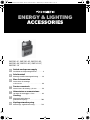 1
1
-
 2
2
-
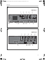 3
3
-
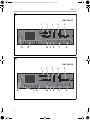 4
4
-
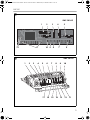 5
5
-
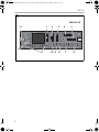 6
6
-
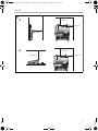 7
7
-
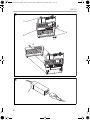 8
8
-
 9
9
-
 10
10
-
 11
11
-
 12
12
-
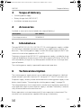 13
13
-
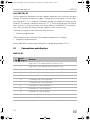 14
14
-
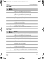 15
15
-
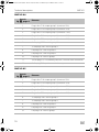 16
16
-
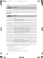 17
17
-
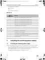 18
18
-
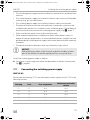 19
19
-
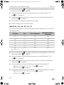 20
20
-
 21
21
-
 22
22
-
 23
23
-
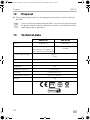 24
24
-
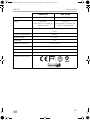 25
25
-
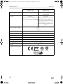 26
26
-
 27
27
-
 28
28
-
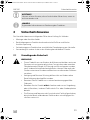 29
29
-
 30
30
-
 31
31
-
 32
32
-
 33
33
-
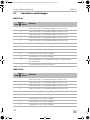 34
34
-
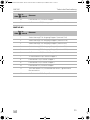 35
35
-
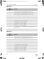 36
36
-
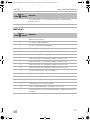 37
37
-
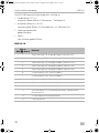 38
38
-
 39
39
-
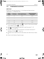 40
40
-
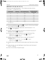 41
41
-
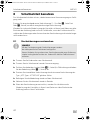 42
42
-
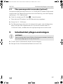 43
43
-
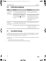 44
44
-
 45
45
-
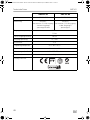 46
46
-
 47
47
-
 48
48
-
 49
49
-
 50
50
-
 51
51
-
 52
52
-
 53
53
-
 54
54
-
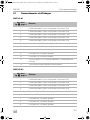 55
55
-
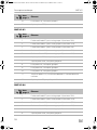 56
56
-
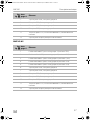 57
57
-
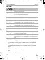 58
58
-
 59
59
-
 60
60
-
 61
61
-
 62
62
-
 63
63
-
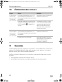 64
64
-
 65
65
-
 66
66
-
 67
67
-
 68
68
-
 69
69
-
 70
70
-
 71
71
-
 72
72
-
 73
73
-
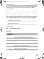 74
74
-
 75
75
-
 76
76
-
 77
77
-
 78
78
-
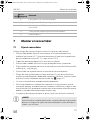 79
79
-
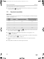 80
80
-
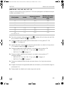 81
81
-
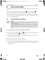 82
82
-
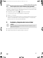 83
83
-
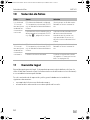 84
84
-
 85
85
-
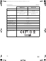 86
86
-
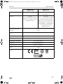 87
87
-
 88
88
-
 89
89
-
 90
90
-
 91
91
-
 92
92
-
 93
93
-
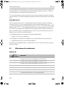 94
94
-
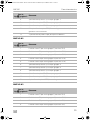 95
95
-
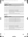 96
96
-
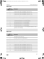 97
97
-
 98
98
-
 99
99
-
 100
100
-
 101
101
-
 102
102
-
 103
103
-
 104
104
-
 105
105
-
 106
106
-
 107
107
-
 108
108
-
 109
109
-
 110
110
-
 111
111
-
 112
112
-
 113
113
-
 114
114
-
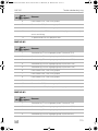 115
115
-
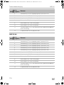 116
116
-
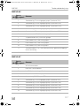 117
117
-
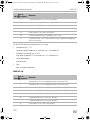 118
118
-
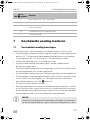 119
119
-
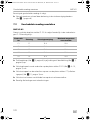 120
120
-
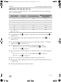 121
121
-
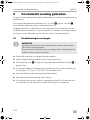 122
122
-
 123
123
-
 124
124
-
 125
125
-
 126
126
-
 127
127
-
 128
128
-
 129
129
-
 130
130
-
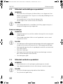 131
131
-
 132
132
-
 133
133
-
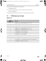 134
134
-
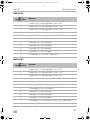 135
135
-
 136
136
-
 137
137
-
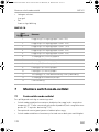 138
138
-
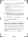 139
139
-
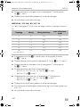 140
140
-
 141
141
-
 142
142
-
 143
143
-
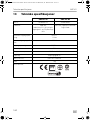 144
144
-
 145
145
-
 146
146
-
 147
147
-
 148
148


Dometic SMP301-01, SMP301-02, SMP301-03, SMP301-04, SMP301-05, SMP301-07, SMP301-10 Instrucciones de operación
- Tipo
- Instrucciones de operación
en otros idiomas
- français: Dometic SMP301-01, SMP301-02, SMP301-03, SMP301-04, SMP301-05, SMP301-07, SMP301-10 Mode d'emploi
- italiano: Dometic SMP301-01, SMP301-02, SMP301-03, SMP301-04, SMP301-05, SMP301-07, SMP301-10 Istruzioni per l'uso
- Deutsch: Dometic SMP301-01, SMP301-02, SMP301-03, SMP301-04, SMP301-05, SMP301-07, SMP301-10 Bedienungsanleitung
- Nederlands: Dometic SMP301-01, SMP301-02, SMP301-03, SMP301-04, SMP301-05, SMP301-07, SMP301-10 Handleiding
- dansk: Dometic SMP301-01, SMP301-02, SMP301-03, SMP301-04, SMP301-05, SMP301-07, SMP301-10 Betjeningsvejledning
Artículos relacionados
-
Dometic PLB40 Instrucciones de operación
-
Dometic CB-36, CB-40, CB-110, RHD-50 El manual del propietario
-
-
-
-
-
-
-
-
