Jøtul F 162 Installation And Operating Instructions Manual
- Categoría
- Chimeneas
- Tipo
- Installation And Operating Instructions Manual
Este manual también es adecuado para

Jøtul F 162 / Jøtul F 163
UK - Installation and Operating Instructions 4
FR - Manuel d’installation et d’utilisation 15
ES - Instrucciones para instalación 26
NL - Installatie- en montagehandleiding 37
PL - Instrukcja montażu i obsługi z danymi technicznymi 49
Jøtul F 162 / F 163
Manual Version P03
Manualene må oppbevares under hele produktets levetid. The manuals which are enclosed with the product must be kept throughout the product’s
entire service life. Les manuels fournis avec le produit doivent être conservés pendant toute la durée de vie du produit. Los manuales suministrados
con este producto deben guardarse durante todo el ciclo de vida del producto. I manuali inclusi con il prodotto vanno conservati per l’intera durata di
vita del prodotto. Das im Lieferumfang des Produkts enthaltene Begleitmaterial ist über die gesamte Nutzungsdauer aufzubewahren. De bij de haard
meegeleverde handleidingen moeten gedurende de volledige gebruiksduur van de haard bewaard blijven.
Jøtul F 162 Jøtul F 163

2
EU no. 215/1186 - 24/04/2015
'DWDVKHHW)LFKH7HFKQLTXH)LFKDWpFQLFD
6FKHGDGDWL'DWDVKHHW'DWHQEODWW'DQHWHFKQLF]QH
5HTXLUHPHQWV([LJHQFHV5HTXLVLWRV5HTXLVLWL
9HUHLVWHQ)RUGHUXQJHQ
6XSSOLHU
)DEULFDQWH
)RUQLWRUH
9HUHLVWHQ
/LHIHUDQW
3URGXFHQW
-¡WXO$6
3URGXFWPRGHOV
3URGXLWVFRQFHUQpV
0RGHORV
0RGHOOL
3URGXFWPRGHOOHQ
9DULDQWHQGHU)HXHUVWHOOH
0RGHOHSURGXNWX
-¡WXO)6HULHV
-¡WXO)
-¡WXO)
-¡WXO)
(QHUJ\HIILFLHQF\FODVV&ODVVHpQHUJpWLTXH&ODVHGH
HILFLHQFLDHQHUJpWLFD&ODVVHHQHUJHWLFD(QHUJLHHIILFLsQF\
NODVVH(QHUJLHHIIL]LHQ].ODVVH.ODVDHIHNW\ZQRĞFL
HQHUJHW\F]QHM
$
'LUHFWKHDWRXWSXW3XLVVDQFHUpHOOHGHVRUWLH3RWHQFLD
FDORULILFDHPLWLGD(PLVVLRQHGLFDORUHGLUHWWD'LUHFWHZDUPWH
DIJLIWH1HQQZlUPHOHLVWXQJ%H]SRĞUHGQLDPRFJU]HZF]D
N:
(QHUJ\HIILFLHQF\LQGH[,QGH[GHUHQGHPHQWpQpUJpWLTXH
ËQGLFHGHHILFLHQFLDHQHUJHWLFD,QGLFHGLHIILFLHQ]DHQHUJHWLFD
(QHUJLHHIILFLsQF\LQGH[(QHUJLHHIIL]LHQ],QGH[,QGHNV
HIHNW\ZQRĞFLHQHUJHW\F]QHM
(IILFLHQF\DWQRPLQDOKHDWRXWSXW5HQGHPHQWjSXLVVDQFH
QRPLQDOH(ILFLHQFLDDOUHQGLPLHQWRQRPLQDO(IILFLHQ]DDOOD
SRWHQ]DQRPLQDOH(IILFLHQF\ELMQRPLQDOHZDUPWHDIJLIWH /
:LUNXQJVJUDGEHL1HQQKHL]OHLVWXQJ6SUDZQRĞüGODPRF\
]QDPLRQRZHM
x $Q\VSHFLILFSUHFDXWLRQVWKDWVKDOOEHWDNHQZKHQWKHORFDO
VSDFHKHDWHULVDVVHPEOHGLQVWDOOHGRUPDLQWDLQHG
x 7RXWHVOHVSUpFDXWLRQVVSpFLILTXHVGRLYHQWrWUHSULVHVORUV
GHO¶DVVHPEODJHO¶LQVWDOODWLRQRXO¶HQWUHWLHQGHO¶DSSDUHLO
x &XDOTXLHUSUHFDXFLyQHVSHFtILFDTXHGHEDWHQHUVHHQ
FXHQWDGXUDQWHHOPRQWDMHLQVWDODFLyQRPDQWHQLPLHQWRGHO
HTXLSRGHFDOHIDFFLyQ
x 3UHFDX]LRQLVSHFLILFKHGDSUHQGHUHTXDQGRLOULVFDOGDWRUH
YLHQHDVVHPEODWRLQVWDOODWRRPDQWHQXWRLQXQRVSD]LR
x (YHQWXHOHVSHFLILHNHYRRU]RUJVPDDWUHJHOHQGLHZRUGHQ
JHQRPHQZDQQHHUGHSODDWVHOLMNHUXLPWHYHUZDUPLQJZRUGW
JHPRQWHHUGJHwQVWDOOHHUGRIRQGHUKRXGHQ
x %HVRQGHUH0DQDKPHQEHL0RQWLHUXQJ,QVWDOODWLRQXQG
:DUWXQJ
x :V]HONLHV]F]HJyOQHĞURGNLRVWURĪQRĞFLNWyUHQDOHĪ\
SRGMąüJG\ORNDOQ\RJU]HZDF]SRPLHV]F]HĔMHVW
]DPRQWRZDQ\OXENRQVHUZRZDQ\
x )LUHVDIHW\SUHFDXWLRQVVXFKDVVDIHW\GLVWDQFHVZKHQ
LQVWDOOLQJQDWLRQDOVWDQGDUGVORFDOFRGHVDQGUHJXODWLRQV
6HHWKH,QVWUXFWLRQVPDQXDO
x /HVSUpFDXWLRQVGLQFHQGLHWHOOHVTXHOHVGLVWDQFHVGH
VpFXULWpORUVGHOLQVWDOODWLRQOHVXLYLGHVQRUPHVOHVFRGHV
ORFDX[HWOHVUqJOHPHQWDWLRQVQDWLRQDOHV9HXLOOH]OLUHOH
PDQXHOG¶LQVWDOODWLRQ
x 3UHFDXFLRQHVIUHQWHDLQFHQGLRVFRPRGLVWDQFLDGHVHJXULGDG
HQ OD LQVWDODFLyQ HVWiQGDUHV QDFLRQDOHV FyGLJRV ORFDOHV \
UHJODPHQWRV/HDHOPDQXDOGHLQVWDODFLyQ
x 3UHFDX]LRQLSHUODVLFXUH]]DDQWLQFHQGLRFRPHOHGLVWDQ]HGL
VLFXUH]]DGXUDQWHOLQVWDOOD]LRQHOHQRUPDWLYHQD]LRQDOLHORFDOL
/HJJHUHLOPDQXDO
x %UDQGYHLOLJKHLGVPDDWUHJHOHQ]RDOVYHLOLJKHLGVDIVWDQGHQELM
LQVWDOODWLHQDWLRQDOHQRUPHQORNDOHFRGHVHQYRRUVFKULIWHQ
/HHVௗGHLQVWDOODWLHKDQGOHLGLQJ
x )UEUHQQWHFKQLVFKH9HUKlOWQLVVHZLH]%
$XIVWHOOEHGLQJXQJHQXQGQDWLRQDOH)RUGHUXQJHQ6LHKHGLH
0RQWDJHXQG%HGLHQXQJVDQOHLWXQJ
x ĝURGNLEH]SLHF]HĔVWZDSU]HFLZSRĪDURZHJRWDNLHMDN
RGOHJáRĞFLRGPDWHULDáyZSDOQ\FKMDNLHQDOHĪ\]DFKRZDü
SRGF]DVLQVWDODFMLQRUP\NUDMRZHORNDOQHSU]HSLV\L
UHJXODFMH3DWU]LQVWUXNFMDREVáXJL

3
EU no. 215/1186 - 24/04/2015
'DWDVKHHW)LFKH7HFKQLTXH)LFKDWpFQLFD
6FKHGDGDWL'DWDVKHHW'DWHQEODWW'DQHWHFKQLF]QH
5HTXLUHPHQWV([LJHQFHV5HTXLVLWRV5HTXLVLWL
9HUHLVWHQ)RUGHUXQJHQ:\PDJDQLD
6XSSOLHU
)DEULFDQWH
)RUQLWRUH
9HUHLVWHQ
/LHIHUDQW
3URGXFHQW
-¡WXO$6
3URGXFWPRGHOV
3URGXLWVFRQFHUQpV
0RGHORV
0RGHOOL
3URGXFWPRGHOOHQ
9DULDQWHQGHU)HXHUVWHOOH
0RGHOHSURGXNWX
-¡WXO)6HULHV
-¡WXO)
-¡WXO)
-¡WXO)
(QHUJ\HIILFLHQF\FODVV&ODVVHpQHUJpWLTXH&ODVHGH
HILFLHQFLDHQHUJpWLFD&ODVVHHQHUJHWLFD(QHUJLHHIILFLsQF\
NODVVH(QHUJLHHIIL]LHQ].ODVVH.ODVDHIHNW\ZQRĞFL
HQHUJHW\F]QHM
$
'LUHFWKHDWRXWSXW3XLVVDQFHUpHOOHGHVRUWLH3RWHQFLD
FDORULILFDHPLWLGD(PLVVLRQHGLFDORUHGLUHWWD'LUHFWHZDUPWH
DIJLIWH1HQQZlUPHOHLVWXQJ%H]SRĞUHGQLDPRFJU]HZF]D
N:
(QHUJ\HIILFLHQF\LQGH[,QGH[GHUHQGHPHQWpQpUJpWLTXH
ËQGLFHGHHILFLHQFLDHQHUJHWLFD,QGLFHGLHIILFLHQ]DHQHUJHWLFD
(QHUJLHHIILFLsQF\LQGH[(QHUJLHHIIL]LHQ],QGH[,QGHNV
HIHNW\ZQRĞFLHQHUJHW\F]QHM
(IILFLHQF\DWQRPLQDOKHDWRXWSXW5HQGHPHQWjSXLVVDQFH
QRPLQDOH(ILFLHQFLDDOUHQGLPLHQWRQRPLQDO(IILFLHQ]DDOOD
SRWHQ]DQRPLQDOH(IILFLHQF\ELMQRPLQDOHZDUPWHDIJLIWH /
:LUNXQJVJUDGEHL1HQQKHL]OHLVWXQJ6SUDZQRĞüGODPRF\
]QDPLRQRZHM
x $Q\VSHFLILFSUHFDXWLRQVWKDWVKDOOEHWDNHQZKHQWKHORFDO
VSDFHKHDWHULVDVVHPEOHGLQVWDOOHGRUPDLQWDLQHG
x 7RXWHVOHVSUpFDXWLRQVVSpFLILTXHVGRLYHQWrWUHSULVHVORUV
GHO¶DVVHPEODJHO¶LQVWDOODWLRQRXO¶HQWUHWLHQGHO¶DSSDUHLO
x &XDOTXLHUSUHFDXFLyQHVSHFtILFDTXHGHEDWHQHUVHHQ
FXHQWDGXUDQWHHOPRQWDMHLQVWDODFLyQRPDQWHQLPLHQWRGHO
HTXLSRGHFDOHIDFFLyQ
x 3UHFDX]LRQLVSHFLILFKHGDSUHQGHUHTXDQGRLOULVFDOGDWRUH
YLHQHDVVHPEODWRLQVWDOODWRRPDQWHQXWRLQXQRVSD]LR
x (YHQWXHOHVSHFLILHNHYRRU]RUJVPDDWUHJHOHQGLHZRUGHQ
JHQRPHQZDQQHHUGHSODDWVHOLMNHUXLPWHYHUZDUPLQJZRUGW
JHPRQWHHUGJHwQVWDOOHHUGRIRQGHUKRXGHQ
x %HVRQGHUH0DQDKPHQEHL0RQWLHUXQJ,QVWDOODWLRQXQG
:DUWXQJ
x :V]HONLHV]F]HJyOQHĞURGNLRVWURĪQRĞFLNWyUHQDOHĪ\
SRGMąüJG\ORNDOQ\RJU]HZDF]SRPLHV]F]HĔMHVW
]DPRQWRZDQ\OXENRQVHUZRZDQ\
x )LUHVDIHW\SUHFDXWLRQVVXFKDVVDIHW\GLVWDQFHVZKHQ
LQVWDOOLQJQDWLRQDOVWDQGDUGVORFDOFRGHVDQGUHJXODWLRQV
6HHWKH,QVWUXFWLRQVPDQXDO
x /HVSUpFDXWLRQVGLQFHQGLHWHOOHVTXHOHVGLVWDQFHVGH
VpFXULWpORUVGHOLQVWDOODWLRQOHVXLYLGHVQRUPHVOHVFRGHV
ORFDX[HWOHVUqJOHPHQWDWLRQVQDWLRQDOHV9HXLOOH]OLUHOH
PDQXHOG¶LQVWDOODWLRQ
x 3UHFDXFLRQHVIUHQWHDLQFHQGLRVFRPRGLVWDQFLDGHVHJXULGDG
HQ OD LQVWDODFLyQ HVWiQGDUHV QDFLRQDOHV FyGLJRV ORFDOHV \
UHJODPHQWRV/HDHOPDQXDOGHLQVWDODFLyQ
x 3UHFDX]LRQLSHUODVLFXUH]]DDQWLQFHQGLRFRPHOHGLVWDQ]HGL
VLFXUH]]DGXUDQWHOLQVWDOOD]LRQHOHQRUPDWLYHQD]LRQDOLHORFDOL
/HJJHUHLOPDQXDO
x %UDQGYHLOLJKHLGVPDDWUHJHOHQ]RDOVYHLOLJKHLGVDIVWDQGHQELM
LQVWDOODWLHQDWLRQDOHQRUPHQORNDOHFRGHVHQYRRUVFKULIWHQ
/HHVௗGHLQVWDOODWLHKDQGOHLGLQJ
x )UEUHQQWHFKQLVFKH9HUKlOWQLVVHZLH]%
$XIVWHOOEHGLQJXQJHQXQGQDWLRQDOH)RUGHUXQJHQ6LHKHGLH
0RQWDJHXQG%HGLHQXQJVDQOHLWXQJ
x ĝURGNLEH]SLHF]HĔVWZDSU]HFLZSRĪDURZHJRWDNLHMDN
RGOHJáRĞFLRGPDWHULDáyZSDOQ\FKMDNLHQDOHĪ\]DFKRZDü
SRGF]DVLQVWDODFMLQRUP\NUDMRZHORNDOQHSU]HSLV\L
UHJXODFMH3DWU]LQVWUXNFMDREVáXJL

4
Table of contents
Installation manual with technical data
1.0 Relationship to the authorities ..............................4
2.0 Technical data .........................................................4
3.0 Safety .......................................................................7
4.0 Installation ..............................................................8
5.0 Daily use ................................................................11
6.0 Service ...................................................................12
7.0 Maintenance ..........................................................13
8.0 Operational problems - troubleshooting.............13
9.0 Optional Equipment .............................................14
10.0 Recycling ...............................................................14
11.0 Guarantee terms ....................................................14
On all our products there is a label
indicating the serial number and year. Write
this number in the place indicated in the
installation instructions.
Always quote this serial number when
contacting your retailer or Jøtul.
les combustibles recommandés.
Respectez les consignes d'utilisation. Utilisez uniquement
Verwenden Sie nur empfohlenen Brennstoffen.
Montage- und Bedienungsanleitung beachten.
Follow user`s instructions. Use only recommended fuels.
standard
Certificate/
The appliance can be used in a shared flue.
Minimum distance to adjacent combustible materials:
Emission of CO in combustion products
Serial no: Y-xxxx, Year: 200x
Manufacturer:
N-1602 Fredrikstad
Norway
Jøtul AS
POB 1441
Sweden
EUR Intermittent
Nominal heat output
Norway
Country
Operational type
Fuel type
Operation range
Efficiency
Klasse II
Classification
Standard
Flue gas temperature
Room heater fired by solid fuel
Product:
Jøtul
SP Sveriges Provnings- och
221546
Forskningsinstitut AB
SP Swedish National
Testing and Research
Institute
:
Approved by
:
:
:
:
:
:
:
Minimum distance to adjacent combustible materials:
OGC SP
EN
Serial no.
1.0 Relationship to the
authorities
Installation of a fireplace must be according to local codes and
regulations in each country.
All local regulations, including those that refer to national and European
standards, shall be complied with when installing the product.
Before use read the Installation and Operating Instructions
carefully. Prior to using the product the installation must be
inspected by a qualifi ed person.
A name plate of heat-resistant material is affi xed to the product
on the underside of the burnchamber (Fig. 3 B). This contains
information about identifi cation and documentation for the
product.
2.0 Technical data
Jøtul F 162 Jøtul F 163
Material: Cast iron Cast iron
Finish: Paint Paint/enamel
Fuel: Wood Wood
Log length, max: 33 cm 33 cm
Flue outlet: Top/rear Top/rear
Flue pipe dimension: Ø150 mm Ø150 mm
Weight: 115 kg 115 kg
Optional equipment: Cover for rear leg, Cover for rear leg,
soapstone top soapstone top
Dimensions, distances: See fi g. 1 See fi g. 1
Technical data according to EN 13240
Jøtul F 162 Jøtul F 163
Nominal heat output: 5 kW 5 kW
Flue gas mass fl ow: 5,0 g/s 5,0 g/s
Recommended
chimney draught: 12 Pa 12 Pa
Effi ciency: 83%@5,9 kW 82%@5,9 kW
CO emission (13% O2): 0,06% 0,10%
CO emission (13% O2): 792 mg/Nm3 1242 mg/Nm3
Flue gas temperature: 260o C 260o C
Operational type: Intermittent Intermittent
Intermittent combustion is here taken to mean normal use of a fi replace.
I.e. that a new fl ame chamber is lit as soon as the fuel has burnt down
to the appropriate quantity of embers.
ENGLISH
Register your fi replace at jotul.com for a
25-year warranty.

5
ENGLISH
300
903
Fig. 1a
Combustible wall
900061-P09
Min. distance to combustible wall
Jøtul F 162 / Jøtul F 163
925
700
1000
200
*150412
*362 647
*592
972
*831
1207
*1066
687
*587
500
*400
Y
X
235
93
450
447
119
100
789
603
Hole in wall for external air
Ø 100 mm
Hole in floor for external air
Ø 100 mm
Min. measurements floor plate X,Y =
According to national standards
and regulations. See chapter 4.1 * With semi-insulated chimney / covered flue pipe down
towards the product.


7
Air supply
The outside air connection may be fi tted directly to the product
through:
• Through a fl exible supply hose from the outside or chimney
(only if the chimney has its own duct for external air) and to
the product’s outside air connector.
Fig. 2a, through an outside wall
Important! The knockout for the outside air connection must be removed
from the inside. Use safety goggles.
Tip: It is a great advantage if the rear leg is dismounted before
removing the knockout.
1. Lay the product carefully down on its side. You can put
the cardboard packaging on the fl oor to protect it from
scratches, etc.
2. Remove the rear leg.
3. Use a heavy mallet and strike hard in the middle of the
knockout.
Fig. 2b, through the fl oor and ground plate
Fig. 2c, through the fl oor and basement
Fig. 2d, indirectly through an outside wall
3.0 Safety
NB! To guarantee optimal performance and safety, Jøtul stoves must
be fi tted by a qualifi ed installer.
Any modifi cations to the product by the distributor, installer or
consumer may result in the product and safety features not
functioning as intended. The same applies to the installation of
accessories or optional extras not supplied by Jøtul. This may
also be the case if parts that are essential to the functioning and
safety of the fi replace have been disassembled or removed.
In all these cases, the manufacturer is not responsible or liable
for the product and the right to make a complaint becomes null
and void.
3.1 Fire Prevention Measures
There is a certain element of danger every time you use your
fi replace. The following instructions must therefore be followed:
• The minimum safety distances when installing and using
the fi replace are given in fi g. 1.
• Ensure that furniture and other fl ammable materials are not
too close to the fi replace. Flammable materials should not
be placed within 1 metre of the fi replace.
• Allow the fi re to burn out. Never extinguish the fl ames with
water.
• The fi replace becomes hot when lit and may cause burns
if touched.
• Only remove ash when the fireplace is cold. Ash can
contain hot embers and should therefore be placed in a
non-fl ammable container.
• Ash should be placed outdoors or be emptied in a place
where it will not present a potential fi re hazard.
ENGLISH

8
In case of chimney fi re:
• Close all hatches and vents.
• Keep the fi rebox door closed.
• Check the loft and cellar for smoke.
• Call the fi re service.
• Before use after a fi re an expert must check the fi replace
and the chimney in order to ensure that it is fully functional.
4.0 Installation
N.B. Check that the fi replace is free of any damage prior to
commencing installation.
The product is heavy! Make sure you have assistance when
erecting and installing the fi replace.
4.1 Floor
Foundations
Ensure that the fl oor is strong enough for the fi replace. See
«2.0 Technical data» for weights. It is recommended that fl ooring
which is not fastened to the foundations – so-called fl oating
fl ooring – is removed during installation.
Combustible fl oor protection
If the fi replace is to be mounted on a combustible fl oor, cover
the fl oor under and in front of the fi replace with a plate of metal
or other non- combustible material. The recommended minimum
thickness is 0,9 mm.
Jøtul recommends that any fl ooring made of combustible
material, such as linoleum, carpets, etc. should be removed
from under the fl oor plate.
The plate must be in accordance with national laws and
regulations.
Contact your local building authority regarding restrictions and
installation requirements.
4.2 Walls (fi g. 1a)
Distance to wall made of combustible
material
You may use the fi replace with an uninsulated fl ue pipe provided
the distances to walls made of combustible materials are as
shown in fi g. 1.
Distance to wall with insulated fl ue pipe: Se fi g. 1.
Distance to walls covered by a fi rewall
(fi g. 1b and fi g. 1c)
Contact your local building authority regarding restrictions and
installation requirements.
Firewall requirement
The fi rewall must be at least 100 mm thick and be made of
brick, concrete-stone or light concrete. Other materials and
constructions with satisfactory documentation may also be used.
Distance to non combustible walls
By non combustible one means a non load-bearing wall of solid
brickwork/concrete.
Contact your local building authority regarding restrictions and
installation requirements.
4.3 Chimneys and fl ue pipes
• The fi replace can be connected to a chimney and fl ue
pipe approved for solid fuel fi red appliances with fl ue gas
temperatures specifi ed in «2.0 Technical data».
• The chimney’s cross-section must be at least as big as
the fl ue pipe’s cross-section. See «2.0 Technical data» when
calculating the correct chimney cross-section.
• Several solid fuel fi red appliances can be connected to the
same chimney if the chimney’s cross-section is suffi cient.
• Connection to the chimney must be carried out in accordance
with the installation instructions from the supplier of the
chimney.
• Before making a hole in the chimney the fi replace should be
test-mounted in order to correctly mark the position of the
fi replace and the hole in the chimney. See fi g. 1 for minimum
dimensions.
• Ensure that the fl ue pipe is inclined all the way up to the
chimney.
• Use a fl ue pipe bend with a sweeping hatch that allows it to
be swept.
Be aware of the fact that it is particularly important that
connections have a certain flexibility in order to prevent
movement in the installation leading to cracks.
N.B. A correct and sealed connection is very important for
the proper functioning of the product.
Chimney draught; See «2.0 Technical data». If the draught
is too strong you can install and operate a fl ue damper to
control the draught.
4.4 Assembly prior to installation
The product is delivered in a single packing case.
After unpacking the stove check that the stove is free of any
damage and that the regulating handles works.
ENGLISH

9
ENGLISH
4.5 Selfclosing doormechanism
The product is delivered with a selfclosing doormechanism. If
wanted this can be removed.
Fig. 3
g
g
A
B
1. Unscrew the screw and nut (fi g. 3 A).
2. Unhook and remove the spring.
4.6 Fitting the fl ue pipe with the rear
outlet
The product is supplied from the factory with the smoke outlet
fi tted for the top outlet.
NB! Proceed as follows for installation with a rear outlet:
Fig. 4
1. Lift the baffl e (Fig. 4 A) up carefully.
2. Remove one of the side burn plates by lifting them up a
little and then out. (Be aware if using tools, that vermiculite
plates may be damaged by rough handling).
3. Remove the baffl e.
4. Remove the other side burn plate.
5. Remove the exhaust defl ectors (Fig. 4 B).
Fig. 5
6. Unscrew the screws (fi g. 5 A) and remove the smoke outlet
(fi g. 5 B) from the top outlet from the inside of the burn
chamber.
Fig. 6a
7. Unscrew the screws (fi g. 6a C) and remove the cover (fi g. 6a
B) from the rear outlet from the inside of the burn chamber.

10
Fig. 6b
8. Knock out the removable cover plates (fi g. 6b A).
9. Attach the smoke outlet (fi g. 6a A) on the inside of the burn
chamber where the cover was.
10. Install the cover (fi g. 6a B) where the smoke outlet was.
11. Refi t the exhaust defl ectors (fi g. 4 B) and the baffl e plate
(fi g. 4 A).
4.7 Control of functions
When the product is set up, always check the control functions.
These shall move easily and function satisfactorily.
Jøtul F 162 and F 163 are equipped with the following control:
Ignition vent/air vent
Ignition
Fig. 7a
• Open the ignition vent and air vent by pulling the handle all
the way out. (Use a glove or something similar to protect
your hand in case the handles are hot.)
• Place two logs at the bottom of the burn chamber and pile
the kindling in layers.
• Finally, place a medium-sized log on the top of the pile.
• Place 2 or 3 briquettes or kindling sticks under the top layer
of kindling and light the fi re.
Heating
Fig. 7b
• Leave the ignition-/air vent 24 mm (fi g. 7 B) open when the
wood has caught fi re properly and is burning well.
• Close the door.
• You can then regulate the rate of combustion to give the
heat you want by adjusting the air vent.
• Check that the afterburning (secondary combustion) starts.
This is best indicated by yellow, fl ickering fl ames in front of
the holes under the baffl e.
Adding fi rewood
Stoke the stove frequently but only add small amounts of fuel at
a time. If the stove is fi lled too full, the heat created may cause
extreme stress in the chimney. Add fuel to the fi re in moderation.
Avoid smouldering fi res as this produces the most pollution.
The fi re is best when it is burning well and the smoke from the
chimney is almost invisible.
ENGLISH

11
ENGLISH
4.7 Danger of overheating
The fi replace must never be used in a
manner that causes overheating
Overheating occurs when there is too much fuel and/or too much
air so that too much heat develops. A sure sign of overheating
is when parts of the fi replace glow red. If this happens, reduce
the air vent opening immediately.
Seek professional advice if you suspect that the chimney is
not drawing properly (too much/too little draught). For further
information, see «4.0 Installation» (Chimney and fl ue pipe).
5.0 Daily use
Odours when using the fi replace for the
fi rst time
When the fi replace is used for the fi rst time, it may emit an
irritating gas which may smell slightly. This happens because
the paint dries.The gas is not toxic but the room should be
thoroughly ventilated. Let the fi re burn with a high draught until
all traces of the gas have disappeared and no smoke or odours
can be detected.
5.1 Operation
Heating advice
NB: Logs that have been stored outdoors or in a cold room
should be brought indoors 24 hours before use to bring them
up to room temperature.
There are various ways of heating the stove but it is always
important to be careful about what you put in the stove. See
the section on “Wood quality”.
Wood quality
By quality wood we mean most well-known types of wood such as
birch, spruce and pine.
The logs should be dried so that the moisture content is no
more than 20%.
To achieve this, the logs should be cut during the late winter.
They should be split and stacked in a way that ensures good
ventilation. The wood stacks should be covered to protect the
logs from rain. The logs should be brought indoors during early
autumn and stacked/stored for use in the coming winter.
Be especially careful never to use the following materials as fuel in
your fi replace:
• Household rubbish, plastic bags, etc.
• Painted or impregnated timber (which is extremely toxic).
• Laminated wooden planks.
• Driftwood
These may harm the product and are also pollutants.
NB: Never use petrol, paraffi n, methylated spirit or similar liquids to
light the fi re. You may cause serious injury to yourself and damage to
the product.
Wood consumption
Use of wood, with nominal heat emission: Approx. 1,6 kg/h.
Another important factor for proper fuel consumption is that
the logs are the correct size. The size of the logs should be:
Kindling:
Length: 23-33 cm
Diameter: 2 - 5 cm
Amount per fi re: 6 - 8 pieces
Daily use
Firewood (split logs):
Length: 23 - 33 cm
Diameter: Approx. 8 cm
Intervals for adding wood: Approximately every 45 minutes
Size of the fi re: 1,2 kg
Amount per load: 2 pieces
Nominal heat output and effi ciency are based on heating with
total 1,15 kg beech (2 logs). The air vent was pulled out 24 mm.
Nominal heat emission is achieved when the air vent is open
approximately 60 %.
Maximum use
Max. load: 2,9 kg/h (max. 3 pieces per load /2,2 kg per load)

12
5.2 Ash removal
Jøtul F 162 / F 163 have an ash pan which makes it easy to
remove the ash.
Fig. 8
1. Scrape the ash through the grate (fi g. 8 A) in the base plate
and into the ash pan. Use a glove to grab the handle on
the ash pan.
1. Make sure that the ash pan doesn’t fi ll up so high that it
keeps ash from coming through the grate into the pan.
6.0 Service
Warning! Any unauthorised change to the product is not allowed.
Only use original spare parts.
6.1 Changing the burn plates/inner
bottom plate
Fig.9
1. Lift the baffl e (Fig. 9 A) up carefully.
2. Remove one of the side burn plates (Fig. 9 E) by lifting
them up a little and then out. (Be aware if using tools, that
vermiculite plates may be damaged by rough handling).
3. Remove the baffl e.
4. Remove the other side burn plate.
5. Unscrew the M8x25 mm screw on the rear burn plate (Fig.
9 F) and remove the burn plate.
6. Then lift up and remove the inner bottom plate (Fig. 9 C).
Follow the same procedure for installation, but in the opposite
sequence.
ENGLISH

13
ENGLISH
6.2 Changing the baffl e plate
• Follow step 1 -3 under Fig. 9.
• Access is then easy to the smoke defl ectors (Fig. 9 B) if they
need to be removed. They are situated on 1 knob on the
side and on the air manifold (fi g. 9 D).
• Edge them down and remove them through the door.
For re-installation follow the same procedure in the opposite
sequence.
7.0 Maintenance
7.1 Cleaning the glass
The product is equipped with an air wash for the glass. Air is
sucked in through the air vent on the top of the product and
down along the inside of the glass.
However, some soot will always stick to the glass, but the
quantity will depend on the local draught conditions and
adjustment of the air vent. Most of the soot layer will normally
be burned off when the air vent is opened all the way and a fi re
is burning briskly in the fi replace.
Good advice! For normal cleaning, moisten a paper towel
with warm water and add some ash from the burn chamber.
Rub it over the glass and then clean the glass with clean water.
Dry well. If it is necessary to clean the glass more thoroughly
we recommend using a glass cleaner (follow the instructions
on the bottle).
7.2 Cleaning and soot removal
Soot deposits may build up on the internal surfaces of the
fi replace during use. Soot is a good insulator and will therefore
reduce the fi replace’s heat output. If soot deposits accumulate
when using the product, they can easily be removed by using
a soot remover.
In order to prevent a water and tar layer from forming in the
fi replace, you should regularly allow the fi re to burn hot in order
to remove the layer. An annual internal cleaning is necessary to
get the best heating eff ect from your product. It is a good idea
to do this when cleaning the chimney and fl ue pipes.
7.3 Sweeping fl ue pipes to the
chimney
Flue pipes must be swept through the fl ue pipe sweeping hatch
or through the door opening.
One of the baffl es will have to be removed fi rst in order to do this.
7.4 Inspection of the fi replace
Jøtul recommends that you carefully inspect your fi replace
yourself after it has been swept/cleaned. Check all visible
surfaces for cracks. Also check that all joints are sealed and
that the gaskets are in the correct position. Any gaskets showing
signs of wear or deformation must be replaced.
Thoroughly clean the gasket grooves, apply ceramic glue
(available from your local Jøtul dealer) and press the gasket
well into place. The joint will dry quickly.
7.4 Exterior maintenance
Painted products may change colour after several years’ usage.
The surface should be cleaned and brushed free of any loose
particles before new paint is applied.
8.0 Operational problems -
troubleshooting
Poor draught
Check the length of the chimney and that it complies with
national laws and regulations. (See also «2.0 Technical
data» and «4.0 Installation» (Chimney and fl ue pipe) in the
installation manual for information.)
Make sure that the minimum cross section on the chimney is
according to «2.0 Technical data» in the installation manual.
Make sure that there is not anything preventing the smoke
gasses from escaping: branches, trees, etc.
Upon suspicion of excessive/poor draught in the chimney,
seek professional help for measurement and adjustment.
The fi re extinguishes after a while
• Make sure that the fi rewood is suffi ciently dry.
• Find out whether there is negative pressure in the house,
close mechanical fans and open a window close to the
fi replace.
• Check that the air vent is open.
• Check that the fl ue outlet is not clogged by soot.
Unusual amount of soot accumulates on
the glass
Some soot will always stick to the glass, but the quantity
depends on:
• Moisture in the fuel.
• The local draught conditions.
• Air vent opening.
Most of the soot will normally burn off when the air vent is
opened all the way and a fi re is burning briskly in the fi replace.
(See «7.1 Cleaning the glass».)

14
9.0 Optional equipment
9.1 Leg cover - outside air connection
Cat. no. 51012329
9.2 Soapstone top - 50 mm, complete
Cat. no. 51012327
10.0 Recycling
10.1 Recycling packaging
Your fi replace is delivered with the following packaging:
• A wooden pallet that can be cut up and burned in the
fi replace.
• Cardboard packaging that should be taken to a local
recycling facility.
• Plastic bags that should be taken to a local recycling facility.
10.2 Recycling the fi replace
The fi replace is made of:
• Metal that should be taken to a local recycling facility.
• Glass that should be disposed of as hazardous waste.
The glass in the fi replace must not be placed in a regular
source segregation container.
• Vermiculite burn plates that can be disposed of in regular
waste containers.
ENGLISH
11.0 Guarantee terms
1. Our guarantee covers:
Jøtul AS guarantees that the external cast-iron parts are
free from defects in materials or manufacturing at the time of
purchase. You may extend the guarantee on the external cast-
iron parts to 25 years from the date of delivery by registering
the product on jotul.com, and print out the extended guarantee
card within three months of purchase. We recommend that
the guarantee card be kept together with the receipt. Jøtul AS
also guarantees that steel plate parts are free from defects in
materials or manufacturing at the time of purchase for a period
of 5 years from the date of delivery.
The guarantee applies on the condition that the stove has been
installed by a qualifi ed installer in accordance with applicable
laws and regulations and Jøtul’s installation and operating
instructions. Repaired products and replacement items are
guaranteed within the original guarantee period.
2. The guarantee does not cover:
2.1. Damage to consumables such as burn plates, fi re grates,
fl ue baffl es, gaskets and similar as these deteriorate over
time due to normal wear and tear.
2.2. Damage caused as a result of improper maintenance,
overheating, use of unsuitable fuel (e.g of unsuitable fuel
are, but not limited to driftwood, impregnated wood, plank
off cuts, chipboard ) or too moist / wet wood.
2.3. Installation of optional extras for the purpose of rectifying
local draught conditions, air supply or other circumstances
beyond Jøtul’s control.
2.4. Cases involving alterations / modifi cations to the fi replace
without Jøtul’s consent or the use of non-original parts.
2.5. Damage caused during storage at a distributor, transport
from a distributor or during installation.
2.6. Products sold by unauthorized sellers in areas where
Jøtul operates a selective distribution system.
2.7. Associated cost (e.g.but not limited to, transport,
manpower, travel) or indirect damages.
Pellets stoves, glass, stone, concrete, enamel and paint
fi nish (e.g. but not limited to chipping, cracking, bubbling or
discolouration and crazing) are applicable to the national
legislation governing the sale of consumer goods. This
guarantee is valid for purchases made within the territory of
the European Economic Area. All guarantee inquiries must
be addressed to your local authorized Jøtul dealer within a
reasonable amount of time, which shall not be later than 14
days from the date on which the fault or defect fi rst became
apparent. See list of importers and dealers on our web site
www.jotul.com.
If Jøtul is unable to meet the obligations outlined in the above
guarantee terms, Jøtul will off er a replacement product with a
similar heating capacity free of charge.
Jøtul reserve the right to decline of any replacement of parts
or service in the event that the guarantee is not registrated
online. This guarantee does not aff ect any rights under
applicable national legislation governing the sale of consumer
goods. The national complaint right applies from the purchase
date and only in exchange for a receipt / serial number.

15
Table des matières
Manuel d’installation et données techniques
1.0 Relations avec les autorités ...............................15
2.0 Caractéristiques techniques .............................15
3.0 Sécurité ................................................................18
4.0 Installation ..........................................................19
5.0 Utilisation au quotidien ......................................22
6.0 Entretien ...............................................................23
7.0 Maintenance ........................................................24
8.0 Dysfunctionnements - Causes et dépannages .....24
9.0 Équipements en option ....................................25
10.0 Recyclage ............................................................25
11.0 Conditions de garantie .......................................25
Tous nos produits sont fournis avec une
étiquette indiquant le numéro de série et
l’année. Reportez ce numéro à l’endroit
indiqué dans les instructions d’installation.
Mentionnez toujours ce numéro lorsque
vous contactez votre revendeur ou Jøtul.
les combustibles recommandés.
Respectez les consignes d'utilisation. Utilisez uniquement
Verwenden Sie nur empfohlenen Brennstoffen.
Montage- und Bedienungsanleitung beachten.
Follow user`s instructions. Use only recommended fuels.
standard
Certificate/
The appliance can be used in a shared flue.
Minimum distance to adjacent combustible materials:
Emission of CO in combustion products
Serial no: Y-xxxx, Year: 200x
Manufacturer:
N-1602 Fredrikstad
Norway
Jøtul AS
POB 1441
Sweden
EUR Intermittent
Nominal heat output
Norway
Country
Operational type
Fuel type
Operation range
Efficiency
Klasse II
Classification
Standard
Flue gas temperature
Room heater fired by solid fuel
Product:
Jøtul
SP Sveriges Provnings- och
221546
Forskningsinstitut AB
SP Swedish National
Testing and Research
Institute
:
Approved by
:
:
:
:
:
:
:
Minimum distance to adjacent combustible materials:
OGC SP
EN
Serial no.
1.0 Relations avec les autorités
L’Installation d’ un poêle doit être conforme aux codes du bâtiment et
régulations locales de chaque pays.
Toutes les régulations locales, y compris celles relatives aux normes
nationales et européennes, devront être respectées au moment
d’installer l’appareil.
Veuillez lire attentivement le manual d’installation et d’utilisation
avant de procéder à l’installation. Avant toute mise en service
de l’appareil, l’installation devra avoir été agréée par un
professionnel qualifi é, suivant les pays..
Une plaque signalétique thermorésistante se trouve sur le
bouclier thermique, sous l’appareil (fi g. 3 B). Elle comporte les
informations suivantes : fabricant, adresse, nom du produit,
référence catalogue, norme de fabrication, référence de
production et puissance.
2.0 Données techniques
Jøtul F 162 Jøtul F 163
Matériau : Fonte Fonte
Finition : Peinture Peinture/email
Combustible : Bois exclusivement Bois
exclusivement
Longueur max.
des bûches : 33 cm 33 cm
Sortie de fumée : Dessus/ derrière dessus/dessrière
Conduit de
raccordement : Ø 150 mm Ø 150 mm
Poids : 115 kg 115 kg
Équipements en option : Cache pour Cache pour
pied arrière, pied arrière,
dessus en pierre dessus en pierre
ollaire : complet ollaire : complet
Dimensions, distances : Voir fi g. 1 Voir fi g. 1
Données techniques conformes à la norme EN 13240 :
Jøtul F 162 Jøtul F 163
Puissance nominale : 5 kW 5 kW
Débit massique
des fumées: 5,0 g/s 5,0 g/s
Tirage de cheminée
recommandé : 12 Pa 12 Pa
Rendement : 83%@5,9 kW 82%@5,9 kW
Émissions CO (13 % O2): 0,06% 0,10%
Émissions CO (13 % O2): 792 mg/Nm3
1242 mg/Nm3
Température des
gaz de fumées : 260o C 260o C
Mode de fonctionnement : Intermittent Intermittent
“Combustion intermittente” signifi e ici une utilisation normale
de la cheminée, c’est-à-dire qu’une nouvelle fl ambée est initiée
dès que le combustible a été réduit à la quantité de braises
appropriée.
Enregistrez votre insert sur jotul.com
pour la garantie de 25 ans.
FRANCAIS

16
300
903
Fig. 1a
900061-P09
Jøtul F 162 / Jøtul F 163
925
700
1000
200
*150412
*362 647
*592
972
*831
1207
*1066
687
*587
500
*400
Y
X
235
93
450
447
119
100
789
603
Trous dans le mur pour air extérieur.
Ø100mm de raccords
Trous dans le sol pour
air extérieur.
Ø100mm de raccords
Dimensions minimales de la
plaque de sol X/Y = Conformes
aux lois et règlements en vigueur. * Avec cheminée semi-isolée/conduit de fumée isolé
complètement appuyé contre le produit.
Espace minimum par rapport à un mur combustible :
Mur en matériau
combustible
FRANCAIS

17
FRANCAIS
Externe
Intégré
Distance minimale par rapport au mur en matériau combustible protégé par un pare-feu
Jøtul F 162 / Jøtul F 163
Mur en matériau
combustible
Mur
ininammable
1000
1000
525
300
312
100
547
1050
1100
100
312
547
300
525
900
100
312
1000
1050
312
100
1000
800
800
712
477
150
337
900
900
900061-P09
712
477
150
337
Fig. 1b

18
Arrivée d’air
L’arrivée d’air frais peut être raccordée directement au poêle
Jøtul F 162 / Jøtul F 163 par :
• Un tuyau flexible depuis l’extérieur ou la cheminée
(seulement si celle-ci dispose d’une conduite propre pour
l’air frais) et vers le raccord d’air frais de l’appareil.
Fig. 2a, par un mur
Important ! Veuillez toujours frapper depuis l’intérieur du pied. Portez
des lunettes de sécurité contre les éclats de fonte.
Astuce : il est préférable de démonter le pied arrière pour ouvrir
le passage de gaine.
1. Coucher le poele sur un côté. vous pouvez le protéger avec
le carton d’emballage.
2. Démonter le pied arrière.
3. Utiliser un marteau lourd et tapez fort au centre de la
prédécoupe.
Fig. 2b, par le sol et la plaque de sol
Fig. 2c, par le sol et la cave
Fig. 2d, indirectement par un mur
3.0 Sécurité
Remarque : Afi n d’assurer un niveau de rendement et de sécurité
optimal, l’installation d’un poêle Jøtul doit être confi ée à un installateur
qualifi é.
Toute modifi cation de l’appareil par le distributeur, l’installateur ou
l’utilisateur fi nal, risque de compromettre le bon fonctionnement
de l’appareil et de ses éléments de sécurité. Ceci s’applique
également à l’installation d’accessoires ou d’équipements
en option qui ne sont pas fournis par Jøtul. Ce risque peut
par ailleurs survenir dans le cas où des pièces ou éléments
essentiels pour le bon fonctionnement et la sécurité du poêle,
ont été désassemblés ou retirés.
Dans tous ces cas, le fabricant ne pourra être tenu responsable
pour le produit et le droit de recours à la garantie sera rendu
nul et sans eff et.
3.1 Mesures de prévention anti-
incendie
Toute utilisation du poêle comporte un certain degré de risque.
C’est pourquoi, il est indispensable de toujours respecter les
consignes de sécurité suivantes :
• Les distances minimales à respecter en utilisant le poêle
ressortent de la fi gure 1.
• Assurez-vous que les meubles et autres matériaux
infl ammables ne sont pas trop rapprochés du poêle. Pas de
matériaux infl ammables dans un rayon de 1 mètre du poêle.
• Laissez le feu s’éteindre de lui-même. Ne tentez jamais
FRANCAIS

19
FRANCAIS
d’éteindre le feu avec de l’eau.
• Le poêle devient chaud lorsqu’il est allumé et peut provoquer
des brûlures à la personne qui le touche.
• Attendez que le poêle soit froid pour retirer les cendres. Les
cendres pouvant encore contenir des braises, il convient de
les recueillir dans un réceptacle ininfl ammable.
• Il convient d’épandre les cendres à l’extérieur ou de les
vider dans un endroit ne présentant aucun risque d’incendie.
En cas de feu de cheminée:
• Fermer l’ensemble des trappes et des entrées d’air.
• Maintenir la porte de la chambre de combustion fermée.
• Vérifi er toute présence de fumée dans le grenier et dans
la cave.
• Contacter le service de sécurité incendie.
• Suite à un feu de cheminée, le foyer et la cheminée
doivent être contrôlés par un spécialiste avant toute
nouvelle utilisation afi n de s’assurer que l’installation est
opérationnelle.
4.0 Installation
N.B. Avant de procéder à l’installation, vérifi ez que la
cheminée est intacte.
Le produit est lourd ! Veillez à obtenir de l’aide avant de le
redresser et de l’installer.
4.1 Le sol
Socle
Assurez-vous que le sol puisse supporter la cheminée. Voir
la section « 2.0 Données techniques » consacrée aux poids
spécifi ques. Il est recommandé d’enlever le revêtement de
sol pendant l’installation si celui-ci n’est pas solidaire du socle
(parquet fl ottant).
Protection d’un sol infl ammable
En cas de montage de la cheminée sur un sol combustible,
recouvrez la partie du dessous et du devant de la cheminée
d’une plaque de métal ou de tout autre matériau infl ammable.
L’épaisseur minimum recommandée est de 0,9 mm.
Jøtul recommande de retirer tout revêtement de sol combustible
(linoléum, moquette, etc.) sur la surface couverte par la plaque de sol.
La plaque de sol doit être conforme aux législations et réglementations
nationales.
En raison des diff érences locales entre les prescriptions en
vigueur, nous vous conseillons de prendre contact avec les
autorités locales compétentes.
4.2 Les murs (fi g. 1a)
Distance par rapport à un matériau
infl ammable
La cheminée peut être utilisée avec un conduit de fumée non
isolé, à condition que les distances entre le poêle et les murs/
cloisons infl ammables soient conformes à la fi g. 1.
Distance par rapport à un mur avec conduit de cheminée non
isolé : Voir fi g. 1.
Distance par rapport aux murs protégés
par un pare-feu (fi g. 1b et fi g. 1c)
En raison des diff érences locales entre les prescriptions en
vigueur, nous vous conseillons de prendre contact avec les
autorités locales compétentes.
Exigences relatives à la cheminée
La cheminée doit avoir une épaisseur minimale de 100 mm et
se composer de briques, de blocs de béton ou de béton léger.
Des constructions et des matériaux diff érents peuvent aussi
être utilisés s’ils présentent un dossier d’application satisfaisant.
Distance par rapport aux murs
ininfl ammables
Par mur ininfl ammable on entend un mur massif non porteur
en brique ou en béton.
En raison des diff érences locales entre les prescriptions en
vigueur, nous vous conseillons de prendre contact avec les
autorités locales compétentes.
4.3 Cheminées et conduits
d’évacuation
• L’appareil peut être raccordé à une cheminée et à un conduit
approuvés pour les poeles à combustible solide, avec les
températures de fumées spécifi ées dans la section « 2.0
Données techniques ».
• La section transversale minimale de la cheminée doit
correspondre au moins à celle du conduit. Voir «2.0 Données
techniques» lors du calcul de la section de cheminée
appropriée.
• Plusieurs appareils à combustible solide peuvent être
raccordés au même système de cheminée, dès l’instant où
la section est suffi sante.
• Le raccordement à la cheminée doit être effectué
conformément aux instructions d’installation du fournisseur
de la cheminée.
• Procédez à un montage d’essai avant de percer un trou
dans la cheminée, afi n d’assurer un montage correct. Voir
la fi g. 1 pour les dimensions minimales.
• Raccordement à l’arrière : assurez-vous que le conduit
d’évacuation est bien incliné légèrement vers le haut à
partir du poêle.
• Utilisez un coude de conduit doté d’une trappe afi n de
permettre les opérations de ramonage, suivant les pays.
Veillez impérativement à ce que les raccordements présentent
un certain degré de fl exibilité afi n de prévenir des mouvements
pouvant provoquer des fi ssures dans l’installation.
N.B. Un raccordement correct et étanche est essentiel pour
assurer le bon fonctionnement de l’appareil.
Tirage recommandé; Voir «2.0 Données techniques».
En cas de tirage trop important, installer et utiliser un
réducteur de tirage.
4.4 Montage avant l’installation
Le produit est fourni en un seul colis.
• Une fois le poêle déballé, assurez-vous qu’il ne présente
aucun dommage et que les poignées de commande
fonctionnent.

20
4.5 Dépose du mécanisme de
fermeture automatique sur la porte
Le produit est livré avec le mécanisme de fermeture automatique
de porte pré-installé. Il pourra être retiré le cas échéant.
Fig. 3
A
B
1. Déposez la vis et l’écrou (Fig. 3 A).
2. Décrochez et retirez le ressort.
4.6 Sortie de fumées à l’arrière
L’appareil est livré avec la buse pour un raccordement dessus.
N.B. Procéder comme suit pour le raccordement arrière :
Fig. 4
1. Soulevez délicatement la chicane (fi g. 4 A).
2. Déposez l’une des plaques de doublage latérales en la
soulevant légèrement pour la dégager. (Si vous utilisez
des outils, n’oubliez pas qu’une manipulation brutale peut
endommager les plaques de vermiculite).
3. Retirez le défl ecteur.
4. Retirez l’autre plaque de doublage latérale.
5. Retirez les défl ecteurs supérieurs (fi g. 4 B).
Fig. 5
6. Dévisser les vis (fi g.5 A) et retirer la buse (fi g. 5B) par l’intérieur
de la chambre de combustion.
Fig. 6a
7. Desserrer les vis (fi g. 6a C) et retirer la cache sortie de
fumées (fi g. 6a B) de l’arrière par l’intérieur de la chambre
de combustion.
Fig. 6b
8. Cassez les cache passage de tuyau (fi g 6b A).
9. Fixer la buse par l’intérieur à la place du cache sortie de
fumées.
10. Remettre en place les défl ecteurs hauts (fi g. 4 B) et bas
(fi g. 4 A).
FRANCAIS

21
FRANCAIS
4.7 Contrôle des fonctions
Une fois le poêle installé, vérifi ez toujours les commandes.
Elles doivent pouvoir être actionnées facilement et fonctionner
correctement.
Les modèles Jøtul F 162 et F 163 sont équipés des
commandes suivantes:
Commande d’entrée d’air inférieure (allumage)/supérieure
Allumage
Fig. 7a
• Ouvrir le registre d’air frais et le registre d’allumage en tirant
le poignée à fond. (Portez un gant ou une protection similaire
pour vous protéger la main si les poignées sont brûlantes.)
• Disposez deux bûches au fond du poêle et empilez le bois
d’allumage en strates successives.
• Pour fi nir, placez une bûche de taille moyenne au sommet
de la pile de bois.
• Placez 2 ou 3 briquettes sous la plus haute strate de bois
d’allumage puis allumez le feu.
Chauff age
Fig. 7b
• Une fois que le feu a bien pris, fermez le registre d’arrivée
d’air (fi g. 7 B) sur environ 24 mm.
• Lors du premier allumage, laissez la porte ouverte jusqu’à
ce que la façade soit bien chaude pour éviter que les joints
ne collent à la peinture.
• Fermez la porte.
• Vous pouvez régler la vitesse de combustion pour obtenir
le degré de chauff age souhaité en ajustant le registre d’air
frais.
• Vérifi ez que la postcombustion (combustion secondaire)
démarre. On le voit aux fl ammes jaunes, dansantes, devant
les trous sous le défl ecteur.
• Conseil pratique : Pour ne pas risquer d’oublier de
fermer l’entrée d’air inférieure (fi g. 7 B) ce qui pourrait être
dommageable pour l’appareil), privilégiez la porte ouverte
pour allumer ou relancer le feu.
Ajouter du bois
Alimentez le poêle régulièrement mais n’ajoutez que de petites
quantités de combustible à la fois. Si la combustion est trop
vive, la contrainte thermique dans la cheminée risque de
devenir excessive. Faites preuve de modération. Évitez les feux
couvants car ils sont les plus polluants. Le feu est parfait lorsque
le bois brûle bien et que la fumée qui sort de la cheminée est
pratiquement invisible.
4.8 Risque de surchauff e
Ne surchauff ez jamais le poêle
La surchauff e est provoquée par un excès de combustible et/ou
d’air qui donne lieu à un dégagement de chaleur trop important.
Lorsque le poêle devient incandescent par endroits, c’est un
signe incontestable de surchauff e. Si le cas se produit, réduisez
immédiatement l’apport d’air frais. En cas de surchauff e, la
garantie ne pourrait pas être assurée.
Si vous pensez que la cheminée tire mal (tirage excessif ou
insuffi sant), contactez un spécialiste. Pour plus de détails,
reportez-vous à «4.0 Installation » (Cheminée et conduit d’évacuation).

22
5.0 Utilisation au quotidien
Odeurs perceptibles lors de la première
utilisation du poêle
Lors de la première utilisation, le poêle peut émettre un gaz
irritant et dégager des odeurs désagréables. Ceci se produit
lorsque la peinture sèche. Ce gaz n’est pas toxique, mais il est
recommandé de bien aérer la pièce. Maintenir une température
élevé dans le poêle jusqu’à qu’aucun gaz, fumée ou odeur ne
puisse être détecté.
5.1 Utilisation
Conseils de chauff age
Remarque : Il est recommandé d’entrer les bûches qui ont été
stockées à l’extérieur ou dans une pièce froide 24 heures avant
de les brûler afi n de les amener à température ambiante.
Il existe diff érentes manières de chauff er le poêle, mais soyez
toujours attentif à ce que vous y mettez. Voir le chapitre intitulé
« La qualité du bois ».
La qualité du bois
Par bois de qualité, nous entendons les essences les plus
courantes telles que bouleau, épicéa et pin ou hêtre, chêne,
érable. Suivant les pays.
Les bûches doivent sécher afi n que leur teneur en eau ne
dépasse pas 20 %.
Pour cela, il convient de couper le bois à la fi n de l’hiver.
Fendez-les et empilez-les pour permettre à l’air de bien circuler.
Recouvrez les piles afi n de protéger les bûches de la pluie.
Entrez les bûches dans la maison au début de l’automne en
vue de leur utilisation pendant l’hiver qui suit.
Soyez particulièrement attentif à ne jamais brûler les
matériaux suivants dans le poêle :
• Les déchets ménagers, les sacs en plastique, etc.
• Le bois peint ou imprégné (très toxique).
• Le bois contreplaqué
• Le bois qui est resté dans l’eau
• Les chutes de menuiserie dont le bois est trop sec.
• Le bois de récupération de chantier
Ceux-ci risquent d’endommager l’appareil et ce sont aussi des
polluants.
Remarque : N’employez jamais de l’essence, de la
paraffi ne, de l’alcool (méthylique) ou tout liquide similaire
pour allumer le feu. Vous risqueriez de vous blesser
sérieusement et d’endommager l’appareil.
Consommation de bois
Utilisation de bois avec puissance thermique nominale: Env. 1,6
kg/h. L’effi cacité de la combustion du bois dépend par ailleurs
d’une longueur correcte des bûches utilisées. La dimension des
bûches devrait être de :
Utilisation quotidienne
Pour le bois d’allumage :
Longueur : 23 - 33 cm
Diamètre : 2 - 5 cm
Quantité par fl ambée : 6 – 8 bûches
Pour le bois de chauff age (fendu) :
Longueur : 23 - 33 cm
Diamètre : Env. 8 cm
Fréquence de remplissage : Environ toutes les 45 minutes
Taille du foyer : 1,2 kg
Quantité par remplissage : 2 bûches
La puissance nominale et le rendement sont basés sur
l’utilisation de 1,15 kg de hêtre (2 bûches). L’arrivée d’air a été
sortie de 24 mm.
La puissance thermique nominale est atteinte avec une
ouverture du clapet de tirage de 60 %.
Utilisation maximum
Chargement maximum : 2,9 kg/h (maximum 3 bûches / 2,2 kg
par chargement).
FRANCAIS

23
FRANCAIS
5.2 Décendrage
Les modèles Jøtul F 162 / F 163 sont équipés d’un cendrier
qui facilite l’élimination des cendres.
Fig. 8
1. Raclez les cendres au-dessus de la grille (fi g. 8 A) de la sole
foyère pour qu’elles tombent dans le cendrier. Utilisez un
gant pour saisir la poignée du cendrier.
2. Assurez-vous que le remplissage du cendrier ne va pas
jusqu’à empêcher la descente des cendres à travers la grille.
Conseil pratique : Afi n de protéger la sole foyère du poêle des
braises extrêmement chaudes, laisser quelques centimètres de
cendres au fond en permanence et videz les excès de cendres
avec une pelle métallique par la porte.
6.0 Entretien
Avertissement : Toute modifi cation du produit sans autorisation
est interdite. N’utilisez que des pièces de rechange d’origine.
6.1 Changement des plaques de
doublage/sole foyère
AVERTISSEMENT ! Les plaques de doublage et le défl ecteur
inférieur sont en vermiculite. C’est un matériau très effi cace
mais fragile. Ne le choquez pas, ne le rayez pas, introduisez
les bûches délicatement lorsqu’il n’y a plus de fl ammes et de
longueur ne dépassant pas 33 cm.
Fig. 9
1. Soulevez délicatement la chicane (fi g. 9 A).
2. Retirez l’une des plaques de doublage latérales (fi g. 9 E) en
les soulevant légèrement pour la dégager. (Si vous utilisez
des outils, n’oubliez pas qu’une manipulation brutale peut
endommager les plaques de vermiculite).
3. Retirez le défl ecteur.
4. Retirez l’autre plaque de doublage latérale.
5. Dévissez les vis M8x25 mm de la plaque de doublage
arrière (fi g. 9 F) et retirez-la.
6. Puis retirez la sole foyère en la soulevant (fi g. 9 C).
Pour l’installation, suivez la même procédure mais dans l’ordre
inverse.

24
6.2 Changement du défl ecteur
• Suivez les étapes 1 à 3 sous fi g. 9.
• Il est ainsi plus facile d’accéder aux défl ecteurs de fumée
(fi g. 9 B) si ces derniers doivent être déposés. Ils reposent
sur un appui sur la plaque de doublage latérale et un sur
le distributeur d’air (fi g. 9 D).
• Abaissez les défl ecteurs et retirez-les par la porte.
Pour la réinstallation, suivez la même procédure dans l’ordre
inverse.
7.0 Maintenance
7.1 Nettoyage de la vitre
Le produit est équipé d’un système d’entrée d’air par le haut.
L’air est aspiré au-dessus du foyer et circule le long de la vitre.
L’accumulation de suie sur la vitre est toutefois inévitable,
la quantité de dépôts dépendant du taux d’humidité du
combustible, des conditions de tirage et du réglage de
l’entrée d’air supérieure. Une grande partie de cette suie est
normalement consumée lorsque l’entrée d’air est ouverte à son
maximum et en présence d’un feu vif dans le poêle.
Un bon conseil ! Pour les opérations courantes de nettoyage,
humidifi er un essuie-tout ou du papier journal ou une simple
éponge à l’eau chaude. Frotter la vitre avec ce moyen puis rincer
à l’eau claire et essuyer. Pour les tàaches persistantes, il est
recommandé d’utiliser un nettoyant à vitres. Ne jamais projeter
le produit directement sur la vitre : il risque de détériorer les
fi xations de la vitre et le joint, ce qui peut entraîner la cassure
de la vitre.
7.2 Nettoyage et élimination de la suie
Pendant l’utilisation, de la suie peut se déposer sur les surfaces
internes du poêle. La suie est un bon isolant. Elle réduit donc le
rendement thermique du poêle. Utiliser une brosse métallique
pour retirer tout dépôt de suie dans le produit sauf sur les
plaques en vermiculite.
Laisser brûler vivement afi n d’éviter tout dépôt de goudron
et d’eau dans le poêle. Un nettoyage annuel de l’intérieur du
poêle est requis pour optimiser le rendement du produit. Cette
opération peut être réalisée lors du ramonage des conduits et
de la cheminée.
7.3 Ramonage des conduits
d’évacuation vers la cheminée
Le ramonage des conduits doit s’eff ectuer à partir de la trappe
de ramonage ou depuis l’intérieur du produit., suivant les pays,
interdit en France. Pour cela, un des défl ecteurs doit être retiré.
7.4 Inspection du poêle
Jøtul recommande que l’utilisateur contrôle personnellement et
soigneusement le poêle suite à une opération de ramonage/
nettoyage. Vérifi er l’absence de fi ssures sur toutes les surfaces
visibles. Vérifi er également l’état et la bonne installation de tous
les joints. Tout joint montrant des signes d’usure, de déformation
ou de dureté doit être remplacé. Un appareil ne doit jamais
fonctionner avec un composant défaillant.
Nettoyer soigneusement les gorges de joint, appliquer de la
colle céramique (disponible auprès des distributeurs Jøtul),
puis insérer correctement le joint sans tirer dessus. La colle
sèche rapidement.
7.5 Entretien de la surface externe
La couleur des produits peints peut se ternir après plusieurs
années d’utilisation. Avant d’appliquer une nouvelle couche
de peinture, brosser et laver la surface peinte pour en éliminer
toutes les particules.
8.0 Dysfonctionnements –
Causes et dépannages
Tirage faible
Vérifi er que la longueur de la cheminée est conforme aux
législations et aux réglementations nationales en vigueur.
(Voir aussi «2.0 Données techniques» et «4.0 Installation»
(Cheminées et conduits) dans le manuel d’installation à ce
sujet.)
Vérifi er que la section minimale de la cheminée est conforme
aux spécifi cations de la section «2.0 Données techniques»
du manuel d’installation.
Vérifi er que rien n’empêche l’évacuation des fumées :
branches, arbres, etc.
Pour remédier à tout tirage semblant faible ou excessif,
demander à un professionnel de vérifi er et éventuellement de
redimensionner la cheminée.
Le feu s’étouff e rapidement
• Vérifi er que le bois de chauff age est suffi samment sec.
• Vérifi er l’absence d’aspiration dans la pièce. Arrêter toute
ventilation mécanique et ouvrir une fenêtre à proximité du
foyer.
• Vérifi er que l’entrée d’air est ouverte.
• Vérifi er que le conduit n’est pas obstrué.
Important dépôt de suie sur la vitre
L’accumulation de suie sur la vitre est inévitable, mais la
quantité de dépôt varie en fonction :
• Du taux d’humidité du combustible.
• Des conditions locales de tirage.
• Du réglage de l’entrée d’air.
Une grande partie de cette suie est normalement consumée
lorsque l’entrée d’air est ouverte à son maximum et en
présence d’un feu vif dans le poêle peandant une dizaine de
minutes.
‘
FRANCAIS

25
FRANCAIS
9.0 Équipements en option
9.1 Cache-pied : raccordement prise
d’air extérieur
Réf. 51012329
9.2 Dessus en pierre ollaire : 50 mm,
complet
Réf. 51012327
10.0 Recyclage
10.1 Recyclage de l’emballage
• Votre poêle est livré avec les emballages suivants :
• Une palette en bois qui peut être sciée et brûlée dans le
poêle.
• Des emballages en carton qui doivent être déposés dans
une station de recyclage près de chez vous.
• Des sacs en plastique qui doivent être déposés dans une
station de recyclage près de chez vous, ou dans poubelle.
10.2 Recyclage du poêle
Le poêle est composé de :
• d’éléments métalliques qui doivent être déposés dans une
station de recyclage près de chez vous.
• de verre qui doit être éliminé comme des déchets
dangereux. Le verre dans le poêle ne doit pas être placé
dans un conteneur de séparation à la source standard.
• de panneaux en vermiculite qui peuvent être déposés
dans des conteneurs de déchets classiques.
11.0 Conditions de garantie
Applicables à partir du 1er Septembre 2016 à tout produit
Jøtul acheté auprès du réseau de revendeurs agréés Jøtul.
Félicitations pour votre achat d’un appareil Jøtul !
Depuis 1853, Jøtul est un fabricant renommé de foyers,
cheminées et inserts durables et d’excellente qualité. La
grande qualité de nos produits nous permet d’off rir à nos clients
une garantie longue durée, et ce, sans frais supplémentaires.
Notre garantie couvre :
En plus de la garantie légale en vigueur, Jøtul France off re une
garantie commerciale étendue à :
• 25 ans à compter de l’achat de l’appareil sur toutes les
pièces en fonte des appareils à bûches, si vous enregistrez
votre appareil sur le site www.jotul.com/fr dans les 3 mois
suivant votre achat. Nous vous conseillons d’imprimer et
de conserver votre justifi catif d’enregistrement de garantie
avec votre preuve d’achat. A défaut d’enregistrement, la
garantie commerciale sera de 5 ans à compter de l’achat
de l’appareil sur ces mêmes pièces.
• 5 ans sur les pièces en acier des appareils à bûches.
La garantie s’applique uniquement si l’appareil a été installé
par un revendeur agréé du réseau Jøtul, conformément à la
règlementation en vigueur et aux instructions d’installation et
d’utilisation décrites dans le manuel de l’appareil.
Les appareils réparés ou les appareils de remplacement, ne
donnent en aucun cas droit à une prolongation de garantie. Ils
sont donc garantis pour la durée restante de la garantie initiale.
Notre garantie commerciale ne couvre pas :
• Les pièces d’usure, telles que les composants de la
chambre de combustion (défl ecteurs, joints, plaques de
doublage, etc.), car ces pièces s’usent avec le temps lors
d’une utilisation normale,
• Les vitres, la peinture, l’émail, les pierres naturelles, les
éléments en béton et tous les revêtements décoratifs,
• Les dommages liés à une mauvaise utilisation : combustible
inapproprié ou de mauvaise qualité, surchauff e, défaut
d’entretien, non respect des instructions d’utilisation
décrites dans le manuel de l’appareil, etc,
• Les dommages liés au transport ou à une mauvaise
installation de l’appareil,
• Les cas impliquant des modifi cations de l’appareil sans le
consentement de Jøtul ou l’utilisation de pièces qui ne sont
pas d’origine,
• Les frais annexes (frais de port, déplacement, main
d’œuvre, etc…), ni les dommages indirects.
La demande de garantie doit être eff ectuée auprès de votre
revendeur agréé du réseau Jøtul, dans les 14 jours suivant
la survenance du défaut. Voir liste de nos revendeurs sur
notre site internet. Elle doit être accompagnée de votre
preuve d’achat de l’appareil (facture) et de votre justifi catif
d’enregistrement de garantie.
Si Jøtul se trouve dans l’incapacité d’assumer la prise en charge
sous garantie de votre appareil, Jøtul remplacera gratuitement
votre produit par un appareil de puissance similaire.
Cette garantie est exclusive de toute autre garantie et prévaut
sur toute autre garantie accordée par toute autre société du
groupe Jøtul.

26
les combustibles recommandés.
Respectez les consignes d'utilisation. Utilisez uniquement
Verwenden Sie nur empfohlenen Brennstoffen.
Montage- und Bedienungsanleitung beachten.
Follow user`s instructions. Use only recommended fuels.
standard
Certificate/
The appliance can be used in a shared flue.
Minimum distance to adjacent combustible materials:
Emission of CO in combustion products
Serial no: Y-xxxx, Year: 200x
Manufacturer:
N-1602 Fredrikstad
Norway
Jøtul AS
POB 1441
Sweden
EUR Intermittent
Nominal heat output
Norway
Country
Operational type
Fuel type
Operation range
Efficiency
Klasse II
Classification
Standard
Flue gas temperature
Room heater fired by solid fuel
Product:
Jøtul
SP Sveriges Provnings- och
221546
Forskningsinstitut AB
SP Swedish National
Testing and Research
Institute
:
Approved by
:
:
:
:
:
:
:
Minimum distance to adjacent combustible materials:
OGC SP
EN
Serial no.
Índice
Manual de instalación con información técnica
1.0 Relación con las autoridades ..........................26
2.0 Datos técnicos ..................................................26
3.0 Seguridad ...........................................................29
4.0 Instalación ........................................................30
5.0 Uso diario ...........................................................33
6.0 Servicio ..............................................................34
7.0 Mantenimiento ...................................................34
8.0 Problemas de funcionamiento:
solución de problemas .....................................35
9.0 Equipo opcional ...............................................35
10.0 Reciclaje .............................................................35
11.0 Términos de la Garantia ...................................36
Todos nuestros productos
presentan una etiqueta que indica
el año y el número de serie. Anote
este número en el lugar que se
indica en las instrucciones de
instalación.
Mencione siempre el número de
serie al ponerse en contacto con
Jøtul o con su distribuidor.
1.0 Relación con las
autoridades
La instalación de una estufa debe realizarse de acuerdo
con los códigos y normativas locales de cada país.
En la instalación de los productos deben cumplirse todas
las disposiciones locales, incluidas aquellas referentes a
las normas nacionales y europeas.
Antes de la instalación, lea atentamente el manual de
Instrucciones para instalación. Antes de utilizar el producto, la
instalación debe ser revisada por un técnico cualifi cado.
Una placa de identifi cación del material resistente al calor está
fi jada en el producto (fi g. 3 B). La placa contiene información
de identifi cación y documentación del producto.
2.0 Datos técnicos
Jøtul F 162 Jøtul F 163
Material: Hierro fundido Hierro fundido
Acabado: Pintura Pintura/esmalte
Combustible: Madera Madera
Longitud máx. de
los troncos: 33 cm 33 cm
Salida de humos: Superior/trasera Superior/trasera
Tamaño del tubo de tiro: Ø150 mm Ø150 mm
Peso : 115 kg 115 kg
Equipo opcional: cubierta para cubierta para
la pata trasera, la pata trasera,
cubierta superior cubierta
superior
de saponita – de saponita –
completa completa
Dimensiones, distancias: Consulte la fi g. 1 Consulte la fi g. 1
Datos técnicos según EN 13240 :
Jøtul F 162 Jøtul F 163
Potencia calorífi ca nominal: 5 kW 5 kW
Flujo másico del gas de tiro: 5,0 g/s 5,0 g/s
Tiro de chimenea
recomendado: 12 Pa 12 Pa
Efi ciencia: 83 % a 5,9 kW 82 % a 5,9 kW
Emisión de CO (13 % O2): 0,06 % 0,10 %
CO emission (13 % O2): 792 mg/Nm3 1242 mg/Nm3
Temperatura de gases: 260 oC 260 oC
Tipo de funcionamiento: Intermitente Intermitente
Aquí, la combustión intermitente supone un uso normal de
la estufa. Se prende una nueva cámara de combustión en
cuanto el combustible se ha consumido hasta la cantidad
de brasas apropiada.
Registre su chimenea en jotul.com y
disfrute de 25 años de garantía.
ESPAÑOL

27
ESPAÑOL
300
903
Fig. 1a
Pared de material
combustible
900061-P09
Jøtul F 162 / Jøtul F 163
925
700
1000
200
*150412
*362 647
*592
972
*831
1207
*1066
687
*587
500
*400
Y
X
235
93
450
447
119
100
789
603
Orificios en la pared para
aire externo
Ø 100 mm conexión
Orificios en el piso para
aire externo
Ø 100 mm conexión
Dimensiones mínimas de la placa
de piso X/Y = De conformidad con
las leyes y reglamentos nacionales.
Ver el capítulo 4.1
Distancia mínima a una pared inflamable
* Con chimenea semiaislada/tubo de tiro con escudo
térmico completamente bajado contra el producto.

28
Externo
Integrado
Jøtul F 162 / Jøtul F 163
Pared de material
combustible
Muro
cortafuegos
1000
1000
525
300
312
100
547
1050
1100
100
312
547
300
525
900
100
312
1000
1050
312
100
1000
800
800
712
477
150
337
900
900
900061-P09
712
477
150
337
Fig. 1b
Distancia mínima a una pared de material combustible protegida con cortafuegos
ESPAÑOL

29
ESPAÑOL
Suministro de aire
La conexión de aire exterior debe conectarse directamente a
la Jøtul F 162 / Jøtul F 163 a través de:
• a través de un tubo fl exible desde el exterior/chimenea (solo
si la chimenea tiene su propio conducto para aire externo)
y al conector de aire externo del producto.
Fig. 2a, a través de una pared exterior
¡Importante! El troquel para la conexión de aire exterior se
debe romper desde el interior. Utilice gafas de seguridad.
Truco: ganará en comodidad y seguridad desmontando la pata
trasera antes de abrir el agujero.
1. Apoye el producto con cuidado lateralmente. Puede
poner el embalaje de cartón en el suelo para protegerlo
de arañazos.
2. Desmonte la pata trasera.
3. Utilice un mazo pesado y golpee con fuerza en medio del
troquel para abrir el agujero.
Fig. 2b, a través de la placa de piso y el suelo
Fig. 2c, a través del suelo y el zócalo
Fig. 2d, indirectamente a través de una pared exterior
3.0 Seguridad
N. B.: para garantizar un rendimiento y seguridad óptimos,
las estufas Jøtul deben ser instaladas por un instalador
cualifi cado.
Cualquier modifi cación del producto por parte del distribuidor,
instalador o usuario puede motivar que el producto y sus
prestaciones de seguridad no funcionen del modo previsto.
Esto también se aplica a la instalación de accesorios o extras
opcionales suministrados por terceros. Lo mismo puede
suceder si se desmontan o retiran componentes esenciales
para el funcionamiento y la seguridad de la estufa.
En cualquier caso, el fabricante no se hará responsable del
producto y el derecho a realizar una reclamación quedará
anulado y sin validez.
3.1 Medidas de prevención de
incendios
Existe un cierto elemento de riesgo cada vez que se usa
la estufa. Por lo tanto, deben respetarse las siguientes
instrucciones:
• Las distancias mínimas de seguridad al utilizar la estufa se
muestran en la fi g. 1.

30
• Asegúrese de que no haya muebles ni otros elementos
infl amables demasiado cerca de la estufa. Los elementos
infl amables no deberían estar a menos de 1000 mm de la
estufa.
• Deje que el fuego se consuma por sí solo. Nunca apague
las llamas con agua.
• La estufa se calienta cuando está encendida y puede causar
quemaduras si se toca.
• Saque las cenizas solo con la estufa fría. Las cenizas
pueden contener rescoldos calientes y, por lo tanto, deberán
ponerse en un recipiente no infl amable.
• Las cenizas deberán sacarse al exterior o vaciarse en un
lugar donde no supongan un riesgo de incendio.
Si se produce un incendio en la chimenea
• Cierre todas las trampillas y los respiraderos.
• Cierre la puerta de la estufa.
• Compruebe si hay humo en el sótano y en la buhardilla.
• Llame a los bomberos.
• Después de producirse un incendio, un experto deberá
comprobar la estufa y la chimenea antes de utilizarse para
asegurar que funciona correctamente.
4.0 Instalación
Nota: compruebe que la estufa no presente daños antes
de comenzar su instalación.
¡El producto es pesado! Asegúrese de contar con ayuda
para montar e instalar la estufa.
4.1 Suelo
Base
Compruebe que el suelo sea lo bastante sólido para la estufa.
Compruebe el peso en «2.0 Información técnica». Se recomienda
retirar durante la instalación el piso que no esté fi jado a la base
(el llamado piso fl otante).
Protección de suelos de material
infl amable
Si la estufa va a montarse sobre un suelo de material infl amable,
cubra el suelo debajo y delante de la estufa con una placa
de metal u otro material no infl amable. El espesor mínimo
recomendado es de 0,9 mm.
Si el suelo de debajo de la estufa está revestido de un material
combustible, como linóleo, alfombras, etc, recomendamos retirarlo.
La plancha deberá cumplir las leyes y normativas
nacionales.
Consulte a la autoridad local competente en materia de
construcción sobre posibles restricciones y requisitos de
instalación.
4.2 Paredes (fi g. 1a)
Distancia hasta una pared de material infl amable
La estufa puede usarse con un tubo de tiro sin aislar siempre
que las distancias hasta las paredes hechas de materiales
infl amables sean como las mostradas en la fi g. 1.
Distancia hasta la pared con tubo de tiro sin aislar: Ver fi g. 1.
Distancia hasta paredes cubiertas por un
cortafuegos (fi g. 1b y fi g. 1c)
Consulte a la autoridad local competente en materia de
construcción sobre posibles restricciones y requisitos de
instalación.
Requisitos del cortafuegos
El cortafuegos debe tener un grosor de al menos 100 mm y
estar hecho de ladrillo, bloques de hormigón u hormigón ligero.
También podrán emplearse otros materiales y construcciones
con documentación satisfactoria.
Distancia hasta paredes de material no
infl amable
Por pared de material no infl amable nos referimos a un muro
sin carga de hormigón/ladrillos.
Consulte a la autoridad local competente en materia de
construcción sobre posibles restricciones y requisitos de
instalación.
4.3 Chimeneas y tubos de tiro
• La estufa puede conectarse a una chimenea y tubo de
tiro homologados para estufas de combustible sólido con
temperaturas de tiro conforme a lo especifi cado en «2.0
Información técnica».
• La sección de la chimenea debe ser al menos igual de
grande que la sección del tubo de tiro. Consulte «2.0
Información técnica» para calcular la sección correcta de
chimenea.
• Si la sección de la chimenea es sufi ciente, se pueden
conectar varios dispositivos de combustible sólido a la
misma chimenea.
• La conexión a la chimenea debe realizarse de acuerdo
con las instrucciones de instalación del proveedor de la
chimenea.
• Antes de practicar un orifi cio en la chimenea, debe instalarse
provisionalmente la estufa para marcar correctamente la
posición de la estufa y del orifi cio de la chimenea. Véase
la fi g. 1 para determinar las dimensiones mínimas.
• Compruebe que el tubo de tiro esté inclinado a lo largo de
la chimenea.
• Use un codo del tubo de tiro con una trampilla que permita
su deshollinado.
Tenga en cuenta el hecho de que es especialmente importante
que las conexiones tengan una cierta fl exibilidad para evitar
que el movimiento en la instalación produzca grietas.
Nota: es muy importante para el funcionamiento del
producto disponer de una conexión correcta y sellada.
Corriente de chimenea: consulte «2.0 Información técnica».
Si la corriente es demasiado fuerte, instale y opere un
regulador del tiro al objeto de controlar la corriente.
4.4 Montaje antes de la instalación
El producto se entrega en un solo bulto.
Después de desembalar la estufa, compruebe que no presente
ningún daño y que funcionen los mandos reguladores.
ESPAÑOL

31
ESPAÑOL
4.5 Desmontar el mecanismo de cierre
automático de la puerta
El producto incluye un mecanismo de cierre automático de la
puerta preinstalado, que puede desmontar si lo desea.
Fig. 3
A
B
1. Quite el tornillo y la tuerca (Fig. 3 A).
2. Suelte y retire el muelle.
4.6 Ajuste de la tubería de humos para
salida posterior
El producto se suministra de fábrica con la salida de humos en
confi guración de salida superior.
Nota: Siga las instrucciones siguientes para instalaciones
con salida posterior.
Fig. 4
1. Levante con cuidado la placa defl ectora (fi g. 4 A).
2. Quite una de las placas de combustión laterales
levantándola un poco y sacándola. (Tenga en cuenta que
si utiliza herramientas, las placas de vermiculita pueden
sufrir daños por una manipulación descuidada).
3. Retire la placa defl ectora.
4. Quite la otra placa de combustión lateral.
5. Retire los defl ectores de escape (fi g. 4 B).
Fig. 5
6. Desatornille los tornillos (fi g. 5 A) y retire la salida de humos
(fi g. 5 B) de su posición superior en la cámara de combustión.
Fig. 6a
7. Desatornille los tornillos (fi g. 6a C) y retire la tapa (fi g. 6a B)
de la salida posterior en la cámara de combustion.
Fig. 6b
8. Rompa las tapas marcadas (fi g. 6b A).
9. Coloque la salida de humos (fi g. 6a A) desde el interior de
la cámara de combustión en el lugar donde estaba la tapa.
10. Instale la tapa (fi g. 6a B) en el lugar donde estaba la salida
de humos
11. Y por último vuelva a colocar los defl ectores de humos (fi g. 4
B) y la placa defl ectora (fi g. 4 A).

32
4.7 Control de las funciones
Una vez instalado el producto, compruebe siempre las
funciones de control. Deberán moverse fácilmente y funcionar
correctamente.
Jøtul F 162 y F 163 están equipadas con los siguientes
controles:
Respiradero de aire/encendido
Encendido
Fig. 7a
• Abra el respiradero de aire y el respiradero de encendido
tirando de los manillares hasta el tope. (Use un guante o
algo similar para protegerse la mano en caso de que los
manillares estén calientes).
• Coloque dos troncos en la parte inferior de la cámara de
combustión y apile las astillas para encender en capas.
• Por último, ponga un tronco de tamaño medio en la parte
superior de la pila.
• Ponga 2 ó 3 briquetas o astillas para encender debajo de
la capa superior de astillas y encienda el fuego.
Calefacción
Fig. 7b
• Deslice el respiradero de aire/encendido (fi g. 7 B) hasta
extenderlo unos 24 mm cuando la leña haya encendido
correctamente y arda bien.
• Cierre la puerta.
• Entonces podrá regular el régimen de combustión para
obtener el calor que desee ajustando el respiradero.
• Compruebe que se inicia la postcombustión (combustión
secundaria). Se indica mediante llamas amarillas que bailan
delante de los agujeros debajo de la placa defl ectora.
• Si el caudal de aire es normal, podrá cerrar la puerta y el
fuego se mantendrá por sí mismo.
Añadir madera
Avive la estufa con frecuencia pero añada solo una pequeña
cantidad de leña en cada ocasión. Si la estufa está demasiado
llena, el calor generado podría causar una elevada tensión en la
chimenea. Añada combustible al fuego con moderación. Evite
el fuego sin llama, pues es el que produce más contaminación.
El fuego irá mejor cuando arda bien y el fuego que salga por la
chimenea sea casi invisible.
4.7 Peligro de sobrecalentamiento
La estufa no debe usarse nunca de
manera que se sobrecaliente
Se produce sobrecalentamiento cuando hay demasiado
combustible y/o demasiado aire y se produce demasiado calor.
Un signo seguro de sobrecalentamiento es cuando partes de la
estufa se ponen al rojo. Si sucede esto, reduzca de inmediato
la abertura del respiradero.
Solicite la ayuda de un profesional si sospecha que la
corriente de la chimenea no es correcta (demasiada corriente
o demasiado poca).
ESPAÑOL

33
ESPAÑOL
5.0 Uso diario
Olores al usar la estufa por primera vez
Cuando se usa la estufa por primera vez, puede emitir un gas
irritante que huela ligeramente. Esto ocurre debido a que se
seca la pintura. El gas no es tóxico, pero la habitación deberá
ventilarse completamente. Deje que el fuego arda con mucha
corriente hasta que haya desaparecido todo rastro del gas y
no sea posible detectar humo ni olores.
Consejos de calentamiento
Nota: Los troncos que se hayan almacenado en el exterior o
en una habitación fría deberán meterse al interior 24 horas
antes de usarlos para que alcancen la temperatura ambiente.
Hay varias formas de calentar la estufa, pero siempre es
importante tener cuidado con lo que introduce en ella. Consulte
la sección sobre “Calidad de la madera”.
Calidad de la madera
Por madera de calidad nos referimos a los tipos más
conocidos de madera, como abedul, picea y pino.
Los troncos deben secarse de forma que su contenido en
humedad no supere el 20 %.
Para esto, los troncos deben cortarse a fi nales del invierno.
Deben partirse y apilarse de forma que se garantice una buena
ventilación. Las pilas de madera deben estar cubiertas para
proteger los troncos de la lluvia. Los troncos deben ponerse a
cubierto a principios del otoño y apilarse para utilizarlos en el
próximo invierno.
Tenga cuidado especialmente de no usar nunca los
siguientes materiales como combustible en su estufa:
• Basura doméstica, bolsas de plástico, etc.
• Madera pintada o impregnada (que es extremadamente
tóxica).
• Planchas de madera laminada.
• Restos de madera
Pueden dañar el producto y también son contaminantes.
Nota: Nunca use gasolina, parafi na, alcohol desnaturalizado
o líquidos similares para encender el fuego. Puede sufrir
lesiones graves y ocasionar serios daños al producto.
Consumo de madera
Uso de madera con emisión calorífica nominal: aprox.
1,6 kg/h. Otro factor importante para un consumo de
combustible apropiado es que los troncos sean del
tamaño correcto. El tamaño de los troncos deberá ser:
Infl amación:
Longitud: 23 - 33 cm
Diámetro: 2 - 5 cm
Número por fuego: 6 - 8 piezas
Utilización habitual
Leña (troncos partidos):
Longitud: 23 - 33 cm
Diámetro: 8 cm aprox.
Intervalo de adición de leña: aproximadamente cada 45 minutos
Tamaño del fuego: 1,2 kg
Cantidad por carga: 2 piezas
La potencia nominal y la efi ciencia se basan en la capacidad
de calefacción conseguida con 1,15 kg de madera de haya (2
troncos). El regulador de aire se extrajo 24 mm.
La emisión calorífi ca nominal se obtiene al abrir el respiradero
cerca de un 60 %.
Utilización máxima carga
Máxima carga: 2,9 kg/h (máximo 3 leños / 2,2 Kg por carga).
5.2 Retirada de cenizas
Jøtul F 162 / F 163 tienen una bandeja de cenizas que permite
retirar las cenizas con facilidad.
Fig. 8
1. Empuje las cenizas a través de la rejilla (fi g. 8 A) de la placa
inferior y en la bandeja de cenizas. Use un guante para
sujetar el asa de la bandeja de cenizas.
1. Compruebe que la bandeja de cenizas no se llene tanto
que impida que la ceniza caiga en ella a través de la rejilla.

34
6.0 Servicio
¡Advertencia! Se prohíbe cualquier modifi cación no autorizada
del producto.
Utilice piezas de repuesto originales únicamente.
6.1 Sustitución de las placas de
combustión/placa inferior interna
Fig. 9
1. Levante con cuidado la placa defl ectora (fi g. 9 A).
2. Quite una de las placas de combustión laterales (fi g. 9 E)
levantándola un poco y sacándola. (Tenga en cuenta que
si utiliza herramientas, las placas de vermiculita pueden
sufrir daños por una manipulación descuidada).
3. Retire la placa defl ectora.
4. Quite la otra placa de combustión lateral.
5. Desatornille el tornillo M8x25 mm en la placa de combustión
trasera (fi g. 9 F) y retire la placa de combustión.
6. Después, levante y retire la placa inferior interna (fi g. 9 C).
Siga el mismo procedimiento para la instalación, pero a la
inversa.
6.2 Sustitución de la placa defl ectora
• Realice los pasos 1-3 indicados bajo la fi g. 9.
• Así podrá acceder fácilmente a los defl ectores (fi g. 9 B) si
es necesario quitarlos. Van apoyados en un saliente del
lateral y en el colector de aire (fi g. 9 D).
• Inclínelos hacia abajo y sáquelos por la puerta.
Para la reinstalación, siga el mismo procedimiento pero a la
inversa.
7.0 Mantenimiento
7.1 Limpieza del cristal
El producto está equipado con un sistema de inyección de aire
para el cristal. El aire se introduce a través del respiradero de
la parte superior del producto y se desplaza hacia abajo a lo
largo de la cara interior del cristal.
Aunque siempre se adhiere algo de hollín al cristal, la cantidad
dependerá de las condiciones de tiro locales y del ajuste del
respiradero de ventilación. La mayor parte de la capa de hollín
se suele quemar cuando se abre completamente el respiradero
de ventilación y arde un fuego vivo en la estufa.
Un buen consejo! Para la limpieza normal humedezca una
toalla de papel en agua caliente y añádale cenizas de la
cámara de combustión. Frote el cristal con la toalla de papel
y, a continuación, enjuáguelo con agua limpia. Séquelo bien.
Si es necesario limpiar el cristal más a fondo, recomendamos
el empleo de un limpiacristales (siga las instrucciones de uso
del envase).
7.2 Limpieza y retirada del hollín
Pueden acumularse depósitos de hollín en las superfi cies
internas de la estufa durante el uso. El hollín es un buen aislante
y, por lo tanto, reducirá la potencia calorífi ca de la estufa. Si se
acumulan depósitos de hollín mientras usa el producto, puede
eliminarlos fácilmente mediante un limpiador de hollín.
Para evitar que se forme una capa de agua y alquitrán
en la estufa, debe dejar que el fuego arda con intensidad
regularmente para eliminar la capa. Es necesario realizar una
limpieza interna anual para obtener el mejor rendimiento térmico
del producto. Es buena idea hacerlo al limpiar la chimenea y
los tubos de tiro.
7.3 Deshollinar los tubos de tiro en la
chimenea
Los tubos de tiro deben deshollinarse a través de la trampilla
del tubo de tiro o a través de la abertura de la puerta.
Será necesario desmontar primero una de las placas defl ectoras
para poder hacerlo.
ESPAÑOL

35
ESPAÑOL
7.4 Inspección de la estufa
Jøtul le recomienda que inspeccione detenidamente la estufa
después de limpiarla/deshollinarla. Revise todas las superfi cies
visibles en busca de grietas. Compruebe también que estén
selladas todas las uniones y que todas las juntas estén en la
posición correcta. Será necesario sustituir cualquier junta que
presente signos de desgaste o deformación.
Limpie cuidadosamente las ranuras de la junta, aplique
adhesivo cerámico (disponible en su distribuidor de Jøtul más
cercano) y coloque la junta en su sitio apretando bien. La unión
se secará con rapidez.
7.5 Mantenimiento exterior
Los productos pintados pueden cambiar de color tras varios
años de uso. Deberá limpiarse y cepillarse la superfi cie para
retirar cualquier partícula suelta antes de aplicar pintura nueva.
8.0 Problemas de
funcionamiento:
solución de problemas
Poco tiro
1. Compruebe la longitud de la chimenea y que cumple los
requisitos y normativas nacionales. (Consulte también la
información de la secciones «2.0 Información técnica» y
«4.0 Instalación» (Chimenea y tubo de humos).
2. Compruebe que la sección transversal mínima de la
chimenea corresponde a lo indicado en la sección «2.0
Información técnica».
3. Cerciórese que no hay ningún obstáculo que impida el
escape de los gases: ramas, árboles, etc.
4. Si sospecha que el tiro de la chimenea es excesivo o
escaso, solicite ayuda profesional para su medición y ajuste.
La llama se extingue transcurrido un tiempo
1. Asegúrese de que la leña está sufi cientemente seca.
2. Averigüe si existe presión negativa en la vivienda, apague
los sistemas de ventilación mecánicos y abra una ventana
cercana a la estufa.
3. Compruebe que el respiradero está abierto.
4. Compruebe que la toma de la salida de humos no está
obstruida con hollín.
Se acumula una cantidad anormal de hollín
en el cristal
Siempre se adherirá algo de hollín al cristal, pero la cantidad
depende de:
• Humedad del combustible.
• Las condiciones de tiro locales.
• Apertura del respiradero de ventilación.
La mayor parte del hollín se suele quemar cuando se abre
completamente el respiradero de ventilación y arde un fuego
vivo en la estufa.(Consulte la sección «7.1 Limpieza del
cristal».)
9.0 Equipo opcional
9.1 Cubierta para la pata: conexión de
aire exterior
N.º cat. 51012329
9.2 Cubierta superior de saponita -
50 mm, completa
N.º cat. 51012327
10.0 Reciclaje
10.1 Reciclaje del embalaje
• Su estufa se entrega con el siguiente embalaje:
• Un palé de madera que puede cortarse y quemarse en la
estufa.
• Embalaje de cartón que debe llevarse a un punto de
reciclaje local.
• Bolsas de plástico que deben llevarse a un punto de
reciclaje local.
10.2 Reciclaje de la estufa
La estufa se compone de:
• Metal que debe llevarse a un punto de reciclaje local.
• Cristal que debe desecharse como un residuo peligroso. El
cristal de la estufa no debe depositarse en un contenedor
de separación convencional.
• Placas de combustión de vermiculita que pueden
desecharse en contenedores de desechos convencionales.

36
11.0 Términos de la Garantía
1. Nuestra garantía cubre:
Jøtul AS garantiza que las partes exteriores de hierro fundido
están libres de defecto en materiales o fabricación en el
momento de la compra. Usted puede extender esta garantía
sobre las piezas exteriores de fundición hasta 25 años desde
la fecha de entrega del producto registrándolo en jotul.com,
e imprimiendo la tarjeta de ampliación de la garantía en un
plazo de tres meses a contar desde la fecha de compra.
Recomendamos conservar la tarjeta de garantía junto con
el justifi cante de compra. Jøtul AS también garantiza que
las piezas de acero están libres de defectos de material o
fabricación en el momento de la compra y durante un período
de 5 años a partir de la fecha de entrega.
La garantía solamente tendrá validez si la instalación de la
estufa se encarga a un instalador cualifi cado y se realiza con
arreglo a la normativa en vigor y siguiendo las instrucciones
de instalación y funcionamiento de Jøtul. Los productos
reparados y las piezas sustituidas estarán garantizados
durante el tiempo que quede de la garantía original.
2. La garantía no cubre:
2.1. Los daños en las piezas de desgaste, como placas
de combustión, rejillas, defl ectores de humos, juntas y
similares, puesto que se deterioran con el tiempo debido
al uso normal.
2.2. Los daños derivados de un mantenimiento inadecuado,
sobrecalentamiento o uso de combustibles inadecuados
(ejemplos de combustible inadecuado son entre otros: restos
de madera extraídos del mar, madera impregnada, recortes
de tablas, aglomerado, etc.) o de leña demasiado húmeda
2.3. La instalación de accesorios opcionales que rectifi quen
el tiro, el suministro de aire u otras circunstancias fuera
del control de Jøtul.
2.4. Casos derivados de alteraciones o modifi caciones de la
estufa efectuadas sin el consentimiento de Jøtul, o el uso
de piezas no originales.
2.5. Daños producidos en el almacén de un distribuidor, en el
transporte posterior o durante la instalación
2.6. Productos vendidos por distribuidores no autorizados en
zonas donde Jøtul opera según distribución selectiva
2.7. Costes asociados (por ejempolo, pero no solo, transporte,
mano de obra, gastos de viaje) o daños indirectos
Las estufas de pellets, cristal, piedra, hormigón, acabados de
pintura y esmalte (por ejemplo, pero no solo golpes, grietas,
burbujas, decoloramiento, etc) están sujetos a la legislación
nacional de consumo aplicable. Esta garantía es válida
para compras realizadas dentro del territorio del Espacio
Económico Europeo. Todas las reclamaciones de garantía se
tramitarán a través de su distribuidor autorizado Jøtul local
en un plazo razonable de tiempo que no excederá de 14 días
respecto a la fecha en la que se detecte la falta o defecto por
primera vez. Consulte la lista de importadores y distribuidores
en nuestra página web www.jotul.com
Si Jøtul no pudiese cumplir con las obligaciones descritas en
los términos de la garantía, se ofrecerá un producto alternativo
de capacidad calorífi ca comparable
Jøtul se reserva el derecho a rechazar cualquier reposición de
piezas si la garantía no se ha registrado online. Esta extensión
de garantía únicamente añade coberturas, y no disminuye en
medida alguna los derechos del consumidor y las garantías
establecidas por la ley. Los derechos de garantía nacional
empezarán a contar desde la fecha de compra y solamente
podrán ejercerse previa presentación del justifi cante de
compra/número de serie.
ESPAÑOL

37
Inhoudsopgave
Installatiehandleiding met technische gegevens
1.0 Wettelijke voorschriften........................................37
2.0 Technische gegevens ..........................................37
3.0 Veiligheid ...............................................................41
4.0 Installatie ...............................................................41
5.0 Dagelijks gebruik ..................................................46
6.0 Groot onderhoud ...................................................46
7.0 Onderhoud .............................................................47
8.0 Gebruiksproblemen - problemen oplossen ........47
9.0 Optionele accessoires .........................................47
10.0 Recycling ...............................................................47
11.0 Garantievoorwarden .............................................48
Al onze producten zijn voorzien van
een label met een serienummer en
een jaartal. Noteer dit nummer op
de daarvoor bestemde plaats in de
installatie-instructies.
Geef dit serienummer altijd door
als u contact opneemt met uw
leverancier of Jøtul.
les combustibles recommandés.
Respectez les consignes d'utilisation. Utilisez uniquement
Verwenden Sie nur empfohlenen Brennstoffen.
Montage- und Bedienungsanleitung beachten.
Follow user`s instructions. Use only recommended fuels.
standard
Certificate/
The appliance can be used in a shared flue.
Minimum distance to adjacent combustible materials:
Emission of CO in combustion products
Serial no: Y-xxxx, Year: 200x
Manufacturer:
N-1602 Fredrikstad
Norway
Jøtul AS
POB 1441
Sweden
EUR Intermittent
Nominal heat output
Norway
Country
Operational type
Fuel type
Operation range
Efficiency
Klasse II
Classification
Standard
Flue gas temperature
Room heater fired by solid fuel
Product:
Jøtul
SP Sveriges Provnings- och
221546
Forskningsinstitut AB
SP Swedish National
Testing and Research
Institute
:
Approved by
:
:
:
:
:
:
:
Minimum distance to adjacent combustible materials:
OGC SP
EN
Serial no.
1.0 Wettelijke voorschriften
Een haard moet in elk land volgens de lokale regels en
voorschriften worden geïnstalleerd.
Bij het installeren van het product moeten alle lokale
voorschriften, inclusief de bepalingen die betrekking
hebben op nationale en Europese normen, worden
nageleefd.
Lees de installatiehandleiding zorgvuldig door voordat u
de kachel of haard installeert. Voordat het product wordt
gebruikt, moet de installatie door een bevoegd persoon zijn
geïnspecteerd.
Op het hitteschild bevindt zich een typeplaatje dat is
gemaakt van hittebestendig materiaal. Op het typeplaatje
staan typegegevens van het product en verwijzingen naar
documentatie.
2.0 Technische gegevens
Jøtul F 162 Jøtul F 163
Materiaal: Gietijzer Gietijzer
Afwerking: Lak Lak/emaille
Brandstof: Hout Hout
Max. lengte blokken: 33 cm 33 cm
Kacheluitlaat: Boven/achter Boven/achter
Afmeting kachelpijp: Ø 150 mm, Ø 150 mm,
Gewicht: 115 kg 115 kg
Optionele accessoires: Afdekking voor Afdekking voor
achterpoot, achterpoot,
spekstenen spekstenen
bovenkant bovenkant
compleet compleet
Afmetingen, afstanden: Zie fi g. 1 Zie fi g. 1
Technische gegevens conform EN 13240:
Jøtul F 162 Jøtul F 163
Nominale warmteafgifte: 5 kW 5 kW
Massastroom rookgas: 5,0 g/s 5,0 g/s
Aanbevolen schoorsteentrek: 12 Pa 12 Pa
Effi ciëntie: 83%@5,9 kW 82%@5,9 kW
CO-uitstoot (13% O2): 0,06 % 0,10 %
CO-uitstoot (13% O2): 792 mg/Nm3 1242 mg/Nm3
Rookgastemperatuur: 260o C 260o C
Werkingstype: cyclisch cyclisch
Onder cyclische verbranding wordt normaal gebruik
van een haard verstaan. Dit houdt in dat een nieuwe
verbrandingskamer wordt ontstoken zodra de brandstof is
opgebrand tot de juiste hoeveelheid gloeiende as.
Registreer uw haard op jotul.com met het
oog op de garantie van 25 jaar.
NEDERLANDS

38
300
903
Afb. 1a
900061-P09
Jøtul F 162 / Jøtul F 163
925
700
1000
200
*150412
*362 647
*592
972
*831
1207
*1066
687
*587
500
*400
Y
X
235
93
450
447
119
100
789
603
Gaten in de muur ten behoeve
van externe lucht
Ø 100 mm verbinding.
Gaten in de vloer ten behoeve
van externe lucht
Ø 100 mm verbinding.
Minimale afmetingen voor de
vloerplaat X/Y = In overeenstemming
met nationale wet- en regelgeving.
Zie hoofdstuk 4.1
Brandbare muur
* Met halfgeïsoleerde schoorsteen/afgeschermde
kachelpijp helemaal omlaag tot aan het product.
Minimale ruimte t.o.v. brandbare muur
NEDERLANDS


40
Luchttoevoer
De externe luchtaansluiting kan direct op de Jøtul F 162 / Jøtul F
163 worden aangesloten door middel van:
• door een fl exibele toevoerslang van buitenaf/schoorsteen
(alleen als de schoorsteen een eigen kanaal heeft voor
externe lucht) op de externe luchtaansluiting van het
product.
BELANGRIJK! De knockout voor de buitenlucht verbinding
moet worden verwijderd vanuit de binnenkant. Gebruik een
veiligheidsbril.
TIP: Het is een groot voordeel als de achterste poot is
gedemonteerd verwijderen van de knockout.
1. Leg de kachel voorzichtig naar beneden op zijn kant. U kunt
de kartonnen verpakking op de vloer om het te beschermen
tegen krassen, etc.
2. Verwijder de achterste poot.
3. Gebruik een zware bolhamer en sla hard op het midden
van de knockout.
Fig. 2a, via een buitenmuur
Fig. 2b, via de vloer en grondplaat
Fig. 2c, via de vloer en kelder
Fig. 2d, indirect via een buitenmuur
NEDERLANDS

41
NEDERLANDS
3.0 Veiligheid
NB! Om zeker te zijn van optimale prestaties en veiligheid,
dienen de kachels van Jøtul altijd te worden geplaatst door
een gekwalifi ceerde installateur.
Aanpassingen aan het product door de distributeur, installateur
of consument kunnen ertoe leiden dat het product en de
beveiligingen niet naar behoren functioneren. Hetzelfde geldt
voor de installatie van niet door Jøtul geleverde accessoires of
optionele extra’s. Dit kan ook het geval zijn indien essentiële
onderdelen voor het functioneren en de veiligheid van de haard
gedemonteerd of verwijderd worden.
In al deze gevallen is de fabrikant niet verantwoordelijk of
aansprakelijk voor het product en het recht op reclamatie komt
hierdoor te vervallen.
3.1 Maatregelen op het gebied van
brandpreventie
Elk gebruik van de haard brengt een zeker risico met zich mee.
Neem daarom de volgende instructies nauwkeurig in acht:
• De minimale veiligheidsafstanden tijdens het gebruik van
de haard zijn weergegeven in fi g. 1.
• Zorg ervoor dat er geen meubels of andere brandbare
materialen te dicht bij de haard staan. Brandbare materialen
mogen nooit binnen 1 meter afstand van de haard geplaatst
worden.
• Laat het vuur vanzelf uitgaan. Blus het vuur nooit met water.
• De haard wordt tijdens gebruik warm en kan bij aanraking
brandwonden veroorzaken.
• Verwijder de as niet voordat de haard koud is. De as
kan smeulende resten bevatten en moet daarom in een
onbrandbare bak worden bewaard.
• De as moet naar buiten worden afgevoerd of worden
weggegooid op een plek waar geen brandgevaar bestaat.
Bij brand in de schoorsteen
• Sluit alle luiken en ventilatieopeningen.
• Houd de deur van de vlamkast gesloten.
• Controleer of er rook is op zolder en in de kelder.
• Bel de brandweer.
• Voordat u de haard opnieuw in gebruik neemt na een
brand, moet een deskundige de haard en de schoorsteen
controleren om na te gaan of deze goed werkt.
4.0 Installatie
Let op: controleer voordat u met de installatie begint of de
haard onbeschadigd is.
Het product is zwaar! Zorg voor hulp bij het neerzetten en
installeren van de haard.
4.1 Vloer
Fundament
Zorg ervoor dat de vloer sterk genoeg is voor de haard. Zie «2.0
Technische gegevens» voor gewichten. Aanbevolen wordt om een
vloer die niet aan het fundament bevestigd is, een zogenaamde
zwevende vloer, bij de installatie te verwijderen.
Brandbare vloerbescherming
Als de haard wordt geplaatst op een brandbare vloer, bedekt u
de vloer onder en vóór de haard met een plaat van metaal of
ander onbrandbaar materiaal. De aanbevolen minimale dikte
is 0,9 mm.
Jøtul raadt aan dat alle vloeren van brandbaar materiaal,
zoals linoleum, tapijt, enz. onder de vloerplaat verwijderd
moet worden.
De plaat moet in overeenstemming zijn met nationale
wetten en voorschriften.
Neem contact op met de afdeling Bouwtoezicht van uw
gemeente voor informatie over beperkingen en installatie-eisen.
4.2 Muren (fi g. 1a)
Afstand tot muur van brandbaar materiaal
De haard mag worden gebruikt met een niet-geïsoleerde
kachelpijp op voorwaarde dat de afstanden tussen de haard
en de muren van brandbare materialen overeenkomen met de
gegevens uit fi g. 1.
Afstand tot muur met geïsoleerde kachelpijp: Zie fi g. 1
Afstand tot muren beschermd door een
brandmuur (fi g. 1b en fi g. 1c)
Neem contact op met de afdeling Bouwtoezicht van uw
gemeente voor informatie over beperkingen en installatie-eisen.
Eis brandmuur
De brandmuur moet minimaal 100 mm dik zijn en van baksteen,
betonsteen of licht beton zijn gemaakt. Andere materialen en
constructies met de juiste documentatie mogen ook worden
gebruikt.
Afstand tot niet-brandbare muren
Onder niet-brandbaar wordt verstaan een niet-dragende muur
van massief metselwerk/beton.
Neem contact op met de afdeling Bouwtoezicht van uw
gemeente voor informatie over beperkingen en installatie-eisen.

42
4.3 Schoorstenen en kachelpijpen
• De haard kan worden aangesloten op een schoorsteen en
kachelpijp die zijn goedgekeurd voor met vaste brandstof
gestookte apparaten met rookgastemperaturen zoals
gespecifi ceerd in “2.0 Technische gegevens”.
• De doorsnede van de schoorsteen moet minimaal even
groot zijn als de doorsnede van de kachelpijp. Zie «2.0
Technische gegevens» voor het berekenen van de juiste
doorsnede van de schoorsteen.
• Als de doorsnede van de schoorsteen groot genoeg
is, kunnen er meerdere met vaste brandstof gestookte
apparaten op dezelfde schoorsteen worden aangesloten.
• De aansluiting op de schoorsteen moet voldoen aan de
installatie-instructies van de leverancier van de schoorsteen.
• Voordat u een opening in de schoorsteen maakt, moet de
haard op proef worden gemonteerd om de juiste positie van
de haard en het gat in de schoorsteen te kunnen bepalen.
Zie fi g. 1 voor minimale afmetingen.
• Zorg dat de kachelpijp helemaal tot aan de schoorsteen
omhoog loopt.
• Gebruik een kachelpijpbocht met een veegluik, zodat de
pijp kan worden geveegd.
Houd er rekening mee dat het erg belangrijk is dat aansluitingen
enigszins fl exibel zijn om te voorkomen dat bewegingen in de
installatie barsten veroorzaken.
Let op: een juiste en luchtdichte aansluiting is van groot
belang voor het goed functioneren van het product.
Schoorsteentrek; Zie «2.0 Technische gegevens». Als de
trek te sterk is, kunt u een demper installeren en gebruiken
om de trek te regelen.
4.4 Vóór installatie
Het product wordt geleverd in één verpakking.
Controleer na het uitpakken van de kachel of deze niet
beschadigd is en of de bedieningshendels functioneren.
4.5 Verwijdering van zelfsluitend
mechanisme op deur
Bij levering is het zelfsluitende deurmechanisme vooraf
geïnstalleerd. Dit kan indien gewenst worden verwijderd.
Fig. 3
A
B
1. Verwijder de bout en de moer (fi g. 3 A).
2. Haak de veer los en verwijder deze.
4.6 Aansluiten met een
achteraansluiting
Het product is standaard geleverd vanaf de fabriek met een
boven aansluiting
NB! Ga alsvolgt te werk voor een installatie voor een
achteraansluiting
Fig. 4
1. Til het schot (fi g. 4 A) voorzichtig op.
2. Verwijder een van de branderplaten aan de zijkant door
deze iets omhoog en vervolgens naar buiten te bewegen.
(Wees voorzichtig met gereedschap. De vermiculietplaten
kunnen anders beschadigd raken.)
3. Verwijder het schot.
4. Verwijder de andere branderplaat aan de zijkant.
5. Verwijder de uitlaatplaten (fi g. 4 B).
NEDERLANDS

43
NEDERLANDS
Fig. 5
6. Draai de schroeven los (fig 5 A) en verwijder de
rookgasaansluiting (fi g 5 B) van de bovenaansluiting aan
de binnenzijde van de verbrandingskamer
Fig. 6a
7. Draai de schroeven los (fi g. 6a C) en verwijder de afdekplaat
(fi g. 6a B) van de achteraansluiting aan de binnenzijde van
de verbrandingskamer.
Fig. 6b
8. Verwijdert de verwijderbare platen (fi g. 6b A).
9. Sluit de rookgasaansluiting (fi g. 6a A) aan de binnenzijde
van de verbrandingskamer waar de afdekplaat was.
10. Plaats de afdekplaat (fi g. 6a B) waar de rookgasaansluiting
was.
11. Plaats de rookgasomleidingsplaten (fig. 4 B) en de
vlamkeerplaar terug (fi g. 4 A).
4.7 Controle van de
bedieningselementen
Controleer na de plaatsing van het product altijd de
bedieningselementen. Deze moeten gemakkelijk beweegbaar
zijn en naar behoren functioneren.
De Jøtul F 162 en F 163 zijn voorzien van de volgende
bedieningselementen:
Ontstekingsopening/ventilatieopening
Ontsteking
Fig. 7a
• Open de luchtopening en de ontstekingsopening door de
hendels volledig uit te trekken. (Gebruik een handschoen of
iets dergelijks om uw hand te beschermen als de hendels
warm zijn.)

44
• Plaats twee blokken op de bodem van de verbrandingskamer
en stapel het aanmaakhout hier in lagen op.
• Plaats tenslotte een middelgroot blok op deze stapel.
• Plaats 2 of 3 briketten of aanmaakblokken onder de
bovenste laag aanmaakhout en steek het vuur aan.
Verwarming
Fig. 7b
• Schuif de ontstekings-/ventilatieopening (fi g. 7 B) zo’n 24
mm uit als het hout goed brandt.
• Sluit de deur.
• Daarna kunt u de verbranding reguleren en met behulp
van de luchtopening voor meer of minder warmte zorgen.
• Controleer of de naverbranding (secundaire verbranding)
goed op gang komt. Dat is het geval als er gele, fl ikkerende
vlammen voor de gaten onder het schot op gang komen.
• Als de luchtstroom normaal is, kunt u de deur sluiten en zal
het vuur automatisch branden.
Houtblokken toevoegen
Stook de kachel regelmatig op, maar gebruik alleen kleine
hoeveelheden brandstof tegelijk. Als de kachel te vol is, kan de
hitte voor extreme druk in de schoorsteen zorgen. Voeg altijd
met mate brandstof bij. Vermijd smeulend vuur omdat dit het
meest vervuilend is. Het vuur is het beste als het goed brandt
en de rook uit de schoorsteen nauwelijks zichtbaar is.
4.7 Gevaar van oververhitting
De haard mag nooit zo gebruikt worden
dat er oververhitting ontstaat.
Oververhitting treedt op als de haard te veel brandstof bevat
en/of de luchtopening te ver openstaat zodat er te veel hitte
wordt ontwikkeld. Een duidelijk teken van oververhitting is dat
er onderdelen van de haard rood gloeien. Als dat gebeurt, moet
u de luchtopening direct verkleinen.
Vraag om professioneel advies als u vermoedt dat er geen
goede trek in de schoorsteen zit (te veel of te weinig trek).
Voor meer informatie, zie «4.0 Installatie» (Schoorsteen en
kachelpijp).
5.0 Dagelijks gebruik
Geur bij eerste gebruik van de haard
Als de haard voor de eerste keer wordt gebruikt, kan irriterend
gas vrijkomen dat onaangenaam kan ruiken. Dit gebeurt omdat
de verf opdroogt. Het gas is niet giftig, maar toch is het beter
om de ruimte goed te ventileren. Stook het vuur fl ink op totdat
alle sporen van gas zijn verdwenen en geen rook of geuren
meer zijn waar te nemen.
5.1 Bediening
Brandadvies
NB: Blokken hout die buiten of in een koude ruimte zijn
opgeslagen moeten 24 uur voor gebruik naar binnen worden
gehaald zodat ze op kamertemperatuur kunnen komen.
Er zijn verschillende manieren waarop in de kachel gestookt
kan worden, maar het is belangrijk dat u altijd voorzichtig bent
met het materiaal dat u in de kachel stopt. Zie het hoofdstuk
“Houtkwaliteit”.
Houtkwaliteit
Met kwaliteitshout bedoelen we de meest bekende soorten
hout zoals berk, spar en den.
De blokken moeten goed worden gedroogd zodat er niet
meer dan 20% vocht in zit.
Om dit te bereiken moet het hout aan het einde van de winter
worden gehakt. De blokken moeten worden gekloofd en
dusdanig worden gestapeld dat er voldoende ventilatie is. De
houtstapel moet worden afgedekt om de blokken tegen regen
te beschermen. De blokken moeten begin herfst naar binnen
worden gehaald en worden gestapeld/opgeslagen voor gebruik
in de komende winter.
Let er goed op dat u de volgende materialen nooit als
brandstof voor uw haard gebruikt:
• Huishoudelijk afval, plastic tassen, enz.
• Geverfd of geïmpregneerd hout (dat is uiterst giftig).
• Gelamineerde houten planken.
• Drijfhout
Deze kunnen schade toebrengen aan het product en zijn ook
vervuilend.
NB: Gebruik nooit benzine, paraffi ne, methylalcohol of
dergelijke vloeistoff en om het vuur aan te steken. Dit kan
leiden tot ernstig persoonlijk letsel en schade aan het
product.
NEDERLANDS

45
NEDERLANDS
Houtverbruik
Houtverbruik met nominale warmteafgifte: ca. 1,6 kg/u. Een
andere belangrijke factor voor het juiste brandstofverbruik is
dat de blokken van het juiste formaat zijn. De blokken moeten
het volgende formaat hebben:
Aanmaakhout:
Lengte: 23 - 33 cm
Diameter: 2 - 5 cm
Hoeveelheid per vuur: 6 - 8 stuks
Dagelijks gebruik
Brandhout (gehakte blokken):
Lengte: 23 - 33 cm
Diameter: Ongeveer 8 cm
Intervallen voor het aanvullen
van het hout: ongeveer iedere 45 minuten
Grootte van het vuur: 1,2 kg
Hoeveelheid per lading: 2 stuks
De nominale warmteafgifte en efficiëntie zijn gebaseerd
op verwarming met 1,15 kg beuk (2 houtblokken). De
ventilatieopening werd 24 mm uitgetrokken.
De nominale warmteafgifte wordt bereikt wanneer de
ventilatieopening ongeveer 60 % is geopend.
Maximum gebruik
Max. lading hout: 2,9 kg/h, max. 3 stukken, 2,2 kg per vulling.
5.2 De as verwijderen
De Jøtul F 162 / F 163 beschikken over een aslade waarmee
de as eenvoudig verwijderd kan worden.
Fig. 8
1. Schraap de as door het rooster (fi g. 8 A) op de basisplaat
en in de aslade. Gebruik een handschoen als u de hendel
van de aslade vastpakt.
1. Zorg ervoor dat de aslade niet zo vol raakt dat er geen as
meer door het rooster de lade in kan.

46
6.0 Groot onderhoud
Waarschuwing! Het is niet toegestaan dit product zonder
toestemming te wijzigen.
Gebruik alleen originele reserveonderdelen.
6.1 Brandplaten/binnenste
bodemplaat vervangen
Fig.9
1. Til het schot (fi g.9 A) voorzichtig op.
2. Verwijder een van de branderplaten aan de zijkant door
deze iets omhoog en vervolgens naar buiten te bewegen.
(Wees voorzichtig met gereedschap. De vermiculietplaten
kunnen anders beschadigd raken.)
3. Verwijder het schot.
4. Verwijder de andere branderplaat aan de zijkant.
5. Draai de M8x25 mm schroef op de achterste brandplaat
los (fi g. 9 F) en verwijder de brandplaat.
6. Vervolgens brengt u de binnenste bodemplaat (fi g. 9 C)
omhoog en verwijdert u deze.
Volg dezelfde procedure als voor de installatie, maar dan in
omgekeerde volgorde.
6.2 Keerplaat vervangen
• Volg stap 1-3 onder fi g. 9.
• U kunt dan makkelijk bij de rookplaten (fi g. 9 B) als deze
verwijderd moeten worden. Deze zitten op een knop op de
zijkant en op het luchtverdeelstuk (fi g. 9 D).
• Kantel hem omlaag en verwijder hem via de deur.
Voor het terugplaatsen volgt u dezelfde procedure, maar dan
in omgekeerde volgorde.
7.0 Onderhoud
7.1 Glas reinigen
De haard is uitgerust met een ventilatieopening voor het glas.
Lucht wordt aangezogen door de luchttoevoer boven de haard
en stroomt langs de binnenkant van het glas naar beneden.
Toch zal zich altijd wel roet op het glas ophopen. De hoeveelheid
is afhankelijk van de luchtstroom ter plaatse en de stand van
de ventilatieopening. De roetlaag wordt gewoonlijk grotendeels
weggebrand wanneer de ventilatieopening helemaal open staat
en de haard fl ink brandt.
Goed advies! Maak voor een gewone schoonmaakbeurt een
papieren handdoek nat met warm water en voeg er wat as uit de
stookplaats aan toe. Wrijf met het papier over het glas en neem
het glas daarna af met schoon water. Laat het glas goed drogen.
Wanneer het glas grondig moet worden gereinigd, adviseren
wij om glasreiniger te gebruiken (volg de gebruiksaanwijzing
op de verpakking).
7.2 Schoonmaken en verwijderen van
roet
Tijdens gebruik kan zich roet afzetten op de binnenwanden
van de haard. Roet werkt isolerend en kan daardoor de
warmteafgifte van de haard verminderen. Als er zich te veel
roet ophoopt, kunt u dit met een roetverwijderaar eenvoudig
verwijderen.
Als u wilt voorkomen dat zich roet of een teerlaag ophoopt in de
haard, moet u regelmatig fl ink stoken om de gevormde laag te
verwijderen. Een jaarlijkse schoonmaakbeurt van de binnenkant
is nodig voor een optimale warmteafgifte van uw product. Het
is verstandig dit gelijktijdig te doen met het schoonmaken van
de schoorsteen en de kachelpijp.
7.3 Kachelpijpen vegen tot aan de
schoorsteen
Kachelpijpen moeten worden geveegd via een veegluik voor
de kachelpijp of via de deuropening.
Eerst moet een van de schotten worden verwijderd om dit te
kunnen doen.
7.4 Inspectie van de haard
Jøtul raadt u aan om na het reinigen/vegen zelf een grondige
inspectie van de haard uit te voeren. Controleer alle
zichtbare oppervlakken op scheuren. Controleer ook of alle
verbindingsstukken goed zijn afgesloten en of de pakkingen
zich in de juiste positie bevinden. Een pakking die tekenen
NEDERLANDS

47
NEDERLANDS
van slijtage of vervorming vertoont, moet worden vervangen.
Maak de groeven van de pakking grondig schoon, breng
keramische lijm aan (verkrijgbaar bij uw lokale Jøtul-dealer) en
druk de pakking stevig aan. De lijm heeft een korte droogtijd.
7.5 De buitenkant onderhouden
Bij gelakte producten kan er na een paar jaar verkleuring
optreden. Voordat u een nieuwe laag verf aanbrengt, moet u
het oppervlak reinigen en alle losse deeltjes wegvegen.
8.0 Gebruiksproblemen -
problemen oplossen
Slechte trek
Controleer de lengte van de schoorsteen en of hij voldoet aan
de geldende wetten en voorschriften.
Zorg ervoor dat de minimale afmetingen van de schoorsteen
overeenkomen met de beschrijving in «2.0 Technische
gegevens».
Controleer of de afvoer van gassen niet wordt belemmerd,
zoals bijvoorbeeld door takken of bomen, enzovoort.
Als u vermoedt dat de schoorsteen overmatig of onvoldoende
trekt, neemt u contact op met een deskundige die maatregelen
kan nemen.
Het vuur gaat na enige tijd uit
• Controleer of het brandhout droog genoeg is.
• Controleer of er onderdruk is in de woning, sluit
mechanische ventilatiesystemen en open een raam dicht
bij de haard.
• Controleer of de ventilatieopening is geopend.
• Controleer of de kachelpijp niet verstopt is met roet.
Als er zich een ongebruikelijke
hoeveelheid roet ophoopt op het glas
Er zal zich altijd roet ophopen op het glas, maar de hoeveelheid
is afhankelijk van:
• De vochtigheid van de brandstof.
• De luchtstroom ter plaatse.
• De instelling van de ventilatieopening.
De roetlaag wordt gewoonlijk grotendeels weggebrand wanneer
de ventilatieopening helemaal open staat en de haard fl ink
brandt.
9.0 Optionele accessoires
9.1 Pootkap - buitenluchtaansluiting
Art. nr. 51012329
9.2 Spekstenen bovenkant - 50 mm,
compleet
Art. nr. 51012327
9.0 Recycling
9.1 Recyclen van de verpakking
Uw kachel wordt in de volgende verpakking geleverd:
• Een houten pallet dat in stukken gesneden en in de kachel
verbrand kan worden.
• Een kartonnen verpakking die naar een plaatselijke faciliteit
voor recyclen van materialen gebracht moet worden.
• Plastic zakken die naar een plaatselijke faciliteit voor
recyclen van materialen gebracht moet worden.
9.2 Recyclen van de kachel
De kachel is gemaakt van:
• Metaal dat naar een plaatselijke faciliteit voor recyclen van
materialen gebracht moet worden.
• Glas dat afgedankt moet worden als gevaarlijk afval. Het
glas van de kachel mag niet via het normale gescheiden
afval worden afgedankt.
• Platen in de verbrandingskamer van vermiculiet die via het
normale afval mogen worden afgedankt.

48
10.0 Garantievoorwaarden
1. Onze garantie dekt:
Jøtul AS garandeert dat de externe gietijzeren onderdelen
vrij zijn van materiaal- en fabricagefouten op het moment
van aankoop. U kunt de garantie op de externe gietijzeren
onderdelen verlengen tot 25 jaar na de leverdatum door het
product te registreren op jotul.com en het bewijs van deze
verlengde garantie binnen drie maanden na aankoop uit
te printen. We adviseren u het garantiebewijs samen met
de aankoopbon te bewaren. Jøtul AS garandeert tevens
dat de staalplaten onderdelen vrij zijn van materiaal- en
fabricagefouten op het moment van aankoop en tot 5 jaar na
de leverdatum.
Deze garantie geldt op voorwaarde dat de kachel is
geïnstalleerd door een erkende installateur, overeenkomstig
de geldende wet- en regelgeving en Jøtul’s installatie- en
gebruiksinstructies. Gerepareerde producten en vervangende
onderdelen vallen onder de garantie gedurende het resterende
deel van de oorspronkelijke garantieperiode.
2. De garantie dekt niet:
2.1. Schade aan verbruiksonderdelen zoals brandplaten,
vuurroosters, keerschotten, ringen en vergelijkbare
onderdelen, aangezien deze onderhevig zijn aan normale
slijtage.
2.2. Schade veroorzaakt door onjuist onderhoud, oververhitting,
gebruik van ongeschikte brandstof (waaronder begrepen
maar niet beperkt tot drijfhout, geïmpregneerd hout,
houtafval, spaanplaat) of te vochtig hout.
2.3. Installatie van optionele extra’s teneinde de trek,
luchttoevoer en andere externe factoren buiten de
invloedssfeer van Jøtul te verbeteren.
2.4. Aanpassingen of wijzigingen aan de haard zonder
toestemming van Jøtul of het gebruik van niet-originele
onderdelen.
2.5. Schade veroorzaakt tijdens opslag bij een distributeur,
transport vanaf een distributeur of tijdens de installatie
2.6. Producten verkocht door niet-erkende verkopers in regio’s
waar Jøtul met een selectief distributiesysteem werkt.
2.7. Bijbehorende kosten (waaronder begrepen maar niet
beperkt tot transport-, arbeids- en reiskosten) of indirecte
schade.
Voor pelletkachels, glas, steen, beton, email en lak
(waaronder begrepen maar niet beperkt tot breuken,
scheuren, barsten, blaasjes, verkleuring of craquelé) geldt
de nationale wetgeving die van toepassing is op de verkoop
van consumentengoederen. Deze garantie is geldig voor
aankopen gedaan binnen de Europese Economische Ruimte.
Alle garantieaanspraken dienen binnen een redelijke termijn te
worden gericht aan uw lokale erkende Jøtul-dealer, uiterlijk 14
dagen nadat de fout of het gebrek is geconstateerd. Zie onze
website www.jotul.com voor een overzicht van importeurs en
dealers.
Wanneer Jotul niet is staat is om zijn verplichtingen na te
komen zoals vermeldt in bovenstaande garantie voorwaarden,
Jotul zal dan een alternatief product kosteloos aanbieden met
gelijke verwarmingscapaciteit.
Jøtul behoudt zich het recht voor af te zien van reparatie of
vervanging van onderdelen in het geval dat de garantie niet
online is geregistreerd. Deze garantie doet geen afbreuk
aan enig recht krachtens de geldende nationale wetgeving
van toepassing op de verkoop van consumentengoederen.
Het nationale reclamerecht geldt vanaf de aankoopdatum
en uitsluitend onder overlegging van een aankoopbon/
serienummer.
NEDERLANDS

49
Spis treści
1.0 Zgodność z przepisami ............................. 49
2.0 Dane techniczne ....................................... 49
3.0 Bezpieczeństwo ........................................ 60
4.0 Montaż ...................................................... 60
5.0 Codzienne użytkowanie ............................ 63
6.0 Serwis ....................................................... 65
7.0 Konserwacja ............................................. 65
8.0 Problemy eksploatacyjne -
rozwiązywanie problemów..............................58
9.0 Wyposażenie opcjonalne .......................... 59
10.0 Recykling .................................................59
14.0 Gwarancja ............................................... 59
Na każdym z naszych produktów
widnieje etykieta pokazująca numer
seryjny oraz rok produkcji. Numer ten
należy wpisać w miejscu wskazanym
w instrukcji obsługi.
Numer ten należy podać przy każdym
kontakcie ze sklepem lub fi rmą Jøtul.
Numer seryjny
Aby uzyskać 25-letnią gwarancję, zarejestruj
swój piec na jotul.com.
POLSKI
1.0 Zgodność z przepisami
Montaż kominka należy wykonać zgodnie z przepisami
obowiązującymi w danym kraju.
W trakcie montażu urządzenia należy przestrzegać wszelkich
przepisów lokalnych, jak również przepisów odnoszących
się do norm państwowych lub europejskich. Przed użyciem
produktu, cała instalacja musi zostać sprawdzona przez
wykwalifi kowanego i uprawnionego instalatora.
Tabliczka z danymi produktu wykonana z materiału
żaroodpornego przytwierdzona jest do produktu (Rys. 3B).
Tabliczka ta zawiera informacje dotyczące identyfi kacji oraz
dokumentacji produktu.
2.0 Dane techniczne
Jøtul F 162 Jøtul F 163
Materiał: Żeliwo Żeliwo
Wykończenie: Farba Farba
Opał: Drewno Drewno
Długość polan, max.: 33 cm 33 cm
Podłączenie: Górne / tylne Górne / tylne
Średnica rury dymnej: Ø150 mm Ø150 mm
pow. przekroju pow. przekroju
Waga: 115 kg 115 kg
Wyposażenie opcjonalne: Osłona nogi
Osłona nogi
tylnej, steatytowa tylnej, steatytowa
płyta górna płyta górna
Wymiary, odległości itp.: Patrz rys.1
Dane techniczne zgodnie z EN 13240
Jøtul F 162 Jøtul F 163
Nomin. moc grzewcza: 5,0 kW 5,0 kW
Przepływ masy gazów
spalinowych: 5,0 g/s 5,0 g/s
Zalecany ciąg kominowy: 12 Pa 12 Pa
Wydajność: 83%@5,9 kW 82%@5,9 kW
Emisja CO (13% O2): 0,06 % 0,10 %
Emisja CO (13% O2): 792 mg/m3 1242 mg/m3
Temperatura spalin: 260 0C 260 0C
Typ pracy: Okresowy
Palenie okresowe oznacza codzienną eksploatację kominka.
Innymi słowy, ogień musi wypalić się do żaru przed ponownym
dołożeniem opału do kominka.

50
300
903
Rys. 1a
ĝFLDQ\]PDWHULDáyZSDOQ\FK
900061-P09
0LQLPDOQHRGOHJáRĞFLRGĞFLDQSDOQ\FK
-¡WXO)-¡WXO)
700
1000
647
*831
*1066
687
*400
Y
X
93
447
119
100
789
603
'RSá\ZSRZLHWU]D]HZQĊWU]QHJR
RWZyUZĞFLDQLHPP
'RSá\ZSRZLHWU]D
]HZQĊWU]QHJR
RWZyUZSRGáRG]H
PP
0LQLPDOQHZ\PLDU\Sá\W\SRGáRJRZHM
;< ]DOHĪ\RGSU]HSLVyZNUDMRZ\FK
3DWU]SXQNW =F]ĊĞFLRZRL]RORZDQ\PNRPLQHP
RVáRQLĊWDUXUDG\PRZDDĪGRSLHFD
POLSKI

51
POLSKI
Dopływ powietrza
Dopływ powietrza zewnętrznego można podłączyć
bezpośrednio do pieca poprzez:
• elastyczny kanał zasilający dopływ powietrza z zewnątrz,
podłączony do wlotu powietrza zewnętrznego pieca.
Uwaga! Zaślepkę podłączenie powietrza zewnętrznego należy
wybić na zewnątrz tylnej nogi od jej strony wewnętrznej. Prace
wykonaj w goglach ochronnych.
Wskazówka: Dużym ułatwieniem jest wykonanie tej pracy, gdy
noga jest zdemontowana.
1. Połóż piec na podłodze chroniąc jej powierzchnię za
pomocą kartonowego opakowania.
2. Zdemontuj tylną nogę pieca.
3. Użyj ciężkiego młotka i mocno uderz w środek zaślepki.
Rys. 2a, podłączenie przez ścianę zewnętrzną
Rys. 2b, podłączenie przez podłogę i fundament
Rys. 2c, podłączenie przez podłogę i piwnicę
Rys. 2d, podłączenie pośrednie przez ścianę zewnętrzną

52
3.0 Bezpieczeństwo
Uwaga! Aby zagwarantować optymalne funkcjonowanie i
bezpieczeństwo użytkowania, instalacja produktu musi zostać
przeprowadzona przez wykwalifi kowanego instalatora.
Wszelkie modyfi kacje produktu wprowadzone przez
dystrybutora, instalatora, bądź też kupującego mogą mieć
wpływ na prawidłowe działanie produktu. To samo odnosi
się do instalacji akcesoriów i wyposażenia opcjonalnego
nie dostarczonego przez fi rmę Jøtul. Ponadto usunięcie
lub demontaż części niezbędnych dla prawidłowego
działania produktu może wpłynąć na bezpieczeństwo w jego
eksploatacji.
W powyższych przypadkach producent nie ponosi
odpowiedzialności za produkt, a gwarancja na produkt zostaje
anulowana.
3.1 Środki zapobiegawcze na
wypadek pożaru
Podczas każdego użycia kominka istnieje niebezpieczeństwo
pożaru. Aby go uniknąć należy stosować się do poniższych
zaleceń:
• Zachowaj minimalne odległości podczas instalacji i
eksploatacji (patrz Rys.1).
• Upewnij się, że meble i wszelkie inne materiały palne
znajdują się w odpowiedniej odległości od kominka.
Zaleca się by materiały palne znajdowały się w odległości
minimum 1 m od kominka.
• Odczekaj by ogień w kominku się wypalił.
• Kominek nagrzewa się podczas eksploatacji i w przypadku
bezpośredniego kontaktu ze skórą może spowodować
oparzenia.
• Usuwaj popiół gdy kominek wystygł. Popiół może zawierać
żar i z tego powodu powinien być umieszczony w pojemniku
wykonanym z materiału niepalnego.
• Składuj popiół na zewnątrz bądź usuwaj w miejsce, które
nie stwarza zagrożenia pożarowego.
W przypadku pożaru w kominie
• Należy zamknąć wszystkie luki i zawory.
• Zamknąć drzwiczki komory spalania.
• Sprawdzić poddasze i piwnice czy nie stwierdza się
obecności dymu.
• Wezwać straż pożarną.
• Po wykryciu pożaru przed ponownym użyciem produktu
należy przeprowadzić ponowną kontrolę by upewnić się że
cały układ działa poprawnie.
4.0 Montaż
Uwaga! Przed rozpoczęciem montażu sprawdź, czy kominek
nie posiada żadnych uszkodzeń. Produkt jest ciężki! Należy
podnosić oraz montować kominek z pomocą innych osób.
4.1 Podłoga
Nośność podłoża
Nośność podłoża (podłogi) należy dostosować do parametrów
kominka. Por. «2.0 Dane techniczne» w zakresie specyfi kacji
dotyczącej wagi.
Ochrona podłogi z materiałów palnych
Jeżeli piec ma zostać zamontowany na podłodze wykonanej
z materiałów palnych, wówczas należy zastosować metalową
płytę lub też inny materiał niepalny, aby osłonić podłogę pod
i przed piecem. Zalecana minimalna grubość tego materiału
musi wynosić 0,9 mm.
Zaleca się, aby podłoga, która nie jest przymocowana do
podłoża – tzw. podłoga pływająca – została usunięta podczas
instalacji.
Wszelkie materiały pokrywające podłogę, wykonane z
materiałów palnych, takich jak linoleum, dywany itd. należy
usunąć spod blachy podłogowej.
Przednia płyta ochronna musi być wykonana zgodnie
z przepisami polskiego Prawa Budowlanego.
W sprawie ograniczeń oraz wymogów dotyczących instalacji
prosimy o kontakt z miejscowymi władzami budowlanymi.
4.2 Ściany
Odległość od ściany z materiałów palnych
(Rys. 1a)
Można zainstalować piec z nie izolowaną rurą dymową pod
warunkiem, że będą zachowane prawidłowe odległości od
materiałów palnych (patrz Rys. 1a).
Odległości od ściany z izolowaną rurą dymową: patrz
Rys. 1A.
Odległość od ściany z materiałów palnych
chronionej murem ogniowym (Rys. 1B)
Wymagania dla ściany ogniowej
Ściana ogniowa musi posiadać grubość min. 100mm i być
wykonana z cegły, betonu lub lekkiego betonu albo z 50mm
kominkowej płyty izolacyjnej + 50mm wełny mineralnej
o gęstości 120 kg/m3 z jednostronnym pokryciem folią
aluminiową. Inne materiały i struktury mogą być stosowane
z odpowiednią dokumentacją, oraz spełniać muszą wymogi
norm krajowych.
W sprawie ograniczeń oraz wymogów dotyczących instalacji
prosimy o kontakt z miejscowymi władzami budowlanymi.
POLSKI

53
Odległość od ściany z materiału
niepalnego
Pojęcie „ściana z materiału niepalnego” należy rozumieć jako
nienośną ścianę wykonaną z cegły lub betonu.
W sprawie ograniczeń oraz wymogów dotyczących instalacji
prosimy o kontakt z miejscowymi władzami budowlanymi.
4.3 Komin i rury podłączeniowe
• Piec należy podłączyć do kanału dymowego za pomocą
rur przeznaczonych do podłączeń palenisk na paliwa stałe
zgodnie ze specyfi kacją w «2.0 Dane techniczne».
• Powierzchnia przekroju poprzecznego kanału dymowego
musi być co najmniej równa powierzchni przekroju
poprzecznego wylotu spalin. Użyj do obliczeń danych
zgodnych ze specyfi kacją w «2.0 Dane techniczne».
• Podłączenie do komina prefabrykowanego musi być
zgodne z instrukcją podłączeń dla tego typu kominów.
• Przed wykonaniem otworów podłączeniowych w kominie,
należy przeprowadzić test montażowy w celu wyznaczenia
miejsca podłączenia. Minimalne wymiary podłączenia
pokazane są na Rys.1.
• Sprawdź czy przewód podłączeniowy na całej swojej
długości jest skierowany ku górze, aż do połączenia z
kanałem dymowym w kominie.
• Aby umożliwić późniejsze usuwanie sadzy z rur
podłączeniowych zastosuj kolano z otworem rewizyjnym.
• Zwróć uwagę, aby połączenia były elastyczne, tzn. nie
mogą być ciasno spasowane. Pozwala to zapobiec
powstawaniu naprężeń i pęknięć.
• Zalecany ciąg kominowy, patrz «2.0 Dane techniczne».
Prawidłowy przekrój rur podłączeniowych, patrz «2.0 Dane
techniczne»
Ważne! Wysokość komina powinna wynosić minimum 4,5
m licząc od poziomu dna komory paleniskowej do górnej
krawędzi wylotu przewodu dymowego. Jeśli ciąg jest zbyt
silny, należy zainstalować na przewodzie dymowym szyber, w
celu zmniejszenia ciągu.
Ciężar konstrukcji obudowy kominka nie może być
przeniesiony na komin. Obudowa kominka nie może utrudniać
ruchów komina i nie może ona być przymocowana do komina.
4.4 Przed montażem
Produkt jest dostarczany w jednym opakowaniu.
Po odpakowaniu kominka upewnij się, że wkład kominkowy
nie jest w żaden sposób uszkodzony, a mechanizm regulacji
działa poprawnie.
4.5 Mechanizm samozamykający
drzwi
Piec posiada mechanizm samozamykający drzwi. W razie
potrzeby można go usunąć
Rys. 3
1. Odkręć śrubę i nakrętkę (Rys. 3A)
2. Zdejmij sprężynę z haczyka i usuń ją.
4.6 Podłączenie rury dymowej -
wylot tylny
Piec jest fabrycznie przygotowany do górnego podłączenia rur
dymowych.
Uwaga! Aby podłączyć rurę dymową z tylnym wylotem należy
postępować zgodnie z poniższą procedurą:
Rys. 4
1. Unieś ostrożnie wermikulitową płytę dopalającą (Rys. 4A).
2. Usuń jedną wewnętrzną płytę boczną: lekko ja podnieś i
wtedy wyjmij. (używając narzędzi bądź bardzo ostrożny,
aby nie uszkodzić wermikulitu).
3. Wyjmij płytę dopalającą.
4. Wyjmij druga boczną płytę wewnętrzną.
5. Wyjmij oba defl ektory żeliwne (Rys. 4B).
POLSKI

54
Rys. 5
6. Odkręć śruby (Rys. 5 A) i usuń króciec dymowy (Rys. 5 B)
z górnej części komory spalania.
Rys. 6a
7. Odkręć śruby (Rys. 6a C) i zdejmij osłonę (Rys. 6a B) z
tylnego wylotu od środka komory spalania.
Rys. 6b
8. Wybij zaślepkę tylnego wylotu spalin (Rys. 6b A).
9. Zamocuj od środka komory spalania króciec dymowy
(Rys. 6a A) w miejscu, gdzie wcześniej znajdowała się
zaślepka tylnego wylotu spalin.
10. Zamontuj pokrywę wylotu spalin (Rys. 6a B) w miejscu, w
którym wcześniej znajdował się króciec dymowy.
11. Zainstaluj ponownie górną (Rys. 4 B) i dolną płytę
dopalającą (Rys. 4 A).
4.7 Kontrola funkcji
Gdy piec jest już podłączony należy zawsze sprawdzić
funkcje kontrolne. Ruchome elementy powinny poruszać się z
łatwością i funkcjonować w prawidłowy sposób.
Jøtul F 162 i Jøtul F 163 są wyposażone w następujące
regulatory:
Cięgno powietrza do rozpalania / Cięgno powietrza do palenia
Rozpalanie
Rys. 7a
• Otwórz zawór rozpalania i palenia wyciągając cięgno
na zewnątrz. (Należy użyć rękawicy lub przedmiotu o
podobnych funkcjach ochronnych na wypadek gdyby
cięgno było gorące).
POLSKI

55
• Umieść dwa polana na dnie komory spalania i warstwę
rozpałki.
• Następnie umieść średniej wielkości polano na szczycie
stosu.
• Umieść 2 lub 3 kostki podpałki pod wierzchnią warstwą
rozpałki i rozpal ogień.
Palenie
Rys. 7b
• Pozostaw zawór rozpalania otwarty tak, by wysunięta
część cięgna była na długości 24 mm. Odczekaj do czasu,
gdy drewno zajmie się ogniem, a piec dobrze sie rozpali.
• Zamknij drzwi pieca.
• Wyreguluj tempo spalania by uzyskać zamierzoną
temperaturę przez ustawienie cięgna zaworu w
odpowiedniej pozycji.
• Upewnij się, że dopalanie (tzw. spalanie wtórne) zostało
zainicjowane. Na rozpoczęcie tego etapu będą wskazywały
żółte migające płomienie przed otworami pod dolną płytą
dopalającą.
Dodawanie opału
Należy regularnie podkładać do ognia, jednak jedynie
niewielkie ilości opału naraz. Jeżeli piec będzie przeładowany,
powstające ciepło może powodować ekstremalne naprężenia
komina. Należy dodawać opału z umiarem.
Staraj się unikać tlenia się drewna, ponieważ w trakcie tego
procesu powstaje najwięcej zanieczyszczeń.
Ogień powinien być dobrze rozpalony, a dym z komina
powinien być prawie niewidoczny.
4.7 Niebezpieczeństwo przegrzania
Zabrania się używania pieca w taki sposób, który mógłby
wywołać efekt przegrzania.
Przegrzanie ma miejsce gdy wewnątrz pieca jest zbyt
dużo tlenu co prowadzi do wytworzenia się zbyt wysokich
temperatur. Oznaką przegrzania są żarzące się elementy
pieca. W takim wypadku należy natychmiast zmniejszyć otwór
zaworu powietrznego.
Jeżeli podejrzewają Państwo, że komin nie wytwarza
odpowiedniego ciągu (ciąg jest zbyt silny lub zbyt słaby),
proszę zasięgnąć porady specjalisty. Szczegóły patrz “4.0
montaż” (komin i rura dymowa).
5.0 Codzienne użytkowanie
Zapach podczas pierwszego użycia pieca
Piec może wydzielać drażniący zapach podczas pierwszego
użycia. Przyczyną jest utwardzanie się powłoki malarskiej.
Mimo, że powstały podczas tego procesu gaz nie jest
toksyczny, pomieszczenie należy dokładnie wywietrzyć.
Pozwól, by ogień palił się przy dużym dostępie powietrza do
spalania, aż wszelkie ślady gazu znikną, a dym lub zapach nie
będą wyczuwalne.
5.1 Obsługa
Zalecenia dotyczące palenia
Uwaga! Polana, które są składowane na zewnątrz należy
przenieść do budynku na 24 godziny przed użyciem by
osiągnęły temperaturę otoczenia.
Istnieje kilka różnych sposobów opalania drewnem, ale istotne
jest by być bardzo ostrożnym, jakich materiałów używamy do
spalania w piecu. Patrz “Jakość drewna opałowego”.
Jakość drewna opałowego
Poprzez dobrą jakość drewna opałowego rozumiemy polana
np. z brzozy, buku, oraz dębu.
Drewno dobrej jakości powinno być wysuszone do poziomu
zawartości wody ok. 20%.
Aby to osiągnąć, drzewo należy ściąć co najmniej późną zimą
lub wczesną wiosną. Powinno zostać pocięte oraz ułożone na
stosie w sposób umożliwiający cyrkulację powietrza. Stosy
drewna powinny zostać zabezpieczone tak, aby uniknąć
nadmiernej absorpcji wody deszczowej. Jesienią drewno
powinno być schowane wewnątrz do zastosowania w okresie
zimowym.
Nigdy nie należy rozpalać ognia przy użyciu następujących
materiałów:
• Śmieci, toreb plastikowych itp.
• Malowanego lub impregnowanego drewna (wysoce
toksyczne).
• Płyt wiórowych lub płyt laminatu.
• Drewna wyrzuconego przez morze (zanieczyszczone
solą).
POLSKI

56
Mogą one uszkodzić urządzenie oraz zanieczyścić atmosferę.
Uwaga. Nigdy nie stosuj do rozpalania ognia płynów
łatwopalnych takich jak benzyna, nafta, alkohol lub podobnych.
Może to spowodować zagrożenie dla ciebie oraz urządzenia.
Zużycie opału
Zużycie drewna przy znamionowej mocy grzewczej wynosi ok.
1,6 kg/h. Innym ważnym czynnikiem właściwego zużycia opału
jest odpowiednia długość polan. Prawidłowy rozmiar polan to:
Drewno do rozpałki:
Długość: ok. 23 - 33 cm
Średnica: 2 - 5 cm
Ilość: 6-8 sztuk
Drewno opałowe:
Długość: ok. 23 - 33 cm
Średnica: ok. 8 cm
Waga: ok. 1,2 kg
Ilość: 2 sztuki
Przedział czasowy dokładania opału: około 45 min.
Nominalna moc grzewcza i sprawność są osiągane przy
całkowitym załadunku 1,15 kg suchego drewna bukowego (2
polana). Zawór regulacji powietrza powinien być wyciągnięty
na ok. 24 mm, co odpowiada otwarciu dopływu powietrza na
ok. 60%.
Maksymalna ilość opału
Maksymalny załadunek opału: 2,9 kg/h (maks. 3 polana/2,2kg)
5.2 Usuwanie popiołu
Piece Jøtul F 162 i Jøtul F 163 są wyposażone w popielnik,
który ułatwia usuwanie popiołu.
Rys. 8
1. Zgarnij popiół przez ruszt znajdujący się w płycie dennej
(Rys. 8 A) do popielnika. Przy tej czynności należy stosować
rękawicę ochronną do uchwycenia za rączkę popielnika.
2. Upewnij się czy popielnik nie jest przepełniony ponieważ
podczas czynności usuwania popiołu z popielnika, popiół
może nie przesypać się przez ruszt do popielnika.
POLSKI

57
6.0 Serwis
Ostrzeżenie! Jakiekolwiek zmiany w konstrukcji pieca są
niedopuszczalne i mogą być przyczyną jego uszkodzenia
i utraty gwarancji. Należy stosować tylko oryginalne części
zamienne
6.1 Wymiana płyt wewnętrznych /
wewnętrznej płyty dennej
Rys. 9
• Wyjmij dolną płytę dopalającą (Rys. 9 A).
• Zdemontuj boczne płyty wewnętrzne (Rys. 9 E), podnosząc
je nieznacznie, a następnie wyciągając na zewnątrz
(w przypadku korzystania z narzędzi należy zachować
ostrożność, gdyż wermikulit z którego wykonane są płyty
może ulec uszkodzeniu).
• Odkręć śrubę M8x25mm znajdującą się na środku tylnej
płyty (Rys. 9 F) i wyjmij tę płytę z pieca.
• Unieś i wyjmij płytę denną (Rys. 9 C).
Nowe płyty włóż w odwrotnej kolejności: najpierw dolną, następnie
tylną i boczne.
6.2 Wymiana płyt dopalających
• Unieś dolną płytę dopalającą (Rys. 9 A) i wyjmij ją
przez drzwi pieca. Teraz masz łatwy dostęp do górnej
płyty dopalającej (Rys. 9 B), jeśli zaistnieje potrzeba jej
usunięcia. Jest ona oparta na wypuście od strony płyty
tylnej i rozgałęzionego przewodu powietrznego (Rys. 9D).
• Skieruj krawędzie ku dołowi i wyjmij górną płytę dopalającą
przez drzwi pieca.
Nowe płyty włóż w odwrotnej kolejności.
7.0 Konserwacja
7.1 Czyszczenie szyby
Niniejsze urządzenie jest zaopatrzone w system
samooczyszczania szyby (air wash), który pomaga utrzymać
szybę w odpowiedniej czystości. Powietrze jest zasysane
przez kurtynę powietrzną na górze urządzenia i idzie ku
dołowi, wzdłuż wewnętrznej powierzchni szyby.
Niestety niewielkie ilości sadzy zawsze będą odkładać się
na szybie, a ich ilość będzie zależała głównie od bieżących
parametrów ciągu kominowego i ustawienia zaworu powietrza
do spalania. Większość tej warstwy sadzy, która odłożyła się
na szybie, wypali się, kiedy cięgno powietrza do spalania
znajdować się będzie w pozycji całkowicie otwartej, a ogień w
piecu będzie intensywnie płonąć.
Zalecana metoda czyszczenia: w celu regularnego
czyszczenia należy zwilżyć ciepłą wodą papierowy ręcznik i
dodać trochę popiołu z komory spalania. Następnie rozetrzeć
popiół na szybie, po czym umyć szybę czystą wodą.
Dokładnie wytrzeć do sucha. Jednak jeśli zaistnieje potrzeba
dokładniejszego czyszczenia, zalecamy zastosowanie
preparatu do czyszczenia szklanych powierzchni (należy
postępować według instrukcji na pojemniku z preparatem).
7.2 Czyszczenie i usuwanie sadzy
Osad z sadzy może się kumulować na powierzchniach
wewnętrznych pieca podczas użytkowania. Sadza jest dobrym
izolatorem i dlatego też zmniejsza ona wydajność grzewczą
urządzenia. Osady te można łatwo usunąć stosując środek do
usuwania sadzy.
Aby uniknąć tworzenia się warstw smolistych w piecu, należy
regularnie pozwalać ogniowi palić się pełną mocą, w celu ich
usunięcia. Raz do roku należy wyczyścić wnętrze pieca w
celu osiągnięcia najlepszych efektów grzewczych urządzenia.
Podczas tej czynności należy zdemontować wszystkie płyty
wewnętrzne i usunąć nagromadzony za nimi popiół. Należy
dokonać takiego czyszczenia przy okazji czyszczenia komina.
POLSKI

58
7.3 Czyszczenie komina oraz rur
podłączeniowych
Komin należy czyścić okresowo, zgodnie z obowiązującymi
przepisami lub w przypadku stwierdzenia jego mocnego
zabrudzenia sadzą. W trakcie czyszczenia przewodu
dymowego, kominiarz ma obowiązek wyczyścić również rury
łączące piec z kanałem dymowym, usunąć sadze zgromadzone
w wyczystce oraz dokonać oceny stanu technicznego komina.
Wszelkie zauważone pęknięcia i nieszczelności muszą być
naprawione przed ponownym rozpaleniem pieca.
Rury podłączeniowe można czyścić przez drzwi pieca po
wcześniejszym demontażu płyty dopalającej (Patrz pkt 6.2).
7.4 Kontrola pieca
Firma Jøtul zaleca uważną kontrolę pieca po każdym
czyszczeniu. Sprawdź wszystkie widoczne powierzchnie
czy nie powstały pęknięcia. Sprawdź ponadto szczelność
wszystkich połączeń i pozycje uszczelek. Te wykazujące
uszkodzenia lub oznaki zużycia należy wymienić.
Zagłębienia na uszczelki należy dokładnie wyczyścić, a
następnie nałożyć klej ceramiczny (do nabycia u dealerów
fi rmy Jøtul). Uszczelkę wcisnąć na miejsce i zaczekać do
wyschnięcia kleju.
7.5 Konserwacja części zewnętrznych
Produkty malowane mogą zmienić kolor po kilku latach eksploatacji.
W takich przypadkach należy oczyścić powierzchnię produktu
usuwając wszystkie odstające cząsteczki, a następnie ponownie
pomalować piec.
8.0 Problemy eksploatacyjne
- rozwiązywanie problemów
Słaby ciąg kominowy
Sprawdź wysokość komina i jego zgodność z krajowymi
przepisami i regulacjami. (Patrz także «2.0 Dane techniczne»).
Upewnij się, że minimalny przekrój przewodu dymowego
jest zgodny z «2.0 Dane techniczne» w instrukcji montażu.
Sprawdź czy przewód dymowy nie jest zablokowany np. przez
gałęzie, drzewa itp.Przy podejrzeniu nadmiernego / słabego
ciągu kominowego,szukaj pomocy w zakresie u lokalnego
przedstawiciela Jotul.
Ogień gaśnie po chwili
• Upewnij się, że drewno jest wystarczająco suche.
• Sprawdź czy w domu nie ma podciśnienia. Wyłącz wentylatory
mechaniczne, okapy nadkuchenne i otwórz okno blisko pieca.
• Sprawdź, czy otwory wentylacyjne są otwarte.
• Sprawdź, czy podłączenie pieca do przewodu dymowego nie
jest zatkane sadzą.
Nadmierna ilość sadzy na szybie
Niewielka ilość sadzy zawsze będzie osadzała sie na szybie,
a jej ilość zależy od:
• Wilgotności używanego do palenia drewna.
• Wielkości ciągu kominowego.
• Ilości powietrza dopływającego do pieca.
Większość sadzy zwykle wypali się, gdy jest zwiększymy
dopływ powietrza do pieca i ogień w komorze spalania będzie
intensywniejszy. (Patrz «6.1 Czyszczenie szkła».)
POLSKI

59
9.0 Wyposażenie opcjonalne
9.1 Osłona nogi – maskownica
dopływu powietrza zewnętrznego
51012329 - Maskownica dopływu powietrza zewnętrznego do
Jøtul F 162 / F 163
9.2 Płyta steatytowa, górna
51012327 - Płyta steatytowa górna do Jøtul F 160 z zaślepką
10.0 Recykling
10.1 Recykling opakowania
Państwa piec dostarczany jest w następujących rodzajach
opakowań:
• • drewniana paleta, którą można pociąć na kawałki i spalić
w piecu;
• • kartonowe opakowanie, które należy oddać do recyklingu
w lokalnym punkcie recyklingowym;
• • plastikowe torby, które należy oddać do recyklingu w
lokalnym punkcie recyklingowym.
10.2 Recykling pieca
Państwa piec został wyprodukowany z następujących
materiałów:
• • żeliwa, które należy oddać do recyklingu w lokalnym
punkcie recyklingowym;
• • szkła, które należy usunąć, jako niebezpieczny odpad
(szkło z pieca nie powinno być umieszczane w normalnym
• pojemniku do segregacji odpadów);
• • wermikulitu (płyty wewnętrzne i dopalające), który może
być usunięty i umieszczony w normalnych pojemnikach na
odpady.
POLSKI
11.0 Gwarancja
1. Gwarancja Jøtul obejmuje
Jøtul gwarantuje, że wszystkie żeliwne części zewnętrzne
w momencie zakupu nie posiadają wad materiałowych ani
produkcyjnych. Istnieje możliwość wydłużenia gwarancji
na zewnętrzne części z żeliwa do 25 lat od daty sprzedaży.
Aby przedłużyć gwarancję, należy zarejestrować zakupione
urządzenie na stronie internetowej Jøtul.com i wydrukować
kartę przedłużonej gwarancji w przeciągu trzech miesięcy
od dokonanego zakupu. Zalecamy przechowywanie Karty
Gwarancyjnej razem z dowodem zakupu. Jøtul udziela
gwarancji, że wszystkie stalowe części w momencie zakupu
nie posiadają wad materiałowych, ani produkcyjnych i
podlegają one 5-letniej gwarancji z prawem do ich zwrotu.
Niniejsza gwarancja ma zastosowanie jedynie, gdy proces
montażowy został przeprowadzony przez wykwalifi kowanego
instalatora zgodnie z obowiązującymi normami i przepisami
krajowymi, stosując się do zaleceń instrukcji montażowej i
eksploatacyjnej Jøtul. Urządzenia naprawione jak i produkty
wymienione podlegają pierwotnemu okresowi gwarancji
producenta.
2. Gwarancja nie obejmuje:
2.1 Uszkodzenia materiałów zużywających się, takich jak
płyty wewnętrzne, ruszty, płyty dopalające, defl ektory,
szyby, uszczelki i wszelkie inne materiały, które ulegają
zużyciu w wyniku standardowej eksploatacji.
2.2 Uszkodzenia spowodowanego nieprawidłową
eksploatacją, przegrzaniem, użyciem nieodpowiedniego
opału (tj. drewna dryfującego, impregnowanego, ścinek
z desek drewnianych, płyty wiórowej itp.) lub zbyt
wilgotnego / mokrego opału.
2.3 Instalacji wyposażenia dodatkowego, np. mającego na
celu poprawianie właściwości ciągu, ujęcia powietrza lub
innych czynników będących poza kontrolą fi rmy Jøtul.
2.4 Uszkodzeń wywołanych nieautoryzowanymi zmianami
/ modyfi kacjami konstrukcyjnymi wprowadzanymi w
urządzeniu, bądź uszkodzeń wywołanych zastosowaniem
nieoryginalnych zamienników części.
2.5 Uszkodzeń spowodowanych składowaniem u
dystrybutora, transportem na adres dostawy lub podczas
procesu instalacji urządzenia.
2.6 Urządzeń zakupionych u nieautoryzowanych sprzedawców
na terenie prowadzonej selektywnej sprzedaży urządzeń
Jøtul.
2.7 Powiązanymi kosztami (np. lecz nie wyłącznie,
dotyczącymi transportu, potencjału ludzkiego, podróży)
i wszelkimi innymi szkodami pośrednimi. Dla elementów
szklanych, wykonanych z kamienia lub betonu, emalii i
powłok malarskich (dot. uszkodzeń takich jak: odpryski,
pęknięcia, wybrzuszenia, odbarwienia, pękanie) mają
zastosowanie przepisy krajowego ustawodawstwa
obowiązującego w sprzedaży towarów konsumpcyjnych.
Niniejsza gwarancja obowiązuje w przypadku nabytych
urządzeń w Europejskiej Strefi e Ekonomicznej.
Wszelkie kwestie dotyczące gwarancji i reklamacji należy
zgłaszać do lokalnego autoryzowanego sprzedawcy Jøtul w
czasie 14 dni od wykrycia wady lub uszkodzenia. Szczegółowy
wykaz importerów i autoryzowanych dystrybutorów na stronie
internetowej www.Jøtul.com.

60
W przypadku, gdy Jøtul nie będzie w stanie wypełnić swoich
zobowiązań określonych w warunkach niniejszej gwarancji,
wówczas Jøtul dokona nieodpłatnej wymiany urządzenia
z identycznymi właściwościami i parametrami grzewczymi,
które zostało pierwotnie zakupione.
Jøtul zastrzega sobie prawo do odmowy wymiany części
lub zapewnienia konkretnej usługi w przypadku, gdy nie
dokonano rejestracji internetowej gwarancji na zakupione
urządzenie. Niniejsza gwarancja nie narusza żadnych praw,
które mogą mieć zastosowanie na mocy przepisów krajowych,
regulujących sprzedaż towarów konsumpcyjnych. Prawo do
złożenia reklamacji ma zastosowanie od momentu zakupu, a
zgłoszenie gwarancyjne honorowane jest jedynie po okazaniu
dowodu zakupu / nr seryjnego zakupionego urządzenia.
POLSKI


Jøtul pursue a policy of constant product development. Products supplied may therefore diff er in
specifi cation, colour and type of accessories from those illustrated and described in the brochure.
Jøtul vise sans cesse à améliorer ses produits. C’est pourquoi, il se réserve le droit de modifi er les
specifi cations, couleurs et équipements sans avis prélable.
Quality
Our policy gives our customers quality and safety piece of mind as a result of Jøtul’s vast experience
dating back to when the company fi rst started in 1853.
Qualité
Cette politique nous permet d’off rir à nos clients une qualité et une sécurité reposant sur la vaste
expérience accumulée par Jøtul depuis sa création en 1853.
Jøtul AS,
P.o. box 1411
N-1602 Fredrikstad,
Norway
www.jotul.com
Art.no. 10050789-P03
Jøtul AS, Oct. 2018
-
 1
1
-
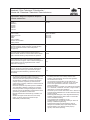 2
2
-
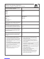 3
3
-
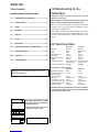 4
4
-
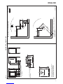 5
5
-
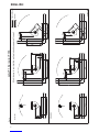 6
6
-
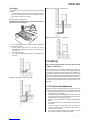 7
7
-
 8
8
-
 9
9
-
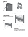 10
10
-
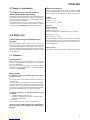 11
11
-
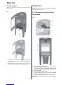 12
12
-
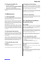 13
13
-
 14
14
-
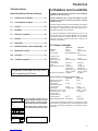 15
15
-
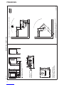 16
16
-
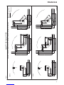 17
17
-
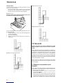 18
18
-
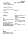 19
19
-
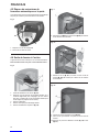 20
20
-
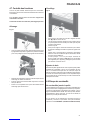 21
21
-
 22
22
-
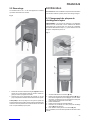 23
23
-
 24
24
-
 25
25
-
 26
26
-
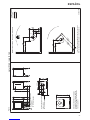 27
27
-
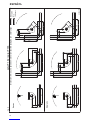 28
28
-
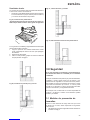 29
29
-
 30
30
-
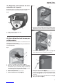 31
31
-
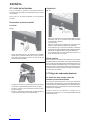 32
32
-
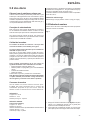 33
33
-
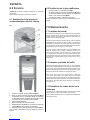 34
34
-
 35
35
-
 36
36
-
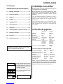 37
37
-
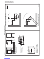 38
38
-
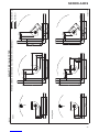 39
39
-
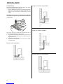 40
40
-
 41
41
-
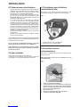 42
42
-
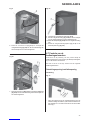 43
43
-
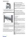 44
44
-
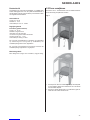 45
45
-
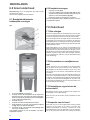 46
46
-
 47
47
-
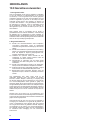 48
48
-
 49
49
-
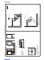 50
50
-
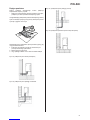 51
51
-
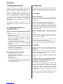 52
52
-
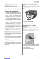 53
53
-
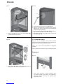 54
54
-
 55
55
-
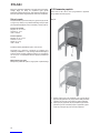 56
56
-
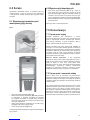 57
57
-
 58
58
-
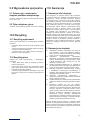 59
59
-
 60
60
-
 61
61
-
 62
62
-
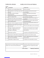 63
63
-
 64
64


Jøtul F 162 Installation And Operating Instructions Manual
- Categoría
- Chimeneas
- Tipo
- Installation And Operating Instructions Manual
- Este manual también es adecuado para
en otros idiomas
- français: Jøtul F 162
- English: Jøtul F 162
- polski: Jøtul F 162
Artículos relacionados
-
Jøtul F 475 Installation And Operating Istructions
-
Jotul F 374 El manual del propietario
-
-
-
-
-
-
-